Project Gutenberg's How it Flies or, Conquest of the Air, by Richard Ferris

This eBook is for the use of anyone anywhere in the United States and most
other parts of the world at no cost and with almost no restrictions
whatsoever.  You may copy it, give it away or re-use it under the terms of
the Project Gutenberg License included with this eBook or online at
www.gutenberg.org.  If you are not located in the United States, you'll have
to check the laws of the country where you are located before using this ebook.

Title: How it Flies or, Conquest of the Air
       The Story of Man's Endeavors to Fly and of the Inventions
              by which He Has Succeeded

Author: Richard Ferris

Release Date: August 5, 2017 [EBook #55268]

Language: English

Character set encoding: UTF-8

*** START OF THIS PROJECT GUTENBERG EBOOK HOW IT FLIES OR, CONQUEST OF AIR ***


Produced by Chris Curnow, Wayne Hammond and the Online
Distributed Proofreading Team at http://www.pgdp.net
4
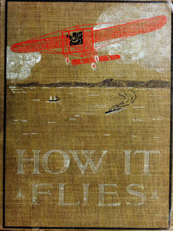
ORVILLE WRIGHT IN THE 80-MILE-AN-HOUR “BABY WRIGHT” RACER. 5
6
Copyright, 1910, by
THOMAS NELSON & SONS
THE TROW PRESS, NEW YORK 7
In these pages, by means of simple language and suitable pictures, the author has told the story of the Ships of the Air. He has explained the laws of their flight; sketched their development to the present day; shown how to build the flying machine and the balloon, and how to operate them; recounted what man has done, and what he hopes to do with their aid. In a word, all the essential facts that enter into the Conquest of the Air have been gathered into orderly form, and are here presented to the public.
We who live to-day have witnessed man’s great achievement; we have seen his dream of ages come true. Man has learned to fly!
The air which surrounds us, so intangible and so commonplace that it seldom arrests our attention, is in reality a vast, unexplored ocean, fraught with future possibilities. Even now, the pioneers of a 8 countless fleet are hovering above us in the sky, while steadily, surely these wonderful possibilities are unfolded.
The Publishers take pleasure in acknowledging their indebtedness to the Scientific American for their courtesy in permitting the use of many of the illustrations appearing in this book.
New York, October 20, 1910. 9
| CHAPTER | PAGE | |
| Preface | 7 | |
| I. | Introductory | 11 |
| II. | The Air | 20 |
| III. | Laws of Flight | 37 |
| IV. | Flying Machines | 55 |
| V. | Flying Machines: The Biplane | 78 |
| VI. | Flying Machines: The Monoplane | 112 |
| VII. | Flying Machines: Other Forms | 141 |
| VIII. | Flying Machines: How to Operate | 151 |
| IX. | Flying Machines: How to Build | 174 |
| X. | Flying Machines: Motors | 193 |
| XI. | Model Flying Machines | 215 |
| XII. | The Glider | 241 |
| XIII. | Balloons | 25710 |
| XIV. | Balloons: The Dirigible | 296 |
| XV. | Balloons: How to Operate | 340 |
| XVI. | Balloons: How to Make | 351 |
| XVII. | Military Aeronautics | 363 |
| XVIII. | Biographies of Prominent Aeronauts | 379 |
| XIX. | Chronicle of Aviation Achievements | 407 |
| XX. | Explanation of Aeronautical Terms | 452 |
11
The sudden awakening—Early successes—Influence of the gasoline engine on aeroplanes—On dirigible balloons—Interested inquiry—Some general terms defined.
In the year 1908 the world awakened suddenly to the realization that at last the centuries of man’s endeavor to fly mechanically had come to successful fruition.
There had been a little warning. In the late autumn of 1906, Santos-Dumont made a flight of 720 feet in a power-driven machine. There was an exclamation of wonder, a burst of applause—then a relapse into unconcern.
In August, 1907, Louis Bleriot sped free of the ground for 470 feet; and in November, Santos-Dumont made two flying leaps of barely 500 feet. That was the year’s record, and it excited little comment. It is true that the Wright brothers had been 12 making long flights, but they were in secret. There was no public knowledge of them.
In 1908 came the revelation. In March, Delagrange flew in a Voisin biplane 453 feet, carrying Farman with him as a passenger. Two weeks later he flew alone nearly 2½ miles. In May he flew nearly 8 miles. In June his best flight was 10½ miles. Bleriot came on the scene again in July with a monoplane, in which he flew 3¾ miles. In September, Delagrange flew 15 miles—in less than 30 minutes. In the same month the Wrights began their wonderful public flights. Wilbur, in France, made records of 41, 46, 62, and 77 miles, while Orville flew from 40 to 50 miles at Fort Myer, Va. Wilbur Wright’s longest flight kept him in the air 2 hours and 20 minutes.
The goal had been reached—men had achieved the apparently impossible. The whole world was roused to enthusiasm.
Since then, progress has been phenomenally rapid, urged on by the striving of the inventors, the competition of the aircraft builders, and the contests for records among the pilots.
By far the largest factor in the triumph of the aeroplane is the improved gasoline engine, designed 13 originally for automobiles. Without this wonderful type of motor, delivering a maximum of power with a minimum of weight, from concentrated fuel, the flying machine would still be resting on the earth.
The Renard and Krebs airship La France, at Chalais-Meudon.
Nor has the influence of the gasoline motor been much less upon that other great class of aircraft, the dirigible balloon. After 1885, when Renard and Krebs’ airship La France made its two historic voyages from Chalais-Meudon to Paris, returning safely to its shed, under the propulsion of an electric motor, the problem of the great airship lay dormant, waiting for the discovery of adequate motive power. If the development of the dirigible balloon seems 14 less spectacular than that of the aeroplane, it is because the latter had to be created; the dirigible, already in existence, had only to be revivified.
Confronted with these new and strange shapes in the sky, some making stately journeys of hundreds of miles, others whirring hither and thither with the speed of the whirlwind, wonder quickly gives way to the all-absorbing question: How do they fly? To answer fully and satisfactorily, it seems wise, for many readers, to recall in the succeeding chapters some principles doubtless long since forgotten.
As with every great advance in civilization, this expansion of the science of aeronautics has had its effect upon the language of the day. Terms formerly in use have become restricted in application, and other terms have been coined to convey ideas so entirely new as to find no suitable word existent in our language. It seems requisite, therefore, first to acquaint the reader with clear definitions of the more common terms that are used throughout this book.
Aeronautics is the word employed to designate the entire subject of aerial navigation. An aeronaut is a person who sails, or commands, any form of aircraft, as distinguished from a passenger. 15
Aviation is limited to the subject of flying by machines which are not floated in the air by gas. An aviator is an operator of such machine.
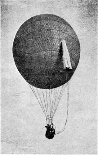
A free balloon, with parachute.
Both aviators and aeronauts are often called pilots.
A balloon is essentially an envelope or bag filled 16 with some gaseous substance which is lighter, bulk for bulk, than the air at the surface of the earth, and which serves to float the apparatus in the air. In its usual form it is spherical, with a car or basket suspended below it. It is a captive balloon if it is attached to the ground by a cable, so that it may not rise above a certain level, nor float away in the wind. It is a free balloon if not so attached or anchored, but is allowed to drift where the wind may carry it, rising and falling at the will of the pilot.
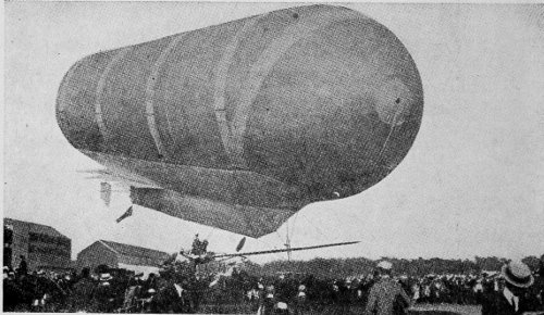
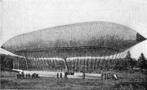
A dirigible balloon.
A dirigible balloon, sometimes termed simply a dirigible, usually has its gas envelope elongated in form. It is fitted with motive power to propel it, 17 and steering mechanism to guide it. It is distinctively the airship.
Aeroplanes are those forms of flying machines which depend for their support in the air upon the spread of surfaces which are variously called wings, sails, or planes. They are commonly driven by propellers actuated by motors. When not driven by power they are called gliders.
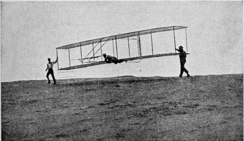
A biplane glider.
Aeroplanes exist in several types: the monoplane, with one spread of surface; the biplane, with two spreads, one above the other; the triplane, with three spreads, or decks; the multiplane, with more than three. 18
The tetrahedral plane is a structure of many small cells set one upon another.
Ornithopter is the name given to a flying machine which is operated by flapping wings.
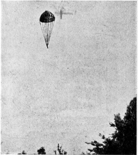
A parachute descending.
Helicopter is used to designate machines which are lifted vertically and sustained in the air by propellers revolving in a horizontal plane, as distinguished from the propellers of the aeroplane, which revolve in vertical planes. 19
A parachute is an umbrella-like contrivance by which an aeronaut may descend gently from a balloon in mid-air, buoyed up by the compression of the air under the umbrella.
For the definition of other and more technical terms the reader is referred to the carefully prepared Glossary toward the end of the book. 20
Intangibility of air—Its substance—Weight—Extent—Density—Expansion by heat—Alcohol fire—Turbulence of the air—Inertia—Elasticity—Viscosity—Velocity of winds—Aircurrents—Cloud levels—Aerological stations—High altitudes—Practical suggestions—The ideal highway.
The air about us seems the nearest approach to nothingness that we know of. A pail is commonly said to be empty—to have nothing in it—when it is filled only with air. This is because our senses do not give us any information about air. We cannot see it, hear it, touch it.
When air is in motion (wind) we hear the noises it makes as it passes among other objects more substantial; and we feel it as it blows by us, or when we move rapidly through it.
We get some idea that it exists as a substance when we see dead leaves caught up in it and whirled about; and, more impressively, when in the violence of the hurricane it seizes upon a body of great size 21 and weight, like the roof of a house, and whisks it away as though it were a feather, at a speed exceeding that of the fastest railroad train.
In a milder form, this invisible and intangible air does some of our work for us in at least two ways that are conspicuous: it moves ships upon the ocean, and it turns a multitude of windmills, supplying the cheapest power known.
That this atmosphere is really a fluid ocean, having a definite substance, and in some respects resembling the liquid ocean upon which our ships sail, and that we are only crawling around on the bottom of it, as it were, is a conception we do not readily grasp. Yet this conception must be the foundation of every effort to sail, to fly, in this aerial ocean, if such efforts are to be crowned with success.
As a material substance the air has certain physical properties, and it is the part of wisdom for the man who would fly to acquaint himself with these properties. If they are helpful to his flight, he wants to use them; if they hinder, he must contrive to overcome them.
In general, it may be said that the air, being in a gaseous form, partakes of the properties of all gases—and these may be studied in any text-book on 22 physics, Here we are concerned only with those qualities which affect conditions under which we strive to fly.
Of first importance is the fact that air has weight. That is, in common with all other substances, it is attracted by the mass of the earth exerted through the force we call gravity. At the level of the sea, this attraction causes the air to press upon the earth with a weight of nearly fifteen pounds (accurately, 14.7 lbs.) to the square inch, when the temperature is at 32° F. That pressure is the weight of a column of air one inch square at the base, extending upward to the outer limit of the atmosphere—estimated to be about 38 miles (some say 100 miles) above sea-level. The practical fact is that normal human life cannot exist above the level of 15,000 feet, or a little less than three miles; and navigation of the air will doubtless be carried on at a much lower altitude, for reasons which will appear as we continue.
The actual weight of a definite quantity of dry air—for instance, a cubic foot—is found by weighing a vessel first when full of air, and again after the air has been exhausted from it with an air-pump. In this way it has been determined that a cubic foot of 23 24 dry air, at the level of the sea, and at a temperature of 32° F., weighs 565 grains—about 0.0807 lb. At a height above the level of the sea, a cubic foot of air will weigh less than the figure quoted, for its density decreases as we go upward, the pressure being less owing to the diminished attraction of the earth at the greater distance. For instance, at the height of a mile above sea-level a cubic foot of air will weigh about 433 grains, or 0.0619 lb. At the height of five miles it will weigh about 216 grains, or 0.0309 lb. At thirty-eight miles it will have no weight at all, its density being so rare as just to balance the earth’s attraction. It has been calculated that the whole body of air above the earth, if it were all of the uniform density of that at sea-level, would extend only to the height of 26,166 feet. Perhaps a clearer comprehension of the weight and pressure of the ocean of air upon the earth may be gained by recalling that the pressure of the 38 miles of atmosphere is just equal to balancing a column of water 33 feet high. The pressure of the air, therefore, is equivalent to the pressure of a flood of water 33 feet deep.
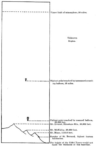
Comparative Elevations of Earth and Air.
But air is seldom dry. It is almost always mingled with the vapor of water, and this vapor weighs 25 only 352 grains per cubic foot at sea-level. Consequently the mixture—damp air—is lighter than dry air, in proportion to the moisture it contains.
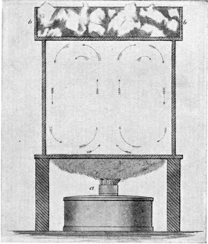
Apparatus to show effects of heat on air currents. a, alcohol lamp; b, ice. The arrows show direction of currents.
Another fact very important to the aeronaut is that the air is in constant motion. Owing to its ready expansion by heat, a body of air occupying one 26 cubic foot when at a temperature of 32° F. will occupy more space at a higher temperature, and less space at a lower temperature. Hence, heated air will flow upward until it reaches a point where the natural density of the atmosphere is the same as its expanded density due to the heating. Here another complication comes into play, for ascending air is cooled at the rate of one degree for every 183 feet it rises; and as it cools it grows denser, and the speed of its ascension is thus gradually checked. After passing an altitude of 1,000 feet the decrease in temperature is one degree for each 320 feet of ascent. In general, it may be stated that air is expanded one-tenth of its volume for each 50° F. that its temperature is raised.
This highly unstable condition under ordinary changes of temperature causes continual movements in the air, as different portions of it are constantly seeking that position in the atmosphere where their density at that moment balances the earth’s attraction.
Sir Hiram Maxim relates an incident which aptly illustrates the effect of change of temperature upon the air. He says: “On one occasion, many years ago, I was present when a bonded warehouse in 27 New York containing 10,000 barrels of alcohol was burned.... I walked completely around the fire, and found things just as I expected. The wind was blowing a perfect hurricane through every street in the direction of the fire, although it was a dead calm everywhere else; the flames mounted straight in the air to an enormous height, and took with them a large amount of burning wood. When I was fully 500 feet from the fire, a piece of partly burned one-inch board, about 8 inches wide and 4 feet long, fell through the air and landed near me. This board had evidently been taken up to a great height by the tremendous uprush of air caused by the burning alcohol.”
That which happened on a small scale, with a violent change of temperature, in the case of the alcohol fire, is taking place on a larger scale, with milder changes in temperature, all over the world. The heating by the sun in one locality causes an expansion of air at that place, and cooler, denser air rushes in to fill the partial vacuum. In this way winds are produced.
So the air in which we are to fly is in a state of constant motion, which may be likened to the rush and swirl of water in the rapids of a mountain torrent. 28 The tremendous difference is that the perils of the water are in plain sight of the navigator, and may be guarded against, while those of the air are wholly invisible, and must be met as they occur, without a moment’s warning.
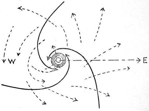
The solid arrows show the directions of a cyclonic wind on the earth’s surface. At the centre the currents go directly upward. In the upper air above the cyclone the currents have the directions of the dotted arrows.
Next in importance, to the aerial navigator, is the air’s resistance. This is due in part to its density at the elevation at which he is flying, and in part to the direction and intensity of its motion, or the wind. 29 While this resistance is far less than that of water to the passage of a ship, it is of serious moment to the aeronaut, who must force his fragile machine through it at great speed, and be on the alert every instant to combat the possibility of a fall as he passes into a rarer and less buoyant stratum.
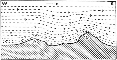
Diagram showing disturbance of wind currents by inequalities of the ground, and the smoother currents of the upper air. Note the increase of density at A and B, caused by compression against the upper strata.
Three properties of the air enter into the sum total of its resistance—inertia, elasticity, and viscosity. Inertia is its tendency to remain in the condition in which it may be: at rest, if it is still; in motion, if it is moving. Some force must be applied to disturb this inertia, and in consequence when the inertia is overcome a certain amount of force is used up in the 30 operation. Elasticity is that property by virtue of which air tends to reoccupy its normal amount of space after disturbance. An illustration of this tendency is the springing back of the handle of a bicycle pump if the valve at the bottom is not open, and the air in the pump is simply compressed, not forced into the tire. Viscosity may be described as “stickiness”—the tendency of the particles of air to cling together, to resist separation. To illustrate: molasses, particularly in cold weather, has greater viscosity than water; varnish has greater viscosity than turpentine. Air exhibits some viscosity, though vastly less than that of cold molasses. However, though relatively slight, this viscosity has a part in the resistance which opposes the rapid flight of the airship and aeroplane; and the higher the speed, the greater the retarding effect of viscosity.
The inertia of the air, while in some degree it blocks the progress of his machine, is a benefit to the aeronaut, for it is inertia which gives the blades of his propeller “hold” upon the air. The elasticity of the air, compressed under the curved surfaces of the aeroplane, is believed to be helpful in maintaining the lift. The effect of viscosity may be greatly reduced by using surfaces finished with polished varnish—just 31 as greasing a knife will permit it to be passed with less friction through thick molasses.
In the case of winds, the inertia of the moving mass becomes what is commonly termed “wind pressure” against any object not moving with it at an equal speed. The following table gives the measurements of wind pressure, as recorded at the station on the Eiffel Tower, for differing velocities of wind:
| Velocity in Miles per Hour |
Velocity in Feet per Second |
Pressure in Pounds on a Square Foot |
|---|---|---|
| 2 | 2.9 | 0.012 |
| 4 | 5.9 | 0.048 |
| 6 | 8.8 | 0.108 |
| 8 | 11.7 | 0.192 |
| 10 | 14.7 | 0.300 |
| 15 | 22.0 | 0.675 |
| 20 | 29.4 | 1.200 |
| 25 | 36.7 | 1.875 |
| 30 | 44.0 | 2.700 |
| 35 | 51.3 | 3.675 |
| 40 | 58.7 | 4.800 |
| 45 | 66.0 | 6.075 |
| 50 | 73.4 | 7.500 |
| 60 | 88.0 | 10.800 |
| 70 | 102.7 | 14.700 |
| 80 | 117.2 | 19.200 |
| 90 | 132.0 | 24.300 |
| 100 | 146.7 | 30.000 |
In applying this table, the velocity to be considered is the net velocity of the movements of the airship 32 and of the wind. If the ship is moving 20 miles an hour against a head wind blowing 20 miles an hour, the net velocity of the wind will be 40 miles an hour, and the pressure 4.8 lbs. a square foot of surface presented. Therefore the airship will be standing still, so far as objects on the ground are concerned. If the ship is sailing 20 miles an hour with the wind, which is blowing 20 miles an hour, the pressure per square foot will be only 1.2 lbs.; while as regards objects on the ground, the ship will be travelling 40 miles an hour.
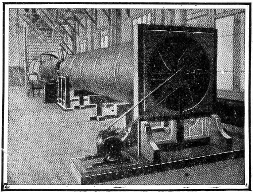
Apparatus for the study of the action of air in motion; a blower at the farther end of the great tube sends a “wind” of any desired velocity through it. Planes and propellers of various forms are thus tested.
33
Systematic study of the movements of the air currents has not been widespread, and has not progressed much beyond the gathering of statistics which may serve as useful data in testing existing theories or formulating new ones.
It is already recognized that there are certain “tides” in the atmosphere, recurring twice daily in six-hour periods, as in the case of the ocean tides, and perhaps from the same causes. Other currents are produced by the earth’s rotation. Then there are the five-day oscillations noted by Eliot in India, and daily movements, more or less regular, due to the sun’s heat by day and the lack of it by night. The complexity of these motions makes scientific research extremely difficult.
Something definite has been accomplished in the determination of wind velocities, though this varies largely with the locality. In the United States the average speed of the winds is 9½ miles per hour; in Europe, 10⅓ miles; in Southern Asia, 6½ miles; in the West Indies, 6⅕ miles; in England, 12 miles; over the North Atlantic Ocean, 29 miles per hour. Each of these average velocities varies with the time of year and time of day, and with the distance from the sea. The wind moves faster over water 34 and flat, bare land than over hilly or forest-covered areas. Velocities increase as we go upward in the air, being at 1,600 feet twice what they are at 100 feet. Observations of the movements of cloud forms at the Blue Hill Observatory, near Boston, give the following results:
| Cloud Form | Height in Feet |
Average Speed per Hour |
|---|---|---|
| Stratus | 1,676 | 19 miles. |
| Cumulus | 5,326 | 24 miles. |
| Alto-cumulus | 12,724 | 34 miles. |
| Cirro-cumulus | 21,888 | 71 miles. |
| Cirrus | 29,317 | 78 miles. |
In winter the speed of cirrus clouds may reach 96 miles per hour.
There are forty-nine stations scattered over Germany where statistics concerning winds are gathered expressly for the use of aeronauts. At many of these stations records have been kept for twenty years. Dr. Richard Assman, director of the aerological observatory at Lindenburg, has prepared a comprehensive treatise of the statistics in possession of these stations, under the title of Die Winde in Deutschland. It shows for each station, and for each season of the year, how often the wind blows from each 35 point of the compass; the average frequency of the several degrees of wind; when and where aerial voyages may safely be made; the probable drift of dirigibles, etc. It is interesting to note that Friedrichshafen, where Count Zeppelin’s great airship sheds are located, is not a favorable place for such vessels, having a yearly record of twenty-four stormy days, as compared with but two stormy days at Celle, four at Berlin, four at Cassel, and low records at several other points.
In practical aviation, a controlling factor is the density of the air. We have seen that at an altitude of five miles the density is about three-eighths the density at sea-level. This means that the supporting power of the air at a five-mile elevation is so small that the area of the planes must be increased to more than 2½ times the area suited to flying near the ground, or that the speed must be largely increased. Therefore the adjustments necessary for rising at the lower level and journeying in the higher level are too large and complex to make flying at high altitudes practicable—leaving out of consideration the bitter cold of the upper regions.
Mr. A. Lawrence Rotch, director of the Blue Hill Observatory, in his valuable book, The Conquest of 36 the Air, gives this practical summary of a long series of studious observations: “At night, however, because there are no ascending currents, the wind is much steadier than in the daytime, making night the most favorable time for aerial navigation of all kinds.... A suitable height in the daytime, unless a strong westerly wind is sought, lies above the cumulus clouds, at the height of about a mile; but at night it is not necessary to rise so high; and in summer a region of relatively little wind is found at a height of about three-fourths of a mile, where it is also warmer and drier than in the daytime or at the ground.”
Notwithstanding all difficulties, the fact remains that, once they are overcome, the air is the ideal highway for travel and transportation. On the sea, a ship may sail to right or left on one plane only. In the air, we may steer not only to right or left, but above and below, and obliquely in innumerable planes. We shall not need to traverse long distances in a wrong direction to find a bridge by which we may cross a river, nor zigzag for toilsome miles up the steep slopes of a mountain-side to the pass where we may cross the divide. The course of the airship is the proverbial bee-line—the most economical in time as well as in distance. 37
The bird—Nature’s models—Man’s methods—Gravity—The balloon—The airship—Resistance of the air—Winds—The kite—Laws of motion and force—Application to kite-flying—Aeroplanes.
If we were asked to explain the word “flying” to some foreigner who did not know what it meant, we should probably give as an illustration the bird. This would be because the bird is so closely associated in our thoughts with flying that we can hardly think of the one without the other.
It is natural, therefore, that since men first had the desire to fly they should study the form and motions of the birds in the air, and try to copy them. Our ancestors built immense flopping wings, into the frames of which they fastened themselves, and with great muscular exertion of arms and legs strove to attain the results that the bird gets by apparently similar motions.
However, this mental coupling of the bird with 38 the laws of flight has been unfortunate for the achievement of flight by man. And this is true even to the present day, with its hundreds of successful flying machines that are not in the least like a bird. This wrongly coupled idea is so strong that scientific publications print pages of research by eminent contributors into the flight of birds, with the attempt to deduce lessons therefrom for the instruction of the builders and navigators of flying machines.
These arguments are based on the belief that Nature never makes a mistake; that she made the bird to fly, and therefore the bird must be the most perfect model for the successful flying machine. But the truth is, the bird was not made primarily to fly, any more than man was made to walk. Flying is an incident in the life of a bird, just as walking is an incident in the life of a man. Flying is simply a bird’s way of getting about from place to place, on business or on pleasure, as the case may be.
Santos-Dumont, in his fascinating book, My Air-Ships, points out the folly of blindly following Nature by showing that logically such a procedure would compel us to build our locomotives on the plan of gigantic horses, with huge iron legs which would go galloping about the country in a ridiculously terrible 39 fashion; and to construct our steamships on the plan of giant whales, with monstrous flapping fins and wildly lashing tails.
Sir Hiram Maxim says something akin to this in his work, Artificial and Natural Flight: “It appears to me that there is nothing in Nature which is more efficient, or gets a better grip on the water, than a well-made screw propeller; and no doubt there would have been fish with screw propellers, providing Dame Nature could have made an animal in two pieces. It is very evident that no living creature could be made in two pieces, and two pieces are necessary if one part is stationary and the other revolves; however, the tails and fins very often approximate to the action of propeller blades; they turn first to the right and then to the left, producing a sculling effect which is practically the same. This argument might also be used against locomotives. In all Nature we do not find an animal travelling on wheels, but it is quite possible that a locomotive might be made that would walk on legs at the rate of two or three miles an hour. But locomotives with wheels are able to travel at least three times as fast as the fleetest animal with legs, and to continue doing so for many hours at a time, even when attached 40 to a very heavy load. In order to build a flying machine with flapping wings, to exactly imitate birds, a very complicated system of levers, cams, cranks, etc., would have to be employed, and these of themselves would weigh more than the wings would be able to lift.”
As with the man-contrived locomotive, so the perfected airship will be evolved from man’s understanding of the obstacles to his navigation of the air, and his overcoming of them by his inventive genius. This will not be in Nature’s way, but in man’s own way, and with cleverly designed machinery such as he has used to accomplish other seeming impossibilities. With the clearing up of wrong conceptions, the path will be open to more rapid and more enduring progress.
When we consider the problem of flying, the first obstacle we encounter is the attraction which the earth has for us and for all other objects on its surface. This we call weight, and we are accustomed to measure it in pounds.
Let us take, for example, a man whose body is attracted by the earth with a force, or weight, of 150 pounds. To enable him to rise into the air, means must be contrived not only to counteract his weight, 41 but to lift him—a force a little greater than 150 pounds must be exerted. We may attach to him a bag filled with some gas (as hydrogen) for which the earth has less attraction than it has for air, and which the air will push out of the way and upward until a place above the earth is reached where the attraction of air and gas is equal. A bag of this gas large enough to be pushed upward with a force equal to the weight of the man, plus the weight of the bag, and a little more for lifting power, will carry the man up. This is the principle of the ordinary balloon.
Rising in the air is not flying. It is a necessary step, but real flying is to travel from place to place through the air. To accomplish this, some mechanism, or machinery, is needed to propel the man after he has been lifted into the air. Such machinery will have weight, and the bag of gas must be enlarged to counterbalance it. When this is done, the man and the bag of gas may move through the air, and with suitable rudders he may direct his course. This combination of the lifting bag of gas and the propelling machinery constitutes the dirigible balloon, or airship.
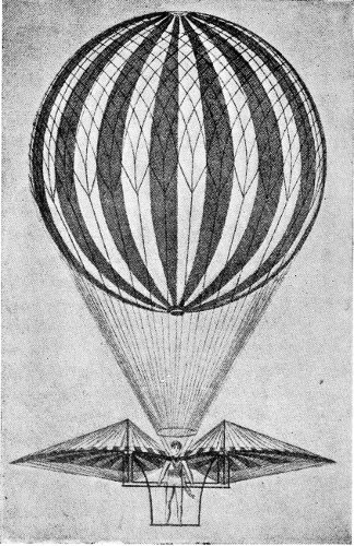
Degen’s apparatus to lift the man and his flying mechanism with the aid of a gas-balloon. See Chapter IV.
The airship is affected equally with the balloon by 42 prevailing winds. A breeze blowing 10 miles an hour will carry a balloon at nearly that speed in the direction in which it is blowing. Suppose the aeronaut wishes to sail in the opposite direction? If the 43 machinery will propel his airship only 10 miles an hour in a calm, it will virtually stand still in the 10-mile breeze. If the machinery will propel his airship 20 miles an hour in a calm, the ship will travel 10 miles an hour—as related to places on the earth’s surface—against the wind. But so far as the air is concerned, his speed through it is 20 miles an hour, and each increase of speed meets increased resistance from the air, and requires a greater expenditure of power to overcome. To reduce this resistance to the least possible amount, the globular form of the early balloon has been variously modified. Most modern airships have a “cigar-shaped” gas bag, so called because the ends look like the tip of a cigar. As far as is known, this is the balloon that offers less resistance to the air than any other.
Another mechanical means of getting up into the air was suggested by the flying of kites, a pastime dating back at least 2,000 years, perhaps longer. Ordinarily, a kite will not fly in a calm, but with even a little breeze it will mount into the air by the upward thrust of the rushing breeze against its inclined surface, being prevented from blowing away (drifting) by the pull of the kite-string. The same effect will be produced in a dead calm if the operator, 44 holding the string, runs at a speed equal to that of the breeze—with this important difference: not only will the kite rise in the air, but it will travel in the direction in which the operator is running, a part of the energy of the runner’s pull upon the string producing a forward motion, provided he holds the string taut. If we suppose the pull on the string to be replaced by an engine and revolving propeller in the kite, exerting the same force, we have exactly the principle of the aeroplane.
As it is of the greatest importance to possess a clear understanding of the natural processes we propose to use, let us refer to any text-book on physics, and review briefly some of the natural laws relating to motion and force which apply to the problem of flight:
(a) Force is that power which changes or tends to change the position of a body, whether it is in motion or at rest.
(b) A given force will produce the same effect, whether the body on which it acts is acted upon by that force alone, or by other forces at the same time.
(c) A force may be represented graphically 45 46 by a straight line—the point at which the force is applied being the beginning of the line; the direction of the force being expressed by the direction of the line; and the magnitude of the force being expressed by the length of the line.
(d) Two or more forces acting upon a body are called component forces, and the single force which would produce the same effect is called the resultant.
(e) When two component forces act in different directions the resultant may be found by applying the principle of the parallelogram of forces—the lines (c) representing the components being made adjacent sides of a parallelogram, and the diagonal drawn from the included angle representing the resultant in direction and magnitude.
(f) Conversely, a resultant motion may be resolved into its components by constructing a parallelogram upon it as the diagonal, either one of the components being known.
The Deutsch de la Muerthe dirigible balloon Ville-de-Paris; an example of the “cigar-shaped” gas envelope.
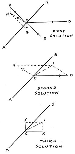
Taking up again the illustration of the kite flying in a calm, let us construct a few diagrams to show graphically the forces at work upon the kite. Let 47 the heavy line AB represent the centre line of the kite from top to bottom, and C the point where the string is attached, at which point we may suppose all the forces concentrate their action upon the plane of the kite. Obviously, as the flyer of the kite is running in a horizontal direction, the line indicating the pull of the string is to be drawn horizontal. Let it be expressed by CD. The action of the air pressure being at right angles to the plane of the kite, we draw the line CE representing that force. But as this is a pressing force at the point C, we may express it as a pulling force on the other side of the kite by the line CF, equal to CE and in the opposite direction. Another force acting on the kite is its weight—the attraction of gravity acting directly downward, shown by CG. We have given, therefore, the three forces, CD, CF, and CG. We now wish to find the value of the pull on the kite-string, CD, in two other forces, one of which shall be a lifting force, acting directly upward, and the other a propelling force, acting in the direction in which we desire the kite to travel—supposing it to represent an aeroplane for the moment.
We first construct a parallelogram on CF and CG, and draw the diagonal CH, which represents the resultant 48 49 of those two forces. We have then the two forces CD and CH acting on the point C. To avoid obscuring the diagram with too many lines, we draw a second figure, showing just these two forces acting on the point C. Upon these we construct a new parallelogram, and draw the diagonal CI, expressing their resultant. Again drawing a new diagram, showing this single force CI acting upon the point C, we resolve that force into two components—one, CJ, vertically upward, representing the lift; the other, CK, horizontal, representing the travelling power. If the lines expressing these forces in the diagrams had been accurately drawn to scale, the measurement of the two components last found would give definite results in pounds; but the weight of a kite is too small to be thus diagrammed, and only the principle was to be illustrated, to be used later in the discussion of the aeroplane.
Nor is the problem as simple as the illustration of the kite suggests, for the air is compressible, and is moreover set in motion in the form of a current by a body passing through it at anything like the ordinary speed of an aeroplane. This has caused the curving of the planes (from front to rear) of the flying machine, in contrast with the flat plane of the 50 kite. The reasoning is along this line: Suppose the main plane of an aeroplane six feet in depth (from front to rear) to be passing rapidly through the air, inclined upward at a slight angle. By the time two feet of this depth has passed a certain point, the air at that point will have received a downward impulse or compression which will tend to make it flow in the direction of the angle of the plane. The second and third divisions in the depth, each of two feet, will therefore be moving with a partial vacuum beneath, the air having been drawn away by the first segment. At the same time, the pressure of the air from above remains the same, and the result is that only the front edge of the plane is supported, while two-thirds of its depth is pushed down. This condition not only reduces the supporting surface to that of a plane two feet in depth, but, what is much worse, releases a tipping force which tends to throw the plane over backward.
In order that the second section of the plane may bear upon the air beneath it with a pressure equal to that of the first, it must be inclined downward at double the angle (with the horizon) of the first section; this will in turn give to the air beneath it a new direction. The third section of the plane must 51 then be set at a still deeper angle to give it support. Connecting these several directions with a smoothly flowing line without angles, we get the curved line of section to which the main planes of aeroplanes are bent.
With these principles in mind, it is in order to apply them to the understanding of how an aeroplane flies. Wilbur Wright, when asked what kept his machine up in the air—why it did not fall to the ground—replied: “It stays up because it doesn’t have time to fall.” Just what he meant by this may be illustrated by referring to the common sport of “skipping stones” upon the surface of still water. A flat stone is selected, and it is thrown at a high speed so that the flat surface touches the water. It continues “skipping,” again and again, until its speed is so reduced that the water where it touches last has time to get out of the way, and the weight of the stone carries it to the bottom. On the same principle, a person skating swiftly across very thin ice will pass safely over if he goes so fast that the ice hasn’t time to break and give way beneath his weight. This explains why an aeroplane must move swiftly to stay up in the air, which has much less density than either water or ice. The minimum 52 speed at which an aeroplane can remain in the air depends largely upon its weight. The heavier it is, the faster it must go—just as a large man must move faster over thin ice than a small boy. At some aviation contests, prizes have been awarded for the slowest speed made by an aeroplane. So far, the slowest on record is that of 21.29 miles an hour, made by Captain Dickson at the Lanark meet, Scotland, in August, 1910. As the usual rate of speed is about 46 miles an hour, that is slow for an aeroplane; and as Dickson’s machine is much heavier than some others—the Curtiss machine, for instance—it is remarkably slow for that type of aeroplane.
Just what is to be gained by offering a prize for slowest speed is difficult to conjecture. It is like offering a prize to a crowd of boys for the one who can skate slowest over thin ice. The minimum speed is the most dangerous with the aeroplane as with the skater. Other things being equal, the highest speed is the safest for an aeroplane. Even when his engine stops in mid-air, the aviator is compelled to keep up speed sufficient to prevent a fall by gliding swiftly downward until the very moment of landing.
The air surface necessary to float a plane is spread out in one area in the monoplane, and divided into 53 two areas, one above the other and 6 to 9 feet apart, in the biplane; if closer than this, the disturbance of the air by the passage of one plane affects the supporting power of the other. It has been suggested that better results in the line of carrying power would be secured by so placing the upper plane that its front edge is a little back of the rear edge of the lower plane, in order that it may enter air that is wholly free from any currents produced by the rushing of the lower plane.
As yet, there is a difference of opinion among the principal aeroplane builders as to where the propeller should be placed. All of the monoplanes have it in front of the main plane. Most of the biplanes have it behind the main plane; some have it between the two planes. If it is in front, it works in undisturbed air, but throws its wake upon the plane. If it is in the rear, the air is full of currents caused by the passage of the planes, but the planes have smooth air to glide into. As both types of machine are eminently successful, the question may not be so important as it seems to the disputants.
The exact form of curve for the planes has not been decided upon. Experience has proven that of two aeroplanes having the same surface and run at 54 the same speed, one may be able to lift twice as much as the other because of the better curvature of its planes. The action of the air when surfaces are driven through it is not fully understood. Indeed, the form of plane shown in the accompanying figure is called the aeroplane paradox. If driven in either direction it leaves the air with a downward trend, and therefore exerts a proportional lifting power. If half of the plane is taken away, the other half is pressed downward. All of the lifting effect is in the curving of the top side. It seems desirable, therefore, that such essential factors should be thoroughly worked out, understood, and applied.
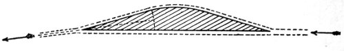
Section of the “paradox” aeroplane. 55
Mythological—Leonardo da Vinci—Veranzio—John Wilkins—Besnier—Marquis de Bacqueville—Paucton—Desforges—Meerwein—Stentzel—Henson—Von Drieberg—Wenham—Horatio Phillips—Sir Hiram Maxim—Lilienthal—Langley—Ader—Pilcher—Octave Chanute—Herring—Hargrave—The Wright brothers—Archdeacon—Santos-Dumont—Voisin—Bleriot.
The term Flying Machines is applied to all forms of aircraft which are heavier than air, and which lift and sustain themselves in the air by mechanical means. In this respect they are distinguished from balloons, which are lifted and sustained in the air by the lighter-than-air gas which they contain.
From the earliest times the desire to fly in the air has been one of the strong ambitions of the human race. Even the prehistoric mythology of the ancient Greeks reflected the idea in the story of Icarus, who flew so near to the sun that the heat melted the wax which fastened his wings to his body, and he fell into the sea. 56
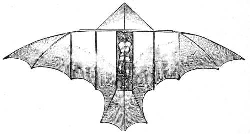
Perhaps the first historical record in the line of mechanical flight worthy of attention exists in the remarkable sketches and plans for a flying mechanism left by Leonardo da Vinci at his death in 1519. He had followed the model of the flying bird as closely as possible, although when the wings were outspread they had an outline more like those of the bat. While extremely ingenious in the arrangement of the levers, the power necessary to move them fast enough to lift the weight of a man was far beyond the muscular strength of any human being.
It was a century later, in 1617, that Veranzio, a Venetian, proved his faith in his inventive ability by leaping from a tower in Venice with a crude, parachute-like contrivance. He alighted without injury.
In 1684, an Englishman, John Wilkins, then bishop of Chester, built a machine for flying in which he installed a steam-engine. No record exists of its performance.
In 1678, a French locksmith by the name of Besnier devised what seems now a very crude apparatus for making descending flights, or glides, from elevated points. It was, however, at that date considered important enough to be described in the Journal 57 of the Savants. It was a wholly unscientific combination of the “dog-paddle” motion in swimming, with wing areas which collapsed on the upward motion and spread out on the downward thrust. If it was ever put to a test it must have failed completely.
In 1742, the Marquis de Bacqueville constructed an apparatus which some consider to have been based on Besnier’s idea—which seems rather doubtful. He fastened the surfaces of his aeroplane directly to his arms and legs, and succeeded in making a long glide from the window of his mansion across the garden of the Tuileries, alighting upon a washerwoman’s bench in the Seine without injury.
Paucton, the mathematician, is credited with the suggestion of a flying machine with two screw propellers, which he called “pterophores”—a horizontal one to raise the machine into the air, and an upright one to propel it. These were to be driven by hand. With such hopelessly inadequate power it is not surprising that nothing came of it, yet the plan was a foreshadowing of the machine which has in these days achieved success.
The Abbé Desforges gained a place in the annals 58 of aeronautics by inventing a flying machine of which only the name “Orthoptere” remains.
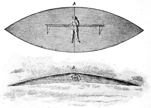
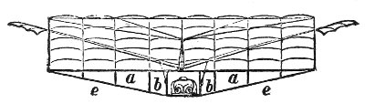
Meerwein’s Flying Machine. A, shows the position of the man in the wings, their comparative size, and the operating levers; B, position when in flight.
About 1780, Karl Friedrich Meerwein, an architect, and the Inspector of Public Buildings for Baden, Germany, made many scientific calculations and experiments on the size of wing surface needed to support a man in the air. He used the wild duck as a standard, and figured that a surface of 126 square feet would sustain a man in the air. This agrees with the later calculations of such experimenters as Lilienthal and Langley. Other of Meerwein’s 59 conclusions are decidedly ludicrous. He held that the build of a man favors a horizontal position in flying, as his nostrils open in a direction which would be away from the wind, and so respiration would not be interfered with! Some of his reasoning is unaccountably astray; as, for instance, his argument that because the man hangs in the wings the weight of the latter need not be considered. It is almost needless to say that his practical trials were a total failure.
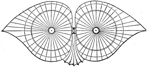
Plan of Degen’s apparatus.
The next prominent step forward toward mechanical flight was made by the Australian watchmaker Degen, who balanced his wing surfaces with a small gas balloon. His first efforts to fly not being successful, he abandoned his invention and took to ballooning.
Stentzel, an engineer of Hamburg, came next with 60 a machine in the form of a gigantic butterfly. From tip to tip of its wings it measured 20 feet, and their depth fore and aft was 5½ feet. The ribs of the wings were of steel and the web of silk, and they were slightly concave on the lower side. The rudder-tail was of two intersecting planes, one vertical and the other horizontal. It was operated by a carbonic-acid motor, and made 84 flaps of the wings per minute. The rush of air it produced was so 61 great that any one standing near it would be almost swept off his feet. It did not reach a stage beyond the model, for it was able to lift only 75 lbs.
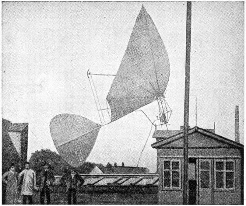
Stentzel’s machine.
In 1843, the English inventor Henson built what is admitted to be the first aeroplane driven by motive power. It was 100 feet in breadth (spread) and 30 feet long, and covered with silk. The front edge was turned slightly upward. It had a rudder shaped like the tail of a bird. It was driven by two propellers run by a 20-horse-power engine. Henson succeeded only in flying on a down grade, doubtless because of the upward bend of the front of his plane. Later investigations have proven that the upper surface of the aeroplane must be convex to gain the lifting effect. This is one of the paradoxes of flying planes which no one has been able to explain.
In 1845, Von Drieberg, in Germany, revived the sixteenth-century ideas of flying, with the quite original argument that since the legs of man were better developed muscularly than his arms, flying should be done with the legs. He built a machine on this plan, but no successful flights are recorded.
In 1868, an experimenter by the name of Wenham added to the increasing sum of aeronautical knowledge by discovering that the lifting power of 62 a large supporting surface may be as well secured by a number of small surfaces placed one above another. Following up these experiments, he built a flying machine with a series of six supporting planes made of linen fabric. As he depended upon muscular effort to work his propellers, he did not succeed in flying, but he gained information which has been valuable to later inventors.
Von Drieberg’s machine; view from above.
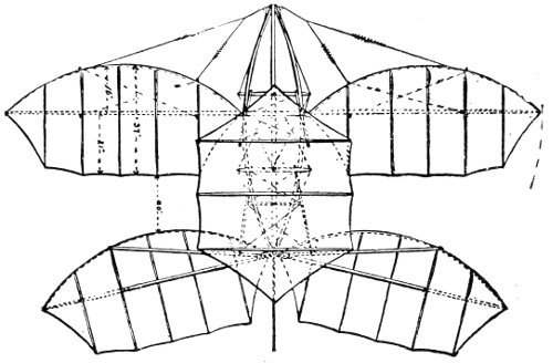
Wenham’s arrangement of many narrow surfaces in six tiers, or decks. a, a, rigid framework; b, b, levers working flapping wings; e, e, braces. The operator is lying prone.
The history of flying machines cannot be written 63 without deferential mention of Horatio Phillips of England. The machine that he made in 1862 resembled a large Venetian blind, 9 feet high and over 21 feet long. It was mounted on a carriage which travelled on a circular track 600 feet long, and it was driven by a small steam engine turning a propeller. It lifted unusually heavy loads, although not large enough to carry a man. It seems to open the way for experiments with an entirely new arrangement of sustaining surfaces—one that has never since been investigated. Phillips’s records cover a series of most valuable experiments. Perhaps his most important work was in the determination of the most 64 advantageous form for the surfaces of aeroplanes, and his researches into the correct proportion of motive power to the area of such surfaces. Much of his results have not yet been put to practical use by designers of flying machines.
Phillips’s Flying Machine—built of narrow slats like a Venetian blind.
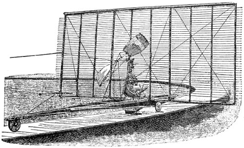
The year 1888 was marked by the construction by Sir Hiram Maxim of his great aeroplane which weighed three and one-half tons, and is said to have cost over $100,000. The area of the planes was 3,875 square feet, and it was propelled by a steam engine in which the fuel used was vaporized naphtha in a burner having 7,500 jets, under a boiler of small copper water tubes. With a steam pressure of 320 lbs. per square inch, the two compound engines each developed 180 horse-power, and each turned a two-bladed propeller 17½ feet in diameter. The machine was used only in making tests, being prevented from rising in the air by a restraining track. The thrust developed on trial was 2,164 lbs., and the lifting power was shown to have been in excess of 10,000 lbs. The restraining track was torn to pieces, and the machine injured by the fragments. The dynamometer record proved that a dead weight of 4½ tons, in addition to the weight of the machine and the crew of 4 men, could have been lifted. The 65 stability, speed, and steering control were not tested. Sir Hiram Maxim made unnumbered experiments with models, gaining information which has been invaluable in the development of the aeroplane.
View of a part of Maxim’s aeroplane, showing one of the immense propellers. At the top is a part of the upper plane.
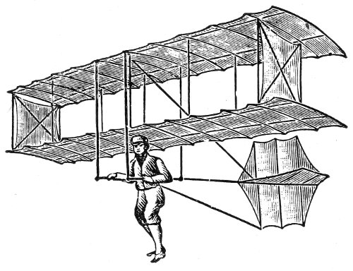
The experiments of Otto Lilienthal in gliding 66 with a winged structure were being conducted at this period. He held that success in flying must be founded upon proficiency in the art of balancing the apparatus in the air. He made innumerable glides from heights which he continually increased until he was travelling distances of nearly one-fourth of a mile from an elevation of 100 feet. He had reached the point where he was ready to install motive power to drive his glider when he met with a fatal accident. Besides the inspiration of his daring personal experiments in the air, he left a most valuable series 67 of records and calculations, which have been of the greatest aid to other inventors in the line of artificial flight.
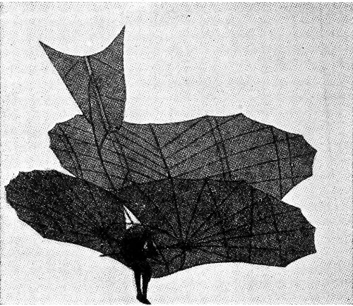
Lilienthal in his biplane glider.
In 1896, Professor Langley, director of the Smithsonian Institution at Washington, made a test of a model flying machine which was the result of years of experimenting. It had a span of 15 feet, and a length of 8½ feet without the extended rudder. There were 4 sails or planes, 2 on each side, 30 inches in width (fore-and-aft measurement). Two propellers revolving in opposite directions were driven by a steam engine. The diameter of the propellers was 3 feet, and the steam pressure 150 lbs. per square inch. The weight of the machine was 28 lbs. It is said to have made a distance of 1 mile in 1 minute 45 seconds. As Professor Langley’s experiments were conducted in strict secrecy, no authoritative figures are in existence. Later a larger machine was built, which was intended to carry a man. It had a spread of 46 feet, and was 35 feet in length. It was four years in building, and cost about $50,000. In the first attempt to launch it, from the roof of a house-boat, it plunged into the Potomac River. The explanation given was that the launching apparatus was defective. This 68 was remedied, and a second trial made, but the same result followed. It was never tried again. This machine was really a double, or tandem, monoplane. The framework was built of steel tubing almost as thin as writing paper. Every rib and pulley was hollowed out to reduce the weight. The total weight of the engine and machine was 800 lbs., and the supporting surface of the wings was 1,040 square feet. The aeroplanes now in use average from 2 to 4 lbs. weight to the square foot of sustaining surface.
About the same time the French electrician Ader, after years of experimenting, with the financial aid of the French Government, made some secret trials of his machine, which had taken five years to build. It had two bat-like wings spreading 54 feet, and was propelled by two screws driven by a 4-cylinder steam engine which has been described as a marvel of lightness. The inventor claimed that he was able to rise to a height of 60 feet, and that he made flights of several hundred yards. The official tests, however, were unsatisfactory, and nothing further was done by either the inventor or the government to continue the experiments. The report was that in every trial the machines had been wrecked.
The experiments of Lilienthal had excited an interest 69 in his ideas which his untimely death did not abate. Among others, a young English marine engineer, Percy S. Pilcher, took up the problem of gliding flight, and by the device of using the power exerted by running boys (with a five-fold multiplying gear) he secured speed enough to float his glider horizontally in the air for some distance. He then built an engine which he purposed to install as motive power, but before this was done he was killed by a fall from his machine while in the air.
Plan of Chanute’s movable-wing glider.
Before the death of Lilienthal his efforts had attracted the attention of Octave Chanute, a distinguished 70 civil engineer of Chicago, who, believing that the real problem of the glider was the maintenance of equilibrium in the air, instituted a series of experiments along that line. Lilienthal had preserved his equilibrium by moving his body about as he hung suspended under the wings of his machine. Chanute proposed to accomplish the same end by moving the wings automatically. His attempts were partially successful. He constructed several types of gliders, one of these with two decks exactly in the form of the present biplane. Others had three or more decks. Upward of seven hundred glides were made with Chanute’s machines by himself and assistants, without a single accident. It is of interest to note that a month before the fatal accident to 71 Lilienthal, Chanute had condemned that form of glider as unsafe.
Chanute’s two-deck glider.
In 1897, A. M. Herring, who had been one of the foremost assistants of Octave Chanute, built a double-deck (biplane) machine and equipped it with a gasoline motor between the planes. The engine failed to produce sufficient power, and an engine operated by compressed air was tried, but without the desired success.
In 1898, Lawrence Hargrave of Sydney, New South Wales, came into prominence as the inventor of the cellular or box kite. Following the researches of Chanute, he made a series of experiments upon the path of air currents under variously curved surfaces, and constructed some kites which, under certain conditions, would advance against a wind believed to be absolutely horizontal. From these results Hargrave was led to assert that “soaring sails” might be used to furnish propulsion, not only for flying machines, but also for ships on the ocean sailing against the wind. The principles involved remain in obscurity.
During the years 1900 to 1903, the brothers Wright, of Dayton, Ohio, had been experimenting with gliders among the sand dunes of Kitty Hawk, 72 North Carolina, a small hamlet on the Atlantic Coast. They had gone there because the Government meteorological department had informed them that at Kitty Hawk the winds blew more steadily than at any other locality in the United States. Toward the end of the summer of 1903, they decided that the time was ripe for the installation of motive power, and on December 17, 1903, they made their first four flights under power, the longest being 853 feet in 59 seconds—against a wind blowing nearly 20 miles an hour, and from a starting point on level ground.
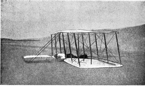
Wilbur Wright gliding at Kitty Hawk, N. C., in 1903.
During 1904 over one hundred flights were made, 73 and changes in construction necessary to sail in circles were devised. In 1905, the Wrights kept on secretly with their practice and development of their machine, first one and then the other making the flights until both were equally proficient. In the latter part of September and early part of October, 1905, occurred a series of flights which the Wrights allowed to become known to the public. At a meeting of the Aeronautical Society of Great Britain, held in London on December 15, 1905, a letter from Orville Wright to one of the members was read. It was dated November 17, 1905, and an excerpt from it is as follows:
“During the month of September we gradually improved in our practice, and on the 26th made a flight of a little over 11 miles. On the 30th we increased this to 12⅕th miles; on October 3, to 15⅓ miles; on October 4, to 20¾ miles, and on October 5, to 24¼ miles. All these flights were made at about 38 miles an hour, the flight of October 5 occupying 30 minutes 3 seconds. Landings were caused by the exhaustion of the supply of fuel in the flights of September 26 and 30, and October 8, and in those of October 3 and 4 by the heating of the bearings in the transmission, of which the oil cups had been 74 omitted. But before the flight on October 5, oil cups had been fitted to all the bearings, and the small gasoline can had been replaced with one that carried enough fuel for an hour’s flight. Unfortunately, we neglected to refill the reservoir just before starting, and as a result the flight was limited to 38 minutes....
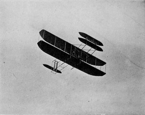
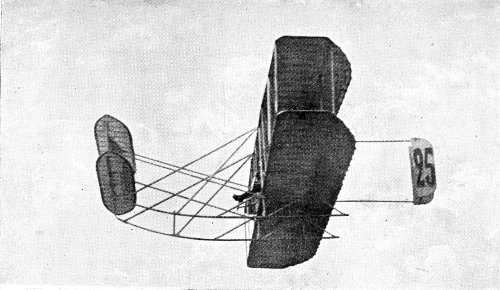
A Wright machine in flight.
“The machine passed through all of these flights without the slightest damage. In each of these 75 flights we returned frequently to the starting point, passing high over the heads of the spectators.”
These statements were received with incredulity in many parts of Europe, the more so as the Wrights refused to permit an examination of their machine, fearing that the details of construction might become known before their patents were secured.
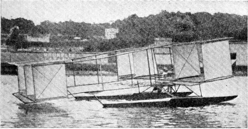
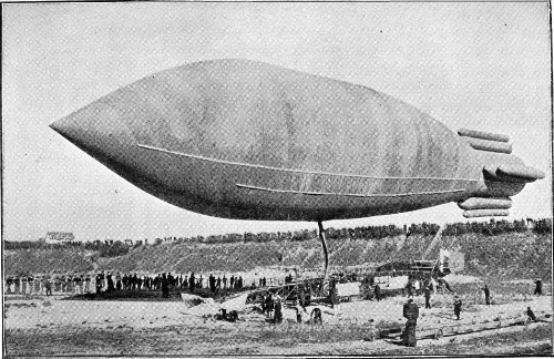
The Archdeacon machine on the Seine.
During the summer of 1905, Captain Ferber and Ernest Archdeacon of Paris had made experiments with gliders. One of the Archdeacon machines was towed by an automobile, having a bag of sand to occupy the place of the pilot. It rose satisfactorily in the air, but the tail became disarranged, 76 and it fell and was damaged. It was rebuilt and tried upon the waters of the Seine, being towed by a fast motor-boat at a speed of 25 miles an hour. The machine rose about 50 feet into the air and sailed for about 500 feet.
Archdeacon gathered a company of young men about him who speedily became imbued with his enthusiasm. Among them were Gabriel Voisin, Louis Bleriot, and Leon Delagrange. The two former, working together, built and flew several gliders, and when Santos-Dumont made his historic flight of 720 feet with his multiple-cell machine on November 13, 1906 (the first flight made in Europe), they were spurred to new endeavors.
Within a few months Voisin had finished his first biplane, and Delagrange made his initial flight with it—a mere hop of 30 feet—on March 16, 1907.
Bleriot, however, had his own ideas, and on August 6, 1907, he flew for 470 feet in a monoplane machine of the tandem type. He succeeded in steering his machine in a curved course, a feat which had not previously been accomplished in Europe.
In October of the same year, Henri Farman, then a well-known automobile driver, flew the second 77 Voisin biplane in a half circle of 253 feet—a notable achievement at that date.
But Santos-Dumont had been pushing forward several different types of machines, and in November he flew first a biplane 500 feet, and a few days later a monoplane 400 feet.
At this point in our story the past seems to give place to the present. The period of early development was over, and the year 1908 saw the first of those remarkable exploits which are recorded in the chapter near the end of this work entitled, “Chronicle of Aviation Achievements.”
It is interesting to note that the machines then brought out are those of to-day. Practically, it may be said that there has been no material change from the original types. More powerful engines have been put in them, and the frames strengthened in proportion, but the Voisin, the Bleriot, and the Wright types remain as they were at first. Other and later forms are largely modifications and combinations of their peculiar features. 78
Successful types of aeroplanes—Distinguishing features—The Wright biplane—Construction—New type—Five-passenger machine—The Voisin biplane—New racing type—The Curtiss biplane—The Cody biplane—The Sommer biplane—The Baldwin biplane—New stabilizing plane—The Baddeck No. 2—Self-sustaining radiator—The Herring biplane—Stabilizing fins.
In the many contests for prizes and records, two types of flying machines have won distinctive places for themselves—the biplane and the monoplane. The appearance of other forms has been sporadic, and they have speedily disappeared without accomplishing anything which had not been better done by the two classes named.
This fact, however, should not be construed as proving the futility of all other forms, nor that the ideal flying machine must be of one of these two prominent types. It is to be remembered that record-making and record-breaking is the most serious business in which any machines have so far been 79 80 engaged; and this, surely, is not the field of usefulness to humanity which the ships of the air may be expected ultimately to occupy. It may yet be proved that, successful as these machines have been in what they have attempted, they are but transition forms leading up to the perfect airship of the future.
The Wright biplane in flight.
The distinguishing feature of the biplane is not alone that it has two main planes, but that they are placed one above the other. The double (or tandem) monoplane also has two main planes, but they are on the same level, one in the rear of the other.
A review of the notable biplanes of the day must begin with the Wright machine, which was not only the first with which flights were made, but also the inspiration and perhaps the pattern of the whole succeeding fleet.
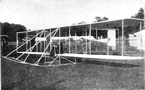
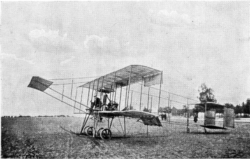
The Wright biplane is a structure composed of two main surfaces, each 40 feet long and 6 feet 6 inches wide, set one above the other, parallel, and 6 feet apart. The planes are held rigidly at this distance by struts of wood, and the whole structure is trussed with diagonal wire ties. It is claimed by the Wrights that these dimensions have been proven 81 82 by their experiments to give the maximum lift with the minimum weight.
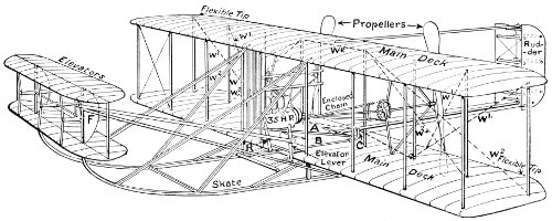
Diagram showing the construction of the Wright biplane. The lever R is connected by the bar A with the rudder gearing C, and is pivoted at the bottom on a rolling shaft B, through which the warping wires W1, W2 are operated. The semicircular planes F aid in stabilizing the elevator system.
The combination of planes is mounted on two rigid skids, or runners (similar to the runners of a sleigh), which are extended forward and upward to form a support for a pair of smaller planes in parallel, used as the elevator (for directing the course of the aeroplane upward or downward). It has been claimed by the Wrights that a rigid skid under-structure takes up the shock of landing, and checks the momentum at that moment, better than any other device. But it necessitated a separate starting apparatus, and while the starting impulse thus received enabled the Wrights to use an engine of less power (to keep the machine going when once started), and therefore of less dead weight, it proved a handicap to their machines in contests where they were met by competing machines which started directly with their own power. A later model of the Wright biplane is provided with a wheeled running gear, and an engine of sufficient power to raise it in the air after a short run on the wheels.
Two propellers are used, run by one motor. They are built of wood, are of the two-bladed type, and are of comparatively large diameter—8 feet. They 83 revolve in opposite directions at a speed of 450 revolutions per minute, being geared down by chain drive from the engine speed of 1,500 revolutions per minute.
The large elevator planes in front have been a distinctive feature of the Wright machine. They have a combined area of 80 square feet, adding that much more lifting surface to the planes in ascending, for then the under side of their surfaces is exposed to the wind. If the same surfaces were in the rear of the main planes their top sides would have to be turned to the wind when ascending, and a depressing instead of a lifting effect would result.
To the rear of the main planes is a rudder composed of two parallel vertical surfaces for steering to right or left.
The feature essential to the Wright biplane, upon which the letters patent were granted, is the flexible construction of the tips of the main planes, in virtue of which they may be warped up or down to restore disturbed equilibrium, or when a turn is to be made. This warping of the planes changes the angle of incidence for the part of the plane which is bent. (The angle of incidence is that which the plane makes with the line in which it is moving. The 84 bending downward of the rear edge would enlarge the angle of incidence, in that way increasing the compression of the air beneath, and lifting that end of the plane.) The wing-warping controls are actuated by the lever at the right hand of the pilot, which also turns the rudder at the rear—that which steers the machine to right or to left. The lever at the left hand of the pilot moves the elevating planes at the front of the machine.
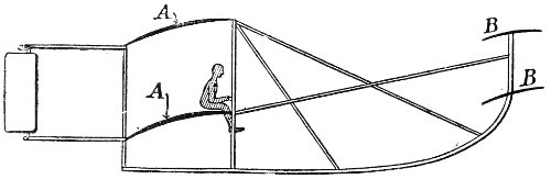
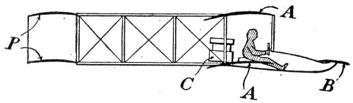
Sketch showing relative positions of planes and of the operator in the Wright machine: A, A, the main planes; B, B, the elevator planes. The motor is placed beside the operator.
The motor has 4 cylinders, and develops 25 to 30 horse-power, giving the machine a speed of 39 miles per hour.
A newer model of the Wright machine is built without the large elevating planes in front, a single elevating plane being placed just back of the rear rudder. This arrangement cuts out the former lifting effect described above, and substitutes the depressing 85 86 effect due to exposing the top of a surface to the wind.
Courtesy of N. Y. Times.
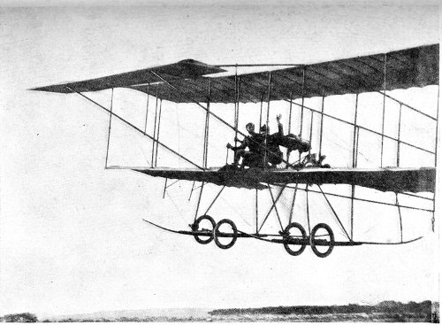
The new model Wright biplane—without forward elevator.
The smallest of the Wright machines, popularly called the “Baby Wright,” is built upon this plan, and has proven to be the fastest of all the Wright series.
While the Wrights were busily engaged in developing their biplane in America, a group of enthusiasts in France were experimenting with gliders of various types, towing them with high speed automobiles along the roads, or with swift motor-boats upon the Seine. As an outcome of these experiments, in which they bore an active part, the Voisin brothers began building the biplanes which have made them famous.
As compared with the Wright machine, the Voisin aeroplane is of much heavier construction. It weighs 1,100 pounds. The main planes have a lateral spread of 37 feet 9 inches, and a breadth of 7 feet, giving a combined area of 540 square feet, the same as that of the Wright machine. The lower main plane is divided at the centre to allow the introduction of a trussed girder framework which carries 87 the motor and propeller, the pilot’s seat, the controlling mechanism, and the running gear below; and it is extended forward to support the elevator. This is much lower than in the Wright machine, being nearly on the level of the lower plane. It is a single surface, divided at the centre, half being placed on each side of the girder. It has a combined area of 42 square feet, about half of that of the Wright elevator, and it is only 4 feet from the front edge of the main planes, instead of 10 feet as in the Wright machine. A framework nearly square in section, and about 25 feet long, extends to the rear, and supports a cellular, or box-like, tail, which 88 forms a case in which is the rudder surface for steering to right or to left.
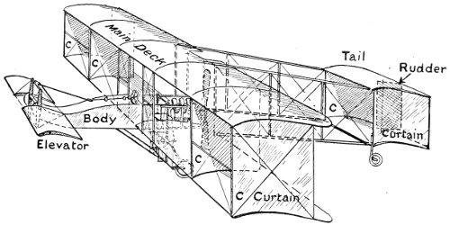
Diagram showing details of construction of the Voisin biplane. C, C, the curtains forming the stabilizing cells.
A distinctive feature of the Voisin biplane is the use of four vertical planes, or curtains, between the two main planes, forming two nearly square “cells” at the ends of the planes.
At the rear of the main planes, in the centre, is the single propeller. It is made of steel, two-bladed, and is 8 feet 6 inches in diameter. It is coupled directly to the shaft of the motor, making with it 1,200 revolutions per minute. The motor is of the V type, developing 50 horse-power, and giving a speed of 37 miles per hour.
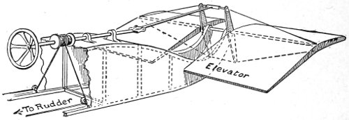
Diagram showing the simplicity of control of the Voisin machine, all operations being performed by the wheel and its sliding axis.
The controls are all actuated by a rod sliding back and forth horizontally in front of the pilot’s seat, having a wheel at the end. The elevator is fastened to the rod by a crank lever, and is tilted up or down as the rod is pushed forward or pulled back. Turning 89 90 the wheel from side to side moves the rudder in the rear. There are no devices for controlling the equilibrium. This is supposed to be maintained automatically by the fixed vertical curtains.
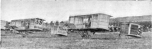
Voisin biplanes at the starting line at Rheims in August, 1909. They were flown by Louis Paulhan, who won third prize for distance, and Henri Rougier, who won fourth prize for altitude. In the elimination races to determine the contestants for the Bennett Cup, Paulhan won second place with the Voisin machine, being defeated only by Tissandier with a Wright machine. Other noted aviators who fly the Voisin machine are M. Bunau-Varilla and the Baroness de la Roche.
The machine is mounted on two wheels forward, and two smaller wheels under the tail.
This description applies to the standard Voisin biplane, which has been in much favor with many of the best known aviators. Recently the Voisins have brought out a new type in which the propeller has been placed in front of the planes, exerting a pulling force upon the machine, instead of pushing it as in the earlier type. The elevating plane has been removed to the rear, and combined with the rudder.
A racing type also has been produced, in which the vertical curtains have been removed and a parallel pair of long, narrow ailerons introduced between the main planes on both sides of the centre. This machine, it is claimed, has made better than 60 miles per hour.
The first Voisin biplane was built for Delagrange, and was flown by him with success. 91
The second biplane built by the Voisins went into the hands of Henri Farman, who made many flights with it. Not being quite satisfied with the machine, and having an inventive mind, he was soon building a biplane after his own designs, and the Farman biplane is now one of the foremost in favor among both professional and amateur aviators.
It is decidedly smaller in area of surface than the Wright and Voisin machines, having but 430 square feet in the two supporting planes. It has a spread of 33 feet, and the planes are 7 feet wide, and set 6 feet apart. In the Farman machine the vertical curtains of the Voisin have been dispensed with. The forward elevator is there, but raised nearly to the level of the upper plane, and placed 9 feet from the front edge of the main planes. To control the equilibrium, the two back corners of each plane are cut and hinged so that they hang vertically when not in flight. When in motion these flaps or ailerons stream out freely in the wind, assuming such position as the speed of the passing air gives them. They are pulled down by the pilot at one end or the other, as may be necessary to restore equilibrium, acting 92 93 in very much the same manner as the warping tips of the Wright machine. A pair of tail planes are set in parallel on a framework about 20 feet in the rear of the main planes, and a double rudder surface behind them. Another model has hinged ailerons on these tail planes, and a single rudder surface set upright between them. These tail ailerons are moved in conjunction with those of the main planes.
The Farman biplane, showing the position of the hinged ailerons when at rest. At full speed these surfaces stream out in the wind in line with the planes to which they are attached.

Diagram of the Farman biplane. A later type has the hinged ailerons also on the tail planes.
The motor has 4 cylinders, and turns a propeller made of wood, 8 feet 6 inches in diameter, at a speed of 1,300 revolutions per minute—nearly three times as fast as the speed of the Wright propellers, which are about the same size. The propeller is placed just under the rear edge of the upper main plane, the 94 lower one being cut away to make room for the revolving blades. The motor develops 45 to 50 horse-power, and drives the machine at a speed of 41 miles per hour.
The “racing Farman” is slightly different, having the hinged ailerons only on one of the main planes. The reason for this is obvious. Every depression of the ailerons acts as a drag on the air flowing under the planes, increasing the lift at the expense of the speed.
Sketch of Farman machine, showing position of operator. A, A, main planes; B, elevator; C, motor; P, tail planes.
The whole structure is mounted upon skids with wheels attached by a flexible connection. In case of a severe jar, the wheels are pushed up against the springs until the skids come into play.
The elevator and the wing naps are controlled by a lever at the right hand of the pilot. This lever moves on a universal joint, the side-to-side movement working the flaps, and the forward-and-back motion the elevator. Steering to right or left is done with a bar operated by the feet. 95
Henri Farman carrying a passenger across country. 96
Farman has himself made many records with his machine, and so have others. With a slightly larger and heavier machine than the one described, Farman carried two passengers a distance of 35 miles in one hour.
This American rival of the Wright biplane is the lightest machine of this type so far constructed. The main planes are but 29 feet in spread, and 4 feet 6 inches in width, and are set not quite 5 feet apart. The combined area of the two planes is 250 square feet. The main planes are placed midway of the length of the fore-and-aft structure, which is nearly 30 feet. At the forward end is placed the elevator, and at the rear end is the tail—one small plane surface—and the vertical rudder surface in two parts, one above and the other below the tail plane. Equilibrium is controlled by changing the slant of two small balancing planes which are placed midway between the main planes at the outer ends, and in line with the front edges. These balancing planes are moved by a lever standing upright behind the pilot, having two arms at its upper end which turn forward so as to embrace his shoulders. The lever is 97 98 moved to right or to left by the swaying of the pilot’s body.
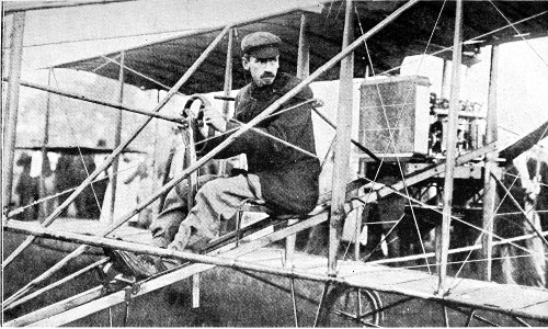
Glenn H. Curtiss in his machine ready to start. The fork of the balancing lever is plainly seen at his shoulders. Behind him is the radiator, with the engine still further back.
The motor is raised to a position where the shaft of the propeller is midway between the levels of the main planes, and within the line of the rear edges, so that they have to be cut away to allow the passing of the blades. The motor is of the V type, with 8 cylinders. It is 30 horse-power and makes 1,200 revolutions per minute. The propeller is of steel, two-bladed, 6 feet in diameter, and revolves at the same speed as the shaft on which it is mounted. The high position of the engine permits a low running gear. There are two wheels under the rear edges of the main planes, and another is placed half-way between the main planes and the forward rudder, or elevator. A brake, operated by the pilot’s foot, acts upon this forward wheel to check the speed at the moment of landing.
Another type of Curtiss machine has the ailerons set in the rear of the main planes, instead of between them.
The Curtiss is the fastest of the biplanes, being excelled in speed only by some of the monoplanes. It has a record of 51 miles per hour. 99
The Cody biplane has the distinction of being the first successful British aeroplane. It was designed and flown by Captain S. F. Cody, at one time an American, but for some years an officer in the British army.
It is the largest and heaviest of all the biplanes, weighing about 1,800 lbs., more than three times the weight of the Curtiss machine. Its main planes are 52 feet in lateral spread, and 7 feet 6 inches in width, and are set 9 feet apart. The combined area of these sustaining surfaces is 770 square feet. The upper plane is arched, so that the ends of the main planes are slightly closer together than at the centre.
The elevator is in two parts placed end to end, about 12 feet in front of the main planes. They have a combined area of 150 square feet. Between them and above them is a small rudder for steering to right or left in conjunction with the large rudder at the rear of the machine. The latter has an area of 40 square feet.
There are two small balancing planes, set one at each end of the main planes, their centres on the 100 101 rear corner struts, so that they project beyond the tips of the planes and behind their rear lines.
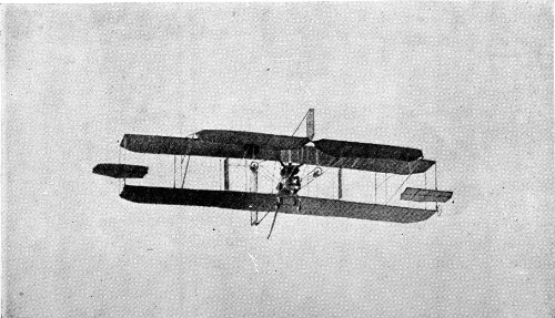
The Cody biplane in flight. Captain Cody has both hands raised above his head, showing the automatic stability of his machine.
The biplane is controlled by a lever rod having a wheel at the end. Turning the wheel moves the rudders; pushing or pulling the wheel works the elevator; moving the wheel from side to side moves the balancing planes.
There are two propellers, set one on each side of the engine, and well forward between the main planes. They are of wood, of the two-bladed type, 7 feet in diameter. They are geared down to make 600 revolutions per minute. The motor has 8 cylinders and develops 80 horse-power at 1,200 revolutions per minute.
The machine is mounted on a wheeled running gear, two wheels under the front edge of the main planes and one a short distance forward in the centre. There is also a small wheel at each extreme end of the lower main plane.
The Cody biplane has frequently carried a passenger, besides the pilot, and is credited with a speed of 38 miles per hour.
The first aeroplane flights ever made in England were by Captain Cody on this biplane, January 2, 1909. 102
The Sommer biplane is closely similar to the Farman machine, but has the hinged ailerons only on the upper plane. Another difference is that the tail has but one surface, and the rudder is hung beneath it. Its dimensions are:—Spread of main planes, 34 feet; depth (fore-and-aft), 6 feet 8 inches; they are set 6 feet apart. The area of the main planes is 456 square feet; area of tail, 67 square feet; area of rudder, 9 square feet. It is driven by a 50-horsepower Gnome motor, turning an 8-foot, two-bladed propeller.
M. Sommer has flown with three passengers, a total weight of 536 lbs., besides the weight of the machine.
The Baldwin biplane, designed by Captain Thomas S. Baldwin, the distinguished balloonist, resembles the Farman type in some features, and the Curtiss in others. It has the Curtiss type of ailerons, set between the wings, but extending beyond them laterally. The elevator is a single surface placed in front of the machine, and the tail is of the biplane type with the rudder between. The spread of the 103 main planes is 31 feet 3 inches, and their depth 4 feet 6 inches. A balancing plane of 9 square feet is set upright (like a fin) above the upper main plane, on a swivel. This is worked by a fork fitting on the shoulders of the pilot, and is designed to restore equilibrium by its swinging into head-resistance on one side or the other as may be necessary.
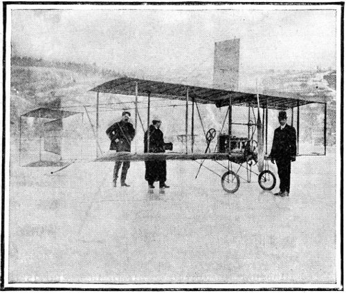
The Baldwin biplane, showing balancing plane above upper main plane.
The motive power is a 4-cylinder Curtiss motor, which turns a propeller 7 feet 6 inches in diameter, 104 set just within the rear line of the main planes, which are cut away to clear the propeller blades.
The newest biplane of the Aerial Experiment Association follows in general contour its successful precursor, the “Silver Dart,” with which J. A. D. McCurdy made many records. The “Baddeck No. 2” is of the biplane type, and both the planes are arched toward each other. They have a spread of 40 feet, and are 7 feet in depth at the centre, rounding to 5 feet at the ends, where the wing tips, 5 feet by 5 feet, are hinged. The elevator is also of the biplane type, two surfaces each 12 feet long and 28 inches wide, set 30 inches apart. This is mounted 15 feet in front of the main planes. The tail is mounted 11 feet in the rear of the main planes, and is the same size and of the same form as the elevator.
The controls are operated by the same devices as in the Curtiss machine. The propeller is 7 feet 8 inches in diameter, and is turned by a six-cylinder automobile engine of 40 horse-power running at 1,400 revolutions per minute. The propeller is geared down to run at 850 revolutions per minute. 105 The motor is placed low down on the lower plane, but the propeller shaft is raised to a position as nearly as possible that of the centre of resistance of the machine. The speed attained is 40 miles per hour.
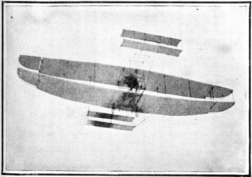
The McCurdy biplane, “Baddeck No. 2.”
A unique feature of the mechanism is the radiator, which is built of 30 flattened tubes 7 feet 6 inches long, and 3 inches wide, and very thin. They are curved from front to rear like the main planes, and give sufficient lift to sustain their own weight 106 and that of the water carried for cooling the cylinders. The running gear is of three wheels placed as in the Curtiss machine. The “Baddeck No. 2” has made many satisfactory flights with one passenger besides the pilot.
At the Boston Aircraft Exhibition in February, 1910, the Herring biplane attracted much attention, not only because of its superiority of mechanical finish, but also on account of its six triangular stabilizing fins set upright on the upper plane. Subsequent trials proved that this machine was quite out of the ordinary in action. It rose into the air after a run of but 85 feet, and at a speed of only 22 miles per hour, and made a 40-degree turn at a tipping angle of 20 degrees. As measured by the inventor, the machine rose in the air with the pilot (weighing 190 lbs.), with a thrust of 140 lbs., and required only a thrust of from 80 to 85 lbs. to keep it flying.
The spread of the planes is 28 feet, and they are 4 feet in depth, with a total supporting surface of 220 feet. A 25 horse-power Curtiss motor turns a 4-bladed propeller of 6 feet diameter and 5-foot pitch 107 108 (designed by Mr. Herring) at the rate of 1,200 revolutions per minute.
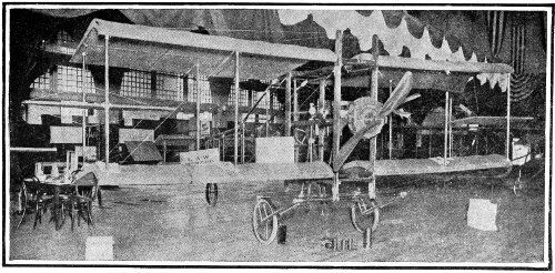
The L. A. W. (League of American Wheelmen) biplane at the Boston Aircraft Exhibition, February, 1910. Note the peculiar curve of the divided planes. The motor is of the rotating type, of 50 horse-power.
The elevator consists of a pair of parallel surfaces set upon hollow poles 12 feet in front of the main planes. The tail is a single surface.
The stabilizing fins act in this manner: when the machine tips to one side, it has a tendency to slide down an incline of air toward the ground. The fins offer resistance to this sliding, retarding the upper plane, while the lower plane slides on and swings as a pendulum into equilibrium again.
The Breguet biplane is conspicuous in having a biplane tail of so large an area as to merit for the machine the title “tandem biplane.” The main planes have a spread of 41 feet 8 inches, and an area of 500 square feet. The tail spreads 24 feet, and its area is about 280 square feet. The propeller is three-bladed, 8 feet in diameter, and revolves at a speed of 1,200 revolutions per minute. It is placed in front of the main plane, after the fashion of the monoplanes. The motive power is an 8-cylinder R-E-P engine, developing 55 horse-power. 109
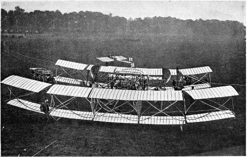
Courtesy of N. Y. Sun.
The Seddon tandem biplane, constructed by Lieutenant Seddon of the British Navy. The area of its planes is 2,000 square feet. Compare its size with that of the monoplane in the background. It is intended to carry ten persons. 110
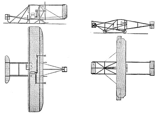
Wright biplane. Curtiss biplane.
Comparative build and area of prominent American biplanes. 111
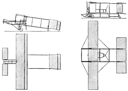
Voisin biplane. Breguet biplane.
Comparative build and area of prominent European biplanes. 112
The common goal—Interchanging features—The Bleriot machine—First independent flyer—Construction and controls—The “Antoinette”—Large area—Great stability—Santos-Dumont’s monoplane—Diminutive size—R-E-P monoplane—encased structure—Hanriot machine—Boat body—Sturdy build—Pfitzner machine—Lateral type—Thrusting propeller—Fairchild, Burlingame, Cromley, Chauviere, Vendome, and Moisant monoplanes.
In all the ardent striving of the aviators to beat each other’s records, a surprisingly small amount of personal rivalry has been developed. Doubtless this is partly because their efforts to perform definite feats have been absorbing; but it must also be that these men, who know that they face a possible fall in every flight they make, realize that their competitors are as brave as themselves in the face of the same danger; and that they are actually accomplishing marvellous wonders even if they do no more than just escape disastrous failure. Certain it is that each, realizing the tremendous difficulties all must overcome, respects the others’ ability and attainments. 113
Consequently we do not find among them two distinctly divergent schools of adherents, one composed of the biplanists, the other of the monoplanists. Nor are the two types of machines separated in this book for any other purpose than to secure a clearer understanding of what is being achieved by all types in the progress toward the one common goal—the flight of man.
The distinctive feature of the monoplane is that it has but one main plane, or spread of surface, as contrasted with the two planes, one above the other, of the biplane. Besides the main plane, it has a secondary plane in the rear, called the tail. The office of this tail is primarily to secure longitudinal, or fore-and-aft, balance; but the secondary plane has been so constructed that it is movable on a horizontal axis, and is used to steer the machine upward or downward. While most of the biplanes now have a horizontal tail-plane, they were not at first so provided, but carried the secondary plane (or planes) in front of the main planes. Even in the latest type brought out by the conservative Wright brothers, the former large-surfaced elevator in front has been removed, and a much smaller tail-plane has been added in the rear, performing the same function of steering 114 the machine up or down, but also providing the fore-and-aft stabilizing feature formerly peculiar to the monoplane. Another feature heretofore distinctively belonging to the monoplane has been adopted by some of the newer biplanes, that of the traction propeller—pulling the machine behind it through the air, instead of pushing it along by a thrusting propeller placed behind the main planes.
The continual multiplication of new forms of the monoplane makes it possible to notice only those which exhibit the wider differences.
The Bleriot monoplane has the distinction of being the first wholly successful flying machine. Although the Wright machine was making flights years before the Bleriot had been built, it was still dependent upon a starting device to enable it to leave the ground. That is, the Wright machine was not complete in itself, and was entirely helpless at even a short distance from its starting tower, rail, and car, which it was unable to carry along. Because of its completeness, M. Bleriot was able to drive his machine from Toury to Artenay, France (a distance of 115 116 8¾ miles) on October 31, 1908, make a landing, start on the return trip, make a second landing, and again continue his journey back to Toury, all under his own unassisted power. This feat was impossible to the Wright machine as it was then constructed, thus leaving the Bleriot monoplane in undisputed pre-eminence in the history of aviation.
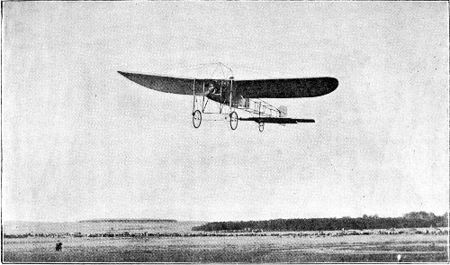
A Bleriot monoplane, “No. XI,” in flight.
At a little distance, where the details of construction are not visible, the Bleriot machine has the appearance of a gigantic bird. The sustaining surface, consisting of a single plane, is divided into two wings made of a stiff parchment-like material, mounted one on each side of a framework of the body, which is built of mahogany and whitewood trussed with diagonal ties of steel wire.
The main plane has a lateral spread of 28 feet and a depth of 6 feet, and is rounded at the ends. It has an area of about 150 square feet, and is slightly concave on the under side. The tail-plane is 6 feet long and 2 feet 8 inches in depth; at its ends are the elevators, consisting of pivoted wing tips each about 2 feet 6 inches square with rounded extremities. The rudder for steering to left or right is mounted at the extreme rear end of the body, and has an area of 9 square feet. 117

The Bleriot “No. XII.,” showing new form of tail, and the complete encasing with fabric. 118
The body is framed nearly square in front and tapers to a wedge-like edge at the rear. It extends far enough in front of the main plane to give room for the motor and propeller. The seat for the pilot is on a line with the rear edge of the main plane, and above it. The forward part of the body is enclosed with fabric.
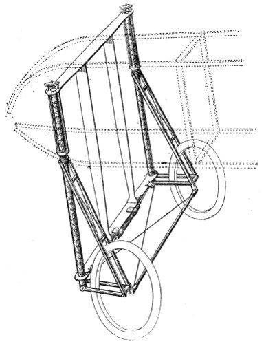
Forward chassis of Bleriot monoplane, showing caster mounting of wheels. The framing of the body is shown by the dotted lines.
The machine is mounted on three wheels attached 119 to the body: two at the front, with a powerful spring suspension and pivoted like a caster, and the other rigidly at a point just forward of the rudders.
The lateral balance is restored by warping the tips of the main plane; if necessary, the elevator tips at the rear may be operated to assist in this. All the controls are actuated by a single lever and a drum to which the several wires are attached.
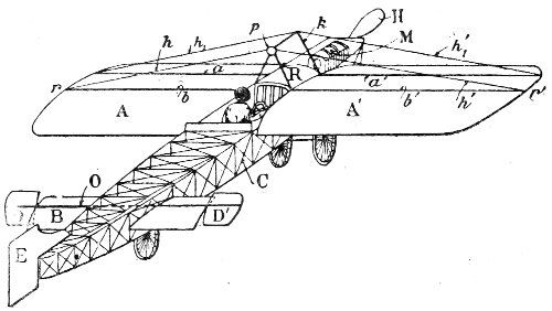
Diagram of Bleriot “No. XI.,” from the rear. A, A, main plane; B, tail; C, body; D, D, wing tips of tail; E, rudder; H, propeller; M, motor; O, axis of wing tips; R, radiator; a, a, b, b, spars of wings; h, h, guy wires; p, k, truss.
The motors used on the Bleriot machines have varied in type and power. In the “No. XI.,” with which M. Bleriot crossed the English Channel, the motor was a 3-cylinder Anzani engine, developing 24 horse-power at 1,200 revolutions per minute. The 120 propeller was of wood, 2-bladed, and 6 feet 9 inches in diameter. It was mounted directly on the shaft, and revolved at the same speed, giving the machine a velocity of 37 miles per hour. This model has also been fitted with a 30 horse-power R-E-P (R. Esnault-Pelterie) motor, having 7 cylinders. The heavier type “No. XII.” has been fitted with the 50 horse-power Antoinette 8-cylinder engine, or the 7-cylinder rotating Gnome engine, also of 50 horse-power.
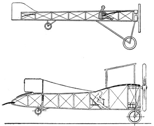
Sketches showing relative size, construction, and position of pilot in the Bleriot machines; “No. XI.” (the upper), and “No. XII.” (the lower). 121
The total weight of the “No. XI.” monoplane is 462 pounds, without the pilot.
The Antoinette is the largest and heaviest of the monoplanes. It was designed by M. Levavasseur, and has proved to be one of the most remarkable of the aeroplanes by its performances under adverse conditions; notably, the flight of Hubert Latham in a gale of 40 miles per hour at Blackpool in October, 1909.
The Antoinette has a spread of 46 feet, the surface being disposed in two wings set at a dihedral angle; that is, the outer ends of the wings incline upward from their level at the body, so that at the front they present the appearance of a very wide open “V.” These wings are trapezoidal in form, with the wider base attached to the body, where they are 10 feet in depth (fore and aft). They are 7 feet in depth at the tips, and have a total combined area of 377 square feet. The great depth of the wings requires that they be made proportionally thick to be strong enough to hold their form. Two trussed spars are used in each wing, with a short mast on each, half-way to the tip, reaching below the wing 122 123 as well as above it. To these are fastened guy wires, making each wing an independent truss. A mast on the body gives attachment for guys which bind the whole into a light and rigid construction. The framework of the wings is covered on both sides with varnished fabric.
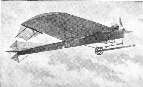
The Antoinette monoplane in flight.
The body is of triangular section. It is a long girder; at the front, in the form of a pyramid, expanding to a prism at the wings, and tapering toward the tail. It is completely covered with the fabric, which is given several coats of varnish to secure the minimum of skin friction.
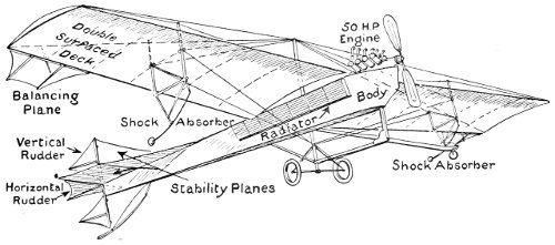
Diagram showing construction of the Antoinette monoplane.
The tail is 13 feet long and 9 feet wide, in the form of a diamond-shaped kite. The rear part of it is hinged to be operated as the elevator. There 124 is a vertical stabilizing fin set at right angles to the rigid part of the tail. The rudder for steering to right or left is in two triangular sections, one above and the other below the tail-plane. The entire length of the machine is 40 feet, and its weight is 1,045 pounds.
It is fitted with a motor of the “V” type, having 8 cylinders, and turning a 2-bladed steel propeller 1,100 revolutions per minute, developing from 50 to 55 horse-power.
The control of the lateral balance is by ailerons attached to the rear edges of the wings at their outer ends. These are hinged, and may be raised as well as lowered as occasion demands, working in opposite directions, and thus doubling the effect of similar ailerons on the Farman machine, which can only be pulled downward.
The machine is mounted on two wheels under the centre of the main plane, with a flexible wood skid projecting forward. Another skid is set under the tail.
It is claimed for the Antoinette machine that its inherent stability makes it one of the easiest of all for the beginner in aviation. With as few as five lessons many pupils have become qualified pilots, even 125 126 winning prizes against competitors of much wider experience.
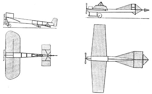
Diagrams showing comparative size and position of surfaces and structure of the Bleriot (left) and Antoinette (right) monoplanes.
This little machine may be called the “runabout” of the aeroplanes. It has a spread of only 18 feet, and is but 20 feet in total length. Its weight is about 245 pounds.
The main plane is divided into two wings, which are set at the body at a dihedral angle, but curve downward toward the tips, forming an arch. The depth of the wings at the tips is 6 feet. For a space on each side of the centre they are cut away to 5 feet in depth, to allow the propeller to be set within their forward edge. The total area of the main plane is 110 square feet.
The tail-plane is composed of a vertical surface and a horizontal surface intersecting. It is arranged so that it may be tilted up or down to serve as an elevator, or from side to side as a rudder. Its horizontal surface has an area of about 12 square feet.
The engine is placed above the main plane and the pilot’s seat below it. The body is triangular in section, with the apex uppermost, composed of three strong bamboo poles with cross-pieces held in place by aluminum sockets, and cross braced with piano wire. 127
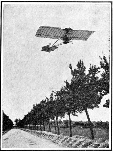
Santos-Dumont’s La Demoiselle in flight.
The motor is of the opposed type, made by Darracq, weighing only 66 pounds, and developing 30 horse-power at 1,500 revolutions per minute. The propeller is of wood, 2-bladed, and being mounted 128 directly on the shaft of the motor, revolves at the same velocity. The speed of the Santos-Dumont machine is 37 miles per hour.
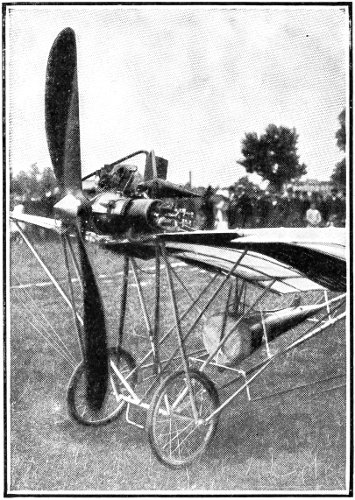
The Darracq motor and propeller of the Santos-Dumont machine. The conical tank in the rear of the pilot’s seat holds the gasoline.
The lateral balance is preserved by a lever which extends upward and enters a long pocket sewed on the back of the pilot’s coat. His leaning from side 129 to side warps the rear edges of the wings at their tips. The elevator is moved by a lever, and the rudder by turning a wheel.
While this machine has not made any extended flights, Santos-Dumont has travelled in the aggregate upward of 2,000 miles in one or another of this type.
The plans, with full permission to any one to build from them, he gave to the public as his contribution to the advancement of aviation. Several manufacturers are supplying them at a cost much below that of an automobile.
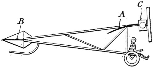
Sketch showing position of pilot in Santos-Dumont machine. A, main plane; B, tail plane; C, motor.
The Robert Esnault-Pelterie (abbreviated by its inventor to R-E-P) monoplane, viewed from above, bears a striking resemblance to a bird with a fan-shaped tail. It is much shorter in proportion to its spread than any other monoplane, and the body being 130 entirely covered with fabric, it has quite a distinct appearance.
The plane is divided into two wings, in form very much like the wings of the Antoinette machine. Their spread, however, is but 35 feet. Their depth at the body is 8 feet 6 inches, and at the tips, 5 feet. Their total combined area is 226 square feet.
The body of the R-E-P machine has much the appearance of a boat, being wide at the top and coming to a sharp keel below. The boat-like prow in front adds to this resemblance. As the body is encased in fabric, these surfaces aid in maintaining vertical stability.
A large stabilizing fin extends from the pilot’s seat to the tail. The tail is comparatively large, having an area of 64 square feet. Its rear edge may be raised or lowered to serve as an elevator. The rudder for steering to right or left is set below in the line of the body, as in a boat. It is peculiar in that it is of the “compensated” type; that is, pivoted near the middle of its length, instead of at the forward end.
The control of the lateral balance is through warping the wings. This is by means of a lever at the left hand of the pilot, with a motion from side to side. 131 The same lever moved forward or backward controls the elevator. The steering lever is in front of the pilot’s seat, and moves to right or to left.
 |
Elevation, showing large stabilizing fin; boat-like body encased in fabric; and compensated rudder, pivoted at the rear end of the fin. |
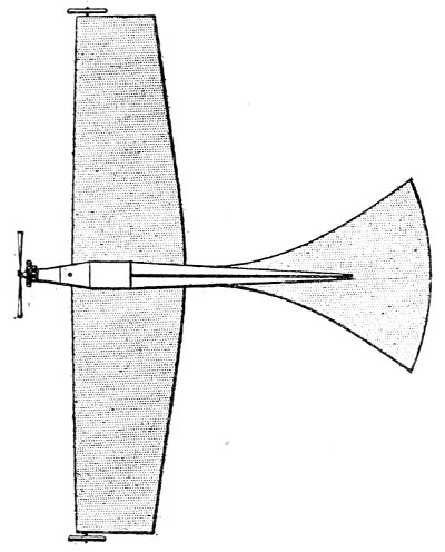 |
Plan, showing comparative spread of surfaces, and the attachment of wheels at the wing tips. |
Graphic sketch showing elevation and plan of the R-E-P monoplane. |
|
The motor is an invention of M. Esnault-Pelterie, and may be of 5, 7, or 10 cylinders, according to the power desired. The cylinders are arranged in two ranks, one in the rear of the other, radiating outward from the shaft like spokes in a wheel. The propeller is of steel, 4-bladed, and revolves at 1,400 revolutions per minute, developing 35 horse-power, 132 and drawing the machine through the air at a speed of 47 miles per hour.
Among the more familiar machines which have been contesting for records at the various European meets during the season of 1910, the Hanriot monoplane earned notice for itself and its two pilots, one of them the fifteen-year-old son of the inventor. At Budapest the Hanriot machine carried off the honors of the occasion with a total of 106 points for “best performances,” as against 84 points for the Antoinette, and 77 points for the Farman biplane. A description of its unusual features will be of interest by way of comparison.
In general appearance it is a cross between the Bleriot and the Antoinette, the wings being shaped more like the latter, but rounded at the rear of the tips like the Bleriot. Its chief peculiarity is in the body of the machine, which is in form very similar to a racing shell—of course with alterations to suit the requirements of the aeroplane. Its forward part is of thin mahogany, fastened upon ash ribs, with a steel plate covering the prow. The rear part of the machine is covered simply with fabric. 133
The spread of the plane is 24 feet 7 inches, and it has an area of 170 square feet. The length of the machine, fore-and-aft, is 23 feet. Its weight is 463 pounds. It is mounted on a chassis having both wheels and skids, somewhat like that of the Farman running gear, but with two wheels instead of four.
The Hanriot machine is sturdily built all the way through, and has endured without damage some serious falls and collisions which would have wrecked another machine.
It is fitted either with a Darracq or a Clerget motor, and speeds at about 44 miles per hour.
The Pfitzner monoplane has the distinction of being the first American machine of the single-plane type. It was designed and flown by the late Lieut. A. L. Pfitzner, and, though meeting with many mishaps, has proved itself worthy of notice by its performances, through making use of an entirely new device for lateral stability. This is the sliding wing tip, by which the wing that tends to fall from its proper level may be lengthened by 15 inches, the other wing being shortened as much at the same time. 134
There is no longitudinal structure, as in the other monoplanes, the construction being transverse and built upon four masts set in the form of a square, 6 feet apart, about the centre. These are braced by diagonal struts, and tied with wires on the edges of the squares. They also support the guys reaching out to the tips of the wings.
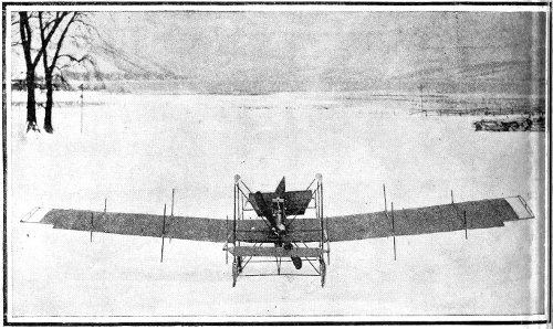
The Pfitzner monoplane from the rear, showing the sliding wing tips; dihedral angle of the wings; square body; and transverse trussed construction.
The plane proper is 31 feet in spread, to which the wing tips add 2½ feet, and is 6 feet deep, giving a total area of 200 square feet. A light framework extending 10 feet in the rear carries a tail-plane 6 135 136 feet in spread and 2 feet in depth. Both the elevator and the rudder planes are carried on a similar framework, 14 feet in front of the main plane.
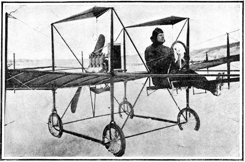
The Pfitzner monoplane, showing the structure of the body; the two conical gasoline tanks above; the propeller in the rear. Lieutenant Pfitzner at the wheel.
The wings of the main plane incline upward from the centre toward the tips, and are trussed by vertical struts and diagonal ties.
The motor is placed in the rear of the plane, instead of in front, as in all other monoplanes. It is a 4-cylinder Curtiss motor, turning a 6-foot propeller at 1,200 revolutions per minute, and developing 25 horse-power.
The Pfitzner machine has proved very speedy, and has made some remarkably sharp turns on an even keel.
Several machines of the monoplane type have been produced, having some feature distinct from existing forms. While all of these have flown successfully, few of them have made any effort to be classed among the contestants for honors at the various meets.
One of these, the Fairchild monoplane, shows resemblances to the R-E-P, the Antoinette, and the Bleriot machines, but differs from them all in having two propellers instead of one; and these revolve in 137 the same direction, instead of in contrary directions, as do those of all other aeroplanes so equipped. The inventor claims that there is little perceptible gyroscopic effect with a single propeller, and even less with two. The propeller shafts are on the level of the plane, but the motor is set about 5 feet below, connections being made by a chain drive.
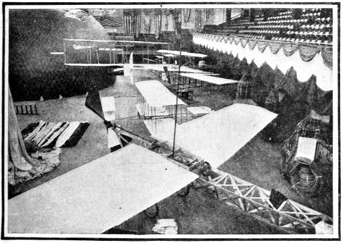
The Beach type of the Antoinette, an American modification of the French machine, at the Boston Exhibition, 1910.
The Burlingame monoplane has several peculiarities. Its main plane is divided into two wings, each 138 10 feet in spread and 5 feet in depth, and set 18 inches apart at the body. They are perfectly rigid. The tail is in two sections, each 4 feet by 5 feet, and set with a gap of 6 feet between the sections, in which the rudder is placed. Thus the spread of the tail from tip to tip is 16 feet, as compared with the 21½ foot spread of the main plane. The sections of the tail are operated independently, and are made to serve as ailerons to control the lateral balance, and also as the elevator.
The Cromley monoplane, another American machine, is modelled after the Santos-Dumont Demoiselle. It has a main plane divided into two wings, each 9 feet by 6 feet 6 inches, with a gap of 2 feet between at the body; the total area being 117 square feet. At the rear of the outer ends are hinged ailerons, like those of the Farman biplane, to control the lateral balance. The tail is 12 feet in the rear, and is of the “box” type, with two horizontal surfaces and two vertical surfaces. This is mounted with a universal joint, so that it can be moved in any desired direction. The complete structure, without the motor, weighs but 60 pounds.
The Chauviere monoplane is distinct in having a rigid spar for the front of the plane, but no ribs. 139 The surface is allowed to spread out as a sail and take form from the wind passing beneath. The rear edges may be pulled down at will to control the lateral balance. It is driven by twin screws set far back on the body, nearly to the tail.
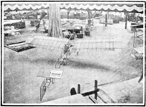
The Morok monoplane at the Boston Exhibition. It has the body of the Bleriot, the wings of the Santos-Dumont, and the sliding wing tips of the Pfitzner.
The smallest and lightest monoplane in practical use is that of M. Raoul Vendome. It is but 16 feet in spread, and is 16 feet fore and aft. It is equipped with a 12 horse-power motor, and flies at a speed of nearly 60 miles per hour. Without the pilot, its 140 entire weight is but 180 pounds. The wings are pivoted so that their whole structure may be tilted to secure lateral balance.
The new Moisant monoplane is built wholly of metal. The structure throughout is of steel, and the surfaces of sheet aluminum in a succession of small arches from the centre to the tips. No authentic reports of its performances are available.
In the Tatin monoplane, also called the Bayard-Clement, the main plane is oval in outline, and the tail a smaller oval. The surfaces are curved upward toward the tips for nearly half their length in both the main plane and the tail. The propeller is 8½ feet in diameter, and is turned by a Clerget motor, which can be made to develop 60 horse-power for starting the machine into the air, and then cut down to 30 horse-power to maintain the flight. 141
The triplane—The quadruplane—The multiplane—Helicopters—Their principle—Obstacles to be overcome—The Cornu helicopter—The Leger helicopter—The Davidson gyropter—The Breguet gyroplane—The de la Hault ornithopter—The Bell tetrahedrons—The Russ flyer.
While the efforts of inventors have been principally along the lines of the successful monoplanes and biplanes, genius and energy have also been active in other directions. Some of these other designs are not much more than variations from prevailing types, however.
Among these is the English Roe triplane, which is but a biplane with an extra plane added; the depths of all being reduced to give approximately the same surface as the biplane of the same carrying power. The tail is also of the triplane type, and has a combined area of 160 square feet—just half that of the main planes. The triplane type has long been familiar to Americans in the three-decker glider used extensively 142 by Octave Chanute in his long series of experiments at Chicago.
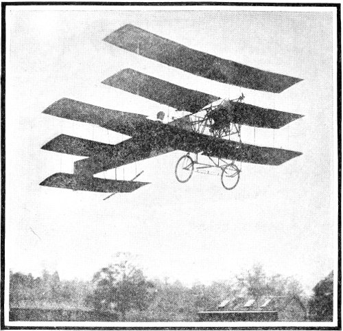
The Roe triplane in flight.
The quadruplane of Colonel Baden-Powell, also an English type, is practically the biplane with unusually large forward and tail planes.
The multiplane of Sir Hiram Maxim should also be remembered, although he never permitted it to have free flight. His new multiplane, modelled after the former one, but equipped with an improved gasoline 143 motor instead of the heavy steam-engine of the first model, will doubtless be put to a practical test when experiments with it are completed.
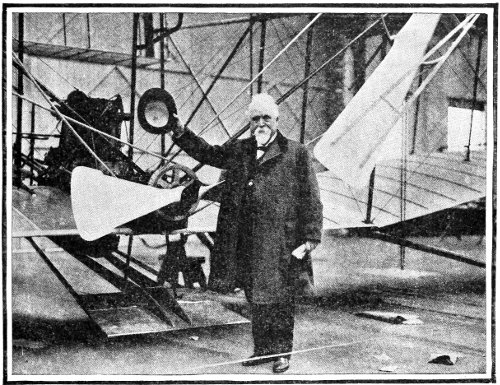
Sir Hiram Maxim standing beside his huge multiplane.
Quite apart from these variants of the aeroplanes are the helicopters, ornithopters, gyropters, gyroplanes, and tetrahedral machines.
The result aimed at in the helicopter is the ability to rise vertically from the starting point, instead of 144 first running along the ground for from 100 to 300 feet before sufficient speed to rise is attained, as the aeroplanes do. The device employed to accomplish this result is a propeller, or propellers, revolving horizontally above the machine. After the desired altitude is gained it is proposed to travel in any direction by changing the plane in which the propellers revolve to one having a small angle with the horizon.
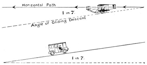
The force necessary to keep the aeroplane moving in its horizontal path is the same as that required to move the automobile of equal weight up the same gradient—much less than its total weight.
The great difficulty encountered with this type of machine is that the propellers must lift the entire weight. In the case of the aeroplane, the power of the engine is used to slide the plane up an incline of air, and for this much less power is required. For instance, the weight of a Curtiss biplane with the pilot on board is about 700 pounds, and this weight 145 is easily slid up an inclined plane of air with a propeller thrust of about 240 pounds.
Another difficulty is that the helicopter screws, in running at the start before they can attain speed sufficient to lift their load, have established downward currents of air with great velocity, in which the screws must run with much less efficiency. With the aeroplanes, on the contrary, their running gear enables them to run forward on the ground almost with the first revolution of the propeller, and as they increase their speed the currents—technically called the “slip”—become less and less as the engine speed increases.
In the Cornu helicopter, which perhaps has come nearer to successful flight than any other, these downward currents are checked by interposing planes below, set at an angle determined by the operator. The glancing of the currents of air from the planes is expected to drive the helicopter horizontally through the air. At the same time these planes offer a large degree of resistance, and the engine power must be still further increased to overcome this, while preserving the lift of the entire weight. With an 8-cylinder Antoinette motor, said to be but 24 horse-power, turning two 20-foot propellers, the machine 146 is reported as lifting itself and two persons—a total weight of 723 pounds—to a height of 5 feet, and sustaining itself for 1 minute. Upon the interposing of the planes to produce the horizontal motion the machine came immediately to the ground.
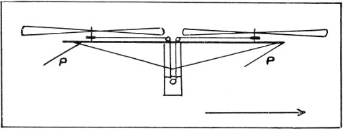
Diagram showing principle of the Cornu helicopter. P, P, propelling planes. The arrow shows direction of travel with planes at angle shown.
This performance must necessarily be compared with that of the aeroplanes, as, for instance, the Wright machine, which, with a 25 to 30 horse-power motor operating two 8-foot propellers, raises a weight of 1,050 pounds and propels it at a speed of 40 miles an hour for upward of 2 hours.
Another form of helicopter is the Leger machine, so named after its French inventor. It has two propellers which revolve on the same vertical axis, the shaft of one being tubular, encasing that of the other. By suitable gearing this vertical shaft may be inclined 147 148 after the machine is in the air in the direction in which it is desired to travel.
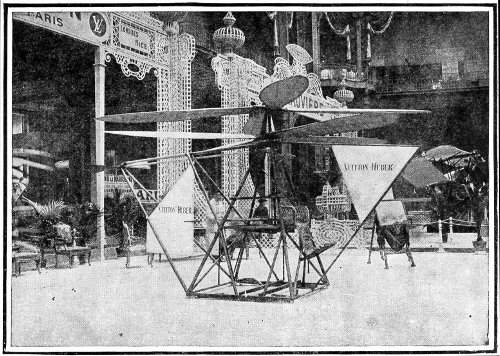
The Vitton-Huber helicopter at the Paris aeronautical salon in 1909. It has the double concentric axis of the Leger helicopter and the propelling planes of the Cornu machine.
The gyropter differs from the Cornu type of helicopter in degree rather than in kind. In the Scotch machine, known as the Davidson gyropter, the propellers have the form of immense umbrellas made up of curving slats. The frame of the structure has the shape of a T, one of the gyropters being attached to each of the arms of the T. The axes upon which the gyropters revolve may be inclined so that their power may be exerted to draw the apparatus along in a horizontal direction after it has been raised to the desired altitude.
The gyropters of the Davidson machine are 28 feet in diameter, the entire structure being 67 feet long, and weighing 3 tons. It has been calculated that with the proposed pair of 50 horse-power engines the gyropters will lift 5 tons. Upon a trial with a 10 horse-power motor connected to one of the gyropters, that end of the apparatus was lifted from the ground at 55 revolutions per minute—the boiler pressure being 800 lbs. to the square inch, at which pressure it burst, wrecking the machine.
An example of the gyroplane is the French Breguet apparatus, a blend of the aeroplane and the helicopter. 149 It combines the fixed wing-planes of the one with the revolving vanes of the other. The revolving surfaces have an area of 82 square feet, and the fixed surfaces 376 square feet. The total weight of machine and operator is about 1,350 lbs. Fitted with a 40 horse-power motor, it rose freely into the air.
The ornithopter, or flapping-wing type of flying machine, though the object of experiment and research for years, must still be regarded as unsuccessful. The apparatus of M. de la Hault may be taken as typical of the best effort in that line, and it is yet in the experimental stage. The throbbing beat of the mechanism, in imitation of the bird’s wings, has always proved disastrous to the structure before sufficient power was developed to lift the apparatus.
The most prominent exponent of the tetrahedral type—that made up of numbers of small cells set one upon another—is the Cygnet of Dr. Alexander Graham Bell, which perhaps is more a kite than a true flying machine. The first Cygnet had 3,000 cells, and lifted its pilot to a height of 176 feet. The Cygnet II. has 5,000 tetrahedral cells, and is propelled by a 50 horse-power motor. It has yet to make its record.
One of the most recently devised machines is that 150 known as the Fritz Russ flyer. It has two wings, each in the form of half a cylinder, the convex curve upward. It is driven by two immense helical screws, or spirals, set within the semi-cylinders. No details of its performances are obtainable. 151
Instinctive balance—When the motor skips—Progressive experience—Plum Island School methods—Lilienthal’s conclusions—The Curtiss mechanism and controls—Speed records—Cross-country flying—Landing—Essential qualifications—Ground practice—Future relief.
Any one who has learned to ride a bicycle will recall the great difficulty at first experienced to preserve equilibrium. But once the knack was gained, how simple the matter seemed! Balancing became a second nature, which came into play instinctively, without conscious thought or effort. On smooth roads it was not even necessary to grasp the handle-bars. The swaying of the body was sufficient to guide the machine in the desired direction.
Much of this experience is paralleled by that of the would-be aviator. First, he must acquire the art of balancing himself and his machine in the air without conscious effort. Unfortunately, this is even harder than in the case of the bicycle. The cases 152 would be more nearly alike if the road beneath and ahead of the bicyclist were heaving and falling as in an earthquake, with no light to guide him; for the air currents on which the aviator must ride are in constant and irregular motion, and are as wholly invisible to him as would be the road at night to the rider of the wheel.
And there are other things to distract the attention of the pilot of an aeroplane—notably the roar of the propeller, and the rush of wind in his face, comparable only to the ceaseless and breath-taking force of the hurricane.
The well-known aviator, Charles K. Hamilton, says:—“So far as the air currents are concerned, I rely entirely on instinctive action; but my ear is always on the alert. The danger signal of the aviator is when he hears his motor miss an explosion. Then he knows that trouble is in store. Sometimes he can speed up his engine, just as an automobile driver does, and get it to renew its normal action. But if he fails in this, and the motor stops, he must dip his deflecting planes, and try to negotiate a landing in open country. Sometimes there is no preliminary warning from the motor that it is going to cease working. That is the time when the aviator 153 must be prepared to act quickly. Unless the deflecting planes are manipulated instantly, aviator and aeroplane will rapidly land a tangled mass on the ground.”
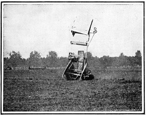
Result of a failure to deflect the planes quickly enough when the engine stopped. The operator fortunately escaped with but a few bruises.
At the same time, Mr. Hamilton says: “Driving an aeroplane at a speed of 120 miles an hour is not nearly so difficult a task as driving an automobile 60 miles an hour. In running an automobile at high speed the driver must be on the job every second. 154 Nothing but untiring vigilance can protect him from danger. There are turns in the road, bad stretches of pavement, and other like difficulties, and he can never tell at what moment he is to encounter some vehicle, perhaps travelling in the opposite direction. But with an aeroplane it is a different proposition. Once a man becomes accustomed to aeroplaning, it is a matter of unconscious attention.... He has no obstacles to encounter except cross-currents of air. Air and wind are much quicker than a man can think and put his thought into action. Unless experience has taught the aviator to maintain his equilibrium instinctively, he is sure to come to grief.”
The Wright brothers spent years in learning the art of balancing in the air before they appeared in public as aviators. And their method of teaching pupils is evidence that they believe the only road to successful aviation is through progressive experience, leading up from the use of gliders for short flights to the actual machines with motors only after one has become an instinctive equilibrist.
At the Plum Island school of the Herring-Burgess Company the learner is compelled to begin at the beginning and work the thing out for himself. He is placed in a glider which rests on the ground. 155 The glider is locked down by a catch which may be released by pulling a string. To the front end of the glider is attached a long elastic which may be stretched more or less, according to the pull desired. The beginner starts with the elastic stretched but a little. When all is ready he pulls the catch free, and is thrown forward for a few feet. As practice gains for him better control, he makes a longer flight; and when he can show a perfect mastery of his craft for 156 a flight of 300 feet, and not till then, he is permitted to begin practice with a motor-driven machine.
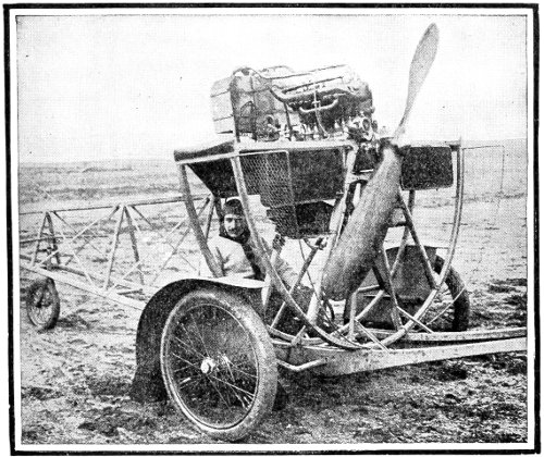
A French apparatus for instructing pupils in aviation.
The lamented Otto Lilienthal, whose experience in more than 2,000 flights gives his instructions unquestionable weight, urges that the “gradual development of flight should begin with the simplest apparatus and movements, and without the complication of dynamic means. With simple wing surfaces ... man can carry out limited flights ... by gliding through the air from elevated points in paths more or less descending. The peculiarities of wind effects can best be learned by such exercises.... The maintenance of equilibrium in forward flight is a matter of practice, and can be learned only by repeated personal experiment.... Actual practice in individual flight presents the best prospects for developing our capacity until it leads to perfected free flight.”
The essential importance of thorough preparation in the school of experience could scarcely be made plainer or stronger. If it seems that undue emphasis has been laid upon this point, the explanation must be found in the deplorable death record among aviators from accidents in the air. With few exceptions, the cause of accident has been reported as, 157 “The aviator seemed to lose control of his machine.” If this is the case with professional flyers, the need for thorough preliminary training cannot be too strongly insisted upon.
Having attained the art of balancing, the aviator has to learn the mechanism by which he may control his machine. While all of the principal machines are but different embodiments of the same principles, there is a diversity of design in the arrangement of the means of control. We shall describe that of the Curtiss biplane, as largely typical of them all.
In general, the biplane consists of two large sustaining planes, one above the other. Between the planes is the motor which operates a propeller located in the rear of the planes. Projecting behind the planes, and held by a framework of bamboo rods, is a small horizontal plane, called the tail. The rudder which guides the aeroplane to the right or the left is partially bisected by the tail. This rudder is worked by wires which run to a steering wheel located in front of the pilot’s seat. This wheel is similar in size and appearance to the steering wheel of an automobile, and is used in the same way for guiding the aeroplane to the right or left. (See illustration of the Curtiss machine in Chapter V.) 158
In front of the planes, supported on a shorter projecting framework, is the altitude rudder, a pair of planes hinged horizontally, so that their front edges may tip up or down. When they tilt up, the air through which the machine is passing catches on the under sides and lifts them up, thus elevating the front of the whole aeroplane and causing it to glide upward. The opposite action takes place when these altitude planes are tilted downward. This altitude rudder is controlled by a long rod which runs to the steering wheel. By pushing on the wheel the rod is shoved forward and turns the altitude planes upward. Pulling the wheel turns the rudder planes downward. This rod has a backward and forward thrust of over two feet, but the usual movement in ordinary wind currents is rarely more than an inch. In climbing to high levels or swooping down rapidly the extreme play of the rod is about four or five inches.
Thus the steering wheel controls both the horizontal and vertical movements of the aeroplane. More than this, it is a feeler to the aviator, warning him of the condition of the air currents, and for this reason must not be grasped too firmly. It is to be held steady, yet loosely enough to transmit any wavering 159 160 force in the air to the sensitive touch of the pilot, enabling him instinctively to rise or dip as the current compels.
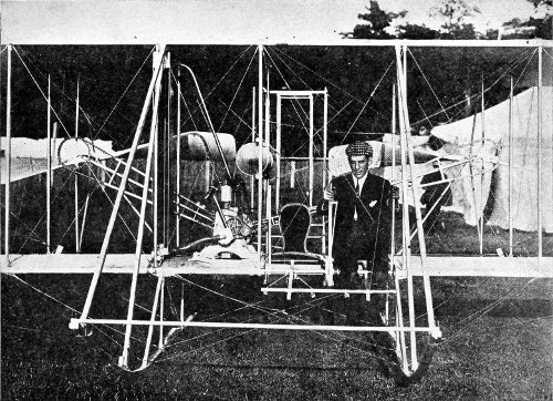
Courtesy N. Y. Times.
View of the centre of the new Wright machine, showing method of operating. Archibald Hoxsey in the pilot’s seat. In his right hand he holds a lever with two handles, one operating the warping of the wing tips, and the other the rudder. Both handles may be grasped at once, operating both rudder and wing tips at the same moment. In his left hand Hoxsey grasps the lever operating the elevating plane—at the rear in this type. The passenger’s seat is shown at the pilot’s right.
The preserving of an even keel is accomplished in the Curtiss machine by small planes hinged between the main planes at the outer ends. They serve to prevent the machine from tipping over sideways. They are operated by arms, projecting from the back of the aviator’s seat, which embrace his shoulders on each side, and are moved by the swaying of his body. In a measure, they are automatic in action, for when the aeroplane sags downward on one side, the pilot naturally leans the other way to preserve his balance, and that motion swings the ailerons (as these small stabilizing planes are called) in such a way that the pressure of the wind restores the aeroplane to an even keel. The wires which connect them with the back of the seat are so arranged that when one aileron is being pulled down at its rear edge the rear of the other one is being raised, thus doubling the effect. As the machine is righted the aviator comes back to an upright position, and the ailerons become level once more.
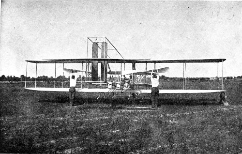
Starting a Wright machine. When the word is given both assistants pull vigorously downward on the propeller blades.
There are other controls which the pilot must operate consciously. In the Curtiss machine these 161 162 are levers moved by the feet. With a pressure of the right foot he short-circuits the magneto, thus cutting off the spark in the engine cylinders and stopping the motor. This lever also puts a brake on the forward landing wheels, and checks the speed of the machine as it touches the ground. The right foot also controls the pump which forces the lubricating oil faster or slower to the points where it is needed.
The left foot operates the lever which controls the throttle by which the aviator can regulate the flow of gas to the engine cylinders. The average speed of the 7-foot propeller is 1,100 revolutions per minute. With the throttle it may be cut down to 100 revolutions per minute, which is not fast enough to keep afloat, but will help along when gliding.
Obviously, travelling with the wind enables the aviator to make his best speed records, for the speed of the wind is added to that of his machine through the air. Again, since the wind is always slower near the ground, the aviator making a speed record will climb up to a level where the surface currents no longer affect his machine. But over hilly and wooded country the air is often flowing or rushing in conflicting channels, and the aviator does not know what he may be called upon to face from one moment to 163 the next. If the aeroplane starts to drop, it is only necessary to push the steering wheel forward a little—perhaps half an inch—to bring it up again. Usually, the machine will drop on an even keel. Then, in addition to the motion just described, the aviator will lean toward the higher side, thus moving the ailerons by the seat-back, and at the same time he will turn the steering wheel toward the lower side. This movement of the seat-back is rarely more than 2 inches.
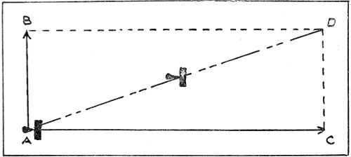
Diagram showing action of wind on flight of aeroplane. The force and direction of the wind being represented by the line A B, and the propelling force and steered direction being A C, the actual path travelled will be A D.
In flying across country a sharp lookout is kept on the land below. If it be of a character unfit for landing, as woods, or thickly settled towns, the aviator must keep high up in the air, lest his engine 164 stop and he be compelled to glide to the earth. A machine will glide forward 3 feet for each foot that it drops, if skilfully handled. If he is up 200 feet, he will have to find a landing ground within 600 feet. If he is up 500 feet, he may choose his alighting ground anywhere within 1,500 feet. Over a city like New York, a less altitude than 1,500 feet would hardly be safe, if a glide became necessary.
Mr. Clifford B. Harmon, who was an aeronaut of distinction before he became an aviator, under the instruction of Paulhan, has this to say: “It is like riding a bicycle, or running an automobile. You have to try it alone to really learn how. When one first handles a flying machine it is advisable to keep on the ground, just rolling along. This is a harder mental trial than you will imagine. As soon as one is seated in a flying machine he wishes to fly. It is almost impossible to submit to staying near the earth. But until the manipulation of the levers and the steering gear has become second nature, this must be done. It is best to go very slow in the beginning. Skipping along the ground will teach a driver much. When one first gets up in the air it is necessary to keep far from all obstacles, like buildings, trees, or crowds. There is the same tendency to run into 165 166 them that an amateur bicycle rider has in regard to stones and ruts on the ground. When he keeps his eye on them and tries with all his might to steer clear of them, he runs right into them.”
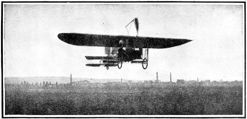
Practicing with a monoplane, 20 feet above the ground.
When asked what he regarded the fundamental requirements in an aviator, Mr. Harmon said: “First, he must be muscularly strong; so that he will not tire. Second, he should have a thorough understanding of the mechanism of the machine he drives. Third, mental poise—the ability to think quick and to act instantly upon your thought. Fourth, a feeling of confidence in the air, so that he will not feel strange or out of place. This familiarity with the air can be best obtained by first being a passenger in a balloon, then by controlling one alone, and lastly going up in a flying machine.”
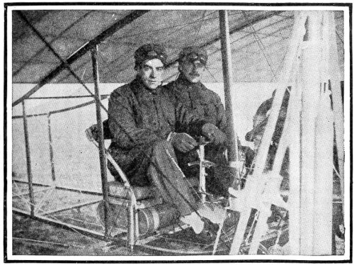
Grahame-White on his Bleriot No. XII. The lever in front of him operates all the controls through the movement of the drum at its base.
Mr. Claude Grahame-White, the noted English aviator, has this to say of his first experience with his big “No. XII.” Bleriot monoplane—which differs in many important features from the “No. XI.” machine in which M. Bleriot crossed the English Channel: “After several disappointments, I eventually obtained the delivery of my machine in working order.... As I had gathered a good deal of information from watching the antics and profiting 167 by the errors made by other beginners on Bleriot monoplanes, I had a good idea of what not to do when the engine was started up and we were ready for our first trial.... It was a cold morning, but the engine started up at the first quarter turn. After many warnings from M. Bleriot’s foreman not on any account to accelerate my engine too much, I mounted the machine along with my friend as passenger, and immediately gave the word to let go, and 168 we were soon speeding along the ground at a good sixty kilometers (about 37 miles) per hour.... Being very anxious to see whether the machine would lift off the ground, I gave a slight jerk to the elevating plane, and soon felt the machine rise into the air; but remembering the warnings of the foreman, and being anxious not to risk breaking the machine, I closed the throttle and contented myself with running around on the ground to familiarize myself with the handling of the machine.... The next day we got down to Issy about five o’clock in the morning, some two hours before the Bleriot mechanics turned up. However, we got the machine out, and tied it to some railings, and then I had my first experience of starting an engine, which to a novice at first sight appears a most hazardous undertaking; for unless the machine is either firmly held by several men, or is strongly tied up, it has a tendency to immediately leap forward. We successfully started the engine, and then rigged up a leash, and when we had mounted the machine, we let go; and before eight o’clock we had accomplished several very successful flights, both with and against the wind. These experiences we continued throughout the day, and by nightfall I felt quite capable of an extended flight, 169 if only the ground had been large enough.... The following day M. Bleriot returned, and he sent for me and strongly urged me not to use the aeroplane any more at Issy, as he said the ground was far too small for such a powerful machine.”
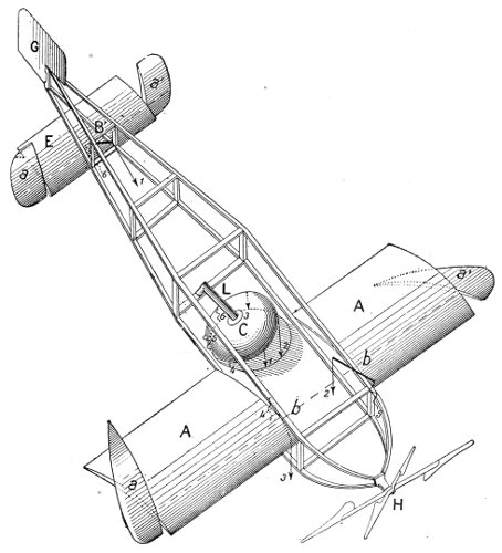
Diagram of Bleriot monoplane, showing controlling lever L and bell-shaped drum C, to which all controlling wires are attached. When the bell is rocked back and forward the elevator tips on the rear plane are moved; rocking from side to side moves the stabilizing tips of the main plane. Turning the bell around moves the rudder.
170
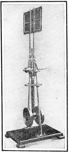 |
The Marmonier gyroscopic pendulum, devised to secure automatic stability of aeroplanes. The wheels are driven by the aeroplane motor at high speed. The pendulum rod is extended upward above the axis and carries a vane which is engaged by any gust of wind from either side of the aeroplane, tending to tilt the pendulum, and bringing its gyroscopic resistance into play to warp the wings, or operate ailerons. |
The caution shown by these experienced aviators cannot be too closely followed by a novice. These men do not say that their assiduous practice on the ground was the fruit of timidity. On the contrary, although they are long past the preliminary stages, their advice to beginners is uniformly in the line of caution and thorough practice. 171
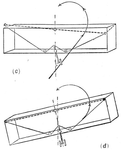
When the aeroplane is steered to the left, the pendulum swings to the right and depresses the right side of the plane, as in (c). The reaction of the air raises the right side of the plane until both surfaces are perpendicular to the inclined pendulum, as in (d).
Diagrams showing action of Marmonier gyroscopic pendulum.
Even after one has become an expert, the battle is not won, by any means. While flying in calm weather is extremely pleasurable, a protracted flight is very fatiguing; and when it is necessary to wrestle 172 with gusts of high wind and fickle air currents, the strain upon the strongest nerve is a serious source of danger in that the aviator is liable to be suddenly overcome by weariness when he most needs to be on the alert.
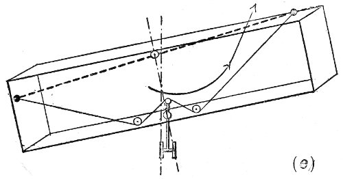
In that inclined position the aeroplane makes the turn, and when the course again becomes straight, both the gyroscopic and centrifugal forces cease, and the pendulum under the influence of gravity becomes vertical. In this position it is inclined to the left with respect to the planes, on which its effect is to depress the left wing and so right the aeroplane, as in (e).
Diagram showing action of Marmonier gyroscopic pendulum.
Engine troubles are much fewer than they used to be, and a more dependable form of motor relieves the mind of the aviator from such mental disturbance. Some device in the line of a wind-shield would be a real boon, for even in the best weather there is the ceaseless rush of air into one’s face at 45 to 50 miles an hour. The endurance of this for hours is of itself a tax upon the most vigorous physique. 173
With the passing of the present spectacular stage of the art of flying there will doubtless come a more reliable form of machine, with corresponding relief to the operator. Automatic mechanism will supplant the intense and continual mental attention now demanded; and as this demand decreases, the joys of flying will be considerably enhanced.
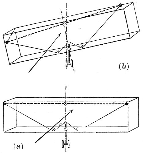
If, when pursuing a straight course, the aeroplane is tilted by a sideways wind (b), the action of the pendulum as described above restores it to an even keel, as in (a).
Diagrams showing action of Marmonier gyroscopic pendulum. 174
Santos-Dumont’s gift—La Demoiselle—Mechanical skill required—Preparatory practice—General dimensions—The frame—The motor—The main planes—The rudder-tail—The propeller—Shaping the blades—Maxim’s experience—The running gear—The controls—Scrupulous workmanship.
When Santos-Dumont in 1909 gave to the world the unrestricted privilege of building monoplanes after the plans of his famous No. 20—afterward named La Demoiselle—he gave not only the best he knew, but as much as any one knows about the building of flying machines. Santos-Dumont has chosen the monoplane for himself because his long experience commends it above others, and La Demoiselle was the crowning achievement of years spent in the construction and operation of airships of all types. In view of Santos-Dumont’s notable successes in his chosen field of activity, no one will go astray in following his advice. 175
Of course, the possession of plans and specifications for an aeroplane does not make any man a skilled mechanic. It is well to understand at the start that a certain degree of mechanical ability is required in building a machine which will be entirely safe. Nor does the possession of a successful machine make one an aeronaut. As in the case of bicycling, there is no substitute for actual experience, while in the airship the art of balancing is of even greater importance than on the bicycle.
The would-be aviator is therefore advised to put himself through a course of training of mind and body.
Intelligent experimenting with some one of the models described in Chapter XI. will teach much of the action of aeroplanes in calms and when winds are blowing; and practice with an easily constructed glider (see Chapter XII.) will give experience in balancing which will be of the greatest value when one launches into the air for the first time with a power-driven machine. An expert acquaintance with gasoline motors and magnetos is a prime necessity. In short, every bit of information on the subject of flying machines and their operation cannot fail to be useful in some degree. 176
The dimensions of the various parts of the Santos-Dumont monoplane are given on the original plans according to the metric system. In reducing these to “long measure” inches, all measurements have been given to the nearest eighth of an inch.
In general, we may note some of the peculiarities of La Demoiselle. The spread of the plane is 18 feet from tip to tip, and it is 20 feet over all from bow to stern. In height, it is about 4 feet 2 inches when the propeller blades are in a horizontal position. The total weight of the machine is 265 lbs., of which the engine weighs about 66 lbs. The area of the plane is 115 square feet, so that the total weight supported by each square foot with Santos-Dumont (weighing 110 lbs.) on board is a trifle over 3 lbs.
The frame of the body of the monoplane is largely of bamboo, the three main poles being 2 inches in diameter at the front, and tapering to about 1 inch at the rear. They are jointed with brass sockets just back of the plane, for convenience of taking apart for transportation. Two of these poles extend from the axle of the wheels backward and slightly upward to the rudder-post. The third extends from the middle of the plane between the wings, backward 177 178 and downward to the rudder-post. In cross-section the three form a triangle with the apex at the top. These bamboo poles are braced about every 2 feet with struts of steel tubing of oval section, and the panels so formed are tied by diagonals of piano wire fitted with turn-buckles to draw them taut.
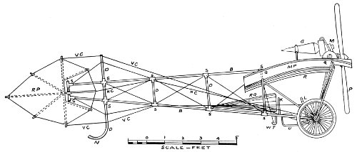
Side view of the Santos-Dumont monoplane. MP, main plane with radiator, R, hung underneath; RP, rudder plane worked by wires HC, attached to lever L; VC, vertical control wires; WT, tube through which run the warping wires worked by lever K, in a pocket of the pilot’s coat; B, B, bamboo poles of frame; S, S, brass, or aluminum sockets; D, D, struts of bicycle tubing; G, gasoline; RG, reserve gasoline; M, motor; P, propeller; Q, Q, outer rib of plane, showing camber; N, skid.
In the Santos-Dumont machine a 2-cylinder, opposed Darracq motor of 30 horse-power was used. It is of the water-cooled type, the cooling radiator being a gridiron of very thin ⅛-inch copper tubing, and hung up on the under side of the plane on either side of the engine. The cylinders have a bore of about 4⅛ inches, and a stroke of about 4¾ inches. The propeller is 2-bladed, 6½ feet across, and is run at 1,400 revolutions per minute, at which speed it exerts a pull of 242 lbs.
Each wing of the main plane is built upon 2 transverse spars extending outward from the upper bamboo pole, starting at a slight angle upward and bending downward nearly to the horizontal as they approach the outer extremities. These spars are of ash, 2 inches wide, and tapering in thickness from 1⅛ inches at the central bamboo to about ⅞ inch at the tips of the wings. They are bent into shape by 179 180 immersion in hot water, and straining them around blocks nailed to the floor of the workshop, in the form shown at QQ, p. 177.
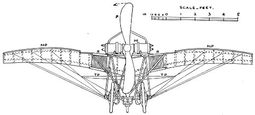
Front view of the Santos-Dumont monoplane, showing position of tubular struts supporting the engine and the wings; also the guys, and warping wires entering the tubes inside the wheels. MP, the main plane; TP, tail plane in the rear; R, radiators; M, motor; P, propeller, the arrow showing direction of revolution.
The front spar is set about 9 inches back from the front edge of the plane, and the rear one about 12 inches forward of the back edge of the plane. Across these spars, and beneath them, running fore and aft, are bamboo rods about ¾ of an inch in diameter at the forward end, and tapering toward the rear. They are set 8½ inches apart (centre to centre), except at the tips of the wings. The two outer panels are 10¼ inches from centre to centre of the rods, to give greater elasticity in warping. These fore-and-aft rods are 6 feet 5 inches long, except directly back of the propeller, where they are 5 feet 8 inches long; they are bound to the spars with brass wire No. 25, at the intersections. They also are bent to a curved form, as shown in the plans, by the aid of the hot-water bath. Diagonal guys of piano wire are used to truss the frame in two panels in each wing.
Around the outer free ends of the rods runs a piano wire No. 20, which is let into the tips of the rods in a slot ⅜ inch deep. To prevent the splitting of the bamboo, a turn or two of the brass wire may be made around the rod just back of the slot; but 181 182 it is much better to provide thin brass caps for the ends of the rods, and to cut the slots in the metal as well as in the rods. Instead of caps, ferrules will do. When the slots are cut, let the tongue formed in the cutting be bent down across the bamboo to form the floor to the slot, upon which the piano wire may rest. The difference in weight and cost is very little, and the damage that may result from a split rod may be serious.
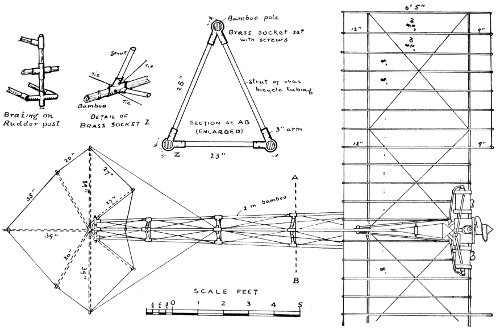
Plan and details of construction of La Demoiselle.
After the frame of the plane is completed it is to be covered with cloth on both sides, so as entirely to enclose the frame, except only the tips of the rods, as shown in the plans. In the Santos-Dumont monoplane the cloth used is of closely woven silk, but a strong, unbleached muslin will do—the kind made especially for aeroplanes is best.
Both upper and lower surfaces must be stretched taut, the edges front and back being turned over the piano wire, and the wire hemmed in. The upper and lower surfaces are then sewed together—“through and through,” as a seamstress would say—along both sides of each rod, so that the rods are practically in “pockets.” Nothing must be slighted, if safety in flying is to be assured.
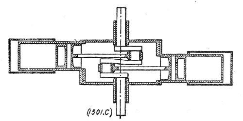
Sectional diagram of 2-cylinder Darracq opposed motor.
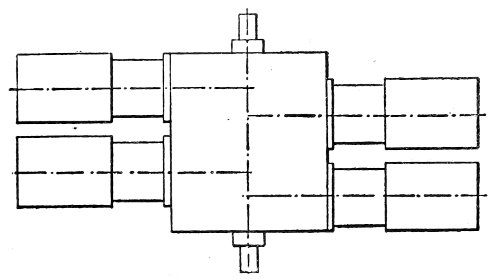
Diagram of 4-cylinder Darracq opposed motor.
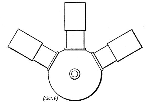
Diagram of 3-cylinder Anzani motor.
Motors suitable for La Demoiselle monoplane.
The tail of the monoplane is a rigid combination 183 184 of two planes intersecting each other at right angles along a central bamboo pole which extends back 3 feet 5½ inches from the rudder-post, to which it is attached by a double joint, permitting it to move upon either the vertical or the horizontal axis.
Although this tail, or rudder, may seem at first glance somewhat complicated in the plans, it will not be found so if the frame of the upright or vertical plane be first constructed, and that of the level or horizontal plane afterward built fast to it at right angles.
As with the main plane, the tail is to be covered on both sides with cloth, the vertical part first; the horizontal halves on either side so covered that the cloth of the latter may be sewed above and below the central pole. All of the ribs in the tail are to be stitched in with “pockets,” as directed for the rods of the main plane.
The construction of the motor is possible to an expert machinist only, and the aeroplane builder will save time and money by buying his engine from a reliable maker. It is not necessary to send to France for a Darracq motor. Any good gasoline engine of equal power, and about the same weight, will serve the purpose. 185
The making of the propeller is practicable for a careful workman. The illustrations will give a better idea than words of how it should be done. It should be remembered, however, that the safety of the aviator depends as much upon the propeller as upon any other part of the machine. The splitting of the blades when in motion has been the cause of serious accidents. The utmost care, therefore, should be exercised in the selection of the wood, and in the glueing of the several sections into one solid mass, allowing the work to dry thoroughly under heavy pressure.
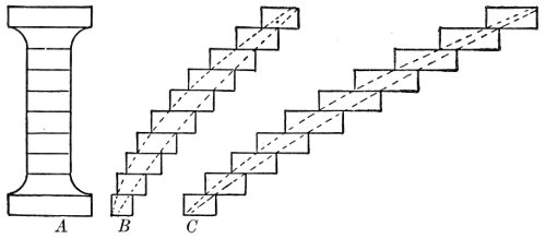
Diagram showing how the layers of wood are placed for glueing: A, at the hub; B, half way to the tip of the blade; C, at the tip. The dotted lines show the form of the blade at these points.
The forming of the blades requires a good deal of skill, and some careful preliminary study. It is apparent 186 that the speed of a point at the tip of a revolving blade is much greater than that of a point near the hub, for it traverses a larger circle in the same period of time. But if the propeller is to do effective work without unequal strain, the twist in the blade must be such that each point in the length of the blade is exerting an equal pull on the air. It is necessary, therefore, that the slower-moving part of the blade, near the hub, or axis, shall cut “deeper” into the air than the more swiftly moving tip of the blade. Consequently the blade becomes continually “flatter” (approaching the plane in which it revolves) as we work from the hub outward toward the tip. This “flattening” is well shown in the nearly finished blade clamped to the bench at the right of the illustration—which shows a four-bladed propeller, instead of the two-bladed type needed for the monoplane.
The propeller used for propulsion in air differs from the propeller-wheel used for ships in water, in that the blades are curved laterally; the forward face of the blade being convex, and the rearward face concave. The object of this shaping is the same as for curving the surface of the plane—to secure smoother entry into the air forward, and a compression 187 188 in the rear which adds to the holding power on the substance of the air. It is extremely difficult to describe this complex shape, and the amateur builder of a propeller will do well to inspect one made by a professional, or to buy it ready made with his engine.
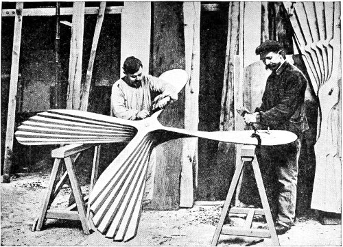
Forming a 4-blade propeller out of 8 layers of wood glued firmly together.
The following quotation from Sir Hiram Maxim’s account of his most effective propeller may aid the ambitious aeroplane builder: “My large screws were made with a great degree of accuracy; they were perfectly smooth and even on both sides, the blades being thin and held in position by a strip of rigid wood on the back of the blade.... Like the small screws, they were made of the very best kind of seasoned American white pine, and when finished were varnished on both sides with hot glue. When this was thoroughly dry, they were sand-papered again, and made perfectly smooth and even. The blades were then covered with strong Irish linen fabric of the smoothest and best make. Glue was used for attaching the fabric, and when dry another coat of glue was applied, the surface rubbed down again, and then painted with zinc white in the ordinary way and varnished. These screws worked exceedingly well.”
The covering of the blades with linen glued fast commends itself to the careful workman as affording 189 precaution against the splintering of the blades when in rapid motion. Some propellers have their wooden blades encased with thin sheet aluminum to accomplish the same purpose, but for the amateur builder linen is far easier to apply.
|
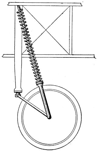 |
The wheels are of the bicycle type, with wire spokes, but with hubs six inches long. The axle is bent to incline upward at the ends, so that the wheels incline outward at the ground, the better to take the shock of a sideways thrust when landing. The usual metal or wood rims may be used, but special 190 tires of exceptionally light construction, made for aeroplanes, should be purchased.
The controlling wires or cords for moving the rudder (or tail) and for warping the tips of the wings are of flexible wire cable, such as is made for use as steering rope on small boats. The cable controlling the horizontal plane of the rudder-tail is fastened to a lever at the right hand of the operator. The cable governing the vertical plane of the rudder-tail is attached to a wheel at the left hand of the operator. The cables which warp the tips of the wings are fastened to a lever which projects upward just back of the operator’s seat, and which is slipped into a long pocket sewed to the back of his coat, so that the swaying of his body in response to the fling of the tipping machine tends to restore it to an even keel. Springs are attached to all of these controlling wires, strong enough to bring them back to a normal position when the operator removes his hands from the steering apparatus.
The brass sockets used in connecting the tubular struts to the main bamboos and the rudder-post, and in fastening the axle of the wheels to the lower bamboos and elsewhere, should be thoroughly made and brazed by a good mechanic, for no one should risk 191 192 the chance of a faulty joint at a critical spot, when an accident may mean the loss of life.
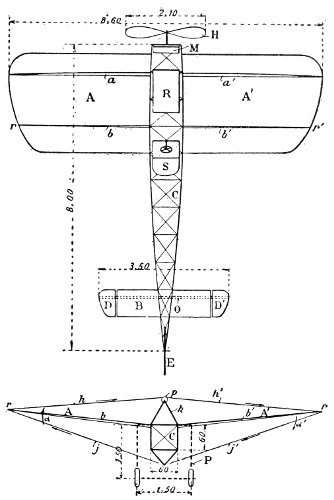
Diagram of Bleriot monoplane showing sizes of parts, in metres. Reduced to feet and inches these measurements are:
| 0.60 metres | 1 ft. | 11½ in. |
| 1.50 metres | 4 ft. | 11 in. |
| 2.10 metres | 6 ft. | 10½ in. |
| 3.50 metres | 11 ft. | 6 in. |
| 8.00 metres | 26 ft. | 3 in. |
| 8.60 metres | 28 ft. | 2½ in. |
The diagram being drawn to scale other dimensions may be found. In both the plan (upper figure) and elevation (lower figure), A, A, is the main plane; B, tail plane; C, body; D, elevator wing-tips; E, rudder; a, a, rigid spar; b, b, flexible spar; r, r, points of attachment for warping-wires; h, h, guys; H, propeller; M, motor; R, radiator; S, pilot’s seat; P, chassis.
For the rest, it has seemed better to put the details of construction on the plans themselves, where they will be available to the aeroplane builder without the trouble of continually consulting the text.
Some of the work on an aeroplane will be found simple and easy; some of it, difficult and requiring much patience; and some impracticable to any one but a trained mechanic. But in all of it, the worker’s motto should be, “Fidelity in every detail.” 193
Early use of steam—Reliability necessary—The gasoline motor—Carburetion—Compression—Ignition—Air-cooling—Water-cooling—Lubrication—The magneto—Weight—Types of motors—The propeller—Form, size, and pitch—Slip—Materials—Construction.
The possibility of the existence of the flying machine as we have it to-day has been ascribed to the invention of the gasoline motor. While this is not to be denied, it is also true that the gasoline motors designed and built for automobiles and motor-boats have had to be wellnigh revolutionized to make them suitable for use in the various forms of aircraft. And it is to be remembered, doubtless to their greater credit, that Henson, Hargrave, Langley, and Maxim had all succeeded in adapting steam to the problem of the flight of models, the two latter using gasoline to produce the steam.
Perhaps the one predominant qualification demanded 194 of the aeroplane motor is reliability. A motor-car or motor-boat can be stopped, and engine troubles attended to with comparatively little inconvenience. The aeroplane simply cannot stop without peril. It is possible for a skilful pilot to reach the earth when his engine stops, if he is fortunately high enough to have space for the downward glide which will gain for him the necessary headway for steering. At a lesser height he is sure to crash to the earth.
An understanding of the principles on which the gasoline motor works is essential to a fair estimate of the comparative advantages of the different types used to propel aeroplanes. In the first place, the radical difference between the gasoline motor and other engines is the method of using the fuel. It is not burned in ordinary fashion, but the gasoline is first vaporized and mixed with a certain proportion of air, in a contrivance called a carburetor. This gaseous mixture is pumped into the cylinder of the motor by the action of the motor itself, compressed into about one-tenth of its normal volume, and then exploded by a strong electric spark at just the right moment to have its force act most advantageously to drive the machinery onward.
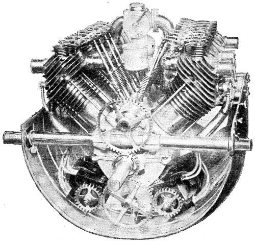
The “Fiat” 8-cylinder air-cooled motor, of the “V” type, made in France.
It is apparent that there are several chances for 195 failure in this series. The carburetor may not do its part accurately. The mixture of air and vapor may not be in such proportions that it will explode; in that case, the power from that stroke will be missing, and the engine will falter and slow down. Or a leakage in the cylinder may prevent the proper compression of the mixture, the force from the explosion will be greatly reduced, with a corresponding loss of power and speed. Or the electric spark may not be “fat” enough—that is, of sufficient volume and heat to fire the mixture; or it may not “spark” at just the right moment; if too soon, it will exert 196 its force against the onward motion: if too late, it will not deliver the full power of the explosion at the time when its force is most useful. The necessity for absolute perfection in these operations is obvious.
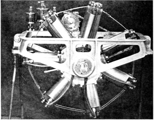
A near view of the Holmes engine from the driving side.
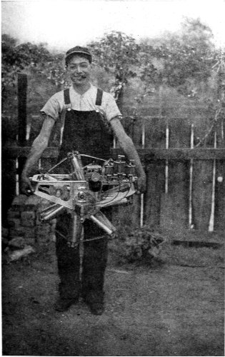
The Holmes rotative engine, 7-cylinder 35 horse-power, weighing 160 pounds.
An American engine built in Chicago, Ill.
Other peculiarities of the gasoline motor affect considerably its use for aeroplanes. The continual and oft-repeated explosions of the gaseous mixture inside of the cylinder generate great heat, and this not only interferes with its regularity of movement, 197 198 but within a very brief time checks it altogether. To keep the cylinder cool enough to be serviceable, two methods are in use: the air-cooling system and the water-cooling system. In the first, flanges of very thin metal are cast on the outside of the cylinder wall. These flanges take up the intense heat, and being spread out over a large surface in this way, the rushing of the air through them as the machine flies (or sometimes blown through them with a rotary fan) cools them to some degree. With the water-cooling system, the cylinder has an external jacket, the space between being filled with water which is made to circulate constantly by a small 199 pump. In its course the water which has just taken up the heat from the cylinder travels through a radiator in which it is spread out very thin, and this radiator is so placed in the machine that it receives the full draught from the air rushing through the machine as it flies. The amount of water required for cooling a motor is about 1⅕ lbs. per horse-power. With an 8-cylinder 50 horse-power motor, this water 200 would add the very considerable item of 60 lbs. to the weight the machine has to carry. As noted in a previous chapter, the McCurdy biplane has its radiator formed into a sustaining plane, and supports its own weight when travelling in the air.
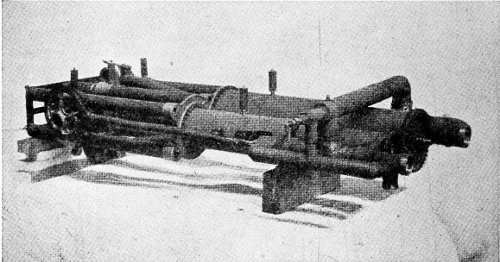
The 180 horse-power engine of Sir Hiram Maxim; of the “opposed” type, compound, and driven by steam.
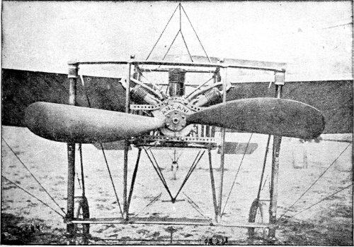
The Anzani motor and propeller which carried M. Bleriot across the English Channel. The curved edge of the propeller blades is the entering edge, the propeller turning from the right of the picture over to the left. The Anzani is of the “radiant” type and is of French build.
It is an unsettled point with manufacturers whether the greater efficiency (generally acknowledged) of the water-cooled engine more than compensates for the extra weight of the water.
Another feature peculiar to the gasoline motor is the necessity for such continual oiling that it is styled “lubrication,” and various devices have been invented to do the work automatically, without attention from the pilot further than the watching of his oil-gauge to see that a full flow of oil is being pumped through the oiling system.
The electric current which produces the spark inside of the cylinder is supplied by a magneto, a machine formed of permanent magnets of horseshoe form, between the poles of which a magnetized armature is made to revolve rapidly by the machinery which turns the propeller. This magneto is often connected with a small storage battery, or accumulator, which stores up a certain amount of current for use when starting, or in case the magneto gives out. 201
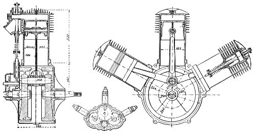
Sectional drawings showing details of construction of the Anzani motor. The flanges of the air-cooling system are distinctly shown. The section at the left is from the side; that at the right, from the front. All measurements are in millimètres. A millimètre is 0.039 inch. 202
The great rivalry of the builders of motors has been in cutting down the weight per horse-power to the lowest possible figure. It goes without saying that useless weight is a disadvantage in an aeroplane, but it has not been proven that the very lightest engines have made a better showing than those of sturdier build.
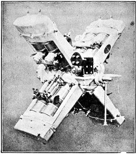
The “Gobron” engine of the “double opposed,” or cross-shaped type. A water-cooled engine, with 8 cylinders.
One of the items in the weight of an engine has been the fly-wheel found necessary on all motors of 4 cylinders or less to give steadiness to the running. 203 With a larger number of cylinders, and a consequently larger number of impulses in the circuit of the propeller, the vibration is so reduced that the fly-wheel has been dispensed with.
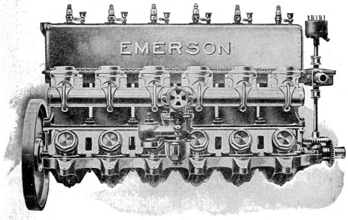
The Emerson 6-cylinder aviation engine, of the “tandem” type, water-cooled; 60 horse-power; made at Alexandria, Va.
There are several distinct types of aircraft engines, based on the arrangement of the cylinders. The “tandem” type has the cylinders standing upright in a row, one behind another. There may be as many as eight in a row. The Curtiss and Wright engines are examples. Another type is the “opposed” arrangement, the cylinders being placed in a 204 205 horizontal position and in two sets, one working opposite the other. An example of this type is seen in the Darracq motor used on the Santos-Dumont monoplane. Another type is the “V” arrangement, the cylinders set alternately leaning to right and to left, as seen in the “Fiat” engine. Still another type is the “radiant,” in which the cylinders are all above the horizontal, and disposed like rays from the rising sun. The 3-cylinder Anzani engine and the 5- and 7-cylinder R-E-P engines are examples. The “star” type is exemplified in the 5 and 7-cylinder engines in which the cylinders radiate at equal angles all around the circle. The “double opposed” or cross-shaped type is shown in the “Gobron” engine. In all of these types the cylinders are stationary, and turn the propeller shaft either by cranks or by gearing.
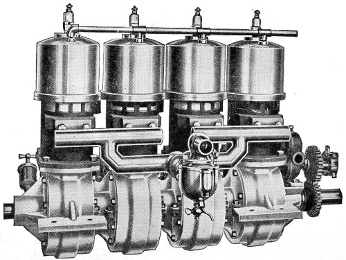
The Elbridge engine, of the “tandem” type and water-cooled. It is an American engine, built at Rochester, N. Y.
An entirely distinct type of engine, and one which has been devised solely for the aeroplane, is the rotative—often miscalled the rotary, which is totally different. The rotative type may be illustrated by the Gnome motor. In this engine the seven cylinders turn around the shaft, which is stationary. The propeller is fastened to the cylinders, and revolves with them. This ingenious effect is produced by an 206 207 208 offset of the crank-shaft of half the stroke of the pistons, whose rods are all connected with the crank-shaft. The entire system revolves around the main shaft as a centre, the crank-shaft being also stationary.
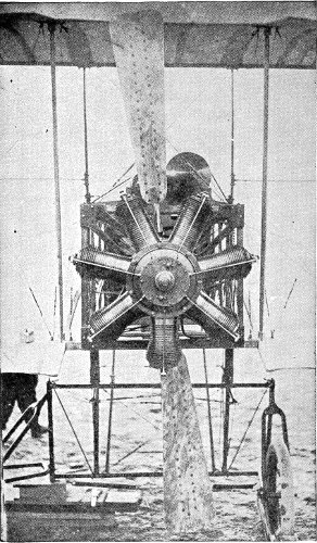
The famous Gnome motor; 50 horse-power, 7-cylinder, air-cooled; of the rotative type; made in France. This illustration shows the Gnome steel propeller.

Sectional diagram of the 5-cylinder R-E-P motor; of the “radiant” type.
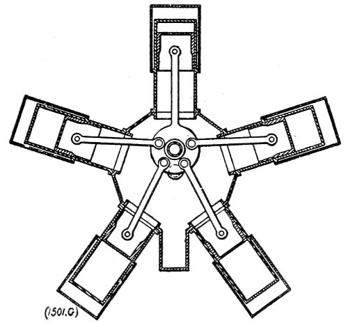
Sectional diagram of the 5-cylinder Bayard-Clement motor; of the “star” type.
Strictly speaking, the propeller is not a part of the motor of the flying machine, but it is so intimately connected with it in the utilization of the power created by the motor, that it will be treated of briefly in this chapter.
The form of the air-propeller has passed through a long and varied development, starting with that of the marine propeller, which was found to be very inefficient in so loose a medium as air. On account of this lack of density in the air, it was found necessary to act on large masses of it at practically the same time to gain the thrust needed to propel the aeroplane swiftly, and this led to increasing the diameter of the propeller to secure action on a proportionally larger area of air. The principle involved is simply the geometric rule that the areas of circles are to each other as the squares of their radii. Thus the surface of air acted on by two propellers, one of 6 feet diameter and the other of 8 feet diameter, would be in the proportion of 9 to 16; and as the central 209 210 part of a propeller has practically no thrust effect, the efficiency of the 8-foot propeller is nearly twice that of the 6-foot propeller—other factors being equal. But these other factors may be made to vary widely. For instance, the number of revolutions may be increased for the smaller propeller, thus engaging more air than the larger one at a lower speed; and, in practice, it is possible to run a small propeller at a speed that would not be safe for a large one. Another factor is the pitch of the propeller, which may be described as the distance the hub of the propeller would advance in one complete revolution if the blades moved in an unyielding medium, as a section of the thread of an ordinary bolt moves in its nut. In the yielding mass of the air the propeller advances only a part of its pitch, in some cases not more than half. The difference between the theoretical advance and the actual advance is called the “slip.”
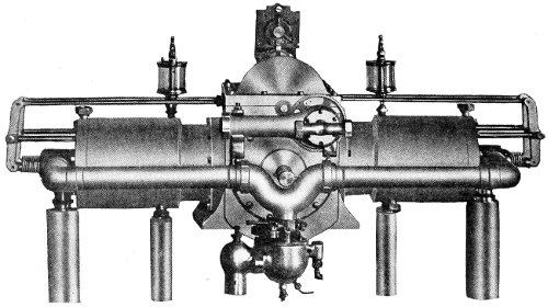
The Call Aviation Engine, of the opposed type; water-cooled. The cylinders are large and few in number. The 100 horse-power engine has but 4 cylinders, and weighs only 250 pounds. (The Gnome 100 horse-power engine has 14 cylinders.) This is an American engine, built at Girard, Kansas.
In practical work the number of blades which have been found to be most effective is two. More blades than two seem to so disturb the air that there is no hold for the propeller. In the case of slowly revolving propellers, as in most airship mechanisms, four-bladed propellers are used with good effect. But 211 where the diameter of the propeller is about 8 feet, and the number of revolutions about 1,200 per minute, the two-bladed type is used almost exclusively.
The many differing forms of the blades of the propeller is evidence that the manufacturers have not decided upon any definite shape as being the best. Some have straight edges nearly or quite parallel; others have the entering edge straight and the rear edge curved; in others the entering edge is curved, and the rear edge straight; or both edges may be curved. The majority of the wooden propellers are of the third-mentioned type, and the curve is fashioned so that at each section of its length the blade presents the same area of surface in the same time. Hence the outer tip, travelling the fastest, is narrower than the middle of the blade, and it is also much thinner to lessen the centrifugal force acting upon it at great speeds. Near the hub, however, where the travel is slowest, the constructional problem demands that the blade contract in width and be made stout. In fact, it becomes almost round in section.
Many propellers are made of metal, with tubular shanks and blades of sheet metal, the latter either solid sheets or formed with a double surface and hollow 212 inside. Still others have a frame of metal with blades of fabric put on loosely, so that it may adapt itself to the pressure of the air in revolving. That great strength is requisite becomes plain when it is considered that the speed of the tip of a propeller blade often reaches seven miles a minute! And at this velocity the centrifugal force excited—tending to tear the blades to splinters—is prodigious.
Just as the curved surface of the planes of an aeroplane is more effective than a flat surface in compressing the air beneath them, and thus securing a firmer medium on which to glide, so the propeller blades are curved laterally (across their width) to compress the air behind them and thus secure a better hold. The advancing side of the blade is formed with a still greater curve, to gain the advantage due to the unexplained lift of the paradox aeroplane.
Where the propeller is built of wood it is made of several layers, usually of different kinds of wood, with the grain running in slightly different directions, and all carefully glued together into a solid block. Ash, spruce, and mahogany, in alternating layers, are a favorite combination. In some instances the wooden propeller is sheathed in sheet aluminum; in others, it is well coated with glue 213 214 which is sandpapered down very smooth, then varnished, and then polished to the highest lustre—to reduce the effect of the viscosity of the air to the minimum.
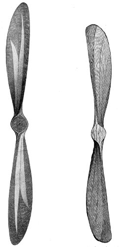
Two propellers, the one on the left of left-hand pitch; the other of right-hand pitch. Both are thrusting propellers, and are viewed from the rear. These fine models are of the laminated type, and are of American make; the one to the left a Paragon propeller made in Washington, D. C.; the other a Brauner propeller made in New York.
In order to get the best results, the propeller and the motor must be suited to each other. Some motors which “race” with a propeller which is slightly too small, work admirably with one a little heavier, or with a longer diameter.
The question as to whether one propeller, or two, is the better practice, has not been decided. The majority of aeroplanes have but one. The Wright and the Cody machines have two. The certainty of serious consequences to a machine having two, should one of them be disabled, or even broken so as to reduce the area, seems to favor the use of but one. 215
Awakened popular interest—The workshop’s share—Needed devices—Super-sensitive inventions—Unsolved problems—Tools and materials—A model biplane—The propeller—The body—The steering plane—The main planes—Assembling the parts—The motive power—Flying the model—A monoplane model—Carving a propeller—Many ideas illustrated—Clubs and competitions—Some remarkable records.
It is related of Benjamin Franklin that when he went out with his famous kite with the wire string, trying to collect electricity from the thundercloud, he took a boy along to forestall the ridicule that he knew would be meted out to him if he openly flew the kite himself.
Other scientific experimenters, notably those working upon the problem of human flight in our own time, have encountered a similar condition of the public mind, and have chosen to conduct their trials in secret rather than to contend with the derision, criticism, and loss of reputation which a sceptical world would have been quick to heap upon them. 216
But such a complete revolution of thought has been experienced in these latter days that groups of notable scientific men gravely flying kites, or experimenting with carefully made models of flying machines, arouse only the deepest interest, and their smallest discoveries are eagerly seized upon by the daily press as news of the first importance.
So much remains to be learned in the field of aeronautics that no builder and flyer of the little model aeroplanes can fail to gain valuable information, if that is his intention. On the other hand, if it be the sport of racing these model aeroplanes which appeals to him, the instruction given in the pages following will be equally useful.
The earnest student of aviation is reminded that the progressive work in this new art of flying is not being done altogether, nor even in large part, by the daring operators who, with superb courage, are performing such remarkable feats with the flying machines of the present moment. Not one of them would claim that his machine is all that could be desired. On the contrary, these intrepid men more than any others are fully aware of the many and serious defects of the apparatus they use for lack of better. The scientific student in his workshop, patiently 217 218 experimenting with his models, and working to prove or disprove untested theories, is doubtless doing an invaluable part in bringing about the sort of flying which will be more truly profitable to humanity in general, though less spectacular.
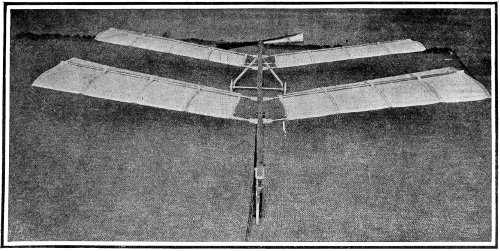
A model flying machine built and flown by Louis Paulhan, the noted aviator, at a prize contest for models in France. The design is after Langley’s model, with tandem monoplane surfaces placed at a dihedral angle.
One of the greatest needs of the present machines is an automatic balancer which shall supersede the concentrated attention which the operator is now compelled to exercise in order to keep his machine right side up. The discovery of the principle upon which such a balancer must be built is undoubtedly within the reach of the builder and flyer of models. It has been asserted by an eminent scientific experimenter in things aeronautic that “we cannot hope to make a sensitive apparatus quick enough to take advantage of the rising currents of the air,” etc. With due respect to the publicly expressed opinion of this investigator, it is well to reassure ourselves against so pessimistic an outlook by remembering that the construction of just such supersensitive apparatus is a task to which man has frequently applied his intellectual powers with signal success. Witness the photomicroscope, which records faithfully an enlarged view of objects too minute to be even visible to the human eye; the aneroid barometer, 219 so sensitive that it will indicate the difference in level between the table and the floor; the thermostat, which regulates the temperature of the water flowing in the domestic heating system with a delicacy impossible to the most highly constituted human organism; the seismograph, detecting, recording, and almost locating earth tremors originating thousands of miles away; the automatic fire sprinkler; the safety-valve; the recording thermometer and other meteorological instruments; and last, if not of least importance, the common alarm-clock. And these are but a few of the contrivances with which man does by blind mechanism that which is impossible to his sentient determination.
Even if the nervous system could be schooled into 220 endurance of the wear and tear of consciously balancing an aeroplane for many hours, it is still imperative that the task be not left to the exertion of human wits, but controlled by self-acting devices responding instantly to unforeseen conditions as they occur.
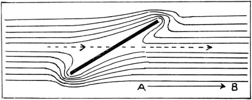
Diagram showing turbulent air currents produced when a flat plane is forced through the air at a large angle of incidence in the direction A-B.
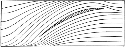
Diagram showing smoothly flowing air currents caused by correctly shaped plane at proper angle of incidence.
Some of the problems of which the model-builder may find the solution are: whether large screws revolving slowly, or small screws revolving rapidly, are the more effective; how many blades a propeller should have, and their most effective shape; what is the “perfect” material for the planes (Maxim found that with a smooth wooden plane he could lift 2½ times the weight that could be lifted with the best made fabric-covered plane); whether the centre of 221 gravity of the aeroplane should be above or below the centre of lift, or should coincide with it; new formulas for the correct expression of the lift in terms of the velocity, and angle of inclination—the former formulas having been proved erroneous by actual experience; how to take the best advantage of the “tangential force” announced by Lilienthal, and reasserted by Hargrave; and many others. And there is always the “paradox aeroplane” to be explained—and when explained it will be no longer a paradox, but will doubtless open the way to the most surprising advance in the art of flying.
It is not assumed that every reader of this chapter will become a studious experimenter, but it is unquestionably true that every model-builder, in his effort to produce winning machines, will be more than likely to discover some fact of value in the progress making toward the ultimate establishment of the commercial navigation of the air.
The tools and materials requisite for the building of model aeroplanes are few and inexpensive. For the tools—a small hammer; a small iron “block” plane; a fine-cut half-round file; a pair of round-nose pliers; three twist drills (as used for drilling metals), the largest 1/16 inch diameter, and two smaller sizes, 222 with an adjustable brad-awl handle to hold them; a sharp pocket knife; and, if practicable, a small hand vise. The vise may be dispensed with, and common brad-awls may take the place of the drills, if necessary.
For the first-described model—the simplest—the following materials are needed: some thin whitewood, 1/16 inch thick (as prepared for fret-sawing); some spruce sticks, ¼ inch square (sky-rocket sticks are good); a sheet of heavy glazed paper; a bottle of liquid glue; some of the smallest (in diameter) brass screws, ¼ to ½ inch long; some brass wire, 1/20 inch in diameter; 100 inches of square rubber (elastic) “cord,” such as is used on return-balls, but 1/16 inch square; and a few strips of draughtsman’s tracing cloth.
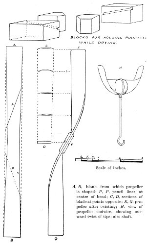
A, B, blank from which propeller is shaped; P, P, pencil lines at centre of bend; C, D, sections of blade at points opposite; E, G, propeller after twisting; H, view of propeller endwise, showing outward twist of tips; also shaft.
As the propeller is the most difficult part to make, it is best to begin with it. The flat blank is cut out of the whitewood, and subjected to the action of steam issuing from the spout of an actively boiling tea-kettle. The steam must be hot; mere vapor will not do the work. When the strip has become pliable, the shaping is done by slowly bending and twisting at the same time—perhaps “coaxing” would be the better word, for it must be done gently and with 223 224 patience—and the steam must be playing on the wood all the time, first on one side of the strip, then on the other, at the point where the fibres are being bent. The utmost care should be taken to have the two blades bent exactly alike—although, of course, with a contrary twist, the one to the right and the other to the left, on each side of the centre. A lead-pencil line across each blade at exactly the same distance from the centre will serve to fix accurately the centre of the bend. If two blocks are made with slots cut at the angle of 1 inch rise to 2¼ inches base, and nailed to the top of the work bench just far enough apart to allow the tips of the screw to be slid into the slots, the drying in perfect shape will be facilitated. The centre may be held to a true upright by two other blocks, one on each side of the centre. Some strips of whitewood may be so rigid that the steam will not make them sufficiently supple. In this case it may be necessary to dip them bodily into the boiling water, or even to leave them immersed for a few minutes; afterward bending them in the hot steam. But a wetted stick requires longer to dry and set in the screw shape. When the propeller is thoroughly dry and set in proper form, it should be worked into the finished shape with the half-round file, according to the several 225 sections shown beside the elevation for each part of the blade. The two strengthening piece’s are then to be glued on at the centre of the screw, and when thoroughly dry, worked down smoothly to shape. When all is dry and hard it should be smoothed with the finest emery cloth and given a coat of shellac varnish, which, in turn, may be rubbed to a polish with rotten stone and oil.
It may be remarked, in passing, that this is a crude method of making a propeller, and the result cannot be very good. It is given here because it is the easiest way, and the propeller will work. A much better way is described further on—and the better the propeller, the better any model will fly. But for a novice, no time will be lost in making this one, for the experience gained will enable the model-builder to do better work with the second one than he could do without it.
For the aeroplane body we get out a straight spar of spruce, ¼ inch square and 15½ inches long. At the front end of this—on the upper side—is to be glued a small triangular piece of wood to serve as a support for the forward or steering plane, tilting it up at the front edge at the angle represented by a rise of 1 in 8. This block should be shaped on its upper 226 side to fit the curve of the under side of the steering-plane, which will be screwed to it.
The steering-plane is cut according to plan, out of 1/16 inch whitewood, planed down gradually to be at the ends about half that thickness. This plane is to be steamed and bent to a curve (fore and aft) as shown in the sectional view. The steam should play on the convex side of the bend while it is being shaped. To hold it in proper form until it is set, blocks with curved slots may be used, or it may be bound with thread to a moulding block of equal length formed to the proper curve. When thoroughly dry it is to be smoothed with the emery cloth, and a strip of tracing cloth—glossy face out—is to be glued across each end, to prevent breaking in case of a fall. It is then to be varnished with shellac, and polished, as directed for the propeller. Indeed, it should be said once for all that every part of the model should be as glossy as it is possible to make it without adding to the weight, and that all “entering edges” (those which push into and divide the air when in flight) should be as sharp as is practicable with the material used.
The steering-plane is to be fastened in place by a single screw long enough to pierce the plane and 227 the supporting block, and enter the spar. The hole for this screw (as for all screws used) should be drilled carefully, to avoid the least splitting of the wood, and just large enough to have the screw “bite” without forcing its way in. This screw which holds the plane is to be screwed “home” but not too tight, so that in case the flying model should strike upon it in falling, the slender plane will swivel, and not break. It will be noticed that while this screw passes through the centre of the plane sideways, it is nearer to the forward edge than to the rear edge.
If the work has been accurate, the plane will balance if the spar is supported—upon the finger, perhaps, as that is sensitive to any tendency to tipping. If either wing is too heavy, restore the balance by filing a little from the tip of that wing.
The main planes are next to be made. The lower deck of the biplane is of the 1/16 inch whitewood, and the upper one is of the glazed paper upon a skeleton framework of wood. The upright walls are of paper. The wooden deck is to be bent into the proper curve with the aid of steam, and when dry and set in form is to be finished and polished. The frame for the upper deck is made of the thin whitewood, and is held to its position by two diagonal struts of whitewood 228 bent at the ends with steam, and two straight upright struts or posts. It is better to bend all cross-pieces into the curve of the plane with steam, but they may be worked into the curve on the top side with plane and file, and left flat on the lower side. The drawings show full details of the construction, drawn accurately to scale.
It is best to glue all joints, and in addition to insert tiny screws, where shown in the plans, at the time of gluing.
When all the wooden parts are in place the entire outline of the upper plane and the upright walls is to be formed of silk thread carried from point to point, and tied upon very small pins (such as are used in rolls of ribbon at the stores) inserted in the wood. The glazed paper is put on double, glossy side out. Cut the pieces twice as large (and a trifle more) than is needed, and fold so that the smooth crease comes to the front and the cut edges come together at the rear. The two inner walls should be put in place first, so as to enclose the thread front and back, and the post, between the two leaves of the folded paper. Cutting the paper half an inch too long will give one fourth of an inch to turn flat top and bottom to fasten to the upper and lower decks 229 230 respectively. The two outer walls and the upper deck may be cut all in one piece, the under leaf being slit to pass on either side of the inner walls. A bit of glue here and there will steady the parts to their places. The cut edges at the rear of the deck and walls should be caught together with a thin film of glue, so as to enclose the rear threads.
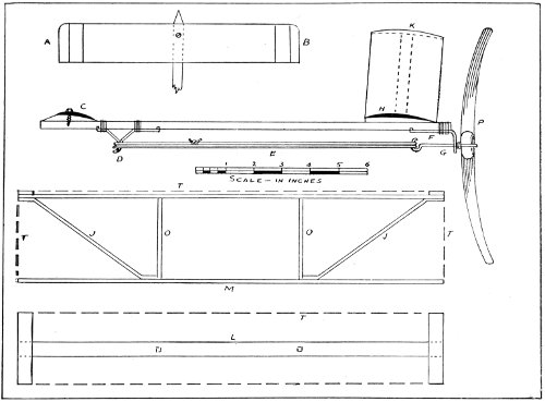
A, B, plan, and C, section, of steering plane; H, section of lower main plane; L, wood skeleton of upper plane; T, T, silk thread; O, O, posts; J, J, braces; E, rubber strands; D, forward hook; G, shaft; F, thrust-block; K, upper plane of paper; M, elevation of main planes, from the rear.
When the biplane is completed it is to be fastened securely to the spar in such a position that it is accurately balanced—from side to side. The spar may be laid on a table, and the biplane placed across it in its approximate position. Then move the plane to one side until it tips down, and mark the spot on the rear edge of the plane. Repeat this operation toward the other side, and the centre between the two marks should be accurately fastened over the centre line of the spar. Even with the greatest care there may still be failure to balance exactly, but a little work with a file on the heavy side, or a bit of chewing gum stuck on the lighter side, will remedy the matter.
The body of the aeroplane being now built, it is in order to fit it with propelling mechanism. The motive power to whirl the propeller we have already prepared is to be the torsion, or twisting strain—in this case the force of untwisting—of india rubber. 231 When several strands of pure rubber cord are twisted up tight, their elasticity tends to untwist them with considerable force. The attachment for the rubber strands at the front end of the spar is a sort of bracket made of the brass wire. The ends of the wire are turned up just a little, and they are set into little holes in the under side of the spar. Where the wire turns downward to form the hook it is bound tightly to the spar with silk thread. The hook-shaped tip is formed of the loop of the wire doubled upon itself. The rear attachment of the rubber strands is a loop upon the propeller shaft itself. As shown in the drawings, this shaft is but a piece of the brass wire. On one end (the rear) an open loop is formed, and into this is slipped the centre of the propeller. The short end of the loop is then twisted around the longer shank—very carefully, lest the wire cut into and destroy the propeller. Two turns of the wire is enough, and then the tip of the twisted end should be worked down flat with the file, to serve as a bearing for the propeller against the thrust-block. This latter is made of a piece of sheet brass (a bit of printers’ brass “rule” is just the thing) about 1/40 of an inch thick. It should be ¼ of an inch wide except at the forward end, where it is to be filed to a 232 long point and bent up a trifle to enter the wood of the spar. The rear end is bent down (not too sharply, lest it break) to form the bearing for the propeller, a hole being drilled through it for the propeller shaft, just large enough for the shaft to turn freely in it. Another smaller hole is to be drilled for a little screw to enter the rear end of the spar. Next pass the straight end of the propeller shaft through the hole drilled for it, and with the pliers form a round hook for the rear attachment of the rubber strands. Screw the brass bearing into place, and for additional strength, wind a binding of silk thread around it and the spar.
Tie the ends of the rubber cord together, divide it into ten even strands, and pass the loops over the two hooks—and the machine is ready for flight.
To wind up the rubber it will be necessary to turn the propeller in the opposite direction to which it will move when the model is flying. About 100 turns will be required. After it is wound, hold the machine by the rear end of the spar, letting the propeller press against the hand so it cannot unwind. Raise it slightly above the head, holding the spar level, or inclined upward a little (as experience may dictate), and launch the model by a gentle throw forward. 233 If the work has been well done it may fly from 150 to 200 feet.
Many experiments may be made with this machine. If it flies too high, weight the front end of the spar; if too low, gliding downward from the start, weight the rear end. A bit of chewing gum may be enough to cause it to ride level and make a longer and prettier flight.
A very graceful model is that of the monoplane type illustrated in the accompanying reproductions from photographs. The front view shows the little machine just ready to take flight from a table. The view from the rear is a snap-shot taken while it was actually flying. This successful model was made by Harold S. Lynn, of Stamford, Conn. Before discussing the details of construction, let us notice some peculiar features shown by the photographs. The forward plane is arched; that is, the tips of the plane bend slightly downward from the centre. On the contrary, the two wings of the rear plane bend slightly upward from the centre, making a dihedral angle, as it is called; that is, an angle between two surfaces, as distinguished from an angle between two lines. The toy wheels, Mr. Lynn says, are put on principally for “looks” but they are also useful in permitting 234 a start to be made from a table or even from the floor, instead of the usual way of holding the model in the hands and giving it a slight throw to get it started. However, the wheels add to the weight, and the model will not fly quite so far with them as without.

Front view of the Lynn model of the monoplane type, about to take flight.
The wood from which this model was made was taken from a bamboo fish-pole, such as may be bought anywhere for a dime. The pole was split 235 up, and the suitable pieces whittled and planed down to the proper sizes, as given in the plans. In putting the framework of the planes together, it is well to notch very slightly each rib and spar where they cross. Touch the joint with a bit of liquid glue, and wind quickly with a few turns of sewing silk and tie tightly. This must be done with delicacy, or the frames will be out of true. If the work is done rapidly the glue will not set until all the ties on the 236 plane are finished. Another way is to touch the joinings with a drop of glue, place the ribs in position on the spars, and lay a board carefully on the work, leaving it there until all is dry, when the tying can be done. It either case the joinings should be touched again with the liquid glue and allowed to dry hard.
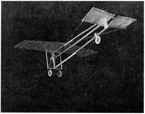
The Lynn model monoplane in flight, from below and from the rear.
The best material for covering these frames is the thinnest of China silk. If this is too expensive, use the thinnest cambric. But the model will not fly so far with the cambric covering. The material is cut one-fourth of an inch too large on every side, and folded over, and the fold glued down. Care should be taken that the frame is square and true before the covering is glued on.
The motive power is produced by twisting up rubber tubing. Five and three-quarter feet of pure rubber tubing are required. It is tied together with silk so as to form a continuous ring. This is looped over two screw-hooks of brass, one in the rear block and the other constituting the shaft. This looped tubing is twisted by turning the propeller backward about two hundred turns. As it untwists it turns the propeller, which, in this model, is a “traction” screw, and pulls the machine after it as it advances through the air. 237
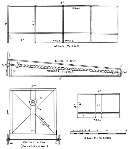
Details and plans of the Harold Lynn model monoplane. W, tail block; Y, thrust-block; S, mounting of propeller showing glass bead next the thrust-block, and one leather washer outside the screw; B, glass bead; C, tin washer; M, M, tin lugs holding axle of wheels.
238
The propeller in this instance is formed from a piece of very thin tin, such as is used for the tops of cans containing condensed milk. Reference to the many illustrations throughout this book showing propellers of flying machines will give one a very good idea of the proper way to bend the blades. The mounting with the glass bead and the two leather washers is shown in detail in the plans.
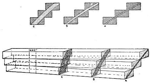
Method of forming propeller of the laminated, or layer, type. The layers of wood are glued,in the position shown and the blades carved out according to the sections. Only one blade is shown from the axle to the tip. This will make a right hand propeller.
The wheels are taken from a toy wagon, and a pair of tin ears will serve as bearings for the axle.
The sport of flying model aeroplanes has led to the formation of many clubs in this country as well as in Europe. Some of the mechanisms that have been 239 240 devised, and some of the contrivances to make the models fly better and further, are illustrated in the drawings.
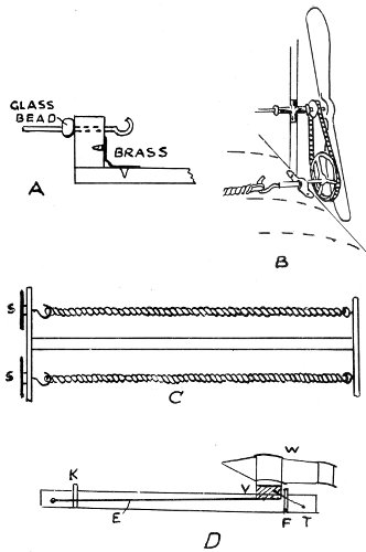
At A is shown a method of mounting the propeller with a glass or china bead to reduce friction, and a brass corner to aid in strengthening. B shows a transmission of power by two spur wheels and chain. C is a device for using two rubber twists acting on the two spur wheels S, S, which in turn are connected with the propeller with a chain drive. D shows a launching apparatus for starting. W, the model; V, the carriage; F, the trigger guard; T, trigger; E, elastic cord for throwing the carriage forward to the stop K.
Records have been made which seem marvellous when it is considered that 200 feet is a very good flight for a model propelled by rubber. For instance, at the contest of the Birmingham Aero Club (England) in September, one of the contestants won the prize with a flight of 447 feet, lasting 48 seconds. The next best records for duration of flight were 39 seconds and 38 seconds. A model aeroplane which is “guaranteed to fly 1,000 feet,” according to the advertisement in an English magazine, is offered for sale at $15.
The American record for length of flight is held by Mr. Frank Schober, of New York, with a distance of 215 feet 6 inches. His model was of the Langley type of tandem monoplane, and very highly finished. The problem is largely one of adequate power without serious increase of weight. 241
Aerial balancing—Practice necessary—Simplicity of the glider Materials—Construction—Gliding—Feats with the Montgomery glider—Noted experimenters—Glider clubs.
It is a matter of record that the Wright brothers spent the better part of three years among the sand dunes of the North Carolina sea-coast practising with gliders. In this way they acquired that confidence while in the air which comes from intimate acquaintance with its peculiarities, and which cannot be gained in any other way. It is true that the Wrights were then developing not only themselves, but also their gliders; but the latter work was done once for all. To develop aviators, however, means the repeating of the same process for each individual—just as each for himself must be taught to read. And the glider is the “First Reader” in aeronautics.
The long trail of wrecks of costly aeroplanes marking the progress in the art of flying marks also the 242 lack of preparatory training, which their owners either thought unnecessary, or hoped to escape by some royal road less wearisome than persistent personal practice. But they all paid dearly to discover that there is no royal road. Practice, more practice, and still more practice—that is the secret of successful aeroplane flight.
For this purpose the glider is much superior to the power-driven aeroplane. There are no controls to learn, no mechanism to manipulate. One simply launches into the air, and concentrates his efforts upon balancing himself and the apparatus; not as two distinct bodies, however, but as a united whole. When practice has made perfect the ability to balance the glider instinctively, nine-tenths of the art of flying an aeroplane has been achieved. Not only this, but a new sport has been laid under contribution; one beside which coasting upon a snow-clad hillside is a crude form of enjoyment.
Fortunately for the multitude, a glider is easily made, and its cost is even less than that of a bicycle. A modest degree of skill with a few carpenter’s tools, and a little “gumption” about odd jobs in general, is all that is required of the glider builder.
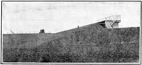
A gliding slope with starting platform, erected for club use.
The frame of the glider is of wood, and spruce is 243 244 recommended, as it is stronger and tougher for its weight than other woods. It should be of straight grain and free from knots; and as there is considerable difference in the weight of spruce from different trees, it is well to go over the pile in the lumber yard and pick out the lightest boards. Have them planed down smooth on both sides, and to the required thickness, at the mill—it will save much toilsome hand work. The separate parts may also be sawed out at the mill, if one desires to avoid this labor.
The lumber needed is as follows:
| 4 | spars | 20 ft. long, | 1¼ in. wide, | ¾ in. thick. |
| 12 | struts | 3 ft. long, | 1¼ in. wide, | ¾ in. thick. |
| 2 | rudder bars | 8 ft. long, | ¾ in. wide, | ½ in. thick. |
| 12 | posts | 4 ft. long, | 1½ in. wide, | ½ in. thick. |
| 41 | ribs | 4 ft. long, | ½ in. wide, | ½ in. thick. |
| 2 | arm rests | 4 ft. long, | 2 in. wide, | 1 in. thick. |
| For rudder frame. | 24 running ft., | 1 in. wide, | 1 in. thick. | |
If it be impossible to find clear spruce lumber 20 feet in length, the spars may be built up by splicing two 10-foot sticks together. For this purpose, the splicing stick should be as heavy as the single spar—1¼ inches wide, and ¾ inches thick—and at least 4 feet long, and be bolted fast to the spar with six ⅛ inch round-head carriage bolts with washers of large bearing surface (that is, a small hole to fit the bolt, and a 245 large outer diameter) at both ends of the bolt, to prevent crushing the wood. A layer of liquid glue brushed between will help to make the joint firmer.
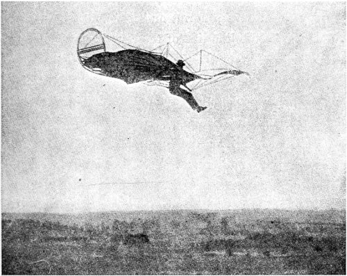
Otto Lilienthal in his single-plane glider. The swinging forward of his feet tends to turn the glider toward the ground, and increase its speed.
Wherever a bolt is put in, a hole should be bored for it with a bit of such size that the bolt will fit snug in the hole without straining the grain of the wood.
The corners of the finished spar are to be rounded off on a large curvature. 246
The ends of the struts are to be cut down on a slight slant of about 1/16 inch in the 1¼ inches that it laps under the spar—with the idea of tipping the top of the spar forward so that the ribs will spring naturally from it into the proper curve.
The ribs should be bent by steaming, and allowed to dry and set in a form, or between blocks nailed upon the floor to the line of the correct curve. They are then nailed to the frames, the front end first: 21 to the frame of the upper plane, and 20 to that of the lower plane, omitting one at the centre, where the arm pieces will be placed.
Some builders tack the ribs lightly into place with small brads, and screw clamps formed from sheet brass or aluminum over them. Others use copper nails and clinch them over washers on the under side. Both methods are shown in the plans, but the clamps are recommended as giving greater stiffness, an essential feature.
At the front edge of the frames the ribs are fastened flush, and being 4 feet long and the frame but 3 feet wide, they project over the rear about 1 foot.
The arm pieces are bolted to the spars of the lower frame 6½ inches on each side of the centre, so as to allow a free space of 13 inches between them. This 247 248 opening may be made wider to accommodate a stouter person.
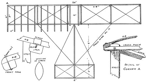
Plan and details of Glider. The upper plane has a rib at the centre instead of the two arm pieces.
The posts are then put into place and bolted to the struts and the spars, as shown, with ⅛inch bolts.
The entire structure is then to be braced diagonally with No. 16 piano wire. The greatest care must be taken to have these diagonals pull just taut, so that they shall not warp the lines of the frames out of true. A crooked frame will not fly straight, and is a source of danger when making a landing.
The frames are now to be covered. There is a special balloon cloth made which is best for the purpose, but if that cannot be procured, strong cambric muslin will answer. Thirty yards of goods 1 yard wide will be required for the planes and the rudder. From the piece cut off 7 lengths for each plane, 4 feet 6 inches long. These are to be sewed together, selvage to selvage, so as to make a sheet about 19 feet 6 inches long and 4 feet 6 inches wide. As this is to be tacked to the frame, the edges must be double-hemmed to make them strong enough to resist tearing out at the tacks. Half an inch is first folded down all around; the fold is then turned back on the goods 2½ inches and sewed. This hem is then folded back 1 inch upon itself, and again stitched. Strips 3 249 inches wide and a little over 4 feet long are folded “three-double” into a width of 1 inch, and sewed along both edges to the large sheet exactly over where the ribs come. These are to strengthen the fabric where the ribs press against it. Sixteen-ounce tacks are used, being driven through a felt washer the size of a gun wad at intervals of four inches. If felt is not readily obtainable, common felt gun wads will do. The tacking is best begun at the middle of the frame, having folded the cloth there to get the centre. Then stretch smoothly out to the four corners and tack at each. It may then be necessary to loosen the two centre tacks and place them over again, to get rid of wrinkles. The next tacks to drive are at the ends of the struts; then half-way between; and so on until all are in, and the sheet is taut and smooth. For a finer finish, brass round-head upholsterer’s nails may be used.
The rudder, so-called, is rather a tail, for it is not movable and does not steer the glider. It does steady the machine, however, and is very important in preserving the equilibrium when in flight. It is formed of two small planes intersecting each other at right angles and covered on both sides with the cloth, the sections covering the vertical part being cut along 250 the centre and hemmed on to the upper and lower faces of the horizontal part. The frame for the vertical part is fastened to the two rudder bars which stretch out toward the rear, one from the upper plane, and the other from the lower. The whole construction is steadied by guys of the piano wire.
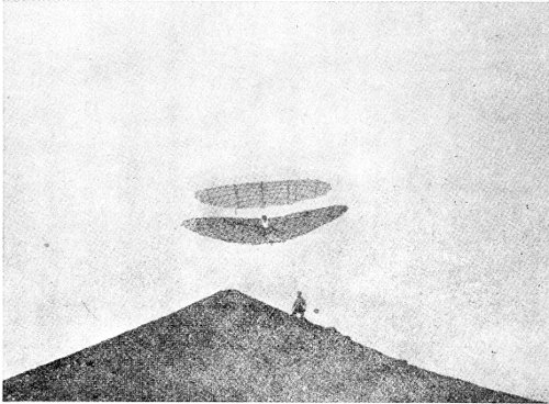
Lilienthal in his double-deck glider. It proved unmanageable and fell, causing his death. The hill is an artificial one built for his own use in experimenting.
All wooden parts should be smoothed off with sandpaper, and given a coat of shellac varnish.
To make a glide, the machine is taken to an elevated 251 252 point on a slope, not far up to begin with. Lift the glider, get in between the arm rests, and raise the apparatus until the rests are snug under the arms. Run swiftly for a few yards and leap into the air, holding the front of the planes slightly elevated. If the weight of the body is in the right position, and the speed sufficient, the glider will take the air and sail with you down the slope. It may be necessary at first to have the help of two assistants, one at each end, to run with the glider for a good start.
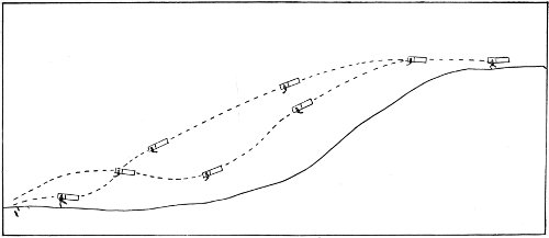
Diagram showing differing lines of flight as controlled by changing the position of the body. The wind must be blowing against the direction of flight; in the illustration this would be from left to right.
The position of the body on the arm rests can best be learned by a few experiments. No two gliders are quite alike in this respect, and no rule can be given. As to the requisite speed, it must be between 15 and 20 miles an hour; and as this speed is impossible to a man running, it is gained by gliding against the wind, and thus adding the speed of the wind to the speed of the runner. The Wrights selected the sand dunes of the North Carolina coast for their glider experiments because of the steady winds that blow in from the ocean, across the land. These winds gave them the necessary speed of air upon which to sail their gliders.
The first flights attempted should be short, and 253 as experience is gained longer ones may be essayed.
Balancing the glider from side to side is accomplished by swaying the lower part of the body like a pendulum, the weight to go toward the side which has risen. Swinging the body forward on the arm rests will cause the machine to dip the planes and glide more swiftly down the incline. Holding the weight of the body back in the arm rests will cause the machine to fly on a higher path and at a slower speed. This is objectionable because the glider is more manageable at a higher speed, and therefore safer. The tendency at first is to place the weight too far back, with a consequent loss of velocity, and with that a proportionate loss of control. The proper position of the body is slightly forward of the mechanical centre of the machine.
The landing is accomplished by shoving the body backward, thus tilting up the front of the plane. This checks the speed, and when the feet touch the ground a little run, while holding back, will bring the glide to an end. Landing should be practised often with brief glides until skill is gained, for it is the most difficult operation in gliding.
After one becomes expert, longer flights may be 254 secured by going to higher points for the start. From an elevation of 300 feet a glide of 1,200 feet is possible.
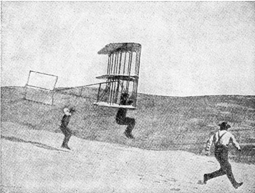
Gliding with a Chanute three-decker. A start with two assistants.
While it is necessary to make glides against the wind, it is not wise to attempt flights when the wind blows harder than 10 miles an hour. While the flight may be successful, the landing may be disastrous.
The accomplished glider operator is in line for the aeroplane, and it is safe to say that he will not 255 be long without one. The skilful and practised operator of a glider makes the very best aeroplane pilot.
This chapter would not be complete without an adequate reference to the gliders devised by Professor Montgomery of Santa Clara, California. These machines were sent up with ordinary hot-air balloons to various heights, reaching 4,000 feet in some instances, when they were cut loose and allowed to descend in a long glide, guided by their pilots. The time of the descent from the highest altitude was twenty minutes, during which the glider travelled about eight miles. The landing was made accurately upon a designated spot, and so gently that there was no perceptible jar. Two of the pilots turned completely over sideways, the machine righting itself after the somersault and continuing its regular course. Professor Montgomery has made the assertion that he can fasten a bag of sand weighing 150 lbs. in the driver’s seat of his glider, and send it up tied upside down under a balloon, and that after being cut loose, the machine will right itself and come safely to the ground without any steering.
Lilienthal in Germany, Pilcher in England, and Chanute in the United States are names eminent in 256 connection with the experiments with gliders which have been productive of discoveries of the greatest importance to the progress of aviation. The illustration of the Chanute glider shows its peculiarities plainly enough to enable any one to comprehend them.
The establishment of glider clubs in several parts of the country has created a demand for ready-made machines, so that an enthusiast who does not wish to build his own machine may purchase it ready made. 257
First air vehicle—Principle of Archimedes—Why balloons rise—Inflating gases—Early history—The Montgolfiers—The hot-air balloon—Charles’s hydrogen balloon—Pilatre de Rozier—The first aeronaut—The first balloon voyage—Blanchard and Jeffries—Crossing the English Channel—First English ascensions—Notable voyages—Recent long-distance journeys and high ascensions—Prize balloon races—A fascinating sport—Some impressions, adventures, and hardships—Accident record—Increasing interest in ballooning.
The balloon, though the earliest and crudest means of getting up in the air, has not become obsolete. It has been in existence practically in its present general form for upwards of 500 years. Appliances have been added from time to time, but the big gas envelope enclosing a volume of some gas lighter than an equal volume of air, and the basket, or car, suspended below it, remain as the typical form of aerial vehicle which has not changed since it was first devised in times so remote as to lie outside the boundaries of recorded history. 258
The common shape of the gas bag of a balloon is that of the sphere, or sometimes of an inverted pear. It is allowed to rise and float away in the air as the prevailing wind may carry it. Attempts have been made to steer it in a desired direction, but they did not accomplish much until the gas bag was made long horizontally, in proportion to its height and width. With a drag-rope trailing behind on the ground from the rear end of the gas bag, and sails on the forward end, it was possible to guide the elongated balloon to some extent in a determined direction.
In explaining why a balloon rises in the air, it is customary to quote the “principle of Archimedes,” discovered and formulated by that famous philosopher centuries before the Christian era. Briefly stated, it is this: Every body immersed in a fluid is acted upon by a force pressing upward, which is equal to the weight of the amount of the fluid displaced by the immersed body.
It remained for Sir Isaac Newton to explain the principle of Archimedes (by the discovery of the law of gravitation), and to show that the reason why the immersed body is apparently pushed upward, is that the displaced fluid is attracted downward. In the 259 case of a submerged bag of a gas lighter than air, the amount of force acting on the surrounding air is greater than that acting on the gas, and the latter is simply crowded out of the way by the descending air, and forced up to a higher level where its lighter bulk is balanced by the gravity acting upon it.
The fluid in which the balloon is immersed is the air. The force with which the air crowds down around and under the balloon is its weight—weight being the measure of the attraction which gravity exerts upon any substance.
The weight of air at a temperature of 32° Fahr., at the normal barometer pressure at the sea-level (29.92 inches of mercury), is 0.0807 lbs. per cubic foot. The gas used to fill a balloon must therefore weigh less than this, bulk for bulk, in order to be crowded upward by the heavier air—and thus exert its “lifting power,” as it is commonly called.
In practice, two gases have been used for inflating balloons—hydrogen, and illuminating gas, made ordinarily from coal, and called “coal gas.” Hydrogen is the lightest substance known; that is, it is attracted less by gravity than any other known substance, in proportion to its bulk.
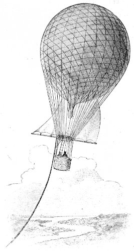
One of the earliest attempts to steer a spherical balloon by retarding its speed with the drag-rope, and adjusting the sail to the passing wind.
A cubic foot of hydrogen weighs but 0.0056 lbs., 260 261 and it will therefore be pushed upward in air by the difference in weight, or 0.0751 lbs. per cubic foot. A cubic foot of coal gas weighs about 0.0400 lbs., and is crowded upward in air with a force of 0.0407 lbs.
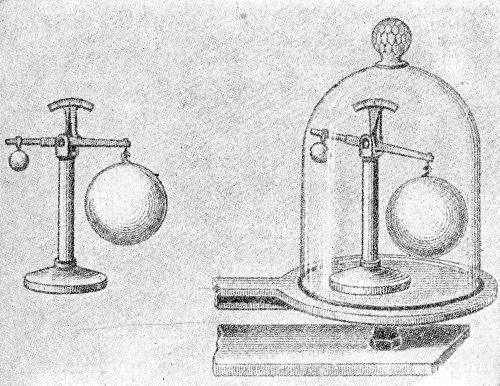
Apparatus to illustrate the principle of Archimedes. At the left, the small solid glass ball and large hollow glass sphere are balanced in the free air. When the balance is moved under the bell-glass of the air pump (at the right), and the air exhausted, the large sphere drops, showing that its previous balance was due to the upward pressure of the air, greater because of its larger bulk.
It is readily seen that a very large bulk of hydrogen must be used if any considerable weight is to be lifted. For to the weight of the gas must be added the weight of the containing bag, the car, and the network supporting it, the ballast, instruments, and 262 passengers, and there must still be enough more to afford elevating power sufficient to raise the entire load to the desired level.
Let us assume that we have a balloon with a volume of 20,000 cubic feet, which weighs with its appurtenances 500 pounds. The hydrogen it would contain would weigh about 112 pounds, and the weight of the air it would displace would be about 1,620 pounds. The total available lifting power would be about 1,000 pounds. If a long-distance journey is to be undertaken at a comparatively low level, this will be sufficient to carry the necessary ballast, and a few passengers. If, however, it is intended to rise to a great height, the problem is different. The weight of the air, and consequently its lifting pressure, decreases as we go upwards. If the balloon has not been entirely filled, the gas will expand as the pressure is reduced in the higher altitude. This has the effect of carrying the balloon higher. Heating of the contained gas by the sun will also cause a rise. On the other hand, the diffusion of the gas through the envelope into the air, and the penetration of air into the gas bag will produce a mixture heavier than hydrogen, and will cause the balloon to descend. The extreme cold of the upper 263 air has the same effect, as it tends to condense to a smaller bulk the gas in the balloon. To check a descent the load carried by the gas must be lightened by throwing out some of the ballast, which is carried simply for this purpose. Finally a level is reached where equilibrium is established, and above which it is impossible to rise.
The earliest recorded ascent of a balloon is credited to the Chinese, on the occasion of the coronation of the Emperor Fo-Kien at Pekin in the year 1306. If this may be called historical, it gives evidence also that it speedily became a lost art. The next really historic record belongs in the latter part of the seventeenth century, when Cyrano de Bergerac attempted to fly with the aid of bags of air attached to his person, expecting them to be so expanded by the heat of the sun as to rise with sufficient force to lift him. He did not succeed, but his idea is plainly the forerunner of the hot-air balloon.
In the same century Francisco de Lana, who was clearly a man of much intelligence and keen reasoning ability, having determined by experiment that the atmosphere had weight, decided that he would be able to rise into the air in a ship lifted by four metal spheres 20 feet in diameter from which the air had 264 been exhausted. After several failures he abandoned his efforts upon the religious grounds that the Almighty doubtless did not approve such an overturning in the affairs of mankind as would follow the attainment of the art of flying.
In 1757, Galen, a French monk, published a book, “The Art of Navigating in the Air,” in which he advocated filling the body of the airship with air secured at a great height above the sea-level, where it was “a thousand times lighter than water.” He showed by mathematical computations that the upward impulse of this air would be sufficient to lift a heavy load. He planned in detail a great airship to carry 4,000,000 persons and several million packages of goods. Though it may have accomplished nothing more, this book is believed to have been the chief source of inspiration to the Montgolfiers.
The discovery of hydrogen by Cavendish in 1776 gave Dr. Black the opportunity of suggesting that it be used to inflate a large bag and so lift a heavy load into the air. Although he made no attempt to construct such an apparatus, he afterward claimed that through this suggestion he was entitled to be called the real inventor of the balloon.
This is the meagre historical record preceding the 265 achievements of the brothers Stephen and Joseph Montgolfier, which marked distinctly the beginning of practical aeronautics. Both of these men were highly educated, and they were experienced workers in their father’s paper factory. Joseph had made some parachute drops from the roof of his house as early as 1771.
After many experiments with steam, smoke, and hydrogen gas, with which they tried ineffectually to inflate large paper bags, they finally succeeded with heated air, and on June 5, 1783, they sent up a great paper hot-air balloon, 35 feet in diameter. It rose to a height of 1,000 feet, but soon came to earth again upon cooling. It appears that the Montgolfiers were wholly ignorant of the fact that it was the rarefying of the air by heating that caused their balloon to rise, and they made no attempt to keep it hot while the balloon was in the air.
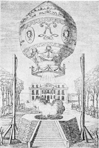
An early Montgolfier balloon.
About the same time the French scientist, M. Charles, decided that hydrogen gas would be better than hot air to inflate balloons. Finding that this gas passed readily through paper, he used silk coated with a varnish made by dissolving rubber. His balloon was 13 feet in diameter, and weighed about 20 pounds. It was sent up from the Champ de 266 Mars on August 29, 1783, amidst the booming of cannon, in the presence of 300,000 spectators who assembled despite a heavy rain. It rose swiftly, disappearing among the clouds, and soon burst from the expansion of the gas in the higher and rarer atmosphere—no allowance having been made for this 267 unforeseen result. It fell in a rural region near Paris, where it was totally destroyed by the inhabitants, who believed it to be some hideous form of the devil.
The Montgolfiers had already come to Paris, and had constructed a balloon of linen and paper. Before they had opportunity of sending it up it was ruined by a rainstorm with a high wind. They immediately built another of waterproof linen which made a successful ascension on September 19, 1783, taking as passengers a sheep, a cock, and a duck. The balloon came safely to earth after being up eight minutes—falling in consequence of a leak in the air-bag near the top. The passengers were examined with great interest. The sheep and the duck seemed in the same excellent condition as when they went up, but the cock was evidently ailing. A consultation of scientists was held and it was the consensus of opinion that the fowl could not endure breathing the rarer air of the high altitude. At this juncture some one discovered that the cock had been trodden upon by the sheep, and the consultation closed abruptly.
The Montgolfier brothers were loaded with honors, Stephen receiving the larger portion; and the people of Paris entered enthusiastically into the sport 268 of making and flying small balloons of the Montgolfier type.
Stephen began work at once upon a larger balloon intended to carry human passengers. It was fifty feet in diameter, and 85 feet high, with a capacity of 100,000 cubic feet. The car for the passengers was swung below from cords in the fashion that has since become so familiar.
In the meantime Pilatre de Rozier had constructed a balloon on the hot-air principle, but with an arrangement to keep the air heated by a continuous fire in a pan under the mouth of the balloon. He made the first balloon ascent on record on October 15, 1783, rising to a height of eighty feet, in the captive balloon. On November 21, in the same year, de Rozier undertook an expedition in a free balloon with the Marquis d’Arlandes as a companion. The experiment was to have been made with two condemned criminals, but de Rozier and d’Arlandes succeeded in obtaining the King’s permission to make the attempt, and in consequence their names remain as those of the first aeronauts. They came safely to the ground after a voyage lasting twenty-five minutes. After this, ascensions speedily became a recognized sport, even for ladies. 269
The greatest altitude reached by these hot-air balloons was about 9,000 feet.
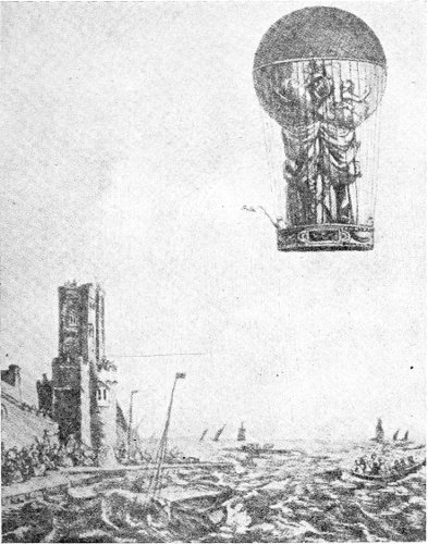
Pilatre de Rozier’s balloon.
The great danger from fire, however, led to the closer consideration of the hydrogen balloon of Professor Charles, who was building one of 30 feet diameter for the study of atmospheric phenomena. His 270 mastery of the subject is shown by the fact that his balloon was equipped with almost every device afterward in use by the most experienced aeronauts. He invented the valve at the top of the bag for allowing the escape of gas in landing, the open neck to permit expansion, the network of cords to support the car, the grapnel for anchoring, and the use of a small pilot balloon to test the air-currents before the ascension. He also devised a barometer by which he was able to measure the altitude reached by the pressure of the atmosphere.
To provide the hydrogen gas required he used the chemical method of pouring dilute sulphuric acid on iron filings. The process was so slow that it took continuous action for three days and three nights to secure the 14,000 cubic feet needed, but his balloon was finally ready on December 1, 1783. One of the brothers Robert accompanied Charles, and they travelled about 40 miles in a little less than 4 hours, alighting at Nesles. Here Robert landed and Charles continued the voyage alone. Neglecting to take on board ballast to replace the weight of M. Robert, Charles was carried to a great height, and suffered severely from cold and the difficulty of breathing in the highly rarefied air. He was obliged to open his 271 gas valve and descend after half an hour’s flight alone.
Blanchard, another French inventor, about this time constructed a balloon with the intention of being the first to cross the English Channel in the air. He took his balloon to Dover and with Dr. Jeffries, an American, started on January 7, 1785. His balloon was leaky and he had loaded it down with a lot of useless things in the way of oars, provisions, and other things. All of this material and the ballast had to be thrown overboard at the outset, and books and parts of the balloon followed. Even their clothing had to be thrown over to keep the balloon out of the sea, and at last, when Dr. Jeffries had determined to jump out to enable his friend to reach the shore, an upward current of wind caught them and with great difficulty they landed near Calais. The feat was highly lauded and a monument in marble was erected on the spot to perpetuate the record of the achievement.
De Rozier lost his life soon after in the effort to duplicate this trip across the Channel with his combination hydrogen and hot-air balloon. His idea seems to have been that he could preserve the buoyancy of his double balloon by heating up the air balloon at intervals. 272 273 Unfortunately, the exuding of the hydrogen as the balloons rose formed an explosive mixture with the air he was rising through, and it was drawn to his furnace, and an explosion took place which blew the entire apparatus into fragments at an altitude of over 1,000 feet.
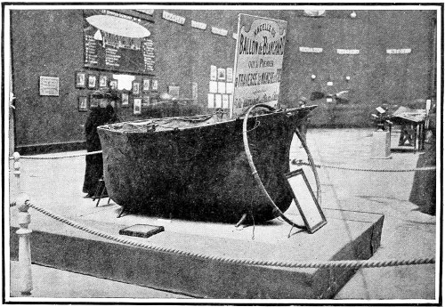
Car and hoop of the Blanchard balloon, the first to cross the English Channel.
Count Zambeccari, an Italian, attempted to improve the de Rozier method of firing a balloon by substituting a large alcohol lamp for the wood fire. In the first two trial trips he fell into the sea, but was rescued. On the third trip his balloon was swept into a tree, and the overturned lamp set it on fire. To escape being burned, he threw himself from the balloon and was killed by the fall.
The year before these feats on the Continent two notable balloon ascensions had taken place in England. On August 27, 1784, an aeronaut by the name of Tytler made the first balloon voyage within the boundaries of Great Britain. His balloon was of linen and varnished, and the record of his ascension indicates that he used hydrogen gas to inflate it. He soared to a great height, and descended safely.
A few weeks later, the Italian aeronaut Lunardi made his first ascent from London. The spectacle drew the King and his councillors from their deliberations, 274 and the balloon was watched until it disappeared. He landed in Standon, near Ware, where a stone was set to record the event. On October 12, he made his famous voyage from Edinburgh over the Firth of Forth to Ceres; a distance of 46 miles in 35 minutes, or at the rate of nearly 79 miles per hour; a speed rarely equalled by the swiftest railroad trains.
From this time on balloons multiplied rapidly and the ascents were too numerous for recording in these pages. The few which have been selected for mention are notable either for the great distances traversed, or for the speed with which the journeys were made. It should be borne in mind that the fastest method of land travel in the early part of the period covered was by stage coach; and the sailing ship was the only means of crossing the water. It is no wonder that often the people among whom the aeronauts landed on a balloon voyage refused to believe the statements made as to the distance they had come, and the marvellously short time it had taken. And even as compared with the most rapid transit of the present day, the speeds attained in many cases have never been equalled.
A remarkable English voyage was made in June, 275 1802, by the French aeronaut Garnerin and Captain Snowdon. They ascended from Chelsea Gardens and landed in Colchester, 60 miles distant, in 45 minutes: an average speed of 80 miles an hour.
On December 16, 1804, Garnerin ascended from the square in front of Notre Dame, Paris; passing over France and into Italy, sailing above St. Peter’s at Rome, and the Vatican, and descending into Lake Bracciano—a distance of 800 miles in 20 hours. This voyage was made as a part of the coronation ceremonies of Napoleon I. The balloon was afterwards hung up in a corridor of the Vatican.
On October 7, 1811, Sadler and Burcham voyaged from Birmingham to Boston (England), 112 miles in 1 hour 40 minutes, a speed of 67 miles per hour.
On November 17, 1836, Charles Green and Monck Mason started on a voyage in the great balloon of the Vauxhall Gardens. It was pear-shaped, 60 feet high and 50 feet in diameter, and held 85,000 cubic feet of gas. It was cut loose at half-past one in the afternoon, and in 3 hours had reached the English Channel, and in 1 hour more had crossed it, and was nearly over Calais. During the night it floated on over France in pitchy darkness and such intense cold that the oil was frozen. In the morning 276 277 the aeronauts descended a few miles from Weilburg, in the Duchy of Nassau, having travelled about 500 miles in 18 hours. At that date, by the fastest coaches the trip would have consumed three days. The balloon was rechristened “The Great Balloon of Nassau” by the enthusiastic citizens of Weilburg.
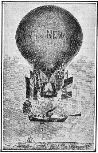
Prof. T. S. C. Lowe’s mammoth balloon “City of New York,” a feature of the year 1860, in which it made many short voyages in the vicinity of New York and Philadelphia.
In 1849, M. Arban crossed the Alps in a balloon, starting at Marseilles and landing at Turin—a distance of 400 miles in 8 hours. This remarkable record for so long a distance at a high speed has rarely been equalled. It was exceeded as to distance at the same speed by the American aeronaut, John Wise, in 1859.
One of the most famous balloons of recent times was the “Geant,” built by M. Nadar, in Paris, in 1853. The immense gas-bag was made of silk of the finest quality costing at that time about $1.30 a yard, and being made double, it required 22,000 yards. It had a capacity of 215,000 cubic feet of gas, and lifted 4½ tons. The car was 13 feet square, and had an upper deck which was open. On its first ascent it carried 15 passengers, including M. Nadar as captain, and the brothers Godard as lieutenants. A few weeks later this balloon was set free for a long-distance 278 journey, and 17 hours after it left Paris it landed at Nieuburg in Hanover, having traversed 750 miles, a part of the time at the speed of fully 90 miles per hour.
In July, 1859, John Wise, an American aeronaut, journeyed from St. Louis, Mo., to Henderson, N. Y., a distance of 950 miles in 19 hours. His average speed was 50 miles per hour. This record for duration at so high a rate of speed has never been exceeded.
During the siege of Paris in 1870, seventy-three balloons were sent out from that city carrying mail and dispatches. These were under Government direction, and receive notice in a subsequent chapter devoted to Military Aeronautics. One of these balloons is entitled to mention among those famous for rapid journeys, having travelled to the Zuyder Zee, a distance of 285 miles, in 3 hours—an average speed of 95 miles per hour. Another of these postal balloons belongs in the extreme long-distance class, having come down in Norway nearly 1,000 miles from Paris.
In July, 1897, the Arctic explorer Andrée started on his voyage to the Pole. As some of his instruments have been recently recovered from a wandering 279 band of Esquimaux, it is believed that a record of his voyage may yet be secured.
In the same year a balloon under the command of Godard ascended at Leipsic, and after a wandering journey in an irregular course, descended at Wilna. The distance travelled was estimated at 1,032 miles, but as balloon records are always based on the airline distance between the places of ascent and descent, this record has not been accepted as authoritative. The time consumed was 24¼ hours.
In 1899, Captain von Sigsfield, Captain Hildebrandt, and a companion started from Berlin in a wind so strong that it prevented the taking on of an adequate load of ballast. They rose into a gale, and in two hours were over Breslau, having made the distance at a speed of 92 miles per hour. In the grasp of the storm they continued their swift journey, landing finally high up in the snows of the Carpathian Alps in Austria. They were arrested by the local authorities as Russian spies, but succeeded in gaining their liberty by telegraphing to an official more closely in touch with the aeronautics of the day.
In 1900 there were several balloon voyages notable for their length. Jacques Balsan travelled from 280 281 Vincennes to Dantzig, 757 miles; Count de la Vaulx journeyed from Vincennes to Poland, 706 miles; Jacques Faure from Vincennes to Mamlity, 753 miles. In a subsequent voyage Jacques Balsan travelled from Vincennes to Rodom, in Russia, 843 miles, in 27½ hours.
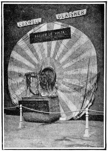
The balloon in which Coxwell and Glaisher made their famous ascent of 29,000 feet.
One of the longest balloon voyages on record in point of time consumed is that of Dr. Wegener of the Observatory at Lindenberg, in 1905. He remained in the air for 52¾ hours.
The longest voyage, as to distance, up to 1910, was that of Count de La Vaulx and Count Castillon de Saint Victor in 1906, in the balloon “Centaur.” This was a comparatively small balloon, having a capacity of only 55,000 cubic feet of gas. The start was made from Vincennes on October 9th, and the landing at Korostischeff, in Russia, on October 11th. The air-line distance travelled was 1,193 miles, in 35¾ hours. The balloon “Centaur” was afterward purchased by the Aero Club of America, and has made many voyages in this country.
The Federation Aeronautique Internationale, an association of the aeronauts of all nations, was founded in 1905. One of its functions is an annual balloon race for the International Challenge Cup, 282 presented to the association by James Gordon Bennett, to be an object for competition until won three times by some one competing national club.
The first contest took place in September, 1906, and was won by the American competitor, Lieut. Frank P. Lahm, with a voyage of 402 miles.
The second contest was from St. Louis, Mo., in 1907. There were three German, two French, one English, and three American competitors. The race was won by Oscar Erbslöh, one of the German competitors, with an air-line voyage of 872¼ miles, landing at Bradley Beach, N. J. Alfred Leblanc, now a prominent aviator, was second with a voyage of 867 miles, made in 44 hours. He also landed in New Jersey.
The third race started at Berlin in October, 1908, and was won by the Swiss balloon “Helvetia,” piloted by Colonel Schaeck, which landed in Norway after having been 74 hours in the air, and covering a journey of 750 miles. This broke the previous duration record made by Dr. Wegener in 1905.
The fourth contest began on October 3, 1909, from Zurich, Switzerland. There were seventeen competing balloons, and the race was won by E. W. Mix, 283 representing the Aero Club of America, with a voyage of 589 miles.
The fifth contest began at St. Louis, October 17, 1910. It was won by Alan P. Hawley and Augustus Post, with the “America II.” They travelled 1,355 miles in 46 hours, making a new world’s record for distance.
Among other notable voyages may be mentioned that of the “Fielding” in a race on July 4, 1908, from Chicago. The landing was made at West Shefford, Quebec, the distance travelled being 895 miles.
In November of the same year A. E. Gaudron, Captain Maitland, and C. C. Turner, made the longest voyage on record from England. They landed at Mateki Derevni, in Russia, having travelled 1,117 miles in 31½ hours. They were driven down to the ground by a severe snowstorm.
On December 31, 1908, M. Usuelli, in the balloon “Ruwenzori” left the Italian lakes and passed over the Alps at a height of 14,750 feet, landing in France. This feat was followed a few weeks later—February 9, 1909—by Oscar Erbslöh, who left St. Moritz with three passengers, crossing the Alps at an altitude of 19,000 feet, and landed at Budapest after 284 285 a voyage of 33 hours. Many voyages over and among the Alps have been made by Captain Spelterini, the Swiss aeronaut, and he has secured some of the most remarkable photographs of the mountain scenery in passing. In these voyages at such great altitudes it is necessary to carry cylinders of oxygen to provide a suitable air mixture for breathing. In one of his recent voyages Captain Spelterini had the good fortune to be carried almost over the summit of Mont Blanc. He ascended with three passengers at Chamounix, and landed at Lake Maggiore seven hours later, having reached the altitude of 18,700 feet, and travelled 93 miles.
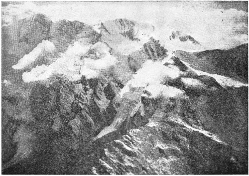
Photograph of the Alps from a balloon by Captain Spelterini.
In the United States there were several balloon races during the year 1909, the most important being the St. Louis Centennial race, beginning on October 4th. Ten balloons started. The race was won by S. von Phul, who covered the distance of 550 miles in 40 hours 40 minutes. Clifford B. Harmon and Augustus Post in the balloon “New York” made a new duration record for America of 48 hours 26 minutes. They also reached the highest altitude attained by an American balloon—24,200 feet.
On October 12th, in a race for the Lahm cup, A. Holland Forbes and Col. Max Fleischman won. 286 They left St. Louis, Mo., and landed 19 hours and 15 minutes later at Beach, Va., near Richmond, having travelled 697 miles.
In 1910, in the United States, a remarkable race, with thirteen competitors, started at Indianapolis. This was the elimination race for the International race on October 17th. It was won by Alan P. Hawley and Augustus Post in the balloon “America II.” They crossed the Alleghany Mountains at an elevation of about 20,000 feet, and landed at Warrenton, Va., after being 44 hours 30 minutes in the air; and descended only to escape being carried out over Chesapeake Bay.
In recent years the greatest height reached by a balloon was attained by the Italian aeronauts Piacenza and Mina in the “Albatross,” on August 9, 1909. They went up from Turin to the altitude of 30,350 feet. The world’s height record rests with Professors Berson and Suring of Berlin, who on July 31, 1901, reached 35,500 feet. The record of 37,000 feet claimed by Glaisher and Coxwell in their ascension on September 5, 1862, has been rejected as not authentic for several discrepancies in their observations, and on the ground that their instruments were not of the highest reliability. As they carried 287 no oxygen, and reported that for a time they were both unconscious, it is estimated that the highest point they could have reached under the conditions was less than 31,000 feet.
The greatest speed ever recorded for any balloon voyage was that of Captain von Sigsfield and Dr. Linke in their fatal journey from Berlin to Antwerp, during which the velocity of 125 miles per hour was recorded.
Ballooning as a sport has a fascination all its own. There is much of the spice of adventure in the fact that one’s destiny is quite unknown. Floating with the wind, there is no consciousness of motion. Though the wind may be travelling at great speed, the balloon seems to be in a complete calm. A lady passenger, writing of a recent trip, has thus described her experience:—“The world continues slowly to unroll itself in ever-varying but ever-beautiful panorama—patchwork fields, shimmering silver streaks, toy box churches and houses, and white roads like the joints of a jig-saw puzzle. And presently cotton-wool billows come creeping up, with purple shadows and fleecy outlines and prismatic rainbow effects. Sometimes they invade the car, and shroud it for a while in clinging warm white wreaths, and anon they fall 288 below and shut out the world with a glorious curtain, and we are all alone in perfect silence, in perfect peace, and in a realm made for us alone.
“And so the happy, restful hours go smoothly by, until the earth has had enough of it, and rising up more or less rapidly to invade our solitude, hits the bottom of our basket, and we step out, or maybe roll out, into every-day existence a hundred miles away.”
The perfect smoothness of motion, the absolute quiet, and the absence of distracting apparatus combine to render balloon voyaging the most delightful mode of transit from place to place. Some of the most fascinating bits of descriptive writing are those of aeronauts. The following quotation from the report of Capt. A. Hildebrandt, of the balloon corps of the Prussian army, will show that although his expeditions were wholly scientific, he was far from indifferent to the sublimer influences of nature by which he was often surrounded.
In his account of the journey from Berlin to Markaryd, in Sweden, with Professor Berson as a companion aeronaut, he says: “The view over Rügen and the chalk cliffs of Stubbenkammer and Arkona was splendid: the atmosphere was perfectly clear. On the horizon we could see the coasts of Sweden and 289 Denmark, looking almost like a thin mist; east and west there was nothing but the open sea.
“About 3:15 the balloon was in the middle of the Baltic; right in the distance we could just see Rügen and Sweden. The setting of the sun at 4 P.M. was a truly magnificent spectacle. At a height of 5,250 feet, in a perfectly clear atmosphere, the effect was superb. The blaze of color was dimly reflected in the east by streaks of a bluish-green. I have seen sunsets over France at heights of 10,000 feet, with the Alps, the Juras, and the Vosges Mountains in the distance; but this was quite as fine.
“The sunsets seen by the mountaineer or the sailor are doubtless, magnificent; but I hardly think the spectacle can be finer than that spread out before the gaze of the balloonist. The impression is increased by the absolute stillness which prevails; no sound of any kind is heard.
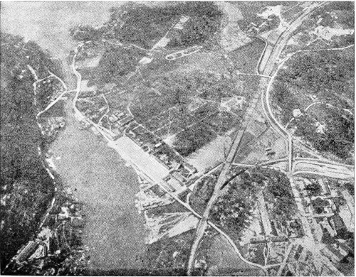
Landscape as seen from a balloon at an altitude of 3,000 feet.
“As soon as the sun went down, it was necessary to throw out some ballast, owing to the decrease of temperature.... We reached the Swedish coast about 5 o’clock, and passed over Trelleborg at a height of 2,000 feet. The question then arose whether to land, or to continue through the night. Although it was well past sunset, there was sufficient 290 291 light in consequence of the snow to see our way to the ground, and to land quite easily.... However, we wanted to do more meteorological work, and it was thought that there was still sufficient ballast to take us up to a much greater height. We therefore proposed to continue for another sixteen hours during the night, in spite of the cold.... Malmö was therefore passed on the left, and the university town of Lund on the right. After this the map was of no further use, as it was quite dark and we had no lamp. The whole outlook was like a transformation scene. Floods of light rose up from Trelleborg, Malmö, Copenhagen, Landskrona, Lund, Elsinore, and Helsingborg, while the little towns beneath our feet sparkled with many lights. We were now at a height of more than 10,000 feet, and consequently all these places were within sight. The glistening effect of the snow was heightened by the blaze which poured from the lighthouses along the coasts of Sweden and Denmark. The sight was as wonderful as that of the sunset, though of a totally different nature.”
Captain Hildebrandt’s account of the end of this voyage illustrates the spice of adventure which is likely to be encountered when the balloon comes down in a strange country. It has its hint also of the hardships 292 for which the venturesome aeronaut has to be prepared. He says:—
“Sooner or later the balloon would have been at the mercy of the waves. The valve was opened, and the balloon descended through the thick clouds. We could see nothing, but the little jerks showed us that the guide-rope was touching the ground. In a few seconds we saw the ground, and learned that we were descending into a forest which enclosed a number of small lakes. At once more ballast was thrown out, and we skimmed along over the tops of the trees. Soon we crossed a big lake, and saw a place that seemed suitable for a descent. The valve was then opened, both of us gave a tug at the ripping cord, and after a few bumps we found ourselves on the ground. We had come down in deep snow on the side of a wood, about 14 miles from the railway station at Markaryd.
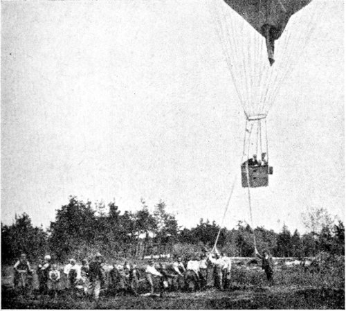
Making a landing with the aid of bystanders to pull down upon the trail-rope and a holding rope.
“We packed up our instruments, and began to look out for a cottage; but this is not always an easy task in the dead of night in a foreign country. However, in a quarter of an hour we found a farm, and succeeded in rousing the inmates. A much more difficult job was to influence them to open their front door to two men who talked some sort of double 293 Dutch, and who suddenly appeared at a farmyard miles off the highway in the middle of the night and demanded admittance. Berson can talk in six languages, but unfortunately Swedish is not one of them. He begged in the most humble way for shelter ... and at the end of three-quarters of an hour the farmer opened the door. We showed him some 294 pictures of a balloon we had with us, and then they began to understand the situation. We were then received with truly Swedish hospitality, and provided with supper. They even proposed to let us have their beds; but this we naturally declined with many thanks.... The yard contained hens, pigs, cows, and sheep; but an empty corner was found, which was well packed with straw, and served as a couch for our tired limbs. We covered ourselves with our great-coats, and tried to sleep. But the temperature was 10° Fahr., and as the place was only an outhouse of boards roughly nailed together, and the wind whistling through the cracks and crevices, we were not sorry when the daylight came.”
Lest the possibility of accident to travellers by balloon be judged greater than it really is, it may be well to state that records collected in Germany in 1906 showed that in 2,061 ascents in which 7,570 persons participated, only 36 were injured—or but 1 out of 210. Since that time, while the balloon itself has remained practically unchanged, better knowledge of atmospheric conditions has aided in creating an even more favorable record for recent years.
That the day of ordinary ballooning has not been dimmed by the advent of the airship and the aeroplane 295 is evidenced by the recently made estimate that not less than 800 spherical balloons are in constant use almost daily in one part or another of Christendom. And it seems entirely reasonable to predict that with a better comprehension of the movements of air-currents—to which special knowledge the scientific world is now applying its investigations as never before—they will come a great increase of interest in simple ballooning as a recreation. 296
Elongation of gas-bag—Brisson—Meusnier—Air-ballonnets—Scott—Giffard—Haenlein—Tissandier—Renard and Krebs—Schwartz—Santos-Dumont—Von Zeppelin—Roze—Severo—Bradsky-Leboun—The Lebaudy dirigible—Zeppelin II—Parseval I—Unequal wind pressures—Zeppelin III—Nulli Secundus—La Patrie—Ville-de-Paris—Zeppelin IV—Gross I—Parseval II—Clement-Bayard I—Ricardoni’s airship—Gross II—The new Zeppelin II—La Republique—The German fleet of dirigibles—Parseval V—The Deutschland—The Erbslöh—Gross III—Zeppelin VI—The America—Clement-Bayard III—The Capazza lenticular dirigible.
The dirigible balloon, or airship, is built on the same general principles as the ordinary balloon—that is, with the envelope to contain the lifting gas, the car to carry the load, and the suspending cordage—but to this is added some form of propelling power to enable it to make headway against the wind, and a rudder for steering it.
Almost from the very beginning of ballooning, some method of directing the balloon to a pre-determined goal had been sought by inventors. Drifting at the fickle pleasure of the prevailing wind 297 did not accord with man’s desire for authority and control.
The first step in this direction was the change from the spherical form of the gas-bag to an elongated shape, the round form having an inclination to turn round and round in the air while floating, and having no bow-and-stern structure upon which steering devices could operate. The first known proposal in this direction was made by Brisson, a French scientist, who suggested building the gas-bag in the shape of a horizontal cylinder with conical ends, its length to be five or six times its diameter. His idea for its propulsion was the employment of large-bladed oars, but he rightly doubted whether human strength would prove sufficient to work these rapidly enough to give independent motion to the airship.
About the same time another French inventor had actually built a balloon with a gas-bag shaped like an egg and placed horizontally with the blunt end foremost. The reduction in the resistance of the air to this form was so marked that the elongated gas-bag quickly displaced the former spherical shape. This balloon was held back from travelling at the full speed of the wind by the clever device of a rope dragging on the ground; and by a sail rigged so as 298 to act on the wind which blew past the retarded balloon, the navigator was able to steer it within certain limits. It was the first dirigible balloon.
In the same year the brothers Robert, of Paris, built an airship for the Duke of Chartres, under the direction of General Meusnier, a French officer of engineers. It was cylindrical, with hemispherical ends, 52 feet long and 32 feet in diameter, and contained 30,000 cubic feet of gas. The gas-bag was made double to prevent the escape of the hydrogen, which had proved very troublesome in previous balloons, and it was provided with a spherical air balloon inside of the gas-bag, which device was expected to preserve the form of the balloon unchanged by expanding or contracting, according to the rising or falling of the airship. When the ascension was made on July 6, 1784, the air-balloon stuck fast in the neck of the gas-bag, and so prevented the escape of gas as the hydrogen expanded in the increasing altitude. The gas-bag would have burst had not the Duke drawn his sword and slashed a vent for the imprisoned gas. The airship came safely to earth.
It was General Meusnier who first suggested the interior ballonnet of air to preserve the tense outline of the form of the airship, and the elliptical form for 299 the gas-bag was another of his inventions. In the building of the airship of the Duke de Chartres he made the further suggestion that the space between the two envelopes be filled with air, and so connected with the air-pumps that it could be inflated or deflated at will. For the motive power he designed three screw propellers of one blade each, to be turned unceasingly by a crew of eighty men.
Meusnier was killed in battle in 1793, and aeronautics lost its most able developer at that era.
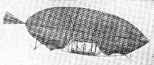
The Scott airship, showing the forward “pocket” partially drawn in.
In 1789, Baron Scott, an officer in the French army, devised a fish-shaped airship with two outside balloon-shaped “pockets” which could be forcibly drawn into the body of the airship to increase its density, and thus cause its descent.
It began to be realized that no adequate power existed by which balloons could be propelled against 300 even light winds to such a degree that they were really controllable, and balloon ascensions came to be merely an adjunct of the exhibit of the travelling showman. For this reason the early part of the nineteenth century seems barren of aeronautical incident as compared with the latter part of the preceding century.
In 1848, Hugh Bell, an Englishman, built a cylindrical airship with convex pointed ends. It was 55 feet long and 21 feet in diameter. It had a keel-shaped framework of tubes to which the long narrow car was attached, and there was a screw propeller on each side, to be worked by hand, and a rudder to steer with. It failed to work.
In 1852, however, a new era opened for the airship. Henry Giffard, of Paris, the inventor of the world-famed injector for steam boilers, built an elliptical gas-bag with cigar-shaped ends, 144 feet long, and 40 feet in diameter, having a cubic content of 88,000 cubic feet. The car was suspended from a rod 66 feet long which hung from the net covering the gas-bag. It was equipped with a 3-horse-power steam engine which turned a two-bladed screw propeller 11 feet in diameter, at the rate of 110 revolutions per minute. Coke was used for fuel. The 301 steering was done with a triangular rudder-sail. Upon trial on September 24, 1852, the airship proved a success, travelling at the rate of nearly 6 miles an hour.
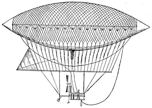
The first Giffard dirigible.
Giffard built a second airship in 1855, of a much more elongated shape—235 feet long and 33 feet in diameter. He used the same engine which propelled his first ship. After a successful trial trip, when about to land, the gas-bag unaccountably turned up on end, allowing the net and car to slide off, and, rising slightly in the air, burst. Giffard and his companion escaped unhurt.
Giffard afterward built the large captive balloon for the London Exhibition in 1868, and the still 302 larger one for the Paris Exposition in 1878. He designed a large airship to be fitted with two boilers and a powerful steam-engine, but became blind, and died in 1882.
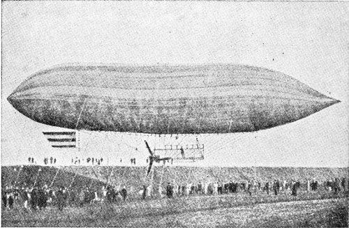
The Haenlein airship inflated with coal gas and driven by a gas-engine.
In 1865, Paul Haenlein devised a cigar-shaped airship to be inflated with coal gas. It was to be propelled by a screw at the front to be driven by a gas-engine drawing its fuel from the gas in the body of the ship. An interior air-bag was to be expanded as the gas was consumed, to keep the shape intact. A second propeller revolving horizontally was intended to raise or lower the ship in the air. 303
It was not until 1872 that he finally secured the building of an airship, at Vienna, after his plans. It was 164 feet long, and 30 feet in diameter. The form of the gas-bag was that described by the keel of a ship rotated around the centre line of its deck as an axis. The engine was of the Lenoir type, with four horizontal cylinders, developing about 6 horse-power, and turned a propeller about 15 feet in diameter at the rate of 40 revolutions per minute. The low lifting power of the coal gas with which it was inflated caused it to float quite near the ground. With a consumption of 250 cubic feet of gas per hour, it travelled at a speed of ten miles an hour. The lack of funds seems to have prevented further experiments with an invention which was at least very promising.
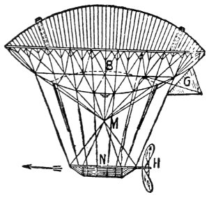
Sketch of the De Lome airship.
In the same year a dirigible balloon built by Dupuy de Lome for use by the French Government during the siege of Paris, was given a trial. It was driven by a screw propeller turned by eight men, and although it was 118 feet long, and 49 feet in diameter, it made as good a speed record 304 as Giffard’s steam-driven airship—six miles an hour.
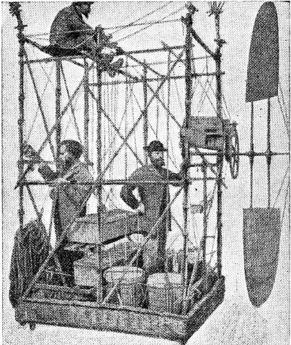
Car of the Tissandier dirigible; driven by electricity.
In 1881, the brothers Albert and Gaston Tissandier exhibited at the Electrical Exhibition in Paris a model of an electrically driven airship, originally designed to establish communication with Paris during the siege of the Franco-Prussian War. In 1883, the airship built after this model was tried. It was 92 feet long, and 30 feet at its largest diameter. The motive power was a Siemens motor run by 24 305 bichromate cells of 17 lbs. each. At full speed the motor made 180 revolutions per minute, developing 1½ horse-power. The pull was 26 lbs. The propeller was 9 feet in diameter, and a speed of a little more than 6 miles an hour was attained.

Sketch of the Renard and Krebs airship La France, driven by a storage battery.
In 1884, two French army engineers, Renard and Krebs, built an airship, the now historic La France, with the shape of a submarine torpedo. It was 165 feet long and about 27 feet in diameter at the largest part. It had a gas content of 66,000 cubic feet. A 9 horse-power Gramme electric motor was installed, driven by a storage battery. This operated the screw propeller 20 feet in diameter, which was placed at the forward end of the long car. The trial was made on the 9th of August, and was a complete success. The ship was sailed with the wind for about 2½ miles, and then turned about and 306 made its way back against the wind till it stood directly over its starting point, and was drawn down to the ground by its anchor ropes. The trip of about 5 miles was made in 23 minutes. In seven voyages undertaken the airship was steered back safely to its starting point five times.
This first airship which really deserved the name marked an era in the development of this type of aircraft. In view of its complete success it is astonishing that nothing further was done in this line in France for fifteen years, when Santos-Dumont began his series of record-making flights. Within this period, however, the gasoline motor had been adapted to the needs of the automobile, and thus a new and light-weight engine, suitable in every respect, had been placed within the reach of aeronauts.
In the meantime, a new idea had been brought to the stage of actual trial. In 1893, in St. Petersburg, David Schwartz built a rigid airship, the gas receptacle of which was sheet aluminum. It was braced by aluminum tubes, but while being inflated the interior work was so badly broken that it was abandoned.
Schwartz made a second attempt in Berlin in 1897. The airship was safely inflated, and managed 307 to hold its position against a wind blowing 17 miles an hour, but could not make headway against it. After the gas had been withdrawn, and before it could be put under shelter, a severe windstorm damaged it, and the mob of spectators speedily demolished it in the craze for souvenirs of the occasion.
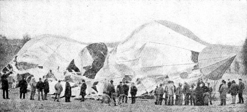
Wreck of the Schwartz aluminum airship, at Berlin, in 1897.
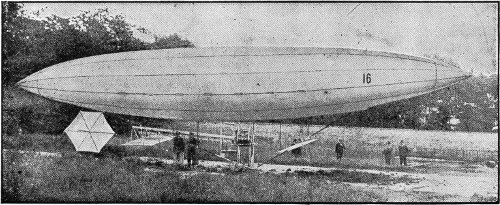
The type of the earlier Santos-Dumont dirigibles. This shape showed a tendency to “buckle,” or double up in the middle like a jackknife. To avoid this the later Santos-Dumonts were of much larger proportional diameter amidships.
In 1898, the young Brazilian, Santos-Dumont, came to Paris imbued with aeronautic zeal, and determined to build a dirigible balloon that would surpass the former achievements of Giffard and Renard, which he felt confident were but hints of what might be accomplished by that type of airship. He began the construction of the series of dirigible balloons which eventually numbered 12, each successive one being an improvement on the preceding. He 308 309 made use of the air-bag suggested by Meusnier for the balloon of the Duke of Chartres in 1784, although in an original way, at first using a pneumatic pump to inflate it, and later a rotatory fan. Neither prevented the gas-bag from “buckling” and coming down with consequences more or less serious to the airship—but Santos-Dumont himself always escaped injury. His own record of his voyages in his book, My Air-Ships, gives a more detailed account of his contrivances and inventions than can be permitted here. If Santos-Dumont did not greatly surpass his predecessors, he is at least to be credited with an enthusiasm 310 which aroused the interest of the whole world in the problems of aeronautics; and his later achievements in the building and flying of aeroplanes give him a unique place in the history of man’s conquest of the air.
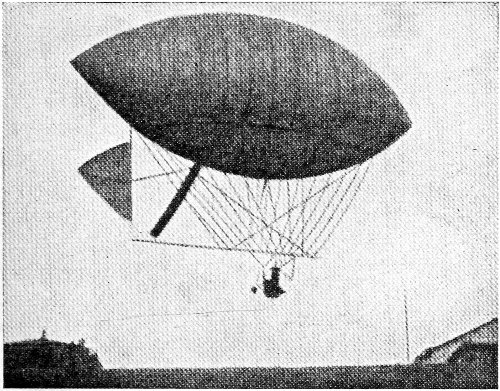
Type of the later Santos-Dumont’s dirigibles.
In 1900, Count von Zeppelin’s great airship, which had been building for nearly two years, was ready for trial. It had the form of a prism of 24 sides, with the ends arching to a blunt point. It was 420 feet long, and 38 feet in diameter. The structure was rigid, of aluminum lattice work, divided into 17 compartments, each of which had a separate gas-bag shaped to fit its compartment. Over all was an outer envelope of linen and silk treated with pegamoid. A triangular keel of aluminum lattice strengthened the whole, and there were two cars of aluminum attached to the keel. Each car held a 16 horse-power Daimler gasoline motor, operating two four-bladed screw propellers which were rigidly connected with the frame of the ship a little below the level of its axis. A sliding weight was run to either end of the keel as might be required to depress the head or tail, in order to rise or fall in the air. The cars were in the shape of boats, and the ship was built in a floating shed on the Lake of Constance 311 312 near Friedrichshafen. At the trial the airship was floated out on the lake, the car-boats resting on the water. Several accidents happened, so that though the ship got up into the air it could not be managed, and was brought down to the water again without injury. In a second attempt a speed of 20 miles an hour was attained. The construction was found to be not strong enough for the great length of the body, the envelope of the balloon was not sufficiently gas tight, and the engines were not powerful enough. But few trips were made in it, and they were short. The Count set himself to work to raise money to build another ship, which he did five years later.
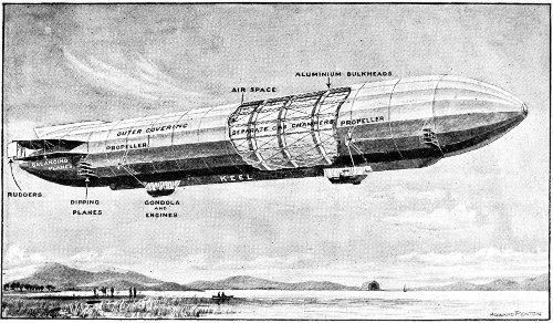
View of the Zeppelin I, with portion of the aluminum shell and external fabric removed to show the internal framing and separate balloons. In the distance is shown the great balloon shed.
In 1901, an inventor named Roze built an airship in Colombo, having two gas envelopes with the engines and car placed between them. He expected to do away with the rolling and pitching of single airships by the double form, but the ship did not work satisfactorily, ascending to barely 50 feet.
In 1902, Augusto Severo, a Brazilian, arranged an airship with the propelling screws at the axis of the gas-bag, one at each end of the ship. Instead of a rudder, he provided two small propellers to work in a vertical plane and swing the ship sideways. 313 Soon after ascending it was noticed that the propellers were not working properly, and a few minutes later the car was seen to be in flames and the balloon exploded. Severo and his companion Sache were killed, falling 1,300 feet.
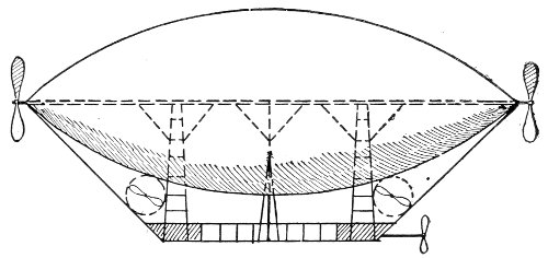
Sketch of the Severo airship, showing arrangement of the driving propellers on the axis of the gas-bag, and the steering propellers.
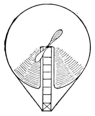
End view of Severo’s airship, showing the longitudinal division of the gas-bag to allow the driving shaft of the propellers to be placed at the axis of the balloon.
In the same year Baron Bradsky-Leboun built an airship with partitions in the gas-bag which was just large enough to counterbalance the weight of the ship and its operators. It was lifted or lowered by a propeller working horizontally. Another propeller drove the ship forward. Through some lack of stability the car turned over, throwing out the two aeronauts, who fell 300 feet and were instantly killed. 314
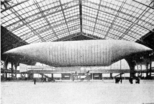
The first Lebaudy airship.
In 1902, a dirigible balloon was built for the brothers Lebaudy by the engineer Juillot and the aeronaut Surcouf. The gas envelope was made cigar-shaped and fastened rigidly to a rigid elliptical keel-shaped floor 70 feet long and 19 feet wide, made of steel tubes—the object being to prevent rolling and pitching. It was provided with both horizontal and vertical rudders. A 35 horse-power Daimler-Mercedes motor was used to turn two twin-bladed screws, each of 9 feet in diameter. Between the 25th of October, 1902, and the 21st of November, 315 1903, 33 experimental voyages were made, the longest being 61 miles in 2 hours and 46 minutes; 38.7 miles in 1 hour and 41 minutes; 23 miles in 1 hour and 36 minutes.
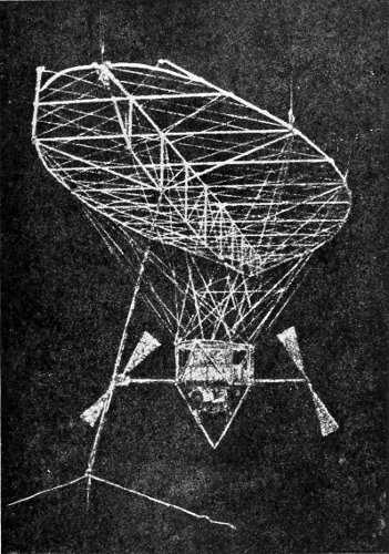
Framing of the floor and keel of the Lebaudy airship.
In 1904 this ship was rebuilt. It was lengthened to 190 feet and the rear end rounded off. Its capacity 316 was increased to 94,000 cubic feet, and a new covering of the yellow calico which had worked so well on the first model was used on the new one. It was coated with rubber both on the outside and inside. The interior air-bag was increased in size to 17,650 cubic feet, and partitioned into three compartments. During 1904 and 1905 30 voyages were made, carrying in all 195 passengers.
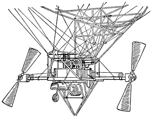
The car and propellers of the Lebaudy airship.
The success of this airship led to a series of trials under the direction of the French army, and in all of these trials it proved satisfactory. After the 76th successful voyage it was retired for the winter of 1905-6. 317
In November, 1905, the rebuilt Zeppelin airship was put upon trial. While superior to the first one, it met with serious accident, and was completely wrecked by a windstorm in January, 1906.
In May, 1906, Major von Parseval’s non-rigid airship passed through its first trials successfully. This airship may be packed into small compass for transportation, and is especially adapted for military use. In plan it is slightly different from previous types, having two air-bags, one in each end of the envelope, and the front end is hemispherical instead of pointed.
As the airship is designed to force its way through the air, instead of floating placidly in it, it is evident that it must have a certain tenseness of outline in order to retain its shape, and resist being doubled up by the resistance it encounters. It is estimated that the average velocity of the wind at the elevation at which the airship sails is 18 miles per hour. If the speed of the ship is to be 20 miles per hour, as related to stations on the ground, and if it is obliged to sail against the wind, it is plain that the wind pressure which it is compelled to meet is 38 miles per hour—a gale of no mean proportions. When the large expanse of the great gas-bags is taken into consideration, 318 it is evident that ordinary balloon construction is not sufficient.
Attempts have been made to meet the outside pressure from the wind and air-resistance by producing mechanically a counter-pressure from the inside. Air-bags are placed inside the cavity of the gas-bag, usually one near each end of the airship, and these are inflated by pumping air into them under pressure. In this way an outward pressure of as much as 7 lbs. to the square foot may be produced, equivalent to the resistance of air at a speed (either of the wind, or of the airship, or of both combined) of 48 miles per hour. It is evident, however, that the pressure upon the front end of an airship making headway against a strong wind will be much greater than the pressure at the rear end, or even than that amidships. It was this uneven pressure upon the outside of the gas-bag that doubled up the first two airships of Santos-Dumont, and led him to increase the proportional girth at the amidship section in his later dirigibles. The great difficulty of adjusting these varying pressures warrants the adherence of Count von Zeppelin to his design with the rigid structure and metallic sheathing.
The loss of the second Zeppelin airship so discouraged 319 320 its designer that he decided to withdraw from further aeronautical work. But the German Government prevailed on him to continue, and by October, 1906, he had the Zeppelin III in the air. This airship was larger than Zeppelin II in both length and diameter, and held 135,000 cubic feet more of gas. The motive power was supplied by two gasoline motors, each of 85 horse-power. The gas envelope had 16 sides, instead of 24, as in the earlier ship. At its trial the Zeppelin III proved highly successful. It made a trip of 69 miles, with 11 passengers, in 2¼ hours—a speed of about 30 miles an hour.
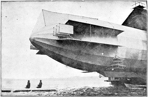
The Zeppelin III backing out of the floating shed at Friedrichshafen. The illustration shows the added fin at the top, the rudders, dipping planes, and balancing planes.
The German Government now made an offer of $500,000 for an airship which would remain continuously in the air for 24 hours, and be able to land safely. Count von Zeppelin immediately began work upon his No. IV, in the effort to meet these requirements, in the meantime continuing trips with No. III. The most remarkable of these trips was made in September, 1907, a journey of 211 miles in 8 hours.
In October, 1907, the English airship “Nulli Secundus” was given its first trial. The gas envelope had been made of goldbeater’s skins, which are considered 321 impermeable to the contained gas, but are very expensive. This airship was of the non-rigid type. It made the trip from Aldershot to London, a distance of 50 miles, in 3½ hours—an apparent speed of 14 miles per hour, lacking information as to the aid or hindrance of the prevailing wind. Several other trials were made, but with small success.
The offer of the German Government had stimulated other German builders besides Count von Zeppelin, and on October 28, 1907, the Parseval I, which had been improved, and the new Gross dirigible, competed for the government prize, at Berlin. The Parseval kept afloat for 6½ hours, and the Gross for 8¼ hours.
Meanwhile, in France, the Lebaudys had been building a new airship which was named “La Patrie.” It was 197 feet long and 34 feet in diameter. In a trial for altitude it was driven to an elevation of 4,300 feet. On November 23, 1907, the “Patrie” set out from Paris for Verdun, a distance of 146 miles. The journey was made in 6¾ hours, at an average speed of 25 miles per hour, and the fuel carried was sufficient to have continued the journey 50 miles further. Soon after reaching Verdun a severe gale tore the airship away from the regiment 322 of soldiers detailed to assist the anchors in holding it down, and it disappeared into the clouds. It is known to have passed over England, for parts of its machinery were picked up at several points, and some days later the gas-bag was seen floating in the North Sea.
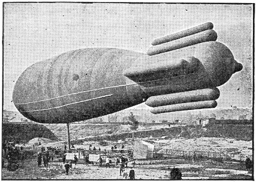
The “Ville-de-Paris” of M. de la Meurthe.
Following close upon the ill-fated “Patrie” came the “Ville-de-Paris,” a dirigible which had been built by Surcouf for M. Henri Deutsch de la Meurthe, an eminent patron of aeronautic experiments. In size this airship was almost identical with the lost “Patrie,” but it was quite different in appearance. It did not have the flat framework at the bottom of the gas envelope, but was entirely round in section, and the long car was suspended below. 323 At the rear the gas-bag was contracted to a cylindrical form, and four groups of two ballonnets each were attached to act as stabilizers. It was offered by M. de la Meurthe to the French Government to take the place of the “Patrie” in the army manœuvres at Verdun, and on January 15, 1908, made the trip thither from Paris in about 7 hours. It was found that the ballonnets exerted considerable drag upon the ship.
In June, 1908, the great “Zeppelin IV” was completed and given its preliminary trials, and on July 1 it started on its first long journey. Leaving Friedrichshafen, its route was along the northerly shore of Lake Constance nearly to Schaffhausen, then southward to and around Lake Lucerne, thence northward to Zurich, thence eastward to Lake Constance, and to its shed at Friedrichshafen. The distance traversed was 236 miles, and the time consumed 12 hours. This voyage without a single mishap aroused the greatest enthusiasm among the German people. After several short flights, during which the King of Württemberg, the Queen, and some of the royal princes were passengers, the Zeppelin IV set out on August 4 to win the Government reward by making the 24-hour flight. Sailing eastward 324 from Friedrichshafen it passed over Basle, then turning northward it followed the valley of the Rhine, passing over Strasburg and Mannheim, and had nearly reached Mayence when a slight accident necessitated a landing. Repairs were made, and the journey resumed after nightfall. Mayence was reached at 11 P. M., and the return trip begun. When passing over Stuttgart, at 6 A. M., a leak was discovered, and a landing was made at Echterdingen, a few miles farther on. Here, while repairs were being made, a squall struck the airship and bumped it heavily on the ground. Some gasoline was spilled, in some unknown way, which caught fire, and in a few moments the great balloon was totally destroyed. It had been in continuous flight 11 hours up to the time of the first landing, and altogether 20¾ hours, and had travelled 258 miles.
The German people immediately started a public subscription to provide Count von Zeppelin with the funds needed to build another airship, and in a few days the sum of $1,500,000 was raised and turned over to the unfortunate inventor. The “Zeppelin III” was taken in hand, and lengthened, and more powerful engines installed.
The “Gross II” was ready to make its attempt for 325 326 the Government prize on September 11, 1908. It sailed from Tegel to Magdeburg and back to Tegel, a distance of 176 miles, in 13 hours, without landing.
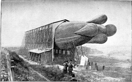
The Clement-Bayard dirigible entering its shed.
Four days later the “Parseval II” made a trip between the same points in 11½ hours, but cut the distance travelled down to 157 miles. In October, the “Parseval II” was sent up for an altitude test, and rose to a height of 5,000 feet above Tegel, hovering over the city for upward of an hour.
During 1908, an airship designed by M. Clement, the noted motor-car builder, was being constructed in France. It made its first voyage on October 29, carrying seven passengers from Sartrouville to Paris and back, at a speed of from 25 to 30 miles per hour. The illustration gives a very good idea of the peculiar ballonnets attached to the rear end of the gas envelope. These ballonnets open into the large gas-bag, and are practically a part of it.
In Italy a remarkable dirigible has been built by Captain Ricaldoni, for military purposes. It has the form of a fish, blunt forward, and tapering straight away to the rear. It has a large finlike surface on the under side of the gas-bag toward the rear. Its performances show that its efficiency as 327 328 compared with its motive power is larger than any other dirigible in commission.
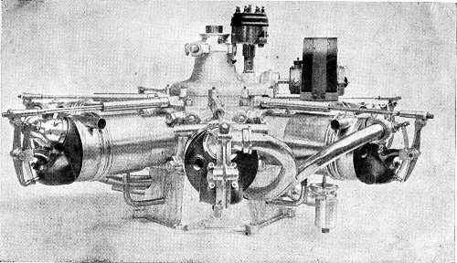
Engine of the Clement-Bayard dirigible; 7-cylinder; 55 horse-power; weighing only 155 pounds.
In May, 1909, the rebuilt “Zeppelin III,” now rechristened “Zeppelin II,” after many successful short flights was prepared for the Government trial. On May 29, 1909, with a crew of six men, Count von Zeppelin started from Friedrichshafen for Berlin, 360 miles away. The great ship passed over Ulm, Nuremburg, Bayreuth, and Leipzig; and here it encountered so strong a head wind from the north, that it was decided to turn about at Bitterfeld and return to Friedrichshafen. The distance travelled had been nearly 300 miles in 21 hours. The course followed was quite irregular, and took the ship over Wurtzburg, and by a wide detour to Heilbron and Stuttgart. The supply of gasoline running low, it was decided to land at Goeppingen, where more could be obtained. It was raining heavily, and through some mistake in steering, or some sudden veering of the wind, the prow of the great dirigible came into collision with a tree upon the hillside. The envelope was badly torn, and a part of the aluminum inner structure wrecked. However, the mechanics on board were able to make such repairs that the ship was able to resume the voyage the next day, 329 330 and made port without further mishap. The vessel having been 38 hours in the air at the time of the accident, so much of the Government’s stipulations had been complied with. But it had not succeeded in landing safely. Nevertheless it was accepted by the Government. The entire journey has been variously estimated at from 680 to 900 miles, either figure being a record for dirigibles.
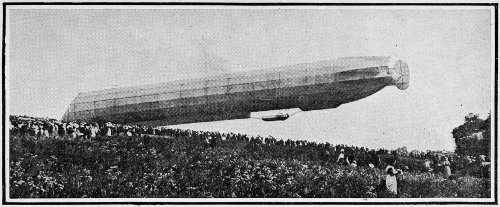
Accident to the new “Zeppelin II” at Goeppingen. The damage was repaired and the airship continued its voyage the next day.
On August 4, the dirigible “Gross II” made a voyage from Berlin to Apolda, and returned; a distance of 290 miles in 16 hours. This airship also was accepted by the German Government and added to its fleet.
In August, the Zeppelin II was successfully sailed to Berlin, where Count von Zeppelin was welcomed by an immense and enthusiastic multitude of his countrymen, including the Emperor and the royal family.
On September 26, the new French dirigible, “La Republique,” built on the model of the successful Lebaudy airships, met with an accident while in the air. A blade of one of the propellers broke and slashed into the envelope. The ship fell from a height of 6,000 feet, and its crew of four men lost their lives. 331
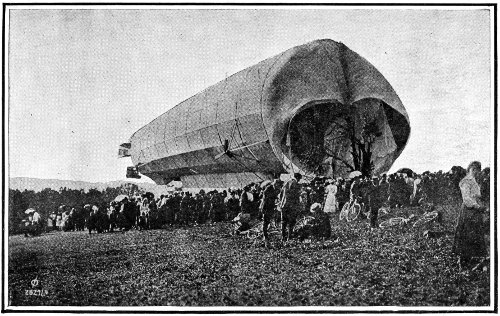
View of the damaged Zeppelin from the front, showing the tree against which it collided. 332
On April 22, 1910, a fleet of German dirigibles, comprising the “Zeppelin II,” the “Gross II,” and the “Parseval I,” sailed from Cologne to Hamburg, where they were reviewed by Emperor William. A strong wind having arisen, the “Gross II,” which is of the semi-rigid type, was deflated, and shipped back to Cologne by rail. The non-rigid “Parseval” made the return flight in safety. The rigid “Zeppelin II” started on the return voyage, but was compelled to descend at Limburg, where it was moored. The wind increasing, it was forced away, and finally was driven to the ground at Weilburg and demolished.
In May, 1910, the “Parseval V,” the smallest dirigible so far constructed, being but 90 feet in length, was put upon its trial trip. It made a circular voyage of 80 miles in 4 hours.
For several months a great Zeppelin passenger dirigible had been building by a stock company financed by German capital, under the direction of the dauntless Count von Zeppelin. It was 490 feet long, with a capacity of 666,900 cubic feet. A passenger cabin was built with ¼-inch mahogany veneer upon a framework of aluminum, the inside being decorated with panels of rosewood inlaid with 333 mother-of-pearl. The seats were wicker chairs, and the window openings had no glass. It was christened the “Deutschland.”
After many days waiting for propitious weather the first “air-liner” set sail on June 22, 1910, from Friedrichshafen for Düsseldorf, carrying 20 passengers who had paid $50 each for their passage. In addition there were 13 other persons on board.
The start was made at three o’clock in the morning, and the course laid was up the valley of the Rhine, as far as Cologne. Düsseldorf was reached at three o’clock in the afternoon, the airline distance of 300 miles having been covered in 9 hours of actual sailing. From Mannheim to Düsseldorf, favored by the wind, the great ship reached the speed of 50 miles per hour, for this part of the trip, outstripping the fastest express trains which consume 6 hours in the winding track up the valley.
The next morning the “Deutschland” left Düsseldorf on an excursion trip, carrying several ladies among its passengers. The voyage was in every way a great success, and public enthusiasm was widespread.
On June 29, a test trip was decided upon. No passengers were taken, but 19 newspaper correspondents 334 were invited guests. The Count had been warned of weather disturbances in the neighborhood, but he either disregarded them or felt confidence in his craft. It was intended that the voyage should last four hours, but the airship soon encountered a storm, and after 6 hours of futile striving against it, the fuel gave out. Caught in an upward draft, the “Deutschland” rose to an altitude of over 5,000 feet, losing considerable gas, and then, entering a rainstorm, was heavily laden with moisture. Suddenly, without definite reason, it began to fall vertically, and in a few moments had crashed into the tops of the trees of the Teutoberg forest. No one on board received more than slight injury, and all alighted safely by means of ladders. The “Deutschland” was a wreck, and was taken apart and shipped back to Friedrichshafen.
On July 13, another giant passenger airship, designed by Oscar Erbslöh, who won the international balloon race in 1907 by a voyage from St. Louis to Asbury Park, met with fatal disaster. It was sailing near Cologne at an altitude of about 2,500 feet when it burst, and Erbslöh and his four companions were killed in the fall.
On July 28, the “Gross III” left Berlin with the 335 object of beating the long distance record for dirigibles. Soon after passing Gotha the airship returned to that place, and abandoned the attempt. In 13 hours a distance of 260 miles had been traversed.
Undismayed by the catastrophes which had destroyed his airships almost as fast as he built them, Count von Zeppelin had his number VI ready to sail on September 3. With a crew of seven and twelve passengers he sailed from Baden to Heidelberg—53 miles in 65 minutes. It was put into commission as an excursion craft, and made several successful voyages. On September 14, as it was being placed in its shed at the close of a journey, it took fire unaccountably, and was destroyed together with the shed, a part of the framework only remaining.
On October 15, 1910, the Wellman dirigible “America” which had been in preparation for many weeks, left Asbury Park in an attempt to cross the Atlantic. Its balloon was 228 feet long, with a diameter of 52 feet, containing 345,000 cubic feet of gas. The car was 156 feet in length, and was arranged as a tank in which 1,250 gallons of gasoline were carried. A lifeboat was attached underneath the car. There were two engines, each of 80 horse-power, and an auxiliary motor of 10 horse-power. 336 Sleeping quarters were provided for the crew of six, and the balloon was fitted with a wireless telegraph system. All went well until off the island of Nantucket, where strong north winds were encountered, and the dirigible was swept southward toward Bermuda. As an aid in keeping the airship at an elevation of about 200 feet above the sea, an enlarged trail-rope, called the equilibrator, had been constructed of cans which were filled with gasoline. This appendage weighed 1½ tons, and the lower part of it was expected to float upon the sea. In practice it was found that the jarring of this equilibrator, when the sea became rough, disarranged the machinery, so that the propellers would not work, and the balloon was compelled to drift with the wind. Toward evening of the second day a ship was sighted, and the America’s crew were rescued. The airship floated away in the gale, and was soon out of sight.
On October 16, a new Clement-Bayard dirigible, with seven men on board, left Paris at 7.15 o’clock in the morning, and sailed for London. At 1 P. M. it circled St. Paul’s Cathedral, and landed at the hangar at Wormwood Scrubbs a half hour later. The distance of 259 miles (airline) was traversed at the rate of 41 miles per hour, and the journey 337 338 surpassed in speed any previous journey by any other form of conveyance.
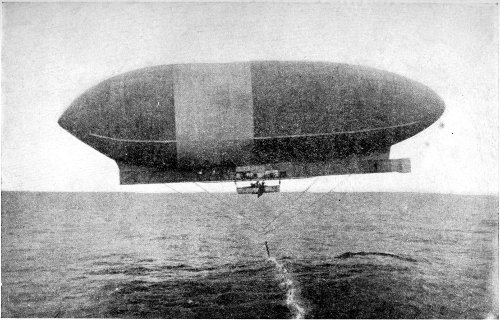
Copyright by Pictorial News Company.
Wellman dirigible “America” starting for Europe, October 15, 1910.
On November 5, 1910, the young Welsh aeronaut, Ernest T. Willows, who sailed his small dirigible from Cardiff to London in August, made a trip from London across the English Channel to Douai, France. This is the third time within a month that the Channel had been crossed by airships.
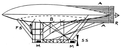
Diagram of the Capazza dirigible from the side. A A, stabilizing fins; B, air-ballonnet; R, rudder; M M, motors; FS, forward propeller; SS, stern propeller.
Toward the close of 1910, 52 dirigibles were in commission or in process of construction. In the United States there were 7; in Belgium, 2; in England, 6; in France, 12; in Germany, 14; in Italy, 5; in Russia, 1; in Spain, 1.
The new Capazza dirigible is a decided departure from all preceding constructions, and may mark a 339 new era in the navigation of the air. Its gas envelope is shaped like a lens, or a lentil, and is arranged to sail flatwise with the horizon, thus partaking of the aeroplane as well as the balloon type. No definite facts concerning its achievements have been published.
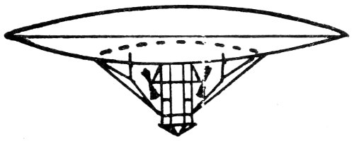
Capazza dirigible from the front. From above it is an exact circle in outline. 340
Preliminary inspection—Instruments—Accessories—Ballast—Inflating—Attaching the car—The ascension—Controls—Landing—Some things to be considered—After landing—Precautions.
The actual operation of a balloon is always entrusted to an experienced pilot, or “captain” as he is often called, because he is in command, and his authority must be recognized instantly whenever an order is given. Nevertheless, it is often of great importance that every passenger shall understand the details of managing the balloon in case of need; and a well-informed passenger is greatly to be preferred to an ignorant one.
It is ordinarily one of the duties of the captain to inspect the balloon thoroughly; to see that there are no holes in the gas-bag, that the valve is in perfect working order, and particularly that the valve rope and the ripping cord are not tangled. He should also gather the instruments and equipment to be carried. 341
The instruments are usually an aneroid barometer, and perhaps a mercury barometer, a barograph (recording barometer), a psychrometer (recording thermometer), a clock, a compass, and an outfit of maps of the country over which it is possible that the balloon may float. Telegraph blanks, railroad time tables, etc., may be found of great service. A camera with a supply of plates will be indispensable almost, and the camera should be provided with a yellow screen for photographing clouds or distant objects.
The ballast should be inspected, to be sure that it is of dry sand, free from stones; or if water is used for ballast, it should have the proper admixture of glycerine to prevent freezing.
It is essential that the inflating be properly done, and the captain should be competent to direct this process in detail, if necessary. What is called the “circular method” is the simplest, and is entirely satisfactory unless the balloon is being filled with pure hydrogen for a very high ascent, in which case it will doubtless be in the hands of experts.
When inflating with coal-gas, the supply is usually taken from a large pipe adapted for the purpose. At a convenient distance from the gas-main the ground 342 is made smooth, and the ground cloths are spread out and pegged down to keep them in place.
The folded balloon is laid out on the cloths with the neck opening toward the gas-pipe. The balloon is then unfolded, and so disposed that the valve will be uppermost, and in the centre of a circle embracing the upper half of the sphere of the balloon, the opening of the neck projecting a few inches beyond the rim of the circle. The hose from the gas-main may then be connected with the socket in the neck.
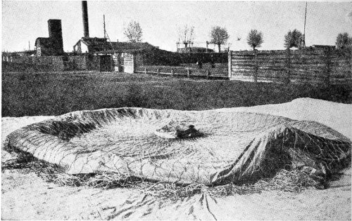
Balloon laid out in the circular method, ready for inflation. The valve is seen at the centre. The neck is at the right.
Having made sure that the ripping cord and the valve rope are free from each other, and properly 343 connected with their active parts, and that the valve is fastened in place, the net is laid over the whole, and spread out symmetrically. A few bags of ballast are hooked into the net around the circumference of the balloon as it lies, and the assistants distributed around it. It should be the duty of one man to hold the neck of the balloon, and not to leave it for any purpose whatever. The gas may then be turned on, and, as the balloon fills, more bags of ballast are hung symmetrically around the net; and all are continually moved downward as the balloon rises.
Constant watching is necessary during the inflation, so that the material of the balloon opens fully without creases, and the net preserves its correct position. When the inflation is finished the hoop and car are to be hooked in place. The car should be fitted up and hung with an abundance of ballast. Disconnect the gas hose and tie the neck of the balloon in such fashion that it may be opened with a pull of the cord when the ascent begins.
The ballast is then transferred to the hoop, or ring, and the balloon allowed to rise until this is clear of the ground. The car is then moved underneath, and the ballast moved down from the ring into it. The trail-rope should be made fast to the car directly 344 under the ripping panel, the object being to retard that side of the balloon in landing, so that the gas may escape freely when the panel is torn open, and not underneath the balloon, as would happen if the balloon came to earth with the ripping panel underneath.
The balloon is now ready to start, and the captain and passengers take their places in the car. The neck of the balloon is opened, and a glance upward will determine if the valve rope hangs freely through it. The lower end of this should be tied to one of the car ropes. The cord to the ripping panel should be tied in a different place, and in such fashion that no mistake can be made between them. The assistants stand around the edge of the basket, holding it so that it shall not rise until the word is given. The captain then adjusts the load of ballast, throwing off sufficient to allow the balloon to pull upward lightly against the men who are holding it. A little more ballast is then thrown off, and the word given to let go. The trail-rope should be in charge of some one who will see that it lifts freely from the ground.
The balloon rises into the air to an altitude where a bulk of the higher and therefore lighter air equal to the bulk of the balloon has exactly the same weight. 345 346 This is ordinarily about 2,000 feet. If the sun should be shining the gas in the balloon will be expanded by the heat, and some of it will be forced out through the neck. This explains the importance of the open neck. In some of the early ascensions no such provision for the expansion of the gas was made, and the balloons burst with disastrous consequences.
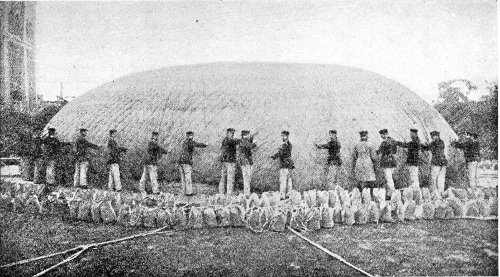
Inflating a military balloon. The net is being adjusted smoothly as the balloon rises. The bags of ballast surround the balloon ready to be attached as soon as the buoyancy of the gas lifts it from the earth.
When some of the gas has been driven out by the heat, there is less weight of gas in the balloon, though it occupies the same space. It therefore has a tendency to rise still higher. On the other hand, if it passes into a cloud, or the sun is otherwise obscured, the volume of the gas will contract; it will become denser, and the balloon will descend. To check the descent the load carried by the balloon must be lightened, and this is accomplished by throwing out some ballast; generally, a few handfuls is enough.
There is always more or less leakage of gas through the envelope as well as from the neck, and this also lessens the lifting power. To restore the balance, more ballast must be thrown out, and in this way an approximate level is kept during the journey.
When the ballast is nearly exhausted it will be necessary to come down, for a comfortable landing 347 cannot be made without the use of ballast. A good landing place having been selected, the valve is opened, and the balloon brought down within a few yards of the ground. The ripping cord is then pulled and ballast thrown out so that the basket will touch as lightly as possible. Some aeronauts use a small anchor or grapnel to assist in making a landing, but on a windy day, when the car is liable to do some bumping before coming to rest, the grapnel often makes matters much worse for the passengers by a series of holdings and slippings, and sometimes causes a destructive strain upon the balloon.
In making an ascent with a balloon full of gas there is certain to be a waste of gas as it expands. This expansion is due not only to the heat of the sun, but also to the lighter pressure of the air in the upper altitudes. It is therefore the custom with some aeronauts to ascend with a partially filled balloon, allowing the expansion to completely fill it. This process is particularly advised if a very high altitude is sought. When it is desired to make a long voyage it is wise to make the start at twilight, and so avoid the heat of the sun. The balloon will then float along on an almost unchanging level without expenditure of ballast. Rain and even the moisture 348 from clouds will sometimes wet the balloon so that it will cause a much greater loss of ballast than would have been required to be thrown out to rise above the cloud or storm. Such details in the handling of a balloon during a voyage will demand the skilled judgment of the captain.
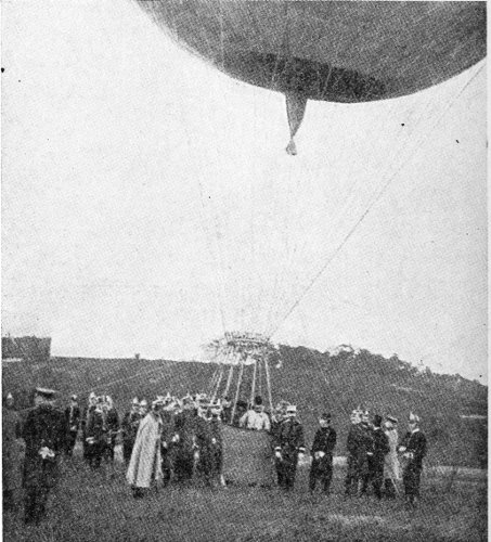
A balloon ready for ascent. Notice that the neck is still tied. 349
The trail-rope is a valuable adjunct when the balloon is travelling near the ground. The longer the part of the trail-rope that is dragging on the ground the less weight the balloon is carrying. And at night, when it is impossible to tell the direction in which one is travelling in any other way, the line of the trailing rope will show the direction from which the wind is blowing, and hence the drift of the balloon.
The care of the balloon and its instruments upon landing falls upon the captain, for he is not likely to find assistants at hand competent to relieve him of any part of the necessary work. The car and the ring are first detached. The ropes are laid out free and clear, and the valve is unscrewed and taken off. The material of the balloon is folded smoothly, gore by gore. The ballast bags are emptied. After all is bundled up it should be packed in the car, the covering cloth bound on with ropes, and definite instructions affixed for transportation to the starting-point.
It is apparent that the whole of the gas is lost at the end of the journey. The cost of this is the largest expense of ballooning. For a small balloon of about 50,000 cubic feet, the coal-gas for inflating 350 will cost about $35 to $40. If hydrogen is used, it will cost probably ten times as much.
In important voyages it is customary to send up pilot balloons, to discover the direction of the wind currents at the different levels, so that the level which promises the best may be selected before the balloon leaves the ground. A study of the weather conditions throughout the surrounding country is a wise precaution, and no start should be made if a storm is imminent. The extent of control possible in ballooning being so limited, all risks should be scrupulously avoided, both before and during the voyage, and nothing left to haphazard. 351
The fabrics used—Preliminary varnishing—Varnishes—Rubberized fabrics—Pegamoid—Weight of varnish—Latitudes of the balloon—Calculating gores—Laying out patterns and cutting—Sewing—Varnishing—Drying—Oiling—The neck—The valve—The net—The basket.
The making of a balloon is almost always placed in the hands of a professional balloon-maker. But as the use of balloons increases, and their owners multiply, it is becoming a matter of importance that the most improved methods of making them should be known to the intending purchaser, as well as to the amateur who wishes to construct his own balloon.
The fabric of which the gas envelope is made may be either silk, cotton (percale), or linen. It should be of a tight, diagonal weave, of uniform and strong threads in both warp and woof, unbleached, and without dressing, or finish. If it is colored, care should be exercised that the dye is one that will not 352 affect injuriously the strength or texture of the fabric. Lightness in weight, and great strength (as tested by tearing), are the essentials.
The finest German percale weighs about 2½ ounces per square yard; Russian percale, 3⅓ ounces, and French percale, 3¾ounces, per square yard. The white silk used in Russian military balloons weighs about the same as German percale, but is very much stronger. Pongee silk is a trifle heavier. The silk used for sounding balloons is much lighter, weighing only a little over one ounce to the square yard.
Goldbeater’s skin and rubber have been used to some extent, but the great cost of the former places it in reach only of governmental departments, and the latter is of use only in small balloons for scientific work—up to about 175 cubic feet capacity.
The fabric is first to be varnished, to fill up the pores and render it gas-tight. For this purpose a thin linseed-oil varnish has been commonly used. To 100 parts of pure linseed-oil are added 4 parts of litharge and 1 part of umber, and the mixture is heated to about 350° Fahr., for six or seven hours, and stirred constantly. After standing a few days the clear part is drawn off for use. For the thicker varnish used on later coats, the heat should be raised 353 to 450° and kept at about that temperature until it becomes thick. This operation is attended with much danger of the oil taking fire, and should be done only by an experienced varnish-maker.
The only advantages of the linseed-oil varnish are its ease of application, and its cheapness. Its drawbacks are stickiness—requiring continual examination of the balloon envelope, especially when the deflated bag is stored away—its liability to spontaneous combustion, particularly when the varnish is new, and its very slow drying qualities, requiring a long wait between the coats.
Another varnish made by dissolving rubber in benzine, has been largely used. It requires vulcanizing after application. It is never sticky, and is always soft and pliable. However, the rubber is liable to decomposition from the action of the violet ray of light, and a balloon so varnished requires the protection of an outer yellow covering—either of paint, or an additional yellow fabric. Unfortunately, a single sheet of rubberized material is not gas-tight, and it is necessary to make the envelope of two, or even three, layers of the fabric, thus adding much to the weight.
The great gas-bags of the Zeppelin airships are 354 varnished with “Pegamoid,” a patent preparation the constituents of which are not known. Its use by Count Zeppelin is the highest recommendation possible.
The weight of the varnish adds largely to the weight of the envelope. French pongee silk after receiving its five coats of linseed-oil varnish, weighs 8 ounces per square yard. A double bag of percale with a layer of vulcanized rubber between, and a coating of rubber on the inside, and painted yellow on the outside, will weigh 11 ounces per square yard. Pegamoid material, which comes ready prepared, weighs but about 4 ounces per square yard, but is much more costly.
In cutting out the gores of the envelope it is possible to waste fully ⅓ of the material unless the work is skilfully planned. Taking the width of the chosen material as a basis, we must first deduct from ¾ of an inch to 1½ inches, in proportion to the size of the proposed balloon, for a broad seam and the overlapping necessary. Dividing the circumference at the largest diameter—the “equator” of the balloon—by the remaining width of the fabric gives the number of gores required. To obtain the breadth of each gore at the different “latitudes” (supposing 355 356 the globe of the balloon to be divided by parallels similar to those of the earth) the following table is to be used; 0° representing the equator, and 90° the apex of the balloon. The breadth of the gore in inches at any latitude is the product of the decimal opposite that latitude in the table by the original width of the fabric in inches, thus allowing for seams.
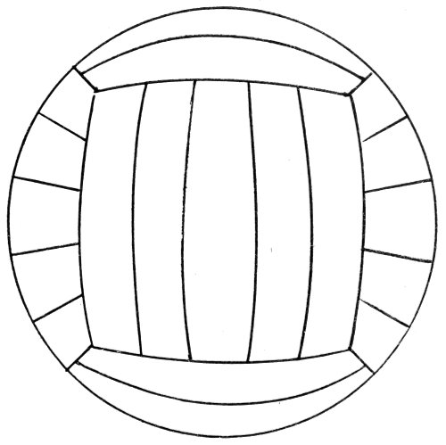
Finsterwalder’s method of cutting material for a spherical balloon, by which over one-fourth of the material, usually wasted in the common method, may be saved. It has the further advantage of saving more than half of the usual sewing. The balloon is considered as a spherical hexahedron (a six-surfaced figure similar to a cube, but with curved sides and edges). The circumference of the sphere divided by the width of the material gives the unit of measurement. The dimensions of the imagined hexahedron may then be determined from the calculated surface and the cutting proceed according to the illustration above, which shows five breadths to each of the six curved sides. The illustration shows the seams of the balloon made after the Finsterwalder method, when looking down upon it from above.
| 0° | 1.000 |
| 3° | 0.998 |
| 6° | 0.994 |
| 9° | 0.988 |
| 12° | 0.978 |
| 15° | 0.966 |
| 18° | 0.951 |
| 21° | 0.934 |
| 24° | 0.913 |
| 27° | 0.891 |
| 30° | 0.866 |
| 33° | 0.839 |
| 36° | 0.809 |
| 39° | 0.777 |
| 42° | 0.743 |
| 45° | 0.707 |
| 48° | 0.669 |
| 51° | 0.629 |
| 54° | 0.588 |
| 57° | 0.544 |
| 60° | 0.500 |
| 63° | 0.454 |
| 66° | 0.407 |
| 69° | 0.358 |
| 72° | 0.309 |
| 75° | 0.259 |
| 78° | 0.208 |
| 81° | 0.156 |
| 84° | 0.104 |
| 87° | 0.052⅓ |
In practice, the shape of the gore is calculated by the above table, and plotted out on a heavy pasteboard, generally in two sections for convenience in handling. The board is cut to the plotted shape and used as the pattern for every gore. In large establishments all the gores are cut at once by a machine.
The raw edges are hemmed, and folded into one 357 another to give a flat seam, and are then sewn together “through and through,” in twos and threes: afterward these sections are sewn together. Puckering must be scrupulously avoided. In the case of rubberized material, the thread holes should be smeared with rubber solution, and narrow strips of the fabric cemented over the seams with the same substance.
Varnishing is the next process, the gores being treated in turn. Half of the envelope is varnished first, and allowed to dry in a well-ventilated place out of reach of the sun’s rays. The other half is varnished when the first is dry. A framework which holds half of the balloon in the shape of a bell is usually employed. In case of haste, the balloon may be blown up with air, but this must be constantly renewed to be of any service.
The first step in varnishing is to get one side (the outer, or the inner) coated with a varnish thin enough to penetrate the material: then turn the envelope the other side out and give that a coat of the thin varnish. Next, after all is thoroughly dry, give the outer side a coat of thick varnish closing all pores. When this is dry give the inner side a similar coat. Finally, after drying thoroughly, give both sides a 358 coat of olive oil to prevent stickiness. The amount of varnish required is, for the first coat 1½ times the weight of the envelope, and for the second coat ½ the weight—of the thin varnish. For the thick coat on the outer side ⅓ of the weight of the envelope, and on the inner side about half as much. For the olive-oil coat, about ⅛ of the weight of the envelope will be needed. These figures are approximate, some material requiring more, some less; and a wasteful workman will cause a greater difference.
The neck of the balloon (also called the tail) is in form a cylindrical tube of the fabric, sewn to an opening in the bottom of the balloon, which has been strengthened by an extra ring of fabric to support it. The lower end of the tube, called the mouth, is sewn to a wooden ring, which stiffens it. The size of the neck is dependent upon the size of the balloon. Its diameter is determined by finding the cube of one-half the diameter of the balloon, and dividing it by 1,000. In length, the neck should be at least four times its diameter.
The apex of the balloon envelope is fitted with a large valve to permit the escape of gas when it is desired that the balloon shall descend. The door of the valve is made to open inward into the envelope, 359 and is pulled open by the valve-cord which passes through the neck of the balloon into the basket, or car. This valve is called the manœuvring valve, and there are many different designs equally efficient. As they may be had ready made, it is best for the amateur, unless he is a machinist, to purchase one. The main point to see to is that the seat of the valve is of soft pliable rubber, and that the door of the valve presses a comparatively sharp edge of metal or wood so firmly upon the seat as to indent it; and the springs of the valve should be strong enough to hold it evenly to its place.
The making of the net of the balloon is another part of the work which must be delegated to professionals. The material point is that the net distributes the weight evenly over the surface of the upper hemisphere of the envelope. The strength of the cordage is an item which must be carefully tested. Different samples of the same material show such wide variations in strength that nothing but an actual test will determine. In general, however, it may be said that China-grass cordage is four times as strong as hemp cordage, and silk cordage is ten times as strong as hemp—for the same size cords.
The meshes of the net should be small, allowing 360 the use of a small cord. Large cords mean large knots, and these wear seriously upon the balloon envelope, and are very likely to cause leaks. In large meshes, also, the envelope puffs out between the cords and becomes somewhat stretched, opening pores through which much gas is lost by diffusion.
The “star,” or centre of the net at the apex of the balloon, must be fastened immovably to the rim of the valve. The suspension cords begin at from 30° to 45° below the equator of the envelope, and are looped through rings in what are called “goose-necks.” These allow a measure of sliding motion to the cordage as the basket sways in the wind.
For protecting the net against rotting from frequent wetting, it is recommended to saturate it thoroughly with a solution of acetate of soda, drying immediately. Paraffin is sometimes used with more or less success, but tarring should be avoided, as it materially weakens the cordage. Oil or grease are even worse.
At the bottom of the net proper the few large cords into which the many small cords have been merged are attached to the ring of the balloon. This is either of steel or of several layers of wood well bound together. The ropes supporting the basket are also 361 362 fastened to this ring, and from it hang the trail-rope and the holding ropes.
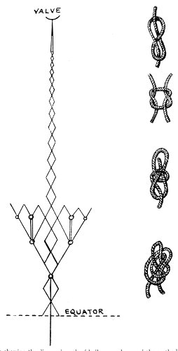
Sketch showing the diamond mesh of balloon cordage and the method of distributing the rings for the goose-necks; also the merging of netting cords into the suspension cords which support the car. The principal knots used in tying balloon nets are shown on the right.
The basket is also to be made by a professional, as upon its workmanship may depend the lives of its occupants, though every other feature of the balloon be faultless. It must be light, and still very strong to carry its load and withstand severe bumping. It should be from 3 to 4 feet deep, with a floor space of 4 feet by 5 feet. It is usually made of willow and rattan woven substantially together. The ropes supporting the car are passed through the bottom and woven in with it. Buffers are woven on to the outside, and the inside is padded. The seats are small baskets in which is stored the equipment. With the completion of these the balloon is ready for its furnishings and equipment, which come under the direction of the pilot, or captain, as detailed in the preceding chapter. 363
The pioneer Meusnier—L’Entreprenant—First aerostiers—First aerial warship—Bombardment by balloons—Free balloons in observations—Ordering artillery from balloon—The postal balloons of Paris—Compressed hydrogen—National experiments—Bomb dropping—Falling explosives—Widespread activity in gathering fleets—Controversies—Range of vision—Reassuring outlook.
Almost from the beginning of success in traversing the air the great possibilities of all forms of aircraft as aids in warfare have been recognized by military authorities, and, as has so often been the case with other inventions by non-military minds, the practically unlimited funds at the disposal of national war departments have been available for the development of the balloon at first, then the airship, and now of the aeroplane.
The Montgolfiers had scarcely proved the possibility of rising into the air, in 1783, before General Meusnier was busily engaged in inventing improvements in their balloon with the expressed purpose of making it of service to his army, and before he was 364 killed in battle he had secured the appointment of a commission to test the improved balloon as to its efficiency in war. The report of the committee being favorable, a balloon corps was formed in April, 1794, and the balloon L’Entreprenant was used during the battle of Fleurus, on June 26th, by Meusnier’s successor, General Jourdan, less than a year after Meusnier’s death. In 1795 this balloon was used in the battle of Mayence. In both instances it was employed for observation only.
But when the French entered Moscow, they found there, and captured, a balloon laden with 1,000 pounds of gunpowder which was intended to have been used against them.
In 1796 two other balloons were used by the French army then in front of Andernach and Ehrenbreitstein, and in 1798 the 1st Company of Aerostiers was sent to Egypt, and operated at the battle of the Nile, and later at Cairo. In the year following, this balloon corps was disbanded.
In 1812 Russia secured the services of a German balloon builder named Leppich, or Leppig, to build a war balloon. It had the form of a fish, and was so large that the inflation required five days, but the construction of the framework was faulty, and some 365 366 important parts gave way during inflation, and the airship never left the ground. As it was intended that this balloon should be dirigible and supplied with explosives, and take an active part in attacks on enemies, it may be regarded as the first aerial warship.
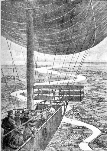
A military dirigible making a tour of observation.
In 1849, however, the first actual employment of the balloon in warfare took place. Austria was engaged in the bombardment of Venice, and the range of the besieging batteries was not great enough to permit shells to be dropped into the city. The engineers formed a balloon detachment, and made a number of Montgolfiers out of paper. These were of a size sufficient to carry bombs weighing 30 pounds for half an hour before coming down. These war balloons were taken to the windward side of the city, and after a pilot balloon had been floated over the point where the bombs were to fall, and the time consumed in the flight ascertained, the fuses of the bombs were set for the same time, and the war balloons were released. The actual damage done by the dropping of these bombs was not great, but the moral effect upon the people of the city was enormous. The balloon detachment changed its position as the wind changed, and many shells were exploded in the heart 367 of the city, one of them in the market place. But the destruction wrought was insignificant as compared with that usually resulting from cannonading. As these little Montgolfiers were sent up unmanned, perhaps they are not strictly entitled to be dignified by the name of war balloon, being only what in this day would be called aerial bombs.
The next use of the balloon in warfare was by Napoleon III, in 1859. He sent up Lieutenant Godard, formerly a manufacturer of balloons, and Nadar, the balloonist, at Castiglione. It was a tour of observation only, and Godard made the important discovery that the inhabitants were gathering their flocks of domestic animals and choking the roads with them, to oppose the advance of the French.
The first military use of balloons in the United States was at the time of the Civil War. Within a month after the war broke out, Professor T. S. C. Lowe, of Washington, put himself and his balloon at the command of President Lincoln, and on June 18, 1861, he sent to the President a telegram from the balloon—the first record of the kind in history.
After the defeat at Manassas, on July 24, 1861, Professor Lowe made a free ascent, and discovered the true position of the Confederates, and proved 368 the falsity of rumors of their advance. The organization of a regular balloon corps followed, and it was attached to McClellan’s army, and used in reconnoitering before Yorktown. The balloons were operated under heavy artillery fire, but were not injured.
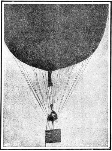
A small captive military balloon fitted for observation. A cylinder of compressed hydrogen to replace leakage is seen at F. 369
On May 24th, for the first time in history, a general officer—in this case, General Stoneman—directed the fire of artillery at a hidden enemy from a balloon.
Later in the month balloons were used at Chickahominy, and again at Fair Oaks and Richmond, being towed about by locomotives. On the retreat from before Richmond, McClellan’s balloons and gas generators were captured and destroyed.
In 1869, during the siege of a fort at Wakamatzu by the Imperial Japanese troops, the besieged sent up a man-carrying kite. After making observations, the officer ascended again with explosives, with which he attempted to disperse the besieging army, but without success.
During the siege of Paris, in 1870, there were several experienced balloonists shut up in the city, and the six balloons at hand were quickly repaired and put to use by the army for carrying dispatches and mail beyond the besieging lines. The first trips were made by the professional aeronauts, but, as they could not return, there was soon a scarcity of pilots. Sailors, and acrobats from the Hippodrome, were pressed into the service, and before the siege was raised 64 of these postal balloons had been dispatched. Fifty-seven out of the 64 landed safely on French 370 territory, and fulfilled their mission; 4 were captured by the Germans; 1 floated to Norway; 1 was lost, with its crew of two sailors, who faithfully dropped their dispatches on the rocks near the Lizard as they were swept out to sea; and 1 landed on the islet Hoedic, in the Atlantic. In all, 164 persons left Paris in these balloons, always at night, and there were carried a total of 9 tons of dispatches and 3,000,000 letters. At first dogs were carried to bring back replies, but none ever returned. Then carrier pigeons were used successfully. Replies were set in type and printed. These printed sheets were 371 reduced by photography so that 16 folio pages of print, containing 32,000 words, were reduced to a space of 2 inches by 1¼ inches on the thinnest of gelatine film. Twenty of these films were packed in a quill, and constituted the load for each pigeon. When received in Paris, the films were enlarged by means of a magic lantern, copied, and delivered to the persons addressed.
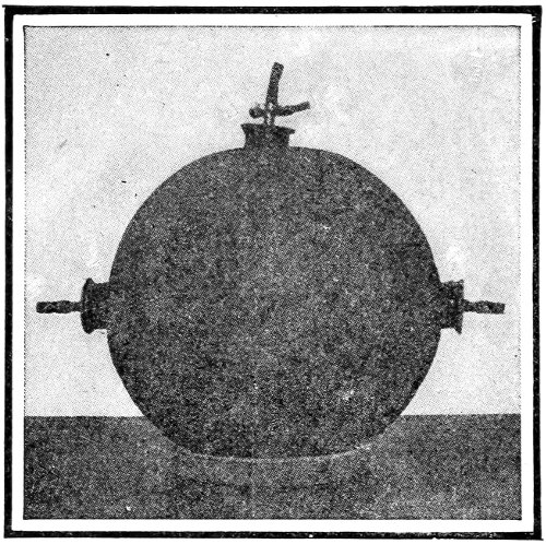
Spherical canister of compressed hydrogen for use in inflating military balloons. A large number of these canisters may be tapped at the same time and the inflation proceed rapidly; a large balloon being filled in two hours.
In more recent times the French used balloons at Tonkin, in 1884; the English, in Africa, in 1885; the Italians, in Abyssinia, in 1888; and the United States, at Santiago, in 1898. During the Boer War, in 1900, balloons were used by the British for directing artillery fire, and one was shot to pieces by well-aimed Boer cannon. At Port Arthur, both the Japanese and the Russians used balloons and man-carrying kites for observation. The most recent use is that by Spain, in her campaign against the Moors, in 1909.
The introduction of compressed hydrogen in compact cylinders, which are easily transported, has simplified the problem of inflating balloons in the field, and of restoring gas lost by leakage.
The advent of the dirigible has engaged the active attention of the war departments of all the civilized 372 nations, and experiments are constantly progressing, in many instances in secret. It is a fact at once significant and interesting, as marking the rapidity of the march of improvement, that the German Government has lately refused to buy the newest Zeppelin dirigible, on the ground that it is built of aluminum, which is out of date since the discovery of its lighter alloys.
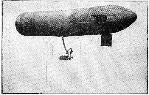
The German military non-rigid dirigible Parseval II. It survived the storm which wrecked the Zeppelin II in April, 1910, and reached its shed at Cologne in safety.
Practically all the armies are being provided with fleets of aeroplanes, ostensibly for use in scouting. But there have been many contests by aviators in “bomb-dropping” which have at least proved that it is possible to drop explosives from an aeroplane with a great degree of accuracy. The favorite target 373 374 in these contests has been the life-sized outline of a battleship.
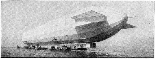
The German military Zeppelin dirigible, which took part in the manœuvres at Hamburg in April, 1910, and was wrecked by a high wind at Weilburg on the return journey to Cologne.
Glenn Curtiss, after his trip down the Hudson from Albany, declared that he could have dropped a large enough torpedo upon the Poughkeepsie Bridge to have wrecked it. His subsequent feats in dropping “bombs,” represented by oranges, have given weight to his claims.
By some writers it is asserted that the successful navigation of the air will guarantee universal peace; that war with aircraft will be so destructive that the whole world will rise against its horrors. Against a fleet of flying machines dropping explosives into the heart of great cities there can be no adequate defence.
On the other hand, Mr. Hudson Maxim declares that the exploding of the limited quantities of dynamite that can be carried on the present types of aeroplanes, on the decks of warships would not do any vital damage. He also says that many tons of dynamite might be exploded in Madison Square, New York City, with no more serious results than the blowing out of the windows of the adjacent buildings as the air within rushed out to fill the void caused by the uprush of air heated by the explosion. 375
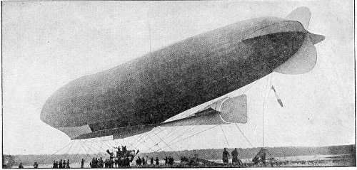
The Lebaudy airship “La Patrie.” As compared with the first Lebaudy, it shows the rounded stern with stabilizing planes, and the long fin beneath, with rudder and dipping planes. 376
As yet, the only experience that may be instanced is that of the Russo-Japanese War, where cast-iron shells, weighing 448 lbs., containing 28 lbs. of powder, were fired from a high angle into Port Arthur, and did but little damage.
In 1899 the Hague Conference passed a resolution prohibiting the use of aircraft to discharge projectiles or explosives, and limited their use in war to observation. Germany, France, and Italy withheld consent upon the proposition.
In general, undefended places are regarded as exempt from attack by bombardment of any kind.
Nevertheless, there are straws which show how the wind is blowing. German citizens and clubs which purchase a type of airship approved by the War Office of the German Empire are to receive a substantial subsidy, with the understanding that in case of war the aircraft is to be at the disposal of the Government. Under this plan it is expected that the German Government will control a large fleet of ships of the air without being obliged to own them.
And, in France, funds were raised recently, by popular subscription, sufficient to provide the nation with a fleet of fourteen airships (dirigibles) and thirty aeroplanes. These are already being built, 377 and it will not be long before France will have the largest air-fleet afloat.
The results of the German manœuvres with a fleet of four dirigibles in a night attack upon strong fortresses have been kept a profound secret, as if of great value to the War Office.
In the United States the Signal Corps has been active in operating the Baldwin dirigible and the Wright aeroplanes owned by the Government. To the latter, wireless telegraphic apparatus has been attached and is operated successfully when the machines are in flight. In addition, the United States Aeronautical Reserve has been formed, with a large membership of prominent amateur and professional aviators.
Some military experts, however, assert that the dirigible is hopelessly outclassed for warfare by the aeroplane, which can operate in winds in which the dirigible dare not venture, and can soar so high above any altitude that the dirigible can reach as to easily destroy it. Another argument used against the availability of the dirigible as a war-vessel is, that if it were launched on a wind which carried it over the enemy’s country, it might not be able to return at sufficient speed to escape destruction by high-firing 378 guns, even if its limited fuel capacity did not force a landing.
Even the observation value of the aircraft is in some dispute. The following table is quoted as giving the ranges possible to an observer in the air:
| Altitude in feet. | Distance of horizon. | |
|---|---|---|
| 500 | 30 | miles. |
| 1,000 | 42 | “ |
| 2,000 | 59 | “ |
| 3,000 | 72 | “ |
| 4,000 | 84 | “ |
| 5,000 | 93 | “ |
As a matter of fact, the moisture ordinarily in the air effectually limits the range of both natural vision and the use of the camera for photographing objects on the ground. The usual limit of practical range of the best telescope is eight miles.
All things considered, however, it is to be expected that the experimenting by army and navy officers all over the world will lead to such improvement and invention in the art of navigating the air as will develop its benevolent, rather than its malevolent, possibilities—“a consummation devoutly to be wished.” 379
The Wright Brothers—Santos-Dumont—Louis Bleriot—Gabriel Voisin—Leon Delagrange—Henri Farman—Robert Esnault-Pelterie—Count von Zeppelin—Glenn H. Curtiss—Charles K. Hamilton—Hubert Latham—Alfred Leblanc—Claude Grahame-White—Louis Paulhan—Clifford B. Harmon—Walter Brookins—John B. Moisant—J. Armstrong Drexel—Ralph Johnstone.
On January 1, 1909, it would have been a brief task to write a few biographical notes about the “prominent” aviators. At that date there were but five who had made flights exceeding ten minutes in duration—the Wright brothers, Farman, Delagrange, and Bleriot. At the close of 1910 the roll of aviators who have distinguished themselves by winning prizes or breaking previous records has increased to more than 100, and the number of qualified pilots of flying machines now numbers over 300. The impossibility of giving even a mention of the notable airmen in this chapter is apparent, and the few whose names have been selected are those who have more 380 recently in our own country come into larger public notice, and those of the pioneers whose names will never lose their first prominence.
The Wright Brothers have so systematically linked their individual personalities in all their work, in private no less than in public, that the brief life story to be told here is but one for them both. In fact, until Wilbur went to France in 1908, and Orville to Washington, the nearest approach to a separation is illustrated by a historic remark of Wilbur’s to an acquaintance in Dayton, one afternoon: “Orville flew 21 miles yesterday; I am going to beat that to-day.” And he did—by 3 miles.
Their early life in their home town of Dayton, Ohio, was unmarked by significant incident. They were interested in bicycles, and at length went into the business of repairing and selling these machines.
Their attention seems to have been strongly turned to the subject of human flight by the death of Lilienthal in August, 1896, at which time the press published some of the results of his experiments. A magazine article by Octave Chanute, himself an experimenter with gliders, led to correspondence with 381 him, and the Wrights began a series of similar investigations with models of their own building.
By 1900 they had succeeded in flying a large glider by running with a string, as with a kite, and in the following year they had made some flights on their gliders, of which they had several of differing types. For two years the Wrights studied and tested and disproved nearly every formula laid down by scientific works for the relations of gravity to air, and finally gave themselves up to discovering by actual trial what the true conditions were, and to the improvement of their gliders accordingly. Meanwhile they continued their constant personal practice in the air.
The most of this experimental work was done at Kitty Hawk, N. C.; for the reason that there the winds blow more uniformly than at any other place in the United States, and the great sand dunes there gave the Wrights the needed elevation from which to leap into the wind with their gliders. Consequently, when at last they were ready to try a machine driven by a motor, it was at this secluded spot that the first flights ever made by man with a heavier-than-air machine took place. On December 17, 1903, their first machine left the ground under its own 382 383 power, and remained in the air for twelve seconds. From this time on progress was even slower than before, on account of the complications added by the motive power; but by the time another year had passed they were making flights which lasted five minutes, and had their machine in such control that they could fly in a circle and make a safe landing within a few feet of the spot designated.
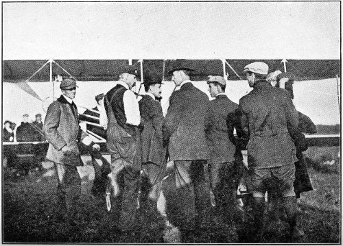
Turpin, Taylor, Orville Wright, Wilbur Wright, Brookins, and Johnstone discussing the merits of the Wright machine.
On the 5th of October, 1905, Wilbur Wright made his historic flight of 24 miles at Dayton, Ohio, beating the record of Orville, made the day before, of 21 miles. The average speed of these flights was 38 miles an hour. No contention as to the priority of the device known as wing-warping can ever set aside the fact that these long practical flights were made more than a year before any other man had flown 500 feet, or had remained in the air half a minute, with a heavier-than-air machine driven by power.
The Wrights are now at the head of one of the largest aeroplane manufactories in the world, and devote the larger part of their time to research work in the line of the navigation of the air. 384
Alberto Santos-Dumont was born in Brazil in 1877. When but a lad he became intensely interested in aeronautics, having been aroused by witnessing the ascension at a show of an ordinary hot-air balloon. Within the next few years he had made several trips to Paris, and in 1897 made his first ascent in a balloon with the balloon builder Machuron, the partner of the famous Lachambre.
In 1898 he began the construction of his notable series of dirigibles, which eventually reached twelve in number. With his No. 6 he won the $20,000 prize offered by M. Deutsch (de la Meurthe) for the first trip from the Paris Aero Club’s grounds to and around the Eiffel Tower in 30 minutes or less. The distance was nearly 7 miles. It is characteristic of M. Santos-Dumont that he should give $15,000 of the prize to relieve distress among the poor of Paris, and the remainder to his mechanicians who had built the balloon.
His smallest dirigible was the No. 9, which held 7,770 cubic feet of gas; the largest was the No. 10, which held 80,000 cubic feet.
In 1905, when Bleriot, Voisin, and their comrades 385 were striving to accomplish flight with machines heavier than air, Santos-Dumont turned his genius upon the same problem, and on August 14, 1906, he made his first flight with a cellular biplane driven by a 24 horse-power motor. On November 13th of the same year he flew 720 feet with the same machine. These were the first flights of heavier-than-air machines in Europe, and the first public flights anywhere. Later he turned to the monoplane type, and with “La Demoiselle” added new laurels to those already won with his dirigibles.
Louis Bleriot, designer and builder of the celebrated Bleriot monoplanes, and himself a pilot of the first rank, was born in Cambrai, France, in 1872. He graduated from a noted technical school, and soon attached himself to the group of young men—all under thirty years of age—who were experimenting with gliders in the effort to fly. His attempts at first were with the flapping-wing contrivances, but he soon gave these up as a failure, and devoted his energy to the automobile industry; and the excellent Bleriot acetylene headlight testifies to his constructive ability in that field. 386
Attracted by the experiments of M. Ernest Archdeacon he joined his following, and with Gabriel Voisin engaged in building gliders of the biplane type. By 1907 he had turned wholly to the monoplane idea, and in April of that year made his first leap into the air with a power-driven monoplane. By September he had so improved his machine that he was able to fly 600 feet, and in June, 1908, he broke the record for monoplanes by flying nearly a mile. Again and again he beat his own records, and at length the whole civilized world was thrilled by his triumphant flight across the British Channel on July 25, 1909.
The Bleriot machines hold nearly all the speed records, and many of those in other lines of achievement, and M. Bleriot enjoys the double honor of being an eminently successful manufacturer as well as a dauntless aviator of heroic rank.
Gabriel Voisin, the elder of the two Voisin brothers, was born in 1879 at Belleville-sur-Saone, near the city of Lyons, France. He was educated as an architect, but early became interested in aeronautics, and engaged in gliding, stimulated by the achievements 387 of Pilcher, in England, and Captain Ferber, in his own country. He assisted M. Archdeacon in his experiments on the Seine, often riding the gliders which were towed by the swift motor boats.
In 1906 he associated himself with his brother in the business of manufacturing biplane machines, and in March, 1907, he himself made the first long flight with a power-driven machine in Europe. This aeroplane was built for his friend Delagrange, and was one in which the latter was soon breaking records and winning prizes. The second machine was for Farman, who made the Voisin biplane famous by winning the Deutsch-Archdeacon prize of $10,000 for making a flight of 1,093 yards in a circle.
The Voisin biplane is distinctive in structure, and is accounted one of the leading aeroplanes of the present day.
Leon Delagrange was born at Orleans, France, in 1873. He entered the School of Arts as a student in sculpture, about the same time that Henri Farman went there to study painting, and Gabriel Voisin, architecture. He exhibited at the Salon, and won several medals. In 1905, he took up aeronautics, assisted at the experiments of M. Archdeacon. 388 His first aeroplane was built by Voisin, and he made his first flight at Issy, March 14, 1907. Less than a month later—on April 11—he made a new record for duration of flight, remaining in the air for 9 minutes and 15 seconds—twice as long as the previous record made by Farman.
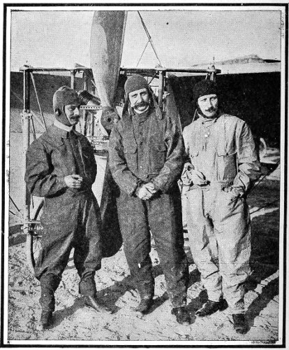
Leblanc, Bleriot, and Delagrange, (from left to right) in aviation dress, standing in front of the Bleriot machine which crossed the English Channel. 389
At Rheims, in 1909, he appeared with a Bleriot monoplane, and continued to fly with that type of machine until his death. At Doncaster, England, he made the world record for speed up to that time, travelling at the rate of 49.9 miles per hour. He was killed at Bordeaux, France, in January, 1910, by the fall of his machine.
Henri Farman, justly regarded as the most prominent figure in the aviation world today, was born in France in 1873. His father was an Englishman.
While a mere boy he became locally famous as a bicycle racer, and later achieved a wider fame as a fearless and skillful driver in automobile races. In 1902 he won the Paris-Vienna race.
In September, 1907, he made his first attempt to fly, using the second biplane built by his friend Gabriel Voisin, and in the following year he won with it the Deutsch-Archdeacon prize of $10,000. He then built a machine after his own ideas, which more resembles the Wright machine than the Voisin, and with it he has won many prizes, and made many world records. Demands for machines, and for teaching the art of handling them, have poured in 390 upon him, necessitating a continual increase of manufacturing facilities until it may safely be said that he has the largest plant for building flying machines in the world, turning out the largest number of machines, and through his school for aviators is instructing a larger number of pupils annually than any other similar establishment.
Robert Esnault-Pelterie was born in 1880, and educated in the city of Paris. He early showed a mechanical turn of mind, and was interested particularly in scientific studies. He became an enthusiast in matters aeronautic, and devoted himself to the construction of gasoline engines suitable for aviation purposes. After satisfying his ideal in this direction with the now famous “R-E-P” motor, he designed a new type of flying machine which is known as the “R-E-P monoplane.” His first flights were made at Buc in October, 1907, and while they were short, they proved the possibility of steering a flying machine so that it would describe a curved line—at that time a considerable achievement among European aviators. In April, 1908, he flew for ¾ 391 of a mile, and reached a height of 100 feet. This feat eclipsed all previous records for monoplanes.
His fame, however, rests upon his motors, which are quite original in design and construction.
Count Ferdinand von Zeppelin was born in 1838, on the shores of the Lake Constance, where his great airships have had their initial trials.
It is an interesting fact that Count von Zeppelin made his first balloon ascension in a war-balloon attached to the army corps commanded by his friend, Carl Schurz, during the Civil War.
It was only after years of absorbing study of all that human knowledge could contribute that Count von Zeppelin decided upon the type of dirigible which bears his name. Under the patronage of the King of Würtemberg he began his first airship, having previously built an immense floating shed, which, swinging by a cable, always had its doors facing away from the wind.
The successful flights of the series of magnificent Zeppelin airships have been marvellous in an age crowded with wonders. And the misfortune which has followed close upon their superb achievements 392 with complete destruction would long ago have undone a man of less energy and courage than the dauntless Count. It should be borne in mind, however, that of the hundreds of passengers carried in his ships of the air, all have come to land safely—a record that it would be difficult to match with any other form of travel. The accidents which have destroyed the Zeppelins have never happened in the air, excepting only the wrecking of the Deutschland by a thunderstorm.
The indefatigable Count is now constructing another airship with the new alloy, electron, instead of aluminum. He estimates that 5,000 pounds’ weight can be saved in this way.
Captain Thomas S. Baldwin, balloonist and aviator, was born in Mississippi in 1855. His first aeronautical experience was as a parachute rider from a balloon in the air. He invented the parachute he used, and received for it a gold medal from the Balloon Society of Great Britain. Exhibiting this parachute, Captain Baldwin made an extensive tour of the civilized world.
In 1892 he built his first airship, a combination 393 of a balloon, a screw propeller, and a bicycle, the last to furnish the motive power. It was not until 1902, when be installed an automobile engine in his airship, that he succeeded in making it sail. It was not yet dirigible, however; but after two years of devising and experimenting, he sailed away from Oakland, Cal., on August 2, 1904, against the wind, and after a short voyage, turned and came back to his balloon-shed. From this time on he made several successful dirigibles, and in 1908 he met all the requirements of the United States Government for a military dirigible, and sold to it the only dirigible it possesses.
He became interested in the experiments of Curtiss and McCurdy at Hammondsport, in 1908, and aided in building the remarkable series of biplanes with which record flights were made. The newer design, known as the Baldwin biplane, is unique in the pivoted balancing plane set upright above the upper plane, a device entirely distinct from the warping or other manipulation of horizontal surfaces for the purpose of restoring lateral balance.
Glenn Hammond Curtiss was born at Hammondsport, N. Y., on the shore of Lake Keuka, in 394 1878. From boyhood he was a competitor and winner in all sorts of races where speed was the supreme test. By nature a mechanic, he became noted for his ingenious contrivances in this line, and built a series of extremely fast motor-cycles, with one of which he made the record of one mile in 26⅖ seconds, which still stands as the fastest mile ever made by man with any form of mechanism.
Through the purchasing of one of his light engines by Captain Baldwin for his dirigible, Curtiss became interested in aeronautical matters, and soon built a glider with which he sailed down from the Hammondsport hills. The combination of his motor and the glider was the next step, and on July 4, 1908, he flew 1½ miles with the June Bug, winning the Scientific American trophy.
Learning that the United States was not to be represented at the Rheims meet in August, 1909, he hastily built a biplane and went there. He won the first prize for the course of 30 kilometres (18.6 miles), second prize for the course of 10 kilometres, the James Gordon Bennett cup, and the tenth prize in the contest for distance. From Rheims he went to Brescia, Italy, and there won the first prize for speed. In all these contests he was matching his 395 biplane against monoplanes which were acknowledged to be a faster type than the biplane.
On May 29, 1910, Mr. Curtiss made the first stated aeroplane tour to take place in this country, travelling from Albany to New York City, 137 miles, with but one stop for fuel. With this flight he won a prize of $10,000.
He has made many other notable flights and stands in the foremost rank of the active aviators. At the same time he is busily engaged in the manufacture of the Curtiss biplane and the Curtiss engine, both staple productions in their line.
Charles Keeney Hamilton is justly regarded as one of the most skilful of aviators. He was born in Connecticut in 1881, and showed his “bent” by making distressing, and often disastrous, leaps from high places with the family umbrella for a parachute.
In 1904 he worked with Mr. Israel Ludlow, who at that time was experimenting with gliders of his own construction, and when Mr. Ludlow began towing them behind automobiles, Hamilton rode on the gliders and steered them. Later he became interested 396 in ballooning, and made a tour of Japan with a small dirigible.
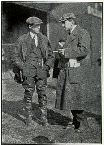
Hamilton and Latham.
He early became famous in the aviation world by his spectacular glides from a great height. He has said that the first of these was unintentional, but his motor having stopped suddenly while he was high in the air, he had only the other alternative of falling 397 vertically. The sensation of the swift gliding having pleased him, he does it frequently “for the fun of it.” These glides are made at so steep an angle that they have gained the distinctive name, “Hamilton dives.”
Hamilton came most prominently before the public at large with his flight from Governor’s Island to Philadelphia and back, on June 13, 1910. Following close upon Curtiss’s flight from Albany to New York, it was not only a record-breaking achievement, but helped to establish in this country the value of the aeroplane as a vehicle for place-to-place journeyings.
Hubert Latham, the famous Antoinette pilot, is a graduate of Oxford. His father was a naturalized Frenchman.
His first aeronautical experience was as companion to his cousin, Jacques Faure, the balloonist, on his famous trip from London to Paris in 6½ hours, the fastest time ever made between the two places until the Clement-Bayard dirigible surpassed it by a few minutes on October 16, 1910.
The Antoinette monoplane with which M. Latham 398 has identified himself began with the ingenious engine of Levavasseur, which was speedily made use of for aeroplanes by Santos-Dumont, Bleriot, and Farman. Levavasseur also had ideas about aeroplanes, and persuaded some capitalists to back him in the enterprise. When it was done, no one could be found to fly it. Here M. Latham, a lieutenant of miners and sappers in the French army, stepped into the breach, and has made a name for himself and for the Antoinette machine in the forefront of the progress of aviation.
After winning several contests he set out, on July 19, 1909, to cross the British Channel. After flying about half the distance he fell into the sea. Six days later Bleriot made the crossing successfully, and Latham made a second attempt on July 27th, and this time got within a mile of the Dover coast before he again came down in the water.
He has shown unsurpassed daring and skill in flying in gales blowing at 40 miles per hour, a record which few other aviators have cared to rival.
Alfred Leblanc, the champion cross-country flier of the world, was born in France in 1879. By profession 399 he is a metallurgist. A friend of Bleriot, he became interested in monoplane flying, the more readily because he was already a skilled balloonist.
At the time Bleriot made his historic flight across the British Channel, Leblanc preceded him, and, standing on the Dover shore, signalled Bleriot where to strike the land.
He organized Bleriot’s school for aviators at Pau, and became its director. Its excellence is exhibited in the quality of its pupils; among them Chavez, Morane, and Aubrun.
The achievement through which Leblanc is most widely known is his winning of the 489-mile race over the northern part of France in August, 1910, and with the victory the prize of $20,000 offered.
Claude Grahame-White, the most famous of British aviators, learned to fly in France, under the tutelage of M. Bleriot, Having accomplished so much, he went to Mourmelon, the location of Farman’s establishment, and made himself equally proficient on the Farman biplane. While in France he taught many pupils, among them Armstrong Drexel. 400 Returning to England, he opened a school for English aviators.
He came into prominent public notice in his contest with Paulhan in the race from London to Manchester, and although Paulhan won the prize, Grahame-White received a full share of glory for his plucky persistence against discouraging mishaps.
At the Boston-Harvard meet, in September, 1910, Grahame-White carried off nearly all the prizes, and in addition won for himself a large measure of personal popularity.
On October 14th he flew from the Benning Race Track 6 miles away, over the Potomac River, around the dome of the Capitol, the Washington Monument, and over the course of Pennsylvania Avenue, up to the State, War, and Navy Department building, alighting accurately with his 40-foot biplane in the 60-foot street. Having ended his “call,” he mounted his machine and rose skilfully into the air and returned to his starting point.
At the Belmont Park meet, in October, Grahame-White captured the international speed prize with his 100-horse-power Bleriot monoplane, and finished second in the race around the Statue of Liberty, being beaten by only 43 seconds. 401
Louis Paulhan was, in January, 1909, a mechanic in Mourmelon, France, earning the good wages in that country of $15 per week. He became an aviator, making his first flight on July 10, 1909, of 1¼ miles. Five days later he flew over 40 miles, remaining in the air 1 hour 17 minutes, and rising to an altitude of 357 feet, then the world’s record. He flew constantly in public through the remainder of 1909, winning many prizes and breaking and making records.
In January, 1910, he was the most prominent aviator at the Los Angeles meet, and there made a new world’s record for altitude, 4,166 feet.
Within the 13 months and 3 weeks (up to October 1, 1910) that he has been flying, he has won over $100,000 in prizes, besides receiving many handsome fees for other flights and for instruction to pupils.
Clifford B. Harmon has the double distinction of being not only the foremost amateur aviator of America, but his feats have also at times excelled those of the professional airmen. On July 2, 1910, 402 Mr. Harmon made a continuous flight of more than 2 hours, breaking all American records, and this he held for several months.
Mr. Harmon’s first experience in the air was as a balloonist, and in this capacity he held the duration record of 48 hours 26 minutes for a year. On this same voyage, at the St. Louis Centennial, he made a new record in America for altitude attained, 24,400 feet.
At the Los Angeles aviation meet, in January, 1910, where he went with his balloon New York, he met Paulhan, and became his pupil. At that meet Paulhan made a new world’s record for altitude with a Farman biplane, and this machine Mr. Harmon bought, and brought to Mineola, L. I., where he practised assiduously, crowning his minor achievements by flying from there across Long Island Sound to Greenwich, Conn.
At the Boston-Harvard aviation meet, in September, 1910, Mr. Harmon won every prize offered to amateur contestants.
Walter Brookins is one of the youngest of noted aviators. He was born in Dayton, Ohio, in 1890, 403 and went to school to Miss Katherine Wright, sister of the Wright brothers. Young Walter was greatly interested in the experiments made by the Wrights, and Orville one day promised him that when he grew up they would build a flying machine for him. Brookins appeared at Dayton in the early part of 1910, after several years’ absence, during which he had grown up, and demanded the promised flying machine. The Wrights met the demand, and developed Brookins into one of the most successful American aviators.
Brookins’s first leap into prominence was at the Indianapolis meet, in June, 1910, where he made a new world’s record for altitude, 4,803 feet. This being beaten soon after in Europe, by J. Armstrong Drexel, with 6,600 feet, Brookins attempted, at Atlantic City, in September, to excel Drexel’s record, and rose to a height of 6,175 feet, being forced to come down by the missing of his motor.
On September 29, 1910, he left Chicago for Springfield, Ill. He made two stops on the way for repairs and fuel, and reached Springfield in 7 hours 9 minutes elapsed time. His actual time in the air was 5 hours 47 minutes. The air-line distance between the two cities is 187 miles, but as 404 Brookins flew in the face of a wind blowing 10 miles an hour, he actually travelled 250 miles. During the journey Brookins made a new cross-country record for America in a continuous flight for 2 hours 38 minutes.
John B. Moisant is an architect of Chicago, born there of Spanish parentage in 1883. Becoming interested in aviation, he went to France in 1909, and began the construction of two aeroplanes, one of them entirely of metal. He started to learn to fly on a Bleriot machine, and one day took one of his mechanicians aboard and started for London. The mechanician had never before been up in an aeroplane. After battling with storms and repairing consequent accidents to his machine, Moisant landed his passenger in London three weeks after the start. It was the first trip between the two cities for an aeroplane carrying a passenger, and although Moisant failed to win the prize which had been offered for such a feat, he received a great ovation, and a special medal was struck for him.
At the Belmont Park meet, in October, 1910, Moisant, after wrecking his own machine in a gale, 405 climbed into Leblanc’s Bleriot, which had been secured for him but a few minutes before, and made the trip around the Statue of Liberty in New York Bay and returned to the Park in 34 minutes 38 seconds. As the distance is over 34 miles, the speed was nearly a mile a minute. This feat won for him, and for America, the grand prize of the meet—$10,000.
J. Armstrong Drexel is a native of Philadelphia. He was taught to fly a Bleriot machine at Pau by Grahame-White, and he has frequently surpassed his instructor in contests where both took part. At the English meets in 1910 he won many of the prizes, being excelled in this respect only by Leon Morane.
At Lanark, Scotland, he established a new world’s record for altitude, 6,600 feet. At the Belmont Park meet he passed his former record with an altitude of 7,185 feet, making this the American record, though it had been excelled in Europe. At Philadelphia, November 23, 1910, he reached an altitude of 9,970 feet, according to the recording barometer he carried, thus making a new world’s record. This record was disputed by the Aero Club, and it may 406 be reduced. A millionaire, he flies for sheer love of the sport.
Ralph Johnstone was born in Kansas City, Mo., in 1880. He became an expert bicycle rider, and travelled extensively in many countries giving exhibitions of trick bicycle riding, including the feat known as “looping the loop.” He joined the staff of the Wright Brothers’ aviators in April, 1910, and speedily became one of the most skilful aeroplane operators.
He made a specialty of altitude flying, breaking his former records day after day, and finally, at the International Aviation Meet at Belmont Park, L. I., in October, 1910, he made a new world’s altitude record of 9,714 feet, surpassing the previous record of 9,121 feet made by Wynmalen at Mourmelon, on October 1st.
Johnstone was instantly killed at Denver, Col., on November 14, 1910, by a fall with his machine owing to the breaking of one of the wings at a height of 800 feet. 407
How feeble the start, and how wondrously rapid the growth of the art of flying! Nothing can better convey a full idea of its beginnings and its progress than the recorded facts as given below. And these facts show beyond dispute that the credit of laying the foundation for every accomplishment in the entire record must be largely due to the men whose names stand alone for years as the only aeroplanists in the world—the Wright Brothers.
After the first flight on December 17, 1903, the Wrights worked steadily toward improving their machines, and gaining a higher degree of the art of balancing, without which even the most perfect machines would be useless. Most of their experimenting having been done in secret, the open record of their results from time to time is very meagre. It may be noted, however, that for nearly three years no one else made any records at all. 408
The next name to appear on the roll is that of Santos-Dumont, already famous for his remarkable achievements in building and navigating dirigible balloons, or airships. His first aeroplane flight was on August 22, 1906, and was but little more than rising clear of the ground.
It was nearly seven months later when Delagrange added his name to the three then on the list of practical aviators. In about five months Bleriot joined them, and in a few more weeks Farman had placed his name on the roll. It is interesting to compare the insignificant figures of the first flights of these men with their successive feats as they gain in experience.
Up to October 19, 1907, the flights recorded had been made with machines of the biplane type, but on that date, R. Esnault-Pelterie made a few short flights with a monoplane. A month later Santos-Dumont had gone over to the monoplane type, and the little group of seven had been divided into two classes—five biplanists and two monoplanists.
On March 29, 1908, Delagrange started a new column in the record book by taking a passenger up with him, in this case, Farman. They flew only 453 feet, but it was the beginning of passenger carrying. 409
During the first six months of 1908 only two more names were added to the roll—Baldwin and McCurdy—both on the biplane side. On July 4, 1908, Curtiss comes into the circle with his first recorded flight, in which he used a biplane of his own construction. The same day in France, Bleriot changed to the ranks of the monoplane men, with a flight measured in miles, instead of in feet. Two days later, Farman advanced his distance record from 1.24 miles to 12.2 miles, and his speed record from about 21 miles an hour to nearly 39 miles an hour. In two days more, Delagrange had taken up the first woman passenger ever carried on an aeroplane; and a month later, Captain L. F. Ferber had made his first flights in public, and added his name to the growing legion of the biplanists.
In the latter part of 1908, the Wrights seem to take possession of the record—Orville in America, and Wilbur in Europe—surpassing their own previous feats as well as those of others. Bleriot and Farman also steadily advance their performances to a more distinguished level.
The record for 1909 starts off with three new names—Moore-Brabazon, and Legagneux in France, and Cody in England. Richardson, Count de Lambert, 410 Calderara, Latham, Tissandier, Rougier, join the ranks of the aviators before the year is half gone, and a few days later Sommer and Paulhan add their names.
Of these only Latham flies the monoplane type of machine, but at the Rheims tournament Delagrange appears as a monoplanist, increasing the little group to four; but, with Le Blon added later, they perform some of the most remarkable feats on record.
The contest at Rheims in August is a succession of record-breaking and record-making achievements. But it is at Blackpool and Doncaster that the most distinct progress of the year is marked, by the daring flights of Le Blon and Latham in fierce gales. Spectators openly charged these men with foolhardiness, but it was of the first importance that it should be demonstrated that these delicately built machines can be handled safely in the most turbulent weather; and the fact that it has been done successfully will inspire every other aviator with a greater degree of confidence in his ability to control his machine in whatever untoward circumstances he may be placed. And such confidence is by far the largest element in safe and successful flying. 411
December 17, 1903—Wilbur Wright with biplane, at Kitty Hawk, N. C., makes the first successful flight by man with power-propelled machine, a distance of 852 feet, in 59 seconds.
November 9, 1904—Wilbur Wright with biplane, at Dayton, O., flies 3 miles in 4 minutes and 30 seconds. (He and Orville made upward of 100 unrecorded flights in that year.)
September 26, 1905—Wilbur Wright with biplane “White Flier,” at Dayton, O., flies 11 miles in 18 minutes and 9 seconds.
September 29, 1905—Orville Wright, with “White Flier,” at Dayton, O., flies 12 miles in 19 minutes and 55 seconds.
October 3, 1905—Wilbur Wright, with “White Flier” at Dayton, O., flies 15 miles in 25 minutes and 5 seconds.
October 4, 1905—Orville Wright with biplane “White Flier,” at Dayton, O., flies 21 miles in 33 minutes and 17 seconds.
October 5, 1905—Wilbur Wright with “White 412 Flier,” at Dayton, O., flies 24 miles in 38 minutes. (He made many unrecorded flights in that year.)
August 22, 1906—A. Santos-Dumont with biplane at Bagatelle, France, made his first public flight with an aeroplane, hardly more than rising clear of the ground.
September 14, 1906—Santos-Dumont with biplane, at Bagatelle, flies for 8 seconds.
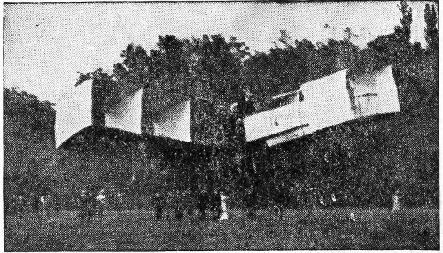
Santos-Dumont flying at Bagatelle in his cellular biplane.
October 24, 1906—Santos-Dumont with biplane, at Bagatelle, flies 160 feet in 4 seconds.
November 13, 1906—Santos-Dumont with biplane, at Bagatelle, flies 722 feet in 21 seconds. This feat is recorded as the first aeroplane flight made in Europe.
March 16, 1907—Leon Delagrange with first Voisin biplane, at Bagatelle, flies 30 feet. 413
August 6, 1907—Louis Bleriot with a Langley machine, at Issy, France, flies 470 feet.
October 15, 1907—Henry Farman with biplane, at Issy, flies 937 feet in 21 seconds.
October 19, 1907—R. Esnault-Pelterie with monoplane, at Buc, France, makes short flights.
October 26, 1907—Farman with biplane, at Issy, flies 2,529 feet in a half circle, in 52 seconds.
November 17, 1907—Santos-Dumont with biplane, at Issy, makes several short flights, the longest being about 500 feet.
November 21, 1907—Santos-Dumont with monoplane at Bagatelle, makes several short flights, the longest being about 400 feet.
January 13, 1908—Farman with biplane, at Issy, makes the first flight in a circular course—3,279 feet in 1 minute and 28 seconds.
March 12, 1908—F. W. Baldwin with biplane “Red Wing,” at Hammondsport, N. Y., flies 319 feet.
March 21, 1908—Farman with biplane, at Issy, flies 1.24 miles in 3 minutes and 31 seconds.
March 29, 1908—Delagrange with biplane, at Ghent, Belgium, makes first recorded flight with one passenger (Farman), 453 feet.
April 11, 1908—Delagrange with biplane at Issy, 414 flies 2.43 miles in 6 minutes and 30 seconds, winning the Archdeacon cup.
May 18, 1908—J. A. D. McCurdy with biplane “White Wing” at Hammondsport, flies 600 feet.
May 27, 1908—Delagrange with biplane, at Rome, in the presence of the King of Italy, flies 7.9 miles in 15 minutes and 25 seconds.
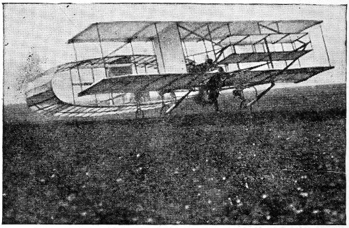
The early Voisin biplane flown by Farman at Issy.
May 30, 1908—Farman with biplane, at Ghent, flies 0.77 miles with one passenger (Mr. Archdeacon).
June 8, 1908—Esnault-Pelterie with monoplane, at Buc, flies 0.75 miles, reaching an altitude of 100 feet.
June 22, 1908—Delagrange with biplane, at Milan, 415 Italy, flies 10.5 miles in 16 minutes and 30 seconds.
July 4, 1908—Glenn H. Curtiss with biplane, at Hammondsport, flies 5,090 feet, in 1 minute and 42 seconds, winning Scientific American cup.
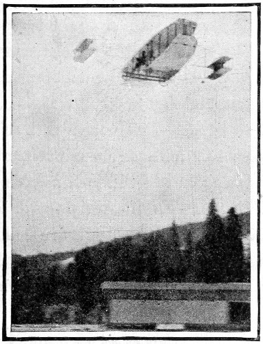
The “June Bug” flown by Curtiss winning the Scientific American cup, July 4, 1908.
July 4, 1908—Bleriot with monoplane, at Issy, flies 3.7 miles in 5 minutes and 47 seconds, making several circles.
July 6, 1908—Farman in biplane, at Ghent, flies 416 12.2 miles in 19 minutes and 3 seconds, winning the Armengand prize.
July 8, 1908—Delagrange with biplane, at Turin, Italy, flies 500 feet with the first woman passenger ever carried on an aeroplane—Mrs. Peltier.
August 9, 1908—Wilbur Wright with biplane, at Le Mans, France, makes several short flights to prove the ease of control of his machine.
August 8, 1908—L. F. Ferber with biplane, at Issy, makes first trial flights.
September 6, 1908—Delagrange with biplane, at Issy, flies 15.2 miles in 29 minutes and 52 seconds, beating existing French records.
September 8, 1908—Orville Wright with biplane, at Fort Myer, Va., flies 40 miles in 1 hour and 2 minutes, rising to 100 feet.
September 9, 10, 11, 1908—Orville Wright with biplane, at Fort Myer, makes several flights, increasing in duration from 57 minutes to 1 hour ten minutes and 24 seconds.
September 12, 1908—Orville Wright with biplane, at Fort Myer, flies 50 miles in 1 hour, 14 minutes and 20 seconds, the longest flight on record.
September 12, 1908—Orville Wright with biplane, 417 at Fort Myer, flies for 9 minutes and 6 seconds with one passenger (Major Squier), making a new record.
September 17, 1908—Orville Wright with biplane, at Fort Myer, flies 3 miles in 4 minutes, with Lieutenant Selfridge. The machine fell: Selfridge was killed and Wright severely injured.
September 19, 1908—L. F. Ferber with biplane, at Issy, flies 1,640 feet.
September 21, 1908—Wilbur Wright with biplane, at Auvours, flies 41 miles in 1 hour and 31 minutes.
September 25, 1908—Wilbur Wright with biplane, at Le Mans, France, flies 11 minutes and 35 seconds, with one passenger, making a new record.
October 3, 1908—Wilbur Wright with biplane, at Le Mans, France, flies 55 minutes and 37 seconds, with one passenger, making new record.
October 6, 1908—Wilbur Wright with biplane, at Le Mans, flies 1 hour 4 minutes and 26 seconds, with one passenger, breaking all records.
October 10, 1908—Wilbur Wright with biplane, at Auvours, flies 46 miles in 1 hour and 9 minutes, with one passenger (Mr. Painleve). Also carried 35 others on different trips, one at a time. 418
October 21, 1908—Bleriot with monoplane, at Toury, France, flies 4.25 miles in 6 minutes and 40 seconds.
October 30, 1908—Farman with biplane at Chalons, France, makes a flight across country to Rheims—17 miles in 20 minutes.
October 31, 1908—Farman with biplane, at Chalons, flies 23 minutes, reaching a height of 82 feet.
October 31, 1908—Bleriot with monoplane, at Toury, flies 8.7 miles to Artenay, in 11 minutes, lands, and returns to Toury.
December 18, 1908—Wilbur Wright with biplane, at Auvours, flies 62 miles in 1 hour and 54 minutes, rising to 360 feet—making a world record.
December 31, 1908—Wilbur Wright with biplane, at Le Mans, flies 76.5 miles in 2 hours 18 minutes and 53 seconds, making a new world record, and winning the Michelin prize. The distance traversed (unofficial) is claimed to have been actually over 100 miles.
January 28, 1909—Moore-Brabazon with biplane, at Chalons, flies 3.1 miles, in practice with a Voison machine.
February 14, 1909—Legagneux with biplane, at 419 Mourmelon, France, flies 1.2 miles, and in a second flight of 6.2 miles (10 kilometres), traces two circles.
February 22, 1909—S. F. Cody with biplane, at Aldershot, England, flies 1,200 feet in a 12-mile wind.
February 23, 1909—J. A. D. McCurdy, with the biplane “Silver Dart,” at Baddeck, Cape Breton, flies 2,640 feet.
February 24, 1909—McCurdy, with the biplane “Silver Dart,” at Baddeck, flies 4.5 miles.
February 24, 1909—Moore-Brabazon, with biplane, at Issy, flies 1.2 miles, tracing two circles.
February 28, 1909—Moore-Brabazon made several flights at Issy.
March 8, 1909—McCurdy, with biplane “Silver Dart,” at Baddeck, made five flights, the longest about 8 miles in 11 minutes and 15 seconds.
March 10, 1909—Santos-Dumont, with monoplane “Libellule,” at Bagatelle, flies 1,300 feet.
March 11, 1909—W. J. Richardson with a new form of aeroplane, at Dayton, O., flies for 38 minutes, rising to a height of over 300 feet.
March 11, 1909—McCurdy with biplane “Silver Dart,” at Baddeck, flies 19 miles in 22 minutes. 420
March 17, 1909—Count de Lambert (pupil of Wilbur Wright) made his first flight alone in biplane, at Pau, France. He remained in the air 3 minutes.
March 18, 1909—McCurdy, with biplane “Silver Dart,” at Baddeck, flies 16 miles, completing a record of an even 1,000 miles in the air within a period of 10 months.
March 18, 1909—F. W. Baldwin with biplane “Silver Dart,” at Baddeck, made a short flight.
March 20, 1909—Wilbur Wright, with biplane, at Pau, succeeds in rising from the ground without the starting device previously used. He makes several flights.
March 24, 1909—Count de Lambert with biplane, at Pau, flies 15.6 miles in 27 minutes and 11 seconds.
April 10, 1909—Santos-Dumont with monoplane “Demoiselle,” at St. Cyr, France, flies 1.2 miles.
April 13, 1909—Count de Lambert with biplane, at Pau, flies for 1 minute and 30 seconds, with one passenger (Leon Delagrange).
April 16, 1909—Wilbur Wright with biplane, at Rome, Italy, made many flights, taking up many passengers, one at a time. 421
April 27, 1909—Legagneux with Voisin biplane, at Vienna, flies 2.5 miles in 3 minutes and 26 seconds.
April 28, 1909—Lieutenant Mario Calderara (pupil of Wilbur Wright) with biplane, at Rome, made his first public flight, remaining in the air 10 minutes.
April 30, 1909—Moore-Brabazon with biplane, in England, flies 4.5 miles.
May 14, 1909—S. F. Cody, with the army biplane, at Aldershot, flies 1 mile.
May 19, 1909—Hubert Latham, with Antoinette monoplane, at Chalons, flies 1,640 feet.
May 20, 1909—Paul Tissandier (pupil of Wilbur Wright) with biplane at Pau, flies 35.7 miles.
May 23, 1909—Delagrange, with biplane, at Juvissy, flies 3.6 miles in 10 minutes and 18 seconds, winning the Lagatineri prize.
May 23, 1909—Henri Rougier, with biplane, at Juvissy, flies 18.6 miles (30 kilometres).
May 30, 1909—Bleriot, with monoplane at Issy, flies 8.7 miles.
June 5, 1909—Latham, with monoplane, at Chalons, flies for 1 hour 7 minutes and 37 seconds in wind and rain. 422
June 6, 1909—Latham, with monoplane, at Juvissy, flies 10 miles across country.
June 12, 1909—Latham, with monoplane, at Juvissy, flies 30 miles in 39 minutes, winning the Goupy prize.
June 12, 1909—Delagrange, with biplane, at Juvissy, makes cross country flight of 3.7 miles.
June 12, 1909—Bleriot, with monoplane, at Juvissy, flies 984 feet, with two passengers—Santos-Dumont and Fournier.
June 13 1909—Ferber, with Voisin biplane, at Juvissy, flies 3.1 miles in 5 minutes and 30 seconds.
June 19, 1909—Santos-Dumont, with monoplane, at Issy, makes several flights.
July 4, 1909—Roger Sommer with biplane, at Chalons, flies 3.75 miles on Farman machine.
July 10, 1909—Louis Paulhan, with biplane, at Douai, France, makes his first flight—1.25 miles.
July 13, 1909—Curtiss, with biplane, at Mineola, L. I., flies 1.5 miles in 3 minutes.
July 13, 1909—Bleriot, with monoplane, at Mondesir, makes a flight of 26 miles across country in 44 minutes and 30 seconds.
July 15, 1909—Paulhan with biplane, at Douai, 423 flies for 1 minute and 17 seconds, soaring to an altitude of 357 feet.
July 17, 1909—Orville Wright, with biplane, at Fort Myer, flies 16 minutes and 40 seconds, at a speed of 40 miles an hour.
July 17, 1909—Curtiss, with biplane, at Mineola, makes 15 miles in 21 minutes, describing circles in both directions, as in the figure 8.
July 18, 1909—Curtiss, with biplane, at Hempstead Plains, L. I., flies 29½ miles in 52 minutes and 30 seconds, a flight exceeded only by the Wrights, in America, and Bleriot, Latham, and Paulhan, in Europe.
July 18, 1909—Farman, with biplane, at Chalons, flies for 1 hour and 23 minutes, making his first long flight.
July 18, 1909—Sommer, with biplane, at Chalons, makes his longest flight—1 hour and 40 minutes.
July 19, 1909—Latham, with monoplane, at Calais, France, makes his first attempt to cross the Channel to Dover. He flies 11 miles, and then his machine falls into the sea.
July 19, 1909—Paulhan, with biplane, at Douai, makes a cross-country flight of 12.1 miles in 22 minutes and 53 seconds. 424
July 20, 1909—Orville Wright, with biplane, at Fort Myer, flies 1 hour and 20 minutes.
July 21, 1909—Orville Wright, with biplane, at Fort Myer, flies 1 hour and 29 minutes.
July 21, 1909—E. Lefebvre, with biplane, at La Haye, France, flies 2 miles.
July 21, 1909—S. F. Cody, with biplane, at Aldershot, flies 4 miles.
July 23, 1909—Farman, with biplane, at Chalons, makes a cross-country flight to Suippes—40 miles in 1 hour and five minutes.
July 23, 1909—Paulhan, with biplane, at Douai, flies 43.5 miles in 1 hour 17 minutes and 19 seconds.
July 24, 1909—Curtiss in biplane, at Hempstead Plains, flies 25 miles in 52 minutes and 30 seconds, winning the Scientific American cup the second time.
July 25, 1909—Bleriot, with monoplane, at Calais, flies to Dover, England, across the English Channel—32 miles in 37 minutes.
July 27, 1909—Orville Wright, with biplane, at Fort Myer, flies 1 hour and 13 minutes, with one passenger, securing acceptance of Wright machine 425 by U. S. Government on the duration specifications.
July 27, 1909—Latham, with monoplane, at Calais, flies 20 miles in a second attempt to cross the English Channel. When near Dover the machine fell.
July 27, 1909—Sommer, with biplane, at Chalons, flies to Vadenay and back—25 miles in 1 hour 23 minutes and 30 seconds.
July 30, 1909—Orville Wright, with biplane, at Fort Myer, established a world record with one passenger in a cross-country flight to Shuter’s Hill and back—about 10 miles in 14 minutes and 40 seconds, a speed of about 42 miles an hour—winning a bonus of $25,000 from the U. S. Government.
August 1, 1909—Sommer, with biplane, at Chalons, flies 1 hour 50 minutes and 30 seconds, at an average height of 80 feet, over a distance estimated at 70 miles, surpassing all French records.
August 2, 1909—McCurdy, with a new type of machine, at Petawawa, makes several flights.
August 2, 1909—F. W. Baldwin, with biplane, at Petawawa, makes several short flights.
August 2, 1909—Sommer, with biplane, at Chalons, 426 flies to Suippes—9 miles, at the rate of 45 miles an hour.
August 4, 1909—Sommer, with biplane, at Chalons, in the effort to beat Wilbur Wright’s record, flies for 2 hours 0 minutes and 10 seconds (Wright’s record flight was 2 hours 20 minutes and 23 seconds, made on December 31, 1908).
August 5, 1909—E. Bunau-Varilla, with Voisin biplane, at Chalons, flies for 15 minutes.
August 6, 1909—Legagneux, with biplane, at Stockholm, flies with one passenger, 3,280 feet.
August 6, 1909—Paulhan, with biplane, at Dunkerque, France, flies for 18 minutes and 20 seconds, reaching an altitude of 200 feet.
August 7, 1909—Paulhan, with Voisin biplane, at Dunkerque, flies 23 miles in 33 minutes.
August 7, 1909—Sommer, with Voisin biplane, at Chalons, flies for 2 hours 27 minutes and 15 seconds, making new world record for duration.
August 13, 1909—Charles F. Willard, with biplane, at Hempstead Plains, made the longest cross-country flight on record for America—about 12 miles in 19 minutes and 30 seconds. The breaking of his engine caused him to come down. He landed without mishap. 427
August 22, 1909—Sommer, with biplane, at Rheims, France, flies 1 hour 19 minutes and 30 seconds.
August 22, 1909—Legagneux, with biplane, at Rheims, flies 6.2 miles in 9 minutes and 56 seconds, winning third prize for speed over course of 10 kilometres.
August 22, 1909—Tissandier, with biplane, at Rheims, flies 18.6 miles in 29 minutes. (He won with this record the third prize for speed over 30 kilometres.)
August 22, 1909—E. Bunau-Varilla, with biplane, at Rheims, flies 6.2 miles in 13 minutes and 30 seconds. (With this record he won the thirteenth prize for speed over course of 10 kilometres.)
August 23, 1909—Delagrange, with monoplane, at Rheims, flies 6.2 miles in 11 minutes and 4 seconds. (He won the tenth prize for speed over 10 kilometres.)
August 23, 1909—Curtiss, with biplane, at Rheims, flies 6.2 miles in 8 minutes and 35 seconds—a speed of 42.3 miles an hour—beating the record for speed over course of 10 kilometres.
August 23, 1909—Paulhan, with biplane, at Rheims, flies 18.6 miles in 38 minutes and 12 seconds, reaching an altitude of 295 feet. 428
August 23, 1909—Paulhan, with biplane, at Rheims, flies 34.8 miles in an endurance test.
August 25, 1909—Paulhan, with biplane, at Rheims, flies 82 miles in 2 hours 43 minutes and 25 seconds. (With this record he won the third prize for duration of flight.)
August 25, 1909—Curtiss, with biplane, at Rheims, flies 6.2 miles in 8 minutes and 44 seconds, again reducing the time for 10 kilometres.
August 25, 1909—Bleriot, with monoplane, at Rheims, flies 6.2 miles in 8 minutes and 4 seconds, making a new record for speed over the course of 10 kilometres.
August 26, 1909—Curtiss, in biplane, at Rheims, flies 19 miles in 29 minutes. (With this record he won the tenth prize for duration of flight.)
August 26, 1909—Count de Lambert, with biplane, at Rheims, flies 72 miles in 1 hour and 52 minutes. (With this record he won the fourth prize for duration of flight.)
August 26, 1909—Latham, with monoplane, at Rheims, flies 96.5 miles in 2 hours 17 minutes and 21 seconds. (With this record he won the second prize for duration of flight.)
August 27, 1909—Farman, with biplane, at Rheims, 429 flies 112 miles in 3 hours 4 minutes and 57 seconds. (This record won for him the first prize for duration of flight.)
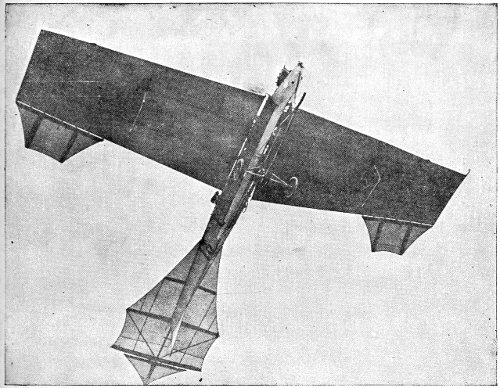
Latham flying in his Antoinette at Rheims. To view this properly the picture should be held overhead.
August 27, 1909—Latham, with monoplane, at Rheims, flies to an altitude of 508 feet. (With this record he won first prize for altitude.)
August 27, 1909—Delagrange, with monoplane, at Rheims, flies 31 miles. (With this record he won the eighth prize for duration of flight.) 430
August 27, 1909—Sommer, with biplane, at Rheims, flies 37 miles. He won the seventh prize for distance.
August 27, 1909—Tissandier, with biplane, at Rheims, flies 69 miles. (This record won for him the sixth prize for distance.)
August 27, 1909—Lefebvre, with biplane, at Rheims, flies 12.4 miles in 20 minutes and 47 seconds, exhibiting great daring and skill. (He was fined for “recklessness.”)
August 27, 1909—Bleriot, with monoplane, at Rheims, flies 25 miles in 41 minutes. (This record won for him the ninth prize for distance flown.)
August 28, 1909—Lefebvre, with biplane, at Rheims, makes a spectacular flight for 11 minutes with one passenger.
August 28, 1909—Curtiss, with biplane, at Rheims, flies 12.4 miles in 15 minutes and 56 seconds, winning the Gordon Bennett cup.
August 28, 1909—Bleriot, with monoplane, at Rheims, flies 6.2 miles in 7 minutes and 48 seconds. (With this record he won the first prize for speed over course of 10 kilometres.)
August 29, 1909—Farman, with biplane, at Rheims, 431 flies 6.2 miles with two passengers, in 10 minutes and 30 seconds, winning a prize.
August 29. 1909—Curtiss, with biplane, at Rheims, flies 18.6 miles in 23 minutes and 30 seconds. (With this record he won the first prize for speed over course of 30 kilometres.)
August 29, 1909—Curtiss, with biplane, at Rheims, flies 6.2 miles in 7 minutes and 51 seconds, winning the second prize for speed over course of 10 kilometres.
August 29, 1909—Rougier, with biplane, at Rheims, rises to a height of 180 feet, winning the fourth prize for altitude.
August 29, 1909—E. Bunau-Varilla, with biplane, at Rheims, flies 18.6 miles in 38 minutes and 31 seconds. (With this record he won the eighth prize for speed over course of 30 kilometres.)
August 29, 1909—Orville Wright, with biplane, at Berlin, makes several short flights.
August 29, 1909—S. F. Cody, with biplane, at Aldershot, flies 10 miles with one passenger.
September 4, 1909—Orville Wright, with biplane, at Berlin, flies for 55 minutes.
September 6, 1909—Sommer, with biplane, at Nancy, 432 France, flies 25 miles in 35 minutes. He takes up a number of passengers; one at a time.
September 7, 1909—Lefebvre, with biplane, at Juvissy, is killed by the breaking of his machine in the air after he had flown 1,800 feet.
September 8, 1909—Orville Wright, with biplane, at Berlin, flies 17 minutes with one passenger—Captain Hildebrandt.
September 8, 1909—S. F. Cody, with biplane, at Aldershot, flies to Farnborough and back—46 miles in 1 hour and 3 minutes. This is the first recorded cross-country flight in England.
September 9, 1909—Orville Wright, with biplane, at Berlin, flies for 15 minutes with one passenger—Captain Englehardt.
September 9, 1909—Paulhan, with biplane, at Tournai, Belgium, flies 12.4 miles in 17 minutes.
September 9, 1909—Rougier, with biplane, at Brescia, flies 12 minutes and 10 seconds, soaring to a height of 328 feet.
September 10, 1909—Sommer, with biplane, at Nancy, flies 18 miles, accompanying troops on review.
September 11, 1909—Sommer, with biplane, at Nancy, flies to Lenoncourt—24 miles. 433
September 11, 1909—Curtiss, with biplane, at Brescia, flies 31 miles in 49 minutes and 24 seconds, winning the first prize for speed.
September 12, 1909—Rougier, with biplane, at Brescia, flies 31 miles in 1 hour 10 minutes and 18 seconds, soaring to a height of 380 feet.
September 12, 1909—Calderara, with biplane, at Brescia, flies 6.3 miles with one passenger, winning a prize.
September 13, 1909—Paulhan, with biplane, at Tournai, flies to Taintiguies and back in 1 hour and 35 minutes.
September 13, 1909—Santos-Dumont, with monoplane, at St. Cyr, France, flies 5 miles in 12 minutes, to Buc, to visit Maurice Guffroy, on a bet of $200 that each would be the first to visit the other.
September 15, 1909—Ferber, with biplane, at Boulogne, France, flies to Wimeroux—6 miles in 9 minutes.
September 15, 1909—Calderara, with biplane, at Brescia, flies 5.6 miles with one passenger, winning the Oldofredi prize.
September 17, 1909—Orville Wright, with biplane, at Berlin, flies for 54 minutes and 26 seconds, 434 rising to an altitude of 765 feet (estimated). He afterward flew for 47 minutes and 5 seconds with Captain Englehardt.
September 17, 1909—Santos-Dumont, with monoplane, at St. Cyr, flies 10 miles in 16 minutes across country.
September 17, 1909—Paulhan, with biplane, at Ostend, Belgium, flies 1.24 miles in 3 minutes and 16 seconds, along the water front and out over the sea.
September 18, 1909—Orville Wright, with biplane, at Berlin, establishes a world record by flying for 1 hour 35 minutes and 47 seconds, with one passenger—Captain Englehardt.
September 18, 1909—Paulhan, with biplane, at Ostend, flies for 1 hour over sea front, circling over the water; winning a prize of $5,000.
September 20, 1909—Rougier, with biplane, at Brescia, broke the record for high flying by reaching an altitude of 645 feet (official measurement).
September 20, 1909—Calderara, with biplane, at Brescia, flies 31 miles in 50 minutes and 51 seconds, winning the second prize for speed.
September 22, 1909—Captain Ferber, with a biplane, 435 at Boulogne, flies 1 mile, when, his engine breaking in the air, his machine falls and he is killed.
September 25, 1909—Wilbur Wright, with biplane, at New York, flies from Governor’s Island around the Statue of Liberty.
September 27, 1909—Latham, in monoplane, at Berlin, flies 6.5 miles across country in 13 minutes.
September 28, 1909—Rougier, with biplane, at Berlin, flies 31 miles in 54 minutes, soaring to an altitude of 518 feet.
September 29, 1909—Latham in monoplane, at Berlin, flies 42 miles in 1 hour and 10 minutes, winning the second prize for distance.
September 29, 1909—Rougier, with biplane, at Berlin, flies 48 miles in 1 hour and 35 minutes.
September 29, 1909—Curtiss, with biplane, at New York, makes flights about the harbor from Governor’s Island.
September 30, 1909—Orville Wright, with biplane, at Berlin, soars to a height of 902 feet, making a world record for altitude.
September 30, 1909—Latham, with monoplane, at Berlin, flies 51 miles in 1 hour and 23 minutes. 436
October 1, 1909—Rougier, with biplane, at Berlin, flies 80 miles in 2 hours and 38 minutes, winning the first prize for distance and speed.
October 2, 1909—Orville Wright, with biplane, at Berlin, makes a flight of 10 minutes’ duration with the Crown Prince of Germany.
October 3, 1909—Farman, with biplane, at Berlin, flies 62 miles in 1 hour and 40 minutes, winning the third prize for distance and speed.
October 4, 1909—Orville Wright, with biplane, at Berlin, soared to an altitude of 1,600 feet, making a world record.
October 4, 1909—Wilbur Wright, with biplane, at New York, flies from Governor’s Island to Grant’s Tomb and back—21 miles in 33 minutes and 33 seconds.
October 10, 1909—Curtiss, with biplane, at St. Louis, Mo., makes several flights at the Centennial celebration.
October 10, 1909—Paulhan, with biplane, at Pt. Aviation, flies 21.5 miles in 21 minutes and 48 seconds.
October 12, 1909—Paulhan, with biplane, at Pt. Aviation, flies 3.6 miles in 6 minutes and 11 seconds, winning the prize for slowest flight. 437
October 16, 1909—Curtiss, with biplane, at Chicago, makes exhibition flights at 45 miles per hour.
October 16, 1909—Sommer, with biplane, at Doncaster, England, flies 9.7 miles in 21 minutes and 45 seconds, making the record for Great Britain.
October 16, 1909—Delagrange, with monoplane, at Doncaster, flies 5.75 miles in 11 minutes and 25 seconds.
October 16, 1909—Cody, with biplane, at Doncaster, flies 3,000 feet, when his machine is wrecked, and he is injured.
October 18, 1909—Paulhan, with biplane, at Blackpool, England, flies 14 miles in 25 minutes and 53 seconds.
October 18, 1909—Rougier, with biplane, at Blackpool, flies 17.7 miles in 24 minutes and 43 seconds, winning the second prize.
October 18, 1909—Farman, with biplane, at Blackpool, flies 14 miles in 23 minutes.
October 18, 1909—Le Blon, with monoplane, at Doncaster, flies 22 miles in 30 minutes, in a rainstorm, winning the Bradford cup.
October 18, 1909—Count de Lambert, with biplane, at Juvissy, flies 31 miles to the Eiffel Tower in Paris, and back, in 49 minutes and 39 seconds. 438
October 19, 1909—Le Blon, with monoplane, at Doncaster, flies 15 miles in a gale.
October 19, 1909—Paulhan, with biplane, at Blackpool, flies 15.7 miles in 32 minutes and 18 seconds, winning the third prize.
October 20, 1909—Farman, with biplane, at Blackpool, flies 47 miles in 1 hour, 32 minutes, and 16 seconds, winning the first prize—$10,000.
October 20, 1909—Le Blon, with monoplane, at Doncaster, makes a spectacular flight in a fierce gale.
October 21, 1909—Count de Lambert, with biplane, at Pt. Aviation, flies 1.25 miles in 1 minute and 57 seconds, winning prize of $3,000 for speed.
October 22, 1909—Latham, with monoplane, at Blackpool, flies in a squally gale blowing from 30 to 50 miles an hour. When headed into the wind the machine moved backward in relation to points on the ground. Going before the wind, it passed points on the ground at a speed of nearly 100 miles an hour. This flight, twice around the course, is the most difficult feat accomplished by any aviator up to this date.
October 26, 1909—Sommer, with biplane, at Doncaster, 439 flies 29.7 miles in 44 minutes and 53 seconds, winning the Whitworth cup.
October 26, 1909—Delagrange, with monoplane, at Doncaster, flies 6 miles in 7 minutes and 36 seconds—a speed of over 50 miles an hour.
October 30, 1909—Moore-Brabazon, with biplane, at Shell Beach, England, wins a prize of $5,000 for flight with a British machine.
November 3, 1909—Farman, with biplane, at Mourmelon, France, flies 144 miles in 4 hours 6 minutes and 25 seconds, far surpassing his previous best record of 112 miles in 3 hours 4 minutes and 57 seconds, made at Rheims, and winning the Michelin cup for duration and distance.
November 19, 1909—Paulhan, with biplane, at Mourmelon, broke the record for height by ascending to 1,170 feet, in a wind blowing from 20 to 25 miles an hour.
November 19, 1909—Latham, with Antoinette monoplane, surpassed Paulhan’s record by rising to an altitude of 1,333 feet.
November 20, 1909—Paulhan, with biplane, at Mourmelon, flies to Chalons and back—37 miles in 55 minutes.
December 1, 1909—Latham, with monoplane, at 440 Mourmelon, soars to 1,500 feet in a 40-mile gale.
December 30, 1909—Delagrange, with monoplane, at Juvissy, flies 124 miles in 2 hours and 32 minutes—an average speed of 48.9 miles per hour, surpassing all previous records.
December 31, 1909—Farman at Chartres, France, flies to Orleans—42 miles in 50 minutes.
December 31, 1909—Maurice Farman, at Mourmelon, defending his brother Henry’s record against competing aviators, flies 100 miles in 2 hours and 45 minutes, without a fault. The Michelin cup remains in his brother’s possession.
January 7, 1910—Latham, with Antoinette monoplane, at Chalons, rises to height of 3,281 feet (world’s record).
January 10, 1910—Opening of aviation meet at Los Angeles, Cal.
January 12, 1910—Paulhan, Farman biplane, at Los Angeles, rises to height of 4,146 feet. (World’s record.)
January 17, 1910—Paulhan, Farman biplane, at Los Angeles, flies 75 miles in 1 hour 58 minutes and 27⅖ seconds.
February 7, 1910—First flight in South America. 441 Bregi, Voisin biplane, makes two flights near Buenos Aires.
February 7, 1910—Duray, with Farman biplane, at Heliopolis, Egypt, flies 5 kilometres in 4 minutes and 12⅘ seconds. (World’s record.)
April 8, 1910—D. Kinet, with Farman biplane, at Mourmelon, flies for 2 hours 19 minutes and 4⅖ seconds with passenger, covering 102 miles. (World’s record for passenger flight.)
April 11, 1910—E. Jeannin, with Farman biplane, flies 2 hours 1 minute and 55 seconds, at Johannisthal. (German record.)
April 15, 1910—Opening of Nice meeting.
April 17, 1910—Paulhan, with Farman biplane, flies from Chevilly to Arcis-sur-Aube, 118 miles. (Record cross-country flight.)
April 23, 1910—Grahame-White, with Farman biplane, flies from Park Royal, London, to Rugby (83 miles) in 2 hours and 1 minute. Starting again in 55 minutes, flies to Whittington in 1 hour and 5 minutes.
April 27, 1910—Paulhan, with Farman biplane, starts from Hendon, London, at 5.31 P. M., flies within 5 mile circle and continues to Lichfield, arriving 8.10 P. M. (117 miles). Grahame-White 442 starts from Wormwood Scrubs, London, at 6.29 P. M., flies to Roade, arriving 7.55 P. M. (60 miles).
April 28, 1910—Paulhan flies from Lichfield to within 5 miles of Manchester, winning the £10,000 Daily Mail prize.
April 30, 1910—Opening of meeting at Tours, France.
May 1, 1910—Opening of flying-week at Barcelona.
May 3, 1910—Wiencziers, with Antoinette monoplane, twice circles the Strassburg cathedral.
May 6, 1910—Olieslagers, with Bleriot monoplane, makes flight of 18 minutes and 20 seconds above the sea at Barcelona, and over the fortress of Monjuich.
May 13, 1910—Engelhardt, with Wright biplane, at Berlin, flies 2 hours 21 minutes and 45 seconds. (German record.)
May 15, 1910—Kinet, with Farman biplane, flies 2 hours and 51 minutes with a passenger at Mourmelon, making the world’s record for passenger flight.
May 15, 1910—Olieslagers, with Bleriot monoplane, flies 15 miles over the sea at Genoa.
May 21, 1910—M. de Lesseps, with Bleriot monoplane, 443 flies from Calais to Dover in 37 minutes, winning £500 prize offered by M. M. Ruinart.
May 28, 1910—G. Curtiss, with Curtiss biplane, starts from Albany at 7.03 A. M., flies to Poughkeepsie in 1 hour and 21 minutes (70 miles). Leaves Poughkeepsie at 9.24 A. M., flies to Spuyten Duyvil in 1 hour and 11 minutes (67 miles). Rises again at 11.45, flies over New York, landing on Governor’s Island at 12.03 P. M. Wins prize of $10,000 given by the New York World.
June 2, 1910—Rolls, with Short-Wright biplane, leaves Dover at 6.30 P. M., crosses Channel to French coast near Calais (7.15 P. M.), without landing re-crosses Channel to Dover, flies over harbor, circles Dover Castle, and lands at 8.10 P. M. Wins second Ruinart prize of £80.
June 14, 1910—Brookins, with Wright biplane, at Indianapolis, reaches height of 4,380 feet. (World’s record.)
June 25, 1910—In Italian Parliament 25 million lire (about $5,000,000) voted for aviation in the extraordinary estimates of the Ministry of War.
June 26, 1910—Dickson, with Farman biplane, at Rouen, wins total distance prize of £2,000 and 444 the £400 for longest unbroken flight. Distance flown, 466 miles.
June 27, 1910—M. de Lesseps, with Bleriot monoplane, flies over Montreal for 49 minutes, covering about 30 miles at height generally of 2,000 feet.
July 6, 1910—First German military aeroplane makes maiden cross-country flight over Doeberitz.
July 26, 1910—M. de Lesseps, with Bleriot monoplane, starting from Ile de Gros Bois in the St. Lawrence, makes trip of 40 miles in 37 minutes.
August 1, 1910—Henry Farman takes up three passengers at Mourmelon for 1 hour and 4 minutes.
August 5, 1910—Chavez, with Bleriot monoplane, attains height of 5,750 feet. World’s record.
August 7, 1910—Lieutenants Cammerman and Villerme fly together from Mourmelon to Nancy, 125 miles in 2½ hours, with a Farman biplane.
August 11, 1910—Drexel, with Bleriot monoplane, at Lanark, beats the world’s record for height, rising 6,600 feet.
August 27, 1910—First wireless telegram from a flying aeroplane, sent by McCurdy from a Curtiss machine in the air, at Atlantic City, N. J. 445 The sending key was attached to the steering wheel.
August 28, 1910—Dufaux, with biplane constructed by himself, flies over Lake Geneva, wins prize of £200 offered by Swiss Aero Club.
August 29, 1910—Breguet, with Breguet monoplane, makes a flight at Lille, France, carrying five passengers, establishing world’s record for passenger flight.
August 29, 1910—Morane, with Bleriot monoplane, at Havre, beats world’s altitude record, reaches height of 7,166 feet.
September 2, 1910—Mlle. Hélène Dutrieux flies with a passenger from Ostend to Bruges, Belgium, and back to Ostend. At Bruges she circled around the famous belfry at a height of 1,300 feet, the chimes pealing in honor of the feat—the most wonderful flight so far accomplished by a woman.
September 3, 1910—M. Bielovucci lands at Bordeaux, France, having made the trip from Paris, 366 miles, inside of 48 hours. The actual time in the air was 7 hours 6 minutes. Strong head winds blew him backward, forcing a landing three times on the way. This is the fourth longest 446 cross-country flight on record, and makes the world’s record for sustained speed over a long distance.
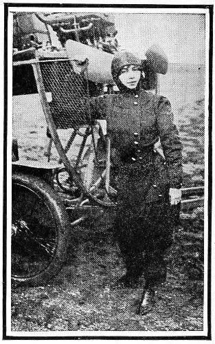
Mlle. Hélène Dutrieux.
September 4, 1910—Morane, at Havre, rises to height of 8,469 feet.
September 7, 1910—Weyman, with Farman biplane, flies from Buc in attempt to reach the top of the Puy-de-Dôme, lands at Volvic, 5 miles from his 447 destination. Establishes world’s record for flight with passenger, having covered 139 miles without landing.
September 28, 1910—Chavez crosses the Alps on a Bleriot monoplane from Brigue, in Switzerland, to Domodossola, in Italy, flying over the Simplon Pass.
October 1, 1910—Henri Wynmalen, of Holland, with a biplane at Mourmelon, France, rises to a height of 9,121 feet, making a new world’s record for altitude.
October 4, 1910—Maurice Tabuteau recrossed the Pyrenees, in his return trip from San Sebastian to Biarritz, without accident or marked incident.
October 5, 1910—Leon Morane, the winner of nearly all the contests in the English meets for 1910, fell with his monoplane at Boissy St. Leger, during a contest for the Michelin cup, and was seriously injured.
October 8, 1910—Archibald Hoxsey, with a biplane, makes the longest continuous aeroplane flight recorded in America, between Springfield, Ill., and St. Louis, Mo.—104 miles.
October 12, 1910—Alfred Leblanc, with monoplane, at St. Louis, flies 13 miles in 10 minutes, a speed 448 of 78 miles per hour. It was not officially recorded, as a part of the distance was outside of the prescribed course.
October 14, 1910—Grahame-White flies from the Bennings Race Track 6 miles across the Potomac River to the Capitol at Washington, circles the dome, and then circles the Washington Monument, and finally alights with precision in Executive Street, between the Executive Offices and the building of the State, Army, and Navy Departments. After a brief call, he rose from the narrow street—but 20 feet wider than his biplane—and returned to the race track without untoward incident.
October 16, 1910—Wynmalen flies from Paris to Brussels, and returns, with one passenger, within the elapsed time of 27 hours 50 minutes, winning two prizes amounting to $35,000. The distance is 350 miles, and the actual time in the air was 15 hours 38 minutes.
October 25, 1910—J. Armstrong Drexel, with monoplane, at Belmont Park, L. I., rises to height of 7,105 feet, breaking previous records, and surpassing his own record of 6,600 feet, made at Lanark, Scotland. 449
October 26, 1910—Ralph Johnstone, in biplane, at Belmont Park, rises to the height of 7,313 feet, through sleet and snow, breaking the new American record made by Drexel the day before.
October 27, 1910—Johnstone, with biplane, at Belmont Park, rises to height of 8,471 feet, surpassing his own record of the day before and establishing a new American record. The feat was performed in a gale blowing nearly 60 miles per hour, and the aviator was carried 55 miles away from his starting point before he landed.
October 28, 1910—Tabuteau, with biplane, at Etampes, France, makes a new world’s endurance record of 6 hours’ continuous flight, covering a distance of 289 miles.
October 29, 1910—Grahame-White, with monoplane, at Belmont Park, wins the International speed race over the distance of 62.1 miles, in 1 hour 1 minute 4⅗ seconds.
October 29, 1910—Leblanc, with monoplane, at Belmont Park, makes a new world’s record for speed, reaching 70 miles per hour during the International speed race. Through a lack of fuel he lost the race to Grahame-White, after covering 59 miles in 52 minutes. 450
October 30, 1910—John B. Moisant, with monoplane, wins the race from Belmont Park around the Statue of Liberty in New York harbor, and the prize of $10,000. The distance is about 34 miles, and Moisant covered it in 34 minutes 39 seconds.
October 30, 1910—James Radley, with monoplane, at Belmont Park, wins the cross-country flight of 20 miles in 20 minutes 5 seconds.
October 31, 1910—Johnstone, with biplane, at Belmont Park, rises to a height of 9,714 feet, breaking the previous world’s record, made by Wynmalen on October 1.
October 31, 1910—Drexel, with monoplane, racing for altitude with Johnstone, reaches a height of 8,370 feet.
October 31, 1910—Moisant, with monoplane, at Belmont Park, wins the two-hour distance race with a record of 84 miles. His next nearest competitor covered but 57 miles.
November 14, 1910—Eugene Ely, with biplane, flew from a staging on the deck of the U. S. Cruiser Birmingham 8 miles to the shore near the mouth of Chesapeake Bay. The flight was intended to end at the Norfolk Navy Yard, but 451 an accident to the propeller at starting forced Ely to make directly for the shore.
November 17, 1910—Ralph Johnstone, holder of the world’s altitude record of 9,714 feet, was killed at Denver, Col., by a fall with his biplane.
November 23, 1910—Drexel, at Philadelphia, reaches an altitude of 9,970 feet, passing all other altitude records. Coming down he made a straight glide of seven miles.
December 2, 1910—Charles K. Hamilton, at Memphis, Tenn., flies 4 miles in 3 minutes 1 second, a speed of 79.2 miles per hour. This is a new world’s record.
452
Every development in human progress is marked by a concurrent development in language. To express the new ideas, new words appear, or new meanings are given to words already in use.
As yet, the vocabulary of aeronautics is in the same constructive and incomplete state as is the science to which it attempts to give voice, and the utmost that can be done at this time is to record such words and special meanings as are in use in the immediate present.
Adjusting Plane—A small plane, or surface, at the outer end of a wing, by which the lateral (from side to side) balance of an aeroplane is adjusted. It is not connected with the controlling mechanism, as are the ailerons—nor with any automatic device.
Aerodrome—A term used by Professor Langley as 453 a better name for the aeroplane; but latterly it has been applied to the buildings in which airships are housed, and also in a few instances, as a name for the course laid out for aeronautical contests.
Aerofoil—Another name for the aeroplane, suggested as more accurate, considering that the surfaces are not true planes.
Aeronef—Another name for an aeroplane.
Aeroplane—The type of flying machine which is supported in the air by a spread of surfaces or planes, formerly flat, and therefore truly “plane,” but of late more or less curved. Even though not absolutely accurate, this term has resisted displacement by any other.
Aerostat—A free balloon afloat in the air.
Aeronate—A captive balloon.
Aileron—A small movable plane at the wing-tips, or hinged between the main planes, usually at their outer ends, operated by the aviator to restore the lateral balance of the machine when disturbed.
Air-speed—The speed of aircraft as related to the air in which they are moving; as distinguished from land-speed (which see). 454
Alighting Gear—Devices on the under side of the aeroplane to take up the jar of landing after flight, and at the same time to check the forward motion at that moment.
Angle of Entry—The angle made by the tangent to the curve of the aeroplane surface at its forward edge, with the direction, or line, of travel.
Angle of Incidence—The angle made by the chord of the arc of a curved “plane,” or by the line of a flat plane, with the line of travel.
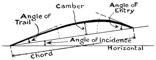
Angle of Trail—The angle made by the tangent to the rear edge of a curved plane with the line of travel.
Apteroid—A form resembling the “short and broad” type of the wings of certain birds—as distinguished from the pterygoid (which see).
Arc—Any part of a circle, or other curved line. 455
Arch—The curve formed by bending the wings downward at the tips, leaving them higher at the centre of the machine.
Aspect—The view of the top of an aeroplane as it appears when looked down upon from above.
Aspiration—The (hitherto) unexplained tendency of a curved surface—convex side upward—to rise and advance when a stream of air blows against its forward edge and across the top.
Attitude—The position of a plane as related to the line of its travel; usually expressed by the angle of incidence.
Automatic Stability—That stability which is preserved by self-acting, or self-adjusting, devices which are not under the control of the operator, nor a fixed part of the machine, as are the adjusting planes.
Aviation—Flying by means of power-propelled machines which are not buoyed up in the air, as with gas bags.
Aviator—The operator, driver, or pilot of an aeroplane.
Balance—Equilibrium maintained by the controlling mechanism, or by the automatic action of 456 balancing-surfaces—as distinguished from the equilibrium preserved by stabilizing surfaces.
Balancing Plane—The surface which is employed either intentionally, or automatically, to restore a disturbed balance.
Biplane—The type of aeroplane which has two main supporting surfaces or planes, placed one above the other.
Body—The central structure of an aeroplane, containing the machinery and the passenger space—as distinguished from the wings, or planes, and the tail.
Brace—A construction member of the framing of aircraft which resists a compression strain in a diagonal direction—as distinguished from a “stay,” or “diagonal,” which supports a pulling strain; also from a strut which supports a compression strain in a vertical direction.
Camber—The distance from the chord of the curve of a surface to the highest point of that curve, measured at right angles to the chord.
Caster, or Castor, Wheel—A wheel mounted on an upright pivoted shaft placed forward of its axle, 457 so that it swivels automatically to assume the line of travel of an aeroplane when landing: used in the alighting gear. To be distinguished from a fixed wheel, which does not swivel.
Cell—A structure with enclosing sides—similar to a box without top or bottom stood upon one side. The vertical walls of the cell give lateral stability, and its horizontal walls fore-and-aft stability.
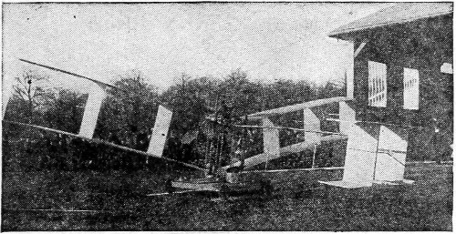
The first Santos-Dumont biplane, constructed of cells.
Centre of Gravity—That point of a body where its weight centres. If this point is supported, the body rests in exact balance.
Centre of Lift—The one point at which the lifting forces of the flying planes might be concentrated, and produce the same effect.
Centre of Resistance—The one point at which the forces opposing the flight of an air-craft might be concentrated, and produce the same result. 458
Centre of Thrust—The one point at which the forces generated by the revolving propellers might be concentrated, and produce the same effect.
Chassis—The under-structure or “running-gear” of an aeroplane.
Chord—The straight line between the two ends of an arc of a circle or other curved line.
Compound Control—A mechanical system by which several distinct controls are operated through different manipulations of the same lever or steering-wheel.
Compression Side—That side of a plane or propeller blade against which the air is compressed—the under surface of a flying plane, and the rear surface of a revolving propeller.
Curtain—The vertical surface of a cell—the wall which stands upright.
Deck—A main aeroplane surface. The term is used generally in describing biplanes; as the upper deck, and the lower deck; or with aeroplanes of many decks.
Demountable—A type of construction which permits a machine to be easily taken apart for transportation. 459
Derrick—A tower-shaped structure in which a weight is raised and allowed to fall to give starting impetus to an aeroplane.
Dihedral—That form of construction in which the wings of an aeroplane start with an upward incline at their junction with the body of the machine, instead of stretching out on a level.
Dirigible—The condition of being directable, or steerable: applied generally to the balloons fitted with propelling power, or airships.
Double Rudder—A rudder composed of two intersecting planes, one vertical and the other horizontal, thus enabling the operator to steer in any direction with the one rudder.
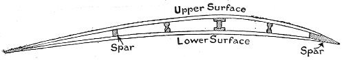
Double-Surfaced—Planes which are covered with fabric on both their upper and lower surfaces, thus completely inclosing their frames.
Down-Wind—Along with the wind; in the direction in which the wind is blowing.
Drift—The recoil of an aeroplane surface forced through the air: also the tendency to float in the same direction as the wind.
460
Elevator—A shorter name for the elevating planes or elevating rudder, used for directing the aeroplane upward or downward.
Ellipse—An oval figure outlined by cutting a cone through from side to side on a plane not parallel to its base. Some inventors use the curves of the ellipse in forming the wings of aeroplanes. See Hyperbola and Parabola.
Entry—The penetration of the air by the forward edge of aircraft surfaces. See Angle of Entry.
Equivalent Head Area—Such an area of flat surface as will encounter head resistance equal to the total of that of the construction members of the framework—struts, braces, spars, diagonals, etc., of the aerial craft.
Feathering—A form of construction in which mounting on hinges, or pivots, permits the surfaces to engage the air flatwise in one direction and to pass edgewise through it in other directions.
Fin—A fixed vertical stabilizing surface, similar in form to the fin on the back of a fish. 461
Fish Section—A term applied to the lengthwise section of an aircraft when the outline resembles the general shape of a fish—blunted in front and tapering toward the rear. This form is believed to encounter less resistance than any other, in passing through the air.
Fixed Wheel—A wheel in a fixed mounting, so that it does not swivel as does a caster wheel.
Flapping Flight—Flight by the up-and-down beating of wings, similar to the common flight of pigeons.
Flexible Propeller—A propeller in which the blades are frames covered more or less loosely with a fabric which is in a measure free to adjust its form to the compression of the air behind it as it revolves.
Flying Angle—The angle of incidence of the main surface of an aeroplane when in flight. See Ground Angle.
Footpound—The amount of force required to raise one pound to a height of one foot.
Fore-and-aft—From front to rear: lengthwise: longitudinal.
Fuselage—The framework of the body of an aeroplane.
462
Glider—A structure similar to an aeroplane, but without motive power.
Gliding—Flying down a slope of air with a glider, or with an aeroplane in which the propelling power is cut off.
Gliding Angle—The flattest angle at which a given machine will make a perfect glide. This angle differs with different machines. The flatter the gliding angle the safer the machine.
Ground Angle—The angle of incidence of an aeroplane surface when the machine is standing on the ground.
Guy—A wire attached to a more or less distant part of the structure of any aircraft to prevent spreading. Also used to denote controlling wires which transmit the movements of the levers.
Gyroscopic Action—The resistance which a rotating wheel, or wheel-like construction, exhibits when a disturbing force tends to change its plane of rotation.
Hangar—A structure for the housing of aeroplanes.
Head Resistance—The resistance encountered by a surface moving through the air. 463
Heavier-than-air—A term applied to flying machines whose weight is not counterbalanced or buoyed up by the lifting power of some gas lighter than air; and which weigh more than the volume of air displaced.
Helicopater—A type of flying machine in which propellers revolving horizontally lift and sustain its weight in the air.
Horizontal Rudder—The rudder surface which is used to steer an aircraft upward or downward: so-called because it lies normally in a position parallel to the horizon; that is, level.
Horse-power—An amount of work equivalent to the lifting of 33,000 footpounds in one minute. See Footpound.
Hyperbola—The outline formed by the cutting of a cone by a plane passing one side of its axis at such an angle that it would also intersect another cone placed apex to apex on the same axis.
Keel—A framework extending lengthwise under an aircraft to stiffen the construction: usually employed on airships with elongated gas-bags.
464
Lateral—From side to side; that is, crossing the length fore-and-aft, and generally at right angles to it.
Land-speed—The speed of aircraft as related to objects on the ground. See Air-speed.
Landing Area—A piece of land specially prepared for the alighting of aeroplanes without risk of injury.
Leeway—Movement of a machine aside from the intended course, due to the lateral drift of the whole body of air; measured usually at right angles to the course.
Lift—The raising, or sustaining effect of an aeroplane surface. It is expressed in the weight thus overcome.
Lighter-than-air—A term used to designate aircraft which, owing to the buoyancy of the gas attached, weigh less than the volume of air which they displace.
Longitudinal—In a lengthwise, or fore-and-aft direction.
Main Plane—The principal supporting surface of an aeroplane. In the biplane, or the multiplane 465 type, it denotes the lowest surface, unless some other is decidedly larger.
Main Landing Wheels—Those wheels on the alighting gear which take the shock in landing.
Mast—A vertical post or strut giving angular altitude to guys or long stays. Also used (erroneously) to designate a spar reaching out laterally or longitudinally in a horizontal position.
Monoplane—An aeroplane with one main supporting surface. A Double Monoplane has two of such surfaces set one behind the other (tandem) but on the same level.
Multiplane—An aeroplane having several main planes, at least more than three (for which there is the special name of triplane).
Nacelle—The framework, or body, of a dirigible balloon or airship.
Negative Angle of Incidence—An angle of incidence below the line of travel, and therefore expressed with a minus sign. Surfaces bent to certain curves fly successfully at negative angles of incidence, and exhibit a comparatively large lift.
466
Ornithopter—A type of flying machine with wing surfaces which are designed to raise and sustain the machine in the air by flapping.
Panel—Another name for Curtain—which see.
Parabola—The form outlined when a cone is cut by a plane parallel to a line drawn on its surface from its apex to its base. Declared to be the correct scientific curve for aeroplane surfaces, but not so proven, as yet.
Pilot—A term widely used for an operator, or driver, of any form of aircraft.
Pitch—The distance which a propeller would progress during one revolution, if free to move in a medium which permitted no slip (which see); just as the thread of a bolt travels in the groove of its nut.
Plane—Speaking with exactness, a flat spread of surface; but in aeronautics it includes also the curved sustaining surfaces of aeroplanes.
Polyplane—Another term for Multiplane.
Port—The left-hand side of an aircraft, as one faces forward. See Starboard. 467
Projected Area—The total area of an irregular structure as projected upon a flat surface; like the total area of the shadow of an object cast by the sun upon a plane fixed at right angles to its rays.
Propeller Reaction—A force produced by a single revolving propeller, which tends to revolve the machine which it is driving, in the contrary direction. This is neutralized in various ways in the machines driven by single propellers. Where two propellers are used it is escaped by arranging them to move in opposite directions.
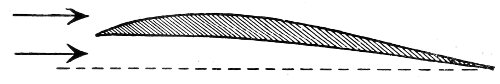
A pterygoid plane.
Pterygoid—That type of the wings of birds which is long and narrow—as distinguished from the apteroid type.
Pylon—A tower-shaped structure used as a derrick (which see); also for displaying signals to aeronauts.
Radial Spoke—A wire spoke extending from the hub of an alighting wheel straight outward from the 468 centre to the rim of the wheel. See Tangent Spoke.
Rarefaction Side—A correct term for the incorrect “vacuum side,” so-called. The side opposite the compression side: the forward side of a revolving propeller blade, or the upper side of a flying surface, or the side of a rudder-surface turned away from the wind.
Reactive Stratum—The layer of compressed air beneath a moving aeroplane surface, or behind a moving propeller blade.
Rib—The smaller construction members used in building up surfaces. Generally they run fore-and-aft, crossing the spars or wing-bars at right angles, and they are bent to form the curve of the wings or planes.
Rising Angle—Technically, the steepest angle at which any given aeroplane will rise into the air.
Rudder—A movable surface by which the aeronaut is enabled to steer his craft in a desired direction. See Horizontal Rudder and Vertical Rudder.
Runner—A construction similar to the runners of a sleigh, used for alighting on some machines, instead of the wheel alighting gear; a skid.
469
Screw—Another term for propeller; properly, screw-propeller.
Single-surfaced—A term used to designate wings or planes whose frames are covered with fabric only on the upper side. See Double-Surfaced.
Skid—Another name for runner.
Skin Friction—The retarding effect of the adherence of the air to surfaces moving rapidly through it. It is very slight with polished surfaces, and in case of slow speeds is entirely negligible.
Slip—The difference between the actual progress of a moving propeller, and the theoretical progress expressed by its pitch. It is much greater in some propellers than in others, due to the “churning” of the air by blades of faulty design and construction.
Soaring Flight—The sailing motion in the air achieved by some of the larger birds without the flapping of their wings. It is to be distinguished from gliding in that it is in an upward direction. Soaring has never been satisfactorily explained, and is considered to be the secret whose discovery 470 will bring about the largest advance in the navigation of the air.
Spar—A stick of considerable length used in the framing of the body of aeroplanes, or as the long members in wing structures.
Stabilize—To maintain balance by the automatic action of adjunct surfaces, as distinguished from the intentional manipulation of controlling devices.
Stabilizer—Any surface whose automatic action tends to the maintaining of balance in the air.
Stable Equilibrium—That equilibrium which is inherent in the construction of the machine, and does not depend upon automatic or controlling balancing devices.
Starboard—The right-hand side of an aircraft as one faces forward. See Port.
Starting Area—An area of ground specially prepared to facilitate the starting of aeroplanes into flight.
Starting Device—Any contrivance for giving an aeroplane a powerful impulse or thrust into the air. See Derrick.
Starting Impulse—The thrust with which an aeroplane is started into the air for a flight. Most 471 machines depend upon the thrust of their own propellers, the machine being held back by force until the engines have worked up to flying speed, when it is suddenly released.
Starting Rail—The rail upon which the starting truck runs before the aeroplane rises into the air.
Starting Truck—A small vehicle upon which the aeroplane rests while it is gaining sufficient impulse to take flight.
Stay—A construction member of an aeroplane sustaining a pulling strain. It is usually of wire.
Straight Pitch—That type of pitch (which see) in a propeller blade in which every cross-section of the blade makes the same angle with its axis of revolution.
Strainer—Another term for Turnbuckle—which see.
Strut—An upright, or vertical, construction member of an aeroplane sustaining a compression strain; as distinguished from a brace which sustains a diagonal compression strain.
Supplementary Surface—A comparatively small surface used as an adjunct to the large surfaces for some special purpose; as, for instance, the preserving of balance, or for steering.
Sustaining Surface—The large surfaces of the aeroplane 472 whose rapid movement through the air at a slight angle to the horizontal sustains the weight of the machine.
Tail—A rear surface on an aeroplane designed to assist in maintaining longitudinal stability. It is in use principally on monoplanes, and is often so arranged as to serve as a rudder.
Tail Wheel—A wheel mounted under the rear end of an aeroplane as a part of the alighting gear.
Tangent—A straight line passing the convex side of a curved line, and touching it at one point only. The straight line is said to be tangent to the curve at the point of contact.
Tangential—In the position or direction of a tangent.
Tangent Spoke—A wire spoke extending from the outer edge of the hub of a wheel along the line of a tangent until it touches the rim. Its position is at right angles to the course of a radial spoke (which see) from the same point on the hub.
Tie—A construction member connecting two points with a pulling strain. 473
Tightener—A device for taking up the slack of a stay, or tie; as the turnbuckle.
Tractor Propeller—A propeller placed in front, so that it pulls the machine through the air, instead of pushing, or thrusting, it from behind.
Triplane—An aeroplane with three main surfaces, or decks, placed in a tier, one above another.
Turnbuckle—A device with a nut at each end, of contrary pitch, so as to take a right-hand screw at one end, and a left-hand screw at the other; used for drawing together, or toward each other the open ends of a stay, or tie.
Uniform Pitch—That varying pitch in a propeller blade which causes each point in the blade to move forward in its own circle the same distance in one revolution.
Up-wind—In a direction opposite to the current of the wind; against the wind; in the teeth of the wind.
Vertical Rudder—A rudder for steering toward right or left; so called because its surface occupies normally a vertical position.
474
Wake—The stream of disturbed air left in the rear of a moving aircraft, due mainly to the slip of the propeller.
Wash—The air-currents flowing out diagonally from the sides of a moving aeroplane.
Wing Bar—The larger construction members of a wing, running from the body outward to the tips. The ribs are attached to the wing bars, usually at right angles.
Wing Plan—The outline of the wing or main plane surface as viewed from above.
Wing Section—The outline of the wing structure of an aeroplane as it would appear if cut by a plane passing through it parallel to the longitudinal centre of the machine.
Wing Skid—A small skid, or runner, placed under the tip of the wings of an aeroplane, to prevent damage in case of violent contact with the ground.
Wing Tip—The extreme outer end of a wing or main plane.
Wing Warping—A controlling device for restoring disturbed lateral balance by the forcible pulling down or pulling up of the tips of the wings, or of 475 the outer ends of the main surface of the aeroplane.
Wing Wheel—A small wheel placed under the outer end of a wing or main plane to prevent contact with the ground. An improvement on the wing skid.
Inconsistent spelling and hyphenation are as in the original.
End of the Project Gutenberg EBook of How it Flies or, Conquest of the Air, by
Richard Ferris

*** END OF THIS PROJECT GUTENBERG EBOOK HOW IT FLIES OR, CONQUEST OF AIR ***

***** This file should be named 55268-h.htm or 55268-h.zip *****
This and all associated files of various formats will be found in:
        http://www.gutenberg.org/5/5/2/6/55268/

Produced by Chris Curnow, Wayne Hammond and the Online
Distributed Proofreading Team at http://www.pgdp.net

Updated editions will replace the previous one--the old editions will
be renamed.

Creating the works from print editions not protected by U.S. copyright
law means that no one owns a United States copyright in these works,
so the Foundation (and you!) can copy and distribute it in the United
States without permission and without paying copyright
royalties. Special rules, set forth in the General Terms of Use part
of this license, apply to copying and distributing Project
Gutenberg-tm electronic works to protect the PROJECT GUTENBERG-tm
concept and trademark. Project Gutenberg is a registered trademark,
and may not be used if you charge for the eBooks, unless you receive
specific permission. If you do not charge anything for copies of this
eBook, complying with the rules is very easy. You may use this eBook
for nearly any purpose such as creation of derivative works, reports,
performances and research. They may be modified and printed and given
away--you may do practically ANYTHING in the United States with eBooks
not protected by U.S. copyright law. Redistribution is subject to the
trademark license, especially commercial redistribution.

START: FULL LICENSE

THE FULL PROJECT GUTENBERG LICENSE
PLEASE READ THIS BEFORE YOU DISTRIBUTE OR USE THIS WORK

To protect the Project Gutenberg-tm mission of promoting the free
distribution of electronic works, by using or distributing this work
(or any other work associated in any way with the phrase "Project
Gutenberg"), you agree to comply with all the terms of the Full
Project Gutenberg-tm License available with this file or online at
www.gutenberg.org/license.

Section 1. General Terms of Use and Redistributing Project
Gutenberg-tm electronic works

1.A. By reading or using any part of this Project Gutenberg-tm
electronic work, you indicate that you have read, understand, agree to
and accept all the terms of this license and intellectual property
(trademark/copyright) agreement. If you do not agree to abide by all
the terms of this agreement, you must cease using and return or
destroy all copies of Project Gutenberg-tm electronic works in your
possession. If you paid a fee for obtaining a copy of or access to a
Project Gutenberg-tm electronic work and you do not agree to be bound
by the terms of this agreement, you may obtain a refund from the
person or entity to whom you paid the fee as set forth in paragraph
1.E.8.

1.B. "Project Gutenberg" is a registered trademark. It may only be
used on or associated in any way with an electronic work by people who
agree to be bound by the terms of this agreement. There are a few
things that you can do with most Project Gutenberg-tm electronic works
even without complying with the full terms of this agreement. See
paragraph 1.C below. There are a lot of things you can do with Project
Gutenberg-tm electronic works if you follow the terms of this
agreement and help preserve free future access to Project Gutenberg-tm
electronic works. See paragraph 1.E below.

1.C. The Project Gutenberg Literary Archive Foundation ("the
Foundation" or PGLAF), owns a compilation copyright in the collection
of Project Gutenberg-tm electronic works. Nearly all the individual
works in the collection are in the public domain in the United
States. If an individual work is unprotected by copyright law in the
United States and you are located in the United States, we do not
claim a right to prevent you from copying, distributing, performing,
displaying or creating derivative works based on the work as long as
all references to Project Gutenberg are removed. Of course, we hope
that you will support the Project Gutenberg-tm mission of promoting
free access to electronic works by freely sharing Project Gutenberg-tm
works in compliance with the terms of this agreement for keeping the
Project Gutenberg-tm name associated with the work. You can easily
comply with the terms of this agreement by keeping this work in the
same format with its attached full Project Gutenberg-tm License when
you share it without charge with others.

1.D. The copyright laws of the place where you are located also govern
what you can do with this work. Copyright laws in most countries are
in a constant state of change. If you are outside the United States,
check the laws of your country in addition to the terms of this
agreement before downloading, copying, displaying, performing,
distributing or creating derivative works based on this work or any
other Project Gutenberg-tm work. The Foundation makes no
representations concerning the copyright status of any work in any
country outside the United States.

1.E. Unless you have removed all references to Project Gutenberg:

1.E.1. The following sentence, with active links to, or other
immediate access to, the full Project Gutenberg-tm License must appear
prominently whenever any copy of a Project Gutenberg-tm work (any work
on which the phrase "Project Gutenberg" appears, or with which the
phrase "Project Gutenberg" is associated) is accessed, displayed,
performed, viewed, copied or distributed:

  This eBook is for the use of anyone anywhere in the United States and
  most other parts of the world at no cost and with almost no
  restrictions whatsoever. You may copy it, give it away or re-use it
  under the terms of the Project Gutenberg License included with this
  eBook or online at www.gutenberg.org. If you are not located in the
  United States, you'll have to check the laws of the country where you
  are located before using this ebook.

1.E.2. If an individual Project Gutenberg-tm electronic work is
derived from texts not protected by U.S. copyright law (does not
contain a notice indicating that it is posted with permission of the
copyright holder), the work can be copied and distributed to anyone in
the United States without paying any fees or charges. If you are
redistributing or providing access to a work with the phrase "Project
Gutenberg" associated with or appearing on the work, you must comply
either with the requirements of paragraphs 1.E.1 through 1.E.7 or
obtain permission for the use of the work and the Project Gutenberg-tm
trademark as set forth in paragraphs 1.E.8 or 1.E.9.

1.E.3. If an individual Project Gutenberg-tm electronic work is posted
with the permission of the copyright holder, your use and distribution
must comply with both paragraphs 1.E.1 through 1.E.7 and any
additional terms imposed by the copyright holder. Additional terms
will be linked to the Project Gutenberg-tm License for all works
posted with the permission of the copyright holder found at the
beginning of this work.

1.E.4. Do not unlink or detach or remove the full Project Gutenberg-tm
License terms from this work, or any files containing a part of this
work or any other work associated with Project Gutenberg-tm.

1.E.5. Do not copy, display, perform, distribute or redistribute this
electronic work, or any part of this electronic work, without
prominently displaying the sentence set forth in paragraph 1.E.1 with
active links or immediate access to the full terms of the Project
Gutenberg-tm License.

1.E.6. You may convert to and distribute this work in any binary,
compressed, marked up, nonproprietary or proprietary form, including
any word processing or hypertext form. However, if you provide access
to or distribute copies of a Project Gutenberg-tm work in a format
other than "Plain Vanilla ASCII" or other format used in the official
version posted on the official Project Gutenberg-tm web site
(www.gutenberg.org), you must, at no additional cost, fee or expense
to the user, provide a copy, a means of exporting a copy, or a means
of obtaining a copy upon request, of the work in its original "Plain
Vanilla ASCII" or other form. Any alternate format must include the
full Project Gutenberg-tm License as specified in paragraph 1.E.1.

1.E.7. Do not charge a fee for access to, viewing, displaying,
performing, copying or distributing any Project Gutenberg-tm works
unless you comply with paragraph 1.E.8 or 1.E.9.

1.E.8. You may charge a reasonable fee for copies of or providing
access to or distributing Project Gutenberg-tm electronic works
provided that

* You pay a royalty fee of 20% of the gross profits you derive from
  the use of Project Gutenberg-tm works calculated using the method
  you already use to calculate your applicable taxes. The fee is owed
  to the owner of the Project Gutenberg-tm trademark, but he has
  agreed to donate royalties under this paragraph to the Project
  Gutenberg Literary Archive Foundation. Royalty payments must be paid
  within 60 days following each date on which you prepare (or are
  legally required to prepare) your periodic tax returns. Royalty
  payments should be clearly marked as such and sent to the Project
  Gutenberg Literary Archive Foundation at the address specified in
  Section 4, "Information about donations to the Project Gutenberg
  Literary Archive Foundation."

* You provide a full refund of any money paid by a user who notifies
  you in writing (or by e-mail) within 30 days of receipt that s/he
  does not agree to the terms of the full Project Gutenberg-tm
  License. You must require such a user to return or destroy all
  copies of the works possessed in a physical medium and discontinue
  all use of and all access to other copies of Project Gutenberg-tm
  works.

* You provide, in accordance with paragraph 1.F.3, a full refund of
  any money paid for a work or a replacement copy, if a defect in the
  electronic work is discovered and reported to you within 90 days of
  receipt of the work.

* You comply with all other terms of this agreement for free
  distribution of Project Gutenberg-tm works.

1.E.9. If you wish to charge a fee or distribute a Project
Gutenberg-tm electronic work or group of works on different terms than
are set forth in this agreement, you must obtain permission in writing
from both the Project Gutenberg Literary Archive Foundation and The
Project Gutenberg Trademark LLC, the owner of the Project Gutenberg-tm
trademark. Contact the Foundation as set forth in Section 3 below.

1.F.

1.F.1. Project Gutenberg volunteers and employees expend considerable
effort to identify, do copyright research on, transcribe and proofread
works not protected by U.S. copyright law in creating the Project
Gutenberg-tm collection. Despite these efforts, Project Gutenberg-tm
electronic works, and the medium on which they may be stored, may
contain "Defects," such as, but not limited to, incomplete, inaccurate
or corrupt data, transcription errors, a copyright or other
intellectual property infringement, a defective or damaged disk or
other medium, a computer virus, or computer codes that damage or
cannot be read by your equipment.

1.F.2. LIMITED WARRANTY, DISCLAIMER OF DAMAGES - Except for the "Right
of Replacement or Refund" described in paragraph 1.F.3, the Project
Gutenberg Literary Archive Foundation, the owner of the Project
Gutenberg-tm trademark, and any other party distributing a Project
Gutenberg-tm electronic work under this agreement, disclaim all
liability to you for damages, costs and expenses, including legal
fees. YOU AGREE THAT YOU HAVE NO REMEDIES FOR NEGLIGENCE, STRICT
LIABILITY, BREACH OF WARRANTY OR BREACH OF CONTRACT EXCEPT THOSE
PROVIDED IN PARAGRAPH 1.F.3. YOU AGREE THAT THE FOUNDATION, THE
TRADEMARK OWNER, AND ANY DISTRIBUTOR UNDER THIS AGREEMENT WILL NOT BE
LIABLE TO YOU FOR ACTUAL, DIRECT, INDIRECT, CONSEQUENTIAL, PUNITIVE OR
INCIDENTAL DAMAGES EVEN IF YOU GIVE NOTICE OF THE POSSIBILITY OF SUCH
DAMAGE.

1.F.3. LIMITED RIGHT OF REPLACEMENT OR REFUND - If you discover a
defect in this electronic work within 90 days of receiving it, you can
receive a refund of the money (if any) you paid for it by sending a
written explanation to the person you received the work from. If you
received the work on a physical medium, you must return the medium
with your written explanation. The person or entity that provided you
with the defective work may elect to provide a replacement copy in
lieu of a refund. If you received the work electronically, the person
or entity providing it to you may choose to give you a second
opportunity to receive the work electronically in lieu of a refund. If
the second copy is also defective, you may demand a refund in writing
without further opportunities to fix the problem.

1.F.4. Except for the limited right of replacement or refund set forth
in paragraph 1.F.3, this work is provided to you 'AS-IS', WITH NO
OTHER WARRANTIES OF ANY KIND, EXPRESS OR IMPLIED, INCLUDING BUT NOT
LIMITED TO WARRANTIES OF MERCHANTABILITY OR FITNESS FOR ANY PURPOSE.

1.F.5. Some states do not allow disclaimers of certain implied
warranties or the exclusion or limitation of certain types of
damages. If any disclaimer or limitation set forth in this agreement
violates the law of the state applicable to this agreement, the
agreement shall be interpreted to make the maximum disclaimer or
limitation permitted by the applicable state law. The invalidity or
unenforceability of any provision of this agreement shall not void the
remaining provisions.

1.F.6. INDEMNITY - You agree to indemnify and hold the Foundation, the
trademark owner, any agent or employee of the Foundation, anyone
providing copies of Project Gutenberg-tm electronic works in
accordance with this agreement, and any volunteers associated with the
production, promotion and distribution of Project Gutenberg-tm
electronic works, harmless from all liability, costs and expenses,
including legal fees, that arise directly or indirectly from any of
the following which you do or cause to occur: (a) distribution of this
or any Project Gutenberg-tm work, (b) alteration, modification, or
additions or deletions to any Project Gutenberg-tm work, and (c) any
Defect you cause.

Section 2. Information about the Mission of Project Gutenberg-tm

Project Gutenberg-tm is synonymous with the free distribution of
electronic works in formats readable by the widest variety of
computers including obsolete, old, middle-aged and new computers. It
exists because of the efforts of hundreds of volunteers and donations
from people in all walks of life.

Volunteers and financial support to provide volunteers with the
assistance they need are critical to reaching Project Gutenberg-tm's
goals and ensuring that the Project Gutenberg-tm collection will
remain freely available for generations to come. In 2001, the Project
Gutenberg Literary Archive Foundation was created to provide a secure
and permanent future for Project Gutenberg-tm and future
generations. To learn more about the Project Gutenberg Literary
Archive Foundation and how your efforts and donations can help, see
Sections 3 and 4 and the Foundation information page at
www.gutenberg.org


Section 3. Information about the Project Gutenberg Literary Archive Foundation

The Project Gutenberg Literary Archive Foundation is a non profit
501(c)(3) educational corporation organized under the laws of the
state of Mississippi and granted tax exempt status by the Internal
Revenue Service. The Foundation's EIN or federal tax identification
number is 64-6221541. Contributions to the Project Gutenberg Literary
Archive Foundation are tax deductible to the full extent permitted by
U.S. federal laws and your state's laws.

The Foundation's principal office is in Fairbanks, Alaska, with the
mailing address: PO Box 750175, Fairbanks, AK 99775, but its
volunteers and employees are scattered throughout numerous
locations. Its business office is located at 809 North 1500 West, Salt
Lake City, UT 84116, (801) 596-1887. Email contact links and up to
date contact information can be found at the Foundation's web site and
official page at www.gutenberg.org/contact

For additional contact information:

    Dr. Gregory B. Newby
    Chief Executive and Director
    gbnewby@pglaf.org

Section 4. Information about Donations to the Project Gutenberg
Literary Archive Foundation

Project Gutenberg-tm depends upon and cannot survive without wide
spread public support and donations to carry out its mission of
increasing the number of public domain and licensed works that can be
freely distributed in machine readable form accessible by the widest
array of equipment including outdated equipment. Many small donations
($1 to $5,000) are particularly important to maintaining tax exempt
status with the IRS.

The Foundation is committed to complying with the laws regulating
charities and charitable donations in all 50 states of the United
States. Compliance requirements are not uniform and it takes a
considerable effort, much paperwork and many fees to meet and keep up
with these requirements. We do not solicit donations in locations
where we have not received written confirmation of compliance. To SEND
DONATIONS or determine the status of compliance for any particular
state visit www.gutenberg.org/donate

While we cannot and do not solicit contributions from states where we
have not met the solicitation requirements, we know of no prohibition
against accepting unsolicited donations from donors in such states who
approach us with offers to donate.

International donations are gratefully accepted, but we cannot make
any statements concerning tax treatment of donations received from
outside the United States. U.S. laws alone swamp our small staff.

Please check the Project Gutenberg Web pages for current donation
methods and addresses. Donations are accepted in a number of other
ways including checks, online payments and credit card donations. To
donate, please visit: www.gutenberg.org/donate

Section 5. General Information About Project Gutenberg-tm electronic works.

Professor Michael S. Hart was the originator of the Project
Gutenberg-tm concept of a library of electronic works that could be
freely shared with anyone. For forty years, he produced and
distributed Project Gutenberg-tm eBooks with only a loose network of
volunteer support.

Project Gutenberg-tm eBooks are often created from several printed
editions, all of which are confirmed as not protected by copyright in
the U.S. unless a copyright notice is included. Thus, we do not
necessarily keep eBooks in compliance with any particular paper
edition.

Most people start at our Web site which has the main PG search
facility: www.gutenberg.org

This Web site includes information about Project Gutenberg-tm,
including how to make donations to the Project Gutenberg Literary
Archive Foundation, how to help produce our new eBooks, and how to
subscribe to our email newsletter to hear about new eBooks.