One of two Ruhmkorff Coils made by Queen & Co. The output with about 650
Watts of current in the primary was a torrent of sparks 45 inches in length.
INCLUDING
RUHMKORFF, TESLA, AND MEDICAL COILS,
ROENTGEN RADIOGRAPHY, WIRELESS
TELEGRAPHY, AND PRACTICAL INFORMATION
ON PRIMARY AND
SECONDARY BATTERY
BY
H. S. NORRIE
(NORMAN H. SCHNEIDER)
SECOND EDITION, REVISED AND MUCH ENLARGED

NEW YORK:
SPON & CHAMBERLAIN, 12 Cortlandt St.
LONDON:
E. & F. N. SPON, Ltd., 125 Strand
1901
Entered, according to Act of Congress, in the year 1896
Re-entered for Copyright in 1901
By SPON & CHAMBERLAIN
in the office of the Librarian of Congress, Washington, D. C.
BURR PRINTING HOUSE,
NEW YORK, N. Y., U. S. A.
ERRATA.
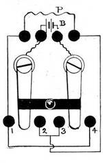
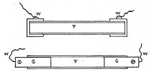
Page 55. Should read, "Cords being attached to binding posts Nos. 1 and 2 are in circuit with the Secondary Coil only. When at Nos. 2 and 3 they receive the induced current or extra current in the Primary."
Index. "Tesla coil, descriptive," should read "Tesla coil, disruptive."
iii
The great favor with which the first edition of this little work has been received and the steadily growing interest in its subject, together with many valuable improvements and researches, may be given as the reasons for this new edition.
The book has been thoroughly revised, partly rewritten, and considerable new matter, with twenty-six new illustrations, added. It has been brought up to date as far as electrical science has gone.
To detail all that has been done is too great a task for a preface; we may briefly mention the following new matter:
Coils for gas and automobile engines; medical coils, concise directions for operation and repairs; new forms of contact breakers, including electrolytic and mechaniivcal; gas-lighting apparatus; primary and secondary batteries.
The chapter on X-Ray Apparatus has been entirely rewritten, and is thoroughly practical; and an entire chapter on Wireless Telegraphy has been added. In a book of this size it is not feasible to give specific directions and full dimensions for the manufacture of all the apparatus described. Indeed, much of the latter must be adapted to the particular purpose for which it is to be utilized. Again, the same amount of material will not always produce the same results. A little closer winding, greater pressure applied to the cooling wax of a condenser, and the output or capacity of either is changed.
Matters purely of design or taste are to be governed by the creative faculty of the worker; but such general details and rules are given as will be sufficient to enable one possessing ordinary constructive ability to make his own apparatus.
The whole process of coil-making doesv not require high mechanical skill, but chiefly patience and attention to details; and, perhaps best of all, but few tools are needed, all of a simple kind.
We beg to acknowledge courtesies received from Messrs. Queen & Co., the Scientific American for frontispiece and Fig. 13, Mr. Goldingham's book on Oil Engines for Fig. 12, and others who have been of assistance to the author. The best American and English practice has been adopted; the American standard gauges and sizes of wires are used, except where noted.
A list of works, particularly of value to the coil worker, will be found following the index.
H. S. Norrie
(Norman H. Schneider.)
April, 1901.
vi
vii
| CHAPTER I. | |
| COIL CONSTRUCTION. | |
| Construction of Ruhmkorff Coils. Sizes of Wires. Winding of Primary and Secondary. Assembling. Connecting Up. Insulation. Coils in Series. Oil Immersed Coils. "Tesla" Coil. Disruptive "Tesla" Coil. Coils for Gas Engines. Spark Coils. Resistance Coils. General Remarks on Coils. The Testing of a Coil for Polarity. Failure to Work. Medical Coils. Medical Coil with Tube Regulation. Medical Coil with Interchangeable Secondaries. Bath Coils | 1-64 |
| CHAPTER II. | |
| CONTACT BREAKERS. | |
| Construction of Contact Breakers. Various Forms of Simple Contact Breakers. The Mercury Vibrator. Polechanging viii Vibrator. Wehnelt Interrupter. Dessauer Contact Breaker. Steel Ribbon Interrupter. Contact Breakers in Vacuo. Queen Contact Breaker. Adjustable Contact Breaker for Medical Coils. The Queen Contact Breaker for Large Coils, Adjustable Cone Vibrator. Contacts | 65-91 |
| CHAPTER III. | |
| INSULATIONS AND CEMENTS. | |
| Selection of Insulating Materials. Mineral Oil. Paraffin Wax. Resin Oils. Beeswax. Shellac Varnishes. Silk. Insulating Compounds | 92-98 |
| CHAPTER IV. | |
| CONDENSERS. | |
| Construction of Condensers. Leyden Jar. Glass Plate Condenser. Paper Condensers. Series Condenser. Rolled-Up Condensers. Adjustable Condensers. Application of Condensers | 99-119 |
| CHAPTER V. | |
| EXPERIMENTS. | |
| Luminous Effects Obtained by Means of a Ruhmkorff Coil. Materials Used. Spark Experiments. The Luminous Pane. Luminous Designs, etc. | 120-130ix |
| CHAPTER VI. | |
| SPECTRUM ANALYSIS. | |
| Color Produced by Burning Different Metals. The Spectroscope Shown in Connection with the Coil. The Screen. The Color Spaces in the Solar Spectrum. Color Values | 131-139 |
| CHAPTER VII. | |
| CURRENTS IN VACUO. | |
| Different Forms of Mercury Air Pumps. Geissler Tubes. Discharges in Vacuo. Characteristic Colors of Different Gases in Tubes, etc. | 140-152 |
| CHAPTER VIII. | |
| ROTATING EFFECTS. | |
| Effects of Discharges in Rotating Tubes. Construction of Rotating Wheels. Arrangement of Tubes, etc. | 153-163 |
| CHAPTER IX. | |
| GAS LIGHTING. | |
| The Application of the Ruhmkorff Coil for Lighting Gas. Gas Lighting in Series. Gas Lighting in Multiple. Gas Lighting Diagram. Jump Spark Burner. Automatic Burners | 164-177x |
| CHAPTER X. | |
| BATTERIES FOR COILS. | |
| The Selection of Suitable Batteries. Open Circuit Cells. Closed Circuit Cells. Description of Cells. Formulæ for Solutions for Different Kinds of Batteries. The Grenet Battery. Fuller Battery. Gravity Battery. Dun Cell. Gethins Cell. Gordon Battery. New Standard. Edison-Lalande Cell. Dry Batteries. Dry Cell Construction, etc. | 178-199 |
| CHAPTER XI. | |
| STORAGE OR SECONDARY CELL. | |
| Construction of a Storage Cell. Connecting Up Cells. Charging Storage Batteries. Diagram for Charging from Dynamo Using a Rheostat. Diagram for Charging, using Lamp instead of Rheostat. Charging from. Primary Batteries. Testing Solutions. Setting Up the Storage Cell. The Harrison Cell. The "U. S." Storage Cell, etc. | 200-223 |
| CHAPTER XII. | |
| TESLA AND HERTZ EFFECTS. | |
| Currents of High Frequency. Electric Resonator. The "Tesla" Effects. Coil Connected to Discharger. High Frequency Currents in Electro-Therapeutics, etc. | 224-234xi |
| CHAPTER XIII. | |
| THE "ROENTGEN" RAYS AND RADIOGRAPHY. | |
| General Arrangement of Connections for Coil and Crookes Tube for Making X Ray Negatives. The Fluoroscope. Phosphorus Tube. The Queen Self-Adjusting Crookes Tube. General Remarks, etc. | 235-247 |
| CHAPTER XIV. | |
| WIRELESS TELEGRAPHY. | |
| Arrangements of Simple Circuits of Coil and Coherer for Receiving and Sending Messages. The Coherer. Carbon Coherer. Coherer without Filings. Aluminum Coherer. Steel Ball Coherer. The Oscillator. Clarke's Oscillator. Triple Oscillator. The Coil. Translating Devices. Air Conductor, etc. | 248-265 |
| Index | 266 |
| Bibliography | 270 |
xii
xiii
| PAGE | |
| Good Proportions of Core Lengths | 7 |
| Table of "Secondary" Windings | 24 |
| Polarity Tests | 45 |
| Dimensions for Different Spark Lengths | 50 |
| Table Showing Resistances and Feet per Pound of Copper and German Silver Wire | 64 |
| Specific Inductive Capacity | 119 |
| Wave Lengths and Temperatures | 138-139 |
| Table of Relative Costs of Materials | 191 |
xiv
Frontispiece, The Queen 45″ Spark Coil.
| FIG. | PAGE | |
| 1. | Section of Coil | 4 |
| 2. | Insulating Tube Ends | 10 |
| 3. | Sectional Winding | 11 |
| 4. | Section " First Method | 12 |
| 5. | "" Second Method | 13 |
| 6. | Proportional Diagram of Coil | 15 |
| 7. | Section Winder, End View | 17 |
| 8. | "" Face View | 17 |
| 9. | Assembly of Coils | 18 |
| 10. | Polechanging Switch | 31 |
| 11. | Disruptive Tesla Coil | 35 |
| 12. | Spark Coil for Gas Engine | 38 |
| 13. | Reproduction of a 32-inch Spark | 47 |
| 14. | Simple Medical Coil | 53 |
| 15. | Connections for Simple Medical Coil | 55 |
| 16. | Interchangeable Medical Coil | 56 |
| 17. | Vibrator for Medical Coil | 60 |
| 18. | Simple Contact Breaker | 65 |
| 19. | Imperfect Form of Contact Breaker | 67 |
| 20. | Superior Form of Contact Breaker | 67 |
| 21. | Spotteswoode Contact Breaker | 69 |
| 22. | Polechanging Contact Breaker | 74 |
| 23. | Wehnelt Interrupter | 78 |
| 24. | Ribbon Vibrator | 81 |
| 25. | Queen Contact Breaker | 82xv |
| 26. | Adjustable Contact Breaker | 86 |
| 27. | Cone Contact Breaker | 88 |
| 28. | Coil Head Contact Breaker | 89 |
| 29. | Leyden Jar | 101 |
| 30. | Plate Condenser | 102 |
| 31. | Arrangement of Condenser Plates | 104 |
| 32. | Condenser Charging, First Method | 110 |
| 33. | Condenser Charging, Second Method | 112 |
| 34. | Adjustable Condenser | 118 |
| 35. | Spark between Balls | 125 |
| 36. | Short Spark between Balls | 125 |
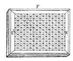
| 37. | Sparkling Pane | 125 |
| 38. | Luminous Design | 128 |
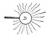
| 39. | Electric Brush | 128 |
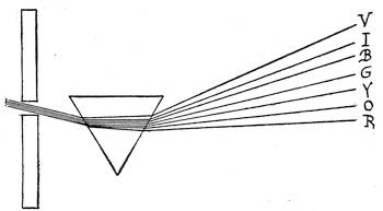
| 40. | Spectrum—Solar | 132 |
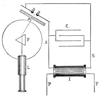
| 41. | Spectroscope and Coil | 133 |
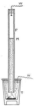
| 42. | Simple Air Pump | 141 |
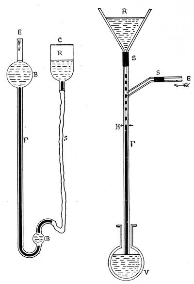
| 43. | Geissler Air Pump | 144 |
| 44. | Sprengel Air Pump | 144 |
| 45. | Solution Tube | 150 |
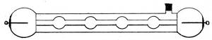
| 46. | Fluorescent Bulbs | 150 |
| 47. | Ruby Tube—Crookes | 150 |
| 48. | Iridio-platinum Tube—Crookes | 151 |
| 49. | Revolving Wheel | 154 |
| 50. | Tube Holder | 157 |
| 51. | Side View of Wheel | 157 |
| 52. | Geissler Tubes | 160 |
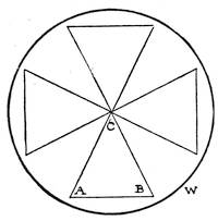
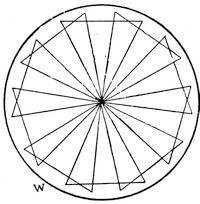
| 53. | Triangle on Disc | 161 |
| 54. | Maltese Cross on Disc | 161 |
| 55. | Gas Lighting Circuit | 165 |
| 56. | Connections for Gas Burners | 169 |
| 57. | Bartholdi Automatic Burner | 172xvi |
| 58. | Connections for Automatic Burner | 174 |
| 59. | The Grenet Cell | 180 |
| 60. | The Fuller Cell | 184 |
| 61. | The Gethins Cell | 193 |
| 62. | Lead Plate for Storage Cell | 201 |
| 63. | Wooden Separator | 201 |
| 64. | Charging with Rheostat | 207 |
| 65. | Charging with Lamps | 207 |
| 66. | Harrison Electrodes | 211 |
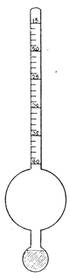
| 67. | Hydrometer | 221 |
| 68. | Hertz Resonator | 227 |
| 69. | Tesla Circuit | 229 |
| 70. | Tesla Cut Out | 231 |
| 71. | Tesla Cut Out, Top Plan | 232 |
| 72. | Circuit for X Ray Apparatus | 237 |
| 73. | Queen's Self-Regulating X Ray Tube | 240 |
| 74. | Transmitter for Wireless Telegraphy | 250 |
| 75. | Receiver for Wireless Telegraphy | 252 |
| 76. | The Branley Coherer | 254 |
| 77. | Clarke's Oscillator | 259 |
| 78. | Triple Oscillator | 259 |
| 79. | Air Wire Insulators | 263 |
1
In commencing a description of the Ruhmkorff coil and its uses, a brief mention of the fundamental laws of induction directly bearing on its action will assist in obtaining an intelligent conception of the proper manner in which it should be constructed and handled.
Any variation or cessation of a current of electricity flowing in one conductor will induce a momentary current in an adjacent conductor; and if the second conductor be an insulated wire coiled around the first conductor, also a coil of insulated wire, the effect is heightened. The intensity of the secondary or induced current increases with the number of turns of its conductor, the abruptness and com2pleteness of the variation of current in the first or primary coil, and the proximity of the coils. And the insertion of a mass of soft iron within the primary coil by its consequent magnetization and demagnetization augments still further the inductive effect. There are other contributing causes which cannot be treated of here, but are of not so much importance as the foregoing.
In the Ruhmkorff coil, which is an application of the above laws, the primary coil is of large wire and the secondary coil of extremely fine wire, of a length many thousand times greater than the wire of the primary coil. The current is abruptly broken in the primary circuit by a suitable device—the contact breaker or rheotome. The current induced in the secondary at the make of the circuit is in the opposite direction to that of the primary coil and battery, but the current at the break of the circuit is in the same direction as that of the primary. The effect of the current3 at the break of the circuit is more powerful than that at the make, which latter is also somewhat neutralized by the opposing battery current. A condenser or Leyden jar is connected across the contact breaker to absorb an extra current induced in the primary coil by the break of the circuit, which would tend to prolong the magnetization of the core beyond the desired limit.
The whole apparatus is mounted on a wood base, having the condenser in a false bottom for the sake of compactness.
It is not herein intended to describe all the minor operations in the construction of a Ruhmkorff coil. A sufficient description and review of the main points to be considered, however, will be given to enable a person fairly proficient in the use of simple tools to construct a serviceable instrument.
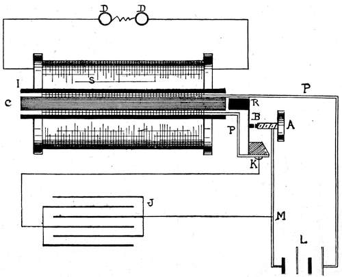
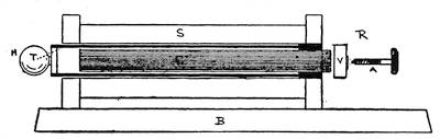
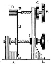
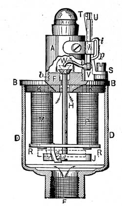
The parts and their arrangement in relation to one another are shown in Fig. 1, but are not drawn strictly to scale, although very nearly so.
4
C is the core, consisting of a bundle of soft iron wires as fine as can be obtained. The greater the subdivision of the core the quicker will it respond to the magnetizing5 current in the primary coil, and lose its magnetism when the current ceases. It has another advantage, in that the disadvantageous eddy, or Foucault currents, are lessened, which fact, however, is of not enough importance to need extended consideration.
Many coil-makers saturate the core with paraffin or shellac, which is of slight benefit. This core is wrapped in an insulating layer of paraffined paper or enclosed in a rubber shell, there not being any great necessity to use more than ordinary insulation between the core and the primary coil.
In the majority of induction coils or "transformers" used in the alternating current system of electric lighting, the iron cores form a closed magnetic circuit. A closed magnetic circuit in a Ruhmkorff coil could be obtained by extending the iron core at each end and then bending and securing the ends together, forming, as it were, a ring partly inside and partly6 outside the coil. But although the inductive effects would be heightened and less battery power required, the slowness of the circuit to demagnetize would alone be detrimental to rapid oscillations of current.
There would also be a loss from a greater hysteresis (energy lost in the magnetization and demagnetization of iron). A core magnetizes quicker than it demagnetizes, and the latter is rarely complete; a certain amount of residual magnetism remains, hysteresis being strictly due to this retention of energy (Sprague). Hysteresis shows itself in heat, but must not be confounded with Foucault or eddy currents. The latter are corrected by subdividing the metal, but the former depends upon the quality of the metal, and increases with its length.
Moreover, a coil with a closed magnetic circuit requires an independent contact breaker.
In most of the alternating currents used in lighting their rapidity of alternation is7 but one hundred and twenty-five periods per second. As in the simple electromagnet, the proportions of diameter and length of the primary coil and core will determine its rapidity of action. A short fat coil and core will act much quicker than a long thin one. But on a short fat coil the outside turns would be too far removed from the intensest part of the primary field. A good proportion of core length is given in the following table:
| Spark Length of Coil. | Iron Core. |
|---|---|
| ¼ | 4″ × ½″ |
| ½ | 5″ × 10∕16″ |
| 1 | 7″ × ¾″ |
| 2 | 9″ × 1″ |
| 6 | 12″ × 1⅛″ |
| 12 | 19″ × 1½″ |
The primary coil P consists of two or not more than three layers of insulated copper wire of large diameter, being required to carry a heavy current in a 2-inch spark coil, probably from 8 to 10 amperes. In designing the primary coil a great ad8vantage arises from using comparatively few turns but of large wire. Each turn of wire in the primary has a choking effect upon its neighbor by what is termed self-induction.
As the primary coil and core may be considered as an electro magnet, it may not be out of place to notice the rule governing such. Magnetization of an iron core is mainly dependent upon the ampere turns of the coil surrounding it—that is, one ampere carried around the core for one hundred turns (100 ampere-turns) would equal in effect ten amperes flowing through ten turns. Practically speaking, there would be certain variations to the rule, for one difficulty would arise in that the smaller wire used in conveying the smaller current would fit more compactly and allow more turns to be nearer the core, the active effect of the turns always decreasing with their distance from the core. And although a large current and few turns would not have so much self9-induction, there would be trouble at the contact breaker, owing to the large current it would have to control.
The most suitable sizes of wire for the primary coil are: No. 16 B. & S. for coils up to 1 inch spark; No. 14 B. & S. up to 4 inches of spark, and No. 12 B. & S. for a 6-inch spark coil. The coil should be, say, one-twelfth of the core length shorter than the core.
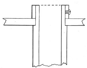
I is the insulating tube between the primary coil and the secondary coil S. Here great precaution is necessary to prevent any liability of short circuiting or breaking through of sparks from the secondary coil. This danger cannot be underestimated, and the tube should be either of glass or hard rubber, free from flaws, varying in thickness with the dimensions of the coil. It should extend at least one-tenth of the total length of the primary coil beyond it at each end. The end of this tube can be turned down so as to allow of the hard rubber reel ends being slipped on and held10 in position by outside hard rubber rings (Fig. 2).
The secondary coil consists of many turns of fine insulated copper wire separated from the primary coil by the insulating tube and a liberal amount of insulating compound at each end. In coils giving under 1 inch of spark this coil may be wound in two or more sections.
The usual manner of constructing these11 sections is to divide up the space on the insulating tube by means of hard rubber rings placed at equal distances apart, in number according to the number of sections desired (Fig. 3). The space between each set of rings, or between the coil end and a ring, is wound with the wire selected, the filled sections constituting a number of complete coils, which are finally connected in series. The sectional method of winding prevents the liability of the spark jumping through a short circuit, but12 heightens its tendency to pass into the primary coil at the ends, where it must be therefore specially insulated from it.
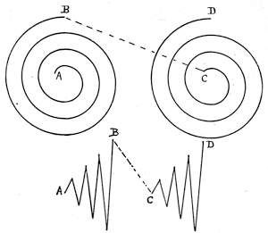
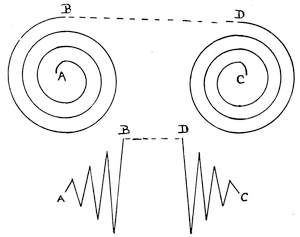
In winding these sections there is a method now generally adopted which has many good points, although at first it may seem complicated. The old way of filling two sections was to wind both in the same13 direction as full as desired, then join the outside end of the left-hand coil to the inside end of the right-hand coil. This necessitated bringing the outside end down between two disks, or in a vertical hole in the sectional divider, and thereby rendered it liable to spark through into its own coil. This is shown in Fig. 4, A and C inside ends, B and D outside ends, the disk being between B and C.
14
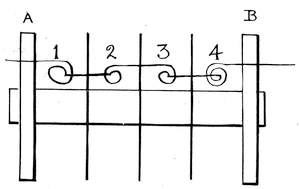
Reference to Fig. 3 shows the new method, and Fig. 5 shows an enlarged diagram of sections 2 and 3 of Fig. 3.
Sections 1 and 3, Fig. 3, are filled with as many turns as desired; the spool is then turned end for end, and sections 2 and 4 are wound, being thus in the opposite direction of winding to sections 1 and 3.
The inside ends of 1 and 2 and 3 and 4 are soldered together, and the outside ends of 2 and 3 are also soldered together.
The outside ends of 1 and 4 serve as terminals for the coil.
This method of connection leaves all the turns so joined that the current circulates in the same direction through them all, as will be seen by an examination of the enlarged diagram, Fig. 5.
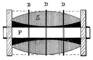
Sprague, in his "Electricity: Its Theory, Sources, and Application," recommends that the turns of wire in the secondary coil shall gradually increase in number until the middle of the spool is15 reached, and then decrease to the spool end, in order that the greatest number of turns be in the strongest part of the magnetic field (see Fig. 6). D D D are section dividers, S secondary windings, P primary coil. The selection of the size of wire to be used depends on the requirements as to the spark. If a short thick spark be desired, use a thick wire, say No. 34 B. & S.; if a long thin one, use No. 36 to No. 40 B. & S.
Although it is impossible to lay down16 rules for determining the exact amount of wire to be used to obtain a certain sized spark, yet a fair average is to allow 1¼ pounds No. 36 B. & S. per inch spark for small coils and slightly less for large ones.
The most satisfactory and perhaps the easiest way for large coils is to wind the secondary in separate coils, made in a manner similar to that employed in winding coils for the Thompson reflecting galvanometer. This method, first described by Mr. F. C. Alsop in his treatise on "Induction Coils," is somewhat as follows:
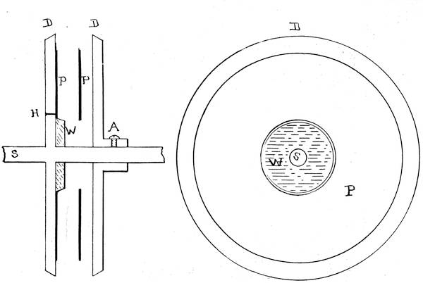
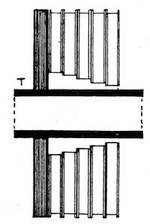
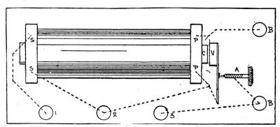
A special piece of apparatus (Figs. 7 and 8) is necessary, but presents no great difficulty in manufacture. A metal disk, D, one-sixth of an inch thick and 7 inches in diameter, is mounted on the shaft S. A second disk is provided with a collar and set screw, A, in order that it may be adjusted on the shaft at any desired distance from the stationary one. When the diameter17 of the coil to be wound has been decided18 upon, a wooden collar, W, with a bevelled surface is slipped on the shaft, it corresponding in diameter with the desired diameter of the hole through the centre of the secondary coil. As these coils are going to be made as flat rings and slipped on over the insulating tube, a remark here becomes necessary on this diameter. Reference to Fig. 9 will show that it is intended that the coils near the reel ends shall fit very loosely on the tube T (Fig. 1)—in fact, that there shall be a clearance of possibly one-half inch in the extreme end, diminishing gradually to a fifteenth of an inch in the centre coils. Therefore it becomes necessary to provide a number of wooden rings equal to the desired diameter of the central hole in the coil. The thickness of19 the wood determining the width of the individual coil depends on the selection of the operator; but the rule may be laid down that the narrower the coils the better the insulation of the complete coil will be on completion.
One-sixteenth of an inch is a very fair average, and has been generally adopted by the writer.
A quantity of paper rings are now cut out of stout writing paper which has been soaked in melted paraffin. If a block or pad of letter paper be soaked in paraffin and allowed to become cold under pressure, the ring may be scratched on the surface of it and the block cut through on a jig saw. The central apertures of course will vary in size with their position on the tube T (Fig. 9).
The coil winder is now either mounted in a lathe or fixed in a hand magnet winder in such manner that it can be steadily and rapidly rotated. The wire to be wound comes on spools, which can be so threaded20 on a piece of metal rod that they turn readily. A metal dish containing melted paraffin is provided with a round rod, preferably of glass, fixed under the paraffin surface, so that it can rotate freely when the wire passes under it through the paraffin. Two paper rings are slipped on the winder that they may form, as it were, reel ends for the coil, and if the metal disks have been warmed it is an easy matter to lay them flat.
The end of the wire is then passed through the paraffin under the glass rod and through the hole H in the metal disk for a distance of, say, 6 inches, and held to the disk outside with a dab of paraffin or beeswax. Then the winder is rotated and the space between the paper disks is filled with wire. The paraffin, being hot, will adhere to the wire, and cooling as the wire lays down on the winder, hold the turns together and at the same time insulate them from each other. It will not be possible to lay the wire in even layers, as21 would be necessary in winding a wider coil, but the spaces can be filled up, using ordinary care that no radical irregularity occurs—that is, that only adjacent layers are likely to commingle.
When the space is filled up to the level of the paper disks and the paraffin is hard, loosen the set screw, and removing the outside disk, the coil can be slipped off, or a slight warming will loosen it. Any number of these coils can be made, and there are the advantages in this mode of construction that a bad coil will not spoil the whole secondary, and that the wire can be obtained in comparatively small quantities.
As each coil will not be of very high resistance, the continuity of the wire can be readily tested by means of a few cells of battery, connecting one end of the coil to one pole of the battery, and the other pole of the battery and coil end touched to the tongue. If a burning sensation is experienced, the connection is not broken.22 Where possible the coils should be measured as to their resistance on a Wheatstone bridge.
When the requisite number of coils has been prepared, they are assembled in the following manner (Fig. 9): The coils, having their aperture diameter graded, are placed in order, and starting with the one having the largest hole, it is slipped over the primary protection tube T, one end being brought out through a hole in the reel end drilled vertically or between the reel end and the coil. A couple of paper rings are then slipped on the tube, and another coil placed over them, having its ends connected as in Fig. 3. This process is continued until all the coils are in place. The annular space between the coils and the tube T (Fig. 9) is filled in with melted paraffin and the coils gently pressed together, so as to form a compact mass, paraffin being poured over the outside of the whole combination. Before winding any wire used in this work it must be per23fectly dry, which end can be accomplished by subjecting the whole spool to a short period of baking in a moderately warm oven.
The accompanying table gives the length of No. 36 silk-covered wire that will fill a linear space equal to one thickness of the wire in different-sized rings. This size wire wound tight will give 125 turns per linear inch. Therefore on a ring having a middle aperture of 1½ inches and an outside diameter of 4 inches, there will be 156 turns, or a total length of 1347 inches. This is obtained as follows: 1½ inches × 3.1416 = 4.7124 (or 4.712); 4 inches × 3.1416 = 12.5664 (or 12.56); (4.712 + 12.56)∕2 = mean circumference—viz., 8.635 inches.
This mean × number of turns in thickness of ring between the two circumferences—viz., 156 = 1347 inches.
24
Table of Secondary Windings.
| No. 36 Silk-Covered Wire. 125 Turns per Linear inch. 13,306 Feet per Pound | 1½″ Aperture Diameter, 4.712″ Aperture Circumference. | 2″ Aperture Diameter, 6.283″ Aperture Circumference. | 2½″ Aperture Diameter, 7.854″ Aperture Circumference. | ||||||
|---|---|---|---|---|---|---|---|---|---|
| Outside diameter | 4″ | 5″ | 6″ | 4″ | 5″ | 6″ | 5″ | 6″ | 7″ |
| Outside circumference | 12.56 | 15.70 | 18.84 | 12.56 | 15.70 | 18.84 | 15.70 | 18.84 | 21.99 |
| Mean circumference | 8.635 | 10.20 | 11.78 | 9.421 | 10.99 | 12.56 | 11.78 | 13.35 | 14.92 |
| Turns between circumferences | 156 | 219 | 282 | 125 | 188 | 250 | 156 | 219 | 282 |
| Distance between aperture and outside, in inches | 1.25 | 1.75 | 2.25 | 1 | 1.50 | 2 | 1.25 | 1.75 | 2.25 |
| Length of wire, in inches | 1347 | 2234 | 2650 | 1178 | 2066 | 3140 | 1838 | 2924 | 4207 |
25
To obtain the length of wire necessary for a ring occupying more than the space of one turn on the primary insulating tube, multiply the length before obtained by the number of turns in the space it occupies. Thus a flat ring one-tenth of an inch thick would equal 1347 inches × 12.5.
This rule is necessarily only approximate, owing to the way the wires bed on each other from their cylindrical section. In actual practice, when the wire is run through the paraffin bath not more than 50 per cent of the calculated wire will occupy the space. And the thickness of the paper rings must also be added when figuring the total length of the coil. In the iron-clad transformers or induction coils of highest efficiency used in the alternating current electric light system, the rule for determining the windings of the coils is based on the ratio of the turns of wire in the primary to the turns in the secondary, the electromotive force in the primary, and the lines of force cut by the windings.
The secondary ends can be attached to 26binding posts mounted on the reel ends. Unless these reel ends be very high and clear the outside of the coil considerably, it is better to mount the binding posts on the top of the hard rubber pillars. A neat plan is to mount on the top of the coil a hard rubber plate reaching from reel end to reel end, and place the binding posts on that.
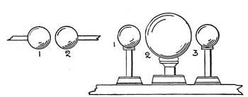
A discharger consists of two sliding metal rods with insulated handles passing through pillars attached to the secondary coil. The inside ends of these rods is provided with screw threads for the ready attachment of the balls, points, etc., which are to be used. The substance to be acted upon is laid on a rubber or glass table midway between the rod pillars and slightly below the level of the rods.
By hinging the rod pillars, or using a ball and socket joint, the discharger can be inclined so as to be better brought near the substance on the table.
The next important part of the coil is 27the contact breaker.
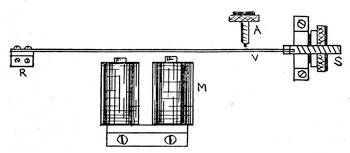
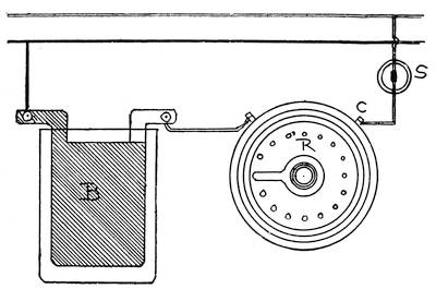
The armature R is a piece of soft iron carried at the end of a stiff spring, in about the middle of which, at B, is riveted a small platinum disk or stud. The adjusting screw A has its point also furnished with a piece of platinum, which is intended to touch the platinum on the spring when the latter is in its normal position. The core C of the coil serves as an electro-magnet. When the current flows from the battery (represented by the figure at L) through the primary coil and armature spring to the adjusting screw, it causes the armature to be drawn to the magnetized core, but thereby draws the platinum disk away from the adjusting screw. In so doing it breaks the circuit, the magnet loses its power, and the elasticity of the spring reasserting itself, carries the armature back, thereby reclosing the circuit. This is repeated many times in a second, the result being a continual vibration of the spring, 28and a consequent interruption to the current.
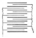
The condenser or Leyden jar J, connected as in the diagram to the base of the vibrating spring at K and to the adjusting screw wire M, is constructed as follows: On a sheet of insulated paper is laid a smaller sheet of tinfoil, one edge of which projects an inch or so over one end of the paper. Another sheet of paper covering this carries a second sheet of tinfoil, one end of which projects as in the first sheet, but at the opposite end of the paper. Tinfoil and paper sheets are laid in this manner alternately until a sufficient number is attained. The projecting ends are then clamped together and the whole pile immersed in melted paraffin, as will be described in a subsequent chapter. Wires are affixed to these clamped ends which serve to connect the condenser with the contact breaker. The conventional sign for a condenser is that used at J, showing the two series of plates, the insulation or dielectric, as it is called, being understood.
29The size of condenser to use with different-sized coils varies according to the winding of the primary and the battery used. A primary coil of few turns would not necessitate as large a condenser as one of a large number of turns. At the same time, a condenser may be made of too great a capacity, and thereby weaken the action of the coil.
The base upon which the coil and its parts are mounted may be of dried polished wood. But where the coil is designed to give large sparks—over 2 inches—it is an advantage to use hard rubber one quarter of an inch and upward in thickness. Glass, were it not for the difficulty of drilling it and its brittleness, would be a desirable material for a coil base in a dry atmosphere. Hard red or black fibre coated with shellac varnish is also serviceable, and, moreover, is extremely easy to work. Slate must never be used; there is too much liability of iron veins being found in it, which in such high 30tension experiments as will be described would seriously impair the usefulness of the apparatus. The material selected for the base must be one that will not absorb moisture. A paraffined surface collects moisture up to a certain point in isolated drops, whereas a glass and even a hard rubber surface condenses the moisture as a film, which latter is extremely undesirable. But unfortunately the fact that a paraffined surface does not present a pleasing appearance would probably result in its rejection. And lastly, by mounting the coil on hard rubber blocks, or extending the reel ends to raise the coil body, a high insulation can be obtained at the sacrifice perhaps of appearance or height. From the care taken to insulate the secondary coil, it may be considered a superfluous precaution to so carefully select a base, but practical work with the instrument at some important crisis will demonstrate the necessity of extreme care in the smallest details relating to insulation. 31It may be well to note here that hard rubber is acted upon by ozone, and is thereby impaired as an insulator.
The base forms the top of a flat box in which the condenser lies; but there are a few points worth considering right here. As the connections of the coil will probably be under the base, a sufficient space must intervene between the base and the top of the condenser. It is a good plan to lay the condenser at least one half inch below the top of this box, and fill up to, say, one eighth of an inch with melted paraffin, leaving the condenser wires projecting for attachment. The connections of the primary coil and contact breaker should by all means be soldered, not simply wires held under screw nuts. And, moreover, all wires under the base should 32be so run that they do not cross one another, which precaution only requires a little planning. Then, when the connections are all made and the base laid on top of the box, it can be pressed down if the paraffin be warm, so that the screw heads and wires mark out their own channels and cavities in which to lie.
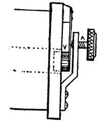
A commutator or pole-changing switch is often added to change the polarity of the battery current. The diagram of connection is shown in Fig. 10. When the levers are as in the figure, the circuit is broken and no current flows through the coil.
Ruhmkorff coils can be connected in series, but it is not to be recommended. When it becomes necessary, however, the cores should be removed, and one long core inserted, extending through each primary. This will bring the time constants of each primary coil together and prevent the interference 33otherwise present. The primary coils and secondary coils are connected in series by assuming that they are but adjacent sections of one complete instrument. Of course, as the resistance of the primary is raised, the electromotive force of the battery must be raised also.
A highly satisfactory induction coil can be made without much labor and few tools, and will prove useful in many experiments which would not warrant a more expensive instrument.
Make a bundle of soft iron wires, No. 22 B W G, for the core, ten inches in length and one inch or more in diameter. Wrap this with insulating tape or even ordinary tape to prevent the primary coil from coming in contact with the iron. Now, wind on a primary of two layers No. 14 B & S gauge cotton-covered copper wire, and insert the coil into a hard rubber (or glass preferred) 34tube large enough to hold the coil tight and to project an inch or so beyond the core ends.
A secondary coil of about one pound No. 36 cotton-covered magnet wire should now be made on a hard rubber spool, the hole through centre of this spool must be at least one inch larger in diameter than the diameter of the primary cover. This spool should not exceed four inches in length, and is to be slipped over the primary coil and held suspended by blocks of wood in such a manner that it does not touch the primary coil or cover. The whole outfit is now immersed in an earthenware or glass vessel filled with linseed or heavy paraffin oil. The contact breaker and condenser will be mounted independently; the condenser for the two-inch spark coil will be suitable (see Table on page—7).
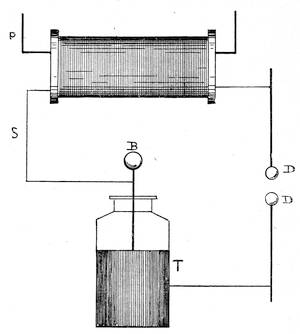
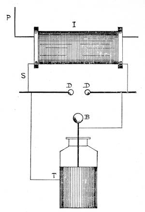
The coil just described, without contact breaker or iron core, can be connected up 35and used in place of a "Tesla coil," which it resembles. The coils used by Nikola Tesla are so many and varied that it becomes a difficult task to describe a mode of construction which will meet the wants of those who ask for "Tesla" coils. The American Electrician gives a description of one wherein a glass battery jar, 6 inches × 8 inches, is wound with 60 to 80 turns of No. 18 B & S magnet wire. Into this is slipped a primary, consisting of 8 to 10 turns of No. 6 B & S wire, and the whole combination immersed in a vessel containing linseed or mineral oil.
36
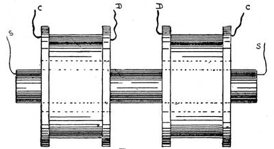
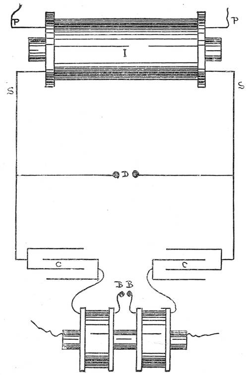
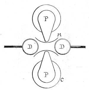
For Fig. 11 the specification is as follows: Secondary, 300 turns of No. 30 B & S silk-covered magnet wire, wound on rubber tube or rod, and the ends encased in glass or rubber tubes. This is inserted into the primary, which consists of two coils, each of 20 turns No. 16 B & S rubber-covered wire, wound separately on a long rubber tube not less than ⅛ inch thick. The last tube must be large enough to be very loose when the secondary coil is inserted in it, and it must project at least two inches over each end of the secondary. A hard rubber division must be placed between these primary coils. The four ends of the latter coils are connected C C to two condensers and D D to two discharger balls, the secondary wires going to the exhibitive apparatus. A further description of these connections is to be found in Chapter XII., also notes upon the use of the 37disruptive coil.
Coils for Gas Engines.
These are either primary only or primary and secondary. Two to three pounds of No. 14 B & S magnet wire are wound on an iron wire core eight to ten inches in length by one inch in diameter. The contact is made and broken in the igniter of the engine as at the wipe spring of a ratchet gas burner. Four to eight large cells of dry battery are used, or eight cells Edison-Lalande—iron-clad type. Number of cells varies with size of coil needed, some classes of engines require a heavier spark than others to ignite the vapor.
When a primary and secondary are used, the primary should be made of two or three layers No. 14 B & S magnet wire, and a secondary of one pound No. 34 B & S magnet wire. There can be an independent contact breaker or the coil can be made up similar to a one-half inch spark Ruhmkorff coil (see Chapter I.).
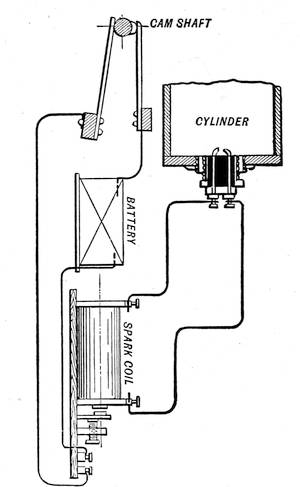
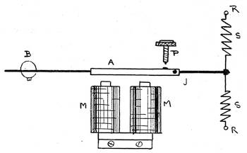
38The method of connecting up a coil of the latter description is shown in Fig. 12, which is self-explanatory. It shows a form of cam-shaft switch which is operated by the engine, and which opens and closes the primary 39circuit of the induction coil, the sparks from the secondary winding passing between the points of the igniter in the engine cylinder. As shown in Fig. 12, the igniter or ignition plug is similar in operation to a coil discharger, the two terminals being, however, insulated from each other by the use of porcelain. To ensure a good insulation under the severe working conditions has been somewhat of a task, but it seems to have been attained in the types of igniters known as the Splitdorf and the Roche or New Standard.
The Splitdorf gas-engine coil is the result of much experiment and careful design. It is built to stand hard usage, and the insulation used has been adopted only after exhaustive test. In automobile work, where a heavy strain is made upon the engine, as in climbing heavy grades, it has been found that a stronger spark gives surer results. This would indicate more battery current through the coil, and it is a wise precaution to have a few extra cells attached that can be 40switched on if necessary.
In constructing spark coils for gas engines particular care must be given to the contact breaker. In most types of gas or oil vapor engines it is absolutely necessary to have the spark pass with uniform regularity, and immediately and surely when required. For automobiles or where the apparatus is subject to jar, a heavy iron vibrating armature would become unreliable by reason of its inertia and its responding to shock. At every jolt of the vehicle it would jar and get out of rhythm, and it certainly seems preferable to use a mechanical contact apparatus whenever feasible. In the older type of gas engine the spark is made by mechanism breaking contact right in the vapor. The actual arrangement of these devices is detailed and illustrated in the later works on gas and oil engines.
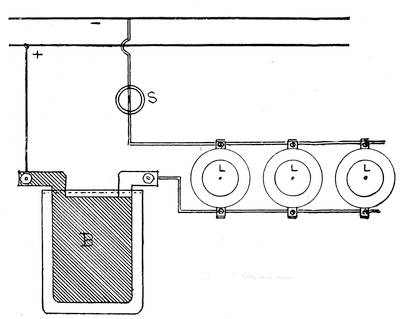
Although foreign to the title of this book, 41these coils will be mentioned, being often necessary as accessories to the operation of coils, wireless telegraphy, etc. These are coils of insulated German silver wire, wound to a specified resistance. The main feature about those designed for testing is that they are wound non-inductively—that is, the wire is wound double in such manner that the current flows both ways around the turns, and so neutralizes the inductive action. In cases where dynamo current is to be used, as in telegraphs operated from dynamo current, the coils are wound on tin tubes to make them fireproof and yet radiate the heat. As the resistance of German silver varies very largely, only approximate figures can be given. The table (page 64) has been made up from the best averages obtainable. The carrying capacity of resistance coils varies with their construction, the better they can radiate heat, the more current 42they can safely carry.
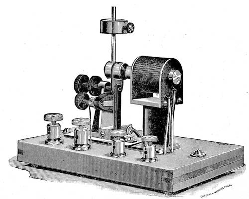
Ruhmkorff induction coils should always be fitted with a switch to open, close, or reverse the power circuit, a double throw, double pole, baby knife switch, mounted on a separate porcelain base, is very suitable. Such a switch is open when the handle is vertical, and it should always be left so when changing connections, fixing battery, etc. A large, well-finished coil will have the secondary wires brought in rubber tubes to binding posts mounted on hard rubber pillars, or to binding posts mounted considerably above the coil cover level. A very neat mode is shown in the frontispiece on the large 45-inch spark coil. Here the secondary wires go to hard rubber pillars, which also carry adjustable rod dischargers. These rods are movable towards or away from each other by means of the large hard rubber handle to which they are connected by a simple system of levers. In this coil the 43secondary is moulded on a flexible tube, which fits loosely over the primary tube in order to compensate for changes of temperature and consequent expansions and contractions. All well-designed coils should be so arranged that the primary coil and core can be readily removed from the secondary, or vice versa. It is sometimes desirable to use a different primary. This arrangement will greatly facilitate any necessary repairs. It must be always remembered that the working of a coil depends on the insulation between primary and secondary. Spare no pains to have perfect insulation; it is a hopeless task to reinsulate a broken-down secondary, although the sectional method of winding facilitates repairs. In large winding rooms it is customary to have a revolution counter connected to the spindle, so that the number of turns can be seen at all times. A bicycle cyclometer can be readily fitted up for this purpose, and will be found of considerable assistance where a number of sections are needed, each with 44a similar number of turns. In the commercial construction of telephone coils and magnet spools it is often the rule to specify only the number of turns of the requisite size wire, the ampere turns of the coils being thus regulated.
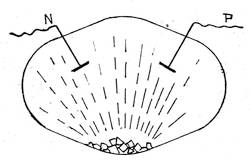
This is often necessary, and may be done in a variety of ways. When the coil is working, and sparks be passed between fine wires mounted on the discharger, the positive wire tip will be cold, whereas the negative end will be quite hot. In vacuo, the positive shows a purple red when the negative glows with a bluish violet. The decomposition of water, which consists of oxygen and hydrogen in the formula H2O, is readily accomplished by the secondary current, and the greatest volume of gas (hydrogen) will be evolved at the negative pole. For ready reference a summary of these facts is given 45below:
| Positive | Negative |
|---|---|
| Cold wire, | Hot wire, |
| Anode, | Cathode, |
| + sign, | - sign, |
| Purple red, | Bluish violet, |
| Zinc plate, | Carbon plate, |
| (Carbon) pole, | Zinc pole, |
| Oxygen gas. | Hydrogen gas. |
Although it is customary to use bundles of fine, soft iron wire for coil cores, very excellent results have been obtained with cores made up of soft iron filings. These filings should be tightly packed in the core tube and have a soft iron head at the contact breaker end. Filings demagnetize very quickly and prevent the formation of destructive eddy currents, which have been previously discussed (Chapter I.).
Modern practice tends towards a lengthening of the core and primary, in some cases fully 20 per cent of the core length projects from each end of the coil. One result must be as in electromagnets, the longer the core, the longer it takes to magnetize or demag46netize. But even here it is a matter of individual construction.
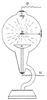
The common practice is to make coils to be in a horizontal position; there is no reason why they cannot be made to stand on end. In fact, this position to an extent takes off some of the strain on the primary. It is mostly a matter of choice or convenience.
As to the possible output of an induction coil, it depends upon design and construction; but S. P. Thompson gives the following law in his work on Electricity and Magnetism: The electromotive force generated in the secondary circuit is to that employed in the primary nearly in the same proportion as the relative turns of the two coils.1
1 We do not attempt to reconcile this quotation with the enormous estimates of spark potential.
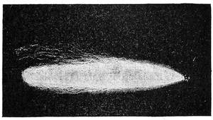
In selecting a Ruhmkorff coil, it must be remembered that the rating in spark length is subject to question. Supposing two similar coils be operated, one with a rapid vibrator and the other with a slow vibrator, other things being equal, the slow vibrator will give the greatest spark length. Again,47 the appearance of the spark is of vast importance. Although two coils might be sparking across the same length air-gap, the one giving the whitest and thickest continuous succession of sparks is the better. Fig. 13 shows a reproduction from a photograph of a spark 32 inches long, generated by the coil shown on the frontispiece.
It is easy to take a coil, and by snapping the vibrator contacts together a few times a spark of thin bluish character will jump48 across a gap, of length far exceeding the spark gap when vibrator is working at normal speed. But this spark only passes at irregular intervals, seemingly gathering strength for its forced leap. It must not be considered in rating the coil.
In winding primary coils it is proposed to reduce the self-induction or inductance of its adjacent coils by means of similar methods used in winding electromagnets. The primary winding, instead of being composed of a number of turns of one large wire, is made up of a multiple winding of small wires, aggregating the conductivity of the large wire. This materially reduces sparking at the contact breaker, and certainly allows of a closer bedding of wire nearer the core, also giving a greater percentage of ampere turns. Another scheme which uses the Dessauer contact breaker provides two separate primary windings, opening one when the other closes. Such schemes as these come well within the scope of the experimenter, and it is highly possible49 that valuable improvements will be made in coil design during the coming years.
The following are the commonest causes of coils not working to their best limit: Contact breaker contacts dirty, burned, stuck, too small, not in good parallel relation face to face of platinum.
Secondary wires crossed outside coil, often happens that the secondary is quietly sparking away into or through some object touching it, particularly when long wire connections are run from secondary to place of desired sparking.
Condenser too small, burned out, badly insulated (see other pages on this subject).
Battery too small—too high internal resistance or wires leading from battery to coil too small—for ordinary coil work, distance of, perhaps, ten feet, use No. 10 to 12 B & S flexible lamp cord or solid wire. Ruhmkorff coils require plenty of current to produce large sparks.
50
| Dimensions for Different Spark Lengths. | |||||
|---|---|---|---|---|---|
| ½ inch | 1 inch | 2 inches | 6 inches | 12 inches | |
| Foil sheets | 5½ × 4 | 6 × 4 | 6 × 6 | 10 × 5 | 12 × 8 |
| Number | 40 | 40 | 60 | 60 | 60 |
| Paper sheets | 6½ × 5 | 9 × 5 | 8½ × 7 | 12 × 7 | 14 × 10 |
| Number | 60 | 60 | 80 | 80 | 80 |
| Core length | 5 | 7 | 9 | 12 | 19 |
| Core diameter | ⅝ | ¾ | 1″ | 1⅛ | 1½ |
| Primary size B & S | 16 | 14 | 14 | 12 | 10 |
| Secondary size B & S. | 36 | 36 | 36 | 36 | 38 |
| Core wire size B W G. | 22 | 22 | 22 | 22 | 22 |
| Quantity in pounds of secondary wire |
¾ | 1¼ | 2½ | 7 | 12 |
| Layers of primary | 3 | 3 | 2 | 2 | 2 |
| Area of paper, sq. in. | 2,000 | 2,700 | 4,800 | 6,600 | 11,000 |
| Area of foil, sq. in. | 880 | 960 | 2,100 | 3,000 | 5,760 |
51
As it is not always convenient to procure paper and foil in set sizes, the area of material needed for condensers is also given. The above table is approximate. It represents data collected from the best modern practice. The gauge above given for copper wire is that of Brown & Sharpe, and is used throughout these pages.
The main points of difference between coils for electrotherapeutics and Ruhmkorff coils is that the former are devoid of condensers, are rarely insulated to a high degree, and are arranged for current strength regulation. The modes of regulation are many, briefly the principal are: (a) In coils with independent circuit breakers, sliding both core and primary coil out of the secondary together or independently. (b) Moving a metal tube over or off the primary coil or core or both. Many combinations of these methods are practised. Attempts have been made to regulate battery current by rheostat,52 but it is not feasible, except in large stationary outfits. Cheap medical coils are wound with bare wire, with layers of thread between adjacent turns, or even only bedding the wire turns in paraffined paper. It is not intended to convey the idea that winding bare wire coils is a makeshift; far from it. This method is being very generally adopted in telephone work. But it requires special and delicate machinery, and is unsuited to amateur work, where slight differences of cost or labor are insignificant. Others for specific purposes consist of a primary coil only. The best and most complete made are so arranged that independent secondary coils of different sized wires can be used with the one primary, being readily slipped on or off as required. There is another scheme of regulation, where the coil is wound in sections and these sections cut in or out by means of a switch, but it is not desirable.
53
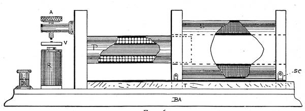
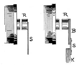
Figure 14 shows a coil with tube mode of regulation. The core C consists of a piece of iron tube, very thin, 4 inches long by ⅜ inch diameter, and filled with soft iron wires. One end of this core is firmly fixed in the left-hand bobbin head. The object of the iron tube is to prevent the sliding tube from catching in the iron wires, otherwise it can be dispensed with. Over this tube is slipped a brass tube T, ending in a handle H at the right-hand end; this must work easily over the core tube. The spool for the primary is now made up by fixing the other bobbin head on a paper or fibre tube and fastening its54 free end to the left-hand bobbin head, or the spool can be made in the usual way by glueing up two spool ends on a fibre or paper tube and securing the iron core firmly in one end, allowing room, of course, for the brass tube to slide in at the right-hand end. The primary winding is three or four layers of No. 20 B & S gauge cotton-covered magnet wire, the ends being brought out for future connection. Over this is now laid a few layers of paraffined paper, and ten or twelve layers of No. 36 B & S cotton-covered magnet wire is wound on for the secondary coil.
The contact breaker R is in no way different from the simple form described in Chapter II. Its construction can be readily seen from the figure.
A layer of cloth of the kind used in covering electromagnets is laid on over the secondary, and the coil is ready to be attached to the base. The base is seven inches long by three wide, and has little feet at its four corners to elevate it from the table and55 prevent abrasion of the connections underneath.
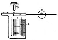
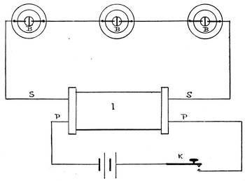
The connections are as given in Fig. 15. When in operation, the electrode cords being attached to binding posts, Nos. 1 and 2 are in circuit with the secondary coil only. When at Nos. 2 and 3 they receive the induced current or extra current in the primary, caused by the break of the battery circuit (see page 3).
Medical Coil with Interchangeable Secondaries.
This form of coil is the only one for practical medical work, and more space will56 be given to its construction than to the foregoing,57 which is suited only for limited use.
Fig. 16 shows side elevation of coil on base. The design can be largely varied, also it can be used either for a wall board, a cabinet top, or made to be carried in a case containing battery, electrodes, etc. S is one of the secondary coils, of which at least three should be provided. The dimensions are, of course, the same—namely, four inches long by 3½ inches wide over all. The spool ends are furnished with heel pieces, which slide under the brass track bar T. This accurately centres the coil and prevents it from working loose.
The following windings for removable or interchangeable secondary coils are those most in use.
Coil No. 1. 4500 feet (.375 pound) No. 36 B & S, approximating 1800 ohms. This may be led out in three divisions by means of switch on coil head. First divi58sion, 4500 feet; second division, 3000 feet; third division, 1500 feet.
Coil No. 2. 2400 feet (.6 pound) No. 31 B & S, about 350 ohms, divided into 2400 feet, 1500 feet, and 900 feet.
Coil No. 3. 750 feet (1 pound) No. 22 B & S in one coil, or two divisions of 500 and 750 feet, respectively; approximate resistance of wire, 125 ohms.
Coil No. 4. It may be necessary to obtain currents of extremely high tension, in which case a coil may be prepared of 5000 feet No. 38 B & S, or No. 40 B & S preferably.
The finer the wire, the less current and the most sedative effect; the coarser the wire, the more current with corresponding increased painful action.
The spools, in fact as much of the framework as possible, should be made of hard rubber, to which a fine finish can be given, although mahogany, rosewood, or even stained oak can be used. On each side of the right-hand spool heads a flat brass spring is screwed, making the contact for the sec59ondary wires on brass strips screwed on top of the track rods. These secondary connections can be made by means of flexible cords to binding posts, but the sliding contact is preferable. The primary coil P is firmly held in the left spool head, and consists of a core of No. 22 B W G soft iron wires, insulated and wound with three layers of No. 20 B & S magnet wire. The outside of this coil is neatly enclosed in a hard rubber tube to permit of the secondary coils sliding freely upon it. It is better, however, for the secondary coils not to touch the primary tube. The vibrator, or contact breaker, should be of the adjustable form shown in Fig. 17. The adjusting screw for the contact breaker can be mounted in a brass lug carried by the spool head.
Connections of this coil are substantially the same as those of the first-described medical coil. This apparatus is well worthy of elaboration; it should be fitted with a ribbon vibrator as well as an adjustable speed slow vibrator, a switch controlling60 either. A great variety of secondary coils can be made, those of coarse wire taking the place of the current from the contact breaker. The vibrators should be operated from an independent battery, although in the last coil described the magnet may be wound with the same size wire as the primary and then be in series with it. The secondary spools can be made of stained hard wood ends fitted on to fibre tube, which latter is easily procurable. Particular attention should always be paid to the spools and heads; if not properly made, they may come apart, and a disastrous unravelling of the wires ensues.
61
A coil much used for electric baths has a primary winding only, regulated by the sliding in and out of the iron core, which necessitates the use of an independent vibrator, or else by varying the current strength with a rheostat. The general directions given before will answer in the present case, the only data necessary being the size of wire, which should be about six to ten layers of No. 20 B & S. The coil with movable secondaries here comes into service. Strong currents are needed for bath work, and any variety of winding can be used with this make of coil. There are so many descriptions of bath and small medical coils in the electrical magazines published for amateur workers, that it is hardly necessary here to give more than a mention of the principal ones.
62
A few remarks on medical coils and their diseases may not be amiss; often a very little defect, if remedied in time, will prevent costly repairs.
The main care in medical electrical apparatus is the battery (see Chapter X. for descriptions of coil batteries and their operation). Clean, fresh solutions and clean contacts are essential. Keep zincs well amalgamated, remove wires from binding posts, and scrape bright the metal where the wires make connection; see no fluid is splashed on contacts, clean all contact springs periodically. The Edison-Lalande battery is probably the best for medical use, but even this requires occasional attention as to contacts, new zincs, fresh solution, etc.
Poor adjustment at contact breaker, dirty or corroded contacts, loose wires, loose binding posts, corroded binding posts, are often the only trouble in a coil refusing to work.
63
Flexible cords are fruitful of trouble: the tinsel breaks, and there is no circuit; gets wet and crosses or causes a leak; cord tips get loose and alternately open and close a contact; one minute all is well, next minute no current can be obtained. Another trouble in acid batteries is caused by leaving the zincs in the fluid. It is easy to do it in most cases, although the ingenuity of the leading medical electrical apparatus makers to-day is directed to this point. Cleanliness and careful inspection of all contacts is well repaid; carelessness surely brings its evils.
It is very desirable in medical work to eliminate the noise attendant upon the working of the coil vibrator. This jarring or humming is often in itself a source of irritation to a nervous patient. The sound can be deadened in various ways, for instance, by placing over the vibrator a temporary wood cover, lined with felt, resting upon a soft rubber gasket; or in any other manner that may suggest itself to the operator.
64
Table Showing Resistances and Feet Per Pound of Copper and German Silver Wires.
| Gauge, Browne & Sharpe. |
Diameter. | Feet per lb. |
Copper. | German Silver. |
|---|---|---|---|---|
| Ohms per 1,000 ft. |
ONLY APPROXIMATE |
|||
| Ohms per 1,000 ft. |
||||
| 8 | .1285 | 20 | .62881 | 11.77 |
| 9 | .1144 | 25 | .79281 | 11.83 |
| 10 | .1019 | 32 | 1 | 18.72 |
| 11 | .09074 | 40 | 1.2607 | 25.59 |
| 12 | .08081 | 51 | 1.5898 | 29.75 |
| 13 | .07196 | 64 | 1.995 | 37.51 |
| 14 | .06408 | 81 | 2.504 | 47.30 |
| 15 | .05707 | 102 | 3.172 | 59.65 |
| 16 | .05082 | 129 | 4.001 | 75.22 |
| 17 | .04525 | 162 | 5.04 | 94.84 |
| 18 | .0403 | 204 | 6.36 | 119.61 |
| 19 | .03539 | 264 | 8.25 | 155.10 |
| 20 | .03196 | 325 | 10.12 | 190.18 |
| 21 | .02846 | 409 | 12.76 | 239.81 |
| 22 | .02535 | 517 | 16.25 | 302.38 |
| 23 | .02257 | 660 | 20.30 | 381.33 |
| 24 | .0201 | 823 | 25.60 | 480.83 |
| 25 | .0179 | 1039 | 32.20 | 606.31 |
| 26 | .01594 | 1310 | 40.70 | 764.59 |
| 27 | .01419 | 1650 | 51.30 | 964.13 |
| 28 | .01264 | 2082 | 64.80 | 1215.76 |
| 29 | .01126 | 2623 | 81.60 | 1533.06 |
| 30 | .01002 | 3311 | 103 | 1933.03 |
| 31 | .00893 | 4165 | 130 | 2437.23 |
| 32 | .00795 | 5263 | 164 | 3073.77 |
| 33 | .00708 | 6636 | 206 | 3875.61 |
| 34 | .0063 | 8381 | 260 | 4888.49 |
| 35 | .00561 | 10560 | 328 | 6163.97 |
| 36 | .005 | 13306 | 414 | 7770.81 |
65
The simple form of contact breaker already described is useful up to a certain point, but it has disadvantages. Its rate of vibration is only variable through narrow limits, and it is not suitable for very heavy currents. But as it stands it has done long service, and will be used probably wherever the requirements from it are not exacting. The most desirable form of this66 simple spring break is shown in Fig. 18. R is the soft iron armature; S, the spring; C, check-nut which holds the adjusting screw A from becoming loose; T, a second adjusting screw used to tighten the spring and so raise its rate of vibration; K is the base to which one wire of the coil is attached; L, base of adjusting device to which battery wire runs at I. Where tightening screw T passes through the pillar of the adjusting screw, the hole therein is bushed with rubber to prevent accidental contact. Both A and T are provided with insulating heads of rubber or ivory. At B are the platinum contacts, which should be fully ⅛ inch in diameter.
One serious defect in the action of the simple spring vibrator (Fig. 19) is the tendency of the spring to vibrate, as it were, sinusoidally. This causes an irregularity in the rate of the vibrations, which affects the discharge of the coil very considerably. By far the better plan is to use a very short thick spring riveted to an67 arm carrying the armature at its end (Fig. 20). R is the armature, S the piece of spring, and K the point of attachment to the base. The actual width of the portion of the spring which vibrates—the hinge portion, it might be called—should not be over ⅛ inch.
The rate of motion is high; but an erroneous notion has been taken of its performance by many persons in the knowledge of the writer. The rate of vibration is not wholly dependent on the68 size, or, rather, smallness of its spring; the arm and armature considerably alter this, although they are not pliable, by reason of their mass and the momentum consequent on their mass.
A word here on the size of the armature. It should be somewhat larger than the face of the electro-magnet core, and should be thick—that is, in a circular form—say one half its diameter. Of course this does not apply to the steel lever armature before mentioned. It is impossible to lay down arbitrary rules where the conditions are not determined, but a very small amount of experimenting will demonstrate the correct lines on which to build.
When in action, all rapid rheotomes give out a definite musical note whereby the rate of vibration can be determined. Reference to any work on acoustics will show a table of the number of vibrations necessary to produce any stated musical note. The foregoing style of rheotome69 forms the basis of very nearly all those which are in use. The shorter and stouter a spring the more rapidly will it vibrate, and vice-versa. Carrying out this rule, we can manufacture an instrument which will give as high as 2500 vibrations per second (Fig. 21).
The armature A is a piece of flat hard steel bar ¼ × ½ inch, held rigidly on the metal support S and just clearing the up70per surfaces of the magnet cores C. The adjusting screw P should be provided with an arm, B B, whereby the rotation of it can be delicately varied. This screw must also be firmly held or the high speed of the armature will jar it loose. A check-nut on each side of the frame carrying it should be provided in every case. The necessary platinum contact can be hammered into a hole drilled before the armature is hardened. The proper place for this contact is about one fourth of the total length of the armature from its support, although in the simple contact breaker it can be placed at the distance of one third if desired. The reason is that the concussion of the adjusting screw dampens the free vibration, and the amplitude thereof is lessened in addition to the counter vibrations of the screw disturbing the regular vibrationary series.
Owing to the fact that the amplitude of the armature vibration is so small, a very delicate adjustment is necessary. The ad71justing screw can be placed nearer the free end, but for the reasons given it is not to be desired. The metal bridge should be a solid casting, and the armature clamped by more than one screw.
The mercury vibrator, which is applied to almost every large coil, is as follows:
A pivoted arm carries on one end a soft iron armature, which is attracted by the coil core. The other end is provided with a platinum point adjustable by a set screw. This platinum point dips into a mercury cup—a glass cup containing mercury, with a thin layer of spirits of turpentine. The object of the spirits of turpentine, which is a non-conductor, is to help choke off the spark which would ensue whenever the platinum point was raised from the mercury.
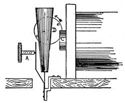
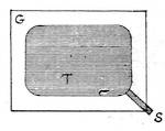
A form of contact breaker which will admit of great variation of speed, and which is adapted to carry large currents, is the wheel-break, constructed in the following manner:
72
A brass or copper disk 3 inches or more in diameter and upward of ½ inch thick has its periphery divided by a number of saw cuts, which divisions are often filled in with plugs of hard rubber or fibre. This disk is mounted on a shaft, which latter is either the shaft of an electro-motor, or is provided with a pulley by which it can be rapidly rotated. A strip of spring copper on each side of the disk presses upon the toothed surface, one strip being connected to the coil and the other to the battery or other current source. It will now be seen that when the disk rotates the slits or pieces of hard rubber cause the break in the circuit through the brushes or copper strips, the rapidity of the breaks depending upon the rate of rotation of the disk, and the number of slits in the wheel.
The slits or rubber pieces should be one-half the width of the intervening brass, but must be at least one sixteenth of an inch in width, especially where a high voltage is used in the primary coil.
73
The shaft of the machine may serve as one point of connection in place of one of the copper brushes; but in this event either a wide journal must be used, or else some conducting substance, as plumbago, replace the lubricating oil in the bearings.
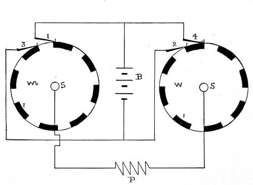
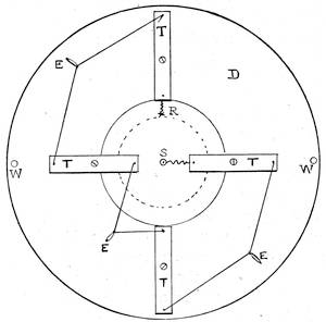
Fig. 22 shows a diagram of a pole changing contact breaker which will allow of rapid alternations of current. It is operated by an electric motor by preference, although any motive power can be applied to it.
W a W b are two brass wheels, the peripheries of which are broken by the insertion of insulating blocks I I, shown black in the sketch. S S are the shafts on which the wheels are mounted, the two wheels being necessarily insulated from each other. 1, 2, 3, 4 are four brushes of copper pressing on the rim of the wheel and leading in the current from the battery B.74 The primary coil is attached to the brass75 body of the wheel or to the shafts. When the wheel is in the position shown, the coil and battery are on an open circuit; but on the wheel commencing to revolve, the brushes 1 and 2 bear on the brass, and the current flows from the positive pole of the battery to 2 through the wheel W a to the coil P, up through wheel W b and out at 1 back to the battery. The next position of the brushes 1 and 2 will be on the insulations, and 3 and 4 will come into action. Then the positive current will reach W b by means of brush 3, and after traversing the primary coil and wheel W a, emerge at 4 to the battery, thus reversing the current through P as many times as there are sets of segments, which latter can be multiplied according to requirements. The main point to be considered after that of good connections is that the brushes 1 and 3 and 2 and 4 do not at any time touch any part of the brass wheel at the same time, as this would short circuit the bat76tery. This is avoided by making the insulating space longer than the brass surface, and adjusting the brushes as in the sketch, that each pair of them is a fraction further apart than the length of the brass tooth.
Accordingly, a wheel may be constructed with many segments and rotated at a high speed and rapid reversals of current produced, the uses of which are manifold.
As will be described in the notes on the Tesla effects, an electro-magnet, the poles of which are brought near the sparking point of the contact breaker, will help wipe out the spark, and so assist the suddenness of the break.
An extremely successful expedient in operating contact breakers is to employ a high-pressure air blast directed point blank against the contact point. The effect of this air blast when the contact is made is of course null, but on the platinum surfaces becoming separated, the high air pressure produced forms a path of extremely high resistance, and tends to blow77 off the spark as soon as it is generated. The stream of air should issue from an insulated nozzle of glass or rubber, and should not contain moisture.
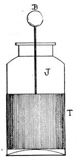
One of the most important inventions in coil work is the electrolytic interrupter of Wehnelt. Briefly, the apparatus consists of a vessel containing a solution of acid, into which dip two electrodes connected in series with the source of power and the primary of the coil. Upon passing a current through the combination the fluid becomes agitated at the electrodes and a rapid make and break of the current ensues (Fig. 23).
It requires considerable electromotive force for operation, a minimum of 40 volts being desirable. Its rapidity of action varies up to and at times exceeding 4000 interruptions per second. A Wehnelt interrupter can be made as follows: Procure a glass jar J holding about one quart or a little less, also78 a cover for same C, a piece of sheet lead L large enough to fit loosely across the jar and yet not touch the bottom, eight inches of one-quarter-inch glass tube M, a few inches of No. 20 platinum wire P, and two ounces of mercury. Heat the end of the glass tube in a gas flame, and bend an inch or less at a right angle; at the same time seal in the platinum wire by means of a blowpipe, so that the tip just projects from the bent end79 of the tube. This sealing can be accomplished readily by one unused to working glass, but almost any philosophical instrument maker will have it done at small cost. Holes being bored through the cover, the lead plate and the glass tube are fitted in, the platinum point almost touching the lead. Adjustment is, however, easy, as the tube, being turned, will retract or advance the platinum point from or towards the lead electrode. Nearly fill the jar with a solution composed of one part sulphuric acid to eight parts water, and fill up the glass tube with mercury. The connections can then be made by means of a clamp on the lead and a wire dipping into the mercury. Connect the lead plate L to one pole of the battery or source of energy, and the platinum-mercury electrode F to one post of primary. The other side of battery and coil being closed, the apparatus will begin to work. No condenser is needed with this interrupter.
80
This is a modification of the spring hammer-head type, but has a platinum contact on both sides of the spring. It thus obtains double vibrations, but is liable to stick. The elasticity of the spring normally prevents the circuit remaining closed on the forward movement of the hammer head, but this combination requires attention.
For light currents and rapid vibrations, such as are employed in electrotherapy, the steel ribbon interrupter is suitable. It consists of a steel ribbon V one-half inch wide by six or eight inches long and the thickness of a stout visiting-card. Near the end is riveted a platinum contact. One end of the ribbon is held by a brass upright R, to which connection is made to circuit; the other end is riveted to a threaded rod, which passes through a brass pillar, and is held by a81 thumb-screw and check nut S. Turning the thumb-screw either way tightens or loosens the ribbon and so raises or lowers the rate of vibration (Fig. 24).
Contact breakers in vacuo, as applied to Ruhmkorff coils, are by no means of recent date. Poggendorff made use of such prior to 1859, and noted the diminished sparking at the contact breaker and increased effect in the secondary circuit.
Mr. D. McFarlan Moore, whose experi82ments in vacuum tube lighting have proven so interesting, was granted patents upon various forms of contact breakers, in which83 the chief merit was that the contacts were broken in a vacuum. The sparking was almost eliminated, and the suddenness of the break of contact so accentuated as to materially improve the output of an induction coil. A perusal of his patents, copies of which may be procured through almost any bookseller, will prove profitable to the coil constructor.
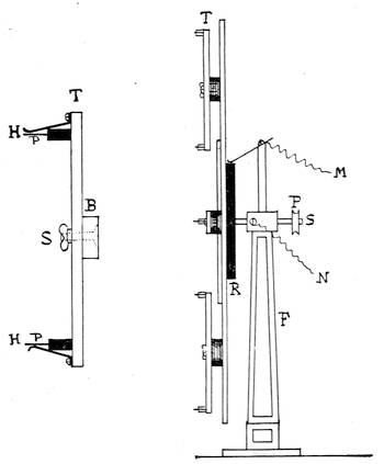
The most important advantage of this arrangement is the abrupt break, owing to a collar in the vibrator striking a movable contact while at full speed. Reference to Fig. 25 will show that the movable platinum contact is carried on a small vertical spring behind the vibrator spring, and projects through a collar on the vibrator spring. When the contact is made, the movement of the vibrator is not arrested, but continues at its full amplitude, thus allowing a long "make." The vibrator is kept moving at84 a constant amplitude by means of the small coil shown in the illustration, which is in shunt with the main circuit. In the old forms there has always been a liability of the platinum contacts sticking (or welding together). In the new form, as the break is made when the vibrator is in the middle of its swing, the sudden blow with the entire momentum of the iron hammer head is always sufficient to break the platinums apart. This form of contact breaker is very efficient on electric-light circuits, and operates with the utmost regularity.
This is a device where the actual break is made in alcohol between large studs of platinum nearly one-quarter inch in diameter. The bottom contact can be raised or lowered by means of an adjusting screw. The top contact is secured into the bottom end of a rod passing down a guide tube into85 the alcohol to meet the lower contact. By means of an electric motor and a cam motion, the top contact and plunger are made to work up and down in the alcohol, thus making and breaking the current flow. One of the commendable features of this contact breaker is that the platinum studs are caused to revolve while in operation, thus presenting new faces to each other after each blow. The apparatus is not adapted for rapid action, but for the handling of heavy currents.
Adjustable Contact Breaker for Medical Coils.
An adjustable contact breaker for medical coils is shown in Fig. 26. M M are the magnet coils, A is the armature, carrying a platinum contact, which vibrates against the adjusting screw P. The armature is pivoted at J, but is held at a distance from the magnets by the springs S S. The other end of the armature carries a ball B, which86 can be slid up and down on the rod and set at any point by a set-screw. When the ball is at the end of the armature rod most remote from the magnets, the vibrations are slowest; when moved towards the magnets, the vibrations become more rapid. Adjustment of the two springs S S at R R enables the contact breaker to operate on varying current strength, and also tends to lessen the jerkiness of gravity contact breakers. A flat spring, however, can be substituted87 for the spiral springs, in which case the pivot would be dispensed with and the spring riveted, as in the hammer form of vibrator. The illustration shows this arranged for a wall board, but it can readily be adapted for table work.
Fig. 27 shows a form of contact breaker much used in portable medical coils for slow speeds. It consists of a cone of iron H, mounted on the vibrator spring, and furnished with adjustable contact spring and screw A. Its amplitude of vibration is limited by the two pins mounted on the disc, between which the cone vibrates. The disc is turned by hand, thus moving the pins, and so varying the travel of the cone H to and from the core C. It does not give good results from the fact that the rhythmical movements are disturbed every time the cone strikes against the pins, also at the contact spring striking the contact screw.88 As we showed before, a really satisfactory contact breaker should have a spring, which allows of no sinusoidal movement. Where a pivoted armature is governed by a spiral spring, the result is a series of steady, rhythmical shocks, provided the adjustments are satisfactory.
Fig. 28 shows the details of a contact breaker to be attached to the coil head direct.89 It is often used on very small coils, which, together with a miniature dry cell, is slipped into a pocket case. An important detail in small coils is to use a contact breaker of sufficient size. Most of them are not large enough to stand ordinary usage, the adjusting screw is not of sufficient diameter and the thread soon strips. There is no reason why the adjusting screw, its platinum tip, and the pillar or lug which holds it should not be solidly built, it would certainly require less adjustment. Either single or double check-nuts can be fitted to the adjust90ment screws of nearly all the forms of contact breakers described.
It is absolutely essential that the diameter of contacts for all contact breakers should be as large as possible and their faces filed truly parallel to enable them to easily carry all the current required. One of the main causes of failure of coil is burning of the platinum point and platinum burr, the current being then materially reduced. Large sparks at point of rupture are often indications that the condenser is not working properly—perhaps has broken down or is not large enough. The contacts will sometimes fuse together; at any rate, the excessive sparking is an evidence of waste as much as in a dynamo generator.
The adjustable method of arranging condensers (see Chapter IV.) is here of great value, but it is easy to attach more condenser91 sections to the contact screw pillar and vibrator pillar and notice result. In the construction of Ruhmkorff coils it is a good plan to make all connections possible on the coil base, instead of inside the condenser chamber. This is done either by means of rubber-covered wires or neat strips of brass, screwed down on the base from points of connection, and, of course, carefully bent over or well insulated from all other leads which they have to cross.
The best makers of induction coils construct their instruments so that they can be readily taken apart with as little detachment of connections as possible.
92
In selecting an insulating compound for apparatus designed to be under the influence of high tension currents, a glance at some of the peculiarities of such currents will not be out of place. Mineral oil is used in many of the converters employed to transform the high voltage currents on the mains of the alternating electric-light systems to the comparatively low voltage used at the points of consumption. Professor Elihu Thomson, in a series of experiments, noticed some interesting facts in the sparking distances of high potentials in oils.
He found that discharges of low frequencies, as 125 alternations per second, were capable of puncturing mineral oils at93 one third to one half the thickness of an air layer sufficient to just resist punctures by the same discharge; but with frequencies of 50,000 to 100,000 per second, an oil thickness of one thirtieth to one sixtieth was a sufficient barrier.
At a frequency of 125 per second, a half-inch spark in the air penetrated one third to one fourth inch of oil; but at frequencies of 50,000 to 100,000 per second, a layer of oil one fourth of an inch successfully resisted the passage of a spark which freely passed through 8 inches of air.
The effect of drying an oil improved its insulating qualities. (Tesla uses boiled-out linseed-oil.)
He also noted that pointed electrodes could be brought nearer together under oil than balls without allowing a discharge. Flat plates allowed of still greater sparking distances. Tesla notes that oil through which sparks have passed must be discarded, probably owing to particles of carbon being formed.
94
Paraffin wax has a higher resistance than oil, providing it has not been heated over 135° C. It will stand alternate heating up to 100° C. and cooling, being of lower resistance when hot than when cold. But a serious permanent deterioration takes place when it has been heated over 100°C.; its color, from the normal pure white, changes to a yellowish tint when its insulation is impaired. Paraffin also undergoes a deterioration when heated for a long time even at 100° C., and should never be used for fine work when it is at all yellow. It is always best to melt it in a hot-water bath, not permitting, however, any steam or moisture to come near it. In this climate (United States) it is not so necessary to mix in any tallow to obviate brittleness, the average temperature of most workshops being sufficiently high to keep it from becoming brittle.
Resin oils do not suffer permanent injury from being heated, as does paraffin, but their insulating properties diminish95 much more rapidly on becoming even warm, the initial resistance of resin oils being lower than that of paraffin.
Paraffin has a fault—its tendency to absorb a slight degree of moisture. It has been found in telephone and telegraph cables saturated with paraffin that this is a very important cause of their deterioration. In Ruhmkorff coils, however, which are intended for operation in enclosed places free from damp atmospheres, the absorption of moisture would be probably reduced to its minimum.
There is one substance which, were it not for its cost, would be far preferable to paraffin for coil work, and that is beeswax. Its cost, however, is generally five times that of paraffin, even when purchased in quantities. It never becomes brittle enough to be damaged in careful handling, its melting point is low, and it does not absorb moisture. But it must be unquestionably pure and clear.
In foreign practice a variety of resinous96 mixtures are used to insulate the turns of the wire in Ruhmkorff coils.
Equal parts of resin and beeswax used hot, paraffin, resin and tallow, and shellac and resin are employed.
Shellac—that is, the yellow lac—is much used as a varnish for electrical instruments, being dissolved in alcohol to saturation. For dynamo armatures and similar apparatus the shellac varnish is of great service, and many good compounds of shellac, such as insullac and armalac, have been prepared for ready use. But (excluding beeswax) for our purposes paraffin stands pre-eminently at the head of the list.
In using shellac varnish, in high tension work more particularly, care must be taken that the moisture has entirely evaporated. Although a piece of shellacked apparatus may appear perfectly dry, yet when the current is allowed to flow unlooked-for results may appear—it takes hours in a dry atmosphere for shellac var97nish to dry. Baking the apparatus in a warm oven is a necessary expedient whenever feasible, care being taken not to burn or decompose the shellac. The proportions most generally used are 1 ounce shellac to 5 ounces alcohol. Stand the vessel containing the mixture in a warm place, and shake it frequently; filtration improves the varnish somewhat.
A ready and efficient varnish for silk is prepared by mixing 6 ounces of boiled linseed-oil and 2 ounces of rectified spirits of turpentine. For paper, 1 part of Canada balsam and 2 parts of spirits of turpentine dissolved in a warm place and filtered before being used. A good insulating cement for Leyden jars and insulating stands is prepared from sulphur, 100 parts; tallow, 2 parts, and resin, 2 parts, melted together until of the consistence of syrup, and sufficient powdered glass added to make a paste. To be heated when applied, this will resist most acids. The resin and98 beeswax compound is handy when making experimental mercurial air pumps of glass tubes, as it has a fair tenacity, is not too brittle, and is easily used.
99
A condenser is an apparatus whereby a charge of electrical energy may be temporarily stored, the amount of energy it will hold determining its "capacity." The capacity of a condenser is measured in micro-farads, the commercial unit representing one millionth of a farad. A farad equals the capacity of a body raised to the potential of one volt by a charge of one ampere for one second at one volt—i.e. = one coulomb.
The measurement of the capacity of a condenser is accomplished by the use of a ballistic galvanometer. The latter instrument has a bell-shaped magnet suspended in a coil of fine wire. When a momentary current is passed through this coil the100 magnet hardly commences to rotate until the current has practically ceased. A beam of light is reflected from a mirror fixed to the magnet on to a scale. The degree of deflection is compared with that obtained by the discharge of a condenser of known capacity, and the capacity of the condenser being measured is deduced by a simple rule. The farad, which is the unit of capacity requiring a condenser of an immense size, is replaced by a commercial unit, the micro-farad—that is, one millionth of a farad.
The original form of the condenser was the Leyden jar, which owes its name from the town of Leyden in Europe.
The Leyden jar is made as follows (Fig. 29): A clean uncracked glass jar with a wide mouth is coated on the inside and outside with tinfoil; sometimes loose tinfoil is filled inside, the tinfoil, however, not reaching more than two thirds of the jar's length from the bottom. A cork is fitted, and through the middle of it a wire101 is passed touching the inside coating of tinfoil and terminating in a metal sphere outside. A simple Leyden jar can be made in a few moments by half filling a glass bottle with water and wetting the lower half of the outside; a wire run through the cork into the water finishes the job. But this is at least only a makeshift, although a fair amount of current has been collected from a leather engine belt in motion in one thus made.
A condenser can be easily made as follows (Fig. 30):
Procure a clear glass plate, G, free from flaws, 11 inches square by 3/33∕32 inch thick. Give this a good coating of shellac varnish all over, sides and edges. Cut out of smooth tinfoil two sheets, T, 8 inches square,102 and round off the corners with a pair of shears. There must be no sharp corners, projections, or angles to induce leakage. Lay the glass plate on a sheet of paper, and mark its outline thereon with a pencil; then remove it and substitute a sheet of the tinfoil, and mark that. This will enable you to centre the foil. Give one side of the glass plate another coat of varnish, and so lay it on the paper that its outline coincides with the pencil outline. When the varnish has partly dried take a sheet of the trimmed foil, and by observing the pencilled marks you can lay it on the varnished plate exactly in the centre. Lay down the top edge first along this line, and carefully deposit the remainder of the foil in place. Next, with a flat brush full of varnish go over the plate, pressing out any air bubbles, and ensuring both a flat and a well-varnished surface. When this is dry,103 turn over the plate and repeat the operation on the other side.
If desired, a metal hemisphere of at least an inch in diameter may be attached with varnish, first scraping the foil to make a contact. The whole plate can be swung in a cradle of two silk threads, laid on a glass tumbler, or mounted on end in a shellacked block of wood.
A strip of tinfoil, S, attached at the corner can be used as a connector. The plates must be joined in the following manner when two or more are used in conjunction, and a quantity of current is desired. They should be placed so the connecting strips project alternately from each side (Fig. 31), and all on each side joined so as to leave two terminals, one to the 1, 3, 5 plates, the other to the 2, 4, 6 plates, and so on, which, when joined, will have the same effect as would result from the use of two large plates of the same total area. The nearer the plates are together the greater capacity they will have,104 always supposing the insulation is good, the insulation being known as the dielectric. Another good method, when a high quality of glass can be procured, is to lay the tinfoil on the plates without varnish, piling one on top of the other, tinfoil and glass alternately, and clamping the whole securely, laying a piece of cloth top and bottom to avoid cracking the glass from the pressure. This must be kept from moisture; a strip of paraffined paper stuck along the edges and extra paraffin run on will answer very well.
In constructing these glass condensers, they must be designed to correspond with the coil with which they are to be charged. In the foregoing description we have allowed a margin of 1½ inches of glass around the foil coatings. This will make 3 inches as the maximum distance between105 the coatings. Although a 2-inch spark from the coil would not jump this interval, a certain discharge will take place, and the less this occurs, the more serviceable the condenser will be. Therefore a greater margin should be allowed for a longer spark than 2 inches.
In the commercial condenser for telephone and telegraph use, paraffin and paper are substituted for glass, as will be described later. Heavy paraffin oil gives excellent results, but its fluidity is disadvantageous.
There is no valid reason why paraffin could not be used on the glass plate condensers, care being observed that it is free from dirt and metallic chips. In fact, the space between the glass plates of the multiplate condenser may be filled in with paraffin, and thereby exclude the air. Only a condenser so built up is not convenient to take apart for experimental purposes.
The foregoing description of a glass in106sulated condenser was written with the assumption that a good quality of glass be used. But the ordinary window glass is generally useless, and paraffined paper is preferable. The quality of glass known as "hard flint glass" is best, the superior qualities being imported from Europe. This latter is used in the manufacture of the standard Leyden jar for lecture purposes.
Were it not for its cost, the finest dielectric we could use would be sheet mica. Unfortunately sheet mica over 3 inches square is expensive, and becomes rapidly more so as it becomes larger.
Standard condensers for testing are made with mica carefully selected, and retain the charge for the maximum length of time. The built-up mica condenser is immersed in molten paraffin until the same has permeated the sheets, and then the complete mass is put under a pressure until the paraffin is well set.
107
The paper used in the manufacture of the commercial form is a special thin, tough linen paper carefully selected, sheet by sheet, to avoid pin-holes or flaws, and kept in an oven until used to ensure absolute dryness.
When this cannot be procured, use thin unsized writing paper of a good quality, well dried, and absolutely clean. As an example of the necessity of cleanliness, a light lead-pencil mark would serve to conduct the current entirely from a charged sheet to wherever it terminated, and if suitably located, utterly destroy the usefulness of the apparatus. Ink, which most generally contains iron, will cause trouble, and although some cheap foreign condensers are built up of old ledger pages, yet their efficiency is very uncertain.
The paper used in commercial condensers is from four to seven thousandths of an inch in thickness.
108
The smaller the amount of surface the less will be the capacity, but the quicker the discharge. The apparatus heretofore mentioned has had the alternate plates connected together in two series, presenting a large surface and rendering a large amount of current. A condenser so made will have a low voltage or potential, but is not so liable to leakage as one made to render a high potential. The multiple condenser of a large capacity will hardly discharge and spark over an air gap requiring a contact of the two electrodes. But a smaller one, consisting only of a single pair of small plates, will spark across quite a considerable air gap.
A number of charged condensers may be put in series, and the resultant potential thereby increased. Cut a number of pieces of paper of the desired size, say 6 inches square, and a number of sheets of foil 3 inches square. Round off the corners of the foil and build up first a sheet109 of paper, then a sheet of foil in its centre, then another paper and another foil sheet, and so on. There is to be no connection from sheet to sheet, only the inductive action of one on its neighbor. The foil must be considerably smaller than the paper in this construction, owing to the greater tendency to discharge round the edges of the sheets, owing to the greater potential of the current.
When the requisite number of sheets have been built up, leave a sheet of foil top and bottom for connection, tie between two pieces of stout card or board, and immerse in the molten paraffin. When thoroughly soaked, remove and put under pressure until cold. It will be found undesirable to make these with more than a dozen pairs of sheets, but to make a number of blocks of that number for ready service.
Fig. 32 shows the arrangement of the apparatus to charge a Leyden jar, the plate form being connected in a similar110 manner. The jar is stood upon an insulating support—a dry tumbler will answer—with the ball B connected to one pole of the coil. From the outside tinfoil coating111 T a wire runs to the discharger D D, which is in circuit with the secondary coil, S. The discharger balls D D are carefully approximated until the spark just passes, this latter point being of great importance. Were the discharger balls too near the spark would probably pierce the dielectric of the condenser, therefore the balls should be carefully brought near to each other until the exact distance is found. Even if the insulation of the condenser were not pierced, yet a path would probably be opened through which some succeeding discharge would pass, and ruin the instrument.
Another method of charging is to leave an air gap at B; then there is not much liability of the condenser discharging back through the coil—an undesirable event, as it would most likely perforate the insulation of the coil.
In designing or using any apparatus intended to hold a charge of high potential, it must be kept in mind how readily points or112 sharp edges serve to allow the current to113 pass off—we might almost say evaporate. Given two bodies, one a globe and the other a rectangular block, each well insulated from the earth or any other large body, and the globe would be found to hold its charge long after the block had dissipated all trace of the charge given to it. Therefore round off every edge and angle, projection or point.
In making handles, supports, or any work requiring an intervening high insulation, hard rubber is preferable to glass where there is liability to moisture. When the apparatus is as shown in Fig. 33, the condenser is alternately charged and discharged with a loud noise, the vivid sparks passing across the discharger balls D D possessing great deflagratory powers.
In experimenting with a Ruhmkorff coil it is not advisable to leave the instrument working while the secondary terminals are beyond sparking distance, as there is a great strain on the secondary insulation.114 Nor is it wise to use only one electrode in an experiment, unless the other is connected to some apparatus of an approximate capacity to that at the other, for the foregoing reason.
Now that the condenser has become so important a factor in telephone work, many schemes for cheapening and facilitating their manufacture have been devised. One in particular merits description, the "rolled-up" condenser having come largely into use. The tin-foil is supplied in rolls containing many yards of foil of the requisite width for the condenser to be made. Likewise rolls of paper are provided, exceeding in width, however, those of tin-foil. These rolls are arranged upon horizontal spindles in front of an empty spindle, or mandrel, upon which the condenser is to be formed. A few turns of the paper ribbon are made around the mandrel, then the foil is brought forward115 and a few turns made, then follows a turn of paper ribbon and another of foil, and finally a paper layer; and the mandrel being rotated, the alternate layers of foil and paper are laid on and rolled around each other on the mandrel until the requisite quantity is obtained. It then becomes an easy matter to cut the paper ends so no contact is possible between the layers of foil. The whole thing is slipped off the mandrel, secured by a rubber band or two, placed in a hot paraffin bath, and left to become saturated while still warm and before the paraffin has time to harden; the cylinder is put under a press and squeezed flat, driving out excess paraffin, and leaving the condenser in a convenient shape to handle. Connections are then made to the foil leaves, and a case of wood or metal completes the work.
There is no reason why aluminum foil or lead foil, or, in fact, any thin sheet metal should not be used in condensers. In telephone work, paper covered with gilt paint was tried, and worked fairly well, but was116 ultimately rejected in favor of tin-foil. In some cases, when it is desired to construct a condenser for high potential work, the oil-tank apparatus can be used. This is readily made of any desired dimensions, as follows: Procure a square glass jar, such as is made for storage batteries, a few pieces of sheet metal cut to fit loosely in the jar, some glass rods and sufficient clean "transformer oil" or heavy paraffin oil to nearly fill the jar. The sheets of metal can then be hung from the glass rods into the jar, being separated one-half inch, and the oil poured in. Two plates, about 8 inches by 6 inches, will hang nicely into a type D3 Chloride Battery jar, which is 7⅞ inches long by 9½ inches high by 3¼ inches wide. Altering the relative distances between the plates will give considerable adjustment to this simple condenser, or, if desired, more plates may be inserted and connected up, as in the tin-foil condensers. This type can be made portable, but it is not to be recommended unless no117 objection is had to emptying and refilling the jar with oil.
In operating large coils, it is convenient to be able to vary the capacity of the condenser on the primary circuit. To make an adjustable condenser presents no more difficulty than a non-adjustable one, simply more labor. For example, the large condenser used with the 6-inch spark coil might be divided into four sections, containing 2000 square inches, 500 square inches, 300 square inches, and 200 square inches of surface (see Fig. 34). Wires leading from the ends of the foil sheets C C are to be brought to the brass plates G G. The brass rods B B are connected by binding posts to the coil, each strip being well insulated from its neighbor. Any combination is possible by the insertion of brass plugs in holes drilled between the strips. The plugs must be fully large enough to make good contact on each of the two strips between which118 they are inserted, and should be turned taper. With the largest coils the condenser and contact breaker are generally mounted separately, and are fully adjustable.
119
| Specific Inductive Capacity. | |
|---|---|
| Dry air | 1.000 |
| Sulphur | 2.590 |
| Hard rubber | 2.290 |
| Paraffin | 1.996 |
| Shellac | 2.750 |
| Kerosene | 2.225 |
| Paraffin oil | 2.710 |
| Castor oil | 4.962 |
| Olive oil | 3.575 |
Condensers made with dielectric of high inductive capacity (insulation being equal) will retain greater charge than those made with dielectrics of low inductive capacity. Thus, one made with shellac would be nearly half as great again as with paraffin.
Capacity of a condenser increases with area of foil surface, with diminished distance between foil plates and with increase of insulation.
120
The luminous effects that can be obtained by means of a Ruhmkorff coil are exceedingly beautiful and instructive. The simplest experiment of this nature is the production of the spark consequent on the approximation of the electrodes attached to the secondary coil. This spark can be varied in both length, intensity, or shape by the form and nature of the substances between which it is permitted to pass. Attach to each end of the discharger a fine steel needle, and bring them together until the spark jumps from one to the other. A long thin snapping spark will pass, which, however, appears to be trying to take any but a straight path across the air gap. The peculiar crooked121ness of this, as in a lightning flash, is credited to the fact of particles of matter floating in the air conducting the current better than the pure air. The curious odor noticed in these discharges, as, in fact, in the working of all high-tension apparatus, is ozone—O3, triatomic oxygen. This gas, so noticeable after a thunderstorm, has a powerful effect on the mucous membranes of the throat and nasal passages, and must be inhaled with caution. It is being used by the medical profession for the destruction of germs and for general therapeutic service.
Substitute pieces of fine iron wire for the needles, and bring the ends together about one quarter the distance through which the normal spark will pass. The spark will be found to have changed its appearance, now being thick and redder, or, rather, of a deep yellow, and to possess vast heating qualities.
The iron wire will melt at one electrode, and if the other be examined it will be per122ceived that it has not even become warm. The cold wire will be the one connected to the positive pole of the coil.
Connecting the poles together with a piece of very fine iron wire will result in the deflagration of the wire in a vivid light.
The short thick spark is termed the calorific spark, and believed to possess its yellow color from the combustion of the sodium in the air. This spark will easily ignite a piece of paper held in its path.
Take a sheet of hard rubber and breathe on its surface; lay a wire from each pole of the secondary to points on the sheet, about twice as far apart as the spark would pass over in the air. The electric current will strive to complete its circuit; streams of violet light forming a perfect network will issue from each pole, until, provided the rubber is sufficiently damp, they will unite in a spark far exceeding its normal length in the air. It is curious to watch how the streams branch out from these two points,123 and how persistently they strive to meet each other. Scatter some finely powdered carbon on this sheet (crushed lead-pencil or electric light carbon is good material). The points may now be removed to still further distant places, and yet the current will work across. Each particle of carbon seems to be provided with innumerable scintillating diamonds, so sparkling is this effect.
Hard rubber is not absolutely necessary for these experiments; glass will do, but the black background of the rubber intensifies the luminosity of the discharges. Take a teaspoonful of powdered carbon and scatter it between the points on the rubber, so that the spark can find a ready path, evidenced by but little visible light. It will be seen that this powder is blown away from one electrode after a few minutes, leaving the latter in the centre of a clear space, but at the other electrode not much disturbed.
Bring the points so close to one another124 that the spark becomes short and fat; soon the carbon will commence to burn, forming a veritable arc light. Take two pointed lead-pencils and wrap a few turns of wire from the electrodes round the blunt ends of them; bring the pointed ends together, and an arc will soon be established; but at various points where the wire is wrapped the current will burn through the wood, and a number of incandescent points will ensue.
In these experiments on the rubber sheet it will be noticed that the spark acts as it does in the air, inasmuch as it does not take a direct path, but jumps in an irregular track from point to point.
If two small metal balls be substituted (Fig. 35) for the points between which the sparks be passing, it will be noted that the sparks do not pass through so great an air gap as before, or even as rapidly.
The spark between two balls is much noisier than that passing between points, and if the balls be of about 1 inch in125 diameter, a curious effect ensues on the passage of the current (Fig. 36). This effect has been likened to a stream of water issuing from a horizontal nozzle into a cavity when the nozzle is moved up and down slowly in the space of a few inches.
This easily made exhibit (Fig. 37) is one that is susceptible of quite a number of applications. In its simple form it is but an enlarged version of the rubber sheet scattered with carbon dust. The old way to make it was to take a plate of glass and cement on one face of it a sheet of tinfoil, using shellac varnish preferably. When dry, the tinfoil was scored across and126 across in such manner as to divide it up into little squares or diamonds. When the current was applied to each end of the plate, the spark divided into innumerable little ones; between each bit of tinfoil and its neighbors there would be many little sparks, and the effect was very pretty, somewhat as was described before when the carbon dust was strewn between the electrodes. It is more easily and quickly prepared by giving a sheet of glass a coating of shellac varnish, and then sparingly dusting any powdered conductor over its surface, using perhaps carbon dust or filings of metal. By cutting out a stencil from a piece of thin card and laying it over the sparkling plate, the design shows out very strikingly, and various designs in stencils can be prepared, different powdered conductors giving different colored sparks.
A long glass tube moistened inside with mucilage or shellac varnish and then having some conducting dust shaken through will also give quite a pleasing effect.
127
Coat one side of a glass plate with tinfoil, leaving an attached strip for connection. Shellac a piece of paper of a size corresponding to the design to be rendered luminous. When the shellac has dried so far as to become "tacky," lay a sheet of foil on it and press it down evenly all over.
Then draw on the paper a design that can be readily cut out. Use a pair of scissors or a very sharp knife. If the latter, lay the sheet on a piece of glass; but there is a greater tendency to tear the design when a knife is used if an unpractised hand wields it.
This design may either be stuck on to the plain side of the glass plate with varnish or simply laid on (Fig. 38). Connect one secondary wire to the foil coating of the plate and the other to the design. This must be shown in the dark, and the luminosity will not be strikingly apparent until the eyes become accustomed to the128 darkness—that is, when the room has been previously lighted.
One of the most beautiful and easily obtained phenomena of the high-tension discharge is the "electric brush" (Fig. 39). This occurs when the secondary electrodes of the coil are too far apart to allow of the free passage of the spark, and can only be seen at its best in a perfectly dark place. The ball tips before mentioned show this brush very plainly, or two sheets of tinfoil in circuit hung far enough apart to prevent vivid sparking will cause this so-called "silent" discharge. This latter arrangement should not be used for over fifteen minutes, as the ozone which is liberated in large quantities will affect those persons in the vicinity.
129
In fact, when a rapid vibrator is being used with the coil, the leading wires from the secondary terminals present this brush appearance, the curious threads of light resembling luminous hairs waving in the air. The more rapid the vibrations the more prominent the brush effect, as will be seen in the Tesla coils. The positive ball of the discharger shows the brush as a spreading mass of luminous threads reaching out toward the negative ball, which latter resembles a star, as in the figure.
The intensely disruptive power of the long spark is readily shown by its power to perforate substances, but great care must be taken that the secondary wires of a coil are led away from the body of the coil. A good plan is to hang two silk cords or stout threads from the ceiling, to which the secondary wires may be attached and kept in sight when experimenting at any distance from the coil.
To pierce a piece of thin glass, take two130 lumps of paraffin about the size of a walnut, and, warming them and the glass sheet, stick them on opposite sides of the glass facing each other. Then warm the ends of the two pointed wires and thrust them into the lumps of paraffin, that they terminate on the glass surface directly opposite each other. On connecting these to the secondary coil a few impulses to the contact breaker will start an electric discharge sufficient to pierce the glass if the thickness be proportioned to the power of the apparatus. The great Spottiswood coil pierced a block of glass 6 inches in thickness.
There is, however, a certain element of danger to the secondary insulation in performing this experiment.
131
If a metal or the salt of a metal be burned in a flame it imparts to the flame a distinctive color; table salt thrown into the fire burns with a yellowish flame, denoting the presence of sodium, and a greenish tint, indicating the combustion of chlorine. Violet flames accompany the burning of the salts of potassium, and barium burns green. Lithium and strontium give a red hue. But to be ordinarily perceptible, the salts require for the most part to be present in considerable quantities. By the use of the spectroscope, however, extremely small proportions of these metals and salts can be readily detected and classified.
If a beam of light be transmitted132 through a prism of glass the rays are decomposed, and what is known as a spectrum is formed (Fig. 40). The most generally observed spectrum is the rainbow. When the light from a flame in which is burning some suitable substance be transmitted through the prism, the color which predominates in the flame will predominate in its spectrum. The combination of a prism and tubes for observing these effects is a spectroscope (Fig. 41). The short fat spark from the Ruhmkorff coil is most useful in this work. The electrodes133 are provided with a portion of the substance to be examined, and the spark is passed and viewed through the spectroscope.
The spectroscope is shown in connection with the coil in Fig. 41. A is the134 aperture in the screen through which the rays from the metal burning at the discharger balls D D passes. The lens at L is used to view these rays after they have been decomposed by the prism P, which, as well as the lens, can be rotated. I is the coil, P P the primary and S S the secondary wires, C being a condenser bridged across the circuit.
The screen should be pierced by a very narrow aperture, A, and be placed at a considerable distance from the prism P, that the rays issuing through the aperture may not strike the prism until they have widely diverged and become separated from each other. The aperture is practically formed of perfectly parallel knife edges, forming a slit not exceeding one hundredth of an inch in width.
The colored spaces in the solar spectrum do not occupy an equal extent of area; the violet is the most extended, the orange the least. The proportion is in three hundred parts: Violet, 80; green,135 60; yellow, 48; red, 45; indigo, 40; orange, 27.
The solar rays exhibit on careful examination dark lines crossing the spectrum at right angles to the order of the colors, and always occupying the same relative positions. These are called Fraunhofer's lines.
If, however, the spectra of metals, gases, and other elements be examined they will be found to present certain characteristic bright lines, the body of the spectrum being often feeble or entirely dark. The spectrum of hydrogen gives two very bright lines of red and orange.
An extremely minute quantity of an element is necessary to give distinct lines. Sodium gives a single or double line of yellow light in a position agreeing with that of the orange rays in the solar spectrum.
Potassium gives a red line in the red end and a violet line in the violet end of the solar spectrum. Strontium presents136 eight bright lines; calcium gives mainly one broad green band and one bright orange band.
In practical work with the spectroscope a solar spectrum is often arranged that it can be used as a comparison with the spectrum being investigated, one spectrum being formed above the other, and the observation made as to which lines coincide. Iron gives nearly sixty bright lines coinciding with the same number of dark lines of the solar spectrum.
The violet rays of the solar spectrum are the rays which possess the maximum chemical action, the yellow the maximum light effect, the red the maximum heating effect. Beyond the violet band of the spectrum exist certain rays termed the invisible rays or ultra-violet rays, which in themselves are not luminous. Their vibratory rate is higher and their wave length shorter than the violet rays, according to the most generally accepted theory of light. These rays, when passed through137 certain substances, suffer a change and become visible in a luminous state of the substance, which luminosity is termed fluorescence.
The bright yellow line of sodium in the orange rays is found in nearly all spectra, owing to its extensive diffusion in the atmosphere.
Tesla has succeeded in producing electric waves of length approximating to those of white light, which appear to have very little heat. The ideal light is that which shows no heat and does not liberate noxious gases in the air, and were it not for its feeble luminosity, the light of the electric spark passing through a carbonic acid vacuum would approximate this most nearly.
The present mode of obtaining light—that of raising to a high temperature some substance or collection of particles—seems certainly somewhat antiquated. The following notes may be of interest and assistance in researches bearing on the lighting question.
138
Solid bodies, when heated, show a red glow in daylight at an elevation of temperature corresponding to 1000° Fahr.
| Temperature, degrees F. | Color of Substance. | |
|---|---|---|
| 1000 | Red. | |
| 1200 | Orange. | |
| 1300 | Yellow. | |
| 1500 | Blue. | |
| 1700 | Indigo. | |
| 2000 | Violet. | |
| 2130 | All colors—i.e., white. | |
The number of vibrations per second necessary for the production of light, and the velocity of light being determined, the calculation of the wave lengths of the colored rays becomes possible.
The following table (Sprague) shows this in ten-millionths of a millimetre (a millimetre = .039 inch) measured in the dark lines of the solar spectrum, from red to violet:
| Orange = | 6.88 |
| Orange, Higher = | 6.56139 |
| Yellow = | 5.89 |
| Green = | 5.26 |
| Blue = | 4.84 |
| Blue, Higher = | 4.29 |
| Violet = | 3.93 |
140
Notwithstanding it requires an intensely high potential to enable the current to jump an air gap of 1 inch, the same potential will produce a luminous discharge through exhausted glass tubes aggregating 8 feet or even more.
But the exhaustion can be carried so far that there is no apparent discharge; and, on the contrary, air at as high a pressure as 600 pounds per square inch will resist the passage of the spark over an extremely short space. If the tubes be filled with various gases and then partially exhausted, the length of tube through which the luminous discharge will pass varies with the gas, becoming shorter in the following141 order: Hydrogen, nitrogen, air, oxygen, and carbonic acid—the shortest.
Before detailing some of the more striking phenomena connected with high-tension discharges in vacuo, a description of a few forms of simple mercurial air pumps will be serviceable.
Fig. 42: If a glass tube, F, stopped at one end, 3 feet long or over, be filled with mercury and the open end immersed in a vessel of mercury, T, the column of metal in the tube will sink until it attains a height, M, of about 30 inches, varying according to the condition of the atmosphere.
The space between the mercury column and the top of the tube will be a fairly good vacuum. This fact was noted many142 years ago, and the gradual evolution of the mercurial air-pump based on this result can be followed in the articles on the mercurial air-pump by Silvanus P. Thompson, read before the Society of Arts, England, some years ago.
Geissler, the first manufacturer of the "Geissler" or vacuum tube for electrical research, seeing the inconvenience of the above-described operation and the meagre results obtained, invented the pump called by his name (Fig. 43).
F E is a stout glass tube some 3 feet long, having a bulb, B, at its upper extremity, and a rubber tube, S, attached to the curved end. A reservoir of mercury, R, connects with this rubber tube, and a special glass tap is fixed in the upper end of the glass tube at E, beyond which tap being the point of attachment for the object to be exhausted. The operation is as follows: On turning the tap a part of the way it allows a passage between the tube F E and the atmosphere. The reservoir143 R is then raised until the mercury flows into the bulb and up the tube to the tap. The tap is then turned a fraction, and the communication with the air is shut off and opened between the object to be exhausted and the tube F E. The reservoir is then lowered and the mercury falls, drawing down the air from the object into the tube. The tap is then turned as in the first place, and the reservoir R raised, when the air drawn into the tube is forced out by the rising column of metal. This operation being repeated many times, withdraws nearly all the air from the object—in fact, makes a fairly good vacuum. This pump has been much modified from the simple form described.
The form of pump most used in the United States lamp factories is based on the application of the piston-like action of a quantity of mercury dropping down a tube. This is known as the Sprengel pump, after the inventor.
Fig. 44: F is a stout glass tube about144 40 inches long by one-twelfth of an inch145 internal diameter, carrying the reservoir funnel R at the top, a piece of soft rubber tubing, S, nipped by a pinch-cock being interposed to admit of the regulation of the mercurial drops. The lower end of this "fall tube," as it is called, is immersed in mercury contained in a suitable vessel, V, a branch tube being blown or cemented into the fall tube to admit of the connection of the object to be exhausted at E. S is another piece of rubber tubing with a pinch-cock regulation. The point H is the normal barometric height of the mercury—about 30 inches. On attaching a bulb, for example, at E, and regulating the pinch-cock at the top of the fall tube F, a succession of drops of mercury falls down the tube, each drop acting as a piston to drive the air before it, sucking the same from the bulb, and forcing it down through the tube and vessel out into the atmosphere.
On its first being set into operation, the146 cushions of air between the drops silence their fall; but as a higher degree of rarefaction occurs, the air cushions become insufficient, and the drops fall with a sharp click on the top of the barometric column.
One great disadvantage in this form of pump is the tendency to fracture of the glass tube that is manifested by the concussion of the drops of mercury at the barometric height. However, this has to a certain extent been obviated in later forms of this useful and efficient pump.
For many electrical experiments, the simple exhaust tube (Fig. 42) mentioned at the beginning of the article will be found very satisfactory. The top end need not necessarily be sealed off with glass, a cork having a wire, W, run through for connection being driven in, and a coat of paraffin or one of the cements mentioned in a later chapter be laid on.
The second electrical connection is made by a wire dipping in the tumbler of mercury.
147
In a simple glass tube having two wires carrying balls inserted through its ends, from which the air has been partially exhausted, the study of the changes shown by the passage of the spark is extremely interesting. Before the commencement of exhaustion no luminous effect can be discerned; at a low degree of exhaustion a luminosity appears between the ends of the wires, the negative pole being surrounded by a violet glow and a larger pear-shaped red discharge from the positive. An interval near the negative electrode is in darkness, widening as the exhaustion progresses. When the degree of exhaustion is very high, a series of arches concentric with the positive ball appear and become broader and more distinct as the rarefaction progresses. The arches or bands are called striæ, and are most distinct when the tube is made in the form of a narrow cylinder, with a bulb at each end.148 Carbonic acid gas vacua give the best results. If the finger be placed on the bulb at either end a luminous spot appears, and by using a very rapid contact breaker in the primary circuit, the luminous discharges become highly sensitive, being diverted from their regular path on the approach of the hand, a magnet, or a grounded wire. An extended treatment of these phenomena would be out of place here, but can be found in nearly all comprehensive works on electricity.
If an incandescent-lamp bulb be held in the hand and one end be brought near to a terminal of the coil, a beautiful bluish light appears.2 The carbon filament, if long, and not held by its loop, becomes electrified and oscillates, often giving out a clear, high, bell-like sound as it strikes the glass. Particles of carbon deposited on the glass during the burning of the lamp, shown in daylight as a blackening deposit, generally show little sparks, like stars scattered over the inside of the globe.
2 This depends on the degree of exhaustion.
149
A vacuum tube will phosphoresce if held in the hand near a secondary terminal, or even if laid on the table near the coil, and will light quite brilliantly if one end be held against a terminal. This latter method, however, is generally inconvenient, as a certain amount of physical pain ensues from the discharge into the skin.
Different gases in the tubes give characteristic colors. In carbonic acid gas the whitish green hue prevails; in hydrogen, white and red; in nitrogen, orange yellow. The characteristic spectra are given by the gases in the tubes, and can be readily examined in the spectroscope. But there is sometimes a slight variation in these colors, dependent upon changes in the current.
In many Geissler tubes, a portion of the bulbs is made of uranium glass. On the passage of the spark in the tube this glass glows with a magnificent emerald green hue. Other tubes are constructed with150 an outside enveloping glass tube fitted with a corked orifice into which can be poured different solutions.
Fig. 45 shows a solution tube to be filled with solution of sulphate of quinine, etc.
Fig. 46 shows three exhausted tubes arranged in series.
151
A is of uranium glass, and glows dark green; B of English glass, showing a blue hue, and C of soft German glass, glowing with a bright apple-green tint.
Crystals of nitrate of calcium, nitrate of silver, benzoic acid, tungstate of calcium, lithia benzoate, sodium salicylate, zinc sulphide, and acetate of zinc fluoresce.
Fig. 47 is a highly exhausted tube, having at its lowest part a few pieces of ruby. When the secondary current is turned on at P and N the rubies shine with a brilliant rich red, as if they were glowing hot.
Fig. 48 shows the tube to exhibit the152 effect resulting from focussing the electric rays on a piece of iridio-platinum at B.
The cup A forms the negative pole; the metal disk C, the positive.
On increasing the intensity of the spark, the metal at B glows with extreme brilliancy, and melts if the intensity be carried too far.
153
Although the luminous discharges in the exhausted tubes are extremely beautiful, yet the effect is indescribably enhanced when the tubes are rotated. Gassiot's star was the name given to the earliest exhibit of a rotating tube carrying a luminous discharge, owing to the curious phenomenon ensuing from the interruptions of the spark. As the human retina is only capable of retaining an impression for a fraction of a second, and as the tube is only momentarily luminous during the passage of the spark, the effect of the revolving tube is that of a series of such arranged as the radii of a circle, the number apparent, being governed by the rapidity of rotation and the rate of interruption of the current.
154
Fig. 49 represents a form of rotating wheel which is easily made, and yet susceptible of many novel and attractive effects. Such a wheel, placed in a store window, would undoubtedly attract many persons by the beautiful variations of col155ored figures which it presents while in motion. And once a crowd is collected and its attention attracted to one spot, the capabilities of advertising the goods on sale are apparent.
A pasteboard or light wooden disk D, 3 feet in diameter or over, is mounted on a shaft, S, operated by an electric motor or such power as may be attainable. Upon its surface are mounted the tube-holders T T T T, connected, as shown, by wires leading from the secondary of the Ruhmkorff coil. Starting at the shaft S, the circuit runs to the first tube-holder, where the continuity of the wire is broken to allow of the attachment of the vacuum tube. From the first tube-holder the wire runs in turn to each of the other three tube-holders, terminating at R, where it passes through a hole to a metal ring on the back of the disk shown by the dotted circle. This ring and the shaft are in connection with the secondary coil, by reason of its electrodes being attached to two156 brushes or strips of metal pressing, one on the ring, the other on the shaft; or the bearing in which the shaft turns may displace one of the brushes. W W are two counterbalance weights, that the wheel may run smoothly and be not affected by the irregular distribution of the tubes or its surface. E E are elastic bands, looped over the wire and through rings in the disk, that the wires may not be liable to touch or short circuit.
At Fig. 50 is an enlarged view of a tube-holder, although, as it is meant only as a diagram, considerable variation of design is permissible. The springs at H H, to which the wires run, being bent back, the metal pins P P may be thrust through the rings on the ends of the tube, and the elasticity and pressure of the spring will hold it in place and make the necessary contact. A wooden block, B, secured to the face of the disk, is provided with a thumb-screw, S, securing the tube-holder to it, by means of which the tube-holders may157 be turned a trifle upon their axes and so vary the effect of the wheel.
Fig. 51 is a side view of the wheel, showing one manner of mounting the disk and158 its connections. The same figures apply to the parts as in the preceding figure. M N are the wires leading to the coil, P is a pulley on the shaft whereby the rotary power may be applied. The wires on the face of the disk are not shown, as they would impair the clearness of the diagram unnecessarily.
The greatest danger in the operation of such a piece of apparatus will be the tendency of the high tension spark to wander where it is not wanted, and to take short but forbidden paths back to the coil. However, care and perhaps experiment will prove the remedy. It will be noticed by reference to Fig. 49 that a circle has been drawn almost bisecting two of the tube-holders. This circle represents a circle of danger, and where a thin material has been used for the disk, the disk may very well be reinforced by a piece of stouter card cemented on its face.
The disk, whether of wood or of pasteboard, must have a liberal coating of in159sulation, either shellac varnish, paraffin, or beeswax, and be absolutely free from unnecessary holes. Moreover, the ring R must be of such a distance from the support F, if the latter be metal, as will preclude any jumping of the spark. A Ruhmkorff coil giving upward of three quarters of an inch of spark will be large enough to operate a wheel carrying four 8-inch tubes.
The wheel may be set back in a window and surrounded by dark fabrics, or built in, as it were, in a cave of such. The judicious use of pieces of looking-glass scattered on the sides of the cave, in such manner as to reflect the light of the tubes, will enhance the effect. There is no danger of fire where ordinary care is used, as the long spark necessary to the production of the luminosity will hardly ignite anything but gas, unless specially arranged to do so.
Fig. 52 is a triangle formed of three Geissler tubes, and intended for rotation160 as a whole. M M are two pieces of mica or glass, to prevent any possibility of the spark jumping and short circuiting, in which event the tubes would fail to light.
This triangle is shown diagrammatically at A B C, Fig. 53, mounted on an insulated rotating disk. Before commencement of rotation, and upon the current being turned on to the tubes, a simple triangle will result, but at a certain stage of rotation the Maltese cross shown is formed. A still higher rate of rotation will produce the161 double star, Fig. 54, and as the rotation and rate of vibration of the coil contact-breaker is varied, an apparently endless succession of stars or triangles appears to grow out into view.
Although Figs. 53 and 54 serve to illustrate a triangle of tubes and its variations, a very pretty and simple effect can be obtained with it as follows: Three strips of looking-glass are cut and scratched across their silvered surface, as described for the luminous pane, Fig. 37. The current then being allowed to pass, and the wheel being rotated, the triangle acts as162 in the preceding paragraphs, multiplying and forming figures, which are extremely interesting to watch.
While treating on the subject of store-window attractions, a few suggestions on a display of stationary Geissler tubes may be made. Starting with the assumption that the platform on which the goods would be displayed is of wood, a very small amount of preparation is necessary. The platform is covered with a dark material free from gloss, such as canton flannel, on which the tubes are laid in any fancy pattern, or may be scattered haphazard. Fine bare wire (No. 36 B. & S. is not any too small) is run from tube to tube, using care that it does not touch itself in such manner as to short circuit the current. There is not much necessity to cover the wires, unless the rate of vibration of the contact be so rapid as to show the brush discharge from the wire strands. In a jewelry store the cylindrical portions of the tubes may be covered with strips of163 dark cloth, concealing all but the bulbs. The Uranium bulbs will resemble emeralds; the yellow bulbs, topaz; and the blue, turquoise—certainly a very striking collection of gems. A few diamond-shaped pieces of the foil-coated glass scratched across, by the whiteness of the tiny sparks will aid to set off the whole. The outfit is not expensive: a coil giving a one half inch spark will light from four to six tubes to great brilliancy. Cloths with metallic threads woven in them must not be used, nor any of the metallic powders known in the trade as "glitters."
164
When it is desired to light clusters of gas jets situated in inaccessible places, or a number of them simultaneously, this method finds ready application. It operates in the division of a long spark among a number of burners, the gas being turned on at the main and the primary circuit of a Ruhmkorff coil closed and opened until the succession of sparks ignites the gas, Fig. 55. There are various commercial forms of these burners, prominent among which is the "Smith jump spark" burner.
A lava tip is provided with a mica or isinglass flange midway between the tip and the lower end of the burner. This flange isolates the electrodes from any possibility of the spark straying away to the165 metallic pillar in which the burner is inserted. The multiple lava tip burner is intended for use where a very short burner is needed, also for flash rings multiple lights. Here the tips are placed close enough together to ignite by contagion. In this case one of the common tips is removed from the ring and a multiple lava tip substituted. It is customary to allow sixteen burners to one inch of spark. Any num166ber of series can be operated alternately by means of a suitable switch.
The wire used to connect the burners is generally bare copper, and as small in diameter as will sustain its own weight without injury, the amount of the current being infinitesimal. It is supported on porcelain or glass knobs screwed to the wall or ceiling, being carefully planned to avoid any metallic substances to which the spark might be tempted to escape. In wiring chandeliers, the wire is run through glass tubes wherever there is any liability of its coming near the metal pipes. There is a very great danger of this jumping of the spark where it is not wanted, and the utmost care must be taken in planning the course the wires shall take. Even a damp wall will cause trouble or a gilt cornice, although the latter may be entirely insulated from the ground. The switch bases for the groups of circuits must be of hard rubber, and the switch points and levers be placed so far apart that there is167 no liability of the spark jumping, which it certainly will do if it gets a chance. Ordinary insulated wires are ineffectually protected by the rubber compounds used. Glass, mica, and better still, a large air gap are the only insulations that will serve, for the tremendous potential or voltage of the current must be carefully considered whenever insulation is necessary. The coil is better provided with a spring key in the primary circuit than a vibrator, it gives better control of the circuit and probably a larger and better spark.
The spark which occurs at the contact breaker of a Ruhmkorff coil is held in check by the condenser; were no condenser used, it would possess considerable powers of combustion. Using a large primary coil and a few cells of open circuit battery, this spark is made to pass across the path of a gas jet, which it instantly ignites. The168 contact breaker consists of a platinum point, fixed on the gas tip, and a German silver spring, carried on a lever, which latter is pulled across the tip so as to make and break the circuit at the burner orifice. Some burners are provided with a ratchet arrangement, by which pulling the lever once turns on and lights the gas, pulling again turns it off; others require the gas to be turned on first.
Reference to Fig. 56 will show the connections to two burners P P and an automatic burner A, to be described later. The coil C is a core of soft iron, about ¾ inch diameter and eight to ten inches long, wound with from two to four pounds of magnet wire, Nos. 12 or 14 B & S. One side of the battery goes to ground or to the gas pipe, thus forming the return circuit. The wiring on the fixtures is done with No. 20 to 24 B & S gas fixture wire, insulated with four windings of silk or cotton. This is fastened to the lacquered brass work by means of thick shellac varnish, it being169 tied on first with thread, which can readily be removed when shellac is dry and hard. The wire is held on the insulated collar of the burner by a small nut and screw, and170 great care must be taken to ensure no grounding. The setting up of a gas-lighting outfit is extremely simple, but it often fails for want of care. There must be the best possible insulation between wire and metal work.
There are several forms of these burners, but the principle of all is the same. A gas burner protrudes from the top of a brass case which encloses the actuating mechanism. This mechanism consists of two electromagnets, the armature of one opening a valve and allowing the gas to flow, at the same time vibrating a platinum-tipped rod, which produces a series of sparks at the burner tip. These sparks ignite the gas, and a second magnet is provided to shut off the flow of gas, thus extinguishing the light. Some devices use one electromagnet for both lighting or extinguishing, but the majority are with double magnets. The171 circuit is worked from a push button situated at any desired location, and having a white and black button, one for lighting and the other for extinguishing. The principal automatic burners are the Holtzer, the Boston, and the Bartholdi, between which there lies little choice, so admirably are they constructed.
Instead of a rotating stop-cock, as in other automatics, a gravity valve is employed in the Bartholdi, which is held to its seat by the weight of the armature and connecting stem, as shown in Fig. 57. When the gas is turned off the valve rests upon its seat, as indicated in the cut. By a closure of the electric circuit at the turn-on button, two of the helices M P are energized, causing the armature J to be lifted, thus, by means of the stem H, raising the valve G from its seat into the dotted position, and opening the gas way so that the gas may172 issue to the tip, as shown by the arrows. At the same time, the top of the valve strikes against the end of the lever W, causing the circuit to be broken at the spark points T U, resulting in a continuous sparking as long as the finger presses the button. The magnet173 when raising the armature has also twisted or partially revolved it, so as to bring the notch d in the armature over the end of the hook e, as shown in dotted lines. When the circuit is broken by lifting the finger from the button the notch falls into the hook and the valve is locked open.
To extinguish the flame the turn-off button is pressed, when a second magnet (not shown in cut) lifts the armature and twists it in the opposite direction, so that when the circuit is broken the armature falls free to its normal position, closing the valve.
In wiring up an automatic burner it is necessary to run two wires to it, one from the white button and another from black button on push plate S. Reference to Fig. 58 will make this clear. Most burners are provided with two binding posts inside the brass case, and the wires are run through a rubber-bushed hole in the base. If the push has already been set in position and wired up, as per Fig. 58, have the buttons174 pressed alternately, when on touching the binding posts on automatic with the wires, the lighting or extinguishing connection is175 easily selected. The lighting armature in most automatic burners buzzes violently, while the extinguishing one only strikes once on contact being made. Fig. 58 shows how to connect up two pushes to one automatic, one push, perhaps, being located downstairs and the other upstairs in the case of a hall lamp. In setting up these burners care must be taken not to bend contacts or alter adjustment, and absolute precaution is necessary that no crosses or weakly insulated places are in circuit. After burning for some time it often happens that the burner refuses to light, only buzzing feebly or not at all. If feebly, the trouble is in battery, which should consist of, at least, four or six cells of open circuit battery with low internal resistance, such as Samson-Law carbon cylinder, or for occasional use large, dry cells.
If no click is heard on pressing white button, examine all connections; if still no trouble is found, examine the platinum break. The platinum tip may be bent176 by the continual hammering against the platinum tip on vibrating rod, preventing contact on collar, or that soot has formed there. These are the commonest maladies of automatic burners, and can be easily remedied by readjusting platinum tip and cleaning. Contacts here must be clean. In general wiring use waterproof office wire or, better still, rubber-covered wire; for fixtures use the fixture wire before described. When shellacking the wire to the fixture don't attempt to connect up batteries until the shellac is dry and hard, say for half a day. Electric gas-lighting is fruitful of trouble if the work is not well done. Another cause of trouble may arise from a dirty burner not allowing the gas to strike near the contact (clean the burner), or the collar carrying contact may have shifted, perhaps short-circuited; it should be insulated with a thin strip of asbestos. Although white lead at the joints makes a fairly good contact, some persons prefer to use tin-foil, a piece of foil being worked around screw thread and the177 burner screwed on; it prevents leaks as well as lead if well done, and makes better contact. As a short circuit on the wires will cause all the burners to fail, many devices have been invented to open the circuit upon such an occurrence. These will be found described in the catalogues of electrical stores; they do not come within the province of this book for description.
178
In selecting a battery to operate the coil, one is needed which will supply a large steady current for a considerable period. Although the primary circuit is opened and closed rapidly, yet the class known as open circuit cells is not suitable, even though they have a low internal resistance, and thereby render a large current. Such cells are only suitable for the uses for which they are mostly designed, bell-ringing or annunciator work. There is one case, however, where an open circuit cell may be used with an induction coil, and that is in gas lighting as previously described; but here a dozen or so impulses of current are generally sufficient, followed by long periods of rest. For the179 latter work the cells in common use are the Samson, Champion, and Monarch, all of which are of low internal resistance and great recuperative power.
The reason that such cells will not work for long periods, is that they polarize. This latter action takes place in these open circuit cells, which are of the Leclanché type as follows: A positive plate of zinc is immersed in a solution of ammonium chloride (or salammoniac), and a negative plate of carbon and peroxide of manganese, contained either in a porous cup or compressed into a block also stands in the solution. Care is taken that these two plates do not touch each other. When the outside circuit is closed the zinc combines with the chlorine of the solution liberating free hydrogen and ammonia. The hydrogen appears at the negative plate, where it is acted upon by the oxygen of the peroxide of manganese to form water.
But when the circuit is of too low resistance, the oxidizing action of the peroxide180 of manganese is not rapid enough, and a film of hydrogen, which is a poor conductor, forms over the negative plate, increasing the internal resistance of the cell and setting up local action. In the best class of these open circuit cells, this hydrogen is absorbed after a rest, and the battery recuperates and is ready for work again. The circuit of the Ruhmkorff coil is low, and this polarization always occurs a few minutes after the contact-breaker is started.
In the class of closed circuit cells, chosen for the present purpose, the Grenet or bottle bichromate is one of the handiest for occasional use. A glass bottle-shaped jar, J, Fig. 59, is provided with a hard rubber cap, G, on which are mounted the181 binding posts A B. To the underside of this cap are attached two carbon plates C C, which reach nearly to the bottom of the jar, being connected together on the cap by a varnished copper strip, the latter being in turn connected to one binding post. Through the centre of the cap passes a brass rod, R, having attached to its lower end a piece of sheet zinc, Z, well amalgamated with mercury. This process of amalgamation consists in cleaning the zinc, then rubbing its surface with a rag dipped in dilute sulphuric acid, and pouring a few drops of mercury on the wet zinc. The mercury will spread readily over the zinc, provided it has been well cleaned, and if properly done should give the zinc plate a bright, shining appearance.
When the cell is not in use, the zinc is drawn up into the neck of the bottle and clamped by a set screw against the brass rod. A copper spring pressing on the rod serves to carry the current to the second binding post.
182
This cell originated in France, whence its name, but a cheaper form is now made in the United States known as the Novelty Grenet. The shape of the jar is somewhat different, and the carbon is moulded, whereas the French carbon is sawed from the carbon deposited in the gas retort; but the American form is practically of as great utility as the French, and the cost recommends it.
The bichromate solutions are affected by light, and deteriorate less it kept in stoneware jugs. The Grenet battery can very well be fitted into a neat wood case, which will serve the further purpose of preventing chance knocks from fracturing the glass jar.
Carbons which are used in batteries containing the foregoing solution should be well washed in warm water whenever the solution is changed, and especially when it is intended to put the battery out of active service. When the solution acquires a decidedly green hue it should be re183placed with fresh. The electromotive force of this cell varies from 1.90 to 2 volts, and the amperage is dependent on the size of the plates, running from 5 amperes upward.
The glass jar is filled up to the commencement of the neck with a solution of bichromate of potash or sodium, called electropoion fluid, and prepared as follows: To 1 gallon of water add 1 pound of bichromate of sodium, mixing in a stoneware vessel. When dissolved add 3 pounds of sulphuric acid in a thin stream, stirring slowly. As the mixture heats on the introduction of the acid, care must be used to pour in the latter slowly. This solution should not be used until quite cold.
The sodium salt is preferable to the potassium, owing to its not forming the crystals of chrome alum, and also on account of its lower cost and greater solubility, the latter being four times greater than that of the potassium salt. The commercial acid used should contain at least184 90 per cent pure acid and should be free from impurities. On filling the battery use utmost care not to splash the solution on any of the metal work, or it will cause corrosion. Although the salts in the solution will most likely make a stain, the corrosive action of the acid can be arrested if the solution be splashed on the clothes by the prompt application of ammonia solution.
The "Fuller" cell, Fig. 60, which is another type of the bichromate cell, is one from which a steady current can be obtained for a longer interval than from the Grenet, but the current is less. The electromotive force is the same, but the current is only 3 amperes, except in certain modifications.
In the porous cup is a cone-shaped zinc having a stout copper wire cast in. This185 wire is occasionally covered with rubber insulation, but, as a rule, is bare. The porous cup is of unglazed porcelain, thick, but very porous. This sets in the glass jar, a wooden cover fitting loosely over the whole to exclude dust. Through this cover passes the wire leading from the zinc, and also the carbon plate carrying a machine screw and check nuts for connection. The cover is dipped in melted paraffin, as is also the upper end of the carbon and the rim of the glass jar. This is to prevent the creeping of the salts in the solutions and the corrosion of the brass work.
Into the porous cup is poured a solution composed of 18 parts by weight of common salt and 72 parts by weight of water. Electropoion fluid is held by the glass jar, the two solutions reaching a level of two thirds the height of the jar. One ounce of mercury is added to the porous cup solution to ensure the complete and continuous amalgamation of the zinc. The186 salt can be more readily dissolved in warm water, but all solutions must be used cold. It is not always necessary to renew the solutions when the battery fails to give out its accustomed strength, but several ounces of water can be substituted for a similar amount of fluid in the porous cup. Stir the solution by moving the zinc up and down, and a temporary improvement will be noticed.
To obtain a greater current from this cell, use a larger zinc, such as a well-amalgamated zinc plate, and add a teaspoonful of sulphuric acid to clean water for the porous cup solution. Additional carbon plates connected together and placed round the porous cup will lower the resistance of the cell and increase the current, and also tend to keep down the polarization.
A new form of this battery was described by M. Morisot a short time ago.
The positive pole is of retort carbon in the outer cell in a depolarizing mixture187 made of 1 part sulphuric acid, 3 parts saturated solution bichromate of potash, crystals of the latter salt being suspended in the cell to keep up the saturation. A porous cup contains a solution of caustic soda. The zinc is in a second porous cup placed within the first, which holds a caustic soda solution of greater density. The electromotive force is 2½ volts when the cell is first placed in circuit, and will remain at 2.4 for some hours. The internal resistance is low, but varies with the thickness of the porous cups. This cell is not suitable for any but use for a few hours at one time.
The Dun cell has a negative electrode of a carbon porous cup filled with broken carbon. The zinc is in the form of a heavy ring, and hangs at the top of the solution in the outer jar. Permanganate of potash crystals are placed in the porous cup, and the entire cell filled with a solution of caustic potash 1 part to water 5 parts. The voltage is 1.8, and the internal resist188ance being low the resultant current is large.
A cell with an electrode of aluminum in a solution of caustic potash and carbon in strong nitric acid in porous cup is claimed to have an electromotive force of 2.8, but the nitric acid is not a desirable acid to handle.
Metallic magnesium in a salammoniac solution with a copper plate in a hydrochloric acid and sulphate of copper mixture is of high voltage, nearly 3 volts being obtained, and the current is large, but it is a new combination and has not as yet stood the test of time.
There are other formulæ for solutions to be used in Fuller or Grenet cells which may be useful to the experimenter. Trouvé's is as follows: Water, 36 parts; bichromate of potash, 3 parts; sulphuric acid, 15 parts, all by weight. Bottone's: Chromic acid, 6 parts; water, 20 parts; chlorate of potassium (increases electromotive force), ⅓ part; sulphuric acid, 3189½ parts, all by weight. A convenient "red salt" or "electric sand": Sulphate of soda, 14 parts; sulphuric acid, 68 parts; bichromate of potash, 29 parts; soda dissolved in heated acid, and potash stirred in slowly. When cold can be broken up and prepared when required by dissolving in five times its weight of water.
The chromic acid used in Bottone's solution is very soluble in water, it being possible to dissolve five or six times the amount in the same quantity of water as of bichromate of potash. The simple solution of chromic acid is 1 pound to 1 pint of water, to which is added 6 ounces of sulphuric acid.
When it becomes necessary to cut zinc plates, it may be readily done by making a deep scratch on the surface, filling the scratch first with dilute sulphuric acid, and then with mercury. The mercury will quickly eat into the metal, and the plate may be easily broken across or cut with a saw. Zinc plates can be bent into190 shape by the application of heat. Hold the plate in front of a hot fire until it cannot be touched by the bare hand: it will be found that it has softened so that it can be bent around a suitable wooden form. As zinc plates are most attacked at the surface of the acid solution, it is advisable to coat the extreme upper portion of them with varnish or paraffin. Rolled zinc is always preferable to cast, especially so when immersed in acid solutions.
To avoid confusion, it may be stated here that it is the rule to speak of the zinc element as the positive plate and the negative electrode or pole, and the carbon vice versa. The portion of the element immersed in the solution is the plate, the part outside, the pole or electrode. In diagrams and also in formulæ positive is shown by a + (plus) sign and negative by a-(minus) sign.
The relation of cost of the materials most used is shown in the subjoined table, which cost, however, varies with the market:
191
| Sulphuric acid, chemically pure | 18 |
| ""commercial | 1.5 |
| Muriatic" | 1.12 |
| Nitric " | 3.5 |
| Electropoion fluid | 2 |
| Bichromate of potash | 10.5 |
| ""soda | 8.5 |
| Caustic soda | 9 |
| Salammoniac | 7 |
| Chromic acid | 19 |
| Blue vitriol | 4 |
| Litharge | 5.75 |
| Mercury bisulphate | 94 |
| Paraffin | 9 |
| Beeswax | 35 to 45 |
| Shellac varnish | 87 |
| Tinfoil | 35 |
A cheap modification of the Daniell cell. A glass jar has at the bottom a copper plate consisting of 4 to 6 leaves of thin sheet copper, set on their edges in a starlike shape, a copper wire being attached to the copper rivet which holds the leaves together. A mass of crystals of sulphate of copper is filled in and laid on the top of192 the copper electrode an inch or so above its top. The negative plate is a variously shaped plate of cast zinc hung from the edge of the jar and reaching about 2 inches from the top into the fluid. Water is poured in until it covers the zinc, and the battery is complete. The sulphate of copper deposits its metallic copper on the copper leaves and liberates sulphuric acid, which rises and attacks the zinc, setting free sulphate of zinc. The sulphate of zinc solution being of greater density remains near the bottom, and the sulphate of zinc solution stays near the zinc. When the cell is left too long on an open circuit the two solutions tend to mix, and copper is deposited on the zinc. The sulphate of zinc finally saturates the top solution, which has to be partly drawn off and replaced by fresh water and crystals of sulphate of copper dropped into the jar to take the place of that which has been decomposed. Electromotive force 1 volt, current from 3∕10 to 5∕10 of an ampere. The193 practical working of this cell will be treated of later on in these pages.
The Gethins (Fig. 61) and the Hussey bluestone cells both have the zincs standing in porous cups (shown by dotted lines), which in turn are supported half-way down the jar, generally resting on the copper strip acting as a porous partition between the fluids. The zinc stands in a solution of zinc sulphate, or a weak sulphuric acid solution. The internal resistance is low, and the current large, being from 1 to 5 amperes. These cells are the ideal bluestone cells for charging storage batteries requiring very little attention. The special Gethins cell shown in the figure has the copper made with a collar, which encircles the porous cup, and thereby lowers the internal resistance of the194 battery. The voltage not being over 1 volt, however, renders these cells hardly suitable for direct connection. Five cells connected in multiple would give all of 10 amperes of current, and 1 volt, and a number of these multiple groups could be connected in series for a higher voltage.
is similar in operation to the Edison-Lalande, but differs in details of construction. The zinc is a heavy ring suspended outside, but not touching a perforated tin cylinder closed at the bottom, containing the oxide of copper in flakes. Its internal resistance is slightly higher than the Edison-Lalande cell, otherwise there is little choice. The 6 × 8 size is excellent for coil work, giving 250 actual ampere hours and remaining on open circuit for long periods without deterioration.
195
This is a practical form of the old Lalande-Chaperon cell, and gives a steady, large current, being of low internal resistance, but is of low electromotive force, being less than .70 volt on closed circuit of medium resistance. Being of low internal resistance, however, its output is large—three cells of the type S; internal resistance, 0.025 ohm. Capacity, 300 ampere hours, will about equal one cell type E 5 of the Chloride Storage Battery. The elements of this cell consist of positive plates of amalgamated zinc, suspended on each side of negative plates of the black oxide of copper in an electrolyte solution of caustic potash. In action the decomposition of water forms an oxide of zinc from the positive element, which with the potash in combination leaves a soluble salt of zinc and potash. The hydrogen of the water acts on the oxide plates to form metallic copper, thus really reducing, instead of increasing, the internal resistance of196 the cell. A layer of heavy paraffin oil is poured on top of the solution to prevent the action of air.
or Roche dry cell. This cell possesses remarkable recuperative powers and low internal resistance. Made in many sizes, the best suited for medical coils is No. 2; dimensions, 57∕8 × 27∕16 inches. For heavier work the No. 5, 6 × 29∕16 inches, and known as the Navy Standard, is recommended. A convenient size for portable medical coils is No. 3, 3¾ × 1⅞ inches, taking up very little room, yet giving a large output. Two of these latter cells enclosed in the coil case will give with a suitably wound primary (No. 18 to 20 B & S) as strong a current as can be used in electrotherapy. For Ruhmkorff coils cells Nos. 6 and 7 (6 × 3 inches and 7 × 3 inches) furnish a most desirable battery for all work not needing the constant operation of the contact breaker,197 such as wireless telegraphy, gas-lighting, etc. They will do service on X-ray work, but the writer prefers a storage cell or the copper oxide types. The E. M. F. of the above cells is one and six-tenths volts, and current from 9 amperes to the No. 7 size, which gives 24 amperes on short circuit.
As a matter of practice, there is no really dry cell; all so-called cells contain liquid held in suspension, and their output is limited to the amount of fluid. One of this type can easily be made in the following manner: A containing jar is made up of first-quality sheet zinc, the edges being joined by a turned seam and then soldered, the bottom of zinc being also soldered in. In soldering here, as actually in all such operations, be absolutely sure the edges of the metal are clean. The jar is partially filled with the following composition: Oxide of zinc, 1 part; sal ammoniac, 1 part; plaster198 of paris, 3 parts; chloride of zinc, 1 part; water, 2 parts, all by weight; or sal ammoniac, 1 part; chloride of calcium, 5 parts; calcined magnesia, 5 parts; water, 2 parts, or enough water to make a thin paste. A brass binding post is soldered to the zinc case and a carbon plate having a binding post is inserted in the centre of the cell, care being taken that it does not touch the zinc. A small disc of wood laid in the bottom of the cell will prevent contact at the bottom. Molten pitch or a composition of pitch and rosin in the proportion of 6 to 1 is poured on top, so as to seal the cell. As gas is generated in the cell, a safety valve should be provided, either a piece of porous cane or a short length of hard rubber tube, inside of which have been placed a few strands of woollen thread. This class of cell is so cheap and so many forms are available for choice that it is rarely desirable to make one's own. They will not do for steady current, but only for intermittent work. The large sizes being of low internal resistance,199 can be used for signalling in wireless telegraphy, where it is not possible to use wet (or free fluid) cells. The principal dry cells on the market are the Mesco, the O. K., the Nungesser, and the Samson semi-dry cell.
200
The development of the storage or secondary cell has been one of the most important electrical advances of the century. For purposes of experiment or work, where a large or steady current is required from compact and readily tended apparatus, the storage cell proves its utility. The simplest form was that used by the early experimenters, and as it is easy to make, a form of it may very well be described.
From a sheet of lead ⅛ inch thick two or more pieces are cut of the requisite size, say, 5 inches square. In making these plates, they should be cut so as to leave a strip 1 inch wide and 3 inches long, projecting from one corner, A (Fig. 62), for the purpose of connection. This is for201 the reason that the fumes of the sulphuric acid solution would quickly corrode any wires or screws in the plates, and also to give a better connection. The number of plates cut must be an odd one, as it is general to make the two outside plates of the same polarity—viz., negative. These plates are then scored with a steel point across and across on both sides to perhaps a depth of 1∕64 of an inch. This scoring is not absolutely necessary; it somewhat hastens the formation of the plates. The202 plates are then laid face to face, being separated by pieces of wood, rubber, or, still better, by a piece of grooved wood, Fig. 63 having a thin piece of asbestos on each side. These grooves are to carry off the gas, and should run up and down the board, as in the figure. The wood is ⅛ of an inch thick or thereabouts, and preferably perforated with holes ¼ of an inch or larger. When laid together, a few strong rubber bands hold the plates from coming apart. To prevent lateral motion, a few rubber pins may be thrust through the plates. The alternate strips are to be connected together in two series, as in a condenser, and the complete series placed in a jar containing a mixture of seven parts of water to one of sulphuric acid. The terminal of the strips connected to the smallest number of plates is to be marked P or +, for positive.
This terminal is now to be connected to a charging current (not over 1 ampere), as described in the directions for charging203 batteries, for eight hours, and then discharged at a rate not over 1 ampere for six hours. Then the connections are to be reversed and the cell charged backward, as it were, and discharged. This has to be repeated for a long period, perhaps a month, before the cell is in good condition; on the final charge it is to be connected positive to positive of charging source. This operation is called "forming," and the result is to change the metallic lead of the positive plate into red-brown peroxide of lead, and the lead negative plates into spongy lead.
In modern commercial cells this operation is no longer pursued, the plates are variously constructed of lead frameworks holding plugs of litharge or lead oxide, which is "formed" with great facility. For many purposes other than operating Ruhmkorff coils, a few simple cells made, as described, are handy to have and easy to make. In sealing the cells up for portability, care must always be taken to leave204 a small hole in the cover for the escape of the sulphurous acid gas.
Although the charging of a storage or secondary battery is by no means a difficult operation, yet it requires care, and one unaccustomed to the work will meet many slight difficulties which may seriously affect the results. Pre-eminently the best charging source is a direct current, constant potential electric-light circuit. The amount of current required varies according to the type and make of the cell, but we will select one of a capacity of 50 ampere hours for illustration.
By 50 ampere hours is meant a delivery of 1 ampere per hour for fifty hours, or a rate of discharge equal to the above, as 2 amperes per hour for twenty-five hours. In practice a secondary cell will not be found to act exactly as above, the total amount of current decreasing as the discharge is greater. Each cell is constructed205 to discharge at a certain rate, above which it is not safe to go. Five amperes per hour is a suitable rate for a fifty-hour cell, and should not be greatly exceeded. The Chloride type, however, is one which can be discharged at a higher rate than normal without any serious results, the latter being generally a bulging or "buckling," as it is called, of the plates whereby they short circuit or fall apart. The voltage of the charging source should be at least 10 per cent over that of the battery when fully charged. The voltage of a cell of storage battery varies from about 2.3 at commencement of discharge to 1.7, at which latter voltage discharge must be stopped and charging recommenced.
Fig. 64 shows the connections to charge a storage battery from an electric-light circuit. The latter must be direct current and of low tension. The circuit from the negative lead runs to the rheostat handle R, thence through as many coils as are in circuit (varied by moving the handle over206 the contact pieces in connection with the resistance coils). The positive of the cell is connected to the positive main.
In connecting storage cells to the mains the utmost care must be taken that the terminals are correctly attached. It happens in isolated plants that some change is made in the wiring or the switchboard, which reverses the current without warning being given to the battery charger. It is the safest way to test the polarity of the terminals of both battery and mains each time charging is commenced. For polarity tests see Chapter I. It is immaterial on which side of the battery the rheostat or similar device is placed.
Fig. 65 shows the employment of lamps instead of the rheostat. The lamps L L regulate the current flow by the manner in which the circuit is arranged. If only one lamp be turned on, the current necessary for only one lamp circulates through207 the battery. Each additional lighted lamp208 adds to the current by decreasing the resistance of the circuit. S is a switch which must always be left open when the dynamos are to be stopped.
In many instances an electric-light circuit is not available for charging purposes, in which event recourse must be made to a primary battery. The one most suited for the work is the modified Daniell, or copper and zinc combination in solutions of sulphate of copper (bluestone) and sulphate of zinc respectively.
There are many good forms of this cell on the market, chief of which are the simple gravity, the Gethins, and the Hussey, which have been previously described. An example will now be described of the operations necessary with the gravity cell, charging one 50-ampere hour storage cell. At least six cells of gravity will be required, as the voltage of each cell is never209 over 1 volt, and is dependent on the resistance in the external circuit falling as the resistance is lowered. Place the six clean glass jars on a firm foundation, where there is no liability of shaking and no dust likely to settle. Unfold the copper strips into the form of a star, bending the corners for half an inch so as to give an anchorage in the bluestone. Place them into the bottom of the jars and pour in water enough to cover them at least 3 inches below the surface. Now carefully drop in 4 pounds of clean bluestone, which will fill in the angles between the copper wings, at the same time holding the element down to the bottom of the jar. Hang the zincs from the top edge of the jar, and fill up with water to 1 inch from the top. The addition of 5 ounces of sulphate of zinc per cell will render the cells immediately available, and for the further hastening of the chemical action, the copper wire from each copper may be inserted in the binding post-hole of the zinc belonging to its210 own cell and screwed tight for a few hours; or the cells may be connected together in series, and the wire from the last copper be screwed to the zinc of the first, thus putting the whole series on short circuit. The only advantage of the first method being a saving of time when a number of cells is being set up. This saving of time is often of consequence, as the longer the newly set-up cell is on open circuit, the more copper will be deposited on the zinc, which is highly undesirable. This is shown by the blackening of the zinc as soon as it is put in the solution, which blackening it is hard to prevent entirely. When the cell is working satisfactorily it will show a clearly defined line between the colorless solution above and the deep blue solution beneath.
Gravity cells should never be moved. If no sulphate of zinc is available, half a teaspoonful of sulphuric acid may be poured in over the zinc, which will tend to form the sulphate of zinc. Without211 any of these helps the cell will take at least twenty-four hours on a short circuit before it will give its normal current. This current should be from 4∕10 to 5∕10 of an ampere. Five cells set up by the writer varied after the addition of the zinc sulphate from 200 milli-amperes (thousandths of an ampere) to 300 milli-amperes, although they were apparently all set up alike; but after twelve hours' short circuiting they all gave a fairly uniform current of from 470 to 500 milli-amperes.
From time to time on storage battery work, say, every week, the specific gravity of the top solution must be tested with a hydrometer (see Fig. 66), which should be put into the solution and allowed to come to rest. The indicated number at the level of the liquid should be 25°. If the number is higher some solution should be drawn off and clear water added, until212 the hydrometer settles down to 25° or thereabouts. The inside of the glass jar for 1 inch from the top may be greased to prevent the salts of zinc creeping over the edge, or half an inch of heavy paraffin oil be poured on the top to prevent evaporation and creeping. When the zinc gets very much coated with the dark deposit it must be taken out and scraped and washed. When the bluestone needs replenishing, drop in carefully and be sure none lodges on the zinc element.
Each manufacturer of storage cells issues specific directions for the charging of his own make, but generally the method is as follows: The acid solution is prepared by mixing one volume of sulphuric acid to from four to seven volumes of water, according to the make of the cell. The sulphuric acid should have a specific gravity of 1.82 and be chemically pure. The acid must always be poured into the water, and213 slowly, stirring all the time, then set aside for the mixture to cool. It is best to mix the solution in a separate earthenware vessel, and when two or more cells are to be set up, to mix all the solution at one time, to ensure the same strength, unless a hydrometer is used to determine this.
A good method to ascertain the exact quantity of solution required is to place the elements in the jar and cover 1 inch deep at least with water, then remove the elements and pour off the volume of water corresponding to the proportion of acid to be added, and lastly pouring the remaining water into the mixing vessel, prepare the solution, or electrolyte, as it is called. New elements should be wetted with pure water before being immersed in the solution. An ordinary charge of the electrolyte requires from six to ten hours to cool thoroughly, as considerable heat is evolved in the mixing.
Having now prepared the storage battery solution and set up the primary cells,214 the charging can be proceeded with. The current must be turned on the storage cell immediately the elements are placed in the acid. Connect the wire from the zinc of the primary battery to the negative of the storage cell and the copper wire to the positive. As the current from a gravity cell is but small, it will take quite a time to charge a storage cell of 50 ampere hours' capacity fully; it is a good scheme to get the cell charged up from a dynamo source, and use the gravity cells to keep it charged; but this cannot always be done, and the gravity battery will do the work in time. As the best storage cells render but 90 per cent of the current put into them, they must be charged over the number of hours for which they are required to deliver current.
When the cell is fully charged the solution will become milky and give off gas freely. This gas in large quantities is detrimental to health, and on no account should a storage cell be charged in a sleep215ing apartment. It affects the throat and lungs, and renders them susceptible to take cold under suitable circumstances. The average voltage of storage cells, when tested with the charging current on, is 2.4 volts, and the lowest they should be allowed to reach is 1.9 volts, unless otherwise specified by the manufacturers.
Cells in poor condition are liable to form a white deposit of sulphate of lead, this fault being known as "sulphating." This trouble requires much careful nursing, and the cells must be charged for a long time at a very low rate until the plates of the positive element regain their normal gray color. Chips of straw or excelsior, etc., falling in between the plates will carbonize and cause trouble.
Most portable cells are sealed, but all cells can be easily sealed with paraffin wax for amateur use. Cover the elements fully ½ inch above the normal height of the electrolyte with water before pouring in the electrolyte. Melt some paraffin in an216 earthenware jar and pour it on top of the water, about the middle of the surface, when it will spread, and care having been taken to have the jar sides dry, will cake solid and form a good seal. Then bore a hole with a brace and bit or some such tool through the wax and pour out the water. The cell can then be set up as usual, the hole being only partly closed to allow of the escape of the generated gas. A glass or rubber tube can be sealed into the hole in the wax, and makes a more finished job.
While on the subject of primary batteries for charging storage cells, a few remarks on their electromotive force may not be amiss. Although the specifications issued by the manufacturers specify an excess charging voltage of 10 per cent over the total voltage of the storage cells, this does not apply to primary cells in its entirety. The voltage of five gravity cells in series would aggregate 5 volts, and the voltage of one storage cell but 2 volts, but217 there would not be 5 volts available to force the charging current through the latter. In the first place there is the counter electromotive force of the storage cell working against the gravity battery. Simple subtraction would show only 3 volts excess in favor of the primary electromotive force; but the working voltage of a galvanic cell varies according to external resistance of the cell and the external resistance of the circuit. When the internal resistance is high, as in the gravity cell, and the circuit resistance is low, in this case being the storage cell, the available electromotive force of the primary is low also.
In many cases it is desired to operate a Ruhmkorff coil from an electric-light main direct. This can readily be done if the circuit be of the constant potential class—that is, one constructed to furnish current for incandescent lamps in multiple. With the direct current, such as the Edison, all that is necessary is either to interpose a rheostat, as in Fig. 64, or to use the lamps,218 as in Fig. 65. The manner of connecting up is the same as if the storage cell B be replaced by the coil. Using the formula C = E/R, for example, if the circuit be at 110 volts and the coil require 10 amperes, a resistance of 11 ohms will be required. Or using the lamps in the diagram, Fig. 65, about 20 lamps are to be put in circuit. If the current be an alternating one, the contact-breaker will have to be screwed down or short circuited.
This cell is of the lead-zinc type, being the practical form of the Reynier cell. It is to be recommended for working Ruhmkorff coils, its output weight for weight being far in excess of the lead-lead types. This cell is readily portable and easy of operation, the zinc electrode being the only one needing renewal, and that at very infrequent intervals.
219
The lead electrode consists of plates of peroxide clamped together, and presents quite a large surface. The zinc in most types is of the circular sheet form, and encloses the lead block, being kept amalgamated by mercury lying in the bottom of the cell. The E. M. F. on open circuit is about 2.5 volts, which is higher than any lead-lead combination. On closed-circuit work this drops to from 2.35 volts downwards. During action, when a large amount of current is being drawn from the cell, a white sulphate appears, but this disappears upon the cell being recharged or even left to rest. Bubbles of gas, which sometimes form under the peroxide block, should be removed by gently tilting the cell or hitting the table or shelf upon which it stands a smart blow. The large type No. 3 is suitable for X-ray work, and a still larger cell is made, which is preferable for heavy or continuous discharges of current.
220
The No. 1 cell recently put upon the market has given excellent results for open circuit work. It consists of a negative element with lead peroxide as a depolarizer. The positive element is self-amalgamating zinc, which is free from local action. The electrolyte is dilute pure sulphuric acid. The potential is high, being 2.5 volts, and the internal resistance is 0.14 ohm. This cell belongs to a group which is midway between primary and storage, or secondary cells. Its construction is similar to the lead-zinc secondary cell, in place of which it may be used, it being easy to recharge an exhausted cell by passing a weak current through it in reverse direction, thus recharging the peroxide of lead grid and renewing the zinc and electrolyte.
The large size, or type No. 3, which the manufacturers are producing, differs from the No. 1 cell in that it has a larger negative221 element, or grid, and has two zincs, instead of one; consequently, it has a lower internal resistance—0.07 ohm—and a higher discharge rate with a capacity of 150 ampere hours. The potential is 2.5 volts. It is suitable for coil work or for sparking gas engines, and for ease of manipulation and convenience is to be highly recommended.
The elements are shown in Fig. 67, lead grid L, which is filled in with paste of peroxide of lead, and which neither buckles nor disintegrates. The zinc Z, however,222 possesses a novel feature. A cavity is cast in the zinc element and filled with an amalgam of mercury, the copper electrode passing through this amalgam into the solid zinc, as shown in the cut. As the action of the battery proceeds, this amalgam forces its way into the pores of the element and keeps up so good an amalgamation of both copper rod and zinc that zincs can be used up to a point when the rising internal resistance makes it economy to throw them away, and absolutely no perceptible local action takes place in the cell upon continued open circuit. A preparation is furnished if desired, which forms a jelly of the electrolyte, making the cell readily portable. Like all of these combinations, its electromotive force exceeds two volts, and its internal resistance is low enough to advise its employment in coil work.
When a storage battery is to remain unused for a long time it must first be fully charged, and then every week or so the charging current passed through it until it bubbles.223 Where it is to be laid away for a long period of time, and weekly charging is not feasible, the following operations are necessary: First, fully charge battery, remove electrolyte, and replace by water immediately. Discharge at normal rate until voltage runs down to 1.7 per cell. Gradually decrease resistance until battery is almost on short circuit. Let it stand for a day, then pour off the water, and keep elements in a dry, clean place.
224
The currents of high frequency used by Tesla in his researches are produced by electrical rather than mechanical means. The alternating current dynamo used by him renders a current of 10,000 alternations per second, but the actual current necessary to the performance of the luminous effects has a frequency of millions of oscillations per second, produced by the discharge of Leyden jars or condensers.
Dr. Oliver J. Lodge, in his "Modern Views of Electricity," shows that the discharge of the Leyden jar is in general oscillatory, the apparently single and momentary spark, when analyzed in a very rapidly rotating mirror, is shown to consist of a series of alternating flashes, rapidly suc225ceeding one another and lasting individually less than one hundred thousandth of a second. The capacity of the condenser and inertia of the circuit regulate the rapidity of these oscillations. A 1 microfarad condenser discharging through a coil of large self-induction, such as one having an iron core, may oscillate only a few hundred times per second. On the other hand, a Leyden jar of the 1 pint size discharging through a short circuit will set up oscillations, perhaps ten million per second; and a still smaller jar would give oscillations away up in the billions. But these small jars are quickly discharged, and require a constant replenishing.
The discharge actually consists of a principal discharge in one direction, and then several reflex actions back and forth, becoming feebler until their cessation. In their vibration they generate waves in the surrounding medium, similar in many respects to sound waves, but of infinitely higher velocity. Their length depends on226 the rate of vibration of the source and their velocity. The microfarad discharge before mentioned will have a wave length of perhaps 1200 miles, the small jar not over 70 feet; and yet the true light wave has only an average length of one fifty thousandth of 1 inch. These waves travel into space until they either die out from exhaustion or are absorbed by some suitable body; but they possess the quality of resonance in a degree like those of sound. Two tuning forks of the same pitch will influence one another—that is, one on being vibrated will start the other in vibration, even at a considerable distance, but the electric waves far surpass them in this respect.
Dr. Hertz made the first practical experiments in this direction with his electric resonator (Fig. 68). This apparatus consisted of a 3-inch spark induction coil, I, the secondary wires S S being connected to the copper rods R R, provided with metal balls B B, nearly 11 inches in diam227eter. The discharging balls D D were approximated until a satisfactory discharge passed between them. A large wire ring having a spark gap in its circuit was so influenced by the resonance as to show minute sparks passing across this gap even when the ring was situated in a distant room. In many experiments with a rapidly vibrating induction coil current, a sparking has been noticed in metallic objects in the same room, in one instance it228 being discovered in the metallic designs on a wall-paper.
In exploring the comparatively new field opened up by Professor Crookes, Nikola Tesla has stimulated research into the mysteries of high tension and frequency currents and their effects. In the majority of his experiments Tesla uses alternating currents generated by machinery of his own design, but in a large number of cases his effects can be duplicated with an induction coil suitably energized. In the latter case the apparatus consists of a battery, a Ruhmkorff coil, two condensers, and a second specially constructed induction or disruptive coil, with some few subsidiary implements. The contact-breaker or rheotome must be one giving interruptions of very rapid sequence.
Fig. 69 shows a diagram of the Tesla arrangement with a Ruhmkorff coil. The terminals of the secondary coil of the229 Ruhmkorff coil I terminate at the condensers230 C C. Bridged across the wires before they reach the condensers is the discharger D. The second terminals of the condensers are led through the split primary of the disruptive coil, terminating at the points B B of the second discharger. The secondary of the disruptive coil is either outside or inside the primary coil. The condensers are of special design, being small, but of high insulation. They each consist of two plates of metal a few inches square immersed in oil and arranged so they can be brought nearer together or further apart, as necessary. Within limits, the smaller these plates are the more frequent will be the oscillations of their discharge. They also fulfil another purpose, they help nullify the high self-induction of the secondary coil by adding capacity to it.
The discharger tips are preferably metal balls under 1 inch in diameter. Tesla uses various forms of dischargers, but for ex231perimental purposes the two metal balls will answer. They are adjusted when the whole apparatus is working according to the results desired. The mica plates serve to establish an air current up through the gap, making the discharge more abrupt, an air blast being also used at times for the furtherance of this object. The device (Fig. 70) consists of an electro-magnet, C,232 set with its poles P across the air gap, helping to wipe out the spark, as in a well-known form of lightning arrester. This form, described by Tesla, has the pole pieces P shielded by mica plates M, to prevent the sparks jumping into the magnets. Fig. 70 is an elevation and Fig. 71 a plan of this device.
The resonance effects obtained during233 the operation of a Tesla coil are very marked, and their study may lead to the solution of the problems of communication between distant points without the use of other conducting media than the atmosphere. But the main use to which the Tesla currents have been put is that of artificial illumination. These currents have enabled experimenters to obtain a high luminosity in vacua by the aid of only one conducting wire—in fact, in some cases without the utilization of any conductor than the air. An ordinary incandescent lamp connected to one terminal of the coil will show in a fair degree some of the luminescent phenomena. The brush effects from the terminals of the secondary coil are extremely marked and interesting; but to detail the experiments that can be performed with the Tesla disruptive coil would be an impossibility here. Reference is recommended to the published works of Nikola Tesla, which happily are readily procurable.
234
These currents of high frequency have of late been turned to account in electrotherapeutics, principally for the stimulation they exert on the nutritive process. They also exert a very great influence on the vasomotor centres, as is evidenced by the reddening of the skin and exudation of perspiration. This result is readily obtainable by placing the patient in connection with one electrode on an insulating stool, and terminating the other electrode at a large metal plate situated a few feet distant; or the patient may be surrounded by a coil of wire in connection with the coil of sufficient diameter, however, to prevent contact.
235
Although the remarkable discovery that it was possible by electrical means to depict an image of an object on a photographic sensitized plate, despite the intervention of solid bodies, was first given to the world at large by Professor Roentgen, yet he was undoubtedly led to the results by consideration of the works of previous experimenters in electrical discharges through vacua.
It is not intended here to trace the previous work of Professor Crookes, the inventor of the radiometer, which is actuated by the heat rays of light, nor of Hertz, who found that gold leaf was transparent to rays emanating from certain236 vacuum tubes carrying a luminous electrical discharge. It is mainly the purpose of these pages to give directions for practical work, and not deal in theories, interesting though they be. At the beginning of X-ray investigation many claims were made which have since been disproven, but the fundamental operations remain the same. A Crookes tube of special design is energized from a coil or similar electrical distributor, and by means of the resultant rays otherwise opaque objects appear partially transparent, their shadows being cast upon the screen of a fluoroscope, or these shadows are allowed to act upon a sensitized photographic plate, and subsequent development reveals outlines or shadowgraphs. The general arrangement of apparatus is shown in Fig. 72. C is a Ruhmkorff coil, giving not less than 2 inches of spark; B the battery operating same; T the modified form of Crookes tube used most generally; X the object under observation; F the fluoroscope or the sensitized photographic plate. The238 usual precautions are taken to avoid the leakage of current from the secondary wires, the tube T being best mounted in a wooden stand (Fig. 72), and the wire connections brought to it as direct as possible. No condenser, stand, etc., are shown in drawing, to avoid unnecessary complication.
237
This is a funnel-shaped cardboard box with an opening at the smaller end for the eyes and a piece of card across the larger end. The inside surface of this card is covered with crystals of barium platino cyanide, the most satisfactory fluorescent substance obtainable. The earlier fluoroscopes were made with tungstate of calcium, but the above salt has proven far more satisfactory. The operation of the fluoroscope is simple. It is held in the hand by a convenient handle, the open end pressed close to the eyes, so as to exclude outside239 light, and with the hand or other object held against the outside of the big end, or screen, it is directed towards the Crookes tube. The screen then appears to glow with a bluish light, and the shadow of the object is distinctly seen on the screen. Different adjustments of the coil give results which will be treated upon later.
Messrs. Siemens and Halske manufactured a tube which allowed of a slight variation of vacuum by using the vapor of phosphorus. An auxiliary tube containing phosphorus was added to the main tube, and upon heat being applied to it by means of a lamp, vapor is given off, which materially reduces the vacuum of the main tube. When the opposite result is desired part of the current is diverted through the auxiliary tube, and the vapor is caused to solidify itself upon the walls of the tube.
240
241
The most satisfactory tube for X-ray work is one where the vacuum is readily adjustable. Reference to Fig. 73 shows the Queen form. A small bulb, containing a chemical which gives off vapor when heated and reabsorbs it when cooled, is directly connected to the main tube and surrounded by an auxiliary tube, which is exhausted to a low vacuum. In the auxiliary tube the cathode is opposite to the above-mentioned bulb, so that any discharge through it will heat the bulb by the bombardment of the cathode rays. The cathode is connected to a spark point, which can be adjusted to any distance from the cathode of the main tube. The anode of the small tube is directly connected to that of the main tube. When the tube is put into operation the vacuum and, consequently, the resistance of the main tube being high, the current preferably passes by the spark point and auxiliary tube, heat242ing the chemical for a few seconds until sufficient vapor has been driven into the main tube to permit the current to pass through the latter. After this only an occasional spark will jump across the gap to counteract the tendency of the reabsorption of the vapor and consequent raising in resistance of the main tube.
This device presents easy means of adjusting the vacuum in the main tube. With the spark point at a considerable distance from cathode the vacuum will be high. When the spark gap is short the vacuum will become low. The main bulb is about 4½ inches in diameter, and at the place where the X-rays pass only 1∕64 of an inch in thickness. The cathode is of aluminum, the anode of platinum. In starting this tube, it is best to make the spark gap about one inch in width. When connected up and working properly the main bulb will be filled with a green striated luminosity between anode and cathode, and the tip of the chemical bulb will have the shadow of the little platinum243 tip thrown upon it. The green light is not always brilliant; at times it is quite weak, but yet does its work well. A brilliant green light is often one of the signs of wrong connection, and particularly so when the little shadow on the chemical bulb is absent. Never run these or any other tubes backwards, but be sure the current is flowing in correct direction at first operation.
Other forms of Crookes tubes differ only in form, or are devoid of adjustment, and the connections of coil, tube, etc., are the same.
A high vacuum gives greater penetrative power than a low vacuum. Where the operator has not an adjustable tube it is imperative that he have at least two tubes, one high and one low. It is the contrasts which render the X-ray practical, and these contrasts are largely governed by the vacuum. In locating a metallic substance in the human body a high vacuum tube244 would be needed, that the bones and dense tissue be rendered more transparent. On the other hand, to make a radiograph of the bones, a lower vacuum is necessary in order to get a contrast between the bones and the tissues. In general, a high vacuum is best for fluoroscope work and a low vacuum for making pictures on a photographic plate. Short exposures in radiography are obtained by powerful rays and consequently by coils operating at considerable energy. In extended examinations or where a subject is under the X-rays for more than a minute or so, a screen should be interposed between the subject and the tube to avoid the burning effect which is often noticeable. This screen consists of a piece of cardboard well covered with gold leaf, and should be grounded—that is, a connection be run from the gold surface to a water-pipe or other ground connection. Sheet lead is an efficient screen to the rays, and, if desired, a lead screen can be made, partially enclosing the apparatus, to protect the operator. But it must be large245 enough and far enough distant from the coil and tube to avoid any possibility of leakage of current or even inductive influence. In operating X-ray machines never attempt to alter connections or make adjustments other than at coil platinum screw or Crookes tube spark gap without first shutting off current. Remember that a very unpleasant shock can be easily obtained from touching the apparatus with only one hand. It is often advisable to remove one's watch, particularly when using Ruhmkorff coils of large size.
The tube may be worked until it shows a slight redness in the centre of the platinum, but care must then be taken not to increase current, or the platinum will melt. Never allow the tube to come in contact with any object other than its stand and connections while working, and be sure the wires from secondary do not come near tube until they reach places of attachment, or they may spark through glass and ruin the tube.
In making radiographs on sensitized246 plates the unused plates should be kept at a considerable distance from the coil while working. Better still if they are in another room. Plates for X-ray work are made by most photographic supply dealers; in fact, almost any good brand of sensitized plates or even films will answer. When making a radiograph, the plate can either be left in the holder or well wrapped in black paper, but current should never be turned on coil before the plate and subject are in position. In photographing the chest, neck, etc., the plate can be strapped on to the part; but the subject must remain absolutely still. The time of exposure varies considerably with the size of coil, thickness of object, etc. Radiographs of the hand have been taken by simply laying the hand on top of the plateholder and operating tube for 100 seconds. But, as a rule, longer exposures are necessary. Most radiographs will generally require that the plate be "intensified" and a developer used that gives great detail, such as metol quinol, etc. At any rate, great care247 should be exercised in developing the plate, as many a good radiograph has been spoiled by undue haste.
248
In Chapter XII. we showed how Dr. Hertz caused electric waves to pass through space and become visible by sparks across an air gap in a wire ring situated at a distance from the source of energy. The apparatus used, and termed an electric resonator, is in principle similar to that of the wireless telegraph. The minute sparks instead of idly passing across the air gap are made to traverse a "coherer" (to be afterwards more fully described). This "coherer" substantially consists of a resistance, preferably metal filings placed in series, with a battery and relay. Normally, the resistance is so adjusted that the battery current is not strong enough to operate the249 relay. A wire is led from one side of this coherer up into the air to intercept the Hertzian waves, the other side of the coherer is put to earth, or "grounded." When a wave strikes the air wire it sends a current through the coherer to ground (as before it sent a spark across the air gap), and this wave acts on the filings in its passage through them; in effect, to lower their resistance, so that the current is increased through the relay circuit and the relay armature is attracted to its magnet. The relay makes contact in the usual manner at the platinum points, and in its turn causes the local circuit, sounder, bell, or pen register to record the wave (or signal). After each wave the filings are in such state that to restore them to their former high resistance it is necessary to give the coherer a smart tap. This is generally accomplished automatically by means of an arm extending from the sounder lever, which strikes against the coherer each time the sounder armature is moved.
250
251
Figures 74 and 75 are diagrams of a simple circuit, Fig. 74 being the transmitting apparatus and Fig. 75 the receiving apparatus.
In Fig. 74 P P and S S are the primary and secondary of a Ruhmkorff coil, D two brass balls on the discharger, B the battery, K a key, in place of the usual contact breaker, which is either absent or screwed down; V a wire leading from one arm of the discharger up into the air, of a height varying with the results desired; G a ground plate in connection with the other discharger arm.
The coil condenser is left out of the diagram for sake of clearness; but, of course, is necessary to the operation of the apparatus.
In Fig. 75, C is the coherer, also called the Branly tube, or radio conductor; S a telegraph sounder, or electric bell; R a relay; R B and L B the relay battery and local battery, respectively; G a ground connection; M a resistance, or choke coil, and252 V a vertical wire, as in the transmitter; in253 fact, in the station set the same vertical wire answers for both transmitter and receiver.
The coil to be used may be from two inches of spark upwards, dependent upon the distance the signals have to travel. The relay battery may be two cells of dry battery, the local battery as much as is desired to operate the bell, sounder, or pen register receiving the signals. Presuming the apparatus set up and adjusted, and designating the transmitter as Station A and the receiver as Station B, the operation will be as follows: A pressure and release of key K sends an impulse of current through the primary P, inducing a current in S, which manifests itself by a spark between the discharger balls at D. An electric wave is released, which, starting from V, Station A, meets in its passage V of Station B. Travelling along this wire to the ground, it finds two paths—through C or R. As the choke coil deters it from passing through the relay, it finds passage through C and so to ground.
254
Many forms of this apparatus are in use, but as yet no definite design can be recommended for specific purposes. The most general mode of construction is that of the Branley Coherer, as shown in Fig. 76.
It consists of a glass tube, 2 inches long by ¼ inch inside diameter, furnished with well-fitted metal plugs at each end, to which connections are made. These plugs can be slid in and out of tube for adjustment, the gap between them being loosely filled with255 fine metal filings. The metal used varies, according to the operator's preference, the most generally adopted being pure nickel for both plugs and filings. Another mode of construction for purely experimental use is to merely cork the ends of the tube and pass the wires through these corks into the filings, ensuring, however, good contact between wires and filings. Marconi's favorite form is a glass tube two inches long with silver plugs, each one-quarter inch long, in each end, intervening space being partially filled with a mixture of nickel and silver filings. These plugs are then adjusted to as close as one-twenty-fifth of an inch, and the whole apparatus exhausted of air either by means of a leading-in tube or by placing coherer in a vessel from which the air can be drawn. As a rule, coherers containing air become less sensitive after continued use.
256
Pointed carbon rods can be inserted in the tube instead of metal, and carbon dust substituted for the metal filings; but this form is suitable only for special purposes. It is very delicate in its action, but somewhat uncertain.
Were it not for reasons, such as difficulty of decoherence, the metal filings might be dispensed with and two rods of metal placed in light contact. The construction of the coherer reminds one very much of the microphone, a satisfactory coherer having been made out of the old "nail microphone," four wire nails being placed crossing one another in the battery circuit, in one case acting as a sound transmitter, whence the name; in the other as a coherer.
257
Aluminium, a metal which has steadily grown into favor, and which is now readily obtainable, can be made to serve in the present apparatus in place of nickel both as to electrodes and filings. It is advisable, however, to use aluminium electrodes of slightly larger diameter than those of other metals.
A recent writer has recommended the use of balls of steel, such as are used in ball bearings, such, however, not to exceed ⅜ inch diameter. Such a coherer would take the form of an upright glass tube, with electrodes exerting pressure on a series of four or more steel balls. Decoherence here becomes difficult, and mention is but made of it to show the variety of forms which this important little article may assume.
Coherers are adjusted by advancing or258 receding the electrodes, altering the quantity of the filings, etc. There exists but little difficulty in operating coherers; considerable latitude is permissible as to adjustment, size, character, etc. There does not seem so much difficulty in obtaining sensitiveness as in guarding against external electrical disturbances. Wings or vanes of thin sheet metal are sometimes attached to the metal ends or electrodes of the coherer for purposes of adjustment, their size and capacity being determined by experiment. It is best that they present no sharp angles, but be of a disc, or spherical, form, the better not to dissipate energy.
This is the name given the contrivance at the ends of the discharger, D being the point at which the electrical oscillations, or waves, are radiated.
259
This consists of two brass spheres, generally 3 inches in diameter, and mounted on a stand or sometimes on top of the induction coil. The distance between the balls is readily adjustable by either attaching the balls on the ends of two sliding rods, or causing the balls themselves to slide on the rods (Fig. 77).
Here three balls are used, two outside ones connected to the circuit, being one-half inch260 diameter, and the middle one, isolated from all connection, of three inches in diameter. This form is best mounted on a separate stand, the balls either being on glass or hard rubber legs (Fig. 78). Connecting wires from the secondary of the coil must in all cases be run with the greatest precautions against crosses, as directed in Chapter V.
It is possible to make many different designs in oscillators. Some experimenters use the simple Clarke form, others prefer the triple balls; yet, again, others vary the sizes and the relative sizes of the balls. One form of oscillator prescribes the balls to be immersed in oil or vaseline. Such methods all have their adherents. Even the plain points of an induction coil discharger will serve for short-distance work.
Oscillators are adjusted by altering their proximity to one another, and should have care given to keep the spheres bright. It is easy to alter capacity of an oscillator by connecting its spheres to other insulated spheres.
261
The coil for wireless telegraphy does not differ from the regular Ruhmkorff, except that in place of the contact breaker a signal or Morse telegraph key is substituted. Of course, the contact breaker can be made to perform the same duty by retracting the adjusting screw out of reach of the platinum on spring, and then operating the hammer and spring in same manner as key.
Under this head are included relay sounder, bell, or register, which are at receiving set. They do not differ from the regular telegraphic apparatus. The sounder may be of the Western Union pattern, wound to 4 ohms; the relay also Western Union pattern, and wound to 150 or 250 ohms, as best suits the individual case.
In order to protect the receiver from the action of the transmitter belonging to the262 same set of instruments, particularly when powerful waves are generated, it has been found at times necessary to enclose the receiver in a metal case. Marconi has patents on such devices, particularly on a movable shutter in the case, which opens when the transmitter is not in operation. Edouard Branly placed his receiving set in a metal case with a vertical slit eight inches by one-tenth of an inch.
The vertical wire extending from the coherer up into the air must be insulated from all other objects in the best possible manner. A bare copper wire of No. 14 B & S gauge can be suspended from porcelain insulating knobs, which in turn can be strung from each other by means of stout silk cord or even wire. There is a special form of insulator used in electric construction work, and known as a circuit breaker, which will answer and which is easy of263 attachment; reference to Fig. 79 will show manner of using.
Temporary grounds can be made to water pipes, but it is better to use regular telephone copper ground-plates sunk deep in moist earth.
At South Foreland, England, a mast has been erected, 150 feet in height for transmission across Channel, a distance of nearly thirty miles. At Notre Dame University, Illinois, Professor Green used a wire 150 feet in length, suspended from top of a high church tower, but was unable to transmit much over three miles, owing, presumably, to fact that the intervening country was well supplied with overhead wires, which probably intercepted the waves.
It has been claimed that earthed or grounded air wires are necessary, but balls or similar "capacities" are not of service on the top of the wire. A theory has been advanced that the currents do not pass from264 air wire tip to air wire tip, but are conducted by the varying strata of the earth. No general confirmation is obtainable, however, and the experimental reader will find a wide field for research in this direction. Marconi, on the other hand, has accomplished much with zinc cylinders under six feet high, not grounded in any respect, indeed, and he also finds it impossible to assume a proportion between distance of effect and height of air wire. The following investigations and experiments are of interest in this connection:
At a meeting of the Institution of Electrical Engineers, in December, 1898, Dr. Oliver Lodge showed that there must be a certain relative position between the receiving and transmitting circuits.
He placed on one side of a room a box, containing a battery, bell, relay, and coherer properly connected up. On the other side he had an induction coil and pair of parallel discharger rods, with a spark gap to transmit waves across the room. When the rods265 of the receiver and transmitter were placed parallel to each other the receiving bell was operated; when the receiving rods of the transmitter were at right angles to those of the receiver the bell either failed to work, or weakened very considerably. He also told of an experiment made to determine the influence of different methods of grounding the apparatus. He found that when the apparatus was connected by a wire laid on the ground, there was the required response at the receiving station; but when the two stations were situated each side of a lake, and the ground wires immersed in the water, the receiving instrument failed to work. It seemed to him that the conductivity and power absorption of ether wave energy by water was too great to allow of the transmission of Hertz waves. This would seem to bear out the results obtained by Marconi in dispensing with ground wires.
266
270
GENERAL REFERENCE
Electricity, Its Theory, Sources and Applications, by John T. Sprague. 3rd edition.
Induction Coils and Coil Making, by F. C. Allsop.
The Construction of Large Induction Coils, a Workshop Handbook, by A. Thare. Illustrated.
A Manual of Electricity, by H. M. Noad, Ph.D. London, 1859. (Scarce.)
Practical Electrics.
Sloane's Electrical Dictionary.
Houston's Electrical Dictionary.
Electricity and Magnetism, by Prof. Silvanus P. Thompson.
BATTERIES
Small Accumulators and How to Make Them, by P. Marshall.
Primary Batteries, by H. S. Carhart.
Practical Electrics.
Electric Batteries, How to Make Them, by P. Marshall.
WIRELESS TELEGRAPHY
A History of Wireless Telegraphy, by J. J. Fahie.
Improvements in Magnetic Space Telegraphy, Telegraphing by Magnetic Induction, and Aetheric Telegraphy, by Sir W. H. Preece, S. Evershed, and Oliver Lodge.
Science Abstracts, Physics and Electrical Engineering.
The Model Engineer and Amateur Electrician.
Queen Instruments
Induction Coils capable of producing thick, heavy sparks from 60" to ¼" in length. Made in 15 different styles for either direct or alternating currents of any voltage.
X Ray Tubes which have an automatic vacuum regulating device by means of which rays of penetrating power can be obtained. Our tubes have large, clear bulbs with a great current capacity and sharp definition.
Fluoroscopes of Platino Barium Cyanide or Calcium Tungstate with removable screens. Permanent and brilliant.
Accessories—such as Tube Stands, Independent Vibrators, Wehnelt Interrupters, Localization Apparatus, Protecting Screens, Radiographic Table, X Ray Plates, Storage Batteries, Motor Transformers, Archives of the Roentgen Ray—everything to make X Ray Work simple and successful.
Electrical Testing Instruments, Meters, Photometric Apparatus
Queen & Co. (Incorporated)
J. G. GRAY, President
1010 Chestnut Street
Philadelphia, Pa.
59 Fifth Avenue
New York
|
The American Inventor. |
PUBLISHED AT 1302 F. Street, N. W. Washington, D. C. The first and fifteenth of every month. |
||||||
|
Is the recognized medium between It reaches
|
|||||||
|
THE PEOPLE WHO HAVE MONEY TO SPEND. Subscription price $1.00 a year ($2.00 foreign), and agents wanted on liberal commission in all sections of the country and Europe. Send for sample copy. Advertising rates, as per published card, furnished on application. |
|||||||
|
Address The American Inventor, 1302 F. St., N.W., Washington, D.C., U.S.A. |
|||||||
The Gas-Engine Handbook
By E. W. ROBERTS, M.E.
has established itself as a standard of reference in
GAS ENGINERY.
2,000 Copies sold in one year.
The book contains 234 pages of just the kind of information you have been looking for on gas engines. It explains their principles of operation their faults and the remedies which apply, how to run them, how to design them and how to make a complete test. All rules and formulas are simple and easily understood by the average mechanic.
"All the most essential information connected with the gas or gasoline engine."—American Machinist.
"The only practical book of its kind."—Engineering and Mining Journal.
"Eminently practical in character."—American Electrician.
"Just the kind of information the buyer and the user of a gas engine wants and finds most difficult to obtain."—Mines and Minerals.
"It discusses almost every phase of the subject."—The Engineer.
"All of the essentials of construction and operation are to be found in it."—The Automobile Review.
The book is published in handy pocket size 3½ × 5½ inches and is handsomely bound in flexible leather.
Sent prepaid to any address for $1.50
The Gas Engine Publishing Co.
ALSO PUBLISHERS OF
THE GAS ENGINE MAGAZINE,
330 West Ninth St., CINCINNATI, O.
No. 1. Harrison Cell
THE MOST POWERFUL OPEN CIRCUIT CELL MADE.
| E. M. F. | 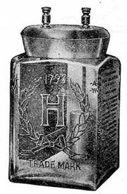 |
Capacity |
| 2.5 | 40 | |
| Volts. | Ampere | |
| Hours. | ||
| No | No | |
| Local | Creeping | |
| Action. | Salts. |
Highly recommended for all kinds of open circuit work such as telephones, gas engines, bells, auto gas lighting, and for medical outfits. Guaranteed to do all that is claimed for it.
HARRISON BROS. & CO., Incorporated.
PHILADELPHIA. CHICAGO. NEW YORK.
J. H. LEHMAN,
Manager of Electrical Department, 102 Times Building, New York.
Mesco Dry Battery
OVER 1,000,000 SOLD ANNUALLY
Can be purchased in all cities and most towns in the United States of Electric Supply dealers. Price low as worthless dry batteries. We are the largest manufacturers of general electric supplies in this country. Catalogue issued yearly.
Manhattan Electrical Supply Co.==========
32 Cortlandt Street, New York
TO OUR READERS
ARE YOU IN THE MARKET FOR
COILS, X-RAY TUBES, BATTERIES, OR
ANY ELECTRICAL APPARATUS?
IF SO
Send to our advertisers for their catalogues
and prices before buying.
| X-Ray Coils | 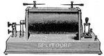 |
| Telephone Coils | |
| Medical Coils | |
| Spark Coils |
MAGNET WINDING OF EVERY DESCRIPTION
C. F. SPLITDORF, 17-27 Vandewater St., New York
New Standard Oil, Gas and Gasoline
Engine Outfit Consisting of ...
| New Standard | "Autogas" Dry Battery, | $5.00 |
| " " | Jump Spark Coil, | 12.00 |
| " " | Insulated Cam-Contact Key, | 3.50 |
| " " | Double Porcelain Insulated Ignition Plug, | 6.00 |
If you are interested write for descriptive pamphlet.
WILLIAM ROCHE, Inventor and Sole Mfr., 42 VESEY ST., NEW YORK CITY
We also manufacture other good and useful appliances to be operated with dry cells.
GOOD BOOKS
The French Polishers Manual, full directions for polishing by a French Polisher. Paper, - 20 cts.
The A. B. C. of Dynamo Design, by Alfred H. Avery, with drawings and illustrations. 12mo, cloth, - 40 cts.
Electric Batteries, How to make and Use Them, by P. Marshall. 12mo, illustrated. Paper, - 25 cts.
Metal Turning. Practical lessons in Metal Turning. A handbook for young engineers and amateurs, by P. Marshall. Fully illustrated, cloth, - 80 cts.
The A. B. C. of Electricity, by W. H. Meadowcroft. Fully illustrated, 12mo, cloth, - 50 cts.
Magnetism and Electricity, by John Cook. A good book for beginners. Illustrated, 16mo, cloth, - 40 cts.
Lightning Protection, a practical treatise on, by H. W. Spang. Illustrated, 12mo, cloth, - 75 cts.
We will mail copies of any book, postpaid, on receipt of price.
SPON & CHAMBERLAIN, Publishers
12 Cortlandt Street, New York, U. S. A.
When writing to advertisers please mention Norrie's Coils.
Published Monthly.
SCIENCE ABSTRACTS.
Physics and Electrical Engineering.
The object of this magazine is to make abstracts of all important papers read before the various Scientific Societies or published in the different Proceedings or Transactions of such societies, and also of all important papers and articles printed in American and foreign Technical Journals and Scientific Periodicals and to classify and index the same.
Science Abstracts will thus keep abreast of the times and place before the librarian, the busy engineer or the scientist in a compact and handy form, a complete digest of all the latest information on
General Physics, Light, Heat,
Sound, Electricity, Electro-Chemistry
and Chemical Physics, General Electrical
Engineering, Dynamos, Motors
and Transformers, Power Distribution,
Traction and Lighting, Telegraphy and
Telephony, Steam Plants, Gas Engines,
Oil Engines and Motor Cars of all kinds.
With Index to Abstracts, Index to Authors.
Annual Subscription, $6.00, Post-paid.
SPON & CHAMBERLAIN,
Sole American Agents,
12 Cortlandt Street, New York, U. S. A.
SAMPLE COPIES MAILED TO ANY ADDRESS ON RECEIPT OF 8 CENTS.
THE
MODEL ENGINEER
AND
AMATEUR ELECTRICIAN
A Journal of Mechanics and
Electricity for Amateurs and Students
Edited by PERCIVAL MARSHALL
ITS GOOD POINTS.
Better than any paper of its kind ever published.
The articles are original and practical.
The articles are so clearly and simply written and everything made so plain that it will be found easy to follow the directions and duplicate the articles described.
Special articles on Model engines and boilers for yachts, torpedo-boats and war-ships.
Designing and building of model yachts and boats.
Making small tools for model work.
The building of small gas engines.
Building screw-cutting and turning lathes.
Building all kinds of model stationary and locomotive steam engines and boilers.
Model engineers and their work.
Building of all kinds of electrical machines, apparatus, coils, batteries, telephones, microphones, phonographs, novelties.
The articles are fully illustrated, principally with detail drawings to scale.
New Books, Notes and Queries, Workshop Notes and Hints, Tools and Supplies,, etc.
ANNUAL SUBSCRIPTION, $1.50 POSTPAID.
Send in your subscription and get your friends to subscribe. Unused postage stamps will be accepted (not revenue.) Address all communications to
SPON & CHAMBERLAIN,
12 Cortlandt Street, NEW YORK.
USEFUL BOOKS
| Barometer.—The barometrical determination of heights. A practical method of barometrical levelling and hypsometry, for surveyors and mountain climbers. By Dr. F. J. B. Cordeiro, U. S. N. 12mo, leather, | $1.00 |
| Dynamo.—Notes on the design of small dynamo, with complete set of drawings to scale. By G. Halliday. 79 pages, illustrated, 8vo, cloth, | 1.00‡ |
| Electric Bells.—A treatise on the construction of electric bells, indicators and similar apparatus. By F. C. Allsop. 131 pages, 177 illustrations, 12mo, cloth, | 1.25 |
| Electric Bells.—Practical electric bell fitting. A treatise on the fitting up and maintenance of electric bells and all their necessary apparatus. By F. C. Allsop. 170 pages, 186 illustrations, 12mo, cloth, | 1.25 |
| Electrical Notes.—Practical electrical notes and definitions, for the use of engineering students and practical men. By W. Perren Maycock, E.E. 286 pages, illustrated, 32mo, cloth, | .75 |
| Electricity.—Comparisons between the different systems of distributing electricity. By Prof. Henry Robinson. 8vo, paper, | .80 |
| Galvanometer.—A series of lectures on the galvanometer and its uses, delivered by Prof. E. L. Nicols, and used by him in his class at Cornell University. 112 pages, 76 illustrations, 8vo, paper, | 1.00 |
| Induction Coils, and coil making. A treatise on the construction and working of shock, medical, and spark coils. By F. C. Allsop. 172 Pages, 124 illustrations, 12mo, cloth, | 1.25 |
| Measurements.—A systematic treatise on electrical measurements. By H. C. Parker. 120 pages, 96 illustrations, 8vo, cloth, | 1.00‡ |
| Phonograph.—The phonograph and how to construct it, and a chapter on sound, with full set of working drawings. 12mo, cloth, | 2.00 |
| Transformer.—History of the transformer, translated from the German. By F. Uppenborn. 60 pages, 31 illustrations, 12mo, | .75 |
| Transformer.—Transformer design, a treatise on their design, construction and use. By G. Adams. In the work the author has avoided as much as possible all historical matter and unnecessary mathematical problems, and has confined himself to practical experience. The work contains much information that will prove of value to the draughtsman, designer and electrical student. Second edition. 75 pages, 34 illustrations, 12mo, cloth, | 1.50‡ |
| Telephones, etc.—Their construction and fitting. A practical treatise on the fitting-up and maintenance of telephones and the auxiliary apparatus. By F. C. Allsop. 5th edition, 184 pages, 13 folding plates and 124 illustrations, 12mo, cloth, | 1.25 |
| Magnets and electric currents. An elementary treatise for the use of electricians and beginners. By J. A. Fleming, M.A., D.Sc., F.R.S., 408 pages, illustrated, 12mo, cloth, | 3.00 |
Workshop Receipts.
THE MOST COMPLETE
Technical Cyclopedia in 5 Vols.
First Series. Principal Contents.—Bronzes, Cements, Dyeing, Electro-metallurgy, Enamels, Etchings, Fireworks, Fluxes, Fulminates, Gilding, Gums, Japanning, Lacquers, Marble Working, Nitro-Glycerine, Photography, Pottery, Varnishes. 420 pages, 103 illus., cloth, $2.00.
Second Series. Principal Contents.—Acidimetry, Albumen, Alcohol, Alkaloids, Bitters, Bleaching, Boiler Incrustations, Cleansing, Confectionery, Copying, Disinfectants, Essences, Extracts, Fire-proofing, Glycerine, Gut, Iodine, Ivory Substitutes, Leather, Matches, Pigments, Paint, Paper, Parchment. 485 pages, 16 illus., cloth, $2.00.
Third Series. Principal Contents.—Alloys, Aluminium, Antimony, Copper, Electrics, Enamels, Glass, Gold, Iron, Steel, Liquors, Lead, Lubricants, Magnesium, Manganese, Mercury, Mica, Nickel, Platinum, Silver, Slag, Tin, Uranium, Zinc. 480 pages, 183 illus., cloth, $2.00.
Fourth Series. Principal Contents.—Water-proofing, Packing, Stowing, Embalming, Preserving, Leather Polishes, Cooling Air and Water, Pumps and Siphons, Dessicating, Distilling, Emulsifying, Evaporating, Filtering, Percolating, Macerating, Electrotyping, Stereotyping, Book-binding, Straw-plaiting, Musical Instruments, Clock and Watch Mending, Photography. 443 pages, 243 illus., cloth, $2.00.
Fifth Series. Principal Contents.—Diamond Cutting, Laboratory Apparatus, Filtering, Magic Lanterns, Metal Work, Percolation, Illuminating Agents, Tobacco Pipes, Taps, Tying and Splicing Tackle, Repairing Books, Netting, Walking Sticks, Boat-Building. 440 pages, 373 illus., cloth, $2.00.
EACH SERIES has its own Contents and Index and is complete in itself.
Cleaning and Scouring
A MANUAL FOR
DYERS AND LAUNDRESSES
And for Domestic Use.
BY S. CHRISTOPHER.
CONTENTS.
Dresses.—Silk, Satin, Irish Poplin and Tabinet, Llama, Alpaca, Printed Muslin and Pique, Pique and Colored Muslin.
Shawls and Scarves.—China Crape, Brocaded or Printed Silk, and Woolen.
Silk Handkerchiefs, Ribbons, Mantles, Fancy Waistcoats, and Lace. Gloves.—Kid, Washleather.
Feathers.—White, Colored; to purify—for Beds, &c.
Bonnets.—Chip, Straw, and Leghorn. Ancient Tapestry.
Curtains, Bed Furniture, &c.—Chintz, Damask, Worsted-and-cotton Damask, French Damask—Silk-and-worsted Moreen, Tabaret or Tabbarea, Satin, Tammy Lining, Fringes—Bullion and worsted, Lace and Gimp—Bullion.
Table Covers.—Silk-and-worsted, Cotton-and-worsted, and Printed Cloth.
Carpets.—Dry Cleaning, thorough Cleaning.
Hearthrugs, Sheepskin Rugs and Mats.
To Remove Various Stains from Linen and Cotton.—Fruit Stains, Grease Spots, Ink Stains, Marking Ink, Mildew, Paint or Varnish, Wine Stains.
Recipes for general Domestic Use.—Oilcloth, Paint, Floors, Marble, Iron and Steel, Brass or Copper, Silver Plate, Furniture, Gilt Frames, Ivory Ornaments, Mirrors, Wall-paper, Stone Steps.
Definitions, &c.—Boards, &c., for French Cleaning, Camphine, Common Sour, Drying, Frame, French Board, Hot Stove, Irons, Parchment Size, Pegs, Puncher, Size, Soap, Starch, To Handle, To Sheet-up, Water.
Price 20 cents, post-paid.
THEORETICAL AND PRACTICAL
Ammonia Refrigeration
A Work of Reference for Engineers and others Employed in the Management of Ice and Refrigeration Machinery.
By ILTYD I. REDWOOD
CONTENTS
B. T. U. Mechanical Equivalent of a Unit of Heat. Specific Heat. Latent Heat. Theory of Refrigeration. Freezing, by Compressed Air. Ammonia. Characteristics of Ammonia. The Compressor. Stuffing-Boxes. Lubrication. Suction and Discharge Valves. Separator. Condenser-Worm, Receiver. Refrigerator or Brine Tank. Size of Pipe and Area of Cooling Surface. Charging the Plant with Ammonia. Jacket-Water, for Compressor, for Separator. Quantity of Condensing Water Necessary. Loss due to Heating of Condensed Ammonia. Cause of Variation in Excess Pressure. Use of Condensing Pressure in Determining Loss of Ammonia by Leakage. Cooling Directly by Ammonia. Freezing Point of Brine. Making Brine. Specific Heat of Brine. Regulation of Brine Temperature. Indirect Effect of Condensing Water on Brine Temperature. Directions for Determining Refrigerating Efficiency. Equivalent of a Ton of Ice. Compressor Measurement of Ammonia Circulated. Loss of Well-Jacketed Compressors. Loss in Double-Acting Compressors. Distribution of Mercury Wells. Examination of Working Parts. Indicator Diagrams. Ammonia Figures—Effectual Displacement. Volume of Gas. Ammonia Circulated per Twenty-Four Hours. Refrigerating Efficiency. Brine Figures-Gallons Circulated. Pounds Circulated. Degrees Cooled. Total Degrees Extracted. Loss due to Heating of Ammonia Gas. Loss due to Heating of Liquid Ammonia. Calculation of the Maximum Capacity of a Machine. Preparation of Anhydrous Ammonia. Construction of Apparatus, etc., etc.
150 pages, 15 illustrations, cloth, $1.00.
LUBRICANTS,
OILS AND GREASES
Treated Theoretically and Giving Practical Information Regarding Their
COMPOSITION, USES AND MANUFACTURE
BY ILTYD I. REDWOOD
CONTENTS
Introduction.—Lubricants.
Theoretical.—Chapter I. Mineral Oils: American and Russian; Hydrocarbons. Chapter II. Fatty Oils: Glycerides; Vegetable Oils; Fish Oils. Chapter III. Mineral Lubricants: Graphite; Plumbago. Chapter IV. Greases: Compounded; "Set" or Axle; "Boiled" or Cup. Chapter V. Tests of Oils: Mineral Oils. Fatty Oils.
Manufacture.—Chapter VI. Mineral Oil Lubricants: Compounded Oils; Debloomed Oils. Chapter VII. Greases: Compounded Greases; "Set" or Axle Greases; Boiled Greases; Engine Greases. Appendix. The Action of Oils on Various Metals. Index.
Tables.—I. Viscosity and Specific Gravity. II. Atomic Weights. III. Origin, Tests, Etc., of Oils. IV. Action of Oils on Metals.
List of Plates.—I.—I. I. Redwood's Improved Set Measuring Apparatus. II. Section Grease Kettle. III. Diagram of the Action of Oils on Different Kinds of Metals.
8vo, cloth, $1.50.
PRACTICAL HANDBOOK ON
Gas Engines
With Instructions for Care and Working of the Same.
BY G. LIECKFELD, C.E.
Translated with permission of the Author by
GEORGE RICHMOND, M.E.
WITH A CHAPTER ON OIL ENGINES
CONTENTS
Choosing and installing a gas engine. The construction of good gas engines. Examination as to workmanship, running, economy. Reliability and durability of gas engines. Proper erection of a gas engine. Foundation. Arrangement for gas pipes. Rubber bag. Locking devices. Exhaust pipes. Air pipes. Setting up gas engines. Brakes and their use in ascertaining the power of gas engines. Arrangement of a brake test. Distribution of heat in a gas engine. Attendance on gas engines. General remarks. Gas engine oil. Cylinder lubricators. Rules as to starting and stopping a gas engine. The cleaning of a gas engine. General observations and specific examination for defects. The engine refuses to work. Non-starting of the engine. Too much pressure on the gas. Water in the exhaust pot. Difficulty in starting the engine. Irregular running. Loss of power. Weak gas mixtures. Late ignition. Cracks in air inlet. Back firing. Knocking and pounding inside of engine. Dangers and precautionary measure in handling gas engines. Precautions when opening gas valves, removing piston from cylinder, examining with light openings of gas engines. Dangers in starting, cleaning, putting on belts. Oil Engines. Gas engines with producer gas. Gasoline and oil engines. Concluding remarks.
120 pages, illustrated, 12mo, cloth, $1.00.
The Best and Cheapest in the Market
ALGEBRA SELF-TAUGHT
FOR THE USE OF
Mechanics, Young Engineers and Home Students
BY W. PAGET HIGGS, M.A., D.Sc.
FOURTH EDITION
CONTENTS
Symbols and the signs of operation. The equation and the unknown quantity. Positive and negative quantities. Multiplication, involution, exponents, negative exponents, roots, and the use of exponents as logarithms. Logarithms. Tables of logarithms and proportional parts. Transportation of systems of logarithms. Common uses of common logarithms. Compound multiplication and the binomial theorem. Division, fractions and ratio. Rules for division. Rules for fractions. Continued proportion, the series and the summation of the series. Examples. Geometrical means. Limit of series. Equations. Appendix. Index. 104 pages, 12mo, cloth, 60c.
See also Algebraic Signs, Spons' Dictionary of Engineering, No. 2. 40 cts.
See also Calculus, Supplement to Spons' Dictionary, No. 5. 75 cts.
THE
FIREMAN'S GUIDE
A Handbook on the Care of Boilers
BY KARL P. DAHLSTROM, M.E.
CONTENTS OF CHAPTERS
I. Firing and Economy of Fuel.—Precautions before and after starting the fire, care of the fire, proper firing, draft, smoke, progress of firing, fuel on the grate, cleaning out, cleaning grate bars and ash pan, dampers, firing into two or more furnaces, dry fuel, loss of heat.
II. Feed and Water Line.—Feeding, the water line, false water line, defective feeding apparatus, formation of scale, gauge cocks, glass gauge, the float, safety plug, alarm whistle.
III. Low Water and Foaming or Priming.—Precautions when water is low, foaming, priming.
IV. Steam Pressure.—Steam gauge, safety valves.
V. Cleaning and Blowing Out.—Cleaning the boiler, to examine the state of the boiler, blowing out, refilling the boiler.
VI. General Directions.—How to prevent accidents, repairs, the care of the boiler when not in use, testing boilers, trimming and cleaning outside. Summary of rules. Index.
8vo, cloth, 50 cents.
THE CORLISS ENGINE.
By John T. Henthorn.
AND
MANAGEMENT OF THE CORLISS ENGINE.
By Charles D. Thurber.
Uniform in One Volume. Cloth Cover; Price, $1.00.
Table of Contents.
Chapter I.—Introductory and Historical; Steam Jacketing. Chapter II.—Indicator Cards. Chapter III.—Indicator Cards continued; the Governor. Chapter IV.—Valve Gear and Eccentric; Valve Setting. Chapter V.—Valve Setting continued, with diagrams of same; Table for laps of Steam Valve. Chapter VI.—Valve Setting continued. Chapter VII.—Lubrication with diagrams for same. Chapter VIII.—Discussion of the Air Pump and its Management. Chapter IX.—Care of Main Driving Gears; best Lubricator for same. Chapter X.—Heating of Mills by Exhaust Steam. Chapter XI.—Engine Foundations; diagrams and templets for same. Chapter XII.—Foundations continued; Materials for same, etc.
Third Edition, with an Appendix.
HOW TO RUN
Engines and Boilers
Practical Instruction for Young Engineers and Steam Users.
BY EGBERT POMEROY WATSON
REVISED AND ENLARGED
Synopsis of Contents
Cleaning the boiler, removing scale, scale preventers, oil in boilers, braces and stays, mud drums and feed pipes, boiler fittings, grate bars and tubes, bridge walls, the slide valve, throttling engine, the piston, testing the slide valve with relation to the ports, defects of the slide valve, lap and lead, the pressure on a slide valve, stem connections to the valve, valves off their seats, valve stem guides, governors, running with the sun, eccentrics and connections, the crank pin, brass boxes, bearings on pins, adjustment of bearings, the valve and gearing, setting eccentrics, the actual operation, return crank motion, pounding, the connections, lining up engines, making joints, condensing engines, Torricelli's vacuum, proof of atmospheric pressure, pumps, no power in a vacuum, supporting a water column by the atmosphere, starting a new plant, the highest qualities demanded.
Water tube boilers, fire tube boilers, why water tube boilers steam rapidly, torpedo boat boilers, management of water tube boilers, economy and maintenance of water tube boilers.
150 pages, illustrated, 16mo, cloth, $1.00
GOOD AMERICAN PRACTICE.
AN
ELEMENTARY TEXT BOOK
ON
STEAM ENGINES AND
BOILERS
By J. H. KINEALY, M.E.
A first class American Book for young Engineers and all those wishing to take a higher position.
CONTENTS OF CHAPTERS.
1. Elementary Thermodynamics. 2. Theory of the Steam Engine. 3, Types and details of Engines. 4. Admission of Steam by Valve. 5. Valve diagrams. 6. Indicator and indicator cards. 7. Compound Engines and condensers. 8. Heat and combustion of fuel. 9. Boilers, types, fittings, etc. 10. Chimneys. Appendix. Care of Boilers, Tables, Numerous Problems with answers.
Third edition, (1901), thoroughly revised to date and considerably enlarged.
259 pages, 108 illustrations, size 9¼ × 6¼.
Cloth, $2.00‡
THE SLIDE VALVE
SIMPLY EXPLAINED
By W. J. TENNANT, Asso. M.I.M.E.
REVISED AND MUCH ENLARGED
By J. H. KINEALY, D.E.
| CONTENTS OF CHAPTERS: | |
|---|---|
| I. | The Simple Slide. |
| II. | The Eccentric a Crank. Special Model to Give Quantitative Results. |
| III. | Advance of the Eccentric. |
| IV. | Dead Centre. Order of Cranks. Cushioning |
| V. | Expansion—Inside and Outside Lap and Lead; Advance Affected Thereby. Compression. |
| VI. | Double-Ported and Piston Valves. |
| VII. | The Effect of Alterations to Valve and Eccentric. |
| VIII. | Note on Link Motions. |
| IX. | Note on Very Early Cut-Off, and on Reversing Gears in General. |
88 Pages. 41 Illustrations. 12mo, Cloth, $1.00.
QUICK AND EASY METHODS
OF
Calculating
With the Slide Rule
A Simple Explanation of the Theory and Use of the Slide Rule, Logarithms, Etc.
With numerous examples worked out.
By R. G. BLAINE, M.E.
A most reliable, practical and valuable work for the engineer.
144 Pages. Illustrated. 12mo, Cloth, $1.00
The Design and Construction
OF
OIL ENGINES
With full directions for
Erecting, Testing, Installing, Running and Repairing.
Including descriptions of American and English
KEROSENE OIL ENGINES.
By A. H. GOLDINGHAM, M.E.
Synopsis of Contents of Chapters:
1. Introductory, Classification, Vaporizers, Spraying and Ignition Devices, etc. 2. Design and Construction, Cylinders, Cranks, Shafts, Pistons, Connecting Rods, Fly-Wheels, Air and Exhaust Cams, Valves, etc., Bearings, Engine Frames, Valve Mechanisms, Gearing, Oil Supply, Different Kinds of Engines, etc. 3. Testing the Engine, Faults and Remedies, etc. 4. Cooling Water Tanks, Exhaust Silencers, Starters. 5. Oil Engine Driving Dynamo, Various Systems. 6. Oil Engine Driving Air Compressors. Water Pump, etc. 7. Full Instructions for Running Oil Engines. 8. Hints on Repairing. 9. Description of the Various English and American Oil Engines.
Fully Illustrated, 12mo. Cloth, $2.00‡
SPONS'$2.50
MECHANIC'S OWN BOOK,
A PRACTICAL MANUAL.
Principal Contents.
Mechanical Drawing. (13 pages).
Casting and Founding. (31 pages).
Forging and Finishing. (56 pages).
Soldering. (26 pages).
Sheet-Metal Working. (10 pages).
Carpentry, Woods, Tools etc. (224 pages).
Cabinet Making. (36 pages).
Carving and Fretwork. (13 pages).
Upholstery. (6 pages).
Painting, Graining and Marbling. (28 pages).
Staining, and Gilding. (16 pages).
Polishing. Varnishing. (26 pages).
Mechanical Movements. (56 pages).
Turning and Lathe work. (30 pages).
Masonry, Stonework, Brickwork, Concrete, etc. (45 pages).
Plastering, Whitewashing, Paperhanging. (13 pages).
Roofing, Glazing. (14 pages).
Bell hanging, Gas fitting. (8 pages).
Lighting, Ventilation, Warming. (21 pages).
Foundations, Roads and Bridges, Banks, Hedges, Ditches and Drains, Water Supply and Sanitation. House Construction, etc. Size of book 6¾ in. by 8¾.
702 pages, half extra gilt and 1420 illustrations.
NEW
EDITION "DE LUXE"
ON HEAVY PLATE PAPER
A SYSTEM OF
EASY LETTERING.
BY
J. H. CROMWELL.
ITS GOOD POINTS.
Very easy to learn.
A rapid method to become a good letterer with a little practice.
Very easy to lay out a line of words in Strict Proportion, whether it be on a fence 500 yards long or on a drawing only a few inches across.
Good for draughtsmen who prefer neat lettering, yet something out of the ordinary.
It contains 26 pages of alphabets whose modifications are almost limitless.
One of the cheapest in the market.
This little book will be appreciated by draughtsmen who wish to use plain letters (and yet somewhat different from the ordinary run of letters) for the titles on drawings. The book will also be valuable and useful to any one who has had no practice in lettering, as the easy method given for forming the letters will enable a person to form the letters correctly, and with a little practice to do so quickly.—American Machinist.
Oblong, 8vo, cloth, 50 cents
EVERYONE'S GUIDE
TO
PHOTOGRAPHY
CONTAINING
INSTRUCTIONS FOR MAKING YOUR OWN APPLIANCES AND
SIMPLE PRACTICAL DIRECTIONS FOR EVERY BRANCH
OF PHOTOGRAPHIC WORK.
BY
E. J. WALL, F.R.P.S.
Author of The Dictionary of Photography, etc., etc.
SECOND EDITION
New York:
SPON & CHAMBERLAIN,
12 Cortlandt Street.
1892
CROSS SECTION PAPER.
THE HANDY SKETCHING PAD.
Printed on one side, in blue ink, all the lines being of equal thickness, with useful tables. Size 8 × 10 inches. Price, 25c. each. Per dozen pads, $2.50.
THE HANDY SKETCHING BOOK.
Made from this paper but printed on both sides. Size of book 5 × 8 inches, stiff board covers. Price, 25c. each; per dozen books, $2.50.
SCALE EIGHT TO ONE INCH.
A large sheet with heavy inch lines and half inch lines, printed in blue ink. Size of sheet, 17 × 22 inches. Per quire (24 sheets), 75c.
SCALE TEN TO ONE INCH.
Size 17 x 22 inches, printed in blue ink, with heavy inch lines and half inch lines. Per quire (24 sheets), 75c.
THE ELECTRICIAN'S SKETCHING PAD.
Size 8 × 10. Scale 10 to 1 in. Price 25c. each. Per dozen, $2.50.
THE ELECTRICIAN'S SKETCHING BOOK.
Made from this paper. Scale 10 to 1 inch. Size of book 5 × 8 inches, with stiff board covers. Price, 25c. each; per dozen, $2.50.
Any quantity mailed to any part of the world on receipt
of price.
Or Books and Pads Assorted, per dozen, $2.50
This paper is not ruled. Try it and you will find it
GOOD, ACCURATE AND CHEAP.
SPON & CHAMBERLAIN, 12 Cortlandt St.,
NEW YORK.
Manual of Instruction in
Hard Soldering
WITH AN APPENDIX ON THE
Repair of Bicycle Frames
Notes on Alloys and a Chapter on Soft Soldering
BY HARVEY ROWELL
The flame, lamp, charcoal, mats, blow-pipes, wash-bottle, binding wire, chemicals, borax, spelter, silver solder, gold solder, oxidation of metals, fluxes, anti-oxidisers, oxidation of cases, the cone, oxidising flame, reducing flame, heat transmission, conduction, capacity of metals, radiation, application, the work table, the joint, applying solder, applying heat, the use of the blow-pipe, joints, making a ferrule, to repair a spoon, to repair a watch case, hard soldering with a forge or hearth, hard soldering with tongs, preserving thin edges, silversmith's pickle, restoring color to gold, chromic acid, to mend steel springs, sweating metals together, retaining work in position, making joints, applying heat, preventing the loss of heat, effect of sulphur lead and zinc, to preserve precious stones, annealing and hardening, burnt iron, to hard solder after soft solder. Tables of—specific gravity, tenacity, fusibility, alloys.
66 pages, illustrated, cloth, 75 cents.
For Soldering Receipts, Cements and Lutes, Pastes, Glues and such like, see Workshop Receipts.
SMALL ACCUMULATORS
How Made and Used
A Practical Handbook for Students and Young Electricians
EDITED BY PERCIVAL MARSHALL, A.I.M.E.
Contents of Chapters
I.—The Theory of the Accumulator.
II.—How to make a 4-Volt Pocket Accumulator.
III.—How to make a 32-Ampere-Hour Accumulator.
IV.—Types of Small Accumulators.
V.—How to Charge and Use Accumulators.
VI.—Applications of Small Accumulators, Electrical Novelties, etc. Useful Receipts. Glossary of Technical Terms.
80 pages, 40 illustrations, 12mo, cloth, 50c.
THE MAGNETO-TELEPHONE
ITS CONSTRUCTION,
Fitting Up and Adaptability to Every-Day Use
BY NORMAN HUGHES
CONTENTS OF CHAPTERS
Some electrical considerations: I.—Introductory. II.—Construction. III.—Lines, Indoor Lines. IV.—Signalling Apparatus. V.—Batteries. Open Circuit Batteries. Closed Circuit Batteries. VI.—Practical Operations. Circuit with Magneto Bells and Lightning Arresters. How to Test the Line. Push-Button Magneto Circuit. Two Stations with Battery Bells. VII.—Battery Telephone. Battery Telephone Circuit. Three Instruments on one Line. VIII.—General remarks. Index.
80 pages, 23 illustrations, 12mo, cloth, $1.00. In paper, 50c.
EVERYBODY'S BOOK ON ELECTRICITY
PRACTICAL ELECTRICS
A UNIVERSAL HANDY-BOOK
ON
EVERYDAY ELECTRICAL MATTERS
FIFTH EDITION
CONTENTS:
Alarms.—Doors and Windows; Cisterns; Low Water in Boilers; Time Signals; Clocks. Batteries.—Making; Cells; Bichromate; Bunsen; Callan's; Copper-oxide; Cruikshank's; Daniel's; Granule carbon; Groves; Insulite; Leclanché; Lime Chromate; Silver Chloride; Smee; Thermo-electric. Bells.—Annunciator System; Double System; and Telephone; Making; Magnet for; Bobbins or Coils; Trembling; Single Stroke; Continuous Ringing. Connections. Carbons. Coils.—Induction; Primary; Secondary; Contact-breakers; Resistance. Intensity Coils.—Reel; Primary; Secondary; Core; Contact-breaker; Condenser; Pedestal; Commutator; Connections. Dynamo-electric Machines.—Field-Magnets; Pole-pieces; Field-magnet Coils; Armature Cores and Coils; Commutator Collectors and Brushes; Relation of size to efficiency; Methods of exciting Field-Magnets; Magneto-Dynamos; Separately excited Dynamos; Shunt Dynamos; Field-Magnets; Armatures; Collectors; Brush Dynamo; Alternate Currents. Fire Risks.—Wires; Lamps; Danger to persons. Measuring.—Non-Registering Instruments; Registering Instruments. Microphones. Motors. Phonographs. Photophones. Storage. Telephones.—Forms; Circuits and Calls; Transmitter and Switch; Switch for Simplex; etc., etc.
135 PAGES. 126 ILLUSTRATIONS. 8VO.
Cloth, 75 cents
VEST POCKET SERIES.
ACTUAL SIZE.
Bound in roan, round corners, gilt edges in celluloid case, 50c.
Bound in roan, round corners, gilt edges, in celluloid case, 50c.
Copies mailed post-paid on receipt of price.
The Errata have been implemented.
Obvious typographical errors have been silently corrected. All other spelling, hyphenation and punctuation remains unchanged.
The highly varied decorative typography of the book catalogue has not been reproduced but every effort has been made to maintain the general appearance and effect of the original.