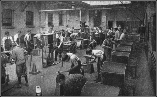
A Manual Training Forge Shop
The Project Gutenberg EBook of Forge Work, by William L. Ilgen

This eBook is for the use of anyone anywhere in the United States and most
other parts of the world at no cost and with almost no restrictions
whatsoever.  You may copy it, give it away or re-use it under the terms of
the Project Gutenberg License included with this eBook or online at
www.gutenberg.org.  If you are not located in the United States, you'll have
to check the laws of the country where you are located before using this ebook.

Title: Forge Work

Author: William L. Ilgen

Release Date: December 31, 2016 [EBook #53854]

Language: English

Character set encoding: UTF-8

*** START OF THIS PROJECT GUTENBERG EBOOK FORGE WORK ***


Produced by deaurider, Brian Wilcox and the Online
Distributed Proofreading Team at http://www.pgdp.net (This
file was produced from images generously made available
by The Internet Archive)
The cover image was created by the transcriber and is placed in the public domain.
A Manual Training Forge Shop
WITH EDITORIAL REVISION BY
CHARLES F. MOORE
HEAD OF MECHANICAL DEPARTMENT, CENTRAL HIGH
SCHOOL, NEWARK, NEW JERSEY
NEW YORK CINCINNATI CHICAGO
AMERICAN BOOK COMPANY
Copyright, 1912, by
WILLIAM L. ILGEN.
FORGE WORK.
W. P. I
Teachers of forge work generally supply their own course of instruction and arrange the exercises for practice. The necessary explanations and information are given orally, and hence often with very unsatisfactory results, as the average student is not able to retain all the essential points of the course. It was the desire to put this instruction in some permanent form for the use of forge students that led the author to undertake this work.
The author wishes to express his thanks for the advice and encouragement of his fellow-teachers, Dr. H. C. Peterson, Mr. Frank A. Fucik, and Mr. Richard Hartenberg. Special obligations are due to Mr. Charles F. Moore, Head of the Mechanical Department in the Central Commercial and Manual Training High School of Newark, New Jersey, for his valuable editorial service.
Figures 146, 147, 150, 153, 157, and 158 have been reproduced, by permission of the publishers, from “Manufacture of Iron” and “Manufacture of Steel,” copyrighted 1902, by the International Textbook Company. Acknowledgments are due also to the Inland Steel Company for the privilege of using Figures 145, 148, 149, 159-163, 166; and to the Columbia Tool Steel Company for the use of Figures 151, 152, 154-156.
WILLIAM L. ILGEN.
| PAGE | |
|---|---|
Chapter I. Tools and Appliances.—1. The Forge; 2. Fire Tools; 3. Fuels; 4. The Anvil; 5. The Hammers; 6. The ball peen hammer; 7. The cross peen hammer; 8. The straight peen hammer; 9. The sledges; 10. The Tongs; 11. The flat-jawed tongs; 12. The hollow bit tongs; 13. The pick-up tongs; 14. The side tongs; 15. The chisel tongs; 16. The link tongs; 17. The tool or box tongs; 18. Anvil and Forging Tools; 19. The hardy; 20. The cold and hot cutters; 21. The hot cutter; 22. The flatter; 23. The square- and round-edged set hammers; 24. The punches; 25. The top and bottom swages; 26. The top and bottom fullers; 27. The button head set or snap; 28. The heading tool; 29. The swage block; 30. The surface plate; 31. The tapered mandrels; 32. Bench and Measuring Tools; 33. The bench or box vise; 34. The chisels; 35. The center punch; 36. The rule; 37. The dividers; 38. The calipers; 39. The scriber or scratch awl; 40. The square; 41. The bevel; 42. The hack saw; 43. The files |
1 |
Chapter II. Forging Operations.—44. The Hammer Blows; 45. The upright blow; 46. The edge-to-edge blow; 47. The overhanging blow; 48. The beveling or angle blows; 49. The leverage blows; 50. The backing-up blows; 51. The shearing blow; 52. Forging; 53. Drawing; 54. Bending; 55. Upsetting; 56. Forming; 57. Straightening; 58. Twisting; 59. Welding; 60. The Material for Welding; 61. Heating; 62. Scarfing; 63. The lap weld; 64. The cleft weld; 65. The butt weld; 66. The jump weld; 67. The V weld |
30 |
Chapter III. Practice Exercises.—68. Staple; 69. Draw Spike; 70. S Hook; 71. Pipe Hook; 72. Gate Hook; 73. Door Hasp; 74. Hexagonal Head Bolt; 75. Square-cornered Angle; 76. Fagot Welding; 77. Round Weld; 78. Flat Right-angled Weld; 79. T Weld; 80. Chain Making; 81. Welded Ring; 82. Chain Swivel; 83. Chain Swivel; 84. Chain Grabhook |
58 |
[viii] Chapter IV. Treatment of Tool Steel.—85. Selecting and Working Steel; 86. Uses of Different Grades of Steel; 87. Injuries; 88. Annealing; 89. Hardening and Tempering; 90. Casehardening |
83 |
Chapter V. Tool Making and Stock Calculation.—91. Tongs; 92. Heavy Flat Tongs; 93. Light Chain Tongs; 94. Lathe Tools; 95. Brass Tool; 96. Cutting-off or Parting Tool; 97. Heavy Boring Tool; 98. Light Boring or Threading Tool; 99. Diamond Point Tool; 100. Right Side Tool; 101. Forging Tools; 102. Cold Chisel; 103. Hot Cutter; 104. Cold Cutter; 105. Square-edged Set; 106. Hardy; 107. Flatter; 108. Small Crowbar; 109. Eye or Ring Bolts; 110. Calipers; 111. Stock Calculation for Bending |
96 |
Chapter VI. Steam Hammer, Tools, and Exercises.—112. A Forging; 113. The Drop Hammer; 114. Presses; 115. The Steam Hammer; 116. Steam Hammer Tools; 117. The hack or cutter; 118. The circular cutter; 119. The trimming chisel; 120. The cold cutter; 121. The checking tool or side fuller; 122. The fuller; 123. The combined spring fullers; 124. The combination fuller and set; 125. The combined top and bottom swages; 126. The top and bottom swages; 127. The bevel or taper tool; 128. The V block; 129. The yoke or saddle; 130. Bolsters or collars; 131. Punches; 132. Steam Hammer Work; 133. Crank Shaft; 134. Connecting Rod; 135. Rod Strap; 136. Eccentric Jaw; 137. Hand Lever; 138. Connecting Lever; 139. Solid Forged Ring; 140. Double and Single Offsets |
123 |
Chapter VII. Art Smithing and Scroll Work.—141. Art Smithing; 142. Scroll Fastenings; 143. Scroll Former; 144. Bending or Twisting Fork; 145. Bending or Twisting Wrench; 146. Clip Former; 147. Clip Holder; 148. Clip Tightener or Clincher; 149. Jardinière Stand or Taboret; 150. Umbrella Stand; 151. Reading Lamp; 152. Andirons and Bar; 153. Fire Set; 154. Fire Set Separated |
146 |
Chapter VIII. Iron Ore, Preparation and Smelting.—155. Iron Ore; 156. Magnetite; 157. Red hematite; 158. Limonite or brown hematite; 159. Ferrous carbonate; 160. The Value of Ores; 161. Preparation of Ores; 162. Weathering; 163. Washing; 164. Crushing; 165. Roasting or calcination; 166. Fuels; 167. Fluxes; 168. The Blast; 169. The Reduction or Blast Furnace; [ix] 170. Classification of Pig Iron; 171. Bessemer iron; 172. Basic iron; 173. Mill iron; 174. Malleable iron; 175. Charcoal iron; 176. Foundry iron; 177. Grading Iron |
161 |
Chapter IX. The Manufacture of Iron and Steel.—178. Refining Pig Iron; 179. The Open-hearth or Finery Process; 180. The Puddling Process; 181. Steel; 182. The Crucible Process; 183. The Bessemer Process; 184. The Open-hearth Process |
177 |
Formulas and Tables |
197 |
Index |
207 |
DEDICATED
TO THE MEMORY OF
MR. DAVID GORRIE

Fig. 1.—The Forge.
FORGE WORK
1. The Forge.—The forge is an open hearth or fireplace used by the blacksmith for heating his metals. The kind most commonly used by the general smiths is such as can be seen in small villages or where the ordinary class of blacksmithing is done. (See Fig. 1.)
Forges are usually built of brick; in form they are square or rectangular, and generally extend out from a side wall of the shop. The chimney is built up from the middle of the left side and is provided with a hood B, which projects over the fire sufficiently to catch the smoke and convey it to the flue.
The fire is kindled on the hearth A under the hood and over the tuyère iron. This iron, the terminal of the blast pipe that leads from the bellows E, is made in various forms and of cast iron; sometimes it has a large opening at the bottom, but often it has none.
The bellows are operated by the lever F, which expands the sides and forces air through the tuyère iron, thereby causing the fire to burn freely and creating a temperature sufficient for heating the metals.
The coal box C is to the right, where it is convenient. The coal should always be dampened with water to prevent2 the fire from spreading. This will produce a more intense and more concentrated heat, so that a certain part of the metal can be heated without danger of affecting the rest.

Fig. 2.—A Manual Training Forge.
The water tub, or slack tub D, as it is more properly called, stands at the right of the forge near the coal box, where the water for dampening the coal can be most readily obtained. It is used for cooling the iron or tongs and for tempering tools.
Modern forges are made of cast iron or sheet steel. There are various kinds designed mostly for special purposes. They are generally used with the fan blast instead of the bellows and have a suction fan for withdrawing the smoke.
The forge illustrated in Fig. 2 was designed for manual training use and is excellent for such a purpose. The bottom or base has six drawers which provide convenient places for keeping exercises and individual tools. As each3 drawer is provided with a special lock, much of the trouble resulting from having the tools or the work mislaid or lost is prevented.

Fig. 3.—Sectional View of the Forge shown in Fig. 2.
The hearth A where the fire is built is provided with a cast-iron fire pot or tuyère. This is constructed with an opening at the bottom where there is a triangular tumbler which is cast upon a rod projecting through the front of the forge; by revolving the rod and tumbler the cinders or ashes can be dropped into the ash drawer at the bottom of the forge without disturbing the fire. A sectional view of these parts is shown in Fig. 3, also the valve which regulates the blast.
Suspended on the upper edge surrounding the hearth, and located to the right and left of the operator, two boxes C and D are located, which are used for storing an adequate supply of coal and water, where they may be conveniently obtained.
In front are two handles; the upper one operates the clinker or ash valve, the lower one regulates the blast.
The front and back edges surrounding the hearth are cut out, so that long pieces of metal can be laid down in the fire. These openings can be closed, when desired, with the hinged slides shown at G.
The hood B projects over the fire sufficiently to catch the smoke and convey it to the opening of the down-draft pipe E. When necessary the hood can be raised out of the way with the lever F, which is constructed with cogs and provided with a locking pin to keep the hood in position.
2. Fire Tools.—The necessary tools required for maintaining the fire and keeping it in good working condition are shown in Fig. 4. A is the poker with which the coke can be broken loose from the sides. B is the rake with which the coke can be moved over the fire on top of the metal to prevent the air from retarding the heating. The shovel C is used for adding fresh coal, which should always be placed around the fire and not on top. In this way unnecessary smoke will be prevented, and the coal will slowly form into coke. The dipper D is used for cooling parts of the work that cannot be cooled in the water box. The sprinkler E is used for applying water to the coal, or around the fire to prevent its spreading.

Fig. 4.—Fire Tools.
A, poker; B, rake; C, shovel; D, dipper; E, sprinkler.
3. Fuels.—The fuels used for blacksmithing are coal,5 coke, and charcoal. Most commonly a bituminous coal of superior quality is used. It should be free from sulphur and phosphorus, because the metals will absorb a certain amount of these impurities if they are in the fuel. The best grade of bituminous coal has a very glossy appearance when broken.
Coke is used mostly in furnaces or when heavy pieces of metal are to be heated. It is a solid fuel made by subjecting bituminous coal to heat in an oven until the gases are all driven out.
Charcoal is the best fuel, because it is almost free from impurities. The most satisfactory charcoal for forging purposes is made from maple or other hard woods. It is a very desirable fuel for heating carbon steel, because it has a tendency to impart carbon instead of withdrawing it as the other fuels do to a small extent. It is the most expensive fuel, and on that account, and because the heating progresses much more slowly, it is not used so generally as it should be for heating carbon steel.
4. The Anvil.—The anvil (Fig. 5) is indispensable to the smith, for upon it the various shapes and forms of metal can be forged or bent by the skilled workman. Except for a few that have been designed for special purposes, it has a peculiar shape which has remained unchanged for hundreds of years. That the ancient smiths should have designed one to meet all requirements is interesting to note, especially as most other tools have undergone extensive improvements.
Anvils are made of wrought iron or a special quality of cast iron. In the latter case the face is sometimes chilled to harden it, or is made of steel which is secured to the base when the anvil is cast. Those that are made of wrought6 iron are composed of three pieces: the first is the base B which is forged to the required dimensions; the second is the top which includes the horn C and the heel; the third is the face A of tool steel which is welded to the top at the place shown by the upper broken line. The top and base are then welded together at the lower broken line.
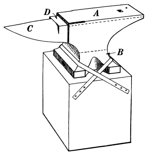
Fig. 5.—The Anvil.
After the anvil has been finished, the face is hardened with a constant flow of water, then it is ground true and smooth and perfectly straight lengthwise, but slightly convex crosswise, and both edges for about four inches toward the horn are ground to a quarter round, thus providing a convenient place for bending right angles. This round edge prevents galling, which is liable to occur in material bent over a perfectly square corner.
The round hole in the face is called the pritchel hole, over which small holes can be punched in the material. When larger ones are to be punched, they can be made on a nut or collar placed over the square hole or hardy hole. This hardy hole is used mostly for holding all bottom tools, which are made with a square shank fitted loosely to prevent their becoming lodged.
The flat portion D at the base of the horn, and a little below the level of the face, is not steel, consequently not hardened, and is therefore a suitable place for cutting or splitting, because there is not much liability of injuring the cutter if the latter comes in contact with the anvil.
The horn C is drawn to a point and provides a suitable place for bending and forming, also for welding rings, links, or bands.
The anvil is usually mounted on a wooden block and is securely held by bands of iron as shown in the illustration, or it may be fastened by iron pins driven around the concave sides of the base. It is sometimes mounted on a cast-iron base made with a projecting flange which holds the anvil in place.
A convenient height for the mounting is with the top of the face just high enough to touch the finger joints of the clenched hand when one stands erect. It is generally tipped forward slightly, but the angle depends considerably upon the opinion of the workman who arranges it in position.
For some time most of the anvils were made in Europe, but at present the majority that are purchased here are made by American manufacturers.
5. The Hammers.—Of the multitude of tools used by mechanics, the hammer is undoubtedly the most important one. There was a time when man had only his hands to work with, and from them he must have received his ideas for tools. Three prominent ones which are used extensively at present were most probably imitations of the human hand. From the act of grasping, man could easily have originated the vise or tongs for holding materials that he could not hold with the hand. Scratching with the finger nails undoubtedly impressed him with the need8 of something that would be effective on hard substances, and so he devised such tools as picks, chisels, and numerous other cutting instruments.
The clenched fist must have suggested the need of a hammer. The first thing to be substituted for the fist was a stone held in the hand. Next a thong of fiber or leather was wound around the stone, and used as a handle. From these beginnings we have progressed until we have hammers of all sizes and shapes, from the tiny hammer of the jeweler to the ponderous sledge. Workmen have adapted various shapes of hammers to their individual needs.

Fig. 6.—Hand Hammers.
A, ball peen hammer; B, cross peen hammer; C, straight peen
hammer.
6. The ball peen hammer (A, Fig. 6), sometimes called a machinist’s hammer, is very conveniently shaped for forging, as the ball end is handy for drawing out points of scarfs or smoothing concave surfaces. A suitable weight of this kind of hammer is one and a half pounds, but lighter ones can be used to good advantage for fastening small rivets.
7. The cross peen hammer (B, Fig. 6) is one of the older styles and is mostly employed in rough, heavy work or for spreading metal.
8. The straight peen hammer (C, Fig. 6) is shaped similarly to the ball peen hammer, except that the peen is flattened straight with the eye. It is convenient for drawing metal lengthwise rapidly.
9. The sledges (A, B, and C, Fig. 7) are used for striking on cutters, swages, fullers, or other top tools; when they are used by the helper, the blacksmith can be assisted in rapidly drawing out metal. The only difference between these two sledges is in the peen—one is crosswise with the eye and the other lengthwise. The double-faced sledge C is sometimes called a swing sledge, because it is used mostly for a full swing blow.

Fig. 7.—The Sledges.
10. The Tongs.—There is an old saying that “a good mechanic can do good work with poor tools,” which may be true; but every mechanic surely should have good tools, on which he can rely and thereby have more confidence in himself. Among the good tools that are essential for acceptable smith work are the tongs.
Very few shops have a sufficient variety of tongs to meet all requirements, and it is often necessary to fit a pair to the work to be handled. Sometimes quite serious accidents happen because the tongs are not properly fitted. They should always hold the iron securely and, if necessary, a link should be slipped over the handles as shown in B, Fig. 8. The workman is thus relieved from gripping the tongs tightly and is allowed considerable freedom in handling his work.
11. The flat-jawed tongs are shown at A, Fig. 8. They are made in various sizes to hold different thicknesses of material. Tongs of this kind hold the work more securely if there is a groove lengthwise on the inside of the jaw; the full length of the jaw always should grip the iron.

Fig. 8.—The Tongs.
A, flat-jawed tongs; B, hollow bit tongs; C, pick-up tongs;
D, side tongs; E, chisel tongs; F, link tongs; G, tool or box
tongs.
12. The hollow bit tongs, shown at B, Fig. 8, are very handy for holding round iron or octagonal steel. They can be used also for holding square material, in which case the depressions in the jaws should be V-shaped.
13. The pick-up tongs (C, Fig. 8) are useful for picking up large or small pieces, as the points of the jaws are fitted closely together, and the two circular openings back of the point will securely grip larger pieces when seized from the side.
14. The side tongs (D, Fig. 8) are used for holding flat iron from the side. Tongs for holding round iron from the side can be made in this form with circular jaws.
15. The chisel tongs are shown at E, Fig. 8. One or more pairs of these are necessary in all forge shops. As the hot and cold cutters frequently get dull or broken, it will be necessary to draw them out and retemper them; and, as the heads of these cutters become battered considerably, they are difficult to hold without chisel tongs. The two projecting lugs at the ends of the jaws fit into the eye, and the circular bows back of them surround the battered head of the cutter, so that it can be held without any difficulty.
16. The link tongs (F, Fig. 8) are as essential as anything else required in making chains or rings of round material. They can be made to fit any size of stock.
17. The tool or box tongs (G, Fig. 8) should be made to fit the various sizes of lathe tool stock that are used. They should be made substantially and fit the steel perfectly so that it can be held securely and without danger of stinging the hand, while the tool is being forged. Another style of tool tongs is made with one jaw perfectly flat; on the other jaw, lugs are provided to hold the steel firmly. These are not illustrated.
Almost an unlimited number of different tongs could be explained and illustrated, but, from those given, any one should be able to add to or change the tongs he has so that his material can be securely held.
18. Anvil and Forging Tools.—If a complete set of these tools were to be illustrated and explained, a volume would be required. Even then, the worker would very often be compelled to devise some new tool to suit the particular work at hand. One advantage that the blacksmith has over all other mechanics is that when a special tool is required, if he is a thorough mechanic he can make it.
An almost unlimited number of tools might be required in a general smith shop; but only such tools as are essential in manual training or elementary smith work will be considered here.
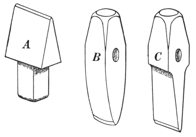
Fig. 9.
A, hardy; B, cold cutter; C, hot cutter.
19. The hardy (A, Fig. 9) should fit the hardy hole of the anvil loosely enough so that it will not stick or wedge fast. It is made of cast steel and should be tempered so that it will not chip or batter from severe use. It is an indispensable tool, especially to one who has to work without a helper, for with it iron can be cut either hot or13 cold, and steel when it is heated. The material should be held on the cutting edge of the hardy, then struck with the hammer. A deep cut should be made entirely around the material, round, square, or flat, so that it can be broken off by being held over the outer edge of the anvil and struck a few downward blows with the hammer.
Material should not be cut through from one side, for the cut would then be angular instead of square; furthermore, there would be the effect of dulling the hardy if the hammer should come in contact with it. The hardy is frequently used to mark iron where it is to be bent or forged, but it is not advisable to use it for such purposes, unless the subsequent operations would entirely remove the marks, for they might be made deep enough to weaken the metal, especially at a bending point.
20. The cold and hot cutters (B and C, Fig. 9) are made, as are all other top tools, with an eye for inserting a handle, and should be held by the workman while some one acting as his helper strikes on them with the sledge. The handles can be of any convenient length from eighteen inches to two feet. Cast steel should be used for making both these cutters, but their shapes differ somewhat. The cold cutter B is forged considerably heavier on the cutting end than is the hot cutter, in order to give it plenty of backing to withstand the heavy blows that it receives. The cutting edge is ground convex to prevent the possibility of the corners breaking off easily, and is ground more blunt than the hot cutter. It should be used only to nick the metal, which should then be broken off with the hammer or sledge, as described in cutting iron with the hardy.
21. The hot cutter (C, Fig. 9) is drawn down, tapering14 from two depressions or shoulders near the eye to an edge about 1⁄8 inch thick, which is ground equally from both sides to form a cutting edge parallel with the eye. It should be used exclusively for cutting hot metal, because the shape and temper will not stand the cutting of cold iron. In order to avoid dulling the cutter and the possibility of injuring some one with the piece of hot metal that is being cut off, the cut should be held over the outside edge of the anvil when the final blows are being struck; the operation will then have a shearing action, and the piece of metal will drop downward instead of flying upward.
Great care should be taken in hardening and tempering each of these cutters to prevent possible injury from small particles of steel that might fly from them if they were tempered too hard. The cold cutter should be hard enough to cut steel or iron without being broken or battered on its cutting edge. The hot cutter should not be quite so hard and should be dipped in water frequently when it is being used to prevent the temper from being drawn.
22. The flatter (A, Fig. 10) is as useful and as essential for the production of smooth and nicely finished work as the finishing coat of varnish on a beautiful piece of furniture. Any work that is worth doing is certainly worth doing well, and in order to make forge work present a finished appearance the smith should use the flatter freely. With it the rough markings of the various forging tools or hammer can be entirely removed. By using it while the work is at a dull red heat, and by occasionally dipping the flatter in water before it is applied, all the rough scale can be removed, thus leaving the work with a smooth, finished appearance.
There are various sizes of this tool, but one with a 2-inch15 face is convenient for use on light forgings. The edges of the face may be made slightly round, so that markings will not be left on the work, but frequently the edges are left perfectly square.
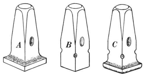
Fig. 10.
A, flatter; B, square-edged set hammer; C, round-edged set
hammer.
It is not necessary to temper this tool; in fact, the constant hammering on it has a tendency to crystallize the steel, often causing it to break off at the eye. As the constant hammering on the head of the flatter will also cause the head to become battered, it is good practice frequently to draw out the head and lay the flatter aside to cool. This will anneal the steel and prevent crystallization, at least for some time.
23. The square-and round-edged set hammers (B and C, Fig. 10) are employed for various purposes. The former is used for making square shoulders or depressions such as could not be produced with the hand hammer alone, or for drawing metal between two shoulders or projections. The latter is used for the same purposes, with the exception that it produces a rounded fillet instead of a square corner. It is also convenient for use in small places where the flatter cannot be employed.
The sizes of these tools vary according to the requirements of the work, but it is advisable to have about three sizes of the square-edged one. A good outfit of set hammers consists of one 5⁄8-inch, one 3⁄4-inch, one 1-inch, all square-edged; and one round-edged set with a 11⁄4-inch face. These four should fulfill all requirements for light forgings. These tools need not be tempered, for the reason explained in connection with the flatter.
24. The punches (A, B, and C, Fig. 11) are merely samples of the multitude of such tools that may be required. They may be of various sizes, depending upon the requirements of the work, and either round, square, or oval in shape at the end. The hand punch A is held with one hand while blows are delivered with the other. It is convenient for punching holes in light pieces; but when the work is heavy the intense heat from the metal makes it impossible to hold a punch of this kind.

Fig. 11.—The Punches.
In such cases the handle punches B and C are employed. They eliminate the danger of burning the hand, but it is necessary to have some one act as helper and do the striking. The proper way to use a punch on hot metal is to drive it partly through, or until an impression can be17 seen on the opposite side after the punch has been removed; then the punch is placed on the impression and driven through the metal while it is held over the pritchel hole, the hardy hole, or anything that will allow the punch to project through without causing the end to be battered. If heavy pieces of metal are to be punched, it is a great advantage to withdraw the tool, drop a small piece of coal into the hole, and cool the punch before again inserting it. The coal prevents the tool from sticking fast, and the operation can be repeated as often as necessary.
Punches need not be tempered, because the strength of the steel from which they should be made will withstand the force of the blows, and also because the metal is generally hot when the punches are used; therefore the temper would be quickly drawn out of them. If sheet metal or light material is to be punched cold, it is advisable to harden the punch slightly; then the hole may be punched through from one side, while the metal is held on something containing a hole slightly larger than the punch. This method has the effect of producing a smoothly cut hole, provided the metal is properly placed.

Fig. 12.—The Top and Bottom Swages.
25. The top and bottom swages (Fig. 12) are made with semicircular grooves of different sizes to fit the various diameters of round material. The former has an eye for the insertion of a handle by18 which it is held when in use. The eye should be crosswise to the groove in the face. The bottom swage is made with a square projecting shank to fit loosely into the hardy hole of the anvil. It should be placed in position for use with the groove crosswise to the length of the anvil, unless the form of the forging should require otherwise. Swages are conveniently used for smoothing round material after it has been welded, or for swaging parts of a forging after they have been roughly hammered out. By dipping the top swage in water occasionally while in use, the work can be made much smoother and the scale of oxide removed; this is called water swaging.

Fig. 13.—The Top and Bottom Fullers.
26. The top and bottom fullers (Fig. 13) are made in pairs with convex semicircular projections or working faces, whose diameters should correspond, if intended to be used together. As the former is quite frequently used alone, it may be made of any desired size. The top fuller, like the top swage, is made to be used with a handle; the bottom fuller, fitted to the anvil like a bottom swage, generally is placed for use with the length of its face parallel to the length of the anvil.
They are used together for forming depressions or shoulders on opposite sides of the material; from the shoulders thus formed, the metal may be forged without disturbing them. They are used also for rapidly drawing out metal between shoulders or projections which may have been previously19 made and are to be left undisturbed. The top fuller is used singly in making scarfs for welding, in forming grooves, in smoothing fillets and semicircular depressions, or in forming shoulders on only one side of metal.
27. The button head set or snap (A, Fig. 14) as it is sometimes called, has a hemispherical depression on its face. It is used for making heads of rivets or finishing the heads of bolts. Only a few different sizes are required, unless considerable riveting or bolt making is to be done.
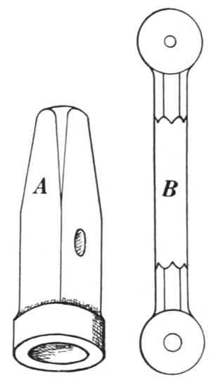
Fig. 14.
A, the button head set; B, the heading tool.
28. The heading tool (B, Fig. 14) is used exclusively for forming the heads of bolts or rivets. Formerly a very large assortment of these tools was required in a general shop; but as bolts can now be made so cheaply by modern machinery, there are not many made by hand. It would be advisable to have a few general sizes, however, because they are sometimes convenient in making other forgings, and bolt making affords an instructive exercise.
29. The swage block (A, Fig. 15) rests on a cast-iron base B. It is a very useful tool in any smith shop and does away with the necessity of having a large assortment of bottom swages, as only top swages will be required for large-sized material. The block is made of cast iron and of different thicknesses. The depressions on the edges include a graduated series of semicircular grooves that can be used in place of bottom20 swages; a large segment of a circle, which is handy in bending hoops or bands; graduated grooves for forming hexagonal boltheads or nuts; and sometimes a V-shaped and a right-angled space used for forming forgings.

Fig. 15.—The Swage Block.
The holes through the blocks are round, square, or oblong. The round ones can be used in place of heading tools for large sized bolts, or in breaking off octagon or round steel after it has been nicked with the cold cutter. The square holes may be used either for making and shaping the face of a flatter or a round-edged set hammer, or in place of a heading tool, when a square shoulder is required under the head. They may be used, also, for breaking square steel. The oblong holes are convenient for breaking lathe tool material. Some swage blocks have in addition a hemispherical depression on the side, convenient for forming dippers or melting ladles.
The base upon which the swage block rests is constructed with lugs on the inner side, as indicated by the broken lines on the sketch. Upon these it is supported, either flat or on any of its four edges. These lugs prevent the swage block from tipping sidewise.
30. The surface plate (C, Fig. 16) is generally made of cast iron about 11⁄2 to 2 inches thick, from 20 to 24 inches wide,21 and from 3 to 4 feet long. It should be planed perfectly smooth and straight on its face, the edges slightly round. It should be supported on a strong wooden bench D and placed somewhere in the middle of the shop so that it is accessible to all the workmen. On it work is tested to see whether it is straight, perpendicular, or if projections are parallel. The anvil is sometimes used for this purpose, but as it is subjected to such severe use, the face becomes untrue and therefore cannot be depended upon. A true surface plate is always reliable and convenient for testing work.

Fig. 16.—The Surface Plate.
31. The tapered mandrels (Fig. 17) are made of cast iron, and are used for truing rings, hoops, bands, or anything that is supposed to have a perfectly circular form. The height ranges from 21⁄2 to 5 feet; the largest diameter varies from 8 to 18 inches. They are cone-shaped with a smooth surface, and should be used with caution. The blows should be delivered on the metal where it does not come in contact with the mandrel; when bands of flat material are to be trued, the best method is to place them on the mandrel from each side alternately. Unless this precaution is observed, the band will be found tapered the same as the mandrel. Alternating is not so necessary when bands or rings of round material are handled.
Mandrels are sometimes made in two sections, as shown at B and C. As B is made to fit into the top of C, the two parts become continuous; the smaller one can also be held in the vise or swage block and thus used separately. They are frequently made with a groove running lengthwise, which allows work to be held with tongs and provides a recess for any eyebolt or chain that may be attached to the ring.

Fig. 17.—The Tapered Mandrels.
It should not be supposed that all mandrels are of this particular form; any shape of bar, block, or rod of iron that is used for the purpose of forming or welding a special shape is called a mandrel.
32. Bench and Measuring Tools.—Another set of blacksmith appliances includes the bench vise, chisels, center punch, rule, dividers, calipers, scriber, square, bevel, hack saw, and files.

Fig. 18.—The Bench Vise.
33. The bench or box vise (Fig. 18) is not ordinarily used in general blacksmithing. The back jaw of a general smith’s vise extends to the floor, forming a leg, and is held in position on the23 floor by a gudgeon on its end. This vise is not illustrated, because the bench or box vise is preferable for manual training work.
The vise should be set so that the tops of the jaws are at the height of the elbows,—a position convenient in filing. It is used for holding the work for filing, chipping, twisting, and sometimes for bending. But when it is used for bending, especially when bending a right angle, the operation should be performed cautiously, for the sharp edges of the jaws are very liable to cut the inner corner of the angle and cause a gall which will weaken the metal at the bend.
34. The chisels (A and B, Fig. 19) are very familiar, yet, though they are so common, they are the most abused tools used by both skilled and unskilled workmen. The mere name “cold chisel” seems to convey the impression to most people that with it they ought to be able to cut anything. But that impression is wrong; chisels ought to be made of a certain grade of steel and drawn for either rough or smooth work, as may be required. Then they should be properly tempered to cut the material for which they are intended.
A chisel for rough, heavy work should not be drawn too thin or too broad at the cutting edge. If it is flattened out into a fan-shaped cutting edge, there should be no surprise if it breaks, for, in order to make a chisel stand rough usage, it should have sufficient metal to back up the corners. On the other hand, a chisel for smooth finishing work can safely be drawn thin but not fan-shaped, as the cuts that ought to be required of such a chisel should not be heavy. A chisel for ordinary work ought to be ground so that the two faces form an angle24 of 60 degrees; if the work is heavy, it should be ground even more blunt.
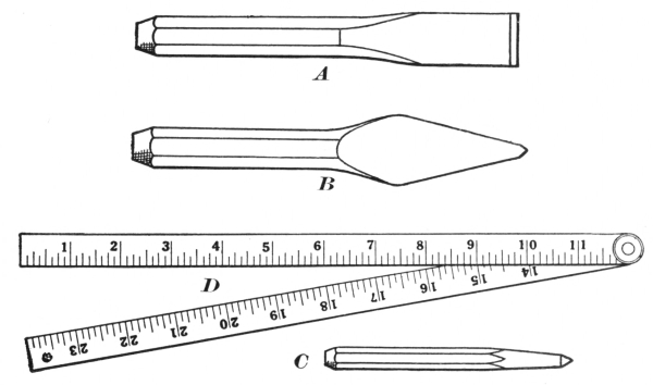
Fig. 19.
A, cold chisel; B, cape chisel; C, center punch; D, rule.
The chisel illustrated at A represents a common cold chisel, which can be used for various purposes. The chisel B is called a cape chisel and is used for cutting and trimming narrow grooves and slots. It is indispensable for cutting key seats in shafting or work of that kind. On account of its being used in such narrow places it is necessary to make the cutting edge somewhat fan-shaped to prevent the chisel from sticking fast; but for additional strength the metal is allowed to spread, as shown. When using the cape chisel, it is a good practice occasionally to dip the cutting edge in some oily waste, which will tend to prevent its wearing away or sticking.
35. The center punch (C, Fig. 19) should be made of the same quality of material as the cold chisel. It can be25 made of steel from 1⁄4 to 5⁄8 of an inch in diameter; octagon steel is preferable. After it has been roughly drawn out, it is ground to a smooth round point, then it is tempered as hard as it will stand without breaking. It is used for marking centers of holes to be drilled, or for marking metal where it is to be bent, twisted, or forged. When used for marking hot metal, it is frequently made with an eyehole in the body, so that a small handle can be inserted; this will prevent burning the hands.
36. The rule (D, Fig. 19) should be of good quality. The one best adapted for forge work is the 2-foot rule, which is jointed in the center. It is 3⁄4 inch wide and is made of either tempered spring steel or hard rolled brass.
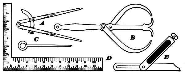
Fig. 20.
A, dividers; B, calipers; C, scriber; D, square; E, bevel.
37. The dividers (A, Fig. 20) are used for measuring distances and for describing circles. The points are clamped in a rigid position with the small thumbscrew, which comes in contact with the segmental arc. Close adjustments can be made with the milled-edge nut on the end of the segmental arc. When metal is to be bent to a circular form, a good method is to rub chalk on the surface plate and describe the desired curve on this chalk. As26 the markings thus made are not easily removed, this plan is much better than drawing upon a board.
38. The calipers (B, Fig. 20) are used for measuring diameters, widths, and thicknesses. Those illustrated are the kind generally used in forge work. They are called double calipers and are the most convenient because two dimensions can be determined by them. As the accuracy of the work depends on them, they should be well made. In the illustration here given, each bow is held securely by an individual rivet. Sometimes they are secured with one; if so, the rivet should be square in the straight central part and tightly fitted. The projecting ends of the rivet should be filed round, and the holes in the bowed sides should be made to fit the round ends of the rivet; then the sides should be riveted on tight so that each bow may be moved independently of the other.
39. The scriber or scratch awl (C, Fig. 20) is used in marking holes, sawing, chipping, or in laying out distances, which can afterward be marked with a center punch if required. It should be made of a good quality of steel, and the point should be well hardened so that it will cut through the surface scale of the metal. A suitable-sized steel for making a scriber is 3⁄16 inch round and the length over all about 6 inches.
40. The square (D, Fig. 20) is another indispensable tool when accurate work is to be produced. Convenient sizes for manual training work are the 8 × 12-inch, with a 16 × 24-inch for general use.
41. The bevel (E, Fig. 20) should be used when bending and laying out angles of various degrees. When metal is to be bent to a given angle, the pupil should set and use the bevel.
42. The hack saw (Fig. 21) is at present considered a necessary part of any forge shop equipment. It is used for sawing iron or untempered steel, and when a power shear is not included in the equipment, considerable filing can be saved by sawing. The frame illustrated is adjustable so that the blades can be made of different lengths and be set at right angles to the frame, which is sometimes convenient.
When using the hack saw, make slow, full-swing strokes; when drawing back for another stroke, it will prolong the efficiency of the blades if the saw is raised up to prevent the teeth from bearing on the metal, as the backward stroke is more destructive to the teeth than the forward or cutting stroke. The blades are made from 8 to 12 inches in length, 1⁄2 inch in width, and with from 14 to 25 teeth to the inch. They are tempered so hard that they cannot be filed, but are so inexpensive that when they cease to be efficient they may be thrown away.

Fig. 21.—The Hack Saw and Files.
43. The files (Fig. 21) are illustrated merely to show that they are to be used for special purposes. As finishing or28 filing is almost a trade in itself, the file should not be used in blacksmithing, unless it is especially necessary. A piece of smith’s work that has been roughly forged is much more admirable than a highly polished piece that has been filed into elegance.
Files are round, flat, square, half round, and of numerous other shapes, and vary in lengths and cuts for rough or smooth filing. Any of them may be used as required, but it should be remembered that filing is not blacksmithing.
Questions for Review
What is the main difference between the old type of smithing forge and a modern one? How is the air supplied for each? What is a tuyère iron? Describe the hearth. What kind of coal is used for forging? Is coal the best fuel for heating all metals? Why is charcoal the best fuel for heating carbon steel? How should the fire be built to prevent making excess smoke? What other fuel is used in forging? What kind of work is it used for? Describe the different parts of the anvil. How is a cast-iron anvil hardened? How is a wrought-iron anvil hardened? Name and describe the different kinds of hammers. Why should the tongs fit properly the iron to be handled? Name and describe the different tongs you have been made familiar with. How would you secure the tongs to relieve the hand?
What is a hardy? What is it used for? Explain the proper method of using it. Is it always good practice to use a hardy for marking the iron? Why? What is the difference between a cold and a hot cutter? What is the general use for a flatter? Should it be tempered? Why? What are set hammers? What is a punch used for? Explain the difference between a hand punch and a handle punch. When punching a heavy piece of metal, how is the tool prevented from sticking fast? Are all punches tempered? Why? Describe and explain the use of top and bottom swages. How should the bottom swage be placed for use? What is meant by water swaging? State the effect it has on the iron. What are top and bottom fullers used for? Are they always used in pairs? How is the bottom one 29 placed for use? What are the button head set and heading tool used for? What is the special advantage of having a swage block? Explain some of the different uses of that tool. What is the special use of the surface plate? What is the tapered mandrel used for? Are all mandrels of this particular kind? Explain others. Is it good practice to use the vise for bending? Why? Describe the cold chisel. Should all cold chisels be made alike? What is the center punch used for? Describe the other bench and measuring tools mentioned. What is the special objection to using the files?
44. The Hammer Blows.—Metal can be forced into desired shapes or forms by delivering the hammer blows in different ways. All hammer blows are not alike; some will have one effect and others will produce an entirely different result.
45. The upright blow is delivered so that the hammer strikes the metal in an upright position and fully on the anvil. Such blows force the metal equally in all directions, providing the surrounding dimensions are equal. They will also reduce the thickness of the metal in the direction in which they are delivered, the reduction depending upon the amount of force put into the blows. They are used for drawing where the metal is supposed to spread equally in all directions and for making smooth surfaces.
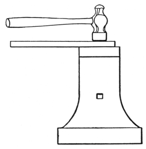
Fig. 22.—The Upright Blow.
Figure 22 shows an upright blow as delivered on a piece of flat material. If the material is as wide as the face of the hammer, or wider, the force of the blow will spread the metal equally, but if it is narrower, the blow31 will lengthen the material more rapidly, because the hammer will cover more in length than in width.
46. The edge-to-edge blow is delivered so that the edge or side of the hammer face will be directly above the edge or side of the anvil. When blows are delivered in this manner (a, Fig. 23), the hammer forms a depression on the upper side of the metal and the anvil forms one on the bottom.
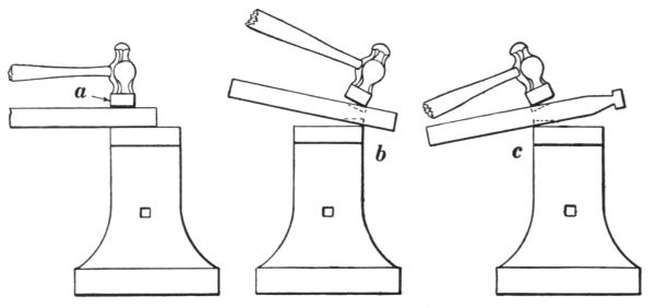
Fig. 23.—The Edge-to-edge Blow.
When a piece of metal is to be drawn to a smaller dimension, with shoulders opposite each other, on either two or four sides, these blows will produce the required result to the best advantage. They are more effective if the metal is held at a slight angle across the edge of the anvil face, but then the hammer blows must be delivered a little beyond the anvil edge, so that the upper and lower depressions in the metal will be formed exactly opposite each other, as shown at b, where the depressions are indicated by the broken lines.
In forming shoulders such as are required on the hasp exercise (page 64) the first pair may be formed as shown32 at b and the second pair as shown at c. In the latter case the metal is held across the nearer edge of the anvil face and the blows delivered in a manner similar to that described in the preceding paragraph. Hammer blows of this class may be used on any edge of the anvil as required.
47. The overhanging blow is delivered so that half the width of the hammer face extends over the edge of the anvil. (See Fig. 24.)

Fig. 24.—The Overhanging Blow.
It is used for forming shoulders on one side of the metal and for drawling out points of scarfs. When blows are delivered in this manner, the anvil will form a depression or shoulder on the lower side of the metal, and the hammer will keep the metal straight on the upper side.
This blow also will be more effective if the metal is held at a slight angle across the edge of the anvil face, but the blows must always be delivered squarely on the upper side of the metal to keep it straight.
48. The beveling or angle blows are delivered at any angle that the form of the work may require. When the metal is to be drawn with a taper on one side, it must be held level on the anvil and the blows delivered at an angle determined by the amount of taper required. Figure 25 shows the manner of holding the metal and the way the blows are to be delivered.

Fig. 25.—The Beveling or Angle Blow.
When the metal is to be drawn tapering on two opposite sides, it should be held to the proper angle on the anvil to establish the taper desired on the bottom, while the hammer blows are delivered so as to form a similar taper on the upper side. (See Fig. 25.)

Fig. 26.—Drawing Metal to a Point by Beveling or
Angle Blows.
A, correct position; B, incorrect position.

Fig. 27.—The Leverage Blow.
Blows of this kind are used for chamfering corners or edges, and may be delivered at any required angle. They are also used when drawing metal to a point, either square, round, hexagonal, or octagonal, but the metal should be held on the anvil, as shown at A, Fig. 26. Then the hammer will not come in contact with the face of the anvil, as shown at B. If the hammer strikes the anvil, small chips of steel are liable to break off from the hammer at the place indicated by c, and cause serious injury.

Fig. 28.—Bending by Leverage Blows.
49. The leverage blows are used mostly for bending, as they will not leave marks where the bending occurs. For instance, when a ring is to be formed, the metal is first held in the tongs and rested on the horn of the anvil, as shown in Fig. 27. Note35 that the metal will bend at a, providing the heat is uniform. If, therefore, bending is required at a certain place, that place should rest on the anvil and the blows should be delivered beyond it.
After the first end has been bent to the required radius, the other should be bent by holding it in the manner shown in Fig. 28, because the joint of the tongs will prevent its being struck out of them while the blow is being delivered. When both ends have been bent to the proper radius, the ring should be finished as described in the ring exercise (page 74), where upright blows are used with a leverage effect.
50. The backing-up blows are used to upset metal when it is impossible to upset it in the usual manner, and in backing up the heel of a scarf.

Fig. 29.—The Backing-up Blow, for Upsetting.
Upsetting with backing-up blows is done in the manner shown in Fig. 29. The metal should be extended over the anvil and thrust forward as the blow is being delivered, to get the best results. This will also prevent jarring the hand. The metal should be as hot as possible when being upset in this manner.
The heel of a scarf is formed with backing-up blows after the metal has been upset in the usual manner. The36 blows should be directed so that they will have an upsetting effect, as indicated in Fig. 30, and not a drawing one. After a few blows have been delivered with the face of the hammer, they should then be delivered with the ball to form the heel better and more rapidly.

Fig. 30.—Backing-up Blows used for Scarfing.
51. The shearing blow (see Fig. 31) is conveniently used for cutting off small portions of metal instead of employing the hardy. It is delivered so that the side or edge of the hammer will pass by and nearly against the side or edge of the anvil. A blow so delivered will have a shearing effect and cut the metal. It is perfectly proper to use this blow for its intended purpose, but it should not be used when the edge-to-edge blow is the one really required.
52. Forging.—Forging is the operation of hammering or compressing metals into a desired shape. Seven37 specific operations are used. Sometimes a piece of work or forging requires two, three, or even all of them to complete it. These operations are designated by the following names: drawing, bending, upsetting, forming, straightening, twisting, and welding.
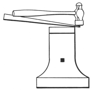
Fig. 31.—The Shearing Blow.
53. Drawing, the process of spreading or extending metal in a desired direction, is accomplished by hammering or by pressing the metal between such tools as the swages and fullers, or by holding it on the anvil and using either of the set hammers, the flatter, or the fuller. When using any of these pressing tools for drawing, a helper is supposed to use the sledge to deliver the blows upon them.
It is always best to draw round metal with the swages, as it will be smoother when finished than if it were done with the hammer; it should be rolled in the swage a little after each blow of the sledge, and after a complete revolution in one direction it should be turned in the opposite direction, and so alternately continued until finished. Especially if iron is being drawn, this will prevent twisting of the fiber, which, if prolonged, would cause the metal to crack. Figure 32 shows the method of drawing with the swages.
When drawing any shape or size of metal to a smaller round diameter, it is best first to draw it square to about the required size, delivering the blows by turns on all four38 sides, then to make it octagonal, and finally round. The finishing should be done with the swages, if those of proper size are at hand; if not, light blows should be used, and the metal revolved constantly in alternate directions, to make an acceptable shape.

Fig. 32.—Drawing with the Swages.
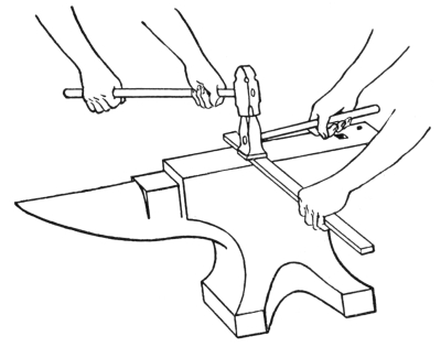
Fig. 33.—Drawing with the Flatter.
Drawing with the top and bottom fullers, in the manner shown with the swages (Fig. 32), ought to be done cautiously,39 as the metal decreases in size so rapidly that there is danger of its becoming too small at the fullered place before the operator is aware of it. When using the top fuller alone, in the same manner as the flatter (Fig. 33), similar precautions should be observed. If the metal is to be decreased between two shoulders, the top fuller may be used to rough it out; but the fuller marks should be distributed between the shoulders, until one of the set hammers or the flatter can be used.
If the metal is being drawn and is held crosswise on the anvil, as shown at a, Fig. 34, it will increase in length more rapidly than it will in width, and if held lengthwise as at b, it will increase more in width than in length. This is due to the fact that the anvil is slightly convex on its face, so that it has the effect of a large fuller.

Fig. 34.—Drawing with the Hand Hammer.
The most difficult drawing for the beginner is to form metal into a square or hexagonal shape. To draw it into a square form, the metal must always be turned either one quarter or one half of a revolution to prevent its becoming diamond-shaped, and the blows must be40 delivered equally on the four sides to prevent its becoming oblong. If it does become diamond-shaped, it can be made square by delivering blows at a slight angle on the corners and sides of its long diagonal as shown at A, B, and C, Fig. 35. If it is but slightly diamond-shaped, the method shown at B will prove satisfactory, but if badly out of square, the method at A will be the best.
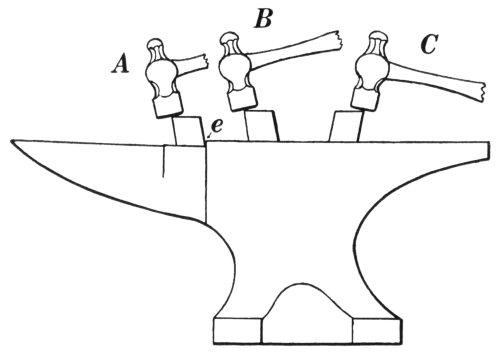
Fig. 35.—Squaring up a Diamond-shaped Piece.
In drawing the hexagonal form, the metal should be turned by sixths of a revolution. If it becomes distorted, it may be forged with such blows as are shown at B and C; if held as at A, it would be marred by the edge e.
54. Bending is the operation of deflecting metal from a straight line or changing its form by increasing the deflection already present. Iron of any cross-sectional shape can be bent, but some shapes are much more difficult than others.
The easiest to bend is the round, the only difficulty being41 to prevent the hammer blows from showing. If the metal is to be round in section when finished, the work will not have a good appearance if the cross section is oval at some places and round at others, and unless the hammer blows are cautiously delivered this will be the result.
Bending metal of a square section at right angles with the sides is not very difficult, but bending such a section in line with the diagonal is quite difficult, because the edges are liable to be marred where they rest on the anvil and where the blows are delivered. The best method of making bends of this kind is to heat the metal only where the bend is to be, and then to bend it by pressure or pulling, while the work is held securely in the vise, hardy hole, or swage block. If the heating cannot be confined to the desired space, all excessively heated parts should be cooled.
Oval sections are easily bent through their short diameters, but in bending through the long diameters, the same method should be pursued as described above for bending the square section in the plane of its diagonal. Further explanations for bending are given on pages 118-121.
55. Upsetting is the operation of enlarging metal at some desired point or place. It is done by hammering, ramming, or jarring. When a piece of metal is too long it can be shortened by upsetting, or when it is too thin at a certain place it can be thickened by the same method. This is done by having the metal hot only at the point or place where the upsetting is required. It is frequently necessary to cool the metal where the heat is not needed in order to confine the upsetting to the desired place.
Upsetting is not a very difficult operation as long as the metal is kept perfectly straight; otherwise the task42 will prove tedious and the metal may break from the constant bending back and forth. Bending will always take place, but breaking generally can be prevented by having the metal hot when it is straightened. The greatest difficulty in this respect will be experienced when operating on common wrought iron.
Upsetting by hammering is done by holding the metal perpendicularly on the anvil or something solid enough to withstand the blows which will be delivered upon it. Figure 36 shows this method.

Fig. 36.—Upsetting by Hammering.
If the end of a bar is being upset, and the upsetting is supposed to extend up through the bar for some distance, the heated end should be placed on the anvil as shown in the figure, because the anvil will slightly chill the end of the bar, and the upsetting will continue much farther43 than if the blows were delivered on the hot end. Striking the hot end with the hammer increases the diameter of the end excessively, because the contact of the hammer does not have a tendency to cool the metal.

Fig. 37.—“Backing up” Metal.
Another method of upsetting with the hammer, which is called “backing up” the metal, is shown in Fig. 37. This method does not upset the metal so rapidly, because the force of the hammer blows jars the hand and arm which hold the bar.
Upsetting by ramming or jarring is thrusting the metal forcibly against some heavy object like the surface plate, the swage block, or the anvil. Figure 38 shows upsetting by this process. This method is very effective and is used mostly when the metal is long enough to be held with the hands, as shown.

Fig. 38.—Upsetting by Ramming.
56. Forming is a term generally applied to the making of a forging with special tools, dies, or forms. This44 process may include bending, punching, and other operations.
Swages are used for forming. A block of steel with a depression of a special design is known as a forming die; a number of other tools and appliances may be used for forming, but it is needless to mention them here.
57. Straightening is one of the most frequent operations. When metal is being forged, the various blows have a tendency to make it crooked, and if the work is supposed to be straight when finished, it should be so.

Fig. 39.—A, Straightening with the
Hammer;
B, Straightening with the Swage.
There is as much skill required to straighten properly a piece of metal as there is to bend it. The most common method (A, Fig. 39) is to hold the metal lengthwise on the anvil with the bowed side or edge upwards, then to deliver the blows at the highest point of the bow. The blows will be most effective at the point where they are delivered, so they should be distributed in order to get the object perfectly45 straight and to avoid making unsightly hammer marks.
If the metal to be straightened is round, or if it is flat with round edges, it is best to use a top swage of the proper size and deliver the blows on the swage as shown at B, Fig. 39. Then the surface of the round or the edges of the flat stock will not show any marks. The flatter or round-edged set hammer may be used in the same manner on flat or square material.
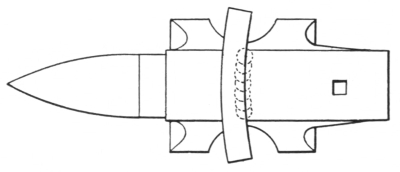
Fig. 40.—Straightening Wide Metal.
When wide pieces of flat metal are to be straightened edgewise, and such blows as are shown at A, Fig. 39, are not effective, then the blows should be delivered along the concave edge as shown in Fig. 40, and distributed as indicated by the dotted circular lines. Blows delivered in this manner will stretch or lengthen the metal on the concave edge and straighten it.
58. Twisting is the operation of rotating metal to give it a spiral appearance. It may be done either hot or cold, as the dimensions of the material may require. It is done by holding the material in the vise, the hardy hole, or the swage block, and turning one end of it with a pair of tongs or a monkey wrench as many times as may be required. The twisting will be confined between the places where it is held with the vise, and where it is seized by the tongs or wrench.
If the material to be twisted is heavy enough to require46 heating, a uniform heat is necessary or the twist will be irregular, and, as an artistic appearance is usually desired, this operation should be carried out with that result in view.

Fig. 41.—A, Metal Twisted while Hot; B, Metal Twisted while Cold.
A, Fig. 41, illustrates a piece of 1⁄2-inch square stock that has been twisted while hot. B shows a piece of 1⁄2 × 1⁄8-inch material that has been twisted cold.
Another difficulty met with in twisting a piece of metal is that of its becoming crooked. It can be straightened by laying the twisted portion on a wooden block and striking it with a wooden mallet. This will prevent the corners from becoming marred. A good method of avoiding this trouble is to twist the metal inside of a piece of pipe whose inside diameter is equal to the diameter of the metal.
59. Welding, the most difficult operation in the art of forging, is the process of joining two or more pieces of metal into one solid mass.
All the previous operations allow some time for thought; in welding, the worker must determine instantly where each blow is to be delivered, as the welding heat of the metal vanishes rapidly; therefore, he is compelled to think and act very quickly.
A scientific analysis of a perfect weld shows that it consists of several processes, and that each one must be perfectly executed. If any of these operations are improperly47 done, the result will be a partial failure; if they are essential ones, the weld may readily be considered as totally unfit.
60. The Material for Welding.—This must be considered, because there are different qualities in each metal to be operated upon, and some metals can be worked more easily than others.
A cross section of a bar of iron viewed through the microscope is seen to be made up of a great number of layers or fibers, called laminæ, resembling the grain or fiber in wood. These were cemented together in the process of rolling or welding in the mill where the iron was manufactured, and are continuous through its length. This makes the bar of uniform quality throughout.
In welding, these fibers are joined diagonally at the ends, consequently the strength of the weld depends entirely on how closely or perfectly this cohesion is made. Careful hammering at the proper heat brings the fibers in as close contact as possible, squeezes out the slag and scale, and therefore greatly assists in strengthening the weld.
Iron is an easy metal to weld. To prove this, place two pieces of iron in a clean, non-oxidizing fire, allowing them to attain a white or welding heat; then place them in contact and notice how readily they stick together, proving that iron is easily welded at the proper temperature. But in order to make the contact thorough, the pieces must be hammered. This shows that hammering is a secondary operation, and that iron cannot be joined by either heating or hammering alone.
By a similar experiment with soft steel, you will notice that the pieces do not adhere like iron. If borax is applied48 while they are heating, then slight indications of adhesion will be noticeable. This shows that borax, sand, or something of a like nature must be used in welding steel. In this case hammering is not a secondary operation, but an essential one.
A higher carbon or tool steel may be experimented upon, with nearly the same result. The noticeable difference between the lower and higher qualities of steel proves that the greater the quantity of carbon, the harder will be the welding, and if the experiments were extended to still higher carbon steels, it would be discovered that they could not be joined except by the use of a specially prepared flux. There are indeed some high carbon steels that cannot be welded.
If a forging is to be made of a special quality of material, it is frequently advisable to avoid welds, because two pieces that are welded can hardly be considered so strong as a piece of the same material that has not been welded.
The weldings which are alluded to here are such as are used by practical blacksmiths in their general work without any special appliances or apparatus whatever. The majority of the exercises on welding in this book require the use of iron; for this reason this preliminary consideration of metals need not have any further special attention.
61. Heating.—When the word “fuel” is used here, either coal or coke may be meant. Coal is the original in either case, for coke is formed from it by the removal of gaseous substances. It is better that the coal first be converted into coke, and that only the coke should come in direct contact with the heating metals.
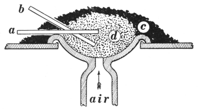
Fig. 42.—Sectional View of a Blacksmithing Fire.
Figure 42 shows a sectional view of a blacksmithing fire: d is the bed of hot coke; c is the dampened and unburned coal which surrounds the fire, continually forming more coke as it is needed and also holding the fire in a compact form; a shows the proper way of placing the metal in the fire, b, the improper way because the metal is too near the entrance of the blast. As heating is such an important operation, a thorough understanding of what causes imperfect heats, as well as how to prevent them, is necessary.
The best fire for perfect heating is a reducing one, that is, one in which the combustion of the fuel is rapid enough to use entirely the oxygen in the air which is supplied. An oxidizing fire is one that does not use all the oxygen in the blast for the combustion of the fuel. The surplus oxygen will produce, on the surface of the metal, oxide of iron, or a black scale, which is extremely injurious. This scale will prevent welding, so all possible precautions should be taken to avoid its forming.
A reducing fire can be maintained, and an oxidizing one avoided, by having plenty of fuel surrounding the metal,50 equally, and allowing the entrance of only sufficient air or blast to provide the necessary heating.
If a piece of metal is left in a fixed position while heating, the lower side will become the hottest. For that reason, all metals to be welded are placed with scarfs downward. If the required heat is to be a penetrating and thorough one, the metal is turned frequently to bring all surfaces in contact with the most intense point of heat.
Even though every possible precaution is taken in all other steps of the welding, the pieces cannot be joined perfectly if the heating is carelessly done.
62. Scarfing.—This is the operation of preparing or shaping metal for welding. There are five general kinds of welds, the distinct form of each depending either on the quality of the material or on the shape of the desired forging. They are called the lap weld, the cleft weld, the butt weld, the jump weld, and the V weld.
63. The lap weld (Fig. 43) is so called because the pieces lap over each other when placed in contact. It is most commonly used in general practice, and all welds formed in a similar manner belong to this class, regardless of the sectional form of the material or the shape of the completed weld.

Fig. 43.—Lap Weld Scarfs.
The pieces should always be upset where the scarfs are to be formed, to provide excess metal for welding. They should be formed with their end surfaces convex, and at an angle of about 45 degrees, which would not make the joining surfaces too long.
When the fire and all tools are ready, place both scarfs face down in the fire; when they are removed to the anvil,51 the piece held in the right hand should be turned face up and rest on the anvil, in order that the other may be placed in position on top of it.
The left-hand scarf should be placed carefully, with its point meeting the heel of the other. If placed too high and overlapping, it will increase the surface to be welded and perhaps decrease the dimensions of the material where the points are welded down upon the exterior. If placed too low, in all probability the surplus metal provided by upsetting will not be sufficient to form the weld to a uniform dimension. A little practice with the scarfs before heating is advisable to prevent this difficulty.
The hand hammer should be placed conveniently on the anvil, with the handle projecting sufficiently over the heel so that it can be grasped quickly with the right hand as soon as the two pieces are in position. If this precaution is not taken, the welding heat may disappear before any blows can be struck.
The first blows after the pieces are placed should be directed toward the center of the scarfs; when the center has been thoroughly united, the blows should be directed toward the points to complete the operation, if this can possibly be done in one heating.
It is impossible to give an invariable routine of blows; those given are sufficient for the beginning, the rest must be left to the observation and skill of the operator. Practice and judgment will determine where the blows should be delivered, and when they should cease.
As the welding heat vanishes very rapidly, it requires careful judgment to determine when the pieces cease to unite. All blows delivered after this will reduce the dimensions of the metal; if reheating is necessary, there52 should be no metal sacrificed by unnecessary hammering. Welds are generally weaker than the metal from which they are made; consequently if the stock is made smaller at the weld, its strength is greatly decreased.
The old adage “Haste makes waste” does not always apply. If you hasten the operation of welding while the pieces are sufficiently hot, you will not waste the metal. If through want of haste you are compelled to reheat, you will waste metal, for every time a piece is heated it loses a fractional part of its area, regardless of any hammering.
Welds made with scarfs of this kind are considered to be nearly as strong as the metal itself, because they allow of a more thorough lamination by hammering than other welds, consequently they are frequently used on various qualities of metal when strength is considered a chief requirement.

Fig. 44.—A, Cleft Weld Scarfs; B, Butt Weld Scarfs.
64. The cleft weld (A, Fig. 44) is so called because one piece of metal is split to receive the other. It is used for welding iron to iron or steel to iron (the inserted portion being the steel). Whatever the metal, the inserted portion is usually roughened with a hot cutter on the pointed surfaces and the cleft hammered down and securely fitted before the whole is heated. The pieces should not be placed in the fire separately, but together, as they have been fitted.
When a welding heat appears, if possible, light blows should be delivered on the end of the inserted portion53 while the two are in the fire; these blows will partly join the pieces and make them secure before removal. If this cannot be done, the first blows after removal from the fire should be on the end. When a final and thorough welding heat has been attained, they should be removed to the anvil and securely joined. If heavy pieces are being operated upon, they may be welded with the steam hammer.
65. The butt weld (B, Fig. 44) is so called because the pieces are butted together and almost thoroughly joined by ramming or backing-up blows before any blows are delivered on the exterior surface. The scarfs are easily formed. The outer edges of the pieces are backed up to form a rounded or convex end to insure their being joined at the center first. As the blows are delivered on the end, the metal will upset and the pieces will be joined from the center to the outer edges. After they have been quite thoroughly joined with these blows, they should be hammered on their exterior to weld them securely.
When scarfed in this manner, the pieces are frequently placed in the fire for heating with the ends in contact, then partly joined while in the fire and removed to the anvil or the steam hammer for final welding.
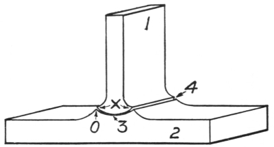
Fig. 45.—Jump Weld Scarfs.
66. The jump weld is shown in Fig. 45. The scarfs require perfect forming, because the opportunity54 for hammering is limited, as blows can be delivered only at certain places: on the end of the scarf 1 driving it into the concave groove 3; on a fuller which is held in the fillet 4; and on both the edges indicated at 3.
The groove at 3 should be formed with sufficient metal at points 0, to meet the projections X, and form a fillet. The convex scarf 1 should first come in contact at 3, so that welding will proceed from that place.
Welds made in this way are considered the weakest of those here described, on account of the limited assistance which can be provided by hammering. Still they are frequently used to avoid the laborious operations required to make such forgings out of solid metal.

Fig. 46.—V Weld Scarfs.
67. The V weld (Fig. 46) is a very important but difficult one. It is generally used on extremely heavy work, such as locomotive frames (Fig. 47), beam straps, rudder stems, and all cumbersome forgings.
The process is as follows: Pieces 5 and 6 are to be welded. They are held in a rigid position with heavy straps and bolts, as shown on the locomotive frame in Fig. 47, sometimes while the V-shaped opening is being formed; however, they must always be held secure while the welding heat is being obtained. The V-shaped55 opening formed by the scarfs on 5 and 6 should penetrate about two thirds of their thickness and form an angle of about 50 degrees, with sufficient metal at 9 to provide for the waste which will occur while a welding heat is being procured.
The wedge 7 is formed with some surplus metal for filling the V-shaped opening. It is handled by a bar which is welded to it. The angle of the wedge should be not less than 5 degrees smaller than the angle of the opening. This will insure that the welding proceeds from the apex or point of the wedge outward.
Two fires are required; 5 and 6, securely strapped and bolted together, are placed in one with the V-shaped opening turned downward. Plenty of coke is placed around this opening, completely covered with moistened coal, and securely packed with a shovel; then two openings or vents are made through the coal with a poker, one on each side of the metal and leading to the scarfs. This is called a covered fire. The blast is now turned on and slowly increased until the proper heat is attained. The progress of heating can be observed through the openings thus made, and the fire replenished with coke when necessary.
These operations are supervised by the smith who has the work in charge, with two or more helpers or assistants, according to the size of the forging. The wedge 7 also is heated in a covered fire with only one opening on the workman’s side of the forge; the wedge is inserted in that opening, and is attended and handled by another smith, who watches its progress in heating.
When the supervising and attending smiths have signaled to each other that the heats are ready, 5 and 656 are removed, turned over, and placed on the anvil or on the steam hammer die to receive the wedge which is placed in position by the attending smith. After the wedge has been thoroughly welded into place with either sledges or steam hammer, the handle and all surplus metal surrounding the openings are removed by the aid of hot cutters and sledges.
This procedure must now be repeated and another wedge welded into place on the opposite side indicated by the broken lines. With these two wedges 5 and 6 will be securely joined.
To insure a perfect weld, a good quality of material should be selected for the wedges. It should be thoroughly hammered to produce good texture, and if iron is operated upon, the fiber of the wedges should run parallel to the fiber of the piece to be welded. As this is not generally observed, welds of this character often break through the centers of the two wedges.

Fig. 47.—A Broken Locomotive Frame.
The broken locomotive frame shown in Fig. 47 would be repaired by the above method. The irregular line at A shows where the break has occurred. The straps and bolts at B indicate the method of holding the parts in alignment. Two tie rods at C prevent the parts from separating.
Questions for Review
What effect is produced by the upright blow? By the edge-to-edge blow? By the overhanging blow? By the beveling or angle blow? By the leverage blows? What are the backing-up blows used for? The shearing blows?
What is meant by forging? How many different operations are used in forging? Name them. What is meant by drawing? What tools may be employed in drawing metal? If you desire to increase the length more than the width, how should you hold the metal on the anvil? Why? What precaution should be observed in revolving metal when it is being drawn into a round form? What is meant by bending? Can iron of any sectional shape be bent? Which is the easiest to bend? What shapes are difficult to bend? How are these difficulties overcome? What is meant by upsetting? Explain how it is done. What difficulty is often experienced in upsetting? What is the difference in effect between resting the heated end on the anvil, and striking on the heated end while upsetting?
What is meant by forming? What other operations may be involved? What special tools or appliances are sometimes used for forming? State what has been said about straightening? Does it require much skill? Would it be as easy to straighten a wide flat piece of metal, as it would a round one? Why? Explain the operation of twisting. Why is it generally done? How can twisting be done and keep the work perfectly straight? Explain the essential parts of a weld. Is a weld as strong as the original unwelded bar? Can all iron and steel be welded? What kind of fire is best for heating? What is meant by an oxidizing fire? What effect does it have on the metal? How can an oxidizing fire be prevented? How should scarfs be placed in the fire? Why? If a penetrating and thorough heat is desired on a piece of metal, how can it be obtained? What is meant by scarfing? Are all scarfs formed alike? Name and describe the different kinds of scarfs and welds. Which one is considered the weakest? Why? On what kind of work is the V weld used?
68. Staple.—Fig. 48. Drawing and bending. Material required: 5 inches of 1⁄4-inch round iron.

Fig. 48.—Steps in Making a Staple.
Draw 1 inch of each end to a flat chisel-shaped point 1⁄4 inch wide; these drawn ends should be 13⁄4 inches long, leaving 3 inches of round stock between them. Heat the center and bend it, with points edgewise, to a semicircle of 3⁄4 inch inside diameter. These ends should be of equal length, parallel and straight.
When drawing the ends, heat the metal to a white heat to prevent the fibers from splitting or separating. Heat only to a cherry red for bending, to prevent heavy scaling, which is one cause of rough-appearing work. Rough work may also be caused by improper use of the hammer in striking too hard or frequently at one place. (See Fig. 48 for dimensions and stages.)
69. Draw Spike.—Fig. 49. Bending and drawing. Material required: 7 inches of 1⁄4-inch round iron.
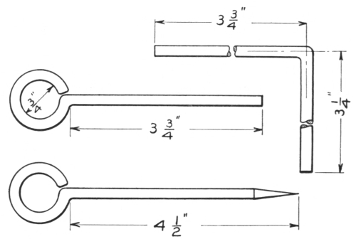
Fig. 49.—Steps in Making a Draw Spike.
Bend 31⁄4 inches of one end nearly to a right angle; have the inner corner almost sharp and square, the outer portion circular at the corner. Then form a perfectly circular eye of the 31⁄4-inch end, having the center of the eye in line with the central portion of the stem. When drawing the point, first draw it square, then octagonal, and then finish it to a round. (See Fig. 49 for dimensions and stages.)
70. S Hook.—Fig. 50. Drawing and bending. Material required: 5 inches of 1⁄4-inch round iron.
Draw 1⁄2 inch of each end to a smooth, round point; this should make the length from point to point 61⁄4 inches, and the central portion for 4 inches should be full-sized 1⁄4-inch round. Using half of the entire length, bend the first hook to an inside diameter of 7⁄8 inch, then bend the remaining half in the opposite direction to the same diameter, bringing both points directly toward each other, as shown.60 When heating for bending, be careful to avoid burning the points. (See Fig. 50 for dimensions and stages.)
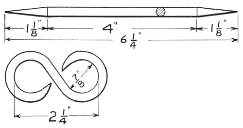
Fig. 50.—Steps in Making an S Hook.
71. Pipe Hook.—Fig. 51. Upsetting, forging, and bending. Material required: 9 inches of 1⁄2-inch square. Norway iron or soft steel is best for this exercise.
(Caution. To avoid injuring the fiber of the metal and to upset it rapidly with the least amount of labor, always have the metal perfectly straight, and heat it only where the upsetting is required.)
Bring 4 inches of the central portion of the material to a white heat; if the heat extends beyond that distance, cool 21⁄2 inches of each end, then the upsetting will be confined to the desired place. Cool the ends quickly and thoroughly, so that the upsetting blows may be delivered before the heat has vanished. The material should be held vertically with the lower end resting on the anvil, while heavy blows are delivered on the top end, thus upsetting the heated metal.

Fig. 51.—Steps in Making a Pipe Hook.
These operations should be repeated until the center is 7⁄8 inch thick one way, with all excess metal forged on one side, as at a, and the three others perfectly straight. Now form a shoulder b, with overhanging blows, about 1⁄8 of an61 inch from the center or thickest portion, but draw it no smaller than 5⁄16 of an inch at the bottom. Then draw the metal marked c to an approximate dimension of 1⁄2 × 5⁄16 inch. Form this shoulder perfectly square, by holding it over a square corner of the anvil and delivering backing-up blows on the heavy end, while the drawn part rests flat on the anvil; the metal should be hot at the shoulder and cold on the end where the blows are to be delivered. Then use the flatter on the drawn end to smooth and draw62 it to the finished dimensions of 1⁄2 × 1⁄4 inch, making it perfectly smooth and straight on all sides. Cut off this drawn end 6 inches from the shoulder, as shown at d.
Draw the heavy end to a sharp, square point, making it straight on the side opposite to the shoulder and tapering from a point about 21⁄4 inches from the shoulder; this should also be made smooth with the flatter. Sketch e shows this so far completed.
Beginning 1⁄2 inch from the shoulder, bend the 6-inch end backward through its smallest dimension, to a semicircle of 3 inches inside diameter. An outline of the required semicircle should be inscribed on a plate, or models may be made to verify it. Sketch F shows the completed hook.
72. Gate Hook.—Fig. 52. Drawing, bending, and twisting. Material required: 71⁄4 inches of 3⁄8-inch square mild steel.
Mark lightly with the hardy on two edges 11⁄2 inches from one end, as shown at a. Form shoulders at these marks on three sides of the metal; do not make them too deep, as surplus metal will be required for bending here. Draw the metal at the shoulders just made, continuing to the end to 5⁄16 inch round and 21⁄2 inches long. Sketch b shows the work completed to this point.
Mark the opposite end on the same edges and in a like manner 41⁄2 inches from where the first shoulders have been formed; form shoulders at these marks and also draw down to 5⁄16 inch round, making the extreme end a smooth, round point, 21⁄2 inches long from the shoulders, as at c. Both of these ends should be round and smoothly drawn with the hand hammer.
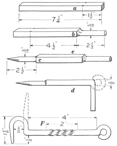
Fig. 52.—Steps in Making a Gate Hook.
Bend the straight, round end from the side e to a right63 angle, proceeding as follows: When placing the work on the anvil, have the side e uppermost and the shoulder projecting over the edge of the anvil the thickness of the round, or 5⁄16 inch; then when the metal is bent, the inside corner will be formed at the proper place and the shoulder will readily form into a right angle on the outer side. Light upright and backing-up blows will aid in forming the right angle after it has been bent, provided the piece is held with the round end vertical and resting64 on the face of the anvil. If such blows are used while it is being held over the edge of the anvil, they will reduce the sectional dimensions and not materially aid in forming the angle. Sketch d shows this angle in solid lines. Now form the round portion of this angle into a circular eye, making the inside diameter 1⁄2 inch, with the center on a line with the center of the main stem. Sketch d shows this eye in broken lines.
Bend the pointed end in the same manner and in the same direction as the eye, having the distance between the eye and the angle 4 inches, as shown in sketch F. Now heat this end and cool the extreme corner of the angle to prevent its straightening, then form the hook to the dimensions given in the sketch.
Heat the central portion of the square metal to an even cherry red; hold the hook and 1 inch of the square portion securely in the vise; then grasp the other end with the tongs or wrench 2 inches from the vise, and revolve it once, thus forming a twist of the proper length. Before cooling this work, see that the eye and hook are parallel and the body of the hook is perfectly straight.
73. Door Hasp.—Fig. 53. Drawing, forging, punching, cutting, and bending. Material required: 7 inches of 1 × 3⁄16-inch mild steel.
Mark lightly with the hardy on the edges 1 inch and 31⁄4 inches from one end, as at a. Form shoulders at these marks with edge-to-edge blows, as shown at b, so that the metal between them may be drawn to smaller dimensions. The shoulders should be formed not deeper than 1⁄8 inch at first, and the metal between them should be drawn to a corresponding dimension. Then forge the 1-inch end into a round eye, as at c, and punch a 5⁄16-inch hole in its center,65 as shown at d. Now draw the metal between the eye and the shoulders to exact dimensions, 3 inches long, 5⁄8 inch wide, and 3⁄16 inch thick, as shown at d.

Fig. 53.—Steps in Making a Door Hasp.
Mark the other end in the same manner 21⁄2 inches from the shoulders, and form new shoulders at these marks with edge-to-edge blows. Draw the metal to a length of 21⁄8 inches, making it 5⁄8 × 3⁄16 inch at the shoulders and 1⁄2 × 1⁄8 inch at the end; the extreme end should be forged round. Sketch E shows these operations completed.
Locate the center of the 21⁄2-inch length; from that point place a center-punch mark 7⁄8 inch each side of the center and punch a 5⁄16-inch hole at each mark with a hand punch, by placing the outer edge of the punch at the66 center-punch mark. Deliver no blows on the edges of this metal after the holes are punched.
Using a sharp, hot cutter, remove the metal between the holes, by cutting it equally from both sides, thus forming the slot as indicated by the broken lines in sketch E. By placing it over the hardy, straighten the metal which forms the sides of this slot, and all other portions, so that all edges will be straight and parallel to each other. Smooth all flat surfaces with a flatter, using water to remove the scale of oxide. If the marking and punching of the holes have been carefully done, the inside length of the slot will now be 2 inches.
Bend the 21⁄8-inch end to a right angle at the shoulders, having the length from the inside of the angle to the outside of the eye about 7 inches. Heat this entire end and quickly cool the extreme corner of the angle to prevent its straightening there, then form the hook to the dimensions given in sketch F. The inner edges of the slot may be filed straight and parallel to the outside edges, but the semicircular ends which have been formed by the punch should not be disturbed.
74. Hexagonal Head Bolt.—Fig 54. Upsetting and forging to a hexagonal cross section. Material required: 7 inches of 1⁄2-inch round iron.
Heat one end to a white heat, then cool off 41⁄2 inches of the opposite end, thus confining the upsetting to the required area; upset the hot end until its diameter is 3⁄4 inch, and the length over all is about 51⁄2 inches.
It is important that the 41⁄2 inches be kept perfectly cold, to prevent upsetting there, also to prevent its sticking fast in the heading tool, or possibly using more metal than is required for forming the head.

Fig. 54.—Hexagonal Head Bolt.
The upset metal should extend equally around the bolt. This will tend to prevent the head from forming unequally when the metal is being forged down on the heading tool. The head can be prevented from forming on one side by directing the blows toward the opposite side. Form the head by heating the upset end to a white heat, by inserting the opposite end in the heading tool, and by delivering upright blows on the heated end, unless others are required, thus forging down the upset metal to 1⁄2 inch thick. Remove it from the heading tool and forge the head into a hexagonal form. It will be necessary to insert the bolt in the heading tool several times to obtain the exact dimensions of the head, which should be 7⁄8 inch through its short diameter and 1⁄2 inch thick. The chamfered finish on the top of the head is produced by using a button head set while the bolt is held in the heading tool.
75. Square-cornered Angle.—Fig. 55. Upsetting, chamfering, and forging a square corner. Material required: 10 inches of 1 × 1⁄2-inch iron.
Upset the center by cooling 31⁄2 inches of each end to68 confine the operation to the required place. The center should be 7⁄8 inch thick, and all upset metal should be forged to one side; the opposite side and both edges should be straight. Draw both ends tapering from where the upsetting ceases to 3⁄4 × 1⁄4 inch at the ends; chamfer the edges of the drawn ends on the straight, flat side, beginning about 2 inches from the center and continuing to the ends. If the drawing and chamfering are properly done, each end will be 51⁄2 inches from the center.

Fig. 55.—Upsetting for a Square Corner.
Heat and bend the stock at the upset center to a right angle, with the upset metal on the outer side to provide for the square corner. The bending should be done over the horn of the anvil to produce the quarter-round fillet on the inner side, and may be confined to the center by cooling both ends to where the upsetting begins.
As bends of this kind are somewhat difficult to make correctly, it would be a great advantage to provide a form which may be made to fit into the vise; then one end of the angle can be held securely with the form while the opposite end is bent over it. By any simple form it is impossible to make the outside corner perfectly sharp and square with one operation; it is therefore necessary to69 forge the outside corner sharp and square by delivering blows on both sides, somewhat in the manner shown in Fig. 56, but good judgment must be used in doing this.

Fig. 56.—Square-cornered Angle.
The chamfering may be marred or entirely removed in forging the corner; if so, rechamfer, and if the ends are of unequal lengths, the longer one should be cut off equal with the other. Then all surfaces should be made straight and smooth with the flatter and the scale removed by occasionally dipping the flatter in water.
76. Fagot Welding.—Welding and forging to dimensions. Material required: convenient pieces of scrap iron and a bar of 5⁄8-inch round stock from 24 to 30 inches long.
Temporarily weld several separate pieces of scrap on to the bar until sufficient metal is provided for a thorough welding and forging of a solid piece of square iron 31⁄2 inches long and 11⁄16 inch square. The welding should be done so as not to show where the pieces were joined. Forge it perfectly square and smooth with the flatter. Cut one end off square with a sharp hot cutter, then cut it to the required length.
77. Round Weld.—Fig. 57. Scarfing, welding, and swaging. Material required: two pieces of 7⁄16-inch round iron, 41⁄2 inches long.
Upset one end to 9⁄16 inch, as shown at a. To form the scarf, deliver backing-up blows with the face of the70 hammer, as shown at b, and finish with blows delivered similarly with the ball. These backing-up blows will form the heel of the scarf. Draw out the point of the scarf with overhanging blows, as shown at c. The joining surface should be convex so that welding will proceed from the center. Scarf both pieces in the same manner, as at d.

Fig. 57.—Steps in Scarfing for a Round Weld.
Heat and weld according to instructions on welding and finish the work smoothly with swages; then cut to a length of 6 inches, having the weld in the center.
Properly formed scarfs will produce perfect welds provided they are heated to the welding temperature when they are joined, but those improperly formed generally produce imperfect welds, although the heat is right.
78. Flat Right-angled Weld.—Fig. 58. Material required: two pieces of iron 3⁄4 × 3⁄8, 41⁄2 inches long.
Upset one end 1⁄8 inch larger than its diameters, as at a. By using backing-up blows as in the previous exercise,71 form a heel on one side, as shown at b, then resting the straight side on the anvil, draw out the point with the ball of the hammer, as at c. In drawing this point, the metal will spread and form a wide fan-shaped end, but by resting the right side d on the horn of the anvil and delivering blows on the left, the latter edge will be straightened, leaving all projecting metal on the right.
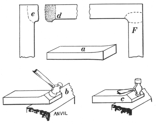
Fig. 58.—Steps in Scarfing for a Corner Weld.
Upset one end of the other piece to the same dimensions, allowing this upsetting to continue along the metal about 1 inch. Form a scarf on the left edge at e, with the ball of hammer, using blows similar to those shown at c and leaving the end square. Place them together to see if the points meet the heels; if not, make necessary alterations so they will.
Place the pieces in the fire, so that the side scarf will be72 removed with the left hand and the end scarf with the right. When placing for welding, the right-hand piece should be laid on the anvil and the left-hand one placed in its proper position on top of it. The inside corner should form a quarter-round fillet, the outside should be sharp and square, and the longer end cut off to make them both equal. Smooth all surfaces with a flatter. Sketch F shows the weld completed; the dotted lines indicate the location of the scarfs before welding.
79. T Weld.—Fig. 59. Scarfing and welding. Material required: two pieces of 3⁄4 × 3⁄8-inch iron, 8 and 41⁄2 inches long.

Fig. 59.—Steps in Scarfing for a T Weld.
Upset one end of the shorter piece 1⁄8 inch larger than its diameters, and form a scarf similar to the first one for the right-angled weld, but here allow it to form fan-shaped and project equally over each edge, as shown at a.
Upset the center of the long piece to 1⁄8 inch or more larger than its diameters, with the upset portion fully 173 inch long, as at b. Form a scarf at this place with the ball of the hammer, allowing the metal to bend edgewise, as at c. Do not make this scarf quite so wide as the first one, as its edges should be entirely covered by scarf a without leaving any openings. See that they fit properly before heating for welding.
Especial care should be taken to have a good fire. The long piece should be placed in the fire so as to be removed with the left hand, and the short one with the right. Place the short piece on the anvil, with the long piece, held in the left hand, on top of and overlapping it sufficiently to prevent any openings. When welded, the long piece should be perfectly straight, with the short one at a right angle to it. Finish the weld with the flatter while it is at a dull red heat. Sketch D shows the T completed.

Fig. 60.—Chain Making.
80. Chain Making.—Fig. 60. Bending, scarfing, and welding links. Material required: 8 pieces of 3⁄8-inch round iron, 6 inches long.
Heat and bend the center of each piece to a semicircle74 3⁄4 inch inside diameter; make the ends of equal length and parallel from the semicircle, as at a. Take one of these bent pieces and form a scarf on one end by holding it on the edge of the anvil at an angle of 45 degrees, as shown at b, and delivering overhanging blows, as indicated by the dotted circle, which represents the hammer. Turn the link over, placing the other end in the same position as the first, and scarf. Bend both scarfs toward each other equally until they overlap sufficiently to prevent any opening being formed, as at c; this is called closing the scarf.
Heat and weld the link by delivering the first few blows on its sides while it is resting on the face of the anvil, then by delivering lighter ones, while it is hung on the horn. While striking the light blows, do not hold the link in a fixed position, but move it to receive the blows around the circumference. The finished dimensions are 2 × 3⁄4 inches inside; a slight variation in length does not make any difference, but their ends and widths should be uniform.
Proceed with another piece in like manner, but after scarfing it insert the finished link and continue adding new ones, until there are five links all together. The three extra pieces are for use in the next three exercises.
81. Welded Ring.—Fig. 61. Bending, scarfing, and welding a ring of round iron. Material required: one piece of 7⁄16-inch round iron, 8 inches long.

Fig. 61.—Steps in Making a Ring.
Heat, and bend over the horn of the anvil about 11⁄2 inches of each end to an inside radius of no less than 1 inch, as at A. Then heat the straight portion to a uniform temperature and bend it by holding the piece in a vertical position on the anvil, and delivering upright blows, as75 shown at B; this should produce a form similar to that shown at C. Continue the bending by holding the work as at D. By carefully observing the effect of these blows, you will be able to determine how the work ought to be held to produce the complete ring. These blows are used here to give the same effect as leverage blows. If the position of the metal is changed when and where it should be, almost a perfect ring may be produced76 without holding it on the horn of the anvil. It is not the best method to hold the work on the horn, because blows delivered in this way have a tendency to produce oval sections where they hit. In forming this ring the ends should be left open about 1 inch.
The directions for scarfing and welding are somewhat similar to those given for links, except that the angle of the scarf should be nearly a right angle. After the welding is completed, the ring should be made perfectly round by placing it over a mandrel or the horn of the anvil. When the ring is welded and complete, connect it to the chain with one of the extra links.
82. Chain Swivel.—Fig. 62. Bending, scarfing, welding, and riveting. Material: about 2 feet of 7⁄16-inch round iron. Norway iron is the best, and this length is the most convenient for the first operations.
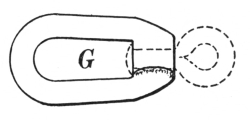
Fig. 62.—Chain Swivel.

Fig. 63.—Tool for Welding a Swivel.
For making this swivel, a special mandrel (Fig. 63) should be provided, made of 3⁄4-inch round, mild or tool steel, with a short offset of 3⁄4 inch; the gudgeon or pin which is shown at a should be 11⁄4 inches long, 7⁄16 inch in diameter at the shoulder, and tapering to 5⁄16 inch at the end. Any convenient length of handle that will prevent burning the hand when welding, will do.
Bend about 21⁄2 inches of the 7⁄16-inch round stock to a right angle, as at a, Fig. 64; make the corner as square as77 possible, by upsetting it before bending; or after bending, by using upright and backing-up blows. Flatten the bent portion b parallel with the bar, by first delivering the blows with the ball of the hammer to increase the width as much as possible, then finish it to 3⁄16 inch thick with the face of the hammer. The corner should be scarfed with the ball of the hammer and the rib worked out, as shown at c.
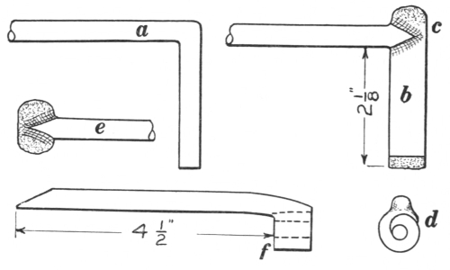
Fig. 64.—Steps in Making a Swivel.
Cut off the flat portion 2 inches from the bar, and form a thin scarf at the end of b. Notice that this should be formed on the same side with c. Beginning with the scarf at the end, the flat portion should be bent or rolled up so that the scarfs will overlap considerably, as indicated in the end view d. The special mandrel should now be inserted in the opening shown here, and all placed in a 3⁄4-inch bottom swage, while the scarfs are hammered into close contact.
The long bar should now be cut off 41⁄2 inches from the inside of the bend, and a fan-shaped scarf formed with78 the ball of the hammer, as at e. This should be drawn thin on the end and sides. The center of the 41⁄2-inch length is next bent and the last scarf placed in position at f by again inserting the mandrel, placing it in the swage, and closing down the edges around the portions at f. It is then ready for welding. Figure 62 shows this in solid lines.

Fig. 65.—Making an Eye for a Swivel.
A good clean heat should be procured for welding; the mandrel should be quickly inserted, placed in the swage, and the welding done. This being completed, a small eye is to be made of 3⁄8-inch round iron: first, by bending it in the form shown at a, Fig. 65; second, by inserting a punch in the opening and hammering the ends together, forming the eye, as shown at b; third, by welding these ends solidly together, as at c, and forging the whole to fit loosely in the swivel. The fitted end is now cut off square 3⁄8 inch longer than the depth of the hole in the swivel, heated, and, while the eye is held in the vise, it is quickly riveted into place with a small straight or ball peen hammer. The eye is shown in place by the broken lines in Fig. 62. Connect this swivel to the chain with one of the extra links.
83. Chain Swivel.—Figs. 66 and 67. Fullering, forging, bending, welding, and riveting. Material: a piece of 1 × 1⁄2-inch iron, 4 or more inches long.
Using top and bottom fullers, form two sets of depressions not deeper than 1⁄4 inch, on each edge and opposite to each other, the first pair to be 1 inch from the end, the second pair 1 inch from the first, as at a.
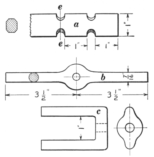
Fig. 66.—Steps in Making a Swivel.
Draw the 1-inch end to 7⁄16 inch round, leaving it slightly heavier where it was fullered to provide excess metal for further bending. The opposite end should now be cut off 1 inch from the fullered place and drawn to the same dimensions as the first end. Forge the central portion into a circular form and punch a 3⁄8-inch hole in its center. Cut off all surplus material, making the ends 31⁄2 inches long from the center of the hole, as at b.

Fig. 67.—The Completed Swivel.
Bend each end to a right angle close up to the eye and make the arms parallel and one inch apart, as at c. Drift the hole by driving the punch80 through between the parallel ends, thereby forming a slightly tapered hole. Scarf and weld the ends as you would a link. Make a small eye of 3⁄8-inch round stock, proceeding in the manner explained in the previous exercise, also following the same instructions as to fitting, cutting, and riveting. Connect the link end of this swivel to the chain with one of the extra links. (See Fig. 67.)

Fig. 68.—Steps in Making a Chain Grabhook.
84. Chain Grabhook.—Fig. 68. Forging, punching, and bending. Material: one piece of 3⁄4 × 3⁄8-inch iron, 41⁄2 inches long.
Form a depression as at a, 1⁄4 inch deep and 3⁄4 inch from81 one end with overhanging blows. (The opposite edge should be kept perfectly straight during this and the following operations.) Forge the 3⁄4-inch end into a circular-shaped eye 3⁄8 inch thick, and punch a 1⁄4-inch hole, in the center, as at b. This hole should be drifted or expanded with a punch driven through from both sides alternately until the diameter becomes 1⁄2 inch.
By hanging this eye over the horn of the anvil so that the inner corners of the eye rest on the horn, by delivering blows opposite to those corners, and by changing its location so that blows will be delivered on all outside corners, the sectional form will be changed from square to octagon; by similar operations the form may be changed from octagon to round. During this change, light blows should be used in order to make the eye smooth. This stage is shown at c with a sectional view of the eye.

Fig. 69.—The Completed Chain Grabhook.
Proceeding from the eye toward the opposite end, forge both edges round to correspond with the eye, leaving the metal 3⁄4 inch wide, 3 inches from the eye, as shown at d.
Draw the remaining section tapering from this extreme width to 1⁄4 inch, and forge the edges round as before. The hook should be 3⁄16 inch round at the end and 3 inches long from the widest point, as shown at E. Heat the middle portion; cool the point and the eye, and bend the hook edgewise over the horn of the anvil toward the straight side, until the point is opposite the depression first formed. The inside semicircle formed by bending should be 1⁄2 inch82 in diameter, the other inside lines straight and parallel. The extreme point should be slightly curved away from the eye, and all flat surfaces hammered smooth with light blows while the hook is at a dull red heat. Figure 69 shows the hook completed. Using the remaining extra link, connect the hook to the swivel.
Questions for Review
What forging operations are employed in making the staple and the draw spike? What hammer blows are used on them? What caution should be observed in heating the S hook for bending? What operations are employed in making the pipe hook? Which is the most difficult? Where was the most difficult forging encountered? How was the point drawn? What operations are employed in making the gate hook? Explain how the angle should be bent, and how the blows should be delivered to make it square. Why should the extreme corner of the angle be cooled off before bending the hook? What operations are employed in making the hasp? Which one is used first? Into what form is the metal to be forged in making the bolt? What is meant by chamfering? What kind of hammer blows should be used in chamfering? Why should the metal be upset for the round weld? What special hammer blows are to be used in forming the scarfs? Explain how the scarfs are formed for the right-angled weld. How should scarfs be placed in the fire? How should they be placed on the anvil? Explain how the scarfs are formed for the T weld. Describe the scarfing of a link. Describe the welding of a link. What is the effect of bending the ring over the horn of the anvil? What operations are used in making the chain swivel?
85. Selecting and Working Steel.—In making a tool, the differences in quality of steel should be considered, because steel suitable for a razor would not do for a cold chisel or any battering tool. (See sec. 181.)
If the steel at hand is not exactly suitable, but the selection must be made from it, then that should be chosen which will most nearly meet the requirements, and tempering must be relied upon to make up the deficiency. In most large factories all grades of steel are kept on hand and are assorted in the stock room so that there need be no difficulty in making the proper selection.
The percentage of carbon in steel represents the amount of carbon it contains. A steel that is called a 75-point carbon steel is one that contains (.75) seventy-five one hundredths of one per cent, each point representing (.01) one one hundredth of one per cent.
Some steel makers use the word “temper” to indicate the amount of carbon, expecting the user of the steel to be familiar with the amounts of carbon each different temper represents. For instance, a razor-temper steel represents one that contains 1.50 per cent carbon and a tool-temper steel represents one containing about 1.25 per cent. The word “temper” as used in this connection should not be confused with the word as it is used in the art of tempering,84 where it indicates the operation of reducing the hardness of the metal in order to make it less brittle and more suitable for some particular use.
86. Uses of Different Grades of Steel.—As the percentage of carbon, and consequently the quality of steel, will vary somewhat with different makes, it is rather difficult to give a rule that will apply generally, but the following list of different grades of carbon will give a general idea of how steel should be selected, forged, and hardened.
Steel of 0.7 to 0.8 per cent carbon should be used for snaps, rivet sets, cupping tools, etc. This grade of steel should be forged at a light red heat. It can be welded easily and will harden at a light red heat.
Steel from 0.8 to 0.9 per cent carbon should be used for drop-forging dies, hammers, cold sets, track chisels, blacksmith’s tools, well drills, etc. It should be forged at a light red heat; it welds easily and hardens at a light red heat.
Steel from 0.9 to 1 per cent carbon should be used for large hand chisels, large punches, shear blades, dies, etc. Forging should be done at a light red heat. It welds readily and hardens at a bright red heat.
Steel from 1 to 1.1 per cent carbon should be used for hand chisels, punches, punch dies, small shear blades, etc. Forging should be done at a light red heat. It welds readily and hardens at a bright red heat.
Steel from 1.1 to 1.2 per cent carbon should be used for screw-cutting dies, large cutting and trimming dies, small punches, small hand chisels, large milling cutters, cups, cones, etc. Forging should be done at a light red heat. It welds readily when care is taken in heating, and hardens at a bright red heat.
Steel from 1.2 to 1.3 per cent carbon should be used for drills, taps, reamers, milling cutters, circular cutters, cutting and trimming dies, mill picks, engraving tools, twist drills, etc. Forging should be done at a bright red heat. Welding can be done when precaution is taken against overheating and burning. It hardens at a dull red heat.
Steel from 1.3 to 1.4 per cent carbon should be used for small drills, taps, cutters, boring tools, etc. Forging should be done at a bright red heat; welding can be done with care against overheating. It hardens at a dull red heat. This steel should be handled carefully.
Steel from 1.4 to 1.5 per cent carbon should be used for tools for working chilled castings or locomotive wheel tires, lathe and planer tools, razors, or any tools required to cut hard materials. Forging should be done at a dull red heat. Welding can scarcely be accomplished with this grade of stock. Hardening should be done at a dark red heat.
87. Injuries.—One of the most common injuries to steel comes from carelessness in the heating for forging. It is one of the important operations, for unless the metal is uniformly heated, violent strains are liable to occur, and, when hardened, the steel will show these strains by cracking. These defects are known as fire cracks.
The smith should always have plenty of fuel surrounding the metal while it is in the fire so that the cold-air blast will not come in direct contact with the metal. The air should be heated by passing through a bed of hot coals before it strikes the steel. It is always necessary to heat steel thoroughly to make it plastic, being careful not to overheat or burn any part of the metal. If it is overheated86 or burned, it cannot be completely restored to its former state; the grain becomes coarse and the structure weak.
Never let steel lie in the fire to soak up heat after it is hot enough to work. If for any cause it cannot be worked when it is ready, it should be taken from the fire and left to cool, then reheated when it can be worked. By this precaution injury to the steel will be prevented.
If steel is heated so that the outer parts are hotter than the center, the metal will forge unevenly. The outer portion will be forged by the hammer blows, while the center remains almost in the original form. This will also cause an uneven grain, sure to produce cracks when the tool is hardened. Forging at too low a heat will injure the steel in the same manner as uneven heating.
After the steel has been properly heated, and forging has begun, the first blows should be struck rather heavily and followed by lighter ones as the heat vanishes. The forging should cease when the steel gets too cold, but it may be reheated as often as necessary to complete the work.
88. Annealing.—After the steel has been forged to the desired shape, it usually is necessary to do some finishing upon it before it can be hardened and tempered; in order to do this, it must be annealed or softened so that it can be machined or filed into shape. Annealing is the process of softening steel. It is done by heating the steel slowly to an even low red heat and placing it in an iron box containing unslaked lime or fine charcoal and leaving it there until perfectly cold. The object of this process is to retain the heat and prolong the cooling. The box is usually of cast iron, but sheet steel is equally good. It87 should be placed in a perfectly dry place and rest on bricks, if necessary, to avoid any dampness.
If an annealing box is not at hand, small steel forgings can be softened very satisfactorily by placing them between two boards, then completely covering all with dry ashes and leaving them there until entirely cold. Precaution should be taken here, also, to leave them in a dry place.
Another method, which is sometimes used, is called water annealing. Some mechanics claim to have had good results with it, while others condemn it entirely. By this method the article is heated to a dull red and allowed to cool partly, out of any direct current of air. When all redness has disappeared as it is held in a dark place, it is plunged into water and left there until perfectly cold.
The first method mentioned above is always the best; the second is nearly as good; and only when there is not sufficient time to allow the metal to cool slowly, should water annealing be attempted.
Such tools as cold chisels and lathe tools may be heated and laid in or on warm ashes until nearly cold, when they may be ground, hardened, and tempered. Quite frequently, if not generally, these tools are not treated in this manner, but it is no doubt the course to pursue to get the best results.
89. Hardening and Tempering.—When steel has been properly heated, forged, finished, or ground, the next two steps are hardening and tempering. These two processes are often understood as one, but they are entirely different in their results. The confusion arises because the two operations are sometimes performed with88 one heating of the steel as in hardening and tempering a cold chisel, or other similar tools.
As the steel has been subjected to severe strains during the heating and forging operations, its structure may have been somewhat altered. It can be restored to the proper crystalline structure by the hardening, scientifically known as refining. The hardening or refining heat is always lower than the forging heat, and should be only as high as is necessary to harden the steel to the required density by sudden cooling. Then this first operation of cooling will harden and refine the steel at the same time.
Extreme hardness is always accompanied by extreme brittleness, a quality undesirable in any cutting tool, and especially so in a tool required to withstand sudden shocks. As the hardness is reduced by subsequent heating, the toughness increases. This modification, called tempering, is accomplished by reheating the hardened portion of the tool until a sufficient toughness has been obtained, when the process is stopped by again plunging the tool into cold water. The heat for tempering may be supplied from the uncooled portion of the tool as in tempering a cold chisel, from the forge fire, from another hot piece of metal, or from a carefully heated furnace.
It has been found that the colored oxides formed on the surface of a piece of polished steel or iron represent a definite temperature in that metal. These colors have been used, therefore, to determine the desired temperature in tempering a tool. When we say “temper a tool to a light straw,” we mean that the hardened tool is to be heated again to a degree which will produce that color; namely, about 430 degrees Fahr. The colors as they89 appear are light straw, dark straw, bronze, bronze with purple spots, purple, dark blue. The light color appears first. Do not allow the colors to pass too quickly, as will happen if the heat applied is too intense.
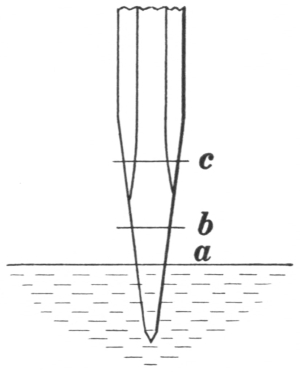
Fig. 70.—Hardening a Chisel.
There are two distinct methods of hardening and tempering. The one generally followed in tempering cold chisels, lathe and various other tools, requires only one heating. The tool is heated to a proper hardening temperature at the end, where hardness is desired, and also over an excess area to supply the heat for tempering. About 2 inches of the cutting end is heated; about 1 inch of this is plunged perpendicularly into water, as shown in Fig. 70; it is then kept in motion perpendicularly between the places indicated at a and b, while the end is cooling. This will prevent a fixed cooling point and prevent a fracture that might possibly occur if it were held in one position while cooling. The portion between b and c should retain sufficient heat to produce the necessary temper. When the end is perfectly cold it should be removed and immediately polished with sandstone or emery cloth to remove the scale of oxide so that the different colors may be more readily seen as they move from b toward the point. The heat in the portion between b and c flows toward the point, causing the colors to appear as the heat extends. When the desired color covers the point, it should again be plunged into90 the water and left there until entirely cold. In this method the first cooling is the hardening, and the second the tempering. A comparative color chart is appended to this chapter for guidance in obtaining the tempers for various tools.
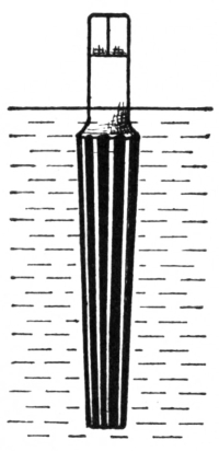
Fig. 71.—Hardening A Reamer.
By the second method the steel is heated as in the first method, then it is cooled off entirely by immersing the tool exactly perpendicularly, as shown in hardening a reamer in Fig. 71; after this it is polished. The temper is then drawn by holding the tool in contact with a piece of heated metal, cast iron preferably. In Fig. 72 the reamer is shown inside of a heated bushing, which is a more practical way than laying it on top of a heated flat plate. The bushing will impart sufficient heat to the tool to produce the desired color, when it should be again cooled. This method is used mostly for tempering plane bits, wood chisels, milling cutters, taps, reamers, and various other tools of a like nature.
Sometimes tools having sharp protruding edges, as milling cutters, taps, reamers, etc., are very liable to crack by the sudden cooling in water; this difficulty is avoided by using oil for hardening and tempering. Any so treated are called oil-tempered tools.
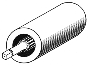
Fig. 72.—Tempering a Reamer.
The above methods of tempering are such as are ordinarily91 used when only a common shop equipment is at hand, and the operator must depend entirely upon his judgment of the colors which represent the proper forging, annealing, hardening, and tempering heats. The degree of accuracy that has been attained in this practice is most surprising.
In large manufacturing establishments where many duplicate pieces are to be tempered, a more modern as well as scientific apparatus is employed to relieve the operator of dependence upon his discernment of colors. Here the steel is heated in a furnace, to which is attached a pyrometer that registers the exact degree of temperature. In this manner all pieces can be heated uniformly for any of the four required heats.
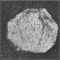 |
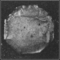 |
| A. Natural Bar. | B. Refined. |
 |
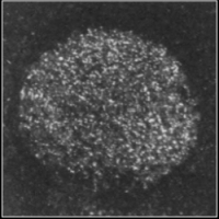 |
| C. Too hot. | D. Burned. |
Fig. 73.—Sectional Views of Tool Steel, showing the Effects of Proper and Improper Treatment. |
|
The views in Fig. 73 were photographed from the same grade or bar of steel to show the various granular structures produced by different heat treatments. A shows the condition of the natural bar, which was broken to be photographed just as it was received from the steel makers.92 The lower left side shows where it was nicked with the cutter to be broken. B shows the structure when proper conditions of heating and hardening have been maintained. Notice how much finer the structure here appears to be; this effect was caused by, and previously referred to as, the refining heat of steel. A similar condition should be produced with any tool steel under correct treatment. C shows a much coarser structure; it was heated too hot and hardened in the same manner. If a tool were made thus, its weakness would be hardly noticeable at the time, but the structure shows that it is considerably weaker. D shows the condition of the stock after being burned. It has produced from a quality of steel that was valuable, a metal worthless for any kind of tool.
90. Casehardening.—Another method of hardening, called casehardening, is used for wrought iron and low carbon or soft steel parts which are to be subjected to considerable friction. Neither of these metals could be hardened by the other methods mentioned. This process adds carbon to the exterior surfaces only, and for that reason is called casehardening, as the outside is made extremely hard, while the inner portion or core remains in a condition like that produced by sudden cooling, thus providing a hard wearing surface and great strength at the same time. It is similar to the old cementation process of steel making, but is not prolonged sufficiently to allow the hardening to continue through the entire structure.
The articles to be hardened are packed in a box somewhat similar to an annealing box. This should be partly filled with charred leather, ground bone, or wood or bone charcoal, all of which are highly carbonaceous materials;93 then the articles are placed in and entirely surrounded with a thin coating of cyanide of potassium, especially if iron is being hardened. The remaining space in the box is filled with the leather, bone, or pieces of charcoal. The box should be provided with a lid that will drop loosely between the outer projecting rims. The outer edges of this lid should be luted with clay to keep it as air-tight as possible. If a few small holes are provided in the center of the lid, test wires can be inserted; by removing a wire and cooling it, the progress of the operation may be known. These wires should be inserted before the box is placed in the furnace. The box and its contents are then placed in a suitable furnace and kept thoroughly heated from 6 to 15 hours, depending upon the depth of hardness required. Then it is withdrawn, the lid removed, and the articles quickly plunged into a large tank of water. This will complete the hardening.
When a number of very small articles are to be hardened, it is advisable to connect them with strong bailing wire before they are placed in the box so that they can all be removed at once. Beside holding the articles together, the wire will provide a means of testing the depth and quality of the process.
If only a thin coating of hardness is needed, or the labor and expense are excessive, the following method may be used: The article is heated thoroughly and evenly to about a bright red and thoroughly sprinkled with, or rolled in, cyanide of potassium. Then it is reheated so that the cyanide may penetrate as deeply as possible, after which it is quickly chilled in cold water. This is a good method of hardening small tack hammers made of soft steel, set screws, nuts, and very small tools.
Temperature and Color Chart to be Used in Tempering
| Tools | Temperature (Fahr.) Degrees |
Color |
|---|---|---|
| Scrapers for brass | 430 | Very pale yellow |
| Light turning tools | 430 | Very pale yellow |
| Lathe and planer tools for steel | 430 | Very pale yellow |
| Steel engraving tools | 430 | Very pale yellow |
| Milling and boring cutters | 460 | Straw yellow |
| Screw-cutting dies | 460 | Straw yellow |
| Taps and reamers | 460 | Straw yellow |
| Punches and dies | 480 | Dark straw |
| Penknives | 480 | Dark straw |
| Twist drills | 500 | Bronze |
| Plane irons | 500 | Bronze |
| Surgical instruments | 530 | Dark purple |
| Cold chisels for steel | 540 | Dark purple |
| Cold chisels for cast iron | 550 | Dark blue |
| Cold chisels for wrought iron | 550 | Dark blue |
| Springs | 570 | Very dark blue |
Suitable Temperature (Fahr.) for:
| Degrees | |
|---|---|
| Annealing tool steel | 900 |
| Forging tool steel | 1200 to 1500 |
| Hardening tool steel | 1200 to 1400 |
| Casehardening iron or soft steel | 1300 to 1500 |
Colors and Corresponding Temperatures (Fahr.) for Iron
| Bright red in dark | 750 to 760 |
| Red hot in twilight | 880 to 890 |
| Dark red hardly visible in daylight | 970 |
| Red visible by daylight | 1070 |
| Brighter red by daylight | 1300 |
| Cherry red by daylight | 1450 |
| Bright cherry red by daylight | 1650 |
| Light cherry red by daylight | 1800 |
| Orange | 2000 |
| Yellow | 2150 |
| White heat | 2350 |
| White welding heat | 2600 |
| White welding and dazzling | 2800 |
Questions for Review
What is meant by the carbon contents of steel? Why is steel graded according to its carbon content? Explain the cause of fire cracks. How can they be prevented? Why should steel be thoroughly healed? If steel is overheated or burned, what is the effect? Why should steel never be left in the fire to soak up heat? How does steel forge if it is unevenly heated? How should the blows be delivered in forging steel? What is annealing? Describe three methods of annealing. Is it best to anneal cold chisels and lathe tools? Explain the process of hardening steel. What effects does hardening have? Are the forging and the hardening heats the same? Why is steel polished after it is hardened? Explain the process of tempering. What is the effect of tempering? How may the heat be supplied for tempering? Name the colors in order as they appear in heating steel. Explain the methods of hardening and tempering. Why should a cold chisel be kept in motion when it is being hardened? What is meant by oil-tempering? What is meant by casehardening? Explain different methods of casehardening.
91. Tongs.—As tongs are among the most important tools and quite difficult to make, they will be taken up in this chapter on tool making.
The weakest places in a pair of tongs are where the shoulders or offsets are formed for the jaws and handles. These places should be reënforced by fillets as large as the usefulness and appearance of the tongs will permit; they should never be made sharp and square, unless their construction demands it.
All tongs for general blacksmithing can be forged properly with the hand hammer and the use of such tools as the top fuller, the swages, and the round-edged set hammer. Some assistance with a light sledge will be necessary. The use of such tools as a square-edged set or the file for forming shoulders or fillets is very objectionable, especially in the hands of unskilled workmen. If the two parts do not seem to fit as they should, due to the fillets which are present, they will generally adjust themselves when they are riveted together, heated, and worked freely.
92. Heavy Flat Tongs.—Fig. 74. Fullering, forging, swaging, punching, and riveting. Material: 15 inches of 7⁄8-inch square mild steel.
Mark the center of the 15-inch length with a hardy or cold chisel. Form two depressions 3⁄8 inch deep, with a97 top fuller, one 2 inches from the end at a, the other 3 inches from the same end but on the opposite side. Form a third depression to the same depth, but at an angle of 45 degrees, starting from the bottom of the first one, and on the side indicated by the broken line, as at b. Draw the 2-inch end to 1 × 1⁄2 inch from a, tapering to 1 × 3⁄8 inch at the end. This portion forms one jaw, as shown at c. Now flatten out about 2 inches of the metal from the beveled depression b toward the center mark, to 9⁄16 inch thick, allowing the metal to spread as wide as possible. This should then be forged and formed into shape for the joint d, and the fuller again placed in the second depression to make the dimension there 5⁄8 inch, as shown at d.

Fig. 74.—Steps in Making Heavy Flat Tongs.
Forge the other end in the same manner, exerting due care to have all dimensions correspond; cut the stock in two at the center. Draw out the heavy ends for the handles with the power hammer or with some assistance from a sledge. They should be roughly forged at first with an allowance for finishing as follows: Beginning at the joint, use the top and bottom swages on the outer edges through the greatest width, and swage to 5⁄8 × 1⁄2 inch. This swaging should be continued toward the end to form the handle. By using the flatter during the swaging, the sides may be kept straight, smooth, and slightly tapering to a round section. Make the end 3⁄8 inch in diameter for a length of 3 inches. Sketch F shows one side of a pair of tongs drawn and swaged.
Place the parts together to see if they fit properly; if they do not, make the necessary alterations. Use a top fuller to form a groove e about 1⁄8 inch deep, lengthwise on the inside of the jaws, and smooth the sides and edges with a flatter. Then punch a 3⁄8-inch hole in the center of the joint, as shown in sketch F. This should be done on both parts.
Heat thoroughly the end of a 3⁄8-inch rivet, 13⁄4 inches long, and with it rivet the two portions tightly together. Heat the tongs, make them work freely, and adjust them to hold 3⁄8-inch flat iron, with the entire length of the jaws in contact and with the ends of the handles 1 inch apart. The jaws and handles should be adjusted so that a line extended lengthwise across the center of the rivet would pass midway between them.
93. Light Chain Tongs.—Fig. 75. Forging, swaging, punching, fullering, and riveting. Material: 13 inches of 3⁄4-inch square mild steel.

Fig. 75.—Steps in Making Light Chain Tongs.
Mark the center of this length with a hardy or cold chisel. Form a shoulder 11⁄4 inches from the end, and draw this end to 7⁄8 × 1⁄2 inch at the bottom of the shoulder, tapering to 3⁄4 × 3⁄8 inch at the end, as at a. Form a second shoulder at an angle of 45 degrees, starting from the bottom of the first one, by holding the work on the anvil, as shown at b. The blows should be directed a little toward the center mark, to flatten and spread the metal for forming the joint of the tongs. Form a third shoulder at c, 1 inch from and on the opposite side to the first and toward the center mark, the thickness here being 1⁄2 inch. Note that these shoulders should be made with overhanging blows and not by using the fuller. The metal between the shoulders c and a should now be forged into shape for the joint. Forge the other end in a similar manner, being careful to have all dimensions correspond; then cut the stock in two at the center.
Draw out the heavy ends for the handles with a power100 hammer or with some assistance from a sledge. Roughly forge them from 1⁄2 × 7⁄16 at c, down to 5⁄16 inch round, 3 inches from the end. Finish the edges by using the top and bottom swages. By using the flatter on the sides during the swaging, the handle may be kept straight, smooth, and slightly tapered to where it terminates into round. Sketch F in Fig. 74 shows the handle drawn out and swaged.

Fig. 76.—The Completed Light Tongs.
Place the two parts together to see if they fit properly; if they do not, make the necessary alterations. Taking each piece separately, perform the following operations: Fuller a groove 1⁄8 inch deep, lengthwise on the inside of the jaw, and another crosswise about 1⁄4 inch from the end as shown at A, Fig. 76. Then punch a 5⁄16-inch hole in the center of the joint. A 5⁄16-inch rivet 11⁄2 inches long should be obtained, its end should be thoroughly heated, and the two parts riveted tightly together. Heat the tongs and make them work freely; adjust them to hold 3⁄16-inch flat iron with the full length of the jaws in contact, also to hold 3⁄8-inch round material in the cross groove when the handles are 1 inch apart. They should be adjusted, so that if a line were extended lengthwise through the center of the rivet, it would pass midway between the jaws and101 handles. When complete these tongs will appear as in Fig. 76.
94. Lathe Tools.—A complete description of lathe tools would require too much space in this book, therefore only six common ones will be explained; by applying the knowledge received from making these, the operator should be able to forge many others. These with the other tool steel exercises should supply sufficient practice in forging, hardening, and tempering tool steel.
If these tools are to be put into practical use, a good quality of tool steel should be provided, cut about 8 inches long for each one, and great care should be taken in the heating, forging, and tempering. If, however, they are to be made for practice alone, then much shorter pieces may be conveniently used, also an inferior grade of steel; mild or soft steel would be sufficiently good to provide the needed practice in heating, forging, and tempering. Even though the material is inferior, the operations should receive the most careful attention.
The material may be 1 × 1⁄2-inch, 7⁄8 × 3⁄8-inch, or any suitable stock size.
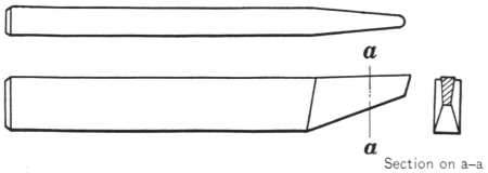
Fig. 77.—Brass Tool.
95. Brass Tool.—Fig. 77. Forging, hardening, and tempering. Material: 6 to 8 inches of 1⁄2 × 1-inch tool steel.
Starting about 3⁄4 inch from one end, draw to a uniform102 taper on both sides and on one edge only, so that the metal is 1⁄4 inch thick and 1⁄2 inch wide at the end. The lower or beveled edge also should be drawn thinner than the upper to provide the necessary clearance amounting to about 5 degrees on each side, as shown in the sectional view. The end should be cut off at an angle of 70 degrees and ground semicircular in form with the necessary clearance.
Heat about 2 inches of this end and harden in the manner described for the cold chisel, but in this case the color for tempering is a very pale yellow.
96. Cutting-off or Parting Tool.—Fig. 78. Fullering, forging, hardening, and tempering. Material: 7 inches of 1⁄2 × 1-inch tool steel.

Fig. 78.—Cutting-off or Parting Tool.
With a top fuller form a depression across one side 5⁄8 inch from the end, fullering the metal to 3⁄16 inch thick. Draw this end down to 1 × 3⁄16 inch. The thickness of the metal where it was fullered should also be decreased to 1⁄8 inch, gradually increasing to 3⁄16 inch at the end, taking extreme care to have sufficient clearance from front to back and from top to bottom. The cutting edge is generally103 allowed to project about 1⁄8 inch above the stock; the end is trimmed off at an angle of 75 to 80 degrees and ground, as shown in Fig. 78, after which it is hardened and tempered to a pale yellow.
97. Heavy Boring Tool.—Fig. 79. Drawing, bending, hardening, and tempering. Material: 7 inches of 1⁄2 × 1-inch tool steel.
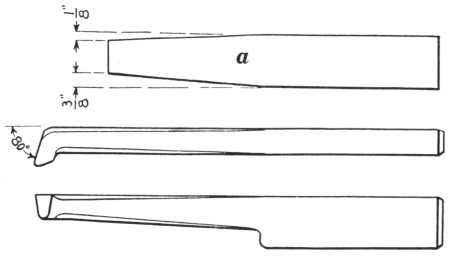
Fig. 79.—Heavy Boring Tool.
Draw about 21⁄2 inches tapering to 1⁄2 inch square at the end; the taper on the top edge should be only 1⁄8 inch, while that on the bottom should be 3⁄8 inch, as shown at a. With the metal resting flat on the anvil and the top edge to the left, bend down 3⁄4 inch of the end to an angle of about 80 degrees, then forge down the corners from the point back to the heel, to a slight octagonal form, as shown in Fig. 79. Grind the projecting end of the angle semicircular with a clearance of 15 degrees, then harden and temper to a pale yellow.
98. Light Boring or Threading Tool.—Fullering, drawing, hardening, and tempering. Material: 5 inches of 1⁄2 × 1-inch tool steel.
Using a top fuller, form a depression 7⁄16 inch deep on one edge and 2 inches from the end. Draw this metal slightly tapering to 7⁄16 inch square at the end, keeping it straight on the top. With the metal resting flat on the anvil and the straight edge to the left, bend down 3⁄4 inch of the end to an angle of 80 degrees, then forge the corners between the angle and where the depression was formed to a slight octagonal form.
For a boring tool, grind the projecting end of the angle semicircular in form, with sufficient clearance for boring a hole of the desired size; for a threading tool grind it to the proper angle of the thread with sufficient clearance, then harden and temper it to a pale yellow.
99. Diamond Point Tool.—Fig. 80. Forging, hardening, and tempering. Material: 7 inches of 1⁄2 × 1-inch tool steel.

Fig. 80.—First Steps in Making a Diamond Point Tool.
Using a top fuller, form a depression 3⁄8 inch deep on one edge 3⁄4 inch from the end, as at a. Then holding the depression over a round edge of the anvil and delivering105 blows on the end, as indicated at b, forge the 3⁄4-inch end into a square form, at an angle of 70 degrees to the lower edge of the stock, as shown at c. By resting the inner corners of this end on the face of the anvil and delivering blows on the opposite outside corners, as shown in Fig. 81, its form should be changed to 7⁄16 inch square, projecting diagonally from the stock, as shown at a, Fig. 82.
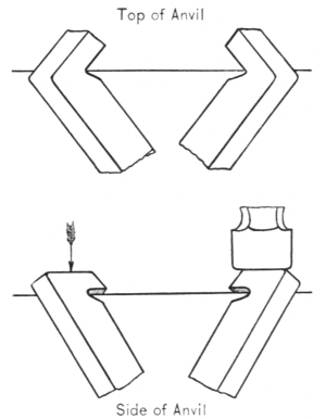
Fig. 81.—Changing the Form of c, Fig. 80, to that of a, Fig. 82.
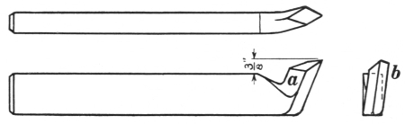
Fig. 82.—Diamond Point Tool, Finished.
By using a sharp, hot cutter and cutting entirely from the right inside surface (a, Fig. 82), and by holding the point over the edge of the anvil, so that the operation will have a shearing effect, the excess metal which extends more than 3⁄8 inch above the upper line of the stock may be removed. For a right-hand tool the point should be set 1⁄8 inch to the left, as shown at b, the two outside surfaces106 being ground smooth and forming an acute angle; the inside portion of the end on the side indicated by a should be ground somewhat shorter, producing a diamond-shaped appearance. Harden and temper to a very pale yellow.
Reverse the operations of cutting, setting, and grinding for a left-hand tool.
100. Right Side Tool.—Fig. 83. Forging, offsetting, hardening, and tempering. Material: 7 inches of 1⁄2 × 1-inch tool steel.

Fig. 83.—First Steps in Making the Side Tool.

Fig. 84.—Side Tool.
Heat and cut off about 5⁄8 inch of one corner, as at a, Fig. 83, and form a depression with the top fuller 11⁄2 inches from the end on the side indicated at b, 1⁄4 inch deep at the upper edge, leaving the metal full thickness at the lower edge. Then the metal should be roughly spread out from the upper edge of the stock by holding the fuller lengthwise, as shown at C, leaving the lower edge the full thickness,107 and smoothed with a flatter, drawing the upper edge to 1⁄8 inch in thickness. The above operations could be done with a hand hammer, but not without considerable hard work.

Fig. 85.—Offsetting the Side Tool for Clearance.
Trim this end to the form shown in Fig. 84, by using a sharp, hot cutter and cutting entirely from the side indicated by d. When this has been done correctly remove all metal extending more than 1⁄4 inch above the upper edge of the stock. When this has been forged to the correct shape, heat and place the tool so that the fullered shoulder is just beyond the edge of the anvil, then form the offset with a round-edged set hammer, as shown in Fig. 85. Grind the upper edge parallel with the stock but at a slight angle, to produce a cutting edge, and grind the face side straight and smooth. In cooling this tool for hardening it should be placed in the water, as shown in Fig. 86, to insure hardening the whole cutting edge. Leave sufficient heat in the heel or bottom of the tool to draw the temper uniformly to a pale yellow.

Fig. 86.—Hardening the Side Tool.
101. Forging Tools.—The following forging tools are108 somewhat smaller than those used in general smith work, but they are perfectly serviceable and sufficiently heavy for manual training or considerable ordinary work. The material for their construction should be tool steel of 0.80 to 0.90 per cent carbon, 11⁄4 inches square, unless otherwise specified. The holes or eyes should be punched straight, and the precautions formerly given under the head of punches should be observed.
A tapered drift pin of an oval section 7⁄8 × 5⁄8 inch at the largest end, also a smaller oval-shaped handle punch, should first be provided.
102. Cold Chisel.—Fig. 87. Forging, hardening, and tempering tool steel. Material: 61⁄2 inches of 3⁄4-inch octagonal tool steel.

Fig. 87.—Cold Chisel.
First draw 1⁄2 inch of one end to a smooth, round taper about 3⁄8 inch in diameter at the extreme end, then grind off the rough projecting edges until it is 1⁄2 inch in diameter. This end should not be cooled quickly, because it might harden somewhat, which would cause it to break easily. Starting 2 inches from the opposite end, draw the tool tapering to 1⁄8 inch thick and 1 inch wide, using the flatter on these tapered sides and edges. They should be made109 straight and smooth, with the edges perfectly parallel. Two views with dimensions are shown in Fig. 87.
Grind the cutting edge of the chisel to the desired angle, then harden and temper it as follows: Heat about 2 inches of the cutting end to a dull cherry red and plunge about 1 inch of this perpendicularly into water; withdraw it about 1⁄2 inch, and keep it in motion between the first and second cooling places until the end is perfectly cold. Remove the tool and quickly polish one side with emery cloth or sandstone, watching the varying colors as they make their appearance and move toward the edge; when the dark purple or blue color entirely covers the point, thrust it into the water again and leave it there until thoroughly cooled. Regrind cautiously, protecting the temper, and test its cutting qualities on a piece of cast iron or soft steel.
103. Hot Cutter.—Figs. 88 and 89. Punching, fullering, forging, hardening, and tempering. Material: 4 inches of 11⁄4-inch square tool steel.

Fig. 88.—Steps in Making the Hot Cutter.

Fig. 89.—Hot Cutter.
Punch and drift an eyehole 13⁄4 inches from the end, making all sides straight and smooth, as shown at a, Fig. 88. With a pair of 3⁄4-inch fullers, form two depressions on opposite sides 1⁄4 inch from the eye,110 as at b, fullering the metal to 5⁄8 inch thick. From this place draw the end tapering to 11⁄2 × 1⁄8 inch, and trim it off at a right angle to the stock, as at c. Using a hot cutter and working equally from all sides, cut the tool from the bar 11⁄4 inches from the edge of the eye. Draw the head end tapering to about 7⁄8 inch from the eye, draw the corners to form a slightly octagonal section. Remove all projecting metal so as to produce a convex head. (See Fig. 89.) This will be referred to later as forming the head. Grind both sides of the cutting end equally to form an angle of 60 degrees, with the cutting edge parallel to the eye. Harden, and temper to a dark purple or blue.
104. Cold Cutter.—Figs. 90 and 91. Punching, forging, hardening, and tempering. Material: 4 inches of 11⁄4-inch square tool steel.

Fig. 90.—Steps in Making the Cold Cutter.

Fig. 91.—Cold Cutter.
Punch and drift an eye 2 inches from the end a, Fig. 90. Draw this end tapering on the sides parallel with the eye, forming convex surfaces and terminating in 1 × 3⁄16 inch. (See111 sketches b and c.) Cut the tool off at c, 11⁄4 inches from the eye, and form the head.
Grind the cutting end equally from both sides to form an angle of 60 degrees, and a convex cutting edge similar to that shown at d. Harden, and temper to a dark purple or light blue. The finished tool is shown in Fig. 91.
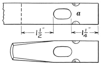
Fig. 92.—Square-edged Set Hammer.
105. Square-edged Set.—Fig. 92. Punching and forging. Material: 31⁄2 inches of 1-inch square tool steel. Heavier or lighter stock may be used if desired.
Punch and drift an eye 11⁄4 inches from the end, then, using a pair of 3⁄8-inch fullers, form depressions about 1⁄8 inch deep across the corners, as at a, Fig. 92. Cut the tool off 11⁄2 inches from the eye, and form the head to 3⁄4 inch at the end. Heat and anneal in warm ashes; when it is cold, grind the face smooth, straight, and at right angles to the stock.
106. Hardy.—Fig. 93. Fullering, forging, hardening, and tempering. Material: 3 inches of 2 × 7⁄8-inch tool steel.
Using steel 2 inches wide with a thickness equal to the dimension of the hardy hole, fuller and draw a slightly tapered shank 13⁄4 or 2 inches long, to fit loosely into the anvil. The broken lines at a, Fig. 93, indicate the drawn shank. Cut off the stock 11⁄2 inches from the shoulders at b. Heat and drive the drawn end into the hardy hole112 so as to square up the shoulders and fit them to the anvil. Then draw the heavy end tapering gradually from the sides, terminating 1⁄8 inch thick and 2 inches wide. Grind this tool similar to the hot cutter; harden, and temper to a purple or blue.

Fig. 93.—Hardy.

Fig. 94.—Flatter or Round-edged Set Hammer.
107. Flatter.—Fig. 94. Upsetting, forging, and punching. Material: 43⁄4 inches of 11⁄2-inch square tool steel.
In forming the face of a flatter, the metal should be upset. This may be accomplished by ramming, but when so done, excess metal is formed just above the wide portion, causing considerable fullering and forging. If a piece of steel 43⁄4 inches long and 11⁄2 inches square is cut off, and one end is drawn slightly tapering, it may, when heated, be placed in a square hole of the right size in the swage block, with the drawn end supported on something solid, leaving 11⁄2 inches projecting. The113 hot steel can then be hammered down with a couple of sledges, until the face is formed to 3⁄8 inch thick or about 2 inches square, as at a, Fig. 94.
Punch and drift an eyehole 11⁄4 inches from the face, then draw and form the head. Anneal in warm ashes. When it is cold, the face should be ground perfectly straight, smooth, and at a right angle to the body, with the surrounding edges slightly round, as shown, or they may be left sharp and square if desired.
A round-edged set hammer may be made in this manner, but as the face should not be so large, less metal is required.
108. Small Crowbar.—Fig. 95. Drawing, swaging, welding, and tempering steel. Material: 16 inches of 3⁄4-inch square mild steel, also a small piece of tool steel.

Fig. 95.—Steel-faced Crowbar.
Draw 11 inches to the following dimensions: the first 4 inches to 3⁄4-inch octagon, then beginning with 3⁄4-inch round gradually reduce to 1⁄2-inch round at the end. This should be smoothly forged and swaged.
Form a depression 1⁄4 inch deep on one side of the square portion 2 inches from the end; from this, draw the metal to 1⁄2 × 3⁄4 inch; by using a hot cutter where the depression was made, split and raise up a scarf fully 3⁄4 inch long, as shown in the sketch. Prepare a piece of tool steel 21⁄2 × 3⁄4 × 1⁄2 inches; on one end of this draw a long, thin scarf and114 roughen it with a hot cutter, so it can be held in place securely. (See Fig. 95.)
Heat the bar cautiously where the scarf was raised, to avoid burning it; slightly cool the tool steel and put it into place. By holding the piece of steel against a hardy, swage, or fuller, the scarf can be hammered down tightly over the tool steel, which should hold it securely for heating. Place the pieces in the fire and heat them to a red; remove and thoroughly cover them with borax; replace them and raise the heat to a bright yellow or welding heat.
While the first light blows for the welding are being delivered, the end should be held against something to prevent the steel from being displaced; when positive that welding is proceeding, make the blows heavier and complete the operation.
When the pieces are securely joined, cut off the corner opposite to the steel face, and draw the bar tapering from this side, to a sharp, flat edge 1 inch wide. Bend this through its smallest dimensions to an inside radius of about 31⁄2 or 4 inches and with the edge extending 1⁄2 inch to one side of the bar, as in Fig. 95. File or grind the outside surface and edge of this; then harden, and temper to a blue.
109. Eye or Ring Bolts.—An assortment of eyes is shown in Figs. 96, 97, and 98. All eyes should possess two essentials: the necessary strength and a good appearance; therefore the method of making should be chosen to fulfill those requirements. Generally the eyes that have the most strength require the greatest amount of labor.
A, Fig. 96, is an open eye which is very easily made, because bending is the only operation required. The115 method of making this form of eye has already been explained in section 69.

Fig. 96.—Eye or Ring Bolts.
A, an open eye; B, a welded eye.
B is a welded eye. It is made by forming first a flat, pointed scarf on the end of the bar and bending it through its smallest diameter where the drawing was begun. This bend should be no less than 70 degrees on the outer side. Determine the length of the material needed for forming a ring of the required diameter, then subtract the diameter of the material from the determined length. Using this result, place a center-punch mark f that distance from e, and bend the piece at f in the same direction as e.
Form the metal between the bends into a circle, and place the scarf in position for welding, as at B. During the heating for welding, if the circle heats more rapidly than desired, it should be cooled off and the heating then continued. The welding should be done as quickly as possible and swaged if required.
The eye bolt, shown in Fig. 97, is similar to a solid forged eye. It is formed and welded with a specially forged scarf called a butterfly scarf.
Determine the amount of material needed to form a ring of the required diameter, and add to that a sufficient allowance for upsetting and welding, which would be approximately equal to the diameter of the material used. An invariable rule for that allowance cannot be116 given, because the results of the upsetting are seldom the same.
Place a center-punch mark the estimated distance from one end of the bar; then upset the end 1⁄8 inch larger than its original diameter, next upset it at the mark to a similar dimension, and bend it there to an angle of no less than 70 degrees. Now with the bend lying flat on the face of the anvil, draw out a thin, narrow scarf with a small ball peen hammer, not any wider than the thickness of the metal. The scarf may be drawn also by holding the outer portion of the bend on a sharp corner of the anvil and by drawing with overhanging blows. This scarf is shown in the upper view of Fig. 97 as it should appear.
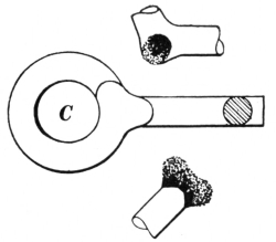
Fig. 97.—Eye Bolt made with a Butterfly Scarf.
The butterfly scarf should now be formed on the opposite side from the one just finished, by holding each side of the end at an angle of about 45 degrees on the edge of the anvil; this scarf may be drawn with overhanging blows. The extreme end should also be drawn thin in a similar manner, while it is held at a right angle with the edge of the anvil. All outer edges of this scarf should be thin and sharp.
Bend the metal into a circle and place the scarfs in position, as shown at C, having all edges overlapping slightly and hammered down into close contact. Heat the work for welding, observing the precaution given in the explanation of the former eye. In welding, deliver the first few blows uprightly on each side, then weld the edges of the117 scarfs with the ball of the hammer. A few careful experiments with these scarfs will show what is required, and with practice no more labor will be needed than is required for the previous eye. The finished product will be more substantial and presentable.

Fig 98.—D, a Ship-smith Eye; E,
a Solid Forged Eye.
D, Fig. 98, is generally called a ship-smith eye, because it is commonly used in ship work where strength is essential. Special swages, convex lengthwise, are usually provided for shaping the concave curves where they are formed and welded. The eye should be circular between the places indicated by f in sketch D, and the lines from f to where it is welded should be as nearly straight as possible, to increase the strength.
In estimating the material, take two thirds of the length for a ring of the required diameter, and add to that the proper allowance for the stock which forms the portion from f to the weld, and also an amount sufficient for the scarf. This scarf is drawn similar to the one for the welded eye in Fig. 96, but it should be made convex through its smallest dimension with a top fuller, whose diameter is equal to that of the metal. This is done while the metal is held in a bottom swage of corresponding size. When the scarf is finished, bend the eye into shape and bring the scarf close up to the stem of the eye.
Heat and weld with swages; if convex swages are not obtainable, others may be used by taking care to prevent118 marring the curves. This eye may also be welded with a large fuller while it is held over the horn of the anvil. If the curves are severely marred, the strength of the eye is lessened.
A solid forged eye is shown at E. When eyes like this are drop-forged in special dies, as they generally are, they do not require much skill, but when made entirely by hand they require considerable experience.
In forging an eye of this kind, the volume of material needed must first be determined, making some extra allowance for the usual waste. A convenient size of material should then be selected (round is preferable) and the amount required for the eye marked off. The round stem should be drawn down to size and the part for the eye forged to a spherical shape, then flattened, punched, and enlarged to correct dimensions.
110. Calipers.—The calipers shown in Fig. 99 may be easily made from the dimensions given; 3⁄4 × 1⁄8-inch stock should be used for the main piece, and 1⁄2 × 1⁄8-inch stock for the legs.
111. Stock Calculation for Bending.—In the expansion and contraction of metals during the operation of bending, there is a fixed line, where the metal is left undisturbed; in other words, where it is not increased or decreased in length. So all measurements taken to determine the length of material required for producing any bent shapes should be taken from that fixed or undisturbed location, in order to attain accurate results.
All materials which have a symmetrical cross section, such as round, square, octagonal, oval, or oblong, have the above line at their true centers, no matter which way they are bent. While the metal remains undisturbed at the119 center of any of the above sections, the rest of it undergoes a change; the inner portion, in the direction of bending, will contract and become thicker, and the outer portion will expand and become thinner.
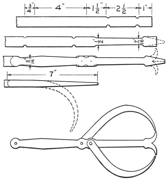
Fig. 99.—Steps in Making Calipers.
Other conditions arise, however, to modify these rules. If the heat is unevenly distributed, or if the stock is not of a uniform thickness, the results will not be exactly as120 estimated. When a heavy ring is formed of oblong material and bent through its larger diameter, as shown in sketch A, Fig. 100, and the product is to be finished to a uniform thickness, the expansion of the outer portion will make it necessary to use somewhat thicker material, to provide for the decrease of metal which will take place. The inner half, then too thick, could be reduced to the required size, but this operation always alters natural conditions of bending, and changes the general results. These conditions are not very noticeable and do not require special attention when small-sized materials are operated upon, but they must be observed when large oblong or square stock is formed into a ring requiring exact dimensions.

Fig. 100.—Calculations of Lengths for Rings.
In all cases of this kind, the required length must be established from the undisturbed center and the ends cut at an angle of 85 degrees. If the material is to be welded, it should be scarfed on opposite sides and lapped when bent.
When hoops or bands of flat or oblong material are121 bent, scarfed, and welded through the small diameter, then both scarfs should be formed on the same side while straight, and bent as shown at B, Fig. 100; the scarfs then will fit more readily than if they were formed on opposite sides. Sometimes, in instances of this kind, only one end is scarfed, and the piece is bent in a similar manner, with the unscarfed end on the outside and just lapping enough to cover the heel of the inner scarf.
Another form of ring requiring a calculation of the area as well as of the length is one of a wedge-shaped section, as shown at C, Fig. 100. Here the area of the required section is found and the material supplied with the proper thickness and area. The length also must be computed, then cut, scarfed, and welded, as previously explained; after this the ring may be drawn to the form desired.
The circumference of a circle may be found by multiplying its diameter by 3.1416 (π). (See tables, pages 205-206.) For rings or bands the length of the center line, c, Fig. 100, should be found. Example: If a equals 5 inches and b equals 2 inches, c will equal 7 inches, and the length of stock for the ring will be 7 × 3.1416 = 21.991 inches,—practically 22 inches. 31⁄7 may be used for the value of π instead of 3.1416.
Questions for Review
Describe the proper construction of a pair of tongs. What sort of steel should be used in making lathe tools? What operations are employed in making them? What is the color of the temper? If they were tempered to a blue, would they be tempered harder or softer? Are forging and hardening heats the same? State the difference in grinding a boring and a threading tool. Explain the difference 122 in making a right- and a left-hand diamond point tool. How should a side tool be hardened? Why shouldn’t the head of a cold chisel be cooled off quickly when it is finished? Explain the difference between tempering a cold chisel and tempering a lathe tool. Describe the shapes of the hot and the cold cutter. How should they be tempered? How are the square-edged set and the flatter treated in place of tempering. Explain how it is done. Describe different methods of making eye or ring bolts. How should measurements be made on stock to be bent? State what has been said about scarfing flat or oblong material for rings.
112. A Forging.—A forging is an article made of metal, generally steel or iron, and produced by heating and hammering. It may be used for either practical or ornamental purposes. The various forgings already described were made by methods such as the older class of smiths practiced, and are called hand forgings. From a practical standpoint these smiths were familiar with the characteristic composition of metals and with the knowledge of how they should be worked.
Many forgings are produced at present by machinery. The product is satisfactory for most practical purposes, and is generally equal to that made by hand. The machines used are the drop hammers, horizontal and vertical presses, steam hammers, and numerous other devices. The power used for operating them may be either steam, air, water, or electricity.
113. The Drop Hammer.—The drop hammer is provided with a pair of dies made of cast steel, one upper and one lower, having suitably shaped depressions made in them for forming the forgings. The lower die is held stationary on a solid foundation block, and the upper one is secured to a heavy weight or hammer. This is raised perpendicularly and allowed to drop upon the metal, which is held on the fixed die by the smith, thus forming the forging.
If the work is small and simple, all depressions may be made in a single pair of dies, and the forging can be completed with one hammer and without changing the dies. Work somewhat complicated may require two or more pairs of dies, with various shapes of depressions. The stock is broken down or blocked out by the first pair and then completed by the stamping and finishing dies. Larger pieces may require also a number of pairs of dies, then an equal number of hammers may be used, each fitted with a set of dies. The material is passed from one to the other, and the work completed without changing dies, and possibly without reheating the metal.
114. Presses.—Presses may be either horizontal or vertical and are generally used for bending or pressing the metal into some desired shape or form; they are quite convenient for producing duplicate and accurate shapes. Forming-dies or blocks are also required here, but they are generally made of cast iron, and their construction need not be so accurate. After the presses have been properly adjusted, very little skill is required in their operation,—simply the heating of the material and placing it against a gauge or between the dies. One thrust of the plunger will complete the operation.
115. The Steam Hammer.—The steam hammer was first recorded by Mr. James Nasmyth in his “scheme book” on the 24th of November, 1839. Although this was the exact date of its origin, he first saw it put into practical use by the Creuzot Iron Works of France in 1842. Nasmyth’s invention legally dates from June, 1842, when his patent was procured.
Of the various machines that have been devised for the125 smith’s use, to relieve him of the laboriousness of pounding metal into shape, there is none that could take the place of this invention. Numerous shapes and forms can be produced more accurately and rapidly by the employment of the steam hammer than by the use of hand methods.

Fig. 101.—A Steam Hammer Equipped with a Foot Lever.
Before proceeding any further, a few words of warning and advice may not be out of place. Although this invention is a great benefactor to the smith, it is not possessed with human intelligence, nor is it a respecter of persons. The power of steam will always exert its utmost force when liberated, so do not let in too much steam at first. Unless the material is held horizontally and flat on the die, the blow will jar the hands badly and will bend the material. All tools such as cutters and fullers should be held firmly but lightly, so that they may adjust themselves to the die and the descending blow.
After the hammer has been put into motion, the blows126 will fall in a perfectly routine manner. By his careful observation and a thorough understanding of the necessary requirements, and by signals from the smith, the hammer operator should regulate the force of the blows to suit the smith’s convenience.
A caution pertaining to the tongs used for handling the material should be carefully observed. Whenever work is to be forged with the steam hammer, the material should be held with perfect-fitting tongs secured by slipping a link over the handles; a few light blows delivered on the link will tighten their grip.
116. Steam Hammer Tools.—First some necessary tools will be explained, then exercises requiring their use will be given, followed by a few operations where simple appliances are needed.

Fig. 102.—The Hack or Cutter.
117. The hack or cutter (Fig. 102) is used for nearly the same purposes as the hot cutter already described. It should be made of tool steel from 0.80 to 0.90 per cent carbon. The head or top is made convex, as shown, and not more than 5⁄8 inch thick, tapering equally on both sides to the cutting edge, which may be made either 3⁄16 or 1⁄4 inch thick. It should be ground straight and parallel to the top and tempered to a dark blue.
The blade is about 21⁄4 or 21⁄2 inches wide, unless intended for heavy forgings, when all dimensions should be increased.127 The width of the blade should not be too great, however, for the broader the cutter, the greater its liability to glance sidewise or turn over when the blows are delivered upon it. The length of this cutter may be from 33⁄4 to 4 inches.
The handle may be about 28 inches long, approximately 3⁄4 inch in diameter at a and gradually tapered towards the end, where it is about 1⁄2 inch. The portion indicated at b is flattened to an oblong section, as shown, to allow springing when the blows are delivered and to prevent bruising the hands.
118. The circular cutter (Fig. 103) is made of the same material and with a handle of similar dimensions and form as the hack. A section of the cutting portion on a-a is shown, and suitable dimensions given. If convex ends are to be cut, the perpendicular side of the blade should always be on the inner side of the curve, but on the outer side for concave ends.

Fig. 103.—The Circular Cutter.
An assortment of these cutters with various-sized arcs may be provided to suit requirements, but quite frequently the curved cutting portion is altered to suit the particular work at hand.
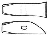
Fig. 104.—The Trimming Chisel.
119. The trimming chisel (Fig. 104) is made quite similar to an ordinary hot cutter and likewise provided with128 a wooden handle. It should be strongly constructed, perfectly straight on one side, and not too long from the cutting edge to the top to avoid its being turned over when the blows are delivered upon it. The grinding should be done on the tapered side only, with the cutting edge tempered to a dark blue.
120. The cold cutter (Fig. 105) is used for purposes similar to those of the ordinary cold cutter. It should be strongly made in a triangular form, as shown in the end view, also with a spring handle like that of the hack. The top is made convex, and the sides taper to the cutting edge, which should be ground equally from both sides. It should be carefully tempered for cutting cold material.

Fig. 105.—The Cold Cutter.

Fig. 106.—Breaking Cold Stock.
In cutting stock with this tool, the material should be nicked sufficiently deep on the exterior to allow it to be broken. By holding the piece securely with the hammer, and the nicked portion even with the edge of the dies, it may be broken off by a few blows from a sledge. The steam hammer may also be used to break the stock when nicked with the cold cutter. The piece should be placed on the lower die of the hammer, as shown in Fig. 106, and broken by one or two sharp blows from the hammer. A piece of round stock can be used instead of the triangular piece of steel, with the same result. When material is being broken in this way, see that no129 one is standing in a direct line with the stock, as there is some liability of one or both pieces flying in either direction.
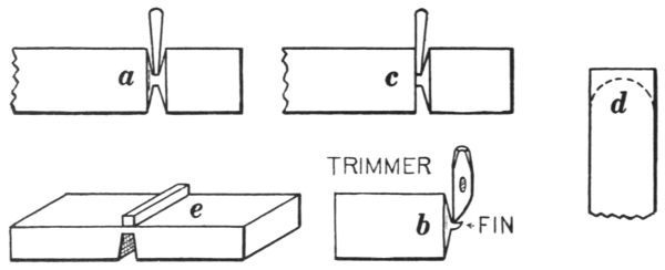
Fig. 107.—Cutting Stock.
When using the hack (Fig. 102) for cutting square stock, cut equally from all sides, as shown at a, Fig. 107. This will produce smoother ends than if it were cut unequally and will prevent the short end from turning upward when the final blows are delivered. The fin or core that is formed by the hack, shown at b, generally adheres to one of the pieces, but it can be removed by using the trimming chisel in the manner shown. These fins are commonly removed by the use of an ordinary hot cutter and sledge.
The hack, if held perpendicularly, will not cut the end of either piece square. If one end is to be cut square, the cutter should be held as shown at c. Round material may be cut similarly, but to avoid marring its circular section it may be held in a swage fitted to the hammer die.
Flat stock may be cut equally from both sides, or if it is cut nearly through from one side, the operation can be completed by placing a small piece of square untempered steel over the cut, as shown at e. A sharp blow of the130 hammer will drive the steel through into the opening and produce a straight, smooth cut.
When a semicircular end is to be produced, similar to that indicated by the broken line at d, the circular cutter should be used. Here, also, the cutting should be done equally from each side.

Fig. 108.—The Checking Tool or Side Fuller.
121. The checking tool or side fuller (Fig. 108) is made of tool steel with a carbon content, the same as for the cutters. The handle also is the same, with the exception of part a, which provides the spring. Here, on account of its being used in two different positions, a twisted form is much better, because the tool may spring in either direction. From the end view you will notice that it has a triangular section with one square corner and two curved ones.
A convenient dimension for this tool is about 21⁄2 inches over all from the square to the circular corners. It would be convenient to have a smaller one also, of about 11⁄2 inches. The length of this tool should correspond with that of the cutters.
In use, one of the circular corners of the checking tool is forced into the metal, forming a triangular-shaped depression, as shown at b. Two depressions are shown in this sketch in opposite directions to each other, made by holding131 the tool in different positions and using both the circular edges. The object of this operation is to set off the rectangular portion b so that the ends c-c can be drawn out without disturbing the center.

Fig. 109.—The Fuller.
122. The fuller (Fig. 109) is made with a handle like that of the checking tool, but the portion used for fullering is made circular in section and about 4 inches long. An assortment of sizes should be provided, with diameters of 1, 11⁄2, and 2 inches. When smaller sizes are needed, a bar of round steel may be conveniently substituted. These tools may be properly termed top fullers, because they are generally held on top of the metal and the blows are delivered from above, thus forming depressions on one side only. Sometimes double depressions are required directly opposite to each other. In such cases a short piece of round metal, the same size as the fuller, is placed on the die directly under the top fuller, with the metal between the two.
If the depressions are to be only semicircular, a short piece of half-round material may be provided which is not liable to be dislocated or jarred out of position on the die.

Fig. 110.—The Spring Fullers.
123. The combined spring fullers (Fig. 110) are very convenient for making double depressions. They are132 similar to the single fuller, but are flattened out at a and b, so that they may be opened for various sizes of stock.
Fig. 111.—The Combination Fuller and Set.
124. The combination fuller and set (Fig. 111) may be made with a straight, round handle, but a twisted one is more desirable, because the tool is frequently used in different positions. It should be made of a quality of steel that will withstand severe hammering without becoming battered. The heavy end which forms the tool is made about 11⁄2 by 21⁄2 inches; the corners on one side are left sharp and square, while those opposite are made quarter-round. One side of this tool may be made almost semicircular if it is intended to be used as a fuller. The length may be about 4 inches.

Fig. 112.—Drawing and Finishing with the Combination Fuller and Set.
This tool is used as a fuller or set in drawing metal between projections which have been formed by using the checking tool. In Fig. 112 the sections of metal, indicated by a and c, are to be drawn to smaller dimensions. This133 cannot be done with the hammer, because these places are narrower than the width of the hammer dies. At c the fuller or set is being used flatwise, which is the better way, because the two round corners will not cause galling. At a it is shown in use edgewise; but this should not be continued after the opening has been enlarged sufficiently to use the tool as at c, unless perfectly sharp corners are desired.
Another convenient use for this tool is for finishing a roughly drawn tapered piece of metal, as at d. Here are shown the roughened tapered surfaces, as they have been produced by the hammer, also the method of using the set. If there is much of this kind of work to be done, it would be advisable to provide a special tool with a circular side which could be used solely as a flatter.

Fig. 113.—The Combined Top and Bottom Swages.
125. The combined top and bottom swages (Fig. 113) are also called spring swages, because they are somewhat flexible at the connecting loop, which keeps them in adjustment. The best material for these swages, on account of the constant hammering to which they are subjected, is a good quality of mild or soft steel. Much hammering has a tendency to crystallize the metal and causes frequent breakage.
The heavy parts forming the swages ought to be well proportioned and made from sufficiently heavy stock. The handles are drawn out from the same material and welded, or merely stub ends may be drawn from this134 material, and then flat stock welded on to form the handles. In either case the edges should be swaged half-round previous to welding. The top and bottom of the handles are not parallel with the upper and lower parts of the swages, because the heavy parts only should receive hammer blows.
The grooves should be perfect semicircles, with the exception of the edges indicated at e, which should be slightly round, as shown. This prevents metal from becoming lodged in the swages. If the metal sticks, the smith will be unable to revolve it in the swages, and it will become oblong in section. The corners on top of the upper swage should be removed, as shown, so that the blows will be received more directly through its center.
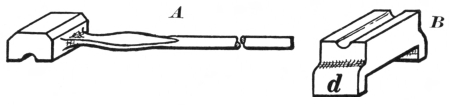
Fig. 114.—The Top and Bottom Swages.
126. The top and bottom swages (A and B, Fig. 114) are made separate, but of the same quality of material as those just described. The handle of the top swage A, however, should be round, with a small portion flattened, as shown. The bottom swage B is constructed with projecting lugs d, as shown. The distance between the lugs should be equal to the width of the lower hammer die, over which the swage should fit closely enough to prevent its displacement. The swages may be used together or separately, as desired, the lower one being convenient for cutting round material, as it prevents marring the sectional form of the stock.
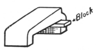
Fig. 115.—The Bevel or Taper Tool.
127. The bevel or taper tool (Fig. 115) is provided with lugs and fits the hammer die. When constructed for general use, the pitch should not be too great, because it may be increased by placing a short piece of metal under one end, as shown, or decreased by inserting metal under the opposite end. The heavy end should be made as nearly perpendicular as possible, with the outer edge of the die. This tool is very handy for drawing any tapering work, such as cold chisels, levers, keys, etc.
128. The V block (Fig. 116) was introduced by the inventor of the steam hammer, and was used instead of a bottom swage. When large, round sections are to be produced, and swages of the proper size are not obtainable, this tool may be used.

Fig. 116.—The V Block.
When round stock is drawn without a swage, only two portions directly opposite to each other are acted on by the hammer, thus causing some liability of producing an oblong section or a hollow centered forging. These difficulties are avoided to a certain extent by the use of the V block, because the force of the blow acts in three directions.
129. The yoke or saddle (Fig. 117) should be made of heavy flat material bent into the form of a U, with the ends perfectly straight and parallel. It should be provided with lugs fitted to the lower die so that both sides will stand erect and at right angles to it, as at A. The distance between the sides may be of any convenient width, 21⁄2 inches or more, depending upon the character of the work to be136 done. Semicircular depressions should be made on the edges, as shown at e.

Fig. 117.—The Yoke or Saddle.
Another view of the yoke is given at B, with one side removed. As seen here, it is used to draw weldless or solid rings after the stock has been blocked out and a sufficiently large hole has been punched in it to allow it to be hung over the pin p, which rests in the depressions previously mentioned. Hammer blows can be delivered on the exterior of the stock, thus drawing it and increasing its diameter. As this is increased, larger pins should be used, to produce a smoother and more evenly drawn ring.
The yoke, shown at C, is being used as a bridge for drawing the ends of a solid forged jaw. By using it for purposes like this, considerable hand labor may be saved.

Fig. 118.—A, Bolster; B, a Plug Punch in Position for Use.
130. Bolsters or collars (a, Fig. 118) are used for punching holes, upsetting metal for bolt heads, and similar operations. They should be made of soft steel.
131. Punches.—At b, Fig. 118, a plug punch is shown in position on the metal over a washer or bolster ready for punching. When properly located, a few blows of the137 hammer will force the punch through the metal and produce a smoothly finished hole.
Notice that the punch is made somewhat tapering, and that the heavier portion is driven through first. Precaution should be taken not to have the punch fit the bolster too closely or be too long, also to have it directly over the hole in the bolster before attempting to drive it through.
Holes can be punched with ordinary handle punches, but care should be taken not to have them too long; even then a bolster or something must be used, so that the punch can be driven clear through the metal and not come in contact with the lower hammer die.
132. Steam Hammer Work.—The following exercises are known as machine forgings. They will require the use of the steam or power hammer and the tools just described. It will be necessary to know beforehand what parts of the work are to be finished, so as to provide a proper allowance at those places. The term “finished” means that the surface is to be removed by the machinist, and the work made smooth and to the required dimensions.
All machine drawings should designate the parts that require finishing, by either the entire word or just the letter “F.” The symbol is more convenient to use for only certain parts, but if the entire forging is to be finished, it may be indicated by “finished all over.”
133. Crank Shaft.—Fig. 119. This is shown without dimensions or finish marks. Select stock sufficiently heavy to produce a forging equal to that shown at b.
Make two depressions with the checking tool, as shown, the distance c between them corresponding with the138 dimension a on the crank. Draw the ends square and straight on the lower side, as shown at d, then octagonal, and then round. In this way the fillets and shoulders will be equal, as shown at e. The two ends should be swaged smooth and round, then made perfectly straight and at right angles to the crank.

Fig. 119.—Steps in Making a Crank Shaft.
134. Connecting Rod.—Fig. 120. The volume of the material required for section e must first be estimated. Then ascertain how many inches of the selected material will be required to give this volume. This will be the distance b for the fullering shown at a. The sizes of the fullers to be used should be the same as the required radii r. Fuller in the depressions as shown, so that they will correspond with the dimensions g, h, and l of the finished rod. The metal between g and h should then be drawn slightly139 tapered, as shown in the top view, and to a uniform thickness l. The small end must now be drawn to the proper size and trimmed with the circular cutter. Make the rod perfectly straight, with the ends parallel to each other and to the rod.

Fig. 120.—Steps in Making a Connecting Rod.
135. Rod Strap.—Fig. 121. This forging is begun by blocking out, as shown at B, with e a little greater than h and plenty of stock at f. The length k must equal l, with a slight allowance of surplus metal for the bending operation.
Sketch C shows the method of bending. A forming block m should be provided for this, the width of which corresponds nearly with the dimension g, and the thickness is somewhat greater than that at d. The length may be equal to the inside length of the finished strap, but it could be used if shorter. By placing this block perpendicularly on the bottom die, with the forging resting on it140 and a small piece of metal n for a blocking on top of that, the upper die may be brought down and a full head of steam turned on while the stroke lever is held down. Both ends can be bent down simultaneously with sledges.

Fig. 121.—Steps in Making a Rod Strap.
After the bending, there may be required more or less labor with the flatter and sledge to square it up in proper shape. Then the ends can be cut off to equal lengths with the hack or hot cutter.

Fig. 122.—Steps in Making an Eccentric Jaw.
136. Eccentric Jaw.—A, Fig. 122. First form the depression c with the checking tool; then draw141 out the end d to the form e and punch a hole at f by using an oblong punch.
Then using the hack, carefully cut from both sides at the places indicated by the broken lines at f. Any fin remaining after the cutting can be removed with a hot cutter or the trimming chisel. The ends forming the jaw can be drawn to the proper size by the use of the yoke. The semicircular ends can also be cut by using the circular cutter, but these ends will require some trimming with a hot cutter, because all the work must be done from exterior sides.
137. Hand Lever.—A, Fig. 123. This illustrates and explains a simple method of stamping which may be extended or adjusted to suit a variety of forgings.

Fig. 123.—Steps in Making a Hand Lever.
In this case two stamping rings are made to suit the work at hand, as follows: If the dimension h is 2 inches and the thickness of the lever i is 1⁄2 inch, the rings must be made of 3⁄4-inch round stock, and welded to an inside diameter corresponding with the dimension k.
First draw the material to correspond exactly with the dimension k in one direction and somewhat greater than that of h in the opposite. The latter dimension is made larger, to provide some excess metal for the stamping operation, which is done in the following manner: Place one of the rings centrally on the bottom die of the hammer,142 as shown at B; lay the material on this, with the dimension h perpendicular and the proper distance from the end to provide enough metal for forming the lever and handle. Then place the other ring on top of the material directly above the lower one, and deliver blows on these rings until the entire thickness almost corresponds with the desired dimension h. The rings will be forced into the metal and form two depressions, as shown at C. Next with a hot cutter or trimming chisel remove the metal forming the corners e. Then draw out the lever portion roughly, at first; by using the taper tool a uniform taper can be produced correctly. Cut off the extra stock at the boss, and remove the surplus metal which projects between the bosses as indicated at d, and finish the end smoothly with a common top swage. The handle portion can be formed at the anvil with top and bottom swages after the end has been cut semicircular and to the desired length.

Fig. 124.—Steps in Making a Connecting Lever.
138. Connecting Lever.—A, Fig. 124. After drawing the metal to an appropriate dimension, fuller two depressions b on opposite sides, the proper distance from the end, to form the jaw. A single boss c should be stamped with one ring, at the required distance from b to provide the necessary amount of metal for the length d of the143 lever. Then remove the corners, as indicated by the broken lines. Begin drawing the lever by using the combination set, and finish the flat side with the hammer, producing the taper edge with the taper tool. Punch a square hole in the jaw and remove the metal indicated by the broken lines at e, with a hot cutter. Finish the jaw similar to the eccentric jaw and the boss as in the previous exercise.
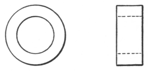
Fig. 125.—Solid Forged Ring.
139. Solid Forged Ring.—Fig. 125. This should be made of soft steel, the dimensions being supplied by the instructor to suit the stock and equipment at hand. The volume (see calculating rules and tables, pp. 197-206) of the forging must first be determined and some surplus allowance for forging provided. The process of making the ring will be found in the explanation of the use of the yoke in section 129.

Fig. 126.—Producing Double and Single Offsets.
140. Double and Single Offsets.—Fig. 126. The following exercises are given to explain the use of simple appliances for producing work accurately and rapidly. Examples similar to the four following ones would require considerable144 care and skill if they were to be produced without the use of the steam hammer.
At a is shown a double offset bend, the depth of which, for illustration, may be 1⁄2 inch. To produce this, place two pieces of 1⁄2-inch flat material, with width corresponding to that of the material to be bent, on the lower die, and sufficiently far apart to allow the offsets to form between them. On these the material is placed, and on top of that also, located midway between the 1⁄2-inch supporting pieces, a third piece of 1⁄2-inch stock is placed. The width of this should correspond with the required dimension at a and should be somewhat longer than the width of the material to be bent. This arrangement is shown at c. By delivering a sufficiently heavy blow upon them, the two offsets, will be formed simultaneously and accurately.

Fig. 127.—Simple Methods for Bending Clamps with a Steam Hammer.
In all operations of this kind the thickness of the lower forming pieces should always correspond with the required depth of the offset, and the corners should be ground round to prevent shearing or galling.
At d is shown a single offset which can be produced in a similar way, with the exception that here only two blocks are required. But the forming corners of these145 should also be ground as previously stated, and they are placed in position as shown at e.
Figure 127 shows the method of bending a semicircular pipe or rod clamp. Here a piece of round stock f is used above for stamping, but as the lower blocks are easily displaced, it would be advisable to make a stamping block like that shown at g. This could be used instead of the two lower pieces. If the clamps were to be made square, then the stamping block should be like the one shown at h, and the upper piece as at f should be made square.
Questions for Review
What is a forging? Name the machines used in making forgings. Who invented the steam hammer? How should material be held on the dies? What tool is used in place of a hot cutter at the hammer? How can a convex end be produced? Describe the special form of a trimming chisel. How should metal be broken after it has been nicked with the cold cutter? Describe the correct way of using a hack in cutting square stock. Explain the use of a checking tool. Describe the different fullers used at the hammer. Explain their uses. For what is a combination fuller and set used? Describe the hammer swages. The bevel or taper tool. What is it used for? What is the advantage in the use of the V block? Describe the yoke. Explain its use. What is the difference between a plug punch and a handle punch? How is a bolster used for punching? What does the word “finished” mean on a drawing? What hammer tools are brought into use in making a crank shaft? In making the connecting rod? Describe how the hammer is used in bending a rod strap. What tools are brought into use in making the eccentric jaw? Describe the method of forming the bosses on the hand lever. Explain some simple methods of bending work with the steam hammer.
141. Art Smithing.—This subject might appropriately be considered a separate branch, because many smiths, who really deserve the credit of being excellent mechanics, have never become proficient in this particular line of work.
Art smithing is the highest development of metal work. The best art smiths are foreigners, as European countries use much more of this kind of work for decoration than this country does. The greater part of this work is entirely too difficult for the average student unless it is attempted with the assistance of machinery.
It is possible, however, to do a certain amount of scroll work with accuracy and make simple decorative pieces. One should commence with the design of the article to be made. The harmonious combinations of straight and curved lines and their adaptation for different purposes should be studied. The study of design will not be taken up here, but several examples which will furnish a basis for further work along this line are given for consideration.
Designing may be done on any convenient material such as paper, wood, or blackboard. The last is preferable because confusing marks can easily be erased. A sketch thus made may be used as a working drawing. If the design is to be used many times, a very convenient and substantial method is to reproduce it on a piece of shellacked147 pine board, and then paint it on in solid form. When this is dry, a few more coats of shellac should be applied to preserve it. If desired, the length of each individual scroll may be indicated.
There are various methods of obtaining the different lengths: by placing a strong string over the scroll and then measuring the string; by using a piece of soft wire in the same manner, lead wire being preferred; or by the following method:—
Take a piece of 1⁄8-inch material 3 or 4 feet long, mark it lightly on both edges into equal spaces either 3 or 6 inches long, and stamp the feet or inches upon it with steel figures. After this is done, a small rolling curl, as shown in Fig. 129, should be formed, and the entire length bent on the scroll former while the material is cold. This is the manner, minus the markings mentioned, in which all scrolls are to be formed. This product with the markings upon it should be kept for ascertaining the number of inches required for either large or small scrolls. Always place the curled end of this measure in position on the working drawing and adjust it until it conforms to the outline of the design. Then place a crayon mark on both the drawing and the measure where they cease to correspond; the length of that portion which corresponds can be ascertained from the markings on the measure, and all remaining irregular curves can be measured by a string, wire, or rule. This measure will prove also to be quite a satisfactory and accurate means of arranging new designs.
142. Scroll Fastenings.—There are three different methods used for joining scrolls: welding, riveting, and banding with clips. The first is the most difficult and the most artistic, but unless one is quite expert at welding,148 especially in joining light material such as is generally used for scroll work, it would perhaps be better to disregard this method entirely.
Riveting presents a very neat appearance and makes the product quite strong and substantial, but unless the marking and drilling of holes is accurately done, the result presents a distorted and ill-shaped combination, which cannot be remedied without drilling new holes.
It would be advisable, then, to adopt the last method generally, resorting to riveting wherever it is impossible to use clips or bands, or where strength is an essential requirement. If a clip is misplaced, it can be replaced with a new one, or it may be moved into the proper position without showing that an error has been made.

Fig. 128.—The Scroll Former.
143. Scroll Former.—Fig. 128. This is a very handy tool for producing scrolls in a rapid and uniform manner. It should be a perfectly designed variable spiral. If several are provided, they should be exactly alike, otherwise the scrolls produced with them will be unequal and irregular and will present an inartistic appearance. The former illustrated is made of 1 × 1⁄2-inch soft steel. Draw the end and form the central portion, gradually tapering to about 3⁄16 of an inch thick, but leave it of a uniform width. This149 end should be slightly beveled from one side to form a protruding edge, over which the small curled end of the material is securely held while the scroll is being bent. A view of the former as it is used to start a scroll is given in Fig. 129 showing the metal in proper position for forming. The end indicated at a, Fig. 128, may be bent downward and edgewise to a right angle, as shown, or, if desired, it may be forged square to fit the hardy hole of the anvil, but as this tool is most conveniently used when held in the vise, the method shown at a is better.
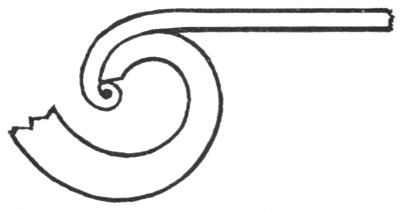
Fig. 129.—Starting a Scroll on the Former.
144. Bending or Twisting Fork.—Fig. 130. This fork is shown with dimensions suitable for bending material 1⁄8 or 3⁄16 inch in thickness. For thicker material all dimensions should be proportionately increased.

Fig. 130.—Bending or Twisting Fork.
This tool is very serviceable and quite easily made of round tool steel; if such stock is not at hand, octagonal150 tool steel can be swaged to the desired dimension. If it is made of soft steel, it will meet requirements for a considerable length of time.
145. Bending or Twisting Wrench.—Fig. 131. This should be made from the same quality of steel of the same dimensions as the preceding tool.

Fig. 131.—Bending or Twisting Wrench.

Fig. 132.—Scroll Bending.
The bending wrench is used in connection with the bending fork for shaping a scroll, as shown in Fig. 132. When the wrench is placed over the material so that its jaws will grip the sides and the handle of the wrench is pulled in the direction indicated by the arrow, bending will take place at e. If the straight end of the scroll were pulled in the same direction, bending would occur at f. Sometimes when scrolls are being connected with the band, they are sprung out of place. By the use of this wrench they can be brought again into position by bending them close to where the band was put on.
These tools may be used together for twisting light material, when the vise and monkey wrench could not readily be utilized.

Fig. 133.—Clip Former.
146. Clip Former.—Fig. 133. This and the two following tools should be made of 0.80 to 0.90 per cent carbon tool steel. A convenient size of material for the one shown is 1 × 1⁄2 inch. The portion forming the connecting loop must be flattened and forged to about 1⁄4 inch thick to provide a spring for retaining its shape. The ends should be forged to two different thicknesses. The 1⁄4-inch side is used in bending clips for banding two pieces of 1⁄8-inch material, and the 3⁄8-inch side for three pieces. When a different thickness of material is to be used, these ends should be made to correspond with it. The inner and outer edges of these ends should be made slightly rounding to prevent cutting the material from which the clips are made. Most of this light scroll work is made from stock with round edges, therefore it is not necessary to have the clips bent sharp and square.
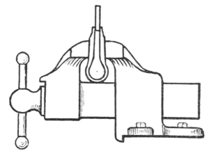
Fig. 134.—Use of the Clip Former.
The former should be so proportioned that it can be placed between the jaws of the vise, as shown in Fig. 134. Here the loop is resting on the box of the vise, which supports it and prevents it from falling out of position152 when the pressure of the vise is released. The ends of the clip former should extend above the jaws of the vise about 2 inches, so that the clips can be bent without striking the vise with the hammer. A view of these ends, with a piece of half-oval iron in position for bending, is shown at A, Fig. 137. One end of the clip material should be placed between the ends of the former, one half the width of the scroll stock, 3⁄16 of an inch if the stock is 3⁄8 inch wide. By tightening the jaws of the vise upon the sides of the former, the half-oval iron will be securely held, while it is being bent over with the hand hammer to the form indicated by the broken lines. The clip will then be ready for fastening the scrolls together.

Fig. 135.—Clip Holder.

Fig. 136.—Use of the Clip Holder.
147. Clip Holder.—Fig. 135. Stock 3⁄4 inch square is best suited for making this tool. The central portion forming the loop should be drawn and forged to about 1⁄4 inch thick, gradually increased to 1⁄2 inch where the shoulders are formed. The distance from these shoulders to the outside end of the loop should be less than the distance from the top of the vise jaws to the vise box. Then the tool will be supported entirely on these shoulders, as shown in Fig. 136, and the tool may be placed near the ends of the vise jaws, which sometimes will prove to be quite an advantage.153 The length from the shoulders to the ends may be about 2 inches. These ends should be drawn tapering from the outer sides to about 1⁄2 inch square. On the inside a depression 3⁄16 inch deep should be formed so that the holder will fit over the bent end of a clip, as shown at B, Fig. 137.
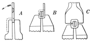
Fig. 137.—Forming a Clip.
The clip and a sectional view of the two pieces of material that are to be connected are shown at B as they are placed in this tool. By tightening the vise upon the holder, the lower portion of the clip will be clamped securely on the pieces and held while the upright end of the clip is bent over and around the upper half of the material with the hand hammer. Then the following tool will be brought into use.
148. Clip Tightener or Clincher.—Fig. 138. The most convenient stock from which to make this tool is 3⁄4-inch octagon tool steel. It is made by upsetting and forging the end to about 11⁄4 × 1⁄2 inches, then filing a depression not more than 3⁄16 inch deep and wide enough to fit tightly over the outer portion of the bent end of a clip. The corners indicated at e should be made slightly round to prevent them from marring the outside of the clips. This tool should be about 61⁄2 inches long, with the head end drawn as for a cold chisel.

Fig. 138.—Clip Tightener or Clincher.
By holding this tool on top of the bent-over clip, as shown at C, Fig. 137, and delivering a few heavy blows upon it, the clip will be tightened and clinched securely over and around the pieces.

Fig. 139.—Jardinière Stand or Taboret.
149. Jardinière Stand or Taboret.—Fig. 139. The height from the floor line to the top of the circular board is 26 inches; the height from the floor line to the upper ring E is 191⁄2 inches; the height from the floor line to the lower ring F is 7 inches; the extreme width is 181⁄2 inches.
The process of making this stand will be given here. By following a similar course, any of the other designs given in this chapter may be made. The material usually employed for making this is 1⁄2 × 1⁄8-inch, and there should be four sections or legs, as shown at the left, also two bands or rings, like the one shown in the upper right, and one top board 7⁄8 inch thick and 8 inches in diameter, which is155 shown under the ring. The following list gives the number and lengths of the various pieces required:—
4 pieces 451⁄2 inches long.
4 pieces 221⁄2 inches long.
4 pieces 151⁄2 inches long.
4 pieces 15 inches long.
2 pieces 141⁄2 inches long.
4 pieces 13 inches long.
All pieces should be straightened immediately after being cut to length. The main branch, 451⁄2 inches long, should be marked with a center punch at all places where bending or twisting is to be done. From the end of the stock to A is 6 inches; from A to B, 9 inches; B to C, 41⁄2 inches; the length of the twisted portion is 21⁄2 inches.
All ends that are to be scrolled, should be drawn, curled, and fitted to the central portion of the former, as previously indicated. When both ends of the same piece are to be scrolled, observe carefully whether they revolve in the same or in opposite directions. These ends should not be cooled after drawing and fitting, because cooling will have a tendency to harden them slightly and prevent uniform bending. All ends that are to be connected to another piece by clips should now be drawn out to a thin edge, but of a uniform width.
Now proceed to form the main branch by making the twisted portion between B and C; straighten if necessary. Form the upper angular bend of 90 degrees at A while it is held in the vise; this can be done cold, by carefully avoiding breaking or cutting the material with the sharp edge of the vise. Now form a scroll at the top on the former. Next bend at B in the same manner and direction as before, and make the two quarter circles between A and B, with the bending fork alone or by combining the use of it with the bending wrench. Exercise care156 in doing this, in order to have the correct space for scroll 2 and ring E, which should be 5 inches outside diameter. The lower angular bend at C should now be made, followed by forming as much of the scroll D as possible on the former. Then bend the irregular curve between D and C.
The next member to be scrolled and fitted into position is the 151⁄2-inch piece, 4. This must be carefully made in order to have the extreme height of the scroll at the proper distance from the bottom line, also at the proper distance from the center line, to provide an exact dimension where the lower ring F is to be connected. The outside diameter of ring F should be 5 inches. Then scroll and fit the 15-inch piece, 3, followed by the 13-inch piece, 5, and finish this leg by arranging the 221⁄2-inch piece, 2, last, so that it will not extend above the bottom line of the circular board and will leave at least a 1⁄4-inch space between the center line and the sides of the curves.
All parts should be assembled on the drawing after they are fitted, and marked with crayon wherever the clips are to be placed to secure them. The material for the clips, which should be 3⁄8-inch half-oval Norway iron, should be cut up in lengths equal to the four outside dimensions of the combined materials plus 1⁄8 of an inch for bending, or 15⁄8 inches in this case. After these pieces are bent on the clip former, fasten the scrolls together with the clip holder and the clincher.
After the four legs or parts have been assembled, lay each separately on the drawing, to make sure that the places, where they are to be connected with the rings and the circular board, are properly located. If they are157 correct, mark these places with a center punch, and drill 9⁄64-inch holes where the rings are to be connected and 3⁄16-inch holes where the top is to be secured.
The two 141⁄2-inch pieces are for the rings. Drill a 9⁄64-inch hole 3⁄8 of an inch from each end in both pieces, countersink one side of one end of each piece, and grind a beveled edge on this end, but on the opposite side from the countersink. Form them into rings having the countersink inside. Connect the ends of each ring with a 1⁄8 × 3⁄8-inch round-head rivet, inserting it from the outside of the ring and riveting the ends together, filling the countersink. Place the rings separately on the mandrel and make them perfectly round on the inside by forming a slight offset on the outside end where it begins to lap over the beveled inside end.
Draw a 5-inch circle on a piece of board and divide it into quarters. Place the rings on this outline with the outside end about 1⁄4 inch from one of the quarter lines. Mark where each quarter line crosses the ring, center-punch these places, drill 9⁄64-inch holes, and countersink them on the inside. Then assemble the legs by riveting the upper ring to the standard with 1⁄8 × 1⁄2-inch rivets, the lower one with 1⁄8 × 3⁄8-inch rivets, their heads toward the exterior so that riveting will be done on the inside of the rings filling the countersink. Place the circular top board in position and secure it with 1-inch #10 round-head wood screws. This will complete the construction, with the exception of a coat of black japanning, if a glossy finish is desired, or a coat of dead black lacquer if a rich dull black is desired.
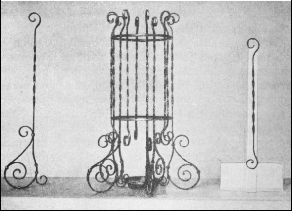
Fig. 140.—Umbrella Stand.
150. Umbrella Stand.—Fig. 140. Extreme height, 271⁄2 inches; extreme width, 181⁄2 inches; upper rings, 91⁄4 inches inside diameter; lower ring, 51⁄4 inches inside diameter. Provide a small deep pan to rest on top of this ring.
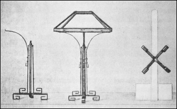
Fig. 141.—Reading Lamp.
151. Reading Lamp.—Fig. 141. Extreme height, 23 inches; height of the stand, 14 inches; base, 81⁄4 inches wide; shade, 14 × 14 inches wide, 61⁄4 inches high, top opening, 4 × 4 inches.
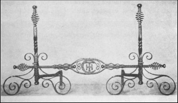
Fig. 142.—Andirons and Bar.
152. Andirons and Bar.—Fig. 142. Extreme height, 24 inches; extreme width of base, 18 inches; height from the floor line to the top of the upper scroll, 111⁄2 inches; length of bar, 40 inches.

Fig. 143.—Fire Set.
153. Fire Set.—Fig. 143. Extreme height, 30 inches; height160 to the holders, 24 inches; height to the top of the upper scroll, 111⁄2 inches; extreme width of the base, 14 inches.

Fig. 144.—Fire Set Separated.
154. Fire Set Separated.—Fig. 144. Extreme length of implements, 22 inches.
Questions for Review
Explain three methods of obtaining the length of a scroll. Should scrolls be bent hot or cold? Why are the ends of the clip former made to different thicknesses? Why is the clip former made thinner at the loop? How is that tool placed in the vise? Why is the clip holder made with shoulders on its outer sides? Give the rule for cutting off clip stock. After the scroll material has been cut to length, what should be done? When ready to draw and bend the curl for a scroll what should be observed? Why shouldn’t it be cooled after drawing and curling? What is done with the ends of a scroll if they are to be fastened with clips? Explain how the rings are made for the jardinière stand. Describe the process of making the umbrella stand in Fig. 140.
155. Iron Ore.—An ore is a portion of the earth’s substance containing metal for which it is mined and worked; the class to which it belongs depends upon the amount and variety of the metal it contains. Any ore that is to be used for the extraction of a certain metal must contain the metal in sufficient amounts to make the operation profitable.
Iron, ordinarily, does not occur in a native state or in a condition suitable for use in the arts and manufactures. The iron in meteors, frequently called native iron, is the nearest possible approach to it. Meteorites, commonly known as falling stones or shooting stars, are solid masses that have fallen from high regions of the atmosphere and are only occasionally found in different parts of the world. They are considered more valuable as a curiosity than as material for manufacturing purposes. The metallurgist, chemist, or geologist can readily distinguish them from other masses, because they invariably contain considerable nickel, which seldom appears in any of the ordinary iron ores. They are usually found in a mass containing crystals and are nearly always covered with a thin coating of oxide, which protects the metal from further oxidation. Several large meteors have been found, one in Germany weighing 3300 pounds and a larger one in Greenland weighing 49,000 pounds. The largest one known was162 discovered by Lieutenant Peary in the Arctic regions. It weighs 75,000 pounds. He brought it to New York City, where it can now be seen at the American Museum of Natural History.
Pure iron is obtainable only as a chemical, and as such it is used in the preparation of medicines. As a commercial product, such as is used in the arts and manufactures and by the smith, it is always combined with other substances, such as carbon, silicon, and phosphorus.
Iron is distributed through the earth very widely, but not always in sufficient quantities to make its extraction from the ore profitable; consequently the ores used for the extraction of iron are somewhat limited. There are four general grades of iron ore, which are known by the following names: magnetite, red hematite, limonite, and ferrous carbonate. These are subdivided and classified according to the particular composition of each.
156. Magnetite when pure contains about 72 per cent of iron, and so is the richest ore used in the manufactures. It is black, brittle, and generally magnetic, and leaves a black streak when drawn across a piece of unglazed porcelain. It sometimes occurs in crystals or in a granular condition like sand, but generally in a massive form. It is found principally in a belt running along the eastern coast of the United States, from Lake Champlain to South Carolina. There are considerable quantities of it in New Jersey and eastern Pennsylvania, but the greatest deposits are found in Missouri and northern Michigan; some is mined also in eastern Canada. It is a valuable ore in Sweden.
A mineral known as franklinite, which is closely allied to magnetite, is a mixture of magnetite and oxides of163 manganese and zinc. In appearance it resembles magnetite, but is less magnetic. In New Jersey, where it is found quite abundantly, it is treated for the extraction of the zinc, and the residue thus obtained is used for the manufacture of spiegeleisen, which is an iron containing a large amount of manganese, usually from 8 to 25 per cent.
157. Red hematite is found in earthy and compact forms. It varies in color from a deep red to a steel gray, but all varieties leave a red streak on unglazed porcelain. It is found also in a number of shapes or varieties, such as crystalline, columnar, fibrous, and masses of irregular form. Special names have been given to these. The brilliant crystalline variety is known as specular ore, the scaly foliated kind as micaceous ore, and the earthy one as red ocher. Each one of this class contains about 70 per cent of iron, and on account of the abundance, the comparative freedom from injurious ingredients, and the quality of iron it produces, it is considered the most important of all the ores in the United States.
Until the discovery of large deposits of this ore in the Lake Superior district it was chiefly obtained from a belt extending along the eastern coast of the United States just west of the magnetite deposits and ending in Alabama. Some of this ore is found in New York, but there is not a great amount of it north of Danville, Pennsylvania. At present the greatest quantities that are used come from the Lake Superior district. There, ore of almost any desired composition may be obtained, and the enormous quantities, the purity, the small cost of mining, and the excellent shipping facilities have made it the greatest ore-producing section of the United States.
158. Limonite or brown hematite contains about 60 per164 cent of iron and is found in both compact and earthy varieties. Pipe or stalactitic and bog ore belong to this grade. The color varies from brownish black to yellowish brown, but they all leave a yellowish brown streak on unglazed porcelain. It is found in a belt lying between the red hematite and magnetite ores in the eastern United States. Formerly there was considerable of this mined in central Pennsylvania, Alabama, and the Lake Superior district.
159. Ferrous carbonate contains about 50 per cent of iron. It also is found in several varieties, called spathic ore, clay ironstone, and blackband. Spathic ore when quite pure has a pearly luster and varies in color from yellow to brown. The crystallized variety is known as siderite; this ore frequently contains considerable manganese and in some places is used for the production of spiegeleisen. When siderite is exposed to the action of the air and water, brown hematite is formed.
Clay ironstone is a variety that is found in rounded masses or irregular shapes and sometimes in layers or lumps, usually in the coal measures. It varies in color from light yellow to brown, but the light-colored ore rapidly becomes brown when exposed to the atmosphere. Like the former it also contains considerable manganese.
Blackband is also a clay ironstone, but it is so dark in color that it frequently resembles coal; hence the name. The ore is not very abundant in this country nor extensively used; it is generally found with bituminous coal or in the coal measures, therefore it is mined to some extent in western Pennsylvania and Ohio. It is an important ore in England.
160. The Value of Ores.—Ores are valued according to165 the amount of iron they contain, the physical properties, the cost of mining, the cost of transportation to the furnace, and their behavior during reduction. The ores of the Mesaba range in the Lake Superior district are very rich, and free from many impurities; they are soft and easily reduced, and as they are found near the surface, they can be mined with steam shovels. These are great advantages, but the greatest disadvantage is the fact that the ore is fine and some of it blows out of the furnace with the escaping gases; this also fouls the heating stoves and clogs the boiler flues.
161. Preparation of Ores.—Most of the ores are used just as they come from the mines, but in some cases they are put through a preliminary treatment. This is sometimes done as an advantage and at other times as a necessity. This treatment is very simple and consists of weathering, washing, crushing, and roasting.
162. Weathering is a common process. Sometimes ores that have been obtained from the coal measures and others that may contain pyrites or similar substances are left exposed to the oxidizing influence of the weather. This separates the shale and the pyrites. The former can easily be removed, and the latter is partly oxidized and washed away by the water or rain falling upon it. The ore piles shown in Fig. 149 are exposed to the atmosphere and partly weathered before being used.
163. Washing is also done for the purpose of removing substances that would retard the smelting process. For instance, the limonite ores, which are generally mixed with considerable clay or earthy compositions, are put through an ore washer to remove those substances before they are charged into the smelting furnace.
164. Crushing is done with machinery to reduce to a uniform size such refractory ores as are mined in rather large lumps. If the ore were charged into the furnace as mined, the coarseness would allow the gases to pass through the ore too readily without sufficient action upon it. Smaller pieces will pack more closely together, thus offering greater resistance to the blast, and hastening the reduction.
165. Roasting or calcination is done to desulphurize ore which contains an excess of sulphur. It is done also to expel water, carbon dioxide, or other volatile matter which it may contain. Ore, made more porous by roasting, exposes a larger surface to the reducing gases. In the case of magnetic ores, roasting converts the ferrous oxide into ferric oxide, which lessens the possibility of the iron becoming mixed with the slag, thereby preventing considerable loss of metal.
Ore is frequently calcined in open heaps, but in more modern practice stalls or kilns are employed. Where fuel is cheap and space is abundant, the first process may be used. A layer of coal a few inches thick is laid on the ground, and a layer of ore is spread upon it; then coal and ore are laid in alternate layers until the pile is from 4 to 9 feet high. The coal at the bottom is then ignited, and the combustion extended through the entire mass. If at any time during the operation the combustion proceeds too rapidly, the pile is dampened with fine ore and the burning allowed to proceed until all the coal is consumed. Blackband ore frequently contains enough carbonaceous matter to accomplish roasting without the addition of any fuel except the first layer for starting the operation.
When the ore is calcined in stalls, it is placed in a rectangular167 inclosure with walls on three sides; these are from 6 to 12 feet high and are perforated to allow a thorough circulation of air. This method is very much like that of roasting in open heaps, but less fuel is necessary, for the draft is under better control and a more perfect calcination is accomplished.
When the same operation is performed in kilns, it is more economical in regard to fuel and labor than either of the two methods explained above. The process is under better control, and a more uniform product is obtained. The kilns are built in a circular form of iron plates, somewhat like a smelting furnace and lined with about 14 inches of fire brick. The most common size of the kilns is about 14 feet in diameter at the bottom, 20 feet at the widest part, and 18 feet at the top; the entire height is about 30 feet. They are capable of receiving about 6000 cubic feet of ore.
166. Fuels.—A variety of fuels may be used in the blast furnace reduction process, but the furnace should be modified to suit the particular quality of fuel. In this country the fuels most used are coke, charcoal, and anthracite coal. Coke is the most satisfactory and is more generally used than either of the others. Charcoal is used to a certain extent on account of its freedom from impurities and because it is generally considered that iron produced with charcoal is better for some purposes than that made by using other fuels. Anthracite coal is used principally in eastern Pennsylvania because the coal mines are near at hand, and it is therefore the cheapest fuel available. In some instances a mixture of anthracite and coke is used.
167. Fluxes.—The materials that are charged into the168 furnace with the ore, to assist in removing injurious elements that it may contain, are called fluxes. They collect the impurities and form a slag which floats on top of the molten iron and which is tapped off before the metal is allowed to run out. The fluxes also assist in protecting the lining of the furnace by thus absorbing the impurities which would otherwise attack the lining and destroy it.
Limestone is almost universally employed as a flux, although dolomite is used also to some extent. The value of limestone as a flux depends upon its freedom from impurities, such as silicon and sulphur.
Sulphur and phosphorus are two elements which must be kept out of the product. When there is too much sulphur, the iron is exceedingly brittle at a dull red heat, although it can be worked at a higher or lower temperature. It is called red-short iron and makes welding difficult. With steel, sulphur diminishes the tensile strength and ductility. If there is too much phosphorus combined with iron, the metal will crack when hammered cold. Iron of this kind is called cold-short iron. This metal can be worked, however, at a higher temperature than can the red-short iron just described.
168. The Blast.—The air blown into the furnace to increase and
hasten combustion is called the blast. Formerly when a cold blast was
used, considerable extra fuel was required to heat the air after it
entered the furnace, but a hot blast is used now almost exclusively.
The air is heated by passing through large stoves built for that
purpose. The stoves are heated by burning the waste gases which are
generated in the furnace and which are conducted from the top of the
furnace through a pipe169
170 leading into the stoves. Four of these stoves
are shown in Fig. 149 at the left of the picture.

Fig. 145.—Running Metal from the Blast Furnace to Ladles for Transporting to either the Open Hearth Furnace or the Pig Molder.
169. The Reduction or Blast Furnace.—Fig. 145. The reduction or blast furnace is almost universally used for the reduction of iron ore. It is a large barrel-shaped structure, the exterior of which is formed of iron plates about 1⁄2 inch thick, bent and riveted together like the outer shell of a boiler. This is lined with brickwork or masonry, the inner portion being made of fire brick to protect the furnace from the intense heat. Figure 146 shows a sectional view of a furnace of this kind.

Fig. 146.—Sectional View of a Blast Furnace.
The stack D is supported on a cast-iron ring, which rests on iron pillars. The hearth K and the boshes E are beneath the stack and are built independent of it, usually after the stack has been erected. This is done so that the hearth can be repaired or relined whenever it becomes injured. The hearth is also perforated for the introduction of the tuyères t, through which the blast enters the furnace from the blast main B. The opening171 to the downcomer or pipe leading to the stoves is shown at A.
Figure 147 shows the mechanical arrangement at the top of the furnace, called the bell and hopper, for receiving and admitting the ore flux and fuel. By lowering the bell C the material is allowed to drop into the furnace.
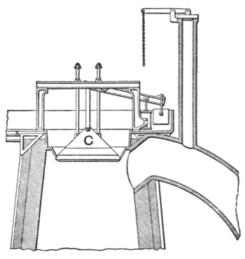
Fig. 147.—Sectional View of the Bell and Hopper.
The fuel, ore, and flux are charged into the furnace at the top in alternate layers, as previously explained; the iron settles down through the boshes, is melted, and drops to the bottom or hearth. The slag is drawn off at the cinder notch c, Fig. 146, after which the iron is tapped off at the iron notch g. Hollow plates p for water circulation are inserted in the boshes to protect the lining from burning out too rapidly.
The melted iron runs from the tapping notch into a large groove made in sand. This groove is called the “sow.” It is connected with smaller grooves called the “pigs.” Into these the metal runs and forms pig iron. Considerable sand adheres to pigs thus formed, and as the sand is objectionable for foundry, Bessemer, and open-hearth purposes, and as an enormous amount of hand labor is required in breaking up and removing it, pig molding172 machines are used. Figure 148 shows one of these machines with a ladle pouring the metal into it.
The only objection to this method is that the metal is chilled rather suddenly by the water through which the molds are led. This sudden chilling causes a structure different from that found in the same quality of metal molded in the sand and allowed to cool off gradually, and most foundrymen as well as other users of iron judge the quality by the appearance of a fracture. On this account machine-molded pigs are objectionable. It is claimed, however, that some machines in use at present have overcome this difficulty.
The approximate dimensions of a modern coke-burning furnace are as follows (see Fig. 146): The hearth K is about 13 feet in diameter and about 9 feet high. The diameter of the portion above the hearth increases for about 15 feet to approximately 21 feet in diameter at the boshes E. From the top of the boshes the diameter gradually decreases until it is about 14 feet in diameter at the stock line. The throat, or top, where the fuel and ore are charged in through the bell and hopper, is about 70 feet above the hearth. On the brackets which are connected to the pillars, the blast main rests, completely surrounding the furnace, and at numerous places terminal pipes convey the blast to the tuyères. After the furnace has been charged, or “blown in,” as it is commonly called, it is kept going continually night and day, or until it becomes necessary to shut down for repairs.
A general view of a smelting plant is shown in Fig. 149. The four circular structures to the left with a tall stack between them are the stoves for heating the blast. Next to these in the center of the picture is the blast furnace,173 somewhat obstructed by the conveyor which carries the ore and fuel to the top for charging. The structural work to the right is the unloader, which takes the ore from the vessels and conveys it to the stock pile in the foreground, where the ore is allowed to drop.

Fig. 148.—Pig Molding Machine.
170. Classification of Pig Iron.—The pig iron produced by the blast furnace is graded as to quality, and is known by the following names: Bessemer, basic, mill, malleable, charcoal, and foundry iron. This classification indicates the purpose for which each kind is best suited.
171. Bessemer iron is that used for making Bessemer steel. In this grade the amounts of sulphur and phosphorus174 should be as low as possible. Bessemer iron is generally understood to contain less than 0.1 per cent of phosphorus and less than .05 per cent of sulphur.
172. Basic iron is that which is generally used in the basic process of steel manufacture. It should contain as little silicon as possible, because the silicon will attack the basic lining of the furnace; therefore the surface of the pig iron used for this purpose should, if possible, be free from sand. By the basic process of making steel, most of the phosphorus in the pig iron is removed, consequently basic iron may contain considerably more phosphorus than if it were to be used in the Bessemer process.
173. Mill iron is that which is used mostly in the puddling mill for the manufacture of wrought iron. It should contain a low percentage of silicon. Therefore pig iron that has been made when the furnace was working badly for foundry iron is sometimes used for this purpose.
174. Malleable iron is that used for making malleable castings. It usually contains more phosphorus than Bessemer iron and less than foundry iron. The percentage of silicon and graphitic carbon is also very low in this class.
175. Charcoal iron is simply that which has been made in a furnace where charcoal has been used as the fuel. It is generally used as a foundry iron for special purposes.
176. Foundry iron is used for making castings by being melted and then poured into molds. For this purpose an iron that will readily fill the mold without much shrinkage in cooling is desired. Other properties of foundry iron will depend upon the character of the castings desired.
177. Grading Iron.—Iron is graded and classified according to its different properties and qualities by two methods; namely, chemical analysis and examination of fracture.
Grading by analysis, although not universally used at present, is no doubt the more perfect method, because the foreign substances contained in the metal can be accurately determined. Grading by fracture is more generally used, although it cannot be considered absolutely perfect, but when done by one who has had years of experience and has trained his eye to discover the different granular constructions and luster of the fractured parts, it is very nearly correct; unless the properties are to be known to an absolute certainty, grading by fracture is sufficiently accurate for all practical purposes.
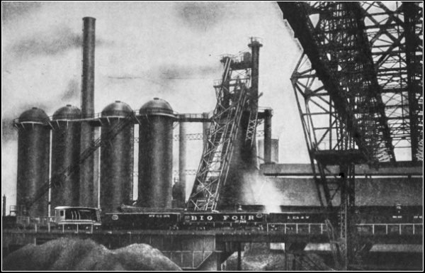
Fig. 149.—General View of a Smelting Plant, showing Blast Furnace Stoves and the Ore Pile.
Questions for Review
What is ore? Name four grades of iron ore. What is native iron? What is the difference between it and other iron ores? What class of ore contains the largest percentage of iron? Red hematite contains less, so why is it considered more valuable than the magnetite? What amount of iron do the limonite and ferrous carbonate ores contain? What determines the value of an ore? How is ore prepared for reduction? What are the results of these preparations? What are fluxes used for? What flux is most generally used? What effect does sulphur produce in wrought-iron? What is the effect of phosphorus in wrought-iron? How is air heated before it enters the blast furnace? What is the difference between sand-molded and machine-molded pig iron? What is the objection to machine-molded pig iron? Name the different classes of pig iron and state the use of each. How is iron graded?
178. Refining Pig Iron.—Two distinct methods have been adopted for the conversion of pig iron into wrought iron, each depending upon the kind of furnace used. They are called the open-hearth or finery process, and the puddling process. The chemical reactions are similar in both processes, being based on the oxidation of the impurities in the metal. This is accomplished both by means of the oxygen in the air supplied and by the oxide of iron in the fluxes that are added to assist the operation.
179. The Open-hearth or Finery Process.—This is carried on in what is sometimes termed a “bloomery” from the product which is called a bloom. The pig iron is placed in direct contact with the fuel on the hearth which is formed of cast-iron plates exposed to a current of air to keep them cool. This mixture of the iron with the fuel is objectionable, because while the fuel acts as a reducer the excess air decarbonizes the product only partly, besides prolonging the process considerably; by the addition of hammer scale and rich slag, the operation is hastened greatly. However, if some carbon is supposed to be contained in the product, making it of a steely nature, then the open-hearth process is considered a good method of refining.
Fusion is allowed to take place gradually, so as to expose178 the metal for a long period to the oxygen of the blast. At the moment of fusion the foreign elements are rapidly oxidized and form a fusible slag. After the slag becomes neutral and has been partly removed, fresh basic slag and hammer scale are added, to hasten the operation. Then the mass of iron, which is now of a white spongy texture, is lifted up in the furnace to a level with the tuyère, in order that the combined carbon may be completely oxidized. It is then formed into balls of about 60 to 80 pounds each, after which it is removed and formed into a bloom by means of a squeezer or hammer. This furnace is not illustrated, because most of the wrought iron is produced by the puddling process. An open-hearth furnace, such as is used in producing steel, is somewhat similar to the one here described and is shown in Fig. 163.
180. The Puddling Process.—The greatest amount of wrought iron is produced from pig iron by this process, owing to the superior quality of the product. The term “puddling” was originally applied to the process of working iron that had never been completely melted, but had only reached a puddled or pasty state. But later, when refined or pig iron was similarly treated, it was discovered that it would melt perfectly and boil up freely. The process was then termed “pig boiling.”
The furnace used in this process is of the reverberatory type; the fuel does not come in contact with the iron. (See Fig. 150.) It is built in a rectangular form; the fireplace A is located at one end, next to it is the hearth C where the metal is placed, and beyond are the flue B and the chimney D.
From the fireplace the heat is supplied and directed179 upon the metal by the top or roof, which is curved downward from the fireplace toward the flue and chimney. The fireplace also is separated from the hearth by a partial partition wall E, called the fire bridge, which prevents the fuel from coming in contact with the metal. Another similar partition F, located between the hearth and the flue, prevents the metal from going into the latter and is called the flue bridge.
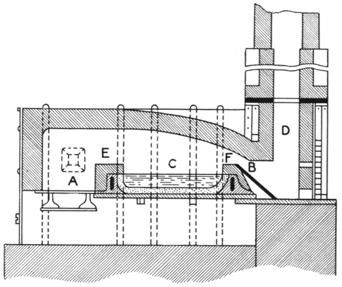
Fig. 150.—Puddling Furnace of a Reverberatory Type.
Both of these and all interior portions that come in contact with the heat and metal are constructed of fire brick. The bridges are built over hollow iron castings, through the openings of which there is a circulation of water provided to keep them cool. The bottom of the hearth is formed of iron plates rabbeted together; this180 and the sides are sometimes provided also with hollow castings for water circulation.
The hearth is lined with blue billy and the sides with bulldog. The former is a fusible silicate, chiefly ferric oxide, and is produced from tap cinder; it does not readily unite with silica when heated. Bulldog is made from burnt pyrites, a quality of ore used for the manufacture of sulphuric acid; the resulting oxide is sometimes called blue billy, but more frequently bulldog, to distinguish it from the former class of oxides. Both of these linings are known as fettlings.
The flue slopes down toward the stack; the draft is regulated with a damper, located in the top and connected by a chain, which hangs within reach of the operators. Various forms of furnaces are used, such as stationary and rolling furnaces; but whatever the style of furnace, the process is based on the decarbonization of the metal, and the charge of pig iron does not come in direct contact with the fuel, as in the open-hearth process. An advantage gained in using the puddling furnace is that various kinds of fuel can be employed without injury to the product of iron, also various labor-saving devices, which have recently been invented, can be better used.
In the pig-boiling process the furnace is first lined with the fettlings and charged with about 500 pounds of white foundry or forge pig iron. The refining process is divided into four distinct stages known as melting down, mixing, boiling, and balling.
A very high temperature is desired during the first stage, which usually lasts about thirty-five minutes. During this time the melting down occurs, and a partial removal of the silicon from the pig iron is effected.
In the second or mixing stage, which lasts about seven minutes, a comparatively low temperature is maintained by lowering the damper in the stack, while the charge is being thoroughly mixed with the oxidizing fluxes or cinders that are added. The puddler draws down the metal from around the sides into the center, where it will become more rapidly refined and mixed.
During the third or boiling stage the damper is raised to increase the temperature. At this time a violent reaction occurs, caused by the release of carbonic oxide, which is formed when the oxygen unites with the carbon in the pig iron. The gas escapes through the slag on the surface of the metal, thus causing it to appear as though it were boiling, from which action the process derives its name. During this stage, which lasts from twenty to twenty-five minutes, a large portion of the manganese, sulphur, and phosphorus contained in the pig iron is removed.
The oxidation is assisted by the constant stirring or rabbling of the metal by the puddler, done for the purpose of bringing it under the oxidizing influence of the air. The boiling gradually ceases, and the surface of the charge “drops,” as it is called, and the whole mass lies in a pasty state on the bed of the furnace, where it is worked by the puddler as thoroughly as possible so as to allow the flames to pass uniformly over it.
The fourth or balling stage requires from fifteen to twenty minutes. This consists of breaking up the contents into balls weighing from 60 to 80 pounds each. After they have been formed, they are rolled near the fire bridge to receive a final welding heat before they are removed to the squeezer, or hammer, where the slag is expelled and the bloom formed.
The blooms from either the open-hearth or puddling process are treated similarly in what is termed the forge; this includes hammering, rolling, and shingling.

Fig. 151.—Rolling Tool Steel.
Squeezers or hammers are used for forming the bloom and expelling the inclosed slag. The bloom is then put through the largest groove of the roughing rolls and passed back through the next smaller, and so on until it is rolled down to the desired size. Figure 151 shows 14-inch rolls in use which, although somewhat similar to those employed for rolling iron, are larger and generally made with more rolls.
The product of this first rolling is not usually considered of superior quality, so, in order to refine it more thoroughly, the bars are cut up into short lengths, piled into bundles, reheated, and again welded. This process is called shingling and is done two or three times, depending upon the desired quality of iron. This shingling produces the laminæ of the iron referred to in section 60. For ordinary bar iron the piles are made about 2 feet long by 4 inches square, and for larger sizes183 they may be made 5 or 6 feet long by 10 or 12 inches square.
The rolls are of various kinds. All shapes and sizes of bar iron used in blacksmithing may be produced in this manner. Rolling machines are known as two, three, and four high, meaning that they are provided with that number of rolls, one above the other. Universal rolling machines have two pairs of rolls in one machine; one pair runs on horizontal axes and the other on vertical axes. Each pair can be opened or closed independently, thus giving the machine a wide range.
181. Steel.—The word “steel” means very little to those who are uninformed as to its different qualities and the causes of the distinctions between them. People are generally familiar with the various purposes for which steel is used, but know very little about its nature. There are, however, great differences in the qualities, and definite reasons for them.
Formerly any combination of iron and carbon that would harden by sudden cooling or quenching was considered steel. But since modern methods of manufacturing have been adopted, tons of metal, which would have been classed as iron if judged by the cooling test, are at present known as mild or soft steel.
Steel may properly be defined as an alloy of iron with carbon, the latter not exceeding 1.8 per cent; the materials are completely fused and poured into molds, allowed to cool, and then rolled into shape. In the processes of making wrought iron the materials are only partly fused and are not cast into molds, but are taken out of the furnace in a soft, pasty condition suitable for immediate working.
The older process of producing “blister” or “cementation” steel is not generally employed now. By this method the bars of iron were put through a soaking or prolonged heating, while they were packed in charcoal. It was similar to the casehardening process, explained in section 90.
We have at present three notable processes of making steel; namely, the crucible, Bessemer, and open-hearth.

Fig. 152.—A Crucible.

Fig. 153.—Sectional View of a Four-hole Crucible Furnace.
182. The Crucible Process.—Crucible furnaces are flat structures containing from two to twenty holes, each one capable of receiving four or six crucibles. The crucibles are earthen vessels made of fire clay, mixed with refractory materials for withstanding intense heat. Each one is capable of receiving from 70 to 80 pounds of metal. (See Fig. 152.) In this furnace the gas and air supply may be applied independently to each hole, practically making each one a separate furnace, but all of the holes are connected with one main stack or chimney. A sectional view of a four-hole185 furnace is shown in Fig. 153, where the crucibles are shown in position.
This process is the most simple. It consists of melting the stock in the crucibles and pouring it, when completely fused, into molds, as shown in Fig. 154, forming what is known as ingots or steel castings. For that reason it is very frequently called cast steel. The stock is carefully selected and weighed so as to produce the required grade. After the ingots are cooled, the piped or hollow ends caused by shrinkage are broken off and graded by the appearance of the granular structure and luster of the fractured parts. They are then marked and piled away for future use. On the ingots shown in Fig. 155, the piped ends can be seen.

Fig. 154.—Pouring Steel into Ingot Molds.
The ingots are heated in an ordinary heating furnace, and rolled or hammered into suitable bars, the sizes being fixed both by the amount of carbon contained in the186 ingots and by the dimensions required for the manufacture of special tools. Figure 151 shows the workmen in the act of rolling tool steel; in Fig. 156 they are seen drawing octagon tool steel with the tilting hammer.

Fig. 155.—Steel Ingots.

Fig. 156.—Drawing Octagon Tool Steel with the Tilting Hammer.
Special alloys of crucible steel such as Mushet, blue chip, high speed, or other special brands are made by the same process,187 the secret of the difference lying entirely in the selection of the stock.

Fig. 157.—Cross Section of a Converter through the Trunnions.

Fig. 158.—Another Cross Section of the Same.
183. The Bessemer Process.—This consists of blowing air through molten pig iron in a vessel called a converter, sectional views of which are shown in Figs. 157 and 158. A converter is a pear-shaped structure hung on trunnions A, A, so that it can be tipped forward. The air is forced through one of the trunnions, which is hollow, and is connected with a pipe which conveys the air to the air chamber f at the bottom of the converter. The bottom grate or tuyère plate is located directly188 above the air chamber, and through the openings j, j, in the tuyère plate, the air passes up through the metal.

Fig. 159.—Pouring Metal into Molds.

Fig. 160.—Ingot Stripper.
The converter is tipped forward into a horizontal position while the molten metal is poured into it. The air is then turned on, and the converter is raised to a perpendicular position. The air passes up through the entire charge of iron; consequently the metal is thoroughly189 acted upon, while in the open-hearth process it is not. The Bessemer process is based on oxidation; it produces a very high temperature and keeps the charge in a liquid state during the time of blowing. This is continued until the sulphur and phosphorus are removed or the charge becomes decarbonized,—a condition termed burned steel, owing to the presence of dissolved oxygen. This condition is then changed or recarbonized by adding manganese alloys, such as spiegeleisen or ferromanganese,190 which give the necessary amount of carbon. By these additions the iron is changed into steel.
The Bessemer process requires a very short time in comparison with the puddling process. Three tons of pig iron can be refined in about twenty minutes, while by the puddling process the same amount of metal requires about twenty-four hours.

Fig. 161.—Lowering an Ingot into the Soaking Pit.
Considerable excitement was caused at the time the process was invented, not only on account of the time saved, but also because there was such a great saving in fuel.
After the metal has been poured from the converter into molds similar to those shown in Fig. 159, and has cooled sufficiently to become solid, the molds are stripped191 off, as shown in Fig. 160, and the ingots of metal placed in the soaking pits, Fig. 161. These pits are somewhat similar to a crucible furnace and are used for reheating ingots before they are slabbed or rolled. Such a furnace is generally made of the regenerative type and is divided into several compartments, each one capable of receiving several ingots which are inserted on end.

Fig. 162.—A Blooming Mill.
From the pit furnace the ingots are taken and rolled into slabs, rails, blooms, or other forms suitable for use. When the plant is equipped with both blast furnace and converter, this is all done without additional heating, but when the plant is not so equipped, the pig iron is melted193 in a cupola furnace before being put into the converter. A blooming mill is shown in operation in Fig. 162.

Fig. 163.—Open-hearth Furnace, from the Charging Side.

Fig. 164.—Sectional View of an Open-hearth Furnace.
184. The Open-hearth Process.—Fig. 163. Here again the process depends on the type of furnace. Open-hearth steel is produced with a reverberatory furnace, and the heat is supplied by regenerative gas and air. The furnace is built mostly of brickwork with the exception of the supporting beams, doors, tie rods, and hearth castings, which are made of cast iron, wrought iron, or steel. All brickwork that comes in contact with the intense heat is made of silica brick, manufactured from rock crystals, flint, or other varieties of quartz rock with about two per cent of quicklime. The roof of the furnace slopes toward the center, so that when the air and gas enter they are directed downward on the charge of metal. The bottom or hearth is constructed of heavy steel plates riveted together and supported on I beams. This bottom is first covered194 with a layer of brick, then sand is applied to about the thickness of one inch and well rammed down, then other layers of brick and sand are added until the thickness is about 14 to 16 inches. This bottom requires repairing with more sand between successive heats. Figure 164 shows a cross section through the center of the charging and discharging openings.

Fig. 165.—Another Sectional View of an Open-hearth Furnace.
When the furnace has been charged, the gas and air are allowed to enter at intervals of fifteen minutes, first from one side, then from the other. When the air and gas enter one side, the exhaust or waste gases pass out through the other side. The reversing is done by means of levers which open and close the valves. A sectional view is given in Fig. 165, showing the air and gas chambers and the brick checker work through which the air and gas pass and are heated. The broken lines represent the passages leading to these chambers; the valves are also shown.

Fig. 166.—Open-hearth Furnace Discharging.
When the metal has been fused sufficiently, a sample is196 dipped out and analyzed, so that its composition may be known and sufficient carbonizing material added to produce the desired quality. This is not possible with the Bessemer process. It is finally tapped into a large ladle, from which it is poured into molds forming the ingots, which are treated in the same way as described in the Bessemer process. The discharging is shown in Fig. 166.
Questions for Review
What methods are used for converting pig iron into wrought iron? Describe in full the two methods. What other name is sometimes given to the puddling process? Why is it so named? Explain the process of puddling. How is the first product of the puddling process treated? What is the object of this treatment? What is steel? Name the different qualities, giving the approximate carbon contents of each. What is the old test for iron and steel? How was “blister” steel produced? By what process is cast or tool steel made? What sort of vessel is used in melting the materials? State the differences between making tool and soft steel. What is an ingot? What is the difference between an ingot of tool steel and an ingot of soft steel? What is meant by the piped end of a tool steel ingot? How are these ingots classified? How is octagon tool steel made? What processes are used in making soft steel? Describe each. Which is the most satisfactory? Which is the most rapid? Why is the product of the open-hearth process the best? What is the purpose of “soaking” the ingots?
1. Weights
The average weight of wrought iron is 480 pounds per cubic foot. A bar 1 inch square and 3 feet long weighs, therefore, exactly 10 pounds. The weight of steel is 2 per cent greater than the weight of wrought iron, or 489.6 pounds. Cast iron weighs 450 pounds to the cubic foot.
2. Lengths
Circumference of circle = diameter × 3.1416.
Diameter of circle = circumference × 0.3183.
Side of square of equal periphery as circle = diameter × 0.7854.
Diameter of circle of equal periphery as square = side × 1.2732.
Side of an inscribed square = diameter of circle × 0.7071.
Length of arc = number of degrees × diameter × 0.008727.
3. Areas
Triangle = base × half altitude.
Parallelogram = base × altitude.
Trapezoid = half the sum of the parallel sides × altitude.
Trapezium, found by dividing into two triangles.
Circle = square of diameter × 0.7854; or,
= square of circumference × 0.07958.
Sector of circle = length of arc × half radius.
4. Standard Dimensions of Nuts and Bolts
Short diameter of rough nut = 11⁄2 × diameter of bolt + 1⁄8 inch.
Short diameter of finished nut = 11⁄2 × diameter of bolt + 1⁄16 inch.
Thickness of rough nut = diameter of bolt.
Thickness of finished nut = diameter of bolt − 1⁄16 inch.
Short diameter of rough head = 11⁄2 × diameter of bolt + 1⁄8 inch.
Short diameter of finished head = 11⁄2 × diameter of bolt + 1⁄16 inch.
Thickness of rough head = 1⁄2 short diameter of head.
Thickness of finished head = diameter of bolt − 1⁄16 inch.
5. Decimals of an Inch for each 1⁄64th
| 1⁄32ds. | 1⁄64ths. | Decimal | Fraction |
|---|---|---|---|
| 1 | .015625 | ||
| 1 | 2 | .03125 | |
| 3 | .046875 | ||
| 2 | 4 | .0625 | 1⁄16 |
| 5 | .078125 | ||
| 3 | 6 | .09375 | |
| 7 | .109375 | ||
| 4 | 8 | .125 | 1⁄8 |
| 9 | .140625 | ||
| 5 | 10 | .15625 | |
| 11 | .171875 | ||
| 6 | 12 | .1875 | 3⁄16 |
| 13 | .203125 | ||
| 7 | 14 | .21875 | |
| 15 | .234375 | ||
| 8 | 16 | .25 | 1⁄4 |
| 17 | .265625 | ||
| 9 | 18 | .28125 | |
| 19 | .296875 | ||
| 10 | 20 | .3125 | 5⁄16 |
| 21 | .328125 | ||
| 11 | 22 | .34375 | |
| 23 | .359375 | ||
| 12 | 24 | .375 | 3⁄8 |
| 25 | .390625 | ||
| 13 | 26 | .40625 | |
| 27 | .421875 | ||
| 14 | 28 | .4375 | 7⁄16 |
| 29 | .453125 | ||
| 15 | 30 | .46875 | |
| 31 | .484375 | ||
| 16 | 32 | .5 | 1⁄2 |
| 33 | .515625 | ||
| 17 | 34 | .53125 | |
| 35 | .546875 | ||
| 18 | 36 | .5625 | 9⁄16 |
| 37 | .578125 | ||
| 19 | 38 | .59375 | |
| 39 | .609375 | ||
| 20 | 40 | .625 | 5⁄8 |
| 41 | .640625 | ||
| 21 | 42 | .65625 | |
| 43 | .671875 | ||
| 22 | 44 | .6875 | 11⁄16 |
| 45 | .703125 | ||
| 23 | 46 | .71875 | |
| 47 | .734375 | ||
| 24 | 48 | .75 | 3⁄4 |
| 49 | .765625 | ||
| 25 | 50 | .78125 | |
| 51 | .796875 | ||
| 26 | 52 | .8125 | 13⁄16 |
| 53 | .828125 | ||
| 27 | 54 | .84375 | |
| 55 | .859375 | ||
| 28 | 56 | .875 | 7⁄8 |
| 57 | .890625 | ||
| 29 | 58 | .90625 | |
| 59 | .921875 | ||
| 30 | 60 | .9375 | 15⁄16 |
| 61 | .953125 | ||
| 31 | 62 | .96875 | |
| 63 | .984375 | ||
| 32 | 64 | 1. | 1 |
6. Weights of Flat Rolled Steel per Linear Foot
One cubic foot weighing 489.6 pounds
| Thick- ness in inches |
1″ | 11⁄4″ | 11⁄2″ | 13⁄4″ | 2″ | 21⁄4″ | 21⁄2″ | 23⁄4″ |
|---|---|---|---|---|---|---|---|---|
| 3⁄16 | .638 | .797 | .957 | 1.11 | 1.28 | 1.44 | 1.59 | 1.75 |
| 1⁄4 | .850 | 1.06 | 1.28 | 1.49 | 1.70 | 1.91 | 2.12 | 2.34 |
| 5⁄16 | 1.06 | 1.33 | 1.59 | 1.86 | 2.12 | 2.39 | 2.65 | 2.92 |
| 3⁄8 | 1.28 | 1.59 | 1.92 | 2.23 | 2.55 | 2.87 | 3.19 | 3.51 |
| 7⁄16 | 1.49 | 1.86 | 2.23 | 2.60 | 2.98 | 3.35 | 3.72 | 4.09 |
| 1⁄2 | 1.70 | 2.12 | 2.55 | 2.98 | 3.40 | 3.83 | 4.25 | 4.67 |
| 9⁄16 | 1.92 | 2.39 | 2.87 | 3.35 | 3.83 | 4.30 | 4.78 | 5.26 |
| 5⁄8 | 2.12 | 2.65 | 3.19 | 3.72 | 4.25 | 4.78 | 5.31 | 5.84 |
| 11⁄16 | 2.34 | 2.92 | 3.51 | 4.09 | 4.67 | 5.26 | 5.84 | 6.43 |
| 3⁄4 | 2.55 | 3.19 | 3.83 | 4.47 | 5.10 | 5.75 | 6.38 | 7.02 |
| 13⁄16 | 2.76 | 3.45 | 4.14 | 4.84 | 5.53 | 6.21 | 6.90 | 7.60 |
| 7⁄8 | 2.98 | 3.72 | 4.47 | 5.20 | 5.95 | 6.69 | 7.44 | 8.18 |
| 15⁄16 | 3.19 | 3.99 | 4.78 | 5.58 | 6.38 | 7.18 | 7.97 | 8.77 |
| 1 | 3.40 | 4.25 | 5.10 | 5.95 | 6.80 | 7.65 | 8.50 | 9.35 |
| 11⁄16 | 3.61 | 4.52 | 5.42 | 6.32 | 7.22 | 8.13 | 9.03 | 9.93 |
| 11⁄8 | 3.83 | 4.78 | 5.74 | 6.70 | 7.65 | 8.61 | 9.57 | 10.52 |
| 13⁄16 | 4.04 | 5.05 | 6.06 | 7.07 | 8.08 | 9.09 | 10.10 | 11.11 |
| 11⁄4 | 4.25 | 5.31 | 6.38 | 7.44 | 8.50 | 9.57 | 10.63 | 11.69 |
| 15⁄16 | 4.46 | 5.58 | 6.69 | 7.81 | 8.93 | 10.04 | 11.16 | 12.27 |
| 13⁄8 | 4.67 | 5.84 | 7.02 | 8.18 | 9.35 | 10.52 | 11.69 | 12.85 |
| 17⁄16 | 4.89 | 6.11 | 7.34 | 8.56 | 9.78 | 11.00 | 12.22 | 13.44 |
| 11⁄2 | 5.10 | 6.38 | 7.65 | 8.93 | 10.20 | 11.48 | 12.75 | 14.03 |
| 19⁄16 | 5.32 | 6.64 | 7.97 | 9.30 | 10.63 | 11.95 | 13.28 | 14.61 |
| 15⁄8 | 5.52 | 6.90 | 8.29 | 9.67 | 11.05 | 12.43 | 13.81 | 15.19 |
| 111⁄16 | 5.74 | 7.17 | 8.61 | 10.04 | 11.47 | 12.91 | 14.34 | 15.78 |
| 13⁄4 | 5.95 | 7.44 | 8.93 | 10.42 | 11.90 | 13.40 | 14.88 | 16.37 |
| 113⁄16 | 6.16 | 7.70 | 9.24 | 10.79 | 12.33 | 13.86 | 15.40 | 16.95 |
| 17⁄8 | 6.38 | 7.97 | 9.57 | 11.15 | 12.75 | 14.34 | 15.94 | 17.53 |
| 115⁄16 | 6.59 | 8.24 | 9.88 | 11.53 | 13.18 | 14.83 | 16.47 | 18.12 |
| 2 | 6.80 | 8.50 | 10.20 | 11.90 | 13.60 | 15.30 | 17.00 | 18.70 |
|
200
Thick- ness in inches |
3″ | 31⁄4″ | 31⁄2″ | 33⁄4″ | 4″ | 41⁄4″ | 41⁄2″ | 43⁄4″ |
| 3⁄16 | 1.91 | 2.07 | 2.23 | 2.39 | 2.55 | 2.71 | 2.87 | 3.03 |
| 1⁄4 | 2.55 | 2.76 | 2.98 | 3.19 | 3.40 | 3.61 | 3.83 | 4.04 |
| 5⁄16 | 3.19 | 3.45 | 3.72 | 3.99 | 4.25 | 4.52 | 4.78 | 5.05 |
| 3⁄8 | 3.83 | 4.15 | 4.47 | 4.78 | 5.10 | 5.42 | 5.74 | 6.06 |
| 7⁄16 | 4.46 | 4.83 | 5.20 | 5.58 | 5.95 | 6.32 | 6.70 | 7.07 |
| 1⁄2 | 5.10 | 5.53 | 5.95 | 6.38 | 6.80 | 7.22 | 7.65 | 8.08 |
| 9⁄16 | 5.74 | 6.22 | 6.70 | 7.17 | 7.65 | 8.13 | 8.61 | 9.09 |
| 5⁄8 | 6.38 | 6.91 | 7.44 | 7.97 | 8.50 | 9.03 | 9.57 | 10.10 |
| 11⁄16 | 7.02 | 7.60 | 8.18 | 8.76 | 9.35 | 9.93 | 10.52 | 11.11 |
| 3⁄4 | 7.65 | 8.29 | 8.93 | 9.57 | 10.20 | 10.84 | 11.48 | 12.12 |
| 13⁄16 | 8.29 | 8.98 | 9.67 | 10.36 | 11.05 | 11.74 | 12.43 | 13.12 |
| 7⁄8 | 8.93 | 9.67 | 10.41 | 11.16 | 11.90 | 12.65 | 13.39 | 14.13 |
| 15⁄16 | 9.57 | 10.36 | 11.16 | 11.95 | 12.75 | 13.55 | 14.34 | 15.14 |
| 1 | 10.20 | 11.05 | 11.90 | 12.75 | 13.60 | 14.45 | 15.30 | 16.15 |
| 11⁄16 | 10.84 | 11.74 | 12.65 | 13.55 | 14.45 | 15.35 | 16.26 | 17.16 |
| 11⁄8 | 11.48 | 12.43 | 13.39 | 14.34 | 15.30 | 16.26 | 17.22 | 18.17 |
| 13⁄16 | 12.12 | 13.12 | 14.13 | 15.14 | 16.15 | 17.16 | 18.17 | 19.18 |
| 11⁄4 | 12.75 | 13.81 | 14.87 | 15.94 | 17.00 | 18.06 | 19.13 | 20.19 |
| 15⁄16 | 13.39 | 14.50 | 15.62 | 16.74 | 17.85 | 18.96 | 20.08 | 21.20 |
| 133⁄8 | 14.03 | 15.20 | 16.36 | 17.53 | 18.70 | 19.87 | 21.04 | 22.21 |
| 17⁄16 | 14.66 | 15.88 | 17.10 | 18.33 | 19.55 | 20.77 | 21.99 | 23.22 |
| 11⁄2 | 15.30 | 16.58 | 17.85 | 19.13 | 20.40 | 21.68 | 22.95 | 24.23 |
| 19⁄16 | 15.94 | 17.27 | 18.60 | 19.92 | 21.25 | 22.58 | 23.91 | 25.24 |
| 15⁄8 | 16.58 | 17.96 | 19.34 | 20.72 | 22.10 | 23.48 | 24.87 | 26.25 |
| 111⁄16 | 17.22 | 18.65 | 20.08 | 21.51 | 22.95 | 24.38 | 25.82 | 27.26 |
| 13⁄4 | 17.85 | 19.34 | 20.83 | 22.32 | 23.80 | 25.29 | 26.78 | 28.27 |
| 113⁄16 | 18.49 | 20.03 | 21.57 | 23.11 | 24.65 | 26.19 | 27.73 | 29.27 |
| 17⁄8 | 19.13 | 20.72 | 22.31 | 23.91 | 25.50 | 27.10 | 28.69 | 30.28 |
| 115⁄16 | 19.77 | 21.41 | 23.06 | 24.70 | 26.35 | 28.00 | 29.64 | 31.29 |
| 2 | 20.40 | 22.10 | 23.80 | 25.50 | 27.20 | 28.90 | 30.60 | 32.30 |
| Thick- ness in inches |
5″ | 51⁄4″ | 51⁄2″ | 53⁄4″ | 6″ | 12″ | ||
| 3⁄16 | 3.19 | 3.35 | 3.51 | 3.67 | 3.83 | 7.65 | ||
| 1⁄4 | 4.25 | 4.46 | 4.67 | 4.89 | 5.10 | 10.20 | ||
| 5⁄16 | 5.31 | 5.58 | 5.84 | 6.11 | 6.38 | 12.75 | ||
| 3⁄8 | 6.38 | 6.69 | 7.02 | 7.34 | 7.65 | 15.30 | ||
| 7⁄16 | 7.44 | 7.81 | 8.18 | 8.56 | 8.93 | 17.85 | ||
| 1⁄2 | 8.50 | 8.93 | 9.35 | 9.77 | 10.20 | 20.40 | ||
| 9⁄16 | 9.57 | 10.04 | 10.52 | 11.00 | 11.48 | 22.95 | ||
| 5⁄8 | 10.63 | 11.16 | 11.69 | 12.22 | 12.75 | 25.50 | ||
| 11⁄16 | 11.69 | 12.27 | 12.85 | 13.44 | 14.03 | 28.05 | ||
| 3⁄4 | 12.75 | 13.39 | 14.03 | 14.67 | 15.30 | 30.60 | ||
| 13⁄16 | 13.81 | 14.50 | 15.19 | 15.88 | 16.58 | 33.15 | ||
| 7⁄8 | 14.87 | 15.62 | 16.36 | 17.10 | 17.85 | 35.70 | ||
| 15⁄16 | 15.94 | 16.74 | 17.53 | 18.33 | 19.13 | 38.25 | ||
| 1 | 17.00 | 17.85 | 18.70 | 19.55 | 20.40 | 40.80 | ||
| 11⁄16 | 18.06 | 18.96 | 19.87 | 20.77 | 21.68 | 43.35 | ||
| 11⁄8 | 19.13 | 20.08 | 21.04 | 21.99 | 22.95 | 45.90 | ||
| 13⁄16 | 20.19 | 21.20 | 22.21 | 23.22 | 24.23 | 48.45 | ||
| 11⁄4 | 21.25 | 22.32 | 23.38 | 24.44 | 25.50 | 51.00 | ||
| 15⁄16 | 22.32 | 23.43 | 24.54 | 25.66 | 26.78 | 53.55 | ||
| 13⁄8 | 23.38 | 24.54 | 25.71 | 26.88 | 28.05 | 56.10 | ||
| 17⁄16 | 24.44 | 25.66 | 26.88 | 28.10 | 29.33 | 58.65 | ||
| 11⁄2 | 25.50 | 26.78 | 28.05 | 29.33 | 30.60 | 61.20 | ||
| 19⁄16 | 26.57 | 27.89 | 29.22 | 30.55 | 31.88 | 63.75 | ||
| 15⁄8 | 27.63 | 29.01 | 30.39 | 31.77 | 33.15 | 66.30 | ||
| 111⁄16 | 28.69 | 30.12 | 31.55 | 32.99 | 34.43 | 68.85 | ||
| 13⁄4 | 29.75 | 31.24 | 32.73 | 34.22 | 35.70 | 71.40 | ||
| 113⁄16 | 30.81 | 32.35 | 33.89 | 35.43 | 36.98 | 73.95 | ||
| 17⁄8 | 31.87 | 33.47 | 35.06 | 36.65 | 38.25 | 76.50 | ||
| 115⁄16 | 32.94 | 34.59 | 36.23 | 37.88 | 39.53 | 79.05 | ||
| 2 | 34.00 | 35.70 | 37.40 | 39.10 | 40.80 | 81.60 |
7. Weights and Areas of Square and Round Bars and Circumferences of Round Bars
| Thickness or Diameter in inches |
Weight of □ Bar one foot long |
Weight of ○ Bar one foot long |
Area of □ Bar in sq. inches |
Area of ○ Bar in sq. inches |
Circumference of ○ Bar in inches |
|---|---|---|---|---|---|
| 1⁄16 | .013 | .010 | .0039 | .0031 | .1963 |
| 1⁄8 | .053 | .042 | .0156 | .0123 | .3927 |
| 3⁄16 | .119 | .094 | .0352 | .0276 | .5890 |
| 1⁄4 | .212 | .167 | .0625 | .0491 | .7854 |
| 5⁄16 | .333 | .261 | .0977 | .0767 | .9817 |
| 3⁄8 | .478 | .375 | .1406 | .1104 | 1.1781 |
| 7⁄16 | .651 | .511 | .1914 | .1503 | 1.3744 |
| 1⁄2 | .850 | .667 | .2500 | .1963 | 1.5708 |
| 9⁄16 | 1.076 | .845 | .3164 | .2485 | 1.7671 |
| 5⁄8 | 1.328 | 1.043 | .3906 | .3068 | 1.9635 |
| 11⁄16 | 1.608 | 1.262 | .4727 | .3712 | 2.1598 |
| 3⁄4 | 1.913 | 1.502 | .5625 | .4418 | 2.3562 |
| 13⁄16 | 2.245 | 1.763 | .6602 | .5185 | 2.5525 |
| 7⁄8 | 2.603 | 2.044 | .7656 | .6013 | 2.7489 |
| 15⁄16 | 2.989 | 2.347 | .8789 | .6903 | 2.9452 |
| 1 | 3.400 | 2.670 | 1.0000 | .7854 | 3.1416 |
| 1⁄16 | 3.838 | 3.014 | 1.1289 | .8866 | 3.3379 |
| 1⁄8 | 4.303 | 3.379 | 1.2656 | .9940 | 3.5343 |
| 3⁄16 | 4.795 | 3.766 | 1.4102 | 1.1075 | 3.7306 |
| 1⁄4 | 5.312 | 4.173 | 1.5625 | 1.2272 | 3.9270 |
| 5⁄16 | 5.857 | 4.600 | 1.7227 | 1.3530 | 4.1233 |
| 3⁄8 | 6.428 | 5.049 | 1.8906 | 1.4849 | 4.3197 |
| 7⁄16 | 7.026 | 5.518 | 2.0664 | 1.6230 | 4.5160 |
| 1⁄2 | 7.650 | 6.008 | 2.2500 | 1.7671 | 4.7124 |
| 9⁄16 | 8.301 | 6.520 | 2.4414 | 1.9175 | 4.9087 |
| 5⁄8 | 8.978 | 7.051 | 2.6406 | 2.0739 | 5.1051 |
| 11⁄16 | 9.682 | 7.604 | 2.8477 | 2.2365 | 5.3014 |
| 3⁄4 | 10.41 | 8.178 | 3.0625 | 2.4053 | 5.4978 |
| 13⁄16 | 11.17 | 8.773 | 3.2852 | 2.5802 | 5.6941 |
| 7⁄8 | 11.95 | 9.388 | 3.5156 | 2.7612 | 5.8905 |
| 15⁄16 | 12.76 | 10.02 | 3.7539 | 2.9483 | 6.0868 |
| 203 2 | 13.60 | 10.68 | 4.0000 | 3.1416 | 6.2832 |
| 1⁄16 | 14.46 | 11.36 | 4.2539 | 3.3410 | 6.4795 |
| 1⁄8 | 15.35 | 12.06 | 4.5156 | 3.5466 | 6.6759 |
| 3⁄16 | 16.27 | 12.78 | 4.7852 | 3.7583 | 6.8722 |
| 1⁄4 | 17.22 | 13.52 | 5.0625 | 3.9761 | 7.0686 |
| 5⁄16 | 18.19 | 14.28 | 5.3477 | 4.2000 | 7.2649 |
| 3⁄8 | 19.18 | 15.07 | 5.6406 | 4.4301 | 7.4613 |
| 7⁄16 | 20.20 | 15.86 | 5.9414 | 4.6664 | 7.6576 |
| 1⁄2 | 21.25 | 16.69 | 6.2500 | 4.9087 | 7.8540 |
| 9⁄16 | 22.33 | 17.53 | 6.5664 | 5.1572 | 8.0503 |
| 5⁄8 | 23.43 | 18.40 | 6.8906 | 5.4119 | 8.2467 |
| 11⁄16 | 24.56 | 19.29 | 7.2227 | 5.6727 | 8.4430 |
| 3⁄4 | 25. | 20.20 | 7.5625 | 5.9396 | 8.6394 |
| 13⁄16 | 26.90 | 21.12 | 7.9102 | 6.2126 | 8.8357 |
| 7⁄8 | 28.10 | 22.07 | 8.2656 | 6.4918 | 9.0321 |
| 15⁄16 | 29.34 | 23.04 | 8.6289 | 6.7771 | 9.2284 |
| 3 | 30.60 | 24.03 | 9.0000 | 7.0686 | 9.4248 |
| 1⁄16 | 31.89 | 25.04 | 9.3789 | 7.3662 | 9.6211 |
| 1⁄8 | 33.20 | 26.08 | 9.7656 | 7.6699 | 9.8175 |
| 3⁄16 | 34.55 | 27.13 | 10.160 | 7.9798 | 10.014 |
| 1⁄4 | 35.92 | 28.20 | 10.563 | 8.2958 | 10.210 |
| 5⁄16 | 37.31 | 29.30 | 10.973 | 8.6179 | 10.407 |
| 3⁄8 | 38.73 | 30.42 | 11.391 | 8.9462 | 10.603 |
| 7⁄16 | 40.18 | 31.56 | 11.816 | 9.2806 | 10.799 |
| 1⁄2 | 41.65 | 32.71 | 12.250 | 9.6211 | 10.996 |
| 9⁄16 | 43.14 | 33.90 | 12.691 | 9.9678 | 11.192 |
| 5⁄8 | 44.68 | 35.09 | 13.141 | 10.321 | 11.388 |
| 11⁄16 | 46.24 | 36.31 | 13.598 | 10.680 | 11.585 |
| 3⁄4 | 47.82 | 37.56 | 14.063 | 11.045 | 11.781 |
| 13⁄16 | 49.42 | 38.81 | 14.535 | 11.416 | 11.977 |
| 7⁄8 | 51.05 | 40.10 | 15.016 | 11.793 | 12.174 |
| 15⁄16 | 52.71 | 41.40 | 15.504 | 12.177 | 12.370 |
| 204 4 | 54.40 | 42.73 | 16.000 | 12.566 | 12.566 |
| 1⁄16 | 56.11 | 44.07 | 16.504 | 12.962 | 12.763 |
| 1⁄8 | 57.85 | 45.44 | 17.016 | 13.364 | 12.959 |
| 3⁄16 | 59.62 | 46.83 | 17.535 | 13.772 | 13.155 |
| 1⁄4 | 61.41 | 48.24 | 18.063 | 14.186 | 13.352 |
| 5⁄16 | 63.23 | 49.66 | 18.598 | 14.607 | 13.548 |
| 3⁄8 | 65.08 | 51.11 | 19.141 | 15.033 | 13.744 |
| 7⁄16 | 66.95 | 52.58 | 19.691 | 15.466 | 13.941 |
| 1⁄2 | 68.85 | 54.07 | 20.250 | 15.904 | 14.137 |
| 9⁄16 | 70.78 | 55.59 | 20.816 | 16.349 | 14.334 |
| 5⁄8 | 72.73 | 57.12 | 21.391 | 16.800 | 14.530 |
| 11⁄16 | 74.70 | 58.67 | 21.973 | 17.257 | 14.726 |
| 3⁄4 | 76.71 | 60.25 | 22.563 | 17.721 | 14.923 |
| 13⁄16 | 78.74 | 61.84 | 23.160 | 18.190 | 15.119 |
| 7⁄8 | 80.81 | 63.46 | 23.766 | 18.665 | 15.315 |
| 15⁄16 | 82.89 | 65.10 | 24.379 | 19.147 | 15.512 |
| 5 | 85.00 | 66.76 | 25.000 | 19.635 | 15.708 |
| 1⁄16 | 87.14 | 68.44 | 25.629 | 20.129 | 15.904 |
| 1⁄8 | 89.30 | 70.14 | 26.266 | 20.629 | 16.101 |
| 3⁄16 | 91.49 | 71.86 | 26.910 | 21.135 | 16.297 |
| 1⁄4 | 93.72 | 73.60 | 27.563 | 21.648 | 16.493 |
| 5⁄16 | 95.96 | 75.37 | 28.223 | 22.166 | 16.690 |
| 3⁄8 | 98.23 | 77.15 | 28.891 | 22.691 | 16.886 |
| 7⁄16 | 100.5 | 78.95 | 29.566 | 23.221 | 17.082 |
| 1⁄2 | 102.8 | 80.77 | 30.250 | 23.758 | 17.279 |
| 9⁄16 | 105.2 | 82.62 | 30.941 | 24.301 | 17.475 |
| 5⁄8 | 107.6 | 84.49 | 31.641 | 24.850 | 17.671 |
| 11⁄16 | 110.0 | 86.38 | 32.348 | 25.406 | 17.868 |
| 3⁄4 | 112.4 | 88.29 | 33.063 | 25.967 | 18.064 |
| 13⁄16 | 114.9 | 90.22 | 33.785 | 26.535 | 18.261 |
| 7⁄8 | 117.4 | 92.17 | 34.516 | 27.109 | 18.457 |
| 15⁄16 | 119.9 | 94.14 | 35.254 | 27.688 | 18.653 |
8. Circumferences and Circular Areas of Numbers from
1 to 100
| No. | Number = Diameter | |
|---|---|---|
| Circumference | Area | |
| 1 | 3.142 | 0.7854 |
| 2 | 6.283 | 3.1416 |
| 3 | 9.425 | 7.0686 |
| 4 | 12.566 | 12.5664 |
| 5 | 15.708 | 19.6350 |
| 6 | 18.850 | 28.2743 |
| 7 | 21.991 | 38.4845 |
| 8 | 25.133 | 50.2655 |
| 9 | 28.274 | 63.6173 |
| 10 | 31.416 | 78.5398 |
| 11 | 34.558 | 95.0332 |
| 12 | 37.699 | 113.097 |
| 13 | 40.841 | 132.732 |
| 14 | 43.982 | 153.938 |
| 15 | 47.124 | 176.715 |
| 16 | 50.265 | 201.062 |
| 17 | 53.407 | 226.980 |
| 18 | 56.549 | 254.469 |
| 19 | 59.690 | 283.529 |
| 20 | 62.832 | 314.159 |
| 21 | 65.973 | 346.361 |
| 22 | 69.115 | 380.133 |
| 23 | 72.257 | 415.476 |
| 24 | 75.398 | 452.389 |
| 25 | 78.540 | 490.874 |
| 26 | 81.681 | 530.929 |
| 27 | 84.823 | 572.555 |
| 28 | 87.965 | 615.752 |
| 29 | 91.106 | 660.520 |
| 30 | 94.248 | 706.858 |
| 31 | 97.389 | 754.768 |
| 32 | 100.531 | 804.248 |
| 33 | 103.673 | 855.299 |
| 34 | 106.814 | 907.920 |
| 35 | 109.956 | 962.113 |
| 36 | 113.097 | 1017.88 |
| 37 | 116.239 | 1075.21 |
| 38 | 119.381 | 1134.11 |
| 39 | 122.522 | 1194.59 |
| 40 | 125.66 | 1256.64 |
| 41 | 128.81 | 1320.25 |
| 42 | 131.95 | 1385.44 |
| 43 | 135.09 | 1452.20 |
| 44 | 138.23 | 1520.53 |
| 45 | 141.37 | 1590.43 |
| 46 | 144.51 | 1661.90 |
| 47 | 147.65 | 1734.94 |
| 48 | 150.80 | 1809.56 |
| 49 | 153.94 | 1885.74 |
| 50 | 157.08 | 1963.50 |
| 51 | 160.22 | 2042.82 |
| 52 | 163.36 | 2123.72 |
| 53 | 166.50 | 2206.18 |
| 54 | 169.65 | 2290.22 |
| 55 | 172.79 | 2375.83 |
| 56 | 175.93 | 2463.01 |
| 57 | 179.07 | 2551.76 |
| 58 | 182.21 | 2642.08 |
| 59 | 185.35 | 2733.97 |
| 60 | 188.50 | 2827.43 |
| 206 61 | 191.64 | 2922.47 |
| 62 | 194.78 | 3019.07 |
| 63 | 197.92 | 3117.25 |
| 64 | 201.06 | 3216.99 |
| 65 | 204.20 | 3318.31 |
| 66 | 207.35 | 3421.19 |
| 67 | 210.49 | 3525.65 |
| 68 | 213.63 | 3631.68 |
| 69 | 216.77 | 3739.28 |
| 70 | 219.91 | 3848.45 |
| 71 | 223.05 | 3959.19 |
| 72 | 226.19 | 4071.50 |
| 73 | 229.34 | 4185.39 |
| 74 | 232.48 | 4300.84 |
| 75 | 235.62 | 4417.86 |
| 76 | 238.76 | 4536.46 |
| 77 | 241.90 | 4656.63 |
| 78 | 245.04 | 4778.36 |
| 79 | 248.19 | 4901.67 |
| 80 | 251.33 | 5026.55 |
| 81 | 254.47 | 5153.00 |
| 82 | 257.61 | 5281.02 |
| 83 | 260.75 | 5410.61 |
| 84 | 263.89 | 5541.77 |
| 85 | 267.04 | 5674.50 |
| 86 | 270.18 | 5808.80 |
| 87 | 273.32 | 5944.68 |
| 88 | 276.46 | 6082.12 |
| 89 | 279.60 | 6221.14 |
| 90 | 282.74 | 6361.73 |
| 91 | 285.88 | 6503.88 |
| 92 | 289.03 | 6647.61 |
| 93 | 292.17 | 6792.91 |
| 94 | 295.31 | 6939.78 |
| 95 | 298.45 | 7088.22 |
| 96 | 301.59 | 7238.23 |
| 97 | 304.73 | 7389.81 |
| 98 | 307.88 | 7542.96 |
| 99 | 311.02 | 7697.69 |
| 100 | 314.16 | 7853.98 |
Transcriber’s Notes.
The spelling, punctuation and hyphenation from the original has been retained except for apparent typographical errors.
End of the Project Gutenberg EBook of Forge Work, by William L. Ilgen

*** END OF THIS PROJECT GUTENBERG EBOOK FORGE WORK ***

***** This file should be named 53854-h.htm or 53854-h.zip *****
This and all associated files of various formats will be found in:
        http://www.gutenberg.org/5/3/8/5/53854/

Produced by deaurider, Brian Wilcox and the Online
Distributed Proofreading Team at http://www.pgdp.net (This
file was produced from images generously made available
by The Internet Archive)

Updated editions will replace the previous one--the old editions will
be renamed.

Creating the works from print editions not protected by U.S. copyright
law means that no one owns a United States copyright in these works,
so the Foundation (and you!) can copy and distribute it in the United
States without permission and without paying copyright
royalties. Special rules, set forth in the General Terms of Use part
of this license, apply to copying and distributing Project
Gutenberg-tm electronic works to protect the PROJECT GUTENBERG-tm
concept and trademark. Project Gutenberg is a registered trademark,
and may not be used if you charge for the eBooks, unless you receive
specific permission. If you do not charge anything for copies of this
eBook, complying with the rules is very easy. You may use this eBook
for nearly any purpose such as creation of derivative works, reports,
performances and research. They may be modified and printed and given
away--you may do practically ANYTHING in the United States with eBooks
not protected by U.S. copyright law. Redistribution is subject to the
trademark license, especially commercial redistribution.

START: FULL LICENSE

THE FULL PROJECT GUTENBERG LICENSE
PLEASE READ THIS BEFORE YOU DISTRIBUTE OR USE THIS WORK

To protect the Project Gutenberg-tm mission of promoting the free
distribution of electronic works, by using or distributing this work
(or any other work associated in any way with the phrase "Project
Gutenberg"), you agree to comply with all the terms of the Full
Project Gutenberg-tm License available with this file or online at
www.gutenberg.org/license.

Section 1. General Terms of Use and Redistributing Project
Gutenberg-tm electronic works

1.A. By reading or using any part of this Project Gutenberg-tm
electronic work, you indicate that you have read, understand, agree to
and accept all the terms of this license and intellectual property
(trademark/copyright) agreement. If you do not agree to abide by all
the terms of this agreement, you must cease using and return or
destroy all copies of Project Gutenberg-tm electronic works in your
possession. If you paid a fee for obtaining a copy of or access to a
Project Gutenberg-tm electronic work and you do not agree to be bound
by the terms of this agreement, you may obtain a refund from the
person or entity to whom you paid the fee as set forth in paragraph
1.E.8.

1.B. "Project Gutenberg" is a registered trademark. It may only be
used on or associated in any way with an electronic work by people who
agree to be bound by the terms of this agreement. There are a few
things that you can do with most Project Gutenberg-tm electronic works
even without complying with the full terms of this agreement. See
paragraph 1.C below. There are a lot of things you can do with Project
Gutenberg-tm electronic works if you follow the terms of this
agreement and help preserve free future access to Project Gutenberg-tm
electronic works. See paragraph 1.E below.

1.C. The Project Gutenberg Literary Archive Foundation ("the
Foundation" or PGLAF), owns a compilation copyright in the collection
of Project Gutenberg-tm electronic works. Nearly all the individual
works in the collection are in the public domain in the United
States. If an individual work is unprotected by copyright law in the
United States and you are located in the United States, we do not
claim a right to prevent you from copying, distributing, performing,
displaying or creating derivative works based on the work as long as
all references to Project Gutenberg are removed. Of course, we hope
that you will support the Project Gutenberg-tm mission of promoting
free access to electronic works by freely sharing Project Gutenberg-tm
works in compliance with the terms of this agreement for keeping the
Project Gutenberg-tm name associated with the work. You can easily
comply with the terms of this agreement by keeping this work in the
same format with its attached full Project Gutenberg-tm License when
you share it without charge with others.

1.D. The copyright laws of the place where you are located also govern
what you can do with this work. Copyright laws in most countries are
in a constant state of change. If you are outside the United States,
check the laws of your country in addition to the terms of this
agreement before downloading, copying, displaying, performing,
distributing or creating derivative works based on this work or any
other Project Gutenberg-tm work. The Foundation makes no
representations concerning the copyright status of any work in any
country outside the United States.

1.E. Unless you have removed all references to Project Gutenberg:

1.E.1. The following sentence, with active links to, or other
immediate access to, the full Project Gutenberg-tm License must appear
prominently whenever any copy of a Project Gutenberg-tm work (any work
on which the phrase "Project Gutenberg" appears, or with which the
phrase "Project Gutenberg" is associated) is accessed, displayed,
performed, viewed, copied or distributed:

  This eBook is for the use of anyone anywhere in the United States and
  most other parts of the world at no cost and with almost no
  restrictions whatsoever. You may copy it, give it away or re-use it
  under the terms of the Project Gutenberg License included with this
  eBook or online at www.gutenberg.org. If you are not located in the
  United States, you'll have to check the laws of the country where you
  are located before using this ebook.

1.E.2. If an individual Project Gutenberg-tm electronic work is
derived from texts not protected by U.S. copyright law (does not
contain a notice indicating that it is posted with permission of the
copyright holder), the work can be copied and distributed to anyone in
the United States without paying any fees or charges. If you are
redistributing or providing access to a work with the phrase "Project
Gutenberg" associated with or appearing on the work, you must comply
either with the requirements of paragraphs 1.E.1 through 1.E.7 or
obtain permission for the use of the work and the Project Gutenberg-tm
trademark as set forth in paragraphs 1.E.8 or 1.E.9.

1.E.3. If an individual Project Gutenberg-tm electronic work is posted
with the permission of the copyright holder, your use and distribution
must comply with both paragraphs 1.E.1 through 1.E.7 and any
additional terms imposed by the copyright holder. Additional terms
will be linked to the Project Gutenberg-tm License for all works
posted with the permission of the copyright holder found at the
beginning of this work.

1.E.4. Do not unlink or detach or remove the full Project Gutenberg-tm
License terms from this work, or any files containing a part of this
work or any other work associated with Project Gutenberg-tm.

1.E.5. Do not copy, display, perform, distribute or redistribute this
electronic work, or any part of this electronic work, without
prominently displaying the sentence set forth in paragraph 1.E.1 with
active links or immediate access to the full terms of the Project
Gutenberg-tm License.

1.E.6. You may convert to and distribute this work in any binary,
compressed, marked up, nonproprietary or proprietary form, including
any word processing or hypertext form. However, if you provide access
to or distribute copies of a Project Gutenberg-tm work in a format
other than "Plain Vanilla ASCII" or other format used in the official
version posted on the official Project Gutenberg-tm web site
(www.gutenberg.org), you must, at no additional cost, fee or expense
to the user, provide a copy, a means of exporting a copy, or a means
of obtaining a copy upon request, of the work in its original "Plain
Vanilla ASCII" or other form. Any alternate format must include the
full Project Gutenberg-tm License as specified in paragraph 1.E.1.

1.E.7. Do not charge a fee for access to, viewing, displaying,
performing, copying or distributing any Project Gutenberg-tm works
unless you comply with paragraph 1.E.8 or 1.E.9.

1.E.8. You may charge a reasonable fee for copies of or providing
access to or distributing Project Gutenberg-tm electronic works
provided that

* You pay a royalty fee of 20% of the gross profits you derive from
  the use of Project Gutenberg-tm works calculated using the method
  you already use to calculate your applicable taxes. The fee is owed
  to the owner of the Project Gutenberg-tm trademark, but he has
  agreed to donate royalties under this paragraph to the Project
  Gutenberg Literary Archive Foundation. Royalty payments must be paid
  within 60 days following each date on which you prepare (or are
  legally required to prepare) your periodic tax returns. Royalty
  payments should be clearly marked as such and sent to the Project
  Gutenberg Literary Archive Foundation at the address specified in
  Section 4, "Information about donations to the Project Gutenberg
  Literary Archive Foundation."

* You provide a full refund of any money paid by a user who notifies
  you in writing (or by e-mail) within 30 days of receipt that s/he
  does not agree to the terms of the full Project Gutenberg-tm
  License. You must require such a user to return or destroy all
  copies of the works possessed in a physical medium and discontinue
  all use of and all access to other copies of Project Gutenberg-tm
  works.

* You provide, in accordance with paragraph 1.F.3, a full refund of
  any money paid for a work or a replacement copy, if a defect in the
  electronic work is discovered and reported to you within 90 days of
  receipt of the work.

* You comply with all other terms of this agreement for free
  distribution of Project Gutenberg-tm works.

1.E.9. If you wish to charge a fee or distribute a Project
Gutenberg-tm electronic work or group of works on different terms than
are set forth in this agreement, you must obtain permission in writing
from both the Project Gutenberg Literary Archive Foundation and The
Project Gutenberg Trademark LLC, the owner of the Project Gutenberg-tm
trademark. Contact the Foundation as set forth in Section 3 below.

1.F.

1.F.1. Project Gutenberg volunteers and employees expend considerable
effort to identify, do copyright research on, transcribe and proofread
works not protected by U.S. copyright law in creating the Project
Gutenberg-tm collection. Despite these efforts, Project Gutenberg-tm
electronic works, and the medium on which they may be stored, may
contain "Defects," such as, but not limited to, incomplete, inaccurate
or corrupt data, transcription errors, a copyright or other
intellectual property infringement, a defective or damaged disk or
other medium, a computer virus, or computer codes that damage or
cannot be read by your equipment.

1.F.2. LIMITED WARRANTY, DISCLAIMER OF DAMAGES - Except for the "Right
of Replacement or Refund" described in paragraph 1.F.3, the Project
Gutenberg Literary Archive Foundation, the owner of the Project
Gutenberg-tm trademark, and any other party distributing a Project
Gutenberg-tm electronic work under this agreement, disclaim all
liability to you for damages, costs and expenses, including legal
fees. YOU AGREE THAT YOU HAVE NO REMEDIES FOR NEGLIGENCE, STRICT
LIABILITY, BREACH OF WARRANTY OR BREACH OF CONTRACT EXCEPT THOSE
PROVIDED IN PARAGRAPH 1.F.3. YOU AGREE THAT THE FOUNDATION, THE
TRADEMARK OWNER, AND ANY DISTRIBUTOR UNDER THIS AGREEMENT WILL NOT BE
LIABLE TO YOU FOR ACTUAL, DIRECT, INDIRECT, CONSEQUENTIAL, PUNITIVE OR
INCIDENTAL DAMAGES EVEN IF YOU GIVE NOTICE OF THE POSSIBILITY OF SUCH
DAMAGE.

1.F.3. LIMITED RIGHT OF REPLACEMENT OR REFUND - If you discover a
defect in this electronic work within 90 days of receiving it, you can
receive a refund of the money (if any) you paid for it by sending a
written explanation to the person you received the work from. If you
received the work on a physical medium, you must return the medium
with your written explanation. The person or entity that provided you
with the defective work may elect to provide a replacement copy in
lieu of a refund. If you received the work electronically, the person
or entity providing it to you may choose to give you a second
opportunity to receive the work electronically in lieu of a refund. If
the second copy is also defective, you may demand a refund in writing
without further opportunities to fix the problem.

1.F.4. Except for the limited right of replacement or refund set forth
in paragraph 1.F.3, this work is provided to you 'AS-IS', WITH NO
OTHER WARRANTIES OF ANY KIND, EXPRESS OR IMPLIED, INCLUDING BUT NOT
LIMITED TO WARRANTIES OF MERCHANTABILITY OR FITNESS FOR ANY PURPOSE.

1.F.5. Some states do not allow disclaimers of certain implied
warranties or the exclusion or limitation of certain types of
damages. If any disclaimer or limitation set forth in this agreement
violates the law of the state applicable to this agreement, the
agreement shall be interpreted to make the maximum disclaimer or
limitation permitted by the applicable state law. The invalidity or
unenforceability of any provision of this agreement shall not void the
remaining provisions.

1.F.6. INDEMNITY - You agree to indemnify and hold the Foundation, the
trademark owner, any agent or employee of the Foundation, anyone
providing copies of Project Gutenberg-tm electronic works in
accordance with this agreement, and any volunteers associated with the
production, promotion and distribution of Project Gutenberg-tm
electronic works, harmless from all liability, costs and expenses,
including legal fees, that arise directly or indirectly from any of
the following which you do or cause to occur: (a) distribution of this
or any Project Gutenberg-tm work, (b) alteration, modification, or
additions or deletions to any Project Gutenberg-tm work, and (c) any
Defect you cause.

Section 2. Information about the Mission of Project Gutenberg-tm

Project Gutenberg-tm is synonymous with the free distribution of
electronic works in formats readable by the widest variety of
computers including obsolete, old, middle-aged and new computers. It
exists because of the efforts of hundreds of volunteers and donations
from people in all walks of life.

Volunteers and financial support to provide volunteers with the
assistance they need are critical to reaching Project Gutenberg-tm's
goals and ensuring that the Project Gutenberg-tm collection will
remain freely available for generations to come. In 2001, the Project
Gutenberg Literary Archive Foundation was created to provide a secure
and permanent future for Project Gutenberg-tm and future
generations. To learn more about the Project Gutenberg Literary
Archive Foundation and how your efforts and donations can help, see
Sections 3 and 4 and the Foundation information page at
www.gutenberg.org


Section 3. Information about the Project Gutenberg Literary Archive Foundation

The Project Gutenberg Literary Archive Foundation is a non profit
501(c)(3) educational corporation organized under the laws of the
state of Mississippi and granted tax exempt status by the Internal
Revenue Service. The Foundation's EIN or federal tax identification
number is 64-6221541. Contributions to the Project Gutenberg Literary
Archive Foundation are tax deductible to the full extent permitted by
U.S. federal laws and your state's laws.

The Foundation's principal office is in Fairbanks, Alaska, with the
mailing address: PO Box 750175, Fairbanks, AK 99775, but its
volunteers and employees are scattered throughout numerous
locations. Its business office is located at 809 North 1500 West, Salt
Lake City, UT 84116, (801) 596-1887. Email contact links and up to
date contact information can be found at the Foundation's web site and
official page at www.gutenberg.org/contact

For additional contact information:

    Dr. Gregory B. Newby
    Chief Executive and Director
    gbnewby@pglaf.org

Section 4. Information about Donations to the Project Gutenberg
Literary Archive Foundation

Project Gutenberg-tm depends upon and cannot survive without wide
spread public support and donations to carry out its mission of
increasing the number of public domain and licensed works that can be
freely distributed in machine readable form accessible by the widest
array of equipment including outdated equipment. Many small donations
($1 to $5,000) are particularly important to maintaining tax exempt
status with the IRS.

The Foundation is committed to complying with the laws regulating
charities and charitable donations in all 50 states of the United
States. Compliance requirements are not uniform and it takes a
considerable effort, much paperwork and many fees to meet and keep up
with these requirements. We do not solicit donations in locations
where we have not received written confirmation of compliance. To SEND
DONATIONS or determine the status of compliance for any particular
state visit www.gutenberg.org/donate

While we cannot and do not solicit contributions from states where we
have not met the solicitation requirements, we know of no prohibition
against accepting unsolicited donations from donors in such states who
approach us with offers to donate.

International donations are gratefully accepted, but we cannot make
any statements concerning tax treatment of donations received from
outside the United States. U.S. laws alone swamp our small staff.

Please check the Project Gutenberg Web pages for current donation
methods and addresses. Donations are accepted in a number of other
ways including checks, online payments and credit card donations. To
donate, please visit: www.gutenberg.org/donate

Section 5. General Information About Project Gutenberg-tm electronic works.

Professor Michael S. Hart was the originator of the Project
Gutenberg-tm concept of a library of electronic works that could be
freely shared with anyone. For forty years, he produced and
distributed Project Gutenberg-tm eBooks with only a loose network of
volunteer support.

Project Gutenberg-tm eBooks are often created from several printed
editions, all of which are confirmed as not protected by copyright in
the U.S. unless a copyright notice is included. Thus, we do not
necessarily keep eBooks in compliance with any particular paper
edition.

Most people start at our Web site which has the main PG search
facility: www.gutenberg.org

This Web site includes information about Project Gutenberg-tm,
including how to make donations to the Project Gutenberg Literary
Archive Foundation, how to help produce our new eBooks, and how to
subscribe to our email newsletter to hear about new eBooks.