Please see the Transcriber’ Notes at the end of this text.
EDITED BY
BERNARD E. JONES
Editor of “Work”
With 78 Illustrations
FUNK & WAGNALLS COMPANY
NEW YORK and LONDON
1917
This handbook, which explains in detail a variety of processes common to general metalworking, has been written by a number of thoroughly practical men, by whom it was contributed in another form to “Work,” the illustrated weekly journal of handicrafts and mechanics. Its appeal is to everybody who makes any attempt at working in metals, inasmuch as at least one of the processes—soldering, brazing or welding—will be met at a very early stage in the beginner’s experience. This handbook will be found a complete workshop guide to the usual methods of soldering and brazing, and will form an excellent introduction to the modern electrical and oxy-acetylene welding processes, to do complete justice to which, however, a separate handbook would, of course, be necessary. If readers encounter difficulty in any of the matters treated in this book, they have only to write to “Work,” in whose columns (but not by post) help will be willingly afforded.
B. E. J.
| CHAPTER | PAGE | |
|---|---|---|
| 1. | Various Processes of Joining Metals | 1 |
| 2. | Soft Solders | 4 |
| 3. | Fluxes Used in Soft-soldering | 12 |
| 4. | Soft-soldering with the Copper Bit | 17 |
| 5. | Soft-soldering with Blowpipe or Bunsen Burner | 37 |
| 6. | Soldering Aluminium | 57 |
| 7. | Wiping Joints on Lead Pipes | 64 |
| 8. | Hard-soldering with Silver Solder | 75 |
| 9. | Soldering Gold and Silver Jewellery | 83 |
| 10. | Brazing | 89 |
| 11. | Welding Iron and Steel Under the Hammer | 108 |
| 12. | Making Blowpipes | 112 |
| 13. | Managing Blow-lamps | 118 |
| 14. | Making Blow-lamps | 122 |
| 15. | Electric and Thermit Welding Briefly Considered | 129 |
| 16. | Oxy-acetylene Welding | 134 |
| 17. | Lead-burning | 150 |
| Index | 155 | |
[1]
SOLDERING, BRAZING AND WELDING
Apart from the use of rivets, screws, etc., metal is commonly joined by soldering, brazing, or welding, three groups of processes that have one thing in common—the use of heat to fuse either the metals themselves or an alloy which is interposed to consolidate the joint. The word “solder” is derived through the French from a Latin word meaning “solid.”
Soldering may be “soft” or “hard.” Soft-soldering uses lead-tin alloys which are easily melted in a bunsen gas flame or with a hot iron or bit; while hard-soldering employs a silver-copper alloy, to melt which a mouth blowpipe at least is necessary. Brazing is hard-soldering with spelter (brass), and a forge or a heavy blowlamp or a powerful blowpipe must be employed to provide the heat.
Welding is a fusion process which in the past was almost entirely confined to wrought-iron and steel, these metals possessing the property of weldability to an extent unknown in the case of any other metals.[2] The blacksmith’s process of welding is to heat the iron or steel until the surface of the metal becomes pasty, and then to bring the two pieces into intimate contact by hammering on the anvil. Of late years the welding of iron, steel, copper and some other metals has been rendered possible by the use of certain electrical and chemical methods and—most important of all—by the use of the oxy-acetylene blowpipe, the process being known as “fusion welding” or “autogenous soldering,” the word autogenous implying that the process is complete in itself and independent of the use of any extraneous substance such as solder. The thermit process, of which so much has been heard, and which is briefly dealt with later, is the fusion welding of iron and steel by means of the intense heat produced by the combustion of a special chemical compound. Perhaps the oldest of the autogenous soldering processes is “lead-burning,” in which the flame of an airo-hydrogen blowpipe is brought to bear upon the lead, the joint being fed with a strip of the same metal.
Soft-soldering is an operation that the beginner will not find nearly so difficult as hard-soldering or brazing, and although the strength of joints made by it is not nearly equal to that produced by the methods named, it fills a useful place within its scope. It is purely a surface union—that is, the solder adheres to the faces in contact in much the same manner as an adhesive sticks to metal; but with the assistance of fluxes, the contact is made so intimate that some force is necessary to break the joint. Soft-soldering is also of use where[3] brazing would simply mean the ruin or destruction of the metals, as in the cases of lead, poor-quality brass, pewter, tin, zinc, and in tinplate and galvanised iron.
In silver-soldering and brazing, the silver or spelter that fuses to form the joint alloys itself so intimately with the copper or brass that it actually becomes part of the piece itself, and for all practical purposes cannot be distinguished from it. But soft-soldering is not always inferior to hard-soldering. Indeed, the surface nature of the soldering often constitutes its value.
The strongest joints of all are produced by fusion welding, as will be duly understood from later chapters.
[4]
A solder should melt at a slightly lower temperature than the metals which it unites, and should possess the quality of alloying with the two surfaces, thus effecting a sound and true metallic joint. Ordinary soft solders are lead-tin alloys, and the larger the proportion of lead the commoner is the solder said to be. At an extreme is plumber’s solder, consisting of 2 parts of lead to 1 part of tin, and, at the other, the best blowpipe soft solder, which contains 2 parts of tin to only 1 part of lead. In the ordinary way, a “coarse” or “common” solder is 2 parts of lead to 1 part of tin; a “fine” or “medium” solder, 1 part of lead to 1 part of tin; and a “very fine” or “best” solder, 1 part of lead to 2 parts of tin.
—Lead-tin solders are eutectic alloys—that is, they are examples of the phenomenon of a combination of two metals melting at a temperature lower than one of them would if melted separately. Thus, lead melts at about 328° C., and tin at about 232° C., yet reference to the following table, given by Mr. A. H. Hiorns, will show that the “commonest” solder mentioned fuses at 303° C., and the “best” at 175° C.
[5]
Melting points of lead-tin alloys
| Tin % | Lead % | Melting point (C.) |
|---|---|---|
| 10 | 90 | 303° |
| 20 | 80 | 278° |
| 30 | 70 | 255° |
| 40 | 60 | 230° |
| 50 | 50 | 205° |
| 60 | 40 | 187° |
| 63 | 37 | 175° |
| 70 | 30 | 185° |
| 80 | 20 | 198° |
| 90 | 10 | 215° |
—According to the before-mentioned authority, Saposhniko, in 1908, determined the hardness of various lead-tin alloys by Brineli’s method, by which a steel cone is forced into the metal. The results he obtained are as follow:
| Lead | 100 | 90 | 80 | 70 | 60 | 50 | 40 | 34 | 33 | 32 | 30 | 20 | 10 | 0 |
| Tin | 0 | 10 | 20 | 30 | 40 | 50 | 60 | 66 | 67 | 68 | 70 | 80 | 90 | 100 |
| Hardness | 3·9 | 10·1 | 12·16 | 14·5 | 15·8 | 15·0 | 14·6 | 16·7 | 15·4 | 14·6 | 15·8 | 15·2 | 13·3 | 4·1 |
These results, says Mr. Hiorns, show that the hardest alloy is the one with 66% (about 2 parts) of tin and 34% (about 1 part) of lead, which also is the one having the lowest melting point of all the lead-tin alloys. The results also show that tin is slightly harder than lead.
—As already shown, solders vary in fusibility according to their composition, and the choice should be determined by the nature of[6] the work and the properties of the metal to be soldered. Should a solder be used of too high a melting-point, the metal will itself be fused before the solder begins to flow.
A point to be particularly observed is that the introduction of a foreign substance into the solder—for example, the addition of a little zinc to a pot of “very fine” solder—will utterly spoil it and render it unworkable. To remove zinc from solder, melt the solder in a pot, take it off the fire and stir in powdered sulphur or brimstone until the whole is of the consistency of wet sand. Replace the pot on the fire and melt, but do not stir the contents. The sulphur and zinc will rise to the surface and form into a cake. Now take the pot off the fire and carefully remove the cake without breaking by employing two pieces of hoop iron with bent ends.
It is false economy to use a rough solder for fine work on the score of cheapness, since more solder is required for a given job on account of the rough particles of solder clinging to the work; moreover, the rough appearance of the soldering may completely spoil the job.
The table on the opposite page gives the fluxes and the compositions of soft solders suited to a number of different metals.
—Only clean, pure tin and pure lead should be employed. The lead is first melted and then the tin added. When all is melted, place a piece of resin on the molten[7] metal to act as a flux, and after well stirring, the solder is made into strips by pouring from a ladle. Solder should not be poured into sand. It may be poured into strips on an oiled sheet of black iron, preferably corrugated to accommodate the strips. In the absence of a corrugated iron sheet, some workers use a ladle resembling a large spoon with a hole about 1⁄16 in. in diameter near the end. To form the strips, get a ladle full of solder, place it on a flat iron sheet; then, tilting the ladle to allow the solder to flow over the hole, quickly draw the ladle across the sheet. A thin[8] strip of solder should thus be formed, and the thickness of the strip may be varied by increasing or decreasing the diameter of the hole in the ladle. A button of solder usually forms at one or both ends of the strip, and this excess should be melted off the strips by just dipping the ends into the molten solder in the pot.
Soft Solders for Various Metals
| Metal to be soldered |
Flux | Soft Solder | |||||||||
|---|---|---|---|---|---|---|---|---|---|---|---|
| Tin | Lead | Other constituents |
|||||||||
| Aluminium | stearin | see table on p. 59 | |||||||||
| Brass | - | [1] | zinc chloride, resin or ammonium chloride |
- | 66 | 34 | |||||
| Gunmetal | 63 | 37 | |||||||||
| Copper | 60 | 40 | |||||||||
| Lead | tallow or resin | 33 | 67 | ||||||||
| Block tin | zinc chloride | 99 | 1 | ||||||||
| Tinplate | zinc chloride or resin | 64 | 36 | ||||||||
| Galvanised steel | hydrochloric acid | 58 | 42 | ||||||||
| Zinc | hydrochloric acid | 55 | 45 | ||||||||
| Pewter | gallipoli oil | 25 | 25 | bismuth, 50 | |||||||
| Iron and steel | ammonium chloride | 50 | 50 | ||||||||
| Britannia metal | tallow or resin | 25 | 25 | bismuth, 50 | |||||||
| Gold | zinc chloride | 67 | 33 | ||||||||
| Silver | zinc chloride | 67 | 33 | ||||||||
| Bismuth | zinc chloride | 33 | 33 | bismuth, 34 | |||||||
| [1] Zinc chloride is the ordinary “killed spirits.” | |||||||||||
Solder wire is very handy for small work, and can be made in the following way: Roll a sheet of stiff writing or drawing paper into a conical form, rather broad in comparison with its length; make a ring of stiff wire to hold it in, attaching a suitable handle to the ring. The point of the cone should first of all be cut off to leave an orifice of the size required. It should then be filled with molten solder, and held above a pail of cold water, and the stream of solder flowing from the cone will solidify as it runs and form the wire. If held a little higher, so that the stream of solder breaks into drops before striking the water, it will form handy elongated “tears” of metal; when it is held still higher, each drop forms a thin concave cup or shell, and each of these forms will be found to have its own peculiar uses in blowpipe work.
The method adopted for granulating tinman’s solder, which is very rarely called for, is as follows: Place a piece of wood, well greased, over a tub containing water, and by gently pouring the molten alloy from a distance in a small stream on to the greased board, the metal is broken up into a large number of very fine shots, which run off the board into the water[9] and are immediately cooled. The fine shots are then taken from the water and gently dried.
—This alloy is composed of variable proportions of tin and lead, the average composition being about 4 parts of lead to 1 part of tin. If old pewter is to be utilised for making solder, tin will have to be added to the molten pewter. Thus, to convert 5 lb. of average pewter to “coarse” or “common” solder, add 1 lb. of tin; to “fine” or “medium,” add 3 lb. of tin; and to “very fine” or “best,” add 7 lb. of tin. The respective proportions of lead and tin will then be 2 and 1; 1 and 1; and 1 and 2. After the proper quantity of tin has been added, mix some powdered sal-ammoniac with the molten metals, and well stir the alloy; it is then ready for pouring into the moulds.
—Good composition piping is made of nearly all tin, or an alloy of tin and lead, in which the former metal is in excess, and formerly was much used by plumbers in the making of coarse solder, as the material consisted of odd pieces of small value. As, however, a great deal of composition tubing is made out of old metals of which lead, tin, antimony, arsenic, and zinc form the alloy, it is not advisable to introduce it into solder. Should it be done, the melting point of the solder would be raised, and in applying it to the lead to be joined together, would probably partly melt it. Neither do the metals named alloy in a thorough manner, but partake more of the nature of a mixture in which the[10] constituents partly separate when making the joints, and some, especially zinc, show as small bright lumps on the surface. Joints wiped with what is usually called “poisoned metal” are difficult to make, almost invariably leak when on water service pipes, and are dirty grey, instead of bright and clean. The zinc could be removed from the mixture by the method already given.
—This consisted of equal parts of lead and tin made into fine tubing and afterwards filled with flux having resin as a base. “Tinol” is a paste made of finely powdered solder and a special flux, and there is also “Tinol wire” having a core of flux.
A “magic” solder, sold by hawkers, consists of the above tubular flux-filled solder of such low melting point that it can be fused in the flame of a lighted match.
—The following soft solders melt at a temperature lower than that of boiling water: 1 part tin, 1 part lead, and 2 parts bismuth, melting point about 200° F.; 8 parts lead, 4 parts tin, 15 parts bismuth, and 3 parts cadmium, melting point 140° to 150° F.; 6 parts lead, 7 parts bismuth, and 1 part cadmium, melting point about 180° F. To ensure the alloys melting at the temperatures stated, the metals of which they are formed should be free from impurities, and care should be taken to prevent oxidation while making the alloys. When melting the metals, that having the highest[11] melting point should be melted first, with a layer of resin over it, the other metals being added in the order of their melting points. The alloy should then be well stirred with a wooden stick, and poured quickly into moulds.
—After solder has been re-melted a number of times or has been overheated, its content of tin will be reduced, and the solder will become poorer and coarser. The tin melts earlier than the lead and, being the lighter of the two, floats over it, and is thus fully exposed to the air, the oxidising effect of which on heated, molten metal is extremely active. The oxidised tin forms a dross, from which most of the tin may, however, be recovered by melting it with powdered charcoal, which combines with the oxygen and frees the tin. The addition of a little fresh tin is desirable.
[12]
—The great essential to successful soldering is the chemical cleanliness of the surfaces to be united, and the proper use of a flux. Although work may be filed or scraped perfectly bright and clean, this is not the kind of cleanliness which is alone sufficient; there is always in course of formation a film of oxide present, and the duty of the flux is to dissolve this and keep any more from forming. Then, and not until then, will the molten solder “run” and spread over faces in the intimate contact necessary. If this vital precaution of cleaning and fluxing is always observed, the difficulties which many beginners experience in effective soldering will vanish.
—There are a good many fluxes employed, including tallow (largely used for lead and pewter), resin (used for lead, compo-pipe, and tinned metals), hydrochloric acid, diluted (for zinc and galvanised iron), and chloride of zinc (the well-known “killed spirit”). The last-named is the most generally used, being suitable for tinplate, tinned iron, new zinc, copper, and brass. Sal-ammoniac is also utilised, sometimes in conjunction with chloride of zinc. The small worker who does but a moderate amount of soldering will find it convenient to use a soldering[13] paste such as “Fluxite,” which is sold in a tin, and can be kept handy and applied to the work with a sliver of wood. “Tinol” is a paste flux in combination with a solder.
—Make this flux at home from finely snipped new sheet-zinc and pure hydrochloric or muriatic acid. (This is sufficiently cheap at any working druggist’s stores, and infinitely preferable to the contaminated oil-shop quality known as “spirits of salt.”) Stand the acid outdoors in a stoneware crock, add the zinc cuttings a few at a time at first, and when the first violent ebullition moderates, put in the rest. Be sure to provide an excess of metallic zinc, observing that a quantity remains undissolved after all chemical action ceases. Leave the metal in the liquor for twelve hours (covering the crock with a pane of glass), then decant and filter into a wide-mouth glass jar of handy size. Do not add water to the concentrated zinc chloride solution; dilution is sometimes recommended, but should never be done; the heavy, slightly syrupy, water-bright liquor should be used as it is. The alleged “cleaning” qualities of this chloride can scarcely be admitted to exist, and its principal function is to shield the surfaces of the work from oxidation; this it fulfils by the formation of a viscid glaze on the heated metal when the salt reaches its anhydrous (waterless) condition by evaporation. The addition of water to the flux, therefore, only uselessly prolongs the period occupied by evaporation, and wastes heat.
[14]
Always remove all trace of flux from finished work, first by soaking in water, and afterwards by washing with soda, soap, and water. Otherwise, there is the risk of the work being corroded.
Special “soldering solutions,” obtainable ready prepared, should not be used in preference to zinc chloride made as before explained or to the well-known paste fluxes.
—A short heavy bottle about 3 in. or 4 in. high is best for bench use as a flux container. It should be particularly noted that soldering and soldering tackle should be kept as far away from other work (and iron and steel goods and tools) as possible.
A pointed wooden stick is not a good tool for applying killed spirit, because the acid acts on the wood, which becomes unpleasant to handle, and the liquid does not leave the wood readily enough to place the right quantity on the exact spot to be soldered. A galvanised iron wire is better. Another good tool is a thin steel or iron “spit,” about 12 in. long, and a steel knitting-needle is also excellent. Should a brush be preferred, take a few hairs from a broom, place them in one end of a thin metal tube, and then flatten the end with a blow from a hammer.
A brush made by hammering the ends of a short length of cane until the fibres are like bristles is frequently used for the purpose, the handle end being soaked in molten wax before using the cane brush the first time.
[15]

Fig. 1.—Wire for Applying Flux
A convenient method of applying liquid flux is to have a bottle with a screw cap sprinkling top such as is often used for perfumes, and to push a length of thick galvanised iron wire through the orifice in the stopper, leaving about 11⁄2 in. projecting above. The lower end should just reach the bottom of the bottle, and may be flattened and pointed. The lead nipple is squeezed round the wire to hold it firmly, and the projecting end bent into a ring to form a handle, as shown in Fig. 1. The cork part should be thinned a little to render it an easy fit in the bottle neck. The flux can be quickly applied with the wire exactly where it is wanted, and in very small quantity; for a long seam the wire can be run along with one dip in the solution. The fingers need not be brought into contact with the flux; the cork will not go soft and will not sink down owing to the lead flange supporting it.
—Killed spirits is objectionable as a flux for soldering vessels intended to contain food of any kind. Not only is this flux a poison, but it is liable to produce subsequent rusting wherever used unless all traces of it are thoroughly removed immediately after soldering. A good non-poisonous flux suitable for tin boxes may be made by dissolving resin in oil. Place a quantity of powdered resin in an iron vessel, add colza, olive, or any similar[16] oil, and apply gentle heat, meanwhile stirring it until the resin is dissolved. Dissolve as much resin in the oil as possible without making the flux too thick (when cold) to apply with a brush. One or two small experiments will soon decide the required proportions. The resin is really the base of the flux; but the oil is added to facilitate its application and removal before and after the soldering process.
[17]
Choice between Blowpipe and Bit.—The method of heating depends on the size of the work, or rather the area to be soldered, and the conveniences at the command of the worker. The soldering bit, although so commonly used, is not necessarily the best for the beginner to use for small work. A blowpipe flame—from a bunsen burner or a spirit lamp—is far more convenient and neat, and its effects can be applied and localised with the greatest precision, down to the merest pin point of heat applied at a definite spot. The bit is chiefly useful for long joints such as in tinplate work, and for pieces bound together to which the bit is applied to heat up and melt solder between them. But for work where the soldering area does not measure more than an inch or so (and there is a vast amount of this kind), the blowpipe flame is far preferable. It must be admitted, though, that this is a matter in which some workmen might have two distinct opinions; and, as already remarked, the bit is far more commonly used.

Fig. 2.—Soldering Bit
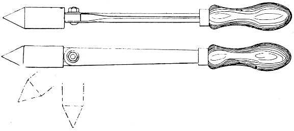
Fig. 3.—Pivoted Soldering Bit
—The soldering bit or bolt (miscalled an “iron”) carries a pointed lump of copper at the end (Fig. 2), riveted in, or alternatively, in small sizes, screwed on to the shank. Some bits are pivoted[18] (see Fig. 3) to enable them to point at various angles for dealing with difficult situations.
A home-made bit (Figs. 4 and 5) may be made by drilling and tapping a short length of 11⁄2-in. or 2-in. square copper to receive the screwed end of a rod of 5⁄16-in. iron, the copper being afterwards heated and drawn to a point or to a blunt edge as preferred. This forms a good bit for most ordinary purposes. An axe-head or hatchet bit is shown in Fig. 6; the copper bolt is riveted in the eye of the iron rod, the bit, however, being free to revolve, as this is essential when making joints in heavy lead pipe, for which purpose it is principally used. Fig. 5 represents a bit which is a combination and modification of the two others, and it is largely used for the internal soldering of bottoms of large drums, milk churns, etc., where great local heat is required.
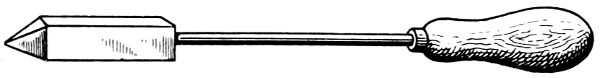
Fig. 4.—Home-made Soldering Bit
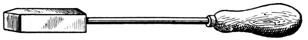
Fig. 5.—Bit for Internal Soldering, etc.
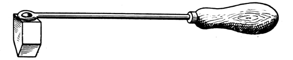
Fig. 6.—Hatchet Soldering Bit
As to the size of bit required, for ordinary small[19] work the straight type should not be less than 8 oz. or 10 oz. (weight of the actual copper).
Two bits are very useful in doing a large job, as the work can then be arranged to progress continuously, one bit heating while the other is in use.
A bit suitable for quite light work can be easily made by drilling and tapping a piece of copper, say 1⁄2 in. by 1⁄2 in. by 11⁄2 in. long, either in the end or in the side, for a 3⁄16-in. steel rod 12 in. long, a handle being then fitted at the other end.
In the “Tinol” telescopic soldering bit for amateurs’ use, the handle is in three parts: (a) the actual wooden handle bushed with metal, and provided with a set-screw shaped like a screw eye, and therefore easily turned; (b) a steel tube which telescopes into the first part, and which is also provided with a set-screw; and (c) a short rod, having at one end a[20] hatchet-shaped copper bit. The extreme length of the tool is 12 in., and the length, when the parts are telescoped together, is about 5 in.
The “Fluxite” bit is larger and heavier. It has a hollow cast-iron handle, perforated to dissipate the heat, threaded internally at one end to receive the screwed end of the iron stem, only 5 in. or so in length, which at the other end screws into an adapter or holder which, in turn, receives the screwed end of the copper bolt, itself about 4 in. long. The bit is taken to pieces in a few moments, and is quite a workmanlike tool.
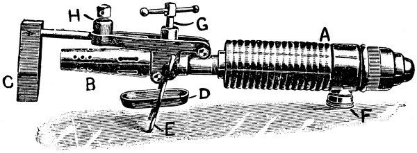
Fig. 7.—Spirit-heated Bit
—Bits heated by benzoline or spirit may be made with a small barrel-shaped reservoir which also forms the handle. One end of the reservoir is fitted with a filling cap, and from the opposite end protrudes the tube carrying the burner. To the tube end of the reservoir an iron clip is attached, and this secures an iron bar which stands out over the burner head. At the end of this bar the copper bit is attached and held either vertically or[21] horizontally in the flame. Tool merchants’ catalogues show a variety of such implements. Fig. 7 illustrates one of the most elaborate of them all, the weight complete being 21⁄4 lb. It has a polished brass container A, of 1⁄5 pint capacity—sufficient for 45 to 60 minutes, whence the benzoline flows to the burner B, the flame from which heats the copper bit C. This bit may be of any of the regular shapes, and weighs about 1⁄2 lb. The position shown is that for heating the bit preparatory to soldering. The tray D catches any drips that might occur at starting, E is the stand, F the filler cap, G is the regulating handle, and H is the clamp that holds the bit in place.
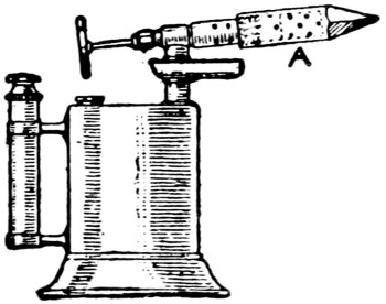
Fig. 8.—Bit attached to Blow-lamp
A writer in Popular Mechanics has stated that the ordinary blow-lamp, with the burner end equipped with a copper bolt (see Fig. 8), makes an excellent soldering device. The point can be easily kept at the proper heat, and there will be no want for hot coppers. The end of the burner is threaded on the outside, and a hole is drilled in the copper point and threaded to match. Small holes are drilled in the copper in the same manner as in the burner, to make vents for the flame.
[22]

Fig. 9.—Gas-heated Bit
—These are largely used in factories, and are cleanly, expeditious, safe, and convenient. The type shown by Fig. 9 is very handy, and the illustration and description are due to F. X. Sommers, Jun., in the American Machinist. A mixture of air and gas enters the pipe at about 10 lb. pressure, or enough to give a hot, blue flame. The part A is of cast-iron, which, on experiment, has been found to last longer without corroding than steel, although copper would be better. The soldering bolt B was made of steel because it kept the correct shape point much longer than cast-iron or copper, although the latter metal is better for transmitting the heat. The point should be tinned before using. This form of soldering head is being used on automatic can-soldering machines, and does the work effectively. It also saves gas. It will heat to the correct temperature in about 11⁄2 minutes.
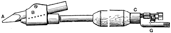
Fig. 10.—Gas-heated Bit complete
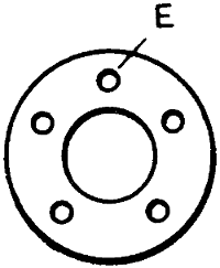
Fig. 11.—Air Inlets in End of Air Chamber
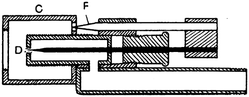
Fig. 12.—Section through Air Chamber and Gas-reducing Valve
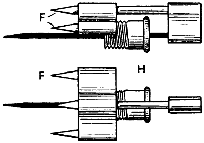
Fig. 13.—Details of Cones or Needles
A gas-heated bit invented by W. G. Ryan is shown in Figs. 10 to 13. The actual bit A is held in a steel sheath B having a space underneath the bit to allow the gas to pass. The sheath has a row of holes on each side to allow the gas to come through, the flame enveloping the bit when in use. The gas, supplied through a flexible tube, passes through the tube that forms the handle, at the end of which is a small chamber C to admit air, which mixes with the gas to cause it to burn atmospherically, the supply of gas passing through a small cone valve D and thence through the air chamber. In the air-inlet holes E at[23] the end of the air chamber are fitted small cones F to regulate the quantity of air. All the cones, including the gas-valve cone, are connected rigidly together, so that when cutting down the gas supply temporarily, the air supply is automatically reduced, and the gas flame remains in being, although its size is much reduced. It has been found that, in some gas-heated bits, the cutting down of the gas seriously interferes with the proportion of the gas and air mixture, resulting[24] in a back-fire. The device here described has been invented especially to obviate that trouble. To reduce the gas supply and, with it, the air supply also, all that is necessary is a slight forward movement of the fitting to which the cones or needles are attached. The copper bit is kept in position by the sheath or clip, the small bolt in which can be taken out in a moment when special attention to the bit becomes necessary. The connection to the flexible gas tubing is at G, while H indicates a guide and stuffing box for the gas-valve cone or needle.
Fig. 14.—Gas-stove for Heating Bits
—Although a copper bit may be heated in any fire, it is better to avoid the dirt, smoke and tarry stickiness which are often present in a coal fire. In the absence of gas, a bright, clear coke fire or a charcoal fire should be used whenever available. Portable oil stoves of the wickless type can also be employed, but the ideal fuel is gas, which may be regulated at will to give a[25] uniform temperature. Two gas-stoves specially constructed for copper bits are shown by Figs. 14 and 15.
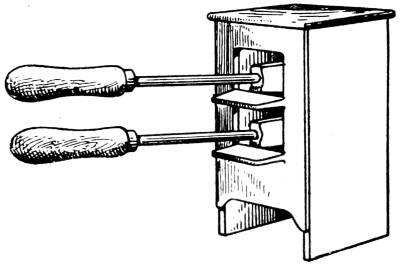
Fig. 15.—Gas-stove for Heating Bits
—Before a bit can be used, it must be “tinned,” that is, coated with solder in a smooth complete covering, for which purpose—by one method, not the best, but the most general—the end is heated to a dull red, rubbed quickly with the file on the facets, dipped in killed spirit or “fluxite,” or rubbed against a piece of sal-ammoniac, and then applied to a stick or lump of solder, the facets being quickly wiped or rubbed on a piece of tinplate so as to spread the solder evenly. When properly done, the nose of the bit is coated with a smooth film of solder. This must always remain so, or the bit will not act, and when it is honeycombed, or the “tinning” is present in patches, it must be re-tinned. A bit must never be raised to a red heat sufficient to melt the tinning. The bit does not operate well at such a heat, because its contact makes solder too fluid and apt to run too quickly.
[26]
When dipping a hot bit, prepared for tinning, into killed spirit, a sharp pop, without smoke or spluttering, denotes the right temperature. If, on withdrawing the bit, it is damp and still unclean, it had not been heated sufficiently.
Another method of tinning may be mentioned. Into a small and clean tin box (a 2-oz. tobacco tin about 3⁄4 in. deep) put some scraps of solder and powdered resin. Heat the bit to a very dull red, quickly file up clean on one side of the point, and then plunge into the solder and resin and rub about; it will at once take on a coat of the alloy. A second side of the bit may be tinned by then repeating the operation, re-heating if necessary. The bottom of the box should be covered with solder, which adheres easily enough, with a film of resin on top. It is probably most convenient to tin the under side and the left-hand working face of the bit. “Tinol” could be used in this way without admixture with anything.
Still another method is to use a firebrick having a hollow in which the solder and resin are placed; but the tin box plan is thought to be better.
Undoubtedly the best method of tinning a bit is that in use by the plumber who well knows the invaluable qualities of sal-ammoniac (ammonium chloride) for the purpose. He has no wish to squander energy on those vigorous rubbings of the bit—on paving-stone, bath brick, tinplate, etc. etc., and he believes that the habit of dipping the bit into zinc chloride is both slovenly and wasteful, for not only is[27] this corrosive stuff sprayed about broadcast, but the remainder is soon rendered unfit for its purpose by contamination with copper chloride and dirt from the fire. The outlay of a few halfpence on a sizable slab of sal-ammoniac will keep the bit in the best condition for years, and save hours of superfluous labour. Commercial sal-ammoniac is obtainable in large, rugged crystals of a tough, fibrous texture. A piece weighing upwards of 1⁄4 lb. can be trimmed to a roughly rectangular slab, a few inches long and wide and about 1 in. thick; and a cavity should be scooped in one of the flat sides to accommodate the bit.
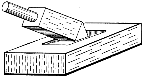
Fig. 16.—Tinning Bit in Sal-ammoniac Block
Let the bit-faces be made shapely and filed bright and the tool thoroughly heated in a clean fire, removed, flicked free of ash, and then held down firmly in the cavity of the sal-ammoniac block (see Fig. 16). Profuse white fumes will arise, and the surface of the salt will fuse. Bear heavily on each facet in turn, and then melt a few beads of solder into the cavity along with the bit, and the latter will become brightly tinned[28] in a moment or so. The bit should be applied to the “ammonia block” every few heats, or as required, as the work progresses, and flicked with a tuft of dampened cotton-waste.
The sal-ammoniac has one great disadvantage—it is deliquescent (collecting moisture from a damp atmosphere), and its near proximity to most metals oxidises and corrodes them. Iron and steel, particularly, it rusts rapidly and deeply. Therefore the tools (saw and chisel) used to shape the block must be washed, dried, warmed, and greased before they are laid by, and the waste fragments must be carefully swept up and disposed of. The block itself must always be kept apart from tools. Plumbers enclose it in a sheet-lead box wrapped in a greasy rag; amateurs may store it on a dry shelf, parcelled in waxed paper secured by a rubber band, or in a length of motor-tyre inner tube, rolled up.
—Scrupulous cleanliness in everything connected with the process of soldering is essential to success. The ordinary procedure in making a joint is to clean the surfaces first by filing or scraping with a scraper or a knife or a plumber’s shave-hook (Fig. 17). In some cases, dirty metal is cleansed with dilute hydrochloric acid. With or without preliminary heating of the work, flux is then applied to the joint, and the heated bit is held in one hand and a stick of solder in the other, and the stick drawn along the joint while the bit touches it (or “drops” of solder may be transferred to the work by[29] means of the bit). This will cause a line of molten solder to run, and some skill and care are necessary to get just the right amount of solder without wasting it and allowing it to spread in a lumpy fashion beyond the necessary area. The bit is next worked up and down the joint to spread the solder, and by the transmitted heat to make it thoroughly penetrate the joint. This is an outline of the process, and there is a number of points requiring special instruction or a few words of caution.
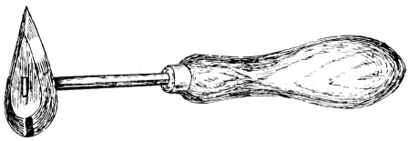
Fig. 17.—Shave-hook
Note that the work must be filed, scraped, or otherwise mechanically cleaned, and then chemically cleaned by coating with the flux just where the soldering is required. In heating the copper bit do not let it reach even a dull red heat. Lightly dip it into the flux to clean the point; then, with a small button or blob of solder resting on the work, place the bit momentarily upon it to cause the solder to flow, and draw the bit where the solder is required.
Many beginners try to draw along the solder with an insufficiently heated bit. The result is a series of lumps—“putting it on with a trowel,” as it is sometimes termed. A good joint cannot be made this way, however much solder may be used.
[30]
Some beginners fly to the other extreme, and try to make a neat job with a red-hot bit, which results in the solder assuming a sandy appearance and in the work being discoloured.
Others try to solder uphill—that is, they hold or place the work in such a way as to cause the solder to flow away from where it is required. The correct method is to solder downhill by tilting or inclining the work, so that the solder will always collect around and travel with the point of the bit. This, besides facilitating the work, makes a strong joint, and imparts a clean and neat appearance to the job.
Figs. 18 and 19.—Incorrect and Correct Methods of Holding Bit
A common mistake is to hold the bit in a cramped and awkward way, as in Fig. 18, the hand being twisted under the handle, the thumb being brought to the top, and the elbow forced to the side. The correct positions of arm and fingers are shown in Fig. 19; the elbow is held well out from the body, and the thumb is placed directly under the handle of the bit, forming a fulcrum over which the bit may be slightly raised or depressed at will. This is all-important when soldering very fusible metals such as pewter, tin, etc., on which the weight of the copper bit should never be allowed to rest, as otherwise a hole will suddenly be made in the work. The whole weight of the bit should be supported and balanced on the thumb by the downward pressure of that part of the hand close to the little finger. The worker should not for a moment lose control of the copper bit, and control is always assured when the thumb is underneath the handle.
[31]
There is but little strength in a butt joint with the edges of the metal only just touching—that is, without a lap; to take the example of a small cylinder, the body seam should have at least a 1⁄4-in. lap. Fig. 20 represents an example of internal grooved seam soldering, which may be executed in the following way:—After applying the flux, place a small button of solder inside the cylinder on the seam, rest the bit momentarily on the solder to melt it, and then draw it gently along the seam. The cylinder should be slightly tilted to allow of the solder travelling with the point of the bit. The hand should avoid touching any part of the work that comes directly into contact with the copper bit, as otherwise the hand would be badly burned.
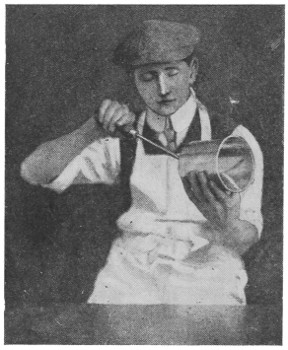
Fig. 20.—Soldering Internal Grooved Seam
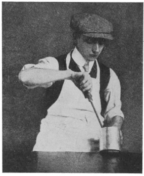
Fig. 21.—Soldering on Can Bottom Internally
The method of internally soldering the bottom on a canister, etc., is shown in Fig. 21. The bottom is[32] held in position by gently pressing it against (but not placing it on) the bench during the soldering process, while the tilt of the canister and the position of the bit cause the solder to travel with the bit.
In soldering all such articles, the soldering should be done with one sweep of the bit, the left hand meanwhile making the necessary revolution. This saves time and solder, and avoids the unsightly appearance of a series of starts and stops.
In work of a larger and more substantial nature, as, for example, galvanised or tinned iron work, the bottom of the article is first “knocked up,” and then soldered internally. Fig. 21 represents an example of internal soldering where the whole weight of the bit is shown resting on the molten solder inside; this provides the local heat required to “sweat” the solder into[33] the four thicknesses of metal which constitute the bottom seam; and for this work the bottoming bit shown in Fig. 3 is often used. Pewter, lead, zinc and tin—the latter should not be confused with tinplate—do not require sweating, on account of their low fusibility, and any attempt even to solder them with a very hot bit will probably end disastrously.
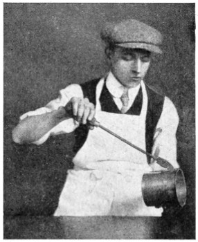
Fig. 22.—Soldering Can Externally
Fig. 22 shows an example of external seam soldering. The method there shown is invariably adopted for simple lap seams, although grooved seams are similarly soldered. A grooved seam, however, should preferably be soldered internally. The position of the worker’s elbow and thumb should be noted, as should also the tilt of the cylinder (more pronounced in this case than the other) in order to secure the downflow of the solder.
Sweating has already been mentioned. It should be said that one of the easiest ways in which a beginner may make a reliable joint is to prepare both faces of the joint by fluxing and covering with a thin film of solder, and then pressing the two parts together with the hot bit until the top part “floats” and then[34] settles down. The advantage of this way is that one can be sure of perfect application of the solder to the joint faces, since each is dealt with first and thoroughly coated, with no faulty patches. Sweating is also done in the flame of a bunsen burner or blowpipe, as explained later.
—The bottoms of square or cylindrical vessels should, preferably, be soldered from the inside, and “buttons” of solder may be melted to assume a stout triangular-shape stud in the corners of the square vessels. A tinned rivet is sometimes riveted or just placed in a corner, and sufficient solder floated over it to strengthen the corner. Solder is always liable to run through an improperly closed seam at the corner when external soldering is resorted to; but in cases where this is the only practical method, a tinned rivet may be inserted from the outside, and then soldered over. It sometimes happens that two “raw” edges require soldering together without a lap. Where a strong joint is required a good plan is to place a length of tinned wire over both edges and solder the lot together. In addition to strengthening the joint, the wire considerably improves the general appearance. A simpler joint may be made by “skimming” the solder over with a copper bit heated only just sufficiently to melt the solder. The quick and skilful touch is required to perform this operation satisfactorily; but a little practice will soon bring the necessary proficiency. The idea is to “draw” the solder across the joint[35] quickly, before it has time to run through. This method is useful when soldering thin metal goods of a lower degree of fusibility than that of the solder employed. No preparation for filling cracks previous to soldering can be recommended, beyond such small pieces of metal that may be afterwards soldered over and effectively hidden. It is much better to endeavour to produce work of such quality that this expedient is altogether unnecessary.
—When soldering the bottom rims on large milk churns, sufficient heat cannot be maintained with only one soldering bit. At least two heavy bits are required, so that one may be getting hot while the other is in use. The rims are usually tinned before being fixed by first pickling them in dilute hydrochloric acid, washing, and then dipping in a bath of molten tin. When repairing and resoldering the rims, remove all dirt and rust with a file, use a few brushfuls of raw spirits further to assist the cleaning process, then wash with clean water and solder in the usual way, using killed spirits as a flux.
—First scrape or file away the enamel quite clear all round the hole, apply a little raw spirit to the surface of the iron, and coat it with solder in the usual manner. Then cut out a tin disc large enough to cover the hole, and solder this in, using killed spirit as the flux.
—For soldering the calmes of a lead-light window, the calmes having been fitted properly together, shave a small round dot at the point[36] of junction, sprinkle a little powdered resin on the shaving, and with a copper bit or with a glazier’s iron having a tinned face, melt a small piece of tinman’s ordinary solder on the shaved part so that it tins to the lead and forms a round button.
—In soldering a catch on a gun barrel it will first be necessary to tin both barrel and catch, and then to wire them together, in addition binding the barrels for some distance from each side of the catch, making the ribs secure with wedges. To melt the solder, use heaters; these are generally made of copper with iron handles; or iron rods can be used, the ends being made red hot and inserted in the barrels. Cut some small slips of thin solder and place them on each side of the catch, using powdered resin. As soon as the solder melts, remove the heaters and cool the barrels.
[37]
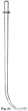
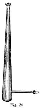
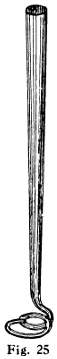
Fig. 23.--Mouth Blowpipe
Fig. 24.--Black’s Mouth Blowpipe
Fig. 25.--Fletcher’s Mouth Blowpipe
Fig. 23.--Mouth Blowpipe
Fig. 24.--Black’s Mouth Blowpipe
Fig. 25.--Fletcher’s Mouth Blowpipe
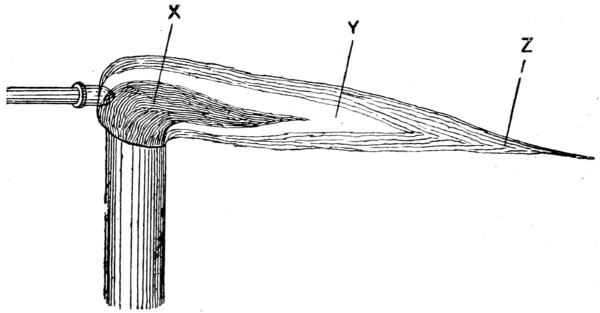
Fig. 26.—Section through Blowpipe Flame
—Although soft-soldering is usually associated with the use of a copper bit, quite a number of jobs can be done without one, using instead a bunsen burner or, more generally, a mouth blowpipe, which is an inexpensive appliance, useful for both hard and soft soldering, and with either gas,[38] candle, or a methylated-spirit flame. Three shapes of mouth blowpipe are shown in Figs. 23 to 25. In a blowpipe flame there are three cones, X, Y, Z (Fig. 26). X is a non-luminous cone, consisting of a mixture of atmospheric air and unburnt combustible gases (each with a low temperature); Y is a luminous cone, composed of burning gases (carbon and carbonic acid being in excess); and Z is a cone the oxygen in which renders it less luminous and free from combustible materials, its temperature being exceptionally high, especially where the cone comes in contact with the point of the cone Y. Because of its properties, Z is termed the oxidising or outer flame, whilst Y is known as the inner or reducing flame, because when it is applied to some easily reducible substance—say, lead oxide—the oxygen in the substance heated mingles with the unburnt carbon in the cone of the flame and produces carbonic oxide, the lead being thus separated or reduced. The blowpipe flame is one of intense heat, even that produced by blowing a common candle being capable of melting metallic fragments when they[39] are supported on a bed of charcoal. The pointed flame gives the greatest heat, and this can be produced simply by increasing or decreasing the space between the flame and the article to be soldered or the metal to be melted.
The particular advantage of a blowpipe is that it gives a fierce heat at a very localised area, beyond which the solder does not run, and it enables spots to be soldered, or parts to be unsoldered, adjusted and re-soldered without allowing heat to stray and cause trouble at other places. A useful little addition to the ordinary blowpipe is a small washer soldered on near the mouth end (see Fig. 23), the object of this being to raise this part off the bench and so keep it from contamination with dirt, filings, etc., which are unpleasant to the lips. Sometimes the washer is made elliptical and slightly concave to fit the lips, so that it forms a[40] convenient stop or steady when the blowpipe is held between the teeth without help from either hand.
—The bunsen burner is, of course, the most convenient device for heating (when the bit is not in question); but failing a gas supply, a spirit-lamp must be employed. This is a small glass bottle with wick, methylated spirit being used. Plumbers and gasfitters make use of metal tubular lamps fed with spirit poured on cotton-wool, and having a blowpipe tube attached and coupled up to the lips with a rubber tube; they also use wax tapers.
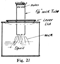
Fig. 27.—Home-made Spirit-lamp
Fig. 28.—Another Home-made Spirit-lamp
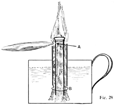
Fig. 27.—Home-made Spirit-lamp
Fig. 28.—Another Home-made Spirit-lamp
A methylated wick lamp may be easily made out of a small “self-opening” canister, as shown in Fig. 27. The holes near the top increase the efficiency of the flame. Another spirit soldering-lamp is shown by Fig. 28. The container for the spirit can be made about 3 in. in diameter by about 11⁄2 in. deep, with a handle soldered on. A glance at the illustration will explain the burner. An outer wick surrounds a piece of tube, which itself contains another wick. The spirit in the inner tube is vaporised by the heat from the burner when the outside wick is lit. The spirit vapour issues from a 1⁄32-in. hole at A. At B a ring is slipped over the outer wick, holding it to the central tube. By lifting the central tube the height of the vaporising flame can be adjusted. The vaporising tube is a piece of 3⁄8-in. brass tube with a 3⁄8-in. gas cap screwed on the end, or a brass disc can be brazed in. The total cost should not exceed sixpence.
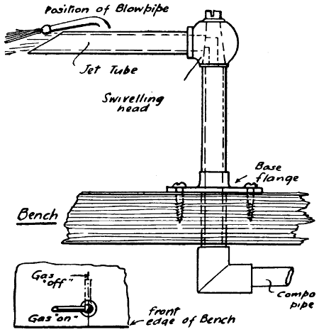
Fig. 29.—Swivelling Gas-burner for Bench Soldering
—The best form of gas bracket for[41] bench use is one having a horizontal swivelling arm, and screwed to the bench by a flange, as shown in Fig. 29. The swivelling head is also a cock, which shuts off the gas when the jet arm is pushed over at right angles to the edge of the bench, as indicated, and the gas is connected by an iron or compo pipe under the bench. A second gas tap should be arranged in the supply to regulate the amount of gas, and for reasons of safety. A simple device (see Fig. 30) may be made by anyone, and connected to a rubber-pipe connecting head on the gas bracket supplying light to the bench and workshop.
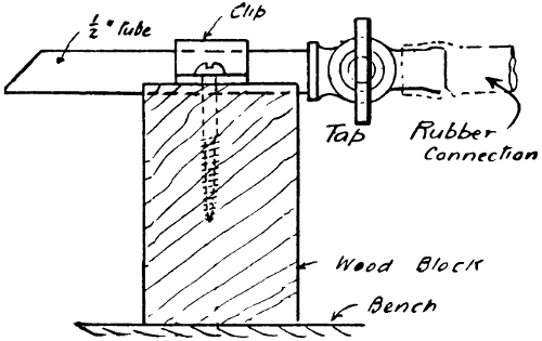
Fig. 30.—Simple Bench Burner

Fig. 31.—Gas Blowpipe for Bench
A design of gas blowpipe which leaves one hand free is shown by Fig. 31. This enables the worker to apply the solder to the work (holding the end of a strip against it), after it has been brought to the melting heat of the solder. The blowpipe is arranged so that it can be held in the hand or dropped into a hole in the bench.
—Tapers for a blowpipe flame are made by untwisting cotton rope until the threads of the individual strands are straight. These are then dipped[42] in melted wax made by melting two wax candles over a gas stove in a jam jar. They are repeatedly dipped until sufficient thickness of wax is obtained. The wax should be just sufficiently hot to keep melted.
—The blowpipe is not essential for some kinds of work, such as when the job can be held wholly in the flame without causing any damage. When solder is being melted to drop on to a surface, the plain bunsen or atmospheric flame is also sufficient, though in this case it is well to tilt the burner over so as to prevent the solder dropping down the tube. An elbow fitted on the top of the tube is handy in this connection, to deflect the flame at an angle, and Figs. 32 and 33 show this, with the addition of a tray to catch the dripping solder which otherwise would splash on the bench and cause untidiness. The tray is riveted to a strip of brass bent round to slip over the outside of the elbow, and a small pin riveted into the tube prevents the tray from falling down.
[43]
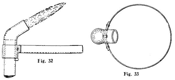
Figs. 32 and 33.—Bunsen Burner and Solder-catching Tray
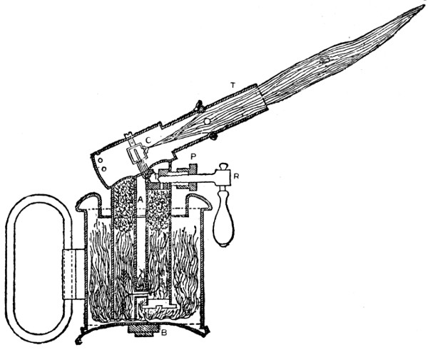
Fig. 34.—Section through Blowlamp for Soldering, Brazing, etc.
[44]
—A soldering lamp is used sometimes in the place of a blowpipe, and it should combine perfect security with compactness and portability. Tool merchants’ catalogues show a number of styles. In the lamp shown by Fig. 34, benzoline is burnt. When the lamp is in use and the body of it is very hot, the inside pressure does not exceed three-fifths of an atmosphere, whether the regulator R is open or almost closed. Thus the danger of explosion, which is such a drawback to some of the lamps that use ordinary paraffin, is avoided. The upper parts of the lamp are subjected to great heat and therefore are packed with asbestos, which serves as a filter and stops any impurity in the benzoline from getting to the burner. The flame can be lowered to a glimmer when not actually in use, thus saving the trouble of relighting. When the lamp is to be used, the regulator R is screwed up tight; and care must be taken to ascertain, from time to time, that the burner or nipple C is open and perfectly clean. If this becomes obstructed, it can be cleaned by unscrewing the tube T and passing a fine steel wire through the hole. The lamp should be completely filled with benzoline every time it is to be used. A little methylated spirits is poured into the basin A, and set alight. When the apparatus has become slightly warm, the regulator is opened gradually. To extinguish the flame, the regulator must be screwed up tight. If any escape is observed round the screw of the regulator, the square P should be screwed up with the key supplied by the makers, so as to tighten the asbestos packing. The lamp above described is only one of a great number of such appliances, but it is fairly typical of them all. The difference between a solderer’s and a brazer’s blowlamp is merely one of size and power.
[45]
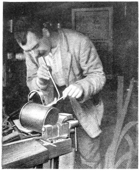
Fig. 35.—Soldering Lading-can handle
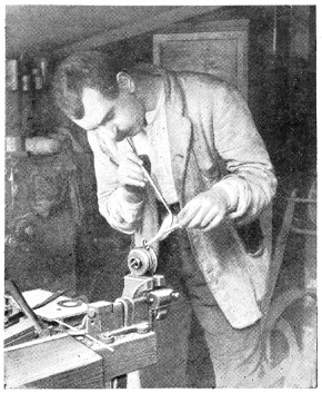
Fig. 36.—Soldering Lug to Lamp Bottom
[46]
—The operation of using the mouth blowpipe does not consist in blowing intermittent and strong blasts with the lungs, as this would soon exhaust the wind power. For very light jobs, however, this method is sometimes adopted; but once the proper way is discovered, the user naturally falls into the use of this method.
The proper way to keep a continuous blast is to breathe naturally through the nose, and at the same time keep the cheeks distended by forcing the air at sufficient pressure from the lungs. The cheeks naturally resist the pressure, and force the air through the blowpipe. The operation requires some practice and a clear nose passage. There is practically no limit to the time a continuous blast can be kept up.
The blowpipe flame is produced by holding the blast end of the blowpipe just above the wick of the taper and touching the flame; the blast then causes a long blue flame to project. This flame is hottest at the tip, which is slightly brown.
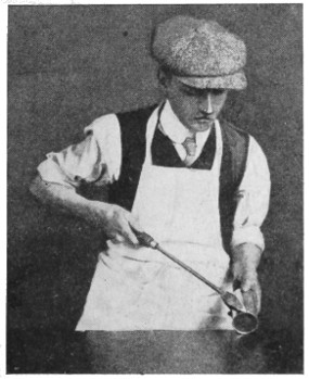
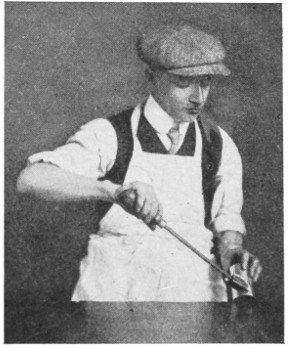
—Some of the photographic reproductions in this chapter show the methods of soldering comparatively light and heavy articles. [47] Fig. 35 shows a lading-can handle being resoldered. As it had broken away, the old solder remained, and the joint did not need cleaning. It is dabbed with the killed-spirit brush, and a small piece of solder put near the joint. The flame is first played on the parts away from the solder to get them to the requisite heat, and as the heat reaches the solder it melts, and flows where[48] required. Where the solder should be the thickest, that part of the joint is inclined downwards.
A job needing very much heat, and therefore a continuous blast for some time, is shown by Fig. 36. A lug is shown being soldered to a heavy brass lamp bottom. Before putting the lug in position the parts of the joints have to be tinned. This consists of applying a film of solder. In this case the heat is applied to the lamp bottom for several minutes, and without loss of time the part where the lug fits is cleaned with a fine file, the spirit brush dabbed on a piece of solder, put in position, and the flame again applied. The solder almost immediately flows over the cleaned portion; if it does not flow as required, the flame is played on the solder and lamp bottom, a dab with the spirit brush helping matters. The lug, which should have been previously tinned, is placed in position on the lamp bottom, and with a slight application of the flame, the solder flows and unites the parts firmly together. It should be particularly noted that, when uniting light articles to heavy ones, the light ones should be tinned first, and secured to the heavier article whilst the latter is still hot.
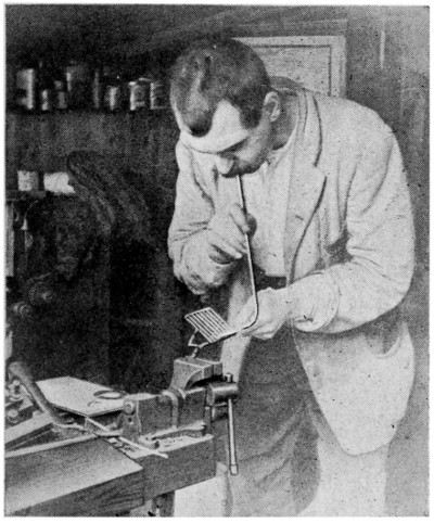
Fig. 37.—Soldering Wires of Vegetable Masher
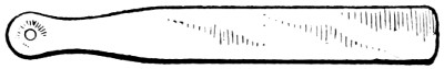
Fig. 38.—Holder for Applying and Adjusting Solder
Fig. 37 shows the wires of a vegetable masher being soldered. There is nothing special about the job, except that the solder cannot be placed on the joint. To effect this a piece of tin (Fig. 38) is indented at one end, and a small hole made in the centre of the depression. The bead of solder is placed in this depression, and held over the joint to be soldered; the flame is then played on the joint and on the solder which flows through the hole.
[49]
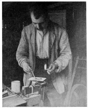
Fig. 39.—Brushing Solder around Dial Ring
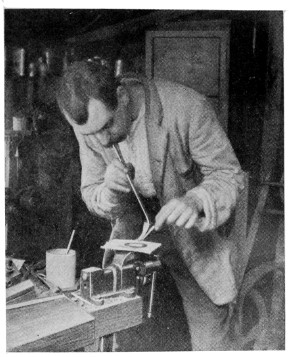
Fig. 40.—Tinning Dial Ring
[50]
Figs. 39 and 40 show the method of tinning a brass dial ring. The ring is filed clean and placed on a piece of asbestos board, the flame being applied until the ring is sufficiently hot all round. A bead or two of solder is placed on, and, as they melt, the solder is brushed round as shown in Fig. 39 with the spirit brush, the flame being applied at intervals to aid the flow.
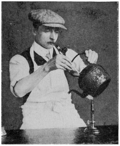
Fig. 41.—Re-soldering Kettle Spout
—Refixing a spout in a “tinned” wrought-iron or copper kettle. The spout and that part of the kettle which comes in contact with it should first of all be filed bright and clean. Next place the spout in position, apply killed spirits, and hold it over a bunsen flame, as in Fig. 41, until sufficient of the strip solder is melted to flow around and sweat through to make a strong sound joint. Should any difficulty be experienced in getting the solder to flow readily, apply a little more flux.
—When the surface of metal to be soldered is badly corroded, and it is difficult to obtain a clean, bright surface preparatory to soldering, it should be treated to a liberal application of raw spirits of salts (hydrochloric acid), which will soon remove the cause of the trouble, but all traces of the acid should be washed away with clean water before attempting the soldering. It is also a good plan in these cases to tin the surface by repeatedly rubbing it with a hot bit and solder, together with plenty of killed[51] spirits, before proceeding with the actual soldering process.
—When soldering two small awkward-shaped pieces together, they can be held in position by pressing slightly into a piece of damp clay. When the work has several soldered joints it can be buried in sand or covered with clay to confine the heat to the part being operated on.
Although care should be taken to limit the solder to the area of the joint, there are circumstances in many cases where it is difficult to prevent some of it from straying. To clean this off, resort may be had[52] to the blowpipe, applying the blast and quickly wiping the surface while the solder is in a molten state. Or it may be filed off while cold and finished with a scraper or a knife and emery-cloth. Or if there is only a thin film the knife or emery-cloth alone will suffice.
—Most joints in lead, tin and compo. pipe are now preferably made by means of a blowlamp, or with a mouth blowpipe, strip-solder being used. When making the joint, heat the pipe in the immediate vicinity, and, dipping the solder in the flux, stroke it around the pipe to form the joint.
In soldering block tin or compo. pipe with a bit, if this is too hot it will promptly melt the pipe. This is also liable to happen with very thin zinc. The only way to prevent this is to have the bit just hot enough to melt the solder, and not to let it rest any length of time on the soft metal.
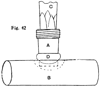
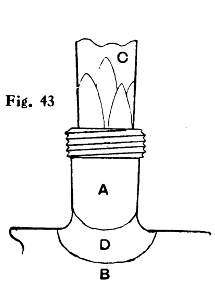
Figs. 42 and 43.—Soldered Branch Joint on Tin or Compo. Pipe
In making connections with soft pipe it is better to make use of brass couplings, and these can be soldered more easily and safely by means of the blowpipe than with a bit. First clean and tin both ends of the coupling, and with the bit put a little ring of solder round about 1⁄8 in. from the end, as shown at D in Fig. 42. Next with a penknife cut a hole in the pipe B where the connection is wanted, a neat fit for the end of the coupling tail A, scraping the surface of the pipe all round the hole. Insert the coupling in the hole in a vertical position. Sprinkle a little powdered resin round the joint, or smear it with fluxite. Using the flame of a spirit lamp or a candle and a[53] mouth blowpipe, heat the upper part of the coupling, being careful not to allow the flame to come too near the soft pipe. The solder will soon melt, and run down into the joint (see D in Fig. 43), when the flame must be instantly withdrawn. The same proceeding can be adopted in soldering the other portion of the coupling into the connecting pipe. If a vertical position is inconvenient for the coupling it can still be soldered in that position, and afterwards twisted carefully into the desired position. In Figs. 42 and 43, C represents a wood plug for steadying the coupling tail.

Fig. 44.—Soldering Birdcage Wires
—For this job, it is better to flatten out the solder to the thinness of brown paper and with a pair of scissors or shears to cut it into very narrow strips. Take little pieces about 1⁄4 in. long, and with the fingers pinch them round the wires just above the joints to be soldered. Touch each joint with a small quantity of killed spirit, and apply the flame of a small blowlamp just underneath the joint;[54] this will cause the solder to run in the joint in an instant (see Fig. 44). The flame is quite free from smoke, and does not discolour the wire in the least, as the solder will run long before the wire is red hot. Every joint may thus be neatly made. With a thin piece of copper wire secured in a handle as illustrated, the solder may be drawn any way desired to make special joints in awkward places, where the point of an ordinary soldering bit could not be used.
—In the preceding chapter it was shown how useful sweating is, when accomplished with the help of the bit. In blowpipe work, also, this method is of much utility, particularly in delicate work where portions have to be joined up in very precise relations. After tinning the joint faces the pieces are secured in accurate relationship with binding wire, or by bolts or screws or other means, or a soldering clamp is employed, having jaws which clamp the pieces and enable them to be adjusted to the exact locations desired, and the flame then brought to bear until the work is hot enough to cause the solder to run.
An example of the usefulness of sweating occurs in the making or repairing of metal name plates having superimposed brass, copper, or other metallic letters. The plate having been flattened and polished and the letters cut out, filed and finished, the backs of the letters must be rendered chemically clean by careful scraping, and are next “tinned” with soft solder. The tinning may be done in several ways, but the easiest is by the blowpipe, using resin oil as flux.
[55]
Each letter may be placed in succession on a lump of charcoal, using plenty of the resin oil, and applying the flame of the blowpipe to the surface while one hand holds the charcoal and the other the strip of solder. To prepare the solder, which is sold in sheets by the pound, cut some strips 1⁄3 in. wide. Take hold of one end 1 in. from the end, and with a sharp knife scrape the surface, drawing the knife edge downwards. Do not use the last 2 in. of the strip, as the handling of this part makes it chemically unclean. The greater part of the solder should be about the edges of the letters. The next operation is to solder the letters to the brass plate. As the brass plate also must be chemically clean, the parts where the letters are to go should be lightly scraped. Having ruled parallel lines in order to get the letters in line, lay each down in its proper place, and draw a pencil line round it; then with a scraper just remove the surface of the brass where the letters are to be soldered. A thin piece of[56] solder is now placed underneath each letter, and each in turn is fixed in its place and secured with a loop of binding wire screwed up tight. Nothing now remains to be done but to apply the blowpipe flame and resin oil, when the solder will run underneath the letters. It is better to set the plate on some small lumps of charcoal. When the letters appear to be set fast, remove the plate and boil it in a solution of potash, about 1⁄2 lb. to 11⁄2 gal. of water, and clean in dry sawdust. The resin oil may be made by dissolving resin in sweet oil by gentle heat, until the oil will cause the solder to run.
[57]
It is well known to those accustomed to the art of soldering that there is no solder which operates with aluminium in the same way that ordinary solders operate with tinplate, copper, brass, etc. Aluminium soldering presents so many difficulties that it has been thought desirable to devote a separate chapter to the subject.
There is more than one reason for the difficulty encountered. Aluminium does not alloy readily with solders at temperatures as low as other metals require; and, secondly, aluminium alloys with lead solders only with great difficulty, and with but a small proportion of lead at that. Consequently, lead solders are not suitable for aluminium. Another and even more serious reason is in respect to the refractory oxide which forms at soldering temperatures, and which is undoubtedly responsible for most of the trouble.
The soldering of aluminium is one of the most debated subjects in metal working. Almost as soon as aluminium was prepared on a large scale, it was discovered that the ordinary solders and fluxes did not answer with it. Either pure tin or pure zinc will wet aluminium, and can, therefore, be used as solder for it; experience shows that the tin soon falls apart, while[58] zinc by itself is brittle and discolours badly. The failure of tin is due to the fact that it forms with the aluminium an alloy that is decomposed by the action of the oxygen present in the air.
Although aluminium is popularly supposed to be non-oxidisable, really the surface is covered with a very thin film of oxide, which prevents solder from alloying with the metal. Aluminium when heated rapidly oxidises. It is customary to scrape the metal before and during the soldering; and although some workers say that it is useless to scrape before soldering because oxidation immediately starts again, it is obvious that a thin film is more easily penetrated than a thick one. Often it answers to scrape with the copper bit during the soldering, previously rubbing off the oxide with emery cloth. The work should, if possible, be backed with asbestos, to keep up heat in the metal. To discover whether the surface is thoroughly tinned, wipe off lightly, and the untinned parts will then soon become apparent. If the oxide is not scraped off beforehand, it will probably mix with the solder and form a scum, which will make a neat flow difficult. Scum should be lightly removed with an old knife blade. It is essential to “tin” every part to be joined, as the solder will not take on any spot that has not been rubbed in some way, unless previously coated.
—Hundreds of aluminium solders have been invented, naturally all claimed to be strong and durable, the alloys containing various[59] metals, such as aluminium, antimony, bismuth, cadmium, chromium, copper, lead, manganese, silver, phosphor tin, tin, and zinc. A table of the most approved aluminium solders is here given.
Many of the best solders for aluminium contain a small proportion of phosphor tin. A molten alloy containing phosphorus placed on aluminium tends to absorb oxygen from the impure film as well as the surrounding air.
Compositions of Aluminium Solders
| Tin | Zinc | Silver | Alu- mi- nium |
Cop- per |
Bis- muth |
Phos- phor Tin |
Cad- mium |
Lead | Anti- mony |
||||||||||
|---|---|---|---|---|---|---|---|---|---|---|---|---|---|---|---|---|---|---|---|
| 72 | ·5 | 25 | -- | 1 | ·5 | -- | -- | 1 | -- | -- | -- | ||||||||
| 80 | 20 | -- | -- | -- | -- | -- | -- | -- | -- | ||||||||||
| 97 | -- | -- | -- | -- | 3 | -- | -- | -- | -- | ||||||||||
| 20 | -- | 10 | 70 | -- | -- | -- | -- | -- | -- | ||||||||||
| 90 | -- | -- | 10 | -- | -- | -- | -- | -- | -- | ||||||||||
| 65 | 27 | 5 | ·75 | 2 | ·25 | -- | -- | -- | -- | -- | -- | ||||||||
| 30 | 20 | -- | -- | -- | -- | -- | 50 | -- | -- | ||||||||||
| 99 | -- | -- | -- | 1 | -- | -- | -- | -- | -- | ||||||||||
| 90 | -- | -- | -- | 9 | 1 | -- | -- | -- | -- | ||||||||||
| 6 | 77 | ·5 | -- | 3 | ·25 | -- | -- | -- | -- | 3 | ·25 | -- | |||||||
| -- | 90 | -- | 6 | 4 | -- | -- | -- | -- | -- | ||||||||||
| -- | 80 | -- | 12 | 8 | -- | -- | -- | -- | -- | ||||||||||
| -- | 80 | -- | 20 | -- | -- | -- | -- | -- | -- | ||||||||||
| -- | 90 | -- | 5 | -- | -- | -- | -- | -- | 5 | ||||||||||
| 80 | 17 | -- | 2 | ·25 | -- | -- | ·75 | -- | -- | -- | |||||||||
| 75 | 22 | -- | 2 | ·5 | -- | -- | ·5 | -- | -- | -- | |||||||||
| 70 | 25 | -- | 3 | -- | -- | 2 | -- | -- | -- | ||||||||||
In making the solders here given, it is advisable to avoid loss of the more easily volatile of the metals by adopting the following precautions: The aluminium is melted first, the zinc is added in small pieces, then tin in small pieces, and lastly the phosphor tin.
[60]
Inasmuch as zinc alloys with aluminium more readily than does any of the common metals, solders that will readily “tin” aluminium generally contain zinc in varying proportions. The solders found most satisfactory contain zinc, tin, aluminium, and a very small proportion of phosphor tin; but they do not run very freely or fuse so readily as the ordinary tin and lead solders, and it is necessary to use a higher temperature, so high, in fact, that difficulty is found in using these solders with a soldering bit, and it is generally necessary to use a blowlamp.
While there is no solder that allows aluminium to be soldered with the facility and success experienced with other metals, that of Richard’s is extensively used, and seems to have given as good results as any. It consists of the following ingredients: Tin 29 parts zinc 11 parts, aluminium 1 part, and 5 per cent. phosphor tin 1 part—practically the same as that given in the last line of the table. This solder has withstood the test of time better than many of the patented solders, and can be used in jointing aluminium to aluminium, also aluminium to copper or brass, and without the use of a flux. In making the solder it is advisable to avoid loss of the more easily volatile of the metals. The aluminium should be melted first, then the zinc, tin, and phosphor tin in the order named.
When using phosphorus instead of phosphor tin in the making of aluminium solder, it will first be necessary to incorporate it with the tin, for which purpose take a length of 1-in. gas barrel, attach a screwed[61] cap at one end, and close the opposite end with a tin (not tin-plate) plug. Remove the screwed cap, and, having carefully dried between blotting paper the proper proportion of phosphorus, insert the latter in the tube and replace the cap. Now put the plugged end of the tube into the molten tin; this will melt the plug of tin and so allow the phosphorus to come in contact with the molten metal. The ingot of phosphor tin formed is afterwards alloyed with the other ingredients, as already explained.
—A large variety of fluxes have been tried with more or less success, namely, borax, copper chloride, lithium chloride, paraffin resin, sal-ammoniac, stearin, silver chloride, tin chloride, venetian turpentine, tallow, vaseline, and zinc chloride. Stearin is undoubtedly the most reliable of them all, but no flux is needed for solders containing phosphorus, which is itself a flux.
—The average temperature required to make a satisfactory and thoroughly sweated joint in aluminium is from 650° F. to 680° F., according to the size of the article. A blowpipe or blowlamp will be of great value, and is frequently preferable to a bit. Should a bit be used, see that it is of aluminium or nickel instead of copper, the point and the soldered joint being kept much cleaner whilst removing the film of oxide during the soldering operation. Another advantage is that the point or “face” of the bit can be “tinned” with the same flux as that which is used for the joint. More care must be taken[62] in the manipulation of the aluminium soldering bit owing to its lower melting temperature than the copper and nickel bits.
—The soldering of aluminium must be performed quickly to be satisfactory, as the metal, if not coated at the first attempt, may be injuriously affected. “Tinning” the parts required to be soldered first is another important factor; also the distance of the overlap of the joints should not exceed more than 1⁄8 in., so as to allow the solder to flow thoroughly through; it does not flow so readily as when soldering other metals.
In soldering large pieces, where the ordinary overlap is not allowable, and where a butt joint would be weak, fit the pieces together as at A (Fig. 45).

Fig. 45.—Aluminium Fitted Together for Soldering
Solder always flows towards the hottest point. This tendency enables one to direct its course under the blowpipe or blowlamp flame. A large flame should only be employed in “heating” up the part to be soldered on large and heavy work. With a small pointed flame directly on the solder and the parts on which it rests, the solder will flow quickly, and leave a smooth, even surface at completion.
Some aluminium solders now on the market are so hard that it is necessary to heat them and the work to redness before they melt. Sheet aluminium is easily warped by heat, and also contracts badly. If the solder is too high in melting point, the metal must also be brought to that point to cause proper union. If a hole is being filled in, the body of the metal on heating[63] expands all round and partly closes the hole; also both the solder and the patch whilst hot are slightly expanded. In cooling, the hole enlarges, the patch contracts, and the solder also contracts; cracks result. The body of the work, if not exactly evenly made, will warp, which is fatal to engine and similar work. By using a low-heat solder (melting point, about 700° F.) these troubles should be avoided.
—Aluminium can be readily soldered to copper or brass with fine solder (2 parts of tin and 1 part of lead): tin the metals, using stearin as flux previous to making the required joint. It is essential that both the “tinning” and soldering should be thoroughly done. Do not expect the solder to pull the joint together, but see that the joint is kept under slight pressure until the solder is hard, otherwise the joint will not be perfect. Many workmen refuse to place any reliance in such joints.
Finally, it seems very likely that, at any rate as regards factory work, the use of solder on aluminium objects will be wholly discarded in the future in favour of fusion welding or autogenous soldering, in which process no alloy is interposed between the surfaces to be joined. Information on the subject is given towards the end of this book.
[64]
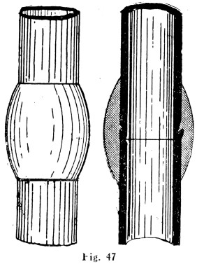
Plumbers make joints in lead pipes with soft solder which, by means of cloths, they “wipe” to the shape shown by Fig. 47.
Figs. 46 and 47 show the difference between a copper-bit or blowpipe joint and a wiped joint.
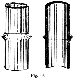
Fig. 46.—Copper-bit Joint on Lead Pipe
Fig. 47.—Wiped Joint on Lead Pipe
—As already stated, coarse, or plumbers’ wiping solder, is made in the proportion of 2 of lead to 1 of block tin. Care must be taken that the lead is quite pure and free from any other metal, as zinc-adulterated solder will be difficult to use, and joints made with it on service pipes will not be sound. In melting up scrap lead for making solder, only sheet lead should be used, as the lead used in the manufacture of sheets is much purer and contains a greater proportion of pure pig lead. The scraps must be quite dry; a damp piece dropped into a pot of molten metal may cause a serious accident, as the contents of the pot may be blown out.
To test the quality of solder when made, heat it as for wiping a joint; the correct temperature is determined by dropping a small piece of newspaper into the pot, and if it quickly burns and catches alight the solder is right for using. Next pour a small quantity on to a cold but dry stone or cement floor. This, on[65] cooling, should have a few spots on the surface about the size of a threepenny-piece, and on the under side should be bright nearly all over. Solder of this quality would, if properly used, stand any pressure without sweating. If the solder on the stone or cement floor looks white on both sides, or has a few small bright spots on the under side only, it is too coarse and requires more tin. On no account should the solder be heated to redness, as the tin rises to the top and quickly turns to dross (see p. 11). If this should happen to solder that is being used for service pipes, it should be rectified by adding more tin.
To purify a pot of “poisoned” solder (solder that contains zinc), melt, stir in a handful of common sulphur or powdered brimstone until the mass is of the constituency of wet sand, heat to the ordinary working temperature, and carefully remove the crust[66] that forms on the top, and the solder will then be fit for use, except that a little tin must be added to it. The presence of zinc in solder can be detected by the difficulty of forming joints, the metal falling apart and working very lumpy, and the joints when finished having a dirty grey appearance.
When plumbers’ solder is bought ready for use from the manufacturers, it is usually in the form of casts of eight bars, weighing about 56 lb. to the cast. The best only should be used, as cheap solder is frequently the cause of much trouble if used on high-pressure work, and joints made with it are never of good appearance. To test manufacturers’ solder, wipe a joint with it, and if it is of good quality it will work easily at a good heat, and when cleaned off with tallow and a clean rag it should be well covered with bright spots.
Brass fittings should not be tinned by dipping into the solder pot, as brass being an alloy of zinc and copper, the zinc may be melted into the pot with disastrous results.
—The flux used is tallow, no other flux answering the purpose so well, although mutton fat has been used as a substitute. Plumbers often call tallow “touch,” and they frequently use it in the form of tallow candles, the cotton wicks coming in handy for packing spindles of taps and slides of gas pendants.
An excellent plumbers’ black, soil or smudge, can be bought in packets, and requires only to be mixed with water before using. Ordinary black consists of lampblack, glue, and water. The black should be first[67] mixed with water, afterwards adding the glue, which must have been previously melted in a glue-pot. Simmer this for a time to remove surplus water. Test the black on a piece of sheet lead and dry off slowly. If it chips, add more black, but if it rubs off add glue.
The black should be made in small quantities, as it deteriorates if kept.
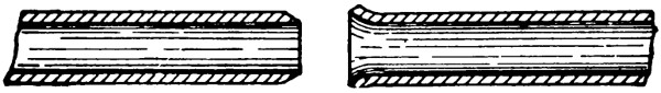
Fig. 48.—Joints prepared for Jointing
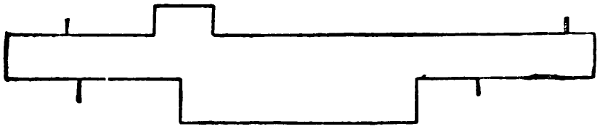
Fig. 49.—Marking-gauge for use on Pipe Ends
Another recipe is to place in the pot 1⁄4 lb. of size or diluted molten glue and a little water; gently warm until the size dissolves, but do not boil. Mix 1⁄2 cub. in. of chalk ground to a fine powder with a pennyworth of lampblack, and then with a pallet knife incorporate some of the melted size with the mixture on a flat board or stone to form a thin paste, after which place the whole in the pot, warm, and stir together thoroughly. Test as before. Old and thick soil is thinned with porter or stout, but do not add too much or the soil will become so sticky that the solder will cling to it. A little brown sugar, or a little stout, added to the black will make it more tenacious, and cause it to dry with a slightly glossy surface. Some[68] plumbers soil their joints after they are made, with black japan or thinned Brunswick black. But it is doubtful whether the effect is so good as when a “dead” black, such as given by ordinary soil, is used.
—Solder cloths for underhand joints should be from 1⁄2 in. to 7⁄8 in. wider than the joint for which they are to be used, and about 1⁄2 in. longer than they are wide. Most plumbers use the same cloths for underhand and upright, but it is preferable to use a special cloth for 4-in. upright joints with the length 1 in. less than the width. For getting up the heat of an underhand joint on a small pipe a larger cloth may be used until the worker is sufficiently skilled in joint wiping not to burn his fingers when using the correct size. For 3-in. joints and upwards a large cloth must be used first to get up the heat, the wiping cloth being kept warmed and ready for use when the heat is right. This large cloth, as used by some plumbers, is often long enough to lay on the worker’s arm, but this is clumsy to use when the joint to be wiped is in a cramped position, and is liable to let the pipe get burnt, as the metal it holds cannot be readily distributed round the joint; 8 in. by 9 in. is a good size to practise with on the bench, and as more skill is obtained it can be reduced to 7 in. by 7 in. A diagonal strap should be stitched to the back to take the little finger and thumb; the position for this can be obtained by laying the cloth face downwards and placing the hand on it with the finger slightly spread; the wrist should be over the right-hand corner, so that when the cloth is being used[69] the edge is readily kept parallel with the sides of the pipe. Branch cloths are made from 11⁄2 in. to 21⁄2 in. wide and about half as long again in width. These cloths should be about seven thicknesses of material, all others being nine or ten.
White moleskin cloth is obtained from the tailor’s for making these solder cloths, is usually 1 yd. wide, and costs about 3s. per square yard. The usual method of making cloths is to cut a strip down the selvedge of the material and fold up the strip till the desired size is obtained; it can then be cut off the piece, and any odd ends left may be used for packing a larger cloth. Another method is to cut a square piece the required size, and then fold it three times each way. This makes a rather clumsy cloth for small sizes, but makes a very good “blanket.”
—For making a successful wiped joint, the ends to be joined must be a good fit and the temporary fixing must be sufficiently strong so that the joints will not be broken in the process of wiping. These two points should be always strictly attended to. Service pipes should be tightly pressed home one in the other, the cupped or female end shaved inside with a knife, but not close in as is the case with soil or waste pipe; this allows the solder to fill up the cavity, which effectually prevents any tendency to sweat. This principle is followed up by some plumbers with branch joints on small size service pipes, the male end being worked in with a twisting motion, to prevent any solder getting into the pipes.[70] All other pipe joints should be closed, the female end being tightly worked in round the male end of pipes as an extra precaution against the solder getting inside. It is a good plan to black the inside of waste and soil pipes, so that the solder will not adhere if any should get through when making the joint. Fig. 50 shows the wiping of an underhand joint.
Beginners often spend a lot of time practising “rolling” underhand joints. This is bad practice, and will be of no use in wiping fixed joints. Little advice can be offered with regard to the actual wiping, constant practice being the essential thing. See that the solder is at the correct heat. This is readily found by dropping a piece of newspaper into the pot, and, if it quickly browns, the solder is ready for use. If the solder is used too hot it will quickly burn holes in the pipe, and if not hot enough a heat cannot be properly worked up, and the cloth may get torn trying to move hard metal. For underhand joints pour on steadily with a circular motion on to the sides of the joint, and on to the soil at the ends of the joint, until sufficient solder in a molten condition can be brought up to cover the top of the joint with the cloth, which is held underneath it; then pour steadily all over the solder until it runs back again. Repeat this continuously until the solder can be worked in a substantial body all round the joint without any hard solder being left at the underneath edges. Give the joint a last pour on, and wash all the solder into the cloth. Bring the solder smartly on to the top, and quickly work it all round the[71] joint with the wiping cloth, using two fingers of one hand for the top and back edges, and the index fingers of both hands for the underneath part. The top of the joint should be roughly shaped first and the surplus[72] metal brought over the back to the underneath; this should be worked into the bottom of the joint with a slight sideways motion. The extra body of metal should be used to warm up any hard edges, the surplus being brought up again to the top and quickly thrown off to the back.
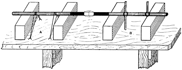
Fig. 50.—Pipes Supported and Secured on Bench for Joint Wiping
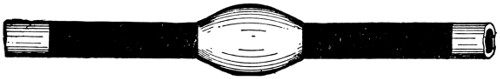
Fig. 51.—Finished Wiped Joint
—These are more trying to the worker’s patience but are the easier to wipe. After the pipe has been fixed in position, a lead collar should be fixed a few inches below the joint to catch the surplus metal. A piece of stout string tied by a half hitch round the pipe will prevent any leakage of the solder. In working up the heat of an upright joint, care should be taken to work steadily round the joint so that the heat is the same throughout. After sufficient metal has been splashed on with the splash stick and ladle, and the metal is at a moving heat, roughly shape up the joint with the splash stick, keeping the metal fairly high on the joint; then splash on a little more hot metal all round. A warm cloth is now used to shape up the joint by bringing the lower metal up to the higher part, after which start to wipe first with the hand as far round the back of the joint as possible and bring the surplus metal to the front, the cloth being held by the thumb and the index and little fingers; then change the cloth to the left hand and repeat the operation. The joint should be finished off at the back, although if quickly done the finish off should not be apparent. The collar must now be taken off and the solder it contains melted with a plumber’s iron.
[73]
A plumber’s iron can be used to good purpose on these joints, especially if they are out of doors and the weather is rough. The iron must be heated to redness and well filed up.
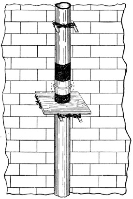
Fig 52.—Making Upright Wiped Joint
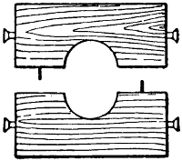
Fig. 53.—Wooden
Collar or Platform
to Catch Waste
Solder
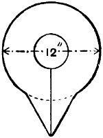
Fig. 54.—Lead
Collar to Catch
Waste Solder
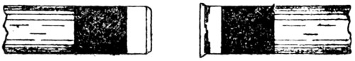
Fig. 55.—Pipes fully prepared for Jointing
Where possible, all joints to be wiped in their permanent position are sprung away from the wall and temporarily fixed with steel points made from 1⁄2-in. hexagon steel about 9 in. long and drawn out to a point[74] at one end. In some cases, more particularly soil-pipe work, the pipes cannot be fixed away from the wall; a hole must then be cut into the wall about 4 in. back and about 12 in. square to allow the joint to be properly made at the back.
—In wiping a lead pipe to a cast-iron pipe perhaps the best practice is to file clean the end of the cast-iron pipe first and then coat with pure tin, sal-ammoniac being used as a flux. The pipe then is washed to remove the sal-ammoniac, and afterwards “retinned,” using resin and grease as a flux. A plumber’s joint then is wiped in the usual way. It is necessary to take great pains to make a good sound strong joint between the two metals, but even then in the course of time (it may be only a few years) the iron will come out of the solder. The first sign of decay will be a red ring of iron rust showing at the end of the joint. This rust will swell a little and cause the end of the soldering to slightly curl outwards. Eventually the rust will creep between the solder and the iron and destroy the adhesion of the one to the other. The joint would eventually become a loose ring on the iron pipe, but not on the lead pipe, as the expansion of lead and solder do not differ to any great extent. Only those metals that alloy together can be satisfactorily joined by soft soldering, and the solder should contain as great a proportion as possible of the metals to be united.
The illustrations to this chapter (Figs. 46 to 55) are self-explanatory.
[75]
Hard-soldering is chiefly of two kinds, brazing and silver-soldering, the former being employed for iron and steel, the solder used being known as “spelter,” a brass alloy which can be obtained in various degrees of fineness. For copper, brass, and nickel silver, alloys containing silver are the best solders. In both forms of hard-soldering, the flux is borax.
The methods of silver-soldering vary with the size of the work. A jeweller may hold the work in his hand, on the end of a piece of binding wire or on a square of charcoal, the heat being applied by a mouth blowlamp from a horizontal gas jet, as already described. Larger work demands a flame of greater intensity, and sufficient air can be supplied only by a footblower or similar device, or, as an alternative, from the flame of a suitable blowlamp.
—This can be purchased at prices up to 3s. 6d. or so per ounce in sheet form, about 1⁄32 in. thick. Where the solder is melted down by the amateur, a good way to obtain the sheet form is to turn the globule of molten metal on to the bench and to place a flat iron on it; but the result will not be equal to a rolled ingot.
An old shop method of making silver-solder is to[76] melt up old silver (using current silver coinage is an expensive method of obtaining the silver, and is said to be illegal) with some brass pins, not the iron ones so common now.
According to W. H. Jubb, two solders compulsory for silver articles that have to be sent to assay for hallmarking are: (1) 12 parts standard silver and 1 part brass; (2) 6 parts standard silver and 1 part brass. No. 1 has a low melting point, and is termed “quick,” and No. 2, which requires a higher temperature, is called “stark” (in some parts of the country, “fine”), but the use of this term here is misleading. No. 2 should be used at the first heating and No. 1 at the second. These should make ideal solders for beginner’s use, as the chances of burning the work, even thin brass, are almost nil.
(3) 2 parts brass, 1 part standard silver; (4) 5 parts brass, 2 parts standard silver. Whereas Nos. 1 and 2 are “silver solders,” Nos. 3 and 4 are termed “German silver solders,” as they are not so white and are used on German or nickel silver (an alloy of copper and nickel). Both Nos. 3 and 4 are good, have a comparatively low melting point, are much less expensive than Nos. 1 and 2, and, if plenty of wet borax is used, will “strike up” well. No. 3 is recommended.
“Standard silver” is about 95 per cent. pure silver. Old “sterling silver” is 92·5 per cent. pure silver.
In making any of the above solders the brass and silver should be melted together, and care should be taken to see that the metal is clean beforehand.[77] Where large quantities of solder are made, the metals are scoured with emery cloth before they are put into the crucible.
—For light jobs in silver-soldering the special tools and materials required are as follow: Suitable gas jet or other flame, mouth blowpipe, scraper, jar containing a sulphuric acid “pickle,” piece of slate, camel-hair brush, pieces of lump borax, two grades of silver solder, charcoal block, iron binding wire.
The pickle is made by pouring 1 part of common sulphuric acid into 20 parts of water, and its function is to remove all dirt and borax from the metal. Silver-soldered articles should not be thrown into the pickle until they are nearly cold, as otherwise the joints may crack, but in the preparatory annealing (that is,[78] softening) of plain metal, wire, rod or tubing, the article may be put into the pickle when hot—but take care of the splashes! Plunging hot copper or brass into cold water does not have the effect of hardening it. Before placing a job in the pickle, remove any iron binding, as this is immediately attacked by the acid.
Often it is advisable to heat the metal and put it “through the pickle” before working on it, especially in the case of tubing that has been lying by for some time and has become dirty.
For heavier work, a foot-bellows and gas blowpipe, or else a blowlamp, are essential. An “Ætna” paraffin blowlamp with horizontal burner will be found quite satisfactory, although, of course, if a gas supply is available in the workshop the user will find that a foot-bellows and blowpipe are more convenient. A blowlamp or blowpipe requires a suitable tray or “forge” of sheet-iron in which coke and odd pieces of brick or tile may be laid and used to pack round the object whilst the flame is being played on the part to be soldered.
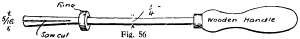
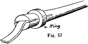
Figs. 56 and 57.—Clip for
Holding and
Applying
Silver Solder
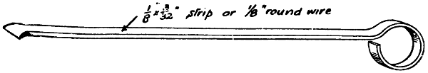
Fig. 58.—Pricker and Spatula for Consolidating Joints and Applying Solder
Among the smaller additional tools that will be required will be a clip to hold the solder (Figs. 56 and 57) and a brass pricker (Fig. 58).
—Make up the flux on the slate by rubbing on it a piece of the lump borax moistened with water. This paste may be applied with the camel-hair brush to the parts to be jointed. The flux prevents the oxidisation of the surfaces, which[79] would resist the amalgamation of the metals and the solder.
—In hard-soldering with silver solder, first file or scrape the parts bright, and cover them and the solder with the borax paste. Heat gently at first so as to harden the borax; then continue to heat by blowpipe until a red heat is reached, at which the solder will run. The secret is to blow continuously until the solder runs, and not to stop half-way.
For soldering a silver watch case, an ordinary easy-running silver solder, which melts at a lower heat than silver, will do. But to make sure, shred the solder into very thin strips, and apply plenty of borax to them as well as to the joint to be united. Use the blowpipe gently at first so as to bake the borax, then heat the case all over almost to the melting point of the solder, and direct the flame to the part to be soldered until the solder runs and glistens. Cease blowing instantly, and plunge the case into a solution of sulphuric acid 1 part and water 10 parts, to whiten it; then wash in hot water and dry in sawdust. Be careful to remove all steel springs before soldering the case.
—These are small squares, say, 1⁄8 in., of sheet silver solder, made by using the snips as in Fig. 61, and prepared by well covering with the borax paste. Each paillon is placed in position with the tip of the brush, this job requiring a little practice. The solder should be clean, and if not, should be made so by passing through the fire and[80] pickling. The work with the paillons in position should be slowly heated by blowing the gas jet on a part of the job farthest away from the solder; the borax will dry, and should the solder have moved, replace it with a suitable tool or the point of the wet camel-hair brush. The heat must not be applied too suddenly at first, otherwise the borax will boil up and push off the pieces of solder. The heat may be increased when the bubbling has ceased. Do not hold the work too far away, or it will get dirty in the smoke of the flame, or yet too near, else the gas will not be used to advantage. As the work begins to get hot, slowly work the flame towards the joint until the solder melts and runs into the joint. Give it now a little extra heat to get the solder thoroughly down into the crevices, and then let the work cool down. When nearly cold twist off the iron binding wire and put the job into the pickle. Leave the work in the pickle about ten minutes, when all the borax will be dissolved.

Fig. 59.—Section through
Pipes prepared for Silver-soldering
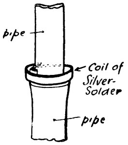
Fig. 60.—Pipes
prepared for
Silver-soldering
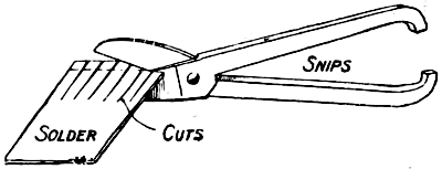
Fig. 61.—Cutting Up Silver Solder into Paillons
—An example of silver-soldering larger work is the joining together of two pipes, one smaller than the other. The best course to adopt is to file or scrape the end of the smaller and the inside of the larger (reaming and filing them if necessary) until a good fitting joint is obtained, as in Figs. 59 and 60. A strip of solder is then cut off, and, after the joint is well coated with borax paste, this solder may be wound round the smaller pipe. If the joint is soldered in a vertical position, the larger pipe should be the lower. The heat should be conserved by laying the[81] work in the coke and building the same round, or, if the work is too large or the joint in an awkward part of the pipe, a shield of tin plate or iron should be placed behind the joint so that the flame is thrown back on to the work. Should the pipe be attached in close proximity to the joint to a heavy piece of metal, then warm this metal up first, otherwise all the heat will travel to this part, and the work will take much longer to get to the proper temperature. In all cases where one part of the joint is of heavier substance than the other, that part should receive the greater amount of attention from the flame.
—Many craftsmen object to the cooling of the work by plunging it into water or pickle whilst it is hot; but no damage or cracking of the joint occurs, it is thought, if the work is not plunged when it is red hot or anywhere near red hot. Plunging into a pickle certainly cracks the burnt-in borax, which can be readily removed and the joint examined to better advantage. Many a silver-soldered[82] joint has been passed as quite sound when it has only been the borax that has been stopping the interstices, and only after it has been placed under service for some time does the faulty joint make itself apparent.
Silver-soldering cannot be done on work that has been previously soft-soldered unless the soft-soldered part is first cut away; but, of course, soft-soldering can be readily accomplished after silver-soldering or brazing so long as the work is clean and all burnt borax is first removed.
—Solder will run away from a part of a joint instead of running into it when the edges of the joint have been imperfectly cleaned preparatory to the application of flux and solder; also, if some dirt has got into the flux, or on the paillons of solder employed. Another cause is unequal heating of the joint, or allowing it to expand too much whilst being heated. The resulting fire marks may be removed by warming the articles on a pan over gas, and plunging them whilst warm into the sulphuric acid pickle. Or the marks may be removed in a hot and strong solution of potassium cyanide, and the polish renewed by a light polishing with a revolving swansdown mop and rouge composition.
[83]
Two methods of soldering are in common use among jewellers and silversmiths. Soft-soldering is done with fine solder (1 of lead and 2 of tin), and is used for articles that will not bear much heating. The metal is filed or scraped clean and bright where the solder is wanted to run, killed spirit is applied, and a little solder is run on the surfaces by applying gentle heat. Having thus been “tinned,” the parts are placed together and heat applied until they unite, a spirit lamp or a blowpipe being used. This is the sweating process, already referred to a number of times.
For soldering catches and joints to cheap metal brooches that have been silver-plated or gilt, the same solder is used as in the above. Both catches and joints can be cheaply purchased, hard-soldered on to small plates, square, oval, or crescent shaped, to suit all kinds of brooches. Take one of these and hold it with an old pair of soldering tweezers in the flame of a spirit lamp, and give it a coating of solder on its under side. First wet it with the killed spirit, and then place a small portion of solder on it, and hold it in the flame until it flows all over the plate. It can be assisted to flow evenly by a copper wire, which is also useful to apply the acid flux. Having “tinned” the catch, clean[84] (by scraping bright) the brooch, and place the catch in position. Direct a gentle blowpipe flame to it until it is seen to settle down and the solder flows. Then wash it immediately in warm water to remove the acid and dry in sawdust, kept in a warm place. Use as little solder as possible, and only clean the brooch where the solder is required to run. Attention to these points will ensure a neat job.
Hard-soldering on jewellery, etc., is done with silver or gold solder, and requires the articles to be heated to a bright red. The parts are cleaned, and a paste of borax and water is applied as a flux. A small piece of the solder is also dipped in the borax paste and laid over the join. Gentle heat is first applied to bake the borax hard, then by the use of a blowpipe the parts are raised to a red heat until the solder runs. The instructions given in the preceding chapter apply generally.
With regard to gold-cased jewellery, it is useless to attempt to hard-solder gold that has the least trace of soft solder or lead on it; the heat causes the lead to heat into and rot the gold, and the articles will tumble to pieces. The only way to mend, say, a gold-cased lead ring is by soft-soldering a tin band or plate over it, applying the heat very gently to avoid melting the lead inside.
For hard-soldering a gold ring without discolouring it, use solders containing gold, the precious metal in the solder being afterwards laid bare by a process of annealing and pickling. The solders are prepared to[85] suit the quality of the gold to be soldered, so that they may “colour” well and thus hide the joint. The following is a list of coloured solders:
Best solder: Fine gold, 121⁄2 parts; fine silver, 41⁄2 parts; copper, 3 parts.
Medium: Fine gold, 10 parts; fine silver, 6 parts; copper, 4 parts.
Common: Fine gold, 81⁄2 parts; fine silver, 61⁄2 parts; copper, 5 parts.
The gold solder is cast in long ingots, rolled thin and flat, and cut up or filed into dust, and thus applied to the cleaned joints, using borax as a flux. After the joint has been closed under a blowpipe flame, the whole ring is annealed on an annealing plate to a dull red heat, then cooled, pickled in acid, and polished. The film of grease left by the polishing process is washed off in hot soda water, and the ring dried in hot sawdust. Hard-soldered rings may be coloured with a film of electro-deposited gold.
If the gold is of common quality, under 12-carat, to remove any excess solder make a mixture by reducing to powder 1 oz. of green copperas and 1⁄2 oz. of saltpetre and boiling in 5 oz. of water. This will crystallise when cool. Redissolve the crystals in eight times their bulk of muriatic acid. For use, add boiling water, and place the gold in the hot mixture. For gold of 12-carat or over, nitric acid and water (1 part of acid to 2 of water) will dissolve the solder without injuring the gold.
Gold solders used on gold articles are made from[86] gold of the quality of the article—say, 18- or 15-carats—to which is added 1⁄12th or more of silver and 1⁄24th or more of copper. The quality of the solder is always a trifle inferior to the metal on which it is used, so that the solder may melt at a lower heat than the article. The melting point of 18-carat gold is 1995° F., of 15-carat 1992°, and 9-carat 1979°, while easy silver solder melts at about 1802° F. This shows that although 9- or 15-carat gold could be used to solder 18-carat, it is not possible to use 18-carat to solder 15-carat. The same principle applies to silver and brass; and the quality of the solder has to be known before any attempt should be made to carry out the actual soldering of an article. Another important point is that thin gold articles, like brooches, will not bear so hard a solder as the same quality of gold will do when made up solid, as in the case of a bangle ring. Solder for 18-carat and 15-carat is made thus: Take 1 dwt. of the gold, and add 2 gr. fine silver and 1 gr. fine copper; melt well together, and roll out thin. For 12-carat, the addition of 3 gr. fine silver and 1 of fine copper to the dwt. is advisable; while for 9-carat the most useful solder is made from 1 part fine gold, 1 part fine copper, and 2 parts fine silver.
Great care must be exercised in hard-soldering gem jewellery, as the stones are likely to be injured. Diamonds are the only stones that it is safe to heat to redness in soldering. Fancy coloured stones, such as rubies, emeralds, sapphires, topazes, amethysts, garnets aquamarines, or pastes must not be made hot.[87] A ring with any of these stones may be hard-soldered at the back if the stones are covered up with a pad of wet tissue paper to keep them cool; but if the soldering has to be done anywhere near the stones, they must all be taken out by un-setting.
Articles set with pearls, turquoises, opals, or cat’s-eyes (these things are not really “stones”) will bear no heat whatever, and must all be taken out before soldering.
In cases where it is very desirable to leave the stones in place, in order to prevent their bursting when heat is applied to the jewellery, cut a juicy potato into halves and make a hollow in both portions, in which the part of the ring having jewels may fit exactly. Wrap the jewelled portion in soft paper, place it in the hollow, and bind up the closed potato with binding wire. Now solder with easy-flowing gold solder, the potato being held in the hand. Another method is to fill a small crucible with wet sand, bury the jewelled portion in the sand, and solder in the usual way.
To restore the colour of gold or silver after soldering, dip the articles while hot into pickling acid (1 part of sulphuric acid to 10 parts of water); or put them in a little acid in a pan and boil them in it. Here, again, diamonds are the only stones that may be dipped hot, and there is a slight risk even with them. Pearls, etc., must not touch the acid, either hot or cold.
After heating and pickling, all gold is of a pale colour, and the commoner the gold the paler. However,[88] 18-carat gold may be restored to its original colour in a few moments by buffing with rottenstone and oil on a leather buff or on a brush, and following with rouge in the same way; or it may be burnished if the nature of the article permits this. Poorer qualities of gold may be restored to their bright colour by the same means, but this takes longer. Most 9-carat articles are gilt to improve their colour, and after soldering must be re-gilt to restore their original appearance.
[89]
Hard-soldering by brazing with spelter is used to a very great extent in the metal industries, especially in the manufacture of cycles and motor-cars. Although several mechanical joints have been tried in cycle manufacture, the greatest number of joints are made by means of brazing solder. A joint made in this manner is almost as strong as a weld, and the steel tube itself will often break under a strain and the brazed joint remain intact. Copper and brass tubes, when well brazed, will stand a pressure of 40 lb. or more per square inch.
—Hard brazing solder (spelter) is somewhat difficult to make. The metals have to be melted in a crucible and cast at a proper heat, and while in a certain condition have to be pounded or punned in a mortar. This disintegrates the materials and forms crystals of various sizes, some being as coarse as wheat grains, varying in fineness down to that known as 0 0, which is very fine dust indeed, and used only on very particular work, such as tubing 1⁄8 in. or 3⁄16 in. in diameter. The quantity of 0 0 from 1 cwt. of solder is very small, the corresponding quantity of coarse grains being much larger; so that unless a quantity is required, it is cheaper to buy than to make. It is[90] necessary to employ the purest materials, and in purchasing hard solder it is advisable to state the purposes for which it is to be used.
As a general rule, a solder should melt at a heat just under the melting point of the metals to be united. Now, in ironwork, or with the steel used in cycle work, this is impossible, for the melting points of these two metals are too high to be effected by the bunsen blowpipe or brazing hearth; but to join two metals in which the melting point approximates very closely to that of the solder requires great care in order that the metals may not be fused and the join spoiled. The reason why the melting point of solder should be about the same as that of the metals being joined is apparent when it is remembered that heat and cold, vibration and concussion, tension and compression, have very considerable effect on metals, and that if the expansion and contraction of these under working conditions is not nearly alike, disruption or opening of the joint will follow.
Hard solders or spelters are mainly composed of copper and zinc—that is, they are brass alloy—the quality most extensively used consisting of equal parts of copper and zinc. As the quantity of copper in the solder is increased, so the fusing or melting point is raised.
Ordinary copper melts at about 2,000° F. and zinc at about 840° F., and a solder composed of equal parts of each metal has therefore a high melting-point.
A very hard solder consists of equal parts of silver[91] and copper. Generally, a spelter of different composition is required for iron, copper, and brass work, that for the latter being required more readily fusible than that for the former. A suitable spelter for ironwork is one composed of 2 parts copper and 1 part zinc; a spelter for copper consists of 3 parts copper and 2 parts zinc; while equal parts of copper and zinc make a suitable spelter for ordinary brass work. If a very low melting point be required, a little silver should be added to the last-given spelter.
—Borax is the best-known flux for brazing. It is beneficial, however, to have the borax calcined (fused), as it settles down to its work immediately when applied to the hot metal, whereas uncalcined borax has a tendency to swell and fall off the work.
Spelter is in the form of filings, a thin stick, or wire. Filings are apt to be blown from the work. Brazing is a very useful, and, if properly done, reliable, method of joining two pieces of iron. A brazed joint is considerably stronger than a soft-soldered one, and easily resists temperatures that would cause ordinary solder to run.
The process is not at all difficult if there is sufficient heat, and, for those who have no gas laid on, the purchase of a paraffin Ætna brazing lamp can be recommended. With this lamp, of course, the bellows is not used, and only an iron hearth with asbestos cubes is wanted; but gas should be used if available.
—For satisfactory brazing, thoroughly[92] clean the surfaces to be joined, first with a file and then with emery-cloth, and, if necessary, bind them together with thin iron wire. A flux of borax and water mixed up into a thick paste is smeared round the joint, which should then be warmed to get rid of the moisture. Heat the metal to a white heat, dip the spelter into the borax paste, and apply to the part to be joined, rubbing round the joint until the brass is seen to run, when the heat can be cut off. The work should be almost covered in the asbestos cubes, and the spelter applied all round and not only in one place; failures to unite the parts mostly result from insufficient heat or cleaning of the parts.
—These lamps are constructed to burn benzoline or paraffin, and the more powerful types are fitted with pumps so that air pressure may be exerted on the oil. The paraffin or benzoline is thus forced into the burner, and by passing through the previously heated tubular coil is converted into gas, which issues forth out of the gas nipple, mixes with air, and then burns with a blue atmospheric flame of high temperature. After filling the lamp, a torch should be held under the burner to vaporise the oil, and thus ignite the lamp, after which pressure is applied by means of the pump. Do not start pumping too soon—that is, before the burner is sufficiently hot to vaporise the oil—or the oil itself will be forced through the gas nipple. The flame may be regulated at will, to suit the work in hand, after the burner has become thoroughly hot to set the lamp fairly going.[93] When brazing, lay the article to be brazed on some broken coke, charcoal, or firebrick, and if the article is comparatively heavy, cover it over with some small pieces (to conserve the heat) except where the brazing is required. After applying flux and spelter to the previously cleaned metal, direct the flame of the lamp on it, gently at first, until the spelter fuses and makes the joint.
—Brazing blowpipes should be fitted with a combination air and gas regulator, by means of which both the size and nature of the flame can be adjusted to suit the work in hand. When choosing a blowpipe it is always better to make one rather larger than the work in hand necessitates—the flame can be reduced when required; by this means a margin of reserve is provided which is useful in emergencies. A blowpipe whose dimensions are 10 in. long, having a 5⁄8-in. gas supply reduced to 7⁄16 in. at the nozzle, and a 3⁄8-in. air supply reduced to 3⁄16 in. at the nozzle, will braze ordinary latch keys and other similar work if used with a No. 3 size blower. As already stated, a paraffin, petrol or benzoline blowlamp is a cheap and effective apparatus, especially where the quantity of work to be done does not warrant the outlay of a foot blower, gas blowpipe, etc., but gas has advantages over the liquid fuel, inasmuch as the blowpipe is more under control. The quantities of gas and air can be readily and more delicately adjusted during the actual brazing process, then as soon as the spelter fuses and the[94] gas is turned off, the stream of cold air soon counteracts any excessive heat.
—The brazing hearth can be bought ready-made, or can be cheaply put together by the worker himself, the necessary materials consisting of two bellows, some lead piping, and an old packing case to support a large size frying-pan—about 1 ft. 4 in. by 1 ft. The bellows are fixed one above the other, interconnected by a fixed lead pipe, one pair of bellows worked by the foot pumping air into the pair above it, from which the air is taken to a bunsen blast burner by flexible tube. This bunsen burner can also be easily and cheaply made, and as this works very well and will be found useful for both soldering and brazing, the following hints on making it are given. First, get two ordinary large house bellows about 1 ft. square, or larger if possible; the larger the better. Next a good strong packing case about 2 ft. long by 1 ft. 3 in. high and 10 in. wide is required. One end of the box will form the base, and to make it steadier two 1-in. boards should be screwed across to protrude about 6 in. on each side, the front one being considerably wider, as can be seen at T (Fig. 62), which shows the apparatus with one of the case sides removed. The packing case proper is denoted by the letter A; the part A S A was formerly the bottom of the case, but is now the back; and the top A V A was the end of the packing case. Half-way between the top and bottom a shelf B should be fixed, having a large hole cut out of the middle at G to accommodate[95] the union piece (seen in section), which holds the lead air-pipe communicating from the lower bellows to the upper.
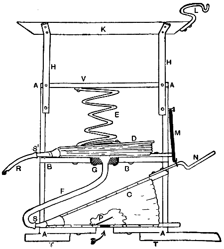
Fig. 62.—Home-made Brazing Hearth
In the back, near the bottom, at S, cut a hole for the nozzle of one of the bellows, and above the shelf cut another hole at S1 to take the nozzle of the other bellows. The bottom bellows C should have the top handle extended by a piece of stout bent iron N to act as a pedal, and should be screwed to the base. A central hole about 3 in. in diameter should be cut at P to allow the air to reach the valve. Now get a piece of lead pipe 1⁄2 in. inside diameter, and, having cut down the nozzle to just under that diameter, force the mouth[96] of the pipe over it as at S, and bend the pipe F as shown, to reach the centre of the shelf B and enter the hole G until flush with the top. Remove the lead pipe and get a block of wood about 3 in. square. Cut off the corners and bore a hole in the middle, so that the lead pipe will just pass through it, and countersink the hole. Broach out the mouth of the lead pipe until it becomes bell-shaped and fits the block of wood, so that its edge is flush with the wood when pressed hard against it. This is clearly shown at G, where the dark shading represents the wood block. Cut a leather washer the size of the block, with a 1⁄2-in. central hole, and lay this over the hole in the bottom of the top bellows where the leather flap valve is. Bore two holes in the wood block, and screw this down tightly to the bottom of the bellows, so that the bell-mouth of the lead pipe faces the hole and has the leather between it and the block. This should make an air-tight joint for the fixing of the pipe to the bellows.
Next, push the nozzle of the bellows through the hole S1, and screw the bellows down tightly to the shelf B. Join the lead pipe to the nozzle of the bottom bellows, and make an air-tight joint with glue and tape bound round. Between the top of the upper bellows D and the top of the packing case at V, a stout sofa spring E is fixed to keep the top bellows shut down tight till air is pumped in from the bellows below.
From a screw near the top of the case stretch a house-bell coil spring M, and attach its lower end to the foot-plate or pedal N. This spring tends to keep[97] the lower bellows open. When pressure is put on the foot-plate N, air is pumped from the lower to the upper bellows, and thence along the flexible pipe R to the bunsen blast nozzle described in detail later. If it were not for the upper bellows, the air would come to the nozzle in puffs, but the spring E keeps the pressure constant, and a steady blast is secured. The rubber pipe R should be of sufficient length to reach the hand conveniently, and allow room for movement.
The hearth K can be made from sheet-metal, with the edges bent upwards to form a tray; or an old frying-pan will answer very well. Whichever is employed, four iron stays or legs H must be used to raise it above the top of the packing case as shown. These legs should be screwed at one end to the sides of the case, and at the other to the pan, and if a frying-pan is used, the handle may be cut and bent to form a hook as at L; it then acts as a support for the blast nozzle.
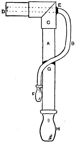
Fig. 63.—Blowpipe or
Blast Gas Nozzle
for
Brazing Hearth
For use with the brazing hearth, a blast gas nozzle on the bunsen principle is required, and this is easily made from two pieces of gas-piping, a right-angle joint, and two mouthpieces to take flexible pipes. First, get 1 ft. of 3⁄4-in. brass (or iron) pipe and an elbow, internally threaded at both ends. Cut 2 in. off the brass pipe, and cut a thread at one end of the short piece and one end of the long piece, to screw into the elbow as shown in Fig. 63. At the other end of the long tube solder in a cock or mouthpiece to take a large diameter flexible pipe from the gas bracket. Next get 1 ft. of 1⁄4-in. brass pipe, and bend it to the shape shown[98] at B, soldering a mouthpiece at F to take the smaller diameter air-pipe R (Fig. 62) from the bellows. Bore a hole through the elbow C, and push the pipe in, making a tight fit, and so that it passes centrally through the larger brass tube until it nearly reaches the end as shown at D. Run a shoulder of solder to hold the small tube firmly in the larger one as at E, and unite with a drop of solder the large tube A and the small tube B where they cross at G.
The gas passes up the large pipe, and out at D, and a blast of air is forced through the centre of the flame through the small pipe B. The shape of the small pipe allows of it being readily hung up on the hook L (Fig. 62) when not in use. Instead of the mouthpiece shown at H (Fig. 63), a cock will be found more convenient; but it should not be too small, or it will restrict the flow of gas, which should be as great as possible. No gas-cock should have less than 1⁄4-in hole.
The “fuel” (heat conservers) consists of chunks or cubes of asbestos, and when these are blown upon with the gas flame, the heat is quite sufficient for moderately heavy brazing. Be careful not to get any kinks in the flexible tubes, or the air and gas will be reduced in quantity, if not stopped altogether.
A square of thick asbestos (sheet) is useful for laying on small articles whilst brazing, and a piece or two of charcoal will be handy for silver-soldering.
—Before attempting to braze either iron or steel the surfaces should be thoroughly cleaned by filing or grinding, etc. Brass or[99] copper may be cleaned by dipping in a solution of 1 part nitric acid and 2 parts of sulphuric acid. This same solution can be used to remove the scale after brazing. The parts should be fastened together in the position they are to occupy when joined. The fastening may be effected by the use of wires, screws, bolts, clamps, etc. If practicable, the parts should be held in such a way that they can be turned over during the brazing process without disturbing the relation of the parts, thus affording a better chance to apply the flux and brazing material.
In brazing sheet metal, if the seams are not required to stand much working after soldering, they may be joined edge to edge. When seams are formed in this way, little nicks, about 1⁄2 in. apart, should be filed out along the edges, so that the solder flowing through the nicks will render the joint sound. If the seam is to be worked after soldering, a small lap is necessary to ensure adequate strength. To form seams of this type, first thin the edge of the metal along the ends that are to form the seams, about 1⁄8 in. in from the edge, so that when the two edges are lapped over each other the combined thickness at the seams will be[100] the same as the single thickness of the metal at other parts. Cut a small cramp at the top and bottom of the seam, and fit the opposite edge in these cramps. After preparing the seams by either of the above methods, fasten binding wire round the articles so as to hold the seams securely in position. Now powder some borax flux, mix equal parts of the borax paste and grains of spelter, and along the seams place sufficient of the mixture to solder them when melted. Some dry borax should also be kept ready at hand, so that a little may be taken and thrown on the solder at any point where the material does not appear to be flowing freely. Gently heat the article by some suitable means, such as foot bellows and blowpipe, so that it will expand equally, and not disarrange the seam; increase the temperature until the metal is a dull red, and the spelter runs. If necessary, with a piece of wire flattened at one end gently rub the solder along the seam until every part is joined.
—For uniting two pieces of copper rod, 1⁄4 in. or 3⁄8 in. in diameter, first prepare the joint as at A in Fig. 64, and file the surface of the copper clean in the immediate vicinity of the joint. A mixture of borax and water and spelter should now be applied to the joint, which should rest on a small heap of broken coke, the coke being also built round it. The flame of the blow-lamp should be directed at first on the coke surrounding the joint, and then gradually brought to bear on the joint itself. If necessary, add a little more spelter before any of it fuses, and when[101] the copper begins to get red hot, throw just a pinch of dry borax on the joint to facilitate matters.
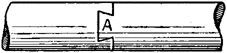
Fig. 64.—Dovetailed Joint in Copper Rod
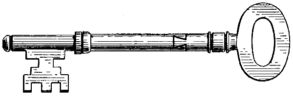
Fig. 65.—Dovetailed Joint in Key Stem
—In brazing together the broken parts of a key stem, first it is necessary to file the fractured ends quite true; this may entail the shortening of the key by 1⁄4 in. or 1⁄2 in., and as another 1⁄4 in. will be lost in making the joint, it may be advisable to use another key bow having a longer piece of stem than the one that was broken off. With a warding file cut a dovetail on each of the ends to be joined, as shown by Fig. 65. A small, half-round file will assist in making the edges true and square. The pieces must interlock perfectly, and when this is the case, very lightly hammer the joint, round which then bind seven or eight turns of brass wire to act as spelter. Wet the joint, sprinkle powdered borax on it (this is to serve as the flux), and, holding the key in a pair of tongs, place it in a clear part of a forge fire made with charcoal, small coke, or coal cinders, and commence[102] to blow steadily the forge bellows or blower. Failing a forge fire, use a blowpipe, the key being placed on a piece of charcoal or pumice-stone whilst the heat is being applied. If the forge fire is used it is as well to support the key on a guard of thick iron plate having a hole in its centre over which is the joint to be brazed. By this means the necessary local heating is obtained, and much labour in cleaning the key afterwards is avoided. On being heated, the borax swells and boils up, and should be pressed down with a spatula, previously dipped in cold water to prevent the hot borax adhering to it; a suitable spatula is made by flattening one end of a 1-ft. length of a 1⁄4-in. round rod, having at its other end an eye by which it may be hung when not in use. With this spatula, also, powdered spelter may be added to the joint if required. When the brass wire begins to run, assist the flow by adding powdered borax, and when all the brass has run into the joint, rub off superfluous molten metal from underneath and allow the joint to cool gradually. When cold, file up and clean the stem of the key until only a thin bright line of brass can be seen.
—In cycle brazing, the first consideration is the means of heating the heaviest joint to a brazing heat. This may be done in several ways, by a paraffin blow-lamp costing at least 35s. to 40s., or, what is better, a gas blowpipe 7⁄8 in. or 1 in. in diameter, with at least 1⁄2 in. gas supply pipe and a fan or bellows to supply the necessary air pressure. A small fan is far preferable to a bellows of any description, the flame[103] being steady and constant, and the operator being able to devote his entire attention to the job. In the absence of power, obtain a small circular double-blast bellows and hearth, costing with blowpipe about £5.
The brazing materials are brass spelter. No. 3 size, or brass brazing wire and powdered borax; a tin to hold the mixture of spelter and borax, and one for the plain borax; a piece of iron wire about 1⁄4 in. by 18 in., flattened at one end to feed the spelter and borax to the joints; and a brazier’s brush, which is desirable, but not absolutely necessary, to brush the superfluous borax and brass from the outside of the joint as soon as it is removed from the hearth; this saves much work in filing up, and saves the files immensely. Do not purchase the borax ready powdered, but buy lump borax, as that purchased ready powdered is likely to be adulterated. In making the brazing mixture, use about equal parts, in bulk, of No. 3 spelter and borax.
In preparing the work for brazing, see that the surfaces are bright, clean, and free from scale. The joints should be a good tight fit, free from shake, and where a joint such as the back forks to the bridge lugs is being made, see that the tube edges fit close up to the shoulder of the lugs all round, and do not depend on the brass to fill up a badly fitted joint.
The chief things to observe are to make a sound joint the full depth of the lug, and not merely to get a thin film of brass round the outer edge. To do this, the flame should be directed on to the thickest part of the lug first before getting the tube too hot, and feeding[104] the joint with borax before the metals get hot enough to scale. As soon as the lug and tube begin to get a dull red, feed with borax only, then with brass and borax, when it should flow almost like water and penetrate to the deepest part of the joint.
Another very important thing is not to “burn” the tube by getting it too hot, which will spoil it and cause an early fracture. If the above method of heating the lug first is observed, and the tube near the lug kept “wet” with borax to prevent it scaling, this should not happen.
Where the joint to be brazed lends itself to inside loading with the spelter, the work should be so placed on the hearth that the brass inside, when it melts, will tend to flow to the outside of the joint. Then if borax only is used on the outside until brass appears round the edges, it will be fairly certain that a sound joint will result. As soon as this comes through, feed a little brass-and-borax mixture to the joint, and, as soon as this melts, stop the flame and remove from the hearth. If the flame is kept on too long after this, there is a possibility of “soaking” all the brass out of the joint, especially so if the joint is not a very good fit.
Some braziers use a blacklead mixture for protecting thin tubes whilst brazing; but care must be taken to keep it out of the actual joint, as brass will not adhere to metal where this is present.
Cycle frame joints can be brazed on an ordinary smith’s hearth, but it is rather risky, and requires more skill than with a gas blowpipe. It also requires a good[105] clear fire and a light blast. The job should be kept well fed with borax to prevent the tubes scaling and burning. The joint should be loaded from the inside with about a thimbleful or less of crushed borax and No. 3 spelter mixed in the proportion of about half of each in bulk. The heaviest part of the lug should be heated first, and the work must be turned frequently in the fire so as to avoid burning the tube. If the joint is fed from the outside with borax until the brass flows round it, a sound joint is ensured. This applies to a joint where the lug is fitted inside the tube. Where the tube is fitted inside the lug, a little brass and borax should be applied outside the joint just as the inside charge has melted, which can be seen with some joints by looking down the inside of the tube. When the tube is closed both ends, such as the last joint of a frame, the job is more difficult and requires careful judgment and skill to ensure a sound joint.
—Although it has been dogmatically asserted both that cast-iron can and cannot be brazed, it may be stated that the general results of attempting this process are so indifferent as to warrant the conclusion that this process cannot be recommended. In brazing, one of the conditions essential to success is that the metal to be brazed and the spelter should unite to form an alloy just where the brazing occurs, and that this should take place spontaneously. This actually happens when brazing copper, brass, wrought-iron, etc., but not in the case of cast-iron. If, however, the reader desires to experiment in this[106] direction, the following hints may be useful. First of all, remove all dirt and grease from the cast-iron, and then chemically clean it by immersion in hydrochloric acid, afterwards well rinsing it in clean cold water. A mixture of borax and water and spelter should now be applied where the brazing is required, and gentle heat then brought to bear on it until the water is evaporated. The heat should now be increased until the casting is red hot in the neighbourhood of the brazing; and some workers claim that at this juncture the best results are obtained by dusting the red hot cast-iron liberally with boric or boracic acid powder. A hard spelter should be used in preference to a readily fusible one, otherwise the spelter would be fused much too soon, and before the casting is raised to a sufficiently high temperature.
An experienced worker who believes that it is possible to make a sound joint in cast-iron by brazing, states that he has brazed articles with equal parts of borax and boracic acid. The chief difficulty is the flux. He has tried one called “Ferroment,” which seems to give good results. The first casting brazed with it was 3 in. wide and 5⁄8 in. thick, and this casting at the time of writing had been in work six months for fifteen hours per day. This same worker prefers to roast borax before use, as it stops on the work better. Also, when a deep, wide joint is being dealt with, he finds it an advantage to smear on a little clay underneath and the side, as should the joint get slightly hotter in one part the spelter will run through and make an unsound[107] joint. The heat required to braze cast-iron varies somewhat with the spelter used. If brazing by means of a smithy fire, the spelter will show a blue flame when it starts to run, and the article must then be removed from the fire. In using a blowpipe or blowlamp, the blue flame does not show, and one has to look for the spelter melting, and see that it flows well along the joint before removing the flame. Spelter which has been kept in stock a good time may not flow well. The worker in question prefers brazing wire to grain spelter, as by means of warming the end of the wire and dipping in the flux (which will adhere to the hot wire), it may be put just where desired. He collects all the soft brass turnings from his lathe and uses them for brazing.
Another worker has stated that those who have a forge of any kind will find the following an effective method of repairing an iron casting. A flux may be made of chlorate of potash 4 oz., boracic acid 1 lb., and carbonate of iron 3 oz. These should be mixed well together and pounded. The parts to be brazed together should be carefully cleaned by scraping them, and brought to a bright-red heat. Then apply the flux and spelter and increase the heat.
Still another worker says that in brazing cast-iron, if powdered soda is used instead of borax, the result will be a perfect joint.
[108]
Iron and steel can be joined by heating until they become plastic and then consolidating the two members of the joint by hammer blows, the work being supported on an anvil. Correct heat and cleanliness are the chief requisites. The “welding heat” corresponds with that temperature at which the metal is in a state of partial fusion on the surface. The better the quality of the iron, the higher the temperature it can stand without being burned and ruined. Iron at a welding heat gives off dazzling sparks, whereas ordinary cast steel is only an intense yellow, but few sparks being evolved. Sufficient lap for the proper making of the joint must always be allowed. When heated in a perfectly clear fire, the metal may need no treatment prior to hammering; but otherwise it may be necessary to sprinkle sand or some special flux over the work. At the proper moment the iron is transferred to the anvil, and the union of the two members of the joint immediately effected; delay means an imperfect joint. In lifting the work out of the fire, remove it vertically and so as not to collect particles of dirt on it. Keep a switch of brushwood at hand for removing adhering matter.
[109]
—Some steels will “stand the fire” better than others, which means that they will stand more heat before they reach the point when they begin to burn.
The different kinds of steel used in a general way may be summed up as blister, spring, shear, double shear, and cast steel. Blister steel will, as a rule, stand the most heating before beginning to burn, and the others follow in the order given. The difference in heating will vary from nearly a white heat on blister to the yellow heat of cast steel.
A simple method of ascertaining what heat a steel will stand before beginning to burn is as follows: Heat the steel to its burning point, and at various stages, beginning at the yellow stage, lay it on the anvil and give it a few blows with the hand hammer. Repeat the process until a heat is reached that will cause the steel, when struck with the hammer, to give off sparks like small fireworks. When this stage is reached it will show that the burning point is arrived at.
Careful observations of these points will enable the smith to know just when to begin to use the flux for welding, which, by the way, must be just before the steel reaches the burning point.
Another important point is the formation of the scarfs. These should not be fullered down so thin or left in the same form as the scarfs as when joining iron, and should be shorter (compare A and B, Fig. 66).
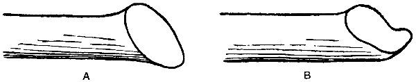
Fig. 66.—Scarfs for Iron and Steel
In bringing the steel up to its welding point, care must be taken to have it at a uniform heat throughout[110] at the part for welding; and, to get this, the blast should not be forced at the start, but used gently. In some cases the blast should be stopped occasionally, to allow the steel to soak. Then restart the blast, and gradually force it when beginning to use the flux, continuing so until the welding point is reached. Only light blows should be given at the start, just to cause the two parts to stick together; but when stuck, the harder the blow the better the weld.
An idea seems prevalent that the flux has a certain influence on the steel, and converts it into a form that makes it more weldable. The real use of a flux in this case is simply to retard the heat, and form a coat or shell on the steel, and so counteract and prevent the burning action which takes place when heating steel in an ordinary blast fire.
The reason why different fluxes are required for different brands of steel is no doubt due to the differences in manufacture. As a rule, the greater the heat the steel will stand before burning, the less it requires a flux to protect it, so that in a great many cases a flux consisting of some clean, sharp sand is all that is required; but the steels that will burn at a lower heat require something more than sand to protect them. Hence arises the necessity of adding burnt borax, crushed glass, powdered marble, etc.
The method of welding steel is as follows; but before proceeding to get the heat make a point of having a shallow tin on the forge large enough to hold a sufficient quantity of the flux, so that it will cover[111] the scarfed end when being dipped in same. Have a clean fire and plenty of firing on the hearth, so that the heat can be well covered. Start with gentle blast until the heat is nearly up to burning point. If necessary, stop the blast and let the heat soak for a few seconds so as to ensure a uniform heat. Gradually force the blast, and keep withdrawing the “heats” and roll them well in the flux, and so continue until it is thought that the heat is plastic enough to unite. Place the scarfs in position, give a few light blows until the parts stick together, then hammer well home and move smartly so as to ensure the proper joining together whilst in a plastic state. When welded, do not continue the hammering or tooling at too low a heat; but if further hammering is necessary, re-heat the work.
These hints are not applicable to every make of steel. With the special steels manufacturers issue particular instructions.
A flux for welding cast steel consists of 2 oz. each of powdered chalk, soda and burnt borax, mixed with 1 lb. of silver sand.
A firm of steel manufacturers recommend a mixture of 21 oz. of sand and 7 oz. of salt, moistened; the steel is to be treated in a fire of sulphurless coal.
[112]
How to Make a Bench Gas Blowpipe.—The blowpipe illustrated by Fig. 67 gives a powerful flame. It can be clamped to the edge of the workbench by means of a winged nut, a hole being made near the edge of the bench to accommodate the bolt. A piece of hard wood A, 5 in. by 2 in. by 1 in. thick, has a strong iron bolt B passed through at one end. A 2-in. cube C, which should also be of good hard wood, is screwed firmly to the other end of A, the combined block being perforated through the centre to take a length of gas tube D, which carries a gas-bracket with flange, elbow joint, and tap E. The flange should be screwed down to the top of the block. The elbow joint allows the direction of the flame to be adjusted within a wide range movement. The arm of the bracket is removed, and a shorter tube F, 3 in. long, is substituted. This carries a 1⁄2-in. iron T-piece G. The tube H, which is 3 in. long, should be of brass, threaded at one end to fit into the T.
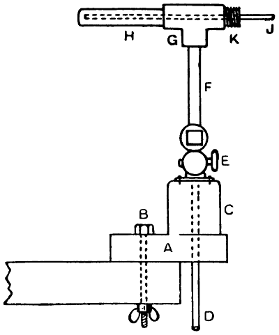
Fig. 67.—Bench Gas Blowpipe
The air is conveyed through an 8-in. brass tube J 1⁄4 in. in diameter, which should be smooth inside. This latter point is of some importance, and, if preferred, a glass tube may be used instead of brass, the current of cold air having a sufficient cooling effect to prevent[113] undue heating. The end should be cut off sharp with a file in the ordinary way and left in that condition. Smoothing the edge by fusion in a flame will not improve matters, but rather the reverse. Of course, the other end, which comes outside, must be smoothed to prevent injury to the indiarubber tube used for making connection with the bellows. The air tube must be held firmly in the centre of the gas tube, while capable of being moved in or out for the purpose of adjusting the flame. This can be done quite satisfactorily by means of a short brass tube or nipple K, threaded to screw into the T (see Fig. 67). A sound cork should be driven into this short tube so as to entirely fill it, a hole being made with a cork-borer to admit the air tube. This hole must be exactly central, and the cork must grip rather tightly.
A foot-bellows is generally used for supplying the air, the bellows being connected with the air jet J by means of an indiarubber tube. The tube D, which should extend an inch or so below the bench, is to be connected with the gas supply.
—A simple form of gas blowpipe is shown in Fig. 68, the rubber tube connecting it with the gas supply being fixed on the pipe at the point of connection with the cock. To construct the appliance, one end of a piece of brass gas pipe of the required length with, say, a 3⁄8-in. bore, is bent as shown, whilst at the back of the curve thus made a hole is drilled to admit a tube A 5⁄16 in. in diameter. This should have one end (see dotted lines) bent to[114] correspond with the angle previously formed in the larger tube, whilst its other extremity should be bent upwards. Make these pipes red hot where they are to be bent, and, if they are afterwards plunged in cold water, the material will to some extent be softened, and its tendency to split will be obviated. The smaller tube is passed through the hole in the bend of the larger one, the ends being almost flush and quite concentric. Solder the parallel portions of the tubes together, and then fix a gas-regulating cock to the larger one, as in Fig. 68. The end is then connected to an ordinary bracket or burner by means of an indiarubber tube G, and a short piece of tubing is fitted with a bone or other mouthpiece, and attached to the projecting end of the air tube. This instrument will do any soldering, and will be suitable for melting gold, silver, and brass, or brazing odd jobs in iron or steel. Of course, when used for the last-named purpose it would be in conjunction with asbestos tubes or other supports.
[115]
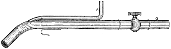
Fig. 68.—Simple Form of Gas Blowpipe
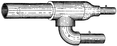
Fig. 69.—Larger and more efficient Blowpipe
—As regards the relative volumes of gas and air for blowpipes, the late Mr. Thomas Fletcher said that, speaking roughly, but still sufficiently near to make a correct rule by which to work, a blowpipe requires one volume of gas to eight of air. If the gas is supplied at a pressure equal to 1 in. of water, and the air at eight times that pressure, then, to get the best effect, the area of the gas and air pipes should be equal. If the air supply is equal to 16 in. of water pressure, the gas pipe must be double the area of the air, and so on in proportion. Some[116] makers assert that a better working flame is produced by using ten volumes of air to one volume of gas; but, of course, if the blowpipe is fitted with taps, the supplies can be adjusted easily. It will be found, however, that any practical departure from Fletcher’s rule will result in a loss of power.
—It has been said, a blowpipe with a 1⁄8-in. air jet, if worked with an air pressure of 10 oz. per square inch—that is, 15 in. of water—will braze up to about 1⁄2 lb. total weight; or in other words, will securely unite two pieces of brass each weighing 1⁄4 lb. With the same pressure a 1⁄4-in. bore air-jet will braze a total weight of about 2 lb., and so on in proportion. It will be understood that the air jet is measured at the point at which the blast leaves the air tube, whilst the area of the gas supply is that of the annular space between the two tubes. When the air tube is thus carried inside the gas tube (see Fig. 69), the tool appears to be much larger than it really is, and this accounts for the fact that a 1⁄2-in. size blowpipe with the air tube fixed outside the gas supply is just as effective as one of the 3⁄4-in. size which carry the air tube inside the stem. All indiarubber tubing must be perfectly smooth inside, for if it is wired or in any way rough, the resultant friction will cause a loss of pressure. It should also be of as large a bore as is convenient.
—A large and efficient blowpipe that can be made in a few minutes is shown by Fig. 69, the only materials required being[117] a T-coupling and diminishing socket, an elbow, and one or two pieces of pipe. The air tube A (represented for the most part by dotted lines) passes through the diminishing socket until it almost reaches the nozzle of the blowpipe, with which it is concentric. By using the elbow D, the two supply pipes are brought parallel to each other, so that the indiarubber connecting tubes can be more easily held in the hand like reins, as by simply squeezing them the flame can be readily regulated. Sometimes, in cases of emergency, a plug drilled to meet the air tube is used in place of the socket. The plug is thrust into the end of the T-socket; but in all cases it must be airtight. This blowpipe can be used efficiently only in conjunction with a foot blower.
[118]
The stoves and lamps burning paraffin in the form of vapour have become very popular on account of their good heating properties, portability, and little attention required. They consist of a container holding paraffin, a burner with a heating tube attached is screwed to the container, and a tube leading almost to the bottom. A small air-tube, similar to a cycle-pump, is fixed in container, the handle and cap only being in sight. When the burner tubes are heated, a thumbscrew on the filler caps is closed, and a few strokes of the pump puts a slight pressure on the oil in the container. The oil is forced up the central tube to the burner; but before reaching this it has to flow round the heating coils, and in so doing is turned to vapour. The outlet at the nipple being very small, causes the vapour to issue with some force, and it mixes with the air, forming a mixture which burns with a non-luminous flame similar to that of a bunsen burner. This flame plays on the heating coils, and once started, the lamp is practically automatic; a stroke or two from the pump will keep it going until the oil is consumed.
There are patterns that use petrol or benzol, their action being slightly different. Petrol and benzol are light spirits, which give off inflammable vapour at a[119] much lower heat than paraffin does. Advantage is taken of this fact by causing burner and nipple to be in one solid brass casting, so that when the nozzle is heated, the brass conducts the heat back to the nipple and so vaporises the petrol, which is fed to the nipple by a thick wick contained in a tube which reaches almost to the bottom of the container, the wick touching the bottom.
To start either paraffin or petrol lamps, the exit tube or nozzle is heated. The petrol lamp has no coils round the nozzle; but comes straight from the holder to the exit nipple. The size of flame is regulated by a needle valve fitted with a wood or fibre handle. The petrol lamp has no pump, except on high-power brazing lamps whose use requires expert handling.
The chief trouble with lamps using paraffin is that the burner becomes choked; this is shown by the lamp jumping out or the flame not attaining sufficient heat. The makers supply a proper cleaning needle, a sheet stamped to form a handle and a piece of fine steel wire fixed at one end. Nothing else, such as pins, etc., should be used, or the hole in the nipple becomes enlarged, and emitting too much gas, causes a smoky flame. The cleaner should be used each time before lighting. A good way to avoid this trouble is to use a small funnel with fine brass gauze soldered in the body when filling. White Rose is a quite satisfactory oil for these lamps.
After considerable use the heating coil becomes choked with carbon deposit. A new heater tube can[120] be obtained, or the old one cleaned by drilling two or three holes in the ends and passing a piece of flexible wire (such as Bowden brake wire) through the heater and removing the obstruction. After getting it clean, tap out the holes and fix suitable screws, flat under the head, with a piece of asbestos to make a tight joint.
If a larger flame is not obtained by pumping, take the cap off the pump and draw out the plunger; the leather is probably worn. Fit a new one; or it may have become hard, in which case apply a little oil and open out carefully. The retaining valve is in the centre of the pump bottom, and is removed by using a long key down the pump barrel. The valve is in four pieces. See that the spring is free and that the cork is in good condition. When replacing, take care not to get it cross thread, and screw firmly home. The washer under the filler cap is of rubber and cuts through in time. Do not use pliers to screw down; it will go gas-tight with the fingers if the washer is good.
To remove the nipple from which the gas issues is almost impossible without a proper key. This has a universal joint, which allows it to be rotated, although the handle is almost at right angles with the burner. Keys and all other parts mentioned can be obtained from any dealer in these lamps.
With the lamps using petrol, the only parts requiring attention are the plate from which gas issues and the wick. Unlike the paraffin nipple, this is a circular stamping of brass approximately 3⁄4 in. in diameter with a fine hole in the centre. To remove[121] this disc, pass a long flat screwdriver blade through two openings in the nozzle and turn to the left (anti-clockwise), holding the body of the lamp firmly on the bench. Before fitting a new disc, thoroughly clean recess and remove any deposit from the inside of the valve box. Unscrew the needle and gland if there is any leak there, and clean and repack with asbestos yarn. A little glycerine on the packing appears to be an advantage. Place the disc in position, dip an asbestos washer in water, and screw the nozzle firmly down.
The wick inside the lamp filters the spirit before reaching the nipple and occasionally needs replacing. Remove the cap from the bottom of the lamp, and with a piece of thick wire flattened at one end and filed to a hook, push it up the tube and withdraw the old wick. The new one is simply put in its place and the cap screwed tight. The washer under the filled cap is of cork and rarely gives any trouble.
[122]
A Paraffin Brazing Blow-lamp.—The brazing blowlamp shown in Fig. 70 was made at a total cost of less than 4s. The illustration is printed to a scale of about one-quarter full size. The lamp illustrated is not a mere experiment, as the writer of this description had a similar one in use for over two years, and during that time brazed hundreds of jobs with its aid.
The container is of tinplate, and adapted from a workman’s tea can. When purchased this will have a wire handle and two hinges, and these should be removed and soldered up. The handle shown at H is made from a strip of iron, 1⁄8-in. by 5⁄8-in. section, bent round to the shape shown and riveted to the side of the container. These rivets should be well soldered over inside to prevent leakage. The joint of the longer strip is shown at X. The lid should next be taken in hand, a 5⁄16-in. hole being drilled at one side close to the handle, to take an ordinary Lucas cycle valve. A leather washer is fitted inside, and also one outside under the lock nut, the latter being then tightly clamped up.
At E is shown the filling cap, the body part of which was taken from an old paraffin oil-lamp container, and the screw cap made at the local brass works; but this[123] fitting can be obtained in a finished state from many model-fittings manufacturers. This is soldered to the lid in the position shown, a hole being afterwards drilled in the tin to suit it.

Fig. 70.—Paraffin Brazing Blow-lamp, the container being shown in section
The cock shown at D is an ordinary gas-cock, with a length of 3⁄8-in. outside-diameter copper piping screwed and sweated in beneath. This is passed through a hole drilled in the lid for its reception, and the base of the cock is then sweated in position. Note that the length of this pipe is such that when the lid is in place it clears the container bottom by 1⁄8 in.
The coil of piping at P is 3⁄8 in. diameter copper tube[124] coiled round to the shape shown, the lower end being tightly screwed into the top of the cock. The opposite end is screwed for a short length of 3⁄8-in. gas thread, and very tightly fitted with a screw plug such as that used by plumbers for shutting off a portion of gas piping. Before screwing this on, a small hole about 1⁄32 in. in diameter should be drilled in the middle of same; this is the nipple for the exit of gas to the burner.
The 3⁄8-in. copper tubing should not require filling with anything before bending; this operation is best done round a mandrel of wood. No heating is necessary. A certain amount of flattening of the tube will no doubt occur, but this is immaterial. The end of the flame tube is, of course, open, otherwise the flame could not emerge. The nipple end of the flame tube is also quite open, with the nipple end of the coil just projecting inside. The portion of tubing shown dotted in Fig. 70 takes the vapour from the coils to the nipple; it does not pass through the coils, but at the back of them, and bends round as shown.
The lid of the container should now be carefully soldered down all round, and then the 3⁄16-in. brass stay rod shown at S must be fitted and both ends sweated over. It is essential that this stay is not omitted, as otherwise the pressure to which the container is subjected would bulge out the ends.
The flame tube A should now be made of 1⁄32-in. sheet-iron, being held in place by two or three clips riveted on and bent over the coil ends as shown at C,[125] only one of which is shown for clearness. The flame tube does not taper, nor is the back end closed up. Its diameter should be 11⁄4 in. and length 31⁄2 in., but this depends on the size of the hole in the nipple. No holes are required in this tube, as all the air is drawn in at the end. The nipple has a gas thread cut inside it, and it is screwed tightly on to the end of the copper coil. The length of the pipe from tap to coil is not important; about 9 in. will be satisfactory.
The best means of joining the nipple to the tube is to screw the end of the tube before bending it round at the end, and then to screw the nipple on tightly. The pipe can afterwards be bent as shown.
The jet hole in the nipple should be about 1⁄32 in. bare, and should be so drilled that the issuing gas passes through the centre of the flame tubes. The tube is open at both ends, to allow air to be drawn down and complete the combustion of the paraffin vapour, the mixture igniting and burning properly when the vapour passes out at the other end and comes into contact with the atmosphere.
To use the lamp, it should be filled about two-thirds or one-half full of paraffin oil, and the container cap then screwed hard down with a leather cap as a washer. A cycle pump should then be connected to the valve V, and a few strokes given, the cock D being meanwhile closed. The copper coil should next be put into a gas flame or the fire for a few minutes until nearly red hot, and then the cock D should be opened a shade, which will allow the paraffin to rise up the pipe I and[126] enter the coils P, where it will become vaporised, and the gas will then issue from the nozzle N, and burn at the mouth of the coils.
The lamp may then be applied to the job, and five or six more strokes given to the pump, when the flame should burn with an intense heat and give out a roaring noise.
The theory of action of lamps of this character is as follows: The pressure of air in the container forces the paraffin up the copper tube into the coil, where it is vaporised by the red-hot piping. The vapour then issues at some pressure from the nipple hole and, passing down the flame tube, an ejector action is caused which draws air in with it. This air mingles with the paraffin vapour, and when the mixture issues at the other end, and comes into contact with more air, combustion takes place.
The heat produced by the lamp should be quite sufficient to braze the bottom bracket of a motor-cycle frame and other similar jobs. The size of nipple with relation to the size of the flame tube is most important. If the flame tube be too large in proportion, the result is an excess of air, which cools the gas unduly and the flame dies out. A candle is put out in a draught from the same cause. On the other hand, if the flame tube is too small, or the nipple hole too large, the result is an excess of gas, causing incomplete combustion and a partly luminous and smoky flame, with less heating power. To ascertain if the nipple hole is too small, take a strip of tin and, whilst the lamp is burning, hold[127] the tin partly over the end of the flame tube, so as to restrict the amount of air entering, and note the result.
If the drawing (Fig. 70) be regarded as 4 in. to 1 ft., and the lamp made accordingly, it will be of ample size to braze small and model boilers. It must be understood, though, that the size of the lamp alone does not govern the size of the flame, this depending entirely on, firstly, the size of the nipple, and secondly, the pressure of air in the container forcing the vapour out. The larger the container, the longer the lamp will burn without refilling, and, incidentally, the larger it is the weaker the container will be, and vice versa.
Should this lamp be required for brazing and silver-soldering articles about 1⁄2 in. in diameter, it must be altered, as it is obviously much too large. The same container will do, of course, although perhaps rather unwieldy. If preferred, another container just half the size could be made; this will be handier in use, although it will not allow the lamp to burn for so long a period without recharging as the larger pattern. For the tubing, 3⁄16-in. copper tube, preferably solid drawn, will be suitable. This should be heated to a dull red and then quenched in water to anneal it, this making the task of bending it much simpler. If it kinks too much in the bent portions, pour some molten resin into the tube, one end being plugged up for this purpose, and when set, bend to the shape desired. The resin can be heated and run out afterwards. The flame tube may be half the diameter and length of the one illustrated, but no hard and fast rule can be given for the dimensions[128] of this part of the lamp, as the size of the nipple hole has everything to do with this. Make the latter just big enough to admit a fine needle. A simple method is to drill the cap almost through, and then punch the rest through with the point of a needle. By experimenting, it will be easy to find the right proportions of flame tube and nipple hole. The screwed joints should be a metal-to-metal fit as it is termed, that is, they should fit so tightly when screwed home that no leakage is possible. This can be ensured by seeing that all male threads are a tight fit in their respective holes.
[129]
Contact Welding.—The electric welding of iron strips and sheets is usually done by the Thomson process of “contact-welding.” In this process the metal is brought to a welding heat by passing a very large current through the joint to be welded, which, by virtue of its high resistance in relation to other parts of the circuit, develops great local heat. When the correct temperature for welding is reached, the joint is pressed together by mechanical means, and the current interrupted. In Fig. 71 the necessary arrangements for the welding of a steel rim are sketched. A is the iron core of an alternating current transformer and B the primary winding supplied with alternating current either from a works dynamo or a public supply, and controlled by a double-pole switch C. The transformer has a secondary winding consisting of a single copper strip of very heavy section D, in which secondary currents of low voltage but very large volume are induced. This winding D terminates in two heavy metal clamps E, one fixed and the other capable of movement by rack and pinion or screw, and the clamps must be shaped to the contours of the work F they are intended to hold, so as to fit well and present as little electrical resistance there as possible. The butt ends of the[130] wheel rim are brought into contact, current switched on at the transformer primary, and immediately a very heavy secondary current passes round the “winding” D, generating intense heat at the junction of the metal rim G held in the clamps, where the electrical resistance is comparatively high. In a few moments the joint will arrive at welding heat and the screw feed is then operated, driving the joint together and completing the weld, except so far as a little hand dressing may be found necessary. Directly the weld is established the current is switched off at the mains and the job allowed to cool out. Nothing less than 5 kilowatts to 10 kilowatts is likely to be very satisfactory for hoops about 3⁄4 in. by No. 16 gauge, and the current must be alternating. The primary voltage and frequency is immaterial, as the transformer can be wound to suit the circuit conditions whatever they may be.
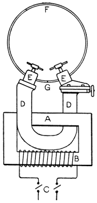
Fig. 71.—Electric Contact
Welding
of Steel Rim
The method of welding by resistance, that is, by raising locally the welding point to the temperature required by bringing the two surfaces into contact until their high resistance produces a welding heat and then squeezing them together, is by far the most manageable and satisfactory commercial process of the two electrical processes. It is adapted for “spot-welding” or producing local adhesions between metal plates after the manner of riveting, for butt or end-on welds, for seams, chains, rings, etc., and automatic welding machines are now made that can deal with no less than 1,500 welds and upwards per hour with semi-skilled labour, with the least possible percentage of failures[131] and a very low cost for electrical energy. Alternating current is essential with this type of weld, and is used to energise a step-down transformer of special construction.
—Notwithstanding the superiority of the resistance welding process to most commercial work, particularly that of a small kind necessitating rapid repeat work, the “arc” method, which has been in use for many years, and was probably the first experimented with, has now become largely used on work where it was thought impossible to adapt it a few years ago. The system is extensively employed in iron and steel works, shipyards, and boiler works, and the class of work it is employed on varies from the dismantling of iron and steel buildings, by fusing and cutting through the structural ironwork and girders, to the filling up of blowholes in castings. The metal to be welded is connected to one pole, and the electrode handled by the operator forms the other pole, an arc being struck between the two. Broken castings and forgings can be satisfactorily repaired by running new fused metal round them.
Recently the arc system has been applied with success for making welds on tramway rails, the resistance[132] of the welded joint being found very much lower than when made with the usual fishplates and bonded joints. Continuous current gives better results than alternating for the arc system, and a generator designed for use with this process has a “drooping characteristic,” that is, the volts at the terminals fall rapidly with an increase in the current output. In this way the current is automatically limited to some extent, when the short-circuiting effect of the operation comes into play. Successfully to weld by this process a current of 300 to 500 amperes at 80 volts is necessary, and every precaution has to be taken to protect the workman from the intense glare of the arc.
Thermit.—Thermit is an aluminium alloy whose combustion generates so much heat that the substance can be used for the welding of iron and steel. It is the patented invention of Dr. Hans Goldschmidt. With thermit as a means of melting and welding, and with the use of special clamps and devices, a number of operations, otherwise difficult, can be performed, and thermit has come into general use for repairing broken or defective parts. By the use of a portable jacket and clamp, the joints of gas, water, and steam pipes may be welded with the pipes in position; and the advantages of such a material to an engineer far removed from supplies and repair shop, as at sea, can hardly be enumerated. New journals have been welded to heavy rolls, broken pump-rods have been joined, and a number of structural parts successfully united by its aid.
[133]
Thermit is made up as follows: Iron oxide is intimately mixed up with about one-third as much in weight of powdered aluminium, according to the equation Fe2 O3 2 Al = Al2 O3 2 Fe. The metals to be united are placed together and surrounded by a little clay or similar substance and the mixture is placed all around the joint. The mixture is fired by a little magnesium, and the chemical change that follows creates such an intense heat that iron is readily welded. When the joint is cold and cleaned up it is hardly perceptible.
According to instructions published by Thermit, Ltd., it is of the utmost importance that the moulds, crucibles, etc., should be kept thoroughly dry, and they may advantageously be warmed before use to ensure the absence of any dampness. The parts to be welded must previously be brought to red heat, which is best effected by means of a gas and air flame. The proper design of the mould is of the utmost importance. It should have a runner and riser, and the metal should be allowed to flow between as well as around the ends of the pieces to be welded. The expense and inconvenience of making wooden patterns may be obviated by making the model of wax, ramming the sand round this, and subsequently melting out the wax.
[134]
Of late years oxy-acetylene welding and cutting have made great strides, and have placed at the disposal of the metal-working trades a means of doing many things that hitherto were impossible. Purified acetylene and oxygen, both under pressure, are supplied to a special blowpipe or torch. The flame in its hottest part has a temperature of about 4,000° C. and is therefore sufficiently high to melt any metals with which it may be brought into contact. The torch is fitted with all necessary adjustments to vary the supply of either of the gases, and constitutes a handy tool with which the intelligent worker soon acquires great dexterity. In a special form of the torch there is a means of introducing a further supply of compressed oxygen, which makes it possible for the blowpipe flame to cut its way rapidly through thick metal, the particles of which are actually consumed in the path of the oxygen.
It is out of the question in a single chapter of a handbook covering such a large scope as the present work to do more than indicate some of the uses to which the oxy-acetylene torch or blowpipe may be put. This chapter is obviously no attempt whatever at providing a complete working guide to oxy-acetylene welding. All that will be here attempted is to present a[135] brief description of a typical outfit and some notes on working the blowpipe, and then to give some practical instruction from the pen of an oxy-acetylene welder on the treatment of copper, aluminium and cast-iron. It may here be pointed out that there is now a large number of firms specialising in the manufacture of oxy-acetylene welders’ appliances, and most of them publish illustrated catalogues which anyone proposing to equip himself for oxy-acetylene welding would do well to obtain.
The source of the oxygen used in welding is now always cylinders, which are obtainable in various sizes, either by purchase or on hire from the gas-compressing companies, to whom they have to be returned for recharging. The acetylene also can be had in the compressed form, but in this case the gas is not simply compressed into steel cylinders because, if it were, any simple shock would be likely to cause explosion. The acetylene is therefore dissolved in liquid acetone, the cylinders containing some porous substance such as fossil meal, which is saturated with the acetone and the acetylene then pumped in. These also can be bought or hired from the gas-compressing companies. A tremendous amount of welding is done, however, with acetylene generated on the spot, and there are on the market quite a number of approved appliances that can be recommended, the best form of generator being that in which the calcium carbide is dropped into the water instead of the water dripping into the charge of calcium carbide. It is essential that the gas be[136] purified before use. As most people doubtless know, acetylene is one of the hydro-carbon series of gases and is evolved by the action of water on calcium carbide, a substance which is one of the products of the electric furnace.
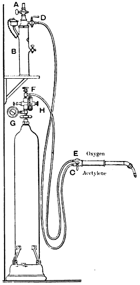
Fig. 72.—Diagram of
Oxy-acetylene
Welding Apparatus
The particulars and instructions on pp. 136 to 139 are due to the Acetylene Corporation, Ltd. Fig. 72 presents a diagrammatic illustration of a complete oxy-acetylene blowpipe equipment with the exception of the acetylene generator and holder, which apparatus may be placed in any suitable position (preferably outside) at any reasonable distance from the blowpipe. A is an ordinary gas tap connecting the hydraulic back pressure valve B with the acetylene supply pipe from the acetylene holder. The blowpipe is connected at valve C by means of a flexible tube with the outlet tap D of the hydraulic back-pressure valve. This forms the acetylene supply pipe to the blowpipe. The blowpipe is connected at valve E by means of a special canvas-covered strong rubber pipe with the outlet tap F of the oxygen pressure regulator, which is fixed, as shown, on the oxygen cylinder. G is a pressure gauge. This pipe conveys the oxygen supply to the blowpipe, and should be securely attached, as it is subject to pressures varying from 5 lb. to 40 lb. per sq. in. The hydraulic back-pressure valve should have been previously charged with water, and the gas regulator screwed into the oxygen cylinder. The blowpipe apparatus is now ready for use, with the taps A and D closed and the taps C, E and F open.
[137]
First, slowly open the oxygen cylinder valve (not shown) with the key supplied for that purpose. By means of the thumb-screw H, adjust the gas pressure to the correct working pressure for the blowpipe used. The approximate pressure of oxygen required for each blowpipe is as follows: No. 2, 8 lb. per sq. in.; No. 3, 10 lb.; No. 4, 11 lb.; No. 5, 12 lb.; No. 6, 14 lb.; No. 7, 16 lb.; No. 8, 19 lb.; No. 10, 20 lb.; No. 12, 25 lb.; No. 15, 30 lb. Then open the acetylene taps A and D, and when acetylene is unmistakably smelt at the nozzle of the blowpipe, ignite the gases by means of a gas jet, candle, or taper. Then by means of the tap C slowly throttle down the acetylene until the small white cone of flame at the nozzle of the blowpipe shows a clearly defined outline. As some indication of the correct size of the cone, it may be mentioned that when working with the No. 10 blowpipe this should be about 1⁄4 in. diameter by[138] 5⁄8 in. long. This cone in the other blowpipes is greater or less according to the relative size.
The tap A must never be used to regulate the supply of acetylene; in fact, after the hydraulic back-pressure valve has been charged with water, it is best to leave this tap always on.
The working pressure for oxygen previously given should not be too rigidly adhered to. Even in the same sizes of blowpipes the conditions must vary slightly, and a little practical experience with each blowpipe will soon indicate the best working conditions. If the flame is not properly regulated it may fire back and go out. If so, the taps C and E should be shut off at once, and a few seconds allowed to elapse before relighting. When work is carried on for a long time at a stretch and the burner becomes warm, it will be found necessary to slightly open the acetylene tap C from time to time. If work is being done which involves the nozzle of the blowpipe being held in a confined space, it is advantageous to cool this end of the blowpipe by immersing it from time to time in a bucket of water. While this is done the gases must be turned off at C and E.
Welding should be done at the apex or outer extremity of the small white cone.
If the hole in the nozzle of the blowpipe gets obstructed at any time through beads of iron being splashed into it, or from any other cause, it may be cleared with a piece of copper wire and cleaned with a wire brush. No steel reamer or other sharp instrument[139] should be used in the hole, which otherwise will be altered in size.
On stopping work the acetylene tap C should be closed first and then the oxygen tap E. When work is completely stopped, the oxygen cylinder should be shut off. The oxygen cylinder valve should never be opened until taps F and E are open, and it should then be opened slowly. In this way sudden impact of oxygen in the regulator is obviated.
The following instructions on the methods of welding copper, cast-iron and aluminium are contributed by a foreman welder.
—Copper to be welded should have its edges bevelled to enable the welding to penetrate the entire thickness of the metal. Bevelling is not generally practised below a thickness of 3⁄32 in. From 3⁄32 in. to 3⁄16 in., a slight open bevel is sufficient; 3⁄16 in. thick and over, the angle of the bevel should be about 90°. It is not necessary to go beyond this even with great thickness. The bevelling should be regular, especially at the bottom, so as not to produce holes or excess of thickness at the bottom of the bevel.
The edges to be welded and their immediate neighbourhood should be thoroughly cleaned. This can be done with a file, scraper, or sheets of emery. Chemical agents such as spirits of salt or nitric acid are sometimes employed; but it is preferable to precede their use by a mechanical cleaning.
Before beginning the welding the parts should be carefully arranged so that during the welding operation[140] they remain perfectly in position. Owing to the high conductivity of copper, a relatively larger blowpipe tip must be used than when welding either iron or mild steel of the same thickness. The power of a blowpipe of 225 litres with an approximate consumption of 7·75 cub. ft. of acetylene per hour would be suitable, with economical results, for iron or mild steel 1⁄8 in. thick, whereas for copper of the same thickness the power of the blowpipe should be of 300 litres, having an approximate consumption of 10·5 cub. ft. of acetylene per hour. Also, a blowpipe which is too strong tends to melt the metal too rapidly. This should be as carefully avoided as that of melting too slowly.
A pure copper welding rod may be employed for filling in, but it is not so effective as a welding rod made of phosphor copper. The phosphorus is incorporated in a very small quantity, so that none remains in the weld after its execution. A filler rod which contains too much phosphorus lacks fluidity, and melts at a temperature much lower than that of the copper to be welded, thus facilitating adhesion. Moreover, the welds in which the phosphorus remains lack elongation, and therefore do not possess the same mechanical properties as pure copper. The welding rod after 1⁄16 in. of its diameter should be about equal to the thickness of the weld, although in practice feeders about 1⁄4 in. in diameter are not generally employed. Welds made on copper without a deoxidising welding rod properly prepared have a tendency to oxidise, and therefore do not possess the required qualities. In addition, the[141] surface of the metal must be covered with a carefully prepared mixture of potassium phosphate and potassium carbonate to a depth of about 1⁄16 in. Upon the application of the flame, the mixture will melt and form a glaze over the surface of the copper, thus preventing oxidation and assuring good work.
A flux consisting of chloride of sodium, sodium borate, and boracic acid is also recommended. The flux should be sparingly applied by dipping the end of the welding rod into the vessel containing the flux. The end of the rod should be warmed in order that the flux adheres.
Before beginning the actual operation of welding, it is essential to raise the edges of the weld and the parts in the vicinity to a high temperature. The high conductivity of the metal necessitates this, as any supply of molten welding rod before the edges are in a molten state inevitably produces adhesion. The flame of the blowpipe should be perfectly regulated and maintained without excess of either acetylene or oxygen. In executing the weld, care must be taken to avoid contact of the white jet of the blowpipe flame with the metal just about to be melted. The distance of the white jet should vary according to the power of the blowpipe, say from 3⁄16 in. to 3⁄8 in. If this distance is increased, the gases resulting from the second phase of combustion, carbonic acid and water vapour, influence the weld. Care must be taken that the fusion of the metal should not be undertaken until the edges of the weld and the parts near have been raised to a[142] high temperature. At this moment the welding rod and the parts to be joined should be melted simultaneously. It is essential that the welding rod should be regularly incorporated in the line of welding, and must not be allowed to fall in drops. The operation should be continuous, taking care to attack regularly the two edges of the metal. The welding is thus executed rapidly.
It is well known that internal strains are always set up in every process of welding, due to the expansion and contraction when a metal is heated and cooled. Copper lacks tenacity when heated; hence contraction of the metal, whose coefficient of expansion is also fairly high; fractures thereby are often produced, especially in the welded part. However, pre-heating the article to a high temperature, maintaining the heating after the operation of welding and slow cooling, enables one in many cases to avoid fractures due to contraction. It is also necessary to hammer the line of welding and its vicinity. After the hammering operation it is essential to reheat the copper, raising it to redness (500° C. to 600° C.). Then plunge into cold water, or cool as rapidly as possible. The structure of the weld is not quite as homogeneous as other parts of the piece welded. This is, however, controlled largely by the skill and workmanship of the operator, who can, at will, make the weld more or less homogeneous.
It is impossible to enumerate in anything like detail all the work in copper which may be executed by[143] oxy-acetylene autogenous welding. However, copper-smiths are advantageously making great use of the system, thereby replacing their old methods of brazing and riveting.
—In preparing aluminium to be welded, the edges must first be thoroughly cleaned and the welding rod very pure, so as to avoid the incorporation of impurities, which is apt to bring about rapid disintegration in the line of welding. Bevelling the edges to be joined is not necessary below a thickness of 1⁄8 in. From 1⁄8 in. to 3⁄16 in. a slight open bevel is sufficient, 3⁄16 in. thick and above angle of bevel should be about 90°. For thin sheets up to a maximum of 3⁄32 in., welding is facilitated by flanging the edges at right angles. The depth of the flange should be slightly deeper than the thickness of the metal. By this method no welding rod is required, the edges being simply fused. The weld should afterwards be hammered level.
Aluminium should never be welded without a flux. If welding is attempted without a flux, globules consisting of aluminium within and a coating of alumina (oxide of aluminium) will appear. In order to eliminate these by the blowpipe flame it would be necessary to raise the temperature to the melting point of the oxide of aluminium, which is nearly 3,000° C., whilst the melting point of metallic aluminium is only 657° C. To produce a flux which will dissolve the oxide at the low melting point of the metal and at the same time protect the hot metal from contact with the air has[144] obviously not been a simple problem to the chemist and engineer. However, several good fluxes are now obtainable which enable any experienced welder to effect satisfactory welds in aluminium.
A flux consisting of the following ingredients can be recommended: sodium chloride 30 parts, potassium chloride 45 parts, lithium chloride 15 parts, potassium fluoride 7 parts, and bisulphate of potassium 3 parts.
When making fluxes for the welding of aluminium, great care is necessary in order to completely dry the ingredients, thus avoiding their combination with each other. On aluminium above 3⁄32 in. thick, the flux is best applied by dipping the end of the welding rod into the vessel containing the flux. The end of the rod should be first warmed in order that the flux adheres. The welding rod after 1⁄16 in., its diameter should be just about equal to the thickness of the weld, although in practice feeders above 1⁄4 in. diameter are not advisable.
In executing the weld, care must be taken to avoid contact of the white jet of the blowpipe flame with the metal just about to be melted, because the high temperature of this part tends to produce holes which are difficult to fill in. The distance of the white jet should vary according to the power of the blowpipe, say from 1⁄4 in. to 3⁄4 in. The flame should be so adjusted as to furnish an excess of acetylene. There need be but little fear of carbonising the metal, for the reason that the temperature of the work is comparatively low. For thin welds, up to 1⁄8 in. thick, it is preferable to hold[145] the welding rod in front of the blowpipe in the direction of the edges to be welded. As soon as the latter begins to melt it is heated rapidly, and should be lowered to form one molten bath with the metal of the piece. The welding is thus done very rapidly. For great thicknesses it is preferable to obtain fusion of the welding rod, previously heated in the molten bath of the bevel. Directly after welding, the weld should be thoroughly washed in clean warm water in order to remove all remaining traces of the flux, which would otherwise continue to have a chemical action on the metal, thereby setting up corrosion.
—The edges of the weld should be bevelled when the thickness exceeds 1⁄8 in.; this enables the welding to penetrate the entire thickness of the metal. Both edges must be bevelled to an angle of 45°, so as to form a right angle at the weld. The bevelling should be regular, especially at the bottom, so as not to produce holes or excess thickness at the bottom of the bevel. Workers who attempt to effect welds on cast-iron above, say, 1⁄4 in. in thickness, without bevelling, invariably obtain poor results, as it is impossible to get regular and thorough penetration. The bevelling of the edges may be done by chipping or grinding, etc. Grinding wheels made from a carbide of silicon abrasive are very effective for cast-iron. The edges to be welded and their immediate neighbourhood must be free from sand, dirt, and rust.
It is known that internal strains are always set up in every process of welding, due to the expansion and[146] contraction when a metal body is heated and cooled. These strains are not unavoidable, but their effect may be minimised or nullified. In the case of cast-iron, the tendency to crack will be greatly increased if the cooling of the metal after fusion is rapid or irregular. Consequently, the article to be welded should be pre-heated slowly to about 700° F. to 1,000° F. Generally speaking, the higher the temperature of pre-heating, the less the danger of cracking. Preferably, pre-heating and subsequent slow cooling should be carried out in a muffle, particularly where light and intricate castings have to be dealt with.
In all cases care should be taken in the selection of the proper size of blowpipe tip to be used on any particular job. Therefore, the size of tip recommended by the manufacturers should be employed. The total heat of fusion of cast-iron being high, it is necessary to use a blowpipe with a greater power than for the same thickness of welds on mild-steel or wrought-iron. In the actual operation of welding, the blowpipe flame should be played on the edges to be welded until the melting of the iron just takes place. It is essential to avoid contact of the white cone of the blowpipe flame with the metal just about to be melted; the point should be kept at a distance varying from 3⁄16 in. to 3⁄4 in., according to the thickness of the work. The two edges to be joined should melt simultaneously. As soon as the first fusion is obtained, a little flux or scaling powder must be added; this is usually applied by dipping the extremity of the welding rod into the[147] vessel containing the flux, the rod having been previously heated. Avoid throwing the powder into the molten metal whilst executing the weld, as the supply from the welding rod is always sufficient.
Many kinds of fluxes for cast-iron are furnished by the manufacturers of welding apparatus, which vary considerably in composition. The principle of all of them is to provide some chemical which, at the high temperature involved, will break up the oxide into its component parts. The following combinations will perform these functions, and can be recommended: (1) Boracic acid 80 parts, powdered chlorate of potash 20 parts, ferric carbide 15 parts. (2) Equal parts of carbonate and bicarbonate of soda, to which is added from 10 to 15 per cent. of borax and 5 per cent. of precipitated silica. (3) Carbonate of soda 50 per cent. and bicarbonate of soda 50 per cent. The necessity for using a flux may not be thoroughly appreciated; but if it is attempted to weld cast-iron without it difficulty will at once be experienced.
Do not add any metal from the welding rod until the bottom of the V is filled from the sides. It is found that by employing silicon in the welding rod, in the form of ferro-silicon, the iron combines with the silicon in preference to the carbon, allowing the carbon to take the form of graphite, and thus facilitate the formation of grey iron. The welding rod should contain about 4 per cent. of silicon and as low as possible in manganese. The purchase of such a welding rod is not at all difficult, and may be obtained from the same[148] manufacturers as the flux, from 1⁄8 in. to 1⁄2 in. in diameter.
One criticism of cast-iron welding has been directed against the hardness of the weld. This hardness may be due to a number of causes, such as inefficiency of the operator, unsatisfactory fluxes and welding apparatus, rapid cooling, etc. Therefore, as stated previously, in order to get good workable welds, there must be slow cooling after the welding is complete; and there is no reason why the worker who carefully follows the instructions given, and applies himself diligently to the task, should not be able to weld cast-iron of any thickness in an efficient and workmanlike manner.
This method of welding cast-iron successfully solves an unlimited variety of manufacturing and repair problems in the engineering industry, and can be relied on to make homogeneous welds on cast-iron. It is impossible to enumerate in anything like detail all the work in cast-iron which may be executed by oxy-acetylene welding; but the following are some of the applications for which it has already been advantageously employed: For repairing broken machine parts, gear boxes, motor cylinders, crank cases, tanks, manifolds, flywheels, etc., filling blowholes and defects in castings. Castings impossible or difficult to mould can be made in parts and united. Teeth broken from gear wheels can be renewed, and adding metal in any desired quantity to worn parts of cast-iron articles. As a concrete example of its economical and positive aid to the engineering industry, the following may be[149] of interest. A cast-iron belt-wheel would have gone on the scrap heap, a total loss, with four of the six spokes broken, three entirely out. It was 5 ft. in diameter, and weighed about 500 lb., but was not worth much as scrap metal. Scrapping it meant the purchase of a new wheel, and perhaps a long delay in getting one cast. But with the oxy-acetylene process the three spokes that were fractured were welded into place; the fourth spoke broken near the hub was also welded. There were seven welds, each about 11⁄2 in. by 4 in.; the job was done profitably at a cost of £5, ready for delivery in two days, and was considerably better than buying a new wheel, and waiting two weeks or two months for delivery. The process is particularly suitable for this class of work, and cannot fail to give satisfaction if performed by an experienced welder. The cost of welding a given job depends not only on its thickness, but on the skill of the workman. For example, the same class of job may vary as much as 50 per cent. if executed by different operators.
[150]
Lead-burning or flaming is the autogenous welding of lead by means of either an aero-hydrogen or oxy-coal-gas blowpipe flame. In the past the apparatus required included a hydrogen-gas generating chamber (called the “lead-burning machine”) and a blower or air chamber. The hydrogen was made by the action of dilute sulphuric acid on zinc. That system is now, or should be, obsolete, having been superseded by the cleanly and altogether more convenient process of employing two cylinders, one of compressed coal-gas and the other of compressed oxygen, in conjunction with an injector-pattern blowpipe. Gauges and regulators are required as in the oxy-acetylene process.
The oxy-acetylene process may be successfully applied to lead-burning in spite of the great heat of such a flame. The consumption of acetylene, according to Mr. D. Richardson’s translation of Granjon and Rosenberg’s French work, is only 1 to 2 cubic feet per hour for lead 1⁄16 in. to 3⁄16 in. thick, and the process is stated to have “considerable advantages over all other methods of autogenous soldering.”
In lead-burning it is customary to employ a triangular stick of refined lead for filling up the seams.[151] By being burnt or joined together in this way, the lead becomes homogeneous, and the various parts of it equally withstand the same chemical action and heat. For this reason it is used for joining the seams of chemical and acid tanks, and for the joints of pipes used for the conveyance of such chemicals. Solder being an alloy, the acid would have a solvent action on it, eating it away and rendering it useless, and it would also give rise to electrical action, practically impossible when only one metal is exclusively employed. Lead-burning is also often used on external or roof work.
The seams burnt on sheet-lead are of two kinds: one forming a butted joint, the other a lapped joint.
In burning a butted seam, the two edges of the lead to be joined are butted together, and shaved about 1⁄4 in. to 3⁄8 in., or slightly less, on each side. The gas and oxygen are turned on and adjusted so as to produce a flame from about 5 in. to 6 in. long, and tapering to a fine point. The hottest part of the flame is the centre of the thickest portion, about 1 in. or 11⁄2 in. from the jet. Hold the jet in the right hand, and a strip of lead in the left, and allow the flame to play on the end of the strip, which is held just above the seam. As the strip melts, the jet is diverted on to the seam so as to fuse the edges together, the additional lead forming a thickened portion. The strip is again melted, and joined to the edges, and also to the thickest part; and so on along the length. Care should be taken to burn the lead through, but not for the metal to flow beneath the seam. After a little practice, the operator[152] will know exactly when to apply and when to remove the jet.
Fig. 73 shows a flat butted joint partly burnt. The stick of lead is just nipped with the flame, and a bead of lead dropped on the seam. The flame is then directed on to this bead until it is fused with the seam. When bead and seam are melted together, the flame is immediately raised. The next bead of lead is then dropped on the seam so as to half cover the previous bead, as shown at M (Fig. 73). The flame is then directed on the second bead, the flame being immediately raised after these are fused together, and this operation is repeated until the whole of the seam is burnt.
A flat lapped joint, partly burnt, is shown by Fig. 74. In burning this joint, the stick of lead is only required to fill up any irregularities in the burning, and is not required to form the seam in the same way as it is in a butted joint, because in lapped burning the overcloak is burnt down on to the undercloak, as shown in Fig. 75. In horizontal and vertical burning, lapped joints only should be used.
Fig. 75 shows a specimen of horizontal or side burning, and Fig. 76 one of vertical or upright burning. In burning both of these, the stick of lead is not required at all, the overcloak being in each case burnt down on to the undercloak. Care must be taken that both the overcloak and undercloak of a lapped joint are well shaved.
[153]
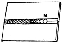
Fig. 73.--Butted Seam Partly Burnt
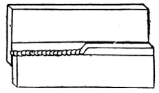
Fig. 75.--Horizontal or Side Burning
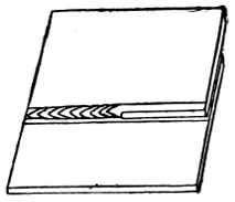
Fig. 74.--Lapped Seam Partly Burnt
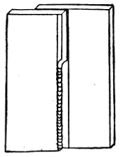
Fig. 76.--Vertical or Upright Burning
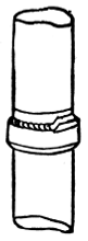
Fig. 77.--Burning Upright Joint
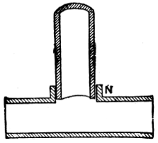
Fig. 78.--Branch Joint Ready for Burning
[154]
The seams should not be soiled or greased, and care must be taken not to tarnish them in any way. If the lead is not shaved quite clean, or it becomes tarnished after it is shaved, it will be found difficult to burn it together successfully. No tallow or smudge is necessary. The operator will soon detect the presence of any foreign substance or dirt on the lead, and the shavehook should be kept handy to remove it.
In burning a vertical lapped seam, starting at the bottom, the lapping lead is melted, and as it runs is turned on to the back portion and fused into it. A slight projection is formed, which holds the next melting, and so on, each layer forming a base for the next, and adding to the height until the top is reached.
In practising either horizontal or vertical burning, the student should first place his work at an easy angle—say, at about 25° or 30°—gradually raising it as he becomes proficient until the seam is in a horizontal or vertical position as desired. Two surfaces can be burned together in any position—horizontal, vertical, or even overhead, where soldering would be impossible.
Pipe joints can also be made by burning. First one pipe is opened to form a socket like a slip joint. The male part, which must enter at least 3⁄4 in., must be well shaved and made to fit tight. Fig. 77 shows an upright joint prepared and partly burnt. Fig. 78 shows a section of a branch joint as prepared for burning. Care must be taken to work up a good thick shoulder for the socket N.
[155]
Printed by Cassell & Company, Limited, La Belle Sauvage, London, E.C.
Inconsistencies in the source document have been retained.
Depending on the hard- and software used, not all elements may display as intended.
Page 59, table: the row Tin 6 does not add up to 100 (%, presumably) as the other rows do.
Minor obvious punctuation errors have been corrected silently.
Page 5: 66° and 34° have been changed to 66% and 34%, respectively.
Page 7: flow over the hoe has been changed to flow over the hole.
Page 154: enter at last has been changed to enter at least.