
GIVING DETAILED INSTRUCTIONS OF
THE PROPER ADJUSTMENT
AND CARE OF THE
LINOTYPE
WITH ILLUSTRATIONS
Price, $2.00
AGENTS
J. W. SUTHERLAND, 62 McVicker’s Theatre Bldg., Chicago
F. H. McCALL, 408 Hall Building, Kansas City
Copyright, 1898, by
F. H. McCall
The object in view in compiling this book is to show by means of cuts and detail drawings the different adjustments and how to make same.
The automatics and how to set them.
The best method of placing machines in an office, with the necessary belting, shafting, etc.
Erecting machine, and other useful information in regard to care of same.
How to keep metal in good condition to obtain best results, and other instructions that will tend to the successful operation of the Linotype.
The machine complete and ready for operation weighs 1,925 pounds. In operation there is no vibration, and the machine may be safely placed in any building of ordinary strength.
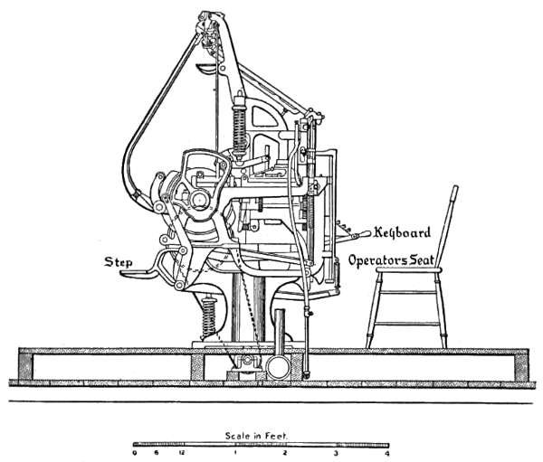
MODE OF ERECTING MACHINES—NO. 1
Machine stands on Platform built on Main Floor. Driving Shaft, Pulleys and Gas Pipes under the Platform and above Floor.
Fig. 1.
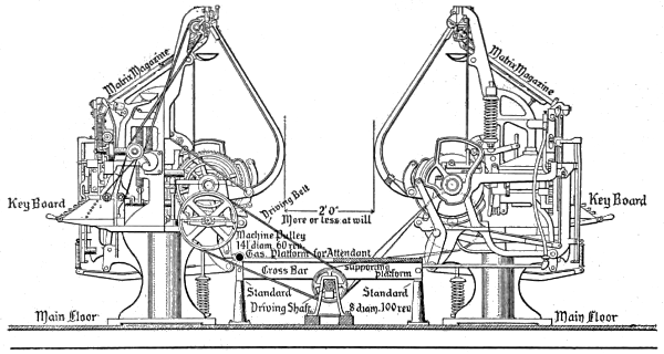
MODE OF ERECTING MACHINES—NO. 2
Machines and Driving Shaft on Main Floor. Intermediate Platform over Shaft. Good plan, but inferior to No. 1.
Fig. 2.
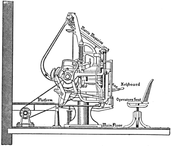
MODE OF ERECTING MACHINES—No. 3
Modification of Plan No. 2. Machines and Driving Shaft on Main Floor. Intermediate Platform over Shaft. Good Plan, but inferior to No. 1.
Fig. 3.
Each machine requires somewhat less than one-quarter of a horsepower to drive it, but the allowance of one-half horsepower is recommended to insure steadiness of motion.
Each machine, including overhanging projections, is a little less than five feet square.
In placing machines allowance must be made for[12] space sufficient to pass around and between them, and for seat of operator in front. A liberal allowance is 7x10 feet.
The driving pulley of the machine is 14½ inches in diameter and should be driven at about 62 revolutions per minute. Never to exceed 66. Any arrangement of shafting and pulleys which will secure this speed will answer.
The Linotype Company has recently had a specially designed electric motor built which is adapted for speedy application to Linotype machines. These motors are cheap, compact, reliable and pleasing in appearance. Their application demands no change in the machine except to remove the driving pulley and substitute a gear wheel furnished with the motor.
The only connection required is the extension of a wire to an ordinary incandescent lamp socket or other suitable source of electric power. The use of these motors avoid the necessity for countershafts, pulleys and belts, and greatly improve the appearance of the office.
Motors wound for 115, 230 and 500 volts are carried in stock. The price, with all attachments, applicable to any machine, is $65.
In shipping the machine the base and heavy parts, such as column, metal pot, cams, vise, etc., are assembled. The base being bolted with lag screws to three skids and boxed up, with the distributer bracket and step cleated in the top.
A second box, 20x24x18 inches, contains the key-board and reeds, intermediate bracket, channel-plate support, and all the small parts, such as vise-locking screws, flexible front, pi box and tube, second elevator, distributer box, keyboard rod guide assembled, all carriages, etc.
A third box, 44x26x16 inches, contains face plate assembled, magazine, set of matrices, two small boxes, one containing large and small assembler glasses, the other the magazine entrance.
A fourth box, 46x9x12 inches, contains distributer assembled and first elevator.
Take boards from base and roll it to its permanent position and remove skids, then cut the wires that bind levers C and J (Fig. 4). Then turn clutch A to the right until second elevator lever J (Fig. 4) is in the position shown in Fig. 5 and put on the distributer bracket A (Fig. 5). Then, in the order given, put on intermediate bracket D, upper rod guide F, channel plate support E, second elevator C (Fig. 5), and vise-locking screws 2 and 3 (Fig. 4).
Fig. 4.
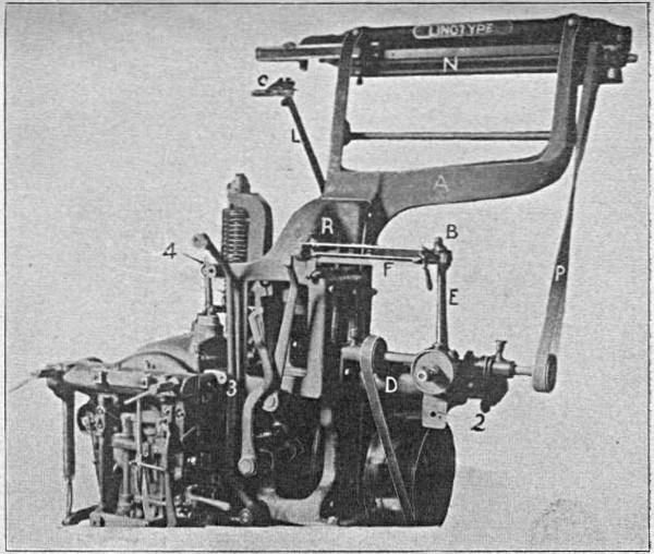
Fig. 5.
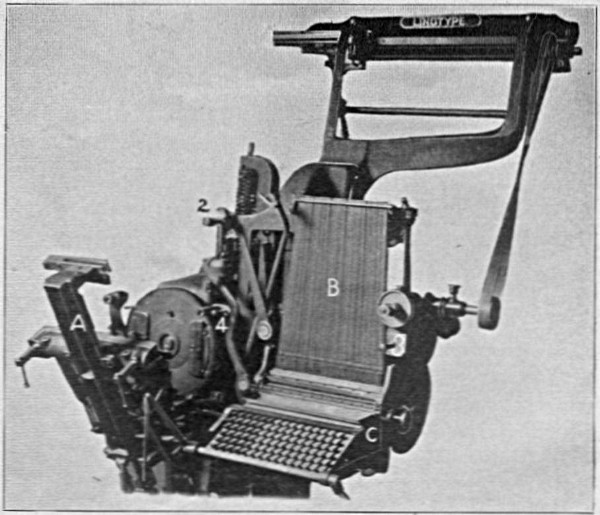
Fig. 6.
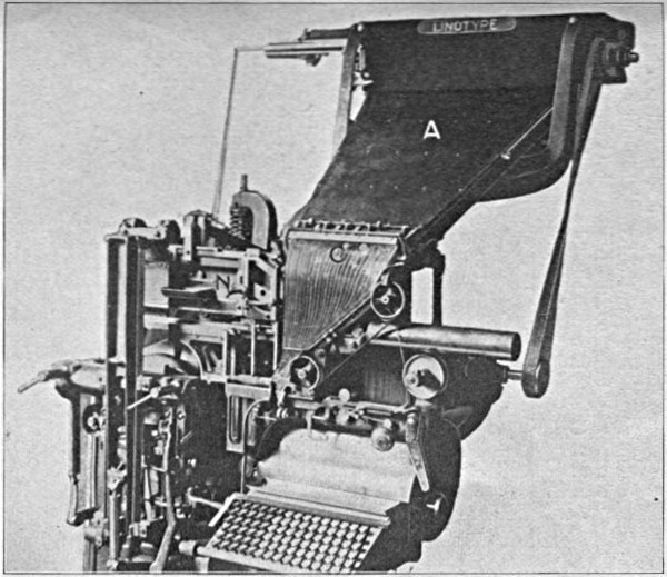
Fig. 7.
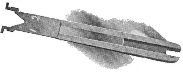
Then put on keyboard C (Fig. 6) and put in rods B (Fig. 6), which are numbered consecutively, beginning with No. 1 at the left. Then put on first elevator A (Fig. 6), distributer N (Fig. 5), and belt P (Fig. 5), which should always be crossed so as to run away from the gears.
Now, with machine in position (Fig. 6), put on face plate N (Fig. 7), which is held by the three cap screws 2, 3 and 4 (Fig. 6), and magazine A and flexible front and glass C (Fig. 7) and connect spaceband lever, spaceband transfer carriage, distributer shifter carriages, line delivery carriage, assembling elevator, etc. Reversing these directions will, of course, show how to take the machine apart.
Before putting on driving belt it is advisable to turn machine over by hand, to be sure everything is all right. If all parts are connected properly there should be no binding and machine should turn easily.
Fig. 8.
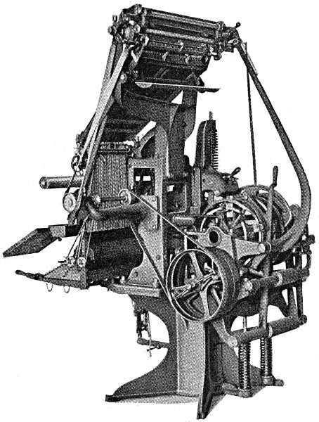
Fig. 9.
It is essential that the temperature of the metal should be kept uniform. If the temperature is too high, porous or spongy slugs will result, also defective faces and a weak surface, which allows the letters to sink in printing.
A temperature that is too low causes the metal to adhere to the mouthpiece and prevents the free flow of the metal to the mold.
We recommend that the metal in front of the well be kept at a temperature anywhere between 536 and 563 degrees Fahrenheit. The temperature can be kept uniform by means of the gas governor attached to each machine, and can be supplemented by a gas pressure governor attached to supply pipe. (See Fig. 10.)
The temperature can be ascertained by plunging a thermometer reading up to 600 degrees Fahrenheit into the molten metal in front of the well and readings taken when the mercury remains constant. Heat the thermometer before plunging it into the metal. The bulb should be wholly covered by the molten metal.
When no thermometer is at hand the temperature may be obtained approximately by plunging a piece of paper into the molten metal. If it turns brown the metal is in a proper condition to cast. The temperature is too low if only a slight color is imparted to the paper; too high if a deep brown or black.
No other metal, such as brass, zinc, or stereotype metal should be mixed with linotype metal. It has been found that better results are obtained if the slugs are melted in a proper furnace and cast into ingots or blocks.
The pot will be kept more free from dross by this method than by melting the slugs in the metal pot of the machine.
For one machine use a ½-inch supply pipe, and increase about ¼-inch for each additional machine, a 2-inch pipe being sufficient for a plant of twelve machines. A ½-inch feed pipe should be run to each machine.
A gas governor is furnished by the Linotype Company, as shown in Fig. 10, which should be attached to the main pipe near the machines. This governor, together with the one on the machine, will keep the gas at a uniform pressure. The governor (Fig. 10) works as follows:
When the gas pressure becomes too heavy it raises the float B, which sets in mercury at point J and A, and closes the valve C, points 1 and 2.
A small bottle of mercury is sent with each governor; also two small lead weights, which go on top of float B. The arrows show how the gas enters and leaves the governor.
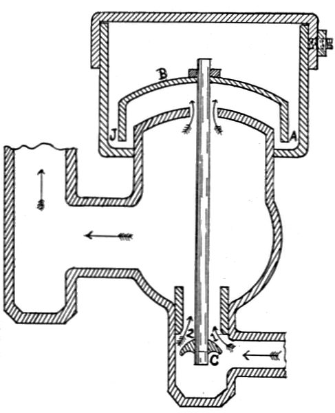
Fig. 10.
The metal may be purified if, when in a molten state, a piece of green wood about 4 inches in diameter and 7 or 8 inches long, attached to an iron rod, is plunged into the molten metal and allowed to remain about 20 minutes, or until the boiling ceases.
The green wood causes the metal to boil violently, and the oxides contained in the interior of the molten metal are affectually reduced.
The metal should then be thoroughly stirred and the scum removed by an iron ladle.
The dross on the surface may be reduced by adding a few ounces of rosin to the molten mass.
Dross is a compound formed by the action of air upon molten metal. The oxygen contained in the atmosphere attacks most metals with which we are acquainted. The formation of this oxide takes place more rapidly and in larger quantities the higher the temperature of the metal.
This oxidation only occurs upon the surface of molten metal where the air has access and not in the center of the molten mass. It is easy to skim this dross from the metal by means of an iron ladle. It can then be reduced to metal during the operation of melting the slugs into blocks already described.
If this is done little loss will result. The principle of its reduction to the metallic state is this:
If such dross is heated in contact with carbonaceous material, such as rosin, the carbon and resulting gases formed in the process take away the oxygen contained in the dross, liberating the metal.
Care should be taken to keep the inside rim of pulley and clutch leather shoes free from oil; if not, the clutch will slip and fail to turn machine over. The clutch and pulleys should be taken off every two weeks and cleaned and oiled; if not, they will become dry on the shaft and cause the mold disk to carry over when the machine stops.
To take off the clutch and pulleys unscrew the nut E (Fig. 13) and loosen screw which holds clutch on the shaft; then clean shaft N (Fig. 11); then put it back and adjust as described in Adjustment of Automatic Stop.
The friction clutch spring S (Fig. 11) is sometimes too weak, and should be strengthened or renewed. To take out this spring, unscrew the cap or end of shaft as shown in Fig. 11.
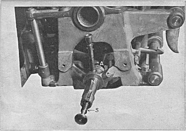
Fig. 11.
First—Adjust the automatic stopping pawl A (Fig. 14) to 15-16 inch from side of cam to back of pawl and adjust automatic safety pawl the same.
Second—Set the automatic stopping lever C (Fig. 14) so as to engage 3-16 inch with automatic stopping pawl A. Then clamp the vertical starting lever shaft K with set screw D (Fig. 12).
Third—By the adjusting nut E (Fig. 13) adjust the driving shaft clutch flange F (Fig. 12) to 29-64 inch from end of driving shaft bearing G (Fig. 12); then tighten check nut.
Fourth—By means of adjusting screw H (Fig. 12) take up the lost motion between the contact points I and J (Fig. 12), leaving 1-32 inch play; then tighten check nut.
To set friction clutch on machines with old-style automatic stop, simply tighten the nut E (Fig. 13) until there is 1-16 inch between flange F and driving shaft bearing G (Fig. 12), with starting lever open; then set vise automatic.
First set eccentric screw 6 (Fig. 15) on inner end of stopping and starting lever connection rod 8 (Fig. 15) so as to take up all lost motion between it and the vertical starting lever. Then set the eccentric screw 7 (Fig. 15) on outer end of the connecting rod 8 so as to take up all lost motion between it and vise automatic stop lever 4 (Fig. 15). To do this, pull out the vise automatic stop lever 4 with your finger until the inside end bears firmly against the vise automatic stop rod 1, which, in turn, comes in contact with the vise automatic stop mold disk dog 3 (Fig. 15); then pull out the starting and stopping hand lever 2 (Fig. 15) until machine starts. At the time when the machine starts the eccentric screw 7 should touch the outer end of the vise automatic stop lever 4, then there would be no lost motion and the vise automatic would act as follows:
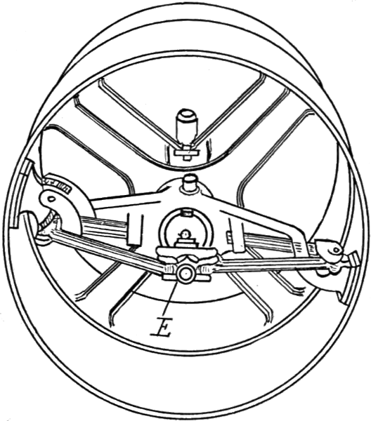
Fig. 13.
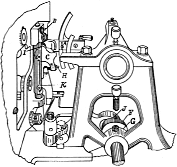
Fig. 12.
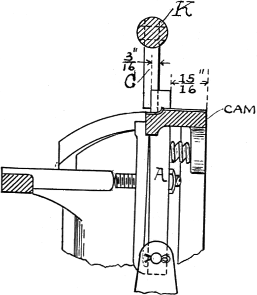
Fig. 14.
In case of a tight line (which would not allow the first elevator to drop into the vise far enough to force the vise automatic stop rod 1 down to allow the mold disk dog 3 to pass over the pawl 5 in the stop rod 1) the disk coming forward would force the mold disk dog 3 against the pawl 5 in stop rod 1 which, coming in contact with inner end of vise automatic stop lever 4, would force the outer end of stop lever against eccentric screw 7, which would cause the machine to be shut off the same as if it were done by pushing the hand lever in by hand.
If the vise automatic is set this way it will stop mold disk nearly 1-16 inch away from matrices, leaving the first elevator free to lift up and a matrix to be taken out. This not only prevents a squirt, but saves the ears of the matrices in many cases.
Fig. 15.
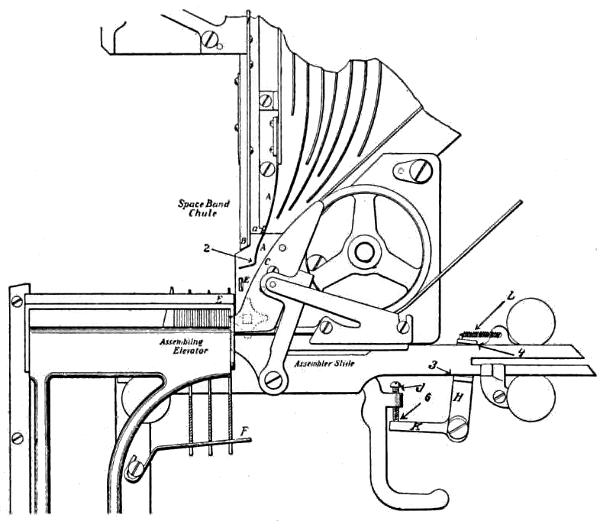
Fig. 16.
In order to prevent transposition of matrices and spacebands the parts should be adjusted as illustrated in Fig. 31.
The assembler chute spring A, which lays between spaceband chute B and assembler rail C, should be set as low as its banking piece “a” will[37] permit. Its lower end should be about midway between the lower end of the spaceband chute B and matrix catch spring E, and in line with them.
The space between the spring A and rail C at point 2 should be equal to the thickness of the capital W matrix.
The spaceband buffer F should be adjusted so that each band as it falls into the line will be supported by the buffer, with its ear about 1-32 inch above the top of the assembler rail.
The buffer wire should have a slight inclination downward toward the left, so that the ears of the bands will settle down as the line is assembled.
The matrix catch spring E should project through the assembler plate a sufficient distance to catch each matrix as it passes, and prevent it from falling back to the right.
The assembler slide brake H and spring L should be adjusted to prevent the assembler slide from jumping ahead to the left or continually vibrating as the matrices enter. If the assembler vibrates it makes it impossible for the operator to read the line, and the last letter will sometimes fall out when the assembling elevator is raised. This is caused by the brake H wearing at points 3 and 4, which lessens the tension of the spring L and takes up the space between bottom screw J and brake lever K at point 6, which should be about 1-32 inch. If brake H is not too badly worn at points 3 and 4 this trouble can be obviated by strengthening spring L[38] and turning up screw J until you have about 1-32 inch space at point 6. Be careful not to get too much space at point 6, or the assembler slide would not return when the line has been released from the assembling elevator.
The assembler star should be renewed as soon as it is worn sufficient to prevent it from pushing the matrices inside the assembling elevator pawls, and it is advisable to renew the assembler chute rails at the same time.
The assembler star friction spring sometimes gets too weak to hold the star and it will slip. The assembler star friction disk will also wear out.
To renew these, take off the assembler Fig. 17 (this shows back view) and unscrew the nut C.
This cut also shows the intermediate gear B and assembler belt driving pulley A.
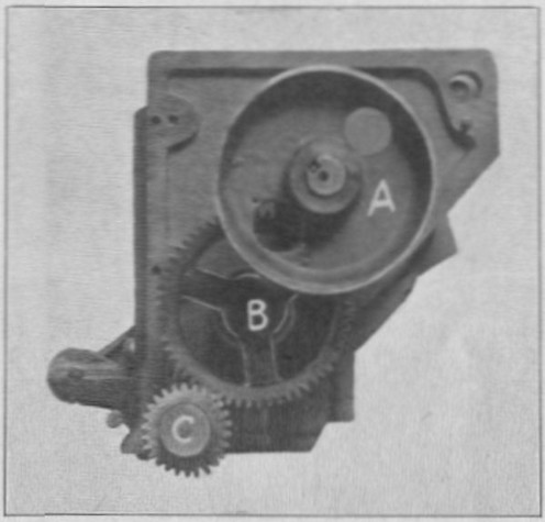
Fig. 17.
The distributer bar has a strip of brass about 1-16 inch wide set into it just above the combinations.
In setting it for height be careful not to set it too low. If set too low the matrix, in leaving the distributer box, will bind between the distributer box upper rails N (Fig. 27), M (Fig. 26) and the brass strip. If the matrices bind it will not only bend the ears, but also wear brass strip.
The bar should be set so that when matrix is about to leave the rails, and has entered onto the first combination of the bar, it will rest on the top of the rails and be perfectly free on the bar.
To make this adjustment, loosen the screws E and F (Fig. 19) and set the bar with the two set screws in top of distributer beam.
To set the bar endwise, the distance from the first combination (e) (Fig. 18) to the outside of the distributer front screw bracket A (Fig. 18) should be 2⅞ inches.
In the latest machines built this bar is adjusted in the factory and a pin driven into it just below screw F (Fig. 19). If bar is taken out it will always go back in its proper place, and the end adjustment will not be necessary.
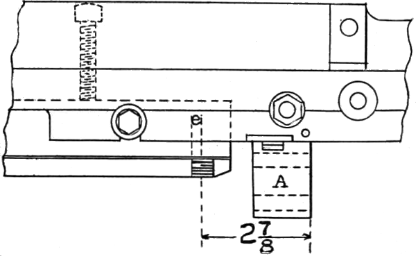
Fig. 18.
In setting the magazine first see that the distributer-bar is set right, as shown in Fig. 18; then run two pi matrices onto the bar, one at each end, as 1 and 2 (Fig. 20); then raise or lower the magazine with screws E and F until there is about 1-16 inch space between the bottom of matrix and the channel-plate entrance partition at points 1 and 2 (Fig. 20); then tighten check nuts on screws E and F to prevent them from changing.
Next run a lower case “e” onto the bar by turning the distributer slowly by hand, and set the magazine sidewise until the lower case “e” drops as soon as it passes the second entrance partition,[42] which would be the right hand partition for the “e” channel. When the machine is running the momentum will be sufficient to carry it to the center of the “e” channel. Then turn out the screws N and M (Fig. 20) until they touch the sides of the distributer bracket, and tighten the check nuts on the screws M and N so they will not change.
The next thing is to set the lower end of the magazine in relation to the rods J, Fig. 21.
First throw the rods into the verges; then touch the first and last keyboard buttons, which are lower case “e” and “—”; then turn rubber roller until the “e” and “—” rods are at their highest point; then raise or lower the magazine by screws in channel-plate support A (Fig. 20) and on column R (Fig. 5) until there is about 1-32 inch between the key rod and verge at point 8 (Fig. 32); then tighten the check nuts B on screws A (Fig. 21).
Turn out screw A (Fig. 20) until the lift C (Fig. 20) will not come down low enough to pick up the matrices; then turn the screw A (Fig. 20) until the lift C will just pick up all the matrices and tighten check nut on the screw. This will allow all extra motion to be on the upward motion which carries the matrix that much higher up into the distributer screws, so there would be little danger of bending the ear of the matrix.
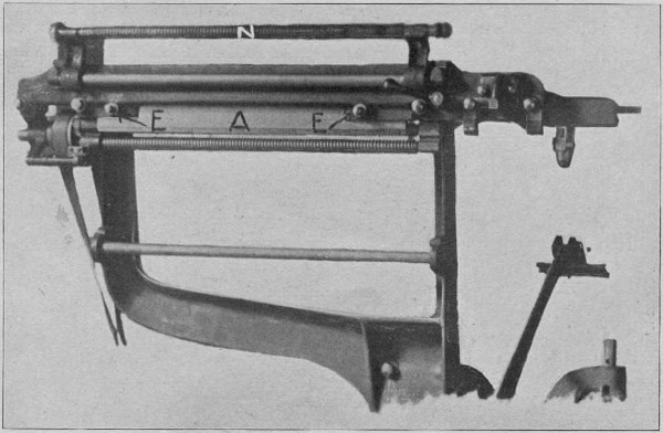
Fig. 19.
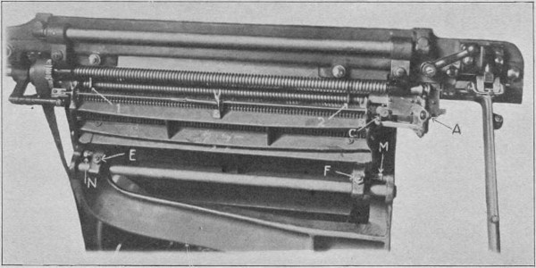
Fig. 20.
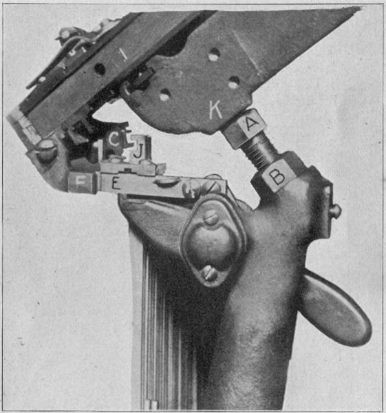
Fig. 21.
The keyboard cams should be taken out and thoroughly cleaned every six or eight months and oiled with a drop of clock oil on the journal pin. This will prevent them from sticking and causing transposition of the matrices.
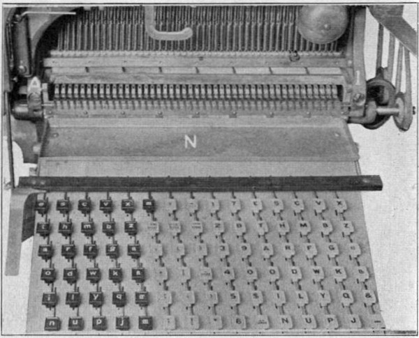
Fig. 22.
Fig. 23.
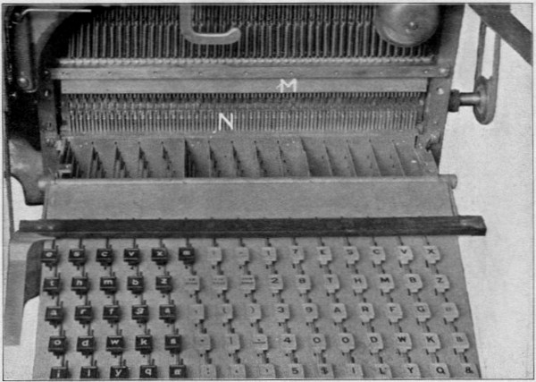
Fig. 24.
The easiest way to take out the cams is to take off the back and front of the keyboard (Fig. 23).[49] This is done by taking off the keyboard tray N (Fig. 23); then taking out screws I and A (Fig. 22) with the keyboard unlocked. The back, of course, comes off the same way. As these are dowelled, you would have no trouble in replacing them.
It will be found easier in putting them back if a small wire is run through the cam yoke triggers C (Fig. 31), locking them so they would enter the keyboard keybars B (Fig. 31) at point 3 (Fig. 31).
Figure 24 shows the keyboard with the front taken off, showing the keyboard keybars N in place and lower keyboard rod guide M.
Figure No. 25 shows the distributer-box complete. The best way to take it apart to renew the rails B and C (Fig. 28) is to take out screws 1, 2 and 3 (Fig. 25) and take off side (Fig. 26).
The rails M and K (Fig. 26) and N and O (Fig. 27) have to be renewed when they have worn (as shown by dotted lines 1 and 2, Fig. 28) enough to allow two thin matrices to pass between points 1 and 2, rails C and B, and distributer-box bar pawl 3 (Fig. 28).
If the rails M (Fig. 26) and N (Fig. 27) are badly worn on the top 2 (Fig. 26) and 4 (Fig. 27) a matrix is liable to leave the box and enter on the distributer-bar diagonally, and if the distributer-box is not set properly the same thing will occur.
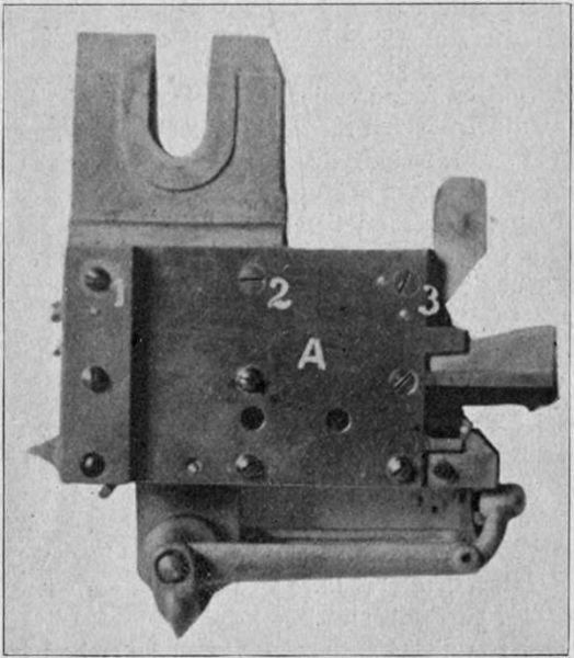
Fig. 25.
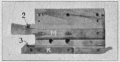
Fig. 26.
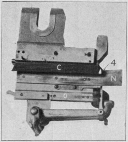
Fig. 27.
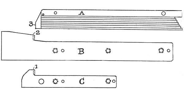
Fig. 28.
To insure good work the spaceband box should be kept thoroughly clean.
To clean box, it will be necessary to take it off the machine and take it apart. To do this take out screw K (Fig. 29) and screws L, which hold the spaceband chute; drive out pin J and take off the pawl lever I (Fig. 29); then take out screws A and C and take off side.
Figure 30 shows inside of box. The screw 1 in pawl lever should be adjusted so that when pawl lever is down the pawls N and O will be low enough to clear the top rails C and J (Fig. 30) about 1-32 inch, with the screw resting on spaceband lever. If too low it will give a double motion to the pawl lever I (Fig. 29) and sometimes throw out two spacebands at once and clog the spaceband chute.
The spaceband center guide A (Fig. 30) will allow two bands to pass if it is not adjusted properly.
At the lower end of the guide is a half pin or ear on each side, which is to catch the second spaceband if pawl lever lifts two. This guide is adjustable and should be set so as to allow only one band to pass freely.
The pawls N and O (Fig. 30) have to be renewed when badly worn. Before putting in new pawls rub them down on an oil stone, so that when in place in the box, and moved up and down slowly by hand, they will stand inside the hooks of the rails C and J about the width of a spaceband ear, and both be the same height so as to lift the band evenly.
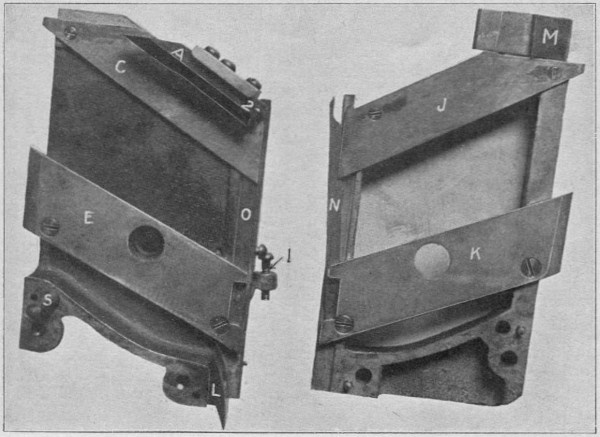
Fig. 30.
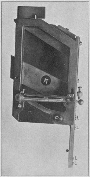
Fig. 29.
The pawls N and O should work in their slots perfectly loose. As the pawl levers and pawls drop by their own weight entirely, it is necessary their movement should be perfectly free.
When putting spacebands into the box always be sure the bottom of the first is back of the stop for spaceband end L (Fig. 30).
Figure 31 shows all parts at rest and Fig. 32 the parts in motion after key lever A has been touched and the cam D has made one-half revolution. In Fig. 31 the cam and yoke D is supported about 1-16 inch above the rubber roller E by the trigger C, which intersects the keyboard keybar B at point 3.
The key rod G, which is suspended from the verge I at point 8, comes down to about 1-16 inch from cam yoke at point 6. Note that point 4 on cam D is only about one-half as far from the journal pin or cam bearing as point 7. Now, suppose the rubber roll to be revolving and key lever A pressed down, this will in turn raise the keybar B and throw out the trigger C from the cam at point 5 and allow the cam to strike the revolving rubber roll E at point 4, which would cause the cam to turn.
Now suppose we stop the rubber roll when the cam D has reached point 7 and we get the result as shown in Fig. 32, i. e., the cam yoke at point 6 where the rod G rests will be raised high enough to raise the upper end of rod G at point 8 enough to allow verge pawl L to release the matrix M, which in Fig. 31 was held in its place in the magazine by the verge pawl, then in Fig. 32 the upper verge pawl K will hold the second matrix N and prevent it from following the first matrix M out of the magazine. When the cam D has completed its revolution or again come round to point 4 all the parts will have come back to the position shown in Fig. 31, except that the matrix M will have gone to the assembler and matrix N have taken its place. When the rod G is raised (as explained) to its position in Fig. 32, the verge I is raised by spring J and brought back again by the rod G, which is returned by the coiled spring H and the keyboard keybar B is returned partly by its own weight, which, if everything is clean, would be sufficient.
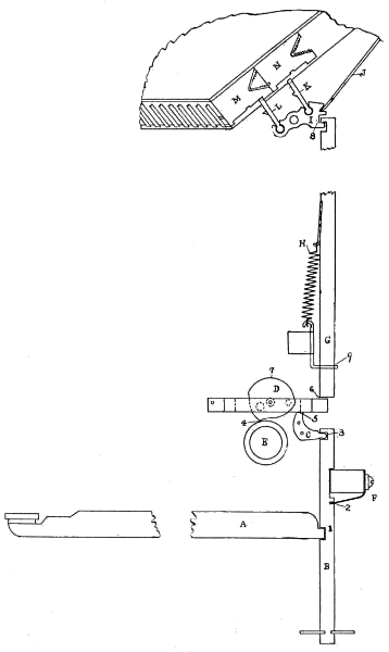
Fig. 31.
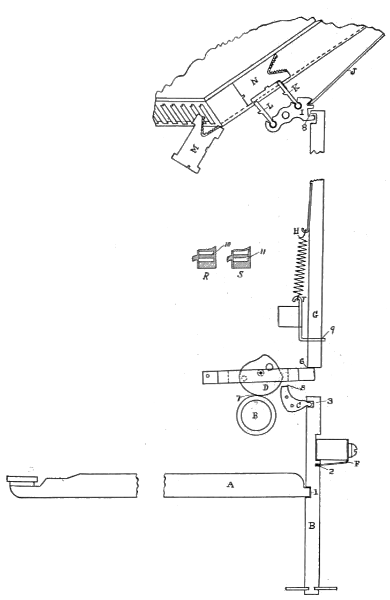
Fig. 32.
But to guard against sticking from dirt or other causes: The keyboard keybar spring F (sometimes called the comb spring) is attached and intersects the keybar B at point 2. R shows a sectional top view of keyboard rod lower guide T as the slot 10 should be when new, and S shows same when it is badly worn by the motion of the keyrod G.
When guide slot is worn as shown at 11 (Fig. 32) the keyboard rod is apt to bind and the spring H would not be strong enough to bring the rod back to its position. The guide T should then be renewed and the old one repaired at leisure, by soldering a piece on the bottom and cutting new slots.
These parts will give no trouble if care is taken to keep them clean.
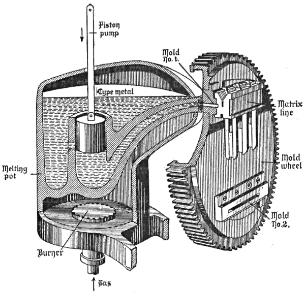
Fig. 33.
Figure 33 shows a sectional view of metal pot and well; also mold-disk, with a line of matrices assembled in front of mold ready to cast a slug.
Squirts will sometimes occur even if the pump-stop attachment is supposed to entirely prevent them. Two of the frequent causes of this trouble are as follows:
First—When a line is given to the first elevator, just as the machine is about completing its revolution to deliver the previous line, and before the elevator is fairly settled into place, the line may become twisted, although not enough to prevent it from going down into the casting pawls. The mold cannot come forward far enough to close up tightly on account of the twisted matrices, and the result is a squirt, and the metal flies all over the mold face and into the elevator jaw, soldering it up and stopping the machine.
Second—If the part of the elevator jaw which holds the upper ears becomes sprung, the matrices will twist and you will get a squirt.
If vise automatic is not set properly, as described under Fig. 15, a squirt is liable to occur.
When a squirt occurs from the first cause, many operators open the vise and force down the jaw until the line breaks away from the mold disk. This will give rise to the second cause, by springing the parts of the jaw referred to. This should never be done, but this part of the jaw should be loosened by taking out the three screws that hold it in place and gently work the vise and line loose. Clean the squirt and put piece back in place.
In many instances a machine will squirt metal back of the disk if the metal is very hot. As a general thing, this is laid to the gas, but in nearly every instance it will be found that it is caused by the mouthpiece not being true with the back of the mold.
In some cases it will be found that the mold is warped slightly, but not often.
If the back knife does not trim the bottom of the slug perfectly the metal will adhere to the back of the mold, making high lines (i. e., lines over .919, as explained under Fig. 39), and also prevent good contact between the mouthpiece and mold, which would, of course, cause metal to squirt back of the mold disk.
To prevent this, the mouthpiece should be faced up true with back of mold, as follows: First send a line through the machine, stopping at casting point; then screw up the nut on end of pot lever eyebolt until it touches the pot lever. This takes up the pot pressure, so that when the vise is let down the metal pot will retain the same position as when casting a line. Then disconnect the vise-closing jaw screw connecting rod by taking out the wing pin on end of vise-closing jaw lever. This will prevent the rod from being bent or broken when vise is let way down.
Then let the machine finish the revolution. Now throw off the driving belt and pull out pot pump plunger pin and turn machine by hand to casting point, disconnect mold disk slide and pull out disk B (Fig. 34); thoroughly clean back of mold A (Fig. 34) and cover with red lead mixed with oil, or it will be found much better and easier to use prussian blue oil paint, a tube of which will not cost over 10 cents.
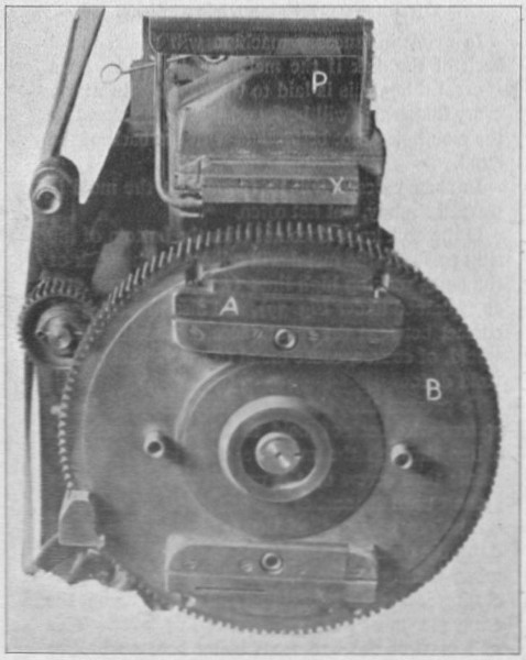
Fig. 34.
Rub the back of mold with this paint; push disk B in until the back of mold A touches the mouthpiece X (Fig. 34); then turn mold disk back and forth, rubbing the back of mold over the mouthpiece. The blue paint will thus be transferred to the mouthpiece, and show the high points.
Should the paint show on one end only, throw the metal pot around by means of set screws to be found in foot of pot legs until it is about true: then, with a small coarse file, file off the blue spots, which are the high or uneven places. Then push the mold in once more, and again rub mold on mouthpiece and file off blue or high spots as before. Continue this operation until the paint shows in small spots all over the mouthpiece.
Before finishing this operation be sure to put in the cross vents between the holes with a cold chisel, making them a little deeper at the top, as shown in Fig. 35. This will prevent porous or spongy slugs.
After connecting the machine up again, put on the driving belt and run through another line, stopping, as at first, at casting point. Then let out the[66] nut on end of pot lever eyebolt until it is about ⅛-inch from back of pot lever.
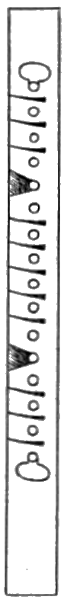
Fig. 35.
If this is done as described there will be a perfect lockup on the mold both back and front, the only metal trimmed from back of mold being that from the vents.
It is essential that these parts receive the most careful attention. Matrices should be washed only when absolutely necessary, which would be if oil should collect on them. This will not happen if machine is properly cleaned and oiled.
Matrices that have been used a long time will sometimes show slight burrs, caused by walls of matrices being crushed. If they are not washed these small cavities will become filled up with dirt and metal so that print will look clear. Washing would, of course, take this dirt and metal away and burrs would show worse than before.
Instead of washing matrices, rub the sides on a piece of felt; then lock them up in a galley and clean the face and front so the operator can read the lines in the assembling elevator.
When a letter sticks in the magazine, take it out and, after making sure that ears are not burred, polish the ears with graphite and wipe them clean.
If a new set of matrices is treated in this way before putting them into the machine there will be little or no trouble with them sticking in the magazine.
Any burrs on the ears should be filed off, or they also will cause the letters to stick.
In cleaning the magazine, do not use benzine unless oil should have collected there by some means.
Be sure to lift up matrix guards at the lower end of magazine 2-2-2-2 (Fig. 36) and clean the channels on under side of these guards; also the channels A (Fig. 36).
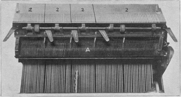
Fig. 36.
The spacebands should be carefully inspected and metal should never be allowed to collect on the slide. Metal on the spaceband slides will destroy a set of matrices in a very few hours.
When cleaning spacebands, never use emery cloth, as this polishes the slide and causes the metal to adhere to it. The best way to clean spacebands is to rub them in graphite on a board or piece of felt nailed on a board.
If a mold is warped (as referred to under directions for facing mouthpiece), the only way to fix it is to lap it down on a lapping block.
Figure 37 shows the lapping block B and mold C that is to be lapped.
A lapping block is one of the most essential tools to have in an office. If you do not have this block procure it at once from the Linotype Company, or one of the stock rooms. This block is of cast iron, corrugated on one face.
To use it, sprinkle a small quantity of emery and benzine on the corrugated face; then rub the mold back and forth, as shown in Fig. 37, until you have a perfect surface.
This block is also used to sharpen all the knives on the machine the same way.
A mold should be taken apart and cleaned and polished at frequent intervals, or the small grooves which make the ribs on the slug will fill up with dirt and cause the slugs to stick.
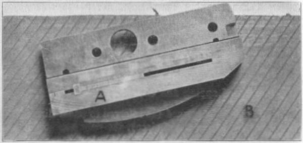
Fig. 37.
Figure 38 shows an adjustable mold and two liners. These molds are made in three sizes for each body, No. 14, No. 24 and No. 30, and cost $30 each.
No. 14 will take liners to cast any length of line from 14 ems down as short as may be desired. No. 24 will take liners to cast any length from 24 ems to 7 ems, both inclusive. No. 30 will take liners to cast any length of line from 30 ems to 13 ems, both inclusive.
These liners cost $1.50, and are interchangeable for any size mold of the same body. For instance, a No. 2 minion liner will give 12 ems in a No. 14 mold, 22 ems in a No. 24 mold, and 28 ems in a No. 30 mold. This, of course, would apply to any size liner.
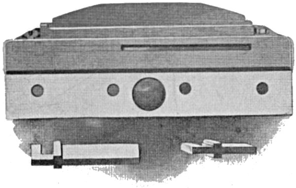
Fig. 38.
Both sides of the spaceband slide 1 and 2 should measure the same at top and bottom, but side 1 should never be thicker than side 2. On the other hand, if side 2 be .001 thicker it will insure a better lockup of the matrices.
Spacebands are made in two classes, thick and thin. The thick bands present a minimum thickness of about .0375 of an inch in the line, and expand to .1, and are stronger and heavier than the others.
The thin bands present a minimum thickness of about .032 of an inch in the line, and expand to .095 of an inch, and are adapted for use where very thin spacing is required; for example, in connection with very small faces.
This point system—adopted for convenience in measuring—is nearly identical with that of Didot, as adopted by the United States Typefounders’ Association. The size of a pica em, as understood before the adoption of the point system, was one-sixth of an inch, or .166⅔. The pica em adopted by the United States Typefounders’ Association measures .166, while the Linotype pica em measures .168. The United States Typefounders’ Association’s unit of measurement, or point, is .01383. The Mergenthaler Linotype Company’s is .014. Therefore 12 points × .014 = .168, or the Linotype pica em.
All the Linotype matrix measurements are made on the basis of .014 to a point, and .168 to an em pica. The following table will furnish an illustration of these dimensions:
| Font. | No. Points. | Point. | Em Space. | ||
|---|---|---|---|---|---|
| Ruby | 5 | × | .014 | = | .070 |
| Agate | 5½ | × | .014 | = | .077 |
| Nonpareil | 6 | × | .014 | = | .084 |
| Minion | 7 | × | .014 | = | .098 |
| Brevier | 8 | × | .014 | = | .112 |
| Bourgeois | 9 | × | .014 | = | .126 |
| Long Primer | 10 | × | .014 | = | .140 |
| Small Pica | 11 | × | .014 | = | .154 |
| Pica | 12 | × | .014 | = | .168 |
To measure Linotype matter, take an em space in the font to be measured, and ascertain how many times it is contained in the matter to be measured. The quotient will show the correct number of ems.
The length of molds is calculated on a basis of 166⅔ to an em pica, while the body or thickness of slug is calculated according to the above table.
The slug should be the same thickness at points 1, 2, 3 and 4 (Fig. 40). If the machine locks up properly, and the back knife is set right, the slug should measure 918 to 919 thousandths high from bottom of slug to top of letter.
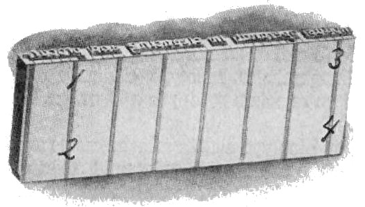
Fig. 39.
These are furnished as sorts. They are similar in shape to the em and en spaces, but are inserted in the line by hand and automatically returned by the machine to the quad box. They are of the following thicknesses, respectively: .012, .013, .014, .015, .016, .017, .018, .019 and .020 of an inch. Regular thin spaces measure .028, .031, .035 and .0385.
Adjustment of the mold slide is done by means of two set screws, which adjusts the gib on which it slides. This gib should be adjusted so that the slide has .007 play. This will allow it to work freely.
The mold disk is held in position for casting and trimming the slug by means of pins attached to the vise, called mold disk locking studs. The studs are located in relation to the mold disk locking bushings at the factory so as to give perfect alignment of the matrices. They are dowelled in place and should never be changed.
Should the bushings or studs become badly worn at any time, renew them and thus keep the alignment perfect.
The forward motion is imparted to the mold slide by means of a roller which runs in a groove in the mold cam and driving gear. This roller is connected with the mold slide lever by means of an eccentric pin that has a pin attached, which serves as a handle with which to adjust it.
To adjust the slide, loosen the screw which holds the eccentric pin with the T or a small monkey wrench, and turn the handle so that the slide will come forward until the face of the mold is within .01 inch of the vise movable jaw at the time when the line in first elevator is to be justified. If pin is set so as to throw the disk too far forward it would[76] bind the spacebands and matrices and prevent the justification levers from driving up the bands sufficient to space the line, which would cause an indention of the line. On the other hand, if the mold disk does not come forward far enough, it will not give a good lockup, owing to the metal pot having to spring the disk too far in making the final lockup.
To put in a new verge, first lock up the machine and disconnect the rods; then take off the magazine and place on a bench or other suitable place, bottom up; then take off the verge partition locking strip (which is held in place by some of the partition’s ears being bent crosswise) up to the verge that is to be removed. Withdraw the verge rod until you have reached the verge to be renewed; at the same time follow it up with another rod, which will keep the other verges in place. Then take out the verge.
In putting in the new one, be sure the hole is large enough to allow the verge to work freely. Then push the verge rod back into place. Put back the locking strip and bend the partition’s ears to hold it in place. The magazine is now ready to be put back on the machine.
The following faces will align with each other and interchange table characters on their respective bodies:
Ruby No. 18 with itself only.
Agate Nos. 1, 2, 3, and Agate Bold Face.
Nonpareil Nos. 1, 2, 3, 12, Nonpareil Old Style No. 1, Nonpareil Italic No. 1 and Nonpareil Old Style Italic No. 1.
Minion Nos. 1, 2, 3, 21, Minion Doric, Minion Bold Face, Minion Gothic, Minion Italic Nos. 1, 3, Brevier Nos. 1, 2, 4, 19, Brevier Italic No. 1 and Brevier Ionic.
Brevier Old Style No. 1, Brevier Old Style Ronaldson, Brevier Old Style Italic No. 1, and German Brevier figures.
Long Primer Nos. 1, 13, Long Primer Old Style No. 1, Long Primer Old Style Ronaldson, Long Primer Clarendon, Long Primer Italic Nos. 1, 13, and Long Primer Old Style Italic No. 1, Bourgeois No. 13 and Bourgeois Italic No. 13.
Small Pica Nos. 1, 9, Small Pica Old Style No. 1, Small Pica Old Style Ronaldson, Small Pica Italic Nos. 1, 9, and Small Pica Old Style Italic No. 1.
Small Pica Gothic with itself only.
German Nonpareil with itself only.
German Brevier with itself only.
German Bourgeois No. 2 with German Bourgeois Bold Face No. 1.
German Long Primer No. 2.
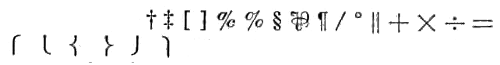
When table characters are ordered changed from No. 1 to No. 2 face, or vice versa, in any font, the following characters are usually changed: Regular figures from 1 to 0, fractions, figure space, $ £ * . ‥ also † ‡ [ ] ℀ % § ⅌ ¶ / ° ‖ + × ÷ = ⎧ ⎩ { } ⎭ ⎫ and all the other special signs when ordered.
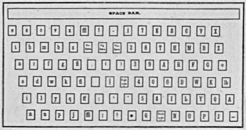
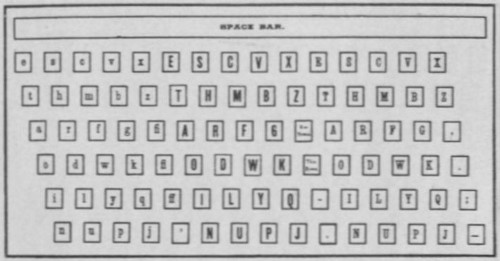
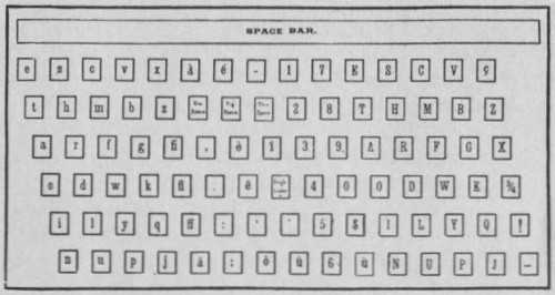
REGULAR KEYBOARD—WITHOUT FRACTIONS
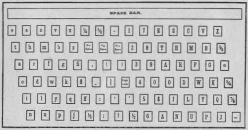
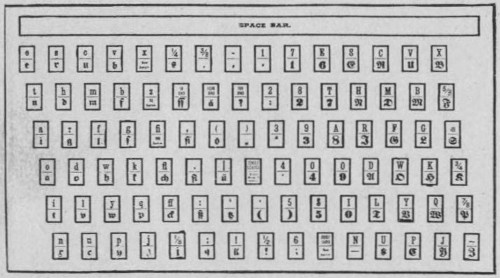
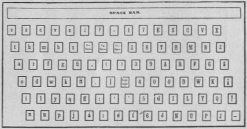
REGULAR KEYBOARD—WITH COMMERCIAL FRACTIONS
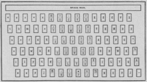
COMBINATION HEAD LETTER AND BODY KEYBOARD
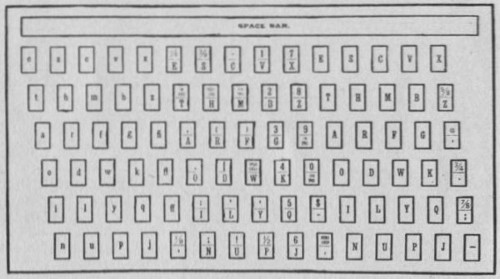
COMBINATION HEAD LETTER ENGLISH—WITH FRACTION.
HEAD LETTER KEYBOARD—TWO FACES—UPPER CASE ONE FACE, UPPER AND LOWER CASE SECOND FACE
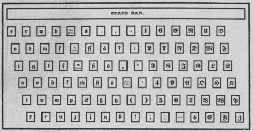
COMBINATION ENGLISH AND GERMAN KEYBOARD
COMBINATION ENGLISH AND GERMAN
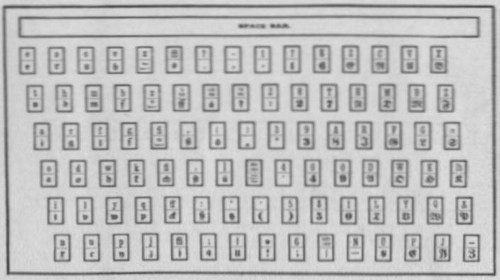
STANDARD GERMAN KEYBOARD
REGULAR FRENCH KEYBOARD
REGULAR SPANISH KEYBOARD
It will be found a great convenience, as well as a saving, to keep the following list of supplies on hand, so that if any of these parts should break or wear out they could be renewed at once and machine would not have to stand idle until they could be procured from factory or stock rooms.
The expense will be small, but the time saved by having these parts at hand in an emergency will more than pay for the outlay:
| Part No. | Sheet. | ||
|---|---|---|---|
| 3 | Line delivery lever link springs | 216 | B |
| 2 | Second elevator starting springs (In ordering state if long or short spring is wanted.) | 238 | B |
| 1 | Spaceband lever pawl hook (State if old or new style.) | 98 | B |
| 10 | Pot cam roller anti-friction rollers | 300 | B |
| 1 | Automatic stop catch | 17 | BB |
| 1 | Ejector lever adjustable pawl assembled | 165 | BB |
| 2 | Line delivery carriage long fingers (L H) | 209 | D |
| 2 | Assembling elevator gate rail pawls | 434 | D |
| 2 | Assembling elevator back rail pawls | 77 | D |
| 4 | Spaceband box pawls | 186 | D |
| 4 | Assembling elevator matrix detaining plate, back | 100 | D |
| 4 | Assembling elevator matrix detaining plate, front | 433 | D |
| 10 | Assembler chute rails (back) | 15 | D |
| 10 | Assembler chute rails (front) | 16 | D |
| 10 | Assembler stars | 6 | D |
| 1 | Assembler glass (small) | 20 | D |
| 1 | Assembler star shaft | 7 | D |
| 1 | Assembler pinion friction disk | 315 | D |
| 1 | Assembler pinion friction spring | 316 | D |
| 3 | Assembler star pinion friction nuts | 317 | D |
| 3 | Assembler chute springs | 459 | D |
| 3 | Assembler matrix catch springs | 18 | D |
| 1 | First elevator back jaw | 107 | E |
| 4 | First elevator back and front jaw pawl levers | 121 | E |
| 4 | First elevator back jaw pawls | 122 | E[85] |
| 4 | First elevator front jaw pawls | 123 | E |
| 6 | First elevator front jaw pawl springs (These last four not used on latest machines.) | 126 | E |
| 2 | Knife wiper bar springs | 171 | E |
| 1 | Knife wiper bar guide | 312 | E |
| 1 | Pot lever spring | 27 | F |
| 1 | Back knife (State if old or new style.) | 254 | F |
| 1 | Distributer box front plate upper rail | 84 | G |
| 1 | Distributer box back plate upper rail | 85 | G |
| 1 | Distributer box back plate lower rail | 86 | G |
| 1 | Distributer box front plate lower rail | 199 | G |
| 1 | Second elevator adjusting spring | 183 | G |
| 2 | Second elevator bar springs | 67 | G |
| 1 | Distributer box bar, assembled | 212 | G |
| 1 | Distributer box matrix lift | 91 | G |
| 2 | Keyboard keybar springs, upper case | 234 | H |
| 2 | Keyboard keybar springs, lower case | 219 | H |
| 6 | Keyboard cam and yokes, assembled (State if old or new style.) | 201 | H |
| 2 | Keyboard cam yoke trigger hinge rods | 145 | H |
| 12 | Escapement verges, assorted | 8 | J |
| 6 | Escapement verge pawls, assorted | 10 | J |
| 6 | Escapement verge springs | 11 | J |
| 1 | Escapement verge hinge rod | 9 | J |
| 25 | Flat-head screws, assorted | ||
| 25 | Round-head screws, assorted |
| Character. | No. of Channel. |
Size of Channel. |
Size of Verge. |
Size of Pawl. |
Size of Ear of Matrix. |
|---|---|---|---|---|---|
| e | 1 | 50 | 60 | 40 | |
| e | 2 | 50 | 75 | 60 | 40 |
| t | 3 | 50 | 45 | 45 | 40 |
| a | 4 | 60 | 70 | 60 | 50 |
| o | 5 | 50 | 65 | 55 | 40 |
| i | 6 | 40 | 40 | 35 | 33 |
| n | 7 | 60 | 75 | 70 | 50 |
| s | 8 | 50 | 60 | 50 | 40 |
| h | 9 | 60 | 70 | 70 | 50 |
| r | 10 | 50 | 60 | 50 | 40 |
| d | 11 | 60 | 70 | 70 | 50 |
| l | 12 | 40 | 40 | 35 | 33 |
| u | 13 | 70 | 75 | 70 | 60 |
| c | 14 | 60 | 65 | 60 | 50 |
| m | 15 | 90 | 105 | 100 | 80 |
| f | 16 | 50 | 75 | 55 | 40 |
| w | 17 | 90 | 90 | 90 | 80 |
| y | 18 | 60 | 70 | 70 | 50 |
| p | 19 | 60 | 70 | 70 | 50 |
| v | 20 | 60 | 70 | 70 | 50 |
| b | 21 | 60 | 70 | 70 | 50 |
| g | 22 | 60 | 70 | 70 | 50 |
| k | 23 | 70 | 90 | 75 | 60 |
| q | 24 | 60 | 70 | 70 | 50 |
| j | 25 | 40 | 50 | 50 | 23 |
| x | 26 | 70 | 90 | 75 | 60 |
| z | 27 | 50 | 60 | 60 | 40 |
| fi | 28 | 60 | 70 | 70 | 50 |
| fl | 29 | 60 | 75 | 70 | 50 |
| ff | 30 | 70 | 95 | 85 | 60 |
| ffi | 31 | 90 | 105 | 105 | 80 |
| ffl | 32 | 90 | 105 | 105 | 80 |
| em | 33 | 90 | 140 | 140 | 80 |
| , | 34 | 40 | 40 | 35 | 33 |
| . | 35 | 40 | 40 | 35 | 33 |
| : | 36 | 50 | 70 | 65 | 40 |
| ; | 37 | 50 | 75 | 65 | 40 |
| ? | 38 | 60 | 70 | 70 | 50 |
| Fig | 39 | 60 | 125 | 70 | 50 |
| ( | 40 | 40 | 55 | 45 | 33 |
| | | 41 | 40 | 90 | 90 | 33 |
| ‘ | 42 | 40 | 45 | 35 | 33 |
| ! | 43 | 50 | 65 | 65 | 40 |
| - | 44 | 40 | 50 | 45 | 33 |
| Thin | 45 | 40 | 40 | 35 | 33 |
| ) | 46 | 40 | 40 | 40 | 33 |
| . | 47 | 60 | 60 | 60 | 50 |
| ’ | 48 | 40 | 35 | 35 | 33 |
| * | 49 | 60 | 55 | 55 | 50 |
| 1 | 50 | 60 | 70 | 70 | 50 |
| 2 | 51 | 60 | 70 | 70 | 50 |
| 3 | 52 | 60 | 70 | 70 | 50 |
| 4 | 53 | 60 | 70 | 70 | 50 |
| 5 | 54 | 60 | 70 | 70 | 50 |
| 6 | 55 | 60 | 70 | 70 | 50 |
| 7 | 56 | 60 | 70 | 70 | 50 |
| 8 | 57 | 60 | 70 | 70 | 50 |
| 9 | 58 | 60 | 70 | 70 | 50 |
| 0 | 59 | 60 | 70 | 70 | 50 |
| $ | 60 | 60 | 70 | 70 | 50 |
| ‥ | 61 | 100 | 100 | 95 | 90 |
| E | 62 | 90 | 95 | 95 | 80 |
| T | 63 | 80 | 100 | 95 | 70 |
| A | 64 | 90 | 100 | 100 | 80 |
| O | 65 | 80 | 100 | 100 | 70 |
| I | 66 | 60 | 55 | 55 | 50 |
| N | 67 | 90 | 100 | 100 | 80 |
| S | 68 | 70 | 75 | 75 | 60 |
| H | 69 | 100 | 110 | 110 | 90 |
| R | 70 | 90 | 95 | 95 | 80 |
| D | 71 | 90 | 105 | 105 | 80 |
| L | 72 | 80 | 85 | 85 | 70 |
| U | 73 | 90 | 105 | 105 | 80 |
| C | 74 | 70 | 75 | 75 | 60 |
| M | 75 | 100 | 110 | 110 | 90 |
| F | 76 | 80 | 95 | 95 | 70 |
| W | 77 | 110 | 145 | 145 | 100 |
| Y | 78 | 90 | 100 | 100 | 80 |
| P | 79 | 80 | 85 | 85 | 70 |
| V | 80 | 90 | 105 | 105 | 80 |
| B | 81 | 80 | 95 | 95 | 70 |
| G | 82 | 80 | 105 | 105 | 70 |
| K | 83 | 90 | 110 | 110 | 80 |
| Q | 84 | 80 | 95 | 95 | 70 |
| J | 85 | 60 | 75 | 70 | 50 |
| X | 86 | 90 | 110 | 110 | 80 |
| Z | 87 | 70 | 95 | 95 | 60 |
| @ | 88 | 90 | 85 | 85 | 80 |
| ℔ | 89 | 90 | 85 | 85 | 80 |
| & £ | 90 | 60 | 85 | 85 | 50 |
| — | 91 | 90 | 125 | 125 | 80 |
| Pi | 92 | 100 |
All figures, except in numbers of channels, in thousandths of inches.
*Channel No. 39 takes .125 verge and .70 pawl.
Transcriber’s Notes:
Figures 12 and 13, and 29 and 30 appear in an inverse order in the original. This has been preserved.
On page 78, some characters may not render correctly with some machine/format combinations. An illustration of the section of the page in question is included here:
Original images of this book can be found here.