THAT THE WORD "HEARTH" is synonymous with "home" in many languages is not surprising since much of the enjoyment of home and camp life centers about an open fire. In mild climates a properly built fireplace will heat a single room, and when equipped with a convection heater will also heat a second room on the same floor or an upper floor. In colder climates it is a useful adjunct to other heating systems if provided with a damper.
This bulletin is intended to give the householder and prospective builder, especially the farmer who might superintend the construction of his home, a working knowledge of the principles to be observed in planning and building fireplaces and chimneys. These principles, if observed, will make the structures useful and satisfactory and insure their safety.
Safe fireplaces and chimneys that function properly can be built by applying the principles given in this bulletin, but a good chimney will not last indefinitely without proper care and repair.
Fireplaces and chimneys, being conspicuous architectural features, should be pleasing in appearance and conform with the general design of the building and its surroundings.
This bulletin supersedes Farmers' Bulletin 1649, Construction of Chimneys and Fireplaces.
Washington, D. C. Issued December, 1941
FIREPLACES AND CHIMNEYS
By Arthur H. Senner, mechanical engineer, and Thomas A. H. Miller, agricultural engineer. Division of Farm Structure Research, Bureau of Agricultural Chemistry and Engineering
|
|
FIREPLACES AND CHIMNEYS should provide a safe place for an open fire and a flue for draft to expel smoke from the fire passage to the open air. They must be properly designed and constructed (fig. 1) if good performance and protection against fire are to be obtained.

Figure 1.—A properly designed and well-built chimney that provides ample draft and protection against fire.
Solid masonry is the most satisfactory and safest material to use for chimneys and fireplaces. If a chimney fire occurs, the safety of the building may be dependent on the soundness of the flue walls (fig. 2). Cracked and leaky flues not only are inefficient, destroying the draft as well as permitting smoke and gases to pass into adjacent rooms, but are a dangerous fire hazard. The chimney as known today was developed about 600 years ago. Experience has shown that the satisfactory performance of a chimney flue is determined by its size, direction, shape, height, tightness, and smoothness.
Draft
The draft of a chimney is the current of air created by the difference in pressure resulting from variation in weight between the relatively hot gases in the flue and the cooler outside air. The strength or intensity of the draft depends, for the most part, on the height of the chimney, and the temperature difference between the chimney gases and the outside atmosphere. The draft is not so good in summer as in winter because the difference in temperature between the outside air and the gases in the flue is less.
A very common error in chimney design is failure to distinguish between the size of the flue required for free passage of the volume of smoke from a given amount of fuel and that which, with proper height, will produce the required draft. A chimney may be high enough (fig. 3), yet have an area too small to expel the volume of smoke; or the size may be ample (fig. 4) but the height not great enough to produce a strong draft. Either fault or a combination of the two will result in unsatisfactory service.
Flue Sites
The dimensions of a flue for adequate draft depend principally on the grate area and type of heating plant[1] and on the kind of fuel to be burned, both of which should be determined before construction is begun. If a chimney is found to be inadequate the only method of improving it, short of reconstruction, is to increase its height. This is not always effective and is often impracticable.
[1] Farmers' Bulletin 1698, Heating the Farm Home, contains information on estimating the size of the heating plant needed for houses of different sizes and for determining grate areas.
Table 1 gives the sizes of fire-clay flue linings ordinarily provided for boilers, furnaces, stoves, or convection heaters burning soft coal. These sizes have proved satisfactory for average flat-grate furnaces under normal conditions. Manufacturers of heating equipment usually specify certain requirements in chimney construction and will not guarantee the performance of their heaters unless these requirements are met. Therefore their recommendations should be followed when differing materially from the dimensions given in this bulletin.
Height of Chimney
A chimney should extend at least 3 feet above flat roofs and 2 feet above the ridge of peak roofs. Where chimneys cannot be built high enough above the ridge to prevent trouble from eddies caused by wind being deflected from the roof, a hood may be provided with the open ends parallel to the ridge. Eddies which force air down the flues may be caused by building the chimney too near trees (fig. 5, B) or a higher structure (fig. 6).

Figure 2.—Heavy masonry chimneys of this type are still being built in rural areas. The thick walls, with unlined flues, are in good condition after 75 years of continuous use.
Table 1.—Sizes of flue linings and heights of chimneys recommended for flat-grate furnaces burning soft coal[A]
| Grate area (Sq. ft.) |
Nominal size of flue lining | Height of chimney top above grate at elevation indicated |
||||||||||
| Round (inside diameter) at elevation indicated |
Rectangular (outside dimensions) at elevation indicated |
|||||||||||
| Sea Level |
2,000 feet |
4,000 feet |
6,000 feet |
Sea Level | 2,000 ft | 4,000 ft | 6,000 ft | Sea Level |
2,000 feet |
4,000 feet |
6,000 feet |
|
| In. | In. | In. | In. | In. | In. | In. | In. | Ft. | Ft. | Ft. | Ft. | |
| 1 | 8 | 8 | 8 | 10 | 8½ by 8½ | 8½ by 8½ | 8½ by 8½ | 8½ by 13 | 2 | 26 | 32 | 36 |
| 2 | 10 | 10 | 10 | 10 | 8½ by 13 | 8½ by 13 | 8½ by 13 | 8½ by 13 | 24 | 29 | 35 | 41 |
| 3 | 10 | 10 | 12 | 12 | 8½ by 13 | 8½ by 13 | 13 by 13 | 13 by 13 | 26 | 33 | 41 | 49 |
| 4 | 12 | 12 | 12 | 12 | 13 by 13 | 13 by 13 | 13 by 13 | 13 by 13 | 30 | 37 | 45 | 49 |
| 5 | 12 | 12 | 15 | 15 | 13 by 13 | 13 by 13 | 13 by 18 | 18 by 18 | 32 | 37 | 43 | 52 |
| 6 | 15 | 18 | 18 | 18 | 18 by 18 | 18 by 18 | 20 by 20 | 20 by 20 | 30 | 37 | 47 | 56 |
| 7 | 18 | 18 | 18 | 18 | 20 by 20 | 20 by 20 | 20 by 20 | 20 by 20 | 32 | 41 | 49 | 64 |
| 8 | 18 | 18 | 18 | 18 | 20 by 20 | 20 by 20 | 20 by 20 | 20 by 20 | 35 | 42 | 56 | 10 |
[A] If anthracite is to be burned the area of the flue cross section may be reduced about 25 percent.
The ratings given are based on comparatively smooth lined flues with no offsets greater than 30° with the vertical.
The smallest sizes of fuels require excessive drafts and may necessitate taller chimneys.
Flue heights and sizes are based upon approximately the several altitudes indicated; it is sufficiently accurate to use the column giving the altitude nearest to that of the particular problem.
When 2 or 3 appliances are connected to the same flue their total grate area may be reduced 15 percent. The method of determining the proper flue size for an altitude of 2,000 feet, when 1 appliance with a grate area of 3 square feet and another with an area of 1.5 square feet are attached to the same flue, is shown by the following example:
Add the 2 grate areas, 3 + 1.5 = 4.5 square feet. Reduce this total area by 15 percent. Thus, 4.5 - 0.68 = 3.8 square feet is the required area. Use the nearest whole number, 4. From the table it is seen that for a grate area of 4 square feet at an elevation of 2,000 feet either a 12-inch (inside diameter) round flue or a 13- by 13-inch (outside dimensions) rectangular flue 37 feet high is required.
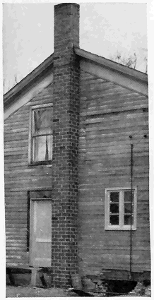
Figure 3.—This tall chimney produced good draft for the kitchen range, but the flue was too small for a furnace. When the house was remodeled, its appearance was greatly improved by building the chimney inside.

Figure 4.—Short chimneys are frequently provided for low bungalows, for architectural reasons. This flue is ample in size but not high enough for use with a stove. The stone masonry has been laid to harmonize with the rustic surroundings.
Frequently metal-pipe extensions are provided to increase the height of a flue on account of the low cost and ease of installation, but these must be securely anchored against wind and have the same area as the flue. Metal extensions are likely to rust in a short time. They are available with a metal cowl or top that turns with the wind to prevent air blowing down the flue. Terra-cotta chimney pots or extensions are more durable and attractive.
A chimney located entirely inside a building has better draft because the masonry retains heat longer when protected from cold outside air.

Figure 5.—Two pleasingly designed fireplace chimneys that fit into their surroundings. A, This chimney stands in the clear and should provide a good draft; B, a chimney under overhanging trees is likely to backdraft. Contrast the appearance of these two chimneys with that of figure 3.

Figure 6.—Several extensions were necessary before this chimney would draw properly on account of the wind deflected from the nearby wall.

Figure 7.—A, A good foundation extending below the soil affected by frost. This chimney is well protected from ground moisture by the concrete carried above the surface; B, an insecure foundation. Supporting a chimney in this manner is a dangerous practice.
Supporting the Chimney
Stable foundations, preferably of concrete, should be provided, at least 6 inches wider all around than the chimney and 8 inches thick« 8 » for one-story and 12 inches thick for two-story houses. When there is no basement or cellar (fig. 7, A), start the foundation of an exterior chimney well below the frost line; otherwise, extend the base to the same level as the bottom of the foundation of the building. Foundations for tall, heavy chimneys require special consideration.
Where the wall of the house is of solid masonry 12 inches or more thick, the chimney may be offset and carried on corbels or masonry brackets instead of being carried down to the ground. The offset should not extend more than 8 inches from the face of the wall, each course projecting not more than 1 inch, and should not be less than 12 inches high. Often the corbeling is started at the second- or third-floor level so that the chimney is only one or two stories high.

Figure 8.—For structural safety the amount of offset must be limited so that the center line, XY, of the upper flue will not fall beyond the center of the wall of the lower flue. A, Offsetting of the left wall of an unlined flue is started two brick courses higher than on the right wall so that the area of the sloping section will not be reduced after plastering; B, a lined flue showing the method of cutting the tile.
Chimneys in frame buildings should be built from the ground up or should rest on the foundation or basement walls if of solid masonry 12 inches or more thick.
A chimney resting on or carried by wooden floors, beams, or brackets or hung from wooden rafters (fig. 7, B) is a fire hazard. Wood framing shrinks, and beams supporting heavy loads deflect in time. Sagging beams injure the walls and ceilings of the house and are apt to crack the chimney, rendering it dangerous.
Flue Linings
Although, to save expense, chimneys are built without flue lining, those with linings are more efficient. When the flue is not lined, the mortar and bricks directly exposed to the action of fuel gases disintegrate. « 9 » This disintegration and that occurring from changes in temperature frequently cause cracks in the masonry, thereby reducing the draft. An unlined chimney is best if not plastered except at the sloped section (fig. 8, A). However, the vertical and horizontal joints should be filled with mortar and struck smooth and flush with the wall. Offsets or bends in flues (fig. 8) should not be greater than 30° with the vertical. This slope can be obtained by offsetting or corbeling each brick course only 1 inch.
Flue lining must withstand rapid fluctuations in temperature and be resistant to the action of ordinary flue gases. The shapes used as flue lining should be of fire-clay, with shells not less than five-eighths of an inch thick, and should be vitrified. As a safeguard against over-burning and brittleness, the lining should be tested by submersion in water at room temperature for 24 hours, during which a quantity of water weighing more than 3 percent of the dry weight of the lining should not be absorbed. Place each length of flue lining in position, setting it in cement mortar with the joint struck smooth on the inside, and then lay the brick around it. If the lining is slipped down after several courses of brick have been laid, the joints cannot be filled and leakage is almost sure to result. Fill any spaces between the lining and the brickwork completely with mortar, especially if the round type of flue is used.
The lower section of flue lining, unless resting on solid masonry at the bottom of the flue, should be supported on at least three sides by brick courses projecting to the inside surface of the lining. When laying brick and lining, it is advisable to draw up a tight-fitting bag of straw as the work progresses so as to catch material that might fall and block the flue.
Where offsets or bends are necessary in lined flues, tight joints can be made by mitering or cutting equally the ends of abutting sections (fig. 8, B). This can be done if a cement sack of damp sand is stuffed firmly into the lining and a sharp chisel is tapped with a light hammer along the line where the cut is desired. If the cutting is done after the lining is built into the chimney, the lining may be broken and fall out of place. The hole for the thimble can be cut the same way when a special thimble section is not used.
The linings commonly used are rectangular or round. Rectangular linings are better adapted to brick construction than round linings, but the latter are considered more efficient. The sizes commonly used are indicated in table 2.
Wall Thickness
Walls of chimneys not more than 30 feet high when lined should be 4 inches thick if of brick and reinforced concrete, 8 inches if of hollow building units, and 12 inches if of stone. Linings may be omitted in chimneys having walls of reinforced concrete at least 6 inches thick or of unreinforced concrete or brick at least 8 inches thick, although lining is desirable in the case of brick construction. Also the outside wall of a chimney exposed to the weather is best made at least 8 inches thick.
In chimneys containing three or more flues, building codes generally require that each group of two flues be separated from the other single flue or group of two flues by brick divisions or withes not less than 3¾ inches wide (fig. 9) . Where two flues are grouped without divisions, « 10 » joints in the linings of adjacent flues are safer if staggered at least 7 inches, and particular care should be taken to have all joints filled with mortar. Individual flues are advisable for fireplaces and heating furnaces or boilers.
Table 2.—Dimensions of commonly used standard commercial flue lining
|
|
||||||||||||||||||||||||||||||||||||||||||||||||||||||||||||||||||||||||||||||||||||||||||||||||||||||||||||
[B] All rectangular flue lining is 2 feet long.
[C] Round flue lining, 6 to 24 inches in diameter, is 2 feet long; that 27 to 36 inches in diameter is 2½ or 3 feet long.

Figure 9.—Cross section of chimney showing the proper arrangement for three flues. The division wall should be well bonded with the side walls by staggering the joints of successive courses. Note the studs are kept 2 inches away from the brickwork for reasons explained on page 14.
When two or more flues are used in unlined chimneys, they must be separated by well-bonded withes 8 niches thick. An attractive and effective method of separating unlined flues in colonial times is shown in figure 10.
Chimneys extending above the roof are exposed to the wind and may sway enough during a gale to open up the mortar joints at the roof line. Openings in a flue at this point are especially dangerous because sparks from the flue may come in contact with the woodwork of the roof. It is therefore good practice to make the upper walls 8 inches thick (fig. 11) by starting to offset the bricks just below the intersection with the roof.
The brickwork around all fireplaces and flues should be laid with cement mortar, as it is more resistant than lime mortar to the action of heat and flue gases. A good mortar to use in setting flue linings and all chimney masonry, except firebrick, consists of 1 part portland cement, 1 part hydrated lime, and 6 parts clean sand, measured by volume. Slacked-lime putty may be used in place of hydrated lime; firebrick is best laid in fire-clay.
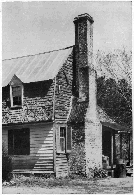
Figure 10.—This Williamsburg chimney shows the pains taken to make the chimney attractive. The three flues are arranged as a T with well-bonded withes between them. Often four flues were used in the form of a cross.
Openings Into the Chimney
No range, stove, fireplace, or ventilating register should be connected with the flue being used for the heating apparatus because this is a frequent cause of unsatisfactory operation. Fires may occur from sparks passing into one flue opening and out through another where there are two connections to the same flue. If an abandoned fireplace chimney is to be used for a range or stove, close the fireplace flue tight about a foot below the smoke pipe hole.

Figure 11.—Greater resistance to the weather is provided by building the exposed upper section of a chimney with 8-inch walls. Also the mortar joint, in which the counter-flashing is embedded, is not so likely to fail as it is when the wall is only 4 inches thick.
Gas-fired house heaters and built-in unit heaters, if not connected to a masonry chimney, may be connected to flues of corrosion-resistant sheet metal not lighter than 20-gage, properly insulated with asbestos or other fireproofing material that will comply with the recommendations of the Underwriter's Laboratories, Inc. Such flues should extend through the roof.
A soot pocket[2] is desirable for each flue. Deep pockets permit the accumulation of soot, which may take fire; therefore start them from a point preferably not more than 8 inches below the center line of the smoke pipe intake and fill the lower part of the chimney with solid masonry instead of extending the pocket to the base of the chimney as is often done. Clean-out doors are necessary at the bottom of deep pockets and, if used, must fit snugly and be kept tightly closed so that air cannot get in. Clean-outs should serve only one flue, for if two or more flues are connected with the same clean-out, air drawn from one to another affects the draft in all of them. Sometimes a door is placed just below the smoke pipe, but one is not really necessary since the pipe, if taken down each year for cleaning, allows removal of soot from shallow pockets through the pipe hole.
Close pipe holes, when temporarily not in use, with tight-fitting metal flue stops; but, if a pipe hole is to be abandoned, fill it with bricks laid in good mortar. This stopping can be readily removed. The practice of closing a pipe hole with papered tin is dangerous, for if there is another stove connected with the flue, the metal may become hot enough to scorch the unprotected wallpaper or even set it afire.
Proper care in setting and looking after pipe at its connection with the chimney will greatly lessen the number of fires chargeable to defective construction. Fit the pipe so that no opening will be left around it, and keep it from projecting into the flue. The connection can be made airtight with a closely fitting collar and boiler putty, good cement mortar, or stiff clay.
Smoke pipes should enter the chimney horizontally, and the hole through the chimney wall to the flue should be lined with fire-clay, or metal thimbles should be securely and tightly built in the masonry. Thimbles or flue rings can be had of 6-, 7-, 8-, 10-, and 12-inch diameters and 6-, 9-, and 12-inch lengths. If the walls are furred (fig. 12), the space between the thimbles and the wood furring should be covered with metal lath and plaster.
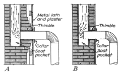
Figure 12.—A, Connection to chimney where furring is used. The brick are built out around the thimble as a protection against its cracking. This is a fire hazard that is frequently overlooked. B, Connection when plaster is applied directly to the masonry. Note that the pipe extends too far into the flue. It should be as shown in A.
When a smoke pipe is less than 18 inches from woodwork, the woodwork requires protection against charring. A metal casing or asbestos board 2 inches from the upper half of the pipe is sometimes employed to protect woodwork directly above it. A pipe, even so protected, should never be closer than 9 inches to any woodwork or other combustible material. Commercial fireproof pipe coverings can be purchased.
If a pipe must be carried through a wood partition, protection for the woodwork can be provided by cutting an opening in the partition and inserting a galvanized-iron double-wall ventilating shield at least 12 inches larger than the pipe (fig. 13) or by using at least 4 inches of brickwork or other incombustible material. Smoke pipes should never pass through floors, closets, or concealed spaces or enter a chimney in a garret.
Gases formed by burning the sulfur contained in coal are the main cause of corrosion of metal smoke pipes. Little corrosion occurs during the heating season, when the pipe is kept hot and dry.
The life of metal pipes can be prolonged if each summer when they are not in use they are taken down, cleaned, wrapped in paper, and stored in a dry place. This is especially true of pipe to heaters in damp cellars.
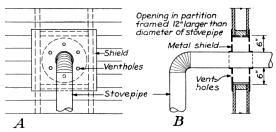
Figure 13.—A, Elevation of protection around a stovepipe passing through a frame partition; B, sectional view.
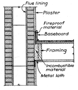
Figure 14.—Method of insulating wood floor joists and baseboard at a chimney with 4-inch walls. A single header is used as it is less than 4 feet long.
Insulation
No wood should be in contact with a chimney. Leave a space of 2 inches between the outside face of a chimney and all wooden beams or joists except when 8 inches of masonry is used outside flue lining, in which case the framing may be within one-half inch of the chimney masonry. The space between the floor framing and the chimney may be filled with porous, nonmetallic, incombustible material, such as loose cinders. Brickwork, mortar, and concrete are not suitable. Place the filling before the floor is laid, as it not only forms a fire stop but prevents accumulation of shavings or other combustible material. Subflooring may be laid within one-half inch of the masonry. Baseboards, when fastened to plaster that is directly in contact with the wall of a chimney, can be protected by a layer of fireproof material, such as asbestos, at least one-eighth of an inch thick between the woodwork and the plaster (fig. 14).
Wooden studding, furring, or lathing should not be placed against a chimney but set back, as indicated in figure 9; or the plaster may be applied directly to the masonry or to metal lath laid over the masonry. The former is the better method, as settlement will not crack the plaster. It is recommended that a coat of cement plaster be applied directly upon the outside surfaces of masonry chimneys that are to be incased by a wooden partition or other combustible construction. Metal lath, lapped 6 inches on the masonry, at the intersection of chimneys with partitions prevents corner cracks. (See plan in fig. 34.)
Chimney and Roof Connection
Where the chimney passes through the roof, provide a 2-inch clearance between the wood framing and masonry for fire protection and for expansion due to temperature changes, settlement, or slight movement of the chimney during heavy winds.

Figure 15.—Method of flashing. Sheet metal, h, over the cricket, extends under the shingles k, at least 4 inches and is counter-flashed at l in joint. Base flashings b, c, d, and e and cap flashings a, f, and g lap over the base flashings and provide watertight construction. A full bed of mortar should be provided where cap flashing is inserted in joints.
A chimney must be flashed and counter-flashed (fig. 15),[3] to make its junction with the roof watertight. When the chimney is not located on the ridge but on a sloping roof, a cricket, j, is built, as detailed in figure 16, high enough to shed water around the chimney. Corrosion-resistant metal, such as copper, galvanized metal, zinc, or lead, is best for the flashing and counter-flashing. When tin is used, paint it well on both sides.
[3] See p. 26, Farmers' Bulletin 1751, Roof Coverings for Farm Buildings and Their Repair, for method of installing flashing.
A feature, said to have originated in colonial Williamsburg as a precaution against fire hazard, is to build the upper section of outside chimneys 18 inches to 2 feet away from the gable ends of the house (fig. 17). This is not only a safety factor but a practical one because the chimney can be more easily flashed, small windows can be used in the walls of upper story rooms behind the chimney, and framing the roof is simplified.
Capping the Chimney
Various methods of terminating chimneys are shown in figures 11 and 18. Whatever one is used should be architecturally acceptable, effective in preventing disintegration, and so made as to keep water out of the flue.
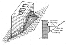
Figure 16.—Cricket, j, as seen from the back of the chimney shown in figure 15. A section through the cricket is also shown. Note how counter-flashing is built into the mortar joint at l.
It is advisable to project the flue lining 4 inches above the cap or top course of brick and surround it with at least 2 inches of cement mortar finished with a straight or concave slope to direct air currents upward at the top of the flue; the sloped mortar also serves to drain water from the top of the chimney. (See fig. 11.) Hoods are commonly used to keep rain out of a chimney (fig. 18, A and B). The area of the hood openings should be at least equal to the area of the flue and each flue should have a separate hood. Concrete and brick caps are usually made 4 inches thick, and it is advisable to project them an inch or two to form a drip ledge.
Many of the chimneys built today are unsightly and frequently detract from an otherwise well-designed house. Within the last 100 years the size and attractiveness of chimneys ordinarily built has declined. The large old chimneys of colonial days were proportioned to suit the house and surroundings and at the same time provide for two or more large fireplaces. With reduction in the size of fireplaces and the substitution of several stoves and eventually one central heating plant, the chimney has developed into a merely utilitarian shaft.
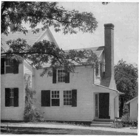
Figure 17.—A house in southern Maryland in which the space between the chimney and the house wall shows clearly. The practice of building the chimney in this way is common in the tidewater section of the South.
Spark Arresters
Spark arresters are desirable and, where chimneys are near combustible roofs, lumber, forests, etc., they are sometimes required, depending on the kind of fuel, waste materials, or refuse that may be burned and the amount of deposits that may accumulate in the flues. While arresters cannot be depended on to eliminate entirely the discharge of sparks under all conditions; yet, when properly built and installed, they materially reduce spark hazard.[4]
[4] See Standards for Construction and Installation of Spark Arresters for Chimneys and Stacks, published by the National Fire Protection Association.
In general all parts, whether of wire, expanded metal, or perforated sheets, give longer service if they are of rust-resistant material. Arresters for domestic purposes should have vertical sides extending « 18 » upward not less than 9 inches so as to provide a gross area of surface at least twice the net flue area. They should be kept outside of the flue area and be securely anchored to the chimney top.
Openings in the screen not larger than five-eights of an inch nor smaller than five-sixteenths of an inch are advisable. Commercially made screens can be purchased which generally last several years. Arresters must be kept adjusted in position and renewed when the openings are worn larger than the normal screen openings.
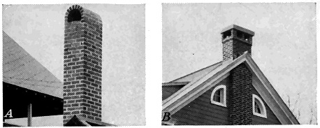
Figure 18.—A, A common type of arched hood; B, flat stone hood; note the withe separating the two flues.
The number of standard-size brick (8 by 3¾ by 2¼ inches) required to build a straight chimney having only two or three flues can be estimated by drawing the flue lining to scale and then drawing lines 4 inches to 8 inches outside of the lining depending on the thickness of the brick walls. Lay out 4- by 8-inch rectangles in the space between the lining and the outside lines to determine how many brick are needed per course.
For example, 15½ brick are needed for each course of the chimney in figure 9. Assuming the height is 30 feet and one-half-inch mortar joints are used, also that there are 4½ courses per foot, there would be 135 courses. Therefore, 135 multiplied by 15½ equals 2,092 brick; about 100 more will be needed to make the lower portion solid, or 2,200 brick in all.
A more general method of estimating that is applicable to more complex structures is given on page 43. Methods of determining the quantity of mortar materials, labor, and cost are also given and can be applied to this example.
Every flue should be subjected to the following smoke test before the heater is connected with it and preferably before the chimney has been furred and plastered or otherwise enclosed. Build a paper, straw, wood, or tar-paper fire at the base of the flue. When the smoke is rising in a dense column, tightly block the outlet at the top of the « 19 » chimney with a wet blanket. Smoke that escapes through the masonry indicates the location of leaks. Frequently this test reveals bad leaks into adjoining flues or directly through the walls or between the linings and the wall. Remedy defects before the chimney is accepted for use. Such defects are usually difficult to correct; hence it is wise to watch the construction closely as it progresses.
Chimneys develop defects which if not promptly repaired cause trouble. Most masonry requires replacement of worn or weathered material or repointing of mortar joints, while flues become clogged and flashings fail.
It is advisable to test a chimney every few years for tightness by the smoke test just described; to examine the inside of the flues by lowering a lantern or flashlight on a strong cord down from the top of the chimney or by holding a hand mirror at the proper angle at a stovepipe hole; to inspect the masonry for loose units, which are most likely to occur at the top (fig. 3) where the action of the flue gases, especially when soft coal is burned, disintegrates the mortar; to test mortar joints from the outside by prodding with a knife or similar tool to determine if the mortar is loose clear through the joint so as to leave a hole; and to notice if the chimney is damp because of leaky flashings, absorption of moisture from the ground, condensation, or excessive rain entering the flues.
Cleaning
Bricks that fall from the top and lodge at offsets or contracted sections can sometimes be reached and dislodged by a long pole or sections of pipe screwed together. They can be caught on a shingle or piece of sheet metal shoved into a stovepipe hole or removed through a clean-out door. A weighted cement sack filled with straw and attached to the end of a rope may be pulled up and down the flue to remove soot and loose material if the offset is not too great.
Trouble with creosote and soot can be reduced when one understands how they are formed. Smoke and soot are caused by imperfect combustion, usually due to one or all of the following conditions: (1) Lack of sufficient air to the fire; (2) improper mixture of air with furnace gases; (3) low furnace temperature; (4) too small combustion space so that the gases reach the comparatively cool furnace surface before they are completely burned and, as a result, soot or tarry matter condenses and then passes up the chimney in the form of smoke. Soft coal causes more soot trouble than hard coal.
If soot accumulates fast or trouble is experienced with unusual smoke when firing, it is probable that the heating equipment is not being operated properly. The manufacturer or installer usually is able to suggest proper adjustments.
Investigations by the United States Bureau of Mines[5] have shown that various materials on being burned or volatilized form a vapor or smoke which settles upon soot; causing it to ignite at a lower temperature and burn more easily. For soot to burn, the gases in contact with it must have a temperature high enough to ignite it and sufficient air to support the combustion. The effectiveness of burning varies with the composition of the remover, but it also depends upon conditions being favorable. It will usually reduce somewhat the soot in a furnace and smoke pipe but not in a chimney. It has no effect on the ash mixed with the soot. This ash not only does not burn, but prevents complete burning of the soot mixed with it.
[5] Nichols, P., and Staples, C. W. REMOVAL OR SOOT FROM FURNACES AND FLUES BY THE USE OF SALTS OR COMPOUNDS. U. S. Bur. Mines Bul. 360, 76 pp., illus. 1932.
Soot removers cause soot to burn and are fire hazards. The correct and most thorough method of cleaning a chimney is to do so manually or to employ modern exhaust or vacuum methods used by furnace repairmen. However, it is inconvenient to remove soot and ash accumulations thoroughly more than once a year; hence a remover may help to keep the passages of stoves and heaters clear between annual cleanings, if deposits of soot accumulate quickly and reduce the draft.
Likelihood of success in cleaning is greater when the deposits of soot are thick, provided they do not cut down the draft too much. If burning is employed, there is less risk when it is done frequently enough to prevent large accumulations, which cause intense fires. Also, freeing the heater and pipe of soot permits better fuel burning and higher temperatures in the chimney flue, thus reducing the amount of soot likely to be deposited on the flue walls.
Common salt (rock or ice-cream salt) is not the most effective remover, yet it is the most widely used because of its cheapness, ease of handling, and general availability. Use two or three teacupfuls per application. Metallic zinc in the form of dust or small granules is often used; however, a mixture of salt and 10 percent zinc dust is more effective than either salt or zinc alone.
One of the most effective mixtures of materials readily available is 1 part dry red lead and 5 parts common salt, measured by weight. Shake these together in a can with a tight-fitting lid. As lead is poisonous, wash the hands after using. One or two teacupfuls are used per application.
Old dry-cell batteries contain suitable ingredients and when they are thrown in a hot furnace the soot usually burns. Quicker action can be had if they are chopped up.
Before a remover is used, the fire must be put in good condition with a substantial body of hot fuel on top. Close the ash-pit door and the slots in the firing door and scatter the remover on the hot coals. Close the firing doors and at once reduce the draft by partially closing the pipe dampers. The draft should not be closed so tight as to cause fumes to escape into the cellar. Let the remover "stew" for 10 to 20 minutes or until fumes stop rising from the coals; then make the fire burn fiercely by opening the ash-pit door and the damper. Shaking ashes out will help. The slots in the firing door can be opened or the door itself set ajar. If soot in the furnace will not ignite, throw a little wood or paper on the fire.
Instead of making a special job of cleaning at intervals, one or two cups of salt may be thrown on the fire once a day with the expectation that the furnace will produce a high enough temperature to ignite some of the soot. This is most likely to succeed in cold weather when the furnace temperatures are high.
Cause of Creosote
Creosote is the result of condensation in the chimney, and trouble from this source is best avoided by preventing creosote formation. It is more likely to form when wood is used for fuel than when coal is burned and is more likely to form in cold than in mild climates. Green wood may contain as high as 40 percent water, and dry wood 15 to 20 percent. When wood is slowly burned, it gives off acetic and pyroligneous acid, which in combination with water or moisture form creosote. When the draft is strong and an active fire is maintained, much of the creosote is carried off into the atmosphere. The trouble is aggravated when the fire does not burn briskly and when an outside flue is subjected to chilling blasts. The walls of the chimney, being comparatively cool, cause condensation of the vapors contained in the smoke. Thus the creosote condenses and runs down the flue, finding its way out of any joints that are not perfectly tight. The formation of creosote is unusual in chimneys that are surrounded by warm rooms. The outer walls of a chimney in an outside wall should be at least two bricks thick and the chimney should have a good flue lining.
Creosote is difficult to remove and when it ignites makes a very hot fire that is likely to crack the masonry and char adjacent timbers. The only safe method of removal is to chip it from the masonry with a blade or straightened-out hoe attached to a pipe or handle. A heavy chain drawn up and down the flue walls is sometimes effective. However, when creosote is removed, care is necessary not to knock out mortar joints or to break the flue lining.
Large quantities of salt thrown on the fire in the grate or fireplace will extinguish a chimney fire. A fire in a fireplace flue can be checked in its intensity and frequently extinguished by first quenching the fire on the hearth and then holding a wet rug or blanket over the opening so as to shut off the air. When this is done, the soot and creosote are likely to slide from the flue walls and drop into the fireplace. Before extinguishing a fire in a flue, cover openings into the rooms, so that the soot will not spread over furnishings.
Repairing Chimneys
When a chimney is damp, examine the flashing at the junction with the roof, especially if wet spots appear on the ceilings of rooms. Methods of repairing flashing are given in Farmers' Bulletin 1751, Roof Coverings for Farm Buildings and Their Repair. If the flashing is sound, possibly water runs down the inside of the flue and through defective mortar joints. Where these cannot be reached readily, the chimney may have to be torn down and rebuilt. Sometimes a hood (fig. 18, A and B) is built on top of the chimney to keep out water or to prevent wind blowing down it. To prevent dampness being drawn up from the ground, the mortar can be raked from a joint at least 12 inches above the ground and a layer of slate, asbestos shingles, or rust-resistant sheet metal and new mortar worked into the joint. This work should be done by a mason. If bricks are porous or eroded, raking out the mortar one-half of an inch deep and applying three-fourths of an inch of cement plaster to the surfaces is effective. Eroded joints in the rest of the masonry should be raked and repointed. « 22 » Where natural gas is burned, dampness due to condensation is not unusual and a drain may be needed. Where such conditions exist, advice should be sought from the manufacturers of the equipment as to the proper remedy.
A chimney that becomes too hot to permit holding the hand against it should be carefully inspected by a reliable mason and adequately protected as suggested in the preceding pages.
If, after a chimney is cleaned, an examination discloses holes, unfilled joints, or other unsound conditions out of reach for repair, it is advisable to tear the masonry down and rebuild properly. Inside bricks that are impregnated with creosote and soot should not be used in the new work because they will stain plaster whenever dampness occurs. It is almost impossible to remove creosote and soot stains on plaster and wallpaper. Sometimes painting the plaster with aluminum-flake paint or waterproof varnish hides the stains.
A hatchway cut through a roof is convenient when high chimneys are repaired or cleaned, especially when access to the roof is difficult. The hatchway should be located so that it will not be necessary to crawl over the roof to reach the chimney and so that a ladder placed on the attic floor will not be too steep for safe ascent. A watertight cover with hooks to prevent its blowing off is essential. Such a hatchway is best provided when the building is erected but can be readily built at any time.
A fireplace is ordinarily considered appropriate to a living room, dining room, and bedroom; however, basement, porch, and outdoor fireplaces are gaining in favor with the householder. Also public dining places, offices, etc., frequently have fireplaces for the comfort and for the air of informality they provide.
All fireplaces should be built in accordance with the few simple essentials of correct design given herein if satisfactory performance is to be realized. They should be of a size best suited to the room in which they are used from the standpoint of appearance and operation. If too small, they may function properly but do not throw out sufficient heat. If they are too large, a fire that would fill the combustion chamber would be entirely too hot for the room and would waste fuel.
The location of the chimney determines the location of the fireplace and too often is governed by structural considerations only. A fireplace suggests a fireside group and a reasonable degree of seclusion, and therefore, especially in the living room, it should not be near doors to passageways of the house.
The principal warming effect of a fireplace is produced by the radiant heat from the fire and from the hot back, sides, and hearth. In the ordinary fireplace practically no heating effect is produced by convection, that is, by air current. Air passes through the fire and up the chimney, carrying with it the heat absorbed from the fire; at the same time outside air of a lower temperature is drawn into the room. The effect of the cold air thus brought into the room is particularly noticeable farthest from the fire. Heat radiation, like light, travels in « 23 » straight lines, and unless one is within range of such radiation, little heat is felt. Tests made by the Bureau of Agricultural Chemistry and Engineering showed that about five times the amount of air required for even liberal ventilation may be drawn into a living room by the operation of a fireplace. Such excessive ventilation may cause chilling drafts. Persons located at advantageous points in the room will be comfortable under such conditions, but those out of the radiation zone will not.
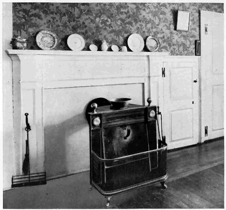
Figure 19.—In 1744 Franklin promoted a metal fireplace of this type to be set out into a room. These are known as Franklin stoves and sometimes are equipped with andirons for burning wood or a grate for burning coal. The metal blower, shown in front of the opening was used with grates and set in place when starting the draft and then removed so that the cheery heat of glowing coals could be enjoyed. At one time this type of stove was highly thought of because it threw out more heat than the built-in fireplace. A few manufacturers specialize in Franklin stoves because of the present-day demand.
Tests conducted by this Bureau indicate that, as ordinarily constructed, a fireplace is only about one-third as efficient as a good stove or circulator heater. Nevertheless, they have a place as an auxiliary to the heating plant and for their cheerfulness and charm. In milder climates, fireplaces may suffice as the sole source of heat; also certain materials often wasted may be utilized for fuel. The disadvantages of the ordinary fireplace are lessened by "modified" fireplaces.
The Franklin stove (fig. 19) is a type of modified fireplace.
The modified fireplaces of today are of several types, as shown in figures 20 and 21.
Both the last two types of modified fireplaces are manufactured as units of heavy metal, designed to be set into place and concealed by the usual brickwork, or other construction, so that no practical change in mantel design is required by their use. The modifications are built-in standard parts of the fireplace—only the grilles show (fig. 22).

Figure 20.—In this modified fireplace air enters the inlet, a, from outside and is heated as it rises by natural circulation through the back chamber, c, and the tubes, t, being discharged into the room from the register, b. Air for supporting combustion is drawn into the fire at d and passes between the tubes up the flue A damper is also provided to close the air inlet.
One advantage claimed for modified fireplace units is that the correctly designed and proportioned firebox, manufactured with throat, damper, smoke shelf, and chamber, provides a form for the masonry, thus reducing the risk of failure and assuring a smokeless fireplace! However, there is no excuse for using incorrect proportions; and the desirability of using a foolproof form, as provided by the modified unit, merely to obtain good proportions should be considered from the standpoint of cost. Even though the unit is well designed, it will not operate properly if the chimney is inadequate; therefore the rules for correct chimney construction must be adhered to with the modified unit as well as with the ordinary fireplace.
Manufacturers claim labor and materials saved tend to offset the purchase price of the unit; also that the saving in fuel justifies any net increase in first cost. A minimum life of 20 years is claimed for the type and thickness of metal commonly used today in these units.
Field tests made by this Bureau have proved that, when properly installed, the better designs of modified-fireplace units circulate heat into the cold corners of rooms and will deliver heated air through ducts to adjoining or upper rooms. For example, heat could be diverted to a bathroom from a living-room fireplace.
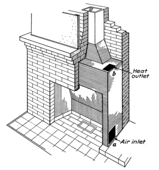
Figure 21.—In this fireplace the air is not drawn in directly from outdoors but through the inlet, a, from the room that is being heated. The air is heated by contact with the metal sides and back of the fireplace, rises by natural circulation, and is discharged back into the room from the outlet, b, or to another room on the same floor or in the second story. The inlets and outlets are connected to registers which may be located at the front of the fireplace, as shown in figure 22. The registers may be located on the ends of the fireplace or on the wall of an adjacent room.
The quantity and temperature of the heated air discharged from the grilles in figures 20 and 21 were measured to determine the merits of the convection features. These measurements showed that very appreciable amounts of convected heat are produced by the modified unit when properly installed and operated. Discharge-air temperatures in excess of 200° F. were attained from some of the units tested. The heated air delivered from the discharge grilles of some of the medium-sized units represented a heating effect equivalent to that from nearly 40 square feet of cast-iron radiation of the ordinary hot-water « 26 » heating system, or sufficient to heat a 15- by 18-foot room built with average tightness to 70° F. when the outside temperature is 40° F. Additional convected heat can be produced with some models by the use of forced-circulation fans.

Figure 22.—Except for the registers and metallic sides and back, the appearance of modified fireplaces is like that of ordinary ones. An interesting effect is secured by the mirror—the reflection of the opposite wall appears like a recess over the mantel.
However, the nature of operation, with the unavoidably large quantity of heated air passing up the stack, makes the inherent over-all efficiency of any fireplace relatively low. Therefore, claims for an increased efficiency of modified fireplaces should be understood merely as constituting an improvement over the ordinary fireplace and not over stoves or central heating plants.
When a fireplace is being selected the kind of fuel to be burned should be considered; also, the design should harmonize with the room in proportion and detail (figs. 23 and 24).
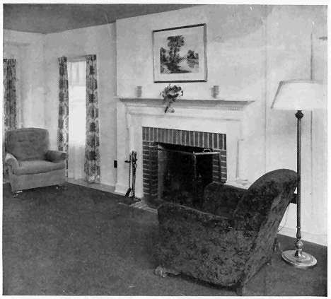
Figure 23.—A well-designed commercial mantel that suits the room. Since it is painted the same color as the walls, it does not focus attention, as the handsomely carved formal mantel or mahogany shown in figure 37 is intended to do.
In colonial days, when cordwood was plentiful, fireplaces 7 feet wide and 5 feet high were common, especially when used in kitchens for cooking (fig. 25). They required large amounts of fuel and too frequently were smoky.
Where cordwood (4 feet long) is cut in half, a 30-inch width is desirable for a fireplace; but, where coal is burned, the opening can be narrower (fig. 26). Thirty inches is a practical height for the convenient tending of a fire where the width is less than 6 feet; openings about 30 inches wide (fig. 27) are generally made with square corners. The higher the opening, the greater the chance of a smoky fireplace.
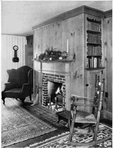
Figure 24.—Another good design is this revival of early New England architecture, which is frequently used for remodeling public dining rooms. The random-width pine planks were selected especially for variety in the pattern of the knots. Note the use of otherwise wasted space for bookshelves and closet.

Figure 25.—A, A fireplace at Mount Vernon, Washington's home, typical of those used before cooking stoves were introduced. This type of fireplace, if not too large, is often retained (B) when a kitchen is remodeled into a living room. Note the Dutch oven at the right, formerly used for baking.

Figure 26.—Fireplaces originally intended for wood were frequently bricked up, and small cast-iron units of this type were built in, since the large openings required for wood were wasteful when coal was used. This was a very popular type of grate for hotel and private bedrooms about 1860 and can still be seen in old houses in coal regions. Note the plain and neat mantel of wide plank.
In general, the wider the opening the greater should be the depth. A shallow opening throws out relatively more heat than a deep one of the same width but accommodates smaller pieces of wood; thus it becomes a question of preference between a greater depth which permits the use of large logs that burn longer and a shallower depth (fig. 28, A and B) which takes smaller-sized wood but throws out more heat.
In small fireplaces a depth of 12 inches will permit good draft if the throat is constructed as explained above, but a minimum depth of 16 to 18 inches is advised to lessen the danger of brands falling out on the floor.
As a rule, fireplaces on the second floor are smaller than those on the first floor and it is well to follow this practice because the flue height is less for second floor fireplaces (fig. 29).
Unless a fireplace 6 feet wide is fully 28 inches deep, the logs will have to be split, and some advantage of the wide opening will be lost.
Screens of suitable design should be placed in front of all fireplaces (fig. 30).

Figure 27.—This inexpensive fireplace 32 inches square shows how a plain brick front can be used in a small room.
A fireplace 30 to 36 inches wide is generally suitable for a room having 300 square feet of floor (fig. 31). The width should be increased for larger rooms, but all other dimensions should be taken from table 3 for the width selected.
The corner of a room often is the favorite location for a fireplace (fig. 32). Fireplaces of the type shown in figure 28 are also built in corners.

Figure 28.—A, A shallow fireplace, with a copper hood, built as shown in B, throws out considerable heat after the hood gets hot. The wall should be of fire-resistant masonry.

Figure 29.—This shallow fireplace with a sloping back is a type that was frequently built in bedrooms before the general use of stoves. Note the neat and well-proportioned mantel.
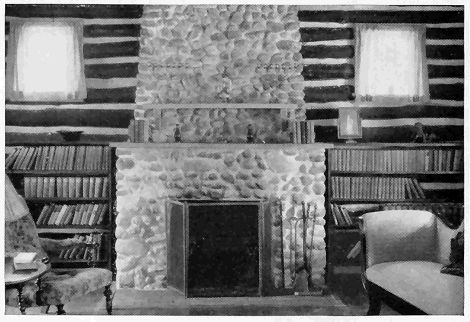
Figure 30.—Screens are almost essential to protect the upholstery of nearby furniture from sparks. This fireplace shows artistic use of small stones and makes a pleasing contrast with the log walls.
Units providing for burning gas are often built in to resemble fireplaces (fig. 33).
Pleasing designs result from exercising good taste in use of materials and mantels that suit the room. The photographs in this bulletin have been selected to illustrate various architectural effects that can be developed and should help in the choice of a type suitable for houses of different designs. The essentials for safety and utility, however, should not be sacrificed for style.

Figure 31.—This 36-inch-wide fireplace does not seem too large for the small room, but its size would have been accentuated by the use of a mantel.
The ordinary fireplace is constructed generally as shown in figure 34. It is essential (1) that the flue have the proper area, (2) that the throat be correctly constructed and have suitable damper, (3) that the chimney be high enough for a good draft, (4) that the shape of the fireplace be such as to direct a maximum amount of radiated heat into the room, and (5) that a properly constructed smoke chamber be provided.

Figure 32.—An adobe fireplace of the Mexican-Indian type commonly built in the Southwestern States, especially when the house walls are of adobe. The logs are stood up, leaning against the back of the grate, in order to secure a high-licking flame.
Table 3 gives recommended dimensions for fireplaces of various widths and heights.
If a damper is installed, the width of the opening j, figure 34, will depend on the width of the damper frame, the size of which is fixed by the width and depth of the fireplace and the slope of the back wall. The width of the throat proper is determined by the opening of the hinged damper cover. The full damper opening should never be less than the flue area. Responsible manufacturers of fireplace equipment give valuable assistance in the selection of a suitable damper for a given fireplace. A well-designed and well-installed damper should be regarded as essential in cold climates.
When no damper is used, the throat opening j should be 4 inches for fireplaces not exceeding 4 feet in height.
Table 3.—Recommended dimensions for finished fireplaces
[Letters at heads of columns refer to figure 34]
| Opening | Depth, d |
Minimum back (horizontal) c |
Vertical back wall, a |
Inclined back wall, b |
Outside dimensions of standard rectangular flue lining |
Inside diameter of standard round flue lining |
|
| Width, w |
Height, h |
||||||
| Inches | Inches | Inches | Inches | Inches | Inches | Inches | Inches |
| 24 | 24 | 16-18 | 14 | 14 | 16 | 8½ by 8½ | 10 |
| 28 | 24 | 16-18 | 14 | 14 | 16 | 8½ by 8½ | 10 |
| 24 | 28 | 16-18 | 14 | 14 | 20 | 8½ by 8½ | 10 |
| 30 | 28 | 16-18 | 16 | 14 | 20 | 8½ by 13 | 10 |
| 36 | 28 | 16-18 | 22 | 14 | 20 | 8½ by 13 | 12 |
| 42 | 28 | 16-18 | 28 | 14 | 20 | 8½ by 18 | 12 |
| 36 | 32 | 18-20 | 20 | 14 | 24 | 8½ by 18 | 12 |
| 42 | 32 | 18-20 | 26 | 14 | 24 | 13 by 11 | 12 |
| 48 | 32 | 18-20 | 32 | 11 | 24 | 13 by 13 | 15 |
| 42 | 36 | 18-20 | 26 | 11 | 28 | 13 by 13 | 15 |
| 48 | 36 | 18-20 | 32 | 14 | 28 | 13 by 18 | 15 |
| 54 | 36 | 18-20 | 38 | 14 | 28 | 13 by 18 | 15 |
| 60 | 36 | 18-20 | 44 | 14 | 28 | 13 by 18 | 15 |
| 42 | 40 | 20-22 | 24 | 17 | 29 | 13 by 13 | 15 |
| 48 | 40 | 20-22 | 30 | 17 | 29 | 13 by 18 | 15 |
| 54 | 40 | 20-22 | 36 | 17 | 29 | 13 by 18 | 15 |
| 60 | 40 | 20-22 | 42 | 17 | 29 | 18 by 18 | 18 |
| 66 | 40 | 20-22 | 48 | 17 | 29 | 18 by 13 | 18 |
| 72 | 40 | 22-28 | 51 | 17 | 29 | 18 by 18 | 18 |

Figure 33.—In regions where natural gas is plentiful and in cities, fireplaces of this type, burning gas with a flickering flame, are frequently used as an auxiliary to the main heating plant. Some types have imitation logs of metal perforated for gas jets.
Footings
Footings for chimneys with fireplaces should be provided as described on page 7; for chimneys without fireplaces, the footings should rest on good firm soil.

Figure 34.—A typical fireplace, illustrating practical details of construction. An alternate method of supporting the hearth is shown in the lower right-hand corner. The various letters refer to specific features discussed in the text.
Hearth
The hearth should be about flush with the floor, for sweepings may then be brushed into the fireplace. When there is a basement, an « 38 » ash dump located in the hearth near the back of the fireplace is convenient. The dump consists of a metal frame about 5 by 8 inches in size, with a plate, generally pivoted, through which ashes can be dropped into a pit below (fig. 35).
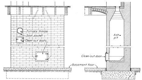
Figure 35.—The ash-pit should be of tight masonry and should be provided with a tightly fitting iron clean-out door and frame about 10 by 12 inches in size. A clean-out for the furnace flue as shown is sometimes provided.
In buildings with wooden floors the hearth in front of the fireplace should be supported by masonry trimmer arches (fig. 34) or other fire-resistant construction. Hearths should project at least 16 inches from the chimney breast and should be of brick, stone, terra cotta, or reinforced concrete not less than 4 inches thick. The length of the hearth should be not less than the width of the fireplace opening plus 16 inches. Wooden centering under trimmer arches may be removed after the mortar has set, though it is more frequently left in place. Figure 36 shows a recommended method of floor framing around a fireplace.
Wall Thickness
The walls of fireplaces should never be less than 8 inches thick, and if of stone they should be at least 12 inches thick. When built of stone or hard-burned brick, the back and sides are often not lined with firebrick, but it is better to use firebrick laid in fire-clay. When firebricks are laid fiat with the long sides exposed there is less danger of their falling out. They are generally placed on edge, however, forming a 2-inch protection, in which case metal ties should be built into the main brickwork to hold the 2-inch firebrick veneer in place. Thick metal backs and sides are sometimes used as lining. When a « 39 » grate for burning coal or coke is built in, firebrick at least 2 inches thick should be added to the fireplace back unless the grate has a solid iron back and is only set in with an air space behind it (fig. 37).
Jambs
The jambs should be wide enough to give stability and a pleasing appearance; they are frequently faced with ornamental brick or tile. For an opening 3 feet wide or less, a 12- or 16-inch width is generally sufficient, depending on whether a wood mantel is used or the jambs are of exposed masonry. The edges of a wood mantel should be kept at least 8 inches from the fireplace opening. For wider openings and large rooms, similar proportions should be kept.
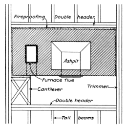
Figure 36.—Where a header is more than 4 feet in length, it should be doubled, as shown. Headers supporting more than four tail beams should have ends supported in metal joist hangers. The framing may be placed one-half inch from the chimney because the masonry is 8 inches thick.
Lintel
Lintels of ½- by 3-inch flat iron bars. 3½- by 3¼- by ¼-inch angle irons, or damper frames are used to support the masonry over the opening of ordinary fireplaces. Heavier lintel irons are required for wider openings.
Where a masonry arch (fig. 38) is used over the opening, the jambs should be heavy enough to resist the thrust of the arch. Arches over openings less than 4 feet wide seldom sag, but sagging is not uncommon in wider fireplaces, especially where massive masonry is used.
Throat
The sides of the fireplace should be vertical up to the throat, or damper opening (ff fig. 34). The throat should be 6 to 8 inches or more above the bottom of the lintel and have an area not less than that of the flue and a length equal to the width of the fireplace opening. Starting 5 inches above the throat, ee, the sides should be drawn in at tt to equal the flue area.
Proper throat construction is so necessary to a successful fireplace that the work should be inspected several times a day during construction to make certain that the side walls are carried up perpendicularly until the throat is passed and that the full length of opening is provided.
Smoke Shelf and Chamber
The smoke shelf is made by setting the brickwork back at the top of the throat to the line of the flue wall for the full length of the throat. Its depth may vary from 6 to 12 inches or more, depending on the depth, d, of the fireplace.

Figure 37.—Grates of this type are commonly used in fireplaces for burning coal or coke. This one has a metal back and ends and is only set in to permit proper circulation of air around it.
The smoke chamber is the space extending from the top of the throat, ee, up to the bottom of the flue proper, tt, and between the side walls. The walls should be drawn inward 30° to the vertical after the top of the throat, ee, is passed and smoothly plastered with cement mortar not less than one-half inch thick.
Damper
A properly designed damper, as shown in figure 34, affords a means of regulating the draft and prevents excessive loss of heat from the room when the fire is out. A damper consists of a cast-iron frame with a lid hinged so that the width of the throat opening may be varied from a closed to a wide-open position. Various patterns are on the market, some designed to support the masonry over the opening, others requiring lintel irons.

Figure 38.—This well-designed small stone fireplace was built in accordance with the principles given in this bulletin. It is a good heater and does not smoke. The jambs are wide enough to resist the thrust of the arch.
A roaring pine fire may require a full-throat opening, but slow-burning hardwood logs may need only 1 or 2 inches of opening. Regulating the opening according to the kind of fire prevents waste of heat up the chimney. Closing the damper in summer keeps flies, mosquitoes, and other insects from entering the house down the chimney.
In houses heated by furnaces or other modern systems, lack of a damper in the fireplace flue may interfere with uniform heating, particularly in very cold windy weather, whether or not there is a fire on the hearth. When air heated by the furnace is carried up the chimney there is a waste of the furnace fuel, but a damper partially open serves a slow fire of hardwood without smoking the room or wasting heated air from the main heating system.
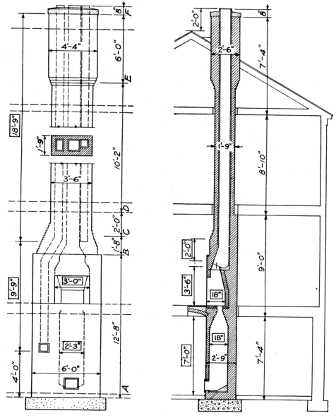
Figure 39.—Diagram showing front view and cross section of an entire chimney such as is commonly built to serve a furnace, fireplace, and kitchen stove. Two sets of dimensions are given, those in rectangles refer to the approximate sizes of the voids or openings; the others refer to the outside dimensions of the brickwork. These are used in estimating the number of bricks in a chimney. The letters A-F indicate sections used in estimating the quantities of brick required (See p. 44.)
Flue
The area of lined flues should be a twelfth or more of the fireplace opening, provided the chimney is at least 22 feet in height, measured from the hearth. If the flue is shorter than 22 feet or if it is unlined, its area should be made a tenth or more of the fireplace opening. The « 43 » fireplace shown in figure 34 has an opening of 7.5 square feet, or approximately 1,080 square inches, and needs a flue area of approximately 90 square inches; a rectangular flue, 8% by 18 inches, outside dimensions, or a round flue with a 12-inch inside diameter might be used, as these are the nearest commercial sizes of lining (table 2). It is seldom possible to obtain lining having exactly the required area, but the inside area should never be less than that prescribed above. A 13- by 13-inch flue was selected for convenience when combining with the other flues. If the flue is built of brick and is unlined, its area should be approximately one-tenth of the fireplace opening, or 108 square inches. It would probably be made 8 by 16 inches (128 square inches) because brickwork can be laid to better advantage when the dimensions of the flue are multiples of 4 inches. The principles of construction given under Chimneys (p. 7) apply to fireplace flues.
Table 4 is convenient in selecting the proper size of flue or for determining the size of fireplace opening for an existing flue. The area of the fireplace opening in square inches is obtained by multiplying the width, w, by the height, h, (fig. 34), both measured in inches.
A convenient method for estimating the number of bricks in a chimney is to calculate the volume of the various sections which differ in outside dimensions and then subtract the voids or cavities resulting from ash-pits, fireplace, and flues. This will be the total cubic feet of brickwork which, when multiplied by 22.5, is converted to number of bricks. For convenience, inches as indicated in figure 39 have been converted to decimals of a foot. [6]
[6] Inches and fractions of an inch are converted to feet and decimals by multiplying by 0.0833; thus 2 X / inches × O.0833 equals 0.208 feet.
Table 4.—Sizes of fireplace flue linings[D]
| Area of fireplace opening |
Outside dimensions of standard rectangular flue lining |
Inside diameter of standard round flue lining |
| Square inches |
Inches | Inches |
| 600 | 8½ by 8½ | 10 |
| 800 | 8½ by 13 | 10 |
| 1,000 | 8½ by 18 | 12 |
| 1,200 | 8½ by 18 | 12 |
| 1,400 | 13 by 13 | 12 |
| 1,600 | 13 by 13 | 15 |
| 1,800 | 13 by 18 | 15 |
| 2,000 | 13 by 18 | 15 |
| 2,200 | 13 by 18 | 15 |
| 2,400 | 18 by 18 | 18 |
| 2,600 | 18 by 18 | 18 |
| 2,800 | 18 by 18 | 18 |
| 3,000 | 18 by 18 | 18 |
[D] Based on a flue area equal to one-twelfth the fireplace opening. Sec table 2 for areas of flue lining.
Number of Bricks
(1) Estimate the total volume of masonry by multiplying together the length, width, and height of the various sections (fig. 39).
| Section | Length Feet |
Width Feet |
Height Feet |
Volume Cubic feet |
|||
| AB | 6.0 | by | 2.75 | by | 12.66 | = | 209.0 |
| BC | 4.25 | by | 2.5 | by | 1.66 | = | 17.6 |
| CD | 3.5 | by | 2.0 | by | 2.0 | = | 14.0 |
| DE | 3.5 | by | 1.75 | by | 10.16 | = | 62.2 |
| EF | 4.33 | by | 2.5 | by | 6.0 | = | 65.0 |
| Total volume including voids | 367.8 | ||||||
(2) Estimate the total volume of voids by multiplying together their length, width, and height.
| Item | Length Feet |
= | Width Feet |
= | = | Height Feet |
= | Volume Cubic feet |
| Ash-pit | 2.33 | by | 1.5 | by | 7.0 | = | 24 46 | |
| Fireplace | 3.0 | by | 1.5 | by | 3.5 | = | 15.75 | |
| Smoke chamber | 2.0 | by | 1.16 | by | 2.0 | = | 4.64 | |
| 8½- by 13-inch flue[E] | 0.78 | square feet | by | 28 5 | = | 22.23 | ||
| 13- by 13-inch flue[E] | 1.20 | square feet | by | 18.75 | = | 22.50 | ||
| 8½- by 8½-inch flue[E] | .50 | square feet | by | 18.75 | = | 9.37 | ||
| Total volume of voids | 98.95 | |||||||
(3) Subtract volume of voids from volume of masonry.
| Cubic feet | |
| Total volume, including voids | 368 |
| Total volume of voids | 99 |
| Total volume of masonry | 269 |
(4) Multiply net volume of masonry by the number of brick per cubic foot.
269 by 22.5 = 6,053 brick, or 6.1 thousand bricks.
Mortar
To estimate the mortar needed, multiply the mortar material given below for 1,000 brick by 6.1 to determine how much will be needed to build the chimney, using 1:1:6 mixture recommended on page 10.
| Bags of hydrated lime | 2.6 | by | 6.1 | = | 16 bags. |
| Sacks of portland cement | 3.5 | by | 6.1 | = | 22 sacks. |
| Cubic feet of sand | 18.0 | by | 6.1 | = | 110 cubic feet = 4 cubic yards. |
Foundation
Concrete needed for foundation can be estimated as follows: Concrete for foundation should be 1:2½:5 and for the top 1:2½. The foundation is 7 by 3.75 by 1, or 26.25 cubic feet, or 1 cubic yard, and will require 5 sacks of cement, 0.46 cubic yard of sand, and 92 cubic yard of gravel. The cap is 4.5 by 2.66 by 0.5 = 5.9 cubic feet The area of the three flues above must be deducted: 5.9 minus 2.48 = 3.42 cubic feet, or one-ninth of a cubic yard. As 1 cubic yard was « 45 » assumed for the foundation, extra cement and sand are not needed. Other material needed:
|
1 8-inch thimble, 9 inches long. 1 6-inch thimble, 9 inches long. 28 feet of 8½- by 13-inch flue lining. 20 feet of 13- by 13-inch flue lining. 20 feet of 8½- by 8½-inch flue lining. Damper, 36- by 10-inch throat opening. 2 clean-out doors and 1 ash dump. Mantel as selected. |
If firebrick is to be used or the exposed breast is to be of face or special brick (or ceramic tile) the number should be counted or estimated and deducted from the number of common brick as estimated above.
Labor
The labor required to build a chimney depends on the thickness of the walls, the height, and the amount of cutting to build in specialties, provide offsets, etc. In general, a mason will take 16 hours with 8 hours of laborer's help to lay 1,000 brick. On this basis, 16 by 6.1 = 97.6 hours of mason's time and 48.8 hours of laborer's time will be required.
Cost
The approximate cost of the chimney can be determined by using actual local cost of materials and wages as follows:[F]
| 6,100 brick at $15.00 per thousand | $91.50 | |
| 27 sacks of cement[G] at $0.70 per sack | 18.90 | |
| 16 bags of lime at $0.50 per bag | 8.00 | |
| 5 cubic yards of sand[G] at $2.25 per cubic yard | 11.25 | |
| 1 cubic yard of gravel at $2.00 per cubic yard | 2.00 | |
| 98 hours, mason's time, at $1.00 per hour | 98.00 | |
| 49 hours, laborer's time,[H] at $0.30 per hour | 14.70 | |
| 28 linear feet of 8½- by 13-inch flue at $1.00 per foot | 28.00 | |
| 20 linear feet of 13- by 13-inch flue at $1.15 per foot | 23.00 | |
| 20 linear feet of 8½- by 8½-inch flue at $0.40 per foot | 8.00 | |
| 1 8-inch thimble | .60 | |
| 1 6-inch thimble | .40 | |
| 2 clean-out doors Damper, lintel mantel, ash dump |
} | 65.00 |
| Total net cost | [I] | 369.35 |
[F] The prices used in this example are merely illustrative.
[G] Includes material for footing and cap.
[H] Includes labor for footing and cap.
[I] Where the chimney is built by contract, 10 to 15 percent should be added for profit and overhead.
When a fireplace smokes, it should be examined to make certain that the essential requirements of construction as outlined in this bulletin have been fulfilled. If the chimney is not stopped up with fallen brick and the mortar joints are not loose, note whether nearby trees or tall structures cause eddies down the flue. To determine whether the fireplace opening is in correct proportion to the flue area, hold a piece of sheet metal across the top of the fireplace opening and then gradually lower it, making the opening smaller until smoke does not come into the room. Mark at the lower edge of the metal on the sides of the fireplace. The opening may then be reduced by building in a metal shield or hood across the top so that its lower edge is at the marks made during the test; or the trouble can generally be remedied by increasing the height of the flue.
Outdoor fireplaces range from simple makeshifts to elaborately equipped structures harmonizing with the architecture of the house.
No one type will meet all conditions, but all types should be practical to use and yet not be fire hazards or eyesores.

Figure 40.—A, A fireplace built for 30 cents, cash. One hundred and twenty bricks and six concrete blocks were picked up a few at a time along the road. One sack of cement was purchased, one-half of which was used for another job Sand was available on the site. B f Detailed drawings show dimensions of this fireplace. As the fireplace is ordinarily built, the material would cost about $5 and the labor from $5 to $10, depending on local conditions.
The tendency is to build too large an outdoor fireplace. Where only a little cooking is to be done occasionally in a small yard or at a picnic, several concrete blocks or stones set on the ground about 12 to 16 inches apart will serve. The shelf of an old refrigerator may be used for a grille. If permanence is desired, the walls should be laid in cement mortar and the fireplace should have a suitable foundation and a permanent grille. An end wall is recommended to prevent embers from being scattered by drafts blowing between the side walls. Smoke annoyance while cooking is lessened by making the fireplace long enough to permit a short chimney (fig. 40).

Figure 41.—An outdoor fireplace built back of an inside fireplace and opening onto a paved terrace provides comfort in early fall.
A circle of stones laid loosely on the surface, larger stones set partly into the ground, or carefully laid masonry walls on a stable foundation may be used for campfires and small barbecue parties. A cast-iron pot with a lid can be buried in the ashes for baking. Pipe supports for pots and pans built into the masonry are a convenience; they can be homemade or purchased. Spits for roasting can be improvised or bought.
Fireplaces opening onto an enclosed porch or paved terrace, are often built as an integral part of the house chimney (fig. 41). The corner of boundary walls permits effective treatment. Such fireplaces should meet the regulations of local fire authorities and be built with the same care and be subject to the same rules as inside fireplaces.
Plans for outdoor fireplaces are available from various publishing houses; several magazines feature illustrations that can be adapted to the material at hand. If a structure is to be built with local labor and material, simple designs are advisable. The size of stones, joints, and proportions have a direct influence upon appearance, and good personal taste frequently results in more pleasing structures than blind adherence to conventional designs. The various combinations of ovens, cranes, grilles, storage compartments, benches, lights, sinks, etc., to be used as built-in features affect the design. Before planning a structure with these features, catalogs of dealers in outdoor fireplace equipment should be consulted for sizes of the available accessories so that ample space and proper details can be provided in the masonry for building them in. Skilled labor should be employed for elaborate designs (fig. 42) when much equipment is built in or when the fireplace, as in figure 41, is an integral part of a permanent building.

Figure 42.—This fireplace, set at a focal point in the garden, enhances the landscape. It was built by a skilled mason.
Ordinarily the fire is built on the hearth, no grate being used. Fire regulations in hazardous localities may require firing doors, dampers, spark screens, and a solid-plate cooking surface; otherwise these features are not essential. Two and a half square feet of cooking surface is desirable, while access to both sides and the end permit several people to cook at the same time. The side walls should have fairly level tops for pots and pans. Side walls are made 2 to 6 inches higher than the cooking level to permit anchoring the grille; if too high, they interfere with cooking. Commercial grilles are available, but satisfactory ones can be made of ½-inch to ¾-inch pipe or ⅝-inch « 49 » reinforcing rods. The pipes should be 6 to 10 inches longer than the width of the firebox; they should be spaced not more than 1¼ inches apart and have their tops exactly level to prevent pots and pans from wobbling. Two or three pipes can be used for a lintel over the opening into the flue if regular iron lintels are not available. Where a solid top is desired, it should be of boiler plate at least ¼-inch thick. Such plates must be stiffened to prevent buckling by alternate heating and cooling; for ordinary purposes they are merely set on top of the grid though they may be hinged at the rear so they can be tipped back against the chimney.
The best draft is secured when the fireplace faces the direction of prevailing breezes and is protected from strong winds which might scatter sparks. If the fireplace is built too near shrubbery or under trees, the heat and smoke may damage or burn the foliage. A slight rise or a gentle slope that affords good drainage should be selected. Paving the ground around the fireplace, with flagstones or covering it with a layer of gravel or sand will prevent the area from becoming a mudhole or an unsightly bare spot; also, danger of starting brush fires by sparks falling from the firebox is lessened.
Fireboxes 12 to 16 inches wide, 16 to 24 inches long, and 6 to 8 inches deep with the hearth at 9 to 16 inches above the ground are sufficient for most purposes. Large fireboxes are wasteful of fuel; while, if the grille is too high above the hearth, much of the best cooking heat from glowing coals is lost. Most grilles are set 15 to 24 inches above the ground, though 30 inches may be desirable to avoid the necessity of stooping when cooking. The hearth should slope 1 to 2 inches toward the front so that rain water will drain away.
The area of the chimney flue should be at least one-eighth the vertical cross-sectional area of the firebox.
Fire-clay linings for the firebox and flue are not absolutely necessary except when required by fire regulations or where hot fires are maintained for long periods. They, or common brick linings, are advisable for the more permanent and expensive structures or where it is necessary to use porous stone, such as sandstone and most stratified rocks, which absorb water and flake or chip upon exposure to fire.
Most rocks or stone that can be worked up without special tools or skill, brick, and concrete are adaptable for the average fireplace (fig. 43). The size of the stones determines the thickness of the walls; no wall should be less than 8 inches thick.
Where suitable stone is difficult to get in sufficient quantity, the exposed surface may consist of a shell the thickness of the stone and the inner portion of the wall be made of concrete or large stone bedded in concrete. When flue lining is necessary, it will serve as a form for the flue: otherwise a metal stovepipe makes a practical form, or the flue can be formed of brick laid on edge. The stones can be laid and the concrete deposited with the least trouble by building the veneer and flue only 6 to 8 inches high at one time. All masonry should be laid in mortar, as described on page 10. Concrete made in the proportions 1:2½:4 will serve most purposes where wall sections are about 8 inches thick. For heavy foundations and thick walls not subject to direct fire, 1:3:6 concrete is strong enough.
A concrete slab 4 to 8 inches thick with the bottom 4 to 6 inches below the surface provides a sufficient foundation for medium-sized structures where frost is negligible and the soil is well drained and « 50 » firm. If the soil is not well drained a 6- to 8-inch layer of stone, cinders, or sand should be provided under the slab and the surface of the immediate vicinity graded or otherwise protected from water. It is advisable to use ¼-inch or ½-inch reinforcing rods, 6 inches apart in both directions, one-third the distance from the top in slabs for all but the smallest fireplaces or where frost is not severe.

Figure 43.—A, Ground plan of a stone fireplace that can be built in different sizes to suit the landscape; B, vertical-section sketch; C, the completed fireplace. The stones for this fireplace were picked up at "the swimming hole." About 8 bushels were used over a backing of concrete; 16 bushels would have been needed if the concrete had not been used. Gravel and sand were dug from the excavation. The chimney is battered 4 inches in the 24-inch height.
Heavy and expensive structures, especially those having tall chimneys, should have foundations below the surface affected by frost or erosion and strong enough to prevent settlement or cracks. Such a foundation can be made of concrete, with a liberal use of « 51 » large stones for economy, extending under the whole structure, or be continuous walls with a footing similar to those used for houses. The advice and help of builders may save money in the construction of foundations of large expensive fireplaces, especially where climatic conditions are severe and the bearing power of soil is not known.
Cooking should be done over glowing coals, as flames and smoke smudge the utensils or even the food. When the wood is nearly charred, most of the smoke has been driven off and the chimney is hot enough to draw the smoke up the flue. All fires should be banked before they are left, to avoid setting fires. Banking can be safely and effectively done by raking the coals and unconsumed fuel into a pile on the hearth and covering the pile with a few inches of earth. Water thrown on a hot fire may result in scalds from the steam and may crack the fireplace.
Barbecue ovens are rather expensive unless for community use. Outdoor fireplaces, without or with spits for roasting, are frequently called barbecues in some sections of the country. For occasional barbecuing parties, a hole in the ground will serve. Dig a hole several feet deep and several feet larger each way than the size of the carcass to be roasted; then place stones in the bottom to retain the heat. A trench 30 inches deep, 36 inches wide, and about 10 feet long will accommodate about 400 pounds of beef. A fire should be built sufficiently ahead of time, about 3 hours, to heat the stones and bottom and accumulate ashes for proper banking. Have someone with previous experience operate the pit, because improper wrapping of the meat and handling of the coals results in poor cooking.
Dutch ovens (fig. 25) are often built in connection with both indoor and outdoor fireplaces to copy early kitchen fireplaces or for actual baking.
When used as an ornament, the oven is fitted with a cast-iron door, and the space thus formed may be used for wood storage. An open firebox or compartment below may be similarly used. Spaces used for wood storage should be separated from the fireplace by a brick or stone partition at least 8 inches thick, all joints being completely filled with mortar.
If the oven is intended for baking, it is advisable to line it with firebrick, and the masonry should be at least 8 inches thick. A greater heat-storing capacity is secured by using thick walls. An ash drop of standard cast-iron unit type is provided for modern ovens and may lead either to the side of the fireplace or to an ash-pit in the chimney base. The throat or dome should be carefully formed with brick molded or ground to an arch and preferably should be fitted with a damper. If the top of the oven is flat, several lintel irons will be needed to support the brick. A separate flue with a damper is recommended. For ovens of ordinary size an 8½- by 8½-inch flue is ample. The oven is preheated by fire or hot coals. Before food is placed in the oven, the coals and ashes are removed through the ash drop.
Figure 44 shows a Dutch oven made of tapered adobe bricks and plastered outside with adobe mud. A hole in the top permits the escape of smoke, while the orño is being heated by the fire built inside on the floor. This hole is closed with an adobe block after the coals are raked out. When loaves of bread have been placed on the floor with a wooden paddle, the door hole is stopped with adobe brick.

Figure 44.—This Dutch oven of adobe bricks is a type very common in the States along the Mexican border. It is called an orño and is usually built a short distance from the kitchen door.
Boy Scouts and campers frequently improvise Dutch ovens by packing damp sandy clay, 8 to 12 inches thick, around a wooden barrel, a tin wash boiler, or slabs of rock to form a vault. After the earth has been gradually dried and baked with a slow fire, the oven is ready for use. The hole in the top and the door can be closed as in the orño.
U. S. GOVERNMENT PRINTING OFFICE: 1947
For sale by the Superintendent of Documents, U. S. Government Printing Office
Washington 25, D. C. - Price 15 cents
Transcriber Note
Paragraphs split by illustrations were rejoined. The footnotes for the tables were changed from arabic numerals to alphabetic characters to distinguish them from the text footnotes. The cover image was derived from materials made available at The Internet Archive and is placed in the Public Domain.

