|
Note: Images of the original pages are available through Internet Archive/American Libraries. See https://archive.org/details/langleymemoironm00lang Some characters might not display in this html version. If so, the reader should consult the original page images referred to above. |
 Transcriber's Endnote
The present work, entitled “Langley Memoir on Mechanical Flight,” as planned by the late Secretary Samuel Pierpont Langley, follows his publications on “Experiments in Aerodynamics” and “The Internal Work of the Wind” printed in 1891 and 1893, respectively, as parts of Volume 27 of the Smithsonian Contributions to Knowledge.
This Memoir was in preparation at the time of Mr. Langley’s death in 1906, and Part I, recording experiments from 1887 to 1896, was written by him. Part II, on experiments from 1897 to 1903, has been written by Mr. Charles M. Manly, who became Mr. Langley’s Chief Assistant in June, 1898. The sources of information for this Part were the original carefully recorded accounts of the experiments described.
It is expected later to publish a third part of the present memoir, to consist largely of the extensive technical data of tests of the working of various types of curved surfaces, propellers, and other apparatus.
It is of interest here to note that experiments with the Langley type of aerodrome1 did not actually cease in December, 1903, when he made his last trial with the man-carrying machine, but as recently as August 6, 1907, a French aviator made a flight of nearly 500 feet with an aerodrome of essentially the same design. (See Appendix.)
In accordance with the established custom of referring to experts in the subject treated, all manuscripts intended for publication in the Smithsonian Contributions to Knowledge, this work was examined and recommended by a Commission consisting of Mr. O. H. Tittman, Superintendent of the United States Coast and Geodetic Survey, who witnessed some of the field trials, George O. Squier, Ph. D. (Johns Hopkins), Major, Signal Corps, U. S. Army, and Albert Francis Zahm, Ph. D., of Washington City.
CHARLES D. WALCOTT,
Secretary of the Smithsonian Institution.
[1] The name “aerodrome” was given by Secretary Langley to the flying machine in 1893, from ἀεροδρομέω (to traverse the air) and ἀεροδρόμος air runner.—Internal Work of the Wind, p. 5.
The present volume on Mechanical Flight consists, as the title-page indicates, of two parts. The first, dealing with the long and notable series of early experiments with small models, was written almost entirely by Secretary Langley with the assistance of Mr. E. C. Huffaker and Mr. G. L. Fowler in 1897. Such chapters as were not complete have been finished by the writer and are easily noted as they are written in the third person. It has been subjected only to such revision as it would have received had Mr. Langley lived to supervise this publication, and has therefore the highest value as an historical record. The composition of the second part, dealing with the later experiments with the original and also new models and the construction of the larger aerodrome, has necessarily devolved upon me. This is in entire accordance with the plan formed by Mr. Langley when I began to work with him in 1898, but it is to me a matter of sincere regret that the manuscript in its final form has not had the advantage of his criticism and suggestions. If the reader should feel that any of the descriptions or statements in this part of the volume leave something to be desired in fullness of detail, it is hoped that some allowance may be made for the fact that it has been written in the scanty and scattered moments that could be snatched from work in other lines which made heavy demands upon the writer’s time and strength. It is believed, however, that sufficient data are given to enable any competent engineer to understand thoroughly even the most complicated phases of the work.
Persons who care only for the accomplished fact may be inclined to underrate the interest and value of this record. But even they may be reminded that but for such patient and unremitting devotion as is here enregistered, the now accomplished fact of mechanical flight would still remain the wild unrealized dream which it was for so many centuries.
To such men as Mr. Langley an unsuccessful experiment is not a failure but a means of instruction, a necessary and often an invaluable stepping-stone to the desired end. The trials of the large aerodrome in the autumn of 1903, to which the curiosity of the public and the sensationalism of the newspapers gave a character of finality never desired by Mr. Langley, were to him merely members of a long series of experiments, as much so as any trial of one of the small aerodromes or even of one of the earliest rubber-driven models. Had his health and strength been spared, he would have gone on with his experiments undiscouraged by these accidents in launching and undeterred by criticism and misunderstanding.
Moreover, it is to be borne in mind that Mr. Langley’s contribution to the solution of the problem is not to be measured solely by what he himself accomplished, important as that is. He began his investigations at a time when not only the general public but even the most progressive men of science thought of mechanical flight only as a subject for ridicule, and both by his epoch-making investigations in aerodynamics and by his own devotion to the subject of flight itself he helped to transform into a field of scientific inquiry what had before been almost entirely in the possession of visionaries.
The original plans for this publication provided for a third part covering the experimental data obtained in tests of curved surfaces and propellers. Owing to the pressure of other matters on the writer, the preparation of this third part is not yet complete and is reserved for later publication.
CHARLES M. MANLY.
NEW YORK CITY.
I2 announced in 1891,3 as the result of experiments carried on by me through previous years, that it was possible to construct machines which would give such a velocity to inclined surfaces that bodies indefinitely heavier than the air could be sustained upon it, and moved through it with great velocity. In particular, it was stated that a plane surface in the form of a parallelogram of 76.2 cm. × 12.2 cm. (30 × 4.8 inches), weighing 500 grammes (1.1 lbs.), could be driven through the air with a velocity of 20 metres (65.6 feet) per second in absolutely horizontal flight, with an expenditure of 1/200 horse-power, or, in other terms, that 1 horse-power would propel and sustain in horizontal flight, at such a velocity (that is, about 40 miles an hour), a little over 200 pounds weight of such surface, where the specific gravity of the plane was a matter of secondary importance, the support being derived from the elasticity and inertia of the air upon which the body is made to run rapidly.
It was further specifically remarked that it was not asserted that planes of any kind were the best forms to be used in mechanical flight, nor was it asserted, without restrictions, that mechanical flight was absolutely possible, since this depended upon our ability to get horizontal flight during transport, and to leave the earth and to return to it in safety. Our ability actually to do this, it was added, would result from the practice of some unexplored art or science which might be termed Aerodromics, but on which I was not then prepared to enter.
I had at that time, however, made certain preliminary experiments with flying models, which have been continued up to the present year,4 and at the same time I have continued experiments distinct from these, with the small whirling-table established at Washington. The results obtained from the latter being supplemental to those published in “Experiments in Aerodynamics,” and [p002] being more or less imperfect, were at first intended not for publication, but for my own information on matters where even an incomplete knowledge was better than the absence of any.
It is to be remembered that the mechanical difficulties of artificial flight have been so great that, so far as is known, never at any time in the history of the world previous to my experiment of May, 1896, had any such mechanism, however actuated, sustained itself in the air for more than a few seconds—never, for instance, a single half-minute—and those models which had sustained themselves for these few seconds, had been in almost every case actuated by rubber springs, and had been of such a size that they should hardly be described as more than toys. This refers to actual flights in free air, unguided by any track or arm, for, since the most economical flight must always be a horizontal one in a straight line,5 the fact that a machine has lifted itself while pressed upward against an overhead track which compels the aerodrome to move horizontally and at the proper angle for equilibrium, is no proof at all of real “flight.”
I desire to ask the reader’s consideration of the fact that even ten years ago,6 the whole subject of mechanical flight was so far from having attracted the general attention of physicists or engineers, that it was generally considered to be a field fitted rather for the pursuits of the charlatan than for those of the man of science. Consequently, he who was bold enough to enter it, found almost none of those experimental data which are ready to hand in every recognized and reputable field of scientific labor. Let me reiterate the statement, which even now seems strange, that such disrepute attached so lately to the attempt to make a “flying-machine,” that hardly any scientific men of position had made even preliminary investigations, and that almost every experiment to be made was made for the first time. To cover so vast a field as that which aerodromics is now seen to open, no lifetime would have sufficed. The preliminary experiments on the primary question of equilibrium and the intimately associated problems of the resistance of the sustaining surfaces, the power of the engines, the method of their application, the framing of the hull structure which held these, the construction of the propellers, the putting of the whole in initial motion, were all to be made, and could not be conducted with the exactness which would render them final models of accuracy.
I beg the reader, therefore, to recall as he reads, that everything here has been done with a view to putting a trial aerodrome successfully in flight within a few years, and thus giving an early demonstration of the only kind which is conclusive in the eyes of the scientific man, as well as of the general public—a demonstration that mechanical flight is possible-—by actually flying.
All that has been done, has been with an eye principally to this immediate [p003] result, and all the experiments given in this book are to be considered only as approximations to exact truth. All were made with a view, not to some remote future, but to an arrival within the compass of a few years at some result in actual flight that could not be gainsaid or mistaken.
Although many experimenters have addressed themselves to the problem within the last few years—and these have included men of education and skill—the general failure to arrive at any actual flight has seemed to throw a doubt over the conclusions which I had announced as theoretically possible.
When, therefore, I was able to state that on May 6, 1896, such a degree of success had been attained that an aerodrome, built chiefly of steel, and driven by a steam engine, had indeed flown for over half a mile—that this machine had alighted with safety, and had performed a second flight on the same day, it was felt that an advance had been made, so great as to constitute the long desired experimental demonstration of the possibility of mechanical flight. These results were communicated to the French Academy in the note given below.7
Independently of the preliminary experiments in aerodynamics already published, I had been engaged for seven years in the development of flying models. Although the work was discouraging and often resulted in failure, success was finally reached under the conditions just referred to, which obviously admitted of its being reached again, and on a larger scale, if desired. [p004]
In view of the great importance of these experiments, as demonstrating beyond question the practicability of the art of mechanical flight, and also in view of the yet inchoate state of this art, I have thought it worth while to publish an account of them somewhat in detail, even though they involve an account of failures; since it is from them, that those to whom it may fall to continue such constructions, will learn what to avoid, as well as the raison d’etre of the construction of the machines which have actually flown.
In an established art or science, this description of the essays and failures which preceded full knowledge would have chiefly an historical interest. Here almost nothing is yet established beyond the fact that mechanical flight has actually been attained. The history of failure is in this case, then, if I do not mistake, most necessary to an understanding of the road to future success, to which it led, and this has been my motive in presenting what I have next to say so largely in narrative form.
Part I of the present work is intended to include an account of the experiments with actual flying models, made chiefly at or near Washington, from the earliest with rubber motors up to the construction of the steam aerodromes that performed the flights of May 6 and November 28, 1896.
An account of some observations conducted at Washington, with the whirling table, on the reaction of various surfaces upon the air, is relegated to a later part.
The experiments with working models, which led to the successful flights, were commenced in 1887, and it has seemed to me preferable to put them at first in chronological order, and to present to the reader what may seem instructive in their history, while not withholding from him the mistaken efforts which were necessarily made before the better path was found. In this same connection, I may say that I have no professional acquaintance with steam engineering, as will, indeed, be apparent from the present record, but it may be observed that none of the counsel which I obtained from those possessing more knowledge was useful in meeting the special problems which presented themselves to me, and which were solved, as far as they have been solved, by constant “trial and error.”
I shall, then, as far as practicable, follow the order of dates in presenting the work that has been done, but the reader will observe that after the preliminary investigations and since the close of 1893, at least four or five independent investigations, attended with constant experiment and radically distinct kinds of construction, have been going on simultaneously. We have, for instance, the work in the shop, which is of two essentially different kinds: first, that on the frames and engines, which finally led to the construction of an engine of unprecedented lightness; second, the experimental construction of the supporting and guiding surfaces, which has involved an entirely different set of considerations, concerned with equilibrium and support in flight. These constructions, however successful, are confined to the shop and are, as will be seen later, useless without a launching apparatus. The construction of a suitable launching apparatus itself involved difficulties which took years to overcome. And, finally, the whole had to be tested by actual flights in free air, which were conducted at a place some 30 miles distant from the shop where the original construction went on. [p006]
Simultaneously with these, original experiments with the whirling-table were being conducted along lines of research, which though necessary have only been indicated. We have, then, at least five subjects, so distinct that they can only be properly treated separately, and accordingly they will be found in Chapters VII, VIII, IX and X, ◊ and in Part Third [in preparation].
It is inevitable that in so complex a study some repetition should present itself, especially in the narrative form chosen as the best method of presenting the subject to the reader. Each of these chapters, then, will contain its own historical account of its own theme, so that each subject can be pursued continuously in the order of its actual development, while, since they were all interdependent and were actually going on simultaneously, the order of dates which is followed in each chapter will be a simple and sufficient method of reference from one to the other.
In order to understand how the need arises for such experiments in fixing conditions which it might appear were already determined in the work “Experiments in Aerodynamics,”8 it is to be constantly borne in mind, as a consideration of the first importance, that the latter experiments, being conducted with the whirling-table, force the model to move in horizontal flight and at a constant angle. Now these are ideal conditions, as they avoid such practical difficulties as maintaining equilibrium and horizontality, and for this reason alone give results more favorable than are to be expected in free flight.
Besides this, the values given in “Aerodynamics” were obtained with rigid surfaces, and these surfaces themselves were small and therefore manageable, while larger surfaces, such as are used in actual flight, would need to be stiffened by guys and like means, which offer resistance to the air and still further reduce the results obtained. It is, therefore, fairly certain, that nothing like the lift of 200 pounds to the horse-power for a rate of 40 miles an hour,9 obtained under these ideal conditions with the whirling-table, will be obtained in actual flight, at least with plane wings.
The data in “Aerodynamics” were, then, insufficient to determine the conditions of free flight, not alone because the apparatus compels the planes to move in horizontal flight, but because other ideally perfect conditions are obtained by surfaces rigidly attached to the whirling-table so as to present an angle to the wind of advance which is invariable during the course of the experiment, whereas the surfaces employed in actual flight may evidently change this angle and cause [p007] the aerodrome to move upward or downward, and thus depart from horizontal flight so widely as to bring prompt destruction.
To secure this balance, or equilibrium, we know in theory, that the center of gravity must be brought nearly under the center of pressure, by which latter expression we mean the resultant of all the forces which tend to sustain the aerodrome; but this center of pressure, as may in fact be inferred from “Aerodynamics,”10 varies with the inclination of the surface. It varies also with the nature of the surface itself, and for one and the same surface is constantly shifted unless the whole be rigidly held, as it is on the whirling-table, and as it cannot be in free flight.
Here, then, are conditions of the utmost importance, our knowledge of which, as derived from ordinary aerodynamic experiments, is almost nothing. A consideration of this led me to remark in the conclusion of “Aerodynamics”:
“I have not asserted, without qualification, that mechanical flight is practically possible, since this involves questions as to the method of constructing the mechanism, of securing its safe ascent and descent, and also of securing the indispensable condition for the economic use of the power I have shown to be at our disposal—the condition, I mean, of our ability to guide it in the desired horizontal direction during transport—questions which, in my opinion, are only to be answered by further experiment and which belong to the inchoate art or science of aerodromics on which I do not enter.”
It is this inchoate art of aerodromics which is begun in the following experiments with actual flying machines.
In all discussions of flight, especially of soaring flight, the first source to which one naturally looks for information is birds. But here correct deductions from even the most accurate of observations are very difficult, because the observation cannot include all of the conditions under which the bird is doing its work. If we could but see the wind the problem would be greatly simplified, but as the matter stands, it may be said that much less assistance has been derived from studious observations on bird-flight than might have been anticipated, perhaps because it has been found thus far impossible to reproduce in the flying machine or aerostatic model the shape and condition of wing with its flexible and controllable connection with the body, and especially the instinctive control of the wing to meet the requirements of flight that are varying from second to second, and which no automatic adjustment can adequately meet.
At the time I commenced these experiments, almost the only flying-machine which had really flown was a toy-like model, suggested by A. Pénaud, a young Frenchman of singular mechanical genius, who contributed to the world many most original and valuable papers on Aeronautics, which may be found in the journal “L’Aeronaute.” His aeroplane is a toy in size, with a small propeller [p008] whose blades are usually made of two feathers, or of stiff paper, and whose motive power is a twisted strand of rubber. This power maintains it in the air for a few seconds and with an ordinary capacity for flight of 50 feet or so, but it embodies a device for automatically securing horizontal flight, which its inventor was the first to enunciate.11
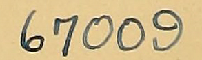
Although Pénaud recognized that, theoretically, two screws are necessary in an aerial propeller, as the use of a single one tends to make the apparatus revolve on itself, he adopted the single screw on account of the greater simplicity of construction that it permitted. One of these little machines is shown as No. 11, Plates 1 and 2.
AB is a stem about 2.5 mm. in diameter and 50 cm. long. It is bent down at each end, with an offset which supports the rubber and the shaft of the screw to which it is hooked. The screw HH1 is 21 cm. in diameter, and has two blades made of stiff paper; two are preferable, among other reasons, because they can be made so that the machine will lie flat when it strikes in its descent. About the middle of AB there is a “wing” surface DC, 45 cm. long and 11 cm. broad, the ends C and D being raised and a little curved. In front of the screw is the horizontal rudder GK having a shape like that of the first surface, with its ends also turned up, and inclined at a small negative angle with this wing surface. Along its center is a small fin-like vertical rudder that steers the device laterally, like the rudder of a ship.
The approximately, but not exactly, horizontal rudder serves to hold the device in horizontal flight, and its operation can best be understood from the side elevation. Let CD be the wing plane set nearly in the line of the stem, which stem it is desired to maintain, in flying, at a small positive angle, α, with the horizon, α being so chosen that the tendency upward given by it will just counteract the action of gravity. The weight of the aeroplane, combined with the resistance due to the reaction of the air caused by its advance would, under these conditions, just keep it moving onward in a horizontal line, if there were no disturbance of the conditions. There is, however, in the wing no power of self-restoration to the horizontal if these conditions are disturbed. But such a power resides in the rudder GK, which is not set parallel to the wing, but at a negative angle (α1) with it equal to the positive angle of the wing with the horizon. It is obvious that, in horizontal flight, the rudder, being set at this angle, presents its edge to the wind of advance and consequently offers a minimum resistance as long as the flight is horizontal. If, however, for any reason the head drops down, the rear edge of the rudder is raised, and it is at once subjected to the action of the air upon its upper surface, which has a tendency to lower the rear of the machine and to restore horizontality. Should the head rise, the lower [p009] surface of the rudder is subjected to the impact of the air, the rear end is raised, and horizontality again attained. In addition to this, Pénaud appears to have contemplated giving the rudder-stem a certain elasticity, and in this shape it is perhaps as effective a control as art could devise with such simple means.
Of the flight of his little machine, thus directed, Pénaud says:
“If the screw be turned on itself 240 times and the whole left free in a horizontal position, it will first drop; then, upon attaining its speed, rise and perform a regular flight at 7 or 8 feet from the ground for a distance of about 40 metres, requiring about 11 seconds for its performance. Some have flown 60 metres and have remained in the air 13 seconds.12 The rudder controls the inclination to ascend or descend, causing oscillations in the flight. Finally the apparatus descends gently in an oblique line, remaining itself horizontal.”
The motive power is a twisted hank of fine rubber strips, which weighs 5 grammes out of a total of 16 grammes for the whole machine, whose center of gravity should be in advance of the center of surface CD, as will be demonstrated in another place. This device attracted little notice, and I was unfamiliar with it when I began my own first constructions at Allegheny, in 1887.
My own earliest models employed a light wooden frame with two propellers, which were each driven by a strand of twisted rubber.13 In later forms, the rubber was enclosed and the end strains taken up by the thinnest tin-plate tubes, or better still, paper tubes strengthened by shellac.
Little was known to me at that time as to the proper proportions between wing surface, weight and power; and while I at first sought to infer the relation between wing surface and weight from that of soaring birds, where it varies from 12 to 1 sq. ft. of wing surface to the pound, yet the ratio was successively increased in the earlier models, until it became 4 sq. ft. to 1 pound. It may be well to add, however, that the still later experiments with the steam-driven models, in which the supporting surface was approximately 2 sq. ft. to the pound, proved that the lack of ability of these early rubber-driven models to properly sustain themselves even with 4 sq. ft. of wing surface to the pound, was largely due to the fact that the wings themselves had not been stiff enough to prevent their being warped by the air pressure generated by their forward motion.
During the years I presently describe, these tentative constructions were [p010] renewed at intervals without any satisfactory result, though it became clear from repeated failures, that the motive power at command would not suffice, even for a few seconds’ flight for models of sufficient size to enable a real study to be made of the conditions necessary for successful flight.
In these earliest experiments everything had to be learned about the relative position of the center of gravity, and what I have called the center of pressure. In regard to the latter term, it might at first seem that since the upward pressure of the air is treated as concentrated at one point of the supporting surface, as the weight is at the center of gravity, this point should be always in the same position for the same supporting surface. This relation, however, is never constant. How paradoxical seems the statement that, if ab be such a supporting surface in the form of a plane of uniform thickness and weight, suspended at c (ac being somewhat greater than cb) and subjected to the pressure of a wind in the direction of the arrow, the pressure on the lesser arm cb will overpower that on the greater arm ac! We now know, however, that this must be so, and why, but as it was not known to the writer till determined by experiments published later in “Experiments in Aerodynamics,” all this was worked out by trial in the models.

It was also early seen that the surface of support could be advantageously divided into two, with one behind the other, or one over the other, and this was often, though not always, done in the models.
At the very beginning another difficulty was met which has proved a constant and ever-increasing one with larger models—the difficulty of launching them in the air. It is frequently proposed by those unfamiliar with this difficulty, to launch the aerodrome by placing it upon a platform car or upon the deck of a steamer, and running the car or boat at an increasing speed until the aerodrome, which is free to rise, is lifted by the wind of advance. But this is quite impracticable without means to prevent premature displacement, for the large surface and slight weight renders any model of considerable size unmanageable in the least wind, such as is always present in the open air. It is, therefore, necessary in any launching apparatus that the aerodrome be held rigidly until the very moment of release, and that instant and simultaneous release from the apparatus be made at all the sustaining points at the proper moment. [p011]
There is but a very partial analogy in this case to the launching of a ship, which is held to her ways by her great weight. Here, the “ship” is liable to rise from her ways or be turned over laterally at any instant, unless it is securely fastened to them in a manner to prevent its rising, but not to prevent its advancing.
The experiments with rubber-driven models commenced in April, 1887, at the Allegheny Observatory, were continued at intervals (partly there, but chiefly in Washington) for three or four years, during which time between thirty and forty independent models were constructed, which were so greatly altered in the course of experiment that more nearly one hundred models were in reality tried. The result of all this extended labor was wholly inconclusive, but as subsequent trials of other motors (such as compressed air, carbonic-acid gas, electric batteries, and the like) proved futile, and (before the steam engine) only the rubber gave results, however unsatisfactory, in actual flight, from which anything could be learned, I shall give some brief account of these experiments, which preceded and proved the necessity of using the steam engine, or other like energetic motor, even in experimental models.
An early attempt was made in April, 1887, with a model consisting of a frame formed of two wooden pieces, each about 1 metre long and 4 centimetres wide, made for lightness, of star-shaped section, braced with cross-pieces and carrying two long strips of rubber, each about 1 mm. thick, 30 mm. wide, 2 metres long, doubled, weighing 300 grammes. Each of these strips could be wound to about 300 turns, one end being made fast to the front of the frame, the other to the shaft of a four-bladed propeller 30 cm. in diameter. The wings were made of lightest pine frames, over which paper was stretched, and were double, one being superposed upon the other. Each was 15 cm. wide, and 120 cm. long. The distance between them was 12 cm. and the total surface a little more than 3600 sq. cm. (4 square feet). In flying, the rubber was so twisted that the propellers were run in opposite directions. The weight of the whole apparatus was not quite 1 kilogramme, or about 1 pound to 2 feet of sustaining surface, which proved to be entirely too great a weight for the power of support. When placed upon the whirling-table, it showed a tendency to soar at a speed of about ten miles an hour, but its own propellers were utterly insufficient to sustain it.
In this attempt, which was useful only in showing how much was to be learned of practical conditions, the primary difficulty lay in making the model light enough and sufficiently strong to support its power. This difficulty continued to be fundamental through every later form; but besides this, the adjustment of the center of gravity to the center of pressure of the wings, the disposition of the wings themselves, the size of the propellers, the inclination and number of their blades, and a great number of other details, presented themselves for examination. [p012] Even in the first model, the difficulty of launching the machine or giving it the necessary preliminary impulse was disclosed—a difficulty which may perhaps not appear serious to the reader, but which in fact required years of experiment to remove.
By June, 1887 two other models, embodying various changes that had suggested themselves, had been constructed. Each of these had a single propeller (one an 1812-inch propeller with eight adjustable blades, the other a 24-inch propeller with four adjustable blades) and was sustained by two pairs of curved wings 4 feet 7 inches long. It is, however, unnecessary to dwell further on these details, since these models also proved altogether too heavy in relation to their power, and neither of them ever made an actual flight.
At this period my time became so fully occupied with the experiments in aerodynamics (which are not here in question) that during the next two years little additional was done in making direct investigations in flight.
In June, 1889, however, new rubber-driven models were made in which the wooden frames were replaced by tubes of light metal, which, however, were still too heavy, and these subsequently by tubes of paper covered with shellac, which proved to be the lightest and best material in proportion to its strength that had been found. The twisted rubber was carried within these tubes, which were made just strong enough to withstand the end-strain it produced. The front end of the rubber being made fast to an extremity of the tube, the other end was attached directly to the shaft of the propeller, which in the early models was still supplied with four blades.
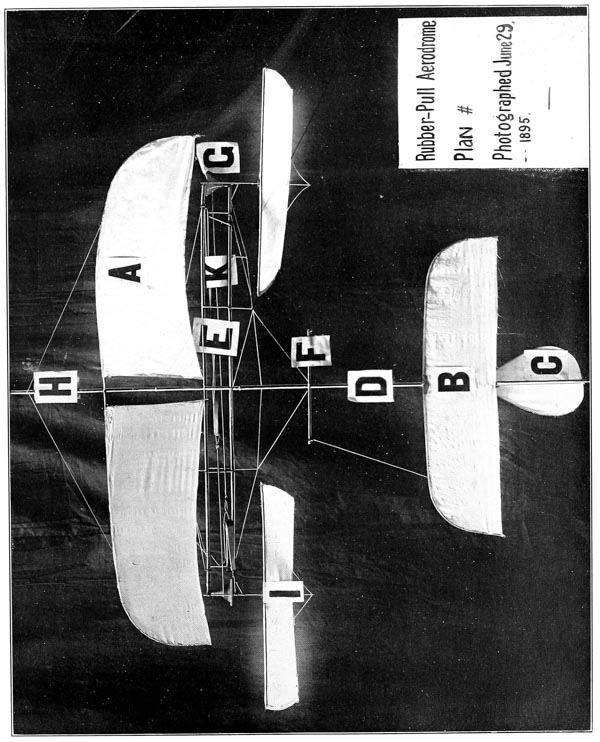
A detailed description of one of these early models, No. 26, shown in Plates 1 and 4, follows:
In each of the two tubes of paper, stiffened with shellac, which form a part of the framing, is mounted a hank of twisted rubber, which connects with a propeller at the rear. There are two pairs of wings, superposed and inclined at an angle, the one above, the other below the frame. A light stem connected with the frame bears a triangular Pénaud tail and rudder.
| Length of model | 105 | cm. |
| Spread of wings | 83 |  |
| Width of upper wings | 14 | |
| Width of lower wings | 19 | |
| Diameter of propeller | 29 | |
| Area of upper wings | 1134 | sq. cm. |
| Area of lower wings | 1548 | |
| Area of tail | 144 | |
| Weight of wings | 51 | grammes |
| Weight of tail | 7 | |
| Weight of frame | 38 | |
| Weight of wheels | 20 | |
| Weight of rubber (.09 pound) | 40 | |
| Total weight | 156 | |
| No. of turns of rubber | 100 | |
| Time of running down | 8 | seconds |
| Horse-power from preceding data | 0.001 | HP |
The aerodromes made at this time were too heavy, as well as too large, to be easily launched by hand, and it was not until 1891 that the first one was constructed light enough to actually fly. This first flight was obtained from the north window of the dome of the Allegheny Observatory, on March 28, 1891, and imperfect as it was, served to show that the proper balancing of the aerodrome which would bring the center of gravity under the center of pressure, so as to give a horizontal flight, had yet to be obtained.
From this time on until 1893, experiments continued to be made with rubber-driven models, of which, as has been stated, nearly 40 were constructed, some with two propellers, some with one; some with one propeller in front and one behind; some with plane, some with curved, wings; some with single, some with superposed, wings; some with two pairs of wings, one preceding and one following; some with the Pénaud tail; and some with other forms. A few of these early forms are indicated on the accompanying Plates 1 to 4, but it does not seem necessary to go into the details of their construction.
No. 11 with which an early flight was made, closely resembles the Pénaud model.
No. 13 has two propellers, one in front and one behind, with a single wing.
No. 14 has two propellers, nearly side by side, but one slightly in advance, with a single wing and a flat horizontal tail.
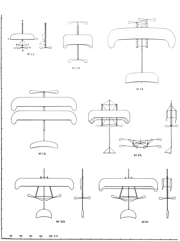
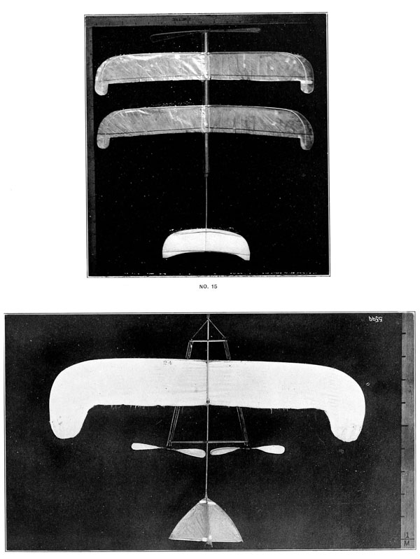
No. 15 has one leading propeller and two broad wings, placed one behind the other.
No. 30 has the propeller shafts at an angle, and one pair of wings.
No. 31 has the propeller shafts at an angle, and two pairs of wings superposed.
The wings in general were flat, but in some cases curved. The rubber was usually wound to about 100 turns, and trouble continually arose from its “kinking” and unequal unwinding, which often caused most erratic flights.
It is sufficient to say of these that, rude as they were, much was learned from them about the condition of the machines in free air, which could never be learned from the whirling-table or other constrained flight.
The advantages and also the dangers of curved wings as compared with plane ones, were shown, and the general disposition which would secure an even balance, was ascertained; but all this was done with extreme difficulty, since the brief flights were full of anomalies, arising from the imperfect conditions of observation. For instance, the motor power was apparently exhausted more rapidly when the propellers were allowed to turn with the model at rest, than when it was in motion, though in theory, in the latter case more power would seem to be expended and a greater speed of revolution obtained in a given time. The longest flights obtainable did not exceed 6 or 8 seconds in time, nor 80 to 100 feet in distance, and were not only so brief, but, owing to the spasmodic action of the rubber and other causes, so irregular, that it was extremely difficult to obtain even the imperfect results which were actually deduced from them. [p014]
The following rules and symbols were adopted for determining the relative position of points on the aerodrome, some of them during 1891, and some of them since. All are given here for convenience of reference, though their chief application is to the larger steam aerodromes described later. Those which immediately follow were meant to give some of the notation of descriptive geometry in untechnical language for the use of the workmen employed. Let X, Y and Z be three lines at right angles to each other, and passing through the same point in space, O, lying at any convenient distance above the floor of the work-shop. The line X lies North and South; the line Y lies East and West, and the line Z points to the zenith. Now place the aerodrome on the floor so that its principal axis lies horizontally in the plane XZ, with its head pointing North, and in such a position that a line passing through the center of the propellers shall coincide with the line Y.

When measurements are made on or parallel to the line X, the point of intersection O will be marked 1500 centimetres, and distances toward the South will be less than, and distances toward the North greater than 1500 centimetres.
When measurements are made on or parallel to the line Z, the point O will be considered to be marked 2500 centimetres, and distances above will be greater than, and distances below will be less than 2500 centimetres. [p015]
Lastly, when measurements are made on or parallel to the line Y, the point O will be marked 3500 centimetres, and distances toward the East will be greater than, and distances toward the West will be less than 3500 centimetres. Measurements in these latter directions will be comparatively infrequent because the center of gravity and center of pressure both lie in the plane XZ.
In the figure the point T in the tail, if 15 centimetres to the South of O, would be graduated 1485 centimetres. A weight (W) 25 centimetres below the axis, would be graduated 2475 centimetres. A point 50 centimetres above the axis would be graduated 2550 centimetres, etc.
CG represents the Center of Gravity of the aerodrome, or (with subscript letters) of any specially designated part, or with reference to some indicated condition.
CG1 CG2 represent the Center of Gravity as referred to the first, or horizontal, and to the second, or vertical plane, respectively.
CP represents the Center of Pressure14 of the whole aerodrome, or (with a subscript) of any specially designated part.
CF represents the Center of Figure of the aerodrome, or of any specially designated part.
Subscripts:
“A” represents the total area of the supporting surface; “a” represents the total area of the tail; HP represents the horse-power by Prony brake measurement. “Horse-power by formula” is given by Maxim’s formula:15
| HP = | rev. × diam. of propeller × pitch × thrust | . |
| 33,000 |
(This formula was not in use at the time of the rubber-motor experiments, for which the thrust was not taken. It appears to assume the conditions where the screws from a fixed position move a mass of still air, are the same as those of free flight. Its results, however, are in better agreement with experiment than might be anticipated.)
“Flying-weight” means everything borne in actual flight, including fuel and water. [p016]
Remembering that the principal object of all these experiments is to be able to predict that setting of the wings and tail with reference to the center of gravity which will secure horizontal flight, we must understand that in the following tables (see No. 30) the figures CPm = 1516.5 cm. mean a prediction that the center of pressure of the sustaining surfaces in motion (CPm) is to be found in a certain position 1516.5; that is, 16.5 cm. in advance of the line joining the propeller shafts. This prediction has been made by means of previous calculation joined with previous experimental adjustment. We know in a rough way where the CP will fall on the wings when they are exposed independently if flat, and at a certain angle, and where it will fall on the tail. From these, we can find where the resulting CP of the whole sustaining surface will be.
It would seem that when we have obtained the center of gravity by a simple experiment, we have only to slide the wings or tail forward and back until the (calculated) center of pressure falls over this observed center of gravity. But in the very act of so adjusting the wings and tail, the center of gravity is itself altered, and the operation has to be several times repeated in order to get the two values (the center of pressure and center of gravity) as near each other as they are found in the above-mentioned table, our object being to predict the position which will make the actual flight itself horizontal. How far this result has been obtained, experiment in actual flight alone can show, and from a comparison of the prediction with the results of observation, we endeavor to improve the formula.
The difficulties of these long-continued early experiments were enhanced by the ever-present difficulty which continued through later ones, that it was almost impossible to build the model light enough to enable it to fly, and at the same time strong enough to withstand the strains which flight imposed upon it. The models were broken up by their falls after a few flights, and had to be continually renewed, while owing to the slightness of their construction, the conditions of observation could not be exactly repeated; and these flights themselves, as has already been stated, were so brief in time (usually less than six seconds), so limited in extent (usually less than twenty metres), and so wholly capricious and erratic, owing to the nature of the rubber motor and other causes, that very many experiments were insufficient to eliminate these causes of mal-observation.
It is not necessary to take the reader through many of them, but not to pass over altogether a labor which was so great in proportion to the results, but whose results, such as they were, were the foundation of all after knowledge, I will, as illustrations, take from an almost unlimited mass of such material the observations of November 20, 1891, which were conducted with Model No. 30 with a single pair of wings, shown in Plate 1, and with another one, No. 31, also shown [p018] in Plate 1, with superposed wings, which was used for the purpose of comparison. S. P. Langley was the observer, the place of observation the larger upper hall of the Smithsonian building, at Washington, the time being taken by a stop-watch, and the distance by a scale laid down upon the floor. The models were in every case held by an assistant and launched by hand, being thrown off with a slight initial velocity. In the case of No. 30, the preliminary calculation of the position of the center of pressure had been made by the process already described; the center of gravity, with reference to the horizontal plane, was determined by simply suspending the whole by a cord.


OBSERVATION OF NOVEMBER 20, 1891. | ||||||||
| OBSERVER, S.P.L. | LOCALITY, UPPER HALL, SMITHSONIAN BUILDING. | |||||||
| No. 30. Single wings. |
No. 31. Superposed wings. | |||||||
|---|---|---|---|---|---|---|---|---|
| CPm | 1516.5 | cm. | ||||||
| CG1 | 1515 | 1517 | cm. | |||||
| CFw | 1528 | cm. | ||||||
| Length (without fender) | 120 | cm. = | 3.94 | ft. | 120 | cm. = | 3.94 | ft. |
| Width over wing tips | 120 | cm. = | 3.94 | ft. | 120 | cm. = | 3.94 | ft. |
| Weight of rubber (72 grammes in each tube) | 144 | gr. = | 0.32 | lbs. | 144 | gr. = | 0.32 | lbs. |
| Total flying weight (including tail) | 432 | gr. = | 0.95 | lbs. | 506 | gr. = | 1.11 | lbs. |
| Turns of rubber | 30 | 30 | ||||||
| Diameter of propellers | 37 | cm. = | 1.21 | ft. | 37 | cm. = | 1.21 | ft. |
| Width of propellers | 7 | cm. = | 0.23 | ft. | 7 | cm. = | 0.23 | ft. |
| Pitch of propellers | 50 | cm. = | 1.64 | ft. | 50 | cm. = | 1.64 | ft. |
| Area of wings (each 992 sq.cm.) | 1984 | sq.cm.= | 2.13 | sq.ft. | Each pair 1984 sq.cm.= 2.13 sq.ft. Total 3968 sq.cm.= 4.26 sq.ft. | |||
| Area of tail | 373 | sq.cm.= | 0.40 | sq.ft. | 373 | sq.cm.= | 0.40 | sq.ft. |
Area of wings and tail in No. 30, 2357 sq. cm. = 2.53 sq. ft. 2.53 sq. ft. ÷ .95 = 2.7. Therefore, there are 2.7 or nearly 3 square feet of sustaining area to the pound. | ||||||||
| Nov. 20, 1891. | ||
| Flight. | Aerodrome. | Results. |
|---|---|---|
| 1 | No. 30 | With 30 turns of the rubber, flew low through 10 metres. |
| 2 | No. 30 | Flew heavily through 12 metres. |
| 3 | No. 31 | Flew high and turned to left; distance not noted. |
| 4 | No. 31 | The right wing having been weighted (to depress it and correct the tendency to turn to the left), model flew high, but the rubber ran down when it had obtained a flight of 10 metres. |
| 5 | No. 31 | The wings were moved backward until the CP stood at 1493. The model still turned to the left; flight lasted three and a-half seconds; distance not noted. |
| 6 | No. 31 | Vertical tail was adjusted so as to further increase the tendency to go to the right. In spite of all this, the model turned sharply to the left, flying with a nearly horizontal motion; time of flight not noted; distance not noted. |
| 7 | No. 30 | Straight horizontal flight; time three and three-fifth seconds, when rubber ran down; distance 13 metres. |
| 8 | No. 30 | Straight flight as before; time two and four-fifth seconds; distance 13 metres. |
| 9 | No. 30 | With a curved wing in the same position as the flat wing had previously occupied, model flew up and struck the ceiling (nearly 30 feet high), turning to right, with a flight whose curtate length was 10 metres. |
| 10 | No. 30 | Wing having been carried back 5 centimetres, model still flew up, but not so high, and still turned to the right. |
| 11 | No. 30 | Wings carried back 5 centimetres more; model still flew high; time two and two-fifths seconds; distance 13 metres. |
| 12 | No. 30 | Wings carried back 4 centimetres more; model still flew high during a flight of 13 metres. |
The observations now ceased, owing to the breaking up of the model. | ||
The objects of these experiments, as of every other, were to find the practical conditions of equilibrium and of horizontal flight, and to compare the calculated with the observed positions of the center of pressure. They enable us to make a comparison of the performances given by earlier ones with a light rubber motor, with the relatively heavy motors used to-day, as well as a comparison of single flat, single curved, and superposed flat wings.
The average time of the running down of the rubber in flight was something like three seconds, while the average time of its running down when standing still was but one and a half seconds. It might have been expected from theory that it would take longer to run down when stationary, than in flight, and this was one of the many anomalies observed, whose explanation was found later in the inevitable defects of such apparatus.
The immediate inferences from the day’s work were:
1. That the calculated position of the CP at rest, as related to the CG, is trustworthy only in the case of the plane wing.
2. The formula altogether failed with the curved wing, for which the CP had to be carried indefinitely further backward.
On comparing the previous flights of November 14, with these, it seems that with the old rubber motor of 35 grammes and 50 turns, the single wing, either plane or curved, is altogether inferior to the double wing; while with the increased motor power of this day, the single wing, whether plane or curved, seems to be as good as the double wing. It also seems that the curved wing was rather more efficient than the plane one.
The weight of the rubber in each tube was 72 grammes, or 0.16 pounds; mean speed of flight in horizontal distance 412 metres (about 15 feet) per second.16
From experiments already referred to, there were found available 300 foot-pounds of energy in a pound of rubber as employed, and in 0.16 of a pound, 48 foot-pounds of energy were used; 4833,000 or 0.00145 = the horse-power exerted in [p019] one minute, but as the power was in fact expended in 1/20 of that time we have 20 × 0.00145 = 0.029; that is, during the brief flight, about 0.03 of a horse-power was exerted, and this sustained a total weight of only about a pound.
In comparing this flight with the ideal conditions of horizontal flight in “Aerodynamics,” it will be remembered that this model’s flight was so irregular and so far from horizontal, that in one case it flew up and struck the lofty ceiling. The angle with the horizon is, of course, so variable as to be practically unknown, and therefore no direct comparison can be instituted with the data given on page 107 of “Experiments in Aerodynamics,” but we find from these that at the lowest speed there given of about 35 feet per second, 0.03 of a horse-power exerted for three seconds would carry nearly one pound through a distance of somewhat over 100 feet in horizontal flight.
The number of turns of the propellers multiplied by the pitch corresponds to a flight of about 16 metres, while the mean actual flight was about 12. It is probable, however, that there was really more slip than this part of the observation would indicate. It was also observed that there seemed to be very little additional compensatory gain in the steering of No. 30 for the weight of the long rudder-tail it carried. It may be remarked that in subsequent observations the superiority of the curved wing in lifting power was confirmed, though it was found more liable to accident than the flatter one, tending to turn the model over unless it was very carefully adjusted.
It may also be observed that these and subsequent observations show, as might have been anticipated, that as the motor power increased, the necessary wing surface diminished, but that it was in general an easier and more efficient employment of power to carry a surface of four feet sustaining area to the pound than one of three, while one of two feet to the pound was nearly the limit that could be used with the rubber motor.17
It may be remarked that the flights this day, reckoned in horizontal distance, were exceptionally short, but that the best flights at other times obtained with these models (30 and 31) did not exceed 25 metres. Such observations were continued in hundreds of trials, without any much more conclusive results. [p020]
The final results, then, of the observations with rubber-driven models (which were commenced as early as 1887, continued actively through the greater portion of the year 1891 and resumed, as will be seen later, even as late as 1895), were not such as to give information proportioned to their trouble and cost, and it was decided to commence experiments with a steam-driven aerodrome on a large scale.
In the introductory chapter to “Experiments in Aerodynamics,” it was asserted that
“These researches have led to the result that mechanical sustentation of heavy bodies in the air, combined with very great speeds, is not only possible, but within the reach of mechanical means we actually possess.”
It was, however, necessary to make a proper selection in order to secure that source of power which is best adapted to the requirements of mechanical flight. Pénaud had used india rubber as the cheapest and at the same time the most available motor for the toys with which he was experimenting, but when models were constructed that were heavier than anything made prior to 1887, it appeared, after the exhaustive trials with rubber referred to in the preceding chapter, that something which could give longer and steadier flights must be used as a motor, even for the preliminary trials, and the construction of the large steam-driven model known as No. 0, and elsewhere described, was begun. Even before the completion of this, the probability of its failure grew so strong that experiments were commenced with other motors, which it was hoped might be consistent with a lighter construction.
These experiments which commenced in the spring of 1892 and continued for nearly a twelvemonth, were made upon the use of compressed air, carbonic-acid gas, electricity in primary and storage batteries, and numerous other contrivances, with the result that the steam engine was finally returned to, as being the only one that gave any promise of immediate success in supporting a machine which would teach the conditions of flight by actual trial, though it may be added that the gas engine which was not tried at this time on account of engineering difficulties, was regarded from the first as being the best in theory and likely to be ultimately resorted to. All others were fundamentally too heavy, and weight was always the greatest enemy.
It is the purpose of this chapter to pass in brief review the work that was done and the amount of energy that was obtained with these several types of motors, as well as the obstacles which they presented to practical application upon working aerodromes.
India rubber is the source of power to which the designer of a working model naturally turns, where it is desirable that it shall be, above all, light and free from the necessity of using complicated mechanism. Rubber motors were, [p022] therefore, used on all of the earlier models, and served as the basis of calculations made to determine the amount of power that would be required to propel aerodromes with other sources of energy.
Some of the disadvantages inherent in the use of rubber are at once apparent, such as the limited time during which its action is available, the small total amount of power, and the variability in the amount of power put forth in a unit of time between the moment of release and the exhaustion of the power. In addition, serious, though less obvious difficulties, present themselves in practice.
There are two ways in which rubber can be used; one by twisting a hank of strands, and, while one end is held fast, allowing the other to revolve; the other, by a direct longitudinal stretching of the rubber, one end being held fast and the other attached to the moving parts of the mechanism. The former method was adopted by Pénaud, and was also used in all of my early constructions, but while it is most convenient and simple in its (theoretical) application, it has, in addition to the above drawbacks, that of knotting or kinking, when wound too many turns, in such a way as to cause friction on any containing tube not made impracticably large, and also that of unwinding so irregularly as to make the result of one experiment useless for comparison with another.
In 1895, some experiments were made in which the latter method was used, but this was found to involve an almost impracticable weight, because of the frame (which must be strong enough to withstand the end pull of the rubber) and the mechanism needed to convert the pull into a movement of rotation.
As the power put forth in a unit of time varies, so there is a corresponding variation according to the original tension to which the rubber is subjected. Thus in some experiments made in 1889 with a six-bladed propeller 18.8 inches in diameter, driven by a rubber spring 1.3 inches wide, 0.12 inch thick and 3 feet long, doubled, and weighing 0.38 pound, the following results were obtained:
| Number of twists of rubber | 50 | 75 | 100 | |||
| Time required to run down | 7 | sec. | 10 | sec. | 12 | sec. |
| Foot-pounds developed | 37.5 | 63.0 | 124.6 | |||
| Foot-pounds developed per min. | 321.4 | 378.0 | 623.0 | |||
| Horse-power developed | 0.0097 | 0.0115 | 0.0189 |
Thus we see that, with twice the number of turns, more than three times the amount of work was done and almost twice the amount of power developed, giving as a maximum for this particular instance 328 foot-pounds per pound of rubber.
The usual method of employing the twisted rubber was to use a number of fine strands formed into a hank looped at each end. One of these hanks, consisting of 162 single or 81 double strands of rubber, and weighing 73 grammes, when given 51 turns developed 55 foot-pounds of work, which was put out in 4 seconds. This corresponds to 0.01 horse-power per minute for one pound of rubber. [p023]
The results of a large number of tests show that one pound of twisted rubber can put forth from 450 to 500 or more foot-pounds of work, but at the cost of an overstrain, and that a safe working factor can hardly be taken at higher than 300 foot-pounds, if we are to avoid the “fatigue” of the rubber, which otherwise becomes as marked as that of a human muscle.
While twisting is an exceedingly convenient form of application of the resilience of rubber to the turning of propelling wheels, the direct stretch is, as has been remarked, much more efficient in foot-pounds of energy developed by the same weight of rubber. It was found that rubber could not, without undue “fatigue,” be stretched to more than four and a half times its original length, though experiments were made to determine the amount of work that a rubber band, weighing one pound, was capable of doing, the stretching being carried to seven times its original length. The results varied with the rubber used and the conditions of temperature under which the experiments were tried, ranging from 1543 foot-pounds to 2600 foot-pounds. The tests led to the conclusion that, for average working, one pound of rubber so stretched, is capable of doing 2000 foot-pounds of work, but, owing to the weight of the supporting frame and of the mechanism, this result can be obtained only under conditions impracticable for a flying machine. In the more practicable twisted form it furnishes, as has been said, less than a fifth of that amount.
The conclusions reached from these experiments are:
1. The length of the unstretched rubber remaining the same, the sustaining power will be directly proportional to the weight of rubber;
2. With a given weight of rubber, the end strain is inversely proportional to the length of the unstretched rubber;
3. With a given weight of rubber, the work done is constant, whatever the form; hence if we let w = the work in foot-pounds, g = the weight of the rubber in pounds, and k = a constant taken at 2000 as given above, we have
This is for an extension of seven units of length, so that for a unit of extension we would have approximately
which for four units of extension corresponds very closely to the 1300 foot-pounds which Pénaud claims to have obtained.
4. The end strain varies with the cross-section for a given unit of extension.
These results can lead to but one conclusion; that for the development of the same amount of power when that amount shall be 1 horse-power or more, rubber weighs enormously more than a steam engine, besides being less reliable [p024] for a sustained effort, and, therefore, cannot be used for propelling aerodromes intended for a flight that is to be prolonged beyond a few seconds.18
It may be desirable to present a tabular view of the theoretical energy of available motors, which it will be noticed is a wholly different thing from the results obtained in practice. Thus, we represent the weight of rubber only, without regard to the weight of the frame required to hold it. In the steam engine, we consider the theoretical efficiency per pound of fuel, without regarding the enormous waste of weight in water in such small engines as these, or the weight of the engine itself. We treat the hot-water engine in like manner, and in regard to carbonic acid and compressed air, we take no note of the weight of the containing vessel, or of the cylinders and moving parts. In the same way we have the theoretical potency of electricity in primary and storage batteries, without counting the weight of the necessary electromotors; and of the inertia-engine without discussing that of the mechanism needed to transmit its power.
Foot-pounds of energy in one pound of
| Gasoline | 15,625,280 |
| Alcohol | 9,721,806 |
| Gunpowder | 960,000 |
| Hot water, under pressure of 100 atmospheres | 383,712 |
| Air, under pressure of 100 atmospheres, isothermal expansion | 120,584 |
| Liquid carbonic acid, at temperature of 30° and pressure of 100 atmospheres | 78,800 |
| Electric battery; short-lived, thin walled; chromic acid and platinum | 75,000 |
| Steel ring, 8 inches in diameter, at speed of 3000 turns per minute | 19,000 |
| Storage battery | 17,560 |
| Rubber, pulled | 2,000 |
| Rubber, twisted | 300 |
It may be interesting to consider next, in even a roughly approximate way, what may be expected from these various sources of energy in practice.
The steam engine on a small scale, and under the actual restrictions of the model, must necessarily be extremely wasteful of power. If we suppose it to realize 2 per cent of the theoretical energy contained in the fuel, we shall be assuming more than was actually obtained. The energy of the fuel cannot be obtained at all, of course, without boiler and engine, whose weight, for the purpose of the following calculation, must be added to that of the fuel; and if we suppose the weight of the boilers, engines and water, for a single minute’s flight, to be collectively ten pounds, we shall take an optimistic view of what may be expected under ordinary conditions. We have in this view 1/500 of the [p025] theoretical capacity possibly realizable under such conditions, but if we take 1/1000 we shall probably be nearer the mark. Even in this case we have, when using gasoline as fuel, 15,625 foot-pounds per minute, or nearly 0.50 horse-power, as against .0091 horse-power in the case of the rubber, so that even with this waste and with the weight of the engines necessary for a single minute’s service, the unit weight of fuel employed in the steam engine gives 55 times the result we get with rubber.


With alcohol we have about 23 the result that is furnished by gasoline, since nearly the same boiler and engine will be used in either case. Certain difficulties which at first appeared to be attendant on the use of gasoline on a small scale induced me to make the initial experiments with alcohol. This was continued because of its convenience during a considerable time, but it was finally displaced in favor of gasoline, not so much on account of the superior theoretical efficiency of the latter, as for certain practical advantages, such as its maintaining its flame while exposed to wind, and like considerations.
Although there are other explosives possessing a much greater energy in proportion to their weight than gunpowder, this is the only one which could be considered in relation to the present work, and the conclusion was finally reached that it involved so great a weight in the containing apparatus and so much experiment, that, although the simplicity of its action is in its favor where crude means are necessary, experiments with it had better be deferred until other things had been tried.
A great deal of attention was given to the hot-water engine, but it was never put to practical use in the construction of an aerodrome, partly on account of the necessary weight of a sufficiently strong containing vessel.
Compressed air, like the other possible sources of power, was investigated, but calculations from well-authenticated data showed that this system of propelling engines would probably be inadequate to sustain even the models in long flights. As the chief difficulty lies in the weight, not of the air, but of the containing vessel, numerous experiments were made in the construction of one at once strong and light. The best result obtained was with a steel tube 40 mm. in diameter, 428 mm. in length, closed at the ends by heads united by wires, which safely contained 538 cubic cm. of air at an initial pressure of 100 atmospheres for a weight of 521 grammes. [p026]
If we suppose this to be used, by means of a proper reducing valve, at a mean pressure of 100 pounds, for such an engine as that of Aerodrome No. 5, which takes 60 cubic cm. of air at each stroke, we find that (if we take no account of the loss by expansion) we have 18,329 foot-pounds of energy available, which on the engine described will give 302 revolutions of the propellers.
There are such limits of weight, and the engines must be driven at such high speeds, that the increased economy that might be obtained by re-heating the air would be out of the question. The principal object in using it would have been the avoidance of fire upon the aerodrome, and the expansion of the unheated air would probably have caused trouble with freezing, while the use of hot (i. e. superheated) water was impracticable. So when, after a careful computation, it was found that, having regard to the weight of the containing vessel, only enough compressed air could be stored at 72 atmospheres and used at 4, to run a pair of engines with cylinders 0.9 inch in diameter by 1.6 inches stroke, at a speed of 1200 revolutions per minute for 20 seconds, all further consideration of its adaptation to the immediate purpose was definitely abandoned. This course, however, was not taken until after a model aerodrome for using compressed air had been designed and partially built. Then, after due consideration, it was decided to make the test with carbonic-acid gas instead.
The gas engine possesses great theoretical advantages. At the time of these experiments, the gas engine most available for the special purposes of the models was one driven by air drawn through gasoline. As the builders could not agree to reduce the weight of a one horse-power engine more than one-half of the then usual model, and as the weight of the standard engine was 470 pounds, it was obvious that to reduce this weight to the limit of less than 3 pounds was impracticable under the existing conditions, and all consideration of the use of gas was abandoned provisionally, although a gasoline engine of elementary simplicity was designed but never built. I purposed, however, to return to this attractive form of power if I were ever able to realize its theoretical advantages on the larger scale which would be desirable.
As it was not intended to build the model aerodromes for a long flight, it was thought that the electric motor driven by a primary or storage battery might possibly be utilized. It therefore occurred to me that a battery might be constructed to give great power in proportion to its weight on condition of being short-lived, and that in this form a battery might perhaps advantageously take the place of the dangerous compressed-air tubes that were at the time (1893) [p027] under consideration for driving the models. I assumed that the longest flight of the model would be less than five minutes. Any weight of battery, then, that the model carried in consumable parts lasting beyond this five minutes would be lost, and hence it was proposed to build a battery, the whole active life of which would be comprised in this time, to actuate a motor or motors driving one or two propellers.
According to Daniell, when energy is stored in secondary batteries, over 300,000 megergs per kilogramme of weight can be recovered and utilized if freshly charged.
In a zinc and copper primary battery with sulphuric acid and water, one kilogramme of zinc, oxidized, furnishes at least 1200 calories as against 8000 for one kilogramme of carbon, but it is stated that the zinc energy comes in so much more utilizable a form that the zinc, weight for weight, gives practically, that is in work, 40 per cent that of carbon. The kilogramme of carbon gives about 8000 heat units, each equal to 107 kilogrammetres, or about 6,176,000 foot-pounds. Of this, in light engines, from 5 to 10 per cent, or at least 308,800 foot-pounds, is utilized, and 25 of this, or about 124,000 foot-pounds, would seem to be what the kilogramme of zinc would give in actual work. But to form the battery, we must have a larger weight of fluid than of zinc, and something must be allowed for copper. If we suppose these to bring the weight up to 1 kilogramme, we might still hope to have 50,000 foot-pounds or 1.5 horse-power for one minute, or 0.3 horse-power for 5 minutes.
Storage batteries were offered with a capacity of .25 horse-power for 5 minutes per kilogramme, but according to Daniell one cannot expect to get more than 0.139 horse-power from a freshly charged battery of that weight for the same time.
The plan of constructing a battery of a long roll of extremely thin zinc or magnesium, winding it up with a narrower roll of copper or platinized silver, insulating the two metals and then pouring over enough acid to consume the major portion of the zinc in 5 minutes, was carefully considered, but the difficulties were so discouraging, that the work was not undertaken.
The lightest motors of 1 horse-power capacity of which any trace could be found weighed 25 pounds, and a prominent electrician stated that he would not attempt to construct one of that weight.
In trials with a 12 horse-power motor driving an 80 cm. propeller of 1.00 pitch-ratio, I apparently obtained a development of 0.56 indicated horse-power at 1265 revolutions; but at lower speeds when tried with the Prony brake, the brake horse-power fell to 0.10 at 546 revolutions, and even at 1650 revolutions [p028] it was but 0.262 indicated, with a brake horse-power of 0.144, or 55 per cent of that indicated.
With these results both of theoretical calculation and practical experiment, all thought of propelling the proposed aerodrome by electricity was necessarily abandoned.
At the first inception of the idea, it seemed that carbonic-acid gas would be the motive power best adapted for short flights. It can be obtained in the liquid form, is compact, gives off the gas at a uniform pressure dependent upon the temperature, and can be used in the ordinary steam engine without any essential modifications. The only provision that it seemed, in advance, necessary to make, was that of some sort of a heater between the reservoir of liquid and the engine, in order to prevent freezing, unless the liquid itself could be heated previous to launching.
The engines in which it was first intended to use carbonic acid were the little oscillating cylinder engines belonging to Aerodrome No. 1. The capacity of each cylinder was 21.2 cu. cm., so that 84.8 cu. cm. of gas would be required to turn the propellers one revolution when admitted for the full stroke, and 101,760 cubic cm. for 1200 revolutions. The density of the liquid at a temperature of 24° C. was taken as .72, and as 1 volume of liquid gives 180 volumes of gas at a pressure of 212 atmospheres, we have 101,760180 = 565 cu. cm. of liquid, or 407 grammes required for 1200 revolutions of the engines.
Thus, a theoretical calculation seemed to indicate that a kilogramme of liquid carbonic acid would be an ample supply for a run of two minutes. The experiments were, at first, somewhat encouraging. The speed and apparent power of the engines were sufficient for the purpose, but the length of time during which power could be obtained was limited.
In 1892, 415 grammes of carbonic acid drove the engines of Aerodrome No. 3 700 revolutions in 60 seconds, 900 in 75, and 1000 in 85 seconds, at the end of which time the gas was entirely expended. The diameter of these cylinders was 2.4 cm., the stroke of the pistons 7 cm., and the work done, that of driving a pair of 50 cm. propellers, when taken in comparison with the propeller tests detailed elsewhere, amounted to an effective horse-power of about 0.10 for the output of the engine.
The difficulties, however, that were experienced were those partially foreseen. The expansion of the gas made such serious inroads upon the latent heat of the liquid, that lumps of solid acid were formed in the reservoir, and could be heard rattling against the sides when the latter was shaken, while the expansion of the exhaust caused such a lowering of temperature at that point, that the [p029] pipes were soon covered with a thick layer of ice, and the free exit of the escaping gas was prevented.
Such difficulties are to be expected with this material, but here they were enhanced by the small scale of the construction and the constant demand for lightness. And it was found to be very hard to fill the small reservoirs intended to carry the supply for the engines. When they were screwed to the large case in which the liquid was received and the whole inverted, the small reservoir would be filled from one-third to one-half full, and nothing that could be done would force any more liquid to enter.
In view of these difficulties, and the objections to using a heater of any sort for the gas, as well as the absolute lack of success attendant upon the experiments of others who were attempting to use liquid CO2 as a motive power on a large scale elsewhere, experiments were at first temporarily and afterwards permanently abandoned.
The above experiments extended over nearly a year in time, chiefly during 1892, and involved the construction and use of the small aerodromes Nos. 1, 2, and 3, presently described.
In dealing with the development of the aerodrome, subsequent to the early rubber-driven models, the very considerable work done and the failures incurred with other types of motors than steam, have been briefly dealt with in the preceding chapter, but are scarcely mentioned here, as no attempts at long flights were ever successful with any other motor than steam, and no information was gained from any of the experiments made with compressed air, gas, carbonic acid, or electricity, that was of much value in the development of the successful steam machines.
In November, 1891, after the long and unsatisfactory experiments with rubber-driven models already referred to, and before most of the experiments with other available motors than steam had been made, I commenced the construction of the engines and the design of the hull of a steam-driven aerodrome, which was intended to supplement the experiments given in “Aerodynamics” by others made under the conditions of actual flight.
In designing this first aerodrome, here called No. 0, there was no precedent or example, and except for the purely theoretical conditions ascertained by the experiments described in “Aerodynamics,” everything was unknown. Next to nothing was known as to the size or form, as to the requisite strength, or as to the way of attaching the sustaining surfaces; almost nothing was known as to the weight permissible, and nothing as to the proper scale on which to build the aerodrome, even if the design had been obtained, while everything which related to the actual construction of boiler and engines working under such unprecedented conditions was yet to be determined by experiment.
The scale of the actual construction was adopted under the belief that it must be large enough to carry certain automatic steering apparatus which I had designed, and which possessed considerable weight. I decided that a flying machine if not large enough to carry a manager, should in the absence of a human directing intelligence, have some sort of automatic substitute for it, and be large enough to have the means of maintaining a long and steady flight, during which the problems (which the rubber-driven models so imperfectly answered) could be effectually solved.
When, in 1891, it was decided to attempt to build this steam aerodrome, the only engine that had been made up to that time with any claim to the lightness and power I was seeking, was the Stringfellow engine, exhibited at the Crystal Palace in London, in 1868, which it was then announced developed 1 horse-power [p031] for a total weight (boiler and engines) of 13 pounds. The original engine came into the possession of the Institution in 1889 as an historical curiosity, but on examination, it was at once evident that it never had developed, and never could develop the power that had been attributed to it, and probably not one-tenth so much.
With the results obtained on the whirling-table at Allegheny as a basis, a theoretical computation of the weight which 1 horse-power would cause to soar showed that, with a plane whose efficiency should be equal to that of a 30 × 4.8 inch plane set at an angle of 5° and moving at a speed of 34 miles an hour, 1 horse-power would support 120 pounds.19 With a smaller angle even better results could be obtained, but as the difficulties of guidance increase as the angle diminishes, I did not venture to aim at less than this. In this computation, no allowance was made for the fact that these results were obtained by a mechanism which forcibly maintained the supporting surface in the ideal condition of the best attainable angle of attack as if in perfect equilibrium, and above all in the equally ideal condition of perfectly horizontal flight.
Besides this, I had to consider in actual flight the air resistance due to the guy wires and hull, but after making an allowance of as much as three-quarters for these differences between the conditions of experiment and those of free flight, I hoped that 1 horse-power would serve to carry 30 pounds through the air if a supporting surface as large as 3 feet to the pound could be provided, and this was the basis of the construction which I will now describe.
The general form of this Aerodrome No. 0, without wings or propellers, is shown in the accompanying photograph in Plate 10. Its dimensions and its weights, as first designed, and as finally found necessary, are as follows:
| COMPARISON OF ESTIMATED AND ACTUAL WEIGHTS OF PARTS OF AERODROME “0”—IN POUNDS AND OUNCES. | ||||
| Estimated | Actual | |||
| lbs. | oz. | lbs. | oz. | |
| Engines | 4 | 0 | 4 | 1 |
| Boilers and Burners | 8 | 11 | 13 | 14 |
| Pumps and Attachments | 0 | 0 | 1 | 10 |
| Steering Apparatus | 0 | 6 | 0 | 0 |
| Frame of Hull and Braces, including bowsprit and tail tube | 7 | 7 | 8 | 11 |
| Oil tank covering and pipes | 0 | 0 | 0 | 13 |
| Shafts, ball bearings (2:1) and wooden propellers (1:7) | 1 | 14 | 3 | 8 |
| Wings (5:4) and guys (0:9) | 4 | 0 | 5 | 13 |
| Tail | 1 | 5 | 2 | 2 |
| Jacket at prow | 0 | 0 | 4 | 0 |
| Total without oil or water | 27 | 11 | 44 | 8 |
(The weights attained in the actual making were, as is seen, nearly double those first estimated, and this constant increase of weight under the exigencies of construction was a feature which could never be wholly eliminated.) [p032]
After studying various forms for the hull or body of the prospective aerodrome, I was led to adopt the lines which Nature has used in the mackerel as most advantageous so far as the resistance of the air was concerned, but it proved to be difficult in construction to make the lines of the bow materially different from those of the stern, and in this first model the figure was symmetrical throughout.
As I wish that my experience may be of benefit to the reader, even in its failures, I will add that I made the not unnatural mistake of building on the plan on which the hull of an ordinary ship is constructed; that is, making the hull support the projecting bowsprit and other parts. In the aerodrome, what corresponds to the bowsprit must project far in advance of the hull to sustain the front wings, and a like piece must project behind it to sustain the rear wings and the tail, or the supporting surfaces of whatever kind. The mistake of the construction lay in disjoining these two and connecting them indirectly by the insufficiently strong hull which supported them. This hull was formed of longitudinal U-shaped ribs of thin steel, which rested on rings made of an alloy of aluminum, which possessed the lightness of the latter metal with very considerable toughness, but which was finally unsatisfactory. I may say parenthetically that in none of the subsequent constructions has the lightness of aluminum been found to compensate for its very many disadvantages. The two rods, which were each 1 metre in length, were with difficulty kept rigorously in line, owing to the yielding of the constructionally weak hull. It would have been better, in fact, to have carried the rod straight through at any inconvenience to the disposition of the boilers and the engine.

I may add that the sustaining surfaces, which were to be nearly flat wings, composed of silk stretched from a steel tube with wooden attachments, were to [p033] have been carried on the front rod, but, as subsequent experience has shown, these wings would have been inadequate to the work, both from their insufficient size and their lack of rigidity.
The propellers, which were to be 80 cm. in diameter, 1.25 pitch-ratio, and which were expected to make from five to six hundred revolutions a minute, were carried on the end of long tubular shafts, not parallel, but making with each other an angle of 25 degrees, and united by gears near the bow of the vessel in the manner shown in Plate 10.
The first engines were of the oscillating type, with the piston-rod connected directly to the crank; were very light, and were unprovided with many of the usual fittings belonging to a steam engine, such as rod or piston packing; and their construction was crude in comparison with their successors. They were tested with the Prony brake and found to be deficient in power, for with a steam pressure of 80 pounds to the square inch, they ran at the rate of 1170 revolutions per minute, and developed only .363 horse-power. It soon became evident that they were too light for the work that it was intended that they should do, and steps were taken, even before the completion of these tests, for the construction of a pair of more powerful cylinders, which should also be provided with a special boiler for the generation of the steam. Acting upon the supposition, in a saving of steam, it was decided to work with compounded cylinders. As two propellers were to be used, they were each fitted with a distinct pair of cylinders working directly upon the shaft, but so connected by gearing that they were compelled to turn at the same rate of speed.
The cylinders were of the inverted oscillating type, like the first pair of engines, but, unlike them, they were single-acting. The dimensions were: diameter of high-pressure cylinder 1.25 inches; low pressure, 1.94 inches, with a common stroke of 2 inches, and with cranks set opposite to each other so that one cylinder was always at work. The cylinders were held at their upper ends by a strap passing around a hollow conical trunk, which served the double purpose of a support for the cylinders and an intermediate receiver between them. This receiver had a mean inside diameter of 1.25 inches, with a length of 4.75 inches, so that it had about twice the cubical capacity of the high-pressure cylinder, while the displacement of the low-pressure cylinder was about 2.5 times that of the high; ratios that would have given satisfactory results, perhaps, had the steam pressure and other conditions been favorable to the use of the compound principle in this place. There were no valves for the admission of the steam, for, inasmuch as the engines were single-acting, it was possible to make ports in the cylinder-head act as the admission and exhaust ports as the cylinder oscillated, and thus avoid the complication and weight of eccentric and valves. [p034]
These cylinders were set in a light frame at an angle of 25° with each other, or 12.5° with the median line of the aerodrome, and drove the long propeller shafts as shown in Plate 10, No. 0. At the extreme forward end of the crank-shafts there was a pair of intermeshing bevel gears which served to maintain the rate of revolution of the two propellers the same.

The boiler built for this work was a beehive-shaped arrangement of coils of pipe. It consisted at first, as shown in Fig. 3, of three double coils of 38-inch copper pipe coiled up in the shape of a truncated cone, carrying in the central portion a pear-shaped receiver into the upper portion of which the water circulating through the coils discharged. Each of these receivers was connected at the top with the bottom of a long cylindrical drum, with hemispherical ends, which formed a steam space from which supply for the engines was drawn. The lower ends of the coils were connected with an injection pipe supplying the water. Each “beehive” had 23 turns of tubing, and had a base of 7.5 inches and a top diameter of 6 inches, the steam drum being 2.5 inches in diameter. I may here say that in the selection of the general type of boiler for the work to be done, there was never any hesitation regarding the use of the water-tube variety. Their superiority for the quick generation of large volumes of steam had been so pronounced that nothing else seemed capable of competing with [p035] them in this respect, regardless of the absolute economy of fuel that might or might not be exhibited. Hence, to the end of my experiments nothing else was used.
Even before the “beehive” boiler was completed, I was anxious to ascertain what could be done with a coil of pipe with a stream of water circulating through it, as well as with various forms of burners, for I realized that the success of the apparatus depended not only upon getting an exceedingly effective heating surface, but also an equally effective flame to do the heating.
For fuel I naturally turned to the liquids as being more compact and readily regulated. Whether to use some of the more volatile hydrocarbons or alcohol, was still an unsolved problem, but my opinion at the time was that, on the limited scale of the model, better results could probably be obtained with alcohol.
In the experiments made with a coil preliminary to the trial of the “beehive” boiler, I tried a simple horizontal coil of 38-inch copper pipe into which two forked burners working on the Bunsen principle and using city illuminating gas, were thrust. The jets were about 12 inch apart. The arrangement primed so badly that the engines could not get rid of the entrained water, and would only make a few turns.
I then tried the same coil with two 1.25-inch drums in the inside and with five longitudinal water tubes at the bottom, beneath which were the same two forked burners used in the previous experiment. The coils were covered with a sheet of asbestos, and two round burners were added. This boiler would hold a steam pressure of about 15 pounds and run the engine slowly; but if the pressure were allowed to rise to 60 pounds, the engine would drive a 2-foot propeller of 18-inch pitch at the rate of about 650 turns per minute for from 80 to 90 seconds, while the steam ran down to 10 pounds, showing that this boiler, at least, was too small. This was further shown in a trial of the plain coil made in October, 1891; 6 pounds of water were evaporated in 32 minutes under a pressure of 60 pounds. This was at the rate of 11.25 pounds per hour, or, taking the U. S. Centennial standard of 30 pounds of evaporation per horse-power, gave an available output of less than 13 horse-power.
With these results before me, I decided to make a trial of the “beehive” principle upon a smaller scale than in the boiler designed for Aerodrome No. 0. I used a small boiler of which the inner coil consisted of 8 turns of 38-inch copper tube about 28 gauge thick, and the outer coil of 11 turns of 14-inch copper pipe. This gave 12 feet of 38-inch, and 16 feet of 14-inch tubing. The drum was of No. 27 gauge, hard planished copper. With this boiler consuming 6 oz. of fuel, 80.3 oz. of water were evaporated in 28 minutes, or at the rate of about 10.75 pounds per hour. As these coils contained but 2.22 square feet of heating surface, and as the three to be built would contain 3.7 square feet each, it was estimated the [p036] 10 square feet afforded by them could safely be depended upon to provide steam for a 1 horse-power engine. As far as fuel consumption was concerned, the rate of evaporation was about 15.6 pounds of water per pound of gasoline, all of which was satisfactory.
The burner originally designed for use in connection with the “beehive” boilers, consisted of a small tank in which a quantity of gasoline was placed, the space above being filled with compressed air. Rising from the bottom of this tank was a small pipe coiling back and down and ending in an upturned jet from which the gas generated in the coil would issue. The burner thus served to generate its own gas and act as a heater for the boilers at the same time.
In the construction of Aerodrome No. 0, four of the “beehive” coils were placed in a line fore and aft. The fuel tank was located immediately back of the rear coil and consisted of a copper cylinder 11 cm. in diameter and 9 cm. long. The engines were placed immediately in front of the coils, all the apparatus being enclosed in a light framing, as shown in the photograph (Plate 10).
Extending front and back from the hull were the tubes for supporting the wings and tail, each one metre in length. The cross-framing for carrying the propeller shafts was built of tubing 1.5 cm. diameter, and the shafts themselves were of the same size. The ribs of the hull were rings made of angle-irons measuring 1.50 × 1.75 cm., which were held in place longitudinally by five 0.7 cm. channel bars.
As it had been learned in the preliminary experiments with the model “beehive” boiler that the heated water would not of itself cause a sufficiently rapid circulation to be maintained through the tubes to prevent them from becoming red-hot, two circulating pumps were added for forcing the water through the coils of the two forward and two rear boilers respectively, the water being taken from the lower side of the drum and delivered into the bottom of the coils, which were united at that point for the purpose. A worm was placed upon each of the propeller shafts, just back of the engines, meshing in with a gear on a crank-shaft from which the pumps were driven. This shaft rotated at the rate of 1 to 24, so that for 1200 revolutions of the engine, it would make but 50, driving a single-acting plunger 1.2 cm. in diameter and 2 cm. stroke.
Apparently all was going well until I began to try the apparatus. First, there was a difficulty with the burner, which could not be made to give forth the relative amount of heat that had been obtained from the smaller model, and steam could not be maintained. With one “beehive” connected with the compound engine, and a 70 cm. propeller on the shaft, there were about 250 turns per minute for a space of about 50 seconds, in which time the steam would fall from 90 pounds to 25 pounds, and the engine would stop. Then, as we had no air-chamber on the pumps at the time, they would not drive the water through the coils. Subsequent experiments, however, showed that the boilers could be [p037] depended upon to supply the steam that the compound engines would require; but after the whole was completed, the weight, if nothing else, was prohibitory.
I had gone on from one thing to another, adding a little here and a little there, strengthening this part and that, until when the hull was finally completed with the engines and boilers in place, ready for the application of the wings, the weight of the whole was found (allowing 7 pounds for the weight of the wings and tail) to be almost exactly 45 pounds, and nearly 52 pounds with fuel and water. To this excessive weight would have to be added that of the propellers, and as the wings would necessarily have to be made very large in order to carry the machine, and as the difficulties of launching had still to be met, nothing was attempted in the way of field trials, and with great disappointment the decision was made in May, 1892 (wisely, as it subsequently appeared) to proceed no further with this special apparatus.
However, inasmuch as this aerodrome with its engines and boilers had been completed at considerable expense, it was decided to use the apparatus as far as it might be practicable, in order to learn what must be done to secure a greater amount of success in the future. The fundamental trouble was to get heat. In the first place there was trouble with the burners, for it seemed to be impossible to get one that would vaporize the gasoline in sufficient quantity to do the work, and various forms were successively tried.
All of the early part of 1892 was passed in trying to get the boilers to work at a steam pressure of 100 pounds per square inch. On account of the defects in the tubes and elsewhere this required much patient labor. The writer, even thus early, devised a plan of using a sort of aeolipile, which should actuate its own blast, but this had to be abandoned on account of the fact that the pear-shaped receivers would not stand the heat. This necessitated a number of experiments in the distillation of gas, in the course of which there was trouble with the pumps, and a continual series of breakages and leakages, so that the middle of April came before I had secured any further satisfaction than to demonstrate that possibly the boilers might have a capacity sufficient for the work laid out for them to do; but subsequent experiments showed that even in this I was mistaken, for it was only after additional jets had been put in between the coils that I succeeded in getting an effective horse-power of 0.43 out of the combination.
Finally, on the 14th of April, after having reduced the capacity of the pumps to the dimensions given above (for the stroke was originally 1.25 inch) I obtained the development of 1 full horse-power by the engine for 41 seconds, with a steam pressure of 100 pounds per square inch, and a rate of revolution of 720 per minute. But at the end of this brief period, the shafts sprung and the worm was thrown out of gear. [p038]
I pass over numerous other experiments, for their only result was to make it clear that the aerodrome, as it had been constructed, could not be made to work efficiently, even if its great weight had not served as a bar to its flight. It was, therefore, decided to proceed with the construction of another.
After the failure of the first steam-driven model No. 0, which has just been described, subsequent light models were constructed. These, three in number, made with a view to the employment of carbonic acid or compressed air, but also to the possible use of steam, are shown in Plate 10, Nos. 1, 2, 3; on the same scale as the larger model which had preceded them. In describing these, it will be well to mention constructive features which were experimented on in them, as well as to describe the engines used.
In No. 1, which was intended to be on about 25 the linear scale of No. 0, the constructive fault of the latter, that of making the support depend on a too flexible hull, was avoided, and the straight steel tube (“midrod” it will hereafter be called) was carried through from end to end, though at the cost of inconvenience in the placing of the machinery, in what may be called the hull, which now became simply a protective case built around this midrod. The mistaken device of the long shafts meeting at an angle, was, however, retained, and the engines first tried were a pair of very light ones of crude construction.
These were later replaced by a pair of oscillating engines, each 3 cm. diameter by 3 cm. stroke, with a combined capacity of 42 cubic cm. and without cut-off. The midrod was made of light steel tubing 2 cm. outside diameter. The framing for the hull was formed by a single ring of U section, 8 cm. across and 18 cm. in depth, stayed by five ribs of wood measuring 0.7 × 0.3 cm. The inclined propeller shafts, which were connected by a pair of bevel gears as in No. 0, were made of tubing 0.5 cm. outside diameter, and were intended to turn propellers of from 40 to 45 cm. in diameter. The weight, without engine or reservoir for gas, was 1161 grammes. With a weight equivalent to that of the intended reservoir and engines plus that of the proposed supporting surfaces, the whole weight, independent of fuel or water, was 2.2 kilogrammes.
The engines, which were not strong enough to sustain a pressure of over 2 atmospheres, at an actual pressure of 20 pounds drove the 45 cm. propellers through the long V shafts and lifted only about 17 of the flying weight of the machine. The power developed at the Prony brake was collectively only about .04 horse-power, giving 1200 turns a minute to two 40 cm. propellers. This was the best result obtained.
This aerodrome was completed in June, 1892, but changes in the engines and other attempted improvements kept it under experiment until November of that year, when it appeared to be inexpedient to do anything more with it.
Aerodrome No. 2 (see Plate 10), was a still smaller and still lighter construction, in which, however, the midrod was bent (not clearly shown in the [p039] photograph), so as to afford more room in the hull. This introduced a constructional weakness which was not compensated by the added convenience, but the principal improvement was the abandonment of the inclined propeller shafts, which was done at the suggestion of Mr. J. E. Watkins, so that the propellers were carried on parallel shafts as in marine practice. These parallel shafts were driven by two very small engines with cylinders 2.3 cm. in diameter by 4 cm. stroke, with a collective capacity of 33 cu. cm. and without cut-off, which were mounted on a cross-frame attached to the midrod at right angles near the rear end of the hull.
These engines, driven either by steam or by carbonic-acid gas developed 0.035 horse-power at the Prony brake, giving 750 revolutions of the 45 cm. propellers, and lifting about 15 of the total weight which it was necessary to provide for in actual flight. A higher rate of revolution and a better lift were occasionally obtained, but there was little more hope with this than with the preceding models of obtaining power enough to support the actual weight in flight, although such sacrifices had been made for lightness that every portion of the little model had been reduced to what seemed the limit of possible frailty consistent with anything like safety. Thus the midrod was lighter than that of No. 1, being only 1 cm. in outside diameter. The frame was made of thin wooden strips 5 mm. × 3.5 mm., united by light steel rings. The cross framing carrying the engines was also of wood, and was formed of four strips, each 7 mm. × 3 mm. The shafts were but 4 mm. in diameter.
As these engines did not give results that were satisfactory, when using carbonic-acid gas, experiments were commenced to secure a boiler that would furnish the requisite steam. As the “beehive” boiler had proved to be too heavy, and as the steam obtained from it had been inadequate to the requirements, something else had to be devised. A few of the boilers used in 1892 are shown in Fig. 3. The one marked A is one of the “beehives,” while an element of another form tried is that marked B. It consisted of 38-inch copper tubes joined to a drum of 10-oz. copper. This was made in May, 1892, and was tested to a pressure of 50 atmospheres, when it burst without any tearing of the metal.
In July another boiler like that shown at C in Fig. 3 was made. This was formed of tubes 3 cm. in diameter, and weighed 348 grammes. It carried about 300 grammes of water and stood a steam pressure of 125 pounds per square inch, but failed to maintain sufficient steam pressure.
Accordingly, in the same month, a third boiler like that shown at D was built. It consisted of a tube 12 inches long to which were attached fifteen 14-inch tubes each 7 inches long, in the manner shown. The heating surface of this boiler, including the tubes and the lower half of the drum, amounted to 750 square cm., and it was thought that this would be sufficient to supply steam for a flight of a [p040] minute and a half. But when a test was made, it also was found to be deficient in steaming power even after changes were made in it which occupied much time.
By the first of October, 1892, there had been built one large aerodrome that could not possibly fly, a smaller one, No. 1, on 25 the linear scale of No. 0, with a pair of engines but no means of driving them, and the still smaller No. 2 with a boiler that was yet untried.
Aerodrome No. 3 (Plate 10) was an attempt to obtain better conditions than had existed in the preceding model without any radical change except that of moving the cross frame, which carried the engines and propellers, nearer the front of the machine. Instead of the oscillatory engines used up to this time, two stationary cylinder engines, each 2.4 cm. in diameter and 4 cm. stroke, having a combined capacity of 36 cu. cm. without cut-off were employed for driving the propellers. The engines, though occasionally run in trials with steam from a stationary boiler, were intended to be actuated either by compressed air or carbonic-acid gas contained in a reservoir which was not actually constructed, but whose weight was provisionally estimated at 1 kilogramme. The weight of the aerodrome without this reservoir was but 1050 grammes, including the estimated weight of the sustaining surfaces, which consisted principally of two wings, each about 1 metre in length by 30 cm. in breadth and which were in fact so slight in their construction, that it is now certain that they could not have retained their shape in actual flight.
The only trials made with this aerodrome, then, were in the shop, of which it is sufficient to cite those of November 22, 1892, when under a pressure of 30 pounds, the maximum which the engines would bear, two 50 cm. propellers were driven at 900 revolutions per minute, with an estimated horse-power of 0.07, about 35 per cent of the weight of the whole machine being lifted. This was a much more encouraging result than any which had preceded, and indicated that it was possible to make an actual flight with the aerodrome if the boilers could be ignored, the best result having been obtained only with carbonic acid supplied without limit from a neighboring ample reservoir.
This aerodrome was also tested while mounted upon a whirling-arm and allowed to operate during its advance through the air. The conclusion reached with it at the close of 1892, after a large part of the year passed in experiments with carbonic-acid gas and compressed air, was that it was necessary to revert to steam, and that whatever difficulties lay in the way, some means must be found of getting sufficient power without the weight which had proved prohibitory in No. 0.
With this chapter, then, and with the end of the year 1892, I close this very brief account of between one and two years of fruitless experiment in the construction of models supplied with various motors, subsequent to and on a larger scale indeed than the toy-like ones of india rubber, but not even so efficient as those had been, since they had never procured a single actual flight.
The following general considerations may conveniently precede the particular description of the balancing of the aerodrome.
In “Experiments in Aerodynamics,” I have given the result of trials, showing that the pressure (or total resistance) of a wind on a surface 1 foot square, moving normally at the velocity of 1 foot per second, is 0.00166 pounds, and that this pressure increases directly as the surface of the plane, and (within our experimental condition) as the square of the velocity,20 results in general accordance with those of earlier observers.
I have further shown by independent investigations that while the shape of the plane is of secondary importance if its movement be normal, the shape and “aspect” greatly affect the resultant pressure when the plane is inclined at a small angle, and propelled by such a force that its flight is horizontal, that is, under the actual conditions of soaring flight.
I have given on page 60 of “Aerodynamics,” the primary equations,
where W is the weight of the plane under examination (sometimes called the “lift”); R the horizontal component of pressure (sometimes called the “drift”); k is the constant already given; A the area in square feet; V the velocity in feet per second; F a function of α (to be determined by experiment); α the angle which, under these conditions, gives horizontal flight.
I have also given on page 66 of the same work the following table showing the actual values obtained by experiment on a plane, 30 × 4.8 inches (= 1 sq. ft.), weighing 500 grammes (1.1 pounds):
| Angle with horizon α. |
Soaring speed V. |
Horiz- ontal pres- sure R. |
Work expended per minute 60 RV. |
Weight with planes of like form that 1 horse-power will drive through the air at velocity V. | |||
|---|---|---|---|---|---|---|---|
| Metres per sec. | Feet per sec. | Gm. | Kgm- metres. |
Foot-pounds. | Kgm. | Pounds. | |
| 45° | 11.2 | 36.7 | 500 | 336 | 2,434 | 6.8 | 15 |
| 30 | 10.6 | 34.8 | 275 | 175 | 1,268 | 13.0 | 29 |
| 15 | 11.2 | 36.7 | 128 | 86 | 623 | 26.5 | 58 |
| 10 | 12.4 | 40.7 | 88 | 65 | 474 | 34.8 | 77 |
| 5 | 15.2 | 49.8 | 45 | 41 | 297 | 55.5 | 122 |
| 2 | 20.0 | 65.6 | 20 | 24 | 174 | 95.0 | 209 |
It cannot be too clearly kept in mind that these values refer to horizontal flight, and that for this the weight, the work, the area, the angle and the velocity are inseparably connected by the formulæ already given.
It is to be constantly remembered also, that they apply to results obtained under almost perfect theoretical conditions as regards not only the maintenance of equilibrium and horizontality, but also the rigid maintenance of the angle α and the comparative absence of friction, and that these conditions are especially “theoretical” in their exclusion of the internal work of the wind observable in experiments made in the open wind.
I have pointed out21 that an indefinite source of power for the maintenance of mechanical flight, lies in what I have called the “internal work” of the wind. It is easy to see that the actual effect of the free wind, which is filled with almost infinitely numerous and incessant changes of velocity and direction, must differ widely from that of a uniform wind such as mathematicians and physicists have almost invariably contemplated in their discussions.
Now the artificial wind produced by the whirling-table differs from the real wind not only in being caused by the advancing object, whose direction is not strictly linear, and in other comparatively negligible particulars, but especially in this, that in spite of little artificial currents the movement on the whole is regular and uniform to a degree strikingly in contrast with that of the open wind in nature.
In a note to the French edition of my work, I have called the attention of the reader to the fact that the figures given in the Smithsonian publication can show only a small part of the virtual work of the wind, while the plane, which is used for simplicity of exposition, is not the most advantageous form for flight; so that, as I go on to state, the realization of the actually successful aerodrome must take account of the more complex conditions actually existing in nature, which were only alluded to in the memoir, whose object was to bring to attention the little considered importance of the then almost unobserved and unstudied minute fluctuations which constitute the internal work of the wind. I added that I might later publish some experimental investigations on the superior efficiency of the real wind over that artificially created. The experiments which were thus alluded to in 1893, were sufficient to indicate the importance of the subject, but the data have not been preserved.
What immediately follows refers, it will be observed, more particularly to the work of the whirling-table. [p043]
In order to get a more precise idea of the character of the alteration introduced into these theoretical conditions by the variation of any of them, let us, still confining ourselves to the use of the whirling-table, suppose that the plane in question while possessing the same weight, shape, and angle of inclination, were to have its area increased, and to fix our ideas, we will suppose that it became 4 square feet instead of 1 as before. Then, from what has already been said, V, the velocity, must vary inversely as the square root of the area; that is, it must, under the given condition, become one-half of what it had been, for if V did not alter, the impelling force continuing the same, the plane would rise and its flight no longer be horizontal, unless the weight, now supposed to be constant, were itself increased so as to restore horizontality.
I have repeated Table XIII under the condition that the area be quadrupled, while all the other conditions remain constant, except the soaring speed, which must vary.
| α | Soaring speed (feet per second) V′. |
Work. | Weight. |
|---|---|---|---|
| Work expended per minute.
A=4 sq.ft.
W=500gr. = 1.1lbs. |
Weight of like planes which 1 H.P. will drive through the air with velocity V′. | ||
| Foot-pounds. | Pounds. | ||
| 45° | 18.4 | 1,217 | 30 |
| 30 | 17.4 | 634 | 57 |
| 15 | 18.4 | 312 | 116 |
| 10 | 20.4 | 237 | 154 |
| 5 | 24.9 | 148 | 244 |
| 2 | 32.8 | 87 | 418 |
W is the weight of the single plane; A is the area; R is the horizontal “drift.” Wt is the weight of like planes which 1 H. P. will drive at velocity V. Work is RV. | |||
I.
If Work is constant, R
varies as
| |||
The reader is reminded that these are simply deductions from the equations given in “Aerodynamics,” and that these deductions have not been verified by direct trial, such as would show that no new conditions have in fact been introduced in this new application. While, however, these deductions cannot convey any confidence beyond what is warranted by the original experiments, in their general trustworthiness as working formulæ at this stage of the investigations, we may, I think, feel confidence.
I may, in view of its importance, repeat my remark that the relation of area and weight which obtain in practice, will depend upon yet other than these theoretical considerations, for, as the flight of the free aerodrome cannot be expected to be exactly horizontal nor maintained at any constant small angle, the [p044] data of “Aerodynamics” (obtained in constrained horizontal flight with the whirling-table) are here insufficient. They are insufficient also because these values are obtained with small rigid planes, while the surfaces we are now to use cannot be made rigid under the necessary requirements of weight, without the use of guy wires and other adjuncts which introduce head resistance.
Against all these unfavorable conditions we have the favoring one that, other things being equal, somewhat more efficiency can be obtained with suitable curved surfaces than with planes.22
I have made numerous experiments with curves of various forms upon the whirling-table, and constructed many such supporting surfaces, some of which have been tested in actual flight. It might be expected that fuller results from these experiments should be given than those now presented here, but I am not yet prepared to offer any more detailed evidence at present for the performance of curved surfaces than will be found in Part III.23 I do not question that curves are in some degree more efficient, but the extreme increase of efficiency in curves over planes understood to be asserted by Lilienthal and by Wellner, appears to have been associated either with some imperfect enunciation of conditions which gave little more than an apparent advantage, or with conditions nearly impossible for us to obtain in actual flight.
All these circumstances considered, we may anticipate that the power required (or the proportion of supporting area to weight) will be very much greater in actual than in theoretical (that is, in constrained horizontal) flight, and the early experiments with rubber-driven models were in fact successful only when there were from three to four feet of sustaining surface to a pound of weight. When such a relatively large area is sought in a large aerodrome, the construction of light, yet rigid, supporting surfaces becomes a nearly insuperable difficulty, and this must be remembered as consequently affecting the question of the construction of boiler, engines and hulls, whose weight cannot be increased without increasing the wing area.
By “balancing” I mean such an adjustment of the mean center of pressure of the supporting surfaces with reference to the center of gravity and to the line of thrust, that for a given speed the aerodrome will be in equilibrium, and will maintain steady horizontal flight. “Balance” and “equilibrium” as here used are nearly convertible terms.
Equilibrium may be considered with reference to lateral or longitudinal stability. The lateral part is approximately secured with comparative ease, by imitating Nature’s plan, and setting the wings at a diedral angle, which I have usually made 150°. Stability in this sense cannot be secured in what at first seems an obvious way—by putting a considerable weight in the central plane and far below the center of gravity of the aerodrome proper, for this introduces rolling. Thence ensues the necessity of carrying the center of gravity more nearly up to the center of pressure than would otherwise be necessary, and so far introducing conditions which tend to instability, but which seem to be imposed upon us by the circumstances of actual flight. With these brief considerations concerning lateral stability, I pass on to the far more difficult subject of longitudinal stability.
My most primitive observation with small gliding models was of the fact that greater stability was obtained with two pairs of wings, one behind the other, than with one pair (greater, that is, in the absence of any instinctive power of adjustment).
This is connected with the fact that the upward pressure of the air upon both pairs may be resolved into a single point which I will call the “center of pressure,” and which, in stable flight, should (apart from the disturbance by the propeller thrust) be over the center of gravity. The center of pressure in an advancing inclined plane in soaring flight is, as I have shown in “Aerodynamics,” and as is otherwise well known, always in advance of the center of figure, and moves forward as the angle of inclination of the sustaining surfaces diminishes, and, to a less extent, as horizontal flight increases in velocity. These facts furnish the elementary ideas necessary in discussing this problem of equilibrium, whose solution is of the most vital importance in successful flight. [p046]
The solution would be comparatively simple if the position of the CP could be accurately known beforehand, but how difficult the solution is may be realized from a consideration of one of the facts just stated, namely, that the position of the center of pressure in horizontal flight shifts with the velocity of the flight itself, much as though in marine navigation the trim of a steamboat’s hull were to be completely altered at every change of speed. It may be remarked here that the center of pressure, from the symmetry of the aerodrome, necessarily lies in the vertical medial plane, but it may be considered with reference to its position either in the plane XY (cp1) or in the plane YZ (cp2). The latter center of pressure, as referred to in the plane YZ, is here approximately calculated on the assumption that it lies in the intersection of this vertical plane by a horizontal one passing through the wings half way from root to tip.
Experiments made in Washington, later than those given in “Aerodynamics,” show that the center of pressure, (cp1) on a plane at slight angles of inclination, may be at least as far forward as one-sixth the width from the front edge. From these later experiments it appears probable also that the center of pressure moves forward for an increased speed even when there has been no perceptible diminution of the angle of the plane with the horizon, but these considerations are of little value as applied to curved wings such as are here used. Some observations of a very general nature may, however, be made with regard to the position of the wings and tail.
In the case where there are two pairs of wings, one following the other, the rear pair is less efficient in an indefinite degree than the front, but the action of the wings is greatly modified by their position with reference to the propellers, and from so many other causes, that, as a result of a great deal of experiment, it seems almost impossible at this time to lay down any absolute rule with regard to the center of pressure of any pair of curved wings used in practice.
Later experiments conducted under my direction by Mr. E. C. Huffaker, some of which will appear in Part III, indicate that upon the curved surfaces I employed, the center of pressure moves forward with an increase in the (small) angle of elevation, and backward with a decrease, so that it may lie even behind the center of the surface. Since for some surfaces the center of pressure moves backward, and for others forward, it would seem that there might be some other surface for which it will be fixed. Such a surface in fact appears to exist in the wing of the soaring bird. These experiments have been chiefly with rigid surfaces, and though some have been made with elastic rear surfaces, these have not been carried far enough to give positive results.
The curved wings used on the aerodromes in late years have a rise of one in twelve, or in some cases of one in eighteen,24 and for these latter the following empirical local rule has been adopted: [p047]
The center of pressure on each wing with a horizontal motion of 2000 feet per minute, is two-fifths of the distance from front to rear. Where there are two pairs of wings of equal size, one following the other, and placed at such a distance apart and with such a relation to the propellers as here used, the following wing is assumed to have two-thirds of the efficiency of the leader per unit of surface. If it is half the size of the leader, the efficiency is assumed to be one-half per unit of surface. If it is half as large again as the leader, its efficiency is assumed to be eight-tenths per unit of surface. For intermediate sizes of following wing, intermediate values of the efficiency may be assumed.
These rules are purely empirical and only approximate. As approximations, they are useful in giving a preliminary balance, but the exact position of the center of pressure is rarely determinable in either the horizontal or vertical plane, except by experiment in actual flight. The position of the center of gravity is found with all needed precision by suspending the aerodrome by a plumb-line in two positions, and noting the point of intersection of the traces of the line, and this method is so superior to that by calculation, that it will probably continue in use even for much larger constructions than the present.
The principal factor in the adjustment is the position of the wings with reference to the center of gravity, but the aerodrome is moved forward by the thrust of its propellers, and we must next recall the fact of experiment that as it is for constructional reasons difficult to bring the thrust line in the plane of the center of pressure of the wings, it is in practice sufficiently below them to tend to tip the front of the aerodrome upward, so that it may be that equilibrium will be attained only when CP1 is not over CG1.
In the discussion of the equilibrium, then, we must consider also the effect of thrust, and usually assume that this thrust-line is at some appreciable distance below the center of pressure.
We may conveniently consider two cases:
1. That the center of pressure is not directly over the center of gravity; that is, CG1−CP1 = a, and estimate what the value of a should be in order that, during horizontal flight, the aerodrome itself shall be horizontal; or, [p048]
2. Consider that the center of pressure is directly over the center of gravity (CP1−CG1 = 0), and in this case inquire what angle the aerodrome itself may take during horizontal flight.
First case. The diagram (Fig. 4) represents the resultants of the separate system of forces acting on the aerodrome, and these resultants will lie in a vertical medial plane from the symmetry of their disposition.
Let af represent the resultant of the vertical components of the pressure on the wings; the horizontal component will lie in the line ae.

Let the center of gravity be in the line bd, and the resultant thrust of the propellers be represented by cd.
Let W = weight of aerodrome.
Let T = thrust of propellers.
Then if we neglect the horizontal hull resistance, which is small in comparison with the weight, equilibrium obtains when W × ab = T × bd.
Second case. The diagram (Fig. 5) represents the same system of forces as Fig. 4, but in this case the point of support is directly over the center of gravity g, when the axis of the aerodrome is horizontal.
Let W = weight of aerodrome.
Let T = thrust of propellers.
Let R = distance of CG2 below CP2 = ag.
Let S = distance of thrust-line below CP2 = ad.
If now the aerodrome under the action of the propellers be supposed to turn about the CP2 (or, a) through an angle α, so that g takes the position g′, we [p049] obtain by the decomposition of the force of gravity an element g′k = W sin α which acts in a direction parallel to the thrust-line.
If we again neglect the horizontal hull resistance, equilibrium will be obtained when

The practical application of these rules is greatly limited by the uncertainty that attaches to the actual position of the center of pressure, and this fact and also the numerical values involved may be illustrated by examples.
The weight was 12.5 kilos. On November 28, the steam pressure was less than 100 pounds, and the thrust may be taken at 4.5 kilos. The distance bd was 25 cm.
This appears to give the position of CP1, but CP1 is a resultant of the pressure on both wings, and its position is determined by the empirical rule just cited. We [p050] cannot tell in fact, then, with exactness how to adjust the wings so that CG1−CP1 may be 9 cm., and equilibrium was in fact obtained in flight when (the empirically determined) CG1−CP1 = 3 cm.
Again, let it be supposed that CP1 was really over CG1 . . . . The distance of the center of gravity below the center of pressure is 43 cm. = R.
The doubt as to the actual position of the resultant center of pressure, then, renders the application of the rule uncertain. In practice, we are compelled (unfortunately) after first calculating the balance, by such rules as the above, and after it has been thus found with approximate correctness, to try a preliminary flight. Having witnessed the actual conditions of flight, we must then readjust the position of the wings with reference to the center of gravity, arbitrarily, within the range which is necessary. This readjustment should be small.

In the preceding discussion it has been assumed that, if there is a flat tail or horizontal rudder, it supports no portion of the weight. This is not an indispensable condition but it is very convenient, and we shall assume it. In this case the action of the so-called Pénaud rudder becomes easily intelligible. This is a device, already referred to in Chapter II ◊, made by Alphonse Pénaud for the automatic regulation of horizontal flight, and it is as beautiful as it is simple.
Let AB (Fig. 6) be a schematic representation of an aerodrome whose supporting surface is Bb, and let it be inclined to the horizon at such an angle α that its course at a given speed may be horizontal. So far it does not appear that, if the aerodrome be disturbed from this horizontal course, there is any self-regulating power which could restore it to its original course; but now let there be added a flat tail AC set at an angle −α with the wing. This tail serves simply for direction, and not for the support of the aerodrome, which, as already stated, is balanced so that the CG comes under the CP of the wing Bb.
It will be seen on a simple inspection that the tail under the given conditions is horizontal, and that, presenting its edge to the wind of advance, it offers no resistance to it, so that if the front rises and the angle α increases, the wind will strike on the under side of the tail and thereby tend to raise the rear and depress [p051] the front again. If the angle α diminish, so that the front drops, the wind will strike the upper surface of the tail, and equally restore the angle α to the amount which is requisite to give horizontal flight. If the angle α is not chosen originally with reference to the speed so as to give horizontal flight, the device will still tend to continue the flight in the straight line which the conditions impose, whether that be horizontal or not.
From this description of its action, it will be seen that the Pénaud tail has the disadvantage of giving an undulatory flight, if the tail is made rigid. This objection, however, can be easily overcome by giving to it a certain amount of elasticity. It does not appear that Pénaud gave much attention to this feature, but stress is laid upon it in the article “Flight,” in the ninth edition of the Encyclopædia Britannica, and I have introduced a simple device for securing it.
The complete success of the device implies a strictly uniform velocity and other conditions which cannot well he fulfilled in practice. Nevertheless, it is as efficient a contrivance for its object as has yet been obtained.
More elaborate devices have been proposed, and a number of them, depending for their efficiency upon the action of a variety of forces, have been constructed by the writer, one of which will be described later. This has the advantage that it tends to secure absolutely horizontal flight, but it is much inferior in simplicity to the Pénaud tail.
Apart from considerations about the thrust, the CP is in practice always almost directly over the CG, and this relationship is, according to what has been suggested, obtained by moving the supporting surfaces relatively to the CG, or vice versa, remembering, however, that, as these surfaces have weight, any movement of them alters the CG of the whole, so that successive readjustments may be needed. The adjustment is further complicated by another important consideration, namely, that those parts which change their weight during flight (like the water and the fuel) must be kept very near the CG. As the water and fuel tanks are fixed, it appears, then, that the center of gravity of the whole is practically fixed also, and this consideration makes the adjustment a much more difficult problem than it would be otherwise.25

During the years 1892 and 1893, it will be recalled, four aerodromes, known as Nos. 0, 1, 2, and 3, had been built, which were of two general types of construction. First, that represented by No. 0, in which a radically weak hull was made to support rods at the front and rear, to which the wings and tail were attached. This aerodrome was abandoned on account of the inability to provide it with sufficient power, as well as because of its constructional weakness. Second, that type represented by Nos. 1, 2, and 3, in which a midrod was carried through from front to rear, around which the hull supporting the machinery was built. These models were much lighter than No. 0, but were all abandoned because it was found impossible to propel even the lightest of them. While all these machines were in the strictest sense failures, inasmuch as none of them was ever equipped with supporting surfaces, yet the experience gained in the construction of them was of the very greatest value in determining the points at which strength was needed, and in indicating the mode of construction by which strength and rigidity could be obtained.26
Another aerodrome, known as No. 4 (shown in Plate 11), was designed in the latter part of 1892, and by the end of March, 1893, its construction was well under way. It was of the second type, in that the midrod was continuous, but it differed from the preceding forms in having the machinery (boilers, burners, and tanks) attached directly to the midrod, the hull now taking the form of a mere protective sheathing. As in Nos. 2 and 3, two engines were used, which were mounted on a cross-frame of light tubing attached to the midrod at right angles. It had, as at first constructed, no provision for the generation of steam, but only for carrying a reservoir of carbonic acid to supply gas for the engines.
The whole, including wings, tail, and engines, but without the carbonic acid reservoir, weighed 1898 grammes (4.18 lbs.). A cylindrical reservoir, weighing 521 grammes (1.14 lbs.) and capable of holding 1506 cu. cm. (92 cu. in.) was constructed for this purpose, and tested for 30 minutes with a pressure of 100 [p054] atmospheres. If the weight of the cylinder, with its contents and adjuncts, be taken as 800 grammes (1.76 lbs.), the total weight of the aerodrome was 2698 grammes (5.95 lbs.). The wings were plane surfaces of silk, stretched over a very light frame, with no intermediate ribs to prevent the wing from being completely distorted by the upward pressure of the air. Even if they had been sufficiently strong and stiff, the total surface of both wings and tail was but 2601 sq. cm. (2.8 sq. ft.) or approximately 0.5 sq. ft. of supporting surface to the pound, much less than was found adequate, even under the most favorable circumstances. The weight was much more than had been contemplated when the wings were designed, yet, if all the other features of the aerodrome had been satisfactory, and sufficient power had been secured, the work of providing suitable supporting surfaces would have been attempted. But as it was found that the engines when supplied with carbonic-acid gas were unable to develop anything like the power necessary to propel the aerodrome, and that the construction could be greatly improved in many other ways, this aerodrome was entirely rebuilt. The work of the engines with carbonic acid had been so completely unsatisfactory that the idea was entirely abandoned, and no further attempts to develop an efficient motor other than steam were made.
It now became realized more completely than ever before that the primary requisite was to secure sufficient power, and that this could be obtained only by the use of steam. This involved a number of problems, all of which would have to be solved before any hope of a successful machine could be entertained. In the first place, engines of sufficient power and strength, but of the lightest possible construction, must be built. Second, a boiler must be constructed of the least possible weight, which would develop quickly and maintain steadily steam at a high enough pressure to drive the engines. This demanded some form of heating apparatus, which could work under the adverse condition of enclosure in a narrow hull, and steadily supply enough heat to develop the relatively large quantity of steam required by the engines.
The first of these problems, that of procuring suitable engines, was at least temporarily solved by the construction of two engines with brass cylinders, which had a diameter of 2.4 cm. (0.95 in.), and a piston stroke of 5 cm. (1.97 in.). The valve was a simple slide-valve of the piston type, arranged to cut off steam at one-half stroke. No packing was used for the piston or the valve, which were turned to an accurate fit to the cylinder and the steam-chest respectively. In the engines built up to this time, the parts had frequently been soldered together, and a great deal of trouble and delay had arisen from this cause. In these new engines, however, as strong and careful a construction was made as was possible within the very narrow limits of weight, with the result that the engines, though by no means as efficient as those constructed later, were used in all the experiments of 1893 and also during the first part of 1894. [p055]
As soon as these engines were completed, in February, 1893, a test was made of one of the cylinders, steam being supplied from the boiler of the shop-engine. The experiments were made with the Prony brake, and showed that at a speed of 1000 revolutions per minute, the power developed from a single cylinder was 0.208 H. P., with a mean effective pressure in the cylinder of only about 21 pounds per square inch of piston area, allowing a loss of 25 per cent for the internal resistance of the engine. This pressure was so much less than should have been obtained with the steam pressure used, that it now seems evident that the steam passages and ports were too small to admit and exhaust the steam with sufficient rapidity to do the work with the same efficiency that is obtained in common practice. This, however, was not immediately recognized. The piston speed at 1000 R. P. M. was 328 feet per minute, at which speed the steam at a pressure of 80 pounds should have been able to follow up the piston and maintain almost, if not quite, full boiler pressure to the point of cut-off, but it did not do so.
The problem of generating steam was much more difficult and required a long and tedious series of experiments, which consumed the greater part of the year before any considerable degree of success had been attained. In the course of these experiments many unexpected difficulties were encountered, which necessitated the construction of special forms of apparatus, which will be described at the proper point. Numerous features of construction, which seemed to be of value when first conceived, but which proved useless when rigorously tested, will be noted here, whenever a knowledge of their valuelessness may seem to be of advantage to the reader.
The boiler was necessarily developed simultaneously with the development of the heating apparatus, and in the following pages, as far as possible, they will be treated together; but often for the sake of clearness and to avoid repetition, separate treatment will be necessary.
At the beginning of these experiments, there was much doubt as to whether alcohol or gasoline would be found most suitable for the immediate purpose. An alcohol burner had been used in connection with the earliest aerodrome, No. 0, but from the results obtained with it at that time, there seemed to be little reason to hope for success with it. It is to be premised that the problem, which at first seemed insoluble, was no less than to produce steam for something like 1 H. P. by a fire-grate, which should occupy only a few cubic inches (about the size of a clenched hand) and weigh but a few ounces. It had to be attacked, however, and as alcohol offered the great advantage of high calorific properties with freedom from all danger of explosion, it was at first used.
Early in 1893, it occurred to me to modify the burner so as to make it essentially an aeolipile, and in April of that year the first experimental aeolipile model shown at A (Plate 12) was made. It was very small and intended for the [p056] demonstration of a principle rather than for actual service, but the construction of this small aeolipile was an epoch in the history of the aerodrome. It furnished immensely more heat than anything that had preceded it, and weighed so little and worked so well that in May the aeolipile marked B was made. In this design two pipes were led from the upper portion of the cylinder, one to a large Bunsen burner which heated the boiler, the other to a small burner placed under the tank to vaporize the alcohol. This was followed by the one shown at C, wherein the heating burner was smaller and the gas pipe, leading to the main burner, larger.
Figures D, E, F, and G (Plate 12) were really continuations and improvements of the same idea. In C there was simply a tube or flue through the tank; in F, however, this tube discharged into a smoke-stack fastened to the end of the cylinder, while in G the flue turned upward within the tank itself and discharged into the short stack on top. The object of these changes was to increase the draft and heating power of the small flame, so that the gas would be more rapidly generated and a greater quantity be thus made available for use under the boiler in a unit of time. They were, however, though improvements in a construction which was itself a great advance, still inadequate to give out a sufficient amount of heat to meet the excessive demands of the required quantity of steam. The boilers in connection with which these aeolipiles were used must now be considered.
The first boiler E (Plate 13) made during this year was a double-coil boiler of the Serpollet type, formed of 19 feet of copper tubing having an internal diameter of about 18 inch. Attached to the boiler was a small vertical drum, from the top of which steam was led to the engine, a pipe from the bottom leading to the pump. This boiler was tested in April with an alcohol heater, the pump in this trial being worked by hand. This apparatus developed a steam pressure varying from 25 to 75 pounds, which caused the engines to drive a 60 cm. propeller of 1.25 pitch-ratio 565 revolutions per minute. The greatest difficulty was experienced in securing a sufficient and uniform circulation in the boiler coils. The action in the present case was extremely irregular, as the pressure sometimes rose to 150 pounds, driving the engines at a dangerous speed and bending the eccentric rod, while at other times it would fall so low that the engines stopped completely.
As the pump used in this trial had proved so unsatisfactory and unreliable, it was replaced by a reservoir of water having an air-chamber charged to 10 atmospheres, the flow from which could apparently be regulated with the greatest nicety by a needle valve at the point of egress; but for some reason its performance was unsatisfactory and remained so after weeks of experiment.

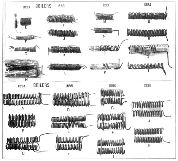
There was used in connection with this device the double-coil boiler shown at F (Plate 13) which was made of tubes flattened so as to be nearly capillary. The idea of this was to obtain a larger heating surface and a smaller volume of [p057] water, so that by proper regulation at the needle valve, just that quantity would be delivered which could be converted into steam in its passage through the coils, and be ready for use in the engines as it left the boiler at the farther extremity. The results obtained from this were an improvement over those from the original coil, and a third set of coils (G, in Plate 13) was made. This boiler consisted of three flattened tubes superposed one over another.
These two boilers were tried by placing them in a charcoal fire and turning on an alcohol blast, while water from a reservoir under constant air pressure was forced through them past a pin valve. The result was that the two-stranded coil supplied steam at from 10 to 40 pounds pressure to run the engines at about 400 revolutions per minute. The pressure rose steadily for about 40 seconds and then suddenly fell away, though the coils were red-hot, and neither the water nor the alcohol was exhausted—apparently because of the irregularity of the supply of water, due to the time taken by it after passing the valve to fill the considerable space intervening between that point and the boiler.
An attempt was made to overcome this difficulty by putting a stop-cock directly in front of the boiler so that the water, while still under the control of the needle valve, could be turned in at once; the alcohol blast was also arranged to be turned on or off at pleasure, and provision was made, by taking out the end of the flue inclosing the boiler, to provide for an increased air supply. With this arrangement a flame eight or nine inches long was obtained, but a test showed that not more than 25 grammes of water per minute passed through the tubes, which was not enough.
Further tests with these boilers were so far satisfactory as to show that with the flattened-tube Serpollet boiler, comprising from 60 to 80 feet of tubing, from 80 to 100 pounds pressure of steam could be maintained, but not steadily. As there were difficulties in flattening the tubes to make a boiler of this sort, a compromise was effected in the construction of the one shown at H (Plate 13), which was made of light copper tubes 5 mm. in diameter, laid up in three lengths of 6 metres each. The ends of these coils were so attached to each other that the water entering at one end of the smallest coil would pass through it and then enter the middle coil, whence it passed through the third or outer coil. Two sets of these coils were made and placed in the thin sheathings shown in the photograph. Repeated experiments with these boilers demonstrated that the pressure did not rise high enough in proportion to the heat applied, and that even the pressures obtained were irregular and untrustworthy. The principal difficulty still lay in maintaining an active and uniform circulation through the coils, and for this purpose the water reservoir under constant air pressure had proved itself inadequate. This pointed to a return to the use of the force pump, the construction of which had hitherto presented so many special difficulties that it had been temporarily abandoned. [p058]
A further difficulty experienced in the use of these boilers had been that of obtaining dry steam for the engines, as during the early experiments the steam had been delivered directly into the engines from the boiler coils. But in August the writer devised a chamber, known as the “separator,” where it had an opportunity to separate from the water and issue as dry steam, or at least approximately dry steam. This was an arrangement familiar in principle to steam engineers under another form, but it was one of the many things which, in the ignorance of steam engineering the writer has already freely admitted, he had to reinvent for himself.
At about the same time, a new pump was designed to drive the water from the bottom of the separator, which served the double purpose of steam drum and reservoir, into the coils. This pump had a diameter of 4.8 cm., and was run at 180 strokes per minute.
The result of the first experiments with these improvements demonstrated that, within certain limits, the amount of water evaporated is proportional to the circulation, and in this boiler the circulation was still the thing that was at fault. Finally, the results of the experiments with the two-stranded, triple-coil boiler may be summed up in the statement that it was possible to maintain a pressure of 80 pounds, and that with it the engines could be made to develop from 0.3 to 0.4 H. P. at best. It weighed 650 grammes (1.43 pounds) without the asbestos jacket.
About this time the writer had the good fortune to secure the temporary services of Dr. Carl Barus, an accomplished physicist, with whose aid a great variety of boilers were experimented on.
The next form of boiler tested was that shown at N (Plate 13), made on a system of coils in parallel, of which there were twenty complete turns. In the first test it generated but 20 pounds of steam, because the flame refused to work in the colder coils. The work of this boiler was very unsatisfactory, and it was only with the greatest difficulty that more than ten pounds pressure could be maintained. There was trouble, too, with the circulation, in that when the flame was in full play the pump seemed to meet an almost solid resistance, so that it could not be made to do its work.
A new boiler was accordingly made, consisting of three coils of four strands each. With this the pump worked easily, but whereas it was expected to get 120 pounds pressure, the best that could be obtained was 70 pounds. The outer coil was then stripped off, and a trial made in which everything ran smoothly and the pressure mounted momentarily to 90 pounds. After some adjustment, a mean pressure of 80 pounds was obtained, giving 730 revolutions of the engine per minute, with an indicated horse-power of 0.32.
It was shown in this work that, within certain limits, steam is generated most rapidly when it is used most rapidly, so that two engines could be used [p059] almost as well as one, the reason apparently being that the rapid circulation increased the steam generating power of the boiler, and that the engines worked best at about 80 pounds. It was also found that a larger tubing was better than the small, weight for weight, this fact being due to the greater ease with which circulation could be maintained, since fewer coils were necessary in order to obtain the same external heating surface. The pressure in the coils and the separator was also much more nearly equalized. The result was that the boiler temporarily approved was one made of tubing 6.35 mm. (0.25 inch) in diameter, bent into a two-coil, two-stranded boiler, having sixteen complete turns for each strand in each coil. The total weight was 560 grammes (1.23 pounds) with a total heating surface of 1300 sq. cm. (1.4 sq. ft.).
The separator used in the experiments made during August and September was of a form in which the water was forced below a series of partitions that prevented it from following the steam over into the cylinders of the engines. It weighed 410 grammes (0.9 pound) and was most conveniently worked with 700 grammes (1.54 pounds) of water. The boiler and separator together weighed 970 grammes (2.1 pounds).
A new separator was, however, designed, which was horizontal instead of vertical, as it was intended that it should be placed just below the midrod. Another form, devised for constructional reasons, consisted of a cylinder in which a pump was imbedded. Heretofore the pump used had been single-acting, but it was now proposed to make a double-acting pump. Upon testing this apparatus, it was found that when using an aeolipile, it took 150 grammes of alcohol to evaporate 600 grammes of water. It was evident that the latter was used very wastefully, so that the thermal efficiency of the engine was not over one per cent; but it was also evident that, under the necessity of sacrificing everything to lightness, this waste was largely inevitable.
About the middle of October, another boiler (O, Plate 13) was made, which consisted of two coils wound in right and left hand screw-threads, one fitting loosely over the other, so as to make a cylindrical lattice-work 32 cm. (12.6 in.) long. Each coil contained two strands of copper tube 0.3 mm. thick, and weighing 54 grammes to the metre (0.036 pound to the foot). The inner coil had a diameter of 5.63 cm. (2.22 in.), with nine turns of tube to the strand, the two strands making a length of 319 cm. (10.5 feet) for the coil. The outer coil had a mean diameter of 6.88 cm. (2.71 in.) and a length of 388 cm. (12.7 feet) for the two strands. The total length of the two coils was, therefore, 707 cm. (23.2 feet), with a heating surface of about 1415 sq. cm. (1.52 sq. ft.) and a total weight of 382 grammes (0.84 pound).
The results obtained with this boiler were so far satisfactory as to show that, under the most favorable conditions, when air was supplied in unlimited quantities and there were no disturbing currents to put out or interfere with the work [p060] of the burners, steam could be supplied at a sufficient pressure to run the engines. It was realized, however, that the conditions in flight would be very different, and that in order to protect the apparatus from the wind, some sort of protecting covering would have to be devised, which would of itself introduce new difficulties in providing the burners with a proper and uniform draft.

The hull, as at first constructed, consisted of a cylindrical sheathing open in front, through the rear end of which the boiler and aeolipile projected inward, so that the air taken in at the front would be drawn through the boiler and hearth to the exclusion of lateral currents. In the first tests, however, after the hull had been applied, it was impossible to secure a proper rate of combustion, nearly the whole hull being filled with a bluish flame, while only a very small portion of the gases of combustion passed into the coils of the boiler. The remedy for this lay in obtaining an increased draft, and a small stack was, therefore, arranged to carry off the products of combustion. This proved inadequate, and it was only after several weeks of experiment with various types of smoke-stack, and constant alteration of the aeolipile, that it was possible to make the apparatus work [p061] efficiently when it was inside the hull. Finally such a degree of success was attained that the burners could be kept lighted even when the aerodrome was placed in a considerable artificial breeze, created by a blower in the shop.
In connection with these tests of the engines and boilers, some method was desired, in addition to the Prony brake tests, by which the thrust of the propellers when driven by the engines at various speeds could be measured accurately and in terms which would be readily available in judging whether the aerodromes were ready to be given an actual trial in free flight. Such a method was found in the use of an apparatus known as the “pendulum,” which was introduced near the end of 1892, but was not generally used until the end of 1893. After this time, however, this test was made a condition prerequisite to taking any of the aerodromes into the field, and proved of the greatest assistance in estimating the probable outcome of the trials.
The apparatus used, which is diagrammatically shown in Fig. 10, was extremely simple both in theory and operation. It consisted primarily of a horizontal arm AC carrying the knife-edge B by which it is pivoted on each side on supporting beams not shown. Depending from AC is the light vertical arm DE, rigidly joined to it and carrying the lower horizontal arm FG, all of which are braced together so as to maintain the arm DE constantly perpendicular to AC. To this arm FG the model was rigidly attached with its center of gravity in line with the vertical arm DE and its weight increased by the addition of properly disposed flat weights, in order to make the angle of lift for a given thrust of the propellers smaller and less likely to interfere with the working of the boiler and separator.
Before the actual test of the “lift” could be made, it was necessary to know the exact distance of the vertical center of gravity of the model and the extra weights from the knife-edge B. This was determined by the following method: A known weight was suspended from the arm AB at some arbitrarily selected distance from the point B. This weight caused the perpendicular arms AB and DE to rotate through an angle, θ, which was measured on the scale KL. Knowing, then, the weight on the arm AB, its point of application, the weight of the aerodrome suspended on the arm DE, and the angle of rotation, it is easy, by a simple application of trigonometric functions, to determine the distance of the center of gravity of the model from the point B.
In a test of Aerodrome No. 6 made on September 23, 1898, the weight suspended from AB was 10,000 grammes, its point of application 50 cm., the model was weighted to 20,450 grammes, and the angle of rotation, θ, was 7° 2′. Letting y equal the distance of the CG from B, we may equate the balanced forces thus:
Having determined this distance, the weight on AB was removed and the aerodrome was allowed to regain its former position. The distance of the center of thrust from B was then measured. The engine was next started and the number of revolutions of the propellers counted by a tachometer. The thrust of the propellers, acting perpendicularly to the arm BD, produced rotation around the point B, the angle of which was measured as above.
In the power test of No. 6, the following data were obtained:
As the propeller thrust and the weight of the model are forces acting in opposite directions at known distances from a center of rotation, letting L equal the “dead lift,” we may express the equation thus:
The flying weight of Aerodrome No. 6 was 12,064 grammes, and the per cent of this weight lifted was, therefore,
This was much more than was necessary for flight, but in order to insure successful flights and avoid delay, the rule was made in 1895 that no aerodrome was to be launched until it had previously demonstrated its ability to generate enough power to maintain for at least two minutes a lift of 50 per cent of the total flying weight. At the same time other important data were obtained, such as the steam-pressure, the time required to raise sufficient steam, the total time of the run, and the general working of the boilers and engines.
As will easily be seen, these tests afforded a most satisfactory basis of judging what the aerodromes might be expected to do in actual flight if the balancing were correct.
At this time, October, 1893, the aerodrome (Old No. 4) was practically complete, and the most anxious thought was given to lightening it in every way consistent with the ever-present demand for more power, which necessitated an increase in the weight of both burners and boilers to supply the requisite steam.
On November 14, when the aerodrome was prepared to be shipped to Quantico for trial, its condition was about as follows. The steam-generating apparatus—the parts of which were of substantially the forms last described, although some slight improvements had been introduced—had been developed to [p063] such a point that a pressure of from 70 to 80 pounds of steam could be maintained for 70 seconds, when it was tested in the shop. What it would do under the unfavorable conditions imposed by flight was to be learned only by trial.
At this pressure, the engines, the efficiency of which had been increased by an improvement in packing, would develop approximately 0.4 indicated H. P., while at 105 pounds pressure they at times developed as much as 0.8 H. P. When the aerodrome was tested on the pendulum, these engines, when making less than 700 revolutions per minute, lifted over 40 per cent of the total flying weight.
The propellers used at this time were accurate helices, having a diameter of 60 cm., a width of blade of approximately 36 degrees, and a pitch-ratio of 1.25. They were formed of wood, and were bushed with brass where they were attached to the shafts.
AERODROME OLD NO. 4
AS PREPARED FOR FLIGHT BEFORE BEING SHIPPED
FOR TRIAL ON NOVEMBER 14, 1893 | ||||
| Part. | Copper. | Steel. | Brass. | Iron. |
|---|---|---|---|---|
| gms. | gms. | gms. | gms. | |
| Aeolipile | 200 | .. | 92 | .. |
| Boiler | 350 | .. | 37 | .. |
| Separator and pumps | 300 | 30 | 100 | 20 |
| Engine and frame | .. | 350 | 570 | .. |
| Midrod (200 cm. long) | .. | 220 | .. | .. |
| Two smoke-stacks | 70 | .. | .. | .. |
| Asbestos jacketing | .. | .. | .. | .. |
| Air chamber | .. | .. | .. | 82 |
| Spider between boiler and burner | 32 | .. | .. | .. |
| Intake valve | .. | .. | 15 | .. |
| Total | 952 | 600 | 814 | 102 |
| Hull | 50 | .. | 50 | .. |
| Pins for starter | .. | 15 | .. | .. |
| Two large wings and tail | .. | .. | .. | .. |
| Buffer and steerer | .. | .. | .. | .. |
| Propellers | .. | .. | .. | .. |
| Total | 50 | 15 | 50 | .. |
| Grand total | 1002 | 615 | 864 | 102 |
| Density | 8.9 | 7.8 | 8.5 | 7.5 |
| Volume (cu. cms.) | 113 | 79 | 102 | 136 |
| Alcohol | .. | .. | .. | .. |
| Water | .. | .. | .. | .. |
| Total | .. | .. | .. | .. |
| Density | .. | .. | .. | .. |
| Volume (cu. cm.) | .. | .. | .. | .. |
| AERODROME OLD NO. 4 DATA, CONTINUED | ||||||
| Part. | Wood and silk. | Mica and asbestos. | Fluid. | Total and mean weights. | ||
|---|---|---|---|---|---|---|
| gms. | gms. | gms. | gms. | |||
| Aeolipile | .. | .. | .. | 292 | ||
| Boiler | .. | .. | .. | 387 | ||
| Separator and pumps | .. | .. | .. | 450 | ||
| Engine and frame | .. | .. | .. | 920 | ||
| Midrod (200 cm. long) | .. | .. | .. | 220 | ||
| Two smoke-stacks | .. | .. | .. | 70 | ||
| Asbestos jacketing | .. | 50 | .. | 50 | ||
| Air chamber | .. | .. | .. | 82 | ||
| Spider between boiler and burner | .. | .. | .. | 32 | ||
| Intake valve | .. | .. | .. | 15 | ||
| Total | .. | 50 | .. | 2518 | =5.54lbs. | |
| Hull | .. | 25 | .. | 125 | ||
| Pins for starter | .. | .. | .. | 15 | ||
| Two large wings and tail | 571 | .. | .. | 571 | ||
| Buffer and steerer | 53 | .. | .. | 53 | ||
| Propellers | 250 | .. | .. | 250 | ||
| Total | 874 | 25 | .. | 1014 | =2.33lbs. | |
| Grandtotal | 874 | 75 | .. | 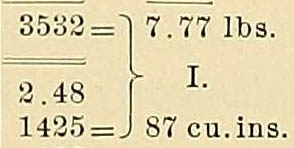
| ||
| Density | 0.8 | 3.0 | .. | |||
| Volume (cu. cms.) | 1092 | 25 | .. | |||
| Alcohol | .. | .. | 100 | 100 | ||
| Water | .. | .. | 500 | 500 | ||
| Total | .. | .. | .. | 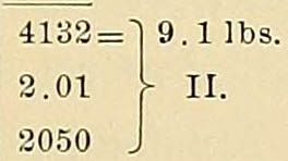
|
||
| Density | .. | .. |  |
|||
| Volume (cu. cm.) | .. | .. | .. | |||
|
Permanent air spaces: in midrod, vol. = 355 cc.
in engine frame, vol. = 100 cc.
volume as per II. 2050 cc.
2505 cc. Density =
41322505
= 1.65 | ||||||
The total flying weight of Old No. 4, including fuel and water, was 4132 grammes (9.1 lbs.), a much larger weight than had been contemplated when the original designs were made. A detailed statement of the weights of the various parts of the aerodrome, together with some data as to its density, is given on the preceding page. There were provided in the wings and tail approximately 2 sq. ft. of supporting surface to the pound of weight, which would have been barely sufficient to sustain the aerodrome, even if it had been successfully launched and the wings had been built much stronger than the flimsy construction in use at this time.
An air chamber, which served the double purpose of floating the aerodrome and of providing a moveable weight by which the center of gravity could be shifted to the proper position relatively to the center of pressure, was constructed of the thinnest sheet-iron and attached to the midrod.
This aerodrome, the fifth in actual construction, and the first, after years of experiment, to be carried into the field, was transported to Quantico, where the first trial with it was made on November 20, under the conditions described in Chapter IX ◊.
The aerodrome, No. 4, which has just been described, had not been put to the test of an actual flight, for reasons connected with the difficulties of launching, which are more fully described elsewhere; but, when the completed machine was more fully studied in connection with the unfavorable conditions which it was seen would be imposed on it in trials in the open air, many possibilities for improvement presented themselves. It was seen, for instance, that a better design might be made, in which the engines, boiler and aeolipile might be placed so that the center of gravity of each would lie in the same vertical plane as the central line of the aerodrome. In order to do this the construction of a single midrod, which was the distinguishing feature of Old No. 4, had to be essentially departed from, the midrod of this new one, No. 5, being opened out into two rods, so to speak, which were bent out so that the open space between them furnished a sufficiently large hull space to hold the entire power generating apparatus. In arranging the machinery within this hull, it was provided that, as the water and fuel were expended, the center of gravity of the aerodrome would shift little, and, if at all, backward relatively to the center of pressure.
Instead of the two small engines, which it will be remembered were mounted on the cross-frame in No. 4, a single engine with a larger cylinder, having a diameter of 3.3 cm. (1.3 in.) and a stroke of 7 cm. (2.76 in.), capable of developing about 1 H. P. was used. This engine was mounted within the hull near the forward end and drove the propellers by suitable gearing. [p065]
In addition to these radical changes many important improvements were made in the different parts. Internal compartments were built in the separator, so that even if the water was displaced by the pitching of the aerodrome, it could still perform its functions properly. The pump was provided with a ratchet, so that it could be worked by hand after the burners were lighted, and before enough steam had been raised to enable the engine to run it. An active circulation was thus maintained in the coils of the boiler as soon as the burner was lighted and before the engine was started, which prevented the tubing from being burnt out, as had frequently happened previously. The wing construction was also improved and many other changes were introduced, which will be treated separately.
In the meantime, No. 4, which had been damaged in the attempted launching in November, 1893, was strengthened and prepared for another trial which took place in January, 1894.
By the end of the first week in February, the engine of No. 5 was ready for trial, and with a boiler pressure of about 80 pounds per square inch, apparently developed 0.56 H. P. on the Prony brake, when making 800 revolutions per minute. To accomplish this called for such good distribution of steam in the cylinder, that it is doubtful if the power could be exceeded at that speed and pressure.
It was, however, apparent that it was desirable to have a boiler capable of supplying steam for at least one horse-power, and that in order to do this, there must be an improvement in the aeolipiles. The problem consisted in arranging to evaporate more than 500 cu. cm., and in fact as nearly as possible 1000 cu. cm. (61 cu. in.) of water per minute, and, since from 200 to 300 cu. cm. per minute had already been evaporated, this was not regarded as impossible of accomplishment. The theoretical advantages of gasoline had for a long time been recognized, as well as the very practical advantage possessed by it of keeping lighted in a breeze, and several attempts had been made during the latter part of the previous year to construct a suitable burner for use with it. These had not been very successful; but in view of the increasing demand for a flame of greater efficiency than that of the alcohol aeolipiles, it was decided to resume the experiments with it.
Accordingly, a gasoline evaporator was tried, consisting in the first experiment of a gasoline tank with nine flues, through which steam was passed. A flow of steam gave a rapid evaporation of gasoline when the pressure did not exceed 5 pounds. The chief difficulty with the burner employed was that the supply of gasoline gas would rise and fall as the steam rose and fell, conditions just the opposite of what was really desired. On the other hand, it was thought that this gasoline tank would form a real condenser for the steam, so that a [p066] portion of the exhaust steam would be condensed and be available for use in the boiler again. The gasoline vapor had many advantages over the alcohol; but it was at first possible to evaporate only 120 cu. cm. of gasoline in a minute.
In the experiments that were made at this time (March 9) with gasoline, the main object in view was to obtain a smooth blue flame at 10 pounds pressure. There had been failures to accomplish this, owing to the high boiling point of the liquid, and while the work was in progress it was still evident that the problem of the boiler and the flame which was to heat it had not been solved. A Prony brake test gave, at 130 pounds pressure, 1.1 H. P. with about 1000 revolutions of the propellers; but this was with steam supplied from the boiler of the stationary shop engine.
On April 1, 1894, the following record was made of the condition of Aerodrome No. 5:
“The wings, the tail, and the two 80 cm. propellers, as well as the two smaller propellers, are ready. The cylinders, gear, pump, and every essential of the running gear, are in place. The boilers, separators, and adjuncts are still under experiment, but may be hoped to be ready in a few days. At present, the boilers give from 450 to 600 grammes of mixed steam and water per minute. With 130 pounds of steam, the engine has actually developed at the brake, without cut-off, considerably more than 1 H. P., so that it may be confidently considered that at 150 pounds, with cut-off, it will give at least 0.8 H. P., if it works proportionately well.”
The delays incident to the accomplishment of the work in hand were always greater than anticipated, as is instanced by the fact that it was the latter part of September before the work was actually completed. The greater part of this delay was due to the necessity for a constant series of experiments during the spring and summer to determine the power that it was possible to obtain with the various styles of boilers, aeolipiles, and gasoline burners.
While No. 5 was thus under construction, new and somewhat larger engines had been built for No. 4, the work on them having been begun in January. The cylinders of these engines, which are more fully described in connection with Aerodrome No. 6, were 2.8 cm. in diameter, with a 5 cm. stroke, each cylinder thus having a capacity of 30.8 cu. cm., which was an increase of 36 per cent over that of the old brass cylinder engines, which had previously been used on No. 4. On April 28, under a pressure of 70 pounds, these engines drove the two 60 cm. propellers at a rate of 900 R. P. M., and lifted on the pendulum nearly 40 per cent of the total flying weight of Aerodrome No. 4, which was now approximately 5 kilos. A trial was made at Quantico in the latter part of May, which is described in Chapter IX ◊. It is only necessary to mention in this connection that there was a great deal of trouble experienced with the alcohol aeolipile, the flame being extinguished in the moderate wind to which the [p067] aerodrome was subjected while preparations for the launch were being made. Moreover the flame was so nearly invisible in the sunlight that it was uncertain whether it was burning in the critical instants just before the launch, when doubt might be fatal. These conditions resulted in a final decision in favor of gasoline, on account of its greater inflammability, and in the provision of such hull covering that the fires could be lighted and maintained in a breeze.
In June, I tried a modification of the burner, in which the gasoline was delivered under the pressure of air to the evaporating coil. In the first trial steam was raised to a final pressure of about 70 pounds, and a run of 45 seconds was secured under a pressure of 40 pounds in the gasoline tank, which was thought to be altogether too high; for, at the end of the run, the whole apparatus was enveloped in flames, because of the gasoline that was projected through the burner-tips.
Continual experiments with different forms of burner, illustrated in Plate 12, occupied the time, with delays and imperfect results, which were trying to the investigator, but are omitted as of little interest to the reader. They had, however, the incidental result of proving the practical superiority of gasoline over alcohol, and culminated in the evolution of the burner that was finally used successfully. It consisted of a tank for the gasoline, from which compressed air delivered the liquid to a small coil surrounded by asbestos, in which it was vaporized. At the rear end of this coil three pipes were led off, one of which was a small “bleeder,” which fed the burner for heating the gasoline, the other two leading to the main burners. After the generation of gas in the small coil had been started, the heat from the small burner was expected to continue the vaporization, so that nothing but gas would be able to reach the main burners. A device was also introduced, which had greatly increased the amount and uniformity of the draft and consequently made the burners and boilers more efficient than before. This consisted simply in passing the exhaust steam from the engines into the smoke-stack, and it is remarkable that it was not thought of earlier.
By the middle of September, 1894, both aerodromes were completed and ready for another test. On September 27 the condition of Aerodrome No. 4 was as follows: The general type of construction, namely, that of a single midrod, to which all the steam generating apparatus was attached, and which supported also the cross-frame and the wings, was the same as in the construction of 1893. On account of the increased weight of the model, and the substitution of an inferior piece of tubing in place of the former midrod, it was found necessary to stiffen it by the use of temporary trusses. Permanent bearing points for holding the aerodrome securely to the newly devised launching apparatus were also attached to this midrod. [p068]
The engines in use at this time were the small steel cylinders described above, which were mounted on the cross-frame, and drove the propellers directly. These engines were capable of delivering to the propellers, as had been proved by repeated tests, at least 0.66 brake horse-power.
The boiler consisted of two inner coils and an enveloping outer coil, loosely wound and connected in series. The inner coils, each of which had about 17 turns of 8 mm. diameter, 0.2 mm. thick tubing, developed about 80 per cent of the steam; the outer coil of 8 turns, while not exactly useless as a steam generator, afforded an efficient means of fastening the smoke-stack and cover of the boiler, and for attaching the latter to the midrod. This boiler was externally 30 cm. long, 16 cm. wide, and 10 cm. deep, weighing with its cover approximately 650 grammes. The stack for the burnt gases, into which exhaust steam was led from a central jet, was about 1 foot long. At best this boiler was capable of developing slightly over 100 pounds of steam.
The separator was of the form last described, except that the steam dome had been moved toward the front, to prevent the jerk of the launching car in starting from causing water to be pitched over into the engines. It was constructed of sheet aluminum-bronze, and weighed, together with its pump, 580 grammes. The pump, which was double-acting and fitted with ball valves, was capable of discharging 4.5 grammes of cold water per stroke, its efficiency being only about one-half as great with hot water.
The gasoline burner, which had been finally adopted in place of the alcohol aeolipiles, had now been perfected to the form in which it was finally used. Two Bunsen burners of special construction were provided with gasoline gas by the heat of an intermediate accessory burner, which played upon a coil to which all three burners were connected. Gasoline was furnished from a tank made of aluminum-bronze, under an air pressure of about 20 pounds, the fluid being under the control of a screw stop-cock. This tank, which was capable of holding 100 to 150 cu. cm. of gasoline, weighed 180 grammes, and the burners with an outer sheathing weighed 302 grammes.
It was calculated that about 3300 cu. cm. (201 cu. in.) of air space would be required to float the aerodrome in water, and this was supplied by an air chamber, having a capacity of 2700 cu. cm. (165 cu. in.), which could be shifted to adjust the longitudinal equilibrium of the aerodrome, and about 900 cu. cm. (55 cu. in.) of space in the gasoline tank and the midrod. The reel and float, which served to indicate the location of the aerodrome, if for any reason it should be submerged, were in one piece, and so moored that there was no danger of fouling the propellers.
The total weight of the aerodrome was about 6 kilogrammes (13.2 lbs.), or, with a maximum quantity of fuel (850 cu. cm. of water, 150 cu. cm. of gasoline), [p069] less than 7 kilogrammes. From 60 to 90 pounds of steam could be maintained by the boilers for about 2 minutes, at which pressure the engines developed about 0.66 brake horse-power, driving the 70 cm., 1.25 pitch-ratio propellers at 700 R. P. M., and giving a lift of from 2.6 to 3.0 kilos (5.7 to 6.6 pounds), or about 40 per cent of the flying weight.
The wings and tail had a total surface of 2.62 sq. m. (28.2 sq. ft.), giving a ratio of 2.7 kilos to 1 sq. m. of wing surface (1.8 sq. ft. per pound). If the hull resistance be neglected, the soaring speed of this aerodrome was about 5.9 metres (19 feet) per second, or 13 miles per hour.
Turning now to the completed No. 5, its frame was of the “double midrod” type described above, the two tubes which formed the frame being prolonged at the front and rear to afford points of attachment for the wings and tail. The range through which the wings could be shifted to adjust the position of the center of pressure was, however, very small. The hull, which, it will be remembered, contained all the power generating apparatus, was much stronger and heavier than that of No. 4, and resembled somewhat the hull of a ship. It had a frame-work of steel tubing brazed to the midrod, to which an outer sheathing of sheet aluminum 0.3 mm. thick was attached. It was, however, excessively heavy, weighing nearly 800 grammes.
The engine, which was mounted near the front of the hull, was the single cylinder, one horse-power engine, described above, which drove the two propellers by suitable gearing. The remaining parts of the power plant were identical with those already described in connection with No. 4, but the more advantageous location of them in No. 5 rendered them somewhat more efficient.
It had been planned to use 80 cm. propellers of 1.25 pitch-ratio on No. 5, but it was found in the shop tests of the aerodrome that the cross-frame was not strong enough to withstand the strains, and that the engine could be made to work much more steadily with a smaller propeller. Accordingly, propellers of 70 cm. diameter and 1.25 pitch-ratio, similar to those used on No. 4, were finally substituted.
For floating the aerodrome, when it descended into the water, an air-chamber similar to that of No. 4, but of a larger capacity was provided. With this in place on the aerodrome, it was calculated that, if all the parts except this float and the gasoline tank were filled with water, there would still be a buoyancy of over 2 kilogrammes.
The total weight of No. 5 was 8200 grammes, or with its full supply of fuel and water 9200 grammes. In this aerodrome the same boilers used in No. 4 were capable of maintaining for at least a minute 115 pounds of steam, so that the engine now gave the maximum of one brake horse-power for which it was designed, and, driving the 70 cm. propellers, lifted repeatedly nearly 45 per cent of the flying weight. [p070]
The wings and tail constructed for No. 5 were identical with those of No. 4, being slightly curved and containing 2.62 sq. m. (28.2 sq. ft.), equivalent to 1.4 sq. ft. to the pound, which with the flimsy construction of the wings gave an entirely inadequate support to the aerodrome.
During the summer a launching apparatus of a new and improved type, which is described in Chapter X ◊, had been perfected, and with it repeated tests were made of both aerodromes in October, November, and December, with the unsatisfactory results recorded in Chapter IX ◊. In the course of these experiments, many slight modifications of the burners and boilers were made, but no important changes were introduced except that the cross-frame of No. 5 was enlarged and strengthened so as to admit of its carrying one metre propellers safely. The results, however, which were obtained, did not compensate for the increased weight of the larger frame.
Viewing the work of this year from the standpoint of results obtained in the numerous attempts at flight, it would seem that very little progress had been made, and that there was small reason to expect to achieve final success. However, if the work be examined more particularly, it will be seen that two of the most difficult problems had been solved, one completely as far as the models were concerned, and the other to a very satisfactory degree. First, a launching apparatus, with which it was possible to give the aerodrome any desired initial velocity, had been devised, and so far perfected that no trouble was ever experienced with it in testing the models. Second, as a result of the extended and systematic series of experiments, which had been conducted under the direction of Dr. Barus, a steam pressure of 115 pounds could be maintained steadily in the boilers for at least a minute, and the burners could be kept lighted even in a considerable breeze.
A summary of these experiments, together with some account of the difficulties encountered and the results finally obtained with the apparatus in use at the end of the year, is given in the following report, which was prepared by Dr. Barus in December, 1894.
“If water be sprayed upon a surface kept in a permanent state of ignition, any quantity of steam might be generated per time unit. Similarly advantageous conditions would be given if threads of water could be passed through a flame. In practice this method would encounter two serious difficulties, the importance of which is accentuated when the boiler apparatus is to be kept within the degree of lightness essential in aerodromics. These difficulties are (1) the danger of chilling the flame below the point of ignition or of combustion of the gases, and (2) the practical impossibility of maintaining threads of water in the flame. For it is clear that the threads must be joined in multiple arc, so as to allow a large bulk of water to circulate through the boiler, whereas even when there are but two independent passages for the water through the furnace, it is hard to keep both supplied with liquid without unduly straining the pump. If the water be even slightly deficient, circumstances will arise in which one of [p071] the passages is better than the other. This conduit will then generate more steam and drive the water under force through the other passage, increasing the temperature discrepancy between them. Eventually the hot passage reaches ignition and either bursts or melts. This is what sooner or later takes place in boilers adapted for flying machines and consisting of tubes joined in multiple arc, when a single moderately strong circulating pump supplies the system.
“To avoid these annoyances, i. e., to increase the length of life of the boiler, the boiler tubes are joined in series to the effect that a single current of water may flow successively through all of them. It is needful therefore to select wide tubes, such as will admit of an easy circulation in consideration of the length of tubing employed without straining the pump and at the same time to allow sufficient room for the efflux of steam. Other considerations enter here, the bearing of which will be seen presently: if the tube be too wide the difficulty of coiling it on a mandrel of small diameter is increased, while at the same time the tube loses strength (cæt. par.) in virtue of the increased width.
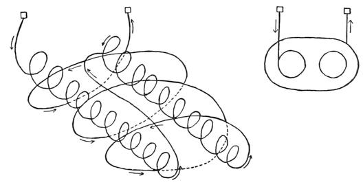
“It is from considerations such as these that, in the course of many experiments, copper tubing about 8 mm. in diameter has been adopted. Copper is selected because of its freedom from internal corrosion, easy coiling, and because of its availability in the market. The thinnest tube to be had (walls only 0.1 mm. thick) will withstand more pressure than can be entrusted to the larger steam receivers in circuit with the boiler. The boiler weight is thus a negligible factor, and it is quite feasible to reduce the thickness of boiler tubing, by the superficial application of moderately strong nitric acid, to 200–400 grammes per horse-power of steam supplied. External corrosion due to flames occurs only in case of deficient water, and if the boiler be made of tubing with the walls 0.2 mm. thick, it is in view of the possibility of such accidents. Boilers may then be tested to 25 atm. without endangering the metal.
“Boilers are wound or coiled with regard to the two points above suggested, viz.: to avoid chilling the flame the successive turns are spaced on all sides, and to bring the water as nearly into the flame as possible, the diameter of the coils is chosen as small as expedient. Further reasons for this will presently be adduced. The type of boiler eventually adopted is shown in the accompanying diagrams, 1 and 2, Fig. 11.
“Diagram 1, is a perspective diagram showing the plan of winding and Diagram 2, an end view. The circulation is indicated. There are two inner coils [p072] each containing about 17 turns, wound on a mandrel 5 cm. in diameter. The turns are spaced so as to allow about 1 cm. clear between successive turns. The outer coil envelopes both, and in this there are about 3 cm. between successive turns, and 8 turns in all. Length, say, 30 cm., breadth 16 cm., thickness 10 cm., give the external dimensions of the boiler. The shell space between outer and inner layers of tubing must nowhere be less than 1 cm. When so wound, the inner coils (here as in other boiler forms) raise about 80 per cent or more of the steam; the outer or enveloping coil, while not quite useless, make the most effective frame work for the boiler jacket which has been devised. The coils are brazed together by blind tubes, as shown in Diagram 2, to keep the whole in shape. Weight with couplings and cover when complete 535 grammes.
“The cover is preferably of mica, through which the flame within the boiler may be seen, and in which lightness, nonconduction, and resistance to the disintegrating effects of high temperature are met with in a pronounced degree. This jacket is held down by copper bands and the end band is continuous with the long smoke-stack, as will be presently shown.
“The wide form of boiler with two coils within the envelope is not absolutely essential. The same amount of steam can be generated from one coil in an envelope in other respects equal to Diagram 1 if a sufficiently hot flame be passed axially through the coils. Such a flame, however, is unstable, and for this reason two milder flames with a good air access are to be preferred on practical grounds even if the weight is thereby increased.
“To further understand the boiler construction it is advisable to consider the action of the flame. Inasmuch as wide tubes must be used, the problem of evaporating water as fast as possible is equivalent to getting heat into the current (water and steam circulating through the coils) as fast as possible from without. If, therefore, t is the mean temperature of the fluids within the coils, and T the effective temperature surrounding the tube, then the rate at which heat will flow into the tubes is proportional to T−t. Now t the temperature of the steam is nearly constant (100°–150°) whereas T the effective flame temperature may vary from 800° to, say, 1600°. It is for this reason that the heat sponged up by the boiler depends almost directly on the flame temperature.
“What conditions, therefore, will make the flame effectively hot?
“(1) The coils must obviously be brought as nearly into the flame as feasible: for this purpose the cylindrical helix is better than any other form. But
“(2) The turns and coils must not be so crowded together as to chill the flame into imperfect combustion in various parts of its extent. Hence the loose form of winding. Again
“(3) There must be oxygen enough to allow complete combustion, and
“(4) The flame itself must be hot and the radiation checked by good jacketing.
“To take up the last points: the effective heat of the flame depends not only on the combustion heat of the fuel used; it depends also, among other things, on the speed with which this combustion takes place. A flame burning from a low pressure of alcohol gas will be at low temperature as compared with a flame burning from high pressures of the gas. If the flame be burnt from a Bunsen burner in the usual way it is an interesting question to know how flame temperature will vary with gas pressure. At present we know it merely in steam pressures incidently produced in a given engine (No. 4) as for instance:
in the running engine.
“Unfortunately there is a limit set to this process of increasing the steam supply, quite aside from conditions inherent in the method. This is due to the fact that a certain speed of efflux cannot be exceeded without putting the flame out. Suppose, for instance, in Fig. 12, that a gas generated from a liquid is ignited at the end of the Bunsen burner F; then if the velocity of efflux of mixed gas and air in the direction AB from the mouth of F exceeds the velocity of combustion in the direction BA, the flame will obviously be carried away from the mouth of the tube and dissipated. This state of things is actually realized at pressures exceeding about 15 lbs., depending on the degree of mixture of the combustible gases used, and therefore on apparently haphazard conditions connected with the jet, the air holes, the air supply, etc.


“If, however, the velocity of the jet at the point of efflux be checked by an obstruction like a cylinder C, Fig. 13, placed co-axially with the burner tube F, the speed of combustion will no longer be exceeded (supposing C properly chosen) and flames will then burn from high-pressure gas. In this way flames were maintained generated from alcohol gas at even 40 lbs. and above.

“The gas escaping from the Bunsen burner is never sufficiently aërated to burn completely. Otherwise there would (in general) be explosions in the tube F. A part of this air is supplied at the mouth of the boiler B, Fig. 14, and the amount available here will depend on the velocity of the jet F. Hence it does not follow that a high-pressure burner like that in Fig. 11 will supply a proportionate amount of heat, since its jet suction is not intense and the combustion within the boiler is incomplete. This difficulty may be remedied by placing [p074] air holes in the jacket of the boiler, provided the boiler be wrapped loosely enough not to chill the flame below ignition. It is with reference to this effect that the boilers, Fig. 11, were wound. A number of rifts aaa, Fig. 15, are then left in the jacket through which air may enter in virtue of the burner flame acting as a jet at the mouth of the boiler.
“When so constructed the flame at first enters the inner coil only; but after a little while it suddenly spreads out throughout the whole interior space and envelops the coils. This sudden expansion is due, probably, to the assumption of the spheroidal state by the water within the coils, the current now flaring on an enveloping cushion of steam. The pump must work well, for deficient water means a hot tube and deficient steam, or eventually a rupture of the tube.
“Thus far the dependence for draft has been on the burner jet and the suction of the smoke-stack in virtue of the inertia of the moving gases. But even with this ventilated boiler, this method is limited to certain dimensions of the boiler. Thus a boiler 80 cm. long yielded about the same quantity of steam as a boiler half as long and otherwise similar. Only the initial parts of the boiler are, therefore, relatively efficient, and the reason of this seems to be that, apart from shape, etc., the flame as a heat-producing agent is practically defunct, when a certain amount of heat has been taken out of it: in other words, even with fair ventilation the flame is eventually chilled off by the voluminous products of combustion continually accumulating in the boiler. The same choking action accompanies the presence of unburnt gases. If, for instance, the flame be burnt in the air, it is slender and much smaller in volume than in the boiler. The flame is also of small volume and burns completely in a wide boiler, but the steam is always deficient, because of the distance between flame and coils (see above). With the above apparatus about 12 lb. of dry steam per minute per square foot of heating surface was attained.
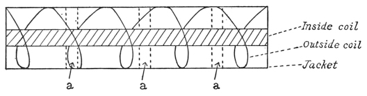
“This introduces the final condition for rapid steam generation. There must be artificial suction at the smoke-stack. By passing the exhaust steam in the form of a central jet through the smoke-stack the yield of steam was increased 20 to 30 per cent. In fact as the supply of gas from the burner is given, the artificial suction in question means more air in the boiler for the same amount of gas and it means also a more rapid removal of the exhaust gases. The experiments with steam suction are yet to be completed, and with them the boiler question is to be finally laid at rest. The chief points at issue are these:
“1. Seeing that the jet suction increases with the length of the smoke-stack, up to a certain length at least, how long and how wide must the efficient smoke-stack be made? Thus a smoke-stack 10 cm. long is all but useless. Good results are obtained when the stack measures 30 cm. in length beyond the end of the steam jet. [p075]
“2. What is the relative efficiency of the initial and final halves of the length of the boiler? This will show in how far it is useful to increase the length of the boiler for a given burner and steam jet. It will also show what advantage is to be gained from triplicate boilers with three burners, as compared with duplicate boilers with two burners, or single boilers with one burner, when the same weight of tubing is used throughout.
“3. What is the effect of pressure on the aeolipile tank, or in how far does the steam generated depend on what may be called the pressure of the flame? This is also an important point which remains for quantitative solution. It can be approached in two ways: either by finding the steam evaporated in terms of the tank pressure, or by finding the temperature of the flame pyrometrically.
“4. What speed of water circulation best conduces to steam generation? A good pump is now installed by which the circulation can be varied. If water can be put into the boiler just fast enough to come out dry steam at the other end, the efficiency ought to be a maximum, but it does not follow that it will be so, for one can imagine a wet circulation sponging up more heat than one which is just dry at the end.”
During January and February, 1895, the experiments with boilers and burners were continued and even better and more uniform results than those given above were obtained. The boilers of Aerodrome No. 5 were finally brought to such a state of efficiency, that under favorable conditions a lift of nearly sixty per cent of the flying weight was secured. This was much more than was required for flight, but it was decided to postpone the trials until No. 4 could also be made ready for a test and the frame of No. 5 could itself be strengthened in many weak places.
Upon examining No. 4, which had been put aside since the trials in December, it was found to have rusted so badly throughout and to be so unfit in every way for trial, that a complete reconstruction of the whole would be necessary. So many advantages had been gained in No. 5 by the double midrod type of construction that it was decided to rebuild No. 4 on a modification of the same plan, as shown in Plate 11, retaining, however, the same engines which had been used before.
In this a very guarded return was made to the type which had proved so unsatisfactory in No. 0, that is, making the hull support rods at the front and rear for attaching the wings and tail. In this case, however, the hull was constructed very rigidly, and the tubes at the front and rear were firmly attached and braced so that they could withstand a considerable strain without undue distortion. The work on this frame was completed in March, but the other parts were not in entirely efficient condition even in May, when the aerodromes were taken to Quantico for trial. Moreover, it was found that the weight of this aerodrome had increased far beyond the original estimates. [p076]
In view of the disasters from trials in the field, due to inability to obtain automatic equilibrium in flight and to the flexure of the large wings rather than to defects of the engines, the conditions at this time, after three years of failure, seemed so nearly hopeless, that without abandoning the work on these steam aerodromes, I again had recourse to the early plan of constructing smaller models driven by India rubber, in which the small wings employed could be made of the requisite stiffness. Instead of employing twisted rubber, however, the defects of which had been amply proved in previous trials, these new constructions were meant to employ rubber directly stretched and pulling. In this condition the rubber exercises nearly six times the power in proportion to weight that it does when twisted, but on the other hand it requires a very strong frame and subordinate parts.
I spent an inordinate amount of time and labor during this year in attempting to employ this latter form of construction and finally got a few useful results from it, but none in proportion to the labor expended.
During March, Aerodrome No. 5, the frame of which had proved on test to be radically weak, was completely refinished except for the wings. The propellers had hitherto been made of wood, but in May, I commenced a new construction of steel, wood and cloth, on a plan giving a figure which, though not rigorously helicoidal, was practically near enough to the theoretical form and was also both lighter and more elastic than the wooden construction.
On May 8 and June 7 Aerodrome No. 5 was again tried at Quantico, and although the tests were unsuccessful, in that the aerodrome failed to fly, partly because of the fact that so much time was spent in raising steam that practically the entire supply of fuel and water was exhausted before the aerodrome was actually launched, yet it had come so much nearer flying than any machine had previously done, that it was felt that if either the power could be increased or the weight decreased even a slight amount, the aerodrome would probably fly. In view of the great care that had been exercised in keeping down the weight, it seemed almost hopeless to attempt to reduce it, and it also seemed equally hopeless to attempt to get more power without increasing the weight. However, something had to be done to increase the ratio of power to weight, and as it was seen that this would involve extensive changes in No. 5, it was decided to entirely rebuild No. 4 with this idea in view, though it was evident that it involved a plan of construction even lighter than the dangerously light plan on which No. 4 had already been constructed.
During Mr. Langley’s absence in Europe in the summer, Aerodrome No. 4 was entirely reconstructed and made to embody many new characteristics, the changes introduced being so radical that this model was henceforth designated as “New No. 4.” The new characteristics of this model were its unprecedentedly [p077] light frame and the elevation of the transverse frame 12 centimeters above the midrod, whereby the position of the line of thrust was raised so that it was 20 centimetres from the center of pressure, which from theory seemed to be very nearly its correct position. The total flying weight was but 6400 grammes (14 pounds), with a total supporting surface of fifty-four square feet, equivalent to very nearly four square feet per pound. It was hoped that with this extremely light construction the “dead lift” would amount to a large percentage of the flying weight, and as much as sixty per cent was actually lifted on the pendulum. As, however, the aerodrome approached completion it became more and more evident that the construction was hopelessly fragile, the frame being scarcely able to support itself in the shop. By November this conclusion became certain, and this aerodrome (New No. 4) was never put to an actual test in the field. The very expensive set of wings covered with gold beater’s skin, which were also constructed at this time for this model, proved so weak under test that they were entirely abandoned.
When Mr. Langley returned to Washington in the fall, many important points, which had been under special consideration during the past year, particularly those relating to the disposition of sustaining surfaces, and the provision of automatic equilibrium, were still not definitely determined. It was not yet decided whether two sets of wings of equal area should be used for the aerodrome, or what the efficiency per unit of area of the following surfaces was in comparison with the leading surfaces. To aid in determining these and other important points concerning the relative position of the center of gravity and the center of pressure in the horizontal planes, he had several small gliding models made, which could be used with either one or two pairs of wings, and afforded an opportunity for testing and comparing several types of curved surfaces.
These models were built so that the center of gravity could be adjusted to any desired point, and had in addition, as a means of assisting in preserving equilibrium, a small tail-rudder, shaped somewhat like a child’s dart, which was intended to support no part of the weight.
The tests with these models were very satisfactory and aided greatly in the final development of what is known as the “Langley type.” Indeed, in the single month of November all the points, which had hitherto been more or less indefinite, were finally decided upon, and the tests of the following spring proved these decisions correct.
Two sets of wings of equal area were hereafter provided for every aerodrome, which not only greatly increased the stability, but also overcame the difficulty hitherto experienced in bringing the CP over the CG. The tail-rudder, formed of planes intersecting at right angles, was adopted as the means of control. In use on the aerodromes it was set at a negative angle, and given a certain [p078] degree of elasticity, which was at first provided in the frame of the rudder, but was later given by a flat wooden spring, by which it was attached to the aerodrome. The tail in this form now became the sole means of controlling the equilibrium, and the results obtained with it were so very satisfactory that no further attention was given either to the gyroscopic control built during the previous summer, or to any of the electrical forms of control constructed prior to that time, all of which involved more or less delicate apparatus.
The definite form into which these ideas crystallized is perhaps best exemplified in the letter of instructions issued by Mr. Langley on November 30, 1895 to the men employed on the work. The text of this letter is given in the Appendix, and the forms referred to in it for recording the weights and adjustments of the aerodromes are those used in the data sheets after this time.
In October work was resumed on Aerodrome No. 5, on which nothing had been done since its test on June 7. The reconstruction of “Old No. 4” into “New No. 4” which had occupied the entire summer, and the final result of which was the production of a machine so radically weak as to be useless, had been so discouraging that it seemed vain to attempt in any way to decrease the weight of No. 5. The addition of the rear wings in place of the tail had, however, so greatly increased the supporting surface that it seemed possible that No. 5 might now be able to fly with no greater engine power than it had on June 7. Some weak places in its frame were, therefore, strengthened and the midrod at the front was raised five centimetres in order to raise the center of pressure farther above the center of gravity and give the front wings a greater range of adjustment. Some slight changes were also made in the gearing which drove the pump, so as to make it work faster, and new burners, boilers and a gasoline tank were constructed during November. Later the midrod, which had formerly consisted of two separate pieces attached at the front and rear respectively of the main frame, was made continuous, and in order to avoid passing it through the smoke-stack, the stack was made to fork at this point. These changes are clearly shown in Plates 14 and 15, which are photographs taken on December 3. This plan was, however, soon changed so that the midrod passed through the smoke-stack and was rigidly attached to the frame at several points, and a new pump and new boilers were substituted for those which had been worn out. Aside from these changes, which although small, added very materially to the general strength of the frame, no important changes were made in No. 5 prior to its remarkable flight of May 6, 1896.


While these changes were being made in No. 5, similar ones were also being carried out in New No. 4, and the addition of the rear wings to No. 4, together with other slight changes, made it such a distinctively different machine from what it had been, that it was now designated as No. 6. After making extensive [p079] repairs to the extremely light frame of No. 6 (formerly New No. 4) it was thought to be in suitable condition for flight and was accordingly boxed preparatory to sending it to Quantico.
The year, therefore, closed with No. 6 apparently in condition for test, but it was decided not to take it to Quantico until No. 5, which was still undergoing repairs, could also be got ready.
A few days after the beginning of the new year, while the repairs on No. 5 were being completed, it was decided that the frame of No. 6 which had been boxed ready to be carried into the field for trial, was so weak that before putting it to an actual test in flight it would be best to make some tests on the strength of its frame. While testing the frame for torsional strength, it broke under the moderate test of a weight of 500 grammes placed at the tips of the wings, the angle of deflection just prior to its breaking being 35°, while the frame of Old No. 4 in March, 1895, had shown a deflection of only 10.5° under a similar test. This breaking of the frame showed very plainly that the worst fears in regard to it had been realized and that by some means or other the frame must be strengthened. This was finally accomplished by making the midrod continuous through the smoke-stack as had already been done in No. 5, and at the same time an additional improvement was made in the means of attaching the Pénaud tail, whereby it was lowered in order to give it a greater clearance in passing under the launching car in actual test. Later the boilers proved defective and new ones were substituted, but except for some minute details no further changes were made in Aerodrome No. 6 prior to its test in May.
On May 6, No. 6 was unsuccessfully tried at Quantico just prior to the very successful test of No. 5. In this test no serious damage was done to the frame, but before going to Europe in the summer, Mr. Langley ordered that both aerodromes be completely overhauled and put in condition for further experiments in the fall. In this remodelling practically no changes were introduced in the frame of either No. 5 or No. 6, but the engines of No. 6 were refitted and a new boiler was substituted, which, with slight improvements in the burner, resulted in a somewhat increased power in the engines.
A complete description, giving all essential details of both Aerodromes Nos. 5 and 6, will be found in Chapter X ◊.
In some early experiments in 1887 with the small models without motor power, which have not been particularly described, two pairs of wings, in the same plane, were employed for reasons connected with stability. Afterward, in many of the rubber-driven motor models, which have been described in Chapter II ◊, two large front wings were employed and the following pair were diminished into what may properly be called a tail. This plan was a retrogression in design, and it was pursued by the writer with a pertinacity which was not justified by the results obtained, being used even on the early rubber-driven models.
In this construction, it will be observed that the flat tail was in fact not only a guiding but a sustaining surface, since it bore its own share of the weight. It was not until a much later date (November, 1895) that the writer returned to his earlier construction of two pairs of wings in the same plane bearing the whole weight of the aerodrome, to which was now added a flat tail, whose function was not to support, but wholly to guide. This was developed into the final construction by the addition of a vertical rudder or rudders.
The present chapter is not concerned with the history of the earlier attempts with small models, or of those numerous constructions of sustaining surfaces which were never put to actual trial; nor does it give any description of the experiments which were made in placing one set of surfaces over the other, according to a method suggested in “Experiments in Aerodynamics.”27
The experiments in “Aerodynamics,” and the theoretical considerations given in Chapter V ◊ on sustaining surfaces, would never alone have led to the construction which was finally reached, which was largely due to the hard lessons taught by incessant accident and failure in the field. The present chapter, therefore, should be read in connection not only with the pages of “Aerodynamics,” but with Chapters V and IX ◊ of this book.

It is to be remembered that, while the center of gravity of the aerodrome could be determined readily and exactly, the center of pressure could be determined only approximately in advance of trial in actual flight. The positions [p081] of the supporting surfaces given in this chapter are, then, approximations made from rules for “balancing,” i. e., for obtaining equilibrium in actual flight, rules which are in fact tentative, since they are founded on a priori considerations with partial correction from the empirical knowledge gained by previous field trials. For these rules see Chapter VI ◊.
With reference to the supporting and guiding surfaces of Aerodromes Nos. 4, 5, and 6, Aerodrome No. 4, in its earliest condition mentioned in the preceding chapter, was taken into the field, but never brought to trial in the air. It is sufficient to say that in the largest of the three sets of wings constructed, each wing was 17 × 51 inches, and therefore contained about six square feet, so that with the tail (which was at this time a supporting surface), whose area was one-half that of the two wings, the total supporting surface was 18 square feet, or since the flying weight was 9.1 pounds, the proportion of surface to weight was somewhat less than 2 square feet to the pound. The wings were at this time ribless, it being expected that the silk cover which was purposely left loose would take its curve from the air filling it, which subsequent experience has shown would have led to certain disaster if the aerodrome had been launched. It may be added that there was a vertical rudder of what is now seen to have been a wholly inadequate size. These remarks may be applied with little modification to the attempted flight with No. 4 on May 25, except that the vertical rudder had been made larger, but was still much too small.
From the account of the field trials to be given in Chapter IX ◊, it will be seen that in numerous attempts at flight prior to October 6, 1894, the cause of failure can in every instance be traced to imperfections more fundamental than those of the sustaining surfaces, either the launching device or some other part failing to work satisfactorily. I therefore commence a description of the sustaining surfaces with those of Nos. 4 and 5 as used on that day.
The construction of the wings of No. 4 and No. 5, which were nearly identical, is shown in Fig. A Plate 16. A rod of hickory, tapering from 12 inch in diameter at the larger end to 14 inch at the smaller, was steamed and bent, as shown in the drawing, to form the main front rib of the wing. This was firmly clamped to the midrod, and to the rib in turn were attached a number of cross-ribs of hickory, slightly curved, the inner one of which was fastened to the hull at its inner extremity, while the whole was covered with silk. The length of each wing was 162 cm. (63.75 inches), and the width 54 cm. (21.25 inches). The tail was plane and equal in area to one of the wings, so that the joint area of the wings and tail was 2.62 square metres (28.2 sq. ft.). [p082]
Each wing was attached to the midrod by a single clamp, different forms of which are shown at F, G, H, I (Fig. 16). The clamp consisted of two short split tubes, into which the main front ribs were securely clamped by means of screws. They were set at an angle and united to a grooved frame, by which the wings could be readily attached to a second piece clamped about the midrod. The tail clamp, like the wing clamp, was composed of two pieces, sliding one upon the other, but as the tail formed a single surface, one part was permanently attached to it. Clamps F, G were fitted to aerodrome No. 4, and H, I to No. 5. The wings were set at a diedral angle of about 150°, but as they were not guyed in any way, this angle in flight and under the upward pressure of the air probably became much less. The tail was plane but ribbed like the wings.
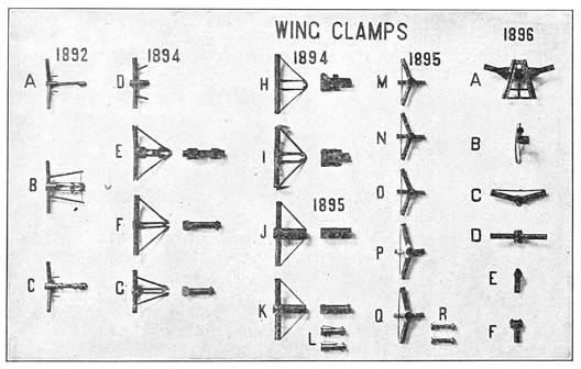
In preparing the machine for flight, the wings and tail of No. 4 were set at a very small root angle with the midrod, perhaps not exceeding 3°, but while this angle might be maintained at the firmly held root of the wing, it was later seen to be probable that the extremity of the wing was flexed by the upward pressure of the air after launching, though the full extent and evil effect of this flexure was not recognized at the time. In the approximative calculations for “balance,” made at this time, the tail was treated as bearing 13 of the weight of the aerodrome, as it was 13 of the supporting area, for though it was recognized that its position in the “lee” of the wings rendered it less efficient, the degree of this diminution of efficiency was not realized. A vertical rudder 20 cm. × 70 cm. (8 in. × 28 in.), with an area of 0.14 metres (1.5 sq. ft.) was used. [p083]
The particulars of the launch will be found in Chapter IX ◊. In the present connection, it is sufficient to say that though launched with the requisite velocity and without accident, it fell into the water at a distance of about 15 metres (49 feet) with the midrod nearly horizontal, the combined effect of engines and initial impulse having in fact kept it in the air for less than two seconds. The true cause of this failure not then being recognized, it was attributed to the angle of the wings with the midrod having been too small.
The launch of No. 5 followed almost immediately, but taking warning by the supposed cause of failure of No. 4, its wings were set at a root angle of 20°, and a hurried adjustment was made to secure greater rigidity, the tip being partly secured against twisting by a light cross-piece, and guyed so that the wing as a whole was not only at a greater angle, but stiffer than in the case of No. 4. These changes it was hoped would cause the aerodrome to advance at a considerable initial angle with the horizontal, and it did so, for instantly after the launch, as the aerodrome escaped from its bonds into free air, the inclination of the midrod increased until it stood at about 60°, when the machine, after struggling a moment to maintain itself, slid backward into the water (with its engines working at full speed) after advancing about 12 metres (39 feet), and remaining in the air about 3 seconds.
On the whole, the result of the first actual trial of an aerodrome in the field was disconcerting, for unless the result was due to the wings being placed in a position wholly unfavorable to support, there seemed to be no doubt that either the engine power or the supporting surface was insufficient. Now this engine power was by computation between three and four times what was necessary to support the aerodrome in horizontal flight at an angle of 20°, and after making every allowance for slip, there should have been still an excess of power for the first flight of No. 4, whereas actual trial indicated that it was insufficient. But on the other hand, the experiment with No. 5, which momentarily held its position in the air at an angle of 60°, seemed to indicate that the engine power was abundant, and that the failure must be traced to some other cause.
As a result of these experiments it was concluded, “that it is an all-important thing that the angle of the front wing shall be correct, and that this cannot be calculated unless it is known how much the tip will turn up under pressure of the weight.” I felt, then, that I had learned something from the failures as to the need of greater rigidity of the wings, though how to obtain this without adding to their weight was a trying problem. It was thus at an early stage suspected that the evil to be guarded against in wing construction was the distortion of the form of the wing under pressure, chiefly by torsion, which is specially hard to provide against without a construction which is [p084] necessarily heavy. This suspicion was a correct one, though the full extent of the evil was not yet surmised.
In the light of subsequent experiment it may now be confidently stated that the trouble was with the wings, which at the moment after launching were flexed wholly out of the shape which they were designed to have, and which they retained up to that critical moment.
After returning to Washington, one of the wings was inverted, and a quantity of sand, equal in weight to the pressure upon the wing in flight, was added, under which the yielding at the tip amounted to 65°, or from +20° to −45°, showing that the wings were entirely too weak to sustain the aerodrome.
In speaking of the efforts to strengthen the wings, it must be constantly remembered that this could hardly be done in any way which did not involve increased weight; that is, it could hardly be done at all, since increased weight was forbidden.
The first attempt at systematic guying was made on October 27. As shown in Fig. B, Plate 16, two guy-posts extending beneath the midrod were connected by guy-wires with the outer extremities of the wing, by means of which it was sought to hold the wing in place and prevent its extremity from twisting upward, while a third wire connecting with the bowsprit prevented its moving backward. In addition, two aluminum wires, stretched across above from wing to wing, kept the lower guys tight.
On October 27, Aerodrome No. 5, equipped with large new wings and tail, having a combined area of 3.7 square metres (40 sq. ft.), the wings being each 64 cm. × 192 cm. (25.25 in. × 75.75 in.), turned sharply and completely round, apparently through some internal current of the main wind against which it was advancing. Owing to this almost instantaneous turn, it lost headway and came down. This led to the subsequent construction and use of a much larger vertical rudder, intended to prevent in future any such sudden pivoting and consequent loss of momentum. The wings showed a tendency to “pocket”28 and bag, which indicated some serious fault in their construction.
As a result of these experiments, it was decided on October 29 to attempt to make the wings stiffer (though their weight was almost prohibitory), by inserting more cross-pieces, cross-pinning and guying them so as to make them more rigid as a whole, and less liable to pocket.
At this time an automatic device in the form of a sliding tail was designed, which it was thought would cause the center of pressure to move backward when the aerodrome reared, and forward when it plunged downward, but the device, though afterward constructed, was never brought to trial in the field.
Aerodrome No. 5, equipped with a new set of wings similar to those used [p085] on October 27, and guyed as in the previous experiment, was again launched on November 21, with the results recorded in Chapter IX ◊. The failure was attributed to the twisting of the wings under pressure to such an extent that not only was their effective area greatly reduced, but the outer portions were upturned so as to catch the air upon the upper surfaces, the result being in part a downward pressure.
On the following day a pair of the wings was inverted and a weight of sand equal to the air pressure to which they were subjected in flight, was distributed over their surfaces. Under the action of this, the twisting of the wing was seen to increase from the root, which was held with comparative rigidity, up to the tip, where in spite of the cross-ribs it amounted to 45°. The resistance to torsion lay chiefly in the front rib, which, in addition, could be bent easily, allowing the surface to become distorted with great loss of lifting power.
The experiments of 1894 had demonstrated the urgent necessity for greater rigidity in the sustaining surfaces, which might, as it seemed, be obtained either by increasing the strength of the framing (which meant additional weight) or by resorting to some new and untried construction, or by a proper system of guying. Guying seemingly offered the most feasible solution of the problem; but although the system of wire guying was thoroughly tried, the result was very unsatisfactory, as the wings continued to twist and bag in a way that was extremely discouraging.
I accordingly had recourse in 1895 to the system of wooden guy-sticks shown in Fig. D, Plate 16, which necessarily added greatly to the weight of the sustaining surfaces. Each wing was separately strengthened by means of a light rod of spruce, in cross-section about the size of the main front rib, extending across the upper surface of the wing, at a distance of about one-third the width of the wing behind the front rib. It was tied to each of the cross-ribs and to the outer bent portion of the front rib, and at its root was fastened to the frame of the aerodrome.
This effectually prevented the bending of the front rib and the consequent bagging of the cover, and to that extent marked a decided advance in wing construction. But it was faulty, in that, not being supplemented by wire guying, it offered little resistance to the twisting of the wing about the main front rib, the rear tip of the wing being free to turn up under pressure, as it had done on former occasions. A similar guy-stick was stretched across the tail. To guard against torsion, rods extending diagonally across the wings and tail were used, which, with the aid of the guy-sticks just described, prevented the surfaces from twisting greatly. In addition, a rod joining the front ribs and stretching across from wing to wing tended to maintain a fixed diedral angle. [p086]
The wings as thus guyed were rigid enough, and in the field-trials of No. 5 on May 8 and June 6, did not yield noticeably under pressure, and there seemed to be no serious default in their lifting power, but the guy-sticks were heavy and the system was not again employed. The wings used in these trials, shown in Fig. C, Plate 16, had a frame of hickory, consisting of a front rib and nine cross-ribs, over which the silk was tightly stretched. The curvature of the wings, which is shown in the cross-sectional drawing, had a rise of about one-twelfth the width, the highest point of curvature occurring about one-fourth the distance from front to rear. Each wing was 64 cm. × 192 cm. (25.25 in. × 75.75 in.), the two with the tail, in surface equal to a single wing, having an area of 3.7 square metres (40 sq. ft.). The combined weight of the wings was 1150 grammes (2.53 pounds), and of the tail, 583 grammes (1.28 pounds).
The evolution of a vertical rudder had meanwhile been going steadily forward. Those first used had been small, rectangular, stiff, and heavy, but in the experiments of May 8 a much lighter and larger construction, consisting of a frame 92 cm. × 76 cm. (36 in. × 30 in.) covered with paper, was used, and on June 7 this was replaced by a long, diamond-shaped rudder, having a spruce frame covered with silk, very light and seemingly more effective than any hitherto used.
I had in the meantime designed a “tail-rudder,” consisting of a horizontal tail and vertical rudder combined, each having an area of about 0.6 square metres (6.5 sq. ft.) which, however, was not used until 1896.
In August was begun the construction of a deeply curved and arched pair of wings for No. 4, which consisted of a light framing of spruce elaborately guyed and covered with gold-beater’s skin drawn tight as a drum-head with pyroxelene varnish. In their construction a new feature, foreshadowed in the method of guying the separate wings used in the field-trials of May and June, was introduced, which was adopted in all subsequent constructions—the guy-stick, previously described as stretching lengthwise across the wing being now made a part of the wing itself, which was thus provided with two longitudinal ribs instead of one. The additional rib occupied a central position, and like the front rib was attached to the midrod by means of a strong wing clamp. Its outer end was united to the front rib, which was here bent into a quadrant of a circle. This pair of wings had an expanse of 435 cm. (14.3 feet), an area of 2.5 square metres (26.8 sq. ft.), a weight of 660 grammes (1.45 pounds), and a depth of curvature equal to one-tenth their width.
This construction offered a two-fold advantage in its resistance to both torsion and bagging, for as the pressures upon the wing were nearly balanced about the middle rib, the tendency to twist was reduced to a minimum, while the bagging, which results from the bending of the framework, as distinct from [p087] its twisting, was greatly reduced by the manner in which the frame was put together, the whole construction permitting a return to the system of wire guying at first adopted, which had been found inapplicable to a wing having but a single longitudinal rib forming its front margin. When completed, the wings were strongly guyed with piano wire, both above and below, to guy-posts attached to the midrod, and each cross-rib was separately guyed with wire chords. Although these wings had cost much in time and labor, and contained many points of improvement, they were eventually found to be too weak to support the aerodrome, and were therefore abandoned without a trial in the field.
For the plane horizontal tail hitherto used a pair of curved wings was substituted, similar in all respects to those just described, but having only half their area, and these were later replaced by a pair equal in size and in every way the counterpart of the front wings. The tail as hitherto used accordingly disappeared, and gave place to another having a wholly different function to perform; for while the old tail, like the rear pair of wings which superseded it, was intended to bear a definite part of the weight of the aerodrome, the new tail which was now added behind the rear pair of wings was not supposed to bear any part whatever of the weight, but to act solely as a guide, and this new feature, first introduced in October, 1895, was continued to the end.
This arrangement of the surfaces is quite different from that adopted by Pénaud in 1872, in which the tail became automatic in its action through its small angle of elevation as compared with that of the wings, while still acting as a supporting surface, whereas in the present arrangement the function of the tail was solely one of guidance. This, I believe, was one of the important changes which perhaps as much as any other led to final success.
During the fall of 1895 a large number of experiments were made both in free flight with gliding models, and in constrained flight with the whirling-table, to determine the relative lifting power of the front and rear wings per unit of area, and from these the following new rules were deduced for finding the center of pressure:
If a following wing is the size of the leader, assume that its efficiency is 66 per cent per unit of surface.
If it is half the size of the leader, assume that its efficiency is 50 per cent per unit of surface.
If it is half as large again as the leader, assume that its efficiency is 80 per cent per unit of surface.
For intermediate sizes of surface, proportionate values per unit of surface may be assumed.
If we consider the area of the front wing to be unity, and that of the rear wing to be n, and if m be the efficiency of the rear wing per unit of surface, [p088] the above is expressed in the following formulæ, which it will be remembered take account only of wings following each other in the same or nearly the same plane, and are not applicable where one wing is either above or below the plane of the other. In the formulæ, CP is the resultant center of pressure upon both wings expressed in the notation described in Chapter II ◊, CPfw is the center of pressure of the front wings, and CPrw the center of pressure of the rear wings.
If the value of n lie between one-half and unity,
while if the value of n lie between unity and 112,
In either case
where the leading and following wings are equal
The steady flight of one of the gliding models referred to led to the construction of a new set of wings for No. 5, patterned after those used on the gliding model. These wings, shown in Plate 17, were rectangular in outline, 200 cm. × 80 cm. (6.56 ft. × 2.62 ft.), each wing having an area of 1.6 square metres (17.1 sq. ft.) They were constructed with spruce framing covered with China silk, and were strongly guyed with piano wire in much the same manner as the light, skin-covered wings already described, which had preceded them. The combined weight of the two pair was 1950 grammes (4.3 pounds).
The long central rib was now much the larger of the two which, as in the preceding wing, formed the foundation of the structure. It occupied a position two-fifths the distance from front to rear, and presumably coincided at all points with the center of pressure of fore and aft sections of the wings, so that the pressure in front of the rib was at all points balanced by the pressure in the rear, and there was consequently little tendency in the wing to twist under pressure of the wind. The two main ribs were rigidly connected by cross-ribs of spruce, 20 cm. (8 inches) apart, steamed and bent to the desired form. The curvature of these ribs was the same for all, and in depth was one-twelfth the width of the wing, while the highest point of curvature was one-sixth of the distance from front to rear, these ratios having been chosen as approximating those found in the wing of the soaring bird. These wings were subsequently used in the first successful flights of the following year.

During the year 1895 but two field-trials were made with the steam aerodromes, and neither of these was successful; but a great step forward had been taken in the construction, guying and arrangement of the sustaining surfaces. The wings had been made stronger with no increase in weight per unit of area. On the contrary, the ratio of weight of sustaining surfaces to area had been actually reduced from 43 to 28 grammes per square foot, so that the surfaces were both lighter and stronger.
Two longitudinal ribs had taken the place of the single one before used, a second wing clamp had been added to correspond to the midrib, the difficult problem of torsion had been effectually solved, the system of guying greatly improved, and it appeared that in the next trial the wings might be expected to bear the weight of the aerodrome without serious distortion.
In January, 1896, two new pairs of wings were designed for No. 6, and in order to give a greater efficiency to the rear wings, they were made larger than the front ones, the area of the latter being 22 square feet, and of the former 27 square feet, and whereas the width of each wing had formerly been one-third of its length, it was now increased to two-fifths to correspond to those of No. 5.
The progress made in construction and guying is shown by the fact that when on January 28 one pair of the wings of No. 5 was inverted and sanded, the yielding at the tip was less than 5° greater than at the root, whereas at one time it had been 65°. A similar test applied to a pair of wings of No. 6 on March 4 gave even better results, as the yield at the root was but 1° 45′, and at the tip 2° 30′.
The successive stages of the development of the wing clamps are shown in Fig. 16. In its final form the front wing clamp, or that which held the main front rib, shown at AB (1896), had adjustable sliding pieces, by means of which the wings could be set at any desired angle of elevation, the wing as a whole revolving about the rear wing clamp, shown at CD (1896).
The general system of guying the wings, as shown in Plate 17, had been greatly improved. In the present form a bowsprit and guy-posts firmly attached to the midrod furnished points of attachment for the piano wires with which the wings were guyed and held rigidly in place, other wires being stretched across from wing to wing so as to maintain them at a constant diedral angle of about 150°. The clamps by which the guy-posts were attached to the midrod, are shown at EF (Fig. 16).
In the successful flights of No. 5 on May 6, the completed wings already described weighed together 1950 grammes (4.29 pounds), and had a total sustaining area of 6.4 square metres (68.8 square feet), the flying weight of the [p090] aerodrome was 11,775 grammes (26 pounds), and the sustaining surfaces therefore amounted to 2.6 square feet to the pound, which, as the event proved, was amply sufficient.
The “tail-rudder,” shown in Plate 17, comprised a vertical and horizontal surface of silk intersecting in a central rod or axis, having a length of 115 cm. (3.8 feet). The framing was of spruce and consisted of two sets of four arms, each radiating from the central rod, the hexagonal outline of the surfaces being formed of piano wire, over which the silk was drawn and sewed. The area of each surface was about 0.6 square metres (6.45 square feet), and the total weight was 371 grammes (0.8 pounds).
A flat steel spring inserted in the forward end between the rudder and the midrod gave it a certain desirable degree of elasticity in a vertical direction. The rudder was held in place by a pin passing through the midrod, and was so set as to coincide with the line of direct flight, its purpose, as already explained, being to guide the aerodrome, but to take no part in its sustention.
In balancing Aerodrome No. 5 on May 6, the wings were so adjusted that in accordance with the notation given above, p. 15:
and as the wings were of equal size, from what has preceded in the present
The center of gravity was located at 1497, so that there should have been a very slight tendency on the part of the aerodrome to rise, as was actually the case. The formula was perhaps not quite so accurate as the prolonged flight of the aerodrome would seem to indicate, as it takes no account of the thrust of the propellers, which in action tended to elevate the aerodrome in front while their resistance would tend to depress it when they had ceased to revolve, which consideration accounts for the action of the aerodrome on May 6, as described in Chapter IX ◊. The formula may, however, be regarded as approximately correct.
In the final successful trial with No. 6 on November 28, 1896, the wings used were similar in general construction and manner of guying to those of No. 5 on May 6, but, as shown in the photograph (Plate 29A, Chapter X), the front rib at its outer extremity was bent to a quadrant to connect with the midrib, this construction being somewhat stronger than that adopted in the wings of No. 5. The curvature was but one-eighteenth of the width of the wing instead of one-twelfth as in No. 5. The front and rear pairs were similar and equal and had a combined area of 5 square metres (54 sq. ft.), and a weight of 2154 grammes [p091] (4.74 lbs.). The flying weight of the aerodrome was 12,120 grammes (26.7 lbs.), the sustaining surface thus amounting to slightly more than 2 square feet to the pound.
The position of the wings, in accordance with the notation adopted, was
Since the wings were equal in size,
The center of gravity was located at 1484, which was 3.5 cm. in the rear of the center of pressure. The flight was approximately horizontal, and the setting seems to have been as accurate as could be desired. The angle of elevation of the wings at the root was 10° 30′, and so well were they guyed that there was no visible yielding at any point during the flight. As the midrod during flight was approximately horizontal the angle of elevation of the wings may be taken as 10° 30′; the efficiency of the rear wings was two-thirds that of the front wings, and the effective area was therefore 27+27×23 = 45 square feet.
The wings being very nearly plane we have therefore the data for determining the soaring speed from the formula of “Aerodynamics” (Chapter VI, p. 60).
in which W = 26.7 pounds; A = 45 sq. ft.; k = 0.00166; α = 10° 30′; F (α) cos α = 0.353. By substituting these values in the formula we obtain V = 32 feet per second.
The speed actually attained, however, was about 30 miles an hour, or 44 feet per second, which seems to indicate that the angle of elevation under pressure was reduced to much less than 10° 30′. For a velocity of 44 feet per second, the theoretical value of α would be but 6°. In this calculation, however, the hull resistance and that of the system of guy-wires, which must have been comparatively large, has been omitted. It would appear, therefore, that the actual results obtainable in flight are much more favorable than calculations based on experimental data would presuppose.
I have elsewhere mentioned that the difficulties of launching even a very small model aerodrome are considerable. Early experiments were tried with an apparatus something like a gigantic cross-bow, and in later years with various forms of pendulum, all of which latter brought out the inherent theoretical defect of the movement of rotation of the aerodrome, and were otherwise practically inefficient.
A device, consisting of two pendulums, one behind the other, connected by a rigid rod, from which the aerodrome could be suspended and cast off without rotation, was at one time considered, but abandoned. Experiments were also made with several forms of railroad, upon which the aerodrome was to run up to the moment of release, before the form of launching apparatus, which finally proved successful, was adopted.
All these had failed chiefly for two reasons; first, it was difficult to cause the aerodrome to be released just at the moment it attained sufficient speed to soar; second, the extensive surface presented to the wind by the wings of the aerodrome, made it necessary to provide means for holding the machine securely at several points up to the moment of release without danger of interfering in any way with the aerodrome when it was cast into the air. This proved a serious problem, which can be appreciated only by one who has seen such a machine in the open air, where its wings are subject to movement and distortion by the slightest breeze. The steps by which these difficulties were removed and the final type of launching apparatus perfected are recorded in the following pages in connection with the field-trials of the model aerodromes.
As the end of the year 1892 approached and with it the completion of an aerodrome of large size which had to be started upon its flight in some way, the method and place of launching it pressed for decision. One thing at least seemed clear. In the present stage of experiment, it was desirable that the aerodrome should-—if it must fall-—fall into water where it would suffer little injury and be readily recovered, rather than anywhere on land, where it would almost certainly be badly damaged. [p093]
The shores of the Potomac on both banks were scrutinized for this purpose, from a point about two miles above Washington to below Chopawamsic Island, some thirty miles below the city. Several lofty and secluded positions were found, but in all these there was the danger that the aerodrome might be wrecked before reaching the water, or, turning in its course, fly inland; but more than this, it could be launched only on the rare occasions when the exact wind was blowing which the local conditions demanded.
Finally, the idea, which seems obvious enough when stated, presented itself of building a kind of house-boat, not to get up initial motion by the boat’s own velocity, but to furnish an elevated platform, which could be placed in the midst of a considerable expanse of water, if desired, under conditions which admitted of turning in the direction of the wind, as it need hardly be repeated that it was indispensable to the machine, as it is to the bird, to rise in the face of a wind, if there be any wind at all.
The house-boat in question was nothing more than a scow about 30 feet long by 12 feet wide, upon which a small house was erected, to be used for the occasional storing of the aerodromes. On account of the accidents which were certain to occur in the first attempts, it was fitted up with the means of making small repairs. On the roof of the house there was a platform upon which the operator stood when making a launch, and upon which were mounted the launching devices hereafter described.
This boat, shown in Plate 18, was completed in November, 1892.
By the kindness of the Superintendent of the Coast Survey, the house-boat was towed in May, 1893, down to Chopawamsic Island, a small island near the western bank of the Potomac River, not far from the Quantico station of the Washington and Richmond Railroad Company. A map of the island and the adjacent land and water is shown in Plate 19.
The house-boat was at all times moored somewhere on the west side of the island, in the stretch of quiet water between that and the west shore of the river. The waters shown here are, with the exception of a narrow channel, very shallow, and, indeed, partly dry at low tide, so that there was no danger of an aerodrome being lost, unless its flight carried it a long distance away and over the land.
Aerodrome No. 4, as shown in Plate 11, had a single midrod, a flying weight of 9 pounds,30 and supporting surface, consisting of wings and tail, of 18 square feet. [p094] Its engines, with about 100 pounds pressure, developed an aggregate of 0.4 H. P., and lifted 50 per cent of the flying weight. The propellers were 60 cm. (2 feet) in diameter and 114 pitch ratio.
The aerodrome was intended to be launched by a contrivance called the “starter,” which was an inclined rod, hinged at the bottom, on the top of which the aerodrome was supported on a rod which was thrown down at the instant of flight, giving the aerodrome a slight forward impulse, with the expectation that it would get up sufficient initial speed to soar from the action of its propellers.
On November 18 the writer (L), with Dr. Barus (B) and the two mechanics (R and M), went to Quantico by an early train, and superintended with interested expectation the arrangements for this first trial in the open air of the mechanism which had now been over two years in preparation.
We met with an unexpected difficulty—that of launching the aerodrome at all, for though the wind was only a very gentle breeze, it was only by holding it down with the hands that it was possible to keep the aerodrome in position for the launch, during the few minutes which passed from the time it was placed upon the apparatus to the time of releasing it. Whether the launching device itself might be effective or not could not be ascertained, since it was found that nothing which could even be called an attempt to launch could be made except in an absolute calm; a condition of things very difficult for any one to understand who has not passed through the experience. The writer returned to Washington at the close of the day without having done anything, but having learned a great deal.
November 20. L, with B and M, came down again, and waited until 4.20, when, the breeze having fallen to almost a calm, the aerodrome was maintained in place on the launching apparatus with great difficulty, while it was repeatedly set on fire by the scattering liquid fuel. Finally it was let go, and fell close to the house-boat, the tail striking the edge of the platform. The immediate cause of failure was the defective launching apparatus, for the design of which the writer felt himself responsible.
November 24. L, with B, M, and R came down again to Quantico, but the very moderate wind proved completely prohibitory to any attempt at launching, and all returned again to Washington.
November 27. L, with B and M, came down to try a new launching apparatus, not different in principle from the preceding one, but of better construction. The morning was exceptionally calm, but the engines were found to be out of order, and precious time was spent in slight repairs which should have been made in the shop. At 3.30 p. m., when the engines were at last ready, the exceptional calm gave place to a very gentle and almost imperceptible breeze, [p095] which, nevertheless, again proved prohibitory to the launching, and with extreme disappointment the party returned to Washington, it being at last fully recognized that unless some ways were found of holding down all the extended supporting surfaces upon the launching piece, and at the same time of firmly clamping the body of the aerodrome until it could be dropped, as well as of releasing all this simultaneously at the critical instant, no attempt at launching was likely to succeed except in such an entire and perfect calm as rarely occurs. Independent of this launching difficulty, some way of protecting the fires from the wind had to be found, which was by no means easy, since an efficient protection meant an enclosure of them and a diminished influx of air, of which it was essential that there should be an unlimited supply.
December 1. L, with B, R, and M proceeded to Quantico. The same conditions presented themselves and the party returned, without effecting anything.
December 7. L, B, R, and M present; day overcast but perfectly calm. Taught by experience, we had everything ready, and a little after one o’clock the launch was made. The aerodrome fell directly into the boat, the rod of the starter having broken. It was little damaged, but in view of the injury and the rising wind, all other attempts were abandoned for the day.
December 11. Present, L, with B, R, and M. A new “starter” had been devised and brought down, but was not yet quite ready for use, and an attempt was made to employ the old one with the improvements suggested by experience, but, after two attempts to launch, the work was abandoned for the day, owing this time not to the launching apparatus, but to troubles in the engines and pumps, due probably to injuries received in the fall of the 7th, which were not detected until the time of the actual trial.
December 20. L, with B, M, and G, present; engine and aerodrome in order and everything apparently favorable. What seemed to be an almost entire calm came toward evening, yet once more the all but imperceptible breeze which prevailed was found to defeat all arrangements for holding the aerodrome to the launching ways before it was let go.
Trips to Quantico were also made on November 24, and December 1 and 21, of which no account is given as the very moderate wind which prevailed in each case precluded any attempt at launching the aerodrome.
It will be seen that eight trips were made to Quantico, and that, far from any flight having been made, not once even was the aerodrome launched at all. The principal cause for this lay in the unrecognized amount of difficulty introduced by the very smallest wind, irrespective of the unfitness of the launching apparatus to give the desired initial speed and direction.
In all these trials, the aerodrome rested on the launching apparatus, by which it was projected forward by means of a spring in such a way as not to interfere with the propellers. [p096]
Previous tests with the rubber-driven models had demonstrated the futility of all simple pendulum types of “cast off,” and likewise all the trials hitherto of a railroad form of launching apparatus, in which the aerodrome was mounted on a car, which had itself to get out of the way, were equally failures, so that when the device referred to above proved to be worthless, it seemed that almost every plan had been exhausted. There were, moreover, other difficulties, some of which have been indicated above, such as that of making the burners work properly in even a moderate wind during the very short time required for attaching the wings and so adjusting the aerodrome on the launching apparatus.
These difficulties, which, now that they have been overcome, seem difficulties no longer, but which then seemed insuperable, were all connected with the ever-present problem of weight. It would have been easy to make rigid sustaining surfaces which would not bend in the wind; to make fires which would not go out; and easy to overcome all the impediments which seem so trivial in description and were so formidable in practice, were it not that the mandate of absolute necessity forbade this being done by any contrivance which would add to the weight of an already phenomenally light construction. The difficulties of the flight as they were seen in the workshop were multiplied, then, beyond measure by the actual experiments in the field, and the year closed with a most discouraging outlook.
The new year began without any essential improvement in the means already described, though a new launching apparatus had been devised by the writer, which was scarcely so much an apparatus for launching, in the ordinary sense of the word, as one of holding the aerodrome out over the water, and simply letting it drop from a height of about 25 feet, during which fall it was hoped (exact data being unobtainable in advance of experiment) that there would be time for the propellers to give the aerodrome the necessary soaring speed before reaching the water. This device consisted of an inverted tripod, which held the aerodrome comparatively steady by three bearing points, while a cross-bar of wood was added to prevent the wings from swaying before the launch. Previously, the supporting surfaces, wings and tail, had been put on only at the last minute. Now it became possible to keep them on in a gentle breeze for an indefinite time before launching.
January 9. The previous day having been spent in practicing the steps preliminary to launching, so as to avoid delay in assembling and mounting the aerodrome, the writer, with Dr. Graham Bell, went to Quantico. The day was calm, and every condition seemed favorable. The aerodrome was dropped fairly, under full steam, and it fell in a nearly horizontal position, but touched the water at a distance of only 50 or 60 feet, evidently before the necessary initial speed [p097] could be impressed on it by its engines. The conclusion should have been that by this method nothing but a practically unsuitable height would suffice to start the aerodrome in a calm, though it might perhaps be done in the face of a considerable breeze.
May 25. After a considerable interval of delay, due to the river being closed by ice and other causes, Aerodrome No. 4 was again dropped from the starter under nearly the same conditions as in the trial of January 9, and with a quite similar result, the final conclusion being that this method must be abandoned. It may be added that a vertical rudder was tried on this day.
June 12. No. 4, with an improved blast, was tried at Quantico, Mr. Goode being present. The day ended in failure from another cause, the improved blast, which worked well in the shelter of the shop, but proved useless in the field, being extinguished by the feeblest wind. At this time (in June and July) I designed a horizontal railroad with launching springs and track, underneath which ran a car which held the aerodrome firmly until the moment of automatic release. This apparatus finally proved to be the successful solution of the launching problem. The description given later, with the drawing in Plate 18, shows the after-improvements, but no specific change from that in use from the first.
About this time I also arranged for certain changes in the boilers and burners, having decided that I would not go into the field without some ground for confidence not only that the aerodrome could be launched successfully, but that a steady flame could be maintained under the boilers.
October 6. No. 4, as remodelled, having a flying weight of about 14.5 pounds, a supporting surface of about 28 square feet, with a total engine power of about 0.5 H. P., and having lifted 40 per cent of its weight on the pendulum, was taken down the river for trial with the new railroad launching apparatus, and several days were spent in erecting the launching apparatus on the house-boat, and in launching “dummy” aerodromes from it for practice.
Aerodrome No. 4 then being fitted under conditions which apparently insured a good start (the center of pressure being nearly over the center of gravity, the root angle of the wing being zero, the midrod nearly horizontal, the engine working well, and with apparently ample sustaining surface) was finally successfully launched, but the hopes which were reasonably entertained proved to be unfounded. The result of this first actual trial of a “flying machine” in free air was most disconcerting, for the aerodrome, which had in theory many times the power required for horizontal flight, plunged into the water with its engines working at full speed, after a course hardly longer than that performed by the dummy. This result was at first inexplicable.
No. 4, then, did not fly at all, from some at first inscrutable cause, and it was decided to make a trial of No. 5, though it was hard to put the result of so much [p098] time, painstaking and cost to the hazard of destruction. With the experience just acquired from the trial of No. 4, the wing of No. 5 was set at an angle of about 20° with the midrod, and the tip was secured by a light cross-piece, so guyed that the wing as a whole, while set at this considerably greater angle with the rod, was stiffer than before. In addition to this, the air chamber was moved back so that the center of gravity was from 6 to 10 cm. behind the (calculated) center of pressure. These changes were made in order to insure that the front should at any rate keep up, and it did.
The aerodrome was launched successfully with the engines working under a pressure of 110 pounds of steam. The head rose continually until the mid-rod stood up at an angle of about 60°, checking all further advance. It remained in the air in a stationary position for nearly a second, and then slid backward into the water, striking on the end of the rudder and bending it. The distance flown was about 12 metres, and the time of flight 3 seconds. One of the propellers was broken short off, and the shaft was bent.
It thus became clearly evident that some cause prevented the proper balancing of the machine, which was necessary to secure even approximately the theoretically simple condition of horizontal flight. It was all-important that the angle of the front wing should be correct, but its position could not be accurately known in advance of experiment, and this experiment could only be made with the machine itself, and involved the risk of wrecking it.
These trials gave a very vivid object lesson of what had already been anticipated,31 that the difficulties of actual flight would probably lie even more in obtaining exact balance than in the first and more obvious difficulty of obtaining the mere engine power to sustain a machine in the air. The immediate problem was to account for the totally different behavior of the two aerodromes in the two flights, under not very different conditions.
Observations of the movement of the two aerodromes through the air, as seen by the writer from the shore, seemed to show, however, that the wings did not remain in their original form, but that at the moment of launching there was a sudden flexure and distortion due to the upward pressure of the air. The time of flight was too short, and the speed too great, to be sure of just what did occur, but it seemed probable that the wings flexed under the initial pressure of the weight which came upon them at the moment of launching, and that they were in fact, while in the air, a wholly different thing from what they were an instant before, so that a very slight initial difference in the angle at which they first met the air might cause the air to strike in the one case on the top of the wings and throw the head down, and in the other case so as to throw the head up. To ascertain the extent and character of this flexure, caused, it will be observed, by [p099] the weight of the aerodrome suddenly thrown on the wings, I inverted the aerodrome and distributed a weight of dry sand equal to that of the whole machine evenly over the supporting surfaces. It was found that under the weight of the sand the extremity of the wings bent to an angle of 45° downwards (and consequently must have bent to an angle of 45° upwards in the air), a condition of affairs worse than anything that had been suspected, and seeming to demand the entire reconstruction of the wings with a strength and consequent weight for which there was no means of providing.
There had been some injuries to the machines in the trials of the 5th and 6th, and these were repaired. A new float had been made for No. 4, and a new set of larger wings for No. 5. Each of these wings had a length of 76 inches and a breadth of 25 inches, making the total surface of the two 26.4 sq. ft., while that of the tail was 13.2 sq. ft., or about 40 sq. ft. in all.
October 22. When No. 5 was finally prepared for another trial, its condition was as follows:
| Flying weight | 22 | pounds |
| Area of supporting surfaces (wings and tail) | 40 | sq. ft. |
| Sq. ft. of surface per pound of weight | 1.832 | |
| Engine power with 115 lbs. steam pressure | 1.0 | H. P.33 |
| Power necessary to soar | 0.35 | H. P. |
| Theoretical soaring speed (plane wings at 20°) | 24 | ft. per sec. |
| Previous lift on pendulum | 40 | per cent of flying weight |
October 25. The aerodromes having been taken to Quantico on October 23, and satisfactory experiments made with dummies in order to test the launching apparatus, the house-boat was carried out into midstream and moored.
Aerodrome No. 4 was launched in the face of a wind of about 1100 feet per minute. The midrod was at a very small inclination with the horizontal, about 3°. The angle (α) of the chord of the curved wing measured at the rod, where it was rigidly held, was 15°. The adjustment was such as to bring the CG immediately under the CP, without any allowance for the fact that the line of propeller thrust was below the CP.34 The aerodrome under these conditions was launched with the head high. It made a real, though brief, flight of about 130 feet in 412 seconds, when it swung abruptly round through 90°, and, losing headway, sank continuously, finally falling backward into the water.
October 27. Aerodrome No. 4, having been repaired and guyed with wires from the wings to vertical guy-posts beneath, was launched again, but one of the [p100] guy-wires caught on the launching car, and threw the aerodrome immediately into the water with but little damage.
On the same day No. 5 was launched. The theoretical CP−CG was nominally 0, but, for the reasons stated in the footnote on p. 99, was really something positive, that is to say, the CP was really somewhat in advance of the CG; inclination of midrod less than α (=20°). The aerodrome under these circumstances, while keeping its head up, at first fell rapidly, yet seemed about to rise just as it struck the water, conveying the idea that if the launching had been made with a greater initial velocity it would have risen and cleared the water. The wings visibly pocketed, however, and it was clear that some better disposition must still be made for them. The flight was 312 seconds.
No. 5 was tried again on the same day with larger wings, whose area was 40 square feet. These wings, though stiffer, pocketed a little, α=20° as before. It flew rapidly, and at first horizontally, to a distance of 100 feet or more against a five-mile breeze. It then turned abruptly round through 180°, at first falling (from loss of headway), then distinctly rising, and at the same time throwing its head up until it reached an angle of nearly 60° with the vertical, when it fell backward after a flight of between 6 and 7 seconds. The wings were evidently not yet strong enough to resist flexure.
November 21. No. 5, in nearly the same condition as before. Two extra springs had been placed on the launching car, in order to give the aerodrome a greater initial velocity than before. Everything appeared favorable, but as it left the launching track a piece flew out of the port propeller, in spite of which the aerodrome, after dropping 5 feet, rose bodily at an angle of 45° and fell backward into the water (time, 5 seconds).
Another trial was made the same day with the same aerodrome, under similar conditions, except that the angle of inclination (α) was reduced to 7°. It now, with all the other circumstances of launching like those immediately before, behaved entirely differently, plunging head downward into the water at a distance of 30 feet. Once more it was shown beyond dispute that the wings must somehow be made even stiffer.
December 8. Another trial was undertaken with No. 5, the CG being 10 cm. in front of the CP at rest. The root angle of the wings was 18°, tip angle 27°, elevation of midrod 1 in 24. The other changes made since the previous trial consisted chiefly in the increased weight due to the longer and stronger frames and shafts that were made to carry 100 cm. propellers. The flight obtained was so short that it was as unsatisfactory as before.
The aerodrome rose in the air after leaving the launching apparatus, and then slid back into the water in the plane of its own wings. On the first trial, it struck the boat, and was slightly injured; on the second, with root angle of [p101] wings 10°, tip angle 20°, the flight partook of the same character, but the machine struck the water clear of the boat.
The fact that with the CG 10 cm. in advance of the calculated CP the aerodrome steadily rose in front, seems to indicate that the rule used at that time for calculating the CP (see Chapter II ◊) was not very accurate. This rule was based upon the assumption that the tail, having an area equal to one-third the entire sustaining surface, supported one-third the total weight (expressed by the formula CP = 2CPwm + CPtm3, where CPwm and CPtm represent respectively the CP of the wings and tail in motion), and that the CP of each surface was one-fifth its width in front of the center of figure.
December 12. Four days later, the tail had been moved back 21 cm., thus carrying the CG back 7 cm., but the vertical rudder (weighing 105 grammes), for which there was now no room, was taken off, which in a measure counteracted this change.
A trial was then made with the wings set at an initial angle of 8° at the root and 20° at the tip. The aerodrome was released with the engines working under a steam pressure of 90 pounds, and soared off horizontally for some distance, when suddenly it swerved to the right as though something on that side had given out, and turning quite through 180° headed toward the boat, striking the water about 76 feet away. The time of the flight was 4 seconds.
It was found upon the recovery of the machine that one of the propellers had been twisted through 90°, so that the two were no longer symmetrical. The turning may have been due to this twist or to unequal influence of the wind upon the two wings; for when I applied the sand test to the wings after returning them to Washington, it was found that they deflected so much that the grains would not lie upon them, which, to a great extent, explains the failure to secure a better flight.
Thus the end of another year had been reached, and what might be called a real flight had not yet been secured. The only progress that seemed to have been made was that the aerodromes were not quite so unmanageable and erratic in their flights as at the beginning of the year, and that it had been demonstrated, at least to the writer’s satisfaction, that the power was sufficient for the work to be done. The launching device had been so perfected that it worked satisfactorily, but the problem of balancing seemed as far from solution as before.
While, for convenience in narrating the progress of the work with the aerodromes, each year has been treated as a unit, it is, of course, understood that the work itself shows no especial difference between the closing of one year and the beginning of another. Changes which had important effects were introduced [p102] at various times, but were, of course, made as they suggested themselves without any reference to time or season. But while it was customary to make, from time to time, a résumé of the progress of the work, yet at the closing of the calendar year it was the custom to make a more complete digest of just what had been accomplished during the year.
Upon thus reviewing the progress of the work during 1894, it was felt that the results which had been accomplished for such a large expenditure of time seemed small, since no real flight had been made by any of the aerodromes, and no definite assurance that a successful flight would be obtained within the immediate future seemed warranted by what had already been accomplished. But now that the principal difficulties connected with the launching apparatus had been overcome, thus permitting the aerodromes themselves to be given a fair trial, the belief was encouraged that the continuance of the actual tests of the machines, with slight changes which previous tests had shown advisable, would finally result in a successful flight.
The early weeks of 1895 were spent in a series of pendulum tests on No. 5, and in making such slight changes as these tests indicated would be advisable. As a result of small improvements introduced in the boilers, No. 5 had by the middle of March shown a repeated lift of considerably over 50 per cent, and in some tests as much as 62 per cent of its flying weight. Certain radical changes previously described in Chapter VII ◊ were also made in Aerodrome No. 4, and in the pendulum tests of it a lift of 44 per cent of its flying weight had been obtained.
Encouraged by the better results which the aerodromes had shown in the above tests, it was decided to test them again in free flight, and they were accordingly sent down to Quantico in charge of the two mechanics, R and M, Mr. Langley, accompanied by Dr. Graham Bell, whom he had invited to witness the tests, following on May 8. On the evening of May 8 No. 5 was mounted on the launching apparatus in order to drill the mechanics so that when favorable weather presented itself the aerodrome could be got ready for launching with the minimum delay.
On May 9 Mr. Langley and Dr. Bell reached the house-boat at 5 a. m., but even with the drill of the previous evening the mechanics were not able to have No. 5 ready for trial until 6.15 a. m. The principal conditions of No. 5 at this time were:
Total weight 11,200 grammes (24.6 pounds), including 800 grammes of fuel and water. Previous lift on the pendulum 54 per cent, with a steam pressure of 150 pounds. With this steam pressure the engine made about 600 R. P. M. when driving the 95 cm. propellers, which through their reduction gearing made about 500 R. P. M. [p103]
When the aerodrome was balanced for flight so as to bring the theoretical “center of pressure in motion” over the center of gravity, it was found that it was not possible to carry the center of gravity in front of this point, although it was known by experience to be necessary. Accordingly in the first trial the outer ends of the tail were pressed down by the guys so that the wind of advance tended to lift the tail and throw the head down more than if the tail had been flat. Furthermore, the float, weighing 200 grammes, instead of being placed in its normal position near the base of the bowsprit, was carried out to its extremity, this change in the position of the float alone being sufficient to carry the center of gravity forward three or four centimetres. The curved wings were set at an angle of nine degrees at the root and eleven degrees at the tip. They were well guyed, and in flight appeared to be not materially twisted or altered.
It was anticipated that the pressing down of the outer ends of the tail and the shifting of the center of gravity would cause the aerodrome to point downward in flight, and this anticipation was verified in the test. At 6.15 a. m. the aerodrome was launched at a steam pressure of 120 pounds. A perfect calm prevailed at the time and the machine started straight ahead. There was no perceptible drop at the moment it was released from the launching car, but a smooth and steady descent until it struck the water, nose down, at a point approximately 200 feet from the boat. Dr. Bell noted that the length of time the aerodrome was in the air was 2.8 seconds. One of the propellers was broken and the other one was found to have twisted its shaft one-fourth of a turn.
At 9.45 a. m., the wings having been dried, No. 5 was again tried. The float was moved back to its normal position at the base of the bowsprit, and the guys, by which the outer ends of the tail had been depressed in the previous trial, were so adjusted that the tail was flat. The machine was, therefore, in the condition of theoretical equilibrium for rapid motion with a plane wing. All the other conditions were precisely as in the previous trial, except that the round-end 100-centimetre propellers were substituted for the 95-centimetre ones which had been broken, and a new paper-covered tail was used. The mechanic in charge was directed to let the steam reach its highest pressure consistent with a flight of one-half a minute, before launching the machine, but he seemed to have lost all sense of the length of time the fuel and water would last, as he let the engines run until almost the whole charge was exhausted before launching it. The aerodrome went off almost horizontally, then turned up into the wind and rose to an angle of about twenty degrees; then (while moving forward) slowly sank as though the engine power had given out, as in fact it doubtless had. The actual distance travelled was 123 feet and the length of time 7.2 seconds. While the exhaustion of the fuel and water prior to launching the machine had prevented what apparently would otherwise have been an [p104] exceedingly good flight, yet the fact that the aerodrome rose immediately after being launched, and continued to do so until the power gave out, was in itself very encouraging.
At 1.40 p. m. No. 5 was again ready for trial (the third one for the day), and this time Mr. Langley and Dr. Bell witnessed it from a greater distance in hopes of being able more clearly to study its behavior when actually in the air.
The previous trial having missed success through the fuel and water having been consumed before the machine was launched, special instructions were given to avoid the recurrence of this mistake. But the machine was held for probably two minutes after the burners were lighted, with very much the same result as before. The conditions of the aerodrome were the same as in the previous trial, except that the tail was a little flatter, so as to tend to make the head slightly lower in flight. It was launched at an angle of about thirty degrees with the very gentle wind that was blowing, and, apparently under the direction of the rudder, turned into the wind, the midrod rising to an angle of about twenty degrees and (as noted in Mr. Langley’s record book) “The whole machine absolutely rising during five or six seconds—a fine spectacle! Then the power visibly gave out, the propellers revolving slower. It settled forward and lost nearly all of its forward motion at the end of about seven seconds, but did not finally touch the water until ten and a quarter seconds.”
While the length of time that the aerodrome had been sustained in the air was so short that no actual flight had really been achieved, yet the results encouraged the belief that with the aerodrome more accurately balanced, it could reasonably be hoped that a somewhat longer flight would be obtained. It was, however, very evident that, although the correct balancing which would insure equilibrium for a few minutes might soon be attained, the machine, lacking a human intelligence to control it, must be provided with some mechanism which would tend to restore the equilibrium, the conditions of which must necessarily change in a machine depending on the air for its support. In order to see what could be done in this direction, it was, therefore, decided to return immediately to Washington with the machines and make some minor changes in them before attempting further flights.
By the end of May, Nos. 4 and 5 were again in readiness for a trial, and the mechanics were accordingly sent to Quantico to complete preparations for the tests. During May Mr. A. M. Herring, who had been experimenting with model machines for several years, was engaged for a few months as an assistant, and he was immediately put in charge of the field trials of Nos. 4 and 5, which were now about to be made. On June 6 Mr. Langley, accompanied by Mr. Herring, went to Quantico, and on June 7, at 5 a. m., Aerodrome No. 5 was ready for trial, but the wind was so high that nothing could be done. The wind later diminished in intensity, but the house-boat had become stuck on the beach [p105] and it was impossible to make the launching apparatus point directly into the wind, which was blowing from the rear of the boat. An attempt was made to launch the aerodrome even with the wind blowing at its rear, but it was found impossible to make the fires burn and the test was accordingly postponed. Later in the afternoon the house-boat was floated and the preparations for a test were immediately completed. At 5.42 p. m. the fires were lighted, but the burners did not work properly and the proper steam pressure could not be obtained. At 6.20 p. m. the fires were again lighted, and at 6.22 the aerodrome was launched, its midrod having an upward angle of 25 degrees, or more, with the launching track. The aerodrome moved off nearly horizontally, but seemed to be very sluggish in its movement and fell in the water about seventy feet from the boat, after having been in the air only 4.8 seconds. The damage consisted of a broken propeller and a slight strain in the main frame, the extent of which, however, was not immediately seen.
The steam pressure at the time of launching was 110 pounds, which was obviously insufficient. The aerodrome had lifted fifty per cent of its weight on the pendulum, and its sluggishness of movement seemed, therefore, unaccountable even for this pressure. It seemed probable, however, that the pressure ran down immediately after the machine was launched, on account either of the use of the light-weight burners in place of the larger and heavier ones, or of the diminution of the air pressure in the gas tank.
At 7.55 the aerodrome was again launched, and this time made a still shorter flight than before, being in the air only three seconds. A serious leak in the engine cylinder was, however, discovered just as the machine was launched, and this probably accounted for the lack of power.
Not only had the tests which have just been described indicated that there was a lack of power during flight, although previous pendulum tests had repeatedly shown lifts greater than fifty per cent, but, furthermore, the wings themselves, while appearing perfectly capable of supporting the aerodrome when viewed with the machine stationary, were seen to flex to such an extent in flight that it seemed probable that much of the power was consumed in merely overcoming the head resistance of a large portion of the wings which had lost all lifting effect.
During the fall and winter, as recorded in Chapters VII and VIII ◊, Aerodrome “New No. 4,” which had been reconstructed during the summer, and which upon test was found radically weak, was almost entirely rebuilt and afterwards known as No. 6. Important changes were also made in No. 5, which greatly increased its strength and power. The improvements, however, which contributed more than anything else to the marked success achieved in the next trial of the aerodromes, were those which had to do with the nature and disposition of the sustaining surfaces and the means for securing equilibrium. [p106]
It will be recalled that in the more recent trials the apparent causes of failure had been the inability to provide sufficiently rigid wings, the great difficulty of properly adjusting the relative positions of the centers of pressure and gravity, and the lack of any means of regaining equilibrium when the balance of the aerodrome had in any way been disturbed. In the fall of 1895, accordingly, it was finally decided to employ a second pair of wings equal in size to the first or leading pair. This not only added greatly to the stability of the aerodrome, but also made it possible, without any alteration in the plan of the frame, to bring the center of pressure into the proper position relative to the center of gravity. In addition the plan of constructing the wings was modified by the introduction of a second main rib, which, placed at approximately the center of pressure of the wings, made them much stiffer, both against bending and torsion. The two pairs of wings now became the sole means of support, and the tail which had hitherto been made to bear part of the weight of the aerodrome, as well as assist in preserving the longitudinal equilibrium, was now intended to perform only the latter function. It was placed in the rear of the wings and was combined with the vertical rudder. Further, in adjusting it on the aerodrome, it was set at a small negative angle and given a certain degree of elasticity, as described above. This device proved to be a most efficient means of maintaining and restoring the equilibrium, when it was disturbed, and its value was apparent in all future tests of the models.
The important changes in the steam-driven models which had been begun in the previous fall, and which in the case of No. 4 had been so extensive as to convert it into a new aerodrome, No. 6, were continued during the early spring, and it was not until the last of April that the models Nos. 5 and 6 were ready for actual test in free flight.

The condition of No. 5, which made the first successful flight, is given in the data sheet for May 6, 1896, and its general form at this time may be seen in the photograph of May 11, Plate 27A. Although the changes described above, as well as the modifications in the boilers and burners of both aerodromes had undoubtedly effected a great improvement in every detail of the machines, the disappointments experienced in the preceding years prevented any great feeling of confidence that the trials which were now to be made would be entirely successful. On May 4, however, the two mechanics, Mr. Reed and Mr. Maltby, were sent down to Quantico with Aerodromes Nos. 5 and 6, and Mr. Langley, accompanied by Dr. Graham Bell, who had been invited to witness the tests, followed on the afternoon of the 5th. On May 6 the wind was so very high all the morning that a test was found impracticable. During the forenoon, however, the wind gradually died down, and by 1 p. m. was blowing from six to ten miles an hour [p107] from the northeast. At 1.10 p. m. Aerodrome No. 6 was launched, but the guy-wire uniting the wings having apparently caught on one of the fixed wooden strips which held the wings down, the left wing was broken before the aerodrome was really launched, and the result was that the machine slowly settled down in the water by the boat, breaking the propellers and slightly injuring the Pénaud tail.
After removing No. 6 from the water, No. 5 was placed on the launching car and immediately prepared for a test. At 3.05 p. m. it was launched at a steam pressure of 150 pounds and started directly ahead into the gentle breeze which was then blowing. The height of the launching track above the water was about twenty feet. Immediately after leaving the launching track, the aerodrome slowly descended three or four feet, but immediately began to rise, its midrod pointing upward at an increasing angle until it made about ten degrees with the horizon and then remained remarkably constant at this angle through the flight. Shortly after leaving the launching track the aerodrome began to circle to the right and moved around with great steadiness, traversing a spiral path, as shown in the diagram (Plate 19). From an inspection of the diagram it will be noticed that the aerodrome made two complete turns and started on the third one. During the first two turns the machine was constantly and steadily ascending, and at the end of the second turn it had reached a height variously estimated by the different observers at from 70 to 100 feet. When at this height, and after the lapse of one minute and twenty seconds, the propellers were seen to be moving perceptibly slower and the machine began to descend slowly, at the same time moving forward and changing the angle of inclination of the midrod until the bow pointed slightly downward. It finally touched the water to the south of the house-boat at the position shown, the time the machine was in the air having been one minute and thirty seconds from the moment of launching. The distance actually traversed, as estimated by plotting its curved path on the coast-survey chart and then measuring this path, was approximately 3300 feet, which is the mean of three independent estimates. This estimate of the distance was checked by noting the number of revolutions of the propellers as recorded by the revolution counter, which was set in motion at the moment the machine was launched. On the assumption that the slip of the propellers was not greater than fifty per cent, the 1166 revolutions as shown by the counter would indicate a distance travelled of 2430 feet. As it was felt very certain that the slip of the propellers could not have amounted to as much as fifty per cent, it seemed a conservative estimate to place the length of flight at 3000 feet, which would mean a rate of travel of between 20 and 25 miles an hour. The circular path traversed by the aerodrome was accounted for by the fact that the guy-wires on one of the wings had not been tightened up properly, thus causing a difference in the lifting effect of the two sides. [p108]
The aerodrome was immediately recovered from the water and preparations made for a second test, the machine being launched again at 5.10 p. m. at a steam pressure of 160 pounds. The conditions were the same as at the first trial, except that the wind had changed from north to south and was perhaps of less velocity than before. The path traversed by the aerodrome in this second trial was almost a duplicate of the previous one, except that on account of the change in the direction of the wind the machine was launched in the opposite direction. In tightening up the guy-wires, which had not been properly adjusted in the previous test, they were probably tightened somewhat too much, since in this second test the aerodrome circled towards the left, whereas in the first flight it had circled towards the right. The aerodrome made three complete turns, rising to a height of approximately sixty feet with its midrod inclined to the horizon at a slightly greater angle than before. The propellers again ceased turning while the machine was high in the air and it glided forward and downward and finally settled on the water after having been in the air one minute and thirty-one seconds. The distance travelled was estimated as before, by plotting the path on the coast-survey chart, and was found to be 2300 feet.
During these flights several photographs were secured of the machine while it was actually in the air, some of the pictures being taken by Dr. Bell and others by Mr. F. E. Fowle. The clearest of these are shown in Plates 20, 21, and 22.
Just what these flights meant to Mr. Langley can be readily understood. They meant success! For the first time in the history of the world a device produced by man had actually flown through the air, and had preserved its equilibrium without the aid of a guiding human intelligence. Not only had this device flown, but it had been given a second trial and had again flown and had demonstrated that the result obtained in the first test was no mere accident.
Shortly after returning to Washington, Mr. Langley left for Europe, but before doing so he gave instructions to the workmen to remedy the small weaknesses and defects which had been found in Aerodrome No. 6, and to have both aerodromes ready for trial before his return in the fall.

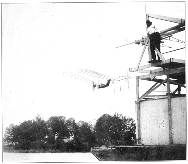


After returning in the fall, Mr. Langley again had Aerodromes Nos. 5 and 6 taken down to Quantico for trial, and this time had as his invited guest Mr. Frank G. Carpenter. On November 27 a test was made of Aerodrome No. 6, the general disposition of which at this time may be learned from the description in Chapter X ◊, and the photographs in Plates 29A, 29B. The model was launched at 4.25 p. m. with a steam pressure of 125 pounds. The aerodrome went nearly horizontally against the wind, and descended into the water in six and a quarter seconds at a distance of perhaps 100 yards. After the machine had been recovered from the water, it was found that a pin had broken in the synchronizing rod which connects the two propeller shafts together, and that the counter, which showed 495 revolutions of the propellers, had been caused to register [p109] inaccurately on this account. The balancing of Aerodrome No. 6 had been made the same as that of No. 5, but in No. 6 the line of thrust was twelve centimetres higher, and this fact, which had not been taken into account in determining the proper balancing for No. 6, seemed to be sufficient cause for the aerodrome coming down into the water so soon after being launched. Darkness had descended before the aerodrome could be recovered and prepared for a second trial. On the next day, November 28, a high wind prevailed in the morning, but in the afternoon it became comparatively calm, and No. 6 was launched at 4.20 p. m. under the same conditions as on the preceding day, except that the float, which weighed 275 grammes, was moved back from the bowsprit eighty centimetres in order to make the machine lighter in front. The aerodrome was launched at a steam pressure of not much over 100 pounds, the air draft for the burners being temporarily bad. The midrod made an angle of approximately three degrees with the horizontal. On account of a slight rain, which had occurred just before the machine was launched, the wings were wet and the weight of the entire aerodrome was doubtless as much as twelve kilos. Immediately on being launched the aerodrome started directly ahead in a gentle south wind, moving horizontally and slowly turning to the right and appearing to approach dangerously near to some thick woods on the west shore. However, it fortunately continued turning until it pointed directly up the beach with the wind in the rear. It then moved more rapidly forward, dipped and rose but once, and this very slightly, and continued its remarkable horizontal flight, varying not more than two yards out of a horizontal course, and this only for a moment, until it finally descended into the bay at a point nearly in a line between the house-boat and the railroad station at Quantico. Upon being recovered, it was found to be absolutely uninjured, and another flight would have been made with it immediately but darkness had descended. The time of flight, as determined independently by two stop-watches, was one minute and forty-five seconds. The number of revolutions of the propellers was 2801, or at the rate of 1600 R. P. M., which, with an allowance of fifty per cent slip, should have carried the aerodrome a distance of 4600 feet in one and three-quarter minutes. While the distance from the house-boat in a straight line to the point at which the aerodrome descended was only about 1600 feet, yet it was estimated by those present that this straight-line distance was certainly not greater than one-third the total length of the path traversed, which would mean a distance of something like 4800 feet. The length of the course, as plotted on the coast-survey map and afterwards measured, was 4200 feet, and it, therefore, seemed safe to say that the total distance travelled was about three-quarters of a mile, and the speed was, therefore, about thirty miles an hour.
Reference has already been made to the development of the “cast-off” apparatus that was used at Quantico for launching the aerodrome. An initial velocity is indispensable, and after long experiment with other forms which proved failures, an apparatus was designed by me, which gave a sufficient linear velocity in any direction. It had, moreover, been found that, when the aerodrome was attached to any apparatus upon the roof of the house-boat, such slight changes in the direction and intensity of the wind as would ordinarily pass unperceived, would tend to distort or loosen it from its support, so that only the most rigid of fastenings at three independent bearing points were of any use in holding it, while the wings must be separately fastened down, lest they should be torn from their sockets. It was, then, necessary to be able to fasten the aerodrome very firmly to the cast-off apparatus, to start it upon its journey in any direction with an initial linear velocity that should equal its soaring speed, and to release it simultaneously at all points at the very same instant, while at the same time the points of contact of the launching device, to which it had just been fastened, were themselves drawn up out of the way of the passing propellers and guys.
All these requirements and others were met by the apparatus finally adopted, which is shown in Plates 23 and 24. It consists of a strong timber frame-work, carrying a track, consisting of two flat iron rails set on edge, upon which runs the launching car, suspended from two small wheels on each side. At the front end of the frame there are two cylindrical air buffers to receive the buffing pistons and thus stop the car after the aerodrome has been released. The car is drawn to the rear end of the track and held by the bell-crank lever A (Plate 23). The contact points BB and C are turned down and the clutch-hook D set over the clutch-post K. The aerodrome is thus held firmly up against the three points BB and C by the clutch D, and a distortion from its proper position rendered impossible. All these points are thrown up out of the way of the projecting portions of the aerodrome at the instant of release. This result is accomplished as follows: when the car has reached the proper point in its forward course, the cam E, which is hinged at 1, is depressed by a roller fixed to the framework of the device. In this motion it pushes down the adjustable connections FF, which are attached at their lower ends to the bell-crank arms GG, which turn about a central pivot at 2. Thus the downward movement of the connections FF opens the jaws of the [p111] clutch D. While the clutch D is rigidly attached to G to prevent transverse movement, it is hinged to the latter at 3 so that it can fold in a longitudinal direction. Screwed to the clutch D is a narrow plate 4, which, when the clutch is closed, is behind the lug 5, thus preventing any turning about the hinge 3.
But when the arms of G and the jaws of the clamp are thrown out by the depression of F, the plate 4 is moved out from behind the lug 5 and the clamp is free to fold to the front. The strut, hinged at 6, is under a constant tension from the spring 7 to fold up, and is prevented from doing so only by the connections 8, by which it is held down until the release of the plate 4 from behind the lug 5, when the spring snaps them instantly up and out of the way.
As the struts BB have no fixed connection with the aerodrome, they are released by the relaxation in the rigidity of the other connections and are thrown up by their spring 9 and held in that position by the clip 10 catching beneath the upper cross-piece.
The power for the propulsion of the car is obtained by means of from one to nine helical springs working under tension, and multiplying their own motion four times by means of a movable two-sheave pulley, as shown in the drawing.
When the details of the aerodrome, whose description is to follow, are considered from the standpoint of the engineer accustomed to make every provision against breakage and accident and to allow an ample factor of safety in every part, they will be found far too weak to stand the stresses that were put upon them. But it must be remembered that in designing this machine, all precedent had to be laid aside and new rules, adapted to the new conditions, applied. It was absolutely necessary, in order to insure success, that the weight should be cut down to the lowest possible point, and when this was reached it was found that the factor of safety had been almost entirely done away with, and that the stresses applied and the strength of material were almost equal.
The same observation holds true of the boilers, aeolipile, and engines, when regarded from the point of view of the economical generation and use of steam. It was fully recognized that the waste of heat in the coil boilers was excessive, but as it was necessary that there should be an exceedingly rapid generation of steam with a small heating surface, this was regarded as inevitable.
In the engine the three points aimed at in the design were lightness, strength and power, but lightness above all, and necessarily in a degree which long seemed incompatible with strength. No attempt was made to secure the requirements of modern steam-engine construction, either in the distribution of the steam or the protection of the cylinder against the radiation of heat by a suitable jacketing. The very narrow limits of weight permissible required that the [p112] barrel of the cylinder should be as thin as possible, that no protective jacketing should be used, and that the valve motion should be of the simplest description. To obtaining the greatest lightness consistent with indispensable power, everything else was subordinated; and hence, all expectation of ordinary economical efficiency had to be abandoned at the outset.
It was only after long trials in other directions that Mr. Langley introduced the aeolipile device, which for the first time provided sufficient heat. Even in the aeolipile, however, is was apparent that nothing short of the most complete combustion accompanied by the highest possible temperature of the flame would be sufficient for the extreme demand. To secure this result under all conditions of wind and weather, with the aerodrome at rest and in motion, required the long series of experiments that are given in another chapter. In respect to the generation of heat, then, it is probable that it would be difficult to exceed the performance of the final type of burner in practical work, but in the utilization of this heat in the boiler, as well as in the utilization of the steam there generated, the waste was so great as to be prohibitive under ordinary conditions. But this was not ordinary work, and the simplest protection against radiation from boiler, separator, and engine could not well be used.
The framework of the aerodrome is made of thin steel tubes, the main or midrod extending the whole length of the machine and carrying the attachments to which the wings are fastened. Suspended from this midrod by rigid connections is a skeleton hull of steel tubing, shaped somewhat like the framework of a boat, from which, directly abeam of the engines, arms are run out like the outriggers of a rowboat for carrying the propellers. Within this central hull are placed the aeolipile, the boiler, and the engine, which with their auxiliary parts, the pump and the separator, constitute the entire power-generating apparatus.
The aeolipile consists of four essential parts: the spherical air chamber containing the supply of compressed air by which the gasoline in the reservoir tank is forced into the burner; the reservoir tank containing the gasoline that is to be used as a fuel; the gas generator wherein the liquid gasoline is heated and converted into gas; and the burners where it is finally utilized to heat the boilers.
The air chamber D, Plate 25, is a spherical vessel 120 mm. in diameter, located at the extreme front end of the hull. It is made of copper 0.25 mm. thick and has two openings. The front opening has a copper pipe 1 cm. outside diameter, to which the air pump for charging the chamber is connected. From the back a copper pipe 5 mm. outside diameter extends to the top of the gasoline reservoir.

This reservoir, shown at I, Plate 25, is also a light, hollow sphere 120 mm. in diameter; both this and the air chamber being made by soldering hemispheres [p113] of copper together at their circumferences. There are three openings in the reservoir tank; two at the top and one at the bottom. One of those at the top serves for the admission of the 5-mm. pipe bringing compressed air from the air chamber; the other is connected with a pipe 1 cm. in diameter, through which gasoline is supplied to the tank, and which is closed by a simple plug at the top. The hole in the bottom serves as the outlet for the gasoline to the burners. Close to the bottom of the tank there is placed a small needle valve, which serves to regulate the flow of oil, for, were the pipe left open, the compressed air would force the oil out with such rapidity that the burners would be flooded and the intensity of the flame impaired. The construction of this valve is clearly shown in Plate 26A. It consists of a brass shell having one end (a) soldered to the bottom of the tank. The needle enters through a stuffing box whose gland is held by two small screws. The stem of the needle is threaded and engages in a thread cut in the body of the casting and is operated by a fine wire on the outside. It will readily be seen that this device affords a means of making a very accurate adjustment of the flow of the liquid to the burners.
After leaving the needle valve the gasoline flows along the pipe S, Plate 25, until it reaches the evaporating coil, N. In order to subject the oil to as large a heating surface as possible, in comparison with the sectional area through which it is flowing, the pipe, which left the needle valve with a diameter of 6 mm. soon contracted to 5 mm., is here flattened to a width of 7 mm. and a thickness of 2 mm. There are seven complete turns of this flattened tubing coiled to an outside diameter of 30 mm. At the end of the seventh coil the pipe is enlarged to a diameter of 1 cm. and two coils of this size are added, the inside diameter being the same as that of the flattened coil. This enlarged portion serves as a sort of expansion chamber for the complete gasification of the gasoline, which is then led back through a turn of the enlarged pipe, beneath the coils and to the front. At the front end of the coil a small branch is led off, forming a “bleeder,” which takes sufficient gas to supply the burner by which the coil is heated, the products of whose combustion pass into and between the coils of the boiler like those of the regular heating burners. The gas pipe rises in front of the coil and by a T connection branches to the two burners that are placed in front of the coils of the boiler. These burner pipes are 5 mm. in diameter and enter sheet-iron hoods forming regular burners of the Bunsen type, which are fully shown in all their details in the accompanying engraving, Plate 26. The pipe is plugged at the end, and a hole 0.9 mm. in diameter drilled for the nipple of the burner in front of the coil where the water first enters from the separator, and 0.85 mm. for the one in front of the return coil. The face of the burner shell stands exactly central with and 41 mm. in front of the coils.35 [p114]
This constitutes the heat-generating portion of the machine, and with it it is probable that a flame of as high a temperature is produced as can be reached, with the fuel used, by any practical device.
The boiler or steam-generating apparatus may be said to consist of three parts: the separator, the circulating pumps, and the generating coils.
The separator (M in Plate 25) is a device which has attained its present form after a long course of development. As at present constructed, it is formed of a hollow sphere 190 mm. in diameter and is located as nearly as possible over the center of gravity of the whole apparatus. It serves the double purpose of water reservoir and steam drum, and is called a “separator” on account of the function which it performs of separating the water from the steam as it enters from the coils. There is a straight vertical pipe 10 mm. in diameter rising from the top of the sphere and fastened to the right-hand side of the midrod. This is used for filling the separator with water. Upon the other side of the midrod there is a small steam dome 42 mm. in diameter with a semi-spherical top rising to a height of 70 mm. above the top of the sphere. From this dome two steam pipes are led off, one to the engine and the other to the steam gauge.
As already stated elsewhere, it was found in the experiments with the coil boiler that an artificial forcing of the circulation of the water was a necessity, as the natural circulation was too slow to be of any service. Accordingly, but only after numerous devices involving less weight had failed, a pump driven from the engine shaft was designed and used. In the early experiments various types of pumps were tried in which the valves were opened and closed automatically by the pressure of the water. It was found, however, that with the mixture of steam and water to be handled, the valves could not be depended upon to open and close properly at the high speeds at which is was necessary to run the engine. In Aerodrome No. 5, therefore, a double-acting pump with a mechanically operated valve was used. The pump, shown in detail in Plate 26A, is driven from a shaft connected with the main engine shaft by a spur gear and pinion, which rotates at half the speed of the engine shaft. The pump itself consists of two barrels, the main barrel having a diameter of 23 mm. with a piston stroke of 20 mm. The outer shell of the barrel is made of aluminum bronze and is lined with a cast-iron bushing 1.25 mm. in thickness. The piston has a length of 14 mm. and is formed of an aluminum disc and center, having a follower plate of the same material with two cast-iron split rings sprung in. The water is received into and delivered from the valve cylinder, which is 18 mm. in diameter and also lined with a cast-iron bushing 1.25 mm. thick. The aluminum bronze shells of both cylinders are 0.75 mm. in thickness. The valve is a simple piston valve 35 mm. long with bearing faces 4 mm. long at each end. The water is taken from the bottom of the separator and led to the center of the valve chest of the pump by a copper pipe 1 cm. outside diameter. The ports [p115] leading from the valve to the main cylinder are 3 mm. wide and 34 mm. apart over their openings. It will thus be seen that when the valve is in its central position, as it should be at the beginning of the piston stroke, both ports are covered with a lap of 0.5 mm. inside and out, so that the valve has to move 0.5 mm. before suction or discharge can take place. As the valve is moving most rapidly at this point, it opens and both functions begin before the piston has advanced perceptibly. The delivery is made at the ends of the valve cylinder through two copper pipes of 1 cm. diameter that unite into a single pipe before reaching the boiler. The throw of the valve is 14 mm. so that the ports are uncovered and held wide open for the greater portion of the stroke of the piston, and begin to close only when the latter approaches the end of its stroke. In this way perfect freedom is given to the flow of the water and all choking is avoided. As the engine has been run at a speed of more than 688 revolutions per minute, the pump must have made at least 344 strokes in the same time, thus displacing 166.2 cc. of water. The diameter of the piston rod and valve stem is 3 mm. and they pass through stuffing boxes with glands of the ordinary type for packing. This pump served its purpose admirably, and with it it was possible to maintain a continuous circulation of water through the two coils of the boiler.
The third element in the steam-generating system is the boiler proper36 (Plates 25 and 26A), which consists of two coils of copper pipe, having an outside diameter of 10 mm., each coil being formed of 21 turns each 75 mm. in diameter upon the outside and spaced 7.5 mm. apart, so that the total axial length of each coil is 36 cm.
The water is delivered to the front end of the right-hand coil, and, first passing through this, crosses over at the rear of the boiler to the left-hand coil, returning through it to the front whence it is led to and delivered into the top of the separator. Here the steam and water are separated, the former going through the separator and thence to the engine, while the unevaporated water falls to the bottom to be again taken into the pumps and sent through the coils.
In order that the draft of the burner and the gases of combustion might not be dissipated, it was necessary to sheathe the boiler. The method of doing this is shown in Plate 25. It will be seen that the front half of the boiler is wrapped in a sheet of mica through which the coils can be faintly seen. This, in turn, is held at the extreme front end by a strip of thin sheet-iron, O. Over the back end the stack Q, made of very thin sheet-iron, is slipped. This has an oblong cross-section at the lower end where it goes over the boiler; it is provided with a hole through which the midrod passes, and terminates in a circular opening of about 10 cm. diameter. [p116]
The engine, which is clearly shown in the dimensional drawing, Plate 26B, is of the plain slide-valve type, using a piston valve and solid piston, without packing rings. The cylinder is formed of a piece of steel tubing 35 mm. outside diameter, with flanges 47 mm. in diameter and 2.25 mm. thick brazed to each end, to which the cylinder heads are attached by small machine screws. Inside this cylinder is a thin cast-iron bushing in order to obtain a better rubbing surface for the piston. The cross-head is a small piece of aluminum bronze, running on round guides that also serve as cylinder braces. There are also four hollow braces, 5 mm. in diameter, running from the back cylinder head to a corrugated steel bed-plate, that stands vertically and reaches from one side rod of the frame of the hull to the other, and to which are bolted the bearings of the main shaft. The connecting rod has the cross-section of a four-rayed star and drives a crank in the center of the shaft. The following are some of the principal dimensions of the engine:
| millimetres. | |
| Inside diameter of cylinder | 33 |
| Stroke of piston | 70 |
| Length of cylinder inside | 88 |
| Length of piston | 11 |
| Clearance at each end | 0.5 |
| Diameter of piston rod | 5 |
| Length of cross-head | 17.5 |
| Diameter of guides | 4.5 |
| Distance from center to center of guides | 26 |
| Length of guides | 110 |
| Length of wrist-pin bearing | 8.5 |
| Length of connecting rod | 150 |
| Ratio of connecting rod to stroke | 2 1/7 to 1 |
| Length of crank pin | 10 |
| Diameter of main shaft | 8 |
| Length of main bearings | 25 |
| Distance from center of cylinder to center of valve stem | 35 |
| Length of valve | 72 |
| Width of ports | 2 |
| Outside lap of valve | 4 |
| Inside lap of valve | 3 |
| Lead of valve | 0 |
| Travel of valve | 13 |
| Cut-off from beginning of stroke | 57 |
| Exhaust opens | End of stroke |
| Exhaust closes on return stroke | 48 |
| Diameter of valve stem | 4.5 |
| Diameter of eccentric | 36 |
| Width of eccentric | 4 |
| Width of crank arm | 4 |
The weights were nearly as follows:
| grammes. | |
| Engine | 464 |
| Pump and pump shafts | 231 |
| Gasoline tank and valves | 178 |
| Burners | 360 |
| Boilers, frames holding boilers, and mica covers over boilers | 651 |
| Separator, steam gauge and pipe for engine | 540 |
| Exhaust pipe | 143 |
| Smoke stack | 342 |
| In all, 2909 grammes, or 6.4 pounds. | |

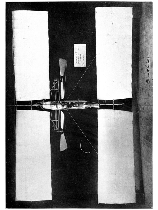
These weights are those determined in December, 1896, when some slight changes had been made from the conditions existing at the time of the flight by this aerodrome on May 6. Previous to that time, with a pressure of 130 pounds, between 1.1 and 1.25 horse-power was given on the Prony brake. At the actual time of flight the pressure was about 115 pounds, and the actual power very near 1 horse-power.
The valve stem was pivoted to the center of the valve partly because this was the lightest connection that could be made, and partly to allow the valve perfect freedom of adjustment upon the seat. Many parts, such as guides, braces, crank-pins, wrist-pin and shafts are hollow. The steam is taken in at the front end of the steam chest, and the exhaust taken out of the center, whence it is led back to the stack and by means of a forked exhaust pipe discharged in such a way as to assist the draught of each coil of the boilers. Like the cylinder the steam chest is made of a piece of steel tubing, 20 mm. diameter on the outside, with an inside diameter of 19 mm., and is fitted with a cast-iron bushing 0.5 mm. thick, making the inside diameter of the steam chest 18 mm. It, too, has flanges brazed to the ends, to which the heads are held by small machine screws.
The shaft for conveying the power to the propeller shafts extends across the machine from side to side; it is hollow, being 8 mm. outside diameter, with a hole 5 mm. diameter through the center.
It is formed of five sections: the middle section, containing the crank, has a length of 110 mm. and is connected at either end, by flanged couplings, to lengths 320 mm. long, which are in turn extended by the end sections having a length of 230 mm. In addition to the four main bearings that are bolted to the pressed-steel bed-plate already mentioned, there are two bearings on the outer framework on each side. At the outer end of each shaft there is keyed thereto a bevel gear with an outside diameter of 27 mm. and having 28 teeth. This gear meshes with one of 35 teeth upon a shaft at right angles to the main shaft and parallel to the axis of the aerodrome. These two shafts, one on either arm, serve to carry and transmit the power to the propellers. They are 192 mm. long, 8 mm. in diameter, and are provided with three bearings that are brazed to a corrugated steel plate forming the end of the outrigger portion of the frame. These shafts are also hollow, having an axial hole 4 mm. in diameter drilled through them. The propeller seat has a length of 43 mm. and the propeller is held in position by a collar 25 mm. in diameter at the front end, from which there project two dowel-pins that fit into corresponding holes in the hubs of the propellers, which are held up against the collar by a smaller one screwed into the back end of the shaft. The thrust of the collar is taken up by a pin screwed into the end of the forward box and acting as a step against which the shaft bears, the arrangement being clearly shown by the accompanying drawing, Plate 26A. [p118]
This, then, comprises the motive power equipment of the aerodrome, and, to recapitulate, it includes the storage, automatic feeding and regulation of the fuel; the storage, circulation and evaporation of the water; the engine to convert the expansive power of the steam into mechanical work; and the shafting for the transmission of the energy developed by the engine to the propellers.
The propellers were made with the greatest care. Those used in the successful trials were 1 metre in diameter, with an actual axial pitch of 1.25 metres. They were made of white pine, glued together in strips 7 mm. thick. The hub had a length of 45 mm. and a thickness or diameter of 25 mm. At the outer edge the blade had a width of 315 mm. and a thickness of 2 mm. These propellers were most accurately balanced and tested in every particular; each propeller blade was balanced in weight with its mate and the pitch measured at every point along the radius to insure its constancy; finally the two propellers of the pair to be used together were balanced with each other so that there would be no disturbance in the equilibrium of the machine. As will be noted from the foregoing description of the machinery, the propellers ran in opposite directions, as they were made right- and left-hand screws. The weight of each propeller was 362 grammes.
We now turn again to take up the details of the construction of the framework by which this propelling machinery is carried. The whole aerodrome, as clearly shown in the photographs, Plates 27A and 27B, is built about and dependent from one main backbone or midrod, which extends well forward of all of the machinery and aft beyond all other parts. This rod, as well as all other portions of the framework, is of steel tubing. The midrod, being largest, is 20 mm outside diameter, with a thickness of 0.5 mm. It is to this midrod that the wings are directly attached, and from it the hull containing the machinery is suspended.
The plan outline of the hull skeleton is similar to that of the deck of a vessel. The steel tubing, 0.5 mm. thick, of which it is formed, has an outside diameter of 15 mm. from the front end to the cross-framing used to carry the propellers, back of which the diameter is decreased to 10 mm.
The midrod makes a slight angle with this frame, the vertical distance between the centers of the tubing being 73 mm. at the front and 67 mm. at the back. The tube, corresponding to the keel of a vessel, is braced to the upper tubes by light U-shaped ribs and by two 8-mm. tubes forming a V brace on a line with the back end of the guides of the engine. At the extreme front and back there is a direct vertical connection to the midrod.
The propeller shafts are 1.23 m. from center to center, and are carried on a special cross-framing, partaking, as already stated, of the character of an outrigger on a row-boat. (See Plate 27B.) The rear rods, which are of 10 mm. steel tubing, start from the front end of the rear bearings of the propeller shaft and [p119] extend across from side to side. The top rod is brazed to the side pieces of the hull and the bottom rod to the keel. They are connected by a vertical strut of 8-mm. tubing at a distance of 265 mm. inside of each propeller shaft. At the front end of the propeller shaft two more rods run across the frame. The lower is similar and parallel to the back rod already described, while the upper is bowed to the front, as shown in the plan view of the frame (Plate 30). In order to take the forward thrust of the propeller a second cross-brace is inserted, which runs from the rear bearing of the propeller shaft to a point just in advance of the front head of the cylinder, and is brazed to the two upper tubes of the cross-frame as well as to the upper tubes of the main framing of the hull. The outer ends of the tubes of the cross-framing are brazed to a thin, stamped steel plate which firmly binds them together, while at the same time it forms a base for attaching the bearings of the propeller shaft. This end plate has a thickness of one millimetre.
In addition to the framing proper there are two guy-posts which fit into the sockets CC, and over which truss wires are drawn, as shown in the side view in Plate 27A. These posts have a length of 730 mm. from the lower edge of the socket, and are capped at their lower extremity by a light steel ferrule whose outside diameter is 10 mm.
From the drawing of the wings of No. 5, shown in Plate 17, it will be seen that they are formed of two pine rods 15 mm. in diameter at the inner ends, tapering to a half circle of the same diameter at the tips. These rods are connected by eleven spruce ribs measuring 8 mm. × 3 mm., and curved, as shown in the side elevation, these, in turn, being covered by a light white silk drawn so tightly as to present a smooth, even surface. The total length of the wing is 2 metres, and the width over all is 805 mm. Vertical stiffness is obtained in the wings by a series of guy-wires, which pass over light struts resting upon the main rods. These main rods are inserted and held in the wing clamps A and B, Fig. 16, and make an angle of 150° with each other. As is the case with all other essential details of the aerodrome, a great deal of time and attention was given to the designing of the wing clamps before a satisfactory arrangement was secured.
To enable it to control the aerodrome in both directions, the tail-rudder, Plate 27A, has both a horizontal and a vertical surface, the approximate dimensions of which are, length 115 cm. (3.8 feet), maximum width 64 cm. (2.1 feet), giving each quarter section an area of about 0.64 sq. m. (6.9 sq. ft.). It is given the proper angle and degree of elasticity in a vertical direction by the flat hickory spring, which fits into the clamp N, and attaches the rudder to the frame.
The only other attachments of the aerodrome are the reel, float, and counter. They have nothing whatever to do with the flying of the machine, and are [p120] merely safety appliances to insure its recovery from the water. The reel consists of a light spool on which a fine cord is wound, one end of which is attached to a light float that detaches itself and lies upon the surface of the water when the machine sinks, while the other end is fastened to the spool that goes down with the aerodrome. The “float” is a light copper vessel with conical ends which is firmly fastened to the midrod, and which is intended to so lower the specific gravity of the whole machine that it will not sink. The cylindrical portion of this float has a length of 250 mm. and a diameter of 170 mm., one cone having a length of 65 mm. and the other and front one a length of 140 mm., which makes the total length of the float 375 mm. It is made of very thin copper, and served in the successful trials not only as a float to sustain the machine on the surface of the water, but also as a weight by which the center of gravity was so adjusted that flight was possible.
The counter records the number of revolutions of the propellers after launching. It is a small dial counter, reading to 10,000, with a special attachment which prevents any record being made of the revolutions of the propellers, until the actual moment of launching, when a piece on the launching apparatus throws the counter in gear at the instant that the aerodrome leaps into the air.
Aerodrome No. 6, it will be remembered, was the outgrowth of a number of changes made in No. 4 during the fall of 1895 and the early part of 1896. In this reconstruction the aim was to lighten the whole machine on account of the smaller engines in either No. 4 or No. 5. The modifications from No. 4 were so radical and the differences that exist between Nos. 5 and 6 are so considerable as to demand careful attention.
As regards general appearance the frame of Aerodrome No. 6 resembles that of No. 5 in consisting of a single continuous midrod of steel tubing, 20 mm. in diameter, 0.5 mm. thick, immediately beneath which the hull containing the machinery is situated. In reconstructing the framework after the tests in January, 1896, had shown it to be dangerously weak, especially against torsion, it was decided to make the hull only strong enough to carry its contents and to attach it to the stronger midrod in such a way that all torsional strains would be taken up by it, whereas in No. 5 the hull structure must bear a large proportion of such strains. It was therefore built throughout of 8-mm. tubing, 0.3 mm. thick, and was rigidly attached to the midrod by braces at the front and rear, and also at the cross-frame. The hull was also made narrower (except at the rear, where it was widened to contain the boiler) and shorter than the hull of No. 5—an advantageous change made possible by the fact that the engines were not contained in the hull, but mounted on the transverse frame.
In No. 5, as described above, a single engine mounted at the front end of the hull communicated its power through transmission shafts and gearing to the propellers, which were necessarily in the same plane. This brought the line of thrust very nearly in the same plane as the center of gravity of the aerodrome, a condition tending to promote instability of longitudinal equilibrium. In No. 6, however, the use of two engines situated on the transverse frame and communicating their power directly to the propellers, made it possible to raise the transverse frame 12 cm. above the hull, and thus raise the line of thrust to a position intermediate between the center of pressure and the center of gravity, without materially affecting the latter. As a result of this change Aerodrome No. 6 was rendered much more stable and made steadier flights with fewer undulations than No. 5.
The engines in use on No. 6 were the small engines described above in connection with No. 4. The cylinders were of steel tubing 2.8 cm. in diameter, with a 5-cm. stroke, each cylinder thus having a capacity of 30.8 cc. They were lined with a thin cast-iron bushing and cast-iron rings were sprung in the piston head so as to give as smooth a rubbing surface and as perfect action as possible. As in the engine of No. 5 a plain sliding valve of the piston type was used, cut-off being approximately at one-half, though the ports were so small that it was difficult to determine it with any great accuracy. No packing was used, but the parts were carefully ground so as to give a perfect fit.
These engines, as is most clearly shown in Plate 30, were mounted symmetrically on either side of the cross-frame and were connected directly to the propeller shafts. In order to insure that the propellers would run at the same rate, there was provided a synchronizing shaft, T, in Plate 30, having on each end a bevel gear, which intermeshed with similar gears on the propeller shafts. Steam for the cylinders was conveyed from the separator through the pipes LL.
The steam-generating apparatus for No. 6 was exactly like that already described in connection with No. 5, the only difference being in the more compact arrangement in the case of No. 6. The relative location of the apparatus in the two models is clearly shown in Plates 28, 29B, and 30, the corresponding parts being similarly labeled, so that a separate description for No. 6 is superfluous.
The wings used on No. 6 were somewhat smaller than those of No. 5, and differed from them in having the front mainrib bent to a quadrant at its outer extremity and continued as the outer rib of the wing. The degree of curvature of the wings was also somewhat less, being one-eighteenth for No. 6 and one-twelfth for No. 5. The four wings were of the same size and had a total area of 54 sq. ft. On account of the shortened hull of No. 6 they were allowed a much greater range of adjustment, which rendered it much easier to bring the CP into the proper relative position to the CG than was the ease with No. 5. [p122]
The Pénaud rudder for No. 6 was similar to that for No. 5, the two in fact being interchangeable, and was similarly attached to the frame. The reel, float, counter, and all other accessories were identical for the two machines.
To sum up the comparative features of these two successful steam-driven models: Aerodrome No. 6 was both lighter and frailer than No. 5, and required much more delicate adjustment, but when the correct adjustments had been made its flying qualities were superior, as regards both speed and stability.


[2] “Experiments in Aerodynamics,” Smithsonian Contributions to Knowledge, Vol. 27, 1891.
[3] This chapter was written almost entirely by Mr. Langley in 1897.
[4] 1897.
[5] In this statement, of course, no account is taken of the “internal work of the wind.”
[6] Ten years prior to 1897.
[7] Communication to the French Academy. Extract from the Comptes Rendus of the Sessions of the Academy of Sciences, Vol. 122, Session of May 26, 1896.
(Translation.)
A Description of Mechanical Flight. By S. P. Langley.
In a communication which I addressed to the Academy in July, 1891, I remarked that the results of experimental investigation had shown the possibility of constructing machines which could give such a horizontal velocity to bodies resembling in shape inclined planes, and more than a thousand times heavier than air, that these could be sustained on this element.
While I have elsewhere remarked that surfaces other than planes might give better results, and that absolutely horizontal flight, which is so desirable in theory, is hardly realizable in practice, so far as I know there has never been constructed, up to the present time, any heavy aerodrome, or so-called flying-machine, which can keep itself freely in the air by its own force more than a few seconds, the difficulties encountered in absolutely free flight being, for many reasons, immeasurably greater than those experienced when the flight is controlled by the body’s pressing upward against a horizontal track, or whirling-arm. No one is unaware that many experimenters have been engaged in trying to execute free mechanical flight, and although the demonstration which I furnished in 1891 [“Experiments in Aerodynamics,” 1891] of its theoretical possibility with means then at our disposition, seemed conclusive, so long a time has elapsed without practical results, that it might be doubted whether these theoretical conditions are to be realized. I have thought it well, then, to occupy myself with the construction of an aerodrome with which I might put my previous conclusions to the test of experiment.
The Academy will, perhaps, find it interesting to read the narrative given here by an eye-witness, who is well known to it. I am led to present it not only by the request with which he honors me, but by the apprehension that my administrative duties may put a stop to these researches, so that it seems to me advisable to announce the degree in which I have already succeeded, although this success be not as complete as I should like to make it.
The experiments took place on a bay of the Potomac River, some distance below Washington. The aerodrome was built chiefly of steel, though lighter material entered into the construction, so that its density as a whole was a little below unity. No gas whatever entered into the construction of the machine, and the absolute weight, independent of fuel and water, was about 11 kilos (24 pounds). The width of the supporting surfaces was about 4 metres (13 feet), and the power was furnished by an extremely light engine of approximately one horse-power. There was no one to direct it on board, and the means for keeping it automatically in horizontal flight were not complete. It is important to remark that the small dimensions of the machine did not allow it to include any apparatus for condensing the steam, so that it could only carry water enough for a very brief course—a drawback which would not be encountered in one of a larger construction.
It is also to be noted that the speed estimated by Mr. Bell was that obtained in a continuous ascending flight, and much less than would have been attained in a horizontal course.
On Mechanical Flight. Letter of Mr. Alexander Graham Bell to Mr. Langley.
Washington, May 6, 1896.
I am quite aware that you are not desirous of publication until you have attained more complete success in obtaining horizontal flight under an automatic direction, but it seems that what I have been privileged to see to-day marks such a great progress on everything ever before done in this way, that the news of it should be made public, and I am happy to give my own testimony on the results of two trials which I have witnessed to-day by your invitation, hoping that you will kindly consent to making it known.
For the first trial, the apparatus, chiefly constructed of steel and driven by a steam engine, was launched from a boat at a height of about 20 feet from the water. Under the impulse of its engines alone, it advanced against the wind and while drifting little, and slowly ascending with a remarkably uniform motion, it described curves of about 100 metres in diameter; till at a height in the air which I estimate at about 25 metres (82 feet), the revolutions of the screws ceased for want of steam, as I understood, and the apparatus descended gently and sank into the water, which it reached in a minute and a half from the start. It was not damaged, and was immediately ready for another flight.
In the second trial it repeated in nearly every respect the action of the first, and with an identical result. It rose smoothly in great curves until it approached a prominent wooded promontory, which it crossed at a height of 8 to 10 metres above the tops of the highest trees, upon the exhaustion of the steam descending slowly into the bay, where it settled in a minute and thirty-one seconds from the start. You have an instantaneous photograph of it, which I took just after the launch. [See plates 20, 21, and 22 of present work.]
From the extent of the curves which it described, which I estimated with other persons, from measurements which I took, and from the number of revolutions of the propellers, as recorded by the automatic counter which I consulted, I estimate the absolute length of each course to be over half an English mile, or, more exactly a little over 900 metres (2953 feet).
The duration of flight during the second trial was one minute and thirty-one seconds, and the average velocity between twenty and twenty-five miles an hour, or, let us say 10 metres a second, in a course which was constantly ascending. I was extremely impressed by the easy regular course of each trial, and by the fact that the apparatus descended each time with such smoothness and gentleness as to render any jar or danger out of the question.
It seemed to me that no one could have witnessed these experiments without being convinced that the possibility of mechanical flight had been demonstrated.
[8] It is desirable that the reader should be acquainted with the contents of this treatise, and of another by me, entitled “The Internal Work of the Wind,” both published by the Smithsonian Institution. A knowledge of these works is not absolutely necessary, but of advantage in connection with what follows.
[9] “Experiments in Aerodynamics,” p. 107.
[11] His device for obtaining automatic equilibrium is found in connection with the description of his “Aeroplane Auto Moteur,” in “L’Aeronaute” for January, 1872.
[12] I have never obtained so good a result as this with any rubber motor. S. P. Langley.
[13] One pound of twisted rubber appears, from my experiments, to be capable of momentarily yielding nearly 600 foot-pounds of energy, but this effect is attained only by twisting it too far. It will be safer to take at most 300 foot-pounds, and as the strain must be taken up by a tube or frame weighing at least as much as the rubber, we have approximately 0.0091 as the horse-power for one minute, or 0.091 horse-power for six seconds as the maximum effect, in continuous work, of a pound of twisted rubber strands. The longitudinal pull of the rubber is much greater, but it is difficult to employ it in this way for models, owing to the great relative weight of the tube or frame needed to bear the bending strain. In either form, rubber is far more effective for the weight than any steel spring (see later chapter on Available Motors).
[14] The aerodrome is sustained by the upward pressure of the air, which must be replaceable by the resultant pressure at some particular point, designated by CP.
[15] See Century Magazine, October, 1891.
[16] Subsequent observations indicate that the maximum velocity of horizontal flight must have been about 10 metres per second.
[17]
Observers following de Lucy have long since called
attention to the fact that as the scale of Nature’s flying things
increases, the size of the sustaining surfaces diminishes relatively
to the weight sustained. M. Harting (Aeronautical Society, 1870) has
shown that the relation
√area/![]() weight is surprisingly
constant when bats varying in weight as much as 250 times are the
subject of the experiment, and later observations by Marey have not
materially affected the statement. As to the muscular power which
Nature has imparted with the greater or lesser weight, this varies,
decreasing very rapidly as the weight increases. The same remark
may be made apparently with at least approximate truth, with regard
to the soaring bird, and the important inference is that if there
be any analogy between the bird and the aerodrome, as the scale
of the construction of the latter increases, it may be reasonably
anticipated that the size of the sustaining surfaces will relatively
diminish rather than increase. We may conveniently use M. Harting’s
formula in the form
a =
n2w(2/3) =
l2m2
where a =
area in sq. cm., w the weight in grammes,
l the length of the wing in cm., n and m constants
derived from observation.
weight is surprisingly
constant when bats varying in weight as much as 250 times are the
subject of the experiment, and later observations by Marey have not
materially affected the statement. As to the muscular power which
Nature has imparted with the greater or lesser weight, this varies,
decreasing very rapidly as the weight increases. The same remark
may be made apparently with at least approximate truth, with regard
to the soaring bird, and the important inference is that if there
be any analogy between the bird and the aerodrome, as the scale
of the construction of the latter increases, it may be reasonably
anticipated that the size of the sustaining surfaces will relatively
diminish rather than increase. We may conveniently use M. Harting’s
formula in the form
a =
n2w(2/3) =
l2m2
where a =
area in sq. cm., w the weight in grammes,
l the length of the wing in cm., n and m constants
derived from observation.
[18] A singular fact connected with the stretching of rubber is that the extension is not only not directly proportional to the power producing it, but that up to a certain limit it increases more rapidly than the power, and after this the relation becomes for a time more nearly constant, and after this again the extension becomes less and less in proportion.
In other words, if a curve be constructed whose abscissae represent extensions, and ordinates the corresponding weights, it will show a reverse curvature, one portion being concave toward the axis of abscissae, the other convex.
[19] The following table taken from “Experiments in Aerodynamics,” p. 107, gives the data for soaring of 30 × 4.8 inch planes, weight 500 grammes.
| Angle with horizon α. | Soaring speed V. | Work expended per minute. | Weight with planes of like form that 1 horse-power will drive through the air at velocity V. | |||
|---|---|---|---|---|---|---|
| Metres per second. | Feet per second. | Kilogram-metres. | Foot-pounds. | Kilogrammes. | Pounds. | |
| 45° | 11.2 | 36.7 | 336 | 2,434 | 6.8 | 15 |
| 30 | 10.6 | 34.8 | 175 | 1,268 | 13.0 | 29 |
| 15 | 11.2 | 36.7 | 86 | 623 | 26.5 | 58 |
| 10 | 12.4 | 40.7 | 65 | 474 | 34.8 | 77 |
| 5 | 15.2 | 49.8 | 41 | 297 | 55.5 | 122 |
| 2 | 20.0 | 65.6 | 24 | 174 | 95.0 | 209 |
The relations shown in the above table hold true only in case of planes supporting about 1.1 pounds to each square foot of sustaining area. For a different proportion of area to weight, other conditions would obtain.
[20] This pressure per unit of area varies with the area itself, but in a degree which is negligible for our immediate purpose.
[21] See “Internal Work of the Wind”; also Revue de L’Aeronautique, 3e Livraison, 1893.
[22] More recent experiments under my direction by Mr. Huffaker give similar results, but confirm my earlier and cruder observations that the curve, used alone, for small angles, is much more unstable than the plane.
[23] As stated in the Preface, Part III has not yet been prepared for publication.
[24] According to Wellner (“Zeitschrift für Luftschiffahrt,” Beilage, 1893), in a curved surface with 1/12 rise, if the angle of inclination of the chord of the surface be α, and the angle between the direction of resultant air pressure and the normal to the direction of motion be β, then β<α and the soaring speed is
while the efficiency is
The following were derived from experiments in the wind:
| α = | −3° | 0° | +3° | 6° | 9° | 12° |
| F(α) = | 0.20 | 0.80 | 0.75 | 0.90 | 1.00 | 1.05 |
| Tan β = | 0.01 | 0.02 | 0.03 | 0.04 | 0.10 | 0.17 |
so that according to him, a curved surface shows finite soaring speeds when the angle of inclination is 0° or even slightly negative.
[25] The following formulæ proposed by Mr. Chas. M. Manly show how the center of pressure may be moved any desired distance either forward or backward without in any way affecting the center of gravity, and by merely moving the front and rear wings the same amounts but in opposite directions, the total movement of each wing being in either case five times the amount that is desired to move the mean CP1, and the direction of movement of the front wing determining the direction of movement of CP1.
In Figure 7, CPfw and CPrw are the centers of pressure of the front and rear wings respectively; the weights of the wings, which are assumed to be equal and concentrated at their centers of figure, are represented by w, w, and a is the distance of the center of pressure in either wing from its center of figure. The original mean center of pressure of the aerodrome is CP1, W is the weight of the aerodrome, supposed to be concentrated at CG1, while m is the distance from CPrw to CG1.
Now, if we have assumed that the rear wing, being of the same size as the front one, has a lifting effect of only 0.66, and on this assumption is calculated the proper relative positions of the front and rear wings to cause the CP1 to come directly over the CG1, and upon testing the aerodrome find that it is too heavy in front and, therefore, wish to move the center of pressure forward an amount, say b, without affecting the center of gravity, we can calculate the proper relative positions of the front and rear wings in the following manner. While the aerodrome as a whole is balanced at the point CG1, the weight of the wings is not balanced around this point, for the rear wing, owing to its decreased lifting effect, is proportionately farther from CP1 than the front wing. In order, therefore, to avoid moving the center of gravity of the machine as a whole, any movement of the wings must be made in such a way as to cause the difference between the weight of the rear wing multiplied by its distance from CG1 and the weight of the front multiplied by its distance from CG1 to equal a constant: that is,
and
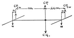
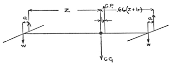

If now the wings be moved so that CP1 is moved forward a distance b, we may indicate the distance from CG1 to the new CPrw by z, and equating the difference between the weight of the rear wing multiplied by its new distance from CG1 and the weight of the front wing multiplied by its new distance from CG1 and making this difference equal to the constant difference, we can calculate z in terms of m and b, as follows:
Fig. 8,
Knowing z, we readily find that the new distance from CPfw to CG1 equals:
In a similar manner we may calculate the proper relative positions of the front and rear wings when we wish to move the center of pressure backward a distance, b, from the original CP1 without changing the position of CG1. From Fig. 7, we have as before:
Fig. 9,
Similarly we have for the new distance from CPfw to CG1:
[26] It is to be remembered that these aerodromes were under incessant modifications, No. 4 for instance, presenting successive changes which made of it in reality a number of different machines, one merging by constant alterations into the other, though it still went under the same name. After 1895 the type of the models remained relatively constant, but during the first five years of the work, constructions equal to the original building of at least eight or ten independent aerodromes were made.
[28] “Pocketing” is a form of distortion in which the canvas or silk bags locally in numerous places between the cross-ribs.
[29] The site of these experiments, which was 30 miles below Washington, has been described. The writer is designated by the initial “L”; Dr. Barus, who several times assisted, by the letter “B”; Mr Reed, carpenter, by “R”; Mr Maltby, machinist, by “M”; and Mr. Gaertner, instrument maker, by “G.”
[30] Weights and dimensions are here given in approximate pounds and feet.
[31] “Experiments in Aerodynamics.”
[32] On the data of “Aerodynamics,” a plane having 1.8 sq. ft. of surface per pound, and advancing at an angle of 20°, would soar at a speed of 24.1 ft. per second.
[33] It will be remembered that the purely theoretical conclusions just cited apply to the power delivered in direct thrust, but that of the above actual H. P. an indefinite amount was lost in friction and slip of propellers.
[34] It may be observed that at this time the position of the CP was calculated on the assumption that the pressure for flight surfaces was proportional to the areas, without also allowing for the fact that the following surfaces, like the tail, were under the “lee” of the wind and so far less efficient. It follows, then, that the value CP−CG was not really 0, as was assumed, but something considerable.
[35] Very exact accuracy in these minute details is indispensable to the efficient working of the engines.
Although in 1896 Mr. Langley had made the firm resolution not to undertake the construction of a large man-carrying machine, as he realized that his multitudinous administrative duties left him practically no time available for original research, yet the longing to take the final great step of actually transporting a human being through the air, which the successful flights of the models had now for the first time in the history of the world actually proved to be possible, soon became irresistible.
Ten years of almost disheartening difficulties, a full appreciation of which can hardly be gained from the preceding description, had already been spent in demonstrating that mechanical flight was practicable, and Mr. Langley thoroughly realized that the construction of a large aerodrome would involve as great, if not even greater difficulties. Nevertheless, his indomitable will, which balked at no obstacle, however great it might seem, prevailed against the advice of his close friends and associates, and even that of his physician, who had counselled him that a resumption of concentrated thought and vigorous endeavor would materially shorten his life, which had already passed three score years. Only a few were privileged to come into close contact with him in his daily work, and thereby catch the inspiration of his unwavering persistence, his ceaseless perseverance, his plain inability to submit to defeat; but no one who has read the record of his astronomical expedition to Mt. Whitney, or the story of his development of the Bolometer, or the preceding chapters of this history of his years of patient work in the development of the flying machine, can have failed to obtain some appreciation of this most striking feature of his character. Having once determined on the accomplishment of a definite object, no amount of difficulty that might arise deterred him from pushing on until in some way and by some means he had succeeded; and no one appreciated better than he that if the thin edge of the right wedge can be inserted under an obstacle, that obstacle can be removed, no matter how formidable it may seem.
The undertaking of the construction of a large aerodrome was very largely influenced by President McKinley, who had become impressed with the great [p124] possibilities of a flying machine as an engine of war. When he found that Mr. Langley was willing to devote his own time to the development of a machine, provided the Government would furnish the funds for the actual construction and tests of it, he appointed a joint board, consisting of Army and Navy officers, to investigate and report on the plans with which Mr. Langley had achieved success with the models. The report of this joint board of Army and Navy officers being favorable, the Board of Ordnance and Fortification of the War Department, at the direction of President McKinley, requested Mr. Langley to undertake the construction and test of a machine, which, while not expected to be a practical war machine, might finally lead to the development of such an engine of war. In this connection it is interesting to read a letter which Mr. Langley addressed to the Board of Ordnance and Fortification at the time he undertook this work.
SMITHSONIAN INSTITUTION, December 12, 1898.
The Board of Ordnance and Fortification, War Department.
GENTLEMEN: In response to your invitation, I repeat what I had the honor to say to the Board—that I am willing, with the consent of the Regents of this Institution, to undertake for the Government the further investigation of the subject of the construction of a flying machine on a scale capable of carrying a man, the investigation to include the construction, development and test of such a machine under conditions left as far as practicable in my discretion, it being understood that my services are given to the Government in such time as may not be occupied by the business of the Institution, and without charge.
I have reason to believe that the cost of the construction will come within the sum of $50,000.00, and that not more than one-half of that will be called for in the coming year.
I entirely agree with what I understand to be the wish of the Board that privacy be observed with regard to the work, and only when it reaches a successful completion shall I wish to make public the fact of its success.
I attach to this a memorandum of my understanding of some points of detail in order to be sure that it is also the understanding of the Board, and I am, gentlemen,
Your obedient servant,
S. P. LANGLEY.
MEMORANDUM
ATTACHED TO MY LETTER OF THIS DATE TO THE BOARD OF ORDNANCE AND FORTIFICATION
While stating that I have, so far as I know, an exclusive right of property in the results of the experiments in aerodromics which I have conducted heretofore and am now conducting, and while understanding that this property and all rights connected with it, whether patentable or otherwise, will remain mine unqualifiedly, I am glad to place these results, without charge, at the service of the Board of Ordnance and Fortification for the special construction at present proposed, which seems to me to be of National utility. [p125]
I assume that no public statement will be made by the permission of the Board until the work is terminated, but that I may publish ultimately at my discretion a statement of any scientific work done in this connection.
I understand that the exercise of this discretion includes the ordering and purchase of all material by contract or in open market, and the employment of any necessary help, without restriction, and that, while I desire that no money shall pass through my hands, itemized bills for each expenditure, made in proper form and approved by me, will be paid by the Chief Signal Officer.
Much has already been spent at the Smithsonian Institution for the purpose in question, in special apparatus, tools and experiments, and in recent constructions now actually going on, which have involved still more time than money, and which are essential for experimental use in building the proposed machine; and since to re-create all this independently would greatly defer progress, I assume that my discretion includes the decision as to how far this shall be used and paid for at the cost of this allotment (it being understood that I have no personal property in any of the material which might be transferred for the purpose of the work); and I also assume that my discretion includes the decision as to where the work shall be conducted—that is, whether in shops already constructed, or in others to be elsewhere erected or rented, with the necessary adjuncts, whether on land or water, and generally whatever is necessary to the earliest attainment of the object desired by the Board.
S. P. LANGLEY.
SMITHSONIAN INSTITUTION, WASHINGTON, D. C.,
December 12, 1898.
As is always the case in experimental work, especially in a field so very new as was the field of aerodromics at the time that this larger construction was undertaken, the “plant,” or shops and laboratories required for the constructional and testing work, grew to a size far beyond what seemed even remotely possible at the beginning of the work; and even the mere administration involved in the carrying on of this work proved to be no inconsiderable matter before it had progressed very far.
The years of experiment with the models had demonstrated clearly that the greatest difficulty in the development of the aerodrome was the construction of a suitable power generator, which should combine the elements of extreme lightness and unusual power with a fair degree of durability. Although remarkably good results had been secured in the case of the models through the use of steam, it was realized from the first that not only would the development of a steam-power plant for a large man-carrying aerodrome present difficulties of a constructional nature, but that such a steam plant would necessarily be so fragile and delicate as to make it a constant menace to the machine which it was to propel. The solution of the difficulty, it was believed, was to be found in the use of an internal combustion engine; but Mr. Langley had had very little experience with such engines, and was averse therefore to undertaking the construction of a large aerodrome until he had assurance that a suitable gasoline engine could be secured. Before making an agreement to attempt the work for the War [p126] Department, he had, therefore, made a search for a reliable builder who would undertake to construct a gasoline engine of not less than 12 horse-power to weigh not exceeding 100 pounds, and what then seemed a safe contract had been entered into with such a builder to supply one engine which would meet these requirements.
Almost immediately before the Board of Ordnance and Fortification had officially placed the work in Mr. Langley’s hands and had made an allotment of fifty thousand dollars to meet the expenses thereof, it was found that the engine builder could not be depended on, and that it would, therefore, be necessary to find one who was more reliable and more experienced in the construction of light engines. After a most extended search for the best builder to undertake this work, a contract was entered into on December 12, 1898, with Mr. S. M. Balzer, an engine builder in New York City. He was to furnish a twelve-horse-power engine to weigh not more then 100 pounds, and delivery of it was to be made on or before February 28, 1899. With this great problem of the engine apparently provided for, every facility of the Institution shops was pressed to the utmost limit in order to have the frame, supporting surfaces, launching apparatus, and other accessories ready as soon as possible after the delivery of the engine. It was expected from the first that more power would be necessary than this one engine would furnish, and provision had been made in the contract that a duplicate engine should be constructed immediately after the completion of this first one. From past experience, however, it was not likely that the correct balancing of the aerodrome could be determined from a priori calculation based on the results obtained with the models, and it was, therefore, expected that the aerodrome would have to be launched several times before a successful flight could be obtained. In view of this it was planned to make a test of the machine as soon as the first engine was ready, with the expectation that, while the aerodrome would not have sufficient power to fly, yet the test would furnish definite data on the all-important question of balancing, and also determine whether or not the launching apparatus would require modification. In fact, Mr. Langley felt so apprehensive that the first, and possibly the second test, would be unsuccessful that, in order to avoid the possibility of a fatal accident, it was planned that a dummy should be used to represent the weight of the man in these preliminary tests.
This plan, however, was not carried out. In 1903, when the large aerodrome was finally completed, so much time had been lost that the writer proposed to assume the risks of such an accident and to guide the machine in its first test, in the hope of avoiding a disaster, with the consequent delay of months for repairs, which the presence of a controlling hand capable of correcting any inaccuracies of balancing rendered far less likely to occur. To this proposal Mr. Langley assented with great reluctance, as he fully realized the danger involved. [p127]
Particular attention is called to the above facts, which clearly show that while a certain degree of success in the initial tests was later hoped for, yet from the beginning it had been felt rather certain that several tests would have to be made before final success would be achieved.
To those experienced in scientific experiments this realization of the probability of several tests being necessary before success could reasonably be expected does not seem strange, for the record of past experience contains very few examples of epoch-making inventions springing full fledged from the hand of their maker and proving a success on the first test.
The two experiments made in the fall of 1903, in which the aerodrome was each time so damaged in the process of launching that its ability to fly was never really tested, should therefore be considered merely as the first of a series which it had been expected would need to be made before success would be achieved. Further tests were made impossible at the time on account of the lack of funds, the expense of such work being unusually heavy.
While the lack of funds, therefore, was the real cause of the temporary suspension of the work, yet an influence which does not often enter into scientific work—the unjust criticism of a hostile press—was directly responsible for the lack of funds. It seems very certain that had it not been for this criticism of the press the funds would have been readily forthcoming for continuing the work to the point of success.
In the development of man-carrying flying machines two well-defined paths are open. First: Starting with gliding machines, in which gravity furnishes the motive power, the operator may by practice acquire sufficient skill in controlling them to warrant the addition of propelling mechanism, and individual skill in control may be gradually replaced by automatic controlling mechanism. Second: From self-propelled models, possessing automatic-equilibrium controlling mechanism, and of a sufficient size to furnish determinative data, one may, by proper modification in size and construction, progress to an automatically controlled man-carrying machine in which, for ideal conditions, no especial skill on the part of the operator is required. Each method has its advantages.
After concluding his earlier and purely physical researches, the results of which were embodied in “Experiments in Aerodynamics,” Mr. Langley was so firmly convinced of the practicability of mechanical flight that he undertook the construction of the model aerodromes in order to demonstrate it. It is very doubtful if at any time, prior to the successful flights of the models in 1896, he seriously contemplated the construction of man-carrying machines. His object in developing the models was not, therefore, to furnish a prototype for a large machine, but merely to demonstrate the feasibility of mechanical flight; and this he did. This is shown very clearly by the closing remark of the article he published in 1897, describing the flights of the models. “I have now brought to a close the portion of the work which seemed to be specially mine—the demonstration of the practicability of mechanical flight-—and for the next stage, which is the commercial and practical development of the idea, it is probable that the world may look to others.”37 When he later undertook the construction of the large machine for the War Department it was natural that, with the inspiring sight of the models in flight still fresh in his mind, he determined to use as a prototype these successful machines, which were the only things of human construction that had ever really flown for any considerable distance.
Not being an engineer, and realizing that to pass from the construction of models to that of man-carrying machines involved the solution of many engineering problems, Mr. Langley, in the spring of 1898, sought the advice of Dr. R. H. Thurston, who had from the first manifested the deepest interest in his [p129] work in aerodromics. On the recommendation of Dr. Thurston he engaged the services of the writer, who assumed charge of the work in June, 1898.
While the method of “cut and try” had brought success in the models, and was perhaps the only method by which they could have been successfully developed, it was thought that, with these models as a basis of design, much time would be saved by making an analytical study of them as engineering structures, and from the data thus obtained the proper proportions for the parts of the larger machine could be calculated.
Such an analytical study, however, revealed very little from which to make calculations as to the strength necessary for the various parts of the large machine, but it did show very clearly that most of the parts were working under stresses generally far above the elastic limit of the materials, and in many cases the ultimate breaking strength was closely approached. Such a condition was the natural outcome of the method by which these models had been developed—all the various parts having been built at first of the least possible weight and, when they proved too weak, strengthened until they would withstand the stresses imposed on them. It is extremely doubtful if previous calculations as to the strength necessary would have been of any assistance, in fact it is probable that it would have been a distinct disadvantage and would have resulted in the machines being entirely too heavy for flight.
The exact strength which had been incorporated in the frames of the models was as unknown as was the exact amount of the stresses which they has been made to withstand. Their static strength was easily determined by calculation, but the stresses due to the live loads were incapable of exact determination from the available data, for stresses produce strains, which in turn generally cause distortions accompanied by greatly increased stresses. While exact data were, therefore, lacking as to stresses and strengths in many of the important parts, yet the models furnished most important illustrations of unusual strength for minimum weight, and a careful study of them showed many ways in which increased strength could be obtained with decreased weight which could hardly have been devised without these concrete examples.
It was, however, by no means possible to build the large aerodrome within the permissible limits of weight by simply increasing the various parts of the models according to some predetermined function of the size of the whole.
The fundamental difficulty is that inevitably, by the laws of geometry, which are mere expressions of the properties of space, if a solid of any form is magnified, the weight increases as the cube, while the surface increases only as the square, of the linear dimensions. Successive generations of physicists and mathematicians pointed out that while this “law of the cube” is of advantage in the construction of balloons, yet it is a stumbling block that will prevent man [p130] from ever building a dynamic flying machine sufficiently large to carry even one human being.38
However, since strength is a function of material and form rather than weight, it is possible by selecting proper materials and adopting suitable structural forms to evade to a certain extent this “law of the cube.” The whole history of structural science has therefore been a series of attempts to find stronger and lighter material and to discover methods of so modifying form as to dispense with all parts of a structure that do not contribute to its strength. So in aerodromics the structural problem has been that of finding materials and forms best suited to the purpose for which they are required, for it does not always follow that either the form or the material best suited for one scale of construction is the most advantageous to employ on a different scale. Nor is even the form or material which gives the greatest strength for the least weight necessarily the best to employ. For the structural problem must necessarily be co-ordinated with those of balancing, propelling, and transporting, and each must, therefore, have its proper attention in the design of the whole machine.
Many of the general considerations of the design of an aerodrome sufficiently large to transport a man were determined during the spring and summer of 1898, when the first actual drawings (Plate 32, Figs. 1, 2 and 3) of the proposed machine were made. Starting with the assumption that the Models Nos. 5 and 6 were capable of transporting a load of approximately ten pounds more than their weight, it was seen that, since the supporting surface of any aerodrome would increase approximately as the square of the linear dimensions, in order to carry a man the aerodrome would need to be approximately four times the linear dimensions of these models. Calculations based on the results accomplished in the construction of the models indicated that such an aerodrome would need to be equipped with engines developing 24 horse-power. The best that could reasonably be hoped for was that these engines would not weigh over 200 pounds, and, therefore, allowing 40 pounds for fuel and fuel tanks, it became necessary to bring the weight of frame, supporting surfaces, tail, rudder, propellers and every other accessory within 250 pounds, if the total weight of the machine, including 150 pounds for the aeronaut, was not to exceed 640 pounds, or 16 times the combined weight of the model and its load of 10 pounds. Although the problem of constructing the frame, wings and all other parts within the limit of 250 pounds seemed indeed formidable, it was believed that the greatest obstacle in the production of such a machine would be that of securing a sufficiently light and powerful engine to propel it.
A brief account has already been given of the attempts made by Mr. Langley to secure a suitable gasoline engine for the large aerodrome, but the difficulties encountered in the search have not perhaps been sufficiently emphasized. At this time (1898) the automobile industry, through which has come the development of the gasoline engine, was in its infancy, and there were few builders either in the United States or Europe who were attempting anything but rough and heavy construction. Many of them were enthusiastic over the possibilities of the internal combustion engine, and were ready to talk of devising such an engine as the aerodrome would require, but few were willing to guarantee any such definite results as were demanded. However, the prospects of securing a suitable gasoline engine from a reliable builder within a reasonable time seemed so strong that it was decided early in 1898 to begin the construction of the frame on the general plan which would probably be best adapted for use with a gasoline engine, and in case it finally proved impossible to secure such an engine, to construct later a steam plant which could be adapted to this particular frame.
Some tentative work on the construction of the frame was accordingly begun in the summer of 1898, some months before an engine builder was found who seemed likely to be successful in furnishing the engines. An extensive series of tests on propellers was also made at this time for the immediate purpose of determining what form and size would be best, since the dimensions of the transverse frame could not be definitely settled until it was known how large the propellers would need to be.
Preliminary designs were also begun for the wings, rudders, and launching apparatus, but when the point was reached of actually making the working drawings for these, it was seen that the change in the scale of the work required many important modifications in constructional details. As the models had flown successfully only three times, and in each case under practically the same conditions, it was felt that it would be unwise to make changes in important details without first making a series of tests of the models in flight to determine the effect of such changes. It was therefore decided to completely overhaul Models Nos. 5 and 6, strengthening them in many important parts and “tuning up” their power plants, which had slightly deteriorated since they were last used in November, 1896. When the work of preparing these models for further experiments was begun it was thought that it would require at most only a few weeks, but as it progressed it was found that certain parts of the mechanical work on the engines had been so poorly executed originally that it would be necessary to practically rebuild the engines. The final result was that the power plants of both aerodromes were entirely rebuilt, and they were not ready for actual test in flight until the spring of 1899. [p132]
Much of the preliminary work necessary for the determination of actual working plans was therefore completed in the summer and fall of 1898, and when on December 12 a seemingly satisfactory contract for the engines for the large aerodrome had been made it was thought that rapid progress could be made on the constructional work after January 1, 1899, when the allotment from the War Department would become available.
Immediately after the contract for the engine had been placed and the actual work had been begun, attention was given to the problem of providing means for properly launching the aerodrome. On the theory that the plan of launching the small aerodromes, which had finally been adopted after many years of painstaking experiment, would be the best to employ for the large aerodrome, Mr. Langley decided to have constructed a large house-boat with the launching track arranged on it in a way similar to that used for the small machines. While the general plans for this boat had been under consideration for some time, the actual working drawings were completed in January, 1899, and so great seemed the need for expediting its construction, in order to have it ready at the time when the engine was expected, that the contract which was made for its construction specifically provided for its being completed promptly, there being a large forfeit to cover any delay on the part of the contractor.
While the boat itself was being constructed, the working drawings were completed for the house to be built on it, and a contract was made for the construction of this house within a given period, there being also a time forfeit in this contract.
When the end of February arrived, it was found that, although the engine builder had succeeded in constructing an engine which weighed one hundred pounds, and which theoretically should have given something over twelve horse-power, yet he was unable to make it work properly. And then began a protracted period of most exasperating delays, the engine builder promising from week to week that certainly within the succeeding ten days he would be able to make delivery of the engine developing the full horse-power for which the contract called. After this delay on the engine had continued for some months—a delay which necessitated the cessation of the work on the main steel frame of the aerodrome, as it was deemed best to make certain tests of the engine running while supported by a portion of the frame to determine whether or not it was strong enough before completing the rest of it-—Mr. Langley decided to employ part of the time in the construction of a model of one-eighth the linear dimensions of the large aerodrome, which was to be used in testing a model of the newly designed launching apparatus described later, and which might also be flown as a kite in making check measurements on the proper balancing which should be employed for the large aerodrome. [p134]
The perfected launching apparatus which had been used for the steam-driven models Nos. 5 and 6 (described in Part I, Chapter X ◊) had proved most satisfactory and reliable, but when the designs were made for a launching apparatus for the large machine it was found that an exact duplication of the plan of the small one involved serious difficulties in connection with the construction of the house-boat, owing to the very considerable weight and size of the turn-table necessary to permit the aerodrome to be launched in any desired direction, regardless of the direction in which the houseboat might be pointing under the influence of the wind and tide. A new design was accordingly made for a launching apparatus in which the launching car was to run on a track mounted directly on the turn-table, the launching car supporting the aerodrome from underneath, instead of being mounted in an inverted position on an overhead track with the aerodrome depending from it.
From the previous description of the launching apparatus, it will be recalled that, in order to provide that the aerodrome should drop slightly at the moment of its release from the car, and thereby avoid all danger of entanglement, the speed of the launching car at the point at which the aerodrome was released was purposely made less than the “soaring speed” of the aerodrome. Having this feature in mind, when designing the “underneath” launching apparatus, it was recognized that the danger of the aerodrome becoming entangled with this form of apparatus could be avoided by making the launching speed greater than the velocity which it would be necessary for the aerodrome to have in order to soar, provided the balancing was correct and the aerodrome did soar. Nevertheless, it was deemed unwise to put too much dependence on the empirical calculations from which the balancing of the large aerodrome would necessarily be determined, and, therefore, some means seemed necessary for causing the launching car to drop out of the way immediately upon releasing the aerodrome. In the new design, more completely described below, in Chapter IV ◊, this was accomplished by so arranging a portion of the front end of the track that, at the moment the launching car released the aerodrome, it dropped like a disappearing gun carriage, leaving the aerodrome free in the air with no possibility of becoming entangled, provided the aerodrome itself did not drop more rapidly than an angle of 15 degrees.
A small working model of this launching apparatus, one-eighth the linear dimensions of that which would be necessary for the large aerodrome, was first designed and constructed in the shop, the small one-eighth-size model of the large aerodrome being launched from it into a sheet stretched in front of it to act as a buffer. When it was found to work very satisfactorily, a large one, twice this size, was immediately built for use with the steam-driven models Nos. 5 and 6. [p135]
These models, Nos. 5 and 6, which had flown so successfully in 1896, had, during the preceding twelve months, been completely overhauled and thoroughly tested in preparing them for trials in actual flight. Many pendulum tests were made on both aerodromes, and it was found after repeated trial that each could be depended on to show a lift of sixty per cent of its flying weight.
This was more than sufficient for flight, but in order to insure successful trials and avoid delay no aerodrome was launched until it had shown previously its ability to generate enough power to maintain for at least two minutes a lift of at least fifty per cent of the total flying weight.
Models Nos. 5 and 6, having thus proved their readiness for trial in flight, were accordingly, in April, 1899, taken to Chopawamsic Island, together with the old “overhead” launching apparatus and the new one above described, and placed on a small house-boat similar to the one which had been used in 1896. Two men were detailed for this special work, and were first employed in mounting the old launching apparatus for a few preliminary tests with it, in order to make sure that the aerodromes were in proper working order before trying them on the new “underneath” one. After considerable delay, due to various causes, this apparatus and the aerodromes were got into proper working condition, and during June, July and August the following flights were made with these machines, the record being condensed from the reports made by the writer to Mr. Langley while he was abroad.
After making a preliminary test of the engines and boiler, with the aerodrome mounted on benches inside the house-boat, to insure that everything connected with the power plant was in proper working order, the aerodrome was mounted on the launching apparatus on top of the house, the various parts were assembled and everything made ready for a flight. As it was calculated that this aerodrome would require a soaring speed of something like twenty-five feet a second, the springs which furnished the motive power for the initial acceleration of the car were adjusted to the proper tension to cause it to reach a speed of approximately twenty-three feet a second at the moment of launching. Everything being in readiness the burners were lighted but worked somewhat sluggishly at first, so that two minutes were consumed in raising a steam pressure of 110 pounds. Although this pressure should have been reached within one minute after lighting the burners, and the extra minute which had been consumed had made a drain on the supply of fuel and water which should have [p136] been left for consumption during flight, yet it was thought best to launch the aerodrome, so at 12.37 p. m. the car was released and the aerodrome launched. The launching apparatus worked perfectly; the aerodrome started off smoothly, and immediately after being released from the car it dropped slightly and began to turn to the right. It had been impossible to move the house-boat out into the stream so as to point the launching apparatus directly into the wind, as one end had settled slightly on the muddy beach in consequence of the existing low tide. For this reason it was necessary to launch the aerodrome due south, while the wind, which was very light, was from the north-northeast, and, therefore, blowing on its port quarter. The effect of the aerodrome turning to the right immediately after being launched was that it caused the wind to strike it to an increasing extent on the port side until, finally, it was going directly with the wind. It did not, however, continue in this direction, but kept turning to the right in a circle until it headed directly into the wind, which, now striking the under instead of the upper surface of the wings, immediately caused the aerodrome to rise. It continued circling, making three complete circles of approximately 200 feet diameter, dropping slightly when moving with the wind, but rising when moving against it, until, at the completion of the third circle, it had altered its path to such an extent that the left front wing touched a tree and caused the front of the machine to dip a little. It, however, kept up its flight, but the contact with the tree had so lowered its bow, and apparently also caused the wings to be twisted to such an extent, that it seemed unable to rise again, and after making another quarter circle it descended. Although the propellers were still turning when it struck the water, they had very greatly decreased their speed, making it apparent that the power had been very greatly reduced through the exhaustion of the fuel and water supply. The aerodrome did not sink, but slowly drifted with the current of the creek and was recovered in about five minutes and brought to the house-boat, where the wings were dismounted and dried, and the metal parts were carefully wiped off to prevent them from rusting. The path of this flight is plotted on a portion of a coast-survey chart and is shown in Plate 33.

This erratic circling at first seemed unaccountable, but on closer examination, after the aerodrome had been brought into the house-boat, it was found that the pin which connects the synchronizing gear to the port propeller shaft had been sheared off. This had evidently happened while the aerodrome was still on the launching apparatus. The effect of this was to throw the total work of the water-circulating pump on the starboard engine, thus giving the port engine less work to do, and consequently making the port propeller run much faster than the starboard one, and thereby causing the peculiar and erratic circling of the aerodrome. It is evident that the undulatory motion of the [p137] aerodrome was due to the fact that, when it was moving against the wind, the speed relative to the air was greater than when it circled so as to go with the wind, and that this greater relative velocity increased the lifting power of the aerodrome.
The total time of the flight was 57 seconds, and the distance covered was between 2000 and 2500 feet, thus giving a speed of a little less than 30 miles an hour. Comparing this flight with that of November 28, 1896, made by the same machine, it will be noted that in the earlier flight the velocity was practically the same, but that the time of flight and the distance traversed then were nearly twice as great as in the present case.
A complete record of the details, not only of weight, but also of the position of the wings, the center of gravity, etc., which show the exact condition of the aerodrome when it made this flight, will be found in the appendix (Data Sheet, No. 3).
In the flight of June 7 there was a slight trembling of the aerodrome while it was in the air, and although this was probably due to the fact that the synchronizing gear was out of operation on account of the shearing off of one of the pins which held it, allowing the port engine to run faster than the starboard one, it was thought possible that some of the trembling might be due to the “wind-vane” rudder, which had been added to represent the equivalent of a steering device by which the operator would control the direction of the large machine. It was decided, therefore, to omit the “wind-vane” rudder in the present test, but to test the aerodrome with the same equipment of single-tier wings and Pénaud tail that had been used in the previous flight, the reel and float being moved to bring the CG the same as on June 7.
Everything being in readiness, with the launching track pointed south, and the wind blowing only about 512 miles an hour from the southwest, the burners were lighted and 63 seconds were consumed before the steam pressure rose to 100 pounds. Although the valve which controlled the burner was open to its full extent the pressure showed no tendency to rise above 100 pounds, which was not considered quite high enough to furnish sufficient power for a successful flight, but as it was desired to determine at once at how low a steam pressure the aerodrome would fly successfully, it was decided to launch it even at this pressure. The launching apparatus was accordingly released and the aerodrome started off, gliding down about three feet immediately after being released, and then rising again, turning slightly to the right and then heading directly for the Virginia shore, where it seemed that it would smash itself in the heavy growth of timber, but when it was about 250 feet from the shore it turned towards the right and started back towards the island. The wind, however, which was blowing from its rear, evidently got down the smoke-stack and put out the fire, [p138] for the aerodrome commenced to descend as soon as it turned its back to the wind, and came down in the channel of the creek. The path of this flight is shown by the solid line in Plate 34.
The total distance covered, as measured by plotting the course of its flight on the coast-survey chart, was about 1800 feet, and the length of time of flight was 40 seconds. The aerodrome was immediately recovered and brought into the house-boat, where it was found that there were still about 1000 grammes of water and 100 grammes of fuel unused in it, showing conclusively that the fire had been put out by the wind.
Upon inspection it was found that the aerodrome was uninjured, and although the burner had not worked at all satisfactorily, yet as the weather was exceedingly favorable it was decided to make another trial with it immediately, using the superposed wings.39
Everything being in readiness the burners were lighted, and 70 seconds were consumed before the pressure rose to 90 pounds, beyond which it was impossible to make it rise. Although it was felt certain that 90 pounds was not sufficient pressure to furnish the power necessary, yet as a storm was approaching in the distance, it was decided to launch the aerodrome, as it could at least be determined whether it was properly balanced for the superposed wings. When a total of 75 seconds had been consumed the car was released and the aerodrome was launched. The wooden arrangement for pressing down on the top of the wings to keep the aerodrome from being injured by the wind while it was on the car had been raised to the proper height for the superposed wings, but it had not been noticed that the sticks which support this arrangement had been elevated so much that they would come in contact with the beam extending across the boat, and from which the launching track was supported. Just as these sticks reached the cross-beam, however, it was noticed that they projected about three inches above the lower side of it; but the next moment they struck it, and although the force with which the car was running broke all four of them, the blow was sufficient to slow down the car, and thereby cause the aerodrome to be launched at a very greatly reduced speed; not over one-fifth of what it should have been. The shock of breaking these sticks evidently jarred the burners so that the fire was extinguished, for the aerodrome shot forward for about 25 feet and settled with everything intact, and with its midrod perfectly horizontal. The aerodrome itself sustained absolutely no injury, coming down as easily as though it had been lowered by a rope, and would have been given another trial immediately but for the fact that it was very late in the afternoon and darkness was rapidly approaching. The data on setting of wings, tail, etc., are shown on Data Sheet No. 4 (Appendix). [p139]
After several days’ delay, due to numerous small but exceedingly annoying troubles,—such as the leaking of boilers because of defects in the copper tubing, and the bursting of the air tank, due to its being pumped up to an excessive pressure, which a defective pressure gauge had failed to indicate,-—Aerodrome No. 6 was made ready for another trial, and it was decided to test it again with the superposed wings which had been used in the second experiment of June 13. The aerodrome was mounted on the “overhead” launching apparatus, which it will be remembered had been used in all the previous tests, and after 90 seconds had been consumed in raising a steam pressure of 110 pounds, it was launched directly into the wind, which was due south. After leaving the launching car, the aerodrome flew straight ahead for about 75 feet, when it suddenly turned its bow up into the air at an angle of about 15 degrees, and it seemed that the machine would be blown back onto the house-boat. However, when the rear end of the tail was within about 10 feet of the boat, and only about 10 feet above the water, it suddenly regained its equilibrium and went straight ahead again in the face of the wind with the guy-posts only about 4 feet above the surface of the water, flying almost exactly horizontally for a distance of about 100 feet, when the bow again suddenly became elevated. As the aerodrome was so close to the water, the wind forced it down until the burners were extinguished by coming in contact with the water. This brought the aerodrome to a standstill absolutely uninjured, the propellers being several inches above the water when they quit turning. The aerodrome was brought into the house-boat and thoroughly dried out, and another trial would have been made with it immediately but the wind which had been steadily increasing was now blowing something more than 12 miles an hour, and it was considered best not to attempt experiments in so strong and gusty a wind, for fear of the wings being broken by the wind suddenly veering and striking them on the side or rear while the aerodrome was still on the launching apparatus. The peculiar action of the aerodrome in the air appeared to be due to the fact that the propellers interfered more with the lifting power of the rear superposed wings, as they were then constructed, than they did with the “single-tier” ones. The data on the setting of the wings, tail, etc., are shown on Data Sheet No. 5 (Appendix).
It was also found after the experiment that one of the workmen, in assembling the machine on the launching car, had secretly increased the stiffness of the spring which controls the elasticity of the Pénaud tail. The effect of this increase in the stiffness of the Pénaud tail might at first thought appear to be similar to that of moving the center of pressure forward. Upon a closer analysis, however, it will be seen that the effect is very much greater, as excessive stiffness of the Pénaud tail not only causes the aerodrome to elevate its bow, [p140] but requires the overcoming of a strong downward force at the rear, even more serious than would be caused by placing an extra load at the rear of the machine without regard to its effect on the balancing. In experiments of this kind, however, the workmen get certain ideas of their own as to how the work should be conducted, and it is almost impossible in assembling the aerodrome to prevent them from making adjustments which are quite different from those which they have been directed to make, and which have been definitely planned with a view to determining the effect of slight changes which it is desired shall not be masked by changes of any kind in other details.
The wind, which had been blowing half a gale all day, gradually quieted down towards sunset and at five o’clock was very light, blowing only two miles an hour from the east-southeast. As one of the rear superposed wings had been injured on the previous day in carrying the aerodrome into the house-boat after its short and erratic flight, it was decided to use the “single-tier” wings in this experiment, and also to continue using the “overhead” launching apparatus for a few more flights. Everything being in readiness, the burners were lighted and 70 seconds were consumed in raising a steam pressure of 120 pounds, at which pressure the aerodrome was launched. It started straight ahead, dropping not more than a foot, and flying on an absolutely even keel for about 800 feet, when it suddenly turned to the left and made a short half circle of about 100 feet diameter, heading for a point about 150 feet east of the house-boat. When it was about 200 feet from the shore, a sudden gust of wind caught under the Pénaud tail, raising the rear portion of the aerodrome and causing the bow to point down at an angle of about 30 degrees. The aerodrome kept this angle and struck the shallow water only about 20 feet from the shore. The aerodrome was comparatively uninjured, and another flight would have been made immediately but for the fact that by the time the aerodrome had been properly inspected it was quite late, and entirely too dark, and there would have been danger of losing it in the adjacent marshes, which are difficult to traverse even under the best conditions of tide and light. The path of this flight is shown by the dotted line in Plate 34.
While the preceding tests had been going on with Aerodrome No. 6, such time as could be spared for it was spent in getting Aerodrome No. 5 into proper condition. The copper tubing from which the boilers for both aerodromes were made was greatly inferior to that which had been used in previous years, and as this tubing could be procured only by having it specially drawn to order in France, and as it required several months after placing an order before the [p141] tubing could be delivered, it was necessary to make the best of what was already on hand. The copper tubing for the boilers which had been used in 1896, after being carefully annealed and filled with fine sand, could be wound into a perfectly smooth helix, free from all wrinkles, indentations, and so forth, on the inner side of the coil. But no amount of care, both in annealing and in winding this present lot of tubing, would produce a smooth helix, the tubing being badly wrinkled on the inner side of the coil in spite of every precaution. These wrinkles, however, were not so much the cause of serious trouble as was the fact that the tubing was not uniform in quality, each length of it having numerous rotten spots which did not always show up in the winding, but which gave way after the boiler had been completed and one or two preliminary runs in the shop had been made with it. While the effect of such small things cannot be appreciated from merely reading about them, yet they were the cause of the most exasperating annoyance and delay, as no sooner had the aerodrome been gotten into what appeared to be perfect working order than the boiler would break at one or more points, thus causing a delay which at the moment would seem to involve not more than a few hours, but before everything was again in working order would amount to several days.

However, after much perseverance, Aerodrome No. 5 was put in satisfactory working condition, and on June 27 was launched with its “single-tier” wings and Pénaud tail. The data on settings of wings, tail, etc., are given on Data Sheet No. 6. After lighting the burners, 70 seconds were consumed in raising a steam pressure of 120 pounds. Immediately upon leaving the launching car the aerodrome started to rise with its bow elevated to an angle of about 15 degrees. It flew straight ahead about 80 feet, when it came backward and downward and touched the water about 40 feet from the boat. The failure of the aerodrome to fly properly was evidently due to its not being in proper balance. The cause of this lack of proper balance was not immediately apparent, but was very soon detected and will be discussed later on.
After several days of incessant rain and strong winds, which prevented an experiment, the weather became brighter and the wind quieted down and the afternoon of June 30 was almost ideal for an experiment. At five o’clock Aerodrome No. 5, with “single-tier” wings and Pénaud tail, was placed on the launching apparatus, a few minutes later the burners were lighted, and just as the propellers started to turn a racking noise was heard. Upon investigation it was found that the circulating pump had broken. The break was a very small matter and could have been repaired in an hour, but it was then too late to repair the damage and get a flight before dark, so the aerodrome was reluctantly dismounted and the men put to work repairing the broken pump. [p142]
The great disadvantage of conducting the experiments at a point forty miles from the city and the shops was felt at all times. Workmen, even of the very best class, cannot be kept contentedly at work at a point so far removed from their homes, even by bringing them to the city on Saturday afternoon and carrying them back to the experimental grounds the following Monday. Moreover, it is worse than useless to try to get even as much as one-third the ordinary amount of work done if there is the slightest excuse for tightening anchor ropes, watching passing boats, or wasting time on any of the multitudinous small variations from their usual routine of life.
On July 7, Aerodrome No. 5, equipped with “single-tier” wings and Pénaud tail, was made ready for a flight in the afternoon. The settings of the wings, tail, etc., are given on Data Sheet 6. Using the “overhead” launching apparatus, the aerodrome was launched with a steam pressure of 115 pounds. Immediately upon being launched its bow rose to an angle of about fifteen degrees or more, and the aerodrome came backward and downward and touched the water about three or four feet from the house-boat.
It may be well to recall from what has been said in Part I, Chapter IX ◊, that Aerodrome No. 5 is the one with the very low thrust line, and in 1896 had its “separator” several centimetres in front of its center of gravity. When this aerodrome was overhauled just previous to these experiments, the separator was moved back to the same relative position as that in Aerodrome No. 6, so that the gradual depletion of the water supply during flight would not cause it to become light in front of the center of gravity.
In the launching of Aerodrome No. 5, above described, it showed no tendency to drop immediately upon leaving the launching ways, but on the contrary its bow in every case rose almost immediately until it was at an angle of about fifteen degrees or more. From the photograph (Plate 35) it will be noticed that the wings of the aerodrome are held down by the longitudinal strips, A, fastened to cross-beams attached to the launching car. If, now, the launching speed is too great and the aerodrome tries to rise immediately upon being released, the front end, which passes from under the launching car before the rear does, and is thus free to rise, will immediately rise, while the rear cannot rise until it has passed entirely in front of the car, which being a distance of several feet requires an appreciable fraction of a second, during which time the bow of the machine has been able to rise to quite a steep angle. This has the effect of slowing down the aerodrome so that it does not get quite the proper chance to start on its flight with a minimum head resistance.
In view of the above facts, it was decided to decrease the speed of the launching car slightly when using Aerodrome No. 5, so that this matter could be thoroughly tested out.
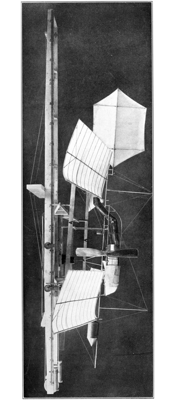
The very early morning preceding actual sunrise on July 11 was undoubtedly as calm as it is possible to find; there was absolutely no breeze stirring and the water in the river was as smooth as glass as far as one could see. The anemometer cups were stationary, the wind vane stood absolutely parallel to the launching apparatus and everything promised a most successful experiment. After mounting the aerodrome on the “overhead” launching apparatus the burner was lighted, and while the steam pressure was still rising and the propellers were revolving faster and faster all the time, there was a snap and they ceased to turn. The fire, which was burning fiercely, ran the pressure immediately to 150 pounds. An attempt was at once made to start the propellers again by giving them an initial turn by hand, it being thought possible that a sudden gush of water had taken place and, accumulating in one end of the engine cylinder, had blocked the engine. However, as the engine refused to keep the propellers going after they were started, and as the pressure was still rising very rapidly, the burner was shut off and an investigation made. Upon removing the hull covering, it was found that the connecting rod bearing had broken off short near the crank pin of the engine, and that it would be necessary to take the part to Washington in order to repair it, as there were no machine tools on the house-boat.
After several days of exceedingly bad weather, the conditions grew more favorable. Late in the afternoon of July 14, Aerodrome No. 5 was again placed on the “overhead” launching apparatus and prepared for a trial. After lighting the burners, 95 seconds were required to raise a steam pressure of 120 pounds. Upon leaving the launching apparatus the aerodrome went directly ahead for a few feet, but immediately commenced to rise, elevating its bow to an angle of 20 degrees by the time it had travelled 40 feet. With its bow in this position, it was blown back towards the house-boat and a little to the right of it, and, when within about 5 feet of the water, suddenly righted itself and started ahead again, rising all the time and reaching a height of about 20 feet by the time it had travelled 100 feet. In the meantime the bow had again become elevated to an angle of about 15 degrees and the aerodrome was blown backwards and downwards again. Just before reaching the water it started to right itself, but it had descended so that the front guy-post was in the water, thus destroying its equilibrium and causing it to settle into the water. The path of this flight is shown by the peculiar S-shaped line in Plate 34.
In the adjustments preliminary to the above trial the Pénaud tail was elevated to an angle of 712 degrees when the aerodrome was stationary in the shop. This excessive elevation, coupled with the fact that the center of gravity was also probably a little too far forward, no doubt accounts for the erratic flight. The data on setting of wings, tail, etc., are given on Data Sheet No. 7 (Appendix). [p144]
After several days of exceedingly bad weather the conditions were more favorable on July 19. Since the last experiment on July 14 the coefficient of elasticity of the Pénaud tail had been decreased, the rear wings moved back 5 centimetres, and the “float” so placed that the center of gravity of the machine was brought to the same position it had had on that day, that is, 2 centimetres back of the line of thrust. With this arrangement, assuming that the CP is over the CG, we should have an apparent efficiency of the rear wings of 63.6 per cent, since the distance between CPfw, and CG is 79.7 centimetres, and the distance between CPrw and CG is 125.3 centimetres. With the adjustment of July 14, the distance between CPfw and CG was 79.7 centimetres, and the distance between CPrw and CG was 118.3 centimetres, thus allowing for an apparent efficiency of 67.37 per cent for the rear wings. It will be recalled that in the unsuccessful flight of July 14 the midrod of the aerodrome was inclined at an angle of about 20 degrees during most of the time that it was in the air, thus indicating that the front wings were lifting proportionately more than they should. On July 14 the Pénaud tail had a negative elevation of 7° 30′, and it required 1240 grammes placed at its center to bring it to the horizontal. On July 19 the elevation of the tail was changed to 5° and a weaker spring for controlling the elasticity was substituted, so that it required only 200 grammes placed at the center of the tail to bring it to the horizontal. A rubber band, of about one-half the strength of the upper spring, was attached by means of a cord to the lower guy-post and the lower vertical ribs of the tail, so that the tail would be elastic both ways. This rubber band was in place and acting to help draw the tail down when the above measurement of the coefficient of elasticity was made. A rubber band connected to the lower side of the tail was also used in the flight of July 14, but it was so very weak, compared to the upper spring, that its effect was negligible.
The effect of this change in the balancing of the aerodrome, and also the more considerable effect which the coefficient of elasticity of the tail has on the balancing, will be immediately noticed from the description of the next flight. The data on setting of wings, tail, etc. are given on Data Sheet No. 8.
At 3 p. m., the wind having died down, Aerodrome No. 5, equipped with its “single-tier” wings and Pénaud tail adjusted as above, was placed on the “overhead” launching apparatus. After lighting the burners, one minute and thirty seconds were required to raise a steam pressure of 120 pounds. Immediately upon leaving the launching apparatus, the aerodrome started straight ahead, dropping about 3 feet by the time it had gone 100 feet; it then rose with its midrod at an angle of about 6 or 8 degrees, regaining its level very quickly, however, and making three of these undulations by the time it had gone [p145] 300 feet. It continued straight ahead for another 300 feet and began to circle to the left, the diameter of the first circle being about 200 feet. As soon as it started to circle, it rose with its midrod at an angle of about 15 degrees, and by the time it had made its first half turn it started to descend, coming down to within 15 feet of the water. As soon, however, as it had completed this first turn, it again rose, making another half circle, then, upon the completion of this half turn of the second circle, descended, this time to within 10 feet of the water, rising again for the third half turn, but again descending to within 2 feet of the water at the completion of this third circle, and then rising and completing the first half turn of the fourth circle. By this time, however, it had sunk so near to the water that the guy-posts caught in the tall grass while it was descending just before the completion of the fourth circle, thus pulling the aerodrome down into the water with the propellers still running. The total time the aerodrome was in the air was 46 seconds. The total number of revolutions of the propellers was 488, or at the mean rate of 637 R. P. M. Upon examining the aerodrome, after it was recovered, it was found that there were 925 grammes of water left in the separator, the fire having been put out by the aerodrome coming down into the water.
When the aerodrome first commenced to circle during its flight, it was noticed that the front wing clamps had twisted on the midrod, the left wing being dipped downwards, and the right one, of course, being elevated, and the peculiar circling of the aerodrome was undoubtedly due to this fact. The cause of the wing clamp twisting on the midrod was that one of the workmen forgot to tighten one of the screws of the wing clamp when the wings were being adjusted on the aerodrome. But for this unfortunate twisting of the wings, it is probable that the flight would have been perfectly straight and the distance covered would have been considerably greater than it was, the total path traversed being about 2600 to 2800 feet, found by plotting the path on the coast-survey chart and measuring it.
As the proper balancing of both Aerodrome No. 5 and No. 6 had now been determined with reasonable accuracy, and as much more time had already been given to the experiments than had been intended, it was decided to dismount the “overhead” launching apparatus at once and substitute the “underneath” one, so that it could be immediately determined whether this newer plan for launching the aerodrome by a car supporting it from underneath would be suitable for use with the large machine. After a considerable period of exceedingly bad weather, during which time the change was made in the launching apparatus, the weather conditions became more favorable on July 27. Aerodrome No. 6, equipped with “single-tier” wings and Pénaud tail, was mounted on the [p146] “underneath” launching apparatus, and everything was got ready for a flight. On lighting the burners, they failed to work properly, and, upon investigation, it was found that the air valve controlling the air pressure on the gasoline tank, was out of order. While this was being repaired, the wind rapidly increased in velocity and became very gusty, thus endangering the aerodrome, as the wings were very liable to be broken by the wind suddenly veering more rapidly than the house-boat could turn or the turn-table could be moved, and thus striking the wings from the side and putting an enormous upward pressure on them, owing to the fact that the diedral angle between them gave to each wing an elevation of 712 degrees from the horizontal. The aerodrome was accordingly dismounted and everything kept in readiness for a trial, with the hope that the wind would die down, or at least become steady, but it did not do so until after dark.
Aerodrome No. 6, equipped with “single-tier” wings and Pénaud tail, was launched from the “underneath” launching apparatus. There was a dead calm, the river not showing a ripple; the wind vane pointed to the northeast, but as the tide was low and the boat was aground, the launching track was pointing due south. At 7 a. m. the burners were lighted, and 80 seconds were consumed in raising a steam pressure of 120 pounds. Everything worked perfectly; the uprights on the car, which initially support the aerodrome and upon its being released are instantaneously pulled down by rubber springs, as well as the disappearing part of the track, acted without the slightest hitch. Immediately upon leaving the launching apparatus, the aerodrome depressed its bow to an angle of between 3 and 4 degrees and made a direct line for the water. At this angle it struck just on the opposite side of the channel, about 300 feet from the house-boat, and while several minor parts, such as guy-posts, were injured no damage of importance was done. Owing to the difficulty of getting through the marsh and recovering Aerodrome No. 6, it was found impossible to make another trial with No. 5 before the wind had increased to a prohibitive velocity. The path of this flight is shown by the dotted line in Plate 36. The data on setting of wings, tail, etc., are given on Data Sheet No. 9.
The last previous trial of Aerodrome No. 6 was made on June 23, and the balancing at that time was evidently correct for the settings of the tail which were then used. The Pénaud tail then had an elevation of 712 degrees, and the coefficient of elasticity was such that 1240 grammes were required at the center of the tail to deflect it to the horizontal. In the trial above recorded, on July 28, the adjustments of the wings were practically what they were on June 23, the CG being moved forward 1 centimetre, but the Pénaud tail had an elevation of something less than 5 degrees, and the coefficient of elasticity was such that [p147] 200 grammes placed at the center were required to deflect the tail to a horizontal. It was not intended that the angle of the tail should have been less than 5 degrees, but it was found that one of the workmen had improperly attached the fastening wire, and had considerably decreased the angle. This last adjustment of the Pénaud tail should have been the same as that used on Aerodrome No. 5 in its flight of July 19. The CG had purposely been moved forward slightly, but the effect of moving the CG forward and at the same time decreasing the stiffness and angle of the tail was shown by this flight.
The above trial not only very clearly emphasizes the importance of carefully determining what the elasticity of the Pénaud tail should be, but also emphasizes the fact that even the best workmen, who have had several years of experience, cannot be relied on in anything which requires that everything be done exactly right and not nearly right.
The aerodrome equipped with “single-tier” wings and Pénaud tail was launched from the “underneath” launching apparatus at 9 a. m., 1 minute and 30 seconds having been required to raise 120 pounds steam pressure. The wind was from the southeast, with a velocity of 3 miles an hour, and the launching track was pointed directly into it.
The launching apparatus, with the disappearing track, worked perfectly, and the aerodrome started straight ahead, dropping slightly at first, but immediately regaining its level and going ahead, gradually raising its bow to an angle of about 8 or 10 degrees, and slightly slacking up its speed by the time it had gone about 300 feet. It then made a circle to the left of a radius of about 75 feet and started back. As soon as it had made this turn it regained its level and directly regained its speed. But as soon as it had speeded up again it elevated its bow, which slackened its speed as before. It then again righted itself, still going in the same direction and crossing the sand-bar on the point of the island at a height of about 40 feet. As soon as it had crossed the sand-bar, it again made a circle to the left with a radius of about 75 feet, heading directly for the house-boat, but when it had got back above the sand-bar it again circled to the left, passing directly between two tall trees, and barely missing them, and still circling to the left, when it again reached the opposite side of the sand-bar. It, however, kept on circling to the left and once more started back towards the house-boat, this time passing to the left of the trees and again barely missing them, and completing this, its second, circle over the sand-bar. It then started due north, heading directly for Quantico, but by this time something had evidently happened to the burners as the fire went out, and the propellers gradually slowed up. However, it kept on towards Quantico, gradually descending on an even keel, and came down in the water at a point about 500 feet [p148] from the sand-bar and about 1000 feet from the house-boat. The propellers had almost ceased turning when the aerodrome came down into the water, and it settled almost as quietly as though it had been picked up and placed there, so that no damage was done to it.
The total time that the aerodrome was in the air was 63 seconds, and the total length of flight was about 2500 feet. The path of this flight is shown by the dotted line with the double circle in Plate 36. The data on settings of wings, tail, etc., are given on Data Sheet No. 10.
As soon as the workmen had had their breakfast, Aerodrome No. 5 was again placed on the launching apparatus, equipped this time with the superposed wings and Pénaud tail. Upon lighting the burners, it was found that they did not work properly, a small piece of soot having clogged up the tip of the vaporizing coil. While this trouble with the burners was being remedied, the wind increased to such an extent that it was found necessary to remove the aerodrome from the launching apparatus to prevent its being injured by side gusts. As it was Saturday and the wind showed no signs of quieting down, the experiments were discontinued until the next week.
After placing the aerodrome on the launching apparatus and getting everything in readiness for a flight, upon lighting the burners a sudden sheet of flame shot out of the smoke-stack and so seriously charred three panels of each of the rear wings that they had to be removed for repairs. The silk covering of the wings had been coated with a special fire-proofing preparation, but the intensely hot flame, of course, charred all the silk that it came in contact with.
By the time that the wings had been repaired, and the defect in the burner which caused the accident had been remedied, a severe storm had arisen, making it necessary to remove everything to the interior of the boat. While waiting for the weather to become more suitable, a test of the engine of Aerodrome No. 5 was made inside of the house-boat. In this test a steam pressure of 140 pounds was obtained, giving 650 R. P. M. of the round-end, 100-centimetre propellers, which previous tests had shown to mean a thrust of 7480 grammes. As the flying weight of the aerodrome was now 14,104 grammes, the thrust obtained would correspond to a lift of 53 per cent of the flying weight, which was maintained in this test for 90 seconds.
As the CG of Aerodrome No. 5 seemed to be a little too far forward in the flight of July 28, it was decided to change it slightly, and it was moved back 4 millimetres.

A trial run in the house-boat was also made on Aerodrome No. 6, while waiting for the weather to become more suitable, but, unfortunately, the result of this test was disastrous. The aerodrome had been placed on trestles and [p149] held down to the floor by wires fastened to the cross-frame. In the midst of the test one of the wires slipped, allowing the aerodrome to push forward and thus permitting the propellers to come in contact with the wires which held it to the floor. Both propellers were entirely demolished and the cross-frame was broken off short just at the right-hand engine. The disaster was entirely due to the carelessness of one of the workmen in tightening one of these wires, a further example of the extreme heedlessness of workmen, even in the most important details, which concern the very existence of the machine.
After the very satisfactory trial of Aerodrome No. 5 in the shop two days previous, it was hoped, now that the weather had become suitable, that a good flight with the superposed wings would be obtained. The aerodrome, equipped with these wings, was accordingly placed on the launching apparatus and the burners were lighted, but they refused to work properly, a steam pressure of only 80 pounds being obtained. After much delay the burners were finally got to work properly, but the wind had increased in velocity to such an extent that it was necessary to remove the aerodrome to the interior of the house-boat. As the wind continued to increase in velocity it was decided to make another trial of the aerodrome inside of the house-boat. Upon doing this it was very soon found that there was a small leak in the front turn of one of the coils of the boiler, and the steam from this played directly against the burner, causing it to work intermittently. A new coil was substituted, and after some adjustment a very excellent run was obtained, the steam pressure reaching 130 pounds and the propellers making 654 R. P. M.
In the afternoon the wind quieted down and the aerodrome, equipped with superposed wings, was again placed on the launching apparatus. The burners were lighted but again refused to work properly, the vaporizing tip being stopped up with soot. This caused the burner to “flood,” which sent a sheet of flame through the stack and burned the rear right wing.
A new wing was substituted, the burner tip was cleaned out and everything was again put in readiness for a flight. Upon lighting the burners, 1 minute and 58 seconds were required to raise 120 pounds steam pressure. The underneath launching apparatus, with the disappearing track, worked perfectly, the aerodrome dropping slightly, but going straight ahead. It, however, continued to descend for a distance of about 100 feet, the bow being elevated about 5 degrees. The bow then became horizontal, the aerodrome rising slightly at the same time, but going only about 50 feet farther, when it again started to descend slightly, and finally settled gently on the water between 300 and 500 feet from the house-boat, with its bow elevated about 3 degrees. There was a hiss as the hull touched the water, showing that the fire was still burning and making it [p150] improbable that the failure of the flight was due to lack of power. The data on settings of wings, tail, etc., are given on Data Sheet No. 11.
The speed of the launching car, one foot in front of the point at which the aerodrome was released, was twenty feet a second, as shown by the carbon record sheet carried by the launching car and moved in front of a tuning fork which had been set in vibration.
The aerodrome, being uninjured in the previous flight, was again placed on the “underneath” launching apparatus, and before attaching the wings a short run was made in order to see that everything was in proper working condition. As everything seemed to be all right, the wings and tail were immediately adjusted for another trial. As the bow was slightly elevated in the previous trial, it was thought best to bring the CG a little farther forward, and this was accordingly done. As the aerodrome also seemed to drop slightly in leaving the launching car in the above trial, the tension of the launching springs was slightly increased so as to increase the velocity at the moment of release.
Just as the sun was setting the aerodrome was again launched, 1 minute and 30 seconds having been required to raise 120 pounds steam pressure, but the pressure was rising very rapidly at the moment of launching. There was an absolutely dead calm prevailing, the river being as smooth as glass. The launching apparatus, with the disappearing track, worked perfectly. Immediately upon being released the aerodrome went straight ahead, with its midrod horizontal, but gradually glided downward as though the wings had very little lifting power, and settled in the water about 200 feet from the house-boat. The velocity of the launching car, 1 foot before the aerodrome was released, was 22 feet a second, as shown by the carbon record sheet.
In the above trials of the superposed wings, the conditions of the wind and of the aerodrome were certainly as favorable as could be expected. There was as much power being furnished by the engine as had been furnished in the previous flights with the “single-tier” wings, and the balancing of the aerodrome was exceedingly good. The superposed wings, unquestionably, had a fair trial and proved inferior to the “single-tier” ones, for they had a supporting surface of 2.75 square feet to the pound, whereas with the “single-tier” wings there was approximately 2 square feet to the pound. The decreased lifting power of the superposed wings seems to be another confirmation of the results of the Allegheny experiments with the “plane-dropper.”40
As more time had already been given to these tests than it seemed well to [p151] spend on them at that time, owing to the pressure of the work of construction for the large machine, it was deemed best to discontinue them for the time being, and as soon as time could be found for it, to construct a set of wings with superposed surfaces, using only two surfaces and making their distance apart at least equal to or greater than their width.
It will be remembered that the prime object in making these tests was to obtain data for use in the balancing of the large aerodrome and in constructing a launching apparatus for it. The chief deductions drawn from them were: First: That it would be best to construct the first set of wings for the large machine on the “single-tier” plan, and later to make a set of superposed ones, should further experiments with new designs develop a type of superposed surfaces which gave as good lifting power as the “single-tier” ones. Second: That the proportioning of the coefficient of elasticity of the Pénaud tail should be given as careful attention as the setting of the wings. Third: That the “underneath” launching apparatus was equally as good as the “overhead” one, and that both worked as well as could be desired; and, fourth, that while short periods of calm weather might be expected during some part of the day on a portion of the days of each month, yet the most favorable conditions were more apt to be met with between the first break of day and the actual rising of the sun, or from an hour preceding sunset until darkness actually came.
It will be noted that while considerable delay was experienced in making these tests, nearly all of it was due to the very delicate adjustments required in the power-generating apparatus of the aerodrome, but it should also be noted that when these adjustments were accurately made the models operated exceedingly well, and could be depended upon to give good flights of sufficient duration to permit a careful study of their action while in the air.
In the experiments of June 27 and July 7, above described, the aerodrome immediately after leaving the launching apparatus began to rise with its midrod pointed upward at an angle of about 15 degrees. From Data Sheet No. 6, which gives in detail the important data as to the settings of the wings, the elasticity of the Pénaud tail,41 etc., we note that the tail had a negative angle of 712 degrees, and that the spring which held it at this angle was of such a stiffness that it required 1240 grammes placed at its center of figure to depress it to the horizontal. It will also be noticed that the position of the front and rear [p152] wings relative to the center of gravity of the machine was not the same as that which existed at the time of the very successful flights of 1896, as shown by Data Sheet No. 1 of No. 5, May 6, 1896. When the elasticity of the tail was adjusted before making this test it was thought that it was made the same as in the experiments of 1896, though accurate data as to the exact amount of this elasticity had, unfortunately, not been kept.
A slight change had also been made in the method employed of attaching the Pénaud tail to the machine. In 1896 the tail was attached to the machine by means of a flat piece of wood (hickory) which had been steamed and bent to the proper extent to cause the rudder to have a negative angle of about 5 degrees, but no accurate note was made of its angle or stiffness, so that in 1899 no data were available as to exactly what the angle had been or how stiff the spring was. Owing to the fact that wood not only warps and twists, but also that any piece which has been steamed and bent gradually loses a certain amount of its curvature, it was decided in 1898 to change this method of attaching the tail, the wooden spring being replaced by a coiled steel spring attached to an upper guy-post and connected to the tail by a bridle wire fastened to the center of figure of the tail.
After the experiment of July 7, 1899, a lower spring, consisting of small rubber bands, was connected by a wire to the lower part of the rudder and fastened to the guy-post, thereby more nearly reproducing the conditions obtained when using a wooden spring, which, of course, tends to return the rudder to its normal position when it is displaced in either direction. After attaching this lower spring to the rudder, the experiment of July 14 was made, and it was found that the aerodrome still flew with its midrod pointed upward at a very steep angle. It was, therefore, felt certain that the upper spring on the rudder was too stiff, and that it should not require so much as 1240 grammes to bring it to the horizontal. This spring was, therefore, replaced by a weaker one, and the angle of the rudder was also decreased until it had a negative angle of only 5 degrees and required only 200 grammes placed at its center of figure to bring it to the horizontal. From the description of the flight of July 19, it will be seen that these changes immediately corrected the tendency of the aerodrome to point its nose upward at such a sharp angle, and it will be later seen that after a further slight adjustment the flight of July 29 was made, in which the proper balancing was obtained and the aerodrome made a good horizontal flight.
After these preliminary tests with the “overhead” launching apparatus, it was dismounted and the “underneath” one substituted and the experiments of July 28, 29 and August 3 were made. Everything connected with this “underneath” launching apparatus worked perfectly from the start and four flights of the aerodromes were made using it.

It will be recalled that in “Experiments in Aerodynamics” Mr. Langley made tests of the soaring speed, etc., of surfaces when superposed. In many of his experiments with rubber-driven models, he also employed superposed surfaces. During the summer of 1898 several forms of superposed surfaces, of a proper size for use on the steam-driven models Nos. 5 and 6, were constructed and were tested under as nearly as possible the same conditions as would exist when used on the aerodrome, by mounting the surfaces on the whirling-table and measuring their soaring speed, lift, drift, etc., to determine just what arrangement of surfaces gave the greatest lifting effect with the least resistance. Two of the forms which were tested are shown in Plate 37, Figs. 1 and 2, and Plates 64 and 65. At the conclusion of these tests, it was decided to construct a set of surfaces on the plan shown in Plates 64 and 65, and to have them ready for use on either of the models Nos. 5 and 6. These surfaces were taken to Chopawamsic Island in April, 1899, when all of the other aerodromic material was first carried there. It was planned to make some tests with them to determine whether or not it would be best to use superposed surfaces on the large aerodrome or to follow the plan of “single-tier” ones, which had the great advantage of having already proved their worth in the successful flights of the models. On August 3, Aerodrome No. 5, equipped with these superposed surfaces, was launched. It will be noted from Data Sheet No. 11 that the superficial area of the superposed surfaces was considerably greater than that provided by the “single-tier” ones, and on the assumption of the same efficiency per unit of surface in both cases, the aerodrome should have soared at a less speed and required less power when using the superposed surfaces. The results obtained, however, were just the reverse, the aerodrome being unable to sustain itself when using the superposed surfaces, whereas with the “single-tier” ones it was evident that a slight excess weight might easily have been carried without preventing the aerodrome from soaring properly. While it was felt that these tests were not entirely conclusive as to the superior lifting power of the “single-tier” surfaces, yet as the engine builder was constantly promising, each time with increased emphasis, that he would within less than a fortnight deliver the engine for the large aerodrome, and that it would develop even more power than the specifications called for, it was deemed best to cease the experiments with the models and concentrate all effort on the completion of the large aerodrome frame and the construction of a set of “single-tier” supporting surfaces for it. It was recognized from the first that the “single-tier” supporting surfaces lacked the rigidity which could be secured by the truss construction afforded by the superposed plan, yet these models, which were the only machines in the history of the world that had ever flown successfully, had been equipped with “single-tier” surfaces; and the experience so dearly bought during the long [p154] years of development of these models had taught the very valuable lesson that in work of this kind where we have no margin on anything, but everything has to be calculated on the “knife-edge” basis, it is an exceedingly unwise thing to introduce any modification from what has been proved to be satisfactory, unless such modification is absolutely necessary.
The principal object in building the one-eighth size model of the large aerodrome, as mentioned in the first part of this chapter, was to determine by actual experiment whether the new form of “underneath” launching apparatus, which had just been designed, was likely to prove as satisfactory as the original “overhead” type, which had been used in the successful flights of the models in 1896. Yet after it was completed this aerodrome was found so very strong and stiff, even though roughly constructed by merely tying the joints of the tubing together with wires and soldering over the joints, that it was decided to equip it with power, if a suitable form of power could be found which could be easily applied. Just at this time liquid air as a motive power was attracting considerable attention all over the country, and attempts were made to procure a small power plant for operation by liquid air. After devoting considerable time to the matter it was found impossible to do anything with it just at that time, as the liquified air could not be obtained in Washington, and one of the chief experimenters in New York, who had been given a commission to make certain experiments at his plant, so continuously delayed beginning them that it was found necessary to give up the idea.
However, after the completion of the tests of the launching apparatus some experiments were made in flying the model as a kite. For this purpose a mast twenty feet high was constructed and so arranged that it could be mounted at the center of a small power launch. The model aerodrome was flown by a cord connected to it by a bridle, the cord passing over a swivel pulley on top of the mast and down into the boat, whence it could be played out or hauled in as occasion required. By heading the launch into the wind it was possible to secure sufficient relative velocity to cause the model to support itself and a number of tests were made in this way. It was found that when the bridle was attached at the point at which the propellers would deliver their thrust, had they been in use and driven by power, the model flew exceedingly well, maintaining its equilibrium even during very strong gusts. Owing to the rolling produced by waves from the large boats which were continually passing in the part of the river where these tests were made, the power launch was often in danger of being upset by its tall mast; and finally, when the tests were just reaching the point where accurate information was being obtained on the balancing of the model, a sudden rolling of the boat caused the mast to snap off while the model was in the air. Before it could be picked up from the water a passing boat had swamped it and it was lost in the river. [p155]
Although the model was, as has been said, rudely constructed and, therefore, did not represent a serious loss, yet the pressure of the more important construction work for the large machine prohibited the construction of another rough model for continuing these kite experiments, which it was felt could not at best be more than approximate indications of the general stability of the machine under practical conditions.
The use of a house-boat seemed to Mr. Langley so indispensable in former years in making open-air tests of the models that he decided from the outset, though advised by the writer against doing so, to use the same plan on a much larger scale in connection with the large aerodrome. Aside from its supposed utility as a convenient and apparently safe place from which to launch the aerodrome, the house-boat was valuable as a portable workshop for making necessary repairs and as a temporary storehouse for the apparatus, thereby saving much packing and unpacking. It also provided sleeping quarters for the workmen.
It was early seen that this plan would require a boat at least 60 by 40 feet, which could be built only at a large initial cost. But as the experience with models had so firmly convinced Mr. Langley that it was necessary not only that the aerodrome be launched over the water, but also at a considerable height above it, and from a station that commanded all points of the compass, he decided to adopt this plan for the large aerodrome, and designs for such a boat were accordingly made in the latter part of 1898.
In order to insure the completion of this house-boat by the time the aerodrome was expected to be ready for trial, it was built under contract. Immediately after its delivery in May, 1899, work was begun on the superstructure which carried the launching track. This superstructure was a considerable undertaking, involving a turn-table weighing about 15 tons, supported on a double circular track, and this track in turn was supported entirely from the side walls of the house to avoid having columns in the middle of the floor. From the photographs, Plate 38, Figs. 1, 2 and 3, it will be seen that the entire superstructure was supported by three trussed girders extending across the boat above the roof and carried by vertical posts built into the side walls of the house. The turn-table was 48 feet square and the launching track carried by it was 5 feet gauge by 80 feet long.

In making tests of the models, it had been the practice to carry the main body of the aerodrome up a ladder to the upper works of the boat, the wings being also carried up in the same manner. As the large aerodrome was expected to weigh at least 640 pounds, of which 350 pounds would be the steel frame with its undetachable parts, such as the engine and its appurtenances, it was seen that something more effective than a ladder would need to be provided for getting the aerodrome from the interior of the boat to the launching track [p157] above. It was therefore decided to place the upper works of the boat rather nearer the rear end than the front, thus leaving a space over the front end of the house through which a large trap-door might be cut in the roof, and it was thought that in this way the aerodrome might be passed up to the launching track by the use of suitable ropes and pulleys. The upper works were so arranged, and a sliding trap-door was provided in the roof, but more intimate knowledge of the difficulties of handling so large and heavy a frame made it certain, even before the aerodrome was ever placed upon the house-boat, that it would be impossible to transport it to the upper works by passing it through the trap-door. A different plan was then resorted to. A very large door was constructed at the rear end of the house, through which the completely assembled frame could be carried in a level position and placed upon a large raft, consisting of a lattice flooring over pontoons, moored at the rear end of the boat, as clearly seen in Plate 38. In order to raise the aerodrome frame from the raft to the upper works, a large, but light, mast and boom, with suitable stays were provided. As the wings, when mounted in their proper position on the aerodrome, would be interfered with by such a mast, the mast and boom were so devised as to be capable of rapid erection and dismounting, only five minutes being necessary for either operation. In Plate 38 the mast and boom are seen in position in Fig. 3, while in Figs. 1 and 2 they have been dismounted.
The construction of the launching track and car was begun in November, 1899, but their completion was long delayed, as they were frequently put aside for the more immediately important parts of the work. Moreover, the arrangement of the struts and clutch of the launching car depended entirely on the form and dimensions of the frame of the aerodrome, which could not be entirely decided until a proper engine had been secured and tested in the frame to determine what modifications of it were necessary. In the spring of 1902, however, the launching car was entirely finished and a number of tests of the large engine were made in the shop with the frame mounted in position on the car.
From the description of the “overhead” launching apparatus (Part I, Chapter X ◊) which had proved so successful in the tests of the models, both in 1896 and in the later experiments of 1899, it will be recalled that the essential features of it were a track and a light car with three hinged struts which extended below the body of the car, and against which suitable co-acting bearing points attached to the frame of the aerodrome were tightly drawn by means of a clutch which gripped a special fitting fastened to the aerodrome frame near the central point of its length. After the engine of the aerodrome had been started and got to running at full speed, the car was released and moved forward along its track by the combined force of the thrust of the propellers and the pull of the coiled launching springs. Just before the car reached the forward end of the track, a cam at this point caused the clutch to open and release [p158] the aerodrome, which immediately dropped slightly, as it had purposely not quite reached a speed sufficient to cause it to soar. This slight drop of the aerodrome, even if it were only a fraction of an inch, made it possible for the hinged struts, against which it had been held by the clutch, to be folded up by their special springs against the floor of the car, thus leaving the aerodrome free in the air without danger of entanglement.
The struts referred to above were three in number, two being placed near the rear and one at the center of the front of the car. The use of three points of support had the advantage of furnishing a rather rigid foundation against which the frame could be tightly drawn by means of the clutch-hook without risk of straining it. In designing the “underneath” launching apparatus, which was very thoroughly tested in the experiments with the models in the summer of 1899, the plan of having three struts with the aerodrome drawn tightly against them by means of a central clutch-hook was continued with most satisfactory results.
When the position of the struts on this launching apparatus had been changed so as to permit it to be used for the quarter-size model, it was found, in making shop tests of the engine with the aerodrome mounted on the launching car, that, owing to the greater vibration produced by the gasoline engine, the three points of suspension did not hold the model in a sufficiently rigid manner. It became necessary, therefore, to use four struts, the two rear ones being left as before, and the single one in front being replaced by two interconnected ones arranged similarly to those in the rear. After making this change no difficulty was found in holding the aerodrome rigidly against the struts, and this modification was therefore immediately introduced in the designs for the large launching car which was already under construction.

Experience, both with models 5 and 6, and with the quarter-size model, had also demonstrated the necessity of providing some means whereby the aerodrome frame would be relieved of the torsional strains produced upon it by a side wind striking the under surface of the wings when the aerodrome was mounted on the car preparatory to a test. The means for preventing these torsional strains in the case of the models, when “overhead” type of launching car was used, has been described in Chapter X of Part I ◊. However, with the “underneath” type of launching car, a different means was necessary. A plan, in which outriggers projected from the body of the car and wires running from these outriggers up to the main ribs of the wings, with means for releasing the wires just before the car reached the end of the track, was used with the “underneath” car in the tests of models 5 and 6 in the summer of 1899, but the outriggers were frequently deranged by the sudden stopping of the car at the end of the run and they were replaced by a simpler arrangement. In this plan the torsional strains were relieved by providing, at the forward and rear ends [p159] of the car, smaller hinged uprights furnished in their upper part with a small slot into which a pin projected from the bottom of the forward and rear guy-posts, respectively. The guy-wires from wings being connected to the lower ends of the guy-posts the torsional strain produced by a side wind was immediately transmitted from the wings through the guy-wires to the guy-post, whence it was transmitted to the car itself, and thus prevented from acting on the metal frame of the aerodrome, as shown in Plate 39. These additional short struts for taking up the torsional strain were first added to the small launching car in 1901, and in the succeeding tests made with the quarter-size model no trouble of any kind was indicated as likely to be caused by them. As it was these extra struts which were directly responsible for the accident in the launching of the large aerodrome October 7, 1903, at the time of its first trial, and possibly also for that on December 8, 1903, at the time of the second trial, special attention is here called to them.
The length of travel which could be provided for the launching car in the case of the large aerodrome, as well as in that of the models was necessarily very limited, owing to the fact that the track had to be constructed on the top of the house of the boat. It was therefore necessary, in order that the aerodrome might attain a speed sufficient for soaring before being launched, to keep the weight of the launching car as small as possible, a given spring tension being capable of accelerating a given mass a definite amount in a given length of travel. With a heavier launching car the spring tension would have to be increased. Moreover, since the blow which would be struck when the car was suddenly stopped at the end of the track, would depend on its mass as well as its velocity, there was an additional reason for trying to keep the weight of the car as small as possible.
While it was found perfectly feasible to keep the weight of the launching car for the model low enough for practical purposes, in designing the launching car for the large aerodrome it was only by eliminating all flooring of the car and providing merely a box frame with necessary cross-braces, that its weight was kept within what appeared reasonable limits. Even then the blow which it would strike when it reached the end of the track was found by calculation to be exceedingly formidable.
Referring to the drawings of Plate 40, Figs. 1, 2 and 3, it will be seen that the large launching car consisted essentially of two parallel longitudinal side members 6 inches deep by 1.5 inches thick by 19 feet long, connected by three main sets of cross-members: one set near the rear, at the point at which the rear struts for supporting the aerodrome were mounted; a second rather heavier set about the middle of its length, at the point where the strut which carried the clutch-hook was mounted; and a third near the front, at the point where the front struts were mounted. Projecting from the forward end of each of the [p160] longitudinal side members were piston rods, on which were mounted leather-cup pistons, which co-acted with buffer cylinders fixed at the extreme front of the track to absorb the blow when the car reached them at the end of its travel. The car was supported on each side by means of four hangers (Figs. 4 and 5) which carried grooved wheels having ball-bearings and running on a steel track consisting of flat plates fastened on the side of the timbers of the launching track. On the extreme lower point of these hangers were small guide pulleys, so placed as to be just below and out of contact with a guard rail on the side of the launching track, thus preventing any possibility of the launching car being raised from the track either during its forward motion or by a side wind striking underneath the wings.
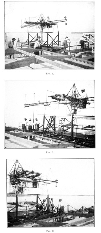

On the large launching car the arrangement of the struts against which the bearing points of the frame were tightly drawn by the clutch was similar in all respects to that used on the model car, there being only slight differences in details. The details of the uprights on which the bearing points of the aerodrome frame rested are clearly shown in Figs. 6, 7, 8, and 9 of Plate 40. From the photographs (Plate 41, Figs. 1, 2, and 3) which show the large frame mounted on the launching car, the general arrangement of the struts and the clutch-hook can be readily seen; and from Plate 42, Figs. 1, 2, and 3, which show in detail most of the important features of the clutch-post and its clutch, a very good idea of the size of the different parts may be had by observing that the distance from the fulcrum of each half of the hook to the pin by which it was connected through the universal joint to the vertical rods is five inches. As previously stated, this clutch-hook gripped the lower pyramid and pulled the bearing points of the frame firmly against the forward and rear struts of the launching car, and in launching the aerodrome the triggers arranged on the bottom of the car, which at the proper time pull on the vertical rods and thereby force the two halves of the clutch-hook apart, are so arranged that they strike a cross-beam at the front end of the track one inch before the triggers, which keep the struts from being pulled down by their springs, which tend to fold them up and force them down against the car. The triggers, which prevent the struts from being folded down, strike a cross-beam in the track one foot before the buffer pistons on the end of the car begin to enter the buffer cylinders at the end of the track, and, consequently, one foot before the folding prop, which supports the front end of the track, is knocked out by the car striking a special trigger which allows this folding prop to swing forward when the front end of the track folds down to insure that the aerodrome will not become entangled with the car, even though the aerodrome be not quite up to soaring speed at the moment of launching. The manner in which this front end of the track folds down can be very readily seen by comparing Plate 43 with Plate 95 of Chapter XII ◊, the former showing the front end of the track in horizontal position, with [p161] the aerodrome at the extreme rear end just preparatory to launching, and the latter showing the front end of the track folded down with the hinged prop standing outward in its downward path and the aerodrome just launched. These photographs will be more particularly referred to later, but attention is here called to them so that the description immediately following may be more easily understood.
Although this method of launching the aerodrome seemed to Mr. Langley, both theoretically and from the experience with the models, to be a satisfactory and feasible plan, there were two very important respects in which it seemed from the very first open to objection. In the first place, it was necessary that the aerodrome should be launched as nearly at its soaring speed as possible, because either an excess or deficiency of speed interfered to some extent with the equilibrium of the machine. So many factors were involved in the determination of what this final velocity should be that it seemed almost impossible to be sure of the results until at least one test of the aerodrome had been made. In the second place it was not known whether the rapid acceleration of the car would seriously interfere with the equilibrium of the aviator.
In reference to the first question it was, of course, known that a freely falling body acquires a speed of 32 feet per second at the end of the first second after having fallen a distance of 16 feet. It was proposed to launch the aerodrome at approximately 35 feet per second; and, since the distance over which the car would pass in acquiring this speed was approximately 60 feet, the rate of acceleration would, of course, be less than that for a freely falling body. The conditions in the two cases, however, are quite different. In the case of the freely falling body there is the constant force of gravity which causes the acceleration. In the case of the aerodrome the car is initially standing still but ready to be acted upon by the combined force of the thrust of the propellers and the tension of the springs. The propeller thrust is approximately 450 pounds at the moment of releasing the car, while the spring tension adds approximately 400 pounds more pull, giving a total pull of 850 pounds acting on the car at the start. The weight of the aerodrome including the aeronaut being approximately 850 pounds, and the weight of the car being approximately 450 pounds, the total weight to be accelerated is 1300 pounds. The resistance of the car and the aerodrome is zero at the moment the car is released, and increases approximately as the square of the velocity until it reaches approximately 300 pounds at the soaring speed of the aerodrome; while on the other hand the spring tension decreases uniformly from 400 pounds at the start to approximately 76 pounds at the end of the track, and the thrust due to the propellers decreases from 450 pounds at the start to approximately 250 pounds at the moment of launching. Consequently, it is in a general way clear that the rate of acceleration of the aerodrome and car decrease, probably in a geometric ratio, the rate of acceleration [p162] at the moment of launching the aerodrome being much less than that of a freely falling body. Since so many factors enter into the problem no confidence was felt in calculations as to what the rate of acceleration would be. It was, therefore, decided to determine it experimentally at the same time that tests were made on the car to determine what spring tension would be necessary to enable the aerodrome and car to acquire soaring speed by the time they reached the end of the track.
It was obviously impossible to make this initial test with the aerodrome mounted on the launching car, as the aerodrome would certainly wreck both itself and the car were it allowed to remain fastened when the car was stopped at the end of the track. It was, therefore, decided to make the tests by mounting on the car boards which would have a head resistance equal to that of the aerodrome. In order to minimize as much as possible the blow due to the car striking the buffers at the end of the track, the car had been made as light as possible. On this account it was felt to be unwise to risk adding to it a weight of 850 pounds to represent the aerodrome, and supplying an additional spring tension to represent the thrust of the propellers, as the total effect of the added weight and the added pull would certainly completely demolish the car. By calculation it was found that the omission of the 850 pounds weight of the aerodrome and the spring tension to represent the thrust of the propellers would practically counterbalance each other; and that if sufficient spring tension were provided to cause the car, with the light boards representing the head resistance of the aerodrome, to reach the soaring speed by the time it arrived at the end of the track, it would be safe to assume that this spring tension would be sufficient for use in launching the aerodrome.
The method of measuring the final speed of the launching car for the models consisted in fastening a strip of smoked paper to the launching car in such a position that it was drawn past a stylus fastened to the end of a vibrating tuning fork placed at the end of the track. This had proved perfectly successful, but it gave a record merely of the final speed attained by the car at the moment of launching the aerodrome. In the case of the large aerodrome it was desirable to have a record of the speed of the car during the first few feet, and also at several other points in its travel down the launching track, and the more numerous these points the better. Short strips of copper were accordingly placed every twelve inches along the length of the track, and these were connected by a wire to one terminal of a small electric battery. Mounted on the car, in such a way that it would be drawn across these contact strips, was a copper brush arranged to make continuous contact with another wire stretched along the track, this second wire being connected to the other terminal of the electric battery and having in its circuit the magnet which actuated a pen on a chronograph. Since the rate of revolution of the chronograph barrel was known, the [p163] distance between the marks which the magnet would cause the pen to make when its circuit was closed by the brush on the car passing across the contact strips on the track would give correct measures of the time consumed by the car in passing over each twelve inches of its travel. Upon test, however, it was found impossible to get the chronograph magnets to work rapidly enough to respond to the very rapid opening and closing of the circuit after the car had passed over the first one-quarter of its length of travel. As a large part of the slowness of action seemed to be due to the weight of the fountain pens, they were replaced by small glass tubes drawn out to a fine point and containing a small amount of ink. These seemed, however, to be still too heavy to respond to the rapid closing of the circuit unless the contacts were made unduly long. The contacts were finally made three inches long and placed only every three feet along the track, but just as these contacts were completed and placed in position the clock-work of the chronograph itself became deranged. Before it could be repaired, the tests were discontinued, as everything was in readiness for the boat to proceed down the river where the actual tests in free flight were to be made. Tests of the final speed of the car were, however, made by the tuning-fork method, and the springs were adjusted until their tension was sufficient to cause the car to attain a speed of thirty-five feet a second at a point three inches in front of the point at which the aerodrome would be released from the car.
The general plan for the large aerodrome was never a matter of uncertainty. At the time when the first general designs were made there had been in the history of mankind only one type of machine, that of the steam-driven Langley models, which had proved capable of flight for any considerable distance. Furthermore, the selection of this type had been the result not of sudden fancy or of purely theoretical consideration, but of years of the most careful experimentation, in the course of which nearly every conceivable style of machine had been tested with some form of power. It would have been worse than folly, therefore, if the one clear path had been left to seek some unknown way.
It was fully realized from the first, however, that the increase in size alone would make necessary in the design for the large aerodrome a great many modifications from the designs of the steam-driven models. It was not possible here, as in nearly every other kind of structure, simply to magnify uniformly the parts and proportions of the small machine in order to obtain a successful large one. This is particularly true in the case of the aerodrome, because the rapid increase of weight in the larger structure is out of all proportion to the increase in strength, while it is very desirable that the more expensive machine which is designed to carry a human being shall be relatively even stronger than the easily replaced model. This problem of increasing size without sacrificing strength and stability, it was known from the beginning, would be encountered in a particularly difficult form in designing the frame of the large machine, and was to be solved not by the discovery of some new and wonderfully strong material, but by improvements both in the general plan and the details of the machine. Here, as is often the case, it was not the large changes in the design but the improvements in small and sometimes seemingly unimportant details which demanded the most careful consideration and, as a whole, contributed most to the final result. For this reason, as well as because the large changes, when pointed out, are usually easily understood, the present chapter is for the most part a description of the improvement of details.
From the experience gained in the construction of the frames of the several steam-driven models, it was decided that the frame for the large aerodrome must consist essentially of two principal parts. First, a rigid backbone was required, extending from the point of attachment of the front wings to the point of attachment of the rear wings; and this backbone, for convenience designated [p165] the “main frame,” must support the second principal part, the “transverse frame,” which formed a cross with the main frame, and at the ends of which the propellers were mounted. While it was necessary that this transverse frame should have considerable rigidity and strength in a vertical direction, yet its main strength and stiffness was required in the horizontal plane for withstanding the thrust of the propellers. It had been possible to construct the frames of the later steam-driven models stiff enough, and at the same time light enough, by the use of properly proportioned steel tubing, but calculation very soon showed that in order to secure sufficient rigidity for the frame of the large aerodrome and at the same time keep the weight within the permissible limit, it would be necessary to depend very largely on guy-wires and to use tubing only for forming the struts against which the guy-wires should act. But this obviously introduced a new series of problems. The extensive system of guy-wires necessary would add materially to the head resistance of the aerodrome, and this might conceivably be so great as to require more propulsive power than would be required for a frame heavier but unincumbered by the head resistance of the wires. It became necessary to consider these problems, but no data were accessible from which the head resistance could be computed with any confidence. The coefficient of resistance for a cylindrical body moving through the air in a direction perpendicular to its length may in general be taken as one-half that of a flat body of the same cross-section; but it was thought very certain that, owing to the fact that tightly stretched wires are in constant vibration when the aerodrome is in the air, the resistance of the wires must be considerably greater than would be calculated from treating them as cylinders having a coefficient of 0.5. Unfortunately, no data on the resistance of vibrating wires were at hand. Before proceeding with the designs for the guying of the frame, therefore, the following brief series of tests was made in November, 1898, on the whirling table, in order to learn approximately the resistance that the proposed system of guy-wires for the large aerodrome would offer:
| RESISTANCE OF FRAME WITHOUT WIRES. | |||
| Frame consists of: 4 tubes, 1 cm. diameter, 14.5 cm. long; 2 tubes, 1 cm. diameter, 41 cm. long; 2 tubes, 1 cm. diameter, 101 cm. long. | |||
| Revolutions of turn-table per minute. | Velocity of frame. Feet per minute. | Resistance. Grammes. r. | Calculated resistance of frame. Grammes. |
| 6.75 | 608 | 11.5 | 14.2 |
| 9.75 | 877 | 34.0 | 29.6 |
| 12.0 | 1080 | 51.8 | 44.8 |
| 16.35 | 1475 | 97.0 | 83.8 |
| 19.75 | 1775 | 134.0 | 121.3 |
| 22.7 | 2045 | 168.0 | 161.2 |
| 25.5 | 2290 | 205.0 | 202.0 |
| RESISTANCE OF FRAME WITH 1ST SET OF WIRES. | ||||
| First set of wires: 16 wires, 0.6 mm. diameter, 102 cm. long; 6 wires, 0.6 mm. diameter, 42 cm. long. | ||||
| Revolutions of turn-table per minute. | Velocity of wires. Feet per minute. | Resistance of frame and wires. Grammes. R1. | Resistance of wires. R1−r=r1. | Calculated resistance of wires. Grammes. |
| 9.75 | 877 | 47.5 | 13.5 | 8.88 |
| 12.0 | 1080 | 73.5 | 21.7 | 13.47 |
| 13.75 | 1237 | 93.5 | 25.5 | 17.65 |
| 17.25 | 1550 | 144.0 | 37.0 | 27.7 |
| 20.25 | 1822 | 187.0 | 45.5 | 38.4 |
| 22.50 | 2025 | 216.0 | 47.5 | 47.4 |
| 22.875 | 2060 | 225.0 | 52.0 | 49.0 |
| 24.56 | 2215 | 250.0 | 56.5 | 56.7 |
| RESISTANCE OF FRAME WITH 2D SET OF WIRES. | ||||
| Second set of wires: 15 wires, 1.2 mm. diameter, 102 cm. long; 2 wires, 1.2 mm. diameter, 42 cm. long. | ||||
| Revolutions of turn-table per minute. | Velocity of wires. Feet per minute. | Resistance of frame and wires. Grammes. R2. | Resistance of wires. R2−r=r2. | Calculated resistance of wires. Grammes. |
| 9.25 | 833 | 54.0 | 26.5 | 15.35 |
| 9.35 | 841 | 55.0 | 27.0 | 15.4 |
| 11.3 | 1018 | 82.0 | 36.75 | 22.65 |
| 11.5 | 1035 | 82.0 | 35.25 | 23.4 |
| 13.0 | 1170 | 104.5 | 43.0 | 29.9 |
| 13.15 | 1185 | 105.0 | 42.5 | 30.60 |
| 16.7 | 1505 | 160.0 | 59.0 | 49.5 |
| 16.75 | 1510 | 160.0 | 58.0 | 49.9 |
| 19.5 | 1755 | 196.0 | 64.0 | 67.4 |
| 19.7 | 1770 | 203.0 | 69.5 | 68.5 |
| 21.60 | 1945 | 236.0 | 77.0 | 82.6 |
| 21.65 | 1950 | 237.0 | 77.75 | 83.2 |
| 21.75 | 1957 | 235.0 | 75.5 | 83.7 |
| RESISTANCE OF FRAME WITH 3D SET OF WIRES. | ||||
| Third set of wires: 15 wires, 2 mm. diameter, 102 cm. long; 2 wires, 2 mm. diameter, 42 cm. long. | ||||
| Revolutions of turn-table per minute. | Velocity of wires. Feet per minute. | Resistance of frame and wires. Grammes. R3. | Resistance of wires. R3−r=r3. | Calculated resistance of wires. Grammes. |
| 9.25 | 833 | 65 | 37.5 | 25.2 |
| 11.55 | 1040 | 91 | 43.5 | 39.35 |
| 11.55 | 1040 | 101 | 53.5 | 39.35 |
| 15.25 | 1375 | 160 | 75.0 | 68.7 |
| 18.1 | 1630 | 203 | 86.5 | 96.6 |
| 19.25 | 1735 | 221 | 92.0 | 109.5 |
| 19.25 | 1735 | 216 | 87.0 | 109.5 |
| 20.63 | 1860 | 237 | 90.5 | 125.8 |
The last column of these tables is calculated for a coefficient of form equal to 0.5, which has been found to be approximately correct for a rigid cylindrical body.
These tables are not sufficiently extensive to determine accurately the exact resistance that wires of various sizes will offer at given velocities, or to serve as the basis for the deduction of formulæ, and were not made for that purpose. However, from the above data, and the curves plotted in Plate 44, it will be seen that some unexpected results were obtained.
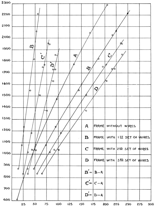
These results are fairly well summarized in the following general statements: First, that the coefficient of resistance increases to some degree as the size of the wire is decreased; second, that in the case of wires of the size which it was expected to use, and at approximately the soaring speed of the aerodrome, the resistance is certainly not greater than 75 per cent, and more probably less than 50 per cent of the resistance encountered by a flat surface of the same projected area; third, that the coefficient of resistance did not seem to be increased by the vibration of the wires. On the contrary, it was noted during the experiments that when they reached a speed which just caused them to “sing,” there was a marked diminution in the resistance. This statement is made, however, with some reserve, for it is probable that the singing of the wires was due to vibration in the horizontal plane, and it is not definitely known what the effect would be of vibration in the vertical plane.
To make the very extensive experiments necessary to determine these propositions conclusively would have required much more time than could at this period be spared from the actual constructional work on the aerodrome. Nevertheless, the data did seem to indicate that it was at least not unwise to employ the extensive system of guying which had been planned in order to give the necessary strength to the frame of the large aerodrome. This plan of construction was, therefore, definitely adopted, and as a result of later experience the system of guying was still further extended.
As the transverse frame had to be made comparatively rigid in order to prevent undue binding of the bearings of the transmission and propeller shafts, it was necessary to make it intrinsically stronger and, therefore, heavier in proportion to its size than the main frame. The main frame, although requiring great strength to enable it to withstand the strains, both torsional and direct, which were imposed upon it by the weights which it supported, did not need excessive rigidity, and could, indeed, be distorted an appreciable amount without danger of any serious effect on the action of the wings or rudder; but even a small amount of distortion in the transverse frame might easily cause such friction at the bearings of the shafts as to absorb fifty per cent or more of the engine power.
In the photographs, Plates 45 to 48, which show the actual condition of the frame on January 31 and February 1, 1900, the letters A, B, C, D, E, F, G, H and I designate parts of the main frame, A and H being the rear and front midrods, respectively, to which the wings were to be attached. B and I are curved extensions of the starboard main tube, the port main tube being exactly similar, and C, D, E, F and G are cross-tubes which connect the midrods to the port and starboard tubes. R is the front main tube of the transverse frame, the rear main tube being exactly similar, and both being connected to the main tubes of the main frame where they cross them. The ends of the main tubes of the [p168] transverse frame are joined together by the “bed plates” L, which are of I-beam section, and have mounted on their outer faces the bearings which support the propeller shafts. At V are bevel gears mounted on the propeller shafts, which are driven by co-acting bevel gears, M, mounted on the outer ends of the transmission shafts, O, the latter being at this point firmly supported in bearings mounted on the inner faces of the bed plates and steadied by the intermediate bearings, N. The two transmission shafts are seen to be not in line, the rotary cylinder engine that was then under construction requiring this arrangement. The bed plates, L, are further stiffened by the brace tubes, K, and the transverse frame is braced against the thrust of the propellers by the tubes J. The four tubes, P, unite at their upper ends to form what was designated as the upper “pyramid,” and the wires, S and T, radiate from its apex to the rear and front, respectively, of the main frame. The lower “pyramid,” on the under side of the frame, also has similar wires running fore and aft. The main portions of both frames are further strengthened by their sub-frames, which merge together, and the main tubes of the main frame are individually stiffened in the vertical plane by a minor system of guying. The scales shown in the photographs are calibrated in metres.
It is to be particularly noted that the midrod, which had heretofore formed the backbone of the main frame, was now made to act merely as a means of attaching the wings to the frame, the main strength of the frame being furnished by the two parallel fifty millimetre tubes which extended the entire length of the frame and which, reinforced by the guy-wires, formed a truss not only more rigid transversely, but also many times stronger in its ability to resist torsional strains than could be secured by a single tube of equal weight. In this plan of constructing the main frame, the pyramids constituted a very important element, for with the guy-wires arranged as they were it was impossible for any portion of the frame to experience a stress which was not transmitted in some way to the pyramids. In the frame, as here shown, these pyramids were formed of tubes 15 mm. in diameter, 0.5 mm. thick, stiffened against buckling under the end pressure by means of the cross-braces, which united them near their midpoints. While the sole function of the upper pyramid was to serve in the system of guying the frame, the lower pyramid not only served a similar purpose, but also provided a means for holding the aerodrome to the launching car in the process of launching it, the clutch-hooks gripping around the short horizontal tube at the apex of the pyramid and thus drawing the “bearing points” of the machine firmly against the uprights on the car. In fact, the particular arrangement of these pyramids was largely determined by this necessity for providing means for holding the aerodrome to the launching car, and the form which seemed best suited to the purpose was duplicated on the upper side of the frame.


The “bearing points” were not attached to the frame at the time these photographs were taken, but are seen leaning against the scales in the foreground of Plate 46. Their position on the frame will be more clearly seen in later photographs, where it will be noted that they were made use of in the more elaborate system of guying which was adopted.
While, in general, the frame at this time seemed to be reasonably stiff and strong, yet it was subjected to a very thorough test by supporting it at different points and suspending from it weights to represent the various parts, such as engine, aviator, wings, rudder and so forth, the deflections which were produced by these weights being carefully noted. It was further tested by subjecting it to vibratory strains, such as it would be likely to meet in actual use. After this the whole frame was tested against torsional strains, such as would be caused by the wind twisting one set of wings more than the other. As a result of these tests it was decided that the frame should be strengthened as far as it was possible to do so without greatly increasing the weight, which even now was found to be rapidly increasing beyond what had been calculated as permissible. The main guy-wires were replaced by heavier and stronger ones, and while these were found to add somewhat to the stiffness of the frame, yet something more seemed necessary to insure safety.
The delay in securing the engine, which had been contracted for with a guarantee that it would be delivered in February, 1899, had become so serious and had delayed the completion of the frame to such an extent that the question of building an exact duplicate of the large machine, but of one-quarter its linear dimensions was being carefully considered at this time, and it was decided to make no further changes in the guying of the large frame until after the small one was built. On account of its smaller size changes could be more readily and cheaply made on it, and the advantages of different methods of guying could be just as well studied. Later, when this was completed, it was found that, with the same system of guying that had been used in the larger frame, the model was so very stiff that it did not require any further strengthening, the smaller scale, of course, accounting for the difference. What was thought to be the best system to follow in strengthening the frame of the large machine was, however, first tried on the smaller one, and it was found that for a very slight increase in weight a very great increase in strength could be obtained. This change in the system of guying consisted essentially of building a “trestle” of tubing at a point on the upper side, midway between the pyramid and the rear end of the frame. One of the former sets of guy-wires which passed to the rear of the frame was then replaced by a set which started at the foot of the rear tubes of the upper pyramid, passed over and was fastened to the trestle, and from there passed to the rear end of the frame at the points where the longer guy-wires from the pyramid had formerly been attached. The [p170] guy-wires on the lower side of the frame, at the rear, were correspondingly changed so that the upper and lower systems should be similar, the wires which started from the main tubes at the foot of the pyramid passing to the bearing points, and from there to the rear end of the frame.
In order to keep the main frame of the large aerodrome as short as possible, it had originally been planned to make the distance between the center of pressure of the front wings and the center of pressure of the rear equal to five metres. When these same proportions were followed in the quarter-size model, it was found that it brought the rear wings so close to the propellers that their lifting effect was certain to be interfered with by the blast of air created by the slip of the propellers. It was therefore decided that all things considered it would be best to increase this distance between the wings, even though this involved an increase in weight, partly on account of the increased amount of tubing, and still more on account of the guy-wires which it would be necessary to add in order to make up for the weakness due to increased length. The large aerodrome frame was accordingly lengthened 2.5 feet (76.2 cm.), and the guy-wire system was changed to that clearly shown by the photographs of July 10, 1902, Plates 49, 50 and 51, the black cross-lines on the background being 50 centimetres apart. From an inspection of these photographs it will be seen that two sets of guy-wires were carried from the upper and lower pyramids, respectively, towards the rear of the frame, the first set being carried to the main tubes at the foot of the “trestle” and the bearing points, and the second set to these same main tubes at the second cross-tube. The sets of wires which started from the feet of the pyramids were carried over the “trestle” on the upper side and the bearing points on the lower side, and both joined to the main tubes at the rear cross-tube. Additional cross-guy-wires for stiffening the frame sideways were added in each of the squares formed by the junction of the cross-tubes with the main tubes. A secondary system of truss guy-wires running over short guy-posts attached to the tubes of the main frame also contributed to the strength and rigidity of the whole.
Although the pyramids had shown no signs of weakness, nevertheless, because of increased strains due to the lengthening of the main frame, it was thought advisable to make them stronger. Instead of the 15-mm. tubing, which had formerly been used, 25-mm. tubing of the same thickness was therefore substituted, and additional cross-braces were added, as will be seen from the photographs, and from the scale drawings in Plates 52, 53 and 54, which show the aerodrome as it was when completed. The numerals attached to these drawings refer to the detail drawings shown in later plates.


In order to secure the proper adjustment of the guy-wires, not only of the frame but of many other parts, notably the wings, propellers and rudder, it was necessary to use a large number of turn-buckles. As almost every wire [p171] required at least one, and in some cases two turn-buckles, the weight represented by this single item rapidly became so formidable as to require serious attention. In the construction of the models, it had been necessary to employ some special turn-buckles in connecting the guy-wires of the wings to their guy-posts in order to secure the minute adjustment of the wires necessary to prevent the wings from being warped and distorted by unequal and improper adjustment. These turn-buckles had been made in the Institution shops, as the very lightest ones which could be secured in the market were from ten to twenty times as heavy as it was necessary for them to be to provide ample strength. In the construction of the large aerodrome, however, the large number required, and the desire to complete the machine at the earliest moment, made it advisable to procure the turn-buckles, if possible, from outside sources, and a very careful search was accordingly made among the various dealers. After much delay some bronze turn-buckles were secured which were very much stronger for their weight than any others on the market, but upon testing them it was found that while they weighed 45 grammes, their average breaking strength was only 593 pounds. Previous experience had shown that turn-buckles which would not break under a less load than 750 pounds could certainly be made to weigh not more than 18 grammes. As even at this time it was realized that at least 100 turn-buckles would be necessary for the entire machine, the excess weight which the heavy turn-buckles would add was felt to be absolutely prohibitory, and the construction of steel turn-buckles was immediately begun in the Institution shops. These turn-buckles were at first made in several sizes, and while some few were at first made “double ended,” most of them were threaded at only one end, the other end being provided with a swivel-hook, or eye. They were at first made of mild steel, the swivel-hooks, in fact, being made of wire nails in order to utilize the head of the nail as a shoulder without the expense of machining rod steel of a size large enough to form the shoulder. It was found, however, that the weak point of this type of turn-buckle was the swivel end, and most of those which were then on hand were made double ended by removing the hook, tapping a left-hand thread into this end of the shank, and fitting a threaded eye-socket in it. The guy-wires themselves were attached to the eyes of the turn-buckles and to the fittings on the frame by twisting loops at the ends of the wires, and although the very greatest difference in the strength of a completed guy-wire may result from the way in which the loops are twisted, yet, after much training, the workmen were taught to twist these very uniformly, following the plan which can be best understood by an inspection of the drawings in Plate 55 which show the loops more clearly than they can be described. After the loops had been properly twisted, soft solder was run all through the twist in order to unite firmly the twists of the wire. Although special grades of wire were found which showed very high tensile strength when the wire was [p172] tested without having loops formed in its ends, yet it appeared that the twisting of these high-grade wires so seriously affected them that in the case of guy-wires with loops at the ends, better final results could be obtained by using softer grades of steel. The wire which was actually found best, after much experiment, was a good grade of Bessemer steel of a medium hardness, which had been “coppered” to prevent rusting. However, even with the softer grades of steel wire, it was found that there were sometimes hard spots in the wire which revealed themselves only upon test, and that when a hard spot occurred in the twisted portion where the loop was formed, the final strength of the completed guy-wire was sometimes only twenty-five per cent of what it should be. The precaution was then taken to subject each of the completed guys to a test strain at least twenty-five per cent greater than it was calculated the wire would have to stand in actual use, so that no accident from defective wires would be likely to occur.
Later on, however, much trouble was caused by the loops in the ends of some of the guy-wires slipping, owing to the giving way of the solder which had been run through the joint, the amount of slipping, while small, being sufficient to alter completely the relative stresses on the various wires, thus causing distortion of the framework itself. In order to avoid this difficulty a new method was devised of attaching the guy-wires to the turn-buckles and to the fittings by which they were carried to the frame. This method consisted in threading the ends of the guy-wires so that they could be inserted directly in the threaded ends of the turn-buckles. The wires when connected in this way to the turn-buckles showed absolutely no slip, and the entire system gained greatly in strength thereby. The only disadvantage which was found in this new method of attaching the guy-wires to their fittings, was that if the wire was bent very close to the fitting, it would break in the screw thread very easily. But since most of the guy-wires when once attached to the machine are always tight, and in fact, under more or less strain, there was in most cases no likelihood of the wires being endangered by being bent close to the fittings. Since the screw threads, which it was necessary to adopt in this new plan of connecting the guy-wires, had to be very much finer than the threads which had been used in the turn-buckles previously constructed, it was necessary to make new turn-buckles, the others being too thin to permit of their being bored out, bushed and re-threaded. The new turn-buckles were made of a much higher grade of steel, and probably represent very nearly the maximum of strength for the minimum of weight possible without the use of some of the very much higher-grade steels which have recently come on the market, but which are exceedingly expensive to work. By means of this improved plan of attaching the wires,42 it [p173] was found possible to gain practically fifty per cent in the strength of the entire system of guy-wires used on the frame.
Many small changes were from time to time made in the various small fittings by which the guy-wires were attached to the frame, nearly all of these fittings having been originally made of a very mild grade of steel owing to the fact that it was so very much easier to work. At the time these fittings were made it was constantly expected that a trial of the aerodrome would be possible very soon, and it seemed necessary to expedite the work as much as possible and avoid the delay involved in using grades of steel that would have been materially harder to work. As is always the case in work of this kind, retrospect shows many instances where what was supposed to be a short cut to results actually proved to be the longest path, but the work as a whole was remarkably free from imperfect parts which necessitated reconstruction.
In the construction of the frames of the models it had been customary to fit the tubing accurately at the joints and to join it permanently together by brazing, as this was not only the lightest form of joint that could be made, but also the most expeditious method consistent with securing a strength of the joint comparable with that of the tubing itself. The construction of the frame by this method of brazing the joints together permanently, offered, however, several serious drawbacks: among them, that when a tube got injured it was a considerable task to replace it, while the brazing of the new tube in place required extreme care to prevent the frame from being warped when completed, as the tube became longer while very hot and contracted after the joint had set. Furthermore, the great heat required destroyed to a considerable degree the desirable qualities due to the tube being “cold drawn,” a reduction of strength of something like 25 per cent being almost inevitable, even when the brazing was most carefully done. It was, therefore, decided that in the construction of the large machine all of the main joints should be made by a system of “thimbles,” and it was planned at first to make these thimbles by brazing short pieces of steel tubing into the proper shapes and angles so that they would accurately fit the tubes which were to be joined. The construction of the thimbles in this manner, however, seemed to involve an excessive amount of work; and, as it was found that very thin castings of aluminum-bronze could be obtained, which would show a tensile strength very nearly as great as steel, it was decided to make up patterns for the thimbles and cast them of aluminum-bronze.
The aluminum-bronze castings were obtained and properly machined to fit the tubes, but when it was attempted to “tin” the interior walls of the thimbles it was found that the solder could not be made to stick to the bronze. As a considerable amount of work had been expended on the machine work of these thimbles much time and effort was spent in attempting to devise “fluxes” [p174] and solders which could be made to work with the aluminum-bronze, but the final result was that the aluminum-bronze thimbles had to be abandoned. They were replaced by similar castings of gun-metal of a slightly heavier section, which at the time were thought to be very suitable for the purpose.
But, in finally assembling the frame after the changes described above had been made, steel thimbles, built up of short pieces of tubing, as had originally been planned, were substituted for the gun-metal thimbles. This change was made not only because of the great increase in strength, but more particularly because many of the gun-metal fittings had been imperfectly constructed, so that it was extremely difficult to align the frame. The steel thimbles, which were made in the Institution shops proved thoroughly satisfactory and gave no trouble of any kind. Many of these thimbles and the method of attaching the guy-wire fittings to them are shown in Plates 56 and 57, as well as in Plate 55.
It will be recalled from the description of the models Nos. 5 and 6, in Part I, that the position of the line of thrust, with respect to the positions of the center of pressure and center of gravity in the vertical plane was, theoretically, very much better in No. 6 than in No. 5. In designing the large aerodrome, it was desired to reproduce as nearly as possible the relative position of the line of thrust with reference to the center of pressure and center of gravity which existed in No. 6, but for constructional reasons it was found impossible to do so. In fact it appeared that without seriously complicating the construction of the frame it was impossible to raise the line of thrust with respect to the center of gravity materially higher than it was in No. 5. In No. 6 the line of thrust was 12 centimetres above the midrod, this being effected by placing the engines some distance from the boiler, and at the extreme ends of the transverse frame where they were connected directly to the propellers. In the case of the steam engine the weight of the engine proper is a relatively small portion of the entire weight of the power plant, and it is, therefore, possible to put the engine almost anywhere without materially affecting the center of gravity. But where a gas engine is used the engine itself constitutes the greater part of the weight of the power plant, and any raising of the engine, therefore, materially raises the center of gravity of the whole machine. The line of thrust in the large aerodrome was, therefore, practically in the plane of the main frame, and consequently very little higher than the center of gravity.
The use of one engine to drive two propellers mounted at opposite ends of the transverse frame, and in a direction perpendicular to the crank shaft of the engine, necessitates the use of a pair of bevel gears between each of the propeller shafts and the shafts by which the power is conveyed to them from [p175] the engine shaft. Since the efficient transmission of power through bevel gears requires that they be very accurately placed with reference to each other, and maintained very accurately in this position while they are at work, it was necessary to make the transverse frame very rigid, especially at its extreme ends. This was accomplished by the use of what were called “propeller-shaft bed plates.” They are designated by the numeral 27 in Plate 54, and are shown in detail in Plate 58 as of a very deep I-beam section, having very narrow flanges top and bottom, the web of the I-beam furnishing the strength in a vertical direction, while sufficient stiffness laterally was obtained from the flanges, assisted by the brace tubes, which acted as struts between the bed plates and the main tubes of the transverse frame. These struts, while very light, added enormously not only to the lateral stiffness of the propeller bed plates, but furnished for a minimum weight a maximum prevention against twisting of the plates. The propeller-shaft bed plates were originally planned to be made of sheet metal with the flanges brazed to the web. But at the time that they were constructed the pressure of the work was so great in the Institution shops that it was found necessary to have some of the work done outside, and the parties who undertook the construction of these bed plates were unwilling to attempt to braze them up, and accordingly worked them from steel forgings made for the purpose. The expense of this plan of construction proved large and unnecessary, as both previous and later experience proved that it was not only practicable to braze up bed plates more complicated in their design than these, but that equal strength for equal weight could thus be obtained for less than one-quarter the cost of constructing them from solid forgings. Furthermore, where such parts are made from the solid, changes which later tests prove advisable can frequently not be carried out without very serious cost and delay, while with the bed plates formed by brazing less hesitancy is felt in removing parts which are brazed thereto and substituting new parts, or even discarding the bed plates altogether and substituting new ones. Particular emphasis is laid on this point for the reason that much expense and delay would have been avoided had these very expensive propeller-shaft bed plates been discarded as early as 1901 and replaced by others which would have permitted a considerable strengthening of the ball-bearings, which, while strong enough to stand even more power than they were originally designed for, were far too weak to be safe when working under the greatly increased stress due to the very much higher engine power which was later used. Instead of discarding these bed plates then for new ones, they were strengthened by brazing to them crescent-shaped pieces, as shown in the drawings and photographs. This strengthening was made necessary by the larger hole cut in the bed plates for the larger bevel gears. The bed plates for the engine, which are later described, besides other bed plates which were made for other purposes, were all [p176] formed by the use of sheet metal and tubing properly brazed together, and none of them ever gave any trouble.
In the early photographs of the aerodrome frame, especially that of January 31, 1900, Plate 45, it will be noted that the two transmission shafts, which extend from the propeller-shaft bed plates towards the center, are not in line, the port transmission shaft being at the center of the transverse frame, while the starboard shaft is three inches to one side. This arrangement was necessary in order to connect the shafts to the rotary cylinder engine which was being constructed under contract, and which was almost momentarily expected for more than a year after its original promise of delivery on February 28, 1899. Later, when this engine was finally found to be a failure, and the writer constructed the engine in the Institution shops, the starboard transmission shaft was moved over to the center line and the crank shaft of the engine, which was carried through on the center line of the transverse frame, was then connected directly to the inner ends of the transmission shafts.
These shafts, as well as the propeller shafts, were originally constructed of steel tubing 1.5 inches in diameter and 116 of an inch thick, but on account of the increased power of the large engine it was found necessary to increase the thickness of the shafts to 18 of an inch. Difficulty was also found with the tubing of which the shafts were made. This, though not exactly straight when received from the factory, could be pretty accurately straightened in the lathe by exercising proper care, but the moment any real strain was put upon it in the transmission of power, it again went out of shape and caused serious damage to the bearings by whirling, buckling, and so forth. As the skin of the tubing is really the strongest part, owing to the cold-drawing process to which it has been subjected, great care was taken to secure shafts which were sufficiently straight for use without machining, but it was finally found impossible to rely on the unmachined shafts, and all the later shafts for the aerodrome were made by getting tubing a sixty-fourth of an inch thicker than was calculated to be necessary and turning off this extra metal in a lathe.
Suitable flanges and collars were brazed to the propeller shafts; but, for convenience in assembling, the flanges by which the main transmission shafts were connected to the crank shaft of the engine were at first fastened to the shafts by screw-threads, the threads being in the proper direction to cause the flanges to jam against the shoulders of the shafts when the engine turned in its normal direction. This method of fastening, however, caused serious trouble, owing to the flanges jamming so tight that it became impossible to unscrew them after they had once been used in driving the propellers. The usual provisions of keys and key-ways adopted in general engineering practice, where solid shafts are employed, were, of course, out of the question, since the shaft would have to be greatly increased in thickness throughout its entire length [p177] merely to provide the extra metal at the small place in which the key-ways were formed. Taper pins either sheared off or very soon stretched the holes so badly as to leave the parts loose, and were otherwise very unsatisfactory. The method finally adopted, which proved very successful, was that of forming integral with the couplings shallow internal tongues and grooves which fitted corresponding tongues and grooves either in the exterior surface of the shafts or in collars brazed to them at the proper point. The form of flange coupling, in which bolts draw the two flanges tightly together, was also a source of considerable trouble and delay, which was finally overcome by forming shallow tongues and grooves in the faces of the flanges, the tongues taking up the torsion and relieving the bolts which held the flanges together of all strain except one of slight tension. The same difficulties experienced in mounting the couplings on the shafts were met with in connection with the gears, both on the propeller and transmission shafts, and were finally obviated in a manner similar to that described above.
The bevel gears originally constructed for transmitting the power from the transmission shafts to the propeller shafts, were made of case-hardened steel and were eight-pitch, twenty-five teeth, with three-quarter inch width of face. The gears were very accurately planed to give as perfect a form of tooth as possible, in order to avoid loss of power in transmission, and although the manufacturer who cut the teeth on them asserted at the time they were made that they would not be capable of transmitting more than five horse-power, yet they actually did transmit considerably more than twelve horse-power on each set; but they were not strong enough to transmit the full power of the large engine which was finally used. The gears that were finally used were similarly constructed of mild steel which was case hardened 164 of an inch deep after they were finished, there being thirty-one teeth in the gear on the transmission shaft and forty teeth in the one on the propeller shaft, the teeth being eight-pitch, three-quarters of an inch face. These light gears proved amply strong, and several times stood the strain which they accidentally received when one of the propellers broke while the engine was under full power, and thus threw the entire fifty horse-power over on the other propeller, which was consequently driven at a greatly increased speed.
Plain bronze bearings had been used throughout on the model aerodromes, but in the construction of the large aerodrome ball-bearings were used on all of the propeller and transmission shafts, not only on account of the decreased loss through friction, but also because ball-bearings can be built much lighter than solid bronze ones, and, furthermore, do not present such great difficulties in lubrication. However, owing to the limited size which it was possible to secure for these bearings, because of their having been originally designed for only twenty-four horse-power, and without any margin for a later increase of the [p178] space in which they had to be applied, they were never really large enough for the work they had to do when transmitting the full power of the large engine. They gave continual trouble, and were the source of delay which, while it cannot be accurately measured, since there were often other causes, yet might be conservatively estimated at not less than three or four months. Such a delay, when reckoned in retrospect, can easily be seen to have caused an expense which would have sufficed for almost any change in the bearings, bed plates, etc., had the change been made immediately after the bearings were found to give trouble. With the better steel which it is now possible to obtain for the races of the bearings, and with the high-grade balls now obtainable, the bearings could be readily replaced without changing any other parts and still be amply strong for the work.
Both the tests on the whirling-table and the actual results with the models had shown that propellers which were true helices formed out of wood were rather more efficient than those constructed by the use of a hub in which were inserted wooden arms, forming a framing over which cloth was tightly drawn. But the very great difference in the cost of construction and the facility with which the latter type could be repaired in case of damage—the wooden ones were practically of no use if once they were much injured-—made it seem advisable to construct all the propellers for the large aerodrome in the manner just explained. Several pair of small propellers had been built on this plan, some as early as 1895, and one very important advantage had been found to be possessed by this type besides cheapness and facility of repair. Wooden propellers of even so small a diameter as one metre had been found to suffer a quite appreciable bending of the blades, due to the thrust produced by them, even though the blades had been made of considerable thickness. In planning a propeller 2.5 metres in diameter for the large aerodrome it was seen that in order to make the blade sufficiently strong to withstand its own thrust it would be necessary to make it inordinately thick, which, of course, would mean a considerable increase in weight. In fact, it was seen that the weight of the larger propellers would increase practically as the cube of the diameter; which, for the 2.5-metre propeller, would involve a weight of something over fifteen times the weight of those one metre in diameter. The other type, which for convenience we will call “canvas covered,” permitted the bending moment produced on the blade by the thrust to be taken up by guy-wires running from the corners of the blades to a central post projecting from the hub of the propeller, and it was found that in this way a considerable saving in weight could be effected. [p179]
In November, 1897, in order to obtain by actual test some data on propellers, such as it was planned to use on the large aerodrome in case it was later built, it was decided to construct one propeller 2.5 metres in diameter and 1.25-pitch ratio with two blades, each covering the sector of 36 degrees on the projected circle. About this same time an engine builder, who some years before had made some experimental model engines in the Institution shops, proposed to construct a gasoline engine for the proposed large aerodrome. As past experience, not only with such engines but with all other forms of explosive motors, had not been very reassuring it was thought best to make brake tests of one of the heavier engines which he was at this time building, and at the same time make tests with one of these large propellers. A first series of tests was made at several different speeds, and then a second series was made with the engine driving the propeller at the same speeds. The engine varied so much, however, in the power developed at any speed that the data obtained were of little value. As it was also desired to learn just how much thrust could be obtained from these propellers, when driven by a given horse-power, a special hand car was fitted up to carry the engine, which was connected to a shaft on which the propeller was mounted. The propeller was raised above the floor of the car and projected over the rear end of it so as to be as little disturbed as possible by the deflection of the air currents caused by the car. This car, with the engine and propeller, was tested on a track near Mount Holly, N. J., in November, 1897, but the results were very unsatisfactory. In the first place, the car with the engine mounted on it was so very heavy and offered such a strong tractive resistance that very little speed of propulsion could be obtained. In the second place, the engine, which was said to have furnished over six horse-power on Prony-brake tests, evidently did not furnish anything like this amount of power at this time. And in the third place, the propeller was evidently far too large to permit the engine to run at the speed at which it would develop a reasonable amount of power unless some reduction gearing were interposed between it and the propeller. As the tests, for various reasons, had to be made at a great distance from Washington, and the supervision of them had to be entrusted by Mr. Langley to others, who either did not understand or appreciate the value of obtaining accurate data, it was found impracticable to continue them.
The large propeller used in these tests was built without special regard to weight, since it was expected that it would be subjected to rather rough usage under the very sudden strains produced by the irregular working of the gas engine. Its hub was made of brass tubing, the horns being brazed to rings which were slid over a central tube, the rings being finally soldered to the tube after the arms had been adjusted to the positions which would give the blade the correct shape and dimensions. The wooden arms were 1.5 inches in [p180] diameter at the hub end, tapering to 1.25 inches at the end of the blade. The blade was exceedingly stiff as regards pressure produced by thrust, but it was found to be considerably strengthened and made very much safer when guy-wires were added, in the manner explained above. This general type of construction was adhered to in all the future propellers for the aerodrome, though slight modifications, both as to the size of the arms and the number and position of the cross-pieces which formed the framing of the blade, were adopted from time to time. A pair of heavy propellers, 2.5 metre, 1.25-pitch ratio, 36-degree blade, the hubs of which were formed of brass castings, was, however, constructed for experimental purposes, where weight was not an important factor.
When these propellers were designed, the calculations as to their size and the horse-power which would be required to drive them at a certain speed were based on the very incomplete data obtained from the various propeller tests conducted during the preceding years. When later calculations were made for them, on the data obtained in the more accurate tests made in the summer of 1898, it was found that the power of the engines with which it was proposed to equip the aerodrome would not be sufficient to drive the propellers at anything like the speed which the former calculations had shown would be possible; and that, therefore, either the ratio of the gearing between the propellers and the engine would have to be changed so as to permit the engine to run at a very much higher speed than the propellers, or that propellers, having either less pitch or a smaller diameter, and possibly both, would have to be substituted for these larger ones.
Since it was easier to change the propellers then to change the gearing, a new set of propellers was designed which were of 2 metres diameter, with a pitch ratio of unity, and with a width of blade of only 30 degrees. It was calculated that 20 horse-power would drive these two propellers at a speed of 640 R. P. M., when the aerodrome was flying at a speed of 35 feet per second and the propellers were slipping about 50 per cent, this being found to be about the speed at which the engines might be expected to develop their maximum power. As the larger propellers having the brass hubs were thought to be excessively heavy, the hubs weighing 10.25 pounds each, and as any change either in size, pitch, or width of blade necessitated a new set of patterns in case the hubs were cast, it was decided to construct the new hubs of steel tubing. The weight was further reduced by decreasing the size of the wooden arms to 114 inch in diameter at the hub, tapering to 1 inch at the end of the blade.
After the engine builder in New York had been unable to fulfil his contract on the engine, and it had been condemned, propeller tests were made with the experimental engine built in the Institution shops. These tests showed: First, that the results which might be expected from larger propellers could be very safely predicted by extrapolation from the results of the propeller tests of 1898; [p181] and, second, that in order to get a thrust which would equal fifty per cent of the flying weight of the aerodrome it would be necessary to use propellers larger than two metres in diameter unless a very large surplus of power were provided. It was accordingly decided to make a set of propellers intermediate between the two-metre, unit-pitch ratio, thirty-degree blade ones, and the original ones which were two and one-half metres, one and one-quarter-pitch ratio, thirty-six-degree blade. A set was, therefore, designed two and one-half metres in diameter, unit-pitch ratio, and thirty-degree width of blade, the hubs being made of steel tubing brazed up in the same manner as the two-metre ones, and the wooden arms of the blades being one and three-eighths inches in diameter at the hub end, and tapering to one inch at the end of the blade.
Later, when the larger engine was actually tested in the frame, the inability of the original transmission and propeller shafts to stand the extra strain caused by the engine starting up very suddenly at times, together with the unsatisfactoriness of the screw-thread method of fastening the gears and couplings to the shafts made it necessary to provide new shafts, gears, couplings, etc. It was then decided to change the ratio of gearing between the engine and the propellers, which had been one to one, so that the engine might run faster and, therefore, permit the use of larger propellers. For constructional reasons the ratio chosen was thirty-one to forty, thus making the engine run approximately one-third faster than the propellers.
In the various tests made of the engine working in the frame there were two or three instances in which the propellers were damaged either by the sudden starting of the engine or by their not being able to stand the strain to which they were subjected by the power absorbed, but in every case such breakages were found to be due to imperfections of the brazing in the joints. While, therefore, it would have been desirable to make the propellers somewhat heavier, yet since the total weight of the aerodrome had been growing so very rapidly, it was felt that this need not be done, as a pair of propellers which had stood quite severe service in shop tests might reasonably be expected to stand the strain of actually propelling the aerodrome through the air.
Nevertheless, when in the summer of 1903 the actual trials of the large aerodrome were started, it was found that the very important difference between a propeller working in a closed room and one working in the open air had not been given due consideration. Several sets of propellers, 2.5 metres in diameter, unit-pitch ratio, 30-degree blade had been constructed and were on hand, in order that no delays might be caused through a lack of such extra parts. On September 9, 1903, when the aerodrome frame without the wings was mounted on the launching car on top of the boat for some trial runs with the engine to make sure that everything was again in readiness, before the engine had made 500 revolutions, the port propeller broke; and a few minutes [p182] later, when a new propeller had been substituted for this and the engine was again started up, the starboard propeller also broke. When, upon further trials and replacements of propellers, all had been so thoroughly demolished that there was not a complete set remaining, it was seen very clearly that the strains produced on a propeller working in the open air are very much greater than those produced in shop tests, where the air is necessarily quiet. These open-air tests of the propellers had demonstrated that their weakest point was where the steel tubes which received the wooden arms of the blade terminated, and that another, though not so serious, point of weakness was where the steel arms were brazed to the central hub, the thin metal tending to tear loose even before the brazed joint would give way. It was, therefore, decided to construct immediately a new set of propellers in which the steel arms should be made of much heavier tubing, that is, a sixteenth of an inch thick at the end where it was brazed to the central hub, and tapering in thickness to one-thirty-second of an inch at the other end. These arms were further made twelve inches long in place of being only three inches long as before. This added length carried the steel out beyond the point where the first section brace joined the three arms together, and where they were further strengthened by having the cloth covering tightly stretched around them. In order to utilize such of the hubs of the former propellers as had not been seriously damaged when the propellers broke, it was also decided to try the effect of merely adding an extra length of tube to the short arms by means of a thimble slipped over and brazed to the two parts, which would make these arms twelve inches long. The construction of these propellers was pushed as rapidly as possible; and after their completion no further trouble was at any later time caused by insufficient strength of the propellers. Even in the test of October 7, 1903, when the aerodrome came down in the water at a speed of something like fifty miles an hour, and at an angle of approximately forty-five degrees, no break occurred in either propeller until, when the aerodrome was plunging through the water, a blade of one propeller was broken by the terrific blow which it received when it struck the water under the impulse of the engine driving it at full speed. The severity of this blow is attested by the fact that the shaft, which was of steel tubing one-eighth inch thick, was twisted about ninety degrees.
This experience with propellers very strongly emphasizes the fact that on any flying machine the strains which are apt to be met with in the open air must be allowed for in the proportioning of the parts of the machine. But since an indiscriminate increase of strength in all the various parts of the machine would entail a prohibitory weight, very careful judgment, based on experience, will have to be exercised in deciding just where added strength must be employed, and also where the “live strains” are not apt to exceed very appreciably the calculation for statical conditions.
Owing to Mr. Langley’s belief that the tests of the man-carrying aerodrome must not only be made over the water, but that it was necessary that the machine be launched from a car running on a track at a considerable elevation in order to permit the machine to drop a short distance after being launched in case it was not quite up to soaring speed when launched, it was necessary that the aerodrome be so constructed that it could be readily transported to the launching track from the interior of the house-boat where it was stored. This plan of storing the main body of the machine in the interior of the boat and hoisting it to the launching track just before attempting a flight (some of the difficulties of which may be more clearly appreciated by an inspection of Plate 60), made it necessary that the wings, tail and guy-posts be so constructed as to be readily attachable to and detachable from the main frame, and since the weather conditions are seldom suitable for a test for more than a couple of hours at a time, it was necessary that the mechanism employed for attaching these parts be so arranged that the proper settings of the different parts could be quickly obtained, and without requiring the exercise of judgment which past experience had shown did not often manifest itself during the hurry of the preparations for a test. While the wings, therefore, were made removable, yet all of the sockets, guy-wires, etc., which were loosened in removing them, were made with positive stops on them so that each fitting that was to be tightened up in assembling could be adjusted to its definitely determined position.
As all of the models had been constructed with these same parts removable in order to permit them to be readily shipped back and forth in the many trips which had been made with them from Washington to Chopawamsic Island, the same details of arrangement were used for attaching these parts on the large aerodrome, though the actual fittings by which the parts were attached in the latter case became more elaborate.
In the drawings, Plates 52, 53 and 54, the method of attaching the wings to the frame is clearly shown. Each of the two main ribs of each wing was secured to the midrod of the frame by a wing clamp, shown in detail in Figs. 1, 2, 5, 6 and 7 of Plate 59. Figs. 1 and 2 show the clamp for the middle main rib of each pair of wings, and Figs. 5 and 6 show the clamp for the main front rib, the latter being so constructed that the wings could be rocked on the midrib clamp as a pivot and secured at any angle of lift desired from 612 degrees to 15 degrees. The horns on each clamp merely acted as receiving sockets for the ends of the ribs, and were not in any way intended to do anything more than merely hold the ends of the ribs in their correct positions. The wings were fastened to the frame by the guy-wires which ran from two points on each main rib to an upper and a lower guy-post mounted on the midrod. The system of guy-wires for the wings is clearly shown in Plates 52, 53 and 54, and [p184] in Plate 61, which shows the aerodrome mounted on its launching car at the rear end of the track, and with the front pair of wings in place and all the guy-wires adjusted. The details of the guy-posts are shown in Plate 62, where it will be noted that the lower guy-post was of wood, with metal fittings, and was 2 metres long from the center of the midrod to the bottom, while the upper guy-post was a steel tube 109 centimetres long from the center of the midrod to its top. The guy-wires from the middle rib of each of the pair of wings were fastened to the fittings at the bottom of the lower guy-post, while the wires from the front main rib were fastened to the fittings which were brazed and riveted to the slidable collar, which was mounted on the steel tube forming the cap on this guy-post. This collar was made slidable to permit the angle of lift of the wings to be readily changed without affecting the length of the guy-wires. This collar, when once set for any particular angle of the wing, was prevented from sliding by a taper pin (not shown) which passed through it and the guy-post. In order to secure the wings more rigidly to the main frame and thereby throw on it all torsional strains from the wings, which it was specially designed to take, each of the middle main ribs was secured to one of the main tubes of the main frame by an auxiliary clamp at the point where this rib crossed the main tube. These auxiliary clamps are clearly shown in Figs. 3 and 4 of Plate 59.
Projecting from the lower end of each of the lower guy-posts was a five-sixteenth-inch steel rod about one inch long, as clearly seen in Plate 62. Brazed to the side of this rod, in such a position that it would project towards the rear of the aerodrome when the guy-post was in position, was a small arm or bracket. When the guy-post was in place with the aerodrome on the launching car, this pin was in a slot formed in a metal cap on the top of the small folding upright at the front or rear of the car, as seen in Fig. 1, Plate 63, while Fig. 2 of Plate 63 shows the pin just being inserted into this slot as the guy-wires of the guy-post are being fastened. This small arm or bracket on this rod projected under the cap to prevent the rod of the guy-post from being lifted out of the slot in the folding upright, when the wind acting under the wings tended to lift the aerodrome from the car. Particular attention is here called to this apparently insignificant detail, for it was this arm or bracket on this small rod of the front guy-post which, hanging in the cap on top of the folding upright, caused the accident in the launching of the aerodrome on October 7, 1903. Certain it is that but for the accident due to this apparently insignificant detail, success would have crowned the efforts of Mr. Langley, who above all men deserved success in this field of work, which his labors had so greatly enriched.
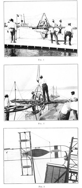


In determining on a suitable car for the aviator various designs were made, differing all the way from that in which the aviator occupied a sitting position facing directly ahead and with practically no freedom of movement, but was even strapped to the machine to avoid the possibility of being thrown out, to the one finally adopted, in which he was provided with the greatest freedom of movement, could either stand or sit, as the occasion seemed to demand, and could face in any direction for giving proper attention to any of the multitudinous things which might at any time require his attention, and could, if agile, even climb from the extreme front of the machine to the rear. The wisdom of giving the aviator complete freedom without hampering him in any way by provisions for preventing his being thrown out of the machine was amply justified, as will later be seen in the description of the tests of the machine, where freedom of movement and agility prevented a fatal accident.
The aviator’s car was therefore designed to occupy the entire available space between the engine and the front bearing points, and between the two main tubes of the main frame, thus allowing him a space of something like three feet by five feet. The car itself was shaped like a flat-bottomed boat, the bottom being approximately level with the bottom of the lower pyramid. It had a guard rail of steel tubing eighteen inches above the floor, with a cloth covering drawn over the frame to decrease the head resistance of the appurtenances of the engine which were placed at the rear end of the car. The car was supported by vertical wires passing from its bottom up to the main frame, and was prevented from longitudinal or side motion by being fastened at the front to the cross-rod connecting the front bearing points, and at the rear to the lower pyramid. A light wooden seat extended fore and aft of the car at a height of about two feet from the floor, this seat resting on blocks of sponge rubber to absorb some of the tremor which existed in the whole aerodrome when the engine and propellers were working at high speed. The aviator was thus free to stand, to sit sidewise or to straddle the seat, and while the network of wires surrounding him prevented any great possibility of his being thrown out, yet there was a comparatively large opening between the guy-wires passing overhead which permitted him to climb out of the machine.
In order to enable the aviator to know exactly how the engine was operating, a tachometer, giving instantaneous readings of the number of revolutions, was connected by a suitable gear to one of the transmission shafts and placed where it could readily be seen.
During 1898 and 1899 considerable time and attention had been given to designing an instrument to be carried by the aerodrome which would automatically record the number of revolutions of the engine, the velocity and direction [p186] of the wind relative to the machine, the height of the aerodrome as shown by a specially sensitive aneroid barometer, and the angle of the machine with the horizontal plane of the earth. The construction of this instrument was undertaken by a noted firm of instrument makers, but after many months of delay, during which it was several times delivered as being complete, only to be returned for further work, it was finally condemned as unsatisfactory, and it was decided not to encumber the machine with such a delicate apparatus, which, even if perfectly made, could not be depended on to work properly when mounted on the aerodrome frame, in which there was a constant, though minute, tremor due to the high speed and power of the engine.
The completed frame, which is perhaps best shown in Plates 49, 50 and 51, and Plate 60, Figs. 1, 2 and 3, in spite of its size gave an appearance of grace and strength which is inadequately represented in the photographs. In making the designs for the large aerodrome no data were available for use in calculating the strains that would come on the different parts of the frame while in the air, and the size and thickness of the tubes and the strength of the guy-wires were consequently determined almost entirely by “rule of thumb,” backed by experience with the models. Although the dimensions, shape, and arrangement of most of the auxiliary parts of the machine were considerably changed during the course of construction in accordance with the indications of the exhaustive series of shop tests, the fundamental features of the construction were practically unaltered, but the changes in the guy-wire system and in the fittings by which they were attached, made the frame as a whole several times as strong as it was originally, and it was felt that the direction of further improvements in it would be shown only by actual test of it in flight where any weaknesses would be certain to manifest themselves.
It may be well to remark here that even with the data which were later obtained, judgment based on experience proved after all to be the safest guide for proportioning the strength of the various parts. It can be assumed that a live stress will produce a strain ten times as great as that due to a static stress on the part when the machine is stationary. For greater safety, it would be still better to assume a strain twenty times as great. If one is building bridges, houses, and similar structures, where weight is not a prime consideration, it would be criminal negligence to fail to provide a sufficient “factor of safety,” or what in many instances may be more properly termed a “factor of ignorance,” while at the present time the insistence on large factors of safety in machines intended to fly would so enormously increase the weight that, before one-half the necessary parts were provided, the weight would be many times what could possibly be supported in the air. Later, no doubt, as experience is gained in properly handling the machine in the air, increased strength entailing [p187] increased weight may be added in proportion to the skill acquired; and there is no doubt that man will acquire this skill with marvelous rapidity, approaching, if not equaling, that exhibited by him in the use of the bicycle, which, when first ridden, requires not only all of the rider’s skill but that of a couple of assistants, but when once mastered requires hardly more thought for its proper manipulation than even the act of walking involves, the balancing and guiding being done intuitively merely by the motion of the body and with practically no exertion.
An examination of the wings of birds, whether those of soarers or of any other type, impresses one not only with the general strength of the wing, but also with the fact that, while it possesses considerable stiffness, there is also a graduated pliability, not only of the whole wing, including the bones, but more especially in the feathers, the rear tips being exceedingly pliable so that, when the wing is held in a stiff breeze, they are seen to be easily deflected in a gentle curve towards the rear and upper side. This lack of rigidity has several advantages, among the more notable of which is the lessening of the strains on the wing caused by sudden wind gusts. Of great importance is the further fact that a supporting surface having a graduated pliability, such as is possessed by a bird’s wing, does not experience a shifting of the center of pressure to the same extent as a rigid surface of similar form. Furthermore, since any bird, even the best soarer, must use its wings not only for soaring, but, when starting to fly from a state of rest, for flapping, a rigid surface would not furnish anything like the same universally available sustaining and propelling means that the bird’s wing does.
In an inspection of the various wings or supporting surfaces which Mr. Langley built, from the very earliest rubber-pull models up to the successful steam machines Nos. 5 and 6, the point which is most impressed upon the observer is the increasing strength and rigidity embodied in these wings. While the success with the later models was due to many things, including the development of a strong frame and a suitable power plant giving sufficient power for the permissible weight, besides the very important development of effective equilibrium mechanism, yet it is safe to say that even with the development of all these other things to the state to which they had been brought in 1896, success would not have been achieved had not the wings themselves been simultaneously changed from the very flimsy construction which was at first used to the later type, using a very strong and rigid wooden frame over which the cloth covering was tightly stretched, and which possessed only a small amount of pliability at the extreme rear ends of the cross-ribs.
The development of this successful type of wing for the models, it will be remembered, had been achieved only after an extensive series of experiments; and it was realized that the construction of suitable wings for the large aerodrome, even with the knowledge gained in the early work, would be still more [p189] difficult. The problem was that of constructing for a very little greater weight per square foot, wings containing approximately sixteen times the area of the model wings.
It will be recalled from the previous description of model Aerodrome No. 5, that its four wings had a combined area of 68 square feet and weighed approximately 2500 grammes, or 37 grammes per square foot. It was not expected that the large wings would be of so light a weight per square foot, which would have meant only about 35,500 grammes (approximately 78 pounds) weight for the 960 square feet originally planned. It was hoped, however, that the increase in weight per square foot for the large wings would be less than the square root of the increased linear dimensions. In this case, the increase in linear dimensions being approximately four, it was, therefore, hoped that the larger wings would not have quite twice the weight per square foot of the smaller ones; the computed weight permissible for the large wings was therefore placed at 120 pounds.
To obtain the required area within the permissible limits of weight two well-defined paths of procedure were open: First, it was possible to so modify the structural form of the wing as to obtain the advantage of the increased strength of trussed structures, that is, by superposing the wings. Or, second, the “single-tier” type of wing, the efficiency of which had been fairly well determined, could be retained, and strength gained without increase of weight by improving the method of constructing the wooden framework and by extending the system of guy-wires.
Some knowledge of the superposed type of supporting surfaces had already been gained by the experiments at Allegheny and the tests of the rubber-driven models, in which superposed wings had frequently been used; but it was felt that this knowledge was altogether inadequate to aid in determining either whether the superposed type of construction possessed in practice the advantages which theory would indicate, or how and at what distance apart the surfaces should be superposed to obtain the best results. In order to obtain the desired information, a series of tests on the whirling-table of complete wings suitable for use on the models was made. These experiments were supplemented by the practical tests with the models, which have already been described in Chapter III ◊, in order to give the wings a trial under the conditions of flight, where they would be subjected to the action of the propellers and the uneven character of the wind.
In addition to determining what type of construction and what form of surface would give the greatest “lift” with the smallest “drift,” these whirling-table tests supplied data as to how much greater the actual resistance of the wing with its necessary guy-posts and guy-wires was than the theoretical resistance, found by extrapolation from the results obtained in the tests of rigid [p190] curved surfaces formed of wood. The first of this series of tests, the results of which are given below, was made November 30, 1898, on the superposed wing shown in Plate 37, Figs. 1 and 2. It should be noted, however, that when this test was made the wing was not provided with the stiffening strips or the vertical partitions.
Weight of wing = 1000 grammes; weight of guy-posts, etc., = 475 grammes; distance of mean center of gravity of guy-posts, etc., from pivots of balance arm = one-half distance of CP of wing from pivots of balance arm; the wing, therefore, had a lever arm of two to one with reference to weight of guy-posts, etc., so that the equivalent weight of guy-posts, etc., = 237 grammes. This gives 1237 grammes of equivalent load on the wing = 2.73 pounds. Area of wing = 21.85 square feet. Therefore load on wing = 0.125 pounds per square foot.
| Angle of chord. | Revolutions of turn-table. | Velocity of center of wing (ft. per min.) | Velocity (ft. per second). | Drift (grammes). |
| 2.0° | 10.75 | 1086 | 18.1 | 255 |
| 3.0° | 10.0 | 1010 | 16.85 | 255 |
| 5.0° | 9.5 | 960 | 16.0 | 255 |
| 10.0° | 7.75 | 783 | 13.0 | 255 |
| Angle of chord. | Drift (pounds). | Foot-pounds per sec. RV. | Calculated soaring speed carrying 0.5 pounds per sq. ft. (ft. per sec.). | |
| 2.0° | 0.561 | 10.15 | 36.2 | |
| 3.0° | 0.561 | 9.47 | 33.7 | |
| 5.0° | 0.561 | 8.98 | 32.0 | |
| 10.0° | 0.561 | 7.3 | 26.0 |
The very interesting phenomenon was noted in this test that the “drift” or resistance of the wing seemed to remain unchanged at soaring speed at different angles of elevation. It is hardly probable that this result is accurate, for the “balance arm” undoubtedly twisted under the action of the wing, and this caused it to strain on its pivots, and thus, to a certain extent, falsify the record as to drift.
A test of a single-tier wing at different angles of elevation was made on December 6, 1898. This wing was nearly the same as those used in actual flights of Aerodromes Nos. 5 and 6 in May and November, 1896, the wing being of the same width fore and aft, but somewhat shorter. The actual wing was a little too long to permit its being used on the whirling-table in the limited space of the shop.
Weight of wing = 420 grammes; weight of guy-posts, etc., = 320 grammes; equivalent weight of guy-posts, etc., = 150 grammes applied on the wing. Therefore, total load on wing = 570 grammes. Area of wing = 11.2 square feet; equivalent load on wing = 0.112 pounds per square foot.
| Angle of chord. | Revolutions of turn-table. | Velocity of center of wing (ft. per min.) | Velocity (ft. per second). | Drift (grammes). |
| 2.0° | 11.6 | 1195 | 19.9 | 210 |
| 3.0° | 9.75 | 1005 | 16.7 | 157 |
| 5.0° | 8.25 | 850 | 14.2 | 133 |
| 10.0° | 6.75 | 695 | 11.6 | 129 |
| 12.5° | 6.0 | 618 | 10.3 | 129 |
| Angle of chord. | Drift (pounds). | Foot-pounds per sec. RV. | Calculated soaring speed carrying 0.5 pounds per sq. ft. (ft. per sec.). | |
| 2.0° | 0.462 | 9.2 | 42.1 | |
| 3.0° | 0.345 | 5.77 | 35.3 | |
| 5.0° | 0.293 | 4.16 | 30.0 | |
| 10.0° | 0.284 | 3.29 | 24.5 | |
| 12.5° | 0.284 | 2.92 | 21.8 |
In this test it is to be noted that the “drift,” or resistance, while considerably greater at soaring speed for 2 degrees than for 5 degrees, remains practically the same between 5 degrees and 1212 degrees. Comparing it with the preceding test with the superposed wing, it is seen that at soaring speed at an angle of 10 degrees, the single-tier wing having a load of 0.112 pounds per [p191] square foot, has only 129 grammes drift, while the superposed one, while supporting 0.125 pounds per square foot, has 255 grammes drift. Moreover, the soaring speed of the single-tier wing is only 11.6 feet per second, while the superposed one requires a speed of 13 feet per second.
As the superposed wing tested on November 30 was so weak structurally that it could not be made to keep its proper shape without adding an excessive number of guy-wires, it was decided that it was not adapted for use on the aerodrome, but before abandoning it the partitions and strips were added and it was again tested on the whirling-table on March 1, 1899, with the following results:
Weight of wing = 905 grammes; weight of guy-posts, etc., = 320 grammes; equivalent weight of guy-posts, etc., = 150 grammes applied at CP of the wing; equivalent load on the wing = 1055 grammes = 2.321 pounds; area of wing = 21.85 square feet; equivalent load on wing = 0.1062 pounds per square foot.
| Angle of chord. | Revolutions of turn-table. | Velocity of center of wing (ft. per min.) | Velocity (ft. per second). | Drift (grammes). |
| 5.0° | 10.875 | 1100 | 18.35 | 250 |
| 5.0° | 10.75 | 1085 | 18.07 | 250 |
| 5.0° | 10.75 | 1085 | 18.07 | 250 |
| 10.0° | 8.0 | 808 | 13.47 | 250 |
| 10.0° | 8.0 | 808 | 13.47 | 250 |
| 10.5° | 7.875 | 797 | 13.3 | 250 |
| 10.5° | 7.875 | 797 | 13.3 | 250 |
| 13.0° | 7.0 | 707 | 11.78 | 250 |
| Angle of chord. | Drift (pounds). | Foot-pounds per sec. RV. | Calculated soaring speed carrying 0.5 pounds per sq. ft. (ft. per sec.). | |
| 5.0° | 0.55 | 10.1 | 39.81 | |
| 5.0° | 0.55 | 9.94 | 39.19 | |
| 5.0° | 0.55 | 9.94 | 39.19 | |
| 10.0° | 0.55 | 7.4 | 29.226 | |
| 10.0° | 0.55 | 7.4 | 29.226 | |
| 10.5° | 0.55 | 7.32 | 28.86 | |
| 10.5° | 0.55 | 7.32 | 28.86 | |
| 13.0° | 0.55 | 6.48 | 25.553 |
An examination of the data obtained in this test shows the wing to be of slightly less efficiency than when first tested. While it was considerably stronger it was still too weak for use on the aerodromes.
A second type of superposed wing, Plates 64 and 65, was therefore constructed and tested on the whirling-table on March 2, 1899, with the following results:
Weight of wing = 1025 grammes; weight of guy-posts, etc., = 320 grammes; equivalent weight of guy-posts, etc., = 150 grammes applied at CP of the wing; equivalent load on the wing = 1175 grammes = 2.585 pounds; area of wing = 21.85 square feet; equivalent load on wing = .1183 pounds per square foot.
| Angle of chord. | Revolutions of turn-table. | Velocity of center of wing (ft. per min.) | Velocity (ft. per second). | Drift (grammes). |
| 5.0° | 11.625 | 1170 | 19.5 | 250 |
| 5.0° | 11.625 | 1170 | 19.5 | 250 |
| 8.0° | 10.5 | 1060 | 17.7 | 250 |
| 10.0° | 9.125 | 919 | 15.3 | 250 |
| 10.0° | 9.125 | 919 | 15.3 | 250 |
| Angle of chord. | Drift (pounds). | Foot-pounds per sec. RV. | Calculated soaring speed carrying 0.5 pounds per sq. ft. (ft. per sec.). | |
| 5.0° | 0.55 | 10.72 | 40.087 | |
| 5.0° | 0.55 | 10.72 | 40.087 | |
| 8.0° | 0.55 | 9.75 | 36.37 | |
| 10.0° | 0.55 | 8.43 | 31.4 | |
| 10.0° | 0.55 | 8.43 | 31.4 |
During the tests on the whirling-table this type of construction seemed to be exceedingly strong and stiff, and to be easily maintained in whatever position it was placed. It was therefore thought that it would prove strong enough for the aerodrome, and it was accordingly inverted and given a “sanding test” [p192] by sprinkling sand uniformly over it to such a thickness as to cause it to have a load of 0.75 pounds per square foot. As it showed no serious deflection or change of form under the sanding test, it was decided that it was strong enough for use in tests of the model aerodromes in actual flight.
Upon the completion of these whirling-table tests, the cloth covering of this wing was painted with collodion varnish, which increased the weight of the wing only 50 grammes. In order to make the results of its tests more easily comparable with those obtained before varnishing, the cross guy-wires on the wing were changed to a slightly smaller size in order to make the weight of the wing the same as before. It was tested on March 3, and the following results were obtained:
Weight of wing = 1025 grammes; weight of guy posts, etc., = 320 grammes; equivalent weight of guy-posts, etc., = 150 grammes applied at CP of the wing; equivalent load on wing = 1175 grammes = 2.585 pounds; area of wing = 21.85 square feet; equivalent load on wing = .1183 pounds per square foot.
| Angle of chord. | Revolutions of turn-table. | Velocity of center of wing (ft. per min.) | Velocity (ft. per second). | Drift (grammes). |
| 5.0° | 10.5 | 1060 | 17.7 | 250 |
| 5.0° | 10.5 | 1060 | 17.7 | 250 |
| 10.0° | 8.5 | 859 | 14.3 | 250 |
| 10.0° | 8.5 | 859 | 14.3 | 250 |
| Angle of chord. | Drift (pounds). | Foot-pounds per sec. RV. | Calculated soaring speed carrying 0.5 pounds per sq. ft. (ft. per sec.). | |
| 5.0° | 0.55 | 9.75 | 36.37 | |
| 5.0° | 0.55 | 9.75 | 36.37 | |
| 10.0° | 0.55 | 7.88 | 29.4 | |
| 10.0° | 0.55 | 7.88 | 29.4 |
Although the varnishing of the wing seemed to have no effect on the “drift,” the soaring speed was slightly decreased.
As a result of these tests it was decided to construct three more wings like this second type, the four forming a complete set for use on the steam-driven models Nos. 5 and 6. Although the tests on the whirling-table indicated a superior efficiency for the “single-tier” wings, and it was not expected that in actual use on the aerodrome the result would be different, yet it was felt that as the conditions of actual use are so very different from those of a whirling-table experiment it would not be safe to decide too definitely against the superposed wings without first giving them a test under actual conditions. Aside from the decreased lifting effect shown by the superposed wing when compared with the “single-tier” one, it was also thought that under the actual conditions of use on the machine the superposed wing would show up still worse. The deflection of the air by the front wings diminishes the lift of the rear ones even for the “single-tier” type, and this, it seemed certain, would be greatly aggravated in the case of the superposed type.
In order to emphasize more fully the results of these tests the following table is added, which gives the data for the “single-tier” wing and this second type of superposed one, when each was tested at ten degrees angle of elevation:


| Wing | ||
|---|---|---|
| “Single-tier” | Superposed. Type No. 2 | |
| Length (feet). | 4.27 | 4.27 |
| Area (sq. ft.). | 11.2 | 21.9 |
| Weight (pounds). | 1.26 | 2.59 |
| Angle of chord. (°) | 10 | 10 |
| Soaringspeed, (ft. per sec.). | 11.6 | 14.3 |
| Weight (lbs. per sq. ft.). | .112 | .118 |
| Drift (lbs. per sq. ft.). | .025 | .026 |
| Calculated soaring speed, carrying 0.5 lbs. per sq. ft. (ft. per sec.). | 24.5 | 29.4 |
The “single-tier” wings actually used on Aerodrome No. 6 were 5.33 feet long, while the wing tested above was only 4.27 feet long. In order to bring out more fully what might be expected of Aerodrome No. 6, when using the two different types of wings, the following table, calculated from the preceding one, is given. This shows the results which might be expected from the aerodrome when the resistance of the machine itself was included:
Aerodrome No. 6 without wings weighs 22 pounds.
| “Single-tier” (short) | “Single-tier” (full length) |
Superposed. Type No. 2 | |
| Length (feet). | 4.27 | 5.30 | 4.27 |
| Area of two pair of wings (sq. feet). | 44.8 | 54.0 | 87.6 |
| Weight of two pair of wings (pounds). | 5.04 | 5.5 | 10.36 |
| Weight of aerodrome with two pair of wings (lbs.). | 27.04 | 27.5 | 32.36 |
| Total weight to be supported (lbs. per sq. ft.). | 0.603 | 0.51 | 0.369 |
| Drift of wings (lbs.). | 6.06 | 6.13 | 6.9 |
| Assumed drift of aerodrome body (lbs.). | 1.0 | 1.0 | 1.0 |
| Total drift (pounds). | 7.06 | 7.13 | 7.9 |
| Soaring speed (ft. per sec.). | 27.0 | 24.7 | 25.3 |
| Thrust horse-power expended. | 0.35 | 0.32 | 0.364 |
| Brake horse-power expended. | 0.70 | 0.64 | 0.73 |
The first line shows the calculations for the aerodrome when equipped with the short “single-tier” wings; the second line, when equipped with the “single-tier” wings of the full length used in the flights of 1896; and the third line, when equipped with superposed wings, Type No. 2.
It will be seen that, on the whole, the result of the comparison of the full-length “single-tier” wing and the superposed one is less in favor of the latter than was to be expected, as, aside from its greater structural strength, it seems to have no real point of superiority, except that it is shorter; and, as already pointed out, one point of presumable inferiority, though not exhibited in the table, is the fact that the rear set of wings would suffer relatively more from being in the lee of the front ones, in the case of the superposed wings, than in the case of the “single-tier” ones.
Besides these “conventional” forms of wings, various other types were tested on the whirling-table. The data of these tests are not given, as in the rough preliminary tests the results were so entirely negative in character that accurate quantitative tests were never made. However, since in work of this kind the greatest delay is experienced in learning what not to do, and in ridding one’s self of freak notions which are continually suggesting themselves, it may be well here to describe sufficiently at least one of these types of wing to enable others to avoid any loss of time in experiments with it. Since the principal disadvantages of a wing possessing considerable width in the fore and aft direction are due to the great extent through which the center of pressure [p194] shifts when the velocity of advance or angle of incidence is changed, and to the further fact that a wide surface does not support proportionately as much per square foot as a long and narrow one, it was thought that some advantage might be gained by making the covering of the wing in the form of strips, the edges of which would be perpendicular to the direction of motion, or by making this covering in more or less slat-like form, which would permit the air which had already been acted upon by the leading slat to slip through between the rear edge of the first slat and the leading edge of the succeeding one. In the tests on the whirling-table, however, it was found that this type of construction not only did not possess any advantages, but was even less effective than a similar one in which the covering was continuous. The difference was probably due to the fact that the air which passed between the slats reduced the suction on the upper side of the following slat, and also to the fact that the distance between the slats was not sufficient to gain the effect of having each slat act on air which had not already been partially deflected by the preceding one.
In view of the results of these tests on various types of wings, it was decided that in constructing the first set of wings for the large aerodrome it would be best to employ the “single-tier” type, which had proved successful with the models, and that after getting a successful flight with these the superposed wings would be tried in order to get, if possible, the advantage which they possessed of being structurally stronger and more compact. It was therefore clear that any gain in the strength and rigidity of the first set of wings, as a whole, would have to be obtained by improvements in the construction of its integral parts, that is, in the main and cross-ribs which made up its framework.
Before attempting to proportion the parts of the necessary wooden wing frame, which it was expected would probably undergo many changes before a final design was secured which would embody maximum strength for minimum weight, various tests were made to determine just how light a cloth covering could be obtained which would be strong enough and sufficiently impervious to the air. In the construction of the wings for the models a good grade of China silk had been employed, but on account of the greatly increased quantity of cloth required for the large wings, it was hoped that something approximately as good as the silk could be secured at a much less cost, and various grades of percaline were therefore tested. The weight of the various grades of percaline ranged from three grammes to ten grammes per square foot, the lighter samples being of a rather coarse mesh, while the heaviest ones were not only close mesh but some specimens contained a large amount of “sizing.” The particular grade which was finally adopted weighed seven grammes per square foot. This material was practically impervious to air at a pressure of one pound per square foot, which, of course, was considerably [p195] more than it would be subjected to in flight. This grade of percaline weighed approximately one and a half times as much as a grade of silk, which on test was found to have a slightly greater tensile strength than the percaline, though the latter did not “flute” or “pocket” nearly as much as the silk. Moreover, the cost of the percaline was only about one-third that of the silk, and it was chiefly for this reason that percaline was adopted in place of silk. Allowing for necessary seams and extra material to be turned over at the front and rear edges of the wings, the percaline covering, which under the original plans comprised approximately 1000 square feet, was therefore calculated to weigh approximately 7000 grammes, exclusive of the necessary cords for lacing the coverings to the wooden frames of the wings.
As the one hundred and twenty pounds allowed for the four wings permitted only thirty pounds per wing, and as the cloth covering, lacing cords, etc., were found to weigh something over four pounds, there remained only about 25 pounds as the permissible weight of the wooden framing, including the necessary metal clips, secondary guy-wires, etc., for each wing. With the relative proportions of the various parts of the wooden framing of the wings of the models as a basis, it was decided to make the main ribs of the large wings 1.5 inches in diameter for one-half their length, and have them taper from this size to one inch in diameter at the extreme point. After making allowance for the weight of these ribs, it was found that, if the cross-ribs were to be spaced no farther than ten inches apart, and the two end ones were to be made at least as wide as 1.5 inches in order to resist the end strain due to the stress of the cloth, the twenty-six intermediate cross-ribs could be only seven-sixteenths of an inch in diameter at the point where they crossed the main rib, and that they must be tapered to three-eighths of an inch in diameter at the front end and to one-fourth of an inch in diameter at the rear tip.
A trial wing, whose total weight was 30 pounds 2 ounces, was made up with the various parts of its frame of the above dimensions. Even upon inspection it appeared to be too flimsy to withstand the sudden gusts of wind which were certain to be met in actual practice. In order, however, to get some definite data as a guide, the wing was inverted and guyed in the same way that it was proposed to guy it on the aerodrome, and a uniform thickness of sand was then sprinkled over it to such a depth as to give it a load of 0.7 pounds per square foot. Even before one-quarter of the sand was sprinkled over it, it was seen that the wing was rapidly going out of shape, and it was feared that the full amount of sand would not only seriously distort it, but would even break it. The full quantity of sand, however, did not break it, but distorted it to such an extent that, had the pressure been due to its being propelled through the air, its serious change in form would have rendered it worse than useless. [p196] While the main ribs had shown a certain amount of deflection under the sanding test, the more serious distortion had been in the cross-ribs, the small guy-wires, which had been fastened to each cross-rib, becoming loose instead of tight, as had been expected, since the rib tended to increase its curvature instead of straightening out. This increase in the curvature of the cross-ribs was partly overcome by tying the guy-wire flat against the cross-rib for a distance of about 2 feet from the rear tip. But while this caused the guy-wire to tighten the general contour of the wing showed very little improvement, as the ribs now assumed a curve more or less like the letter S, the rear tip now being bent downward to form the tail of the elongated S.
From this sanding test it was seen that the cross-ribs must be materially stiffer, and a new set was accordingly made one-sixteenth of an inch larger in diameter at the various points of measurement. Upon giving the wing, equipped with these larger ribs, a sanding test it was found that, while there had been some improvement, it was entirely too flimsy, even when it been double-guyed by running a second wire on each cross-rib from the middle of the portion in front of the mid-rib to the middle of the portion behind the mid-rib. As the weight of the wing with these larger solid cross-ribs had now increased to more than 33 pounds, and the wing had proved itself altogether too weak for use on the aerodrome, it was evident that some other plan of constructing the ribs which would give greater strength for the same weight must be found. At first sight it might appear that the obvious way of increasing the stiffness of the cross-ribs was to employ a cross-section other than a round one, since material added to the depth of the rib is very much more effective than if added to the width. It must, however, be remembered that these cross-ribs were 11 feet long, and that, as the main mid-rib was 6 feet in front of the rear tips of the cross-ribs, with no intermediate bracing, except the light threads by which the cloth cover was attached, it was inevitable that, should the depth be made materially greater than the width, the rib would buckle sideways. Test ribs of I-beam form, which are later described, were constructed, but, although they proved exceedingly stiff, had to be discarded.
In view of these facts the obvious remedy appeared to be to make the rib hollow, and one cross-rib, 34 of an inch in diameter at the point where it crossed the main rib, tapering to 58 of an inch at the front and 38 of an inch at the rear tip, was accordingly constructed. Tests showed that this form of rib, which was about 10 grammes lighter than the 12-inch solid ribs, was much stiffer than anything yet constructed. But when a wing, with cross-ribs of this size placed 20 inches apart, was sanded it was found that, although a great advance in construction had been made, still further improvement was necessary before a suitable wing for the large aerodrome could be procured. [p197]
Before proceeding with the construction of any more complete wings, an extended series of experiments was made in order to secure ribs of proper lightness and strength. Various forms of metal tubes were tested; but, although aluminum seemed at one time to promise good results, it was found that hollow ribs could be constructed of spruce which were much stronger than aluminum tubes of the same weight. In order to determine more accurately what mode of construction would give the greatest stiffness and strength for a minimum weight, it was decided to make up some test pieces of different forms before making up complete ribs. For convenience in construction, these test pieces were made straight and shorter than the large cross-ribs. Each piece was tested by fastening it in the testing clamp with 1 metre of its length projecting horizontally, and attaching at its end a weight of 1 kilogramme. The deflection from the horizontal gave an index of the stiffness of the piece under examination.
The first test piece was a hollow square, 17 mm. length of side on the exterior, and 11 mm. length of side on the interior, the walls thus being 3 mm. thick. This weighed 73 grammes per metre and had small internal stiffening pieces, like the partitions in bamboo, glued into it 4 inches apart. A weight of 1 kilogramme at the distance of 1 metre gave a deflection of 56 mm. The second test piece was a duplicate of the first one, except that it had no internal stiffening pieces, and the weight per metre was made the same, 73 grammes, as formerly, by leaving the walls a fraction thicker. The deflection in this case was, as would be expected, exactly the same as in the first one. The first test piece, however, was superior to the second one in that it was stiffer against being crushed in by accident. The third test piece was a hollow cylinder, 22 mm. outside diameter and 17 mm. inside diameter, the walls thus being 2.5 mm. thick. The weight per metre was 91 grammes, and the deflection was 46 mm. The fourth test was made by taking two of the original solid cross-ribs, 12 mm. in diameter, and fastening them in the clamp side by side, with a length of 1 metre projecting. The weight per metre for the two ribs was 105 grammes, and the deflection produced on the two by 1 kilogramme at 1 metre distance was 115 mm. The fifth test piece was an I-beam of spruce, having a depth of 25 mm., with the flanges 12.5 mm. wide and the web 3 mm. thick. The weight per metre was 65 grammes, and the deflection was 26 mm. All of these test pieces were made of carefully selected straight-grained spruce.
It is readily seen that the test piece having the I-beam section weighed less than the hollow square in the first and second tests, and had a deflection of less than half. This I-beam section, however, did not show up so well when a longer piece was tested, for as soon as the length was made appreciably greater than a metre it began to twist, the twisting becoming more and more serious the [p198] greater the length, until with a piece 11 feet long, the full length of a cross-rib, the twisting was so serious as to make the rib practically useless. It was at first thought that this twisting might be overcome by making the webs slightly wider, and it would to a certain extent, but in looking ahead and planning how the cross-ribs were to be fastened to the main ribs, the I-beam section was seen to present so many difficulties that it was thought hardly worth while to spend time on further experiments with it. This decision was made all the more imperative by foreseeing the difficulty of bending the I-beam section to the curve which the cross-ribs were to have. In fact it had been found by experience that while many different forms of ribs could be bent to the proper curve by steaming and clamping them over a form and then drying them out while still clamped to the form, yet the grain of the wood varied so in different ribs, that of a dozen steamed and bent over the same form it was seldom that as many as three would have approximately the same amount of curvature when removed from the form after drying. If, however, the curve was formed in the ribs by making them in two parts, which were glued together and clamped up on the form while the glue dried, practically any number could be made which would have the same curvature when thinned down to the proper thickness of wall.
It was recognized at all times that the gluing together of the ribs not only entailed extra work, but introduced an element of uncertainty unless some kind of a varnish for the ribs could be found which would prevent any possibility of the glue becoming soft from moisture in the atmosphere or from the wings actually coming down into the water when the aerodrome was tried in flight. A search was therefore made for a varnish that was water-proof. A large number of different varnishes were tried, and one was finally found which, after repeated tests, seemed to be thoroughly good. Several test ribs were given three coats of this varnish, and were then kept immersed in water for 24 hours without the glue showing any signs of softening. It was therefore decided to follow the plan of gluing the ribs together and protecting them with three coats of this varnish, which seemed to possess the remarkable properties of being not only impervious to water, but also unaffected by the application of concentrated ammonia or of gasoline, either of which produces immediate softening when applied to ordinary varnishes.
Following the indication of these tests that the hollow, round section, 22 mm. outside diameter by 17 mm. inside diameter, would probably give the best cross-rib for the weight that it seemed possible to allow, a set of cross-ribs of this form was constructed and put in place in the large experimental wing, in which the former solid ribs had been tested. The wing was inverted and fastened into two posts at the angle it would have in flight, the guy-wires from the [p199] lower guy-posts of the aerodrome being represented by wires stretched from the posts. In actual use on the aerodrome it was proposed to have three main guy-wires running from each of the main cross-ribs to the lower guy-post, but in the test, which is now to be described, the wires which would have come nearest the body of the machine were left off to see what effect their removal would have on the wing.
The weight and dimensions of the wing, as set up, were as follows: Length of the main ribs, 24 feet; length of the cloth covering, 22 feet; width of the cloth covering, 11 feet; total weight, 29 pounds. The two main ribs (front rib and mid-rib) were solid, 3.5 cm. in diameter at butt, 2.5 cm. in diameter at tip, and tapering from the middle to the tip. There were twelve regular cross-ribs set 50.8 cm. (20 inches) apart, each rib being as above described, 11 feet long, 22 mm. outside diameter by 17 mm. inside diameter at the butt, and tapering from where they were attached to the mid-rib to the tip, and each weighing 300 grammes. There were two extra cross-ribs, one at the inner end next to the body of the machine and the other at the outer end. These were solid strips of wood 3.8 cm. wide by 1.2 cm. thick, made extra wide and stiff in order to withstand the strain of stretching the cloth covering. There was also a thin, flat strip at the rear edge, which connected together all the tips of the cross-ribs, holding them a uniform distance apart, and also serving to fasten the cloth. The main mid-rib was stiffened in a vertical direction by a system of small guy-wires drawn over short guy-posts about 6 inches high. With the wing inverted and fastened in the way above described, a weight of 2 kilogrammes placed at the inner rear corner produced a deflection of 26.7 cm. When the inner rear corner was pulled up by a spring balance until the balance registered 2 kilogrammes, there was an upward deflection of 41.3 cm. When the main mid-rib was held at the inner end, the pull of 2 kilogrammes, applied to the inner corner as before, caused an upward deflection of 25.4 cm. instead of 41.3 cm. This wing was afterwards given a sanding test under a weight of 0.7 pound per square foot. With fine guy-wires fastened from the front of the cross-ribs to the tip and drawn just taut, the ribs showed an average deflection of 9 inches at the tip under the above weight. When a small wooden guy-post was added under each of these small guy-wires, the same weight produced an average deflection of 5 inches at the tip of each rib under the same load. In a previous test of the wing, using hollow cross-ribs 16 mm. outside diameter by 10 mm. inside diameter at the butt, and only half as far apart as the later ones, a load of 1 pound per square foot on the wing produced an average deflection of 9 inches at the tip of each rib when the cross guy-wires on each rib were held up by short guy-posts, but when these short guy-posts were removed, the same load produced a deflection of nearly 25 inches at the tip of each rib. [p200]
Although this wing was a great improvement in every way over any of the previous constructions, it was felt that it was too weak for the large aerodrome. Further experiments were therefore made in order to secure a form of cross-rib which would meet the rigorous requirements imposed. An inordinate amount of time was spent in the construction and tests of various forms of rib, but as a result a satisfactory cross-rib was at last constructed of the form shown in Plate 66, Figs. 4–8, the dimensions at the three principal points, viz., first, where the cross-ribs join the front rib; second, where they cross the mid-rib; and third, at the rear tip, being given both for the intermediate cross-ribs and the end cross-ribs.
Following the plan employed by Nature in the construction of the bamboo pole, small partitions, approximately one millimetre thick, were placed every three inches in the thin, hollow rib to keep it from being crushed. The partitions were glued in place when the hollow rib was glued together on the form around which it was bent and clamped until the glue dried. Longer blocks were also inserted in each of the intermediate ribs at the point where it crossed the main rib and also at the front end where it was attached to the front rib. In the end ribs blocks were also inserted at the points where the cross-braces were fastened to them for resisting the end stress due to the cloth covering.
Upon making up one of these ribs and testing it, it was found to possess remarkable stiffness, so much so that it was thought probable that it was as stiff in proportion to its size as the best thing that Nature had produced in the bird’s wing. A large quill from the wing of a harpy eagle was therefore stripped and the large end clamped in a special holder, and measurements were made of the deflection produced by weights at various distances from the clamp. As the main mid-rib of the wing of the aerodrome is placed approximately at the point of the center of pressure, the bending action on the cross-ribs may be assumed to act on a lever arm from the mid-rib towards the front, and from the mid-rib towards the rear in the cases of the pressure on the front and rear portions of the wing, respectively. In testing these cross-ribs, therefore, against the quill, the rib was clamped at the point where it crosses the mid-rib of the wing, and measurements were made of the deflection produced by weights placed at various distances from the point of clamping both front and rear.
The quill on which the measurements were made was 19.5 inches long and had a gradual curve, the highest point of the curve being about the center of the length of the quill, and the depth of curvature being about 2 inches. When the butt of this quill was placed in the clamp the tip stood 17 cm. above the horizontal. The hollow spruce rib, when clamped at a point 5 feet from the tip (the point from which it tapers in both directions) had its tip 2.2 cm. above the horizontal, there being very little curve in that portion of the rib. The quill weighed 4 grammes when stripped and 18 inches of it projected from the [p201] clamp which held it during the tests. The rear portion of the spruce rib projected 5 feet from the clamp, being thus 3.3 times as long as the quill, and it weighed 120 grammes, the weight for the larger size having, therefore, increased slightly less than the cube of the length.
The results of the tests of both the quill and the rib are given in the following table. The approximate cross-section of the quill at the point of clamping, the middle and the tip are shown in diagrams A, B and C, respectively, of Plate 67. The cross-sections of the rib at the corresponding points are shown in diagrams D, E and F. The cross-sections of the quill, enlarged five times, are shown in diagrams A′, B′, and C′.
| QUILL FROM THE REMIGES OF HARPY EAGLE. | |||
| Weight, 4 grammes; length, 45 cm.; tip, 17 cm. above butt when the latter is horizontal. | |||
| Point of application of weight in terms of length. | Absolute weight in grammes. | Weight in terms of greatest weight. | Deflection in terms of length. |
| 0.39 | 1050 | 1.0 | .38 |
| 0.445 | 605 | 0.58 | .38 |
| 0.56 | 405 | 0.39 | .38 |
| 0.75 | 210 | 0.20 | .38 |
| 0.95 | 77 | 0.075 | .38 |
| HOLLOW SPRUCE RIB. | |||
| Weight, 120 grammes; length 153 cm.; section, rectangular; tip, 17 cm. above butt. | |||
| Point of application of weight in terms of length. | Absolute weight in grammes. | Weight in terms of greatest weight. | Deflection in terms of length. |
| 0.39 | 15,000 | 1.0 | .11 |
| 0.445 | 11,400 | 0.76 | .11 |
| 0.56 | 7,900 | 0.53 | .11 |
| 0.75 | 4,000 | 0.27 | .11 |
| 0.95 | 2,000 | 0.135 | .11 |
In each case the unit of length was the portion extending beyond the clamp; the unit of weight, the greatest weight employed to produce the deflection. It should be noted, however, that the relative deflection was quite different in the two comparisons. In the case of the quill the deflection was 17 cm. in 45 cm., or 38 per cent; in the case of the rib it was 17 cm. in 153 cm., or 11 per cent. In the case of the rib at the point 0.39 the absolute weight was 15,000 grammes, the relative weight unity and the deflection in terms of length 0.11. While no rigorous comparison can be instituted, since the rib was not deflected nearly as much proportionately as the quill, yet the general inference is that while the rib was not intended to be, and was not as elastic proportionately as the quill, it was probably at least as strong in proportion to its weight. Briefly summarizing these results it will be noted that the spruce rib was about 3.3 times the length and 30 times as heavy, while it was 15 times as stiff near the butt and 26 times as stiff at the tip, as the quill.
As this test on the rib for the large wings had apparently shown that the plan of constructing the ribs in the form of a hollow square secured maximum strength for minimum weight, it was decided to construct a few sample ribs after the same plan for the wings of the new quarter-size model of the large aerodrome, and to test, these ribs in a similar manner. The following table shows the results of the test on one of these ribs:
Total length of rib = 80 cm. Curve = 1 in 18. Highest point of curvature = 0.25 from front. Section of rib = 10 mm × 14 mm. at the point of attachment to mid-rib, tapering to 8 mm. × 12 mm. at the front point and to 7 mm. × 2 mm. at the tip. The rib was clamped with the tip projecting [p202] 46 cm. and was weighted at different percentages of its length to such an extent that it was deflected 11 per cent of its length, or 5 cm. The weight of the 46 cm. length of rib which projected from the clamp was 11 grammes, the whole rib weighing 22 grammes and balancing on a knife edge placed at the point where it was clamped.
| Point of application of weight in terms of length. | Absolute weight in grammes. | Weight in terms of greatest weight. | Deflection in terms of length. |
| 0.39 | 7680 | 1.0 | 0.11 |
| 0.445 | 5980 | 0.78 | 0.11 |
| 0.56 | 3680 | 0.48 | 0.11 |
| 0.75 | 2300 | 0.30 | 0.11 |
| 0.95 | 1100 | 0.143 | 0.11 |
| 1.00 | 930 | 0.121 | 0.11 |
A lighter rib than the above, which was constructed at the same time, was also tested with the results shown in the following table. This rib was also 80 cm. long, but was only one-half the linear dimensions in section of the rib previously tested. The rear portion of it projected 46 cm. from the clamp. The total weight of the rib was 11 grammes, or 5.5 grammes for the 46 cm. on which the measurements were made.
| Point of application of weight in terms of length. | Absolute weight in grammes. | Weight in terms of greatest weight. | Deflection in terms of length. |
| 0.39 | 1400 | 1.0 | 0.11 |
| 0.445 | 1100 | 0.785 | 0.11 |
| 0.56 | 700 | 0.50 | 0.11 |
| 0.75 | 400 | 0.275 | 0.11 |
| 0.95 | 250 | 0.178 | 0.11 |
| 1.00 | 220 | 0.157 | 0.11 |
A still lighter rib of the same length, weighing 9 grammes, suitable for use in the wings of the quarter-size model, was constructed and a set of tests was made on it with the following results. As in the above test, 46 cm. of the rear portion of it projected from the clamp which held it.
| Point of application of weight in terms of length. | Absolute weight in grammes. | Weight in terms of greatest weight. | Deflection in terms of length. |
| 0.39 | 1450 | 1.0 | 0.11 |
| 0.445 | 1150 | 0.795 | 0.11 |
| 0.56 | 740 | 0.51 | 0.11 |
| 0.75 | 380 | 0.262 | 0.11 |
| 0.95 | 210 | 0.145 | 0.11 |
| 1.00 | 180 | 0.124 | 0.11 |
Among quite a number of different forms of cross-ribs which were constructed of a size suitable for use in the model aerodrome, but made primarily for use in tests to determine the best form to employ, may be mentioned the following, in which both ribs were seven-sixteenths of an inch outside diameter and five-sixteenths of an inch inside diameter. One was filled with elder pith, formed up into a round rod that just fit the interior of the hollow rib, and was glued into it when the rib was glued up. The other rib was left hollow. Upon testing these by suspending weights at different points, the rib without [p203] the pith showed a slightly less deflection than the one with it, it happening probably that the wood in one case was a little stiffer than in the other, although they were carefully selected to be as nearly alike as possible. The rib with the pith in it weighed 34 grammes and the one without it weighed 30 grammes. It was inferred from this test that the placing of a light pithy material in the interior of the ribs would have no good effect, and would not only add weight, but also complicate the construction. The reason for making this test with pith in one of the ribs was that it was thought probable that the rib flattened out somewhat when it was deflected under a load, and that the pith stiffened with the glue with which it was fastened in, might lessen this.
As the cross-rib described above, which was tested on October 23, 1899, seemed in every way suited for use in the wings of the large aerodrome, a complete wing equipped with similar ribs but of slightly changed dimensions, as shown in Plate 66, Fig. 5, was immediately constructed. As previous tests had shown that the wing covering did not “flute” or “pocket” to any considerable extent even when the ribs were as much as thirty inches apart, only ten cross-ribs were used in this wing. The eight intermediate cross-ribs were of the form described above, but the ribs at either end of the wing were made of a larger cross-section and otherwise stiffened in order to resist the strain of the tightly stretched cloth covering.
On April 13, 1900, a final sanding test was made on this wing, guyed in a manner similar to that used in the aerodrome, in which the following results were obtained:
| SANDING TEST OF LARGE WING. | |||
|
Area, 260 sq. ft.; weight of wing, 29 pounds; weight of sand on wing,
231 pounds; total weight supported by wing, 260 pounds, or one pound
per square foot.
Deflection of cross-rib, numbering from inner edge to extreme outer
edge of wing—
| |||
| Number of rib. | Deflection. Inches. | ||
| 1 (Heavy end rib) | 5.5 | ||
| 2 | 9.5 | ||
| 3 | 11.75 | ||
| 4 | 12.25 | ||
| 5 | 12.5 | ||
| 6 | 12.75 | ||
| 7 | 12.9 | ||
| 8 | 13.0 | ||
| 9 | 12.0 | ||
| 10 (Heavy end rib) | 9.75 | ||
The weight of sand put on the wing in this test was 1.5 times as great as the pressure which at this time it was expected would be imposed upon it in flight, and was in fact 1.2 times as great as the normal pressure when supporting the aerodrome as finally constructed. Even under this weight the greatest deflection noted in terms of the total length of the rib was less than 0.10, showing that the elastic limit of the rib was far from being reached. [p204]
As this test seemed to indicate that the wings constructed in this manner were certainly strong and rigid enough for use on the aerodrome, and that immediate further improvement could hardly be made, three similar wings were at once constructed to complete the set. Somewhat later two additional wings were provided, so that when the large aerodrome was taken to Widewater on the Potomac in 1903 one and a half complete sets of wings were on hand, which seemed to be ample to provide for any emergencies that might arise.
Each of these wings had, as is clearly shown in the drawings, Plates 53 and 54, two main ribs, which formed the main strength of the framework and gave the wing longitudinal rigidity. To the main front rib were attached the cross-ribs and the pieces for the curved extension later described. The mid-rib extended across the cross-ribs, parallel to and about 5 feet behind the front rib, this being approximately the line in which lay the center of pressure of the wing. It was upon this rib, therefore, that the greatest strain would fall.
The mid-rib, Plate 66, Fig. 2, was 731.5 cm. (24 ft.) long, having at the butt an outer diameter of 38 mm. (1.5 in.) and an inner diameter of 25 mm. (1 in.), the walls being, therefore, approximately 6.5 mm. (0.25 in.) thick. From the butt to the middle point the section was uniform, but from this point it had a taper of one-twenty-fourth of an inch to the foot, so that at the tip it had an outer diameter of 25 mm. (1 in.), the thickness of the wall being unchanged. At the butt end a wooden block 8 inches long was glued inside the rib, and at uniform distances of 75 mm. (30 in.) 10 smaller blocks were glued in where the cross-ribs were attached. The main front rib was of the same form and size, except that it was some 2 inches shorter and had no blocks, except the long one at the butt, glued in it.
To these main ribs were attached, in the manner later described, the 10 cross-ribs, to which the cloth cover was attached. The 8 intermediate cross-ribs have already been described in connection with the tests. The cross-ribs at the end of the wings, upon which greater lateral strains would come from the stretching of the cloth, were made of the larger cross-section shown in Fig. 8 of Plate 66. Additional longitudinal stiffness was provided by gluing a strip 2 mm. thick between the upper and lower halves, as shown in the section. These end ribs, as well as those next to the ends, had small blocks glued into them where they were crossed by the diagonal braces, in addition to the small partitions 1 mm. thick, which were glued into the ribs every 3 inches to prevent crushing, and the blocks 2.5 and 3 inches long respectively, where they were attached to the front rib and to the mid-rib. At the extreme rear edge of the wing the cross-ribs were attached to the small “D”-rib, which served to hold the ribs at equal distances and to keep the cloth cover stretched tight. This “D”-rib, as shown in Plate 66, Fig. 3, had semi-circular walls 4 mm. thick, 21 mm. in diameter, to the edge of which was glued a flat strip 3 mm. thick. [p205]
As originally designed the wings had a curve of only 1 in 18, the main front rib forming the leading edge of the wing. Later, however, it seemed desirable to “quicken” the curve and at the same time give the wing a sharper leading edge. This was accomplished by attaching to the front rib, at the points where the cross-ribs joined it, properly curved wooden pieces of the form shown in Plate 66, Fig. 10, over which the cloth cover of the wing was stretched. The curve of the wing after the addition of this extension is shown in Plate 66, Fig. 4, and was a curve having a rise of approximately 1 in 12, with the highest point .25 from the front end.
On account of the large size of these wings and the consequent difficulty in handling them it was necessary to construct them in such a manner that they could be easily taken apart, rolled up, transported to the house-boat or any other point where they might need to be used, and then quickly reassembled. After much experiment as to the best means of constructing them, the following plan was devised. The cloth covering was permanently fastened to the front rib, to which were attached the front extension pieces by means of small metal clips secured by small wood screws. On the rear edge of the front main rib, at a uniform distance of 30 inches apart, 10 small metal horns of 1-mm. tubing, 5 cm. long, each brazed to an independent clamping thimble, as shown in Fig. 9 of Plate 66, were fastened. The front end of each of the cross-ribs was slightly rounded out to fit the front main rib, and in the wooden block which was glued in this end of the cross-rib a hole was bored to fit these horns. Each of the cross-ribs was then pushed over its proper horn and against the front main rib, and the cloth covering then drawn back toward the rear tips of the cross-ribs. In the extreme rear edge of the cloth covering a seam was made, and in this was inserted the “D”-rib already described. The cloth was then tightly stretched and a wood screw forced through the “D”-rib and into and through the metal ferrule at the tip of the cross-rib. Near the inner and outer edges of the cloth covering eyelets were placed about 6 inches apart, through which small cords were then inserted and tied to the end cross-ribs. The main or mid-rib was then placed on top of the cross-ribs and fastened to them with wood screws, and the cross-braces were then fastened on the top of the wing, as shown in Plate 54. The frame of the wing was stiffened horizontally by cross guy-wires which passed from each cross-rib, at the point where the mid-rib crossed it, to the adjoining cross-rib, at the point where it was connected to the front rib. Each of the main ribs was individually guyed, in the manner clearly shown in Plate 52, in order to stiffen it in the vertical direction, the fittings for these guy-wires being shown in detail in Figs. 11–15 of Plate 66. Finally, small guy-wires were run from the front end of the cross-ribs over a guy-post 12 inches high at the point where the cross-rib crossed the mid-rib to the rear tip of the cross-rib. These cross guy-wires were regulated in [p206] tightness by raising and lowering a screw in the slot of the head of which they rested, and which was threaded in the end of the small guy-post. Upper and lower guy-wires, running from the main ribs to the guy-posts on the aerodrome, as already described, and as is clearly shown in the drawings, Plates 52 and 54, completed the guy-wire system for the wings, except for the “drift wires,” which for the front wings were run from the lower side of the mid-rib to the bowsprit at the front of the machine, and for the rear wings to the main frame.
Each wing when completely assembled weighed approximately 29 pounds, and had a rectangular surface 22.5 by 11.5 feet (measured on the chord of the curve), or 260 square feet, making the weight per square foot equal about 50 grammes, rather less than 1.5 times as much per square foot as the wings for the steam-driven models. The total supporting surface of the aerodrome was 1040 square feet, and as the aerodrome when equipped for flight weighed, including the aviator, 850 pounds this gave 1.22 square feet to the pound, or 0.82 pound to the square foot. Although this was a somewhat larger proportion of weight to supporting surface than it had originally been expected to have, there is every reason to believe that it was sufficient, for the quarter-size model, when weighted so that it had 1.22 square feet to the pound, flew well, as will later appear.
In an aerodrome it is essential not only that its component parts shall be so disposed that the initial equilibrium is correct and highly stable, but also that some efficient means be provided for quickly and accurately restoring the equilibrium, if for any reason it is disturbed. If the aerodrome is of sufficient size and power to carry a human being it is, of course, possible merely to supply an efficient means of controlling the lateral and horizontal equilibrium of the machine and depend upon the intelligence and skill of the operator, as developed by practice and experience, to maintain the proper equilibrium of the machine while in the air. This method, however, is open to the objection that no matter how skilled the aviator may be there remains the probability of a serious if not fatal accident as the result of any momentary lapse or diversion of attention until the “sense of equilibrium” has been developed. One of the chief problems, therefore, which had impressed itself from the beginning of the work, was to devise some means by which the equilibrium of the aerodrome would be automatically maintained under the varying conditions of flight, so as to leave the aviator free, as far as possible, to control the direction of flight and to devote his attention to other important matters connected with the proper functioning of the various parts of the aerodrome. In the development of the models it had been absolutely necessary to develop some efficient automatic control, as they were far too small to carry an aviator, and the conditions of flight in the open air, even on the calmest day, were such that constant readjustments of the equilibrium were necessary. The success attained in the automatic control of the equilibrium of the models had been so great, and so much time would have been required for an aviator to acquire skill sufficient to control a machine without such automatic equilibrium, that it was considered both expedient and safe to embody in the large aerodrome the plans which had proved so successful in the models. It was necessary, however, to provide in addition in the large machine means whereby the aviator could quickly and accurately either modify the action of the automatic devices or, if desired, entirely supersede the automatic control by purely manual control. Three distinct problems were, therefore, encountered in connection with the equilibrium and control of the large aerodrome. In the first place, the machine as a whole had to be so designed, and its component parts so disposed as to secure a highly stable initial equilibrium; second, automatic means had to be provided for [p208] maintaining this equilibrium under the varying conditions of flight and for restoring it if for any reason it was disturbed, and, finally, provision had to be made for the quick and accurate control of the flight by the aviator. These problems, while intimately related, had to be met one by one and solved separately.
The general type of machine adopted was that which had been developed in the years of experiment with the steam-driven models. From the very first consideration of the large aerodrome, it seemed advisable to follow this type, which not only had shown itself to be distinguished by remarkable longitudinal and lateral stability in the tests, but was actually the only type in the world which had at that time shown any possibility of successful flight. There was, of course, a question whether single surface or superposed wings would be used, and in spite of the negative results obtained in the tests of the models with the superposed wings, it was felt that a considerable field for development was open in this direction. However, in spite of the advantages which theoretical considerations showed might be obtained through the introduction of this and various other modifications of the original type, the whole teaching of past experience in the construction of the model aerodromes had been that success was more certain to be achieved by following the course in which genuine practical results had been achieved. It was decided, therefore, that in the construction of the large aerodrome the design should follow as closely as constructional conditions would permit the lines of the successful model Aerodromes Nos. 5 and 6, which have already been fully described.
The longitudinal stability of an aerodrome is largely dependent upon the relation of three chief factors; the center of pressure, the center of gravity and the line of thrust. For an aerodrome of the “Langley” type, the relative positions of these which give the greatest degree of stability had been determined as far as possible through the years of experiment with the models. However, while it is the usual experience in designing machinery, or even scientific apparatus, that what appears theoretically to be the best plan has to be considerably modified for constructional reasons, yet in the design of an aerodrome this is particularly true, for not only must all the various parts function properly, both separately and as a whole, but this result must be secured for the very minimum of weight. Experience alone can enable one to appreciate thoroughly how seriously this consideration of weight complicates the problem.
In making the original designs for the large aerodrome it had been recognized that the relative positions of the line of thrust, center of pressure, and center of gravity were much better in model No. 6 than in model No. 5. From Data Sheet No. 1, for Aerodrome No. 5 when it made its flight on May 6, 1896, it will be noted that the line of thrust being assumed to be at the point 1500,43 [p209] the center of gravity was at the point 1497, and that, assuming the rear wings to have two-thirds of the lifting effect of the front ones, the center of pressure was calculated to be at the point 1498, or one centimetre in front of the center of gravity, measured in the horizontal plane. In the vertical plane the center of pressure was calculated to be at the point 2536, and the center of gravity was found by test to be at the point 2501, when the line of thrust was assumed to be at the point 2500, the center of gravity being actually one centimetre above the line of thrust.
From the data sheet of Aerodrome No. 6, for its flight of November 28, 1896, it will be noted that the line of thrust being at the point 1500 the center of pressure was at the point 1487, and the center of gravity at the point 1484; that is, the center of pressure was three centimeters in front of the center of gravity, measured in the horizontal plane. In the vertical plane, taking the line of thrust at the point 2500, the center of pressure was at the point 2525, and the center of gravity at the point 2486, the center of gravity being 14 centimetres below the line of thrust and 39 centimetres below the center of pressure, the distance from the center of pressure to the line of thrust being, therefore, 64 per cent of the distance between the center of pressure and the center of gravity.
As has been explained in Part I, while it is not desirable that the center of gravity be a great distance below the center of pressure, as such a relation tends to produce a special kind of rolling and pitching in varying currents of air, it is highly desirable that the center of gravity should lie some distance below the line of thrust in order that the three forces may be balanced. In a machine like model No. 5, where the center of gravity was actually, though very slightly above the line of thrust, there is a constant tendency to produce rotation of the aerodrome, if for any reason its equilibrium is disturbed, which is corrected in practice by the action of the Pénaud tail. In model No. 6, on the other hand, the disposition of the three factors was such that they tended to maintain, rather than to destroy, the initial equilibrium of the machine.
These desirable relative positions had been made possible in model No. 6 by the fact that the center of gravity and line of thrust could be located at practically any desired point, since with the use of steam the power plant consists of two separable parts, the boiler, with its fuel and water tanks, and the engine. These parts can, therefore, be placed in any part of the aerodrome that constructional or theoretical reasons demand. Furthermore, the engine constitutes such a relatively small portion of the weight of the entire machine that, if for any reason it is desirable to place the engine in the same plane as the line of thrust, its weight is not sufficient to alter materially the position of the center of gravity, since the boiler, water and fuel tanks can be placed as low as desirable and connected with the engine by suitable pipes. [p210]
With a gasoline engine, however, the conditions are very greatly altered. Here the engine constitutes practically the entire weight of the power plant, only such accessories as the ignition coil, batteries, and carburetor being available for lowering the center of gravity, unless the fuel, cooling water tanks and radiator be placed below the engine and the liquids forced up by means of a pump. In making the first designs for the large aerodrome, therefore, it was found that it would be practically impossible to make the relative positions of the center of gravity and line of thrust the same as had existed in model No. 6, however desirable it might be. The center of gravity could be brought appreciably lower than the line of thrust only by placing the gasoline engine in a plane considerably below that of the propellers, and this necessitated the addition of at least two more sets of gears with heavy bearings and braces. Besides this almost prohibitive factor of weight, it was also foreseen that great difficulty would be experienced in keeping even the two sets of bevel gears already necessary aligned and in proper condition for efficiently transmitting the power to the propellers unless the frame and other parts were made prohibitively heavy. It was, therefore, found necessary to bring the center of gravity practically in the same plane with the line of thrust, which made its general features as regards equilibrium more nearly resemble those of model No. 5 than of No. 6.
The weight of the aviator, it is true, constituted an appreciable part of the flying weight of the large machine, and it at first seemed possible to lower the center of gravity by placing him at a considerable distance below the line of thrust. But it was recognized from the beginning that the aviator would probably have to give a great deal of attention to any form of engine in order to insure its working properly, and his position must, therefore, be selected with a view to the proper supervision of the engine and without regard to its effect on the center of gravity.
Although the repeated successful flights of model No. 5 under varying conditions of wind and power inspired the belief that the minor adjustments, as well as the general plan of the large aerodrome, were such as to give highly stable equilibrium, nevertheless, more direct corroboration of this opinion was desired, and it was largely for this reason that the quarter-size model was constructed. In it every detail of the larger machine which in any way affected its equilibrium was exactly reproduced to scale, and the greatest care was taken that the same relative positions of the center of pressure, the center of gravity and the line of thrust which it was proposed to employ for the large aerodrome should be used on the model in its flight of August 8, 1903, which is later described. The entire success of this flight, so far as the balancing was concerned, in spite of the fact that the engine worked erratically and that the launching speed was much less than it should have been, removed every doubt [p211] that the equilibrium of the large aerodrome would be satisfactory under normal conditions.
The second problem encountered in connection with the balancing and control of the large aerodrome was that of providing an efficient means for maintaining the equilibrium under varying atmospheric conditions. Although much had been done toward the solution of this problem in the development of the models, the whole question was reopened and thoroughly reconsidered in designing the large aerodrome. The Pénaud tail, when made elastic or when more or less rigid, but attached to the frame through an elastic connection, and normally set at a negative angle, furnishes a means of automatically controlling the equilibrium, which is sufficiently sensitive and accurate to enable a machine to fly for a considerable distance, at least in moderately calm weather, as is evidenced by the various flights of the model aerodromes, where there was no human intelligence to control them. But owing to the principle of action of the Pénaud tail, the flight of an aerodrome controlled by it must of necessity be more or less undulatory in its course. Furthermore, the tests with the models had indicated that, while the Pénaud tail served remarkably well as a means of controlling the equilibrium of the machine, provided the balancing had been rather accurately determined, and, further, provided nothing happened to affect seriously the equilibrium of the machine, it was limited in its effectiveness by its narrow range of action. It was thought that a control mechanism which should be more sensitive and at the same time should act more powerfully to prevent the upsetting of the equilibrium when the machine was subjected to rather strong disturbing forces was desirable for any machine which was to transport a human being and, therefore, involved the risk of a fatal accident.
In the earlier period of the work and before the correct application of the Pénaud tail to the model aerodromes had been found, Mr. Langley had planned a large number of different forms of automatic control for preserving the equilibrium of the machines. The more frequently recurring of these were devices for changing the angle of the wings or tail, and others for shifting the wings or tail bodily so as to shift the position of the center of pressure with respect to the center of gravity, the motive power for operating the devices being in some cases that derived from a gyroscope or a pendulum, and in others small electric motor apparatus controlled by a pendulum or a gyroscope. Most of these, however, never reached the stage of development where they were actually tried on the machines in flight, as the tests of some of them in the shop showed that they were unreliable, while others were abandoned either when partly built or when only the drawings for them had been made. Among the better-preserved models of devices for this purpose which were in existence when the writer became associated with the work are those shown in Plate 68, [p212] where the piece at the top is a pendulum (inverted or direct) which controls the movement of the horizontal tail by means of the cords and apparatus shown, actuating these through the small electro magnets and apparatus attached. Just below the rod, which represents a piece of the midrod, are three parts, the first of which is a group of six little batteries clustered in a circle, while next to it is a system of needles hung in gymbals, with electro-steering apparatus in cups which itself turns on a graduated base, these electric connections, together with the battery, controlling the vertical rudder. On the right of this is another piece of apparatus for actuating windlass cylinders which turn one way or the other as the contact is made by one side or the other of the pendulum or the needle. At the bottom, on the two rods, is a tail-piece which automatically throws the center of pressure forward or backward according as the aerodrome departs one way or the other from the horizontal.
In spite of the fact that all the early attempts of Mr. Langley to devise such a mechanical control had been very unsatisfactory, the idea that something of this kind was necessary had never really been abandoned by him. Here was to be seen one of his chief characteristics, which was never to abandon any idea that seemed valuable until it was brought to a successful issue or some very strong proof was developed that the idea was impracticable. While on a trip abroad during the summer of 1899, and especially while resting at Vallombrosa, Italy, Mr. Langley’s mind again turned to this problem, and he wrote a number of very interesting letters emphasizing the importance of devising such a mechanism which should be controlled by gravity. When he returned to the Institution in the fall he insisted upon the same idea.

A mechanism which had been devised by the writer for another, but somewhat similar, purpose seemed to be well adapted to this end, and it was accordingly decided to construct a small model of such a size as would be suitable for use on one of the steam-driven models. The plan of control which it was proposed to follow was to have some mechanism which would control the angle of the tail through the action of gravity on a pendulum bob. Since it would require an exceedingly heavy pendulum should the deflections of it be directly utilized to produce corresponding movements of the tail, the most feasible plan seemed to be to have a light pendulum, which, while free to move under the action of gravity, would nevertheless by its movement cause some outside force to produce corresponding and simultaneous movements of the tail. The general scheme of arrangement is shown in Plate 69, Figs. 1 and 2. This device consists essentially of a cylinder (1) in which is mounted a piston with the piston rod (3) passing through the cylinder head and connected to the cord (5) which passes over the pulley (6), fastened to the tube (2), which is slidably mounted on the midrod (7), whence it is carried over the pulley (8) on the guy-post (9). From here it is connected to the spring (10) which is fastened by the [p213] bridle (11) to the upper side of the Pénaud tail (12). The other end of the piston rod (3) passes through the head in the other end of the cylinder, and has connected to it a cord (14) which passes over the pulley (15) fastened to the tube (2), whence it is continued over the pulley (16) and is joined to the spring (17), which is connected by the bridle (18) to the lower side of the tail. Mounted on top of the cylinder (1) is a valve chamber (20) having ports leading to the two ends of the cylinder. Mounted in the valve chamber is a rocking valve surrounded by a bushing having ports in it, and to which is fastened a rod (25) which passes through the said valve and the head of the valve chamber. Fastened to the rod (25) of the bushing is a lever (26), which by means of the link (27) is connected to the piston rod (3). Fastened to the rocking valve is a rod (28) which telescopes over the rod (25) and also passes through the same head of the valve chamber, and carries at its outer end a pendulum (29) on the lower end of which is the bob (30).
If steam or any other fluid under pressure is furnished to the valve chamber through the pipe (31), none will be admitted to the cylinder so long as the pendulum is vertical or at right angles to the axis of the cylinder; and the tail will be in its normal position, which we will suppose to be an upward inclination of five degrees. If, now, the front of the machine be depressed, thereby causing the pendulum to move to the right, such movement of the pendulum will cause the valve to open, admitting fluid to the left-hand end of the cylinder. This, acting on the piston, will force it towards the right, which, by means of the cord, will cause the angle of the tail to be increased, thereby causing the rear of the machine to be depressed and the front to be raised. But as soon as the piston begins to move under the action of the fluid pressure it simultaneously moves the bushing which surrounds the valve by means of the connecting links and levers, so that as soon as the piston has moved a distance proportional to the amount that the valve has been opened by the pendulum, it causes the bushing to shut off the port and thus prevents further fluid entering the cylinder. As soon as the aerodrome responds to the action of the tail the pendulum will, of course, begin to move back to its normal position of perpendicularity to the cylinder, and will then open the valve to the other port, thereby causing fluid to pass into the opposite end of the cylinder. This fluid acting on the piston will move it in the opposite direction and thereby cause the tail to be drawn back to its normal position at the same time that the pendulum gradually reaches its normal position, owing to the return of the aerodrome to its normal position. In the explanation given above it was assumed that the slidable tube (2) was in a fixed position. It was planned to have the equilibrium normally maintained automatically and at the same time permit the operator to modify the automatic control and even to assume full manual control. To secure this, the slidable tube (2) was connected at each end to an [p214] endless cord (20) which after passing over suitable pulleys was connected to the control wheel (51) at the aviator’s car.
A model of this device was constructed in the spring of 1900 and was tested with steam pressure in the shop. The test showed that the device acted immediately and with precision, the piston performing movements simultaneously and in exact accordance with the pendulum. The device, however, was never tried in a flight of any of the aerodromes owing to the lack of time necessary to properly install it on the machine. Furthermore, it was thought probable that the rapid acceleration of the aerodrome at the moment of launching would so disturb the pendulum as to cause it to be in a very different position from that of vertical, and also that the motion of the aerodrome through the air would itself be a somewhat disturbing factor.
Because of the difficulties involved in this or any other mechanical device for controlling the equilibrium, it was in every way advisable to retain in the large machine the Pénaud system, which, though itself imperfect in many ways, had been thoroughly tested in actual flight. In the models, it will be remembered, the combined Pénaud tail and rudder controlled the longitudinal equilibrium by movement in the vertical plane under the combined influence of its initial negative angle and the elasticity of its connection with the frame, the flight being kept as nearly as possible in a straight line by the vertical surfaces of the tail. Although it was necessary that the large aerodrome should be capable of being steered in a horizontal direction, it was felt to be unwise to give the combined Pénaud tail and rudder motion in the horizontal plane in order to attain this end, since the use of it for such a double function might very seriously interfere with its proper action in preserving the longitudinal stability. It was, therefore, at first thought best to dissociate the rudder and tail so that the rudder might be used for horizontal steering without in any way interfering with the proper functioning of the tail. But, as the main desideratum was to obtain a flight of the large machine as soon as possible, and perfection of steering control seemed secondary, it was decided, after further consideration, in order not to risk the unpredictable effects that might result from small changes, to duplicate on the large machine the combined Pénaud tail and rudder of the model, and to add another rudder for steering in the horizontal plane. Constructional requirements determined as the only available position for this rudder a rather disadvantageous one. As will be seen from Plate 53, its efficiency was diminished by its being only about half as far from the center of gravity as the combined Pénaud tail and rudder, and by being located in the lee of a considerable portion of the frame, where it would be subject to the cross-currents of air created by the forward motion of the frame. [p215]
For the preservation of the equilibrium of the aerodrome, though the aviator might assist by such slight movements as he was able to make in the limited space of the aviator’s car, the main reliance was upon the Pénaud tail. But, in the absence of any data for determining the effect produced in passing from the model to the large machine, it could not be certain that calculations based upon the balancing of the model would accurately determine the proper balancing of the large machine. It was therefore decided to provide such attachment for the Pénaud tail that, while it would always have elastic connection with the main frame, yet its angle could be appreciably changed without affecting in any way the degree of elasticity of this connection. After many changes in plans for securing this result, it was finally decided to arrange it in the manner shown in the drawings. Referring to the general plans in Plates 53 and 54, and to the details in Fig. 1 of Plate 56, the main stem of the Pénaud tail is seen to be connected by a pin to the horn (17), which is brazed to the clamping thimble, by which it is mounted on the vertical tube (16), suitably connected and braced to the rear end of the midrod, the horn (17) being larger than the stem of the tail and set at an angle to the vertical tube (16), the pin connection permitting the tail to swing up and down. The bridle (40), connected to the center of the tail on its upper side, passes upward where it is connected to the spring (41), the other end of which is connected to a single wire rope (42), which passes over the pulley mounted on the top of the post (43), which is guyed to the upper guy-post by the wire (44). The wire rope (42), after passing over the pulley, is connected to the spring (45), around the two ends of which it forms a loop, and from there it passes down to the plane of the main frame and through suitable pulley blocks to the aviator’s control wheel (50), which is mounted on the starboard side of the main frame, convenient to the aviator’s right hand when he is facing forward. From this point the wire rope passes through the various pulley blocks towards the rear of the machine, and through the pulley block (46) mounted on the side and near the bottom of the rear lower guy-post. At a short distance beyond this pulley it is connected to a weaker spring (47), the other end of which is connected by a second bridle (48) to the under side of the Pénaud tail at its center. In order to prevent the springs (41), (45) and (47), which furnish the elasticity for the Pénaud-tail connection, from being strained beyond their elastic limit, either by a sudden gust of wind or by the aviator attempting to move so large an area of surface too suddenly, the wire rope (42) was made continuous around the springs, the portion between the points where it was joined to the two ends of the springs being made of such a length as to take the entire strain should the strain on the cord become greater than sufficient to stretch the springs 50 per cent of their original length. [p216]
In the construction of the equilibrium control wheel it was decided that some arrangement must be secured whereby the wheel would normally be inactive and maintain whatever position it had been set to, and at the same time could be moved by the aviator with one hand, the mere act of grasping it rendering it free to be moved, and whereby it must automatically lock itself in any position in which it might be when the aviator removed his hand from it. The multiplicity of things requiring the attention of the aviator made it desirable that his attention to any one of the important details, whether the engine, the equilibrium, or the steering, should never require more than one hand, thus leaving the other hand free either to hold on to the machine or to control some other detail at the same time. While an irreversible wheel, such as would be secured by the use of a worm and worm-wheel, at first seemed likely to answer the purpose, yet the movement of a worm-wheel by means of a worm is necessarily very slow if it is irreversible, and it here seemed desirable to so arrange the wheel that in case of emergency, of for rising or descending, the aviator could swing the Pénaud tail from its extreme upper position to its extreme lower one by a small motion of his hand, and thus small or large adjustments of the Pénaud tail could be intuitively felt to have been produced without the aviator having to remember how many turns he had made of the wheel.
The control of the steering rudder was effected by a steering wheel (51) similar in construction to the equilibrium control wheel (50), a continuous cord (52) passing from the steering wheel through suitable pulleys to either side of the steering rudder (r), springs being interposed in loops in the cord on either side of the steering rudder to give some elasticity to the control apparatus in order to prevent possible danger from the aviator attempting to move the rudder too suddenly. This steering rope passed directly through the steering rudder at the points where it was joined to it; so that, should one side of the cord in any way become entangled with the frame or with its pulleys, the strain produced by the aviator in attempting to move it in the opposite direction would be taken up by the cord and thereby avoid the possibility of destroying the rudder. For even should the cord become entangled on one side, the rudder could be given a slight amount of adjustment through the elasticity of the coiled springs.
The design of the combined Pénaud tail and rudder followed very closely that which had been used for the models, and its area of ninety-five square feet on the horizontal surface with a corresponding area of vertical surface bore the same relation to the area of the tail and rudder of the models that the area of the wings of the large machine bore to that of the wings of its prototype.
While the provisions for automatic equilibrium and manual control were not entirely ideal, even for the quiet atmospheric conditions under which it [p217] was proposed to make the first tests, nevertheless it was and still is believed that the provisions for such conditions were sufficient to enable a successful flight of a few miles to be obtained. It was thought to be very certain that, once a successful flight could be made, the funds for the further prosecution of the work would be readily forthcoming, and that when these funds were obtained the many problems of control, rising and alighting, could be undertaken.
It will be recalled that the contract for the engine for the large aerodrome, which had been entered into on December 12, 1898, called for its completion on February 28, 1899. Between the time when the engine should have been completed and May, 1900, the engine builder had been engaged in a continuous series of changes on it, all connected with what might be briefly called its proper functioning. The actual mechanical construction of the more important parts had been admirably executed, and this main portion of the constructional work had been completed within the time called for by the contract. The trouble was that the engine, which was of the rotary cylinder type, would not furnish anything like the power which had been expected of it, and which the size and number of its cylinders indicated that it should furnish. No one who has not had practical experience in the development of gasoline engines, can understand or appreciate how fourteen months could be spent in changes in the minor details of the engine with the expectation that each contemplated change would bring success; and to anyone who has had experience in the matter, an attempt to explain the delays would merely seem like a history of his own experiences. It is, therefore, sufficient to say that the delay on the engine had now reached a point where it was necessary to bring it to a successful completion immediately or to abandon it definitely, and either find a competent builder who had already built engines which, while not necessarily light, were successful, and who would undertake to construct a light one on the same principles, or, as a last resort, to turn to steam; and even the contemplation of this was appalling.
On May 6, 1900, the writer went to New York to see what could be done towards assisting the engine builder to complete the large engine and also, if possible, the small one which had been ordered for the quarter-size model later described. He immediately made brake tests of the engine to determine accurately just what effects were being produced by the different changes the engine builder was making. Upon the first test the engine was found to develop only 2.83 horse-power, and this could not be maintained for more than a few minutes, when without any apparent cause and without any signs of overheating the engine would altogether cease to develop any power. After remaining in New York for several weeks, during which time many changes were made in the engine, he finally got it to the point where it would develop four horse-power continuously; but, as it seemed impossible to get any better results [p219] without an indefinite amount of experiment, it was decided that all hope of making this engine an immediate success would have to be abandoned.
Interest in the development of the automobile was increasing at a rapid rate all over the world, and while the builders in this country had not reached the stage of development which had been attained in Europe, especially in France, yet some American builders had succeeded in constructing cars propelled by gasoline engines which could be depended upon to run at least a short distance, and it was, therefore, hoped that some one of the more competent of these builders might be found who would undertake to construct a suitable engine. After making a most extensive but fruitless search for such a builder in this country, it was decided that it would be best to see what could be done in Europe, and as other administrative matters made it necessary for Mr. Langley to go to Europe about the middle of June, the writer accompanied him to see what could be done towards having a suitable engine built there. Some six weeks were spent in visiting all the important builders of gasoline engines in Europe, and the results were very discouraging. Everywhere the builders said that they did not care to undertake the work, and that they did not consider it possible to construct an engine of 12 horse-power weighing less than 100 to 150 kilograms (220 to 330 lbs.), or that, if they had thought it possible, they would already have built it, as they had had numerous inquiries for such engines, and also wanted them for their own use. The last hope of securing a suitable gasoline engine seemed to have vanished.
But, discouraging as was the refusal of the engine builders of Europe to undertake to build the engine, and still more so their opinion that such an engine was an impossibility, inspection of the engines exhibited at the Paris Exposition had so strengthened the writer’s conviction of the possibility of the undertaking that, before parting with Mr. Langley on August 3 to return to America, he personally assumed the responsibility of building an engine which would meet the requirements.
Upon returning from Europe on August 13, and finding that the engine builder in New York had made no progress whatever towards improving the engine during his absence, the writer condemned both the large engine and the small one. The engine builder had practically bankrupted himself in his attempts to construct these two engines, having spent something like $8000 or $10,000 in actual wages over and above the contract prices for the engines, to say nothing of remuneration for his own time or such expenses as shop rent and power. As all of the money for the large machine and practically all for the small one had been advanced to him at various times to assist him over financial stringencies—such advances, however, having been secured by suitable bonds—it was decided to take the various parts of the two engines in [p220] payment for the money which had been advanced, as it was hoped that some of the parts of the engines might prove of use in experimental work.
Immediately after the writer’s return to Washington he began work on the development of an engine. Taking some of the parts of the engine which had been condemned and constructing others, he was able by September 18 to have an experimental engine at work which, while not water-jacketed, but provisionally cooled by wrapping wet cloths around the cylinders, developed 1812 horse-power on the Prony brake at 715 R. P. M., the engine, including these wet cloths, weighing 108 pounds. Of course these wet cloths sufficed to keep the engine cool for only a short time—three to four minutes being the maximum. This was only a temporary expedient for enabling the engine to run for a sufficient time to make brake tests and determine the power it developed, but the results obtained were so very encouraging that it was decided to make water jackets for the cylinders of this engine and see what power it would then develop for more extended periods.
This experimental engine, which was merely a “patched-up” affair, was first equipped with a sparking arrangement built on the wiping-contact principle. With this sparking arrangement several important difficulties presented themselves, among which may be particularly mentioned the great difficulty of so adjusting the sparking arrangements that the explosion in each cylinder occurred at exactly the same point in its cycle that the explosions occurred in all the other cylinders, it being necessary to secure this result to a reasonably accurate degree in order to cause the engine to run smoothly enough to be used in the aerodrome. Where an engine has a large and heavy fly-wheel running at a high rate of speed, the nicety of adjustment of the sparking arrangement is not so essential, for the fly-wheel acts as a reservoir of energy and tends to smooth out the rough and jerky impulses which would be otherwise introduced by slight variations in the force of the explosions in the cylinders. In constructing an engine for an aerodrome, however, the permissible weight of the engine is so very small that the use of a fly-wheel having sufficient weight to act as an energy reservoir is practically prohibited. Another serious difficulty which was encountered with the wiping-contact type of sparking arrangement was that of keeping the stuffing boxes around the rotating contact rods tight enough to prevent leakage, without at the same time binding and causing excessive friction. Although it seemed probable that the difficulties which have been mentioned, and other minor ones which were apparent, could be remedied by further experiment, yet the high tension or “jump-spark” type of sparking apparatus seemed to offer much greater advantages. Since it had fewer moving parts, and furthermore since the wiping-contact sparking arrangement would have to be considerably modified in order to permit the construction of water jackets around the cylinders, it was decided to construct a [p221] new sparking arrangement for the engine on the jump-spark principle. After introducing this change in the engine it was found to run very much more smoothly and to require a minimum amount of care in adjusting it.
At the time that this engine was being developed it was practically impossible to obtain any outside information regarding the proper way of constructing it. The little that was then known had been learned through laborious experience and at great cost by the experimenters who were attempting to build automobiles, and was zealously guarded in the hope of preventing their rivals from utilizing the results of their labors. It was the known custom, however, of all engine builders at this time to use a separate spark coil and a separate contact maker for each cylinder of an engine, no matter how many cylinders there were. This multiplication of the spark coils, which at that time were very heavy, not only added greatly to the weight but also had the same defect that the wipe-spark type of sparking arrangement had of being exceedingly difficult to so adjust that all of the contact makers would perform their functions at exactly the same point in the cycle for each cylinder. To obviate these difficulties, both of adjustment and of excessive weight, the writer devised what is supposed to have been at that time a new and valuable multiple-sparking arrangement whereby only one battery, one coil and one contact maker were utilized for causing the spark in all five cylinders, a small commutating arrangement in the high-tension circuit distributing the sparks to the proper cylinders at the proper time. This form of sparking arrangement was found upon test to work so satisfactorily that it was afterwards adopted for the small engine of the quarter-size model, and also for the new and larger engine which was afterwards built and which will be described further on. It is needless to describe in detail the many and perplexing difficulties which were experienced in procuring suitable spark coils, spark plugs and other appurtenances of the sparking apparatus, all of which at this time were in a very crude state of development, there being only a few different makes on the market, and most of these being very unsatisfactory. One important minor improvement connected with the spark plugs may be described, as the beneficial effect produced by it was so very great that its use was continued in all future spark plugs for all of the engines. This improvement, however, is now incorporated in many of the plugs which are on the market, and in some cases patents, covering the particular form in which the improvement is incorporated, are exploited by the manufacturer. Considerable difficulty was at first experienced with the spark plugs from a coating of soot (resulting from the incomplete combustion of the gas and oil in the cylinder at the time of explosion) which formed on the porcelain and thereby caused a short-circuit, preventing the plug from working properly. This was overcome by extending the metal portion of the plug for some distance into the cylinder, and for something like three-quarters of an [p222] inch beyond the end of the porcelain insulator. The terminal which passed through the insulator was also extended for something like half an inch beyond the porcelain and bent to a proper extent to co-act with a piece of platinum wire inserted in the interior wall of the plug which formed the other terminal. After making this improvement in the plugs practically no difficulty was experienced from short-circuits caused by the soot.
In making the tests of this experimental engine it was found practically impossible to absorb the power by a Prony brake in a sufficiently uniform manner on account of the fact that the engine was being run without a fly wheel. The consequent variation in the torque and speed during each revolution caused such great fluctuations in the reading of the scales which measured the pull of the Prony brake that no confidence could be felt in the accuracy of the readings and, therefore, no confidence could be placed in the determinations of the effect which different changes in the engine produced. A water-absorption dynamometer consisting of a number of flat, circular discs fastened to a shaft and rotating between other parallel flat discs arranged in a circular drum which was filled to any desired extent with water was immediately planned, and the construction of two of them was begun so that power could be taken from both ends of the engine shaft, which, on account of its necessary lightness, was apt to be injured by being twisted when all the power was taken from one end of the shaft. In order to continue the tests on the engine while this dynamometer was being made it was decided to employ one of the propellers as a dynamometer. Although no accurate tests had been made to determine just how much power was required to drive these propellers at various speeds, yet the fundamental law was known that under the same conditions the power required to drive any propeller would vary as the cube of the number of revolutions, and since the Prony-brake tests had given an approximation as to the amount of power which the engine developed at certain speeds, the law of the propeller, and extrapolations from the data obtained in the tests of the smaller propellers in 1898, enabled further approximations to be made as to the amount of extra power which the engine developed when certain changes enabled it to drive the propeller at increased speeds. This method had also the great advantage that, since the power required varies as the cube of the number of revolutions, it is practically impossible for the engine to “run away” with the propeller and cause serious damage through the possible excessive strains introduced by high speed. This feature is also possessed by water-absorption dynamometers of the type which were built and used in the later tests.
The construction of water jackets for this engine proved an exceedingly formidable task, it being impossible to braze the jackets directly to the walls of the cylinders without risk of ruining them. It therefore became necessary to attach them by means of stuffing boxes, which, on account of their large size [p223] and the necessity for keeping the weight a minimum, was a most difficult piece of work. The work was rendered still more difficult by the fact that the water jackets had to be made in halves which were brazed together after they had been fitted over the head of the cylinder. Even when the work was done in the most careful way this method of construction gave a great deal of trouble from the leaking of the stuffing boxes or the jackets themselves. However, after much delay, the water jackets were finally completed, and upon test the engine was found to develop 21.5 horse-power at 825 R. P. M., the engine itself weighing 120 pounds.
Further changes were made in this engine, especially in the pistons, a new set of which were constructed which weighed 15 pounds less than the original set. On account of the difficulty with the leakage of the water around the stuffing boxes of the water jackets, and also from imperfections in the brazed joints of the jackets themselves, it was found impossible to rely on the power that the engine would develop at any particular time, as the water leaking from the jackets and running down on the spark plugs of the lower cylinders caused these cylinders to work erratically, and this not only materially reduced the power but also caused jerky impulses in the absence of fly wheels.
It seemed so desirable to obtain as soon as possible a first test in actual flight of the large machine that the writer offered to put this engine in the aerodrome frame and make a test with it if the machine were launched over the water, but with the launching track mounted directly on the river bank. However, Mr. Langley felt it so necessary to make the initial test from the top of the house-boat and at an elevation of 30 feet or more that he would not consent to this, and as the engine at its best did not develop quite 24 horse-power, which had been calculated as the minimum which should be provided, it was thought unwise to attempt to make the first test from the top of the house-boat until the aerodrome had been provided with engines that could be depended on to develop continuously not less than 24 horse-power.
It then became necessary either to build a duplicate engine and use both of them in the aerodrome, the original plan as already explained having been to have two engines developing the 24 horse-power together; or, second, to construct an entirely new engine large enough to furnish a minimum of 24 horse-power and use this single engine.
As the construction and tests of this experimental engine had shown many places in which the weight might be safely reduced, the writer decided to construct an entirely new and larger single engine, and thereby avoid the extra weight and difficulties which would be introduced by having to use synchronizing gears where two engines were used, it being impossible, of course, to run the two propellers from the two engines independently without risk of serious disaster. [p224]
It will be recalled that when the aerodrome was originally planned in 1898 it was proposed to have two engines of 12 horse-power each, and the contract for the single engine of 12 horse-power provided that a duplicate was to be supplied, if desired, immediately upon the completion and delivery of the first one. The calculations, both from the whirling-table tests and from the results with the steam-driven models in actual flight, indicated that 24 horse-power would be ample for the aerodrome, which it was then expected would not exceed 640 pounds in weight, with a supporting surface of 960 square feet. But it was found that the total weight of the machine was rapidly increasing on account of slight increases in the various details, which when added together made a considerable increase in weight. Furthermore, as it had been found difficult to keep all five of the cylinders of the experimental engine working uniformly, it was thought best to build this new engine sufficiently large to provide not only the extra power necessary because of the increased weight of the aerodrome, but also to provide for further inevitable increases in weight, and over and above all this, to provide also that the engine would furnish all the power necessary, even though one of its cylinders should absolutely fail to work and act as a dead load on the others. The writer accordingly designed this new engine to give 40 horse-power when all five of the cylinders were working, and 28 horse-power even though one cylinder should act as a dead load on the others.
The various materials for the construction of this engine were ordered early in December, 1900, with the promise of delivery not later than January, 1901. Owing to various causes, however, the major portion of the materials could not be obtained until late in the spring, and, in fact, a portion of them were not obtained until the summer of 1901. During this period of delay, however, the engine for the quarter-size model was completely reconstructed and further tests were made with the experimental engine in developing accessories, such as carburetors and spark coils.
The float-feed type of carburetor which was then coming into prominence in automobile work proved at that stage of its development to be totally unsuitable, as the slight but constant tremor of the aerodrome frame, when the engine was working at high speeds under a heavy load, caused the float to act as a pump and periodically flood the carburetor. This resulted in an irregularity of action of the engine which at times injured not only the transmission shafts, gears, and frame, but the engine itself by the serious pounding which occurred. A form was next tried in which the gasoline was fed in through the valve seat of a lightly loaded valve which raised whenever there was suction in the inlet pipe, the amount of gasoline fed being regulated by a pin valve. Later there were built several shapes and sizes of tanks filled with absorbent material, which was saturated with gasoline and the surplus drawn off before starting the engine. Some of these tanks were provided with a jacket through which [p225] a portion of the exhaust gases was passed in order to compensate for the cooling of the tank caused by the evaporation of the gasoline. As a result of these tests it was found that a type consisting essentially of a tank filled with small lumps of a porous cellular wood (tupelo wood) which was initially saturated with gasoline, and into which the gasoline was fed through a distributing pipe as rapidly as it was taken up by the air, which was sucked through it by the engine, gave the best results. Instead of jacketing this tank, the cooling effect due to evaporation was compensated by drawing the somewhat heated air from around the engine cylinders up through the loosely packed lumps of wood. When tested in the shop this type was found to give such a very uniform mixture that the engine ran as smoothly and regularly as an electric motor, the vibration in no way interfering with it, and even when the sudden change from a state of rest to one of rapid motion through the air was imitated by suddenly turning on the carburetor the blast of several large electric fans from various angles, it was found to have no appreciable effect on the running of the engine, thus indicating that the trouble which was experienced with the model aerodrome in the trials of 1901 was not likely to be repeated with the large aerodrome. Somewhat more than a dozen carburetors of various forms were constructed before this last type was devised, but this proved so satisfactory that there were never thereafter any carburetor troubles. In fact, as will later appear, a carburetor of this type kept the engine on the large aerodrome running at full power not only when the aerodrome was in a vertical position in the air, but also after it had turned completely over on its back.
Owing to the very considerable changes which constructional reasons necessitated in the relative positions of the center of pressure, center of gravity, and line of thrust from those which theoretical considerations pointed to as being best, it was decided in January, 1900, to build a one-quarter-size model of the large aerodrome, if a suitable engine capable of furnishing something like one and a half horse-power could be procured without delay. It was hoped that it might be possible to construct this model immediately without seriously interfering with the progress of the work on the large machine, and that some tests in free flight could then be made with it, which would give very much more reliable data from which to determine the balancing of the large aerodrome than had been obtained from the tests of the steam-driven models Nos. 5 and 6. A factor of uncertainty would still remain, due to the difference in size between the large machine and the model, which could be determined only by actual trial of the large machine itself; but by making the model an exact duplicate, on a smaller scale of the large machine, very valuable results could be obtained. Tests of it in free flight would involve, even with the probable attendant breakages, a comparatively small expenditure of time and money. A search was immediately begun for an engine builder who would undertake to furnish a suitable engine for this model. The specifications called for an engine developing one and a half horse-power on the Prony brake for five minutes without diminution in power caused by over heating. While it was desired if possible to get an engine which would come within the given weight and develop the required power for a longer time than five minutes, it was foreseen that the construction of a multiple-cylinder engine of so small a power made it necessary to resort to the air-cooled type, and that such an engine would be doing exceedingly well to develop its maximum power continuously for as much as five minutes. The only engine builder who could be found willing to undertake the construction of such an engine was the one already engaged in the construction of the larger engine. As this builder was already twelve months behind in the delivery of the large engine, it was felt that it would be unwise to give it to him, both because the work on it might still further delay him in the completion of the large one, and also because he was still having troubles with the large one, which it was not certain he would ever be able to overcome. After further consideration of the matter, however, it seemed so important to have a model which was an exact duplicate of the large machine for the [p227] making of tests, which might prevent not only serious damage but possibly fatal accidents, that upon the assurance of the engine builder that the undertaking of the small engine would in no way interfere with the completion of the large one, a contract was entered into on February 23, 1900, which specified that the engine should be delivered by April 1, with a penalty for any delay beyond that date.
The frame for this quarter-size model was immediately begun and extra workmen were employed for work on it in order that its construction should in no way delay the completion of the large machine. The decision to construct this quarter-size model of the large aerodrome had been made on the assumption that, since it was to be one-sixteenth the weight of the large machine, and therefore much heavier in comparison to its size than the steam models Nos. 5 and 6, it would, therefore, not need to be so carefully constructed in order to obtain sufficient strength. But when construction was actually begun it was found not only that the simpler and less expensive methods which it had been proposed to use in joining its frame together resulted in a weak construction, but also that the time consumed in tinkering up the imperfections in the joints more than counterbalanced the extra time which would have been required to make the joints in the best manner from the beginning. Before going very far it was therefore decided to make the joints by following the same process which had been developed in the construction of the previous models. The frame was accordingly built in the most substantial manner, and when guyed by a system of guy-wires similar to that employed for the large machine it was found to be exceedingly stiff, in fact very much stronger and stiffer than the frame of any of the preceding models.
In originally planning the model the intention was to make all its linear dimensions exactly one-fourth those of the large aerodrome. Before the designs were completed, however, it was seen from the previous experience with the steam-driven models that instead of the 62.5-cm. propellers, which a strict adherence to the quarter-size plan would demand, it would be necessary to use propellers which were at least one metre in diameter. Moreover, as the small engine would be more than one-fourth the size of the engine under construction for the large aerodrome, a departure from the scale in the case of the transverse frame would be necessary. The designs were therefore altered so as to admit of using the larger propellers, and the tubes which formed the front of the transverse frame were bent, as shown in the plan photograph, Plate 70, in order to give a large enough space for properly mounting the engine.
The frame with these modifications was completed in June, 1900, but no engine was ready for it, as the builder had failed to fulfill his contract for either the large or the small engine, although several trips to New York had been made to expedite their successful completion. [p228]
Soon after this it became certain that the engines for both aerodromes would have to be constructed in the shops of the Institution, and owing to the greater importance of the experimental engine for the large aerodrome, all the facilities of the shops were devoted to the early completion of it. In November, 1900, however, it was seen that the experimental engine alone would not furnish sufficient power for the large aerodrome, and that a duplicate of it would have to be built or a new and larger engine designed and constructed, and that therefore it would be impossible to get the first tests of the large aerodrome in free flight before the following summer. It was therefore decided that it would be best to suspend work temporarily on the large aerodrome and its engine, and put all the workmen who could possibly be employed on the construction of the small engine, so that it would be ready in time to permit some tests of the quarter-size model to be made during the following spring.
In order to expedite its construction as much as possible, the attempt was made to utilize all the available parts from the small engine which had been undertaken by the engine builder in New York. The cylinders, which it had been expected would be kept cool by their rotation around the crank pin, were not well adapted for use as stationary cylinders, since they were not provided with radiating ribs, but it was hoped that by using them an engine could be very quickly constructed which would keep cool long enough to enable some short flights to be made with the model.
The work on this small engine was pushed forward very rapidly, so that within a short time it was sufficiently complete to allow some power tests to be made with it. In the first of these tests the attempt was made to measure the power by means of the Prony brake, but as the engine had no fly wheel the fluctuations in speed during each revolution were so great as to make it impossible to obtain readings of any value. When it was attempted to remedy this by putting a fly wheel on either side of the crank shaft of the engine, it was found that the sudden starting of the engine caused such severe strains in the crank shaft, which had been built strong enough for driving the propellers but not for suddenly starting fly wheels having considerable inertia, as to make it unsafe to continue the use of fly wheels. As without them the Prony brake could not be used, it was decided to build a small water-absorption dynamometer on the same principle as the larger ones which were under construction for the large engine. As this larger dynamometer has already been described, it is only necessary to add that the small one consisted of twelve rotating plates and twelve stator plates twelve inches in diameter. In order to avoid the construction of a special and elaborate testing frame for mounting the engine and the dynamometer exactly in line with each other, it was attempted to connect them by means of a universal joint. This “short cut” also proved the “long way around.” The strains set up in the universal joint by the sudden starting of [p229] the engine caused so much trouble on account of the inertia of the rotating plates of the dynamometer that the time lost in keeping the universal joint in working order during the tests more than counterbalanced the extra time which would have been required to construct a special wooden frame on which the dynamometer and engine could have been mounted in line with each other so that the crank shaft of the engine could have been directly connected to the shaft of the dynamometer.
Much time was also lost in the effort to construct an apparatus by which a record could be obtained of the power actually used in propelling the aerodrome. Various methods were in use by which the thrust of the propellers could be more or less satisfactorily measured while the aerodrome was at rest, but it was desired to know just how much power the aerodrome consumed while in actual free flight. Such a record it was hoped to obtain from a device incorporated in the propeller shafts. This thrust-measuring device consisted essentially of a propeller shaft made in two sections, one section telescoping the other for a short distance. On the section of the shaft to which the propeller was attached there was mounted a drum, having in its circumference two long slots diametrically opposite. To the other section of the shaft a disc was fastened with two diametrically opposite rollers mounted on its periphery, which fitted the slots in the drum of the other section. A compression spring was interposed between the disc and the drum, and the outside of the drum was so arranged that a strip of paper could be wound around and fastened to it which would serve as a chronograph sheet. A pencil was fastened to the frame, and, since the drum was connected to the section of the shaft to which the propeller was attached and which therefore moved to and from the frame under the action of the propeller thrust, a record of the actual thrust of the propeller at any particular moment could be obtained by simply pressing the pencil up against the paper on the drum and calculating the thrust from the calibration of the compression spring. Since the thrust would naturally be greater when the propellers were revolving in a moored condition, during the few moments after the engine was started up and before the aerodrome was launched, it was necessary to provide means for having the pencil point held away from the chronograph sheet until the aerodrome was launched, and then have the point come to bear on the sheet. This was accomplished by having the point held off by a small trigger arrangement which was to be released just at the moment that the aerodrome left the launching car. A set of propeller shafts embodying this thrust-recording device was constructed, but when they were actually tested on the aerodrome many difficulties were encountered which had not been anticipated. In the first place the gasoline engine for the model was started up (or “cranked over”) by turning the propellers by hand. A gasoline engine never starts slowly, and on account of this suddenness of starting causes a very great strain in any [p230] shafting by which it is connected to any driven mechanism. The inertia of the driven mechanism, even though it be apparently small, becomes a most serious matter when an attempt is made to start up very suddenly. This effect is very much intensified if the driven mechanism is connected to the engine through even one pair of gears, for there is always a certain amount of back-lash between the teeth of the gears, and the effect of this back-lash is still further intensified when the driven mechanism is turned over by hand in order to start the engine, as this takes up the back-lash on one side of the gears, and the moment the engine starts permits a free movement until it suddenly takes up the back-lash and strikes the other side of the gear teeth with a blow. The effect of this sudden starting of the engine proved most disastrous to the thrust-recording devices, and, although they were considerably strengthened, it was found after a short time that in order to make them strong enough to withstand the shock of the sudden starting of the engine it would be necessary to make them inordinately heavy. It was therefore decided to abandon all attempts to incorporate the thrust-recording device on this quarter-size model, but it was hoped to install it later on one of the steam-driven models, where the engine starts so slowly that there would be no need for excessive strength in it.
The engine for the quarter model when reconstructed with stationary instead of rotating cylinders was found in the shop tests referred to above to develop when working at its best between 112 and 2 horse-power, as measured by the absorption dynamometers. However, it was impossible to maintain this power steadily for more than 30 seconds. In the first place, the same difficulties (heretofore described) that were met with in securing a suitable carburetor for the experimental engine were experienced at the same time in the development of the small engine. In the second place, as the engine had no cooling apparatus of any kind, it was found that it could not be tested in the shop for more than 30 seconds owing to premature explosions. It was hoped, however, that by having everything ready for a flight before starting the engine, it might be possible to launch the aerodrome before the cylinders began to heat seriously, and that the greatly increased cooling effect due to the motion of the aerodrome through the air would permit the engine to develop sufficient power to secure a flight that would show whether or not the balancing was correct, as the final disposition of some of the accessories on the large aerodrome could not be so well settled until it was known just how the calculated balancing of this new model corresponded with the actual balancing necessary for flight.
On account of Mr. Langley’s reliance on the generally sound theory that where a successful method of conducting an experiment has been found only after a long series of failures it is best not to change to some unknown and untried plan, it was impossible, especially where failure in the test might involve a fatal accident, to get him to deviate from his original plan of [p231] launching the large aerodrome from the top of the house-boat. He apparently realized as well as anyone, that in many respects the making of the test from the top of the house-boat had many serious drawbacks, but he emphasized and impressed on the writer the importance of following as far as possible in the construction and test of the large machine, the plans which had brought success with the models. Believing, however, that there was probably a better method of launching the aerodrome than from the top of the house-boat, and that it would be well to prepare before hand as far as possible for following some other plan of launching immediately after a first successful test had been obtained from the top of the boat, Mr. Langley had constructed some floats which were arranged to be attached to the launching car of the quarter-size model so that the car could be converted into a catamaran raft. It was not believed that this crude arrangement would suffice for a complete launching apparatus, since the power of the aerodrome propellers would not be great enough to force the raft through the water at a sufficiently high speed; still it was thought that by having the launching car arranged in this way the model might be allowed to drive the raft rapidly through the water and thus give some idea as to what would be necessary, in a more complete launching apparatus, to obviate the danger of the drag of the raft causing the model to plunge over headlong into the water. The launching car with these floats attached to it, and with the quarter-size model mounted on the car, is clearly shown in Plates 73 and 74.
While the results obtained with superposed wings in the tests of models Nos. 5 and 6 in the summer of 1899 indicated that the “single-tier” surfaces were much more efficient, still, as has been already stated, the great advantages of the superposed surfaces, so far as strength of construction is concerned, was fully realized at all times. As a result of these tests it was decided to use the “single-tier” surfaces in the first test of the large machine in order to insure as far as possible the best conditions. However, it was from the beginning planned to construct superposed surfaces for use in the later tests of the large machine; and, in order to obtain more reliable data on such surfaces than had been obtained in the tests of the models in the summer of 1899, a set of superposed surfaces for the quarter-size model were constructed during the winter of 1900–1901. The quarter-size model, equipped with these surfaces, is shown in Plates 75 and 76, where the model is seen mounted on its launching car, which is attached to the floats heretofore referred to. It was originally planned not to employ guy-posts when using the superposed surfaces, but after the latter had been constructed and attached to the frame, it was found that they would have to be made with rigid joints instead of hinged joints if the guy-posts were omitted. As the hinged joints, however, were already made, and permitted the surfaces to be folded up so as to occupy a much smaller [p232] space in shipping them, it was decided to retain the hinged form of construction and use the guy-posts as shown in the above plates.

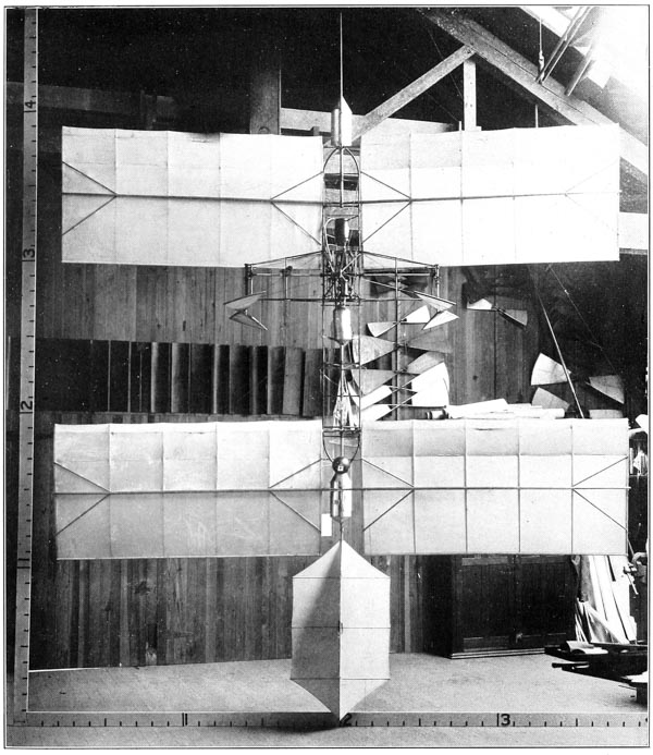
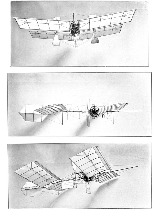


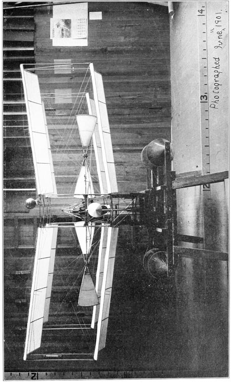
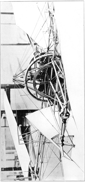
After much delay, due to various causes, the quarter-size model, as shown in plan, end elevation, side elevation and three-quarter elevation in Plates 71 and 72, respectively, was taken down the river in June, 1901, in order to make some tests with it from the small house-boat, which had been previously moved to the middle of the river opposite Widewater, Va. A test of it in free flight was made on June 18, its condition at this time being shown by Data Sheet No. 12 in Appendix. The launching apparatus worked perfectly and the aerodrome started off on an absolutely even keel, dropping only a few inches immediately upon leaving the launching apparatus, and continuing straight ahead directly into the light wind of something less than 2 miles an hour. After it had gone only about 100 feet, however, it began to descend slowly, but still maintained a perfectly even balance, and finally touched the water about 150 feet from the house-boat, having been in the air between 4 and 5 seconds. It was immediately recovered, and as soon as the wings could be dried out another test was made, as it was thought probable that the wind had interfered with the carburetor to such an extent that the engine had not received the proper mixture of gas. Upon this second test the launching apparatus again worked perfectly and the aerodrome again flew straight ahead on a perfectly even keel, and at a uniform height from the water until it had gone about 300 feet, when it again began to descend slowly and finally touched the water about 350 feet from the house-boat, having been in the air about 10 seconds. While the tests were very disappointing, owing to the extreme brevity of the flights, yet they showed conclusively that the balancing of the aerodrome was correct, at least as far as motion in a straight line and in a quiet atmosphere was concerned. As one and a half horse-power, which was felt to be the very minimum which would successfully propel the aerodrome, was furnished by the engine only when working at its very best, and as the change in conditions from a quiet state to a velocity of something like 40 feet per second evidently caused a considerable drop in the power because of the change in the gaseous mixture which the carburetor furnished to the engine, it was decided not to make any further test of the aerodrome until the engine cylinders could be reconstructed so as to provide more effective means for cooling it, and thereby a reasonable margin of power above that actually necessary. The aerodrome was accordingly returned to Washington for the purpose of making new cylinders for the engine. In constructing these new cylinders the old cylinder heads from the previous cylinders were used in order to expedite their completion. This proved in the end to be a very great mistake, though at the time it seemed probable that the use of them would save much delay and considerable expense. The new cylinders were constructed of steel tubing originally one-half inch thick, which [p233] was machined to the form clearly shown in the photograph, Plate 77, where it will be seen that thin radiating ribs spaced one-quarter inch apart were formed integral with the cylinder, the combustion chambers or heads being screwed on and brazed to the cylinders. After much delay the new cylinders were completed, and upon test it was found that while the radiating ribs assisted very greatly in keeping the engine cool, yet the valves were so small that the gas was not able to get in and out of the cylinders rapidly enough to permit the engine to furnish its full power. Even at this stage it would have been better either to have made new cylinder heads with larger valves or to have made entirely new cylinders and cylinder heads, but in the effort to economize time and money it seemed best to try to overcome part of the defect by adding an auxiliary inlet valve. This was constructed, and upon test it was found that, although the engine developed 3.2 horse-power on the Prony brake at 1800 R. P. M., and even maintained 5.1 horse-power on the brake for a few seconds when running at 3000 R. P. M., the ports leading from the valve chamber to the cylinders were so small that they became heated after the engine had run for 2 minutes and premature ignition occurred, which, of course, immediately and very greatly reduced the power developed.
It was decided, however, in view of the tests in which the engine had developed 3.2 horse-power at 1800 R. P. M., that there was sufficient margin of power to enable it to propel the quarter-size model, even if it was not working at its best. After concluding the Prony-brake tests on the engine, it was mounted in its proper position in the aerodrome frame and connected to the propeller shafts. Some pendulum tests were then made, showing an average lift of approximately 57 per cent of the total flying weight. But it was found that the propeller and transmission shafts and their bearings would not stand the strain due to the increased power of the engine. Newer and stronger shafts and bearings were, therefore, constructed and further pendulum tests were made. It was then found that the transverse frame which supported the shafts and bearings was too weak, and this was strengthened by substituting newer and thicker tubing where it seemed necessary.
These changes and repairs were all completed by October, 1901, and the quarter-size model was at last, after months of delay, felt to be in a condition which justified the expectation that its next flight would be entirely successful. In view of the much more important work on the large aerodrome which demanded immediate attention the quarter-size model in this completed condition was put aside. Nothing more was done with it until April, 1903, when some shop tests were made preliminary to taking it to Quantico, where, on August 8, it made a successful flight, which is described in Chapter XII ◊.
The main requirement in an engine for an aerodrome—aside from reliability and smoothness of operation, which are necessary in an engine for any kind of locomotion—is that it shall develop the greatest amount of power for the least weight. It is, therefore, desirable to reduce the weight and number of parts of the engine to the very minimum, so far as this can be done without sacrificing reliability and smoothness of running. Furthermore, since the strongest metal for its weight is steel, and since the greatest strength of steel is utilized when the stress acting on it is one of tension, it is advisable to design the engine so that the parts which sustain the greatest strains shall be of steel and, as far as possible, meet with strains which are purely tensional ones.
In designing the new engine for the large aerodrome it was, therefore, planned to make it entirely of steel, as far as this was possible. The only parts which were not of steel were the bronze bushings for the bearings, the cast-iron pistons, and cast-iron liners of the cylinders. Previous experience had shown that, while it is possible to use a cast-iron piston in a steel cylinder or even a steel piston in a steel cylinder, provided the lubrication be kept exactly adjusted, yet the proper lubrication of the piston and cylinder of a gas engine is difficult even under the most favorable conditions, owing to the fact that excessive lubrication causes trouble from the surplus oil interfering with the sparking apparatus. It was, therefore, determined not to risk serious trouble by attempting to have the pistons bear directly on the steel walls of the cylinders.
While visiting the French engine builders in the summer of 1900 in the attempt to find one willing to undertake the construction of a suitable engine for the aerodrome, it was pointed out to them that the great amount of weight which they claimed to be necessary for the cylinders, and which they stated made it impossible for them to build an engine which would meet the requirements as to power and weight, could be very greatly reduced by making the cylinders in the form of thin steel shells having cast-iron linings. All, however, to whom this suggestion was made declared that it was impossible to build satisfactory cylinders in this way; some of them even stated that they had tried it and found it impossible to keep the thin liners tight in the steel shells. The difficulty which they had encountered is due to the difference in expansion of the steel and the iron when raised to a rather high temperature by the heat of the explosions, if the cylinders are not well jacketed with water; and if the steel [p235] shells are water jacketed they then do not expand as much as the cast-iron liners, and this causes the latter to become “out of round” because of the compression strains produced in them when trying to expand more than the steel shells. As past experience had shown, however, that it was possible to keep the liners tight in small cylinders, it was believed that by taking proper care in the construction there would be no difficulty in this respect with the cylinders of this larger engine.
In carrying out these plans, however, of making the cylinders of steel, numerous constructional difficulties were encountered which could not be foreseen when the design was made. Had they been foreseen, provision for obviating them could easily have been made. As will be seen from the drawing, Plate 78, the engine cylinders consisted primarily of a main outer shell of steel one-sixteenth of an inch thick, near the bottom end of which was screwed and brazed a suitable flange, by which it was bolted to the supporting drum or crank chamber. These shells, which were seamless, with the heads formed integral, were designed to be of sufficient strength to withstand the force of the explosion in them, and, in order to provide a suitable wearing surface for the piston, a cast-iron liner one-sixteenth of an inch thick was carefully shrunk into them. Entering the side of the cylinder near the top, was the combustion chamber, machined out of a solid steel forging, which also formed the port which entered the cylinder and was fastened to it by brazing. The water jackets, which were formed of sheet steel .020 inch thick, were also fastened to the cylinder by brazing, and it was in connection with the brazing of these water jackets that the first serious difficulty was met in the construction of the engine. In the first place, as the jackets were of an irregular shape and of a different thickness of metal from the walls of the cylinder to which they were joined, the expansion and contraction due to the extreme heat necessary for properly brazing the joints caused such serious strains in various and unexpected directions that it was only by exercising the very greatest care and patience that a completely tight joint at all points of the jacket could be secured. In the second place, the size of the cylinders and the consequently large extent of water-jacket surface, complicated the problem. The maintenance over this large surface of the extreme heat necessary for brazing involved discomfort and, indeed, actual suffering to the person engaged in the work, and much care and skill were demanded in so distributing the heat that the temperature of the surface of the jackets would be uniform enough to prevent serious strains from expansion and contraction. As no workman could be found either competent to do the work or willing to undergo the personal discomfort, the writer was obliged to do all this brazing work himself. Besides the difficulties due to the expansion and contraction of the jackets while they were being brazed, the greatest care had to be exercised to avoid heating the cylinders so hot as to weaken the [p236] joint where the explosion chambers were joined to the cylinders, which, of course, had been brazed before the jackets were fitted to them preparatory to brazing them.
Another great difficulty was that the ring which encircled the cylinder near the middle of its length, and which formed the bottom part of the water jacket, expanded very much more than the cylinder itself, so that, if it was brazed to the cylinder before the jacket was brazed to it, the heat of brazing the jacket to the ring would cause the ring to break loose from the cylinder; while if the ring was not previously brazed to the cylinder, but was brazed after the jacket had been brazed to it, the very much greater heat required for brazing the ring to the cylinder caused the spelter to burn out of the joint between the jacket and the ring. Furthermore, it was found very difficult to braze the two joints at the same time, since in brazing the ring to the cylinder it was best to have the cylinder in an inverted vertical position, so that the spelter could be made to flow evenly around the ring and form a fillet against the wall of the cylinder, while in brazing the jackets to the ring it was best to have the cylinder in the reverse vertical position or lying on its side so that the spelter could properly flow into this joint. Finally, however, after what proved to be most exasperating and tedious work, the five cylinders necessary for the engine were completed and a series of tests was immediately made. During the course of these tests the water circulation became obstructed in several instances, and the consequent high temperature to which the cylinders and jackets were raised caused severe strains in the jackets which, in turn, produced breaks in the brazed joints. These breaks had to be rebrazed, and in brazing them it was necessary in almost every case to remove the cast-iron liners and rebraze the entire jackets from start to finish, as the application of the intense heat necessary for brazing at any one point produced such severe strains that before the break which was being repaired could be completed other breaks developed at various points of the jacket. It was, therefore, necessary to get the whole jacket up to a fairly uniform heat and complete the brazing while it was in this condition, and then keep the whole cylinder at a uniform but gradually decreasing temperature until it had sufficiently cooled off.
On account of these troubles with the water jackets and the cylinders, it was decided to build some extra cylinders, not only because past experience had suggested improvements in detail in the construction of the jackets, which would prevent to a large extent the great troubles which had been met with in the brazed joints, but also to insure having sufficient cylinders to enable the engine to be always in working condition, even though several of the cylinders might be out of commission from slight imperfections in the jackets or at other points. While the construction of these new cylinders involved a repetition of the arduous task of brazing, yet the minor improvements which were introduced [p237] proved eminently successful in providing against future troubles from leaky jackets.


The general form of construction of the engine with the improved cylinders will be readily understood from the drawings, Plates 78–81, in which Plate 78 is a detail sectional view, previously referred to, through one of the cylinders; Plate 79 is an end elevation of the port side, Plate 80 is a plan view, and Plate 81 is an elevation of the starboard bed plate which supports that side of the engine, and by which it was fastened to the aerodrome frame, this view showing particularly the sparking apparatus which was mounted on the bed plate. The engine consists primarily of a single crank shaft provided with a single crank pin, the shaft having bearings in a drum which consists essentially of two heads. Arranged around the crank shaft and attached at equidistant points of the drum are five cylinders. Mounted on the port side of the crank shaft and close to the crank arm is a small gear, which through suitable gears mounted on the port head of the drum drives a double-pointed cam which has a bearing on the exterior of the hub of the drum. The ratio of these gears is such that the cam is driven at one-quarter the speed of the crank shaft, and in the reverse direction. Mounted on the exterior side of the port head of the drum are five punch rods, the upper ends of which are within a sixty-fourth of an inch of being in contact with the exhaust-valve stems of the cylinders, and on the lower end of these rods are hardened-steel rollers which rest on the double-pointed cam—this one cam thus serving to operate the exhaust valves of all five of the cylinders. The port head of the drum is connected to the port bed plate, by which it is supported, by means of a flanged bushing in which are formed tongues and grooves which fit into corresponding grooves and tongues formed in the hub of the drum, it being necessary to have a certain amount of space between this bed plate and the head of the drum to provide room for the exhaust-valve cam and its co-acting punch rods. The starboard bed plate is fastened to the starboard head of the drum by bolts which draw the web of the bed plate against the face of the drum. The sparking gears are driven by means of a gear formed on a sleeve which telescopes over the hub of the starboard drum, and has a bearing thereon, the end of the sleeve terminating in a ring which is fastened to the crank shaft.
Since the five connecting rods must center on the one crank pin, the bronze shoes in which they terminate can occupy only a portion of the circumference of the pin, and with the relative proportions which here existed between the length of stroke of crank and the length of the connecting rod, the circumferential width of the connecting-rod shoes was slightly less than sixty degrees, thus leaving uncovered a crank space of about one-sixth of the circumference, which it was necessary to have in order to provide room for the change in relative position of the shoes due to the angularity of the connecting rods. In [p238] the experimental engine the connecting-rod shoes were all given their bearing directly on the crank pin, as heretofore described, being held in contact therewith by means of cone nuts, which were screw-threaded to the crank pin, the taper of the cones permitting adjustment for wear. This method of connecting these parts to the crank pin is the usual plan of connecting three or more connecting rods to one crank pin. So much trouble had been experienced with the water jackets and with minor defects in the experimental engine that no long runs had been possible with it, and consequently no trouble had been experienced because of the small amount of bearing area provided by this method of joining the connecting rods to the crank pin. When, however, the new engine was completed it was found that after working at high power for a few minutes the connecting-rod shoes heated so rapidly that it was impossible to run the engine for more than ten or twelve minutes, the excessive heating of the shoes causing a great diminution in power besides the danger of serious damage if the tests were continued longer. At first this defect seemed almost fatal, as there appeared to be no way of providing sufficient bearing area for the five connecting rods on one crank pin. Happily, however, the writer was able to overcome this defect by an improved design which enables all five connecting rods to operate on the one crank pin, and at the same time provides each with the full amount of bearing area which it would have were it the only connecting rod operating on the crank pin. This arrangement consists essentially of a main connecting rod formed of a steel forging terminating in a sleeve which encircles the crank pin and is provided with a bronze lining for giving a proper bearing surface between the connecting rod and the crank pin, both the steel sleeve and the bronze lining being split, but at right angles to each other, to permit assembling them on the crank pin. This steel sleeve, the upper half of which is formed integral with the main connecting rod is rounded off to a true circle on its exterior circumference, except at the point where the rod joins it. The other four connecting rods terminating in bronze shoes are then caused to bear on the exterior of this sleeve, being held in contact therewith, and permitted to have a sliding motion thereon sufficient to take care of the variation in angularity of the connecting rods, by means of the cone nuts which are screw-threaded to the sleeve and locked thereto by means of the jam nuts, as shown in the drawings. The main connecting rod, of course, acts in the same way as in the ordinary case where each cylinder has its separate crank pin. The other four connecting rods deliver their effort to the crank pin through the sleeve in which the first connecting rod terminates, and they, therefore, do not receive any of the rubbing effect due to the rotation of the crank pin, except that of slipping a very short distance over the circumference of the sleeve during each revolution, the amount of slipping depending on the angularity of the connecting rod. This improved type of bearing was successful from the time of its first trial, and even in later [p239] tests in which the engine was run for ten consecutive hours at full power it showed no signs whatever of overheating. As this new form of connecting-rod bearing for the crank pin had never been tried before, the precaution was taken to leave the threads on the crank pin for the cone nuts, so that if this new bearing should not prove successful the old plan of having the connecting-rod shoes bear directly on the crank pin could be reverted to. These threads are clearly seen in Plate 78 and were never removed from the crank pin, though their removal would have added considerably to the area of the bearing surface of the main connecting rod, had more bearing surface seemed necessary.
The lubrication of the main crank-shaft bearing and of the crank pin was effected by means of a small oil cup, fastened to the port bed plate, which fed oil through a hole in the hub of the drum to a circular groove formed in the bronze bushing in the hub. The crank shaft being hollow, a hole was drilled through it in line with the groove in the bushing, and the oil was then led from the interior of the crank shaft through a pipe connected to the plug in the end thereof, and through a hole drilled in the crank arm to the hollow crank pin. Small holes through the crank pin permitted oil to pass to the exterior thereof and thus oil the bearing of the main connecting rod. Small holes through the sleeve and bushing of the main connecting rod fed oil under the shoes of the other four connecting rods, the small holes being placed in oil grooves formed in the interior of the bronze bushing. The lubrication of the pistons was effected by means of small crescent-shaped oil cups fastened to the outer wall of the cylinders, which distributed the oil equidistantly around the circumference of the pistons, through small tubes which projected through corresponding holes drilled in the cylinder wall. These oil cups for the cylinders were, while small, of sufficient size to furnish a supply for approximately one hour, and were so positioned on each cylinder as to have a gravity feed. It may be mentioned here that while there were many parts of the engine which were of unprecedented lightness there was nothing which excelled these oil cups in this respect, as they were made of sheet steel .003 of an inch thick, riveted and soldered up. The crank-shaft bearing in the starboard drum was oiled from an oil cup mounted on the outside of the bed plate and connected by a pipe to a hole in the inner wall of the drum, which was connected to the oil grooves in the bronze bushing in the hub of the drum.
The first set of pistons for this engine were similar in design to those shown in the assembled drawings, except that they had side walls and heads which were twice as thick as those shown. These lighter pistons were constructed later, and were just as good as the earlier and heavier ones. It will be noted that the pistons have two deep but thin ribs reinforcing the head. The pistons were slightly tapered from the middle, where they were .005 inch smaller than the cylinder bore, toward the outer end, where they were .0075 inch smaller [p240] than the bore. The outer piston ring was .0035 inch narrower than its groove, the second one .003 inch, the third .0025 inch, and the inner one .002 inch narrower than its groove. The rings were bored one-sixteenth inch off center with the exterior surface, and had one-eighth inch diameter of spring. They were of the lap-joint type, with the sides of the laps carefully fitted and only one-sixty-fourth-inch clearance at the ends of the laps to allow for thermal expansion. As no grinding facilities were obtainable in Washington, the cylinders were carefully bored smooth and free from taper, and the pistons were worn in to a perfect fit by running them in by a belt for twenty-four hours, with copious oil supply.
The main connecting rod was 78-inch diameter and solid, while the other four were of the same diameter but with a 58-inch hole in them. The gudgeon pins in the pistons were hollow steel tubes 78-inch diameter and case-hardened, and were oiled entirely by the oil thrown off by centrifugal force from the crank-pin bearing, the oil running along the connecting rods and through suitable holes at the heads into oil grooves in the bronze bushings in these heads.
Since on an engine for an aerodrome the best plan for releasing the exhaust gases from the engine is to get rid of them as soon as possible, so long as they are released behind the aviator and do not interfere with his view in the direction of motion, it was decided to have the gases exhaust immediately from the combustion chambers; but in order to prevent their playing on and heating the main bearing of the crank shaft in the port drum the combustion chambers were each provided with a chamber below the exhaust-valve seat, with a side outlet therefrom. The manifold pipe through which the gaseous mixture was supplied to the inlet valves of the engine consisted of a tube bent to a circle and having five branch tubes, each leading to one of the automatic inlet valves, which fitted removable cast-iron seats fastened by a nut in the upper part of each combustion chamber. The very small amount of clearance between the engine and the frame necessitated that this pipe be cut in three places and joined by flanges in order to properly assemble it on the engine when the latter was mounted in the frame. The carburetor, which was placed near the rear of the aviator’s car, was connected through suitable pipes to this circular inlet pipe, at a point horizontally in line with the center of the shaft. The auxiliary air valve consisted of a sleeve rotatably mounted on the vertical pipe leading from the carburetor to the manifold, holes in the sleeve being brought to coincide more or less with holes in the vertical pipe, by the operator, when more or less air was required or when he wished to vary the speed of the engine. The cooling water for the jackets of the cylinders was led to them through a circular manifold pipe on the starboard side connected by a vertical pipe with the centrifugal pump situated at the lower point of the lower pyramid of the aerodrome frame. The heated water was led from the jackets through another [p241] circular manifold pipe on the port side, through two connections to the radiating tubes at the front and rear, respectively, of the cross-frame. These radiating tubes, which were provided with thin radiating ribs soldered to them, finally led the cooled water to the tank situated in the extreme rear of the aviator’s car, a suitable pipe from the bottom of this tank being connected to the inlet side of the centrifugal pump. The centrifugal pump was driven by means of a vertical shaft connected to the crank shaft through a set of bevel gears which drove it at three times the speed of the engine. The bearings through which these gears were connected were mounted on the port bed plate, and in order to allow for a certain amount of vibration between the engine and the pump this vertical connecting shaft had a telescoping section connected through suitable splines.
The sparking apparatus comprised, first, a primary sparker similar to the simplest form of such devices which have since come into common use, where a cam driven by the engine co-acts with a pawl on the end of a spring, but in this case, as this sparker was used for all five cylinders, the cam was driven at a speed of two and one-half times that of the engine shaft, thus making and breaking the primary circuit five times in each two revolutions of the engine. Second, a spark coil, the primary terminals of which were connected to the primary sparker and to a set of dry batteries. Third, a secondary distributor consisting of a disc carrying a contact brush and driven at a speed one-half that of the engine, this brush being constantly connected through a contact ring to one of the terminals of the high-tension side of the spark coil and running over the face of a five-section commutator, each of the sections of which was connected to a spark plug, the other high-tension terminal of the spark coil being, of course, grounded on the engine frame. This sparking apparatus was first constructed by using blocks of red fibre for insulation. After the engine was completed and was being tested difficulties were met with in the sparking apparatus which at that time appeared inexplicable. After a great deal of annoyance and loss of time it was finally discovered that the red fibre was not as good an insulating medium as it was supposed to be, owing to the zinc oxide used in making it. In damp weather the sparking apparatus absolutely refused to work, and it was found that the moisture in the air caused the zinc oxide in the fibre to nullify its insulating qualities. This trouble, after being located, was cured by substituting hard rubber for the red fibre.
At the time when this engine was built, as well as earlier when the experimental engine was built, it was impossible to procure any wire which had been properly insulated to withstand the high voltages necessary for the connections between the high-tension side of the spark coil and the secondary distributor, and from the secondary distributor to the spark plugs in the cylinders. While at this time this appears a very simple matter, yet the trouble experienced and [p242] the delays caused by the lack of such small accessories which are now so easily procurable were very exasperating, and it was finally necessary to insulate these wires by covering them with several thicknesses of ordinary rubber tube of different diameters telescoped over each other.
In the early tests of this new engine, which were made with it mounted on a special testing frame and delivering its power to the water-absorption dynamometers, the engine was operated without any fly wheels, and, so far as its smoothness of operation was concerned and its ability to generate its maximum power, it did not require any.
After the completion of the tests on the testing frame the engine was assembled in the aerodrome frame, which was first mounted on the floor of the launching car. The car itself was mounted on a short track in the shop, which arrangement provided a smoothly rolling carriage which could be utilized for measuring the thrust of the propellers by merely attaching a spring balance between the rear of the car and a proper holding strap on the track. In the first tests of the engine under these conditions, it was found that while the engine itself did not require any fly wheels, yet the lack of them caused trouble with the transmission and propeller shafts, which, while it had never been anticipated, was easily understood when it was encountered. This difficulty was caused by the “reverse torque,” which fluctuated from a maximum to a minimum five times during each double revolution of the engine, and which set up fluctuating torsional strains of such magnitude in the transmission and propeller shafts that the shafts themselves became exceedingly hot after a few minutes operation of the engine, and under more prolonged periods of operation these fluctuating torsional strains caused a permanent twisting and bending of the shafts. The transmission and propeller shafts were at first made of tubing one-sixteenth of an inch thick, but these were abandoned both on account of the necessity of abandoning the screw-thread method of attaching the flange couplings and gears, and also because these shafts had been designed when it was expected to transmit only twelve horse-power to each propeller, while the increase of power in the large engine necessarily required much stronger shafts. The first shafts which were actually tested in the frame were, therefore, one and one-half inches in diameter by three-thirty-seconds of an inch thick, the tubing having been one-thirty-second of an inch larger originally and turned down to this size to insure a straight shaft. When these shafts twisted under the action of the reverse torque of the engine, a very much heavier set, practically twice as thick, were constructed. When used in the tests these heavier shafts, while much stronger, still showed a large amount of heating due to the fluctuating torsional strains.
Upon calculation it was found that by providing specially light fly wheels the major portion of this reverse torque could be eliminated for a less increase [p243] in weight than would be occasioned by sufficiently increasing the thickness of the transmission and propeller shafts to safely stand it. Since it was desired to concentrate as much as possible of the weight of the fly wheels in the rims, the idea at once suggested itself of building them up like a bicycle wheel by means of tangent spokes. Two steel automobile-wheel rims were therefore procured thirty-three inches in diameter, and these were provided with tangent spokes connected to special steel hubs fitted to the crank shaft of the engine. The rims themselves not being quite heavy enough, and constructional reasons necessitating their being at different distances from the center of length of the crank pin, the extra weight which it was desired to give to these rims was provided by means of steel wire wound tightly around and fastened to the rims, the weight of each rim being made inversely proportional to its distance from the center of the crank pin. The first spokes which were used for these wheels were standard bicycle spokes three-thirty-seconds of an inch in diameter, but these were soon found to be entirely too weak to withstand the sudden strains due to the rapid starting of the engine. They were therefore replaced by standard spokes one-eighth of an inch in diameter, but these also proved too weak and were later replaced with special spokes made in the shop out of No. 10 coppered-steel wire, which by test was found to have a tensional strength of 2192 pounds. As these steel rims were only one-sixteenth of an inch thick and had not been made exactly true, but had been straightened before being used, it was found that they very quickly went out of shape under the strain due to the centrifugal force at high speeds, and also when the engine was suddenly accelerated. As long as they did stay true, however, it was found that they were sufficiently heavy to provide all of the fly-wheel effect it was necessary to have in order to eliminate all trouble from the reverse torque.
After further consideration, it was decided that the only means of constructing a fly wheel which would have a stiff rim and at the same time would not be heavier than the steel ones, which had been found adequate, was by perpetrating what would at first sight appear to be an absurdity. A new set of rims for the fly wheels was made by constructing them of an aluminum casting, the section of the rim being U-shaped. After machining these rims and assembling the fly wheels with them, it was found that they were many times stiffer than the previous steel ones of the same weight, and after this change no further trouble was experienced in keeping the fly wheels perfectly true, even under the most severe strains. In fact, on one occasion when the engine broke loose from the propellers, it ran to a speed, which, while not exactly known, yet reached the limit of the tachometer, which was 2000 R. P. M., without injury to the fly wheels.
It will be recalled that in starting up the engine on the quarter-size model, the initial “cranking” necessary with a gasoline engine was accomplished by [p244] having two of the mechanics turn the propellers. While this same plan might have been followed in the case of the large aerodrome, yet it would have involved some danger to the mechanics and would also have left the aviator without any means of restarting the engine should it for any reason stop while in the air. Believing it to be very important to provide means for enabling the aviator to restart the engine in case it stopped in the air, the writer devised the starting mechanism shown in the drawings, Plates 78 to 80. Fastened by tongues and grooves to the port side of the engine crank shaft, just outside of the bed plate, is a worm wheel, on the hub of which is mounted the bevel gear which drives the water-circulation pump through the bevel pinion, as already described. Mounted on the web of the bed plate are two brackets, in which the shaft for the starting crank is journaled, this shaft passing forward and downward through the front of the cross-frame of the aerodrome, where it is journaled in a bracket secured to the brace tubes thereof. At the front or lower end of the shaft a crank handle is connected thereto by a ratchet mechanism. The upper end of the starting shaft, between the bearings of the two supporting brackets, is tongued and grooved, and slidably mounted thereon with co-acting grooves and tongues is a worm screw which, in the position shown in Plates 79 and 80, is in gear with the worm wheel just described. However, when the worm screw is slid along on the shaft until it is against the upper bracket it is out of gear with the worm wheel. Mounted in the interior of the tubular starting shaft is a spring-pressed pawl plug, not shown, but which projects through one of the tongues on the shaft near the upper bracket. If the worm screw is slid up against this upper bracket, this pawl catches in a radial hole in the worm screw and holds it in this position out of gear with the worm wheel. Connected to this pawl plug and passing longitudinally through the center of the shaft is a wire which terminates in a button just at the end thereof. By pulling on this button the operator may release the worm and thus permit it to slide downward so that when the starting crank is turned in a clockwise direction the worm will screw itself into gear with the worm wheel, and any further turning of the starting crank will cause the worm to force the worm wheel, and, consequently, the engine shaft, around in a clockwise direction. As soon as the engine gets an explosion the worm wheel slides the worm along against the upper bracket, where the spring pawl catches and holds it till it is again released by the operator as before.
This starting mechanism was a success from the first, and the engine was never started up in any other way. With an aerodrome having the qualities of automatic equilibrium, which the Langley machines have, it was felt very certain that by this mechanism the engine could be easily restarted while in the air, in case it was inadvertently stopped. [p245]
The reason for building the engine with five cylinders instead of some other number, and for arranging them radially on a central drum using only one crank pin may not appear quite obvious. The advantages gained by such a construction, however, are very great, and may be briefly summed up as follows:
First, since in a gas engine of the four-cycle type there is only one explosion in each cylinder every two revolutions, and the crank shaft and crank pin therefore are loaded only one-quarter of the time for each cylinder, it is obvious that by having four cylinders arranged radially around a central drum the load on the bearings of a single crank shaft and crank pin may be kept very uniform. However, with four cylinders thus arranged it is impossible to have the cylinders explode and exert their effort on the crank at uniform intervals in the cycle, it being necessary to have the cylinders explode in the order of 1, 3, 4, 2, 1, etc., thus giving intervals between explosions of 180 degrees, 90 degrees, 180 degrees, 270 degrees, etc., or to have them explode in the order of 1, 3, 2, 4, 1, etc., thus giving intervals of 180 degrees, 270 degrees, 180 degrees, 90 degrees, etc. On the other hand, with any odd number of cylinders the explosions will occur at equal intervals in the cycle. With three cylinders they will explode in the order of 1, 3, 2, 1, etc., or at equal intervals of 240 degrees, while with five cylinders they will explode in the order of 1, 3, 5, 2, 4, 1, etc., or at equal intervals of 144 degrees. It is therefore seen that there is a great advantage in smoothness of operation and uniformity of torque of the engine through having an odd number of cylinders instead of an even number.
Second, it is readily apparent that the greater the number of cylinders, provided the number is an odd one, the more uniform the torque will be, and it would seem at first that seven cylinders would therefore be better than five, since the uniform intervals between explosions with seven cylinders would be only 103 degrees (approximately). The advantage gained, however, through seven cylinders instead of five is largely, if not completely, counterbalanced by the added number of parts and the difficulty of providing sufficient circumferencial width for the connecting-rod shoes on the crank-pin bearing, even with the improved construction of this bearing already described. There is considerable fluctuation of the torque in each revolution of the engine with five cylinders, but this fluctuation of torque is more easily smoothed out by the use of very light fly wheels than by increasing the number of cylinders, and thus adding to the complication of the engine.
Third, the strongest point in favor of the radially arranged cylinders is the reduction in weight and complication which it permits. The crank shaft is reduced to the very minimum, there being only one crank pin with two main bearings which can, without any difficulty whatever, be kept absolutely in line with each other and thus prevent binding and loss of power. Again, the use of a single-throw crank not only reduces the cost and weight of the crank [p246] itself, but makes it very much less liable to damage; long crank shafts with several crank pins being frequently twisted by improper explosions in the cylinders. The supporting drum or crank chamber is likewise reduced to the very minimum, both in weight and simplicity, the drums being perfectly symmetrical with no lost space either inside of them or on their exteriors. The cam mechanism for operating the valves is reduced to a simple ring carrying (for a five-cylinder engine) a double-pointed cam and journaled on the exterior of the hub of one of the drums, the cam being driven by a train of gears journaled on studs mounted on the drum, and co-acting with a gear fastened to the crank shaft against the crank arm.
The radial arrangement of the cylinders is thus seen to give not only an engine with the smallest number of parts, each of which is as far as possible worked to a uniform amount during each complete revolution of the crank shaft, but it also gives a very compact and readily accessible mechanism with its center of gravity coincident with its center of figure, and with the liability of damage to it, in case of a smash of the vehicle on which it is used, reduced to the minimum from the fact that the greatest weight is located at the strongest part.
Fourth, and of almost as great importance as the reduction in weight which the five-cylinder radial arrangement permits, is its unusual qualities as regards vibration. Since these five-cylinder engines were built by the writer a very thorough treatment of their properties as regards balancing has been given in a treatise on the balancing of engines,44 so no discussion of the mathematical formulæ involved in a study of the question of the inherent balancing properties of these engines will be here given. It is sufficient to call attention to the fact that in an engine having five cylinders arranged radially, all of the reciprocating parts are balanced for all forces of the first, second and third orders. As it is only the reciprocating parts which give any trouble in balancing any engine, the unbalanced rotating parts being readily balanced by placing an equal weight at an equal distance from the center of rotation, and on the opposite side thereof, it is readily seen that the properties of balancing which are inherent in this type of engine are unusual. A six-cylinder engine having a six-throw crank shaft is not nearly so thoroughly balanced as this type having its five cylinders radially arranged, for in the latter case all the moving parts are in one plane, while in the former case the moving parts are in six separate and parallel planes, and there is consequently considerable longitudinal vibration which can never be overcome. While this is true as regards the vibration due to moving masses, it is still more impressively true as regards vibration due to reaction arising from the force of the explosions in the engine cylinders, especially when the engine is running slowly and having heavy explosions.
The usual practice in balancing the rotating parts of an engine is to attach [p247] balance weights to the crank arms which are prolonged beyond the center of the crank shaft and on the opposite side from the crank pin; the radius of rotation of these balance weights being made approximately equal to the radius of the crank pin. But aside from the constructional difficulties which would be introduced, it was seen that if this plan was followed in this engine it would require a very large additional weight. Since the amount of this weight could be diminished in exact proportion to the increase of the radius of rotation of the balance weights, it was at first decided to attach the weights to the rims of the fly wheels, the relative amount of weight attached to each wheel being inversely proportional to its actual longitudinal distance from the crank-pin center. It was very soon found that the attachment of these balance weights to the fly wheel caused excessive strains on the rims of the wheels, thereby causing them to go out of line. In order, therefore, to keep the amount of balance weight small by carrying it at a considerable distance from the center of the shaft, the weights were finally arranged as clearly shown in the drawings, Plates 78 to 80. There it is seen that the main portion of each of the balance weights consists of a flat arm bolted between the flanges which couple the transmission shafts to the engine shafts. The flat arm terminates in a lozenge-shaped lug, additional weight being provided by a plate fastened to one end of a tube, the other end of which terminates in a collar fastened around the transmission shaft. The tube is inclined at an angle of about thirty degrees with the flat balance arm, thus acting as a brace to prevent the balance arm from wobbling, the plate on the bracing tube being fastened to the lozenge-shaped lug by means of small bolts.
The tabulated statement of the weight of this large engine is given below. From this it will be readily seen that the net weight of the engine proper is 124.17 pounds. The fly wheels were in no way necessary to the engine itself, but were used solely for the purpose of smoothing out the torque of the engine so that the transmission shafts and propeller shafts might be kept down to the very minimum in weight. Including the two fly wheels, the weight is 140 pounds.
Including the 20 pounds of cooling water the total weight of the power plant is 207.47 pounds. Without flywheels the total weight is 191.64 pounds.
The construction of this large engine was completed in December, 1901, and the first tests of it were made in January, 1902. As already stated, these first tests were made with the engine mounted on a special testing frame and delivering its power to two water-absorption dynamometers, no fly wheels being used, as none were required. Later, when it became necessary either to use fly wheels or to greatly increase the weight of the transmission and propeller shafts, in order to overcome the reverse torque, the two light fly wheels were added, and another series of tests was made of the engine on its testing frame. The arrangement of the engine, dynamometers, and accessory [p248] apparatus is clearly shown in Plates 82, 83 and 84. The engine ran in a clockwise direction, as viewed in Plate 82. AA are the fly wheels; BB the balance weights; CC the dynamometer shafts, on which are fastened the rotor plates which revolve inside of the dynamometer drums, DD, between stator plates fastened therein. The drums have a hub on either side, by which they are supported, these hubs being journaled on ball-bearings in the pedestals resting on the wooden framework. The rotor plates do not touch the stator plates in the dynamometers, but drag on the water with which the drums are partially filled, and thus tend to cause the drums to revolve around with them. The torque on each drum is measured by means of a rope, not shown, fastened into the hook at the top of the drum, the rope being given a partial coil around the drum and passing off tangent thereto at the horizontal diameter is fastened to a pair of spring scales hung from the ceiling vertically above the point of tangency. The scales and ropes were unfortunately not in position when these photographs were taken, but the arrangement of them should be readily understood. As the friction of the rotor plates on the water heats it in exact proportion to the amount of power absorbed, the small amount of water in the drums would be soon converted into steam unless continually renewed or cooled. When the rotor plates are revolving the centrifugal force keeps the water pressed toward the circumference of the drum, and the friction at any speed is dependent on the area of the rotor plates in contact with the water. The horse-power required to revolve the plates at any definite speed can therefore be controlled by having an outlet for the water at the proper radial distance from the shaft. The water from the water mains is led through the upper vertical pipe and allowed to flow into the funnel, and thence into the drum near the center where the centrifugal force throws it to the circumference of the drum. The lower vertical pipe is connected to the drum at a suitable radial distance from the center, and the heated water thus passes through this pipe and into the lower funnel connected to the sewer. By the use of the funnels the drums are allowed to rock sufficiently to exert their pull on the spring scales without being affected by the supply and exhaust of water.

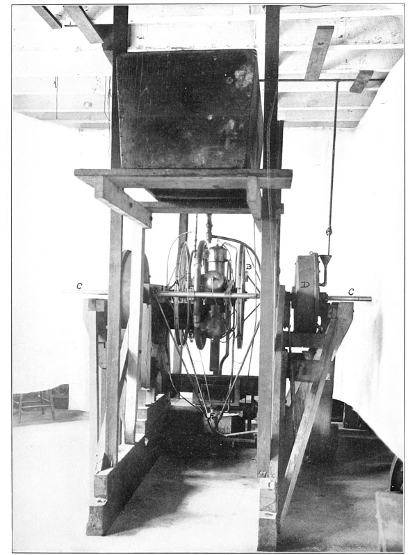
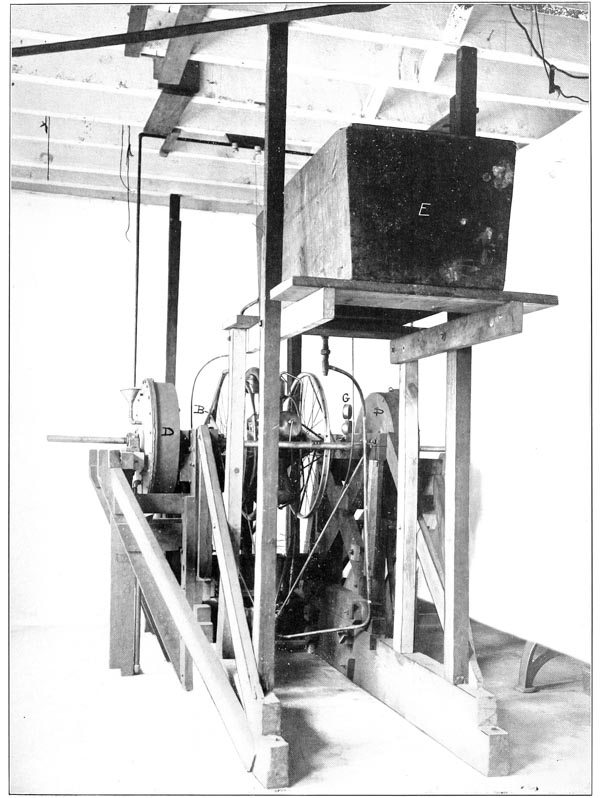
The water for cooling the cylinders is led from the bottom of the tank E to the circulating pump F, supported in a discarded lower pyramid of the aerodrome frame, the pump being driven by the small vertical shaft, as already described. The water, after passing through the pump and the engine cylinders, is led back to the upper part of the tank. By suitable connections to the water mains and sewer, the water in the tank is kept at any desired temperature. The gasoline supply tank is seen on the left-hand side of the testing frame, as viewed in Plate 82, the carburetor being placed below it and the gas supply pipe from the carburetor passing through the gasoline tank. Instead of jacketing the carburetor, a grid formed of thin copper tubes is supported just above the multitude of small air pipes leading into the carburetor, and some of [p249] the hot water from the engine is by-passed through this grid and thus warms the air as it passes into the carburetor. The small pipe that by-passes this water through the grid is seen connected to the outlet water pipe just above the cylinders, a small butterfly valve in the outlet pipe enabling the amount of heated water passing through the grid to be controlled. The return from the grid is by means of the small pipe leading to the top of the large water tank. The tachometer, which gives instantaneous readings of the speed of the engine, is seen at G, where it is at all times in full view of the operator.
These dynamometers proved to be excellently suited for the testing work, and far ahead of anything else the writer has ever found for engine testing. Since the power required to rotate the rotor plates, with a uniform amount of water in the drums, varies as the cube of the speed, it is readily seen that it is impossible for the engine to race or injure itself by running away, as frequently happens where there is no engine governor and Prony brakes are used to measure the power.
In the early tests the engine was never allowed to develop more than 40 horse-power, as it was feared that by letting it develop more, which it was clearly seen to be capable of, it might be injured and cause a delay in the tests of the aerodrome. In the second series of tests it was allowed to develop 51 horse-power at 935 R. P. M., but it was not thought to be advisable to let it run at maximum power for more than an hour, for the same reason as before. In the summer of 1904, after it was seen that there was no immediate possibility of securing funds for continuing the tests of the aerodrome, it was planned to enter the engine in the competitive tests at the St. Louis Exposition, where a prize of $2500 was offered for the lightest engine for its power. As the conditions specified in this competition required that the engine run at its maximum power for one hour, and that this be followed by a durability test of ten hours’ continuous running, it was decided to make some durability tests of the engine before taking it to St. Louis. In these tests, the engine was run on three separate trials for a period of ten hours45 with a constant load of 52.4 horse-power at 950 R. P. M. Even in these long durability tests the engine and the dynamometers both worked so smoothly and evenly that the engine did not vary its speed more than ten revolutions per minute, and the pull on the spring scales varied less than ten pounds in the entire ten hours. Considerable correspondence was had with the officials of the St. Louis Exposition regarding the entrance of the engine in the competition, in order to make sure that suitable facilities for conducting the tests had been provided. After receiving assurance that everything necessary had been provided, the engine and its testing dynamometers were boxed for shipment to St. Louis and arrangements were just being completed for their transportation when the following telegram was [p250] received from the director in charge of the aeronautical department of the Exposition: “On account of lack of competition engine tests abandoned.” As the main object of entering the engine in the competition was to insure for it an unquestioned record of its performance it was decided to reassemble it in the testing frame in Washington and invite some engineers of prominence to witness and certify to its performance, but on account of the lack of funds for meeting the expenses incident to such a series of tests as it was planned to make this was never done.
In the tests which were witnessed on April 26, 1902, by Captain I. N. Lewis, Recorder of the Board of Ordnance and Fortification, the engine was held down to a pull of 200 pounds on a 13-inch lever, when running at 1000 revolutions per minute. In the later tests in May, 1903, which were witnessed by Captain Gibson, who was then Recorder of the Board of Ordnance and Fortification, and Mr. G. H. Powell, the Secretary of the Board, the engine was allowed to work at a pull of 265 pounds on the 13-inch lever arm at a speed of 950 revolutions per minute. In the tests made in August, 1904, the engine was run for ten consecutive hours46 at a pull which varied from 263 to 271 pounds, or an average of 267 pounds, on a 13-inch lever, with the speed varying from 945 to 955 revolutions per minute, thus showing 52.4 horse-power at the average speed of 950 R. P. M.
| DETAILED WEIGHT OF NEW LARGE ENGINE. | |
| Name of part. | Weight in grammes. |
| Crank shaft | 5,225 |
| Connecting rods (total) | 5,005 |
| Pistons— | |
| No. 1 | 1,652 |
| No. 2 | 1,647 |
| No. 3 | 1,655 |
| No. 4 | 1,660 |
| No. 5 | 1,646 |
| Cylinders— | |
| No. 1 (including exhaust and inlet valves, oil cups, etc.) | 4,768 |
| No. 2 (including exhaust and inlet valves, oil cups, etc.) | 4,685 |
| No. 3 (including exhaust and inlet valves, oil cups, etc.) | 4,638 |
| No. 4 (including exhaust and inlet valves, oil cups, etc.) | 4,637 |
| No. 5 (including exhaust and inlet valves, oil cups, etc.) | 4,796 |
| Port crank chamber drum, including cam, cam gears, punch rods, etc. | 5,225 |
| Starboard crank chamber drum | 3,440 |
| Spark plugs (5) | 450 |
| Outlet water pipe | 450 |
| Inlet water pipe | 360 |
| Inlet gas manifold | 1,700 |
| Primary and secondary sparkers and wires | 512 |
| Balance arm with braces for same—starboard | 1,040 |
| Balance arm with braces for same—port | 1,067 |
| Total | 56,323 gm.=124.17 lbs. |
| Starboard fly wheel | 3,946 |
| Port fly wheel | 3,234 |
| Total weight of engine and fly wheels | 63,503 gm.=140.00 lbs. |
| Spark coil and batteries | 6,800 |
| Carburetor | 3,751 |
| Inlet gas pipe from carburetor to manifold | 756 |
| Gasoline tank | 1,004 |
| Water tank | 717 |
| Water circulating pump and shaft | 807 |
| Radiator | 7,700 |
| Total weight of power plant | 85,038 gm.=187.47 lbs. |
In June, 1902, after the proper adjustments of the carburetor and other accessories of the engine had been accurately determined in the tests on the testing frame, the engine was assembled in its proper position in the aerodrome frame and connected to the propellers. The aerodrome frame was then mounted directly on the floor of the launching car, which was placed on a short track laid on the floor of the shop, as previously described. A large spring balance, which had been previously calibrated, was then connected between the car and an upright fastened to the track, and tests were made to determine the thrust developed when the engine drove the propellers at different speeds. Upon finding that there was comparatively little vibration when the engine was driving the propellers even at its maximum speed, it was felt safe to raise the aerodrome from the floor of the car and place it upon the uprights on which it would be supported in launching it. Quite an extended series of tests was then made, and although the uprights raised the aerodrome frame until the midrod was practically 9 feet from the floor of the car, and in the tests at maximum power the propellers developed an average thrust of 450 pounds, yet it was found that the clutch hook held the bearing points of the frame so securely on the uprights of the car that all fear that the aerodrome might break loose from the car during the launching process was removed.
Upon the completion of these tests, which had proved most satisfactory, the aerodrome frame was supported from the ceiling of the shop by means of four short coil springs which reproduced as nearly as possible the elastic or flexible suspension which the aerodrome would have when supported by its wings in the air. These springs were attached at the same points on the main frame of the aerodrome at which the wings would be attached, thus permitting a careful study of the amount of flexure and vibration which it would undergo in actual flight. The most remarkable difference in the nature of the vibration induced in the frame was found when the aerodrome was thus supported by springs. When it was supported on the rather unyielding launching car, the general tremor set up in the frame by the engine and propellers was, while small, yet harsh, the effect on a person standing in the aviator’s car being rather unpleasant in the joints of the knees when experienced for several minutes. When the frame was suspended by the springs it was found that all this harshness of tremor disappeared, it being replaced by a slight general and rapid tremor of the whole frame, which was not at all unpleasant, and which [p252] had no tiring effect on one standing in the aviator’s car. In fact, the vibration in the first case resembled rather closely that of a motor vehicle supported on wheels having metal tires, and in the second case a motor vehicle supported on wheels having pneumatic tires.
As in these tests in the shop it was impossible to keep the engine cool by circulating its cooling water through the radiator, since there was no air current blowing across the latter to carry away the heat, it was necessary to connect an extra water tank in the cooling-water circuit. A tank holding about ten gallons was used, and this sufficed for about ten minutes before the water was raised to the boiling point.
During one of these tests when the frame was supported from the springs, and while the engine was developing about fifty horse-power, without any warning whatever, both propellers suddenly twisted off from the flanges by which they were connected to the propeller shafts, thus leaving the engine entirely unloaded. The propellers both dropped quietly to the floor, making only about one or two turns in falling the distance of approximately 10 feet, and the engine, which had been running at about 850 R. P. M., immediately speeded up to an exceedingly high speed, which, while not exactly known, since the tachometer only read to 2000 R. P. M., yet from the deflection produced on the tachometer needle must have been considerably higher than this. Although the fly wheels, which were 33 inches in diameter, with the aluminum rims and wire spokes, had been exceedingly well made, yet it was not considered safe to run them at this speed, and the engine was immediately shut down. At the moment, however, that the engine had broken loose from its propellers and also momentarily jumped to this exceedingly high speed there was absolutely no vibration that could be noticed, the unloaded engine running as smoothly as an electric motor. This showed very clearly that the running balance of the engine was as near perfect as it would be possible to get it, except with a seven-cylinder engine, which is theoretically capable of more perfect balance. It was evident that what small vibration there was in the frame while the engine was developing its power was due almost entirely to the reverse torque, and, of course, could never be entirely eliminated.
In the tests of the engine working in the frame, both while mounted on the car and also when suspended from the springs, a great amount of delay was caused from the fact that the ball-bearings on the transmission and propeller shafts frequently went to pieces. There were two reasons for this: In the first place, although carefully selected balls were used, defective ones were continually encountered. Even a slight defect in a single ball resulted in its breaking under the rather severe test to which they were subjected, and, as is well known, the breaking of one ball in a ball-bearing usually results in the destruction of the whole bearing, especially if the races are light. The second cause was that [p253] the whole aerodrome had been originally designed with the expectation of using a maximum of 24 horse-power, and as no margin had been left to provide for possible increases in the size of the bearings, there was no room to permit them to be increased without almost completely reconstructing portions of the transverse frame. While in the end it would have been cheaper to have reconstructed these portions in order to put in larger bearings, yet, as is always the case in experimental work of this kind, small changes which seem to hold out hope of overcoming difficulties are usually followed, rather than reconstructions which can be seen to involve considerable expense and delay. After a number of minor changes had been made in the bearings, they were finally able to stand up fairly well under the severe strain to which they were subjected when the engine developed its full power, and no further changes were made in them; a defective race being, however, replaced by a new one as occasion demanded.
These tests demonstrated very clearly that at speeds of approximately 1000 revolutions per minute ball-bearings which are subjected to considerable loads should be calculated with a considerable margin of safety, as the yielding of the frame, which must necessarily be far from rigid, causes more or less error in the alignment of the shafts and bearings, and this introduces considerably increased strains on the bearings. In the early tests before the bearings were strengthened, the balls in some of the races were on a few occasions ground to a very fine powder before it was discovered that they had failed. Such a result, it will be understood, could and did occur in the course of a very minute length of time.
In imitating as nearly as possible the conditions to which the carburetor of the engine would be subjected during the period of launching, numerous tests were made in which the engine was brought to its maximum speed and, without changing the adjustment of the mixture-controlling devices of the carburetor, sudden blasts of air were turned on it from various directions, and these were continued until the mixture-control devices were perfected to such a point that gusts of thirty miles an hour suddenly directed from any point against any portion of the apparatus would in no way effect the speed and power of the engine. These tests were considered necessary in view of the very sudden changes in conditions to which the aerodrome would be subjected during its brief run down the launching track, the conditions changing in approximately three seconds from absolute quiescence of the aerodrome to a plunge through space at thirty-five feet per second. An aviator would be more than occupied with maintaining control of himself and of the aerodrome, which at the moment of leaving the track might require considerable change in the adjustment of the Pénaud tail, and he would, therefore, not be able to make any adjustments of the engine-control devices. This supposition was entirely confirmed in the actual tests of the aerodrome which are to be later described, the rush down the track being [p254] so very brief that the engine could not have been given any attention by the aviator had it needed it, which fortunately it did not.
It is hardly necessary to recount at any length the great difficulties which was experienced in these tests of the engine in the aerodrome frame before the shafts, bearings, propellers, and, in fact, the frame itself were all properly co-ordinated so that confidence could be felt that all of the parts would stand the strains which were likely to come on them when the aerodrome was in flight. These tests were really not tests of the engine itself, but of the frame, shafts, and bearings. Suffice it to say that nearly a year was consumed by the various breakages of the shafts, bearings, and propellers before it was felt that all of these parts could be depended on, and even then the weakness of the bearings above referred to was fully recognized. Had some of the better-grade balls and steels for the bearings, which have since that time come on the market, been obtainable then, there would have been no difficulty with these bearings. However, this same remark might be made with reference to nearly all of the details of the aerodrome, for it was the accessories, such as bearings for the transmission and propeller shafts, spark plugs, coils, batteries, and a suitable carburetor for the engine, that caused the chief delay after the main difficulty of getting a suitable engine had been overcome.
The extended series of shop tests which had occupied a considerable portion of the late winter and early spring of 1903 had demonstrated the following facts: First, with the aerodrome mounted on the launching car, a propeller thrust of from 450 to 475 pounds could be maintained indefinitely by the engine, and even when the engine was delivering its full power to the propellers, the vibration was so small as to cause no apprehension that the wings and rudder would be made to vibrate sufficiently to produce undue strains in them. Second, with the aerodrome suspended from the ceiling by springs at the points at which the wings would be attached, the vibration produced by the engine developing it’s full power was even less than when the machine was mounted on the launching car and there was, consequently, even less cause for concern that the wings and rudder might be set in vibration when the machine was free in the air. Third, the engine could be depended upon to deliver something over 52 horse-power when the five cylinders were working properly, and even with one cylinder not working, but acting as a dead load against the others, approximately 35 horse-power could be developed, while with two cylinders not working at all, the three which were working would deliver about 25 horse-power. Therefore, even assuming that two of the five cylinders might become deranged during a flight, there should still be sufficient power to propel the machine. These tests, some of which had been witnessed by members of the Board of Ordnance and Fortification, clearly demonstrated that the time had arrived when it was safe to give the aerodrome a test in free flight. The machine itself together with all its appurtenances and much extra material for repairs in case of breakages, which previous experience had shown to be almost certain, was accordingly taken from the shop and placed on the house-boat preparatory to taking it down the river to the point opposite Widewater, Va., which had already been selected as the “experimental ground.”
Owing to the limited size of the shops it had been impossible to place the wings and rudder in their proper positions on the aerodrome and determine its balancing in a way similar to that practiced with the models. The approximate settings for the wings and rudder had, however, been determined by calculation from the data obtained in the test of the quarter-size model, so that it remained only to place the wings and a weight to represent the rudder actually on the machine in the large space of the house-boat (which, however, was not large enough to permit the rudder to be assembled along with the wings), and thus check the balancing previously determined by calculation. There were very [p256] few appurtenances which could be shifted in balancing the aerodrome, but the proper disposition of weight had been so accurately determined by calculation that the floats, which, as will be seen from the various photographs, were merely cylindrical tanks with pointed ends, and of a sufficient capacity to cause a displacement great enough to float the aerodrome when it came down into the water, proved sufficient ballast for shifting the center of gravity to its proper point. The flying weight of the aerodrome was 830 pounds,47 including the weight of the writer, which was 125 pounds. The total area of the wings or supporting surfaces was 1040 square feet, or the ratio of supporting surface to weight was 1.25 square feet per pound, which is the same as .8 pound per square foot.
After the balancing of the large aerodrome had been completed on the house-boat, and everything else got in readiness as far as could be done before actually arriving at the point at which the test was to be made, the house-boat was towed down the river on July 14, 1903, and fastened to its mooring buoy, which had been placed in the middle of the river at a point practically opposite Widewater, Va., and approximately forty miles from Washington. See Coast-Survey Chart, Plate 85.
Sleeping quarters for the force of eight workmen and the regular soldier from the United States Army, who had been detailed as a special guard, had been provided on the boat, but owing to the lack of space it had been found impracticable to arrange proper cooking facilities on the boat, and it had been found necessary to arrange to transport the workmen to Chopawamsic Island, near Quantico, Va., for their meals. It had been planned to use the twenty-five-foot power launch for this purpose, but owing to the heavy storms which became quite frequent soon after the house-boat was taken down the river, it was found that the small launch was not sufficient, and it was necessary to employ a tug-boat and keep it stationed there at all times. This added very considerably to the expense of the experiments, as the hire of this one tug-boat very nearly equalled the pay-roll of the workmen, and while it was not expected that the stay down the river would be so greatly prolonged as afterwards proved the case it was felt certain that minor delays were sure to occur and the experiments would at the very least require several weeks.
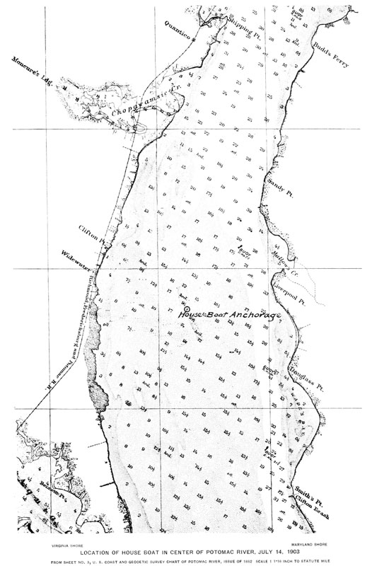
Had it been possible to foresee the great delay which finally occurred before the large aerodrome was actually launched, and the great expense arising from the necessity of maintaining one or more expensive tug-boats constantly, it is very certain that an experimental station nearer Washington would have been selected, even though the nearer places on the river which were available were much less suitable, both on account of the river being much narrower and the traffic very much heavier. In fact, at the time that the house-boat was taken down the river on July 14, with the expectation that the experiments with the [p257] large aerodrome would certainly be concluded within four weeks, the expenses of the work, which had been met from the Hodgkins Fund of the Smithsonian Institution since the original allotment from the Board of Ordnance and Fortification was exhausted more than a year previously, had already made such heavy drafts on this fund that Mr. Langley was most reluctant to draw further on it, even to the extent which seemed necessary to meet the expenses of a month of “field-work.”
Before making the tests of the large aerodrome, it was intended to give the quarter-size model a preliminary trial to test the balancing which it was proposed to use on the large machine. For this test it was planned to employ the small launching apparatus mounted on top of the small house-boat, which had been used in the experiments with the steam-driven models Nos. 5 and 6 in 1899, and later with the quarter-size model in 1901. However, after arriving down the river, it was found that the small house-boat which had been anchored at Chopawamsic Island since the experiments in 1901 had deteriorated to such an extent that it was unsafe to take it out into the river. The launching apparatus for the model was, therefore, removed from it and placed on the turn-table of the large house-boat, alongside the launching track for the large machine. After completing this transfer of the model-launching apparatus everything was thought to be in readiness for a test of the quarter-size model, but upon making a shop test of the model to make sure that its engine was working properly, it was found impossible to get it to work at all. A few explosions could be obtained once in a while, but very irregularly. After spending considerable time in trying to locate the difficulty, it was found that the commutator which distributes the high-tension sparking current to the proper cylinder at the proper time was short-circuited. This commutator had been made of “insulating fibre” and had never caused any previous trouble. It was now found, however, that the very damp atmosphere which had been experienced during the preceding two weeks, when the fog for a large portion of the time was so heavy that objects at a short distance across the water could not be seen, had caused the moisture to penetrate the fibre and thus destroy its insulating qualities. After much trouble some vulcanite and mica were secured and a new commutator made to replace the fibre one, and, then, after some minor difficulties had been remedied, the engine for the model was got into good condition again. After getting satisfactory shop tests on the model aerodrome, and having everything in readiness for a flight, it was necessary to wait many days before the weather was calm enough for a test. However, on August 8 the weather quieted down and the model was launched at 9.30 a. m. into a wind blowing about 12 miles per hour from E. SE.
Referring to Plate 86, which shows the quarter-size model mounted on its launching car on top of the large house-boat, and which was taken only a few [p258] minutes before the model was actually launched, it will be noted that a board (A) projects from the front of the launching car. This board, which is mounted in a false floor of the launching car, is so arranged that when it strikes the two blocks (B) at the end of the track it is driven backward in the car against the triggers which prevent the uprights (D), supporting the aerodrome, from being folded down against the floor. When this board strikes the triggers it releases them and the springs (C), which in this case were rubber bands, immediately fold the vertical posts or uprights (D) against the brace posts (E), which are immediately folded down flat against the floor of the car through the action of the spring hinges, by which they are connected to it. These uprights (D), which support the aerodrome at the front and rear, respectively, are not released until a fraction of a second after the release of the clutch hook (F), which is attached to the middle upright (G), and which, grasping the lower pyramid, holds the machine down firmly against the uprights (D) previously referred to. In order to prevent the possibility of the aerodrome being released prematurely while the car is held at the extreme rear end of the track by the hook (H), a steel pin (J), which can just be seen in the photograph, is pushed through a hole in the board (A), and into a hole in a cross-member on the bottom of the car, thus holding the board in its proper position. After the engine is started up one of the mechanics who has assisted in starting it is under orders to remove the pin at the word “Ready,” and at the word “Go” the other mechanic who has assisted in starting the engine is under orders to release the hook (H), and thus allow the car to dash down the track. In the experiment on August 8 the mechanic failed to remove the pin (J) at the proper time, and it was only after the machine had been released and started down the track that it was seen that the pin had not been removed. It was then, however, too late to stop it, so the car dashed down the track. Although the striking of the board against the blocks caused the pin to split the board to pieces, the launching apparatus worked perfectly and the aerodrome started off on a perfectly even keel, the propellers revolving at an exceedingly high rate of speed. The aerodrome flew straight ahead for a distance of 350 feet, when it began to circle towards the right, descending slightly as it circled. Upon completing a quarter circle it again began to rise, flying straight ahead until it had gone a similar distance, when it again lost headway, but before it reached the water the engine increased its speed and the aerodrome again rose. When the engine slowed down for the third time, however, the aerodrome was not many feet above the river, so that before the engine regained its normal speed the aerodrome touched the water with its propellers still revolving, but very slowly. While the total distance covered was only about 1000 feet, and the time that it was actually in the air 27 seconds, yet in this brief time it had served the main purpose for which it had been built, which was to find out if the balancing of [p259] the large aerodrome, which had been determined by calculation from the results obtained with the steam-driven models, was correct. For it was assumed that if the quarter-size model, which was an exact counterpart of the large machine, should fly successfully with the same balancing as that calculated for the large one, the large one could reasonably be expected to act similarly. It was at first thought best to make another test with the model immediately after recovering it from the water, but by the time it could be brought into the house-boat and the water which had got into the engine cylinders could be removed and the engine made to work properly quite a strong wind had sprung up and rendered further tests of the model on this day impossible. If the launching track for the small machine could have remained on the top of the boat without interfering with the completion of the preparations for testing the large machine, it would have been left there and other tests made with the model when the weather was suitable, but as this could not be done without interfering with the work on the large machine, and the delays with the model had already been so great, the small track was immediately removed and the model stored away in the house-boat for possible later tests.
At the first it was impossible to account for the engine on the model running so irregularly and slowing down so soon after it was launched, as it was felt very certain that the cylinders could not in so short a time, and with the aerodrome actually moving through the air, have heated up sufficiently to cause it. After a while, however, one of the workmen volunteered the information that in his zeal to fill the fuel tank completely so as to insure a long flight, he had caused the tank to overflow so that some of the gasoline had run into the intake pipe, and that he had noticed gasoline dripping from the intake pipe as the machine went down the track. This excess gasoline in the intake pipe had caused the mixing valve which controls the quality of the explosive mixture to be improperly set, so that it would not furnish the proper mixture when the fuel was supplied in the proper way by the carburetor, and consequently when this excess gasoline had evaporated, the mixture furnished to the engine was not proper, and it consequently slowed down, there being no human intelligence on board to correct the adjustment of the mixing valve.
A series of seven photographs of this flight of the quarter-size model is given in Plates 87 to 93. Plate 87, taken with a kodak from the tug-boat stationed several hundred yards directly ahead of the house-boat, shows the machine in full flight heading directly for the tug-boat. Although the aerodrome was about fifteen or twenty feet higher above the level of the water than the camera, still, at the considerable distance from which the photograph was taken, this view would not show so much of the under side unless the machine had been pointing upward. The photograph also proves very clearly that at the time it was taken the machine had certainly not dropped at all below the level [p260] at which was launched. In Plate 88 the camera was unfortunately not well aimed, and only the front guy-post, bearing points, float and bowsprit are visible, besides the blur of the propellers, which, it will be noted, were moving very rapidly. The camera with which this and the succeeding plates were taken was one of the two special telephoto cameras belonging to the Zoological Park, but built in the course of the aerodromic work and used where especially rapid shutters were needed. As the shutters on these cameras give an exposure of only 1500 of a second, and consequently are sufficiently rapid to show the individual feathers in a rapidly moving bird’s wing, any distortion of the machine in flight would certainly have been shown, but, as will be seen from the later photographs, no distortion of any kind occurred, both the surfaces and the framework remaining in a perfectly straight condition. Near the bottom of Plate 88 is the tug from which Plate 87 was taken, and a careful inspection of Plate 87 shows two persons standing on the roof of the house-boat, below the upper works, the gentleman on the left being Mr. Thomas W. Smillie, the official photographer of the Smithsonian Institution, who took all of the photographs except Plate 87, and, as stated above, used therefor the special telephoto cameras with the rapid shutters. Plate 89 is an exceedingly good view, and shows the propellers revolving very rapidly while Plates 90, 91 and 92 show very clearly that the speed of the propellers had greatly decreased between the successive photographs. Plate 93 shows the aerodrome shortly after it touched the water and had been almost completely submerged, in spite of its floats, by the very strong tide which was running. Though these plates show all that photographs can, they give no adequate idea of the wonder and beauty of the machine when actually in flight. For while the graceful lines of the machine make it very attractive to the eye even when stationary, yet when it is actually in flight it seems veritably endowed with life and intelligence, and the spectacle holds the observer awed and breathless until the flight is ended. It seems hardly probable that anyone, no matter how skeptical beforehand, could witness a flight of one of the models and note the almost bird-like intelligence with which the automatic adjustments respond to varying conditions of the air without feeling that, in order to traverse at will the great aerial highway man no longer needs to wrest from nature some strange, mysterious secret, but only, by diligent practice with machines of this very type, to acquire an expertness in the management of the aerodrome not different in kind from that acquired by every expert bicyclist in the control of his bicycle.
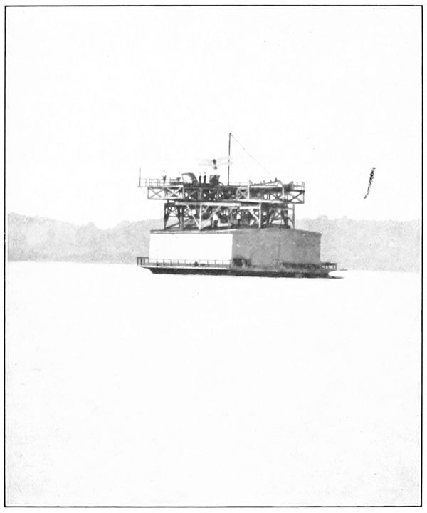


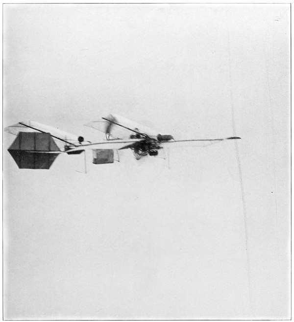
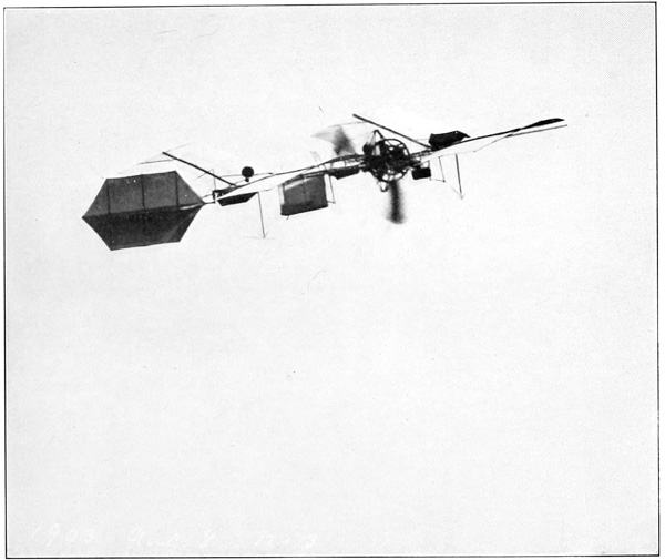
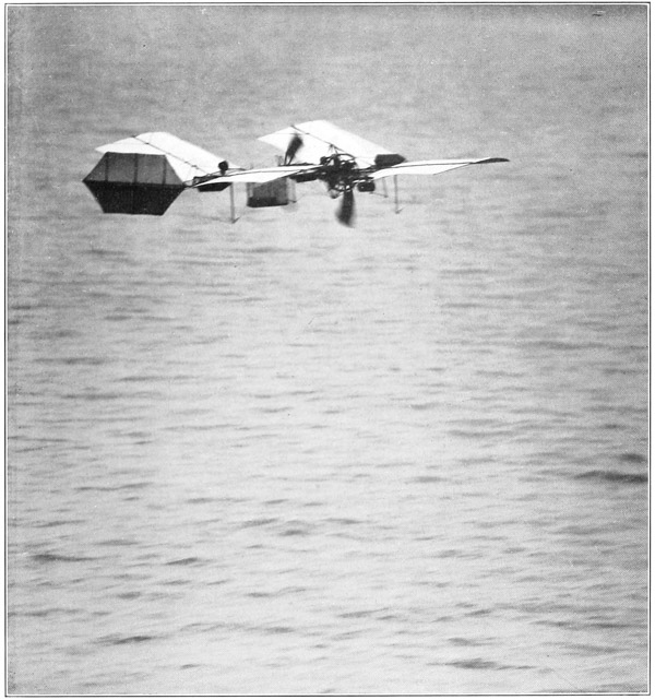
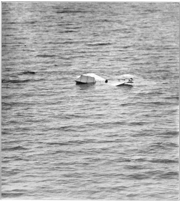
In describing this flight immediately after it was made, Professor John M. Manly, who took the photograph shown in Plate 87, said: “The flight of the small aerodrome was an event which all who saw it will remember for the rest of their lives. We were, of course, in a state of considerable nervous excitement and tension, for, after weeks of delay from high winds, rains, and [p261] other uncontrollable causes, at last we had a day ideally suited to the test. This was, to be sure, not the great test, the final test, the test of the man-carrying flyer, but it was felt by all to be of almost equal importance, for if the balancing of the small aerodrome was correct, the large one would maintain its equilibrium, and the problem of human flight would be solved practically as well as theoretically. That the weather was now favorable for the test filled us with excitement. Again and again the favorable moment had seemed to come, and had gone again before we could make ready for it. The aerodrome was rapidly carried to the upper works of the house-boat and the observers and helpers went hastily to their positions. The large tug-boat was stationed directly ahead, almost in the line of flight, and about a mile from the house-boat. Signals of readiness were exchanged, and with every sense astrain we awaited the supreme moment. The rocket gave the starting signal, and instantly there rushed towards us, moving smoothly, without a quiver of its wings, with no visible means of motion and no apparent effort, but with tremendous speed, the strange new inhabitant of the air. Onward it moved, looking like a huge white moth, but seeming no creature of this world, not only on account of its size, its ease of movement and its wonderful speed, but also because of its strange, uncanny beauty. It seemed visibly and gloriously alive as it advanced, growing rapidly larger and more impressive. Straight at us it came, and for a moment there was a wild fear that it would come right on and crush itself against the ponderous tug-boat. There was a half impulse to move the tug-boat out of its way, but the aerodrome seemed to realize its danger and rapidly, though not abruptly or violently, as if it had intelligence and power of self-direction, it checked its speed and circled to the right, descending slightly. Soon it quickened its speed again and went straight ahead for about ten seconds, when it again checked its flight and descended, circling once more. Once again it attempted to increase its speed and rise, but it was too near the water, and in a few moments the waves had wet its propellers and wings, and it sank, a poor, bedraggled creature. But the vision of its beauty and power and seeming intelligence and life will long remain with those who saw its flight.”
After removing the model-launching track so that the final arrangements could be completed for testing the large machine, many weeks of delay were experienced, almost entirely due to the unusually bad weather conditions which prevailed, and which were unprecedented for the time of the year. However, on September 3 the weather became more suitable, and the aerodrome being in readiness the metal frame of the large machine was hoisted to the top of the boat and placed on the launching car, and the wings, rudder, etc., were then hoisted up and properly assembled and everything made ready for a flight. The parties with the telephoto cameras were sent to their stations on the shore, where definite base lines had been marked out so that with the data as to [p262] altitude and azimuth, which these cameras automatically recorded, the speed, height, etc., of the machine in flight could be accurately computed. After stationing the tug-boats at proper points, so as to render assistance should the aerodrome come down into the water at a considerable distance from the house-boat, it was found, upon attempting to start the engine, that for some reason it would not operate. The sparking battery which had been placed at the extreme rear of the aerodrome was found to be giving such a weak spark that it would not ignite the mixture in the cylinders. Upon removing the connection which grounded the terminal of the battery to the framework and replacing it by a large copper wire leading up to the engine so as to decrease the resistance of the circuit it was found that the battery still would not give sufficient spark. A large quantity of dry cells, such as were used for the engine, had been procured to insure against delay from lack of batteries, but upon attempting to get a new set from this reserve supply it was found that they, as well as the set that was on the machine, had so deteriorated that instead of giving eighteen amperes on short circuit they would give only three, which was not a sufficient current to enable the engine to operate. No shop tests on the large engine had been made since the large aerodrome had been brought down the river, as no provision had been made for properly supporting the aerodrome in the house-boat in such a way as to permit the large propellers to whirl around without causing damage, and, therefore, the batteries which had hitherto proved to be suitable had not had any special test since they had been brought down the river. As no batteries suitable for use were on hand, and as none could be procured from a point nearer than Washington, the test had to be abandoned for the day and the aerodrome removed to the interior of the boat.
It was at first impossible to account for the rapid deterioration of so large a number of dry cells, but it was later found that the damp, penetrating fogs which had been experienced for nearly two months were responsible for it, and that in order to preserve the batteries in such a climate it was necessary to place them in metallic boxes which could be nearly, if not quite, hermetically sealed. New batteries were immediately procured from Washington, and before again mounting the aerodrome on the launching track provision was made for testing the engine inside the house-boat.

Up to this time the wings had been stored inside the house-boat by suspending them from the ceiling, but the time required to hoist them to the upper works on top of the boat, after the main body of the aerodrome had been placed on the launching car preparatory to making a flight, had added so greatly to the delay, and consequently to the difficulty of getting the machine entirely ready for a flight while the weather conditions remained suitable for a test, that it was decided to build some framework on the upper works and cover it with canvas so as to provide some boxes in which the wings could be [p263] stored whenever it seemed probable that a flight would soon be possible. Some of the difficulties experienced in hoisting these wings from the interior of the boat to the upper works may be appreciated by an inspection of Plate 94, where one of them is seen just ready to be hoisted from the raft. Only one wing at a time could be handled on the raft, even when there was no appreciable wind or roughness of the water, so that in order to hoist all four wings the raft had to be hauled around from the door at the end of the boat to the side where the wing was hoisted, and back again four times every time the machine was assembled preparatory to a flight. The necessity for making occasional tests of the engine in order to make sure that no trouble would be again experienced in having proper batteries, etc., for the engine when the machine was again on the point of being launched also made it imperative to remove the wings from the interior of the house-boat, as the tremendous blasts of air from the propellers would certainly have wrecked the wings had they remained in the boat while the engine was being tested.
After the wings had been stored in the “wing boxes,” thorough tests of the engine were made, and before there came another day which was at all suitable for a trial, it was accidentally discovered that the glued joints in the cross-ribs of the large wings had been softened by the moisture of the fogs which had penetrated everything, and that the joints had all opened up and left the ribs in a practically useless condition.
It will be recalled from the description of these cross-ribs, Chapter VI ◊, that the rib is composed of two channel-shaped strips, the edges of which are glued together while the strips are bent over a form which causes the ribs to maintain the curved form desired after the glue has hardened. Recalling these facts, it will be readily understood that there is at all times a considerable strain on the glued joints due to the two strips of wood trying to straighten out, and, therefore, if the glue should at any time become softened sufficiently to allow one strip to slide along on the other, the joint would open up and the rib would consequently become straight. When the construction of the hollow ribs was first contemplated it was realized that although the hollow construction would enable the ribs to be strong, and at the same time exceedingly light, yet it would make it imperative that the ribs be covered with a water-proof varnish in order to prevent the glue from being softened when the aerodrome came down into the water, as it was expected from the first that it would do at the end of its flight. Considerable time and attention had, therefore, been given to this very problem of securing a suitable water-proof varnish, and ribs coated with the varnish which was finally used had been submerged in water for more than 24 hours in testing this very point, and no softening of the glue could be detected after this long submergence. It had, therefore, been felt that the ribs had been given a test which was much more severe than any conditions which [p264] were likely to be met with, since the aerodrome would, in no case which could be anticipated, be in the water for so long a period as 24 hours, and no trouble from this source need be anticipated.
In the present case, however, the moisture of the atmosphere, which had been heavily laden with fog for several weeks, had penetrated the varnish and softened the glue, even though the submergence of 24 hours in water had shown no effect. To construct new ribs for the wings would have required several weeks, and the delays which had already been experienced had by this time prolonged the stay down the river so greatly that even under the very best conditions it seemed hardly possible to complete the tests before the coming of the equinoxial storms, which would make it necessary to remove the boat from the middle of the river and place it in a safe harbor. Something, therefore, had to be done, and that very quickly, so that an immediate test could be made, or else the tests would have to be delayed until the following season, or possibly postponed indefinitely on account of the lack of funds.
Owing to the varnish with which the ribs were covered, it was impossible in repairing them to carry out the first plan which suggested itself of binding the ribs with a strip of cloth impregnated with glue and wound spirally from end to end. As the wood was so very thin, it was impossible to bind the two parts together with wire, and even thin bands of metal driven up on the tapered portion of the rib were not likely to draw the two strips together without crushing the wood. What was finally done was to scrape the edges of the two strips where the joint had opened, thereby removing all the old glue, and after putting fresh glue on all these edges the two strips were drawn together and bound with surgeons’ tape, which was found to adhere very firmly even to the varnished surface.
After repairing the ribs in this manner and readjusting the guy-wires of their framework so as to make the wing assume the correct form, which had been slightly altered by the warping and twisting consequent on the opening up of the ribs, everything was again in readiness for a test in free flight, numerous tests of the engine having meanwhile been made both with the aerodrome frame inside of the house-boat and also when mounted on the launching track above. The weather, which had been unprecedentedly bad all summer, now became even worse, and although short periods of calm lasting an hour or less occasionally occurred, there were for several weeks no calm periods long enough for completing the necessary preparations and making a test, although the time required for assembling the aerodrome had been greatly shortened by building the “wing boxes” on the superstructure, and in other ways previously described. On several occasions when an attempt was made to utilize what appeared to be a relative calm, the aerodrome was assembled on the launching apparatus and everything got in readiness except the actual fastening of the [p265] wings and rudder to it, but in every instance, before the wings could be actually applied and a flight made, the wind became so strong as to absolutely prohibit a test. On two occasions when the wings were actually attached, heavy rain storms suddenly came up and drenched the machine before the wings could be removed, and on several occasions it was necessary to leave the entire metal frame and engine of the aerodrome mounted on top of the boat all night, because the heavy sea which was running made it impossible to utilize the large raft in returning the frame to the interior of the boat.
Finally, however, after it seemed almost useless to hope for calm weather, what appeared to be a most propitious day arrived on October 7. The wind which had been quite high in the early morning gradually quieted until at 10 a. m. it was blowing only about twelve miles per hour and the indications were that it would quiet down still more. Every energy was concentrated in getting the aerodrome ready at the earliest possible moment, as previous experience had shown too clearly that the conditions might be completely reversed in less than an hour. As the tide and wind caused the boat to swing up the river from its buoy, and thus made the launching track point down the river, the steam tug-boat was sent down the river for a distance of a mile or more so that, should the aerodrome come down into the water without being able to make a return trip to the house-boat, the tug-boat would be able to reach it quickly and render assistance to both the writer and the machine should they need it. At 12.20 p. m. everything was in readiness and what appeared to be the decisive moment had arrived, when the writer, after starting up the engine and gradually raising its speed to the maximum, and after taking the last survey of the whole machine to insure that everything was as it should be, finally gave the orders to release it.
Although the writer did not have the privilege of seeing it glide down the track, as his attention was too thoroughly engaged in insuring that he was in the proper position for reaching immediately any of the control apparatus, either of the aerodrome or of the engine, yet those who did witness the actual passage of the machine down the track have said that the sight was most impressive and majestic. No sign of jar was apparent when the machine was first released, but with lightning-like rapidity it gathered its speed as it rushed down the sixty feet of track, the end of which it reached in three seconds, at which time it had attained a speed of something over thirty-two feet per second. Just as the machine reached the end of the track the writer felt a sudden shock, immediately followed by an indescribable sensation of being free in the air, which had hardly been realized before the important fact was intuitively felt that the machine was plunging downward at a very sharp angle, and he instinctively grasped the wheel which controls the Pénaud tail and threw it to its uppermost extent in an attempt to depress the rear of the machine and [p266] thereby overcome the sharp angle of descent. Finding that the machine made no response to this extreme movement of the tail, he immediately realized that a crash into the water was unavoidable and braced himself for the shock. The tremendous crash of the front wings being completely demolished as they struck the water had hardly become apparent before he found himself and the machine plunging downward through the water. By some instinct he grasped the main guy-wires which were above his head, and pulling himself through the narrow space between them freed himself from the machine and swam upward as rapidly as possible. A few moments after reaching the surface of the water the uppermost point of the pyramid of the machine was seen to project from the water and he swam over and sat down on it until a row-boat could be sent to it from the nearby power-boat.
The first thing that the writer saw after looking around him was a newspaper reporter, his boatman expending the utmost limit of his power in pushing his boat ahead to be the first one to arrive.
After giving directions to the workmen regarding the recovery of the machine, the writer returned to the house-boat to obtain dry clothing, and although his first inclination was not to make any statement until a complete examination could be made to determine both the cause of the lack of success and also the extent of the damage which had been sustained by the machine, yet owing to the very great pressure brought to bear by the press representatives who said that unless some statement was given out they would write their own conclusions as to the cause of the mishap, he finally gave out the following statement:
STATEMENT MADE BY MR. MANLY TO ASSOCIATED PRESS
“It must be understood that the test to-day was entirely an experiment, and the first of its kind ever made. The experiment was unsuccessful. The balancing, upon which depends the success of a flight, was based upon the tests of the models and proved to be incorrect, but only an actual trial of the full-size machine itself could determine this. My confidence in the future success of the work is unchanged. I can give you no further information. I shall make a formal report to Secretary Langley.”

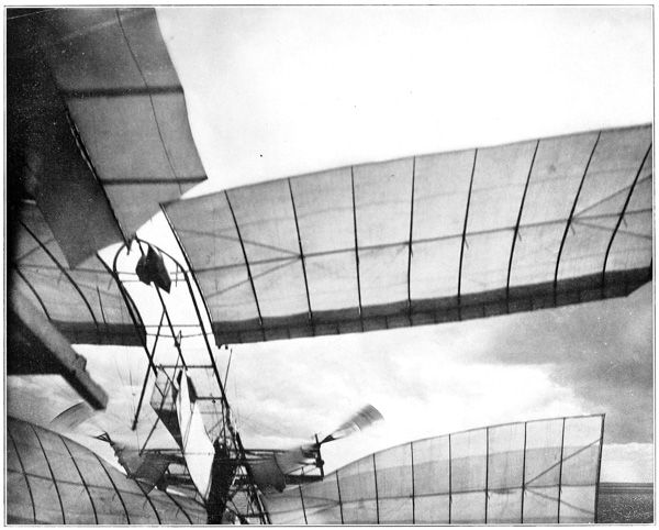
After recovering the machine the foreman of the workmen (Mr. Reed) [who together with Mr. McDonald were the only ones on top of the boat when the launching actually took place], busied himself to discover what had caused the jerk to the machine at the moment it was released, which had been immediately followed by the great depression of the front end. After some little time he discovered that the upright guide at the extreme front of the launching car (which, as heretofore stated, was slotted to receive a metal lug projecting from the end of the guy-post, and thus prevent the front end of the [p267] framework from being twisted by a side wind striking the machine while it was still on the launching car) had been distorted, the metal cap on it being stretched out of shape in a way which indicated that the pin of the front guy-post had hung in the cap, and that the guy-post was not therefore free from this part of the car when the end of the launching track dropped. The shock which the writer felt at the moment of launching and which had also been seen by others to occur was thus conclusively shown to have been due to the falling track, dragging the front end of the machine down with it. As the machine was travelling forward and the car had been almost instantly brought to a standstill by its buffer pistons co-acting with the buffer cylinders at the foot of the track, this front guy-post had been pulled backwards, and thus not only pulled the main guy-wires of the wings backwards and thereby depressed the front edge of the front wings so that they had no angle of inclination, but had also bent the front end of the metal framework downward,—effects which were discovered from the later examination of the frame and the guy-post itself. From the instantaneous photographs which were obtained, indisputable evidence was obtained that this was what actually occurred. Referring to the photograph, Plate 95, which was taken by Mr. G. H. Powell, Secretary of the Board of Ordnance and Fortification, and which shows the machine just a few feet in front of the point where it was actually launched, it will at once be seen that the front end of the frame is bent downward and that the front guy-post instead of being parallel with the rear one has been deflected backward at the lower end through an angle of 30 degrees. Referring further to the photograph, Plate 96, which was taken at the same instant as the one just described, it will be seen that even this one, which is a view of the machine as it passed almost directly over Mr. Smillie’s head, most clearly shows the extreme extent to which the front wings had been distorted, the rear edges of the wings near the frame having been twisted up until they struck the cross-frame, and the outer ends being free to twist had been forced up very much higher.
After completing the recovery of the machine and the examination as to the extent of the injuries it had sustained, and finding unquestionable evidence that the accident had been caused by the front guy-post hanging in its guide block on the launching car, the workmen were set to work straightening out and arranging the various parts, fittings and accessories, and cleaning up the engine which fortunately had sustained no injury whatever. After a consultation in Washington with Mr. Langley, who had been unable to be present at the experiment, both concerning what had already occurred and also what should be done regarding the future of the work, and in view of the fact that the statement which the writer had given to the press representatives, immediately after the accident, had been made before there had been time to make an examination of the machine itself, it was decided that it would be best to give to the press [p268] a short statement to correct the earlier one, and Mr. Langley accordingly made public the following note:
“Mr. Langley states that he was not an eye witness of the experiment at Widewater yesterday, having been detained in Washington by business, but that on the report of Mr. Manly, immediately in charge, he is able to say that the latter’s first impression that there had been defective balancing was corrected by a minuter examination, when the clutch, which held the aerodrome on the launching ways and which should have released it at the instant of the fall, was found to be injured.
“The machinery was working perfectly and giving every reason to anticipate a successful flight, when this accident (due wholly to the launching mechanism) drew the aerodrome abruptly downward at the moment of release and cast it into the water near the house-boat. The statement that the machine failed for lack of power to fly was wholly a mistaken one.
“The engine, the frame and all the more important parts were practically uninjured. The engine is actually in good working order. The damage done was confined to the slighter portions, like the canvas wings and propellers, and these can be readily replaced.
“The belief of those charged with the experiment in the ultimate successful working of the machine is in no way affected by this accident, which is one of the large chapter of accidents that beset the initial stages of experiments so novel as the present ones. It is chiefly unfortunate in coming at the end of the season when outdoor work of this sort is impossible.
“Whether the experiments will be continued this year or not has not yet been determined.”
In view of the many inaccurate accounts published in the daily press at the time of this experiment, special attention is directed to the fact that even under the enormous strain to which the aerodrome was subjected, due to its striking the water at an angle of approximately forty-five degrees and at a speed certainly not less than forty miles an hour, no bending or distortion of any kind was found in the frame after it was recovered, except that a slight depression at the front had been produced by the lower guy-post catching on the launching car, as previously described. This is very clearly seen in Plate 97, Fig. 1, which shows the aerodrome being hoisted from the water, and in Plate 97, Fig. 2, which shows it just afterwards resting on the raft, the wings, tail and rudder having been completely demolished by towing it through the water to the house-boat from the place where it struck the water. This single distortion, therefore, was in no way a result of the strains experienced by the frame either while it was in the air or when it struck the water. Some of the press reports, and, in fact, some of the accounts published in the scientific press, stated that the aerodrome frame had proved so weak that it broke while the machine was in the air, and that this was the cause of the accident. Nothing could be farther from the actual facts than this, for though there were many things connected with the machine which could not be properly tested until it was actually in the air, yet the strength of the frame had been most thoroughly [p269] tested in the shops prior to the trial, and it had been found that with the frame supported only at the extreme front and rear, no appreciable deflection was produced upon it by the concentrated weight of four men at the center, even when they simultaneously jumped up and down on it. That the aerodrome frame was amply strong was further evidenced by the fact that in the later trial, hereafter described, no injury was sustained by the frame even when the machine turned over in mid-air and struck the water flat on its back. In fact, no point regarding the aerodrome is more certain than that the frame was more than strong enough for its purpose.
Plates 98 to 100 show the aerodrome in the water from the moment after it arose and the writer, who had extricated himself while it was plunging down through the water and beat it to the surface, had swum over to it and sat down on the upper pyramid to await a row-boat, until the machine was taken in tow by the tug-boat.
As the weather conditions were continually growing worse, owing to the lateness of the season, it was decided that it would be absolutely impossible to undertake to keep the house-boat down the river until the aerodrome could be repaired and another test made, and the writer accordingly returned to Quantico on the following day, expecting to take the tug-boat from there to the house-boat and complete arrangements for bringing everything to Washington. On reaching Quantico, however, it was found that a most violent storm was raging on the river, and had, in fact, been increasing in violence since the evening of October 7, immediately following the trial. On account of the storm it was impossible to reach the house-boat or to get into communication with the workmen, who had sought refuge at the hotel at Clifton Beach, as the tug-boat itself was not at the point at which it was expected to be found, and, in fact, it had not been seen by any of the river people since the morning of October 8, when it was seen taking the workmen from the boat to Clifton Beach. Two days later, or October 11, when the storm had subsided and the tug-boat, which had been blown many miles down the river, was able to return the workmen to the house-boat, it was found that the storm had made a complete wreck of all the row-boats, the power-launch, and the large raft. The row-boats had been completely demolished on the beaches, the launch had been broken from its moorings to the house-boat and driven ashore some four miles down the river, where it was found with the deck torn completely off, a large hole stove in it amidships, and the engine seriously damaged, while the raft had been very seriously damaged on the beach many miles down the river. After making temporary repairs to the raft and getting it launched, it was used as a floating dock for making temporary repairs on the power-launch; both were then returned to their moorings at the house-boat and everything got in readiness for towing the house-boat to Washington, and this was finally accomplished on October 12. [p270] Even while the boat was en route some of the workmen were busily engaged in the repair of the damaged parts, the others having been sent ahead to Washington to begin work on the construction of new wings, so that another trial could be had at the earliest moment that the weather would permit.
One extra pair of wings was on hand, but these had been stored in the house-boat while it was down the river, and the damp weather, which had caused such serious damage to the cross-ribs of the wings which were actually used, had also so seriously affected the ribs of these extra wings that it was necessary to discard some of them and repair the others. An extra Pénaud tail was on hand, as well as a steering rudder, and it was estimated that unless some unforeseen delay occurred the aerodrome would be ready for flight in three weeks.
After making a careful examination of the places on the river which seemed most available for an experiment, it was finally decided to make the next test just off the Potomac Flats, at the junction of the main body of the river and the Eastern Branch, the traffic on this part of the river, which would have been more dangerous and troublesome during the summer, being quite light at this time of the year. By making the experiment at this point it was possible to leave the house-boat at its dock until the weather seemed suitable and then have a tug-boat tow it to the exact point, which would be determined by the state of the wind and the tide.
After more completely examining the condition of the framework of the machine, and discussing and maturely deliberating on the causes which had led to the accident of October 7, the writer advised Mr. Langley not to make any changes either in the machine itself or in the launching apparatus, except to remove the small lug from the metal rod which projected from the end of the guy-post, and which by catching in its guide on the launching car had been the sole cause of the accident. The aerodrome was accordingly repaired so as to reproduce exactly the conditions which obtained at the time of the previous experiment, except for this slight change, and it was again ready for trial by the middle of November. The weather, however, at this time was very variable, there being at times comparatively quiet periods which lasted for only an hour or less, which was not sufficient time for procuring a tug-boat and towing the boat to the proper point, and then assembling the aerodrome and making a trial. However, after many days waiting, what appeared to be an exceptionally quiet day occurred on December 8, the wind quieting down by noon to such an extent that practically a dead calm prevailed. Vigorous search was immediately instituted for a tug-boat to tow the house-boat to the point selected, but it was very late in the afternoon before one could be procured, and by the time the boat arrived at the proper place darkness was descending and a strong [p271] and exceedingly gusty wind had sprung up, and it seemed almost disastrous to attempt an experiment.

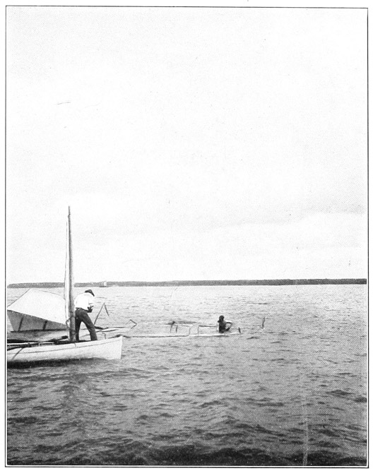


However, the funds which had been appropriated by the Board of Ordnance and Fortification had been exhausted nearly two years before, and all the expense since that time had been met from a special fund of the Smithsonian Institution. But, owing to the heavy drains which the work had made upon this fund, Mr. Langley felt unwilling to draw further upon it, and since there were no other funds available from which to meet the expenses which would be incurred by postponing the experiments until spring, it was decided that it was practically a case of “now or never,” and although the river was full of large blocks of floating ice several inches thick, which added enormously to the danger involved in the experiment, the writer decided to make the test immediately so that the long-hoped-for success, which seemed so certain, could be finally achieved.
After considerable delay, due to the great difficulty of properly assembling the huge wings in the strong and gusty wind, into which the boat could not be kept directly pointed, owing both to the strong tide which was running and to the fact that the wind itself was rapidly varying through as great a range as ninety degrees, and after many minor delays, due to causes too numerous to mention, the aerodrome was finally ready for test.
The wind was exceedingly gusty, varying in velocity from twelve to eighteen miles per hour and shifting its direction most abruptly and disconcertingly, so that the aerodrome was at one moment pointed directly into it and at the next moment side gusts striking under the port or starboard wings would wrench the frame severely, thus tending to twist the whole machine from its fastenings on the launching car. After starting up the engine and bringing it to full speed, the writer gave the signal for the machine to be released, and it started quietly, but at a rapidly accelerated pace, down the launching track. Exactly what happened, either just before or just as the aerodrome reached the end of the track, it has been impossible to determine, as all the workmen and visitors had gone to their stations on the various auxiliary boats, except the two workmen (Mr. Reed and Mr. McDonald) who had been retained on top of the boat to assist in the launching. It had grown so dark that the cameras of Mr. Smillie, the official photographer, were unable to get any impression when he used them, owing to the extreme rapidity of the shutters with which they were equipped. Fortunately, one photograph of the machine while still in the air was secured, which shows the result of what had occurred in the launching and before any further damage had been caused by its coming down into the water, but the all-important question as to just what caused the accident which did occur remains to a certain extent a mystery. [p272]
Mr. Reed, the foreman, who was qualified to observe accurately, not only through his having worked continuously for many years on the machines, but also from his having witnessed the numerous tests of the models, states that from his position near the rear end of the launching track he noticed that at a point about ten feet before the machine reached the end of the track the Pénaud tail seemed to have dropped at the rear end in some inexplicable way so that it was dragging against the cross-pieces of the track, and that at the next instant, when the car reached the end of the track, he saw the machine continue onward, but the rudder and whole rear portion of the frame and the wings seemed to be dragging on the launching car. Mr. McDonald, the head machinist, states that he had his attention so concentrated on the engine, which he noticed was working perfectly and driving the propellers at a higher rate of speed than he had ever before seen it do, that he did not see anything happen until he saw the machine shoot upward in the air, gradually attaining a vertical position with its bow upward, where it was sustained for a few moments by the upward thrust of the propellers. After a few moments, however, the strong wind, which was blowing from twelve to eighteen miles an hour directly ahead and acting against the wings which were now vertical, drove the machine backwards towards the house-boat, and he saw it come down into the water on its back, with the writer gradually righting himself in accordance with the turning of the machine until he was finally hidden from view by the machine coming down on top of him. The witnesses on the tug-boats seem not to have been able to perceive exactly what occurred. All unite in stating that something seemed to happen to the machine just a few feet before the launching car reached the end of the track, but what it was they could not say. Everyone who saw the accident and who was sufficiently familiar with the construction of the machine to be able intuitively to form an idea as to just what was taking place was so very close to the machine that when the accident happened everything seemed to merge into one vision, which was that of the whole rear of the wings and rudder being completely destroyed as the machine shot upward at a rapidly increasing angle until it reached the vertical position previously mentioned.
The writer can only say that from his position in the front end of the machine, where he was facing forward and where his main attention was directed towards insuring that the engine was performing at its best, he was unable to see anything that occurred at the rear of the machine, but that just before the machine was freed from the launching car he felt an extreme swaying motion immediately followed by a tremendous jerk which caused the machine to quiver all over, and almost instantly he found the machine dashing ahead with its bow rising at a very rapid rate, and that he, therefore, swung the wheel which controls the Pénaud tail to its extreme downward limit of motion. Finding that [p273] this had absolutely no effect, and that by this time the machine had passed its vertical position and was beginning to fall backwards, he swung himself around on his arms, from which he supported himself, so that in striking the water with the machine on top of him he would strike feet foremost. The next few moments were for him most intense, for he found himself under the water with the machine on top of him, and with his cork-lined canvas jacket so caught in the fittings of the framework that he could not dive downward, while the floor of the aviator’s car, which was pressing against his head, prevented him from coming upward. His one thought was that if he was to get out alive he would have to do so immediately, as the pressure of the water on his lungs was beginning to make itself seriously felt. Exerting all of the strength he could muster, he succeeded in ripping the jacket entirely in two and thus freeing himself from the fastenings which had accidentally held him, he dived under the machine and swam under the water for some distance until he thought he was out from under the machine. Upon rising to the surface his head came in contact with a block of ice, which necessitated another dive to get free of the ice. Upon coming to the surface of the water he noticed Mr. Hewitt, one of the workmen, just about to plunge in; before he could call out to indicate he was safe, Mr. Hewitt had heroically plunged in with the expectation of diving under the machine where he believed the writer to be entangled. Finding the house-boat was being rapidly shoved upon him, imperilling the life of both himself and Mr. Hewitt, besides the safety of the aerodrome, the writer gave orders that the tug-boat reverse and tow the house-boat away. Then, with the assistance of a row-boat, he reached the house-boat, where willing hands drew him on board and assisted him into dryer and warmer clothing.
Meanwhile, it had become quite dark, and when the writer went outside to see about the aerodrome he found that the men on the tug-boat, in their zeal to render assistance, had fastened a rope to the rear end of the machine, at the same time pulling it in the direction in which the front end was pointed, and through their ignorance had forced it down into the muddy bottom of the river and broken the main framework completely in two, thus rendering it absolutely impossible with the facilities at hand to remove it from the water to the interior of the boat. It was finally necessary to tie the wrecked machine to the stern of the house-boat and have the boat towed to its dock where the mast and boom were assembled and the wrecked machine hoisted from the water. This was finally accomplished about midnight, when the workmen, who had been working at a fever heat all day, were glad to close up the work for the day, which had proved so unfortunate.
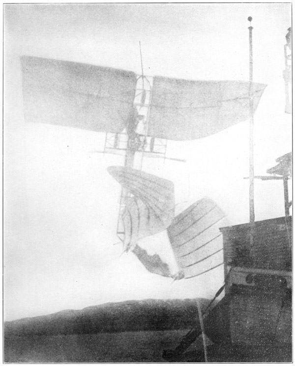
As has already been remarked, darkness had descended to such an extent that the light was not strong enough to give photographs with the very rapid shutters with which Mr. Smillie had his cameras equipped, and that, therefore, [p274] incontrovertible evidence, which the instantaneous photographs had given as to just what had occurred to the machine in the accident of October 7, was in this case unfortunately lacking. It was at first thought that no photographs had been obtained while the machine was actually in the air, but it was later found that by some rare fortune the photographer for The Washington Star had secured a photograph, which, while small, showed very distinctly some decidedly interesting facts. An enlargement of this photograph is shown in Plate 101, by the kind permission of The Washington Star. Referring to this photograph, it will be seen that at the moment it was taken the machine was practically vertical in the air, and it confirms the testimony of the eye witnesses, and also the writer’s impression that the machine was maintained in a vertical position for several moments by the upward thrust of the propellers. It will also be seen that the Pénaud tail has been completely demolished and is hanging as a limp roll of cloth, which the strong wind has deflected backwards towards the house-boat, the port rear wing has broken its main ribs, both where they are attached to the main frame and also about midway the length of the wing, the outer end being partially folded towards the frame. The starboard rear wing has also broken both of its main ribs at the point where they are joined to the frame, and they have also broken at a point about one-third their length from the frame, the outer end being likewise folded towards the frame. By a still more careful inspection, it will also be seen that the port front wing is apparently uninjured, while the starboard front wing has broken the middle main rib at a point between the sixth and seventh cross-ribs, and while it cannot be distinctly seen at first that the front main rib has also broken at the same point very careful inspection will show that this is the case, as the sixth and seventh ribs, showing as faintly darker lines in the photograph, are seen to be displaced, so that they are together and actually crossing each other. It will furthermore be seen that both front wings have been pressed upward by the wind until their tips near the inner ends are in contact with the cross-frame. This could not have happened unless the front guy-post had given away either by bending or breaking. The fact that it has given way is further evidenced by a more careful examination of the extreme front end of the machine, where it will be seen that the bowsprit and the curved tubes which form the extreme end of the steel frame have been bent from a straight line with reference to the main frame. This bending of the bowsprit and the curved tubes could be produced only by the front guy-post coming in contact with some obstruction on the launching car as the machine left it. It is known very certainly that the rear end of the machine came in contact with the launching car, as the car itself shows a very deep gash in the wooden cross-piece at its center, which was produced by the port-bearing point at the rear striking it. As this bearing point was elevated five feet above the cross-piece of the launching car, and was also six feet six inches to [p275] the rear of the point where the wood is torn, this rear-bearing point must have travelled downward at an angle of approximately thirty-eight degrees in order for the bearing point to strike the car at this point. As the lower end of the rear guy-post was only eighteen inches above the cross-piece of the launching car, it, of course, would be broken before the bearing point could descend so much. As has been previously stated, Mr. Reed, who was at the rear of the launching track, states very positively that the rudder was dragging on the track at least ten feet before the launching car reached the front end of the track where the machine was actually launched. There are several ways in which the rudder could have gotten down on the track, but positive information is lacking. If it was dragging on the track, as Mr. Reed states (and from his extended experience and rather acute powers of observation I should place great credence in his report), the subsequent demolition of the guy-posts succeeded by the destruction of the rear wings and serious injury of the front ones is easily explained. If the dropping of the rudder on the track occurred from the breaking of the upper rudder post, over which the upper control wire passed, the lower vertical surface would first come in contact with the track, and the destruction of this part would certainly occasion subsequent destruction of the horizontal and upper vertical surfaces of the rudder, leaving the central rib of the rudder still attached to the frame, and upon the machine being released from the car a few moments later this destroyed rudder would easily catch in the launching car and pull the aerodrome down on it, and thus cause the destruction of the guy-posts, wings, and so forth. If the dropping of the rudder was caused primarily by its main rib breaking loose from its connection with the frame, the rudder would still be dragged along behind the machine by the wire cords through which it was operated, and the subsequent launching of the machine would still give the rudder every chance to catch in the launching car and drag the machine down on it.
It can therefore be said that, while positive information is lacking, there is very strong evidence that the accident in the launching was due to the rudder becoming entangled with the launching track owing to the breakage of some part of the mechanism by which it was connected to the main frame.
It is of importance to note that the photograph furnishes incontrovertible evidence that the main frame of the machine was in no way injured, except for the slight bending of the forward curved extension, and that, therefore, the accident was in no way due to the weakness of the frame. The main frame was not even injured by the machine coming down in the water on its back, and the later damage was entirely caused by the combination of the ignorance of the tug-boatmen and the darkness in which they were working, when they attempted to tow it to the rear of the house-boat so that it could be removed from the water. [p276]
On the day following the trial a very careful inspection was made in the hope of obtaining some more definite information as to just what caused the accident, but the serious injury to the machine caused by the tug-boatmen breaking it in the water had so greatly tangled things up that it was impossible to tell anything about it. The workmen were immediately put to work removing fittings from the broken wings, rudder, etc., and dismounting the engine, which was immediately reassembled on its testing frame and found to be absolutely uninjured. The transverse frame of the machine was comparatively uninjured, the damage done by the men on the tug-boat being the breaking of the machine in two at a point just back of the cross-frame, together with the consequent destruction of the bearing points, “trestle,” and certain fittings by which the main guy-wires were attached to the main tubes and pyramids.
The situation which now existed was most distressing and disheartening. Mr. Langley felt that he could not approve of further expenditures from any Smithsonian fund, and the Board of Ordnance and Fortification of the War Department having been severely criticised on the floors of Congress for its original allotment for the work, deemed it inexpedient to incur a possible curtailment of the funds annually placed at its disposal for general experimental work through a manifestation of continued interest in the flying machine.
As has already been stated, representatives from the Board of Ordnance and Fortification of the War Department were present at both tests of the large aerodrome; on October 7 Major Montgomery M. Macomb and Mr. G. H. Powell, and on December 7 General W. F. Randolph accompanied by Major Macomb and Mr. Powell, represented the War Department, and Dr. F. S. Nash, at that time Contract Surgeon, U. S. A., was officially present at both trials to render medical assistance should it be needed.
By permission of the War Department, the official report of the tests submitted by Major Macomb to the Board of Ordnance and Fortification is here made public:
Enc. 1st to 3d end’t, BOF 6191.
REPORT
Experiments with working models which were concluded August 8 last having proved the principles and calculations on which the design of the Langley aerodrome was based to be correct, the next step was to apply these principles to the construction of a machine of sufficient size and power to permit the carrying of a man, who could control the motive power and guide its flight, thus pointing the way to attaining the final goal of producing a machine capable of such extensive and precise aerial flight, under normal atmospheric conditions, as to prove of military or commercial utility.
Mr. C. M. Manly, working under Prof. Langley, had, by the summer of 1903, succeeded in completing an engine-driven machine which under favorable [p277] atmospheric conditions was expected to carry a man for any time up to half an hour, and to be capable of having its flight directed and controlled by him.
The supporting surface of the wings was ample, and experiment showed the engine capable of supplying more than the necessary motive power.
Owing to the necessity of lightness, the weight of the various elements had to be kept at a minimum, and the factor of safety in construction was therefore exceedingly small, so that the machine as a whole was delicate and frail and incapable of sustaining any unusual strain. This defect was to be corrected in later models by utilizing data gathered in future experiments under varied conditions.
One of the most remarkable results attained was the production of a gasoline engine furnishing over fifty continuous horse-power for a weight of one hundred and twenty pounds.
The aerodrome, as completed and prepared for test, is briefly described by Prof. Langley as “built of steel, weighing complete about seven hundred and thirty pounds, supported by one thousand and forty feet of sustaining surface, having two propellers driven by a gas engine developing continuously over fifty brake horse-power.”
The appearance of the machine prepared for flight was exceedingly light and graceful, giving an impression to all observers of being capable of successful flight.
On October 7 last everything was in readiness, and I witnessed the attempted trial on that day at Widewater, Va., on the Potomac. The engine worked well and the machine was launched at about 12.15 p. m. The trial was unsuccessful because the front guy-post caught in its support on the launching car and was not released in time to give free flight, as was intended, but on the contrary, caused the front of the machine to be dragged downward, bending the guy-post and making the machine plunge into the water about 50 yards in front of the house-boat. The machine was subsequently recovered and brought back to the house-boat. The engine was uninjured and the frame only slightly damaged, but the four wings and rudder were practically destroyed by the first plunge and subsequent towing back to the house-boat. This accident necessitated the removal of the house-boat to Washington for the more convenient repair of damages.
On December 8 last, between 4 and 5 p. m., another attempt at a trial was made, this time at the junction of the Anacostia with the Potomac, just below Washington Barracks.
On this occasion General Randolph and myself represented the Board of Ordnance and Fortification. The launching car was released at 4.45 p. m., being pointed up the Anacostia towards the Navy Yard. My position was on the tug Bartholdi about 150 feet from and at right angles to the direction of proposed flight. The car was set in motion and the propellers revolved rapidly, the engine working perfectly, but there was something wrong with the launching. The rear guy-post seemed to drag, bringing the rudder down on the launching ways, and a crashing, rending sound, followed by the collapse of the rear wings, showed that the machine had been wrecked in the launching, just how, it was impossible for me to see. The fact remains that the rear wings and rudder were wrecked before the machine was free of the ways. Their collapse deprived the machine of its support in the rear, and it consequently reared up in front under the action of the motor, assumed a vertical position, and then toppled over to the rear, falling into the water a few feet in front of the boat. [p278]
Mr. Manly was pulled out of the wreck uninjured and the wrecked machine was subsequently placed upon the house-boat, and the whole brought back to Washington.
From what has been said it will be seen that these unfortunate accidents have prevented any test of the apparatus in free flight, and the claim that an engine-driven, man-carrying aerodrome has been constructed lacks the proof which actual flight alone can give.
Having reached the present stage of advancement in its development, it would seem highly desirable, before laying down the investigation, to obtain conclusive proof of the possibility of free flight, not only because there are excellent reasons to hope for success, but because it marks the end of a definite step toward the attainment of the final goal.
Just what further procedure is necessary to secure successful flight with the large aerodrome has not yet been decided upon. Professor Langley is understood to have this subject under advisement, and will doubtless inform the Board of his final conclusions as soon as practicable.
In the meantime, to avoid any possible misunderstanding, it should be stated that even after a successful test of the present great aerodrome, designed to carry a man, we are still far from the ultimate goal, and it would seem as if years of constant work and study by experts, together with the expenditure of thousands of dollars, would still be necessary before we can hope to produce an apparatus of practical utility on these lines.
M. M. MACOMB,
The attitude of the Board of Ordnance and Fortification, with reference to rendering further financial assistance to the work, is clearly shown by the following extract from the official report of the Board on October 6, 1904, to the Secretary of War:
THE LANGLEY AERODROME
Early in the year 1898 a board composed of officers of the Army and Navy was appointed to examine the models and principles of the aerodrome devised by Dr. S. P. Langley, Secretary of the Smithsonian Institution, and to report whether or not, in its opinion, a large machine of this design could be built, and, if so, whether it would be of practical value.
The report of this board was referred to the Board of Ordnance and Fortification for action, and Doctor Langley was invited to appear before the Board and further explain the proposed construction.
In view of the great utility of such a device, if a practical success, the Board, on November 9, 1898, made an allotment of $25,000 for the construction, development, and test of an aerodrome to be made under the direction of Doctor Langley, with the understanding that an additional allotment of the same amount would be made later. On December 18, 1899, the additional allotment of $25,000 was made.
The construction of the machine was delayed by Doctor Langley’s inability to procure a suitable motor, which he was finally obliged to design. The aerodrome was completed about July 15, 1903, and preparations for its test were made at a point in the Potomac River about 40 miles below Washington. [p279]
Preliminary arrangements having been completed and tests made of a quarter-size model, the first attempt at actual flight with the man-carrying aerodrome was made on October 7, 1903.
On this occasion there were present on behalf of the Board, Major M. M. Macomb, Artillery Corps, and Mr. G. H. Powell, clerk of the Board.
Major Macomb in his report to the Board stated that—
“The trial was unsuccessful because the front guy-post caught in its support on the launching car and was not released in time to give free flight, as was intended, but on the contrary, caused the front of the machine to be dragged downward, bending the guy-post and making the machine plunge into the water about 50 yards in front of the house-boat.”
This accident necessitated the removal of the house-boat to Washington for the more convenient repair of damages. The repairs having been completed, on December 8, 1903, another attempt at a trial was made, this time at the junction of the Anacostia and the Potomac Rivers. General W. F. Randolph and Major Macomb, members of the Board, and Mr. Powell, were present. Major Macomb reported as follows:
“The launching car was released at 4.45 p. m. . . . The car was set in motion and the propellers revolved rapidly, the engine working perfectly, but there was something wrong with the launching. The rear guy-post seemed to drag, bringing the rudder down on the launching ways, and a crashing, rending sound, followed by the collapse of the rear wings, showed that the machine had been wrecked in the launching, just how, it was impossible for me to see.”
March 3, 1904, the Board stated that it was not “prepared to make an additional allotment at this time for continuing the work,” whereupon Doctor Langley requested that arrangements be made for a distribution of the aerodrome material procured jointly from funds allotted by the Board and by the Smithsonian Institution. Doctor Langley was informed that all of the material would be left in his possession and available for any future work that he might be able to carry on in connection with the problem of mechanical flight.
That this refusal of the Board of Ordnance and Fortification to render further assistance to the work was due to the fear that such action would result in a curtailment of their appropriation by Congress is clearly shown by the following extract from the official report of the Board on November 14, 1908, to the Secretary of War:
AERIAL NAVIGATION
For a number of years the Board has been interested in the subject of aerial navigation, and as long ago as 1898 made allotments to carry on experiments with a machine of the heavier-than-air type, under the direction of the late Dr. S. P. Langley, Secretary of the Smithsonian Institution, who had made exhaustive experiments in aerodynamics,48 and who had demonstrated the practicability of mechanical flight by the successful operation of engine-driven models.
The many problems and mechanical difficulties met with in the development of the full-size machine have been set forth in the various published statements49 [p280] of Doctor Langley, and the unsuccessful outcome of the experiments is too well known to require reiteration. It may be said, however, that at the time of the trials the Board was of the opinion that the failure of the aerodrome to successfully operate was in no manner due to the machine itself, but solely to accidents in the launching apparatus, which caused the wreck of the aerodrome before it was in free flight.
Doctor Langley considered it desirable to continue the experiments, but the Board deemed it advisable, largely in view of the adverse opinions expressed in Congress and elsewhere, to suspend operations in this direction.
These adverse opinions expressed in Congress were wholly due to the bitter criticism by the newspapers, whose hostility was engendered by Mr. Langley’s refusal to admit their representatives to the shops and house-boat where the work was in progress. Mr. Langley had at all times tried to make his position in the matter clear to the newspapers, but, on August 19, 1903, at the time of one of his visits to the experimental station near Widewater, Va., he found the newspaper representatives so persistent in their misrepresentations of his reasons for excluding them that he gave out the following statement, which was published at that time:
SMITHSONIAN INSTITUTION, WASHINGTON, D. C.,
August 19, 1903.
TO THE PRESS: The present experiments being made in mechanical flight have been carried on partly with funds provided by the Board of Ordnance and Fortification and partly from private sources, and from a special endowment of the Smithsonian Institution. The experiments are carried on with the approval of the Board of Regents of the Smithsonian Institution.
The public’s interest in them may lead to an unfounded expectation as to their immediate results, without an explanation which is here briefly given.
These trials, with some already conducted with steam-driven flying machines, are believed to be the first in the history of invention where bodies, far heavier than the air itself, have been sustained in the air for more than a few seconds by purely mechanical means.
In my previous trials, success has only been reached after initial failures, which alone have taught the way to it, and I know no reason why the prospective trials should be an exception.
It is possible, rather than probable, that it may be otherwise now, but judging them from the light of past experience, it is to be regretted that the enforced publicity which has been given to these initial experiments, which are essentially experiments and nothing else, may lead to quite unfounded expectations.
It is the practice of all scientific men, indeed of all prudent men, not to make public the results of their work till these are certain. This consideration, and not any desire to withhold from the public matters in which the public is interested, has dictated the policy thus far pursued here. The fullest publicity, consistent with the national interest (since these recent experiments have for their object the development of a machine for war purposes), will be given to this work when it reaches a stage which warrants publication.
(Signed.) S. P. LANGLEY.
Although it was impossible to immediately find funds for actively continuing the work, the writer finally, after some delay, persuaded Mr. Langley to allot a small sum from a limited fund which personal friends had some time previously placed at his disposal for use in any experiments he might wish to make. This small sum was used to meet the expense of the workmen who were kept employed long enough to completely repair the main frame so that, should further experiments be possible at a later time, there would be no danger of important parts and fittings having been lost in the meantime, and even if no further experiments were made the frame would be in such condition that others could profit from an examination of it, the frame itself embodying the solution of many important problems which had cost much time and money.
In the spring of 1904, after the repairs to the main frame were well under way, the writer on his own initiative undertook to see what could be done towards securing for Mr. Langley’s disposal the small financial assistance necessary to continue the work; but he found that while a number of men of means were willing to assist in the development of the aerodrome, provided arrangements were made for later commercialization, yet none were ready to render the assistance from a desire to assist in the prosecution of scientific work. Many years prior to this Mr. Langley had had some very tempting propositions made to him by certain business men with a view to carrying on the work in a way that would lead to later commercial development. He had never patented anything previously in his life, and although many friends had urged that it was only proper that he should patent whatever of value had been developed in connection with the aerodromes, he steadfastly refused to do so. He had given his time and his best labors to the world without hope of remuneration, and he could not bring himself at his stage of life to consent to capitalize his scientific work. Success seemed only a step away, and his age was such that any delay in achieving success increased the probability of his not living to see it, but he maintained positively and resolutely that, if neither the War Department nor others felt sufficient interest in the work to provide the small amount of funds necessary to continue the experiments, and they therefore could be continued only by his giving in and permitting his work to be capitalized, he would have to deny himself the hope of living to see the machine achieve success.
The result is well known to all.
The completely repaired frame of the large machine is now stored in one of the workshops at the Smithsonian Institution. The large engine, the steam-driven models Nos. 5 and 6, and the quarter-size model, driven by the three [p282] horse-power gasoline engine, are on exhibition at the U. S. National Museum. The launching-car and a small amount of materials have also been stored away. The large house-boat, the construction and maintenance of which proved such a serious drain on the finances, and the preservation of which would have entailed the continuance of heavy fixed charges, has been turned over to the War Department and sold, as has also the power-launch and other paraphernalia which it seemed useless to preserve.
The writer is firmly convinced that the aerodrome is not only correct in principle but that it possesses no inherent faults or weaknesses, and that the success which the work deserves has been frustrated by two most unfortunate accidents in the launching of the machine. Other plans of launching, several of which were studied out during the early stages of the work on the large machine, would have avoided the accident which did occur, but, of course, might have produced others possibly even more disastrous, but which could be determined only by actual trial. But even recognizing certain fundamental weaknesses of the launching mechanism as used, he believes that there is no inherent reason why the machine should not have been successfully launched, and that the accidents which proved so disastrous in the two experiments were not such as should cause a lack of confidence in the final success of the aerodrome.
It might be of interest to add that the writer is now preparing to resume the work at the earliest opportunity, and that the machine will be used in practically the form in which it existed at the two previous experiments, though a slight change will be made permitting experiments over the land rather than the water. The only thing that prevents an immediate resumption is the pressure of private business matters.
Before closing this record the writer wishes to acknowledge the very valuable assistance in the work rendered by Mr. Richard Rathbun, Assistant Secretary of the Smithsonian Institution, through his moral support and interest in it at all times, and especially during the trying days of the summer of 1903; by Captain I. N. Lewis, who, while Recorder of the Board of Ordnance and Fortification from 1898 to 1902, manifested keen interest in the work and gave it his moral support before the Board; by Professor John M. Manly, who devoted the whole of the summer of 1903 to it; and by Professor W. G. Manly, who devoted a large part of the summer of 1903 to assistance in the preparation for the actual field-trials of the aerodrome.
Mention must also be made of the very loyal and valuable services rendered by Mr. R. L. Reed, the very efficient foreman of the work during the last ten years of its progress, to whom much credit is due for his perseverance and skill in overcoming many of the difficulties which presented themselves, as well as to Mr. G. D. McDonald, Mr. C. H. Darcey, Mr. F. Hewitt, Mr. R. S. Newham [p283] and the other employees who labored faithfully for the several years they were engaged on it.
Since completing the preparation of this Memoir, the writer’s attention has been called to some very interesting tests made at Issy by M. Louis Blériot with a machine of the Langley type. These tests confirm in such a practical manner the conviction that the large aerodrome would have flown successfully had it not been wrecked in launching that it has seemed well to here quote an interesting description of them published in the “Bollettino della Società Aeronautica Italiana, August, 1907,” under the title “Il nuovo aeroplano Blériot,” a translation of which is as follows:
THE NEW BLÉRIOT AEROPLANE
The Blériot IV in the form of a bird, of which we spoke at length in No. 4 of the Bulletin of this year, does not appear to give good results, perhaps on account of its lack of stability, and Blériot instead of trying some modifications which might remedy such a grave fault, laid it aside and at once began the construction of a new type, No. V, adopting purely and simply the arrangement of the American, Langley, which offers a good stability (see Bulletin 11–12, November to December, 1905, pages 187 and 188).
The experiments, which were commenced a month ago, were first completely negative, because the 24 HP. motor would not turn the propeller, which was 1.80 m. in diameter and 1.40 m. pitch.
By advice of Captain Ferber, Blériot reduced the pitch of his propeller to 0.90 m., so that the motor could give all its force.
This modification was an important one for his aeroplane. From that moment every trial marked an advance. On July 12, he made a flight of 30 m., and the aviator was able to show that the lateral stability was perfect. On July 15, the trial was made against a wind of 6 miles an hour, but gave good results. He made a flight of 80 m., showing, however, that the hind part of the aeroplane was too heavy. In this flight he arose as high as a second story, and on landing the wheels and one propeller were somewhat damaged.
On July 24, repairs having been completed, a new trial was made. This time, in order to remedy the defect in the balance, Blériot had moved his seat forward about 80 cm. The correction was too great, for on that day the aeroplane, although the hind part arose, was not able to leave the ground. On July 27, after having mounted the seat on wheels as skiffs, Blériot resumed the trials and made a flight of 120 m., at first moving his seat back and then, after getting started, bringing it forward. Blériot had not provided this aeroplane with an elevating rudder, but, following the example of Lilienthal, changed the center of gravity of the apparatus by moving his own person, and after having established the proper angle remained immovable on his seat. In order to arise or descend, the aviator made use of the spark lever, thus varying the number of turns of the propeller.
During a second trial on the same day, having accidently reached the limit of the aviation field, Blériot, without allowing himself to be surprised and obliged to descend, decided to attempt a turn by maneuvering the steering rudder [p284] and to return again to the center of the field. With marvelous precision, the aeroplane began to describe a circle of about 200 m. radius, inclining as if on a banked track. Having finished the flight, he quickly regained his balance still in the direction of the wind, but on account of a slight movement of the aviator, the aeroplane fell to such an extent that he was obliged to land. He landed gently and without shock, rolling on his wheels.
On August 1, he made another flight of 100 m. in 612 seconds; and on the 6th, one of 265 m. with one interruption. While the attention of the pilot was distracted for a moment, the aeroplane, which was flying at a height of 2 or 3 m. above the ground, touched the soil with its sustaining wheels at the end of 122 m. and then immediately arising, covered the remaining 143 m. at a height of 12 m. Blériot, moving forward too quickly, caused the aeroplane to descend swiftly to the ground, and the shock broke the axle and the blades of the propeller were bent. In order to confirm this account, we reproduce what was said in the “Auto” of August 7, 1907.
“M. Blériot, continuing the trials of his aeroplane yesterday, surpassed the superb results which he had already obtained. The trial took place at 2 o’clock in the afternoon on the aviation field of Issy. After a sustained flight of about 122 m. at a height of 2 m., the aeroplane touched the ground, without stopping, however, and set out again almost immediately at a height of 12 m. and traversed about 143 m. M. Blériot, who for the time had no other means of balancing but by moving his body, then moved a little forward to stop the ascent. The aeroplane plunged forward, and in the fall the propeller was damaged and the axle broken.
“M. Blériot, whose courage as a sportsman equals his learning as an engineer, was fortunately uninjured. An inspection of the apparatus showed that one blade of the propeller was bent, which was sufficient to prevent the maneuver made by the aviator having its desired effect and contributed to the fall. The engine will be repaired without difficulty and the trials will be resumed Friday.”
On August 10, he made a flight of 80 m., but the motor was not in perfect order, so Blériot did not make other trials. He decided, however, to substitute definitely a 50 HP. motor for the 24 HP. motor with which he made all the experiments above reported, which were of a character to encourage the most sanguine expectations.
Ferber advised Blériot to adopt an elevating rudder also, because the effect produced by changing the position of the center of gravity, although efficacious is very difficult and delicate to control.
The conclusion of an article by Ferber in “Nature” of August 10, is worthy of note. He says: “Let us remark, in conclusion, how fruitful is the method of personal trial which we have always advised in preference to any calculation. This year, with his fourth apparatus, Blériot has not met with any damage to his aeroplane. He made the trials himself and they quickly led to results, because each trial gave him an exact idea of what was to be corrected. That is the condition of success.”
In the preparation of this Memoir, the writer has deemed it best to generally omit any mention of plans and ideas which were brought forth in the work, unless constructions or tests in accordance with them were carried to a sufficient extent to admit of some definite conclusion regarding them. However, owing to the important part played by the warping of the supporting surfaces, or the variation in the angle of auxiliary surfaces, in the methods of preserving the equilibrium of practically all flying machines of the present day, it may be of interest to here add a short mention of the direction in which plans along this line were originally proposed in this work. Mention has already been made of the importance which Mr. Langley attached to the study of the works of the great master-builder, Nature, though recognizing at the same time that owing both to the difference in the forces and methods of construction possible to man, it was not in general possible for him to produce the best results by attempting to too closely imitate the methods or plans of Nature.
Mr. Langley considered it not practicable or best to attempt to imitate the details of construction of the flying mechanism of birds. At the same time, he strongly believed that much was to be learned from them about the practical side of the art of balancing, and he therefore spent a great deal of time both in analyzing the methods practiced by the birds in preserving their equilibrium and in criticizing his own plans in this direction in the light of what Nature would seem likely to do if she had to construct a flying creature on such a large scale. In carrying on his investigations in the art as practiced by the birds, he made a trip to Jamaica during the early weeks of 1900, in order to study the species of buzzard which are so numerous and tame there and are known locally as the “John Crow.” After his return from this trip he wrote the following very interesting letter to Mr. Robert Ridgway, requesting certain data regarding the American buzzard, which he wished to compare with some data on the “John Crow” which he had obtained on this trip:
MARCH 29, 1900.
DEAR MR. RIDGWAY:
I have just returned from Jamaica, where among other occupations, I have been studying the evolutions of the buzzard locally called the “John Crow,” a soaring bird which is almost as much superior in skill to our buzzard as that is to a barn-yard fowl in its power of keeping itself in the air without flapping its wings, in what is very nearly a calm.
I have observed particularly the following points with the Jamaica specimen (which I can only give, however, approximately), and I should like to have you give corresponding ones for our Washington buzzard if you can oblige me. [p286]
I note here that the measurements were made on a live bird and that it was impracticable to get the separate weight of the wings except by estimate, but the two wings may be estimated collectively as 114 lbs., the whole weight being 234 lbs. to 3 lbs.
Approximate values:
When the bird is soaring in a nearly calm atmosphere, which it inexplicably does,—soaring I mean nearly in line of the observer’s eyes and coming directly to of going directly away from him,—it presents nearly the following appearance:
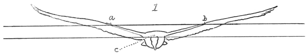
FIG. 1—Jamaica, Mch. 22, 1900. “John Crow.” Sketch soaring horizontally, by W. H. Holmes. Weight 3 lbs. Total wings area = 546 in. Perpendicular distance c below a b = 3.3 in. =

FIG. 2—Another.
FIGS. 1 and 2.—Type sketches of wings by Holmes from a mean of positions taken from his own sketches and photographs, and also from sketches and photographs by Langley.

FIG. 3.—Type sketch of same birds, average type, position of wings.—S. P. Langley.

FIG. 4.—Average typical position of wings in soaring gull. From memory by S. P. Langley. (The scale here may be taken approximately at 113).
I must preface what follows by a little statement of the things which particularly interest me here and which are not a naturalist’s ordinary concern.
First, I want to know the CG of the bird when in flight. You will understand that though there is but one center of gravity (here symbolized as CG), it may be considered (1) with reference to its position on the horizontal plan of the bird with wings extended, when it will always be found somewhere in the medial vertical plane, passing through the body, and usually nearly at a certain point with reference to length, the position thus considered being called CG, or (2) the position of the same CG with reference to a vertical plane passing transversely through the medial line, the position thus considered being called CG2. In the latter case you will understand that the CG which is that of the whole body, wings and all, will be carried more or less upward when the wings are thrown high up, and will be carried temporarily downward when the wings are at their lowest point of the stroke. It would have a certain position when the bird was at rest and another position when it was soaring and the wings were above the body.
The soaring bird is chiefly held upward by the pressure of the air under each wing, and just as the common center of gravity is a point where all the efforts of gravity are supposed to be centered, so there is a common center of pressure, or one point where all the efforts of the upper pressure of the air may be supposed to be centered, and it will be clear, on very little consideration that this latter point must be always nearly in a vertical line through the CG, and usually above it. Call it CP.
CG1 and CP1 are then, the symbols of CG and CP as referred to the horizontal plane. CG2 and CP2 are the symbols for the corresponding ones when referred to their position in the vertical plane.
I shall be glad to explain to you, if you are not familiar with it, the simple method of finding the CG1 and CG2. It consists in bending the wings into just the position that they would ordinarily occupy above the body in plain soaring flight, keeping them there by a very light bent stick or wire, then hanging the bird up by a line attached to the tip of one wing, and see where this line would pass through the body of the bird, for the CG will be somewhere in this line. After marking then, on the body of the bird its position, hang it up a second time by the head or tail and note again where the new vertical line runs in the new position. There is but one CG and but one point in which two straight lines can cross, and that will be the CG necessarily. Note with all care just where this is above or below the center of the body of the bird.
As for the CP for either wing, that may be nearly found by tracing the wing on a flat piece of thick paper or cardboard strong enough not to bend much—cutting out the tracing and balancing it well on the point of a pencil—the point about which it balances is very near CP2 or the center of pressure in the vertical plane. There is such a point of course in each wing, and when they are thrown up in the actual position that they have in calm soaring flight, we may suppose a horizontal line drawn between them, and it is the distance from this horizontal line to CG2 compared with the area of the wings or with the distance between their extended tips which we want to know, which gives the vertical distance which the CG is below the CP, the thing we want to know.
It will be very convenient also to have a wing dissected from the body and the wing itself held in about the soaring curve by a bit of light stick balanced on a pencil point, which will give the CG of the wing as distinct from that of the body. However, the three things I principally want, beside a sketch or [p288] photograph of the bird from about its own level coming directly toward or going directly away in soaring flight, are these:
Approximate weight of the bird,—and approximate tracing of its extended wing with the area, so that we can tell the area of the supporting surface relative to the weight, and finally, the distance between CP2, and CG2, which is obtainable by the process which I have explained.
I am afraid that what I have just been describing at such length may have a certain obscurity to you, but if you will give me an opportunity, I shall be pleased to illustrate it with the actual experiment when the bird is hung up by a string, and you will see that it is in reality simple.
Referring to the sketches on page 3 of this communication, a and b correspond to the centers of pressure on either wing where the upward pressure of the air distributed over each wing may be supposed to be gathered in a single point. This, as I have said, is called the center of pressure with reference to the vertical flight, and its symbol is CP2, while the horizontal dotted line between them represents the level of CP2, from the best estimate that I could make when the wings are in their natural position of soaring. It is evident that this line passed far above the body of the vulture, and if (the corresponding symbol for the height of the center of gravity being CG2), the CG2, of the entire bird be taken, it will be found to lie nearly in the point c. Where c is in the present case, I could not determine exactly in my hasty examinations in the live bird, but I assume that it is about 12 way between the central horizontal axial line of the bird’s body and the upper portion. I repeat that it is important to me to know what the vertical distance is between CP2 and CG2 in each specimen of soaring bird. I may observe in illustration that in the common sea-gull, it is nearly as shown in the faint sketch; that is to say, that the corresponding line a b in the soaring gull passes distinctly through the upper part of the body, and the distance down to the CG2 of the whole in the gull is almost nil, while in the buzzard it is very considerable as shown by the corresponding distance in the “John Crow.”
Now, what I want to get from you is the corresponding figures for an average specimen of our Washington buzzard. If you will kindly have one killed and weighed while fresh, and before the rigor-mortis has set in, first noting the position of its wings when soaring in a calm, and (if possible) when coming toward you or going away in about a horizontal plane with your eye, in which position the wings will be elevated and bent somewhat as in the case of the above sketch of the “John Crow”; if you will kindly do this, so as to give me corresponding facts with reference to the buzzard, namely weight, area of extended wing surface, distance between tips as bent up in ordinary flight, distance between extended tips, the quantity CP2−CG2, and also will make such a tracing of the buzzard’s wing as Mr. Manly will show you of the “John Crow’s,” I shall be obliged.
My impression is that the buzzard is a considerably heavier bird than the “John Crow,” without, however, very much greater spread of wing. I may observe that when the wings of the Jamaica bird were spread out, they were spread quite to their utmost extent, and the distance between the tips of the terminal feathers was much greater than when in flight. I wish you would kindly also add the scientific name of the “John Crow,” with any particulars that you would think of interest.
If there be any special expenses incurred in the preparation of this memorandum, including the time of a photographer, I will direct them to be paid from the Smithsonian fund. [p289]
If you could get Mr. Holmes (who made most of the sketches and all of the photographs of the “John Crow”), to try and do something like this for your buzzard, especially getting such a photograph of it in flight, as will give the position of its center of gravity relative to the center of pressure on the wings, it would add very greatly to the value of your memoranda, and I think Mr. Holmes takes so full and intelligent an interest in the subject, that he might be pleased to give his help.
Very truly yours,
S. P. LANGLEY,
Secretary.
MR. ROBERT RIDGWAY,
Smithsonian Institution,
In response to this request, Mr. Ridgway submitted the following very interesting information:
PROF. S. P. LANGLEY,
Secretary, Smithsonian Institution.
I have the honor of submitting herewith the data obtained by Mr. Rolla P. Currie concerning measurements, etc., of the common Turkey Buzzard (Cathartes aura) of the United States, as requested by you in your letter of March 29, last.
The difficulties in the way of securing these data, already explained by me in previous communications, are responsible for the delay in submitting them.
Hoping that this material may prove of use to you, I am,
Very respectfully,
R. RIDGWAY,
Curator, Division of Birds.
MEMORANDA IN REGARD TO THE TURKEY BUZZARD (SECOND SPECIMEN)
1. Weight.—1850 grammes.
2. Area of outstretched wings.—641 square inches. (Computed from three sheets of tracings, A1 and A2 comprising the entire area of both wings; B, a single wing.)
Note.—As the bird was in process of moult, one of the large wing quills, as shown by the tracings and compo-board patterns, is but partially developed, thus slightly modifying the results obtained. Its length, if full grown, would be nearly the same as that of the quill just above it.
3. Distance between the tips of these wings.—5 feet, 8.7 inches.
4. Distance between the tips of the same wings when the bird is in horizontal soaring flight.—Estimating the dihedral angle of the wings to be 150°, and elevating the wings so as to make this angle, the distance between their tips [p290] measures 5 feet, 5.7 inches, or 3 inches less than when fully extended in the horizontal plane.
5. The position of the center of pressure of the wing.—This is indicated on two compo-board patterns, C and D. C was made from a fully extended wing, while D was made from the wing in the soaring position. The centers of pressure of the wings are about 2 feet, 0.5 inches apart, or 1 foot, 0.25 inches from the central point of the bird’s body.
6. The position of the center of gravity of the soaring bird.—(Length of buzzard, 26 inches.) The center of gravity of the soaring buzzard in the horizontal plane, CG1, was found to lie 912 inches behind the tip of the beak and 1612 inches in front of the tip of the tail.
The center of gravity of the soaring bird in the vertical plane, CG2, was found to lie 2.8 inches above the ventral point of the body and 1.6 inches below the dorsal point, the depth of the bird’s body at CG1, being 4.4 inches.
In determining the center of gravity, the bird was frozen in the soaring position, its wings making a dihedral angle of 150°. It was then hung up, first horizontally and then vertically, and balanced till the line from which it was suspended coincided with a plumb-line placed in front of it; the measurements were then made.
The bird was afterwards, and while still frozen, hung up in the same way in Mr. Smillie’s photographic room, and exposures made by him in both positions. These photographs, E1 and F1 were enlarged to natural size, and measurements made on the enlargements yielded, as nearly as could be determined, the same results as when taken directly upon the bird.
As determined by measurements upon the buzzard in soaring position, the center of gravity was found to be 2.65 inches below the center of pressure (estimating the center of pressure to be at the bend of the wing); or, employing the compo-board pattern in a corresponding position, the distance was seen to be a small fraction of an inch less.
7. The position of the root of the wing.—This is indicated on the tracing A1.
a. (Depth of the body on a vertical line with root, 3.5 inches.) The root lies 1.6 inches below dorsal line, 1.9 inches above ventral line.
b. (Length of body, 26 inches.) The root lies 7.6 inches behind tip of beak, 18.4 inches in front of tip of tail.
8. The dihedral angle between the wings.—The photographs taken previously were not sufficiently large or distinct to enable us to determine this with exactness. It was estimated, however, as 150°, and experiments were made on this basis.
9. The center of gravity of the dissected wing.—This was found, first, for the wing having all the muscles, up to the ball and socket joint, intact. One of the wings was frozen in the soaring position and its center of gravity found by balancing on a point. Its position was marked by a wire thrust through the wing at this place, and the wing (H) is preserved in formalin. This position is also marked on a special tracing, I. It lies 6 inches from the base of the humerus bone (root of wing). Secondly, it was found for the wing denuded of all muscle. Its position was marked on the other wing of the bird, which is preserved dry, spread in the soaring position. It lies 934 inches from the base of the humerus. [p291]
10. The weight of the dissected wing.—
a. With all muscle up to the ball and socket joint intact, 325 grammes.
b. With all muscle removed, 190 grammes.
Weight of muscle, therefore, 135 grammes.
The position of the root of the tail.—
a. In the horizontal plane, 11.8 inches in front of the tip of the longest tail feather; 14.2 inches behind tip of beak.
b. In the vertical plane: (depth of body from ventral point below root of tail to a point directly above, which is on a level with the highest point of the back, 2.5 inches.) 1.5 inches above ventral point, 1 inch below dorsal point.
Weight of tail.—With muscle, 40 grammes; without muscle, 30 grammes. Weight of muscle, therefore, 10 grammes.
EXHIBITS ACCOMPANYING THESE MEMORANDA
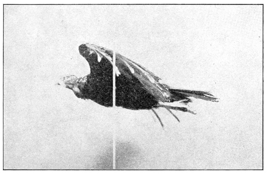
A1 and A2. Two sheets, comprising a tracing of the entire turkey buzzard with fully outstretched wings. From these the area of the wings and the distance between their tips was obtained. The position of the root of the wing and the root of the tail is also marked on one of these sheets.
B. One sheet, comprising a tracing of a single wing, and from which the area was also computed. This area, multiplied by 2, gives the same result as the sum of both wings on A1 and A2. The compo-board pattern C was made from this tracing.
C. Compo-board pattern of fully extended wing, on which the center of pressure is indicated.
D. Compo-board pattern of wing in soaring position, on which the center of pressure is shown. [p292]
E1. Photograph of bird in soaring position, suspended horizontally.
E2. Same, enlarged to natural size.
F1. Photograph of bird in soaring position, suspended vertically.
F2. Same, enlarged to natural size.
G. Tracing of wing in soaring position, from which the compo-board pattern D was made.

H. Wing preserved in formalin, on which the center of gravity is recorded.
I. Tracing of wing H when frozen in soaring position, on which the center of gravity is marked.
J. Wing with muscle removed, on which the center of gravity is shown.
Several persons connected with the Smithsonian Institution and U. S. National Museum have contributed towards securing the results herewith submitted. Among them, I desire especially to mention Mr. W. H. Holmes, Mr. [p293] F. A. Lucas, Mr. N. R. Wood, and Mr. R. L. Reed. Mr. Holmes superintended the experiments in connection with No. 6 (finding the bird’s center of gravity), and by his suggestions and criticisms helped me in many other particulars. The photographs and enlargements were made by Mr. T. W. Smillie.
Respectfully submitted,
ROLLA P. CURRIE,
Aid, Division of Insects, acting in the Division of Birds.
OCTOBER 16, 1900.
The feats of airmanship performed by the “John Crow” seemed to greatly impress Mr. Langley and shortly after this trip he wrote the following letter to the writer:
SMITHSONIAN INSTITUTION
WASHINGTON, D. C., April 16, 1900.
DEAR MR. MANLY:
I am reminded of the consequence that I have, in connection with Mr. Chanute and perhaps Mr. Huffaker, attached in the past to the possibility of directing the bird, and consequently the flying machine, by the mere inflection of the wing, that is, by changing its angle; and you recall to me that Mr. Huffaker at one time proposed to arrange a wing, with some provision of a spring, which should enable it to change its angle automatically. . . . .
I have been noting this ability to guide by the slight inflection of the wing, in my studies of the Jamaica buzzard, and am ready to say that I think, while the quarter-sized working model of the great aerodrome is building, it will be worth while to make some arrangement of the frame or wing-holder which will make it possible to test this idea. I will endeavor to work out something of the kind more in detail myself, but whatever it is, it will apparently involve the ability of the wing to rotate about a line passing nearly through it lengthwise, and an allowance for this; if not in the wing itself, then in the wing-holder; will need to be made while the present model is under construction.
I will request you to especially look out for this, as far as you can on these indications.
Very respectfully yours,
S. P. LANGLEY,
Secretary.
The instructions and suggestions contained in this letter and in many conferences on the subject were never carried out by the writer, on account of the extreme pressure of the work already on him which had for its object, not the production of a flying machine which would embody all of the control which we wished it to have, but which would be burdened only with such devices and arrangements as would enable it to transport a human being, and thus demonstrate the practicability of human flight.
SMITHSONIAN INSTITUTION, WASHINGTON, D. C., November 30, 1895.
DEAR SIR:
The following instructions are to replace those of May 13, 1895:
1. The minimum fraction of its own “flying weight” (that is, weight complete with initial water and fuel), which the aerodrome shall lift on the pendulum, is 50 percent,50 under such engine power as can certainly be gotten up in the field and maintained during forty seconds from the time the aerodrome is let go.
The blast, the pumps, and all other essential parts must, in other words, be in such a condition that steam enough for this lifting over 50 per cent of weight can be gotten up readily and surely in the field and in a time which will still leave at least forty seconds’ supply.
2. The minimum relation of supporting area to weight in any aerodrome constructed hereafter, is to be two feet to the pound,50 and the minimum of power at the rate of one steadily-maintained horse power50 at the brake under ordinary conditions, to not over twenty-two pounds (ten kilos) of flying weight. In absence of a brake determination horse power may be taken—
H. P. =
revs. per min. at rest × pitch × diameter (in ft.) × thrust (in lbs.)33,000.These rules do not apply to No. 5, but they do to No. 6, which is to be built over, if necessary, to meet them.
3. In balancing an aerodrome, unless otherwise instructed, set wings at a root angle of either 10°, 7°, or 5°, after being certain from previous inversion and sanding, that the tip angle in motion will not differ from this root angle as much as 5°.
The object in balancing any aerodrome with a single pair of wings is to be able to bring the c g2 under their c p2 without any reference to the tail, which supports nothing, unless specially ordered. But as this condition cannot now be obtained in Nos. 5 and 6, these at any rate, and perhaps future aerodromes, are to carry a second pair of wings. When this second pair of wings is of nearly equal size with the first it is to be assumed in preliminary adjustments for weight and center of pressure, that the second pair has two-thirds the lifting efficiency per unit area of the first.
Calling the whole distance from the mean center of pressure of the wings to the center of gravity M. M is to have a definite relation to the breadth of [p295] wings from tip to tip (b) and total fore and aft length (1), which is provisionally fixed at M =√(bl)8, and the line of thrust is to be not over one-fourth the way from c p2 to c g2.
Generally speaking the front pair of wings will be fixed in position and the adjustment for balancing made by moving the rear pair.
The individual weights of all parts checked by lump weighing are to be given by the caretaker (Mr. Huffaker), under the general scheme shown in the note. The work on the aerodromes being divided into two classes, viz.: metal work and all which is not metal, the two in charge of this work (Mr. Reed and Mr. Maltby) are severally responsible for knowing the weight in grammes of any of the parts they have put into their work, giving these weights to Mr. Huffaker, together with any data for filling out the annexed tables,51 on his request.
Until further orders, Mr. Huffaker is charged with the responsibility of seeing that these conditions are met before any aerodrome is boxed, and will keep the record of weights of the aerodromes and their principal parts as already completed, in a book, to be preserved in your keeping, which will also be arranged to show with signed photographs and descriptions, and with sketches where needed, the condition and weight (as far as constructed) of every aerodrome, and of any new construction of any part, on the first of each month.
Particular attention is directed to the preceding paragraph, and to the need that evidence of a definite character is to be obtained and preserved of everything already done, and being done.
Without special orders to the contrary, you will not authorize the boxing of any aerodrome which does not, to your knowledge, meet these conditions.
Each aerodrome is to have the following parts in duplicate or in triplicate:
with any other parts in duplicate or triplicate, which experience has shown to be necessary.
Mr. Reed will not box any aerodrome till a certificate from Mr. Huffaker can be put on the inside cover, with the list of contents, showing what the conditions are as to weight, wing area, power, etc., and the person in the field charged with the duty of launching the aerodrome (at present Mr. Reed), is authorized not to let it go unless he is satisfied that it has a full forty seconds’ supply of steam. [p296]
I am satisfied that a great deal of time is lost in putting the aerodrome together for flight, owing to the absence of any preliminary drill in doing this. Before it goes into the field the whole is to be completely boxed, and then taken out from the box and set up on the clutch, and steam gotten up for flight. All this is to be done in the shop before the final boxing, and provision is to be made so that no wiring or adjusting of parts is to be done in the field which can possibly be avoided by forethought in the shop. The tail-piece, for instance, is to be bushed with brass, so that it will always come into the same place, and make a tight fit, in spite of wetting or shrinking, in the steel tube, where it is to go into a guide-way with a bayonet spring, or a like contrivance for setting it at once securely into position.
The mean positions of the wings and tail are to be laid out in some way permanently on the mid-rod, but every guy-rod or adjustable piece is to be arranged so as to fit at once securely and permanently in its position without wiring or like slow process.
Very truly yours,
S. P. LANGLEY,
Secretary.
W. C. WINLOCK, Esq.,
Assistant in Charge,
Smithsonian Institution.
A copy to be communicated to:——
[37] “The Flying Machine” McClure’s Magazine, June, 1897.
[38] One noted astronomer and mathematician re-affirmed this opinion as late as 1900 and even stated that man could not hope to construct a flying machine capable of sustaining a weight as great as our largest birds, knowing that even at that time the model Aerodromes Nos. 5 and 6 had already done more than this.
[40] See “Experiments in Aerodynamics.” It will be recalled that in the experiments with the “plane-dropper” there was a greatly reduced lifting power with superposed planes when their distance apart was one-half the width the planes, unless a speed of about 42.5 feet a second was obtained. In the above tests with the superposed wings, the speed was only from twenty to twenty-two feet a second at the time of launching, and as the distance between the surfaces was only one-half as great as their width, it is not surprising that the lifting power should not be as great as with the “single-tier” wings.
[41] In fact the setting of the tail at a negative angle and fastening it to the frame by an elastic or spring connection was only begun in 1896, and while it proved to be the key to the solution of the problem of automatic longitudinal stability, yet it was not at that time so recognized, although the first real test of the aerodromes after the elastic connection and negative angle of the tail were adopted resulted in the epoch-making flight of No. 5 on May 6. By comparing the angle of the tail on No. 5 in Plate 27A, Part I, with the angle of the tail on No. 6 in Plate 27B, Part I, it will be seen that while the first had an angle of much less than 5 degrees, the latter had an angle of about 15 degrees. But the wooden springs changed so that it was not accurately known what the angle really was at the time at either flight in 1896.
[42] The drawings, Plate 55, which illustrate many of the fittings used on the frame, show the guy-wires as attached by means of loops twisted in their ends, these drawings having been made before the final plan of attaching the wires had been devised.
[43] See explanation of system of locating points in Part I, Chap. II, p. 15.
[44] See Balancing of Engines, by Archibald Sharpe.
[45] Except for a ten minute stop to renew the supply of lubricating oil and change the sparking batteries.
[47] The weight was afterwards increased to 850 pounds due to repairing the wings and adding more sparking batteries.
[48] See Experiments in Aerodynamics, Smithsonian Contributions to Knowledge, Vol. 27, Washington 1891.
[49] Researches and Experiments in Aerial Navigation, Smithsonian Publication No. 1809, Washington, 1908.
[50] All these minimum permissible conditions are connected by the tacit assumption that the supporting area is not greatly over 2 ft. to the pound of weight. If for instance the weight were increased by larger wings or more wings, furnishing a much greater supporting area per pound, these conditions would not necessarily apply.
[51] These tables were later designated as “Data Sheets.” Several copies, with the data duly entered on them, are given in this appendix, and the form which Mr. Langley included in this letter is therefore not repeated here.—EDITOR.
| Parts. | Sizes. | Weight. | ||
|---|---|---|---|---|
| m. | ft. | gr. | lbs. | |
| 1 Frame, including everything of metal, permanent and undetachable, such as bed-plate, cross-rods for the support of propellers, bearing points for clutch, etc. | 2443 | |||
| 2 Engine, gears, shafts, etc. | 1110 | |||
| 3 Pump, pump shaft | 231 | |||
| 4 Hull covering | 350 | |||
| 5 Gasoline tanks, valves | 178 | |||
| 6 Smokestack | 342 | |||
| 7 Float | 275 | |||
| 8 Reel | 77 | |||
| 9 Wing clamps, 235; clamp for guy-posts, 29 | 264 | |||
| 10 Other things, counter | 75 | |||
| 11 Burners | 360 | |||
| 12 Boilers | 651 | |||
| 13 Separators, steam gauge, pipe to engine | 540 | |||
| 14 Exhaust pipe | 143 | |||
| 15 | ||||
| 16 | ||||
| 17 Wings (without clamp) | 1950 | |||
| 18 Tail (without clamp) | ||||
| 19 Rudder | 350 | |||
| 20 Guy sticks, each, 57 | 114 | |||
| 21 Propellers | 800 | |||
| 22 Extra length of midrod, 308; drop piece for rudder, 40 | 348 | |||
| 23 Wood Bowsprit | 74 | |||
| 24 Other things | ||||
| 25 | ||||
| 26 | ||||
| 27 Fuel (at starting flight) | 200 | |||
| 28 Water (at starting flight) | 900 | |||
| 29 | ||||
| 30 | ||||
| 31 Sundries unknown | ||||
| 32 | ||||
| 33 | ||||
| 34 Total flying weight | 11,775 | 26 | ||
| 35 | ||||
| 36 | ||||
| 37 | ||||
| 38 Total area of support (not including tail) . . . sq. ft. | 68 | |||
| 39 Total area of support in feet, divided by total flying weight in lbs. | 2.6 | |||
| 40 Total area of horizontal tail . . . sq. ft. | ||||
| 41 Total area of rudder (vertical) . . . sq. ft. | 6 | |||
| 42 Horse-power at brake. Horse-power by formula* .72 | 7 | |||
| 43 Minimum pressure during 40 secs. lift, 150 lbs. | ||||
| 44 Lift at pendulum (during 40 secs. absolute) 5772 | ||||
| 45 Lift at pendulum (during 40 secs. in terms of wt.) 49% | ||||
| 46 Minimum pressure with which wheels turn, 10 lbs. | ||||
| 47 Position of center of pressure of wings† F. W., 1575; R. W., 1383.5 | ||||
| 48 Time of getting up full steam, 1 minute | ||||
| 49 | ||||
| 50 Curvature of wings, 1/11 | ||||
| 51 Root angle of wings, 9° | ||||
| 52 Tip angle of wings, 9° | ||||
| 53 Position of wings, Front rib on F. W., 1607; R. W., 1415.5 | ||||
| 54 How guyed | ||||
| 55 | ||||
| 56 | ||||
| 57 | ||||
| 58 Position of tail | ||||
| 59 Angle of tail | ||||
| 60 Co-efficient elasticity of tail | ||||
| 61 Position of rudder, center, 1288.3; rear end, 1229.8 | ||||
| 62 Line of thrust, 2500 | ||||
| 63 Line of thrust, 1500 which is 9 cm. below the center of midrod | ||||
| 64 Center of gravity1 of whole, 1497 | ||||
| 65 Center of gravity2 2501, i. e., 1 cm. above line of thrust | ||||
| 66 Center of pressure1 of whole estimate, 1498 | ||||
| 67 Center of pressure2, 2536 | ||||
| 68 | ||||
| 69 | ||||
| 70 | ||||
| 71 | ||||
| 72 | ||||
Parts. Remarks.
Footnotes.
| Parts. | Sizes. | Weight. | ||
|---|---|---|---|---|
| m. | ft. | gr. | lbs. | |
| 1 Frame, including everything of metal, permanent and undetachable, such as bed-plate, cross-rods for the support of propellers, bearing points for clutch, etc. | 1178 | |||
| 2 Engine, gears, shafts, etc. | 1043 | |||
| 3 Pump, pump shaft | 190 | |||
| 4 Hull covering | 345 | |||
| 5 Gasoline tanks, valves | 306 | |||
| 6 Smokestack, 302; burner, 172 | 474 | |||
| 7 Float | 275 | |||
| 8 Reel | 77 | |||
| 9 Wing clamps, 238; drop piece for rudder, 40 | 278 | |||
| 10 Other things | 156 | |||
| 11 Boiler, frames, mica cover | 694 | |||
| 12 Separator, steam gauge, pipe to engines | 535 | |||
| 13 Exhaust pipe | 82 | |||
| 14 | ||||
| 15 | ||||
| 16 | ||||
| 17 Wings (without clamp), wet | 2154 | |||
| 18 Tail (without clamp) | ||||
| 19 Rudder | 375 | |||
| 20 Guy sticks, each 53 | 106 | |||
| 21 Propellers | 644 | |||
| 22 Extra length of midrod | 398 | |||
| 23 Wood bowsprit | 135 | |||
| 24 Counter | 75 | |||
| 25 | ||||
| 26 | ||||
| 27 Fuel (at starting flight) | 250 | |||
| 28 Water (at starting flight) | 2350 | |||
| 29 | ||||
| 30 | ||||
| 31 Sundries unknown | ||||
| 32 | ||||
| 33 | ||||
| 34 Total flying weight | 12,120 | |||
| 35 | ||||
| 36 | ||||
| 37 | ||||
| 38 Total area of support (not including tail) . . . sq. ft. | 54 | |||
| 39 Total area of support in feet, divided by total flying weight in lbs. | 2 | |||
| 40 Total area of horizontal tail . . . sq. ft. | .6 | |||
| 41 Total area of rudder (vertical) . . . sq. ft. | .6 | |||
| 42 Horse-power at brake. . .Horse-power by formula* | ||||
| 43 Minimum steam pressure during 40 secs. lift | 130 | |||
| 44 Lift at pendulum (during one minute absolute) | 7,211 | |||
| 45 Lift at pendulum (during one minute in terms of wt.) | ||||
| 46 Minimum pressure with which wheels turn | 10 | |||
| 47 Position of center of pressure of wings† | ||||
| 48 Time of getting up full steam, 75 secs. | ||||
| 49 Angle of midrod with horizon, 2° 17′ | ||||
| 50 Curvature of wings, 1 in 18, 1/4 from front | ||||
| 51 Root angle of wings, 10° 30′ | ||||
| 52 Tip angle of wings, 10° 30′ | ||||
| 53 Position of wings | ||||
| 54 How guyed | ||||
| 55 | ||||
| 56 | ||||
| 57 | ||||
| 58 Position of tail | ||||
| 59 Angle of tail | ||||
| 60 Co-efficient elasticity of tail | ||||
| 61 Position of rudder | ||||
| 62 | ||||
| 63 Line of thrust 1500 | ||||
| 64 Center of gravity1 of whole, 1483.8 | ||||
| 65 Center of gravity2, 2482‡ | ||||
| 66 Center of pressure1 of whole estimate, 1487 | ||||
| 67 Center of pressure2, 2520 | ||||
| 68 | ||||
| 69 | ||||
| 70 | ||||
| 71 | ||||
| 72 | ||||
Parts. Remarks.
Footnotes.
| Parts. | Sizes. | Weight. | ||
|---|---|---|---|---|
| m. | ft. | gr. | lbs. | |
| 1 Frame, including everything of metal, permanent and undetachable, such as bed-plate, cross-rods for the support of propellers, bearing points for clutch, etc. | 2867 | |||
| 2 Engine, gears, shafts, etc. | ||||
| 3 Pump, 123; pump shaft, 49 | 172 | |||
| 4 Hull covering, including apron and piece behind separator | 274 | |||
| 5 Gasoline and air tanks, 167, 114; air valve, 16 | 297 | |||
| 6 Smokestack, 319; counter, 95; burner, 165 | 679 | |||
| 7 Float, 275; pipe from pump to boiler, 40 | 315 | |||
| 8 Reel, with fork and float | 128 | |||
| 9 Wing clamps, 188; guy-post clamps, 24 | 212 | |||
| 10 Boiler, 764; steam gauge and connections, 79 | 843 | |||
| 11 Front lower bearing post, 75; clutch post, 58; rear bearing points, 155 | 288 | |||
| 12 Separator and pipes leading to engines and pump | 502 | |||
| 13 Drop piece for rudder, 57; guy-post for rudder, 18 | 75 | |||
| 14 | ||||
| 15 | ||||
| 16 | ||||
| 17 Wings (without clamp) | 2077 | |||
| 18 Superposed wings, 3448 | ||||
| 19 Rudder | 323 | |||
| 20 Guy sticks, each 53 | 106 | |||
| 21 Propellers | 620 | |||
| 22 Extra length of midrod | 377 | |||
| 23 Wood bowsprit | 128 | |||
| 24 Canvas keel, 36; rudder, 76 | 112 | |||
| 25 | ||||
| 26 | ||||
| 27 Fuel (at starting flight) | 175 | |||
| 28 Water (at starting flight) | 1525 | |||
| 29 | ||||
| 30 | ||||
| 31 Sundries unknown | ||||
| 32 | ||||
| 33 | ||||
| 34 Total flying weight | 11,995 | 26.44 | ||
| 35 | ||||
| 36 | ||||
| 37 | ||||
| 38 Total area of support (not including tail) . . . sq. ft. | 54 | |||
| 39 Total area of support in feet, divided by total flying weight in lbs. | 2.04 | |||
| 40 Total area of horizontal tail . . . sq. ft. | 9.5 | |||
| 41 Total area of rudder (vertical) . . . sq. ft. | 7.75 | |||
| 42 Horse-power at brake . . . Horse-power by formula* | ||||
| 43 | ||||
| 44 Lift at pendulum (during one minute absolute) | ||||
| 45 Lift at pendulum (during one minute in terms of wt.) | ||||
| 46 Minimum pressure with which wheels turn | ||||
| 47 Position of center of pressure of wings† 40% from front | ||||
| 48 | ||||
| 49 | ||||
| 50 Curvature of wings, 1 in 18 | ||||
| 51 Root angle of wings, 10° | ||||
| 52 Tip angle of wings, 10° | ||||
| 53 Position of wings—front edge of front wing, 1595.7; of rear wing, 1406.5 | ||||
| 54 How guyed—with wires from wing to wing on top and to guy-post on bottom | ||||
| 55 | ||||
| 56 | ||||
| 57 | ||||
| 58 Position of center of rudder, 1279.5 | ||||
| 59 Angle of tail, 10° | ||||
| 60 Co-efficient elasticity of tail | ||||
| 61 Position of rudder | ||||
| 62 | ||||
| 63 Line of thrust, 1500 | ||||
| 64 Center of gravity1 of whole, 1484.4 | ||||
| 65 Center of gravity2 | ||||
| 66 Center of pressure1 of whole estimate | ||||
| 67 Center of pressure2 | ||||
| 68 | ||||
| 69 | ||||
| 70 | ||||
| 71 | ||||
| 72 | ||||
Parts. Remarks.
Footnotes.
| Parts. | Sizes. | Weight. | ||
|---|---|---|---|---|
| m. | ft. | gr. | lbs. | |
| 1 Frame, including everything of metal, permanent and undetachable, such as bed-plate, cross-rods for the support of propellers, bearing points for clutch, etc. | 2867 | |||
| 2 Engine, gears, shafts, etc. | ||||
| 3 Pump, 123; pump shaft, 49 | 172 | |||
| 4 Hull covering, including apron and piece behind separator | 274 | |||
| 5 Gasoline and air tanks, 167, 114; air valve, 16 | 297 | |||
| 6 Smokestack, 319; counter, 95; burner, 170 | 584 | |||
| 7 Float | 315 | |||
| 8 Reel, with fork and float | 128 | |||
| 9 Wing clamps, 188; guy-post clamps, 24 | 212 | |||
| 10 Boiler, 764; steam gauge and connections, 79 | 843 | |||
| 11 Front bearing point, 75; clutch post, 58; rear bearing points, 155 | 288 | |||
| 12 Separator and pipes to engines and pump | 502 | |||
| 13 Drop piece and guy-post for rudder | 75 | |||
| 14 | ||||
| 15 | ||||
| 16 | ||||
| 17 Wings (without clamp), 2077; superposed wings | 3448 | |||
| 18 Tail (without clamp) | ||||
| 19 Rudder | 323 | |||
| 20 Guy sticks | 106 | |||
| 21 Propellers | 620 | |||
| 22 Extra length of midrod | 377 | |||
| 23 Wood bowsprit | 128 | |||
| 24 Canvas keel, 36 | 36 | |||
| 25 | ||||
| 26 | ||||
| 27 Fuel (at starting flight) | 175 | |||
| 28 Water (at starting flight) | 1525 | |||
| 29 | ||||
| 30 | ||||
| 31 Sundries unknown | ||||
| 32 | ||||
| 33 | ||||
| 34 Total flying weight | 13,275 | |||
| 35 | ||||
| 36 | ||||
| 37 | ||||
| 38 Total area of support (not including tail) . . . . . . sq. ft. | 87.4 | |||
| 39 Total area of support in feet, divided by total flying weight in lbs. | ||||
| 40 Total area of horizontal tail . . . . . . sq. ft. | 9.5 | |||
| 41 Total area of rudder (vertical) . . . . . . sq. ft. | 7.75 | |||
| 42 Horse-power at brake . . . Horse-power by formula* | ||||
| 43 | ||||
| 44 Lift at pendulum (during one minute absolute) | ||||
| 45 Lift at pendulum (during one minute in terms of wt.) | ||||
| 46 Minimum pressure with which wheels turn | ||||
| 47 Position of center of pressure of wings†, 40% from front | ||||
| 48 | ||||
| 49 | ||||
| 50 Curvature of wings, 1 in 18 | ||||
| 51 Root angle of wings, 10° | ||||
| 52 Tip angle of wings, 10° | ||||
| 53 Position of wings—front edge of front wing, 159 | ||||
| 54 How guyed | ||||
| 55 | ||||
| 56 | ||||
| 57 | ||||
| 58 Position of tail | ||||
| 59 Angle of tail, 712° | ||||
| 60 Co-efficient elasticity of tail, 1240 grammes at center to deflect to the horizontal | ||||
| 61 Position of rudder | ||||
| 62 | ||||
| 63 Line of thrust, 1500 | ||||
| 64 Center of gravity1 of whole, 1484.4 | ||||
| 65 Center of gravity2 | ||||
| 66 Center of pressure1 of whole estimate | ||||
| 67 Center of pressure2 | ||||
| 68 | ||||
| 69 | ||||
| 70 | ||||
| 71 | ||||
| 72 | ||||
Parts. Remarks.
Footnotes.
| Parts. | Sizes. | Weight. | ||
|---|---|---|---|---|
| m. | ft. | gr. | lbs. | |
| 1 Frame, including everything of metal, permanent and undetachable, such as bed-plate, cross-rods for the support of propellers, bearing points for clutch, etc. (bowsprit, 78g) | 2867 | |||
| 2 Engine, gears, shafts, etc. | ||||
| 3 Pump, 123; pump shaft, 49 | 172 | |||
| 4 Hull covering, including apron and piece behind separator | 274 | |||
| 5 Gasoline and air tanks, 167, 174; air valve, 16 | 357 | |||
| 6 Smokestack, 319; counter, 95; burner, 170 | 584 | |||
| 7 Float | 315 | |||
| 8 Reel, with fork and float | 128 | |||
| 9 Wing clamps, 188; guy-post clamps, 24 | 212 | |||
| 10 Boiler, 764; steam gauge and connections, 79 | 843 | |||
| 11 Front bearing post, 75; clutch-post, 58 | 133 | |||
| 12 Rear bearing points | 155 | |||
| 13 Separator and pipes to engines and pump | 502 | |||
| 14 Drop piece and guy-posts, 18; for rudder, 57 | 75 | |||
| 15 | ||||
| 16 | ||||
| 17 Wings (without clamp) | 2077 | |||
| 18 Tail (without clamp) | ||||
| 19 Rudder | 323 | |||
| 20 Guy sticks | 106 | |||
| 21 Propellers | 620 | |||
| 22 Extra length of midrod | 377 | |||
| 23 Wood bowsprit | 128 | |||
| 24 Other things | ||||
| 25 | ||||
| 26 | ||||
| 27 Fuel (at starting flight) | 175 | |||
| 28 Water (at starting flight) | 1525 | |||
| 29 | ||||
| 30 | ||||
| 31 Sundries unknown | ||||
| 32 | ||||
| 33 | ||||
| 34 Total flying weight | 11,948 | 26.3 | ||
| 35 | ||||
| 36 | ||||
| 37 | ||||
| 38 Total area of support (not including tail) . . . sq. ft. | 54 | |||
| 39 Total area of support in feet, divided by total flying weight in lbs. | ||||
| 40 Total area of horizontal tail . . . sq. ft. | 9.5 | |||
| 41 Total area of rudder (vertical) . . . sq. ft. | 7.75 | |||
| 42 Horse-power at brake . . . Horse-power by formula* | ||||
| 43 | ||||
| 44 Lift at pendulum (during one minute absolute) | ||||
| 45 Lift at pendulum (during one minute in terms of wt.) | ||||
| 46 Minimum pressure with which wheels turn | ||||
| 47 Position of center of pressure of wings† 40% from front | ||||
| 48 | ||||
| 49 | ||||
| 50 Curvature of wings, 1 in 18 | ||||
| 51 Root angle of wings, 10° | ||||
| 52 Tip angle of wings, 10° | ||||
| 53 Position of wings | ||||
| 54 How guyed | ||||
| 55 | ||||
| 56 | ||||
| 57 | ||||
| 58 Position of tail | ||||
| 59 Angle of tail, 7° 30′ | ||||
| 60 Co-efficient elasticity of tail, 1240 grammes at center to deflect to the horizontal | ||||
| 61 Position of rudder | ||||
| 62 | ||||
| 63 Line of thrust, 1500 | ||||
| 64 Center of gravity1 of whole | ||||
| 65 Center of gravity2 | ||||
| 66 Center of pressure1 of whole estimate | ||||
| 67 Center of pressure2 | ||||
| 68 | ||||
| 69 | ||||
| 70 | ||||
| 71 | ||||
| 72 | ||||
Parts. Remarks.
Footnotes.
| Parts. | Sizes. | Weight. | ||
|---|---|---|---|---|
| m. | ft. | gr. | lbs. | |
| 1 Frame, including everything of metal, permanent and undetachable, such as bed-plate, cross-rods for the support of propellers, bearing points for clutch, etc. | 3050 | |||
| 2 Engine | 464 | |||
| 3 Pump, 334; pump shaft, 55 | 389 | |||
| 4 Hull covering | 398 | |||
| 5 Gasoline tanks, air tanks, valves, etc. | 348 | |||
| 6 Smokestack | 373 | |||
| 7 Float, 275; drop piece for rudder, 57; guy-post, 18 | 350 | |||
| 8 Reel, 128; steam gauge, 81 | 209 | |||
| 9 Wing clamps, 200; guy-post clamps, 32 | 232 | |||
| 10 Boiler, 764; burner, 170; counter, 95 | 1029 | |||
| 11 Rear extension to midrod | 174 | |||
| 12 Separator and pipes to engine and pump | 502 | |||
| 13 Exhaust pipe | 84 | |||
| 14 Front lower bearing point, 84; clutch post, 41 | 125 | |||
| 15 Rear bearing points, 146; extra strengtheners, 32 | 178 | |||
| 16 | ||||
| 17 Wings (without clamp) | 2342 | |||
| 18 Tail (without clamp) | ||||
| 19 Rudder | 322 | |||
| 20 Guy sticks, each 56 | 112 | |||
| 21 Propellers | 837 | |||
| 22 Extra length of midrod at front | 129 | |||
| 23 Wood bowsprit | 132 | |||
| 24 Other things | ||||
| 25 | ||||
| 26 | ||||
| 27 Fuel (375 at starting flight) | 200 | |||
| 28 Water (2100 at starting flight) + 616 in boiler | 1400 | |||
| 29 | ||||
| 30 | ||||
| 31 Sundries unknown | ||||
| 32 | ||||
| 33 | ||||
| 34 Total flying weight | 13,370 | |||
| 35 | ||||
| 36 | ||||
| 37 | ||||
| 38 Total area of support (not including tail) . . . sq. ft. | 68 | |||
| 39 Total area of support in feet, divided by total flying weight in lbs. | ||||
| 40 Total area of horizontal tail . . . sq. ft. | 6.94 | |||
| 41 Total area of rudder (vertical) . . . sq. ft. | 7.64 | |||
| 42 Horse-power at brake . . . Horse-power by formula* | ||||
| 43 | ||||
| 44 Lift at pendulum (during one minute absolute) | ||||
| 45 Lift at pendulum (during one minute in terms of wt.) | ||||
| 46 Minimum pressure with which wheels turn | ||||
| 47 Position of center of pressure of wings† | ||||
| 48 | ||||
| 49 | ||||
| 50 Curvature of wings | ||||
| 51 Root angle of wings, 10° | ||||
| 52 Tip angle of wings, 10° | ||||
| 53 Position of wings | ||||
| 54 How guyed | ||||
| 55 | ||||
| 56 | ||||
| 57 | ||||
| 58 Position of tail | ||||
| 59 Angle of tail, 7° 30′ | ||||
| 60 Co-efficient elasticity of tail | ||||
| 61 Position of rudder | ||||
| 62 | ||||
| 63 Line of thrust, 1500 | ||||
| 64 Center of gravity1 of whole | ||||
| 65 Center of gravity2 | ||||
| 66 Center of pressure1 of whole estimate | ||||
| 67 Center of pressure2 | ||||
| 68 | ||||
| 69 | ||||
| 70 | ||||
| 71 | ||||
| 72 | ||||
Parts. Remarks.
Footnotes.
| Parts. | Sizes. | Weight. | ||
|---|---|---|---|---|
| m. | ft. | gr. | lbs. | |
| 1 Frame, including everything of metal, permanent and undetachable, such as bed-plate, cross-rods for the support of propellers, bearing points for gears, clutch, shafts, etc. | 3050 | |||
| 2 Engine | 464 | |||
| 3 Pump, 334; pump shaft, with gear and eccentric and end rod, 55 | 389 | |||
| 4 Hull Covering, 264; apron 115; piece behind separator, 19 | 398 | |||
| 5 Gasoline and air tanks, 167, 165; air valve, 16 | 348 | |||
| 6 Smokestack, 310; piece to protect midrod, 63 | 373 | |||
| 7 Float, 275; drop piece for rudder, 57; guy-post, 18 | 350 | |||
| 8 Reel, fork and float, 128; steam gauge with pipe, 81 | 209 | |||
| 9 Wing clamps, 200; guy-post clamps, 32 | 232 | |||
| 10 Boiler, 764; burner, 170; counter, 95 | 1029 | |||
| 11 Rear extension to midrod | 174 | |||
| 12 Separator and pipes to engine and pump | 502 | |||
| 13 Exhaust pipe, 84 | 84 | |||
| 14 Front lower bearing point, 84; clutch post, 41 | 125 | |||
| 15 Rear bearing points, 146; extra strengtheners, 32 | 178 | |||
| 16 | ||||
| 17 Wings (without clamp) (2180 in 1896) | 2342 | |||
| 18 Tail (without clamp); part of rudder | ||||
| 19 Rudder reduced (No. 2 or new one, 299) | 322 | |||
| 20 Guy sticks, each 56 | 112 | |||
| 21 Propellers (95 cms.; wood, 837; 95 cms. canvas, 548) | 837 | |||
| 22 Extra length of midrod (front), 129 | 129 | |||
| 23 Wood bowsprit (complete), 132 | 132 | |||
| 24 Other things | ||||
| 25 | ||||
| 26 | ||||
| 27 Fuel (375 at starting flight) | 200 | |||
| 28 Water (2100 at starting flight) + 616 in boiler | 1400 | |||
| 29 | ||||
| 30 | ||||
| 31 Sundries unknown | ||||
| 32 | ||||
| 33 | ||||
| 34 Total flying weight | 13,379 | |||
| 35 | ||||
| 36 | ||||
| 37 | ||||
| 38 Total area of support (not including tail) . . . sq. ft. | 68 | |||
| 39 Total area of support in feet, divided by total flying weight in lbs. | ||||
| 40 Total area of horizontal tail . . . sq. ft. | 6.94 | |||
| 41 Total area of rudder (vertical) . . . sq. ft. | 7.64 | |||
| 42 Horse-power at brake . . . Horse-power by formula* | ||||
| 43 | ||||
| 44 Lift at pendulum (during one minute absolute) | ||||
| 45 Lift at pendulum (during one minute in terms of wt.) | ||||
| 46 Minimum pressure with which wheels turn | ||||
| 47 Position of center of pressure of wings† | ||||
| 48 | ||||
| 49 | ||||
| 50 Curvature of wings, 1 in 12 | ||||
| 51 Root angle of wings, 10° | ||||
| 52 Tip angle of wings, 10° | ||||
| 53 Position of wings | ||||
| 54 How guyed | ||||
| 55 | ||||
| 56 | ||||
| 57 | ||||
| 58 Position of tail | ||||
| 59 Angle of tail, 7° 30′ | ||||
| 60 Co-efficient elasticity of tail, 1240 grammes at center of rudder to bring it to a horizontal; 490 grammes at point same distance from front end of rudder as length of rudder of 1896, to bring to horizontal | ||||
| 61 Position of rudder | ||||
| 62 | ||||
| 63 Line of thrust, 1500 | ||||
| 64 Center of gravity1 of whole | ||||
| 65 Center of gravity2 | ||||
| 66 Center of pressure1 of whole estimate | ||||
| 67 Center of pressure2 | ||||
| 68 | ||||
| 69 | ||||
| 70 | ||||
| 71 | ||||
| 72 | ||||
Parts. Remarks.
Footnotes.
| Parts. | Sizes. | Weight. | ||
|---|---|---|---|---|
| m. | ft. | gr. | lbs. | |
| 1 Frame, including everything of metal, permanent and undetachable, such as bed-plate, cross-rods for the support of propellers, bearing points for clutch, etc. | 3556 | |||
| 2 Engine, gears, shafts, etc. | 476 | |||
| 3 Pump, pump shaft | 389 | |||
| 4 Hull covering, 264; apron, 115; piece behind separator, 19 | 398 | |||
| 5 Gasoline and air tanks, 167, 165; air valve, 16 | 348 | |||
| 6 Smokestack, 310; piece to protect midrod, 63 | 373 | |||
| 7 Float, 275; drop piece for rudder, 57; guy-post, 18 | 350 | |||
| 8 Reel, fork and float, 128; steam gauge with pipe, 81 | 209 | |||
| 9 Wing clamps, 200; guy-post clamps, 32 | 232 | |||
| 10 Boiler, 800; burner, 170; counter, 95 | 1065 | |||
| 11 Rear extension to midrod | 174 | |||
| 12 Separator and pipes to engine and pump | 502 | |||
| 13 Exhaust pipe | 84 | |||
| 14 Front lower bearing point, 84; clutch post, 41 | 125 | |||
| 15 Rear bearing points, 146; extra strengtheners, 32 | 178 | |||
| 16 | ||||
| 17 Wings (without clamp) | 2446 | |||
| 18 Tail (without clamp), part of rudder | ||||
| 19 Rudder | 299 | |||
| 20 Guy sticks, each 56 | 112 | |||
| 21 Propellers, 95 cm. wood | 837 | |||
| 22 Extra length of midrod | 168 | |||
| 23 Wood bowsprit | 78 | |||
| 24 Other things | ||||
| 25 | ||||
| 26 | ||||
| 27 Fuel (375 at starting flight) | 200 | |||
| 28 Water (2100 at starting flight) + 616 in boiler | 1400 | |||
| 29 | ||||
| 30 | ||||
| 31 Sundries unknown | ||||
| 32 | ||||
| 33 | ||||
| 34 Total flying weight | ||||
| 35 | ||||
| 36 | ||||
| 37 | ||||
| 38 Total area of support (not including tail) . . . sq. ft. | 68 | |||
| 39 Total area of support in feet, divided by total flying weight in lbs. | ||||
| 40 Total area of horizontal tail . . . sq. ft. | ||||
| 41 Total area of rudder (vertical) . . . sq. ft. | ||||
| 42 Horse-power at brake . . . Horse-power by formula* | ||||
| 43 | ||||
| 44 Lift at pendulum (during one minute absolute) | ||||
| 45 Lift at pendulum (during one minute in terms of wt.) | ||||
| 46 Minimum pressure with which wheels turn | ||||
| 47 Position of center of pressure of wings† | ||||
| 48 | ||||
| 49 | ||||
| 50 Curvature of wings | ||||
| 51 Root angle of wings, 10° | ||||
| 52 Tip angle of wings, 10° | ||||
| 53 Position of wings | ||||
| 54 How guyed | ||||
| 55 | ||||
| 56 | ||||
| 57 | ||||
| 58 Position of tail | ||||
| 59 Angle of tail, 5° | ||||
| 60 Co-efficient elasticity of tail, 200 grammes at center gives deflection to horizontal | ||||
| 61 Position of rudder | ||||
| 62 Elasticity caused by two 1/2-inch rubber bands above and two 1/4-inch bands, in tandem, below | ||||
| 63 Line of thrust, 1500 | ||||
| 64 Center of gravity1 of whole | ||||
| 65 Center of gravity2 | ||||
| 66 Center of pressure1 of whole estimate | ||||
| 67 Center of pressure2 | ||||
| 68 | ||||
| 69 | ||||
| 70 | ||||
| 71 | ||||
| 72 | ||||
Parts. Remarks.
Footnotes.
| Parts. | Sizes. | Weight. | ||
|---|---|---|---|---|
| m. | ft. | gr. | lbs. | |
| 1 Frame, including everything of metal, permanent and undetachable, such as bed-plate, cross-rods for the support of propellers, bearing points for clutch. etc. | 2867 | |||
| 2 Engine, gears, shafts, etc. | ||||
| 3 Pump, 123; pump shaft, 49 | 172 | |||
| 4 Hull covering, including apron and piece behind separator | 274 | |||
| 5 Gasoline and air tanks, 167, 174; air valve, 18 | 361 | |||
| 6 Smokestack, 319; counter, 95; burner, 170 | 584 | |||
| 7 Float | 290 | |||
| 8 Reel, fork and float | 128 | |||
| 9 Wing clamps, 188; guy-post clamps, 24 | 212 | |||
| 10 Boiler, 764; steam gauge and connections, 79 | 843 | |||
| 11 Front bearing point, 75; clutch post, 58; rear bearing points, 155 | 288 | |||
| 12 Separator and pipes leading to engine and pump | 502 | |||
| 13 Drop piece and guy-post for rudder | 75 | |||
| 14 | ||||
| 15 | ||||
| 16 | ||||
| 17 Wings (without clamp), repaired | 2123 | |||
| 18 Tail (without clamp) | ||||
| 19 Rudder | 299 | |||
| 20 Guy sticks | 106 | |||
| 21 Propellers | 628 | |||
| 22 Extra length of midrod | 377 | |||
| 23 Wood bowsprit | 78 | |||
| 24 Other things (canvas keel, 36; rudder, 76) | 112 | |||
| 25 | ||||
| 26 | ||||
| 27 Fuel (at starting flight) | 175 | |||
| 28 Water (at starting flight) | 1525 | |||
| 29 | ||||
| 30 | ||||
| 31 Sundries unknown | ||||
| 32 | ||||
| 33 | ||||
| 34 Total flying weight | 12,019 | |||
| 35 | ||||
| 36 | ||||
| 37 | ||||
| 38 Total area of support (not including tail) . . . sq. ft. | 54 | |||
| 39 Total area of support in feet, divided by total flying weight in lbs. | ||||
| 40 Total area of horizontal tail . . . sq. ft. | 9.5 | |||
| 41 Total area of rudder (vertical) . . . sq. ft. | 7.75 | |||
| 42 Horse-power at brake . . . Horse-power by formula* | ||||
| 43 | ||||
| 44 Lift at pendulum (during one minute absolute) | ||||
| 45 Lift at pendulum (during one minute in terms of wt.) | ||||
| 46 Minimum pressure with which wheels turn | ||||
| 47 Position of center of pressure of wings† | ||||
| 48 | ||||
| 49 | ||||
| 50 Curvature of wings, 1 in 18 | ||||
| 51 Root angle of wings, 10° | ||||
| 52 Tip angle of wings 10° | ||||
| 53 Position of wings. | ||||
| 54 How guyed. | ||||
| 55 | ||||
| 56 | ||||
| 57 | ||||
| 58 Position of tail | ||||
| 59 Angle of tail, 5° | ||||
| 60 Co-efficient elasticity of tail, 200 grammes at center to deflect it to the horizontal | ||||
| 61 Position of rudder | ||||
| 62 | ||||
| 63 Line of thrust, 1500 | ||||
| 64 Center of gravity1 of whole | ||||
| 65 Center of gravity2 | ||||
| 66 Center of pressure1 of whole estimate | ||||
| 67 Center of pressure2 | ||||
| 68 | ||||
| 69 | ||||
| 70 | ||||
| 71 | ||||
| 72 | ||||
Parts. Remarks.
Footnotes.
| Parts. | Sizes. | Weight. | ||
|---|---|---|---|---|
| m. | ft. | gr. | lbs. | |
| 1 Frame, including everything of metal, permanent and undetachable, such as bed-plate, cross-rods for the support of propellers, gears, shafts, etc. (such as guy-wires and turn buckles, 26g). | 3342 | |||
| 2 Engine. | 476 | |||
| 3 Pump, 301; pump shaft, 55; support to pump, 33. | 389 | |||
| 4 Hull covering: front, 47; sides, 92; top 46; small side pieces, 44. | 229 | |||
| 5 Gasoline and air tanks, 167, 165; air valve, 18; netting, 30; piece rear of separator, 20. | 400 | |||
| 6 Smokestack, 310; piece to protect midrod, 63. | 373 | |||
| 7 Float, 290; drop piece for rudder, 57. | 347 | |||
| 8 Reel, fork and float, 128; counter, 95. | 223 | |||
| 9 Wing clamps, 202; guy-post clamps, 33. | 235 | |||
| 10 Burner, 170; boiler 759. | 929 | |||
| 11 Separator with tubes brazed to it. | 513 | |||
| 12 Steam pipe, 87; steam gauge and connections, 81. | 168 | |||
| 13 Exhaust pipe, 90; wooden plugs in nose of frame, 10 | 100 | |||
| 14 Upper front bearing point and clutch post. | 136 | |||
| 15 Lower front bearing point, 84; lower rear bearing point, 146; clutch, 41. | 271 | |||
| 16 | ||||
| 17 Wings (without clamp), front, 2 × 662; rear 2 × 605. | 2534 | |||
| 18 Tail (without clamp). | ||||
| 19 Rudder. | 299 | |||
| 20 Guy sticks 65; rear, 50. | 114 | |||
| 21 Propellers, 100 cm. round ends, 30° blade. | 757 | |||
| 22 Extra length of midrod, front, 174; rear, 227. | 401 | |||
| 23 Wood bowsprit (heavy one). | 130 | |||
| 24 Other things. | ||||
| 25 | ||||
| 26 | ||||
| 27 Fuel (390 at starting flight). | 225 | |||
| 28 Water (2000 at starting flight). | 1500 | |||
| 29 | ||||
| 30 Lead on bowsprit to balance. | 13 | |||
| 31 Sundries unknown. | ||||
| 32 | ||||
| 33 | ||||
| 34 Total flying weight. | 14,704 | 1 03 | ||
| 35 | ||||
| 36 | ||||
| 37 | ||||
| 38 Total area of support (not including tail). . . . sq. ft. | 68 | |||
| 39 Total area of support in feet, divided by total flying weight in lbs. | 2.1935 | |||
| 40 Total area of horizontal tail. . . . sq. ft. | 6.94 | |||
| 41 Total area of rudder (vertical). . . . sq. ft. | 7.64 | |||
| 42 Horse-power at brake . . . Horse-power by formula* | ||||
| 43 | ||||
| 44 Lift at pendulum (during one minute absolute). | ||||
| 45 Lift at pendulum (during one minute in terms of wt.). | ||||
| 46 Minimum pressure with which wheels turn. | ||||
| 47 Position of center of pressure of wings†. | ||||
| 48 | ||||
| 49 | ||||
| 50 Curvature of wings, 1 in 12, but about 1 in 11 now. | ||||
| 51 Root angle of wings, 10°. | ||||
| 52 Tip angle of wings 10°. | ||||
| 53 Position of wings. | ||||
| 54 How guyed. | ||||
| 55 | ||||
| 56 | ||||
| 57 | ||||
| 58 Position of tail. | ||||
| 59 Angle of tail, 5° elevation at rear end. | ||||
| 60 Co-efficient elasticity of tail, 200 grammes at center to deflect it to a horizontal. | ||||
| 61 Position of rudder. | ||||
| 62 | ||||
| 63 Line of thrust, 1500. | ||||
| 64 Center of gravity1 of whole, 1498. | ||||
| 65 Center of gravity2. | ||||
| 66 Center of pressure1 of whole estimate. | ||||
| 67 Center of pressure2. | ||||
| 68 | ||||
| 69 | ||||
| 70 | ||||
| 71 | ||||
| 72 | ||||
Parts. Remarks.
Footnotes.
| Parts. | Sizes. | Weight. | ||
|---|---|---|---|---|
| m. | ft. | gr. | lbs. | |
| 1 Frame, including everything of metal, permanent and undetachable, such as bed-plate, cross-rods for the support of propellers, bearing points for clutch, etc. | 3556 | |||
| 2 Engine, complete | 476 | |||
| 3 Pump, 301; pump shaft, 55; support to pump, 33 | 389 | |||
| 4 Hull covering, 276; apron, 117; piece behind separator | 393 | |||
| 5 Gasoline and air tanks, 167, 165; air valve, 17 | 349 | |||
| 6 Smokestack and piece to protect midrod | 385 | |||
| 7 Float, 290; drop piece for rudder, 57; guy-post and clamp, 17 | 364 | |||
| 8 Reel, fork and float, 128; steam gauge with pipe, 81 | 209 | |||
| 9 Wing claps, 202; guy-post clamps, 33 | 235 | |||
| 10 Boiler, 775; burner, 171; counter, 100 | 1046 | |||
| 11 Rear extension to midrod | 227 | |||
| 12 Separator and pipes to engine and pump | 513 | |||
| 13 Exhaust pipe | 90 | |||
| 14 Front lower bearing points, 84; clutch post, 41 | 125 | |||
| 15 Rear bearing points, 146; extra strengtheners, 32 | 178 | |||
| 16 | ||||
| 17 Wings (without clamp) | ||||
| 18 Tail (without clamp), part of rudder | ||||
| 19 Rudder | 309 | |||
| 20 Guy sticks, each 60 | 120 | |||
| 21 Propellers, 100 cm. round end | 757 | |||
| 22 Extra length of midrod, front | 174 | |||
| 23 Wood bowsprit | 130 | |||
| 24 Other things, 248 grammes of lead on end of bowsprit | 248 | |||
| 25 | ||||
| 26 | ||||
| 27 Fuel (at starting flight) | ||||
| 28 Water (at starting flight) | ||||
| 29 | ||||
| 30 | ||||
| 31 Sundries unknown | ||||
| 32 | ||||
| 33 | ||||
| 34 Total flying weight | 14,354 | |||
| 35 | ||||
| 36 | ||||
| 37 | ||||
| 38 Total area of support (not including tail) . . . sq. ft. | 87.5 | |||
| 39 Total area of support in feet, divided by total flying weight in lbs. | 2.75 | |||
| 40 Total area of horizontal tail. . . . sq. ft. | 6.94 | |||
| 41 Total area of rudder (vertical). . . . sq. ft. | 7.64 | |||
| 42 Horse-power at brake . . . Horse-power by formula* | ||||
| 43 | ||||
| 44 Lift at pendulum (during one minute absolute) | ||||
| 45 Lift at pendulum (during one minute in terms of wt.) | ||||
| 46 Minimum pressure with which wheels turn | ||||
| 47 Position of center of pressure of wings† | ||||
| 48 | ||||
| 49 | ||||
| 50 Curvature of wings, 1 in 11 | ||||
| 51 Root angle of wings, 10° | ||||
| 52 Tip angle of wings, 10° | ||||
| 53 Position of wings | ||||
| 54 How guyed | ||||
| 55 | ||||
| 56 | ||||
| 57 | ||||
| 58 Position of tail | ||||
| 59 Angle of tail | ||||
| 60 Co-efficient elasticity of tail, 200 grammes at center gives deflection of 5° | ||||
| 61 Position rudder | ||||
| 62 Elasticity caused by rubber bands | ||||
| 63 Line of thrust, 1500 | ||||
| 64 Center of gravity1 of whole | ||||
| 65 Center of gravity2 | ||||
| 66 Center of pressure1 of whole estimate | ||||
| 67 Center of pressure2 | ||||
| 68 | ||||
| 69 | ||||
| 70 | ||||
| 71 | ||||
| 72 | ||||
Parts. Remarks.
Footnotes.
| Parts. | Sizes. | Weight. | ||
|---|---|---|---|---|
| m. | ft. | gr. | lbs. | |
| 1 Frame, including everything of metal, permanent and undetachable, such as bed-plate, cross-rods for the support of propellers, bearing points for clutch, etc. | 3245 | |||
| 2 Engine, bed plates and sparkers | 4549 | 10 | ||
| 3 Gears, shafts, etc. | 1662 | |||
| 4 | ||||
| 5 | ||||
| 6 | ||||
| 7 Floats, front, 212; rear, 220 | 432 | |||
| 8 Reel, float and cord, 142 | 142 | |||
| 9 Wing clamps, 86 and 97; rudder clamp and post | 183 | |||
| 10 Carburetor and fuel | 737 | |||
| 11 Spark coil, 1512; holders, 110 | 1622 | |||
| 12 Battery | 1627 | |||
| 13 Primary connections | ||||
| 14 Secondary connections | ||||
| 15 Guy-post clamps, each 13 | 26 | |||
| 16 | ||||
| 17 Wings (without clamp), new flat wings | 2634 | |||
| 18 Tail (without clamp), Pénaud rudder | 353 | |||
| 19 Rudder, wind vane | 88 | |||
| 20 Guy sticks | 30 | |||
| 21 Propellers, 585 each | 1170 | |||
| 22 Extra length of midrod, front, 125; rear, 225 | 350 | |||
| 23 Wood bowsprit | 75 | |||
| 24 Other Things | ||||
| 25 Counter | 110 | |||
| 26 Guy-post clamp and post for rudder | 16 | |||
| 27 | ||||
| 28 | ||||
| 29 Drop piece for rudder | 53 | |||
| 30 | ||||
| 31 Sundries unknown | ||||
| 32 | ||||
| 33 | ||||
| 34 Total flying weight | 19,104 | |||
| 35 | ||||
| 36 | ||||
| 37 | ||||
| 38 Total area of support (not including tail) . . . sq. ft. | 61.41 | |||
| 39 Total area of support in feet, divided by total flying weight in lbs. | 1.46 | |||
| 40 Total area of horizontal tail. . . . sq. ft. | 6 | |||
| 41 Total area of rudder (vertical). . . . sq. ft. | 6 | |||
| 42 Horse-power at brake 1.5 at 750 R. P. M. | ||||
| 43 Engine gave 2.01 H. P. on brake at 900 R. P. M. | ||||
| 44 Lift at pendulum (during one minute absolute) | ||||
| 45 Lift at pendulum (during one minute in terms of wt.) | ||||
| 46 Minimum pressure with which wheels turn | ||||
| 47 Position of center of pressure of wings† | ||||
| 48 | ||||
| 49 | ||||
| 50 Curvature of wings, 1 in 20-1/2 | ||||
| 51 Root angle of wings, 10° | ||||
| 52 Tip angle of wings, 10° | ||||
| 53 Position of wings: C. P. F. W., 157.82; C. P. R. W., 1386.9 | ||||
| 54 How guyed | ||||
| 55 Position of tail | ||||
| 56 Angle of tail, 5° | ||||
| 57 Co-efficient elasticity of tail, 200 at center depresses to horizontal | ||||
| 58 Position of rudder (center), 1292.9 | ||||
| 59 | ||||
| 60 Line of thrust, 1500, through center of propellers | ||||
| 61 Center of gravity1 of whole, 1503.7 | ||||
| 62 Center of gravity2, 2497.5 | ||||
| 63 Center of pressure1 of whole estimate, 1503.7 | ||||
| 64 Center of pressure2, 2513.2 | ||||
| 65 Center of clutch post, 1515.4 | ||||
| 66 Center of coil, 1555.3 | ||||
| 67 Center front float, 16.45 | ||||
| 68 Center rear float, 1372.6 | ||||
| 69 Center wind vane rudder, 1435.6 | ||||
| 70 Center Pénaud rudder, 1292.9 | ||||
| 71 Rear end Pénaud rudder, 1215.9 | ||||
| 72 Front end of Bowsprit, 1707.2 | ||||
Footnotes.
Original spelling and grammar have been generally retained, with some exceptions noted below.
Original printed page numbers are shown in the right margin like "p052".
Original small capitals LOOK LIKE THIS.
Footnotes have been renumbered and moved from the ends of pages to the ends of the appropriate sections, which are: Advertisement (page iii); Part I; and Part II, up to just ahead of the Data Sheets—which have their own footnotes, which were neither moved nor renumbered.
Illustrations are moved from inside paragraphs to between paragraphs. The symbol "lgr", in a caption to an illustration, links to a larger image—these are available only in the html edition. The transcriber created the cover image by editing the title page image, and hereby assigns it to the public domain.
Pages 16–18. Page 16 ended after "with another one, No. 31, also shown" (i.e. in the middle of a sentence). This was followed by Plates 1–4, & then by page 17, which contained two data tables, & then page 18, which continued the original paragraph. The transcriber has closed the paragraph, and moved the Plates and tables to follow it.
Pages 31–32. The footnote on page 31 said only "See footnote on page 32." The footnote on page 32 had no anchor in the text. Therefore, to simplify, the page 31 footnote has been eliminated, and its anchor is linked directly to the page 32 footnote. Pages 46–47. The footnote on page 47 had no anchor in the text. However, the footnote on page 46 said only "See Footnote page 47". Therefore, the footnote anchor on page 46 has been linked directly to the footnote on page 47, eliminating the page 46 footnote.
Page 63. The large table was split into two tables, repeating the first column in each part.
Page 140. The paragraph for June 23 originally ended "dotted line in Plate". The transcriber has inserted " 34.", as a guess.
Pages 190–192. The wide tables were split into two, repeating the first column in each part.
Page 193. The wide tables were transposed, row for column.
Page 201. The wide table was split into two.
Pages 297–308, Data Sheets. Remarks originally situated in the tables are appended below each Data Sheet. The units of measurement were originally spelled out—m. = Metres; ft. = Feet; gr. = Grammes; and lbs. = Pounds. In the footnotes to the Data Sheets, in the phrases "curved wings 2-5 the way", and "rear wings have 2-3 of the efficiency", the hyphen seems to mean division, like "/". This usage occurs also in the caption to Plate 85, in "SCALE 1 1-16 INCH TO STATUTE MILE".
Page 299. Item 41, "7 75" changed to "7.75".
INDEX. The original index was structured in a way not suitable for this ebook. The white space on the printed page substituted for words not repeated. Thus, under "Balancing of aerodrome, … ", were indented entries for "engine", "wings and rudder", &c. This spacing has been rendered herein as a horizontal bar "―", one for each word to be understood as repeated. So in this case, two bars, meaning "Balancing of". Moreover, page numbers referenced by index entries were right-justified and preceded by dotted leaders. Herein, the leaders have been suggested by horizontal ellipsis "…".
Estimating from Internet Archive's stated scanning rate of 400 ppi, the pages were about 6.2 by 9.2 inches. Body text was printed in 9 point type, with 3 point leading, and footnotes were printed in 5.4 point type.
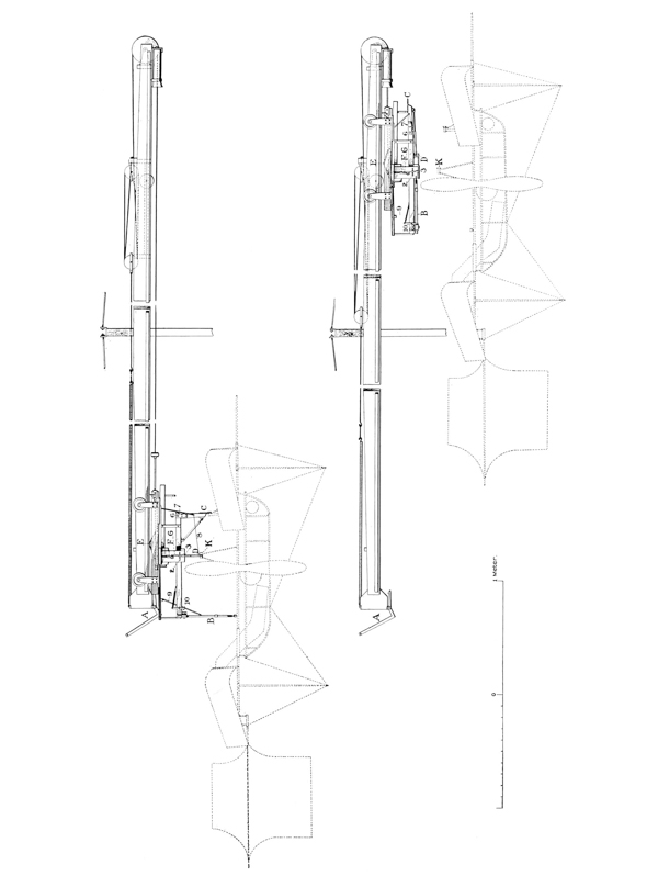


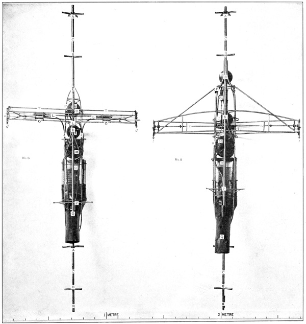


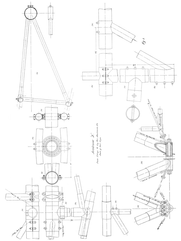
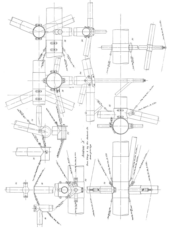


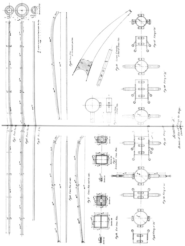


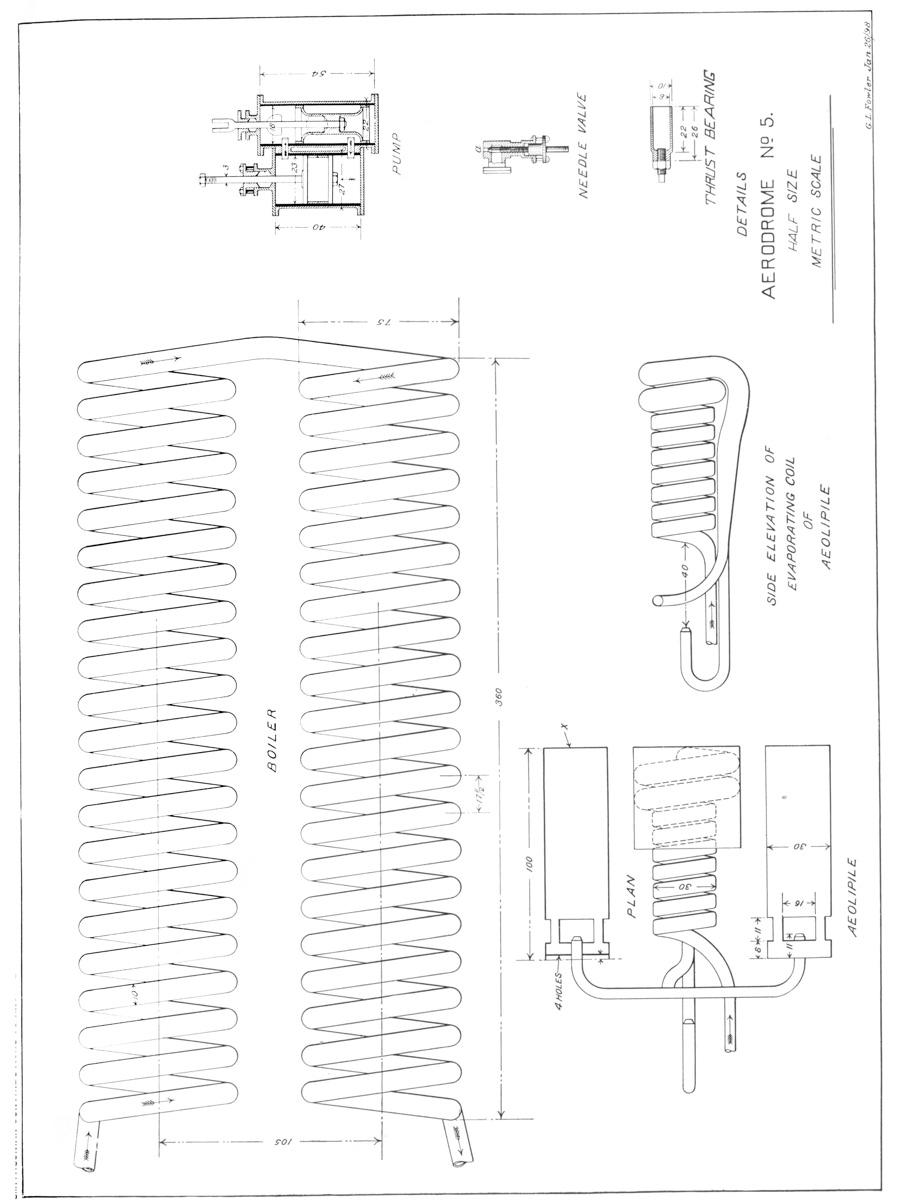
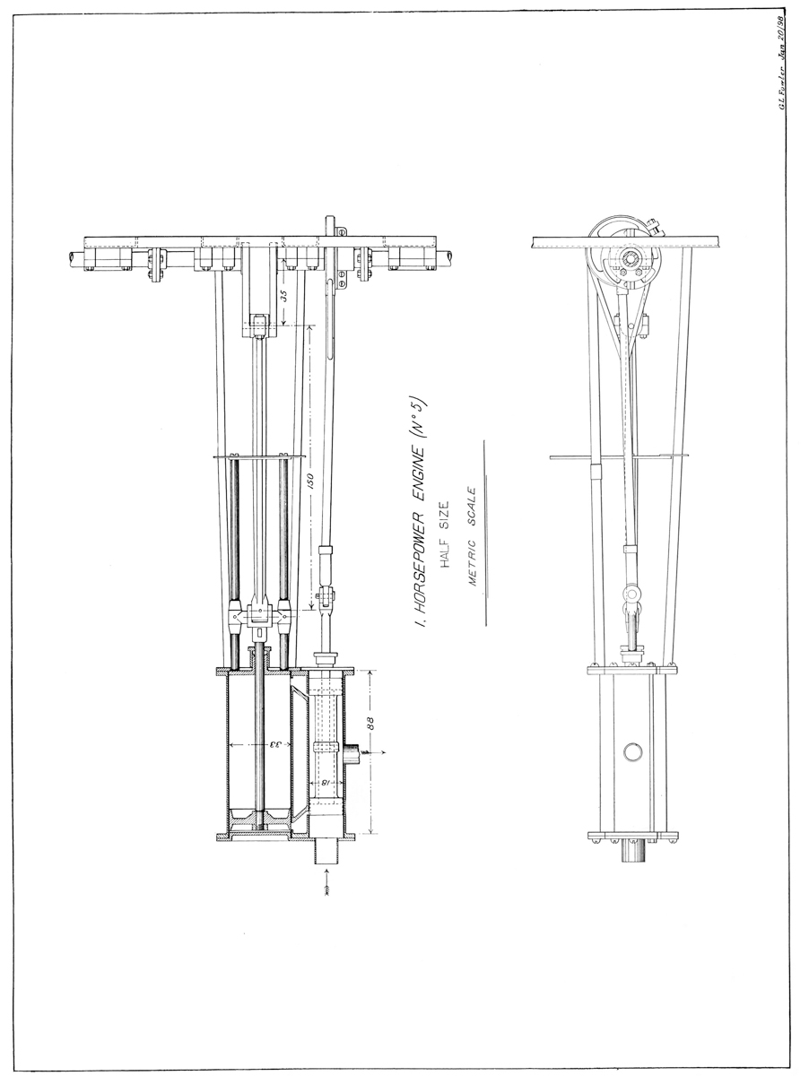
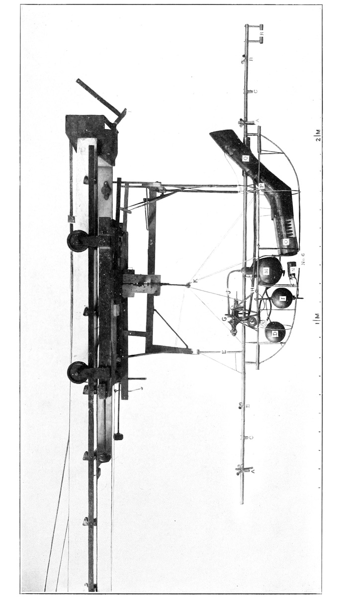
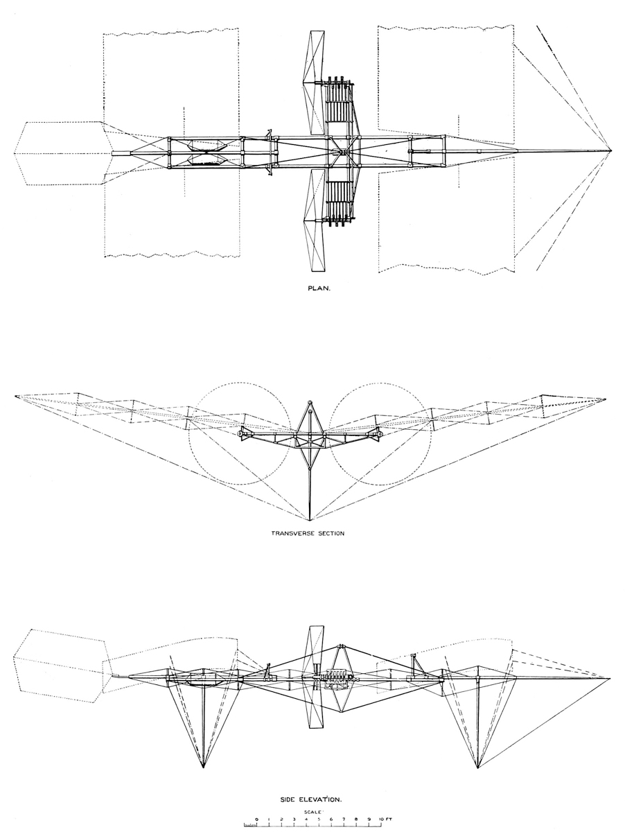
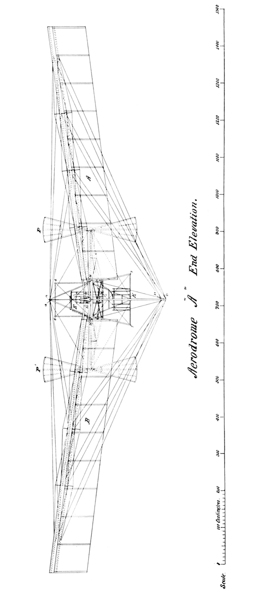
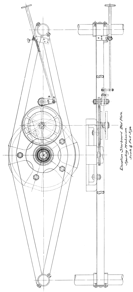
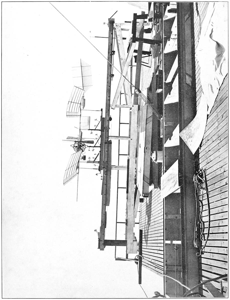