
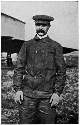
WILBUR WRIGHT
Who with his younger brother, Orville Wright, invented the first practical aeroplane. Wilbur Wright's death of typhoid fever in the summer of 1912 was an irreparable loss to aviation
WILBUR WRIGHT
Who with his younger brother, Orville Wright, invented the first practical aeroplane. Wilbur Wright's death of typhoid fever in the summer of 1912 was an irreparable loss to aviation
BY
HARRY E. MAULE
MANY ILLUSTRATIONS
Garden City New York
DOUBLEDAY, PAGE & COMPANY
1912
Copyright, 1912, by
Doubleday, Page & Company
All rights reserved including that of
translation into foreign languages,
including the Scandinavian
To My Mother
In Appreciation of Her Broad Interest
In All the Activities of the World
The thanks of the publishers and author are due a great many individuals and publications for aid in securing photographs and data used in the preparation of this volume.
Although space prevents giving the names of all, opportunity is here taken to express to each the heartiest appreciation of their generous help and valuable suggestions.
More than to all of these are my thanks due my wife, Edna O'Dell Maule, for her constant aid and coöperation.
IN THE preparation of this book the author has tried to give an interesting account of the invention and workings of a few of the machines and mechanical processes that are making the history of our time more wonderful and more dramatic than that of any other age since the world began. For heroic devotion to science in the face of danger and the scorn of their fellowmen, there is no class who have made a better record than inventors. Most inventions, too, are far more than scientific calculation, and it is the human story of the various factors in this great age of invention that is here set forth for boy readers.
New discoveries, or new applications of forces known to exist, illustrating some broad principle of science, have been the chief concern of the author in choosing the subjects to be taken up in the various chapters, so that it has been necessary to limit the scope of the book, except in one or two instances, to inventions that have come into general use within the last ten years. In vi "The Boy's Book of Inventions," "The Second Boy's Book of Inventions," and "Stories of Invention," Mr. Baker and Mr. Doubleday have told the stories of many of the greatest inventions up to 1904, including those of the gasoline motor, the wireless telegraph, the dirigible balloon, photography, the phonograph, submarine boats, etc. Consequently for the most part the important developments in some of these machines are treated briefly in the final chapters, while the earlier chapters are devoted to new inventions, which, if made before 1904, did not receive general notice until after that time.
Although the subjects treated in the earlier chapters are here spoken of as new inventions, all of them are not recent in the strictest sense of the word, for men had been working on the central idea of some of them for many years before they actually were developed to a stage where they could be patented and sent out into the world.
H. E. M.
| CHAPTER | PAGE | |
| I. | The Aeroplane How a Scientist Who Liked Boys and a Boy Who Liked Science Followed the Fascinating Story of the Invention of the Aeroplane. |
3 |
| II. | Aeroplane Development How the Inventors Carried On the Art of Aviation Until It Became the Greatest of All Sports and Then a Great Industry. |
49 |
| III. | Aeroplanes To-day Our Boy Friend and the Scientist Look Over Modern Aeroplanes and Find Great Improvements Over Those of a Few Years Ago. A Model Aeroplane. |
91 |
| IV. | Artificial Lightning Made and Harnessed To Man's Use Our Friends Investigate Nikola Tesla's Invention for the Wireless Transmission of Power, by Which He Hopes to Encircle the Earth With Limitless Electrical Power, Make Ocean and Air Travel Absolutely Safe, and Revolutionize Land Traffic. |
129 |
| V. | The Motion Picture Machine Machines That Make Sixteen Tiny Pictures Per Second and Show Them at the Same Rate Magnified Several Thousand Times. Motion Pictures in School. Our Boy Friend Sees the Whole Process of Making a Motion Picture Play. |
164 |
| viii VI. | Adventures With Motion Pictures Perilous and Exciting Times in Obtaining Motion Pictures. How the Machine Came to Be Invented and the Newest Developments in Cinematography. |
195 |
| VII. | Steel Boiled Like Water and Cut Like
Paper Our Boy Friend Sees How Science Has Turned the Greatest Known Heats to the Everyday Use of Mankind. |
224 |
| VIII. | The Tesla Turbine Dr. Nikola Tesla Tells of His New Steam Turbine Engine, a Model of Which, the Size of a Derby Hat, Develops More Than 110 Horse Power. |
263 |
| IX. | The Romance of Concrete The One Piece House of Thomas A. Edison and Other Uses of the Newest and Yet the Oldest Building Material of Civilized Peoples, Seen By the Boy and His Scientific Friend. |
288 |
| X. | The Latest Automobile Engine Our Boy Friend and the Scientist Look Over the Field of Gasoline Engines and See Some Big Improvements Over Those of a Few Years Ago. |
320 |
| XI. | The Wireless Telegraph Up To The Minute The Scientist Talks of Amateur Wireless Operators. The Great Development of Wireless That Has Enabled It to Save Three Thousand Lives. Long Distance Work of the Modern Instruments. |
332 |
| XII. | More Marvels of Science Color Photography, the Tungsten Electric Lamp, the Pulmotor, and Other New Inventions Investigated by Our Boy Friend. |
352 |
LIST OF DIAGRAMS
THE BOY'S BOOK OF NEW INVENTIONS
HOW A SCIENTIST WHO LIKED BOYS AND A BOY WHO LIKED SCIENCE FOLLOWED THE FASCINATING STORY OF THE INVENTION OF THE AEROPLANE.
WHEN, with engine throbbing, propellers whirling, and every wire vibrating, the first successful aeroplane shot forward into the teeth of a biting December gale and sailed steadily over the bleak North Carolina sand dunes for twelve seconds, the third great epoch in the age of invention finally was ushered in. First, man conquered the land with locomotive, electricity, steam plow, telegraph, telephone, wireless and a thousand other inventions. Almost at the same time he conquered the ocean with steamship, cable, and wireless. Now, through the invention of the aeroplane, he is making a universal highway of the air.
Such was the way the real beginning of aviation was summarized one day to a bright young man who spent all his spare time out of school at the laboratory of his good friend the scientist. Always in good humour, and with a world of knowledge of things that 4 delight a boy's heart, the man was never too deep in experiments to answer any questions about the great inventions that have made this world of ours such a very interesting place
The laboratory was filled with models of machines, queer devices for scientific experiment, a litter of delicate tools, shelves of test tubes, bottles filled with strange smelling fluids, and rows upon rows of books that looked dull enough, but which the scientist explained to the boy contained some of the most fascinating stories ever told by man.
Coming back to aeroplanes the boy said, "But my father says that aviation is so new it is still very imperfect."
"That is true," answered the scientist, taking a crucible out of the flame of his Bunsen burner and hanging it in the rack to cool, "but it has seen a marvellous development in the last few years.
"It was less than ten years ago—the end of 1903, to be exact—that Orville and Wilbur Wright first sailed their power-driven aeroplane," he continued, "but so rapid has been the progress of aviation that nowadays we are not surprised when a flight from the Atlantic to the Pacific is accomplished. It seems a tragic thing that Wilbur Wright should have been called by death, as he was in May, 1912, by typhoid fever, for he was at the very zenith of his success and probably would have carried on his work to a far, far greater development."

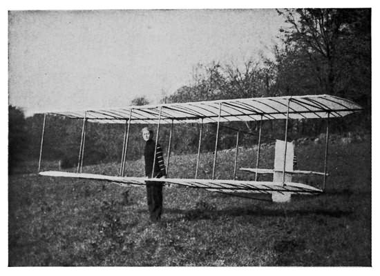
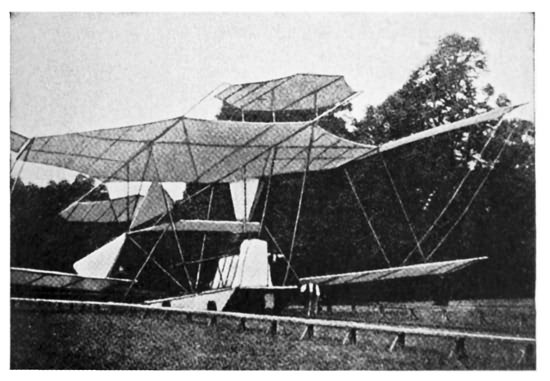
THE FIRST WRIGHT AEROPLANE
This was the machine that made the first successful flight in the history of the world, of a power-driven, man-carrying aeroplane
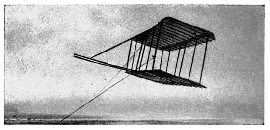
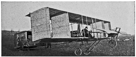
THE FIRST WRIGHT GLIDER
This device was first flown as a kite without a pilot, and the levers worked by ropes from the ground, to test the principles

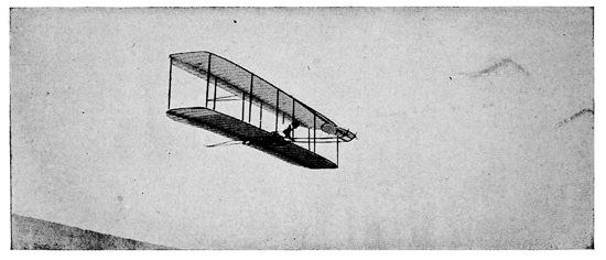
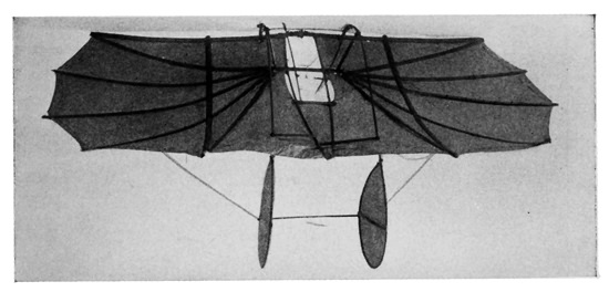
THE SECOND WRIGHT GLIDER
The machine was launched into the air from the top of a sand dune against a high wind, and proved a great success
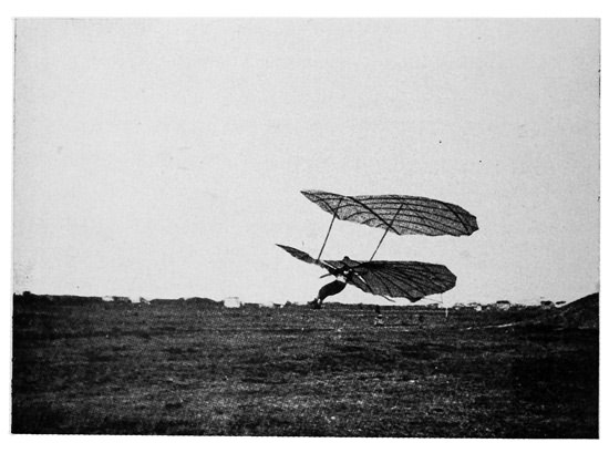
A LONG GLIDE
Wright glider in full flight over Kill Devil Hill, N. C.
5 After a little pause the scientist continued, saying that, at the time the Wright brothers made their first flight they were experimenting with what we now know as a biplane, or Chanute type glider, at Kill Devil Hill, near Kitty Hawk, N. C. It is a desolate wind-swept spot on the coast where only a little rank marsh grass grows on the sheltered sides of the great sand dunes. The brothers chose this barren place for their experiments because here the winds were the most favourable for their purpose.
They were not ready for their first attempt to fly in a motor-propelled machine until December 17th, and though they sent out a general invitation to the few people living in that section, only five braved the cold wind. Three of these were life savers from the Kill Devil Hill station near by. Doubtless the other people had heard of the numerous failures of flying machines and expected the promised exhibition of the silent young men who had spent the autumn in their neighbourhood, to be just another such. They were sadly mistaken, for they missed a spectacle that never before had been seen in all the history of the world. Nowadays we are familiar with the sight of an aeroplane skimming over the ground and then soaring into the sky, but to the five people who, besides the inventors, were present it undoubtedly was almost beyond belief.
The brothers had installed a specially constructed gasoline engine in their glider, and after thoroughly 6 testing it they carried the machine out on to a level stretch of sand, turned it so that it would face the wind, and while the life savers held it in place the brothers went over every wire and stay. They felt perfectly confident that the machine would fly, but they made no predictions, and in fact spoke but few words between themselves or to the five men gathered about the aeroplane. The machine was not the smoothly finished one we know to-day as the Wright biplane. The operator lay flat on his face on the lower plane, the elevating rudder composed of two smaller planes stuck out in front, instead of behind, and there were several other important differences in design, but in principle it was the same machine that has carried the fame of the American inventors around the world.
Finally the operator took his place, the engine was started, the signal was given, the men holding the machine dropped back and it started out along the rail from which it was launched. It ran along the track to the end, directly against the wind, and rose into the air.
It meant that the air had been turned into a highway, but the Wright brothers were very modest in setting down an account of their achievement.
"The first flight," they wrote, "lasted only twelve seconds," a flight very modest compared with that of birds, but it was, nevertheless, the first in the history of the world in which a machine carrying 7 a man had raised itself by its own power into the air in free flight, had sailed forward on a level course without reduction of speed, and had finally landed without being wrecked. The second and third flights (the same day) were a little longer, and the fourth lasted fifty-nine seconds, covering a distance of 853 feet over the ground against a twenty-mile wind.
"After the last flight the machine was carried back to camp and set down in what was thought to be a safe place. But a few minutes later, when engaged in conversation about the flights, a sudden gust of wind struck the machine and started to turn it over. All made a rush to stop it, but we were too late. Mr. Daniels, a giant in stature and strength, was lifted off his feet, and, falling inside between the surfaces, was shaken about like a rattle in a box as the machine rolled over and over. He finally fell out upon the sand with nothing worse than painful bruises, but the damage to the machine caused a discontinuance of experiments."
"Thus," said the scientist, we see the record aeroplane flight for 1903 was 853 feet while in 1911 a Wright biplane flew more than 3,000 miles from the Atlantic to the Pacific. In ten years more we may look back to our monoplanes and biplanes of to-day in the same way we do now on the first cumbersome 'horseless carriages' that were replaced by the high-powered automobiles we know now. Some experts in 8 aeronautics say that we may even see the complete passing of the monoplane and biplane types in favour of some now unknown kind of aeroplane."
Who knows but that the man to invent the perfect aeroplane will be one of the boy readers of this! Everywhere the making and flying of model aeroplanes by boys is looked upon, not only as play, but as a valuable and instructive sport for boys and young men of any age. One of the indications of this may be seen in the public interest taken in the tournaments of boys' model aeroplane clubs. Not only do crowds of grown people with no technical knowledge of aeroplanes attend the tournaments, but also older students of aviation who realize that among the young model fliers there may be another Orville or Wilbur Wright, a Blériot, or a Farman.
So important is this knowledge of aviation considered that the principles and the practical construction of model aeroplanes are taught in many of the public schools. Instead of spending all their school hours in the study of books, the boys now spend a part of their time in the carpenter shop making the model aeroplanes which they enter in the tournaments. Of course, dozens of types of models are turned out, some good and some bad, but in the latter part of Chapter III is given a brief outline for the construction of one of the simplest and most practicable model aeroplanes.
Not only the schools but the colleges also have 9 taken up aviation, and nearly every college has its glider club, and the students work many hours making the gliders with which they contest for distance records with other clubs. As a consequence aviation has become a regular department of college athletics, and intercollegiate glider meets are a common thing.
The epochs of invention go hand in hand with the history of civilization, for it has been largely through invention that man has been able to progress to better methods of living. In the olden days, when there were few towns and every one lived in a castle, or on the land owned by the lord of the castle, war was the chief occupation, and the little communities made practically everything they used by hand. When they went abroad they either walked or rode horses, or went in clumsy ships. Pretty soon men began to invent better ways of doing things; one a better way of making shoes, another a better way of making armour, and the people for miles around would take to going to these men for their shoes and armour. Towns sprang up around these expert workmen, and more inventions came, bringing more industries to the towns. Inventions made industry bigger, and war more disastrous because of the improvement invention made in weapons. Then came inventions that changed the manner of living for all men—the machines for making cloth, which did away with the spinning-wheels of our great-grandmothers, and created the great industry 10 of the cotton and woollen mills; the inventions for making steel that brought about the great steel mills, and enabled the armies of the world to use the great guns we know to-day, and the battleships to carry such heavy armour plate; the steam locomotive that enabled man to travel swiftly from one city to another; the steamship that brought all the nations close together; the telegraph, cable, telephone, and wireless, that made communication over any distance easy; the submarine that made war still more dangerous; and finally the aeroplane that makes a highway of the air in which our earth revolves.
But even from the time of the ancient Greeks and Romans man had tried to fly. Every nation had its list of martyrs who gave their lives to the cause of aviation. In modern times, too, many attempts had been made to discover the secret of flight. Otto Lilienthal, a German, called the "Flying Man," had made important discoveries about air currents while gliding through the air from hills and walls by means of contrivances like wings fitted to his person. Others had made fairly successful gliders, and Prof. Samuel Pierepont Langley of the Smithsonian Institution in Washington actually had made a model aeroplane that flew for a short distance. Also, Clement Ader, a Frenchman, had sailed a short way in a power flier, and Sir Hiram Maxim, the English inventor, had built a gigantic steam-driven aeroplane that gave some evidences of being able to fly. But these men 11 were laughed at as cranks, while the Wrights kept their secret until they were sure of the success of their biplane. However, the question as to who first rode in a power-driven flier under the control of the operator still is the subject of a world-wide controversy.
It was as boys that the Wright brothers first began experiments with flying, and though they have received the highest praises from the whole world, Orville still is, and until his death Wilbur was, the same quiet, modest man who made bicycles in Dayton, and the surviving brother of the pair is working harder than ever. In telling the story of their own early play, that later proved to be one of the most important things they ever did, the Wright brothers wrote for the Century Magazine: "We devoted so much of our attention to kite-flying that we were regarded as experts. But as we became older we had to give up the sport as unbecoming to boys of our age." As every boy knows, kite-flying was one of the early methods of experimenting with air currents and greatly aided the scientists in their exploration of the ocean of air that surrounds the world, eddying and swirling up and down, running smoothly and swiftly here, coming to a dead stop there—but always different from the minute before.
But before the Wright brothers gave up flying kites they had played with miniature flying machines. 12 They were known then as "helicopteres," but the Wright brothers called them "bats," as the toys came nearer resembling bats than anything else the boys had seen about their home in Dayton, Ohio. Most boys probably have played with something of the kind themselves, and maybe have made some. They were made of a light framework of bamboo formed into two screws driven in opposite directions by twisted rubber bands something like the motors on boys' model aeroplanes of to-day. When the rubber bands unwound the "bats" flew upward.
"A toy so delicate lasted only a short time in our hands," continues the story of the Wright brothers, "but its memory was abiding. We began building them ourselves, making each one larger than that preceding. But the larger the 'bat' the less it flew. We did not know that a machine having only twice the size of another would require eight times the power. We finally became discouraged."
This was away back in 1878, and it was not until 1896 that the Wright brothers actually began the experiments that led to their world-famous success.
Strangely enough it all started when Orville, the younger of the two, was sick with typhoid fever, the same disease that caused Wilbur Wright's death. According to all accounts, the elder brother, having remained away from their bicycle factory in order to nurse Orville, was reading aloud. Among other 13 things he read to Orville the account of the tragic death of Otto Lilienthal, the German "Flying Man" who was killed while making a glide.

MOTOR OF THE WRIGHT BIPLANE

A 16-CYLINDER 100-HORSEPOWER ANTOINETTE MOTOR
A frequent prize winner

AN 8-CYLINDER 5O-HORSEPOWER CURTISS MOTOR
THE GNOME MOTOR

Standard Gnome aeroplane motor, showing interior.

Photo by Philip W. Wilcox
Fourteen-cylinder 100-horsepower Gnome motor. Used on many racing aeroplanes.
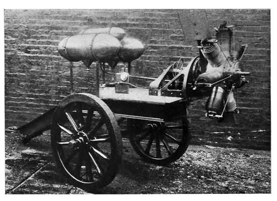
Courtesy of the Scientific American
Testing a Gnome motor on a gun carriage. So great is the power of the engine that the tongue of the heavy carriage is buried in the ground to hold it in place
"Why can't we make a glider that would be a success?" the brothers asked each other. They were sure they could, and they got so excited in talking it over that it nearly brought back Orville's fever. When he got well they studied aeronautics with the greatest care, approaching the subject with all the thoroughness that later made their name a byword in aviation for care and deliberation.
Neither of these two young men was over demonstrative, and neither was lacking in the ability for years and years of the hardest kind of work, but together they made an ideal team for taking up the invention of something that all the scientists of the world hitherto had failed to develop. Wilbur was called by those who knew him one of the most silent men that ever lived, as he never uttered a word unless he had something to say, and then he said it in the most direct and the briefest possible manner. He had an unlimited capacity for hard work, nerves of steel and the kind of daring that makes the aviator face death with pleasure every minute of the time he is in the air.
No less daring is Orville, the younger of the two, who is a little bit more talkative and more full of enthusiasm than was Wilbur. He was the man the reporters always went to when they knew the elder 14 brother would never say a word, and his geniality never failed them. He also is a true scientist and tireless in the work of developing the art of aviation.
First, the brothers read all the learned and scientific books of Professor Langley, and Octave Chanute, the two first great American pioneers in aviation, and the reports of Lilienthal, Maxim, and the brilliant French scientists.
They saw, as did Professor Langley, that it was out of the question to try to make a machine that would fly by moving its wings like a bird. Then they began with great kites, and next made gliders—that is, aeroplanes without engines—for the brothers knew that there was no use in trying to make a machine-driven, heavier-than-air flier before they had tested out practically all the theories of the earlier scientists.
They fashioned their gliders of two parallel main planes like those of Octave Chanute. The width, length, distance between planes, rudders, auxiliary planes and their placing were all problems for the most careful study. It was very discouraging work, for no big thing comes easily. As their experiments proceeded they said they found one rule after another incorrect, and they finally discarded most of the books the scientists had written. Then with characteristic patience they started in to work out the problem from first principles. "We had taken aeronautics merely as a sport," they wrote 15 later. "We reluctantly entered upon the scientific side of it. But we soon found the work so fascinating that we were drawn into it deeper and deeper."
The Wrights knew that an oblong plane—that is, a long narrow one—driven through the air broadside first is more evenly supported by the air than would be a plane of the same area but square in shape. The reason for this is that the air gives the greatest amount of support to a plane at the entering edge, as it is called in aviation—that is, the edge where it is advancing into the air. A little way from the edge the air begins to slip off at the back and sides and the support decreases. Thus, it will be seen that if the rear surface, which gives little support because the air slips away from under it, is put at the sides, giving the plane a greater spread from tip to tip and not so much depth from front to rear, the plane is more efficient—that is, more stable, less subject to drifting, and better able to meet the varying wind currents. Scientists call this proportion of the spread to the depth the aspect ratio of planes. For instance, if a plane has a spread of 30 feet and a depth of 6 feet it is said to have an aspect ratio of 5. This is a very important consideration in the designing of an aeroplane, because aspect ratio is a factor in the speed. In general, high speed machines have a smaller aspect ratio than slower ones. The aspect ratio also has an important bearing on the general efficiency of an aeroplane, but the lifting power of 16 a plane is figured as proportionate to its total area. In order to hold the air, and keep its supporting influence, aviators have tried methods of enclosing their planes like box kites, and putting edges on the under sides. This latter was found a mistake because the edge tended to decrease the speed of the flier and did more harm than the good obtained through keeping the air.
In aviation, as we know it to-day, aeroplane builders believe in giving their planes a slight arch upward and backward from the entering edge, letting it reach its highest point about one third of the way back and then letting it slope down to the level of the rear edge gradually. This curve, which is called the camber, is mathematically figured out with the most painstaking care, and was one of the things the Wright brothers worked out very carefully in their early models. Also, planes are driven through the air at an angle—that is, with the entering edge higher than the rear edge—because the upward tilt gives the air current a chance to get under the plane and support it. This angle is called by the scientists the angle of incidence and is very important because of its relation to the lifting powers of the planes.

MODEL AEROPLANE FLIERS
Every fair Saturday the model makers and fliers spend in the parks either practising for or holding flight tournaments
A MODERN COLLEGE MAN'S GLIDER
OTTO LILIENTHAL MAKING A FLIGHT IN HIS GLIDER
Another one of the difficult problems the inventors had to struggle with was the balance of their fliers. Before the Wright brothers flew, it was thought that one of the best ways was to incline the planes upward 17 from the centre—that is—make them in the shape of a gigantic and very broad V. This is known in science as a dihedral angle. The idea was that the centre of gravity, or the point of the machine which is heaviest and which seeks to fall to earth first through the attraction of gravitation, should be placed immediately under the apex of the V. The scientists thought that the V then would keep the machine balanced as the hull of a ship is balanced in the water by the heavy keel at the bottom. The Wrights decided that this might be true from a scientific point of view, but that the dihedral angle kept the machine wobbling, first to one side and then righting itself, and then to the other side and righting itself. This was a practical fault and they built their flier without any attempt to have it right itself, but rather arched the planes from tip to tip as well as from front to rear.
The winglike gliders of Lilienthal and Chanute had been balanced by the shifting of the operator's body, but the Wrights wanted a much bigger and safer machine than either of these pioneers had flown. In their own words, the Wrights "wished to employ some system whereby the operator could vary at will the inclination of different parts of the wings, and thus obtain from the wind forces to restore the balance which the wind itself had disturbed." This they later accomplished by a device for warping or bending their planes, but in their first glider there 18 was no warping device and the horizontal front rudder was the only controlling device used. This latter device on the first glider was made of a smaller plane, oblong-shaped and set parallel to, and in front of, the main planes. It was adjustable through the system of levers fixed for the operator, who in those days lay flat on the front plane.
Thus the two main planes and the adjustable plane in front with stays, struts, etc., made up the first Wright glider.
The Wright brothers took their machine to Kitty Hawk, N. C., in October, 1900, presumably for their vacation. They went there because the Government Weather Bureau told them that the winds blew stronger and steadier there than at any other point in the United States. Also it was lonely enough to suit the Wrights' desire for privacy. It was their plan to fly the contrivance like a boy does a huge box kite, and it looked something like one. A man, however, was to be aboard and operate the levers. According to the Wright brothers' story the winds were not high enough to lift the heavy kite with a man aboard, but it was flown without the operator and the levers worked from the ground by ropes.
A new machine the next year showed little difference of design, but the surface of the planes was greater. Still the flier failed to lift an operator. At this time the Wright brothers were working with Octave Chanute, the Chicago inventor, engineer and 19 scientist whom they had invited to Kitty Hawk to advise them. After many discussions with Chanute they decided that they would learn the laws of aviation by their own experience and lay aside for a time the scientific data on the subject.
They began coasting down the air from the tops of sand dunes, and after the first few glides were able to slide three hundred feet through the air against a wind blowing twenty-seven miles an hour. The reason their glider flights were made against the wind was because the wind passing swiftly under the planes had the same effect as if the machine was moving forward at a good clip, for the faster the machine moves, or the faster the air passes under it, the easier it remains aloft. In other words, no one part of the air was called upon to support the planes for any length of time, but each part supported the planes for a very short time. For instance, if you are skating on thin ice you run much less danger of breaking through if you skate very fast, because no one part of the ice is called upon to support you for long.
In 1902 the Wright brothers were approaching their goal. Slowly and with rare patience they were accumulating and tabulating all the different things different kinds of planes would do under different circumstances. In the fall of that year they made about one thousand gliding flights, several of which carried them six hundred feet or more. Others 20 were made in high winds and showed the inventors that their control devices were all right.
The next year, 1903, which always will be remembered as the banner one in the history of aviation, the brothers, confident that they were about to succeed in their long search for the secret of the birds, continued their soaring or gliding. Several times they remained aloft more than a minute, above one spot, supported by a high, steady wind passing under their planes.
"Little wonder," wrote the Wright brothers a few years, later, "that our unscientific assistant should think the only thing needed to keep it indefinitely in the air would be a coat of feathers to make it light."
What the inventors did to keep their biplane glider in the air indefinitely, however, was to add several hundred pounds to the weight in the shape of a sixteen-horsepower gasoline motor. The total weight of the machine when ready to fly was 750 pounds. Every phase of the problem had been worked out in detail—all the calculations gone over and proved both by figures and by actual test. The planes, rudders, and propellers had been designed by mathematical calculations and practical tests.
The main planes of this first machine had a spread from tip to tip of 40 feet, and measured 6 feet 6 inches from the entering edge to the rear edge, a total area of 540 square feet. This will show how 21 great is the spread of the main planes as compared to their length from front to rear. The two surfaces were set six feet apart, one directly above the other, while the elevating rudder was placed about ten feet in front of the machine on a flexible framework. This elevating rudder was composed of two parallel horizontal planes which together had an area of eighty square feet. The elevating planes could be moved up or down by the operator just as he desired to fly upward or downward. The machine was steered from right to left or left to right by two vertical vanes set at the rear of the machine about a foot apart. They were a little more than six feet long, extending from the upper supporting plane to a few inches below the lower supporting plane. These also were turned in unison by the operator, according to the direction toward which he wished to fly.
The most intricate device of their machine, however, was not perfected on their first biplane. This is the one for maintaining a side to side balance, or lateral equilibrium, as the scientists say. In watching the flights of gulls, hawks, eagles, and other soaring birds, the brothers had observed that the creatures, while keeping the main part of their wings rigid, frequently would bend the extreme tips of their wings ever so slightly, which would seem to straighten their bodies in the air. The inventor decided that they needed some such device as nature had given to these birds.
22 The system was called by the scientists the torsional wing system, which means that the tip ends of the wings were flexible and could be warped or bent or curled up or down at will by the operator. Only the rear part of the tips of the wings on the Wright machines could be bent, but this was enough to keep the machine on an even keel when properly manipulated. How the Wright modern machines are operated is fully described on page (99). The whole machine was mounted on a pair of strong light wooden skids like skiis or sled-runners.
To start the early Wright biplanes, the machines were placed on a monorail, along which they were towed by a cable. The force for towing them at sufficient speed was obtained by dropping from the top of a derrick built at the rear of the rail a ton of iron which was connected with the cable. The later Wright biplanes were equipped with rubber-tired wheels mounted on the framework, which still retained the skids. Heavy rubber springs were provided to absorb the shock. With the wheels the machine could run over the ground of its own power and thus the cumbersome derrick and monorail were done away with.
The operator was supposed to lie on his face in the middle of the lower plane, but in the later machines a seat was provided for him alongside the engine, and in still later ones seats for one or two passengers.
The engine which was designed by the Wright 23 brothers themselves for this purpose, was a water-cooled four-cylinder motor which developed sixteen horsepower from 1,020 revolutions per minute. The engine was connected with the propellers at the rear of the biplane by chains. The propellers were about eight feet in diameter and the blades were six to eight inches wide. The materials used in the biplane were mostly durable wood like spruce pine and ash, the metal in the engine and the canvas on the planes. There was not one superfluous wire. Everything had a use, and even the canvas was stretched diagonally that it might fit more tightly over the framework of the planes and offer less wind resistance, and also stretch more easily for the wing warping.
Finally on December 17, 1903, everything was in readiness for the first attempt of these two patient men—then unknown to the world—to fly in a power-driven machine. That first flight, made practically in secret amid the desolate sand dunes of the North Carolina coast, lasted only twelve seconds. However, it was the first time, but one, in the history of the world that a machine carrying a man had lifted itself from the ground and flown entirely by its own power.
The two succeeding flights were longer, and the fourth covered 853 feet, lasting fifty-nine seconds.
The inventors were not heralded as the greatest men of their time. There were no medals or speeches. The five men—fishermen and life savers—who saw 24 the flights agreed that it was wonderful, but they kept the Wrights' secret and the brothers calmly continued their studies and experiments.
The spring of 1904 found them at work on Huffman Prairie about eight miles east of Dayton. The first trials there were not very successful and the brothers, who had worked seven long years in secret, had the unpleasant experience of failing to show satisfactory results to the few friends and reporters invited to see an aeroplane flight. Their new machine was larger, heavier, and stronger, but the engine failed to work properly.
Of course this was no great disappointment to those two silent, determined young men. "We are not circus performers," they said. "Our aim is to advance the science of aviation."
And advance it they did.
Their experiments continued, and in 1904 they made a record of three miles in 5 minutes 27 seconds. The next year, 1905, they made a record flight of 24.20 miles and remained in the air 38 minutes 13 seconds at heights of from 75 to 100 feet.
All this time the brothers were solving problems and correcting faults, but in 1904 and 1905 their chief endeavour was to keep their machines from tipping sidewise when they turned. Only the most technical study and the final development of their wing-warping device solved the problem.
Perhaps the strangest part was the lack of interest 25 shown in their work by the world and even by their own townsmen, for, though there had been several newspaper accounts of their test flights, no great enthusiasm was aroused.
They were not wealthy and they had spent more on their experiments than they could afford, so all this time they had proceeded without attracting any more attention than necessary. They desired to perfect their patents before letting the world know the secret of their inventions, and spent the next two years in business negotiations. Meanwhile, the French inventors were making much progress and soon brought out several successful aeroplanes.
Why was this?
Why was it that the art of air navigation sought by man since the earliest times should have been discovered and mastered so quickly?
The answer lies in the putting together of two things by the Wright brothers—that is, their discovery of the kind of a plane that would stay aloft with the air passing under it at a swift enough clip to give it support, and their adaptation of the gasoline engine to the use of driving the plane forward with enough speed.
When they began work, the gasoline engine was just coming to its real development. It was light, developed a high power, and its fuel could be concentrated into a small space. These things were essential to the success of the aeroplane—light weight, 26 high power, and concentrated fuel. And these were things that the early inventors lacked. Sir Hiram Maxim equipped his machine with a steam engine, while Langley used steam engines in most of his models. These were very heavy, cumbersome, gave slight power in comparison to their weight, and could carry only a little fuel with them.
Undoubtedly the adaptation of the gasoline engine to the use of the aeroplane marked the difference between mechanical flight and no flight, but it also is not to be doubted that those aviators, who are more mechanical than scientific, have overrated the importance of the engine in aeroplane construction. Before engines ever were used, the Chanute type of biplane had to be worked into a state of reliability, if not perfection. Now the scientific leaders in aviation are giving every bit as much attention to the perfection of their planes, their gliding possibilities, and the scientific rules governing their action as they are to their engines.
Most boys understand, at least generally, how an automobile or motor-boat engine works. Scientists call gasoline engines "internal combustion motors," and that means that the force is gathered from the explosion of the gasoline vapour in the cylinder. Enough gasoline to supply fuel to run an aeroplane motor for as much as eight or nine hours can be carried in the tank. From the tank a small pipe carries the gasoline to a device called the carbureter. 27 The carbureter turns the gasoline into gas by spraying it and mixing it with air, for gasoline turns into a very inflammable and explosive gas when mixed with the oxygen in the air. So this gas, if lighted in a closed space, will explode. The explosion takes place in the motor-cylinder by the application of an electric spark, and the force pushes the piston, which turns the crank and drives the aeroplane propeller, automobile wheels, or motor-boat screw.
Thus we have the piston driven out and creating the first downward thrust, but the thrusts must be continuous. The piston must be drawn back to the starting place, the vapours of the exploded gas expelled, and the new gas admitted to the cylinder ready for the next explosion. On the ordinary four-cycle motor two complete revolutions of the flywheel are necessary to do all the work. First, we must have the explosion that causes the initial thrust; second, the return of the piston rod in the cylinder by the momentum of the flywheel as it revolves from the initial thrust, thus forcing out the burned gas of the first explosion; third, the next downward motion to suck in a fresh supply of gas; and, fourth, the next upward thrust to compress it for the second explosion. It sounds simple enough, but it isn't, as every one knows who has tried to run a gasoline motor for himself.
The carbureter must do its work automatically 28 and convert the air and gasoline into gas in just the right proportions. A slight fault with the feed of gasoline or air would cause trouble. Also the electric-spark system that ignites the gas and causes the explosions must be in perfect running order. The explosions cause great heat, so some system of cooling the cylinders either by air or water must be used.
Only one cylinder has been explained here, but most engines have several, each working at a different stage, so that the power is exerted on the shaft continuously. For instance, take a four-cylinder engine; on the instant that the first cylinder is exploding and driving the shaft, the second cylinder is compressing gas for the next explosion, the third is getting a fresh supply of gas, and the fourth is cleaning out the waste gas of the explosion of a second before. Thus it will be seen why the explosions are almost constant.
Now think of the aeroplane motor that has fourteen cylinders and develops 140 horsepower! This is probably the most powerful aeroplane engine in the world, although there are many motor boats that have engines developing 1,000 horsepower.
In the early days when scientists were groping for the secret of air navigation the best that the clumsy steam engines they had at their disposal would do was to generate one horsepower of energy for every ten pounds of weight. These days the light powerful aeroplane engines we hear roaring over our heads 29 are generating one horsepower of energy for every three or three and a half pounds of dead weight, and engines have been constructed weighing only one pound to every horsepower, though they are impractical for general use.
The first engines that were used in aeroplanes were simply automobile engines adapted to air navigation. The main question in those days was lightness and power. This was achieved by skimming down the best available automobile engines so that they were as light as safety would allow.
Although lightness is still an important factor in aeroplane engine construction, many authorities declare that it is growing less so as the science advances and aeroplanes are able to carry heavier loads.
There were many intricate and difficult problems, however, that attended taking a motor aloft to drive an aeroplane. The motor had to run at top speed every second, for it could not rest on a low gear as an automobile engine could. First one part and then another would give out and the motors were constantly overheating. Experience taught the makers how to make their machines light enough and yet strong enough to do the required work.
It was in cooling that the greatest difficulties were met, and it was this that brought about the great innovations in motor building. The system of cooling the engine with water required much heavy 30 material, such as pipes, pumps, water, water jackets, and radiator.
On account of the general efficiency of a water-cooled engine many builders of aeroplanes stuck to it and developed it to a very high standard. At present many of the prize-winning engines are water cooled, as, for instance, the Wright and Curtiss.
All of these water-cooled engines and several standard air-cooled makes are of the reciprocating type that have stationary cylinders and crankcase while the crankshaft rotates like that of the motor boat.
The famous Curtiss, Anzani, Renault, and others are all engines of this type. They all differ, but all have a high capacity, as we know from the records they have broken. The Anzani and R. E. P. makers, whose motors are air cooled, have used to great advantage the plan of making their motors star-shaped—that is, with the cylinders arranged in a circle around the crankshaft.
This is the shape taken by the famous air-cooled rotary engines of which the much-discussed Gnome is the best known make. In this rotary motor the cylinders and crankcase revolve about the crankshaft which is stationary. Authorities are divided over the Gnome, which has many severe critics as well as many enthusiastic supporters. Its lightness is certainly an advantage. The ordinary Gnome has 31 seven cylinders and develops fifty horsepower while the newest models have fourteen cylinders and develop 100 and 140 horsepower.
A brief description of the motor here will suffice to show the general principle of the rotary engine. The stationary crankshaft is hollow, and through it the gasoline vapour passes from the carbureter at the rear to the cylinders. Of course the inlet valves in the pistons are made to work automatically. The magneto is also placed behind the motor and the segments revolve on the crankcase. Wires extend from the segments to the spark plugs in the cylinders, and revolve with them. The cylinders are turned out of solid steel and the whole engine is conceded by experts to be one of the most wonderfully ingenious ever built. The cylinders and crankcase themselves serve as flywheel, thereby eliminating the dead weight of the usual heavy flywheel in the other types of motors, and the rotation serves to cool the engine perfectly. Again, the rotary motor is light and small, while it develops a tremendously high power. Aviators also claim for it other advantages too technical for consideration here.
Many authorities, in fact, declare that the rotary engine is the aeroplane motor of the future. It is very popular among the French aviators and at present holds a great many speed records. It was with one of these high-power Gnomes that Claude Grahame-White, the English flier, won the Gordon Bennett race 32 at Belmont Park in the fall of 1910, and Weyman again in England in 1911.
While this high state of development in the aeroplane motor has been attained comparatively within a few years, the art of flying has occupied the mind of man since it was described in Greek mythology. The Chinese for thousands of years have used kites and balloons. The ancient Greeks watched the wonderful flights of the birds and invented myths about men who were able to fly. Then Achytes, his mind fired by these stories, invented a device in the form of a wooden dove which was propelled by heated air. Other inventors made devices that were intended to fly, and during the reign of Nero, "Simon the Magician" held the world's first aviation meet in Rome. According to the account, he "rose into the air through the assistance of demons." It further states that St. Peter stopped the action of the demons by a prayer, and that Simon was killed in the resultant fall. Simon made another record that way by being the first man to be killed in an aeronautical accident. Other records show that Baldud, one of the early tribal kings in what later was named England, tried to fly over a city, but fell and was killed. A little later, in the eleventh century, a Benedictine monk made himself a pair of wings, jumped from a high tower and broke his legs. These wings really were rude gliders and the principle remained in the minds of men, even in those days when their chief occupation was war. 33 According to the legends, a man named Oliver of Malmesburg, who lived during the Middle Ages, built himself a glider and soared for 375 feet.

Courtesy of the Smithsonian Institution
THE CHANUTE TYPE GLIDER
Upon this machine was based the invention of the biplane.
Courtesy of the Smithsonian Institution
THE HERRING GLIDER
Based on the idea of the Lilienthal gliders.

AN EARLY HELICOPTER
An idea that was abandoned before the aeroplane became a reality.
THE THREE GREAT PIONEERS IN AVIATION

Courtesy of the Smithsonian Institution
Prof. Samuel Pierpont Langley

Courtesy of the Scientific American
Sir Hiram Maxim
Courtesy of E. L. Jones, N. Y.
Octave Chanute
It was in the fifteenth century that men first began to make flying a scientific study by making records and, in part at least, tabulating the results of their experiments.
Among these early students of the science were Leonardo da Vinci, who is best known to the world as a painter and sculptor, but who was a great engineer and architect of his time, and Jean Baptiste Dante, a brother of the great poet. Although Da Vinci was the more scientific in his experiments, Dante made greater progress, and it is on record that he made many wonderful flights with a glider of his own construction over Lake Trasimene. He launched his glider from a cliff into the teeth of the wind, showing thereby his knowledge of the fact that a glider works best when flown against a high wind, because in that way the air is passing under it at greater speed. In one flight he made about 800 feet, which would be a fine record for any glider manipulated by an expert to-day. Finally Dante attempted an exhibition at Perugia, at the marriage festival of a celebrated general, fell on the roof of the Notre Dame Church and broke one of his legs.
Da Vinci had three different schemes for human flight. One was the old idea of bird flight, first dreamed of by the Greeks when Ovid wrote the poem 34 of "Dædalus and Icarus." Scientists called the machine that Da Vinci proposed an orthopter and the operator was supposed by the movement of both arms and legs to fly by flapping the wings. Needless to say it did not work, and we know to-day that bird flight by wing flapping is probably impossible for man. Another of Da Vinci's ideas is still being worked upon by some inventors. This was a machine known as the helicopter, which was supposed to fly upward by the twisting of a great horizontal screw ninety-six feet in diameter. The idea was just the same as that of the toy that started the Wright brothers to thinking. The trouble with Da Vinci's machine was that he had no power to run it. Boys in playing with toy helicopters to-day can run them with rubber bands, but Da Vinci had to turn his screw by human power. Little was accomplished with this machine, although Da Vinci showed its practicability with models. The third scheme of this Italian scientist is one that many years later was perfected and demonstrated at every county fair—that is, the parachute. The first parachute was very crude, but it soon was developed to a fairly high stage of effectiveness and men came down from the tops of towers in them without much injury.
Again, in 1742, the Marquis de Bacqueville, then sixty-two years old, made a contrivance with which he flew about nine hundred feet before he fell into 35 a boat in the Seine River and broke his leg. The Marquis had announced in advance that he would fly from his great house in Paris, across the Seine River and land in the famous Garden of the Tuileries. A crowd assembled and marvelled when the nobleman sailed into the teeth of the wind supported by what apparently were great wings. Something went wrong after a flight that would be considered remarkable by a scientific glider to-day, and his fall resulted in a broken leg for the experimenter. According to the authorities, all these experiments were not very valuable to science, because while the flights were accurately described the construction of the fliers (except in the case of Leonardo da Vinci) was not given, or only indicated in the most uncertain and unscientific language.
In 1781 a French scientist named Blanchard attempted to make a flying machine of which the man driving it was to be the power. He was still working with it when ballooning became known, and he took up that sport with avidity.
At that point came the true division between heavier-than-air and lighter-than-air machines. Before 1783 many scientists had hinted at the practicability of a hot air or gas balloon, but all successful flying experiments had been made with what we suppose to have been some form of gliders. However, in 1783 Tiberius Cavallo, an Italian scientist living in London, made a small hydrogen balloon, 36 and was followed by the manufacture of fairly successful balloons by the Montgolfier brothers, two French inventors.
From that time ballooning, with which this chapter has no concern, made rapid strides, until to-day the balloon has reached the stage where great motor-driven balloons are used by the European armies, and also to carry passengers.
The next step in the heavier-than-air machine, known these days as the aeroplane, was taken in 1810, by Sir George Cayley, an Englishman and a true scientist, who constructed a glider and tabulated much valuable information. It was this scientist who made the first conclusive demonstrations looking toward the proof that man can never fly like a bird, but must proceed upon the principle of sustained planes. Sir George set down many laws of equilibrium governing the control of flying machines, estimated the power necessary to carry a man, and even hinted at the possibility of a gas engine more powerful and lighter than the then crude steam engine. He declared that a plane driven through the air, and inclined upward at a slight angle, would tend to rise and support a weight, and also that a tail with horizontal and vertical vanes would tend to steady the machine and enable the pilot to steer it up or down.

Courtesy of the Smithsonian Institution
LANGLEY'S STEAM MODEL
This tandem monoplane made several successful trial flights.
THE MAXIM AEROPLANE
Maxim's great machine was claimed as the first successful aeroplane. In trials it rose a few inches off the ground.

MEDALS WON BY THE WRIGHT BROTHERS
Top, Langley medal bestowed by the Smithsonian Institution; bottom, medal authorized by Act of Congress.
This, it will be seen, was a very close approach to the idea of the aeroplane as we know it to-day. It 37 remained for another British inventor, by the name of Henson, to carry these ideas to a further development, and with his colleague, F. Stringfellow, he worked out a model that embodied most of the principles of the present-day flier of the monoplane type. They decided the proper proportion for the width and length of the plane and steadied their machine with both horizontal and perpendicular rudders. In 1844 Henson and Stringfellow built a model of their aeroplane and equipped it with a small steam engine. A subsequently constructed steam-propelled model made a free flight of forty yards. This is claimed to be the first flight of a power-driven machine, although it was only a model. In 1866 F. H. Wenham, another Englishman, took out a patent on an aeroplane made up of two or more planes, or, as the scientists call it, two or more superposed surfaces. Immediately following this, Stringfellow constructed a steam-propelled model of triplane type, but it was no more successful than his monoplane. This latest model may be seen in the Smithsonian Institution at Washington to-day along with other models marking the progress of aeroplanes.
In the years following other inventors contributed much valuable information to the data concerning aviation. Among these was Warren Hargrave, the Australian, who had discovered the box kite, and who had seen in it the principle for the aeroplane. Hargrave even built a small monoplane weighing 38 about three pounds and propelled by compressed air, which flew 128 feet in eight seconds.
Though the Wright brothers were the first to make a practical man-carrying, power-propelled aeroplane, they were not the first men to be carried off the ground by such a machine. The first man admitted by most authorities to have flown in a power-driven aeroplane was Clement Ader, a Frenchman, who had spent his life in the study of air navigation. His first machine was of monoplane type driven by a forty-horsepower steam engine. It was called the Eole and it had its first test before a few of the inventor's friends near the town of Gretz on October 9, 1890, making, according to witnesses, a free flight of 150 feet. Ader built two more machines in subsequent years and succeeded in interesting the French military authorities. In October of 1897 he made several secret official tests of his last machine, the Avion. It had a spread of 270 square feet, weighed 1,100 pounds, and was driven by a forty-horsepower steam engine. The day for the trial was squally but he persevered. The flier ran at high speed over the ground, several times lifted its wheels clear off its track and finally turned over, smashing the machine. The officials did not consider the exhibition successful, and the support of the army was withdrawn. Ader in disgust gave the Avion to a French museum and abandoned aviation, with success almost within his grasp.
39 Shortly before this time Prof. Samuel Pierpont Langley of the Smithsonian Institution and Octave Chanute, the great American pioneers in aviation, were making their early experiments. Professor Langley experimented with numerous kinds of model fliers, and finally, on May 6, 1896, launched a steam-propelled model over the Potomac River. According to the scientist Dr. Alexander Graham Bell, who was present, it flew between 80 and 100 feet and then "settled down so softly and gently that it touched the water without the least shock, and was in fact immediately ready for another trial." The second test was equally successful. The speed was between twenty and twenty-five miles an hour and the distance flown about 3,000 feet. Professor Langley's first aerodrome, as he called it (the word is now used to mean aviation field), was made in the form of a tandem monoplane about sixteen feet long from end to end and with wings measuring about thirteen feet from tip to tip. The steam engine and propellers were placed between the forward and aft planes. The whole machine weighed about thirty pounds and of course was too small to carry a pilot.
Langley next made a model which took the form of a tandem biplane, and which had some success in flights. When the Government appropriated $50,000 for him to build an aerodrome that would carry a man, Langley began to experiment with a gasoline engine. He used his tandem biplane and a motor 40 that developed two and a half to three horsepower. The whole machine weighed fifty-eight pounds, and the planes, which were set at a dihedral angle, had sixty-six square feet of surface. A successful test without a pilot was made on the Potomac River below Washington on August 8, 1903, and while the spectators and reporters were lauding him the inventor merely remarked: "This is the first time in history, so far as I know, that a successful flight of a mechanically sustained flying machine has been seen in public."
The man-carrying machine was ready for its tests a few months later. Ever since having been financed by the Government, Langley had been at work, and the result was a tandem monoplane much like his early models. It was driven by a gasoline motor placed amidships which acted on twin screw propellers, which also were between the tandem planes. The whole machine with the pilot weighed 830 pounds, and had 1,040 square feet of wing surface. It was fifty-two feet long from front to rear and the wings measured forty-eight feet from tip to tip. The wings were arched, like those of modern aeroplanes, and the double rudder at the rear had both horizontal and vertical surfaces to steer the machine up or down, or from right to left. The aerodrome did not have any device for keeping it on an even keel, such as the ailerons we know to-day, or the wing-warping system of the Wright machine. This was a serious drawback, according to the present-day 41 scientists, but Professor Langley had set his wings in a dihedral angle—that is, like a broad V, to give what is called automatic stability. This dihedral angle, it will be remembered, is one of the principles discarded by the Wright brothers early in their experiments as one that tended to keep the machine oscillating from side to side. Professor Langley realized this, it is said, and to offset it had already advanced several ideas along the line of wing warping, for keeping his machine on an even keel when buffeted by the wind.
The aerodrome also lacked the wheels now used on aeroplanes for starting and alighting, and even the skids that were used on the first Wright machines. His motor was remarkably well adapted to the work. It developed 50 horsepower with a minimum of vibration, and with its radiator, water, pump, tanks, carbureter, batteries, and coil weighed twenty pounds, or about five pounds per horsepower. The arrangement of the five cylinders around the shaft like the points of a star was one that has become very popular in modern aviation motors.
The first trial took place at Widewater, Va., on September 7, 1903. The machine was placed on a barge on the Potomac River; the pilot, Charles M. Manley, Professor Langley's able young assistant, took his seat in the little boat amidships, and a catapult arrangement, like the early Wright starting device, sent it into the air. To the bitter disappointment 42 of Langley and his friends the machine dived into the water. It came up immediately, the daring Manley undaunted and uninjured. Investigation showed that in launching it the post that held the guys which steadied the front wings had been so bent that the forward planes were useless.
At the next trial, December 8, the rear guy post was injured in a similar accident and the machine fell over backward. This ended the experiments, as the Government appropriation had been spent, and the machine was repaired and stored in the Smithsonian Institution, where it is yet.
Professor Langley died a few years after this, feeling that his great work had never been appreciated or understood by the world. Many have declared that he died of a broken heart as a result of the frequent ridicule of the public and press. Although he never saw the triumph of aerial navigation, he died firm in the belief that it was only a matter of time and the working out of theories then laid down until man could fly. His last hours were cheered by the receipt of a copy of resolutions of appreciation passed by the Aero Club of America.
In the meantime, the Frenchman Ader had actually flown in a power-driven machine of his own construction, at private tests, while Captain Le Bris and L. P. Mouillard, Frenchmen, and Otto Lilienthal, a German, had been carrying on important glider flights. Also Sir Hiram Maxim, the American-born 43 inventor who was knighted in England, made a great aeroplane that was tested with some success. The machine was built in 1889 and was mounted on a track. It was called a multiplane—that is, it had several planes, one above the other, and was driven by a powerful steam engine. The whole machine weighed three and a half tons and had a total surface of 5,500 square feet. During its tests on the track it lifted a few inches off the ground. Thus Maxim claimed that his was the first machine that had ever lifted a man off the ground by its own power.
It was Otto Lilienthal, however, the "flying man," who established a systematic study of one phase of aviation which became general enough to be called the Lilienthal School. This was the system of practising on gliders before attempting to go into the air with power-driven machines. As will be remembered, this was exactly the system the Wright brothers followed out.
Lilienthal's first experiments were made in 1891 with a pair of semicircular wings steadied by a horizontal rudder at the rear. The whole apparatus weighed forty pounds and had a total plane surface of 107 square feet. He would run along the ground and jump from the top of a hill. He made many good flights, and in 1893 with a new glider averaged 200 to 300 yards and steered up or down or to either side at will. Lilienthal found that the air flowing along the earth's surface had a slightly 44 upward current, as science tells us it does, and that it would carry him upward if the wind was blowing strong enough. Hence he could go forward either up or down in about the same way that a yacht tacks against the wind. But Lilienthal had the same trouble in balancing that the Wright brothers had at first, so he kept an even keel as best he could by swinging his legs and body from side to side as he hung underneath the glider.
The "flying man" made about 2,000 flights and then constructed a still more successful biplane glider for which he built an engine. He was killed while making a glide on August 9, 1896, however, and the motor was never used. Several authorities who were in touch with Lilienthal declared that the machine had become wobbly and unreliable. This, they said, was the cause of its collapsing in midair under the heavy strain.
Lilienthal's death, though mourned by scientists all over the world, did not interfere with the great work he had started, for his system had many disciples both in Europe and America. Among these, besides the Wrights, were the Americans Octave Chanute and A. M. Herring, and Percy S. Pilcher of the University of Glasgow. Pilcher was killed three years after Lilienthal, September 30, 1899, while trying to make a glide in stormy weather.

THE FIRST SANTOS-DUMONT AEROPLANE
This was the first successful aeroplane to be flown in Europe, and was quickly followed by others.

THE CROSS-CHANNEL TYPE BLÉRIOT MONOPLANE
The Blériot monoplane was the first of the monoplane type to make a success in Europe.
A VOISIN BIPLANE
The Voisin brothers perfected the first permanent aeroplane used in Europe. Henri Farman made his first wonderful flights in a Voisin.
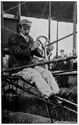
GLENN CURTISS ABOUT TO MAKE A FLIGHT
HENRI FARMAN STARTING ALOFT WITH TWO PASSENGERS
LOUIS BLÉRIOT SHORTLY AFTER COMPLETING HIS TRANS-CHANNEL FLIGHT
Great credit must be given to Chanute because it was in great part through his advice that the Wright 45 brothers achieved final success, and all biplanes to-day are known to the technical side of the aviation world as Chanute type machines. Chanute and Herring started experiments with gliders among the sand dunes on the southern shore of Lake Michigan, and, after some indifferent success with the Lilienthal monoplane type of glider, made a flier of five surfaces one above the other. The rudder was in the rear and the pilot hung below the machine. One by one experiments pared down the number of planes to three and then to two. The planes were arched, as they are in modern aeroplanes. The rudder extended behind the contrivance and had both horizontal and vertical blades. The whole machine weighed 23 pounds and had 135 square feet of plane surface.
The biplane was eminently satisfactory and Herring decided to make an engine for it and sail in a power-driven flier—or a dynamic aeroplane, as the scientists call it. His motor was a compressed air machine and he proposed to go into the air as if for a glide and then start the engine. According to newspaper accounts, he accomplished this and his compressed air engine drove him forward seventy-three feet in eight or ten seconds against a strong breeze. The flight was not given very much consideration, however, for lack of authoritative witnesses.
This brings us around again to the activities of 46 the Wright brothers, who started their work with the glider built along the lines laid down by Octave Chanute. They had the active support and aid of this inventor throughout their three or four years of experiments, although many other scientists were inclined to discredit their work.
While the brothers were going ahead with their practical flier the European scientists were developing with rapid strides and Prof. John J. Montgomery of Santa Clara College, Santa Clara, Cal., who was killed in a glider accident in 1911, was astonishing the far West with gliding experiments of great importance.
Montgomery's best glider was a tandem monoplane with a device by which the pilot could change at will the amount of curvature of any of the wings. This gave him the tremendous advantage of being able to vary the lifting power of the wings independently of each other and hence a means of maintaining side to side balance. Professor Montgomery made his own flights until injuring his leg in alighting, and then he hired trained aeronauts to glide from great heights. As it turned out it would have been better had he never resumed flying himself. He used balloons to carry up the gliders and when they reached the required altitude the operator cut the cable. Daniel Maloney, a daring parachute jumper, and two other aeronauts, named Wilkie and Defolco, carried on these hair-raising experiments.
Flights were made at Santa Clara, Santa Cruz, 47 San José, Oakland, and Sacramento, in 1905. The balloon would take up the aeroplane, and aviator, who sat on a saddle like a bicycle seat between the tandem planes and manipulated the wing control and rear rudder with hand levers and a pair of stirrups for his feet. In April of that year a forty-five-pound glider, such as the one described, with Maloney in the seat, was taken up four thousand feet. When the aviator cut loose he glided to earth, making evolutions never before made by man in the air, and finally landed as lightly as a feather on a designated spot.
Shortly afterward Maloney while making a sensational glide was killed. As the balloon was rising with the aeroplane, a guy rope switched around the right wing and broke the post that braced the two rear wings and which also gave control over the tail. Those below shouted to Maloney that the machine was broken, but he probably did not hear, and when he cut loose the machine turned turtle.
One of the saddest of all the many aeroplane fatalities was the accident early in the fall of 1911, in which Professor Montgomery was killed while experimenting with his glider.
Thus we see that the pioneers whose work has counted for the most in the early history of aviation were Americans—that the science can almost be claimed as a development of American genius. True, Ader was the first man to fly in a power-propelled machine, and Lilienthal led the way in the science 48 of gliding, but it remained for Chanute, Langley, Montgomery, and the Wright brothers to gather all this scientific data together and put it to practical use so that the motor could be installed and power flight, or dynamic flight, as the scientists call it, begun.
HOW THE INVENTORS CARRIED ON THE ART OF AVIATION UNTIL IT BECAME THE GREATEST OF ALL SPORTS AND THEN A GREAT INDUSTRY
SO INTERESTED in aviation had our young friend become that he forgot all other inventions in his enthusiasm for flying. He never missed a chance to go to the aviation field, and sometimes his scientist friend would go with him. These days were rare treats indeed, for the boy always learned some new and important points from their conversations.
With them we have seen how the science of aeronautics has been divided into two great departments: balloons, or lighter-than-air fliers, and all other machines that are not maintained in the air by hot air or gas. We have seen also the three great divisions of heavier-than-air aviation—that is, orthopters or wing-flapping machines; helicopters or machines that fly upward through the operation of horizontal screws; and aeroplanes. Lastly we see the three divisions of aeroplanes: gliders; dynamic aeroplanes, 50 or the machines we know to-day; and true bird soaring, the art of flying without artificial power and without the flapping of wings.
But on every side the boy heard people talking of great feats of flying that he knew nothing about.
"Who was Santos-Dumont? What was that first trans-Channel flight? Why do they always talk about the first Rheims meet?" he asked one afternoon as he was returning home from the field with the scientist.
The man could not answer the questions all in one breath, but we will follow his explanation, which extended over many pleasant hours, and see how aviation developed into a mighty sport and industry.
For several years following 1905 the world of aviation was led by Europeans—mostly Frenchmen who readily grasped the principles of the science and made the best and lightest motors that the world has ever seen. The United States, however, was the first nation to experiment with aeroplanes for military purposes, although at present the country is far behind France, England, and Germany in the development of aeroplanes for use in war.
Alberto Santos-Dumont, a daring young Brazilian who a few years earlier had astounded the world with his achievements with dirigible balloons, was the first of the aviators working in Europe to construct a practical man-carrying power flier. Scores of brilliant foreigners were working on the principles 51 for gliders laid down by Lilienthal, but Santos-Dumont, working along the ideas of the scientists who had built power-propelled models, made himself a clumsy biplane equipped with a 50-horsepower motor and actually inaugurated public flights, considering that all done by the Wrights up to that time was experimental and practically in secret.
On August 22, 1906, he made his first flight near Paris. It was brief, but authorities agree that it was the first time in Europe that a power-propelled flier had risen in free flight with a man at the steering wheel since Ader's secret flight in 1892. Two months later he made a public flight of 221 metres in 21 seconds, winning the world's first regularly offered aviation prize. This was the Archdeacon Cup of 2,000 francs authorized by the Aero Club of France for a flight of 100 metres.
Scientists gave these flights more attention than they did the flights of the Wright brothers the year before because they were viewed by many thousands of people and also by men who had studied the science of aviation for years. Besides this, Santos-Dumont made no secret of the construction or workings of his machine as the Wright brothers did. He was already a popular idol through his work with dirigible balloons, and being very rich—the son of a millionaire plantation owner in Brazil—he did not have the same financial incentive for keeping his plans secret.
52 His flights gave the aviators of France tremendous encouragement and it was but a short time until half a dozen aeroplanes, the makes of which are all well known now, were making successful flights and breaking records.
Santos-Dumont called his biplane an aeromobile. The two main planes had perpendicular surfaces enclosing them so that the wings of each side looked like two box kites hitched together side by side, as shown in the picture. The rudder extended to the front and it also looked like a box kite. The pilot sat just in front of the wings and could manipulate his rudder from side to side or up and down. Thus he could steer his machine from right to left, upward or downward. The Brazilian had not solved the problem of keeping his aeromobile from tipping sideways, so he arranged its wings in a dihedral angle, which balanced it fairly well. The starting and alighting device was a set of wheels which we know so well to-day. The biplane contained 65 square feet of plane surface and the total weight was 645 pounds.
Perhaps the most important factor in this machine was an eight-cylinder 50-horsepower Antoinette gasoline motor. This was the first time that this now famous motor was used in an aeroplane and it gave promise at that time of the prize-winning capabilities it later developed. The propeller, which was made of aluminum, was about six feet in diameter, 53 or about two feet less than the diameter of the twin screws in the early Wright biplanes.

Copyright H. M. Benner, Hammondsport, N. Y.
THE JUNE BUG
Glenn Curtiss making a flight in one of his first aeroplanes.

ORVILLE WRIGHT MAKING A FLIGHT AT FORT MYER
The aeroplane first became well known in this country when the Wright brothers carried on their Fort Myer tests.

Courtesy of the Scientific American
THE FIRST LETTER EVER WRITTEN ABOARD AN AEROPLANE IN FLIGHT
This was written at the time Ovington was carrying aeroplane mail from Garden City to Mineola, by aeroplane.
Several years before this the Voisin brothers had been taken by the general fever for aviation and in 1907 they finished a practical biplane in which Henri Farman, a former auto racer, and Leon Delagrange, an artist, astonished the world. This early machine is described by one authority as something like a cross between a box kite and a Chanute glider. Extending out behind the two main planes was a rudder like a huge box kite, which was used to steer the machine from right to left. This also helped to keep the biplane from tipping forward or backward. A single horizontal rudder in front steered it upward or downward. These rudders were manipulated by the operator, who sat between the two main planes in front of his engine, by either pushing his pilot wheel forward or backward or by turning it like the steering wheel of an automobile. There was no device for balancing the aeroplane, but the construction kept it on a fairly even keel—or, as the scientist said, it had inherent or automatic stability—i. e., stability automatically gained from the construction of the machine. Also the operator was supposed to swing his body from side to side to aid this. The aeroplane started from and alighted on four wheels set under the main plane and the tail. It had 559 square feet of surface and with the engine weighed 1,100 pounds. The motor was a 50-horsepower 54 Antoinette, which drove a single aluminum propeller.
After preliminary "bird hops" at Issy-les-Mollineaux, Farman on October 26 beat Santos-Dumont's record by flying 771 metres. On January 13, 1908, he won the Deutsch-Archdeacon Cup of 50,000 francs for the first person to make a circular flight of 500 metres. Two months later Delagrange challenged Farman for his world championship, but lost, Farman twice circling the two pylons, or marking poles, that had been set up 500 metres apart, in 3 minutes 31 seconds. The distance covered with turns was 2004.8 metres. Delagrange flew the 500 metres in 2.5 minutes.
Then for the first time in the world's history two men rode in an aeroplane, Delagrange taking his rival behind him and sailing over a part of the course. A month later Delagrange took the distance record from Farman with a flight of 5,575 metres in 9-1/4 minutes.
While these pioneers were winning prizes and breaking records Louis Blériot was bringing his aeroplane to a successful stage. He had been working on the problem of aviation since 1900, but had failed with wing flappers and machines like box kites. Finally he had some success with a tandem monoplane like Professor Langley's. The first of his machines of this kind was smashed in a fall, but the second, Blériot's seventh flier, flew steadily and was the fastest aeroplane ever developed.
55 Thus Blériot at the opening of 1908 had developed his monoplane idea far past the stage Professor Langley ever had developed it. He had increased the size of the forward plane and decreased the size of the rear plane until the great forward wings did all the work of sustaining the machine in the air, while the chief uses of the tail were steering and steadying the machine. Moreover, Blériot's was the first machine among the practical European fliers to have a system of wing warping such as the Wright brothers had developed in their wonderful biplane, and such as Glenn Curtiss, another American inventor, was at the same time developing for his machines.
This gave Blériot what is called three-rudder control—that is, the vertical rudder at the rear to steer it from right to left, the horizontal rudder, also on the tail, to steer it up or down, and the flexible wing tips to keep it from tipping sidewise. The aspect ratio of the early Blériots was low, which gave them greater speed. In other words, the main plane did not have so great a spread as most aeroplanes do, while it was much deeper, and, having less of an entering edge, it could go faster. There were three wheels—two under the main plane and the third under the tail for starting and alighting. The engine was just under and at the front of the main plane, driving a single propeller. This propeller—which is the type most used on monoplanes—is called 56 a tractor propeller because, instead of pushing the aeroplane forward from the rear, it pulls it from the front. The operator sat just to the rear and above the engine so he could look out and over the top of the main plane.
The last day of October, 1908, Blériot jumped into international fame with this machine by making a cross-country flight from Toury to Artenay, a total distance of about 17 miles. This was the second cross-country flight ever attempted. The day previous Farman had flown his biplane from Châlons to Rheims, nearly 17 miles.
Meanwhile the Wright brothers had been making great progress, as will be seen shortly, and Wilbur Wright had brought a biplane to France to make demonstrations for a French syndicate. He took up quarters at Le Mans in August, 1908. His notable flights broke the world's records for distance and duration. Early in the month he flew 52 miles and was in the air 1 hour and 31 minutes. A few days later he broke the French records for altitude by going up 380 feet, and on the last day of the year won the Michelin prize of 20,000 francs for the longest flight of the year.
In January Wilbur Wright went to Pau, where he opened a school and was joined by his brother Orville, who had just recovered from a historical accident in the United States which will be described shortly. At Pau they made a great many flights and exhibited 57 their aeroplane to thousands and thousands of people from all over the world, including great scientists, military men, statesmen, and many members of the European nobility. Among these was young King Alfonso of Spain, who took such a delight in the machine that he would have made an ascension were it not for the objections of his ministers. King Edward of England also visited the famous brothers, talked with them about their achievements, and witnessed several fine flights. Then Wilbur took his machine to Italy, where King Emanuel attended his exhibitions in Rome. Later in London the two brothers were entertained by the Aeronautical Society of Great Britain and received its gold medal. During this time they won the respect of the whole world of aviation.
"Now to return to the progress made by the intrepid American inventors in our own country, led by the Wright brothers, Glenn Curtiss, A. M. Herring, Dr. Alexander Graham Bell, and his associates, F. W. Baldwin and J. A. D. McCurdy," continued the boy's friend.
"You remember that toward the close of 1905 the Wright brothers suspended their flights near Dayton because it had become necessary for them to spend all their time in business negotiations. In the spring of 1908, after increasing the motor power of their flier, they began tests again because the brothers had agreed to furnish a machine to the United 58 States Signal Corps and another to a French syndicate."
The machine that was to be furnished to the Signal Corps, he explained, had to be able to carry two men and to be able to fly for one hour without stopping, at an average speed of 40 miles an hour. Furthermore, this flight had to be made across country dotted with hills, valleys, and forests. Another of the requirements was that the machine should be able to fly 125 miles without stopping. The Wright brothers agreed to furnish such an aeroplane for $25,000, and Orville Wright went to Fort Myer, Va., near Washington, for the tests.
His preliminary flights were very successful and thousands of Americans flocked to the drill ground to see what was practically the first public exhibition in the United States. About the time that the French aviators were making flights of 1 hour or so Orville Wright flew his machine for one hour and 3 minutes. Repeatedly he took Lieut. Frank P. Lahm or Lieutenant Selfridge for short flights.
On the 17th of September the tragic accident that put a stop to the flights occurred. Orville Wright was flying about 75 feet high with Lieutenant Selfridge as a passenger when one of the propellers hit a stay wire which coiled about the blade, breaking it and making the machine unmanageable. The aeroplane plunged to the ground, throwing the occupants forward. Lieutenant Selfridge suffered injuries from 59 which he died within three hours, while Wright suffered several broken bones. This occurred while Wilbur Wright was at Le Mans, France.
The year before Dr. Alexander Graham Bell, the American inventor, had invited Glenn Curtiss, a bicycle and motor manufacturer, to aid him in equipping with power the fliers that he was constructing with the help of Lieutenant Selfridge, F. W. Baldwin, and J. A. D. McCurdy. They formed the Aerial Experiment Association, which later became famous, and early in March, 1908, began the test of their first aeroplane, which they called the Red Wing. The machine was tried over the ice of Lake Keuka, near Hammondsport, N. Y., and before its makers were ready to fly it went into the air and sailed 300 feet. The Red Wing was of biplane type and mounted on skids, with the propeller and vertical direction rudder at the rear. The horizontal elevating rudder was at the front. The notable feature was the curve of the planes. The upper plane curved from the centre downward, while the lower plane curved from the centre upward, so that the two planes, if they had been a little bit longer, would have met. This curvature was expected to give automatic stability, but the machine was never a great success.
The next machine made by these experimenters was called the White Wing, and made some fair flights. The next was the famous June Bug which was designed by Curtiss and entered by him to 60 contest for the Scientific American Cup for a flight of one kilometre. The test, which was held on the 4th of July, 1908, near Hammondsport, was the first official flight for a prize in America, and was successful in every way, winning the cup with a flight of 200 yards. This biplane had the three-rudder control—that is, a tail at the rear shaped like a box kite to steer it from right to left, two small parallel planes in front to steer it up or down, and a system of flexible wing tips which enabled the operator to maintain a side to side balance.
In 1909 Curtiss made some important improvements over his machine of previous years by replacing the flexible wing tips with ailerons. This was the first time these devices were used in this country, but they had already been introduced in Europe on several machines. There are many kinds of ailerons, but on Curtiss's biplane they were two small horizontal planes fixed between the outer tips of the upper and lower planes. They could be turned so as to keep the aeroplane balanced when making a sharp turn or when struck by a gust of wind.
Curtiss and his partner, A. M. Herring, took the machine to the plains near Mineola, L. I., that summer, and began preliminary flights. They won several rich prizes, including that year's Scientific American Cup for the longest flight of the season. In this Curtiss made an official distance of 24-1/2 miles.

Photograph by the American Press
THE GODDESS OF LIBERTY
Photographed from an aeroplane

FIRST ACTUAL WAR EXPEDITION OF AN AEROPLANE
This picture shows Rene Simon returning from his scouting trip over the camp of the Mexican insurrectos, February 11, 1911.

WAR MANŒUVRES
American army aeroplane manœuvring over the troops mobilized at San Antonio, Texas, during the 1911 Mexican revolution.
61 We will leave Mr. Curtiss and his associates for the time being and take up again the work of the Wright brothers, who in the spring of 1909 returned to the United States after their European triumphs. Their laurels were further added to by a medal from the Aero Club of America, presented by President Taft at the White House, and medals from the Federal Government, the state of Ohio, and their home town of Dayton. All this time they were busy making the aeroplane with which they were to resume the final tests for the Government that had been interrupted the previous fall by the death of Lieutenant Selfridge. They arrived at Fort Myer in June, but spent most of that month and a large part of July in preparations and short practice flights. The great crowds, among which were scores of statesmen and politicians, gathered in Washington, became impatient at the delays, but the brothers had waited for a good many years to perfect their biplane and would not risk failure by attempting the official tests in bad weather, with their plane out of tune, or their engine in bad working order.
Finally ten thousand cheering spectators were rewarded by seeing Orville Wright ascend with Lieutenant Lahm as a passenger, and sail for 1 hour and 40 seconds, fulfilling the endurance requirements. The next few days the weather prevented the distance test, but one calm evening just before sunset Orville carried Lieut. B. D. Foulois 62 across hills and valleys to Alexandria and return at an average speed of 42.6 miles per hour. This won the brothers a bonus of $5,000 on the price of the machine because they were to receive $2,500 extra for each mile per hour more than the 40 miles per hour called for in the contract. It was the greatest feat of aviation ever seen in the United States at the time and the ovation tendered the brothers was equal to the occasion. Not once, however, did they lose their heads in the slightest or show any undue enthusiasm over their achievement. Statesmen, army officers, and newspaper men crowded around with congratulations and praises, but the great victory was only what the brothers had expected and they soon were planning improvements on their biplane.
The real meaning of this feat by the Wright biplane, however, was that the United States was the first nation officially to adopt an aeroplane for military purposes. To Americans it seems peculiarly fitting that it was the Wright machine that was adopted because it was the Wright aeroplane, strictly an American product, that was the first practical flier.
Later on Wilbur returned to Fort Myer to finish off his contract by teaching two Signal Corps officers to handle the machine. During this time the aviator changed his biplane by transferring one of the forward elevating planes to the rear, where it was used as a fixed tail to give greater stability from front to rear. This was such a success that it was used in 63 subsequent models, and the present-day Wright biplanes have no forward lifting plane at all—the horizontal plane at the rear serving as the elevator and also as the fore and aft balancer.
In the fall of 1909, after the Fort Myer tests, the brothers again separated, Orville going to Europe, where he achieved more distinction, and Wilbur remaining at home to astonish his countrymen with his exhibitions at the Hudson-Fulton Celebration. He made the first trip around the Statue of Liberty on September 9, starting from and returning to Governor's Island in New York Bay.
In the meantime the European aviators were making even greater strides, and 1909 saw many new aeroplanes take the air to break records of different kinds. Throughout the season there was hardly a day that some record was not broken, or that some previously unknown man did not achieve undying fame for his daring feats.
Aeroplane schools were established and aviation passed from the stage of experimenting into the stage of record making and breaking.
The European governments, particularly France and Germany, were carefully watching progress, and dozens of the pupils in the aviation schools were young officers detailed to learn the art of flying and report on its usefulness in warfare. Also the building of aeroplanes became a great industry and in France thousands of scientists, designers, mechanics, motor 64 experts, and wood-working experts were engaged in turning out machines as fast as they could.
It would be impossible in this brief space to describe all of the important flights of the last few busy years in aviation, which were talked of by the boy and his scientist friend, but a very brief outline of the feats accomplished will show the wonderful progress that has been made. The first great international meet, which was held at Rheims, France, in 1909, did more than anything else up to that time to show the world how far the science had gone and how many good machines there were. So great was the public interest in this meet that before the end of the year meets were arranged and held at Blackpool and Donchester, England; Berlin, Juvisy, France, and Brescia, Italy. The most notable achievements of the year in Europe were the flight across the English Channel by Blériot in his graceful monoplane, by which he won the prize of 1,000 pounds offered by the London Daily Mail, the winning of the James Gordon Bennett Cup by Curtiss, the only American to contest for the great honour, and the winning of the Grand Prix by Farman in his biplane. Blériot, while practising, before his famous flight across the English Channel, broke many records with his monoplanes, No. XI and No. XII. He was the first man to take two passengers in such a craft, those in the machine besides himself being Santos-Dumont and A. Fournier. The total weight of machine and 65 three men was 1,232 pounds. He also made several cross-country records and received medals from the Aero Club of Great Britain and the Aero Club of France.

HARRY N. ATWOOD
Arriving at Chicago on his flight from St. Louis to New York
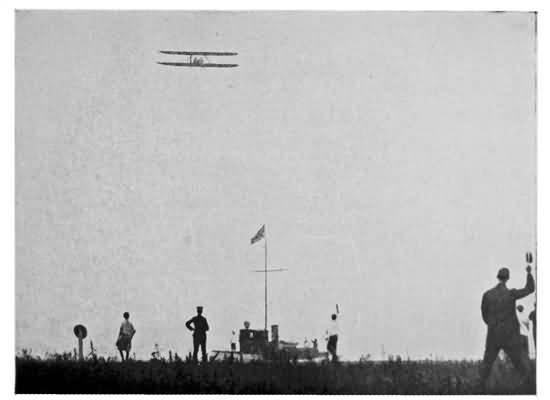
THE FINISH OF ATWOOD'S ST. LOUIS TO NEW YORK FLIGHT
The aviator is here seen arriving at Governor's Island in New York Bay

POSTMASTER-GENERAL HITCHCOCK AND CAPTAIN BECK STARTING WITH THE AERO-MAIL
This is the first time regular United States mail ever was carried by aeroplane. Throughout the meet at Garden City in 1911, Earle L. Ovington and Beck carried mail over a regular route
Blériot's flight over the English Channel was one of the most dramatic that ever has been made by an aviator, as he encountered perils that no birdman ever before had faced. He had as a contestant one of the daring young aviators who has made the history of aviation read like a novel. This was Hubert Latham, who used the Antoinette monoplane, one of the most beautiful machines ever designed, and which is described fully later on. Young Latham had become a popular hero because of his daring feats. The aviators said that he was carrying on an endless battle with the wind, for he seemed to prefer flying high in the air when the wind was so gusty that other aviators were afraid to leave their hangars. He had made several monoplane records for endurance and altitude, and after a notable cross-country flight announced his intention of sailing across the English Channel to collect the 1,000 pounds from the Daily Mail. So he took his graceful monoplane to Calais, and after impatiently waiting for fair weather, soared from the towering cliffs and out over the stormy waters of the English Channel. Thousands cheered his daring and wished him success, but before he had gone more than six miles his motor failed him and he glided to the water. In a few minutes the 66 boat that was sailing below him came up and found him calmly sitting on the upper framework of his machine, which was buoyed up by the great wings. He was looking as unconcerned as if he had been sitting in a motor boat on a lake, and declared he would try again the next day. His machine was wrecked in getting it ashore, however, and Blériot made his famous flight before the young man could get it repaired.
The older man had been injured in an accident and was still walking on crutches, with a badly burned foot, when a favourable opportunity for the trans-channel flight came. He was awakened before dawn on the morning of July 25th, and, throwing away his crutches as he got into his machine for a practise spin, he said: "I will show the world that I can fly even if I cannot walk."
At 4:35, just as the sun was rising, he sailed out over the precipice, and Latham, watching him, wept with disappointment at not being able to enter the contest. A torpedo boat destroyer was following him, but soon she dropped behind and he was over the trackless channel without any landmark to guide him. Finally the coast of France dropped out of sight and the intrepid aviator was alone, with nothing but his carefully planned monoplane between him and death in the tossing waters hundreds of feet below.
After ten minutes of this the cliffs of the English 67 coast loomed up ahead, bathed in the early morning sunlight. He saw several boats far below him and followed their course, which brought him to the town of Deal, near which he landed. The first man to greet him was his good friend M. Montaine, but soon after a crowd of Englishmen were crowding about congratulating him on his wonderful achievement. Not to be outdone, young Latham cabled his congratulations.
August saw the beginning of the first great international meet at Rheims. Most of the leading aviators of the world gathered there to contest for the prizes and for fame. Curtiss, Blériot, Farman, Latham, Lefabre, Count de Lambert, Paul Tissandier, Louis Paulhan, Le Blanc, Roger Sommer, and Rougier all distinguished themselves and made their names as familiar in this country as they were in France.
Latham, with his apparently fearless disregard of danger, and his great, soaring Antoinette monoplane that looked more like a dragon-fly when up in the air than anything else, was one of the popular idols. Not only did he fly in rough winds but also in heavy rainfall, as did his rival, Blériot. Of course there were several bad accidents, but none to compare with the later fatalities.
The winning of the $10,000 Grand Prix de la Champagne for the longest flight was not so spectacular as the next day's great race. Latham had 68 made a record of 96 miles that it was thought would stand. On the day of the finals, Friday, August 27th, Latham again took the air, making a spectacular flight several hundred feet high. At the same time several others were performing evolutions in the air, some high and some low. Farman was flying close to the ground and making but poor time in his slower craft. Finally, after all the others had come to earth, the longest flight having been made by Latham, with 68 miles to his credit, the crowd realized that Farman was making a record. Time after time he passed the grand stand, marking off the miles. It became dark, but the crowd still lingered, and was rewarded finally by seeing him bring his machine softly to the ground in front of the judges' stand, winner of the $10,000, with a record of 190 kilometres. His friends, wild with joy, pulled the exhausted aviator from his seat and carried him off the field on their shoulders.
The next day Curtiss, the only American taking part in the meet (although several Wright biplanes were flown by Frenchmen), brought out his 60-horsepower biplane to try for the speed prize of $5,000 offered by James Gordon Bennett. He made two rounds of the field at a speed of 47.04 miles an hour. Blériot then brought out his great 80-horsepower monoplane, but the test flights were discouraging. Finally, after working over his machine all afternoon and trying several propellers, he started at five o'clock 69 and made his first round in much better time than Curtiss had done. He slackened up on the second round, however, and came to earth to find that he had lost to the gallant American. By winning the prize Curtiss was allowed to take the next year's contest to his own country.
There were many other records broken at the other meets held in 1909, but none of them stood long after the 1910 season had got well under way. Altitude, endurance, distance and speed records all were shattered by the ever-increasing army of aviators and the constantly improving machines.
Undoubtedly the most spectacular and daring feat of 1910 was the flight across the Alps by George Chavez, who was born in Paris of Peruvian parents only twenty-three years before his tragic death. In September of that year he set out to win the prize of 70,000 francs offered by the Italian Aviation Society to the first aviator who would fly the 75 miles from Brig to Milan, across the towering peaks and yawning chasms of the Alps. Of the five who entered the contest Chavez was the only one to make a real start. After waiting for several days, during which wind, rain and fog kept him chained to the ground, he finally rose in the air.
In a few minutes he was 7,000 feet above sea level, crossing the famous Simplon Pass, braving the fierce eddies of wind that swirled around the cruel, jagged crags and precipices. Finally he crossed the mountains 70 and glided down the Italian slope to Domodossola. Thousands had gathered to greet his arrival, but as he was sinking gradually to the earth, only thirty feet above the ground, a gust of wind caught the machine, the wings collapsed and the brave young man fell to earth underneath the machinery. He received injuries from which he died four days later. The committee granted him one third of the prize on the basis that he had completed the difficult part of the journey.
No less dangerous was Glenn Curtiss's trip from Albany to New York in his biplane, by which he won the $10,000 prize offered by the New York World. Most of his route lay over wooded hills, the waters of the Hudson River, or the cliffs along its banks, which territory, as any one who has travelled from New York to Albany knows, offers few landing places. Starting with a letter from the Mayor of Albany to the Mayor of New York and followed by a special train on the New York Central he made Camelot, 41 miles from Albany, in about an hour. The next jump was clear to Spuyten Duyvil, the northern boundary of Manhattan, which completed the required 128 miles in a total elapsed time of 2 hours and 32 minutes. His average speed was 50-1/2 miles an hour.
This stage of the journey nearly brought serious disaster to the aviator, for, while passing the famous old mountain Storm King, he was caught by a terrific 71 gust of wind and his machine was twisted sideways so that it dropped suddenly toward the river. By skilful manipulation he righted his biplane and continued.
After a brief pause at Spuyten Duyvil he sailed down the Hudson River and the upper New York Bay to Governor's Island. Every whistle in the harbour, a few million people and the reporters representing the newspaper readers of the whole civilized world, proclaimed his victory over the wind gusts eddying around the palisades and the New York skyscrapers.
In the United States there were many aviators besides Curtiss who were making an effort to win long distance prizes. The New York Times and the Philadelphia Ledger had offered a large purse, supposed to be $10,000, for the first flight from New York to Philadelphia, and on June 13th, a few days after Glenn Curtiss's flight from Albany to New York, Charles K. Hamilton, another young man new to aviation, sailed in his Curtiss biplane the 86 miles from Governor's Island to Philadelphia in 1 hour and 43 minutes, and returned the same day. His average speed was 50-1/2 miles an hour, the same maintained by Curtiss in his Albany-New York trip. These two flights added tremendously to the fame of the Curtiss machines.
The great International Aviation Tournament of 1910, held at Belmont Park in October, was the 72 climax of the season in this country. Of course interest centred around the race for the James Gordon Bennett Cup and prize of $5,000, which had been won the year before at Rheims by Curtiss. The total prizes amounted to $60,000 and practically every standard make of aeroplane was represented. The American aviators came into prominence at this meet, as will be remembered by the feats of Walter Brookins, Arch. Hoxsey, Ralph Johnstone, J. A. Drexel and a dozen others. The English contingent was led by Claude Grahame-White, who had been making himself famous at the Harvard-Boston meet. Of the Frenchmen, Alfred LeBlanc, Hubert Latham, Emiel Aubrun and Count de Lesseps were among the leaders.
Nearly every one nowadays is familiar with the story of how Grahame-White brought out his 100-horsepower Blériot monoplane for its first trial and made 100 kilometres at an average speed of 61 miles an hour. Soon after that LeBlanc came out with another 100-horsepower Blériot, acknowledged to be one of the swiftest machines ever made at that time, and started on a race around the course at a speed such as the world had never seen before. In the last lap his gasoline gave out, the aeroplane shot downward and was smashed against a telephone pole. LeBlanc was more angry than injured, because he had lost the race, although his speed had been 67 miles an hour, or six miles better than Grahame-White's. 73 Brookins, with the Wright biplane racing machine, started out with high speed, but the engine soon began to miss fire and he too came to earth. Consequently Grahame-White carried off the prize.
The next day the aviators were out to contest for the $10,000 offered by Thomas F. Ryan for the quickest flight from the aviation field to the Statue of Liberty in New York Harbour, 16 miles away, and return. Never before was there such a dramatic race. Together Count de Lesseps and Claude Grahame-White, both in Blériot machines, started for the Statue. John Moisant, the American aviator, who only that summer had made the first flight from Paris to London, suddenly determined to win the prize. It took him about five minutes to buy LeBlanc's 50-horsepower Blériot monoplane for $10,000, and just as Grahame-White and de Lesseps were returning from their flight Moisant started out. Instead of taking the safer roundabout course, where there were many landing places, this dauntless birdman sailed directly over the church steeples of Brooklyn, cutting through the treacherous air currents at terrific speed, circling the Statue at great altitude and returning by the same route. His time was 43 seconds better than that of Grahame-White, who flew a machine of double the power. The Americans were wild with delight, thinking Moisant had won the prize, but the committee finally gave the 74 award to Count de Lesseps, who made the slowest time, because Grahame-White had fouled the starting post, or pylon, as it is called by aviators, and because Moisant in his desperation to get started had failed to qualify.
But there were other records broken. Ralph Johnstone, flying the small Wright biplane racer, which was equipped with particularly large propellers, broke the altitude record of 9,104 feet which had been set in France by climbing to an altitude of 9,714 feet. The round trip to and from the clouds took him 1 hour and 43 minutes. In connection with the altitude trials, the daring of Johnstone and Hoxsey was particularly notable. Both of these aviators took up their Wright biplanes when the wind was blowing so fiercely that they could hardly turn the pylons. When they got to a great altitude, one time the gale was so terrific that they were carried backward at a speed of nearly 40 miles an hour, and both of them had to land in open country; Johnstone at Holtsville, L. I., 55 miles away, and Hoxsey at Brentwood, half that distance. During these flights both of them had reached altitudes of more than a mile in the air. But these records were not destined to stand long, as will be shown by the table on page 75.
But world's distance and altitude records were being broken in Europe, too, and during the summer of 1910 the record keepers were busy putting new 75 names at the heads of their lists, as will be shown by the table on page 76. The long distance speed race, called the "Circuit de l'Est," which took in a course 488 miles long, of six towns around Paris, aroused as much enthusiasm as any. The prize which was offered by the newspaper Le Matin of Paris was for 100,000 francs. The race started on August 7, with eight contestants, and ended on August 17 with Alfred LeBlanc, in his Blériot monoplane, the winner. He had made the distance in six stages at an average speed of 40 miles an hour, flying through rain, fog and wind. Next came Aubrun in a Blériot and Weyman in a Farman. Not only was this race one of the severest tests that the aeroplane had ever had, but also it was a trial to the aviators that did a great deal to prove the practicability of the aeroplanes for more serious work than pleasant day sport.
ALTITUDE FLIGHTS IN 1910[A]
| AVIATOR | ALTITUDE | AEROPLANE | PLACE | DATE |
| Paulhan | 4,164 feet | Farman biplane | Los Angeles | Jan. 12, 1910 |
| Olieslaegers | 4,490 " | Blériot monoplane | Brussels | July 30, " |
| Brookins | 4,503 " | Wright biplane | Indianapolis | July 16, " |
| Latham | 4,658 " | Antoinette monoplane | Rheims | July 7, " |
| Chavez | 5,850 " | Blériot monoplane | Blackpool | Aug. 3, " |
| Morane | 6,691 " | Blériot monoplane | Havre | Aug. 29, " |
| Morane | 8,469 " | Blériot monoplane | Havre | Sept. 2, " |
| Chavez | 8,790 " | Blériot monoplane | Issy, Paris | Sept. 8, " |
| Drexel, A. | 9,450 " | Blériot monoplane | Philadelphia | Oct. 31, " |
| Johnstone | 9,714 " | Wright biplane | Belmont Park | Nov. 23, " |
| Legagneux | 10,746 " | Blériot monoplane | Pau | Dec. 9, " |
| Hoxsey, A. | 11,476 " | Wright biplane | Los Angeles | Dec. 26, " |
DISTANCE AND ENDURANCE FLIGHTS
| AVIATOR | AEROPLANE | DISTANCE MILES | TIME HR. MIN. |
PLACE | DATE |
| L. Paulhan | H. Farman bi-p | 108 in all | 2 3 | Chevilly-Arcis-sur-Aube to Châlons two stages. | Apr. 18, 1910 |
| Grahame-White | H. Farman bi-p | 83 | 2 5 | London to Rugby. | Apr. 23, 1910 |
| L. Paulhan | H. Farman bi-p | 193 | 4 12 | London to Manchester, two stages. | Apr. 28, 1910 |
| G. H. Curtiss | Curtiss bi-p. | 150 | 250 | Albany to New York | May 29, 1910 |
| C. K. Hamilton | Curtiss bi-p. | 86 | 1 43 | New York to Philadelphia. | June 13, 1910 |
| R. Labouchere | Antoinette mono-p | 211.27 | 4 37 | Over course Rheims, France, world's record | July 9, 1910 |
| J. Olieslaegers | Blériot mono-p | 244.43 | 5 3 | Rheims, France, world's record. | July 10, 1910 |
| A. Leblanc | Blériot mono-p | 485 | 251 55 elapsed time |
Circular course, Paris, Troyes, Nancy, Mexziers, Douai, Amiens and back. | Aug. 7-17, 1910 |
| E. Aubrun | Blériot mono-p | 485 | 252 15 elapsed time | Same as above. Won second prize. Arrived only 20 minutes later than Leblanc. | Aug. 7-17, 1910 |
| M. Cattaneo | Blériot mono-p | 141 miles 188 yds in all | 3 18 | Lanark, Scotland. | Aug. 7-17, 1910 |
| R. Johnstone | Wright bi-p | 101 miles 389 feet | 3 5 | Boston | Sept. 3, 1910 |
| Walter Brookins | Wright bi-p | 192.5 in all | 5 49 | Chicago to Springfield, Ill., two stops. | Sept. 29, 1910 |
| Arch Hoxsey | Wright bi-p | 109 | 3 33 | Springfield, Ill., to St. Louis, Mo., one stop, | Oct. 8, 1910 |
| M. Tabuteau | H. Farman bi-p | 289.39 | 6 1 | Buc, France. | Oct. 28, 1910 |
| G. H. Curtiss | Curtiss bi-p | 120 | Across Lake Erie and return. | Aug. 31, 1910 | |
| J. A. D McCurdy | Curtiss bi-p | 90 | 2 | Key West to near Havana (fell into ocean). | Jan. 30, 1911 |
| Capt. Bellenger | 330 | 8 22 | Paris to Bordeaux, France. | Feb. 1, 1911 | |
| Lieut. Bague | 124 | 4 32 | Antibes, Italy, across Mediterranean to Gorgona Island. | March 5, 1911 | |
| Hirth | 330 | 5 41 | Munich to Berlin, Germany. | June 29, 1911 | |
| Vedrines | 267 | 3 50 | London to Paris | Aug. 2, 1911 | |
| H. N. Atwood | Burgess-Wright bi-p. | 462 | 17 12 Net flying time | Boston to Washington | June 30, July 11, 1911 |
| H. N. Atwood | Burgess-Wright bi-p. | 1,266 | 28 53 Net flying time | St. Louis to New York | Aug. 14-25, 1911 |
| Olieslaegers | Blériot | 388 | 7 18 | Kiewit, Belgium (over course). | July 17, 1911 |
| Loridan | 434 | 10 43 | Mourmelon, France (over course). | July 21, 1911 | |
| 77Vassilieff | 400 | St. Petersburg to Moscow. | July 24, 1911 | ||
| Renaux | M. Farman | 428 | 12 12 | Chartres, France (over course). | Aug. 7, 1911 |
| Vedrines | Morane | 504 | 8 54 | Issy, France (over course). | Aug. 9, 1911 |
| C. P. Rodgers | Wright bi-p. | 4,029 | 82 4 Total flying time | N. Y. to Long Beach, Cal., World's record. | Aug. 14,-Dec. 6, 1911 |
| Helen | Nieuportmono-p | 704 | 12 40 | Bethany, France (over course), 3 stops. | Aug. 26, 1911 |
| Helen | Nieuportmono-p | 778 | 14 7 | Etampes, France (over course), 3 stops. | Sept. 8, 1911 |
| Lieuts. Ellyson, Towers | Curtiss bi-p | 140 | 2 27 | Annapolis to near Fortress Monroe (over water). | Oct. 25, 1911 |
Then, too, there was the great London to Manchester race for the $50,000 offered by Lord Northcliffe, owner of the London Daily Mail. This was one of the most exciting contests of the year, not only because of the difficulties of the trip, but also because of the nip and tuck finish between the two contestants.
Claude Grahame-White had just purchased a Farman biplane, and hearing that Paulhan was hurrying across the Atlantic from the United States to try for the prize himself, the Englishman announced that he would start as soon as his machine could be set up. He had had but little experience with the biplane, as always before that time he had used a Blériot, but nevertheless, in spite of the advice of his friends to wait, Grahame-White started on the 183-mile flight on the morning of April 23d in the teeth of a high wind. According to Grahame-White's 78 own account of the flight he was buffeted about so unmercifully by the wind that several times he thought he would have to descend. At the same time the cold was so intense that he suffered agonies. He reached his first stop at Rugby in safety, though so cold he had to be lifted from his seat, but soon after taking the air again the gale rose to such a pitch that he was forced to land. He went to a hotel to rest and wait for the wind to abate, but while there the gale tipped over his biplane, smashing it so badly that the aviator had to give up and take his machine back to London practically to be rebuilt.
Meanwhile Paulhan had reached England and was rushing his workmen night and day to get his aeroplane set up before Grahame-White could complete his repairs and make a fresh start.
Finally, with the wind still blowing a gale, Paulhan started for Manchester. Grahame-White heard of this at 6:30 in the evening, but manfully started after his competitor and flew 60 miles, when he was finally forced to land in the dark. Determined to remain in the race, he started again about three o'clock in the morning with the intention of trying to catch up with the daring Frenchman. Besides the bitter cold, it was so dark that the Englishman could not see whether he was flying high or low or even toward Manchester. The danger of this kind of flying he knew was very great, because if his engine failed him he would have had to come to 79 earth anywhere he happened to light, as likely on a church steeple or in a lake as on a level spot. Of this famous flight Grahame-White wrote in his book, "The Story of the Aeroplane":
"My start was really something in the nature of a confused jumble. Faint lights swept away on either side as my machine moved across the ground. I could not judge my ascent at all, on account of the darkness. But I elevated as quickly as possible, and got away from the ground smartly.
"Directly I was at a respectable height, I could see the lights of the railway station very distinctly. I headed toward them. Looking directly down, I found that I could distinguish nothing on the ground below me. It was all a black smudge. I flew right over the lights of the railway station—and as I was doing so my engine began to miss fire. It was certainly a very uncomfortable moment—one of the most uncomfortable I have ever experienced.
"But, very fortunately for me, after a momentary spluttering, the engine picked up again, and fired properly. I had begun to sink toward the ground, upon which I knew I could have picked out no landing place in the darkness. As soon as my engine began to do its work again, however, I rose and continued my flight smoothly."
With the dawn came a terrific wind which forced the aviator to land near Polesworth. While waiting for the wind to abate the Englishman and his friends heard Paulhan had reached Manchester and won the prize.
80 Of Paulhan's famous flight, one of the men who was aboard the special train following Paulhan, according to Mr. Grahame-White, said:
"I do not think I have ever seen a machine roll about in the air as his did. He was, we could see, incessantly at work. One wind gust after another struck the machine and it literally reeled under the shock.
"Up and down it went, and from side to side. Paulhan's pluck and determination were remarkable. I do not think that any other man could have kept on with such determination as he displayed. It was a strange thing to see how the wind got worse and worse as the airman flew on."
But these feats that startled the world in 1910 would not cause a ripple of enthusiasm now, since the North American Continent has been crossed by aeroplane; since the trip from Boston to Washington and from St. Louis to New York has been made; since a machine has stayed in the air a whole day, or more than eight and a half hours, since a dozen passengers have been carried half a dozen miles and since the development of the hydro-aeroplane.

Copyright, by Brown Brothers, N. Y.
CHAVEZ ON HIS FATAL FLIGHT ACROSS THE ALPS

THE LATE CALBRAITH P. RODGERS, TRANS-CONTINENTAL FLIER
This picture was taken just after Rodgers had picked himself up after one of the many smash-ups of his aeroplane during his ocean to ocean flight.
Of course it hasn't all been the winning of prizes and the cheering of crowds, for, as we all know, there has been a tragic side to aviation. Up to the summer of 1912 more than 150 persons had met death in aeroplane accidents. To analyze all these accidents would require a whole book, but experts 81 agree that in a great many cases they were the result of carelessness on the part of the pilot. Of course there were other causes, such as the collapse of the wings, the breaking of stays, the overturning by wind gusts, "holes in the air," the explosion of the motor, the failure of the motor at a critical time, or the collapse of the aviator, but authorities declare that many of these can be prevented by the use of proper care by the designers, manufacturers, and pilots of the air vehicles.
Two of the most tragic of the recent air fatalities were the deaths of Arch. Hoxsey and Rodgers at Los Angeles, the former in December, 1910, and the latter in April, 1912. Hoxsey had just set a world's record for altitude in his Wright biplane, while Rodgers only a few months before his death had completed a transcontinental flight and made a world's record.
Several women aviators also were killed in 1912, including Miss Harriet Quimby, one of the first American women to take up flying. Miss Quimby's machine fell with her in Boston while she was making an exhibition flight.
The 1911 death roll of American aviators included: Lieutenant Kelly, U. S. A.; A. Hartle, Los Angeles; Kreamer, Badger and Johnstone, Chicago; Frisbie, Norton, Kan.; Castellana, Mansfield, Pa.; Miller, Troy, Ohio; Clarke, Garden City, N. Y.; Dixon, Spokane, Wash.; Ely, Macon, Ga.; and Professor 82 Montgomery, Santa Clara, Cal., whose early experiments are held in such high esteem by scientists.
Just as 1910 was the year for record-breaking aeroplane contests, 1911 was the year that proved the aeroplane a machine with a greater and more important use than that of a very exciting and a very expensive sport. Probably the most astounding developments in the world of aviation in 1911 were the experiments of the Wright brothers at Kitty Hawk, which showed that man has come very near to solving the problem of true soaring flight. We will look more closely at the experiments in a later chapter.
Of much greater practical use was the development of the hydro-aeroplane by Glenn Curtiss. His lead in this was quickly followed by the Wrights and most of the European makers.
The year 1911 saw the aeroplane employed for the first time in the world's history in actual warfare. When the revolution was raging in Mexico in February, 1911, the Diaz Army sent Rene Simon in a Blériot monoplane to make a scouting trip over the camp of the insurrectos. A little later on Lieutenant Foulois of the American Signal Service, whose name will be remembered in connection with the Fort Myer experiments, sailed over and about the camp of the mobilized American Army at San Antonio, Texas, while the Mexican revolution was in progress just across the American boundary line.
Next came the use of the aeroplane for scouting 83 by the Italian Army in its invasion of Tripoli. All of these expeditions showed that the aeroplane can be used more successfully in war for scouting than as a means for dropping explosives. Of course there have been many experiments conducted by aviators in dropping paper bombs, but army officers both in the United States and abroad are not agreed as to the success of such projects.
Another of the important military experiments has been the equipping of aeroplanes with wireless apparatus so that a wireless operator in the machine with the aviator could send and receive brief messages such as would describe the position and strength of an enemy in war time. Also many aviators have taken up with them photographers who have taken accurate photographs of both the still and motion variety of the country over which they were passing. Of course the armies of the world are building guns which will carry to a great altitude as a defence from aerial attack.
Although the first country to adopt aeroplanes for use by its army, the United States is now far behind other nations in its aviation squads. The United States Signal Corps owns only a few Wright and Curtiss biplanes, with only a small number of officers who know how to fly them. France has an extensive fleet of several hundred aeroplanes and a small army of aviators, while Germany has established a school for aviation where sixty or seventy officers are always 84 being instructed in flying the various types of machines. The German Army has now more than one hundred aeroplanes, besides many dirigible balloons. The British Government has not gone so far, but has conducted some interesting experiments in which Claude Grahame-White was one of the leaders.
The latest things in the aeroplane, however, are always expected to be brought out at the French Army tests, and several machines that were first exhibited in this way will be described a little later on.
But not only in war is the aeroplane being developed, but also in the greater work of peace, because the aeroplane enthusiasts expect that in the near future the art will be developed to such a degree of safety that regular systems of passenger traffic can be installed. Besides this, the aeroplane is the fastest mode of travelling now known, and it may be used for the carrying of mail. It was only in the summer of 1911 that the first aeroplane mail route of the United States was established between the aviation field in Garden City, L. I., and the United States post-office at Mineola, several miles away. Daily throughout the meet at Garden City Captain Beck and Earle L. Ovington carried a sack of officially stamped and sealed mail from the post-office on the field to the postal station at Mineola. The first sack was handed to Beck by Postmaster-General Hitchcock. Before this, mail had 85 been carried by aeroplane in England, but not on a regularly established route.
Also the aeroplane has been pressed into service by deputy sheriffs seeking criminals and by searching parties hunting for lost persons. The former was done in Los Angeles when a gang of desperadoes escaped into the California desert and an aeroplane soared over the sagebrush in an effort to locate them, while the latter was done near New York after duck hunters had got lost in a storm on great South Bay, and near New Orleans when an aviation student skimmed over Lake Pontchartrain and located the body of a man drowned there.
These are some of the useful developments of the aeroplane. Of course there have been many spectacular achievements such as the trip of Calbraith P. Rodgers, a comparatively inexperienced aviator, from Sheepshead Bay, N. Y., to Long Beach, Cal., across the whole American continent; the trips of Harry N. Atwood from Boston to Washington and from St. Louis to New York via Chicago, Buffalo and Albany; the trip of Vedrines from Paris to Madrid, across the Pyrenees Mountains, and the terrific speed of about 155 miles an hour, or more than two and a half miles a minute, maintained by Vedrines for eighty miles. Just to think of such a speed would take the ordinary person's breath away, but the aviators speak of it calmly and say it won't be long before it will be a common thing for aeroplanes to 86 make a speed of 200 miles an hour, about twice as fast as the fastest automobile has ever burned up the road. Then, too, there was the winning of the James Gordon Bennett Cup and prize in England by C. F. Weyman, an American who flew a Nieuport monoplane equipped with a 100-horsepower Gnome motor. It would be impossible in our space to give a list of the contests, races, circuit races and endurance tests of the year. Not only were aeroplanes seen in the United States, but they were flown in South America, Africa, Australia, Japan, India and China. The Sphinx in the Great Sahara Desert, the Panama Canal, Niagara Falls, the Chinese Wall, the Far Eastern temples to Buddha, and the Islands of the Antipodes all have been circled by the dauntless birdmen, as well as the Goddess of Liberty in New York and the Eiffel Tower in Paris.
Young Atwood started from Boston without much ado on June 30, 1911, sailed 93 miles to New London, Conn., and the day following reeled off the 112 miles to New York as easily as he would walk across the street. The Fourth of July he went to Atlantic City; July 10th he sailed from there to Baltimore, a distance of 122 miles, which was made in four hours and a half; and the day after that finished up by sailing into Washington, D. C.
This young aviator still was not satisfied and shipped his aeroplane to St. Louis, from where on August 14th he started for New York. His longest 87 single flight was made from St. Louis to Chicago, 283 miles in 6 hours and 32 minutes. Flying an average distance of 105-1/2 miles a day for the remaining eleven days, he completed the 1,266 miles on August 25th. His total flying time was 28 hours and 53 minutes, and his average speed 43.9 miles per hour.
Far more exciting was the record-breaking flight of the ill-fated Rodgers from the Atlantic to the Pacific. He had a number of severe falls, but his determination carried him through in spite of everything. His machine was a specially constructed Wright biplane model Ex, something of a mixture between the regular racing and passenger carrying types. Starting from Sheepshead Bay, N. Y., on September 17th, the young giant, who had only learned to fly that summer, was off on the longest trip ever attempted by a birdman. After being on the go for forty-nine days, he sailed over the coast towns to Long Beach on the Pacific Ocean. He was actually in the air the equivalent of 3 days, 10 hours, 4 minutes; made an average speed of 51 miles an hour, and his longest single flight was from Sanderson to Sierra Blanca, Texas, on October 28th, a distance of 231 miles. He crossed three ranges of mountains, two deserts and the continental plain; he wrecked and rebuilt his machine four times and replaced some parts of it eight times; he rode through darkness and wind and rain and lightning, 88 at the heart of a thunder cloud. Once his engine blew up while he was 4,000 feet high and he had to glide to earth. A special train with duplicate parts, a complete repair-shop, and mechanics followed as he winged his way up the Hudson across New York State, across the plains of the Middle West, down through Kansas, Oklahoma and Texas, across the Arizona and California deserts, over the Pacific range, and finally to the western ocean. His worst accident came at Compton, Cal., on the last stage of his journey, when he was so badly injured that he was laid up twenty-eight days. This occurred on November 12th, but, persevering to the end, Rodgers arose as soon as he was able and sailed to the ocean on December 10th.
Rodgers remained in California the rest of the winter, giving many exhibitions of his daring and skill, only to meet his death while holding the world's record. On April 3, 1912, while 7,000 persons at Long Beach, near Los Angeles, watched his evolutions, his machine tipped forward. The crowd cheered, thinking it a daring dive, but became silent when they saw the aviator had lost control. From a height of 200 feet the biplane plunged into the surf where the water was only two feet deep. When the people reached the broken machine Rodgers was dead—his neck broken. There was nothing to show the cause of the biplane's dive. The spot where Rodgers was killed is only a few yards from the one 89 where he completed his transcontinental flight, and where the citizens of Los Angeles planned to erect a monument to his achievement.
Most boys are perfectly familiar with the important events of 1912 in aviation, which the scientist and his young friend talked over so eagerly, for, of course, the papers are full of them, and aviation meets are a common thing now in nearly every city of the country.
The development of the hydro-aeroplane was probably the chief work of the inventors for the year, but with it came many devices designed to prevent the appalling loss of life while the art of flying is being perfected. One of them is a parachute fixed to the top of the plane, which the aviator is supposed to open in case his machine gets beyond control. In tests aviators have descended to earth in these parachutes without injury. Also a number of automatic balancing and stabilizing devices have been brought out.
Frank Coffyn's feats in and about New York Bay during the winter of 1912 with his Wright hydro-aeroplane gave that city the best idea of the success of the aeroplane in and over water it had ever had. He flew from and alighted on the water and great ice floes in the bay as easily as aviators would fly from a clear landing ground on a calm day. It was from Coffyn's machine that the picture of the Statue of Liberty was taken.
90 The world saw the first hydro-aeroplane meet in March of 1911 off the coast of the little European principality of Monaco. Seven aviators competed for the rich prizes, and, although the Maurice Farman machine won the greatest number of points, the Curtiss hydros showed the greatest speed, and alighted with perfect ease in breakers four feet high.
Far more important than the winning of prize contests is the latest achievement of Glen Curtiss in perfecting his "flying boat," pictures of which are shown opposite page 23. Curtiss describes this aeroplane as a combination between a speed motor boat, a yacht and a flying machine. Speaking of the new plane, he said recently: "With this craft the dangers common to land aeroplanes are eliminated and safe flying is here. It will develop a new and popular sport which will be known as aerial yachting." The most important factor in this machine is its safety, but it also is speedy, for in its official tests at Hammondsport it developed 50 miles an hour as a motor boat and 60 miles an hour as an aeroplane. The boat is 26 feet long and 3 feet wide. The planes are 30 feet wide and 5-1/2 feet deep. The rudders are attached to the rear; the propeller, driven by an 80-horsepower motor, is at the front.
Before we go on to other inventions let us look closely at a few of the aeroplanes so well known to-day, so that when we see them at the meets we can distinguish the different makes.
OUR BOY FRIEND AND THE SCIENTIST LOOK OVER MODERN AEROPLANES AND FIND GREAT IMPROVEMENTS OVER THOSE OF A FEW YEARS AGO—A MODEL AEROPLANE.
EVERY effort of the aeroplane inventors these days is bent toward making the power flier useful—a faithful servant to man in his day-to-day life—and to this end greater carrying capacity is one of the chief objects," said the scientist one day in answer to a question from his young friend as to what the future of aviation would be.
"No one can tell what the future will bring forth," he continued. "You or one of your friends might invent the ideal aeroplane. There is one way of telling how the wind blows, though, and that is by watching the new developments of aeroplanes very carefully. Let's look at some of them."
Of course it was impossible for the boy to study every improvement or every make of aeroplane, but the scientist pointed out a few examples that served 92 to show how science is trying to improve on aviation as we know it to-day.
The boy's friend said that probably the most wonderful accomplishment in the art of air navigation since power fliers became an accomplished fact was the work of Orville Wright in the fall of 1911 with his new glider, which he tested at the Wright brothers' old experiment station at Kitty Hawk, N. C.
"Never before in the history of aviation, so far as is known," said the scientist, "has man come so near to the true soaring flight which we have seen is the third stage of aeroplaning."
Not only did this wonderful glider sail into the wind and reach an altitude of 200 feet, but, under the control of the pilot, it stayed in the air 10 minutes and 1 second, most of the time hovering over one spot, without the use of any propelling device.
On the day of the great test the glider was taken to the top of Kill Devil Hill, which is 110 feet high, and while the wind was roaring through the canvas at 42 miles an hour the machine was launched. To those unaccustomed to the actions of gliders it would have seemed that the engineless biplane would be blown backward over the edge of the hill. Instead, it shot forward and upward into the teeth of the hurricane. The force of the wind on the planes, which were presented diagonally to it, caused the flier to rise and go ahead by just about the same 93 principle that a ship can sail almost into the teeth of the wind by having her sails set at the proper angle.
When it had reached the altitude of 200 feet it stopped motionless and to those below who saw Orville Wright sitting calmly in the pilot's seat it seemed that some unseen hand was holding him aloft. Suddenly the pilot pressed a lever and the glider darted 250 feet to the left, returned to her original position, sank to within a few feet of the hillside and hovered there for two minutes.
The Wrights had been working on the principles involved for a long time and at the testing grounds were Orville Wright, his brother Loren, who up to that time had not been known to the world of aviation, and Alexander Ogilvy, an English aviator.
After the remarkable test Orville Wright was asked, "Have you solved real bird flight?"
"No," he replied, "but we have learned something about it."
The aviator went on to explain that had he been up 3,000 feet or so, where the wind currents are always strong, he probably could have stayed up there all night, or as long as he cared to.
This greatest of all feats of soaring was accomplished in a glider that looked to the ordinary person very much like the modern Wright biplane without the engine. There were skids but they were very low. In general outline the machine was composed of two main planes, a vertical vane set out 94 in front, two vertical planes at the rear of the tail, and behind these the horizontal plane. The details of the construction of the glider were not made public and only a few persons saw it, but from all accounts the curve of the main planes was much greater than is usual, thus gaining the glider a greater degree of support from the air, and the planes were capable of being warped much more than in the ordinary Wright biplane. The vertical vane in front, which does not appear on any of the Wright power fliers, was a foot wide and five feet tall. It acted as a keel and gave the machine greater side-to-side stability because the wind passing at a high speed to each side of it tended to keep it vertical.
In working out a biplane that could rise from or alight on the water, Glenn Curtiss practically doubled the usefulness of aeroplanes. The experiments, conducted under the auspices of the United States Navy so impressed the officers that several have been added to its equipment. Curtiss has been experimenting with hydro-aeroplanes for several years, but before actually completing one he conducted a number of experiments with ordinary biplanes in the vicinity of Hampton Roads, Va., in 1911, to prove them available for use on battleships. Finally, Lieutenant Ely flew from the deck of the cruiser Birmingham over the water and to a convenient landing spot on land.
Later on Curtiss went to California to perfect 95 his hydro-aeroplane, and while conducting the work Lieutenant Ely made a flight from shore to the deck of the battleship Pennsylvania which was lying in San Francisco Harbour. These two incidents were more in the nature of "stunts" than developments, but they showed what an aeroplane could do if attached to a battleship fleet as a scout.
Even more convincing was the proof when Curtiss finally worked out a form of wooden float which was put between the mounting wheels. The float was flat-bottomed with an upward inclination at the prow so that when skimming over the water the tendency was to rise from the surface rather than to cut through it. Small floats at the outer tips of the lower main plane helped to keep the machine on an even balance while floating at rest upon the water. The wheels served their regular purpose if the machine started from or alighted upon land.
The experiments were conducted on San Diego Bay, and it was only after long and patient labour that the work of Mr. Curtiss and his military associates was rewarded with success. In the course of the experiments he tried a triplane, which had great lifting power, but this later was abandoned in favour of the regular biplane fitted with a float. After the machine had been perfected, Curtiss flew his hydro-aeroplane out into the bay to the cruiser Pennsylvania, upon which Ely had landed a month before, and after landing on the water at the cruiser's side 96 was pulled up to her deck and later was put back into the water from where he sailed to camp. The machine was named the Triad because it had conquered air, land, and water.
Of the machine Curtiss says: "I believe the hydro-aeroplane represents one of the longest and most important strides in aviation. It robs the aeroplane of many of its dangers, and as an engine of warfare widens its scope of utility beyond the bounds of the most vivid imagination. The hydro-aeroplane can fly 60 miles an hour, skim the water at 50 miles and run over the earth at 35 miles."
It was not long after the Curtiss hydro-aeroplane had been successfully demonstrated, before all the other leading makers brought out air craft that could sail from and alight on water as well as on land. The Wright hydro-aeroplane, which is equipped with two long air-tight metal floats instead of one, has achieved great success in the United States. In Europe all the leading biplane types are now made with hydro-aeroplane equipment, and flying over water became as popular last year as flying over land did in 1910.
The first American monoplane to be equipped with the floats of a hydro-plane was shown by the "Queen" company at the New York Aero show in May, 1912. It was called an aero boat as the front part of the fuselage was enclosed like a boat and the operator sat in it, under the wings. The propeller was at the rear and there was a small pontoon at each 97 end of the wings to keep it on an even keel when stationary in the water. A short time after this the Curtiss company turned out the flying boat which was described on page 90.

THE WORLD'S LONGEST GLIDE
This photograph shows the new Wright glider, driven by Orville Wright, being held above Kill Devil Hill, N. C., in the face of a high wind, for 10 minutes 1 second.
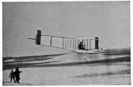
THE END OF A GLIDE
After remaining aloft the new glider was allowed gently to settle to earth.
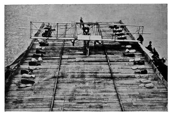
LANDING ON A WARSHIP
Lieutenant Ely is here shown landing in a Curtiss biplane on the platform built on the deck of the cruiser Birmingham, at anchor in Hampton Roads.

Courtesy of the Scientific American
BOARDING A BATTLESHIP
Glenn Curtiss being hoisted aboard the battleship Pennsylvania in San Diego Harbour after alighting alongside in his hydro-aeroplane.
In general outline the aeroplanes in use to-day differ greatly from those seen several years ago, but the difference is in form rather than in principle. There have been many improvements, of course, in construction, control of the fliers, and in the powerful engines that drive them. In fact the tendency of aeroplane builders has been to adopt the successful devices on other machines rather than to work out original ones.
The most noticeable change in the present-day aeroplanes is the way in which builders nowadays are enclosing the bodies and landing framework in canvas or even light metal, so that they shall offer as little resistance to the air as possible. It gives the machines the appearance of being armoured, as will be noticed from the pictures of the new planes, so the term has come to be used in that sense, although, of course, the covering would not protect them against bullets. This armour has become particularly popular with the designers who are making aeroplanes for the French Army, and at the recent military tests in France most of the machines were covered to some degree, and many of them looked for all the world like great long-bodied gulls or mammoth flying fishes.
98 Several aeroplanes have been equipped with twin motors and double steering systems so that either or both could be used. This, of course, is a great advantage in case one fails. Also designers are figuring on wing surfaces that can be reefed or telescoped for better stability as well as wings that can be folded for easier transportation.
Experts do not agree on the respective merits of the two great general types of aeroplanes—that is, monoplanes and biplanes. Some claim that the monoplane is the best and others that the biplane is the most successful flier. Records show that so far monoplanes are the faster of the two types, but biplanes can be fitted with hydro-aeroplane floats, whereas it is impractical with most monoplanes. Many declare the biplane to have the greater lifting power, but the Blériot "Aero-Bus" has carried a jolly family party of eight without difficulty. Each type has its champions as to safety, reliability and endurance, but time will have to decide the question.
First let us look at one of the latest Wright biplanes as it is brought out on the aviation field and is being tuned up by its keen-eyed young American pilot. The description of the 1909 Wright will be remembered. Also it will be remembered how the Wright brothers in 1910 discarded the forward horizontal elevating rudder entirely, and substituted in its place a single 99 elevating rudder at the rear end of the tail, which also served to give fore and aft stability. Also in 1910 the Wright brothers added wheels to the skids that hitherto had been used for starting and alighting. Thus the old system of having the machine skidded along a rail by a falling weight, as previously described, was done away with in favour of its running over the ground on its wheels.
After noting these improvements, we will look at the general outlines of such a Wright racing machine as contested for the James Gordon Bennett Cup in 1910. The two main planes are the smallest yet used on a biplane, being only 21-1/2 feet wide from tip to tip, and only 3-1/2 feet from front to rear. Thus, the aspect ratio, it will be seen is 7. They are the same general shape as the planes on the other Wright machines, and their total area is 145 square feet. The machine is steered up or down by the horizontal elevator rudder in the rear, which is oblong-shaped, 8 by 2 feet. The rudder that steers the machine from right to left is set vertically at the tail and is worked in combination with the levers that work the warping of the tips of the planes. On this little machine the twin-screw propellers, 8-1/2 feet in diameter, sweep practically the whole width of the machine. They are connected by chains to the 60-horsepower 8-cylinder Wright engine (in ordinary biplanes of this type the engine is 30 horsepower) and make 525 revolutions 100 per minute (in ordinary machines of this type they make 450 revolutions per minute). The machine weighs a total of 760 pounds and is capable of more than 60 miles an hour.
The elevation rudder is controlled by a lever set either at the right or left hand of the operator. The direction rudder is controlled by a lever that also controls the warping of the planes, as in turning it is necessary to cant the machine over to the inner side of the curve being made, in order to prevent slipping sidewise through the air. However the handle of the direction and warping lever is so arranged by a clutch system that by moving the lever simply from side to side the direction lever can be worked independently of the warping. The direction and balancing system then, we see, is worked in this manner. Say, while flying, a gust of wind causes the biplane to dip at the right end. The operator quickly moves his warping lever forward. This pulls down the tips of the right planes, and at the same time elevates the tips of the left planes. The change of the angle makes the right side lift to its normal position while it makes the left side drop. Consequently the machine is restored to an even keel and the operator lets the planes spring back to their normal shape.
The large 1911 Wright biplanes, model B, are designed the same as the small racing models except that the wings have a spread of 39 feet, and a depth 101 of 6-1/4 feet—a total area of 440 square feet. The perpendicular triangular surfaces in front like two little jib sails, are a distinguishing feature, although the latest Wright models substitute narrow vertical fins about six feet tall and six inches wide. They are placed immediately in front of the main planes. The hydro-aeroplane substitutes two aluminum floats for the wheels.
The Curtiss biplane, which we have seen has had a great deal to do with the development of aviation, is one of the simplest and most successful machines known to-day. The main planes of the regular-sized machines have a spread of 26-1/2 feet, are set 5 feet apart, and have a depth from front to rear of 4-1/2 feet. The total wing area is 220 feet. The direction rudder is a single vertical vane at the rear, which is turned by the steering wheel connected by cables. The elevation rudder consisting of one horizontal plane 24 square feet in area is at the front and is turned up or down by the pilot as he desires to sail up or down, by means of a long bamboo pole connecting the elevation rudder with his pilot wheel. He pushes the wheel forward or back to rise or descend, while he twists it from right to left to turn in either of those directions. The side-to-side balance was maintained in the early Curtiss machines by flexible wing tips, but these 102 later were replaced by ailerons placed between and at the outer tips of the main planes. Each aileron had an area of 12 square feet and they were operated by a brace fitted to the operator's body. Thus, if the machine tipped to the right, the operator would swing to the left, turn the ailerons, and right the machine. In some later Curtiss biplanes these ailerons were replaced by others, like flaps attached to the rear outer edges of the main planes. By raising the flaps on one side and lowering them on the other the balance was well preserved.
As before stated, these machines are driven by Curtiss engines. In most of them the engines are 4-cylinder, 25-horsepower motors. The cylinders in this type, of course, are stationary, but the engine shaft is directly connected with the 6-foot propeller at the rear, which makes 1,200 revolutions per minute. The pilot sits between the two main planes of his engine. On large Curtiss machines seats for as many as three passengers have been arranged at the sides of the pilot.
The most important work Curtiss has done in the last few years is the development of the hydro-aeroplane, which has been explained.
The next biplane with which we are familiar is the Voisin, which Henri Farman demonstrated as the first really successful aeroplane seen in Europe. This 103 machine was a standard of what was called the cellular type because it was composed of cells, like a box kite. The two main planes, which were the same size, 37 feet by 6-1/2 feet, were connected at the outer edges so as to make the plane a closed cell—i. e., a box with the ends knocked out. Two other vertical surfaces between the main plane gave the machine the appearance of three box kites side by side. The tail out behind was composed of a square cell. In the centre of it was a vertical vane for steering it from right to left, while out in front was a single horizontal rudder for raising or lowering the plane. The control was much the same as in the Curtiss machine. The steering wheel turned the plane from right to left, and was connected by a rod with the elevator, so that by pushing it forward or back, the machine was raised or lowered. There was no device for maintaining a side-to-side balance as the cell formation was supposed to keep the machine on an even keel. The motor drove a propeller at the rear.
The later Bordeaux type of Voisin which was built for military purposes does away with the side curtains and box tail. On the outer rear edge of the upper main plane are ailerons for maintaining the balance, which are operated by foot pedals. The elevator is a single horizontal plane at the rear of the tail, while the direction rudder is a vertical plane beneath it. This machine carries two persons, and is frequently driven by a Gnome engine.
104 Still another and later type of the Voisin Bordeaux is the front control. In this the ailerons are used as previously described, but also there are side curtains enclosing the outer edges of the main planes. Out in front at the end of a long framework or fuselage are the horizontal elevating planes, and the vertical direction planes. Both these machines have double control systems.
Dissatisfied with the work of his first Voisin biplane in the early days of flying Henri Farman designed and built a machine that bore his own name, of which the military type is now looked upon with great favour by many of the European experts.
The two main supporting planes in the regular Farman models were 33 feet by 6-1/2 feet, set 7 feet apart, and with a total area of 430 square feet. These dimensions have been varied slightly in other machines. The elevating rudder, which was set well out in front of the body of the machine, was a horizontal plane controlled by a wire and lever. In the rear was a tail of two parallel surfaces, slightly curved like the main planes of the biplanes. These two surfaces steadied the machine from front to rear. At their two sides were two vertical surfaces, giving the tail the appearance of a box kite, so familiar in the Voisin. These two vertical surfaces, however, comprised 105 the direction rudder, and were turned from side to side by the operator with a foot lever. In some of the later Farman biplanes the two vertical surfaces were done away with in favour of a single one, extending between the centres of the two horizontal surfaces of the tail. The side-to-side balance was maintained by ailerons in the form of wing tips set at the outer rear edges of the main planes. The tips were hinged and connected with wires which led to the lever that worked the elevating rudder. Thus by pulling this lever toward him the operator tilted the rudder up, and the machine rose, and by moving it from side to side the biplane was kept on an even keel. For instance, if the machine were to tip to the right he would move the lever to the left, pulling down the hinged ailerons on the right. The ones on the left would still remain standing straight out at the same angle as the main planes. The increase in the lifting power on the right side would cause that end to rise, righting the machine.
Most Farman biplanes these days are driven by the well known 7-cylinder Gnome rotary air-cooled engines, set at the rear of the main plane. They are directly connected with the single propeller, which is 8-1/2 feet in diameter. The seat for the aviator is in front of the engine at the front edge of the lower plane, and there also frequently are placed seats for two other passengers. The machine is mounted on wheels and skids.
106 The "Farman Militaire" type is one of the largest and heaviest machines made to date, having a total area of supporting plane of 540 square feet. The chief difference is that instead of two direction rudders there are three, and that the lower main plane is set at a dihedral angle. It was on such a machine ("Type Michelin") that Farman flew steadily for eight and a half hours. It also has made remarkable distance, endurance, and weight-carrying records, although it is a slow machine, making but 34 to 35 miles an hour. The "Type Michelin" is distinguished by the fact that the upper main plane has a spread of 49 feet, 3 inches, while the lower plane had a spread of only 36 feet.
Soon after Henri Farman had become famous as an aviator and constructor of aeroplanes, his brother Maurice began to build air craft. The Maurice Farman biplane was the result. After conducting their business separately for several years the brothers consolidated, and each type is known by the name of the brother designing it. The Maurice Farman biplane has some remarkable records, among them the winning of the Michelin prize in 1910 by Tabuteau, who flew 362-1/2 miles in seven and a half hours without stopping.
The main planes have a spread of 36 feet and a depth of 7-1/2 feet. They have not as great a curve 107 or camber as most biplanes, which increases their speed. The tail is of the well-known Farman cell formation—that is, it has four sides. The two vertical surfaces swing on pivots and are controlled by wires connecting with the direction steering wheel. The horizontal surfaces of the tail, except for the tips, are stationary, and steady the machine from front to rear. The rear tips of these two surfaces, however, work on pivots in connection with the main elevating plane which is set out in front. The elevator is a single plane controlled by a rod connected with the steering wheel, while the tips of the horizontal tail surfaces are controlled in unison with the main elevator by wires, also connected with the steering wheel. Ailerons are set into the rear outer tips of the main planes, for the control of the side-to-side balance, and these are worked by foot pedals. In order to give greater safety in case of the breakage of a wire, all the controlling parts in the Maurice Farman machine are duplicate, which is a big step toward the much-desired double controlling system in aeroplanes. The biplane is mounted on both skids and wheels. The operator sits well forward on the lower plane in a comfortable little pit enclosed in canvas. Thus, the Maurice Farman machine was the first to adopt this device for shielding the pilot from the wind. The engine used usually is an 8-cylinder air-cooled Renault, which drives a propeller nearly 10 feet in diameter.
Only slightly known in the United States but well and favourably known in Europe, particularly in France, is the Breguet biplane, which made wonderful records in the French Army tests in 1911. A brief description will show the difference between this machine and others of the biplane type. It has won many prizes for its stability and lifting powers, and also has shown great speed. The framework is mostly metal and is so elastic that it gives under the pulsations for the wind, so that the machine is not so badly strained by gusts as the more rigid kinds. Also it is thought the elasticity increases its lifting capacity. Of the two main planes the upper one spreads 43-1/2 feet, while the lower one spreads 32-1/2 feet. They are 5-1/2 feet deep, and set 7 feet apart. The body and tail of the machine are made on delicate graceful lines, terminating in the elevation and direction rudders at the rear. There are no rudders, vanes, or other rigging out in front. The lateral balance is maintained by warping the planes. The propeller is at the front of the machine, and is of the tractor type, pulling it through the air instead of pushing it. In the latest machines a metallic three-bladed Breguet propeller, the pitch of which is self-adjusting, is used, but in others a two-bladed wooden propeller, such as is familiar in this country. The long body, or fuselage, as the framework of the tail 109 is called, is enclosed on the latest types of Breguets in use by the French Army, greatly adding to its gracefulness, and decreasing the wind pressure.
There are several other makes of biplanes that could be described to advantage but space prevents it, and the descriptions here given serve to illustrate the principle of the biplane type of aeroplane.
The first and probably best known monoplane, the Blériot, still holds many records for both speed and endurance. The Blériot machines have so many variations that it would be impossible to describe all the types of monoplanes this versatile Frenchman has turned out. We are familiar in a general way with the Blériot, the single widespreading main plane, set at a slight dihedral angle, with its long, graceful body out behind terminating in the horizontal elevating and vertical direction rudders, giving it the appearance of a great soaring bird as it sails through the air as steadily as an automobile on a smooth road—much more steadily in fact, for as soon as the wheels of an aeroplane leave the ground all jolting disappears, and not even the vibration of the engine is noticeable, although the roar of its explosions can be heard a great distance. There is nothing but the breeze and the earth streaming along behind you, as if it were moving and you were hovering motionless high up in the sky.
110 In the famous Blériot XI, in which the designer made the first trip across the English Channel, the main plane had a spread of a little more than 28 feet and a depth of 6-1/2 feet, a total area of 151 square feet and a low aspect ratio of about 4.6. At the end of the stout wooden framework, that made up the body and tail, was the vertical direction rudder 4-1/2 square feet in area which was turned from right to left by a foot lever. The elevation rudder was divided into two halves, one part being put at each side of the direction rudder. The total area of the elevator was 16 square feet, while the horizontal stabilizing plane to which the elevator was attached was about the same. The balance was maintained by warping the main plane, but instead of warping the tips of the plane, as is done in the Wright biplanes, the two sides of the main plane were warped from the base, so that the operator could change the angle of incidence—that is, the angle at which the planes travel through the air. Thus, if the machine should tip down on the right side, the operator would warp the planes so as to increase the angle of incidence on the right side and lessen it on the left side. In other words, the rear part of the right wing would be bent downward, while on the left side the rear edge would be raised. The forward edge remains stationary. The increase of the angle on the right side would cause an increase of the lifting power on that side and also the decrease of the angle on the left side 111 would lessen the lifting power of the left wing so the right side, which was tipping down, would be lifted, and the machine restored to an even keel. This warping was done by moving from side to side the same lever on which was mounted the steering wheel. The whole machine was mounted on a strong chassis with wheels for starting and alighting. The pilot sat in the framework above the main plane. The monoplane was propelled by a single propeller of the tractor type 6 to 7 feet in diameter, placed at the front of the machine. It was driven in the early Blériots by a 23-horsepower Anzani motor, but more lately the Blériot machines have carried Gnome motors.
One of the important improvements which appeared on the No. XI bis was the changing of the main plane so that the upper side was curved but the under side was nearly flat. This gave the machine much more speed and the designers found that the flattening out of the curve on the under side did not greatly lessen the lifting power. This same type of machine also was made later to carry three passengers. The machine known as the "Type Militaire" was just about like the others except that the tail instead of being rectangular was fan-shaped. It carried seats for two and was equipped with all the latest aviation accoutrements, such as tachometers, barographs to record altitude, instrument to record inclination, various other gauges, map cases and thermos bottles.
112 The most distinctive feature of the Blériot No. XII, which was the first aeroplane to carry three passengers, was the long vertical keel, shaped like the fin of a fish at the top of the framework. The direction rudder was at the rear of this keel, while the elevation rudder was at the rear and a little below it. Immediately below the direction rudder was a small horizontal plane about the size of the elevation rudder which helped to maintain a fore and aft stability.
Then there was the famous Blériot aerobus which would carry 8 to 10 people. The machine was very large, the wings having a spread of 39 feet and a total area of 430 square feet. It was driven by a 100-horsepower Gnome motor and a propeller 10 feet in diameter, which was placed at the rear of the main plane. Thus the propeller drove the machine through the air from the rear instead of pulling it from the front as do the tractor propellers on most of the Blériot monoplanes. The passengers were seated underneath the main plane on the framework which extended out to the rear. The tail terminated in the vertical direction rudder and a large stationary horizontal surface which gave the necessary front-to-rear stability. The elevating plane of this type was placed out in front.

THE FLYING BOAT STARTING
The latest aeroplane is here seen cutting through the water preparatory to ascending into the air.

THE CURTISS FLYING BOAT
This is the very latest development in the hydro-aeroplane, and moreover it is claimed by its inventor, Glenn Curtiss, to be the first absolutely safe aeroplane.
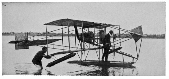
GLENN CURTISS ALLOWING HIS HYDRO-AEROPLANE TO FLOAT ON THE WATER AFTER ALIGHTING
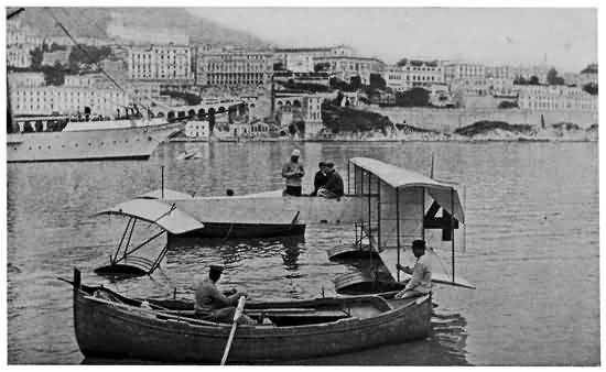
HYDRO-AEROPLANE AT MONTE CARLO
At the hydro-aeroplane meet at Monaco practically every well-known type of biplane was equipped with pontoons and entered the contest.
The Blériot Canard or "duck" is one of the latest developments of the pioneer constructor, and the chief difference between it and the other Blériot 113 machines is that the body extends out in front of the main plane instead of behind, something like Santos-Dumont's first machine. The main plane has a spread of 29 feet, and has a total supporting surface of 129 square feet. At the forward end of the body is placed the horizontal elevating rudder, while two small vertical rudders, placed on the top of the outer ends of the main plane and working in unison, serve to steer it from side to side. The balance in this machine is preserved by large hinged ailerons at the outer rear edges of the main plane. The pilot sits in front of the engine underneath the plane, which is a military advantage, giving him ample chance for looking down and observing everything over which he is passing.
No machine that ever was flown has excited more admiration from those on the ground than the graceful Antoinette monoplane, designed by the famous French motor-boat builder, Levavasseur. Its great tapering wings and long fan-shaped tail give it the appearance of a huge swallow or dragon-fly as it sails through the air, and whenever this type has appeared at the American meets it has received tremendous applause.
The two best known models of the Antoinette are the type used by Latham in this country, and the "armoured" type, entered in the French military 114 tests. The bow of the first-mentioned machine is shaped very much like the prow of a boat with the 50 to 100 horsepower 8-or 16-cylinder water-cooled Antoinette engine occupying the extreme forward part. The propeller is set in front of this, and is of the tractor type, drawing the machine through the air behind it. In the recent models of the Antoinette, the main plane, set at a slight dihedral angle, spread a little more than 49 feet (compare this with the spread of 28 feet of the Blériot). The two sides of the main plane taper from the body of the machine, but have an average depth from front to rear of 8 feet, which gives a fairly high aspect ratio of about 6. The total area is 405 square feet. The main plane also tapers in thickness, being nearly a foot through close to the body and tapering down to a few inches at the outer tips. The graceful tail at the rear has both vertical and horizontal surfaces gently tapering to the height and width of the elevating and direction rudders. The elevating rudder is a single horizontal triangular surface at the rear controlled by cables running to a pilot wheel at the operator's right hand. It has an area of 20 square feet. The direction rudder is composed of two triangular surfaces with an area of 10 square feet each. One is above the elevator and the other below, but both are worked in unison by wires connecting with a foot lever. The machine is balanced by a warping system much like that on the Wright biplanes we know 115 so well. This is accomplished by wires connecting with a steering wheel at the pilot's left hand, so that he uses his right hand to steer his machine up or down, his feet to steer from right to left, and his left hand to maintain the balance. Of course, in making a sharp turn he uses his warping wheel as well as his direction wheel, because, as previously explained, it is necessary to incline the machine over toward the inside of the curve desired to be made. The pilot sits in the framework, above and a little back of the supporting plane.
The "armoured" Antoinette, which was designed for military purposes, is entirely enclosed, even increasing the already great resemblance to a bird, while the direction rudder is made of a single surface, and the elevating rudder of two rhomboid-shaped rudders. The pilot sits in a cockpit with only his head and shoulders protruding above and has a view below through a glass floor. Its most important feature is the total elimination of cross wires, struts and the like. The resistance is greatly decreased, but the weight increased. In addition, a peculiar wing section is used, flat on the under side and curved on the upper side. The wings are immensely thick, being entirely braced from the inside. At the body the wings are over two feet thick. Their thickness decreases toward the tips, which are about eight inches thick. The shape of each wing is called trapesoidal, and they are set at a large dihedral 116 angle. The motor is a regular 100-horsepower Antoinette.
The oddest feature of this type is the landing gear, which is entirely enclosed to within a few inches of the ground; the landing wheels at the front are six in number, three on each side of the centre, enclosed in what is called a "skirt." At the rear are two smaller wheels.
The dimensions are roughly as follows: Spread, 52-1/2 feet, wings, 602 square feet; length over all, 36 feet; depth of wings (from front to rear) at tips, over 9 feet, increasing to almost 13 feet at the centre. The total weight is nearly 2,400 pounds.
The Nieuport monoplane is one of the newer machines that has attracted a great deal of attention for its speed with low-powered engines. Among the achievements of this monoplane was Weyman's winning of the James Gordon Bennett Cup and prize in England in 1911, and the demonstration of its remarkable passenger carrying abilities. The Nieuport also is a wonderful glider, for Claude Grahame-White took his new one up 3,000 feet at Nassau Boulevard, Garden City, during the 1911 meet there and glided down the whole distance without power, the downward sail taking him nearly as long as the upward climb.

THE WRIGHT BIPLANE
Baby Wright model. Orville Wright is in front of seat, while Wilbur Wright is holding back on the fuselage.

STANDARD CURTISS BIPLANE
For reliability and stability the Curtiss biplane is one of the best known models.

CURTISS STEERING GEAR
Sitting in front of the engine the aviator controls the ailerons by straps over his shoulders, and the direction and elevation rudders by the steering wheel.
The passenger machine has a spread of 36 feet 117 with a length of about 24 feet from front to rear. This machine is generally equipped with a 50 or 70 horsepower Gnome motor, although the plane with which Weyman won the Gordon Bennett contest was equipped with a 100-horsepower Gnome motor. The smaller machine has a spread of 27 feet, 6 inches and a length of 23 feet. An engine of the 3-cylinder Anzani type is usually mounted on this monoplane.
The body of the flier gracefully tapers to a point at the rear where are placed the elevating and steering rudders.
The chief characteristics of the Nieuport are strength, simplicity in design, and great efficiency of operation. The smaller machine, which is equipped with an engine of from 18 to 20 horsepower, has acquired a speed of 52-1/2 miles an hour. The Nieuport is constructed along original lines throughout. The wings are very thick at the front edge, while the rear edges are flexible so that in gusts of wind they give a little.
The fuselage, or body of the machine, which is extraordinarily large, and shaped like the body of a bird, is entirely covered with canvas.
The weakest part of the Nieuport monoplane is the alighting and running gear, which is so designed as to eliminate head resistance, but unfortunately this simplicity is carried to an extreme which makes the machine the most difficult one to run along the 118 ground, and to this construction may be traced most of the accidents which have occurred to the Nieuport machines.
The Nieuport control differs from that of the majority of other machines inasmuch as the wing warping is controlled by the feet, while hand levers operate the vertical and elevating rudders.
After having taken in such a lot of information about aeroplanes the scientist's young friend considered himself fairly well equipped to build a flier.
"Why couldn't I build a little model aeroplane?" he said one day.
"No reason why young couldn't," answered his friend in the laboratory. "You have a little workshop at home and your own simple tools will be plenty. You will have to buy some of your materials, but they are all cheap.
"There is no sport like model aeroplane flying, but to the average American boy the flying is not half so much fun as meeting and overcoming the obstacles and problems entailed in making the little plane. These days nearly any boy would scorn to enter a model aeroplane tournament with any machine that he did not make himself, and a great many of the amateur aviators even prefer to make their own designs and plans.
"When we begin to take up the construction of a 119 glider or an aeroplane, we must, like the Wright brothers, reluctantly enter upon the scientific side of it, because in model building we cannot simply make exact reproductions of the great man-carrying fliers, but must meet and overcome new problems. The laws that govern the standard aeroplanes apply a little differently to models, so it is necessary for the model builder to figure things out for himself.
"For instance," explained the scientist, "most amateurs have decided that monoplane models fly much better than biplanes. The reason for this is probably that with the miniature makes the air is so disturbed by the propeller that its action on the lower plane tends to make it unsteady rather than to give it a greater lifting capacity. This could be avoided by placing the two planes farther apart, but they would have to be so far separated that the machine would be ungainly and out of all proportion. Moreover, the second plane, with the necessary stays and trusses, adds to the weight of the machine, and this is always bad in models.
"There are as many different types of model aeroplanes as there are of the big man carriers, but you had better make a small flier first, experiment with it, and then work out your own variations just as you think best."
"Will you help me build one?" asked the boy.
"No, for you don't need my help and you will have more fun doing it alone. I will tell you how to go 120 about it, and with what you know of the principles of aviation from our conversations it will be easy to make a successful model."
Then taking a piece of paper and a pencil the scientist began to draw rough plans for the building of a little model monoplane something like the Blériot, except that it was driven tail first, with the propeller at the rear. As he worked he explained how the plan shown below should be followed, saying that the beginner would find that a length of about one foot would be the most convenient for this first model. Later on he can make the big ones with a spread of wings of three feet, and a length of forty or more inches.
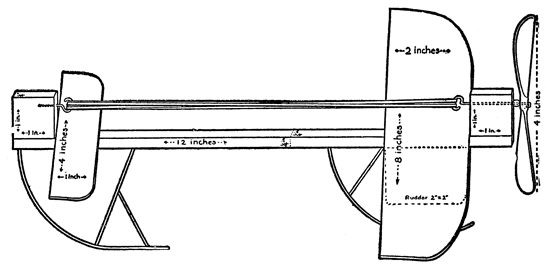
A SIMPLE MODEL AEROPLANE
First, the three main parts of the model should be made. Those are the two main planes and backbone. The simplest way of making the planes for a model of this kind is to use thin boards of poplar or spruce, which will not split easily and which can be worked with a jackknife. The large plane should 121 be rectangular, with a spread of eight inches and a depth of two inches, while the smaller plane should be the same shape, four by one inch. They should be one eighth of an inch or less in thickness. Plane and sandpaper them down as thin and as smooth as possible without splitting them, and round off the corners just enough to do away with sharp edges. Now draw a line parallel with the side that is eight inches long, three quarters of an inch from the edge. Measure off two inches toward the centre from the outer edges, along this line, and draw lines parallel with the edges that are two inches deep. At the corners which are to be the rear we find the lines make two rectangles three quarters of an inch by two inches, and these corners are to be cut away in a graceful curve from the corners of the rectangles. When it is done the main plane will be shaped like a big D with the curved edge to the rear. The front edge of the small plane also should be curved, but not nearly so much as the larger plane. This done, the planes can be steamed or moistened with varnish, and given a slight curve or camber by laying them on a flat board with a little stick underneath and weights at the front and back to hold down the edges while they dry and set. The sticks should be about one third of the way back from the front edges, from there tapering down to the level of the rear edge. Of course, in this process great care must be used not to split the delicate planes.

STANDARD FARMAN BIPLANE
Note the box tail and the single elevating plane.

FARMAN PLANE WITH ENCLOSED NOSE
This type is sometimes used in Europe, and it led to the Farman "canard" with the box tail in front.
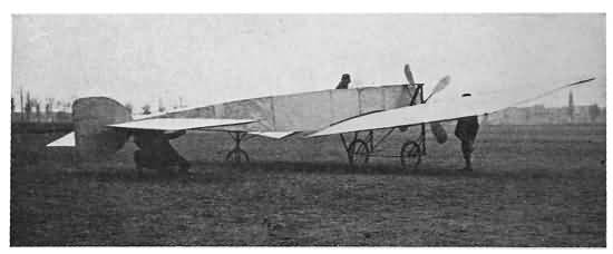
A MODERN BLÉRIOT
This machine has the enclosed fuselage and other recent improvements. Note the four-bladed propeller
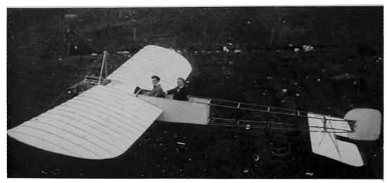
A STANDARD BLÉRIOT
This is the regular type of Blériot made famous by long over-water flights.

PASSENGER-CARRYING BLÉRIOT
This type has tremendous capacity for carrying great weights.
122 There are many other ways of making planes. If one does not care to round off the edges, he can make very light wooden rectangular frames of the size indicated, and cover them with cloth, or silk, afterward varnishing them to make them smooth and air-tight. It is difficult to give such planes a camber, but if the framework is made of strong light wire, such as umbrella ribs, and then covered, the camber can be obtained by putting light wire or light wooden ribs in the planes, much like on the big standard makes. Plane building can be developed to a high art, and after a boy makes one or two models he will see any number of ways that he can make them lighter, stronger and more professional looking.
With the planes finished, the next work is to make the backbone of the machine by planing and sandpapering a light strong stick one foot long and not more than a quarter of an inch square. Cut out a neat block of the same wood, the same thickness as the backbone, and one inch square. Glue it to the end of the backbone and reinforce it by wrapping it with silken thread moistened with glue or varnish. Be sure to have the grain of this block, which is the motor base, run the same as the backbone. Three quarters of an inch from the backbone, and parallel with it, bore a little hole for the propeller shaft or axle. Unless you are sure of your drill, heat a thin steel wire and burn the hole, rather than risk splitting the block.
123 The propeller is the next thing to make, while the glue on the backbone is drying, and the camber of the plane is setting. Some models have metal propellers, but most boys prefer to make wooden ones, either from blocks of their own cutting or from blanks that can be purchased. The blank should be four inches in diameter an inch wide, and half an inch thick. It can be cut away very thin with a sharp knife, and a fairly good whittler can make a propeller that looks as businesslike as the great gleaming blades on the big machines. A wire then should be run through the dead centre of the propeller and bent over so that when the wire shaft turns the propeller also turns. As a bearing or washer the simplest device is a glass bead strung on the shaft and well oiled to lessen the friction, between the propeller and the propeller base. The shaft is then run through the hole in the motor base and bent into a hook for the rubber strands that drive the propeller. Great care should be taken in mounting the propeller and making the hook that the shaft is kept in an absolutely straight line, and at an accurate right angle with the propeller, so that the screw can turn free and true with as little friction as possible, and no wobbling or unbusinesslike vibration. Next a wire hook should be placed at the other end of the backbone upon which to hook the other end of the rubber strands. This hook can either be imbedded in another block the same size as the motor base or can 124 be set out by some other ingenious device, so that the strands will turn free of the backbone, and will make an even line parallel with it. Both hooks should be covered by little pieces of rubber tubing to protect the rubber strands. Any friction whatever in a model is bad, but it is worst of all upon the rubber strands of the motor.
With the parts in hand the next step is attaching the planes to the backbone. In this machine the motor should be above the planes, so that the planes should be affixed to the upper side of the central stick, with the rubber strands above them. The propeller is at the rear, so the small front plane should be placed at the front, with the slightly curved edge to the rear. It should be about an inch from the tip of the stick and the front edge should be elevated slightly to give the necessary lifting power. The main plane should be placed about an inch from the rear tip of the backbone, with the curved edge to the rear and the front slightly elevated. The planes should be affixed with rubber bands so that it is possible to move them forward or back, because the little monoplane might be lacking in fore and aft stability and the rearrangement of the planes might correct it. It might even be found more satisfactory in some models to change the order and let the propeller, base, and strands of the motor come below the planes instead of above them. Your own experience will tell best.

THE ANTOINETTE MONOPLANE
New armoured Antoinette shown in the large picture, while the small insert shows the old-style machine.

Photo by Philip W. Wilcox
THE NIEUPORT MONOPLANE
Comparatively a new make, the Nieuport monoplane has sprung into great favour for its speed and passenger-carrying capacities.
125 Of course, the planes must be placed on the backbone exactly evenly or the airship will be lopsided, a fatal fault. By experimenting, the boy can tell just how high the front edges should be elevated, or, in other words, what angle of incidence he should give his plane. A rudder, to keep the machine in a straight course, can be added underneath the centre of the main plane. It should be about two inches square, but shaved off to a curving razor edge. Also light skids of cane or rattan may be added. They should be glued to the under side of the backbone and curved backward like sled runners. The front one should be two and a half to three inches high, while the rear one should be about an inch to an inch and a half less.
After trying out the model as a glider by throwing it across a room and making sure it is well balanced both laterally and longitudinally, or from side to side, and fore and aft, the rubber strands can be put on, and the motor wound up. About four strands of rubber one eighth of an inch square, such as is sold for this purpose, would suffice for good flights of more than one hundred feet, if the machine were of the same weight and proportions as the model from which this description was written. In models, however, there are many little details that can change the conditions, and a boy can only experiment, locate his mistakes, and try it over again.
126 This is one of the simplest and easiest model aeroplanes that can be made. A trip to one of the model aeroplane tournaments will reveal dozens of more elaborate ones, which will give any ingenious boy ideas for development of the principles he can learn from the simpler type. Probably the next step of the average boy would be to build a machine with two motors, which can be done by elaborating the single stick backbone or by making a backbone of two or three sticks well braced with cross pieces at each end and in the middle. Then there are interesting experiments with the size of planes, number of planes, their aspect ratio—that is the proportion of their width to their depth—ailerons for automatic stability, and rudders for keeping the machine on a straight course. There are always new things to be done with the motors, because, though the rubber motors have driven models close to half a mile, there are now on the market miniature gasoline motors to drive models, and experiments are being tried with clockwork and compressed air. Indeed the model aeroplane field is as broad in itself as that of the man-carrying machines.
Aviation has been reduced to an exact science, but it is yet in its early growth, both in the field of models and in the field of the various kinds of man-carrying machines. Not only are the designers making great headway with aeroplanes, but also with dirigible 127 balloons so any one interested in aeronautics has a very wide field for his work. As we said in an earlier chapter, the boy model designer of to-day may be the inventor of to-morrow who gains undying fame by some now undreamed-of development of the aeroplane.
The designers of the man carriers are trying to make their machines stronger, safer, more reliable, capable of carrying more passengers, and they hope at last to bring them to a more practical use in the world than as a sport. The most thoughtful aviators do not favour exhibition flying so strongly as they do long cross-country flights, endurance tests, passenger-carrying tests, and other experiments that will develop aeroplanes beyond their present limitations.
The next great feat of the aeroplane is the crossing of the Atlantic Ocean, and that may not be far distant, for at the time of writing half a dozen aviators are planning the attempt, but even more important than that, even more important than the development of the aeroplane for war scouting, is the development of the aeroplane as a faithful servant of the people who are quietly going about their own everyday business. The time will come when the readers of this may send their mail by aeroplane, take pleasure rides in the aeroplane instead of the automobile, and even make regular trips on regularly established aeroplane routes, buying their tickets at the great 128 central aeroplane stations as they would buy railroad tickets in the Grand Central or the Pennsylvania stations to-day, taking their seats in comfortably arranged aero cars, and being whisked in a few hours from one part of the country to the other, and even from one side of the ocean to the other.
OUR FRIENDS INVESTIGATE NIKOLA TESLA'S INVENTION FOR THE WIRELESS TRANSMISSION OF POWER, BY WHICH HE HOPES TO ENCIRCLE THE EARTH WITH LIMITLESS ELECTRICAL POWER, MAKE OCEAN AND AIR TRAVEL ABSOLUTELY SAFE, AND REVOLUTIONIZE LAND TRAFFIC.
"HOW would you like to send a signal clear through the earth with your wireless outfit and get it back again on your receiving instrument as clear and strong as at first, just about the same way you hear the echo of your voice when it rebounds from a mountainside or a big building?" asked the scientist one day while his young friend was telling him about his amateur wireless experiments.
"I don't see how I could," answered the boy.
"No, of course you don't," said the boy's friend, "for it took Nikola Tesla, 'the wizard of electricity' almost a lifetime to work out the invention by which he could do that, but if you like we will go 130 and see Doctor Tesla and ask him to tell us about his wonderful experiments.
"You see this is a series of inventions by Tesla, and wireless telegraphy is only a small part of it. You remember the other day you told me of having read about aeroplanes equipped with wireless. Just think, Tesla's invention will make it possible for airships to be propelled and operated all by electricity sent without wires. The whole broad plan is called the wireless transmission of power, and that simply means that electricity can be transmitted without wires for all the uses we now have for it, as well as for a number of entirely new and hitherto unknown devices."
The boy was delighted with the prospect of seeing the great scientist Tesla, about whom he had read so much, and began to ask his older friend a thousand questions about the man, his work and life.
It was a good many days before the whole thing had been talked over, and the boy understood the series of inventions, but we will follow through a part of our scientist's explanation and the visit to Tesla's laboratory and plant.
Although Tesla's plan is one of the most astounding ever proposed by science, it has been proved possible by experiments of such hair-raising nature that the inventor has been called a "daredevil" a "demon in electricity" and a "dreamer of dynamic 131 dreams." In his experiments he has produced electrical currents of a voltage higher even than the bolts of lightning we see cleaving the sky during the worst thunderstorms. These currents he has harnessed to his own use and made them tell him the inmost secrets of the earth—in fact of the palpitation at the very core of the globe—the heartbeats of our sphere. He has given exhibitions in which he has caused currents of inconceivably high power to play about his head as if they were gentle summer breezes, and while working in the mountains of Colorado, he has brought forth electrical discharges which caused disturbances in the wireless telegraph apparatus in all parts of the globe.
In short, Nikola Tesla plans to make artificial lightning, and so harness it to the use of man, that it can be sent anywhere on or above the earth, without wires.
To scientists and electrical engineers, Tesla's plan offers a field for limitless study and discussion, but to the boy who is interested in electricity it offers one of the most fascinating subjects for reading and thinking in all the realm of science. Just reflect that with the wireless transmission of power, and the development of an art that Tesla calls "telautomatics," the navigators of wireless power-driven airships and ocean liners will know their exact speed, position, altitude, direction, the time of night or day, and whether there is anything in their path, 132 all through the wireless "telautomatic" devices for registering such impressions.
Tesla declares that the terrible Titanic disaster never would have occurred had his system been in effect last April, for he declares that the Titanic's captain would have known of the iceberg he was approaching long enough in advance to slacken speed and get out of its way. Moreover, he declares that with the wireless transmission of power, the wireless telegraph becomes a very simple matter, and that immediately after the accident, had the ship struck an obstacle in spite of warnings, the captain could have been in wireless telephone communication with his offices in London and New York, and with all the ships that were on the seas in the vicinity of the ill-fated liner.
But making air and sea navigation safe, sure, and speedy, are only the first steps Tesla intends to take in the wireless transmission of power. After that he hopes to light the earth—to carry a beautiful soft bright light to ranchmen far out on the deserts, to miners in their cabins or deep in the earth, to farmers, and to sailors, as well as to people in their homes in the cities all over the world—Australia as well as the United States.
Wireless electrical power, according to Tesla, will be one of the greatest agencies in war, if there is any, but it first will be an argument for universal peace. "Fights," says the inventor, "whether between 133 individuals or between nations arise from misunderstandings, and with the complete dissemination of intelligence, constant communication, and familiarity with the ideals of other nations, that international combativeness so dangerous to world peace, will disappear."
If Tesla's plan were carried out in full it would completely revolutionize the industries of the world, for all the power of Niagara or any other waterfall in the world could be sent without wires to turn the wheels of the industries in China or Australia, while the power of the Zambesi Falls in Africa could be transmitted to run trains, subways, elevateds, and all other forms of industry in the United States. There is practically no limit to the possibilities of the scheme, because through Tesla's invention, distance means nothing, and the power instead of losing force with distance as is the case when power is transmitted through wires, retains practically the same voltage as at the outset.
We will visit Doctor Tesla at his office and laboratory in the Metropolitan Tower in New York with the scientist and his young friend to see what kind of a man it is who has invented machines for creating and handling such tremendous voltages.
Tesla sits at a wide flat-topped desk in the centre of his sunny office surrounded by books, a few models of inventions, and a few pictures of some of his most remarkable electrical experiments. He is very tall 134 and slight, with a mass of black hair thrown back from his intellectual forehead. His piercing gray eyes sparkle as he smiles in greeting, and his thin pointed face lights up with an expression of pleasure and kindness that cannot help but make the great electrician's visitors feel that he is a good friend. Although he was naturalized more than twenty years ago, and has been an American citizen ever since, his English still shows some slight traces of his foreign birth. He looks no more than forty-odd and he is as interested in everything that is going on in the world as a young boy, but he has passed his fiftieth year.
"For all that I am something of a boy still myself," says the inventor. "You see I could work for the present generation to make money. Of course that's all right, but I don't care what the present generation thinks of me. It is the growing generation—the boys of to-day that I want to work for, because they will live in an age when the world has advanced far enough in science to understand some of the deeper mysteries of electricity. The boys of to-day are the great scientists of to-morrow, and it is to them that I dedicate my greatest efforts."
All his life Tesla has been working with an eye to the future as well as to the present, and some of his inventions probably will be far better appreciated in twenty years than they are now, although to Tesla we owe our thanks for some of the most 135 important electrical machinery in use at the present time.
As an inventor Tesla is best known as a pioneer in high tension currents. It was he who introduced to the world the great principle of the alternating current, as up to the time he carried out his experiments only the direct current was used. Indeed, more than four million horsepower of waterfalls are harnessed by Tesla's alternating current system. That is the same as forty millions of untiring men working without pay, consuming no food, shelter or raiment while labouring to provide for our wants. In these days of conservation, it is interesting to note that this electrical energy derived from water power saves a hundred million tons of coal every year. Our trolley roads, our subways, many of our electrified railroads, the incandescent lamps in our homes and offices, all use a system of power transmission of this man's invention.
As said before Tesla is a naturalized American citizen. He was born in Smiljan, Lika, on the Austro-Hungarian border, in 1857. He came by his scientific and inventive turn of mind naturally, for his father was an intellectual Greek clergyman, and his mother, Georgia Mandic, was an inventor herself as was her father before her. The boy attended the public schools of Lika and Croatia, where he was a leader among his playmates in sports where imagination and mechanical skill were required. There are 136 marvellous tales of the ingenuity of Tesla while a schoolboy, but with all his play he was a serious-minded student, and went through the Polytechnic in Gratz and the University of Prague in Bohemia with honours. While in the Polytechnic, Tesla saw the defects of some of the machinery that was used in the laboratory, and made suggestions for its improvement.
After finishing college Tesla began his practical career in Budapest as an electrical engineer in 1881. His first invention followed soon after in the form of a telephone repeater. He continued in electrical engineering in Paris until 1884, when he came to the United States. His first employment in America was with The Edison Company at Orange, N. J., but in 1887 he went into business for himself as an electrical engineer. From that time on he has been an important figure in the scientific world. He has made many addresses before various gatherings of experts and has written numerous papers on scientific subjects for the magazines. Of course the bulk of his time has been given to his inventions and the necessary research therefor.

LIKE A BOLT OF LIGHTNING
The electrical discharge of this Tesla oscillator created flames 70 feet across, under the pressure of 12,000,000 volts and a current alternating 130,000 times per second.

DR. NIKOLA TESLA
Wizard of electricity, and inventor of the wireless transmission of power.

DOCTOR TESLA'S FIRST POWER PLANT
From this oscillator Doctor Tesla sends out the electrical waves with which he hopes to revolutionize industry.
Throughout his life Tesla has been more interested in the adventurous and scientific side of electricity than the commercial side, and all of his inventions smack of the marvellous. To name all his inventions would be almost like giving a list of the machines and devices that mark man's progress in the use of 137 electricity. His invention for the alternating current dynamo, for instance, brought forth an entirely new principle, while his rotating magnetic field made possible the transmission of alternating currents from large power plants over great distances and is very extensively used to-day. High power dynamos, transformers, induction coils, oscillators, and various kinds of electric lamps all came in for his attention.
He became one of the foremost authorities on high tension currents and in 1889 invented a system of electrical conversion and distribution by oscillatory discharges which was a step toward his great goal, the wireless transmission of power. He was very near the prize when in 1893 he announced a system of wireless transmission of intelligence. His studies continued and finally, in 1897, he announced his famous high potential transmitter by which he claimed to be able to send power through the earth without wires. The art of telautomatics announced in 1899 was really a part of Tesla's invention for the wireless transmission of power, for the plan was to control such objects, for instance, as airships or boats, from a distance by electricity transmitted without wires.
Through that marvellous invention the boat or aeroplane dispatcher, sitting before a complex little wireless dispatching board could send his craft, at any speed, at any height, in perfect safety, and with exact precision to the place or port he desired it to 138 go. It would not be necessary for the dispatcher ever to see the craft he was directing, for his instruments would show him everything in regard to its speed, direction, and location; nor yet would it be necessary for a craft to have a crew aboard, for all the operations in connection with sending it from one place to another would be controlled perfectly by telautomatics.
Such are the almost inconceivable inventions of Nikola Tesla. "Sometimes they call me a dreamer," says Tesla, "because I do not capitalize these inventions, start in manufacturing and make a big fortune. That is not what I care to do. I want to go further in this great mystery of wireless power, and if I am busy making money I cannot devote my best abilities to inventions that will be in use when the next generation is grown."
But let us try to fathom the mysteries of Tesla's scheme for the transmission of electric energy without wires. In the first place we must not try to think of it as being on the same basis as the radio, or Hertzian wireless telegraph, for, although the modern developments of the wireless telegraph take into consideration the central theory of Tesla's invention, they are not at all the same in their practical working.
Tesla's theory is based entirely on his discovery of what he calls stationary electrical earth waves which he sets in motion with his high potential 139 magnifying transmitter, an electrical apparatus of tremendous power.
First, let us remember the three essential departments of Tesla's idea for world telegraphy, world telephony, and world transmission of power for commercial purposes.
Assuming that the power is created by Niagara or some other great waterfall—"white coal" as it is picturesquely called by many engineers—the first necessities are a transformer and a transmitter that will send the electrical energy, thus gathered, into the earth and air. The next necessity is a receiving instrument that will record the impulse, whether it be a voice, a telegraph click, or several million volts for driving factory wheels or lighting houses. Lastly, it is necessary to tune the currents so that millions of different impulses can be sent without causing confusion between them. In other words, there must be departments for sending, receiving and "individualizing."
To ask Doctor Tesla to tell us the whole story of this invention would be to ask him to tell us in detail the whole history of his life work—and that would take several volumes, for he is one of those men who have worked incessantly, day and night, sacrificing himself and overcoming his natural desire for leisure and amusement. It all started, Tesla explains, when he was a very small boy. He was troubled at that time with a strange habit. Whenever any one 140 would mention a thing to him, a vision of the object immediately would come before his eyes. He declares that this was very troublesome, and that as he grew older he tried to overcome it, thinking it some strange malady. With an effort he learned how to banish the images by putting them from his mind. On inquiring into the cause of the visions, the young scientist's penetrating brain brought him to the conclusion that every time he saw a vision, some time previous he had seen something to remind him of the object. The tracing back of the cause of his vision so frequently caused it to become a mental habit, and he declares that for many years he has done it automatically, and that he has been able to trace the cause of nearly every impression, even including his dreams. Reflecting on these things, as a mature scientist, Tesla came to the conclusion that he was an automaton, responding automatically to impressions registered on his senses from the outside.
"Why couldn't I make a mechanical automaton that would represent me in every way, except thought?" he asked himself. The answer to the question which came only after years of study and experiment was the art of "telautomatics," which Tesla declares can be developed just as soon as the wireless transmission of power is an accomplished fact.
In the course of his research into the realm of high tension currents Tesla reached the stage where it 141 was no longer safe nor convenient to experiment in the centres of population. Moreover, he desired to make a study of the action of lightning. Colorado, with its vast stretches of uninhabited plains and mountains, offered an ideal place for his laboratory, particularly because the high, dry climate of that state brings forth some of the worst electrical storms seen in the United States. Consequently, in the spring of 1899, Tesla built an experiment station on the plateau that extends from the front range of the Rocky Mountains to Colorado Springs, and began the experiments through which the secret with which he hopes to revolutionize the communication and transportation systems of the world, was revealed to him.
Besides his high power alternating current dynamo, Tesla set up an electrical oscillator with which he hoped to send out electrical waves, through the earth and air, that would prove to him the possibility of an extensive system of wireless communication, and telautomatic, or wireless control of airships, projectiles, steamships, etc. In his early experiments he used the oscillator at low tension, but as his success became more marked he increased the tension, until the oscillator was giving twelve million volts, and the current was alternating a hundred thousand times a second.
In regard to these high tension experiments in Colorado and elsewhere, Doctor Tesla said, "I 142 have produced electrical oscillations which were of such intensity that when circulating through my arms and chest they have melted wires which have joined my hands, and still I have felt no inconvenience. I have energized, with such oscillations, a loop of heavy copper wire so powerfully that masses of metal placed within the loop were heated to a high temperature and melted, often with the violence of an explosion. And yet, into this space in which this terribly destructive turmoil was going on I have repeatedly thrust my head without feeling anything or experiencing injurious after effects."
Among the earlier experiments, which in themselves were wonderful enough, were the transmission of an electrical current through one wire without return, to light several incandescent lamps. Advancing further along the trail of wireless transmission of power, Tesla lighted the lamps without any wire connection between them and his transmitter.
The oscillator, though simple in its construction, is one of the most wonderful of all electrical devices. "You see," said Doctor Tesla, "all that is necessary is a high power alternating dynamo which generates a tremendous alternating current. For our oscillator proper, we make a few turns of a stout cable around a cylindrical or drum-shaped form, and connect its two ends with the source of electrical energy. Then, inside the big cable, or primary coil, we wind a lighter wire in spiral form. One end of the 143 secondary coil is sunk into the ground and connected with a plate, and the other is erected in the air. When the current is turned on, our oscillator sends these electrical impulses into the earth and air—or, as the scientists say, into the natural media. These oscillations create electrical waves and affect any device that is tuned to them—but (and this is very important) no device that is not tuned to them."
Continuing the explanation of his high tension experiments, Tesla tells us that the awe-inspiring electrical display, of which there is a picture on page 136, was made by his oscillator which created an alternate movement of electricity from the earth into a hollow metal reservoir and back at a speed of 100,000 alternations a second. The reservoir is already filled to overflowing with electricity and as the current is sent back to it at each alternation the terrific force makes it burst forth with a deafening roar, as great as the heaviest lightning detonation. The electric flames shoot out in every direction searching for something on which they may alight, just as lightning sent from the clouds searches for a conductor upon which it may alight and escape into the earth. The induction coils in the picture are tuned to these tremendous electrical explosions, and the flames shoot direct to them, a distance of 22 feet.
The flames shooting from the coil of the oscillator pictured on page 164 were nearly 70 feet across, 144 represented twelve million volts of electricity, and a current alternating 130,000 times a second. These hair-raising experiments created such electrical disturbances that it was possible to draw great sparks more than an inch long, from water plugs over 300 feet from the laboratory. One of the most marvellous things about these experiments is that any human being could remain in the vicinity. The absolute safety of these discharges when properly harnessed is well illustrated in the picture shown there as the man seen amidst the flames felt no ill effects from his experience, simply because this power was so thoroughly harnessed by the wizard Tesla, that it could go only to the device tuned to receive it. Every boy is familiar with stories of lightning striking one person, but yet leaving another person right next to him unharmed. Such is the action of Tesla's high tension currents, only he directs them by induction just as he wants them to go.
"But this is just like lightning!" exclaimed the boy.
"So it is," calmly answered Doctor Tesla with a smile. "I have often produced electrical oscillations even greater than the energy of lightning discharges."
These experiments were marvellous enough, but they were surpassed in a short time by his famous discovery of July 3, 1899, which showed him that he could send his wireless waves to the opposite side of the earth just as well as a hundred feet away.
145 This revelation, as the scientist calls it, came about through his study of lightning. The scientist had set up in his Colorado laboratory many delicate electrical instruments to register various different electrical effects. Tesla noticed, however, that strangely enough his instruments were just as violently affected by distant electrical storms as by nearby disturbances.
"One night when meditating over these facts," said Tesla, "I was suddenly staggered by a thought. The same thing had presented itself to me years ago; but I had then dismissed it as impossible. And that night when it recurred to me I banished it again. Nevertheless, my instinct was aroused, and somehow I felt that I was nearing a great revelation.
"As you know, it was on the third of July that I obtained the first definite evidence of a truth of overwhelming importance for the advancement of humanity. A dense mass of strongly charged clouds gathered in the west, and toward evening a violent storm broke loose which, after spending much of its fury in the mountains, was driven away with great velocity over the plains. Heavy and long persisting arcs formed almost at regular intervals of time. My observations were now greatly facilitated and rendered more accurate by the records already made. I was able to handle my instruments quickly, and was prepared. The recording apparatus being properly adjusted, its indications became fainter and fainter 146 with the increasing distance of the storm, until they ceased altogether. I was watching in eager expectation. Sure enough, in a little while the indications again began, grew stronger, gradually decreased, and ceased once more. Many times, in regularly recurring intervals, the same actions were repeated, until the storm, as evident from simple computations, with nearly constant speed had retreated to a distance of about two hundred miles. Nor did these strange actions stop then, but continued to manifest themselves with undiminished force.
"When I made this discovery I was utterly astounded. I could not believe what I had seen was really true. It was too great a revelation of Nature to accept immediately and unhesitatingly."
What Tesla had discovered, and soon announced to the scientific world, was the existence of stationary terrestrial waves of electricity, and its meaning was that an impulse sent into the earth was carried on these waves to the other side of the earth and rebounded without any loss of power. He had, in fact, discovered and turned to man's use the very heartbeats of our earth.
"Whatever electricity may be," he continued, "it is a fact that it acts like a fluid, and in this connection, we may consider the earth as a great hollow ball filled with electricity." He goes on to explain that when an impulse is sent into this ball of electricity it proceeds to the opposite wall of the earth in 147 waves and, finding no outlet it returns to the place it started, but in a series of waves exactly the opposite of the outgoing ones, so that the two cross and diverge at regular intervals as indicated in the diagram.

A—Oscillator B—Opposite side of earth C—Waves in nodal and ventral intervals.
As Tesla put it, "The outgoing and returning currents clash and form nodes and loops similar to those observable on a vibrating cord." Tesla figured from these experiments that the waves varied from 25 to 70 kilometres from node to node, that they could be sent to any part of the globe, and that they could be sent in varying lengths up to the extreme diameter of the earth.
In order to prove his discovery Tesla sent an impulse into the earth, and received it back, on his delicate instrument, in a few seconds. "It is like an echo," he explained. "When you shout and in a few seconds hear your voice coming back, you do not think it is another voice but know immediately that it is simply your own vocal vibrations reflected by the house, mountainside, or what not. It is 148 just the same with an electrical vibration. The stationary terrestrial wave goes through the earth, reaches the other side and, finding no outlet, is reflected without any loss of power. Indeed, in some cases it is returned with greater power than at first."
"Then in your system the wireless electrical current passes through the earth, and not through the air," interrupted the scientist.
"No," he answered, "it passes through both. It is difficult to understand the big things about electricity, but just think of the earth as a great ball filled with electricity, as I said before. Think of the tower of the oscillator as a tube, and of the great mushroom-shaped top of the plant as another ball. Now from our great alternating current dynamo we first fill the ball at the top of the oscillator with electricity, and then we make a motion that corresponds to squeezing it. What happens? Just what happens when you have two rubber balls connected with a tube. You squeeze one of them, and push the air, or water, into the other ball. In that way we push the electricity into the earth, but it comes back to us on the stationary waves, from the opposite side, and when it does we are ready to give it another mighty push with another tremendous squeeze from our dynamo. When this is going on the top of the oscillator is gathering electricity from the air all the time and sending it out to be used wherever there is a receiver properly tuned to receive these rates of vibration."
149 "But," again asked our friend, "isn't there a great deal of valuable electrical power wasted in that way?"
"No, there is very little waste," answered the electrician, "for this reason: If, for instance, our oscillator can generate a hundred thousand or a million, or any other number of volts, and we only wish to use it for some small purpose on the other side of the earth, the receiver at the antipodes takes as much power as is needed, and the rest remains unused and our oscillator can be run at reduced capacity."
Thus, according to Tesla's plan, the electrical energy will be sent into the earth and air by the high potential magnifying transmitter or oscillator, the stationary electrical waves carry it through the earth and the receiving instrument on the other side of the world collects the energy to put it to a thousand and one purposes of mankind. And do not forget that the oscillator and the receiving instrument are so tuned to each other that there is no danger, according to Tesla's scheme, of different oscillators and receivers getting mixed up.
Before Tesla had discovered the stationary electrical waves he had gone deep into the mystery of the "individualization" of electrical impulses, and as a result advanced plans for sending a number of messages over one wire without their interfering with each other. This study was continued with even greater energy, after he had taken the first 150 steps toward the realization of his world telegraphy and world telephony without wires. In wireless telegraphy as we know its practice to-day, one of the serious drawbacks is the interference of other operators, both amateur and professional, with important messages. Tesla holds that the simple tuning of instruments to one another as is done nowadays would not be sufficient, when there were millions of currents passing through and around the earth. For instance, he says that an instrument tuned to a single rate of vibrations would be very apt to come into contact with another instrument sending at the same rate. Of course the confusion so familiar in modern radio-telegraphy would result. Moreover, it makes it difficult to send messages that cannot be intercepted and read by every wireless operator in hearing. "This can be avoided," continues the inventor, "by combining different tones or rates of vibration. In actual practice it is found that by combining only two tones, a degree of privacy sufficient for most purposes is attained. When three vibrations are combined it is extremely difficult even for a skilled expert to read or disturb signals not intended for him. It is vain to undertake to 'cut in on' a series of wireless impulses made up of four different rates of vibration. The probability of getting the secret of the combination is as slight as of your solving the number combination on the door of a safe. From experiments I have concluded that 151 this individualization will allow the transmission of several million different messages. It is interesting when you think that one world telegraphy plant would have a greater capacity than all the ocean cables combined."
In regard to the amount of power to be transmitted, Tesla points out that an impulse of low voltage, or low horsepower, will carry to the other side of the earth without any loss of power, just as easily as a high voltage current. "A wire," says Tesla, "offers certain resistance to an electrical current causing some loss, but not so when it is sent through the natural media. The earth is a conducting body of such enormous dimensions that there is virtually no loss, so that distance means nothing. To the average intelligence this will appear incomprehensible. We are continuously confronted with limitations, and those truths which are contradicted by our senses are the hardest to grasp. For example, one of the most difficult tasks was to satisfy the human mind that the earth rotated round the sun; for to the eye it seemed just the opposite."
Tesla further pointed out that five-hundred miles is about the farthest that high power can be transmitted by wires with complete success, but that without wires, by his system, power can be transmitted, as we have seen, to any part of the globe or the atmosphere about it.
The plan for a world-wide system of wireless 152 telegraphs and telephones differs considerably from the original idea laid down by scientists for radio or Hertzian wireless telegraphy. Originally Guglielmo Marconi, who first successfully telegraphed without wires, and whose system is well known all over the world, planned to send his electrical impulses through the ether, in the form of Hertzian rays, but later the method was amended. The theory advanced was that since everything is afloat in the colourless, intangible something called ether (not the drug used as an anæsthetic), and that since waves of light, heat, and electricity travel through ether, it would be possible to send electrical impulses through the ether in the earth and air, just as well as through the ether in a copper wire. In his early experiments Marconi used the light rays or waves named after their discoverer, Hertz, but these were found to be very limited, so electrical vibrations of a higher intensity were substituted, as we shall see in a later chapter.
"From the very first," declared Tesla, "my system has been based on a different principle, as you can see from what I have told you. For instance, my invention takes no consideration of light rays in any visible or invisible form (and Hertzian rays are invisible light), which can only travel in a straight line. Hence, you can see that they could not be used except as far as could be seen. In other words, they only could be used as far as the horizon, for just as soon as the curve of the earth's surface took the receiving instrument 153 below the level of the Hertzian waves they became ineffective. You see the difference is that my system is based on the stationary earth waves, along which the electrical currents can pass to any distance irrespective of horizon, or matter."
A simple explanation will serve to show the principle of Tesla's theory of wireless telegraphy and telephony. We can easily think of a reservoir with two openings in the cover filled with some fluid. In each of these openings is a piston and above each piston is a tuning fork. The two tuning forks must be of exactly the same tone or the experiment will not work. We strike one of the pistons with the tuning fork, and continue to strike it until the fork sets up vibrations. The vibrations pass through the air, and also communicate vibrations to the piston, which in turn passes the vibrations on to the fluid in the reservoir. These vibrations naturally continue through the reservoir, as waves, just the same as when we throw a pebble into a calm pond and watch the waves radiate out in every direction. The water does not advance, but merely moves up and down. The waves, however, advance. So with the waves set up by the tuning fork, and they set up an oscillation of the piston at the other side, agitating the tuning fork in unison with the sound vibrations coming through the air.
It is just the same, declares Tesla, with two of his oscillators set up on the earth's surface and tapping 154 the great sea of electricity, which he says is in the earth. The oscillators correspond to the tuning forks, the reservoir to the earth, and the fluid in the reservoir to the electrical currents with which he says the interior of the earth is alive. Exactly attuned, Tesla says, the vibrations set up by the sender will be communicated to the receiver through the earth and through the air.
"Now, with the development of the world system," continued Tesla, "we shall be able to telephone without wires just as well as telegraph, and to any part of the world just as easily as we now talk to a friend in an adjoining house over the modern wire circuits."
Before going with Doctor Tesla to his great plant out on Long Island to see how he is carrying on these tremendous theories of his, the boy asked him a few more questions about them, for it is a big and intricate question.
"What application will you first make of the wireless transmission of power?"
"My first concern," replied the magician of electricity, "will be to make air and water navigation safe. We have plenty of demonstrations of the value of the wireless telegraph in saving human lives when ships are in danger, in the Republic and Titanic disasters. But also we know that the wireless can be greatly improved upon. With a perfect system of communication, both by wireless telegraph and 155 telephone, consider what it would mean to the navigators of air and ocean craft.
"By the art of telautomatics, which is a part of the broad scheme for the wireless transmission of power, many of the worst dangers of air and water navigation will be avoided, which is right in line with the modern tendency of preventing trouble rather than waiting for it to happen before remedying it." He then went on to enumerate the various telautomatic devices that will be carried by ocean liners and airships of the future, as mentioned in the early part of this chapter.
"Just for instance, how could telautomatics have saved the Titanic?" the inventor was asked.
"You understand, of course," answered Tesla, "that the devices I propose would be of almost inconceivable sensitiveness. They would be the centre of electrical waves, and, as soon as the iceberg got into the path of these waves from the wireless transmission plant to the ship, it would cause the electricity to register an impression of danger ahead. Of course mariners would become so expert in the reading of these danger signals that they could tell the meaning of each one, and alter their course or reverse their engines according to the needs of the case."
"How much have you accomplished in telautomatics at this time?"
"I have made a little submarine boat that will 156 answer to every necessary impulse. The boat contained its own motive power in a storage battery and gear for propulsion, steering sidewise, or upward or downward, and all other accessories necessary for its operation. All of these were worked from a distance by wireless impulses, sent by an oscillator to the circuit in the boat through which magnets and other devices operated the interior mechanism.
"This proved to me the possibility of a high development of telautomatics. When my system is complete, a crewless ship may be sent from any port in the world to any other port propelled by wireless energy from a power plant anywhere on the face of the earth, and controlled absolutely by telautomatics."
Tesla's plan for aerial navigation is even more startling than that for crewless ocean liners. He thinks that the airships of the future will be propelled by wireless power and that they will have, neither planes nor other supporting surfaces, such as we are so familiar with nowadays. Neither will they be supported by gas bags like balloons and dirigibles. The inventor thinks they will be compact and just as airworthy as ocean liners are seaworthy. They will be tightly enclosed, so that the terrific rush of air through the high altitudes will not strangle the passengers and crew. He sees no reason why the airships of the future should not travel at a rate of several hundred miles an hour, so that you could leave San 157 Francisco in the morning and be in New York in time for a six o'clock dinner, and the theatre, or cross the Atlantic in a night.
"How will these airships be propelled?" the boy asked.
"By engines driven with power supplied by our great oscillator wherever we care to erect it. These engines will work with such incredible force that they will make of the air above them a veritable rope to sustain them at any desired altitude, while they will make of the air in front of them a rope to pull them forward at a high rate of speed." Tesla continues to say that these ships can be made just as large as it is practicable to make their landing stages, or small enough for one or two passengers.
In the waterfalls of the United States alone, he pointed out, there are twenty-five hundred million horsepower of electrical energy. Niagara Falls could supply more than one fifth of all the power now used in this country, he says. Moreover, none of the great sites, such as those in the far Northwest, are developed to their highest state, because of the difficulty in transmitting the power over long distances to where it is used.
"It must be borne in mind," said Tesla, "that electrical energy obtained by harnessing a waterfall is probably fifty times more effective than fuel energy. Since this is the most perfect way of rendering the sun's energy available the direction of the future 158 material development of man is clearly indicated. He will live on 'white coal.'"
"Doctor Tesla, can you tell us, please, just how far you have developed this invention for the wireless transmission of power?"
"Well," answered the electrical inventor, "the best way to tell you is to show you what has been done so far." In order to see Tesla's great plant we must follow the scientist and his boy friend out to Bay Shore, L. I., where, overlooking Long Island Sound, we see a great mushroom-shaped steel network tower surmounting a low building—the first of Tesla's many proposed high potential magnifying transmitters.
"So far," said Tesla of his power plant where the first attempts at wireless transmission are being made, "only about three million horsepower has been harnessed by my system of alternating current transmission. This is little, but it corresponds nevertheless to adding to the world's population sixty million indefatigable laborers, working virtually without food or pay."
As the boy approached the power plant he was impressed by the great size of the tower and its circular top, as shown in the photograph. It is this circular top, with its conductive apparatus, that gathers the electricity from the air and from the dynamo, and sends it forth in great waves both through the air and through the earth. 159 The tower is 185 feet high, from the ground to the top, and from the ground to the edge of the cupola it is 153 feet. The diameter of the cupola floor is 65 feet. The cupola can be reached by both a staircase and an elevator, but it would hardly be healthy for any one to be within the network of electrical conductors when the plant was working. Inside the building are the high power alternating dynamos and underneath it extends the ground wire from the cupola, through which the electricity is pumped into the ground in great spurts at the rate of more than a hundred thousand spurts a second. At this plant Tesla plans to gather and concentrate millions of horsepower of electrical energy and then, in the ways we have seen, send it out to be used in a thousand different ways.
"This is merely an experiment," declared Tesla. "We can telegraph and carry on other such operations as require only a small amount of power from here, but it is nothing compared to the great power plants we will erect in the future."
"Is it necessary," asked the boy, "to have your power plant erected near the waterfall, or other means of producing the electricity?"
"No, it is not. This plant, for instance, can be made a great receiving station for electric power from all the great hydro-electric sites, and from it we hope to be able to send out electrical waves that will run our ships, airships, trains and street cars, carry 160 our voices, light our houses, and turn the wheels of our factories. It is better, however, to have the plants located close to the seats of power, and to have a greater number of plants."
"How much horsepower did you say this plant would send out?"
"Only a mere trifle of three million horsepower, but of course this is only an experiment. To be done properly the thing must be done on a large scale, and the time will come—not necessarily remote—when we will be carrying on the whole programe embraced by the wireless transmission of power. The cost of wireless power I estimate would be about one sixteenth of that of the present system."
"When you are sending such tremendous voltages won't it be very dangerous to be anywhere in the vicinity of a plant, much less anywhere that the electricity might be brought from the earth?"
"No, for the power is so well harnessed that we can send it just where we want it and nowhere else. Of course, on the other hand, if we wanted to make trouble with this well-harnessed lightning we could make a terrible disturbance in the earth and on the surface of the earth."
"What about lightning?"
"That is one of the things we had to guard against right from the very first, and I can tell you that lightning will not bother us a bit, although I cannot give you the details of our method of avoiding it.
161 "When we are using the plant at night, however, there will be a display far more beautiful than lightning, all about the cupola in the form of a great halo of electric light visible for miles around."
Before we leave this fascinating subject of the wireless transmission of power let us ask Doctor Tesla about the effect of his invention on war.
"The wireless transmission of power will first be a big factor in promoting world peace, as I said before, because through the great improvement in communication it will lead to a better understanding between nations and break down many of the old prejudices that have lived for so many thousands of years. It will facilitate travel and commerce so that a citizen of the United States will find it as simple and cheap to travel abroad as he now finds it to travel in the neighbouring state. His commercial interests also will spread to foreign countries, and the nations will be so linked with one another socially and commercially that war will be out of the question.
"However, in case war should break out between the nations it will be a conflict of such gigantic proportions, and carried on with such tremendous death-dealing machines, that it will surpass our wildest dreams.
"For one thing, the new art of controlling electrically the movements and operations of individualized automata at a distance without wires will soon 162 enable any country to render its coast impregnable against all naval attacks.
"I have invented a number of improvements of this plan, making it possible to direct a telautomaton torpedo, submersible at will, from a distance much greater than the range of the largest gun, with unerring precision, upon the object to be destroyed. What is still more surprising, the operator will not need to see the infernal engine or even know its location, and the enemy will be unable to interfere, in the slightest, with its movements by any electrical means. One of these devil-telautomata will soon be constructed, and I shall bring it to the attention of governments. The development of this art must unavoidably arrest the construction of expensive battleships as well as land fortifications, and revolutionize the means and methods of warfare. The distance at which it can strike, and the destructive power of such a quasi-intelligent machine being for all practical purposes unlimited, the gun, the armour of the battleship, and the wall of the fortress, lose their import and significance. One can prophesy with a Daniel's confidence that skilled electricians will settle the battles of the near future, if battles we must have.
"The future of wireless power development," explained the inventor, "may render it folly for any nation to have afloat a vessel of war. The secret of another nation's scheme of selectivity or combination 163 of vibrations might be disclosed to the enemy, when the guns of their own vessels might be turned against sister ships and a whole fleet destroyed by shells from their own guns, or their magazines might be exploded by the enemy at will. However, should there be battleships in the wireless future, they will be crewless. They will be manœuvred, their guns will be loaded, aimed, and fired, and their torpedoes discharged with unerring accuracy, by the director of naval warfare seated before a telautomatic switch-board on land.
"The time will come, as a result of my discovery," says Tesla, "when one nation may destroy another in time of war through this wireless force: great tongues of electric flame made to burst from the earth of the enemy's country might destroy not only the people and the cities, but the land itself. I realize that this is indeed a dangerous thing to advocate. At first thought it might mean the annihilation of the nations of the world by evilly disposed individuals. The public might at first look upon the perfection of such an invention as a calamity. We say that all inventions assist the criminal in his work. To-day the safe burglar despises the use of dynamite, turning to electrical contrivances to cut the lock from a safe. It is fortunate for the world, therefore, that 90 per cent. of its people are good, and that only 10 per cent. are evilly disposed: otherwise all invention might be turned more greatly to evil than to good."
MACHINES THAT MAKE SIXTEEN TINY PICTURES PER SECOND AND SHOW THEM AT THE SAME RATE MAGNIFIED SEVERAL THOUSAND TIMES—MOTION PICTURES IN SCHOOL—OUR BOY FRIEND SEES THE WHOLE PROCESS OF MAKING A MOTION-PICTURE PLAY.
"IHAVE just been to the moving-picture show," said the young man whose inquiring turn of mind has brought him into touch with so many recent inventions. His friend in the laboratory had just finished a very successful chemical experiment and seemed glad to see the boy.
"Did the pictures move very much?" he asked with a smile.
"Of course they did. They moved all the time."
"No, they only seemed to move, for as a matter of fact there are no such things as 'moving pictures.' We call them 'motion pictures' now, for that comes nearer to expressing the idea.
"Cinematography, which is the technical name for the whole art of motion pictures, is based on one of nature's defects, whereas most inventions are based 165 on some of nature's perfect processes. The defect is called by the scientists the persistence of vision, which means that after you look at an object, and it is quickly taken from before your eyes, the image remains there for the fraction of a second.
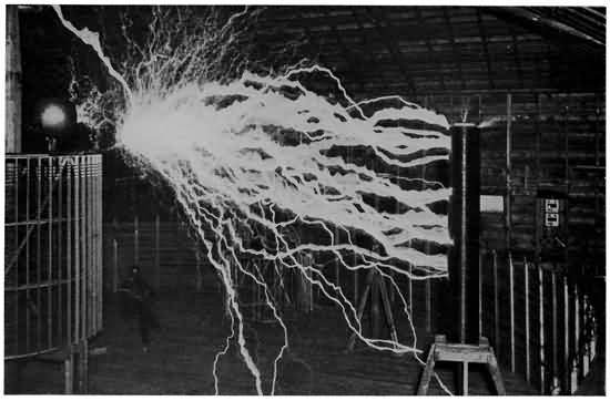
ELECTRICITY ENOUGH TO KILL AN ARMY PERFECTLY HARNESSED
The Oscillator shown on the left sending an alternating current from the earth into a large reservoir and back at the rate of 100,000 oscillations per second causes the tremendous electrical explosions as the reservoir is filled each time. The flames in this experiment were 22 feet long.

Courtesy of Thomas A. Edison Inc.
A BATTLE SCENE IN THE STUDIO
In this picture the stage director can be seen shouting directions to both actors and photographer at once.
"With this in mind you will see how the cinematograph is simply still photography worked out so as to show a series of snapshots at such speed that the eye cannot notice the change from one picture to another, but will see only the changing positions of the figures. Each picture shows the figures in a little different position, in the same order that they move, so that the whole series thrown on the screen at high speed shows the figures moving just as they do in real life."
"But where does visual persistence come in?" asked the youth.
"It would be plain if you could see the pictures thrown on the screen twenty times as slowly as they are, for each snapshot of each stage of motion must be displayed separately. It must remain perfectly still for an instant and then must be moved away while the shutter of the projecting machine is closed. When the shutter is opened again the next picture is thrown on the screen. Now, through the persistence of vision, the image of the first picture remains in your brain, photographed on the retina of your eye, while the shutter is closed, and you are 166 not conscious that there is nothing on the white screen before your eyes.
"The scientific explanation of this is simple enough: After an image has been recorded by your eye it will remain in the brain for an instant even after the object has been removed. Then it fades slowly away and gives place to the next image sent along the optic nerve from the eye. Thus the eye acts as a sort of dissolving lantern for the motion-picture man, and lets one image fade into another without showing any perceptible change in pictures. Thus the 'moving picture' is only a scientifically worked out illusion of motion."
The scientist went on to say that with marvellously constructed machines this scientific fact has been turned to such account that boys and girls in some of the schools now study geography partly from motion pictures, and some of the most wonderful sights of nature are seen every day by millions of people as they sit comfortably in their seats in the motion-picture theatre. A few years ago, before the invention of cinematography, the magic lantern was largely used, as many boys will remember; but it could only show scenes in which there was no movement—or in other words, scenes that were confined to still-life photography. Nowadays every boy is familiar with motion pictures depicting great historical occurrences, parades, inaugurations, coronations, volcanoes in eruption, earthquakes, buildings 167 burning and crumbling, railroad wrecks, shipwrecks, scenes in every country in the world and plays of every imaginable kind.
The motion-picture photographer takes pictures in the frozen North, and in the densest tropical jungles. He goes close to the craters of volcanoes in eruption to make a film of the terrifying flow of molten lava, and he sails the seas in the worst storms, that boys and girls who have never seen the ocean may understand its mighty upheavals. One motion-picture outfit was taken to the Arctic regions off the coast of Alaska where the volcanic activity in Behring Sea frequently causes new islands to spring from the ocean, or old ones to sink out of sight, in an effort to record on the motion-picture film the birth of a new island or the death of an old one.
"Ever connected with scientific research, cinematography," said the boy's friend, "is now one of the important branches of recording the phenomena of nature through which great scientific discoveries are made. Of late years we have heard much about germs, and the science of germs called bacteriology. A great deal has been learned about this most important factor in the preservation of our health, through the study of disease germs, by watching their activities through the medium of the cinematograph. The little parasites are photographed under a very high power microscope and the film is cast upon a screen in the usual way.
168 "Also exploring parties and parties that go into remote places to search for additions to our store of scientific knowledge invariably carry motion-picture outfits. One of the most notable examples of this was the expedition of Lieut. Robert F. Scott in his search for the South Pole. Lieutenant Scott carried many hundreds of feet of standard film, a good camera, and a portable developing outfit, with which he made pictures of the Antarctic Continent, in order to show the world the things that he and his men risked their lives to see.
"As I said before, the cinematograph is rapidly growing as an educational force, and Thomas A. Edison, the pioneer inventor and the leader in the development of the cinematograph, declares that it will in a short time completely do away with books in the study of geography. It is already in use in several special school and college courses, and with the improvements in the non-inflammable film, which will be explained later, it can be taken up far more extensively."
The man went on to say that in this connection Mr. Edison, who had been watching the schoolwork of his own twelve-year-old son Theodore, recently said in the magazine The World To-day (now Hearst's Magazine):
"I have one of the best moving-picture photographers in the world in Africa. I told him to land at Cape Town, and to take everything in sight between 169 there and the mouth of the Nile. His pictures will show children what Kaffirs are and how they live. He will show them at work, at play, and in their homes. They will be life-size Kaffirs that will run and skip or work right before the children's eyes. But the Kaffirs will be but the smallest part of what the African pictures will show. The biggest beasts of the jungle—the elephants, lions, rhinos, and giraffes—will be shown, not in cages, but in their native haunts. The city of Cape Town will be shown with its characteristic streets and its shipping. The broad veldts over which Kruger's armies marched will be shown just as they are, with here and there a burgher's cottage. Every step in the process of mining gold and diamonds will be put upon the film. The Nile will be shown, not as a small black line upon a map, but as a body of beautiful blue water, alternately plunging over cataracts and creeping through meadows to the sea. Then will come the Pyramids, with natives and tourists climbing them, and, lastly, the great cities of Alexandria and Cairo. Would any child stay at home if he knew such a treat as this was in store for him at school? Would he ever be likely to forget what he had learned about Africa?"
"Of course," continued the man in the laboratory, "this is but an example of the use of motion pictures in schools. Many of you boys have probably seen them in special lectures on other subjects, for they can be used to show how people live and work in every part of the world and how the various commercial products that so largely govern our lives are made."
170 But the motion-picture man, he explained, is not at all dependent upon what really happens for his films, because if he cannot train the eye of his camera on some occurrence that he desires to transfer to a film, he reproduces it in a studio, spending thousands and thousands of dollars, if necessary for actors, scenery and stage fittings. Nothing is too difficult for the motion-picture man, and he has never proposed a feat so daring but what he could find plenty of actors willing to take the necessary parts. Battles, scenes from history, sessions of Congress, railroad wrecks, earthquakes and hundreds of other spectacles have been planned, staged and acted out by the makers of cinematograph films, while, of course, all the plays that we see on the screen are planned and carefully rehearsed before they are photographed.
This all means that cinematography has become a gigantic industry, giving employment to hundreds of actors, photographers, and the army of men and women engaged in making and showing the films, to say nothing of the thousands of picture theatres that have sprung up in every city and town in the country.
While the boy's friend was telling him these things about the adventurous life of the motion-picture man, the listener sat spellbound.
"I'd love to see some motion pictures made," he said. "The machines must be wonderful."
"Well," answered the scientist, "we can do that, and if you'd like we can go up to one of the motion-picture 171 studios some day soon and see the whole process from beginning to end."
He was as good as his word, and several days later they were initiated into all the tricks of cinematography at one of the biggest laboratories in the country. We will follow them there and see what they found out about the machines by which motion pictures are made and shown.
With the fact clear in mind that cinematography is simply a series of snapshots of figures in motion, taken at high speed and thrown on a screen at a similar rate so that the human eye is tricked into sending to the brain an impression of moving figures rather than a series of still photographs, the various machines necessary in cinematography will not be difficult to understand.
Before there can be a cinematograph play there must be a negative film upon which the pictures are taken, a camera to take the pictures, an apparatus for developing them, a positive film which corresponds to the printing paper in still photography, upon which the pictures are printed from the negative film, a printing machine to print the positives from the negatives, and lastly a projecting machine to throw the picture upon the screen in the schoolroom, college lecture room, or theatre.
Every boy who is an amateur photographer is familiar with the photographic film. Up to the time the method for making practical cinematograph 172 films was discovered in this country, scientists vainly tried to portray motion by the use of photographic plates, but had little success. In a very short time after Eastman had announced the discovery of a celluloid substance that was transparent, strong and flexible, light, and compressible into a small space, Edison announced a machine for showing motion pictures.
The film base, or, in other words, the material which takes the place of the glass used in glass plates, was discovered by George Eastman in 1889, after years of painstaking experiment with dangerous chemicals. The base is a kind of guncotton called by chemists pyroxylin, which is mixed in wood alcohol. The guncotton is made by treating flax or cotton waste with sulphuric and nitric acids. After the guncotton and the wood alcohol have been thoroughly stirred up, the mixture looks like a thick syrup, but it is about as dangerous a syrup as ever was brewed, for its ingredients are those of the most powerful explosives. Its technical name is cellulose-nitrate. It is poured out on a polished surface, dried, rolled, trimmed, and after being coated with the sensitive material that makes it valuable for photography, is ready for delivery to the motion-picture maker in lengths up to 400 feet.
THE MEN WHO GAVE THE WORLD MOTION PICTURES
Eadweard Muybridge, called the "Father of Motion Pictures."

Thomas A. Edison, inventor of the motion-picture machine.

THE MOTION-PICTURE PROJECTOR
This is the standard Edison projector from two points of view, showing its complicated mechanism as clearly as possible.
One of the interesting points to remember about these films is that although they are made in lengths up to 400 feet they are all one and three eighths of 173 an inch wide, and the three eighths of an inch is given over to a margin at each side of the picture. That leaves a width for each picture on the film of just one inch. The height of each picture is three quarters of an inch. Fancy a photograph one inch by three quarters of an inch! No matter how clear it is you could not see with the naked eye all its details, and so it is in the cinematograph picture. It is so clear and sharp that when put under a good magnifying glass details that cannot be seen by the human eye are noticed. Now fancy multiplying the area of each little picture 2,700 times, and think of the chance for magnifying imperfections! And yet that is the amount that each picture is magnified in throwing it on a screen of the average size.
The films are coated with the sensitive emulsion in two degrees. The negative films must be as sensitive as possible to light, as they are intended to receive the shortest possible exposure, while the positive films, or the ones which correspond to the print paper in still photography, are made less sensitive to light, inasmuch as they are exposed for a longer time in the printing machine.
Fireproof films are probably one of the most important developments in the whole great motion-picture industry, for through these, schools, colleges, churches, lecture halls, and other public places not fitted with the fireproof box in which the motion-picture 174 operator works, can have the advantage of cinematography.
It was a difficult matter to find a non-inflammable film, for science has not yet discovered a base that can be made without cellulose, but the base we know to-day was treated so as to be non-explosive and practically non-inflammable. This film base is called cellulose-acetate, and when it is exposed to an excessive heat, as, for instance, the beam of the motion-picture lamp when the film is not moving, or when it touches a flame, it melts but does not blaze up. In the melting it gives off a heavy smoke, but there is no serious danger from this, as there is from the spurting flames from an exploding cellulose-nitrate base.
The films are packed in metal airtight and lightproof boxes and sent to the motion-picture firms, where they begin a complicated and an interesting career. The first stage is the perforating machine, through which all films, whether negative or positive, must go. The holes are made along the two edges of the celluloid strips, just as shown in the picture opposite page 176. There are sixty-four holes to the foot, on each side of the film, and each hole is oblong-shaped, as can be seen, with a width of about one eighth of an inch and a depth of about one sixteenth of an inch. This is known as the Edison Standard Gauge, and it is observed by practically all the motion-picture firms in the world.
175 The perforations along the edges of the films furnish the means for drawing them through the camera, printing machine, and projector; and as the correct movement of the films is one of the important factors in making good pictures, they must be absolutely mathematically exact. A fault in perforation of even as much as one thousandth part of an inch is apt to cause the film to buckle in the camera or projector and ruin the whole thing.
There are several different perforating machines in use now, and all of them are claimed by their makers to be perfect. It will not be necessary for us to take one of these machines to pieces further than to see that the holes along the edges of the films are punched by hardened steel punches. The films unwind from one bobbin, pass through the perforating device, and wind upon another bobbin. Of course the work must be done in absolute darkness, except for a small ruby lamp, as the films are so sensitive to light that any rays other than faint red would spoil them.
After perforation the negatives and positives are ready for use. The negative goes to the photographer in its light-tight metal box to be run off in making a film of a historical scene, a comedy, some wonderful phenomenon of science, or any one of a million different subjects. Just for the sake of seeing everything in its proper order we will assume that the negative is about to be used in portraying a comedy about the troubles of a book agent, and 176 that it is all done in the studio where the scientist and his boy friend watched this very film made.
Now for a look into a motion-picture camera—something few people get, because the competition among the various cinematographers is keen, and those who hold patents on cameras fear infringement.
The camera, which is enclosed in a strong mahogany box, stands upon a tripod. It is about eighteen inches long, eighteen inches high, and four inches wide. (This size varies with the make, and kind of work required.) The left side opens on a hinge, while on the right side are the ground glass finder, the distance gauge, and a dial to register the number of feet of film used. In the rear of the camera is a small hole which connects with a tube running straight through the box so that the operator looking through can sight it like a telescope, before the film is exposed. When the sighting and focusing are completed the opening is closed with a light-tight cap, and the film can be threaded through the camera. Having no bellows for focusing like an ordinary camera, the lens of the motion-picture camera is moved back and forward a short distance in the little tube in which it is set, to aid in the focusing. Of course the lenses of these wonderful snapshot machines are the best that money can buy and the factories can turn out.

A SECTION OF MOTION-PICTURE FILM
This is the exact size of the little pictures we see on the screen almost life size. Note how slowly the changes appear. It takes only one second to take sixteen of these.

Courtesy of Thomas A. Edison, Inc.
MAKING A MOTION-PICTURE PLAY IN THE STUDIO
Note the photographer, the stage manager beside him, and the battery of arc lights making the scene in the studio as light as day.
In the rear half of the camera are two boxes. The top one holds the unexposed roll of negative, while 177 the exposed film is rolled in the bottom one. Roughly speaking, the film unwinds from the top spool, passes out of the containing box through a slit, over a set of sprockets into the "film gate," down past the lens and shutter, where it is exposed over a lower set of sprockets, and through a slit into the lower containing box, where it is wound on a spool.
A MOTION-PICTURE CAMERA
A —Box for coil of unexposed film. A´—Box for coil of exposed film. B —Film passing over rollers. B´—Exposed film passing over rollers. C —Cogwheel which draws out film. D —Teeth which jerk film past lens. E —Lens and film-gate. H —Cogwheel which draws in exposed film.
"It looks simple enough, doesn't it?" asked the photographer, who was explaining the making of a moving-picture play to his visitors. "Well, it is a simple idea, but it takes a very complicated and a wonderfully accurate machine to accomplish the desired result.
"In the first place our cinematography is just still photography at high speed. We have to take approximately sixteen snapshots a second, so you can see that it takes a perfect machine to move the film 178 along fast enough so that we can get sixteen good, clear, sharp pictures only slightly bigger than a postage stamp, on our film between the ticks of your watch.
"Now if you look through the little hole at the back of the camera you will see that the scene in front of us is in the proper focus, and if you look at the little ground glass finder at the side here you will see it just the same way, except that it will be upside down. Now I will close the telescope focus at the rear so that when the film is brought down before the lens it will not be light struck."
The "threading" of the camera then began. "This little flap sticking out of this slit in the top box," continued the cinematographer, "is the end of the film, which is tightly wound up in its holder. You notice that I draw it out and thread it between these rollers, making sure that the teeth of the sprockets enter the perforations along the sides of the film. I also make sure that the sensitized side of the film is turned out, so that the light coming through the lens will strike it first. After the negative has been led over the sprockets you notice that it is allowed to make a loop of a couple of inches of slack. Then it is led into the important device we call the 'film gate.'
"You see the gate is hinged and that these little claws or fingers running in grooves take hold of the perforations. The next thing is to close the hinged 179 gate so that the film is tightly held against the aperture, through which the light strikes it and makes the picture. Below the gate we let the negative make another loop and then thread it over another system of rollers and sprockets and so to the slit in the lower box, where the exposed negative is rolled.
"The camera is now loaded and threaded and when I give the crank by which the wheels are turned a few trial turns you can see the way the mechanism works. In the first place you must understand that the film has to be jerked down with an intermittent motion. Don't forget to look for the intermittent motion, because, after the persistence of vision, that jump and stop, jump and stop, is the most important thing in cinematography—intermittent motion!
"You can see as the crank turns that the sprockets pull the film out and guide it along its course, and the little fingers jerk it down the space of one picture, or three quarters of an inch, at each jump. When the fingers are jerking the negative down, the shutter must be closed, and when the fingers are making their back trip to take a new hold on another length of film the strip must be as still as the Washington Monument, for the shutter to open, let in the light and transfer the image before the lens to the negative."
The photographer turned his crank and all the wheels in the camera began to move. The sprockets 180 working in the perforations pulled out the film and made the loop larger. The little fingers entered the perforations and jerked the film down, taking up some of the slack of the loop. The reason that the loop is formed is to prevent the film being torn by a hard jerk by the fingers when it is taut.
"Now if your eye were quick enough—which it is not"—said the photographer, "and you could see behind the gate, you would see a movement like the following repeated sixteen times to the second: Crank turns, top sprocket adds three quarters of an inch to the top loop, bottom sprocket takes up three quarters of an inch of bottom slack loop, fingers spring from groove and carry film down three quarters of an inch, inconceivably short pause while shutter opens and picture is taken; during this pause, while film is stationary, fingers jump back into groove, slide back to starting point without touching film and shutter closes. The shutter is a revolving disk between the lens and film, and the holes in the disk passing the negative admit the light."
After a roll of negative film has been exposed it is sent to the studio dark room for development. Every precaution is taken, of course, that no ray of light other than that which comes from the ruby lamp shall enter this room where films representing hundreds, and perhaps thousands, of dollars are being developed. The actual process for developing is no different from that used in developing other films, 181 but the difficulties in handling a delicate snakelike, strip some 300 or 400 feet long and 1-3/8 inches wide are tremendous. All amateur photographers appreciate the difficulties of developing in one string a roll of twelve films of a reasonable size, but think of handling a roll of film several hundred feet long no wider than a ribbon, and holding sixteen pictures to each foot of surface!
The difficulties of scratching, tangling, etc., were overcome by systematizing the process. In some cinematograph dark rooms the films are wound on racks about four by five feet, and then plunged into the various baths, which are in vertical tanks of convenient size. In yet other dark rooms the films are wound upon drums about four feet in diameter and revolved in horizontal tanks, only the lower part being immersed. The only difference is that the racks can be manipulated easier than the drums.
While in the motion-picture dark room the boy visitor asked the photographer in charge whether an amateur could step in and develop a few hundred feet of film granted that he had the necessary materials.
"Of course he could," came a cheerful voice from the darkness. "It's just the same as developing a roll of ordinary films, only we do more in a bunch than the amateur. If you'll step over here and watch this reel that we are now putting into the developing bath you'll see that it does just the same as the 182 single film developed in the amateur's dark room." After watching this trained photographer and his assistant for a few minutes, however, the newcomer decided that it was not an amateur's job, but rather one of the most delicate operations in all cinematography, for the developer can remedy many faults of exposure by bringing out an under-exposed film or toning down an over-exposed one.
Leaving the dark room the next stage of the negative is the drying room, where the film still on the rack is hung up to dry. This drying is a very difficult process because there is great danger of the film either becoming too brittle and cracking or of its being not hard enough. The air in the drying room has to be kept at a certain even temperature and it must be filtered so that no dust or impurity can injure the film.
After it has been properly dried the film again is wound upon a metal spool, put in an airtight box and sent to the assembling room, where the various scenes that go to make up the picture play, taken at different times and on different rolls of negative, are joined together in their proper order to make a complete play in a single roll about one thousand feet long.
After the negative film is developed, dried and wound upon a metal spool it is sent to the printing room, where positive prints are made from the original impression. Right here it may be well to say that 183 on a negative film or plate in any kind of photography white appears black and black appears white—hence the name negative. The paper or film upon which the print is to be made turns black wherever the light strikes it, so that when the negative is laid over the positive and exposed to a strong light the rays quickly penetrate the white spots on the negative and turn the corresponding spots on the positive black. The light does not penetrate the places on the negative which are black, and consequently leaves those places on the positive white. The result is that the positive shows the image just as it appears to the eye.
The principle of printing positive films, then, is the same as the principle of making photographic prints or positives from ordinary still photography plates or films, but of course it is far more complicated because of the mechanical difficulties of bringing the two long, unwieldy strips of film together in the proper position. The whole process is carried out by a machine which takes the place of the printing frame into which the amateur so easily puts the still-life photographic plate and printing paper.
There are several motion-picture printing machines in use in this country, but in their central idea they are similar, as they all pass the negative and positive films before a very bright light so that the impressions on the negative are transferred to the positive. The invention of this machine was a necessity for the 184 commercial success of motion pictures, for obviously it was impossible to lay a strip of film several hundred feet long and about an inch wide in a printing frame over a positive film of the same length and width.
A MOTION-PICTURE PRINTING MACHINE
A-A´—Rollers for negative film. B-B´—Rollers for positive film. C—Film gate where positive is held over negative for printing. D-D´—Negative film. E—Unexposed positive film. E´—Exposed, or printed positive film. F—Light which, shining through film gate, imprints image of negative on positive
The explanation of one printing machine will suffice to indicate the general principle. Some of the machines are worked by hand power, but in the larger reproduction studios electric power is used practically altogether for running the battery of printing machines.
The spool of negative film is slipped on to a spindle so that it can unwind easily, and immediately underneath it the roll of unexposed positive film, properly perforated along the edges in exactly the same way that the negative film is perforated, is suspended on a similar spindle. Of course the only 185 light in the printing room is the photographer's ruby lamp.
The two films unwind and pass downward, with the sensitive surfaces to the inside, and the positive on the outside of the negative. They are drawn together, and with the positive stretched flatly over the negative they pass over a pair of smooth rollers and toothed sprockets which enter the perforations of the two films with mathematical accuracy. They then make a small loop and enter a side hinged gate which holds them tightly against the printing aperture. This aperture is a hole just the size and shape of each picture on the film, and through it shines a very bright light which casts its direct rays upon the negative and imprints the image of the negative film upon the sensitized surface of the positive film. After passing the printing aperture, the two films make another small loop, run down to another toothed sprocket wheel and roller, and then separate, the printed positive being rolled upon one spool and the negative upon its spool below.
The action of this machine is very similar to that of the motion-picture camera, for like the device for taking the photographs, the movement must be intermittent in order to obtain good results.
If the operator desires to see whether the two films are in exactly the right position and everything is going smoothly, he can, by the use of a lever in the printing gate, drop a little red screen between the 186 light and the films, and by looking through the hole see through the unprinted positive, and the developed negative, to the light inside.
After a roll of positive has been printed, it is developed by just about the same process as is used in bringing out the images on the negative film. Then, after it is dried, the various scenes are joined together, titles and sub-titles put in, any final editing that is necesary is done, and the positive film is ready to be put on the projection machine for the first trial.
The preparation of the titles, sub-titles, and other explanatory writings that are thrown on the screen in the course of a cinematograph play is a comparatively simple matter. The words are written or printed out in large letters on cards and photographed by a camera with a slower movement than the ones used for recording moving figures. The positives are made from the negatives so taken, in the same way that positives of other films are made, and after development and drying are ready to be joined to the film in the proper places.
Every firm engaged in the fascinating business of making and reproducing cinematographic plays gives the most careful and painstaking attention to the first "performance" of a film. Of course it is held in private before only the officials and a few critics invited for the exercise of their judgment. The event amounts to the same thing as the dress rehearsal 187 of a play to be reproduced upon the stage, and any changes that are necessary in the judgment of the critics cause just about as much trouble. Any one of a hundred things may be wrong. Some little incongruous detail in the scenery may be noticed, some jarring gesture by an actor or a scene in which the action does not proceed fast enough.
If the officials of the firm decide that a film is below their standard, parts must be cut out, and new parts photographed over again until the whole thing suits requirements. Sometimes one scene must be done over many times before it suits exactly, and several hundred feet of film wasted. At a cost of about three cents a foot, it is plain that the waste in film alone is great, but when a big scene with a hundred or so actors in it has to be done over again, the cost of assembling the company, paying their salaries and other expenses is enormous.
Finally, when the officials themselves are satisfied with a film it is thrown on the screen for the board of censors in the various cities, and if it measures up to standard, and contains no objectionable features, it is ready for public reproduction.
When all this is done, the printing machine again comes into play, and as many prints of the negative as are needed are struck off, for in cinematography, as in still photography, it is a simple matter to run off as many prints as are desired, once a good negative is made. These prints then are sent out to 188 as many theatres, in as many different cities, as desire them, and released for public view on the same day in every theatre in the country.
Having looked at the motion-picture camera, and at the complicated process for developing and printing the films, we are now ready to climb into the little fireproof box from which comes the beam of light that throws the pictures on the screen. This is the projector and it is probably the most complicated of all the machines used in cinematography. As it was a development through the application of well-known mechanical principles we will not go into this subject more deeply than merely to understand its central principle, which is intermittent motion.
The result toward which the inventors worked was a magic lantern such as was familiar to every boy ten years ago, that would throw upon the screen the tiny consecutive pictures on the film, with such speed, and at the same time so clearly and steadily, that the effect would be that of figures in motion. Most boys will remember the flickering, flashing and jumping that used to be noticeable in motion pictures, and many are probably aware that it was the improvement of the projecting machine that did away with these objectionable features.
The essential parts of the projecting machine are the lantern with its light and lens, and the device for running the positive film before the light with the 189 proper intermittent motion. It might be said generally that the projecting machine looks like a magic lantern, but on close examination it will be seen to be an extremely complicated affair.
The powerful electric light, usually an arc light, which is placed in a metal box a few inches behind the rest of the projector, directs its rays through the glass condensers, thence through the film, and thence through the lens, which throws the image upon the white screen or curtain. The condensers are made of two carefully ground glass parts. The first is dish shaped, with the concave side turned in toward the light and the convex side turned outward. Immediately against it is another condenser the same diameter and convex on both sides so that the collected rays from the dished part are shot forward to a point where they will all converge. This point is the centre of the lens. From the lens the rays of light are projected in a widening beam to the white screen on which the pictures appear.
The film is passed before the beam of light at a point between the condensers and the lens, so that the image is projected through the lens. The film is run before the light with the figures upside down, like in the ordinary stereopticon, and the lens turns the image right side up again.
The most interesting part of the solution of the problem is the advantage taken of the persistence of vision. Photographed at the rapid rate of sixteen 190 a second, and thrown upon the screen at the same rate of sixteen a second, it is plain that the stage of motion shown in the pictures every sixteenth of a second is reproduced. With the inability of the eye to tell that the screen is merely exhibiting separate photographs, the appearance is of motion. In most persons this visual persistence is only about one twenty-fourth of a second, but that is long enough to allow animated photography to be a pleasing illusion to them, for it gives the shutter of the projector time to hide one picture while the mechanism moves the film down to the next picture, bring the film to a dead stop, and let the shutter open again to reveal the next stage of animation.
The manner in which modern mechanical skill took advantage of this physiological defect, proved many years ago by the leading scientists, is nearly as interesting as this slight defect in nature's own camera—the eye.
Above the film gate is a metal fireproof box (many of them are lined with asbestos) in which is the roll of unprojected positive film. Below it is another similar box in which the film that has been shown is wound. The motion, which is directed either by a crank turned by hand or by electrical power, is the same speed, and practically the same in detail, as that of the film in the cinematograph camera. From the film box the film runs to a roller, where a sprocket enters the all-important perforations and 191 draws out the strip to make a small loop above the film gate.
The shutter is placed in front of the lens. It is made up of a black metal circular disk, with either two or three open spaces, and a similar number of solid or opaque spaces. In general it looks like a very wide flat aeroplane propeller. Like the movement of the camera, the film is stationary while the shutter is open, and when the shutter is closed the film is jerked down three fourths of an inch, or the length of one picture, and brought to a dead stop by the time the shutter revolves and is open again. This is repeated sixteen times every second, so the film is cast upon the screen for one thirty-second part of a second, and the screen is blank one thirty-second part of a second while the shutter is closed and, as we might say, the scenes are being changed for the next act. Although the movement is just the same as in the camera, it may be well for the sake of making the thing perfectly clear to go through the motion very slowly.
For the sake of keeping out of fractions entirely too small for our consideration we have assumed that in both camera and projecting machine the shutter is open one thirty-second part of a second and then closed one thirty-second part of a second, the whole operation taking one sixteenth of a second. As a matter of fact the effort of the experts in animated photography is to have the shutter of the camera 192 open for just as brief a space of time as possible, and on the other hand it is their effort to have the shutter of the projecting machine open just as long a space of time as possible, and closed as short a time as possible. In other words, they desire to shorten the time when there is nothing on the screen, and lengthen the time for the eye to photograph each image on the brain. By using a little different mechanism in the film gate of the projector this is accomplished to some extent, as well as obtaining a clearer, steadier picture than formerly was shown.
You will remember that in the camera and printing machine the film was jerked down by little teeth or fingers.
The simpler of the two methods in general use on projectors now is called the "dog" movement. It is composed of an eccentric wheel placed below the film gate, with a little roller projecting from it. The wheel revolves and once every sixteenth part of a second the roller is brought around so that it strikes the film and jerks it down the three fourths of an inch that makes the space of one picture.

A MOTION-PICTURE STUDIO
This is where a great many of the Edison Photoplays are made. Besides all the other departments there is room on the stage for several different plays to be photographed at one time.

Courtesy of Thomas A. Edison, Inc.
A REALISTIC FILM OF WASHINGTON CROSSING THE DELAWARE
This picture was taken in zero weather on a real stream with real ice menacing the actors in the boats.
The other method is known as the "Maltese Cross" movement. The name is taken from the fact that the chief sprocket wheel is shaped somewhat like a Maltese Cross. This wheel, with four notches in it, is attached to the sprocket below the film gate, and it is driven intermittently by a wheel with a pin that enters one of the notches on the Maltese 193 Cross wheel at each revolution, and pushes it around the space of one quarter of a turn. This of course turns the lower toothed sprocket and jerks the film down the space of one picture. On the next revolution of the driving wheel the pin enters the next notch, turns the Maltese Cross wheel another quarter of a turn, and, by the motion imparted to the sprocket, jerks the film down another three quarters of an inch, thereby pulling another picture into place as the shutter opens.
Recent improvements on this movement have largely done away with the jar resulting from the pin catching the notches in the cross. The wheel that looks like a Maltese Cross has, instead of four notches, three grooves, dividing the wheel into three equal parts just as if a pie were cut into three equal parts but the knife stopped short, leaving a solid hub in the centre. The space between each groove represents the length of one picture on the film. Without going into a long, tiresome, technical explanation of this very important little feature of the projecting machine, it will suffice to say that the three-groove wheel is connected with the sprocket underneath the film gate. Near it is a revolving arm, and upon this arm is a horizontal bar. When the arm makes a revolution, and reaches a point where it touches the three-divided wheel, the mechanical adjustment is so fine that the horizontal bar enters the groove, and the revolution of the arm carries the three-divided 194 wheel around one third of a revolution—or the space from one groove to another—turns the sprocket and pulls the film down the space of one picture, with a quick steady pull. After getting this far, the arm on its upward course leaves the three-divided wheel, which stands still while the shutter is open until the arm gets around again, and as the shutter closes pulls the sprocket around another space.
The strong light concentrated upon the film, in just the same way that you concentrate the sun's rays upon your hand with a burning glass, is very apt to set the film afire, particularly if through any slip in the machinery it stops in its rapid progress of about a foot a second. As machinery is not infallible, the manufacturers have invented various safety devices for protecting the film in case the machinery stops. Of course this is not necessary when non-inflammable film is used.
PERILOUS AND EXCITING TIMES IN OBTAINING MOTION PICTURES.—HOW THE MACHINE CAME TO BE INVENTED, AND THE NEWEST DEVELOPMENTS IN CINEMATOGRAPHY
WITH a clear understanding of the mechanism of the various motion-picture machines in mind, we are free to go on with the scientist and our young friend to the exciting times experienced by actors and photographers in making the pictures that delight people all over the world. First, however, let us briefly look back over the history of the art, for there is nothing more interesting than to follow up the experiments upon which Thomas A. Edison based his invention of the original cinematograph or kinetoscope.
Long ago, even before Edison was born, scientists tinkered with devices that would picture apparent motion, but they were rude attempts and little progress was made for many years. The first man to take a decisive step toward practical cinematography was Edward (or Eadweard) Muybridge, a 196 photographer who lived in Oakland, Cal.; so he is rightly called the father of motion pictures.
Muybridge had been experimenting with snapshot cameras, as in those days instantaneous photography with wet plates was comparatively new, and, being something of an artist as well as a photographer, he decided that snapshot photographs of animals and men while running, jumping, and walking would greatly aid artists in transferring to their canvases the exact positions of the figures they wished to paint. In 1872 the people of California were considerably excited over the feat of Governor Leland Stanford's trotting horse Occident, which was the first racer west of the Rocky Mountains to make a mile in two minutes and twenty seconds, and the Governor was having him photographed on every occasion.
Governor Stanford also wagered that at one time during the trotter's stride all four feet were off the ground. Muybridge suggested his plan for photographing the animal's every movement, while running, trotting or walking, as a means of settling the bet, and the Governor, very much pleased, gave him free access to the stables and race course.
The photographer built a studio at the course and systematically went to work. First, he built a high fence along the track and had it painted white. Then he securely mounted twenty-four cameras side by side along the opposite side of the course and stretched thin silk threads from the shutter of each camera 197 across the track about the height of the horse's knees. Occident was then led out and ridden along the course so that he would pass between the white background and twenty-four cameras. As he came to each silk thread his legs broke it and opened the shutter of the camera to which it was attached. Thus the animal photographed himself twenty-four times as he passed over the track and showed that Governor Stanford's contention regarding his movements was correct.
Laid in consecutive order in which the photographs were taken, each picture showed a different stage of the horse's movements, and if the series of photographs was held together and riffled over the thumb, so that each one would be visible for just the fraction of a second, the impression received, thanks to the persistence of vision, was that of a horse in motion. When Muybridge went to Paris the year after taking the photographs of Governor Stanford's horse he received a warm welcome from some of the greatest French painters of the day. He gave several exhibits of his photographs, but carried the work no farther.
Almost one hundred years before this, several brilliant Frenchmen were groping in the darkness for some way of showing motion by means of pictures, and brought forth a device known as the "Wheel of Life," or the Zoetrope. It was simply an enclosed cylinder, and upon the inner lower face, which was 198 free to rotate, were placed a series of pictures showing the stages of some simple animation, in sequence, such as two children seesawing, or a child swinging. The upper surface was pierced with long, narrow slits, and when one looked through the slits, and the lower surface with the pictures on it was rotated, one actually saw only one picture at a time, but as they passed before the eyes the appearance was of motion. Various improvements on this idea were made, and silhouette paintings even were thrown on a screen so as to give an illusion of motion.
The development of photography was necessary, however, before motion pictures ever could be a success. About the time Muybridge took his pictures the old wet plate was superseded by the dry plate we know to-day, and scientists began the search for some material from which they could make film base.
Before the invention of films, motion pictures, as they were known at that time, were used chiefly by scientists in trying to analyze motion which cannot be traced by the human eye. Among the leaders in this work was the French scientist Dr. E. J. Marey, who studied the flight of birds and the movements of animals and men so carefully that he wrote a book entitled "Movement," which is still used by authorities in scientific research.
Doctor Marey set up another camera at the Physiological Station in Paris with which he and his 199 associates made pictures of great scientific value. Those were the days of the early experiment with flying machines, as will be remembered from Chapter II, and the French inventors made careful studies of Marey's pictures of bird flight.
Doctor Marey's stationary camera was a simple bellows type which took an exceptionally wide plate. The shutter, which was operated by a crank, was a disk with slits in it, so that as it turned it intermittently admitted and shut off the light. Thus, as a white-clothed figure passed a dead-black background, in front of the camera, the various stages of its movements in the course of its trip from one side of the camera's focus to the other were faithfully recorded on the plate, each slit making an exposure of the image on a different section of the plate, showing the figure in a different position.
Many machines that were merely developments of the old zoetrope were brought out both in the United States and Europe, but the greatest obstacle to their success was that they were peep-hole machines of the kind that flourished in penny arcades a few years ago, rather than devices for throwing pictures on a screen so that a large number of persons could see at the same time. In general, these old-fashioned "moving-picture" machines were simply cabinets in which were mounted a series of transparencies made from pictures representing the stages of some simple animation. An electric light illuminated the 200 transparencies and they were rotated so that one picture at a time was seen. In some of the more improved "wheels of life," such as were shown in this country, the transparencies in consecutive order were mounted on a hub like the spokes of a wheel and were rotated so that one was seen at a time, very much like the way Muybridge riffled his horse pictures over his thumb.
All this time two American inventors had been at work on the two most perplexing problems in animated photography at that time, and it was through their achievements that the first practical motion-picture machine was given to the world, just as it was through the achievements of the Wright brothers that the first practical aeroplane was given to the world.
These two men were Thomas A. Edison and George Eastman.
Mr. Edison had been working for several years on a motion-picture machine, but was handicapped by the lack of a practical film.
Mr. Eastman, after years of experiment, produced the film that made cinematography possible, in 1889.
With a strong transparent film, flexible, and compressible, to take the place of the clumsy glass plate, Edison was ready to go ahead with his work, started years before, and in 1893 the crowds at the World's Fair in Chicago saw the first motion-picture machine. It was called a Kinetoscope.
Courtesy of Thomas A. Edison, Inc.
THE CORSICAN BROTHERS—A FAMOUS TRICK FILM
The parts of the twin brothers in this film were acted by the same man, the illusion being accomplished by the double exposure trick.

Courtesy of the Vitagraph Company of America
THE GUILLOTINE
Famous scene from the photoplay based on Dickens's great novel, "A Tale of Two Cities."
201 Simple as it was, thousands and thousands dropped nickels into a slot and peeped into the hole at the "moving pictures." Some of the boys who read this may remember machines like it. The mechanism was in a cabinet in which the pictures were shown on a positive film. This was about forty feet long and was strung backward and forward inside the cabinet on a series of spools in a continuous chain. The film passed before the peep-hole and the pictures were magnified by a lens. They were illuminated by an electric lamp behind them. A rotating shutter cut off the light intermittently, so that each picture was seen for the fraction of a second, and then a period of darkness ensued. The shutter was the only attempt at intermittent revealing of the pictures, for the film travelled continuously.
The camera that Edison invented for taking the pictures shown in his kinetoscope was in principle about the same as the one described earlier in this chapter, except that it has been wonderfully improved in mechanical accuracy and photographic clearness. The hardest problem facing him was the machine which would show the pictures to a large number of spectators at the same time and do away with the old peep-hole machine. The idea of the magic lantern immediately presented itself, but the inventor quickly saw the necessity of an intermittent motion, for if the ribbon of pictures was drawn before the beam of light fast enough to give the illusion of 202 motion, each picture was thrown on the screen for such a short time that it was too faint to be seen easily. From this it was to Edison but a step to a practicable projector, and nothing remained but to improve its mechanical working.
Getting motion pictures is the adventurous part of the business, for this work requires operators and actors who are athletes and who do not know the meaning of fear. As pictures of scenery and events are taken in every corner of the world—in the jungles, in the arctic ice, on mountains and in deserts, the photographers all can tell absorbing stories of the strange places and things they have filmed.
In the rough the films are divided into four great general classes, with several special classes besides. They are scenic, industrial (showing the working of some great industry like steel making), topical, and dramatic. Scenic and industrial films are simply taken at an opportune time, as it is usually not necessary to make any advance arrangements, though the photographing may incur great risks.
Topical films, such as the pictures of the recent Durbar in India or some other great current event, are very valuable when quickly sent broadcast. Of course the photographer must have the same news instinct that the reporter has to get good topical films, for he must get there first and deliver his picture "story" to his studio "editors" as quickly as possible. The photographers often have hair-raising 203 adventures in taking such films, as the single instance of the man who went up Mount Vesuvius during an eruption and took a cinematograph film of it will show.
The greatest variety of experiences, however, is to be found in the making of dramatic films—that is, motion-picture plays. As every boy knows, these stories have just as wide a range as the books in a library. There are plays based on biblical stories, and plays dealing with Wild West adventures; there are farces, comedies, and tragedies; in fact, there is no limit to the variety. These plays, however, can be divided roughly into two classes—that is, those that are produced on the motion-picture studio stage and those produced out of doors with the natural surroundings as the stage. The interesting things about either kind would fill a book the size of this.
In the early days of cinematography only simple shows were attempted, but now nothing is too big or too complicated or too expensive for the big concerns making pictures in the United States and Europe. The first motion-picture studio here was simply a portable, glass roofed, black walled shed set on a pivot in Edison's yard in Orange, N. J. It was called the Black Maria and makes an interesting contrast to the great glass studio at Bronx Park, N. Y., costing $100,000, in which many of the Edison films are now made. All well-equipped motion-picture 204 studios these days are fitted out with space for several stages; a great tank for water scenes, carpenter shops, scene-painting studios, furniture and other stage properties to furnish scenes, costumes, stage fittings, and a great corps of photographers, mechanics, electricians, etc., besides the company of well-paid actors who take part in the shows.
If a play is to be reproduced in the studio, the architect draws the plans for the scenery, which are sent to the stage carpenters, who make the framework and stretch the canvas. The blank scenery is then sent to the racks, where the scene painters get to work on it.
In the meantime the property man at the studio, just like the property man at a theatre, has received a list of the things he will need to furnish the scene and give the actors the paraphernalia necessary for the carrying out of the play. He ransacks his storeroom and brings out tables, chairs, pictures, etc. The studio costumer also checks off her list and sees that she has in her great wardrobe costumes to dress the characters for their parts.
Meantime the stock company of actors is called together, the scenario, or plan of the play, is read, and rehearsals begin. All this part of it and the rehearsing are very much like the work preliminary to the staging of a regular play, except that the scenes are arranged, not according to the size of the stage, 205 but according to the focus of the camera. Each scene is timed to the second so that the pantomime will tell the story but not tire the spectators with useless repetition. In rehearsing, the actors sometimes speak their lines—that is, the words the character would say—just as if they were to be heard, because it often helps them to give the proper effect.
Finally, when the stage director has one scene of a play down fine, after perhaps days or weeks of rehearsing, the photographer is called. He consults with the stage manager, measures off the distance for his focus, so that he will get all that is necessary into the picture, and nothing that is not wanted; and after seeing that every detail is attended to, the great battery of arc lights overhead is turned on, and the stage manager says, "GO!"
The photographer begins to turn his crank, keeping one eye on the stage and the other on his stop watch, and the stage director counts off the seconds, meanwhile shouting instruction to the actors on the stage. To an outsider the noises sound like a riot or a street fair rather than a theatrical performance timed to the fraction of a second in which the movement of an eye counts in the final effect. While the camera clicks off sixteen instantaneous snapshots to the second the stage director calls out the seconds, "One, two, three. One, two, three. Look out there, don't get out of focus! Keep toward the centre of the 206 stage. Now, Jim, run in and grab the book agent—hurry, look angry! One, two, three. That's fine! Hey, there! shake your fist." And so it goes, until the director rings a bell or shouts, "That's all!" and the scene is ended. Just as the last pictures are being run off, a stage hand rushes into the scene and holds up a large placard with a big number on it. This number is the number of the scene in the play, and is watched by the men and women in the assembling room when they gather the various scenes of a picture play together and join them up in the proper order for one continuous roll. Of course in the joining the number is cut out of the picture for projection.
It very often happens that a stage director in his effort to get a graphic story reproduced on the film takes a great many more pictures than can be crowded within the limits set for the play. Then with the scenario in front of him, and a good magnifying glass to bring out the detail of the pictures, he takes his scissors, just as the editor takes his blue pencil, and begins cutting from the story the unnecessary pictures, just as the newspaper or magazine editor cuts useless paragraphs from the story or article. He must not cut out any picture that helps to tell the story, and yet he must sometimes cut out as much as 400 feet of film. He "kills" an unnecessary picture here, and an unnecessary picture there, and adds up their length until the story has been reduced to the proper size.
207 Although spectacles such as the one in the picture representing a battle on a bridge, and others even larger, are staged in the various big motion-picture studios, the most exciting work in the filming of motion-picture plays is out of doors where the natural surroundings make the stage. A great many of the shows seen to-day are taken this way, with real trees, real water, real mountains, or real streets affording the settings. Hence with studios in which battle scenes, riot scenes, water scenes, and practically any indoor scene can be reproduced; and also the great outdoors at the disposal of the cinematographer, there is practically no limit to the subjects that can be turned into dramatic films for the education and amusement of the public.
A few instances of the plays made out of doors will serve to show the limits to which the producers are willing to go to get new shows. The Edison company, with its big studio in New York and its manufacturing plant at West Orange, N. J., in the heart of the country where the Revolutionary War was fought, is reproducing a whole series of films of American history. These, so far as possible, are made on the exact spots where the dramatic events occurred. The first of the series entitled, "The Minute Men," was taken near Boston, where those historic defenders of liberty fought for their country. In this film is the famous scene representing the Battle of Concord, which was taken on practically 208 the identical ground where the battle was fought. The producers spent a great deal of time in planning this series of pictures and so far as possible had every historical fact correct, so that the value of the series from the educational point of view is apparent. The other titles in the series will show how the scenes of the Revolutionary War were brought home to the American people. They included "The Capture of Fort Ticonderoga," "The Battle of Bunker Hill," "The Declaration of Independence," "The Death of Nathan Hale," "How Washington Crossed the Delaware," "Church and Country; an Episode of the Winter at Valley Forge," and so on. The film dealing with Washington's trip across the Delaware in the ice was made under conditions as nearly like those of the actual events as possible to get them. The pictures were taken during the coldest part of last winter (1912), and the photograph opposite page 193 was taken while the big scene was being acted out. This was taken in an arm of Pelham Bay, near New York, and the "scene shifters" had to work for hours in the bitter cold breaking up the ice and shifting around the great cakes in order to get the desired effect. Their success is attested by the picture reproduced here.
The Selig Company, with studios in Chicago and Los Angeles, and big stock companies of actors in both places also take some wonderful outdoor films. One of these was a play representing life in the 209 African jungle, for which a special trainload of actors, and a whole menagerie of elephants, camels, lions, rhinos, leopards, pumas, zebras, and other animals, were shipped to Florida, where scenes much like those in Africa were found. This same company also sent a stock company and a corps of photographers to the Far North, where a film play was made amid the Arctic ice.
The Chicago studio of this concern is one of the wonders of cinematography, for not only has it a great building in which indoor plays are filmed, but a great land reserve for outdoor productions. In one place are artificial hills built in the natural forest, and upon them artificial feudal castles. In another are log cabins for frontier scenes, and in yet another a barren stretch for other kinds of scenes. The Los Angeles company is close to the mountains, the ocean, and the Great American Desert, so that it can furnish material for an endless amount of exciting Wild West shows.
One of the big films made in Europe was "The Fall of Troy," produced by the Itala Film Company, which reproduced the great wooden horse, the walls of Troy, and all other historical details. The great French, German, and English companies also have made big films.
In the production of plays built on well-known novels the motion-picture industry has found one of its most successful fields. Dickens's great novel, 210 "A Tale of Two Cities," afforded the Vitagraph Company of America, one of its best films, while James Fennimore Cooper, Alexander Dumas, and even Shakespeare, and grand opera have been transferred to the cinematograph. From the great Biblical stories also have been taken films that have been shown by missionaries, and others interested in religious work, all over the world. The "Passion Play" was one of the first long films ever shown and it made a tremendous success.
Big spectacles are always popular and to fulfill the demand two locomotives have been run together at high speed, the motion-picture concern buying the machines outright for the purpose and leasing the railroad for a day; an automobile has been driven over the Palisades of the Hudson River, ships have been towed out into the ocean and blown up and whole towns of flimsy stage construction have been built only to be burned, while the motion-picture photographer recorded the whole thing on a film. One concern even got permission from the Los Angeles Fire department during a big fire, and dressing an actor as a fireman cinematographed him as he heroically rushed up a ladder amidst the flames and rescued a screaming woman from an upper window. The woman was an actress who had risked her life to go into the burning building and be rescued.
Of course the great motion-picture industry has not been without its fatal accidents. Several times 211 actors playing the parts of men in difficulty in the water have actually been seized with cramps and have drowned before the eyes of the spectators. One time a picture was being taken of a band of train wreckers who were supposed to tie the switchman to the track. The train was supposed to stop just short of the man, but it actually ran over and killed him. The pictures were used at the inquest. During the filming of war pictures there have been explosions of gunpowder that were not intended, and in the taking of pictures of wild animals in their native haunts and in menageries, several photographers have been badly injured.
There is another big and important department in the filming of motion picture plays in trick photography. Every one who reads this has seen at the picture-theatre films of things that he knows perfectly well never could have happened—men walking on the ceiling, fairies the size of a match acting on a table beside a man, a saw going through a board, a piece of furniture assembling itself, a man run over by an automobile, his legs cut off, and then stuck on again all within a few minutes, marvellous railroad wrecks, and a thousand other things which could not happen or which the motion-picture photographer probably never could catch in his lens. All of these things are done through trick photography.
Double exposure, double printing, and the stop motion are the most common methods of obtaining 212 these marvellous results. Opposite page 200 is a picture obtained during the reproduction by the Edison Company of Alexander Dumas's novel, "The Corsican Brothers." This film was obtained completely by the double exposure. In the story, the two brothers are twins so much alike that they cannot be told apart. They act exactly alike, and one even feels what, the other feels. In making the film the producers decided that it would be impossible to get two actors that looked enough alike to take the parts of the two brothers, so the same man acted both parts. In the picture referred to the brothers sitting at table with their mother are one and the same actor.
The picture was made by blocking off the whole left half side of the film with black paper and running it through the camera while the actor played the part of the brother on the right side of the table. He was timed to the fraction of a second, and when the exposed half of the film was blocked off with paper and the unexposed half run through, he acted out his part on the left side of the table, to this time schedule. So exact was his work that when the brother on one side of the table spilled a drop of hot coffee on his hand and started in pain, the brother on the other side, feeling the same pain as his counterpart, jumped at exactly the same second.
Another popular trick with the double exposure 213 is a scene showing mermaids or divers swimming or walking at the bottom of the sea. First a large brilliantly lighted glass tank is set up in the studio, stocked with fish and sea life, and photographed. In this kind of a film the images of the real water are a little under exposed. Next a space the size of the tank is measured off on the floor with a gray scene laid flat. On the scene are painted faint lines to indicate water, and faint outlines of fish, seaweed, etc. Then the actress dressed for the part of a mermaid lies flat on the setting and goes through the graceful motions of swimming while the film upon which the real water pictures were taken, is run through the camera, which is placed above her with the lens pointing directly downward.
Another example of double exposure is seen in most films where Lilliputians or small fairies enter into the picture. The parts of both full-grown human beings and diminutive fairies are played alike by adult actors, but the difference in their size is obtained by taking each on the same film at different times. For instance, suppose a tiny fairy is supposed to appear to a grown man in the picture play. First the man goes through his act with the camera photographing him from a distance of about fifteen feet. Next the fairy goes through her act, bowing, etc., to the place where the man stood and is photographed on the film from a distance of say one hundred and fifty feet. The two impressions when 214 printed give a lifelike effect of a full-grown man and a tiny sprite.
There are numberless films made by the stop-motion system, which simply means that the stage hands rush in and arrange things while the shutter is closed. All pictures in which you see a man or a woman falling off a roof or out of a window and subsequently getting up and running away are made by this system. The Edison film showing an automobile going over the Palisades and the driver being hurled to the rocks below was done with the stop motion. It is very simple. The cinematographer photographed the approach of the automobile and the human driver in the seat approaching the cliff at terrific speed. He stopped his camera, the automobile came to a stop, the automobilist got out and a dummy was placed in his seat. Then by starting the automobile a little back of where it was slowed down and stopped, and photographing, it the public could not tell that it had been stopped, and that the man in the seat who was hurled to the rocks below with the machine was a dummy.
A development of this is the picture-a-turn motion, which simply means that with each turn of the crank of the camera one exposure is made. By this trick many of the strangest films seen are made possible. The magic carpenter shop where saws and hammers move without human aid is an example. It is simply done by stage hands who rush on to the 215 stage between each turn of the camera and advance the tools to one more stage of progress. The saw is at the top of the board, and the hammer is suspended in air (by invisible wires), etc. In the next picture, the saw is in different position, and the hammer has descended to the head of a nail. In this way all the magical effects of inanimate objects taking on life in the film are accomplished. One of the interesting details is the appearance of such objects as boards rising from the floor and placing themselves upon the bench ready for the saw. To do this the operator, keeping his shutter closed, advances his film a couple of feet and takes a picture of the board falling to the floor from the bench (pulled off by an invisible wire). As the film is moving backward, the picture when exhibited in sequence shows the board not falling but rising from the floor, and placing itself on the bench in a most mysterious manner.
Moving the film backward will give many strange results. For instance, in the plays where a little child is snatched from death under the wheels of an onrushing train just as the cow-catcher is upon her, it is no longer necessary to risk human lives before trains. First, the onrushing train is photographed with the film moving forward right up to the point where the child is to be standing when rescued. Then the train is allowed to run on past the point. It is then backed up at high speed, and the film run backward. When the locomotive rushes past the spot 216 where the child is to be rescued her heroic rescuer simply dashes on to the tracks amid the dust of the receding train and places the child between the rails. When this section of film, which is taken backward, is fitted into the rest of the ribbon, and is run through the projector forward, it looks as if the rescuer rushed on to the track and grabbed the child out of the way as the train passed by.
Another popular trick by which fairies or ghosts are made to appear gradually in motion-picture scenes is the one by which the lens is narrowed down or opened up gradually. If a ghost is to appear, the hole through which the light strikes the lens is narrowed down so that only the brightest objects are photographed. The hole is gradually enlarged so that the light increases and brings out the figures plainer and plainer, until the ghost is in full view.
A great many good films, such as railroad wrecks, automobile journeys through the clouds, etc., are made with models, propelled by invisible strings over skilfully built scenery. The scene of figures walking on the ceiling is very simple inasmuch as it is only necessary to set the floor of the stage to represent a ceiling and take the pictures with the camera upside down. Men and animals can be made to run up the sides of buildings, simply by laying the scenery on the studio floor, and photographing the whole thing from above.

A ROMANCE OF THE ICE FIELDS
This film was taken in the dead of winter, and the man is in a dangerous position on a real ice cake.

THE SPANISH CAVALIER
A whole motion-picture outfit was taken to Bermuda to get this photoplay.

ALL READY FOR A THERMIT WELD
After the little hole at the bottom of the weld, through which the redhot shaft inside shows, is plugged up, the thermit is ignited.
Of the recent developments in cinematography the 217 ones we hear most about are colour pictures and talking pictures. So far, these two points which would give the last touch of realism to the scenes thrown on the screen are in a very imperfect state of development, but it is safe to say that it will not be very many years before we will have them duplicating what we see and hear in actual life just as faithfully as the black and white pictures now duplicate motion.
Science so far has not given us a method of actually taking a motion-picture negative in the natural colours, such as now can be taken in still photography, so at first the pictures were coloured by hand, and later by stencils. This is a difficult and a tedious undertaking, however, and newer methods have been introduced.
Although there are several systems being worked out the one best known is the Kinemacolour, which achieved its greatest fame by showing the pictures of the coronation of King George in England, and the Durbar in India in colours. The Kinemacolour system is simply one of photographing and projecting through screens of red and green. The shutter of the camera is made up of four parts, as follows: a transparent red screen, an opaque space, a transparent green screen, and another opaque space. Thus, by the law of colours laid down by science, when one picture is photographed through a red screen, all the different tones but red are arrested by the screen, and only the objects having shades 218 of red are photographed. Next, when the green screen exposes the next space of three quarters of an inch, only the objects having green tints are photographed, as all other tints are arrested by the green screen.
The film itself shows no colour other than black and white, but when it is projected through a shutter that works exactly the same as the camera shutter the pictures show the objects in their natural colours. That is, the alternating pictures taken through the red screen and shown through a screen of the same colour show all the tones of red, while the alternating pictures taken through the green screen and likewise projected through a green screen show all the tones in which appear green. Thus, with the aid of the persistence of vision and a somewhat faster system of photographing and projecting, the tones blend and we see on the screen at the same instant red-coated soldiers marching past beautiful green trees, and so on. In order to make this possible it is necessary to give the films a treatment in a solution that makes them more sensitive to all light than they would be for ordinary cinematography.
The drawback to the system, as you will have noticed if you have seen these pictures, is that red and green do not make up all the primary colours of light. In the direct rays of light (not reflected light as from a painted wall) the primary colours, from which all the other tones are obtained, are red, 219 green, and violet, but it has been found a little too difficult a mechanical process to use the three screens instead of only two.
The hardest job of the inventors of talking pictures was to work out a mechanical device that would make a good phonograph and a motion-picture projector keep step, so that, for instance, the actor would not be heard singing after the pictures had shown him close his mouth and leave the stage. Ever since his invention of the Kinetoscope, Edison has had this very thing in mind, and has prophesied that in the near future grand opera with motion pictures and phonographs will be within the means of every patron of the motion-picture theatre. Edison's idea for obtaining this is to make the phonographic and the cinematographic records at the same time in order to insure perfect accuracy of sound and appearance, and his experiments are meeting with success.
A fairly successful device for giving the phonograph and the projector synchronism, or, in other words, keeping them in step, has been worked out by the Gaumont firm of Paris. The phonograph and the projector are run by two motors of exactly the same size and power, from the same wires. The armatures of the motors are divided into an equal number of sections, and each section of one is connected with the corresponding section in the armature of the other, so that one cannot rotate for the fraction 220 of a second unless the other rotates with it. A little switch working on another motor, which works on a set of gears, will speed up or slacken down the talking machine so that if the armatures get "out of step" one can be speeded up or slowed down so that the figures in the pictures will appear to be talking, laughing, or singing, just as they do in real life.
Another of the recent developments in cinematography is the di-optic system which aims to show every stage of the motion of figures, instead of the stage of motion every sixteenth of a second, as is in the case with the usual apparatus. The di-optic camera is simply two machines set side by side in one. It takes two loads of film, has two film gates, and two lenses, but works by turning one crank. The single shutter revolves in front of the twin lens, so that when one side is exposing a length of film the other is closed and the film is advancing. The two rolls of negative exposed in this way record the complete motions of the figures before the camera. The projector also is a di-optic machine working in the same manner as the double-eyed camera, so that when the pictures are thrown on the screen they are seen practically constantly, instead of every sixteenth of a second, for while one is hidden by the shutter, another is thrown on the screen. Also inventors are working on a scheme for taking motion pictures on glass plates instead of on films.
221 As was mentioned previously the use of the motion-picture machine has been very valuable to science, and by adapting the cinematograph to a powerful microscope a great many motion pictures of the life of bacteria have been obtained. Also motion pictures are sometimes made of surgical operations. Carrying this work even farther still, animated photography and X-ray photography have been joined so that science now can make motion pictures of the processes that go on inside small animals.
Owing to difficulties not yet overcome moving X-ray pictures cannot be taken of the human body at this time. Röntgen rays cannot be refracted, or collected in a lens. Hence the film for an X-ray picture must be equal in size to the picture desired. It is impossible to increase the size of cinematograph films with much success because of the danger of breaking or tearing them when under the strain of the rapid course they must pursue through camera and projector. These facts made it necessary for the scientists experimenting with X-ray motion pictures to photograph only animals, but they were greatly encouraged because they obtained some excellent views of the digestive processes of mice, guinea-pigs, fowls, and other small animals. The bones of the human hand also were photographed while the hand was opened and closed.
M. J. Garvallo, who carried on a great many interesting experiments in France with this type of motion 222 pictures, used a somewhat larger and more sensitive film than the standard, combined with an apparatus too complex for attention here. This phase of cinematography, however, is still in its infancy and we can look for great improvements at an early date.
Another Frenchman, Prof. Lucien Bull, who was one of Doctor Marey's assistants in the early stages of cinematography, has made pictures of the movement of the wings of various insects such as flies, bees, wasps, etc. To do this he has had to make the fastest known cinematograph. It was an especially constructed apparatus entirely unlike the ones described here, but through the agency of an electrical spark which illuminated the vicinity in which the insect flew, 2,000 pictures per second were taken, instead of the usual sixteen.
The very antithesis of the scientific are the uses of the motion-picture film as an illustrated magazine or newspaper. There are only a few successful "animated newspapers" in the world, but the idea will probably spread. The staff of such a publication is made up of photographers, who are scattered about in every nation on the globe. There are regular offices in all the big cities which are ready at a moment's notice to send photographers to any part of their territory. These photographers get films of all the important news occurrences of the day, parades, street demonstrations, wrecks, fires and 223 whatever else fills the newspapers you read every day. The films are hurried to the main office where they are developed, cut down to short "items," or allowed to run as long, "stories" just like in a regular newspaper, pasted together with suitable headlines, printed in one continuous roll of about 1,000 feet and rushed out to the subscribers, who are usually theatres with audiences eager for the "paper."
Such are a few of the many motion-picture activities which have sprung up in the last few years, and made it possible for us to see whatever is interesting in any part of the world, on the cinematograph screen. Beside the professional cinematographers, there are of course any number of smart boys and young men who are having fine times with the amateur projecting outfits sold by the big makers of apparatus. These machines run from mere toys made up for a little roll of film, already prepared, to projectors with which very creditable parlour shows can be given.
OUR BOY FRIEND SEES HOW SCIENCE HAS TURNED THE GREATEST KNOWN HEATS TO THE EVERYDAY USE OF MANKIND
"HOW hot is it in that furnace?" asked the scientist's young friend as he poked about the laboratory one day.
"That is not very hot now, but we could increase the temperature to about 4,000 degrees Fahrenheit if we tried hard enough," answered the man who, outside of his work, enjoyed best of all the visits of the boy. "But the heat of the laboratory furnace most of the time is nothing compared to the heat that we can put to practical use through a couple of new inventions I have been trying here."
"What are they for?" asked the boy, immediately all interest, for he was a member of the metalworking class in his school, and was constantly on the lookout for better ways of working in iron, steel, copper, and brass.

THERMIT IN ERUPTION
With a blinding, dazzling glare and a gentle hissing the thermit in a white-hot molten mass fills the mould and runs down the sides like volcanic lava.

DR. HANS GOLDSCHMIDT
The inventor of Thermit.
"Well, they both are used in welding metals and 225 in one—the thermit process—the hardest steel can be reduced to a molten mass of white hot metal boiling like a tea kettle on a stove, in about a half a minute. You see that requires a great deal of heat," continued the chemist, "and in fact the temperature is 5,400 degrees, Fahrenheit.
"The other process that I have been trying is known as autogenous welding, and in this even a greater temperature is generated than by the thermit process. In the tiny flame no bigger than the point of this pencil that comes from the autogenous welding torch the temperature is about 6,000 degrees Fahrenheit."
"My!" said the boy, "how could any one ever measure such a heat as that?"
"Science teaches us how to do that just as science taught us how to produce these great heats. Why, you know, in the electrical furnaces at Niagara Falls they produce a heat that they think reaches the 10,000 degrees of the sun. Outside of that, however, the thermit process and the autogenous welding process attain the greatest known heats."
"Those must be fine," said the boy, "because before our schools began to teach metal working, I used to play blacksmith and heat pieces of iron in the fire, but I could never do anything with it, and now that we are learning welding in the blacksmith shop at school I see what a hard job it is. I wish we could use these processes at school."
226 "Well, you will be able to use them some day," said the scientist, "but it took science a long time to find out how to produce and use very high temperatures.
"In the stone age, thousands and thousands of years ago, when men lived in caves and ate raw the animals that they caught with their hands, fire was first discovered by an accident. There are many legends of how the hairy savages that populated the earth fell down and worshipped the aboriginal scientist who taught them how to warm their caves.
"Soon, however, fire became a necessity of life to mankind, for it was discovered that meat tasted better when exposed to a flame—that, is, when it was cooked—than when it was raw. That was a big step toward civilization, but it was a bigger one when some wild mountain tribe found that they could make much more deadly weapons than the rude ones they chipped from flint, by melting down a certain kind of rock and fashioning it into spear heads, arrow heads, and hatchets. From that time on the development of the art of metal working took only a few thousand years, until to-day man's great knowledge of metalurgy has enabled him to make such tremendous fighting machines that war is becoming entirely too destructive, and too expensive a thing to rush into lightly. Thus, heat and metal working are helping to force the world forward to another step in civilization—universal peace.
227 "After learning how to make these hardest of metals, man has now solved the problem of making them boil like water with the thermit process and of cutting them like paper with the oxy-acetylene gas torch, all in less than a minute.
"You see this bag of coarse black powder that looks like iron filings? Well, it is the thermit. Put it into a crucible, set off a pinch of ignition powder on the top, and the whole thing will ignite in half a minute, throwing off a blinding white light and thousands of sparks like beautiful fire works. That is the thermit reaction.
"You know more about the oxy-acetylene gas torch, for in your metal working at school you used the gas blowpipe to make a very hot flame. The oxy-acetylene gas torch is just a high development of this, for instead of ordinary gas, acetylene is used and instead of air we use pure oxygen."
The caller sat down and asked his friend to tell something more about these two marvelous inventions. The story was several days in the telling, for there were visits to foundries and experiments in the laboratory, besides many long talks.
"First we will see about thermit," said the man, and began to talk as he worked over a crucible.
As a result of his discovery that by starting a terrific battle for oxygen between two metals he 228 could reduce one of them to almost absolute purity, Dr. Hans Goldschmidt has converted to the use of man a process of welding so simple and yet so forceful that it is making world-wide changes in the working of metals. This battle itself is the most interesting feature of the Goldschmidt process because of the terrific heat it generates.
Imagine sticking your finger into boiling water. By so doing you would be exposing your flesh to a temperature of 212 degrees Fahrenheit. Imagine sticking your finger into a pot of molten lead if even for the fraction of a second. You know very well what the effect would be. The temperature is 618 degrees Fahrenheit. Still again, think of a redhot iron. This is about 1,652 degrees Fahrenheit. Steel boils at 3,500 degrees.
They are all hot enough, but compare them with the temperature of 5,400 degrees Fahrenheit or about 3,000 degrees Centigrade, which is attained by the thermit reaction. The range of temperature in which we can live extends from a little over 100 degrees to 70 or 80 degrees below zero, and yet man can so direct the heat of the thermit reaction that it will work for him.
The commonest use of the process is in welding steel or iron, such as broken parts of machinery and welding steel rails, and steel or iron pipes. Besides this, the thermit process will reduce many metals to a high degree of purity. After spending a few 229 minutes in seeing how the inventor of this process came to discover it, we will take a little trip in our mind's eye to some of the places where the thermit process is in use, and see what happens.
As you know, metals rarely come from the mines in a state of purity. They usually are very much mixed up with rock, slag, and other minerals, so that it takes a complicated process called smelting to separate them. Even then they are not pure, and more complicated processes have to be gone through with. Oxides, or metals that have been oxidized, are common because oxidization merely means that the metal has been burned so that each atom of metal has taken up an atom of oxygen to make what is called a molecule of oxide. Iron ore is usually found in the form of iron oxide, because when this great earth was nothing but a swirling ball of burning gases, probably as hot as the sun, gradually cooling and forming a great cauldron of molten matter, boiling and bubbling more fiercely than the hottest cauldron of molten metal in any steel mill, much of the matter that later became iron ore was burned or oxidized. Other chemical actions too technical for our attention just now were responsible for other forms of ore, such as sulphides, etc. When the earth cooled sufficiently to become solid, these things were completed, and they only had to remain hidden away under the surface for ages and ages until a little man who could live but a hundred years at 230 the utmost solved the deepest secrets of the earth's formation.
Thus, to obtain pure metals the oxygen must be removed from the oxide. In other words, it must be reduced. Plainly such reduction was a problem of smelting, but Doctor Goldschmidt in his efforts to obtain purity was working along lines of smelting, in his little German laboratory, very different from the ones in general use.
His first object was to reduce iron oxides. First, he knew that aluminum has a great affinity for oxygen, or, in other words, when the two are heated will absorb oxygen like a sponge will absorb water, only more forcibly and more violently than any such comparison even faintly suggests. In yet other words, aluminum wants oxygen more than any other metal does. Of course no chemical changes would occur if a piece of iron oxide and a piece of aluminum were set side by side, any more than we would have gunpowder if we set a chunk of saltpetre, a chunk of sulphur, and a chunk of charcoal all in a row. The iron oxide and the aluminum would have to be mixed by cutting or filing them into small pieces and making a coarse powder. Still nothing would happen without heat to start it.
If you collected some flakes of iron oxide in the palm of your hand they wouldn't look to you like very promising material for a bonfire, and you wouldn't be in any danger of an explosion, but you would have 231 something in your hand that would burn, nevertheless. If you sprinkled your iron filings over a gas flame, Welsbach burner, or over a common lamp chimney the heat would cause them to splutter and fly out with all the brilliancy you know so well when the blacksmith gives the redhot horseshoe the first pound.
Of course Doctor Goldschmidt knew all this, just as he knew that the way the aluminum would take the oxygen away from the iron oxide was through heating the coarse powder of filings to a very high temperature. But this was attended with serious troubles and many times the German scientist came near losing his life in explosions in his laboratory.
At first he failed to get the mixture hot enough and nothing happened. Bit by bit he increased the heat under the crucible containing the filings until it reached about 3,000 degrees Fahrenheit. At this point the metals were hot enough to fuse or run together and the whole thing reacted with such violence that it amounted to an explosion. What really happened was that the mass reached the temperature where the aluminum could take the oxygen from the iron oxide, and it did so with such force that an explosion resulted.
Doctor Goldschmidt then saw his problem. It was that of devising some way of heating the mixture to a temperature sufficient to gain the reaction, but without an explosion.
232 After trying everything that he could think of, he conceived the plan of leaving the crucible in the open air and starting the heat at just one point first, instead of heating the whole thing in a furnace. He did this with a pinch of ignition powder placed on the top of his pile of iron oxide and aluminum. The ignition powder was simply lighted with a match.
What happened?
Thermit was discovered.
The heat, or reaction started at one point, gradually spread through the whole mass, and reduced it to white-hot molten material.
In other words the application of intense heat at one point in the mixture was sufficient to fuse the metals and start the battle between the iron oxide on one side and the aluminum on the other, in the immediate vicinity of the point where the heat was applied. As the few particles set off by the ignition powder struggled for the oxygen they themselves generated heat—terriffic heat—which gave a high enough temperature to start the particles that were their next-door neighbours to struggling for the oxygen. These in turn generated heat to set off their own neighbours, and so it went.
In far less time than it takes to read this, Doctor Goldschmidt saw the whole crucible of dead mineral particles take on life and become white-hot liquid metal. Scientifically speaking, the reaction had spread through 233 the whole mass in less than a minute, but what Doctor Goldschmidt saw was a blinding white light, more intense than any arc lamp, throwing off a little cloud of white smoke or vapour. Apparently the whole thing was burning up. He only heard a little hissing as the metals battled for the precious oxygen.
There was no explosion, there was no violent scattering of molten particles, and there were no noxious life-destroying gases such as come from the explosion of gunpowder, dynamite, or even the burning of coal. And yet the seething, molten metals in the crucible reached a temperature second or third to the highest ever registered by man. Five thousand four hundred degrees—think of it!—more than half as hot as science tells us is the sun which makes this world of ours habitable.
But what was the result of this temperature which staggers the imagination?
Just this. Doctor Goldschmidt knew that the aluminum had won the prize of battle and had paid the price of victory.
The conquered iron was at the bottom of the crucible, a molten mass of pure metal, while the victorious aluminum, seething on the top, was nothing but slag (aluminum oxide).
Perhaps there may be a little lesson in this drama of the metals, because while the iron was vanquished it emerged from the stress of conflict purified and fitted for its high service to mankind, while the 234 more aggressive aluminum came to the top an almost useless product, ruined by the prize for which it had fought.
Another interesting point about this reaction is that the heat produced by a certain quantity of the mixture is no greater in total volume than the heat that would be produced by the burning of an equal amount of anthracite coal. The difference is that the thermit process concentrates all the heat in a few seconds whereas the coal gives off its heat bit by bit for a long period of time.
The mixture of filings used in this process is called thermit. A technical definition of the product is as follows: "Thermit is a mixture of finely divided aluminum and iron oxide. When ignited in one spot, the combustion so started continues throughout the entire mass without supply of heat or power from outside and produces superheated liquid steel and superheated liquid slag (aluminum oxide)."
Thus the makers of thermit call the pure metal that results from the combustion, thermit steel.
For the boy who has studied chemistry the simple equation by which the scientist described the process to his young friend will mean as much as his long explanation. The equation is:
Fe2O3 + 2Al = Al2O3 + 2Fe.
The scientist simply went on to say that Fe2, iron, and O3, oxygen, in the equation means iron oxide, 235 while 2Al means aluminum. Thus we have iron oxide plus aluminum, heated to 5,400 degrees Fahrenheit, equals aluminum oxide, Al2O3, plus pure iron, 2Fe. These signs are simply the abbreviations scientists use for expressing processes in the terms of mathematical equations.
With this general outline of the principle of the thermit process in mind its actual application will seem a simple matter. Suppose that a great steel ship ploughing her way through a storm breaks her sternframe. This is the steel framework upon which the rudder post is mounted, and naturally a fracture puts the rudder out of commission. Repairs must be made before the ship can make another trip. Quick repairs are desired by the owners. Perhaps the ship is a passenger steamer due to leave port in a few days with passengers and mail, so to put the liner in drydock, wait for the steel mills to cast a new sternframe, wait for it to come by freight, and then wait for the steelworkers to fit the piece in the place of the broken one is a matter of weeks, perhaps more.
With the thermit process at hand this is not necessary. The company that manufactures and sells thermit has big plants in several cities in various parts of the world, but if there is steel repairing to be done elsewhere the company will send its materials and expert workmen on a minute's notice. So if the crippled ship limps into the port where there 236 is a thermit plant the repairs can begin at once, but there need be only a little delay otherwise, because the captain of the ship can notify his owners of the damage by wireless while still out at sea, and long before he reaches the port he is making for they can have a complete thermit outfit on the way.
One of the biggest advantages of the thermit process of repairing machinery or structural steel is that the welding in a great many cases can be made without taking the complicated parts to pieces. Consequently after the ship is in drydock the workmen build a wooden scaffolding about the broken sternframe, so that they can work the better.
The next step is the preparation of the broken parts for welding. Most boys know how the doctor has to put splints on a broken arm so that it will knit properly. It is something like that with a thermit weld.
The broken parts are supported in exact alignment by heavy blocks of concrete, and the fractured ends sliced off clean by the oxygen-gas torch. This leaves a space of from one inch to two and a half inches between the fractured ends, just according to the size of the piece to be welded. After the parts are all thoroughly cleaned the workmen are ready to take the next step.
This is the preparation of the mould for the weld. First, a pattern of the weld, as it will appear when completed, is put on the fracture with beeswax. The 237 space between the broken ends is filled in and a thick "collar" of wax is packed around the parts, so that when this is done the pattern looks like a swelling on the frame. The mould is then built around this wax pattern.
The inventor of the thermit process had to make a number of experiments before he found a material refractory enough to stand the terrific heat to which the mould had to be exposed. Finally he decided upon an equal mixture of fire brick, fire clay, and fire sand.
With this material, then, the workmen go about making the mould. It is solid, with the exception of three apertures or tunnels, which are left by inserting in the moulding clay, wooden models of the size and shape desired. These are a gate, or place into which the molten welding material is to be poured, a "riser" or larger hole into which the surplus material can run for the overflow, and a heating aperture. The gate runs from the top of the mould down to the lowest point of the wax pattern, while the "riser" extends from the top of the wax pattern to the top of the mould. Thus we really have a small inlet and large outlet, although it is always arranged so that the surplus metal remains in the riser, and as little as possible runs over. The heating aperture is a small hole in the side of the mould extending to the bottom of the wax pattern.
238 With the mould complete the wooden models of the gate, riser, and heating aperture are pulled out and the first step in the process of welding is taken. The long pipe of a specially constructed gasoline compressed-air torch is inserted in the heating aperture and the process called preheating started. The gasoline torch, of course, quickly melts the beeswax, and leaves the space occupied by the pattern clear for the molten metal that is to be introduced to make the weld. The blast from the torch is continued through this heating aperture until the parts to be welded have reached a red heat, because if this were not done the cold steel would so chill the molten thermit steel that the weld could not be accomplished. The length of time taken by this preheating is governed, of course, by the size of the parts to be welded. Sometimes it is many hours.
Everything is now ready for the thermit. There has been some elaborate preparation of the thermit too. The coarse powder or grains of iron oxide and aluminum previously have been prepared according to the job to be done. In very large welds, or welds where very hard steel is required, certain additions, to be explained later, are made to the thermit.
The amount of thermit to be used is an important factor, of course, as there must be plenty to fill the mould, and yet not so much that it will overflow 239 the riser. To decide on the amount takes a careful calculation because in large operations there are certain additions to the thermit which have to be considered. In general, however, the engineer must remember that he must have just twice as much molten thermit steel as he needs to fill the space left by the melting of the wax pattern. The surplus flows up into the riser, heating aperture, and gate, effectually closing all of them. The calculation, then, is that it takes four and a half ounces of steel to fill a cubic inch. It takes nine ounces of thermit to produce four and a half ounces of steel, so the engineer directing the weld must figure on eighteen ounces of thermit to each cubic inch in the wax pattern, including the space between the parts to be welded.
After seeing that the proper amount of thermit is measured out the engineer must see that the crucible in which the reaction is to take place is ready to contain the strenuous battle that is to be fought in it.
As before mentioned there are very few products that can withstand the heat of the fire produced by thermit. Ordinary fire brick and mortar would melt or be burned to powder in a few seconds. Metal would go the same way that the metal in the crucible goes. Science, however, has established that magnesia tar is not affected by the thermit fire, so the crucible in which the thermit is reduced is heavily lined with magnesia 240 tar. The crucible itself is shaped like a cone with the point downward. At the bottom is a magnesia stone, which has a conical-shaped hole for the "thimble." This "thimble" also is made of magnesia stone, and has a hole through it for the molten thermit steel to run through after the reaction has taken place. Before filling the crucible with the thermit, however, the pouring hole is very carefully plugged up by a special process, with a little steel pin protected by fire sand and fire clay. This pin extends below the lowest point of the crucible a couple of inches, and by knocking it upward the molten metal is allowed to flow out. The upper end of this little plug that otherwise would be melted instantaneously by contact with the burning thermit, as indicated above, has to be protected by a layer of fire sand. The hole through which the metal flows is never more than half an inch in diameter.
With the crucible, mould, and thermit prepared, the next thing is to put the thermit in the crucible and put the crucible in place. There are many ways of placing the crucible. In some cases, it is hung by a chain and in others it is supported by a tripod or wooden scaffolding. The latter is the better because, though the wood always catches fire from the heat, it can be kept standing by throwing on water, whereas steel or iron would be eaten in two in an instant by the touch of a few sparks of flying thermit. The point is to support the crucible so that the pouring 241 hole is directly over the entering gate, or pouring gate of the mould.

THERMIT WELD ON STERNFRAME OF A STEAMSHIP
Notice metal left above weld, where it flowed up into the riser.

A LARGE SHAFT WELDED BY THE THERMIT PROCESS
Protruding metal is that which flowed up into gate and riser. It is cut away by the gas torch to leave a neat weld.
Courtesy of the American Machinist
CUTTING UP THE OLD BATTLESHIP MAINE WITH AN OXY-ACETYLENE GAS TORCH
Picture shows end of boat crane over exploded magazine, which was cut off in fifteen minutes.
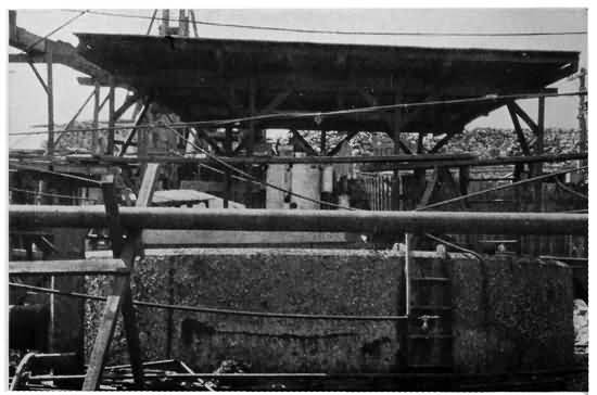
Courtesy of the American Machinist
CUTTING AWAY THE DECKS
Oxygen and acetylene generators can be seen on top of after-turret.
Things move with a rush now, for all these arrangements are made ahead of time, and as soon as the workmen are sure that the parts in the mould are redhot the heating aperture is carefully plugged with fire sand and the thermit is ignited. From a mere pinch to half a teaspoonful of the ignition powder is put into a little hollow in the thermit so that the heat may be communicated at once to as much of the thermit as possible. This is then set off with a storm match. The workman quickly withdraws his hand, slams the lid on to the crucible and gets out of the way of flying sparks.
There is a hiss, a puff of white smoke, a blinding glare from the hole in the top of the crucible, and that is all, beside a few sparks, to indicate that a heat second only to that of the sun is being generated within.
One cannot help but marvel at the wonders of science as this inconceivable heat is being produced, the process is seemingly so simple, so easily handled, and so accessible for all kinds of work where steel welding is necessary.
Half a minute to a minute (according to the amount of thermit used) after the match has been applied a workman holding at arm's length a long tool called a "tapping spade" gives a few upward knocks to the little metal pin extending down from 242 the closed pouring aperture. He jumps back for the heat is enough to set his clothes afire, even at a considerable distance, and a few flying particles of the molten thermit would inflict a serious burn.
Down through the little hole the thermit, that a minute before had been only a coarse dark gray powder like metal filings, seemingly the last thing on earth that would catch fire, flows into the pouring gate of the mould in a steady stream of white-hot liquid steel. The white glow from the metal is brighter than any electric light. It is so intense that although the workmen wear heavy dark goggles, they shade their eyes and turn their heads away.
Now you will be wondering, if you know anything about steel and its wonderful properties, how it is that this can be good steel when it is all mixed up with the aluminum oxide or slag. The reason it is of best quality is that as soon as the reaction reduces the whole mass to a molten liquid the heavier steel, set free, as the scientists say, but as we have chosen to think of it, robbed of the aluminum, sinks to the bottom, while the lighter aluminum oxide rises to the top. Consequently the steel goes into the mould to make the weld while the slag, having risen to the top, will be found at the top of the pouring gate, and only around the outer edges of the weld.
When the pour is completed the workmen go away and leave it to cool. It is usually left over night, 243 sometimes as long as forty hours, when the weld is a very large one.
Finally the mould is broken down and the weld is found complete, with big extensions of the steel extending from the weld, in just the shape of the pouring gate "riser" and heating aperture.
The molten thermit steel rushing in at the bottom of the mould has risen between the heated broken ends, and all around them, in just the shape left by the wax pattern. As the scientists say, the thermit steel has united the broken sternframe and formed a homogeneous mass with it. In other words the terrific heat of the thermit rushing on the heated ends has resulted in the two parts becoming one with the added thermit steel.
After the mould is broken down the oxygen-gas torch comes into use again to cut away the ends of steel sticking up where they had cooled in the pouring gate, "riser" and heating aperture. After this the weld looks like a great swelling upon the sternframe, and if the swelling is where it will not interfere with the working of the rudder or steamer propellers, nothing more need be done. On the other hand, if the swelling is in the way, it can be reduced to the size of the frame, and squared off with machines built for the purpose.
Thus the ship is repaired and is ready to be taken out of drydock for her next trip, as good as new.
244 About the same plan is followed out on all kinds of welding except pipes and rails. Locomotives can be repaired without taking the complicated machinery apart just by working around until the crucible can be so hung, and the pouring gate so arranged that the metal can be poured into the place designed for it. The chief difference lies in the size of the weld to be made and the consequent amount of thermit to be used. Welds have been made where as much as 2,000 pounds of thermit—enough to make 1,000 pounds of steel—have been run into a mould. In these very big welds a certain percentage of steel "punchings," or small pieces of steel, and a little pure manganese are used to give the additional hardness to the weld.
Without going into details as to the manner in which the principle of the thermit process is applied on rails or pipes, it will be enough to say that in welding rails three different systems are used. The first is done by building the mould around the ends of the two rails to be welded together and letting the thermit steel run in and completely surround the rails and the space between them. This gives one continuous rail just as far as the welding is carried on, and one through which the electric current of an electric road can pass without any trouble at all. It is plain, then, why this system is used so much on third rails of electric roads. The trouble with it is that the swelling on the top and inside of 245 the rails must be machined down to present a smooth running surface to the wheels.
The next system, which is now almost out of date, is one in which two moulds are used so that the thermit does not come up over the running surface of the rails. This relieves the engineers of the necessity of machining the welded joints.
The third system is a mixture of the joining by plates and the thermit process. This is called the "Clark joint," after the name of Chief Engineer Charles H. Clark of the Cleveland, (Ohio) Electric Company, who formulated the plan. The rails are joined with plates and bolted, or riveted together in the old way, but a thermit weld is made at the base of the rail, welding the bases of the two rails together and to the plate.
The method of welding steel pipes is an exact reversal of the principle of welding together solid pieces of steel or iron. After the pipes are cut off clean, the mould, which is made of cast iron, is placed around them with specially constructed clamps to force the two ends closer together after the thermit has been poured in. The thermit is then set off in a flat-bottomed crucible like a long-handled ladle, and poured into the mould by hand as if from a ladle. As the slag rises to the top it goes into the mould first and coats the pipes. The thermit steel does not touch the pipes, but merely supplies the heat to weld them perfectly, so that they are as strong as the 246 piping itself. Just after the pour has been made, the clamps are tightened up and the white-hot pipe ends forced together. They are thus held until cold, when the mould is broken away. The slag coats the outside of the pipes and this is chipped away, leaving a perfect weld.
Another interesting use of thermit is in the great foundries where cauldrons of metal have to be kept at a very high temperature. To help keep the mass in a liquid state thermit can be introduced in it either by throwing it into the cauldrons in bags, with a little ignition powder so fixed that it will be touched off by the heat of the boiling metal, or by putting it in especially designed cans affixed to the ends of long rods. By these rods the thermit can be plunged to the bottom of the cauldron before it "burns." The reaction of the thermit, with the intense heat caused by it, helps to keep the mass at the proper temperature.
Also thermit is used in the same way with a small amount of titanium oxide, to purify iron and steel. The metal becomes much more liquid, and a commotion like boiling is started. This is the result of the titanium driving out the impure gases and driving other impurities such as metallic oxides and sulphur contents to the top. Chemically what happens when the titanium is introduced by the thermit process is that the titanium combines with the nitrogen in the molten iron, giving it a much finer grain, and making 247 it a much lighter colour, more like steel, than previously.
One of the things thermit is not extensively used for is the repairing of gray iron castings. The first reason is that gray iron is cheaper than steel, and a new casting often can be turned out by the mills quickly.
Another and a more interesting reason is that gray iron melts in a much lower temperature than does thermit steel and consequently has a lower shrinkage. Therefore when the molten thermit, with its terrific heat, cools there is a large shrinkage. Thermit steel being much stronger than gray iron, its shrinking sometimes strains and cracks the iron casting.
In spite of this difficulty very successful repairs have been made on cast-iron and it has been found that by mixing 2 per cent. of ferro-silicon and 1 per cent. pure manganese with the thermit for welding, a thermit steel is formed which is very soft and comes close to the properties of gray iron. By using this mixture important welds have been made on cast-iron flywheels, water wheels, and other cast-iron parts with great success.
While industry is making progress with all these uses of thermit, science is experimenting all the time to add to the scope of the process. As was pointed out before, many other metals can be reduced to a high degree of purity with this process and in the laboratories they are always trying new ones and working out new formulas. Of the pure metals that 248 can be reduced by the thermit process there are chromium, which is 98 to 99 per cent. pure; manganese, which is 96 per cent. pure; and molybdenum, which is 98 to 99 per cent. pure. These are used in the manufacture of very hard steel, such as armour plate, and "high speed steel." Among the alloys, or mixtures of metals, there are chromium-manganese, manganese titanium, ferro-titanium, ferro-vanadium, and ferro-boron, all of which have uses in industry and help us to travel faster and more safely by railroad, electric train, and steamship.
It may have occurred to some bright boy that, since this heat is so intense and so handy, it might be a good way to make steam in locomotive boilers, or cook our meals, but it will be remembered that the heat is all over within a few minutes. In other words, where a terrific heat is required for a few seconds, thermit will fill the bill, but where a continuous heat for many hours is needed, electricity, gas, coal, coke, oil, or wood are better. The high cost of aluminum would probably prevent the thermit process coming into use in the manufacture of steel for our armour plate, ship plate, or structural steel, at least for a good many years.
Earlier in this chapter I said that the slag, or aluminum oxide, from the thermit process was an almost useless product. This is not the precise scientific truth, for the slag becomes a black powder such as is used in making emery wheels, but the slag from thermit 249 is never actually used for this. Another use for the slag from the thermit process in which chromium is used has been discovered. Potters use a material called corundum, which this slag resembles, except that it is superior to natural corundum in pottery manufacturing because of its freedom from metallic impurities. The slag can be mixed with clay and baked. It is especially useful in chemical apparatus that must withstand great extremes of temperature, because its experience has so tempered it that nothing less than a heat equal to that of the sun would give it much concern.
Another interesting thing about the slag from chromium thermit is that small rubies have been found in it. The scientific explanation is that they are nothing but crystallized alumina, coloured with chromium. The jewels usually are too small for any commercial purpose but serve as a very striking example of the intensity of the thermit fire. All the real jewels, diamonds, rubies, emeralds, amethysts, and so on, were formed by the terrific heat in the bosom of the earth millions of years ago when it was cooling down from gases hotter than anything we can possibly conceive of, to a molten ball, then to a solid redhot mass and then to a globe sufficiently cool on the outside to be crusted over. That they can be made in this little chemical furnace shows how far science has gone in imitation of the wonders of nature.
"Now," said the scientist, after he and his young friend had finished some experiments, and were ready to talk about autogenous welding, "imagine a little white flame no bigger than a pencil point at the end of a brass pipe about the size, and not entirely unlike in appearance the old-fashioned taper holder with which you used to light the gas, and you have before you in the rough, a picture of one of the oxy-acetylene torches that will in a few minutes weld two pieces of almost any metal, or in a few seconds cut a solid plate of the hardest steel of several inches thickness almost as fast and easy as a carpenter could saw a board, and yet without taking the temper out of the metal."
Picking up what seemed to be a little brass rod bent at the end, the man turned a valve, applied a match, and as the gas burned up with a beautiful little flame of dazzling whiteness, he continued:
"This tiny flame, so easily controlled, is hotter than any produced by man except that generated by the electrical furnace, for it reaches a temperature of about 6,300 degrees Fahrenheit. Previous to the invention of these wonderful torches the oxy-hydrogen was the hottest gas flame, but it only reached a temperature of 4,000 degrees Fahrenheit."
"How do you use it?" asked the boy.
"Well, for instance, Uncle Sam is enabled to weld 251 and cut steel plate in building his battleships, steelworkers to carry on their gigantic tasks, and wreckers to clear away tangled masses of steel beams far more quickly and easily than with the older methods.
"If you had visited one of the navy yards, a shipyard or any place where big work in iron and steel was being carried on as short a time as three years ago, you would have seen a man sitting for hours sawing away on the end of a steel beam, for instance, trying to cut it down to the required length. He would dull many saws, use a great deal of energy, and an appalling amount of the most valuable thing in the world—time. Again, you would have seen them welding pieces of iron and steel by the old blacksmith method, or riveting other pieces that could not be joined by heating them and pressing them together.
"To-day you would see fewer of these processes because autogenous welding and cutting by the powerful little oxy-acetylene torches is revolutionizing certain methods of working with metals. Instead of squatting at the end of the beam and sawing away like an old-fashioned carpenter, the modern iron worker takes up his little torch, turns a valve in the handle and concentrates the flame on the steel beam that he wishes cut. Almost instantly a shower of sparks on the under side of the beam shows him that the flame has burned its way through. Then 252 he slowly moves the flame along the line where he desires to cut and the trick is done."
Illustrating with his own little laboratory torch, the scientist continued his explanation, saying that cutting is only one of the many uses to which this modern invention in steel working is put. Not quite so spectacular but every bit as useful is the autogenous welding by means of these magic wands. Welding metals has ever been more or less unsatisfactory. The old process of heating the two ends and then beating them together is cumbersome and practically impossible in many cases. Consequently inventors have sought other welding processes with wider application and greater facility ever since the first metal workers of earliest times forged crude chains and weapons. With this modern device two pieces of steel or other metal are brought to within a small fraction of an inch of each other and by the use of the oxy-acetylene torch and a thin strip or rod of metal are melted and fused together.
Although the acetylene flame gives off a far greater proportion of light than heat, it is a very powerful gas and Le Chetalier, a French inventor, was sure that he could put it to other uses than furnishing lights for automobiles, etc. To this end he tried mixing acetylene gas with oxygen, for there can be no fire or combustion without oxygen. He very properly figured that by introducing pure oxygen into the acetylene, the burning, or combustion, would be 253 greater, and the heat of the flame greatly intensified. His experiments were ultimately successful, and it was then only a short step to the time when three different oxy-acetylene torches were in use. In France there were developed low pressure, medium pressure, and high pressure torches; but the last named has not been found commercially practicable in the United States, where the "medium pressure" torch is sometimes called the high pressure. As we are dealing entirely with the American use of the invention we also will call the two kinds of torches used here the low pressure and the high pressure.
The general principle of the torch is, as we see, the mixture of oxygen with acetylene in order to obtain a hotter flame, but right here we come to the difference between the low-pressure and the high-pressure tools. Both are made of brass pipes, terminating in the burning tip and connected at the rear of the handle with rubber tubes which run to the separate tanks holding the acetylene gas and the oxygen, but the method by which these gases are combined in the torch constitutes the principle differences in the two systems, with the consequent greater or less efficiency claimed by the manufacturers. Without going into the technical details, which are a matter of controversy between scientists as well as the various commercial concerns interested in the torches, it will be sufficient to say that in the low-pressure torch the acetylene gas is only used 254 under a pressure of a few ounces, with the oxygen under a much heavier pressure, while in the high-pressure torches, the acetylene and oxygen both are under an appreciable pressure of several pounds.
Thus in the low-pressure torch invented by Fouché, the oxygen is forced out of the nozzle by the pressure and the outrush sucks out the acetylene in the proper quantities. The two gases mix in a chamber at the end of the torch just above the tip and flow out into the air in this mixed form. The proportions of the gases in the low-pressure tool are about 1.7 of oxygen to 1.0 of acetylene.
The high-pressure torch, which has largely taken the place of the low-pressure one in France, and which we also see most frequently in this country, has a different method of mixing the gases, due to the fact that they both are under pressure. According to many authorities the tip where the gases are mixed is by far the most important factor in the success or failure of the tool. In the high-pressure torch the oxygen enters the tip from a hole in the centre, while the acetylene enters it from two holes, one on each side. They meet under high pressure at the upper end of the tip, and have the length of the hollow tip in which to mix, before they strike the air. The long, narrow hole in the tip is called the mixing chamber. Those who are interested in the high-pressure torch declare that it is the fact that the gases are positively mixed in proper proportion in the detachable 255 tip, that so greatly adds to the efficiency of the tool. They declare that by allowing the acetylene to enter the tip laterally, at right angles with the oxygen, the blast of the oxygen is broken as it mixes with the acetylene, and the tendency of an oxygen flame to oxidize any metal with which it comes in contact by reason of an excess of oxygen in the flame is largely done away with. This, with the small diameter of the mixing chamber and the friction with the walls, gives a perfect mixture, according to the claims of the high-pressure torch enthusiasts. Moreover, the small hole which is the mixing chamber, effectually prevents serious accidents by flash-backs of the highly explosive acetylene, and also provides a much easier method of control. Each outfit has several different sizes of tips for various kinds of work.
The pressure under which the two gases are used is the other big difference between the high-pressure and the low-pressure torches, as said before. In the the high-pressure tool the oxygen is compressed about the same as in the low-pressure torch, while the acetylene is under several pounds pressure, just in accordance with the size of the tip used. In the low-pressure torch the pressure on the acetylene is only about ten ounces to the square inch, or only enough to keep it flowing. On account of this difference in the pressure making the big difference in the mixture of the gases, scientists have chosen to call the low-pressure torches injector mixture 256 types, from the fact that the acetylene is sucked into the tip by an injector system, while the high-pressure torches are called positive mixture types, because the gases are mixed directly by pressure. In the latest high-pressure tool the mixture of gases is 1.14 parts of oxygen to 1 part of acetylene, while the low-pressure torch takes a proportion of 1.7 parts of oxygen to 1 part of acetylene.
The torches also vary in size from the little 8-ounce "jeweller's" torch, that the scientist used, to nineteen to twenty inches long and a weight of two and a quarter pounds. The average size, however, is twelve inches long with a weight of one pound. The welding torch is made up of two brass tubes, one for the acetylene and the other for the oxygen, connected at the two ends. At the nozzle end there is a sharp turn in the piping so that the tip is very nearly at right angles to the main pipes. At the handle end, are the connections for the rubber tubes that lead to the gas tanks, and the little valves by which the operator can control the flow of gas. The pipes carrying the gases to the tip are the same size the whole length, but at one end are enclosed in a larger tube, which serves as a handle.
Now that we have seen the general construction of the oxy-acetylene torches, we will assume that the tanks, which look like large soda-water reservoirs, are filled with pure oxygen and acetylene gas, and transported to some convenient point in a railroad 257 repair shop where great forges are spurting flames, and one can hardly hear the talk of a man beside him for the roar of the hammers and the compressed air riveters. Assume that some large expensive steel part of a locomotive has been broken and must be repaired quickly so that the engine can go out on the road to help haul an accumulation of freight.
In the old days an engine would have to be taken apart, a new part turned out at the steel mill, shipped to the shops, and the locomotive put together again. Nowadays it is only necessary to take enough of the machinery apart for the workmen to get at the broken parts. After cutting off the edges to be welded so that they make a small V, and supporting them within the fraction of an inch apart in the exact position and shape that they are to be repaired, the workman selects a rod of steel or iron, to use in somewhat the same way the tinker uses a strip of solder when he wants to repair a break in a kettle with solder and soldering iron.
The selection of this filling rod, or wire, is all-important, for the skilful and successful iron worker uses a piece of metal that will fuse well with the parts to be repaired, at about the same temperature at which they themselves will fuse. Mild steel or Norway iron which is 90 per cent. pure is frequently used, but there are no hard and fast rules because every master mechanic has his own ideas about such 258 things, and would not take the word of any manufacturing company.
Then the operator turns on his torch, lights it with a match, takes it in one hand, and the rod of welding steel in the other. Holding the end of the steel rod at the thin crack or bevelled edges between the pieces to be welded the operator directs the small flame on the point, holding the tip of the torch about a quarter to a half inch from the metal. It only takes a few seconds for the terrific heat of the flame to melt the strip of steel and the edges of the parts to be welded so that they all are fused together in one perfect mass.
Strange as it may seem, the brass tip of the torch does not melt in this heat because the pressure behind the gases forces them out with such velocity that the flame is far enough removed from the tip to do it no injury, just so long as the operator does not put the tip square against the metal and drive the flame back against it. This not only would melt the tip but probably would cause a flash-back in the torch.
As the end of the strip melts into the crack the operator moves up the steel, and moves his torch along the crack until the whole operation is complete. At the end the weld is very rough but when it is machined down it may be so perfect that it is difficult to tell where it was made, and the strength is equal to that of any other part of the piece.
In other words, the weld becomes homogenous 259 with the parts repaired. From this fact autogenous welding takes its name. Autogenous is defined as "self produced," or independent of outside materials.
Thus, we see that the autogenous process is a system of putting on new material, without either heating, compression, or adding flux (molten material) to the broken parts. In the foregoing paragraphs we have taken up the welding of steel parts, but the process can be as well applied to steel pipe, steel plate, iron, cast-iron, aluminum, copper, and other materials with only slight variations in the manner of using the torch.
The cutting process is even more spectacular because while the welding proceeds quietly, the cutting is accompanied by just enough fireworks to show us the progress of the tiny flame through the hardest and thickest of metals.
The cutting torch is the same as the welding torch with the exception of an additional pipe from which flows a jet of pure oxygen to give the flame the necessary cutting property. The greater the supply of oxygen the greater the combustion, and the more penetrating the flame. The acetylene gas flame heats up the steel—"fills the office of a preheater," said the scientist—while the oxygen jet follows close behind and makes a thin cut through the hot metal.
The extra pipe is the same size as the others and extends down to the end of the torch at an angle where its tip is clamped alongside the main tip. The rear 260 end of the third tube is connected with a rubber hose like the others, which extends to the oxygen tank. The flow of oxygen is under higher, and individual working pressure, controlled by a valve. In a new style torch the extra hose is done away with and the separation of the oxygen is done in the torch.
When the modern steel carpenter wants to cut a hole, or saw off a strip from a piece of steel, no matter whether it be a steel beam, steel plate, or almost any other form of iron (except cast-iron), he attaches the cutting pipe, lights his torch and sets to work. Holding the tool about half an inch from the surface he directs the little blue flame, which is no more than three quarters of an inch long, and a quarter of an inch thick, against the spot where he desires to start cutting. He holds it there a few seconds, then there is a shower of sparks on the under side of the steel plate, indicating that the flame has eaten its way all the way through. The operator next moves the torch along the line where he wants to cut. The speed with which he can move is governed by the thickness of the steel to be cut. Half-inch ship steel, for instance, could be cut at a rate of more than a foot a minute. The heat of the flame melts a little of the steel, which drops down in molten particles, but the edge that is cut is sharp and clean, and its temper is as perfect as if the cutting were done with one of the laborious old-fashioned steel saws.

AN OXY-ACETYLENE GAS TORCH WELD
Note the little torch in the man's left hand, the filling metal in his right, and the inserted picture of the apparatus.
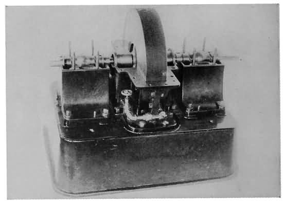
TINY 200-HORSEPOWER TURBINE
This engine could almost be covered by a derby hat. A part of the casing is removed to show the smooth disks.

THE TESLA TURBINE PUMP
Driven by a 1/12-horsepower motor. The little pump here shown is delivering 40 gallons of water per minute against a 9-foot head.
261 This cutting process is of especial value to navy yards, shipyards, and wreckers, where there is a great deal of steel to be cut. Uncle Sam uses it at most of his navy yards, for in building his battleships there are thousands and thousands of holes to be cut in steel plates, plates to be shaped, and beams to be cut off to required lengths.
When the scientist and his young friend visited the Brooklyn Navy Yard to see this process in operation the naval constructors had made considerable headway on the framework of the great Dreadnaught New York, in course of building there. The huge steel ribs of the ship towered upward amid the scaffolding nearly as high as a five-story building. In laying this steel framework, and shaping the plates that will make the hull, bulkheads, and decks, there will be millions of holes to be cut, and virtually miles and miles of plates to be shaped. Instead of sawing these the workmen were cutting them with the oxy-acetylene torches.
Half a dozen men were at work, all cutting as fast as possible, and the great steel plates, and beams were coming and going as quickly as ever boards were passed along by a carpenter. The lines that were to be cut were all marked out in advance so the men never put out their torches. The only cessation in the work was when one of them stopped for a minute or so, to wipe his eyes, for in spite of the dark goggles worn by all operators of the oxy-acetylene 262 process the intense flame is very hard on the eyes.
One reason why the cutting process is so popular in shipyards is because in making steel ships, holes are cut in the plates, ribs, and beams, wherever possible without lessening the strength, to lighten the frame.
Probably the most picturesque use of the cutting device is by wreckers of steel structures. Nowadays whenever there is a bad fire the building is left a tangled mass of steel pipes and girders that can only be cleared away with the greatest risk of life, and the greatest difficulty. The process always was a long, tedious one until the oxy-acetylene cutting came into use.
Thousands of New York boys saw the device in use during the winter of 1911-1912 when they visited the ruins of the Equitable Life Assurance Society fire. The sight is unmistakable. Far up in the ruins you see a man bending over a great twisted steel beam that it might take weeks to pull out of the débris. Soon there is a shower of sparks, and the part that is sticking out is cut off and ready to be sent to the street and hauled away. The device has been used in the ruins of a large number of disastrous fires, lately, particularly where men have been entombed in the collapse of ceilings, and haste means everything in getting out their bodies. Also, it was very successfully used in cutting up the old battleship Maine before the hull was removed from Havana harbour.
DR. NIKOLA TESLA TELLS OF HIS NEW STEAM TURBINE ENGINE A MODEL OF WHICH, THE SIZE OF A DERBY HAT, DEVELOPS MORE THAN 110 HORSEPOWER
"HOW would you like to have an engine for your motor boat that you could almost cover with a man's derby hat and yet which would give 110 horsepower?" asked the scientist of his young friend one day when they had been talking about boats and engines.
"I never heard of any real engine as small as that," said the boy. "I used to play with toy engines, but they wouldn't give anywhere near one horsepower, much less 110."
"Well, I think I can show you a little engine that, for mechanical simplicity and power is about the most wonderful thing you ever have seen, if you would like to make another visit to Dr. Nikola Tesla, who told us all about his invention for the wireless transmission of power the other day. Doctor Tesla invented this little engine and he is going to do great things with it."
264 Of course the boy jumped at the opportunity, for what real boy would miss a chance to find out all about a new and powerful engine?
"Is it a gasoline engine?" he asked.
"No, it is a steam turbine, but if you know anything at all about turbines you will see that it is entirely different from any you ever have seen, for Doctor Tesla has used a principle as old as the hills and one which has been known to men for centuries, but which never before has been applied in mechanics."
After a little more talk the scientist promised to arrange with Tesla to take the young man over to the great Waterside power-house, New York, where the inventor is testing out his latest invention. We will follow them there and see what this wonderful little turbine looks like.
Picking his way amid the powerful machinery and the maze of switchboards, the scientist finally stopped in front of a little device that seemed like a toy amid the gigantic machines of the power-house.
"This is the small turbine," says Tesla. "It will do pretty well for its size."
The little engine looked like a small steel drum about ten inches in diameter and a couple of inches wide, with a shaft running through the centre. Various kinds of gauges were attached at different points. Outside of the gauges and the base upon which it was mounted, the engine almost could have 265 been covered by a derby hat. The whole thing, gauges and all, practically could have been covered by an ordinary hat box.
Yet when Tesla gave the word, and his assistant turned on the steam, the small dynamo to which the turbine shaft was geared, instantly began to run at terrific speed. Apparently the machine began to run at full speed instantly instead of gradually working up to it. There was no sound except the whir of well-fitted machinery. "Under tests," said Tesla, "this little turbine has developed 110 horsepower."
Just think of it, a little engine that you could lift with one hand, giving 110 horsepower!
"But we can do better than that," added the inventor, "for with a steam pressure of 125 pounds at the inlet, running 9,000 revolutions per minute, the engine will develop 200 brake-horsepower."
Nearby was another machine a little larger than the first, which seemed to be two identical Tesla turbines with the central shafts connected by a strong spring. Gauges of different kinds, to show how the engine stood the tests, were attached at various places. When Tesla gave the word to open the throttle on the twin machines the spring connecting the shafts, without a second's pause, began to revolve, so that it looked like a solid bar of polished steel. Outside of a low, steady hum and a slight vibration in the floor, that steadied down after the engine 266 had been running a little while, there was no indication that enough horsepower to run machinery a hundred times the weight and size of the turbine was being generated.
"You see, for testing purposes," said Doctor Tesla, "I have these two turbines connected by this torsion spring. The steam is acting in opposite directions in the two machines. In one, the heat energy is converted into mechanical power. In the other, mechanical power is turned back into heat. One is working against the other, and by means of this gauge we can tell how much the spring is twisted and consequently how much power we are developing. Every degree marked off on this scale indicates twenty-two horsepower." The beam of light on the gauge stood at the division marked "10."
"Two hundred and twenty horsepower," said Doctor Tesla. "We can do better than that." He opened the steam valves a trifle more, giving more power to the motive end of the combination and more resistance to the "brake" end. The scale indicated 330 horsepower. "These casings are not constructed for much higher steam pressure, or I could show you something more wonderful than that. These engines could readily develop 1,000 horsepower.
"These little turbines represent what mechanical engineers have been dreaming of since steam power was invented—the perfect rotary engine," continued 267 Doctor Tesla, as he led the way back to his office. "My turbine will give at least twenty-five times as much power to the pound of weight as the lightest weight engines made to date. You know that the lightest and most powerful gasoline engines used on aeroplanes nowadays generally develop only one horsepower to two and one half pounds of weight. With that much weight my turbine will develop twenty-five horsepower.
"That is not all, for the turbine is probably the cheapest engine to build ever invented. Its mechanical simplicity is such that any good mechanic could build it, and any good mechanic could repair such parts as get out of order. When I can show you the inside of one of the turbines, in a few moments, however, you will see that there is nothing to get out of order such as most turbines have, and that it is not subjected to the heavy strains and jerks that all reciprocating engines and other turbines must stand. Also you will see that my turbine will run forward or backward, just as we desire, will run with steam, water, gas, or air, and can be used as a pump or an air compressor, just as well as an engine."
"But most of your research has been in electricity," Tesla was reminded, for no one can forget that Tesla's inventions largely have made possible most of the world's greatest electrical power developments.
"Yes," he answered, "but I was a mechanical 268 engineer before I was an electrical engineer, and besides, this principle was worked out in the course of my search for the ideal motor for airships, to be used in conjunction with my invention for the wireless transmission of electrical power. For twenty years I worked on the problem, but I have not given up. When my plan is perfected the present-day aeroplanes and dirigible balloons will disappear, and the dangerous sport of aviation, as we know it now with its hundreds of accidents, and its picturesque birdmen, will give way to safe, seaworthy airships, without wings or gas bags, but supported and driven by mechanical means.
"As I told you before when we were talking of the wireless transmission of power, the mechanism will be a development of the principle on which my turbine is constructed. It will be so tremendously powerful that it will make a veritable rope of air above the great machine to hold it at any altitude the navigators may choose, and also a rope of air in front or in the rear to send it forward or backward at almost any speed desired. When that day comes, airship travel will be as safe and prosaic as travel by railroad train to-day, and not very much different, except that there will be no dirt, and it will be much faster. One will be able to dine in New York, retire in an aero Pullman berth in a closed and perfectly furnished car, and arise to breakfast in London."
269 Tesla's plans for the airship are far in the future, but his turbine is a thing of the present, and it has been declared by some of the most eminent authorities in the world in mechanical engineering to be the greatest invention of a century. The reason for this is not altogether on account of the wonderful feats of Tesla's model turbines, but because in them he has shown the world an entirely unused mechanical principle which can be applied in a thousand useful ways.
James Watt discovered and put to work the expansive power of steam, by which the piston of an engine is pushed back and forth in the cylinder of an engine, but it has remained for Nikola Tesla to prove that it is not necessary for the steam to have something to push upon—that the most powerful engine yet shown to the world works through a far simpler mechanism than any yet used for turning a gas or a fluid into the driving force of machinery.
"How did you come to invent your turbine while you were busy with your wonderful electrical inventions?" Tesla was asked.
"You see," he answered, "while I was trying to solve the problem of aerial navigation by electrical means, the gasoline motor was perfected; and aviation as we know it to-day became a fact. I consider the aeroplane as it has been developed little more than a passing phase of air navigation. Aeroplaning 270 makes delightful sport, no doubt, but as it is now it can never be practical in commerce. Consequently I abandoned for the time being my attempts to find the ideal airship motor in electricity, and for several years studied hard on the problem as one of mechanics. Finally I hit upon the central idea of the new turbine I have just been showing you."
"What is this principle?"
"The idea of my turbine is based simply on two properties known to science for hundreds of years, but never in all the world's history used in this way before. These properties are adhesion and viscosity. Any boy can test them. For instance, put a little water on a sheet of metal. Most of it will roll off, but a few drops will remain until they evaporate. The metal does not absorb the water so the only thing that makes the water remain on the metal is adhesion—in other words, it adheres, or sticks to the metal.
"Then, too, you will notice that the drop of water will assume a certain shape and that it will remain in that form until you make it change by some outside force—by disturbing it by touch or holding it so that the attraction of gravitation will make it change.
"The simple little experiment reveals the viscosity of water, or, in other words, reveals the property of the molecules which go to make up the water, of sticking to each other. It is these properties 271 of adhesion and viscosity that cause the 'skin friction' that impedes a ship in its progress through the water, or an aeroplane in going through the air. All fluids have these qualities—and you must keep in mind that air is a fluid, all gases are fluid, steam is fluid. Every known means of transmitting or developing mechanical power is through a fluid medium.
"It is a surprising fact that gases and vapours are possessed of this property of viscosity to a greater degree than are liquids such as water. Owing to these properties, if a solid body is moved through a fluid, more or less of the fluid is dragged along, or if a solid is put in a fluid that is moving it is carried along with the current. Also you are familiar with the great rush of air that follows a swiftly moving train. That simply means that the train tends to carry the air along with it, as the air tries to adhere to the surface of the cars, and the particles of air try to stick together. You would be surprised if you could have a picture of the great train of moving air that follows you about merely as you walk through this room.
"Now, in all the history of mechanical engineering, these properties have not been turned to the full use of man, although, as I said before, they have been known to exist for centuries. When I hit upon the idea that a rotary engine would run through their application, I began a series of very successful experiments."
Tesla went on to explain that all turbines, and in fact all engines, are based on the idea that the steam 272 must have something to push against. We shall see a little later how these engines were developed, but it will suffice for the moment to listen to Doctor Tesla's explanation.
"All of the successful turbines up to the time of my invention," he says, "give the steam something to push upon. For instance"—taking a pencil and a piece of paper—"we will consider this circle, the disk, or rotor of an ordinary turbine. You understand it is the wheel to which the shaft is attached, and which turns the shaft, transmitting power to the machinery. Now it is a large wheel and along the outer edge is a row of little blades, or vanes, or buckets. The steam is turned against these blades, or buckets, in jets from pipes set around the wheel at close intervals, and the force of the steam on the blades turns the wheel at very high speed and gives us the power of what we call a 'prime mover'—that is, power which we can convert into electricity, or which we can use to drive all kinds of machinery. Now see what a big wheel it is and what a very small part of the wheel is used in giving us power—only the outer edge where the steam can push against the blades.
"In my new turbine the steam pushes against the whole wheel all at once, utilizing all the space wasted in other turbines. There are no blades or vanes or sockets or anything for the steam to push against, for I have proved that they hinder the efficiency of the turbine rather than increase it."
273 Comparing his turbine to other engines Tesla says, "In reciprocating engines of the older type the power-giving portion—the cylinder, piston, etc.—is no more than a fraction of 1 per cent. of the total weight of material used in construction. The present form of turbine, with an efficiency of about 62 per cent., was a great advance, but even in this form of machine scarcely more than 1 per cent. or 2 per cent. is used in actually generating power at a given moment. The only part of the great wheel that is used in actually making power is the outside edge where the steam pushes on the buckets.
"The new turbine offers a striking contrast using as it does practically the entire material of the power-giving portion of the engine. The result is an economy that gives an efficiency of 80 per cent. to 90 per cent. With sufficient boiler capacity on a vessel such as the Mauretania, it would be perfectly easy to develop, instead of some 70,000 horsepower, 4,000,000 horsepower in the same space—and this is a conservative estimate.
"You see this is obtained by the new application of this principle in physics which never has been used before, by which we can economize on space and weight so that the most of the engine is given over to power producing parts in which there is little waste material."
Tesla then went on to explain the details of his new turbine. Leading the way to a small model in 274 his office he unscrewed a few bolts and lifted off the top half of the round steel drum or casing. Inside were a number of perfectly smooth, circular disks mounted upon one central shaft—the shaft that extends through the machine, and corresponds to the crankshaft of an ordinary engine. The disks all were securely fastened to the rod so that they could not revolve without making it also turn in its carefully adjusted bearings. The disks, which were only about one sixteenth of an inch in thickness, and which he said were constructed of the finest quality of steel, were placed close together at regular intervals, so that a space of only about an eighth of an inch intervened between them. They were solid with the exception of a hole close to the centre. The set of disks is called the rotor or runner.
When the casing is clamped down tight, the steam is sent through an inlet or nozzle at the side, so that it enters at the periphery or outside edge of the set of disks, at a tangent to the circle of the rotor. Of course the steam is shot into the turbine under high pressure so that all its force is turned into speed, or what the scientists call velocity-energy. The steel casing of the rotor naturally gives the steam the circular course of the disks, and as it travels around the disks the vapour adheres to them, and the particles of steam adhere to each other. By the law that Tesla has invoked, the steam drags the disks around with it. As the speed of the disks increases 275 the path of the steam lengthens, and at an average speed the steam actually travels a distance of twelve to fifteen feet. Starting at the outside edge of the disks it travels around and around in constantly narrowing circles as the steam pressure decreases until it finally reaches the holes in the disks at their centre, and there passes out. These holes, then, we see act as the exhaust for the used-up steam, for by the time the steam, which was shot into the turbine by the nozzle under high pressure, reaches the exhaust, it registers no more than about two pounds gauge pressure.
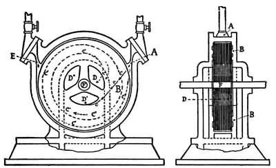
DIAGRAM OF THE TESLA TURBINE
A—Steam Inlet. B—Disks. C—Path of the Steam. D,D´D´´—Exhaust. E—Reverse Inlet. F—Shaft.
For reasons which will be explained later, ordinary turbines cannot be reversed, but Tesla's invention 276 can run backward just as easily as forward. The reverse action is accomplished simply by placing another nozzle inlet on the other side of the rotor so that the steam can be turned off from the right side of the engine, for instance, and turned into the left side, immediately reversing its direction, with the change in the direction of the steam. The action is instantaneous, too, for as we saw in the experiments Tesla showed us, the turbine began to run at practically top speed as soon as the steam was turned on.
The disks in the little 110-horsepower engine which we saw, were only a little larger than a derby hat were only nine and three quarter inches in diameter, while in his larger turbines he simply increases the diameter of the disks.
Tesla further explained that the 110-horsepower turbine represented a single stage engine, or one composed simply of one rotor. Where greater power is required he explained that it would be easy to compound a number of rotors to a double, or triple or even what he calls a multi, or many stage, turbine. In engineering the single stage is called one complete power unit, and a large engine could be made up of as many units as needed, or practicable.
"Then do you mean to say," Tesla was asked, "that the only thing that makes the engine revolve at this tremendous speed is the passage of steam through the spaces between those smooth disks?"
"Yes, that is all," he answered, "but as I explained 277 before, the steam travels all the way from the outer edge to the centre of the disks, working on them all the time; whereas in the ordinary turbines the steam only works on the outside edge, and all the rest of the wheel is useless. By the time it leaves the exhaust of my engine practically all the energy of the steam has been put into the machine."
This is only one of the many advantages that Tesla points out in his invention, for the turbine is the exemplification of a principle, and hence more than a mechanical achievement. "With a 1,000-horsepower engine weighing only 100 pounds, imagine the possibility in automobiles, locomotives, and steamships," he says.
Explaining the large engines that he is testing, one against the other, at the power plant, the inventor said:
"Inside of the casings of the two larger turbines the disks are eighteen inches in diameter and one thirty-second of an inch thick. There are twenty-three of them, spaced a little distance apart, the whole making up a total thickness of three and one half inches. The steam, entering at the periphery, follows a spiral path toward the centre, where openings are provided through which it exhausts. As the disks rotate and the speed increases the path of the steam lengthens until it completes a number of turns before reaching the outlet—and it is working all the time.
278 "Moreover, every engineer knows that, when a fluid is used as a vehicle of energy, the highest possible economy can be obtained only when the changes in the direction and velocity of movement of the fluid are made as gradual and easy as possible. In previous forms of turbines more or less sudden changes of speed and direction are involved.
"By that I mean to say," explained Doctor Tesla, "that in reciprocating engines with pistons, the power comes from the backward and forward jerks of the piston rod, and in other turbines the steam must travel a zigzag path from one vane or blade to another all the whole length of the turbine. This causes both changes in velocity and direction and impairs the efficiency of the machine. In my turbine, as you saw, the steam enters at the nozzle and travels a natural spiral path without any abrupt changes in direction, or anything to hinder its velocity."
But the Tesla turbine engine, claims the inventor, will work just as well by gas as by steam, for as he points out gases have the properties of adhesion and viscosity just as much as water or steam.
Further, he says that if the gas were introduced intermittently in explosions like those of the gasoline engine, the machine would work as efficiently as it does with a steady pressure of steam. Consequently Tesla declares that his turbine can be developed for general use as a gasoline engine.
279 The engine is only one application of the principle of Tesla's turbine, because he has used the same idea on a pump and an air compressor as successfully as on his experimental engines. In his office in the Metropolitan Tower he has a number of models. Pointing to a little machine on a table, which consisted of half a dozen small disks three inches in diameter, he said: "This is only a toy, but it shows the principle of the invention just as well as the larger models at the power plant." Tesla turned on a small electric motor which was connected with a shaft on which the disks were mounted, and it began to hum at a high number of revolutions per second.
"This is the principle of the pump," said Tesla. "Here the electric motor furnishes the power and we have these disks revolving in the air. You need no proof to tell you that the air is being agitated and propelled violently. If you will hold your hand down near the centre of these disks—you see the centres have been cut away—you will feel the suction as air is drawn in to be expelled from the outer edges.
"Now, suppose these revolving disks were enclosed in an air-tight case, so constructed that the air could enter only at one point and be expelled only at another—what would we have?"
"You'd have an air pump," was suggested.
"Exactly—an air pump or a blower," said Doctor 280 Tesla. "There is one now in operation delivering ten thousand cubic feet of air a minute."
But this was not all, for Tesla showed his visitors a wonderful exhibition of the little device at work. "To make a pump out of this turbine," he explained; "we simply turn the disks by artificial means and introduce the fluid, air or water at the centre of the disks, and their rotation, with the properties of adhesion and viscosity immediately suck up the fluid and throw it off at the edges of the disks."
The inventor led the way to another room, where he showed his visitors two small tanks, one above the other. The lower one was full of water but the upper one was empty. They were connected by a pipe which terminated over the empty tank. At the side of the lower tank was a very small aluminum drum in which, Tesla told his visitors, were disks of the kind that are used in his turbine. The shaft of a little one twelfth horsepower motor adjoining was connected with the rotor through the centre of the casing. "Inside of this aluminum case are several disks mounted on a shaft and immersed in water," said Doctor Tesla. "From this lower tank the water has free access to the case enclosing the disks. This pipe leads from the periphery of the case. I turn the current on, the motor turns the disks, and as I open this valve in the pipe the water flows."
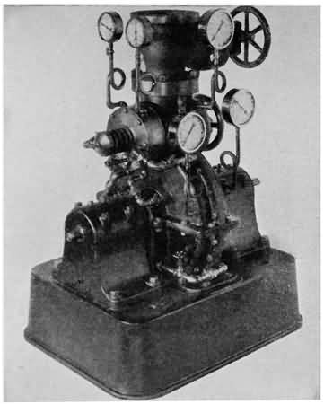
THE MARVELLOUS TESLA TURBINE
The 200-horsepower engine, which a man could lift with one hand.
How the Tesla Turbine compares in size with a man.

THOMAS A. EDISON AND HIS CONCRETE FURNITURE
The white cabinet is a piece of Edison's poured concrete furniture, while the other one is the ordinary wooden phonograph cabinet.
MODEL OF EDISON POURED CONCRETE HOUSE
This little house, which stands on a table in Edison's laboratory, shows what he expects to do with the poured concrete house.
He turned the valve and the water certainly did 281 flow. Instantly a stream that would have filled a barrel in a very few minutes began to run out of the pipe into the upper part of the tank and thence into the lower tank.
"This is only a toy," smiled the inventor. "There are only half a dozen disks—'runners,' I call them—each less than three inches in diameter, inside of that case. They are just like the disks you saw on the first motor—no vanes, blades or attachments of any kind. Just perfectly smooth, flat disks revolving in their own planes and pumping water because of the viscosity and adhesion of the fluid. One such pump now in operation, with eight disks, eighteen inches in diameter, pumps 4,000 gallons a minute to a height of 360 feet.
"From all these things, you can see the possibilities of the new turbine," he continued. "It will give ten horsepower to one pound of weight, which is twenty-five times as powerful as many light weight aeroplane engines, which give one horsepower of energy for every two and one half pounds of weight.
"Moreover, the machine is one of the cheapest and simplest to build ever invented and it has the distinct advantage of having practically nothing about it to get out of order. There are no fine adjustments, as the disks do not have to be placed with more than ordinary accuracy, and there are no fine clearances, because the casing does not have to fit more than conveniently close. As you see, there are no blades 282 or buckets to get broken or to get out of order. These things, combined with the easy reversibility, simplicity of the machine when used either as an engine, a pump or an air compressor, and the possibility of using it either with steam, gas, air, or water as motive power, all combine to afford limitless possibilities for its development."
Doctor Tesla calls the invention the most revolutionary of his career, and it certainly will be if it fulfils the predictions that so many eminent experts are making for it.
It is interesting to think that although this latest and most modern of all steam engines is a turbine, the first steam engine ever invented, also was a turbine.
Though most of us usually think of James Watt as the inventor of the steam engine, he was not the first by any means, for the very first of which history gives us any record was a turbine, which was described by Hero of Alexandria, an ancient Egyptian scientist, who wrote about 100 B.C.
Hero's engine was a hollow sphere which was made to turn by the reaction of steam as it escaped from the ends of pipes, so placed that they would blow directly upon the ball.
Centuries later—in 1629, about the time the New England States were being colonized—a scientist named Branca made use of the oldest mechanical principle in the world—the paddle-wheel—which, 283 turned by the never-ceasing river, goes on forever in the service of mankind. Branca's invention was simply a paddle-wheel turned by a jet of steam instead of by a water current. The engine was really a turbine, for that type is simply a very high development of this idea—the pushing power of a fluid on a paddle-wheel.
The picture of Branca's crude machine shows the head and shoulders of a great bronze man suspended over a blazing wood fire. Evidently it is intended to convey the idea that the figure's lungs are filled with boiling water, for he is pictured breathing a jet of steam on to the blades of a paddle-wheel, the revolving of which sets some crude machinery in motion.
After Branca, however, the turbine dropped from view and what few inventors did experiment with steam worked on the idea of a reciprocating engine.
The principle of the reciprocating engine, as most boys know from their own experiments with toy steam engines, and as was discovered by Watt, is simply the utilization of the power of steam for expanding with great force when let into first one side, and then the other side of the cylinder. Thus, as the steam expands, it pushes the piston back and forth at a high rate of speed, transmitting motion to shafts and flywheels.
In 1888 the world was ready for a bigger and more powerful type of steam engine; and C. A. Parsons, an 284 Englishman, and Dr. G. de Laval of Stockholm, brought forth successful turbines at about the same time.
The machines were developed to a high state of efficiency, and are still in general use, although most turbines for driving heavy electrical machinery in the United States are the great Curtiss engines, which are a combination of the principles of both the De Laval and Parsons machines. All of them are run by the old principle of the water-wheel. Instead of the steam being turned into a cylinder to push the piston, it is turned into a steel drum or casing in which wheels or disks are mounted on the central shaft. All along the edge of these wheels are hundreds of little vanes or blades or buckets against which the steam flows from many nozzles placed all around the inside of the casing. The steam flows with great force, and naturally pushing against the blades, starts the wheels and the engine shaft to revolving. After expending its force on the blades that turn the steam passes on to a set of stationary blades which then shoot it out against the next set of moving blades.
In the Curtiss turbine the wheels at one end of the shaft are smaller than those at the other, and the steam enters at the small end, where it is under heavy pressure. After having expended its force on the blades of the first wheel, the steam passes through holes in a partition at the side and zigzags back so 285 that it strikes the vanes or blades on the next larger disk. It then repeats the process, expands a little, and goes to a larger disk. Finally, by the time the steam has expanded to its full capacity, the greater part of its force has been expended against the disks of the turbine.

THE CURTISS TURBINE
Diagram of Steam Diaphragm Showing Nozzles and Fixed and Moving Blades
A—Single stage turbine wheel. B—Steam nozzles. B´—Steam exhausts. C—Moving blades. D—Stationary blades.
From this we see the main points of difference between reciprocating engines and turbines, and between most turbines and Tesla's invention.
While most turbines take advantage of the expansive power of steam, the main idea is to make use 286 of the velocity of the vapour as it is driven from a set of nozzles around the turbine wheel, under high pressure.
Also it will be seen that Tesla's invention is a turbine in form, but that it is entirely different from either of the two earlier types, because instead of giving the steam something to push against, it is allowed to follow its own natural course around between the smooth disks, and drag them after it.
Some kind of a crank motion is necessary in all reciprocating engines, to convert the backward and forward movement of the piston to the rotary motion of the shaft, but this is done away with entirely in the turbine. What engineers call a "direct drive" is substituted in its place. In other words, the turbine wheels or disks, fastened to the shaft, turn it, and drive the machinery directly from the source of power. The speed of the machine is regulated by gears.
The great advantage of the "direct drive," particularly for big steamships and for turning big electric dynamos, will be plain to every boy when he thinks of the long narrow body of a ship in which can lie the turbine engines working directly on the propeller shafts (with the exception of certain gears, of course, for regulating the speed) instead of the big flywheels, and flying cranks of marine reciprocating engines. Also with dynamos it is just as important to have the power applied directly to save space and increase the general efficiency of the machine.
287 The greatest disadvantage of the usual kinds of turbines for most machinery, including steamships, is the fact that they cannot be reversed. To solve this difficulty, all the great ocean and coast liners, battleships, cruisers, and torpedo boats that are equipped with turbines have two sets of engines, one for straight ahead and one for backward.
With the Tesla turbine this disadvantage, as we have seen, is entirely done away with, and the one turbine can be reversed as easily and simply as it can be started.
And so, while we are waiting for the world-moving wireless transmission of power and for the completion of Tesla's invention for safe and stable airships, we can look for the speedy development of his turbine in practically all departments of mechanical engineering.
THE ONE-PIECE HOUSE OF THOMAS A. EDISON, AND OTHER USES OF THE NEWEST AND YET THE OLDEST BUILDING MATERIAL OF CIVILIZED PEOPLES SEEN BY THE BOY AND HIS SCIENTIFIC FRIEND
WHILE we are looking around at all these epoch-making inventions let us follow our friendly scientist and his boy companion to one of the big cement shows held in the various large cities of the United States every year, for a glance at some of the uses of reinforced concrete in modern engineering and building. For the boy who intends to become a civil engineer this wonderful material will have an especial interest, because its successful use in all of the greatest engineering works going on to-day has brought it to the front as the modern substitute, in a great many cases, for wood, brick, or expensive stone and steel structures.
WHAT ONE SET OF BOYS DID WITH CONCRETE


This Indian tepee of concrete was made by the boys of Dr. W. A. Keyes' summer school, at Sebasco, Maine.
The picture on the top shows the method of construction.
MASSIVE CONCRETE WORK
Completed side walls of solid concrete in the Gatun Locks of the Panama Canal.
A LEVEL STRETCH OF CATSKILL AQUEDUCT
Showing completed section as well as forms for the concrete.
On entering the cement show our friends saw on every side long rows of booths showing models of structures and articles that could be made of concrete. There were models of houses, subways, dams, bridges, 289 dock works, retaining walls, sewers, bridges, pavements and even boats and furniture. In fact, so the men in the exhibition booths said, concrete can be used for practically every building purpose where strength, lasting qualities, and resistance to heat and cold are needed. "This is the concrete age," they declared. "Concrete is fireproof, waterproof, sanitary, and resists frost when properly used. Our timber supply is decreasing, the supply of iron ore for structural steel is limited, and stone is expensive; so concrete, reinforced with steel, and used by engineers who understand their business, will be the greatest building material of the future."
These are the things that the enthusiasts at all the concrete shows say, but they admit that there are certain kinds of construction in which concrete is not as effective as steel or granite. Also they say that the use of reinforced concrete requires the highest type of engineering skill, and a complete understanding of the technicalities of the subject.
One of the places where we know concrete best is in pavements and sidewalks, and several of the booths exhibited samples of such work. To show its strength the men in charge piled on weights, struck the slabs with hammers, or subjected them to any kind of hard usage suggested by the crowd. Then, too, there were sections of concrete buildings, and exhibitions of various systems of reinforced concrete construction. With these there were concrete 290 chimneys, portable concrete garages, railroad ties, and what not.
"Oh, but look here," broke out the boy as he led his older friend about. "Here's a perfect model of a house."
"Yes," answered the man, "that is a model of the famous Edison poured cement, or 'one-piece' house, the latest invention of our great American inventor."
There the little building stood, perfect in every way, surrounded by a model concrete wall, a beautiful lawn, and approached by fine concrete walks and driveways.
"This model," explained the scientist, "represents what Thomas A. Edison is trying to get time to accomplish for workingmen and their families. Instead of being built piece by piece, the house is supposed to be made all at one time by pouring the concrete into a complete set of moulds. This house is so interesting that we shall look at it much closer a little later on."
"And here," said the boy; "what's this?"
He had paused before a perfect model of the Gatun locks of the Panama Canal, where the world's greatest work in concrete, or any other kind of masonry, is being carried on. The work is greater than the Pyramids of Egypt or the Great Wall of China. Though we will not bother ourselves much with figures, it will give an idea of the size of the job on the canal when we realize that it will require 8,000,000 291 cubic yards of concrete, and more then 900,000 tons of Portland cement.
In all there will be six great locks for the transportation of our ships from the Atlantic to the Pacific and back. Three of these locks are at Gatun on the Atlantic side of the canal, one at Pedro Miguel, and two at Miraflores. Each lock will be 1,000 feet long, 110 feet wide, and 45 feet deep—and practically all of this is done with concrete. So massive is most of the work that steel reinforcement is only necessary in certain parts of the project. The problem of sinking the great retaining walls to bedrock, and making them strong enough to hold in the face of the tremendous floods of the Chagres River, alone makes one of the most stupendous engineering works ever undertaken by man. Were it not for the use of concrete the cost of the work would be so great as to make it almost impossible of accomplishment.
The model of the Gatun locks showed the boy everything, just as it will be when the canal is opened for traffic in 1913. There was the wide Gatun lake, surrounded by the tropical forests, the great Gatun dam, and the series of locks in one solid mass of concrete. These locks when completed will be 3,800 feet long, and their tremendous height and thickness can be seen from the pictures of the work as it is actually being carried on. In the model there were perfect little ships on the lake and going through the locks.
292 Besides the many present day uses of cement some of the concrete enthusiasts are suggesting that heavily reinforced concrete be used in place of steel in making bank vaults, as they declare that the material will resist the keen tools and the powerful explosives of bank robbers even more successfully than the hardest steel.
Then too, at the cement show, the boy saw, besides models of big works and examples of all kinds of concrete construction, exhibits of the various methods of placing steel bars and steel network in the cement to make it stronger, and the different machines used in mixing concrete and in making Portland cement, which is the binding element in concrete.
As concrete is a material that can be mixed by an amateur and used for a great many purposes, the booths where mixing and simple uses were demonstrated attracted a great deal of attention. For instance, in the last few years the farmers have found out that they can make watering troughs, drains, floors for stables, hen houses, and even fence posts, of concrete just as easily as they can of wood or iron. Moreover, the articles thus made will last practically forever. All that is needed is a supply of Portland cement, and a little careful study as to the best way of mixing it with the proper amounts of sand and gravel. The amateur has best results if he starts modestly and takes up the use of reinforced 293 concrete after learning how to use the material in its simple form.
One of the most interesting uses of reinforced concrete for the amateur who has learned something of the craft is in making a good, seaworthy rowboat, or even a small motor boat. Poured boats are strong, graceful, and durable. If they are properly made there never is any danger of their leaking, and by a little extra pains it is possible to make them with air-tight compartments so that they are non-sinkable.
The usual method of making concrete boats is very simple. The kind of boat to be duplicated is borrowed and hung on the shore so that it swings free of the ground. Then a mould of clay is built all around it. A strong bank of sand is heaped around the clay, to hold it firm. Then the boat is worked a little each way so that a space of about an inch and a half is left all around between the outside of the boat and the clay. The space between the boat and the clay is the space into which the concrete is poured for sides and bottom after the reinforcing rods have been properly inserted. After the whole thing has stood a day or so the inside boat is taken out and the clay mould broken down, revealing a complete concrete hull.
Thus, we see that concrete can be used as a building material in practically any kind of construction, that it is easily handled since all that is necessary is to pour it into the moulds after the engineers have 294 properly placed the reinforcement, and that it can be cast in practically any decorative design just as easily as plain. Add to this the fact that concrete is cheaper than stone or steel, and that it is practically indestructible when properly handled, and it is easy to see the reason for calling this the cement age, and concrete the building material of the future.
After the Panama Canal, the greatest engineering feat in which concrete figures as one of the chief materials used, is the Catskill aqueduct, by which water from four watersheds in the Catskill Mountains of New York State is to be piped to all five boroughs of New York City. The Ashokan reservoir, near Kensington, N. Y., was the first part of the work to be taken up, together with the Kensico storage reservoir twenty-five miles from New York, several smaller reservoirs, and the aqueducts to carry this water from the mountains to every home in greater New York. The dam and containing walls of the Ashokan reservoir are all made of reinforced concrete, and the size of the lake and the strength of the walls can be appreciated when one thinks that the 130,000,000,000 gallons of water it holds in check would cover all Manhattan Island with twenty-eight feet of water. A large part of the aqueduct proper, through which this great stream of water is carried from the mountains, under the Hudson River, and to the city where it runs more than a hundred feet below the street level, is made of reinforced concrete.
295 For other examples of the use of this material in big engineering works a boy has only to look around him. There are the tunnels under the rivers around New York, the New York subways, the Philadelphia and Boston subways, the Detroit River tunnel, bridges, culverts, big piers and other dock works, miles of concrete snowsheds along the lines of the railroads that cross the continental divide of the Rocky Mountains, and in fact practically every big structural undertaking.
Almost anywhere we look these days we see a big machine crushing rock, mixing it with sand and mortar, and turning out concrete to be shovelled into a hole and perhaps used far below the surface by "sand hogs" working under compressed air, or hoisted to the towering walls of some great office building or factory that is being constructed of the artificial stone.
We are familiar with the falsework of a concrete building under construction. It is all, apparently, a maze of wooden beams that look like scaffoldings, and yet they seem to make the outlines of the building. This maze of woodwork, seemingly so lacking in plan or system, as a matter of fact is a triumph of engineering skill, for it is the mould for the building, and was all built by the most careful plans as to strains, stresses, floor loads, etc.
First, however, before building the mould for a residence, school, theatre, office building, or factory, 296 the engineer decides what strength his foundations must have. The foundation for a small residence is an easy matter, but when it comes to a big factory, or an office building of a dozen stories or so, the most careful work must be done beforehand. In the old days, when it was desired to sink the foundations of a building down to bedrock, they used steel or wooden piles, but these will rust or rot, and the modern way is to use concrete piles. Either the great poles are moulded first and sunk like the ordinary wooden ones, or a pipe with a sharpened point is sunk and the concrete deposited in it by buckets designed for the purpose. Once these piles are driven, they are there for all time, if the work is done properly, and the engineer can be sure that his building is as good as if resting on bedrock.
From then on the erection of a reinforced concrete building is a most intricate matter, because while concrete in itself is a very simple substance, its use in buildings is a highly developed science. Of course there are many different methods of using concrete, and each one prescribes a different kind of steel network for the reinforcement. Then, too, some engineers cast parts of their buildings separately and put them in place after they have set, while others run the concrete for beams, floors, and walls into moulds, built right where those parts are to be in the finished structure. In laying the steel reinforcing rods, before the concrete is poured, the 297 engineer sees that they make a perfect network so as to take care of all the strains, just as they will be put upon the building when it is completed. It is in the proper placing of reinforcement that the greatest engineering knowledge is needed in this kind of building.
As the wooden moulds for the first foundation beams and girders are completed and the reinforcement is placed, the concrete is poured in. The subcellar or cellar floor mould then is laid, the reinforcement placed and the concrete run in. Next the moulds for the cellar walls are built and perhaps the moulds for the beams and girders for the first floor. The reinforcing rods are placed in these moulds and the concrete run in, and so on, a story at a time, or a small section at a time, until the structure reaches the height called for in the plans, and it stands completed. As the building progresses and the concrete on the lower floor sets, the moulds can be taken down and used on higher stories. Concrete is even used for the roofs of buildings, as it can be moulded right in place or set up in slabs that can be later cemented together.
When properly used reinforced concrete is absolutely fireproof, so it is coming into extensive use in the construction of schools, theatres, warehouses, factories, and all other such buildings where a great height is not required. So far, none of the great skyscrapers has been built of reinforced concrete, 298 although office buildings of sixteen stories have been erected with complete success.
There is still another method of using concrete as a building material. This is in the form of building blocks, and doubtless all who read this will recall seeing many beautiful residences built of blocks of stone that on closer inspection proved to be concrete. The blocks can be cast in any size or form and used in just the same way as structural stone.
Now, after having looked about the city and having seen the numerous ways that concrete is used as a building material, we come back to the very latest thing in the use of this man-made stone—the "one-piece" or poured house.
For a good view of it let us take a little jaunt out to West Orange, N. J., with the scientist and look into the library of Thomas A. Edison's laboratory, where we will see a perfect model of this marvel of invention. It is practically the same as the one at the cement show. Standing in the centre of the great room where Edison works is this perfect little cottage, about the size of a large doll's house. It represents not only Edison's latest invention, but also his favourite scheme. In years to come, when the boys who read this are grown men, it will probably be no novelty to build houses by pouring them all at once into a steel mould, but just at present it is one of the most startling developments in an age of epoch-making inventions.
299 Every boy knows that Edison has never followed the ideas of others in working out his inventions, and the poured house is no exception to his rule. It will be interesting to take a little look back over a part of Edison's life and see how he came to enter the cement-making business, and how, when he had his process down to a fine point, he said to himself, "It is cheap and easy to build a house or an office building of concrete in sections, why not build it all in one piece?"
We shall see that no sooner had he asked himself this startling question than he began by making models, and satisfied himself that it was not only possible, but one of the cheapest and best methods of making small, simply arranged houses, such as could be bought or rented for a small sum.
Although Edison has within the last few years brought his idea to a state where it can be put to practical use, he himself is not trying to push it commercially, as he has his other great inventions like the phonograph, storage battery, and the motion-picture machine. In fact, he is content to let it be worked out by others just so long as it fulfills his idea of giving to workingmen good houses at a low price.
"Years ago, long before Edison had retired from active business affairs to give his whole attention to scientific research," said the scientist, as he and the boy walked about the laboratory, "he became 300 interested in metallurgy, just as he was and always is interested in every other science where great difficulties must be overcome. In those days iron and steel were not used as extensively as they are now, but the scientists and leaders in the big industries saw that the day was coming when far, far greater quantities of iron ore would be needed to supply the great demand for steel to build skyscrapers, ships, machinery, and so on. Men were going farther and farther away in their search for iron ore, but Edison, with his never failing originality, said to himself that it was likely there was plenty of iron ore right around his laboratory in New Jersey if he only knew how to get at it.
"For one thing," continued the boy's friend, "Edison had seen on the ocean beaches great stretches of white sand with millions and millions of little black particles sprinkled through them. He knew that the specks were pure iron ore. You can prove this to yourself by simply holding a good magnet close to a pile of such sand, and watching the iron particles collect."
It was Edison's idea to concentrate the iron ore found in the earth, in just this way, for he had sent out a corps of surveyors who had reported vast quantities of low-grade ore in most of the Atlantic Coast States. Low-grade ore is that which contains only a small percentage of the metal desired, and hence it does not pay to smelt it, unless a very cheap 301 process can be found. Edison thought he had a process cheap enough, for he simply intended to grind the mountains to sand and take out the particles of iron by running it through a hopper with a high-power magnet at the mouth.
The process sounds simple, but the machinery required was very complicated, to say nothing of being extremely heavy. Edison set up his mill in the mountains of New Jersey and started to blast down the cliffs of low-grade ore and run them through a series of gigantic crushers that ground them to a fine powder. The iron particles, called concentrates, after being extricated were pressed into briquets ready for delivery to the foundry.
After having spent close to $2,000,000 on the experiment, and satisfactorily proving its mechanical success, the discovery of vast quantities of high-grade ore in the Messaba range of Minnesota forced Edison to close his plant. "This would have been a crushing failure to most men," added the scientist, "but Edison's only comment was a whimsical smile. Indeed, even on his way home after closing his plant, Edison was planning new and more important activities, for with his experience at rock crushing he was satisfied he could enter the field as a maker of the building material called Portland cement."
At that time cement and concrete were even less used than were steel and iron, but Edison for many 302 years had seen that in the future they would take the place of wood, stone, and brick.
"Well-made concrete, employing a high grade of Portland cement," said Edison on one occasion, "is the most lasting material known. Practical confirmation of this statement may be found abundantly in Italy at the present time, where many concrete structures exist, made of old Roman cement, constructed more than a thousand years ago, and are still in a good state of preservation.
"Concrete will last as long as granite and is far more resistant to fire than any known stone."
But Edison had something more than a successful business in mind when he returned from his rock-crushing plant, for he intended setting up cement-making machinery such as had never before been seen. With this end in view he began to read up on the subject, just as we have seen the Wright brothers read up on aviation. Incidentally, as an indication of the manner in which this wizard works, it may be said that all this time Edison was perfecting his new storage battery.
One big improvement upon the usual process in the manufacture of cement, planned by Edison, was that the grinding should be so fine that 65 per cent. of the ground clinker should pass through a 200-mesh screen instead of only 75 per cent. as is the usual rule. Thus, Edison made into cement 10 per 303 cent. more material that other manufacturers sent back to be ground over again.
The success of Edison's Portland cement plant is not matter for our attention here, so we will pass over those busy years to the time of Edison's retirement to devote all his time to scientific research.
For many years he had watched the cities grow, had seen the great tenements become more crowded, and less comfortable each year. He had seen the children playing in the streets, and had compared their lives to the happy lives of the children whose parents could afford to live away from the great cities, where boys could have yards to play in. He decided that the boys of the city streets would have a far better time, that their mothers and fathers would have a far more cheerful life if they could live in comfortable little houses in the country with yards, and gardens, and plenty of room for every one.
Edison saw that what was needed was a building material cheap enough, and a method of using it cheap enough, so that dwellings could be put up at a cost that would place them within the means of workingmen and their families.
Concrete, he decided, was the material to solve the problem, and Edison set himself to the task of making houses poured complete into one mould so as to make the cost of labour as low as possible. The "one-piece" house was an assured thing from that time on. All that remained was for the "Wizard of Orange," as 304 he is called, to work out the difficult details of a properly mixed cement and a practical system of moulds.
An incident that occurred at the time of the failure of his ore crushing plant in the New Jersey mountains was one of the things that brought the whole situation home to him. When the plant was closed and the buildings vacated, the fire insurance companies cancelled the policies, declaring that the moral risk was too great.
The inventor's reply was short and to the point. He made no protest against the cancellation of his policies, but simply said he would need no more policies, as he would erect fireproof buildings in which there would be no "moral risk."
This promise of Edison's, made at the time of his so-called failure and pondered during the years of his tremendous activities, was not redeemed until he had retired from the business of invention as a means of gaining riches. "I am not making these experiments for money," Edison has said many times. "This model represents the character of the house which I will construct of concrete. I believe it can be built by machinery in lots of 100 or more at one location for a price which will be so low that it can be purchased or rented by families whose total income is not more than $550 per annum. It is an attempt to solve the housing question by a practical application of science, and the latest advancement in cement and mechanical engineering."
HUGE CONCRETE MOULDS AT PANAMA
These great locks are made as monoliths or in moulds of one piece, the whole making the greatest masonry work the world has ever seen.

CONCRETE LOCKS ON THE PANAMA CANAL
The Gatun middle locks, east chamber, looking south from the east bank.
305 Edison's plan, as we have seen before, was simply to make a set of moulds in the shape of the house he desired to build, run the concrete into them, let them stand until the material had settled, and then take down the retaining surfaces, exposing to view the finished house.
It was contrary to all the previous ideas in building, and was ridiculed by many famous architects. Nevertheless, tremendous obstacles are the stuff upon which Edison's genius feeds, and he only worked the harder to produce a concrete that would be liquid enough to fill all the intricate spaces and turns in the moulds and yet sufficiently thick to prevent the sand or gravel in the concrete from sinking to the bottom. Thus, it first had to run like thin mush and then set in walls and floors harder than any brick or stone. Another of the difficulties to be overcome was to discover a concrete that would give perfectly smooth walls.
Although this may sound very simple, it has not yet been completely worked out in this country, owing to the heavy demands on Edison's time. The perfected process, however, will be made known just as soon as the inventor can find time to complete certain small details that he wants to clear up before giving the system to the world. A French syndicate working along Edison's ideas for a poured house has made some progress and it is reported they have constructed two attractive dwellings with considerable 306 success. One of these is at Santpoort, Holland, and the other near Paris.
Whether the houses are poured completely in one mould, or whether they are built a story at a time on different days, this newest form of house building is carried on along about the same lines.
"Let us just suppose," said the scientist, "that we are standing on a building site in some pretty suburb of a great city. We will also suppose that an Edison poured house is to be erected there. Plans are drawn beforehand for a small house of simple arrangement and a set of steel moulds in convenient sizes are turned out. These moulds all have connections so they can be set up and joined together in one piece. First, we see that a solid concrete cellar floor, called the 'footing', has been laid down just the size and shape of the house. A crowd of skilled workmen quickly set up the moulds on this footing and lock them together. The moulds make one complete shell of the house, from cellar to roof, just as it will appear when completed. Reinforcing rods are placed in the mould so that they will be left in the concrete walls, floors, etc., of the house after the steel shell is taken away.
"Nearby we see a few more skilled workmen mixing the concrete in great vats. When the mould and the material are ready we see the concrete taken to a tank on the roof and poured into troughs which carry the stuff to a number of different holes through 307 which it flows into the mould. We hear it splash, splash, splash as it gradually fills every space in the shell, and finally after six hours or so it overflows at the roof. The main part of the work is now done and we can go away for a few days while the liquid in the shell sets, or turns to the hardest kind of stone.
"After about six days we return to see the moulds unlocked, taken down and the complete house standing ready with walls, floors, stairways, chimneys, bathtubs, stationary tubs in the cellar, electric-wire conduits, water, gas and heating pipes all complete. In making the moulds the spaces for bathtubs, wash-tubs, electric wiring and piping for gas, water, and heat, are just as carefully arranged as walls and floors. The only work necessary after the concrete has set is to put in the doors and windows, install the furnace and necessary fixtures for heating, lighting and plumbing and connect them up ready for use. No plaster is used in these houses, but the walls can be tinted or decorated just as the landlord or occupant desires."
The boy's friend went on to say that one might think that this was about as far as science could carry the use of concrete, but Edison said to himself: "If we can make houses, why can't we make furniture?" and he set about experimenting with poured furniture. He obtained some wonderful results with this newest use of concrete, and in his Orange laboratory he has several cabinets, chairs, and other 308 articles of furniture that are every bit as attractive to look at as wooden furniture and that are practically indestructible.
"And my concrete furniture will be cheap, as well as strong," says Edison. "If I couldn't put it out cheaper than the oak that comes from Grand Rapids, I wouldn't go into the business. If a newlywed starts out with, say, $450 worth of furniture on the installment plan, I feel confident that we can give him more artistic and more durable furniture for $200. I'll also be able to put out a whole bedroom set for $5 or $6."
At present the weight of this concrete furniture is about one third greater than wooden furniture, but Edison is confident he can reduce this excess to one quarter. The concrete surface can, of course, be stained in imitation of any wood finish. The phonograph cabinet shown at the left of Edison in the picture opposite page 281 has been trimmed in white and gold. Its surface resembles enamelled wood. The cabinet at his right is the old style wooden type.
This concrete cabinet easily withstood the hard usage of shipment by freight for a long distance.
THE WORLD-WIDE USE OF CONCRETE

Courtesy of the Atlas Portland Cement Co.
An eight-story all-concrete office building under construction in Portland, Maine.

Courtesy of the Atlas Portland Cement Co.
A perfect little model of the great Gatun Locks of the Panama Canal.
THE CATSKILL AQUEDUCT, ONE OF THE WORLD'S GREATEST CONCRETE WORKS
Laying a level section of the great concrete tunnel through which New York City is to get its drinking water.
THE AQUEDUCT DEEP UNDER GROUND
A partially completed section showing the concrete work. Note the size of the tunnel.
Of course, the poured concrete furniture is made in just the same way as the houses except that it is a much simpler process. It is a very easy matter to set up a steel mould for a chair, a cabinet, a dresser, or a bedstead, whereas a house, with its tubs, conduits, 309 stairways, hallways, doorways, window frames, plumbing system, etc., is a most complex matter, requiring a set of moulds that could be put together properly by only a man who combined the highest abilities of an architect, a builder, an engineer, and a mechanic. Although concrete has been used for many years in making garden furniture, Edison's plan for making finished indoor pieces with it is entirely new.
But to return to the houses; Edison says it is just as easy to make poured dwellings in decorative designs as in plain ones. It is only necessary to have the moulds cast in the desired shape. It is his idea to have all the poured houses pretty as well as perfectly sanitary and substantial. He intends that there shall be many different kinds of moulds, and also that each set of moulds shall be so cast that it can be joined in different ways, in order to give the houses a variety of appearance. Thus, in a small town where a large number of poured houses were set up, there would be no two exactly alike if the owners preferred to have them different.
According to the plans Edison now has on foot, the first complete poured houses will have on the main floor two rooms, the living room and dining room, while on the second floor there will be four rooms, a bathroom and hallway. Of course as the main idea is to give perfectly sanitary and comfortable houses, there will be plenty of windows, for lots of fresh air 310 and sunlight. Edison figures that he can build a house of poured concrete for $1,200 that would cost $30,000 if built of cut stone. Furthermore, he figures that the rent ought to be about $10 per month, as he will only license reputable concerns to use his patents, and his licenses will stipulate the approximate rent that can be charged.
Thus, the high cost of living about which we all hear so much at the family dinner table as well as everywhere else is being attacked by science and invention through a new channel, and Edison's latest invention can be expected soon to give good homes at low rents to thousands of families now paying exorbitant prices for dark stuffy city flats.
It was significant that at the celebration of Edison's sixty-fifth birthday, February 10, 1912, the great American inventor should sit at the head of the table surrounded by his family and associates facing a perfect model of one of his poured cement houses. The chair in which he sat, to all appearances was beautiful mahogany, but in reality was cast in a mould of Edison concrete at the Edison plant. At the place of each guest was a bronze paperweight, appropriately engraved, with Edison's favourite motto:
"All things come to him who hustles while he waits."
HISTORY OF CONCRETE
Although concrete is in truth the newest building material in our time, it is the oldest known to civilization 311 because it was the stuff with which the eternal buildings of ancient Rome were constructed. Even before the Romans used concrete it was used by the Eygptians, more than 4,000 years ago. Every boy will remember from his history classes that the Egyptians, so far as we can learn, were the first people in the history of the world to reach a high state of civilization. Every boy also will remember that the only way we know this is through the evidence of ruins of tombs and buildings. Many of these buildings were made of a material very much like concrete that must have been made in some such manner as concrete is made nowadays.
About 2,000 years later, long after the Egyptian civilization had died, the men of Carthage discovered concrete for themselves and built a marvellous aqueduct 70 miles long, through which water was brought to their city. It was carried across a great valley over about 1,000 arches, many of which are still standing in good condition.
To the Romans, however, we are indebted for some of the best examples of ancient concrete work. They used this material in their wonderful city for buildings, bridges, sewers, aqueducts, water mains, and in fact in a great many of the ways that we have seen it is used to-day. The great Coliseum and the Pantheon at Rome are relics of the skill of the ancient architects in the use of concrete.
Although many historians think that the secret 312 of making cementious building material was lost from the fall of Rome until the middle of the eighteenth century, there are ruins of ancient castles which stood in mediæval times in Europe which indicate at least some use of concrete.
The real discoverer of natural cement in our modern times though, was John Smeaton, who will be remembered by the readers of "The Boy's Second Book of Inventions" as the man who built the first rock lighthouse at Eddystone, England, in 1756. In his great work he discovered a kind of limestone with which he could make a cement that would set, or harden, under water. His discovery was hailed as the recovery of the secret of the ancient Romans of making hydraulic cement. It was so called because it would harden under water.
In 1796, Joseph Parker, another Englishman, made what he called Roman cement. Several others followed, and in 1818 natural cement was first made in the United States by Canvass White near Fayetteville, N. Y. The material was made from natural rock and was used in the construction of the Erie Canal.
All of these early cements are called natural cements by engineers nowadays, because they were made from natural rock. It was only necessary to find a clayey limestone which contained a certain percentage of iron oxide and two other minerals known as silica and alumina. The limestone was crushed to a convenient 313 size and was burned in a kiln. The heat turned the stuff into cinders which, when ground to a fine powder and mixed with water, would make a cement that would harden under either air or water very quickly, and last for practically all time. Just for the sake of those who have studied chemistry we will say that in this process the heat drives off the carbon dioxide in the limestone, and the lime, combining with the silica alumina and iron oxide, forms a mass containing mineral properties called silicates, aluminates, and ferrites of lime. These properties mixed with the water make natural cement. In the United States, natural cement was called Rosendale cement, because it was first made commercially in a town of New York State by that name.
The supply of natural cement, however, is limited, because the proper kind of limestone is only found in a few places. Consequently, when an artificial mortar called Portland cement was invented in 1824, the world took a step forward that could not be measured in those days.
Most authorities give the credit for the invention to Joseph Aspdin, a bricklayer of Leeds, England. He took out a patent on the material and in 1825 set up a large factory. In 1828 Portland cement was used in the Thames tunnel, making the first time that the material figured in any big engineering work. In those days even the most enthusiastic supporters of cement little dreamed that in this modern age it 314 would be the material that would make possible such tremendous victories over the obstacles of nature as the Panama Canal, the tunnels under the rivers that surround New York and the great dams that hold back the waters all over the country.
Aspdin, however, is not given the credit for the invention of Portland cement by all authorities, as some claim that Isaac Johnson, also an Englishman, who early in 1912 died at the age of 104, was really the first man to invent a practical, commercial, artificial cement.
The advantage in Portland cement is that it can be made of a number of different kinds of earth, to be found in many different parts of the world, and makes a far stronger rock. It sets more slowly than natural or hydraulic cement, but is more satisfactory for use in reinforced concrete work. In the Lehigh Valley, where about two thirds of the Portland cement used in the United States is made, the raw material is a rock, called cement rock, and limestone. In New York State they make Portland cement of limestone and clay; in the Middle West they make it of marl and clay, while in other Western States they make it of chalk and clay. In Europe slag is sometimes used. The artificial product contains lime oxide, silica, alumina, iron oxide, and other minerals in varying quantities, but the necessary ones are silica, alumina, and lime. In making Portland cement the raw material is ground into a fine 315 powder and poured into one end of a long cylindrical kiln which looks like a smokestack lying on its side. Powdered coal is shot into the kiln, where it is kept burning, at a heat of about 2,500 to 3,000 degrees Fahrenheit. After the raw material has been burned thoroughly and is taken from the kiln it looks like little cinders or clinkers about the size of marbles. The cement clinker is then cooled and ground to a powder, after which it is stored away for a little while to season.
The first Portland cement ever made in the United States was turned out by David O. Saylor, of Coplay, Pa., in 1875, but the development of the new industry was very slow, as builders and engineers seemed to be blind to the great possibilities of the material that built Imperial Rome. In 1890, nearly twenty years after the process was introduced in America, only 335,500 barrels of Portland cement were manufactured in this country. The country woke up to the situation a few years later, and in 1905 there were manufactured in the United States 35,246,812 barrels of Portland cement. In 1911 the industry turned out the stupendous total of 77,877,236 barrels.
This was because the age of concrete had dawned on the world and man had learned in those years that by mixing gravel and sand with cement he could make a material cheaper, more easily handled, and far more lasting than wood, brick or some stone.
As Edison once said to some of his associates:
316 "I think the age of concrete has started, and I believe I can prove that the most beautiful houses that our architects can conceive can be cast in one operation in iron forms at a cost, which, by comparison with present methods, will be surprising. Then even the poorest man among us will be enabled to own a home of his own—a home that will last for centuries with no cost for insurance or repairs, and be as exchangeable for other property as a United States bond."
The technical definition of concrete is as follows: "Concrete is a species of artificial stone formed by mixing cement mortar with broken stone or gravel. Cement is the active element called the matrix and the sand and stone forms the body of the mixture called the aggregate."
The ingredients are mixed in different proportions for different work. A common proportion is 1 part cement, 2 parts sand, and 5 parts broken stone or gravel. Cement users speak of this as a "1: 2: 5 mixture." Sometimes the gravel is left out and a mixture of 1 part cement to 3 or 4 parts sand is made. The cement binds the mass together and sand fills up any little vacant spaces about the gravel, making what is called a dense mixture.

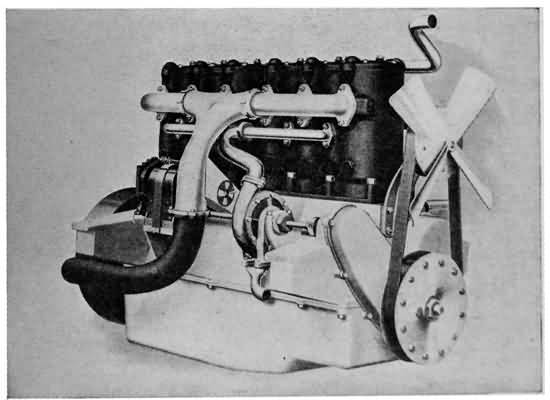
THE SILENT KNIGHT MOTOR
Two views of the latest automobile engine. At the top can be seen the sliding sleeves, the inlets and outlets which do away with valves.
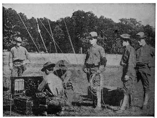
A PORTABLE ARMY WIRELESS OUTFIT
The Signal Service is rapidly increasing its wireless equipment for use on land.

THE WIRELESS IN THE NAVY
Practically all of Uncle Sam's warships and Navy Yards now are equipped with wireless, and a regular navy wireless operators' school is maintained at the Brooklyn Navy Yard.
From the use of concrete it was only a short step to reinforced concrete, or, concrete braced on the inside with iron or steel rods. It is sometimes called concrete steel, ferro-concrete, and armoured concrete. 317 If we asked an engineer the idea in using reinforced concrete he might say to us that the steel when imbedded, united so closely with the concrete as to form one single mass of very great strength. Steel rods add to the tensile strength of concrete which alone has a tremendous strength under compression. In other words, steel does not break nor stretch easily; that is, it has great tensile strength. Concrete has great strength under compression; that is, it will hold up an enormous weight without crushing. Thus, a concrete beam alone might crack on the bottom, because it has not as great tensile strength as steel. But, if we put steel rods into a concrete mould, an inch or so from the bottom, turn out a reinforced concrete beam, for instance, and place it in the building, with the reinforcement at the bottom, we use a beam in which the strength of the concrete and iron is combined. Thus, when a great weight is placed on the top of the beam the concrete resists the compression of the weight, and the reinforcement at the bottom, by its tensile strength, prevents the beam from cracking where the strain of the weight is greatest.
That is what the engineer might tell us is the theory of reinforced concrete, and the practice requires the highest engineering skill and technical knowledge, but in the simplest terms, it is concrete, braced by an imbedded skeleton of steel. In actual practice the reinforcing rods run both ways, or diagonally, 318 just as the engineers decide it is necessary to resist the particular kind of stress that the wall or beam must withstand.
Reinforced concrete was first used, so far as known, by M. Lambot, who exhibited a small rowboat made of that material at the World's Fair in Paris, in 1855. The sides and bottom of the boat were 1-1/2 inches thick, with reinforcement of steel wires. The boat is still in use at Merval, France. F. Joseph Monier, however, is called the "father of reinforced concrete," as he took out the first patent on it in France in 1865. Monier was a gardener and had experimented with large urns for flowers and shrubs. He wanted to make his pots lighter but just as strong, so he tried making some of concrete with a wire netting imbedded in the material. But even then the world did not realize that his accomplishment was more important to mankind than a great many of the wars that had been fought, and little was done with concrete as a building material until the Germans developed it.
Reinforced concrete was not used in the United States, according to the best records, until 1875, when W. E. Ward, without having studied the subject very carefully, built himself a house of it, in Port Chester, N. Y. He made the whole thing, including foundation, outside walls, cornices, towers, and roof of reinforced concrete, placing the steel rods where his own good judgment told him they would 319 do the most good. About this time the Ransome Cement Company began to use the material for building, and put up a great many strong and beautiful structures, still to be seen in California and elsewhere.
Finally, bit by bit, in the face of opposition of all kinds, reinforced concrete came to be recognized by architects, engineers, and builders as one of the best materials for certain kinds of work. To-day we find that most of the predictions of the early enthusiasts have been fulfilled and that the age of concrete has dawned. That it will be used even more extensively in the future, as men learn more and more about this wonderful artificial stone, is certain.
OUR BOY FRIEND AND THE SCIENTIST LOOK OVER THE FIELD OF GASOLINE ENGINES AND SEE SOME BIG IMPROVEMENTS OVER THOSE OF A FEW YEARS AGO
WHILE we are following the conversations of the scientist and his young friend about new inventions, we must not overlook some of their most interesting times in keeping abreast of the vast improvements that are being made every year—almost every day—in the inventions of a dozen years ago.
For instance, there is the gas engine. Ten years ago it was a very imperfect machine, as every boy who has heard the old jokes about "auto-go-but doesn't," "get a horse," etc., will remember.
Then there is the wireless telegraph. No invention of recent years has shown a more remarkable development than that of Guglielmo Marconi for sending messages without wires.
But these are only a few of the things that the two friends talked about. They looked into the wonderful advancement in the art of photography 321 about which every boy knows something, and they investigated the latest achievements of science in electric lighting. Ten years is a very short time, even in this fast moving age of ours, and we shall see that many inventions made years ago are still being worked upon by the original inventors and others.
First, let us see a few of the ways the gas engine has been improved, for we are all more or less familiar with it in automobiles, motor boats, or the hundred and one other places that it has become an invaluable aid to man in carrying on the world's work.
Our young friend brought up the subject one day when he asked the scientist for a few pointers on getting better results with his motor-boat engine.
"We will look it over together," said the man. "Of course you know that every gasoline engine has its own peculiarities, and crankinesses, so it's hard to tell just what's the matter with one until you see it. I don't know very much about them; I wish I knew more, but I have been talking with my automobile friends a good deal lately about the new motor invented by Charles Y. Knight."
"Oh, I know," replied the boy, "it is called the 'Silent Knight' motor because it doesn't make any noise, and it is used on a great many high-priced automobiles."
"That's it. If you like we will go and have one of these engines explained to us. At any rate the 322 automobile man can tell you more about your motor-boat engine than I can."
The expedition was made shortly after the conversation. "You understand, of course," said the scientist on the way, "that the Knight motor represents only one of the many, many improvements in the gas engine, but it is what we call a fundamental improvement, as it is a development in the main idea of the gasoline motor, rather than merely an improvement of one of the parts. Most of the evolution of gas engines has consisted merely of the improvement and perfection of the various parts for more power, and more all around efficiency.
"You remember what you found out about gasoline motors in general when we were spending so much time talking about aeroplanes. The high speed motor, as we know it now, was invented, you know, by Gottlieb Daimler, a German inventor, in 1885, and with the ordinary four-cycle engine it takes four trips, or two round trips of the piston rod, to exert one push on the crankshaft of the engine. In other words, the explosion drives down the piston giving the power, and on its return trip the piston forces out the burned fumes. On the next downward stroke the fresh vapour is sucked into the cylinder and on the fourth trip, or second upward trip, the gas is compressed for the explosion. The carbureter on your motor-boat engine, and all others, as you know, is the device that mixes the gasoline 323 with air and converts it into a highly explosive gas, and the sparking system is the electrical device that ignites the gas in the cylinders for each explosion which makes the 'pop, pop, pop' so familiar with all gasoline engines.
"In the old gas engines the ignition was derived from a few dry-cell batteries and some sort of a transformer coil, whereas nowadays the magneto takes care of this work. As you know there are many kinds of magnetos, and inventors have spent years working out better and better ones. Also, in the old style motors the carbureter was more or less of a makeshift, with a drip feed arrangement, and a hand regulating shutter for admitting the air. Now a special automatic device regulates this, so that it is no longer a toss up whether the gas is mixed in the proper quantities or not. Then, too, the oiling systems have been improved, so that the function is done automatically. In short, the motor has been made a perfectly reliable servant instead of a very capricious plaything.
"All these improvements made no fundamental change in the valves through which the gas was admitted to the cylinders, and the exhausted vapours expelled—and from your own experience you know that you are just about as apt to have trouble with your valves as with any other part of your machine.
"It is in these valves that the Knight motor departs from the usual style, and by this it eliminates 324 the well-known 'pop, pop, pop' by which gas engines have been known all over the world."
As they looked over the engine, an expert in gasoline motors explained all the parts of the "Silent Knight" and showed the scientist and his boy friend just how the machine worked.
He said that the only big difference between the Knight motor and other standard makes of engines is that the Knight substitutes for the intake and exhaust valves an entirely new device composed of two cylinders, one within the other, sliding upon each other so as to regulate the flow of gas and the exhaust of fumes.
Early in his career as an inventor, while living in his home city of Chicago, Knight decided that gasoline engines had entirely too many parts—that they were too complicated—and he set about trying to simplify them. For one thing, he made a careful study of valves, and collected a specimen of every kind known to mechanics. The sliding locomotive valve seemed to him to hold the greatest possibilities for his work, and he began a series of experiments with sliding valves until he finally brought out his first engine in 1902.
Strange as it may seem, Knight's work was not recognized in his own country until after he had gone to Europe, where his engine was taken up by some of the biggest automobile manufacturers of England, France, Germany, Belgium, and Italy. After that 325 it was taken up in the United States, and only now is coming to be generally known. The inventor now lives in England, where he was first successful, and he is still at work on improvements of his engine.
The motor expert went on to explain that the advantage of the Knight motor lay in the fact that the two sleeves or cylinders, which go to make up the combustion chamber or engine cylinder, sliding up and down upon one another, give a silent, vibrationless movement, as against the noisy action of the old style poppet or spring valve motors.
"But," interrupted the boy, "there are lots of other engines that run without making a noise nowadays."
"That is true," the man answered, "but most of them run quietly only when at low speed, or stationary. When they begin to hit the high places the noise of the poppet valves is very noticeable. A few years ago, when most engine builders were satisfied to make motors that would run, regardless of noise, they paid no attention to some of the finer mechanical problems, but since they have become more skilful, they are cutting down on the noise. But, as I say, the explosions are plainly heard when these engines are running at high speed. With the 'Silent Knight' the only noise is that of the fan and magneto, whether at low speed or the very fastest the motor can run. There can be no noise, for there is nothing for the sleeves to strike against."
326 The expert then went on to explain the motor in detail. The combustion chambers of the four or six-cylinder "Silent Knight," he explained, are made up of two concentric cylinders or sleeves, or, in other words, one cylinder within another. There is only the smallest fraction of an inch between them, and as they are well oiled by an automatic lubricating device they slide up and down upon each other with perfect ease. Of course the sleeves, which are made of Swedish iron, a very fine material for cylinder construction, are machined down inside and out so that they are perfectly smooth to run upon each other.
The two sleeves which go to make up one cylinder work up and down upon each other by means of a small connecting rod affixed to the bottom of each sleeve connected to an eccentric rod, which is driven by a noiseless chain from the engine shaft.
The most important features are the slots cut in each side, and close to the upper end of each sleeve, so that, as the sleeves move upon one another the slot in the right-hand side of the inner one will pass the slot of the right-hand side of the outer sleeve, and also the same with the left-hand side.
Then when the left-hand slots of the outer sleeve open upon, or come into register with the left-hand slots of the inner sleeve, a passage into the cylinder is opened for the new gas to enter. When a charge of gas has been drawn into the cylinder, one sleeve 327 rises while the other falls, so that the openings are separated and the passage is tightly closed. The compression stroke then begins with the piston rising to the top. At this juncture the igniting spark explodes the compressed gas and the downward or power stroke takes place. During the upward compression stroke and the downward impulse stroke the slots have been closed, allowing no opportunity for the gas to escape. When the explosion has taken place and the piston has been driven to the bottom of its stroke, the right-hand openings in the inner sleeve and those of the outer sleeve come together, providing a passage for the exhausted gases to escape with the fourth or exhaust stroke. Thus it is plain that the motor is of the four-cycle type and it should not be confounded with two-cycle motors.
As the expert explained the motion he showed how it was carried out on an engine from which the casing had been partly removed. The careful mechanical adjustment of the eccentric shaft, which operated the connecting rods that pull the sleeves of the cylinder up and down so that the openings for the entrance of the fresh gas and the expulsion of the exploded fumes come together at just the proper second, was what took the boy's eye.
In connection with this the scientist handed the boy a magazine to read. It was a copy of the Motor Age in which an expert said editorially:
"Those who pin their faith to the slide-valve motor do so for many reasons, chief of which is that with this motor there is a definite opening and closing of the intake and exhaust parts, no matter at what motor speeds the car be operating. Two years ago one of the leading American engineers experimented with poppet valves and discovered that frequently at the high speeds the exhaust valves did not shut, there not being sufficient time owing to the inability of the valve spring to close the valve in the interval before a cam returned to open it again. With such a condition it is certain that the most powerful mixture was not obtained. With the sleeve valve such failure of operation cannot be, because no matter how fast the motor is operating there is a definite opening and closing for both intake and exhaust valve.
"It is a well-known fact that with poppet valves the tension of the springs on the exhaust side varies after five or six weeks' use, and consequently the accuracy of opening and closing is interfered with. Carbon gets on the valve seatings and prevents proper closing of the valve, with the result that the compression is interfered with and the face of the valve injured. These troubles are, as far as can be learned, obviated in the sleeve valve."
The friends of the Knight motor claim that it is simpler than the ordinary types of engines, having about one third less parts, that it is economic, powerful, and, as previously pointed out, runs silently. Beside these advantages, there are claimed for it many technical virtues that we need not enter into here.
329 The lubricating system of the Knight motors is another interesting point, as it serves to illustrate one more way in which the gasoline engine has been improved upon of late years. The manner of oiling used is known as the "movable dam" system. Located transversely beneath the six connecting rods are six oil troughs hinged on a shaft connected with the throttle. With the opening and closing of the throttle these troughs are automatically raised and lowered. When the throttle is opened, which raises the troughs, the points on the ends of the connecting rods dip deep into the oil and create a splashing of oil on the lower ends of the sliding sleeves. These sleeves are grooved circularly on their outer surfaces in order to distribute the oil evenly, while toward the lower ends holes are drilled to allow for the passage of oil.
When the motor is throttled down, which lowers the troughs, the points barely dip into the oil and a corresponding less amount of oil is splashed. An oil pump keeps the troughs constantly overflowing.
The motor is cooled by a complete system of water jackets, and it is fitted with a double ignition system, each independent of the other.
Of course in the adoption of the sliding sleeve type, mushroom valves, cams, cam rollers, cam shafts, valve springs, and train of front engine gears all are eliminated, the sliding parts fulfilling their various functions.
330 Before Mr. Knight ever achieved success with his motor it was subjected to some of the severest tests on record in the whole automobile industry. In France, Germany, and England, it was only accepted by the leading manufacturers after being tried out for periods extending over several months of the hardest kind of usage. Now, that it has proven itself a practical success, automobile men declare that the sliding valve principle, never before applied to gas engines until Knight began work, will undoubtedly have a lasting effect on the whole industry.
The compact little two-cycle motors represent another big fundamental development in the field of gas engines. There are many different makes of two-cycle motors, of course, and all have their various merits. They are used in practically all the work for which gas engines are employed, including automobiles, motor boats, and aeroplanes. It will not be necessary to describe these engines further than to say that the name describes the fundamental difference between them and the four-cycle motors. Instead of the piston making four strokes for every explosion—that is, an, upward stroke to clean out the burnt vapours, a downward stroke to suck in the fresh gas, an upward stroke to compress it, and finally the downward explosion or power stroke, all this work is done in two strokes.
For the general development of the gasoline engine, it is only necessary for a boy to look about him. 331 Everywhere motors built on the same ideas as laid down in earlier inventions, but improved in every detail, are in use. Not only do we see them on fine pleasure automobiles, motor boats, and aeroplanes, but on our biggest trucks, fire engines, and in business establishments where light machinery is to be run.
THE SCIENTIST TALKS OF AMATEUR WIRELESS OPERATORS—THE GREAT DEVELOPMENT OF WIRELESS THAT HAS ENABLED IT TO SAVE ABOUT THREE THOUSAND LIVES—LONG DISTANCE WORK OF THE MODERN INSTRUMENTS
WHILE the inspiring stories of Jack Binns of the steamship Republic, and of J. G. Phillips and Harold S. Bride of the ill-fated Titanic are fresh in our minds, it is not necessary to say that within the last few years the wireless telegraph has established itself as indispensable to the safe navigation of the seas. The story of its development is a marvellous one when we think that it was only in December of 1901 that Marconi received the first signal ever transmitted across the Atlantic Ocean without wires. Now, as every boy knows, all the big steamships are equipped with wireless, all the governments of the world operate their own stations to communicate with their warships, at sea, and thousands upon thousands of boy amateurs operate their own little plants with complete success.
333 More wonderful still is the story when we think that by the use of this invention a total of about three thousand persons have been saved from death in shipwrecks. Nowhere in the pages of all history are there any more thrilling stories of heroism and devotion to duty than those of the men who, in the face of death themselves, have stuck by their keys sending out over the waves the "C. Q. D." and the "S. O. S." signals, which as every boy knows are the wireless calls for help.
The scientist and his boy friend never tired of talking of these things, for the young man was one of the many amateurs who had mastered the art, so that many a night as he sat at his receiver he caught the messages of steamships far out on the broad Atlantic, and heard the Navy Yard station transmitting orders to Uncle Sam's ships at sea.
One day shortly after the Titanic disaster the boy said to his friend: "I saw by the paper to-day that they are talking of passing a law to prevent the amateur wireless operators from working. I don't think they ought to do that. I'm sure most amateurs never interfere with any signals, as was said they did in connection with the messages to and from ships that went to the rescue of the Titanic."
"So long as the amateurs do not have powerful sending apparatus," answered the scientist, "I don't think they will make any serious trouble, for it makes no confusion to have them 'listening in' on 334 the passing radiographs. Of course with a powerful sender a mischievous person could work irreparable damage by sending fake messages of one kind or another. In fact there have been several instances of messages that were thought to be fakes, but I am sure no boy with the intelligence to rig up a wireless outfit, would be so lacking in understanding of his responsibilities as to try to confuse traffic.
"But it would be a shame to stop the amateurs altogether," he continued, "for, no matter what the companies may say, the wireless telegraph is still in an experimental stage, and we must look to the bright boys who are studying it now, for its greatest development. The marvellous strides in improving the apparatus, and solving the mysteries of electro-magnetic currents, that have been made in the last dozen years, should be eclipsed in the next decade, if young men with some practical experience and a desire to get at the real scientific basis of the art, work at it."
"What are some of the main improvements of the last few years?" asked the boy.
For answer, the scientist and the boy made a journey down to the steamship docks, and visited the wireless cabins of several of the big transatlantic liners. They also went to the Brooklyn Navy Yard, where there is a wireless school, that turns out Navy operators after a thorough course in all the various branches of the art. While on vacations to the seashore, 335 the youth had visited some of the big high-power stations that send and receive messages to and from the ships at sea.
In talking to the operators and electricians the boy learned much about the wide extent to which wireless is used nowadays. The law passed by Congress in the United States in 1911, making it necessary for every passenger steamer sailing from American ports with fifty or more passengers, to carry a wireless outfit capable of working at least 100 miles, in charge of a licensed operator, capable of transmitting 20 or more words a minute, did a great deal to increase the use of wireless. Also, not only the actions of one government but the concerted action of all the civilized nations represented at the various international wireless conferences have brought it to the official notice of the whole world.
Thus it has become a commercial reality on the sea, and the Great Lakes, and also it has become a big factor in war. All of the nations, besides having their warships equipped with wireless, now have wireless squads in the army, and have small compact apparatus that can be transported in small wagons, or even on horses' backs. These portable army wireless outfits are very valuable for the communication between detachments of an army, particularly in places where there are few disturbing elements to intercept the electro-magnetic waves.
In the recent campaign in Tripoli, in the war between 336 Italy and Turkey, the wireless was extensively used by the Italian army in the field, and it was found that the messages radiated over the desert just about as well as over the sea. Of course as will be seen later, it is not meant here to convey the idea that wireless cannot be sent over the land, for the electro-magnetic waves travel through the ether in every direction, and as the ether fills the whole universe, mountains, buildings, or water just as well as the air, the waves are thought to go through obstacles as well as over water. The difficulty in sending over land, is that there are various electrical disturbances that intercept and confuse the wireless waves. In other words, wireless works through mere physical obstructions without any difficulty, just so long as certain little known electrical disturbances do not interfere. Just think of the thousands and thousands of wireless messages that are passing through the ether every hour of the day and night. And yet the scientists really know very little about the laws that govern them!
One of the instances of the strange antics of wireless was told to the boy by an operator who had been in charge of the wireless outfit on a Hudson River boat. He said that he and the operators on the other boats were able to communicate with a station on shore until they had passed the Poughkeepsie bridge, and the great steel and stone structure stretched between the boat and the station. Immediately communication 337 stopped short and all efforts failed to get any response. A series of experiments proved that the obstruction was at the bridge, but whether it was some electrical property in the bridge itself, or in the hills on each side of the bridge, they have never been able to find out, and the land station was finally discontinued.
This is just an instance of what the scientists do not know about wireless, but it shows the many boy amateurs that there are still worlds for them to conquer in scientific research.
The central principle upon which the wireless telegraph works now is the same as it was when Marconi, through his marvellous invention, first received a signal from the other side of the Atlantic Ocean, but the inventors have learned much more about the details of the theory and it is in the improvement of devices for applying these laws of electricity that the development has been, rather than in the discovery of new theories. Nikola Tesla's invention for the wireless transmission of power by earth waves is a revolutionary departure from the usual wireless practice, but as we saw in the earlier chapter on this subject the Tesla invention has not yet been put in practical operation.
Though Guglielmo Marconi did not discover the laws of electricity upon which his invention is based, to him belongs all the credit for making use of the discoveries of the scientists of his day, and working 338 out from them a practical system of wireless communication.
As many boys know, the wireless telegraph is possible through the radiation of electric waves. For instance, if a stone is thrown into a pool waves are started out in every direction from the point where the water is disturbed. The water does not move except up and down, and yet the waves pass on until they reach the side of the pool, or their force is expended.
The scientists before Marconi found out that when an electric spark was made to jump between two magnetic poles it started electric waves in every direction, much like the stone thrown into the pool, except at a speed that is reckoned at 186,000 miles per second.
Prof. Amos Dolbear, of Tufts College, Massachusetts, first made use of these waves in 1880, and a few years later Doctor Hertz, conducting experiments along the same lines, discovered them. Since that time these waves have been called Hertzian waves.
For many years scientists had understood that electrical waves or vibrations travelled through the ether in a copper wire, and that gave us telegraphy by wires, but it was a new thing to think of the waves travelling in every direction through space without wires. These early investigators found out that they could detect these waves by a device called a Hertzian loop, which was simply a copper wire bent into a 339 hoop with the two ends close together but not touching. A spark would appear between the ends of the wire when the electric waves were sent out.
Marconi began his work where these scientists left off, as a very young man on his father's farm in Italy, but soon went to England, of which country his mother was a native, and placed the results of his experiments before the government authorities. Continuing his labors he soon had his wireless apparatus worked out in the form in which it first became known to the world.
It consisted of a transmitter, receiving machine or detector, and a set of antennæ or aerial wires from which the electrical waves were sent. For his transmitter, he created a spark between the two brass knobs on the ends of two thick brass wires by closing and opening an electrical circuit with a key, very much like, but somewhat larger than the regulation telegraph key. The space between the knobs was called the spark gap. For a dash he would hold down his key and make a large spark, and for a dot he would release his key quickly and make only a short one. Thus, he could send the regular Morse or Continental telegraphic codes of dots and dashes. These impulses were transmitted by wires to the aerial wires, or antennæ. The impulses left the antennæ as electro-magnetic waves, and went forth in all directions, only to be caught on the antennæ of another station aboard a ship or on land.
340 Here is where the receiver did its work, and the problem was a far more difficult one than the working out of the transmitter, for the waves as received were too weak in themselves to register a dot or a dash. In Marconi's first instruments he used a device called the "coherer." This was a glass tube about as big around as a lead pencil, and perhaps two inches long. It was plugged at each end with silver, and the narrow space between the plugs was filled with finely powdered fragments of nickel and silver, which possess the strange property of being alternately very good and very bad electrical conductors. The waves in Marconi's first experiments were received on a suspended kite wire, exactly similar to the wire used in the transmitter, but they were so weak that they could not of themselves operate an ordinary telegraph instrument. They possessed strength enough, however, to draw the little particles of silver and nickel in the coherer together in a continuous metal path. In other words, they made these particles "cohere," and the moment they cohered they became a good conductor for electricity, and a current from a battery near at hand rushed through the connection, operated the Morse instrument, and caused it to print a dot or a dash; then a little tapper, actuated by the same current, struck against the coherer, the particles of metal were broken apart, becoming a poor conductor, and cutting off the current from the home battery.
341 In Marconi's early experiments there was little or no attempt at tuning the instruments for waves of certain lengths, but this art has been developed to a high state in modern wireless telegraphy and we shall see how the operator tunes his instruments to talk to any one special station.
The distinguishing feature of the modern wireless transmitter, now familiar to every boy who has ever taken a trip aboard a large ship, or attended an electrical show, as it was in the old days, is the "crack, crack, cr-r-r-ack, crack" of the spark as it flickers between the brass knobs of the instrument, as the operator pounds away at his key. In some of the great high-power land stations, where long distance work is done the crash of the spark is like that of thunder, the flame is as big around as a man's wrist and of such intensity that it could not be looked at with unshaded eyes. On ships where the crash is too loud it has become necessary to cover the spark gap with a wooden muffler so as to deaden the noise.
While the simple spark gap of the early Marconi instruments was enough to send out the Hertzian waves, the modern transmitter is a marvel of electrical construction utilizing as it does the latest discoveries in electrical apparatus.
The most noticeable difference in the sending apparatus is in the arrangement of the two wires between which the spark flies. In the early instruments 342 the wires were set in a horizontal line, and connected to an induction coil, but in the later ones the oscillator was turned up lengthwise with the spark gap between the vertical wings.
The different position of the spark gap is a change only in form, and not in principle. In the Marconi apparatus used nowadays the current comes from a dynamo of more than 110 volts, direct current. The two terminals of the circuit are connected with an induction coil, and from there to the two ends of the wires, making the terminals of the spark gap. The upper wire runs from the spark gap to the aerial, and the lower runs through a battery of Leyden jars, through a high tension transformer (as does the other side of the circuit), and thence to the ground. Aboard ship the ground connection is simply made by attaching a wire to the hull of the ship, which is in connection with the water, the best possible earth connection.

MARCONI TRANSMITTER LAYOUT
A—Key. B—Induction coil. C—Spark gap. D—Dynamo. E—Rheostat. F—Interrupter magnet. G—Aerial. H—High tension transformer. I —Ground wire. K—Battery of Leyden jars.
343 There are, of course, a great many different kinds of transmitters, but they are all worked out on the same general principle—a spark gap which creates electrical oscillations that are sent into the ether from the aerials.
In some modern stations an alternating current is used at more than 100 volts and is stepped up through a transformer to about 30,000 volts. This high power current then charges a condenser consisting of a battery of Leyden jars.
When the operator presses his key he establishes a connection, which immediately sets up electrical waves oscillating at a rate of anywhere from 100,000 to 2,500,000 per second. These oscillations are carried to the antennæ where they pass into the ether and spread in all directions to be caught on the aerials of all stations within range.
One of the improvements in wireless transmission which makes long distance work possible aboard ships is the use of what the engineers call "coupled circuits." The arrangement consists in connecting the aerial to an induction coil, and connecting the latter with a ground wire. Another coil is placed close to this and is connected with the spark gap, and a condenser. The period of oscillation of the antennæ circuit, and of the spark gap circuit are timed to be exactly the same. The two circuits are then called "coupled circuits," for while they are coupled together by induction only, the oscillation or 344 spark gap circuit increases its capacity, and at the same time has a small spark gap.
With these new devices for increasing the power of the oscillations, or in other words throwing a bigger stone into the pond, the electrical waves are sent out with far greater force, just as the water waves are sent farther in the pond, and will reach stations at a greater distance.
"Crash, bang," goes the oscillator, and in less time than it takes to think it the oscillations have reached the antennæ of ships hundreds or thousands of miles away, or even those of another land station on the other side of the Atlantic Ocean.
The next thing is to understand the apparatus used for receiving the faint electric waves transmitted through the ether, for the modern instruments are far different from the old style "coherer" explained before. As with the spark gaps, there are many different styles of receiving devices, all known by the general name of "detectors," as they detect the faint electro-magnetic waves radiating through the ether.
Some of the latest Marconi experiments show a return to the "coherer" idea, very greatly improved upon, but the full details of the device have not been made public.

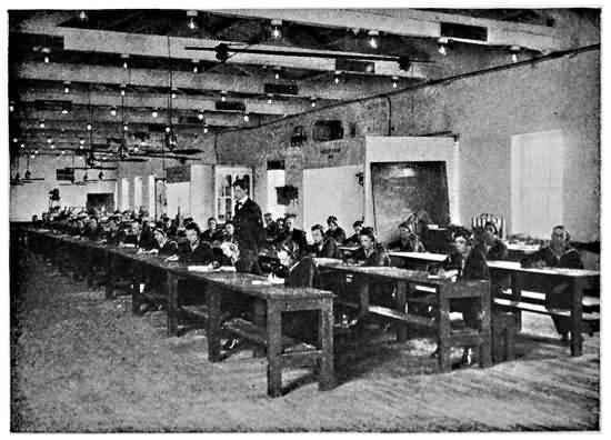
Courtesy of the New York Edison Co.
THE NAVY WIRELESS SCHOOL
At top is the class in sending, while below is shown the class learning to receive messages.
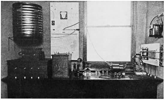
AN AMATEUR WIRELESS OUTFIT
Hundreds of boys are receiving and sending wireless messages with far less efficient apparatus than that shown here.
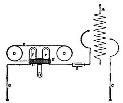
MARCONI DETECTOR LAYOUT
A—Aerial. B—Condenser. C—Glass tube oscillator transformer. D—D´—Rollers. E—E´—Iron wire passing through oscillator transformer. F—F´—Magnets. G—G´—Ground wires. H—Telephone receiver.
One of the detecting devices used by the Marconi system, after the old-style "coherer" was done away with, was very simple indeed in comparison to the 345 cohering and tapping machines. It was made up of a small glass tube wound with copper wire. One end of this made the ground connection, and the other end led to the aerial, and also to an earth connection through a tuning inductance coil. Then another coil was wound around the first one on the glass tube and connected with the head telephone receivers which have taken the place of the Morse dot and dash printing instrument in all the modern wireless instruments. Two magnets were placed just above the glass tube, and a flexible iron wire was made to move through it by means of a pair of rollers a little way from each end. When the electro-magnetic waves reached the aerial and made oscillations in the first coil about the glass tube, the magnetic intensity of the iron wire band was disturbed and the glass tube became an oscillation transformer, setting up currents in the coil leading to the telephone receivers. The impulses were manifested by ticks, just the 346 length of the dots and dashes being sent out by the operator perhaps thousands of miles away.
Another form of detector is the "electrolytic" which consists of a very fine platinum wire about one ten-thousandth of an inch in diameter, which dips into a platinum cup filled with nitric acid. When the invisible electro-magnetic waves impinge upon the wires of the receiving station, and cause electrical surges to take place in those wires, they in turn affect the detector, giving an exact reproduction of the note of the transmitting spark at the distant station.
This device has since been replaced by one of another type, equally sensitive and much better suited for general work on account of its greater stability and freedom from atmospheric disturbances. This detector consists simply of a crystal of carborundum supported between two brass points. When connected to the antennæ it is affected by the oscillations caused by distant transmitting stations as previously stated. These wireless signals are reproduced in telephone receivers.
Another frequently used detector known as the Audion is composed of a small incandescent lamp with filaments of carbon, tantalum, or preferably tungsten, and one or more sheets or wings of platinum secured near the filaments. The lamp is lighted by a set of home batteries, and is connected with a ground wire, the aerial, and the telephone receivers. 347 The tungsten filament and the platinum wing act as two electrodes, and the faint electric oscillations received on the antennæ and transmitted to the platinum plate are supposed to affect the discharge of negatively electrified particles, or ions, between the two electrodes. This affects the flow of the battery current, and consequently registers the oscillations in the telephone receivers.
By diligent study of the subject the wireless experts also have learned that the arrangement of the aerials is of great importance, because much depends upon the send-off received by the electrical oscillations. In Marconi's early experiments he used a single wire attached to a kite, then changed to a single wire stretched from the top of a high mast. Later, the system of stretching the wires horizontally between two masts, as we see them so often aboard passenger steamships, and at land stations, came into general use. The old idea that the height of the aerial wires had something to do with the efficiency of the apparatus has passed, for science showed that the electro-magnetic waves travelled in all directions irrespective of land, water, mountains, or buildings. Whether, in sending messages across the ocean, they actually pass through the globe, or follow the curve of the surface, is more than the most careful wireless students have been able to tell.
Another of the big improvements in wireless is in the tuning of the instruments to certain wave 348 lengths or rates of vibrations, and in controlling the wave lengths by the sender. Science has established that these waves usually vary from a few feet up to 12,000 feet or more. The ordinary wave lengths for ships is between 1,000 feet and 1,800 feet, but on the biggest land stations and the transatlantic liners the full 12,000 feet is used. Even greater lengths of waves are used by the big Marconi stations transmitting messages between Clifden, on the west coast of Ireland, and Glace Bay, Nova Scotia. The reason for this is that with the same power messages can be sent greater distances with long wave lengths than with shorter ones.
The wave length is controlled by an apparatus called the "helix," which may be seen in the picture of the wireless outfit. It looks like a drum wound with a spiral of copper tubing, and although it looks simple it presents some of the greatest problems in connection with wireless.
On the receiving end is the instrument called the tuner, by which the operator can adjust his detector to the wave lengths being sent out by the station with which he wishes to talk. There are various kinds of "tuners," all more or less complicated. The device corresponds to the telephone exchange or the telegraph switch-board. Of course a good receiving apparatus can be tuned so that the operator can listen to any messages going through the ether, within range, but all messages that are intended to be secret are sent in 349 code, just as all wire and cable messages that are secret are sent in code.
In line with the advent of wireless telegraphy it is fitting that we should have the wireless telephone. While this instrument is still in the experimental stage, some very promising results have been obtained. There are several experimental wireless telephone stations in New York City, but the best results are obtained when some one keeps up a steady conversation, so it is far easier to connect the reproducer of a phonograph to the transmitter of the wireless telephone. It is surprising how distinctly this music or speech is received. In fact the ship operators nearing New York are often entertained by strains of music from these wireless telephones. The wireless telephones employ what are known as undamped oscillations created by electric arcs, and it is very easy to "tune out" such vibrations for musical effects.
Just as we have the motion-picture "newspaper," we have the wireless newspaper published aboard the big transatlantic liners every day. The news is sent out from certain land stations at certain times in the day and night, and every ship within range copies it, and publishes it just as our regular daily papers are published. Of course, the paper is small, but it usually contains most of the important news of the day, the big sporting items, such as baseball scores, and the stock quotations.
350 In the United States the great station at Wellfleet, Cape Cod, Mass., sends out the press matter each night from dispatches prepared in the main offices of the big American press associations. Ships as far as 1,600 miles distant frequently receive this news matter, and by the time the ocean-going editor is ready to get out his next day's edition he is in touch with the wireless press station on the other side, and is receiving the world's news from the English coast.
As our young friend found out when he was gathering up all the information he could about aeroplanes, some success has been made in the equipment of the fliers with wireless. The project offers some serious difficulties, however, as on an aeroplane there is no place for long aerials. Experiments have been tried with long trailing wires, but these are dangerous to the aeroplane, and to use the wires of the machine for antennæ endangers the operator to electric shocks. One scheme tried by several aviators in the United States with some success has been the stringing of aerials in the rear framework.
The problem of equipping balloons and airships with wireless is much simpler because it allows of long trailing wires to act as the antennæ. Most boys will remember the success of the wireless apparatus that was set up on the America at the time Walter Wellman made his famous attempt to cross the Atlantic in his airship.
That wireless will take its place as one of the great 351 forces in civilization is the idea of Guglielmo Marconi, the inventor of the wireless telegraph, expressed when he was in New York in the spring of 1912.
"I believe," he said, "that in the near future a wireless message will be sent from New York completely round the globe with no relaying, and will be received by an instrument located in the same office as the transmitter, in perhaps even less time than Shakespeare's forty minutes.
"Most messages across the Atlantic will probably go by wireless at a comparatively early date. In time of war wireless connections will be invaluable. The enemy can cut cables and telegraph wires; but it is difficult seriously to damage the wireless service. The British Empire has realized this, and is already equipping many of its outposts with wireless stations."
COLOUR PHOTOGRAPHY, THE TUNGSTEN ELECTRIC LAMP, THE PULMOTOR, AND OTHER NEW INVENTIONS INVESTIGATED BY OUR BOY FRIEND
BEFORE we leave our good friend the scientist and his young companion, let us go over a few more of the things about which they talked. To take up all of them would be to prolong this book indefinitely, for the boy's mind was ever unfolding to the new things of the world and with each subject mastered, or at least partially understood, he was anxious to go on to the next. Not that he did not have his special hobbies upon which he spent most of his time, for he did, but that did not prevent his inquiring young mind from reaching out for new and more wonderful things once he had come to realize the world of marvels in which we live.
One of this youth's favourite pastimes was photography, and as an amateur his work had attracted considerable attention from his friends. One day in the summer, when all the trees, shrubs, and flowers were at the height of their beauty, he came into the 353 laboratory where his scientific friend was working over an experiment.
"I have heard of a process of colour photography," he said, "and I wonder if I couldn't make use of it to get some good pictures out in the country, showing just exactly how it is."
"Certainly," replied his friend. "There are a number of systems of colour photography now—all invented within the last few years. None of them is perfect though, and you would have the added fun of carrying on some experiments that might bring to light some valuable knowledge.
"While it is possible to make coloured photographic prints now, by means of a specially treated paper, colour photography is best known as a means of making beautiful transparent glass plates and lantern slides. When held up to the light, the transparencies give an accurate picture of the scene in natural colours. The paper I mention can be bought at the photographic houses, but the inventors do not claim yet that their process is so perfect as to give exact reproductions of all the shades of colours unless they are well defined in the positive plates. The prints are made from the positive transparencies in just the same way that photographic prints are made from black and white photographic plates."
"Let's try some colour photographs," promptly said the boy. "Will you go out into the country with me some Saturday and help me?"
354 "I certainly will be glad to go with you, but you are a better photographer than I am, for you see, about the only kind of photography I do now is with a microscope, such as you have looked through here many times. Your own regular camera and tripod will be all you will need, for I will buy the colour plates upon which the pictures are to be taken."
They made their trip to the country on the first pleasant Saturday, and while they were out the scientist explained many points about the system.
"Years ago," he said, "even before that wonderful Frenchman, Daguerre, invented light photography, scientists were trying to discover some means of mechanically registering on paper, the beautiful things they saw in nature, in their natural colours, as well as in their natural form in black and white. All through the years of the development of photography with light and shadow, scientists never relaxed their search for some way of photographing colours. Although many of them hit upon the colour screen idea by which it finally was accomplished, there remained years and years of patient experiment. Prof. James Clark Maxwell, Ducos du Hauron, Doctor Konig, Sanger Shepherd, and, in later years, Frederick Eugene Ives, of Philadelphia, all worked on the idea.
"In 1907, however, Antoine Lumiére, of the famous French photographic house that bears his name, announced a system of colour photography which 355 has grown in popularity ever since. The system, which is known as the autochrome, was the result of many years patient study and research with his sons who are associated in business with him."
The scientist then went on to explain that in attacking the problem the investigators first had to learn all they could about colours, and how they are reflected by light rays. As we have seen in the colour process for motion pictures there are really only three fundamental or primary colours, and all other shades and tints are made up from combinations of these. The three are blue-violet, green, and orange-red, and a screen of these forms the foundation of all the colour plates now used.
In the autochrome process the lowly potato, which we generally think of merely as a common article of our food, forms the first factor. The starch of the potato is ground down and sifted so that the grains are the same size—not more than 0.0004 to 0.0005 of an inch in diameter. These grains then are divided into three equal portions, and each portion is dyed, respectively, blue-violet, green, and orange-red. The three little piles of starch grains are then mixed together in suitable amounts and dusted on to a plate, which has previously been coated with a substance to make them stick. The difficulty in dusting on the starch grains is great, for they must cover the whole plate equally and yet not make any piles of starch at any one point, for to have several grains 356 on top of one another would spoil the effect. The extreme delicacy of this operation will be appreciated when it is realized that there are over five million grains to the square inch. When the starch is all properly placed it makes the colour screen, though in appearance the plate is a dark gray.
The plate is next put through a rolling process so that all the grains are flattened out to form a mosaic covering over the whole surface. In spite of all the manufacturers can do there will still be some microscopic spaces between the particles, and these are filled up with a fine powder of carbon to prevent the passage of light.
The screen is then coated with a very thin layer of varnish and upon this is laid a thin and extremely sensitive photographic emulsion.
"And so that is the way these autochrome plates we have here were made," concluded the scientist. "Now our troubles begin, for we must be careful to give them a fair trial with the proper kind of an exposure and the proper kind of development."
As the plates are extremely sensitive to all kinds of light the scientist cautioned the boy against loading the camera carelessly. It is better, he said, to load in a dark room.
In putting the plates in the camera the plates are reversed and instead of placing the sensitized side toward the lens, the uncoated glass is put in front and the photograph is taken through the glass. Thus, 357 the image first passes through the glass, next, through the grains of coloured starch, and, lastly, is recorded on the sensitive photographic emulsion.
Before loading the camera, however, the scientist fitted a yellow colour screen over the lens, explaining that this was necessary to absorb some of the overactive blue-violet light rays, to which the emulsion is extremely sensitive.
In exposing the plate what happens is this: Suppose a green field is to be photographed. The green rays of light, reflected from the field, pass through the lens, and through the glass support of the plate. But when they reach the coloured starch, the green rays pass through the green particles of starch, but not through the violet-blue particles, or the orange-red particles, for the grains of other colours absorb the green rays and hold them. Thus, development would show that the green light rays passing through the green starch particles caused the emulsion to darken under the green particles in just the proportion in which the green light reached them, and to record the image they carried. As the light would not pass through the other coloured particles they would not record any image. Thus a negative is produced, as we have seen, not the colour we see in life but the complement. By treating the plate with a solvent of silver the tiny black specks that were brought out behind each green particle are removed and each starch grain is allowed to transmit exactly 358 the colour we see in life. In other words, we have a positive.
This is just as true of all the shades and hues as it is of the three fundamental colours, for the various rays of light will penetrate the starch in just the proportion of the hues they represent in the scene before our eyes. While the silver solvent will remove the dark images built up by the penetration of green light, it will leave behind the particles of red-orange, and blue-violet, backed up by the creamy silver bromide of the emulsion. If above the green field we had a blue sky, the blue-violet particles would let the blue-violet rays penetrate them, and record the image of the sky.
After the negative has been treated and made a positive, a second development reduces the silver bromide to opaque metallic silver, preventing any light from passing through the grains through which a part of the image did not pass. This second bath also brightens the colours, while the hypo bath removes the unaltered silver bromide ensuring permanency to the image.
"Of course in taking these colour photographs," went on the scientist, "we must take into consideration a great many things, to which the manufacturers will call your attention in their booklets. The exposure is the most important part of all, for these plates are necessarily slow and must be exposed for a much longer time than the ordinary rapid plates. 359 For instance, this field, with this bright summer sunlight, will require a full second with this lens at U. S. 4."
The scientist then went on to give the boy directions for developing his colour plates, as follows:
The whole process of development consists of three operations and but two solutions are required, one of them being kept preferably in two stock solutions. Apothecary weight is used.
STOCK DEVELOPER
| Water | 30 ounces |
| Metoquinone | 3-1/2 drams |
| Sodium sulphite (dry) | 3 ounces |
| Ammonia (density 0.923 or 22 degrees B) | 1 ounce |
| Potassium bromide | 1-1/2 drams |
Dissolve the metoquinone first in lukewarm water and then the other chemicals in the order given.
STOCK REVERSING SOLUTIONS
| A. Water | 25 ounces |
| Potassium permanganate | 50 grains |
| B. Water | 25 ounces |
| Sulphuric acid | 4 drams |
Errors in exposure are to be corrected by varying the duration of development and the amount of stock solution added after the appearance of the image. Use the solutions at a temperature of 60 degrees Fahrenheit, and start development of a 5 × 7 plate in
| Water | 4 ounces |
| Metoquinone stock solution | 2 drams |
360 Have ready two graduates, one containing 6 drams of the stock developer, the other 2-1/4 ounces. Begin counting seconds upon immersion of the plate in the weak developer and watch for the outlines of the image, not considering the sky. If the time of appearance is less than 40 seconds, add the smaller quantity of stock solution; if more, add the greater. The total times of development are given in the following table. Cover the tray for protection from light as soon as the solution has been modified properly.
| TIME, IN SECONDS, OF APPEARANCE OF IMAGE, DISREGARDING THE SKY. |
QUANTITY OF METOQUINONE STOCK SOLUTION TO BE ADDED AFTER IMAGE APPEARS. |
TOTAL DURATION OF DEVELOPMENT, INCLUDING TIME OF APPEARANCE. |
|
| Minutes. | Seconds. | ||
| 12 to 14 | 6 drams | 1 | 15 |
| 15 " 17 | " | 1 | 45 |
| 18 " 21 | " | 2 | 15 |
| 22 " 27 | " | 3 | 15 |
| 28 " 33 | " | 3 | 30 |
| 34 " 39 | " | 4 | 30 |
| ——— | ———— | — | —— |
| 40 to 47 | 2-1/2 ounces | 3 | |
| Over 47 | "" | 4 | |
As soon as development is finished rinse the plate briefly, immerse in equal parts of the reversing solutions and carry the tray into bright daylight. Gradually the image clears and the true colours are seen by transmitted light. In three or four minutes the action will be complete. Rinse the plate in running water for thirty or forty seconds and immerse 361 again, still in daylight, in the developer. In three or four minutes the white parts of the image will be seen to have turned entirely black. The plate may now be rinsed for three or four minutes in running water and set away to dry without fixing.
To avoid frilling in summer, it is well to immerse the plate for two minutes after reversal in
| Water | 5 ounces |
| Chrome alum | 25 grains |
After a brief rinsing proceed with the second development as usual.
The completed transparency may be protected from scratches to a certain extent by varnishing the film side, although this is not necessary. The varnish consists of
| Benzole (crystallizable) | 5 ounces |
| Gum dammar | 1 ounce |
It should be applied cold in the usual way, making sure that the entire surface is covered, and then setting the plate on edge to dry.
The other colour processes now used with success also are based upon the colour screen.
The process known as the omnicolore, which was brought out in France, depends upon a screen consisting of a very fine network of violet lines in one direction, crossed by red and green lines at right angles. The usual sensitive emulsion is placed over these. The lines run more than two hundred to the 362 inch but they can be seen by close examination of the plate.
In the Thames process which was brought out in England the colour screen and the sensitive emulsion are on separate plates which must be bound together during exposure and again placed in register or in exactly the same relative position after development. This causes some trouble, but reduces expense as the failures waste the sensitive plates but not the colour screens. The primary colours instead of being scattered at random, as in the autochrome system, are arranged in a pattern to give the proper proportions to each. The red-orange and green particles are arranged in circles, with the green a little larger than the red ones, while the blue particles fill the spaces.
One evening our boy friend entered the scientist's laboratory and found it more brilliantly illuminated than it ever had been before.
"Oh, I know," he said looking up at the ceiling, "those new electric lights up there are tungsten lamps. It certainly makes a difference in the looks of this place."
"Lights up all the dingy corners, doesn't it?" answered his friend. "You remember," he continued, "we talked last week about some of the new 363 kinds of electric light and that made me think that I might just as well take advantage of what other scientists have done and install this newest kind of electric lamps."
From the ceiling were suspended several stationary fixtures with bright glass reflectors. The lamps the boy saw were somewhat larger than the usual electric light bulbs, and gave off a beautiful white light instead of the slightly yellowish illumination that comes from the ordinary ones. He saw that the filament from which the illumination came was not arranged in a series of horseshoe curves, as in the case of the ordinary globes, but that it was strung between the ends of cross trees, or "spiders," so that there was a greater total length of filament in the same size bulb than in the ones used before the invention of the tungsten lamp. It is a sight familiar enough to most boys in these days of the rapid adoption of new inventions, but it brought to the boy's mind a question that had often occurred to him before.
"Who invented tungsten lights?" he asked.
"Well, it would hardly be right to say that any one individual invented them, for they were really a development of science worked out by many men, who studied the problem for many years. This caused a number of very bitter lawsuits over the patents and brought about the imprisonment of one United States patent office official who was 364 convicted of falsifying the records at Washington to help one of the inventors. This inventor was John Allen Heany, and his patents were rejected finally, the rights of the tungsten filament going to the General Electric Company. The name 'tungsten' is taken from the material of which filament, or the little wire which lights up in the globe, is made."
"What is tungsten?" asked the boy.
"Tungsten is a metal that for a great many years some of our most prominent chemists and scientific investigators declared could not be put to the use we see it here," answered the man.
Noticing that the boy leaned forward in his chair, keen on his every word, the boy's friend continued his description of this strange metal that has been put to work lighting us in our march along the road of life.
He explained that tungsten, or wolfram, was discovered in 1781 and was named from the Swedish words "tung" (heavy) and "sten" (stone). The mineral is not found in a pure state but rather in wolframite, which is what the scientists call a tungstate of iron and manganese, and also in schoolite which is calcium tungstate. Pure tungsten is bright steel gray, very hard, and very heavy. It is one of the most brittle of all the metals and for that reason was put to very few uses before the invention of the tungsten lamp. It was most commonly used, however, in various steel processes, to harden the metal.
365 From the time Edison invented the incandescent lamp in 1879, right up to the present electricians have tried to get a better electric light filament. A number of persons conceived the idea of making a filament of tungsten on account of its peculiar characteristics, which seemed to be just about the ones needed for the ideal electric light globe.
In its fundamental idea the tungsten lamp is not very greatly different from the early Edison incandescent lamps, but in the application of the principle there is half a century of accomplishment packed into a little over a quarter of a century of years. Edison saw that he must have a filament that would carry the current of electricity, but yet one which would be of such high resistance that it would not take up all the current fed to it. He saw that he had to have a filament that would heat to incandescence with the electrical current, and yet one that would stand a certain amount of wear and tear, and which would not be consumed by the heat. To obtain the latter effect he put his filament in an air-tight glass globe from which the atmosphere was exhausted, leaving it in a vacuum. As there was no air, there was no oxygen, and hence there could be no oxidization, or, in other words, combustion of the filament.
Edison thought that success lay in a carbon filament, and in these early days when he was experimenting at his Menlo Park laboratory he carbonized 366 just about everything he could lay his hands on and tried heating the result to incandescence in the vacuum globe. Finally, on October 21, he carbonized a piece of cotton thread and put it in his vacuum globe in the form of a horseshoe loop. On connecting it with his electric circuit he was rewarded by seeing a brilliant incandescent light that lasted without dimming for forty straight hours.
What a dim, dingy little light it was in comparison to the world famous lights that Edison now puts forth! And yet in one way it was the most brilliant light that ever had shone in the world, for it showed mankind the pathway toward a complete system of electric lighting by incandescent lamps.
The carbonized cotton thread filament had many drawbacks, and Edison continued carbonizing various fabrics and fibres, including, it is said, some of the red hairs out of the beard of one of his loyal staff! At last he hit upon a filament made of carbonized Japanese bamboo that was very successful for a number of years, but this was later superseded by a cellulose mixture mechanically pressed out by dies.
Meanwhile, several investigators began work with tungsten and a similar metal called tantalum because of their extremely high melting points, high resistance, and other technical characteristics favourable for an incandescent filament.
For years they had no success because the metal was so very brittle that they could do nothing with 367 it, but finally a filament of pressed tungsten was brought out. In this type of lamp several filament loops would be fused or welded together to make one complete filament. The result was a very fine light, but the little wire was too fragile to stand hard usage, and owing to the fact that the various connected loops were not all of exactly the same thickness, one frequently burned out far ahead of the others and caused early lamp failure.
The next step, and the one which a great many scientists had declared impossible, was the manufacture of a tungsten wire through a regular process of drawing it out through dies to the desired length, and in the desired thickness. The investigators had declared that in spite of all they could do, tungsten was too brittle ever to be drawn into wire. In the latest methods this is accomplished with such perfection that tungsten wire of 0.0015 of an inch in diameter is produced.
"With the invention of a method for drawing out tungsten wire," continued the scientist, "an almost ideal lamp was practically accomplished. The wire simply was strung on the spiders or cross pieces, and a filament of almost any length giving almost any desired candlepower light could be used.
"You see in an incandescent light the higher the melting point of the filament the greater the quantity of light for the amount of electricity used. Also tungsten has a low vapour tension, which prevents 368 discolouration of the globe by the evaporation of the filament. It also has other advantages which are too technical for us to go into.
"Of course, tungsten lamps still have the drawback of being rather delicate. When not in use, and when the filament is cold, it is apt to break with rough treatment, but when lighted the filament, being at a white heat, is more durable. This delicacy of the tungsten lamp is the reason the fixtures for most of them are placed in stationary positions, rather than on swinging drop cords, as is the case with so many carbon incandescent lights.
"While the tungsten lamp is far from perfect, it is a great advance over other forms, and an advance in the right direction, for it gives a better light with a smaller consumption of electricity than other types. I think your father will agree with me that anything that will help ever so little to reduce the high cost of living is a benefit."
"But," answered the boy, "there are other new kinds of electric lights besides tungsten, aren't there?"
"Oh, of course, but they are hardly as generally used as the tungsten light. There is the mercury light about which you read in 'The Second Boys' Book of Inventions,' several new kinds of arc lights, the Nernst light, the tantalum lamp (which we know is much like the tungsten lamp with the exception that in the latter each loop of the wire can be made 369 longer), and the new carbon dioxide gas electric light, which is a very good imitation of daylight.
"From all our little scientific journeys you have doubtless formed the idea that light is not the simple thing it seems, and that the rays of different kinds of light will bear a limitless amount of study. Now some of the greatest scientists the world ever has known have spent the best part of their lives trying to produce a light that would duplicate the beautiful health-giving rays of the sun. This light we are speaking of comes as near to it as any."
He picked up a long glass test tube and holding it between his fingers said: "Now if this tube were exhausted of air to a vacuum, and we had an ingenious little device at each end which would allow just the right amount—no more, no less—of carbon dioxide gas to enter it, and also we had electrodes at either end, and connected them to an alternating current, we would have a rough model of the light that duplicates daylight.
"In actual practice the vacuum tubes are long, and turn upon themselves in many lengths. You have seen these lights in many places, for photographers, lithographers, dye works, textile mills, and all other places where the true light of day is necessary for the judgment of colours are adopting them for their night work."
"But the light is a ghastly pale blue," interrupted the boy. "It doesn't look like daylight to me."
370 "No, you are thinking of the mercury light, which also is strung around in tubes. That has a blue-greenish tinge to it, and gives people's faces a disagreeable greenish tinge, but this carbon dioxide electric light is white with a salmon pink tinge. Of course it isn't perfect, but the men who developed it from the work of others who started on this idea years ago, are constantly at work trying to improve it."
"My father read in the paper to-day about a new machine called the pulmotor, which he said was one of the greatest inventions ever brought out," said our boy friend one day in the winter of 1911-12.
"Yes, it is a great invention," replied the scientist, "and like so many other big things it is so simple we wonder how it is no one was bright enough to think of it before. I suppose most of us are too busy trying to make money."
"My father said it would be a fine thing for humanity and that it would save hundreds of lives every year."
"That is true, and the pulmotor is just about the newest invention of our time, along those lines. When I first heard of it, I wrote to a friend of mine in Chicago, where it was brought out, and asked him about it."
"How does it work?" asked the boy, and ever 371 willing to explain the marvels of science to his young friend, the scientist took a pencil and a piece of paper to illustrate as he talked.
As every boy knows, oxygen is the property in the air we breathe that gives us life. Also, every boy knows that physicians and surgeons use pure oxygen stored in iron tanks to restore respiration to the lungs of their patients when breathing has almost stopped. Until the invention of the pulmotor, how ever, this oxygen was simply introduced into the patient's lungs by placing the tube in his mouth and turning on the valve.
The pulmotor makes the patient breathe—because it carries on the function for him artificially. "In Chicago this winter," said the boy's friend, "there were several cases where the pulmotor brought back to life people who apparently were dead, from asphyxiation, or gas poisoning. The machine is most successful where breathing has stopped through some unnatural interference, and the rest of the organs are physically intact, but of course it can be used in all surgical cases just as the ordinary oxygen tank is used.
"One case, and probably the one about which your father was reading," continued the boy's friend, "was that of a family of three, father, mother and little girl, who were asphyxiated, and were apparently dead. The pulmotor pumped pure oxygen into their lungs until they began to breathe naturally again."
372 When the pulmotor is unpacked from its little wooden box, about the size of a suitcase, it looks like a confusion of rubber tubes and bags. The oxygen is contained in the tank under high pressure, and this pressure also furnishes the power to keep up the artificial breathing.

THE PULMOTOR
A—Oxygen tank. B—Reducing valve. C—Inspirator. D-E—Inlet and outlet of controlling valve. F—Operating bellows. G—Dashpot bellows. H—Face cap.
The oxygen flows from the tank through a reducing valve, which cuts down the pressure, and into a controlling valve whence it flows by a rubber tube to the face cap which fits tightly over the patient's nose and mouth. The patient's tongue is kept from 373 sliding back into his throat by a pair of forceps placed for the purpose.
Thus, the oxygen is forced into the lungs by the pressure, but when it reaches a certain degree, about what it would be in normal breathing, a bellows connected with the controlling valve is pressed, and the pressure is turned to suction so that the oxygen that has been forced into the lungs is brought out, through the outlet, causing the poisonous gases to be expelled from the lungs. After the exhalation is complete the controlling valve works again and another blast of pure oxygen is sent into the lungs, only to be withdrawn at the proper moment. This is kept up until the patient's breathing is normal.
We will leave the scientist and his young friend here, for already we have spent more time in following their journeys and talks than we set out to do. We have not touched upon every invention of the last ten years or so, nor every important development, by a long ways, but we have gone far enough to get a pretty fair idea as to the trend of modern thought in inventive research.
This is the epoch of electricity, and of the utilization of all the great forces of Nature that have been right here to our hands since the world began, but which it has taken all these thousands of years to discover and analyze. More and more man is coming to see that Nature's own forces will carry on the big works of the world, if they are properly led 374 through an understanding of their laws. We have aviation because man learned how to utilize the fact that air gives support; we have wireless telegraphy, and we will have the wireless transmission of power, because man learned that Nature has her own perfect system of carrying electrical currents when they are properly delivered to her, without any cumbersome system of wires; we have the Tesla turbine because its inventor found out that Nature gave steam, gas, water, and even air, certain properties that are intangible, and yet stronger far than mere brute force; and so it goes:
Ever a greater familiarity with Nature leads to greater progress, and a happier, more interesting world.
THE END
[A] These records were broken in 1911 and 1912. The 1912 record being 16,240 feet, made by Garro, France.
Transcriber's note:
Minor spelling and punctuation inconsistencies been harmonized.
Obvious printer errors have been repaired. Missing page numbers
are page numbers that were not shown in the original text. A
"List of Diagrams" section has been added as an aid to the reader.