| Note: | Images of the original pages are available through Internet Archive. See https://archive.org/details/presentpracticeo00sponuoft |
WATER SUPPLY.
THE PRESENT PRACTICE
OF
SINKING AND BORING WELLS;
WITH GEOLOGICAL CONSIDERATIONS AND
EXAMPLES OF WELLS EXECUTED.
BY
ERNEST SPON,
MEMBER OF THE SOCIETY OF ENGINEERS; OF THE FRANKLIN INSTITUTE; OF THE IRON AND STEEL
INSTITUTE; AND OF THE GEOLOGISTS’ ASSOCIATION.
LONDON:
E. & F. N. SPON, 48, CHARING CROSS.
NEW YORK: 446, BROOME STREET.
1875.
| CHAP. | PAGE | |
| PREFACE. | v. | |
| I. | GEOLOGICAL CONSIDERATIONS. | 1 |
| II. | THE NEW RED SANDSTONE. | 35 |
| III. | WELL SINKING. | 40 |
| IV. | WELL BORING. | 60 |
| V. | AMERICAN TUBE WELL. | 81 |
| VI. | WELL BORING AT GREAT DEPTHS. | 85 |
| VII. | EXAMPLES OF WELLS EXECUTED, AND OF DISTRICTS SUPPLIED BY WELLS. | 155 |
| VIII. | TABLES AND MISCELLANEOUS INFORMATION. | 202 |
| INDEX. | 211 | |
| E. & F. N. SPON’S NEW BOOKS. | Advertisements |
In modern times the tendency of the inhabitants of a country to dwell together in large communities, and the consequent need for accumulating in a particular locality a sufficient supply of water for household, social, and industrial purposes, have rendered necessary the construction of such engineering works as impounding reservoirs and wells, by means of which the abundant measure of sparsely populated districts may be utilized, and water obtained not only free from those impurities which it collects in densely populated districts, but also in greater quantity than the natural sources of the district are capable of supplying.
Of the works mentioned, wells have fairly a primary claim upon the notice of the sanitary engineer, for, without undervaluing other sources of supply, the water from them certainly possesses the advantage over that from rivers and surface drainage, of being without organic admixture and unimpregnated with those deadly spores which find their way into surface waters and are so fatal in seasons of epidemic visitation. A great deal of the irregularity in the action of wells, and the consequent distrust with which they are regarded by many, is attributable either to improper situation or to the haphazard manner in which the search for underground water is frequently conducted. As regards the first cause, it cannot be too strongly stated that extreme caution is necessary in the choice of situations for wells, and that a sound geological knowledge of the country in which the attempt is to be made should precede any sinking or boring for this purpose, otherwise much useless expense may be incurred without a chance of success. Indeed,[vi] the power of indicating those points where wells may, in all probability, be successfully established, is one of the chief practical applications of geology to the useful purposes of life.
Two cases in point are before me as I write; in the one 15,000l. has been spent in sinking a shaft and driving headings which yield but little water, found abundantly at the same depth in a mine adjoining; and in the other a town would be, but for its surface wells, entirely without water, the waterworks having been idle for weeks, and the sinkers are feebly endeavouring to obtain water by deep sinkings, in a position where its occurrence in any quantity is physically impossible. Ample supplies could be obtained in both these cases by shifting the situation a few hundred yards.
The subject-matter of the following pages is divided into chapters which treat of geological considerations, the new red sandstone, well sinking, well boring, the American tube well, well boring at great depths, and examples of wells executed and of localities supplied respectively, with tables and miscellaneous information. Each system with its adjuncts has been kept complete in itself, instead of separating the various tools and appliances into classes, the plan adopted in the most approved French and German technical works. This, however, when too rigidly adhered to, as is the case with German works in particular, renders it troublesome for even a practised engineer to grasp a strange system in its entirety, while the pupil is wearied and retarded in his reading by an over-elaborate classification.
It may, perhaps, be remarked that undue prominence has been given to the tertiary and cretaceous formations, but it is urged in extenuation that they happen to underlie two of the most important cities in Europe, and that they have, in consequence, received a more thorough investigation than has been accorded to other districts. The records of wells in many formations are singularly scanty and unreliable, but it is hoped that the time is not far distant when the water-bearing characteristics of strata, such as the new red sandstone and permian, will receive proper attention, and that correct official records of[vii] well-work will be found in every locality, as this alone can rescue an important branch of hydraulic engineering from the charge of empiricism.
In the course of the work the writings of G. R. Burnell, C.E., Baldwin Latham, C.E., M. Dru, Emerson Bainbridge, C.E., G. C. Greenwell, and other well known authorities, have been freely referred to, particular recourse having been had to the works of Professor Prestwich, F.G.S.
I am indebted to Geo. G. André, C.E., F.G.S., Messrs. S. Baker and Son, and Messrs. T. Docwra and Son, for many suggestions and much valuable information; to Messrs. Docwra special thanks are due for some of the important sections illustrating chapter vii.
Any claim to attention the book may deserve is based upon its being an attempt to embody, in a collected form, facts and information derived from practice, or from various sources not accessible to the majority of those engaged in the superintendence, or otherwise interested in the construction of wells.
ERNEST SPON.
16, Craven Street, Charing Cross,
June, 1875.
SINKING AND BORING WELLS.
Nearly every civil engineer is familiar with the fact that certain porous soils, such as sand or gravel, absorb water with rapidity, and that the ground composed of them soon dries up after showers. If a well be sunk in such soils, we often penetrate to considerable depths before we meet with water; but this is usually found on our approaching some lower part of the porous formation where it rests on an impervious bed; for here the water, unable to make its way downwards in a direct line, accumulates as in a reservoir, and is ready to ooze out into any opening which may be made, in the same manner as we see the salt water filtrate into and fill any hollow which we dig in the sands of the shore at low tide. A spring, then, is the lowest point or lip of an underground reservoir of water in the stratification. A well, therefore, sunk in such strata will most probably furnish, besides the volume of the spring, an additional supply of water.
The transmission of water through a porous medium being so rapid, we may easily understand why springs are thrown out on the side of a hill, where the upper set of strata consist of chalk, sand, and other permeable substances, whilst those lying beneath are composed of clay or other retentive soils. The only difficulty, indeed, is to explain why the water does not ooze out everywhere along the line of junction of the two[2] formations, so as to form one continuous land-soak, instead of a few springs only, and these oftentimes far distant from each other. The principal cause of such a concentration of the waters at a few points is, first, the existence of inequalities in the upper surface of the impermeable stratum, which lead the water, as valleys do on the external surface of a country, into certain low levels and channels; and secondly, the frequency of rents and fissures, which act as natural drains. That the generality of springs owe their supply to the atmosphere is evident from this, that they vary in the different seasons of the year, becoming languid or entirely ceasing to flow after long droughts, and being again replenished after a continuance of rain. Many of them are probably indebted for the constancy and uniformity of their volume to the great extent of the subterranean reservoirs with which they communicate, and the time required for these to empty themselves by percolation. Such a gradual and regulated discharge is exhibited, though in a less perfect degree, in all great lakes, for these are not sensibly affected in their levels by a sudden shower, but are only slightly raised, and their channels of efflux, instead of being swollen suddenly like the bed of a torrent, carry off the surplus water gradually.
An Artesian well, so called from the province of Artois, in France, is a shaft sunk or bored through impermeable strata, until a water-bearing stratum is tapped, when the water is forced upwards by the hydrostatic pressure due to the superior level at which the rain-water was received.
Among the causes of the failure of Artesian wells, we may mention those numerous rents and faults which abound in some rocks, and the deep ravines and valleys by which many countries are traversed; for when these natural lines of drainage exist, there remains only a small quantity of water to escape by artificial issues. We are also liable to be baffled by the great thickness either of porous or impervious strata, or by the dip of the beds, which may carry off the waters from adjoining high lands to some trough in an opposite direction,—as when the borings are made at the foot of an escarpment[3] where the strata incline inwards, or in a direction opposite to the face of the cliffs.
As instances of the way in which the character of the strata may influence the water-bearing capacity of any given locality, we give the following examples, taken from Baldwin Latham’s papers on ‘The Supply of Water to Towns.’ Fig. 1 illustrates the causes which sometimes conduce to a limited supply of water in Artesian wells. Rain descending on the outcrop E F of the porous stratum A, which lies between the impervious stratum B B, will make its appearance in the form of a spring at S; but such spring will not yield any great quantity of water, as the area E F, which receives the rainfall, is limited in its extent. A well sunk at W, in a stratum of the above description, would not be likely to furnish a large supply of water, if any. The effect of a fault is shown in Fig. 2. A spring will in all probability make its appearance at the point S, and give[4] large quantities of water, as the whole body of water flowing through the porous strata A is intercepted by being thrown against the impermeable stratum B. Permeable rock intersected by a dyke and overlying an impermeable stratum is seen in Fig. 3. The water flowing through A, if intersected by a dyke D, will appear at S in the form of a spring, and if the area of A is of large extent, then the spring S will be very copious. As to the depth necessary to bore certain wells, in a case similar to Fig. 4, owing to the fault, a well sunk at A would require to be sunk deeper than the well B, although both wells derive their supply from the same description of strata. If there is any inclination in the water-bearing strata, or if there is a current of water only in one direction, then one of the wells would prove a failure owing to the proximity of the fault, while the other would furnish an abundant supply of water.
It should be borne in mind that there are two primary geological conditions upon which the quantity of water that may be supplied to the water-bearing strata depends; they are, the extent of superficial area presented by these deposits, by which the quantity of rain-water received on their surface in[5] any given time is determined; and the character and thickness of the strata, as by this the proportion of water that can be absorbed, and the quantity which the whole volume of the permeable strata can transmit, is regulated. The operation of these general principles will constantly vary in accordance with local phenomena, all of which must, in each separate case, be taken into consideration.
The mere distance of hills or mountains need not discourage us from making trials; for the waters which fall on these higher lands readily penetrate to great depths through highly-inclined or vertical strata, or through the fissures of shattered rocks; and after flowing for a great distance, must often reascend and be brought up again by other fissures, so as to approach the surface in the lower country. Here they may be concealed beneath a covering of undisturbed horizontal beds, which it may be necessary to pierce in order to reach them. The course of water flowing underground is not strictly analogous to that of rivers on the surface, there being, in the one case, a constant descent from a higher to a lower level from the source of the stream to the sea; whereas, in the other, the water may at one time sink far below the level of the ocean, and afterwards rise again high above it.
For the purposes under consideration, we may range the various strata of which the outer crust of the earth is composed under four heads, namely: 1, drift; 2, alluvion; 3, the tertiary and secondary beds, composed of loose, arenaceous and permeable strata, impervious, argillaceous and marly strata, and thick strata of compact rock, more or less broken up by fissures, as the Norwich red and coralline crag, the Molasse sandstones, the Bagshot sands, the London clay, and the Woolwich beds, in the tertiary division; and the chalk, chalk marl, gault, the greensands, the Wealden clay, and the Hastings sand; the oolites, the has, the Rhætic beds, and Keuper, and the new red sandstone, in the secondary division; and 4, the primary beds, as the magnesian limestone, the lower red sand, and the coal measures, which consist mainly of alternating beds of sandstones and shales with coal.
[6]The first of these divisions, the drift, consisting mainly of sand and gravel, having been formed by the action of flowing water, is very irregular in thickness, and exists frequently in detached masses. This irregularity is due to the inequalities of the surface at the period when the drift was brought down. Hollows then existing would often be filled up, while either none was deposited on level surfaces, or, if deposited, was subsequently removed by denudation. Hence we cannot infer when boring through deposits of this character that the same, or nearly the same, thickness will be found at even a few yards’ distance. In valleys this deposit may exist to a great depth, the slopes of hills are frequently covered with drift, which has either been arrested by the elevated surface or brought down from the upper portions of that surface by the action of rain. In the former case the deposits will probably consist of gravel, and in the latter, of the same elements as the hill itself.
The permeability of such beds will, of course, depend wholly upon the nature of the deposit. Some rocks produce deposits through which water percolates readily, while others allow a passage only through such fissures as may exist. Sand and gravel constitute an extremely absorbent medium, while an argillaceous deposit may be wholly impervious. In mountainous districts springs may often be found in the drift; their existence in such formations will, however, depend upon the position and character of the rock strata; thus, if the drift cover an elevated and extensive slope of a nature similar to that of the rocks by which it is formed, springs due to infiltration through this covering will certainly exist near the foot of the slope. Upon the opposite slope, the small spaces which exist between the different beds of rock receive these infiltrations directly, and serve to completely drain the deposit which, in the former case, is, on the contrary, saturated with water. If, however, the foliations or the joints of the rocks afford no issue to the water, whether such a circumstance be due to the character of their formation, or to the stopping up of the issues by the drift itself, these results will not be produced.
It will be obvious how, in this way, by passing under a mass[7] of drift the water descending from the top of hill slopes reappears at their foot in the form of springs. If now we suppose these issues stopped, or covered by an impervious stratum of great thickness, and this stratum pierced by a boring, the water will ascend through this new outlet to a level above that of its original issue, in virtue of the head of water measured from the points at which the infiltration takes place to the point in which it is struck by the boring.
Alluvion, like drift, consists of fragments of various strata carried away and deposited by flowing water; it differs from the latter only in being more extensive and regular, and, generally, in being composed of elements brought from a great distance, and having no analogy with the strata with which it is in contact. Usually it consists of sand, gravel, rolled pebbles, marls or clays. The older deposits often occupy very elevated districts, which they overlie throughout a large extent of surface. At the period when the large rivers were formed, the valleys were filled up with alluvial deposits, which at the present day are covered by vegetable soil, and a rich growth of plants, through which the water percolates more slowly than formerly. The permeability of these deposits allows the water to flow away subterraneously to a great distance from the points at which it enters. Springs are common in the alluvion, and more frequently than in the case of drift, they can be found by boring. As the surface, which is covered by the deposit, is extensive, the water circulates from a distance through permeable strata often overlaid by others that are impervious. If at a considerable distance from the points of infiltration, and at a lower level, a boring be put down, the water will ascend in the bore-hole in virtue of its tendency to place itself in equilibrium. Where the country is open and uninhabited, the water from shallow wells sunk in alluvion is generally found to be good enough and in sufficient quantity for domestic purposes.
The strata of the tertiary and secondary beds, especially the latter, are far more extensive than the preceding, and yield much larger quantities of water. The chalk is the great water-bearing stratum for the larger portion of the south of England. The[8] water in it can be obtained either by means of ordinary shafts, or by Artesian wells bored sometimes to great depths, from which the water will frequently rise to the surface. It should be observed that water does not circulate through the chalk by general permeation of the mass, but through fissures. A rule given by some for the level at which water may be found in this stratum is, “Take the level of the highest source of supply, and that of the lowest to be found. The mean level will be the depth at which water will be found at any intermediate point, after allowing an inclination of at least 10 feet a mile.” This rule will also apply to the greensand. This formation contains large quantities of water, which is more evenly distributed than in the chalk. The gault clay is interposed between the upper and the lower greensand, the latter of which also furnishes good supplies. In boring into the upper greensand, caution should be observed so as not to pierce the gault clay, because water which permeates through that system becomes either ferruginous, or contaminated by salts and other impurities.
The next strata in which water is found are the upper and inferior oolites, between which are the Kimmeridge and Oxford clays, which are separated by the coral rag. There are instances in which the Oxford clay is met with immediately below the Kimmeridge, rendering any attempt at boring useless, because the water in the Oxford clay is generally so impure as to be unfit for use. And with regard to finding water in the oolitic limestone, it is impossible to determine with any amount of precision the depth at which it may be reached, owing to the numerous faults which occur in the formation. It will therefore be necessary to employ the greatest care before proceeding with any borings. Lower down in the order are the upper has, the marlstone, the lower has, and the new red sandstone. In the marlstone, between the upper and lower beds of the has, there may be found a large supply of water, but the level of this is as a rule too low to rise to the surface through a boring. It will be necessary to sink shafts in the ordinary way to reach it. In the new red sandstone, also, to find the water, borings must be made to a considerable depth, but when this formation exists[9] a copious supply may be confidently anticipated, and when found the water is of excellent quality.
Every permeable stratum may yield water, and its ability to do this, and the quantity it can yield, depend upon its position and extent. When underlaid by an impervious stratum, it constitutes a reservoir of water from which a supply may be drawn by means of a sinking or a bore-hole. If the permeable stratum be also overlaid by an impervious stratum, the water will be under pressure and will ascend the bore-hole to a height that will depend on the height of the points of infiltration above the bottom of the bore-hole. The quantity to be obtained in such a case as we have already pointed out, will depend upon the extent of surface possessed by the outcrop of the permeable stratum. In searching for water under such conditions a careful examination of the geological features of the district must be made. Frequently an extended view of the surface of the district, such as may be obtained from an eminence, and a consideration of the particular configuration of that surface, will be sufficient to enable the practical eye to discover the various routes which are followed by the subterranean water, and to predicate with some degree of certainty that at a given point water will be found in abundance, or that no water at all exists at that point. To do this, it is sufficient to note the dip and the surfaces of the strata which are exposed to the rains. When these strata are nearly horizontal, water can penetrate them only through their fissures or pores; when, on the contrary, they lie at right-angles, they absorb the larger portion of the water that falls upon their outcrop. When such strata are intercepted by valleys, numerous springs will exist. But if, instead of being intercepted, the strata rise around a common point, they form a kind of irregular basin, in the centre of which the water will accumulate. In this case the surface springs will be less numerous than when the strata are broken. But it is possible to obtain water under pressure in the lower portions of the basin, if the point at which the trial is made is situate below the outcrop.
The primary rocks afford generally but little water. Having[10] been subjected to violent convulsions, they are thrown into every possible position and broken by numerous fissures; and as no permeable stratum is interposed, as in the more recent formations, no reservoir of water exists. In the unstratified rocks, the water circulates in all directions through the fissures that traverse them, and thus occupies no fixed level. It is also impossible to discover by a surface examination where the fissures may be struck by a boring. For purposes of water supply, therefore, these rocks are of little importance. It must be remarked here, however, that large quantities of water are frequently met with in the magnesian limestone and the lower red sand, which form the upper portion of the primary series.
Joseph Prestwich, jun., in his ‘Geological Inquiry respecting the Water-bearing Strata round London,’ gives the following valuable epitome of the geological conditions affecting the value of water-bearing deposits; and although the illustrations are confined to the Tertiary deposits, the same mode of inquiry will apply with but little modification to any other formation.
The main points are—
The extent of the superficial area occupied by the water-bearing deposit.
The lithological character and thickness of the water-bearing deposit, and the extent of its underground range.
The position of the outcrop of the deposit, whether in valleys or hills, and whether its outcrop is denuded, or covered with any description of drift.
The general elevation of the country occupied by this outcrop above the levels of the district in which it is proposed to sink wells.
The quantity of rain which falls in the district under consideration, and whether, in addition, it receives any portion of the drainage from adjoining tracts, when the strata are impermeable.
The disturbances which may affect the water-bearing strata, and break their continuous character, as by this the subterranean flow of water would be impeded or prevented.
To proceed to the application of the questions in the particular instance of the lower tertiary strata. With regard to the first question, it is evident that a series of permeable strata encased between two impermeable formations can receive a supply of water at those points only where they crop out and are exposed on the surface of the land. The primary conditions affecting the result depend upon the fall of rain in the district where the outcrop takes place; the quantity of rain-water which any permeable strata can gather being in the same ratio as their respective areas. If the mean annual fall in any district amounts to 24 inches, then each square mile will receive a daily average of 950,947 gallons of rain-water. It is therefore a matter of essential importance to ascertain, with as much accuracy as possible, the extent of exposed surface of any water-bearing deposit, so as to determine the maximum quantity of rain-water it is capable of receiving.
The surface formed by the outcropping of any deposit in a country of hill and valley is necessarily extremely limited, and it would be difficult to measure in the ordinary way. Prestwich therefore used another method, which seems to give results sufficiently accurate for the purpose. It is a plan borrowed from geographers, that of cutting out from a map on paper of uniform thickness and on a large scale, say one inch to the mile, and weighing the superficial area of each deposit. Knowing the weight of a square of 100 miles cut out of the same paper, it is easy to estimate roughly the area in square miles of any other surface, whatever may be its figure.
The second question relates to the mineral character of the formation, and the effect it will have upon the quantity of water which it may hold or transmit.
If the strata consist of sand, water will pass through them[12] with facility, and they will also hold a considerable quantity between the interstices of their component grains; whereas a bed of pure clay will not allow of the passage of water. These are the two extremes of the case; the intermixture of these materials in the same bed will of course, according to their relative proportions, modify the transmission of water. Prestwich found by experiment that a silicious sand of ordinary character will hold on an average rather more than one-third of its bulk of water, or from two to two and a half gallons in one cubic foot. In strata so composed the water may be termed free, as it passes easily in all directions, and under the pressure of a column of water is comparatively but little impeded by capillary attraction. These are the conditions of a true permeable stratum. Where the strata are more compact and solid, as in sandstone, limestone, and oolite, although all such rocks imbibe more or less water, yet the water so absorbed does not pass freely through the mass, but is held in the pores of the rock by capillary attraction, and parted with very slowly; so that in such deposits water can be freely transmitted only in the planes of bedding and in fissures. If the water-bearing deposit is of uniform lithological character over a large area, then the proposition is reduced to its simplest form; but when, as in the deposit between the London clay and the chalk, the strata consist of variable mineral ingredients, it becomes essential to estimate the extent of these variations; for very different conclusions might be drawn from an inspection of the Lower Tertiary strata at different localities.
In the fine section exposed in the cliffs between Herne Bay and the Reculvers, in England, a considerable mass of fossiliferous[13] sands is seen to rise from beneath the London clay. Fig. 5 represents a view of a portion of this cliff a mile and a half east of Herne Bay and continued downwards, by estimation below the surface of the ground to the chalk. In this section there is evidently a very large proportion of sand, and consequently a large capacity for water. Again, at Upnor, near Rochester, the sands marked 3 are as much as 60 to 80 feet thick, and continue so to Gravesend, Purfleet, and Erith. In the first of these places they may be seen capping Windmill Hill; in the second, forming the hill, now removed, on which the lighthouse is built; and in the third, in the large ballast pits on the banks of the river Thames. The average thickness of these sands in this district may be about 50 to 60 feet. In their range from east to west, the beds 2 become more clayey and less permeable, and 1, very thin. As we approach London the thickness of 3 also diminishes. In the ballast pits at the west end of Woolwich, this sand-bed is not more than 35 feet thick, and as it passes under London becomes still thinner.
Fig. 6 is a general or average section of the strata on which London stands. The increase in the proportion of the argillaceous strata, and the decrease of the beds of sand, in the Lower Tertiary strata is here very apparent, and from this point westward to Hungerford, clays decidedly predominate; while at the same time the series presents such rapid variations, even on the same level and at short distances, that no two sections are alike. On the southern boundary of the Tertiary district, from Croydon to Leatherhead, the sands 3 maintain a thickness of 20 to 40 feet, whilst the associated beds of clay are of inferior importance. We will take another[14] section, Fig. 7, representing the usual features of the deposit in the northern part of the Tertiary district. It is from a cutting at a brickfield west of the small village of Hedgerley, 6 miles northward of Windsor.
Here we see a large development of the mottled clays, and but little sand. A somewhat similar section is exhibited at Oak End, near Chalfont St. Giles. But to show how rapidly this series changes its character, the section of a pit only a third of a mile westward of the one at Hedgerley is given in Fig. 8.
In this latter section the mottled clays have nearly disappeared, and are replaced by beds of sand with thin seams of mottled clays. At Twyford, near Reading, and at Old Basing, near Basingstoke, the mottled clays again occupy, as at Hedgerley, nearly the whole space between the London clays and the chalk. Near Reading a good section of these beds was exhibited in the Sonning cutting of the Great Western Railway; they consisted chiefly of mottled clays. At the Katsgrove pits, Reading, the beds are more sandy. Referring back to Fig. 6, it may be noticed that there is generally a small quantity of water found in the bed marked 1, in parts of the neighbourhood of London. Owing, however, to the constant presence of green and ferruginous sands, traces of vegetable matters and remains of fossil shells, the water is usually indifferent and chalybeate. The well-diggers term this a slow spring. They well express the difference by saying that the water creeps up from this stratum, whereas that it bursts up from the lower sands 3, which is the great water-bearing stratum. In the irregular sand-beds interstratified with the mottled clays between these two strata water is also found, but not in any large quantity.
Fig. 9 is a section at the western extremity of the Tertiary district at Pebble Hill, near Hungerford. Here again the mottled clays are in considerable force, sands forming the smaller part of the series.
[15] The following lists exhibit the aggregate thickness of all the beds of sand occurring between the London clay and the chalk at various localities in the Tertiary district. It will appear from them that the mean results of the whole is very different from any of those obtained in separate divisions of the country. The mean thickness of the deposit throughout the whole Tertiary area may be taken at 62 feet, of which 36 feet consist of sands and 26 feet of clays; but as only a portion of this district contributes to the water supply of London, it will facilitate our inquiry if we divide it into two parts, the one westward of and including London, and the other eastward of it, introducing also some further subdivisions into each.
| Measurement of Sections Eastward of London. | |||
| Southern Boundary. | Sand. | Clay. | |
| ft. | ft. | ||
| Lewisham | 65 | 26 | |
| Woolwich | 66 | 18 | |
| Upnor | 80 | ? | 8 |
| Herne Bay | 70 | ? | 50 |
| Average | 70 | 25 | |
| Northern Boundary. | Sand. | Clay. | |
| ft. | ft. | ||
| Hertford | 26 | 3 | |
| Beaumont Green, near Hoddesdon | 16 | 10 | |
| Broxbourne | 28 | 2 | |
| Gestingthorpe, near Sudbury | 50 | ? | ? |
| Whitton, near Ipswich | 60 | ? | 5 |
| Average | 36 | 5 | |
The mean of the three columns in two western sections gives a thickness to this formation of 57 feet, of which only 19 feet are sand and permeable to water, and the remaining 38 feet consist of impermeable clays, affording no supply of water.
The area, both at the surface and underground, over which they extend is about 1086 square miles.
| Measurement of Sections Westward of London. | ||||
| On or near the Southern Boundary of the Tertiary District. |
||||
| Sand. | Clay. | |||
| ft. | ft. | |||
| Streatham | 30 | 25 | ||
| Mitcham | 47 | 34 | ||
| Croydon | 35 | ? | 20 | ? |
| Epsom | 31 | 23 | ||
| Fetcham | 35 | 20 | ||
| Guildford | 10 | ? | 40 | |
| Chinham, near Basingstoke | 20 | ? | 30 | |
| Itchingswell, near Kingsclere | 22 | 34 | ||
| Highclere | 24 | 27 | ||
| Pebble Hill, near Hungerford | 9 | 39 | ||
| Average | 26 | 29 | ||
| On a Central Line in the Tertiary District. |
||||||
| Sand. | Clay. | |||||
| Sand. | Clay. | ft. | ft. | |||
| London: | ft. | ft. | ||||
| Millbank | 49 | 40 | ||||
| Trafalgar Square | 49 | 30 | ||||
| Tottenham Court Road | 35 | 30 | ||||
| Pentonville | 34 | 44 | 46 | 39 | ||
| Barclay’s Brewery | 55 | 42 | ||||
| Lombard Street | 53 | 35 | ||||
| The Mint | 49 | 38 | ||||
| Whitechapel | 45 | 50 | ||||
| Garrett, near Wandsworth | 20 | 52 | ||||
| Isleworth | 17 | 70 | ||||
| Twickenham | 7 | 50 | ||||
| Chobham | 3 | 45 | ||||
| Average | 18 | 51 | ||||
| On or near the Northern Boundary of the Tertiary District. |
||
| Sand. | Clay. | |
| ft. | ft. | |
| Hatfield | 23 | 2 |
| Watford | 25 | 10 |
| Pinner | 12 | 32 |
| Oak End, Chalfont St. Giles | 3 | 40 |
| Hedgerley, near Slough | 5 | 45 |
| Starveall „ „ | 13 | 20 |
| Twyford | 5 | 60 |
| Sonning, near Reading | 12 | 54 |
| Reading | 16 | 33 |
| Newbury | 20 | 36 |
| Pebble Hill | 9 | 39 |
| Average | 13 | 34 |
[17]The average total thickness of the eastern district deduced from the nine sections we have taken gives 68 feet, of which 53 feet are sands and 15 feet clays. The larger area, 1849 square miles, over which the eastern portion of the Tertiary series extends, and the greater volume of the water-bearing beds, constitute important differences in favour of this district; and if there had been no geological disturbances to interfere with the continuous character of the strata, we might have looked to this quarter for a large supply of water to the Artesian wells of London.
From these tables it will be readily perceived that the strata of which the water-bearing deposits are composed are very variable in their relative thickness. They consist, in fact, of alternating beds of clay and sand, in proportions constantly changing. In one place, as at Hedgerley, the aggregate beds of sand may be 5 feet thick, and the clays 45 feet; whilst at another, as at Leatherhead, the sands may be 35, and the clays 20 feet thick, and some such variation is observable in every locality. But although we may thus in some measure judge of the capacity of these beds for water, this method fails to show whether the communication from one part of the area to another is free, or impeded by causes connected with mineral character. Now as we know that these beds not only vary in their thickness, but that they also frequently thin out, and sometimes pass one into another, it may happen that a very large development of clay at any one place may altogether stop the transit of the water in that locality. Thus in Fig. 10 the beds of sand at y allow of the free passage of water, but at x, where clays occupy the whole thickness, it cannot pass; the obstruction which this cause may offer to the underground flow of water can only be determined by experience. It must not, however, be supposed that such a variation in the strata is permanent or general along any given line. It is always local, some of the beds of clay commonly thinning out after a certain horizontal range, so that, although[18] the water may be impeded or retarded in a direct course, it most probably can, in part or altogether, pass round by some point where the strata have not undergone the same alteration.
This involves some considerations to which an exact value cannot at present be given, yet which require notice, as they to a great extent determine the proportion of water which can pass from the surface into the mass of the water-bearing strata. In the first place, when the outcrop of these strata occurs in a valley, as represented in Fig. 11, it is evident that b may not only retain all the water which might fall on its surface, but also would receive a proportion of that draining off from the strata of a and c. This form of the surface generally prevails wherever the water-bearing strata are softer and less coherent than the strata above and below them.
It may be observed in the Lower Tertiary series at Sutton, Carshalton, and Croydon, where a small and shallow valley, excavated in these sands and mottled clays, ranges parallel with the chalk hills.
It is apparent again between Epsom and Leatherhead, and also in some places between Guildford and Farnham, as well as between Odiham and Kingsclere. The Southampton Railway crosses this small valley on an embankment at Old Basing.
This may be considered as the prevailing, but not exclusive, form of structure from Croydon to near Hungerford. The advantage, however, to be gained from it in point of water supply is much limited by the rather high angle at which the strata are inclined, as well as by their small development, which greatly restrict the breadth of the surface occupied by the outcrop. It rarely exceeds a quarter of a mile, and is[19] generally very much less, often not more than 100 to 200 feet. The next modification of outcrop, represented in Fig. 12, is one not uncommon on the south side of the Tertiary district. The strata b here crop out on the slope of the chalk hills, and the rain falling upon them, unless rapidly absorbed, tends to drain at once from their surface into the adjacent valleys. V, L, shows the line of valley level.
This arrangement is not unfrequent between Kingsclere and Inkpen, and also between Guildford and Leatherhead. Eastward of London it is exhibited on a larger scale at the base of the chalk hills, in places between Chatham and Faversham, a line along which the sands of the Lower Tertiary strata, b, are more fully developed than elsewhere. As, however, the surface of b is there usually more coincident with the valley level, V, L, of the district, it is in a better position for retaining more of the rainfall.
A third position of outcrop, much more unfavourable for the water-bearing strata, prevails generally along the greater part of the northern boundary of the Tertiary strata. Instead of forming a valley, or outcropping at the base of the chalk hills, almost the whole length of this outcrop lies on the slope of the hills, as in Fig. 13, where the chalk c forms the base of the hill and the lower ground at its foot, whilst the London clay, a, caps the summit, thus restricting the outcrop of b to a very narrow[20] zone and a sloping surface. This form of structure is exhibited in the hills round Sonning, Reading, Hedgerley, Rickmansworth, and Watford; thence by Shenley Hill, Hatfield, Hertford, Sudbury; and also at Hadleigh this position of outcrop is continued. If, as on the southern side of the Tertiary district, the outcrop were continued in a nearly unbroken line, then these unfavourable conditions would prevail uninterruptedly; but the hills are in broken groups, and intersected at short distances by transverse valleys, as that of the Kennet at Reading, of the Loddon at Twyford, of the Colne at Uxbridge, and so on. Between Watford and Hatfield there is a constant succession of small valleys running back for short distances from the Lower district of the chalk, through the hills of the Tertiary district. The Valley of the Lea at Roydon and Hoddesdon is a similar and stronger case in point. The effect of these transverse valleys is to open out a larger surface of the strata b than would otherwise be exposed, for if the horizontal line, V, L, Fig. 13, were carried back beyond the point x, to meet the prolongation of b, then these Lower Tertiary strata would not only be intersected by the line of valley level, but would form a much smaller angle with the plane V, L, and therefore spread over a larger area than where they crop out on the side of the hills.
The foregoing are the three most general forms of outcrop, but occasionally the outcrop takes place wholly or partly on the summit of a hill, as, near the Reculvers in the neighbourhood of Canterbury, of Sittingbourne, and at the Addington Hills, near Croydon, in which cases the area of the Lower Tertiary is expanded. When the dip is very slight, and the beds nearly horizontal, the Lower Tertiary sands occasionally spread over a still larger extent of surface, as between Stoke Pogis, Burnham Common, and Beaconsfield, and in the case of the flat-topped hill, forming Blackheath and Bexley Heath, as in Fig. 14. Favourable as such districts might at first appear to be from the extent of their exposed surface, nevertheless they rarely contribute to the water supply of the wells sunk[21] into the Lower Tertiary sands under London, the continuity of the strata being broken by intersecting valleys; thus the district last mentioned is bounded on the north by the valley of the Thames, on the west by that of Ravensbourne, and on the east by the valley of the Cray; consequently the rain-water, which has been absorbed by the very permeable strata on the intermediate higher ground, passes out on the sides of the hills, into the surface channels in the valleys, or into the chalk. Almost all the wells at Bexley Heath, for their supply of water, have, in fact, to be sunk into the chalk through the overlying 100 to 133 feet of sand and pebble beds, b.
Thus far we have considered this question, as if, in each instance, the outcropping edges of the water-bearing strata, b, were laid bare, and presented no impediment to the absorption of the rain-water falling immediately upon their surface, or passing on to it from some more impermeable deposits. But there is another consideration which influences materially the extent of the water supply.
If the strata b were always bare, we should have to consider their outcrop as an absorbent surface, of power varying according to the lithological character and dip of the strata only. But the outcropping edges of the strata do not commonly present bare and denuded surfaces. Thus a large extent of the country round London is more or less covered by beds of drift, which protect the outcropping beds of b, and turn off a portion of the water falling upon them.
The drift differs considerably in its power of interference with the passage of the rain-water into the strata beneath. The ochreous sandy flint gravel, forming so generally the subsoil of London, admits of the passage of water. All the shallow surface springs, from 10 to 20 feet deep, are produced[22] by water which has fallen on, and passed through, this gravel, g, Fig. 15, down to the top of the London clay, a, on the irregular surface of which it is held up.
When the London clay is wanting, this gravel lies immediately upon the Lower Tertiary strata, as in the valley between Windsor and Maidenhead, and in that of the Kennet between Newbury and Thatcham, transmitting to the underlying strata part of the surface water. Where beds of brick earth occur in the drift, as between West Drayton and Uxbridge, the passage of the surface water into the underlying strata is intercepted.
Sometimes the drift is composed of gravel mixed very irregularly with broken up London clay, and although commonly not more than 3 to 8 feet thick, it is generally impermeable.
Over a considerable portion of Suffolk and part of Essex, a drift, composed of coarse and usually light-coloured sand with fine gravel, occurs. Water percolates through it with extreme facility, but it is generally covered by a thick mass of stiff tenacious bluish grey clay, perfectly impervious. This clay drift, or boulder clay, caps, to a depth of from 10 to 50 feet or more, almost all the hills in the northern division of Essex, and a large portion of Suffolk and Norfolk. It so conceals the underlying strata that it is difficult to trace the course of the outcrop of the Lower Tertiary sands between Ware and Ipswich; and often, as in Fig. 16, notwithstanding the breadth, apart from this cause of the outcrop of the Tertiary sands, b, and of the drift of sand and gravel, 2, they are both so covered by the boulder clay, 1, that the small surface exposed can be of comparatively little value.
There are also, in some valleys, river deposits of silt, mud,[23] and gravel. These are, however, of little importance to the subject before us. Under ordinary conditions they are generally sufficiently impervious to prevent the water from passing through the beds beneath.
The height of the districts, wherein the water-bearing strata crop out, above that of the surface of the country in which the wells are placed, should be made the subject of careful consideration, as upon this point depends the level to which the water in Artesian wells may ascend.
Again, taking the London district as an example, Prestwich remarks that, as the country rises on both sides of the Thames to the edge of the chalk escarpments, and as the outcrop of the Lower Tertiary strata is intermediate between these escarpments and the Thames, it follows that the outcrop of these lower beds must, in all cases, be on a higher level than the Thames itself, where it flows through the centre of the Tertiary district. Its altitude is, of course, very variable, as shown in the following list of its approximate height above Trinity high water-mark at London. These heights are taken where the Tertiaries are at their lowest level in the several localities mentioned.
| South of London. | North of London. | ||||||
| Croydon | about | 130 | feet. | Thetford | about | 200 | feet. |
| Leatherhead | „ | 90 | „ | Watford | „ | 170 | „ |
| Guildford | „ | 96 | „ | Slough | „ | 60 | „ |
| Old Basing | „ | 250 | „ | Reading | „ | 120 | „ |
| Near Hungerford | „ | 360 | „ | Newbury | „ | 236 | „ |
Eastward of London these strata crop out at a gradually decreasing level. In consequence, therefore, of the outcrop of the water-bearing strata being thus much above the surface of the central Tertiary district bordering the Thames, the water [24] in these strata beneath London tended originally to rise above that surface.
As, however, these beds crop out on a level with the Thames immediately east of the city between Deptford, Blackwall, and Bow, the water, having this natural issue so near, could never have risen in London much above the level of the river.
When inquiring into the probable relative value of any water-bearing strata, it is necessary to compare the rainfall in their respective districts.
Rain is of all meteorological phenomena the most capricious, both as regards its frequency and the amount which falls in a given time. In some places it rarely or never falls, whilst in others it rains almost every day; and there does not yet exist any theory from which a probable estimate of the rainfall in a given district can be deduced independently of direct observation. But although dealing with one of the most capricious of the elements, we nevertheless find a workable average in the quantity of rain to be expected in any particular place, if careful and continued observations are made with the rain-gauge. G. J. Symons, the meteorologist, to whose continued investigations we are indebted for our most reliable data upon the subject of rainfall, gives the following practical instructions for using a rain-gauge;—
“The mouth of the gauge must be set quite level, and so fixed that it will remain so; it should never be less than 6 inches above the ground, nor more than 1 foot except when a greater elevation is absolutely necessary to obtain a proper exposure.
“It must be set on a level piece of ground, at a distance from shrubs, trees, walls, and buildings, at the very least as many feet from their base as they are in height.
“If a thoroughly clear site cannot be obtained, shelter is most endurable from N.W., N., and E., less so from S., S.E., and W., and not at all from S.W. or N.E.
[25]“Special prohibition must issue as to keeping all tall-growing flowers away from the gauges.
“In order to prevent rust, it will be desirable to give the japanned gauges a coat of paint every two or three years.
“The gauge should, if possible, be emptied daily at 9 A.M., and the amount entered against the previous day.
“When making an observation, care should be taken to hold the glass upright.
“It can hardly be necessary to give here a treatise on decimal arithmetic; suffice it therefore to say that rain-gauge glasses usually hold half an inch of rain (0·50) and that each 1⁄100 (0·01) is marked; if the fall is less than half an inch, the number of hundredths is read off at once, if it is over half an inch, the glass must be filled up to the half inch (0·50), and the remainder (say 0·22) measured afterwards, the total (0·50 + 0·22) = 0·72 being entered. If less than 1⁄10 (0·10) has fallen, the cipher must always be prefixed; thus if the measure is full up to the seventh line, it must be entered as 0·07, that is, no inches, no tenths, and seven hundredths. For the sake of clearness it has been found necessary to lay down an invariable rule that there shall always be two figures to the right of the decimal point. If there be only one figure, as in the case of one-tenth of an inch, usually written 0·1, a cipher must be added, making it 0·10. Neglect of this rule causes much inconvenience.
“In snow three methods may be adopted—it is well to try them all. 1. Melt what is caught in the funnel, and measure that as rain. 2. Select a place where the snow has not drifted, invert the funnel, and turning it round, lift and melt what is enclosed. 3. Measure with a rule the average depth of snow, and take one-twelfth as the equivalent of water. Some observers use in snowy weather a cylinder of the same diameter as the rain-gauge, and of considerable depth. If the wind is at all rough, all the snow is blown out of a flat-funnelled rain-gauge.”
A drainage area is almost always a district of country enclosed by a ridge or watershed line, continuous except at the place where the waters of the basin find an outlet. It may be, and generally is, divided by branch ridge-lines into a number of[26] smaller basins, each drained by its own stream into the main stream. In order to measure the area of a catchment basin a plan of the country is required, which either shows the ridge-lines or gives data for finding their positions by means of detached levels, or of contour lines.
When a catchment basin is very extensive it is advisable to measure the smaller basins of which it consists, as the depths of rainfall in them may be different; and sometimes, also, for the same reason, to divide those basins into portions at different distances from the mountain chains, where rain-clouds are chiefly formed.
The exceptional cases, in which the boundary of a drainage area is not a ridge-line on the surface of the country, are those in which the rain-water sinks into a porous stratum until its descent is stopped by an impervious stratum, and in which, consequently, one boundary at least of the drainage area depends on the figure of the impervious stratum, being, in fact, a ridge-line on the upper surface of that stratum, instead of on the ground, and very often marking the upper edge of the outcrop of that stratum. If the porous stratum is partly covered by a second impervious stratum, the nearest ridge-line on the latter stratum to the point where the porous stratum crops out will be another boundary of the drainage area. In order to determine a drainage area under these circumstances it is necessary to have a geological map and sections of the district.
The depth of rainfall in a given time varies to a great extent at different seasons, in different years, and in different places. The extreme limits of annual depth of rainfall in different parts of the world may be held to be respectively nothing and 150 inches. The average annual depth of rainfall in different parts of Britain ranges from 22 inches to 140 inches, and the least annual depth recorded in Britain is about 15 inches.
The rainfall in different parts of a given country is, in general, greatest in those districts which lie towards the quarter from which the prevailing winds blow; in Great Britain, for instance, the western districts have the most rain. Upon a given mountain ridge, however, the reverse is the case, the[27] greatest rainfall taking place on that side which lies to leeward, as regards the prevailing winds. To the same cause may be ascribed the fact that the rainfall is greater in mountainous than in flat districts, and greater at points near high mountain summits than at points farther from them; and the difference due to elevation is often greater by far than that due to 100 miles geographical distance.
The most important data respecting the depth of rainfall in a given district, for practical purposes, are, the least annual rainfall; mean annual rainfall; greatest annual rainfall; distribution of the rainfall at different seasons, and especially, the longest continuous drought; greatest flood rainfall, or continuous fall of rain in a short period.
The available rainfall of a district is that part of the total rainfall which remains to be stored in reservoirs, or carried away by streams, after deducting the loss through evaporation, through permanent absorption by plants and by the ground, and other causes.
The proportion borne by the available to the total rainfall varies very much, being affected by the rapidity of the rainfall and the compactness or porosity of the soil, the steepness or flatness of the ground, the nature and quantity of the vegetation upon it, the temperature and moisture of the air, which will affect the rate of evaporation, the existence of artificial drains, and other circumstances. The following are examples:
| Ground. | Available Rainfall. ÷ Total Rainfall. |
| Steep surfaces of granite, gneiss, and slate, | nearly 1 |
| Moorland and hilly pasture | from ·8 to ·6 |
| Flat cultivated country | from ·5 to ·4 |
| Chalk | 0 |
Deep-seated springs and wells give from ·3 to ·4 of the total rainfall. Stephenson found that for the chalk district round Watford the evaporation was about 34 per cent., the quantity carried off by streams 23·2 per cent., leaving 42·8 per cent., which sank below the surface to form springs. In formations less absorbent than the chalk it can be calculated roughly, that[28] streams carry off one-third, that another third evaporates, and that the remaining third of the total rainfall sinks into the earth.
Such data as the above may be used in approximately estimating the probable available rainfall of a district; but a much more accurate and satisfactory method is to measure the actual discharge of the streams, and the quantity lost by evaporation, at the same time that the rain-gauge observations are made, and so to find the actual proportion of available to total rainfall.
The following Table gives the mean annual rainfall in various parts of the world;—
| Table of Rainfall. Collected by G. J. Symons. | ||||
| Country and Station. | Period of Observations. |
Latitude. | Mean Annual Fall. |
|
| EUROPE. | years | ° ′ | ins. | |
| Austria—Cracow | 5 | 50 4N | 33·1 | |
| Prague | 47 | 50 5 | 15·1 | |
| Vienna | 10 | 48 12 | 19·6 | |
| Belgium—Brussels | 20 | 50 51 | 28·6 | |
| Ghent | 13 | 51 4 | 30·6 | |
| Louvain | 12 | 50 33 | 28·6 | |
| Denmark—Copenhagen | 12 | 55 41 | 22·3 | |
| France—Bayonne | 10 | 43 29 | 56·2 | |
| Bordeaux | 32 | 44 50 | 32·4 | |
| Brest | 30 | 48 23 | 38·8 | |
| Dijon | 20 | 47 14 | 31·1 | |
| France—Lyons | .. | 45 46 | 37·0 | |
| Marseilles | 60 | 43 17 | 19·0 | |
| Montpelier | 51 | 43 36 | 30·3 | |
| Nice | 20 | 43 43 | 55·2 | |
| Paris | 44 | 48 50 | 22·9 | |
| Pau | 12 | 43 19 | 37·1 | |
| Rouen | 10 | 49 27 | 33·7 | |
| Toulon | .. | 43 4 | 19·7 | |
| Toulouse | 52 | 43 36 | 24·9 | |
| Great britain— | ||||
| England, London | 40 | 51 31 | 24·0 | |
| „ Manchester | 40 | 53 29 | 36·0 | |
| „ Exeter | 40 | 50 44 | 33·0 | |
| „ Lincoln | 40 | 53 15 | 20·0[29] | |
| Wales, Cardiff | 40 | 51 28 | 43·0 | |
| „ Llandudno | 40 | 53 19 | 30·0 | |
| Scotland, Edinburgh | 40 | 55 57 | 24·0 | |
| „ Glasgow | 40 | 55 52 | 39·0 | |
| „ Aberdeen | 40 | 57 8 | 31·0 | |
| Ireland, Cork | 40 | 51 54 | 40·0 | |
| „ Dublin | 40 | 53 23 | 30·0 | |
| „ Galway | 40 | 53 15 | 50·0 | |
| Holland—Rotterdam | .. | 51 55 | 22·0 | |
| Iceland—Reikiavik | 5 | 64 8 | 28·0 | |
| Ionian Isles—Corfu | 22 | 39 37 | 42·4 | |
| Italy—Florence | 8 | 43 46 | 35·9 | |
| Milan | 68 | 45 29 | 38·0 | |
| Naples | 8 | 40 52 | 39·3 | |
| Rome | 40 | 41 53 | 30·9 | |
| Turin | 4 | 45 5 | 38·6 | |
| Venice | 19 | 45 25 | 34·1 | |
| Malta | .. | 35 54 | 15·0 | |
| Norway—Bergen | 10 | 60 24 | 84·8 | |
| Christiania | .. | 59 54 | 26·7 | |
| Portugal—Coimbra (in Vale of Mondego) | 2 | 40 13 | 224·0? | |
| Lisbon | 20 | 38 42 | 23·0 | |
| Prussia—Berlin | 6 | 52 30 | 23·6 | |
| Cologne | 10 | 50 55 | 24·0 | |
| Hanover | 3 | 52 24 | 22·4 | |
| Potsdam | 10 | 52 24 | 20·3 | |
| Russia—St. Petersburg | 14 | 59 56 | 16·2 | |
| Archangel | 1 | 64 32 | 14·5 | |
| Astrakhan | 4 | 46 24 | 6·1 | |
| Finland, Uleaborg | .. | 65 0 | 13·5 | |
| Sicily—Palermo | 24 | 38 8 | 22·8 | |
| Spain—Madrid | .. | 40 24 | 9·0 | |
| Oviedo | 1 | 43 22 | 111·1 | |
| Sweden—Stockholm | 8 | 59 20 | 19·7 | |
| Switzerland—Geneva | 72 | 46 12 | 31·8 | |
| Great St. Bernard | 43 | 45 50 | 58·5 | |
| Lausanne | 8 | 46 30 | 38·5 | |
| ASIA. | ||||
| China—Canton | 14 | 23 6 | 69·3 | |
| Macao | .. | 22 24 | 68·3 | |
| Pekin | 7 | 39 54 | 26·9 | |
| India— | ||||
| Ceylon, Colombo | .. | 6 56 | 91·7 | |
| „ Kandy | .. | 7 18 | 84·0[30] | |
| „ Adam’s Peak | .. | 6 50 | 100·0 | |
| Bombay | 33 | 18 56 | 84·7 | |
| Calcutta | 20 | 22 35 | 66·9 | |
| Cherrapongee | .. | 25 16 | 610·3? | |
| Darjeeling | .. | 27 3 | 127·3 | |
| Madras | 22 | 13 4 | 44·6 | |
| Mahabuleshwur | 15 | 17 56 | 254·0 | |
| Malabar, Tellicherry | .. | 11 44 | 116·0 | |
| Palamcotta | 5 | 8 30 | 21·1 | |
| Patna | .. | 25 40 | 36·7 | |
| Poonah | 4 | 18 30 | 23·4 | |
| Malay—Pulo Penang | .. | 5 25 | 100·5 | |
| Singapore | .. | 1 17 | 190·0 | |
| Persia—Lencoran | 3 | 38 44 | 42·8 | |
| Ooroomiah | 1 | 37 28 | 21·5 | |
| Russia—Barnaoul | 15 | 53 20 | 11·8 | |
| Nertchinsk | 12 | 51 18 | 17·5 | |
| Okhotsk | 2 | 59 13 | 35·2 | |
| Tiflis | 6 | 41 42 | 19·3 | |
| Tobolsk | 2 | 58 12 | 23·0 | |
| Turkey-Palestine, Jerusalem | { | 14 3 |
31 47 31 47 |
65·0? 16·3 |
| Smyrna | .. | 38 26 | 27·6 | |
| AFRICA. | ||||
| Abyssinia—Gondar | .. | 12 36 | 37·3 | |
| Algeria—Algiers | 10 | 36 47 | 37·0 | |
| Constantina | .. | 36 24 | 30·8 | |
| Mostaganem | 1 | 35 50 | 22·0 | |
| Oran | 2 | 35 50 | 22·1 | |
| Ascension | 2 | 8 8S | 11·5 | |
| Cape Colony—Cape Town | 20 | 33 52 | 24·3 | |
| Guinea—Christiansborg | .. | 5 30N | 19·2 | |
| Madeira | 4 | 33 30 | 30·9 | |
| Mauritius—Port Louis | .. | 20 3S | 35·2 | |
| Natal—Maritzburgh | .. | 29 36 | 27·6 | |
| St.Helena | 3 | 15 55N | 18·8 | |
| Sierra Leone | .. | 8 30 | 86·0 | |
| Teneriffe | 2 | 28 28 | 22·3 | |
| NORTH AMERICA. | ||||
| British Columbia—New Westminster | 3 | 49 12 | 54·1 | |
| Canada—Montreal, St. Martin’s | 2 | 45 31 | 47·3 | |
| Toronto | 16 | 43 39 | 31·4[31] | |
| Honduras—Belize | 1 | 17 29 | 153·0 | |
| Mexico—Vera Cruz | .. | 19 12 | 66·1 | |
| Russian America—Sitka | 7 | 57 3 | 89·9 | |
| United States—Arkansas, Fort Smith | 15 | 35 23 | 42·1 | |
| California, San Francisco | 9 | 37 48 | 23·4 | |
| Nebraska, Fort Kearny | 6 | 40 38 | 28·8 | |
| New Mexico, Socorro | 2 | 34 10 | 7·9 | |
| New York, West Point | 12 | 41 23 | 46·5 | |
| Ohio, Cincinnati | 20 | 39 6 | 46·9 | |
| Pennsylvania, Philadelphia | 19 | 39 57 | 43·6 | |
| South Carolina, Charlestown | 15 | 32 46 | 48·3 | |
| Texas, Matamoras | 6 | 25 54 | 35·2 | |
| West Indies—Antigua | .. | 17 3 | 39·5 | |
| Barbadoes | 10 | 13 12 | 75·0 | |
| „ St. Philip | 20 | 13 13 | 56·1 | |
| Cuba, Havannah | 2 | 23 9 | 50·2 | |
| Matanzas | 1 | 23 2 | 55·3 | |
| Grenada | .. | 12 8 | 126·0 | |
| Guadaloupe, Basseterre | .. | 16 5 | 126·9 | |
| „ Matonba | .. | 16 5 | 285·8 | |
| Jamaica, Caraib | .. | 18 3 | 97·0 | |
| „ Kingstown | .. | 17 58 | 83·0 | |
| St. Domingo, Cape Haitien | .. | 19 43 | 127·9 | |
| „ Tivoli | .. | 19 0 | 106·7 | |
| Trinidad | .. | 10 40 | 62·9 | |
| Virgin Isles, St. Thomas’ | .. | 18 17 | 60·6 | |
| „ Tortola | .. | 18 27 | 65·1 | |
| SOUTH AMERICA. | ||||
| Brazil—Rio Janeiro | .. | 22 54S | 58·7 | |
| S. Luis de Maranhao | .. | 3 0 | 276·0 | |
| Guyana—Cayenne | 6 | 4 56 | 138·3 | |
| Demerara, George Town | 5 | 6 50 | 87·9 | |
| Paramaribo | .. | 6 0 | 229·2 | |
| New Granada—La Baja | 6 | 7 22 | 54·1 | |
| Marmato | 15 | 5 29 | 90·0 | |
| Santa Fé de Bogota | 6 | 4 36 | 43·8 | |
| Venezuela—Cumana | .. | 10 27 | 7·5 | |
| Curaçoa | .. | 12 15N | 26·6 | |
| AUSTRALIA. | ||||
| New South Wales—Bathurst | 3 | 33 24S | 22·7 | |
| Deniliquin | 2 | 35 32 | 13·8[32] | |
| Newcastle | 3 | 32 57 | 55·3 | |
| Port Macquarie | 12 | 31 29 | 70·8 | |
| Sydney | 6 | 33 52 | 46·2 | |
| New Zealand—Auckland | 2 | 36 50 | 31·2 | |
| Christchurch | 3 | 43 45 | 31·7 | |
| Nelson | 2 | 41 18 | 38·4 | |
| Taranaki | 2 | 39 3 | 52·7 | |
| Wellington | 2 | 41 17 | 37·8 | |
| South Australia—Adelaide | 6 | 34 55 | 19·2 | |
| Tasmania—Hobart Town | 12 | 42 54 | 20·3 | |
| Victoria—Melbourne | 6 | 37 49 | 30·9 | |
| Port Phillip | 11 | 38 30 | 29·2 | |
| West Australia—Albany | .. | 35 0 | 32·1 | |
| York | 1 | 31 55 | 25·4 | |
| POLYNESIA. | ||||
| Society Islands—Tahiti, Papiete | 5 | 17 32 | 45·7 | |
The last question to be considered relates to the disturbances which may have affected the strata; for whatever may be the absorbent power of the strata, the yield of water will be more or less diminished whenever the channels of communication have suffered break or fracture.
If the strata remained continuous and unbroken, we should merely have to ascertain the dimensions and lithological character of the strata in order to determine their water value. But if the strata is broken, the interference with the subterranean transmission of water will be proportionate to the extent of the disturbance.
Although the Tertiary formations around London have probably suffered less from the action of disturbing forces than the strata of any other district of the same extent in England, yet they nevertheless now exhibit considerable alterations from their original position.
[33]The principal change has been that which, by elevation of the sides or depression of the centre of the district, gave the Tertiary deposits their present trough-shaped form, assuming it not to be the result of original deposition. If no further change had taken place we might have expected to find an uninterrupted communication in the Lower Tertiary strata from their northern outcrop at Hertford to their southern outcrop at Croydon, as well as from Newbury on the west to the sea on the east; and the entire length of 260 miles of outcrop would have contributed to the general supply of water at the centre.
But this is far from being the case; several disturbing causes have deranged the regularity of original structure. The principal one has caused a low axis of elevation, or rather a line of flexure running east and west, following nearly the course of the Thames from the Nore to Deptford, and apparently continued thence beyond Windsor. It brings up the chalk at Cliff, Purfleet, Woolwich, and Loampit Hill to varied but moderate elevations above the river level. Between Lewisham and Deptford the chalk disappears below the Tertiary series, and does not come to the surface till we reach the neighbourhood of Windsor and Maidenhead.
There is also, probably, another line of disturbance running between some points north and south and intersecting the first line at Deptford. It passes apparently near Beckenham and Lewisham, and then, crossing the Thames near Deptford, continues up a part, if not along the whole length of the valley of the Lea towards Hoddesdon. This disturbance appears in some places to have resulted in a fracture or a fault in the strata, placing the beds on the east of it on a higher level than those on the west; and at other places merely to have produced a curvature in the strata. Prestwich states that he was unable to give its exact course, but its effect, at all events upon the water supply of London, is important, as, in conjunction with the first or Thames valley disturbance, it cuts off the supplies from the whole of Kent, and interferes most materially with the supply from Essex; for in its course up the valley of the Lea it either brings up the Lower Tertiary strata to the surface, as at Stratford[34] and Bow, or else, as farther up the valley, it raises them to within 40 or 60 feet of the surface.
The Tertiary district thus appears, on a general view, to be divided naturally into four portions by lines running nearly north and south, the former line passing immediately south, and the latter east of London, which stands at the south-east corner of the north-western division, and consequently it must not be viewed as the centre of one large and unbroken area, so far as the Tertiary strata are concerned.
This formation has been already alluded to at pp. 5 and 8; it is, next to the chalk and lower greensand, the most extensive source of water supply from wells we have in England, and although the two formations mentioned occupy a larger area, yet, owing to geographical position, the new red sandstone receives a more considerable quantity of rainfall, and, owing to the comparative scarceness of carbonate of lime, yields softer water.
The new red sandstone is called on the Continent “the Trias,” as in Germany and parts of France it presents a distinct threefold division. Although the names of each of the divisions are commonly used, they are in themselves local and unessential, as the same exact relations between them do not occur in other remote parts of Europe or in England, and are not to be looked for in distant continents. The names of the divisions and their English equivalents are:
1. Keuper, or red marls.
2. Muschelkalk, or shell limestones (not found in this country).
3. Bunter sandstone, or variegated sandstone.
The strata consist in general of red, mottled, purple, or yellowish sandstones and marls, with beds of rock-salt, gypsum pebbles, and conglomerate.
The region over which triassic rocks outcrop in England stretches across the island from a point in the south-western part of the English Channel about Exmouth, Devon, north-north-eastward, and also from the centre of this band along a north-westward course to Liverpool, thence dividing and running north-east to the Tees, and north-west to Solway Firth.
In central Europe the trias is found largely developed, and[36] in North America it covers an area whose aggregate length is some 700 or 800 miles.
The beds, in England, may be divided as follows;
| Average Thickness. | ||
| Keuper— | Red marls, with rock-salt and gypsum | 1000 ft. |
| Lower Keuper sandstones, with trias sandstones and marls (waterstones) |
250 ft. | |
| Dolomitic conglomerate | ||
| Bunter— | Upper red and mottled sandstone | 300 ft. |
| Pebble beds, or uncompacted conglomerate | 300 ft. | |
| Lower red and mottled sandstone | 250 ft. |
The Keuper series is introduced by a conglomerate often calcareous, passing up into brown, yellow, or white freestone, and then into thinly laminated sandstones and marls. The other subdivisions are remarkably uniform in character, except in the case of the pebble beds, which in the north-west form a light red pebbly building stone, but in the central counties becomes generally an unconsolidated conglomerate of quartzose pebbles.
The following tabulated form, due to Edward Hull, Esq., M.A., shows the comparative thickness and range of the Triassic series along a south-easterly direction from the estuary of the Mersey, and also shows the thinning away of all the Triassic strata from the north-west towards the south-east of England, which Hull was amongst the first to demonstrate.
| Thickness and Range of the Trias in a S.E. direction from the Mersey. | |||
| Names of Strata. | Lancashire and West Cheshire |
Staffordshire. | Leicestershire and Warwickshire. |
| Keuper Series— | |||
| Red marl | 3,000 | 800 | 700 |
| Lower Keuper sandstone | 450 | 200 | 150 |
| Bunter Series— | |||
| Upper mottled sandstone | 500 | 50 to 200 | absent |
| Pebble beds | 500 to 750 | 100 to 300 | 0 to 100 |
| Lower mottled sandstone | 200 to 500 | 0 to 100 | absent |
[37]The formation may be looked upon as almost equally permeable in all directions, and the whole mass may be regarded as a reservoir up to a certain level, from which, whenever wells are sunk, water will always be obtained more or less abundantly, This view is very fairly borne out by experience, and the occurrence of the water is certainly not solely due to the presence of the fissures or joints traversing the rock, but to its permeability, which, however, varies in different districts. In the neighbourhood of Liverpool the rock, or at least the pebble bed, is less porous than in the neighbourhood of Whitmore, Nottingham, and other parts of the midland counties, where it becomes either an unconsolidated conglomerate or a soft crumbly sandstone. Yet wells sunk even in the hard building stone of the pebble beds, either in Cheshire or Lancashire, always yield water at a certain variable depth. Beyond a certain depth the water tends to decrease, as was the case in the St. Helen’s public well, situated on Eccleston Hill. At this well an attempt was made, in 1868, to increase the supply by boring deeper into the sandstone, but without any good result. When water percolates downwards in the rock we may suppose there are two forces of an antagonistic character brought into play; there is the force of friction, increasing with the depth, and tending to hinder the downward progress of the water, while there is the hydrostatic pressure tending to force the water downwards; and we may suppose that when equilibrium has been established between these two forces, the further percolation will cease.
The proportion of rain which finds it way into the rock in some parts of the country must be very large. When the rock, as is generally the case in Lancashire, Cheshire, and Shropshire, is partly overspread by a coating of dense boulder clay, almost impervious to water, the quantity probably does not exceed one-third of the rainfall over a considerable area; but in some parts of the midland counties, where the rock is very open, and the covering of drift scanty or altogether absent, the percolation amounts to a much larger proportion, probably one-half or two-thirds, as all the rain which is not evaporated passes downwards. The new red sandstone, as remarked, may be regarded, in[38] respect to water supply, as a nearly homogeneous mass, equally available throughout; and it is owing to this structure, and the almost entire absence of beds of impervious clay or marl, that the formation is capable of affording such large supplies of water; for the rain which falls on its surface and penetrates into the rock is free to pass in any direction towards a well when sunk in a central position. If we consider the rock as a mass completely saturated with water through a certain vertical depth, the water being in a state of equilibrium, when a well is sunk, and the water pumped up, the state of equilibrium is destroyed, and the water in the rock is forced in from all sides. The percolation is, doubtless, much facilitated by joints, fissures, and faults, and in cases where one side of a fault is composed of impervious strata, such as the Keuper marls, or coal measures, the quantity of water pent up against the face of the fault may be very large, and the position often favourable for a well. An instance of the effect of faults in the rock itself, in increasing the supply, is afforded in the case of the well at Flaybrick Hill, near Birkenhead. From the bottom of this well a heading was driven at a depth of about 160 feet from the surface, to cut a fault about 150 feet distant, and upon this having been effected the water flowed in with such impetuosity that the supply, which had been 400,000 gallons a day, was at once doubled.
The water from the new red sandstone is clear, wholesome, and pleasant to drink; it is also well adapted for the purposes of bleaching, dyeing, and brewing; at the same time it must be admitted that its qualities as regards hardness, in other words, the proportions of carbonates of limes and magnesia it contains, are subject to considerable variation, depending on the locality and composition of the rock. As a general rule, the water from the new red sandstone may be considered as occupying a position intermediate between the hard water of the chalk, and the soft water supplied to some of our large towns from the drainage of mountainous tracts of the primary formations, of which the water supplied from Loch Katrine to Glasgow is perhaps the purest example, containing only 2·35 grains of solid matter to the gallon. Having besides but a small proportion of saline[39] ingredients, which, while they tend to harden the water, are probably not without benefit in the animal economy, the water supply from the new red sandstone possesses incalculable advantages over that from rivers and surface drainage. Many of our large towns are now partially or entirely supplied with water pumped from deep wells in this sandstone; and several from copious springs gushing forth from the rock at its junction with some underlying impervious stratum belonging to the primary series.
Previous to sinking it will be necessary to have in readiness a stock of buckets, shovels, picks, rope, a pulley-block or a windlass, and barrows or other means of conveying the material extracted away from the mouth of the sinking. After all the preliminary arrangements have been made, the sinking is commenced by marking off a circle upon the ground 12 or 18 inches greater in circumference than the intended internal diameter of the well. The centre of the well as commenced from must be the centre of every part of the sinking; its position must be carefully preserved, and everything that is done must be true to this centre, the plumb-line being frequently used to test the vertical position of the sides.
To sink a well by underpinning, an excavation is first made to such a depth as the strata will allow without falling in. At the bottom of the excavation is laid a curb, that is, a flat ring, whose internal diameter is equal to the intended clear diameter of the well, and its breadth equal to the thickness of the brickwork. It is made of oak or elm planks 3 or 4 inches thick, either in one layer fished at the joints with iron, or in two layers breaking joint, and spiked or screwed together. On this, to line the first division of the well, a cylinder of brickwork, technically called steining, is built in mortar or cement. In the centre of the floor is dug a small pit, at the bottom of which is laid a small platform of boards; then, by cutting notches in the side of the pit, raking props are inserted, their lower ends abutting against a foot block, and their upper ends against the lowest setting, so as to give temporary support to the curb with its load of brickwork. The pit is enlarged to the diameter of the shaft above; on the bottom of the excavation is laid a new curb, on [42] which is built a new division of the brickwork, giving permanent support to the upper curb; the raking props and their foot-blocks are removed; a new pit is dug, and so on as before. Care should be taken that the earth is firmly packed behind the steining.
A common modification of this method consists in excavating to such a depth as the strata will admit without falling in. A wooden curb is laid at the bottom of the excavation, the brick steining laid upon it and carried to the surface. The earth is then excavated flush with the interior sides of the well, so that the earth underneath the curb supports the brickwork above. When the excavation has been carried on as far as convenient, recesses are made in the earth under the previous steining, and in these recesses the steining is carried up to the previous work. When thus supported the intermediate portions of earth between the sections of brickwork carried up are cut away and the steining completed.
In sinking with a drum curb, the curb, which may be either of wood or iron, consists of a flat ring for supporting the steining, and of a vertical hollow cylinder or drum of the same outside diameter as the steining, supporting the ring within it and bevelled to a sharp edge below. The rings, or ribs, of a wooden curb are formed of two thicknesses of elm plank, 11⁄2 inch thick by 9 inches wide, giving a total thickness of 3 inches.
Fig. 17 is a plan of a wooden drum curb, and Fig. 18 a section showing the mode of construction. The outside cylinder or drum is termed the lagging, and is commonly made from 11⁄2-inch yellow pine planks. The drum may be strengthened if necessary by additional rings, and its connections with the rings made more secure by brackets. In large curbs the rings are placed about 3 feet 6 inches apart. Fig. 19 is a plan, and Fig. 20 an enlarged segment of an iron curb. When the well has been sunk as far as the earth will stand vertical, the drum curb is lowered into it and the building of the brick cylinder commenced, care being taken to complete each course of bricks before laying another, in order that the curb may be loaded equally all round. The earth is dug away from the interior of [43] the drum, and this, together with the gradually increasing load, causes the sharp lower edge of the drum to sink into the earth; and thus the digging of the well at the bottom, the sinking of the drum curb and the brick lining which it carries, and the building of the steining at the top, go on together. Care must be taken in this, as in every other method, to regulate the digging so that the well shall sink vertically. Should the friction of the earth against the outside of the well at length[44] become so great as to stop its descent before the requisite depth is attained, a smaller well may be sunk in the interior of the first well. A well so stopped is said to be earth-fast. This plan cannot be applied to deep wells, but is very successful in sandy soils where the well is of moderate depth.
The curbs are often supported by iron rods, fitted with screws and nuts, from cross timbers over the mouth of the well, and as the excavation is carried on below, brickwork is piled on above, and the weight of the steining will carry it down as the excavation proceeds, until the friction of the sides overpowers the gravitating force or weight of the steining, when it becomes earth-bound; then a set-off must be made in the well, and the same operation repeated as often as the steining becomes earth-bound, or the work must be completed by the first method of underpinning.
When the rock to be sunk through is unstratified, or if stratified, when of great thickness, recourse must be had to the action of explosive agents. The explosives most frequently used for this purpose are guncotton, dynamite, lithofracteur, and gunpowder. Lithofracteur is now often employed, and always with considerable success, as its power is similar to that of dynamite, but, what is particularly important in vertical bore-holes, its action is intensely local; it is, moreover, safe, does not generate fumes more harmful than ordinary gunpowder, requires smaller holes, and but little tamping. The dangerous character of guncotton has hitherto prevented its adoption for ordinary operations, while the comparatively safe character and convenient form of gunpowder have commended it to the confidence of workmen, and hence for sinking operations this explosive is generally employed. We shall therefore, in treating of blasting for well sinking, consider these operations as carried out by the aid of gunpowder alone.
The system of blasting employed in well sinking is that known as the small-shot system, which consists in boring holes from 1 to 3 inches diameter in the rock to be disrupted to receive the charge. The position of these holes is a matter of the highest importance from the point of view of producing the greatest[45] effects with the available means, and to determine them properly requires a complete knowledge of the nature of the forces developed by an explosive agent. This knowledge is rarely possessed by sinkers. Indeed, such is the ignorance of this subject displayed by quarrymen generally, that when the proportioning and placing the charges are left to their judgment, a large expenditure of labour and material will produce very inadequate results. In all cases it is far more economical to entrust these duties to one who thoroughly understands the subject. The following principles should govern all operations of this nature.
The explosion of gunpowder, by the expansion of the gases suddenly evolved, develops an enormous force, and this force, due to the pressure of a fluid, is exerted equally in all directions. Consequently, the surrounding mass subjected to this force will yield, if it yield at all, in its weakest part, that is, in the part which offers least resistance. The line along which the mass yields, or line of rupture, is called the line of least resistance, and is the distance traversed by the gases before reaching the surface. When the surrounding mass is uniformly resisting, the line of least resistance will be a straight line, and will be the shortest distance from the centre of the charge to the surface. Such, however, is rarely the case, and the line of rupture will therefore in most instances be an irregular line, and often much longer than that from the centre direct to the surface. Hence in all blasting operations there will be two things to determine, the line of least resistance and the quantity of powder requisite to overcome the resistance along that line. For it is obvious that all excess of powder is waste; and, moreover, as the force developed by this excess must be expended upon something, it will probably be employed in doing mischief. Charges of powder of uniform strength produce effects varying with their weight, that is, a double charge will move a double mass. And as homogeneous masses vary as the cube of any similar line within them, the general rule is established that charges of powder to produce similar results are to each other as the cubes of the lines of least resistance. Hence when the charge requisite to produce a given[46] effect in a particular substance has been determined by experiment, that necessary to produce a like effect in a given mass of the same substance may be readily determined. As the substances to be acted upon are various and differ in tenacity in different localities, and as, moreover, the quality of powder varies greatly, it will be necessary, in undertaking sinking operations, to make experiments in order to determine the constant which should be employed in calculating the charges of powder. In practice, the line of least resistance is taken as the shortest distance from the centre of the charge to the surface of the rock, unless the existence of natural divisions shows it to lie in some other direction; and, generally, the charge requisite to overcome the resistance will vary from 1⁄15 to 1⁄35 of the cube of the line, the latter being taken in feet and the former in pounds. Thus, suppose the material to be blasted is chalk, and the line of least resistance 4 feet, the cube of 4 is 64, and taking the proportion for chalk as 1⁄30, we have 64⁄30 = 22⁄15 lb. as the charge necessary to produce disruption.
When the blasting is in stratified rock, the position of the charge will frequently be determined by the natural divisions and fissures; for if these are not duly taken into consideration, the sinker will have the mortification of finding, after his shot has been fired, that the elastic gases have found an easier vent through one of these flaws, and that consequently no useful effect has been produced. The line of least resistance, in this case, will generally be perpendicular to the beds of the strata, so that the hole for the charge may be driven parallel to the strata and in such a position as not to touch the planes which separate them. This hole should never be driven in the direction of the line of least resistance, and when practicable should be at right-angles to it.
The instruments employed in boring the holes for the shot are iron rods having a wedge-shaped piece of steel welded to their lower ends and brought to an edge so as to cut into the rock. These are worked either by striking them on the head with a hammer, or by jumping them up and down and allowing them to penetrate by their own weight. When used in the[47] former manner they are called borers or drills; in the latter case they are of the form Fig. 21, and are termed jumpers. Recently power jumpers worked by compressed air, and drills actuated in the same manner have been very successfully employed. Holes may be made by these instruments in almost any direction; but when hand labour only is available, the vertical can be most advantageously worked. Hand-jumpers are usually about 4 feet 8 inches in length, and are used by holding in the direction of the required hole, and producing a series of sharp blows through lifting the tool about a foot high and dropping it with an impulsive movement. The bead divides a jumper into two unequal lengths, of which the shorter is used for commencing a bore-hole, and the longer for finishing it. Often the bit on the long length is made a trifle smaller than the other to remove any chance of its not following into the hole which has been commenced.
Drills and jumpers should be made of the best iron, preferably Swedish, for if the material be of an inferior quality it will split and turn over under the repeated blows of the mall, and thus endanger the hands of the workman who turns it, or give off splinters that may cause serious injury to those engaged in the shaft. Frequently they are made entirely of steel, and this material has much to recommend it for this purpose; the length of drills varies from 18 inches to 4 feet, the different lengths being put in successively as the sinking of the hole progresses. The cutting edge of the drills should be well steeled, and for the first, or 18-inch drill, have generally a breadth of 2 inches; the second, or 28-inch drill, may be 13⁄4 inch on the edge; the third, or 3-foot drill, 11⁄2 inch, and the fourth, or 4-foot drill, 11⁄4 inch.
The mode of using the drill in the latter case is as follows; The place for the hole having been marked off with the pick, one man sits down holding the drill in both hands between his legs. Another man[48] then strikes the drill with a mall, the former turning the drill partially round between each blow to prevent the cutting edge from falling twice in the same place.
The speed with which holes may be sunk varies of course with the hardness of the rock and the diameter of the hole. At Holyhead the average work done by three men in hard quartz rock with 11⁄2-inch drills was 14 inches an hour; one man holding the drill, and two striking. In granite of good quality, it has been ascertained by experience that three men are able to sink with a 3-inch jumper 4 feet in a day; with a 21⁄2-inch jumper, 5 feet; with a 21⁄4-inch, 6 feet; with a 2-inch, 8 feet; and with a 13⁄4-inch, 12 feet. A strong man with a 1-inch jumper will bore 8 feet in a day. The weight of the hammers used with drills is a matter deserving attention; for if too heavy they fatigue the men, and consequently fewer blows are given and the effect produced lessened; while, on the other hand, if too light, the strength of the workman is not fully employed. The usual weight is from 5 to 7 lb.
As the labour of boring a shot-hole in a given kind of rock is dependent on the diameter, it is obviously desirable to make the hole as small as possible, due regard being had to the size of the charge; for it must be borne in mind in determining the diameter of the boring that the charge should not occupy a great length in it. Various expedients have been resorted to for the purpose of enlarging the hole at the bottom so as to form a chamber for the powder. If this could be easily effected, such a mode of placing the charge would be highly advantageous, as a very small bore-hole would be sufficient, and the difficulties of tamping much lessened. One of these expedients is to place a small charge at the bottom of the bore and to fire it after being properly tamped. The charge being insufficient to cause fracture, the parts in immediate contact with it are compressed and crushed to dust, and the cavity is thereby enlarged. The proper charge may then be inserted in the chamber thus formed by boring through the tamping. Another method, applicable chiefly to calcareous rock, has been tried with satisfactory results at Marseilles. When the bore-hole has been sunk to the required[49] depth, a copper pipe, Fig. 22, of a diameter to fit the bore loosely, is introduced, the end A reaching to the bottom of the hole, which is closed up tight at B with clay so that no air may escape. The pipe is provided with a bent neck C. A small leaden pipe e, about half an inch in diameter, with a funnel f at the top, is introduced into the copper pipe at D and passed down to within about an inch of the bottom. The annular space between the leaden and copper pipes at g is filled with a packing of hemp. Dilute nitric acid is then poured through the funnel and leaden pipe. The acid dissolves the calcareous rock at the bottom, causing an effervescence, and a substance containing the dissolved lime is forced out of the orifice C. This process is continued until from the quantity of acid consumed it is judged that the chamber is sufficiently enlarged. Other acids, such as muriatic or sulphuric, will produce the same effects, but the result of the chemical solution will of course depend upon the nature of the stone.
After the shot-hole has been bored, it is cleaned out and dried with a wisp of hay, and the powder poured down; or, when the hole is not vertical, pushed in with a wooden rammer. The quantity of powder should always be determined by weight. One pound, when loosely poured out, will occupy about 30 cubic inches, and 1 cubic foot weighs 57 pounds. A hole 1 inch in diameter will therefore contain ·414 ounce for every inch of depth. Hence to find the weight of powder to an inch of depth in any given hole, we have only to multiply ·414 ounce by the square of the diameter of the hole in inches, and we are enabled to determine either the length of hole for a given charge, or the charge in a given space. It is important to use strong powder in blasting operations, because, as a smaller quantity will be sufficient, it will occupy less space, and thereby save labour in boring.
When the hole is in wet stone, means must be provided for keeping the powder dry. For this purpose, tin cartridges are sometimes used. These are tin cylinders of suitable dimensions, fitted with a small tin stem through which the powder is ignited. The effect of the powder is, however, much lessened by the use of these tin cases. Generally a paper cartridge, well greased to prevent the water from penetrating, will give far more satisfactory results. When the paper shot is used, the hole should, previous to the insertion of the charge, be partially filled with stiff clay, and a round iron bar, called a clay-iron or bull, Figs. 24, 25, driven down to force the clay into the interstices of the rock through which the water enters. By this means the hole will be kept comparatively dry. The bull is withdrawn by placing a bar through the eye near the top of the former, provided for that purpose, and lifting it straight out. The cartridge is placed upon the point of a pricker and pushed down the hole. The pricker, shown in Fig. 23, is a taper piece of metal, usually of copper to prevent accidents, pointed at one end and having a ring at the other. When the cartridge has been placed in its position by this means, a little oakum is laid over it, and a Bickford fuse inserted. This fuse is inexpensive, very certain in its effects, not easily injured by tamping, and is unaffected by moisture. The No. 8 fuse is preferred for wet ground; and when it is required to fire the charge from the bottom in deep holes, No. 18 is the most suitable.
When the line of least resistance has been decided upon, care must be taken that it remains the line of least resistance; for if the space in bore-hole is not properly filled,[51] the elastic gases may find an easier vent in that direction than in any other. The materials employed to fill this space are, when so applied, called tamping, and they consist of the chips and dust from the sinking, sand, well-dried clay, or broken brick or stones. Various opinions are held concerning the relative value of these materials as tamping. Sand offers very great resistance from the friction of the particles amongst themselves and against the sides of the bore-hole; it may be easily applied by pouring it in, and is always readily obtainable. Clay, if thoroughly baked, offers a somewhat greater resistance than sand, and, where readily procurable, may be advantageously employed. Broken stone is much inferior to either of these substances in resisting power. The favour in which it is held by sinkers and quarrymen, and the frequent use they make of it as tamping, must be attributed to the fact of its being always ready to hand, rather than to any excellent results obtained from its use. The tamping is forced down with a stemmer or tamping bar similar to Figs. 26, 27, too frequently made of iron, but which should be either of copper or bronze. The tamping end of the bar is grooved on one side, to admit of its clearing the pricker, or the fuse, lying along the side of the hole. The other end is left plain for the hand or for being struck with a hammer.
All tamping should be selected for its freedom from particles likely to strike fire, but it must not be overlooked that the cause of such a casualty may lie in the sides of the hole itself. Under these circumstances is seen the advisability of using bronze or copper tamping tools, and of not hammering violently on the tamping until a little of it has been first gently pressed down to cover over the charge, because the earlier blows on the tamping are the most dangerous in the event of a spark occurring. A little wadding, tow, paper, or a wooden plug is sometimes put to lie against the charge before any tamping is placed in the hole.
To lessen the danger of the tamping being blown out, plugs or cones of metal of different shapes are sometimes inserted in the hole. The best forms of plug are shown in Figs. 28 and 29; Fig. 28 is a metal cone wedged in on the tamping with arrows, and Fig. 29 is a barrel-shaped plug.
When all is ready, the sinkers, with the exception of one man whose duty it is to fire the charge, are either drawn out of the shaft, or are removed to some place of safety. This man then, having ascertained by calling and receiving a reply that all are under shelter, applies a light to the fuse, shouts “Bend away,” or some equivalent expression, and is rapidly drawn up the shaft.
To avoid shattering the walls of a shaft, no shot should be placed nearer the side than 12 inches. The portion of stone next the wall sides of the shaft left after blasting is removed by steel-tipped iron wedges 7 or 8 inches in length. These wedges are applied by making a small hole with the point of the pick and driving them in with a mall. The sides may be then dressed as required with the pick.
After some 30 or 40 feet have been sunk the air at the bottom of the well may be very foul, especially in a well where blasting operations are being carried on, or where there is any great escape of noxious gases through fissures. Means must then be provided for applying at the surface a small exhaust fan to which is attached lengths of tubing extending down the well. Another good plan is to pass a 4 or 6 inch pipe down the[53] well, bring it up with a long bend at surface, and insert a steam jet; a brick chimney is frequently built over the upper end of the pipe to increase the draught, and the lower end continued down with flexible tubing. With either fan or steam jet, the foul air being continuously withdrawn, fresh air will rush down in its place. This is far better than dashing lime-water down the well, using a long wooden pipe with a revolving caphead, or pouring down a vertical pipe water which escaped at right-angles, the old expedients for freshening the air in a well.
A means of increasing the yield of wells, which is frequently very successful, is to drive small tunnels or headings from the bottom of the well into the surrounding water-bearing stratum.
As an example, let Fig. 30 represent a sectional plan of a portion of the water-bearing stratum at the bottom of the shaft. This stratum is underlaid by an impervious stratum, and, consequently, the water will flow continuously through the former in the direction of the dip, as shown by the arrow and the dotted lines. That portion of the stratum to the rise of the shaft, S, which is included within vertical lines tangent to the circle at the points m and n, will be drained by the shaft. The breadth of this portion will, however, be extended beyond these lines by the relief to the lateral pressure afforded by the shaft, which relief will cause the fillets of water to diverge from[54] their original course towards the shaft, as shown in the figure. Hence the breadth of drainage ground will be a b, and it is evident that the shaft, S, can receive only that water which descends towards it through this space. But if tunnels be driven from the shaft along the strike of the stratum, as at m c, n d, these tunnels will obviously intercept the water which flows past the shaft. By this means the drainage ground is extended from a b to a´ b´, and the yield of the well proportionately increased.
It should be remarked that when the strata is horizontal or depressed in the form of a basin, that is, when it partakes more of the character of a reservoir than a stream, the only use of tunnels is to facilitate the ingress of water into the shaft, and in such case they should radiate from the shaft in all directions. They are also of service in case of accident to the pumps, as the time they take to fill up allows of examination and repairs being made in that time to the pumps, which could not be got at if the engines stopped pumping and the water rose rapidly up the shaft.
The size of the headings is usually limited by the least dimensions of the space in which miners can work efficiently, that is about 41⁄2 feet high and 3 feet wide. The horse-shoe form is generally adopted for the sides and top, the floor being level, for the drawing off of the water by the pumps is quite sufficient to cause a flow, unless of course the dip of the stratum in which the tunnels are driven is such as to warrant an inclination. Where there is any water it is not possible to drive them with a fall, for the men would be drowned out.
The cost of some headings in the new red sandstone which the writer recently inspected, varied from 30s. a yard in ordinary stone, to 4l. 10s. a yard in very hard stone.
The foregoing remarks do not apply to headings driven in the chalk, where it is the usual practice to select the largest feeder issuing from a fissure and follow that fissure up, unless the heading is merely to serve as a reservoir, when the direction is immaterial.
The sides of wells usually require lining or steining, as it is[55] termed, with some material that will prevent the loose strata of the sides of the excavation falling into the well and choking it. The materials that have been successfully used in this work are brick, stone, timber, and iron. Each description of material is suitable under certain conditions, while in other positions it is objectionable. Brickwork, which is universally used in steining wells in England, not unfrequently fails in certain positions; through admitting impure water when such water is under great pressure, or from the work becoming disjointed from settlement due to the draining of a running sand-bed, or the collapse of the well. Stone of fair quality, capable of withstanding compressive strains, is good in its way; but, inasmuch as it requires a great deal of labour to fit it for its place, it cannot successfully compete with brickwork in the formation of wells, more especially as it has no merits superior to those of brick when used in such work; however, if in any locality, by reason of its cheapness, it can be used, care should be taken to select only such as contains a large amount of silica; indeed, in all cases it is a point of great importance in studying the nature of the materials used in the construction of wells, to select those which are likely to be the most durable, and at the same time preserve the purity of the water contained in the well; and this is best secured by silicious materials.
Timber is objectionable as a material to be used in the lining of wells, on account of its liability to decay, when it not only endangers the construction of the well, but also to some extent fouls the water. It is very largely used under some circumstances, especially in the preliminary operations in sinking most wells. It is also successfully used in lining the shafts of the salt wells of Cheshire, and will continue entire in such a position for a great number of years, as the brine seems to have a tendency to preserve the timber and prevent its decay. Iron is of modern application, and is a material extensively employed in steining wells; and, as it possesses many advantages over materials ordinarily used, its use is likely to be much extended. It is capable of bearing great compressive strains, and of effectually excluding the influx of all such waters as it may be desirable to keep out, and[56] is not liable to decay under ordinary circumstances. Baldwin Latham mentions instances in his practice where recourse has been had to the use of iron cylinders, when it was found that four or five rings of brickwork, set in the best cement, failed to keep out brackish waters; and, if the original design had provided for the introduction of these cylinders, it would have reduced the cost of the well very materially.
The well-sinker has often, in executing his work, to contend with the presence of large volumes of water, which, under ordinary circumstances, must be got rid of by pumping; but by the introduction of iron cylinders, which can be sunk under water, the consequent expense of pumping is saved.
When sinking these cylinders through water-bearing strata, various tools are used to remove the soil from beneath them. The principal is the mizer, which consists of an iron cylinder with an opening on the side and a cutting lip, and which is attached to a set of boring rods and turned from above.
The valve in the old form of mizer is subject to various accidents which interfere with the action of the tool; for instance, pieces of hard soil or rock often lodge between the valve and its seat, allowing the contents to run out whilst it is being raised through water. To remedy this defect the eminent well-sinker, Thomas Docwra, designed and introduced the improved mizer, shown of the usual dimensions in Figs. 31 to 36; Fig. 31 being a plan at top, Fig. 32 an elevation, Fig. 33 a plan at bottom, Fig. 35 a section, Fig. 34 a plan of the stop a, and Fig. 36 a plan of the valve. It consists of an iron cylinder,[57] conical shaped at bottom, furnished with holes for the escape of water, and attached to a central shank by means of stays. The shank extends some 7 inches beyond the bottom, and ends in a point, while the upper part of the shank has an open slot, to form a box-joint, Figs. 37 to 39, with the rods. The conical bottom of the mizer has a triangular-shaped opening; on the outside of this is fitted a strong iron cutter, and on the inside a properly-shaped valve, seen in section and plan in Figs. 35 and 36. When the mizer is attached to and turned by means of the boring rods, the débris, sand, or other soil to be removed, being turned up by the lip of the cutter, enters the cylinder, the valve, whilst the mizer is filling, resting against a stop. After the mizer is charged, which can be ascertained by placing a mark upon the last rod at surface and noting its progress downwards, the rods are reversed and turned once or twice in a backward direction; this forces the valve over the opening and retains the soil safely in the tool.
Fig. 40 is a pot mizer occasionally used in such soils as clay mixed with pebbles; there is no valve, as the soil is forced upwards by the worm on the outside, and falls over the edge into the cone.
Mizers are fastened to the rods by means of the box-joint, shown in Figs. 37 to 39, as a screw-joint would come apart on reversing.
[58]As many as five or six different sized mizers, ranging from 1 foot 6 inches to 9 feet in diameter, can be used successively, the smallest commencing the excavation, and the larger ones enlarging it until it is of the requisite size.
As an accessory, a picker, shown by the three views, Figs. 41 to 43, Fig. 42 indicating its correct position when in operation, is employed where the strata is too irregular or compact to be effectually cleared away by the cutter of the mizer. The picker is fixed upon the same rods above the mizer, and is used simultaneously, being raised and lowered with that tool.
The cutting end of the picker is frequently replaced by a scratcher, Figs. 44, 45. This useful tool rakes or scratches up the débris thrown by the mizer beyond its own working range, and causes it to accumulate in the centre of the sinking, where it is again subjected to the action of the mizer.
[59]Brick steining is executed either in bricks laid dry or in cement, in ordinary clay 9-inch work being used for large wells, and half-brick, or 41⁄2-inch work, for small wells.
Figs. 46 and 47 show the method of laying for 9-inch work, and Fig. 48 for 41⁄2 inches. The bricks are laid flat, breaking joint; and to keep out moderate land-springs clay, puddle, or concrete is often introduced at the back of the steining; for most purposes concrete is the best, as, in addition to its impervious character, it adds greatly to the strength of the steining. A ring or two of brickwork in cement is often introduced at intervals, varying from 5 feet to 12 feet apart, to strengthen the shaft, and facilitate the construction of the well.
Too much care cannot be bestowed upon the steining; if properly executed it will effectually exclude all objectionable infiltration, but badly made, it may prove a permanent source of trouble and annoyance. Half the wells condemned on account of sewage contamination really fail because of bad steining.
The first method of well boring known in Europe is that called the Chinese, in which a chisel suspended by a rope and surrounded by a tube of a few feet in length is worked up and down by means of a spring-pole or lever at the surface. The twisting and untwisting of the rope prevents the chisel from always striking in the same place; and by its continued blows the rock is pounded and broken. The chisel is withdrawn occasionally, and a bucket or shell-pump is lowered, having a hinged valve at the bottom opening upwards, so that a quantity of the débris becomes enclosed in the bucket, and is then drawn up by it to the surface; the lowering of the bucket is repeated until the hole is cleared, and the chisel is then put to work again.
Fig. 49 is of an apparatus, on the Chinese system, which may be used either for hemp-rope or wire-rope, and which was originally made for hoop-iron. At A, Fig. 49, is represented a log of oak wood, which is set perpendicularly so deep in the ground as to penetrate the loose gravel and pass a little into the rock, and stand firm in its place; it is well rammed with gravel and the ground levelled, so that the butt of the log is flush with the surface of the ground, or a few feet below. Through this log, which may be, according to the depth of loose ground, from 5 feet to 30 feet long, a vertical hole is bored by an auger of a diameter equal to that of the intended boring in the rock. On the top of the ground, on one side of the hole, is a windlass whose drum is 5 feet in diameter, and the cogwheel which drives it 6 feet; the pinion on the crank axle is 6 inches. This windlass serves for hoisting the spindle or drill,[61] and is of a large diameter, in order to prevent short bends in the iron, which would soon make it brittle.
In all cases where iron, either hoop-iron or wire-rope, is used, the diameter of the drum of the windlass used must be sufficiently large to prevent a permanent bend in the iron. On the opposite side of the windlass is a lever of unequal leverage, about one-third at the side of the hole, and two-thirds at the opposite side, where it ends in a cross or broad end where men do the work. The workmen, with one foot on a bench or platform, rest their hands on a railing, and work with the other foot the long end of the lever. In this way the whole weight of the men is made use of. The lift of the bore-bit is from 10 to 12 inches, which causes the men to work the treadle from 20 to 24 inches high. Below the treadle, T, is a spring-pole, S, fastened under the platform on which the men stand, the end of this spring-pole is connected by a link to the working end of the lever, or to the rope directly, and pulls the treadle down. When the bore-spindle is raised by means of the treadle, the spring-pole imparts to it a sudden return, and increases by these means the velocity of the bit, and consequently that of the stroke downwards.
This method has been generally disused, iron or wood rods substituted in the place of the rope, and a variety of augers and chisels instead of the simple chisel, with appliances for clearing[62] the bore-hole of débris. Figs. 50 to 56 show examples of an ordinary set of well boring tools. Fig. 52 is a flat chisel; Fig. 53 a V-chisel; and Fig. 54 a T-chisel. These chisels are made from wrought-iron, and when small are usually 18 inches long, 21⁄2 inches extreme breadth, and weigh some 41⁄2 lb.; the cutting edge being faced with the best steel. They are used for hard rocks, and whilst in operation need carefully watching that they may be removed and fresh tools substituted when their sides are sufficiently worn to diminish their breadth. If this circumstance is not attended to the size of the hole decreases, so that when a new chisel of the proper size is introduced it will not pass down to the bottom of the hole, and much unnecessary delay is occasioned in enlarging it. In working with the chisel, the borer keeps the tiller, or handles, in both hands, one hand being placed upon each handle, and moves slowly round the bore, in order to prevent the chisel from falling twice, successively, in the same place, and thus preserve the bore circular. Every time a fresh chisel is lowered to the bottom it should be worked round in the hole, to test whether it is its proper size and shape; if this is not the case the chisel must be raised at once and worked gradually and carefully until the hole is as it should be. The description of strata being cut by the chisel can be ascertained with considerable accuracy by a skilful workman from the character of the shock transmitted to the rods.
When working in sandstone there is no adherence of the rock to the chisel when drawn to the surface, but with clays the contrary is the case. Should the stratum be very hard, the chisel may be worn and blunt before cutting three quarters of an inch, it must therefore be raised to the surface and frequently examined; however, 7 or 8 inches may be bored without examination, should the nature of the stratum allow of such progress being made.
Ground augers, Figs. 50, 51, and 56, are similar in action to those used for boring wood, but differ in shape and construction. The common earth auger, Fig. 50, is 3 feet in length, having the lower two-thirds cylindrical. The bottom is partially closed by the lips, and there is an opening a little up one[63] side for the admission of soft or bruised material. Augers are only used for penetrating soft rock, clay, and sand; and their shape is varied to suit the nature of the strata traversed, being open and cylindrical for clays having a certain degree of cohesion, conical, and sometimes closed, in quicksands. Augers are sometimes made as long as 10 feet, and are then very effective if the strata is soft enough to permit of their use. The shell is made from 3 feet to 31⁄2 feet in length, of nearly the same shape as the common auger, sometimes closed to the bottom, Fig. 56, or with an[64] auger nose, Fig. 51; in either case there is a clack or valve placed inside for the purpose of retaining borings of a soft nature or preventing them from being washed out in a wet hole. Fig. 59 shows a wad-hook for withdrawing stones, and Fig. 58 a worm-auger.
The Crow’s Foot, Fig. 55, is used when the boring rods have broken in the bore-hole, for the purpose of extracting that portion remaining in the hole; it is the same length, and at the foot the same breadth as the chisels. When the rods have broken, the part above the fracture is drawn out of the bore-hole and the crow’s foot screwed on in place of the broken piece; when this is lowered down upon the broken rod, by careful twisting the toe is caused to grip the broken piece with sufficient force to allow the portion below the fracture to be drawn out of the bore-hole. A rough expedient is to fasten a metal ring to a rope and lower it over the broken rod, when the rod cants the ring, and thus gives it a considerable grip; this is often very successful. Fig. 57 is a worm used for the same purpose. A bell-box, Fig. 60, is frequently employed for drawing broken rods; it has two palls fixed at the top of the box, which rise and permit the end of the rod to pass when the box is lowered, but upon raising it the palls fall and grip the rod firmly. A spiral angular worm, similar to Fig. 57, is also applied for withdrawing tubes.
Of these withdrawing tools the crow is the safest and best, as it may be used without that intelligent supervision and care absolutely necessary with the worms and wad-hooks, or the bell-box.
The boring rods, Figs. 61, 62, are in 3, 6, 10, 15, or 20 feet[65] lengths, of wrought-iron, preferably Swedish, and are made of different degrees of strength according to the depth of the hole for which they are required; they are generally 1 inch square in section: at one end is a male and at the other end a female screw for the purpose of connecting them together. The screw should not have fewer than six threads. One of the sides of the female screw frequently splits and allows the male screw to be drawn out, thus leaving the rods in the hole. By constant wear, also, the screw may have its thread so worn as to become liable to slip. Common rods being most liable to accident should be carefully examined every time they are drawn out of the bore-hole, as an unobserved failure may occasion much inconvenience, and even the loss of the bore-hole. In addition to the ordinary rods there are short pieces, varying from 6 inches to 2 feet in length, which are fixed at the top, as required, for adjusting the rods at a convenient height.
Fig. 63 is a hand-dog; Figs. 64 and 65, a lifting dog; Fig. 66, the tillers or handles by which the workmen impart a rotary[66] motion to the tools. The tillers are clamped to the topmost boring rod at a convenient height for working. Fig. 61, a top rod with shackle. Fig. 67, a spring-hook. When in use this should be frequently examined and kept in repair.
Lining tubes are employed to prevent the bore-hole falling in through the lateral swelling of clay strata, or when passing through running sand. The tubes are usually of iron, of good quality, soft, easily bent, and capable of sustaining an indent without fracture. Inferior tubes occasion grave and costly accidents which are frequently irreparable, as a single bad tube may endanger the success of an entire boring.
Wrought-iron tubes with screwed flush joints, Fig. 68, are to be recommended, but they are supplied brazed, Fig. 69, or riveted, Fig. 70, and can be fitted with steel driving collars and shoes. Cast-iron tubes are constantly applied; they should have turned ends with wrought-iron collars and countersunk screws.
Cold-drawn wrought-iron tubes have been used, and are very effective as well as easily applied, but their relatively high cost occasions their application to be limited.
Fig. 71 shows a stud-block, which is used for suspending tubing either for putting it down or for drawing it up. It consists of a block made to fit inside the end of the tube, and attached to the rods in the usual way. In the side of the block is fixed an[67] iron stud for slipping into a slot, similar to a bayonet-joint, cut in the end of the tube, so that it may be thus suspended. Figs. 72 to 74 show various forms of spring-darts, and Fig. 75 a pipe-dog, for the same purpose. Sometimes a conical plug, with a screw cut around the outside for tightening itself in the upper end of the tube, is used for raising and lowering tubing. Figs. 76 and 77 are of tube clamps, and Fig. 78 tongs for screwing up the tubes. Fig. 79 is of an ordinary form of sinker’s bucket.
Fig. 80 is a pipe-dolly, used for driving the lining tubes; the figure shows it in position ready for driving.
When a projection in the bore-hole obstructs the downward[68] course of the lining tubes, the hole can be enlarged below the pipes by means of a rimer, Fig. 81. It consists of an iron shank, to which is bolted two thin strips, bowed out in to the form of a drawing pen. The rimer is screwed on to the boring rods, and forced down through the pipes; when below the last length of pipe the rimer expands, and can then be turned round, which has the effect of scraping the sides and enlarging that portion of the hole subject to its operation. Fig. 82 is of an improved form of rimer, termed a riming spring. It will be seen that this instrument is much stronger than the ordinary rimer, in consequence of the shank being extended through its entire length, thus rendering the scraping action of the bows very effective, whilst the slot at the foot of the bows permits of its introduction into, and withdrawal from, the tubing.
In England, for small works, the entire boring apparatus is frequently arranged as in Fig. 83, the tool being fixed at the end of the wrought-iron rods instead of at the end of a rope, as in the Chinese method. Referring to Fig. 83, A is the boring tool; B the rod to which the tool is attached; D D the levers by which the men E E give a circular or rotating motion to the tool; F, chain for attaching the boring apparatus to the pole G, which is fixed at H, and by its means the man at I transmits a vertical motion to the boring tool.
The sheer-legs, made of sound Norway spars not less than 8 inches diameter at the bottom, are placed over the bore-hole for the purpose of supporting the tackle K K for drawing the rods [70]out of or lowering them into the hole, when it is advisable to clean out the hole or renew the chisel. It is obvious that the more frequently it is necessary to break the joints in drawing and lowering the rods, the more time will be occupied in changing the chisels, or in each cleaning of the hole, and as the depth of the hole increases the more tedious will the operation be. It therefore becomes of much importance that the rods should be drawn and lowered as quickly as possible, and to attain this end as long lengths as practicable should be drawn at each lift. The length of the lift or off-take, as it is termed, depending altogether upon the height of the lifting tackle above the top of the bore-hole, the length of the sheer-legs for a hole of any considerable depth should not be less than 30 to 40 feet; and they usually stand over a small pit or surface-well, which may be sunk, where the clay or gravel is dry, to a depth of 20 or 30 feet. From the bottom of this pit the bore-hole may be commenced, and here will be stationed the man who has charge of the bore-hole while working the rods.
The arrangement, Fig. 84, is intended for either deep or difficult boring. A regular scaffolding is erected upon which a platform is built. The boring chisel A is, as in the last instance, coupled by means of screw-couplings to the boring rods B. At each stroke two men stationed at E E turn the rod slightly by means of the tiller D D. A rope F, which is attached to the boring tool, is passed a few times round the drum of a windlass G, the end of the rope being held by a man at I. When the handles are turned by the men at L L the man at I pulls at the rope end, the friction between the rope and the drum of the windlass is then sufficient to raise the rods and boring tool, but as soon as the tool has been raised to its intended height the man at I slackens his hold upon the rope, and as there is insufficient friction on the drum to sustain the weight of the boring tools, they fall. By a repetition of this operation the well is bored, and after it has been continued a sufficient length of time the tiller is unscrewed, and a lifting dog, attached to the rope from the windlass, is passed over the top of the rods, and then a short top rod with a shackle is screwed on. The two men at the windlass draw up the rods as far as the height of [72]the scaffolding or sheer-legs will allow, when a man at E, Fig. 84, by passing a hand-dog or a key upon the top of the rod under the lowest joint drawn above the top of the hole, takes the weight of the rods at this joint, the men at L having lowered the rods for this purpose; with another key the rods are unscrewed at this joint, the rope is lowered again, the lifting dog put over the rod, another top rod screwed on, the rods lifted, and the process continued until the chisel is drawn from the hole and replaced by another, or, if necessary, replaced by some other tool.
When a deep boring is undertaken, direct from the surface, the operation had best be conducted with the aid of a boring sheer-frame such as is shown in the frontispiece. This consists of a framework of timber balks, upon which are erected four standards, 27 feet in height, and 9 inches × 1 foot thick, 3 feet 8 inches apart at bottom, and 1 foot 2 inches at top, as seen in the front and rear elevations. The standards are tied by means of cross pieces, upon which shoulders are cut which fit into mortise holes, and are fastened by means of wooden keys, the standards being surmounted by two head pieces 5 feet long, mortised and fitted. Upon the head pieces two independent cast-iron guide pulleys are arranged in bearings; over these pulleys are led the ends of two ropes coiling in opposite directions upon the barrel of a windlass moved by spur gearing, and having a ratchet stop attached to a pair of diagonal timbers, connected with the left-hand legs or standards of the sheers, near the ground. These ropes are used for raising or lowering the lengths of the boring rod.
Eight feet below the bearings of the top pulleys, a pair of horizontal traverses is fixed across the frame, supporting smaller pulleys mounted on a cast-iron frame, which is capable of motion between horizontal wooden slides. Over these pulleys is led a rope from a plain windlass fixed to the right-hand legs of the frame, to be used for raising or lowering the shell to extract the débris or rubbish from the hole.
The lever, 15 feet long, and 9 inches × 6 inches in section, is supported by an independent timber frame. It has a cast-iron[73] cap, fastened by means of two iron straps, cast with lugs through which bolts are passed, these being tightened with nuts in the ordinary manner. The bearing-pins at a are 11⁄2 inch in diameter, and also form part of the lower strap. Upon the cap is an iron hook, to this a chain is attached carrying the spring-hook which bears the top shackle of the rods. The top of the bore-hole is surrounded by a wooden tube 1 foot in diameter, and surrounded by a hinged valve, whose action is similar to that of a clack-valve; this has a hole in the centre for the rods to pass up and down freely. The valve permits of the introduction and withdrawal of the tools, and at the same time prevents anything from above falling into the bore-hole.
The lever is applied by pressure upon its outer end, and as the relation of the long to the short arm is as 4 to 1, a depression of 2 feet in the one case produces an elevation of 6 inches in the other, the minimum range of action, the maximum being 26 inches.
With the sheer-frame the boring tools are worked in the same manner as in the preceding arrangements, Figs. 83, 84; but its portability, compactness, and adaptation of means to the required end, render its use desirable wherever it is possible to obtain it.
When in the progress of the work it is found that the auger does not go down to the depth from which it was withdrawn, after trial, tubing will generally be necessary. The hole should be enlarged from the surface, or, if not very deep, commenced afresh from the surface with a larger auger, and run down to nearly the same depth; the first length of tube is then driven into the hole, and when this is effected another tube, having similar dimensions to the first, is screwed into its upper end, and the driving repeated, and so on until a sufficient number of pipes have been used to reach to the bottom of the hole. If the ordinary auger is now introduced through these tubes it will have free access to the clay or sand, and after a few feet deeper have been bored another pipe may be screwed on, and the whole driven farther down. In this way from 10 to 20 feet of soft stratum may be bored through. If the thickness of the surface clay or sand is considerable the method here mentioned will not[74] be effective, as the friction of the pipes caused by the pressure of the strata will be so great that perhaps not more than 80 or 100 feet can be driven without the pipes being injured. It will then be necessary to put down the first part of the bore-hole with a large auger, and drive in pipes of larger diameter; the hole is continued of smaller diameter, and lined with smaller tubes projecting beyond the large tubes, as in Fig. 85, until the necessity for their use ceases. It will be evident that to ensure success the tubing, whatever it is made of, should be as truly cylindrical as possible, straight, and flush surface, both outside and in. It will also be evident that in thus joining pieces of tubing together, the thickness ought to have a due proportion to the work required, and the force likely to be used in screwing or driving them down. Wrought-iron tubes, when driven, must be worked carefully, by means of a ring made of wrought-iron, from 11⁄2 to 2 inches in height and 3⁄4 inch thick, and of the form shown in Fig. 86; or driven with a pipe-dolly such as that in Fig. 80. The ring, or the dolly, is screwed into the lowermost boring rod and worked at the same rate and in a similar manner to the chisel, due regard being had to the depth at which the driving is being done, as the weight of the boring rods will materially affect the strength of the blow delivered. Cast-iron tubing may be driven hard with a monkey. To withdraw broken or defective tubing[75] quickly, two hooks attached to ropes are lowered down from opposite sides of the bore-hole, caught on the rim of the lowermost tube, and power applied to haul the tubing up bodily.
Figs. 87 to 91 show good methods of forming tube or pipe joints both in cast and wrought-iron, when not screwed.
P. S. Reed, an English mining engineer, gives the following instance of replacing defective tubing in a boring which had been pursued to the depth of 5821⁄2 feet, but which, owing to circumstances which were difficult to determine, had become very expensive, and made slow progress.
The 5821⁄2 feet had been bored entirely by manual labour; but Reid recommended the erection of a horse-gin, in which the power was applied to a 40-inch drum placed upon a vertical axle, the arms of which admitted of applying two horses, and men at pleasure, the power gained being in the proportion of one to ten at the starting-point for the horses.
Upon the upright drum a double-ended chain was attached, which worked over sheer-legs erected immediately over the hole, so as to attain an off-take for the rods of 60 feet, and so as that, in the act of raising or lowering, there might always be one end of the chain in the bottom, ready to be attached, and expedite the work as much as possible.
These arrangements being made, it was soon found that there was a defect in the tubing which was inserted to the depth of 109 feet, and the defect was so serious, in permitting the sand[76] to descend and be again brought up with the boring tools, as to render it very difficult to tell in what strata they really were; this increased to such a degree as to cause the silting up of the hole in a single night to the extent of 180 feet, and it occupied nearly a fortnight in clearing the hole out again.
On carefully examining into this defect, it appeared that the water rose in the hole to the depth of 74 feet from the surface; and that at this point it was about level with the high-water mark on the Tees, about two miles distant, with which it was no doubt connected by means of permeable beds, extending from the arenaceous strata at a depth of 100 feet.
On commencing to bore, the motion of the rods in the hole caused the vibration of the water between a range of 40 feet at the bottom of the tubing, and so disturbed the quiescent sand as to cause it to run down through the faults in the lower end of the tubing.
This tubing was made of galvanized iron plates, riveted together and soldered; at the top of the hole it was in three concentric circles, which had been screwed and forced down successively until an obstacle was met with at three different places. So soon as the outer circle reached the first depth, all hope appears to have vanished, from those who bored the earlier part of the work, of getting the tube farther; a second tube was, therefore, inserted, which seems to have advanced as far as the second obstacle, where it, in its turn, was abandoned; and a third one advanced until it rested in the strata at the lower part of the lias freestone of a blue nature, as found on the rocks at Seaton Carew, and in the bed of the Leven, near Hutton Rudby. The diameter of the first tubing was 37⁄8 inches external and 31⁄2 inches internal; the second tube was 31⁄4 inches external, and 3 inches internal diameter; and the third tube was 23⁄4 inches external and 21⁄2 inches internal diameter.
Such being the account gathered from the workmen who superintended the earlier part of the boring, it became necessary to decide upon the best cause to remedy the evil. At first sight it would have appeared easy enough to have caught the lower end of the tubes by means of a fish-head properly contrived, and[77] thus to have lifted them out of the hole, and replaced them with a perfect tube, such as a gas-tube, with faucet screw-joints; but, on attempting this, it soon became evident that however good the tubing which might have been adopted, it would be a work of the greatest difficulty to extract when once it was regularly fixed and jammed into its place by the tenacious clayey strata surrounding it; and the difficulty of extracting it, in the present case, was even enhanced by the inferior quality and make of the tubing; in short, that, unless by crumpling it up in such a manner as to destroy the hole, it was impossible to extract this tubing by main force.
There was, therefore, no other choice left but to attempt cutting it out, inch by inch; though before doing so, force was applied to the bottom of the tubing, to the extent of upwards of 30 tons, the only result being the loss of several pieces of steel down the hole, which had to be brought up with a powerful magnet.
After much mature consideration and contrivance, it was determined to order such tubing as would at the same time present as little obstacle as possible to the clay to be passed through on the outside, as well as surround the largest of the three tubes then in the hole, and present no obstacle to their being withdrawn through its interior.
These tubes were made 12 feet in length, flush outside and in, the lower portion being steeled for 6 inches from the bottom end, so as to cut its way and follow down the space, and cover that exposed by the old tubes when cut and drawn, as shown in Fig. 92.
In order to commence operations, and avoid too much clay going down to the bottom of the hole, a straw-plug was firmly fixed in the lias portion of the hole. The lower portion of the new tubes was then screwed around the old ones by means of powerful clamps, attached to the exterior in such a manner as to avoid injuring the surface; and when they could be screwed no farther, the knife or cutter, Figs. 92 to 94, was introduced inside the old tubing. Some force was needed to get this knife down into the tubing, but the spring a giving so as to accommodate[78] itself to the hole, permitted its descent to the distance required; this being effected, it was turned round so that the steel cutter, shown at b, being forced against the sides of the tube, cut it through in the course of ten minutes or a quarter of an hour’s turning. See section at b, c, Fig. 93.
The old tubes being three-ply, three of these knives or cutters were required to cut out the three tubes, the inner one being detached first, and then the two exterior ones; and so soon as these latter were cut out as far as they had been forced into the clay, the work became simplified into following down the interior tubing by the new tubes, as shown by the dotted lines. From d at the lower end, it was found that the old inner tube had been so damaged or torn, either by the putting in or hammering it down, as to leave a vent or fissure for the sand to descend, and thus spoil the whole of the work for all future success in the boring, to say nothing of the very great cost of lifting the sand out, and subsequent most arduous labour to put the hole right.
Boring was recommenced after about a month’s labour in taking out the old[79] tubings, leaving the new ones firmly bedded into the lias formation, 112 feet from the surface, and the hole was subsequently bored to a depth of 710 feet in the new red sandstone formation, proceeding at the rate of about 3 feet in the twelve hours, and leaving the hole so as, if requisite, it might be widened out to 4 inches diameter. Fig. 92 shows the action of the knife and spring-cutter when forced down into the tubing, ready to commence cutting. It also shows the lower end of the new tubing, enclosing the others at the commencement of the work. The joints of the new tubes were made by means of a half-lap screw. Fig. 94 is a back view of the knife or cutter b. Fig. 93 shows the action of the spring and cutter when the requisite length is cut through and ready for lifting; the position of the tube being maintained perpendicular, or nearly so, by the ball or thickening on the rods at K, and the lower end of the tube being supported by the projecting steel cutter at b, the dotted lines from d showing the position of the new steel-ended tube when screwed down ready for another operation. In boring deeper after the tubes were removed, three wooden blocks were used round the rods in the new tube to keep them plumb.
In some cases it is necessary to widen out holes below the sharp edge of tubing, so as to permit its descent. This is effected with a rimer, Figs. 81 and 82, and is an operation requiring great care and attention.
To reduce the stoppages for the withdrawal of débris the system of Fauvelle was introduced, but it is now very little practised on the Continent, and not at all in Great Britain. The principles upon which it was founded were: first, that the motion given to the tool in rotation was simply derived from the resistance that a rope would oppose to an effort of torsion; and therefore that the limits of application of the system were only such as would provide that the tool should be safely acted upon; and, secondly, that the injection of a current of water, descending through a central tube, should wash out the débris created by the cutting tool at the bottom. The difficulties attending the removal of the débris were great; and though the system of Fauvelle answered tolerably well when applied[80] to shallow borings, it was found to be attended with such disadvantages when applied on a large scale, that it has been generally abandoned. The quantity of water required to keep the boring tool clear is a great objection to the introduction of this system, especially as in the majority of cases Artesian wells are sunk in such places as are deprived of the advantage of a large supply.
In the ordinary system of well boring, innumerable breakages and delays occur when a boring is required to be carried to any depth exceeding 200 or 300 feet, owing to the buckling of the rods, the crystallization of the iron by the constant jarring at each blow, and particularly the increased weight of the rods as the hole gets deeper. It follows from this, that where the excavation is very deep, there is considerable difficulty in transmitting the blow of the tool, in consequence of the vibration produced in the long rod, or in consequence of the torsion; and, for the same reason, there is a danger of the blows not being equally delivered at the bottom. It has been attempted to obviate this difficulty, but without much success, by the use of hollow rods, presenting greater sectional area than was absolutely necessary for the particular case, in order to increase their lateral resistance to the blows tending to produce vibration.
Boring is usually executed by contract. The approximate average cost in England may be taken at 1s. 3d. a foot for the first 30 feet; 2s. 6d. a foot for the second 30 feet; and continue in arithmetical progression, advancing 1s. 3d. a foot for every additional 30 feet in depth. This does not include the cost of tubing, conveyance of plant and tools, professional superintendence, or working in rock of unusual hardness, such as hard limestone and whinstone. A clause is usually inserted in the contract, to the effect that, if any unforeseen difficulty is met with in the course of the work, it is then paid for by the day, at a rate previously determined upon, until the difficulty has been overcome.
This well consists of a hollow wrought-iron tube about 13⁄4 inch diameter, composed of any number of lengths from 3 to 11 feet, according to the depth required. The water is admitted into the tube through a series of holes, which extend up the lowest length to a height of 21⁄2 feet from the bottom.
The position for a well having been selected, a vertical hole is made in the ground with a crowbar to a convenient depth; the well tube a, having the clamp d, monkey c, and pulleys b, Fig. 95, previously fixed on it, is inserted into this hole.
The clamp is then screwed firmly on to the tube from 18 inches to 2 feet from the ground, as the soil is either difficult or easy; each bolt being tightened equally, so as not to indent the tube.
The pulleys are next clamped on to the tube at a height of about 6 or 7 feet from the ground, the ropes from the monkey having been previously rove through them.
The monkey is raised by two men pulling the ropes at the same angle. They should stand exactly opposite each other, and work together steadily, so as to keep the tube perfectly vertical, and prevent it from swaying about while being driven. If the tube shows an inclination to slope towards one side, a rope should be fastened to its top and kept taut on the opposite side, so as gradually to bring the tube back to the vertical. When the men have raised the monkey to within a few inches of the pulleys,[82] they lift their hands suddenly, thus slackening the ropes and allowing the monkey to descend with its full weight on to the clamp. The monkey is steadied by a third man, who also assists to force it down at each descent. This man, likewise, from time to time, with a pair of gas-tongs, turns the tube round in the ground, which assists the process of driving, particularly when the point comes in contact with stones.
Particular attention must be paid to the clamp, to see that it does not move on the tube; the bolts must be tightened up at the first appearance of any slipping.
When the clamp has been driven down to the ground, the monkey is raised off it, the screws of the clamp are slackened, and the clamp is again screwed to the tube, about 18 inches or 2 feet from the ground. After this, the monkey is lowered on to it, and the pulleys are then raised until they are again 6 or 7 feet from the ground.
The driving is continued until but 5 or 6 inches of the well tube remain above the ground, when the clamp, monkey, and pulleys are removed, and an additional length of tube screwed on to that in the ground. This is done by first screwing a collar on to the tube in the ground, and then screwing the next length of tube into the collar, till it buts against the lower tube; a little white-lead must be placed on the threads of the collar before the ends of the tubes are screwed into it.
The driving can thus be continued until the well has obtained the desired depth. Soon after another length has been added, the upper length should be turned round a little with the gas-tongs, to tighten the joints, which have a tendency to become loose from the jarring of the monkey. Care must be taken, after getting into a water-bearing stratum, not to drive through it, owing to anxiety to get a large supply. From time to time, and always before screwing on an additional length of tube, the well should be sounded, by means of a small lead attached to a line, to ascertain the depth of water, if any, and character of the earth which has penetrated through the holes perforated in the lower part of the well tube. As soon as it appears that the well has been driven deep enough, the pump is screwed on to[83] the top and the water drawn up. It usually happens that the water is at first thick, and comes in but small quantities; but after pumping for some little time, as the chamber round the bottom of the well becomes enlarged, the quantity increases and the water becomes clearer.
When sinking in gravel or clay, the bottom of the well tube is liable to become filled up by the material penetrating through the holes; and before a supply of water can be obtained, this accumulation must be removed by means of the cleaning pipes.
The cleaning pipes are of small diameter, 1⁄2-inch externally, and the several lengths are connected together in the same way as the well tubes, by collars screwing on over the adjoining end of two pipes.
To clear the well, one cleaning pipe after another is lowered into the well, until the lower end touches the accumulation; the pipes must be held carefully, for if one were to drop into the well it would be impossible to get it out without drawing the well. A pump is then attached to the upper cleaning pipe by means of a reducing socket; the lower end of the cleaning pipe is then raised and held about an inch above the accumulation by means of the gas-tongs: water is next poured down the well outside the cleaning pipe, and, being pumped up through the cleaning pipe, brings up with it the upper portion of the accumulation; the cleaning pipe is gradually lowered, and the pumping continued until the whole of the stuff inside the well tube is removed. The pump is then removed from the cleaning pipe, and the cleaning pipes are withdrawn piece by piece; and finally the pump is screwed on to the upper end of the tube well, Fig. 96, which is then in working order.
The tube being very small, is in itself capable of containing only a limited supply of water, which would be exhausted[84] by a few strokes of the pump; the condition, therefore, upon which alone these tube wells can be effective, is that there shall be a free flow of water from the outside through the apertures into the lower end of the tube. When the stratum in which the water is found is very porous, as in the case of gravel and some sorts of chalk, the water flows freely; and a yield has been obtained in such situations as great and rapid as the pump has been able to lift, that is 600 gallons an hour. In some other soils, such as sandy loam, the yield in itself may not be sufficiently rapid to supply the pump; in such cases, the effect of constant pumping is to draw up with the water from the bottom a good deal of clay and sand, and so gradually to form a reservoir, as it were, around the foot of the tube, in which water accumulates when the pump is not in action, as is the case in a common well. In dense clays, however, of a close and very tenacious character, the American tube well is not applicable, as the small perforations become sealed, and water will not enter the tube. When the stratum reached by driving is a quicksand, the quantity of sand drawn up from the water will be so great, that a considerable amount will have to be pumped before the water will come up clear; and even in some positions, when the quicksand is of great extent, the effect of the pumping may be to injure the foundations of adjoining buildings on the surface of the ground.
The tube well cannot itself be driven through rock, although it might be used for drawing water from a subjacent stratum through a hole bored in the rock to receive it.
Subject to these conditions, these tube wells afford a ready and economical means for drawing water to the surface from a depth not exceeding 27 or 28 feet.
The first well that was executed of great depth, and which gave rise to the adoption of tools which directed public attention to the art of well boring, was that for the city of Paris by Mulot, at the Abattoir of Grenelle. This was commenced in the year 1832; and after more than eight years’ incessant labour, water rose, on the 26th of February, 1842, from the total depth of 1798 feet. Subsequent to this, many wells have been sunk on the Continent, with the hope of attaining the brine springs so often met with in the Rhine provinces, or the springs destined for the supply of towns, and which are even deeper than the well of Grenelle, reaching in some cases to the extraordinary depth of 2800 feet; but all of them, like the Grenelle well, of small diameter. In their construction, however, the German engineers introduced some important modifications of the tools employed; and, amongst other inventions, Euyenhausen imparted a sliding movement to the striking part of the tool used for comminuting the rock, so as to fall always through a certain distance; and thus, while he produced a uniform action upon the rock at the bottom, he avoided the jar of the tools. Kind also began to apply his system to the working of the large excavations for the purpose of winning coal. Whilst the art was in this state, and when he had already executed some very important works in Germany, Belgium, the North of France, Creuzot, and Seraing, the Municipal Council of Paris determined to entrust him with the execution of a new well they were about to sink at Passy.
In sinking the well of Passy, the weight of the trepan for comminuting the rock was about 1 ton 16 cwt., 1800 kilog.: the height through which it fell was about 60 centimètres; and[86] its diameter was 3 feet 37⁄16 inches, 1 mètre. The rods were of oak, about 8 inches on the side, and the dimensions of the cutting tool were limited to 3 feet 37⁄16 inches because it worked the whole time in water; but generally the class of borings Kind undertook were of such a description as justified resorting to tools of great dimensions. When sinking the shafts for winning coal, his operations required to be carried on with the full diameters of 10 feet or 14 feet; and he then drove a boring of 3 feet 4 inches diameter in the first instance, and subsequently enlarged this excavation. There can be no objection to executing Artesian borings of this diameter, other than the probable exhaustion of the supply; particularly as it is now known that the yield of water by these methods is proportionate to the diameter of the column; though, strange as it may appear, the first opposition to Kind’s plan of sinking the well of Passy was founded upon the assumption that he would not meet with a larger supply of water from the subcretaceous formations than had been met with at Grenelle, where the diameter of the boring was at the bottom not more than 8 inches. It is now, however, proved that there is a direct gain in adopting the larger borings, not only as regards the quantity of water to be derived from them, but also in their execution, arising from the fact that the tools can be made more secure against the effects of torsion or of concussion against the sides of the excavation, which is the cause of the most serious accidents met with in well sinking.
The trepan of M. Kind contains some peculiar details, which are shown in Figs. 97, 98. The trepan is composed of two principal pieces, the frame and the arms, both of wrought-iron, with the exception of the teeth of the cutting part, which are of cast steel. The frame has at the bottom a series of holes, slightly conical, into which the teeth are inserted, and tightly wedged up, Fig. 99. These teeth are placed with their cutting edges on the longitudinal axis of the frame that receives them; and at the extremity of the frame there are formed two heads, forged out of the same piece with the body of the tool, which also carries two teeth, placed in the same direction as the others, but[87] double their width, in order to render this part of the tool more powerful. By increasing the dimensions of these end teeth, the diameter of the boring can be augmented, so as to compensate for the diminution of the clear space caused by the tubing, necessarily introduced for security in traversing strata disposed to fall in, or for the purpose of allowing the water from below to escape at an intermediate level.
Above the lower part of the frame of the trepan is a second piece composed of two parts bolted together, and made to support the lower portion of the frame. This part of the machinery also carries two teeth at its extremities, which serve to guide the tool in its descent, and to work off the asperities left by the lower portion of the trepan. Above this, again, are the guides of the machinery, properly speaking, consisting of two pieces of wrought-iron, arranged in the form of a cross, with the ends turned up, so as to preserve the machinery perfectly vertical in its movements, by pressing against the sides of the boring already executed. These pieces are independent of the blades of the trepan, and may be moved closer to it or farther away from it, as may be desired. The stem and the arms are terminated by a single piece of wrought-iron, which is joined to the frame with a kind of saddle-joint, and is kept in its place by means of keys and wedges. The whole of the trepan is finally jointed to the great rods that communicate the motion from the surface, by means of a screw-coupling, formed below the part of the tool which bears the joint; this arrangement permits the[88] free fall of the cutting part, and unites the top of the arms and frame, and the rod, Fig. 100. It has been proposed to substitute for this screw-coupling a keyed joint, in order to avoid the inconvenience frequently found to attend the rusting of the screw, which often interposes great difficulties in cases where it becomes necessary to withdraw the trepan.
The sliding joint is the part of Euyenhausen’s invention most unhesitatingly adopted by Kind, and it is one of the peculiarities of his system as contrasted with the processes formerly in use. So long as his operations were confined to the small dimensions usually adopted for Artesian borings, he contented himself with making a description of joint with a free fall; a simple movement of disengagement regulating the height fixed by the machinery itself, like the fall of the monkey in a pile-driving machine; but it was found that this system did not answer when applied to large borings, and it also presented certain dangers. Kind then, for the larger class of borings, availed himself of sliding guides, so contrived as to be equally thrown out of gear when the machinery had come to the end of the stroke, and maintained in their respective positions by being made in two pieces, of which the inner one worked upon slides, moving freely in the piece that communicated the motion to the striking part of the machinery. The two parts of the tool were connected with pins, and with a sliding joint, which, in the Passy well, was thrown out of gear by the reaction of the column of water above the tool unloosing the click that upheld the lower part of the trepan, Figs. 101 to 103. The changes thus made in the usual way of releasing the tool, and in guiding it in its fall were, however, matters of detail; they involved no new principle in the manner of well boring: and the modern authorities upon the subject consider that there was something deficient in Kind’s system of making the column of water act upon a disc by which the click was set in motion. This system, in fact, required the presence of a column of water not always to be commanded, especially when the borings had to be executed in the carboniferous strata.
The rods used for the suspension of the trepan, and for the transmission of the blows to it, were of oak; and this alone would constitute one of the most characteristic differences between the system of tools introduced by Kind and those made by the majority of well-borers, but which, like the disengagement of the tool intended to comminute the rock, depended for its success upon the boring being filled with water. The resistance that the wood offers, by its elasticity, to the effects of any sudden jar, is also to be taken into account in the comparison of the latter with iron, for the iron is liable to change its form under the influence of this cause. The resistance to an effort of torsion need not, however, be much dwelt on, for the turn given to the trepan is always made when the tool is lifted up from its bed. For the purpose of making the rods, Kind recommended that straight-grown trees, of the requisite diameter, should be selected, rather than they should be made of cut-timber, as there is less danger of the wood warping, and the character of the wood is more homogeneous. He generally used these trees in lengths of about 50 feet, and he connected them at the ends with wrought-iron joints, fitting one into the other, Fig. 104. The ironwork of the joints is made with a shoulder underneath the screw-coupling, to allow the rods to be suspended by the ordinary crow’s foot during the operation of raising or lowering them. In the works executed at Passy there was a kind of frame erected over the centre of the boring, of sufficient height to allow of the rods being withdrawn in two lengths at a time, thus producing a considerable economy of time and labour.
Nearly all the processes yet introduced for removing the products of the excavation must be considered to be, more or less, [90] defective, because all are established on the supposition that the comminuting tool must be withdrawn, in order that the shell, or other tool intended to remove the products of the working of the comminutor, may be inserted. This remark applies to Kind’s operations at Passy and elsewhere, as he removed the rock detached from the bottom of the excavation by a shell, Figs. 105, 106, which was a modification of the tool he invariably employs for this purpose. It consisted of a cylinder of wrought-iron, suspended from the rods by a frame, and fastened to it, a little below the centre of gravity, so that the operation of upsetting it, when loaded, could be easily performed. This cylinder was lowered to the level of the last workings of the trepan, and the materials already detached by that instrument were forced into the tool, by the gradual movement of the latter in a vertical direction. Some other implements, employed by Kind for the purpose of removing the products of the excavation in the shafts for the coal-mines of the North of France, were ingenious, and well adapted to the large dimensions of the shafts; but they were all, in some degree, exposed to the danger of becoming fixed, if used in the small borings of Artesian wells, by the minute particles of rocks falling down between their sides and the excavation from above. Their use was therefore abandoned, and the well of Passy was cleared out with the shell, the bottom of which was made to open upwards, with a hinged flap, which admitted the finer materials detached by the trepan. There were also several tools for the purpose of withdrawing the broken parts of the machinery from the excavation, or whatever substances might fall in from above; and all were marked by a great degree of simplicity, but they did not differ enough from those generally used for the same purpose to merit further remarks. In fact, the accidents intended to be guarded against or remedied are so precisely alike in all cases, that there can be little variety in the manufacture of these instruments. But there is no doubt that Kind deprived himself of a valuable[91] appliance in not using the ball-clack, la soupape à boulet, that other well-borers employ, Fig. 107.
At Passy great strength was given to the head of the striking tool, and to the part of the machinery applied to turn the trepan, because the great weight of the latter superinduced the danger of its breaking off under the influence of the shock, and because the solidity of this part of the machinery necessarily regulated the whole working of the tool. The head of the boring arrangement was connected with the balance-beam of the steam-engine by a straight link-chain, with a screw-coupling, admitting of being lengthened as the trepan descended, Figs. 108, 109. The balance-beam, in order to increase its elastic force in the upward stroke, is in Kind’s works made of wood, in two pieces; the upper one being of fir and the lower one of beech. The whole of the machinery is put in motion by steam, which is admitted to the upper part of the cylinder, and presses it down, and thus raises the tool at the other end of the beam to that part in connection with the cylinder. The counterpoise to the weight of the tools is also placed upon the cylinder-end of the beam. The cylinder receives the steam through ports that are opened and closed by hand, like those of a steam-hammer; so that the number of the strokes of the piston may be increased or diminished, and the length of the strokes may be increased, as occasion may require.
The balance-beam is continued beyond the point where the piston is connected with it, and it goes to meet the blocks placed to check the force of the blow given by the descent of the tool. The guides of the piston-head are attached to the part of the machinery that acts in this manner; but at Passy, Kind made the balance-beam work upon two free plummer-blocks,[92] or blocks having no permanent cover, that they might be more easily moved whenever it was necessary to displace the beam, for the purpose of taking up or letting down the rods, or for changing the tools; for the balance-beam was always immediately over the centre of the tools, and it therefore had to be displaced every time that the latter were required to be changed. This was effected by allowing the beam to slide horizontally, so as to leave the mouth of the pit open. The counter-check, above mentioned, likewise prevented the piston from striking the cylinder cover with too great a force, when it was brought back by the weight of the tools to its original position. The operation of raising and lowering the rods, or of changing the tools, was performed at Passy by a separate steam-engine, and the shell was discharged into a special truck, moving upon a railway expressly laid for this purpose in the great tower erected over the excavation. All these arrangements were in fact made with the extreme attention to the details of the various parts of the work which characterizes the proceedings of foreign engineers, and conduces so much to their success.
The beating, or comminution of the rock, was usually effected at Passy at the rate of from fifteen strokes to twenty strokes a minute. The rate of descent, of course, differed in a marked manner, according to the nature of the rock operated upon; but, generally speaking, the trepan was worked for the space of about eight hours at a time, after which it was withdrawn, and the shell let down in order to remove the débris. The average number of men employed in the gang, besides the foreman, or the superintendent of the well, was about fourteen: they consisted of a smith and hammerman, whose duty it was to keep the tools in order; and two shifts of men entrusted with the excavation, namely, an engine-driver and stoker, a chief workman, or sub-foreman, and three assistants. The total time employed in sinking the shafts executed upon this system in the North of France, where it has been applied without meeting with the accidents encountered in the Passy well, was found to be susceptible of being divided in the following manner: from 25 per cent. to 56 per cent. was employed in manœuvring the trepan;[93] from 11 per cent. to 141⁄2 per cent. in raising and lowering the tools; from 19 per cent. to 21 per cent. in removing the materials detached from the rocks, and cleaning out the bottom of the excavation; and from 8 per cent. to 101⁄2 per cent. was lost, owing to the stoppage of the engines, or to the accidents from broken tools, or to other causes always attending these operations. In the well of Passy there was, of course, a considerable difference in the proportions of the time employed in the various details of the work; and the long period occupied in obviating the effects of the slips which took place in the clays, both in the basement beds of the Paris basin and in the subcretaceous strata, would render any comparison derived from that well of little value; but it would appear that, until the great accident occurred, the various operations went on precisely as Kind had calculated upon.
In the year 1872 Emerson Bainbridge, C.E., drew attention to the Kind-Chaudron system of sinking mine shafts through water-bearing strata, without the use of pumping machinery, in a paper read before the Institute of Civil Engineers. As the operation is almost identical with that which would have to be carried through in the case of a well sunk through an upper series of water-bearing strata, of minor importance or of impure quality, past rock and into the lower water strata, as for instance through tertiaries and chalk into the lower greensand, the following extract from Bainbridge’s paper may be read with interest.
In the first place, it may be desirable to describe briefly the system of sinking hitherto pursued in passing through strata yielding large quantities of water. The most important sinkings of this character have been carried out in the county of Durham, to the east of the point at which the Permian overlie the carboniferous rocks. In this district there is a thin bed of sand between the Permian rock and the coal measures. Towards this bed the feeders of water are generally found to increase, and in the sand there is usually a large reservoir of water. The[94] mode of sinking will be understood by reference to Fig. 110. Whilst sinking in hard rock, it has ordinarily been the custom to place iron curbs, or cribs, wherever a bed of stone appeared to form a natural barrier between two distinct feeders of water. Thus it has frequently happened that important feeders have been tubbed back, rendering much less pumping power necessary than would have been required had all the feeders been allowed to accumulate in the shaft. As will be seen by Fig. 110, the number of wedging cribs employed is no less than thirteen in 250 feet. The cribs forming the foundation of each set of tubbing are generally much more massive and costly than the segments of tubbing.
The process of fixing the crib is as follows;—The diameter of the shaft is made about 30 inches larger than that of the inside of the tubbing. When a bed of rock, which may be considered[95] sufficiently hard and close to separate the feeders above and below it, is reached, the shaft is contracted to the diameter of the tubbing, and a smooth horizontal face is made on which to place the wedging crib. The wedging crib, which usually consists of segments about 4 feet long by 6 inches high by 14 inches wide, is then placed on the bed. To give the crib a firm and secure position, it is tightly wedged with wood, both behind and between the joints; the tubbing is then built upon it to the next wedging crib, which rests upon a bell-shaped section of rock. When the tubbing nearly reaches this crib, the rock is removed piece by piece, and the top ring of tubbing is placed close up against the crib. It will thus be seen that the fixing of each crib is a costly process, often causing considerable delay.
In some cases, where it has been difficult to find suitable foundations for intermediate wedging cribs, the whole of the water-bearing rocks have been sunk through without attempting to stop the feeders separately, and no tubbing has been placed in the shaft till the wedging crib could be fixed below the lowest feeder. This process is more expeditious where there are small quantities of water; but where the water is excessive greater delay is caused by contending with it than from putting in numerous sets of tubbing to stop the feeders separately. The tubbing used in England has almost invariably been of cast-iron; on the Continent, till recently, tubbing of wood has chiefly been used. Illustrations of both descriptions are shown by Figs. 111 and 112.
[96]Figs. 113, 114, show, in elevation, the plant and the arrangements generally in use at extensive sinkings. Where the water is in large quantities it is usually pumped by an engine erected for the purpose, assisted by the engine or engines intended to be employed to raise the coal. A small capstan engine is used for passing the men and material up and down the pit during the sinking, such engine being provided also with a drum on slow motion, which is used for heavy weights. The continual pumping, the placing of cribs, and the fixing of the tubbing are proceeded with till the lowest feeder is reached, when a hard bed is sought for on which to fix the lowest wedging crib. In all cases the water has to be pumped out before the wedging crib, which forms the foundation of each set of tubbing, can be placed.
From this description it will be understood that the sinkers, who number from ten to twelve at one time, working four hours at a shift in a pit, say, 14 feet in diameter, are compelled to work in water until all the tubbing is fixed. This[97] causes a serious obstacle to blasting, and in other ways delays the progress of the work.
The tubbing used for damming back the water is generally in segments from 1 foot to 3 feet high, and about 4 feet in length, the thickness[98] varying from half an inch to 33⁄4 inches. It is kept in position by packing with wood behind the joints; and is made water-tight by placing between the segments pieces of wood sheeting about half an inch thick, which are wedged when all the tubbing is fixed, usually twice with wood, and sometimes once with iron wedges.
To equalize the pressure of water and gas behind the different sets of tubbing, pass pipes, Figs. 115 and 116, are sometimes used. Another expedient to effect this is to have a valve, working upwards, placed in the wedging crib, Fig. 117. A ball is also sometimes used, Fig. 118.
The various modes of piercing beds of quicksand are;—By hanging tubbing to that already fixed, and adding fresh rings as the sand is removed. This is only practicable when the quantity of sand is inconsiderable. By heavily weighting a cylinder of iron of the same size as the shaft, and thus forcing it down through the sand. By keeping back the sand by the use of piles—a resource that can only be recommended when the bed of sand is not of great thickness. When the water is excessive, by using pneumatic agency. As these operations are apart from our immediate subject we need not further discuss them.
M. Chaudron’s system, which is a modification of Kind’s, is divisible into the following distinct processes, which consist of;—
[99]The erection of the necessary machinery on the surface, and the opening of the mine.
The boring of the pits to the lowest part of the water-bearing strata.
The placing of the tubbing.
The introduction of cement behind the tubbing to complete its solidity.
The extraction of the water from the pits, and the placing of the wedging cribs, or “faux cuvelage,” below the moss box.
Figs. 119 to 121 show in elevations and in plan the plant usually employed on the surface. O is a small capstan engine, having a cylinder 20 inches in diameter and a stroke of 32 inches, working on the third motion. Attached to this engine, and working in the small pit C, is a counterbalance weight. This engine is used for raising and lowering boring tools, and for lifting the débris resulting from the boring. As far as the platform, which is about 10 feet from the surface, the pit has a diameter of 19 feet, or 4 feet more than the diameter of the pit below. A at level of about 38 feet above this platform there is[100] a tramway on which small trucks run, carrying the débris cylinder on one side, and the boring tools on the other. At a level of 48 feet above the platform are placed supports for the wooden spears to which the boring tools are attached. The machinery for boring is worked by a cylinder, which has a diameter of 391⁄3 inches, and a full stroke of 391⁄3 inches, the usual stroke varying from 2 feet to 3 feet. A massive beam of wood transmits motion from this cylinder to the boring apparatus, the connection between the beam and the piston-rod and the beam and the boring tools being made by a chain. The engine-man sits close to the engine, and applies the steam above the piston only. The down stroke of the boring tools is caused by the sudden opening of the exhaust, and a frame then prevents the shock of the boring rods from being too severe. The engines work at speeds varying from 12 to 18 strokes a minute, according to the character of the strata passed through.
After the working platform is fixed, the first boring tool applied is the small trepan, Figs. 122 to 125. This tool is attached to the wooden beam by the same arrangement shown by Fig. 109. The boring tools can be lowered at pleasure by means of an adjusting screw. Next in order comes the handle for boring. This is worked by four men on the platform, and is turned by the aid of a swivel. Attached to the handle-piece are wooden rods, made from Riga pitch pine. These rods are 59 feet in length and 73⁄4 inches square. A swivelled ring, Figs. 126, 127, is attached to the rope when raising and lowering the boring rods. The small trepan cuts a hole 4 feet 83⁄4 inches in diameter, and has fourteen teeth, fitted in cylindrical holes and secured by pins entering through circular slots. The teeth are steeled. At a distance of 4 feet 4 inches above the main teeth of the trepan there is an arm, with a tooth at each end. This piece answers the purpose of a guide, and at the same time removes irregularities from the sides of the hole. At a distance of 13 feet 6 inches above the main teeth are the actual guides, consisting of two strong arms of iron fixed on the tool, and placed at right-angles to each other. The hole made by the small trepan is not kept at any fixed distance in advance of the full-sized pit, but the distance generally varies from 10 to 30 yards. With the small trepan, which weighs 8 tons, the progress varies from 6 to 10 feet a day.
[102]The large trepan, Figs. 128 to 130, weighs 161⁄2 tons, is forged in one solid piece, and has twenty-eight teeth. A projection of iron forms the centre of this trepan, and fits loosely into the hole made by the small trepan, acting as a guide for the tool. At a distance of 7 feet 6 inches above the teeth, a guide is sometimes fixed on the frame, but is not furnished with teeth. At a distance of 13 feet [103] 3 inches from the teeth are two other guides at right-angles to each other. These guides are let down the pit with the boring tool, the [104]hinged part of the guides being raised whilst passing through the beams at the top of the pit, which are only 6 feet 7 inches apart. When the tool is ready to work, the two arms are let down against the side of the pit, and are hung in the shaft by ropes, thus acting as a guide for the trepan, which moves through them. To provide against a shock to the spears when the trepan strikes the rock on the down stroke, at the upper part of the frame a slot motion is arranged, the play of which amounts to about half an inch. The teeth of the large trepan are not horizontal, but are deeper towards the inside of the pit, the face of the inside tooth being 33⁄4 inches lower than the outside. The object of this is to cause the débris to drop at once into the small hole, by the face of the rock at the bottom of the pit being somewhat inclined. The teeth used, Figs. 131 to 134, are the same both for the large and the small trepan, and weigh about 72 lb. each. As a rule, only one set of teeth is kept in use, this set working for twelve hours, the alternate twelve hours being employed in raising the débris. This time is divided in about the following proportions;—Boring, twelve hours; drawing the rods, one hour to five hours, according to depth; raising the débris, two hours; and lowering the rods one hour to five hours.[105] The maximum speed of the larger trepan may be taken at about 3 feet a day. The ordinary distance sunk is not more than 2 feet a day, and in flint and other hard rocks the boring has proceeded as slowly as 3 inches a day.
The débris in the small bore-hole contains pieces of a maximum size of about 8 cubic inches. In the large boring, pieces of rock measuring 32 cubic inches have been found. As a rule, however, the material is beaten very fine, having much the appearance of mud or sand. In both the large and the small borings the débris is raised by a shell, similar to Figs. 105, 106, and in this system consisting of a wrought-iron cylinder, 3 feet 3 inches in diameter by 6 feet 9 inches long, and containing two flap-valves at the bottom, through which the excavated material enters. This apparatus is passed down the shaft by the bore-rods, and it is moved up and down through a distance varying from 6 to 8 inches, for about a quarter of an hour, and is then drawn up and emptied. In some cases where the rock is hard, three sizes of trepan are used consecutively, the sizes being 5 feet, 8 feet, and 13 feet.
The several other tools and appliances used during the boring operations are shown, Figs. 135 to 140, including the key, Figs. 139, 140, used at the surface to disconnect the rods, the hook on which each rod is hung after being raised to the high platform and there detached, the bar upon which the hooks are moved, [107] and the fork for suspending the rods or tools from the rollers when it is desired to move the rods or tools from above the shaft.
Figs. 141 to 146 are of the connections to the trepan and spears or rods.
Should broken tools fall into the shaft, several varieties of apparatus are used for their recovery. In case of broken rods of any kind having a protuberance that can be clutched, a hook or crow, Figs. 137, 138, of an epicycloidal form, enables the object to be taken hold of very readily. Where the broken part has no shoulder which can be held, but is simply a bar, the apparatus shown by Figs. 147, 148, is employed. This is composed of two parts. The rods, the bottom of which have teeth inside, are prevented from diverging by the cone and slide on the main rods. When passed over a rod or pipe, they clutch it by means of the teeth, and draw it up. Chaudron has, by this tool, raised a column of pipes 295 feet in length and 8 inches in diameter. An instrument, called a “grapin,” Figs. 149, 150, is used for raising broken teeth or other small objects which may have fallen into the bottom of the shaft. This tool also has one part sliding in the other, and is lowered with the claws closed. The parts are moved by two ropes worked from the surface. By weighting the cross-bar, which is attached to the moving parts, the pressure desired can be exerted on the claws. The weight is then lifted, the claws are opened, and are made to close upon the substance to be raised. This instrument is now seldom required.
[108]In boring shafts in the manner described, without being able to prove in the usual way the perpendicularity of the shaft, it might be feared that the system would be open to objection on this account. It appears, however, that in all cases where Chaudron has sunk shafts by this system he has succeeded in making them perfectly vertical. This is ensured by the natural effect of the treble guide, which the chisels and the two sets of arms attached to the boring tools afford, and by the fact that if the least divergence from a plumb-line is made by the boring tool, the friction of the tool upon one side of the shaft is so great as to cause the borers to be unable to turn the instrument.
Boring alternately with the large and the small instrument, the shaft is at length sunk to the point at which the lowest feeder of water is encountered. In a new district this has to be taken, to some extent, at hazard; but where pits have been sunk previously, it is not difficult to tell, by observing the strata, almost the exact point at which the bottom of the tubbing may be safely fixed. This point being ascertained, the third process is arrived at.
As the object of placing tubbing in a shaft is effectually to shut off the feeders, which for water supply may have some bad qualities, and to secure a water-tight joint at the base, it is important that the bed on which the moss box has to rest should be quite level and smooth. This is attained by the use of a tool, termed a “scraper,” attached to the bore-rods, the blades being made to move round the face of the bed intended for the moss box. The tubbing employed is cast in complete cylinders. At Maurage each ring has an internal diameter of 12 feet and is 4 feet 9 inches high.[109] Each ring has an inside flange at the top and bottom, and also a rib in the middle, the top and bottom of the ring being turned and faced. The rings of tubbing are attached to each other by twenty-eight bolts 1·1 inch in diameter, passed through holes bored in the flanges. The tubbing is suspended in the pit by means of six rods, which are let down by capstans placed at a distance of 30 feet above the top of the pit. These machines work upon long screws. When a new ring of tubbing is added, the rods are detached at a lower level, and are hung upon chains, thus leaving an open space for passing it forward. Before each ring is put into the pit it is tested by hydraulic apparatus, Fig. 151. The tubbing is usually proved to one-half more pressure than it is expected to be subjected to. At Maurage, where a length of 550 feet of tubbing has to be put in, the chief particulars respecting it are;—
| Length. | Thickness | Pressure expected. |
Pressure at which Tubbing is proved. |
|
| feet. |
inches. |
lbs. a square inch. |
lbs. a square inch. | |
| Top | 130 | 1·17 | 30 | 45 |
| 60 | 1·31 | 60 | 90 | |
| 60 | 1·57 | 90 | 135 | |
| 60 | 1·76 | 120 | 180 | |
| 60 | 1·96 | 150 | 225 | |
| 60 | 2·16 | 180 | 270 | |
| 60 | 2·35 | 210 | 315 | |
| Bottom | 60 | 2·55 | 240 | 360 |
The joints between the rings of tubbing are made with sheet lead one-eighth of an inch thick, coated with red-lead. The lead is allowed to obtrude from the joint one-third of an inch, and is wedged up by a tool which has a face one-twelfth of an inch thick. The mode of suspending the tubbing to the rods will be understood by referring to Figs. 152 to 154. The rods are attached to a ring by the bolts connecting one ring of tubbing with another. The bottom ring of tubbing and the ring carrying the moss box have their top flange turned inwards, but their bottom flange outwards. A strong web of iron, forming the base[110] of a tube 161⁄2 inches in diameter, is attached to the tubbing. The object of this tube is to cause the water in the shaft to ease the suspension rods, by bearing part of the weight of the tubbing. Cocks to admit water are placed at intervals up the tube, by which means the weight upon the rods can be easily regulated, so that not more than one-tenth to one-twentieth of the weight of the tubbing is suspended by the rods at one time. The ring holding the moss box is hung from the bottom joint in the tubbing by sliding rods.
The arrangement of the moss box which forms the base of the tubbing is one of the most important points requiring attention[111] in this system of sinking. Ordinary peat moss is used. It is enclosed in a net, which, with the aid of springs, keeps it in its place during the descent of the tubbing. When the moss box, which hangs on short rods fixed to the tubbing, reaches the face of rock, it is dropped gently upon it, and the whole weight of the tubbing is allowed to rest upon the bed. This compresses the moss, the capacity of the chamber holding it is diminished, and the moss is forced against the sides of the shaft, thus forming a water-tight joint, past which no water can escape. This completes the third process.
It may be noted that up to this point the following important differences between this and the ordinary system of placing tubbing are to be observed;—The tubbing, on reaching its bed, bears the aggregate pressure of all the feeders of water which have been met with in the shaft. The tubbing, having been passed down the shaft in the manner described, no wedging behind, or other modes of consolidating it in the shaft, have been carried out. The connection between each ring of tubbing is so carefully made, that the repeated wedging of the joints, as in the ordinary system, is rendered unnecessary. The pit is still full of water up to the ordinary level.
Under these conditions the next process is;—The introduction of cement behind the tubbing to complete its solidity.
Before the water is removed, the annular space between the tubbing and the sides of the shaft is filled with hydraulic cement, to render the tubbing impermeable, by a process of consolidation, less liable to the effect of any pressure of water or gas which may be exerted towards the centre of the shaft. The cement is inserted behind the tubbing by close ladles, Figs. 155, 156, capable of holding 44 gallons, and consisting of two iron plates, one-eighth of an inch thick, fixed on two wooden uprights 31⁄8 inches square. This apparatus is curved to suit the mean circumference of the space to be concreted. A piston is placed at the top of the ladle, and to this piston is attached a rod, which can be moved from the surface; a door is also attached to the piston. The ladle containing the concrete is passed down behind the tubbing by means of a windlass at the surface, and when it reaches the[112] lowest point, the piston is pushed down and the cement allowed to escape from the chamber. The weight of the cement and the ladle is sufficient with a little ballast to enable it to descend easily.
A number of experiments have been made to discover a cement which will not harden too quickly, and which, when hardened, will form a perfectly compact and solid mass. A composition having the following proportions has been found the best;—Hydraulic lime, from the lias near Metz, slaked by sprinkling, 1 part; picked sand, from the Vosges sandstone, 1 part; trass, from Andernacht on the Rhine, 1 part; cement from Ropp (Haute Saone), 1⁄4 part.
Six men are employed in putting in the cement;—two at the windlass for letting down the ladle, two for working the rods attached to the piston, and two on the working platform. The rods referred to have been found such an inconvenience, that lately a rope on another windlass has been used, and an appliance arranged for dropping the piston by moving the rope.
When a sufficient time has elapsed for the cement to harden, the water within the tubbing, now effectually separated from the feeders, is drawn out by a bucket worked by the crab engine,—an operation which occupies from one to three weeks, according to circumstances. When concluded, the joint between the moss box and the rock bed can be examined. In some cases this joint is considered sufficient; but it is generally thought desirable to form a base to the tubbing by building a few feet of brickwork in cement on a ring or crib of wood, as in Fig. 157. Another wooden crib is then placed on the top of this brickwork, and[113] above this, two cast-iron segmental wedging cribs with a broad bed also wedged perfectly tight. On the base so prepared, four or more rings of tubbing in segments are fixed, the top ring coming close against the bottom of the moss box. This being done the work is completed, and the sinking of the shaft is continued in the ordinary way.
The application of the boring trepan is not to be recommended in the sinking of the dry part of the shaft. The use of the tool would cause the sinking to extend over a longer period, since the breaking of the rock passed through into such minute particles would lead to loss of time.
The system applied by Dru is worthy of attention, not so much on account of the novelty of the invention, or of any new principle involved in it, as on account of the contrivances it contains for the application of the tool, “à chute libre,” or the free-falling tool, to Artesian wells of large diameters. It has been already explained that under Kind’s arrangements the trepan was thrown out of gear by the reaction of the water which was allowed to find its way into the column of the excavation; but that it is not always possible to command the supply of the quantity necessary for that purpose; and even when possible, the clutch Kind adopted was so shaped as to be subject to much and rapid wear. Dru, with a view to obviate both these inconveniences, made his first trepan similar to that shown in Fig. 101, in which it will be seen that the tool was gradually raised until it came in contact with the fixed part of the upper machinery, when it was thrown out of gear. The bearings of the clutch were parallel to the horizontal line, and were found[114] in practice to be more evenly worn, so that this instrument could be worked sometimes from eight days to fourteen days without intermission; whereas, on Kind’s system, the trepan was frequently withdrawn after two days’ or three days’ service.
We take the following complete account of the system from a paper read by M. Dru at the Conservatoire des Arts et Métiers, Paris, 6th June, 1867.
It will be seen from Figs. 158, 159, that the boring rod A is suspended from the outer end of the working beam B, which is made of timber hooped with iron, working upon a middle bearing, and is connected at the inner end to the vertical steam cylinder C, of 10 inches diameter and 39 inches stroke. The stroke of the boring rod is reduced to 22 inches, by the inner end of the beam being made longer than the outer end, serving as a partial counterbalance for the weight of the boring rod. The steam cylinder is shown enlarged in Fig. 160, and is single-acting, being used only to lift the boring rod at each[115] stroke, and the rod is lowered again by releasing the steam from the top side of the piston; the stroke is limited by timber stops both below and above the end of the working beam B.
The boring tool is the part of most importance in the apparatus, and the one that has involved most difficulty in maturing its construction. The points to be aimed at in this are,—simplicity of construction and repairs; the greatest force of blow possible for each unit of striking surface; and freedom from liability to get turned aside and choked.
The tool used in small borings is a single chisel, as shown in Figs. 161, 162; but for the large borings it is found best to divide the tool-face into separate chisels, each of convenient size and weight for forging. All the chisels, however, are kept in a straight line, whereby the extent of striking surface is reduced; and the tool is rendered less liable to be turned aside by meeting a hard portion of flint on a single point of the striking edge, which would diminish the effect of the blow.
The tool is shown in Figs. 163 to 169, and is composed of a wrought-iron body D, connected by a screwed end E to the boring rod, and carrying the chisels F F, fixed in separate[116] sockets and secured by nuts above; two or four chisels are used, or sometimes even a greater number, according to the size of the hole to be bored. This construction allows of any broken chisel being easily replaced; and also, by changing the breadth of the two outer chisels, the diameter of the hole bored can be regulated exactly as may be desired. When four chisels are used, the two centre ones are made a little longer than the others, as shown in Fig. 167, to form a leading hole as a guide to the boring rod. A cross-bar G, of the same width as the tool, guides it in the hole in the direction at right-angles to the tool; and in the case of the larger and longer tools a second cross-bar higher up, at right-angles to the first and parallel to the striking edge of the tool, is also added.
If the whole length of the boring rod were allowed to fall suddenly to the bottom of a large bore-hole at each stroke,[117] frequent breakages would occur; it is therefore found requisite to arrange for the tool to be detached from the boring rod at a fixed point in each stroke, and this has led to the general adoption of free-falling tools. M. Dru’s plan of self-acting free-falling tool, liberated by reaction, is shown in side and front view in Figs. 170 to 173. The hook H, attached to the head[118] of the boring tool D, slides vertically in the box K, which is screwed to the lower extremity of the boring rod; and the hook engages with the catch J, centred in the sides of the box K, whereby the tool is lifted as the boring rod rises. The tail of the catch J bears against an inclined plane L, at the top of the box K; and the two holes carrying the centre-pin I of the catch, are made oval in the vertical direction, so as to allow a slight vertical movement of the catch. When the boring rod reaches the top of the stroke, it is stopped suddenly by the tail end of the beam B, Fig. 159, striking upon the wood buffer-block E; and the shock thus occasioned causes a slight jump of the catch J in the box K; the tail of the catch is thereby thrown outwards by the incline L, as shown in Fig. 172, liberating the hook H, and the tool then falls freely to the bottom of the bore-hole, as shown in Fig. 173. When the boring rod descends again after the tool, the catch J again engages with the hook H, enabling the tool to be raised for the next blow, as in Fig. 171.
Another construction of self-acting free-falling tool, liberated by a separate disengaging rod, is shown in side and front view in Figs. 174 to 178. This tool consists of four principal pieces, the hook H, the catch J, the pawl I, and the disengaging rod M. The hook H, carrying the boring tool D, slides between the two vertical sides of the box K, which is screwed to the bottom of the boring rod; and the catch J works in the same space upon a centre-pin fixed in the box, so that the tool is carried by the rod, when hooked on the catch, as shown in Fig. 175. At the same time the pawl I, at the back of the catch J, secures it from getting unhooked from the tool; but this pawl is centred in a separate sliding hoop N, forming the top of the disengaging rod M, which slides freely up and down within a fixed distance upon the box K; and in its lowest position the hoop N rests upon the upper of the two guides P P, Fig. 174, through which the disengaging rod M slides outside the box K. In lowering the boring rod, the disengaging rod M reaches the bottom of the bore-hole first, as shown in Figs. 174, 175, and being then stopped it prevents the pawl I from descending[119] any lower; and the inclined back of the catch J sliding down past the pawl, the latter forces the catch out of the hook H, as shown in Fig. 176, thus allowing the tool D to fall freely and strike its blow. The height of fall of the tool is always the[120] same, being determined only by the length of the disengaging rod M.
The blow having been struck, and the boring rod continuing to be lowered to the bottom of the hole, the catch J falls back into its original position, and engages again with the hook H, as shown in Fig. 177, ready for lifting the tool in the next stroke. As the boring rod rises, the tail of the catch J trips up the pawl I in passing, as shown in Fig. 176, allowing the catch to pass freely; and the pawl before it begins to be lifted returns to the original position, shown in Fig. 177, where it locks the catch J, and prevents any risk of its becoming unhooked either in raising or lowering the tool in the well.
The boring tool shown in Figs. 163, 164, which was employed for boring a well of 19 inches diameter, weighs 3⁄4 ton, and is liberated by reaction, by the arrangement shown in Figs. 170 to 173; and the same mode of liberation was applied in the first instance to the larger tool, shown in Figs. 166 to 169, employed in sinking a well of 47 in. diameter at Butte-aux-Cailles. The great weight of the latter tool, however, amounting to as much as 31⁄2 tons, necessitated so violent a shock for the purpose of liberating the tool by reaction, that the boring rods and the rest of the apparatus would have been damaged by a continuance of that mode of working; and M. Dru was therefore led to design the arrangement of the disengaging rod for releasing the tool, as shown in Figs. 174, 175. In this case the cross-guide G fixed upon the tool is made with an eye for the disengaging rod M to work through freely. For borings of small diameter, however, the disengaging rod cannot supersede the reaction system of liberation, as the latter alone is able to work in borings as small as 31⁄4 inches diameter; and a bore-hole no larger than this diameter has been successfully completed by M. Dru with the reaction tool to a depth of 750 feet.
The boring rods employed are of two kinds, wrought-iron and wood. The wood rods seen in Figs. 159, 179, are used for borings of large diameter, as they possess the advantage of having a larger section for stiffness without increasing the weight; and also when immersed in water the greater portion of[121] their weight is floated. The wood for the rods requires to be carefully selected, and care has to be taken to choose the timber from the thick part of the tree, and not the toppings. In France, Lorraine, or Vosges, deals are preferred.
The boring rods, whether of wood or iron, are screwed together either by solid sockets, as in Fig. 181, or with separate collars, as in Figs. 180, 182. The separate collars are preferred for the purpose, on account of being easy to forge; and also because, as only one half of the collar works in coupling and uncoupling the rods, while the other half is fixed, the screw-thread becomes worn only at one end, and by changing the collar, end for end, a new thread is obtained when one is worn out, the worn end being then jammed fast as the fixed end of the collar.
The boring rod is guided in the lower part of the hole by a lantern R, Fig. 159, shown to a larger scale in Fig. 179, which consists of four vertical iron bars curved in at both ends, where they are secured by movable sockets upon the boring rod, and fixed by a nut at the top. By changing the bars, the size of the lantern is readily adjusted to any required diameter of bore-hole, as indicated by the dotted lines. In raising up or letting down the boring rod, two lengths of about 30 feet each are detached or added at once, and a few shorter rods of different lengths are used to make up the exact length required. The coupling screw S, Fig. 158, by which the boring rod is connected to the working beam B, serves to complete the adjustment of length; this is turned by a cross-bar, and then secured by a cross-pin through the screw.
In ordinary work, breakages of the boring rod generally take[122] place in the iron, and more particularly at the part screwed, as that is the weakest part. In the case of breakages, the tools usually employed for picking up the broken ends are a conical screwed socket, shown in Fig. 183, and a crow’s foot, shown in Fig. 184; the socket being made with an ordinary V-thread for cases where the breakage occurs in the iron; but having a sharper thread, like a wood screw, when used where the breakage is in one of the wood rods. In order to ascertain the shape of the fractured end left in the bore-hole, and its position relatively to the centre line of the hole, a similar conical socket is first lowered, having its under surface filled up level with wax, so as to take an impression of the broken end, and show what size of screwed socket should be employed for getting it up. Tools with nippers are sometimes used in large borings, as it is not advisable to subject the rods to a twist.
When the boring tool has detached a sufficient quantity of material, the boring rod and tool are drawn up by means of the rope O, Fig. 158, winding upon the drum Q, which is driven by straps and gearing from the steam-engine T. A shell is then lowered into the bore-hole by the wire-rope U, from the other drum V, and is afterwards drawn up again with the excavated material. A friction break is applied to the drum Q, for regulating the rate of lowering the boring rod down the well. The shell shown in Figs. 186, 187, consists of a riveted iron cylinder, with a handle at the top, which can either be screwed to the boring rod or attached to the wire-rope; and the bottom is closed by a large valve, opening inwards. Two different forms of valve are used, either a pair of flap-valves, as shown in Fig. 186, or a single-cone valve, Fig. 187; and the bottom ring of the cylinder, forming the seating of the valve, is forged solid, and steeled on[123] the lower edge. On lowering this cylinder to the bottom of the bore-hole, the valve opens, and the loose material enters the cylinder, where it is retained by the closing of the valve, whilst the shell is drawn up again to the surface. In boring through chalk, as in the case of the deep wells in the Paris basin, the hole is first made of about half the final diameter for 60 to 90 feet depth, and it is then enlarged to the full diameter by using a larger tool. This is done for convenience of working; for if the whole area were acted upon at once, it would involve crushing all the flints in the chalk; but, by putting a shell in the advanced hole, the flints that are detached during the working of the second larger tool are received in the shell and removed by it, without getting broken by the tool.
The resistance experienced in boring through different strata is various; and some rocks passed through are so hard, that with 12,000 blows a day of a boring tool weighing nearly 10 cwt., with 19 inches height of fall, the bore-hole was advanced only 3 to 4 inches a day. As the opposite case, strata of running sand have been met with so wet, that a slight movement of the rod at the bottom of the hole was sufficient to make the sand rise 30 to 40 feet in the bore-hole. In these cases Dru has adopted the Chinese method of effecting a speedy clearance, by means of a shell closed by a large ball-clack at the bottom, as shown in Fig. 186, and suspended by a rope, to which a vertical movement is given; each time the shell falls upon the sand a portion of this is forced up into the cylinder, and retained there by the ball-valve.
Borings of large diameter, for mines or other shafts, are also sunk by means of the same description of boring tools, only considerably increased in size, extending up to as much as 14 feet diameter. The well is then lined with cast-iron or wrought-iron tubing, for the purpose of making it water-tight; and a special contrivance, invented by Kind, and alluded to at p. 110, has been adopted for making a water-tight joint between the tubing and the bottom of the well, or with another portion of tubing previously lowered down. This is done by a stuffing-box, shown in Fig. 188, which contains a packing of moss at[124] A A. The upper portion of the tubing is drawn down to the lower portion by the tightening screws B B, so as to compress the moss-packing when the weight is not sufficient for the purpose. A space C is left between the tubing and the side of the well, to admit of the passage of the stuffing-box flange, and also for running in concrete for the completion of the operation. The moss-packing rests upon the bottom flange D; but this flange is sometimes omitted. The joint is thus simply made by pressing out the moss-packing against the sides of the well; and this material, being easily compressible and not liable to decay under water, is found to make a very satisfactory and durable joint.
M. Dru states that the reaction tool has been successfully employed for borings up to as large as about 4 feet diameter, witness the case of the well at Butte-aux-Cailles of 47 inches diameter; but beyond that size he considers the shock requisite to liberate the larger and heavier tool would probably be so excessive, as to be injurious to the boring rods and the rest of the attachments; and he therefore designed the arrangement of the disengaging rod for liberating the tool in borings of large diameter, whereby all shock upon the boring rods was avoided and the tool was liberated with complete certainty.
In practice it is necessary, as with the common chisel, to turn the boring tool partly round between each stroke, so as to prevent it from falling every time in the same position at the bottom of the well; and this was effected in the well at Butte-aux-Cailles by manual power at the top of the well, by means of a long hand-lever fixed to the boring rod by a clip bolted on, which was turned round by a couple of men through part of a revolution during the time that the tool was being lifted. The[125] turning was ordinarily done in the right-hand direction only, so as to avoid the risk of unscrewing any of the screwed couplings of the boring rods; and care was taken to give the boring rod half a turn when the tool was at the bottom, so as to tighten the screw-couplings, which otherwise might shake loose. In the event of a fracture, however, leaving a considerable length of boring rod in the hole, it was sometimes necessary to have the means of unscrewing the couplings of the portion left in the hole, so as to raise it in parts instead of all at once. In that case a locking clip was added at each screwed joint above, and secured by bolts, as shown at C in Fig. 180, at the time of putting the rods together for lowering them down the well to recover the broken portion; and by this means the ends of the rods were prevented from becoming unscrewed in the coupling sockets, when the rods were turned round backwards for unscrewing the joints in the broken length at the bottom of the bore-hole.
When running sands are met with, the plan adopted is to use the Chinese ball-scoop, or shell, Fig. 186, described for clearing the bottom of the bore-hole; and where there is too much sand for it to be got rid of in this way, a tube has to be sent down from the surface to shut off the sand. This, of course, necessitates diminishing the diameter of the hole in passing through the sand; but on reaching the solid rock below the running sand, an expanding tool is used for continuing the bore-hole below the tubing with the same diameter as above it, so as to allow the tubing to go down with the hole.
In the case of meeting with a surface of very hard rock at a considerable inclination to the bore-hole, M. Dru employs a tool, the cutters of which are fixed in a circle all round the edge of the tool, instead of in a single diameter line; the length of the tool is also considerably increased in such cases, as compared with the tools used for ordinary work, so that it is guided for a length of as much as 20 feet. He uses this tool in all cases where from any cause the hole is found to be going crooked, and has even succeeded by this means in straightening a hole that had previously been bored crooked.
[126]The cutting action of this tool is all round its edge; and therefore in meeting with an inclined hard surface, as there is nothing to cut on the lower side, the force of the blow is brought to bear on the upper side alone, until an entrance is effected into the hard rock in a true straight line with the upper part of the hole.
Although as regards diameter, depth, and flow of water in favourable localities, some extraordinary results have been obtained with this system of boring by rods worked by steam power, yet, as Dru himself observes, “in some instances his own experience of boring had been, that owing to the difficulties attending the operation, the occurrence of delays from accidents was the rule, while the regular working of the machinery was the exception.” A further disadvantage to be noticed is that, owing to the time and labour involved in raising and lowering heavy rods in borings of 10 inches diameter and upwards, there is a strong inducement to keep the boring tool at work for a much longer period than is actually necessary for breaking-up fresh material at each stroke. The fact is that after from 100 to 200 blows have been given, the boring tool merely falls into the accumulated débris and pounds this into dust, without again touching the surface of the solid rock. It may therefore be easily understood how much time is totally lost out of the periods of five to eight hours during which with the rod system the tool is allowed to continue working.
In the most recent method of boring adopted in England, the rope employed in the Chinese system has been reverted to, in place of the iron or wood rods used on the Continent. A flexible rope admits of being handled with greater facility than iron rods, but wants the advantage of rigidity: in the Chinese method it admitted of withdrawing the chisel or bucket very rapidly, but gave no certainty to the operation of the chisel at the bottom of the hole. The rods on the other hand enable a very effective blow to be given, with a definite turning or[127] screwing motion between the blows according to the requirements of the strata; but the time and trouble of raising heavy rods from great depths on each occasion of changing from boring to clearing out the hole form a serious drawback, which makes the stoppages occupy really a longer time than the actual working of the machinery.
The method invented by Colin Mather, and manufactured by Mather and Platt, of Oldham, employed largely in England for deep boring, seems to combine the advantages of the systems hitherto used, and to be free from many of their disadvantages. The distinctive features[128] of this plan, which is shown in Figs. 189 to 195, are the mode of giving the percussive action to the boring tool, and the construction of the tool or boring-head, and of the shell-pump for clearing out the hole after the action of the boring-head. Instead of these implements being attached to rods, they are suspended by a flat hemp-rope, about 1⁄2 inch thick and 41⁄2 inches broad, such as is commonly used at collieries; and the boring tool and shell-pump are raised and lowered as quickly in the bore-hole as the bucket and cages in a colliery shaft.
[130]The flat rope A A, Fig. 189, from which the boring-head B is suspended, is wound upon a large drum C driven by a steam-engine D with a reversing motion, so that one man can regulate the operation with the greatest ease. All the working parts are fitted into a wood or iron framing E E, rendering the whole a compact and complete machine. On leaving the drum C the rope passes under a guide pulley F, and then over a large pulley G carried in a fork at the top of the piston-rod of a vertical single-acting steam cylinder.
This cylinder, by which the percussive action of the boring-head is produced, is shown to a larger scale in the vertical sections, Figs. 192, 193; and in the larger size of machine here shown, the cylinder is fitted with a piston of 15 inches diameter, having a heavy cast-iron rod 7 inches square, which is made with a fork at the top carrying the flanged pulley G of about 3 feet diameter and of sufficient breadth for the flat rope A to pass over it. The boring-head having been lowered by the winding drum to the bottom of the bore-hole, the rope is fixed secure at that length by the clamp J; steam is then admitted underneath the piston in the cylinder H by the steam valve K, and the boring tool is lifted by the ascent of the piston-rod and pulley G; and on arriving at the top of the stroke the exhaust valve L is opened for the steam to escape, allowing the piston-rod and carrying pulley to fall freely with the boring tool, which falls with its full weight to the bottom of the bore-hole. The exhaust port is 6 inches above the bottom of the cylinder, while the steam port is situated at the bottom; and there is thus always an elastic cushion of steam retained in the cylinder of that thickness for the piston to fall upon, preventing the piston from striking the bottom of the cylinder. The steam and exhaust valves are worked with a self-acting motion by the [132] tappets M M, which are actuated by the movement of the piston-rod; and a rapid succession of blows is thus given by the boring tool on the bottom of the bore-hole. As it is necessary that motion should be given to the piston before the valves can be acted upon, a small jet of steam N is allowed to be constantly blowing into the bottom of the cylinder; this causes the piston to move slowly at first, so as to take up the slack of the rope and allow it to receive the weight of the boring-head gradually and without a jerk. An arm attached to the piston-rod then comes in contact with a tappet which opens the steam valve K, and the piston rises quickly to the top of the stroke; another tappet worked by the same arm then shuts off the steam, and the exhaust valve L is opened by a corresponding arrangement on the opposite side of the piston-rod, as shown in Fig. 193. By shifting these tappets the length of stroke of the piston can be varied from 1 to 8 feet in the large machine, according to the material to be bored through; and the height of fall of the boring-head at the bottom of the bore-hole is double the length of stroke of the piston. The fall of the boring-head and piston can also be regulated by a weighted valve on the exhaust pipe, checking the escape of the steam, so as to cause the descent to take place slowly or quickly, as may be desired.
The boring-head B, Fig. 189, is shown to a larger scale in Figs. 194, 195, and consists of a wrought-iron bar about 4 inches diameter and 8 feet long, to the bottom of which a cast-iron cylindrical block C is secured. This block has numerous square holes through it, into which the chisels or cutters D D are inserted with taper shanks, as shown in Fig. 195, so as to be very firm when working, but to be readily taken out for repairing and sharpening. Two different arrangements of the cutters are shown in the elevation, Fig. 194, and the plan, Fig. 196. A little above the block C another cylindrical casting E is fixed upon the bar B, which acts simply as a guide to keep the bar perpendicular. Higher still is fixed a second guide F, but on the circumference of this are secured cast-iron plates made with ribs of a saw-tooth or ratchet shape, catching only in one direction; these ribs are placed at an inclination like segments[133] of a screw-thread of very long pitch, so that as the guide bears against the rough sides of the bore-hole when the bar is raised or lowered they assist in turning it, for causing the cutters to strike in a fresh place at each stroke. Each alternate plate has the projecting ribs inclined in the opposite direction, so that one half of the ribs are acting to turn the bar round in rising, and the other half to turn it in the same direction in falling. These projecting spiral ribs simply assist in turning the bar, and immediately above the upper guide F is the arrangement by which the definite rotation is secured. To effect this object two cast-iron collars, G and H, are cottered fast to the top of the bar B, and placed about 12 inches apart; the upper face of the lower collar G is formed with deep ratchet-teeth of about 2 inches pitch, and the under face of the top collar H is formed with similar ratchet-teeth, set[134] exactly in line with those on the lower collar. Between these collars and sliding freely on the neck of the boring bar B is a deep bush J, which is also formed with corresponding ratchet-teeth on both its upper and lower faces; but the teeth on the upper face are set half a tooth in advance of those on the lower face, so that the perpendicular side of each tooth on the upper face of the bush is directly above the centre of the inclined side of a tooth on the lower face. To this bush is attached the wrought-iron bow K, by which the whole boring bar is suspended with a hook and shackle O, Fig. 192, from the end of the flat rope A. The rotary motion of the bar is obtained as follows: when the boring tool falls and strikes the blow, the lifting bush J, which during the lifting has been engaged with the ratchet-teeth of the top collar H, falls upon those of the bottom collar G, and thereby receives a twist backwards through the space of half a tooth; and on commencing to lift again, the bush rising up against the ratchet-teeth of the top collar H receives a further twist backwards through half a tooth. The flat rope is thus twisted backwards to the extent of one tooth of the ratchet; and during the lifting of the tool it untwists itself again, thereby rotating the boring tool forwards through that extent of twist between each successive blow of the tool. The amount of the rotation may be varied by making the ratchet-teeth of coarser or finer pitch. The motion is entirely self-acting, and the rotary movement of the boring tool is ensured with mechanical accuracy. This simple and most effective action taking place at every blow of the tool produces a constant change in the position of the cutters, thus increasing their effect in breaking the rock.
The shell-pump, for raising the material broken up by the boring-head, is shown in Figs. 197, 198, and consists of a cylindrical shell or barrel P of cast-iron, about 8 feet long and a little smaller in diameter than the size of the bore-hole. At the bottom is a clack A opening upwards, somewhat similar to that in ordinary pumps; but its seating, instead of being fastened to the cylinder P, is in an annular frame C, which is held up against the bottom of the cylinder by a rod D passing up to a wrought-iron bridge E at the top, where it is secured by a[136] cotter F. Inside the cylinder works a bucket B, similar to that of a common lift-pump, having an indiarubber disc valve on the top side; and the rod D of the bottom clack passes freely through the bucket. The rod G of the bucket itself is formed like a long link in a chain, and by this link the pump is suspended from the shackle O, Fig. 192, at the end of the flat rope, the bridge E, Fig. 197, preventing the bucket from being drawn out of the cylinder. The bottom clack A is made with an indiarubber disc, which opens sufficiently to allow the water and smaller particles of stone to enter the cylinder; and in order to enable the pieces of broken rock to be brought up as large as possible, the entire clack is free to rise bodily about 6 inches from the annular frame C, as shown in Fig. 197, thereby affording ample space for large pieces of rock to enter the cylinder, when drawn in by the up stroke of the bucket.
The general working of the boring machine is as follows. The winding drum C, Fig. 189, is 10 feet diameter in the large machine, and is capable of holding 3000 feet length of rope 41⁄2 inches broad and 1⁄2 inch thick. When the boring-head B is hooked on the shackle at the end of the rope A, its weight pulls round the drum and winding engine, and by means of a break it is lowered steadily to the bottom of the bore-hole; the rope is then secured at that length by screwing up tight the clamp J. The small steam jet N, Figs. 192, 193, is next turned on, for starting the working of the percussion cylinder H; and the boring-head is then kept continuously at work until it has broken up a sufficient quantity of material at the bottom of the bore-hole. The clamp J which grips the rope is made with a slide and screw I, Fig. 192, whereby more rope can be gradually given out as the boring-head penetrates deeper in the hole. In order to increase the lift of the boring-head, or to compensate for the elastic stretching of the rope, which is found to amount to 1 inch in each 100 feet length, it is simply necessary to raise the top pair of tappets on the tappet rods whilst the percussive motion is in operation. When the boring-head has been kept at work long enough, the steam is shut off from the percussion cylinder, the rope unclamped, the winding engine[137] put in motion, and the boring-head wound up to the surface, where it is then slung from an overhead suspension bar Q, Fig. 189, by means of a hook mounted on a roller for running the boring-head away to one side, clear of the bore-hole.
The shell-pump is next lowered down the bore-hole by the rope, and the débris pumped into it by lowering and raising the bucket about three times at the bottom of the hole, which is readily effected by means of the reversing motion of the winding engine. The pump is then brought up to the surface, and emptied by the following very simple arrangement: it is slung by a traversing hook from the overhead suspension bar Q, Fig. 189, and is brought perpendicularly over a small table E in the waste tank T; and the table is raised by the screw S until it receives the weight of the pump. The cotter F, Fig. 197, which holds up the clack seating C at the bottom of the pump, is then knocked out; and the table being lowered by the screw, the whole clack seating C descends with it, as shown in Fig. 198, and the contents of the pump are washed out by the rush of water contained in the pump cylinder. The table is then raised again by the screw, replacing the clack seating in its proper position, in which it is secured by driving the cotter F into the slot at the top; and the pump is again ready to be lowered down the bore-hole as before. It is sometimes necessary for the pump to be emptied and lowered three or four times in order to remove all the material that has been broken up by the boring-head at one operation.
The rapidity with which these operations may be carried on is found in the experience of the working of the machine to be as follows. The boring-head is lowered at the rate of 500 feet a minute. The percussive motion gives twenty-four blows a minute; this rate of working continued for about ten minutes in red sandstone and similar strata is sufficient for enabling the cutters to penetrate about 6 inches depth, when the boring-head is wound up again at the rate of 300 feet a minute. The shell-pump is lowered and raised at the same speeds, but only remains down about two minutes; and the emptying of the pump when drawn up occupies about two or three minutes.
In the construction of this machine it will be seen that the great desideratum of all earth boring has been well kept in view; namely, to bore-holes of large diameter to great depths with rapidity and safety. The object is to keep either the boring-head or the shell-pump constantly at work at the bottom of the bore-hole, where the actual work has to be done; to lose as little time as possible in raising, lowering, and changing the tools; to expedite all the operations at the surface; and to economize manual labour in every particular. With this machine, one man standing on a platform at the side of the percussion cylinder performs all the operations of raising and lowering by the winding engine, changing the boring-head and shell-pump, regulating the percussive action, and clamping or unclamping the rope: all the handles for the various steam valves are close to his hand, and the break for lowering is worked by his foot. Two labourers attend to changing the cutters and clearing the pump. Duplicate boring-heads and pumps are slung to the overhead suspension bar Q, Fig. 189, ready for use, thus avoiding all delay when any change is requisite.
As is well known by those who have charge of such operations, in well boring innumerable accidents and stoppages occur from causes which cannot be prevented, with however much vigilance and skill the operations may be conducted. Hard and soft strata intermingled, highly-inclined rocks, running sands, and fissures and dislocations are fruitful sources of annoyance and delay, and sometimes of complete failure; and it will therefore be interesting to notice a few of the ordinary difficulties arising out of these circumstances. In all the bore-holes yet executed by this system, the various special instruments used under any circumstances of accident or complicated strata are fully shown in Figs. 199 to 207.
The boring-head while at work may suddenly be jammed fast, either by breaking into a fissure, or in consequence of broken rock falling upon it from loose strata above. All the strain possible is then put upon the rope, either by the percussion cylinder or by the winding engine; and if the rope is an old one or rotten it breaks, leaving perhaps a long length in the[139] hole. The claw grapnel, shown in Fig. 199, is then attached to the rope remaining on the winding drum, and is lowered until it rests upon the slack broken rope in the bore-hole. The grapnel is made with three claws A A centred in a cylindrical block B, which slides vertically within the casing C, the tail ends of the claws fitting into inclined slots D in the casing. During the lowering of the grapnel,[140] the claws are kept open, in consequence of the trigger E being held up in the position shown in Fig. 199, by the long link F, which suspends the grapnel from the top rope. But as soon as the grapnel rests upon the broken rope below, the suspending link F continuing to descend allows the trigger E to fall out of it; and then in hauling up again, the[141] grapnel is lifted only by the bow G of the internal block B, and the entire weight of the external casing C bears upon the inclined tail ends of the claws A, causing them to close in tight upon the broken rope and lay hold of it securely. The claws are made either hooked at the extremity or serrated. The grapnel is then hauled up sufficiently to pull the broken rope tight, and wrought-iron rods 1 inch square with hooks attached at the bottom are let down to catch the bow of the boring-head, which is readily accomplished. Two powerful screw-jacks are applied to the rods at the surface, by means of the step-ladder shown in Fig. 201, in which the cross-pin H is inserted at any pair of the holes, so as to suit the height of the screw-jacks.
If the boring-head does not yield quickly to these efforts, the attempt to recover it is abandoned, and it is got out of the way by being broken up into pieces. For this purpose the broken rope in the bore-hole has first to be removed, and it is therefore caught hold of with a sharp hook and pulled tight in the hole, while the cutting grapnel, shown in Fig. 200, is slipped over it and lowered by the rods to the bottom. This tool is made with a pair of sharp cutting jaws or knives I I opening upwards, which in lowering pass down freely over the rope; but when the rods are pulled up with considerable force, the jaws nipping the rope between them cut it through, and it is thus removed altogether from the bore-hole. The solid wrought-iron breaking-up bar, Fig. 203, which weighs about a ton, is then lowered, and by means of the percussion cylinder it is made to pound away at the boring-head, until the latter is either driven out of the way into one side of the bore-hole, or broken up into such fragments as that, partly by the shell-pump and partly by the grapnels, the whole obstacle is removed. The boring is then proceeded with again, the same as before the accident.
The same mishap may occur with the shell-pump getting jammed fast in the bore-hole, as illustrated in Fig. 208; and the same means of removing the obstacle are then adopted. Experience has shown the danger of putting any greater strain upon the rope than the percussion cylinder can exert; and it is therefore usual to lower the grapnel rods at once, if the boring-head[142] or pump gets fast, thus avoiding the risk of breaking the rope.
The breaking of a cutter in the boring-head is not an uncommon occurrence. If, however, the bucket grapnel, or the small screw grapnel, Fig. 202, be employed for its recovery, the hole is readily cleared without any important delay. The screw grapnel, Fig. 202, is applied by means of the iron grappling rods, so that by turning the rods the screw works itself round the cutter or other similar article in the bore-hole, and securely holds it while the rods are drawn up again to the surface. The bucket grapnel, Fig. 206, is also employed for raising clay, as well as for the purpose of bringing up cores out of the bore-hole, where these are not raised by the boring-head itself in the manner already described. The action of this grapnel is nearly similar to that of the claw grapnel, Fig. 199; the three jaws A A, hinged to the bottom of the cylindrical casing C, and attached by connecting rods to the internal block B sliding within the casing C, are kept open during the lowering of the tool, the trigger E being held up in the position shown in Fig. 206, by the long suspending link F. On reaching the bottom, the trigger is liberated by the further descent of the link F, which, in hauling up again, lifts only the bow G of the internal block B; so that the jaws A are made to close inwards upon the core, which is thus grasped firmly between them and brought up within the grapnel. Where there is clay or similar material at the bottom of the bore-hole, the weight of the heavy block B in the grapnel causes the sharp edges of the pointed jaws to penetrate to some[143] depth into the material, a quantity of which is thus enclosed within them and brought up.
Another grapnel that is also used where a bore-hole passes through a bed of very stiff clay is shown in Fig. 207, and consists of a long cast-iron cylinder H fitted with a sheet-iron mouthpiece K at the bottom, in which are hinged three conical steel jaws J J opening upwards. The weight of the tool forces it down into the clay with the jaws open; and then on raising it the jaws, having a tendency to fall, cut into the clay and enclose a quantity of it inside the mouthpiece, which on being brought up to the surface is detached from the cylinder H and cleaned out. A second mouthpiece is put on and sent down for working in the bore-hole while the first is being emptied, the attachment of the mouthpiece to the cylinder being made by a common bayonet-joint L, so as to admit of readily connecting and disconnecting it.
A running sand in soft clay is, however, the most serious difficulty met with in well boring. Under such circumstances the bore-hole has to be tubed from top to bottom, which greatly increases the expense of the undertaking, not only by the cost of the tubes, but also by the time and labour expended in inserting them. When a permanent water supply is the main object of the boring, the additional expense of tubing the bore-hole is not of much consequence, as the tubed hole is more durable, and the surface water is thereby excluded; but in exploring for mineral it is a serious matter, as the final result of the bore-hole is then by no means certain. The mode of inserting tubes has become a question of great importance in connection with this system of boring, and much time and thought having been spent in perfecting the method now adopted, its value has been proved by the repeated success with which it has been carried out.
The tubes used by Mather and Platt are of cast-iron, varying in thickness from 5⁄8 to 1 inch according to their diameter, and are all 9 feet in length. The successive lengths are connected together by means of wrought-iron covering hoops 9 inches long, made of the same outside diameter as the tube, so as to be flush with it. These hoops are from 1⁄4 to 3⁄8 inch thick, and the[144] ends of each tube are reduced in diameter by turning down for 41⁄2 inches from the end, to fit inside the hoops, as shown in Fig. 209. A hoop is shrunk fast on one end of each tube, leaving 41⁄2 inches of socket projecting to receive the end of the next tube to be connected. Four or six rows of screws with countersunk heads, placed at equal distances round the hoop, are screwed through into the tubes to couple the two lengths securely together. Thus a flush joint is obtained both inside and outside the tubes. The lowest tube is provided at the bottom with a steel shoe, having a sharp edge for penetrating the ground more readily.
In small borings, from 6 to 12 inches diameter, the tubes are inserted into the bore-hole by means of screw-jacks, by the simple and inexpensive method shown in Figs. 210, 211. The boring machine foundation A A, which is of timber, is weighted at B B by stones, pig iron, or any available material; and two screw-jacks C C, each of about 10 tons power, are secured with the screws downwards, underneath the beams D D crossing the shallow well E, which is always excavated at the top of the bore-hole. A tube F having been lowered into the mouth of the bore-hole by the winding engine, a pair of deep clamps G are screwed tightly round it, and the screw-jacks acting upon these clamps force the tube down into the ground. The boring is then resumed, and as it proceeds the jacks are occasionally worked, so as to force the tube if possible even ahead of the boring tool. The clamps are then slackened and shifted up the tubes, to suit the length of the screws of the jacks; two men work the jacks, and couple the lengths of tubes as they are successively added. The actual boring is carried on simultaneously within the tubes, and is not in the least impeded[145] by their insertion, which simply involves the labour of an additional man or two.
[146]A more perfect and powerful tube-forcing apparatus is adopted where tubes of from 18 to 24 inches diameter have to be inserted to a great depth, an illustration of which is afforded by an extensive piece of work at the Horse Fort, standing in the channel at Gosport. This fort is a huge round tower, as shown in Fig. 212; and to supply the garrison with fresh water, a bore-hole is sunk into the chalk. A cast-iron well A, consisting of cylinders 6 feet diameter and 5 feet long, has been sunk 90 feet into the bed of the channel in the centre of the fort, and from the bottom of this well an 18-inch bore-hole B is now in progress. The present depth is 400 feet, and the bore-hole is tubed the whole distance with cast-iron tubes 1 inch thick, coupled as before described.
The method of inserting these tubes is shown in Fig. 213. Two wrought-iron columns C C, 6 inches diameter, are firmly secured in the position shown, by castings bolted to the flanges of the cylinders A A forming the well, so that the two columns are perfectly rigid and parallel to each other. A casting D, carrying on its under side two 5-inch hydraulic rams I I of[148] 4 feet length, is formed so as to slide freely between the columns, which act as guides; the hole in the centre of this casting is large enough to pass a bore-tube freely through it, and by means of cotters passed through the slots in the columns the casting is securely fixed at any height. A second casting E, exactly the same shape as the top one, is placed upon the top of the tubes B B to be forced down, a loose wrought-iron hoop being first put upon the shoulder at the top of the tube, large enough to prevent the casting E from sliding down the outside of the tubes; this casting or crosshead rests unsecured on the top of the tube and is free to move with it. The hydraulic cylinders I, with their rams pushed home, are lowered upon the crosshead E, and the top casting D to which they are attached is then secured firmly to the columns C by cottering through the slots. A small pipe F, having a long telescope joint, connects the hydraulic cylinders I with the pumps at the surface which supply the hydraulic pressure. By this arrangement a force of 3 tons on the square inch, or about 120 tons total upon the two rams, has frequently been exerted to force down the tubes at the Horse Fort. After the rams have made their full stroke of about 3 feet 6 inches, the pressure is let off, and the hydraulic cylinders I with the top casting D slide down the rams resting on the crosshead E, until the rams are again pushed home. The top casting D is then fixed in its new position upon the columns C, by cottering fast as before, and the hydraulic pressure is again applied; and this is repeated until the length of two tubes, making 18 feet, has been forced down. The whole hydraulic apparatus is then drawn up again to the top, another 18 feet of tubing added, and the operation of forcing down resumed. The tubes are steadied by guides at G and H, Fig. 213, shown also in the plans.
The boring operations are carried on uninterruptedly during the process of tubing, excepting only for a few minutes when fresh tubes are being added. It will be seen that the cast-iron well is in this case the ultimate abutment against which the pressure is exerted in forcing the tubes down, instead of the weight of the boring machine with stones and pig iron added,[149] as in the case where the screw-jacks are used; the hydraulic method was designed specially for the work at Gosport, and has acted most perfectly. Both the cast-iron well and the bore-hole are entirely shut off from all percolation of sea-water, by first filling up the well 30 feet with clay round the tubes, and making the tubes themselves water-tight at the joints at the time of putting them together.
In the event of any accident occurring to the tubes while they are being forced down the bore-hole, such as requires them to be drawn up again out of the hole, the prong grapnel, Fig. 204, is employed for the purpose, having three expanding hooked prongs, which slide down readily inside the tube, and spring open on reaching the bottom; the hooks then project underneath the edge of the tube, which is thus raised on hauling up the grapnel. In case the tubes get disjointed and become crooked during the process of tubing, the long straightening plug, Fig. 205, consisting of a stout piece of timber faced with wrought-iron strips, is lowered down inside them; above this is a heavy cast-iron block, the weight of which forces the plug past the part where the tubes have got displaced, and thereby straightens them again.
Although there are few localities where the geological formation is not favourable to the yield of pure water if a boring be carried deep enough, yet it rarely happens that free-flowing wells such as those in Paris and Hull are the result. Generally after the water-bearing strata have been pierced, the level to which the water will rise is at some depth below the surface of the ground; and only by the aid of pumps can the desired supply be brought to the surface. Various pumping arrangements have therefore been adopted to suit the different conditions that are met with.
It is not the object of the present work to treat of the forms and fittings of pumps, and the following details are only given as completing Mather and Platt’s system.
It is always desirable to sink a cast-iron well, such as that at the Horse Fort, as nearly as possible down to the level at which the water stands in the bore-hole. The sinking of such a well[150] is rendered an easy and rapid operation, with the aid of the boring machine in winding out the material from the bottom, and keeping the sinkers dry by the use of the dip-bucket, shown in Figs. 214 to 216, which will lift from 50 to 100 gallons of water a minute, for taking off the surface drainage. A well having thus been made down to the level of the water in the bore-hole, the permanent pumps are then applied to the bore-hole as follows, the size of the pumps varying according to the diameter of the bore-hole. Taking the case of a 15-inch bore-hole, a pump barrel consisting of a plain cast-iron cylinder, say 12 inches diameter and 12 feet long, as shown in section in Fig. 219, is attached at the bottom of cast-iron or copper pipes, which are 1⁄4 inch larger in diameter than the pump barrel, and are coupled together in lengths by flanges, Fig. 217. By adding the requisite number of lengths of pipe at the top, the pump barrel is lowered to any desired depth down the bore-hole: the nearer to the depth of the water-bearing strata the better. The topmost length of pipe has a broad flange at its upper end, which rests upon a preparation made to receive it on the cast-iron bottom of the well, as at C in Fig. 219.
A pump bucket D, Fig. 219, with a water passage through it and a clack on the top side, is then lowered into the barrel, being suspended by a solid wrought-iron pump-rod E, which is made up of lengths of 30 feet coupled together by right-and-left-hand screw-couplings, as in Fig. 218. A second bucket F[151] of similar form is also lowered into the pump barrel, above the first bucket, and is suspended by hollow rods G coupled together in the manner just described; the inside diameter of the hollow rods G being such that the couplings of the solid rods E may pass freely through. The pump-rods are carried up the well A to the surface, where the hollow rod of the top bucket is attached to the horizontal arm of a bell-crank lever H, Fig. 219; and the solid rod of the bottom bucket, passing up through the hollow rod of the top bucket, is suspended from the horizontal arm of a second reversed bell-crank lever K, facing the first lever H. As the extremities of the horizontal arms of the levers meet over the centre of the well, one of them is made with a forked end to admit of the other passing it. The vertical arms of the two levers are[152] coupled by a connecting rod L, and a reciprocating motion is given to them by means of an oscillating steam cylinder M, the piston-rod of which is attached direct to the extremity of one of the vertical arms; a crank and flywheel N are also connected to the levers, for controlling the motion at the ends of the stroke. With the proportion shown in the Figure of 3 to 4 between the horizontal and vertical arms of the bell-crank levers, the stroke of 5 feet 4 inches of the steam piston gives 4 feet stroke of the pump. The reciprocating motion of the reversed bell-crank levers causes the two buckets to move always in opposite directions, so that they meet and separate at each stroke of the engine. A continuous flow of water is the result, for when the top bucket is descending, the bottom bucket is rising and delivering its water through the top bucket; and when the top bucket rises, it lifts the water above it while the bottom bucket is descending, and water rises through the descending bottom bucket to fill the space left between the two buckets. In this way the effect of a double-acting pump is produced.
Although a continuous delivery of water is thus obtained of equal amount in each stroke, it is found in practice that a heavy shock is occasioned at each end of the stroke, in consequence of both the buckets starting and stopping simultaneously, causing the whole column of water to be stopped and put into motion again at each stroke. As an air-vessel for keeping up the motion of the water is inapplicable in such a situation, a modified arrangement of the two bell-crank levers has been adopted, which answers the purpose, causing each bucket at the commencement of its up stroke to take the lift off the other, before the up stroke of the latter is completed. By this means all shock is avoided, as the first bucket gently and gradually relieves the second, before the return stroke of the second commences.
In this improved pumping motion, which is shown in Figs. 220, 221, the two bell-crank levers H and K, working the pump buckets, are centred one above the other, the upper one being inverted; the vertical arms are slotted, and are both actuated by the same crank-pin working in the slots, the revolution of the crank thus giving an oscillating movement to the two levers [154] through the extent of the arcs shown by the dotted lines in Fig. 220. The solid pump-rod E suspending the bottom bucket D is attached to the upper bell-crank lever K, and the hollow rod G of the top bucket is suspended from the lower lever H; the crank-shaft J working the levers is made to revolve in the direction shown by the arrow in Fig. 220, by means of gearing driven by the horizontal steam-engine P.
The result of this arrangement is, that in the revolution of the crank the dead point of one of the levers is passed before that of the other is reached; so that the bucket which first comes to rest at the end of its stroke is started into motion again before the second bucket comes to rest. Thus in the lifting stroke of the bottom bucket worked by the upper lever K, the bucket in ascending has only reached the position shown at D in Fig. 220, at the moment when the top bucket worked by the lower lever H arrives at the bottom extremity of its stroke, and the bottom bucket D, which is still rising, continues to lift until it reaches its highest position, by which time the top bucket has got well into motion in its up stroke, and is in its turn lifting the water.
Durham.—Large quantities of water are pumped from the lower Permian sandstone beneath the magnesian limestone of this county, and are used for the supply of the towns of Sunderland, South Shields, Jarrow, and many villages. The quantity, calculated by Daglish and Foster to reach five millions of gallons a day, is obtained from an area of fifty square miles overlying the coal measures. The water-level has not been lowered in the rock by these operations. Along the coast it is that of mean tide, and inland rises to a level of 180 feet. In the coal measures below there is little water, and that little is saline. Sedgwick gives the strata as red gypseous marls, 100 feet; thin bedded grey limestone, 80 feet; red gypseous marls, slightly salt, 200 feet; magnesian limestone, 500 feet; marl slate, 60 feet; lower red sandstone, 200 feet.
Coventry.—Warwickshire. The town is supplied with 750,000 gallons of water a day from two bore-holes made in the bottom of the reservoir. The bore-holes are respectively 6 inches and 8 inches diameter, and 200 feet and 300 feet deep. The town is situated on the Permian formation, but Latham states that the supply is procured from the red sandstone, and, from observations made, it has been found that the two bore-holes yield water at the rate of 700 gallons a minute.
Birkenhead.—There are here several deep wells belonging to the Tranmere Local Board, the Birkenhead Commissioners, and[156] the Wirral Water Company, yielding together about 4,000,000 gallons a day. Figs. 222, 223, show a section and plan of the No. 2 or new engine well at the Birkenhead Waterworks. The shaft is 7 feet diameter for 105 feet, with a bore-hole 26 inches for 35 feet, 18 inches for 16 feet, 12 inches for 99 feet, and 7 inches for 150 feet, or a total depth from surface of 405 feet. The water-level is about 95 feet from surface when the engine is not at work. At the upper water-level, shown in the 26-inch hole, the yield was at the rate of 1,807,400 gallons in twenty-four hours, at the lower level at the rate of 2,000,000 gallons in the same time. At the water-level indicated in the 7-inch bore, water was met with in large quantities. The old engine well is almost identical.
Fig. 222. New Engine Well, Birkenhead Waterworks.
Fig. 223. PLAN
Fig. 224. Well at Aspinall’s Brewery, Birkenhead.
Fig. 225. PLAN
Fig. 226. Enlarged Parts
at A. A
at B. B
at C. C
at D. D
at E. E
Figs. 224, 225, are a section and plan, and Fig. 226 enlarged parts of the well at Aspinall’s brewery, Birkenhead. It consists of a shallow shaft 5 feet in diameter and steined, continued by means of iron cylinders 3 feet 3 inches in diameter and 50 feet in depth. When sand with much water of poor quality was met with, a series of lining tubes was introduced from the point A A, the space between these and the cylinders being filled with concrete. The tubes were discontinued at the sandstone, and the lowest portion of the hole, 3 inches in diameter, is unlined. The water overflows.
Figs. 227, 228, are a section and plan of the well at Cook’s brewery, Birkenhead. The shaft is 6 feet diameter, lined with 9-inch steining, and is 66 feet deep. At 29 feet from surface it is enlarged for the purpose of affording increased storage room for the water. There is a 16-inch pipe at bottom of shaft 49 feet deep, continued by a 12-inch bore-hole 13 feet into the red sandstone. The water-level is 27 feet from the surface of the ground.
Birmingham.—Out of the 7,000,000 gallons a day supplied to the town in 1865 by the Waterworks Company, 2,000,000 were derived from wells in the new red sandstone. In that year an Act was passed authorizing the sinking of several new wells, whereby the quantity may be greatly increased.
Burton-on-Trent.—Fig. 229 is a section of the well at the[157] London and Colonial Brewery. Extraordinary precautions were taken in constructing this well to obtain the water from the[158] lower strata perfectly free from admixture with that from above. There is a steined shaft within which is an iron cylinder, and this again is lined with brick steining backed with concrete. The bore-hole, 182 feet deep and 4 inches diameter, is lined throughout with copper tubes. At the top the bore-hole is surrounded with a short tube upon which a thread is cut, so that, if necessary, a pipe may be screwed on and up to surface. The water rises to within 6 feet 3 inches of the level of the ground. Fig. 230 is an enlarged section of the arrangements at the top of the bore-hole, and Fig. 231 an enlarged section of the pipe joints.
Crewe.—Cheshire. A very plentiful supply of water for the supply of the town and works of Crewe is obtained from a well sunk in the new red sandstone. The water is said to be very pure, and from the analysis of Dr. Zeidler it appears that there are only 6·10 grains of solid matter to the gallon.
Leamington.—The well in this town is situated at the foot of Newbold Hill, and is 5 feet in diameter and sunk to a depth of 50 feet. At the bottom of the well a bore-hole, part of the way 18 inches and the remainder 12 inches in diameter, is carried down 200 feet. It passes through alternating beds of marl and sandstone, and the surface water met with has been bricked or puddled out. The yield is about 320,000 gallons in twenty-four hours. Previously to this well being made, a trial boring, of which Figs. 232, 233, are sections, was made. This boring was lined with iron tubes 9 inches in diameter for 17 feet, inside this 8 inches in diameter for 22 feet 9 inches, and within this again a 5-inch tube. It was continued by a 5-inch bore reduced to 41⁄2 inches, and at bottom to 3 inches.
Fig. 227. Well at Cook’s Brewery, Birkenhead.
Fig. 228. PLAN A.B.
Fig. 229. Well at London and Colonial Brewery, Burton-on-Trent.
Fig. 230. Top of Bore-hole
Fig. 231. Enlarged Section of Pipe Joints
Liverpool.—The oldest wells are at Bootle, to the north of the town; these consisted in the first instance of three lodges or excavations in the rock, covering about 10,000 feet super and about 261⁄2 feet deep. These were covered with timber or slate roofs, and in them 16 bore-holes were sunk, of various diameters and at depths ranging from 13 feet to 600 feet. In 1850 the yield of one of these bore-holes was 921,192 gallons in twenty-four hours, and the total yield in the same time only 1,102,065.
[160]The water was collected in the lodges and conveyed by a tunnel 255 feet to a well 8 feet in diameter and 50 feet deep, from which it was pumped. The yield of the Bootle well in 1865 was 643,678 gallons a day. Since this time a new well of oval form, 12 feet by 9 feet and 108 feet deep, has been sunk, and at its completion the yield rose to 1,575,000 gallons a day, but it has again diminished considerably.
The Green Lane wells were commenced in 1845, the surface being 144 feet above the sea-level and their depth 185 feet, or 41 feet below the sea-level. Headings extend in all about 300 feet from the shafts in various directions, three separate shafts being carried up to the surface. At first the yield was 1,250,000 gallons a day. A bore-hole, 6 inches in diameter, was then driven to a depth of 60 feet from the bottom of the well, when the yield increased to 2,317,000 gallons. In June, 1856, the bore-hole was widened to 9 inches and carried down 101 feet farther, when the yield amounted to its present supply of over 3,000,000 gallons a day.
The large quantity of water yielded by the Green Lane well is probably due to the existence of a large fault which is considered to pass in a north-westerly direction by the well. In 1869 a bore-hole, 24 inches in diameter at the top and diminishing to 18 inches in diameter, was sunk from the bottom of a new shaft, 174 feet deep, to a depth of 310 feet, and the additional quantity of water derived from the new hole was about 800,000 gallons a day.
The Windsor Station well is of oval form, 12 feet by 10 feet and 210 feet deep, with a length of headings of 594 feet, and a bore-hole 4 inches in diameter and 245 feet deep. The yield is 980,000 gallons a day.
The Dudlow Lane well is also oval, 12 feet by 9 feet, and is sunk to a depth of 247 feet from the surface of the ground. Headings have been driven from the bottom of the well for a total distance of 213 feet, and an 18-inch bore-hole has been sunk to a depth of 196 feet from the bottom of the well, which is chiefly in a close hard rock, with occasional white beds from which the water is mainly obtained. The yield is nearly 1,500,000 gallons a day.
[162]The total weekly supply from wells in Liverpool is upwards of 41,000,000 gallons, and there are also a great number of private wells drawing water from the sandstone, and their supply may be roughly estimated at 30,000,000 gallons a week.
Longton, Staffordshire.—The Potteries obtain a portion of their supply from a series of wells at Longton, which are shown in the diagrammatic sectional plan, Fig. 234. The well marked No. 1 is 12 feet in diameter, and 135 feet deep in the new red sandstone. When finished the water rose to within 35 feet from the surface. The cost of the first 45 feet was 3l. 10s. a yard; of the second 45 feet, 6l. 10s. a yard; and the third 45 feet, 9l. a yard. When this well was 36 feet down, a large quantity of water was met with, so a heading was driven at that depth in the direction of No. 2 well; this, after 30 feet, passed through a fault which drained off the water, and the sinking of No. 1 was proceeded with. After the engine had been erected and pumping some short time, it was proposed to drive headings from the bottom; but owing to the pumps taking up so much room in[163] the shaft, there was not space enough for sinking operations to be carried on, and No. 2 well was therefore sunk for convenience sake, at the cost of about 30s. a yard. When No. 2 was down 54 feet, a trial bore-hole 3 inches diameter was put down, and water rose in a jet about 3 feet high. The well was then continued to the level of No. 1, and a heading, 39 feet long, driven between the two shafts. No. 2 has now a 12-inch bore-hole at bottom, down 54 feet.
Headings have also been driven W. and N. of No. 2 well, at a cost of 30s. a yard. The western heading is 213 feet long, driven with a slight rise, and gave much water. There are two headings N., running in the direction of the railway, one over the other. The lower was driven level with the bottom of the shaft, but no water met with; the upper is 36 feet from the surface, and is intended to carry away surplus water down to a line of earthenware pipes which are led along the railway to a low-level reservoir.
In the eastern heading there is a rise of 4 feet, owing to the nature of the strata; and after it had been driven 510 feet, well No. 3 was sunk for ventilation and for drawing out material. A bed of very hard sandstone, 63 feet long, was passed, cost 4l. 10s. a yard, and beyond came marl, in which driving cost 45s. a yard. This heading was continued 330 feet beyond No. 3, and an air-hole 3 inches diameter put down 126 yards deep, but no water was met with. The bed of hard sandstone was also found in driving the lower N. heading, which was discontinued after going into it some 5 or 6 feet. The yield from these wells is about 600,000 gallons a day, and recently a new bore-hole at No. 3 well, when down 350 feet, gave some 380,000 gallons a day additional.
Leek.—The Potteries waterworks have also wells at the Wallgrange Springs, near Leek; these rise from the conglomerate beds, and are stated to yield 3,000,000 gallons daily. The water from these springs is pumped into Ladderidge reservoir, and is distributed from thence into the town of Newcastle-under-Lyme and the Potteries.
Middlesborough.—The Figs. 235 to 238 are sections and plans[164] of a well at the works of Messrs. Bolckow and Vaughan, Middlesborough, made under the direction of S. C. Homersham, C.E. A trial hole was first put down to a depth of 398 feet 6 inches, and a shaft afterwards sunk by Messrs. Docwra and Son to that depth, through alternating beds of clay, sand, gypsum, and sandstone. At the bottom of the shaft a bore-hole of 18 inches diameter throughout was made with Mather and Platt’s apparatus to a depth of 1312 feet; the first 1160 feet of which were through new red sandstone interspersed with beds[165] of clay, white sandstone, red marl, and gypsum. Next came 40 feet of gypsum, hard white sandstone, and limestone; and the remaining 100 feet were through red sandstone, pure salt rock, occasional layers of limestone, and then salt rock to the bottom. The gross time spent in sinking this bore-hole was 510 days, or an average of 2 feet 5 inches a day.
Ross, Herefordshire.—The well at the Alton Court Brewery is shown in Figs. 239, 240. The shaft, 5 feet in diameter and 27 feet deep, is steined with 9-inch brickwork for a distance of 17[166] feet. At the bottom is a 12-inch bore-hole 100 feet 9 inches deep, unlined. The water is abundant. At level of the bore a heading, 6 feet high, 5 feet wide, and 27 long, has been driven, to afford storage room.
Wolverhampton.—This town is partially supplied from wells sunk in the new red sandstone. There are two shafts, 7 feet in diameter and 300 feet deep, a heading 459 feet long, and in this a boring of 390 feet. The yield when first completed was 211,000 gallons a day.
St. Helens, Lancashire.—Supplied with about 570,000 gallons daily from two wells, each 210 feet deep, in the new red sandstone. Each well has a bore-hole at the bottom.
Northampton.—The well at the waterworks is sunk and bored 253 feet 3 inches in the lias. The shaft is steined with brickwork and iron cylinders in the following order: for 16 feet 9 inches in depth the well is 7 feet 6 inches in diameter, lined with brickwork; at this depth two cast-iron cylinders 5 feet 6 inches diameter are introduced, which are again succeeded by 9-inch brickwork, commencing at 5 feet 6 inches internal diameter and widening out to 7 feet 6 inches in diameter. The bottom of the shaft is floored with bricks at a distance of 120 feet from surface. At this point the bore-hole commences, and for the first 31 feet it is lined with 14-inch pipes, which rise into the[167] shaft 5 feet above the floor. The remaining portion of the bore-hole, 102 feet, is 9 inches diameter.
Swanage, Dorset.—The section and plan, Figs. 241, 242, are of a well at Swanage, sunk 60 feet and bored 53 feet, the lining tube rising 8 feet into the shaft, which is 5 feet 6 inches in diameter, and lined with 9-inch steining. The strata passed through are clays and limestones, and may perhaps be referred to the Purbeck beds. At first this well yielded little or no water, but it now gives a sufficient supply.
Bishop Stortford.—The waterworks and well are situate west of the town, near the farm buildings known as Marsh Barns. The shaft is 160 feet deep, the bore-hole 140 feet. The following is a section of the strata;—
| Feet. | |
| Boulder Clay | 17 |
| London Clay, 54 feet;— | |
| Brown Clay | 14 |
| Black Clay | 2 |
| Black Sandy Loam, with iron pyrites | 12 |
| Black Clay, with lignite | 11 |
| Dark Grey Sand, with large pieces of sandstone and shells | 15 |
| Reading Beds, 451⁄2 feet;— | |
| Black Clay | 2 |
| Brown Clay | 20 |
| Light Brown Sand | 01⁄2 |
| Variegated Sand | 18 |
| Brown Clay | 4 |
| Flints and Pebbles | 1 |
| To Chalk | 1161⁄2 |
| Chalk | 1831⁄2 |
| Total | 300 |
[168]The water rises to within 140 feet of the surface of the ground. The yield is 10,000 gallons a minute; only 25 gallons a minute from the bore; the rest from the headings driven north and south respectively at a depth of 154 feet.
Braintree.—The well sunk for the Local Board is in a field near Pod’s Brook. The shaft is 8 feet in diameter, steined with 9-inch steining, and carried down 55 feet, the remainder of the well being bored. Strata;—
| Drift, 14 feet;— | Feet. |
| Sandy Gravel | 5 |
| Drift Clay | 9 |
| London Clay, 136 feet;— | |
| Clay, with sand, shells, and septaria, the bottom part more sandy | 126 |
| Dark Sand, with a few shells, yielding much water | 10 |
| Reading Beds, 45 feet;— | |
| Mottled Plastic Clays, getting more sandy lower down, and with specks of chalk | 44 |
| Coarse Black Sandy Clay | 1 |
| Thanet Sand (?), 33 feet;— | |
| Light-coloured Sands, firm and hard, getting darker and more friable lower down | 20 |
| Light-coloured Sands, firm, changing to coarse and dark | 13 |
| To Chalk | 228 |
| Chalk, with much water, rising to about 12 feet from the surface | 17 |
| Total | 245 |
The level of the ground is 140 feet above the sea-level; water stands 29 feet deep; yield about 11,500 gallons an hour.
Brighton.—This town has always been supplied from wells sunk in the chalk. One well is sunk near the Lewes Road, and has a total length of 2400 feet of headings driven in a direction parallel with the sea, and at about the coast-level of low water. These headings intercept many fissures and materially add to the yield.
A second well was sunk in 1865, at Goldstone Bottom, and headings driven to the extent of about a quarter of a mile across the valley parallel to the sea.
Goldstone Bottom is a naturally formed basin in the chalk,[169] the lowest side of which, nearest the sea, is more than 60 feet higher than the middle or bottom of the basin. The water is obtained as at Lewes Road, from fissures running generally at right-angles to the coast-line, but they are of much larger size and at far greater distances from each other; whereas at the Lewes Road well it is rare that 30 feet of headings were driven without finding a fissure, and the yield of the largest was not more than 100 to 150 gallons a minute. At Goldstone nearly 160 feet were traversed without any result, and then an enormous fissure was pierced which yielded at once nearly 1000 gallons a minute; and the same interval was found between this and the next fissure, which was of a capacity nearly as large. The total length of the headings at Goldstone Bottom is 13,000 feet. The yield from each well is about 3,000,000 gallons daily.
Chelmsford.—The well belonging to the Local Board of Health, situated at Moulsham, yields about 95,000 gallons of water a day. It is sunk for 200 feet; the rest bored. Water overflowed at first, but now that the well is in use and pumped from, the water only rises to 76 feet from the surface. The following strata were pierced;—
| Feet. In. | |
| Black Soil (Mould) | 3 0 |
| Drift, 631⁄2 feet;— | |
| Yellow Clay | 2 6 |
| Gravel | 12 6 |
| Quicksand | 44 6 |
| Sand, with stones | 4 0 |
| London Clay, 1861⁄2 feet;— | |
| Clay | 104 0 |
| Clay, with sand | 50 0 |
| Dark Sand | 12 6 |
| Clay Slate (? septaria) | 0 9 |
| Clay and Shells | 4 0 |
| Clay Slate (? septaria) | 0 3 |
| Dark Sand and Clay | 9 6 |
| Sand and Shells | 4 0 |
| Pebbles | 1 6 |
| Woolwich Beds;— | |
| Sand | 7 0 |
| Red Clay | 12 0 |
| Clay and Sand | 64 0 [170] |
| Dark Thanet Sand | 30 0 |
| To Chalk | 366 0 |
| Chalk, 202 feet;— | |
| Chalk | 88 0 |
| Rubble | 1 0 |
| Chalk | 113 0 |
| Total | 568 0 |
Cheshunt, New River Company.—Situate at the engine-house between the two reservoirs. The well is 171 feet deep, and is steined partly with brickwork and partly with iron cylinders. For 12 feet in depth the well is 11 feet 6 inches in diameter, and steined with 14-inch brickwork; for a farther depth of 44 feet it is 9 feet diameter, and steined with 9-inch brickwork; of the 44 feet, 41 feet are lined with cast-iron cylinders, 8 feet diameter, which are also carried to a depth of 105 feet from the surface. There are fifteen cylinders of this size in use, and they are succeeded by others 6 feet 10 inches diameter, of which there are six in use; these are again succeeded by two cylinders 6 feet diameter. The whole of the cylinders are 6 feet in depth. The bottom of the last cylinder is 118 feet from the surface, at which point they rest upon a foundation of 9-inch brick steining 7 feet in depth. At the bottom of the 6-feet cylinders the well widens out in the form of a cone 12 feet 6 inches diameter at the floor, which is 26 feet below the bottom of the 6-feet cylinder. In the centre of the well a bore-hole, 3 inches diameter and 27 feet deep, was made, and the well is provided on the floor-level with headings.
| Section of Strata. | Feet. In. |
| Surface Earth | 1 6 |
| Gravel | 8 0 |
| London Clay, 47 feet;— | |
| Blue Clay | 45 0 |
| Yellow Clay | 2 0 |
| Reading Beds, 51 feet;— | |
| White Sand | 12 0 |
| Dark Sand | 39 0 |
| To Chalk | 107 6 |
| Chalk | 63 6 |
| Total | 171 0 |
[171]Dorking, Surrey, obtains its water supply from a well sunk into the outcrop of the lower greensand, at the south side of the town. The shaft is 11 feet in diameter and 160 feet deep, steined with 9-inch work laid dry. The yield is not more than 30 gallons a minute, owing to the unfortunate position of the well, but might be considerably increased if suitable means were adopted.
Harrow Waterworks.—The well is situate 430 yards to the west of the church. The surface of the ground is 226 feet above the Ordnance datum. There is a shaft for 1931⁄2 feet; the rest is a bore. In a bed of dark red sand 144 feet down, the water was very foul. Strata;—
| Feet. In. | |
| Light Blue Clay, with light-coloured stone | 19 11 |
| Brown Clay, with white stone | 54 11 |
| Dark Mottled Clay | 15 0 |
| Similar Clay, with dark and green sand | 4 0 |
| The same, very hard | 3 0 |
| The same, very hard, and dark sand | 2 0 |
| Lighter-coloured Hard Clay | 5 0 |
| The same, and dark sand | 6 0 |
| Large Pebbles | 0 6 |
| Clay and Sand | 5 0 |
| Light Blue Clay | 0 4 |
| Light-coloured Stone, with red and blue spots | 1 3 |
| Mottled Clays | 7 11 |
| Yellow, Light Blue, and Green Clay | 1 0 |
| Dark Green Clay, with black veins and spots | 5 0 |
| Blue Clay | 1 6 |
| Very Hard Brown, Yellow, and Blue Clay | 4 0 |
| Light Brown Running Sand, with water | 2 6 |
| Hard Mottled Clays | 6 6 |
| Light Brown Dead Sand | 8 8 |
| Black Peat, with dark pebbles | 0 6 |
| Brown and Green Gravel, with flints | 3 2 |
| Green Clay | 0 4 |
| To Chalk | 158 6 |
| Chalk, with beds of flint 4 to 15 inches in thickness, 15 to 24 inches apart; 3951⁄2 feet down, from surface, a bed of flint 6 feet thick | 254 0 |
| Total | 412 6 |
Water rises to a height of 125 feet below the surface. The yield is about 190 gallons a minute.
Highbury, Middlesex.—Well at the residence of H. Rydon, Esq., New Park. Figs. 243 to 245. The shaft is 4 feet 6 inches diameter, and 136 feet deep, steined with 9-inch work set in cement. The bore was commenced with a 12-inch hole, but the character of the ground was such that the successive reductions in size, shown in the enlarged section of the lining tubes, Fig. 245, had to be made. When in the chalk the bore was continued some 48 feet unlined. The strata passed were;—
| Gravel | 3 | feet. |
| London Clay, 111 feet;— | ||
| Blue Clay | 110 | „ |
| Claystone | 1 | „ |
| Reading and Thanet Sand, 85 feet;— | ||
| Mottled Clay | 25 | „ |
| Coloured Sand | 60 | „ |
| To Chalk | 199 | „ |
| Chalk | 50 | „ |
| Total | 249 | „ |
Kentish Town.—This well was sunk under the supposition that as the outcrop of the subcretaceous formations was continuous around the margin of the cretaceous basin surrounding and underlying the London tertiaries, except at the eastern border, those subcretaceous formations would be found under London, just as they actually were at Paris. This proved to be the case until the gault was passed, when a series of sandstones and clays was encountered, occupying the place of the lower greensand, but evidently of older geological character, and having many of the features of the new red sandstone.
The surface of the ground, Fig. 246, is 174 feet above Thames high-water mark. There is a shaft for 539 feet; the remainder being bored. The following detailed account of the strata is due to Prestwich.
| London Clay, 236 feet;— | Feet. | In. |
| Yellow Clay | 30 | 6 |
| Blue Clay, with septaria | 205 | 6 |
| Reading Beds, 611⁄2 feet:— | ||
| Red, Yellow, and Blue Mottled Clay | 37 | 6 |
| White Sand, with flint pebbles | 0 | 6 |
| Black Sand, passing into the bed below | 2 | 0 |
| Mottled Green and Red Clay | 1 | 0 |
| Clayey Sand | 3 | 0 |
| Dark Grey Sand, with layers of clay | 9 | 6 |
| Ash-coloured Quicksand | 6 | 6 |
| Flint Pebbles | 1 | 6 [174] |
| Thanet Sand, 27 feet;— | ||
| Ash-coloured Sand | 10 | 0 |
| Clayey Sand | 4 | 0 |
| Dark Grey Clayey Sand | 11 | 0 |
| Angular Green-coated Flints | 2 | 0 |
| Chalk, with Flints (? Upper Chalk), 2441⁄2 feet;— | ||
| Chalk, with flints | 119 | 6 |
| Hard Chalk, without flints | 8 | 0 |
| Chalk, softer, with a few flints | 31 | 6 |
| Nodular Chalk, with three beds of tabular flints | 13 | 6 [175] |
| Chalk, with layers of flint | 32 | 6 |
| Chalk, with a few flints and patches of sand | 9 | 6 |
| Very Light-grey Chalk, with a few flints | 30 | 0 |
| Chalk, without Flints (Lower Chalk), 341 feet;— | ||
| Light Grey Chalk, and a few thin beds of marl | 133 | 0 |
| Grey Chalk Marl, with compact and marly beds and occasional pyrites |
161 |
0 |
| Grey Marl | 20 | 0 |
| Harder Grey Marl, rather sandy and with occasional pyrites |
27 |
0 |
| Chalk Marl, 591⁄4 feet;— | ||
| Hard Rocky Marl (? Tottenhoe Stone) | 0 | 6 |
| Bluish Grey Marl, rather sandy, lower part more clayey | 58 | 9 |
| Upper Greensand;— | ||
| Dark Green Sand, mixed with grey clay | 13 | 9 |
| Gault, 1301⁄2 feet;— | ||
| Bluish Grey Micaceous Clay, slightly sandy | 39 | 0 |
| The same, with two layers of clayey greensand | 6 | 7 |
| Micaceous Blue Clay; at base a layer full of phosphatic nodules |
84 |
11 |
| Lower Greensand (?), 1881⁄2 feet;— | ||
| Red and Yellow Clayey Sand and Sandstone | 1 | 0 |
| Compact Red Clay, with patches of variegated sandstone | 4 | 0 |
| Dark Red Clay | 4 | 7 |
| Red Clay, Whitish Sand, and Mottled Sandstone | 3 | 0 |
| Hard Red Conglomerate, with pebbles from the size of a marble to that of a cannon-ball |
2 |
0 |
| Micaceous Red Clay, mottled in places | 26 | 0 |
| Layers of White Sandstone and Red Sand | 3 | 8 |
| Mottled Sandstone | 0 | 4 |
| Red Sand and Sandstone, with pebbles (a spring) | 2 | 0 |
| Layers of Red Sandstone and White Sand | 4 | 0 |
| Pebbly Red Sand and Sandstone | 1 | 0 |
| White and Red Sandstone | 5 | 0 |
| Fine Light Red Sand | 2 | 9 |
| Hard Sandstone | 0 | 3 |
| Very Fine Light Red Sand | 4 | 0 |
| Red Clay | 2 | 0 |
| Clayey Sand | 1 | 3 |
| Red Sandy Micaceous Clay, with sandstone | 2 | 5 |
| Compact Hard Greenish Sandstone | 10 | 0 |
| Very Micaceous Red Clay | 1 | 0 |
| Grey and Red Clayey Sand | 1 | 1 |
| Light-coloured Soft Sandstone | 2 | 1 |
| Red Sand and Sandstone | 6 | 2 |
| Greenish Sandstone | 4 | 0 |
| White and Grey Clayey Sand, with iron pyrites | 2 | 0 |
| Reddish Clayey Sand, with layers of sandstone | 3 | 8 [176] |
| Micaceous Red Clay | 18 | 4 |
| Greenish Sandstone | 0 | 5 |
| Red Mottled Micaceous Clay, with patches of sand | 34 | 6 |
| Red Quartzose Micaceous Sandstone | 2 | 0 |
| Brownish-red Clayey Sand and Sandstone | 4 | 0 |
| Very Hard Micaceous Sandstone, with pebbles of white quartz |
4 |
0 |
| Light Red Clayey Sand | 10 | 0 |
| Red Micaceous Quartzose Sandstone | 8 | 0 |
| Light Red Clayey Sand, small fragments of chalk | 2 | 0 |
| Whitish and Greenish Hard Micaceous Sandstone | 6 | 0 |
| Total | 1302 | 0 |
The engravings, Figs. 246 to 249, which are on the authority of G. R. Burnell, do not exactly agree with Prestwich’s section, but in the main they are both alike. The following summary may be found of service;—
| Feet. | In. | |
| London Clay | 236 | 0 |
| Lower London Tertiaries | 88 | 6 |
| Chalk | 644 | 9 |
| Upper Greensand | 13 | 9 |
| Gault | 130 | 6 |
| Lower Greensand (?) | 188 | 6 |
Michelmersh, Hants.—Fig. 250 shows a section of a well in this village, comprised within the writer’s practice. The shaft is 4 ft. 6 in. in diameter and 400 feet deep, steined both above and below the chalk with 9-inch work, the upper course having rings of cement at every 12 inches.
The strata pierced were;—
| Feet. | In. | |
| Surface Soil | 4 | 0 |
| Dark Clay | 27 | 0 |
| Chalk | 250 | 0 |
| Band of Calcareous Sand | 2 | 6 |
| Upper Greensand | 17 | 0 |
| Total | 300 | 6 |
The water rises some 19 feet in the shaft, and is abundant, although up to the present its quantity has not been tested.
Mile End, Middlesex.—Well at Charrington, Head, and Co.’s brewery. Figs. 251 to 253. The surface is 331⁄2 feet above Trinity high-water mark.
In the upper part there are three iron cylinders built upon[177] 9-inch brickwork, which is carried down into the mottled clay. A 9-inch iron cylinder, partially supported by rods from the surface, rises some 28 feet into the brick shaft into which it is built by means of rings. Another iron cylinder is carried down into the chalk, the space between the cylinders being filled in with concrete.
The strata passed were;—
| Feet. | In. | |
| Made Earth | 7 | 0 |
| Valley Drift, 6 feet;— | ||
| Sand | 3 | 0 |
| Gravel | 3 | 0 |
| London Clay, 86 feet;— | ||
| Blue Clay | 7 | 0 |
| Hard Brown Clay, with claystones | 68 | 0 |
| Brown Sandy Clay | 2 | 0 |
| Hard Brown Sandy Clay, rotten at bottom | 9 | 0 |
| Woolwich and Reading Beds | 63 | 0 |
| Thanet Sand, 40 feet;— | ||
| Green Sand | 2 | 0 |
| Brownish-green Quicksand and Pebbles | 2 | 0 |
| Brown Sand | 2 | 0 |
| Grey and Brownish-green Sand | 2 | 0 |
| Green Sand and Pebbles | 2 | 0 |
| Brown Sand | 2 | 0 |
| Green Sand and Pebbles | 15 | 0 |
| Grey Sand and small Pebbles | 2 | 0 |
| Dark Grey and Green Sand | 10 | 6 |
| Green Sand and Green-coated Flints | 0 | 6 |
| To Chalk | 202 | 0 |
| Chalk Flints | 0 | 6 |
| Hard Chalk and Water | 2 | 0 |
| Total | 204 | 6 |
The water-level is some 103 feet from surface, and the yield 60,000 to 70,000 gallons a day.
Norwich.—Well at Coleman’s works. After a few feet of alluvium the borer passed through hard chalk with flints at distances of about 6 or 7 feet apart, for 700 feet, with the exception [179]of 10 feet at the depth of 500 feet where the rock was soft and of a rusty colour, thence the flints were thicker, namely, about 4 feet apart to the depth of 1050 feet. After this 102 feet were pierced of chalk, free from flints, to the upper greensand, a stratum of about 6 feet, and then gault for 36 feet. The whole boring being full of water to within 16 feet of the surface.
Section of strata;—
| Feet. | |
| Alluvium | 12 |
| Hard Chalk, with flints | 483 |
| Soft Chalk | 10 |
| Hard Chalk | 190 |
| Hard Chalk, flints closer | 350 |
| Chalk without flints | 102 |
| Upper Greensand | 6 |
| Gault | 36 |
| Total | 1189 |
Paris.—The wells sunk in the Paris basin, of which Fig. 254 is a section, are very numerous, and many of them of great depth. Fig. 255 is a plan indicating the position of the principal wells, and Figs. 256 to 258 sections giving each a summary of the nature and thickness of the formations passed through.
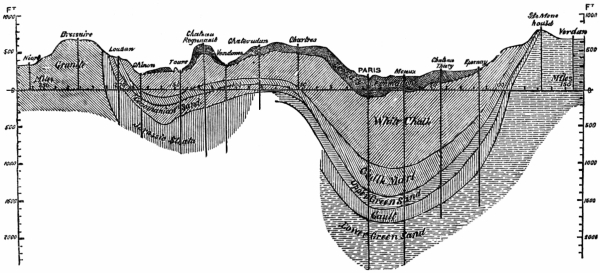
Fig. 254.
Geological Section from Niort to Verdun, through the Paris Basin.
Horizontal scale, 90 miles the inch.
Vertical scale, 1500 feet the inch.
Larger image (201 kB)
For boring these wells special tools had to be used, which have already been described at length in Chap. VI.
A large Artesian well was, in 1867, being constructed by Dru at Butte-aux-Cailles, Fig. 255, for the supply of the city of Paris, which is intended to be carried down through the greensand to a depth of 2600 or 2900 feet to reach the Portland limestone. The boring in 1867 was 490 feet deep, and its diameter 47 inches.
During the previous 21⁄2 years, M. Dru was engaged in sinking a similar well of 19 inches diameter for supplying the Sugar Refinery of M. Say, in Paris, Fig. 255; 1570 feet deep of this well had been bored in 1867, see Fig. 258.
The well at Grenelle was sunk by Mulot in 1832, and after more than eight years’ incessant labour, water rose on the 26th of February, 1842, from the total depth of 1806 feet 9 inches. The diameter of the bore-hole is 8 inches, ending, as is seen in the detail sections, Figs. 259 to 262, in the lower greensand.
[180]The well of Passy was intended to be executed in the Paris basin which it was to traverse with a diameter, hitherto unattempted, of 1 mètre (3·2809 feet); that of the Grenelle well being only 20 centimètres (8 inches). It was calculated that it would reach the water-bearing stratum at nearly the same depth as the latter, and would yield 8000 mètres or 10,000 cubic mètres in twenty-four hours, or about 1,786,240 gallons to 2,232,800 gallons a day.
Figs. 263 to 266 show a detail section of the strata passed.
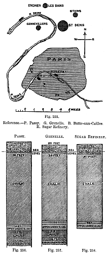
Figs. 255-258.
Reference.—P. Passy. G. Grenelle. B. Butte-aux-Cailles.
R. Sugar Refinery.
Larger image (208 kB)
The operations were undertaken by Kind under a contract with the Municipality of Paris, by which he bound himself to complete the works within the space of twelve months from the date of their commencement, and to deliver the above quantity of water for the sum of 300,000 francs, 12,000l. On the 31st of May, 1857—after the workmen had been engaged nearly the time stipulated for[181] the completion of the work, and when the boring had been advanced to the depth of 1732 feet from the surface—the excavation suddenly collapsed in the upper strata, at about 100 feet from the ground, and filled up the bore. Kind would have been ruined had the engineers of the town held him to the strict letter of his contract; but it was decided to behave in a liberal manner, and to release him from it, the town retaining his services for the completion of the well, as also the right to use his patent machinery. The difficulties encountered in carrying the excavation through the clays of the upper strata were found to be so serious that, under the new arrangement, it required six years and nine months of continuous efforts to reach the water-bearing [182]stratum, of which time the far larger portion was employed in traversing the clay beds. The upper part of this well was finally lined with solid masonry, to the depth of 150 feet from the surface; and beyond that depth tubing of wood and iron was introduced. This tubing was continued to the depth of 1804 feet from the surface, and had at the bottom a length of copper pipe pierced with holes to allow the water to enter. At this depth the compound tubing could not be made to descend any lower; but the engineers employed by the city of Paris were[183] convinced that they could obtain the water by means of a preliminary boring; and therefore they proceeded to sink in the interior of the above tube of 3.2809 feet diameter, an inner tube 2 feet 4 inches diameter, formed of wrought-iron plates 2 inches thick, so as to enable them to traverse the clays encountered at this zone. At last, the water-bearing strata were met with on the 24th of September, 1861, at the depth of 1913 feet 10 inches from the ground-line; the yield of the well [184] being, at the first stroke of the tool that pierced the crust, 15,000 cubic mètres in 24 hours, or 3,349,200 gallons a day; it quickly rose to 25,000 cubic mètres, or 5,582,000 gallons a day; and as long as the column of water rose without any sensible diminution, it continued to deliver a uniform quantity of 17,000 mètres, or 3,795,000 gallons a day. The total cost[185] of this well was more than 40,000l., instead of 12,000l., at which Kind had originally estimated it.
It may be questioned whether the engineers of the town were justified in passing the contract with Kind to finish the work within the time, and for the sum at which he undertook it; but they certainly treated him with kindness and consideration,[186] in allowing him to conduct the work at the expense of the city of Paris, for so long a period after the expiration of his contract. It seems, however, that the French well-borers could not at the time have attempted to continue the well upon any other system than that introduced by Kind; that is to say, upon the supposition that it should be completed of the dimensions originally undertaken. Experience has shown that both steining and tubing were badly executed at the well of Passy. The masonry lining was introduced after Kind’s contract had expired, and when he had ceased to have the control of the works; the wrought-iron tubing at the lower part of the excavation being a subsequent idea. It has followed from this defective system of tubing—the wood necessarily yielding in the vertical joints—that the water in its upward passage escaped through the joints, and went to supply the basement beds of the Paris basin, which are as much resorted to as the London sand-beds for an Artesian supply; and, in fact, the level of the water has been raised in the neighbouring wells by the quantity let in from below, and the yield of the well itself has been proportionally diminished, until it has fallen to 450,000 gallons a day. That the increased yield of the neighbouring wells is to be accounted for by the escape of the water from the Artesian boring is additionally proved by the temperature of the water in them; it is found to be nearly 82° Fah., or nearly that observed in the water of Passy. This was an unfortunate complication of the bargain made between Kind and the Municipal Council; but it in no respect affects the choice of the boring machinery, which seems to have complied with all the conditions it was designed to meet. The descent of the tubes and their nature ought to have been the subject of special study by the engineers of the town, who should have known the nature of the strata to be traversed better than Kind could be supposed to do, and should have insisted upon the tubing being executed of cast or wrought-iron, so as effectually to resist the passage of the water. At any rate, this precaution ought to have been taken in the portions of the well carried through the basement beds of the Paris basin, or through the lower members of the chalk and the upper greensand.
[187]Ponders End, Middlesex.—At the works of the London Jute Company. It will be seen from the Figs. 267, 268, that this well is bored all but the top 4 feet, which is 5 feet across and steined with 9-inch work. The uppermost tube is 12 inches in diameter, decreased to 9 inches, and then to 8 inches, and ending with a 6-inch bore, unlined, in the chalk.
The strata passed were;—
| Alluvium, 6 feet;— | Feet. | In. |
| Clay and Mud | 3 | 6 |
| Peat | 2 | 6 |
| Sand and Shingle (Gravel). | 7 | 0 |
| London Clay, 15 feet;— | ||
| Blue Clay | 8 | 0 |
| Sandy Clay (basement bed?) | 7 | 0 |
| Reading Beds, 491⁄2 feet;— | ||
| Dead Sand | 10 | 0 |
| Mottled Clays | 22 | 0 |
| Sand and Metal (pyrites?) | 1 | 0 |
| Sandy Clay | 3 | 0 |
| Sand and Pebbles | 4 | 0 |
| Dead Sand | 1 | 6 |
| Dead Sand and Pebbles | 1 | 0 |
| Sand and Pebbles | 7 | 0 |
| Thanet Sand (?), 35 feet;— | ||
| Green Sand | 27 | 0 |
| Dead Sand | 8 | 0 |
| To Chalk | 112 | 6 |
| In Chalk | 290 | 6 |
| Total | 403 | 0 |
The water at this well overflows.
Freshwater, Isle of Wight.—Well, Figs. 269, 270, sunk at Golden Hill for H.M. Government. The diameter of the shaft[188] is 4 feet 6 inches, brickwork 9 inches thick, there are 3 feet in cement at the top of the well, and 3 feet 9 inches at the bottom. There are four courses in cement every 5 feet, internal work four courses in cement every 10 feet. The bore-hole is lined throughout with pipes of 6 inches, 5 inches, and 4 inches diameter respectively.
[189]Winchfield, Hants.—Well, Figs. 271 to 273, at the brewery of Messrs. W. Cave and Son. The shaft above the steining is lined with iron cylinders into which the bore-pipe is carried up.
The strata passed were;—
| Feet. | |
| Made Earth, Soil, Gravel, Blue Clay and Dead Sand |
350 |
| Dark Sandy Clay | 3 |
| Black Pebbles | 2 |
| Coloured Clay | 5 |
| Stone (septaria?) | 2 |
| Coloured Clay | 22 |
| Coarse Shifting Sands | 7 |
| Total | 391 |
The following Table, compiled from the Government Memoirs and other reliable sources, furnishes in a condensed form the most important particulars relating to wells, and trial bore-holes comprised within the geographical area known as the London Basin.
The first column gives the name of the place where the well is situated, the second column that of the county, and the third column the precise locality. The following abbreviations have been employed: B. for Bedfordshire; Berks, Berkshire; Bucks, Buckinghamshire; E., Essex; H., Hampshire; Herts, Hertfordshire; K., Kent; M., Middlesex; S., Surrey.
O.D. stands for, above Ordnance Datum; T., above Trinity high-water mark.
| PARTICULARS OF WELLS. | ||||||||
| Name of Place. | County. | Locality. | Depth. | |||||
| of Shaft. |
of Bore. |
in Tertiary Strata. |
in Chalk. |
to Water from Surface. |
||||
| feet. | feet. | feet. | feet. | feet | ||||
| Remarks. | ||||||||
| Abridge | E. | Brewery | 100 | 190 | 290 | — | 30 | |
| London Clay, 280 feet. | ||||||||
| Acton | M. | Mr Engleheart’s | — | — | 284 | 119 | 12 | |
| Ditto | „ | Mr. Wood’s | — | — | 315 | 135 | 40 | |
| Ditto, East | „ | Mr. Davis’s | — | — | 267 | 68 | ||
| Albany Street | „ | London | — | — | 182 | 125 | — | |
| 100 feet O.D. | ||||||||
| Aldershot Place | H. | — — | — | — | 194 | — | — | |
| 260 feet O.D. | ||||||||
| Ditto | „ | — — | — | — | 148 | 691⁄2 | — | |
| 245 feet O.D. | ||||||||
| Amwell End | Herts. | New River Company | 72 | 3473⁄4 | 36 | 3833⁄4 | — | |
| Yield about 2,500,000 gallons a day. | ||||||||
| Arlesey | B. | Asylum | 100 | 365 | 7 | 120 | — | |
| 233 feet O.D.; water rises into shaft; yield 2640 gallons an hour. | ||||||||
| Ash | S. | S.W. Railway Station | — | 600 | 370 | 230 | — | |
| 290 feet O.D. | ||||||||
| Bank of England | M. | London | 137 | 1971⁄2 | 2341⁄2 | 100 | 88 | |
| About 27 feet T.; yield, 35 gallons a minute. | ||||||||
| Bagshot | S. | Orphan Asylum | 123 | 523 | 646 | — | — | |
| Last 192 feet London Clay. | ||||||||
| Balham Hill | „ | Near Clapham Common | — | — | 347 | — | — | |
| Last 40 feet Thanet sands. | ||||||||
| Barking | E. | Byfron’s | 140 | — | 140 | — | 30 | |
| Bottom in hard pebbles. | ||||||||
| Barnet, East | Herts. | Lion’s Down | 122 | 270 | 162 | 230 | 130 | |
| Shaft half steined, half iron cylinders. | ||||||||
| Ditto, New | „ | Near Railway Station | 137 | 302 | 159 | 280 | 130 | |
| Battersea | S. | Jones’s Works | 249 | — | 249 | |||
| Ditto | „ | Beaufoy’s Works | 240 | — | 240 | — | — | |
| Yield said to equal 15,000 gallons a day. [191] | ||||||||
| Bearwood | Berks. | Mr. Walters’s | — | — | 350 | 15 | ||
| Beaumont Green | Herts. | Near Cheshunt | 1831⁄2 | — | 1261⁄2 | 57 | ||
| Belleisle | M. | Pashes and Co.’s | — | — | 185 | 118 | 118 | |
| Berkeley Square | „ | London | 160 | 156 | 224 | 92 | 80 | |
| Bermondsey | S. | Crimscott Street | — | — | 120 | — | — | |
| 9 feet O.D.; yield plentiful. | ||||||||
| Ditto | „ | Donkin’s Works | — | 232 | 911⁄2 | 1401⁄2 | 16 | |
| Yield 30 gallons a minute. | ||||||||
| Berry Green | Herts. | Hadham | 40 | 20 | 60 | — | 8 | |
| Bexley | K. | Brickfield | 65 | 110 | 1291⁄4 | 453⁄4 | 60 | |
| Bishop Stortford | Herts. | Waterworks | 160 | 140 | 1161⁄2 | 1831⁄2 | 140 | |
| Supply 10,000 gallons a minute. | ||||||||
| Ditto | „ | Hockerill | 85 | 125 | 90 | 120 | 78 | |
| Good supply. | ||||||||
| Ditto | „ | New Road | 77 | — | 56 | 21 | ||
| Blackfriars | M. | Apothecaries’ Hall | — | — | 218 | 76 | ||
| Blackheath | K. | Near Enfield Terrace | — | — | 109 | 30 | ||
| Boston Heath | „ | Near Woolwich | — | — | 130 | 70 | ||
| Bow | M. | Starch Works | 176 | 148 | 174 | 150 | ||
| Boxley Wood | K. | Near Maidstone | 3861⁄2 | 2131⁄2 | 3 | 600 | — | |
| 382 feet T.; last 781⁄2 feet in chalk, marl, and gault. | ||||||||
| Braintree | E. | Near Pod’s Brook | 55 | 190 | 228 | 7 | 216 | |
| Yield, 11,500 gallons an hour. | ||||||||
| Brentford | M. | Brewery | 30 | 338 | 315 | 53 | 5 | |
| Bromley | K. | Gas Works | 50 | 120 | 150 | 20 | — | |
| Supply abundant. | ||||||||
| Ditto | „ | Widmore Kiln | 52 | 98 | 140 | 10 | ||
| Ditto | „ | Ditto | 55 | 85 | 120 | 10 | 61 | |
| Ditto | „ | Tylney Road | 77 | 85 | 137 | 25 | ||
| Ditto | „ | Waterworks | — | — | 70 | 180 | — | |
| Yield, 500 to 600 gallons a minute. | ||||||||
| Broxbourne | Herts. | — — | 84 | — | 84 | 6 | ||
| Water overflowed. | ||||||||
| Bushey | „ | Near Watford | 142 | 24 | 145 | 21 | ||
| Camberwell | S. | The Grove | — | — | 208 | 3001⁄2 | 90 | |
| Camden Station | M. | L. and N.W. Railway | 180 | 220 | 234 | 166 | 150 | |
| 100 foot O.D. [192] | ||||||||
| Camden Town | M. | Pickford’s | — | — | 215 | 82 | 120 | |
| Good supply. | ||||||||
| Ditto | „ | Whitaker’s Brewery | 235 | 75 | 210 | 90 | 190 | |
| Canterbury | K. | Orphan Asylum | — | — | 145 | — | 120 | |
| Caterham | S. | Waterworks | — | — | 89 | 349 | — | |
| 709 feet T.; through chalk, and 39 feet into upper greensand. | ||||||||
| Chelmsford | E. | Moulsham | 200 | 368 | 366 | 202 | 76 | |
| Water overflowed at first. | ||||||||
| Cheshunt | Herts. | New River Company | 144 | 27 | 1071⁄2 | 631⁄2 | 120 | |
| Yield, 702,000 gallons a day. | ||||||||
| Ditto | „ | Theobald’s Park | 71 | 1311⁄2 | 1211⁄2 | 81 | 65 | |
| Chiswell Street | M. | Whitbread’s Brewery | 183 | 150 | 183 | 150 | 132 | |
| Chiswick | „ | Griffin Brewery | 204 | 200 | 297 | 107 | — | |
| Yield, 14 gallons a minute. | ||||||||
| Ditto | „ | Lamb Brewery | 203 | 194 | 293 | 104 | ||
| Ditto | „ | Ditto | 8 | 339 | 297 | 50 | ||
| Clewer Green | Berks. | Capt. Winterbottom’s | 42 | 294 | 270 | 66 | ||
| Ditto | „ | Wycombe Cottage | 20 | 246 | 169 | 97 | ||
| Colnbrook | M. | Paper Mills | — | — | 207 | 175 | — | |
| Water found at 203 feet down. | ||||||||
| Colney Hatch | „ | Asylum | 137 | 193 | 189 | 141 | ||
| Covent Garden | „ | Market | 140 | 218 | 260 | 98 | 120 | |
| 70 feet O.D. | ||||||||
| Cricklewood | „ | Near Hampstead | 225 | 85 | 291 | 19 | 110 | |
| 157 feet T. | ||||||||
| Croydon | S. | Well for Local Board | 77 | — | 11 | 62 | — | |
| Yield 1,500,000 gallons a day. | ||||||||
| Ditto | „ | New Well | — | — | 15 | 137 | 111⁄2 [193] | |
| Dartford Creek | K. | Paper Mills | 34 | 49 | 33 | 50 | — | |
| Supply good. | ||||||||
| Ditto | „ | Ditto | 10 | 2401⁄2 | 30 | 2201⁄2 | 2 | |
| Denham | Bucks. | Tile House | 110 | 85 | 67 | 128 | 85 | |
| Deptford | K. | Waterworks | 27 | — | 14 | 13 | — | |
| 20 feet O.D. | ||||||||
| Dulwich | S. | Champion Hill | — | — | 210 | 298 | ||
| East Ham Level | E. | Beckton Gas Works | 25 | 175 | 117 | 83 | 2 | |
| Edgware | M. | Mr. Day’s | — | — | 290 | 45 | 40 | |
| Edgware Road | „ | The Hyde | — | — | 101 | 37 | ||
| Edlesborough | Bucks. | Well, near Mill | — | 301 | — | — | 70 | |
| 6-inch bore; through 50 feet of chalk marl to lower greensand. | ||||||||
| Eltham | K. | Dr. King’s | 46 | — | 46 | — | 17 | |
| Ditto | „ | The Moat | 110 | — | 100 | 10 | ||
| Ditto | „ | Mr. Tuck’s | 44 | 123 | 1221⁄2 | 441⁄2 | 25 | |
| Ditto | „ | Well Hall | — | 107 | 104 | 3 | ||
| Ditto Park | „ | — — | — | — | 122 | 94 | 170 | |
| Enfield Lock | E. | Small Arms Factory | 45 | 2391⁄2 | 1521⁄2 | 132 | 4 | |
| Epping | „ | Waterworks | 275 | 129 | 400 | 4 | 260 | |
| Slow spring. | ||||||||
| Erith | K. | Mineral Oil Company | 166 | — | 146 | 20 | ||
| Farnham | S. | Near Hale Farm | 176 | — | 80 | 96 | ||
| Fleet Street | M. | London, Shoe Lane | 100 | 225 | 100 | 225 | ||
| Fulmer | Bucks. | J. Kay’s | 85 | — | 473⁄4 | 371⁄4 | — | |
| Through gravel and Reading beds. | ||||||||
| Golden Lane | M. | Baths and Washhouses | 158 | — | 1511⁄2 | 61⁄2 | — | |
| 65 feet O.D. | ||||||||
| Gravesend | K. | Church Street | 10 | 234 | 120 | 124 | 8 | |
| Supply good and abundant. | ||||||||
| Greenwich | „ | Brewery | 22 | 158 | 80 | 100 | 11 | |
| Ditto | „ | East Street | 189 | — | 159 | 30 | ||
| Ditto | „ | Hospital Brewery | 155 | 150 | 1241⁄2 | 1801⁄2 | 19 | |
| 7 feet T.; supply 120 gallons a minute. | ||||||||
| Hackney Road | M. | Wiltshire Brewery | 96 | 3153⁄4 | 1523⁄4 | 259 | 80 | |
| Haggerstone | „ | Imperial Gas Works | 1181⁄2 | 302 | 1641⁄2 | 256 | [194] | |
| Hainault Forest | E. | — — | 165 | — | 110 | 55 | ||
| Halstead | „ | The White Hart | — | — | 170 | 30 | ||
| Hammersmith | M. | Average of four wells | — | — | 245 | 68 | — | |
| Yield, 16 gallons a minute. | ||||||||
| Hampstead | „ | Lower Heath | 320 | 130 | 378 | 72 | — | |
| Now not used. | ||||||||
| Hampstead Road | „ | Eagle Brewery | 138 | 94 | 146 | 86 | 147 | |
| Ditto | „ | Reservoir | 244 | — | 152 | 92 | 106 | |
| 77 feet T. | ||||||||
| Hanwell | „ | Asylum | 230 | 90 | 290 | 30 | — | |
| Water to surface. | ||||||||
| Harrow | „ | Waterworks | 1931⁄2 | 219 | 1581⁄2 | 254 | 125 | |
| 226 feet O.D. | ||||||||
| Haverstock Hill | „ | Orphan School | 230 | 160 | 312 | 78 | 196 | |
| 176 feet O.D. | ||||||||
| Hayes | „ | Dawley Court | 19 | 300 | 231 | 88 | 27 | |
| Hendon | „ | Mr. Booth’s | — | — | 244 | 132 | 76 | |
| Highbury | „ | Brewery | 104 | 210 | 180 | 134 | 95 | |
| Yield, 1000 gallons an hour. | ||||||||
| Ditto | „ | New Park | 136 | 113 | 199 | 50 | ||
| Hoddesdon | Herts. | New River Company | 52 | 234 | 241⁄2 | 2611⁄2 | 2 | |
| Holloway | M. | — — | 140 | 200 | 240 | 100 | ||
| Ditto | „ | City Prison | — | — | 217 | 102 | ||
| Ditto | „ | Hanley Road | — | — | 67 | 13 | ||
| Ditto | „ | Redcap Lane | — | — | 210 | 90 | ||
| Ditto | „ | Islington Workhouse | 234 | 306 | 299 | 250 | ||
| Hornsey | „ | Near Church | — | — | 202 | 48 | ||
| Ditto | „ | The Priory | — | — | 225 | — | — | |
| Horselydown | S. | Anchor Brewery | 100 | 162 | 158 | 104 | 50 | |
| Hoxton | M. | — — | 152 | 10 | 151 | 11 | [195] | |
| Hyde Park Corner | „ | St. George’s Hospital | 200 | 1371⁄4 | 3191⁄4 | 18 | 100 | |
| 50 foot O.D.; yield, 3300 gallons an hour. | ||||||||
| Ickenham | „ | Public Well | 64 | 80 | 64 | 80 | ||
| Isle of Dogs | „ | Oil Mills | 27 | 337 | 1241⁄2 | 2391⁄2 | 10 | |
| Isle of Grain | K. | Fort | 180 | 140 | 320 | — | 20 | |
| 21 feet O.D. | ||||||||
| Isleworth | M. | Sion House | — | — | 420 | 115 | — | |
| Water overflowed at the rate of 5 gallons a minute. | ||||||||
| Ditto | „ | Mr. Wilmot’s | — | 327 | 327 | — | — | |
| Water rose above surface. | ||||||||
| Islington Green | „ | Webb’s Mineral Water Works | — | 320 | 176 | 144 | 200 | |
| Kensington | „ | Brewery | — | — | 197 | — | — | |
| 16 feet T. | ||||||||
| Ditto | „ | Britannia Brewery | 100 | 170 | 270 | — | 88 | |
| Ditto | „ | Horticultural Society | 200 | 201 | 317 | 84 | 100 | |
| 60 feet O.D. | ||||||||
| Ditto | „ | Workhouse | — | — | 270 | 100 | ||
| Ditto Gardens | „ | Serpentine | 263 | 58 | 2631⁄4 | 573⁄4 | 105 | |
| 60 feet O.D.; yield, 250 gallons a minute. | ||||||||
| Kentish Town | „ | Waterworks | 539 | 763 | 3241⁄2 | 6443⁄4 | — | |
| Through London clay, 236 feet; London tertiaries, 881⁄2 feet; chalk, 6443⁄4 feet; upper greensand, 133⁄4 feet; gault, 1301⁄2 feet; and into lower greensand (?), 1881⁄2 feet. | ||||||||
| Kilburn | „ | Brewery | 250 | 30 | 235 | 45 | 150 | |
| Kingsbury | „ | Brent Reservoir | 101 | 139 | 132 | 108 | ||
| Kingston-on-Thames | S. | Brook Street | 90 | 380 | 371 | 99 | — | |
| 25 feet O.D.; yield, about 44,000 gallons a day. | ||||||||
| Knightsbridge | M. | — — | 240 | — | 240 | — | 50 | |
| Lambeth | S. | Beaufoy’s Vinegar Works | 100 | 275 | 201 | 174 | — | |
| Yield, 92 gallons a minute. | ||||||||
| Ditto | „ | South Lambeth Road | 25 | 166 | 187 | 4 | [196] | |
| Ditto | „ | Bethlehem Hospital | 30 | 161 | 191 | 20 | 15 | |
| Ditto | „ | Lion Brewery, Belvedere Road | — | — | 245 | 173 | 40 | |
| Ditto | „ | Duke Street, Street, Clowes & Sons’ | 26 | 184 | 210 | |||
| Lea Bridge | M. | Waterworks | 118 | — | 100 | 18 | ||
| Leicester Square | „ | Alhambra | 150 | 195 | 244 | 101 | ||
| Limehouse | „ | Johnson’s, Commercial Road | 90 | 110 | 190 | 10 | ||
| Ditto | „ | Brewery, Fore Street | — | — | 1391⁄2 | |||
| Liquorpond Street | „ | Reid’s Brewery | 2221⁄2 | 40 | 136 | 1261⁄2 | 121 | |
| 70 feet O.D.; yield, 277,200 gallons in 24 hours. | ||||||||
| Long Acre | „ | Combe & Co.’s Brewery | 263 | 228 | 223 | 268 | — | |
| 70 feet O.D.; yield, 90 gallons a minute | ||||||||
| Loughton | E. | — — | — | 535 | 324 | 211 | 90 | |
| No water from chalk. | ||||||||
| Lower Morden | S. | On the Green | 20 | 365 | 340 | 45 | — | |
| Water to surface. | ||||||||
| Luton | B. | Waterworks | 50 | 272 | — | 322 | ||
| Maldon | E. | Waterworks | 234 | — | 234 | — | — | |
| Entirely through London clay. | ||||||||
| Margate | K. | Cobb’s Brewery | 31 | 243 | — | 374 | ||
| Marylebone Road | M. | London; a Brewery | 186 | 101 | 232 | 55 | 156 | |
| Mile End | „ | Mann’s Brewery | 195 | — | 185 | 10 | ||
| Ditto | „ | Charrington’s Brewery | 204 | — | 202 | 2 | 103 | |
| 331⁄2 feet T.; yield, 60,000 to 70,000 gallons a day. [197] | ||||||||
| Ditto Road | „ | City of London Union | — | — | 175 | 10 | ||
| Millbank | „ | Distillery | 115 | 190 | 205 | 100 | 70 | |
| Level of T. | ||||||||
| Ditto | „ | Westminster Brewery | — | — | 225 | 70 | — | |
| 51⁄2 feet T. | ||||||||
| Mitcham | S. | Nightingale’s Factory | — | 211 | 189 | 22 | ||
| Monkham Park | E. | Near Waltham Abbey | 225 | 125 | 304 | 76 | 50 | |
| Mortlake | S. | Mortlake Brewery | 30 | 288 | 287 | 31 | 50 | |
| Yield, 14,000 gallons a day. | ||||||||
| Ditto | „ | Mr. Randell’s | — | 365 | 315 | 50 | ||
| New Cross | K. | Naval School | 50 | 130 | 125 | 55 | 60 | |
| Northolt | M. | Near Harrow | 12 | 228 | 180 | 60 | 4 | |
| Notting Dale | „ | Near Notting Hill | — | — | 244 | 12 | ||
| Notting Hill | „ | Mr. Knight’s | — | — | 230 | 200 | ||
| Old Kent Road | S. | Welsh Ale Brewery | — | — | 30 | 170 | — | |
| 10 feet O.D. | ||||||||
| Old Windsor | Berks. | Pelham Place | — | — | 222 | 9 | ||
| Ditto | „ | The Union | 60 | 180 | 240 | 47 | ||
| Orange Street | M. | Back of National Gallery | 174 | 126 | 250 | 50 | 115 | |
| 42 feet T. | ||||||||
| Oxford Street | „ | Star Brewery | 166 | 170 | 158 | 178 | ||
| Peckham | S. | Marlborough House | — | — | 100 | 123 | ||
| Penge | „ | Palace Grounds | 250 | 310 | 358 | 202 | 90 | |
| Pentonville | M. | Brewery, Caledonian Road | 2191⁄2 | — | 2191⁄2 | 45 | 180 | |
| To chalk. | ||||||||
| Ditto | „ | Prison | 170 | 2001⁄2 | 2191⁄2 | 151 | ||
| Pimlico | „ | Cubitt’s Works | 188 | — | 188 | — | — | |
| 2 feet T. | ||||||||
| Ditto | „ | Brewer Street | 30 | 368 | 271 | 127 | ||
| Ditto | „ | Simpson’s Factory | — | — | 231 | 100 | 36 | |
| 1 foot T. | ||||||||
| Pinner | „ | Hatch End | 140 | — | 60 | 80 | ||
| Plaistow | E. | Odam’s Manure Works | — | — | 1701⁄2 | 128 | ||
| Ponders End | M. | London Jute Company | 4 | 399 | 1121⁄2 | 2901⁄2 | — | |
| Water overflows. | ||||||||
| Ditto | „ | Crape Works | 20 | 42 | 62 | |||
| Ditto | „ | Local Board (Speller) | — | — | 106 | 961⁄2 | ||
| Ditto | „ | Waterworks | 23 | 181 | 97 | 107 | — | |
| 43 feet T. [198] | ||||||||
| Pudsey Hall | E. | Near Canewdon | 297 | — | 297 | — | — | |
| Water abundant and good. | ||||||||
| Ratcliffe | M. | Queen’s Head Brewery | — | — | 160 | 200 | ||
| Ditto | „ | Marine Brewery | 16 | 236 | 150 | 102 | ||
| Ditto | „ | Ravenhill’s | — | 137 | ||||
| Regent’s Park | „ | Colosseum | 150 | 100 | 171 | 79 | ||
| Ditto | „ | Mr. Day’s | — | — | 184 | 216 | 80 | |
| Ditto | „ | Zoological Gardens | 183 | 91 | 224 | 50 | 120 | |
| Yield, 90,000 gallons a day. | ||||||||
| Richmond | S. | Old Waterworks | — | — | 276 | 103 | ||
| Ditto | „ | Star and Garter | — | — | 416 | 76 | ||
| Romford | E. | Ind, Coope, & Co. | 155 | — | 145 | 10 | ||
| Rotherhithe | S. | Brandram’s Works | 30 | 222 | 107 | 145 | 27 | |
| Yield, 100,000 gallons in 12 hours. | ||||||||
| Ditto | „ | Tunnel Flour Mills | — | — | 125 | 135 | — | |
| 15 feet O.D.; yield, 80 gallons a minute. | ||||||||
| Ruislip | M. | Near “The George” | 15 | 903⁄4 | 753⁄4 | 30 | — | |
| Water to surface. | ||||||||
| Saffron Walden | E. | — — | — | — | — | 1000 | ||
| Sandhurst | Berks. | Well at College | — | 603 | — | — | — | |
| Trial boring; chalk reached. | ||||||||
| Sandwich | K. | The Bank | 70 | — | 62 | 8 | 20 | |
| Sheerness | „ | Waterworks | 300 | 84 | 384 | — | — | |
| 51⁄2 feet O.D.; yield, 10,000 gallons an hour. | ||||||||
| Ditto | „ | Dockyard | 330 | 125 | 455 | — | 53 | |
| Yield, 675 gallons an hour. | ||||||||
| Shoreditch | M. | Truman’s Brewery | 300 | 230 | 199 | 331 | 120 | |
| Yield, 71⁄2 gallons a minute. | ||||||||
| Shorne Meade Fort | K. | Near Gravesend | 112 | — | 771⁄2 | 341⁄2 | [199] | |
| Shortlands | „ | Near Bromley | 59 | 150 | 109 | 100 | 61 | |
| Yield, 1000 gallons an hour. | ||||||||
| Slough | Bucks. | Eton Union | 28 | 103 | 107 | 24 | ||
| Ditto | „ | Royal Nursery | — | — | 94 | 171⁄2 | ||
| Ditto | „ | Upton Park | — | — | 1021⁄4 | 1701⁄4 | ||
| Ditto | „ | Waterworks | 117 | — | 90 | 27 | 7 | |
| Heading into chalk. | ||||||||
| Smithfield | M. | Booth’s Distillery | — | — | 230 | 70 | 70 | |
| Southend | E. | Waterworks | 417 | — | 417 | — | 100 | |
| Old well. | ||||||||
| Southwark | S. | Barclay’s Brewery | 115 | 288 | 212 | 211 | — | |
| Level of T.; yield, 300 gallons a minute. | ||||||||
| Ditto | „ | Guy’s Hospital | 132 | 173 | 196 | 109 | 84 | |
| 2 feet T.; yield, 33 gallons a minute. | ||||||||
| Staines | M. | Ashby’s Brewery | — | — | 369 | 154 | — | |
| Water to surface. | ||||||||
| Stifford | E. | S.E. of Church | 63 | — | 33 | 30 | ||
| Stockwell Green | S. | Waltham’s Brewery | 100 | 210 | 210 | 100 | 46 | |
| Yield, 33 gallons a minute. | ||||||||
| Ditto | „ | Hammerton’s Brewery | 25 | 186 | 211 | 154 | — | |
| Yield, 46 gallons a minute. | ||||||||
| Stratford | E. | Great Eastern Works | 56 | 344 | 106 | 294 | ||
| Ditto | „ | Savill Bros.’ Brewery | 1121⁄2 | — | 1091⁄2 | 3 | ||
| Ditto | „ | Langthorn Chemical Works | 60 | 395 | 132 | 323 | — | |
| Supply abundant. | ||||||||
| Streatham | S. | The Common | 100 | 185 | 285 | |||
| Sudbury | M. | London and North-Western Rail. Station | 200 | — | 120 | 80 | ||
| Tottenham | „ | Warne’s Works | — | — | 147 | 104 | ||
| Ditto | „ | Long Water | — | — | 1491⁄2 | 1011⁄2 | ||
| Ditto | „ | Tottenham Hall | — | 253 | 153 | 100 | ||
| Tottenham Court Road | „ | Meux’s Brewery | 188 | 622 | 156 | 654 | — | |
| 85 feet O.D.; yield, 121⁄2 gallons a minute. | ||||||||
| Tower Hill | „ | Royal Mint | 1951⁄2 | 202 | 1951⁄2 | 202 | 80 | |
| Trafalgar Square | „ | London | 168 | 228 | 248 | 148 | — | |
| Yield, 450 gallons a minute. | ||||||||
| Upchurch | K. | Burntwick Island | — | 236 | 236 | [200] | ||
| Ditto | „ | Milford Hope Marshes | — | 304 | 210 | 94 | — | |
| Good supply at bottom. | ||||||||
| Upper Thames Street | M. | City of London Brewery | 90 | 415 | 210 | 295 | 10 | |
| Uxbridge | „ | The Dolphin | 121 | — | 811⁄2 | 391⁄2 | 3 | |
| Ditto | „ | Near Market Place | — | — | 104 | 28 | 151⁄2 | |
| Ditto | „ | Page’s Lane | 98 | — | 98 | |||
| Ditto | „ | Town Well | — | — | 109 | 30 | 19 | |
| Ditto | „ | Near “King’s Arms” | 24 | 84 | 108 | — | 19 | |
| To chalk. | ||||||||
| Ditto | „ | New Year’s Green Farm | 63 | — | 63 | — | 51 | |
| Ditto | „ | Hurdle Yard | 78 | 391⁄2 | 78 | 391⁄2 | ||
| Ditto | „ | Near Meeting House | 411⁄2 | 1091⁄2 | 115 | 36 | 39 | |
| Ditto | „ | The Union | 51 | 162 | 175 | 38 | 29 | |
| Vauxhall | S. | Burnett’s Distillery | 140 | 186 | 224 | 102 | 55 | |
| Yield, 80 gallons a minute. | ||||||||
| Waltham Abbey | E. | Brewery | 164 | — | 160 | 4 | — | |
| Water supply from bed of sand. | ||||||||
| Walthamstow Marsh | „ | East London Waterworks | — | — | 152 | 140 | — | |
| 15 feet T. | ||||||||
| Wandworth | S. | Young & Bainbridge’s | 170 | 164 | 274 | 60 | 45 | |
| Yield, 10 gallons a minute. | ||||||||
| Ditto | „ | Prison | — | — | 357 | 1261⁄2 | 80 | |
| Yield, 27 gallons a minute. | ||||||||
| Ditto | „ | County Asylum | — | — | 331 | 6 | 30 | |
| Westbourne Grove | M. | Hippodrome | 240 | 67 | 300 | 7 | ||
| West Drayton | „ | Victoria Oil Mills | 12 | 274 | 186 | 100 | — | |
| Water overflowed. | ||||||||
| Ditto | „ | Vitriol Works | — | — | 1331⁄2 | 451⁄2 | ||
| Ditto | „ | Drayton Mills | 3 | 146 | 149 | — | — | |
| To chalk. [201] | ||||||||
| West Ham | E. | Mr. Tucker’s | — | — | 132 | 306 | ||
| Ditto | „ | Union | — | — | 110 | 55 | ||
| West India Dock | M. | South of Export Dock | — | — | 120 | 240 | ||
| Westminster | „ | Artillery Brewery | — | — | 230 | |||
| Ditto | „ | Chartered Gas Works | — | — | 225 | |||
| Ditto | „ | Vickers’ Distillery | 116 | 184 | 249 | 51 | 70 | |
| Yield, 94 gallons a minute. | ||||||||
| Ditto | „ | Swallow Street | — | — | 210 | — | 60 | |
| Whitechapel | „ | Furze’s Brewery | 130 | 218 | 248 | 100 | ||
| Ditto | „ | Smith’s Distillery | 106 | 264 | 210 | 160 | 36 | |
| 36 feet T. | ||||||||
| Ditto | „ | Smith, Druce, & Co.’s | 1411⁄2 | — | 1411⁄2 | — | 85 | |
| 39 feet T. | ||||||||
| Willesden | „ | Mr. Kilsby’s | — | — | 273 | 97 | 30 | |
| Wimbledon | S. | Convalescent Hospital | 200 | 367 | 537 | 30 | 50 | |
| Ditto, New | „ | Opposite “White Hart” | — | — | 193 | 75 | ||
| Windsor | Berks | Clower Lodge | 40 | 175 | 175 | 40 | ||
| Ditto | „ | Royal Brewery | 72 | — | 72 | — | — | |
| Through clay and running sand to chalk. | ||||||||
| Ditto | „ | Jennings’ Brewery | — | — | 30 | 500 | 12 | |
| Winkfield Plain | „ | Captain Forbes’ | — | — | 304 | 126 | 70 | |
| Witham | E. | — — | — | — | 306 | — | 5 | |
| Woodley Lodge | Berks. | 3 miles east of Reading | 95 | 35 | 130 | |||
| Woolwich | K. | Well of Arsenal | — | — | 541⁄2 | 3111⁄2 | 37 | |
| Ditto | „ | Paper Factory | — | 550 | 51⁄2 | 5441⁄2 | — | |
| Yield, 650 gallons a minute. | ||||||||
| Ditto | „ | Dockyard | — | 608 | 20 | 588 | 70 | |
| Yield good. | ||||||||
| Wormley | Herts. | Nunsbury | 26 | 761⁄2 | 801⁄2 | 22 | — | |
| Water overflows. | ||||||||
| Ditto | „ | West End | 85 | 1501⁄2 | 72 | 631⁄2 | 62 | |
| Wormwood Scrubbs | M. | — — | — | — | 250 | 116 | 5 | |
The following tabulated form shows the order of succession of the various stratified rocks with their usual thicknesses.
| Groups. | Strata. | Thickness in Feet. | |||||||||
| RECENT | 1 | Modern Deposits. | |||||||||
| PLEISTOCENE | 2 | Drift and Gravel Beds | 20 to 100 | ||||||||
| 3 | Mammaliferous Crag | 10 to 40 | |||||||||
| PLIOCENE | 4 | Red Crag | 30 | ||||||||
| CAINOZOIC, OR | 5 | Suffolk (Coralline) Crag | 30 | ||||||||
| TERTIARY. | MIOCENE | 6 | Faluns (Touraine) Molasse Sandstones | 6000 | |||||||
| 7 | Hempstead Series | 170 | |||||||||
| Upper | 8 | Bembridge Series | 110 | ||||||||
| 9 | Headon Series | 200 | |||||||||
| EOCENE | Middle | 10 | Barton Beds | 300 | |||||||
| 11 | Bagshot and Bracklesham Series | 1200 | |||||||||
| Lower | 12 | London Clay and Bognor Beds | 200 to 520 | ||||||||
| 13 | Woolwich Beds & Thanet Sands | 100 | |||||||||
| 14 | Maestricht Beds | 110 | |||||||||
| 15 | Upper Chalk | 300 | |||||||||
| 16 | Lower Chalk and Chalk Marl | 400 | |||||||||
| CRETACEOUS | 17 | Upper Greensand | 130 | ||||||||
| 18 | Gault | 100 | |||||||||
| 19 | Speeton Clay | 130 | |||||||||
| 20 | Lower Greensand | 250 | |||||||||
| WEALDEN | 21 | Weald Clay | 150 | ||||||||
| 22 | Hastings Sands | 600 | |||||||||
| PURBECK | 23 | Purbeck Beds | 150 | ||||||||
| UPPER | 24 | Portland Rock and Sand | 150 | ||||||||
| OOLITE | 25 | Kimmeridge Clay | 400 | ||||||||
| 26 | Upper Calcareous Grit | 40 | |||||||||
| MESOZOIC, OR | MIDDLE | 27 | Coralline Oolite | 30 | |||||||
| SECONDARY. | OOLITE | 28 | Lower Calcareous Grit | 40 | |||||||
| 29 | Oxford Clay | 400 | |||||||||
| 30 | Kellaways Rock | 30 [203] | |||||||||
| 31 | Cornbrash | 10 | |||||||||
| 32 | Forest Marble and Bradford Clay | 50 | |||||||||
| LOWER | 33 | Great Oolite | 120 | ||||||||
| OOLITE | 34 | Stonesfield Slate | 9 | ||||||||
| 35 | Fullers’ Earth | 50 to 150 | |||||||||
| 36 | Inferior Oolite | 80 to 250 | |||||||||
| 37 | Upper Lias Shale | 50 to 300 | |||||||||
| LIAS | 38 | Marlstone and Shale | 30 to 200 | ||||||||
| 39 | Lower Lias and Bone Beds | 100 to 300 | |||||||||
| TRIASSIC, or | 40 | Variegated Marls or Keuper | 800 | ||||||||
| NEW RED | 41 | Muschelkalk | |||||||||
| SANDSTONE | 42 | Red Sandstone or Bunter | 600 | ||||||||
| PERMIAN or | 43 | Red Sand and Marl | 50 | ||||||||
| MAGNESIAN | 44 | Magnesian Limestone | 300 | ||||||||
| LIMESTONE | 45 | Marl Slate | 60 | ||||||||
| 46 | Lower Red Sandstone | 200 | |||||||||
| 47 | Coal Measures | 3000 to 12,000 | |||||||||
| CARBONIFEROUS | 48 | Millstone Grit | 600 | ||||||||
| 49 | Mountain Limestone | 500 to 1400 | |||||||||
| 50 | Limestone Shales | 1000 | |||||||||
| PALÆOZOIC, OR | DEVONIAN or | 51 | Upper Devonian | ||||||||
| PRIMARY. | OLD RED | 52 | Middle Devonian | 3000 to 8000 | |||||||
| SANDSTONE | 53 | Lower Devonian and Tilestones | |||||||||
| 54 | Ludlow Rocks | 2000 | |||||||||
| Upper | 55 | Wenlock Beds | 1800 | ||||||||
| 56 | Woolhope Series | 3050 | |||||||||
| SILURIAN | Middle | 57 | Llandovery Rocks | 2000 | |||||||
| 58 | Caradoc and Bala Rocks | 5000 | |||||||||
| Lower | 59 | Llandeilo Rocks | 4000 | ||||||||
| 60 | Lingula Flags | 8000 | |||||||||
| CAMBRIAN | 61 | Longmynd and Cambrian Rocks | 20,000 | ||||||||
| METAMORPHIC | Clay Slate, Mica-Schist. | ||||||||||
| AZOIC. | Gneiss, Quartz Rocks. | ||||||||||
| IGNEOUS | Granite. | ||||||||||
| The Quantity of Excavation in Wells for each Foot in Depth. (Hurst.) | ||
| Diameter of Excavation. |
Quantity. | |
| ft. | in. | cubic yards. |
| 3 | 0 | ·2618 |
| 3 | 3 | ·3072 |
| 3 | 6 | ·3563 |
| 3 | 9 | ·4091 |
| 4 | 0 | ·4654 |
| 4 | 3 | ·5254 |
| 4 | 6 | ·5890 |
| 4 | 9 | ·6563 |
| 5 | 0 | ·7272 |
| 5 | 3 | ·8018 |
| 5 | 6 | ·8799 |
| 5 | 9 | ·9617 |
| 6 | 0 | 1·0472 |
| 6 | 3 | 1·1363 |
| 6 | 6 | 1·2290 |
| 6 | 9 | 1·3254 |
| 7 | 0 | 1·4254 |
| 7 | 3 | 1·5290 |
| 7 | 6 | 1·6362 |
| 7 | 9 | 1·7472 |
| 8 | 0 | 1·8617 |
| 8 | 6 | 2·1017 |
| 9 | 0 | 2·3562 |
| 9 | 6 | 2·6253 |
| 10 | 0 | 2·9089 |
| 10 | 6 | 3·2070 |
| 11 | 0 | 3·5198 |
| 12 | 0 | 4·1888 |
| The Measure in Gallons, and the Weight in Pounds, of Water contained in Wells, for each Foot in Depth. | |||
| Diameter. | No. of Galls. | Weight. | |
| ft. | in. | ||
| 2 | 0 | 19·61 | 196·1 |
| 2 | 6 | 30·56 | 305·6 |
| 3 | 0 | 43·97 | 439·7 |
| 3 | 6 | 60·00 | 600·0 |
| 4 | 0 | 78·19 | 781·9 |
| 4 | 6 | 98·87 | 988·7 |
| 5 | 0 | 122·23 | 1222·3 |
| 5 | 6 | 147·96 | 1479·6 |
| 6 | 0 | 175·99 | 1759·9 |
| 6 | 6 | 206·59 | 2065·9 |
| 7 | 0 | 239·05 | 2395·0 |
| 7 | 6 | 275·49 | 2754·9 |
| 8 | 0 | 313·43 | 3134·3 |
| 8 | 6 | 353·03 | 3533·0 |
| 9 | 0 | 395·42 | 3954·2 |
| 9 | 6 | 441·71 | 4417·1 |
| 10 | 0 | 489·93 | 4899·3 |
| Brickwork. The Number of Bricks and Quantity of Brickwork in Wells for each Foot in Depth. (Hurst.) | ||||||
| Half-Brick Thick. | One Brick Thick. | |||||
| Number of Bricks. | Number of Bricks. | |||||
| Laid Dry. |
Laid in Mortar. |
Cubic Feet of Brickwork. |
Laid Dry. |
Laid in Mortar. |
Cubic Feet of Brickwork. | |
| 1·0 | 28 | 23 | 1·6198 | 70 | 58 | 4·1233 |
| 1·3 | 33 | 27 | 1·8145 | 80 | 66 | 4·7124 |
| 1·6 | 38 | 31 | 2·2089 | 90 | 74 | 5·3015 |
| 1·9 | 43 | 35 | 2·7979 | 112 | 92 | 6·4795 |
| 2·3 | 53 | 44 | 3·0926 | 122 | 100 | 7·0686 |
| 2·6 | 58 | 48 | 3·3870 | 132 | 108 | 7·6577 |
| 3·0 | 68 | 57 | 3·9760 | 154 | 126 | 8·8357 |
| 3·6 | 79 | 65 | 4·5651 | 174 | 142 | 10·0139 |
| 4·0 | 89 | 73 | 5·1541 | 194 | 159 | 11·1919 |
| 4·6 | 100 | 82 | 5·7432 | 214 | 176 | 12·3701 |
| 5·0 | 110 | 90 | 6·3322 | 234 | 192 | 13·5481 |
| 5·6 | 120 | 98 | 6·9213 | 254 | 209 | 14·7263 |
| 6·0 | 130 | 107 | 7·5103 | 276 | 226 | 15·9043 |
| 6·6 | 140 | 115 | 8·0994 | 296 | 242 | 17·0825 |
| 7·0 | 150 | 123 | 8·6884 | 316 | 260 | 18·2605 |
| 7·6 | 160 | 131 | 9·2775 | 336 | 276 | 19·4387 |
| 8·0 | 170 | 140 | 9·8665 | 358 | 292 | 20·6167 |
| 8·6 | 180 | 148 | 10·4556 | 378 | 308 | 21·7949 |
| 9·0 | 191 | 156 | 11·0446 | 398 | 326 | 22·9729 |
| 10·0 | 212 | 174 | 12·2227 | 438 | 360 | 25·3291 |
Good bricks are characterized as being regular in shape, with plane parallel surfaces, and sharp right-angles; clear ringing sound when struck, a compact uniform structure when broken, and freedom from air-bubbles and cracks. They should not absorb more than one-fifteenth of their weight in water.
After making liberal allowance for waste, 9 bricks will build a square foot 9 inches thick, or 900, 100 square feet, or say 2880 to the rood of 9-inch work, which gives the simple rule of 80 bricks = a square yard of 9-inch work.
[206]The resistance to crushing is from 1200 to 4500 lb. a square inch; the resistance to fracture, from 600 to 2500 lb. a square inch; tensile strength, 275 lb. a square inch; weight, in mortar, 175 lb. a cubic foot; in cement, 125 lb. a cubic foot.
Compressed bricks are much heavier, and consequently proportionately stronger, than those of ordinary make.
The reservoirs for storing well-water should be covered with brick arches, as the water is generally found to become rapidly impure on being exposed to the sunlight, principally owing to the rapid growth of vegetation. Various methods have been tried, such as keeping up a constant current of fresh water through them, and a liberal use of caustic lime; but so rapid is the growth of the vegetation, as well as the change in the colour of the water, that a few hours of bright sunlight may suffice to spoil several million gallons. These bad results are completely prevented by covering the reservoirs.
The engineer who has to superintend the construction of a well should be ever on the watch to see whether, in the course of the work, the strata become so modified as to overthrow conclusions previously arrived at, and on account of which the well has been undertaken.
A journal of everything connected with the work should be carefully made, and if this one point alone is attended to it will be found of great service both for present and future reference.
Before commencing a well a wooden box should be provided, divided by a number of partitions into small boxes; these serve to keep specimens of the strata, which should be numbered consecutively and described against corresponding numbers in the journal. At each change of character in the strata, as well as every time the boring rods are drawn to surface, the soil should be carefully examined, and at each change a small quantity[207] placed in one of the divisions of the core box, noting the depth at which it was obtained, with other necessary particulars. A note should be made of all the different water-levels passed through, the height of the well above the river near which it is situated, as well as its height above the sea. The memoranda in the journal relating to accidents should be especially clear and distinct in their details; it is necessary to describe the effects of each tool used in the search for, or recovery of, broken tools in a bore-hole, in order to suit the case with the proper appliances, for without precaution we may seek for a tool indefinitely without being sure of touching it, and perhaps aggravate the evil instead of remedying it. It is by no means a bad plan to make rough notes of all immediate remarks or impressions, in such a manner as to form a full and detailed account of any incidents which occur either in raising or lowering the tools. At the time of an accident a well kept journal is a precious resource, and at a given moment all previous observations, trivial as they may have often seemed, will form a valuable clue to explain difficulties, without this aid perfectly inexplicable.
When an engineer has a certain latitude allowed him in the choice of the position for a well, he should not, other things being equal, neglect the advantages which will be derived from the proximity of a road for the transport of his supplies; of a well, if not a brook, from which to obtain the water necessary for the cleansing of the tools; and of a neighbouring dwelling, to facilitate his active supervision. This supervision, having often to be carried on both day and night, should be the object of particular study; well carried out, it may be effective, while at the same time allowing a great amount of liberty; badly carried out, however fatiguing it may be, it will be incomplete.
There are probably no engineering operations in which the rate of progress is so variable as it is in that of boring. That[208] such must necessarily be the case will be obvious when we bear in mind that the strata composing the earth’s crust consist of very different materials; that these materials are mingled in very different proportions, and that they have in different parts been subjected to the action of very different agencies operating with very different degrees of intensity. Hence it arises not only that some kinds of rocks require a much longer time to bore through than others, but also that the length of time may vary in rocks of the same character, and that the character may change within a short horizontal distance. Thus it is utterly impossible to predicate concerning the length of time which a boring in an unknown district may occupy, and only a rough approximation can be arrived at in the case of localities whose geological constitution has been generally determined. Such an approximation may, however, be attained to, and it is useful in estimating the probable cost; and to attain the same end, for unknown localities, an average may be taken of the time required in districts of a similar geological character. The following, which are given for this purpose, are the averages of a great number of borings executed under various conditions by the ordinary methods. The progress indicated represents that made in one day of eleven hours.
| ft. | in. | ||||||
| 1. | Tertiary and Cretaceous Strata, | to a depth of | 100 | yards, | average progress | 1 | 8 |
| 2. | Cretaceous Strata, without flints | „ | 250 | „ | „ | 2 | 1 |
| 3. | Cretaceous Strata, with flints | „ | 250 | „ | „ | 1 | 4 |
| 4. | New Red Sandstone | „ | 250 | „ | „ | 1 | 10 |
| 5. | New Red Sandstone | „ | 500 | „ | „ | 1 | 5 |
| 6. | Permian Strata | „ | 250 | „ | „ | 2 | 0 |
| 7. | Coal Measures | „ | 200 | „ | „ | 2 | 3 |
| 7. | Coal Measures | „ | 400 | „ | „ | 1 | 8 |
| General Average | 275 | 1 | 9 |
When the cost of materials and labour is known, that of the boring may be approximately estimated from the above averages. Should hard limestone or igneous rock be met with, the rate of progress may be less than half the above general average. Below 100 yards, not only does the rate of progress rapidly increase, but the material required diminishes in like proportion, so that for superficial borings no surface erections are needed, and the cost sinks to two or three shillings a yard.
The cost of boring when executed by contract has already been treated of at page 80. The following formula will furnish the same results as the rule there given, but with the least possible labour of calculation;
x = 0·5d(·187 + ·0187d);
x being the sum sought, in pounds, and d the depth of the boring in yards.
Example. Let it be required to know the cost of a bore-hole 250 yards deep.
Here 125{·187 + (·0187 × 250)} = £607·75.
1. Heat the chisel to a blood red heat, and then hammer it until nearly cold; again, heat it to a blood red and quench as quickly as possible in 3 gallons of water in which is dissolved 2 oz. of oil of vitriol, 2 oz. of soda, and 1⁄2 oz. of saltpetre, or 2 oz. of sal ammoniac, 2 oz. of spirit of nitre, 1 oz. of oil of vitriol: the chisel to remain in the liquor until it is cold.
2. To 3 gallons of water add 3 oz. of spirit of nitre, 3 oz. of spirits of hartshorn, 3 oz. of white vitriol, 3 oz. sal ammoniac, 3 oz. alum, 6 oz. of salt, with a double handful of hoof-parings, the chisel to be heated to a dark cherry red.
The most abundant deleterious gas met with in wells is carbonic acid, which extinguishes flame and is fatal to animal life. Carbonic acid is most frequently met with in the chalk, where it has been found to exist in greater quantity in the lower than in the upper portion of the formation, and in that division to be unequally distributed. Fatal effects from it at Epsom, 200 feet down, and in Norbury Park, near Dorking, 400 feet down, have been recorded. At Bexley Heath, after sinking through 140[210] feet of gravel and sand and 30 feet of chalk, it rushed out and extinguished the candles of the workmen. Air mixed with one-tenth of this gas will extinguish lights; it is very poisonous, and when the atmosphere contains 8 per cent. or more there is danger of suffocation. When present it is found most abundantly in the lower parts of a well from its great specific gravity.
Sulphuretted hydrogen is also occasionally met with, and is supposed to be generated from the decomposition of water and iron pyrites.
In districts in which the chalk is covered with sand and London clay, carburetted hydrogen is occasionally emitted, but more frequently sulphuretted hydrogen. Carburetted hydrogen seldom inflames in wells, but in making the Thames Tunnel it sometimes issued in such abundance as to explode by the lights and scorch the workmen. Sulphuretted hydrogen also streamed out in the same place, but in no instance with fatal effects. At Ash, near Farnham, a well was dug in sand to the depth of 36 feet, and one of the workmen descending into it was instantly suffocated. Fatal effects have also resulted elsewhere from the accumulation of this gas in wells.
LONDON: PRINTED BY WILLIAM CLOWES AND SONS, STAMFORD STREET AND CHARING CROSS.
Crown 4to, cloth, 36s.
Pyrology; or, Fire Chemistry.
A Science interesting to the general Philosopher, and an Art of
infinite importance to the Chemist, Mineralogist, Metallurgist,
Geologist, Agriculturist, Engineer (Mining, Civil, and Military),
&c., &c. By William Alexander Ross,
lately a Major in the Royal Artillery.
Crown 8vo, cloth, 8s.
Electricity: Its Theory, Sources, and Applications.
By John T. Sprague, Member of the
Society of Telegraph Engineers. With 91 Woodcuts and 30 valuable
Tables.
Crown 4to, cloth, 15s.
The Draughtsman’s Handbook of Plan and Map
Drawing, including Instructions for the preparation of Engineering,
Architectural, and Mechanical Drawings, with numerous Illustrations and
Coloured Examples. By G. G. André, F.G.S.,
Member of the Society of Engineers, Assoc. Inst. C.E.
Second Edition, royal 8vo, cloth, 12s. 6d.
A Practical Treatise on the Science of Land and
Engineering Surveying, Levelling, Estimating
Quantities, &c. With a General Description of the several
Instruments required for Surveying, Levelling, Plotting, &c.
By H. S. Merritt. 41 fine Plates, with
Illustrations and Tables.
With Portrait, 8vo, cloth, 12s. 6d.
The Autobiography of Sir John Rennie, past
President of the Institution of Civil Engineers, F.R.S., &c.,
&c. Edited by his Son, C. G. C. Rennie.
Crown 8vo, cloth, 5s.
Arbitrations: a Text-Book for Surveyors, in
tabulated form. By Banister Fletcher,
A.R.I.B.A., Author of ‘Model Houses,’ ‘Dilapidations,’ ‘Compensations,’
&c.
32mo, roan, 4s. 6d.; or cloth, 3s. 6d.
Spons’ Architects’ and Builders’ Pocket-Book of
useful Memoranda and Prices for 1875. By W.
Young, Architect, Author of ‘Picturesque Architectural Studies,’&c.
Crown 4to, cloth, 15s.
Practical Geometry and Engineering Drawing.
A Course of Descriptive Geometry, adapted for the requirements of the
Engineering Draughtsman, including the Determination of Cast Shadows
and Isometric Projection, each chapter being followed by numerous
Examples. To the above are added Rules for Shading, Shade-Lining,
&c., together with practical Instructions as to the Lining,
Colouring, Printing, and general Treatment of Engineering Drawings. By
George S. Clarke, Lieut. Royal Engineers,
Instructor in Mechanical Drawing, Royal Indian Engineering College,
Coopers Hill.
Third Edition, 8vo, sewed, 1s. 6d.
The Liverpool Waterworks.
By Charles M. Beloe, M. Inst. C.E., Author
of the ‘Construction of Catch-Water Reservoirs.’
Crown 8vo, cloth, 7s. 6d.
Dry Rot.
A Treatise on the Origin, Progress, Prevention, and Cure of Dry Rot in
Timber, Remarks on the Means of Preserving Wood from Destruction by
Sea-Worms, Beetles, Ants, &c. By Thomas Allen
Britton, late Surveyor to the Metropolitan Board of Works,
&c., &c.
To be completed in 12 Monthly Parts, 4to, sewed, 5s. each, Parts I. to V. now ready.
Mining Engineering.
A Practical Treatise on Coal Mining. By G. G.
André, F.G.S., Mining Civil Engineer, Member of the Society of
Engineers. With Plates of Practical Drawings.
Foolscap 8vo, cloth, 6s.
Slide Valve.—On Designing Valve Gearing.
By Edward J. Cowling Welch, Memb. Inst.
Mechanical Engineers. With Diagrams.
London: E. & F. N. SPON, 48, Charing Cross.
New York: 446, Broome Street.
| Architects’ Handbook. | |||
| A Handbook of Formulæ, Tables, and Memoranda, for Architectural Surveyors and others engaged in Building, by J. T. Hurst, C.E., tenth edition, thoroughly revised and re-written, royal 32mo, roan | 5 0 | ||
| Andre’s Handbook of Mapping. | |||
| Containing Instructions for the Preparation of Engineering, Architectural, and Mechanical Drawings, with numerous coloured examples, crown 4to, cloth | 15 0 | ||
| Blast-Furnace. | |||
| Researches on the Action of the Blast-Furnace, by Charles Schintz, translated from the German by W. H. Maw, and Moritz Müller, plates, crown 8vo, cloth | 8 6 | ||
| Bridges. | |||
| Estimates and Diagrams of Railway Bridges for Turnpike, Public and Occupation Roads, in the Embankments of Double or Single Lines, and Cuttings of Double Lines, with Form for Calculating Quantities in Skew Structures, etc.; also Culverts of various dimensions, and at Station Buildings, by J. W. Grover, M.I.C.E., second edition, enlarged, with 37 coloured plates, folio, cloth | 31 6 [2] | ||
| Bridges. | |||
| Iron and Timber Railway Superstructures and General Works; giving Dimensions and Quantities for the Standard 4ft. 81⁄2in. gauge and the Mètre 3ft. 33⁄8in. gauge, with some Earthwork Tables and Outlines of a Specification and Requirements, by J. W. Grover, M. Inst. C.E., folio, cloth | £2 2 0 | ||
| Bridges. | |||
| The Strains upon Bridge Girders and Roof Trusses, including the Warren, Lattice, Trellis, Bowstring, and other Forms of Girders, the Curved Roof, and Simple and Compound Trusses, by Thos. Cargill, C.E.B.A., T.C.D., Assoc. Inst. C.E., Member of the Society of Engineers, with 64 illustrations, drawn and worked out to scale, 8vo, cloth | 12 6 | ||
| Bridges. | |||
| Construction of the Great Victoria Bridge, in Canada, by James Hodges, Engineer to Messrs. Peto, Brassey, and Betts, Contractors, vol. 1, imp. 4to, illustrated with 17 coloured plates, and numerous wood engravings; vol. 2, royal folio, containing 28 double and 19 single plates, together 2 vols., half-bound in morocco | £4 14 6 | ||
| Bridges. | |||
| Long-Span Railway Bridges, comprising Investigations of the Comparative Theoretical and Practical Advantages of the various adopted or proposed Type Systems of Construction, with numerous Formulæ and Tables giving the weight of Iron or Steel required in Bridges from 300 feet to the limiting Spans; to which are added similar Investigations and Tables relating to Short-Span Railway Bridges, second and revised edition, by B. Baker, Assoc. Inst. C.E., plates, crown 8vo, cloth | 5 6 | ||
| Builders’ Price-Book. | |||
| Spons’ Builders’ Pocket-Book of Prices and Memoranda, edited by W. Young, architect, royal 32mo, roan | 4 6 | ||
| or cloth, vermillion edges | 3 6 | ||
| Published Annually. | |||
| Cabinet Making. | |||
| The Cabinet Maker; being a Collection of the most approved designs in the Mediæval, Louis-Seize, and Old English styles, for the use of Cabinet Makers, Carvers, etc., by R. Charles, 96 plates, folio, half-bound | 21 0 | ||
| [3] Carpentry. | |||
| Elementary principles of Carpentry, by Thomas Tredgold, revised from the original edition, and partly re-written, by John Thomas Hurst, contained in 517 pages of letterpress, and illustrated with 48 plates and 150 wood engravings, second edition, crown 8vo, handsomely bound in cloth | 18 0 | ||
| Compensations. | |||
| Compensations, a Text-book for Surveyors, in tabulated form, by Banister Fletcher, crown 8vo, cloth | 5 0 | ||
| Coffee. | |||
| The Coffee Planter of Ceylon, by William Sabonadière, with an Appendix, containing various extracts and letters from other authority, bearing on the same subject, second edition, enlarged and revised, illustrated by plates and wood engravings, crown 8vo, cloth | 7 6 | ||
| Coffee and Chicory. | |||
| Coffee and Chicory; the Culture, Chemical Composition, Preparation for Market, and Consumption, with simple tests for detecting adulteration, and practical hints for the Producer and Consumer, by P. L. Simmonds, F.S.S., author of ‘The Commercial Products of the Vegetable Kingdom,’ ‘Dictionary of Products,’ etc., etc., illustrated by numerous wood engravings, post 8vo, cloth | 2 0 | ||
| Cotton Cultivation. | |||
| Cotton Cultivation in its various details, the Barrage of Great Rivers, and Instructions for Irrigating, Embanking, Draining, and Tilling Land in Tropical and other Countries possessing high thermometric temperatures, especially adapted to the improvement of the cultural soils of India, by Joseph Gibbs, Member Institute Civil Engineers, with 5 plates, crown 8vo, cloth | 7 6 | ||
| Curves, Railway. | |||
| Treatise on the setting out of Railway Curves, with full Tables of the Angles, Distances, and Offsets required, especially arranged for the use of Measurements in feet and imperial links, but also adapted for the use of any other unit of Measurement, by David Livingstone, crown 8vo, cloth | 10 6 [4] | ||
| Curve Tables. | |||
| Tables for setting out Railway Curves, arranged by Chas. Pullar Hogg, C.E., a series of cards arranged for Manipulation, with a sheet of Explanations and Examples, in neat cloth case | 4 6 | ||
| Dilapidations. | |||
| Dilapidations, a Text-book for Architects and Surveyors, in tabulated form, by Banister Fletcher, Fellow Royal Inst. Brit. Arch. (Author of Model Houses), showing who are liable for Dilapidations, and the extent of the liability of Lessors, Lessees, Tenants at will, Tenants by elegit, Statute, Merchant, or Staple Tenants in fee simple, Tenants in tail, Tenants for life, Tenants for years without impeachment of waste, Mortgagor, Mortgagee in possession, Yearly Tenants, Tenants in common, and joint Tenants, Rights of comparceners, also what are dilapidations and waste, and further fully instructs the surveyor how to take and value them, to which is added the duties of surveyors, with a table of legal cases, embracing the most recent, and illustrated throughout by examples drawn from the author’s experience, and latest legal decisions, crown 8vo, cloth | 5 0 | ||
| Earthwork Tables. | |||
| Tables for Computing the Contents of Earthwork in the Cuttings and Embankments of Railways, by W. Macgregor, royal 8vo, cloth | 6 0 | ||
| Economy in the Use of Steam. | |||
| A Statement of the Principles on which a Saving of Steam can be best effected, by Frank Salter, B.Sc., crown 8vo | 3 6 | ||
| Electrical Standards. | |||
| Reports of the Committee on Electrical Standards appointed by the British Association, revised by Sir W. Thomsom, Dr. J. P. Joule, Professors Clark, Maxwell, and Fleeming Jenkin, with a Report to the Royal Society on Units of Electrical Resistance, by Prof. F. Jenkin, edited by Professor Fleeming Jenkin, F.R.S., plates, 8vo, cloth | 9 0 [5] | ||
| Electric Telegraph. | |||
| Electrical Tables and Formulæ for the Use of Telegraph Inspectors and Operators, compiled by Latimer Clark and Robert Sabine, with wood engravings, crown 8vo, cloth | 12 6 | ||
| Engineering. | |||
| Spons’ Dictionary of Engineering, Civil, Mechanical, Military, and Naval, with technical terms in French, German, Italian, and Spanish, 3100 pp., and nearly 8000 engravings, super-royal 8vo, in | |||
| 8 divisions, cloth 13s. 6d. each | £5 8 0 | ||
| 8 „ half-morocco | £6 8 0 | ||
| 8 „ French morocco | £7 4 0 | ||
| Complete in 3 vols., cloth | £5 5 0 | ||
| Bound in a superior manner, half-morocco, top edge gilt, 3 vols. | £6 12 0 | ||
| Engineers’ Companion. | |||
| The Office and Cabin Companion for Engineers and Officers of Steam Vessels, consisting of observations, rules, and tables to facilitate such Calculations as Naval Officers and Engineers are called upon to make, by J. Simond Holland, second edition, 12mo, cloth | 3 0 | ||
| Engineering Drawing. | |||
| An Elementary Treatise on Orthographic Projection, being a new Method of Teaching the Science of Mechanical and Engineering Drawing, intended for the Instruction of Engineers, Architects, Builders, Smiths, Masons, and Bricklayers, and for the use of Schools, with numerous illustrations on wood and steel, by William Binns, Associate Institute Civil Engineers, late Master of the Mechanical Drawing Class at the Department of Science and Art, and at the School of Mines, formerly Professor of Applied Mechanics, at the College for Civil Engineers, etc., eighth edition, 8vo, cloth | 9 0 | ||
| Mr. Binns’ system of Mechanical Drawing is in successful operation in all the Art Schools of the United Kingdom. | |||
| Engineering Drawing. | |||
| The Second Course of Orthographic Projection;
being a continuation of the new Method of Teaching
the Science of Mechanical and Engineering Drawing;
with some Practical Remarks on the Teeth of Wheels,
the Projection of Shadows, Principles of Shading, [6] and the Practice of Making to Scale Drawings from Actual Machinery. Intended for the Instruction of Engineers, Architects, Builders, Smiths, Masons, and Bricklayers, and for the use of Science Schools and Classes, with numerous illustrations, by Wm. Binns, Consulting Engineer, Associate I.C.E., late Master of the Mechanical Drawing Class, at the Department of Science and Art, and at the Royal School of Mines; formerly Professor of Applied Mechanics at the College for Civil Engineers, etc., 8vo, cloth |
10 6 | ||
| Engineers’ Pocket-Book. | |||
| The Pocket-Book of Pocket-Books, being Molesworth and Hurst’s Pocket-Books, printed on India paper, bound together in one volume, royal 32mo, Russia, gilt edges | 12 6 | ||
| Engineers’ Pocket-Book. | |||
| A Pocket-Book of Useful Formulæ and Memoranda, for Civil and Mechanical Engineers, by Guilford L. Molesworth, Mem. Ins. C.E., Consulting Engineer to the Government of India for State Railways, eighteenth edition, revised, with considerable additions by the author; together with a valuable contribution on Telegraphs, by R. S. Brough, 32mo, roan | 6 0 | ||
| Ditto, interleaved with ruled paper for Office use | 9 0 | ||
| Ditto, printed on India paper, for the waistcoat pocket | 6 0 | ||
| Engineers’ Price-Book. | |||
| Appleby’s Illustrated Handbook of Machinery and Iron Work, with the Cost, the Working Expenses, and the Results obtained in the use of Steam and Hand Cranes, Pumps, Fixed and Portable Steam Engines, and various other Machines; with Weight Measurement, etc., etc.; also Prices of Tools, Iron Works, Stores and Materials required by Civil and Mechanical Engineers, Merchants, and others; together with numerous Tables and Memoranda, by Appleby Bros., Engineers, many hundred wood engravings, 8vo, cloth | 12 6 | ||
| Engineers’ Tables. | |||
| Spons’ Tables and Memoranda for Engineers, selected and arranged by J. T. Hurst, C.E., Author of ‘Architectural Surveyors’ Handbook,’ ‘Hurst’s Tredgold’s Carpentry,’ etc., 64mo, roan, gilt edges, second edition | 1 0 | ||
| Or in cloth case | 1 6 [7] | ||
| French Measures. | |||
| French Measures and English Equivalents, by John Brook. For the use of Engineers, Manufacturers of Iron, Draughtsmen, etc., 18mo, roan | 1 0 | ||
| “In a series of compact tables the English values of the French measures are arranged from one to a thousand millimètres, and from one to a hundred mètres; the fractions of an inch progressing in sixteenths are also reduced to French values. The little book will be found useful to almost every engineer.” —Engineering. | |||
| French-Polishing. | |||
| The French-Polisher’s Manual, by a French-Polisher, containing Timber Staining, Washing, Matching, Improving, Painting, Imitations, Directions for Staining, Sizing, Embodying, Smoothing, Spirit Varnishing, French-Polishing, Directions for Re-polishing, royal 32mo, sewed | 0 6 | ||
| Gas. | |||
| Analysis, Technical Valuation, Purification and Use of Coal Gas, by the Rev. W. R. Bowditch, M.A., with wood engravings, 8vo, cloth | 12 6 | ||
| Gas Works. | |||
| Instructions for the Management of Gas Works, by W. C. Holmes, Engineer, 8vo, cloth | 4 0 | ||
| Gunner’s Pocket-Book. | |||
| Bridges’ Gunner’s Pocket-Book, compiled by Captain T. W. Bridges, H.P. Royal Artillery, crown 32mo, roan, 1s.; or morocco | 1 6 | ||
| Handrailing. | |||
| Handrailing cut square to the Plank, without a Falling Mould, as discovered and taught at the Mechanics’ Institution, Liverpool, by John Jones, Staircase Builder, containing seven plates, with full instructions for working them, fol. boards | 6 0 | ||
| Hydraulics. | |||
| Practical Hydraulics: a Series of Rules and Tables for the use of Engineers, etc., etc., by Thomas Box, fourth edition, numerous plates, post 8vo, cloth | 5 0 | ||
| Iron. | |||
| Iron as a material of Construction, forming a Handbook for the use of Students in Engineering, by William Pole, C.E., F.R.S., cuts, post 8vo, cloth | 6 0 [8] | ||
| Iron and Steel. | |||
| The Journal of the Iron and Steel Institute, edited by Jno. Jones, F.G.S., and David Forbes, F.R.S., published half-yearly, 8vo, each Part | 7 6 | ||
| Indian Engineering. | |||
| India and Indian Engineering: Three Lectures delivered at the Royal Engineer Institute, Chatham, in July, 1872, by Julius George Medley, Lieut.-Col. R.E., Assoc. Inst. C.E., Fellow of the Calcutta University, Principal Thomason Civil Engineering College, Roorkee, crown 8vo, cloth | 3 0 | ||
| Link-Motion. | |||
| Link-Motion and Expansion-Gear practically considered, by N. P. Burgh, Engineer, illustrated with 90 plates and 229 wood engravings, small 4to, handsomely half-bound in morocco | £2 2 0 | ||
| Mechanical Engineering. | |||
|
The Mechanician and Constructor for Engineers, comprising Forging, Planing, Lining, Slotting, Shaping, Turning, Screw-cutting, etc., by Cameron Knight, illustrated by 96 4to plates, containing 1147 illustrations, and 397 pages of letterpress, 4to, cloth |
£2 10 0 | ||
| Or, half-bound French morocco | £2 12 6 | ||
| Mechanics. | |||
| The Essential Elements of Practical Mechanics, based on the principle of work, designed for Engineering Students, by Oliver Byrne, formerly Professor of Mathematics, College for Civil Engineers, second edition, illustrated by numerous wood engravings, post 8vo, cloth | 7 6 | ||
| Mechanics. | |||
| The Principles of Mechanics and their Application to Prime Movers, Naval Architecture, Iron Bridges, Water Supply, etc., by W. J. Millar, C.E., Secretary to the Institution of Civil Engineers and Shipbuilders, Scotland, crown 8vo, cloth | 4 6 | ||
| Metric Weights and Measures. | |||
| Scales for the Ready Comparison of British and Metric Weights and Measures, by A. L. Newdigate, M.A., in neat cloth case | 5 0 [9] | ||
| Military Terms. | |||
| A Handy Dictionary of Military Terms, by Major W. W. Knollys, F.R.G.S., 93rd Sutherland Highlanders, Garrison Instructor, Home District, etc., 18mo, cloth | 2 0 | ||
| Mill Gearing. | |||
| A Practical Treatise on Mill Gearing, Wheels, Shafts, Riggers, etc., for the use of Engineers, by Thomas Box, post 8vo, cloth, with eight plates | 5 0 | ||
| Millwright’s Guide. | |||
| The Practical Millwright’s and Engineer’s Ready Reckoner, or Tables for finding the diameter and power of cog-wheels, diameter, weight and power of shafts, diameter and strength of bolts, etc., by Thomas Dixon, fourth edition, 12mo, cloth | 3 0 | ||
| Mine Engineering. | |||
| A Practical Treatise on Coal Mining, by George G. André, Mining Civil Engineer, F.G.S., Assoc. Inst. C.E., numerous plates, 2 vols., royal 4to, cloth | £3 12 0 | ||
| Mining. | |||
| Records of Mining and Metallurgy; or, Facts and Memoranda for the use of the Mine Agent and Smelter, by J. Arthur Phillips and John Darlington, in crown 8vo, cloth, illustrated with wood engravings | 4 0 | ||
| Oilman’s Calculator. | |||
| The Oilman’s Calculator, containing Tables showing the Conversion in Imperial Gallons of any Weight of Oil of a specific Gravity of from ·700 to ·960, from 1 lb. to 400 cwt.; Prices per Gallon equivalent to Prices per Ton at 16 different Weights, from £3 to £100; Contents of Circular Tanks in Imperial Gallons from 3 feet to 36 feet diameter; Conversion of Foreign Moneys and Weights into British Value, etc., by James Ireland, 8vo | 7 6 | ||
| Pyrology. | |||
| Pyrology, or Fire Chemistry; a Science interesting to the general Philosopher, and an art of infinite importance to the Chemist, Mineralogist, Metallurgist, Geologist, Agriculturalist, Engineer (Mining, Civil, [10] and Military), etc., etc., by William Alexander Ross, lately a Major in the Royal Artillery, with plates and woodcuts, crown 4to, cloth | £1 16 0 | ||
| “A work which we have no hesitation in pronouncing original and invaluable. The author is not a chemist trained in the orthodox school outside which there is no salvation: for cooked results and unproved theories he shows very little respect. We can strongly recommend this book to Analysts, Assayers, Mineralogists, and to all persons interested in Mining and Metallurgy.” —Chemical News, August 6th, 1875. | |||
| Railway Engineering. | |||
| Manual of Railway Engineering, for the Field and the Office, by Charles P. Cotton, C.E., second edition, revised and enlarged, post 8vo, cloth | 7 6 | ||
| Rennie, Sir John. | |||
| The Autobiography of Sir John Rennie, Past-President of the Institution of Civil Engineers, F.R.S., etc., etc., edited by his son, C. G. C. Rennie, with portrait, 8vo, cloth | 12 6 | ||
| Reservoirs. | |||
| On the Construction of Catch-water Reservoirs in Mountain Districts for the supply of Towns, or for other purposes, by C. H. Beloe, Author of ‘The Handbook of the Liverpool Waterworks,’ plates, 8vo, cloth | 5 0 | ||
| Retaining Walls. | |||
| Surcharged and different Forms of Retaining Walls, by J. S. Tate, cuts, 8vo, sewed | 2 0 | ||
| Ropemaking. | |||
| A Treatise on Ropemaking as practised in public and private Rope-yards, with a description of the manufacture, rules, tables of weights, etc., adapted to the Trade, Shipping, Mining, Railways, Builders, etc., by R. Chapman, formerly foreman to Messrs. Huddart and Co., Limehouse, and late Master Ropemaker to H.M. Dockyard, Deptford, second edition, 12mo, cloth | 3 0 | ||
| Sanitary Engineering. | |||
| Proceedings of the Association of Municipal and Sanitary Engineers and Surveyors, Vol. I., 1873-4, edited by Lewis Angell, Mem. Inst. C.E., F.R.I.B.A., etc., etc., 8vo, cloth | 10 6 | ||
| Ditto, Vol. II. | 7 6 [11] | ||
| Sanitary Engineering. | |||
| A Series of Lectures given before the School of Engineering, Chatham. Division I. Air. Division II. Water. Division III. The Dwelling. Division IV. The Town and Village. Division V. The Disposal of Sewage. Copiously illustrated. By J. Bailey Denton, C.E., F.G.S., Honorary Member of the Agricultural Societies of Norway, Sweden, and Hanover, and Author of the ‘Farm Homesteads of England,’ ‘Storage of Water,’ etc., etc., royal 8vo, cloth | 21 0 | ||
| Sanitary Works Abroad. | |||
| Report of the Commission appointed to propose Measures for Remedying the Pollution of the Seine; with a Description of the Works in course of execution for the Sewerage of Berlin, and the Application of Sewage to Irrigation at Marienfelder and Falkenburg. Translated from the French by Robert Manning, M. Inst. C.E., Chief Engineer to Her Majesty’s Board of Public Works in Ireland, 8vo, sewed | 2 0 | ||
| Sewage. | |||
| A Handbook of Sewage Utilization, by Ulick Ralph Burke, Esq., Barrister-at-Law, crown 8vo, cloth | 3 6 | ||
| This work treats: I. Of the evils of the present System of Sewage Treatment, the Pollution of Water, and the Waste of Manure. II. Remedies, Privy, and Ash-pit; Eureka System; Milan, Goul, and Moule’s Systems. III. Treatment of Sewage by Chemical means; Experiments with Lime; Lime and Chloride of Iron; Sulphate of Ammonia; Holden’s Process; Sulphate of Alumina; Persalts of Iron; Blyth, Lenk, Phospate, A.B.C., Scott, and Hille Processes; Filtration. IV. Irrigation. With an Appendix, including the Law relating to Sewage Utilization. | |||
| Sewage. | |||
| The Sewage Question on the Treatment and Utilization of Sewage, the Preparation of Land for Irrigation, and for Intermittent Downward Filtration, by J. Bailey Denton, Mem. Inst. C.E., F.G.S., 8vo, sewed | 2 0 | ||
| Silver Mines. | |||
| Vazeeri Rupi, the Silver Country of the Vazeers, in Kulu: its Beauties, Antiquities, and Silver Mines, including a Trip over the lower Himalayah Range and Glaciers, by J. Calvert, F.G.S., Mem. Inst. C.E., illustrated with a map and coloured plates, 8vo, cloth | 16 0 [12] | ||
| Slide Valve. | |||
| The Slide Valve practically considered, by N. P. Burgh, Engineer, seventh edition, containing 88 illustrations and 121 pages of letterpress, crown 8vo, cloth | 5 0 | ||
| Slide Valve. Designing Valve Gearing. | |||
| A Treatise on a Practical Method of Designing Slide Valve Gearing, by Simple Geometrical Construction, based upon the principles enunciated in Euclid’s Elements, and comprising the various forms of Plain Slide Valve and Expansion Gearing; together with Stephenson’s, Gooch’s, and Allan’s Link-Motions, as applied either to reversing or to variable expansion combinations, by Edward J. Cowling Welch, Memb. Inst. Mechanical Engineers, crown 8vo, cloth | 6 0 | ||
| The system described in this work enables any draughtsmen or foreman to “get out” in a few minutes, and with the greatest precision, all the details of a Slide Valve Gear, without recourse to models or other similar appliances. | |||
| Steam Boilers. | |||
| Practical Treatise on Steam Boilers and Boiler-making, by N. P. Burgh, Mem. Inst. Mec. Eng., illustrated by 1163 wood engravings and 50 large folding plates of working drawings, royal 4to, half-morocco | £3 13 6 | ||
| Steam Engine. | |||
| Modern Marine Engineering applied to Paddle and Screw Propulsion; consisting of 36 plates, 259 wood engravings, and 403 pages of descriptive matter, the whole being an exposition of the present practice of the following firms: Messrs. J. Penn and Sons; Maudslay, Sons, and Field; James Watt and Co.; J. and G. Rennie; R. Napier and Sons; J. and W. Dudgeon; Ravenhill and Hodgson; Humphreys and Tenant; Mr. J. F. Spencer; and Messrs. Forester and Co. By N. P. Burgh, Engineer, 4to, cloth | £2 5 0 | ||
| Steam Engine. | |||
| Modern Compound Engines, being a Supplement to Modern Marine Engineering, by N. P. Burgh, Mem. Inst. Mech. Eng., numerous large plates of working drawings, 4to, cloth | 18 0 | ||
| The following Firms have contributed Working Drawings of their best and most modern examples of Engines fitted in the Royal and Mercantile Navies: Messrs. Maudslay, Rennie, Watt, Dudgeon, Humphreys, Ravenhill, Jackson, Perkins, Napier, Elder, Laird, Day, Allibon. [13] | |||
| Steam Engine. | |||
| Practical Treatise on the Condensation of Steam: contained in 262 pages of letterpress, and illustrated with 212 engravings, by N. P. Burgh, Engineer, super-royal 8vo, cloth | £1 5 0 | ||
| Steam Engine. | |||
| A Pocket-Book of Practical Rules for the Proportions of Modern Engines and Boilers for Land and Marine purposes, by N. P. Burgh, fifth edition, revised, with Appendix, royal 32mo, roan | 4 6 | ||
| Details of High-Pressure Engine, Beam Engine, Condensing, Marine Screw Engines, Oscillating Engines, Valves, etc., Land and Marine Boilers, Proportions of Engines produced by the rules, Proportions of Boilers, etc. | |||
| Steep Gradients on Railways. | |||
| A Treatise on the Improved Method for overcoming Steep Gradients on Railways, whereby an ordinary locomotive capable of hauling a given load up a gradient 1 in 80, can take the same up 1 in 8, by Henry Handyside, 8vo, sewed | 1 0 | ||
| Strength of Beams. | |||
| On the Strength of Beams, Columns, and Arches, considered with a view to deriving methods of ascertaining the practical strength of any given section of Beam, Column, or Arch, in Cast-iron, Wrought-iron, or Steel, by B. Baker, numerous cuts, crown 8vo, cloth | 9 0 | ||
| Strength of Beams. | |||
| New Formulas for the loads and Deflections of Solid Beams and Girders, by William Donaldson, M.A., Assoc. Inst. C.E., 8vo, cloth | 4 6 | ||
| Sugar. | |||
| The Practical Sugar Planter; a complete account of the cultivation and manufacture of the sugar-cane, according to the latest and most improved processes, describing and comparing the different systems pursued in the East and West Indies, and the Straits of Malacca, and the relative expenses and advantages attendant upon each, being the result of sixteen years’ experience of a sugar planter in those countries, by Leonard Wray, Esq., with numerous illustrations, 8vo, cloth | 10 6 [14] | ||
| Short Logarithms. | |||
| Short Logarithmic and other Tables, intended to facilitate Practical Calculation, and for solving Arithmetical Problems in class, by Professor W. C. Unwin, 8vo, cloth | 2 0 | ||
| Sulphuric Acid. | |||
| The Chemistry of Sulphuric Acid Manufacture, by Henry Arthur Smith, cuts, crown 8vo, cloth | 4 6 | ||
| Surveying. | |||
| The Principles and Practice of Engineering, Trigonometrical, Subterraneous, and Marine Surveying, by Charles Bourne, C.E., third edition, numerous plates and woodcuts, 8vo, cloth | 5 0 | ||
| Surveying. | |||
| A Practical Treatise on the Science of Land and Engineering Surveying, Levelling, Estimating Quantities, etc., with a general description of the several Instruments required for Surveying, Levelling, Plotting, etc., by H. S. Merrett, 41 fine plates, with illustrations and tables, royal 8vo, cloth, second edition | 12 6 | ||
| Table of Logarithms. | |||
| Table of Logarithms of the Natural Numbers, from 1 to 108,000, by Charles Babbage, Esq., M.A., stereotyped edition, royal 8vo, cloth | 7 6 | ||
| Tables of Squares and Cubes. | |||
| Barlow’s Tables of Squares, Cubes, Square Roots, Cube Roots, Reciprocals of all Integer Numbers up to 10,000, post 8vo, cloth | 6 0 | ||
| Teeth of Wheels. | |||
| Camus (M.) Treatise on the Teeth of Wheels, demonstrating the best forms which can be given to them for the purposes of Machinery, such as Mill-work and Clock-work, and the art of finding their numbers, translated from the French, third edition, carefully revised and enlarged, with details of the present practice of Millwrights, Engine Makers, and other Machinists, by Isaac Hawkins, illustrated by 18 plates, 8vo, cloth | 5 0 [15] | ||
| Telegraphy. | |||
| Journal of the Society of Telegraph Engineers, including original Communications on Telegraphy and Electrical Science, edited by Major Frank Bolton and G. E. Preece, Parts I. to XII., demy 8vo, sewed, with wood engravings, each | 5 0 | ||
| To be continued quarterly. | |||
| Torpedo Warfare. | |||
| A Treatise on Coast Defence; based on the experience gained by Officers of the Corps of Engineers of the Army of the Confederate States, and compiled from Official Reports of Officers of the Navy of the United States, made during the North American War from 1861 to 1865, by Von Scheliha, Lieutenant-Colonel and Chief Engineer of the Department of the Gulf of Mexico, of the Army of the late Confederate States of America; with numerous fine plates, imperial 8vo, cloth, top edge gilt | 15 0 | ||
| Trevithick. | |||
| The Life of Richard Trevithick (Inventor of the High-pressure Steam-engine), with an account of his Inventions, by Francis Trevithick, C.E., 2 vols., medium 8vo, cloth, illustrated by a steel portrait, lithographs, and numerous beautiful wood engravings, including many accurate illustrations of Cornwall, its Mines, and Mining Machinery, reduced to | 12 6 | ||
| Turbine. | |||
| A Practical Treatise on the Construction of Horizontal and Vertical Waterwheels, with 11 plates, specially designed for the use of operative Mechanics, by William Cullen, Millwright and Engineer, second edition, revised and enlarged, small 4to, cloth | 12 6 | ||
| Turning. | |||
| The Practice of Hand-turning in Wood, Ivory, Shell, etc., with Instructions for Turning such work in Metal as may be required in the Practice of Turning in Wood, Ivory, etc.; also an Appendix on Ornamental Turning, by Francis Campin, second edition, with wood engravings, crown 8vo, cloth (a book for beginners) | 6 0 [16] | ||
| Valve-Gears. | |||
| Treatise on Valve-Gears, with special consideration of the Link-Motions of Locomotive Engines, by Dr. Gustav Zeuner, third edition, revised and enlarged, translated from the German, with the special permission of the author, by Moritz Müller, plates, 8vo, cloth | 12 6 | ||
| Ventilation. | |||
| Health and Comfort in House Building, or Ventilation with Warm Air by Self-acting Suction Powder, with Review of the mode of Calculating the Draught in Hot-air Flues, and with some actual Experiments, by J. Drysdale, M.D., and J. W. Hayward, M.D., second edition, with Supplement, demy 8vo, with plates, cloth | 7 6 | ||
| The Supplement separate | 0 6 | ||
| Weight of Iron. | |||
| Tabulated Weights of Angle, T, Bulb, and Flat Iron, for the use of Naval Architects and Shipbuilders, by Charles H. Jordan, M.I.N.A., 18mo, sewed, second edition | 1 6 | ||
| Wood-working Factories. | |||
| On the Arrangement, Care, and Operation of Wood-working Factories and Machinery, forming a complete Operators’ Handbook, by J. Richards, Mechanical Engineer, woodcuts, crown 8vo, cloth | 5 0 | ||
| Wood-working Machines. | |||
| A Treatise on the Construction and Operation of Wood-working Machines, including a History of the Origin and Progress and Manufacture of Wood-working Machinery, by J. Richards, Mechanical Engineer, 25 folding plates and nearly 100 full-page illustrations of English, French, and American Wood-working Machines in modern use, selected from the designs of prominent Engineers, 4to, cloth | £1 5 0 | ||
| Workshop Receipts. | |||
| Workshop Receipts for the Use of Manufacturers, Machinists, and Scientific Amateurs, by Ernest Spon, crown 8vo, cloth | 5 0 | ||
Royal 8vo, cloth, 7s. 6d.
Spons’ Engineers’ and Contractors’ Illustrated Book of
Prices of Machines, Tools, Ironwork, and Contractors’ Material.
E. & F. N. SPON: LONDON AND NEW YORK
Transcriber’s Note:
A Table of Contents has been added for the convenience of the reader.
Larger images have been provided where more detail is needed.
Hyphenation has been made consistent except where the meaning would be affected.
Metre and centimetre changed to mètre and centimètre for consistency; all other accentuation unchanged.
Original spelling has been retained with the exception of ‘guage,’ which has been changed to ‘gauge;’ Parimaribo changed to Paramaribo; filteration changed to filtration; homogenous changed to homogeneous. Suction ‘powder’ appears to be a misprint for ‘power’, and has not been changed.
'P. S. Reed' is mentioned in several places and is probably a misprint for 'Reid'; see NEIMME Library. H. S. Merritt changed to H. S. Merrett.
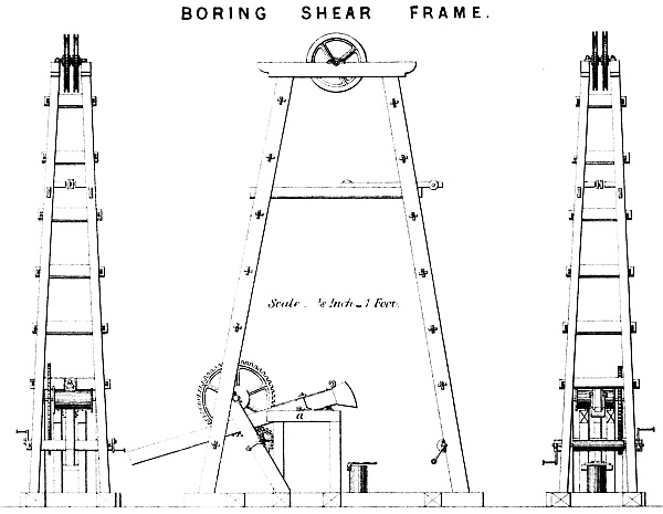
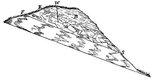
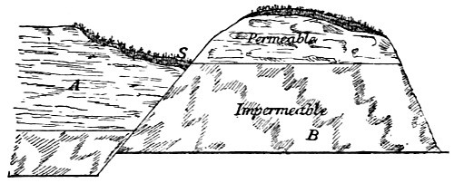
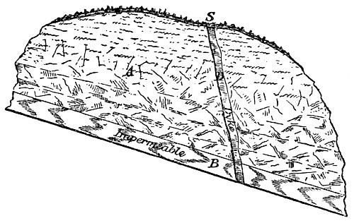
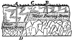
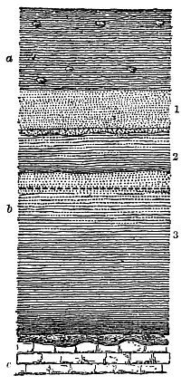
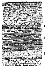
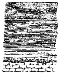
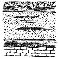
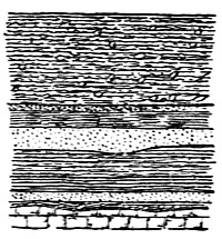
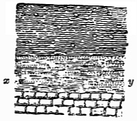
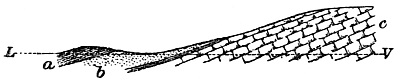
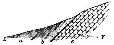
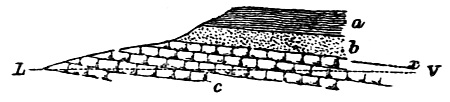
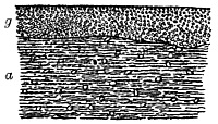
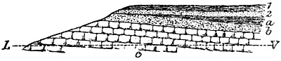
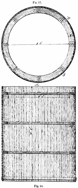
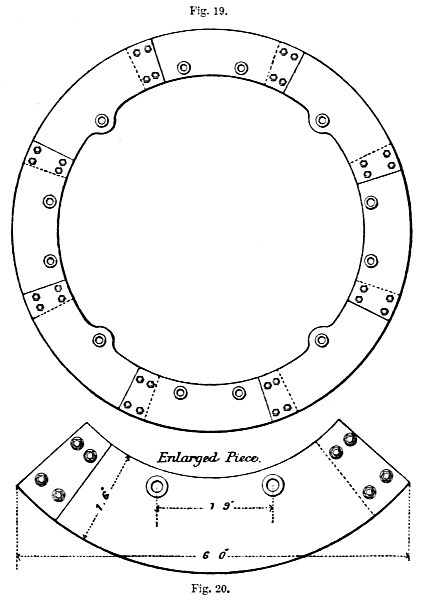
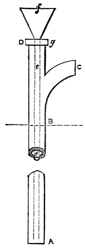
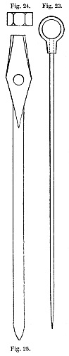
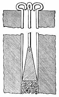
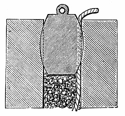
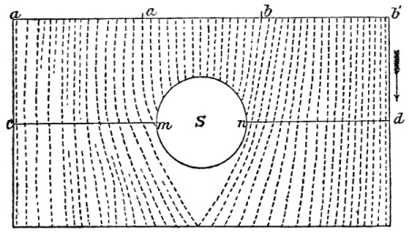
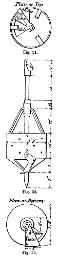
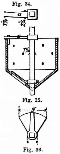
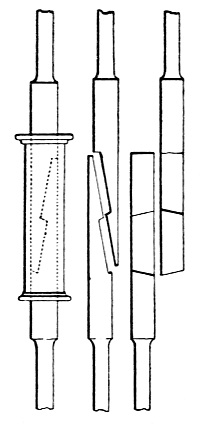
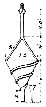
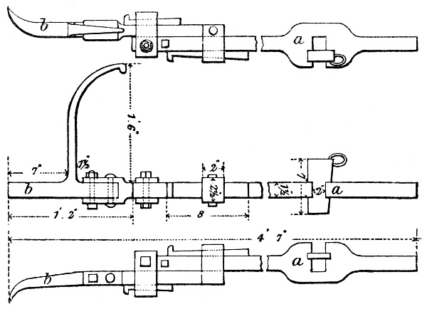
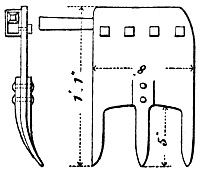
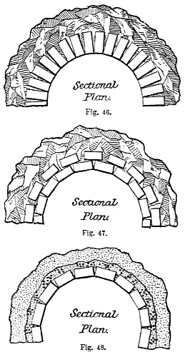
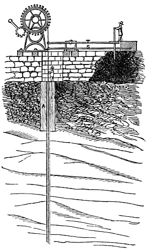
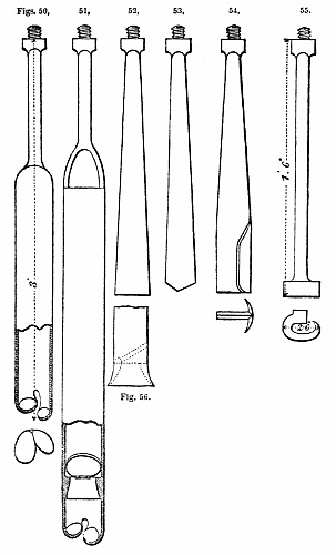
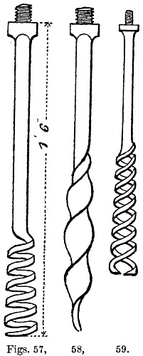
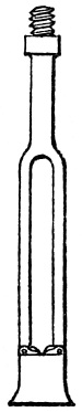
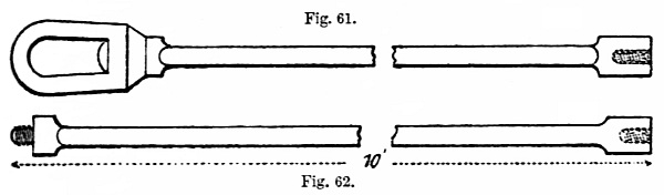
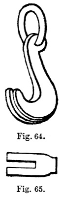
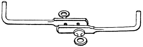

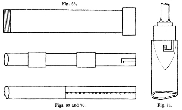
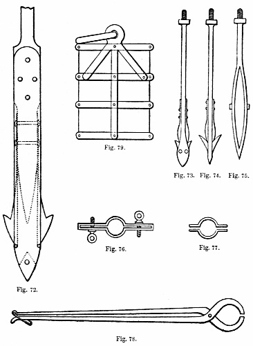
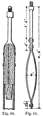
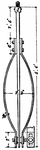
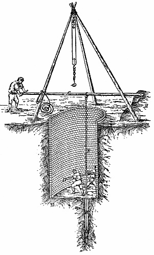
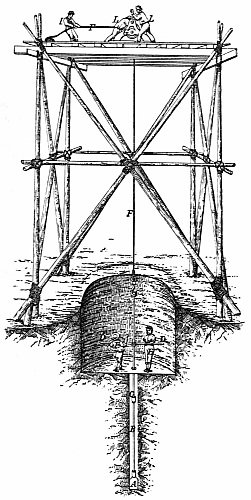
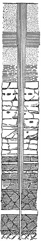
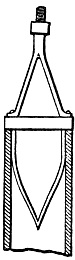
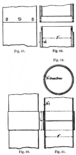
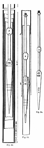
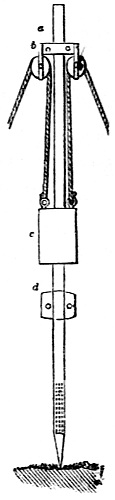
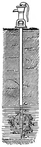
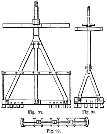
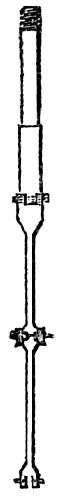
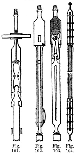
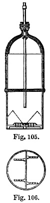
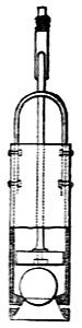
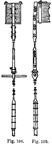
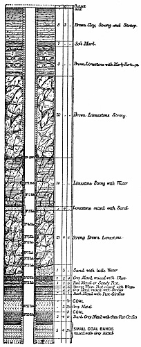
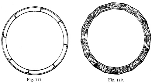
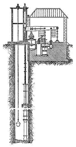
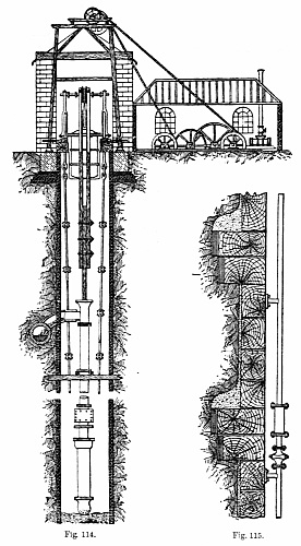
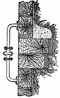
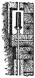
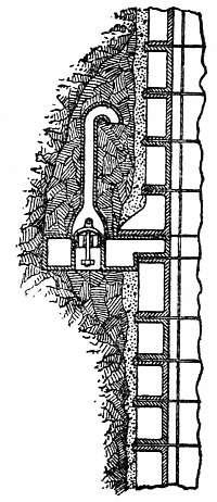
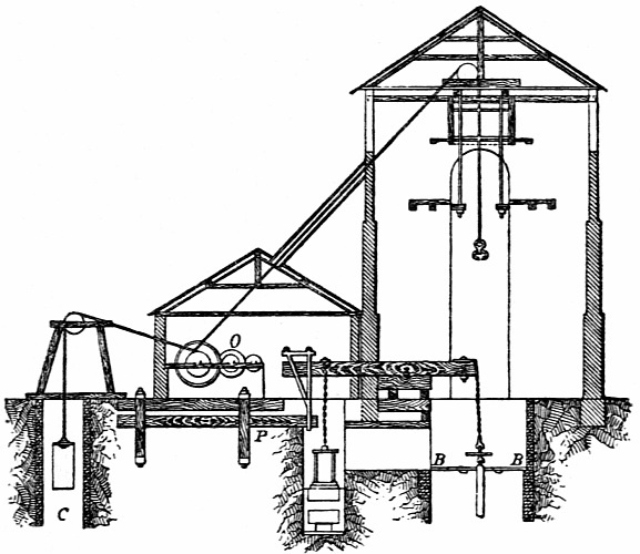
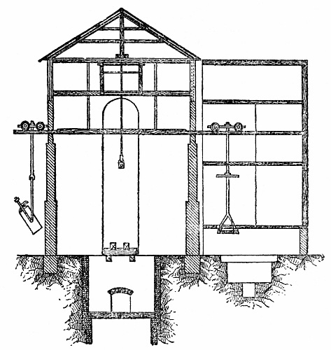
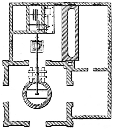
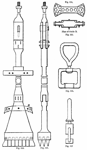
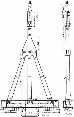
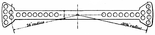
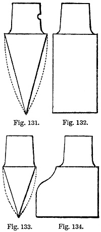
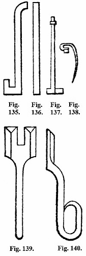
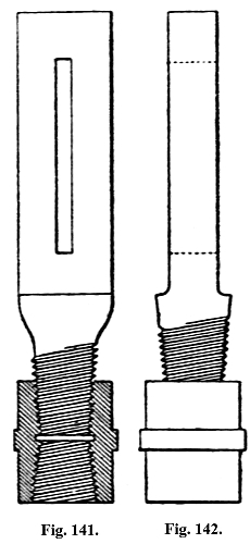
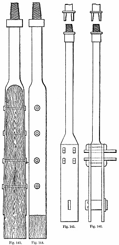
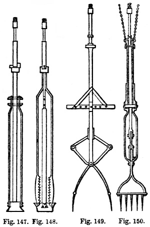
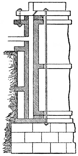
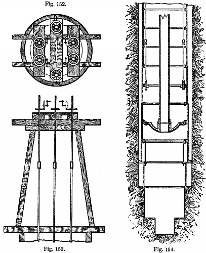
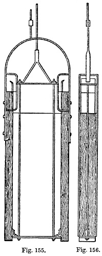
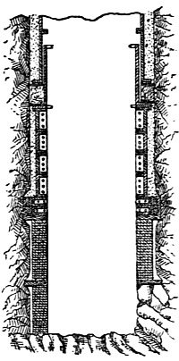
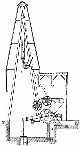
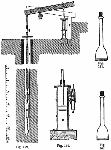
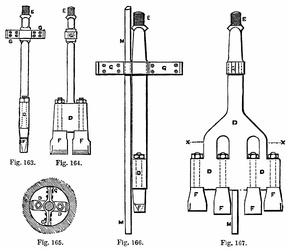
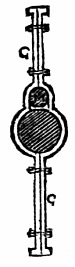
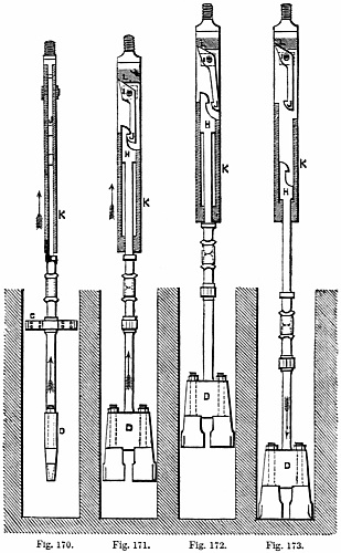
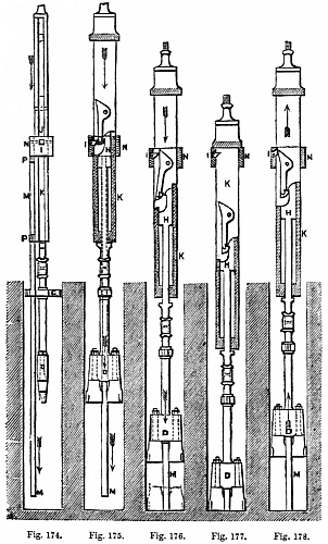
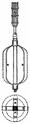
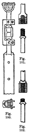
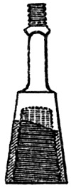
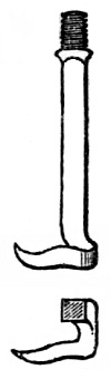
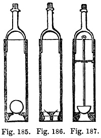
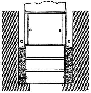
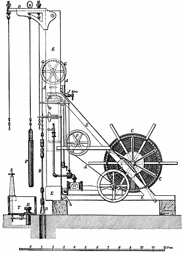
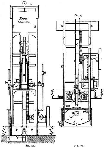
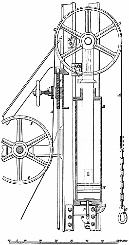
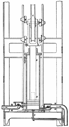
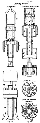
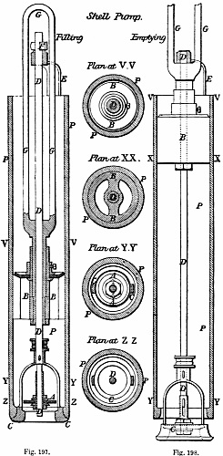
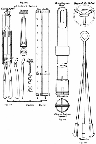
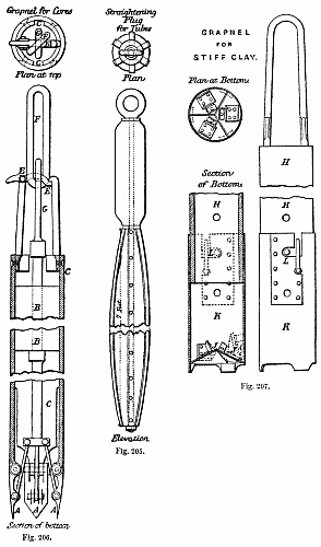
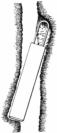
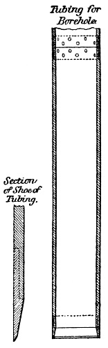
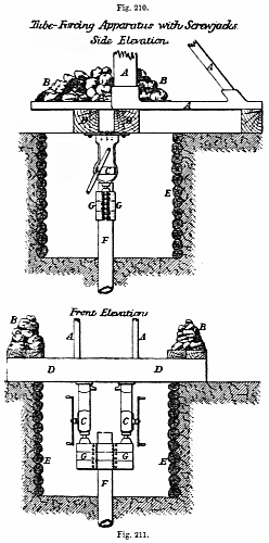
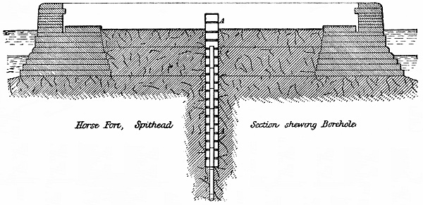
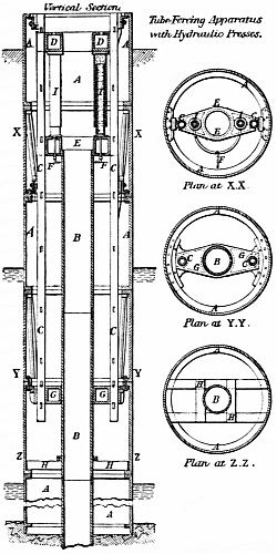
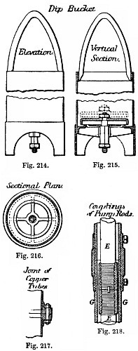
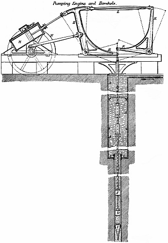
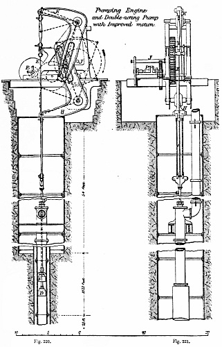
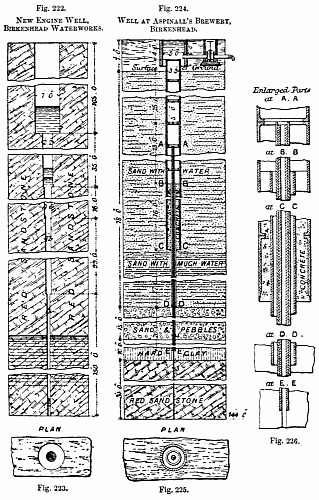
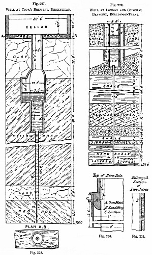
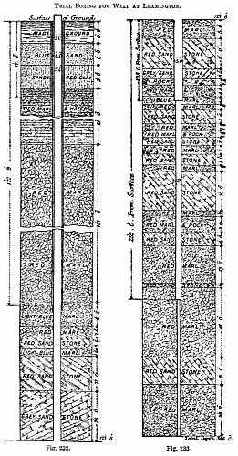
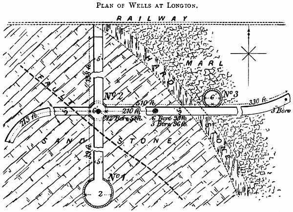
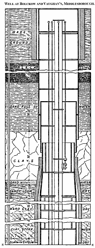
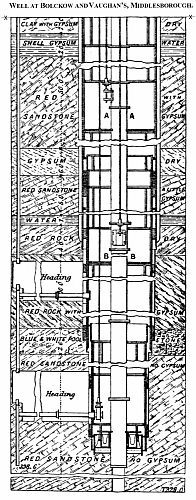
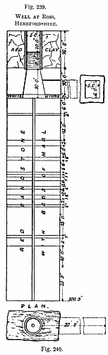
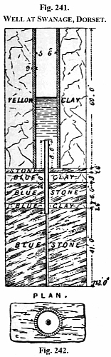
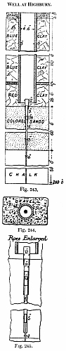
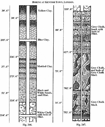
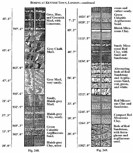
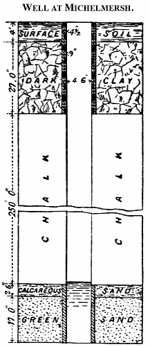
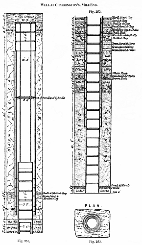
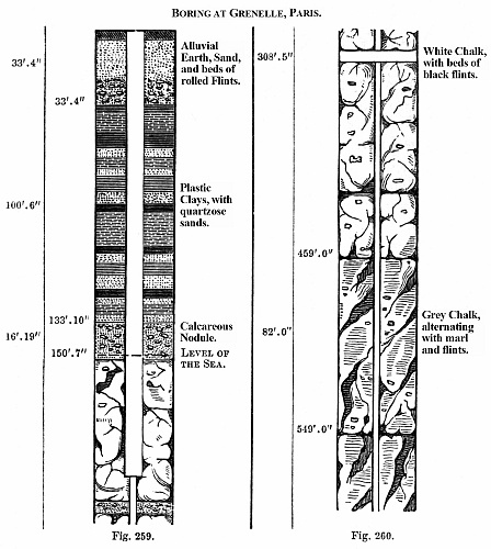
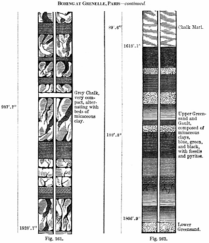
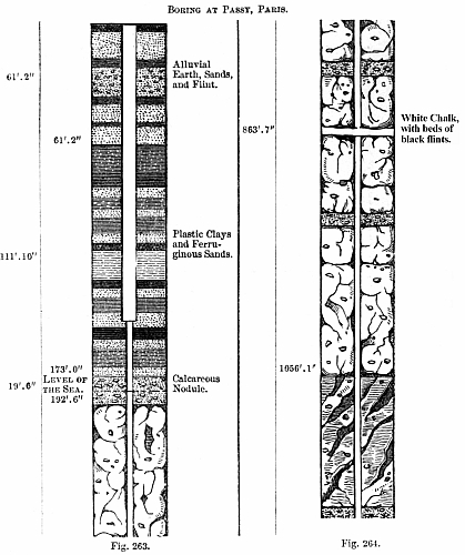
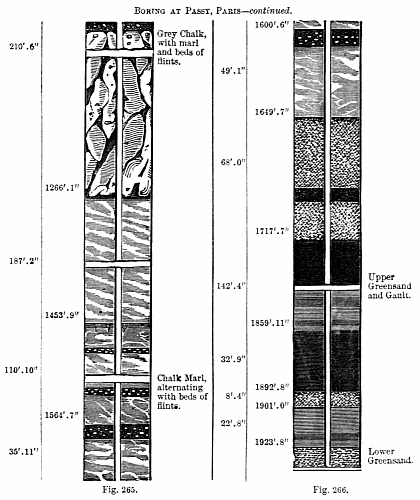
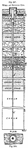
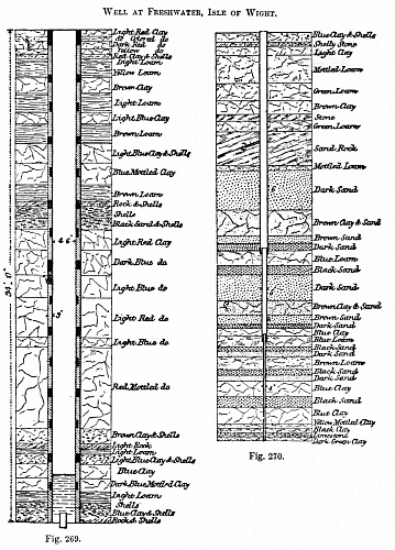
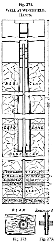
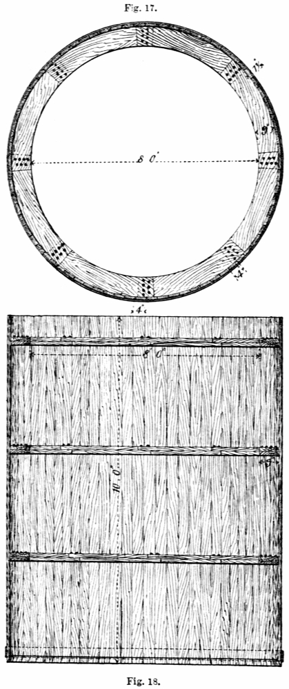
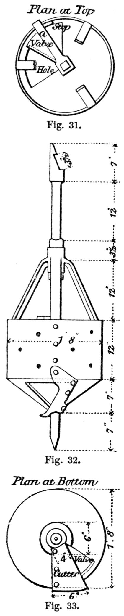
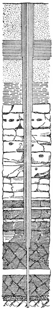
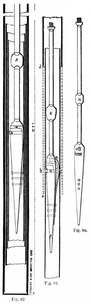
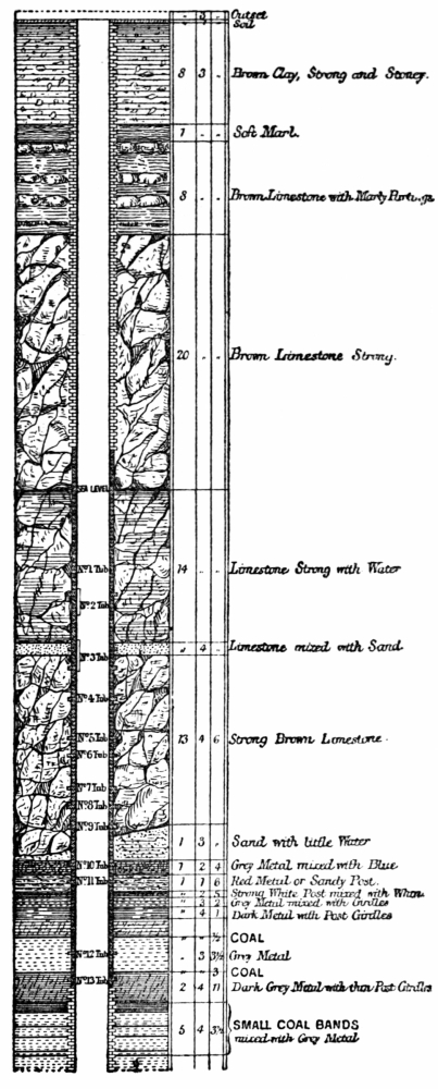
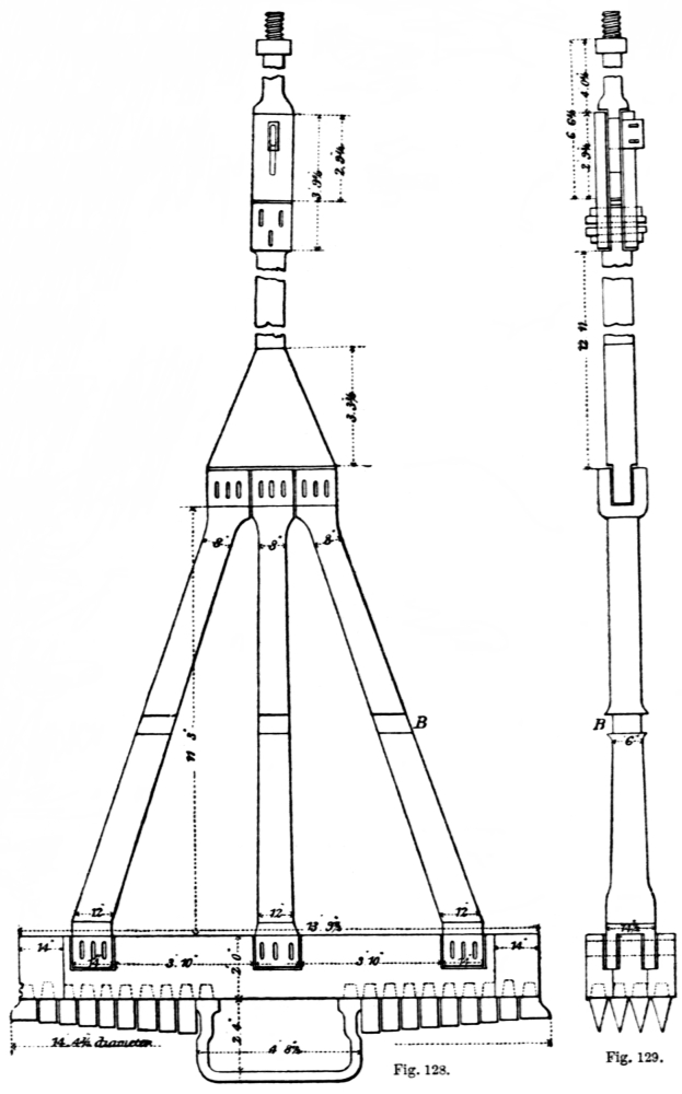
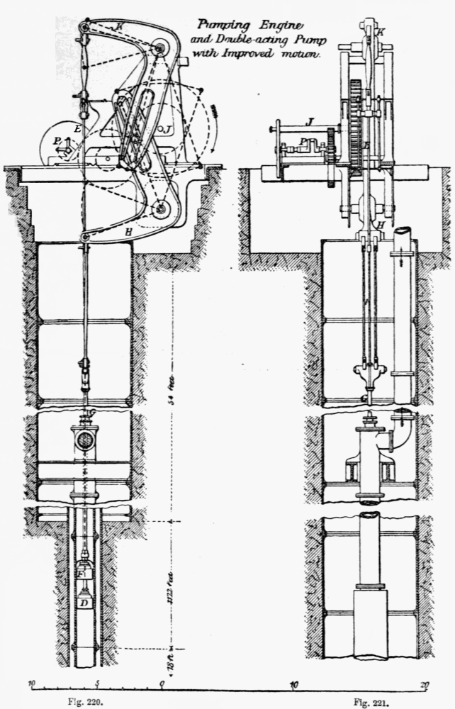
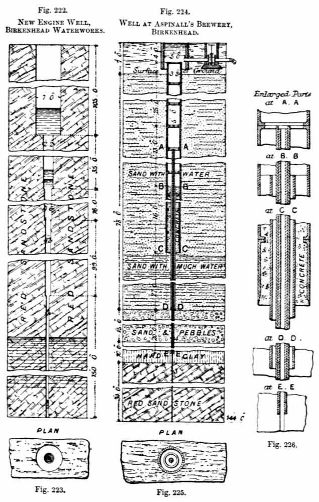
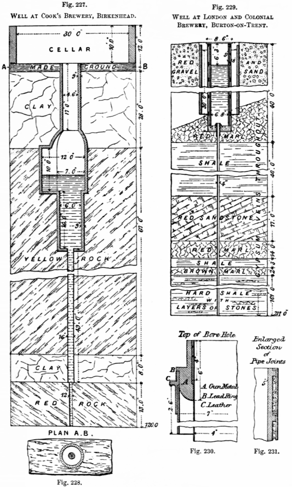
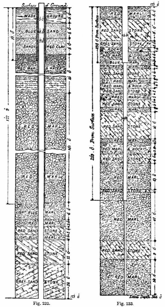
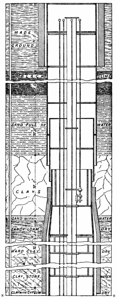
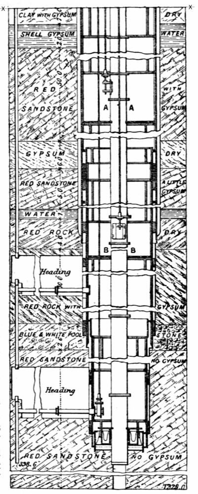
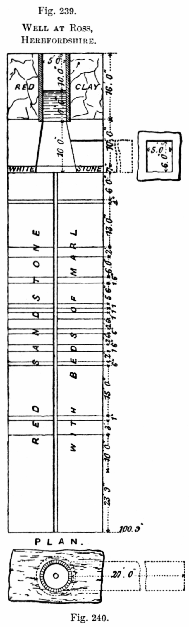
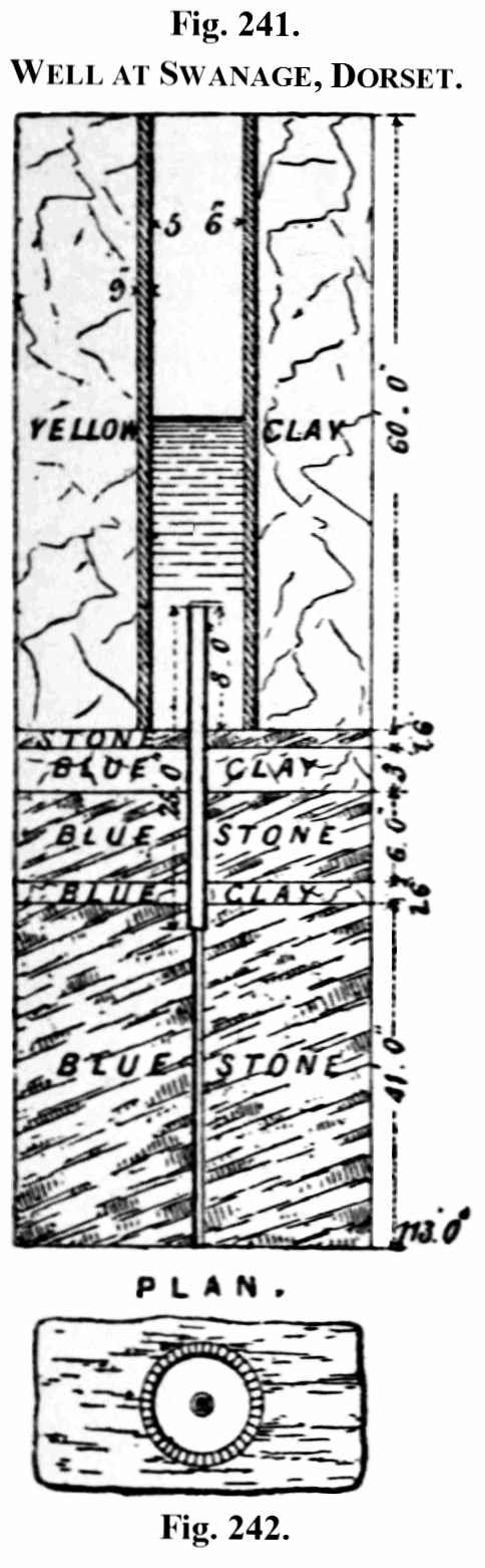
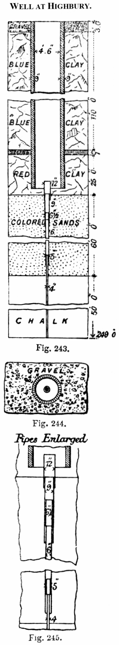
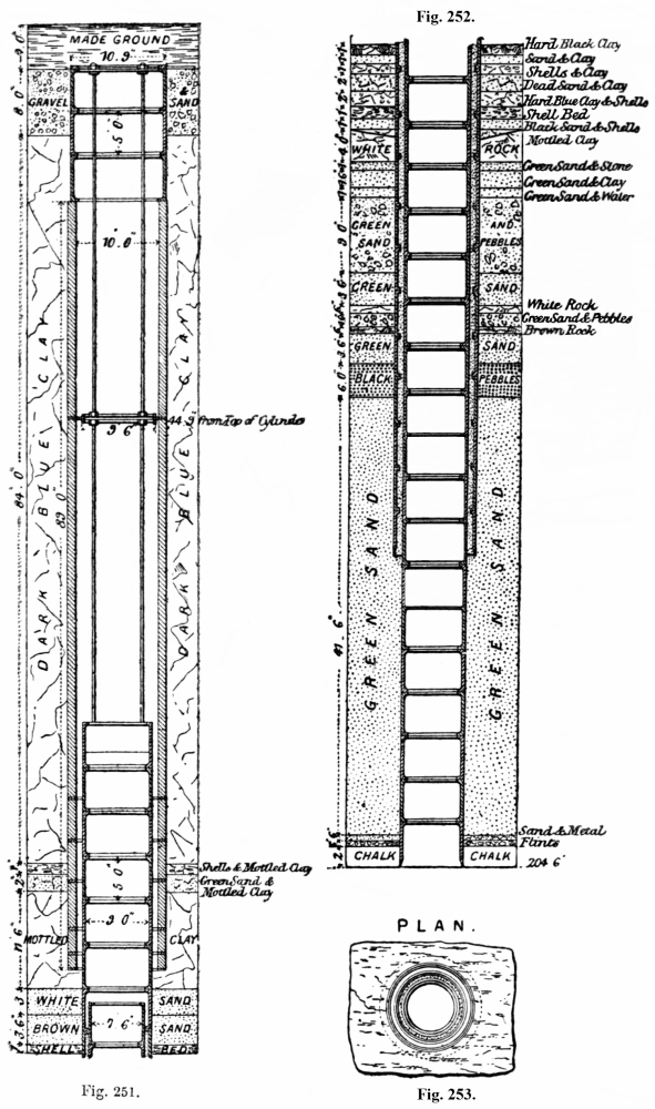
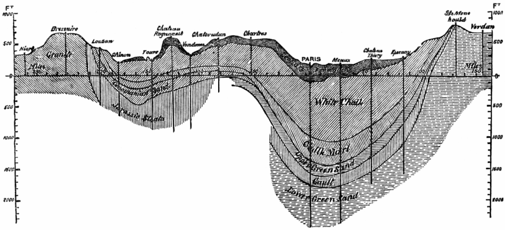
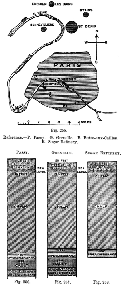
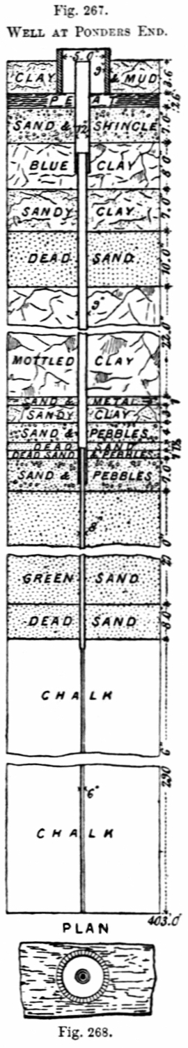
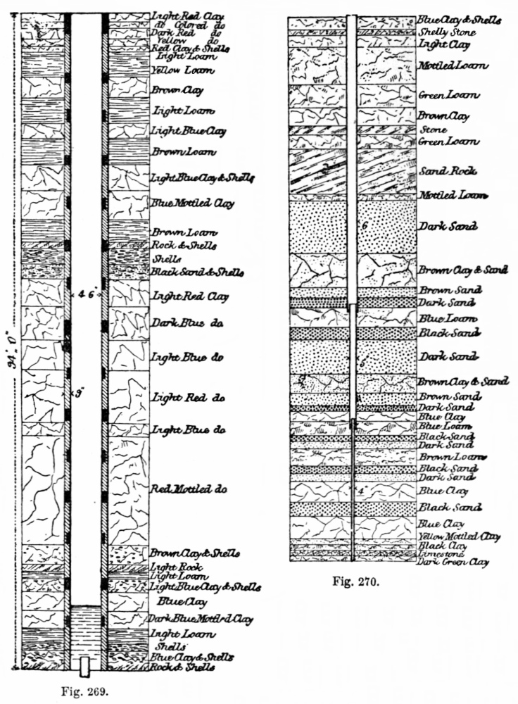