Please see the Transcriber’s Notes at the end of this document.
A Pocket-Book of Aeronautics.—By H. W. L. Moedebeck. Translated from the German by Dr. W. Mansergh Varley. With 150 Illustrations. 10s. 6d. net.
Contents.—Gases—Physics of the Atmosphere—Meteorological Observations—Balloon Technics—Kites and Parachutes—On Ballooning—Balloon Photography—Photographic Surveying from Balloons—Military Ballooning—Animal Flight—Artificial Flight—Airships—Flying Machines—Motors—Air Screws—Appendix—Index.
“Will be highly welcome to all aeronauts. It may be said to be the only complete work practically dealing with such matters. We have no hesitation in thoroughly recommending this as an absolutely indispensable book.”—Knowledge.
“It is without a doubt the best book that has appeared on the subject.”—Aeronautical Journal.
“The present volume ought certainly to be possessed by every student of Aeronautics, as it contains a vast amount of information of the highest value.”—Glasgow Herald.
WHITTAKER & CO., LONDON, E.C.
ARTIFICIAL AND
NATURAL FLIGHT.
BY
SIR HIRAM S. MAXIM.
WITH 95 ILLUSTRATIONS.
WHITTAKER & CO.,
2 WHITE HART STREET, PATERNOSTER SQUARE,
LONDON, E.C.,
AND 64-66 FIFTH AVENUE, NEW YORK.
1908.
It was in 1856 that I first had my attention called to the subject of flying machines. My father, who was a profound thinker and a clever mechanician, seems to have given the subject a great deal of thought, and to have matured a plan identical with what has been proposed by hundreds since that time. I was then sixteen years of age, and a fairly good mechanician, and any new thing in the mechanical line interested me immensely.
My father’s proposed machine, of which he made a sketch, was of the Hélicoptère type, having two screws both on the same axis—the lower one to be right hand and mounted on a tubular shaft, and the top one to be left hand and mounted on a solid shaft running through the lower tubular shaft. These screws were to be rotated in reverse directions by means of a small pinion engaging a bevel gear attached to each of the shafts. His plan contemplated large screws with very fine pitch, and he proposed to obtain horizontal motion by inclining the axis forward. He admitted that there was no motor in existence light enough, but thought one might be invented, and that an engine might be worked by a series of explosions in the cylinder, that is, what is known to-day as internal combustion; but he was not clear how such an engine could be produced. He, however, said that a flying machine would be so valuable in time of war, that it mattered little how expensive the explosive might be, even if fulminate of mercury had to be used. It is interesting to note in this connection that the great Peter Cooper of New York thought out an identical machine about the same time, and actually commenced experiments. It seems that this gentleman regarded fulminate of mercury[vi] as altogether too feeble and inert, because we find that he selected chloride of nitrogen as his explosive agent. However, his work was soon brought to an end by the loss of the sight of one eye, after which time he had no further dealings with this lively explosive.
The many early conversations that I had with my father on the subject kept the matter constantly before me, and I think it was in 1872, after having seen Roper’s hot-air engine and Brayton’s petroleum engine, that I took the matter up, and commenced to make drawings of a machine of the Hélicoptère type, but instead of having one screw above the other, I saw at once that it would be much better if the two screws were widely separated, so that each would engage new air, the inertia of which had not been disturbed. The designing of the machine itself was a simple matter, but the engine gave me trouble. No matter from what point I examined the subject, the engine was always too heavy. It appears that the Brayton engine was shown at the Centennial Exhibition at Philadelphia in 1876, and that Otto visited this exhibition. Up to that time, he had been making a species of rocket engine—that is, an engine in which an explosive mixture shot the piston upward and then sucked it back, a rack and pinion transmitting movement to the rotating shaft by means of a pawl and ratchet. He appears to have been much interested in the Brayton engine, as it was evidently very much in advance of his own. It actually developed, even at that time, one horse-power per hour for every pound of crude petroleum consumed, but it was very heavy indeed, very difficult to start, and not always reliable. The shaft that worked the valve gear was parallel to the cylinder, and placed in the exact position occupied by a similar shaft in the present Otto engine, but instead of revolving only half as fast as the crank shaft, it made the same number of revolutions. On Otto’s return to Germany, he evidently profited by what he had seen, and made a new engine, which in reality was a cross between his own and the[vii] Brayton; the result was a very important invention, which has been of incalculable value to mankind. It is this engine which is now propelling our motor cars, and it is the only engine suitable for employment on a flying machine; but even this motor was not in a sufficiently high state of development as far as lightness was concerned, to be of any use to me. The drawings which I made in 1873, although of little or no value, kept my thoughts on artificial flight, and while I was away from home attending to business, especially when in foreign countries, I often amused myself by making mathematical calculations. Quite true, the formula which I used at the time—Haswell’s—was not correct; still, it was near enough to the mark to be of considerable value. Moreover, the error in this formula affected the Hélicoptère quite as much as the aeroplane system, and as I was working with the view of ascertaining the relative merits of the two systems, the error, although considerable, did not have any influence at all in the decision which I arrived at—namely, that the aeroplane system was the best. The machine that I thought out at that time contemplated superposed aeroplanes of very great length from port to starboard. The size in the other direction was more for the purpose of preventing a rapid fall than for a lifting effect. I saw that it would be necessary to have horizontal fore and aft rudders placed a long distance apart, so as to prevent rapid pitching, and it appeared to me that the further these rudders were apart, the easier it would be to manœuvre the machine. As I never had any doubts regarding the efficiency of screw propellers working in the air, I decided to use two of these of a large size rotating in opposite directions. Of course, all this speculation was theory only, but I verified it later on by actual experiments before I built my machine, and it is very gratifying to me to know that all the successful flying machines of to-day are built on the lines which I had thought out at that time, and found to be the best. All have superposed aeroplanes[viii] of great length from port to starboard, all have fore and aft horizontal rudders, and all are driven with screw propellers. The change from my model is only a change in the framework made possible by dispensing with the boiler, water tank, and steam engine. In this little work, I have dealt at considerable length with air currents, the flight of birds, and the behaviour of kites, perhaps at the expense of some repetitions; as the resemblance between kite flying and the soaring of birds is similar in many respects, repetitions are necessary. To those who go to sea in ships, it is necessary to know something of the currents they are liable to encounter; if it be a sailing ship, certainly a knowledge of the air currents is of the greatest importance, and so it is with flying machines. If flights of any considerable distance are to be made, the machine is liable at any time to encounter very erratic air currents, and it has been my aim in discussing these three subjects—air currents, birds, and kites—to bring them before the would-be navigators of the air, in order that they may anticipate the difficulties they have to deal with and be ready to combat them. Then, again, there has been almost an infinite amount of discussion regarding the soaring of birds and the flying of kites. Many years ago, after reading numerous works on the subject of flight, I became a close observer myself, and always sought in my travels to learn as much as possible. I have attempted to discuss this subject in simple and easily understood language, and to present sufficient evidence to prevent the necessity of any further disputes. I do not regard what I have said as a theory, but simply as a plain statement of absolute and easily demonstrated facts. During the last few years, a considerable number of text-books and scientific treatises have been written on the subject of artificial flight, the most elaborate and by far the most reliable of these being the “Pocket-Book of Aeronautics,” by Herman W. L. Moedebeck, Major und Battaillonskommandeur im Badischen Fussartillerie[ix] Regiment No. 14; in collaboration with O. Chanute and others. Translated by W. Mansergh Varley, B.A., D.Sc., Ph.D., and published by Whittaker & Co. This work does not, however, confine itself altogether to flying machines, but has a great deal of information which is of little or no value to the builder of true flying machines; moreover, it is not simple enough to be readily understood by the majority of experimenters. In some other works which I have recently examined, I find a confusing mass of the most intricate mathematical calculations, abounding in an almost infinite number of characters, and extending over hundreds of pages, but on a close examination of some of the deductions arrived at, I find that a good many of the mathematical equations are based on a mistaken hypothesis, and the results arrived at are very wide of the truth. I have shown several diagrams which will explain what I mean. What is required by experimenters in flying machines—and there will soon be a great number of them—is a treatise which they can understand, and which requires no more delicate instruments than a carpenter’s 2-foot rule and a grocer’s scales. The calculations relating to the lift, drift, and the skin friction of an aeroplane are extremely simple, and it is quite possible to so place this matter that it can be understood by anyone who has the least smattering of mathematical knowledge. Mathematics of the higher order expressed in elaborate formulæ do very well in communications between college professors—that is, if they happen to be agreed. When, however, these calculations are so intricate as to require a clever mathematician a whole day to study out the meaning of a single page, and if when the riddle is solved, we find that these calculations are based on a fallacy, and the results in conflict with facts, it becomes quite evident to the actual experimenter that they are of little value. For many years, Newton’s law was implicitly relied upon. Chanute, after going over my experimental work, wrote that Newton’s law was out as 20 is to 1—that is, that an aeroplane would[x] lift twenty times as much in practice as could be shown by the use of Newton’s formula. Some recent experiments, which I have made myself, at extremely high velocities and at a very low angle, seem to demonstrate that the error is nearer 100 to 1 than 20 to 1. It will, therefore, be seen how little this subject was understood until quite recently, and even now the mathematicians who write books and use such an immense amount of formulæ, do not agree by any means, as will be witnessed by the mass of conflicting controversy which has been appearing in Engineering during the last four months. When an aeroplane placed at a working angle of, say, 1 in 10 is driven through the air at a high velocity, it, of course, pushes the air beneath it downwards at one-tenth part of its forward velocity—that is, in moving 10 feet, it pushes the air down 1 foot. A good many mathematicians rely altogether upon the acceleration of the mass of air beneath the aeroplane which is accelerated by its march through the air, the value of this acceleration being in proportion to the square of the velocity which is imparted to it. Suppose now that the aeroplane is thin and well-made, that both top and bottom sides are equally smooth and perfect; not only does the air engaged by the under side shoot downwards, but the air also follows the exact contour of the top side, and is also shot downwards with the same mean velocity as that passing on the underneath side, so if we are going to consider the lifting effect of the aeroplane, we must not leave out of the equation, the air above the aeroplane, which has quite as much mass and the same acceleration imparted to it, as the air below the aeroplane. Even calculations made on this basis will not bring the lifting effect of an aeroplane up to what it actually does lift in practice; in fact, the few mathematicians who have made experiments themselves have referred to the actual lifting effect of aeroplanes placed at a low angle and travelling at a high velocity as being unaccountable. Only a few mathematicians appear to have a proper grasp of the[xi] subject. However, three could be pointed out who understand the subject thoroughly, but these are all mathematicians of the very highest order—Lord Kelvin, Lord Rayleigh, and Professor Langley. In placing before the public, the results of my experiments and the conclusions arrived at, it is necessary to show the apparatus which I employed, otherwise it might be inferred that my conclusions were guesswork, or mathematical calculations which might or might not be founded on a mistaken hypothesis; this is my excuse for showing my boiler and engine, my rotating arm, and my large machine. I do not anticipate that anyone will ever use a steam engine again, because any form of a boiler is heavy; moreover, the amount of fuel required is much greater than with an internal combustion engine, and certainly seven times as much water has to be dealt with. However, the description which I am giving of my apparatus will demonstrate that I had the instruments for doing the experimental work that I have described in this work. In the Appendix will be found a description of my machine, and some of my apparatus. The conclusions which I arrived at were written down at the time with a considerable degree of care, and are of interest because they show that, at that date, I had produced a machine that lifted considerably more than its own weight and had all of the essential elements, as far as superposed aeroplanes, fore and aft horizontal rudders, and screw propellers were concerned, common to all of the successful machines which have since been made. The fact that practically no essential departure has been made from my original lines, indicates to my mind that I had reasoned out the best type of a machine even before I commenced a stroke of the work.
I have to thank Mr. Albert T. Thurston for reading the proofs of this work.
H. S. M.
| CHAPTER I. | |
| PAGE | |
| Introductory, | 1 |
| CHAPTER II. | |
| Air Currents and the Flight of Birds, | 11 |
| CHAPTER III. | |
| Flying of Kites, | 25 |
| CHAPTER IV. | |
| Principally Relating to Screws, | 31 |
| CHAPTER V. | |
| Experiments with Apparatus Attached to a Rotating Arm—Crystal Palace Experiments, | 62 |
| CHAPTER VI. | |
| Hints as to the Building of Flying Machines—Steering by Means of a Gyroscope, | 77 |
| CHAPTER VII. | |
| The Shape and Efficiency of Aeroplanes—The Action of Aeroplanes and the Power Required Expressed in the Simplest Terms—Some Recent Machines, | 99 |
| CHAPTER VIII. | |
| Balloons, | 120 |
| Appendix I., | 125 |
| Appendix II.— | |
| Recapitulation of Early Experiments—Efficiency of Screw Propellers, Steering, Stability, &c.—The Comparative Value of Different Motors—Engines—Experiments with Small Machines Attached to a Rotating Arm, | 130 |
| Index, | 163 |
| FIG. | PAGE | |
| 1. | Diagram showing the reduction of the projected horizontal area, | 2 |
| 2. | Professor Langley’s experiments, | 5 |
| 3. | Eagles balancing themselves on an ascending current of air, | 14 |
| 4. | Air currents observed in Mid-Atlantic, | 16 |
| 5. | Glassy streaks in the Bay of Antibes, | 17 |
| 6. | Air currents observed in the Mediterranean, | 18 |
| 7. | The circulation of air produced by a difference in temperature, | 27 |
| 8. | Kite flying, | 29 |
| 9. | Group of screws and other objects used in my experiments, | 32 |
| 10. | Some of the principal screws experimented with, | 32 |
| 11. | The three best screws, | 33 |
| 12. | Apparatus for testing the thrust of screws, | 34 |
| 13. | Apparatus for testing the direction of air currents, | 35 |
| 14. | The ends of screw blades, | 36 |
| 15. | The manner of building up the large screws, | 39 |
| 16. | A fabric-covered screw, | 40 |
| 17. | The hub and one of the blades of the screw on the Farman machine, | 42 |
| 18. | Section of screw blades having radial edges, | 43 |
| 19. | Form of the blade of a screw made of sheet metal, | 44 |
| 20. | New form of hub, | 45 |
| 21. | Small apparatus for testing fabrics for aeroplanes, | 50 |
| 22. | Apparatus for testing the lifting effect of aeroplanes and condensers, | 51 |
| 23. | Apparatus for testing aeroplanes, condensers, &c., | 52 |
| 24. | Cross-sections of bars of wood, | 53 |
| 25. | Sections of bars of wood, | 54 |
| 26. | A flat aeroplane placed at different angles, | 55 |
| 27. | Group of aeroplanes used in experimental research, | 56 |
| 28. | An 8-inch aeroplane which did very well, | 57 |
| 29. | Resistance due to placing objects in close proximity to each other, | 58 |
| 30. | Cross-section of condenser tube made in the form of Philipps’ sustainers, | 60 |
| 31. | The grouping of condenser tubes made in the form of Philipps’ sustainers, | 61 |
| 32. | Machine with a rotating arm, | 63 |
| 33. | A screw and fabric-covered aeroplane in position for testing, | 64 |
| 34. | The rotating arm of the machine with a screw and aeroplane attached, | 65 |
| 35. | The little steam engine used by me in my rotating arm experiments, | 66 |
| 36. | The machine attached to the end of the rotating shaft, | 68 |
| 37. | Marking off the dynamometer, | 69 |
| 37a. | Right- and left-hand four-blade screws, | 70 |
| 38. | Apparatus for indicating the force and velocity of the wind direct, | 71 |
| 39. | Apparatus for testing the lifting effect of aeroplanes,[xiv] | 73 |
| 40. | Front elevation of proposed aeroplane machine, | 77 |
| 41. | Side elevation of proposed aeroplane machine, | 78 |
| 42. | Plan of proposed aeroplane machine, | 79 |
| 43. | Plan of a hélicoptère machine, | 82 |
| 44. | Showing the position of the blades of a hélicoptère as they pass around a circle, | 83 |
| 45. | System of splicing and building up wooden members, | 86 |
| 46. | Cross-section of struts, | 86 |
| 47. | Truss suitable for use with flying machines, | 87 |
| 48. | The paradox aeroplane, | 88 |
| 49. | The Antoinette motor, | 89 |
| 50. | Section showing the Antoinette motor as used in the Farman and De la Grange machines, | 90 |
| 51. | Pneumatic buffer, | 91 |
| 52. | Gyroscope, | 94 |
| 53. | Adjusting the lifting effect, | 95 |
| 54. | Showing that the machine could be tilted in either direction by changing the position of the rudder, | 96 |
| 55. | Adjusting the lifting effect, | 97 |
| 56. | Adjustment of the rudders, | 98 |
| 57. | Diagram showing the evolution of a wide aeroplane, | 102 |
| 58. | In a recently published mathematical treatise on aerodynamics an illustration is shown, representing the path that the air takes on encountering a rapidly moving curved aeroplane, | 104 |
| 59. | An illustration from another scientific publication also on the dynamics of flight, | 104 |
| 60. | Another illustration from the same work, | 105 |
| 61. | The shape and the practical angle of an aeroplane, | 105 |
| 62. | An aeroplane of great thickness, | 106 |
| 63. | Section of a screw blade having a rib on the back, | 106 |
| 64. | Shows a flat aeroplane placed at an angle of 45°, | 107 |
| 65. | The aeroplane here shown is a mathematical paradox, | 107 |
| 66. | This shows fig. 65 with a section removed, | 107 |
| 67. | Diagram showing real path of a bird, | 108 |
| 68. | The De la Grange machine on the ground, | 111 |
| 69. | The De la Grange machine in full flight, | 111 |
| 70. | Farman’s machine in flight, | 112 |
| 71. | Bleriot’s machine, | 113 |
| 72. | Santos Dumont’s flying machine, | 113 |
| 72a. | Angles and degrees compared, | 115 |
| 72b. | Diagram showing direction of the air with a thick curved aeroplane, | 118 |
| 72c. | Aeroplanes experimented with by Mr. Horatio Philipps, | 118 |
| 73. | The enormous balloon “Ville de Paris,” | 123 |
| 74. | Photograph of a model of my machine, | 130 |
| 75. | The fabric-covered aeroplane experimented with, | 131 |
| 76. | The forward rudder of my large machine showing the fabric attached to the lower side, | 131 |
| 77. | View of the track used in my experiments, | 134 |
| 78. | The machine on the track tied up to the dynamometer, | 135 |
| 79. | Two dynagraphs, | 136 |
| 80. | The outrigger wheel that gave out and caused an accident with the machine, | 137 |
| 81. | Shows the broken planks and the wreck that they caused, | 138 |
| 82. | The condition of the machine after the accident, | 139 |
| 83. | This shows the screws damaged by the broken planks, | 140 |
| 84. | This shows a form of outrigger wheels which were ultimately used, | 141 |
| 85. | One pair of my compound engines,[xv] | 142 |
| 86. | Diagram showing the path that the air has to take in passing between superposed aeroplanes in close proximity to each other, | 144 |
| 87. | Position of narrow aeroplanes arranged so that the air has free passage between them, | 145 |
| 88. | The very narrow aeroplanes or sustainers employed by Mr. Philipps, | 146 |
| 89. | One of the large screws being hoisted into position, | 149 |
| 90. | Steam boiler employed in my experiments, | 157 |
| 91. | The burner employed in my steam experiments, | 157 |
| 92. | Count Zeppelin’s aluminium-covered airship coming out of its shed on Lake Constance, | 161 |
| 93. | Count Zeppelin’s airship in full flight, | 161 |
| 94. | The new British war balloon “Dirigible” No. 2, | 162 |
| 95. | The Wright aeroplane in full flight, | 162 |
ARTIFICIAL AND NATURAL FLIGHT.
It has been my aim in preparing this little work for publication to give a description of my own experimental work, and explain the machinery and methods that have enabled me to arrive at certain conclusions regarding the problem of flight. The results of my experiments did not agree with the accepted mathematical formulæ of that time. I do not wish this little work to be considered as a mathematical text-book; I leave that part of the problem to others, confining myself altogether to data obtained by my own actual experiments and observations. During the last few years, a considerable number of text-books have been published. These have for the most part been prepared by professional mathematicians, who have led themselves to believe that all problems connected with mundane life are susceptible of solution by the use of mathematical formulæ, providing, of course, that the number of characters employed are numerous enough. When the Arabic alphabet used in the English language is not sufficient, they exhaust the Greek also, and it even appears that both of these have to be supplemented sometimes by the use of Chinese characters. As this latter supply is unlimited, it is evidently a move in the right direction. Quite true, many of the factors in the problems with which they have to deal are completely unknown and unknowable; still they do not hesitate to work out a complete solution without the aid of any experimental data at all. If the result of their calculations should not agree with facts, “bad luck to the facts.” Up to twenty years ago, Newton’s erroneous law as relates to atmospheric[2] resistance was implicitly relied upon, and it was not the mathematician who detected its error, in fact, we have plenty of mathematicians to-day who can prove by formulæ that Newton’s law is absolutely correct and unassailable. It was an experimenter that detected the fault in Newton’s law. In one of the little mathematical treatises that I have before me, I find drawings of aeroplanes set at a high and impracticable angle with dotted lines showing the manner in which the writer thinks the air is deflected on coming in contact with them. The dotted lines show that the air which strikes the lower or front side of the aeroplane, instead of following the surface and being discharged at the lower or trailing edge, takes a totally different and opposite path, moving forward and over the top or forward edge, producing a large eddy of confused currents at the rear and top side of the aeroplane. It is very evident that the air never takes the erratic path shown in these drawings; moreover, the angle of the aeroplane is much greater than one would ever think of employing on an actual flying machine. Fully two pages of closely written mathematical formulæ follow, all based on this mistaken hypothesis. It is only too evident that mathematics of this kind can be of little use to the serious experimenter. The mathematical equation relating to the lift and drift of a well-made aeroplane is extremely simple; at any practicable angle from 1 in 20 to 1 in 5, the lifting effect will be just as much greater than the drift, as the width of the plane is greater than the elevation of the front edge above the horizontal—that[3] is, if we set an aeroplane at an angle of 1 in 10, and employ 1 lb. pressure for pushing this aeroplane forward, the aeroplane will lift 10 lbs. If we change the angle to 1 in 16, the lift will be 16 times as great as the drift. It is quite true that as the front edge of the aeroplane is raised, its projected horizontal area is reduced—that is, if we consider the width of the aeroplane as a radius, the elevation of the front edge will reduce its projected horizontal area just in the proportion that the versed sine is increased. For instance, suppose the sine of the angle to be one-sixth of the radius, giving, of course, to the aeroplane an inclination of 1 in 6, which is the sharpest practical angle, this only reduces the projected area about 2 per cent., while the lower and more practical angles are reduced considerably less than 1 per cent. It will, therefore, be seen that this factor is so small that it may not be considered at all in practical flight.
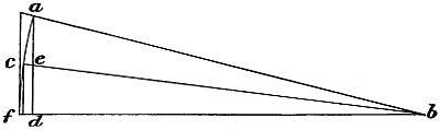
Fig. 1.—Diagram showing the reduction of the projected horizontal area of aeroplanes due to raising the front edge above the horizontal—a, b, shows an angle of 1 in 4, which is the highest angle that will ever be used in a flying machine, and this only reduces the projected area about 2 per cent. The line c b shows an angle of 1 in 8, and this only reduces the projected area an infinitesimal amount. As the angle of inclination is increased, the projected area becomes less as the versed sine f d becomes greater.
Some of the mathematicians have demonstrated by formulæ, unsupported by facts, that there is a considerable amount of skin friction to be considered, but as no two agree on this or any other subject, some not agreeing to-day with what they wrote a year ago, I think we might put down all of their results, add them together, and then divide by the number of mathematicians, and thus find the average coefficient of error. When we subject this question to experimental test, we find that nearly all of the mathematicians are radically wrong, Professor Langley, of course, excepted. I made an aeroplane of hard rolled brass, 20 gauge; it was 1 foot wide and dead smooth on both sides; I gave it a curvature of about 1⁄16 inch and filed the edges, thin and sharp. I mounted this with a great deal of care in a perfectly horizontal blast of air of 40 miles an hour. When this aeroplane was placed at any angle between 1 in 8 and 1 in 20, the lifting effect was always just in proportion to its angle. The distance that the front edge was raised above the horizontal, as compared with the width of the aeroplane, was always identical with the drift as compared with the lift. On account of the jarring effect caused by the rotation of the screws that produced the air blast, we might consider that all of the articulated joints about the weighing device were absolutely frictionless, as the jar would cause them to settle into the proper position quite irrespective of friction. I was, therefore,[4] able to observe very carefully, the lift and the drift. As an example of how these experiments were conducted, I would say that the engine employed was provided with a very sensitive and accurate governor; the power transmission was also quite reliable. Before making these tests, the apparatus was tested as regards the drift, without any aeroplane in position, and with weights applied that would just balance any effect that the wind might have on everything except the aeroplane. The aeroplane was then put in position and the other system of weights applied until it exactly balanced, all the levers being rapped in order to eliminate the friction in their joints. The engine was then started and weights applied just sufficient to counterbalance the lifting effect of the aeroplane, and other weights applied to exactly balance the drift or the tendency to travel with the wind. In this way, I was able to ascertain, with a great degree of accuracy, the relative difference between the lift and drift. If there had been any skin friction, even to the extent of 2 per cent., it would have been detected. This brass aeroplane was tested at various angles, and always gave the same results, but of course I could not use thick brass aeroplanes on a flying machine; it was necessary for me to seek something much lighter. I therefore conducted experiments with other materials, the results of which are given. However, with a well-made wooden aeroplane 1 foot wide and with a thickness in the centre of 7⁄16 inch, I obtained results almost identical with those of the very much thinner brass aeroplane, but it must not be supposed that in practice an aeroplane is completely without friction. If it is very rough, irregular in shape, and has any projections whatsoever on either the top or bottom side, there will be a good deal of friction, although it may not, strictly speaking, be skin friction; still, it will absorb the power, and the coefficient of this friction may be anything from ·05 to ·40. These experiments with the brass aeroplane demonstrated that the lifting effect was in direct proportion to the angle, and that skin friction, if it exists at all, was extremely small, but this does not agree with a certain kind of reasoning which can be made very plausible and is consequently generally accepted.
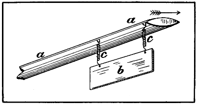
Fig. 2.—Professor Langley’s experiments—a, end of the rotating arm; b, brass plane weighing 1 lb.; c c, spiral springs. When the arm was driven through the air, in the direction shown, the plane assumed approximately a horizontal position, and the pull on the springs c c was reduced from 1 lb. to 1 oz.
Writers of books, as a rule, have always supposed that the lifting effect of an aeroplane was not in proportion to its inclination, but in proportion to the square of the[5] sine of the angle. In order to make this matter clear, I will explain. Suppose that an aeroplane is 20 inches wide and the front edge is raised 1 inch above the horizontal. In ordinary parlance this is, of course, called an inclination of 1 in 20, but mathematicians approach it from a different standpoint. They regard the width of the aeroplane as unity or the radius, and the 1 inch that the front edge is raised as a fraction of unity. The geometrical name of this 1 inch is the sine of the angle—that is, it is the sine of the angle at which the aeroplane is raised above the horizontal. Suppose, now, that we have another identical aeroplane and we raise the front edge 2 inches above the horizontal. It is very evident that, under these conditions, the sine of the angle will be twice as much, and that the square of the sine of the angle will be four times as great. All the early mathematicians, and some of those of the present day, imagine that the lift must be in proportion to the square of the sine of the angle. They reason it out as follows:—If an aeroplane is forced through the air at a given velocity, the aeroplane in which the sine of the angle is 2 inches will push the air down with twice as great a velocity as the one in which the sine of the angle is only 1 inch, and as the force of the wind blowing against a normal plane increases as the square of the velocity, the same law holds good in driving a normal plane through still air. From this reasoning, one is led to suppose that an aeroplane set[6] at an angle of 1 in 10 will lift four times as much as one in which the inclination is only 1 in 20, but experiments have shown that this theory is very wide of the truth. There are dozens of ways of showing, by pure mathematics, that Newton’s law is quite correct; but in building a flying machine no theory is good that does not correspond with facts, and it is a fact, without any question, that the lifting effect of an aeroplane, instead of increasing as the square of the sine of the angle, only increases as the angle. Lord Kelvin, when he visited my place, was, I think, the first to mention this, and point out that Newton’s law was at fault. Professor Langley also pointed out the fallacy of Newton’s law, and other experimenters have found that the lifting effect does not increase as the square of the sine of the angle. In order to put this matter at rest, Lord Rayleigh, who, I think we must all admit, would not be likely to make a mistake, made some very simple experiments, in which he demonstrated that two aeroplanes, in which we may consider the sine of the angle to be 1⁄4 inch, lifted slightly more than a similar aeroplane in which the sine of the angle was only 1⁄2 inch. Of course, Lord Rayleigh did not express it in inches, but in term of the radius. His aeroplanes were, however, very small. We can rely upon it that the lifting effect of an aeroplane at any practical angle, everything else being equal, increases in direct proportion to the angle of the inclination. In this little work, I have attempted to make things as simple as possible; it has not been written for mathematicians, and I have, therefore, thought best to express myself in inches instead of in degrees. If I write, “an inclination of 1 in 20,” everyone will understand it, and only a carpenter’s 2-foot rule is required to ascertain what the angle is. Then, again, simple measurements make calculations much simpler, and the lifting effect is at once understood without any computations being necessary. If the angles are expressed in degrees and minutes, it is necessary to have a protractor or a text-book in order to find out what the inclination really is. When I made my experiments, I only had in mind the obtaining of correct data, to enable me to build a flying machine that would lift itself from the ground. At that time I was extremely busy, and during the first two years of my experimental work, I was out of England fourteen months. After having made my apparatus, I conducted my experiments[7] rather quickly, it is true, but I intended later on to go over them systematically and deliberately, make many more experiments, write down results, and prepare some account of them for publication. However, the property where I made these experiments was sold by the company owning it, and my work was never finished, so I am depending on the scraps of data that were written down at the time. I am also publishing certain observations that I wrote down shortly after I had succeeded in lifting more than the weight of my machine. I think that the experiments which I made with an aeroplane only 8 inches wide will be found the most reliable. All the machinery was running smoothly, and the experiments were conducted with a considerable degree of care. In making any formula on the lifting effect of the aeroplane, it should be based on what was accomplished with the 8-inch plane. Only a few experiments were made to ascertain the relative value of planes of different widths. However, I think we must all admit that a wide plane is not as economical in power as a narrow one. In order to make this matter plain, suppose that we have one aeroplane placed at such an angle that it will lift 2 lbs. per square foot at a velocity of 40 miles an hour; it is very evident that the air just at the rear of this aeroplane would be moving downward at a velocity corresponding to the acceleration imparted to it by the plane. If we wish to obtain lifting effect on this air by another plane of exactly the same width, we shall have to increase its inclination in order to obtain the same lifting effect, and, still further, it will be necessary to use more power in proportion to the load lifted. If a third aeroplane is used, it must be placed at an angle that will impart additional acceleration to the air, and so on. Each plane that we add will have to be placed at a sharper angle, and the power required will be just in proportion to the average angle of all the planes. As the action of a wide aeroplane is identical with that of numerous narrow ones placed in close proximity to each other, it is very evident that a wide aeroplane cannot be as efficient in proportion to its width as a narrow one. I have thought the matter over, and I should say that the lifting effect of a flat aeroplane increases rather faster than the square root of its width. This will, at least, do for a working hypothesis. Every flying machine must have what we will[8] call “a length of entering edge”—that is, the sum of entering edges of all the aeroplanes must bear a fixed relation to the load carried. If a machine is to have its lifting effect doubled, it is necessary to have the length of entering edge twice as long. This additional length may, of course, be obtained by superposed planes, but as we may assume that a large aeroplane will travel faster than a small one, increased velocity will compensate in some degree for the greater width of larger aeroplanes. By careful study of the experiments which I have made, I think it is quite safe to state that the lifting effect of well-made aeroplanes, if we do not take into consideration the resistance due to the framework holding them in position, increases as the square of their velocity. Double their speed and they give four times the lifting effect. The higher the speed, the smaller the angle of the plane, and the greater the lifting effect in proportion to the power employed. When we build a steamship, we know that its weight increases as the cube of any one of its dimensions—that is, if the ship is twice as long, twice as wide, and twice as deep it will carry eight times as much; but at the very best, with even higher speed, the load carried by a flying machine will only increase with the square of any one of its dimensions, or perhaps still less. No matter whether it is a ship, a locomotive, or a flying machine that we wish to build, we must first of all consider the ideal, and then approximate it as closely as possible with the material at hand. Suppose it were possible to make a perfect screw, working without friction, and that its weight should only be that of the surrounding air; if it should be 200 feet in diameter, the power of one man, properly applied, would lift him into the air. This is because the area of a circle 200 feet in diameter is so great that the weight of a man would not cause it to fall through the air at a velocity greater than the man would be able to climb up a ladder. If the diameter should be increased to 400 feet, then a man would be able to carry a passenger as heavy as himself on his flying machine, and if we should increase it still further, to 2,000 feet, the weight of a horse could be sustained in still air by the power which one man could put forth. On the other hand, if we should reduce the diameter of the screw to 20 feet, then it would certainly require the power of one horse to lift the weight of one man, and, if we made the[9] screw small enough, it might even require the power of 100 horses to lift the same weight. It will, therefore, be seen that everything depends upon the area of the air engaged, and in designing a machine we should seek to engage as much air as possible, so long as we can keep down the weight. Suppose that a flying machine should be equipped with a screw 10 feet in diameter, with a pitch of 6 feet, and that the motor developed 40 horse-power and gave the screw 1,000 turns a minute, producing a screw thrust, we will say, of about 220 lbs. If we should increase the diameter of the screw to 20 feet, and if it had the same pitch and revolved at the same rate, it would require four times as much power and would give four times as much screw thrust, because the area of the disc increases as the square of the diameter. Suppose, now, that we should reduce the pitch of the screw to 3 feet, we should in this case engage four times as much air, and double the screw thrust without using any more power—that is, assuming that the machine is stationary and that the full power of the engine is being used for accelerating the air. The advantages of a large screw will, therefore, be obvious. I have been unable to obtain correct data regarding the experiments which have taken place with the various machines on the Continent. I have, however, seen these machines, and I should say when they are in flight, providing that the engine develops 40 horse-power, that fully 28 horse-power is lost in screw slip, and the remainder in forcing the machine through the air. These machines weigh 1,000 lbs. each, and their engines are said to be 50 horse-power. The lifting effect, therefore, per horse-power is 20 lbs. If the aeroplanes were perfect in shape and set at a proper angle, and the resistance of the framework reduced to a minimum, the same lifting effect ought to be produced with an expenditure of less than half this amount of power, providing, of course, that the screw be of proper dimensions. It is said that Professor Langley and Mr. Horatio Philipps, by eliminating the factor of friction altogether, or by not considering it in their calculations, have succeeded in lifting at the rate of 200 lbs. per horse-power. The apparatus they employed was very small. The best I ever did with my very much larger apparatus—and I only did it on one occasion—was to carry 133 lbs. per horse-power. In my large machine experiments, I was[10] amazed at the tremendous amount of power necessary to drive the framework and the numerous wires through the air. It appeared to me, from these experiments, that the air resisted very strongly being cut up by wires. I expected to raise my machine in the air by using only 100 horse-power, and my first condenser was made so that it did actually condense water enough to supply 100 horse-power, but the framework offered such a tremendous resistance that I was compelled to strengthen all of the parts, make the machine heavier, and increase the boiler pressure and piston speed until I actually ran it up to 362 horse-power. This, however, was not the indicated horse-power. It was arrived at by multiplying the pitch of the screws, in feet, by the number of turns that they made in a minute, and by the screw thrust in pounds, and then dividing the product by the conventional unit 33,000. I have no doubt that the indicated horse-power would have been fully 400. On one occasion I ran my machine over the track with all the aeroplanes removed. I knew what steam pressure was required to run my machine with the aeroplanes in position at a speed of 40 miles an hour. With the planes removed, it still required a rather high steam pressure to obtain this velocity, but I made no note at the time of the exact difference. It was not, however, by any means so great as one would have supposed. From the foregoing, it will be seen how necessary it is to consider atmospheric resistance. Although I do not expect that anyone will ever again attempt to make a flying machine driven by a steam engine, still, I have thought best to give a short and concise description of my engine and boiler, in order that my readers may understand what sort of an apparatus I employed to obtain the data I am now, for the first time, placing before the public. A full description of everything relating to the motor power was written down at the time, and has been carefully preserved. An abridgement of this will be found in the Appendix.
In Mr. Darwin’s “Voyage of the Beagle” I find:—
“When the condors are wheeling in a flock round and round any spot their flight is beautiful. Except when rising from the ground, I do not remember ever having seen one of these birds flap its wings. Near Lima I watched several for nearly half an hour, without taking off my eyes; they moved in large curves, sweeping in circles, descending and ascending without giving a single flap. As they glided close over my head I intently watched from an oblique position, the outlines of the separate and great terminal feathers of each wing, and these separate feathers, if there had been the least vibratory movement, would have appeared as if blended together; but they were seen distinct against the blue sky.”
Man is essentially a land animal, and it is quite possible if Nature had not placed before him numerous examples of birds and insects that are able to fly, he would never have thought of attempting it himself. But birds are very much in evidence, and mankind from the very earliest times has not only admired the ease and rapidity with which they are able to move from place to place, but has always aspired to imitate them. The number of attempts that have been made to solve this problem has been very great; but it was not until quite recently that science and mechanics had advanced far enough to put in the hands of experimenters suitable material to attack the problem. Perhaps nothing better has ever been written regarding our aspirations to imitate the flight of birds than what Prof. Langley has said:—
“Nature has made her flying machine in the bird, which is nearly a thousand times as heavy as the air its bulk displaces, and only those who have tried to rival it know how inimitable her work is, for ‘the way of a bird in the air’ remains as wonderful to us as it was to Solomon, and the sight of the bird has constantly held this wonder before men’s eyes, and in some men’s minds, and kept the[12] flame of hope from utter extinction, in spite of long disappointment. I well remember how, as a child, when lying in a New England pasture, I watched a hawk soaring far up in the blue, and sailing for a long time without any motion of its wings, as though it needed no work to sustain it, but was kept up there by some miracle. But, however sustained, I saw it sweep, in a few seconds of its leisurely flight, over a distance that to me was encumbered with every sort of obstacle, which did not exist for it. The wall over which I had climbed when I left the road, the ravine I had crossed, the patch of undergrowth through which I had pushed my way—all these were nothing to the bird—and while the road had only taken me in one direction, the bird’s level highway led everywhere, and opened the way into every nook and corner of the landscape. How wonderfully easy, too, was its flight. There was not a flutter of its pinions as it swept over the field, in a motion which seemed as effortless as that of its shadow.”
During the last 50 years a great deal has been said and written in regard to the flight of birds; no other natural phenomenon has excited so much interest and been so imperfectly understood. Learned treatises have been written to prove that a bird is able to develop from ten to twenty times as much power for its weight as other animals, while other equally learned works have shown most conclusively that no greater amount of energy is exerted by a bird in flying than by land animals in running or jumping.
Prof. Langley, who was certainly a very clever observer and a mathematician of the first order, in discussing the subject relating to the power exerted by birds in flight and the old formula relating to the subject, expresses himself as follows:—
“After many years and in mature life, I was brought to think of these things again, and to ask myself whether the problem of artificial flight was as hopeless and as absurd as it was then thought to be. Nature had solved it, and why not man? Perhaps it was because he had begun at the wrong end, and attempted to construct machines to fly before knowing the principles on which flight rested. I turned for these principles to my books and got no help. Sir Isaac Newton had indicated a rule for finding the resistance to advance through the air,[13] which seemed, if correct, to call for enormous mechanical power, and a distinguished French mathematician had given a formula showing how rapidly the power must increase with the velocity of flight, and according to which a swallow, to attain a speed it is known to reach, must be possessed of the strength of a man.
“Remembering the effortless flight of the soaring bird, it seemed that the first thing to do was to discard rules which led to such results, and to commence new experiments, not to build a flying machine at once, but to find the principles upon which one should be built; to find, for instance, with certainty by direct trial how much horse-power was needed to sustain a surface of given weight by means of its motion through the air.”
There is no question but what a bird has a higher physical development, as far as the generation of power is concerned, than any other animal we know of. Nevertheless, I think that everyone who has made a study of the question will agree that some animals, such as hares and rabbits, exert quite as much power in running, in proportion to their weight, as a sea-gull or an eagle does in flying.
The amount of power which a land animal has to exert is always a fixed and definite quantity. If an animal weighing 100 lbs. has to ascend a hill 100 feet high, it always means the development of 10,000 foot-lbs. With a bird, however, there is no such thing as a fixed quantity. If a bird weighing 100 lbs. should raise itself into the air 100 feet during a perfect calm, the amount of energy developed would be 10,000 foot lbs. plus the slip of the wings. But, as a matter of fact, the air in which a bird flies is never stationary, as I propose to show; it is always moving either up or down, and soaring birds, by a very delicate sense of feeling, always take advantage of a rising column. If a bird finds itself in a column of air which is descending, it is necessary for it to work its wings very rapidly in order to prevent a descent to the earth.
I have often observed the flight of hawks and eagles. They seem to glide through the air with hardly any movement of their wings. Sometimes, however, they stop and hold themselves in a stationary position directly over a certain spot, carefully watching something on the earth immediately below. In such cases they often work their wings with great rapidity, evidently expending an enormous[14] amount of energy. When, however, they cease to hover and commence to move again through the air, they appear to keep themselves at the same height with an almost imperceptible expenditure of power.
Fig. 3.—While in the Pyrenees I often observed eagles balancing themselves on an ascending current of air produced by the wind blowing over large masses of rock.
Many unscientific observers of the flight of birds have imagined that a wind or a horizontal movement of the air is all that is necessary to sustain the weight of a bird in the air after the manner of a kite. If, however, the wind, which is only air in motion, should be blowing everywhere at exactly the same velocity, and in the same direction—horizontally—it[15] would offer no more sustaining power to a bird than a dead calm, because there is nothing to prevent the body of the bird from being blown along with the air, and whenever it attained the same velocity as the air, no possible arrangement of the wings could prevent it from falling to the earth.
It is well known that only a short distance above the earth’s surface, say 30 or 40 miles, we find an extremely low temperature sometimes referred to as interstellar temperature or absolute zero. In order to illustrate the extremely low temperature of space, I would cite the following instance:—
One evening, in the State of Ohio, a farmer saw a very brilliant meteor; it struck in one of his fields not more than 100 feet from his house. He at once rushed to the spot, and, pushing his arm down the hole, succeeded in touching it; but he very quickly withdrew his hand, as he found it extremely hot. Some of the neighbours rushed to the spot, and he told them what had occurred, whereupon one of them put his hand in the hole, expecting to be burnt, but, much to his surprise, the tips of his wet fingers were instantly frozen to the meteor. The meteor had been travelling at such an exceedingly high velocity that the resistance of the intensely cold and highly attenuated outer atmosphere was sufficient to bring its temperature up to the melting point of iron; but the heat did not have time to pass into the interior, it only extended inwards perhaps 1⁄8 inch, so that when the meteor came to a state of rest, the heat of the exterior was soon absorbed by the intensely cold interior, thus reducing the surface to a temperature much below any natural temperature that we find at the surface of the earth.
Nothing can be more certain than that the temperature is extremely low a slight distance above the earth’s surface. As the air near the earth never falls in temperature to anything like the absolute zero, it follows that there is a constant change going on, the relatively warm air near the surface of the earth always ascending, and, in some cases, doing sufficient work in expanding to render a portion of the water it contains visible, forming clouds, rain, or snow, while the very cold air is constantly descending to take the place of the rising column of warm air. I have noticed a considerable degree of regularity in the movement of the air, especially at a long distance from land, where the[16] regularity of the up and down currents is, at times, very marked.
On one occasion while crossing the Atlantic in fine weather I noticed, some miles directly ahead of the ship, a long line of glassy water. Small waves indicated that the wind was blowing in the exact direction in which the ship was moving, and as we approached the glassy line, the waves became smaller and smaller until they completely disappeared in a mirror-like surface, which was about 300 or 400 feet wide, and extended both to the port and starboard in approximately a straight line as far as the eye could reach. After passing the centre of this zone, I noticed that small waves began to show themselves, but in the exact opposite direction to those through which we had already passed, and these waves became larger and larger for nearly half an hour. Then they began to get gradually smaller, when I observed another glassy line directly ahead of the ship. As we approached it, the waves again completely disappeared, but after passing through it, the wind was blowing in the opposite direction, and the waves increased in size exactly in the same manner that they had diminished on the opposite side of the glassy streak (Fig. 4).

Fig. 4.—Air currents observed in mid Atlantic, warm air ascending at a, a, a, and cold air descending at b, b, b. c, c, c represent the lines where the waves were the largest.
This, of course, shows that directly over the centre of[17] the first glassy streak, the air was meeting from both sides and ascending in practically a straight line from the surface of the water, and then spreading out high above the sea, setting up a light wind in both directions.
I spent the winter of 1890-91 on the Riviera, between Hyères les Palmiers and Monte Carlo. The weather for the most part was very fine, and I often had the opportunity of observing the peculiar phenomena which I had already noticed in the Atlantic, only on a much smaller scale. Whereas, in the Atlantic, the glassy zones were from 8 to 15 miles apart, I often found them not more than 500 feet apart in the bays of the Mediterranean. This was most noticeable at Antibes (Fig. 5), very good photographs of which I obtained. It will be observed that the whole surface of the water is streaked like a block of marble.
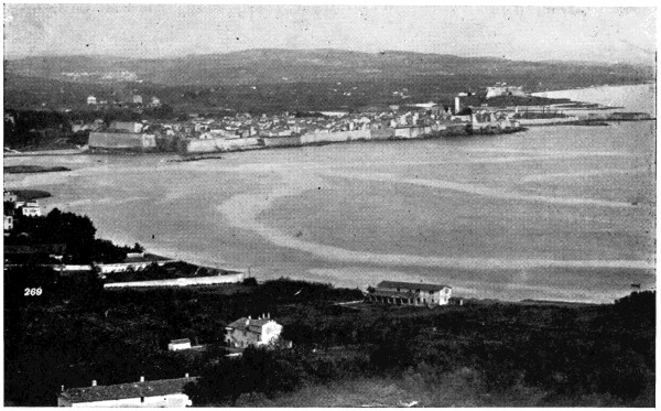
Fig. 5.—Glassy streaks showing the centres of ascending and descending columns of air in the Bay of Antibes, Alpes Maritimes.
At Nice and Monte Carlo this phenomena was also very marked. On one occasion, while making observations from the highest part of the promontory of Monaco on a perfectly calm day, I noticed that the whole of the sea presented this peculiar effect as far as the eye could reach,[18] and that the lines which marked the descending air were never more than 1,000 feet from those which marked the centre of the ascending column. At about three o’clock one afternoon, a large black steamer passed along the coast in a perfectly straight line, and its wake was at once marked by a glassy line, which indicated the centre of an ascending column. This line remained almost straight for two hours, when finally it became crooked and broken. The heat of the steamer had been sufficient to determine this upward current of air.

Fig. 6.—Air currents observed in the Mediterranean, ascending currents at a, a, a, and descending currents at b, b, b.
In 1893 I spent two weeks in the Mediterranean, going and returning by a slow steamer from Marseilles to Constantinople, and I had many opportunities of observing the peculiar phenomena to which I have referred. The steamer passed over thousands of square miles of calm sea, the surface being only disturbed by large patches of small ripples (Fig. 6), separated from each other by glassy streaks, which, however, were not straight as on the Atlantic, and I found that in no case was the wind blowing in the same direction on both sides of these streaks, every one of which indicated the centre of an ascending or a descending column of air. If we should investigate these phenomena in what might be called a dead calm, we should find that the air was rising very[19] nearly straight up over the centres of some of these streaks and descending in a vertical line over the centres of others. But, as a matter of fact, there is no such thing as a dead calm. The movement of the air is the resultant of more than one force. The air is not only rising in some places and descending in others, but at the same time, the whole mass is moving forward with more or less rapidity from one part of the earth to another, so we must consider that, instead of the air ascending directly from the relatively hot surface of the earth and descending vertically in other places, in reality the whole mass of rotating air is moving horizontally at the same time.
Suppose that the local influence which causes the up and down motion of the air should be sufficiently great to cause the air to rise at the rate of 2 miles an hour, and that the wind at the same time should be blowing at the rate of 10 miles an hour, the motion of the air would then be the resultant of these two velocities. In other words, it would be blowing up an incline of 1 in 5. Suppose, now, that a bird should be able to so adjust its wings that it advanced 5 miles in falling 1 mile through a perfectly calm atmosphere, it would then be able to sustain itself in an inclined wind, such as I have described, without any movement at all of its wings. If it were possible to adjust its wings in such a manner that it could advance 6 miles by falling through 1 mile of air, it would then be able to rise as relates to the earth while in reality falling as relates to the surrounding air.
In conducting a series of experiments with artillery and small guns on a large and level plain just out of Madrid, I often observed the same phenomena, as relates to the wind, that I have already spoken of as having observed at sea, except that the lines marking the centre of an ascending or a descending column of air were not so stationary as they were over the water. It was not an uncommon thing, when adjusting the sights of a gun to fire at a target at a very long range, making due allowances for the wind, to have the wind change and blow in the opposite direction before the word of command was given to fire. While conducting these experiments, I often noticed the flight of eagles. On one occasion a pair of eagles came into sight on one side of the plain, passed directly over our heads, and disappeared on the opposite side. They were apparently always at the same height[20] from the earth, and in soaring completely across the plain they never once moved their wings. These phenomena, I think, can only be accounted for on the hypothesis that these birds were able to feel out with their wings an ascending column of air, that the centre of this column of air was approximately a straight line running completely across the plain, that they found upward movement more than sufficient to sustain their weight in the air, and that whereas, as relates to the earth, they were not falling at all, they were in reality falling some 4 or 5 miles an hour in the air which supported them.
Again, at Cadiz in Spain, when the wind was blowing in strongly from the sea, I observed that the sea-gulls always took advantage of an ascending column of air. As the wind rose to pass over the fortifications, the gulls selected a place where they would glide on the ascending current of air, keeping themselves always approximately in the same place without any apparent exertion. When, however, they left this ascending column, it was necessary for them to work their wings with great vigour until they again found the proper place to encounter a favourable current.
I have often noticed that gulls are able to follow a ship without any apparent exertion; they simply balance themselves on an ascending column of air, where they seem to be quite as much at ease as they would have been roosting on a solid support. If, however, they are driven out of this position, they generally commence at once to work their passage. If anything is thrown overboard which is too heavy for them to lift, the ship soon leaves them behind, and in order to catch up with it again they move their wings very much as other birds do; but when once established in the ascending column of air, they manage to keep up with the ship by doing little or no work. In a calm or head wind we find them directly aft of the ship; if the wind is from the port side they may always be found on the starboard quarter, and vice versâ.
One Sunday morning, while living at Kensington, I noticed some very curious atmospheric effects. The weather had been intensely cold for about a week, when suddenly the atmosphere became warm and very humid. The earth being much colder than the atmosphere, water was condensing on everything that it touched. I went to the bridge over the Serpentine in Hyde Park, and was[21] not disappointed in finding a large number of sea-gulls waiting about the bridge to be fed. On all ordinary occasions these birds manage to move about with the expenditure of very little energy, but on this occasion every one of them, without a single exception, no matter in what position he might be, was working his passage like any other bird, just as I had expected. It is only on very rare occasions that the surface of the earth is sufficiently cold as relates to the atmosphere to prevent all upward currents of air.
Everyone who has passed a winter on the northern shores of the Mediterranean must have observed the cold wind which is generally called the mistral. One may be out driving, the sun may be shining brightly, and the air warm and balmy, when suddenly, without any apparent cause, one finds himself in a cold descending wind. This is the much-dreaded mistral, and if at sea it would be marked by a glassy line on the surface of the water. On land, however, there is nothing to render its presence visible. The ascending column of air is, of course, always very much warmer than the descending column, and this is taking place in a greater or lesser degree everywhere and at all times. A decided upward trend of air is often encountered by those who are experimenting with kites, the kite often mounting higher than can be accounted for on the hypothesis that the wind is moving in a horizontal direction. I have heard this discussed at considerable length. When a kite is flown in an upward current, it behaves in many respects like a soaring bird.
From the foregoing, I think, we may safely draw the following conclusions:—
First, that there is a constant interchange of air taking place, the cold air descending, spreading itself out over the surface of the earth, becoming warm, and ascending in other places.
Second, that the centres of the two columns are generally separated from each other by a distance which may be from 500 feet to 20 miles.
Third, that the centres of greatest action are not in spots, but in lines which may be approximately straight, but sometimes abound in many sinuosities.
Fourth, that this action is constantly taking place over both the sea and the land; that the soaring of birds, the phenomenon which has heretofore been so little understood,[22] may be accounted for on the hypothesis that the bird seeks out an ascending column of air, and while sustaining itself at the same height in the air, without any muscular exertion, it is in reality falling at a considerable velocity through the air that surrounds it.
It has been supposed by some scientists that birds may take advantage of some vibratory or rolling action of the air. I find, however, from careful observation and experiment, that the motion of the wind is comparatively steady, and that the short vibratory or rolling action is always very near to the earth and is produced by the air flowing over hills, high buildings, trees, etc.
Tools and instruments used by mechanicians are very often made of the material most used in their profession; for instance, a blacksmith’s tools are generally of iron, a carpenter’s tools largely of wood, and a glass-blower uses many things made of glass, and so on. Mathematicians are no exception to this general rule, and seem to imagine that everything can be accomplished by pure mathematical formulæ.
It appears that Prof. Langley was at times considerably puzzled by the extraordinary behaviour of birds, and was led to believe that they took advantage of some vibratory or oscillating movement of the air; he called it “the internal work of the air.” I have been very much amused in a recent mathematical work that I have read, in which the writer seeks to solve all questions by pure mathematics. In this case, notwithstanding that all of the factors are unknown and unknowable, still, with the use of about two pages of closely written algebraic formulæ, he appears to have solved the whole question. Just how he arrived at it, however, is more than I am able to understand.
If a kite is flown only a few feet above the ground, it will be found that the current of air is very unsteady. If it is allowed to mount to 500 feet the unsteadiness nearly all disappears, while if it is allowed to mount further to a height of 1,500 or 2,000 feet, the pull on the cord is almost constant, and, if the kite is well made, it remains practically stationary in the air.
I have often noticed in high winds that light and fleecy clouds come into view, say, about 2,000 feet above the surface of the earth, and pass rapidly and steadily by preserving their shape completely. This would certainly[23] indicate that there is no rapid local disturbance in the air in their immediate vicinity, but that the whole mass of air in which these clouds are formed is practically travelling in the same direction and at the same velocity. Numerous aeronauts have also testified that, no matter how hard the wind may be blowing, the balloon is always practically in a dead calm, and if a piece of gold-leaf is thrown overboard, even in a gale, the gold-leaf and the balloon never part company in a horizontal direction, though they may in a vertical direction.
Birds may be divided into two classes. First, the soaring birds, which practically live upon the wing, and, by some very delicate sense of touch, are able to feel the exact condition of the air. Many fish which live near the top of the water are greatly distressed by sinking too deeply, while others which live at great depths are almost instantly killed by being raised to the surface. The swim-bladder of a fish is in reality a delicate barometer provided with sensitive nerves which enable the fish to feel whether it is sinking or rising in the water. With the surface fish, if the pressure becomes too great, it involuntarily exerts itself to rise nearer the surface and so diminish the pressure, and I have no doubt that the air cells, which are known to be very numerous and to abound throughout the bodies of birds, are so sensitive as to enable soaring birds to know at once whether they are in an ascending or a descending column of air.
The other class of birds consists of those which only employ their wings occasionally for the purpose of taking them rapidly from one place to another. Such birds do not expend their power so economically as the soaring birds. They do not pass much of their time in the air, but what time they are on the wing they put forth an immense amount of power and fly very rapidly, generally in a straight line, taking no advantage of air currents. Partridges, pheasants, wild ducks, geese, and some birds of passage may be taken as types of this kind. This class of birds has relatively small wings, and carries about two and a half times as much weight per square foot of surface as soaring birds do.
We shall never be able to imitate the flight of the soaring birds. We cannot hope to make a sensitive apparatus that will work quick enough to take advantage of the[24] rising currents of air, and he who seeks to fly has this problem to deal with. A successful flying machine, moving at a high velocity, is likely at any time to encounter downward currents of air, which will greatly interfere with its action. Therefore flying machines must, in the very nature of things, be provided with sufficient power to propel them through various currents of air, after the manner of ducks, partridges, pheasants, etc.
| Common Name. | Sq. Ft. per Lb. |
Lbs. per Sq. Ft. |
Corresponding Speed for a Plane at 3° in Miles per Hour. |
|||
|---|---|---|---|---|---|---|
| Bat, | 7 | ·64 | 0 | ·131 | 15 | ·9 |
| Swallow, | 3 | ·62 | 0 | ·276 | 23 | ·1 |
| Lark, | 3 | ·06 | 0 | ·327 | 25 | ·1 |
| Sparrow hawk, | 3 | ·00 | 0 | ·333 | 25 | ·3 |
| Sparrow, | 2 | ·42 | 0 | ·414 | 28 | ·2 |
| Gull, | 2 | ·35 | 0 | ·426 | 28 | ·6 |
| Owl, | 2 | ·26 | 0 | ·443 | 29 | ·2 |
| Crane, | 2 | ·02 | 0 | ·495 | 30 | ·9 |
| Rook, | 1 | ·74 | 0 | ·575 | 33 | ·3 |
| Plover, | 1 | ·38 | 0 | ·725 | 37 | ·4 |
| Balbuzzard, | 1 | ·26 | 0 | ·795 | 39 | ·2 |
| Egyptian vulture, | 1 | ·18 | 0 | ·848 | 40 | ·4 |
| Duck, | 0 | ·864 | 1 | ·158 | 44 | ·2 |
| Grey pelican, | 0 | ·732 | 1 | ·365 | 51 | ·3 |
| Wild goose, | 0 | ·586 | 1 | ·708 | 57 | ·4 |
| Turkey, | 0 | ·523 | 1 | ·910 | 60 | ·6 |
| Duck (female), | 0 | ·498 | 2 | ·008 | 62 | ·2 |
| D„ck (male), | 0 | ·439 | 2 | ·280 | 66 | ·2 |
It was said of Benjamin Franklin that when he wished to fly a kite in order to ascertain if lightning could be drawn down from the clouds, he managed to have a boy with him in order to avoid ridicule. It was considered too frivolous in those days for grown-up men to amuse themselves with kites, and a good many besides Benjamin Franklin have feared to face the ridicule that was inevitable if they took up or even discussed the question of artificial flight. Nineteen years ago, when I commenced my own experiments, I was told that my reputation would be greatly injured, that mankind looked upon artificial flight as an ignis-fatuus, and that anyone who experimented in that direction was placed in the same category as those who sought to make perpetual-motion machines or to find the philosopher’s stone. Although I had little fear of ridicule, still I kept things as quiet as I could for a considerable time, and I had been working fully six months before anyone ascertained what I was doing. When, however, it became known that I was experimenting with a view of building a flying machine, the public seemed to think that I was making honest and praiseworthy scientific investigations; true, I might not succeed, still it was said that I would accomplish something, and find out some of the laws relating to the subject. No one ridiculed my work except two individuals, and both of these were men whom I had greatly benefited. As is often the case, those whom you find in difficulties and place on their feet seek to do you some injury as compensation for the benefits they have received.
At the present time it is not necessary for any man to take a small boy with him as a species of lightning-rod to ward off ridicule when he flies a kite. I have been one of a committee on kite-flying at which some of the most learned and serious men in England were my colleagues in investigating the subject. The behaviour of kites is certainly very puzzling to those who do not thoroughly[26] understand the subject. A kite may be made with the greatest degree of perfection, and placed in the hands of one of considerable experience; nevertheless, it may behave very badly, diving suddenly to the ground without any apparent cause. Then, again, this same kite will sometimes steadily mount in the air until it reaches a height difficult to account for. If the surface of the earth should be perfectly smooth, and the wind should always blow in a horizontal direction, kites would not show these eccentric peculiarities, but, as a matter of fact, the air seldom moves in a horizontal direction; it is always influenced by the heat of the surface of the earth. Heated air is continually ascending in some places only to be cooled and to descend in other places. If one is attempting to fly a kite where the air is moving downwards, he will find it an extremely difficult matter, whereas, if he is fortunate enough to strike a current of air which is rising, the kite will mount much higher in the air than can be accounted for, except we admit of the existence of these upward draughts of air. On one occasion many years ago, I was present when a bonded warehouse in New York containing 10,000 barrels of alcohol was burnt. It was nine o’clock at night, and I walked completely around the fire, and found things just as I had expected. The wind was blowing a perfect hurricane through every street in the direction of the fire, although it was a dead calm everywhere else; the flames mounted straight in the air to an enormous height, and took with them a large amount of burning wood. When I was fully 500 feet from the fire, a piece of partly burnt 1-inch board, about 8 inches wide and 4 feet long, fell through the air and landed very near me, sending sparks in every direction. This board had evidently been taken up to a great height by the tremendous uprush of air caused by the burning alcohol. It is very evident that a kite made of boiler iron could have been successfully flown under these conditions providing that it could have been brought into the right position.
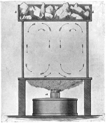
Fig. 7.—The circulation of air produced by a difference in temperature.
The sketch (Fig. 7) shows a device consisting of a spirit lamp and a box of ice. The lamp heats the metallic plate, expands the air which rises and is cooled by convection on coming in contact with the top plate, and descends as shown. However, a fire is not necessary to accomplish this result; it is taking place all over the earth, all the time. A great number of plants depend upon a rising current of[27] air to transport their seeds to distant places. Seeds of the thistle and dandelion variety are sometimes able to travel hundreds of miles, to the great vexation of farmers; and there is a certain class of small spider known as “Balloon Spiders” which also depend upon a rising current of air to carry them from the place of their birth to some distant part where they, of course, hope to start a colony. When I was a boy of eight, I noticed small spiders webbing down from the sky. I was greatly puzzled; it appeared to me that they had attached their web to some stationary object high in the air and were spinning a web in order to lower themselves to the earth. What could that stationary object be? As the sky was clear, I was quite unable to understand[28] this phenomenon, but afterwards I learned from scientific books that there was a class of spiders that managed to rise high in the air by the aid of the wind. It appears that they climb a high tree until they have reached the uppermost extremity and then, from a leaf or twig that projects into the air, they wait for an ascending current of air. Although the spider is exceedingly small—the size of a pin’s head—it has about 200 spinnerets, its ordinary web being formed of no less than that number of extremely fine threads. These are spun out singly into the air until an almost invisible mass of fine webs interlacing each other in all directions and forming an approximately cylindrical network about half an inch in diameter and 18 inches long is produced. Whenever an upward draft of air approximately vertical occurs, it takes this weightless tangle of fine webs with it, and so soon as the spider finds there is sufficient pull to lift its weight, it lets go and ascends with the air. When the Nulli Secundus ascended at Farnborough and landed at the Crystal Palace, Mr. Cody, who was on board, reported what he supposed to be a very curious and unaccountable phenomenon. The balloon was covered with many thousands of minute spiders that it had picked up in the air on the voyage. Certainly this of itself is very strong evidence of the existence of these ascending currents of air.
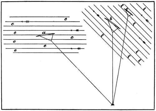
Fig. 8.—a represents a kite in a horizontal wind, e, e, e; b, the same kite in a rising column of air, the wind blowing in the direction shown at f, f. If the kite is a good one, it may pass over to the point c.
When in Boston about fifteen years ago, I went to Blue Hill to witness the remarkable kite flying which was taking place at that time. The kites experimented with were of the Hargrave type, and of enormous dimensions. A steel wire and windlass worked by a steam engine was employed. I was told that on certain occasions the kites mounted extremely high, much higher than they were able to account for; but on this particular occasion, although they let out a great amount of wire, the kite did not mount very high. I have heard much discussion first and last regarding the flight of kites, and I think it is generally admitted that they do sometimes rise upwards and continue moving to the windward until they pass directly over the spot where they are attached to the earth. It was not, however, till about three years ago that I witnessed this phenomenon myself. Mr. Cody, who is the inventor of a very good kite, had been flying kites at the Crystal Palace for some months, and on one occasion I saw his kite rise, pass to the windward and directly over our[29] heads. I took hold of the cord with both hands, and was somewhat surprised to find what the lifting effect was. The kite was, however, of large dimensions, but by no means so large as Mr. Cody’s “man-lifting kites.” In the drawing (Fig. 8) I have shown, at a, the action of a kite in a horizontal wind, lines e, e, showing the direction of the wind. A good kite will easily mount 45°, the angle shown, but on the occasion just mentioned, the sun had been shining brightly into the valley where the experiments[30] took place, and an upward current of air had been determined. The cooler air was, of course, rushing in from each side and mounting in about the centre of the valley, and Mr. Cody’s kite, instead of flying in a horizontal wind, soon reached a point where the wind was ascending at an angle, as shown at f, f. The kite would therefore mount until at b, where it presented the same angle to the wind as with the horizontal wind at a, and if it should be made to fly at a higher angle, it might pass over to the position shown at c. But it must not be imagined that this phenomenon can be witnessed every day in the year. It is only on rare occasions that one is fortunate enough to find a wind which is blowing at a sufficiently sharp upward trend to cause a kite to pass to the windward over the point of support. Neither must it be supposed that this favourable condition of things is of long duration. As the centre of the upward current is constantly moving, it is certain that very soon it will move away from the point from which the kite is being flown. What is true of kites is also true of flying machines. It is very difficult indeed to make a kite mount providing that it is in a descending current of air, and one is just as likely to find a descending current as any other. Flying machines will, therefore, have to be made with a considerable amount of reserve energy, so as to be able to put on a spurt when they encounter an adverse current. If a machine is made that is able to maintain itself in the air for any considerable length of time, it will not be a very difficult task to know when a current of air of this kind is encountered, because, if the engine is working up to speed, and everything is in perfect order, and still the machine is falling, it is very certain that an unfavourable current has been encountered, and efforts should be made to get out of it as soon as possible. Then, again, if the machine has an abnormal tendency to rise without any increase in the number of rotations made by the screws, the aeronaut may be certain that he has encountered an upward and favourable current of air which, unfortunately, will not last. It should, however, be borne in mind that, while the width of the upward current is not very great, nevertheless, it may extend in a practically straight line for many miles.
In 1887 I was approached by several wealthy gentlemen who asked me if I thought it was possible to make a flying machine. I said, “certainly; the domestic goose is able to fly and why should not man be able to do as well as a goose?” They then asked me what it would cost and how long it would take, and, without a moment’s hesitation, I said it would require my undivided attention for five years and might cost £100,000. A great deal of experimenting would be necessary; the first three years would be devoted to developing an internal combustion engine of the Brayton or Otto type, and the next two years to experimenting with aeroplanes and screws and building a machine. Even at that time I had a clear idea of the system that would be the best. However, nothing was then done, but in 1889 I employed for the purpose two very skilful American mechanics, and put them to work at Baldwyn’s Park, Kent. At that time the petroleum motor had not been reduced to its present degree of efficiency and lightness; it was not suitable for a flying machine, and I saw that it would require a lot of experimental work in order to develop it. After taking into consideration all the facts of the case, I decided to use a steam engine. Had I been able to obtain the light and efficient motors which have been recently developed, thanks to the builders of racing cars, I should not have had to experiment at all with engines and boilers, as I could have obtained the necessary motors at once. As it was, I was obliged to content myself with the steam engine.
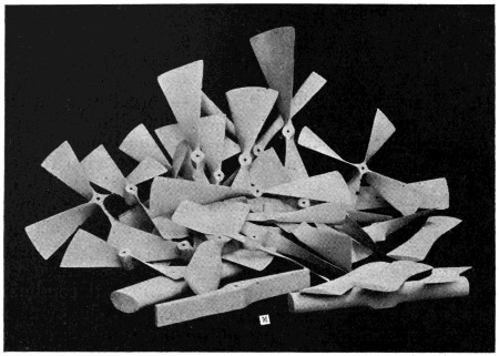
Fig. 9.—Group of screws and other objects used in my experiments.

Fig. 10.—Some of the principal screws experimented with—h, a screw with very thick blades, and g, a screw made after a French model.
I found that there was a great deal of misunderstanding regarding the action of aeroplanes, and also of screws working in the air. I procured all the literature available on the subject, both English and French, and attempted to make a thorough study of the question; but I was not satisfied, on account of the wide difference in the views of the writers and the conflicting formulæ that were employed. I therefore decided to make experiments[32] myself, and to ascertain what could be done without the use of anybody’s formula. Although this was nearly twenty years ago, I find that there is still a great deal of discussion regarding the action of aeroplanes and screws, in which the majority taking part in the discussion are in the wrong. However, several good works on the subject have recently been published.

Fig. 11.—The three best screws. The screw on the right has a uniform pitch throughout, the middle screw has increasing pitch, and the left screw compound increasing pitch.
Having designed and put my boiler and engine in hand, I commenced a series of experiments for the purpose of ascertaining the efficiency of screw propellers working in the air, and the form and size that would be best for my proposed machine. The illustration Fig. 9 shows a photographic group of the screws and other objects with which I experimented. Fig. 10 shows some of the leading types which, as will be seen, have blades of different shape, pitch, and size. Fig. 11 shows three of the best screws employed. It will be observed that one has uniform pitch, another increasing pitch, and the third compound increasing pitch. In order to test the efficiency of my screws I made the apparatus shown in Fig. 12. The power for running the screw was transmitted by means of a belt to the straight cylindrical pulley c, c. Shaft b, b was of steel, rather small in diameter, and ran smoothly, and practically without friction, through the two bearings d, d. When the first screw, a, a, was run at a high velocity, the axial thrust pushed the shaft b, b back and elongated the spiral spring e. The degree of screw thrust was indicated in pounds by the pointer g. The power was transmitted through a very accurate and sensitive dynamometer, so that the amount consumed could be easily observed by a pointer similar to the one employed for indicating the screw thrust. A tachometer was also employed to observe the number of turns that the screw was making in a minute. The whole apparatus was carefully and accurately made and worked exceedingly well. I was thus enabled, with my various forms of screws and other objects, to make very accurate measurements, some of which are exceedingly interesting.
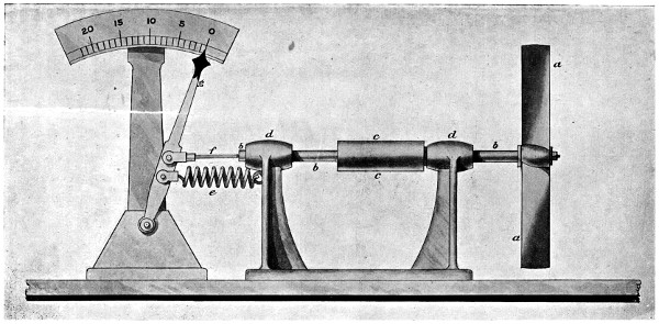
Fig. 12.—Apparatus for testing the thrust of screws—a, a, the screw; b, b, shaft sliding freely in the bearing d, d; c, cylindrical pulley; e, spiral spring; f, steel rod; g, pointer for indicating the thrust in pounds.
Fig. 13.—Apparatus for testing the direction of air currents caused by a rapidly rotating screw. Silken threads were attached to the wire c, c, which indicated clearly the direction in which the air was moving.
In many of the treatises and books of that time it was[34]
[35]
stated that a screw propeller, working in the air, was
exceedingly wasteful of energy on account of producing
a fan-blower action. Some inventors suggested that the
screw should work in a stationary cylinder, or, better
still, that the whole screw should be encased in a rotating
cylinder, to prevent this outward motion of the air. In
order to ascertain what the actual facts were, I attached
a large number of red silk threads to a brass wire, which
I placed completely around my screw (see Fig. 13). Upon
starting up I found that, instead of the air being blown
out at the periphery of the screw, it was in reality sucked
in, as will be seen in the illustration. I was rather surprised[36]
to see how sharp a line of demarkation there was
between the air that was moving in the direction of the
screw and the air that was moving in the opposite
direction. The screw employed in these experiments was
18 inches in diameter and had a pitch of 24 inches. It
was evident, however, if the pitch of the screw was coarse
enough that there would be a fan-blower action. I therefore
tried screws of various degrees of pitch, and found
when the pitch was a little more than three times the
diameter, giving to the outer end of the blade an angle
of 45°, that a fan-blower action was produced—that is,
part of the time when the screw was running, the air
would alternate; sometimes it would pass inwards at the
periphery and sometimes outwards. The change of direction,
however, was always indicated by a difference in
the pitch of the note given out, and also by the thrust.
In Fig. 14 I have shown the extremities of the blades of
some of the different forms of screws experimented with,[37]
in which a shows a plain screw, the front side being
straight and of equal pitch from the periphery to the
hub; b is a screw of practically the same pitch, but
slightly curved so as to give what is known as an
increasing pitch; c shows the extremity of a screw in
which the curve is not the same throughout—that is, it
is what is known as a compound increasing pitch; d is
the shape of the screw that gave the angle of 45° above
referred to.

Fig. 14.—This drawing shows the ends of screw blades in which a is a plain screw; b, screw with increasing pitch; c, screw with compound increasing pitch; d, end of screw blade 45°; e, screw with very thick blade; f, blade with no pitch at all; g, blade which gave a thrust in the direction of the convex side, no matter in which direction it was revolved; h, screw said to have been used in the French Government experiments.
The first screw experimented with was a. This screw was run at a high velocity—about 2,500 revolutions per minute—until a screw thrust of 14 lbs. was obtained, and then the governor of the engine was set so that all screws of the same diameter could be run at the same speed. Wishing to ascertain the efficiency of the screw and how much was lost in skin friction, I multiplied the thrust in pounds by the pitch of the screw in feet and by the number of turns it was making in a minute. This, of course, gave the exact number of foot-pounds in energy that was being imparted to the air. I was somewhat surprised to find that it corresponded exactly with the readings of the dynamometer. I thought at first that I must have made some mistake. Again I went very carefully over all the figures, tested everything, and made another experiment and found, even if I changed the number of revolutions, that the readings of the dynamometer were always exactly the same as the energy imparted to the air. This seemed to indicate that the screw was working very well and that the skin friction must be very small indeed. In order to test this, I made what we will call, for the moment, a screw without any pitch at all—that is, the blades were of wood and of the exact thickness and width of the blades of the screw a, but without any pitch at all. The extremity of the blade is shown at f. I placed this screw on my machine in place of a, and although my dynamometer was so sensitive that the pointer would move away from the zero pin by simply touching the tip of the finger to the shaft, it failed to indicate, and thus the screw appeared to consume no power at all. These experiments were repeated a considerable number of times. I then obtained a sheet of tin the same diameter as the screws, 18 inches, and upon running it at the same speed, I found that it did consume a measurable amount of power, certainly more than the two blades f.[38] This no doubt was due to the uneven surface of the tin. Had it been a well-made saw blade without teeth, perfectly smooth and true on both sides, it probably would not have required power enough to have shown on the dynamometer. However, it is quite possible that there is a little more skin friction with a polished metallic surface, than with a piece of smooth evenly lacquered wood. The screws which I employed were of American white pine such as used by patternmakers. This wood was free from blemishes of all kind, extremely light, uniform, and strong. When the screw had been formed, it was varnished on both sides with a solution of hot glue, which greatly increased the strength of the wood crosswise of the grain. When this glue was thoroughly dry, the wood was sand-papered until it was as smooth as glass; the whole thing was then carefully varnished with shellac, rubbed down again and revarnished with very thin shellac something like lacquer. In this way the surface of the screw was made very smooth. The screws, of course, were made with a great degree of accuracy and as free as possible from any unevenness. Having tested screw a, I next tested screw b. I found with the same number of revolutions per minute that this screw produced more thrust, but it required more power to run it, and when the energy imparted to the air was compared with the readings of the dynamometer, it was found that it did not do quite so well as a; still as the thrust was greater and the efficiency only slightly less, it appeared to be the better screw. Upon trying screw c, under the same conditions, the thrust was very much increased, but the power required was also increased to a still greater degree, showing that this form was not so favourable as either a or b. All the screws experimented with had very thin blades, and it occurred to me that the difference between a and b might arise from the fact that, when a was running at a very high velocity, the working side instead of being flat might have become convex to a slight extent, whereas with b, a slight bending back of the edges of the blade would still leave the working side concave. I therefore made the screw shown at e, which had the same pitch as the other three, but the working side was of the same shape as a. Of course the additional thickness of the blades made it impossible to give an easy curve to the back. Curiously enough I found that e did nearly as well as a, and quite as well as b. The additional thickness did not interfere to[39] any appreciable extent with its efficiency. I then made another propeller, shown at g, which was of the same thickness in the middle as e. Upon running this, I found that it required considerable power, and no matter which way it was run, the thrust was always in the direction of the convex side, which was quite the reverse from what one would have naturally supposed.
Fig. 15.—The manner of building up the large screws.
About the time that I was making these experiments, my duties called me to Paris, and while there I called on my old friend Gaston Tissandier. Through his influence I was permitted to see some models of the screws that were alleged to have been used by Captain Renard in his experiments for the French Government, and I was somewhat surprised to find the form of the blades, the same as shown at h, Fig. 14, and completely without any twist. On my return to England, I made a screw of this description. It is also shown in the photographic illustration, Fig. 9. Upon testing this screw, I found that its efficiency was only 40 per cent. of that of a—that is, the energy or acceleration imparted to the air was only 40 per cent. of the readings of the dynamometer. It then occurred to me that this particular form of screw was probably the one that the French had for exhibition purposes, but not the one they intended to use. Having tried all the various forms of screws and other objects shown in Fig. 9, I made some sheet metal screws; also a screw which consisted of a steel frame covered with woven fabric, and which was identical with screws that I had seen described in various works[40] relating to aerial navigation. It was found quite impossible to keep the fabric taut and smooth, and the results were very bad indeed, it being only 40 per cent. as efficient as a well-made wooden screw.

Fig. 16.—A fabric-covered screw with a very low efficiency.
Having thus ascertained the best form of a screw, I built up my first large screws, which were 17 feet 10 inches in diameter, after the well-known manner of making wooden patterns for casting steamship propellers. Fig. 15 shows the form of the end of the blade, the middle of the blade, and the hub. My first pair of large screws had a pitch of 24 feet, but these were too great a drag on the engine. I therefore made another pair with 16 feet pitch which greatly increased the piston speed, and permitted the engines to develop much more power; the screw thrust was also increased just in an inverse ratio to the pitch of the screws. Another pair of screws[41] was tried with 14 feet pitch and 12 feet in diameter, but these did not do so well. My large screws were made with a great degree of accuracy; they were perfectly smooth and even on both sides, the blades being thin and held in position by a strip of rigid wood on the back of the blade. In order to prevent the thrust from collapsing the blades, wires were extended backwards and attached to a prolongation of the shaft. Like the small screws, they were made of the very best kind of seasoned American white pine, and when finished were varnished on both sides with hot glue. When this was thoroughly dry, they were sand-papered again and made perfectly smooth and even. The blades were then covered with strong Irish linen fabric of the smoothest and best make. Glue was used for attaching the fabric, and when dry another coat of glue was applied, the surface rubbed down again and then painted with zinc white in the ordinary way and varnished. These screws worked exceedingly well. I had means of ascertaining, with a great degree of accuracy, the thrust of the screw, the number of turns per minute, the speed of the machine, and, in fact, all the events that were taking place on the machine. It was found that when the screw thrust in pounds was multiplied by the pitch in feet, and by the number of revolutions made in a minute of time, it exactly corresponded to the power that the engines were developing, and that the amount of loss in skin friction was so small as to be practically negligible.
Fig. 17.—The hub and one of the blades of the screw on the Farman machine. The blade c, is a sheet of metal riveted to the rod b, and forms a projection on the back of the blade which greatly reduces its efficiency. The peculiar form of hub employed makes it possible to change the diameter and pitch of this screw at will.
In connection with this subject I would say that many
experimenters claim to have shown that the skin friction
on screws is considerable, in fact, so great as to be a very
important factor in the equation of flight. I am, however,
of the opinion that these experimenters have not had well-made
screws. If the surface of the screw is uneven,
irregular, or rough, a considerable amount of energy is lost,
as shown in the French screw and the fabric covered
screw. It is simply a question of having a screw well-made.
In those recently employed in France (see Fig. 17),
the blades are of hammered sheet metal, the twist is not
uniform or true, and what is worst of all, the arm b
projects on the back of the blade and offers a good deal of
resistance to the air. This form of screw, however, is very
ingenious; as will be seen by the drawing, the pitch and
diameter can be changed at will. It is, however, heavy,[42]
wasteful of power, and altogether too small for the work
it has to do. The skin friction of screws in a steamship
has led inventors to suppose that the same laws relate to
screws running in air, but such is by no means the case.
In designing a steamship, we have to make a compromise
in regard to the size of the screw. If the screw is too
small, an increase in diameter is, of course, an advantage,
and it may also be an advantage, not only to increase the[43
44]
diameter, but also to reduce the pitch; however, a point
is soon reached where the skin friction will more than
neutralise the advantages of engaging a larger volume of
water. This is because the water adheres to the surface;
in fact, the skin friction of a ship and its screw consumes
fully 80 per cent. of the total power of the engines, but
with an air propeller its surface is not wetted and the air
does not stick to its surface. If made of polished wood,
the friction is so extremely small as to be almost unmeasurable.
The diameter of a well-made screw running in air is
therefore not limited in any degree by skin friction, as is
the case with a screw running in water; in fact, it is rather
a question of its weight, and its efficiency ought to increase
in direct ratio with its diameter, because the area of the
disc increases with the square of the diameter. The screw
slip is therefore reduced by one-half by simply doubling
the diameter of the screw. It will be understood that by
doubling the diameter of the screw, four times as much air[45
46]
will be engaged. If we push this back at half the speed,
we shall have the same screw thrust, because the resistance
of the air is in proportion to the square of the velocity
that we impart to it, so that one just balances the other,
and the diminution of wasteful slip is just in proportion to
the increase in diameter. In all cases, the screw should be
made as large as possible.

Fig. 18.—Section of screw blades having radial edges. With screws of this form, the blades, of course, become narrower as the hub is approached, and if it is a true screw and the edges radial, the sine of the angle will be the same at all points. It is 2 inches in this case.
Fig. 18 enlarged (55 kB)
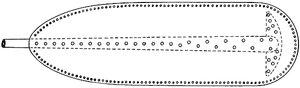
Fig. 19.—Shows the form of the blade of a screw propeller made of sheet metal. It is riveted at the edges and also to the arm of a screw with a stiffening piece at the extreme end. However, it is not necessary to rivet edges together. They may be welded with a name of acetylene oxygen gases.

Fig. 19a.—Shows the manner of welding and the finished edge.
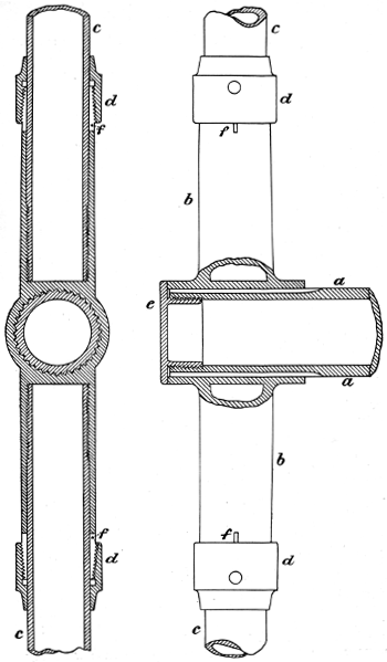
Fig. 20.—A new form of hub, of great strength and lightness, for use on flying machines.
In the drawing (Fig. 18) I have shown screw blades of a proper shape to give the best results—that is, providing a metallic screw is employed. Instead of having the arm of the screw on the back of the blade to offer resistance to the air, the arm should be tubular, flattened, and covered on both sides with sheet metal. This particular formation not only prevents the air from striking the arm, but, at the same time, prevents the pressure of the air from deforming the blade, so, if a metallic screw is to be used, the form of blade which I have shown will be found much superior to that employed at the present time on continental flying machines. We should not lose sight of the fact that weight tells very seriously against the success of a flying machine, and that no expense should be spared to reduce the weight, providing that it is possible to do so without reducing the factor of safety. Suppose, for example, that we use an ordinary hub secured to a solid shaft by a common key. All the parts have to be made heavy in order to be sufficiently strong to withstand the strain. In the drawing (Fig. 20) I have shown a hub which I think is quite as light and strong as it is possible to make it. The action of the motor is often spasmodic and puts very great strain upon the parts, and there is a very strong tendency for the shaft to turn round in the hub. If a key is used, the hub has to be large and strong, and the key of considerable size, otherwise the parts would be deformed. In my own experiments, I have found considerable difficulty in securing a shaft to wooden screws. However, it will be seen in the drawings that a series of grooves is cut in the shaft and that the hub has internal projections, so that the one fits the other. This makes a very strong connection and is of extreme lightness. Both the hub and the shaft should be of tempered steel. The spokes should be hard drawn steel tubes with long fine threads, so as to withstand centrifugal force. To prevent them from rotating in the hub, the nuts d, d are provided, which compress the arms of the steel hub so as to grip the tube with any[47] degree of force required. It will be seen that with this system the pitch of the screw may be adjusted to some extent; however, it is better to have all parts of the screw, from hub to centre, of the same pitch. A slight deviation from this is admissible in the experimental stage, so long as the deviation from a true screw, caused by rotating the arm, is not greater than one half of the slip while in flight.
Many experimenters have imagined that a screw is just as efficient placed in front of a machine as at the rear, and it is quite probable that, in the early days of steamships, a similar state of things existed. For several years there were steamboats running on the Hudson River, New York, with screws at their bows instead of at their stern. Inventors of, and experimenters with, flying machines are not at all agreed by any means in regard to the best position for the screw. It would appear that many, having noticed that a horse-propelled carriage always has the horse attached to the front, and that the carriage is drawn instead of pushed, have come to the conclusion that, in a flying machine, the screw ought, in the very nature of things, to be attached to the front of the machine, so as to draw it through the air. Railway trains have their propelling power in front, and why should it not be the same with flying machines? But this is very bad reasoning. There is but one place for the screw, and that is in the immediate wake, and in the centre of the greatest atmospheric disturbance. While a machine is running, although there is a marked difference between water and air as far as skin friction is concerned, still the conditions are the same as far as the position of the screw is concerned. With a well-designed steamship, the efficiency of the screw is so great as to be almost unbelievable; in fact, if a steamship had never been made, and the design of one should be placed before the leading mathematicians of to-day, with the request that they should compute the efficiency of the screw, none of them would come anywhere near the mark. They would make it altogether too small. As before stated, when a steamship is being driven through the water, the water adheres to its sides and is moved forward by the ship—that is, it has acceleration imparted to it which exactly corresponds to the power consumed in driving the ship through the water. This, of course, retards it and we find in a well-designed ship, not run above its natural speed, that about 80 per cent. of the[48] power of the engine is consumed in skin friction, or in imparting a forward motion to the water. Suppose that we should take such a ship, remove the screw, and tow it through the water with a very long wire rope at a speed of, say, 20 miles an hour; we should find that the water at the stern of the ship was moving forward at a velocity of fully 6 miles an hour—that is, travelling in the same direction as the ship. By replacing the screw, and applying engine power sufficient to give the ship the same speed of 20 miles an hour, identical results would be produced. The skin friction still impels the water forward, so that the screw, instead of running in stationary water, is actually running in water moving in the same direction as the ship at a velocity of 6 miles an hour. If the slip of the screw should only be equal to this forward motion, the apparent slip would be nothing; in fact, the ship would be moving just as fast as it would move if the screw were running in a solid nut instead of in the yielding water. Curiously enough there have been cases of negative slip in which the actual slip of the screw in the water was less than the forward movement of the water, and in such cases a ship is said to have negative slip. A very noticeable case of this kind occurred in the Royal Navy in the sixties.[1] I was at the time engaged in a large shipbuilding establishment in New York, and remember distinctly the interest that the case created amongst the draughtsmen and engineers of that establishment. Of course, this apparently impossible phenomenon created a great deal of discussion on both sides of the Atlantic. It appears that this ship had been built under an Admiralty Specification which called for a screw of a certain diameter and pitch with a specified number of revolutions per minute, and for a certain number of knots per hour, also that the boiler pressure should not go above a certain number of pounds per square inch. When the ship was finished and went on her trial trip, it was found impossible to make the full number of turns called for in the specification with the boiler pressure allowable; nevertheless, the speed was greater than the specification called for, and as speed was the desideratum, and not the number of revolutions, the contractors thought their ship should be accepted. Then arose a discussion as to the diameter and[49] pitch of the screw. It was claimed that a mistake must have occurred. A careful measurement was made in the dry dock, and all was found correct. Once more the ship was tried, and again her speed was in excess of the specification, notwithstanding that it was still impossible to get the specified number of revolutions per minute. Mathematicians then took the matter in hand, and it was found that the ship actually travelled faster than she would have done if the screw had been running in a solid nut. Instead of a positive slip, the screw had in reality a negative slip; but this was not believed at the time, and the discussion and controversy continued. The ship was tried again and again, and always with the same results. This apparently inexplicable phenomenon was accounted for in the following manner:—The hull of the ship was said to be rather imperfect and to cause a considerable drag in the water, so that, when the ship was moving at full speed, the water at the stern had imparted to it a forward velocity greater than the actual slip.
[1] The particulars relating to this event are taken from accounts published at the time in American papers.
What is true of ships is true of flying machines. Good results can never be obtained by placing the screw in front instead of in the rear of the machine. If the screw is in front, the backwash strikes the machine and certainly has a decidedly retarding action. The framework, motor, etc., offer a good deal of resistance to the passage of the air, and if the air has already had imparted to it a backward motion, the resistance is greatly increased. The framework will always require a considerable amount of energy to drive it through the air, and the whole of this energy is spent in imparting a forward motion to the air, so if we place the propelling screw at the rear of the machine in the centre of the greatest atmospheric resistance, it will recover a portion of the lost energy, as in the steamship referred to. It will, therefore, be seen that when the screw is at the rear, it is running in air which is already moving forward with a considerable velocity, which reduces the slip of the screw in a corresponding degree. I have made experiments with a view of proving this, which I shall mention further on, and which ought to leave no chance for future discussion.
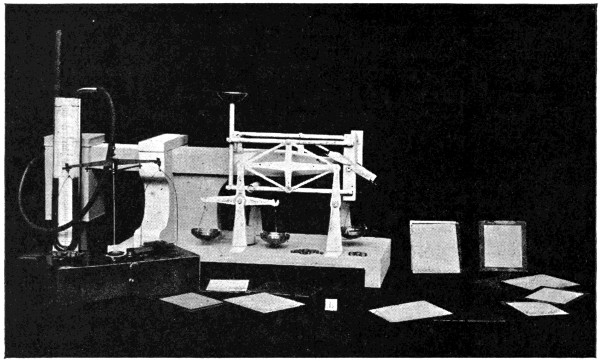
Fig. 21.—Small apparatus for testing fabrics for aeroplanes, the material being subjected to an air blast in order to test its lifting effect as compared with its tendency to travel with the blast.
My first experiments had shown that wooden aeroplanes
did much better than any of the fabric covered aeroplanes
that I was able to make at that time, but as wood was
quite out of the question on my large machine on account[50]
of its weight, it was necessary for me to conduct experiments
with a view of ascertaining the relative values of
different fabrics. For this purposes, I made the little
apparatus shown (Fig. 21). This was connected to a fan
blower driven by a steam engine having a governor that
worked directly on the point of cut-off. The speed was,
therefore, quite uniform and the blast of air practically
constant. I had a considerable number of little frames cut
out of sheet steel, and to these I attached various kinds of
fabric, such as ordinary satin, white silk, closely woven
silk, linen, various kinds of woollen fabrics, including some
very coarse tweeds, also glass-paper, tracing linen, and the
best quality of Spencer’s balloon fabric. The blast of air
was not large enough to cover the whole surface of the
aeroplanes, so that the character of the back of the frames
was of no account. The first object experimented with
was a smooth piece of tin. When this was placed at an
angle of 1 in 14, it was found that the drift or tendency to
travel in the direction of the blast was just one-fourteenth
part of the upward tendency, or lift. This was exactly
as it should have been. Upon changing the angle to
1 in 10, a similar thing occurred; the lift was ten times[51]
[52]
the drift. I, therefore, considered the results obtained
with the sheet of tin as unity, and gave to every other
material experimented with, a coefficient of the unity thus
established. Upon testing a frame covered with tightly-drawn
white silk, a considerable amount of air passed
through, and with an angle of 1 in 14, the lift was only
about double the drift. A piece of very open fabric,
a species of buckram, was next tried, and with this the
lift and drift were about equal. With closely-woven,
shiny satin the coefficient was about ·80; with a piece
of ordinary sheeting the coefficient was ·90; with closely-woven,
rough tweeds, ·70; and with glass-paper about ·75.
With a piece of tracing linen very tightly drawn, results
were obtained identical with those of a sheet of tin, and
with Spencer’s balloon fabric the coefficient was about ·99.
I, therefore, decided to cover my aeroplanes with this
material. It will be observed that the apparatus is so
arranged that both the lift and the drift can be easily
measured.
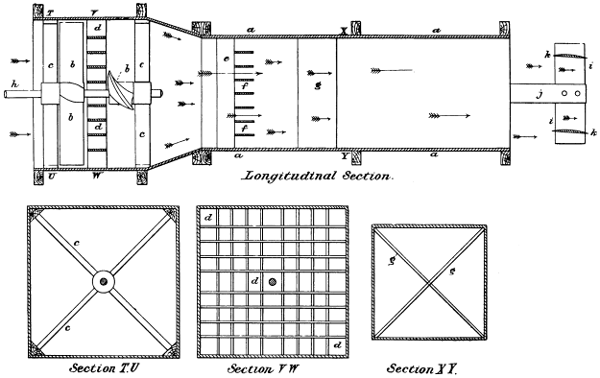
Fig. 22.—Apparatus for testing the lifting effect of aeroplanes and condensers in an air blast. k, k show two aeroplanes in position for being tested.
Fig. 22 enlarged (110 kB)
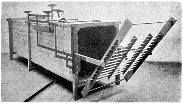
Fig. 23.—Apparatus for testing aeroplanes, condensers, etc., in an air blast. The opening is 3 feet square. Thin brass sustainers are shown in position for testing.
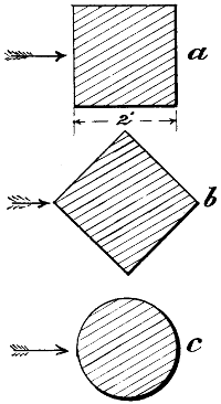
Fig. 24.—Cross-sections of bars of wood employed for ascertaining the coefficient of different forms.
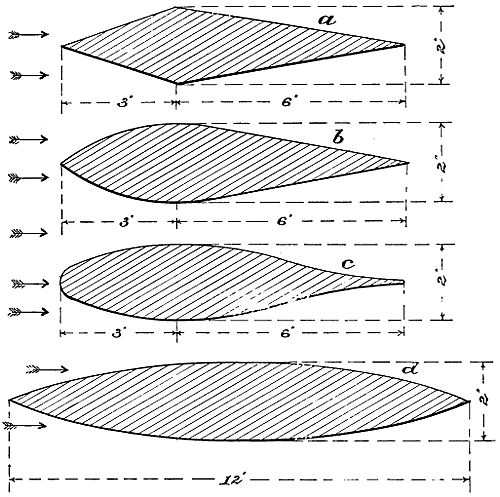
Fig. 25.—Transverse sections of bars of wood experimented with for the purpose of ascertaining their coefficients as relates to a normal plane.

Fig. 26.—A flat aeroplane placed at different angles.
In order to ascertain the resistance encountered by various shaped bodies driven at various speeds through the air, the best form of aeroplanes, and the efficiency of atmospheric condensers, I made the apparatus shown in Figs. 22 and 23. The smaller and straight portion of this[53] apparatus was 12 feet long and exactly 3 feet square inside, and was connected as shown to a shorter box 4 feet square. Two strongly made wooden screws b, b and d, were attached to the same shaft. These screws had two blades each, and while one pair of blades was in a vertical position, the other was in a horizontal position. I interposed between the screws, slats of thin wood arranged in the manner shown at d, d; this was to prevent rotation of the air. At e I placed vertical slats of thin wood, and horizontal slats of the same size at f. At g two wide and thin boards, sharp at both edges and made in the form of the letter X, were placed in the box as shown in section XY. An engine of 100 H.P. with an automatic variable cut-off was employed which gave to the screws a uniform rate of rotation, and as the engine had no other work to do, the governor could be arranged to give varying speeds such as were required for the experiments. The objects to be tested were attached to the movable bars. In the drawing, the aeroplane k, k is shown in position for testing. This apparatus was provided with a rather complicated set of levers, which permitted not only the measurement of the lift of the objects experimented with, but also that of the drift. The principle employed in this apparatus was a modification of the ordinary weighing apparatus used by grocers, etc. The first object tested was a bar of wood exactly 2 inches square shown in Fig. 24. This was placed in such a manner that the wind struck squarely against the side as shown in the drawing, and with a wind of 49 miles per hour, it was found that the drift or tendency to move with the air was 5·16 lbs.; at the same time, the wind on my instrument gave a pressure of 2 lbs. on a normal plane 6 inches square. The velocity of the wind was ascertained by an anemometer of the best London make.[54] Upon turning the same bar of wood in the position shown at b, the drift mounted to 5·47 lbs. A round bar of wood, 2 inches in diameter, shown at c, gave a drift of 2·97 lbs. These experiments were repeated with a wind velocity of 40 miles per hour, when it was found that the drift of a was 4·56 lbs., and that of the round bar, 2·80 lbs. It will be seen from these experiments that the power required for driving bars or rods through the air is considerably greater than one would have supposed. The next object experimented with was a, Fig. 25. When this was subject to a wind of 40 miles an hour, the drift was 0·78 lb. Upon reversing this bar—that is, putting the thin edge[55] instead of the thick edge next to the wind—the drift mounted to 1·22 lbs.; b showed a drift of 0·28 lb. with the thick edge to the wind, and 0·42 lb. with the thin edge to the wind; c showed a drift of 0·23 lb. with the thick edge to the wind, and 0·59 lb. with the thin edge to the wind; and d, which was the same thickness as the others and 12 inches wide, both edges being alike, showed a drift of only 0·19 lb. These experiments show in a most conclusive manner the shapes that are most advantageous to use in constructing the framework of flying machines. Aeroplane e, Fig. 26, when placed on the machine in a horizontal position showed neither lift nor drift, but upon placing it at an angle of 1 in 20, as shown at f, the lift was 3·98 lbs. and the drift 0·30 lb. with a wind velocity of 40 miles per hour. At this low angle the blade trembled slightly. Upon placing the same plane at an angle of 1 in 16 as shown at g, the lift was 4·59 lbs. and the drift 0·53 lb. It will be observed that the underneath side of this plane is perfectly flat. The next experiment was with planes slightly curved, as shown in Fig. 27. The aeroplane a was 16 inches wide, very thin, and only slightly curved. When set at a very low angle,[56] it vibrated so as to make the readings very uncertain, but when set at an angle of 1 in 10 it lifted 9·94 lbs. with a drift of 1·12 lbs. By slightly changing the angle it was made to lift 10·34 lbs. with a drift of 1·23 lbs., the wind velocity being 41 miles per hour. Aeroplane b, 12 inches wide, Fig. 27, when placed at an angle of 1 in 14 with an air blast of 41 miles per hour, gave a lift of 5·28 lbs. with a drift of 0·44 lb.; at an angle of 1 in 12 the lift was 5·82 lbs. and the drift 0·5 lb.; at an angle of 1 in 10 the lift was 6·75 lbs. and the drift 0·73 lb.; with an angle of 1 in 8 the lift was 7·75 lbs. and the drift 1 lb.; with an angle of 1 in 7 the lift was 8·5 lbs. and the drift 1·25 lbs.; at an angle of 1 in 6 the lift was 9·87 lbs. and the drift 1·71 lbs. Aeroplane c, Fig. 27, which had more curvature than b, when run in a horizontal position, gave a considerable lift, and when raised to an angle of 1 in 12 it gave a lift of 6·12 lbs. with a drift of 0·54 lb. In another experiment at the same angle, it gave a lift of 6·41 lbs. with a drift of 0·56 lb.; at an angle of 1 in 16 it gave a lift of 5·47 lbs. with a drift of 0·37 lb.; at an angle of 1 in 10 it gave a lift of 6·97 lbs. and a drift of 0·70 lb.; at an angle of 1 in 8 it gave a lift of 8·22 lbs. with a drift[57] of 1·08 lbs.; at an angle of 1 in 7 it gave a lift of 9·94 lbs. with a drift of 1·45 lbs.; at an angle of 1 in 6 it gave a lift of 10·34 lbs. and a drift of 1·75 lbs. This plane was then carefully set so that both the forward and aft edges were exactly the same height, and with a wind blast of 41 miles per hour it gave a lift of 2·09 lbs. with a drift of 0·21 lb. It was then pitched 1 in 18 in the wrong direction, and at this point, the lifting effect completely disappeared, while the drift was practically nothing.

Fig. 27.—Group of aeroplanes used in experimental research. Although shown the same size in the drawing, aeroplane a was 16 inches wide, and b and c, 12 inches wide.
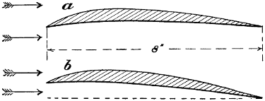
Fig. 28.—An 8-inch aeroplane which did very well. This aeroplane gave decided lifting effect when the bottom side was placed dead level, as shown at a.
When the aeroplane a (Fig. 28) was placed in a horizontal position, and the apparatus carefully balanced, it showed at a wind velocity of 40 miles an hour, a lift of 1·56 lbs., and a drift of 0·08 lb.; at an angle of 1 in 20, a lift of 3·62 lbs. and a drift of 0·21 lb.; at an angle of 1 in 16, a lift of 4·09 lbs. with a drift of 0·26 lb.; at an angle of 1 in 14, a lift of 4·5 lbs. and a drift of 0·33 lb.; at an angle of 1 in 12, a lift of 5 lbs. and a drift of 0·43 lb.; at an angle of 1 in 10, a lift of 5·75 lbs. and a drift of 0·60 lb.; at an angle of 1 in 8, a lift of 6·75 lbs. and a drift of 0·86 lb. The blast was then increased to a velocity of 47·33 miles an hour, when it was found that the lift at an angle of 1 in 16 was 5 lbs. and the drift 0·33 lb. It will be observed that this aeroplane was only 8 inches wide, while the others were 12 inches or more. They were all rather more than 3 feet long, but the width of the blast to which they were subjected was exactly 3 feet, and they were placed as near to the end of the trunk as possible.
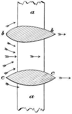
Fig. 29.—Resistance due to placing objects in close proximity to each other.
The next experiments were made with the view of ascertaining what effect would be produced when objects[58] were placed near to each other (see Fig. 29). Two bars of wood 2 inches thick, and shaped as shown in the drawing, were placed on the machine and subjected to a blast of 41 miles per hour; the drift at various distances from center to center was as follows:—
| 24 | inches | centers, | drift | 6 | ozs. | |
| 22 | „ | „ | „ | 6 | „ | |
| 20 | „ | „ | „ | 6 | „ | |
| 18 | „ | „ | „ | 6 | 1⁄8 | „ |
| 16 | „ | „ | „ | 6 | 1⁄8 | „ |
| 14 | „ | „ | „ | 6 | 1⁄4 | „ |
| 12 | „ | „ | „ | 6 | 1⁄2 | „ |
| 10 | „ | „ | „ | 7 | „ | |
| 8 | „ | „ | „ | 7 | 3⁄4 | „ |
| 6 | „ | „ | „ | 8 | 1⁄2 | „ |
| 4 | „ | „ | „ | 9 | 1⁄4 | „ |
It will be seen by this that the various members constituting the frame of a flying machine should not be placed in close proximity to each other.
A bar of wood similar in shape to d (Fig. 25), but being 9 inches wide instead of 12 inches, was mounted in a wind blast of 41 miles an hour, with the front edge 3·31 inches above the rear edge, and this showed a lift of 7·08 lbs. and a drift of 3·23 lbs. When the angle was reduced to 2·31 inches, it gave a lift of 4·53 lbs. with a drift of 0·78 lb., and with the angle reduced to 1·31 inches, the lift was 3·37 lbs. and the drift 0·5 lb. It will, therefore, be seen that even objects rounded on both sides give a very fair lift, and in designing the framework of machines advantage should be taken of this knowledge. The bar of wood c (Fig. 25) was next experimented with. With the sharp edge to the wind, and with the front edge 2 inches higher than the rear edge, the lift was 2·54 lbs. and the drift 0·76 lb. By turning it about so that the wind struck the thick edge, the lift was 4·45 lbs. and the drift 0·47 lb. This seemed rather remarkable, but, as it actually occurred, I mention it for other people to speculate upon. It, however, indicates that we should take advantage of all these peculiarities of the air in constructing the framework of a machine, which in itself is extremely important, as I find that a very large percentage of the energy derived from the engines is consumed in forcing the framework through the air. It is quite true that a certain amount of this energy may be recovered by the screw, provided that the screw runs in the path occupied by the framework. Still, it is much better that the framework should be so constructed as to offer the least possible resistance to the air, and, as far as possible, all should be made to give a lifting effect.
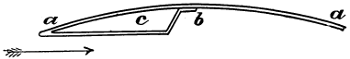
Fig. 30.—Cross-section of condenser tube, made in the form of Philipps’ sustainers, in which c is the steam passage.
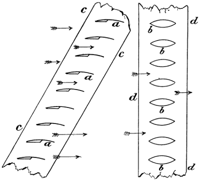
Fig. 31.—The grouping of condenser tubes, made in the form of Philipps’ sustainers. This arrangement is very effective, condenses the steam or cools the water, and gives a lifting effect at the same time. The shape and arrangement of tubes shown at b, b, although effective as a condenser, produce no lifting effect, but a rather heavy drift.
Having ascertained the lifting effect of wooden aeroplanes of various forms and at varying velocities of the wind, and, also, the resistance offered by various bodies driven through the air, I next turned my attention to the question of condensation. I wished to recover as much water as possible from my exhaust steam. I had already experimented with Mr. Horatio Philipps’ sustainers, and I found that their lifting effect was remarkable. A curious thing about these aeroplanes was that they gave an appreciable lift when the front edge was rather lower than the rear. I therefore determined to take advantage of this[60] peculiar phenomenon, and to make my condenser tubes as far as possible in the shape of Mr. Philipps’ sustainers. Fig. 30 shows a section of one of these tubes, in which a, a is the top surface, b a soldered joint, and c the steam space. These were mounted on a frame as shown at a (Fig. 31). I had already found that bodies placed near to each other offered an increased resistance to the air, but by placing these sustainers in the manner shown this was avoided, as the air had sufficient space to pass through without being either driven forward or compressed. It was found by experiment that the arrangement of tubes or sustainers,[61] shown at d, d (Fig. 31), was very efficient as a condenser, but it gave a very heavy drift and no lifting effect at all; whereas, on the other hand, the arrangement shown at a was equally efficient, and, at the same time, gave a decided lifting effect. When twelve of these tubes or sustainers were placed at an angle of 1 in 12, the lifting effect was 12·63 lbs. and the drift 2·06 lbs. It was found, however, that a good deal of the drift was due to the wind getting at the framework that was used for holding the sustainers in position. With a wind velocity of 40 miles an hour and a temperature of 62° F., 2·25 lbs. of water were condensed in five minutes, and, while running, the back edge of the sustainers was quite cool. At another trial of the same arrangement under the same conditions, the lift was 11 lbs. and the drift 2·63 lbs. It is quite possible on this occasion that the metal was so extremely thin that the angles were not always maintained; consequently, that no two readings would be alike. It was found at this point that the belt was slipping, and a larger pulley was put on the driving shaft of the screws; and under these conditions, with a wind of 49 miles per hour and an angle of 1 in 8, the lifting effect ran up to 14·87 lbs. with a drift of 2·44 lbs., and the condenser delivered 2·87 lbs. of water from dry steam in five minutes. The weight of metal in this condenser was extremely small, the thickness being only about 1⁄500 of an inch. This condenser delivered the weight of the sustainers in water every five minutes. They should, however, have been twice as heavy. Cylinder oil was now introduced with the steam in order to ascertain what effect this would have. After seven minutes’ steaming, 2·25 lbs. of water were condensed in five minutes. It will be seen from these experiments that an atmospheric condenser, if properly constructed, is fairly efficient. Roughly speaking, it requires 2,400 times as much air in volume as of water to use as a cooling agent. With the steam engine condenser only a relatively small amount of water is admitted, and this is found to be sufficient; but in an atmospheric condenser working in the atmosphere, it must be as open as possible, so that no air which has struck one heated surface can ever come in contact with another.
From what information I have at hand, it appears that Prof. Langley made his first experiments with a small apparatus, using aeroplanes only a few inches in dimensions which travelled round a circle perhaps 12 feet in diameter. With this little apparatus, he was able to show that the lifting effect of aeroplanes was a great deal more than had previously been supposed. After having made these first experiments, he seems to have come to the conclusion that Newton’s law was erroneous. Shortly after Langley had made these experiments on what he called a whirling table, which, however, was not a very appropriate name, I made an apparatus myself, but very much larger than that employed by Prof. Langley. I reckoned the size of my aeroplanes in feet, where he had reckoned his in inches. The circumference of the circle around which my aeroplanes were driven was exactly 200 feet, and shortly after this Langley constructed another apparatus, the same dimensions as my own. From an engraving which I have before me, it appears that he constructed an extremely large wooden scale beam supported by numerous braces, but free to be tilted in a vertical direction after the manner of all other scale beams. As this apparatus was of great weight and offered enormous resistance to the air, I do not understand how it was possible to obtain any very correct readings, especially as it was in the open and subject to every varying current of air.
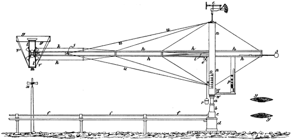
Fig. 32.—Machine with a rotating arm, 31·8 feet long, to which is attached the object to be experimented with. Professor Langley had a similar machine and called it a “whirling table.”
Fig. 32 enlarged (70 kB)

Fig. 33.—A screw and fabric covered aeroplane in position for testing.

Fig. 34.—The rotating arm of the machine with a screw and aeroplane attached.
In constructing my apparatus, which is shown in the
photographs, and also in a side elevation (Fig. 32), I aimed
at making the apparatus very light and strong, avoiding as
far as possible atmospheric resistance. In the drawing, a,
is a thick seamless steel pipe 6 inches diameter; b, is a cast-iron
pedestal firmly bolted to d, and connected to a large
cast-iron spider embedded in hydraulic cement; by this
means great rigidity and stiffness were obtained. n, n was
formed of strong Georgia pine planks 2 inches thick, and[63]
[64]
strongly bolted together. The two members of the long
radial arm h, h, were made of Honduras mahogany, an
extremely strong wood, and had their edges tapered off as
shown at y, y. The power was transmitted from a small
steam engine provided with a sensitive governor through
the shaft f, f. In the base c, of the casting b, was placed a
pair of tempered steel bevel gears, giving to the vertical
shaft a high velocity. From a pulley on the top of this
shaft, the belt i, was run through the arms h, h, as shown in
section y, y. This gave a rapid rotation to the screw shaft
in a very simple manner. The operation of the machine
was as follows:—the aeroplane g, to be tested was secured
to a sort of weighing apparatus which is shown in detail
(Fig. 36), and the screw attached to the shaft. Upon
starting the engine, a very rapid rotation was given to the
screw which caused the radial arm to travel at a high
velocity, the whole weight resting on a ball bearing at w.
The radial arms and all of their attachments were balanced
by a cigar-shaped lead weight s, which was secured to a
sliding bar so as to make it easily adjustable. The thrust
of the screw caused the screw shaft to travel longitudinally,
and this was opposed by a spring connected by a very[65]
thin and light wire to the pointer of the index o. As the
apparatus rotated rather slowly on account of its great
diameter, it was quite possible to observe the lift while the
machine was running at its highest speed. The aeroplanes
were mounted after the manner of the tray of a grocer’s
scales (see Fig. 36), and the lift of the aeroplane was
determined by what it would lift at r—that is, while
the machine was running at a given speed, iron or lead
weights were placed in the pail r, until the lift of the
aeroplane was exactly balanced, and then, in order to
ascertain exactly what the lift was, the aeroplane was
placed under what might be called a small crane, and
a cord, running over a pulley, attached. The amount of
weight necessary to lift the plane into the same position
that it occupied while running was taken as its true
lift. In order to facilitate experiments the gauge p,
was provided. This gauge consisted of a large glass tube
and the index p, with a quantity of red water at q. The[66]
centrifugal force of rotation caused the red water to rise
in the tube. This was easily seen, so that if experiments
were being tried, we will say at 50 miles an hour, it
was always possible to turn on steam until the red
liquid mounted to 50. This device was very simple
and effective, and saved a great deal of time. In order to
prevent the twisting of the radial arm, a piece of stiff
oval steel tube 12 feet long was secured between the arms
at j, and on each end of this tube were attached the wires
u, u. This not only effectually supported the end of
the arm, but at the same time prevented twisting and
made everything extremely stiff. Of course, while the
machine was running at a high velocity, centrifugal force
had to be dealt with, and in order to prevent this from
causing friction in the articulated joints of the weighing
apparatus (Fig. 36), thin steel wires k, k were provided.
As this apparatus was in the open, it was found that
the slightest movement of the air greatly interfered with
its action. On one occasion when a fabric covered aeroplane,[67]
4 feet long by 3 feet wide, was placed in position,
the four corners being held down by the wires v, v, and
the apparatus driven at a high velocity, a sudden gust of
wind snapped two of the wires, broke the aeroplane, and
the flying fragments smashed the screw, and this notwithstanding
that each of the four wires was supposed to be
strong enough to resist at least four times any possible
lifting that the whole aeroplane might be subjected to.

Fig. 35.—The little steam engine used by me in my rotating arm experiments; the tachometer and dynamometer are distinctly shown.
In order to ascertain the force and direction of the wind, I made an extremely simple and effective apparatus which is fully shown (see Fig. 38). Whilst conducting these experiments it occurred to me, when a large aeroplane was used, that after it had been travelling for a considerable time, it would impart to the air in the path of its travel, a downward motion, and that the lifting effect would be greatly reduced on this account. In order to test this, I provided four light brass screws and mounted them, as shown at x, on a hardened polished steel point much above their centre of gravity, so that they balanced themselves. On account of the absence of friction, they were easily rotated, and responded to the least breath of air that might be moving. One morning when there was a dead calm, I placed four of these screws equidistant around the whole circle. Some of them rotated very slowly in one direction and some in another; some alternated, but all their motions were extremely slow. However, upon setting the machine going with a large aeroplane and a powerful screw, I found after a few turns that the air was moving downwards around the whole circle at a velocity of about 2 miles an hour, but as the screw was a considerable distance below the aeroplane, I estimated that the actual downward velocity of the air in which the aeroplane was travelling was about 4 miles an hour. The result of my experiments are clearly shown in an unpublished paper which I wrote at the time, and as it is of considerable historical interest, I have placed it in the appendix, notwithstanding that there may be certain repetitions.
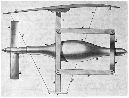
Fig. 36.—The machine attached to the end of the rotating shaft—a, a, the body of the machine; b, b, four-legged spider secured to a, a; c, c, parallel bars; d, d, vertical member to which the aeroplane g, g is attached; h, h, the screw; f, f, wires for preventing distortion of the aeroplane.
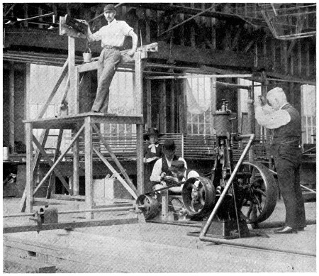
Fig. 37.—Marking off the dynamometer. In order to ascertain the actual amount of power consumed in driving the propeller, a brake was put on in place of the screw, a weight applied, and the engine run at full speed. In this way all the uncertain and unknowable factors were eliminated.
In Fig. 36, a, a is the body of the apparatus, partly of gunmetal and partly of wood. It is provided with a steel shaft to which the screw h, is attached, and also with a cylindrical pulley for taking the belt. The thrust of the screw pushes the shaft inwards and records the lift at o (Fig. 32). The corners of the aeroplane g, g, are attached[68] by wires to the steel plate e. b, b, is a four-arm spider for holding the ends of the parallel bars c, c, and d, d, show vertical steel bars to which all devices to be tested are attached. In testing aeroplanes, weights may be placed at e, sufficient to balance the lifting effect, and then by adding the weight to the upward pull of the aeroplane, the true lift of the aeroplane is obtained. It is also possible to attach an aeroplane at e, that is, the machine was made to test superposed aeroplanes if required. In these experiments, I naturally assumed that the best position for a screw was at the rear and in the path of the greatest resistance, but as some experimenters with navigable balloons placed the screw in front in order to pull the apparatus along instead of to push it, I made experiments to see what the relative difference might be. In order to do this, I wound a large amount of rope one-half[69] inch in diameter around the whole apparatus forward of the screw, converting it into an irregular mass well calculated to offer atmospheric resistance. Upon starting the engine, I was rather surprised to see how little retardation these ropes gave to the apparatus. It appeared to me that nearly all of the energy consumed in driving the ropes through the air was recovered by the screw. I then removed the right-hand screw and replaced it by a left-hand screw of the same pitch and dimensions (Fig. 37a). I then found that the blast of the screw blowing against the tangle of ropes greatly retarded the travel; in fact, with the same number of revolutions per minute, the velocity fell off 60 per cent. I think that these experiments ought to show that there is but one place for the screw, and that is at the stern, and in the direct path of the greatest atmospheric resistance.

Fig. 37a.—Right- and left-hand four-blade screws used in my experiments for ascertaining the comparative efficiency between screws placed in front and in the rear of the machine.
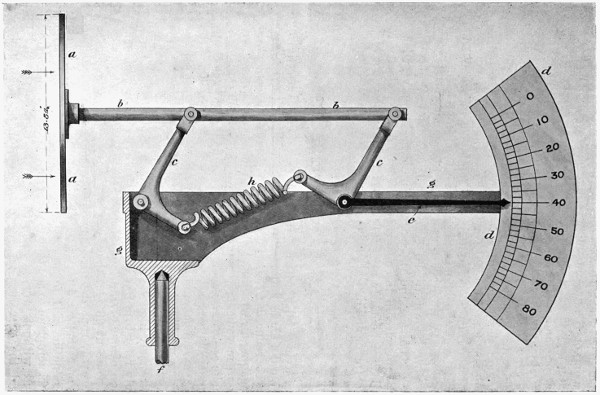
Fig. 38.—Apparatus for indicating the force and velocity of the wind direct without any timing, counting, or mathematical calculations.
Fig. 38 shows an original apparatus which I designed
and made for my own use; with ordinary anemometers it
is necessary to count the number of turns per minute in
order to ascertain the velocity of the wind. I wanted
something that would indicate the velocity and the
direction of the wind without any figures or formulæ.
I therefore made the apparatus shown in the drawing,
in which a, a, is a metallic disc 13·54 inches in diameter,
giving it an area of exactly 1 square foot. This is
attached to the horizontal bar b, and the whole mounted
on two bell crank levers as shown. When the wind is
not blowing, the long arms of these two levers assume
a vertical position, and the spiral spring h, is in exact
line with the pivots on which these levers are mounted,
and has no effect except to hold the levers in a vertical
position. As the spring has very little tension in this
position, and as it requires a considerable movement in
order to give it tension, the arms c, c, and the bar b, b, are
very easily pushed backwards, but as the distance through
which they travel increases, the angle of the lever changes
and the tension of the spring increases at the same time,
so that when the disc is pushed backwards to any considerable
distance, a strong resistance is encountered. Had
I made this apparatus so that the pressure acted directly
on the spiral spring, the spaces on the index indicating
low velocities would have been very near together, while[71]
[72]
those indicating high velocities would have been widely
separated, but with this device properly designed, the
spacing on the index became regular and even. The index
being very large enabled one to read it at a considerable
distance, and at the same time, it acted as a tail and kept
the apparatus face to the wind. The spaces of the dial
were not laid off with a pair of dividers, but each particular
division was marked by an actual pull on the bar b,
through the agency of a cord and easily running pulley
and weight. The markings, however, were not correct,
because Haswell’s formula was employed in which the
pressure of the wind against the normal plane is considerably
greater than with the more recent formula, which
is now known to be correct. Haswell’s formula was
V² × ·005 = P, and the recent formula P = 0·003 × V², where
P = pressure in lbs. per square foot and V = velocity in
miles per hour. In my experiments, I also employed a very
well made and delicate anemometer by Negretti & Zambra.

Fig. 39.—Apparatus for testing the lifting effect of aeroplanes at a low angle and extremely high velocity. a, a, the aeroplane; b, lead weight; c, long and slender pine rod; d, tail for keeping the apparatus head on and ensuring its travelling straight through the air; e, the point of suspension, also the centre of gravity. When this apparatus was travelling at the rate of 80 miles an hour, it gave a lifting effect of about 36 lbs., which is about 7 lbs. per square foot.
Having fully satisfied myself that aeroplanes flying around a circle 200 feet in circumference had their lifting effect reduced to no insignificant degree by constantly engaging air which had already had imparted to it a downward movement by a previous revolution, I determined to make some experiments where this trouble could not occur, but the opportunity did not present itself until after the large roundabout, erroneously described as “a captive flying machine,” was put up at the Crystal Palace. This presented a fine opportunity for making experiments at an extremely high velocity around a very large circle. I will only refer to a few of these experiments. To a prolongation of one of the long arms, I attached a thin steel wire rope about 60 feet above the platform; I then attached to this wire rope the little device shown (Fig. 39), in which a, is an aeroplane, 5 feet long and 1 foot wide, placed at an inclination of 1 in 20. Great care was used in preparing this aeroplane to see that it was free from blemish, smooth, and without any irregularities. Both edges were sharp and the curvature was about one-eighth of an inch on the underneath side. It was made relatively thick in the middle where it was attached to the bar c, and thinner at[73] the ends. b, shows a lump of lead just heavy enough to balance the bar c, and the tail; d, was a light but strong wooden frame, all the edges being thin and sharp, and covered with a special silk that Mr. Cody had found to be best for such purposes. The wire rope e, was attached to the long arm which I referred to. The great length of the bar c, and the accuracy with which the whole was made and balanced caused the aeroplane to travel straight through the air adjusting itself to all the shifting currents. Upon starting the machine on a very calm day, this apparatus mounted as high as the point of support, sometimes going 10 or more feet higher and sometimes 8 or 10 feet lower. However, as a rule, it carried its own weight at a velocity of 80 miles an hour around a circle 1,000 feet in circumference. Under these conditions, of course, there could be no downward motion of the air as all the air affected would be removed long before it could be struck the second time by the aeroplane. I had no means of ascertaining exactly how much this plane did[74] actually lift, because the air was always moving to some extent, and it was not an easy matter to ascertain whether it was above or below the point of support. I am sure, however, that it was as much as 36 lbs., or rather more than 7 lbs. to the square foot, and this is just what it should have lifted, providing that we consider the results obtained by smaller planes placed in an air blast of 40 miles an hour and at the same angle. When these experiments were finished, I made a very small apparatus having only about 25 square feet of lifting surface, and this carried the weight of a man, in fact several gentlemen came up from London and went round on it themselves. I saw, however, that it was a dangerous practice, because if the wind was blowing at all, the apparatus would mount very much above the point of support while travelling against the wind, only to drop much below the point of support on the other side of the circle where it was travelling with the wind; in fact, on one occasion the apparatus shown (Fig. 39) mounted in a high wind fully 20 feet above the point of support and came down with such a crash on the other side that it broke the wire rope. In connection with this, it is interesting to note that when I erected the first so-called “captive flying machine” on my own grounds at Thurlow Park, I intended that instead of ordinary boats such as were ultimately employed, each particular boat should be fitted with an aeroplane, that the engine should be of 200 H.P., and that the passengers should actually be running on the air, each boat being provided with a powerful electric motor in addition to the motive power that drove the shaft. Had this been carried out as was originally designed, it would have removed the apparatus altogether from the category of vulgar merry-go-rounds, but such was not to be. Unforeseen circumstances were against me. I had some of these boats fitted up with aeroplanes and running on my grounds, and two of the engineers of the London County Council came out to see the apparatus before it was put up for public use. On that occasion the wind was blowing a perfect gale of 40 miles an hour, and as the boats travelled at the rate of 35 miles an hour, they, of course, encountered a wind of 75 miles an hour when passing against the wind, and a minus velocity of 5 miles an hour when travelling with the wind on the other side of the circle. The aeroplanes, although of considerable size, were small in relation to[75] weight. I had neglected to put any weight in the boats, and when three of us were studying the eccentric path through which the boats were travelling, suddenly one of them in passing to the windward, raised very much above the point of support and plunged down with great force on the other side; in fact, the shock was so great that it made everything rattle, but nothing was broken. Nevertheless, the engineers said at once, it would not do to run the boats with those aeroplanes; it was too dangerous. This would not, however, have occurred if the boats had been loaded, or the velocity of the wind had been less. It, however, demonstrated what a tremendous lift may be obtained from a well-made aeroplane passing at a high velocity through the wind at a sharp angle. These aeroplanes were only about 12 feet long and 5 feet wide, having, therefore, 60 square feet of surface. They were, however, strong, well-made, and perfectly smooth, both top and bottom. I would say right here that I am not a success as a showman—previous long years of rubbing up against honest men have disqualified me altogether for such a profession. I was extremely anxious to go on with my experiments. I appreciated fully that I had made a machine that lifted 2,000 lbs. more than its own weight, and I knew for a dead certainty if I took the matter up again, got rid of my boiler and water tank, and used an internal combustion engine, such as I thought I could produce, that mechanical flight would soon be a fait accompli. I had already spent more than £20,000, and was looking about for some means of making the thing self-supporting. I believed that the so-called “captive flying machine” would be very popular, and bring in a lot of money, and it would have done so, if it had been put up as originally designed. I proposed to use my share of the profits for experimental work on real flying machines. That I was not far wrong in believing that such a machine would be a success, is witnessed by the fact that just about the same time, an American inventor thought of the same thing, put up some three or four machines the first year, and the next year about 50. They were highly profitable, and there are fully 140 of them running at the present time in the U.S.A. It is a fact that nothing in the way of side-shows at exhibitions or public resorts has ever had the success of this machine in the U.S.A., and even the little machine at Earl’s Court[76] took £325 10s. in one day and £7,500 in a season. However, this little attempt to make one hand wash the other cost me no less than £10,400, not to mention more than a year of very hard work. This sum would have been amply sufficient to have enabled me to continue my experiments until success was assured.
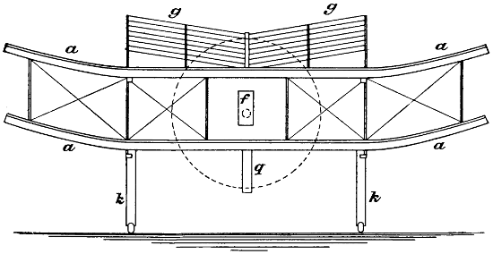
Fig. 40.—Front elevation of proposed aeroplane machine—a, a, the aeroplanes; g, g, condenser; f, the engine; q, guard for screw; k, k, support for wheels.
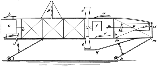
Fig. 41.—Side elevation of proposed superposed aeroplane machine—a, a, main aeroplanes; b, b, rear aeroplanes; c, vertical rudder; d, horizontal front rudder; e, screw; f, motor; g, condenser; h, steering gear; i and j, pneumatic buffers; k and l, wheels; m, point at which k is pivoted to the main frame; n, handle of the steering gear.
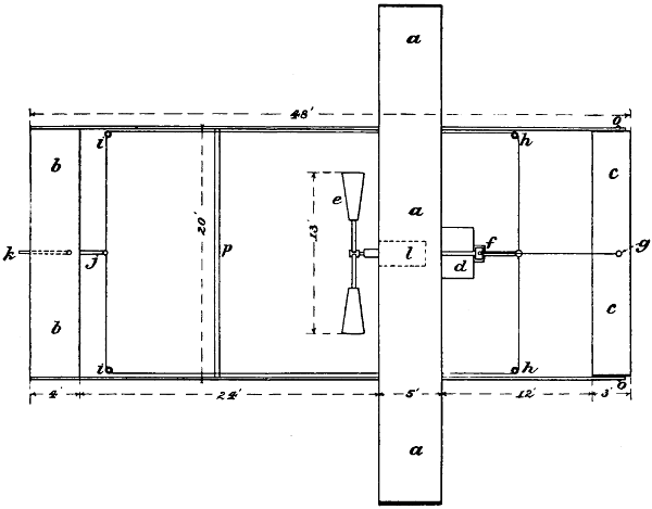
Fig. 42.—Plan of proposed aeroplane machine, in which a, a are the proposed superposed main aeroplanes; b, b, the after superposed aeroplanes; c, c, the forward horizontal rudder; d, platform; e, screw; h, h, and i, i, pulleys used in communicating motion from the steering gear, f, to the rudder, j; g, lever attached to the aeroplane or rudder, c, c, and connected to the steering gear, f.
For those who really wish to build a flying machine that
will actually fly with very little experimental work, I have
given an outline sketch sufficiently explicit to enable a
skilful draughtsman to make a working drawing in which
Fig. 40 is a front elevation, Fig. 41 a side elevation, and
Fig. 42 a plan. Fig. 41, a, a, shows the two forward or
main aeroplanes; b, b, the two after aeroplanes, which are
smaller and shorter; c, the rudder; d, the forward horizontal
rudder; e, the screw; f, the motor; g, the condenser
or cooler; h, the steering gear; i, and j, atmospheric
buffers; k and l, wheels attached to a lever pivoted to the
body of the machine; q, a shield for protecting the screw.
It will be observed that the framework is extremely long,
and, consequently, the distance between the aeroplanes is
very great; but it should be borne in mind that the longer
the machine, the less any change of center of lifting effect,
as relates to the center of gravity, will be felt. Moreover,[78]
[79]
it is much easier to manœuvre a machine of great length
than one which is very short, because it gives one more
time to think and act. If the length was infinitely great
the tendency to pitch would be infinitely small. I have
shown a steering gear consisting of a lever with a handle
n, arranged in such a manner that it moves both the
vertical rudder c, and the horizontal rudder d, so that the
man who steers the machine has nothing to think of except
to point the lever n, p, in the direction that he wishes the
machine to go. This lever is mounted on a universal joint
at h, and is connected with suitable wires to the two
rudders. In order to prevent shock when the machine
alights, it is necessary to provide something that is strong
and, at the same time, yielding, and able to travel through
a considerable distance before the machine comes to a state[80]
of rest. In the machines which I have seen on the Continent,
a very elaborate apparatus is employed, which is
not only very heavy, but also offers a considerable resistance
to the forward motion of the machine through the air.
It consists of many tubes, very long levers and heavy spiral
springs, etc. In the device which I am recommending,
all this is dispensed with, and something very much
simpler, cheaper, and lighter is substituted. Moreover,
with my proposed apparatus a certain amount of lifting
effect is produced. The levers k, k, to which the wheels are
attached, should be of thin wood, light and strong, and
say about a foot wide, strongly pivoted to the frame and
held in position by an atmospheric buffer made of strong
and thin steel tubing, shown in section (Fig. 51). These
pneumatic cylinders may be pumped up to any degree, so
as to support the weight of the machine, and then, as it
comes down, the compression and escape of air arrest its
motion. The condenser g, is placed in such a position that
it will act even while the machine is on the ground and the
propellers working. In Continental machines, very small
screw propellers are used. These screws have probably
been made small because the experimenters have found
that they encounter a good deal of friction in the atmosphere,
but this is caused by imperfect shape and the rib of
steel at the back of the blades. In order to use a small
screw, experimenters have been forced to use a very quick-running
engine which makes it necessary to have the
cylinders very short, so, in order to get the necessary
power, they are obliged to use no less than eight cylinders.
However, by increasing the diameter of the screw and
making it of such a form that very little or no atmospheric
skin friction is encountered, a much better and cheaper
engine of a totally different type may be employed. There
is no reason why more than four cylinders should be used,
but the stroke of the piston and diameter of the cylinder
should be increased. Doubtless Continental experimenters
have an idea that, as the engine cannot be provided with a
flywheel, it must have a very large number of cylinders in
order to give a steady pull completely around the circle, and
thus avoid so-called “dead centers”; but, when we consider
the enormously high velocity of the periphery of the screw,
and also take into consideration that the momentum is in
proportion to the square of the velocity, it is quite obvious
that there can be no slowing up between strokes even if[81]
only one cylinder should be employed working on the
four-cycle principle, in which work is only done one stroke
in four. Then, again, I find that the weight of these
Continental engines can be greatly reduced, providing that
they are made with the same degree of refinement that
I employed in building my steam engines.
Recently there has been a great deal of discussion in Engineering and other journals regarding the comparative merits of the aeroplane system and the hélicoptère. Some condemn both systems and pin their faith to flapping wings. It has been contended that the screw propeller is extremely wasteful in energy, and that in all Nature neither fish nor bird propels itself by means of a screw. As we do not find a screw in Nature, why then should we employ it in a machine for performing artificial flight?
Why not stick to Nature? In reply to this, I would say that even Nature has her limits, beyond which she cannot go. When a boy was told that everything was possible with God, he asked; “Could God make a two-year old calf in five minutes?” He was told that God certainly could. “But,” said the boy, “would the calf be two years old?” It appears to me that there is nothing in Nature which is more efficient, or gets a better grip on the water than a well-made screw propeller, and no doubt there would have been fish with screw propellers, providing that Dame Nature could have made an animal in two pieces. It is very evident that no living creature could be made in two pieces, and two pieces are necessary if one part is stationary and the other revolves; however, the tails and fins very often approximate to the action of the propeller blades; they turn first to the right and then to the left, producing a sculling effect which is practically the same. This argument might also be used against locomotives. In all Nature, we do not find an animal travelling on wheels, but it is quite possible that a locomotive might be made that would walk on legs at the rate of two or three miles an hour. But locomotives with wheels are able to travel at least three times as fast as the fleetest animal with legs, and to continue doing so for many hours at a time, even when attached to a very heavy load. In order to build a flying machine with flapping wings, to exactly imitate birds, a very complicated system of levers, cams, cranks, etc., would have to be employed, and these of themselves would weigh more than the wings would be able to lift.[82] However, it is quite possible to approach very closely to the motion of a bird’s wings with no reciprocating or vibrating parts, and without flapping at all.
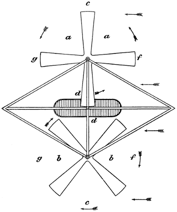
Fig. 43.—Plan of a hélicoptère machine showing position of the screws. Owing to the tilting of the shaft forward, the blades present no angle when at d, d, but 10° at c, c, while at f, f their angle above the horizontal is 5°. The horizontal arrows show the direction of the wind against the machine.
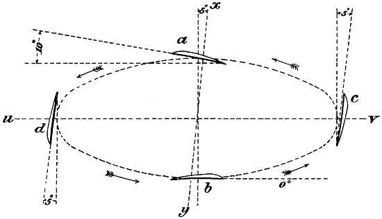
Fig. 44.—Shows the position of the blades of a hélicoptère as they pass around a circle, when the angle of the shaft and the angle of the blades are the same.
In Fig. 43, I have shown a plan of a hélicoptère machine in which two screws are employed rotating in opposite directions, a, a, being the port screw; b, b, the starboard screw; and d, d, the platform for the machinery and operator. The screws should be 20 feet in diameter and made of wood. Suppose now that the pitch of these screws is such that the extremities of the blades have[83] an angle of 5°; if now we tilt the shaft forward in the direction of flight to the extent of 5°, we shall completely wipe out the angle of inclination of the blades when at b (Fig. 44), whereas it will be observed that the pitch as regards the horizontal will be increased to 10° at a, on the outer side, and remain unchanged at c, and d. If the peripheral velocity of the blades is, say, four times the velocity at which the machine is expected to travel, the blades will get a good grip on the air at c, d, but when they travel forward and encounter air which is travelling at a high velocity in the opposite direction, they assume the position shown at b. If the pitch of the screw blades was a little more than the angle of the shaft, the blades at b would also produce a lifting effect, and as the velocity with which they pass through the air is extremely high, a very strong lifting effect would be produced even if the angle was not more than 1 in 40. By tracing the path and noting the position of the ends of the blades as they pass completely around the circle as shown (Fig. 44), it will be observed that they very closely resemble the motion of a bird’s wing. I have no doubt that a properly made machine on this plan would be highly satisfactory, but one should not lose sight of the fact that even with a machine of this type, well designed and sufficiently light to sustain itself in the air while flying, it would still be necessary for[84] it to move along rapidly when starting in order to get the necessary grip on the air. Upon starting the engine, in a machine of this kind, a very strong downward draught of air would be produced, and the whole power of the engines would be used in maintaining this downward blast, but if the machine should at the same time be given a rapid forward motion sufficiently great to bring the blades into contact with new air, the inertia of which had not been disturbed, and which was not moving downwards, the lifting effect would be increased sufficiently to lift the machine off the ground. It would, therefore, work very much like an aeroplane machine. It would also be possible to provide a third screw of less dimensions and running at a less velocity, to push the machine forward, so as not to render it necessary to give such a decided tilt to the shafts.
As before stated, great care should be taken in designing and making the framework of flying machines, and no stone should be left unturned in order to arrive at the greatest degree of lightness without diminishing the strength too much; then, again, elasticity should be considered. If we use a thin tube all the material is at the surface, far from the neutral centre, and great stiffness is obtained, but such a tube will not stand so much deflection as a piece of wood; then, again, wood is cheaper than steel, and in case of an accident, repairs are very quickly and easily made. Wood, however, cannot be obtained in long lengths absolutely free from blemishes. It therefore becomes necessary to find some way of making these long members of flying machines of such wood as may be found suitable in the following table.
| Strength per Sq. In. in Lbs. |
Weight of a Cube Foot in Lbs. |
Relative Value. |
|||
|---|---|---|---|---|---|
| Alder, | ... | 50 | ... | ||
| Apple, | ... | 49 | ·562 | ... | |
| Ash, English, | 16,000 | 52 | ·812 | 302 | ·9 |
| Ash, White, | 14,000 | 43 | ·125 | 324 | ·6 |
| Bamboo, | 6,300 | 25 | 252 | ||
| Beech, English, | 11,500 | 53 | ·25 | 215 | ·9 |
| Birch, | 15,000 | 45 | 333 | ·3 | |
| Box, African, | 23,000 | ... | ... | ||
| Bo„x,France, | ... | 83 | ... | ||
| Cedar, American, | 11,600 | 35 | ·062 | 330 | ·8 |
| Deal, Christiania, | 12,400 | ... | ... | ||
| Ebony, | 27,000 | 83 | ·187 | 324 | ·6 |
| Elm, | 6,000 | 35 | ·625 | 168 | ·4 |
| E„m,Rock, | 13,000 | 50 | 260 | ||
| Fir, Norway Spruce, | ... | 32 | ... | ||
| F„r, Dantzic, | ... | 36 | ·375 | ... | |
| Hackmatack, | 12,000 | 37 | 324 | ·3 | |
| Hickory, | 11,000 | 49 | ·5 | 222 | ·2 |
| Ironwood, | ... | 61 | ·875 | ... | |
| Juniper, | ... | 36 | ·375 | ... | |
| Lance, | 23,000 | 45 | 511 | ·1 | |
| Lignum-Vitæ, | 11,800 | 83 | ·312 | 141 | ·6 |
| Lime, | ... | 50 | ·25 | ... | |
| Locust, | 20,500 | 45 | ·5 | 450 | ·5 |
| Mahogany, Honduras, | 21,000 | 35 | 600 | ||
| Maho„any, Spanish, | 12,000 | 53 | ·25 | 225 | ·3 |
| Maple, | ... | 46 | ·875 | ... | |
| Oak, African, | 9,500 | 51 | ·437 | 184 | ·7 |
| O„k, Canadian, | ... | 54 | ·5 | ... | |
| O„k, Dantzic, | 4,200 | 47 | ·437 | 88 | ·5 |
| O„k, English, | 7,571 | 53 | ·625 | 141 | ·2 |
| O„k, Live, | 16,380 | 66 | ·75 | 245 | ·4 |
| O„k, Pa, seasoned, | 20,333 | ... | ... | ||
| O„k, White, | 16,500 | 53 | ·75 | 306 | ·9 |
| O„k, Va, | 25,222 | ... | ... | ||
| Pine, Norway, | 14,000 | 46 | ·25 | 302 | ·7 |
| Pi„e, Pitch, | ... | 41 | ·25 | ... | |
| Pi„e, Red, | 13,000 | 36 | ·875 | 352 | ·5 |
| Pi„e, White, | 11,800 | 34 | ·625 | 340 | ·8 |
| Pi„e, Yellow, | 13,000 | 28 | ·812 | 451 | ·2 |
| Pi„e, Va, | 19,200 | ... | ... | ||
| Poplar, | 7,000 | 23 | ·937 | 292 | ·4 |
| Pop„ar,White, | ... | 33 | ·062 | ... | |
| Redwood, Cal, | 10,833 | ... | ... | ||
| Spruce, | 12,400 | 31 | ·25 | 396 | ·8 |
| Sycamore, | 13,000 | 38 | ·937 | 333 | ·8 |
| Tamarack, | ... | 23 | ·937 | ... | |
| Teak, African, | 21,000 | 61 | ·25 | 342 | ·8 |
| Te„k, Indian, | 15,000 | 41 | ·062 | 365 | ·3 |
| Walnut, | ... | 41 | ·937 | ... | |
| Wal„ut, Black, | 16,633 | 31 | ·25 | 532 | ·2 |
| Wal„ut, Michigan, | 17,500 | ... | ... | ||
| Willow, | 13,000 | 36 | ·562 | 355 | ·5 |
The relative value of different kinds of wood is shown in
this table, and it will be observed that some are much more
suitable for the purpose than others. The true value of a
wood to be used in flying machines is only ascertained
by considering its strength in comparison with its own
weight—that is, the wood which is strongest in proportion
to its weight is the best. It will be seen that Honduras
mahogany stands at the head of the list, but American
white pine is very good for certain purposes, as it is light,
strong, easily obtained, and takes the glue very well
indeed. In Fig. 45, I have shown a good system of
producing the long members necessary in flying machines.
I will admit that it costs something to fit up and produce
the kind of joints which I have shown, but when the[85
86]
members are once made, they are exceedingly strong and
stiff. Fig. 46 shows sections of the struts, and these may
be made of either straight-grained Honduras mahogany or
of lance wood; either answers the purpose very well,[87]
because being very strong and straight-grained,
permits the struts to be made
of such a shape and size as to offer
very little resistance in cutting their
way through the air. The framework
of the aeroplane unless carefully designed
will offer great resistance to
being driven through the air. Suppose
that the bottom member of the truss
(Fig. 47) is straight, and the top one
curved in the direction shown; no
matter how taut the cloth may be
drawn, the pressure of the air will
cause it to bag upwards between the
different trusses, so as to present very
nearly the correct curve which is
necessary to produce the maximum
lifting effect, and without offering too
much resistance to the air; however,
one must not forget for a single moment
that the air flows over both sides of
the aeroplane. When the aeroplane is
made very thick in the middle and
sharp at the edges (Fig. 48), with the
bottom side dead level, it produces a
decided lifting effect no matter which
way it is being propelled through the
air. This is not because the bottom
side produces any lifting effect of itself,
but because the air running over the
top follows the surface. The aeroplane
encounters air which is not moving at
all. The air is first moved upwards
slightly, but it also has to run down
the incline to the rear edge of the
aeroplane, so that, when it is discharged,
it has a decided downward trend;
therefore, the air passing over the top
side instead of under the bottom side,
produces the lifting effect, showing
that the top side of an aeroplane as
well as the lower side should be considered.
The top side should, therefore,
be free from all obstructions.
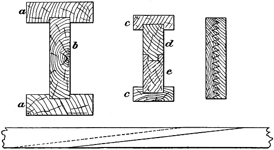
Fig. 45.—System of splicing and building up wooden members. When they have to be curved and to keep their shape, they should be bent at the curve at the time of being glued together, and joined in the middle as at d.
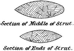
Fig. 46.—Cross-section of struts.
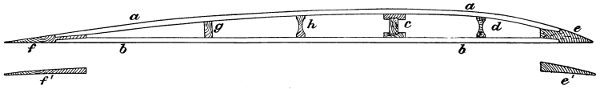
Fig. 47.—Truss suitable for use with flying machines, having aeroplanes about 6 feet to 8 feet wide.
Fig. 47 enlarged (30 kB)
The top of the aeroplane as well as the bottom should be covered with some light material, if the very best results are to be obtained. In another chapter I have shown a form of fabric-covered aeroplane, made by myself, that was not distorted in the least by the air pressure, and produced just as good effects as it would have done if it had been carefully carved out of a piece of wood. On more than one occasion Lord Kelvin came to my place; he said that my workshop was a perfect museum of invention. At the Oxford Meeting of the British Association for the Advancement of Science, Lord Salisbury in the chair, I was much gratified when Lord Kelvin said that he had examined my work, and found that it was beautifully designed and splendidly executed. He complimented me very highly indeed. While at my place, he said that the most ingenious thing that he had seen was the way I had prevented my aeroplanes from being distorted by the air. He spoke of this several times with great admiration, and, I think, if the fabric-covered aeroplane is to be used at all, that my particular system will be found altogether the best.
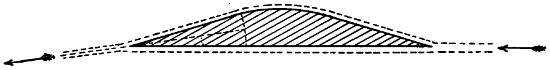
Fig. 48.—The paradox aeroplane that lifts no matter in which direction it is being driven.
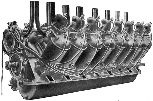
Fig. 49.—The Antoinette motor.
Regarding the motors now being employed, I think
that there is still room for a great deal of improvement
in the direction of greater lightness, higher efficiency
and reliability. At the present time, flying machine
motors have such small cylinders, the rotation is so rapid,
and the cooling appliances so imperfect, that the engine
soon becomes intensely heated, and then its efficiency
is said to fall off about 40 or 50 per cent., some say even
60 per cent. This is probably on account of the high
temperature of the cylinder, piston, and air inlet. The
heat expands the air as it enters, so that the actual weight
of air in the cylinder is greatly reduced, and the engine
power reduced in a corresponding degree. There is no
trouble about cooling the motor, and a condenser of high
efficiency may be made that will cool the water perfectly,
and, at the same time, lift a good deal more than its
own weight. All the conditions are favourable for using[89
90]
a very effective atmospheric condenser (see Figs. 30
and 31).
Water may be considered as 2400 times as efficient as air, volume for volume, in condensing steam. When a condenser is made for the purpose of using water as a cooling agent, a large number of small tubes may be closely grouped together in a box, and the water pumped in at one end of the box and discharged at the other end through relatively small openings; but when air is employed, the tubes or condensing surfaces must be widely distributed, so that a very large amount of air is encountered, and air which has struck one tube and become heated must never touch a second tube (see Figs. 30 and 31, also Appendix).
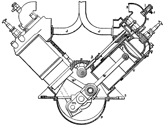
Fig. 50.—Section showing the Antoinette motor, such as used in the Farman and De la Grange machines.
Fig. 51 shows a pneumatic buffer which I have designed, in which a, a, is a steel tube highly polished on the inside; b, a nozzle for connecting the air-pump, which is of the bicycle variety; c, a nipple to which is attached a strong india-rubber bulb; d, a piston which is made air-tight by a leather cup; and f, the connection to the lever carrying the wheels on which the machine runs. While the machine is at a state of rest on the ground, the piston-rod d, is run out to its full extent, and supports the weight of the machine—the pressure being about 150 lbs. to the square inch. When, however, the machine comes violently down[91] to the earth, the piston is pushed inward, compressing the air, and by the time it has travelled, say, one-half the stroke, the air pressure will have mounted to 300 lbs. to the square inch. At this point, the rubber bulb c, ought to burst and allow the compressed air to escape under a high pressure. Air escaping through a relatively small hole absorbs the momentum of the descent and brings the machine to a state of rest without a destructive shock. It is, of course, necessary for the navigator to select a broad and level field for descent, and then to approach it from the leeward and slow up his machine as near the ground as possible, tilting the forward end upwards in order to arrest its forward motion, and touching the ground while still moving against the wind at a fairly high velocity. If all these points are studied, and well carried out, very little danger will result; then, again, the aeroplanes b, b, and the forward rudder d (Fig. 41), should be so arranged that, in case of an accident, their outward sides may be instantly turned upwards, in such a manner as to prevent the machine from plunging, and keep it on an even keel while the engines are not running.
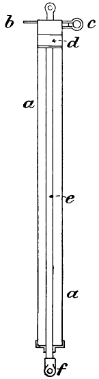
Fig. 51.—Pneumatic buffer—a, a, cylinder; b, attachment for pumping up; c, air outlet, covered with a rubber thimble made to burst under about 300 lbs. pressure; d, the piston.
A ship at sea has only to be steered in a horizontal direction; the water in which it is floated assures its stability in a vertical direction; but when a flying machine is once launched in the air, it has to be steered in two directions—that is, the vertical and the horizontal. Moreover, it is constantly encountering air currents that are moving with a much higher velocity than any water currents that have ever to be encountered. It is, therefore, evident that, as far as vertical steering is concerned, it should be automatic. Some have suggested shifting weights, flowing mercury, and swinging pendulums; but none of these is of the least value, on account of the swaying action which always has to be encountered. A pendulum could not be depended upon for working machinery on board a ship, and the same laws apply to an airship. We have but one means at our disposal, and that is the gyroscope. When a gyroscope is spun at a very high velocity on a vertical axis, with the point of support very much above the center of gyration, it has a tendency to maintain a vertical axis; a horizontal or swinging motion of its support will not cause it to swing like a pendulum. It therefore becomes possible by its use to maintain an airship on an even keel. In a steam steering apparatus, such as is used on shipboard, it is not sufficient to apply steam-power to move the rudders, unless some means are provided whereby the movement of the rudder closes off the steam, otherwise the rudder might continue to travel after the effect had been produced, and ultimately be broken; and so it is with steering a flying machine in a vertical direction. Whenever the fore and aft rudders respond to the action of the gyroscope and are set in motion, they must at once commence to shut off the power that works them, otherwise they would continue to travel. In the photograph (Fig. 52) I have shown an apparatus which I constructed at Baldwyn’s Park. It will be seen that the gyroscope is enclosed in a metal case; a tangent screw, just above the case, rotates a pointer around a small disc, which admits of the speed of the gyroscope being observed. Steam is admitted through a universal joint, descends through the shaft and escapes through a series of small openings placed at a tangent, so as to give rotation to the[93] wheel after the manner of a Barker’s mill. The casing about the rotating wheel is extremely light as relates to the wheel, so that, when the gyroscope is once spun on a vertical axis, the rest of the apparatus may be tilted in any direction, while the gyroscope and its attachments maintain a vertical axis. The gyroscope and its attachments are suspended from a long steel tube, which in reality is a steam cylinder. The sleeve which supports the gyroscope moves freely in a longitudinal direction, and the whole is held in position by a triple-threaded screw on the small tube above the cylinder. The steam is admitted through a piston value operated by a species of link motion, as shown. The piston-rod extends to each end of the cylinder, and regulates the rudders by pulling a small wire rope, the travel of the piston being about 8 feet. At the end of the cylinder (not shown) the piston-rod is provided with an arm and a nut which engages the small top tube—this tube being provided with a long spiral—so that, as the piston moves, the top tube is rotated, and thereby slides the gyroscope’s support, and changes its position as relates to the piston valve. It will, therefore, be seen that the action is the same as with the common steam steering gear used on shipboard. A little adjusting screw at the right hand of the print is shown. The upward projecting arm of the bell crank lever is for the purpose of attaching the wooden handle, making it possible to move the connecting-rod instantly into a position where the steam piston will move the rudders into the position shown (Fig. 56).
I copy the following from a description which I wrote of this apparatus at the time:—
“Gyroscope Apparatus for Automatically Steering Machine in a Vertical Direction.
“This apparatus consists of a long steam cylinder which is provided with a piston, the piston-rod extending beyond the cylinder at each end; the ropes working the fore and aft rudders are attached to the ends of this piston-rod, and steam is supplied through an equilibrium valve. The gyroscope is contained in a gunmetal case, and is driven by a jet of steam entering through the trunnions. When the gyroscope is spinning at a high velocity, the casing holding it becomes very rigid and is not easily moved from its[94] vertical position. If the machine rears or pitches, the cylinder and valve are moved with the machine while the gyroscope remains in a vertical position. This causes the steam valve to be moved so as to admit steam into the cylinder and move the piston in the proper direction to instantly bring the machine back into its normal position. As the fore and aft rudders are moved, the long tubular shaft immediately over the steam cylinder is rotated in such a manner as to move the whole gyroscope in the proper direction to close off the steam. The apparatus may be made to regulate at any angle by adjusting the screw which regulates the position of the tubular shaft. The link that suspends the end of the steam valve connecting-rod is supported by a bell crank lever, and while the machine is moving ahead, the lever occupies the position shown in the photograph (Fig. 52); but if the machinery and engine stop, the bell crank lever may be moved so as to throw the connecting-rod below the centre, when the steam will move the piston in the proper direction to throw both the rudders into the falling position, as shown in Fig. 56.”
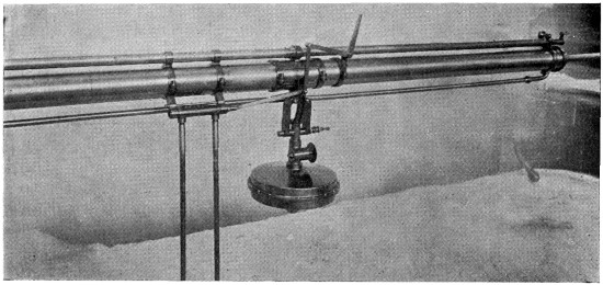
Fig. 52.—Gyroscope, used for the control of the fore and aft horizontal rudders, thus keeping the machine on an even keel while in the air.

Fig. 53.—In order to adjust the lifting effect so that it was directly over the centre of gravity, and to test the action of my fore and aft horizontal rudders, I ran the machine along the steel rail i, i, and adjusted my weights and aeroplanes in such a manner that, when the machine was run at a speed of 30 miles an hour along the track, with the rudders adjusted in the manner shown, the front wheel j, was raised from the steel track and the small wheel m, brought into contact with the upper track h. When the rudder b, b, is in this position, it produces a strong lifting effect, while the rudder c, c, does not lift at all.
Fig. 53 enlarged (66 kB)
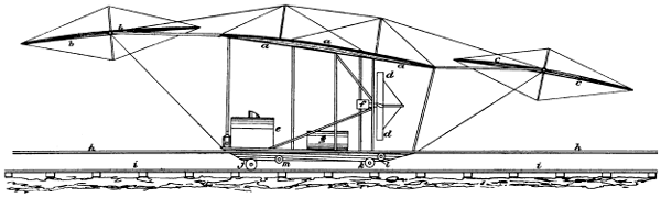
Fig. 54.—This shows the rudders placed in such a position that b, b, does not lift at all, while c, is placed at such an angle as to produce a strong lifting effect, especially so as it is in the blast of the screws d, d. With the rudders in this position, and at a speed of 30 miles an hour, I was able to lift the rear wheels k, k, off the steel rails and to bring the small wheel l, in contact with the upper track h. These experiments showed that the machine could be tilted in either direction by changing the position of the rudder.
Fig. 54 enlarged (60 kb)
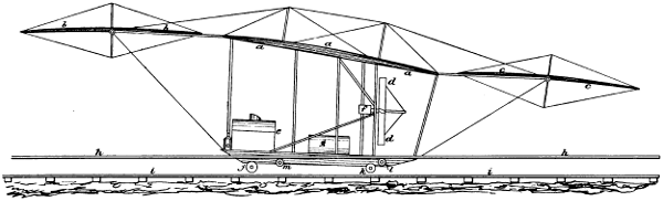
Fig. 55.—When the rudders were placed in the position shown, and the machine was run over the track at a rate of 40 miles an hour, all the weight was lifted off the wheels, j, and k, and both the small wheels m, and l, engaged the upper track.
Fig. 55 enlarged (62 kB)
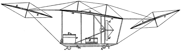
Fig. 56.—In case of a breakdown or failure of the engines when the machine is in flight, it is necessary to place the rudders in the position shown, in order to prevent the machine from diving to the earth. When the rudders are in this position, a rapid and destructive descent is not possible, as the machine will preserve an even keel while falling.
Fig. 56 enlarged (50 kB)
In Prof. Langley’s lifetime, we had many discussions regarding the width and shape of aeroplanes. The Professor had made many experiments with very small and narrow planes, and was extremely anxious to obtain some data regarding the effect that would be produced by making the planes of greater width. He admitted that by putting some two or three aeroplanes tandem, and all at the same angle, the front aeroplane a (Fig. 57), would lift a great deal more than b, and that c, would lift still less. He suggested the arrangement shown at a′, b′, c′, in which b′ is set at such an angle as to give as much additional acceleration to the air as it had received in the first instance by passing under a′, and that c′, should also increase the acceleration to the same extent. With this arrangement, the lifting effect of the three aeroplanes ought to be the same, but I did not agree with this theory. It seemed to me that it would only be true if it dealt with the volume of air represented between j, and k, and that he did not take into consideration the mass of air between k, and l, that had to be dealt with, and which would certainly have some effect in buoying up the stream of air, j, k. Prof. Langley admitted the truth of this, and said that nothing but experiment would demonstrate what the real facts were. But it was a matter which I had to deal with. I did not like the arrangement a′, b′, c′, as the angle was so sharp, especially at c′, that a very large screw thrust would be necessary. I therefore made a compromise on this system which is shown at a′′, b′′, c′′. In this case a′′, has an inclination of 1 in 10, b′′ an inclination of 1 in 6, and c′′ an inclination of 1 in 5. It will be seen that this form, which is shown as one aeroplane at a′′′, b′′′, c′′′, is a very good shape. It is laid out by first drawing the line c, d, dropping the perpendicular equal to one-tenth of the distance between c and d, and then drawing a straight line from c, through e, to f, where another perpendicular is[100] dropped, and half the distance between d and e laid off, and another straight line drawn from e, through g, to h, and the perpendicular h, i, laid off the same as f, g. We then have four points, and by drawing a curve through these, we obtain the shape of the aeroplane shown above, which is an exceedingly good one. This shape, however, is only suitable for velocities, up to 40 miles per hour; at higher velocities, the curvature would be correspondingly reduced.
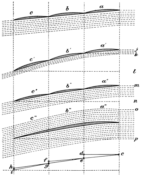
Fig. 57.—Diagram showing the evolution of a wide aeroplane.
In designing aeroplanes for flying machines, we should not lose sight of the fact that area alone is not sufficient. Our planes must have a certain length of entering edge—that is, the length of the front edge must bear a certain relation to the load lifted. An aeroplane 10 feet square will not lift half as much for the energy consumed as one 2 feet wide and 50 feet long; therefore, we must have our planes as long as possible from port to starboard. At all speeds of 40 miles per hour or less, there should be at least 1 foot of entering edge for every 4 lbs. carried. However, at higher speeds, the length may be reduced as the square of the speed increases. An aeroplane 1 foot square will not lift one-tenth as much as one that is 1 foot wide and 10 feet long. This is because the air slips off at the ends, but this can be prevented by a thin flange, or à la Hargrave’s kites. An aeroplane 2 feet wide and 100 feet long placed at an angle of 1 in 10, and driven edgewise through the air at a velocity of 40 miles per hour, will lift 2·5 lbs. per square foot. But as we find a plane 100 feet in length too long to deal with, we may cut it into two or more pieces and place them one above the other—superposed. This enables us to reduce the width of our machine without reducing its lifting effect; we still have 100 feet of entering edge, we still have 200 feet of lifting surface, and we know that each foot will lift 2·5 lbs. at the speed we propose to travel. 200 × 2·5 = 500; therefore our total lifting effect is 500 lbs., and the screw thrust required to push our aeroplane through the air is one-tenth of this, because the angle above the horizontal is 1 in 10. We, therefore, divide what Prof.[101] Langley has so aptly called the “lift” by 10; 50010 = 50. It will be understood that the vertical component is the lift, and the horizontal component the drift, the expression “drift” also being a term first applied by Prof. Langley. Our proposed speed is 40 miles per hour, or 3,520 feet in a minute of time. If we multiply the drift in pounds by the number of feet travelled in a minute of time, and divide the product thus obtained by 33,000, we ascertain the H.P. required—
50 × 3,52033,000 = 5·33.
It therefore takes 5·33 H.P. to carry a load of 500 lbs. at a rate of 40 miles per hour, allowing nothing for screw slip or atmospheric resistance due to framework and wires. But we find we must lift more than 500 lbs., and as we do not wish to make our aeroplanes any longer, we add to their width in a fore and aft direction—that is, we place another similar aeroplane, also 2 feet wide, just aft of our first aeroplane. This will, of course, have to engage the air discharged from the first, and which is already moving downwards. It is, therefore, only too evident that if we place it at the same angle as our first one—viz., 1 in 10—it will not lift as much as the first aeroplane, and we find that if we wish to obtain a fairly good lifting effect, it must be placed at an angle of 1 in 6. Under these conditions, the screw thrust for this plane will be 1⁄6th part of the lift, or 8·88 H.P. against 5·33 H.P. with our first aeroplane. In order to avoid confusion, we will call our first plane a′′, our second plane b′′, and the third c′′, the same as in Fig. 57. Still we are not satisfied, we want more lift, we therefore add still another aeroplane as shown (c′′, Fig. 57). This one has to take the air which has already been set in motion by the two preceding planes a′′ and b′′, so in order to get a fair lifting effect, we have to place our third plane at the high angle of 1 in 5. At this angle, our thrust has to be 1⁄5th of the lifting effect, and the H.P. required is twice as much per pound carried as with the plane a′′, where the angle was 1 in 10; therefore, it will take 10·66 H.P. to carry 500 lbs. As there is no reason why we should have three aeroplanes placed tandem where one would answer the purpose much better, we convert the whole of them into one, as shown (a′′′, b′′′, c′′′, Fig. 57), and by making[102] the top side smooth and uniform, we get the advantage of the lifting effect due to the air above the aeroplane as well as below it. The average H.P. is therefore 5·33 + 8·88 + 10·66 ÷ 3 = 8·29 H.P. for each plane, or 25 H.P. for the whole, which is at the rate of 60 lbs. to the H.P., all of which is used to overcome the resistance due to the weight[103] and the inclination of the aeroplanes, and which is about half the total power required. We should allow as much more for loss in screw slip and atmospheric resistance due to the motor, the framework, and the wires of the machine. If, however, the screw is placed in the path of the greatest resistance, it will recover a portion of the energy imparted to the air. We shall, however, require a 50 H.P. motor, and thus have 30 lbs. to the H.P.
From the foregoing it will be seen that at a speed of 40 miles an hour, the weight per H.P. is not very great. If we wish to make a machine more efficient, we must resort to a multitude of very narrow superposed planes, or sustainers, as Mr. Philipps calls them, or we must increase the speed. If an aeroplane will lift 2·5 lbs. per square foot placed at an angle of 1 in 10, and driven at a velocity of 40 miles an hour, the same aeroplane will lift 1·25 lbs. if placed at an angle of 1 in 20, and as the lifting effect varies as the square of the velocity, the same plane will lift as much more at 60 miles per hour, as 60² is greater than 40²—that is, 2·81 lbs. per square foot instead of 1·25 lbs. At this high speed, providing that the width of the plane is not more than 3 feet, it need be only slightly curved and have a mean angle of 1 in 20.
An aeroplane 100 feet long and 3 feet wide would have 300 square feet of lifting surface, each of which would lift 2·81 lbs., making the total lifting effect 843 lbs. 843 ÷ 20 = 42·15, which is the screw thrust that would be necessary to propel such a plane through the air at a velocity of 60 miles per hour. 60 miles per hour is 5,280 feet in a minute, therefore the H.P. required is 42·15 × 5,280 ÷ 33,000 = 6·7 H.P. Dividing the total lifting effect 843 by 6·7, we have 843 ÷ 6·7 = 125·8, the lift per H.P. If we allow one-half for loss in friction, screw slip, etc., we shall be carrying a load of 843 lbs. with 13·4 H.P. It will, therefore, be seen that a velocity of 60 miles an hour is much more economical in power than the comparatively low velocity of 40 miles an hour; moreover, it permits of a considerable reduction in the size and weight of the machine, and this diminishes the atmospheric resistance.
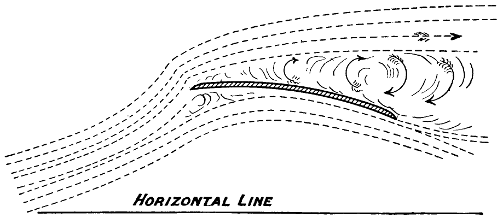
Fig. 58.—In a recently published mathematical treatise on Aerodynamics, an illustration is shown, representing the path that the air takes on encountering a rapidly moving curved aeroplane. It will be observed that the air appears to be attracted upwards before the aeroplane reaches it, exactly as iron filings would be attracted by a magnet, and that the air over the top of the aeroplane is thrown off at a tangent, producing a strong eddying effect at the top and rear. Just why the air rises up before the aeroplane reaches it is not plain, and as nothing could be further from the facts, mathematical formulas founded on such a mistaken hypothesis can be of but little value to the serious experimenter on flying machines.
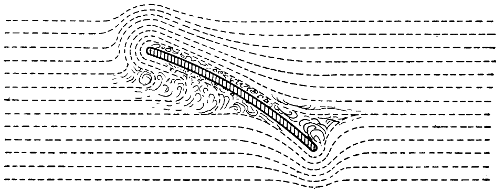
Fig. 59.—An illustration from another scientific publication also on the Dynamics of Flight. It will be observed that the air in striking the underneath side of the aeroplane is divided into two streams, a portion of it flowing backwards and over the top of the edge of the aeroplane where it becomes compressed. An eddy is formed on the back and top of the aeroplane, and the air immediately aft the aeroplane is neither rising nor falling. Just how these mathematicians reason out that the air in striking the front of the aeroplane would jump backwards and climb up over the top and leading edge against the wind pressure is not clear.
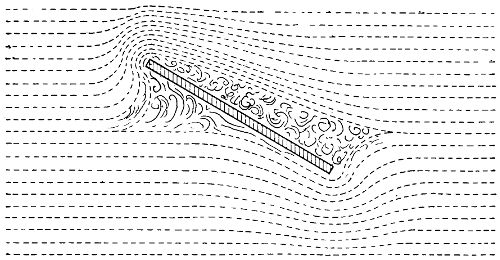
Fig. 60.—This shows another illustration from the same mathematical work, and represents the direction which the air is supposed to take on striking a flat aeroplane. With this, the air is also divided, a portion moving forward and over the top of the aeroplane where it is compressed, leaving a large eddy in the rear, and, as the dotted lines at the back of the aeroplane are horizontal, it appears that the air is not forced downwards by its passage. Here, again, formula founded on such hypothesis is misleading in the extreme.
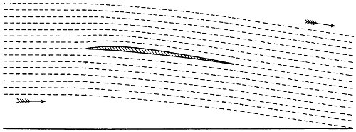
Fig. 61.—This shows the shape and the practical angle of an aeroplane. This angle is 1 in 10, and it will be observed that the air follows both the upper and the lower surface, and that it leaves the plane in a direction which is the resultant of the top and bottom angle.
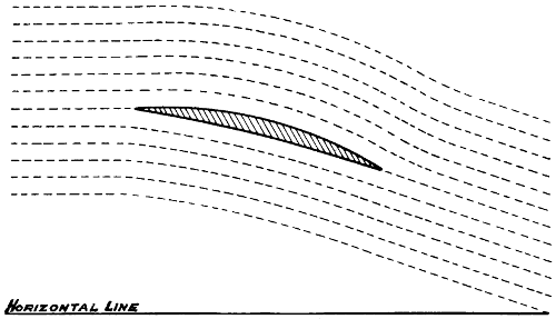
Fig. 62.—This shows an aeroplane of great thickness, placed at the highest angle that will ever be used—1 in 4—and even with this the air follows the upper and lower surfaces. No eddies are formed, and the direction that the air takes after leaving the aeroplane is the resultant of the top and bottom angles.

Fig. 63.—Section of a screw blade having a rib on the back. The resistance caused by this rib is erroneously supposed to be skin friction.
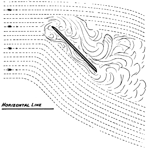
Fig. 64.—Shows a flat aeroplane placed at an angle of 45°, an angle which will never be used in practical flight, but at this angle the momentum of the approaching air and the energy necessary to give it an acceleration sufficiently great to make it follow the back of the aeroplane are equal, and at this point, the wind may either follow the surface or not. Sometimes it does and sometimes it does not. See experiments with screws.
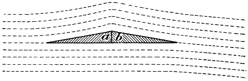
Fig. 65.—The aeroplane here shown is a mathematical paradox. This aeroplane lifts, no matter in which direction it is driven. It encounters air which is stationary and leaves it with a downward trend; therefore it must lift. However, if we remove the section b, and only subject a to the blast, as shown at Fig. 66, no lifting effect is produced. On the contrary, the air has a tendency to press a, downwards. The path which the air takes is clearly shown; this is most important, as it shows that the shape of the top side is a factor which has to be considered. All the lifting effect in this case is produced by the top side.
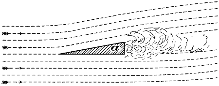
Fig. 66.
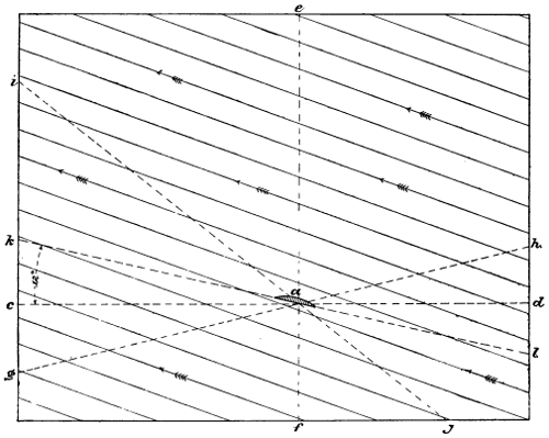
Fig. 67.—In this drawing a represents an aeroplane, or a bird’s wing. Suppose that the wind is blowing in the direction of the arrows; the real path of the bird as relates to the air is from i to j,—that is, the bird is falling as relates to the air although moving on the line c, d, against the wind. In some cases, a bird is able to travel along the line g, h, instead of in a horizontal direction, thus rising and apparently flying into the teeth of the wind at the same time.
Professor S. P. Langley, of the Smithsonian Institute, Washington, D.C., made a small flying model in 1896. This, however, only weighed a few pounds; but as it did actually fly and balance itself in the air, the experiment was of great importance, as it demonstrated that it was possible to make a machine with aeroplanes so adjusted as to steer itself automatically in a horizontal direction. In order to arrive at this result, an innumerable number of trials were made, and it was only after months of careful and patient work that the Professor and his assistants succeeded in making the model fly in a horizontal direction without rearing up in front, and then pitching backwards, or plunging while moving forward.
The Wright Brothers of Dayton, Ohio, U.S.A., often referred to as “the mysterious Wrights,” commenced experimental work many years ago. The first few years were devoted to making gliding machines, and it appears that they attained about the same degree of success as many others who were experimenting on the same lines at the same time; but they were not satisfied with mere gliding machines, and so turned their attention in the direction of motors. After some years of experimental work, they applied their motor to one of their large gliding machines, and it is said that with this first machine they actually succeeded in flying short distances. Later on, however, with a more perfect machine, they claim to have made many flights, amongst which I will mention three: 12 miles in 20 minutes, on September 29th, 1905; 20·75 miles in 33 minutes, on October 4th; and 24·2 miles in 38 minutes, on October 5th of the same year. As there seems to be much doubt regarding these alleged flights, we cannot refer to them as facts until the Wright Brothers condescend to show their machine and make a flight in the presence of others; nevertheless, I think we are justified in assuming that they have met with a certain degree of success which may or may not be equal to the achievements of Messrs Farman and De la Grange. It is interesting to note in this connection that all flying machines that have met with any success have been made on the same lines; all have superposed aeroplanes, all have fore and aft horizontal rudders, and all are propelled with screws; and in this respect they do not[110] differ from the large machine that I made at Baldwyn’s Park many years ago. I have seen both the Farman and the De la Grange machines; they seem to be about the same in size and design, and what is true of one is equally true of the other; I will, therefore, only describe the one that seems to have done the best—the De la Grange. The general design of this machine is clearly shown in the illustrations (Figs. 68 and 69). The dimensions are as follows: The two main aeroplanes are 32·8 feet long and 4·9 feet wide; the tail or after rudder is made in the form of a Hargrave’s box kite, the top and bottom sides of the box being curved and covered with balloon fabric, thus forming aeroplanes. This box is 9·84 feet long from port to starboard, and 6·56 feet wide in a fore and aft direction. The diameter of the screw is 7·2 feet and it has a mean pitch of 5·7 feet. The screw blades are two in number and are extremely small, being only 6·3 inches wide at the outer end and 3·15 inches at the inner end, their length being 2·1 feet. The space between the fore and aft aeroplanes is 4·9 feet. The total weight is about 1,000 lbs. with one man on board. The speed of this machine through the air is not known with any degree of certainty; it is, however, estimated to be 32 to 40 miles per hour. When the screw is making 1,100 revolutions per minute, the motor is said to develop 50 H.P.

Fig. 68.—The De la Grange machine on the ground and about to make a flight.
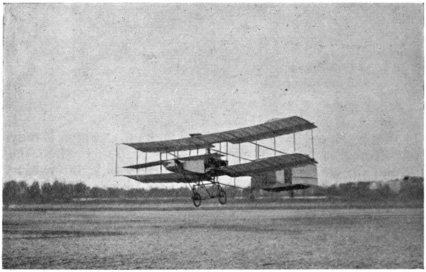
Fig. 69.—The De la Grange machine in full flight and very near the ground.
In the following calculations, I have assumed that the machine has the higher speed—40 miles per hour. I have been quite unable to obtain any reliable data regarding the angle at which the aeroplanes are set, but it would appear that the angle is about 1 in 10. The total area of the two main aeroplanes is 321·4 square feet. A certain portion of the lower main aeroplane is cut away, but this is compensated for by the forward horizontal rudder placed in the gap thus formed. The two rear aeroplanes forming the tail of the machine have an area of 128·57 square feet. The area of all the aeroplanes is, therefore, 450 square feet. As the weight of the machine is 1,000 lbs., the lift per square foot is 2·2 lbs. Assuming that the angle of the aeroplanes is 1 in 10, the screw thrust would be 100 lbs., providing, however, that the aeroplanes were perfect and no friction of any kind was encountered. Forty miles per hour is at the rate of 3,520 feet in a minute of time, therefore, 3,520 × 10033,000 = 10·66 H.P. If we allow another 10 H.P. for[111] atmospheric resistance due to the motor, the man, and the framework of the machine, it would require 20·66 H.P. to propel the machine through the air at the rate of 40 miles per hour. If the motor actually develops 50 H.P., 29 H.P. will be consumed in screw slip and overcoming the resistance[112] due to the imperfect shape of the screw. The blades of the De la Grange screw propeller are extremely small, and the waste of energy is, therefore, correspondingly great—their projected area being only 1·6 square feet for both blades. Allowing 200 lbs. for screw thrust, we have the following: 2001·60 = 125 lbs. pressure per square foot on the blades. If we multiply the pitch of the screw in feet by the number of revolutions per minute, we find that if it were travelling in a solid nut it would advance over 70 miles an hour. By the Eiffel tower formula P = 0·003 V², a wind blowing at a velocity of 70 miles per hour produces a pressure of 14·7 lbs. per square foot on a normal plane; therefore, assuming that the projected area of the screw blades is 1·6, we have 1·6 × 14·7 = 23·52 lbs., which is only one-fifth part of what the pressure really is when the screws are making 1,100 turns a minute. It is interesting to note that the ends of the screw blades travel at a velocity of 414 feet per second, which is about one-half the velocity of a cannon ball fired from an old-fashioned smooth bore.
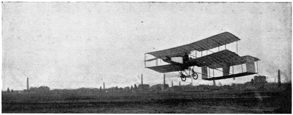
Fig. 70.—Farman’s machine in flight.
A flying machine has, of course, to be steered in two directions at the same time—the vertical and the horizontal. In the Farman and De la Grange machines, the horizontal steering is effected by a small windlass provided with a hand wheel, the same as on a steam launch, and the vertical steering is effected by a longitudinal motion of the shaft of the same windlass. As the length of the machine is not very great, it requires very close attention on the part of the man at the helm to keep it on an even keel; if one is[113] not able to think and act quickly, disaster is certain. On one occasion, the man at the wheel pushed the shaft of the windlass forward when he should have pulled it back, and the result was a plunge and serious damage to the machine;[114] happily no one was injured, though some of the bystanders were said to have had very narrow escapes. The remedy for this is to make all hand-steered machines of great length, which gives more time to think and act; or, still better, to make them automatic by the use of a gyroscope.
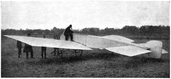
Fig. 71.—Bleriot’s machine. This machine raised itself from the ground, but as the centre of gravity was very little, if any, above the centre of lifting effect, it turned completely over in the air.
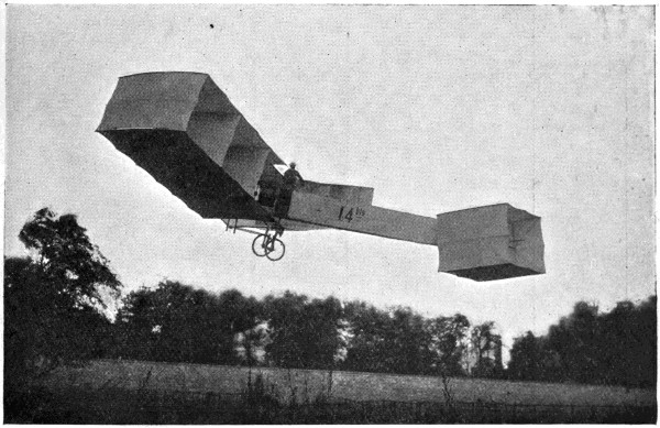
Fig. 72.—Santos Dumont’s flying machine.
Velocity and Pressure of the Wind.
The pressure varies as the square of the velocity or P ∝ V². The old formula for wind blowing against a normal plane was P = 0·005 × V². The latest or Eiffel Tower formula gives a much smaller value, being P = 0·003 × V², where V represents the velocity in miles per hour, and P the pressure in pounds per square foot.
| Velocity. | Pressure on a Sq. Foot. |
Character of the Wind. | |||||||
|---|---|---|---|---|---|---|---|---|---|
| Per Hour. |
Per Minute. |
Per Second. |
|||||||
| Miles. | Feet. | Feet. | Lbs. | ||||||
| 1 | 88 | 1 | ·5 | ·003 | Barely observable. | ||||
| 2 | 176 | 2 | ·9 | ·012 | - | Just perceptible. | |||
| 3 | 264 | 4 | ·4 | ·027 | |||||
| 4 | 352 | 5 | ·9 | ·048 | Light breeze. | ||||
| 5 | 440 | 7 | ·3 | ·075 | - | Gentle, pleasant wind. | |||
| 6 | 528 | 8 | ·8 | ·108 | |||||
| 8 | 704 | 11 | ·7 | ·192 | |||||
| 10 | 880 | 14 | ·7 | ·3 | Fresh breeze. | ||||
| 15 | 1,320 | 22 | ·675 | Brisk breeze. | |||||
| 20 | 1,760 | 29 | ·4 | 1 | ·2 | Stiff breeze. | |||
| 25 | 2,200 | 36 | ·7 | 1 | ·875 | Very brisk breeze. | |||
| 30 | 2,640 | 44 | 2 | ·7 | - | High wind. | |||
| 35 | 3,080 | 51 | ·3 | 3 | ·675 | ||||
| 40 | 3,520 | 58 | ·7 | 4 | ·8 | Very high wind. | |||
| 45 | 3,960 | 66 | 6 | ·075 | Gale. | ||||
| 50 | 4,400 | 73 | ·4 | 7 | ·5 | Storm. | |||
| 60 | 5,280 | 88 | 10 | ·8 | - | Great storm. | |||
| 70 | 6,160 | 102 | ·7 | 14 | ·7 | ||||
| 80 | 7,040 | 117 | ·2 | 19 | ·2 | Hurricane. | |||
| 90 | 7,920 | 132 | 24 | ·3 | - | Tornado. | |||
| 100 | 8,800 | 146 | ·7 | 30 | |||||
| 110 | 9,680 | 161 | ·2 | 36 | ·3 | - | “Washoe zephyrs.”[2] | ||
| 120 | 10,560 | 176 | 43 | ·2 | |||||
| 130 | 11,440 | 191 | 50 | ·7 | |||||
| 140 | 12,320 | 205 | ·3 | 58 | ·8 | ||||
| 150 | 13,200 | 220 | 67 | ·5 | |||||
[2] With apologies to Mark Twain.
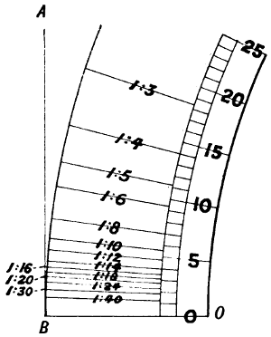
Fig. 72a.—Angles and degrees compared. It will be observed that an angle of 1 in 4 is practically 14°.
Table of Equivalent Inclinations.
| Rise. | Sine of Angle. |
Angle in Degrees. |
|||
|---|---|---|---|---|---|
| 1 | in | 30, | ·0333 | 1 | ·91 |
| 1 | „ | 25, | ·04 | 2 | ·29 |
| 1 | „ | 20, | ·05 | 2 | ·87 |
| 1 | „ | 18, | ·0555 | 3 | ·18 |
| 1 | „ | 16, | ·0625 | 3 | ·58 |
| 1 | „ | 14, | ·0714 | 4 | ·09 |
| 1 | „ | 12, | ·0833 | 4 | ·78 |
| 1 | „ | 10, | ·1 | 5 | ·73 |
| 1 | „ | 9, | ·1111 | 6 | ·38 |
| 1 | „ | 8, | ·125 | 7 | ·18 |
| 1 | „ | 7, | ·143 | 8 | ·22 |
| 1 | „ | 6, | ·1667 | 9 | ·6 |
| 1 | „ | 5, | ·2 | 11 | ·53 |
| 1 | „ | 4, | ·25 | 14 | ·48 |
| 1 | „ | 3, | ·3333 | 19 | ·45 |
Table of Equivalent Velocities.
| Miles per Hour. |
Feet per Second. |
Feet per Minute. |
Metres per Minute. |
Metres per Second. |
|||
|---|---|---|---|---|---|---|---|
| 1, | 1 | ·5 | 88 | 26 | ·8 | ·447 | |
| 2, | 2 | ·9 | 176 | 53 | ·6 | ·894 | |
| 3, | 4 | ·4 | 264 | 80 | ·5 | 1 | ·341 |
| 4, | 5 | ·9 | 352 | 107 | ·3 | 1 | ·788 |
| 5, | 7 | ·3 | 440 | 134 | ·1 | 2 | ·235 |
| 6, | 8 | ·8 | 528 | 160 | ·9 | 2 | ·682 |
| 8, | 11 | ·7 | 704 | 214 | ·6 | 3 | ·576 |
| 10, | 14 | ·7 | 880 | 268 | ·2 | 4 | ·470 |
| 15, | 22 | 1,320 | 402 | ·3 | 6 | ·705 | |
| 20, | 29 | ·4 | 1,760 | 536 | ·4 | 8 | ·940 |
| 25, | 36 | ·7 | 2,200 | 670 | ·5 | 11 | ·176 |
| 30, | 44 | 2,640 | 804 | ·6 | 13 | ·411 | |
| 35, | 51 | ·3 | 3,080 | 938 | ·8 | 15 | ·646 |
| 40, | 58 | ·7 | 3,520 | 1,072 | ·9 | 17 | ·881 |
| 45, | 66 | 3,960 | 1,207 | 20 | ·116 | ||
| 50, | 73 | ·4 | 4,400 | 1,341 | ·1 | 22 | ·352 |
| 60, | 88 | 5,280 | 1,609 | ·2 | 26 | ·822 | |
| 70, | 102 | ·7 | 6,160 | 1,877 | ·5 | 31 | ·292 |
| 80, | 117 | ·2 | 7,040 | 2,145 | ·8 | 35 | ·763 |
| 90, | 132 | 7,920 | 2,414 | 40 | ·233 | ||
| 100, | 146 | ·7 | 8,800 | 2,682 | ·2 | 44 | ·704 |
| 110, | 161 | ·2 | 9,680 | 2,950 | ·2 | 49 | ·174 |
| 120, | 176 | 10,560 | 3,218 | ·4 | 53 | ·644 | |
| 130, | 191 | 11,440 | 3,486 | ·6 | 58 | ·115 | |
| 140, | 205 | ·3 | 12,320 | 3,755 | ·1 | 62 | ·585 |
| 150, | 220 | 13,200 | 4,023 | ·3 | 67 | ·056 | |
To convert feet per minute into
metres per second, multiply by ·00508.
Table Showing Velocity and Thrust Corresponding with Various Horse-Powers.
| Velocity in Miles per Hour. |
Horse-Power. | |||||||||||||||||||||
|---|---|---|---|---|---|---|---|---|---|---|---|---|---|---|---|---|---|---|---|---|---|---|
| 1 | 10 | 20 | 30 | 40 | 50 | 60 | 70 | 80 | 90 | 100 | ||||||||||||
| Thrust in Pounds. | ||||||||||||||||||||||
| 1, | 375 | 3,750 | 7,500 | 11,250 | 15,000 | 18,750 | 22,500 | 26,250 | 30,000 | 33,750 | 37,500 | |||||||||||
| 5, | 75 | 750 | 1,500 | 2,250 | 3,000 | 3,750 | 4,500 | 5,250 | 6,000 | 6,750 | 7,500 | |||||||||||
| 10, | 37 | ·5 | 375 | 750 | 1,125 | 1,500 | 1,875 | 2,250 | 2,625 | 3,000 | 3,375 | 3,750 | ||||||||||
| 15, | 25 | 250 | 500 | 750 | 1,000 | 1,250 | 1,500 | 1,750 | 2,000 | 2,250 | 2,500 | |||||||||||
| 20, | 18 | ·8 | 187 | ·5 | 375 | 562 | ·5 | 750 | 937 | ·5 | 1,125 | 1,312 | ·5 | 1,500 | 1,687 | ·5 | 1,875 | |||||
| 25, | 15 | 150 | 300 | 450 | 600 | 750 | 900 | 1,050 | 1,200 | 1,350 | 1,500 | |||||||||||
| 30, | 12 | ·5 | 125 | 250 | 375 | 500 | 625 | 750 | 875 | 1,000 | 1,125 | 1,250 | ||||||||||
| 35, | 10 | ·7 | 107 | ·1 | 214 | ·3 | 321 | ·4 | 428 | ·6 | 535 | ·7 | 642 | ·8 | 750 | 857 | ·1 | 964 | ·3 | 1,071 | ·4 | |
| 40, | 9 | ·4 | 93 | ·8 | 187 | ·5 | 281 | ·3 | 375 | 468 | ·8 | 562 | ·5 | 656 | ·3 | 750 | 843 | ·8 | 937 | ·5 | ||
| 45, | 8 | ·3 | 83 | ·3 | 166 | ·7 | 250 | 333 | ·3 | 416 | ·7 | 500 | 583 | ·3 | 666 | ·7 | 750 | 833 | ·3 | |||
| 50, | 7 | ·5 | 75 | 150 | 225 | 300 | 375 | 450 | 525 | 600 | 675 | 750 | ||||||||||
| 60, | 6 | ·3 | 62 | ·5 | 125 | 187 | ·5 | 250 | 312 | ·5 | 375 | 437 | ·5 | 500 | 562 | ·5 | 625 | |||||
| 70, | 5 | ·4 | 53 | ·6 | 107 | ·1 | 160 | ·7 | 214 | ·3 | 267 | ·9 | 321 | ·4 | 375 | 428 | ·6 | 482 | ·1 | 535 | ·7 | |
| 80, | 4 | ·7 | 46 | ·9 | 93 | ·8 | 140 | ·6 | 187 | ·5 | 234 | ·4 | 281 | ·3 | 328 | ·2 | 375 | 421 | ·9 | 468 | ·8 | |
| 90, | 4 | ·2 | 41 | ·7 | 83 | ·3 | 125 | 166 | ·7 | 208 | ·3 | 250 | 291 | ·7 | 333 | ·3 | 375 | 416 | ·7 | |||
| 100, | 3 | ·75 | 37 | ·5 | 75 | 112 | ·5 | 150 | 187 | ·5 | 225 | 262 | ·5 | 300 | 337 | ·5 | 375 | |||||
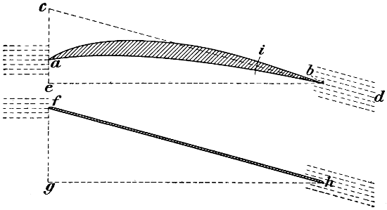
Fig. 72b.—When an aeroplane is driven through the air, it encounters stationary air and leaves it with a downward trend. With a thick curved aeroplane, as shown, the air follows both the top and the bottom surfaces, and the direction that the air takes is the resultant of these two streams of air. It will be seen that the air takes the same direction that it would take if the plane were flat, and raised from a to c, which would be substantially the same as shown at f, h, g. It has, however, been found by actual experiment that the curved plane is preferable, because the lifting effect is more evenly distributed, and the drift is less in proportion to the lift.
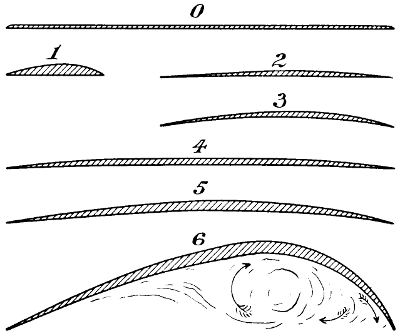
Fig. 72c.—Aeroplanes experimented with by Mr. Horatio Philipps. In
the published account which is before me, the angles at which these
planes were placed are not given, but, by comparing the lift with the
drift, we may assume that it was about 1 in 10.
Fig. 5 seems to have been the best shape, and I find that this plane
would have given a lifting effect of 2·2 lbs. per square foot at a velocity
of 40 miles per hour.
Philipps’ Experiments.
| Description of Form. |
Speed of Air Current. |
Dimensions of Aeroplanes. |
Lift. | Drift. | Lift divided by Drift. |
||||||
|---|---|---|---|---|---|---|---|---|---|---|---|
| Feet per sec. |
Miles per hour. |
Whole Plane. Ozs. |
Lbs. per sq. ft. |
Whole Plane. Ozs. |
Lbs. per sq. ft. |
||||||
| Plane surfaces, | 39 | 26·59 | 16" × 5" | 9 | 1 | ·013 | 2 | 0·225 | 4 | ·5 | |
| Fig. 1, | 60 | 40·91 | 16" × 1·25" | 9 | 4 | ·05 | 0 | ·87 | 0·392 | 10 | ·3 |
| F„g 2, | 48 | 32·73 | 16" × 3" | 9 | 1 | ·688 | 0 | ·87 | 0·163 | 10 | ·3 |
| F„g 3, | 44 | 30 | 16" × 3" | 9 | 1 | ·688 | 0 | ·87 | 0·163 | 10 | ·3 |
| F„g 4, | 44 | 30 | 16" × 5" | 9 | 1 | ·013 | 0 | ·87 | 0·098 | 10 | ·3 |
| F„g 5, | 39 | 26·59 | 16" × 5" | 9 | 1 | ·013 | 0 | ·87 | 0·098 | 10 | ·3 |
| F„g 6, | 27 | 18·41 | 16" × 5" | 9 | 1 | ·013 | 2 | ·25 | 0·253 | 4 | |
| Rook’s wing, | 39 | 26·59 | Area sq. ft. 0·5 |
8 | 1 | ·0 | 1 | ·0 | 0·125 | 8 | |
As far as the actual navigation of the air is concerned, balloonists have had everything to themselves until quite recently, but we find that at the present moment, experimenters are dividing their attention about equally between balloons or machines lighter than the air, and true flying machines or machines heavier than the air. In all Nature, we do not find any bird or insect that does not fly by dynamic energy alone, and I do not believe that the time is far distant when those now advocating machines lighter than the air, will join the party advocating machines heavier than the air, and, eventually, balloons will be abandoned altogether. No matter from what standpoint we examine the subject, the balloon is unsuitable for the service, and it is not susceptible of much improvement. On the other hand, the flying machine is susceptible of a good deal of improvement; there is plenty of scope for the employment of a great deal of skill, both mechanical and scientific, for a good many years to come.
I do not know that I can express myself better now than I did when I wrote an article for the Engineering Supplement of the Times, from which I quote the following:—
“The result of recent experiments must have convinced every thinking man that the day of the balloon is past. A balloon, from the very nature of things, must be extremely bulky and fragile.
“It has always appeared to the writer that it would be absolutely impossible to make a dirigible balloon that would be of any use, even in a comparatively light wind. Experiments have shown that only a few hundred feet above the surface of the earth, the air is nearly always moving at a velocity of at least 15 miles an hour, and more than two-thirds of the time at a velocity considerably greater than this. In order to give a balloon sufficient lifting power to carry two men and a powerful engine, it is necessary that[121] it should be of enormous bulk. Considered as a whole, including men and engine, it must have a mean density less than the surrounding air, otherwise it will not rise. Therefore, not only is a very large surface exposed to the wind, but the whole thing is so extremely light and fragile as to be completely at the mercy of wind and weather. Take that triumph of engineering skill, the ‘Nulli Secundus,’ for example. The gas-bag, which was sausage-shaped and 30 feet in diameter, was a beautiful piece of workmanship, the whole thing being built up of goldbeater’s skin. The cost of this wonderful gas-bag must have been enormous. The whole construction, including the car, the system of suspension, the engine and propellers, had been well thought out and the work beautifully executed; still, under these most favourable conditions, only a slight shower of rain was sufficient to neutralise its lifting effect completely—that is, the gas-bag and the cordage about this so-called airship absorbed about 400 lbs. of water, and this was found to be more than sufficient to neutralise completely the lifting effect. A slight squall which followed entirely wrecked the whole thing, and it was ignominiously carted back to the point of departure.
“We now learn that the War Office is soon to produce another airship similar to the ‘Nulli Secundus,’ but with a much greater capacity and a stronger engine. In the newspaper accounts it is said that the gas-bag of this new balloon would be sausage-shaped and 42 feet in diameter, that it is to be provided with an engine of 100 horse-power, which it is claimed will give to this new production a speed of 40 miles an hour through the air, so that, with a wind of 20 miles an hour, it will still be able to travel by land 20 miles an hour against the wind. Probably the writer of the article did not consider the subject from a mathematical point of view. As the mathematical equation is an extremely simple one, it is easily presented so as to be understood by any one having the least smattering of mathematical or engineering knowledge. The cylindrical portion of the gas-bag is to be 42 feet in diameter; the area of the cross-section would therefore be 1,385 feet. If we take a disc 42 feet in diameter and erect it high in the air above a level plain, and allow a wind of 40 miles an hour, which is the proposed speed of the balloon, to blow against it, we should find that the air pressure would be 11,083 lbs.—that is, a wind blowing at a velocity of 40 miles an hour would produce a pressure[122] of 8 lbs. to every square foot of the disc.[3] Conversely, if the air were stationary, it would require a push of 11,083 lbs. to drive this disc through the air at the rate of 40 miles an hour.
[3] Haswell gives the pressure of the wind at 40 miles an hour as 8 lbs. per square foot, and this is said to have been verified by the United States Coast Survey. Molesworth makes it slightly less; but the new formula, according to most recent experiments (Dr. Stanton’s experiments at the National Physical Laboratory and M. Eiffel’s at Eiffel Tower), is P = 0·003 V², which would make the pressure only 4·8 lbs. per square foot, and which would reduce the total H.P. required from 472 to 283, where P represents pounds per square foot and V miles per hour.
“A speed of 40 miles an hour is at the rate of 3,520 feet in a minute of time. We therefore have two factors—the pounds of resistance encountered, and the distance through which the disc travels in one minute of time. By multiplying the total pounds of pressure on the complete disc by the number of feet it has to travel in one minute of time, we have the total number of foot-pounds required in a minute of time to drive a disc 42 feet in diameter through the air at a speed of 40 miles an hour. Dividing the product by the conventional horse-power 33,000, we shall have 1,181 horse-power as the energy required to propel the disc through the air. However, the end of the gas-bag is not a flat disc, but a hemisphere, and the resistance to drive a hemisphere through the air is much less than it would be with a normal plane or flat disc. In the ‘Nulli Secundus’ we may take the coefficient of resistance of the machine, considered as a whole, as 0·20—that is, that the resistance will be one-fifth as much as that of a flat disc. This, of course, includes not only the resistance of the balloon itself, but also that of the cordage, the car, the engine, and the men.
“Multiplying 1,181 by the coefficient ·20, we shall have 236; therefore, if the new balloon were attached to a long steel wire and drawn by a locomotive through the air, the amount of work or energy required would be 236 horse-power—that is, if the gas-bag would stand being driven through the air at the rate of 40 miles an hour, which is extremely doubtful. Under these conditions, the driving wheels of the locomotive would not slip, and therefore no waste of power would result, but in the dirigible balloon we have a totally different state of affairs. The propelling screws are very small in proportion to the airship, and their slip is fully 50 per cent.—that is, in order to drive the ship at the rate of 40 miles an hour, the screws would have to[123] travel at least 80 miles an hour. Therefore, while 236 horse-power was imparted to the ship in driving it forward, an equal amount would have to be lost in slip, or, in other words, in driving the air rearwards. It would, therefore, require 472 horse-power instead of 100 to drive the proposed new balloon through the air at the rate of 40 miles an hour.
“It will be seen from this calculation that the new airship will still be at the mercy of the wind and weather. Those who pin their faith on the balloon as the only means of navigating the air may dispute my figures. However, all the factors in the equation are extremely simple and well known, and no one can dispute any of them except the assumed coefficient of resistance, which is given here as ·20. The writer feels quite sure that, after careful experiments are made, it will be found that this coefficient is nearer ·40 than ·20, especially so at high speeds when the air pressure deforms the gas-bag. Only a slight bagging in the front end of the balloon would run the coefficient up to fully ·50, and perhaps even more.”—Times, Feb. 26, 1908.
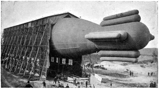
Fig. 73.—The enormous balloon, “Ville de Paris,” of the French Government. This balloon is a beautiful piece of workmanship, and is said to be the most practical balloon ever invented, not excepting the balloon of Count Zeppelin. Some idea of its size may be obtained by comparing it with the size of the men who are standing immediately underneath.
Since writing the Times article, a considerable degree of success has been attained by Count Zeppelin. According[124] to newspaper accounts, his machine has a diameter of about 40 feet, and a length of no less than 400 feet. It appears that this balloon consists of a very light aluminium envelope, which is used in order to produce a smooth and even surface, give rigidity, and take the place of the network employed in ordinary balloons. It seems that the gas is carried in a large number of bags fitted in the interior of this aluminium envelope. However, by getting a firm and smooth exterior and by making his apparatus of very great length as relates to its diameter, he has obtained a lower coefficient of resistance than has ever been obtained before, and as his balloon is of great volume, he is able to carry powerful motors and use screw propellers of large diameter. It appears that he has made a circuit of considerable distance, and returned to the point of departure without any accident. A great deal of credit is, therefore, due to him. His two first balloons came to grief very quickly; he was not discouraged, but stuck to the job with true Teutonic grit, and has perhaps attained a higher degree of success than has ever been attained with a balloon. However, some claim that the French Government balloon, “La Patrie” is superior to the Zeppelin balloon at all points. When we take into consideration the fact that the Zeppelin machine is 400 feet long and lighter than the same volume of air, it becomes only too obvious that such a bulky and extremely delicate and fragile affair will easily be destroyed. Of course ascensions will only be made in very favourable weather, but squalls and sudden gusts of wind are liable to occur. It is always possible to start out in fine weather if one waits long enough, but if a flight of 24 hours or even 12 hours is to be attempted, the wind may be blowing very briskly when we return, and an ordinary wind will not only prevent the housing of Count Zeppelin’s balloon, but will be extremely liable to reduce it to a complete wreck in a few minutes.[4]
[4] Shortly after this was written, the Zeppelin machine was completely demolished by a gust of wind.
I am still strongly of the opinion that the ultimate mastery of the air must be accomplished by machines heavier than the air.
(From our own Correspondent.)
Berlin, Friday.
Germany’s fleet of “air cruisers,” or dirigible airships, will, it is proudly announced to-day, presently number six:—
The first announcement of the last-named airship was given in The Daily Mail several months ago. The company has engaged a celebrated military aeronaut, Captain von Krogh, as commander of the vessel. The Study Society’s new non-rigid ship will be sold to the War Office as soon as she has completed her trial trips.
The Army will then possess three dirigibles, each representing one of the three opposed types of construction—rigid, half-rigid, and non-rigid—with a view to arriving at a conclusion on their merits.
..........
“Only a year or so ago, our authorities were talking of aerial navigation in its relation to war as ‘an interesting[126] and instructive study.’ Now we must reckon it as the gravest problem of the moment. The cleverest aeronauts in England should be called upon at once to design an airship, not only as efficient as that of Count Zeppelin’s, but possessed of even greater speed. (His average was said to be about 34 miles an hour.) In speed will lie the supremacy of the air when it comes to actual warfare. Of two opposing airships, the faster will be able to outmanœuvre its adversary and hold it at its mercy.”—Daily Mail, July 11, 1908.
GERMANY AS THE AERIAL POWER.
TEUTONIC VISION.
A LANDING OF 350,000 MEN.
Herr Rudolph Martin, author of books on war in the air and “Is a World-War Imminent?” points out how England is losing her insular character by the development of airships and aeroplanes.
“In a world-war,” he said to me, “Germany would have to spend two hundred millions sterling in motor airships, and a similar amount in aeroplanes, to transport 350,000 men in half an hour during the night from Calais to Dover. Even to-day the landing of a large German army in England is a mere matter of money. I am opposed to a war between Germany and England, but should it break out to-day, it would last at least two years, for we would conclude no peace until a German army had occupied London.
“In my judgment it would take two years for us to build motor airships enough simultaneously to throw 350,000 men into Dover via Calais. During the same night, of course, a second transport of 350,000 men could follow. The newest Zeppelin airship can comfortably carry fifty persons from Calais to Dover. The ships which the Zeppelin works in Friedrichshafen will build during the next few months are likely to be considerably larger than IV., and will carry one hundred persons. There is no technical reason against the construction of Zeppelin airships of 1,100,000 or even 1,700,000 cubic feet capacity, or twice or three times the capacity of IV. (500,000 cubic feet).
“I am at present organising a German ‘Air Navy League,’ to establish air-traffic routes in Germany. Aluminium airships could carry on regular traffic between Berlin and London, Paris, Cologne, Munich, Vienna, Moscow, Copenhagen, and Stockholm. In war time these ships would be at the disposal of the German Empire.
“The development of motor airship navigation will lead to a perpetual alliance between England and Germany. The British fleet will continue to rule the waves, while Germany’s airships and land armies will represent the mightiest Power on the Continent of Europe.”—Daily Mail, July 11, 1908.
It is needless to say that the above was written before the wreck of Zeppelin’s machine.
For many years scientific mechanicians and mathematicians have told us that the navigation of the air was quite possible. They have said it is only a question of motive power; “Give us a motor that is sufficiently light and strong, and we will very soon give you a practical flying machine.” A domestic goose weighs about 12 lbs., and it has been estimated that it only exerts about one-twelfth part of a horse-power in flying—that is, it is able to exert one man-power with a weight of only 12 lbs., which seems to be a very good showing for the goose. However, at the present moment, we are able to make motors which develop the power of ten men—that is, one horse-power—with less than the weight of a common barnyard fowl. Under these conditions it is quite evident that if a machine can be so designed that it will not be too wasteful in power, it must be a success. It is admitted by scientific men that all animals, such as horses, deer, dogs, and also birds, are able to develop much more dynamic energy for the carbon consumed than is possible with any thermodynamic machine that we are able to make. It may be said that many animals are able to develop the full dynamic energy of the carbon they consume, whereas the best of our motors do not develop more than 10 per cent. of the energy contained in the combustibles that they consume; but, as against this, it must be remembered that birds feed on grass, fruit, fish, etc., heavy and bulky materials containing only a small percentage of carbon, whereas with a motor we are able to use a pure hydrocarbon that has locked up in its atoms more than twenty times as much energy per pound as in the[128] ordinary food consumed by birds. I think, in fact I assert, that the time has now arrived, having regard to the advanced state of the art in building motors, when it will be quite a simple and safe affair to erect works and turn out successful flying machines at less cost than motor cars; in fact, there is nothing that stands in the way of success to-day. The value of a successful flying machine, when considered from a purely military standpoint, cannot be over-estimated. The flying machine has come, and come to stay, and whether we like it or not, it is a problem that must be taken into serious consideration. If we are laggards we shall, unquestionably, be left behind, with a strong probability that before many years have passed over our heads, we shall have to change the colouring of our school maps.
As the newspaper accounts that we receive from the Continent give all weights and measures in the metric system, it is convenient to have some simple means at hand to convert their values into English weights and measures. I therefore give the following, which will greatly simplify matters both for French and English measurements:—
| One | metre = | 39 | ·37 | inches. |
| „ | decimetre = | 3 | ·937 | inc„ |
| „ | centimetre = | ·3937 | inch. | |
| „ | millimetre = | ·03937 | in„ |
| In order to convert | |||
| Metres into inches, multiply by | 39 | ·37. | |
| Metre„ into feet,es, mul„iply „ | 3 | ·28. | |
| Metre„ into yards,s, mu„iply „ | 1 | ·09. | |
| Metre„ into miles,s, mul„iply „ | ·00062138. | ||
| Cubic metres into cubic yards, multiply by | 1 | ·30802. | |
| Cubic„metres into„cubicfeet,s, mul„iply „ | 35 | ·31658. | |
| Miles per hour into feet per minute, multiply by | 88 | . | |
| Miles„per hour„into fee„persecond,mult„iply „ | 1 | ·46663. | |
| Miles„per hour„intokilometres per hour,„iply „ | 1 | ·6093. | |
| Miles„per hour„intometres per second, „iply „ | ·44702. | ||
| Miles per minute into feet per second,m„iply „ | 88 | . | |
| Pounds into grammes, multiply by | 453 | ·5926. | |
| Pou„ds in„o kilogrammes,ul„ply„ | ·45359. | ||
| Pounds pressure per sq. inch into atmospheres, multiply by | ·06804. | ||
| British thermal units into | |||
| Pounds of water, 1° C., multiply by | ·55556. | ||
| Kilogramme-calories,C., mu„ilpy „ | ·252 | ||
| Joules (mechanical equivalent), multiply by | 1047 | ·96. | |
| Foot-pounds, multiply by | 778 | . | |
| Pounds of water into pints, multiply by[129] | ·8. | ||
| Pou„ds of „ater i „to cubic feet,tipl„ | ·016046. | ||
| Pou„ds of „ater i „to litres,, multipl„ | ·454587. | ||
| Pou„ds of „ater i „to cubic centimetres, multiply by | 454 | ·656. | |
| Gallons of water into pounds, multiply by | 10 | . | |
| Ga„ons of „ater in„o cubic feet,ulti„ply „ | ·16057. | ||
| Ga„ons of „ater in„o kilogrammes,„ply „ | 4 | ·5359. | |
| Ga„ons of „ater in„o litres,ammes,„ply „ | 4 | ·54586. | |
| Litres of water into cubic inches, multiply by | 61 | ·0364. | |
| Lit„es of„water i„to pounds,ches, mul„ply „ | 2 | ·20226. | |
| Lit„es of„water i„to gallons, ches, mul„ply „ | ·21998. | ||
| Air, 1 cubic foot weighs at 62° | 532 | ·5 grains. | |
| Air, cubic feet into pounds, 32° F., multiply by | ·08073. | ||
| Pounds of dry air into cubic feet,F., mul„ply „ | 13 | ·145. | |
| Kilogramme-calories into British thermal units, multiply by | 3 | ·9683. | |
| Kilog„amme-cal„ories i„togramme-calories,its, mul„ply „ | 1000 | . | |
| Kilog„amme-cal„ories i„tomechanic equivalent in foot-lbs., multiply by | 3065 | ·7. | |
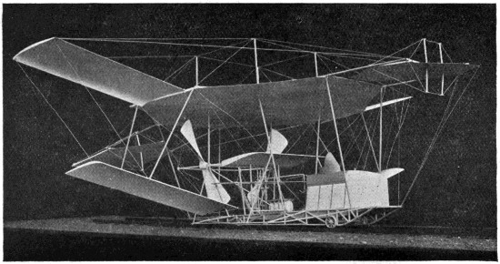
Fig. 74.—Photograph of a model of my machine, showing the fore and aft horizontal rudders and the superposed aeroplanes.
In my early “whirling table”[5] experiments, the aeroplanes used were from 6 inches to 4 feet in width. They were for the most part made of thin pine, being slightly concave on the underneath side and convex on the top, both the fore and aft edges being very sharp. I generally mounted them at an angle of 1 in 14[6]—that is, in such a position that in advancing 14 feet they pressed the air down 1 foot. With this arrangement, I found that with a screw thrust of 5 lbs. the aeroplane would lift 5 × 14, or 70 lbs., while if the same plane was mounted at an angle of 1 in 10, the lifting effect was almost 50 lbs. (5 × 10). This demonstrated that the skin friction on these very sharp, smooth and well-made aeroplanes was so small a factor as not to be[131] considered. When, however, there was the least irregularity in the shape of the aeroplane, the lifting effect, when considered in terms of screw thrust, was greatly diminished. With a well-made wooden plane placed at an angle of 1 in 14, I was able to carry as much as 113 lbs. to the H.P., whereas with an aeroplane consisting of a wooden frame covered with a cotton fabric (Fig. 75), I was only able to carry 40 lbs. to the H.P.[7]
[5] A name given by Professor Langley to an apparatus consisting of a long rotating arm to which objects to be tested are attached.
[6] I found it more convenient to express the angle in this manner than in degrees.
[7] The actual power consumed by the aeroplane itself was arrived at as follows:—The testing machine was run at the desired speed without the aeroplane, and the screw thrust and the power consumed carefully noted. The aeroplane was then attached and the machine again run at the same speed. The difference between the two readings gave the power consumed by the aeroplane.
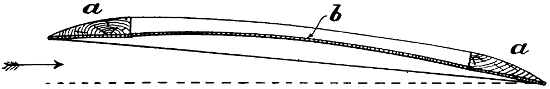
Fig. 75.—The fabric-covered aeroplane experimented with. The efficiency of this aeroplane was only 40 per cent. of that of a well-made wooden aeroplane.
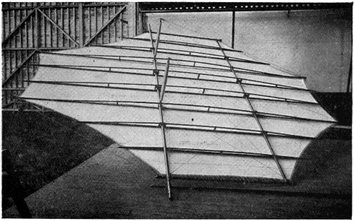
Fig. 76.—The forward rudder of my large machine, showing the fabric attached to the lower side. The top was also covered with fabric. This rudder considered as an aeroplane had a very high efficiency and worked very well indeed.
These facts taken into consideration with my other experiments with large aeroplanes, demonstrated to my mind that it would not be a very easy matter to make a large and efficient aeroplane. If I obtained the necessary rigidity by making it of boards, it would be vastly too heavy for the purpose, while if I obtained the necessary lightness by making the framework of steel and covering it with a silk or cotton fabric in the usual way, the distortion would be so great that it would require altogether too much power to propel it through the air. I therefore decided on making a completely new form of aeroplane. I constructed a large steel framework arranged in such a manner that the fore and aft edges consisted of tightly drawn steel wires. This framework was provided with a number of light wooden longitudinal trusses, similar to those shown in Fig. 76. The bottom side was then covered with balloon fabric secured at the edges, and also by two longitudinal lines of lacing through the centre. It was stretched very tightly and slightly varnished, but not sufficiently to make it absolutely air-tight. The top of this framework was covered with the same kind of material, but varnished so as to make it absolutely airtight. The top and bottom were then laced together forming very sharp fore and aft edges, and the top side was firmly secured to the light wooden trusses before referred to. Upon running this aeroplane, I found that a certain quantity of air passed through the lower side and set up a pressure between the upper and lower coverings. The imprisoned air pressed the top covering upward, forming longitudinal corrugations which did not offer any perceptible resistance to the air, whereas the bottom fabric, having practically the same pressure on both sides, was not distorted in the least. This aeroplane was found to be nearly as efficient as it would have been had it been carved out of a solid piece of wood. It will be seen by the illustration that this large or main aeroplane is practically octagonal in shape, its greatest width being 50 feet, and the total area 1,500 square feet.
Upon running my large machine over the track (Fig. 77) with only the main aeroplane in position, I found that a lifting effect of 3,000 to 4,000 lbs. could be obtained with a speed of 37 to 42 miles an hour. It was not always an easy matter to ascertain exactly what the lifting effect was at a given speed on account of the wind that was generally blowing. Early in my experiments, I found if I ran my machine fast enough to produce a lifting effect within 1,000 lbs. of the total weight of the machine, that it was almost sure to leave the rails if the least wind was blowing. It was, therefore, necessary for me to devise some means of keeping the machine on the track. The first plan tried was to attach some very heavy cast-iron wheels weighing with their axle-trees and connections about 11⁄2 tons. These were constructed in such a manner that the light flanged wheels supporting the machine on the steel rails could be lifted 6 inches above the track, leaving the heavy wheels still on the rails for guiding the machine. This arrangement was tried on several occasions, the machine being run fast enough to lift the forward end off the track. However, I found considerable difficulty in starting and stopping quickly on account of the great weight, and the amount of energy necessary to set such heavy wheels spinning at a high velocity. The last experiment with these wheels was made when a head wind was blowing at the rate of about 10 miles an hour. It was rather unsteady, and when the machine was running at its greatest velocity, a sudden gust lifted not only the front end, but also the heavy front wheels completely off the track, and the machine falling on soft ground was soon blown over by the wind.
I then provided a safety track of 3 × 9 Georgia pine placed about 2 feet above the steel rails, the wooden track being 30 feet gauge and the steel rails 9 feet gauge (Fig. 77). The machine was next furnished with four extra wheels placed on strong outriggers and adjusted in such a manner that when it had been lifted 1 inch clear of the steel rails, these extra wheels would engage the upper wooden track.[8]
[8] Springs were interposed between the machine and the axle-trees. The travel of these springs was about 4 inches; therefore, when the machine was standing still, the wheels on the outriggers were about 5 inches below the upper track.
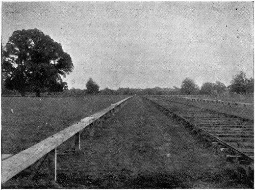
Fig. 77.—View of the track used in my experiments. The machine was run along the steel railway which was 9 feet gauge, and was prevented from rising by the wooden track which was 35 feet gauge.
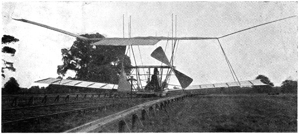
Fig. 78.—The machine on the track tied up to the dynamometer.
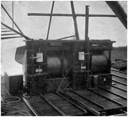
Fig. 79.—Two dynagraphs, one for making a diagram of the lifting effect off the main axle-tree, and the other for making a diagram of the lift off the front axle-tree. By this arrangement, I was able to ascertain the exact lifting effect at all speeds, and to arrange my aeroplanes in such a manner that the center of lifting effect was directly over the center of gravity. The paper-covered cylinders made one rotation in 2,000 feet.
When fully equipped, my large machine had five long and narrow aeroplanes projecting from each side. Those that are attached to the sides of the main aeroplanes are 27 feet long, thus bringing the total width of the machine up to 104 feet. The machine is also provided with a fore and an aft rudder made on the same general plan as the main aeroplane. When all the aeroplanes are in position, the total lifting surface is brought up to about 6,000 square feet. I have, however, never run the machine with all the planes in position. My late experiments were conducted with the main aeroplane, the fore and aft rudders, and the top and bottom side planes in position, the total area then being 4,000 square feet. With the machine thus equipped, with 600 lbs. of water in the tank and boiler and with the naphtha and three men on board, the total weight was a little less than 8,000 lbs. The first run under these conditions was made with a steam pressure of 150 lbs. to the square inch, in a dead calm, and all four[135] of the lower wheels remained constantly on the rails, none of the wheels on the outriggers touching the upper track. The second run was made with 240 lbs. steam pressure to the square inch. On this occasion, the machine seemed to vibrate between the upper and lower tracks. About three of the top wheels were engaged at the same time, the weight on the lower steel rails being practically nil. Preparations were then made for a third run with nearly the full power of the engines. The machine was tied up to a dynamometer (Fig. 78), and the engines were started with a[136] pressure of about 200 lbs. to the square inch. The gas supply was then gradually turned on with the throttle valves wide open; the pressure soon increased, and when 310 lbs. was reached, the dynamometer showed a screw thrust of 2,100 lbs.,[9] but to this must be added the incline of the track which amounts to about 64 lbs. The actual thrust was therefore 2,164 lbs. In order to keep the thrust of the screws as nearly constant as possible, I had placed a small safety valve—3⁄4-inch—in the steam pipe leading to one of the engines. This valve was adjusted in such a manner that it gave a slight puff of steam at each stroke of[137] the engine with a pressure of 310 lbs. to the square inch, and a steady blast at 320 lbs. to the square inch. As the valves and steam passages of these engines were made very large, and as the piston speed was not excessive, I believed if the steam pressure was kept constant that the screw thrust would also remain nearly constant, because as the machine advances and the screws commence to run slightly faster, an additional quantity of steam will be called for and this could be supplied by turning on more gas. When everything was ready, with careful observers stationed on each side of the track, the order was given to let go. The enormous screw thrust started the machine so quickly that it nearly threw the engineers off their feet, and the machine bounded over the track at a great rate. Upon noticing a slight diminution in the steam pressure, I turned on more gas, when almost instantly the steam commenced to blow a steady blast from the small safety valve, showing that the pressure was at least 320 lbs. in the pipes supplying[138] the engines with steam. Before starting on this run, the wheels that were to engage the upper track were painted, and it was the duty of one of my assistants to observe these wheels during the run, while another assistant watched the pressure gauges and dynagraphs (Fig. 79). The first part of the track was up a slight incline, but the machine was lifted clear of the lower rails and all of the top wheels were fully engaged on the upper track when about 600 feet had been covered. The speed rapidly increased, and when 900 feet had been covered, one of the rear axle-trees, which were of 2-inch steel tubing, doubled up (Fig. 80), and set the rear end of the machine completely free. The pencils ran completely across the cylinders of the dynagraphs and caught on the underneath end. The rear end of the machine being set free, raised considerably above the track and swayed. At about 1,000 feet, the left forward wheel also got clear of the upper track and shortly afterwards, the right forward wheel tore up[139] about 100 feet of the upper track. Steam was at once shut off and the machine sank directly to the earth imbedding the wheels in the soft turf (Figs. 81 and 82) without leaving any other marks, showing most conclusively that the machine was completely suspended in the air before it settled to the earth. In this accident, one of the pine timbers forming the upper track went completely through the lower framework of the machine and broke a number of the tubes, but no damage was done to the machinery except a slight injury to one of the screws (Fig. 83).
[9] The quantity of water entering the boiler at this time was so great as to be beyond the range of the feed-water indicator.
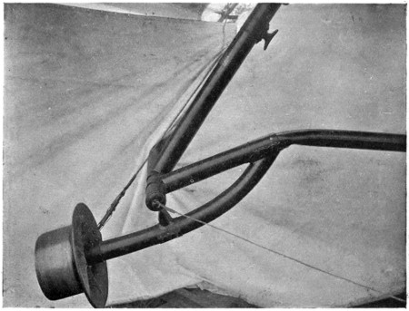
Fig. 80.—The outrigger wheel that gave out and caused an accident with the machine.
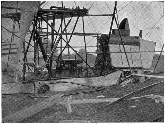
Fig. 81.—Shows the broken planks and the wreck that they caused. It will be observed that the wheels sank directly into the ground without leaving any track.

Fig. 82.—The condition of the machine after the accident. One of the broken planks that formed the upper track is shown. It will be observed that the wheels have sunk directly into the ground without leaving any tracks, showing that the machine did not run along the ground, but came directly down when it stopped.
In my experiments with the small apparatus for ascertaining the power required to perform artificial flight, I found that the most advantageous angle for my aeroplane was 1 in 14, but when I came to make my large machine, I placed my aeroplanes at an angle of 1 in 8 so as to be able to get a great lifting effect at a moderate speed with a short run. In the experiments which led to the accident above referred to, the total lifting effect upon the machine must have been at least 10,000 lbs. All the wheels which[140] had been previously painted and which engaged the upper track were completely cleaned of their paint and had made an impression on the wood, which clearly indicated that the load which they had been lifting was considerable.[10] Moreover, the strain necessary to double up the axle-trees was fully 1,000 lbs. each, without considering the lift on the forward axle-trees which did not give way but broke the upper track.

Fig. 83.—This shows the screw damaged by the broken planks; also a hole in the main aeroplane caused by the flying splinters.
The advantages arising from driving the aeroplanes on to new air, the inertia of which has not been disturbed, are clearly shown in these experiments. The lifting effect of the planes was 2·5 lbs. per square foot. A plane loaded at this rate will fall through the air with a velocity of 22·36 miles per hour, according to the formula √200 × P = V. But as the planes were set at an angle of 1 in 8, and as the machine travelled at the rate of 40 miles an hour, the[141] planes only pressed the air downwards 5 miles an hour (40 ÷ 8 = 5). A fall of 5 miles an hour without advancing would only exert a pressure of ·125 lb. per square foot, according to the formula (V² × ·005 = P).[11]
[11] This is the old formula used by Haswell. The account of this experimental work was written in the autumn of 1894 and Haswell’s formula was used. I have thought best to make no changes.
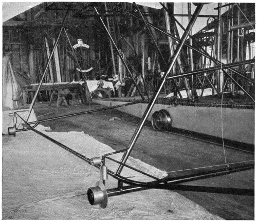
Fig. 84.—This shows a form of outrigger wheels which were ultimately used.
Engineers and mathematicians who have written to prove that flying machines were impossible have generally computed the efficiency of aeroplanes moving through the air, on the basis that the lifting effect would be equal to a wind blowing against the plane at the rate at which the air was pressed down by the plane while being driven through the air. According to this system of reasoning, my 4,000 square feet of aeroplanes would have lifted only ·125 lb. per square foot, and in order to have lifted[142] 10,000 lbs. they would have to have had an area twenty times as great. This corresponds exactly with the discrepancy which Professor Langley has found in the formula of Newton.
With aeroplanes of one-half the width of those I employed, and with a velocity twice as great, the angle could be much less, and the advantages of continually running on to fresh air would be still more manifest. With a screw thrust of 2,000 lbs., the air pressure on each square foot of the projected area of the screw blades is 21·3 lbs., while the pressure on the entire discs of the screws is 4 lbs. per square foot, which would seem to show with screws of this size, that four blades would be more efficient than two.
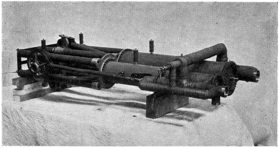
Fig. 85.—One pair of my compound engines. This engine weighed 310 lbs. and developed 180 H.P., with 320 lbs. of steam per square inch.
The engines, as before stated, are compound (Fig. 85). The area of the high-pressure piston is 20 square inches, and that of the low-pressure piston is 50·26 square inches. Both have a stroke of 12 inches. With a boiler pressure of 320 lbs., the pressure on the low-pressure piston is 125 lbs. to the square inch. This abnormally high pressure in the low-pressure cylinder is due to the fact that there is a very large amount of clearance in the high-pressure cylinder to prevent shock in case water should go over when the machine pitches; moreover, the steam in the high-pressure cylinder is cut off at three-quarters stroke, while the steam in the low-pressure cylinder is cut off at five-eighths stroke. If[143] we should compute the power of these engines with the steam entering at full stroke, without any friction, and with no back pressure on the low-pressure cylinder, the total horse-power would foot up to 461·36 horse-power at the speed at which the engines were run—namely, 375 turns per minute. If we compute the actual power consumed by the screws, by multiplying their thrust, which is probably 2,000 lbs. while they are travelling, by their pitch, 16 feet, and this by the number of turns which they make in a minute, and then divide the product by 33,000,
2,000 × 16 × 37533,000 = 363·63,
we find that we have 363·63 horse-power in actual effect delivered on the screws of the machine, which shows that there is rather less than 22 per cent. loss in the engines, due to cutting off before the end of the stroke, to back pressure, and to friction. The actual power applied to the machine being 363·63 horse-power, it is interesting to know what becomes of it. When the machine has advanced 40 miles (which it would do in an hour), the screws have travelled 68·1 miles (375 × 16 × 605,280) = 68·1; therefore, 150 horse-power is wasted in slip, and 213·63 horse-power consumed in driving the machine through the air. Now, as the planes are set at an angle of 1 in 8, the power actually used in lifting the machine is 133·33, and the loss in driving the body of the machine, its framework and wires through the air is 90·30 horse-power.
| Power | lost in | screw slip, | 150 | H.P. | |
| „ | „ | driving machinery and framework, | 80 | ·30 | „ |
| „ | actually consumed in lifting the machine, | 133 | ·33 | „ | |
| Total power delivered by the engines, | 363 | ·63 | „ | ||
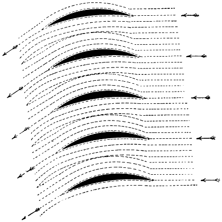
Fig. 86.—The path that the air has to take in passing between superposed aeroplanes in close proximity to each other. By this arrangement the drift is considerably increased.
My experiments have demonstrated that relatively narrow aeroplanes lift more per square foot than very wide ones; but as an aeroplane, no matter how narrow it may be, must of necessity have some thickness, it is not advantageous to place them too near together. Suppose that aeroplanes should be made 1⁄4-inch thick, and be superposed 3 inches[144] apart—that is, at a pitch of 3 inches—one-twelfth part of the whole space through which these planes would have to be driven would be occupied by the planes themselves, and eleven-twelfths would be air space (Fig. 86). If a group of planes thus mounted should be driven through the air at the rate of 36 miles an hour,[12] the air would have to be driven forward at the rate of 3 miles an hour, or else it would have to be compressed, or spun out, and pass between the spaces at a speed of 39 miles an hour. As a matter of fact, however, the difference in pressure is so very small that practically no atmospheric compression takes place. The air, therefore, is driven forward at the rate of 3 miles an hour, and this consumes a great deal of power; in fact,[145] so much that there is a decided disadvantage in using narrow planes thus arranged.
[12] The arrows in the accompanying drawings show the direction of the air currents, the experiments having been made with stationary planes in a moving current of air.
In regard to the curvature of narrow aeroplanes, I have found that if one only desires to lift a large load in proportion to the area, the planes may be made very hollow on the underneath side; but when one considers the lift in terms of the screw thrust, I find it advisable that the planes should be as thin as possible, and the underneath side nearly flat. I have also found that it is a great advantage to arrange the planes after the manner shown in Fig. 87. In this manner the sum of all the spaces between the planes is equal to the whole area occupied by the planes; consequently, the air neither has to be compressed, spun out, nor driven forward. I am, therefore, able by this arrangement to produce a large lifting effect per square foot, and, at the same time, to keep the screw thrust within reasonable limits.
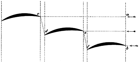
Fig. 87.—The position of narrow aeroplanes arranged in such a manner that the air has free passage between them, and this arrangement has been found superior to arranging one above the other after the manner of a Venetian blind.
A large number of experiments with very narrow aeroplanes have been conducted by Mr. Horatio Philipps at Harrow, in England. Fig. 88 shows a cross-section of one of Mr. Philipps’ planes. Mr. Philipps is of the opinion that the air, in striking the top side of the plane, is thrown upwards in the manner shown, and a partial vacuum is thereby formed over the central part of the plane, and that the lifting effect of planes made in this form is therefore very much greater than with ordinary narrow planes. I have experimented with these “sustainers” (as Mr. Philipps calls them) myself, and I find it is quite true that they lift[146] in some cases as much as 8 lbs. per square foot,[13] but the lifting effect is not produced in the exact manner that Mr. Philipps seems to suppose. The air does not glance off in the manner shown. As the “sustainer” strikes the air two currents are formed, one following the exact contour of the top, and the other that of the bottom. These two currents join and are thrown downwards, as relates to the “sustainer,” at an angle which is the resultant of the angles at which the two currents meet. These “sustainers” may be made to lift when the front edge is lower than the rear edge, because they encounter still air, and leave it with a downward motion.
[13] In my early experiments I lifted as much as 8 lbs. per square foot with aeroplanes which were only slightly curved, but very thin and sharp.
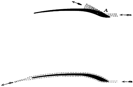
Fig. 88.—The very narrow aeroplanes, or sustainers, employed by Mr. Philipps. It has been supposed that the air in striking at A was deflected in the manner shown, but such is not the case. The air in reality follows the surface, as shown in the dotted line in the second illustration.
In my experiments with narrow superposed planes, I have always found that with strips of thin metal made sharp at both edges and only slightly curved, the lifting effect, when considered in terms of screw thrust, was always greater than with any arrangement of the wooden aeroplanes used in Philipps’ experiments. It would, therefore, appear that there is no advantage in the peculiar form of “sustainer” employed by this inventor.
If an aeroplane be made perfectly flat on the bottom side and convex on the top, and be mounted in the air so that[147] the bottom side is exactly horizontal, it produces a lifting effect no matter in which direction it is run, because, as it advances, it encounters stationary air which is divided into two streams. The top stream being unable to fly off at a tangent when turning over the top curve, flows down the incline and joins the current which is flowing over the lower horizontal surface. The angle at which the combined stream of air leaves the plane is the resultant of these two angles; consequently, as the plane finds the air in a stationary condition, and leaves it with a downward motion, the plane itself must be lifted. It is true that small and narrow aeroplanes may be made to lift considerably more per square foot of surface than very large ones, but they do not offer the same safeguard against a rapid descent to the earth in case of a stoppage or breakdown of the machinery. With a large aeroplane properly adjusted, a rapid and destructive fall to the earth is quite impossible.
Before I commenced my experiments at Baldwyn’s Park, I attempted to obtain some information in regard to the action of screw propellers working in the air. I went to Paris and saw the apparatus which the French Government employed for testing the efficiency of screw propellers, but the propellers were so very badly made that the experiments were of no value. Upon consulting an English experimenter, who had made a “life-long study” of the question, he assured me that I should find the screw propeller very inefficient and very wasteful of power, and that all screw propellers had a powerful fan-blower action, drawing in air at the centre and discharging it with great force at the periphery. I found that no two men were agreed as to the action of screw propellers. All the data or formulæ available were so confusing and contradictory as to be of no value whatsoever. Some experimenters were of the opinion that, in computing the thrust of a screw, we should only consider the projected area of the blades, and that the thrust would be equal to a wind blowing against a normal plane of equal area at a velocity equal to the slip. Others were of the opinion that the whole screw disc would have to be considered; that is, that the thrust would be[148] equal to a wind blowing against a normal plane having an area equal to the whole disc, and at the velocity of the slip. The projected area of the two screw blades of my machine is 94 square feet, and the area of the two screw discs is 500 square feet. According to the first system of reasoning, therefore, the screw thrust of my large machine, when running at 40 miles an hour with a slip of 18 miles per hour, would have been, according to the well-known formula,
V² × ·005 = P
18² × ·005 × 94 = 152·28 lbs.
If, however, we should have considered the whole screw disc, it would have been 18² × ·005 × 500 = 810 lbs. However, when the machine was run over the track at this rate, the thrust was found to be rather more than 2,000 lbs. When the machine was secured to the track and the screws revolved until the pitch in feet, multiplied by the turns per minute, was equal to 68 miles an hour, it was found that the screw thrust was 2,164 lbs. In this case, it was of course, all slip, and when the screws had been making a few turns they had established a well-defined air-current, and the power exerted by the engine was simply to maintain this air current. It is interesting to note that, if we compute the projected area of these blades by the foregoing formula, the thrust would be—68² × ·005 × 94 = 2,173·28 lbs., which is almost exactly the observed screw thrust.
When I first commenced my experiments with a large machine, I did not know exactly what sort of boiler, gas generator, or burner I should finally adopt; I did not know the exact size that it would be necessary to make my engines; I did not know the size, the pitch, or the diameter of the screws which would be the most advantageous; neither did I know the form of aeroplane which I should finally adopt. It was, therefore, necessary for me to make the foundation or platform of my machine of such a character that it would allow me to make the modifications necessary to arrive at the best results. The platform of the machine is, therefore, rather larger than is necessary, and I find if I were to design a completely new machine, that it would be possible to greatly reduce the weight of the framework, and, what is still more, to greatly reduce the force necessary to drive it through the air.
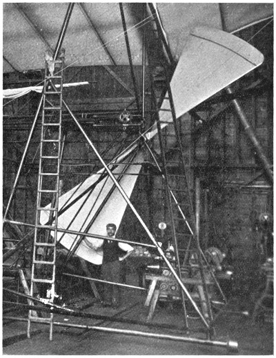
Fig. 89.—One of the large screws being hoisted into position. Its size may be judged by comparison with the man.
At the present time, the body of my machine is a large platform, about 8 feet wide and 40 feet long. Each side is[149] formed of very long trusses of steel tubes, braced in every direction by strong steel wires. The trusses which give stiffness are all below the platform. In designing a new machine, I should make the trusses much deeper and at the same time very much lighter, and, instead of having them below the platform on which the boiler is situated, I should have them constructed in such a manner as to completely enclose the boiler and the greater part of the machinery.[14] I should make the cross-section of the framework rectangular and pointed at each end. I should cover the[150] outside very carefully with balloon material, giving it a perfectly smooth and even surface throughout, so that it might be easily driven through the air.
[14] This arrangement of the framework is now common to all successful machines.
In regard to the screws, I am at the present time able to mount screws 17 feet 10 inches in diameter (Fig. 89). I find, however, that my machine would be much more efficient if the screws were 24 feet in diameter and I believe with such very large screws, four blades would be much more efficient than two.
My machine may be steered to the right or to the left by running one of the propellers faster than the other. Very convenient throttle valves have been provided to facilitate this system of steering. An ordinary vertical rudder placed just after the screws may, however, prove more convenient if not more efficient.
The machine is provided with fore and aft horizontal rudders, both of which are connected with the same windlass.
In regard to the stability of the machine, the centre of weight is much below the centre of lifting effect; moreover, the upper wings are set at such an angle that whenever the machine tilts to the right or to the left the lifting effect is increased on the lower side and diminished on the higher side. This simple arrangement makes it automatic as far as rolling is concerned. I am of the opinion that whenever flying machines come into use, it will be necessary to steer in a vertical direction by means of an automatic steering gear controlled by a gyroscope. It will certainly not be more difficult to manœuvre and steer such machines than it is to control completely submerged torpedoes.
When the machine is once perfected, it will not require a railway track to enable it to get the necessary velocity to rise. A short run over a moderately level field will suffice. As far as landing is concerned, the aerial navigator will touch the ground when moving forward, and the machine will be brought to a state of rest by sliding on the ground for a short distance. In this manner very little shock will result, whereas if the machine is stopped in the air and allowed to fall directly to the earth without advancing, the shock, although not strong enough to be dangerous to life or limb, might be sufficient to disarrange or injure the machinery.
So far I have only discussed the navigation of the air by the use of propellers driven by a steam engine. The engines that I employ are what is known as compound engines—that is, they have a large and a small cylinder. Steam at a very high pressure enters the high-pressure cylinder, expands and escapes at a lower pressure into a larger cylinder where it again expands and does more work. A compound engine is more economical in steam than a simple engine, and therefore requires a smaller boiler to develop the same horse-power, so that when we consider the weight of water and fuel for a given time, together with the weight of the boiler and the engine, the engine motor with a compound engine is lighter than a simple engine. However, if only the weight of the engine is to be considered then the simple engine will develop more power per unit of weight than the compound engine. For instance, if, instead of allowing the steam to enter the small cylinder, and the exhaust from this cylinder to enter the large or low-pressure cylinder—which necessitates that the high-pressure piston has to work against a back pressure equal to the full pressure on the low-pressure cylinder—I should connect both cylinders direct with the live steam, and allow both to discharge their exhaust directly into the air, I should then have a pair of simple engines, and instead of developing 363 H.P. they would develop fully 500 H.P., or nearly 1 H.P. for every pound of their weight. I mention this fact to show that the engines are exceedingly light, and that when compared with simple engines their power should be computed on the same basis. It will, therefore, be seen that if we do not take into consideration the steam supply or the amount of fuel and water necessary, the simple steam engine is an exceedingly light motor.
But, as before stated, great improvements have recently been made in oil engines. I have thought much on this subject, and am of the opinion that if one had an unlimited supply of money, a series of experiments could be very profitably conducted with a view of adapting the oil engine for use on flying machines. If we use a steam[152] engine, it is necessary to have a boiler, and at best a boiler is rather a large and heavy object to drive through the air. If we use an oil engine, no boiler is necessary, and the amount of heat carried over in the cooling water will only be one-seventh part of what is carried over in the exhaust from a steam engine of the same power. Therefore, the condenser only need be one-seventh part the size, and consequently should be made lighter with the tubes placed at a greater distance apart, and thus reduce the amount of power necessary to drive the machine through the air. Moreover, the supply of water necessary will be greatly reduced, and a cheaper and heavier oil may be employed, which is not so liable to take fire in case of an accident. It is then only a question as to whether an oil engine can be made so light as to keep its weight within that of a steam motor; that is, an oil engine in order to be available for the purpose must be as light, including its water supply, as a complete steam motor, which includes not only the engine, but also the boiler, the feed pumps, the water supply, the burner, the gas generator, and six-sevenths of the condenser. It requires a very perfect steam engine and boiler, not using a vacuum, to develop a horse-power with a consumption of 11⁄2 lbs. of petroleum per hour; but there are many oil engines which develop a horse-power with rather less than 1 lb. of oil per hour. It will, therefore, be seen that, as far as fuel is concerned, the oil engine has a decided advantage over the more complicated steam motor. Moreover, with an oil engine, the cooling water is not under pressure, so that the waste of water would be much less than with a steam engine, where the pressure is so high as to cause a considerable amount of waste through joints and numerous stuffing-boxes.
The great advances that have been made of late years in electrical science and engineering have led many to believe that almost any knotty scientific question may be solved by the employment of electrical engineering, and a great deal has been written and said in regard to navigating the air by flying machines driven by electric motors.
Before I commenced my experiments, I made enquiries of all the prominent electrical engineering establishments where there was any likelihood of obtaining light and efficient electric motors, and found that it was impossible[153] to obtain one that would develop a horse-power for any considerable time that would weigh less than 150 lbs. Since that time, notwithstanding that a great deal has appeared in the public prints about the efficiency and lightness of electric motors, I am unable to learn of any concern that is ready to furnish a complete motor, including a primary battery, which would supply the necessary current for two hours at a time, at a weight of less than 150 lbs. per horse-power, and as far as I have been able to ascertain from what I have myself seen, I cannot learn that there are any motors in practical use which do not weigh, including their storage batteries, at least 300 lbs. per horse-power. The last electric motor which I examined was in a boat; it was driven by a primary battery which weighed over 1,000 lbs. to the horse-power. From this I am of the opinion that we cannot at present look to electricity with any hope of finding a motor which is suitable for the purpose of aerial navigation.
There is no question but what birds, and for that matter all animals, when considered as thermo-dynamic machines, are very perfect motors; they develop the full theoretical amount of energy of the carbon consumed. This we are quite unable to do with any artificial machine, but birds, for the most part, have to content themselves with food which is not very rich in carbon. It is quite true that a bird may develop from ten to fifteen times as much power from the carbon consumed as can be developed by the best steam engine, but, as an off-set against this, a steam engine is able to consume petroleum, which has at least twenty times as many thermal units per pound as the ordinary food of birds. The movement of a bird’s wings, from long years of development, has without doubt attained a great degree of perfection. Birds are able to scull themselves through the air with very little loss of energy. To imitate by mechanical means, the exact and delicate motion of their wings would certainly be a very difficult task, and I do not believe that we should attempt it in constructing an artificial flying machine. In Nature it is necessary that an animal should be made all in one piece. It is, therefore, quite out of the question that any part or parts should revolve. For land animals there is no question but what[154] legs are the most perfect system possible, but in terrestrial locomotion by machinery, not necessarily in one piece, wheels are found to be much more effective and efficient. The swiftest animal can only travel for a minute of time at half the speed of a locomotive, while the locomotive is able to maintain its much greater speed for many hours at a time. The largest land animals only weigh about 5 tons, while the largest locomotives weigh from 60 to 80 tons. In the sea, the largest animal weighs about 75 tons, while the ordinary Atlantic liner weighs from 4,000 to 14,000 tons. The whale, no doubt, is able to maintain a high speed for several hours at a time, but the modern steamer is able to maintain a still higher speed for many consecutive days.
As artificial machines for terrestrial and aquatic locomotion have been made immensely stronger and larger than land or water animals, so with flying machines, it will be necessary to construct them much heavier and stronger than the largest bird. If one should attempt to propel such a machine with wings, it would be quite as difficult a problem to solve as it would be to make a locomotive that would walk on legs. What is required in a flying machine is something to which a very large amount of power can be directly and continuously applied without any intervening levers or joints, and this we find in the screw propeller.
..........
When the Brayton gas engine first made its appearance, I commenced drawings of a flying machine, using a modification of the Brayton motor which I designed expressly for the purpose; but even this was found to be too heavy, and it was not until after I had abandoned the vertical screw system that it was possible for me to design a machine which, in theory, ought to fly. The next machine which I considered was on the kite or aeroplane system. This was also to be driven by an oil engine. Oil engines at that time were not so simple as now, and, moreover, the system of ignition was very heavy, cumbersome, and uncertain. Since that time, however, gas and oil engines have been very much improved, and the ignition tube which is almost universally used has greatly simplified the ignition, so that at the present time, I am of the opinion that an oil engine might be designed which would be suitable for the purpose.
In 1889 I had my attention drawn to some very thin, strong, and comparatively cheap tubes which were being made in France, and it was only after I had seen these tubes that I seriously considered the question of making a flying machine. I obtained a large quantity of them and found that they were very light, that they would stand enormously high pressures, and generate a very large quantity of steam. Upon going into a mathematical calculation of the whole subject, I found that it would be possible to make a machine on the aeroplane system, driven by a steam engine, which would be sufficiently strong to lift itself into the air. I first made drawings of a steam engine, and a pair of these engines was afterwards made. These engines are constructed, for the most part, of a very high grade of cast steel, the cylinders being only 3⁄32 of an inch thick, the crank shafts hollow, and every part as strong and light as possible. They are compound, each having a high-pressure piston with an area of 20 square inches, a low-pressure piston of 50·26 square inches, and a common stroke of 1 foot. When first finished, they were found to weigh 300 lbs. each; but after putting on the oil cups, felting, painting, and making some slight alterations, the weight was brought up to 320 lbs. each, or a total of 640 lbs. for the two engines, which have since developed 362 horse-power with a steam pressure of 320 lbs. per square inch. A photograph of one of these engines is shown in Fig. 85.
..........
When first designing this engine, I did not know how much power I might require from it. I thought that in some cases it might be necessary to allow the high-pressure steam to enter the low-pressure cylinder direct, but as this would involve a considerable loss, I constructed a species of an injector. This injector may be so adjusted that when the steam in the boiler rises above a certain predetermined point, say 300 lbs. to the square inch, it opens a valve and escapes past the high-pressure cylinder instead of blowing off at the safety valve. In escaping through this valve, a fall of about 200 lbs. pressure per square inch is made to do work on the surrounding steam and to drive it forward in the pipe, producing a pressure on the low-pressure piston considerably higher than the back pressure on the high-pressure piston. In this way a portion of the work which[156] would otherwise be lost is utilised, and it is possible, with an unlimited supply of steam, to cause the engines to develop an enormous amount of power.
..........
Boiler Experiments.—The first boiler which I made was constructed something on the Herreshoff principle, but instead of having one simple pipe in one very long coil, I used a series of very small and light pipes, connected in such a manner that there was a rapid circulation through the whole—the tubes increasing in size and number as the steam was generated. I intended that there should be a pressure of about 100 lbs. more on the feed water end of the series than on the steam end, and I believed that this difference in pressure would be sufficient to ensure a direct and positive circulation through every tube in the series. This first boiler was exceedingly light, but the workmanship, as far as putting the tubes together was concerned, was very bad, and it was found impossible to so adjust the supply of water as to make dry steam without overheating and destroying the tubes.
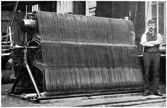
Fig. 90.—Steam boiler employed in my experiments. With this boiler, I had no trouble in producing all the steam that I could possibly use, and at any pressure up to 400 lbs. to the square inch.
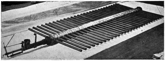
Fig. 91.—The burner employed in my steam experiments. This produced a dense and uniform blue purple flame 20 inch deep.
Before making another boiler I obtained a quantity of copper tubes, about 8 feet long, 3⁄8 inch external diameter, and 1⁄50 of an inch thick. I subjected about 100 of these tubes to an internal pressure of 1 ton per square inch of cold kerosine oil, and as none of them leaked I did not test any more, but commenced my experiments by placing some of them in a white-hot petroleum fire. I found that I could evaporate as much as 261⁄2 lbs. of water per square foot of heating surface per hour, and that with a forced circulation, although the quantity of water passing was very small but positive, there was no danger of over-heating. I conducted many experiments with a pressure of over 400 lbs. per square inch, but none of the tubes failed. I then mounted a single tube in a white-hot furnace, also with a water circulation, and found that it only burst under steam at a pressure of 1,650 lbs. per square inch. A large boiler, having about 800 square feet of heating surface including the feed-water heater, was then constructed. It is shown in Fig. 90. This boiler is about 41⁄2 feet wide at the bottom, 8 feet long and 6 feet high. It weighs with the casing, the dome, the smoke stack and connections, a little less than 1,000 lbs. The water first passes through a system of small tubes—1⁄4 inch in[157] diameter and 1⁄60 inch thick—which were placed at the top of the boiler and immediately over the larger tubes—not shown in the cut. This feed-water heater is found to be very effective. It utilises the heat of the products of combustion after they have passed through the boiler proper and greatly reduces their temperature, while the feed-water enters the boiler at a temperature of 250° F.[158] A forced circulation is maintained in the boiler, the feed-water entering through a spring valve, the spring valve being adjusted in such a manner that the pressure on the water is always 30 lbs. per square inch in excess of the boiler pressure. This fall of 30 lbs. in pressure acts upon the surrounding hot water which has already passed through the tubes, and drives it down through a vertical outside tube, thus ensuring a positive and rapid circulation through all the tubes. This apparatus is found to work extremely well. A little glass tube at the top provided with a moving button, indicates exactly how many pounds of water per hour are passing into the boiler. By this means, the engineer is not only enabled to ascertain at a glance whether or not the pumps are working, but also to what degree they are working.
Water may be considered as 2,400 times as efficient as air, volume for volume, in condensing steam. When a condenser is made for the purpose of using water as a cooling agent, a large number of small tubes may be grouped together in a box, and the water may be pumped in at one end of the box and discharged at the other end through relatively small openings; but when air is employed, the tubes or condensing surface must be widely distributed, so that a very large amount of air is encountered, and the air which has struck one tube and become heated must never strike a second tube.
In order to accomplish this, I make my condenser something in the form of a Venetian blind, the tubes being made of very thin copper and each tube in the form of a small aeroplane. These were driven edgewise through the air, so that the actual volume of air passing between them is several thousand times greater than the volume of water passing through a marine condenser. I find that with such a condenser I can recover the full weight of the copper tubes in water every five minutes, and if I use aluminium, in half that time. Moreover, experiments have shown that a condenser may be made to sustain considerably more than its own weight and the weight of its contents in the air, and that all the steam may be condensed into water sufficiently cool to be pumped with certainty.
I find that the most advantageous position for the condenser is immediately after the screw propellers. In this case, if the machine is moving through the air at the rate of 50 miles an hour, and the slip of the screws is[159] 15 miles an hour, it follows that the air will be passing through the condenser at the rate of 65 miles an hour. At this velocity, the lifting effect on the narrow aeroplanes forming the condenser is very great, and at the same time the steam is very rapidly condensed. The tubes are placed at such an angle as to keep them completely drained and prevent the accumulation of oil, the steam entering the higher end and the water being discharged at the lower end.
..........
These experiments demonstrated most conclusively that as much as 133 lbs. could be sustained and carried by the expenditure of one horse-power, and that a screw was a fairly efficient air propeller. They also demonstrated that a well made aeroplane, placed at an angle of 1 in 14, would lift practically fourteen times the thrust required to drive it through the air, and that the skin friction on a smooth and well finished aeroplane or screw was so small as not to be considered. A large number of aeroplanes were experimented with, and it was found that those which were slightly concave on the underneath side and convex on the top, both edges being very sharp and the surface very smooth and regular, were the most efficient; also that with small screw propellers, two blades having slightly increasing pitch were the most efficient.
Since writing the foregoing, great progress has been made with flying machines, and great disasters have happened to airships or balloons. Count Zeppelin’s gigantic airship encountered a squall or thunder shower, and the work of years, which had cost over £100,000, was reduced to scrap metal in a few minutes. Similar disasters have happened to other balloons.
The British Dirigible No. 2 has not attempted a long flight, but the Wright Brothers, Farman, and De la Grange have all met with a certain degree of success.
A few months ago, the remarkable feats of the Wright Brothers in the States were discredited in Europe. It was claimed that “the accounts were not authentic,” “too good to be true,” etc., but recent events have shown that the Wright Brothers are able to outdo anything that was reported in the American Press. On many occasions they have remained in the air for more than an hour, and have travelled at the rate of 30 to 40 miles an hour; in fact, the remarkable success of the Wright Brothers has placed the true flying machine in a new category.
It can no longer be ranked with the philosopher’s stone or with perpetual motion. Success is assured, and great and startling events may take place within the next few years.
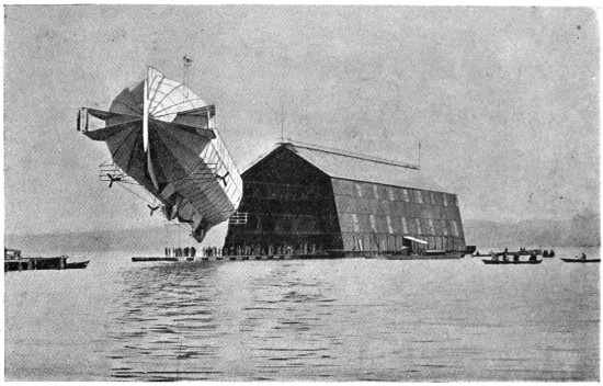
Fig. 92.—Count Zeppelin’s aluminium-covered airship coming out of its shed on Lake Constance.
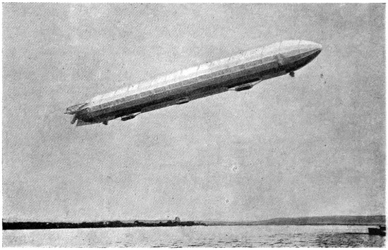
Fig. 93.—Count Zeppelin’s airship in full flight.
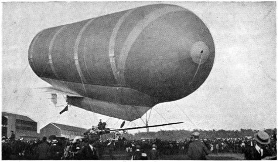
Fig. 94.—The new British war balloon “Dirigible” No 2.
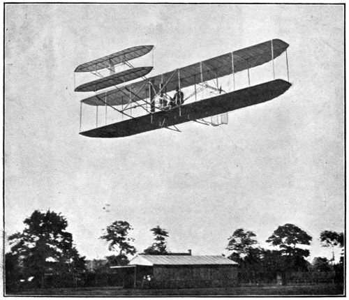
Fig. 95.—The Wright aeroplane in full flight.
| PAGE | |
| Accident to my large machine, | 138 |
| Action of aeroplanes and power required, | 100 |
| Adjustment of birds’ wings, | 19 |
| Admiralty specification for a steamship, | 48 |
| Advantages of driving aeroplanes on to new air, | 140 |
| Advantages and disadvantages of very narrow planes, | 143 |
| Aeroplanes:— | |
| Action of, | 31, 32, 100 |
| Advantageous angle of, | 139 |
| Advantages and disadvantages of very narrow, | 143 |
| Advan„ages arising from driving aeroplanes on to new air, | 140 |
| Curvature of, | 145 |
| Evolution of a wide aeroplane, | 102 |
| Experiments with, | 49-59 |
| Fabric covered, | 131 |
| Lifting effect of, | 141 |
| Lifting surface of, | 103 |
| Philipps’ sustainers, | 146 |
| Reduction of projected horizontal area, | 3, 4 |
| Shape and efficiency of, | 99 |
| Superposed, | 144, 146 |
| Testing fabrics for, | 50 |
| The paradox aeroplane, | 88 |
| Air currents and the flight of birds, | 11 |
| Air cu„rentsConclusions regarding, | 21 |
| Air cu„rentsAlpes Maritimes, | 17 |
| Air cu„rentsMediterranean, | 18 |
| Air cu„rentsMid-Atlantic, | 16 |
| Air cu„rents2,000 feet above the earth’s surface, | 22 |
| Air cu„rentswitnessed at Cadiz, | 20 |
| Angles and degrees compared, | 115 |
| Antoinette motor, The, | 89 |
| Balloons, | 120 |
| Bal„oons spiders, | 27 |
| Birds as thermo-dynamic machines, | 153 |
| Bi„ds Two classes of, | 23 |
| Bleriot’s machine, | 113 |
| Boiler experiments, | 156 |
| Brayton’s gas engine, | 154 |
| British war balloon, | 159, 162 |
| Building up of my large screws, | 41 |
| Burner employed in my experiments, | 157 |
| Character of text-books recently published, | 1 |
| Circulation of air produced by differences in temperature, | 27 |
| Cody’s kite,[164] | 28, 30 |
| Comparative value of different motors, | 151 |
| Conclusions regarding air currents, | 21 |
| Condensers, Testing of, | 52 |
| Condenser tubes, | 60 |
| Continental flying machines, | 9 |
| Crystal Palace experiments, | 72-76 |
| Darwin on the flight of condors, | 11 |
| Deflection of air coming in contact with aeroplanes, | 2 |
| De la Grange machine, The, | 110 |
| “Dirigible” No 2, | 159, 162 |
| Drift at various distances from center to center, Table of, | 58 |
| Dynagraphs, | 136 |
| Dynamic energy of animals, | 127 |
| Eagles, Flight of, | 19 |
| Efficiency of screw propellers, | 147 |
| Effici„ncy of screws in steamships, | 47 |
| Energy developed by a bird, | 13 |
| Engines, | 153 |
| Equivalent inclinations, | 115 |
| Equi„alent velocities, | 116 |
| Experiments of Count Zeppelin, | 124 |
| Experim„nts of Horatio Philipps, | 9, 118, 119, 145 |
| Experim„nts of Lord Rayleigh in reference to Newton’s Law, | 6 |
| Experim„nts of Professor Langley, | 9, 62, 99, 109 |
| Experim„nts of Wright Bros., | 109 |
| Experiments to show efficiency of Screw propellers, | 33 |
| Exper„mentswith apparatus attached to rotating arm, | 62 |
| Exper„mentsw„thboiler, | 156 |
| Exper„mentsw„thhard rolled brass aeroplane, | 3 |
| Exper„mentsw„thmy large machine, | 10, 133 |
| Exper„mentsw„throtating arm, | 64-72 |
| Exper„mentsw„thsmall machines attached to rotating arm, | 159 |
| Fabric covered screw, | 40 |
| Farman’s machine, | 110 |
| Flying of kites, | 25, 28, 29 |
| Forced circulation used by me, | 158 |
| Formulæ unsupported by facts, | 3 |
| French and English measurements, | 128, 129 |
| Gulls, | 20, 21 |
| Gyroscope apparatus, | 93 |
| Gyro„cope Steering by means of, | 92 |
| Hawks and Eagles, | 13 |
| Hélicoptère machine, | 82 |
| Hints as to the building of flying machines, | 77-91 |
| Horizontal movement of the air, | 14 |
| Hub for flying machine, New form of, | 45 |
| Interstellar temperature,[165] | 15 |
| Introductory, | 1 |
| Kites, | 21, 22, 25, 26, 28, 29 |
| Ki„es Behaviour of, | 26 |
| Ki„es Flying of, | 25, 28, 29 |
| Langley, Experiments of, | 9, 62, 99, 109 |
| Lan„ley, on the flight of birds, | 11, 22 |
| Lan„ley, on the power exercised by birds, | 12 |
| “La Patrie,” | 124 |
| Lifting effect of aeroplanes, | 5 |
| Lif„ing surface of aeroplanes, | 103 |
| Low temperature of space, | 15 |
| Major Baden Powell’s demand, | 125 |
| Mistral, The, | 21 |
| Motors, Development of, | 31 |
| Motor, The Antoinette, | 89 |
| My compound engines, | 142 |
| M„ experiments with aeroplanes, | 7 |
| M„ experim„ents withlarge machine, | 10, 133 |
| M„ steam engines, | 155 |
| Newton’s Law, | 2, 6 |
| “Nulli Secundus,” | 28, 121 |
| Oil engines, | 154 |
| Philipps’ experiments, | 9, 118, 119, 145 |
| Phil„pps’sustainers, | 145 |
| Pneumatic buffer, | 90 |
| Position of screw, | 49 |
| Power exerted by a land animal, | 13 |
| Po „er required, | 100 |
| Principally relating to screws, | 31 |
| Rayleigh’s experiments in reference to Newton’s law, | 6 |
| Recapitulation of early experiments, | 130 |
| Recent machines, | 109 |
| Relative value of woods for flying machines, | 85 |
| Reserve energy necessary in flying machines, | 30 |
| Resistance encountered by various shaped bodies, | 52 |
| Rotating arm experiments, | 64-72 |
| Santos Dumont’s flying machine, | 113 |
| Screw blade on Farman’s machine, | 41 |
| Sc„ew blades, Testing of, | 36 |
| Sc„ew bl„des, used by the French Government, | 39 |
| Sc„ew bl„des, with radial edges,[166] | 43 |
| Sc„ew Fabric-covered, | 40 |
| Sc„ew Position of, | 49 |
| Sc„ew propeller made of sheet metal, | 41 |
| Sc„ew propellers, Efficiency of, | 33, 147 |
| Screws, | 8, 31, 35, 36, 40, 41, 46, 47, 49 |
| Scr„ws, Building up of my large, | 40 |
| Scr„ws, their efficiency in steamships, | 47 |
| Shape and efficiency of aeroplanes, | 99 |
| Skin friction, | 41, 48 |
| Spider’s webbing down from the sky, | 27 |
| Spirit lamp and ice box, | 62 |
| Stability of flying machines, | 147, 150 |
| Steam engines used by me, | 155 |
| Steering, | 147, 149 |
| Superposed aeroplanes, | 144 |
| System of splicing and building up wooden members, | 86 |
| Tables:— | |
| Equivalent inclinations, | 115 |
| Equi„alent velocities, | 116 |
| French and English measurements, | 128, 129 |
| Philipps’ experiments, | 119 |
| Relative value of different woods, | 85 |
| Showing the relative power exerted by different birds, | 24 |
| Velocity and pressure of the wind, | 114 |
| Vel„city a„ d thrust corresponding with various horse-powers, | 117 |
| Testing aeroplanes, condensers, etc., | 52 |
| Teutonic vision of aerial power, | 126 |
| Velocity and pressure of wind, | 114 |
| Velo„ity a„d thrust corresponding with various horse-powers, | 117 |
| “Ville de Paris,” | 123 |
| Wright Bros.’ experiments, | 109, 159, 162 |
| Zeppelin’s experiments, | 124, 159, 161 |
BELL AND BAIN, LIMITED, PRINTERS, GLASGOW.
Inconsistent spelling and hyphenation in the original work have been retained.
Depending on the hard- and software used to read this text and their settings, not all lay-out, characters and symbols may display as intended.
Changes made to the text:
Illustrations and tables have been moved out of the text, and footnotes have been moved to directly under the paragraph or table they refer to.
Obvious punctuation and typographical errors have been corrected silently.
In some formulas × has been inserted for consistency.
Page vii: battaillons Kommandeur changed to Bataillonskommandeur
Page x: 1 in 20 changed to 1 in 10 (as discussed in the remainder of the paragraph)
Page 24, table: ·64 changed to 7·64
Page 73: all the air effected changed to all the air affected
Page 110: Hargraves’ changed to Hargrave’s
Page 128: over estimated changed to over-estimated.
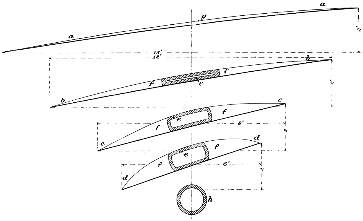
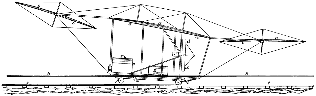