| Carpentry and Woodwork |
| By Edwin W. Foster |
| Electricity and Its Everyday Uses |
| By John F. Woodhull, Ph.D. |
| Gardening and Farming |
| By Ellen Eddy Shaw |
| Home Decoration |
| By Charles Franklin Warner, Sc.D. |
| Housekeeping |
| By Elizabeth Hale Gilman |
| Mechanics, Indoors and Out |
| By Fred T. Hodgson |
| Needlecraft |
| By Effie Archer Archer |
| Outdoor Sports, and Games |
| By Claude H. Miller, Ph.B. |
| Outdoor Work |
| By Mary Rogers Miller |
| Working in Metals |
| By Charles Conrad Sleffel. |
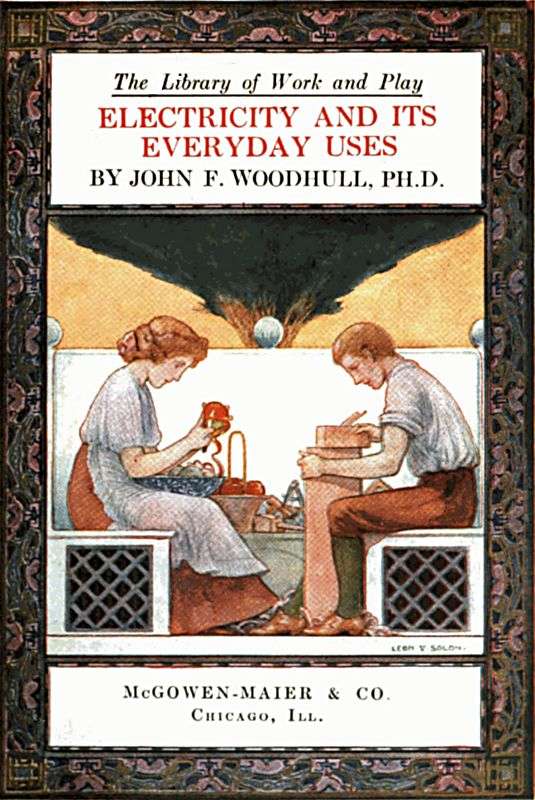
The Library of Work and Play
ELECTRICITY AND ITS
EVERYDAY USES
BY JOHN F. WOODHULL, PH.D.
McGOWEN-MAIER & CO.
Chicago, Ill.
ALL RIGHTS RESERVED, INCLUDING THAT OF TRANSLATION
INTO FOREIGN LANGUAGES, INCLUDING THE SCANDINAVIAN
COPYRIGHT, 1911, BY DOUBLEDAY, PAGE & COMPANY
Why do we pursue one method when instructing an individual boy out of school, and a very different method when teaching a class of boys in school?
The school method of teaching the dynamo is to begin with the bar magnet and, through a series of thirty or forty lessons on fundamental principles, lead up to the dynamo, which is then presented, with considerable attention to detail, as a composite application of principles. This might be styled the synthetic method. He who teaches a boy out of school is pretty likely to reverse this order and pursue the analytic method. The class in school has very little influence in determining the order of procedure. The lone pupil with his questions almost wholly determines the order of procedure. Out of school no one has the courage to deny information to a hungry boy; in school we profess to put a ban upon information giving, and we do quite effectually deaden his sense of hunger. The school method rarely yields fruit which lasts beyond[vi] the examination period; on the other hand, a considerable number of boys have become electrical experts without the aid of a school. This book is the story of how my boy and I studied electricity together. We have had no other method than to attack our problems directly, and principles have come in only when they were needed.
My boy had learned to read when very young by having stories read to him while he watched the printed pages. The construction of sentences out of words and words out of letters had come to him very incidentally but all in due time, and when he first went to school rather late in life for a beginner he found himself more proficient than the other boys of his own age both in reading and in understanding the printed pages. I could see no good reason why he should not pursue the same method in studying electricity.
We live in a modern apartment house in a great city. My boy likes to visit engine rooms and talk with the engineers about their machinery. His mother and I always encourage him to talk with us about the things in which he is most interested. If the family is alone at dinner, he is quite likely to lead the conversation into the field of electricity.[vii] When particularly burdened with my work I have learned to find relief by giving an afternoon to Harold, who generally takes me to some electrical store or power station or to ride by electric train out into the country.
| CHAPTER | PAGE | |
| I. | The Dynamo and The Power Station | 3 |
| II. | Dynamo continued—The Magnet | 11 |
| III. | The Ammeter | 25 |
| IV. | The Wattmeter | 35 |
| V. | The Electric Motor | 43 |
| VI. | Applications of the Electro-magnet | 57 |
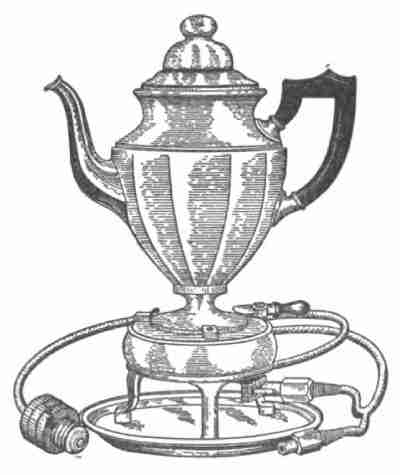
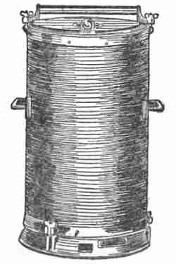
| VII. | Electric Heating | 97 |
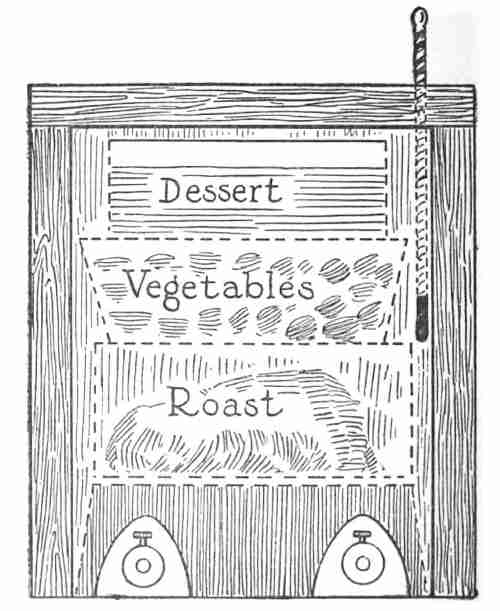
| VIII. | Applications of Electric Heating | 107 |
| IX. | Lighting a Summer Camp by Electricity | 160 |
| X. | How Electricity Feels | 168 |
| XI. | The Electric Sparking Equipment for a Gasolene Engine | 178 |
| XII. | Electricity From Central Stations | 204 |
| XIII. | Electricity From an Old Mill | 218 |
| XIV. | Doing Chores by Electricity | 240 |
| XV. | Electric currents from Chemical Action and Chemical Action from Electric Currents | 248 |
| XVI. | Electrocution at Millville | 271 |
| XVII. | The Telephone | 274 |
| XVIII. | Electric Bell Outfit for the Cottage | 296 |
| XIX. | Using Electricity to Aid the Memory | 300 |
| XX. | The Electric Brick Oven | 305 |
| XXI. | Electric Waves | 309 |
| XXII. | Ringing Bells and Lighting Lamps by Electric Waves | 324 |
| XXIII. | Telegraphing by Electric Waves | 329 |
| XXIV. | Halley's Comet and Electric Waves | 333 |
| XXV. | How the Idea of a Universal Ether Developed | 339 |
| XXVI. | Electric Currents Cannot Be Confined to Wires | 349 |
| XXVII. | Wireless Telegraphy In Earnest | 355 |
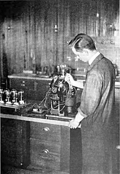
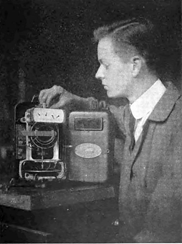
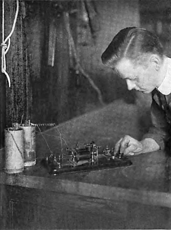
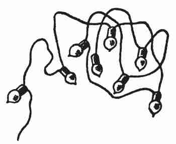
| Harold Sending the C. Q. D. Message | Frontispiece |
| FACING PAGE | |
| Testing a Generator | 8 |
| Wiring | 16 |
| Wattmeter | 40 |
| Testing the Telegraphy Outfit | 62 |
| Electric Bell | 72 |
| Feeling Electricity | 174 |
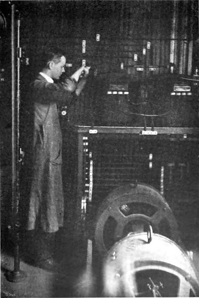
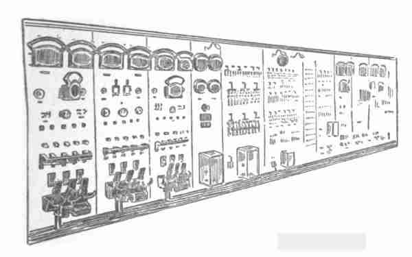
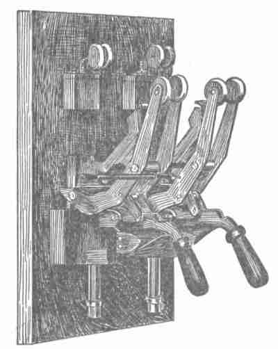
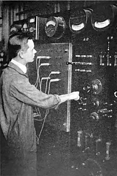
| Operating the Switchboard | 204 |
| Induction Coil of a Wireless | 330 |
ELECTRICITY AND ITS EVERYDAY USES
One day Harold expressed a desire to see the dynamos, five miles away, which furnish the electric light in our apartment. So I told him to invite his best friend to accompany us and we would go.
When we were some distance from the station the boys noticed the very tall chimneys and inquired why tall chimneys were needed for dynamos. I explained that the dynamos were run by steam-engines, and steam-engines required the burning of coal. "Oh!" said Ernest, Harold's friend, "I read in the paper that electricity is the rival of steam and is going to drive out the steam-engine." I suggested that we were about to see some steam-engines driving electricity out of that power station. But more seriously, I explained that steam-engines were used for many years as locomotives to draw the trains on the elevated railroads of New York City, and when at last they were displaced by electric trains some people thought that it was[4] a case of electricity driving out steam, whereas what had really happened was that the steam power for running those trains had been concentrated at a central station, and its power was merely transmitted to the trains by means of electricity. The trains were, therefore, run by steam power quite as much as ever. In like manner, the surface cars of New York a few years ago were run by a cable, which was merely a very long belt used to transmit to the cars the power of steam-engines located at a central station. When they were changed to electric cars, electricity became the successful rival of nothing else than a twisted wire cable. The cars still run by steam power as before, but that power is transmitted by electricity instead of the discarded cable. Steam has driven out the horse as a power for drawing street cars, and electricity has enabled us to gather all the steam engines into central stations, where now they are furnishing the power for moving surface, elevated, and subway cars for street traffic, as also trains for suburban travel. Central station steam-engines are producing a vast amount of power, distributed all over the city by means of electricity, for doing a great variety of work and for furnishing electric[5] light and heat, all of which we shall presently study. "Just before we go into this central station, can you tell me how the elevator is run in our apartment house?" "It is an electric elevator," said Harold. "And where does the electricity come from?" I inquired. "Well, I know that it comes from the street mains, but do they come from this power station?" "Yes," said I, "and we will now go in and see the steam-engines which lift you up stairs many times each day by sending electricity to run that elevator. If you choose to do so, you may claim for purposes of discussion that your elevator is run by steam."
As we entered the building we came first to the dynamo room and both boys noticed that the tone which met their ears was that which I had produced for them in the telephone the night before. "I shall try to show you before we get through," I said, "that these dynamos are doing something which makes iron pulsate sixty times a second and that that is the cause of the pitch of this tone. But let us begin with the coal which is the source of all this power.
"This particular station at the present time is burning forty tons of coal an hour. That is as much as Mr. —— uses to heat his twelve-room[6] house for a whole year. One pound of coal is capable of liberating enough energy to supply 5¾ horse-power for an hour. (Written for short 5¾ H.P.H.) One ton of coal is capable of furnishing (2,000 × 5¾) 11,500 H.P.H. Forty tons would yield 460,000 H.P.H. But the best furnaces, boilers, and steam-engines are terribly wasteful of energy. About nine tenths of all this energy is wasted and only one tenth, or about 46,000 horse-power per hour, is delivered by the steam-engines to the dynamos.
"Coal is already scarce in the world and the supply is rapidly being exhausted. Meanwhile we are growing more dependent upon coal. A century ago we used scarcely any power except that of men, horses, and oxen, and what little heat men then used came chiefly from wood. They lived in cold houses, attended cold churches and schools, did not ride in steam or electric cars, and did not have power plants. Our wood is nearly all gone, our coal is going, and we are very rapidly growing more dependent upon heat and power, our chief source of which is coal. Wind power is too uncertain to depend upon, and we turned our backs upon water-power when we began to crowd into cities. What little[7] water-power there is, however, is nearly all in use.
"There is great need both that we learn how to save the major part of the energy of the coal which we now waste, and that we find a substitute for the coal to use when that is gone.
"A part of the heat from the forty tons of coal which is being burned in this particular power plant goes into the water in the boilers. It converts this water into steam. The steam, if free to expand into the air, would occupy about one thousand seven hundred times the volume of the water. We compel it to expand through the cylinders of the steam-engine, using its force of expansion to make wheels go around—to make the dynamo revolve. These dynamos are not devices for producing power but merely for transmitting the power of these steam-engines to far away places where it may be used, as, for instance, in our apartment house, where we are unwilling to walk upstairs and want some power to carry us.
"Our own apartment is fifty feet above the street. I weigh one hundred and sixty-five pounds. If I walk up stairs from the street to our apartment in one minute, which is the rate of a rather slow elevator, I work at the rate of one quarter of a horse-power.[8] One hundred and sixty-five pounds raised two hundred feet in one minute requires one horse-power. You boys each weigh about half as much as I do, and if one of you walks up the same stairs in one minute you exert half the power that I do, or if you run up the stairs in half a minute you exert the same power, that is, one quarter of a horse-power. When we three walk up together in one minute we exert one half horse-power. If we all three run up the stairs in half a minute we expend one horse-power. Now, the speed of elevators for apartment houses is about one hundred feet a minute. We are unwilling to walk up stairs, not because we are lazy but because we have the New York haste, and so we employ elevators which run at the rate of about one hundred feet a minute.
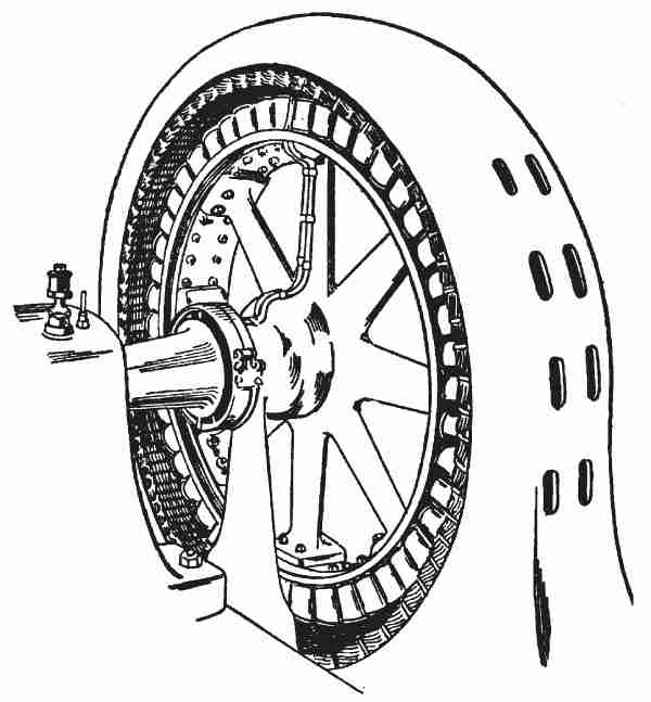
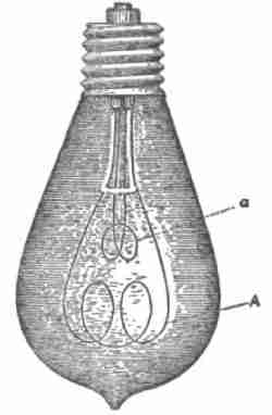
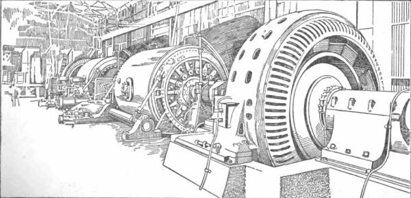
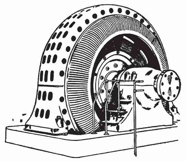
"These dynamos enable us to employ the power of this central station to run the elevator in our apartment house. Here is a dynamo rolling over now in the act of sending out power, some of which goes to that elevator; and standing beside it is another waiting to be used when necessary. Examining these dynamos, we find that they are composed of nothing else than iron and copper. About all that we can say of these mysterious[9] machines is that the moving iron generates the electricity and the copper leads it away.
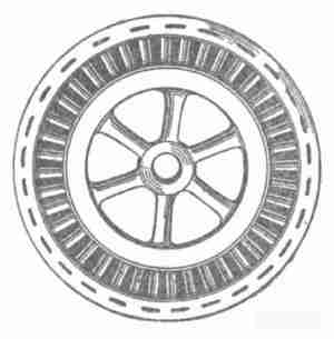
"Each one of these dynamos has many hundred tons of iron in it. A huge wheel of iron, thirty-two feet in diameter, one hundred feet in circumference, portions of which are surrounded by insulated copper conductors, forms the centre-piece of the machine. This movable part weighs four hundred tons. Around about this is a fixed ring of iron, portions of which are surrounded by insulated copper conductors. Ordinarily the ring which is stationary is called 'the field,' and the wheel, which rotates, is called 'the armature,' although these terms are sometimes reversed for certain reasons. The movable part in these machines rotates about once a second, that is, its circumference moves a little faster than a mile a minute. The iron moving at this high rate of speed creates ether streams or electric currents, which are led off by the copper conductors.[10] The generation of electricity on a large scale requires large masses of iron and high velocity."
I noticed that the boys stood before this machine in a state of utter bewilderment, bewildered as a man who is told that what he had considered north is really south, bewildered as a man who, having wandered through a maze of city streets, looks up at length and unexpectedly finds the building he has been seeking towering before him. The questions they asked were entirely without thought. "What is inside of it?" "Simply more iron and copper, such as you see on the surface," I replied. "But what makes it go?" "The steam engines, of course, four of which you see, are coupled directly to each dynamo." "But where does it get its electricity?" "Don't forget that you are looking at a generator of electricity. Big mass of iron—rapid motion! That is the whole truth. But it cannot satisfy you as an answer until you have become used to it. We have seen all that we ought to see here to-day. Let us drop the whole matter now, but return to my laboratory to-morrow, and I will give you the next step which will help you."
The boys did no talking upon their return journey. Whether one may say they were thinking or not I cannot tell, but certainly their ideas were incubating.
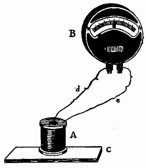
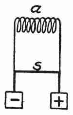
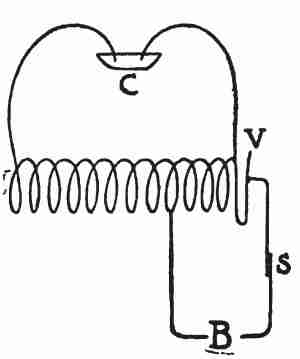
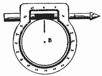
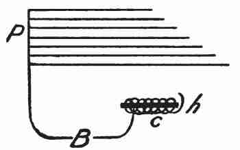
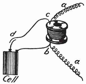
When we had gathered at my laboratory the next day I took down a spool of one pound No. 24 cotton-covered copper wire (Fig. 2 A), which had its centre filled with wire nails. The boys had seen it before and remembered it. With flexible wires I connected the two ends of the wire on this spool to a sensitive ammeter, B, which had its zero in the middle of the scale, and I laid down upon the table a bar magnet, C.
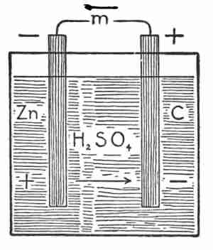
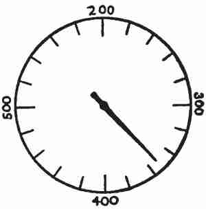
"Here," I said, "is a dynamo complete." The bar magnet furnishes the 'field' and this spool of copper wire, A, which I will move back and forth immediately over the magnet from end to end, is 'the armature.' D and e are the line wires and the circuit is completed through the ammeter to show whether we are generating electricity. And now as I move this armature along the field you see the needle of the ammeter move to the right from zero to ten. When the armature is moved in the opposite direction along the field the needle moves[12] in the opposite direction past zero and on to ten at the left. The moving of the needle in the ammeter shows that we are generating electricity. The swinging to and fro of the needle shows that we are generating an alternating current of electricity. It is a mere matter of detail whether we move the armature or the field, as I will show you by letting the spool A rest quietly upon the table and moving the magnet to and fro lengthwise across the end of the spool. Or I may accomplish the same results by moving them both in opposite directions. It is simply necessary that they move with reference[13] to each other. Some dynamos are made with stationary fields and rotating armatures, some with stationary armature and rotating fields, and some with both parts designed to rotate in opposite directions.
"Magnetism is not confined to the magnet. It extends more or less widely into the region about it. It is this region affected by the magnet that we designate its magnetic field. By bringing this sensitive compass needle into the region of this bar magnet from all directions, I show you that it has a slight power to change the direction of the needle when about a foot away. This power grows rapidly greater as the distance grows less. Of course its field extends rather indefinitely, but we may say that this particular magnet has an appreciable field extending about one foot in all directions from it. We find upon examination that some magnets have bigger and stronger fields than others, that all have their strongest fields when first magnetized and lose their strength gradually, but never entirely. We find that hardened iron and steel hold magnetism longer than soft iron, but all iron is magnetized somewhat at all times. Iron that is feebly magnetized can be made into a strong magnet by bringing it into a strong magnetic field.[14] The earth is a feeble magnet, and that is why it gives direction to the compass needle. That is also probably the reason why every piece of iron upon the earth is a magnet, or, to put the cause back another step, we may say that whatever causes the earth to be a magnet also causes every piece of iron upon the earth to be likewise a magnet.
"But thanks to Oersted in Denmark in 1819 and Faraday in England in 1821 and Joseph Henry in Albany, N. Y., in 1827, we have learned to make exceedingly powerful magnets by sending a current of electricity in a whirl around the iron. This is the meaning of the coils of copper wire around iron cores in the dynamo, in electric bells, in telegraph sounders, in motors, etc., etc. To prevent the electric current from taking the shortest route, through the iron core or through the successive layers of copper wire, the iron core and the wire must be covered with something like wood or paper or cotton or silk or rubber—such things as electricity does not readily pass through—that is, insulating material.
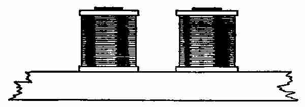
"Joseph Henry, while teaching in the Albany Academy, was the first to make electro-magnets. There was no such thing as wire covered with an insulating material then in the market, and he wound[15] all his wire with silk ribbon. But in the year 1834 he made magnets which lifted thirty-five hundred pounds, to the astonishment of every one. A pair of such electro-magnets as I have here (Fig. 3), each consisting of one pound of No. 24 cotton covered copper wire, eight hundred feet long, wound in one thousand turns about an iron core two inches in diameter, will lift several hundred pounds: much more than we three can lift, as I shall now show you."
The cores of the two magnets were bolted fast to an iron beam, and a large bar of iron with a ring in it was laid across the other free ends of the magnet cores. I made connections with the electric lighting circuit (that in my laboratory is what is called a direct current), and sent a current of electricity around the coils. The two boys and I tugged at the ring in the iron bar to no avail. We were unable to pull the iron bar away from the magnet.[16] But when I opened the switch and cut off the electric current, one boy with one finger in the ring lifted the bar with perfect ease.
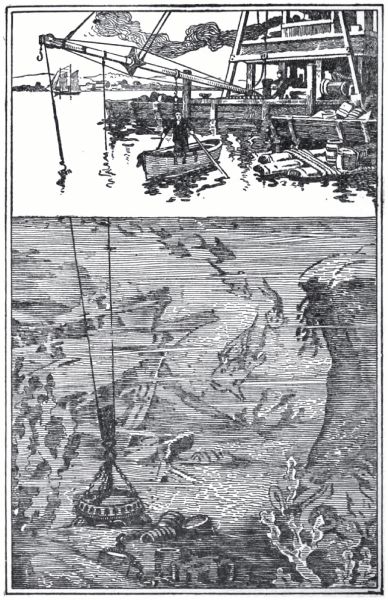
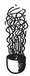
"Electro-magnets are now made with a magnetic intensity 90,700 times that of the earth's magnetism. Electro-magnets are used for hoisting iron castings weighing many tons. Here is a picture of an electro-magnet lifting a whole wagon load of kegs of nails from the wagon to the hold of a ship.
"Electro-magnets are our only means of utilizing electricity for power. It is the pull of electro-magnets that moves the electric car. Electro-magnets are now used for pulling all the trains out of the Grand Central Depot in New York City.
"Let us now compare the strength of our electro-magnet with that of the bar magnet used in our former experiment."
I opened and closed the switch, which sent the electric current through my magnet coils at frequent intervals, and the two boys, each with a compass needle, searched the field for magnetic effects. They found that the magnetic field extended six or eight feet, but this piece of research was broken up by a new idea which appeared to strike them both at the same instant, for they shouted both together,[17] "Let's use this electro-magnet in place of the bar magnet for our dynamo experiment!"
"That is surely the next step in our programme," said I, "but you will need a steam-engine to move an armature in this magnetic field, will you not, judging from the struggle we had with that iron bar a few minutes ago?" The boys looked quite hopeless until I said, "The best thing about the electro-magnet remains yet to be told. You have perfect control of its strength by changing the amount of electricity which you send around the coil.
"By means of an instrument which works like the motorman's controller on the electric car, I may control the amount of electricity which flows, just as well as you may control the flow of water by a faucet or stop-cock. By this means I will control the strength of the magnet so that you may move the armature in your dynamo experiment.
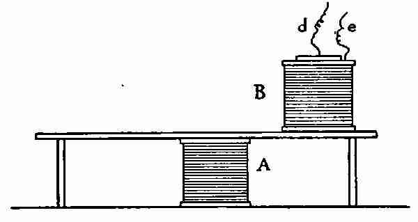
"In 1821, Faraday, at the Royal Institution, London, learned that he could produce magnetism by means of the electric current, and, in 1831, he learned that the reverse was also true, namely, that he could produce electricity from magnetism. This idea coming as the result of ten years of incessant search made him shout and dance like a child. You are feeling a little of the pleasure of his discovery."
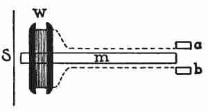
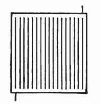
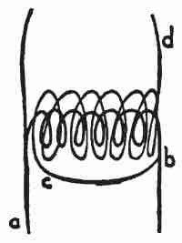
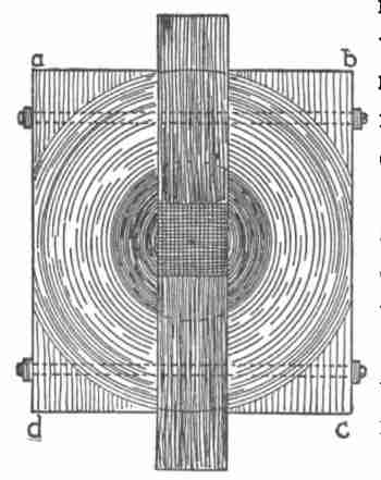
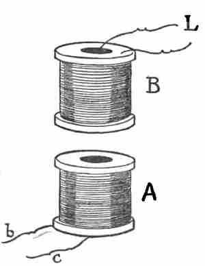
[18]I then fastened one of the coils upon the table underneath a small bench (Fig. 4) and sent an electric current around it. The other coil, B, connected with the ammeter was pushed back and forth along the surface of the bench over this coil. The boys found that the more electric current I sent around the coil A, that is, the stronger I made the magnetic field, the harder it was to move the coil B. They found that the nearer B was to A the harder it was to move it. They found that the faster they moved B the more electricity was produced. They tried laying B upon its side upon the bench and thus moving it. They tried taking B off the bench and moving it on all sides of A. They found it much harder to move in some ways[19] than in others, but in all cases they found that the harder they had to work the more electricity was developed, as was shown by the ammeter.
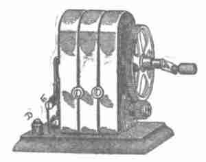
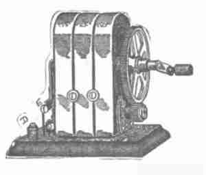
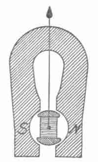
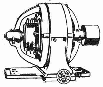
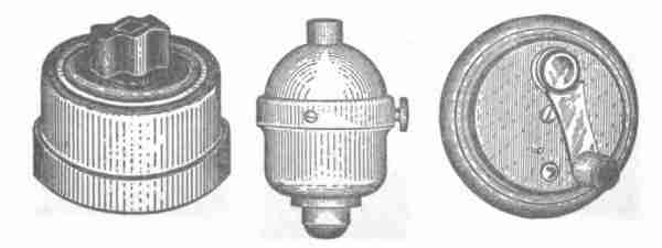
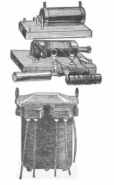
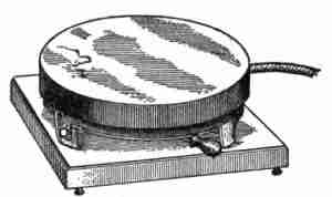
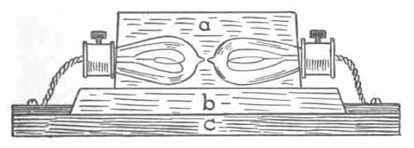
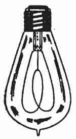
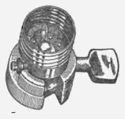
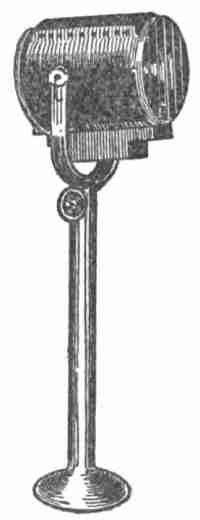
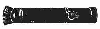
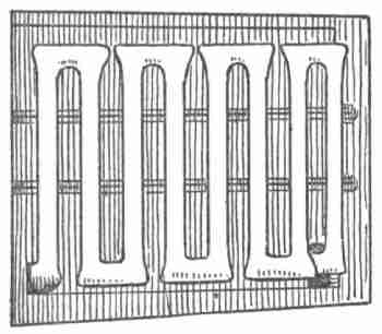
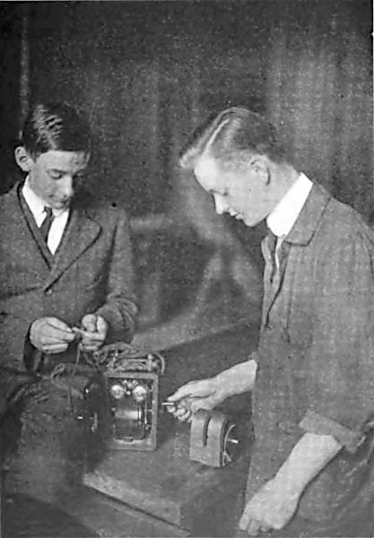
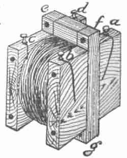
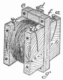
"The dynamo is any machine which will convert mechanical work into electricity. The magneto is one form of a dynamo which you have used much at the summer cottage, but have never seen the inside of. Here are several (see Figs. 5, 6, and 8) which I will let you examine inside and out, and with these I must leave you to yourselves for a time."
When I returned I asked the boys why these dynamos were called magnetos. "Because they have steel magnets for their fields," they replied. "There are several magnets bent in the shape of a horseshoe."
"Yes," I said, "in this case the field is made stronger by taking several magnets. Have you noticed any armature?" "Yes, it is made of iron with insulated copper wire wound around it."
"Please recall that the amount of energy you expend in going upstairs depends on two things: (1) your weight and (2) the speed with which you move. Also recall that the amount of electricity you could generate with a dynamo depended upon the amount of energy you expended. Therefore,[20] the strength of the electric current which this machine may produce depends upon two things: (1) the strength of the magnetic field against which you must pull and (2) the speed of the motion of the armature. Evidently this field is made as strong as it is possible to make it with steel magnets. Now is there any device for giving high speed to the armature?"
"Yes, indeed," said the boys, "one has a pulley so that it may be connected by a belt with a gas engine, and the others have each a large cog-wheel working into a smaller one. We found in one of them that a single revolution of the crank gave six revolutions to the armature."
I found that the boys had made large-sized drawings of the parts, and were preparing to report on the magneto as a form of dynamo at the next meeting of the Science Club, which we had started among the boys in school.
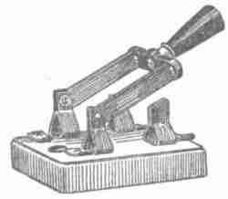
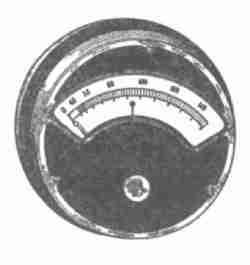
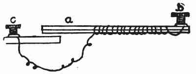
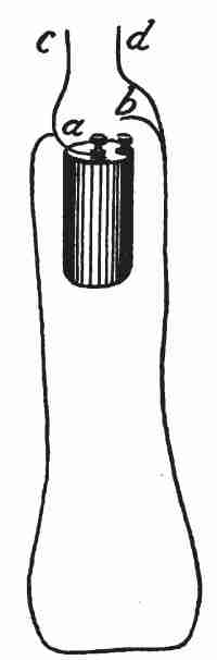
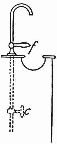
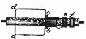
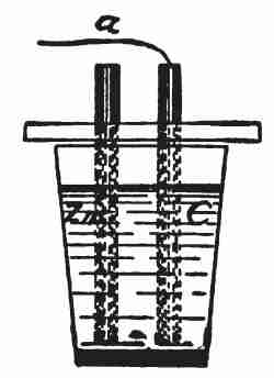
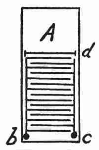
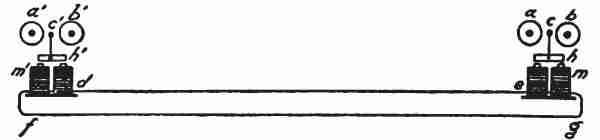
"I will loan you some apparatus so that you may give a very interesting demonstration on that subject," said I, "only let me show you how to use[21] it first. Connect the binding posts D and E of this magneto (Fig. 5) with my ammeter. Turn the crank very slowly and notice that the needle of the ammeter swings to and fro with each revolution of the armature. That shows that you have not only a dynamo, but an alternating current dynamo.
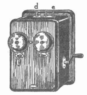
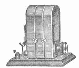
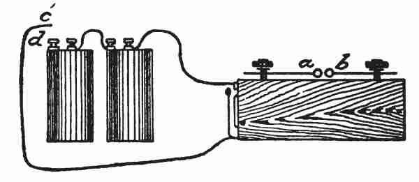
"Now connect the binding posts d and e of this magneto (Fig. 6) with a short piece of copper wire. Turn the crank and you notice that this dynamo rings two electric bells. Turn slowly and you notice that the alternations of the current are numbered by the strokes on the bells. The hammer swings to and fro just as the needle of the ammeter did. Each bell therefore receives one stroke of the hammer for each revolution of the armature. Now try to turn the crank steadily at the rate of one revolution per second. The armature is making six revolutions, or cycles, per second and you now have not only an alternating current dynamo but a six-cycle alternating current dynamo.[22] The lighting circuit used in our apartment is a sixty-cycle alternating current. To be sure the armature of the dynamo which generates that current revolves only once a second, but it carries coils enough upon its rim to make that number of alternations.
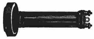
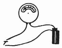
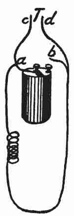
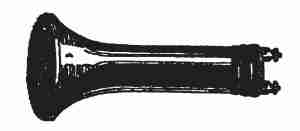
"Now connect this telephone receiver with the binding posts D and E of this magneto (Fig. 7). Unscrew the cap of the receiver. Move to one side the iron diaphragm and turn slowly the crank of the magneto. Notice that the diaphragm vibrates in time with the alternations of the dynamo. Replace the diaphragm, screw on the cap, hold the receiver to your ear and turn the crank as fast as you can. You will probably be able to make about sixteen cycles per second. The receiver in that case is giving forth a sound of the same pitch as a sixteen-foot closed organ-pipe.
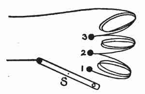
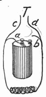
"Connect the telephone receiver to the binding posts D and E of this magneto (Fig. 8), and by means of a belt connect the pulley to this series of cog-wheels. Now you may turn the crank and readily make the[23] armature revolve at the rate of sixty cycles per second, and you notice that you get the same tone that we heard in the dynamo room of the power station and the same tone the telephone receiver gave when I connected it to a coil in our apartment. The tone which is produced by sixty vibrations per second is very nearly that of the C two octaves below middle C on the piano. Try it along with the piano and you will find it a little flat. This string on the piano is making sixty-four vibrations per second.
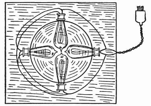
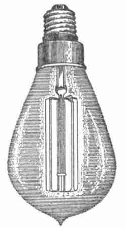
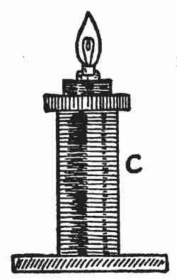
"Now connect this miniature telephone switchboard lamp with the magneto (Fig. 9) and turn the crank fast. The lamp lights up to full brilliancy and you notice that the light is steady, although it is made by an alternating current passing through the filament in one direction, stopping entirely,[24] and then passing in the opposite direction. The filament has no time to cool off, provided you turn fast enough, but try turning a little slower and you will notice the flickering of the lamp."
At the last meeting of the Science Club so many questions were asked, which the demonstrators could not answer, that a programme committee, to whom such questions might be referred thereafter, was appointed. It was made the duty of this committee to assign to various members the task of searching for satisfactory answers, and when the material was ready[26] to be reported to the club, the programme committee determined the time and order of presentation. I found that I had been made an honorary member of this committee and that it was expected that I should steer the committee. I told them that I accepted this appointment with the understanding that the fellow who steers is always the smallest man in the crew, and if they would do all the work I would enjoy the honorary title of cockswain. Secretly, however, I appreciated that this was in effect adding several courses to my already rather heavy programme. I must, under the régime, direct a large number of inexperienced students in library research, in laboratory research, and in the art of giving demonstrations with apparatus and experiments to audiences.
The most urgent questions, as also those which were next in the natural order, concerned the ammeter. I told the committee to make that the subject of the next meeting and to send to my laboratory on a certain day the person or persons whom they might appoint to report upon it.
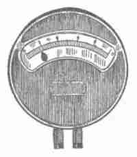
I find that the boys never come singly, but generally[27] in pairs. When the boys came they found lying upon the table an ammeter (Fig. 11).
I told one of them to take out the three screws in the front and remove the face of the instrument. I had told the boys that the instrument cost sixty dollars and that letting them open it was like letting them open my watch. As soon as the face came off one of the boys exclaimed that from my reference to the watch he had expected to see very complicated machinery with many wheels, but from the exceeding simplicity of the mechanism he could not see why it should cost sixty dollars. I told him that although it was a fine piece of workmanship it was fortunately very easy to understand, and I asked them if it reminded them of anything else that they had ever seen. After a few moments of reflection they agreed that it was very much like one of the magnetos. "Well," said I, "where is the field?"
"Is this horseshoe arrangement a magnet?" they inquired.
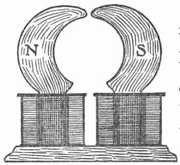
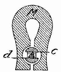
"There is a compass needle right at your hand waiting to answer that question," I replied. They[28] immediately found that it was a magnet. "Well," I said, "to be really sure that it is a magnet you must find a portion of it that will repel a portion of your compass needle as well as other portions in both horseshoe and needles which attract each other." Whereupon, they found that the portion marked N (Fig. 13) repelled the blue end of the compass needle and attracted strongly the bright end of the needle, while the portion marked S did the reverse. "We will call N and S the poles of the magnet. This is simply a steel bar magnet bent into the shape of a horseshoe."
"You told us," remarked one of the boys, "that steel magnets gradually lose their strength. How then can this be correct as a measuring instrument?"
"It is the purpose of the iron case to enable this magnet to retain its magnetism, and if you will examine its field, as we did that of another magnet upon a former occasion, you will find that although this is a strong steel magnet its field does not extend outside of the iron case. It is as though we could box up magnetism and keep it from escaping.
"Now if this is like the magneto, where is the armature? The spool-like thing between the poles of the magnet looks just like the armature in one of the magnetos.
"Yes, it has an iron core with a coil of insulated wire around it, and you remember that when an electric current is sent around a piece of iron, that iron is made into a magnet, and if it is a magnet it must have poles. It is very delicately poised upon a pivot and will act exactly like your compass needle, which is also a little magnet with poles. I will send an electric current through the wire which surrounds this armature, and you notice that the needle which it carries moves to the right. Notice that the lower end of this armature acts like the blue end of your compass needle in that it is repelled from the pole N of the field and is attracted toward S of the field. In like manner, the upper end or pole of the armature is repelled from S and attracted to N of the field. The blue end of the compass needle is called its north pole because it points north under the magnetic influence of the earth, and so we may call the lower end of the armature its north pole.
"The electric current which I am sending through the armature comes first through one ordinary[30] 16-candle-power electric lamp which you see lighted on this 'resistance board,' as it is called, and you notice that the needle points to .5. This means that half an ampere of electricity is passing through this lamp. I will now send the current through a 32-candle-power lamp, and you notice that the needle points to one, indicating that one ampere is required to light that lamp. But what prevents the needle from going farther, and what brings it back to zero each time?" The boys discovered a very small spring, like the hair spring of a watch, coiled around the pivot of the armature. "So, then, one ampere of electricity gives magnetism to this armature so that it may pull against its coiled spring hard enough to carry the needle to the point one. Twice as much electricity will give it magnetism enough to carry it to two, and so on across the scale.
"The full name of this instrument is Ampere meter, which by usage has been shortened to ammeter. It was named in honour of André Marie Ampère, who was born at Lyons, in France, in 1775, the year our Revolutionary War broke out. He died in 1836. When Oersted made his famous discovery of the action of an electric current upon a magnetic needle, in 1819, Ampère was in middle life (forty-four), and took up the same line of research with[31] great vigour. The next year, 1820, he discovered what you will doubtless enjoy rediscovering now.
"You will notice that the binding posts on the bottom of this ammeter are marked, one positive, +, and the other, negative -. The electric current now enters the instrument by the post marked + and after passing around the armature leaves by the post marked -. I will reverse the connections and thus send the current around the armature in the other direction, and you notice that its poles are now reversed. The lower end which was formerly the north pole of the armature has now become the south pole, as proven by the fact that it is repelled from the south pole of the field and attracted to its north pole. This carried the needle to the left, and inasmuch as the zero is in the middle of the scale we may with this instrument both measure the amount of current and tell its direction. You will recall that when we connected the magneto with this instrument, it indicated that the magneto sent the current first in one direction and then in the other, which we call an 'alternating current.' But you notice that the current which I am using in this laboratory flows continuously in one direction. This is called the 'direct current.' We shall find out how a dynamo may produce a direct current[32] at another time. Let us not forget, however, that we have repeated Ampère's discovery, and found out that the direction in which we send the current around an electro-magnet determines which end shall be its north and which its south pole. If you will note carefully which way the wire is wound around the armature you will see that when I send the current in at the positive post it is passing around the north pole of the armature opposite to the direction in which the hands of a clock move. If I reverse the current it passes around the lower end of the armature in the same direction as the hands of a clock move and then this end becomes a south pole. This is 'Ampère's rule,' and it is what candidates for admission to college are very careful to learn.
"Before we replace the face of this ammeter I must call your attention to a wire running by a short cut from one binding post to the other, s (Fig. 14). Suppose a represents the wire around the armature. Electricity, like water, goes more readily through a big conductor than a small one and more readily through a short than a long conductor. If s and a were water pipes, each having a stop-cock, we might easily adjust the cocks so that one tenth of the water would go through a and nine tenths through s. Or, indeed, without stop-cocks,[33] the size and length of s and a might be so apportioned that one tenth of the water would flow through a and nine tenths through s. This is precisely the adjustment which has been made with reference to the flow of electricity through this instrument. s is called a 'shunt.' When the shunt is out all the current goes through a and when the shunt is in only one tenth of the current goes through a. I have two other shunts, each of which may be put in the place of s. With the second only one hundredth of the current goes through a and with the third only one thousandth of the current goes through a. Thus I have an instrument which will measure anything from one thousandth of an ampere up to ten amperes.
"In this laboratory we pay about one cent for an ampere of electricity for one hour. Twice as much coal must be consumed to furnish two amperes as one, and twice as much coal must be consumed to furnish an ampere for two hours as for one hour. Hence we need an instrument which will keep account of time as well as amount of current. Such an instrument we must look into next.
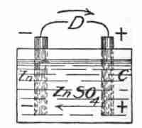
"Just before we pass to that, however, let me ask if you have ever heard of a 'shunt-wound' dynamo. Can you guess from the way we have just used the word 'shunt' what the expression could mean with reference to a dynamo?" Without hesitation the boys told me that it meant that the field and armature were wound parallel to one another, as shown by diagram in Fig. 15. In which case the electric current which the machine generates divides, part of it going around the field and part around the armature. Another type, called series-wound dynamos, is indicated by diagram in Fig. 16, in which case the electric current goes through field and armature in succession. Under either of these circumstances, how can the armature move with reference to the field? The answer will appear in the next chapter.
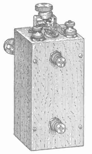
We were able to maintain connections between the binding posts of the ammeter and the movable armature of flexible wires because the armature never moves more than one third of a revolution, but we now wish to examine an instrument in which the armature must not only make a complete revolution but must continue to revolve in the same direction indefinitely. How are connections made so that an electric current may pass from the fixed binding posts to the wire of the moving coil? I will lift the cover off this instrument, which is called a wattmeter, and let you find the answer to that question.
I sent through the instrument the current from a 32-candle-power lamp. According to the ammeter, which was also in circuit, the amount was one ampere.
The armature of the wattmeter revolved slowly and it was not long before the boys reported that connections for the current were made by strips of[36] metal sliding on metal plates. The ends of the armature wire were fastened one to one plate and the other to the other plate, and the metal strips brush along over the surfaces of the plates. (That is why they are called "brushes," I said.) And the brushes slide from one plate to the other each time the armature makes half a revolution. (That is, the brushes change the connection and thus change the poles of the armature at the proper instant so that they are always attracted to the poles of the field toward which they are moving.) This is called a commutator.
Notice that while the ammeter was like the magneto in having a steel magnet for its field, the wattmeter is like the dynamo in having electro-magnets for both armature and field. Notice in the second place that this instrument is an electric motor since it is made to revolve by an electric current. If it were made to revolve by some other power it would generate electricity and would then be called a dynamo. Indeed, let me tell you something which must at present be nothing more than a puzzle to you. Every machine, while it is being driven by an electric current as an electric motor, is, at the same time, acting as a dynamo to generate a current in the opposite direction. Notice[37] in the third place that this is a shunt-wound instrument. The current which is sent into the instrument divides, and part of it goes through the field, while part goes through the armature. Motors, as well as dynamos, are either shunt-wound or series-wound. But notice finally that the axle on which the armature is carried has a cyclometer arrangement which keeps account of the number of revolutions. The armature is going slowly enough for us to count the revolutions. With watch in hand we found that it made one hundred and twenty revolutions per minute. I next brought the current to the wattmeter through a 16-candle-power lamp and the ammeter, connected in series, showed that half an ampere was passing. We counted the revolutions of the wattmeter and found them to be sixty per minute.
Here, then, is a simple electric motor which will register the amount of electricity we use. It will register the same amount whether we use one ampere for one hour or half an ampere for two hours or two amperes for half an hour. In any case this product is called one ampere hour. But the words printed upon the dials of this instrument are not ampere hours, but watt hours and the name of the instrument is wattmeter. This next requires[38] explanation. Follow me in a little roundabout journey and the matter will be readily understood when viewed from another approach.
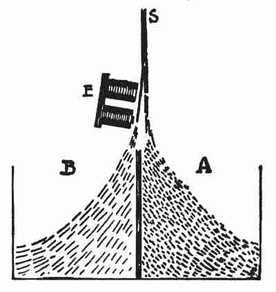
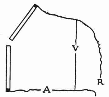
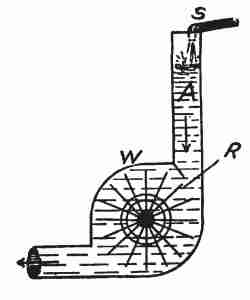
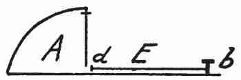
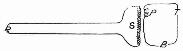
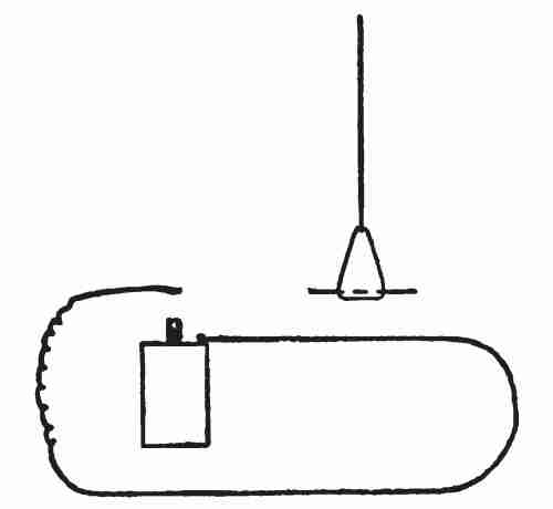
When we were estimating the energy required to climb the stairs of an apartment house, we needed to take into account two factors, (1) our weight and (2) the time which we took in climbing them. The amount of coal burned, steam generated, electricity produced, to run our elevator depends upon two factors, (1) its weight and (2) its speed. That idea is fundamental. Let us get at it in still another way. Suppose we have a mill pond, (Fig. 17, A). We construct a penstock p and install a water-wheel, S, to operate a mill. Our business increases and we install more machinery in our mill and must have more power to run it. We have two ways of getting it, (1) we may lengthen our wheel and enlarge our penstock so that a greater weight of water will fall upon the wheel, or (2) we may lengthen our penstock and move the wheel[39] farther down so that the water will fall upon the wheel with greater velocity. It is just so with the electric current. Like water it is driven on in its course by pressure. The unit for electric pressure is called a volt. If we wish to drive the wattmeter or any other electric motor twice as fast as now, we may choose whether we shall do so by doubling the volts of pressure or by doubling the amperes of quantity.
The electric pressure on our mains is about one-hundred and ten volts. We three together weigh 330 pounds. Our elevator brought us up stairs at the speed of 100 feet per minute. It requires one horse-power to raise 330 pounds 100 feet in a minute. The ammeter in the engine room showed that 7 amperes of electricity were sent through the motor of the elevator to bring us up. That is, seven amperes at 110-volt pressure give one horse-power. In the office building across the street where they use a 220-volt current 3½ amperes are required to take us up stairs at the same speed. It is necessary that the same amount of coal be consumed to furnish the horse-power of energy whether we supply it by means of seven amperes at 110 volts or 3½ amperes at 220 volts. You notice that the product is 770 in each case. The name given[40] to this product is watts. More accurately 746 watts of electrical power are equivalent to one horse-power. The name of this unit commemorates the famous inventor of the steam engine, James Watt (1736–1819). His monument now overlooks the Clyde at his native town, Greenock, Scotland.
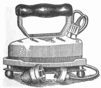
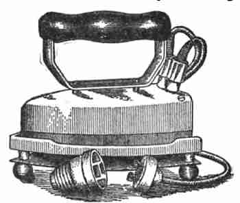
To light a certain lamp, to heat a certain laundry iron, to furnish a certain amount of power for an electric motor, we must have a definite number of watts. We may choose whether we will have it at high or low voltage with correspondingly low or high number of amperes.
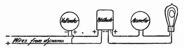
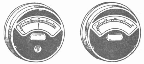
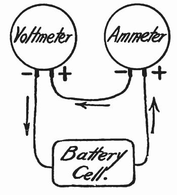
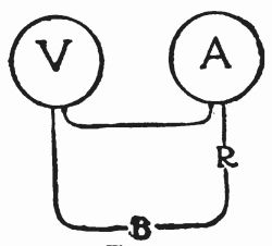
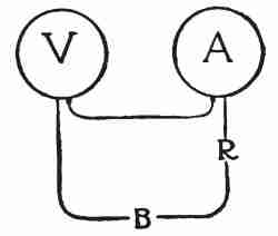
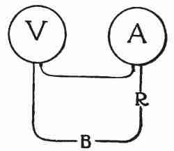
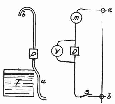
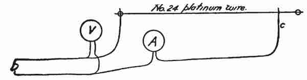
We will now connect with our laboratory current a 32-candle-power lamp, an ammeter, and a wattmeter, all in series, Fig. 18, and in parallel with these a volt meter. This last instrument indicates the electric pressure. Its mechanism will be examined later. The volt meter indicates 110 volts and the ammeter shows that one ampere is passing.[41] The filament in the lamp resists the passage of the current. It gets quite hot and gives forth as much light as thirty-two candles. Its resistance is just such that 110 volts of pressure send one ampere through it. We will now take the reading of the wattmeter, note the time and read it again later. One hour later its index showed that 110 watt hours of electrical energy had been converted into light and heat. This at the usual rate, costs 1.1 cents, one cent per hundred watt hours or ten cents per thousand watt hours, called a kilowatt hour. The more common 16-candle-power lamp costs about half a cent an hour to operate. It requires one horse-power to keep fourteen of them burning.
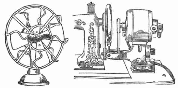
I will now take you to see the wattmeter which measures all the electric energy used in this building. You note down its reading and the date and the next time you come we will read it again and thus find out how much electricity has been used for electric lights, for electric ventilating fans, for electric elevators, for electric ovens, and electric irons in the school of household arts, for electric motors to run lathes and other machines in the school of technical arts, for electric experiments in my laboratories and lecture room, for[42] electric vacuum cleaners and, lastly, for pumping the pipe organ in chapel.
I saw by the boys' faces as they departed what would be the next question that they would bring to me. Knowing, however, that the hour was up, they were too polite to press it then.
In a few days I received a telephone message, asking if I could appoint an hour to meet the programme committee in my laboratory. I must confess that my pleasure in these meetings had increased so much that I was quite ready to slight other duties, if need be, to engage in them. Moreover, since my business was education it was not difficult for me to regard these meetings in the light of a duty quite as important as my regular class instruction—perhaps more effective. At any rate the boys and I managed to get together. May God forgive the man who essays to teach boys, but does not love to be with them.
Of course at the last meeting of the Science Club every one wanted to know how we ran a pipe organ by electricity. Moreover the Electrical Show was coming on in the city, and cows were to be milked by electricity, dishes were to be washed by electricity, rugs and furniture were to be cleaned[44] by electricity, and innumerable distracting and distressing things were to take place. I told the boys that really only two kinds of things were to be done by electricity at the show, and if they would give me two one-hour appointments I would furnish them with the key to the whole show. We might as well begin to-day with the pipe organ question.
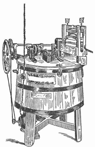
A pipe organ is operated by air. It has bellows which are simply one form of an air pump. A boy is often employed to turn a crank which works the bellows. Down in the basement underneath our pipe organ I will show you how a half-horse-power electric motor takes the place of a boy. We found a dark and dirty corner where a boy used to stand and turn a crank every time æsthetically inclined people enjoyed an organ recital in the room above. Science, which has not been given credit for being humanitarian, put an electric motor into that dark corner and sent the boy up stairs to hear the music. The motor grumbled at the dirt in the corner and compelled the janitor to keep it clean.
The electric motor, better than any device I know, enforces justice, but never requires mercy, or at least rarely receives it. It comes nearer[45] than any other machine to paying back all that you put into it. It is most economical when working up to its full capacity. I recommend that you look it over carefully and after a few minutes tell me what you have seen in it.
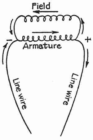
The boys said that it looked just like a dynamo. We must not forget that it is a dynamo, but is here used as a motor by sending an electric current through it. This fact, that a dynamo might be driven by an electric current and serve as a mover of other machinery, was first publicly exhibited in 1873 at the Vienna Exhibition, and by many believed to have been discovered by accident at that exhibit. But why does it look like a dynamo? It has a field whose magnetism is produced by an electric current sent through coils of wire, and it has an armature whose magnetism is likewise produced by the electric current. If it were used as a dynamo, where would it get the electric current to magnetize its field? From its own moving armature. Is it adapted for direct current? Yes.[46] It has a commutator and brushes. Is it shunt- or series-wound? Shunt-wound, as shown by diagram in Fig. 20.
Suppose we treat the machine as a dynamo. Bring the ends of the line wire together, thus, as we say, closing the circuit. By some external force let us cause the armature to rotate and under the influence of the magnetic field it will generate an electric current, part of which will pass through the field and part through the line circuit. We may adjust the relative amount of wire in field and line so that any portion of the current we choose will pass through the field. The amount of current it will generate depends, (1) upon the strength of the field and (2) upon the speed of the armature. Its field, although never entirely without magnetism, is very feeble at first, and hence in the first instance a very small current[47] will be generated in the moving armature. This, however, will strengthen the field slightly, and as the field is strengthened the armature will generate more current, and thus by a mutual reaction the machine gradually "builds up" to full strength.
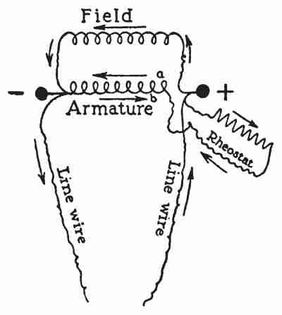
When now we use the machine as a motor, an electric current must be sent along the line wires in the opposite direction (Fig. 21) from which it would come out of the machine when acting as a dynamo. It will then be noticed that, although the direction of the current through the field is the same, whether the machine is used as a dynamo or a motor, the direction through the armature, when used as a motor, is the reverse of that when used as a dynamo.
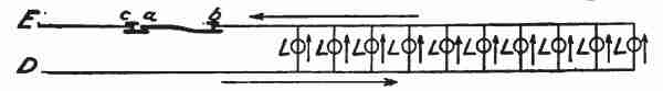
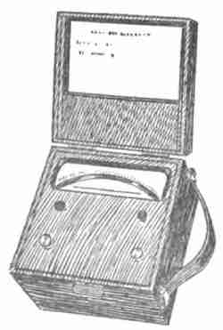
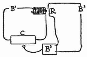
You may perhaps be able to notice that the amount of wire on the field is considerably more than that on the armature. Now if you will trace the wires carefully you will find that there is provided a way of supplementing the wire of the armature with some more wire in what is called the rheostat, Fig. 22. This wire, or[48] portions of it, is introduced into the armature circuit when the machine first starts. When, however, the machine has started and the armature is moving within the influence of a magnetic field, it plays the part of a dynamo at the same time that it is acting as a motor. Two conflicting and opposite electro-motive forces therefore exist in the armature at the same time. In Fig. 22 the arrow a represents the direction of the electro-motive force which is impressed upon the armature, and the arrow b represents the counter-electro-motive force which the moving armature develops.
This counter-electro-motive force, which develops while the machine is in motion, makes it unnecessary to hold back the current longer by the extra resistance of the rheostat and hence that is usually cut out. Being used only for starting purposes[49] and looking like a box, it is generally called the "starting box." If now it was intended that this motor should run at a constant speed, as is often the case, no other governor would be needed than this counter-electro-motive force, for whenever the machine begins to go faster, on account of reduced load, its counter-electro-motive force increases as the speed and holds in check the impressed electro-motive force. This acts very perfectly as a governor, and motors operate with notoriously constant speed under variable loads. But, of course, in this present instance the motor is required to work at a variable speed. It must pump air slowly for the soft passages of music, and it must work the pump to its utmost for the very strong passages.
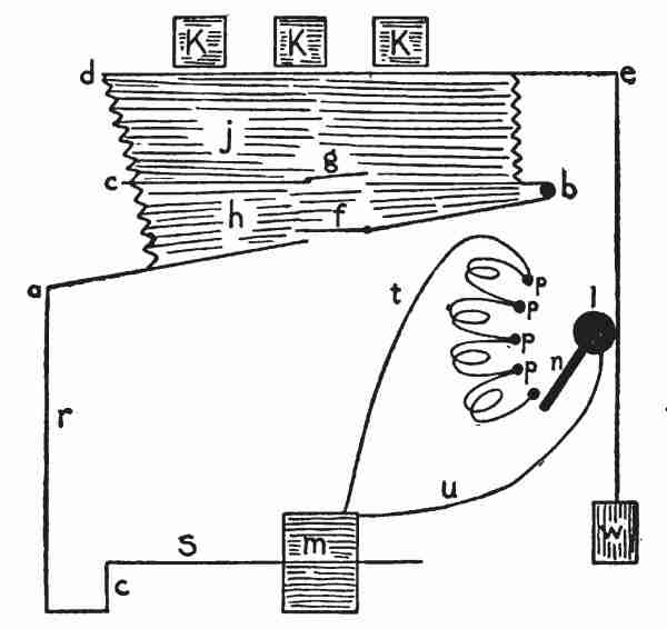
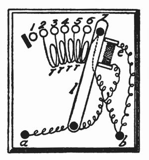
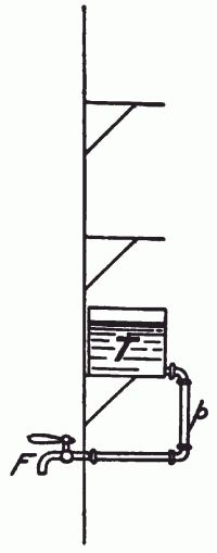
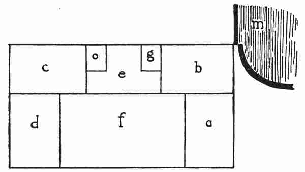
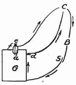
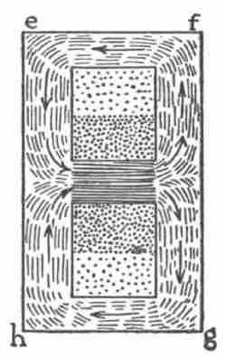
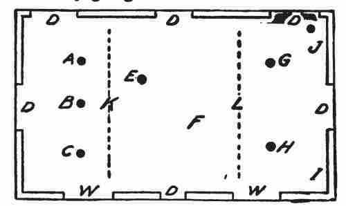
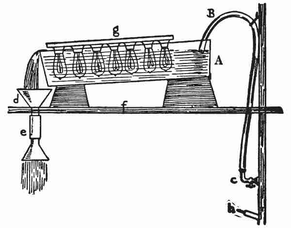
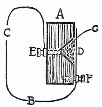
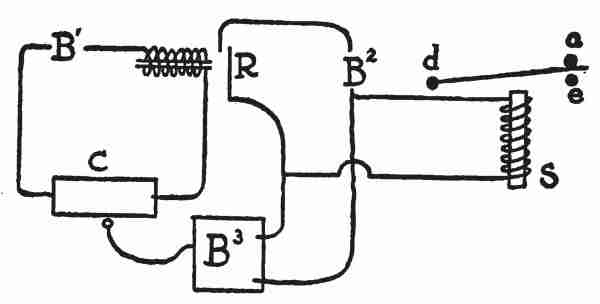
To understand how an electric motor may pump an organ and have its speed automatically controlled, let us examine the diagram in Fig. 23. The motor m causes the shaft S to revolve, carrying the crank C around with it. The rod r causes a b, the lower side of the bellows, to rise and fall, this side being hinged at b. The side b c, is fixed. When the side a b is pushed upward by the crank rod the valve f closes and the air in the compartment h pushes open the valve g and enters the compartment j. The upper side d e, of this compartment[50] rises as it is filled with air. Weights K, K, K, rest on the top of this and air ducts lead from this compartment to the pipes of the organ. The keys of the organ operate air cocks which open and close the air ducts connected with the organ-pipes. A chain connected with e passes around the axle of the wheel l and has a weight W upon its lower end. The wheel l carries a strip of brass n, which slides over metal points p, p, p, etc. The successive points are connected by coils of wire to furnish resistance. This[51] series of coils is called a rheostat. The wires t and u form a loop from the armature of the motor and connect this rheostat in series with the armature. u is connected with the brass strip n. Notice that when the compartment j is full of air and the side d e, is lifted to its greatest height the strip n is moved to the lowest point p, and the electric current must pass from u through all the resistance of the rheostat in order to get back to the armature by the wire t. This makes the motor go very slowly. When d e sinks down, the strip n moves to the upper points p, and the resistance is reduced step by step, enabling the motor to quicken its speed and pump faster as more air is required.
Small motors in order to be effective must travel at high speed. This motor when moving at its highest speed makes 1,800 revolutions per minute. The bellows on the other hand needs to be large and move slowly in order to be efficient. Hence the motor is not in reality connected directly to the shaft S, but causes the shaft to revolve by means of a series of pulleys and belts. The pulley on the motor is three inches in diameter. It is connected by a flat leather belt with a wheel thirty inches in diameter. When the motor therefore,[52] makes 1,800 revolutions per minute this wheel makes 180 revolutions per minute. The axle of this wheel carries a small cog-wheel three inches in diameter and it is connected by a chain belt with a cog wheel on the shaft S (Fig. 23). Thus this shaft revolves thirty times per minute, that is, the rod r rises and falls each second. A pull of one pound on the rim of the motor pulley will cause a pull of sixty pounds on the cogs of the wheel upon the shaft S. If the second belt were leather, a sixty-pound pull would cause it to slip on the smaller pulley. Hence the second belt is a steel chain and the wheels have cogs, or sprockets, like a bicycle.
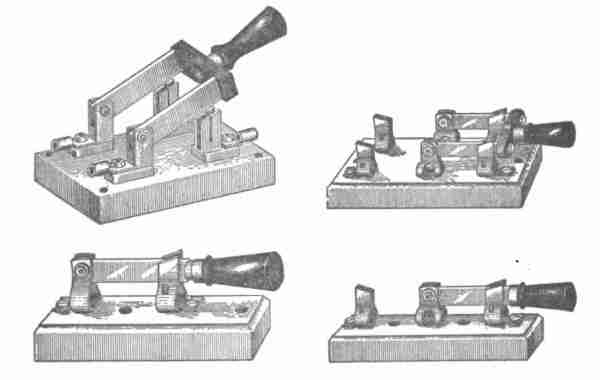
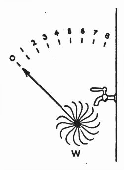
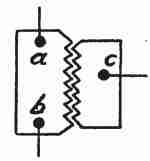
The organist before beginning to play closes a double-pole, single-throw switch (Fig. 24), which sends the electric current to the motor.
The motor pumps air until the bellows is full, and if the organist delays playing, the strip of brass n (Fig. 23) is carried below the lowest point p, thus cutting off the current and stopping the motor. As soon as he uses some of the air in the bellows, however, n rises and makes contact with the points p and the motor starts.
This suggests that a somewhat similar thing is accomplished under electric cars which have air brakes. An electric motor pumps the air and compresses it in a tank. When the pressure reaches a certain point, say sixty pounds per square inch, it automatically shuts off the electric current from the motor which works the pump. But when the motorman uses some of the air to apply the brakes to the wheels, and the pressure in the tank falls below sixty pounds, the electric current is again automatically turned on to the motor.
Of course if an electric motor can operate a pump to compress air it may also work a pump to exhaust air. This is what is done in a vacuum cleaner. The electric pump as it is called (which means a pump worked by an electric motor), exhausts some of the air from a compartment in the machine, and the atmosphere pressing in through nozzle and hose carries dust from rugs and furniture with it into the compartment. The best vacuum cleaners will produce a pressure of seven or eight pounds per square inch, about half an atmosphere. This will remove dust from the warp and woof of a rug better than our greatest hurricanes can when the rugs are hung upon a line. There are three[54] kinds of air pumps in use with vacuum cleaners: (1) bellows, (2) rotating disk or fan, (3) piston.
To milk cows by electricity is simply to apply the vacuum-cleaner idea to the process, and, in general, doing things by electricity usually means doing them by some machine that is made to go by an electric motor. This then is the first key to the Electrical Show, and if you will remember to look first for the motor it may remove much of the mystery from some of the exhibits. In many cases it is not necessary to have a complete electric motor, but simply an electro-magnet to do the work. In booth No. 56 you will find a piano played by electricity. Its keys are moving, but no hands strike them. There is no ghost at work here. A little strip of iron has been placed upon the under side of each key and a small electro-magnet is placed under that. It is only necessary that wires should run from these electro-magnets to two dry-battery cells and to push buttons, and a person far away may play the piano. In reality, however, it is not a person but a roll of punctured paper that opens and closes the electric circuits to these various magnets underneath the keys.
It often happens that you see a person playing a pipe organ with his keyboard far removed from the organ itself. In this case the keys simply act as push buttons to close the electric circuit through electro-magnets placed in the organ itself. These electro-magnets operate the air valves of the various pipes.
You call at some apartment house where there is no hall boy, but a row of push buttons labelled with the names of the tenants. You push a button and the door which was locked opens apparently of its own accord. To say that the door opens by electricity is only to add mystery. What does happen is that an electric bell up in the apartment rings in response to your push of the button, and in reply the tenant pushes a button and the door is unlatched by an electro-magnet concealed in the door casing (Fig. 25).
So I would say that the first key to the Electric Show or to the multitude of electrical appliances which you meet in life is the electro-magnet. Consider the motor as one illustration of its use.
If you are really to understand the Electric Show you should go twice. I advise going with this key alone first and note down all the applications of electro-magnets which you can find there. When you have done so I shall be glad to have your report.
It became quite the rage now among the boys to find as many uses of electro-magnets as possible. These were reported and explained to the club and a list kept. This list included:
Already noticed in the preceding pages, and the following:
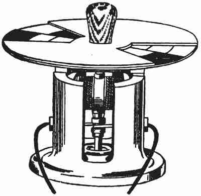
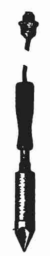
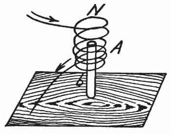
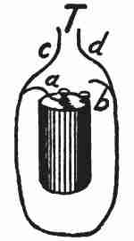
8. The Electric Spinner (Fig. 26).—A toy full of instruction. The standard is a steel magnet which produces a magnetic field. Inside of this is an electro-magnet which serves as an armature. Plainly[58] visible on its shaft is a commutator to which the electric current from a dry cell is sent. This causes the armature to revolve and carry with it a series of colour disks which may be adjusted so as to show what tint or shade results from mixing colours in various proportions.
9. The Electric Engine (Fig. 27).—This toy, with one dry battery cell, develops power enough to run several other toy machines. The diagram in Fig. 28 will make its plan of operation plain. B is the battery cell, c the electro-magnets, a an armature of iron. By a rod this armature is connected with a crank on[59] the axle which carries the fly wheel f. Another crank, d, upon the same axle serves like a push button to close the electric circuit at the right instant. The wire g from the battery cell encircles the electro-magnet c and then is connected to the iron base of the toy. When the crank d touches the conductor e, which is a spring, the electric current passes around the magnet, the magnet pulls the iron armature a, and this gives an impulse to the wheel f whose momentum carries it around during that portion of the revolution when d is separated from e and a is receding from the magnet.
It is customary to say that the circuit is closed through the base of the machine, but this language requires interpretation. It means that a way is provided for the electric current to pass through the base. A person who is expert in language but not in electricity might expect us to say "the circuit is open through the base."
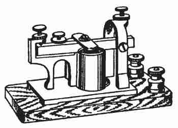
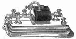
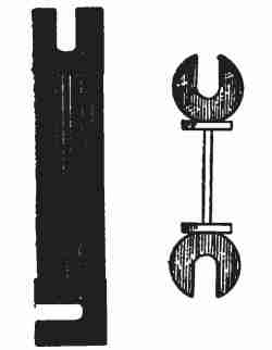
10. The Telegraph Sounder (Fig. 29).—This was[60] a toy half a century ago, but since the days of Samuel Finley Breese Morse it has become of vast commercial importance. The Western Union Telegraph Company in 1909 had 211,513 miles of poles and cables, 1,382,500 miles of wire, 24,321 offices, sent 68,053,439 messages, received $30,541,072.55, expended $23,193,965.66, and had $7,347,106.89 in profits. In the United States more than 93,000,000 and in the world at large more than 600,000,000 messages are sent annually, and there are men still living who scoffed at Morse's ideas as impracticable.
It is interesting to contemplate what would happen to the Stock Exchange, to the newspapers, to the railroads, to the congressman addressing his constituents from the floor of a legislative chamber, to business in general, if the world were deprived of the telegraph.
A few years ago a telegraph despatch was sent from New York to San Francisco, Tokio, London, and back to New York, 42,872 miles, in three minutes less than an hour. Electricity can travel around the world in a fraction of a second, the time was consumed in repeating the message. I once sent a message from New York to New Haven to announce that I was coming, and afterward took my train and reached New Haven in time to receive my own[61] message and pay the messenger boy. But I have never lost faith in the beneficent results of Morse's labours.
Morse (1791–1872) was an artist and the first President of the National Academy of Design. He was likewise a professor in New York University and constructed his first experimental telegraph line upon the University campus in 1835. His first public line was built from Washington to Baltimore in 1844. The Western Union Telegraph Company was incorporated in 1856. Of course the work of Morse rested upon that of Oersted, in Copenhagen, who, in 1819, discovered electro-magnetism, and upon that of Joseph Henry of Albany, who in 1827 first insulated the wires.
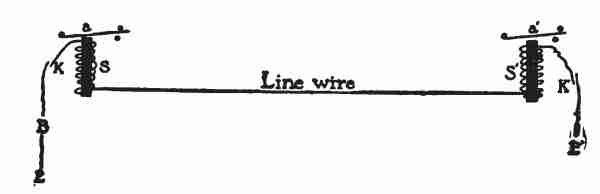
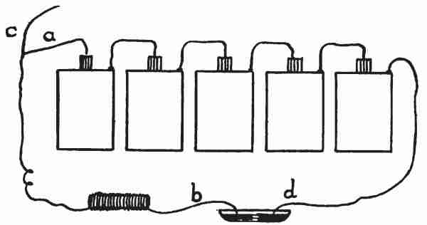
The application of the electro-magnet to producing telegraphic signals will be understood by referring to Fig. 30. B is the generator of an electric current—sometimes a battery and sometimes a dynamo. One wire from this goes to the earth, E. The other[62] wire goes through a key, which, like a push button or a switch, serves to open or close the circuit. This is normally closed when not in use. Through this the current passes around the electro-magnet S, which attracts the armature a, causing it to click against a metal stop, hence it is called the sounder. From this the current passes along the line wire to a distant station and there through the sounder and closed key to the earth. There is likely to be a generator at each station. The current must run continually through the system. If a battery is employed, the copper sulphate, or gravity cell, to be described later, is chosen, because it will endure continued usage better than any other.
The operator, in sending signals, opens the circuit, the magnets cease to hold down the armatures, and they are raised by springs and strike against metallic stops above. It is customary to say that the circuit is completed through the earth. This statement misleads some persons into imagining an electric current capable of corroding water pipes and decomposing chemical compounds, passing through the earth between stations.
Perhaps it will help to a better understanding of the truth if we think of a city pumping water out of the ocean, say to fight fire, and disposing of it[63] again into the ocean. The ocean currents thus produced are not likely to be destructive. Indeed, just as we measure height from the ocean level as zero, so we measure electric pressures as from the zero level of the earth's electrical state.
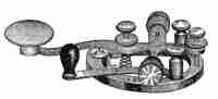
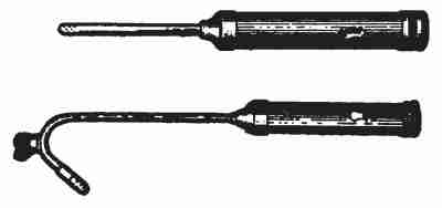
The key used by telegraphers is represented in Fig. 31. It has connected with it a switch to keep the circuit closed when the key is not in operation. The Morse code of signals consists of dots and dashes, when printed, as follows:
| a | . - |
| b | - . . . |
| c | . . . |
| etc. |
Operators learn to read the message by the intervals between sounds. A dot consists of two taps of the sounder with a short interval between, and a dash consists of two taps with a longer interval between. One tap of the sounder is caused by its descending upon the metal stop below and another by its rising against the upper stop.
Telegraph sounders are operated on about a[64] quarter of an ampere of current if from a battery circuit, or on about one tenth of an ampere from a dynamo circuit. The dynamo circuit is supplied with more volts of electric pressure, and hence its power is ample to cause the armature to strike the metal stops hard enough to be heard by the operator.
For example a battery circuit may supply to the sounder a current with these characteristics:
2 volts × .25 amperes = .5 watts,
while a dynamo circuit may give:
6 volts × .1 ampere = .6 watts.
Telegraph line wires are usually bare, the insulation being merely the glass knobs at the poles. Clean water is a very good insulator but dirty water is a fairly good conductor. A wet telegraph pole may bring so much current to earth as to prevent all sounders on the line from operating. Hence the line is separated from the poles by glass. The poles are about one hundred and thirty-two feet apart, making forty to the mile. The wires are usually galvanized iron one sixth of an inch in diameter. Copper conducts six times as well as iron, and is now replacing iron in the lines.
Morse laid a submarine telegraph line in New York Harbour and suggested a cable across the[65] ocean. But that gigantic undertaking had to await the masterful intelligence of Lord Kelvin and the indomitable will of Cyrus W. Field. A submarine cable was laid across the Strait of Dover in 1850. It was cut by the anchor of a fisherman a few hours after it was laid. The first attempt to lay a submarine cable across the Atlantic Ocean was made in 1857. Two ships of war, the Agamemnon of Great Britain and the Niagara of the United States, engaged in this undertaking. Three hundred miles had been laid when the cable parted where the ocean was more than two miles deep. William Thomson was on board the Agamemnon as electrical expert. He went home to study and improve the methods. The next year, 1858, the Agamemnon and the Niagara met in midocean each with a portion of the cable on board. The splice was made, and the Agamemnon started toward Ireland and the Niagara toward Newfoundland. When six miles apart the cable broke. The ships met again, made a new splice and again started in opposite directions. They laid eighty miles and the cable parted a second time. They met again, spliced and laid two hundred miles when it parted for the third time. They met a fourth time, made the splice and succeeded in laying[66] the first cable from Ireland to Newfoundland on August 5, 1858.
In a few weeks the insulation failed and no more messages could be sent. Seven years were spent in studying the problem, and again in 1865 the Great Eastern, a mammoth ship, started to lay the cable. William Thomson was again on board as the expert. When twelve hundred miles had been laid the cable parted in deep water. Three times the cable was grappled and brought part way to the surface and lost again. The Great Eastern returned to land. The next year, 1866, the Great Eastern, having on board William Thomson (Lord Kelvin), Mr. Canning, the engineer of the expedition, and Captain Anderson, in command, laid the cable which has worked successfully ever since. Thomson, Canning, and Anderson were knighted as a result of their labours. Sir William Thomson (1824–1907), afterward Lord Kelvin, is credited with having solved the difficult electrical problems connected with this enterprise. Cyrus W. Field (1819–1892), born in Stockbridge, Mass., helped to secure the many millions of dollars necessary to carry the work to completion.
There are now seventy-three cables connecting Europe and America, and two across the Pacific[67] Ocean. Cable rates are: New York to England, France, Germany, or Holland twenty-five cents a word, to Switzerland thirty cents a word, and to Japan one dollar and thirty-three cents a word.
The boys were kept very busy now looking up historical and biographical sketches, as well as working up the many applications of the electro-magnet. The next to be reported was:
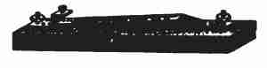
11. The Relay (Fig. 32).—Telegraphing from 3,000 to 10,000 miles under the ocean is full of difficulties not now to be explained.
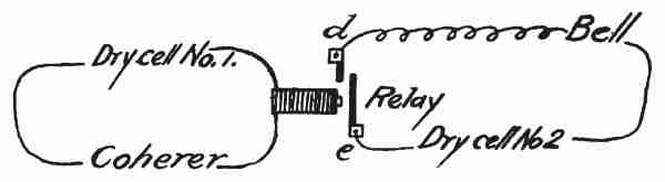
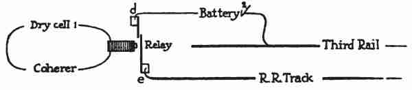
Of course when we attempt to telegraph many miles upon land we find that the resistance of the wire cuts down the strength of the current so that it will not move the sounder. This, however, is readily obviated by the relay devised by Morse. It simply serves as an automatic key to close a[68] circuit. A diagram will make this clear (Fig. 33). Suppose the line wire to be very long and on account of its resistance the current is too feeble to operate a sounder. It is likely to be about .025 ampere where the local sounder may require .25 ampere or ten times as much. It is easily possible to wind a magnet (Fig. 33), R, such that .025 ampere will close the armature a, so that it may complete a local circuit when it would not make noise enough for a sounder. B may represent a local battery of any desired strength which may operate the sounder S of that station as loudly as may be desired.
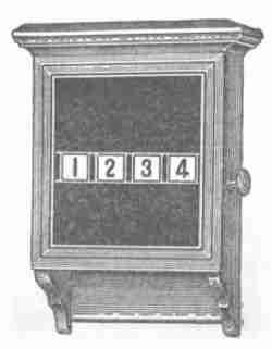
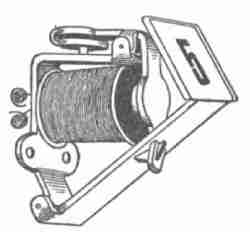
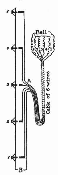
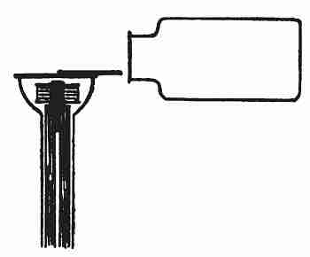
12. Annunciator (Fig. 34).—We live in a fifth-floor apartment. When we push[69] the button to call the elevator a No. 5 appears in the annunciator in the elevator car. This tells the elevator boy where the call comes from. Take out two or three screws and the annunciator opens, revealing a series of electro-magnets like the one shown in Fig. 35. When an electric current passes around the coil it pulls back an iron catch and allows a number to drop so as to show through a small window. The elevator boy, having noted that the call is from the fifth floor, pushes up the number and the iron catch holds it until the coil is magnetized again by an electric current.
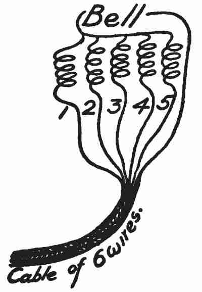
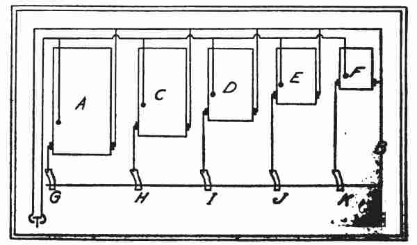
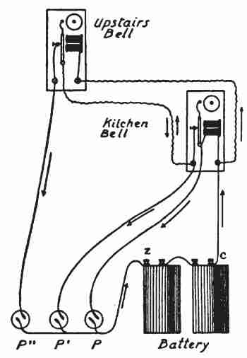
The annunciator has a bell to call attention. A cable of six wires enters this annunciator (Fig. 36). One wire goes direct to the bell and the other five reach the bell through the separate coils of the electro-magnets which control the drops. But how are[70] electrical connections made between a moving elevator car and the push buttons on various floors? The diagram in Fig. 37 shows this in elevation. B represents a battery of several dry cells located in the basement. One wire from it runs direct to the push buttons 1, 2, 3, 4, 5, located upon the five floors of the house. The other wire from the battery, together with wires from each of the five push buttons, all run to a point, A, half-way up the elevator shaft. Here the six wires are gathered into a cable long enough to reach either to the top or the bottom of the elevator shaft. The other end of this cable enters the elevator car and runs to the annunciator. The wire from the battery goes direct to the bell. The wires from the various push buttons go through correspondingly numbered electro-magnets to the bell. When, therefore, we pushed the button on the fifth floor, we closed the gap in the electric circuit at that point. The current[71] came up from the battery, passed through the button, went down the cable to the car, went through electro-magnet No. 5, went through the bell, and returned direct to the battery, thus completing the circuit. Annunciators are used about buildings to call other attendants, besides the elevator boy. They are likewise used in burglar alarms to inform the householder which door or window is being forced. They are used in the fire department to tell what part of the city the call came from.
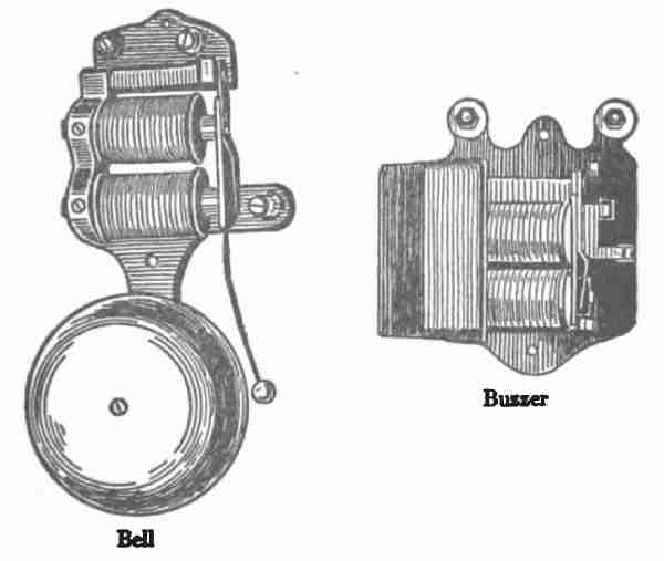
13. The Electric Bell and Buzzer (Fig. 38).—So common a thing as an electric bell really belongs to[72] the present generation. Bells were either novelties or toys when I was your age. They cost then many times what they do now and then were poorly made. Nobody dared to trust them for front-door bells. It was necessary to have a card permanently posted over the push button saying, "If the bell does not ring, knock." In those days batteries were troublesome to care for, houses were not wired when built, and no one had learned the art of concealing the wires neatly.
The buzzer is simply a bell minus gong and hammer. Those shown in Fig. 38 ring well on a single dry cell. A cell costing twelve cents operated one for two years while it was used as a call bell from dining room to kitchen, the current required being .15 ampere.
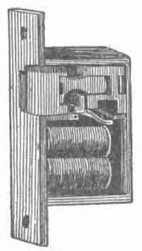
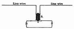
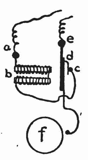
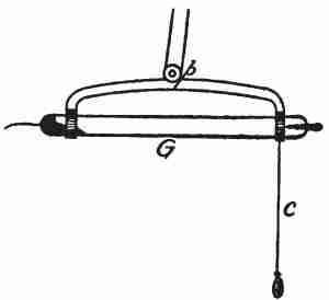
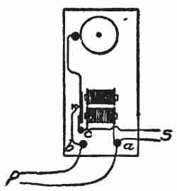
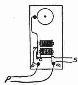
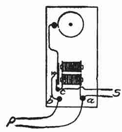
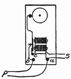
The connections are shown in the diagram (Fig. 39). Suppose the current to enter at the binding post a, pass around the magnets b and then to the post c. The armature d normally rests against the post c and the current finds its way along this to the post e and thence back to the battery. But as soon as the current passes, b becomes[73] a magnet and pulls the armature d away from the post c, thus breaking the circuit, when b ceases to be a magnet and a spring pushes the armature d back against the post c to repeat the operation. The armature d carries a hammer which strikes the gong f. If the wire, which is usually connected with the binding post e, is connected with the post c, the "clatter" bell is changed to a "single-stroke" bell, and if the gong and hammer are removed the "bell" is changed to a "buzzer."
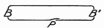
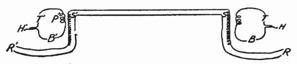
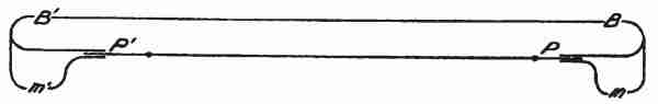
In the case of the buzzer, by changing the length of the armature or by weighting it, we may change the time of its vibrations and its tone. The connections between battery push button and bell form a complete circuit. In Fig. 40 B represents a battery, usually of dry cells, B' represents the bell, and P represents the push button. The electric circuit is "open," (that is, there is a break in the conductor) at P until some one "pushes the button," that is, simply pushes against a spring so as to cause a piece of metal to bridge the gap in the conductor. Then we say the circuit is "closed."
Push button devices and switches are innumerable. In every case they are simply devices for pushing one piece of metal against another and completing the circuit for an electric current. Every one should unscrew and examine a few of them, both for the pleasure of seeing how they work and to learn how[75] to make them work when they sometimes fail. Not only in bells but in all other instruments where electro-magnets are used, the magnets are placed in pairs, fastened together upon an iron base. They are wound so that the free ends are made opposite poles by the electric current. Like a horseshoe magnet, they form one magnet. The two poles thus placed are mutually helpful and each is stronger than it would be if separated from the other.
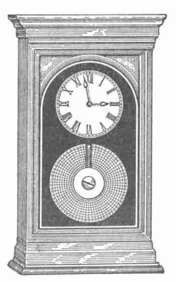
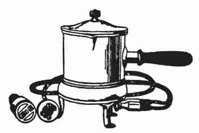
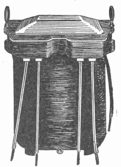
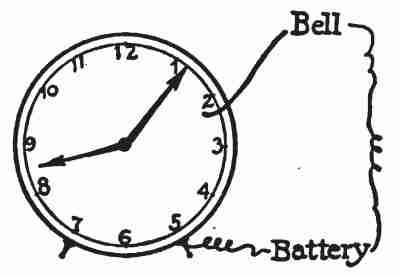
14. Electric Clocks, Self-winding Clocks, Programme Clocks.—A pretentious-looking thing which appeared like a dish pan with a glass bottom was opened by the boys and found to be the simplest of all clocks.[76] It had an electro-magnet like that in Fig. 44. A strip of iron acting as an armature across the free ends of this magnet, pushed like a finger against the cogs of a wheel. This wheel was on the axle of the minute hand and it had sixty cogs. The electric circuit was closed through the magnet for an instant each minute and the armature pushed the wheel ahead one cog. Thus it made one complete revolution in an hour. A train of four other cog-wheels caused the hour hand to trail after at one twelfth the speed of the minute hand. This machinery made simply a small handful in an eighteen-inch stamped-metal "dish-pan" costing fifteen dollars.
A self-winding clock was opened and found to contain two dry battery cells, an electro-magnet which operated very much like that of a "clatter" bell, the hammer like a finger poking against the cogs of a wheel. Once an hour the long hand closed the circuit through the battery and the magnet and its armature swung back and forth long enough to give the cog wheel one complete revolution and[77] wind a spring, which it carried upon its axle. This spring kept the clock running one hour, until the next winding.
The programme clocks which were examined were self-winding clocks, but were connected by wires to the master clock which corrected them each hour. Each time the long hand of the master clock came to twelve it closed an electric circuit through all the clocks in the system. In each clock the current passed around an electro-magnet and caused it to pull an armature against a metal stop and set each long hand exactly at twelve. This master clock is sometimes situated many miles away and may correct the time for a whole city. Thus a master clock at Washington, D. C., furnishes standard time to all parts of the United States. The master[78] clock which we examined also closed the circuit at proper intervals through a series of programme bells placed in the various class rooms, and these called and dismissed classes automatically.
15. Watchman's Time Detector (Fig. 45).—This is a device to compel a watchman to make his appointed trips. Push buttons or switches are distributed about the building at various points, and it is made his duty to close the circuits at these points at stated times. When he does so, the fact is recorded by electro-magnets puncturing, or, in some way, marking a revolving time card in the clock.
16. Circuit Breakers (Fig. 46).—Electro-magnets are used to open switches and thus protect dynamos and other machines against a larger electric current than they are able to carry. The switch is held[79] closed by a spring which, by an adjusting device, may be tightened or loosened. A dynamo which we examined had its circuit breaker adjusted so that it would remain closed if any current under 1500 amperes passed, but if a greater current than that passed it would strengthen the magnet sufficiently to open the switch and thus break the circuit.
17. Separating Iron from Ore.—In 1897 Edison first proposed to use an electro-magnet to separate iron from crushed earth. Fig. 47 represents the process. E is an electro-magnet. S is the stream of crushed ore containing iron. Gravity would cause all the material to fall into bin A, but the electro-magnet E pulls that portion of the material which is magnetic to one side so that it falls into the bin B.
18. Lifting Magnets.—Electro-magnets are made for use with hoisting apparatus to save the trouble of manipulating grappling hooks, etc. They may[80] lift barrels and boxes of iron, the wood of the barrel or box being transparent, we say, to the magnetic influence. That is, the magnet will attract iron through the wood just as light will shine through glass. Such magnets are used to pick up from the bottom of the sea cases of hardware from wrecked ships. (See the accompanying illustration, Fig. 48.) In such cases the electric conductors which lead to and encircle the magnets must be well insulated from the water of the sea, otherwise the electric current would take the shorter path from one line wire through the sea water, which is a fairly good conductor, and back by the other line wire, rather than go the path of greater resistance around the magnet. Electro-magnets are coming into use in foundries, etc., for lifting heavy iron castings.
19. Electro-Magnet on Starting Box.—As was explained under electric motors, a starting box is simply a series of resistance coils r, r, r, r, r, in Fig. 49. When the motor is not in use the switch l rests upon the point 1 and no electric current passes.[82] When the switch is moved to point 2, the current entering at a passes to the pivot of the switch and up the metal strip l to the point 2, then around the series of coils, r, r, r, r, r, to the post b and thence back to the generator. As the switch is moved to the right, the current passes through less and less of this resistance until, when it reaches point 7, all the coils of resistance are "cut out," that is, they are not in the path of the current. Now the motor has reached its full speed and is developing enough counter-electro-motive force to protect itself against too much current. Through a shunt, however, a portion of the current passes from a to b around the electro-magnet e, the two poles of which are presented to the metal strip l, which must be of iron. This magnet holds the switch over so long as the current is on, but when the current is cut off, by opening a switch in the line wire, e ceases to be a magnet and l is carried back to point 1 by a spring. Thus an extra resistance must always be in circuit when the motor is first started. Those who start motors are expected to move the lever l of the starting box slowly from point to point, pausing a second or two on each to give the motor time to acquire proper speed for its protection.[83] How too great a current would "burn out" a motor will be explained later.
The motor man handles a lever for starting his car, which works like that of the "starting box." His "starting box," however, is called a "controller." Although it accomplishes the same result as the starting box it has a wholly different and vastly more complex mechanism than that already described.
The elevator boy, who runs our electric elevator, handles a lever which also does the same thing through far different mechanism. Indeed, in his case electro-magnets are used to prevent him from cutting out resistance too fast if he should move his lever too quickly.
20. Starting Switches for Electric Elevators.—The motor man has to be instructed particularly how he should handle the lever of his controller, and he is trusted to follow his directions to some extent, however lacking in intelligence and integrity he may be. But the elevator boy receives scarcely any instructions about his machine, and, indeed, his machine has been constructed pretty nearly "foolproof." It will automatically correct his errors of management. If he throws the handle from one extreme to the other, all resistance cannot be[84] thrown out instantly, but this is accomplished by a series of electro-magnets closing one switch after another and thus cutting out resistance gradually.
21. Arc Lamp Feed.—As will be explained later, an arc lamp must have its carbons touching one another when the current is first thrown on, and then the carbons must be drawn apart from a quarter to half an inch. The upper carbon is lifted away from the lower one by a portion of the current passing by means of a shunt around an electro-magnet.
22. Volt meter.—The volt meter measures the pressure of an electric current. The volt meter which we examined looked outside like our ammeter, and when we removed the face it appeared inside like an ammeter. There was the steel magnet of horseshoe shape to furnish a field (Fig. 51), and there was an electro-magnet poised between its poles for an armature. The armature in the volt meter, however,[85] had wound upon it finer wire and more of it than was the case in the ammeter. There was no shunt wire in the volt meter as there was in the ammeter. We connected in series a fluid cell (to be described later), the ammeter, and the volt meter (Fig. 52). The ammeter shunt was removed so that all the current went through its armature. The volt meter needle went to one which was two thirds of the scale (Fig. 53), and the ammeter needle indicated .016. That is, this particular cell can push sixteen thousandths of an ampere through the resistance of this volt meter, and .016 ampere[86] passing through the armature of this volt meter will magnetize it sufficiently to move it against its spring, say sixty degrees.
We put into the circuit a lot more fine wire for resistance, R (Fig. 54), so that the volt meter needle went only half as far as before, that is to .5. The ammeter indicated only half as much as before, that is .008 ampere. We put in resistance enough to bring the volt meter needle down to .25 and the ammeter indicated one quarter of the original current. We put in less resistance, bringing the volt meter needle to .75, and the ammeter indicated three fourths of the original current. Evidently the[87] volt meter is merely an ammeter with a different scale marked upon its card. With a pen we marked upon the card of the volt meter a true ammeter scale (Fig. 55).
In order to understand the volt meter, let us turn our attention for a moment to Fig. 56. I have arranged the water tank T at such a height above the faucet F that when the faucet is opened one quart of water will flow in a minute. If I partially close the faucet, making the opening one half as large (that is, offering twice the resistance to the flow), half a quart will flow in a minute. If I make the resistance four times as great only one quarter of a quart will flow in a minute. It is evident that I could arrange a scale underneath the handle of the faucet to indicate the quantity of water flowing, just as the ammeter and volt meter indicate the quantity of electricity which flows. If now that much is understood, it will be easy to learn how the water faucet may be used to measure water pressure and the volt meter in like manner used to measure electric pressure.
Having set the faucet so that a quart will flow per minute, let us put on a longer tube p, and move the tank up to another shelf so that the distance from the water level in the tank to the faucet is twice as great as before. Under the increased pressure water runs through the faucet twice as fast and we now get two quarts per minute.
I purposely placed the tank out of sight behind a partition so that you might practise judging the water pressure by the flow at the faucet. We cannot very well talk about pressure in quarts. We might talk about it in pounds, but if we used this apparatus much we should probably get into the habit of talking about the pressure from one shelf, two shelves, three shelves, etc.
In order that the pressure might remain nearly constant during the experiment we would probably introduce resistance (that is, partially close the faucet) so that the water level should not fall much. We might, for example, set the faucet so that half a pint would flow in a minute when the tank was on the first shelf. Then a pint per minute would flow when the tank was on the second shelf and one and a half pints per minute when the tank was on the third shelf, etc. Thus we should infer the pressure by measuring the quantity.
One more illustration and the case will be clear. To save the trouble of measuring the quantity of water which flows through the faucet, suppose I introduce the device represented in Fig. 57. W is a small water wheel comparable to the armature of the volt meter. It carries a pointer which moves over a scale just as in the case of the volt meter.
It has a spring coiled around its axle which tends to keep the pointer at 0, as in the case of the volt meter. The tank is placed upon the first shelf, the faucet is fixed so that a small amount of water flows and the needle moves to a certain figure upon the scale. We will mark this point one and call it "first-shelf pressure." The tank is lifted to the second shelf and the index moves to another point, which we will mark two and call it "second-shelf pressure." The tank is lifted to the third shelf and the index moves to a third point, which we will mark three and call it "third-shelf pressure," etc.
Ordinarily we measure water pressure with an instrument which allows no water to run to waste,[90] but in measuring electric pressure by the volt meter some current must pass through the instrument, just as in the case of our water-wheel illustration in Fig. 57. We put in large resistance so as to make this current as small as possible, while we let enough pass to move the armature.
Now let us return to the volt meter itself. By referring to Fig. 55, we see that it requires .024 ampere to move the needle of the volt meter clear across the scale, and we have found that one fluid cell was able to send enough current through the resistance of the armature to move the needle two thirds of the way across the scale. At this point we find Fig. 1, which might be read "one-cell pressure." We prefer to commemorate the name of one of the workers in the field of electricity and call this pressure a "volt" after Alessandro Volta (1745–1827), born at Como, Italy. It is the electric pressure which is produced by one fluid cell of a certain kind. We say, then, that one volt pushes through the resistance of this armature .016 ampere. Half a volt would push through the resistance of the armature half as much current[91] or .008 ampere. At this point we put .5. Thus each of the figures in the lower row (Fig. 55) shows what part of a volt is required to send enough current through this particular armature to move the needle to that point.
We found out how much wire was wound upon the armature and put exactly the same amount in the outside resistance, R (Fig. 59). The needle now showed that one volt is able to push through twice the resistance of the armature only half as much current, and the needle stopped at .008 ampere. If this were to be the resistance in the volt meter circuit one volt should stand under .008 ampere and two under .016 and three under .024. It is evident then, that, if we know the internal resistance of a volt meter, we may make it capable of measuring greater electrical pressures by adding the proper amount of resistance. By putting at R, (Fig. 59) nine times the internal resistance of the instrument, thus multiplying the total resistance tenfold, the figures upon the scale of volts may be read as whole numbers from one to fifteen. In this case it will require fifteen cells to push the needle clear across[92] the scale and ten cells to push it two thirds of the way across. If now we add enough external resistance to multiply the resistance of the armature a hundred fold it will require 150 volts to push .024 of an ampere through the armature and pull its needle clear across the scale. In this case the figures upon the scale of volts are multiplied by one hundred and read from ten to one hundred and fifty. Such a scale would adapt this volt meter for use with our 110-volt lighting circuit. Volt meters are made with a series of such external resistances, called "multipliers," attached so that they may be easily thrown into the circuit.
It is evident that we need some term so that we may speak of quantities of resistance. This need has given rise to a unit of resistance called an ohm, after George Simon Ohm (1789–1854) born at Erlanger in Bavaria. Two inches of No. 36 German silver wire, such as is wound upon the armature of this volt meter, gives one ohm of resistance. There are 125 inches of this wire upon the armature. Its resistance is, therefore, 62.5 ohms, and we may, therefore, say that one volt of electric pressure can push through 62.5 ohms of resistance .016 of an ampere of current. Ohm[93] discovered this relationship in 1827, and formulated it as follows:
| 62.5) | 1.0000 | (.016 |
| 625 | ||
| —— | ||
| 3750 | ||
| 3750 | ||
| —— |
This is called Ohm's law, as every candidate for college admission will hear and hear again.
Volt meters and armatures for the alternating current have electro-magnets for their fields as well as for their armatures. Such instruments are equally well adapted for either direct or alternating currents. For when the current reverses its direction it reverses in field and armature alike, and thus a repulsion between like poles is maintained. Such an instrument, however, cannot respond to as slight a current as those previously described, since they must consume some energy in both field and armature.
23. Telephone Receiver (Fig. 61).—It requires a[94] stretch neither of the imagination nor of the truth to call a telephone receiver an electro-magnet, although perhaps it has never been called that before. We took it apart and found that it consisted of a steel-bar magnet m (Fig. 62), with a small spool of wire w around one end of it. The ends of the wire on the spool run along inside the hard rubber shell to the two binding posts a and b at the other end. A disk of sheet iron S is held in the large end of the case very near to, but not quite touching, the end of the magnet. When an alternating current is sent through the wire upon the spool it causes rapid changes in the strength of the magnetic field, if not reversals of the poles of the field, and the iron disk is made to vibrate, keeping time with the alternations of the current.
In this laboratory we have seen that our current has sixty alternations per second. When it is connected with the receiver the disk, therefore, makes sixty vibrations per second, and produces[95] a tone which has very nearly the pitch of C two octaves below the middle C upon the piano.
24. Spark Coil (Fig. 63).—The automobile spark coil which we have already used is an electro-magnet. The battery sends a current through wire coiled around an iron core. At one end of this iron core is an iron armature which is made to vibrate in precisely the same manner as the armature of an electric bell. This makes and breaks the current and causes rapid changes in the strength of the field. A rapidly changing magnetic field may be used to develop electricity in a conductor, as we have already seen in the case of the dynamo.
How it is used in the automobile spark coil will be shown later. It is sufficient now to mention it as a case of a magnetic field produced by an electric current passing through a wire coiled around an iron core, or, in short, an electro-magnet.
Induction coils, Ruhmkorff coils, and transformers, to be described later, are closely related to this. They all create magnetic fields in the same way and are all electro-magnets.
It was Washington's birthday. The schools were to have a holiday and the Science Club was to hold a special, open meeting at which I had been asked to present the subject of electricity in the household. I replied to the programme committee that that was too large a subject, but that I would talk upon electric heating. I warned them, however, that it would be a dry study, and not an entertainment. They replied that the father of his country had been born at a time of the year when the weather was unfavourable to outdoor sports, and that February usually found them acclimated to vigorous study. Neither they nor their friends objected to study if it seemed to have a motive.
I found an audience composed of old and young, men and women, girls and boys. Most of them had left school—many of them because their teachers thought they were incompetent to continue.
Not far from here is "a wheel in the middle of a wheel ... as for their rings they are so high that they are dreadful ... and the spirit of the living creature is in the wheels." Those wheels are now sending the electric current to this room for our experiments. I propose to show that we convert electricity into heat by offering resistance to its flow. Experience teaches us that resistance to motion always produces[99] heat. At Niagara Falls thousands of tons of water descend at the rate of one hundred and sixty feet in three seconds. When the water reaches the bottom of the falls, it is moving a little faster than a mile a minute. The resistance which this mass meets after its fall retards its motion and generates heat.
Hundreds of meteors fall into our atmosphere daily, travelling a thousand times as fast as the waters of Niagara Falls. The resistance to their motion, which our atmosphere offers, heats them white hot, melts them, vaporizes them, burns them up, so that very few of them reach the solid earth in a solid condition.
An iron spile driver, measuring two cubic feet, weighs about half a ton. When it falls sixteen feet upon the end of a spile it is moving at the rate of twenty miles an hour. The energy of this moving mass depends upon both its weight and its velocity, and when its motion is arrested by the spile that energy of motion is largely converted into heat energy, from which both the spile and the spile driver get hot.
A piece of iron may be made red hot by pounding it with a trip hammer.
Count Rumford found, in 1798, while boring cannon in the arsenal at Munich, that the resistance which the iron offered to the motion of the boring tool furnished heat enough to boil water.
Seven hundred and seventy-eight foot pounds of mechanical energy when converted into heat would raise one pound of water (one pint) one degree. This is called the British thermal unit. The spile driver, weighing 1000 pounds, falling 16 feet upon a spile, produces heat enough to raise 1 pint of water 20 degrees.
Here are two binding posts, a and b, 8 feet apart (Fig. 66), connected by copper wires with the dynamo circuit. The volt meter indicates 112 volts of pressure. I will close the circuit by stretching between a and b 8 feet of No. 24 iron wire. (This wire is about the thickness of a common pin.) The iron wire offers resistance to the flow of the electric current, thereby producing heat—heat enough as you see to make the wire white hot, indeed heat enough to raise it to something over two thousand degrees Fahr., for now you see it has melted.
We will put in a fresh piece of wire and connect also the ammeter in the circuit (Fig. 67). As I close the circuit the needle of the ammeter at first indicates 20 or 30 amperes, but in a second drops to[101] 8 amperes, and remains there a second until the wire melts and falls apart. One hundred and twelve volts of electric pressure are able to push 8 amperes of electricity through this wire when hot.
Hence it required about one and one fifth horse-power to melt the wire in a second, and the heat produced was a little less than one British thermal unit, a unit much used by engineers.
1 pound raised 1 foot = 1 foot pound
550 foot pounds per second = 1 horse-power
778 foot pounds (1.4 H.-P.) = 1 B. T. U. (British thermal unit) = heat required to raise 1 pound of water 1° Fahrenheit
1 volt × 1 ampere = 1 watt
746 watts = 1 horse-power
In order to hold back 112 volts of electric pressure so that not more than eight amperes of electricity[102] should pass, the iron wire must have offered about 14 ohms of resistance.
The behaviour of the ammeter needle showed that the wire offered very much less resistance when cold than when hot. Indeed eight feet of No. 24 iron wire offers about one and one third ohms resistance when cold, hence heat had increased its resistance to the passage of the electric current tenfold.
This piece of iron wire offered resistance to the flow of the electric current. It offered resistance to the motion of the dynamo. This offered resistance to the steam-engine which drives the dynamo. This caused the governor of the engine to open and pass more steam from the boiler. This reduced the pressure at the steam gauge. This caused the fireman to shovel more coal into the furnace. The heat of the burning coal melts the wire, but it does it only after several changes. First, it is converted into mechanical energy in the steam-engine with great loss—about nine tenths being lost. Second, it is converted into electrical energy by the dynamo, with some loss, and, third, it is conducted to the iron wire and converted back to heat with still further loss. It is evident that the most economical way to heat the wire would be[103] to take it to the furnace. Yet all electric cooking is done by sending electric current through wires embedded in the walls of the cooking utensils, and it is the most wasteful method of using the energy stored in coal that has yet been devised.
That merely connecting the binding posts a and b (Fig. 67) by a small piece of wire should throw a load upon the dynamo miles away; should offer resistance to its motion, and make it require 1.18 horse-power more of energy to keep up its speed of revolution, is, indeed, uncanny. I will attempt to make it seem more real. At one end of the lecture table I have a rotary pump P (Fig. 68). The end of the rubber tube a, which leads to the pump[104] is lying upon the table outside of the tank of water, T. While things are in this condition I move the crank which operates the pump with perfect ease. Now while still turning the crank I pick up the tube a and drop its free end into the water tank. I cannot now conceal the fact, even if I were disposed to do so, that I must work hard to keep the pump going. The pump itself tells you by its laboured sound that it is working hard, and the stream of water which issues from the pipe b tells how much work I am performing. The pump is discharging five and a half pints of water per second, that is 5.5 pounds, and it raises this water 10 feet. Hence I am doing 55 foot pounds of work per second, which requires one tenth of a horse-power. Here is a lad who consents to try the experiment for us. He turns the crank easily while I am holding the tube a out of the water, but when I lower it into the water he finds the resistance so great that, tug however much he may, he is unable to keep the pump going.
At the other end of the table I have a small hand dynamo, D (Fig. 68), M is an ammeter, V is a volt meter, S is a switch. All the wires are good-sized copper, and offer little resistance, except that stretched between the binding posts a and b. This[105] is a piece of fine German silver wire. While the switch is open I turn the crank of the dynamo with perfect ease. A small amount of current is going through the volt meter, but this is too slight to offer any perceptible resistance to the motion of the machine.
Notice that the volt meter needle moves according to the speed of revolution. If I turn the crank once a second the needle stands at 25 volts. The electric pressure increases or decreases according to whether I rotate the armature faster or slower. Now I will attempt to keep the machine revolving at a constant rate while I close the switch S, and surely you must see that I have hard work to do so. The wire a b has now become red hot. The volt meter shows 25 volts of pressure, and the ammeter shows 3 amperes of current.
Twenty-five volts × 3 amperes = 75 watts, which require one tenth of a horse-power (746 watts = 1 horse-power). The lad now takes my place at turning the machine and finds it easy when the switch is open, but I actually overload him by merely closing the switch. Heating the wire red hot requires more energy than he is able to put forth.
I proposed to the president that my lecture close at this point, and that each one in the room have a[106] chance to feel the load which was thrown upon the dynamo each time it was required to heat the wire. I suggested that each person should get a realizing sense of this fact, first by doing the work himself, and second by going home and reflecting upon this hint. When the switch is closed three amperes of electricity pass around the circuit. This increases the magnetism in both the field and the armature of the dynamo, and it requires one tenth of a horse-power more to keep the armature moving within the field against this magnetic pull.
I further desired to announce that during this hour I had delivered to them the second key to the Electrical Show which I had promised a few days ago. The second key is:
Heat (and light) is produced by offering resistance to the flow of the electric current. The first key is the electro-magnet. These two unlock all the mysteries of the show.
The president closed the formal exercises with the facetious remark that I had warned them before the lecture that they must work, so now each would be expected to take a turn at the cranks of the pump and dynamo.
The programme committee decided that each member of the Science Club should busy himself looking for applications of electric heating and should consult me freely about the matter. My telephone was kept busy, my laboratory was in great demand, and we were all getting a good deal more education than the school was giving us credit for.
The boys generally came to me in pairs, and each pair having worked up some illustration of heat produced by electricity reported it to the club. These were spread by the secretary in due form upon the minutes of the club and constituted "The Proceedings of the Science Club."
1. The Electric Sad Iron (Fig. 69).—Removing[108] three screws the iron comes apart, revealing a lot of No. 24 German silver wire wound upon a sheet of mica. This is put between other sheets of mica (Fig. 70) and tucked away within the body of the iron. German silver offers about twice the resistance of iron when it is cold, but, at the temperature of the sad iron when in use, there is not much difference between the resistance of the two metals. German silver wire, however, does not rust as iron wire would, and hence it is chosen. German silver is an alloy of copper, zinc, and nickel.
We put the 112-volt current upon this wire of the iron, and according to the ammeter it passed 4 amperes. Its resistance must therefore have been 28 ohms.
(112 volts)/(28 ohms) = 4 amperes
Electricity costs us about 10 cents per kilowatt hour. That is 10 cents for 1000 watts for an hour, or 1 cent for a hundred watts for an hour, or, on a 100-volt current, 1 cent for an ampere for an hour. It, therefore, costs about 4 cents or, more accurately, 4½ cents an hour to heat this iron.
Persons sometimes carry electric irons with them, when they travel, to iron pocket handkerchiefs and other small articles while stopping at a hotel. Before connecting an iron in a chandelier one must know the voltage used in the building. If the voltage in use in the building is not the same as that stamped upon the iron, it is not safe to connect it. Not knowing this, many persons have had the embarrassment of "blowing a fuse" and extinguishing their own lights, and perhaps those of others in the same building, and very likely also ruining the iron.
Suppose we take for example this iron stamped 110 V; 400 Watts. (A slight variation of 5 or 10 volts will not injure an iron.) The wire in this iron we found to offer about 28 ohms resistance when hot, and it lets pass 4 amperes. This is about all the current which it is able to carry without melting. Now suppose a 220-volt current is used in the building where it is proposed to connect the iron. This would force through the wire enough current to melt it. The wire was seen to be at a very dull-red heat when examined in a dark room. Its temperature was about nine hundred degrees. At this temperature its resistance is about three times what it is when cold. We estimated by measurements[110] that the iron contained about twenty-five feet of the wire. The boys then took twenty-five feet of No. 24 German silver wire and stretched it between two nails driven up in the laboratory (Fig. 71, a b). The dynamo current was then sent through this. The end, c, of the wire from the dynamo was provided with a metal clip which could be slid along on the German silver wire. Sliding this to the left, and thus shortening the distance on the German silver wire through which the current must pass, increased the amount of current and heated the wire hotter. The resistance decreases as the wire is shortened.
The boys wound this wire upon a piece of asbestos board (Fig. 72), about nine inches square and one eighth of an inch thick, taking care to keep the successive turns half an inch apart. Asbestos paper was wrapped around this. The two ends of the wire were left free for connections. This they called a "hot plate."
2. Electric Hot Plate (Fig. 73).—This when opened was found to have wire coiled up inside in the same manner as the sad iron. Indeed the sad iron supported bottom side up makes a perfectly good hot plate. The particular hot plate which we examined had a three-point switch which gave three different heats for the plate. (See Fig. 74.) When the switch S is upon the first point the current goes through 112 ohms of resistance and 1 ampere passes:
(112 volts)/(112 ohms) = 1 ampere
This warms the plate slightly—enough to keep food warm which has been already cooked. This costs about one cent an hour.
When the switch is placed upon the[112] second point the current goes through 56 ohms of resistance and 2 amperes pass.
(112 volts)/(56 ohms) = 2 amperes.
This makes the plate warmer and is adapted to certain cooking processes. It costs about two cents an hour.
When the switch is placed upon the third point the current goes through 28 ohms of resistance and 4 amperes pass.
(112 volts)/(28 ohms) = 4 amperes.
We placed upon this hot plate a basin containing 1 pint of water (equals 1 pound) and heated it from the temperature of the room (68 degrees) to boiling (212 degrees) in 7 minutes and then put an egg in and boiled it 3 minutes. Using 4 amperes for 10 minutes cost two thirds of a cent. If it takes 7 minutes to boil a pint of water it would require 1 hour to boil a gallon upon this hot plate using 4 amperes, or 448 watts. That is,[113] it costs us about 4.5 cents a gallon to boil water by electricity. The cost is usually put at three and a half cents per gallon, but much depends upon conditions.
3. Traveller's Cooker (Fig. 75).—This consists of a hot plate with a covered basin permanently attached to it.
4. Electric Coffee Percolator (Fig. 76) consists of a hot plate with a coffee percolator to sit upon it. The coffee percolator might sit upon any other hot plate or this hot plate might serve any other purpose, but people do not seem to think of that.
5. Electric Chafing-Dish (Fig. 77) consists merely of an electric hot plate with a chafing-dish attached. The electric coffee percolators and chafing dishes require from 300 to 600 watts according to size. If used on the 110-volt[114] current they take about 3 to 6 amperes, and if adapted to the 220-volt current they take from 1½ to 3 amperes, but cost the same to operate in either case. They have connected with them flexible cords and plugs to screw into the lamp sockets.
6. Electric Broilers are merely hot plates, generally corrugated to conduct off the melted fat. One that we examined had a switch for three heats: low, requiring 360 watts—costs 3.6 cents per hour; medium, requiring 600 watts—cost 6 cents per hour; high, requiring 1280 watts—cost 12.8 cents per hour.
7. Electric Oven.—This one has double walls to retain the heat and has two large hot plates, one on the bottom and one on the top. It is large enough to hold four loaves of bread. It required 1520 watts for 40 minutes to heat it to the baking temperature and one hour to bake the bread. Hence the cost of the electricity is about 25 cents, about what the bread would cost in the market.
8. Electric Incubator.—This is simply a well-ventilated oven warmed by an electric hot plate and automatically controlled so that it keeps a[115] constant temperature of 103 degrees. Under these conditions chickens hatch from hens' eggs in three weeks. An incubator for 5 dozen eggs was found to take 25 cents' worth of electricity for the whole process of incubation.
9. Electric Toaster.—The wire coiled up in sad irons and hot plates becomes hot enough to scorch cloth and paper, and even set fire to them if they come in direct contact. We proved this by opening the iron and touching paper to the wire while it was carrying the current. We also lighted a cigar by touching it to the wire. Electric toasters have the hot German silver wire simply covered by a screen.
10. Electric Cigar Lighters (Fig. 78).—The one we examined hung by a flexible cord from the chandelier. It had a small disk on the side which contained a lot of fine wire covered by perforated mica. The wire became red hot when the push button in the handle was pressed. It took half an ampere of 110-volt current, and operated only while the button was pushed. As near as we could calculate it cost .0003 of a cent to light a cigar.
11. Electric Curling Iron (Fig. 79).—One who has flat hair needs no curling iron, but those who have round hair may curl it temporarily, if they will unscrew an electric light bulb and screw into its socket the plug of an electric curling iron. The flexible cord contains two wires insulated from each other. One of these wires is attached to the outer shell of the plug, the other wire is attached to the central button of the plug. These make connections with the two separate dynamo wires in the socket. The current comes down one of the wires in the flexible cord, passes through a coil of fine German silver wire inside of the curling iron, and returns by the other wire in the flexible cord. The small wire in the curling iron offers 220 ohms of resistance when hot and passes half an ampere of the 110-volt current.
(110 volts)/(220 ohms) = .5 ampere.
12. Electric Soldering Irons (Fig. 80).—Or coppers, as they should be called, are ideal implements for[117] soldering. They remain continually at the proper temperature and are free from corrosion. They require from 55 to 220 watts. On the 110-volt current they take from one half to two amperes.
13. Electric Heating Pad (Fig. 81).—This consists of resistance wire inside of a pad of soft material. It maintains a temperature of 180 degrees, and is an excellent substitute for a hot water bag. It contains about two hundred and twenty ohms of resistance and requires the same current as a 16-candle-power lamp.
14. Electric Fuses (Fig. 82).—Fuses are made of short pieces of wire or thin sheet metal. The metal is an alloy of lead and tin which melts at a low temperature. They derive their name from the fact that they readily fuse or melt. A building is wired in various separate circuits. The size of the copper wires used in each circuit is determined by the amount of current which the circuit is expected to carry.[118] Each circuit is protected by one or more fuses. These melt and cut off the current whenever too much passes for the copper conductor to carry without getting hot. The fuse wire melts at about six hundred degrees, while the copper will not melt until it reaches nearly two thousand degrees. This temperature is sufficient to set fire to wood, paper, and cloth. When any fuse melts, the current is cut off from all chandeliers, etc., in the particular circuit controlled by the fuse. This produces consternation among people who do not understand the function of a fuse. They become panic-stricken and begin to trample their neighbours to death in the theatre or on the electric train when they hear that a fuse is "blown" (which is the electrician's way of saying that it has melted). Everyone should know that a fuse is a safety device. It is always enclosed in a box lined with sheet iron or asbestos, so that it is impossible for the flash, which occurs when the circuit is broken, to set fire to anything.
15. Electric Gas Lighter (Fig. 83).—These usually[119] have two or three small, dry battery cells in the handle. By pushing a button in the handle connection is made between this battery and a short piece of resistance wire in the tip. This wire gets red hot and lights the gas. It is a surprise to many that we can light illuminating gas without bringing a flame to it, and it is equally surprising that some flames, or at least sparks, may not be able to light the gas. The fact is that it is wholly a matter of temperature and kind of gas. Iron heated to dull red will not light the illuminating gas now being furnished in New York City, while iron at a bright red heat will do so. Iron may be hot enough to light illuminating gas but too cool to light gasolene vapour, which requires a dazzling white heat. Iron which is just under the temperature at which it gives any light may set fire to wood and paper. After it has cooled a good deal below that, it will set fire to sulphur, and when it has cooled so that one may[120] hold it in the hand, it is still hot enough to set fire to phosphorus. The glowing end of a lighted cigar, the spark made by striking flint, or the spark from a spark coil with a feeble battery, all fail to set fire to gasolene vapour, simply because they are not hot enough.
Fresh battery cells must occasionally be put in the handle of the electric gas lighter.
Four facts regarding the resistance of wires it is well to remember:
1. The longer the wire the more resistance it offers to the electric current.
2. The smaller the diameter of the wire the more resistance it offers.
3. Some materials offer more resistance than others, for example, iron about six times as much as copper and German silver about twelve times as much as copper.
4. The common metals offer more resistance when hot than when cold, about double the resistance when heated to five hundred degrees. It is the reverse with carbon, which offers more resistance when cold than when hot. The carbon filament lamp offers about double the resistance when cold as when lighted to full brilliancy.
16. Electric Flasher (Fig. 84).—For automatically[121] flashing electric lights. The one which we examined was constructed according to the plan shown in Fig. 85. The lighting circuit is brought to the binding posts b and c. A small insulated wire of high resistance connects b and c, being wound around the metal bar a b. The resistance of this wire, when added to that of lamps, permits not more than one fifth of an ampere to pass, and this warms the wire slightly. The bar a b is composed of two strips of metal, brass above and iron below. Heat expands brass more than iron. The result is that when the current is turned on, the bar begins to curve downward until presently it touches the metal base of c. Then the full current required to light the lamps which are in circuit passes. While the circuit is closed through the large metal strips not enough passes through the fine wire to warm it. On cooling, a b curves upward and breaks the connection with c, and now the current begins again to warm up the small wire.
The flasher that we examined was adapted to operate: one 32-candle-power lamp; or two 16-candle-power lamps; or four 8-candle-power lamps, on a one ampere circuit of 110-volt pressure.
Let us see what would happen if it were connected either with a current of higher voltage or a circuit of more lamps. Suppose we have a 32-candle-power carbon filament lamp in circuit. This requires one ampere to light it. Its resistance when hot is 110 ohms.
(110 volts)/(110 ohms) = 1 ampere.
When cold its resistance is about double or 220 ohms. The German silver wire of the electric flasher offers 330 ohms of resistance, and together they make 550 ohms. Thus the current is cut down to .2 ampere.
(110 volts)/(330 + 220 ohms) = .2 ampere
Suppose now we should undertake to use the same flasher and the same lamp on a 220-volt current. This might push more current through than the small wire could carry. It might melt, or its insulation might burn off before a made contact with b; if not the lamp would certainly burn out after the contact. If we undertook to operate with this flasher several 32-candle-power lamps[123] instead of one upon the 110-volt circuit, the result would be the same, for in that case the resistance would be reduced and, therefore, a greater current would pass than the wire could carry without undue heating.
The boys were at first troubled to see how increasing the number of lamps in a circuit would decrease the resistance in that circuit. Fig. 86 was drawn to explain the matter. The lamps l, l, l, etc., are connected in parallel. Each lamp makes an independent connection from one feed wire to the other. The flasher a acts as a switch to close the circuit for the whole.
Now if we think of these wires as pipes to conduct water we would say that water flows from D to E through ten pipes more readily than through one. It would meet with only one tenth as much resistance. The result would be the same, if we should substitute for the ten pipes one pipe ten times as large in cross section. So it is with wires which are conducting electricity. Introduce two in parallel, and you allow twice as much current to pass by reducing the resistance to one half. Ten parallel[124] conductors reduce the resistance to one tenth and allow ten times as much current to pass.
It is to be noticed that this flasher is an automatic switch which is opened or closed according to temperature. Remove the fine wire from a and we have precisely the device which regulated the temperature in our electric incubator. Suppose the "thermostat" (as it is called in that case) is placed within the egg chamber which is to be kept at 103 degrees. A screw in the metal strip c underneath the end of a may be set so that it will normally touch a. Suppose now the brass strip is underneath the strip of iron in a. As the hot plate warms up the egg chamber, the brass will expand more than the iron, and the bar will curve upward and break the connection with c. As soon as the current stops the temperature of the chamber begins to fall, and the bar curves downward again until connection[125] is made. This device is capable of adjustment so as to keep the temperature constantly at 103 degrees or any other desired degree. The device is in use for scores of different purposes, including the regulation of temperature in school rooms.
17. Electric Car Heaters.—Ten or fifteen years ago there were no heated street cars in New York City. Now they are all heated by electricity and their maximum and minimum temperatures are regulated by law. The resistance wire may be seen in coils underneath the car seats. Electric street cars usually operate on a 500 or 600-volt current. The amount of current used for heating varies from 2 to 12 amperes. Perhaps 3 amperes may be taken as an average.
500 V × 3 a = 1500 w = 1½ kilowatts.
It costs the large electric railway companies about 1.5 cents per kilowatt hour to generate their supply of current. Eighteen hours is considered a car day.
1½ kilowatts × 18 hours = 27 kilowatt hours.
27 kilowatt hours at 1.5 cents = 40 cents per car day.
18. Heating Apartments by Electricity.—For heating apartments by electricity the same sort of apparatus is used as that already described for heating cars. A family of four adults, living in an eight-room apartment with at least 120 cubic[126] feet of fresh air admitted per minute, will use on an average ten amperes of the 110-volt current. The cost will be about two dollars and fifty cents per day or seventy-five dollars per month. Although this is as much as the entire rental of a perfectly comfortable apartment, the novelty and the convenience attract tenants and the extra cost of rent does not deter them.
19. Electric Bedroom Heater.—One of the boys constructed a heater for his own room as follows: He procured a box eight inches deep by eighteen inches square on the bottom. This he lined with asbestos paper. He then stood it upon its side and arranged four incandescent light sockets as shown in Fig. 88. These were connected by a flexible cord to a plug which he could insert in place of a lamp in the chandelier. He placed this heater on the floor underneath the window and usually had 16-candle-power lamps in the sockets. He claimed that it was a jolly foot warmer and kept the room comfortable without other heat. He turned on[127] from one to four lamps according to his need and replaced the 16-candle-power lamps by 32-candle-power lamps when the weather was extremely cold. I remarked that he must have light along with heat by this arrangement, and I should think that might be objectionable when he desired to sleep at night. He said that he always turned it off, and opened the window at night, always preferring a cold room to sleep in.
20. Cooking with Incandescent Lamps.—This piece of apparatus was devised by the boys and used in my laboratory. A sheet iron basin a, was inverted over four 16-candle-power incandescent lamps, shown in elevation by Fig. 89, and shown in plan by Fig. 90. The sides of the basin were cut so as to admit the glass globes of the lamps, but the sockets and keys were outside, so that it was convenient to turn on and off the lamps separately, thus using one half to two amperes of current, as desired. This rested[128] upon another basin, b. Basin b was covered with asbestos for the lamps to lie on and the whole was attached to a board base, c. A flexible cord and plug allowed us to attach this to the chandelier. A pint of water was boiled upon this stove in fifteen minutes, and refreshments have been served hot from it repeatedly.
21. Electric Fireless Cooker.—There are five indictments against ordinary cooking processes.
1. They heat the house in summer.
2. They convert what would be pleasant flavours in the food into noxious odours about the house.
3. They cannot be controlled with regard to time and temperature as scientific experiments should be.
4. They confine the cook too closely and are not sufficiently automatic.
5. They are wasteful of fuel.
It would seem that electricity might enable us to cure most of these evils. To be sure the production of heat by electricity is wasteful of fuel, and it seems doubtful how the account will balance regarding the fifth item. But the remaining four items furnish a very hopeful field for research. I use the last word advisedly, and think it is just as applicable to high school boys as to university students. After experimenting awhile the boys and I concluded to give a dinner party in the laboratory and invite a few friends to test the results of our cooking.
We procured a cylinder of magnesia such as is used for covering large steam-pipes. This was inverted over our electric stove which was illustrated in Fig. 89. The magnesia was cut at the bottom, so as to give access to the key sockets of the lamps, (Fig. 91). First upon the electric stove was placed a covered dish containing a roast of lamb. Above this was another dish containing a vegetable, and upon the top of that was a pudding. A flat piece of magnesia was used as a cover to the whole. Through a hole in this was suspended a thermometer.
This "fireless cooker" was sitting in the centre of the dinner table when the guests gathered around it. We had these problems for investigation:
1. Will this cooker heat the house in summer?
All testified that they did not know that there was any heat about it until they laid their hands upon it, and then they found it only very slightly warm.
2. Is there any smell of cooking here? The process has been carried on from start to finish right on this table.
All agreed that no smell could be detected.
I then turned off the electric current which had been running until now and served the meat and vegetable, leaving the pudding inside to be kept warm by the hot walls of the cooker.
3. Regarding the control of the process: we were using 32-candle-power lamps, which gave us a variable current, from 0 to 4 amperes, and a watch and a thermometer. We had control, but as yet lacked knowledge of how it should be used. In the present case we had arbitrarily decided to begin with temperature of 400 degrees, continue it for 20 minutes, then turn off all the electric current, and let the temperature fall gradually. This had been done at our convenience in the morning before school. At a quarter before twelve we had found the temperature at 200 degrees, and turned on all the current, and now, at five minutes past twelve o'clock, all testified that the lamb was particularly good—neither too well done nor undercooked, and that its flavour was better than usual.
As for economy of fuel, we find at least that we get better results from incandescent lamps than[132] from hot plates used in the same apparatus, and the electric equipment enables us to put the heat exactly where it is needed and nowhere else.
22. Incandescent Lamp.—We feel quite justified in putting the incandescent lamp under the heading, Applications of Electric Heating, since the electric lamps in general use convert 96 per cent. of the electric energy into heat and only 4 per cent. into light.
They were originally made by introducing a short piece of fine wire into the circuit, choosing the kind of wire, its diameter, and its length so as to make the proper relation between resistance and voltage, in order that enough current might pass to make it white hot, but not quite melt it. Platinum wire was first chosen because it would stand the highest heat without melting and without rusting.
We will pass our 112-volt current through 9 feet of the No. 24 iron wire. The wire is heated to bright red, but does not melt as it did when we used 8 feet in a former experiment. The increased length has added resistance, and, as you see by the ammeter, cut the current down from 8 to 7.5 amperes. I will now darken the room and you find that it is giving light enough to read by. But you notice that the light is growing dimmer, its colour is growing[133] redder, and the ammeter indicates that less current is passing. I will cut off the current and let you examine the wire and you notice that a crust has formed upon it. This is due to the oxygen of the air which unites with the iron, forming iron rust. Iron rust does not conduct electricity. We have converted No. 24 iron wire into a wire of smaller diameter with a sheath of iron rust around it. We might prevent the rusting by putting the wire in a glass globe and exhausting the air from it.
I have here a piece of No. 24 platinum wire which has about the same resistance as iron wire when cold, but you notice that I may use a very much shorter length than I did of the iron wire because it will endure a very much higher heat without melting. Reducing the length would reduce the resistance, but reducing the resistance would allow more current to pass. If more current should pass it would make the wire hotter, and raising the temperature would increase the resistance, which would cut down the current, etc. By sliding the clip c (Fig. 92), along, I finally reach a point where conditions balance so that I get a very brilliant light, dangerously near the fusing point of the platinum which is three thousand degrees above the boiling point of water.
In 1879 Mr. Thomas A. Edison literally searched the whole world for something better than platinum for the filament of an incandescent lamp. He finally decided upon charred threads of a bamboo which he found in Japan. No research was ever more timely than this. Whereas there was practically no electric lighting before 1880, soon after that there began a phenomenal demand for carbon filament lamps. In 1890, 800,000 of these lamps were manufactured in the United States. In 1900 the number had risen to 25,000,000. In 1909 central stations were supplying electric current to 41,807,944 incandescent electric lights. By far the greatest number are still made with carbon filaments.
We examined an ordinary 110-volt 16-candle-power carbon filament lamp, (Fig. 93). As near as we could estimate, its filament measured about eight inches in length. We broke open the bulb of this lamp by laying it upon the table and tapping[135] it with a board. The bulb broke with rather a loud noise and the brittle carbon filament broke into many pieces. We found one of these pieces and measured its diameter with a wire gauge, (Fig. 94). It was the same size as No. 33 wire, which we also found by the wire gauge was the size of No. 90 sewing cotton. The diameter of No. 33 wire was given upon the wire gauge as .007 inch. When lighted, the filament of this lamp had looked to be about the size of No. 18 wire, which has a diameter of .04. That is, the filament when lighted looked six times as thick as it really was. Those who use sewing cotton learn quickly to know the size of the thread by its number. So those who have much to do with wire easily learn the system of designating sizes by numbers. Here are some selected figures easy to remember. A trolley wire is about one third of an inch in diameter. It is designated as No. 0. Notice in the following table that as the numbers rise by six the diameters are divided by two. Notice also that as the diameters diminish by two the resistance increases by four.
| TABLE OF RESISTANCE OF COPPER WIRES | |||||||
| Nos. | Diameter | Resistance | |||||
| 0 | .32 | inch | 10560 | feet | to | the | ohm |
| 6 | .16 | " | 2640 | " | " | " | " |
| 12 | .08 | " | 660 | " | " | " | " |
| 18 | .04 | " | 165 | " | " | " | " |
| 24 | .02 | " | 40 | " | " | " | " |
| 30 | .01 | " | 10 | " | " | " | " |
| 36 | .005 | " | 2.5 | " | " | " | " |
| 42 | .003 | " | 1 | " | " | " | " |
10,560 feet equal two miles.
Number 36 is the wire used upon the spools of telegraph receivers. They offer 75 ohms of resistance and therefore contain 30 feet of wire (30 × 2.5 = 75). These resistances are for ordinary school room temperatures.
Since iron has six times, and German silver twelve times the resistance of copper, divide the figures of the third column by six, and the table will answer for iron wire, or divide those figures by twelve and the table may be used for German silver wire, thus:
| Number Feet to the Ohm | ||||||
| Nos. | Diameter | Copper | Iron | German Silver | ||
| 0 | .32 | inch | 10560 | 1760 | 880 | |
| 6 | .16 | " | 2640 | 440 | 220 | |
| 12 | .08 | " | 660 | 110 | 55 | |
| 18 | .04 | " | 165 | 27 | 14 | |
| 24 | .02 | " | 40 | 6 | 32 | inch |
| 30 | .01 | " | 10 | 1.5 | 8 | " |
| 36 | .005 | " | 2.5 | .45 | 2 | " |
| 42 | .003 | " | 1 | 2 inch | 1 | " |
These figures are not exact, but useful.
We procured a string of eight small lamps (Fig. 95), such as are used in lighting Christmas trees. Each was marked 14 volt, 2-candle-power. The carbon filament of each was about one inch long and apparently the same diameter as that of the 16-candle-power lamp. When the 110-volt current was sent through the group of eight connected in series they seemed to give about the same light as the single 16-candle-power lamp. It is as though the filament of the 16-candle-power lamp had been cut into eight pieces, and distributed through eight small lamps. We introduced an ammeter into the circuit and found that half an ampere of electricity passed through the single 16-candle-power lamp—and half an ampere likewise passed through the group of eight 2-candle-power lamps.
The 110-volt current can push an ampere of electricity through eight inches of carbon thread seven thousandths of an inch in diameter, and when this happens the filament gets hot enough to give out as much light as sixteen standard candles. In the place of the 16-candle-power lamp, we put a 32-candle-power 110-volt lamp. The ammeter indicated one ampere. The carbon filament was larger (No. 30, diameter = .01 inch), so as to allow more current to pass. An 8-candle-power 110-volt lamp was substituted; one quarter of an ampere passed. A 4-candle-power 110-volt lamp was used; one eighth of an ampere passed. A 100-candle-power 110-volt lamp was substituted; three amperes of current passed through it. In all these cases the lamps which passed the larger current had the larger filaments. A little practice would enable one to distinguish between these lamps without labels by examining their filaments. Among these 110-volt lamps, it is to be noted that the amount of light which they give is proportional to the amount of current which they pass. And it is convenient to remember that one ampere of electricity for one hour costs about one cent.
We introduced into the socket a "Hylo" lamp (Fig. 96). The filament, A, took half an ampere of[139] electricity, gave 16-candle-power of light, and cost half a cent an hour. When the lamp was turned in its socket the current was switched off of the filament A, and on to the filament a. This took .03 of an ampere, gave one candle-power of light, and cost .03 of a cent an hour, or at the rate of about $3.00 a year, burning continuously day and night.
The uses of such a lamp are apparent in rooms which have no daylight. However, a wall switch at the entrance of such a room, making it easy to throw on and off the light entirely, seems to be a more satisfactory arrangement. One of the boys connected a wattmeter in the circuit with a hylo lamp and found that the small filament did not pass current enough to move the armature of the wattmeter. Hence that may be burned alone without affecting the consumer's bills.
We took a 16-candle-power 220-volt lamp, and lighted it by a 220-volt current. The meter showed that it allowed only one quarter of an ampere to pass. The filament was very much smaller than that in the 110-volt, 16-candle-power lamp. The[140] pressure was twice as great as before, but the resistance was four times as great, and hence only half as much current passed. We find that it costs just as much to generate one quarter of an ampere at 220-volt pressure as it does to generate half an ampere at 110-volt pressure.
We must, of course, pay for electricity according to the cost of producing it. To produce .5 ampere at 110-volt pressure costs the same as one ampere at 55-volt pressure, or .25 amperes at 220 volts. It will be noticed that the products of the two factors in each case are the same. The product of an ampere multiplied by a volt is a watt. In each of the above three cases the amount of electrical energy is 55 watts. This will produce a definite quantity of light—about 16 candle-power when the carbon filament is used, and this quantity does not vary as either volts or amperes, but as the product of these, namely, watts.
Each of these lamps is called a 55-watt lamp, and, since they each give 16 candle-power of light, a carbon filament lamp gives one candle-power of light for three and a half watts of electricity. Electricity for lighting purposes usually costs 10 cents per kilowatt hour, that is, 10 cents for 1000 watts for one hour, or one cent for 100 watts for[141] one hour. Hence a 55-watt lamp costs a trifle more than half a cent for one hour, or exactly .55 cents, and a 32-candle-power lamp costs 1.1 cents per hour.
We introduced into the socket a 48-candle-power 110-volt tungsten lamp (Fig. 97), and turned on the 110-volt current. The ammeter showed 55 ampere. Hence the lamp is a 60-watt lamp, and requires one and a quarter watts per candle-power. That is, the metal tungsten is nearly three times as efficient as carbon for producing light from electricity.
With pincers we broke off the tip of a 32-candle-power carbon filament lamp, making a small hole in the large end of the bulb. The air rushed in. We then put the lamp in the socket and turned on the current. The carbon filament glowed as usual, and slowly burned up, growing smaller as it did so. The ammeter which was in circuit showed that the current, which was one ampere at the beginning, grew steadily less as the filament grew smaller, until finally when it was about one quarter of an ampere, the circuit was broken by the filament[142] burning in two. We removed the lamp from the socket and with a dropper tube introduced a little lime water, and shook it to absorb any gas which might have been formed in there. It became milky white, as it always does when introduced where carbon has been burned. This would be a sufficient proof that the filament was made of carbon, if we did not already know it. The air is exhausted from these bulbs to prevent the carbon filament from burning up.
The carbon filament lamps were, as has been said, the invention of Mr. Thomas A. Edison in 1879. Such a statement must, however, be qualified by the assertion that this, like nearly all invention, was but the consummation of a long line of researches made by many men for many years. The early filaments were made of bamboo thread, charred, but now they are drawn like spider's web out of a sticky liquid and carbonized at a high temperature. They are attached in the lamp to short pieces of platinum wire which are sealed through the glass walls of the bulb. One wire connects with the brass collar of the bulb, and the other with the central piece of brass at the base of the bulb. We dissected a socket and found that when the lamp is placed in the socket, the collar[143] of the lamp is screwed into the collar of the socket, and the base of the lamp comes in contact with a brass spring in the bottom of the socket (Fig. 98). The spring is connected with one copper wire bringing electricity from the dynamo. The collar is connected with the other wire from the dynamo. This connection is made and broken by turning the key of the socket. The wires are made of copper since copper is a particularly good conductor of electricity. No electricity can flow unless this circuit is complete. Socket keys and wall switches make or close gaps in this circuit. No copper wires for carrying electric-lighting current are smaller than No. 12, which has a diameter of .08 or about one twelfth of an inch. The intention is to have as little resistance to the current as possible, except in the filament of the lamp itself. There resistance is purposely introduced in order to convert electricity into light, light without heat if that were possible, but since that has not yet been found possible, heat for the sake of the accompanying light. Unhappily only 4 per cent. of the electrical energy goes into light and 96 per cent. goes into useless, or even[144] harmful, heat. The tungsten lamps, which are now coming into use, are nearly three times as efficient in the production of light as are the carbon filament lamps. The dynamo exerts its entire pressure upon the lamp and furnishes current as follows:
A dynamo of 110-volt pressure gives:
1 ampere = 110 watts, through a 32-candle-power lamp, cost one cent an hour, or
.5 ampere = 55 watts, through a 16-candle-power lamp, cost half a cent an hour, or
.25 ampere = 27½ watts, through an 8-candle-power lamp, cost a quarter of a cent an hour.
A dynamo of 220-volt pressure gives:
.5 ampere = 110 watts, through a 32-candle-power lamp, cost one cent an hour, or
.25 ampere = 55 watts, through a 16-candle-power lamp, cost half a cent an hour, or
.125 ampere = 27½ watts, through an 8-candle-power lamp, cost a quarter of a cent an hour.
The carbon filament lamps, barring accidents, have a natural life varying from 600 to 1000 hours of actual incandescence. At the end of that period the filament has become so thin that it will fall apart by ordinary usage. It is never profitable, however, to use them for their whole lifetime. The lamp gradually volatilizes carbon and deposits[145] it upon the inner walls of the bulb, producing a smoky appearance and shutting off light. As the filament grows thinner by this process, it offers greater resistance to the current, and as the amount of current grows less the proportion of light to current grows rapidly less, so that at last instead of paying for 3.5 watts of electricity per candle-power of light one must pay for perhaps seven or eight watts per candle-power. We pay fifteen cents apiece for 16-candle-power lamps, and it is economy to renew them about twice a year, if they are burned, say three hours a day, or a little over five hundred hours. It is interesting to note that when a direct current is used the evaporation from the carbon filament always takes place at the negative end alone, that is, the end from which the current is leaving the lamp. If an alternating current is used the evaporation goes on from all parts of the filament alike. This is a case of evaporation from the solid state. Carbon does not boil below 6,000 degrees, and the filament reaches about 2,450 degrees.
Tantalum, tungsten, and osmium lamps have metal filaments. These metals are better conductors than carbon but unlike carbon their resistance increases as their temperature rises, and their special virtue is that they are capable of enduring[146] an extremely high temperature without melting. The wire used in some of these filaments is as small as .002 of an inch, or No. 44. In order to furnish sufficient resistance to prevent the 110-volt current from melting, they often have a length exceeding two feet. This is laced back and forth within the small bulb. At the temperature of bright incandescence their resistance may be increased as much as fivefold and sometimes becomes about ten ohms to the inch. Like all metals they are more brittle when cold than hot. Hence when cleaning such lamps it is advisable to turn on the current to avoid breaking the filament by jarring. Filaments which are too fragile to endure the jar of ordinary railway travel, when cold, have gone through railway wrecks safely when lighted.
It is a general rule that good conductors of electricity grow more resistant as the temperature rises while non-conductors resist less as the temperature rises. Hence the insulating material which is used to cover copper wires fails to protect if highly heated.
If a 110-volt lamp is put into a 220-volt circuit, one might expect that the lamp would burn out without doing further damage to the circuit, but this is not the case. As the filament approaches its melting point, 6000 degrees, it becomes so good[147] a conductor that it carries current enough to melt a fifteen ampere fuse. It is, therefore, the fuse that protects the circuit and not the burning out of the lamp. The bulb containing the highly heated carbon vapour would conduct the current as an arc lamp does.
23. Arc Lamp.—We fastened two electric light carbons to the ends of copper wires connected for the 110-volt current. A rheostat, R (Fig. 99), in circuit, was set at 6.5 ohms. One lower carbon was fastened into a clamp, and the other was touched to it, and then drawn away about three-eighths of an inch. A very brilliant light was produced. Probably about 1800 candle-power. The ammeter A showed 10 amperes, and the volt meter V showed 45 volts. 45 volts × 10 amperes = 450 watts, 1800 candle-power, 25 watts per candle-power.
The arc light is the cheapest of all lights but is too dazzlingly bright for household purposes. It[148] is used for outdoor lighting chiefly, and particularly for large search-lights. The temperature is over 6000 degrees, which boils the carbon and fills the gap between the two pencils with a stream of carbon vapour. This conducts the current like the filament in an incandescent lamp. The air gap between the carbon pencils would have a resistance of many thousand ohms if it were not for the presence of the carbon vapour. The hot carbon vapour reduces the resistance of this space to 4.5 ohms.
(45 volts)/(4.5 ohms) = 10 amperes.
or
(110 volts)/(6.5 + 4.5 ohms) = 10 amperes.
The carbon pencils account for part of this resistance—not more than a third of an ohm however.
It is evident that arc lamps in use must have an automatic mechanism which shall permit the carbons to touch whenever the current is not passing, but which shall draw them apart to the proper distance after the carbon vapour has been formed, or, as we say, after the arc has been established. This mechanism is nothing else than electro-magnets which are operated by the lighting circuit itself. It may require thoughtful examination to[149] recognize these as electro-magnets, in every case, but that is what they are. Sometimes they are coils of wire, which do not have iron cores and armatures separate to be sure—but nevertheless they have both of these united in one movable rod, and they produce magnetic fields.
Suppose I pass an electric current around this coil A (Fig. 100). The region about the coil becomes a magnetic field with its north pole situated at a point in space, say N. The influence of this field causes the iron rod to become a magnet with its south pole uppermost, and if the current is strong enough, and the field which it produces is strong enough, it will lift the iron rod up into the coil. By varying the strength of the current you see I may make this rod dance up and down in space touching nothing—a veritable ghost dance.
It may be pettifogging to say that the upper portion of this iron rod is the core of the magnetic field, and its lower portion is the armature. Yet[150] this is right, and pettifogging may be right when it is the only way to bring out the fact.
Our great study now is to produce light without heat, or at least to come as near to it as the firefly does. The firefly gives 98 per cent. light and two per cent. heat. The arc lamp gives 12 per cent. light and 88 per cent. heat. The carbon filament gives 4 per cent. light and 96 per cent. heat. When we have made considerable progress in that direction we shall take electric lamps out of the chapter on electric heating and form a new chapter on electric lighting.
One might expect that a rod made of carbon would quickly burn up, particularly when raised to the exceeding high temperature of the electric arc. While it is true that carbon in the form of charcoal burns so readily that it is used instead of kindlings for lighting a fire, carbon in the form of graphite in our so-called "lead" pencils and carbon as it is prepared for electric light pencils burns only very slowly even at exceedingly high temperatures. The carbon rods used in arc lamps endure a temperature of over 6000 degrees, without losing more than one inch an hour, and half of that is simply volatilized—not burned.
One of the most interesting improvements ever made in the arc light is that of enclosing the arc[151] in an inner glass globe. This globe is closed airtight below with a small opening above. When the arc is formed the oxygen of the air in the inner globe is soon consumed and then combustion is no longer possible. We illustrated this by an experiment. An ordinary cork was chosen to fit the large end of an argand lamp chimney and through a hole in this was passed one of the carbon rods (Fig. 101). A metal clamp made connections between this carbon and the negative wire from the dynamo. The other carbon, attached by a clamp to the positive wire, was thrust down into the upper end of the chimney until it touched the negative carbon, and then drawn upward a short distance, drawing an arc, as we say. This soon makes an atmosphere within the chimney where combustion cannot go on for want of oxygen. The arc, however, continues to glow as in the open air, and the carbons may be drawn further apart than in the open air without breaking the arc, hence more of the external resistance may be cut out and a higher voltage put upon the lamp.
Carbons which burn out in a single night if used in open arc lamps last two weeks in enclosed arc lamps.
The lower carbon, when removed from the lamp chimney of the last experiment, served as a lead pencil to write on paper. The positive carbon would not make a mark on paper. In all arc lamps carbon is distilled from the positive pencil, condensing upon the negative pencil as graphite, which is the material used in making "lead" pencils. They are called "lead" pencils because they were originally made of lead, but now they are made of graphite which is mined from the earth.
As soon as the arc is broken it becomes evident that the positive carbon has been heated much the hotter of the two, a fact that could not be detected while it was lighted because of the dazzling brightness of the arc. The negative carbon turns black almost immediately, while the positive carbon remains at a bright red heat for some time.
This fact needs to be borne in mind when adjusting arc light carbons in search-lights, stereopticons, and all like apparatus in which the light must be placed at the focus of a lens. That is, it is necessary to know from what point the light really comes and it is necessary to have some adjusting device[153] to keep this point continually at the focus of the lens.
24. Search-Light.—(Fig. 102). This is simply an arc lamp with reflectors behind it and lenses in front of it. The whole apparatus is pivoted so as to be easily made to shine in any direction. The function of the lenses and the reflectors is to collect stray rays of light and send them all out in the same direction. This is shown in Fig. 103 where for simplicity the lens is represented as a single piece. L represents a point of light which will naturally send its rays out in all directions as the radii of a sphere; m, m, m represents a bright reflecting surface which is given that peculiar curve called a parabola. It has the unique faculty of reflecting in a parallel direction all the rays which may fall upon it from L, so long as L is kept at that particular point called the focus, a b is a lens of glass which has that peculiar curve that enables it to bend all rays which fall upon it from L, so that they may pass out parallel.
25. Stereopticon.—This also has the necessary[154] devices to gather the rays of the arc lamp and send them forth parallel, and in addition it has a series of lenses which produce upon a distant screen an enlarged picture of any transparent object held in these parallel rays.
26. Burglar's Flash-Light.—There are many forms of this. The one we examined is represented in Fig. 104. We unscrewed a metal ring at the left-hand end and found, first a glass lens and behind that a miniature electric light, requiring three volts and half an ampere. We knew, therefore, that it must be supplied with two cells, since one cell may give not more than 1.5 volts. We also knew that it would only be used to flash a[155] light, since if dry cells are required to furnish half an ampere continuously they soon run down. Behind the lamp there was a bright metal reflector—the lens and reflector are fairly well represented in Fig. 103. The filament of the lamp is connected with two small battery cells in the handle. These may be removed and replaced by new ones by unscrewing a cap at the right-hand end. The circuit is closed by a metal spring on the side of the tube, which acts as a push button. It is situated where it may be conveniently pressed by the thumb. The small batteries necessarily have a short life and must be replaced quite frequently. Being a special thing they cost nearly twice what the regular dry cell does.
27. Mercury Vapour Lamp.—This is an interesting variety of arc light in which the vapour of mercury takes the place of the vapour of carbon. G, in Fig. 105, represents a glass tube from which the air has been exhausted. The wires of the lighting circuit are fused into the ends of the tube. At one end, and in contact with one of these wires, is a small pool of mercury. By pulling the cord c the tube is tilted on the pivot p, so that a stream of[156] mercury flows along the whole length of the tube and closes the electric circuit. When the tube falls back into its normal position, as represented in the figure, the electric arc persists upon the mercury vapour. Incandescent mercury vapour gives light strong in green, blue, and violet, but deficient in red and yellow. It, therefore, gives nothing its natural appearance but casts a ghastly hue over everything.
This lamp was invented in 1902, by Peter Cooper-Hewitt, grandson of the founder of Cooper Union in New York City.
It gives a very suitable light for making photographic prints, and is much used for that. This lamp operates upon the 110-volt circuit. It is the longest step yet taken toward getting light without heat, but perhaps shows what we must expect when we reach that goal, namely, unsatisfactory colour values in the light. Probably such is the case with the firefly.
28. The Moore Light.—In 1896 Prof. D. McFarland Moore brought out his vacuum tube light (Fig. 106). We visited an ordinary dry goods store which had been equipped with this. Glass tubing is put together very much as one would put up a stove pipe or a job of plumbing. The joints are[157] fused and made air-tight by playing a flame upon them after the pipe is up in place. This pipe is led around into all nooks and corners where there would be dark places. The air is pumped out of this tube and a trifling amount of some vapour is introduced, the kind varying according to the tint of colour which is desired.
Metal terminals are fused into the ends of this tube. The tube we saw was seventy-five feet long. A 1000-volt alternating current is applied to the terminals and the vapour becomes incandescent, filling the whole tube full of light. The first thing that the boys remarked was that although the room was brilliantly lighted no object cast a shadow. It seemed as though light was everywhere and there was no chance to screen it off.
29. The Nernst Lamp.—In 1897 the Nernst lamp appeared in Germany. It is a good illustration of an insulating substance becoming a conductor when heated to a high temperature. The "glower," as it is called, is composed of one or several short[158] rods of clay-like material. This is first heated by sending the electric current through resistance wire placed directly underneath it and connected in shunt with it. When it gets hot, current begins to pass through it, and is automatically cut off from the resistance coil. The glower produces an intensely bright and white light although it does not itself exceed the temperature of 1742 degrees.
Electric installations are now so carefully constructed that fires from poor insulation are very rare. Less than one fire in three hundred appears to be traceable to that cause.
30. Electric Welding.—Nothing is more common in electrical matters than heat produced by poor contacts. In this laboratory are two chandeliers, each controlled by a wall switch. After the current has been on the chandeliers for half an hour you will always find one of those wall switches warm, while the other is not perceptibly warmer than other objects in the room. The explanation is that there is poor contact in one of them. When two metal conductors touch one another at a mere point the electric current, in passing from one of these conductors to the other across such a narrow bridge, meets resistance and develops heat—sometimes[159] heat enough to fuse the point, and either break the contact, or, what is more likely, start a minute arc at that point. In some cases this makes the apparatus dangerously hot, and in other cases it bridges the gap with a broader and better contact—a true electric weld. Electric welding is applied to everything, from chicken fence to railway rails. Enormously large currents are used for the purpose, in some cases as high as 50,000 amperes being employed. The rails of railroads are welded end to end by a current of several thousand amperes sent through the joint by perhaps two or three volts. The joint heats and fuses together merely because the poor contact offers resistance to this enormous current.
Summer had arrived. The Science Club had held its last meeting for the season. Harold had engaged three other boys to spend the summer at the farm. I had the roof of an old mill reshingled and gave it to them for a camp. They were to make it over inside. I sent the boys to the country as early as it was possible for them to get away. It would be six weeks later before I could follow them.
When I did arrive I found they had elaborate schemes indeed. The first floor of the mill had been partitioned off into rooms, as shown in diagram (Fig. 107), a, b, c and d being bedrooms; e was a wash room, the like of which has never been seen before. It had not occurred to me that the mill pond m, which came to the very corner of the building, would furnish the boys a complete system of city water-works. At g, in the corner of this room, they had cut a hole in the floor and nailed slats[161] across upon the under side of the timbers, making a depressed floor for a shower bath. This was directly over a stream of water which issued from the mill pond. Hanging from the ceiling over this spot was the nozzle of a garden hose. The other end of this hose ran into the mill pond. The nozzle was capable of delivering either a stream or a shower, according to which way it was twisted in its socket. It was also capable of shutting off entirely the flow of water. The boys asked me to hold my hand in the shower, and to my astonishment it was warm. "What,[162] pray, is your heating system?" I inquired. They invited me to go and see. Moored outside in the mill pond at the corner of the building was our motor boat, which the boys were allowed to use freely and which they understood as well as any one.
They said that ordinarily they used for the shower the cool water of the lake, which they much preferred, and which ran of its own accord, the lake being a trifle higher than the nozzle of the shower, but knowing my antipathy for the cold bath they had slipped the end of the rubber hose over the outlet pipe of the pump which served to cool the gasolene engine in the boat. The engine uncoupled from the propeller was heating and pumping water for my shower bath, and I immediately accepted the invitation to enjoy it.
Certainly no bath was ever more delightful than that one, coming, as it did, at the close of a hot, dirty ride from the city.
I had hastened the bath, because it was already dusk and I had no candle at the mill, but suddenly the room lighted up as if by magic. I saw then what had before escaped my notice, a miniature electric lamp, six-volt, two-candle-power, tungsten, such as are used for tail lights on automobiles. Since tungsten requires about 1.25 watts per candle-power[163] it was a 2.5-watts lamp, and since it was adapted to six volts it would take about four tenths of an ampere.
6 volts × .4 ampere = 2.4 watts. The little wire filament looked to be about 1.5 inches long. Its resistance must have been 15 ohms.
6 volts/15 ohms = .4 ampere.
A battery of five cells was used to furnish electric current for the lamp. Lamps were installed in the bedrooms also and were not intended to be used more than half an hour at a time. Dry battery cells are excellent for this purpose, and for so small a current the cheapest dry cells are as good as the more expensive ones. These cost fifteen cents a cell. They were connected by short pieces of bare copper wire; No. 18 "in series," as shown in Fig. 109. A wire ran from the central (carbon) binding post of one cell to the marginal (zinc) binding post of the next cell. This battery was placed on a shelf in a convenient place. A bare copper wire, No. 18, was attached to the carbon post at one end of the battery and another to the zinc post at the other end of the battery, and these two wires ran to all the rooms where lamps were placed. The wires were fastened up on the walls by staples, taking care that they should nowhere[164] come in contact with each other and "short circuit" the battery. Whenever it was necessary for one wire to cross another, small pieces of pasteboard were tacked up to prevent their touching each other. The lamps L (Fig. 109) were connected to these wires "in parallel." They cost forty cents apiece, and the miniature sockets, into which they were screwed, cost five cents each. One of these sockets was screwed to the side of the door casing in each bedroom. Wires were attached to the line wires, simply by twisting them together. One of these came down to one side of the socket and the other came to the other side of the socket through a switch, s, made of a strip of sheet zinc. The cost of the entire installation was as follows:
| 5 dry cells at 15c | .75 |
| 5.2 cp., 6-volt tungsten lamps at 40c | 2.00 |
| 5 miniature wall sockets at 5c | .25 |
| Wire, etc. | .20 |
| —— | |
| $3.20 |
Suppose each lamp is used thirty minutes a day for 100 days, making a total of fifty hours. There[165] are five lamps, making a total of 250 lamp hours. Each lamp takes .4 of an ampere, making a total of 100 ampere hours. The lamps are operated at six volts, making a total of 600 watt hours.
| 100 | days |
| .5 | an hour each day |
| —— | |
| 50 | hours |
| 5 | lamps |
| —— | |
| 250 | lamp hours |
| .4 | ampere for each lamp |
| —— | |
| 100 | ampere hours |
| 6 | volts |
| —— | |
| 600 | watt hours |
This amount of electrical energy would cost six cents if generated by a dynamo. It is generally stated that electricity costs fifty times as much if generated by battery as by dynamo. In this case the battery actually did serve for the whole season of 100 days and was not exhausted at the end of the season.
Indeed, since that season, the boys have found that battery cells which had been too much exhausted for use on the engine served very well on the lamps. By use the cells lose, not much in voltage, but in the ability to furnish sufficient quantity in amperes to make the hot spark required for igniting[166] the mixture of gasolene and air in an engine cylinder. When they have been discarded for use with the engine they may still furnish the small amount of current required for the lamps—provided not too many lamps are used at one time.
The dynamo current is always surprisingly cheap when compared with that produced by a battery, but, on the other hand, we are never as economical in the use of the dynamo current as we are with that of the battery.
If all five of the lamps in the above equipment were lighted at the same time and kept burning for half an hour, the battery would run down rather badly and would not fully recover. But if one only is used at a time and for not more than thirty minutes, or if more than one is used at a time and for a proportionately shorter period, the battery will receive no damage.
Dry battery cells may be purchased for either twenty-five cents or fifteen cents each. The chief difference is that the former are capable of giving larger current than the latter, when working against very small resistance. For example, the former may give twenty to twenty-five amperes on a short circuit, that is, connected directly with the ammeter without other resistance, while the latter may give[167] not more than six to ten amperes under similar conditions. For most purposes, other than igniting gasolene engines, in which dry cells are used, an exceedingly small current is required. The electric bell, for example, may not require more than .2 of an ampere and that intermittently. Now it is found by experience that the dry cells which are only capable of furnishing on short circuit six to ten amperes will last quite as long in bell work as one which may give on short circuit twenty to twenty-five amperes. Hence it is good economy to buy them.
"What a fine sitting room you have here! (Fig. 107, f.) When do you expect to fit it up?" said I. Instantly reminding myself, however, that boys do not want a sitting room, I inquired what they intended to use this fine, large room for. They told me that they had plans for making a machine shop out of that. The idea had been suggested by a counter shaft which still hung from the ceiling, and they had discovered that the old mill wheel would still roll over if the penstock were repaired. I replied that I would see what could be done about that sometime.
On the next day matters concerning the motor boat engaged our attention.
What is more fickle and yet more fascinating than a motor boat? On the morning after my arrival at Millville the boys wanted me to go out with them in the motor boat on the mill pond, as our beautiful little lake is called.
Each one took a hand at trying to start the boat, but although she had acted perfectly well the day before, on this morning no one could get a single explosion. The switch was closed. The gasolene was turned on. The carburetor valves were set at the mark. The spark coils responded with their familiar buzz. She had been primed and, when she had refused to respond to this treatment, the pet valves were opened and the wheel rolled over several times to sweep out the cylinders. But absolutely nothing moved her—neither coaxing nor gibes. Suddenly some one rolled the wheel over for the five-hundredth time and she started and behaved well all day.
All this would not have given us the slightest[169] aggravation if we could only have found out what was the matter and what it was we finally did to correct it. But this we shall probably never know, and hence we are worshippers of the motor boat while we continue to distrust it and complain of it.
While the boat was running one of the boys noticed that a binding post at the end of one of the spark plugs seemed to be loose. He inadvertently put out his hand to tighten it and received a terrific shock. This raised the question among the boys, why one gets a shock from some of the binding posts in the electrical equipment but not from others. I suggested that we run in and call at the house to get my portable measuring instrument (Fig. 110) and a little lunch, and then go up to the upper end of the lake and take our time in examining the electrical equipment of the boat.
The engine had two cylinders. There were two batteries—one for each cylinder. Each battery consisted of five dry cells like the one represented in Fig. 111.
"Now, why don't I feel the electricity when I touch the binding posts of this dry cell?" inquired one of the boys as he handled one of the cells which we had taken out. "Well, I'll give you two reasons why do you not feel it," said I. "First, because you were touching only one binding post at a time. You must touch both of the binding posts of the battery cell at the same time, so that the electric current may pass from one post to the other through your body. Second, even when you do touch both binding posts at the same time you feel no current, simply because you offered probably about 100,000 ohms of resistance to the passage of the current and inasmuch as the one cell exerts only 1.5 volts of pressure, it could send only about .0000015 of an ampere through you. This you cannot feel.
(1.5 volts)/(100,000 ohms) = .0000015 amperes.
"I now connect my instrument as a volt meter between the binding posts of the cell and you see it indicates 1.5 volts, and when I connect it for an instant[171] as an ammeter you see it indicates twenty amperes. That is twice as much as they use for executing criminals by electricity. So you see if you could reduce your resistance sufficiently this one battery cell might kill you. Some people have less resistance than others. The resistance of the body is chiefly in the outer skin. If one's hands are dry and his skin has been made tough and horny by hard work, he has many times the resistance of one whose hands are moist and whose skin is thin and tender.
"Suppose we select the tip of the tongue as the portion of the body which will offer the least resistance and will be most sensitive to slight electric currents. Let us then connect one dry cell with the ammeter and place the tip of the tongue between the bare ends of the wire at T (Fig. 112).
"I have connected the ammeter so that it will indicate thousandths of an ampere, and you see that the needle moves only slightly. We cannot call it more than .001 ampere." Each boy in turn tried sending the current through his tongue and each tried to tell how it felt. One said it tingled, another said it felt warm, another[172] said it tasted sour and the other said he did not feel or taste anything. "Well," I said, "whether you feel anything or not one-thousandth of an ampere is passing through your tongue and you are offering fifteen hundred ohms of resistance.
(1.5 volts)/(1500 ohms) = .001 ampere
"Your hand offers nearly seventy times as much resistance as your tongue. Suppose we try increasing the voltage, or pressure, of our electric current. We will connect in series the ten cells, making a battery which you see by the volt meter gives fifteen volts of pressure. We now find that having ten times the pressure it sends ten times as much current as formerly through the tongue."
(15 volts)/(1500 ohms) = .01 ampere
Each one now testified that the battery sent all the current he cared to take through his tongue. If they send one thousand times as much as that through a criminal no wonder it kills him. It produces a twitch when the contact is first made, afterward a decided sensation of warmth and acid taste.
If we should increase the voltage tenfold more, say the 110-volt dynamo current (direct current), and touch the bare conductors with our hands, the ammeter would indicate about .001 ampere. That is, although this current has about seventy times as much push, or voltage, as a dry cell, no more electricity passes through the fingers than did through the tongue in the preceding experiment with one cell. The fingers offer so much greater resistance.
By wetting the fingers and pressing them firmly upon the bare wires, we may make the ammeter read .01, that is, we may increase the current tenfold by reducing the resistance to one tenth. But there is nothing disagreeable about the feeling. If the same experiment is tried with the 110-volt alternating current, although the quantity of current which passes through the fingers is the same as before, the tingling is more perceptible than in the case of the direct current. If we join together seventy-five dry cells, giving a voltage of 112, and press the bare wires with our wet fingers, the ammeter will indicate .01, but there is no tingling sensation, merely a slight warmth. The battery current, being continuous, causes no twitching of the muscles while the contact is closed. The direct current dynamo furnishes a slightly pulsating current. Hence, one may tell[174] by the feeling whether an electric current comes from a battery or a direct current dynamo. The alternating-current dynamo gives a surging of electricity back and forth in the wires, and this may be distinguished from the direct current by its feeling; when, however, the number of alternations per second is increased very greatly, one may receive through the body considerable quantities of electricity without feeling it. With a very high frequency current one may put himself in circuit and light a 16-candle-power lamp without any disagreeable sensation.
The outer skin is our chief insulation. If it is dry and well toughened by work it offers a resistance of over 100,000 ohms upon gentle contact. A wounded spot, or places like the tongue with moist, thin skin, may offer a resistance as low as 500 ohms. If one has a pin prick or a splinter in his hand which he cannot locate, he may hold one bare wire of a 110-volt alternating circuit in one hand and move the other bare wire about on the suspected region, and know when it reaches the spot by a tingling sensation.
One may touch lightly the 220-volt direct current and scarcely note any difference between this and the 110-volt direct current, because one is not very sensitive[175] to the difference between .001 ampere and .002 ampere passing through his body.
(100 volts)/(100,000 ohms) = .001 ampere,
and
(200 volts)/(100,000 ohms) = .002 amperes
Physicians treat certain ailments by the use of the electric current. For this purpose they invariably use a pulsating or alternating current and reduce the resistance by using metal handles and wet sponges for contact with the skin, but even so a very small amount of current passes. The moderate twitching of the muscles seems to be the end sought.
Men who are supposed to be killed by electric shocks often die from other causes. A man perching upon an electric light pole, repairing wires, may come in contact with a wire charged, say, to 2000 volts. He may receive a shock which throws him in an unconscious condition across another live wire which burns its way into his flesh, or he may fall to the ground and be killed by the fall. A workman may hold a tool so as to short circuit a current through it, making it red hot in his hands. So many men who have been shocked into unconsciousness by high voltage currents have recovered consciousness later that we cannot say how much current is required to kill a man. For the execution of criminals[176] 1800 to 2000 volts are used, and by special metal contacts ten to fourteen amperes are forced through the body.
The first execution of a criminal by electricity was performed in Sing Sing Prison, New York State, in 1890. There was at that time a hot controversy among experts over the question whether death, or merely unconsciousness, could be produced by electricity. To be on the safe side the legislature passed a law requiring that the electrocution of a criminal should be followed immediately by the dissection of his body. Only six states out of forty-nine have thus far adopted that method of capital punishment, five have abolished capital punishment, and thirty-eight still prefer hanging to electrocution. But it should be remembered that it is amperes, not volts, that kill. One often hears the meaningless expression, "he received 2000 volts into his body." The volts indicate the pressure, analogous to pounds per square inch of water pressure. Amperes of electricity are analogous to gallons of water. It is possible to have exceedingly high voltage of electricity without amperes enough to do damage. When one holds his finger near to a rapidly moving leather belt and a stream of sparks passes between the finger and the belt, the voltage may be 50,000 or even[177] 100,000, but the quantity in amperes is too small to do any damage or even produce much sensation. A similar thing is true when one produces sparks by rubbing a cat's back, or lights the gas by a spark produced by rubbing the feet upon a carpet. Such sparks are miniature lightning discharges. The real lightning does damage because it furnishes quantity, measurable in amperes, as well as extremely high volts of pressure.
At this point I was reminded by the boy who had received a shock from the engine that morning that he had touched only one binding post. How then had he closed a circuit through his body, and how could he receive such a terrible shock when there were only a few battery cells to produce the electric current. I replied that he had the distinction of having encountered about a 5000-volt current. In the language of the newspapers he might say, Took 5000 volts and still live. We must next proceed to show how he really did close the circuit and how the spark coil enables a battery of a few dry cells to produce exceedingly high voltages.
Under the shade of a great sugar maple, with Millville Lake spread before us, we took apart and examined the entire equipment for producing the electric sparks to explode the mixture of gasolene and air in the cylinders of our motor boat. The engine has two cylinders. For each cylinder there is a separate battery and spark coil. Inasmuch as the electrical outfit is duplicated for each cylinder it will be necessary for us to consider the case of one cylinder only.
When this engine is running, 700 explosions per minute are produced in each cylinder. In one-twelfth of a second the following four events take place:
1. The cylinder is swept clear of the products of combustion formed by the last explosion.
2. Four drops of gasolene are vaporized and mixed with one quart of air and pushed into the cylinder by the pressure of the atmosphere.
3. This mixture is compressed by the piston in the cylinder to about one-fifth its original volume.
4. The mixture is heated to its kindling temperature, which is above 2000 degrees. It then burns with a sudden expansion, which drives the piston before it and pushes the crank which is concealed in the lower end of the cylinder half-way around. The crank is attached to the shaft, which carries the fly-wheel upon one end and the propeller wheel upon the other end. The momentum of the moving parts—chiefly that of the fly-wheel—suffices to accomplish the remaining half of the revolution.
That any machine could be devised which could repeat these four events 700 times a minute was unthinkable a few years ago.
The first men who thought that a gasolene engine could be a practical thing were considered visionaries, but now they are found to be more practicable than steam engines. They are so efficient that they compete with the steam engine upon its own ground, and, in addition, they have opened up regions of usefulness which the steam engine can never exploit. So far as we can see, they have a permanent monopoly of the navigation of the air.
It is with the fourth event mentioned above, viz., kindling the explosive mixture, that we are[180] now concerned. The high temperature required for this is obtained by forcing an electrical current against resistance.
Five dry battery cells would very readily heat a short piece of fine wire to a sufficiently high temperature to explode the mixture, but it is impossible to alternately heat and cool a wire twelve times a second. It is too slow an operation. The only other method known at present is to imitate the lightning and force an electric current against the resistance of the air with sufficient power to produce the required heat. This, however, requires an extremely high voltage—at least 5000 volts, and our battery of five cells has not more than seven and a half volts of pressure. The interesting question then is, how does the spark coil enable us to raise the voltage from 7 to 5000.
To help toward an understanding of the matter I took seven small wire nails which I found in the boat—they were sixpenny finishing nails. I then took two or three yards of No. 24 insulated magnet wire, such as is used upon electric bells, etc. I use it more often than any other wire, and always have some about the boat. I fastened one end of this wire to one of the binding posts of a dry cell (Fig. 113), a, and attached branches c and d[181] to it. The other end, b, was left free to act as a switch for closing the circuit by touching it to the remaining binding post.
One boy then touched the bare ends c and d to the tip of his tongue, while I touched repeatedly the binding post with b. There was, of course, no sensation. We now wound a portion of the wire upon the bundle of nails, laying on about fifty turns. (See Fig. 114.) The tongue was now placed at T and b was touched a few times to the free binding post. A very decided shock was felt, not while the end of the wire was resting upon b, but at the instant of touching and again at breaking the connection. The shock was noticeably stronger at the instant of breaking than of making the connection. There was also a spark formed when the connection was broken, which did not appear before the coil was made. We next wound on more of the wire—about fifty more turns (Fig. 115). When now connections were made and broken at b the tongue at T felt a much more decided shock, and a[182] larger spark occurred at b when the circuit was broken. Both the tongue and the spark indicate that the voltage is creeping up very rapidly in this series of experiments. We next connected two cells in series, then three, four, and finally five cells in place of the one. The spark grew larger and "fatter," as the boatmen say, with each addition of a cell. It was not pleasant to use the tongue in the experiment after the number of cells exceeded two. I removed the branch d from the wire b and connected it to the binding post, as shown in Fig. 116. I then removed the crystal from my watch and poured into it a little gasolene. I rubbed the ends of b and d together over this, and when they separated the spark which was produced would not light the gasolene. We had made a coil which produced a spark that looked like a miniature flame, but still was not hot enough to set fire to gasolene vapour. It simply needs more iron in the core and more turns of wire about it. Bringing the ends of the wires together and[183] separating them is somewhat like drawing an arc with the arc light carbons. It requires a vastly higher voltage to make a spark jump across an air gap than it does to lead it across thus.
The kind of coil we have made (only larger) is very much used in houses as a gas-lighting coil (to be described later). It is very much used also for exploding gasolene engines. It generally passes under the name of the "make and break" coil. The revolving shaft of the engine is made to push together the ends of the wire and separate them at the right instant to make the spark for explosion. Of course this is done inside of the engine cylinder.
That type of coil does not offer resistance enough to protect the battery, and dry cells soon run down if used with it. The coils that we have in this boat[184] are somewhat different from that, the details of which we cannot now entirely explain.
They offer enough resistance to cut the current required of the battery down to one third what the "make and break" coil would take and at the same time they raise the voltage so much higher that the spark will jump across an air gap without being led across as an arc. Hence they are called "jump spark" coils.
It will be remembered that when we were studying the dynamo we produced an electric current by moving a magnet. We may now add that an electric current may be produced by simply changing the strength of a magnetic field. The coil that we have just made creates a magnetic field in the region about itself whenever a current is passing through it. The tongue at T (Fig. 117) detects an extra current while the magnetic field is being produced, or while it is dying away, or it will detect any slight variations in the strength of the current which produces the magnetic field. It is customary to distinguish between these two currents. The battery current which produced the magnetic field is called the primary current and the current which is detected by the tongue is called the secondary current. The primary current in our experiments [185] had only a few volts of pressure, from one to seven. The secondary current had many volts, as indicated by the spark. If we rub the end of the wire c across the binding post under b (Fig. 117) no spark occurs. The current does not in this case go through the coil, and no secondary current is produced. Whenever we touch the wire b to that post we have, in addition to the primary current which has not voltage enough to produce a spark, a secondary current flowing in the same wire at the same time and having voltage enough to produce a spark. The primary current is continuous while the contact is closed; the secondary current is momentary, as the tongue detects, and is produced only while changes are being made in the strength of the magnetic field. We will now take another piece of wire and wind upon the coil about two hundred more turns, leaving this outer coil wholly disconnected from the inner one, (Fig. 118). I connect c and d, the terminals of what we may call the secondary coil, with my measuring instrument and I connect a, one of the terminals of the primary coil, with the battery. I then rub b, the other primary terminal across the free binding post of[186] the battery. At the instant of closing the primary circuit—that is, of building up the magnetic field—a secondary current is induced in the secondary coil, which lasts for only an instant, too brief a time for the needle to measure it, although its motion indicates both the presence and the direction of the induced current. While the primary circuit remains closed—that is, while no change is occurring in the strength of the magnetic field—the needle returns to zero, indicating no secondary current. But when now the primary circuit is broken and the magnetic field loses its strength, the needle indicates a momentary current in the secondary coil and in the opposite direction from what it had been at first.
If, therefore, I rapidly make and break the current at b I produce an alternating current in the secondary coil. I will connect c and d with a miniature lamp and, resting a coarse file upon the free binding post, I will rake the end of the wire b up and down upon this file so that, as it dances along upon the file, it will rapidly make and break the primary circuit, and therefore rapidly change the strength[187] of the magnetic field. You notice that the lamp lights up moderately well. It is being lighted by an alternating current. I move the wire a little more slowly and you see the flicker of the alternations. According to the label upon the lamp it requires ten volts, and our battery could not give that. We have therefore "stepped up" the voltage as we say and we have a veritable step-up transformer.
In this case the primary and secondary circuits are entirely separate. It is a familiar fact that different electric currents may pass through the same wire at the same time without apparent conflict. We send numerous telegraph despatches through the same wire at the same time. It is quite as easy for several pairs of persons to telephone over the same wire at the same time as it is for those same several pairs to carry on separate conversations in the same room at the same time, at, say, an "afternoon tea." We may use the same wire at the same time to carry direct and alternating currents. This fact was first discovered in 1902 by Bedell of Cornell University.
Primary and secondary currents do not require separate primary and secondary coils to convey them. They may or may not be connected into one continuous coil. It is quite immaterial whether[188] they are connected or not so long as they are in the same magnetic field. Indeed, it seems that the field outside of the wire may be quite as important as the wire itself.
We have now 100 turns in the primary and 200 turns in the secondary coils. Let us connect b with c so as to make one continuous circuit of 300 turns. Let us then put a branch upon b to connect with the battery, thus having 100 turns for the primary circuit, and put a branch upon a to connect with the lamp, thus having 300 turns upon the lamp, (Fig. 119). When now we rub b upon the file, as before, the lamp lights up more brightly than before, indicating that we have stepped up the voltage still higher. Varying the strength of the magnetic field induces a secondary current and the voltage of the induced current is determined, in part, by the number of turns in the secondary circuit. If what we have been saying is true we ought to be able to get these same results from an electric bell. To test this we connected wires with a and c, (Fig. 120), and since I knew that the secondary current at S would be too severe for the tongue[189] we decided to feel it with the hands. For this purpose we want a larger surface than the wires themselves offer for contact with the hands, and so I twisted the bare end of each wire around an iron spike. The four boys then arranged themselves in line, joining hands, and the boy at each end of the line held a spike in his free hand. Thus we had put the enormous resistance of four human bodies joined in series in the secondary circuit. When now I connected two dry cells with a and b (P, Fig. 120) the hammer of the bell acted, like the file in the former case, as interrupter of the primary circuit. As it rapidly made and broke the primary circuit, it produced rapid changes in the strength of the magnetic field and thus induced a secondary current which the boys all felt. The fact that it forced its way through four bodies shows that its voltage was high. The high voltage was also indicated by the spark which always occurred in the bell. The primary circuit in this case has not more than three volts while the secondary has more than a hundred. We have it in our power to give the secondary current almost any voltage we choose, with this[190] limitation each increase in voltage necessitates a proportional sacrifice of quantity. The watt power induced in the secondary circuit cannot exceed that contributed to the primary circuit—indeed cannot quite equal it since there is some loss in heat.
Suppose we operate a bell on a primary current having three volts and .25 ampere, that is, .75 watt. Suppose then the voltage of the secondary current is stepped up to fifty times three, or 150 volts. The quantity of secondary current will be found to be somewhat less than one fiftieth of .25 or .005 ampere. The 150-volt alternating current from the bell is more tolerable than that from a 150-volt dynamo, because the quantity is limited in the former case.
Our spark coil has a vibrator which acts precisely like the hammer of the bell to make and break the primary circuit and thus make rapid changes in the magnetic field produced by the primary coil. The primary coil of the spark coil is many times larger than the coil of the bell, that is, it contains many more turns of wire. It has much more iron in the core. We use upon it five cells instead of the two cells upon the bell. The result of all this is that we have a much more powerful magnetic field than that in the bell and many more watts[191] of energy from which to induce a secondary current. Now the number of turns employed in the secondary circuit of our spark coil is very great, stepping its voltage up to thousands where the bell induced hundreds.
Suppose we now repeat our experiment in which we tried to light the gasolene in the watch crystal, using now the spark coil of the boat instead of our small "home-made" coil. In Fig. 121, B is the battery of five dry cells. S is a switch. V is the vibrator, which, like the hammer of an electric bell, makes and breaks the primary circuit. Of course the coil has a core of iron, although that is not here represented, and, of course, the coil has many hundred turns instead of the few here represented, and of course also it is built up of many layers instead of one as here represented. The secondary has very many more turns than the primary, but those in which the primary current passes are common to both circuits. There is also a condenser—not here represented, and not to be[192] described in this book. The result of all this is that the secondary circuit has a voltage of between 5000 and 10,000, and a spark jumps across the gap at c between one sixteenth and one eighth of an inch long. This spark is hot enough to light the gasolene which I have put in the watch crystal at c.
Let us return to the bell for a few minutes. I have here a miniature lamp which requires 10 volts and .1 ampere, that is, 1 watt, which I will connect at S (Fig. 122). When now I close the primary circuit with two cells at P you notice that the lamp lights up, but faintly. It is not receiving .1 ampere. Remember we have only .75 watt at our disposal and this lamp requires 1 watt. Hence it is getting only three quarters enough energy. We connect in a third cell and now it lights up to full brilliancy. The resistance of this lamp must be about 100 ohms.
(10 volts)/(100 ohms) = .1 ampere
The resistance of the four boys might have been[193] 60,000 ohms, and the voltage of the secondary circuit might in that case have been, say, 150.
(150 volts)/(60,000 ohms) = .0052 ampere
How does it happen that the secondary current had a pressure of 150 volts on the boys but cannot supply even the 10 volts required by the lamp?
Perhaps we can be brought to appreciate the answer to that question best by asking ourselves some others quite like it.
Why did not the man who built our mill two generations ago locate it upon the small stream that flowed near his house? The small stream was more conveniently located for him and it has quite as much fall as he got at the foot of this lake. We sometimes express the fact by saying that the "head of water" or the water pressure was quite as much in one of these cases as the other.
One boy said that the stream sometimes gives out. Another one said that it never did have water enough to run that wheel. "Undoubtedly the trouble is with the quantity," said I, "but I want to show you that we cannot maintain the pressure unless there is sufficient quantity back of it."
In Fig. 123, suppose A represents a small, slim[194] tank of water three feet high. The water-wheel W, requires one gallon of water a minute pushed along by a three-foot head of water pressure to run it. The supply pipe S is bringing into the tank not more than one quart of water per minute. A gate at R enables us to regulate the flow of water, as we regulate the flow of electricity, by using more or less resistance. Now it is evident that if we close the gate, or partially close it, and allow the tank to fill with water, we may then open the gate and run the wheel for a short time, but the level of the water in the tank soon begins to fall and the pressure grows less and the wheel stops moving. It is just so with all generators of electric current. If we take from them more than they can supply continuously the voltage falls. This is notoriously true of dry cells. Like the water tank represented in Fig. 123, they "run down" if used continuously to furnish, say, one ampere of current, but they may furnish it for a short time, the voltage rapidly falling meanwhile. Then if given a short rest they "pick up" and will again furnish full pressure. The voltage of a[195] dry cell falls somewhat when it is required to give the very small amount of current required to actuate a volt meter, say .015 ampere. Hence, our volt meter will not quite correctly show what the voltage of a single cell would be on open circuit. Notice that, when I put one cell upon this volt meter the needle shows 1.42 volts; but when I put four cells in series upon it the needle indicates six volts, as nearly as we can read it. That is, the voltage of each cell in this case appears to be 1.5. What has increased the voltage of a cell from 1.42 to 1.50? Simply this: when .015 ampere, the amount required by the volt meter, was taken from one cell it reduced its pressure, but when a multiplier with ten times the resistance was added we secured our reading by using only .006 ampere of current, and this did not appreciably reduce the true pressure of the cells.
The induced current from our bell when held back by 60,000 ohms of resistance in the four boys was able to push with 150 volts of pressure, and .0025 ampere passed without noticeably reducing this pressure, but when the same current was held back by only 100 ohms in the filament of the lamp nearly forty times as much current passed, and the pressure dropped to something less than ten volts.
"We will try an experiment to show how the voltage[196] will suddenly fall when we reduce the resistance of your four bodies.
"Fill these two empty tin pails in which our lunch was brought with water from the lake and sprinkle in the salt left over from the lunch. Now twist a bare copper wire around the bail of each pail and connect these with the bell so as to get the induced current from its magnet. (See Fig. 124.) Let the two pails of water be the terminals of the two wires at S. Now you four boys wet your hands in the water and then join hands, and those at the two ends of the line put your free hands upon the outside of the pails of water while I close the primary circuit. You of course feel the current just as you did when you held the spikes in your hands in a former experiment. But now you two end boys put your free hands into the salt water, and you instantly get a very smart shock. The resistance is no longer 60,000. It has dropped way down to 2000, and if the voltage had remained at 150 you would have received a terrible shock, but the voltage has dropped down to five. It is as though you had been pushing very hard against a post and it suddenly[197] gave way. You cannot push against a thing which offers no resistance. So the voltage falls when resistance is reduced, and particularly if the source of supply has very little capacity. Here is another experiment you must try when you go back to the city. At a certain water faucet in my laboratory the pressure is disagreeably high. The water flows with great force and spatters badly. We can easily reduce the pressure so that the water will flow in a limpid stream. Fig. 125 shows the situation; f is the faucet, and in the pipe underneath the sink there is a stop-cock c. This may be adjusted permanently so that the faucet f will act pleasantly. The same thing is represented again at the gas stove. Let f in the Fig. 125 represent a gas cock at the stove. Suppose the pressure is so high that the gas flames pass more gas than is readily consumed. It is possible to adjust a stop-cock like c further back in the pipe so as to produce hotter flames, get rid of the poisonous fumes of half burned gas, and cut down the monthly gas bills one half.
"My garden hose will usually throw a stream across[198] the street, which is very desirable when one wishes to sprinkle the street, but this pressure is disastrous when I wish to sprinkle the flowers. Turning down the stop-cock at the nozzle makes it shoot a smaller stream but more spiteful in pressure, knocking the flowers to pieces and washing the soil away from their roots. But if I partially close the stop-cock at the side of the house where the hose is attached I may have the stream of water flow as gently as I choose.
"I should meet precisely the same situation if I tried to ring an ordinary electric bell by a 110-volt current, and I should use the same method of overcoming the difficulty.
"The great virtue of the dynamo is that it can furnish a large supply so that the voltage is kept constant on a great flow of current.
"I have not forgotten the question, but have tried to work toward its answer all this time. The question is, why did Ernest get a shock this morning when he touched only one binding post, and when the battery of five cells is not capable of giving shocks to any one who touches its binding posts directly? We need one more diagram to give the final answer. In Fig. 126 e represents the binding post from which the shock was received. B is the[199] battery of five cells, C is the spark coil, G is the engine cylinder, f is the spark plug. When one wishes to start the engine he closes the switch S. This makes a continuous conductor from the battery to the metal cylinder itself. As the engine rolls over it closes the gap in the conductor at d for an instant. The primary circuit is then completed and the current passes from B to the cylinder, through the metal of the cylinder to d, then to the coil C, where it passes through a portion of the coil and then back to the battery. The vibrator on the coil causes the magnetic field to rapidly vary in strength. This induces a secondary current in the whole coil which, because it passes through a very great number of turns, has a high voltage. This passes from C through B to the base of the engine, then up the walls of the cylinder to the plug f, then jumps across the gap at a, causing the spark which explodes the mixture of gasolene and air in the cylinder. The spark plug f is porcelain—an exceedingly good insulator. Through the centre of this passes a wire from a to e. The current[200] passes up this and back to C. Now the engine rests upon the floor of the boat, and Ernest stood upon the same floor. The wood of this floor when dry and clean is a very good insulator, but when wet, and particularly when wet with water that has ever so slight an amount of any salt in solution, it becomes a conductor for such high tension currents. When therefore Ernest, standing upon the floor of the boat, touched the binding post, e, this induced current of high voltage found it about as easy to pass from the metal of the engine cylinder through the wood to his body and through his body to e as to jump across the short air gap at a. There are two things upon which he may congratulate himself.
"1. While the coil stepped up the voltage so high it reduced the available quantity of the current, so that the shock was a safe one.
"2. He received only a portion of the current which passed. The major part of it passed across the gap at a, otherwise we should have noticed that the engine missed an explosion when he touched the binding post."
The only part of this electrical outfit from which one may receive a shock is that line from e to C. The greatest difference in electric pressure is always to be found between the two extremities of the[201] electric generator; as, for example, between the carbon end and the zinc end of the battery, the positive and negative poles of the dynamos; the right-hand and left-hand end of this coil. Since the right-hand end is connected by good conductors with the metal of the engine and with the floor of the boat and through it with our bodies, we are in the same electrical condition as the right end of the coil; but the left-hand end and the wire connecting it with e are forced by the varying magnetic field into a very different state of electric tension, and it is insulated from the engine and from us by the porcelain spark plug. We say that the "difference in potential" between the two sides of this system is 5000 to 10,000 volts.
The water in this lake flows through the stream at the other end of the lake to the ocean. The water of the ocean evaporates to form clouds. Clouds drift over the land and drop their rain to replenish the lake. The difference in water level between this lake and the ocean is twenty feet. A difference in water level is what makes it a water power and it is what occasioned the building of our mill. This difference of water level corresponds in our electric generators to the difference in potential. The difference in potential maintained[202] by our battery of five cells when not producing current is 7.5 volts. The difference in potential between the two ends of our coil, when the battery is agitating its magnetic field, is perhaps a thousand times as much, or 7500 volts.
The boys took their swim in the lake and afterward, while we were all on shore lying on the grass, they brought up again the question of the machine-shop. They were anxious to know if I had any plans in regard to it. I said I had been thinking about it a good deal over night but had been waiting to hear their plans. Well, they thought it would be good to have a turning lathe, but could not think of anything else unless it might be a grindstone run by power. I said I had thought of a Central Station Electric Plant. At this they all sat up.
"Hydro-electric stations are the proper thing now," I remarked. "On the Rio Grande River in Colorado they are constructing several plants where water power will be utilized to generate electricity for use more than one hundred and fifty miles away. For transmitting electricity to such a distance they step up the voltage, or electro-motive force as it is called, to 100,000 volts.
They are harnessing the Au Sable River in Michigan to generate electricity and transmit it at 135,000[203] volts e. m. f. to towns nearly two hundred miles away. Electricians use e. m. f. for electro-motive force, just as you boys use "exams." as slang for the motive force in school.
Of course we are aware that since 1896 some of the water power of Niagara had been converted into electric power to run street cars and factories and furnish electric light and electric heat as far away as Buffalo, twenty-six miles distant.
About $18,000,000 are now being invested in hydro-electric enterprises even in Mexico.
By this time the boys were all standing up and staring at me, while Harold inquired if I were talking in my sleep. "I have at any rate succeeded in waking you all up," said I, "and what I have said is not altogether a joke. Let me explain somewhat at length."
Large dynamos generate electricity very much more cheaply than small machines can, and machines which have a full load continually produce the current very much more cheaply than those which run upon very light load part of the time. The largest central stations with load evenly distributed for the whole day could furnish electricity profitably at four cents per kilowatt hour. There are many small electric lighting plants which furnish current from sundown to midnight only at fifteen cents per kilowatt hour, with little profit. The transformer (Fig. 127) makes it possible to gather all this generation of electricity for sparsely settled districts into large central stations, located sometimes far away from the consumer perhaps, where there is abundant power in some water-fall, thus saving the expense of coal for running the dynamos.
A few years ago there were no central stations[205] for this purpose. Now according to the latest census reports there are in the United States about 30,000 plants, including those which belong to certain cities, that generate electricity for sale, and there are twice as many more isolated plants to furnish light and power in factories, hotels, etc.
The money invested in central station business now exceeds six billion dollars, and the annual output of electric current is sufficient to keep eight billion 16-candle-power carbon filament electric lights burning continuously night and day. All this has more than doubled in the last five years. Central stations are now furnishing about five times as much current for heating, cooking, and charging automobiles as they did five years ago. About one third of all the central stations depend on water power.
We might take as the type of hydro-electric central station, that is, one which generates electricity by water-power, the Glenwood Station of the Central Colorado Power Company. This station has two 9000 horse-power water turbines. Each water-wheel drives an alternating-current generator which develops 4000 volts of e. m. f. These water wheels and generators are shown in Fig. 129. The penstocks are to be seen coming through the back wall of the building. They bring water at 170 foot head, or about seventy-five pounds per square inch static (standing) pressure. Three huge transformers, each weighing twenty-six tons, step up the e. m. f. from 4000 to 100,000 volts. These are the cylinders shown in Fig. 130. They simply contain a great many coils of copper wire with a vast amount of iron at the centre. They accomplish in a large way what our spark coil does in a lesser degree. But why go to all this expense to produce such a dangerous and troublesome voltage? The answer briefly is, that while it is dangerous and troublesome the expense is not so great as it would be to supply by any other method the electric current required. Denver and numerous other places, large and small, require electric current. From one to two hundred miles away[208] on the Grande River, there is vast power running to waste. We have to choose on the one hand between buying power in the shape of coal and distributing power plants to those various localities where electricity is needed, and on the other using this water-power, which is now running to waste, to generate electricity which we may transmit and distribute throughout the one hundred and eighty-five miles to Denver, Leadville, Boulder, Dillon, Idaho Springs, etc. But electric energy transmitted a long distance suffers great loss.
Suppose, for instance, I needed to supply fifty amperes at one hundred-volt pressure ten miles distant from the generator, and had a conductor the size of a trolley wire to bring the current. The resistance of the trolley wire is one ohm for every two miles, or five ohms. The drop in voltage is found by multiplying the amperes of current by the ohms of resistance. Ten miles from the central station, therefore, the drop on fifty amperes would be 50 × 5 = 250 volts. It would, therefore, be necessary to maintain a pressure of 350 volts at the generator to deliver the fifty amperes at 100 volts. The energy supplied by the generator is 350 volts × 50 amperes = 17,500 watts = 17.5 K. W. The energy delivered to the consumer is 100 volts × 50 amperes = 5000 watts = 5 K. W. In order to deliver fifty cents' worth of electricity per hour to the consumer it would, in this case, be necessary to generate $1.75 worth of electricity at the central station. That is, about seventy per cent. of the energy generated would be wasted in transmission. If now we decide to generate this electrical energy at ten times as high voltage it will be necessary to transmit only one tenth as many amperes, or five. In this case the drop in voltage would be 5 amperes × 5 ohms = 25 volts. It would be necessary to[211] maintain 1025 volts of pressure at the generator to deliver to the consumer the five amperes at 1000 volts = 5000 watts. That is, to deliver 5000 watts in this case we must generate 1025 volts × 5 amperes = 5125 watts, and less than 2½ per cent. of the energy generated would be lost in transmission.
If now the consumer must have his energy delivered at 100 volts, we must introduce a step-down transformer at his end of the line which may give him 50 amperes at 100 volts = 5000 watts. This transformer, being small, will cause a loss of 15 or 20 per cent., but if there were a very large amount to transform it might be done with a loss of only 4 per cent.
It is not thought to be advisable to raise the voltage at the generator higher than 4000. This will not suffice to supply large working currents to a greater distance than about six or eight miles. For a distance of 10 miles 6000 volts are desirable; for 50 miles 30,000 volts; for 100 miles 60,000 volts; for 165 miles 100,000 volts; and for 200 miles 120,000 volts. Notice that in this table the voltage rises at the rate of 600 per mile. Since it is not desirable for the generator itself to produce a higher voltage than 4000, we must depend upon transformers to[212] produce these high voltages. Let us then consider, a little more in detail, the construction of a transformer. I have here some drawings of one which I propose that we make in the machine shop, and use in our central station equipment in the future. We will procure the thinnest and softest sheet iron possible and cut out of it a lot of pieces shaped like the letter H with the dimensions shown in Fig. 131. These are to be piled one upon another, with strips of paper between, until the pile is 1½ inches thick. Then four pieces of board are to be bolted to the sides of these (Fig. 132). The dimensions of each of the four blocks, is to be 7½ inches long by 3 inches wide by 1½ inches thick. Upon the cross bar of the H we will wind 400 turns of No. 12 double cotton-covered copper wire, bringing out the ends for future attachments, and then wind on 1200 turns of No. 10 double cotton-covered copper wire. The[213] wire will fill the space between the blocks as indicated by the diagram in Fig. 133. We will then cut strips of the sheet iron 6 inches long by 1¼ inches wide, and bridge across the ends of the H, prying open the leaves of sheet iron and tucking them in between as shown in Fig. 134. We shall then drill a hole at each corner and bolt them in place. Binding posts will be placed at a, b, c, and d (Fig. 134), and the two ends of the No. 12 wire will be brought to a and b and those of the No. 18 wire will be brought to c and d. Going through all this detail of construction has probably made you lose sight of the essential features of this transformer. Let us for a moment turn back and see what they are. We have a large coil of wire 3 inches long and 7½ inches in diameter. It is composed of a coarse winding and a fine winding, which we may designate as the primary and secondary coils, if we choose. Of course the only reason for having different sizes of wire is so that we may send larger currents through one than the other. The coil has a laminated iron[214] core, that is, it is composed of layers of sheet iron. These layers are insulated from one another. This is essential, although we cannot explain why now. But perhaps the most essential feature of the transformer is that iron extends clear around from one pole of this electro-magnet to the other. Fig. 135 represents a section through the coil made in the plane of e f g (Fig. 134). The core of the magnet is represented as heavily shaded. The magnetic circuit is said to be closed from one pole of this magnet to the other through the strips of iron which pass across the ends and down the sides of the coil. The arrows show the path of the magnetic circuit. The dotted portion shows where the copper wire may be supposed to have been cut[215] across. Inasmuch as the electric current is induced in the secondary circuit by continually varying the strength of the magnetic field as much as possible, the alternating current is the most desirable to use in the primary. If the direct current were used an interrupter would be necessary, which would of course produce too much sparking when any but low tension currents are used in the primary circuit. The most interesting and curious fact about the transformer is that the voltages of the primary and secondary currents are in exact proportion to the number of turns in the wire of the two circuits.
In our transformer the number of turns in the coil between the binding posts a and b is 400 and the number of turns between c and d is 1200. If now we connect a 112-volt alternating current with the binding posts a and b, a volt meter connected across between c and d will show 336 volts, and if b and c be connected by a short wire, bringing in 1600 turns into the secondary circuit, a volt meter connected across between a and d will show a voltage of 448.[216] Or if, leaving b and c still connected by a short wire, we connect the 112-volt alternating current to a and d a volt meter connected across between a and b will show 28 volts, or if connected between c and d it will show 84 volts, and if finally the 112-volt current is connected to c and d the pressure between a and b will be 37⅓.
The story, then, of the central station which we have chosen as a type is briefly this: Falling water makes dynamos revolve, generating a 4000-volt alternating current. This current is sent through the primary windings of transformers. The secondary windings of these transformers have twenty-five times as many turns as the primary coils. This steps up the voltage from 4000 to 100,000, making it necessary to send only one twenty-fifth as many amperes over the lines as would be required at 4000 volts, and reduces the loss in transmission to nearly one twenty-fifth. At the other end of the line the current traverses the secondary windings of transformers, and the consumer receives his current from primary coils which may step the e. m. f. down to any required volts of pressure, generally 110.
Now I shall be glad to have you consider whether this suggests any practicable problems for us here in Millville.
The sun is nearly setting and I suppose the family is expecting me home.
Millville is only a name or rather a reminiscence. There was once a village here, but now its population has all gone with the tide down the river, even its ghost appears to have departed. The ruins have all fallen, except the mill, which we propose to revivify.
I had built a summer cottage on the shore of the lake, about one mile from the mill. The absolute stillness of the place charmed me when worn out by the noise and heat and dirt and smell of the city. Here even the owl twittered softly as if afraid to disturb the silence.
The silence which was such a boon to me seemed to be oppressive to the younger members of the family. To prevent therefore their becoming dissatisfied with the place and wishing to go to other resorts, I planned to have some of their best friends spend much of the summer with us, and I encouraged their plans for making use of the mill. I will not[219] offer this as an excuse for introducing electricity into a sleeping valley. Indeed, electricity has always disported itself there in the lightning, jumping from cloud to mountain peak as I have seen it nowhere else on earth.
The next time I saw the boys they had ambitious plans indeed. The penstock at the mill was to be repaired. The water-wheel was to drive an alternating current dynamo. The voltage of this current was to be stepped up by a transformer. It was to be transmitted to the cottage and there the e. m. f. was to be stepped down again by another transformer. My wife suggested that if it interfered with the simple life it would have to step down and out. Harold, however, assured his mother that they were going to simplify everything—even the subject of electricity.
Their plans were: To light the cottage by electricity; introduce a number of electric back logs, with coloured glass bottles; heat the fireless cooker by electricity; pump the water for the house by electricity; run mother's sewing machine by electricity; run the washing machine and wringer by electricity; heat sad irons by electricity; percolate coffee, wash dishes and run the vacuum cleaner by electricity; operate the door bell and the telephone[220] and wind the clock by electricity. I was sure that if they carried out these plans they would stay in Millville at least that summer, so I said go ahead.
We fixed the penstock. The boys estimated that 10 cubic feet of water per second would pass through it. They said that a cubic foot of water weighed 62.5 pounds and 10 cubic feet weighed 625 pounds. They said it fell at the rate of 7 vertical feet a second, making 4375 foot-pounds per second. But 550 foot-pounds per second is one horse-power, hence this is about 8 horse-power. Since one horse-power is equivalent to 746 watts of electricity, we have, if we could generate it without loss, said the boys, nearly the equivalent of 6 kilowatts of electricity, or about 54 amperes at 110 volts.
There were several things they wanted to know before they could go further with their plans.
1. How many of these electrical appliances we would be likely to use at one time.
2. How much current each device would require.
3. How much they must allow for losses in generating the current, in transmitting it, and in transforming it.
We assured them that we would never use more than twenty amperes, say, two thousand watts at one time. They might install a fuse, or circuit[221] breaker in our line to protect their plant against a greater load from us. I told them that they might allow 20 per cent. loss of energy at the dynamo in converting water-power into electric-power.
I would suggest generating their current at 115 e. m. f. and stepping it up to 460 for transmission to us, and then stepping it down to about one hundred and ten volts for our use. They might count on about one-third loss on our supply, that is, they would need to generate about three thousand watts in order to deliver us 2000 watts.
I suggested making our line of No. 6 copper wire, which has a resistance of two ohms to the mile. The distance from the mill to the cottage is one mile, and the complete circuit therefore would require two miles of wire, or four ohms of resistance.
If we start with 3000 watts and lose 14 per cent. in transforming we shall have 2580 watts to transmit. If the voltage has been stepped up fourfold there will be about 5.6 amperes to transmit which will suffer a loss of 22.4 volts in passing through four ohms of resistance on the line. The loss in transmission will be about 5 per cent., and we shall have on arrival at the cottage about two thousand four hundred and fifty watts with a voltage of 437.6. If now in stepping this down to one fourth the[222] voltage, viz., 109.4, we lose 14 per cent., we shall have left something over two thousand one hundred watts, or nearly twenty amperes.
Assuming that you are able to generate 4800 watts of electricity and that 3000 watts must be furnished for transmission to the cottage, you have left 1800 watts, which will give you something over fifteen amperes at 115 volts for use in your machine shop. I suggest that we get a dynamo which will generate both alternating and direct current—the alternating current you will send to the cottage, and the direct current you will have for use at the machine shop.
But how is it possible for a dynamo to generate both alternating and direct current at the same time?
Recall that all dynamos are generators of alternating current. If the brushes rest upon rings upon the axle they send forth alternating current—but if the brushes rest upon commutator bars they send forth direct current. Now we will have two sets of brushes, one pair of which shall rest upon the rings on the axle, and they will collect alternating current for the cottage, while the other pair will slide over the commutator bars and collect direct current for the machine shop. I have constructed a model which will make it plain. Here is[223] a piece of a broom handle (Fig. 138), one foot long, which shall represent the axle of an armature. a b c d is a stout wire which represents the coil of the armature. In this case it has no iron at its centre. Nevertheless it will serve as an armature having one loop of its coil left. e and f are rings, sawed from a piece of brass pipe, which fit snugly upon the axle. Another ring of the brass pipe was sawed lengthwise, as shown in Fig. 139. These two halves are also fastened upon the axle and one end of the wire loop, c, is fastened to one of these, and the other end of the loop, b, is fastened to the other half of the ring. These two halves of the piece of brass pipe are placed so that their edges are near to each other but do not touch on either side of the axle. The two ends of this wire loop are also connected with the rings e and f. A short wire connects b and e and another connects c and f passing through the wood of the axle, as shown by the dotted line. We will now revolve this loop slowly about its axle in a strong magnetic field. To produce this field I will send two amperes of electricity through the coils of wire (Fig. 140), which[224] surround two iron pole pieces that are screwed into an iron base. Between the poles N and S of this electro-magnet we will thrust this wire loop and revolve it as an armature very slowly. Meanwhile I connect two wires to my sensitive ammeter and let their free ends brush along on the rings e and f. The needle of the ammeter swings to and fro for each half revolution of the armature, showing an alternating current of .01 amperes. If this armature had many turns of wire instead of this one loop, if it had an iron core, and if it should revolve at high speed, the results would differ in degree but not in kind.
We will now move the wires which are acting as brushes over to the metal pieces b and c. When now we revolve the armature the needle swings to the right, and just as the needle is about to swing back each brush slides from the plate on which it is rubbing to the opposite one and the needle gets another impulse forward. If the armature is turned rapidly the pulses disappear and the needle stands[225] constantly at about .015 amperes. This then is both an alternating and a direct current dynamo. It simply needs more iron, more copper wire, and more rapid motion, to give us the 4800 watts of electrical energy we are seeking.
"But how shall we produce the current which we wish to send around the spools of the field?" inquired the boys.
"Connect the field with the brushes which rub upon the commutator," I replied. "It will magnetize its own field."
As good luck would have it, we found that the ledge of rock which furnished the basis for the mill dam was immediately underneath the floor at the north end of the machine shop. Upon this we built up a solid foundation for the dynamo. Our water-wheel gave a speed of 240 revolutions per minute to the counter shaft. A pulley of two feet in diameter upon this counter shaft was belted to the pulley of one foot in diameter upon the dynamo—thus giving its armature a speed of 480 revolutions per minute. We had to fix a governor upon the water-wheel to keep this speed constant at varying loads. The voltage is very sensitive to slight changes in the speed of the generator.
We had next to plan what equipment we should need for the machine shop and to decide where to locate each machine. The first machine we installed was a lathe adapted for use both with metals and wood. Among the adjuncts of this were all sorts of drills, chisels, circular saws, grinding and burnishing tools, etc. The second machine located was a small forge with an electric fan to furnish the blast. These were followed by a small band saw and a small planer. The fifth machine was a big grindstone and the sixth was an emery wheel. The boys had a long discussion, running through several days, on the question whether these machines should be belted to the counter shaft, and thus get power directly from the water-wheel, or whether each machine should be operated by an electric motor attached to it.
Harold said: "Suppose I want to saw a piece of wood requiring a horse-power, I must start an eight horse-power water-wheel which will run a six-horse-power dynamo which will operate a two-horse-power motor that will revolve the saw. There is a loss in each machine, and the lighter the load the greater the loss. In order that the motor may deliver one horse-power to the saw, it must receive from the dynamo, say, one and one-half horse-power, and in[227] order that the dynamo may deliver to the motor one and one-half horse-power, it must receive from the water-wheel, say, two horse-power. What is the matter with my saving time and energy by sawing off the block with my own right arm?"
"But," said Ernest, "you forget that this water-wheel and the dynamo must run all the time by the terms of our agreement with the cottage, and they will run fairly well loaded, so that the starting of the saw will not entail any such losses as you reckon. Furthermore the water-power is running to waste, anyway. You simply divert its channel when you start all this machinery. That's all. And lastly, if the saw requires a horse-power, as you say, your right arm could not furnish it."
"Oh," interposed Dyne, "it would take a horse-power to do it as quickly as the machine does, but Harold simply proposes to take more time in sawing the block and less in running the machinery. An infant can do the work of a horse if you give him proportionally more time."
"I don't like the idea," drawled Erg, "that this machinery has got to be kept running all the time. When will a fellow get a chance to sleep or go a-fishing or have any vacation, with this central-station machine shop on his hands all the time?"
I had inquired how the last two boys won their nicknames of Dyne and Erg and had been informed that one was very keen about dining and the other had a great aversion for work. They had doubtless seen these terms somewhere in their reading of physics, but they appeared to have forgotten their significance by a too familiar use of them. I told them that these were sacred terms, the first being a name for the unit of force, while the second designated the unit of work. Both boys said that under those circumstances they would like to shed the names. The names, however, stuck and the boys themselves might, I think, be said to exercise a maximum of power with the least waste of energy.
This idea of running the plant continuously had evidently received no attention hitherto and it bid fair to quench all the enthusiasm until I came to the rescue by proposing a storage battery.
If we can procure a battery in which we may store energy, which shall always be on draught by merely pushing a button, one which "is not injured by overcharging nor too rapid discharging, nor even by complete discharge"; one which is not injured by standing idle for any length of time, either charged or discharged; and finally one which "is practically foolproof"—we want to try it. I propose that[229] you appoint a committee to look into it. But at any rate this enterprise must go on even if I have to hire a man to live in the loft of the mill and keep the machinery going.
"No man in the loft," said Dyne, "while I have my rations."
"There will be no need for him so long as I can store energy here," said Erg, "so let the job of equipping the establishment go on in the regular fashion."
After a long confab one evening at the mill we settled upon the arrangement shown in Fig. 141. D represents the location of the doors and W that of the windows. The equipment is designated as follows: A, saw; B, planer; C, lathe; E, emery wheel; F, grindstone; G, dynamo; H, forge; I, storage battery; J, switchboard; K and L, counter shafts[230] suspended from the ceiling. The water-wheel is belted directly to the counter shaft L. This revolves at the rate of 240 r. p. m. A two-foot pulley on this shaft is belted to a one-foot pulley on the dynamo G, giving the dynamo a speed of 480. A 4-inch pulley on this counter shaft is belted to a 16-inch pulley on the grindstone F, giving the stone a speed of 60 r. p. m., or one revolution per second. A 32-inch pulley on shaft L is belted to an 8-inch pulley on the counter shaft K, giving a speed of 4 times 240, or 960 r. p. m. 12-inch pulleys on this shaft are belted to 6-inch pulleys on each of the machines A, B, and C, giving them a speed of 1920 r. p. m., and a 16-inch pulley on this shaft is belted to a 4-inch pulley on the emery wheel, giving it a speed of 3840 r. p. m. As soon as everything was in running order, Harold took his mother down to the machine shop and started all the machinery going at once, and while they stood in the middle of the room I heard him explaining to her how she might find out the speed of each machine. He said that she must start with the grindstone, because that goes slowly enough to count. She held her watch in hand and counted the number of revolutions in a minute, as he directed, and found them to be sixty. Then he asked her to judge how much larger[231] the pulley on the grindstone was than the corresponding one on the counter shaft. She said that she thought it looked four times as large. He told her that she had it just right, and explained that the shaft must move four times as fast as the stone, or 240. "Now how fast do you think the emery wheel is going?" She acknowledged that she had no idea.
"Well," said he, "when you get real used to it you can tell by the tone a wheel makes just about how fast it is going."
Then he explained how she might calculate its speed by looking at the pulleys, and she found that the counter shaft was going four times as fast as the shaft L and that the emery wheel was going four times as fast as K. Hence it was going sixteen times as fast as L, or 3840 r. p. m. His mother said she thought that it was fascinating to stand in the middle of the room with the slowly moving grindstone on one hand and emery wheel moving sixty-four times as fast on the other hand and think that they were propelled by the same water-wheel. I handed Harold a speed indicator which I had just received, (Fig. 142), the mechanism of which was all visible. Harold looked at it for a minute and found stated upon it that the wheel B had 100 cogs,[232] and he very quickly inferred that the axle A, whose screw threads fitted into these cogs, must revolve one hundred times each time the wheel B revolves once. The tip end of this axle had a soft rubber cap C. Without suggestion from me he soon held this rubber shoe against the end of the axle of the emery wheel and counted, not thirty-eight, but thirty-six revolutions of the wheel of the speed indicator in one minute. This puzzled him and he inquired how it happened that the emery wheel made only 3600 rather than 3840 revolutions per minute.
"Well," said I, "we always have to count on belts slipping some, particularly upon very fast moving pulleys and upon very small pulleys. Here are two belts to slip, and still you are losing only the effect of one revolution of the counter shaft L in a minute. Grind something on the emery wheel and you will find that the belts will slip more. In fact, grinding upon the emery wheel will compel the water-wheel to go more slowly until its governor opens and gives it more water. The water-wheel makes fifteen revolutions[233] per minute and the emery wheel goes 256 times as fast as that. One pound of resistance at the emery wheel is like 256 pounds of resistance at the water-wheel. You notice the same thing when you use the saw or planer, or even present a chisel to a piece of soft wood in the turning lathe.
"The only machine here that it is important to keep running at constant speed is the dynamo. We shall probably notice the dimming of our lights at the cottage every time you saw a block or grind with the emery wheel or even polish with the felt buffer, because the speed of the dynamo will slacken for a moment and the voltage will drop a little."
In addition to sending electric current to the cottage the dynamo was to keep the battery stored all the time. Each machine had an appropriate motor attached to it which could run it by drawing current directly from the battery when the water-wheel was not running. Thus if one wanted to sharpen his pocket knife he merely closed a switch at the lathe and used the small stone, or if he wished to sharpen his lead pencil he put it in the lathe and applied a chisel to it.
These motors were all adapted to the 110-volt direct current and the battery contained fifty-seven cells, each cell being rated a little under two volts.
The boys frequently discussed possible combinations in this system. I spent a great deal of time loafing around among them in a comatose condition, and they talked quite as freely when I was around as when they were alone among themselves. One day I heard Dyne say, "Suppose we should store in a reservoir the water which comes down the penstock during a day and store all the electricity it will generate in a day in a storage battery, then at night let the battery run the dynamo backward as a motor, and that turn the water-wheel backward as a rotary pump, we should have the water in the upper reservoir to begin work with the next morning and the problem of perpetual motion would be solved.
"Aw, why do you want to do all that," said Erg, "when nature is doing it for us?"
Ernest said he had a better scheme than that. He would turn the battery current on to all the motors in the room and they would run the counter shafts forward and the counter shafts would run the dynamo forward and the dynamo would charge the battery, and so you could keep up the motion perpetually if you wanted to.
"Get out your pencils," said Harold, as he took down a copy of Houston and Kennelly. "Let us see how we would come out if we tried Dyne's proposition[235] for, say, twenty hours, storing the energy from the falling water for ten hours in the battery and then using this energy during the next ten hours for re-storing the water in the upper pond. We will say that the water-wheel furnishes eight horse-power for ten hours—eighty horse-power hours."
I notice it is stated in this book that small dynamos are usually unable to deliver more than 75 per cent. of the energy impressed upon them, and storage batteries and motors deliver about 80 per cent. of the energy impressed upon them. The accounts would, therefore, stand as follows:
| Dynamo | Horse-power Hours | |
| Dr. | Cr. | |
| To energy impressed by water-wheel | 80 | |
| By energy delivered to storage battery | 60 | |
| By loss in heat | 20 | |
| ———————— | ||
| 80 | 80 | |
| (Assuming that the battery was able to receive all the dynamo could give.) | ||
| STORAGE BATTERY ACCOUNT | ||
| To energy impressed by dynamo | 60 | |
| By energy delivered back to dynamo running as motor | 48 | |
| By loss in heat | 12 | |
| ———————— | ||
| 60 | 60 | |
| Dynamo Running as Motor | Horse-power Hours | |
| Dr. | Cr. | |
| To energy impressed by battery | 48 | |
| By energy delivered back to water-wheel | 36 | |
| By loss in heat | 12 | |
| ———————— | ||
| 48 | 48 | |
| (This dynamo being a particularly inefficient motor.) | ||
We cannot give the account of a water-wheel acting as a pump, because such a machine has not yet been perfected. It is evident however that if a water-wheel could be devised that should be a perfect pump, the losses in this chain of machinery are more than half; indeed, the accounts show them to be 60 per cent. We should, therefore, be able to return less than half the water drawn from the lake each day, and we should rapidly move toward bankruptcy.
"Well," said Ernest, "my proposition is more successful than that, because it sets out to be a fool proposition."
It was first suggested by the snake who undertook to swallow himself. Suppose the account does taper down from eighty to one, so does the snake, but he still remains "wise as a serpent." Our account would stand as follows:
| Dynamo | Battery | Motors | |||
| 36 | 27 | 27 | 20 | 20 | 15 |
| 15 | 12 | 12 | 9 | 9 | 7 |
| 7 | 5 | 5 | 4 | 4 | 3 |
| 3 | 2 | 2 | 1 | 1 | .8 |
| .8 | .6 | .6 | .48 | .48 | .36 |
| .36 | .27 | .27 | .20 | .20 | .15 |
| .15 | .12 | .12 | .09 | .09 | .07 |
| .07 | .05 | .05 | .04 | .04 | .03 |
| .03 | .02 | .02 | .01 | .01 | .003 |
It is evident that while our energy would dwindle continually we should never quite come out of the little end of the horn, since any number may diminish by 20 per cent. of itself indefinitely.
"Let us get at something practical," said Erg. "How are we going to furnish electricity to the cottage when the dynamo is not running? If we put a storage battery at the cottage, how are we going to store it having nothing but alternating current up there; and if we attempt to transmit current from our central station battery, how are we going to get along with the drop in the voltage?"
"I'll tell you how to do that," said Dyne. "They want 20 amperes and the line offers 4 ohms of resistance. That means a drop of 80 volts. We have simply to provide a subsidiary battery of 48 cells, which we may throw in series with our 57 cells when[238] we supply electricity to the cottage, and then they will have the right voltage for use out there."
"Yes," said Erg, as he rolled over, "they will have the right voltage when they use 20 amperes, but what will happen if they simply turn on one lamp. The drop in voltage then will be (.5 amperes × 4 ohms =) 2 volts; 105 cells at 1.8 volts a cell will send out there 189 volts minus the drop of 2 volts, leaving 187 volts upon a lamp adapted to 110 volts, and it will immediately burn out. The same thing would happen to any single piece of apparatus if the current was turned upon it alone. The only thing they could do if they wanted to light a lamp, say in the middle of the night to take a dose of medicine, would be to start up all together, all their lamps, sewing machine, wringer, dishwasher, fireless cooker, vacuum cleaner, etc., etc., to keep down the voltage so that one lamp would not burn out."
"I have read," said Ernest, "that they use rectifiers, which convert the alternating into direct current, for storing batteries. These are much used over the country. Electric automobiles run by storage batteries, and in the great majority of communities there is no other electric current than the alternating. So they would be helpless without[239] the rectifier. We should then get another battery of fifty-five cells for the cottage and keep it stored by using a rectifier with our alternating current.
"But all their equipment up there," said Ernest, "is adapted to the alternating current. Of what use would a direct current be to them?"
"Well," said Harold, "it is all the same whether you have alternating or direct current on lamps, cooking apparatus, etc., and I have understood that they have motors which run on both alternating and direct currents. If so, that would fix them up all right."
The boys now turned to me for the first time to inquire whether motors could be obtained which would run on both alternating and direct current, and I replied that small motors for running sewing machines, vacuum cleaners, etc., were made which would serve us, perhaps not economically, but as they were the only solution to our problem we could get along with them.
"Why don't they have alternating current batteries?" inquired Erg.
"Well, it is time that we learned about the nature of batteries," said I, "if you boys are going to have two storage batteries to care for."
Chores were my salvation in youth, and those chores were not trifles. I was made to feel that the whole family depended on my milking the cows, bringing in the eggs, keeping the wood box full of wood, the water pail full of water brought from the old well, churning the butter, feeding and watering the animals, and performing a multitude of regular daily and weekly tasks. As I grew older my responsibilities were allowed to increase proportionally so that I might feel some measure of the dignity of being a mainstay and a support of the family. Long before I reached manhood occasional opportunities were presented for me to play the full part of a man. These sometimes came during a temporary absence or sickness of my father, but more often, as I learned afterward, by his skilfully eliminating himself from the situation so that I might try my powers.
We attempt in the present generation to furnish[241] a substitute for the old time chores by our daily programme in school or in summer camp, but I often wonder whether this round of trifles can make men. Can one grow great without having a chance to feel occasionally that the world depends upon what he does?
The great advantage of Millville to us all lies in the fact that my wife is a good organizer. She immediately saw that the introduction of electricity into the cottage enabled her to assign chores to us all. These chores were assigned so that the establishment ran like clock-work. On Monday morning in a large room, called the wash room, she arranged the soiled clothes in five piles. Pile No. 1 contained sheets and pillow cases; No. 2, white shirts, shirtwaists, and other starched clothes; No. 3, underclothes; No. 4, towels, etc., and No. 5, coloured clothes. Here stood a washing machine run by electric motor and a wringer run by the same motor (Fig. 143). By the side of it sat a tub for rinsing water and next to that a tub for bluing water. Two boys placed a wash boiler over a two-burner oil stove, put five pails of water into it, and cut up one cake of laundry soap which they also put in. When this was boiling hot, about half of it was poured into the washing machine. The[242] other half was to take its place later in the washing machine. The first pile of clothes was put in and the motor run for five minutes. This batch was then run through the wringer into the rinsing water, and then again through the wringer into the bluing water, and then through the wringer a third time into the clothes basket, and hung upon the line out doors in the clear sunshine, which did more than all else to make them sweet and clean. A basket of such clothes from the line makes you want to plunge your face right into it and take a good whiff. There is nothing like it except a mow full of new hay. The piles of soiled clothes follow one another through[243] this series of tubs on about a fifteen to twenty minutes headway, so that the whole family washing is done wholly by two boys inside of two hours. Each pile after the first is given ten minutes in the washing machine.
On Tuesday the ironing is done with electric irons (Fig. 144). On Friday the house is cleaned by the vacuum cleaner, run by electricity (Fig. 145).
On Saturday a lot of baking is done in a series of fireless cookers (Fig. 146).
The sewing machine runs more than ever before. I hear "It is such fun to sew with an electric motor." And the electric fan which Harold installed for his mother over the sewing machine "makes that the coolest spot in the house."
Chores do not take all of the time, nor most of the[244] time. They are simply the important things which must be done right on time. Meanwhile there is plenty of time for other things and a vast lot of experimenting goes on down at the mill. It is my chief entertainment to stroll down there every day and look on. One day I found this project on trial: On the floor (Fig. 148, f) of the[245] room over the wash room at the mill a large dripping pan A, was set on blocks of wood so that one corner was lower than the rest. A rubber pipe, B, brought water to this pan from the mill pond, an inverted faucet, c, regulating the flow. The overflow from the pan fell into a funnel, d, the stem of which went through a hole in the floor. A short piece of rubber pipe connected this with the nozzle, e, of a gardener's sprinkling can, which hung from the ceiling in the compartment for the shower bath. Electric lamps attached to a board, g, were inverted over the pan of water, so that the bulbs of the lamps were immersed in the water. The electric current for these lamps was controlled by a switch, h, placed by the side of the water faucet. When one wanted a shower he could have it as cold or as hot as he chose by adjusting properly the switch and the faucet. Moreover,[246] it was not necessary for him to wait, for warm water flowed immediately.
In discussing this the boys said that a 32-candle-power lamp used 110 watts, and that since 96 per cent. of the energy supplied to the lamps went into heat each lamp transformed 105 watts of electrical energy into heat. But 100 watts sufficed to raise one pint (one pound) of water five degrees in one minute. They used seven lamps or about one horse-power, and adjusted the flow so that the shower delivered one quart of lake water per minute warmed for a tepid bath.
The next time I sauntered down to the mill the boys were working on what they called an electric shower bath. They had fastened upon the wall of the bath room an electric bell (Fig. 149), and placed on a shelf near by a battery of two dry cells, P. The switch which closed this primary circuit was on the wall by the side of the faucet and electric heating switch (Fig. 148). One of the wires, S, for the secondary circuit was carried up and connected to the pan A (Fig. 148). The other wire was fastened to a sheet of zinc about a foot square, which lay upon the floor of the shower bath. The idea was that when one was taking a shower bath, if he chose to vary his sensations he might step upon the sheet of zinc, close the switch in the primary circuit and let the secondary current pass through his body by way of the shower. They said that it was particularly prescribed for slow people.
Speaking of chores, of course the most insistent chore was to keep the storage batteries stored. This process gave rise to many questions, through which the information contained in the next chapter was brought out.
Luigi Galvani (1737–1798) of Bologna, Italy, in 1786 unwittingly produced an electric current from chemical action. Because he was eagerly seeking other results he misinterpreted this. Several words in the dictionary are becoming either obsolete or misnomers. For example, galvanism is an old-fashioned word for an electric current. The expression galvanic electricity is a relic of the abandoned idea that there are several kinds of electricity, of which Galvani discovered one. Galvanized iron is wholly a misnomer. It is a name used for iron which has been coated with zinc, and it suggests the idea that somehow the zinc is coated upon the iron by means of an electric current, whereas in fact it is done by dipping the iron into melted zinc.
Alessandro Volta (1745–1827) of Como, Italy, took up the discovery of Galvani, interpreted it correctly, and perfected the method of producing[249] electricity by chemical action. What these two men really discovered was that it is possible to produce continuous currents of electricity. Before that electricity was known only by the instantaneous discharge or spark. From the name of Volta is derived the word volt, which designates the unit of electro-motive force. The adjective voltaic is synonymous with galvanic, as voltaic or galvanic cell, voltaic or galvanic current. For a long time it was thought that such an adjective was needed to designate electric currents generated by chemical action as a peculiar kind of electricity. We no longer think of electricity which is generated by chemical action as different from that generated by a dynamo or from any other source.
For about seventy-five years after the discovery of Galvani chemical action was our only method of generating currents of electricity, and it is largely owing to the inadequacy of this method of production that so few uses for electricity were discovered previous to the perfection of the dynamo about a third of a century ago. Two things have conspired to bring about this age of electricity. (1) The dynamo reduced the cost of production from five dollars to ten cents per kilowatt hour. (2) Mankind grew extravagant, greatly increased the number of things[250] which it considered necessary, and at length became both able and willing to spend more for the things which it demanded.
The so-called voltaic cell is of scarcely more than academic interest now. The school which, as a rule, follows half a century behind practical life, has taught and still teaches the philosophy of the galvanic cell with great particularity. It is now being urged to undertake the teaching of the dynamo. Meanwhile the dynamo has almost driven out of existence all electric battery cells except the storage cell and the so-called "dry cell," and each year the dynamo is encroaching more and more upon the territory of the dry cell. In the present day, when a passenger upon a street car pushes a button to stop the car, he uses, not a voltaic cell, but a 500-volt dynamo current to ring a small buzzer, and it costs the company not one-hundredth part as much as it would to furnish him a battery equipment to do the same thing. Small dynamos and magnetos are displacing dry battery cells in the sparking equipment of motor boats and automobiles.
We lifted a dry battery cell out of its pasteboard case and found that it was contained in a metal cup of sheet zinc. The top of this was sealed over airtight with pitch, the purpose of which is to[251] prevent this "dry" cell from drying up. We dug away the hardened pitch and found a black powder which was distinctly moist. In case the pitch becomes cracked or a hole appears in the zinc cup, the moisture passes out and the cell ceases to act as a generator of electric current.
The zinc cup had a lining of pasteboard on the sides and the bottom, similar to the pasteboard which enveloped the outside, only the lining was quite moist. A corrugated rod of carbon about an inch in diameter occupied the middle of the cup, and the space around it was packed full of a mixture of ammonium chloride, manganese dioxide, and other substances like plaster, etc., which differ with different cells. A dry cell which has been long in use is quite apt to show stains upon its pasteboard case. These are caused by holes which appear in the zinc. The production of electric current by the cell is dependent wholly upon a chemical action between the zinc and the ammonium chloride which results in the destruction of both. This chemical action cannot go on without moisture.
The zinc cup of the particular cell which we were examining appeared to be intact, and we proceeded to dig out the black powder. Its black colour is due to the manganese dioxide. Ammonium chloride[252] is white. We lifted out the carbon rod and scraped the zinc cup clean. The binding posts attached to both the zinc cup and the carbon rod were left intact. Into the zinc cup we now poured a tumblerful of water and added about a quarter of its volume of hydrochloric acid, setting the whole into a large bowl to guard against disaster. Bubbles of gas were formed rapidly, causing the liquid to effervesce as a tumbler of soda water would do. We inverted an empty tumbler over the cup so as to collect this gas. In about two minutes we lifted the tumbler, still holding its mouth downward, and brought a lighted match to it. There was a flash and the contents burned with a pale-blue flame. Some of the zinc had united with some of the hydrochloric acid and set free hydrogen gas, which is one of the constituents of the acid. This is typical of chemical actions. Something similar takes place between the ammonium chloride and the zinc. Three interesting things occur in this experiment:
1. Chemical action, just described, is produced.
2. Heat is produced. This was very evident when we took the zinc cup up in our hands. It was as hot as though boiling water had been put into it.
3. An electro-motive force is produced. This we[253] showed by connecting one end of a piece of copper wire to the binding post of the zinc cup and the other end of the wire to an electric bell. Another wire ran from the bell to the carbon rod. When the carbon rod was lowered into the acid the bell rang.
Within ten minutes holes began to appear in the side of the zinc cup. The acid contents began to flow out into the bowl, and not long after the zinc fell to pieces. After fifteen or twenty minutes the action began to grow less. The acid was being used up as well as the zinc. If enough acid is added the zinc will wholly disappear.
We have chosen substances which would produce striking results in this experiment, but the same sort of thing is going on about us continually.
One summer by the seashore I fastened a brass plate upon my boat with two screws—one of brass and one of galvanized iron. The plate was attached below the water line so that it might be acted upon by the salt water. Within three weeks the head of the galvanized iron screw had entirely dissolved, while the brass screw was as good as ever. A galvanized iron screw near by but not in contact with the brass was still in as good order as ever. I had simply made an electric battery cell out of the ocean by dipping into it zinc and brass in contact.
A most interesting relationship exists between the three kinds of activity in the cell, which have been mentioned, viz.: (1) chemical action; (2) production of heat; (3) production of electric current.
As has been already noted, chemical action produces heat. Conversely, if we apply heat to the cell we greatly increase its chemical action. We have also noted that chemical action produces an electric current, but unless the current is allowed to flow through some external channel like a closed circuit of wire the chemical action is greatly restrained or entirely checked.
In a glass tumbler I put a rod of pure zinc (Fig. 150, Zn), and an electric light carbon, C. A short wire, a, was arranged for connecting the two externally. In the tumbler was put some water with about one tenth its volume of sulphuric acid. No chemical action was evident until the wire was touched to the zinc, closing the circuit. Then bubbles of hydrogen gas gathered upon the surface of the carbon rod, and clung to it very tenaciously. We lifted out the carbon rod and rinsed off the bubbles in another tumbler of[255] water, and then returned the carbon to its place in the cell. The experiment was repeated many times, and each time no bubbles of hydrogen, which is in this case the sign of the chemical action, appeared until the circuit was closed for the flow of the electric current. Incidentally it should be said that the amount of hydrogen produced by the chemical action is a measure of the amount of electric current produced. Incidentally also it should be said that the bubbles of hydrogen clinging to the carbon rod check and almost stop both the chemical action and the production of electric current when the circuit is closed. If now we put in sodium bichromate to use up the hydrogen as fast as it is produced we may have a continuous current whenever the circuit is closed. Chemical action does not entirely cease in this cell when the circuit is opened. But if two cells are prepared, and one is left with its circuit closed while the other remains with its circuit open, it will be found that the zinc disappears and the acid is used up in the closed cell in a short time, while these remain not greatly changed for a long time in the cell on which the circuit is open. No cell will remain forever without chemical action, yet a dry cell which might use up its zinc and ammonium chloride in a few hours[256] if the circuit is closed may be kept idle three or four years, and still be able to furnish electricity enough to ring a bell. Some persons feel defrauded if the author of a book fails to give them all the new words and conventional terms which belong to any subject. For such here is a page or so.
It is conventional to speak of the electric current as flowing from the carbon through the wire to the zinc, although every one has suspicions that it may flow in the other direction or even that it may not flow at all. It is conventional to designate any part of the circuit from which the current comes as positive (+) to any other part toward which it flows, this latter being considered negative to the former and designated (-). The current is conceived of as making a complete circuit, from carbon to zinc through the wire and from zinc to carbon through the liquid. Hence, the binding post of the carbon rod is called the + pole and that of the zinc is called the-pole, while the zinc rod or plate beneath the surface of the fluid is called the + plate and the carbon is called the-plate. The liquid is termed the electrolyte. The sodium bichromate, introduced to cause the hydrogen to unite with oxygen, is called an oxidizing agent or even a depolarizing agent, and hydrogen collecting[257] upon the negative plate is said to polarize the cell.
Hydrogen may be made to collect upon the carbon or negative plate until the electric current reverses its direction. The hydrogen is said to be more - than the zinc. If we connect the zinc and carbon rods with the wires bringing an electric current from the dynamo we may make either one positive as we choose, according to which is connected with the positive wire. Hydrogen bubbles will collect upon whichever plate we make the negative one.
When we send an electric current from the dynamo into this cell it is called an electrolytic cell, and when it is used to generate an electric current it is called a battery cell. In either case the electrolyte is decomposed and put through a chemical change, though the chemical action in one case is the reverse of that in the other, and the direction of the electric current in one case is the reverse of that in the other. For example let us consider the case of a zinc rod and a carbon rod immersed in sulphuric acid and the external circuit closed. The current passes as indicated by the arrows in Fig. 151, and the chemical actions result in hydrogen leaving the sulphuric acid and zinc taking its place, forming[258] zinc sulphate. This is a white salt and for purposes of this experiment must remain dissolved in water. So far we have been considering a generator of electricity—a battery cell. We may introduce something at m, say a motor, which will indicate that an electric current is flowing. At length the cell ceases to generate current and is, as we say, "run down." Suppose now we substitute a dynamo in place of the motor in this circuit, connecting it so that the carbon rod shall be its positive pole and the zinc its negative pole. We now call this an electrolytic cell, (Fig. 152). The current will decompose the zinc sulphate. The zinc will be coated upon the zinc rod and hydrogen will be procured from the water present, of which it is a constituent, to form again sulphuric acid as originally.
We shall thus restore the conditions which prevailed in the first case as represented in[259] Fig. 151. H2SO4 is the chemist's designation of sulphuric acid and ZnSO4 is his expression for zinc sulphate.
The experiment illustrates a storage battery so called. It might better be called a chemical transformer.
It is wholly unnecessary that one rod be composed of zinc. If we begin with both rods of carbon immersed in a solution of ZnSO4, and send into this cell the dynamo current, the carbon which acts as the negative pole will be coated with zinc in a short time, and we shall have in effect a rod of zinc and one of carbon as before. After a minute or two we may disconnect the generator and substitute in its place a bell as indicator, and it will ring, showing that we have transformed electrical energy into chemical energy which is now being retransformed into electrical energy. We say that we store electricity by this means, which is, however, no more true than that a farmer stores his farm in the bank when he sells it and deposits the money until he shall need it to buy another farm.
Here is a very beautiful blue salt. I will drop a few crystals of it into a tumbler of water and dip in two carbon pencils connected to the dynamo current, using between fifty and sixty ohms of resistance[260] in the circuit so as to have two amperes flowing. After a minute or two I lift out the negative carbon and you see that it is well plated with copper. The blue salt is copper sulphate. If we weigh the negative carbon, both before and after the experiment, we shall find that copper has been depositing at the rate of one ounce in twelve hours. If we reduce the current one half, making it one ampere, it will deposit copper at the rate of one ounce in twenty-four hours. One ampere will separate three ounces of lead in a day from a solution of any lead salt; it will separate .9 ounce of iron in a day from a solution of any iron salt, and it will liberate from water, which is a compound of hydrogen, one gallon of the gas in ten hours. The amount of chemical action is a measure of the amount of electrical energy expended. Before the present form of commercial wattmeter was devised electrolytic cells were used to determine what the consumer's bill for electricity should be each month. These chemical meters contained a solution of zinc sulphate for the electrolyte and both the positive and the negative plates were of zinc. While the current is passing, zinc from the solution is coated upon the negative plate and zinc from the positive plate takes its place in the solution, thus maintaining a constant strength of solution.
Here are three iron nails. I propose that you plate one with zinc and another with copper and then expose all three to the weather and see which will rust. I propose that you replate all the spoons at the cottage and the metal tops of the salt cellars with silver. Electro-plating results better if done slowly. Ten volts and .1 ampere will be sufficient current.
In the storage battery we generally use lead for both positive and negative plates and dilute sulphuric acid for the electrolyte. Hydrogen is liberated at the positive plate and oxygen unites with the negative plate. When the charging current is cut off the chemical action reverses, and an electric current is produced by the cell.
In all other batteries there is a destruction of one plate and of the electrolyte, which cannot be fully restored by a charging current, although in the case of the lead and sulphuric acid combination the charging and discharging of the cell may go on alternately for a very long period without permanent change or loss of any substance except water. There is, however, plenty of loss of energy in this as in other transformers. One hundred ampere hours of current expended to charge a storage battery will yield from seventy-five to eighty-five ampere hours while the battery is discharging.
The lead storage battery is, however, full of disappointments for those who do not properly care for it. It is irretrievably ruined if neglected and allowed to charge too far, or discharge too far, or evaporate too much water, etc. The voltage of a lead cell must not rise above 2.2 nor fall below 1.8. It must not be allowed to furnish at any one time a greater number of amperes than it is rated for. It must not stand idle too much. It must not be cleaned up and put away for a period. In fact, the lead-sulphuric acid battery is so poorly adapted to our need that I feel disposed to try Mr. Edison's new storage battery. This has nickel hydrate packed in tubes of metallic nickel for the positive plates and iron oxide pressed into pockets in a sheet of metallic iron for the negative plate. A solution of potassium hydrate in water is used for the electrolyte. This is said to be uninjured by being emptied out and left idle, as our batteries must be for a large part of the year. The e. m. f. of this battery is less than that of the lead battery, being only 1.2 volts. We shall therefore need ninety-six cells (type B-4) for the machine shop and ninety-one cells of the same kind for the cottage. Our dynamo will be unable to charge at one time more than sixty of these cells connected in series.
The particular chore which you boys must perform is to see that the voltage of these batteries is maintained at about 1.2. It should be charged up to 1.8 volt at least once a week and never allowed to discharge to a lower pressure than one volt. The level of the electrolyte must be maintained one half inch above the plate by adding distilled water occasionally.
A few years ago every student of chemistry was more or less agitated by the thought that more than half of every clay bank was composed of metal nearly as valuable, or at least as costly, as gold. This is aluminum. By all the methods then known it was a very difficult and expensive process to extract the metal from the clay. At length, by the perfecting of the dynamo, the chemist had under his control great and powerful electric currents which enabled him to unlock any chemical compound however refractory and isolate its elements. As a result aluminum became common enough and cheap enough for even kitchen utensils.
The metal calcium which a short time ago was an exceedingly rare substance worth $40 an ounce is now fairly abundant and cheap for chemical experiments, although it has no qualities which will give it an extended use.
Powerful electric currents, such as are obtained at Niagara, enable us to combine elements into hitherto unknown chemical compounds. Carbon and silicon are made to unite to form carborundum, which vies with the diamond for hardness. Carbon and calcium unite to form calcium carbide, used with water to form acetylene gas.
In such processes the intense heat of the electric arc—perhaps 6000 degrees—is employed, together with the electrolytic action of the current, to separate and combine substances. Enormous currents are used in the electric furnaces for producing chemical reactions—from 1000 to 30,000 amperes at a time.
Electric currents passing through the human body expend their energy partly in heat and partly in electrolysis. So simple and harmless a thing as common salt would become a virulent poison if it could be electrolized in the body into its elements sodium and chlorine.
Let us make use of an electric current to decompose water into its elements, hydrogen and oxygen. I have a three-ounce wide-mouthed bottle (Fig. 153) and through its cork I pass two short pieces of No. 24 platinum wire by pushing a stout needle through first. I fill this bottle with pure water and cut[265] a slight furrow in the side of the cork, where water may drip out when the gas is produced in the bottle. We crowd the cork firmly into the mouth of the bottle and invert it. No water drops out. We bend the ends of the platinum wires into hooks and hang upon them the wires bringing the dynamo direct current. There is no evidence of chemical action. Pure water is an exceedingly poor conductor of electricity. Let us now put about fifty-five ohms of resistance into the dynamo circuit, so that it will pass about two amperes, and put a very small pinch of salt into the water, which makes it so good a conductor that its resistance may be ignored. When now we close the circuit, as before, a brisk effervescence takes place. Bubbles of gas rapidly form on the platinum wires and break away, rising through the liquid. Twice as many form on the negative wire as on the positive one. As these gases rise to the top of the bottle an equal volume of the water drips out through the small hole in the cork.
Two amperes of electricity will liberate two fluid ounces of hydrogen at the negative pole and one[266] fluid ounce of oxygen at the positive pole, in five minutes. Hence in five minutes the bottle should be full of a mixture of two gases, two thirds of which, by volume, is hydrogen and one third oxygen. We will catch the water which drips out so that we may measure it. The bottle being now full of gas I shut off the current, and removing the cork I bring a flame to its mouth. A very loud and startling explosion takes place. We pour the water back into the bottle, and it seems to fill it as well as before. We have decomposed a few drops of water—not enough to measure—into two gases, one of which, the hydrogen, occupied two thirds of the bottle, and the other, oxygen, occupied the remaining third. At ordinary temperatures they would not reunite, but when raised to their kindling temperature they united, producing light, heat, a loud noise, and the few drops of water which had been originally decomposed by the current.
This is the electrolysis of water. I wonder if any such chemical action took place in Ernest's body when he received that severe shock on the motor boat the other day.
It is significant that the "dry" battery cell must be moist in order that chemical action may go on in it. Compare with that fact several others that[267] we may learn from observation, for example: Baking powders must be kept dry to retain their strength. That is, if they get moist chemical action will begin in them, and the gas which is one of the products of this chemical action will pass off. Now it is the sole function of baking powders to produce gas within the dough, and if the gas has wholly or partially escaped they will fail to make the bread stuff "light." The same reasons obtain for keeping seidlitz powders and other effervescing salts, such as vichy and kissingen, dry. It is to prevent the chemical action which is provoked by the presence of water. The same thing is true of the rusting of iron, and the various kinds of corrosion of metals. We may prevent such action indefinitely by keeping them dry. Berries, fruits, meats, milk, eggs, grain—all kinds of foods—are preserved from spoiling—from chemical changes—by drying them and keeping them dry. The same thing is true of wood, paper, cloth, etc. A wooden fence post may last from five to ten years. A fence rail, being less exposed to moisture, may last two or three times as long. The interior wood of a house may last a century or two, while the exterior wood, being exposed to the weather, may require repairs very frequently. Shingles on the roof do not last as[268] long as shingles on the side of the house. Those on a steep roof last longer than those on a flatter one. A pitch of at least forty-five degrees in a roof is desirable to keep it dry. The north and west sides of a house being least exposed to storm in this climate last the longer. Precious books, records, deeds, wills, etc., on paper must be preserved in dry air. A sail will keep strong and white if kept dry.
But it is impressed upon us by our experiences that sunlight is even more potent than moisture to produce chemical change. Photographic processes are dependent upon the power of light to produce chemical changes. The fading of our tapestries and our garments, the tanning of our skins, the development of green material in the leaves of plants, all are evidently the direct result of sunlight. A picture hung on the wall prevents the wall paper behind it from being faded by the light, or it prevents the wood behind it from being turned yellow by the light. Folds in our garments prevent them from being faded all alike. Very many substances to be found in a chemical laboratory, in a drug store, or in a kitchen must be kept in the dark if they are to be guarded against chemical change. No experienced housewife would let a[269] barrel of flour or potatoes sit in the sun, and every housewife knows that the sun is the best agent for bringing about those chemical changes which she desires. Hence she puts her bedding, her milk pans, her bread box, her butter jar, etc., "out to sun." She has open plumbing, that the sun may enter those dark and dirty corners.
If you would guard a substance against chemical change, keep it in a dry, dark place. We have come to associate the sun and the weather as disintegrating forces. Hence the south and east sides of the building need most frequent repairs. Every one who has made time exposures in photography knows that the sunlight from the east is, as a rule, two or three times as powerful as that from the west. There is less moisture and dust in the air to screen us from the early morning sun than from the late afternoon sun. When there is enough moisture in the air to make the sun look red, those rays from it which would produce chemical action, called actinic rays, are cut off. Photographic processes are then exceedingly slow. It is like exposing a plate in a dark room behind the ruby glass.
But our daily experiences teach us that not only moisture and light but also heat stimulates chemical[270] action. We restrain chemical action by cold when we put things in the ice box. We hasten chemical action by heat when we put things on the stove. Winter restrains all the chemical activities of nature, and summer quickens all the vegetable and mineral kingdoms into chemical activity. If we would preserve a substance from chemical change we must keep it in a cool, dark, dry place. Now those conditions which will favour the chemical activity of a battery cell will enable it to produce electricity, and those conditions which will restrain chemical action will enable us to preserve the cell from running down.
But we have lately learned that other forms of radiation besides light and heat exist and aid in chemical action. We may produce radiographs—pictures on photographic plates—without light but with invisible rays, which are akin to light and to electricity.
The old mill was infested with rats. My wife laid down to the boys the principle that good housekeepers were never troubled with vermin of any kind. The rats' sole occupation is to search for food. If you don't feed them they will not stay with you. But the boys said that they were glad of a chance to try an experiment on the rats. So one day when I went down to the mill I found them discussing the possibility of killing the rats by electricity. Harold said that he had read that it took much less electricity to kill any animal than to kill a man, and he would like to try, for instance, whether the shock which they had received from a bell would kill a rat.
"Well, who's going to sit by," said Erg, "to close the primary circuit when the rat happens to get himself into the secondary circuit?"
"Make him close it himself by some device," said Ernest.
"They have a regular thoroughfare, a beaten[272] highway, along by the wall, under the mill and up through a hole in the floor of my bedroom," said Dyne.
"Well," said Harold, "I propose an electric trap which shall have two compartments. We will keep cheese in the inner compartment, the walls of which shall be of wires so that the rats may see the cheese. The floor of the outer apartment shall be covered with wire, as shown in Fig. 154. The wires of the secondary circuit from the bell (Fig. 156) shall be fastened to the binding posts b and c (Fig. 154). The partition d shall be a swing door into the apartment A where the cheese is. This is shown in profile in Fig. 155. d must act as a switch to close the primary circuit through the bell P (Fig. 156). We will have three dry cells in the primary circuit. Now this is the way it will work: A rat comes up from under the mill with wet and slimy feet—just suited for making contact for the electric current to enter his body. The smell of the cheese attracts him. He circles around the trap several times, watching the cheese in apartment A through the[273] wire screen. He sees a narrow opening into this apartment under the door d. He puts himself in position upon the floor of the outer apartment B, his feet bridging the gaps between the two systems of wires belonging to the secondary circuit. When he thrusts his head under the door and pushes it, it swings in a little, bringing one metal strip against another, which belongs to the primary circuit. This closes that circuit. He will never hear the bell ring, for the electric current which will shock him to death travels 186,000 miles per second, while his sensations travel only sixty miles an hour. If the involuntary recoil of his muscles does not make him jump back, so that the door will shut and stop the bell from ringing, Dyne will be awakened and he will close the door, since we will put the trap at that hole where the rats enter his bedroom."
The next night three rats were electrocuted by this device.
I told the boys they had so many interesting things going on at the mill that we should have to have a telephone between it and the cottage so that we could talk them over.
The telephone was the great invention of our centennial year, 1876. Elisha Gray and Alexander Graham Bell each claimed to have been the inventor. It is quite probable that each did discover it independently, but the result of the long patent suit was that the court awarded the claim to Bell. It is, therefore, known as the Bell telephone.
Many who installed telephones during the first few years of their existence had them taken out again as nuisances. They are far greater nuisances now than at that time, but the necessity of them has come upon us and entirely enslaved us.
There were more than eleven billion messages sent by telephone in the United States in 1907. The capital invested in telephone business was $814,616,004. The income for that year was $184,461,747. All of these items had more than doubled during the previous five years. In 1880 there were about eight times as many miles of[275] telegraph wires as of telephone wires. In 1907, there were about eight times as many miles of telephone wires as of telegraph wires. The Bell system had 3,132,063 stations, and independent companies had 2,986,515 stations in 1907.
The first telephone line ran from Salem to Boston, Mass. This was in 1877. The next year the first telephone exchange was established. It was eight years before a telephone line was extended from Boston to New York. On October 18, 1892, the first telephone message was sent from New York to Chicago. Previous to 1895 telephoning, like telegraphing, was done by one wire, using the earth, as we say, to complete the circuit.
But at about that time electric car and electric lighting lines became so common that they interfered with telephoning. These currents running in lines parallel to the telephone wires induced currents in them, and when a person put a receiver to his ear for conversation he heard the hum of electric light dynamos and the buzz of electric cars so loud that conversation was quite impossible. The next step was to introduce a return wire—the double metallic circuit as we call it. Thus outside currents induce equal and opposite currents in the two wires of the circuit, which neutralize each other.
It was this same year, 1895, that the "central battery" system was introduced into telephone equipment. This is not usually a battery at all, but a dynamo.
The price of all electrical supplies in 1895 was about one tenth what it had been in 1885, and at the same time the goods were of far better quality.
Important telephone patents expired in this year, and immediately private and independent lines began to be established. It was also in 1895 that the telephone company began to use an automatic registering device which enabled it to charge telephone rates according to the number of calls.
The boys unscrewed the end of a telephone receiver (Fig. 157) and found inside a permanent magnet made of several steel bars bolted together (Fig. 158). This was shown to be a magnet by presenting a small pocket compass to either end. The left-hand end of this magnet proved to be its north pole by repelling the blue end of the compass needle.
On the left-hand end of the magnet was a small spool of No. 36 copper wire, silk covered. It offered[277] 75 ohms of resistance, and since it takes 2½ feet of this wire to furnish 1 ohm of resistance the spool contains 187½ feet. A thin disc of soft iron .01 inch in thickness is held by the hard rubber case very near to but not quite touching this end of the magnet. We drew this disc to one side, as shown in Fig. 159, and connected the receiver by wires to a magneto. We turned the crank of the magneto slowly and the iron disk danced up and down, keeping time with the revolutions of the armature. The magneto furnished an alternating current, which, when it flowed around the coil in one direction, strengthened the pole of the magnet, and in the reverse direction weakened the pole. When the crank was turned so as to produce twenty to thirty revolutions of the armature per second the dancing of the disc sounded like the low hum produced by the wing of a humming bird. When a large, wide-mouthed bottle was brought near to this the sound was greatly reinforced, as the sound of a bee becomes louder when he appears at your open window. We next replaced the iron disc and[278] put on the cap again. We then connected the receiver at S (Fig. 160) and connected two dry cells at p. When the primary circuit was closed the disc vibrated in time with the hammer of the bell making the same tone. We substituted for the bell a series of buzzers. The smallest had an armature about one inch long, while that of the largest was about two inches long. The shorter the armature the faster it vibrated, and the higher was the pitch of its tone. We arranged these as shown in Fig. 161. A, C, D, E and F are the buzzers. B is a battery of two cells and G, H, I, J and K are springs of sheet[279] brass which act as push buttons. By operating upon these springs with one's fingers, as upon the keys of an organ, it was possible to represent the tones of a reed organ after a fashion. The armatures are reeds and they are made to vibrate by electro-magnets. We called it an electric organ. The telephone receiver was connected at T, and the wires which led to it were lengthened so that the receiver might be a long distance away. The disc in the receiver kept time with the armature of each buzzer when it sounded and faithfully reproduced its sound. But the strangest thing was that when any two buzzers sounded together, or, indeed, if all five buzzers sounded together, the receiver responded to them all at the same time, so that a person in another room or in another house, with the receiver at his ear, might hear exactly what those did who were in the same room with the buzzers. The wires from the receiver were connected with the coil in each buzzer so as to get the induced current, as shown in detail in Fig. 160.
We took a telephone induction coil (Fig. 162) and fastened it to a board as represented in Fig. 163, I.[280] One wire of the primary circuit was fastened to the binding post a. The other wire from the primary coil passed to the switch S and then to the battery. From the battery the wire ran to the binding post b. C is a steel tuning fork. The secondary circuit is closed through a telephone receiver. These wires are extended so that the receiver is too far distant for the tuning fork to be heard through the air. When the switch S is closed the tuning fork acts as the interrupter for the primary circuit, and it interrupts according to its time of vibration. If, for instance, the fork gives the tone of middle C on the piano it vibrates 256 times a second. It interrupts the primary circuit 256 times a second. It induces an alternating current of the same frequency in the secondary circuit. The diaphragm of the telephone receiver vibrates in perfect time with the tuning fork and produces the same tone as the tuning fork. We had a series of tuning forks giving a variety of tones, which we could substitute one after another in place of this one. The receiver[281] reproduced accurately the tone of each one of them.
We took a small induction coil (Fig. 164) c and fastened one end of the primary circuit to a battery, B. The wire at the other end of the primary circuit was bent into a hook h. This hook was adjusted about a quarter of an inch from the end of the iron core of the coil. The other wire from the battery was attached to the steel strings of a piano, P. When the coil c was brought over a string and the hook h was allowed to pass beneath the string and touch it very gently, the primary circuit was closed through the string, which served as an interrupter of the current and vibrated according to its tone. The secondary coil, not represented in the figure, was connected to a distant telephone receiver, which reproduced the tones of the piano strings.
Producing a tone is merely a matter of making something vibrate with the required frequency. It may be a piano string, or a tuning fork, or a reed of an electric buzzer, or the diaphragm of a telephone receiver. If it vibrates 256 times a second, it will[282] produce the same tone as middle C on a piano; if it vibrates 512 times a second it will produce the C which is an octave above, and if 128 times a second an octave below middle C. The human voice is produced by vocal cords in the throat, which vibrate with the proper frequency to give any required tone. But how can we make the human voice act as an interrupter of the primary circuit? An examination of the telephone transmitter will supply the answer to this question.
The boys after taking the transmitter (Fig. 165) apart proceeded to make one which should answer the purpose as follows: A block of wood about one inch thick and three inches square (Fig. 166), A, was hollowed out, making a cone-shaped cavity about one half inch deep and one inch broad. This cavity was filled with small pieces of graphite, G, made by cutting up a lead pencil. An old[283] tin-type, D, was laid over this as a diaphragm and tacked around the edges. A binding post, E, passed through the block, its head being buried in the graphite at the bottom of the cavity. The binding post F furnished contact with the tin-type. One dry cell was placed at B and the sensitive ammeter was connected at C. The needle showed that although a small current was passing it was constantly varying in strength. Tapping upon the table, walking across the floor of the room, shouting, and particularly whistling, caused variations in the conducting power of the graphite and consequently variations in the current strength. This is precisely the condition we wished to produce in the primary circuit.
We next substitute for the ammeter at C the primary and secondary coil of the telephone. In Fig. 167 T is the transmitter, B is a battery of two dry cells, P is the primary winding of the coils, and S is the secondary winding. To this a telephone receiver,[284] R is connected by wires long enough to reach into another room. A person holding the receiver at his ear could hear everything said or done in the room where the transmitter was almost as plainly as though he were present in the room.
Two such transmitters were made and the second one was placed in the room where the receiver had been, while a second receiver was installed near the first transmitter. The arrangement is shown in Fig. 168. T is the transmitter at one end of the line and T' the transmitter at the other end. B and B' are the batteries at each end, P and P' the primary coils, S and S' the secondary coils and R and R' the receivers. With this arrangement two persons carried on a conversation with perfect ease, holding the receivers to their ears, presenting their mouths to the transmitters and speaking in moderate tones. H and H' are hooks upon which the receivers are to be hung when not in use. These hooks act as switches to open and close the primary[285] circuit. A spring normally pushes the hook upward and closes the circuit, but while the receiver is hanging upon it the circuit is open at this point. Thus the battery is saved from running down when the telephone is not in use.
The wires were finally extended from the mill to the cottage and this equipment was installed at each end.
It will be noticed that the secondary circuit includes two receivers and two secondary coils besides the wire of the lines to offer resistance.
The receivers offer 75 ohms of resistance each. The secondary coils offer 250 ohms each and the line wires between the mill and the cottage offer 100 ohms. This makes a total of 750 ohms for the secondary circuit. But the rapid alternations which are induced in the secondary circuit impede the electric current ten times as much as the resistance already mentioned.
When considering alternating currents passing through coils of wire we are obliged to take into account two kinds of resistance:
1. Ohmic resistance.
2. Impedance.
"You boys understand the resistance to the flow of the electric current, which we have so often measured[286] in ohms. But I want to show you that there is another kind of resistance which alternating current meets. Here is a coil containing 1000 feet of No. 20 copper wire. I throw on to it, for only an instant, the 110-volt direct current, and the ammeter reads 11 amperes, showing that it offers a resistance of 10 ohms to the direct current. I now throw on the alternating current, and the ammeter shows only a small fraction of an ampere. The surging of the current back and forth induces a counter electro-motive force, in the successive layers of the coil, which we call impedance. In the experiment which we have just performed impedance is fifty times as important a factor as ohmic resistance. Impedance depends chiefly upon the frequency of alternation. The impedance in telephone circuits is particularly large because of the extremely high frequency of the alternations produced by the tones of the human voice, these being usually not far from ten times as rapid as those of alternating currents in common use.
"We may estimate the total resistance of our telephone circuit as equivalent to 7500 ohms.
"Our secondary coils have forty times as many turns as the primary coils, and by means of them the voltage is stepped up to somewhere near one[287] hundred on open circuit. When closed through the line, however, the voltage drops down to about ten. The result is that the actual current which passes between the cottage and the mill when we telephone is not far from .001 ampere. We may, however, hear a whisper transmitted by .000001 ampere or less.
"The tone E´ which is produced by the tenth key above middle C on the piano, is the one most readily heard over the telephone. It is produced by anything which vibrates 640 times per second."
We used No. 12 galvanized iron wire for our telephone lines. Two miles of No. 12 copper wire would offer 16 ohms of resistance. The iron wire offers about 100 ohms. But this is a trifle when compared with the total resistance. We used a double metallic circuit so as to avoid the effects of inductance from our electric lighting circuit.
The next thing that we were obliged to consider was some arrangement for calling persons to the[288] telephone for conversation. We decided to use magnetos and alternating current bells. Fig. 169 shows the essential mechanism of the bells. The bell at each end of the line consists of two gongs a, b and a´ b´, with a hammer c, c´ between them. This hammer is attached to an iron armature h, h´, pivoted over the electro-magnets, m, m´, in such a way that it rocks back and forth when an alternating current passes through the lines d e, f g. The bells at both ends of the line always ring together, since they are connected in series. A magneto (Fig. 170) is situated at each end of the line. This, as has been previously explained, is a generator of electricity, in which the field is furnished by steel magnet, M. The armature A is a coil of wire whose ends are in contact with the leading out wires d and c by means of brushes which slide upon rings. The armature is revolved by hand. The crank and cog wheels employed to produce high speed are not shown in the figure. By turning the armature rapidly this magneto will develop 60 volts e. m. f. on open circuit. The magnets of the bells are wound with a very large number of turns of very[289] fine wire, so that .025 ampere is sufficient to ring them.
Figure 171 shows how the magneto at either end of the line is introduced into the circuit for the purpose of ringing the bells. B and B' represent the bells, m and m' the magnetos, and P and P' represent switches. Springs push them upward so that they normally close the circuit through the bells. When a person at P wishes to call another at P' he pushes the switch P down so as to bring his magneto m into series with the bells. When now he turns the crank and generates the electric current, both bells ring. His own bell serves the purpose of telling him that the line is operating all right. The other bell calls the party desired for conversation. As soon as the operator removes his finger from the switch P the spring throws it upward again, leaving his bell in circuit, so that he may be called at any time, but cutting out of the circuit his magneto, which would introduce unnecessary resistance.
The same wires which carried the current for[290] ringing the telephone bells carried also the current for operating the telephone receiver. When the receiver is removed from the hook it releases a twofold switch. This serves the double purpose of closing the primary circuit through the local battery and substituting the telephone receiver circuit for the bell-ringing circuit upon the line.
We used fifty chestnut poles to carry our line between the mill and the cottage. Each pole had a cross bar, on one end of which the electric light and power wires were carried and on the other end the telephone wires. Glass insulators prevented the wires from coming in contact with the wood of the cross bars. The necessity for this was impressed upon the boys by something which happened while they were stringing the wires. The telephone apparatus at the mill had been installed and the two leading out wires had been connected to it. One of these was coiled up on the floor, while the other had been strung along upon the poles for half a mile, but had not yet been attached to the insulators on the poles. While the boys were lunching at the mill, one of them gave the crank of the magneto a turn, when, to the astonishment of all, the bell rang. The circuit had been completed through the damp wood of the mill, through the damp wood of[291] some of the poles, and through the earth. After lunch the wire, so far as it had been strung, was fastened to the insulators upon the poles. But when some one turned the crank of the magneto the bell still rang. We walked along the line to see where the difficulty was. We found the end of the line about half a mile from the mill dangling free from the ground, but touching a tall spear of grass. When this was moved away from the spear of grass the magneto could no longer ring the bell. The slight current required to ring this bell—.025 ampere—had found its way through the spear of grass, through the woodwork of the mill and through the earth.
We had no sooner got the two telephone wires properly strung and attached to the hundred glass insulators when a thunder storm came up, and drove us back to the mill for shelter. Pretty soon the bell rang and we, supposing that some one at the cottage was trying to call, went to the instrument, but could get no response, nor could we make the bell ring. Lightning had sent an alternating current over the line which rang the bell, but the strength of the current was too great for our coils of fine wire and one of them was burned out, as we say. In other words, the wire[292] had melted at the point where it offered the greatest resistance.
The burned-out coil was replaced, and then we installed lightning arresters which were of two kinds. The first were simply fuses which were introduced into the line to protect it against any current too large for the apparatus to carry, and the second was a plate, c (Fig. 172). These are to be found upon the top of the magneto cases. A wire is connected with c, and its other end is grounded by being connected with a piece of iron pipe which is driven deep into moist earth.
The plate a b is inserted in the line, and the gap between this and the plate c offers sufficient resistance so that the telephone circuit suffers no leakage at this point, but lightning has such extremely high tension that it readily passes across this gap and finds its way to the earth without damaging the instruments.
We have already noticed that our alternating current dynamo, which produces 60 vibrations per second in the telephone receiver, causes it to give a tone very nearly like the C, which is two octaves below middle C upon the piano. C requires 64 vibrations per second. We may speed up our[293] dynamo so as to make it yield a tone exactly like C or even above it.
Dr. Cahill of Holyoke, Mass., has devised an organ in which alternating current dynamos produce the necessary number of vibrations for each tone. The name telharmonium has been proposed for this organ. It has a separate dynamo for each tone, each dynamo having a frequency corresponding to the tone required of it. The dynamo, for instance, which produces middle C makes the electric currents surge back and forth 256 times a second, and this causes the diaphragm of a telephone receiver to vibrate 256 times a second, and this sends forth 256 air waves per second, and when these reach our ears we recognize the tone we call middle C. The frequency of alternation in a dynamo may be increased by either increasing its speed of revolution or by increasing the number of coils upon its armature.
Mr. Cahill's great organ looks like a large machine shop with many counter shafts geared so as to run at different speeds. On each shaft are a large number of little dynamos whose armatures have various numbers of coils. The organist, who may be far removed from this "machine shop," fingers an ordinary keyboard. Each key opens and closes a switch, thus bringing into action its own dynamo.
If the key which is known as C, one octave below middle C, is pressed down, a switch closes the circuit between the telephone and a dynamo which gives 128 double alternations of current.
The tone which is produced by 128 vibrations per second is the one most often heard from a man's voice in ordinary conversation.
Another key brings into action upon the same telephone receiver—and at the same time if desired—a dynamo which gives twice as many alternations per second and produces the tone most often heard in female conversation. It is middle C.
Another key might bring into action a dynamo which gives 64 vibrations per second to the diaphragm of the telephone receiver. This would send forth a tone very nearly like the base note of our 60-cycle alternating current dynamo.
The following table shows a series of ten tones which might be produced by the same little piece of sheet iron in a telephone receiver played upon by ten dynamos at the same time. The whole list of ten tones would sound well when produced simultaneously. The great mystery is that the iron disc can vibrate in such a complex manner. It is important to note, however, that the number of[295] vibrations in each of the upper tones is a multiple of that of the lowest tone:
| 2nd octave above Middle C | C´´—1024 | (= 16 × 64) |
| G´ — 768 | (= 12 × 64) | |
| E´ — 640 | (= 10 × 64) [A] | |
| 1st octave above Middle C | C´ — 512 | (= 8 × 64) |
| G — 384 | (= 6 × 64) | |
| E — 320 | (= 5 × 64) | |
| Middle C | C — 256 | (= 4 × 64) [B] |
| G — 196 | (= 3 × 64) | |
| 1st octave below Middle C | C, — 128 | (= 2 × 64) [C] |
| 2nd octave below Middle C | C,,— 64 | (= 1 × 64) |
| [C] The tone most easily reproduced by the vocal cords of a man. | ||
| [B] The tone most easily reproduced by the vocal cords of a woman. | ||
| [A] The tone which the telephone receiver responds to most readily. | ||
| The table covers the range of the human voice, male and female. | ||
All the intermediate tones, with their sharps and their flats, are produced each by its own separate dynamo.
The insignificant amount of current required to operate a telephone receiver makes it possible to furnish the music of these dynamos to many and far distant telephones. This naturally suggests the idea of having a great musician perform upon the keyboard and have many auditors scattered about the city in their private homes or even in many public halls, for the telephone receiver can readily be made audible to a good-sized audience.
The boys asked me what arrangement of electric bells we needed at the cottage and so I gave them this problem to work out by themselves:
1. We want a bell in the kitchen to be rung by a push button at the front door. But there are times when no one is in the kitchen and hence,
2. We want a bell upstairs to make a single stroke whenever the kitchen bell is rung from the front door.
3. We want a floor push under the dining-room table which will cause the kitchen bell to ring a single stroke.
4. We want a push button in the dining-room which will cause both bells to clatter and call people from their beds, from the piazza, the lawn, etc., to their meals.
This equipment needs only one battery of two dry cells, two bells, three push buttons and about two hundred feet of wire. It should cost less than five dollars.
The boys drew many plans and tried many schemes and at last determined upon the plan shown in Fig. 173.
P is the floor push under the dining-room table. When the circuit is closed at this point the current leaves the battery from the carbon pole c, passes up and around the magnets of the kitchen bell and back to the zinc pole of the battery z by way of the push button P. All other circuits are open.
P´ is the push button at the front door. When the circuit is closed at this point the current leaves the battery at c, passes up to the right-hand binding post of the kitchen bell and divides, part going through each bell. The portion of the current which goes through the kitchen bell passes around the magnets and through the armature to the left-hand binding post before it can find a path back to the battery.[298] Hence, the kitchen bell clatters. The portion of the current which passes to the upper bell goes around its magnets and finds a path back from the middle binding post to the battery by way of P´. Hence the bell upstairs rings with a single stroke.
P´´ is a push button situated upon the wall by the side of the door which leads from the dining-room to the kitchen. When the circuit is closed at this point, the current leaves the battery at c, passes up to the right-hand binding post of the kitchen bell and divides, part of it going through each bell. The portion which goes through the kitchen bell passes around its magnets and through its armature to the left-hand binding post, then up to the middle binding post of the upper bell, through its armature to its left-hand binding post and back to the battery by way of the push button P´´. The other portion of the current passes directly up to the right-hand binding post of the upper bell, around its magnets, and through its armature to its left-hand binding post, thence back to the battery by way of the push button P´´. Hence, both bells clatter and keep time with each other. The upper bell will ring independently of the lower bell, but the lower bell is dependent upon the upper one to open and close its circuit, somewhat as a relay.
Soon after the cottage had been equipped with electric bells I went to the mill one day and found a push button at the door. Upon going in I was curious to examine the electric bell outfit of that place and found what is illustrated in Fig. 174.
A switch, S, had been attached to the bell. The boys said that when they felt well they kept the switch upon the left-hand point and the bell rang as a clatter bell. When they felt a little sick they put the switch upon the middle point and the bell rang with a single stroke, but when they felt very sick they put the switch upon the dead point and the bell did not ring at all.
For the sparking equipment of the motor boat we use dry cells which have an internal resistance of not more than .06 ohm. They will, when short circuited through the ammeter for only an instant, give 25 amperes.
(1.5 volt)/(.06 ohm) = 25 amperes
When we allow for a slight resistance in the ammeter itself, and for the drop in voltage, we see that the internal resistance of a cell must be even less than .06 ohm.
After being used about two months upon the motor boat these cells develop more internal resistance, and they will then show not more than six to ten amperes when short circuited through an ammeter. They are then not reliable for ignition of the engine, but are quite as good as ever for bell-ringing, and often continue so for more than a year. The result is that we always have more partly run-down[301] dry cells than we can use. Seeing them about has stimulated the boys to devise ways for using them.
The housekeeper is distracted by carrying on so many cooking processes at one time. She forgets the eggs, and lets them boil five minutes instead of three because the coffee must percolate twelve minutes, and she lets the coffee percolate twenty instead of twelve minutes because the biscuit must bake twenty minutes, and the biscuit are forgotten because the pies must come out in thirty minutes, and the cake in forty minutes. All this worries the cook. Harold is a sympathetic boy and enters into the troubles of others. I had at one time shown him how to bore a hole in a glass plate in five or ten minutes by using a round file wet with water. One day he presented the kitchen with a clock, intended to relieve the burdened memory of the cook. This is represented in Fig. 175.
An ordinary kitchen clock had a hole bored[302] through the glass which covers its face. This glass is easily moved around in its metal rim, bringing the hole over any desired minute upon the face. One wire of the battery is attached to a leg of the clock, the other goes to a bell, and then the wire from the bell is poked through this hole. When the minute hand reaches that point the electric current is closed through the metal of the clock, and the bell rings warning that the eggs, coffee or what not are done.
We each urged that our memories should share in the vacation, and applied for one of these outfits. I took one of the clocks and cut back the minute hand so as to make it shorter than the hour hand, and then had the hole in the glass made so that the hour hand should close the electric circuit. This was kept at my study table and reminded me of my appointments. Some used these clocks to alarm themselves in the morning when they slept overtime.
Another reminder is shown in Fig. 176. C is a float which rises and falls with the water in our house tank. A cord running over two pulleys connects this with a weight, d, hanging in front of a scale upon the wall of the kitchen. This indicates how much water there is at any time in the tank,[303] which is situated in the garret. The boys arranged a bell and battery so that when the tank is nearly empty the weight d will pull upward a spring, a, and make it close the circuit through the bell to warn that water must be pumped. When the tank is nearly full the weight d pushes down the spring b and rings the bell again.
Harold said that yeast cakes were the heaviest tax upon our memories. If some one started for the village store, before he got out of hearing, a call would come after him, "I forgot the yeast cake. Please put that on the list." When one returned from the village store with numerous packages, he would generally hear, "My yeast cake was forgotten." We tried all sorts of schemes to get rid of this yeast-cake nuisance, and finally adopted Harold's "curled bread" project.
We had built a brick oven out back of the house[304] for experimental purposes. Harold proposed that the boys bake a month's supply of bread at a time, and, when it was a day or two old, cut it all into thin slices and let it dry. These slices curled up as they dried and were known as "curled bread." A flour barrel was filled with it each month. It kept perfectly any length of time. The family voted it to be better than crackers and better than fresh breadstuff of any kind.
Harold's suggestion regarding yeast cakes worked so well and was such a relief to our memories that I proposed he next attack the problem of the often forgotten salt in cooking.
We had no end of experiments with brick ovens. One of the most interesting was that wherein we used the brick fireplace as an oven and did the family baking in it. On a cold morning we would build up a smart wood fire in the fireplace and enjoy it during breakfast time. Then we shovelled out the coals and the ashes, and shut it up tight with a sheet iron arrangement and utilized the heat stored in the bricks for doing all sorts of cooking.
Our outdoor brick oven and our monthly baking day were such a success that they led to the construction of another oven of smaller dimensions for the kitchen. This one was heated by electric lamps—one in each of the eight corners. It had double glass doors in front so that the cooking process might be watched. The glass of the inner door would be clouded with moisture for a while, when the cooking first began, but this would soon clear up, and then the lamps enabled us to watch the[306] colour changes in baking, etc. The lamps in the upper part of the oven were connected with a different switch from those in the lower part of the oven, so that we were able to control the browning on top or bottom at pleasure.
Harold introduced a device for automatically controlling the temperature of this oven.
Strips of brass and iron, B and I (Fig. 177), were riveted together. These were fastened in the socket A. They are shown edgewise in the diagram. The upper end of this compound strip is free to bend back and forth in the plane of the paper, as here represented. They normally touch the screw C. One of the electric light wires runs from the lamps in the oven to this screw C. One wire of the dynamo circuit G goes to the lamps, and the[307] other connects with A. Thus the compound strip acts as a switch to open and close the circuit upon the lamps.
This thermostat, as it is called, was placed inside of the oven. Heat causes brass to expand more than iron and therefore when the temperature reaches a certain height the thermostat curves, so as to break the contact with C, and the lamps go out. When the temperature falls a little the thermostat straightens until contact is again made with C. C is a screw and can be made to advance or recede in its socket E, so that the temperature of the oven may be maintained at any point desired. The wire of the screw C extends to the outside of the oven, where it carries an index, D, over the face of a dial, as shown in Fig. 178.
The cook may set this index at any desired degree, and the lamps will indicate when that degree has been reached. The thing to be baked is then put inside and the clock, illustrated in Fig. 175, is set so as to warn when the time is up.
The electric spark which occurs when the thermostat breaks contact with C causes the metals to corrode at that point, and corroded metals are poor conductors. This corrosion is due to the oxygen of the air. There is one metal—the expensive platinum—which is not corroded by the electric spark. We drilled small holes in the end of the screw C and in the brass strip and pounded into these holes little pieces of platinum wire. Harold said he felt like a dentist filling a tooth. This furnished good, clean contact at all times.
It takes a long time to heat up the brick oven, but it holds its heat a long time and makes an excellent fireless cooker after the lamps are turned out. It does not allow heat to escape into the kitchen, which makes it a comfort in our summer cottage. We are all becoming daft on slowly cooked food—a sort of ripening process which gives time for the chemical changes to take place and develops the finest flavours of the food.
Much has been said about bringing young people up to do what they don't like to do so as to make them strong and virtuous. My own life has always been guided by a different principle. It is: Find something worth while which you will enjoy doing, and do it with your might. I am bringing up my boy on the same principle. In September we have a real desire to get back to our work in the city, and in June we have an eager longing for the occupations of Millville. I am not aware that there is any part of my work which I would like to be relieved from, and Harold and his mother said that they were now ready to return to the city apartment with real pleasure for a winter.
One evening we were seated about the dinner table when Harold asked me how electricity could travel without wires. I replied, "It travels as light does. But I am very much puzzled to know why it ever follows a wire when light does not."[310] This did not settle the question and left us both unsatisfied, so I told him to invite two or three of his best friends in to-morrow evening, and I would perform some experiments for them that would at least help them to think further upon this subject.
When the evening came I showed the boys an automobile spark coil to which I had attached two knobs, a and b (Fig. 179), and with which I had connected two dry battery cells. When I touch the wire c to the binding post d a spark passes between the knobs a and b. When this spark occurs at least four kinds of waves pass out in all directions from the spark gap between the knobs.
First, sound waves go through the air. Our ears detect these. If the air is removed from around the apparatus no sound wave can go forth. A careful examination of the internal ear shows us that it is constructed so as to respond to such air waves.
Second, light waves go forth. These affect our[311] eyes. We are blind to the first kind of waves and deaf to the second. The light waves travel without air—somewhat better without air than with air. A microscopic examination of the eye indicates that it is constructed so as to respond to waves. We believe there are waves in the ether which fills all space. Sound waves travel in air at the rate of one mile in five seconds. We had this nicely illustrated at the sea shore one summer. The steamer touched each morning at a wharf which we could plainly see two miles distant. We could see the steam arise when she blew the warning whistle, and with our watches we found that it always required ten seconds for the sound to reach us after we saw the steam of the whistle. This at least showed us that it takes five seconds longer for sound waves to travel a mile than it does for light waves to travel the same distance. For light had to travel the same distance before we could see the steam arise from the whistle. Although the time it takes for light to travel a mile is inconceivably small, we have a simple method of finding out that it requires eight minutes for light waves to come to us from the sun.
The satellites of the planet Jupiter, in revolving about that body, disappear and reappear at regular intervals, acting as flash lights to mark time.
The earth, being 92,000,000 miles distant from the sun, is 184,000,000 miles farther from Jupiter when at B than it is when at A. (See Fig. 180.) It is found by observation that sixteen minutes more are required for the light waves from a reappearing satellite to reach us at B than when we are at A. Hence eight minutes would be required for light waves to travel the distance from the sun to the earth. Although light travels at the inconceivable velocity of 186,000 miles per second, the nearest star is so far distant that it takes light three and a half years to come from it to us. The North star requires forty-two years to send its light to us, and Arcturus is so far away that waves of light sent out from it one hundred and sixty years ago are only just reaching us now, and if it should cease to send forth light[313] now men would continue to see it for five generations yet to come.
A third kind of wave which goes forth in the ether from the spark gap of our coil is a heat wave. This affects neither our eyes nor our ears, but I will undertake to make you conscious of it by another method.
Before a mixture of gasolene vapour and air can be ignited its temperature must be raised to about 2000 degrees Fahrenheit. I will show that heat waves pass out from this spark gap by placing my watch crystal filled with gasolene underneath the knobs of the spark coil, (Fig. 181). When now I close the electric circuit at the battery the mixture of gasolene vapour and air just above the watch crystal is ignited. If I increase the distance between the knobs you still hear the crackle of the sound waves and see the light waves, but the mixture of gasolene vapour and air does not ignite, because there are not heat waves enough. The automobilist expresses this fact by saying a "fat" spark or a "warm" spark is needed. A battery which has ceased to give a sufficiently hot spark to explode the mixture of gasolene and air in the cylinder of a gasolene engine may serve all other[314] purposes quite as well as ever. It may ring bells almost as long as it ever would.
I proved that the temperature for igniting a mixture of gasolene vapour and air was nearly as high as melting iron, by heating an iron rod to a dull red heat and bringing it to the watch crystal containing gasolene. It did not take fire. I showed that it could not be ignited by a lighted cigar, nor even by a glowing coal taken from the fire.
It was necessary to heat the iron rod to a very bright red heat—nearly white heat, or nearly to its melting point, before it would ignite the mixture.
These heat waves are ether waves, differing from light only in having greater wave length. They travel at the speed of light, they travel better without air than with air. They come from the sun and all other light-giving bodies. Indeed, an ordinary incandescent electric lamp gives out about twenty-four times as much energy in heat as in light. Heat waves are being thrown off from all bodies which are around us. The steam radiators are placed in this room for the express purpose of sending out heat waves through the ether in this room. This is the chief method of distributing heat, and it is hindered rather than helped by the presence of the air. The walls, ceiling, floor,[315] furniture, people—everything here is sending out heat waves.
The fourth kinds of waves, which go out from the spark gap of our coil, are also waves in the ether. They are still longer than heat or light. We have ears for sound, eyes for light, and temperature sensation for heat, but as yet we have not evolved a delicate sense organ for detecting electric waves. At least few of us claim to have such a sense. I will, however, undertake to make you feel electricity. I then adjusted the coil so that each boy might take a mild electric shock from it by touching the two knobs. That is by placing himself in the spark gap. They agreed that although they could not hear, see, taste, or smell electricity they were a little more familiar with it now, having felt it.
Sound waves in air, as given out by the piano, vary in length from, say, four inches to forty feet, those having the shorter wave length being the higher pitched tones.
Light waves in the ether, as given out by the sun, vary in length from, say, 1⁄60000 to 1⁄80000 of an inch, those having the shorter wave length being the violet-coloured light, which may be seen in the rainbow, and those having the longer wave length being the red-coloured light of the rainbow or the sunset.
Heat waves, which are also waves in the ether, vary in length from above 1⁄80000 to, say, 1⁄5000 of an inch. Roentgen or X waves are ether waves, shorter than light; while Hertzian, or wireless telegraph waves are very long ether waves, varying from a few feet to many rods in length. Those used by Marconi in sending despatches across the Atlantic Ocean are as long as 1000 feet, four or five of them cover a mile, and 12,000 of them cover the whole distance from Cape Cod to Poldhu.
Electric waves are easily broken up into the shorter heat waves, or the still shorter light waves. On the other hand Roentgen waves are readily transformed into the longer light waves, and are thus brought within our powers of vision.
Sound waves of various lengths (of high and low pitch) all travel at the same speed (one mile in five seconds), else how would the piccolo and the bass horn of the distant band sound together. So ether waves of various lengths (light, heat, electricity, etc.) all travel at the same speed, i. e., 186,000 miles per second.
For detecting the electric waves which may be sent out from the spark gap of our automobile spark coil I shall ask you to help me prepare a special piece of apparatus. One boy may file this silver[317] ten-cent piece and another may file this nickel five-cent piece, each gathering the filings upon a piece of paper. A third boy may select a piece of glass tubing about one eighth of an inch in the inside diameter, and with a three-cornered file cut off a short piece, about one and a half inches long, and smooth the ends with a wet file. A fourth boy may select a piece of stout copper wire nearly as large as the bore of the glass tubing, and cut from it two pieces, each about two inches long. Wind one end of each of these with thread to make them fit snugly in the glass tubing.
We thrust one of the wires into the tube, then mixed equal parts of the silver and nickel filings and put as much of the mixture into the tube as we could hold upon the tip of a penknife blade, and then thrust in the other copper wire. (See Fig. 182.) The ends of the wire were about one eighth of an inch apart and the gap was loosely filled with the metal filings. This was connected by short pieces of copper wire, as shown in Fig. 183, to a dry battery cell, B, and a sensitive ammeter. When all connections were made the needle of the ammeter remained at zero, showing that no electric current was passing,[318] that is, the battery cell was unable to send any electricity through the metal filings.
This is the apparatus which is to help us detect electric waves when they pass about us. Electricity has been called invisible light, that is, invisible to our eyes, and this apparatus has been called an "electric eye" because it will detect electric waves in the ether, just as our eyes may detect light waves passing through the ether.
We placed the automobile spark coil upon the table near to the tube containing the filings of silver and nickel, and as soon as we made a spark pass between the knobs the ammeter needle moved half way across the scale, indicating that the spark had somehow influenced the metal filings in the tube so that now they permitted the battery cell to send some electric current through them and through the ammeter. I asked one of the boys to tap the tube slightly with a lead pencil so as to jar[319] the metal filings, and as soon as he did so the needle of the ammeter went back to zero.
The spark coil sent electric waves out in every direction, and those which hit the metal filings made them cohere together. In that condition they allowed the dry cell to send through them enough current to move the needle of the ammeter. Tapping the tube made the metal filings break apart again, in which condition they do not allow the current of the cell to pass in sufficient quantity to move the needle. This tube is called a coherer, because the filings in it cohere together. The apparatus then serves to indicate when electric waves are passing. As yet, however, it would not respond when the spark coil was more than one foot away. Our next step was to attach extra pieces of wire, each ten or twelve feet long, at either end of the coherer, as indicated in Fig. 184. One of these wires was stretched out upon the floor while the other one was connected with the wire of a picture hanging upon the wall.
We now found that the coherer would respond when the spark coil was operated several feet away. The extra wires which we had attached to the coherer are called antennæ, because they suggest the long "feelers" or antennæ of some insects.
Our next step was to put antennæ upon the spark coil also, as shown in Fig. 185. One of these wires was stretched out upon the floor, while the other one was connected with the wire of a picture hanging upon the wall on the opposite side of the room from where the coherer was. We now found that the coherer would respond when the spark coil was operated in the farthest part of the room. With the wires which were lying upon the floor extending toward each other, but lacking several feet of touching,[321] the coherer responded when the spark coil was operated in various other rooms of the house, although the doors between were shut. When the floor wires were connected to the water pipes the coherer would respond when the spark coil was operated in a neighbouring house. We tried a similar experiment, substituting an ordinary electric bell for the spark coil. The coherer or electric eye detected that ether waves were sent forth from an electric bell every time a spark was produced in the bell. For this purpose connections were made, as shown in Fig. 186. One dry battery cell was used to ring the bell. The floor wire a, or, as it is usually called, the ground wire, was connected to the binding post 1, and the other antenna was connected to the screw 3, and then supported aloft on a picture hung upon the wall. With this transmitter we sent waves across the room which were detected by the coherer.
We constructed a simple spark coil as follows: We bought a pound of No. 24 single cotton covered copper wire, such as is used in the electro-magnets of bells. It was, when we bought it, wound upon[322] a wooden spool. We filled the hole in the centre of this spool with wire nails. One dry cell was connected with this (Fig. 187). When the wires at d were touched together, and then separated, a spark was produced at that point. A ground wire was connected at b, and an antenna at c, as before. Using this apparatus now as a transmitter of ether waves, we found that the coherer detected them.
We next gave our attention to making changes in the receiving apparatus, not to change the coherer, but to provide substitutes for the ammeter. A sensitive relay was procured, which is essentially like a bell or buzzer except that it does not clatter. It will be readily understood, by referring to the accompanying Fig. 188, that R is a coil of insulated wire around an iron core exactly like what we see in the electric bell. (In practice there will be a pair instead of one of them.) Such coils are called electro-magnets, because when electricity flows in[323] the wires they become magnets, and will attract iron. A is an iron spring, B is a dry battery cell and C is the coherer. Whenever an ether wave passes the coherer permits the battery cell to send a current around the magnet of the relay, and it attracts the iron spring a, so that it hits against the metal post d with a click. Whenever we used this to respond to ether waves the click of the relay suggested the telegraph sounder. How it served in wireless telegraphy will appear in the following pages.
Harold was to have a birthday party, to which many of his school friends were invited. For this occasion he prepared, with my help, to perform for the girls and boys some electrical experiments, and particularly to give all who chose to try it an electric shock. For this purpose he had them all join hands, and the electric charge was sent through the whole line at once. One thing he did shocked his mother more than anything else. He instituted a mock court, at which one of the boys was tried, convicted and condemned to be executed by electricity. The whole affair was enacted with no great solemnity, but the electrical experiment was voted a great success by the executed "criminal." The following group of experiments, however, seemed to give the most satisfaction: On a table was placed the coherer connected to the relay, and in another room was placed the spark coil for sending ether waves.[325] He had this operated by a confederate whom he chose for the purpose. He then connected two wires to the relay, one at d and the other at e (Fig. 189). These ran to a battery cell and a bell in a far corner of the room. At a given signal (a cough) the confederate made a spark at the spark coil in the other room; this sent ether waves through the partition between the rooms; the ether waves caused the coherer to pass electricity from the dry cell No. 1, to close the relay spring R. This acted like a switch to close the second circuit through the dry cell No. 2 and the bell, which rang out to the surprise of all. It continued to ring until he tapped the coherer tube and broke apart the filings. When this had been tried to the satisfaction of all, the company was invited to another room. Here they found an electric train with tracks, train sheds, stations, tunnels, bridges, switches, signals, etc., arranged upon a centre table. The electric train was to be started by ether waves. A wire from the railroad track was connected with e of the relay[326] (See Fig. 190). A wire from d of the relay was connected to the third rail through a battery of sufficient strength (Battery 2). The electric train completed the circuit by connecting the tracks with the third rail. All heard the crack of the spark coil in the adjoining room, and saw the train start immediately. Ether waves had caused battery 1 to close the relay R. This had closed the circuit so that battery 2 might run the train, of course by means of a motor in the train. He tapped the coherer. The relay spring R flew open and the train stopped. Presently another crack from the adjoining room, and the train instantly started again. When all the details of the electric train had been examined the company was invited to go to the dining room, which was dimly lighted by candles. All were seated and busily conversing when the crackling noise of the spark coil was again heard, and a group of little electric lights flashed forth upon a birthday cake. The wires from the lamps and a battery to run them[327] had been connected with the binding posts d and e of the relay.
The chandelier over the dining-room table had a pendant push button A (Fig. 191), with which the regular electric lights could be turned on and off. This I had removed and extended the wires down upon the table. It was only necessary to connect these to the binding posts d and e of the relay, and the next wave from the spark coil lighted the chandelier.
The flexible wires underneath the dining-room table with which the maid is usually summoned from the kitchen were next extended up and connected with d and e of the relay, and the maid was called in by an ether wave. She brought with her a tray in the centre of which stood an earthenware cup, such as is used for baking custard. This had been filled with a mixture of granulated sugar and powdered potassium chlorate. Four dry battery cells stood around this upon the tray connected in series[328] (Fig. 192). A very small iron wire connecting two of these cells dipped into the sugar mixture. Two wires from the battery were connected to d and e of the relay. At the proper signal an ether wave was sent out by the spark coil. The coherer closed the relay and the relay acted as a push button to close the circuit of the four cells upon the tray. The fine wire dipping into the sugar and potassium chlorate got red hot. This caused the mixture to flash up and burn in most beautiful coloured flames. (Fig. 193).
On this occasion Harold's friends gave him, with due formalities, the degree of E. E., which they said meant electrical expert, and ever since that night he has been called "the expert." I inquired of the young folks, as their party was breaking up, if they understood Harold's explanations of all these things, and he replied that he at any rate understood them better having attempted to explain them.
The next time Harold and I experimented we arranged something to save us the trouble of tapping the coherer each time we used it. We employed simply an electric bell, B (Fig. 194), from which we removed the gong. By reference to the figure the arrangement will be understood. Each time ether waves cause the metal filings to cohere and the battery B1 closes the relay R, battery B2 causes the hammer of B3 to tap against the coherer. This causes the current to cease to flow from B1 and the relay opens again by its own spring.
Our next addition was a telegraph sounder as shown in Fig. 195. B1 is a single dry cell, C is the coherer, R is the relay, B2 is now a battery [330]of three cells. Part of its current goes to B3, the tapper for the coherer, and part of its current goes to the electro-magnet of the telegraph sounder S. Ordinarily a spring holds the iron strip d up against the metal stop a, but when the current passes through the electro-magnet it pulls down this iron strip with a click against the metal stop e. But while this is happening C is being tapped by B, and is ready to respond to each wave. It was only necessary now to have some code of signals in order to communicate by telegrams. We learned the system of dots and dashes, or short and long periods marked off by the sounder, which all telegraphers use and which is known as the Morse alphabet, and very soon Harold and I were telegraphing from one room to another messages of several sentences at a time, the Morse alphabet[331] being told off on the spark coil and being received through the coherer and telegraph sounder. It was not long before Harold and one of the neighbours' boys were exchanging messages between their homes, each having a spark coil and the necessary receiving apparatus, and having extended their antennæ to the top of the buildings into what are called in the wireless language aerials.
The fever for wireless telegraphy spread like wild-fire among the boys. In a few months they had formed a "wireless club." They had each read anywhere from ten to thirty books and articles upon the subject, and had secured the latest improved apparatus. They made it a practice to spend hours daily at their instruments picking up and keeping on file messages which were sent to and from steamers leaving the harbour for European ports. On one occasion they showed me from these files scores of messages—fond, personal, and supposedly private farewells to friends and communications between business partners which they would never have made on land without first closing the office door. The boys had acquired a mass of technical knowledge upon the subject which far exceeded my comprehension. But their teachers in school complained that they would learn nothing[332] else, and some of the boys had already received warning that they might fail of promotion.
How to have compelling interests without riding hobbies is the great problem for both boys and men. I have known many boys who could, or at least would, do nothing well in school or out, except some specialty like manual training or science. In later years they were so deficient in education that they could hold no worthy position in anything. My anxiety was to save my boy from such a fate. I was determined that he should have a fair share of all kinds of culture. To this end we read together much of biography, history and classical literature, ancient and modern, through the medium of the English language.
As both prevention and cure of the wireless telegraph mania I deemed it not necessary to suppress enthusiasm, nor to introduce obviously useless tasks for the sake of the training which might be in them. My method was, on the contrary, to encourage my boy to have several hobbies which he might ride with enthusiasm, but to make it a rigorous rule to exchange his "mount" occasionally.
It was the year 1910 and Halley's comet was approaching the sun. On May 18 its tail might be expected to reach the earth. Astronomers had requested all who might be possessed of wireless telegraph apparatus to watch on that day for any peculiar behaviour of their apparatus so that evidence might be obtained whether or not the comet sends forth such ether waves as we call electricity. Harold desired me to explain the whole matter to his group of friends, which I did on a subsequent evening, as follows:
"Although Halley's comet has come within the earth's orbit about three thousand times since its first recorded appearance, I know of no man living who can give a satisfactory account of having seen it. Any one who has seen it before must be at least seventy-five years old, for it requires seventy-five years to make one complete circuit of its own orbit. But no one who is now seventy-five could have observed it intelligently, and even one who is now eighty-five years old would have to tell what he saw when he was ten years old and has remembered for seventy-five years. Furthermore, any account of how it looked on a former return is no guide to how it may appear on this trip. You may properly think of the comet as a group of solid pieces no bigger than the stones you may throw, scattered, two or three to the mile, through a space 12,500 miles broad. This extremely thin cloud of particles does not reflect enough sunlight to be visible, even in a telescope, in any part of its journey, and hence we should be wholly unaware of its existence if it did not sometimes have the strange faculty of giving out light of its own while in that part of its own orbit nearest to the sun. At such a time there is a hazy light enveloping the mass of small bodies, and streaming away sometimes many[335] million miles from them. The mass of small bodies is generally referred to as the nucleus, and the stream of luminous gas which the nucleus gives forth is called the tail, though it reminds me more of a search-light.
"It does not trail along behind the comet but always points away from the sun (Fig. 197). The normal thing for a comet to do is to begin to develop a faint light and a short streamer as it gets near to the sun, to have its light grow brighter and its streamer to grow longer until it reaches the point nearest the sun, and then to have its light grow dimmer and the streamer grow shorter as it recedes from the sun.
"It has many times been suggested that this strange search-light appearance may be an electrical phenomenon, some form of ether waves which the comet sends forth when under the immediate influence of the sun. But not all comets are alike in this matter, nor does the same comet always act alike on succeeding trips, so that we may not predict what Halley's comet will do on this visit. It would be natural to suppose that Halley's comet, like[336] radium, might in time lose the power to radiate off material, in which case it might at length become wholly invisible to us, even though it continued to travel in its wonted path. Our only way of knowing of its existence then would be that on its returns some of its small pieces might be attracted to the earth and enter our atmosphere as meteors. This sort of thing is continually happening, and may be the last reminders of once brilliant comets.
"For almost a century it has been the common belief that light is merely a wave motion in the ether. Our eyes respond to ether waves of certain length only. Waves a little longer than those which affect our eyes are felt by us as heat waves. Waves still longer than those of heat are the so-called electric waves. These we use in wireless telegraphy. There are still shorter waves than those of light. These affect the sensitive plate in photography. They help to form the green material in the leaves of plants and the brilliant colours in flowers. They assist in the fading of our clothes and the tanning of our skin. These are called chemical waves. Still shorter waves in the ether than those of which we have just spoken are the X rays, and all the strange things which they may do have not yet been determined. Certain it is that they can make dreadful[337] sores in our flesh. They can penetrate through wood and paper, but not metals. They pass readily through flesh, but not bones. All such ether waves are treated in a book by Sylvanus P. Thompson, entitled 'Light Visible and Invisible,' in which he points out that electricity, heat, light, chemical rays, etc., are all alike in being ether waves, and this was suspected by James Clerk Maxwell and others half a century ago, and has come now to be quite generally believed.
"Halley's comet, already having been seen upon this return, must be sending out those ether waves which we call light; whether it is also sending forth some of the other kinds of ether waves may yet be determined."
My audience being chiefly composed of those persons who were present at Harold's birthday party, they pressed me to tell them more about wireless telegraphy and similar matters, and so I agreed to give them at some future date some account of the history of these ideas. But my present purpose was to start an interest in astronomy as an antidote for the wireless epidemic, and so I invited all who desired to do so to come again one week from that evening, bringing with them such opera and field glasses as they might be able to secure. I promised[338] to show them how to make a telescope such as Galileo had more than three hundred years ago. I agreed to go out with them several evenings and scan the sky with our telescopes, and to tell them of some readable books and articles upon astronomical matters.
The evening for the meeting of the Science Club had arrived. Its membership had increased tenfold within a year. At its monthly meetings, which were open to the public, an audience of two hundred, old and young, was usually present—a number about three times that of the regular membership. General science was now the study of this club. At its weekly meetings, which only members attended, the studies of specific topics by individuals, oftentimes illustrated by experiments, were reported. These meetings were held in one of my laboratories, while the open monthly meeting was always held in my lecture room, with some rather famous speakers to instruct the audience. An enthusiastic friend of science had given a fund with the stipulation that we should engage the services of those who both knew their subjects and had acquired the art of presentation. The fund was $10,000 and it yielded $500 a year. I think beyond question it was doing[340] more for science than any other fund of ten times that amount which can be mentioned.
On the particular evening of which I am about to speak, the lecturer told the members of the Science Club frankly how, beginning at the age of thirteen, he had spent forty years of enjoyment in study, that he had always found great satisfaction in the study of ancient civilizations and literatures. He had been fortunate, he said, in having teachers early in life who could make these subjects full of meaning to him. His greatest satisfaction, however, during the last twenty-five years had been found in tracing the development of modern science, both in the evolution of its theories and in its applications to modern industries. He said he was sure that young people of high-school age would find it profitable to learn, for instance, how the modern theory of combustion had developed slowly through the centuries, even if to do so they must curtail somewhat their study of how Greece and Rome developed and declined. He said that science furnished a tremendously rich field of study for young people, which as yet had been untouched by our schools, first, because educational conservatism had made it impossible to determine the relative importance of subjects of study, and, second, because education[341] in science had, for a brief period, found its worst enemies within its own camp. He would like especially to commend on this evening some historical studies in science, and had chosen for his subject, "How the Idea of a Universal Ether Developed."
Men seem to talk freely now about the transmission of light, heat, and electricity by means of the ether. How did this idea arise? Is it a product of wild imagination? or did the idea develop out of experiences which, if given to any person of fair intelligence, would yield the same result?
A little over thirty years ago, at the Royal Institution of Great Britain, James Clerk Maxwell (1831–1879) delivered a lecture on "Action at a Distance." It was no new subject, but rather one of the oldest and most often discussed subjects from the days of the ancient Greeks down to the present. We talk of gravitation as an attraction or pull between the various bodies of the universe, but how can they pull one another without some material bond between? This was Sir Isaac Newton's great puzzle which he never solved, though he expended upon it the greatest efforts of his great intellect.
The sun appears to repel the tail of the comet, yet how can there be a push without intervening material[342] with which to push? When we speak of light pouring or streaming in, do we think of it as a substance? When we speak of warm bodies losing heat, or when we cover them to keep the heat in, are we thinking of heat as a substance? What are heat, light, electricity, magnetism, and gravitation?
These are no new questions. They are certainly older than history. Various ideas have prevailed at different times. It is much easier to change our ideas than to change our language. You occasionally see and hear the words calorie and caloric used in connection with heat. They stand for an idea, abandoned for three generations, that heat is a substance called caloric, which saturates warm bodies and drains out of them when they cool off. I hardly think these ideas either arise or fall without good and sufficient reason. Each theory has been the natural conclusion from our observations of nature as far as we have gone with them. To be sure, it is difficult for us to see how men acquired, from any observations of nature, the idea of light which seems to have prevailed previous to the time of Aristotle, three and a half centuries B.C. This idea was that objects were made visible by something projected from the eye itself. Still, the questions which I have indicated regarding heat, light,[343] and electricity have impelled men for many centuries to observe nature for hints as to the answers. The doctrine of the universal ether as a medium for transmitting wave motions, and of light, heat, and electricity as being motions of different wave length, is the natural conclusion of the present time. It may give place to another theory when we have further facts to reason upon. Imagine your never having seen a harp or other musical instrument. Would it require a long time, do you think, for you to find out its use, at least to this extent, that it will produce tones whenever the strings are made to vibrate? That the short strings vibrate more rapidly than the long ones, and at the same time produce tones of a higher pitch? Imagine that having become familiar with the harp you should successively come upon scores of other musical instruments of very differing types. You would soon become adept at divining their uses. Now, a study of the microscopic structure of the eye, for one thing, would suggest that light may be in the nature of a vibration. Scores of other lines of study in a similar manner have at length brought all who pursue them to the conclusion that light is a form of vibration.
Robert Hooke in England (1631–1703) and[344] Christian Huygens in Holland (1629–1695), back in the seventeenth century seem to have been the first to give expression to this idea, which was nothing more than an inkling in Hooke's mind, but which was the necessary result of observations on the part of Huygens. For nearly a century the idea lay dormant, largely because Sir Isaac Newton (1642–1727), the cleverest thinker of his time, opposed it. It was perhaps unfortunate for the success of the theory that Huygens, its founder, adopted the word ether, for that was an old term, and had been very badly overworked. The word ether, or æther as it was often written, had been invented in the days of ignorance, for such foolish reasons as: (a) because "nature abhors a vacuum," or (b) "for planets to swim in," or (c) "to constitute electric atmospheres and magnetic effluvia," or (d) "to convey sensations from one part of our bodies to another."
"When we remember," says Maxwell, "the mischievous influence on science which hypotheses about æthers used formerly to exercise, we can appreciate the horror of æthers which sober-minded men had during the eighteenth century."
Newton in England (1642–1727) and Laplace in France (1749–1827) stoutly opposed the undulatory[345] theory of Huygens and championed a corpuscular or emission theory, that light-giving and heat-giving bodies emit a subtile fluid.
There is no other instance in the whole history of modern physics in which truth was so long kept down by authority. Fresnel (1788–1827) and Arago (1786–1853) in France appear to be the only persons during the eighteenth century who caught a clear vision of the truth of the undulatory theory.
But it remained for Mr. Thomas Young (1773–1829), a colleague of Sir Humphrey Davy at the Royal Institution, in his Bakerian lecture (1801) on "Theory of Light and Colour" to bring together such good evidence for the ether wave theory that it has hardly been questioned since.
Young, like Davy, was a most remarkable man in literature and in science. It was he who first deciphered the Rosetta Stone, now in the British Museum, and gave us a key to the Egyptian hieroglyphics. Probably he was the only man who was able to overthrow the influence of Newton's authority even a century after Newton did his work.
Faraday's (1791–1867) chief work as director of the laboratory of the Royal Institution, London, was a study of ether phenomena, particularly electric[346] and magnetic. About seventy-five years ago he became impressed with the fact that although wires may give direction to an electric current the electric influence is not confined to the wires, but may permeate more or less widely the region about them.
Nearly fifty years ago Maxwell (1831–1878) professor of physics at Cambridge University, England, conceived the idea that light is electricity of a very short wave length.
Nearly twenty-five years ago Heinrich Hertz (1857–1894), in Germany, proved by experiments the existence of electric waves, and measured their length and velocity, determining their various characteristics as compared with light.
About fifteen years ago Marconi developed a wireless telegraph apparatus, which made it possible to use electric waves for purposes of communication.
Thirteen years ago (1897) the first wireless telegraph company was formed. Eleven years ago (1899) the international yacht races in New York Harbour were reported by wireless telegraph, and bulletin boards in New York City announced to waiting crowds the details of the race while it was in progress. Nearly ten years ago (1901) wireless despatches were first sent across the Atlantic Ocean.[347] Wireless telegraphy was opened for public use in 1905, and very soon the company began to coöperate with the regular telegraph companies. Nearly all coastwise and trans-Atlantic steamers are now equipped with wireless telegraph outfits, and a law has passed both houses of Congress making it obligatory on the part of steamers which carry fifty or more passengers to have such equipment. On several disabled steamers, notably the Republic, loss of life has been averted by the wireless emergency call for help, to which the captains of all steamers feel obliged to respond. If you desire to communicate with a friend who left for Europe several days ago, you simply write him a telegram, addressing it to his ship, and deliver it at your nearest telegraph office. Each telegraph office has a record of the location of every ship having a wireless telegraph outfit. It despatches your message to the wireless station along the coast which is nearest to your friend's steamer, and from this station it is sent on the ether to the ship. Or in some cases it may be repeated from one ship to another along the Atlantic highway until it reaches the desired one. Thus also news of important events on either continent is distributed daily on board ships which are crossing the ocean. There are said to be more than 50,000[348] amateur wireless stations in the United States, and already Congress is taking steps to regulate the use of the wireless telegraph in order to prevent interference with Government and other important messages.
More than three dozen books and countless magazine articles have already been written upon wireless or ether wave telegraphy. Hundreds have and thousands are contributing to our knowledge of ether wave phenomena. If the names of all who have said or done something to render stable the foundations of this idea of a universal ether, whose undulations account for the phenomena of heat, light, and electricity, were to be mentioned, the list would contain nearly all the important workers in the field of physics for the last century.
Harold said that if electricity was so much like light that it could go without wires he thought light ought to be enough like electricity to be conducted by wires on occasions. I told him that I had no hope of being able to confine light to a wire; indeed, if the Science Club would give me an opportunity I would show them that even when electricity follows the general direction of a wire its influence is not confined to the wire. As a result of this bid I received an invitation to address an open meeting of the Science Club.
In my first experiment on that occasion I took a one-pound spool of No. 24 cotton-covered copper[350] wire and crowded the hole in the spool full of wire nails A (Fig. 198). I disconnected the wires from an electric drop lamp and connected them to b and c, the ends of the wire from the spool. Our electric lighting circuit was what is called the alternating current. I also had a second spool, B, precisely like the first. The wires from this were connected to a miniature lamp, L, such as is used at the switchboard of a telephone exchange. We then screwed the drop-light plug into the chandelier and turned on the electric current. I brought spool B with the miniature lamp near to spool A, as shown in Fig. 199, and when it was within a distance of about two inches the little lamp lighted up to full brilliancy, thus showing that while the electric current is passing in the wire of spool A its influence is not confined to the wire, but exhibits itself in the region outside of the wire. To illustrate still further this fact we substituted an electric bell in the place of the lamp L, and when the spool B was brought near to A the bell rang. But the most striking illustration was obtained when a telephone receiver was put in the place of L. With this held to the ear while the spool B was brought toward A a humming sound could be heard when B was about a foot distant from A. This sound grew rapidly[351] louder as B approached A, until, when the spool B rested upon the spool A, a sound like the peal of a pipe organ was heard all over the apartment. The tone was very nearly that of the key on the piano which is two octaves below middle C. I unscrewed the cap on the large end of the telephone receiver, took it off, and moved the thin iron diaphragm to one side, when it began to dance about at great speed. It was keeping time with the dynamo, five miles away, which generated the electric current. The dynamo changed the direction of the electric current sixty times per second, and this made sixty vibrations per second. The dynamo sent out ether waves which affected the telephone receiver, although the receiver was not connected to the dynamo by wires.
To emphasize the fact that the dynamo had lighted the lamp, rung the bell and made the telephone receiver hum without being connected with them, I repeated all these experiments in a different way. Spool A, connected as before with the electric lighting circuit, was concealed beneath the table. For spool B I substituted spool C (Fig. 199), on which the wire was wound so as to appear like a candlestick. On the top of this was placed the miniature electric lamp screwed into a miniature socket and[352] connected to the wires of the spool. This "Witches' Candle," as we called it, was sitting unlighted upon the table when I called attention to the fact that if I moved it to a certain spot upon the table it flashed into full light. (Of course this spot was directly over spool A.) I moved it slowly away from that spot and its light slowly grew dim and disappeared.
On the table was also sitting a cream pitcher in which I had placed spool B with a buzzer attached to it. Remarking that this pitcher groaned for more cream whenever it was empty, and thus of its own accord called the waiter, I moved it to the spot on the table directly over spool A, when the buzzer gave forth a sound like a husky bumble-bee shut up in a resounding bottle. At this signal my assistant came in and took up the pitcher and placed my silk hat upon the table, when it instantly boomed forth a base note two octaves below middle C of the piano. Out of the hat I took a coil and the telephone receiver and the mystery was solved.
In 1819 Hans Christian Oersted in Denmark (1777–1851) first noted that the region about a wire carrying an electric current has an influence upon a magnet. I will show this fact by a simple experiment. I magnetize a stout sewing needle by drawing it from end to end across the pole of a steel magnet, and by means of a triangular piece of paper and a fine thread I suspend it a few inches above the table (Fig. 200). I then lay upon the table a piece of wire parallel with the needle and fasten one end of it to one binding post of a dry cell. Whenever I touch the other end of the wire to the other binding post of the cell, thus sending an electric current[354] through the wire, the magnetized needle is deflected at right angles.
This experiment, performed by Oersted, seems to have started Faraday upon that wonderful series of researches which has resulted in giving us the dynamo.
We had decided to let Harold make a trip to Europe alone. The first message from him after his departure was a brief note to his mother saying that they had had a turbulent voyage, but all had landed safely upon the other side, none the worse for their experiences.
The next day a number of letters came to me from total strangers. One of these ran as follows:
My Dear Sir:
Prompted by my own impulses, and urged to do so by the passengers under my charge, I improve this first opportunity to express to you our high appreciation for your noble but very modest son, to whom more than to any one else we owe the lives of all on board our fated ship.
I am sending this direct to you both, because I understand a father's heart and because the young man escaped as soon as we came to land, without any of us learning his address. I beg you will communicate to him the desire of the president of our company to meet him and personally to thank him for his gallant conduct. I am also instructed to say that whenever Harold desires to cross the ocean the best which any ship I may command can afford will be his without charge.
Another letter was the following:
My Dear Sir:
Permit me to congratulate you on having such a heroic and self-possessed son. We, his fellow passengers, are, if possible, as proud of him as you must be.
I fear that his account of the affair will not do himself full justice, and so, with your permission, I will give you the full details as I have gathered them from the passengers, from the crew, and from my own observation.
During the last night of our voyage a thick fog closed about us. The constant blowing of the fog whistle made the night dismal. Few persons slept at all. About two o'clock in the morning the ship struck a reef, and instantly it seemed as though every person on that ship reached the decks at the same time. The water poured in and put out the fires. The ship heeled badly, and it seemed that any minute she might slip off the reef on which she was resting into deep water and go down. To add to our horror fire broke out. It seems to have started in the wireless operator's room.
Very much damage was done to the wireless outfit itself, and the operator was badly burned, so much so that he was taken to the ship's hospital suffering with many painful and dangerous wounds.
Meanwhile the flames spread rapidly and we were unable to summon help. The crew and many of the passengers fought the flames, but with little success.
In the midst of our despair word passed around the ship that an unknown boy from among the passengers was sending the C. Q. D. message to all the world by wireless. It was afterward learned that your Harold was the youth. He had repaired the damaged apparatus sufficiently to establish connection with a storage battery which he found, and, under the captain's direction, was sending forth that hurry call for help known to all the wireless fraternity and heeded by all sea-faring men. I learned that your boy was not a regular operator, but that somehow he had learned to send this message and also to send out the captain's calculations of our position at sea. He was also able to detect that his call had been heard and that help was coming, although he could not understand much that came to his instrument in reply to his calls. I learned, also,[357] that he was one of the first to reach the operator's room and to give assistance. He was himself badly burned, so much so that one hand was being dressed by a nurse while he was continually using the other to operate his instrument.
I can testify, my dear sir, that he appeared to be the calmest and most self-possessed person on board that ship, as I saw him in the glare of the dreadful flames which lit up the blackest night.
I am an artist and would like to attempt to paint that scene, which has left its lasting impression upon my soul. I beg that you will allow me to exhibit it for a time in several of our galleries and finally present it to your family.
Help came none too soon. We were all transferred to other boats, but the sea was rising, and scarcely had we reached a safe distance when the burning ship slipped into the sea and disappeared.
I do not know by which boat your son reached the land. In the great confusion I lost sight of him at last. He has doubtless communicated with you by this time, and I shall esteem it a great favour if you will put me in communication with him again.
In order that I may do justice to him in the painting I would like to arrange with him a few sittings while he is in Europe.
Could you kindly send me a photograph of him which will assist me somewhat?
The letter contained several references to mutual acquaintances.
Harold's letters have been frequent and full of the pleasure he is having in European travel, but the only thing he has said about the voyage is that "it was not worth so much fuss."

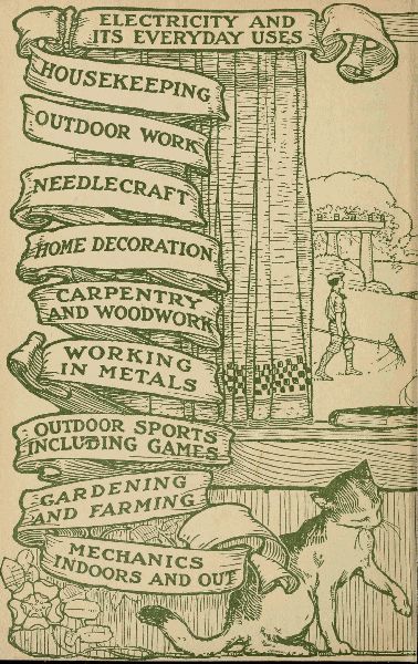
Obvious typos and inconsistencies in spelling have been corrected:
Throughout the text:
In the Table of Contents:
In the Table of Illustrations:
p63. The example of Morse code given is correct for "Original" or American Morse. It has some differences from Continental or International Code which is the current standard. The spacing of the dots is significant.