*** START OF THE PROJECT GUTENBERG EBOOK 45231 ***
Books by
Horstmann & Tousley
| Motion Picture Operation, Stage Electrics and Illusions. |
$2.00 |
| (Ready July 1, 1914.) |
| Alternating Current Theory, Practice and Diagrams. |
$2.00 |
| Modern Electric Illumination. |
$2.00 |
| Practical Armature and Magnet Winding. |
$1.50 |
| Modern Electrical Construction. |
$1.50 |
| Electrical Wiring and Construction Tables. |
$1.50 |
| Dynamo Tending for Engineers. |
$1.50 |
| Modern Wiring Diagrams and Descriptions. |
$1.50 |
| Electricians’ Operating and Testing Manual. |
$1.50 |
Motion Picture Operation
STAGE ELECTRICS
AND ILLUSIONS
A Practical Hand-book and Guide for Theater
Electricians, Motion Picture Operators and
Managers of Theaters and
Productions
By
Henry C. Horstmann
 and
and
Victor H. Tousley
Authors of
“Alternating Current,” “Modern Wiring Diagrams,” “Modern
Electrical Construction,” “Electrical Wiring and Con-
struction
Tables,” “Practical Armature and Magnet
Winding,” “Electricians’ Operating and Test-
ing
Manual,” “Modern Illumination.”
ILLUSTRATED
Chicago
FREDERICK J. DRAKE & CO.
Publishers
Copyright 1914, by
HENRY C. HORSTMANN
and
VICTOR H. TOUSLEY
PREFACE
In this volume the authors have attempted to lay
before the Motion-Picture Operators and Theatrical
Employes generally, a reference and handbook making
a specialty of electrical requirements about theaters.
A working knowledge of electricity in general is
assumed, and therefore elementary ideas have been
treated sparingly. A specialty, however, has been
made of all matters peculiar to theaters, and it is
thought that theater electricians will find in this volume
everything that they need whether they be operating
motion-picture machines or switchboards in
first-class houses.
The two special chapters “Portable Stage Equipment”
and “Theater Wiring” have been arranged
so that they are particularly valuable for reference.
They should be consulted before undertaking any
electrical construction work, either for the stage or
for the auditorium. These chapters embody all of
the practical knowledge that has come to the notice
of the authors in many years of actual experience
with theatrical construction.
The aim of this volume has been to present in a
simple and practical way the essential principles of
Motion-Picture Work.
The Authors.
Table of Contents
| |
PAGE |
| Chapter I |
| The Electrical Circuit and Electrical Hazards |
9 |
| Chapter II |
| The Arc Lamp |
19 |
| Chapter III |
| Projection |
31 |
| Chapter IV |
| Motion Pictures |
55 |
| Chapter V |
| The Motion-Picture Machine |
62 |
| Chapter VI |
| The Film |
89 |
| Chapter VII |
| General Hints on Installation, Operation and Care of Machines |
96 |
| Chapter VIII |
| Light |
113 |
| Chapter IX |
| Principles of Vision |
122 |
| Chapter X |
| Reflection |
126 |
| Chapter XI |
| Refraction |
137 |
| Chapter XII |
| Optical Instruments |
147 |
| Chapter XIII |
| Optical Illusions |
155 |
| Chapter XIV |
| Theater Buildings |
163 |
| Chapter XV |
| Operating Room Equipment |
176 |
| Chapter XVI |
| Current Control for Arc Lamps |
190 |
| Chapter XVII |
| Management of Generators and Motors |
213 |
| Chapter XVIII |
| Theater Wiring |
218 |
| Chapter XIX |
| Portable Stage Equipment |
311 |
| Chapter XX |
| Useful Facts and Formulas |
353 |
| Chapter XXI |
| Glossary of Electrical, Mechanical and Optical Words, Terms and Phrases |
358 |
| Index |
385 |
[9]
MOTION PICTURE OPERATION
STAGE ELECTRICS AND
ILLUSIONS
CHAPTER I.
THE ELECTRICAL CIRCUIT AND ELECTRICAL HAZARDS.
Two and Three-Wire Systems.
Two and Three-Wire Systems.—If the theater electrician
will take the trouble to trace the circuits in
the building to their supply, he will find them entering
the building either as two-wire or three-wire circuits.
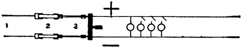
FIGURE 1.
A two-wire circuit is diagrammatically shown in
Figure 1. The circuit, coming from 1, enters the
building, passes through the fuses 2, and through
switch 3 to the lights. A two-wire system will ordinarily
be found operating at 110 volts, the current
varying according to the number of lights turned on.
In the drawing, for instance, only one light is shown
with the switch closed, the other three switches being
open. The current in the circuit is equal to that
which passes through the single lamp. If another[10]
switch be closed, another light will burn and the
current will be increased, so that the more lights
be turned on, the greater will be the current.
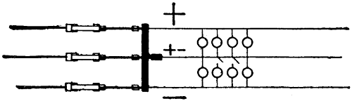
FIGURE 2.
The three-wire system, Figure 2, is almost universally
used where the supply is from the outside and
where any considerable number of lights are connected.
The chief advantage of the three-wire system lies
in its economy of copper. The middle or neutral
wire ordinarily does not carry current, but it is a necessity
whenever the number of lights burning on the
two sides of the system are not equal.
With the neutral wire omitted, we have a straight
two-wire system using double the voltage of the ordinary
two-wire system and always operating two
110-volt lamps in series. Two lamps would always
have to be turned on at the same time and if one of
them should burn out, the other would be extinguished
also.
A system using double voltage requires only half
the current and consequently but half the copper. In
order to obviate the necessity of always using two
lamps together and at the same time economizing
in copper, the neutral wire is provided. As long
as the same number of lamps are burning on each side
of the neutral wire, the same current always passes
through two lamps in series and there is no current[11]
in the neutral. Should, however, the group on one
side be turned out, the other would still continue to
burn; but the path of the current to the dynamo, or
bank of transformers, would be through the neutral
wire.
The system is thus seen to possess all the advantages
of the ordinary two-wire system since each
lamp can be operated by itself and at the low voltage,
while the actual supply voltage for the whole
system is double that which is actually used at any
lamp. We have thus two voltages at our command;
110 and 220 being the voltages in common use.
Electrical Hazards.
Electrical Hazards.—Since this work is not intended
for mere beginners, we shall not enter into elementary
considerations, but shall take up the matter
of fire and life hazard, both of which are important
items to which attention cannot be too often
called.
The electrical current may cause fire by overheating
the wires. This overheating may be due to the
willful overloading of circuits; and to prevent this,
no wire should ever be used to carry more current
than is allowed by the table of carrying capacities
given on page 238.
The overheating may also be due to an unknown
load which is caused by a “ground” or a partial
short circuit. “Ground” is the technical term used
to designate the connection of a wire to any substance
over which electricity may be carried to the
wire of opposite polarity. A ground may be caused
by a bare wire coming in contact with the iron framework
of a building, wet wood, or moist substances of
any kind. One such ground on a circuit can do no
harm; but, if one ground exists, in the course of time[12]
another one may come on and, when the second one
appears, if it is on the side of the circuit opposite to
the first, there will be trouble at once.
If the two grounds are both “good”—that is, if
they are of low resistance—we shall have a short circuit
and probably blow a fuse; but if they are not
“good,” we may have but a small current which may
continue unnoticed for months. Such a current may
eat away the copper of the positive pole and in time
cause the wire to break, creating an electric arc and
perhaps causing a fire. It may also cause wet wood
through which it flows to become charred and finally
ignited.
The ground is the bane of the electrical worker.
If a system can be kept free of grounds, the chances
of trouble are vastly reduced. The cause of most
grounds is moisture. Nearly all substances except
metals are fairly good insulators if dry; and nearly
all of them are fairly good conductors if sufficiently
wet.
Another very prolific source of fires is the electrical
spark, large and small. The spark, due to the breaking
of an incandescent lamp, often causes fires when
it comes in contact with inflammable material or
gases. The ordinary lamp cord also causes many fires
because it is easily damaged and liable to short circuits
which often result in arcing. Short circuiting
two wires or breaking a wire carrying current may
easily ignite inflammable material in the vicinity.
The best way to reduce the fire hazard to a minimum,
is to install all electrical work carefully according
to the rules laid down in the “National Electrical
Code”.
The life hazard is one which concerns the operator[13]
personally and is especially great to those traveling
with shows. Traveling men are often obliged to get
along with all sorts of make shifts, especially in the
smaller towns where one-night stands are the rule.
Here it is often necessary to connect to trolley circuits
or power lines of different voltages, frequencies, etc.
A person may suffer injury directly from a current
of electricity by making himself part of the circuit.
If the system on which he is working is alive
and grounded, he may easily cause injury to himself
by touching a live wire with his hands while standing
upon anything that is grounded. By so doing he completes
a path for the current through his body.
He may also become part of a circuit by holding a
wire with both hands while someone is cutting it between
his two hands. As long as a wire so held is
intact, no shock can be received except to ground, but
when the wire is cut or breaks, a very high voltage
may be produced for an instant which will cause a
current through the body of the man holding the
wire. The extra high voltage is produced only if the
wire is carrying current at the time it is being cut.
Under these circumstances there will often be a strong
flash, due to the momentary increase in voltage, produced
by the breaking of the circuit, which may be
excessive, especially if there is considerable inductance
in the circuit.
The most frequent cause of injury is due to making
contact with the two opposite polarities of a system.
As a rule circuits, with which operators ordinarily
have to work, are low voltage, i.e., not over 220 volts.
But many deaths have been caused by this voltage,
sometimes directly and at other times indirectly as,
for instance, by causing a fall. People whose hearts[14]
are in any way defective should be careful about exposing
themselves to shocks even at 110 volts.
It is true that many wiremen are in the habit of
testing 220-volt circuits by allowing the current to
pass through their bodies, but it will be noticed that
they are very careful not to make a good contact. The
current which passes through the body, when one
touches two wires of opposite polarity very lightly
with the finger tips, is but a fraction of what one
would receive if he were unwittingly to grab two
wires of opposite polarities with the hands, especially
if the hands were moist.
Numerous cases are on record of persons having
been killed by 110 volts under favorable circumstances;
as, for instance, while in the bath receiving
a shock from a so-called vibrator. The body partly
immersed in water and perhaps a foot resting against
a water pipe forms a conductor of very low resistance,
and a comparatively strong current may pass
through the body.
The most important precautions against injury
while working on live circuits are:
(1) Insulate yourself from the ground.
(2) Handle only one side of a line at a time.
(3) If possible, work with only one hand at a time
in contact with the wires.
(4) Use rubber gloves, or rubber boots where necessary,
but bear in mind that they are of little value
unless kept dry. Moisture will allow some current to
pass over the surface of any substance no matter how
good an insulator it may otherwise be.
(5) Always place yourself so that a slight shock
which might cause you to lose your balance will not
give you a bad fall.
[15]
(6) Remember that if once you make good contact
with an alternating-current circuit, you cannot let
go.
(7) Fix firmly in your mind the directions for
resuscitation from electric shock, on pages 15-18.
When energy is obtained through transformers,
there is another danger to be added to the above, viz.,
the possibility of the breaking down of the insulation
between primary and secondary wires of the transformer.
If this happens, we have suddenly and without
warning, instead of the 110 or 220 volts supposed
to exist between the wires forming the circuit, 2,000
or 3,000 volts. Such accidents are especially likely
during thunder storms when lightning often breaks
down transformers.
In order to reduce this danger to a minimum, the
secondaries of transformers are grounded. It will be
well for the electrician to assure himself that the
secondaries of the transformers from which he is getting
his supply are grounded. This can be tested by
an incandescent lamp. Connect the lamp to ground
with one wire and, with the other, try the two sides
of the circuit. If the transformer secondaries are
properly grounded, the lamp will burn at full candle
power from one of the wires; this will show that the
other wire is grounded.
A person working on such a circuit is of course
more likely to receive a low voltage shock than if the
secondaries were not grounded, but he is fairly well
protected against the primary voltage or lightning.
RESUSCITATION FROM ELECTRIC SHOCK.
Rules recommended by commission on resuscitation
from electric shock, representing The American[16]
Medical Association, The National Electric Light
Association, The American Institute of Electrical Engineers:
Dr. W. B. Cannon, chairman; professor of
physiology, Harvard University. Dr. Yandell Henderson,
professor of physiology, Yale University; Dr.
S. J. Meltzer, head of department of physiology and
pharmacology, Rockefeller Institute for Medical Research;
Dr. Edw. Anthony Spitzka, director and professor
of general anatomy, Daniel Baugh Institute
of Anatomy, Jefferson Medical College; Dr. George
W. Crile, professor of surgery, Western Reserve University;
W. C. L. Eglin, past-president National Electric
Light Association; Dr. A. E. Kennelly, professor
of electrical engineering, Harvard University; Dr.
Elihu Thomson, electrician, General Electric Company;
W. D. Weaver, secretary, editor Electrical
World. Issued and copyrighted by National Electric
Light Association. Reprinted by permission. Follow
these instructions even if victim appears dead.
I. IMMEDIATELY BREAK THE CIRCUIT.
With a single quick motion, free the victim from
the current. Use any dry non-conductor (clothing,
rope, board) to move either the victim or the wire.
Beware of using metal or any moist material. While
freeing the victim from the live conductor have every
effort also made to shut off the current quickly.
II. INSTANTLY ATTEND TO THE VICTIM’S BREATHING.
1. As soon as the victim is clear of the conductor,
rapidly feel with your finger in his mouth and throat
and remove any foreign body (tobacco, false teeth,
etc.) Then begin artificial respiration at once. Do
not stop to loosen the victim’s clothing now; every
moment of delay is serious. Proceed as follows:
[17]
a. Lay the subject on his belly, with arms extended
as straightforward as possible and with face
to one side, so that nose and mouth are free for
breathing, see Figure on page 17. Let an assistant
draw forward the subject’s tongue.
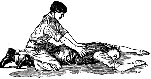
INSPIRATION—PRESSURE OFF.
b. Kneel straddling the subject’s thighs and
facing his head; rest the palms of your hands on the
loins (on the muscles of the small of the back), with
fingers spread over the lowest ribs, as in Figure on
page 17.
c. With arms held straight, swing forward slowly
so that the weight of your body is gradually, but not
violently, brought to bear upon the subject, see Figure
on page 18. This act should take from two to
three seconds.
Immediately swing backward so as to remove the
pressure, thus returning to the position shown in the
Figure on page 17.
d. Repeat deliberately twelve to fifteen times a[18]
minute the swinging forward and back—a complete
respiration in four or five seconds.
e. As soon as this artificial respiration has been
started, and while it is being continued, an assistant
should loosen any tight clothing about the subject’s
neck, chest or waist.
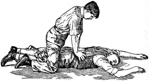
EXPIRATION—PRESSURE ON.
2. Continue the artificial respiration (if necessary,
at least an hour), without interruption, until
natural breathing is restored, or until a physician arrives.
If natural breathing stops after being restored,
use artificial respiration again.
3. Do not give any liquid by mouth until the subject
is fully conscious.
4. Give the subject fresh air, but keep him warm.
III. SEND FOR NEAREST DOCTOR AS SOON AS ACCIDENT IS DISCOVERED.
[19]
CHAPTER II.
THE ARC LAMP.
General Discussion of the Electrical Arc.
General Discussion of the Electrical Arc.—The
name of the electrical arc lamp is derived from the
arch-like appearance of the vapors which give out
the light when the carbons are placed horizontally.
The horizontal arc was the earliest form, hence the
name which it carries to this day.
The arc proper is due to the vapors of volatilized
carbon or other materials forming the electrodes,
which may be consumed by the passage of an electrical
current from one electrode to another through the
intervening medium. In order that an arc may be
formed, it is necessary first to bring the electrodes
together. This, if the circuit is properly arranged,
starts the current and when the circuit is partly interrupted,
as by slowly separating the points of the
electrodes, the current passes through the intervening
space, with the result that a high degree of heat
(about 3,500 centigrade) is produced. This results
in volatilizing the carbon or any other material of
which one or both electrodes may consist.
As long as the distance between the electrode points
is small, the current will be quite strong and a hissing
or frying sound will be given out. In order to
keep the current within bounds during the time that
the electrodes are together or while they are separated
only a very short distance, some resistance, or reactance
in the case of alternating-current arcs, is always
connected in series in the circuit. If this were[20]
not done, there would be a short circuit at the time
of starting or striking the arc.
The arc formed with very short separation of electrodes
is generally spoken of as a low tension arc and
requires very hard carbons and about 25 volts. This
type of arc is very little used for illuminating purposes.
If the distance between the electrodes is increased
gradually, the light becomes very unsteady and
flickers considerably until at a certain point it begins
to improve and give the long quiet arc. This condition
will occur when, with direct current, the electrodes
are about one-eighth of an inch apart. It
will then be found that the voltage across the arc is
from 45 to 50 volts, which is the best voltage to use
with open arcs. If the separation be carried still
further, the arc will grow longer and become flaming
until finally it breaks entirely.
The resistance of the arc is closely proportional to
the cross section of the electrodes and increases with
the distance of the arc gap. It acts, however, very
much as though there were a small counter e. m. f. set
up within it.
The color of the light given off varies with the
length of the arc somewhat, but depends mainly upon
the material of which the electrodes consist. In the
so-called flaming arcs, the peculiar color is obtained
by certain chemicals imbedded in the material composing
the electrodes. Whenever an arc is allowed
to burn down until it reaches the electrode holders,
a greenish light is given off which is due to the volatilization
of the metal—usually brass—in these
holders.
The light of a strong arc is extremely injurious to[21]
the eyes and should only be viewed through colored
glass. Many very painful experiences have resulted
from persons gazing upon arcs of 200 or 300 amperes,
such as are used sometimes in cutting away metals
of old buildings, etc.
The most powerful arcs known at the present time
are those used in some steel mills for refining steel.
These use upward of 10,000 amperes.
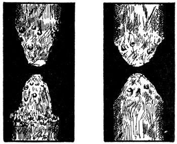
FIGURE 3.FIGURE 4.
The length of the ordinary arc varies from one
thirty-second of an inch to one inch. The light is
not of much use and is rather unsteady until the electrodes
have assumed a shape somewhat similar to that
shown in Figure 3 for direct current, and Figure 4
for alternating current. With direct-current arcs, a
crater is formed at the bottom of the positive electrode
and, from this crater, about 80 per cent of the light is
emitted. Where the light is wanted in a downward
direction, the crater is always formed at the top and[22]
for this purpose the top electrode must be made positive;
that is, the electricity must flow from the top
electrode into the lower one. In some cases, where
special illumination effects are desired, the bottom
electrode is made the positive with the result that most
of the light is thrown upward. In such cases strong
shadows are thrown against the ceiling and the lamp
is said to be burning “upside down.”
The positive electrode can always be distinguished
from the negative (a) by the shadows cast; (b) by
the form of the electrodes; and (c) by the fact that
since it is heated to a greater degree, it will, when
the lamp is turned off, remain hot for some time after
the negative electrode has cooled off.
In case the arc is drawn out very long and operated
in this way for a considerable time, the crater will
almost wholly disappear and the electrodes will appear
rounded off.
In an alternating-current circuit, the positive and
negative poles reverse generally about 120 times per
second and both electrodes in the alternating-current
arc are positive and negative to the same degree. They
are therefore very nearly alike, except that the heat
rising from the lower one increases slightly the volatilization
of the upper. The positive electrode in the
direct-current arc is consumed approximately twice
as fast as the negative electrode. The consumption
of the two electrodes in an alternating-current arc
is about equal and a crater much smaller than the
kind formed in a direct-current arc is, therefore,
formed on each electrode, instead of only on the positive
electrode as in the case of the direct-current arc.
The general form of alternating-current arc carbons
is given in Figure 4. The small elevations shown in[23]
the cuts are due to impurities and do not appear with
first-class carbons.
When arc lamps are operated on alternating-current
circuits, the best voltage for the arc is about
28; and consequently, for the same quantity of light,
the current must be increased so that the amperage
of alternating-current lamps is always much greater
than that of direct-current lamps.
The alternating-current arc is much noisier than
the direct-current arc, but with very high frequencies
this noise ceases.
In general, arc lamps do not work very well on
low frequencies. The time at which the current is
practically zero is long enough to allow the vapor
between the electrode points to cool off sufficiently
to interfere with successful operation.
Any arc light is affected by draughts of air and
can even be blown out. If this occurs often, there
will be rapid feeding, a short arc, and great waste
of electrode.
A magnet held close to an arc can be made to blow
it out or force it to one side. This fact is made use
of in some lightning arresters.
Generally speaking, arc lamps are of two kinds,
open and enclosed. The enclosed arc operates at a
much higher voltage and is but little used about
theaters. The open arc is almost universally used
for stage work and this is about the only place where
it is still considered useful. This kind of arc lamp
is, however, very hazardous in localities where inflammable
material abounds and for this reason it
is always enclosed with wire mesh when possible.
Lens lamps can be tightly enclosed since none of[24]
the light is wanted except that which passes through
the lens in front.
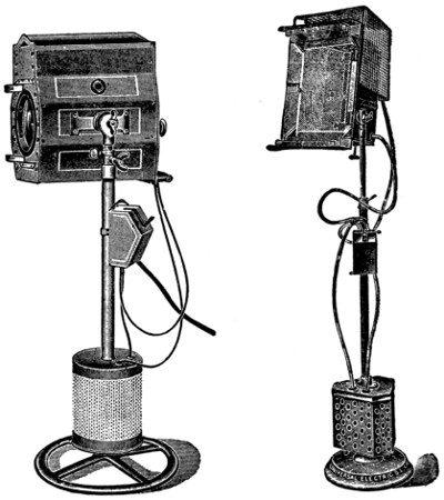
FIGURE 5.FIGURE 6.
The so-called flood lamps are usually provided
with wire gauze in front of the arc, which prevents
the escape of pieces of the electrodes and also prevents
parts of scenery, etc., from coming in contact
with the arc.
The lamp houses should be of such dimensions
that, with the highest amperage the lamp is capable[25]
of using, the outer walls will not become excessively
hot.
Illustrations of standard lens and flood lamps, as
made by the Chicago Stage Lighting Company, are
shown in Figures 5 and 6.
Operation of Arc Lamps.
Operation of Arc Lamps.—From the standpoint of
operation, arc lamps may be divided into two classes,
viz.: hand-feed and automatic-feed. The hand-feed
lamp is generally used in theaters and is practically
the only kind admitted on the stage, or for stage
illuminating purposes. Only a very few houses now
use arc lamps for general illumination.
The operation of hand-feed lamps[1] is ordinarily
quite simple and will be fully treated under the
head of “Projection”, so that we may now consider
only the automatic lamps. At the present time these
are used mostly, if at all, for the illumination of
the exterior of the theater.
The operator should first familiarize himself with
the construction and principles upon which the
mechanism of his lamp is based. For this purpose
he should remove the outer jacket, thus exposing the
working mechanism; turn on the current; and endeavor
to learn the significance of each part. It is
of course necessary that the operator understand the
hazards due to manipulating live wires and that he
should be very careful not to make short circuits or
grounds which might destroy parts of the lamp.
Automatic-feed lamps are usually trimmed in the
following manner: Bring the lamp within reach;
remove the globe; take out the lower electrode; let[26]
down the upper electrode rod and thoroughly clean
it with crocus cloth. This upper electrode rod is the
principal thing that concerns the lamp trimmer; it
must be perfectly straight and care must be exercised
not to bend it accidentally; it must be clean so that
the clutches may properly grip it; it must not be
greasy. If it grows dirty or greasy, it will soon become
pitted from the current that passes from the
contacts to it.
The next operation is to remove the upper electrode
and place it in the lower electrode holder.
(The length of electrode necessary should be known.
The lower one generally burns out first—it being
shorter—and if the arc reaches the lower electrode
holder, will begin to consume it; if the lower carbon
is too long, the arc is liable to reach the upper electrode
holder and destroy it.) The upper electrode
may then be placed in position and aligned with the
lower. To do this it is best to turn it about and try
it until it aligns in all positions. The two electrodes
should form a straight line, up and down, no matter
which way the upper is turned.
In some forms of enclosed lamps, the clutch grips
the electrode direct. In such a case all of the upper
electrode must be carefully examined to see that it is
straight and free from burs, and that it can pass
freely into the opening at the top of the inner globe.
The successful operation of enclosed arcs depends
upon the confinement of the gas in the inner globe.
This globe must, therefore, be kept as tight as possible
without interfering with the operation of the
electrodes which pass through it.
With enclosed arcs, the care of the inner globe
is of great importance, because impurities are cast[27]
off which soon coat the inner globe and absorb much
of the light.
The care of the outer globes in general is also an
important matter. A dirty globe looks very unsightly
and absorbs much light.
The following points should be carefully considered
in handling and trimming lamps:
(1) Be sure that you understand your system and
know whether it is a constant-current or a constant-potential
system of distribution. With constant-current
systems, the current is constant and the
voltage over the arc is regulated; while with constant-potential
systems, the voltage is constant and
the current through the arc is regulated.
(2) With constant-current or series lamps, the line
must never be opened, but must be shunted around
the lamp if a lamp is to be cut out.
(3) With constant-potential lamps, the lamp must
never be shunted but the circuit must be opened.
(4) In all cases each lamp should be controlled by
a double pole switch.
(5) Constant-potential lamps cannot be operated
without resistance in the circuit; this resistance may
be in the lamp itself or outside.
(6) Never handle high tension lamps without insulating
yourself from the ground; and handle live
wires only with one hand at a time.
(7) Provide spark arresters for all open-arc lamps
in the vicinity of inflammable material.
(8) Never leave a lamp without globes where the
wind can strike it. It will be blown out or feed
often, thus consuming the electrodes very fast and
at the same time yielding a very poor light.
Green light emitted by the lamp will indicate that[28]
the electrode holders are burning. Strong shadows
cast upwards indicate a lamp burning “upside
down”. The positive electrode retains heat longer
than the negative. The quality and size of electrodes
has much to do with successful operation. Always
use the kind of electrodes recommended by the
maker of the lamp.
Direct-current arc lamps do not require much in
the shape of reflectors as they naturally throw most
of the light downward, when the upper electrode is
positive. They should as a rule be suspended high.
Alternating-current arc lamps throw most of the
light from the upper electrode slightly below the
horizontal and that from the lower electrode somewhat
above. If the light is wanted in a downward
direction, suitable reflectors must be provided.
Testing of Arc Lamps.
Testing of Arc Lamps.—The constant-potential
arc lamp is usually designed for a certain current
and voltage. The enclosed arcs as a rule operate
singly on 110 volts, while open arcs are run two in
series on the same voltage. In order to test and see
that the voltage and current are right, an ammeter
and a voltmeter are needed. The current and voltage
can both be adjusted by altering the resistance,
which is always in series with such lamps. To get
the correct voltage over the arc, be sure to connect
the voltmeter to the two electrode holders so as to
eliminate any other potential drops that may affect
the reading.
Testing Carbons.
Testing Carbons.—The color of the light and the
steadiness of it can of course only be determined by
actual operation tests. The arc obtained by using
large electrodes with low current density is liable
to rotate around the electrodes, burn unsteadily, and[29]
flicker. This is due to the fact that the arc tends to
establish itself at the point of least resistance. In
order that the arc may burn uniformly, the current
density must be great enough to force all of the
electrode points into use.
As a rule the best electrode is the one that has the
longest range from the low voltage point of hissing
to the high voltage point of flaming. With such an
electrode the greatest range in light can be obtained
without either the hissing or the flaming.
The same qualities that give an electrode long
range, as above, also indicate its purity and if we
make a test for range, we shall therefore at the same
time make a test for purity.
The test for range can be carried out by any ordinary
hand-feed lamp. To make it, the electrodes
are inserted and allowed to burn until their points
have assumed the proper shape. The arc can then
be shortened until the familiar hissing sound is
heard. Note the voltage at which this occurs, being
careful to have the voltmeter connected so as to get
the voltage across the arc only. Now separate the
electrodes slowly until they begin to flame and note
this voltage. Ordinarily the hissing voltage will be
about 42 and the flaming voltage about 62. The
greater the difference between the two, the better
the carbons are assumed to be. In making comparative
tests on electrodes in this manner, care
should be taken that all of the conditions of current
and size of electrodes be the same.
The test for comparative life of electrodes is best
made by arranging the different electrodes so that
the same current will pass through each for the
same length of time. If this is done, all that is[30]
necessary is to weigh the electrodes before and after
burning. The approximate useful life of an electrode
can be easily determined by burning it for a
stated length of time, noting the length consumed
and comparing it with the length available for burning.
[31]
CHAPTER III.
PROJECTION.
Setting and Adjustment of Carbons.
Setting and Adjustment of Carbons.—To project
a picture upon a screen properly is an art and requires
close study and some knowledge of all the
factors involved. The most important factor is that
of the light. Electric light is so universally used
at the present time that it is hardly necessary to
mention the other sources of illumination.
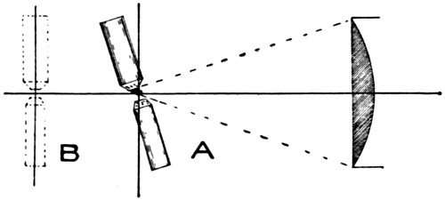
FIGURE 7.
The electric current with which the operator has
to deal may be either alternating or direct, and the
kind is of great importance. The color of the light
obtained from a direct-current arc is not only superior
to that obtained from an alternating-current
arc but is obtained at a much lower cost since, as
we shall presently see, it is so much more efficient.
To project clear white light upon the screen is
impossible, some color will always be in it. But by
careful attention and by training himself to notice
slight degrees of color, the operator can learn to
render a light which will be clear enough to satisfy[32]
the majority of the spectators. In order to obtain
this light, the source from whence it comes should
be located exactly in the optical axis of the lens system;
that is, a straight line drawn through the
center of all of the lenses should pass also directly
through the center of the arc as indicated in Figure
7. (For comprehensive treatise on lenses, see Chapter
XII.)
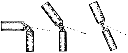
FIGURE 8. FIGURE 9. FIGURE 10.
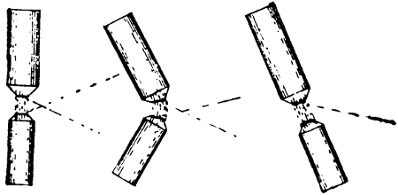
FIGURE 11. FIGURE 12. FIGURE 13.
Most of the light, we have already seen, is emitted
from the crater of an arc of which there is but one
in a direct-current arc and two in an alternating
current arc. In order to obtain the most light with
the least expenditure of current and heat in the lamp
house, the crater must be formed in such a manner
as to face the center of the condensers as nearly as
possible. Since, however, there are always two electrodes
and the current must pass from one to the
other, the crater always tends to face the lower electrode
if the upper one is positive. It is, therefore,
impossible to get the full benefit of the light for the
condenser; we must be satisfied with getting a part
of it, and to do this such settings of electrodes as
are shown in Figures 8 to 13 are used. About the
relative merits of these various settings there is considerable
dispute and the best advice that can be
given to any new comer in the operating line is to[33]
make his own experiments and find out for himself.
The fact that a certain point is much disputed, alone
indicates that there is no exact knowledge available;
for we very seldom have any differences of opinion
about the things that we can prove.
In the operating line very much depends upon
the judgment of the operator. Electrode setting
like that of Figure 8 may be good for an operator
who is extremely careful and has a reliable machine
which requires a minimum of attention. But it can
readily be seen that if the top electrode were fed a
trifle too far forward, the crater would form underneath
and the lenses would receive but a small part
of the light. Each of the settings given has its
peculiarities and it is best for any operator who has
not done so, to try them all out and find which one
best suits him and his conditions.
Figures 8 to 10 show the settings used with direct-current
arcs; while those illustrated by Figures 11
to 13 are used with alternating-current arcs.
With alternating-current arcs the problem is even
more difficult than with direct, for we have here
two craters to deal with; and if we wish to use the
light from both, we shall have to be very careful
about it. If the electrodes are not set exactly right,[34]
we may get a double spot and poor illumination at
the center of the screen. Perhaps most operators
will soon give up the idea of using the light of both
craters and will settle down to an electrode setting
something like that shown in A, Figure 7. In this
setting both electrodes are angled and the lower one
is set a little ahead of the upper. This has a tendency
to draw the crater of the upper electrode forward,
thus improving the light on the condenser;
but if this be carried too far, the lower electrode
will obstruct the lower part of the lens. The lower
electrode must always be set so that it allows all parts
of the condenser to receive direct rays of light from
the crater of the upper. The electrode must align
perfectly in the vertical plane as shown in B, Figure
7, or the arc will move while burning.
In order to enable the operator to arrange his electrodes
at any angle and to bring them into the center
of the optical system, arc lamps are made up in
various ways as illustrated in Figures 14 to 19. The[35]
simpler types are used only in stage lighting lamps
where the centering is not so important. The more
elaborate lamps are provided for motion picture arc
lamps and allow of all necessary adjustments which
are: feed electrodes; move lamps forward or back;
up or down; sideways and angle electrodes.
Where direct current is used, the upper electrode
must be fed approximately twice as fast as the
lower; but with alternating current, they both feed
at practically the same rate.
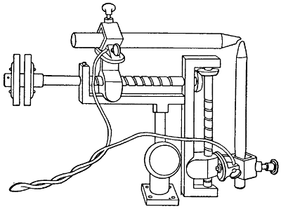
FIGURE 14.
Figure 14 shows a form of McIntosh stereopticon
lamp.
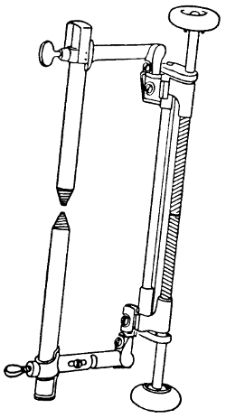
FIGURE 15.
Figure 15 is a Kliegl lamp for open arc lamps.
[36]
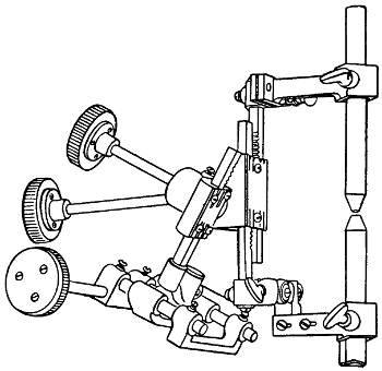
FIGURE 16.
Figure 16 is an Edison lamp used for motion picture
work.
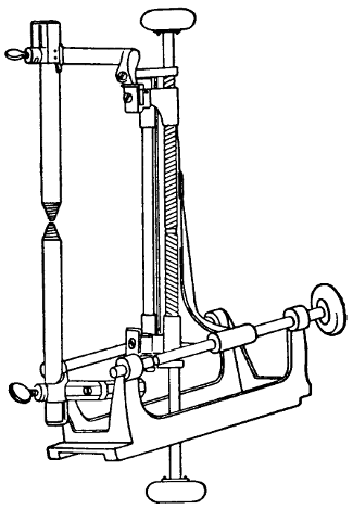
FIGURE 17.
[37]
Figure 17 is a Kliegl lamp used for focusing purposes.
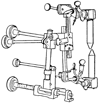
FIGURE 18.
Figure 18 shows the Powers lamp.
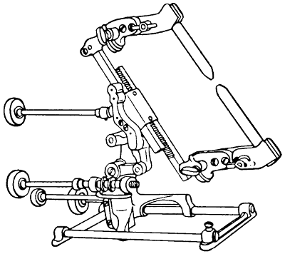
FIGURE 19.
Figure 19 shows one of the Motiograph Company
lamps.
[38]
Optical System.
Optical System.—In Figure 20 we have the complete
optical system of the moving picture or stereopticon
outfit. The crater of the arc lamp and the
center of the objective lens are at the conjugate focal
points (see Optics) and must always be in this relation.
The size of the picture projected upon the
screen is governed entirely by the focal length of
the objective lens and the distance of the screen from
this lens. The shorter the focal length, the greater
will be the bulging out or rounding of the lens, and
the larger the picture projected. The objective lens
is always fitted with an adjusting device of some
kind by which it can be moved forward or back a
little to focus the picture properly.
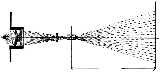
FIGURE 20.
In order to project a picture properly, it is necessary
that the center of the arc or other illuminant,
the center of the condensers, and the center of the
objective, all fall in one straight line as indicated
in Figure 20. The condensers are provided for the
purpose of gathering and condensing as many of the
scattering light rays of the arc lamp as possible and[39]
bringing them to bear upon the slide and the objective.
The light used must come either from a reasonably
small source or from a larger source far enough
away so that the rays can be considered as parallel.
The focal point for parallel rays would, however,
differ somewhat from that of a point source and
such illumination is seldom used; in fact, it is used
only where special arrangements are made for it.
One of the principal points to be borne in mind
in trying to project a good clear picture is to keep
the arc down to as small a point as is practicable. A
long arc can be tolerated only when it is absolutely
impossible to obtain sufficient illumination from a
short arc; as, for instance, in operating the Kinemacolor
machines, in which from 80 to 100 amperes are
used with a very long arc. The above expedient is
imperative because the colored discs through which
the light must pass absorb a great amount of it and
the definition or outline of the picture is apt to be
poor.
The position of the arc with reference to the condensers
is also an important point to consider. The
focal length of the condensers determines the point
at which the arc must be maintained. The flatter the
condensers are, the farther away the arc may be, and
the less will be the heating; but this position is accompanied
with considerable loss of light.
For the purpose of projection we can use only the
light which strikes the condensers direct from the
arc. Rays reflected by the lamp house do not pass
through the condensers in the same direction as those
coming directly from the crater and will not focus
with them. Hence, the farther the arc is from the[40]
condensers, the smaller will be the percentage of
light used; the shorter the focal length of the condensers,
the closer to them must the arc be maintained,
and the greater will be the percentage of
light used. But if the light is brought too close,
there will be undue heating of the condensers and
these, especially the one nearest the light, will be
likely to break. So great is the heat produced that
sometimes the two lenses are partially melted and
welded together. This is a frequent occurrence in
cases where very heavy currents are used. It must
be recalled that the heat produced is proportional
to the square of the current and that other things
being equal, 80 amperes would produce four times
the heat of 40 amperes.
Condenser breakage is quite an important subject
and one upon which there is much argument among
operators. Many of the theories held are, however,
not plausible enough to merit mention. The principal
cause is no doubt overheating without allowing
sufficient room for expansion in the setting. No
lens should ever be set so that it does not move freely
even while it is hot. Even if free while cold, the expansion,
where the heating is great, may be sufficient
to tighten it in the casing, and this is likely to cause
breakage. The best methods of preventing heating
are: a large lamp house well ventilated and condensers
of such focal length as to allow the arc to
be maintained at some distance from them. Drafts
of air are often given as the cause of breakage, but
the truth of this is rather problematical. There is
no doubt that sudden contraction, due to rapid cooling,
would have a strong tendency to break them;
but the air in operating rooms is not often cold and[41]
is not likely to strike the lens anyway. It must be
noted that it is usually the inner lens, which is ordinarily
enclosed, that breaks.
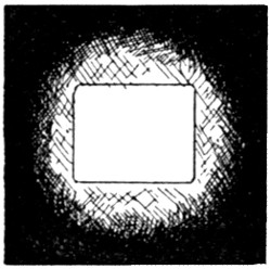
FIGURE 21.
In the projection of moving pictures there are two
important points that must always be considered.
(1) the size of the spot on the gate at which the film
appears, and (2) the clearness of the field or light
on the screen. By properly adjusting the arc, we
can make the spot any size we desire; and the smaller
we make it, so long as it covers the whole aperture,
the brighter the light will be. But if we make this
spot too small, we shall bring in the fringe of color
which always appears at the outer edge. Color of
this kind is objectionable and must be avoided as
much as possible; but it is not necessary to go to
extremes. A little coloring will not be noticed by
the audience and will therefore not be objectionable.
With a given system there will thus be a certain size
of spot which gives the best results obtainable. Considering
that if the spot is increased in size, the light
becomes clearer but also less intense; and that if the
spot is decreased in size, the light on the screen,
though more brilliant, is liable to show coloring, a
good operator should practice distinguishing the coloring
and make himself as proficient in this art as possible.[42]
The customary proportions of spot and aperture
are shown in Figure 21.
Coloring appears, however, from another cause
also, viz., improper centering or adjustment of the
arc lamp with reference to the condensers. If the
arc is not properly adjusted, bands of color such as
are indicated in Figure 22 may appear in any of the
positions shown. This is commonly spoken of as the
“ghost”, and it must be eliminated. It is not possible
to get rid of it entirely, but by a little skill,
patience, and experience, it can be reduced to a
negligible amount. When the spot is right and the
screen clear, the picture may be focused by adjusting
the objective lens.
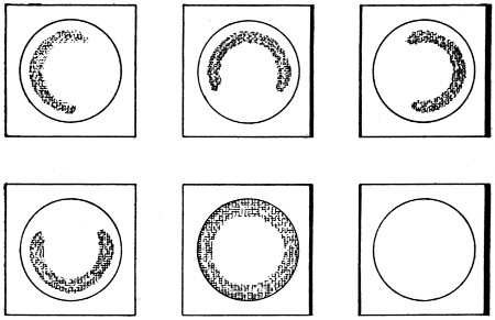
FIGURE 22.
To focus sharply, it is advisable to move the lens
in one direction until the picture appears a trifle
blurred; then move it in the opposite direction until
at this point there is also a blurred picture. The[43]
exact focus will be at a point half way between the
two. To focus the lens in this manner is important
where the slide or film has some play, as when the
aperture plate on a machine is worn and allows the
film some movement.
Current Required.
Current Required.—The measurement of the candle
power of arc lamps has never been satisfactorily
taken, and the difficulties encountered in determining
it for a projecting arc are especially great because
only a small part of the total light can be
utilized and this is constantly varying. The light
may, however, be assumed as proportional to the
wattage of the arc, hence, we can best judge it by
noting the volts and amperes. Where a very strong
light is desirable, the arc is usually drawn out to
some length; and as there is a rise in voltage, with a
long arc, in such a case, the light increases at a
greater rate than the amperage. In ordinary projection
work, the arc is kept quite short because of the
better definition obtainable by the use of such an arc;
and we may assume that the light obtained is nearly
directly proportional to the amperage. This relation
of light and the current input to the lamp will be
practically correct, especially if the size of the electrodes
chosen is proportional to the amperage.
Current Required for Projecting.
Current Required for Projecting.—The value of
the current to be used for projection is a matter of
some dispute among operators and probably much
of this is caused by the absence of ammeters, most
operators merely guessing at what they are using, or
being guided by markings of rheostats or compensators.
In most cases something like 40 amperes seems
to be the rule.
In order to give the reader a clear understanding[44]
of the theoretical requirements, Table I has been
prepared. This table is not intended to act as an
accurate guide, but merely to show the amperage
theoretically required with different sized pictures,
to bring about the same illumination in each case.
Greatest
Dimension
of Picture
in feet. |
Area
Illuminated. |
Amperes |
Direct
Current. |
Alter-
nating
Current. |
| 5 |
39 |
8 |
12 |
| 6 |
56 |
11 |
16 |
| 7 |
77 |
15 |
22 |
| 8 |
100 |
20 |
30 |
| 9 |
127 |
25 |
37 |
| 10 |
157 |
31 |
45 |
| 11 |
189 |
38 |
57 |
| 12 |
224 |
45 |
67 |
| 13 |
260 |
52 |
78 |
| 14 |
307 |
60 |
90 |
Two errors are very common in the computation
of the light intensity for a given picture: (1) the
length of throw governs the amperage; and (2) the
amperage depends upon the actual space to be illuminated.
Apparently only an oblong square of exactly
the proportions of the aperture in the machine
is illuminated, but in reality the light must be spread
out so that its total illumination covers a circle enclosing
the actual visible picture. This is illustrated
in Figure 23 where the enclosed oblong square represents
the space illuminated on the screen and the
circle represents the area over which the light must
be spread. The portion shown by shading is nearly
equal to the clear portion and shows that half of the
light is wasted since it is blocked out by the cooling
plate in the machine or the framework of the slides.
With increasing size of picture, the light is, however,[45]
diminished in proportion to the area of the circle
and not in proportion to the area of the picture. If,
for instance, the picture were to retain its width and
be reduced in height by one half, or even more, there
would still be about the same quantity of illumination
required. For this reason we have, in Table I,
given only the maximum dimension of the picture and
have based the amperage calculation upon the area
of the circle which encloses the picture.
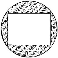
FIGURE 23.
The values given are less than are generally used
for small pictures and more than are generally used
for large pictures. As a rule much light is wasted
on small pictures because the apparatus is at hand
to deliver it; with large pictures, the illumination is
often poor because transformers and rheostats are
seldom fitted to deliver more than 60 amperes. Much
light can easily be wasted if the picture is made too
bright. In such a case, much of the light is reflected
back to the auditorium and this in turn makes
the picture appear less bright.
In determining the amperage necessary to show a
picture properly, the following conditions must be
borne in mind, any one of which may appreciably
affect the result:
[46]
(1) Nature of Screen.—A good screen will reflect
more light than a poor one.
(2) Size of Picture.—The larger the picture, the
more light will be required.
(3) Character of Film.—Some films are very dark
and require extra illumination.
(4) House Illumination.—In some cities the law
requires fairly bright illumination of auditoriums
and this makes the picture appear less bright.
(5) Atmosphere.—Where the air is full of dust, or
where smoking is allowed; much light will be absorbed.
(6) Lenses.—Some lenses are badly discolored and
absorb much light.
(7) Electrodes and Electrode Setting.—This is a
very important factor and one which a good operator
will never neglect.
Selection of Lenses.
Selection of Lenses.—Upon the proper selection of
lenses depends very much the quality of the picture.
The size of the picture, under given circumstances,
depends entirely upon the focal length of the objective.
With a given distance between lens and
screen there is practically but one size of picture obtainable.
If we wish to obtain a picture of another
size by the use of the same lens, this can be done
only by sacrificing the definition and had better not
be attempted.
Very large pictures are desirable only in large halls
in which portions of the audience are very far from
the screen. Such a picture requires very much light
and, on account of its size, shows many imperfections
to those who sit in the front rows. It is better
to limit the size of the picture to one which can be
easily illuminated, and thus avoid such imperfections.
[47]
| Size of Mat opening 11-16 × 15-16 inch. |
E.E.
In. |
15
ft. |
20
ft. |
25
ft. |
30
ft. |
35
ft. |
40
ft. |
45
ft. |
50
ft. |
60
ft. |
70
ft. |
80
ft. |
90
ft. |
100
ft. |
| 2 |
1⁄8 |
4. |
8 |
6. |
4 |
8. |
0 |
9. |
6 |
11. |
3 |
12. |
9 |
14. |
5 |
16. |
1 |
... |
... |
... |
... |
... |
| 6. |
5 |
8. |
7 |
11. |
0 |
13. |
2 |
15. |
4 |
17. |
6 |
19. |
8 |
22. |
0 |
... |
... |
... |
... |
... |
| 2 |
1⁄2 |
... |
5. |
4 |
6. |
8 |
8. |
2 |
9. |
6 |
10. |
9 |
12. |
3 |
13. |
7 |
16. |
4 |
... |
... |
... |
... |
| ... |
7. |
4 |
9. |
3 |
11. |
2 |
13. |
1 |
14. |
9 |
16. |
8 |
18. |
7 |
22. |
4 |
... |
... |
... |
... |
| 3 |
|
... |
4. |
5 |
5. |
7 |
6. |
8 |
8. |
0 |
9. |
1 |
10. |
3 |
11. |
4 |
13. |
7 |
16. |
0 |
... |
... |
... |
| ... |
6. |
2 |
7. |
7 |
9. |
3 |
10. |
9 |
12. |
4 |
14. |
0 |
15. |
6 |
18. |
7 |
21. |
8 |
... |
... |
... |
| 3 |
1⁄2 |
... |
... |
4. |
9 |
5. |
8 |
6. |
8 |
7. |
8 |
8. |
8 |
9. |
8 |
11. |
7 |
13. |
7 |
15. |
7 |
... |
... |
| ... |
... |
6. |
6 |
8. |
0 |
9. |
3 |
10. |
6 |
12. |
0 |
13. |
3 |
16. |
0 |
18. |
7 |
21. |
4 |
... |
... |
| 4 |
|
... |
... |
4. |
2 |
5. |
1 |
6. |
0 |
6. |
8 |
7. |
7 |
8. |
5 |
10. |
3 |
12. |
0 |
13. |
7 |
15. |
4 |
... |
| ... |
... |
5. |
8 |
7. |
0 |
8. |
1 |
9. |
3 |
10. |
5 |
11. |
6 |
14. |
0 |
16. |
3 |
18. |
7 |
21. |
0 |
... |
| 4 |
1⁄2 |
... |
... |
... |
4. |
5 |
5. |
3 |
6. |
2 |
6. |
8 |
7. |
7 |
9. |
1 |
10. |
6 |
12. |
2 |
13. |
7 |
15. |
4 |
| ... |
... |
... |
6. |
2 |
7. |
2 |
8. |
4 |
9. |
3 |
10. |
5 |
12. |
4 |
14. |
5 |
16. |
6 |
18. |
7 |
21. |
0 |
| 5 |
|
... |
... |
... |
... |
4. |
8 |
5. |
4 |
6. |
1 |
6. |
8 |
8. |
2 |
9. |
6 |
10. |
9 |
12. |
3 |
13. |
7 |
| ... |
... |
... |
... |
6. |
5 |
7. |
4 |
8. |
4 |
9. |
3 |
11. |
2 |
13. |
0 |
14. |
9 |
16. |
8 |
18. |
7 |
| 5 |
1⁄2 |
... |
... |
... |
... |
4. |
3 |
4. |
9 |
5. |
6 |
6. |
2 |
7. |
4 |
8. |
7 |
9. |
9 |
11. |
2 |
12. |
4 |
| ... |
... |
... |
... |
5. |
9 |
6. |
7 |
7. |
6 |
8. |
4 |
10. |
2 |
11. |
9 |
13. |
6 |
15. |
3 |
17. |
0 |
| 6 |
|
... |
... |
... |
... |
... |
4. |
5 |
5. |
1 |
5. |
7 |
6. |
8 |
8. |
0 |
9. |
1 |
10. |
3 |
11. |
4 |
| ... |
... |
... |
... |
... |
6. |
2 |
7. |
0 |
7. |
7 |
9. |
3 |
10. |
9 |
12. |
4 |
14. |
0 |
15. |
6 |
| 6 |
1⁄2 |
... |
... |
... |
... |
... |
... |
4. |
7 |
5. |
2 |
6. |
3 |
7. |
3 |
8. |
4 |
9. |
6 |
10. |
6 |
| ... |
... |
... |
... |
... |
... |
6. |
4 |
7. |
1 |
8. |
6 |
10. |
0 |
11. |
4 |
13. |
0 |
14. |
5 |
| 7 |
|
... |
... |
... |
... |
... |
... |
4. |
4 |
4. |
9 |
5. |
8 |
6. |
8 |
7. |
8 |
8. |
8 |
9. |
8 |
| ... |
... |
... |
... |
... |
... |
6. |
0 |
6. |
6 |
8. |
0 |
9. |
3 |
10. |
6 |
12. |
0 |
13. |
3 |
| 7 |
1⁄2 |
... |
... |
... |
... |
... |
... |
... |
4. |
5 |
5. |
4 |
6. |
4 |
7. |
3 |
8. |
2 |
9. |
1 |
| ... |
... |
... |
... |
... |
... |
... |
6. |
2 |
7. |
4 |
8. |
7 |
10. |
0 |
11. |
2 |
12. |
3 |
| 8 |
|
... |
... |
... |
... |
... |
... |
... |
... |
5. |
1 |
6. |
0 |
6. |
8 |
7. |
7 |
8. |
5 |
| ... |
... |
... |
... |
... |
... |
... |
... |
7. |
0 |
8. |
1 |
9. |
3 |
10. |
5 |
11. |
6 |
Example: With a lens of 51⁄2 inch focus at a distance of 35 ft. the screen image will be
4.3×5.9; at 40 ft., 4.9×6.7; at 45 ft., 5.6×7.6; etc.
Note: When ordering lenses, give size of picture wanted, and distance from machine
to screen.
[48]
| Size of Mat opening 23⁄4 × 3 inches. |
E.F.
In. |
15
ft. |
20
ft. |
25
ft. |
30
ft. |
35
ft. |
40
ft. |
45
ft. |
50
ft. |
60
ft. |
70
ft. |
80
ft. |
90
ft. |
100
ft. |
| 5 |
|
8. |
0 |
10. |
8 |
13. |
5 |
16. |
3 |
19. |
0 |
... |
... |
... |
... |
... |
... |
... |
... |
| 8. |
8 |
11. |
8 |
14. |
8 |
17. |
8 |
20. |
8 |
... |
... |
... |
... |
... |
... |
... |
... |
| 5 |
1⁄2 |
7. |
3 |
9. |
8 |
12. |
3 |
14. |
8 |
17. |
3 |
19. |
8 |
... |
... |
... |
... |
... |
... |
... |
| 7. |
9 |
10. |
7 |
13. |
4 |
16. |
1 |
18. |
8 |
21. |
6 |
... |
... |
... |
... |
... |
... |
... |
| 6 |
|
6. |
6 |
8. |
9 |
11. |
2 |
13. |
5 |
15. |
8 |
18. |
1 |
20. |
4 |
... |
... |
... |
... |
... |
... |
| 7. |
3 |
9. |
8 |
12. |
3 |
14. |
8 |
17. |
3 |
19. |
8 |
22. |
3 |
... |
... |
... |
... |
... |
... |
| 6 |
1⁄2 |
6. |
1 |
8. |
2 |
10. |
4 |
12. |
5 |
14. |
6 |
16. |
7 |
18. |
8 |
... |
... |
... |
... |
... |
... |
| 6. |
7 |
9. |
0 |
11. |
3 |
13. |
6 |
15. |
9 |
18. |
2 |
20. |
5 |
... |
... |
... |
... |
... |
... |
| 7 |
|
5. |
7 |
7. |
6 |
9. |
6 |
11. |
6 |
13. |
5 |
15. |
5 |
17. |
5 |
19. |
4 |
... |
... |
... |
... |
... |
| 6. |
2 |
8. |
3 |
10. |
5 |
12. |
6 |
14. |
8 |
16. |
9 |
19. |
0 |
21. |
2 |
... |
... |
... |
... |
... |
| 7 |
1⁄2 |
5. |
3 |
7. |
1 |
8. |
9 |
10. |
8 |
12. |
6 |
14. |
4 |
16. |
3 |
18. |
1 |
... |
... |
... |
... |
... |
| 5. |
8 |
7. |
8 |
9. |
8 |
11. |
8 |
13. |
8 |
15. |
8 |
17. |
8 |
19. |
8 |
... |
... |
... |
... |
... |
| 8 |
|
... |
6. |
6 |
8. |
4 |
10. |
1 |
11. |
8 |
13. |
5 |
15. |
2 |
17. |
0 |
20. |
4 |
... |
... |
... |
... |
| ... |
7. |
3 |
9. |
1 |
11. |
0 |
12. |
9 |
14. |
8 |
16. |
6 |
18. |
5 |
22. |
3 |
... |
... |
... |
... |
| 8 |
1⁄2 |
... |
6. |
2 |
7. |
9 |
9. |
5 |
11. |
1 |
12. |
7 |
14. |
3 |
16. |
0 |
19. |
2 |
... |
... |
... |
... |
| ... |
6. |
8 |
8. |
6 |
10. |
3 |
12. |
1 |
13. |
9 |
15. |
6 |
17. |
4 |
20. |
9 |
... |
... |
... |
... |
| 9 |
|
... |
5. |
9 |
7. |
4 |
8. |
9 |
10. |
5 |
12. |
0 |
13. |
5 |
15. |
1 |
18. |
1 |
21. |
1 |
... |
... |
... |
| ... |
6. |
4 |
8. |
1 |
9. |
8 |
11. |
4 |
13. |
1 |
14. |
8 |
16. |
4 |
19. |
8 |
23. |
1 |
... |
... |
... |
| 9 |
1⁄2 |
... |
5. |
6 |
7. |
0 |
8. |
5 |
9. |
9 |
11. |
4 |
12. |
8 |
14. |
2 |
17. |
1 |
20. |
0 |
... |
... |
... |
| ... |
6. |
1 |
7. |
6 |
9. |
2 |
10. |
8 |
12. |
4 |
14. |
0 |
15. |
5 |
18. |
7 |
21. |
9 |
... |
... |
... |
| 10 |
|
... |
5. |
3 |
6. |
6 |
8. |
0 |
9. |
4 |
10. |
8 |
12. |
2 |
13. |
5 |
16. |
3 |
19. |
0 |
21. |
8 |
... |
... |
| ... |
5. |
8 |
7. |
3 |
8. |
8 |
10. |
3 |
11. |
8 |
13. |
3 |
14. |
8 |
17. |
8 |
20. |
8 |
23. |
8 |
... |
... |
| 12 |
|
... |
... |
5. |
5 |
6. |
6 |
7. |
8 |
8. |
9 |
10. |
1 |
11. |
2 |
13. |
5 |
15. |
8 |
18. |
1 |
20. |
4 |
... |
| ... |
... |
6. |
0 |
7. |
3 |
8. |
5 |
9. |
8 |
11. |
0 |
12. |
3 |
14. |
8 |
17. |
3 |
19. |
8 |
22. |
3 |
... |
| 14 |
|
... |
... |
... |
5. |
6 |
6. |
6 |
7. |
6 |
8. |
6 |
9. |
6 |
11. |
6 |
13. |
5 |
15. |
5 |
17. |
5 |
19. |
4 |
| ... |
... |
... |
6. |
2 |
7. |
3 |
8. |
3 |
9. |
4 |
10. |
5 |
12. |
6 |
14. |
8 |
16. |
9 |
19. |
0 |
21. |
2 |
| 16 |
|
... |
... |
... |
... |
5. |
8 |
6. |
6 |
7. |
5 |
8. |
4 |
10. |
1 |
11. |
8 |
12. |
5 |
15. |
2 |
17. |
0 |
| ... |
... |
... |
... |
6. |
3 |
7. |
3 |
8. |
2 |
9. |
1 |
11. |
0 |
12. |
9 |
14. |
8 |
16. |
6 |
18. |
5 |
| 18 |
|
... |
... |
... |
... |
5. |
1 |
5. |
9 |
6. |
6 |
7. |
4 |
8. |
9 |
10. |
5 |
12. |
0 |
13. |
5 |
15. |
1 |
| ... |
... |
... |
... |
5. |
6 |
6. |
4 |
7. |
3 |
8. |
1 |
9. |
8 |
11. |
4 |
13. |
1 |
14. |
8 |
16. |
4 |
| 20 |
|
... |
... |
... |
... |
... |
5. |
3 |
6. |
0 |
6. |
6 |
8. |
0 |
9. |
4 |
10. |
8 |
12. |
2 |
13. |
5 |
| ... |
... |
... |
... |
... |
5. |
8 |
6. |
5 |
7. |
3 |
8. |
8 |
10. |
3 |
11. |
8 |
13. |
3 |
14. |
8 |
| 22 |
|
... |
... |
... |
... |
... |
... |
5. |
4 |
6. |
0 |
7. |
3 |
8. |
5 |
9. |
8 |
11. |
0 |
12. |
3 |
| ... |
... |
... |
... |
... |
... |
5. |
9 |
6. |
6 |
7. |
9 |
9. |
3 |
10. |
7 |
12. |
0 |
13. |
4 |
| 24 |
|
... |
... |
... |
... |
... |
... |
... |
5. |
5 |
6. |
6 |
7. |
8 |
8. |
9 |
10. |
1 |
11. |
2 |
| ... |
... |
... |
... |
... |
... |
... |
6. |
0 |
7. |
3 |
8. |
5 |
9. |
8 |
11. |
0 |
12. |
3 |
Example: With lens of 10-inch focus at a distance of 20 ft. the screen image will be
5.3×5.8; at 25 ft., 6.6×7.3; at 30 ft., 8.0×8.8; at 50 ft., 13.5×14.8.; etc.
[49]
Table II shows the size of picture obtainable from
films, and Table III, the size obtainable from lantern
slides. Since the slide pictures must be shown upon
the same screen as the film, it can be seen from the
tables that lenses of different focal length must be
used for the two. The aim should be to get the two
pictures to match as nearly as possible, but as they
are not of the same proportions, it is impossible to
match them exactly in both directions. The nearest
approximation that can be brought about by standard
lenses is illustrated in Figure 24. The heavy
lines show the dimension of the picture projected
through the film, and the light and dotted lines show
the dimensions obtainable by the use of slides. If
the slide picture is matched to the height of the film,
it will be considerably narrower; if it is matched to
the sides, it will be considerably higher. It would of
course be possible to trim down slides so that the
dimensions of the two pictures would be exactly
alike; but as most all stereopticon slides belong to
traveling actors this is not practicable.
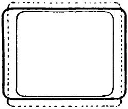
FIGURE 24.
If the focal length of a lens is not known, it can
easily be measured by focusing some distant object,
an incandescent lamp for instance, against the wall
of a room or against some screen placed upon a table[50]
as shown in Figure 25. In the case of a single plano-convex
lens, the measurements must be made from
both sides—first one side turned toward the light,
and then the other. There will always be some difference
between the two measurements and we must
take the mean of the two. To get the measurement
accurately, place a rule upon a table and set up some
suitable object upon which the picture can be projected.
Turn the flat side of the lens toward the
screen and focus some distant object by moving the
lens to a point at which the object selected will appear
clearly upon the screen. Note the distance of
the flat side of the lens from the picture. Now turn
the lens half way around and focus again in the same
manner, noting this distance also. Add the two
measurements and divide by two; this will give the
focal length of the lens. In the case of an objective
lens, we must turn the side which bulges out most
toward the screen and focus in the same manner.
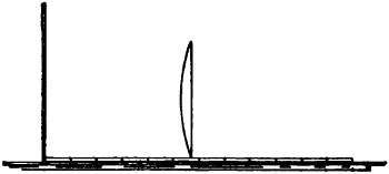
FIGURE 25.
With the objective lens we have two possible focal
lengths to consider. If we measure from the center
of the lens to the screen, we shall obtain what is
called the equivalent focal length (usually abbreviated
E.F. or e.f.). If, instead, we take measurements
from the face of the lens nearest the screen,
we shall obtain what is termed the back focus, or[51]
b.f., of the lens. In all cases it is important, when
ordering, to state which of the two is meant.
Lenses may also be tested for chromatic and
spherical aberration. Chromatic aberration is the fault
of showing colors unduly. It is impossible to avoid
a fringe of color when using only a single lens, but
where we have a complete optical system, consisting
of two condensers and an objective, it must be possible
to adjust the combination so that practically no
color is visible. Spherical aberration is best tested
for by laying out very accurately, as in Figure 26, a
set of small squares upon some material that will not
be damaged by the heat of the lamp—mica for instance—and
projecting this upon the screen. If the
lenses are all good, the lines will all appear square;
if the lenses are poor, the lines will appear curved a
little, or perhaps considerably.
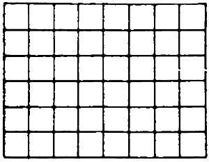
FIGURE 26.
The diameter of the ordinary condenser lens is 41⁄2
inches. Smaller lenses than this cannot well be used
because they would not cover the diagonal of lantern
slides. A very common focal length of condenser is
61⁄2 inches. There is no very accurate relation necessary
between the focal length of condenser and
objective. There is considerable difference of opinion
on this subject and much of it is induced by the
possibility of condenser breakage which is increased[52]
by using condensers of short focal length, but in this
case, as in many others, the operator must find out
by his own experiments.
A very good plan—since, on account of breakage,
extra lenses must be carried anyway—is to carry two
71⁄2-inch and two 61⁄2-inch condensers and experiment
with these. The two of the same diameters may be
tried together and also those of different focal lengths,
using the one of shorter focal length either in front
of or behind the other.
HINTS ON MANAGEMENT OF PROJECTING ARCS.
Before starting to work about the lamp, be sure
the switch is off.
See that the lamp house is clean and spark tight.
The gauze provided at the top must be kept free
from dirt and carbon ash, or the house itself may get
too hot.
The house should be of such dimensions, relative
to the length of electrodes used, that the latter cannot
touch either at the top or bottom and thus ground
the circuit on the lamp house and possibly burn a
hole in it.
See that your lamp mechanism is well aligned so
that electrodes center at all positions.
All of the screws and adjustments should be well
lubricated frequently. The heat in the lamp house
soon evaporates all lubrication.
Where lamps are used much and carry heavy currents,
the leading in wires will probably need reconnecting
about once a week. It is best to reconnect
them some time before they burn off rather than be
obliged to do this during a show.
See that your polarity is right. With direct current,[53]
the upper electrode will retain its heat longer
than the lower if connections are made properly.
With alternating current the polarity is immaterial.
Always point your electrodes, especially the lower.
If the lower electrode is not pointed, it will interfere
with the light of the crater.
The recommendations for sizes of upper and lower
electrodes vary somewhat but run mostly to 5⁄8 inch
for upper and 1⁄2 inch for lower. The size depends
very much upon the current used. If the electrodes
are too large, the arc will travel around the outside
and yield a poor and uneven light.
Always use cored carbons for alternating current.
The best length for electrodes is about 6 inches, if
they do not strike the lamp house.
Notch the carbon electrode a little before attempting
to break it off.
Many operators are in the habit of watching the
arc, opening the lamp-house door to look at it. Not
only is this injurious to the eyes but it also interferes
with proper judgment of the illumination of
the picture. A better way is to punch a very small
hole in the lamp house exactly opposite the arc. Over
this opening a lens may be placed, and a picture of
the arc may be thrown against a wall or screen set
up for that purpose. A picture of the arc is also obtainable
in another way: If the lamp is once set exactly
right, a cross may be painted at the proper
place on the screen which will indicate the exact
point where the arc should be maintained. The arc
will of course appear inverted. Another method of
keeping the arc always in view without inconvenience
consists in arranging a small mirror, at an angle to[54]
the peep glass in the door, so that it will reflect the
arc towards the operator.
An adjustable resistance should always be kept in
reach so that the current may be varied to suit different
films or stereopticon lamps.
Keep your hands as free from carbon dust as possible.
This dust is responsible for much damage to
films.
[55]
CHAPTER IV.
MOTION PICTURES.
Strictly speaking there are no pictures of motion.
What we see as such is simply an optical illusion.
This illusion is produced by presenting a series of
pictures of an object in a systematic manner, each
picture showing some slight change from the preceding
one. If these changes be all in a certain direction
and brought before our eyes in regular order,
we shall perceive the appearance of motion in that
direction. Such pictures may be made by means of
photography.
A very simple form of motion picture is made up
in the form of a small book containing a number of
leaves that may be run off under the finger of the
holder. If these leaves contain such a series of pictures
as is mentioned above, the holder, on manipulating
them properly, will see motion reproduced
quite naturally.
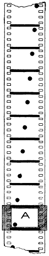
FIGURE 27.
The manner in which the illusion of motion is produced
can perhaps best be illustrated by Figure 27.
Here we have an ordinary film, or it may be any
piece of white paper, upon which are drawn a series
of black dots as shown. If this film—the observer being
able to see only that part in the aperture A—be
drawn downward the length of one section very quickly;
allowed to rest a moment; then, in the same manner,
be drawn down another section; and this process
repeated at proper speed, until the full length of
the film has passed the aperture, we shall have received
the impression that the black dot moved from[56]
the lower left-hand corner to the upper
right-hand corner of the aperture. In
order that such an illusion might be
perfect, we should have to move the film
so rapidly that the eye would not perceive
the movement. This is not possible
except with very weak illumination
and we should actually, in the
above experiment, receive a blurred impression,
because we could not help seeing
the dots while they were moving,
and our eyes would behold a mixture
of stationary and moving dots. In order
to produce the impression of perfect
motion, it is necessary to shut off
the light during the time that the film
is actually in motion. Thus, paradoxical
as it may seem, in order to simulate
motion, we must have the object
which is to appear in motion always perfectly
still before our eyes.
In order that we may not notice that
the film is out of sight, it must be moved
very quickly. The actual time during
which the picture on the average film
is hidden from view, and in which the
picture is changed, is about 1⁄80th of a
second and the time during which the
picture is stationary is about 4⁄80th of
a second.
The possibility of the illusion of motion pictures
depends upon a faculty of the eye known as persistence
of vision. The eye retains an impression for
something like 1⁄25th of a second. When an object[57]
is in motion, we see, therefore, not only one position
of the object but all positions of it during the time
of persistence of vision. This time varies somewhat
with the intensity of the light or the impression made
upon the eye. If it is equal to 1⁄25th of a second in
the case of a ball thrown at the rate of one hundred
feet per second, then we should see, instead of one
ball, a large number of balls merging imperceptibly
into one another, or, in other words, a streak of balls
four feet long. Thus, in actual life, we obtain from
the moving ball but a blurred impression.
We see thus that in order to produce the impression
of motion, we must present the picture to the
eye long enough to stimulate it properly; we must
very quickly remove that picture and substitute another
differing to a slight extent from the former;
and we must repeat this process a number of times.
The ordinary moving picture film contains 16 pictures
per foot, and is run off at the rate of about 60
feet per minute, so that in one minute, we see 960
different pictures.
In order to make motion visible, we must bring it
within a certain speed limit. Thus, to show the motion
of a swiftly thrown ball in detail, we must make
it appear to move more slowly than it really does;
and to show the development of a growing plant, it
must appear to grow much faster than it actually
does. Both of these requirements can easily be fulfilled
by the motion picture camera and the projecting
machine.
A man, walking at the rate of three miles an hour,
displaces himself about three inches during the time
of the exposure of one picture, or 1⁄16th of a second.
At this rate we obtain the impression of even[58]
and continuous motion unless he be too close to the
camera. In order to obtain pictures of other objects
moving at faster or slower rates, we must take them
at intervals in order that the displacement between
pictures will be about the same or at least not any
more. This means that pictures of rapidly moving
objects must be taken at short intervals and those of
slowly moving objects, at long intervals. A kernel
of corn develops into a stalk six feet high in about
ninety days. If a photograph of this is taken every
day during its growth and these pictures arranged
in proper order, they will be run off at normal speed
in less than six seconds, thus showing us in six seconds
the growth which actually takes place in ninety
days.
The motion picture camera enables us not only to
produce the illusion of motion, but to see in detail
what actually takes place in connection with the
moving object at any instant. If we take pictures
of a running horse, for instance, at short enough intervals,
we shall be able to see, on the films, just how
he holds or places his feet or any other part of his
body at any time.
In order to obtain a perfect picture simulating
motion, we must present the first picture long enough
to stimulate the eye; then we must shut off the light,
remove the first picture, and substitute the second;
remove the second and substitute the third, etc., as
long as desired. During the time that the light is
shut off, the first picture must persist in our vision
until the new one has appeared. The two pictures
thus mix until the first one has faded, and thus we
obtain the illusion of motion.
If the bright picture remains too long, the pupil[59]
contracts—as explained in the chapter on Optics—and
when next the light is shut off, the darkness is noticeable
and gives rise to the disagreeable phenomenon of
flicker. In order to prevent this over-stimulation of
the eye, the long period of exposure is interrupted by
a shutter at least once and, in some cases, two times;
and some machines are equipped with a three-blade
shutter. This three-blade shutter has a wide blade
which shuts off the light while the film is in motion
and two narrower blades which pass across the light
during the time that the film is stationary, to prevent
the over-stimulation of the eye.
Colored Pictures.
Colored Pictures.—There are two general methods
of producing colored motion pictures: One is that of
hand coloring or tinting, and the other is what is
known as the Kinemacolor process. In the latter
process, no color whatever is used on the film; the
coloring is supplied by a shutter with a green and a
red blade which are alternately thrust into the light
by which the picture is projected upon the screen.
In order that this process may be used, the film
pictures must first be taken through screens of corresponding
color. The film in the Kinemacolor camera,
or projecting machine, must run at more than double
the speed of that which is used in the ordinary process;
and each alternate picture must be photographed
through a red screen; the others, through a
green screen.
The red screen will allow only red light to pass;
hence, any part of an object that contains no red
will not affect the photographic emulsion. Similarly,
the green screen will allow only green light to pass;
and such parts of the objects as contain no green
will not affect the emulsion. The alternate sections[60]
of film will thus be entirely different from each
other.
In order to reproduce the original color of the
object upon the screen, it is but necessary to arrange
that the pictures shall in turn be projected through
the same or similar color screens. In order to accomplish
this, the Kinemacolor machine has, in addition
to the regular shutter which cuts off the light during
the time the film is in motion, an additional two-wing
shutter which inserts the properly colored screens
before each picture, as it comes to a standstill in the
film window. Thus we see in alternation, a red picture
and a green. Persistence of vision, which is explained
in Chapter IX, helps us to mix the two colors
and we see the object approximately in its own colors.
The color effect is not very good, owing partly to
the fact that only two colors are used. If the three
primary colors—red, blue, and yellow—could be used,
the effect would doubtless be better; but the complications
would be multiplied.
In order to get the best results with the Kinemacolor
process, colors of a certain shade are used and the
size and depth of coloring in the two shutters is
variable. One of the colors is adjustable and must
be so arranged that when the machine is run without
film, it will throw approximately white light upon
the screen. The high speed with which the film
must be run makes it impossible to turn the machine
by hand and it is always motor-driven.
The colored shutters are constantly in the light
and absorb a large portion of it and this must be
compensated for by an extraordinary high amperage.
This process requires more than two times as much
current as the ordinary projection of black and[61]
white pictures. In order to obtain the greatest possible
amount of light, operators usually run a very
long arc and this often results in imperfect definition.
In arranging for an exhibition, it is important that
the film and the colored screens be correctly placed
with reference to each other; to facilitate this, an
identifying mark is placed on the side of one of the
colors.
[62]
CHAPTER V.
THE MOTION-PICTURE MACHINE.
A diagrammatic sketch of the essentials of a good
motion picture machine is given in Figure 28. This
does not represent any machine in particular and no
machine exactly like it will be found; it does, however,
show the theoretical elements necessary to the
projection of motion pictures and the usual safety
devices with which standard machines are provided.
As a variation from Figure 28, the exact method of
threading the film through the Edison machine is
given in Figure 29. In Figure 28, the parts are
designated as follows:
- A—feed reel or upper reel
- B—feed reel magazine or upper magazine
- C—magazine fire traps, or film valves, or fire valves
- D—upper steady-feed sprocket
- E—presser rollers, or friction rollers, or idlers
- F—upper feed loop or upper loop
- G—film-steady drum or film steadier
- H—film gate
- I—tension spring
- J—automatic fire shutter
- K—revolving shutter
- L—intermittent sprocket
- M—lower feed loop
- N—lower steady-feed sprocket
- O—take-up reel and lower magazine
- P—framing device or adjusting lever (not shown)
- Q—film shields
[63]
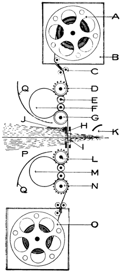
FIGURE 28.
[64]
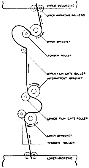
FIGURE 29.
In addition to the above, there are the gearing and
the belting which transmit motion to the various
sprockets and drums shown. The whole function of
the machine, however, is the proper moving of the
film along the lines indicated in the figure, the heavy
black line representing the film. The film is unwound
from the upper reel by the upper steady feed
sprocket D. After forming the upper loop F, it
passes over G, through the film gate H, to the intermittent
sprocket L. This sprocket moves the film by an[65]
intermittent motion allowing the film to remain stationary
in the light for about four-eightieths of a
second and shifting it during about one-eightieth of
a second. After leaving the intermittent sprocket,
the film forms the lower loop and then passes to the
lower steady feed sprocket, which prevents the take-up
from pulling the loop away from the intermittent
sprocket. The object of the upper and lower loops
is to lighten the work of the intermittent sprocket
as much as possible by making it unnecessary to
move anything but the film between the two loops.
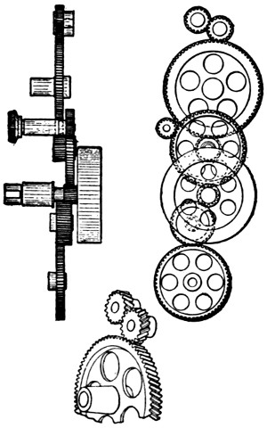
FIGURE 30.
All of the sprockets and the shutter K are connected
together by a train of gears (see Figure 30,
which is the gearing of the Motiograph machine) and
when properly adjusted they all work in proper relation[66]
to each other. The upper steady-feed sprocket
feeds just as much film into the upper loop as the
intermittent sprocket takes away; while the lower
steady-feed sprocket takes away just as much as the
intermittent sprocket feeds to it. The film is unwound
from the upper reel and rewound upon the
lower; but before it is used again, it must be rewound
from the lower reel upon another one. If it
were to be exhibited from the lower reel without this
rewinding, the pictures would be exhibited backwards.
DISCUSSION OF PARTS.
A—Upper, or Feed Reel.
A—Upper, or Feed Reel.—The feed reel is usually
either 10 or 12 inches in diameter. A 10-inch reel
accommodates 1,000 feet of film and a 12-inch reel,
about 2,000 feet. The reel fits loosely upon bearings
in the upper magazine and the film is unwound from
the reel, which revolves, by the upper steady-feed
sprocket. To prevent its unwinding more film than
is wanted, a small spring is arranged to cause a slight
friction. It is best to keep good reels in the operating
room for use as feed reels. A reel to be used
for this purpose should be perfectly true and in good
order; reels sent out from the exchanges are often
bent or have loose parts which cause trouble. A
good operator will keep a supply of good reels always
on hand.
B—Upper Magazine.
B—Upper Magazine.—The upper magazine is a
steel box made up without solder and fitted with a
steel door on the crank side of the machine. It exists
for the purpose of protecting the film against fire or
injury from other causes. It is important that the
door be kept closed for, without this precaution, there
is no fire protection. In some cities, it is required[67]
that the door be provided with spring hinges to keep
it closed, but it is doubtful whether this is a wise
provision; for since the door must be opened to
change films and since there is nearly always great
haste in making the change, it is likely that the operator
will block the door open if the spring hinges
interfere with him. All doors now swing to the side,
but it seems as though it would be a great improvement
if the doors were arranged to drop down. The
door would then, even if open, prevent fire from
below reaching the film. The magazine might as well
be entirely missing as to be left with the side-swinging
door open. Many operators have the habit of
opening the door to watch the progress of the reel
instead of noting it on the screen, or of preparing
for a change of reel by opening the door long before
necessary and starting the new run before closing
the doors. Needless to say, this is highly reprehensible.
In order to put out a fire in case it should communicate
to the reel, the magazines have been connected
with water piping and a valve so arranged
that the water could be turned on instantly thus filling
the magazines. If the door of the magazine is
kept closed, the progress of a fire will be comparatively
slow.
C—Fire Traps.
C—Fire Traps.—The fire traps are an important
adjunct. Their object is to prevent fire, which often
occurs at the aperture, from reaching the film on the
reel. All of the various makes of fire traps have been
tested and will ordinarily prevent fire from passing
through them. The larger the roller and the smaller
the space around the film, the better the traps seem
to be. The metal of the rollers has a cooling effect[68]
upon the flame and this is undoubtedly one reason
why they do their work so well. None of them, however,
is absolutely sure.
If the opening through which the film passes is
made too narrow, the film is likely to brush one side
or the other and wear grooves in it, or cut entirely
through it, with the result that a splice may be
caught in the opening and the film torn. Fire traps,
cut in this manner, have been the cause of many
fires. This trouble is due mainly to improper alignment
of the magazine with the fire traps. Examine
them often and, if the least wear shows, improve the
alignment.
It is advisable that every operator test his traps
with pieces of film and assure himself that they will
not, under ordinary circumstances, carry fire; but
he must never rely too much upon them as safeguards,
for although they will check a small blaze,
such as would result from the burning of a few
inches of film, they would probably not extinguish
a fire occurring when there was much film crowded
around them, as might be the case when a take-up
reel or the intermittent sprocket failed to work. If
the film catches fire and there is any possible chance
to do so, the operator should tear it off at the upper
and lower magazines, and thus break the communication.
But if there happens to be a lot of film
lying loosely about, it is advisable for the operator
to get away as quick as possible.
D—Upper Steady-Feed Sprocket.
D—Upper Steady-Feed Sprocket.—The office of
the upper steady-feed sprocket is to unwind the film
from the reel and feed it toward the intermittent
sprocket. In order that it may do its work well and
relieve the intermittent sprocket of all unnecessary[69]
strain, there must be a loop F. The upper steady-feed
sprocket is in continual steady motion and feeds
just as much film to the loop as the intermittent
sprocket takes from it by periodical jerks. The main
trouble with all sprockets is in the wear of the teeth,
as in time they wear away near the body of the
sprocket and form hooks. The best sprockets have
a number of teeth to engage the film. In some of
the older machines, only two teeth catch the film, in
which case, if two holes in the film are torn out, the
film may stand still.
E—Presser or Friction Rollers.
E—Presser or Friction Rollers.—The presser or
friction rollers exist merely to hold the film in its
proper place. They are sometimes spoken of as
friction rollers although they have nothing to do with
friction.
F—Upper Loop.
F—Upper Loop.—The upper loop is provided for
the purpose of storing slack film which the intermittent
sprocket may pull away with a very rapid jerk.
It avoids placing unnecessary strain upon the film.
The upper loop often causes trouble by enlarging;
this occurs when the intermittent sprocket fails to
work while the steady sprocket continues to feed. The
most frequent cause of this is due to faulty films. In
order to prevent the excess film in the upper loop
from falling over in front of the light of the arc
lamp (which would quickly set it on fire), the film
shields Q are provided. In many machines they are
too short or too narrow to be of much use.
G—Film-Steady Drum, or Film Steadier.
G—Film-Steady Drum, or Film Steadier.—The film
steadier is not found in all machines. If the upper
portion of the machine head is properly arranged,
the film may feed directly into the gate.
H—Film Gate.
H—Film Gate.—The film gate is to hold the film[70]
in position. In order that the picture may be properly
projected, the film must lie perfectly flat and at
a fixed distance from the lenses. If this distance
varies, there will be improper focusing of the picture.
The film must also be held in its proper position
laterally and vertically. The film gate has nothing
to do with the height of the film. This is taken care
of by the framing device. The film gate wears quite
rapidly and when badly worn allows the film too
much play. In order to avoid the wobbling of the
picture, a new gate must be provided. There should
be considerable metal surrounding the aperture and
there should also be an air space and some little ventilation.
The metal surrounding the gate is subject
to the heat from the arc lamp rays and, unless properly
constructed, may overheat and damage the tension
springs, if it does not set fire to the film.
I—Tension Springs.
I—Tension Springs.—The tension springs are provided
to hold the film flat against the film gate and
also to check its motion as soon as the intermittent
sprocket has stopped pulling it. A certain intermittent
movement is advertised to make the change from
one picture to another in 1⁄96 of a second at normal
operating speed. The film moved at this rate of speed
acquires considerable momentum; and the office of
the tension spring is to bring it to rest as quickly as
possible. If the springs are set too tight, they will
cause the machine to run hard and may also be the
cause of tearing out splices. They should be set just
tight enough to keep the picture steady; anything
beyond this will merely cause unnecessary wear of
the parts, besides calling for unnecessary exertions
on the part of the operator.
J—Automatic Fire Shutter.
J—Automatic Fire Shutter.—The automatic fire[71]
shutter is provided for the purpose of shutting off
the light when the machine is not in motion. It is
required by most city ordinances. The ideal fire
shutter would be one so controlled by the film that
it would remain up only while the film is moving at
operating speed. The shutters in use at the present
time vary widely in details of construction. Some of
them are raised and admit the light to the film the
instant the handle is pressed sufficiently to start the
machine. Other types are raised only after the machine
has nearly attained its proper speed. Some
operate as indicated in the figure and others operate
from the side. All of them are liable to become deranged
at times, and it is no unusual thing to find
them tied up in some way because they failed to work
properly. The shutter is a great convenience when in
proper order and has probably prevented many fires;
but it is good practice to consider it as entirely absent
and not get into the habit of relying upon it. The
operator should always push his lamp to the side
whenever anything is out of order. This act is necessary
in most houses at the end of every run of film
showing stereopticon slides. It would inconvenience
the operator but little to do this at all times, and then
the habit would be formed and become second nature.
On the machines now in use, there is no automatic
shutter governed by the action of the film, which
would give protection in case the film should come
to rest, as old films often do when their sprocket
holes are torn out, or, as often happens, when the
film splits along the row of holes. In some machines
the fire shutter is made up of such thin material and
rests so close to the film that the light may heat it
sufficiently to fire the film below it. Pieces of film[72]
often become detached at the aperture and remain
in the light long enough to be ignited. Against such
occurrences as these there is no protection whatever
except the watchfulness of the operator. If the film
fits snugly into the gate and is well enclosed, such
fires do not usually spread.
K—The Revolving Shutter.
K—The Revolving Shutter.—The revolving shutter
is sometimes arranged in front of the machine and
often between the film and the lenses. The shutter
K is of the “barrel” type and is further illustrated
in Figure 31 at the left. The object of the shutter
is to shut off the light during the time that the film
is in motion so that the impressions made upon the
eye by the succession of stationary pictures may not
be blurred by the motion of the film when it is
changed. The ideal shutter is one that shuts the
light off instantly and, at the expiration of the necessary
time, allows it as quickly to come to view again.
The barrel-type shutter allows the light to pass
through while it is in the position shown by solid
lines, Figure 31, and has it entirely shut off when in
the position indicated by broken lines. When it is in
motion, the upper wing begins to shut off the light
from the top and the lower from the bottom, thus
causing the total eclipse of light in one-half of the
time that a single wing shutter could do it.
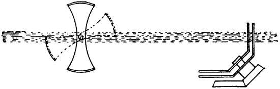
FIGURE 31.
[73]
At the right of Figure 31, we have a cone shutter
such as is used in the Motiograph. The stem and
gearing of this shutter are set at an angle of forty-five
degrees to the rays of light, for the purpose of
arranging them inside of the mechanism without
taking up too much room. There are two cones of
the kind illustrated in Figures 32 and 33 and they
move in opposite directions, thus shutting off the
light in about the same time that a barrel shutter
could be made to do it. These two figures show the
positions of wings just before shutting off the last
vestige of light and just as they are beginning to
admit it again.
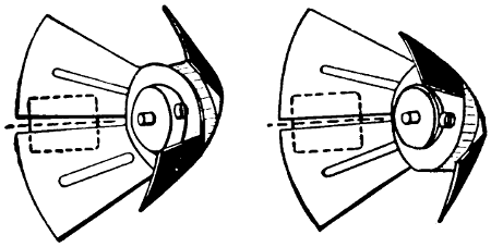
FIGURE 32.FIGURE 33.
The disk type of shutter is much used. It may
have either one, two, or three blades and may also be
double, i.e., two disks revolving in opposite directions
so as to shut off the light from two sides of the
opening at once. Three types of disk shutters are
shown in Figures 34 to 36. In order to obtain a
flickerless picture, it is necessary to cut off the light
not only during the time that the film is in motion,
but also during part of the time that it is standing
still. If the light were not interrupted during the[74]
time of exposure, the light interval would be so long
that the difference between the dark period, when
it is shut off entirely, and the light period would be
great enough to be noticed in the form of a flicker.
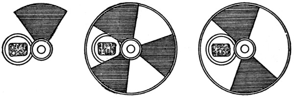
FIGURE 34. FIGURE 35. FIGURE 36.
If a single-blade shutter is used, it must make two
revolutions during the time that a single picture is
exposed; once to shut off the light while the film is
being moved and once to interrupt the period of
illumination. This shutter would thus have to run
twice as fast as the two- or three-blade shutter, the
three-blade shutter interrupting the light twice during
the time the film is standing still.
The three-blade shutter has one wide blade which
must be in front of the light while the film is moving
and two narrower ones which interrupt the light
during the time of exposure.
The two-blade shutter must have both blades of
the same size and run one and one-half times as fast
as the three-blade shutter to obtain the same effect,
i.e., cause two interruptions of light during the time
of exposure.
In order to shut the light off very rapidly with a
blade, which approaches the opening from one side
only, the disk shutter must be of sufficient size to
produce great angular velocity. It can not well be[75]
used, therefore, inside of the mechanism, but is usually
placed in front of the machine; and it is much
larger than the aperture which it must cover. The
shutters must all be set so as to shut off the light
during the time that the film is in motion. When the
dividing line between two film pictures is in the center
of the aperture, the shutter should have it entirely
covered. It is possible, however, to arrange
the shutter so that the film may move a trifle before
the light is shut off and continue in motion also for
a very short time after the light is again admitted.
This is practicable with the “Geneva” intermittent
movement which starts and stops the film gradually.
A shutter should be adapted to the speed of the
film movement. There is no need of keeping the film
covered any longer than it is in motion. A quick
film movement and a narrow shutter will add considerably
to the light obtained from a given lamp
and a given current consumption. If the shutter is
not properly adjusted, there will be what is known
as “travel ghost”, “light rain”, or “halo”. These
are due to the improper timing of the shutter, allowing
a part of the picture to be seen while in motion.
The travel ghost may be seen either at the top or the
bottom, according to whether the shutter is set too
fast or too slow.
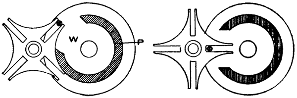
FIGURE 37.FIGURE 38.
L—Intermittent Sprocket.
L—Intermittent Sprocket.—The intermittent sprocket
is a very important part of the machine. Owing
to the swiftness with which it strikes the film, the
teeth on it are more subject to wear than those on the
other sprockets. The number of teeth that engage
the film is also an important item. In order to obtain
the best picture with the least expenditure of light,
the film should be moved very rapidly so as to allow[76]
the greatest possible length of time for the stationary
picture. The film should, furthermore, be started
slowly; then increased in speed; and the speed should
decrease gradually until brought to rest, and thus
avoid unnecessary jerking. It is also necessary to
prevent all motion of the film during the time the
mechanism which moves it is preparing for the next
succeeding movement. All of these conditions are
admirably fulfilled by the “Geneva” movement,
Figure 37. The pin wheel W is in continuous motion
and the pin is so placed upon it that it enters one
slot of the cross and carries it along with it, thus
causing a quarter revolution of the cross each time
the pin wheel makes one revolution. The cam band
P is cut away sufficiently to allow the cross to make
a quarter revolution, but the remaining portion of it
is made to fit the cross snugly, so that when the cross
is not in motion it is held rigid. Figure 37 shows
the movement just starting and Figure 38 shows it
half completed. It can be seen that the motion begins
very slowly; comes to a maximum when it is in
the middle; and ends slowly; thus subjecting the film
to the least possible strain. This movement is widely
used and may be arranged with one pin, as shown,
or with two. If the pin wheel is equipped with two
pins, it will move only half as fast as with one pin[77]
and thus the proportionate time that the film is in
motion will be lengthened. By making the pin wheel
large as compared with the cross or star, the time
during which the motion takes place can be reduced
as much as desired; but the characteristic feature of
starting and stopping the film gradually will be lost
directly in proportion as the relative size of the pin
wheel is increased.
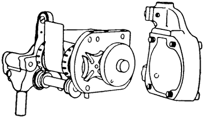
FIGURE 39.
The “Geneva” movement requires extremely accurate
construction and careful management. If
dusty or insufficiently lubricated, it wears very
rapidly. It is often arranged so that it can be immersed
in oil while running. Figure 39 shows a
practical application of the “Geneva” as used in the
Motiograph. The cover shown at the right entirely
encloses it.
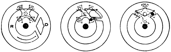
FIGURE 40. FIGURE 41. FIGURE 42.
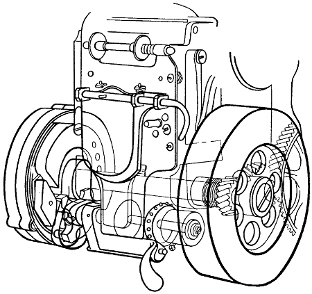
FIGURE 43.
A form of intermittent movement which has lately
come out and is used on the Powers No. 6 Cameragraph
is shown in Figures 40 to 42 inclusive. The
moving element of this intermittent movement is a
diamond-shaped projection on the surface of a revolving
disk. The driven element is a cross carrying
four pins—termed a “pin cross”—and is indicated
by broken lines. The raised portion A of the diamond
strikes one of the pins of the cross and starts it in[78]
motion as indicated in Figure 41. The movement
of the cross can be traced by the black dot indicating
one of the pins. At every revolution of the driving
disk, the cross makes one quarter of a revolution and
when not in motion is held rigidly locked by the locking
ring R, which fits snugly between the pins. This
movement probably moves the film in the shortest[79]
time of any. It is entirely encased, runs in oil, and
is practically noiseless. The manner in which it is installed
in the machine is indicated in Figure 43.
M—Lower Feed Loop.
M—Lower Feed Loop.—The lower feed loop is
provided to prevent the lower sprocket from pulling
on the film and thus interfering with the work of the
intermittent sprocket. The intermittent sprocket
feeds the loop, by jerks, three-fourths of an inch of
the film at a time; and the lower sprocket is geared
to take away that much by steady motion. Thus,
everything working properly, the loop remains of the
same size. In case the lower sprocket is not working
properly, the loop may become enlarged and the film
may run onto the floor. Sometimes the intermittent
sprocket does not work properly and the lower
sprocket pulls away all of the loop.
N—Lower Steady-Feed Sprocket.
N—Lower Steady-Feed Sprocket.—The lower
steady-feed sprocket maintains the loop and restrains
the film. If it were not for this sprocket, the take-up
mechanism would pull directly on the intermittent
sprocket and keep the film jiggling.
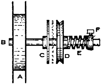
FIGURE 44.
O—Take-up Reel.
O—Take-up Reel.—The take-up reel is identical
with the upper reel and, in fact, the two are generally
used interchangeably. In both cases, only perfect[80]
reels should be used; and reels delivered by exchanges
are very often untrustworthy.
The principle of the take-up mechanism is shown
in Figure 44. When a run of film is started, the
diameter of the roll of film being small, the reel must
travel comparatively fast to take up the film as fast
as it is unwound from the upper reel. As more and
more film is gathered by the lower reel, the travel
must become slower until finally, with a twelve-inch
reel, the number of revolutions per minute are but
about one-fourth as many as at the beginning.
In Figure 44, A is the reel which is fastened to the
spindle B; C is a collar also fastened to the same
spindle. D is a loose pulley capable of revolving
around the spindle without imparting motion to it
and arranged so that it can be driven by a belt. E
is a spiral spring which is controlled by the small
collar F, and it presses the loose pulley against the
collar C. If the loose pulley is pressed against C
with sufficient force, it will cause C to revolve with
it; and the movement of C will impart motion to the
reel and wind up the film which is fastened to it. D
must revolve fast enough so that, even when the reel
is empty, it will take up all of the film fed to it. As
the film is wound up, the size of the roll of film increases
and the speed must become less; thus D begins
to slip a little on C and this slippage increases
until the end of the run.
Friction in one form or another is the only method
by which take-up reels are now operated; but in some
of them this friction may be in a belt, as well as in
the two disks as shown. Sometimes a fiber washer is
interposed between the two friction disks. In the[81]
Motiograph take-up, Figure 45, the necessary friction
and slip are all in the belting.
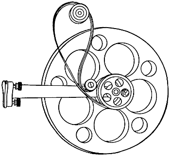
FIGURE 45.
If the take-up is not handling the film properly, it
is due to a loose belt or to insufficient tension on the
spring. The take-up probably causes more trouble
than any other part of the mechanism and it should
be carefully watched. On account of the trouble incurred
from it, there are still many operators who
prefer to run films into a tank; although the take-up
saves them much time. A careful operator who
understands the care of machinery would have little
trouble with a take-up; while the one who has not
the faculty of keeping things in order would, perhaps,
be better off (fire hazard neglected) with a
tank. With most machines, the take-up magazine is
located where it is very difficult for the operator to[82]
watch its operation. Those machines in which it is
located in easy sight of the operator have considerable
advantage in this respect. A careless operator
is often compelled to open the lower magazine door
and turn the reel by hand when the take-up tension
is out of order. Remember that the take-up can cause
trouble only when it is out of order and that a good
operator will never allow it to get out of order and
he will inspect it carefully before every show.
P—Framing Device.
P—Framing Device.—The aperture in the film gate
is just large enough to fit the picture on the film.
If the film is accurately placed, the whole picture will
show upon the screen. In order to bring this about,
the machine must either be provided with a means
of adjustment, or a certain part of the film must be
placed upon a certain sprocket tooth. This latter
method causes considerable annoyance and waste of
time; furthermore, every splice in a film would have
to be made exactly right or the whole succeeding part
of the show would be “out of frame”. In order to
avoid these troubles, every machine is provided with
a so-called framing device. Somewhere about the
machine, convenient to the operator, will be found a
lever by which, during the operation of the machine
and without interruption, the position of the film
with reference to the film window and the lens may
be adjusted either up or down. The precise manner
in which this is done varies with different machines.
The framing device must be capable of adjusting the
film to somewhat more than the width of one picture.
The splice should be so made that framing becomes
unnecessary and this is accomplished by cutting
out full pictures so as to leave each picture with[83]
the full four holes. If a picture is left, for instance,
with only two holes, it will appear upon the screen
with the black line, which should be hidden in the
center. If this happens, by moving the framing
lever either up or down, the picture can again be
centered upon the screen.
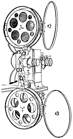
FIGURE 46.
Q—Film Shields.
Q—Film Shields.—The film shield is an important
part of the machine; although it is often very much
neglected and in many machines is so small as to be
practically useless. It should prevent films from
crowding out into the light when the loops enlarge.[84]
Many operators do not take kindly to machines that
enclose the film too tightly; for in case the take-up
fails to work properly, it is often a convenience to
be able to handle the film. This is also the case
where very badly torn or old film is used. Many old
films are so badly worn that they will not run properly
on the sprockets and must be very closely
watched.
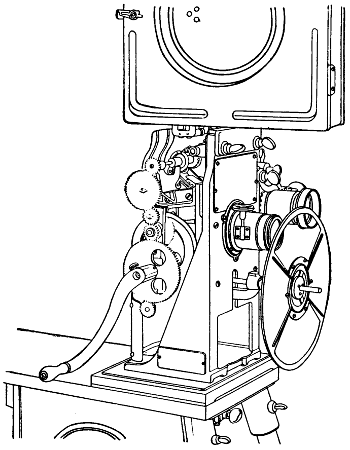
FIGURE 47.
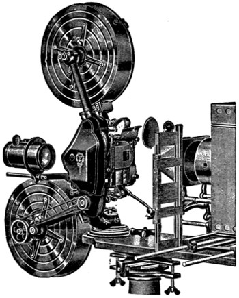
FIGURE 48.
It is not thought necessary or advisable to go into
the details of construction of any particular machine[85]
as changes are made nearly every year so that
such description would not be of great value and
might, in fact, be misleading. Any person possessing
a little mechanical ingenuity and taking an interest
in such matters can readily learn the peculiarities of
any of the machines. They are, after all, when one
has mastered the principles, quite simple affairs. All
progressive manufacturers, furthermore, publish instruction
books which are issued whenever a change[86]
is made in any machine; and these are always obtainable.
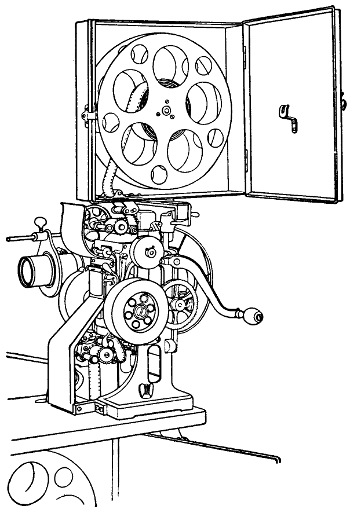
FIGURE 49.
In Figure 46 we have a general view of the Edengraph
machine. It will be noticed that the total
length of film between the two magazines is exposed
to view making threading of the film very easy; also
that the revolving shutter works between the objective
lens and the film gate.
The well-known Edison machine is shown in [87]Figure
47. This is one of the best known machines; and it
is very compact and durable.
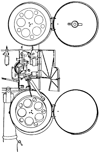
FIGURE 50.
The Motiograph is shown in Figure 48. The take-up,
shown on the lower magazine, is different in this
machine from what it is in the others. This machine
also has a special rewind feature. By an adjustment
of the operating handle, the film, after having been
run off onto the take-up reel, can be rewound upon
the upper reel without taking it out of the magazines.
[88]
Figure 49 shows a general view of the Powers No.
6 Cameragraph mechanism.
The Simplex mechanism is shown in Figure 50.
In this machine the film is entirely enclosed between
the two magazines.
[89]
CHAPTER VI.
THE FILM.
Film Making and Characteristics.
Film Making and Characteristics.—All film is of
celluloid. The commercial film used for the projection
of motion pictures comes in long strips, is about
one and three-eighths inches wide, and about one
two-hundredths of an inch thick. Upon one side
of this film is a photographic emulsion of gelatine
impregnated with a solution of bromide of silver.
This silver is sensitive to the light and has the property
of turning black, during the process of developing,
in proportion to the quantity of light that has
struck the different parts of the emulsion. Wherever
the light has been very intense or has been applied
for a sufficiently long time, the film, after treatment
with a proper developing fluid, becomes very black;
where no light has reached it, it remains white; and
in the intermediate portions, the shading is in proportion
to the light that has reached those parts.
Film that has not been exposed and developed is
of a creamy yellowish color and, if immersed in a
solution of hyposulphite of soda, will turn perfectly
clear and offer no obstruction to the light. If, on
the other hand, it is completely exposed and developed,
it will become solid black; such black pieces
are sometimes used as leaders and tails in connection
with motion pictures.
The emulsion on the film melts at a temperature
of about 90 degrees Fahrenheit and will then run off
the film. It is also soluble in warm water. The[90]
celluloid of the film is very inflammable and bursts
into flame at a temperature of 284 degrees Fahrenheit.
If it is ignited while tightly wound upon a
reel, it burns somewhat slowly; if it is ignited in a
tank, the beginning of the fire is also slow; but as
soon as the air in the tank attains the proper temperature,
the whole of the film bursts into flame at
once. It acts in this respect very much like gunpowder.
In burning, the film gives off a dense brownish
mass of poisonous smoke. Film will burn even
when it has no access to the air and a film fire cannot
be put out by smothering.
Before sending out their films, the manufacturers
treat them with glycerine. This is for the purpose
of keeping them pliable as long as possible. In time,
however, a film dries out and there is then very little
that can be done with it. At any rate, whatever is
to be done should be done by the exchange, as no
operator has facilities for handling it.
Some films are waterproofed and a little water will
not damage them much; but other films must be kept
dry. If by accident a roll of film should become
wet, it can be saved by very quickly unrolling it and
spreading it out to dry. If it can be spread out
quickly enough, it will not be harmed; but if it is
not spread out at once, the emulsion will stick to
the celluloid and will come off when the film is finally
unwound.
There is also a process of fireproofing film. This
must not, however, be too thoroughly relied upon, especially
if the film is old. Fireproof film is a valuable
aid, but it is best to treat it exactly like other
film in respect to the fire hazard.
[91]
On account of its inflammable character, film
should always be kept in fireproof enclosures.
The film contains sixteen pictures to each foot
and for every picture there are four sprocket holes
on each side of the film. The size of the aperture
plate and also the size of the actual picture on the
film is 11⁄16 inch high by 15⁄16 inch wide. If the
picture on the screen is enlarged to 18 feet 9 inches
in width and 13 feet 9 inches high, every part of the
picture on the film will appear 57,600 times as large
on the screen as it is in the film. In viewing a
1000-foot film, the audience will see 16,000 separate
pictures following each other so rapidly that the
change from one to the other will be unnoticeable.
If a three-blade shutter is used, the beholder will
see the light shut off and turned on 48,000 times in
the same run of film, but will not be able to notice
it if the speed with which it is done is correct.
New film coming directly from the exchange is likely
to be too moist and cause trouble from that condition;
while old film is likely to be too dry and cause
trouble by warping or bending out of shape.
Patching Film.
Patching Film.—All reels of films contain patches
and but little trouble will arise from them, provided
they are properly made and reasonable care is exercised
in watching them. In order to obtain a satisfactory
splice, it should not be made more than
3⁄16 inch long; a greater length than this will reach
two sprocket teeth and this is objectionable because
the splice stiffens the film and will prevent it from
fitting the teeth properly. The splice should be so
made that it does not throw the pictures out of frame.
If made properly, it will never be noticed in the
running picture at all, unless a large quantity of[92]
film is cut out. If however, the splice be made over
part of a picture—as would be the case if an improper
number of holes were cut out—the picture,
when projected, would appear out of frame, i.e., the
dividing line between two pictures would then appear
on the screen and would continue to show until
the framing lever had been adjusted to cover the
dividing lines again. Care must also be taken that
the film is straight after being spliced. If the ends
are not fitted squarely to each other, there will be a
bend in the film at the point the splice is made;
and this may cause trouble.
Many operators have a plate of ground glass fitted
into a work bench at the place where splices are to
be made and a small lamp under this glass. This is
very convenient for, as a rule, the illumination in
an operating room is very poor although a good light
is necessary to match film properly. If ground glass
is used, the rough side must be at the bottom; otherwise
it will be difficult to clean off the cement which
adheres to the glass.
By making every splice in exactly the same order,
the operator will acquire the habit of doing it nicely
and quickly. Most splices are made in a hurry (before
or after a show) and in this, as well as in all
things that must be done hastily and at a moment’s
notice, habit and practice are very important. One
does not become expert until he has practiced it often
enough to be able to do it mechanically.
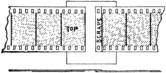
FIGURE 51.
Proceed as follows and as outlined in Figure 51:
Cut exactly along the dividing line of one picture
and save this to become the top piece. (The emulsion
side of the two sections of film must always be
either up or down, and for convenience it is well to[93]
form the habit of having them always one way or
the other.) Now, with a sharp knife, scrape the
celluloid side of this piece until all of the gloss is
removed for a width of a little more than 3⁄16 inch.
Do not scrape any more than necessary, but be sure
that all dirt and oil are removed. Now take up the
other part of the film and cut off the bad portion,
leaving a strip a trifle less than 3⁄16 inch beyond
the dividing line. This strip need not be scraped
on the back, but all of the emulsion must be scraped
from the front side of it. To scrape the front side
nicely, lay a short ruler across it to act as a guide
for the knife and scrape up to this ruler. Scrape
only to the dividing line, but give particular attention
to the sprocket holes and the edges, for it is at
the edges and sprocket holes that film first begins
to work loose and where it is most difficult to secure
proper adhesion. Both parts of the film should be
so scraped that, when finished, each will furnish half
of the dividing line. Now apply a liberal coating
of cement to the latter section and carefully lay the
first upon it, taking great care that the sprocket
holes in the two sections overlap and match perfectly.
It is for this matching purpose that the
glass in the table (with a small lamp underneath it)[94]
is valuable. The sprocket holes must match accurately
and the films must line up straight. After
the upper film is placed, it must be pressed down
for a few seconds until the cement has set. Wipe off
all superfluous cement before it has time to set. Be
sure that there are four sprocket holes for each
picture. Keep a knife on hand and use it for no
other purpose. Keep also a suitable stone on which
to sharpen this knife, for, unless the knife is very
sharp, it will do only poor work and the edge on it
will not last long at any rate. Ordinary cement will
not hold non-inflammable film, and water-proof film
must be more thoroughly scraped than ordinary film.
In the bench, provide a recess into which the cement
vessel may be set and where it will always remain.
Provide also a pair of scissors for cutting the film.
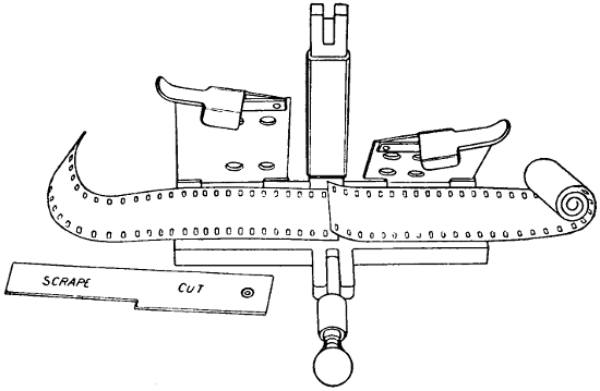
FIGURE 52.
The Edison film mender is shown in Figure 52.
This is made with three gates or hinges. Those on
the right and left clamp down to hold the film, while
the narrower one in the center clamps down on the[95]
cemented edge. To mend a film, place one of the
pieces to be joined in the mender. Place that part
of the gage marked “cut” in position, cutting between
first and second perforations above the floor
line separating the picture. The remaining piece
of film should be placed in the other side of the
mender and cut exactly on the line. Set the opposite
end of the gage marked “scrape” on the first
section; remove the emulsion; cut to the floor line
with a sharp pen knife, moistening it so that the
emulsion will come off easily. After applying the
cement with a brush to the scraped piece, lay the
other piece over it in the mender, clamping it down;
and leave it for an instant to adhere.
[96]
CHAPTER VII.
GENERAL HINTS ON INSTALLATION, OPERATION, AND CARE OF MACHINES.
Tools.
Tools.—First of all provide a suitable and sufficient
set of tools. There should be an assortment of screw
drivers, large and small, to fit the different sizes of
screws used not only with the machine but about the
operating room and with other devices as well. Keep
these screw drivers filed or ground to proper shapes.
A screw driver rounded off, or too small, or bent,
will ruin the heads of the screws. There should also
be a collection of pliers (especially such as are commonly
termed “gas pliers”), files, raps, chisels (for
wood and metal), punchers, drills, and monkey
wrenches; a hack saw, a blow torch, and a vise will
also come in handy. Tools, however, depend upon
the man who uses them. There are men who would
be no better off with such a collection at their disposal;
on the other hand, a clever man would be able
to make use of all these tools and show his skill
thereby.
Aligning the Machine.
Aligning the Machine.—The first thing to do in
setting up a new machine, after it has been unpacked
and put together, is to line it up properly. This can
be done by stretching a string from the lamp house,
through the center of the condenser opening, film
gate, and objective lenses. These must all be in such
a position relative to one another that a taut string
will pass through the center of each. The center
can be determined by measurement either with a
suitable rule or a pair of calipers.
[97]
Anchoring the Machine.
Anchoring the Machine.—The next step is to anchor
the machine so as to reduce vibration to a
minimum. Vibration is often due to a flimsy floor
which will not stand the strain of the unavoidable
vibration and thus helps to increase it. Often, however,
the vibration is due to some part of the running
gear of the machine, such as the revolving shutter,
for instance, being out of balance. If there is undue
vibration, the machinery should be looked after first,
for it is much better to prevent the vibration by removing
the cause than to seek to restrain it by bolts
and braces. If the machine runs very badly, it cannot
be bolted down with any satisfactory results.
Inspection.
Inspection.—After the machine is lined up and
running smoothly, the next step should be to inspect
every part of it thoroughly for loose screws, pins,
gears, or other parts. It is best to do this by beginning
at one end and continuing to the other so
that no part may be overlooked.
Upper Magazine.
Upper Magazine.—See that the spring in the upper
magazine, or on the door of it, which prevents the
momentum of the upper reel from running off film
after the sprocket has ceased pulling, is in good order
and the reel true. A crooked reel will generally
cause trouble and force the operator to keep the
magazine door open so as to be able to aid the movement
of the film.
Fire Trap.
Fire Trap.—The fire trap must next be looked
after. The upper magazine, the fire trap, and the
sprockets must all be in perfect alignment and the
film must run through the trap without touching
either side. Film wears the metal very fast and a
day’s run with the film brushing one side of a valve
will show decided wear. If it is allowed to run this[98]
way, it will soon cut through the side of the valve,
forming an opening in which the film will run and
in which it will often catch and tear splices. Special
care must be exercised to see that the traps are kept
clean and, when not in use, they should always be
covered. The film is drawn through the traps very
rapidly and any kind of dirt accumulating on them
is apt to scratch it. After a fire, burned film is likely
to be found in the trap, and this, when cold, becomes
hard and is difficult to remove.
Cleaning Machine.
Cleaning Machine.—After the machine has been
used for a considerable time, it is advisable to wash
out the gears thoroughly. Not only the gearing, but
the bearings also, should be reached by this process.
If one has plenty of gasoline and a suitable receptacle,
the quickest way is to take out the lenses and
immerse the whole machine for a while in a vessel
filled with gasoline. It can then be taken out, worked
a little, and immersed again; this process being repeated
until all of the old and hardened grease is
worked out. If facilities for immersing the machine
are not at hand, the bearings may easily be cleaned
by using kerosene or gasoline to oil them and then
running the machine a little; this will work all of
the old grease out of the bearings. The gearing can
be cleaned in the same way. If gasoline is used, it
will quickly evaporate and leave the machine in good
order.
Oiling Machine.
Oiling Machine.—After the machine is thoroughly
cleaned, it may be oiled again. The best lubricants
to be used range all the way from sewing-machine
oil to beeswax. Beeswax is used only for the gearing
and only where that is somewhat worn. It is
solid enough to compensate for some of the wear.[99]
That part of it which works out on the sides should
be wiped off at once. There are many lubricants to
be recommended; in general, however, the particular
kind to be chosen depends upon the parts to be lubricated.
A part moving rapidly with no great friction
can be well served with a light lubricant, but heavier
parts, or parts that fit so closely as to cause much
friction are best served by some lubricant that has
more body. If a light oil is used, it will of course
have to be applied oftener than a heavy oil. None
of the extremely light oils should be used because
they run off too fast.
Care of Sprockets.
Care of Sprockets.—Having thus cleaned and oiled
the machine, the next step is to look after the
sprockets. In an old machine it is likely that the
sprocket teeth will be so worn as somewhat to resemble
hooks. A little wear of this kind will do no
great harm, but beyond a certain point of wear, the
sprocket teeth tend to carry the film farther than is
necessary and in so doing tear out the holes. Some
sprockets are made reversible and the trouble can
be remedied by turning the sprocket wheel around.
In most cases it will, however, be advisable, when
the old teeth are badly worn, to get a new set of
sprockets.
The sprockets must also be examined for accumulation
of dirt, for in case there is much dirt on a
sprocket, it will not guide the film properly. The
dirt will cause it to jump, and thus bring about an
unsteady picture; or, if the accumulation of dirt is
sufficient, it may even cause the film to jump off
the sprocket. Hundreds of feet of film have been
ruined in this way. The sprockets should be cleaned
every day with a suitable brush. An operator too[100]
careless to clean his machine properly, is also as a
rule too careless to watch the picture properly; and
he suddenly finds himself with a length of film ruined
by sprocket teeth which have cut a row of holes
through the center of it.
The sprocket should be made to align perfectly
with the upper and lower magazines, the fire valves,
the film gate, and the path of the film. They may
be aligned with a straight edge made of a flexible
piece of steel or, if nothing else is available, a piece
of film may be placed upon the sprockets. Be sure
to examine the film carefully before using it for this
purpose; old film is apt to be warped. The film must
fit perfectly in the aperture and on the different
sprockets. The sprockets must have little or no end
play, especially the intermittent, or it may cause the
picture to wiggle sideways. The idlers, or presser
rollers, should not fit tight enough to bind, but must
fit closely enough to hold the film securely. In the
adjustment of these and all other parts of a moving
picture machine, considerable practice and judgment
are necessary to estimate how much freedom
of movement is permissible.
Adjusting Intermittent Sprocket.
Adjusting Intermittent Sprocket.—The “Geneva”
wears rapidly when it is not well oiled or protected;
and it becomes necessary to adjust it. There are
other ways of doing this but generally it is done by
means of an eccentric bushing which must be set to
compensate for the wear. In many operating rooms,
there is a wide range of temperature and, as heat
expands the metals, they will bind unduly when
they become warmed up, if the star and cam wheel
are set too close while cold. In many machines the[101]
heat from the lamp warms them up irrespective of
the temperature in the operating room.
Automatic Fire Shutter.
Automatic Fire Shutter.—Some means of adjusting
and regulating the automatic fire shutter is usually
provided; this should be adjusted so that it
will not rise before the machine is in motion and
will fall before it has come to rest. Under no conditions
should the stationary film be allowed in the
path of the light. There are fire shutters that do
not depend upon the motion of the machine, but
are raised as soon as the handle is pressed to give
motion to the machine. This type of shutter is
raised as soon as the handle is pressed and may expose
the stationary film to the light. Such a shutter
should not be tolerated at all. The fire shutter
should be carefully tested to see that it operates
properly under all conditions. If one is not acquainted
with the particular type of fire shutter in
use, it is advisable for him to test it with the lamp
turned on it for some time. Some shutters are so
thin and are placed so close to the film they are
supposed to protect, that it is possible to fire the
film through them.
The Revolving Shutter.
The Revolving Shutter.—In some machines the
light is shut off before the film begins to move, and
in others a very slight movement of the film is permitted
before the shutter closes out the light entirely.
The general object of the shutter is to shut
off the light while the film is moving and to interrupt
the long period of light so that it may not affect
the eye too strongly and give rise to the sensation
of flicker. The exact manner of setting the shutter
varies with different machines, but in general the
above consideration must be kept in view. Where a[102]
shutter has several blades, it is always the larger one
that shuts off the light while the film is moving and
this is the only one to which any attention must be
paid while setting.
The best test for the setting of the shutter is the
appearance of the picture. The best kind of picture
with which to judge a shutter is one that has strong
contrasts of light and darkness. If a picture contains
a very bright object, the travel ghost will appear
if there is any motion while the light is on the
film. If the shutter is set too late, the travel ghost
will be in the lower part of the screen; and if too
soon, in the upper. If the shutter is made too small,
the travel ghost cannot be entirely eliminated but
must be divided half on the lower and half on the
upper side of the picture. The travel ghost and
other imperfections of a picture are much more
noticeable to persons close to the screen than to
those far away. As the operator himself is the
farthest away of all spectators, he is likely to miss
many imperfections that are plainly visible to the
audience. For this reason many operators have
opera glasses through which they view their pictures.
Framing.
Framing.—When the machine is finally threaded,
the film should be so placed on the upper sprocket
that, with a proper loop, the picture will be in frame
when the framing lever is about in the middle position.
This position will allow the operator to frame
either up or down without seriously affecting the
loop. The framing is best done by looking at the
picture thrown upon the screen.
Film Gate.
Film Gate.—The film gate needs special attention
when new film is being used. Very often new film is
so damp that some of the emulsion sticks to the gate.[103]
Wet film running through a machine makes it work
hard and is likely to cause much trouble. With
such film it is often necessary to stop during a run
and clean off the gate and it is always necessary
to do so after each run. Never use a sharp tool or
anything that may scratch the gate or roughen the
bearing surfaces where the film runs. The gate
must be watched closely for wear; if worn too much,
the picture may be out of focus or jump in all directions.
Tension Springs.
Tension Springs.—The tension springs will repay
careful study by the operator. The object of the
springs is twofold: First, to hold the film flat, and
second, to introduce sufficient friction to overcome
quickly the slight momentum which the film has
acquired while in motion. The springs should be
just tight enough to do this. The pressure of the
springs necessary to overcome the momentum of the
film is proportional to the speed at which the film
moves. If the film is to be run at a high rate of
speed—as is often the case when a crowd is waiting
outside the doors—the tension must be increased,
unless it was originally great enough to hold the
film at this rate of speed.
As the film varies in thickness, the adjustment cannot
be made too close; but the springs must be made
tight enough so that they will hold the film at the
highest rate of speed when the thinnest part of the
film is passing through. If the springs are not sufficiently
tight, the picture will seem to move a trifle.
They must be just tight enough to prevent this at
the highest rate of speed at which the machine is to
operate.
The Take-Up.
The Take-Up.—The lower sprocket exists for the[104]
purpose of restraining the take-up from pulling on
the intermittent sprocket. There is thus actually always
a strain that the one puts on the other. For
this reason the tension on the take-up should be no
greater than necessary. Excessive tension will increase
the wear on the machine; may cause the tearing
of many splices; and will cause the machine to
run hard, thus imposing extra labor on the operator.
While the lower reel is nearly empty, the strain is
small; but as it fills up, the strain becomes greater.
The driving wheel or belt must move at a fixed rate
of speed while the slip of the driven wheel becomes
greater with every turn. Thus the energy expended
in friction becomes greater as the picture progresses.
Defective belting, crooked reels, or poor adjustment
of tension are the most frequent cause of annoyance
in the take-up and the take-up as a whole gives
probably more trouble than any other part of the
equipment.
Cover.
Cover.—Every machine should be covered when
not in use and the cover should be dust tight.
Getting Ready for the Show.
Getting Ready for the Show.—The first thing for
the operator to do before entering the operating
room is to put away all smoking paraphernalia he
may have about him. No smoking tobacco or matches
should ever be found inside of any operating room.
After taking this precaution the next thing will be
to rewind and inspect the films to be used for the
next performance. If the reel happens to be properly
wound when received, it is not absolutely necessary
to rewind it and, in an emergency, one may take a
chance and run it through without previous inspection.
When possible, however, the operator should[105]
always inspect his film before using and also familiarize
himself with its contents.
A film is best inspected by rewinding it slowly
from one reel onto another, gripping it with a gentle
pressure, and allowing it to run between the fingers.
This method will catch all splices and also all split
films. Films are frequently split along the line of
the sprocket holes. The film should be run through
the fingers in this manner twice: once to catch such
irregularities as make themselves manifest along the
outer edge and again to catch the defects that exist
only in the middle of the film. Every splice should
be carefully inspected to note how the sprocket holes
match and whether the splice will throw the picture
out of frame. All splices that are not properly made
should be re-made as directed in Chapter VI.
If there is sufficient time, it would be well to run
the film through the machine in the regular way.
Thus the operator can familiarize himself with the
picture and note every place where improvements
can be made by adjusting the speed, for very often
a picture may be improved by slowing down or increasing
the speed in certain scenes. The flicker
varies with the illumination; the brighter the light
the greater will be the tendency to flicker, if the
machine is not run at proper speed. The operator
should know before hand just when his brightest
scenes will come on so as to adjust the speed or,
in case he must run slowly, so as to reduce the flicker
by reducing the illumination. Running the film
through will also show every place where the picture
goes out of frame and all such places can be
corrected. All bad places should be cut out of the
film, but not more than necessary. Every additional[106]
section cut out of a film will increase the jerkiness of
the motion. A few are not noticed, but one often
sees in old reels, scenes that are simply ridiculous
because too much film has been cut out. Such effects
are especially noticeable if a picture is run slowly.
The operator must always be prepared to run pictures
at abnormal speeds. It is bad practice to do
so but often unavoidable; for instance, if the next
number on the program is delayed, it is desirable to
extend the picture until it is ready in order that the
audience may not be dissatisfied; or if all the seats
are filled and people are waiting outside, the manager
may demand extra speed so as to make room
for the outsiders.
The operator who is wise and has had experience
will provide himself with a receptacle in which he
can store the pieces he cuts out of films. Saving
such pieces and taking them to the exchange will
often make an impression upon the exchange management
and induce greater care in the inspection of
films at the exchange. Such pieces will sometimes be
good evidence in the hands of an operator, too, in
case he is charged with having damaged a film. While
the film is being run through the machine, it can
also be measured. Every turn of the crank means
one foot of film.
Before the film is wound upon the reel from which
it is to be exhibited, an opaque piece of film about
two feet in length should be attached to the tail
end of the film. This piece of film will in some
cases serve a double purpose. With some machines
the film can be rewound from the lower magazine
into the upper without taking it out of either, if this
tail piece is long enough to remain fast to the upper[107]
reel after the whole film is run off the upper reel.
Thus the operator when through running the picture
may immediately change his crank and, without delay,
begin to rewind. The main purpose of this tail
piece, however, is to shut off the light immediately
after the last section of the picture has been exhibited.
If the light is left on the screen while the
operator slows down the machine, it will cause a disagreeable
flicker to appear before the eyes of the
audience immediately after the picture is over, and
thus leave an unpleasant impression.
The beginning of the film should be provided with
a leader from three to five feet long. The purpose
of this leader is to allow the operator time to frame
his picture and get his lamp adjusted before the
title appears, or is finished, so that when the picture
actually begins, everything will be running
smoothly.
The film must be rewound upon the reel in such a
manner that when threaded, the emulsion side will
face the lamp. If this is not done, the titles will
read from right to left instead of from left to right
as they should. It will be well for the operator to
form the habit of regularly testing his film by the
actual projection to see that his titles are right.
There are often many other things to think of and
cases of absent-mindedness are not uncommon. If
the title shows wrong, the reel may be taken out
and turned around; this will reverse it, but ordinarily
it is best to wind it in one certain way.
Every operator should have a full supply of good
reels for use in the machine and should never let
these get out of his house. The reels furnished by
the exchanges are often very bad and if perchance[108]
a real good one is sent out, some wide-awake operator
will surely keep it.
Although it is best to rewind a reel as slowly as
your time will permit, it is necessary sometimes to
do it very rapidly. The reel from which the film
is being unwound should be under a steady tension
and some form of brake is often provided. The
practice of “pulling down,” which is indulged in
by so many operators, is highly reprehensible. It
causes the emulsion side of the film to slide over the
other and any dirt or dust that may be between the
two is thus ground into them. The scratches thus
caused soon fill up with dirt and cause streaks in
the picture which are commonly termed “rain.” The
dirt—especially the carbon dust, which is so plentiful
in an operating room and which is very sharp and
cuts badly into the emulsion or the celluloid—disfigures
the picture very much.
A good film box should be located in every operating
room and it should be so conveniently located
that the operator will use it in preference to anything
else. Such a box should be provided with automatic
self-closing covers and should be near the floor, as
the film is less liable to dry out there than if placed
near the ceiling where the heat is greater. Nothing
whatever should be placed upon the floor itself and
it should be kept absolutely clean. Although it is
very bad practice to run film on the floor and it
should not be done, there are occasions when it will
be done and, if the floor is clear of all obstruction,
the hazard of doing so is much reduced. An operator
who, having trouble with his take-up and having
run the film on the floor, has had it entangled, will
appreciate this fact. The spasmodic bursts of applause[109]
which an impatient audience is apt to offer
while the show is being delayed are not especially
comforting to any one in such a position.
Under no circumstances should film ever be left
exposed. Occasional small fires at the aperture plate
are unavoidable and in such cases the operator will
seek to tear off the burning film and throw it on the
floor, and it may then ignite the film lying about.
Form the habit of keeping your film under cover;
and make up your mind that it is absolutely necessary.
Keeping films under cover will also tend to
save them from drying out and prevent accumulation
of dust.
A slide with the words “Just a moment please,”
or some equivalent expression, will reassure the audience;
one should always be kept in place and when
any trouble causes an interruption of the show, the
lamp should be pushed over thus exhibiting this sign.
The habit of pushing the lamp over in case of interruption
is also a very good one. It is the simplest
and most natural way of taking the light off the film
and satisfying the audience at the same time. This
practice should become a habit. It will be a great
protection against fire in addition to the other safety
devices. All the work of making ready should if
possible be done before a considerable part of the
audience is in the house. It is best to let none of
them see the process of getting the show in readiness.
As has been stated before, an occasional fire at the
aperture is unavoidable. Sometimes pieces of film
are torn loose, stick where they are subject to the
light, and in time catch fire. A fire thus started may
easily consume all of the film between the two magazines
and will progress slowly toward the lower one,[110]
but towards the upper one very rapidly. If the
doors of the magazines are tightly closed and fit tight
and if the fire traps are in good order, there will be
but a small chance of fire getting at the rolls of film
that may be in either magazine. Every effort should,
however, be made to extinguish it before it reaches
the fire traps. Just what can be done depends upon
the design of the machine. In order to be prepared
for such an emergency, the operator should study
his machine and decide what would be best to do.
In many cases the film can be torn off before the
fire extends to the magazine and thus break the connection.
In some machines the film runs in such a
narrow groove that the fire is generally extinguished
there without any outside help. Some operators
have been known to open their magazines and attempt
to remove the film after a fire had started,
resulting in burning all their film. It is far better to
leave the film in the magazine and trust to the fire
traps than to attempt to remove it.
No visitors should be allowed in any operating
room during the time that the audience is in the
house, more especially when the time for opening
the show approaches. There should be nothing to
distract the operator’s attention from his duties. The
arc lamp should be started a few minutes before the
show is to begin so that the electrodes may burn to
their proper shape and the light be adjusted. Before
the show begins, the house should be made dark
for a few minutes. This will make the picture appear
brighter.
In case the film tears during a run, some operators
have the habit of pinning the pieces together with
the intention of making the splice after the picture[111]
is run. This practice is well enough for an operator
who feels sure that he will not forget about the pin,
but with one who is forgetful or absent-minded, or
who has a lot of other duties which might take his
mind off the film, it is a bad practice. The film
may be rewound with the pin remaining in position
and cause very serious trouble. It is safer to put
the film on the take-up without pinning.
In a general way the points alluded to in the following
list should be carefully looked after. This
is a list which is used by the Electrical Inspection
Bureau of the City of Chicago in checking up operators
and their equipment.
[112]
[113]
CHAPTER VIII.
LIGHT.
Light is emitted from a luminous body. A luminous
body is one in which all of the particles are conceived
to be in violent motion, which motion is transmitted
to a supposed ether. The existence of such
ether cannot be demonstrated, but it is supposed to
exist because it is impossible to think of anything
being transmitted except through some medium. This
ether is a rather imponderable substance; it is supposed
to pervade all space; and it exists in all matter
and in every vacuum. It is supposed to be elastic
without weight and capable of transmitting motion
without loss of energy or friction. It is, however,
assumed to be modified to some extent by the matter
in connection with which it exists. Thus the rate
of transmission of light waves is different for air,
glass, water, and other substances through which
they may pass and such bodies as are entirely opaque
are supposed to suppress the ether vibrations, resulting
in light entirely.
Light is then a mode of motion of this universal
ether which pervades all space even to the farthest
star. The motion of this ether is conceived to be
about as illustrated in Figure 53. If we take a
heavy string or a small rope and, stretching it reasonably
taut, jerk it forward and back quickly a
few times, it will be seen to move and assume the
appearance shown in the figure; and that portion[114]
shown between the two vertical lines represents one
complete wave.
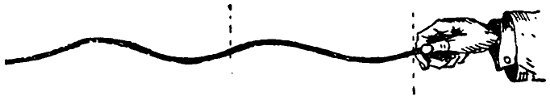
FIGURE 53.
The assumption of this ether and the vibratory
motions of it form the only explanation that is capable
of accounting for all of the phenomena of
light. All other theories advanced have failed to
stand the test; sooner or later some phenomena have
appeared which could not be explained by them.
Light waves are known to travel through space in
straight lines until they meet with some medium
which is capable either of reflecting, refracting, or
absorbing them. The rectilinear propagation of light,
consisting of vibratory motion, is one of the most
difficult parts of the theory to explain. It involves
rather deep study and more mathematics than the
scope of this work will warrant. Suffice it to say
that the rectilinear propagation is brought about
through the interference of light waves. An analogy
of this can be found in a stream of water. It is well
known that a stream of water issuing from the nozzle
of a garden hose moves in a straight line until
gradually forced into a spray by the resistance of
the air. Yet the water passing through the hose is
interfered with on all sides and on all sides there
is a tendency to deflect it. If the water were to
move along slowly so that we could observe the action
on one side independently of the balance of the
stream, we should see a series of waves being formed[115]
by every particle of the hose which offers resistance
to the flow. The waves formed in the interior of the
hose on all sides are interfered with by waves from
all other directions and the result is motion in a
straight line. In a similar way it may be conceived
that the millions of light waves emitted from
a luminous body interfere with each other and thus
cause light rays to move in a straight line.
Light is a form of energy and can be converted
into other forms of energy. It can be converted into
heat, for instance, or can be used to produce chemical
effects. Light differs from heat only in the rate of
vibration and the length of the ether waves. Heat
can be reflected in the same manner as light, as the
following experiment will show: Arrange two ordinary
reflectors as shown in Figure 54. In the
focal point of one, place a heated iron ball or something
of the kind; if this be hot enough, it will
ignite paper suspended in the focal point of the
other reflector, although a thermometer placed anywhere
between the two reflectors will give only a
small indication of a rise in temperature.
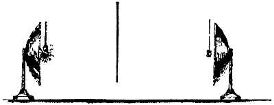
FIGURE 54.
All light rays as well as heat rays are in themselves
invisible; we can see only the object which[116]
emits or reflects them. If a beam of light be allowed
to enter a darkened room, as shown in Figure 55, we
shall probably be able to see the whole path of the
rays illuminated, as well as the spot on the floor.
But this will be because of particles of dust in the
air which reflect the rays to our eyes. If we introduce
some smoke into the room, we shall see the light
much more plainly because there are now more particles
of matter to reflect it. On the other hand, if
special precautions are taken to have the air absolutely
clear of dust, we shall be able to see nothing
but the spot on the floor.
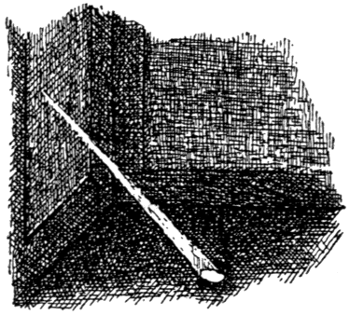
FIGURE 55.
Light travels through space at the rate of about
186,000 miles per second. White light is a combination
of light of many colors, but the speed of
transmission is the same for all colors. The length
of waves and the rate of vibrations, however, vary.
The red rays have the longest waves and the slowest
rate of vibration; they vibrate about three hundred
ninety-five billion times per second and the wave
length is about 0.0008 millimeters. The violet rays
possess a wave length of about seven hundred sixty-three
billion per second. There are light waves[117]
which are longer than the red rays and these are
known as infra red. They are not visible to the eye
but their existence can be proved in many ways.
Light waves shorter than the violet are also invisible
and are known as ultra violet. These have much
importance in photography and to this class belong
the X ray.
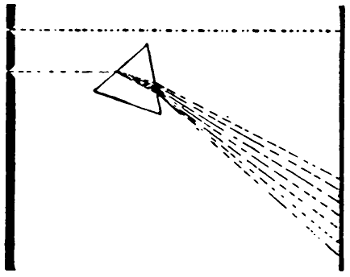
FIGURE 56.
We have mentioned above that white light is a
combination of light rays of many colors. This can
be proved by the following experiments: If we arrange
to have a beam of sunlight pass through a small
hole into a darkened room, it will pass to the wall
on the opposite side in a straight line and give
us white illumination upon a small spot. If we now
arrange a prism in the path of this ray or beam of
light, we shall find that the light no longer passes
straight to the wall but that instead, it is bent in
a certain direction and furthermore shows us a brilliant
array of colors. This is illustrated in Figure
56. The rays are thus shown to be separated into
their constituent colors; red is shown at the top and
the following colors merge imperceptibly into one
another—orange, yellow, green, blue, indigo, and
finally violet at the bottom.
[118]
The reason for this change is that the rays of light
on entering the glass are slowed down—those of
the higher rate of vibration more than the others.
The violet rays are thus said to be more refrangible
than the red, for instance. The colors thus produced
are simple colors. This is proved by the fact
that if the light is passed on through another prism,
it will be again reflected but will not be resolved
into other colors; although whichever color is carried
to the next prism will spread out and show finer
gradations in its color.
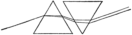
FIGURE 57.
The colors given above are those obtainable from
the decomposition of sunlight and make up what is
known as the solar spectrum. If instead of sunlight
some other illuminant be used, the arrangement of
colors will be different; and it has been found possible
to tell from the colors of the spectrum what
substances are burning, or heated to a luminous degree,
in the source from which the light comes. This
method is known as spectrum analysis.
There are several ways in which light, which has
thus been separated into its fundamental colors, can
be re-composed so as to give us white light again.
One of these methods consists in arranging an inverted
prism to receive the light, as shown in Figure
57. The rays leave the second prism parallel and
produce the effect of white light. Another method
consists in gathering the rays from the prism by a[119]
lens, as shown in Figure 58. Furthermore, if we
take a disc and paint the colors of the solar spectrum
upon it in the proper proportions, as indicated in
Figure 59, and cause this disc to be rapidly revolved,
we shall see it as almost white.
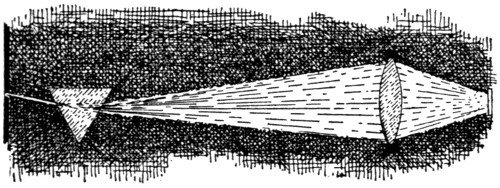
FIGURE 58.
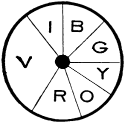
FIGURE 59.
Another fact which goes to prove the undulatory,
or motion, theory of light is that two sources of
light arranged to oppose each other can actually be
made to produce darkness. To do this, the waves
of one source of light must be made so that they
exactly oppose those of the other; thus they destroy
each other and destroy what light there is in either.
There are other methods, but this can be partially
accomplished in the following manner: Two
small mirrors of black glass or of metal are placed,[120]
as shown in Figure 60, very close together and so
that they form an angle of nearly 180 degrees. A
beam of light arranged to fall upon both of the
mirrors will be reflected in such a manner that the
two halves interfere with each other and cause bands
of light and darkness to appear. The dark lines are
due to the opposition and nullification of certain
of the light waves.
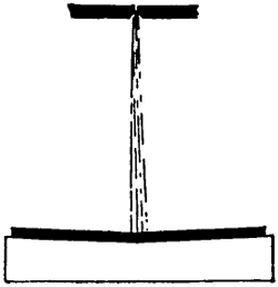
FIGURE 60.
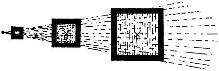
FIGURE 61.
The intensity of light diminishes directly as the
square of the distance through which it is transmitted.
This is illustrated in Figure 61. The light,
starting from a point, is limited by the size of the
first square at the left; it spreads out more and
more, and illuminates larger and larger spaces.
Exact measurement will show that the spaces illuminated
by a ray of light are always exactly proportional
to the square of the distance from the point
of light. This law, however, applies strictly only if[121]
the distances considered are long compared to the
source of light, so that the light may be considered
as being a mathematical point, that is, having no
physical dimensions. If the source of light, for
instance, were of the same size as the first opening
and of uniform intensity there would result the same
intensity of illumination of a similar space at all
distances. There would, however, be an outer fringe
of light which would be proportional to the law of
inverse squares. Many reflectors are arranged to
throw very nearly parallel rays; and with these the
intensity remains the same except for absorption,
which is ordinarily not very great.
We see things only through the rays of light they
reflect. All colored bodies have this peculiarity, viz.,
that they are capable of reflecting only such rays
as make up the color the body is said to possess.
A red body, for instance, absorbs all colors except
red and reflects red only. A black body absorbs all
rays and a perfectly dull black body is visible only
by contrast; that is, we do not see it but we are
aware that there is something invisible before our
eyes. When we are in a perfectly dark room, we
see nothing but we have blackness before our eyes.
A perfectly white body is one which reflects all of
the rays of light and absorbs none.
When we view things through colored glasses, we
see them only in the colors which the glass will
transmit. If we view a red body through a green
glass or under a green light, it will appear black
because it is capable of reflecting only red rays
and in the green light there are no red rays; hence
there is nothing to be reflected and the red appears
black.
[122]
CHAPTER IX.
PRINCIPLES OF VISION.
Through the medium of our eyes we see objects
by means of the light which is reflected from them.
This light enters the eye and forms an inverted
image of the object upon the retina, just as an inverted
image is formed upon the ground glass of a
camera. This impression made upon the eye is corrected
automatically, so that, although we see everything
upside down, we are not at all aware of so
doing. The proof of this peculiarity of the eye is
found in cases where persons born blind have later
through operations acquired sight. In the eyes of
slaughtered cattle also the image can be seen inverted.
A further proof that we are able thus to
adjust ourselves is found in the experience of persons
using cameras with ground glass screens. The
image on these screens is always inverted both horizontally
and vertically. The user soon learns to see
his object, although inverted, in the natural way,
that is, vertically, because this is so plain that he
must take it into account at every focusing. He
does not, however, accommodate himself to the reversal
from right to left because this is of no consequence
ordinarily and is not noticed. Many photographers,
who have been accustomed to the vertical
inversion, still find themselves confused when trying
to locate the right and left of a view seen through
the lens.
Unless a special arrangement of lenses is provided,[123]
all images cast upon screens through small openings
appear inverted. The reason for this can be seen
from Figure 62. It is obvious that no other light
can reach the bottom of the screen through the pin
hole O, at the left of the figure, except that coming
from the flame of the candle; also that no other light
can reach the top of the screen except that reflected
from the bottom of the candle at the right. Hence
the image of the candle appears inverted.
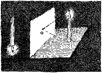
FIGURE 62.
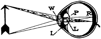
FIGURE 63.
A general understanding of the structure of the
eye can be had from Figure 63. W indicates a
watery substance in the front of the eye; I is the
iris which has power to contract or expand and thus
regulate the quantity of light admitted to the eye;[124]
P is the pupil; L is the lens; and R is the retina
which connects with the optic nerve and the brain.
The lens is made up of several parts having different
indexes of refraction. The whole resembles an ordinary
convex lens but has considerable power of
adjustment. When looking at objects close by, for
instance, the pupil can often be seen to bulge out
which is its method of accommodating itself to objects
close at hand.
To the iris falls the duty of regulating the quantity
of light which is to reach the retina. If confronted
by a bright light, it closes partially; in a
dim light, it opens out wide. When subject to a
flickering light, there is a tendency to follow the
flickerings by rapid opening and closing, which causes
pain. If subject to flickerings long enough, however,
the pain becomes somewhat less, probably because the
iris has come to rest on an intermediate point.
An image formed upon the retina remains for
some time, the time varying with the intensity of the
light. Very intense impressions are supposed to last
about one twenty-fifth of a second; milder ones as
long as one-tenth of a second. This tendency to
retain images is known as the persistence of vision
and can be noticed in many ways. A twenty-five
cycle alternating current falls to zero fifty times in
one second; and fifty times in each second there is
a slight cooling off of the incandescent filament. Yet
the variation in the intensity of the light is noticeable.
Many of the sleight-of-hand tricks depend
upon this persistence of vision and the projection of
moving pictures would be impossible without it.
We are able to judge distance principally through
the fact that we have two eyes. If our eyes were[125]
immovable, we should see two images for every object.
But as they are movable and as both normally
point directly at the object we are looking at, their
axes form angles with each other and in this way
we are enabled to judge the distance, as well as
other qualities of objects.
When both eyes are centered upon an object, the
impressions received by the brain from both sources
are mixed, and the picture we become conscious of
is a composite of the two images in the eyes.
This is verified by the fact that many persons
with defective vision can see much more clearly with
one eye than with both. They are not able to focus
both eyes upon the same point and thus the perfectly
clear picture which may exist in one eye is mixed
with an uncertain picture in the other.
In youth normal eyes are able to adjust themselves
to different intensities of light and different
distances very rapidly. This power is largely curtailed
as age advances. Where a young person can
almost instantly, after gazing at some distant object,
turn to a newspaper and read, the eyes of a
person of advanced age generally require considerable
time before they can adjust themselves in the
same way. Quite frequently, however, very old
people regain their powers of vision and become able
to do without the glasses formerly used.
All of the above facts should be thoroughly understood
by those having to do with illumination used
by a mixed audience. Light that may seem perfectly
satisfactory to one may be entirely unsuitable
for another.
[126]
CHAPTER X.
REFLECTION.
Light may be reflected from opaque or transparent
bodies such as glass. In the case of transparent
bodies, the reflected rays are not noticeable unless
the ground behind the reflecting body is dark. If
there is much light behind a pane of glass, for instance,
the pupil of the eye will be partially closed
and not be able to see the faint light which is reflected.
As we gradually darken the space behind
the glass, the image begins to appear more and more
distinct, partly from contrast with the dark background
and partly on account of the increased opening
of the pupil. This can be readily noticed if some
evening out of a dimly-lighted room we look at some
object just discernible. If we then turn on the light
suddenly, the object will at once disappear but reflections
will appear in the glass where there were
none before.
The reflections from clear glass are much stronger
at an angle than when the rays are thrown straight
back. This can be seen by placing any object directly
in front of a pane of glass with a dark background.
If we place the eye so as to receive only those rays
which are reflected directly back, we shall obtain but
a weak reflection. If, however, we place the object
a little to one side and stand close to the glass, we
shall see the object almost as plainly as in a regular
mirror.
A ray of light is always reflected at exactly the[127]
same angle at which it strikes, the reflecting body;
that is, the angle of incidence is equal and opposite
to the angle of reflection. This can be illustrated by
Figure 64. If a mirror be attached to the pointer
in the position shown at an angle of exactly ninety
degrees and a beam of light be allowed to enter
through the slit at the top, it will be reflected back
exactly to the spot at which it entered. If we then
turn the pointer slightly, we shall notice that the
reflection of the beam of light moves twice as fast
as the pointer and, when the pointer occupies the
position indicated by broken lines, the light will be
reflected at right angles to the line along which it
enters. If the mirror is turned still more, the same
law will hold; so that, if the mirror were turned
through an angle of nearly ninety degrees, the reflected
beam of light would in the same space of time
make an angle of nearly one hundred eighty degrees.
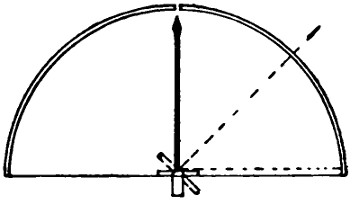
FIGURE 64.
Reflected light results in the formation of images
in mirrors and other reflecting bodies and, by bearing
in mind the law of reflection given above, we can
readily explain how these images are formed and the
manner in which they appear to us.
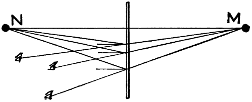
FIGURE 65.
Let N, Figure 65 be an object in front of the
mirror. The only rays that are reflected back to
the eye are those that strike the mirror at the proper[128]
angle. All others are wasted with reference to the
particular position of the eye. If the eye and the
object reflected are equally distant from the mirror,
we need but draw a line at right angles to the
mirror and half way between the eye and the object
and, from these two, draw lines to the point at which
the perpendicular line strikes the mirror. The two
lines thus drawn will give us the path of the incident
and the reflected rays. The image will appear to
lie in the direction from which the reflected ray
comes and as far behind the mirror as the object is
in front of it. If the eye and the object to be reflected
are not equally distant from the mirror, it is
more difficult to find the paths of the rays and it
simplifies matters very much to use the following
construction: Draw a line from the object before
the mirror at right angles to the mirror and extend
it behind the mirror as far as the object is in front
of it. From this point behind the mirror, draw
another line to the eye. By drawing a third line from
the object to the point in the mirror where this
line, from back of the mirror to the eye, crosses it,
we shall obtain the paths of the rays and the position
of the image in the mirror. The image will exist
in the mirror at the point where the reflected and[129]
incident rays meet but will have the appearance of
lying some distance behind the mirror. This is illustrated
in Figure 65, N being the object reflected and
M the apparent position of the image to the eyes
as located in the cut.
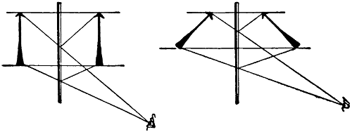
FIGURE 66. FIGURE 67.
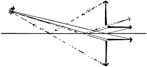
FIGURE 68.
In Figures 66 and 67 the same construction is
used to show the appearance of arrows as they are
reflected from a mirror to the eye. Objects standing
erect over horizontal mirrors or arranged at right
angles to mirrors and looked at, as in Figure 68, always
appear inverted. This can be noticed in quiet
ponds of clear water which give reflections of trees
and other objects. Figure 68 shows two arrows,
one horizontal, the other vertical; by the construction[130]
in the figure one appears inverted, the other
not. If the arrow were placed in the position indicated
by broken lines, the eye would see only the
butt. If the arrow were placed a little nearer the
horizontal, it would appear in its natural position;
if a little more vertical, it would appear inverted in
the mirror.
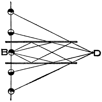
FIGURE 69.
All objects seen in mirrors are reversed with reference
to right and left. A pocket on the left side of a
person facing a mirror will appear to be on the right
side. Printed matter held before a mirror will appear
just as it would if seen through the paper
from the back side and will have to be read from
right to left.
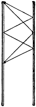
FIGURE 70.
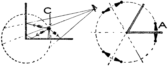
FIGURE 71. FIGURE 72.
If an object be placed between two parallel mirrors
as B, Figure 69, there will be a vast number of reflections
visible at the point D. Several reflections
of B will come to the eye in the manner indicated
but there will be a large number of additional reflections.
If the mirrors are exactly parallel and absolutely
smooth, the number of reflections would[131]
theoretically be infinite. At each reflection, however,
some light is absorbed and some diffused so
that many of the reflections are not discernible. Two
mirrors set opposite each other will also give many
reflections of each other as indicated in Figure 70.
The images seen in parallel mirrors all appear arranged
in straight lines on both sides, as indicated in
Figure 69. If now one of the mirrors be inclined
so as to form an angle with the other, the long line
of images will seem to become curved and finally lie
in a circle. If the mirrors be placed at right angles
to each other, as in Figure 71, there will be three reflections[132]
of the object C visible and these will reach
the eye by the paths shown. If the mirrors be
placed at an angle of sixty degrees to each other,
five images will appear as shown in Figure 72, in
which A is the object being reflected.
The following tabulation shows the number of
images obtainable at different angles between the
mirrors.
Angle between
mirrors |
Number of
images |
| 90 degrees |
3 |
| 72 degrees |
4 |
| 60 degrees |
5 |
| 45 degrees |
7 |
| 30 degrees |
11 |
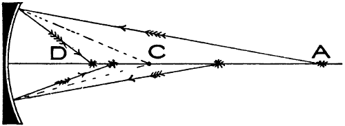
FIGURE 73.
Instead of being plain, mirrors may be either
concave or convex. A concave mirror is hollowed
out in conformity with a small section of the surface
of a sphere. If a piece of glass be cut out of a
hollow sphere, the inner side of it will show the
surface of a concave, and the outer side, the surface
of a convex mirror. A section of a concave mirror
is shown in Figure 73. C is the center of curvature
and any line drawn from the surface of the mirror
to this center is at right angles, or normal, to the
curvature of the mirror. A ray of light emanating[133]
from this center will be reflected straight back to it.
If the source of light be moved a little nearer to
the mirror, the light reflected will be spread out
more and come to a focus farther back from the
glass; if it be moved farther back from the glass, the
rays will be focused nearer the mirror. Thus if a
light be placed at A, its rays will be focused at D
and a light placed at D will focus at A. This can
be seen by the lines which represent the rays of
light. The two points at which a source of light will
thus focus are known as the conjugate foci of the
mirror.
If such a mirror receives parallel rays of light,
they will be reflected and come to a focus at a point
midway between the mirror and the center of curvature.
This point is known as the principal focus
of the mirror, and the distance between it and the
mirror is called the focal length of the mirror. A
source of light placed at this point will throw out
parallel rays from the mirror. If the light be moved
closer to the mirror, the reflected rays will spread
out; while if moved farther away, the light will
come to a focus at some distant point, as shown
above.
Figure 74 can be used to illustrate the manner
in which a concave mirror reflects the light from an
object placed before it. From the upper point of
the large arrow, rays of light emanate in all directions.
All that strike the face of the mirror are
thrown to a certain point which can be found by
tracing out the lines, using the small arrows as
guides. At this point will appear the image of the
top of the arrow. It will be noted that it is inverted.[134]
The rays from the lower part of the arrow
are of course all reflected in the same manner.
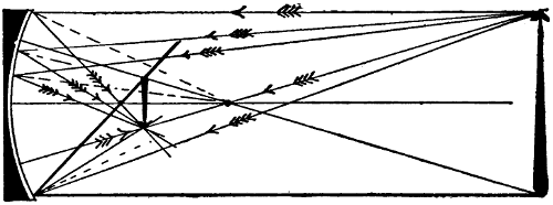
FIGURE 74.
With mirrors of this kind, the position of the object
with reference to the focal length and center of
curvature is of great importance. If the object be
placed in the position shown as the image in Figure
74, the image will appear as though it were in place
of the object; it will be much enlarged and also inverted.
If the object is placed between the principal
focus and the mirror, it will appear to lie behind the
mirror as shown in Figure 75. In this case it will
not be inverted.
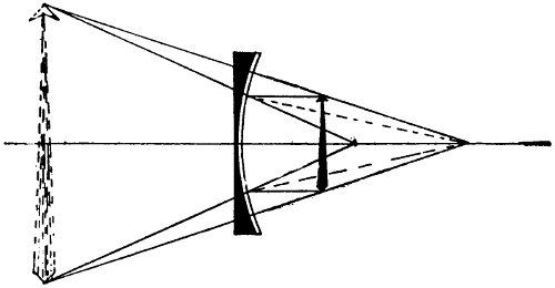
FIGURE 75.
When concave mirrors forming large sections of
spheres are used, the rays reflected from the outer
edges will not all meet exactly at the focal point.[135]
There will then be a somewhat fuzzy image formed.
This is illustrated in Figure 76. In order to obtain
a perfectly clear and distinct image, only the central
part of concave mirrors should be used.
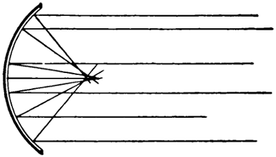
FIGURE 76.
Convex mirrors are not much used. Sometimes
glass spheres are set up to show miniature reflections
of scenery; convex mirrors are also found in
the lobbies of theaters and in places of amusement
to amuse the patrons with the caricatures of themselves
reflected in them.
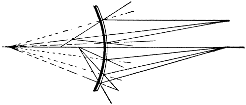
FIGURE 77.
All of the rays that strike a convex mirror are
reflected back in such a manner that they seem to
come from a common point behind the mirror. This
is shown in Figure 77. The center of curvature here
is behind the mirror but the paths of the various[136]
rays can be determined as before explained. Thus
we shall find that every ray, striking the mirror from
a certain point, is reflected back in a direction which
gives it the appearance of coming from a certain
point behind the mirror. Two such points are shown
in Figure 77.
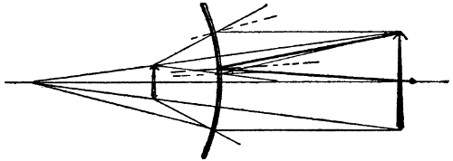
FIGURE 78.
In Figure 78 we have drawn the arrow and the
image it would produce in the mirror. If the mirror
forms a section of a sphere, the object reflected will
appear reduced in size in all directions. If the
mirror forms merely a section of a cylinder, a person
standing in front of it will appear very much
shorter than natural but of full width thus presenting
a ridiculous appearance. Convex and concave
mirrors are often combined and if properly set, a
person standing in front of one may see himself
either very much elongated or shortened.
[137]
CHAPTER XI.
REFRACTION.
If a straight stick or pencil be plunged into a
vessel containing water, it will appear to be bent.
The reason for this appearance is given in detail
in Figure 79. The only light which can reach the
eye from the lower extremity of the stick must reach
it by a path similar to that of the bended ray at the
left. According to this, the rays of light leaving
the bottom of the stick at E bend at the water’s edge
and meet the eye as shown. To the eye the rays, by
which it sees the end of the stick, appear to come
from the direction F; hence the stick is seen crooked.
When a ray of light passes from air into a denser
medium such as water or glass, the ray appears to
be bent somewhat, as illustrated at the left of Figure
79. This bending of the rays of light is called
refraction.
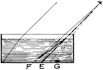
FIGURE 79.
[138]
The fact of refraction can be further verified by
placing an object G into an empty vessel in the position
shown. In this position the object is not visible
to the eye. By slowly filling the vessel with water,
the object will gradually appear and will seem to lie
in the direction of the straight dotted line.
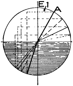
FIGURE 80.
The bending or refraction of light rays is governed
by a law which holds in all cases. The bending
differs with different kinds of glass, with water, with
oils, or even with water mixed with chemicals; but
no matter how much the bending may differ with
different materials, for each material there is a fixed
ratio between the angle at which the light enters
and the angle at which it continues in the material.
This ratio is known as the index of refraction. For
water it is about 1.33; for glass about 1.5; for the
diamond about 2.5; etc. This can perhaps be most
easily explained by reference to Figure 80. Here
the top of the shaded space represents the surface
of the glass at which the light enters. The line E
is drawn at right angles to this surface and the
various lines, meeting in the center of the circle,[139]
represent different rays of light falling upon the
glass at different angles. The heavy line shows the
ray of light striking the glass and passing through
it. Similarly each line is drawn differently and the
nature of the lines will act as a guide by which the
angle of incidence upon the glass and the angle at
which the rays continue through the glass can be
traced.
When it is said that glass has an index of refraction
of 1.5, or 3⁄2, it means that the sine of the
angle of incidence is 1.5 times as great as the sine
of the angle of refraction. The sine of the angle
of incidence is proportional to the length of a line
drawn from the vertical E to the periphery of a
circle, outside of the glass or other substance, to
where it meets the ray; and the sine of the angle of
refraction is proportional to the length of a line
drawn from the same vertical to the periphery of
the same circle, inside of the glass or other substance,
where it meets the ray.
In order to lay out the path of a ray through the
material, its angle of incidence being known, we may
resort to the construction shown in Figure 80. Draw
the incident ray at its proper angle and the vertical
line at right angles to the surface of the material.
From the point A, where the ray enters the circle,
and at right angles to the vertical line, draw the line
1. Measure the distance from A to the vertical line
and divide it by the index of refraction; and on a
continuation of the line 1, lay off the distance as
found. From the point so located, draw a line
parallel to the vertical until it intersects the circle
at the bottom. From the point at which the ray
enters the medium, draw another line to where the[140]
last line drawn strikes the circle. This line will give
the direction in which the ray is propagated in the
medium. For glass, the index of refraction is taken
as 3⁄2; hence the line 1 must contain three parts,
while the continuation contains two of the same
length. Upon leaving the medium, the ray is bent
back again so that it continues in a direction parallel
to that at which it entered, as shown in Fig. 81;
and thus the case is reversed.
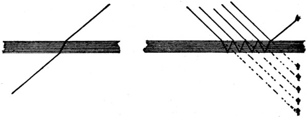
FIGURE 81.FIGURE 82.
Figure 82 is an illustration of how both refracted
and reflected rays may be several times reflected.
If one will hold a match close to a mirror, looking
at it somewhat from the side, there will be visible
six or eight distinct reflections of it. These will be
of different intensity.
If a source of light has its origin in a medium
denser than air, it will be bent as shown in Figure
83. In such a case some of the rays do not leave the
medium at all but are reflected back into it, as indicated
at the right. The heavy line indicates what
is commonly known as the critical angle. This angle
varies with different substances and is the angle at
which the refracted ray of light skims along the
surface and does not pass out. All rays emitted at
a lower angle are returned back into the medium.[141]
If an electric light were immersed in water, only the
rays of light at the left of the black line would be
visible to an eye outside.
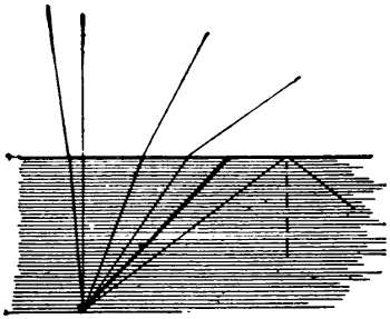
FIGURE 83.
Figure 84 is an illustration of an equilateral prism.
Here we have refraction on both surfaces and a light
placed at A would be seen by the eye as located at B.
With prisms it is easily possible to locate a light so
that it may be seen in two positions at the same time.
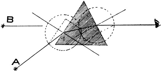
FIGURE 84.
Figure 85 shows a double convex lens. Both sides
of it are segments of circles or sections of a sphere.
The center of curvature or the radius of one side
is at A and that of the other at B. Each minute
particle on the surface of such a part of a sphere[142]
may be looked upon as the surface of a prism, the
inclination of it being indicated by a line drawn
at right angles to a line passing from the point
through the center of curvature. This is illustrated
in the figure by the short heavy lines at right angles
to the broken lines centering at A and B.
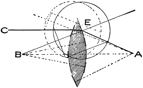
FIGURE 85.
By using the construction explained with Figure
80 and using for the left-hand surface the circle of
broken lines and for the surface at E the circle of
solid lines, we find the path of the ray coming from
C to cross the principal optical axis at A. A similar
construction for a ray at the lower side of the lens
would bring it to the same point and furthermore
all parallel rays would focus at this point. This
point is thus known as the principal focus of the lens,
and the distance between this point and the lens is
called the focal length of the lens. Every lens has
two principal foci, one on either side and at equal
distances from the lens.
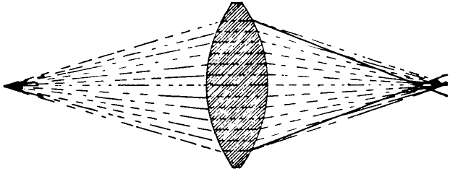
FIGURE 86.
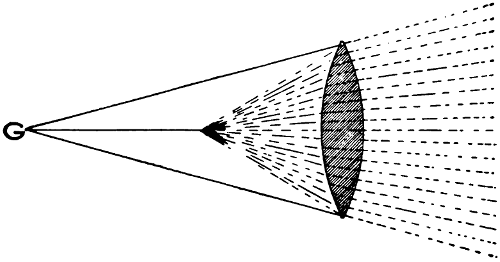
FIGURE 87.
If, instead of subjecting the lens to parallel rays,
we use rays emanating from a central point on the
optical axis, they will come to a focus at some different[143]
point on the other side of the lens, as illustrated
in Figure 86. If the light be placed at the
principal focus of the lens, the rays leaving the lens
will be parallel. If the light be brought nearer the
lens, the rays leaving it will spread out as shown
in Figure 87; they will leave the lens in a direction
such as to make upon an observer from in front the
impression that they are coming from the point C
behind the lens. If the light be placed beyond the
principal focus of the lens, the rays will converge
to a point some distance ahead of it. This distance
varies with the position of the light and the two
points (light on one side and focus on the other)
are known as conjugate foci of the lens[144].
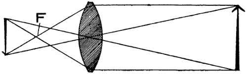
FIGURE 88.
If an object be projected through a lens as, for
instance, the arrow at the right of Figure 88, it will
appear upon a screen placed on the opposite side,
but will be inverted. The reason for this is that the
rays of light striking the lens from the top of the
arrow will be refracted as shown, cross the focal
point F, and meet those which come from the same
point and pass through the center of the lens in a
straight line; and thus the image of the arrow head
will appear at the bottom; in a similar manner the
image of the tail of the arrow will appear at the
top. The flatter the lens, the farther away will be
the point at which the image is formed.
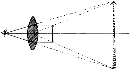
FIGURE 89.
If such a lens be placed over an object, the light[145]
will come to the eye as shown in Figure 89. The
solid lines show the rays by which the eye receives
the light and the broken lines show the direction
from which it appears to come. Thus we see the
object much enlarged. A lens used in this manner
is spoken of as a reading glass, and the greater the
curvature, the greater its magnifying power.
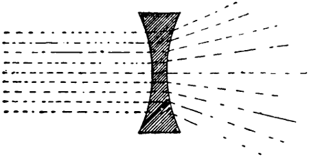
FIGURE 90.
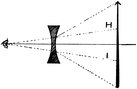
FIGURE 91.
In Figure 90 is illustrated a double concave lens.
Parallel rays entering this lens are scattered by it,
as shown. Therefore, if such a lens be placed over an
object, the light from the extremity of the object
will come to the eye as indicated in Figure 91, but
will give the appearance of coming along the lines
H and I. Thus the object will be seen much reduced[146]
in size. Such lenses are sometimes used by
artists to bring landscapes to a reduced size so that
they may be viewed as a whole more easily.
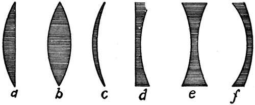
FIGURE 92.
The general forms of lenses are shown in Figure
92,
- (a) Is a plano-convex lens
- (b) Is a double convex lens
- (c) Is a convexo-concave lens, or convex meniscus
- (d) Is a plano-concave lens
- (e) Is a double concave lens
- (f) Is a concavo-convex lens, or concave meniscus.
[147]
CHAPTER XII.
OPTICAL INSTRUMENTS.
In most optical instruments, lenses are used for the
purpose of gathering a large number of rays of light
and altering the apparent direction of the rays so
that an enlarged picture may be presented to the eye.
In order to accomplish this, it is necessary that the
rays of light be bent or refracted. This refraction,
we have already seen, is always accompanied by a
dispersion which causes the light to be dissolved into
its original colors more or less. This has been illustrated
by means of prisms.
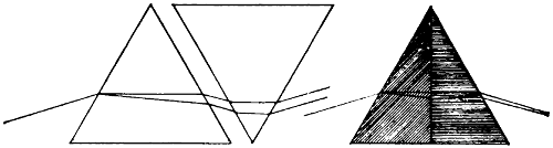
FIGURE 93. FIGURE 94.
Wherever a single lens is used, the light around
the edges of the illuminated space is always more or
less colored, varying with the illuminant used. Such
coloring is most noticeable along the edges of projected
pictures but it also exists, though to a less
noticeable degree, over the whole field, showing least
in the center.
The light which is thus refracted and dispersed by
one prism may be gathered again by another, as shown
in Figure 93, but the light rays after passing
through the second prism will be exactly parallel to[148]
the ray striking the first. The light coming out of
the second prism will appear white but it will be impossible
either to enlarge or diminish the size of a
picture in this way; hence lenses, corrected to give
white light in this manner, would be of no use.
Fortunately it has been found that, with different
kinds of glass, the ratio of refraction to dispersion
is different; and by combining two pieces of glass of
different nature, it is possible to recombine the colors
without causing the emergent ray to become parallel
to the incident ray. Consider, for instance, Figure
94 in which we have drawn a prism made up of two
different kinds of glass. If the right half were of a
glass having the same index of refraction as the left,
for the red rays for instance, these would continue
through both in a straight line. If the dispersion
were less in the right half, i.e., if the violet rays were
refracted less—sufficiently less to cause them to approach
the red—they would meet the latter at some
point outside of the prism and combine into white
light again, thus eliminating the colors ordinarily
visible through single glass lenses.
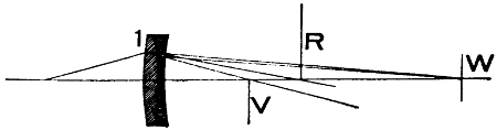
FIGURE 95.
Whenever it is necessary to project especially good
pictures upon a screen, lenses corrected in some such
manner as outlined above are always used and the
lenses are often combined as shown in Figure 95. In
this figure, R indicates the line, through the principal[149]
axis, at which the red rays refracted by lens 1 alone
would strike; and V, the line where the violet rays
would be projected. The addition of lens 2 brings
the red and violet together again at W. A combination
of two such lenses, placed the proper distance
apart and the surfaces properly proportioned, may
be made to combine any two of the colors of the spectrum.
Hence even with these corrected lenses there
is always some coloring on the screen although it is
hardly noticeable.
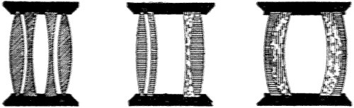
FIGURE 96. FIGURE 97. FIGURE 98.
Figures 96, 97, and 98 are drawings showing the
manner in which objective lenses are usually made up.
The types at the right and left are used for camera
work, while the one shown in the center is used mostly
for moving picture and stereopticon projection. The
end having the separate lenses is turned towards the[150]
light. Those shown in contact are glued together
by the use of Canadian balsam.
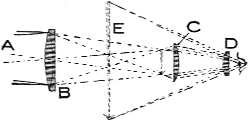
FIGURE 99.
The optical system of the ordinary telescope is
shown in Figure 99. Light from the distant object
A is gathered by the large lens B and an image is
formed as indicated by the small arrow. This image
acts as the object to lens C and is projected to lens
D where the rays of light are strongly refracted,
entering the eye by angles which cause an enlarged
view of the object at E, as indicated. There must of
course be some means by which the lenses may be
adjusted to each other for focusing.
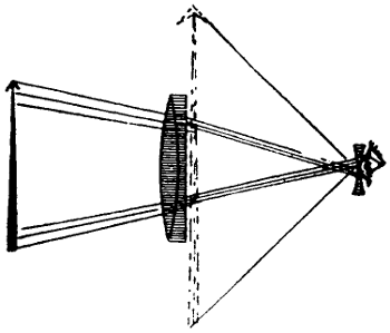
FIGURE 100.
The arrangement of the opera glass in Figure 100
is quite different from the above because of the reduced
size of the instrument and for the reason that
an erect picture is desired, whereas the telescope
above gives an inverted one. The principal difference
between the two is in the eyepiece. In the opera glass
this is a concave lens while in the other it is a convex
lens. In this case it is necessary to have the eye
very close to the lens to catch the rays of light. The
opera glass, as well as the telescope, must be provided
with means of varying the distance between the lenses[151]
according to the distance of the object viewed, for
the purpose of focusing. In some telescopes and also
opera glasses, prisms are used for the purpose of obtaining
erect images. Figure 101 will show how the
rays of light entering a prism are reflected and the
image reversed thereby.
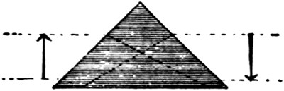
FIGURE 101.
Figure 102 is an explanation of the reflecting
stereoscope. Let the black circles represent the eyes
of the observer and let M represent two mirrors placed
as shown. If two pictures taken by a stereoscopic
camera are placed as indicated by the arrows at the
right and the left, they will appear superimposed in
the position of the arrow in the rear.
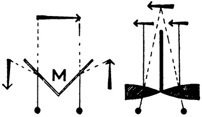
FIGURE 102.FIGURE 103.
The refracting stereoscope is the one mostly used
and the plan of it is shown in Figure 103. Pictures
for use with stereoscopes are taken by special
cameras provided with two lenses placed about as
far apart as the human eyes and mounted together.
Stereoscopic effects may, however, be produced even[152]
without this precaution and it is possible to obtain
some queer results by combining certain pictures.
In the so-called “Camera Lucida”, prisms of the
type shown in Figures 104 and 105 are used. At the
left is a combination lens and reflecting prism which
gives an erect image, and Figure 105 is a prism also
designed to give erect images. Such instruments are
used for sketching. They may be made to throw an
image upon a small screen where its lines may be
traced out by the artist.
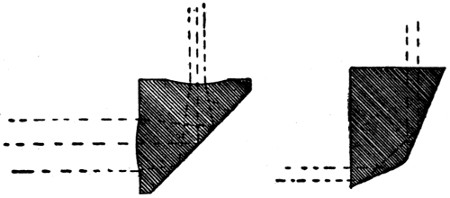
FIGURE 104.FIGURE 105.
The most important optical instrument with which
we have to deal is the projecting arc lamp and its
optical system. The passage of light through this system
of lenses is altogether different from that passing
through a camera lens for instance. In a camera
lens the picture is formed upon the ground glass
screen by the light reflected from the object. From
any single point of the object, rays of light strike all
parts of the lens, pass through it, and are recombined
or focused at some point behind it. Under these conditions,
focus can be obtained only at a certain distance
behind the lens, this distance varying with the
distance of the object whose light is being received
by the lens.
[153]
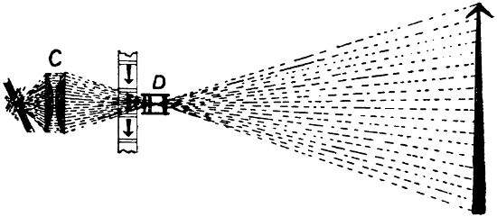
FIGURE 106.
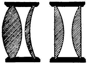
FIGURE 107.FIGURE 108.
With our projecting lens we have no reflected light
leaving the object in all directions, but instead we
have rays of light having definite directions. This
can be seen from Figure 106. The light used must
come from a point source, the smaller and the more
intense it is the better. This light is gathered by condensers,
as shown at C, which are so arranged as to
focus the light in the center of the objective lens D.
In the moving-picture machine the light, before reaching
the objective lens, is passed through the film as
indicated, the arrows representing sections of film.
The picture projected in this manner can be made to
appear upon a screen in front of the object lenses at
any distance, but the farther away it is, the larger it
will be and the less bright the illumination of it. A[154]
picture projected in this manner is always inverted,
and, in order to have it appear right side up, it must
be placed in position upside down. Figures 107 and
108 show arrangement of lenses frequently used as
condensers.
[155]
CHAPTER XIII.
OPTICAL ILLUSIONS.
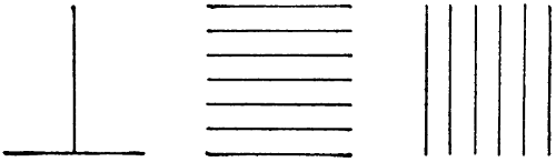
FIGURE 109. FIGURE 110. FIGURE 111.

FIGURE 112.
The eye is easily deceived and is also very inaccurate
in its judgment. In Figures 109 to 111, all of
the lines are of precisely the same length, yet they
appear to differ considerably. The reason for this
error in the estimation of objects is not known. It is
especially noticeable with such objects as a high hat;
almost any one will estimate the height of a silk hat
as much greater than it really is. In general, white
objects also appear to be much larger than black
objects. This can be seen by the two inscribed squares
one black and the other white in Figure 112; both of
these are of exactly the same size. Probably the fact
that more light reaches the eye from a light-colored[156]
object than from a dark-colored one of equal proportions
causes the impression of greater size.
That the mind has the power of mixing contradictory
or conflicting impressions made upon it is
proved by many facts. If a star, Figure 113, be
pinned to the center of a wheel and rapidly revolved,
the center of it will appear jet black; while the outer
portions, made up of the points and the white background,
will appear grey which will gradually fade
to a lighter shade from the center black spot outward.

FIGURE 113.FIGURE 114.
If a card be provided with a picture of a bird on
one side and a ring on the other, Figure 114, and this
be rapidly spun on one corner, after the manner of
a top, the bird will appear to be in the center of the
ring. This effect is due to the persistence of vision;
an image formed upon the retina requires some time
before it can be eliminated so that both images appear
together.
This persistence of vision and the power of suggestion
are made use of in a well-known act which consists
of apparently throwing something, for instance
a guinea pig, into the air and causing it to vanish.
To perform this trick, the operator holds the pig in[157]
his hand and makes a few motions suggestive of tossing
it into the air. Then, with a final more extreme
motion on the downward swing of his hand, he drops
the pig and swiftly moves his empty hand upward.
Due to the persistence of vision, the audience actually
still sees the pig and due to the suggestion of tossing
the eyes look upward, and thus the persistence of vision
and the power of suggestion create the illusion.
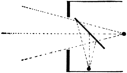
FIGURE 115.
Dissolving Views of Living Pictures.
Dissolving Views of Living Pictures.—This act requires
a large glass plate of good clear quality arranged
upon the stage, as shown in Figure 115. One
of the poses is arranged as at the black circle behind
the glass and when illuminated is seen by the audience.
The other is arranged at one side. The lighting
of both is connected to the same dimmers in such
a manner that when the light of one is increasing,
that of the other is diminishing. Thus the two figures
are dissolved into one another. The paths of the
various rays of light to different parts of the auditorium
are shown in the drawing and it is possible
to procure perfect registry.
Human Figure Floating or Performing in Air.
Human Figure Floating or Performing in Air.—This
act is arranged by means of a large mirror[158]
placed upon the stage as shown in Figure 116. In
the pit out of sight of the audience is a revolving
table draped in dull black and all of the pit is draped
in the same manner. A figure lying upon this table
dressed in light clothes will appear erect in the mirror
as indicated by the arrow. If now the table is
revolved, the figure will be seen as turning over in
the mirror. The figure upon the table may perform
a number of evolutions suggestive of floating, flying,
etc. The black cloth of the pit will reflect no light
and only the figure will be visible. If a glass plate
is used instead of a mirror, suitable scenery may be
arranged back of it. The figure must of course be
brightly illuminated. By moving the table upon
which the figure rests across the pit, the figure will
appear to move along.
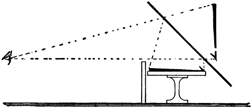
FIGURE 116.
Head Suspended in Air.
Head Suspended in Air.—This act is worked out
in bright light. It requires a mirror with a hole in
the center of it large enough to admit the head of a
person, as shown in Figure 117. Above the mirror
suitable decorations are provided which cause one
looking at the mirror to imagine seeing the back wall
of a room. The ceiling must of course be kept out[159]
of view as much as possible. A person looking on
sees the head and the mirror gives him the impression
of vacant space about it. The head must be
surrounded by a collar or drapery of some kind so
that no reflection of it will be visible.
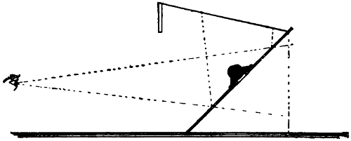
FIGURE 117.
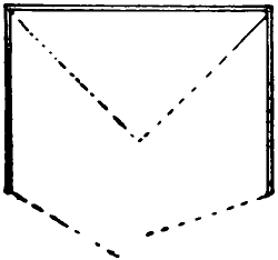
FIGURE 118.
Magic Cabinet.
Magic Cabinet.—In this act a person enters the
cabinet, Figure 118. The outer doors are closed for
an instant and then opened. The person has disappeared!
The disappearance is brought about by pulling
the two mirrors, arranged inside of the cabinet,
into the position indicated by the dotted lines. When
the cabinet is open for inspection, these are swung to
the side and are invisible. The backs are of the same
design as the rest of the interior cabinet. When they
are pulled together and hide the person behind them,
they reflect the side walls of the cabinet and are not[160]
noticed. If the cabinet is well made and the act skilfully
performed, the outer doors may even be omitted.
Head Resting on Table.
Head Resting on Table.—For this act a hole large
enough to allow a person’s head to project through is
cut in the top of a table, Figure 119. This table has
only two legs and is fitted up with mirrors, as indicated
by shading. The reflection of the two legs in
the mirror causes the observer to see four and imagine
that the space below the table is vacant.
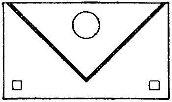
FIGURE 119.
Multiplication of Images.
Multiplication of Images.—If three large mirrors
be arranged in the form of an equilateral triangle, as
indicated in Figure 120, a person standing in the
center will see his image reflected so many times that
he will receive the impression of being in the midst
of a crowd. He will see the reflections of reflections
repeated until by absorption so much light is lost that
they finally become invisible.
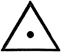
FIGURE 120.
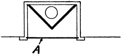
FIGURE 121.
Trick Mirror.
Trick Mirror.—Rather startling effects can be produced
by a thinly coated mirror A, Figure 121, behind
which an electric light is arranged so that it[161]
may be easily turned on. The space behind the mirror
being dark, no one suspects that it is anything but
a common looking glass. It is, however, quite transparent
when the light behind it is turned on. The
person in front viewing himself may thus suddenly
be brought to see anything that is behind the mirror.
If another set of mirrors is arranged, as shown by
shaded lines, the person in front of the mirror may
suddenly be made to see a head floating in the air
in front of him.
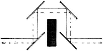
FIGURE 122.
The manner in which one can see through a brick
is illustrated in Figure 122. Four mirrors reflect the
light around it. If the mirrors are properly arranged,
the person will imagine he is looking through the
brick.
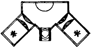
FIGURE 123.
The face of a person may be thrown upon a screen
among clouds or other pictures in the manner shown
in Figure 123. The face occupies the space marked
by a half circle and two arc lamps with condensers
are trained upon it at very close range. The face
itself acts as a reflector projecting itself through the[162]
object lens in the center. This act is very trying on
the person whose face is reflected.
At a certain distance from a concave mirror, an
object will be seen inverted. If the mirror be brought
closer, the image will gradually go out of focus and,
by bringing the mirror still closer, it will gradually
come into focus again but this time erect. Properly
arranged such a mirror can be made to give weird
effects, for instance a skeleton, rushing at the observer;
and the image will appear to step out of the
mirror.
[163]
CHAPTER XIV.
THEATER BUILDINGS.
General Requirements.
General Requirements.—In most cities it is required
that theaters be built in locations which give free
space for exits on two or more sides. A common requirement
is that two sides adjoin public streets or
alleys and one or both the other sides be provided
with an open court allowing space for fire escapes
and connections to street or alley. The buildings are
also, as a rule, required to be of fireproof construction
and divided practically into two parts by strong
fire walls; one of these parts being the auditorium,
that portion of the building used by the public, and
the other, the stage and its belongings.
The main fire hazard of course is on the stage and
every possible precaution should be taken, first to
keep a fire from starting, and second, to keep it,
should it start, from communicating to the auditorium.
In order to protect the audience in case a
fire starts doing damage on the stage, a steel and
asbestos fireproof curtain is generally provided, large
enough to cover the whole proscenium opening and
equipped with the necessary apparatus to lower it
instantly in case of necessity. In order to keep this
curtain in first-class working order it is lowered at
the end of every act and in the case of continuous
vaudeville performances, which are not divided into
acts, at least once or twice during each performance.
This curtain must be strong enough to withstand
the strain of air pressure which would exist in case[164]
of a fire raging behind it. This strain, when one considers
the quantity of oil-painted scenery carried by
many of the large shows, is apt to be considerable, in
case of fire.
In order further to protect the audience, a large
vent flue is required above the stage. The purpose
of this vent is to carry off the smoke and gases. The
Chicago law requires the vent to be equal in area to
one-twentieth of the area of the stage and to extend
fifteen feet above the highest point of the roof.
The hazard to the audience is not so much that of
the actual fire, as of the rapid consumption of oxygen
by the flames. This causes strangling. In the
case of the Iroquois Theater fire the death of many
was due almost entirely to this cause. The flames
spreading rapidly consumed all of the oxygen in the
tightly closed theater; at the same time the smoke
and gases were spreading and hundreds of the audience
inhaled this heated and vitiated air with almost
instantly fatal results.
As a further precaution against fire, it is now required
in all large cities, that all scenery be fireproofed
to such an extent that it will not carry fire.
The usual test for this is, to hold a match to a part
of the cloth long enough to burn a hole through it.
The fire must go out as soon as the match is withdrawn.
The following are extracts from the Chicago ordinances
governing theaters of the larger class:
The building must be of fireproof construction. It
must adjoin two public highways one of which may
be an alley.
There must be an open space on both sides of the
audience room and in front.
[165]
All balconies, galleries, main floor, and stage must
connect with this open space by means of doors or
fire escapes.
There must be an opening into this free space also
from both sides of stage.
The floor level of the highest bank of seats on the
main floor shall not be more than three feet above
the sidewalk level and the lowest bank of seats not
more than eight feet below this level.
All stairways must have a width of twenty inches
for each one hundred seats in the room, but no stairway
shall be less than four feet in width.
An iron stairway must lead from the stage to the
fly floor, rigging loft, and out onto the roof.
All openings leading from the stage to the outside
must be vestibuled.
Above the stage there must be a ventilating flue
which must extend fifteen feet above the highest point
of the roof and must equal in area one-twentieth of
the area of the stage.
No seat must be less than twenty inches wide and
thirty-four inches from back to back.
Every aisle must lead directly to an exit.
Between the stage and the auditorium there must
be a wall of masonry and all openings in this wall
must be equipped with self-closing doors.
There must be a steel curtain provided to close the
main stage opening and the lowering of this curtain
must be controlled at two different places.
The use of wood is allowed only for the stage floor
and this must be at least two and three-fourths inches
thick.
Automatic sprinklers must be provided in paint
room, storeroom, property room, scene storage room,
carpenter shop, and dressing rooms.
A special fire alarm system must be provided on
the stage.
[166]
All scenery must be treated with a suitable fireproofing
compound.
All parts of the building used by the audience must
be equipped with two separate lighting systems, one[167]
of which is known as the “Emergency Lighting” and
must be kept lighted at all times while the audience
is in the building.
A suitable supply of axes, pike poles, and fire extinguishers
must be kept on hand.
There must be regular drills of employes on the
use of these appliances and in the operations of doors
and vents.
All doors must swing to the outside.
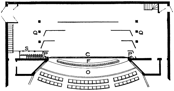
FIGURE 124.
The Stage.
The Stage.—Figure 124 is a floor plan of a typical
stage, showing the orchestra pit O, foot lights F, steel
curtain C, switchboard S, stage pockets Q, proscenium
side lights P, and general arrangement of scenery.
The foot lights are not always curved but it
seems advantageous to arrange them in this way. The
rows of seats are of necessity curved so as to face
each patron squarely toward the stage. If then the
stage and foot lights are curved in the same way, the
actors will be able to come that much closer to the
audience and can thus make themselves more easily
heard. The curving of the foot lights will have the
further advantage of illuminating the sides of an
actor more than would be the case if they were laid
out in a straight line.
At each side of the steel curtain are the proscenium
side lights. In some cases these lights are arranged
on the audience side of the curtain, the object being
to arrange them as far in front of the stage as possible.
The location of these lights is awkward and it
is difficult to get light from them in a useful direction.
In most theaters the switchboard is located on the
right-hand side of the stage, facing the audience.
This is the side from which the stage manager prefers
to work and the operating electrician should be[168]
close to him. In most well-arranged theaters, the
switchboard is raised above the stage level so that it
may not obstruct the exits of the actors. Where
practicable, the board should be let into the proscenium
wall so as to allow the operator to stand as
close to the proscenium opening as possible. He
should have a full view of the stage at all times, since
many of his cues are given by movements of the
actors.
The stage pockets are laid out far enough from the
center of the stage to insure their being always behind
the scenery. If they are brought in too close,
it is possible that, in a panorama setting, for instance,
they would be visible to the audience.
Doors leading from the stage to the outside are always
vestibuled in good houses. The vestibule prevents
the wind from blowing the drapery about unduly
and also shields the actors from unpleasant
drafts.
Dressing rooms are arranged wherever the conditions
of the building allow suitable space. Many of
them are under the stage and others are arranged on
one or both sides of the stage, sometimes very high up.
A view of the stage looking from the rear is shown
in Figure 125. This figure shows the vent, the method
of border light suspension, bridges for support of arc
lamps or other sources of illumination, the fly floor,
and the rigging loft, or “grid”.
The rigging loft is generally constructed entirely
of iron slats with open spaces between them. This is
necessary to insure ventilation in case of fire.
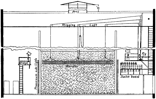
FIGURE 125.
In most theaters the height from stage to ceiling
is about seventy feet or more. The height must be
great enough to allow the scenery to be hoisted out[169]
of sight above the proscenium opening. There must
also be sufficient space above the rigging loft to allow
men to walk about straightening out ropes, etc. The[170]
total height should, therefore, be nearly two and one-half
times that of the proscenium opening.
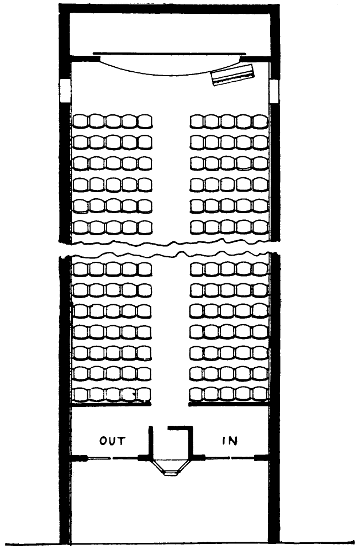
FIGURE 126.
As a rule no openings of any kind are arranged in
any of the enclosing walls of the stage, except those
that are necessary as entrances. In houses which[171]
are likely to originate shows, a paint bridge is generally
provided along the back wall.
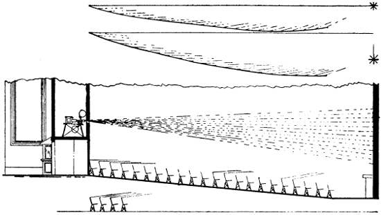
FIGURE 127.
Moving-Picture Theater.
Moving-Picture Theater.—Figure 126 is a plan of
a typical small moving-picture theater. A spacious[172]
lobby is an important adjunct to any such theater and
this space is often as valuable as the seating space
inside. It affords shelter to those who cannot be
seated at the moment. It is especially convenient in
localities where race suicide is not yet very noticeable
and where it forms a repository for many baby carriages.
A view showing the location of a picture-machine
booth is given in Figure 127. This is the arrangement
most in use although there are localities where
it is required that the operating room be at the end
of the theater opposite the main entrance, the object
being to avoid the necessity of the audience passing
under the fire to the outside in case a fire should
occur in the operating room. This plan has so many
disadvantages that it is never followed except where
the law requires it. If a properly arranged operating
room is provided, there is no necessity whatever for it.
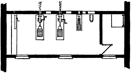
FIGURE 128.
The chief use of Figure 127 is to illustrate the importance
of adjusting the height at which the picture
is thrown upon the curtain to the pitch of the floor.[173]
The curved lines in the upper part of the picture
indicate the floor conditions which would give each
seat the same clearance over-the-one-in-front-of-it to
a view at the bottom of the picture. The upper line
shows the bottom of the picture, level with highest
seat, the other with the same point somewhat below it.
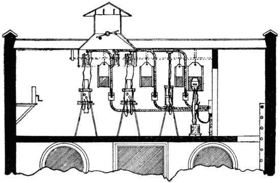
FIGURE 129.
Figures 128 and 129 show the plan and the elevation
of a large operating room. Every operating
room should be of ample size to allow the operator to
walk on all sides of the machine. It should be strictly
fireproof, well-ventilated, and provided with a door
giving easy exit to a floor outside, level with the floor
of the room. In altogether too many rooms the only
means of getting in or out is by a ladder which leads
directly into the room through a small trap door.
Such an arrangement is extremely dangerous in case
of fire. The fumes of burning film are poisonous if
inhaled and spread very fast. If two men should
happen to be in such a room at the time the film is[174]
ignited, it is likely that they would wedge each other
into the narrow opening and both perish. The door
to the operating room should open outward and be
self-closing. All openings in the operating room must
be fitted with fireproof shutters by which they can
be instantly closed in case of fire. There should also
be suitable ventilation to the outside to carry off all
smoke from burning film.
The Screen.
The Screen.—The screen upon which the picture is
projected should be a clear white but of a dull finish.
All glare should be avoided and wherever there is a
polished surface, this glare is always conspicuous.
There are a number of patent or special makes of
screens on the market, but it is not the purpose at
this time to discuss any of them. It will be sufficient
to point out some of the simpler methods by which
screens may be made.
A simple plaster wall is often used and is very
serviceable, but it must not be polished and must be
coated in some way to allow of washing off occasionally.
Perhaps, all things considered, a muslin screen is
the best of all. Such a screen, if well stretched, gives
a good flat surface entirely without glare and has the
further advantage that it can easily be taken down
and laundered as often as necessary. It is best to
provide duplicate sets so that there may be one for
use while the other is in the wash.
The only real objection to a muslin screen is the
loss of light which it entails. It is not only a poor
reflector of light, but it allows much of the light to
pass through it. With many such screens, the picture
is as well visible behind the screen as it is in
front of it. This indicates a great loss of light and it[175]
is to prevent this loss of light that the other forms
of screens have been devised. The most noticeable of
these is the mirror screen, which is a mirror of ground
glass. It is very economical in light but expensive
in first cost and hard to keep clean. It must be
washed quite frequently and careless men are apt to
use too much water and get some of it on the back
where it will soon begin to loosen the silver coating
and ruin the mirror.
The screen should be surrounded so that no other
light except that coming from the picture can reach
the audience. To this end there should be a black
frame around it and this black frame must also be
a dull black and without glare. Velvet drapery is
the very best thing that can be provided and should
be brought in so close from all sides that no white
rim around the picture will be visible, as such a white
rim would detract greatly from the illumination of
the picture.
The decorations around the proscenium should
preferably be of a dark color and kept dull, especially
in cities where it is necessary to maintain emergency
illumination. If the front is light in color, there
will be considerable reflection which will detract from
the picture and require a higher illumination of it.
Wherever there is an opportunity to do so, the
screen should be set well away from the nearest row
of seats. This will not affect the view of those in
the rear, and it will very much improve the view of
those in front. It must of course be seen to that a
clear view from both sides is possible.
[176]
CHAPTER XV.
OPERATING ROOM EQUIPMENT.
Construction and Ventilation.
Construction and Ventilation.—The operating room
should be built of fireproof material, such as cement,
brick, or tile. If it is of wood, it may be made
nearly fireproof by lining the inside with heavy
sheet iron. It will be well if asbestos is placed between
the sheet iron and the wood which it covers.
All woodwork, whether window frames, doors, or
shelving should be thus lined. It may be taken as
practically certain that sooner or later one or more
reels of film will be burned in the room and every
precaution should be taken to prevent the fire from
spreading. If this is done there will probably be
no serious results, for in the past there have been
so many film fires which have been successfully
confined to the operating room that audiences have
become pretty well accustomed to them. If all
operating rooms are strongly built and of ample dimensions,
with all openings as small as practicable,
it will help to inspire confidence in the audience
and there will be but little likelihood of a panic.
The chief danger is to the operator. It is true
that he is generally to blame, but it is not always
possible even with the utmost care to prevent a fire.
Above all the operator should be given every possible
chance to get away in case of fire. An operator
who feels that he can get away at the last
moment is far more likely to stay and fight a fire
than one who is penned up in a coop from which it[177]
is difficult to get out rapidly. There are in existence,
at the present time, operating rooms where it
is necessary to crawl on hands and knees some
twelve or fifteen feet to get from the machine to
the exit, and where the exit is by means of a trap
door at the head of a ladder. Such operating rooms
are an abomination and no self respecting operator
would work in one of them.
The entrance and exit from the booth should be
by means of a door at the right hand or crank side
of the machine. The door should be self closing
and should open into a space having a floor level
with the floor of the operating room. The door
should preferably be kept closed but if the provision
illustrated in Figure 128 is made there can
be no serious objection to leaving the door open
for ventilation. A thin bar of iron is fastened to
the door by a screw eye and is used to block the
door open. A person rushing out will naturally
knock this away and the door will close. The door
could also be arranged to be held open by means
of the strings, to be described later, which hold
the shutters in place.
The ventilation of the operating room should be
by means of a fireproof duct leading to the outer
air. This flue should preferably extend above the
highest point of the roof and should be of good
size. The smoke from burning film is heavy and
does not rise very fast but it is generated with extreme
rapidity. Film burns at a temperature of
284 degrees Fahrenheit. If it is incased in a tank
and fire communicates with it, the whole body of
the film will be raised to this temperature in a very
short time and will burn with the rapidity of an[178]
explosion. In the magazines, which are in general
use in the newer houses, the combustion will be
slower but nevertheless will take not more than
about one minute.
It has often been suggested that a motor be provided
in the ventilating flue, this motor to be kept
running during the time the machine is in operation.
This would no doubt help clear away all
smoke very quickly but there is no assurance that
it will be running at the time when it is most
needed. A simple way to help out the ventilation
without the expense and noise of a motor, would
be to arrange the ventilating flue directly above
the arc lamps so that heat rising from these would
cause a draft. This can be further helped out by
locating all resistances in this flue. They will then
be out of the way in a safe place and assist in
ventilating the room. The ventilating flue will
need to be fitted with a damper for use in cold
weather. This damper should be arranged to open
by gravity and be held closed by a string connected
to the shutter strings so that the damper
may open when the shutters close.
The floor of the operating room is a very important
part of it. It should, above all, be extremely
rigid so that the machine may be fastened solid and
thus obviate any vibration which will cause movement
of the picture. All floors that are constructed
of wood are somewhat elastic and aid this vibration.
Movement of the picture is especially noticeable
and annoying to those compelled to sit close
to it. Floors must furthermore be lined with fireproof
material and the only material used is sheet
iron which, upon the floor, is very noisy and can[179]
hardly be nailed sufficiently to eliminate the noise.
A metal floor lining has the further disadvantage
of affording a good “ground,” so that any one
standing upon it and touching a live part of the
lamp is liable to receive a severe electrical shock.
It will also soon wear through, make pockets to
catch dirt, and allow a fire to communicate with
the woodwork beneath it. The best floor material
is cement, but this, when wet, also becomes a fairly
good conductor and shocks may easily be obtained
while standing upon it. There is no reason, however,
why it should ever be wet in an operating
room and it is therefore advisable to use cement.
The floor of the operating room should be kept
clear as far as possible. Careless operators often
allow their take-up magazines to become deranged
and when they fail to work, allow the film to run
on the floor. A thousand feet of film scattered
loosely about occupies considerable space and is very
likely to become badly tangled in case there is anything
on the floor for it to tangle with. The writer
has witnessed cases where it was necessary to take
some of the film outside of the booth in order to
get it straightened out. Any operator who has been
in a similar predicament will appreciate the advantage
of having every possible obstacle to a
speedy re-adjustment removed. Above all, resistances
and other sources of heat should be kept off
the floor.
Every moving-picture machine requires at least
two openings; one through which the picture is
projected, which need not be very large; another
through which the operator must view his picture,
and this must be large enough to allow him to sit[180]
in comfort while watching the picture. In some
operating rooms the opening through which the
picture is projected is closed by a metal funnel
which covers the opening and extends back enclosing
the front of the projecting lens. This arrangement
is very simple in the case of machines in which
the revolving shutter is behind the lens. With many
machines, however, this shutter works in front of
the lens and the funnel would have to be extended
so as to enclose the revolving shutter.
There is no reason why strong clear glass could
not be used in the operator’s peep hole. This would
of course interfere slightly with the clearness of
his vision for focusing, but every operator should
be provided with an opera glass for this purpose
anyway, so that this objection would be easily overcome.
The same considerations which apply to motion-picture
machines also applies to stereopticon lamps.
In the more pretentious houses a spot light is
generally maintained. This is for the purpose of
illuminating vaudeville performers. The opening,
provided for this lamp, must be large enough to
allow the light to follow an actor about the stage,
and glass cannot well be used in it.
The best color for the operating room is green
but it must be a dull dark green. Every vestige of
light maintained in the room helps dull the vision
of the operator to the light upon the screen. There
is, furthermore, much light reflected from the film
where the light strikes it and it is unavoidable that
the operator should be bothered by this at times.
All other light should be kept away from his eyes
while the picture is running.
[181]
All of the openings in the room must be equipped
with fire shutters. These are generally made of
heavy iron and are arranged so that, if necessary,
they can be instantly released and made to close
all the openings, thus preventing the escape of fire
and smoke into the auditorium.
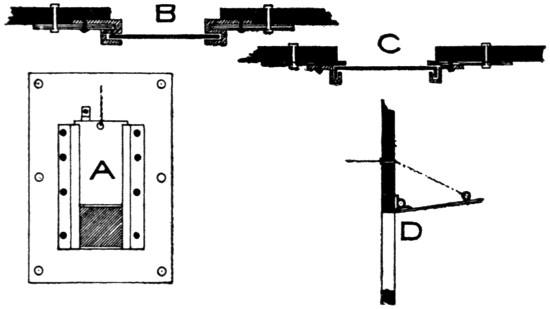
FIGURE 130.
The best arrangement of such a shutter is illustrated
in Figure 130 at A. The shaded portion
shows the opening; above is the iron slide, preferably
one-sixteenth inch metal held up by a string.
At the top is a step which will prevent the shutter
from being pulled up out of the guides, for many
operators would do this if the step were not there.
It is best to mount the shutter on a large piece
of heavy metal which can then be bolted to the
wall of the room. The hole in the wall can then
be cut to the right proportions. When the machine
is in place the shutter can be placed very accurately.
In this way it will be possible to arrange for
the smallest possible opening through which the
machine can work.
[182]
Making up the shutter, as suggested above, is
further of great advantage in old operating rooms
of flimsy wood construction. If the guides in such
places are fastened independently to the wall it is
possible that they will not always remain in line
with each other. A slight giving of the flimsy wall
on one side may cause them to bind the shutter and
prevent its free descent. If the metal on which the
shutter guides are mounted is strong and heavy and
the guides themselves substantially made, there will
be but little chance to get them askew.
In that part of the guides in which the shutter
runs there must be no screws, rivets, or anything
else that could work loose and obstruct the shutters.
Good methods of making up the guides are shown
in Figure 130, at B and C. They should be loose
enough to work without lubrication. At the bottom
there should be a bumper to stop the fall at
the proper place. This bumper should be padded
with some fireproof or slow-burning material and
should be narrow. If it is made wide the operator
is apt to use it as a shelf for tools or other things and
this would prevent it from closing properly in case
of fire.
All of the shutters must be normally self-closing
and must be held open by some arrangement which
can readily be worked by the operator; or, in case
he fails to close them, they should be arranged so
that the flames will cause them to close automatically.
This is often arranged for by simply attaching
a light strong string to each shutter, running
it through a hook eye directly above and attaching
it to a master string which is led over every
place at which there is thought to be a likelihood of[183]
fire. The idea is, that the first spread of flames
shall strike this string and by burning it, release
all of the shutters. In order to enable the operator
to drop the shutter perhaps before the flames have
spread at all, the string is carried to the door and
fastened so that he, on leaving the room, may quickly
release it. It is even better to carry it still
farther so that one can release it from the outside.
Some people have recommended that these strings
be soaked in oil to make them more inflammable and
tarred rope has even been made mandatory for similar
purposes in ordinances. This might make the
string more readily inflammable, but it would at the
same time make it last longer. A string or rope
so treated would act like a lamp wick and the better
soaked or tarred it might be, the longer would
it last and thus fail to its purpose.
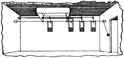
FIGURE 131.
The principle of the arrangement of strings is
shown in Figure 131. The string is fastened at the
door in a manner allowing of easy and quick removal.
Instead of the strings, light chains may be
used provided that at a sufficient number of places
fusible links are inserted. Such links are made up
of an alloy which melts at a low temperature and
allows the shutters to drop just as they would in
the case of a string burning in two.
[184]
In many cases the strings are run over grooved
pulleys. This is, however, inadvisable. Experience
has proved that very often the string has come out
of the groove and is wedged in between the shaft
of the pulley and the side so that it will not allow
the shutter to descend at all. A substantial hook
eye is much better than any pulley. The strain
being taken off the string when it separates, there
is no friction and it slides through the eyes very
readily. The door and the vent flue may all be
brought under control of the same string so that
all will operate together, the vent of course opening
while the others close.
Where there is but one door there is little need
of connecting it with the shutters, since, if it is provided
with spring hinges it will naturally close after
the operator has passed through it. In some operating
rooms, however, there are two doors and both
are often found open. In case of fire in such a
booth it is extremely likely that one of the doors
would be left open unless it is provided with some
automatic manner of closing.
At D, Figure 130 is shown a shutter, provided with
strong spring hinges, which closes over the opening
from the outside. Such shutters should not be used
where there is room for the drop shutters. Where
it is necessary to have them, they should always be
arranged on the outside of the booth; if on the inside
there is too much chance of obstacles being in
the way to prevent their closing.
It is very desirable that all of the shutters be
closed after each show. If this is done there will
be strong assurance that they will be in working
order in case of need and this is about the only way[185]
in which they can be kept in order. The string
arrangement above described is, however, not well
suited to this purpose unless each shutter string be
detachable from the main string. There are also
various other ways of accomplishing this which will
readily suggest themselves to the operator.
In every operating room there should be ample
provision for keeping tools but it is advisable to
have all tools, that are not kept in the lockers, on hooks
instead of shelves. It is best to limit the amount
of shelving to what is actually necessary. Shelving
offers great temptation for the accumulation of rubbish.
There must be a shelf upon which to locate
the rewinding apparatus and upon which to place
the machine while looking it over or making repairs,
also a shelf to hold a small vise, etc. But
this is all; any additional shelving will be inexpedient.
A locker for tools can easily be arranged
under the rewind shelf. A good safe place is an
encouragement to an operator to keep a supply of
good tools and nothing is more essential to the
proper management of a machine than good tools.
If the operating room is large enough, it may also
contain a locker for clothes but this should be fireproof.
Preferably, however, the clothes locker
should be outside of the room, since a film fire gives
one but little time to pick up clothes or anything
else.
There should, further, be a metal pail or receptacle
of some kind for hot carbons taken from the
lamps from time to time. A wise operator will also
provide himself with a small receptacle in which
he can keep the pieces of film which he finds it is
necessary to cut out of films received from the exchanges.[186]
The inspection of films in the exchange
is often very perfunctory and many lengths are left
in that should be cut out. Cutting them out and
saving them for a time will often help an operator
to win out in disputes with his film exchange. There
are operating rooms which have film boxes built into
the wall in fireproof manner, some of them even
surrounded by water. At the present time there
are a number of good portable boxes on the market
so that this is unnecessary.
Wiring of Operating Room.
Wiring of Operating Room.—Every operating
room must have at least two circuits run into it;
one for the arc lamp and another for one or more
incandescent lights. In the larger cities an emergency
lighting system is required for all parts of
the house used by the audience. This system is
always entirely independent of the main service and
is supposed to furnish sufficient light for the audience
in case the other lighting system should fail.
It will be well if one light connected to the emergency
system is arranged in the operating room. If
this is done, there must be special provisions that
no cords, fan motors, or portables be connected to
it. A short circuit, or trouble of any kind on this
light might put the whole emergency system out
of operation. If such a light is installed, it should
be at the ceiling and protected by a strong wire
guard fastened to the outlet box. All wires carried
into the operating room should be in conduit,
with the exception of the asbestos covered wires
used with arc lamps and resistances.
In addition to the incandescent light above mentioned,
there should be several other lights so arranged
that good light can be obtained in any part[187]
of the room. The color of walls being dark there
is but little reflection and a single light will only
illuminate a small space. One light should be arranged
above the rewind reel and there is often
another arranged under a piece of glass in a shelf
above which films are patched. Only the best reinforced
cord should be used and all work that is
stationary should be in conduit. Several outlets
should be arranged for portable cords so that one
may have a light to bring down to the take-up reel
or close to the floor if necessary. Every incandescent
lamp in the operating room should be protected
by a substantial wire guard fastened to the
socket.
Fan motors should be provided with strong
brackets located near the ceiling and close to the
outlet from which the motor is to be run. Fan
motors should never be allowed upon the floor.
Where rewinding is to be done by motor, it will
be well to arrange a separate circuit for this motor
independent of all lights. The commutator part of
the motor should be enclosed so that there may be
no possibility of a spark igniting the film.
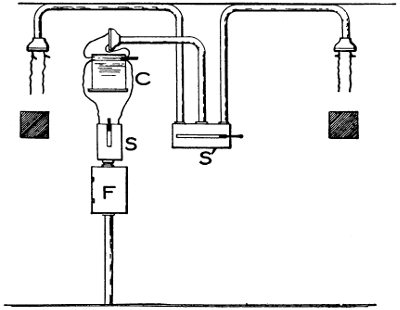
FIGURE 132.
Figure 132 is a sketch illustrating the arrangement
of wiring by which two arc lamps may be
connected to mains of sufficient carrying capacity
for one only. F is the fuse box in which the arc
lamp fuses are enclosed and may be large enough
to accommodate a set of fuses for the incandescent-lamp
circuit also. In many cases these are, however,
taken from the house circuit since the meter
rate for arc lamps is usually different from that for
incandescent lamps. S is the main arc-lamp switch
by which the whole installation in the room can be[188]
cut off. This is necessary especially if so-called
compensarcs, economy coils, or transformers are
used, for these always take some current if left
alive even if the arc lamp be not burning. At C
is the resistance or economy coil which serves for
both lamps and at S is the throw-over switch. This
switch is provided to make it impossible to burn
the two arcs at the same time as this would overload
the small capacity mains. The above is a
cheap arrangement and is installed only where a
set of mains exists which is too small to supply
more than one arc at a time. It is not to be advised
for a new installation because it is of great
advantage to be able to burn both arcs at the same
time. When changing rapidly from one machine to[189]
the other it is of advantage to have the second one
on for a short time before the first is off, not only
to save a little time, but also for bringing electrode
points to the proper shape. Wherever it is possible
to do so always provide mains of sufficient size to
feed all of the arcs and give each lamp its own
fuse, switch, and resistance or transformer.
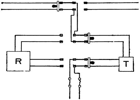
FIGURE 133.
Figure 133 shows a method by which it is possible
to arrange for either one of two arcs to be run from
a rectifier R, indicated by the square at the left, or
transformer T, at the right. In case rectifiers, heavy
transformers that cannot well be raised to the ceiling,
or motor generators are to be installed, they
should be located in a separate enclosure which
must be fireproof.
In general, all of the wiring in the operating
rooms must be installed in accordance with the rules
given in the chapter on Theater and Stage Wiring.
These are the rules of The National Board of Fire
Underwriters and are familiarly known as the “National
Electrical Code,” or “N.E.C.”
[190]
CHAPTER XVI.
CURRENT CONTROL FOR ARC LAMPS.
Voltages Required.
Voltages Required.—The commercial distribution
of electrical energy is at voltages of 110 or 220, in
most cases, and occasionally runs as high as 550. The
direct-current arc requires for its best operation a
voltage of from 45 to 50, while the alternating-current
arc uses from 30 to 40. In order to secure satisfactory
operation of arc lamps, it becomes necessary
to provide some means of reducing the voltage at the
arc to the proper amount.
Resistance Control.
Resistance Control.—The simplest method and the
one universally applicable is that of inserting resistance
in series with the arc. The drop in voltage
is equal to the current multiplied by the resistance;
hence, if we wish to decrease our voltage, say 65
volts, as would be the case in connection with a 110-volt
circuit and a 45-volt arc, using 25 amperes, we
should need a resistance of 2.6 ohms. Twenty-five
times 2.6 equals 65 volts lost, which leaves 45 volts
to operate the arc with. In connection with arc lamps,
however, it is not only necessary to lower the voltage
but some provision must be made so that the current,
when the electrodes are brought together, will not
become excessive. At the time the arc is struck, i.e.,
at the time the electrodes are brought in contact with
each other, the current is limited only by the extra
resistance in the circuit, for the electrodes then form
a short circuit. In the above case, 110 volts and a
rheostat with 2.6 ohms resistance we should obtain,[191]
during the time the electrodes are together, a current
equal to 110 divided by 2.6 which equals about 43
amperes. If it were not for this resistance the current
would rise to several times this value and blow
out any fuse we might provide. It is not necessary
that this resistance be in any particular place; if we
have a very long run of small wire from the service
to the arc, there may be sufficient resistance in this
so that very little extra resistance is required. Somewhere,
however, there must be some provision inserted
in the circuit to prevent the current from becoming
too great at the time the electrodes are brought together.
In passing it may be noted at this point that
an arc can be started without any resistance in the
circuit by bridging the space between the electrodes
with a small fuse wire which will melt the instant the
current is turned on and establish the arc.
The resistance method is very wasteful of energy,
as the following tabulation will show; but with direct
currents it is the only method available, unless we
are willing to provide a motor generator to give us
the proper voltage. For alternating currents, resistances
are not much used, except with traveling
shows where the portability of the control as well as
its fitness for all possible conditions is an important
consideration.
| Volts |
Current |
Watts
Lost |
Useful
Watts |
| 110 |
30 |
1950 |
1350 |
| 220 |
30 |
5250 |
1350 |
| 550 |
30 |
15150 |
1350 |
[192]
The tabulation in Table IV shows that the higher
our voltage the greater the loss of energy caused by
the use of resistances. The figures apply, as given,
only to cases where only a single arc lamp is used.
Where several can be used in series the loss due to
high voltage need not be greater than with lower
voltage.
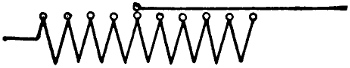
FIGURE 134.
In Figure 134 we have shown diagrammatically
the usual representation of a resistance. The more
wire there is in circuit, the higher will be the resistance
and the greater the drop caused by a given
current. If we lengthen the arc, the current will be
somewhat decreased and the drop in voltage over the
resistance will be less, thus allowing a rise in the
voltage at the terminals of the lamp. The energy
lost in resistances takes the form of heat and all resistances,
used for the control of arc lamps, give off
much heat and must be located in safe places. The
heating also makes them objectionable in small operating
rooms in summer, but somewhat welcome in
winter. The heat generated in a wire is proportional
to the square of the current; hence if we double the
current through a certain resistance we shall have
four times the heat.
If several resistances are connected in series the
total resistance will be equal to the sum of the individual
resistances, and the current will be correspondingly
decreased. If we wish to get more current
than can be obtained with the use of one resistance[193]
we may connect up two or more in parallel.
Two equal resistances connected in parallel will give
approximately double the current that can be obtained
through one of them.
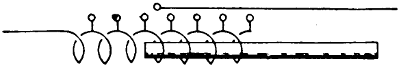
FIGURE 135.
Reactance Control.
Reactance Control.—A reactance, shown diagrammatically
in Figure 135, may take the place of the
resistance in alternating-current circuits and is preferable
because it wastes comparatively little energy.
It lowers the voltage over the arc but its operation
depends upon a counter e.m.f. which opposes the
impressed e.m.f. of the circuit and must be subtracted
from the latter. The nature of reactances
as well as of transformation, etc., has been fully
treated in another work of the authors’, entitled,
“Alternating Current Theory, Practice and Diagrams”
and would carry us too far were it to be
discussed in this work. Every reactive coil is made
up of copper wire wound upon an iron core and contains
both resistance and reactance. So far as the
resistance in it is concerned, this causes a waste of
energy, but it is always very small. There is also a
waste of energy due to the hysteresis and eddy-current
losses in the iron, but this is also small.
The reactance is proportional to the square of the
number of turns of wire, if the iron core is fixed,
and may be controlled either by adjusting the position
of an iron core in a helix, or by adjusting the
number of turns of wire around a fixed iron core.
The light obtainable through a reactance is not of the
best quality and reactances are not much used.
[194]
Transformation Control.
Transformation Control.—Another method of
lowering the voltage is by means of the transformer.
A diagram of an ordinary transformer winding is
given in Figure 136. The fine-wire winding is the
primary winding or coil, if the transformer is used
to lower the voltage; and the other is known as the
secondary winding or coil. The energy in both coils
of the transformer, neglecting the iron and copper
losses, is always exactly equal. The ratio of voltage
between the primary and secondary terminals is in
direct proportion to the number of turns of wire in
each. If there are half as many turns in the secondary
winding as in the primary, the voltage will be
just one-half, but the current will be double. The
transformer is self-regulating, within the limits of
its capacity, and whatever energy is taken from the
secondary, the primary will automatically supply.
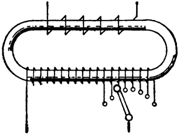
FIGURE 136.
A transformer must be specially built for the voltage
and frequency, at which it is to be used; but
many of them are provided with taps, such as shown
in Figure 136, by which small adjustments of voltage
or current can be made. A transformer must always
be connected so that the switch, when open, will disconnect
the primary wires. If these remain closed[195]
there will be a small current through the primary
winding which will mean a considerable waste of
energy.
Auto-transformer Control.
Auto-transformer Control.—The auto-transformer
is a special type of transformer used to obtain reduced
voltage and increased current. Its principle
may be gathered from Figure 137. There is an iron
core and two coils of wire as in ordinary transformers
but the two coils are connected in series, as shown
in the figure. It will also be noted that the arc is
connected directly across one of the coils. The lower
portion of the winding or coil is traversed by the
alternating current from the mains at all times and
this current also passes through the arc lamp when
the circuit through it is closed. The current passing
through the lower coil and the arc induces a current
in the upper portion of the winding and these two
currents then pass in parallel through the lamp.
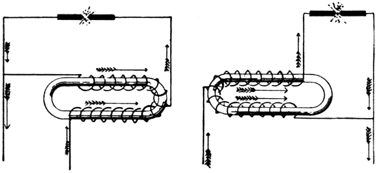
FIGURE 137.FIGURE 138.
When the arc circuit is open, both coils are in
series and act as choke coils so that but very little
current is used. The auto-transformer may be designed
to reduce the voltage to any desirable amount
and the current will be correspondingly increased,
neglecting all losses.
[196]
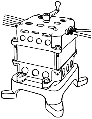
FIGURE 139.
If the reduced voltage were to be obtained from an
ordinary transformer, the secondary coil would be
called upon to carry the full current used by the lamp,
while with this connection it carries much less. If
the two coils are equal, the voltage will be reduced
one-half, the current will be doubled, and only half
of the current will pass through the secondary coil.
The nearer equal the primary and secondary voltages
are, the greater the saving in copper in the secondary
coil. If it were intended to transform from 110 to
100 volts, the capacity of the secondary winding
would need to be only one-eleventh of the total capacity.
The auto-transformer is a very useful device
but on account of the fact that the high voltage[197]
exists in all of its parts, it is not safe to use with
the high commercial voltages outside.
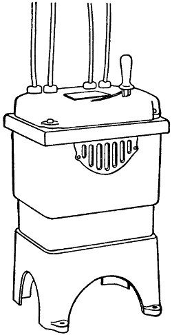
FIGURE 140.
If the auto-transformer is connected as shown in
Figure 138, it can be used to raise the voltage; but
in this case the current will be decreased. These auto-transformers,
as well as the ordinary transformer,
must always be connected to the source of energy by
means of a switch so that they may be disconnected
when not in use; otherwise there will be a small current
in the primary circuit all the time which will
show up quite strong on the watt hour meter. Transformers
and auto-transformers are arranged to be
portable. A general view is given in Figures 139 and[198]
140; the former being the Edison and the latter the
Fort Wayne.
Motor-Generator Control.
Motor-Generator Control.—The proper voltage for
the operation of arc lamps can be obtained by the
use of motor-generators. A motor-generator is a generator
driven by a motor, the two armatures being
placed upon one shaft or belted together. The motor
may be driven by a current of any voltage desired.
The diagram of such an outfit for direct current is
shown in Figure 141. This type of machine is used,
as a rule, only where the supply voltage is much
higher than that used at the arc. Resistance must be
used at each arc lamp.
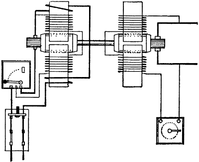
FIGURE 141.
Figure 142 shows the connections of an alternating-current
to a direct-current motor-generator of the
Fort Wayne Electric Company. The switch A is
used to start it and is shown connected to a three-phase
line. Aside from the field winding there are
three wires leading to the generator. The wire B[199]
carries a compound winding inside of the generator
which opposes the magnetization of the shunt winding.
The wire C carries another compound winding
which is arranged to strengthen the shunt field. D
is a box containing two resistances, one for each arc
lamp shown.
If only one lamp is to burn, the switch E is closed
and the arc started in the usual way. When ready
to change to the other arc lamp, switch E must be
opened, the switch on the second arc lamp closed, and
the arc struck. Then extinguish the first arc and
close the switch E again. If both lamps are to be
used continually, switch E must be left open.
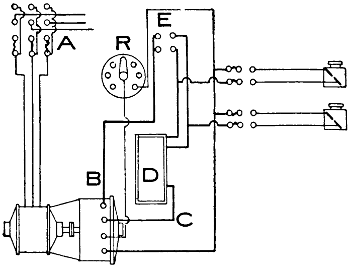
FIGURE 142.
As long as current is used through wire B, there is
no loss of energy in any resistance and should the
current in the arc rise, as when the electrodes are
brought together, the increased current in the series
winding, cut into this wire, would weaken the
field and thus keep the current down. When current[200]
is used through the wire C, the series field winding
strengthens the field and builds up the voltage sufficiently
so that the lamps may be operated through
the resistances. The field strength may be further
regulated by the rheostat R.
Another connection of the Fort Wayne motor-generator
is shown in Figure 143. In this case the lamps
may be operated either from the compensarc C or the
generator. By throwing either one of the switches
connected to the arc lamps up, the corresponding
arc lamp is connected to the compensarc. By throwing
the switch down it is fed from the generator.
The lamp, by which the picture is being projected,
should be fed from the generator and when nearly
ready to change, the other may be started on the
compensarc. This lamp will burn with a short arc
and when it is connected in parallel with the one on
the generator, it will immediately extinguish the latter.
No attempt must be made to burn both arcs
from either the compensarc or the generator. This
generator is also wound to protect itself against an
overload.
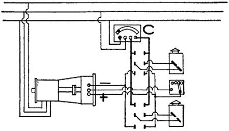
FIGURE 143.
[201]
Where these connections are to be installed, it will
be best to consult the local inspection departments
concerning the necessary fusing for the compensarc
and the generator. In some localities the possibility
of throwing both arcs on either compensarc or generator,
where these have capacity for but one arc at
a time, will be considered very objectionable.
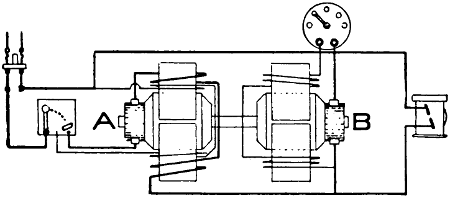
FIGURE 144.
Another combination of motor and generator sometimes
used is shown in Figure 144. By tracing out
the circuits it will be seen that the armatures of both
are in series and that the electrodes, when they come
together, form a shunt about B. With the electrodes
separated, if current is turned on, it must pass
through both armatures in series. Thus the counter
e.m.f. of both armatures opposes that of the line and
they operate at a certain speed. Each motor has a
natural tendency to send current in opposition to that
impressed upon it by the line. If then the electrodes
are brought together, they at once form a short circuit
around the armature of B. The current in B
reverses and it then begins to act as a generator and
sends current through the arc lamp. The current
which passes through the armature of A also passes
through the arc lamp. A is then a motor and operates
B as a generator.
[202]
The voltage at the arc is less than the line voltage
by as much as the counter e.m.f. of motor A amounts
to, neglecting the drop in voltage due to resistance.
No resistance is needed if the winding is properly
arranged and there is not the less in heat which goes
with the use of resistances. This arrangement can
be used with direct-current circuits only. It is not
suitable where the supply voltage is very much higher
than the voltage used at the arc. A field rheostat is
provided to adjust the field strength of B. A is
equipped with the ordinary motor-starting rheostat
only.
Rotary Converter Control.
Rotary Converter Control.—This is a machine used
only where the supply is alternating current. The
voltage delivered to the converter must be the same
as that desired at the direct-current terminals. This
machine has an armature essentially similar to that
of a direct-current dynamo. Alternating current is
supplied to it at one set of terminals and direct current
is taken from the others. This armature acts
as motor and generator at the same time. Whatever
voltage regulating is necessary with this machine must
be done on the alternating-current side. Changing
the field strength does not materially affect the voltage
so that no means for regulating the field strength
is provided.
The polarity of the direct-current terminals depends
upon the position the armature happens to be
in when the alternating current is applied to it and is
very apt to come in wrong when the machine is
started. It is therefore necessary to have a polarity
indicating voltmeter in the circuit and to watch it
when starting the machine. If the polarity is wrong,
the switch must be opened and in a moment thrown[203]
in again; and if still wrong, this process must be repeated
until the polarity comes right. Each arc lamp
fed from a converter must be equipped with resistance.
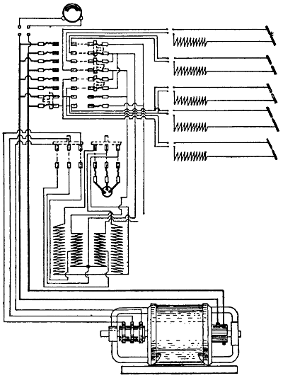
FIGURE 145.
The Martin rotary converter is especially designed
for motion-picture work and may be provided with
the proper connections for either single-phase, two-phase,
or three-phase work. There is a stator ring[204]
which entirely surrounds the armature. This ring is
made up of laminated disks with squirrel-cage bars
and slots alternating. The squirrel-cage bars are
joined at the end to a copper bar and it is by the aid
of this squirrel-cage that the motor may be started
and brought into step. The squirrel-cage also prevents
“hunting” which is one of the common
troubles experienced with synchronous motors or converters.
Into the slots are wound special compensating
coils to balance the armature reaction and
keep the neutral point in constant position from no
load to full load. This prevents sparking at the
brushes. On the outside of this damper ring or
squirrel-cage winding is the regular shunt-field winding
used with direct-current motors or generators.
Figure 145 is a diagram showing the connections
of the Martin Rotary Converter as installed by the
Northwestern Electric Company of Chicago. This
switchboard is equipped to operate two moving-picture
arcs, two dissolving stereopticon lamps, and one
spot light. Each lamp is provided with a throw-over
switch so that current may be used, either from the
alternating-current mains direct or from the direct-current
side of the converter.
Figure 146 is another panel board for moving-picture
work made up by the same company. In this
case resistances are provided for use when the arc
lamps are operated from the converter. In case it
is desired to run from the alternating-current mains,
transformers or compensarcs are used. The emergency
feature of these panel boards is highly to be
recommended. It must be borne in mind that one
may suddenly be forced to deal with an operator who
has never seen a converter and knows nothing of its[205]
operation; and there is also always the possibility of
some trouble with the machine.
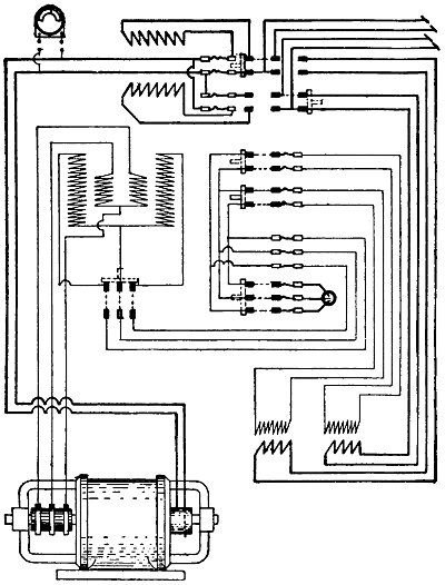
FIGURE 146.
A Martin rotary converter to be operated from a
single-phase line is shown in Figure 147. This machine
is started through the commutator side. In
order to start this machine it is necessary first to[206]
close the main switch. Next throw the switch 2 to the
right and leave it there for about five seconds. It
may then be thrown over to the running position at
the left and allowed to remain in this position. If
the polarity is not correct, the switch must be opened
again for an instant and closed again; and this process
must be repeated until the polarity comes in
right. To stop the converter, first open the main
switch and then the throw-over switch. The manner
in which the above machines are preferably set up
is shown in Figure 148.
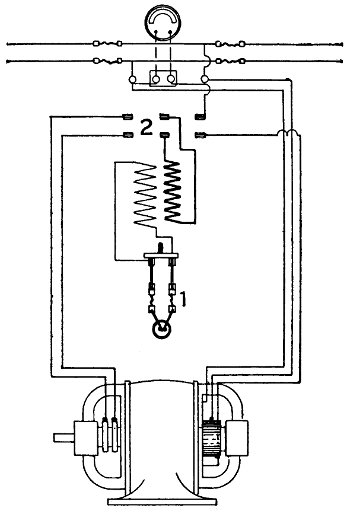
FIGURE 147.
[207]
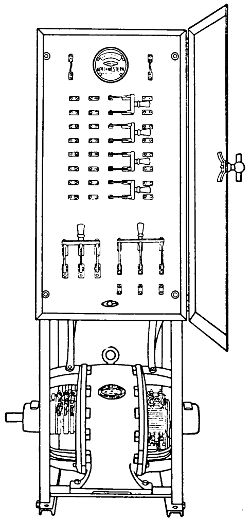
FIGURE 148.
The Mercury-Arc Rectifier Control.
The Mercury-Arc Rectifier Control.—The mercury-arc
rectifier has three essential parts: the rectifier
tube, the main reactance, and the panel. The rectifier
tube, Figure 149, is a glass vessel from which the
air has been exhausted and in which there are two
graphite electrodes, A and A´, and one mercury electrode
B. From the two upper electrodes current can[208]
pass in the direction of the mercury only. They are
always positive and the term anode is usually applied
to them. B is always negative and the term cathode
applies to it. Each anode is connected to a separate
side of an alternating-current circuit and is thus subject
alternately to positive or negative potential.
When current has once been started, the tube is
filled with ionized mercury vapor through which the
electricity can flow, from whichever of the two anodes
is positive, toward the cathode B. Under no conditions,
however, can electricity flow from the mercury
in the tube toward the anodes. The action of the
tube is started by tilting it sufficiently, so that the
mercury in the bottom of it connects the starting
anode C to A. This starts the current and when the
tube is returned to its upright position, the mercury
bridge from C to A is interrupted; but the current
then continues from one or the other of the anodes.
Should the current be interrupted, even for an instant,
the tube would cease to work until it had been
tilted again. In order to provide that the current,
which is alternating and comes to zero twice in every
cycle, may never cease in the tube, it is necessary to
provide some reactance. Such a reactance causes the
current to lag behind the e.m.f. and in consequence
lap over the time when it would otherwise fall to
zero. While the current from the rectifier is always
in the same direction, positive from B to the lamp, it
is also a pulsating current changing in value to some
extent.
In Figure 149 a complete diagram of the connections
of the General Electric Company Mercury Arc
Rectifier for moving-picture arcs is given. This type
of rectifier is entirely automatic and is much used.[209]
The front and back connections are shown in Figure
150. The following instructions are taken from a
publication of the General Electric Company:
The leads marked A C should be connected to the
lower side of a double-pole switch located near the
moving-picture machine. The upper studs of the
switch should be connected to the A C source of supply.
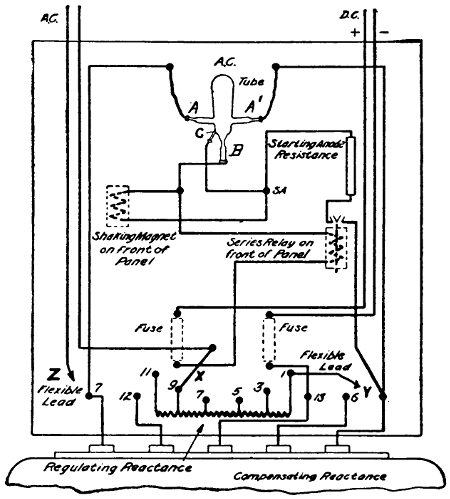
FIGURE 149.
The leads marked + and - should be connected,
respectively, to the positive (upper) and negative
(lower) electrodes of the moving-picture lamp.
If the A C supply voltage is 110 volts; then connect
the flexible lead marked Z to stud marked 12;
and flexible lead marked Y to stud marked 6[210].
If the A C supply voltage is 220 volts; then connect
lead Z to stud 7, and lead Y to stud 1.
Note:—Do not disturb the other connections that
are made on studs 1, 6, 7, and 12, but only place
leads Y and Z as directed.
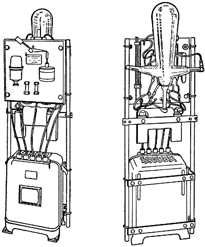
FIGURE 150.
The tube holder should be reversed so that the clip
and support will be turned away from the panel instead
of towards the panel, as it is when shipped.
Remove the tube from its box, being very careful
not to handle it roughly and not to strain the seals[211]
in any way whatever. Care must also be taken to
prevent the mercury from suddenly flowing into any
of the arms; otherwise the resultant pounding might
damage them.
Examine the tube for vacuum by noting the sound
the mercury makes when allowed to roll gently about
in the large chamber. If it makes a clear, metallic
click, the vacuum is good; but, if the sound is dull
and the mercury sluggish in moving, the vacuum is
either partially or wholly destroyed. If the vacuum
is poor, the life of the tube may be short or it may not
start at all. To insure careful handling and safe delivery,
Mercury-Arc Rectifier tubes are always shipped
by express in the special box as they come from the
factory.
Place the tube in the holder by inserting the small
part of the tube just above the anode arms in the
upper clip; then gently lower it until it rests firmly
on the lower support. Connect the tube and beaded
leads according to the above diagram.
Adjustment of current (number of amperes) at the
arc is obtained by connecting leads marked X to
studs marked 11, 9, 7, 5, 3, or 1 of the regulating reactance.
Stud 1 gives the maximum and stud 11 the
minimum number of amperes. In starting up the first
time it is best to start with lead X on stud 11 and
move toward the maximum position by steps until
the desired current is obtained, as indicated by the
ammeter. For this adjustment it is advisable to connect
an ammeter in series with the arc in the moving-picture
machine.
With the above instructions carried out, all that is
necessary to start is to close the switch in the A C
line; then bring the electrodes of the arc together.[212]
The automatic shaking device should then rock the
tube until the arc in the tube starts; as soon as the
arc in the tube starts separate the electrodes.
The best and whitest light can be obtained when a
5⁄8-inch cored-carbon electrode is used above and a
1⁄2-inch solid-carbon electrode below, care being taken
not to get solid carbons too hard. The average current
in the arc should not exceed 30 amperes and it
will be found that excellent pictures can be obtained
with 25 amperes or even less and the cost of energy,
carbons, and condensers will be less.
[213]
CHAPTER XVII.
MANAGEMENT OF GENERATORS AND MOTORS.
Operation of Generators.
Operation of Generators.—The generator should be
located in a clean dry place. If it is belt driven, the
belt should be run horizontal if possible and so that
the slack side will be on top. This increases the arc
of contact with the pulleys and allows the belt to
run with less tightening. The frame should be provided
with a slide for the purpose of adjusting and
tightening. The proportion between the largest and
the smallest pulleys used close together should not be
greater than about 6 to 1.
To start a dynamo it is best first to disconnect it
from the switchboard. Start it running and adjust
the voltage by the field rheostat. When the voltage
has arisen to its proper value and everything is running
smoothly, the main switch may be closed. If
there is much of a load, it will probably be found
that the voltage has fallen off a little and it will be
necessary to re-adjust it. Next, look carefully after
the brushes and set them at the points where there
will be the least sparking. A good modern generator
should not spark at all. All of the bearings must be
carefully looked after and watched for heating. If
they are not properly oiled or in good condition, they
may heat considerably. The armature should run
with considerable end play as this helps to distribute
the oil over the bearings and even up the wear on
the commutator surface.
Small generators sometimes lose their residual
magnetism and it is then impossible to start them[214]
generating. In such a case the fields may be connected
to a live-lighting circuit; or a small exciting
current may be obtained from a battery. One should
know which is the positive pole of the field and apply
the battery or line current accordingly. A test for
polarity may be made by placing the ends of wires of
opposite polarity in a vessel with water and bringing
them within an inch or so of each other. Under
these conditions bubbles will be given off at the negative
pole. The polarity of the generator will vary
with the polarity of the field, the direction of rotation,
and the connection of the brushes. By reversing
any one of these we may reverse the polarity of the
current delivered. Shunt dynamos cannot well be
operated in parallel; where it is desired to operate
several dynamos together, compound-wound machines
are used.
Operation of Motors.
Operation of Motors.—The speed of a direct-current
motor is always such that the counter e.m.f. of
the motor becomes nearly equal to the impressed
e.m.f. of the line. In order to speed up a motor it
is necessary to weaken the fields; and conversely, to
slow it down we must strengthen the fields. The above
methods are necessary if the motor is to run at a
nearly fixed speed with a variable load. The speed
can also be controlled by a variable resistance placed
in the armature circuit. This method, however, does
not result in a steady speed with a variable load. It
has very little effect if the load is light, and very
much if it is heavy.
In order to start a motor it is necessary to have
some resistance in the armature circuit. In very
small motors the armatures are usually wound with
sufficient resistance so that no external resistance is[215]
required. The larger motors are, however, equipped
with starting boxes which limit the current through
the armature until it has attained sufficient speed
so that its counter e.m.f. will keep the current in
check.
These starting boxes are usually wound with fine
wire and cannot stand the starting current very long.
The handle must be moved over steadily and slowly
and not allowed to remain on an intermediate position
unless it is known that the box is meant to be
used as a speed controller as well as a starting box.
The direction of rotation of a direct-current motor
can be reversed by reversing either the field or the
armature current. If both are reversed, it will continue
to run in the same direction.
Alternating-Current Motors.
Alternating-Current Motors.—Synchronous alternating-current
motors are not used in theater work
but the rotary converter is frequently used and may
be considered as such. This machine must run at a
certain speed which depends upon the frequency of
the current supplied and the number of poles on the
machine.
Rotary converters are of different types and may
be started either from the direct-current side or from
the alternating-current side. Some of them are provided
with connections so that the alternating current
may be applied on the direct-current side of the
armature. For starting and operating these converters,
the instruction of the maker should be consulted.
For motor-generators where alternating current is
used, the induction motor is generally employed. It
may be either single-phase, two-phase, or three-phase.
All of these are essentially constant-speed motors.[216]
Simple repulsion motors and single-phase induction
motors that start as repulsion motors are reversed
by shifting the brushes.
Alternating-current series motors are reversed in
the same manner as direct-current motors by reversing
either field or armature. If both are reversed,
the motor will continue to run in the same
direction.
A three-phase induction motor will reverse its direction
of rotation if any two of the line wires connected
to the primary winding be reversed. If all
three wires are changed in order, the direction of
rotation will remain unchanged. Synchronous motors
when started as induction motors are also governed
in this way.
These motors of the larger size are generally started
through an auto-transformer. For the smaller ones,
it is customary to provide a throw-over switch, one
side only of the switch being fused. The motor at
starting takes very strong currents which would blow
the running fuse. To reverse a two-phase induction
motor the two wires of one phase must be reversed.
GENERAL HINTS.
Be sure that all belts are sufficiently tight.
See that all bearings are well oiled.
Let all shafts have sufficient end play.
Use no oil cans of iron around dynamos or motors.
Keep files and other iron or steel away.
See that all connections are good and tight.
Allow no metal dust or gritty substances to accumulate
at the insulation of exposed parts.
See that the brushes fit properly and do not cut or
scratch.
Use no emery paper on commutators.
[217]
Lubricate the commutators very sparingly and
wipe off as much of the lubricant as you can.
Keep everything about the machines clean and
allow no oil drippings to accumulate.
Place the starting box for a motor so you can see
the motor start from the box.
Always place a switch which will disconnect all of
the wires close to the motor.
If possible arrange motors so they may start without
load.
Allow no motor or generator to be placed in the
operating room of a moving-picture theater.
[218]
CHAPTER XVIII.
THEATER WIRING.
The wireman should not fail to consult local rules
or inspection departments as to whether any rules
conflict with those given below. He must be warned
to consult local authorities or rules, too, because safety
rules are liable to change.
The purpose of this chapter is to furnish a ready
reference work concerning questions of electrical construction
in theaters which come up daily in all progressive
play houses. To this end the subjects have
been arranged in alphabetical order and the practical
considerations, as well as extracts from the National
Electrical Code governing construction, have
been given together. The aim has been to enable the
workman to find all information concerning construction
work grouped together, so as to obviate the
necessity of looking through various parts of the book
for the information sought. This order of things will
probably avoid the troubles now often caused by overlooking
certain points that should be considered.
Aisle Light.
Aisle Light.—Figure 151 is an illustration of an
aisle light. Such lights are often placed along steps
and aisles. The light illuminates only the floor.
Aisle lights should be arranged on a separate circuit
and controlled by a switch at the door.
Alternating Current.
Alternating Current.—All wires of any circuit or
mains or sub-mains of any system must be run in the
same conduit. Failure to do this will cause an unnecessary
drop in voltage and heating of the conduit.
Arc Lamps.
Arc Lamps.—For treatment and construction of[219]
portable arc lamps, see the chapter on “Portable Stage
Equipment”.
Permanently located arc lamps are used about
theaters mostly for out-door lighting. Very often,
two or more lamps are arranged in front of the house.
Such lamps are mostly of the flaming arc lamp type
and are hung up high.
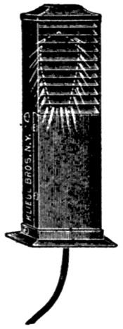
FIGURE 151.
In some of the cheaper theaters a pair of arc lamps
is used on the stage, but they do not give satisfaction.
The light is not even and steady enough and cannot
be properly “dimmed”. Where arc lamps are to be
arranged for stage illumination they must be suspended
amid the scenery and enclosed with wire
guards. In some cities the use of arc lamps suspended
above the stage is prohibited.
In the auditorium, arc lamps are sometimes installed,
but this practice can not be recommended
and, with the present high efficiency incandescent
lamps, there is but little excuse for it. The only advantage
in using arc lamps lies in the first cost of[220]
wiring, and this is more than balanced by the difficulties
of trimming lamps located in such places.
Wherever arc lamps are used it is essential that they
be hung high and those that do not naturally throw
the light downward must be equipped with suitable
reflectors. The question of drop in voltage need not
be considered with arc lamps unless runs are very
long.
National Electrical Code Rules for Arc Lamps.
Arc Lamps in General.
Must be provided with reliable stops to prevent
carbons from falling out in case the clamps become
loose.
All exposed parts must be carefully insulated from
the circuit.
Must, for constant-current systems, be provided
with an approved hand switch, and an automatic
switch that will shunt the current around the carbons,
should they fail to feed properly.
The hand switch to be approved, if placed anywhere
except on the lamps itself, must comply with
requirements for switches on hanger-boards.
Terminals must be designed to secure a thoroughly
good and permanent contact with the supply wires,
which contact must not become loosened by motion
of the lamp during trimming.
Spark arresters must so close the upper orifice
of the globe that it will be impossible for any sparks,
thrown off by the carbons, to escape.
Series Arc Lamps.
Must be carefully isolated from inflammable material.
Must be provided at all times with a glass globe[221]
surrounding the arc, and securely fastened upon a
closed base. Broken or cracked globes must not be
used.
Must be provided with a wire netting (having a
mesh not exceeding one and one-fourth inches)
around the globe and an approved spark arrester,
when readily inflammable material is in the vicinity
of the lamps, to prevent escape of sparks of carbon
or melted copper.
Outside arc lamps must be suspended at least eight
feet above sidewalks. Inside arc lamps must be placed
out of reach or suitably protected.
Arc lamps, when used in places where they are exposed
to flyings of easily inflammable material, must
have the electrodes enclosed completely in a tight
globe in such manner as to avoid the necessity for
spark arresters.
“Enclosed arc” lamps, having tight inner globes
may be used, and the requirements of b and c above
would, of course, not apply to them.
Where hanger-boards are not used, lamps must
be hung from insulating supports other than their
conductors.
Lamps when arranged to be raised and lowered
either for carboning or other purposes, shall be connected
up with stranded conductors from the last
point of support to the lamp, when such conductor is
larger than No. 14 B. & S. gauge.
Arc Lamps on Constant-Potential Circuits.
Must have a cut-out for each lamp or each series
of lamps.
The branch conductors must have a carrying capacity
about fifty per cent in excess of the normal
current required by the lamp.
[222]
Must only be furnished with such resistances or
regulators as are enclosed in non-combustible material,
such resistances being treated as sources of
heat. Incandescent lamps must not be used for this
purpose.
Arc Lamps Used as a Part of a Moving-Picture Machine.
Must be constructed, so far as practicable, similar
to arc lamps of theaters, and wiring to same must
not be of less capacity than No. 6 B. & S. gauge. See
“Portable Stage Equipment”.
Stage and Gallery Pockets.
Must be of approved type, insulated from ground
and controlled from switchboard, each receptacle to
be of not less than 35 ampere rating for arc lamps
nor 15 amperes for incandescent lamps, and each receptacle
to be wired to its full capacity. Arc pockets
to be wired with wire not smaller than No. 6 B. & S.
gauge and incandescent pockets with not less than No.
12 B. & S. gauge.
Plugs for arcs and incandescent pockets must not
be interchangeable.
Armored Cable.
Armored Cable.—All wires in the stage part of
theaters must be enclosed in conduit or armored cable.
Armored cable is thus the only flexible conductor
allowed for permanent work. This cable is very convenient
where wires must be “fished”, or run around
beams or other obstacles making many bends necessary.
It should, however, be used only where the
rigid conduit cannot well be installed and it is advisable
to use the latter, even where the additional
expense is considerable. Wires run in rigid conduit
can be taken out and replaced by new ones at any[223]
time, while this is not the case with armored cable.
Should a wire incased in armored cable develop a
serious fault, the old cable would have to be abandoned
and a new circuit run, which in many cases would
mean the tearing up of parts of the building.
FIGURE 152.
Where armored cable is to be used great care should
be exercised to see that bends are not made too short,
and that each length of cable is tested for grounds,
short circuits, and open circuits. Special attention
must be given to the wires at the place where the
armor has been cut. Careless workmen can do great
damage at this point. The manner of cutting the
armor is shown in Figure 152. Each strand of the
armor is partly cut with a saw and may then be
broken off, taking care that no sharp edge is left
in position to pierce the wire.
Installation rules are given below. Before installing
any armored cable, be sure that it is of approved
make and guaranteed to pass inspection.
National Electrical Code Rule for Armored Cables.
Must be continuous from outlet to outlet or to
junction boxes or cabinets, and the armor of the cable
must properly enter and be secured to all fittings,
and the entire system must be mechanically secured
in position.
In case of service connections and main runs, this
involves running such armored cable continuously
into a main cut-out cabinet or gutter surrounding the
panel board, as the case may be.
[224]
Must be equipped at every outlet with an approved
outlet box or plate, as required in conduit
work.
Outlet plates must not be used where it is practicable
to install outlet boxes.
For concealed work in walls and ceilings composed
of plaster on wooden joist or stud construction, outlet
boxes or plates and also cut-out cabinets must be
so installed that the front edge will not be more than
one-fourth inch back of the finished surface of the
plaster, and if this surface is broken or incomplete it
shall be repaired so that it will not show any gaps or
open spaces around the edges of the outlet box or
plate or of the cut-out cabinet. On wooden walls or
ceilings, outlet boxes or plates and cut-out cabinets
must be so installed that the front edge will either be
flush with the finished surface or project therefrom.
This will not apply to concealed work in walls or ceilings
composed of concrete, tile or other non-combustible
material.
In buildings already constructed where the conditions
are such that neither outlet box nor plate can
be installed, these appliances may be omitted by special
permission, provided the armored cable is firmly
and rigidly secured in place.
Must have the metal armor of cables permanently
and effectually grounded to water piping, gas
piping, or other suitable grounds, provided that when
connections are made to gas piping, they must be on
the street side of the meter. If the armored cable
system consists of several separate sections, the sections
must be bonded to each other, and the system
grounded, or each section may be separately
grounded, as required above.
[225]
The armor of cables and gas pipes must be securely
fastened in outlet boxes, junction boxes, and cabinets,
so as to secure good electrical connection.
If armor of cables and metal of couplings, outlet
boxes, junction boxes, cabinets, or fittings having protective
coating of non-conducting material, such as
enamel, are used, such coating must be thoroughly
removed from threads of both couplings and the
armor of cables, and from surfaces of the boxes, cabinets,
and fittings where the armor of cables or ground
clamp is secured in order to obtain the requisite good
connection. Grounded pipes must be cleaned of rust,
scale, etc., at place of attachment of ground clamp.
Connections to grounded pipes and to armor of cables
must be exposed to view or readily accessible, and
must be made by means of approved ground clamps,
to which the ground wires must be soldered.
Ground wires must be of copper, at least No. 10 B.
& S. gauge (where largest wire contained in cable is
not greater than No. 0 B. & S. gauge), and need not
be greater than No. 4 B. & S. gauge (where largest
wire contained in cable is greater than No. 0 B. & S.
gauge). They must be protected from mechanical
injury. The ground for the armored cable system is
not to be considered as a ground for a secondary
system.
When installed in so-called fireproof buildings
in course of construction, or afterwards if exposed to
moisture, or where it is exposed to the weather, or
in damp places, such as breweries, stables, etc., the
cable must have a lead covering placed between the
outer braid of the conductors and the steel armor.
The lead covering is not to be required when the[226]
cable is run against brick walls, or laid in ordinary
plaster walls unless same are continuously damp.
Where entering junction boxes, and at all other
outlets, etc., must be provided with approved terminal
fittings which will protect the insulation of the conductors
from abrasion, unless such junction or outlet
boxes are specially designed and approved for use
with the cable.
Junction boxes must always be installed in such a
manner as to be accessible.
For alternating-current systems must have the two
or more conductors of the circuit enclosed in one
metal armor.
All bends must be so made that the armor of
the cable will not be injured. The radius of the
curve of the inner edge of any bend not to be less
than 11⁄2 inches.
Asbestos.
Asbestos.—As all wiring in theaters is required to
be run in conduit, and metal cabinets are compulsory
in this connection, there is but little opportunity to
use asbestos. Wherever the use of asbestos is advisable
it must conform to the general requirements
as given for wooden cutout cabinets, viz.: “for lining
wooden cabinets, one-eighth inch rigid asbestos
board may be used when firmly secured in place by
screws or tacks”.
Attachment Plugs.
Attachment Plugs.—Attachment plugs should be
used to connect all portable apparatus. All plugs
should be of approved type and constructed so as to
pull out in case strain is put on them. On the stage,
pin-plug connectors should be used in place of attachment
plugs, as none of the latter are sufficiently
rugged to withstand the hard usage.
[227]
National Electrical Code Rules for Attachment Plugs.
Link fuse attachment plugs of the types now on the
market are considered unsafe, as under entirely possible
conditions an arc may be produced when the
fuses blow, damaging the plug and perhaps causing
fire. Attachment plugs are not approved for more
than six hundred and sixty watts or two hundred and
fifty volts.
Auditorium.
Auditorium.—Two separate systems of lighting are
required: See emergency or exit lighting. Metal
moulding, as well as armored cable or conduit, is permissible
in wiring the auditorium part of the theater.
Auto-Starters.
Auto-Starters.—Auto-starters perform the same
service with alternating-current motors that resistances
do with direct-current motors. They are
used with motors from two or three horse power upward,
and not generally with the smaller motors.
The following are extracts from the “National
Electrical Code” concerning their use:
In all wet, dusty, or linty places, auto-starters, unless
equipped with tight casings enclosing all current-carrying
parts, must be enclosed in dust-tight fireproof
cabinets. Where there is any liability of short
circuits, caused by accidental contacts, across their
exposed live parts a railing must be erected around
them.
The switch on the auto-starter must provide an off
position, a running position, and at least one starting
position. It must be so arranged that it will be held
in off and running position, but not in starting position
or without the proper running overload-protection
devices in the circuit.
For currents above 30 amperes, lugs, into which
the connecting wires may be soldered, or approved
solderless connectors must be used. Clamps or lugs[228]
will not be required when leads are provided as a
part of the device.
The following rules are drawn for rheostats but
may also apply to auto-starters:
Where the circuit-breaking device on the motor-starting
rheostat disconnects all of the wires of the
circuit, the switch called for in this section (to disconnect
all apparatus) may be omitted.
Overload-release devices on motor-starting rheostats
will not be considered to take the place of the
cutout required to protect the motor and the rheostat.
Balconies.
Balconies.—The illumination of balconies is a difficult
matter. The ceilings under galleries above are
always low, and to obtain even illumination requires
the use of many small candle-power lamps. These
should be set well back so as not to be visible too
much to the audience.
Stage-pocket capacity for one or more arc lamps
should always be provided. Where there are galleries
above, the arc lamps used for stage illumination
are generally placed there, but it often happens
that a moving-picture machine must be installed and
it is very disadvantageous if this must be located in
the galleries. Balconies require the same exit and
emergency light service as is required in the auditorium.
Batteries.
Batteries.—See Portable Stage Equipment.
Bells.
Bells.—Systems of call bells are generally arranged
between the box office or the manager’s office and the
stage switch board; also from the stage switch board
to the fly floor by which signals for raising and
lowering the curtain may be given; also to the orchestra
leader. In some cities all of this wiring is
required to be in conduit. These signaling circuits[229]
should be carefully installed, for they are as important
as any part of the wiring. Only the very best
bells and push buttons should be used, and it is advisable
to avoid the use of the ordinary annunciator
wire so often seen in connection with bell work.
Numerous diagrams and much information concerning
bell wiring is given in “Modern Wiring Diagrams
and Descriptions”, which should be consulted
in case some complicated annunciator system is to
be installed. Figure 153 is a diagram of a simple
call-and-return-call system.
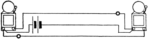
FIGURE 153.
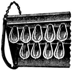
FIGURE 154.
Borders.
Borders.—The number of borders used in theaters
varies from one to six, the latter number being sufficient
for almost any stage. They are generally made
of a length about equal to the proscenium opening.
The borders placed in the rear are of less importance
than those in front and consequently are made shorter
and are not provided with so many lights. Each
border should have at least three circuits, one for each[230]
color; each circuit being taken through a separate
dimmer so that any color may be used alone and
dimmed as desired.
Figures 154 and 155 show types of borders, and
the method of wiring is shown in Figure 156.
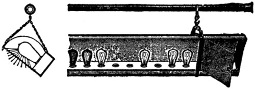
FIGURE 155.
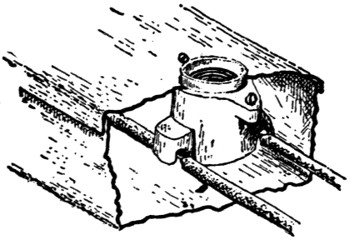
FIGURE 156.
Large borders are very heavy and are usually suspended
by wire rope and provided with counterweights
to make handling easy. The wire rope should
be kept well protected by oiling; the moisture given
off by fireproofed scenery is liable to rust them very
fast, and as the ropes are made up of very fine
strands the rust soon cuts entirely through them.
The suspending ropes and also cables supplying lights
must be long enough to admit of bringing the border
within five or six feet of the stage floor for lamp renewals
and cleaning. The cleaning is very important
as the dust which accumulates may absorb a large
part of the light.
[231]
The National Electrical Code Rules Governing Border and Proscenium Sidelight Construction.
Must be constructed of steel of a thickness not
less than No. 20 U. S. sheet metal gauge; treated to
prevent oxidation; be suitably stayed and supported;
and so designed that flanges of reflectors will protect
lamps.
Must be so wired that no set of lamps requiring
more than 1,320 watts nor more than 26 receptacles
shall be dependent upon one cut-out.
Must be wired in approved conduit or armored
cable, each lamp receptacle to be enclosed within an
approved outlet box, or the lamp receptacles may be
mounted in an iron or steel box, metal to be of a
thickness not less than No. 20 U. S. sheet metal gauge
treated to prevent oxidation, so constructed as to enclose
all wires. Wires to be soldered to lugs of receptacles.
Must be provided with suitable guards to prevent
scenery or other combustible material coming in contact
with lamps.
Cable for borders must be of approved type and
suitably supported; conduit construction must be
used from switchboard to point where cables must
be flexible to permit of the raising and lowering of
border.
For the wiring of the border proper, wire with
approved slow-burning insulation must be used.
Borders must be suitably suspended, and if a wire
rope is used same must be insulated by at least one
strain insulator inserted at the border.
Box Office.
Box Office.—The box office is often a very stuffy
place in summer and very cold in winter. There
should be an outlet for a fan motor, and also one for[232]
a heater. Very many box offices depend upon electric
heating for comfort in winter. Plenty of light
should be provided and the light should be at the ceiling,
out of the way, and directly over the ticket
window.
Brackets.
Brackets.—Any brackets used in theaters should
be at least seven feet above the floor. Brackets used
for emergency or exit lights must be fitted with keyless
sockets. See “Fixtures”.
Branch Circuits.
Branch Circuits.—The term, “branch circuit”, as
here used refers to the wires leaving the last cut-outs
and connecting directly to the lamps or other
devices. Mains are often run from the switchboard
to various parts of the building to feed cut-out centers,
and the branch circuits are then run from
these centers. This is often the cheapest method, but
it is by no means the best. In a well designed theater
all branch circuits lead out from the vicinity of the
switchboard so that, in case of any trouble with fuses,
they may be replaced without interfering with any
part of the audience and in the shortest possible time.
This method of wiring involves some long runs of
branch circuit wires and Table V, which shows the
drop in voltage, was prepared for the convenience of
wiremen. If possible the circuits should be so arranged
that the lamps fed are closely together so all
may receive nearly the same voltage. The drop
should not much exceed two per cent.
Table showing drop in voltage due to 6 amperes,
with sizes of wire and distances given:
[233]
| Distance in feet |
50 |
75 |
100 |
125 |
150 |
175 |
200 |
225 |
250 |
300 |
| Size of Wire No. 14 |
1.58 |
2.37 |
3.16 |
3.95 |
4.74 |
5.53 |
6.32 |
7.11 |
7.90 |
9.48 |
| Size of Wire No. 12 |
0.99 |
1.48 |
1.98 |
2.47 |
2.97 |
3.45 |
3.96 |
4.45 |
4.95 |
5.94 |
| Size of Wire No. 10 |
0.63 |
0.94 |
1.25 |
1.56 |
1.87 |
2.19 |
2.50 |
2.81 |
3.12 |
3.75 |
| Size of Wire No. 8 |
0.39 |
0.59 |
0.78 |
0.97 |
1.17 |
1.36 |
1.56 |
1.75 |
1.95 |
2.34 |
National Electrical Code Rules Governing Size of Wire for Branch Circuits and Fuses for Same.
No wire smaller than No. 14 B. & S. gauge must
be used.
Each branch circuit must be protected by fuses,
which must be so placed that no set of small motors,
small heating devices, or incandescent lamps, whether
grouped on one fixture or on several fixtures or pendants
(nor more than 16 sockets or receptacles) requiring
more than 660 watts, will be dependent upon
one cut-out.
By special permission, in cases where wiring equal
in size and insulation to No. 14 B. & S. gauge approved
rubber-covered wire is carried direct into keyless
sockets or receptacles, and where the location of
sockets and receptacles is such as to render unlikely
the attachment of flexible cords thereto, the circuits
may be so arranged that not more than 1,320 watts
(or thirty-two sockets or receptacles) will be dependent
upon the final cut-out.
Except for signs and outline lighting, sockets and
receptacles will be considered as requiring not less
than 40 watts each.
[234]
All branches or taps, from any three-wire system,
which are directly connected to lamp sockets or other
translating devices, must be run as two-wire circuits
if the fuses are omitted in the neutral, or if the difference
of potential between the two outside wires
is over 250 volts, and both wires of such branch or
tap circuits must be protected by proper fuses.
The above shall also apply to motors, except that
small motors may be grouped under the protection
of a single set of fuses, provided the rated capacity
of the fuses does not exceed 10 amperes.
When 1,320 watts are dependent upon one fusible
cut-out, as is allowed in theater wiring, outline lighting
and large chandeliers, the fuses may be in accordance
with the following:
| 125 volts or less |
20 amperes |
| 125 to 250 volts |
10 amperes |
Bus-Bars.
Bus-Bars.—Bus-bars may be made of bare metal.
They must, however, be protected against accidental
contact. The metal should be ample so that it will
not heat more than 50 degrees Fahrenheit above the
surrounding air.
It is customary to calculate the metal needed, on
the basis of 1,000 amperes per square-inch cross section.
On this basis bars of the sizes given below
would have the carrying capacities in amperes given
in the body of the table.
[235]
| Thickness |
2⁄32 |
3⁄32 |
4⁄32 |
5⁄32 |
6⁄32 |
7⁄32 |
8⁄32 |
9⁄32 |
10⁄32 |
12⁄32 |
16⁄32 |
Width
in
In-
ches |
|
1⁄2 |
30 |
45 |
60 |
75 |
90 |
105 |
120 |
135 |
150 |
165 |
180 |
| |
5⁄8 |
37 |
57 |
75 |
94 |
108 |
132 |
150 |
168 |
188 |
206 |
225 |
| |
6⁄8 |
45 |
68 |
90 |
112 |
135 |
158 |
180 |
202 |
225 |
248 |
270 |
| |
7⁄8 |
53 |
79 |
105 |
130 |
158 |
184 |
210 |
236 |
263 |
289 |
315 |
| 1 |
.0 |
60 |
90 |
120 |
150 |
180 |
210 |
240 |
270 |
300 |
330 |
360 |
| 1 |
1⁄4 |
75 |
112 |
150 |
188 |
225 |
263 |
300 |
338 |
375 |
412 |
450 |
| 1 |
1⁄2 |
90 |
135 |
180 |
225 |
270 |
315 |
360 |
405 |
450 |
495 |
540 |
| 1 |
3⁄4 |
105 |
157 |
210 |
263 |
315 |
367 |
420 |
473 |
525 |
577 |
630 |
| 2 |
.00 |
120 |
180 |
240 |
300 |
360 |
420 |
480 |
540 |
600 |
660 |
720 |
| 3 |
.00 |
180 |
270 |
360 |
450 |
540 |
630 |
720 |
810 |
900 |
990 |
1080 |
Cabinets.
Cabinets.—Cabinets are required to enclose all
fuses. It is advised that they be arranged so that it
will not be necessary to open the fuse compartment
to operate switches.
Care should be exercised in locating cut-out cabinets.
They should be in a dry place, easily accessible
to authorized persons, and not accessible to the general
public or miscellaneous employes. If too accessible
they are likely to be made receptacles for
all sorts of rubbish. Wooden or composition cabinets
must not be used in theaters. Use only approved
cabinets.
In some cities special rules, governing the construction
of cabinets for theaters, exist and these should
be looked up.
Cables.
Cables.—For construction rules, see “Stage
Cables” in the chapter on “Portable Stage Equipment”.
Cables are required to connect border lights.[236]
The cable is usually run from an outlet on the grid
floor above the center of the border. It must be long
enough to allow the border to be lowered for the cleaning
and renewal of lamps. The slack cable must be
taken up when the border is raised and some provision
must be made to support the cable without injury
to the insulation. Wire ropes or cables are generally
used to support the borders, but the lower end,
which is handled by the stage crew, is of ordinary
manilla rope. Wire cables must be insulated from
the border by strain insulators.
Canopies.
Canopies.—Very many theaters are provided with
canopies which extend over the street. Sometimes
these are fitted out with glass signs behind which incandescent
lamps are installed. Often, also, a row
of lights is arranged around the bottom of the canopy
ceiling. The number of lights to be used depends
upon the design of the canopy, but the effect is best
if a large number of small candle-power lamps are
used. These lamps should be of low intrinsic brilliancy.
If possible, the lamps and sockets should be
arranged to be out of the weather. In addition to
the small outline lamps, other lights are often placed
under canopy to provide bright illumination. Each
circuit may carry 1,320 watts.
National Electrical Code Rule.
Where insulating joints are required, fixture
canopies of metal must be thoroughly and permanently
insulated from metal walls or ceilings, or from
plaster walls or ceilings on metal lathing, and from
outlet boxes.
Canopy insulators must be securely fastened in
place, so as to separate the canopies thoroughly and[237]
permanently from the surfaces and outlet boxes from
which they are designed to be insulated.
Carriage Call.
Carriage Call.—See “Program Board”.
Carrying Capacity of Wires.
Carrying Capacity of Wires.—Table VII is designed
to help the wiremen select the proper size of
wire to use in supplying a certain number of lights.
The first column at the left gives the B. & S. gauge
number. The second column gives the number of
amperes allowed on each wire according to the National
Electrical Code. The third column gives the
distance in feet which will cause a loss of 2 volts
with the current given; thus a current of 70 amperes
in a No. 4 B. & S. gauge wire will lose 2 volts
over a distance of 56 feet. The proper size of wire
to be used can easily be determined from the table.
The loss will always be in proportion to the product
of distance and current. The balance of the table is
devoted to showing the number of watts and lamps
of various sizes the wires will be allowed to supply.
Ceiling Fans.
Ceiling Fans.—Must be hung from insulated hooks,
or else there must be an insulator interposed between
the motor and its support. Not more than 660 watts
may be on one circuit.
Chandeliers.
Chandeliers.—Large and elaborate chandeliers are
sometimes used in the center of the auditorium ceiling
for purposes of illumination. Such chandeliers
should be suspended in a manner which will admit
of readily raising or lowering them for lamping up
or repairs. For rules governing wiring, see “Fixtures”.
[238]
B. & S.
Gage |
Rub-
ber
Insu-
lation |
Dis-
tance
in
Feet
Caus-
ing
a Loss
of
2 Volts |
Total
Capacity
in Watts |
Total Number of Lamps of Different Voltages and Wattages that may be supplied |
| 25-Watt |
40-Watt |
60-Watt |
100-Watt |
150-Watt |
250-Watt |
Am-
peres |
110 V. |
220 V. |
110 V. |
220 V. |
110 V. |
220 V. |
110 V. |
220 V. |
110 V. |
220 V. |
110 V. |
220 V. |
110 V. |
220 V. |
| 14 |
15 |
26 |
1650 |
3300 |
66 |
132 |
41 |
82 |
27 |
54 |
16 |
33 |
11 |
22 |
6 |
13 |
| 12 |
20 |
30 |
2200 |
4400 |
88 |
176 |
55 |
110 |
36 |
73 |
22 |
44 |
14 |
29 |
8 |
17 |
| 10 |
25 |
38 |
2750 |
5500 |
110 |
220 |
68 |
137 |
46 |
91 |
27 |
55 |
18 |
36 |
11 |
22 |
| 8 |
35 |
43 |
3850 |
7700 |
154 |
308 |
96 |
192 |
64 |
128 |
38 |
77 |
25 |
61 |
15 |
30 |
| 6 |
50 |
50 |
5500 |
11000 |
220 |
440 |
137 |
275 |
91 |
183 |
55 |
110 |
36 |
73 |
22 |
44 |
| 5 |
55 |
56 |
6050 |
12100 |
242 |
484 |
151 |
302 |
100 |
201 |
60 |
121 |
40 |
80 |
24 |
48 |
| 4 |
70 |
56 |
7700 |
15400 |
308 |
616 |
192 |
385 |
128 |
256 |
77 |
154 |
49 |
99 |
30 |
61 |
| 3 |
80 |
61 |
8800 |
17600 |
352 |
704 |
220 |
440 |
146 |
292 |
88 |
176 |
58 |
117 |
35 |
70 |
| 2 |
90 |
68 |
9900 |
19800 |
396 |
792 |
247 |
494 |
165 |
330 |
99 |
198 |
66 |
132 |
39 |
78 |
| 1 |
100 |
67 |
11000 |
22000 |
440 |
880 |
275 |
550 |
183 |
366 |
110 |
220 |
73 |
146 |
44 |
88 |
| 0 |
125 |
78 |
13750 |
27500 |
550 |
1100 |
343 |
686 |
229 |
458 |
137 |
274 |
91 |
182 |
55 |
110 |
| 00 |
150 |
82 |
16500 |
33000 |
660 |
1320 |
412 |
824 |
275 |
550 |
165 |
330 |
110 |
220 |
66 |
132 |
| 000 |
175 |
89 |
19250 |
38500 |
770 |
1540 |
481 |
962 |
320 |
640 |
192 |
384 |
128 |
256 |
77 |
154 |
| 0000 |
225 |
87 |
24750 |
49500 |
990 |
1980 |
618 |
1236 |
412 |
824 |
247 |
404 |
165 |
330 |
99 |
198 |
| 200000 |
200 |
92 |
22000 |
44000 |
880 |
1760 |
550 |
1100 |
367 |
734 |
220 |
440 |
146 |
292 |
88 |
176 |
| 300000 |
275 |
101 |
30250 |
60500 |
1210 |
2420 |
756 |
1512 |
504 |
1008 |
302 |
604 |
201 |
402 |
121 |
242 |
| 400000 |
325 |
114 |
35750 |
71500 |
1430 |
2860 |
893 |
1786 |
596 |
1192 |
357 |
714 |
238 |
476 |
143 |
286 |
| 500000 |
400 |
117 |
44000 |
88000 |
1760 |
3520 |
1100 |
2200 |
733 |
1455 |
440 |
880 |
293 |
586 |
176 |
352 |
| 600000 |
450 |
123 |
49500 |
99000 |
1980 |
3960 |
1237 |
2474 |
825 |
1650 |
495 |
990 |
330 |
660 |
198 |
396 |
| 700000 |
500 |
130 |
55000 |
110000 |
2200 |
4400 |
1375 |
2750 |
916 |
1832 |
550 |
1100 |
366 |
732 |
220 |
440 |
| 800000 |
550 |
135 |
60500 |
121000 |
2420 |
4840 |
1512 |
3024 |
1008 |
2016 |
605 |
1210 |
403 |
806 |
242 |
484 |
| 900000 |
600 |
139 |
66000 |
132000 |
2640 |
5280 |
1650 |
3300 |
1100 |
2200 |
660 |
1320 |
440 |
880 |
264 |
528 |
| 1000000 |
650 |
143 |
71500 |
143000 |
2860 |
5720 |
1787 |
3574 |
1191 |
2382 |
715 |
1430 |
476 |
952 |
286 |
572 |
| 1100000 |
690 |
147 |
75900 |
151800 |
3036 |
6072 |
1897 |
3794 |
1264 |
2528 |
759 |
1518 |
506 |
1012 |
303 |
606 |
| 1200000 |
730 |
151 |
80300 |
160600 |
3212 |
6424 |
2007 |
4014 |
1338 |
2676 |
803 |
1606 |
535 |
1070 |
321 |
642 |
| 1300000 |
770 |
155 |
84700 |
169400 |
3388 |
6776 |
2117 |
4234 |
1412 |
2824 |
847 |
1694 |
564 |
1128 |
338 |
676 |
| 1400000 |
810 |
161 |
89100 |
178200 |
3564 |
7128 |
2227 |
4454 |
1485 |
2970 |
891 |
1782 |
594 |
1188 |
356 |
712 |
| 1500000 |
850 |
164 |
93500 |
187000 |
3740 |
7480 |
2337 |
4674 |
1558 |
3116 |
935 |
1870 |
623 |
1246 |
374 |
748 |
B. & S.
Gage |
Rub-
ber
Insu-
lation |
Dis-
tance
in
Feet
Caus-
ing
a Loss
of
2 Volts |
Total
Capacity
in Watts |
Total Number of Lamps of Different Voltages
and Wattages that may be supplied |
| 25-Watt |
40-Watt |
60-Watt |
Am-
peres |
110 V. |
220 V. |
110 V. |
220 V. |
110 V. |
220 V. |
110 V. |
220 V. |
| 14 |
15 |
26 |
1650 |
3300 |
66 |
132 |
41 |
82 |
27 |
54 |
| 12 |
20 |
30 |
2200 |
4400 |
88 |
176 |
55 |
110 |
36 |
73 |
| 10 |
25 |
38 |
2750 |
5500 |
110 |
220 |
68 |
137 |
46 |
91 |
| 8 |
35 |
43 |
3850 |
7700 |
154 |
308 |
96 |
192 |
64 |
128 |
| 6 |
50 |
50 |
5500 |
11000 |
220 |
440 |
137 |
275 |
91 |
183 |
| 5 |
55 |
56 |
6050 |
12100 |
242 |
484 |
151 |
302 |
100 |
201 |
| 4 |
70 |
56 |
7700 |
15400 |
308 |
616 |
192 |
385 |
128 |
256 |
| 3 |
80 |
61 |
8800 |
17600 |
352 |
704 |
220 |
440 |
146 |
292 |
| 2 |
90 |
68 |
9900 |
19800 |
396 |
792 |
247 |
494 |
165 |
330 |
| 1 |
100 |
67 |
11000 |
22000 |
440 |
880 |
275 |
550 |
183 |
366 |
| 0 |
125 |
78 |
13750 |
27500 |
550 |
1100 |
343 |
686 |
229 |
458 |
| 00 |
150 |
82 |
16500 |
33000 |
660 |
1320 |
412 |
824 |
275 |
550 |
| 000 |
175 |
89 |
19250 |
38500 |
770 |
1540 |
481 |
962 |
320 |
640 |
| 0000 |
225 |
87 |
24750 |
49500 |
990 |
1980 |
618 |
1236 |
412 |
824 |
| 200000 |
200 |
92 |
22000 |
44000 |
880 |
1760 |
550 |
1100 |
367 |
734 |
| 300000 |
275 |
101 |
30250 |
60500 |
1210 |
2420 |
756 |
1512 |
504 |
1008 |
| 400000 |
325 |
114 |
35750 |
71500 |
1430 |
2860 |
893 |
1786 |
596 |
1192 |
| 500000 |
400 |
117 |
44000 |
88000 |
1760 |
3520 |
1100 |
2200 |
733 |
1455 |
| 600000 |
450 |
123 |
49500 |
99000 |
1980 |
3960 |
1237 |
2474 |
825 |
1650 |
| 700000 |
500 |
130 |
55000 |
110000 |
2200 |
4400 |
1375 |
2750 |
916 |
1832 |
| 800000 |
550 |
135 |
60500 |
121000 |
2420 |
4840 |
1512 |
3024 |
1008 |
2016 |
| 900000 |
600 |
139 |
66000 |
132000 |
2640 |
5280 |
1650 |
3300 |
1100 |
2200 |
| 1000000 |
650 |
143 |
71500 |
143000 |
2860 |
5720 |
1787 |
3574 |
1191 |
2382 |
| 1100000 |
690 |
147 |
75900 |
151800 |
3036 |
6072 |
1897 |
3794 |
1264 |
2528 |
| 1200000 |
730 |
151 |
80300 |
160600 |
3212 |
6424 |
2007 |
4014 |
1338 |
2676 |
| 1300000 |
770 |
155 |
84700 |
169400 |
3388 |
6776 |
2117 |
4234 |
1412 |
2824 |
| 1400000 |
810 |
161 |
89100 |
178200 |
3564 |
7128 |
2227 |
4454 |
1485 |
2970 |
| 1500000 |
850 |
164 |
93500 |
187000 |
3740 |
7480 |
2337 |
4674 |
1558 |
3116 |
B. & S.
Gage |
Rub-
ber
Insu-
lation |
Dis-
tance
in
Feet
Caus-
ing
a Loss
of
2 Volts |
Total
Capacity
in Watts |
Total Number of Lamps of Different Voltages
and Wattages that may be supplied |
| 100-Watt |
150-Watt |
250-Watt |
Am-
peres |
110 V. |
220 V. |
110 V. |
220 V. |
110 V. |
220 V. |
110 V. |
220 V. |
| 14 |
15 |
26 |
1650 |
3300 |
16 |
33 |
11 |
22 |
6 |
13 |
| 12 |
20 |
30 |
2200 |
4400 |
22 |
44 |
14 |
29 |
8 |
17 |
| 10 |
25 |
38 |
2750 |
5500 |
27 |
55 |
18 |
36 |
11 |
22 |
| 8 |
35 |
43 |
3850 |
7700 |
38 |
77 |
25 |
61 |
15 |
30 |
| 6 |
50 |
50 |
5500 |
11000 |
55 |
110 |
36 |
73 |
22 |
44 |
| 5 |
55 |
56 |
6050 |
12100 |
60 |
121 |
40 |
80 |
24 |
48 |
| 4 |
70 |
56 |
7700 |
15400 |
77 |
154 |
49 |
99 |
30 |
61 |
| 3 |
80 |
61 |
8800 |
17600 |
88 |
176 |
58 |
117 |
35 |
70 |
| 2 |
90 |
68 |
9900 |
19800 |
99 |
198 |
66 |
132 |
39 |
78 |
| 1 |
100 |
67 |
11000 |
22000 |
110 |
220 |
73 |
146 |
44 |
88 |
| 0 |
125 |
78 |
13750 |
27500 |
137 |
274 |
91 |
182 |
55 |
110 |
| 00 |
150 |
82 |
16500 |
33000 |
165 |
330 |
110 |
220 |
66 |
132 |
| 000 |
175 |
89 |
19250 |
38500 |
192 |
384 |
128 |
256 |
77 |
154 |
| 0000 |
225 |
87 |
24750 |
49500 |
247 |
404 |
165 |
330 |
99 |
198 |
| 200000 |
200 |
92 |
22000 |
44000 |
220 |
440 |
146 |
292 |
88 |
176 |
| 300000 |
275 |
101 |
30250 |
60500 |
302 |
604 |
201 |
402 |
121 |
242 |
| 400000 |
325 |
114 |
35750 |
71500 |
357 |
714 |
238 |
476 |
143 |
286 |
| 500000 |
400 |
117 |
44000 |
88000 |
440 |
880 |
293 |
586 |
176 |
352 |
| 600000 |
450 |
123 |
49500 |
99000 |
495 |
990 |
330 |
660 |
198 |
396 |
| 700000 |
500 |
130 |
55000 |
110000 |
550 |
1100 |
366 |
732 |
220 |
440 |
| 800000 |
550 |
135 |
60500 |
121000 |
605 |
1210 |
403 |
806 |
242 |
484 |
| 900000 |
600 |
139 |
66000 |
132000 |
660 |
1320 |
440 |
880 |
264 |
528 |
| 1000000 |
650 |
143 |
71500 |
143000 |
715 |
1430 |
476 |
952 |
286 |
572 |
| 1100000 |
690 |
147 |
75900 |
151800 |
759 |
1518 |
506 |
1012 |
303 |
606 |
| 1200000 |
730 |
151 |
80300 |
160600 |
803 |
1606 |
535 |
1070 |
321 |
642 |
| 1300000 |
770 |
155 |
84700 |
169400 |
847 |
1694 |
564 |
1128 |
338 |
676 |
| 1400000 |
810 |
161 |
89100 |
178200 |
891 |
1782 |
594 |
1188 |
356 |
712 |
| 1500000 |
850 |
164 |
93500 |
187000 |
935 |
1870 |
623 |
1246 |
374 |
748 |
[239]
National Electrical Code Rules for Fusing Chandelier Circuits.
When 1,320 watts are dependent upon one cut-out,
as is allowed in theater wiring, outline lighting, and
large chandeliers, the fuse may be in accordance with
the following:
| 125 volts or less |
20 amperes |
| 125 to 250 volts |
10 amperes |
Circuit Breakers.
Circuit Breakers.—Circuit breakers are not used
much about theaters. They are used mostly in connection
with motors and on switchboards of isolated
plants. They are more sensitive and quicker to act
than fuses and, in case of a blow-out, can be more
easily replaced. Where circuit breakers are used it
is good practice to set them for a higher amperage
than the fuses so that, in case of a heavy short circuit,
the breaker may act while the fuse will take
care of an overload which comes on more gradually.
National Electrical Code Rides for Circuit Breakers.
With motors an automatic circuit breaker, disconnecting
all wires of the circuit, may serve as both
switch and cut-out.
Where the circuit-breaking device on the motor-starting
rheostat disconnects all wires of the circuit,
the switch may be omitted.
Circuit breakers must not be set more than thirty
per cent above the allowable carrying capacity of
the wires, unless a fusible cut-out is also installed on
the circuit.
When installed without other automatic overload
protective devices, automatic overload circuit
breakers must have the poles and trip coils so arranged
as to afford complete protection against overloads
and short circuits and, if also used in place of[240]
the switch, must be so arranged that no one pole can
be opened manually without disconnecting all the
wires.
Concealed Work.
Concealed Work.—All concealed work must be in
conduit or armored cable. Wherever possible, rigid
conduit should be used. Armored cable should be
used only where the whole cable may at any time be
withdrawn, or where it is impracticable to use rigid
conduit.
Conduit Work.
Conduit Work.—This is now considered the
standard method of construction. It is, however,
somewhat over-rated and, especially in wet places, has
led to much disappointment. It is generally recognized
that wires, placed in conduit, will cause more
trouble than those placed in any other standard manner.
The trouble is, however, confined to the interior
of the conduit and, if the conduit system be kept in
good order, and fuses at their proper limit, there is
no chance of fire from the wire confined within the
conduit.
There are three points which, if carefully observed,
will avoid most, if not all, of the conduit troubles:
Avoid as far as possible locating conduit in wet or
damp places.
Run all conduits so that they will drain.
Give particular attention to joints in outlet or
junction boxes; tape them heavily; and arrange them
so they are not pressed against metal more than is
necessary; use large boxes.
Wires used in conduits must have approved rubber
insulation and double braid.
[241]
National Electrical Code Rules for Wires and Interior Conduits.
Wires for Conduit Work.
Must have an approved rubber insulated covering
(Type Letter R. D.), and must within the conduit
tubing be without splices or taps.
Must not be drawn in until all mechanical work
on the building has been, as far as possible, completed.
Conductors in vertical conduit risers must be supported
within the conduit system in accordance with
the following:
- No. 14 to 0 every 100 feet
- No. 00 to 0000 every 80 feet
- No. 0000 to 350,000 C. M. every 60 feet
- 350,000 C. M. to 500,000 C. M. every 50 feet
- 500,000 C. M. to 750,000 C. M. every 40 feet
- 750,000 C. M. every 35 feet
The following methods of supporting cables are
recommended:
(1) A turn of 90 degrees in the conduit system will
constitute a satisfactory support.
(2) Junction boxes may be inserted in the conduit
system at the required intervals, in which insulating
supports of approved type must be installed and secured
in a satisfactory manner so as to withstand the
weight of the conductors attached thereto, the boxes
to be provided with proper covers.
(3) Cables may be supported in approved junction
boxes on two or more insulating supports so placed
that the conductors will be deflected at an angle of
not less than 90 degrees, and carried a distance of
not less than twice the diameter of the cable from[242]
its vertical position. Cables so suspended may be
additionally secured to these insulators by tie wires.
Other methods may be used if specially approved.
Must, for alternating-current systems, have two
or more wires of a circuit drawn in the same conduit.
It is suggested that this be done for direct-current
systems, also, so that they may be changed to alternating
systems at any time, induction troubles preventing
such a change if the wires are in separate
conduits.
Except in the case of stage pocket and border circuits
the same conduit must not contain more than
four two-wire, or three three-wire circuits of the same
system, except by special permission, and must never
contain circuits of different systems.
Interior Conduits.
No conduit smaller than one-half inch electrical-trade
size shall be used.
Must be continuous from outlet to outlet or to
junction boxes or cabinets, and the conduit must
properly enter, and be secured to all fittings and the
entire system must be mechanically secured in position.
In case of service connections and main runs,
this involves running each conduit continuously into
a main cut-out cabinet or gutter surrounding the
panel board, as the case may be. Departure from
this rule may be authorized in case of underground
services by special permission.
Must be first installed as a complete conduit system,
without the conductors.
Must be equipped at every outlet with an approved
outlet box or plate. At exposed ends of conduit
(but not at fixture outlets), where wires pass[243]
from the conduit system without splice, joint, or tap,
an approved fitting, having separately bushed holes
for each conductor, must be used. Departure from
this rule may be authorized by special permission.
Outlet plates must not be used where it is practicable
to install outlet boxes.
For concealed work in walls and ceilings composed
of plaster on wooden joist or stud construction, outlet
boxes or plates, and also cut-out cabinets must be
so installed that the front edge will not be more than
one-fourth inch back of the finished surface of the
plaster; and if this surface is broken or incomplete
it shall be repaired so that it will not show any gaps
or open spaces around the edges of the outlet box or
plate or of the cut-out cabinet. On wooden walls or
ceilings, outlet boxes or plates and cut-out cabinets
must be so installed that the front edge will either
be flush with the finished surface or project therefrom.
This will not apply to concealed work in walls
or ceilings composed of concrete, tile or other non-combustible
material.
In buildings already constructed where the conditions
are such that neither outlet box or plate can
be installed, these appliances may be omitted, providing
the conduit ends are bushed and secured.
It is suggested that outlet boxes and fittings, having
conductive coatings, be used in order to secure
better electrical contact at all points through the
conduit system.
Metal conduits, where they enter junction boxes
and at all other outlets, etc., must be provided
with approved bushings or fastening plates fitted so
as to protect wire from abrasion, except when such[244]
protection is obtained by the use of approved nipples,
properly fitted in boxes or devices.
Must have the metal of the conduit permanently
and effectually grounded to water piping, gas
piping, or other suitable grounds, provided that when
connections are made to gas piping, they must be
on the street side of the meter. If the conduit system
consists of several separate sections, the sections
must be bonded to each other, and the system
grounded; or each section may be separately
grounded, as required above. Where short sections of
conduit (or pipe of equivalent strength) are used
for the protection of exposed wiring on side walls,
and such conduit or pipe and wiring is installed as
required by the Code Rules, the conduit or pipe need
not be grounded.
Conduits and gas pipes must be securely fastened
in outlet boxes, junction boxes, and cabinets, so as
to secure good electrical connections.
If conduits, couplings, outlet boxes, junction
boxes, cabinets or fittings, having protective coating
of non-conducting material such as enamel, are used,
such coating must be thoroughly removed from
threads of both couplings and conduit, and such surfaces
of boxes, cabinets, and fittings, where the conduit
or group clamp is secured, in order to obtain the
requisite good connection. Grounded pipes must be
cleaned of rust, scale, etc., at place of attachment of
ground clamp.
Connections to grounded pipes and to conduits
must be exposed to view or readily accessible, and
must be made by means of approved ground clamps
to which the ground wires must be soldered.
Ground wires must be of copper, at least No. 10 B.[245]
& S. gauge (where largest wire contained in conduit
is not greater than No. 0 B. & S. gauge), and need
not be greater than No. 4 B. & S. gauge (where
largest wire contained in conduit is greater than No.
0 B. & S. gauge). They shall be protected from
mechanical injury. The ground on the conduit system
is not to be considered as a ground for a secondary
system.
Junction boxes must always be installed in such
a manner as to be accessible.
All elbows or hands must be so made that the
conduit will not be injured. The radius of the curve
of the inner edge of any elbow must not be less than
three and one-half inches, and must have not more
than the equivalent of four quarter bends from outlet
to outlet, the bends at the outlets not being
counted.
Contacts.
Contacts.—Must be mounted on non-combustible
non-absorption insulated bases. Other materials than
slate, marble, or porcelain must be submitted for special
examination before being used.
Cord.
Cord.—The use of flexible cord should be reduced
to a minimum. Wherever drop lights are necessary
they should be wired with reinforced cord or stage
cable.
Current Taps.
Current Taps.—Must be of approved construction
and may be used if properly installed.
National Electrical Code Rules for Current Taps.
Where, in addition to sockets or receptacles already
installed, connections are desired to lighting circuits
for portable lamps, for motors, or other special appliances
requiring only small amounts of current,
multiple-current taps may be used, provided the entire
circuit does not require more than 660 watts, and[246]
provided their use will not, under any conditions, involve
a departure from the requirements of Rule 23-d
of the National Electrical Code. Current taps must
not be used in key or pull sockets if the device, controlled
through such sockets, requires more than 250
watts.
Cut-Outs.
Cut-Outs.—All cut-outs should be on the stage
switchboard. This requires considerable extra wire,
but it will be profitable in the end. Fuses should be
inspected occasionally to see that contacts are bright
and screws kept tight. There is everywhere a very
strong tendency to over-fuse, and the principal reason
for it is the failure to keep screws tightly fastened.
There is no fuse better than the plug fuse but it
is not permitted with voltages higher than 125 or
with more than 30 amperes. Refillable fuses must
not be used. Cartridge fuses, especially, require to
be kept clean. The spring contacts on these often
grow weak and cause heating which helps to blow the
fuse. The neutral fuse in three-wire installations
should be larger than the outside fuses. Link fuses
should be avoided on account of the delay that may
be caused through difficulty of installing.
It is advisable not to place switches in the same
cabinet with fuses.
National Electrical Code Rules for Automatic Cut-outs (Fuses and Circuit-Breakers).
Constant-Potential Systems.
Must be placed on all service wires, either overhead
or underground, in the nearest accessible place
to the point where they enter the building, inside the
walls, and arranged to cut off the entire current from
the building. Departure from this rule may be[247]
authorized only under special permission in writing.
Where the service switch is inside the building, the
cut-out required by this section must be placed so as
to protect it.
For three-wire (not three-phase) systems the fuse
in the neutral wire may be omitted, provided the
neutral wire is of equal carrying capacity to the larger
of the outside wires and is grounded.
Must be placed at every point where a change is
made in the size of wire (unless the cut-out in the
larger wire will protect the smaller). For three-wire
direct current or single-phase systems the fuse in the
neutral wire, except that called for under Section d,
may be omitted, provided the neutral wire is
grounded.
Must be in plain sight, or enclosed in an approved
cabinet, and readily accessible. They must not be
placed in the canopies or shells of fixtures. Link
fuses may be used only when mounted on approved
bases and must be enclosed in dust-tight, fireproofed
cabinets, except on switchboards.
Must be so placed that no set of small motors,
small heating devices, or incandescent lamps, whether
grouped on one fixture or on several fixtures or pendants
(nor more than 16 sockets or receptacles) requiring
more than 660 watts, will be dependent upon
one cut-out.
By special permission, in cases where wiring equal
in size and insulation to No. 14 B. & S. gauge approved
rubber-covered wire is carried direct into keyless
sockets or receptacles, and where the location of
sockets and receptacles is such as to render unlikely
the attachment of flexible cords thereto, the circuits[248]
may be so arranged that not more than 1,320 watts
(or thirty-two sockets or receptacles) will be dependent
upon the final cut-out. Except for signs
and outline lighting, sockets and receptacles will be
considered as requiring not less than 40 watts each.
All branches or taps from any three-wire system
which are directly connected to lamp sockets or other
translating devices, must be run as two-wire circuits
if the fuses are omitted in the neutral or if the difference
of potential between the two outside wires
is over 250 volts, and both wires of such branch or
tap circuits must be protected by proper fuses.
The above shall also apply to motors, except that
small motors may be grouped under the protection
of a single set of fuses, provided the rated capacity
of the fuses does not exceed 10 amperes. When 1,320
watts are dependent upon one fusible cut-out, as is
allowed in theater wiring, outline lighting, and large
chandeliers, the fuses may be in accordance with the
following:
| 125 volts or less |
20 amperes |
| 125 to 250 volts |
10 amperes |
The rated capacity of fuses must not exceed
the allowable carrying capacity of the wire. Circuit
breakers must not be set more than 30 per cent above
allowable carrying capacity of the wire, unless a
fusible cut-out is also installed on the circuit. Fixture
wire or flexible cord of No. 18 B. & S. gauge,
will be considered as properly protected by 10-ampere
fuses.
Each wire of motor circuits, except on main
switchboard or when otherwise subject to competent
supervision, must be protected by an approved fuse
whether automatic overload circuit breakers are installed[249]
or not. Single-phase motors may have one
side protected by an approved automatic overload
circuit breaker only if the other side is protected by
an approved fuse.
For circuits having a maximum capacity greater
than that for which enclosed fuses are approved, circuit
breakers alone will be approved. The ordinary
porcelain link fuse cut-out will not be approved.
Link fuses may be used only when mounted on slate
or marble bases conforming to the rules, and must be
enclosed in dust-tight, fire-proofed cabinets, except
on switchboards located well away from combustible
material, as in the ordinary engine and dynamo room,
and where these conditions will be maintained.
Damp Places.
Damp Places.—It is best to avoid wiring in damp
places if possible. If wires must be run in such
places, they should be lead covered. If armored
cable is used, the wires in cable must be incased in
lead. Weatherproof sockets must be used and the
use of cords should be avoided. Where cords must
be used they should be of the brewery or packing-house
type. If outside of the theater, proper open
work may be used. Conduit work is permissible but
not advisable, except where wires are subject to
mechanical injury.
Decorative Lighting Systems.
Decorative Lighting Systems.—The commercial
decorative lighting systems are not suitable for use
inside of theaters and should be used only outside.
National Electrical Code Rule for Decorative Lighting Systems.
Special permission may be given in writing
for the temporary installation of approved systems
of decorative lighting, provided the difference of[250]
potential between the wires of any circuit shall not
be over 150 volts and also provided that no group
of lamps requiring more than 1,320 watts shall be
dependent on one cut-out.
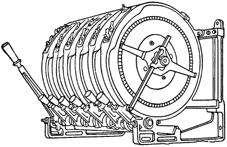
FIGURE 157.
Dimmers.
Dimmers.—“Dimmer” is the name given to the
resistances which are used to dim the electric lights
on the stage. They are usually mounted at the top
or bottom of the switchboard with the operating
handles in easy reach of the operator. A dimmer
should be provided for each color in every border
light and also for the foot lights. In some cases the
proscenium side lights are also arranged for several
colors. The dimmers should be mounted so that
each one is directly above the switch which controls
the circuit to which it belongs. They should be protected
by wire guards against rubbish, which is likely
to accumulate among them if they are not enclosed.
Good ventilation must be provided. A certain dimmer
can be used only while the amperage remains
within the proper limitations. If carbon lamps, for
instance, are changed for tungsten, the amperage[251]
will be much reduced and the dimmer may not work
properly.
Modern dimmers are all of the interlocking type so
that the whole bank may be worked together or any
one singly. Figure 157 is an illustration of a small
bank of dimmers.
Door Switches.
Door Switches.—Door switches are used mostly in
connection with dressing rooms. When the light in
the room is burning, opening and closing the door
will turn it out.
Dressing Rooms.
Dressing Rooms.—Many dressing rooms are wired
with lights on pendant cords, but this method is not
to be recommended. It is better to arrange the
lights in sockets fitted into the outlet boxes. It will
be well if each dressing room is provided with a circuit
for flatirons. If this is considered too expensive,
the fuses on circuits leading into dressing rooms
must be kept small enough to blow in case a flatiron
is connected. Many actors are in the habit of carrying
flatirons and will use them on incandescent-light circuits
if no other circuit is provided. If metal
guards are fastened on securely, much of the trouble
from flatirons will be avoided, but they must be fastened
so that an ordinary screwdriver will not loosen
the screws.
Dressing room illumination, if properly carried
out, will save the proprietor much annoyance. Actors
have ways of obtaining the light they want by
fair means or foul, and it is much better to arrange
the lighting so that it will be satisfactory to those
using it, than to have it continually tampered with.
A bright illumination is essential for making up
and both sides of the face should be fully illuminated.
To accomplish this it is necessary to provide[252]
at least two lights for each mirror. Every lamp
should be provided with a substantial guard which
may be securely fastened to the outlet box. This is
especially necessary if small candle power lamps are
furnished. For, if the light furnished is insufficient,
there will be strong efforts made to replace the small
lamps by larger ones. Guards are also necessary as
a protection against fire. Actors are in the habit of
drying small articles of clothing on the lamps, and
fires have been known to start from this cause. The
guards on the lamps throw shadows on the faces of
the actors, and for this reason are not liked. In
order to avoid the shadows, frosted lamps may be
used, or two lamps on each side of the mirror. One
lamp will then illuminate the shadows caused by
the other. Where there are long dressing tables, as
in rooms occupied by the chorus, mirrors may be
placed between each two lamps on each side of the
table and the lamps staggered vertically. In this
way each party will receive the benefit of at least
four lamps and the shadows will be less noticeable.
The color value of the lamps used in dressing
rooms should match that of the lamps used on the
stage. Some stages, for instance, are illuminated by
flaming arcs which may give an altogether different
effect to a “make up” than the tungsten lamps, for
instance.
Where there are a large number of sockets without
lamps in them, it is advisable to close the socket
by a fuse plug from which the fuse has been removed,
or in some similar manner in order to avoid the
chance of short circuits from hat pins or similar objects
used in dressing rooms.
Drop Lights.
Drop Lights.—Drop lights should be avoided as[253]
much as possible. Where they must be installed reinforced
cord, armored cable, or flexible steel armored
cord should be used.
Emergency Lighting.
Emergency Lighting.—Every theater must have
an emergency lighting system as outlined in the rules
below. The object of this is to provide a double system
of illumination so as to reduce the likelihood of
the theater being left in total darkness. This is a
frequent occurrence where the theater is supplied
by an isolated plant, and may also occur where the
supply is obtained from a large outside lighting system
although the latter is usually more reliable.
Every unnecessary light that is added to an emergency
system increases the likelihood of trouble. A
sufficient number of lights added to it to illuminate
the space used by the audience in getting out is,
therefore, necessary but more than this is a detriment
rather than a help. The practice of connecting
all of the hall and lobby lights to the emergency
system is to be condemned, since it defeats the purpose
of the rule which provides a double illumination
system for every part of the theater used by the
audience. The two systems should be carried into
the auditorium, all stairways, exits, and lobby clear
to the street. They should, furthermore, be kept
entirely separate, in separate conduits and using
separate meters.
The rule does not specify the number of exit and
emergency lights required. Good practice requires a
light for every 400 square feet or so. If each of these
outlets be fitted with a 50 watt lamp the illumination
will interfere with many of the acts and so, smaller
lamps are generally used. One emergency light for
each 60 seats will fill the bill nicely.
[254]

FIGURE 158.
Over each exit, an exit light must be provided, but
as these exit lights are usually incased in ruby glass
such as shown in Figure 158 they cannot be counted
as giving any illumination. In many theaters gas
is used for emergency and exit lighting and in many
respects this seems to be a good practice. In some
quarters, however, it is believed that a fire in the
scenery of a theater might create such an air pressure
in the building as to overcome the low gas pressure
and thus put out the gas at the very time when
it is most needed. The very best suggestion that
can be made is that of a storage battery to supply the
emergency system. Where alternating current is
used this, however, introduces some complications and
becomes quite expensive. Avoid the use of key
sockets, fan motors, or any unnecessary device on
emergency or exit light circuits.
National Electrical Code Rules for Services.
Where supply may be obtained from two separate
street mains, two separate and distinct services
must be installed, one service to be of sufficient
capacity to supply current for the entire equipment
of theater, while the other service must be at least
of sufficient capacity to supply current for all emergency[255]
lights. Where supply cannot be obtained from
two separate sources, the feed for emergency lights
must be taken from a point on the street side of
main service fuses. By “emergency lights” are
meant exit lights and all lights in lobbies, stairways,
corridors, and other portions of theater to which the
public have access, which are normally kept lighted
during the performance. Where the source of supply
is an isolated plant within the same building,
an auxiliary service of at least sufficient capacity to
supply all emergency lights must be installed from
some outside source, or a suitable storage battery
within the premises may be considered the equivalent
of such service.
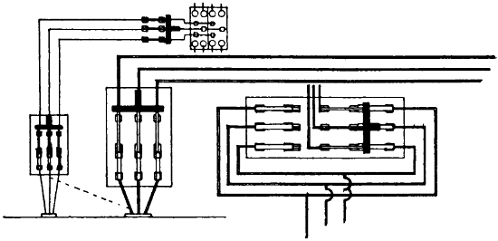
FIGURE 159.
Exit lights must not have more than one set of
fuses between same and service fuses. Exit lights
and all lights in halls, corridors, or any other
part of the building used by audience, except the
general auditorium lighting, must be fed independently
of the stage lighting, and must be controlled
only from the lobby or other convenient place in[256]
front of the house. All fuses must be enclosed in
approved cabinets.
Figure 159 shows a diagram of an emergency lighting
system together with that of the house lighting
system. The main house switch is sometimes arranged
with two sets of fuses, so that it need only
be thrown over when a fuse blows. See Figure 159
at the right.
Exit Lights.
Exit Lights.—Exit lights are usually required over
all doors leading from any part of the auditorium
to the lobby or outside of the theater. They are
usually incased in ruby glass on which the word
EXIT has been etched in large letters. See also
Emergency Lighting.
Fan Motors.
Fan Motors.—In large theaters, sometimes as many
as ten or twelve fan motors are arranged along the
walls of the auditorium, to blow air toward the
audience. In small theaters there is a strong temptation
to connect these to the emergency circuit, but
this should never be done. The motors are too noisy
to be allowed to run during an act and must be
wired so that they can all be thrown on or off together
from the stage switchboard. Not more than
660 watts should be connected to any one circuit and
the connection should be by means of attachment
plugs and reinforced cord, a bracket for the motor
being placed as near as possible to the outlet, so as
to reduce the amount of cord required to a minimum.
Fire Alarm.
Fire Alarm.—In some of the cities a special signal
system between stage and box office is required and
it is necessary to consult authorities about this.
Ordinarily a bell circuit, such as shown under
“Bells,” will answer.
Fish Work.
Fish Work.—The fishing of wires incased in loom,[257]
as is permitted in other places, is not permissible in
theaters. If wires are to be “fished” they must be
incased in metal armor.
Fixtures.
Fixtures.—Fixtures require careful inspection before
installing. It is seldom that the piping is properly
reamed out as required by the rule. Chain fixtures
especially, must be closely watched. There is
little if any trouble to be expected from the wires
laced among the chain links, but there is much trouble
to be looked for from the wires at the points where
they leave the chain support and where they enter
the socket. The openings for the wires at these
points are seldom large enough to admit of the proper
wire being used, and they are not well reamed either.
The result of these conditions is that the wire is
very quickly abraded and short circuits are common.
Fixtures may be tested for short circuit by connecting
a magneto at the feed end of the wires and
turning it briskly. If a ring is obtained it is an
indication that something in wrong. The test for
open circuit may be made with the same connection.
Insert a screw driver or a plug into each socket; if
it is not possible to obtain a ring there must be an
open circuit. The test for “ground” may be made
by connecting both feed wires to one pole of the
magneto, and the other pole to the metal of the fixture
taking care that there is no lacquer on that
part of the fixture. If a ring is obtained it is an
indication that some bare spot on the wire is in
contact with the fixture. Fixtures used for emergency
lighting must carry no key sockets and must
not feed fan motors.
[258]
National Electrical Code Rules for Fixture Wire and Fixtures.
Wires for Fixture Work.
Must not be smaller than No. 18 B. & S. gauge,
and must have an approved rubber insulating
covering. In wiring certain designs of show-case fixtures,
ceiling bull-eyes, and similar appliances in
which the wiring is exposed to temperature in excess
of 120 degrees Fahrenheit (49 degrees centigrade),
from the heat of the lamps, approved slow-burning
wire must be used. All such forms of fixtures must
be submitted for examination, test and approval before
being introduced for use.
Supply conductors, and especially the splices to
fixture wires, must be kept clear of the grounded
part of gas pipes, and, where shells or outlet boxes
are used, they must be made sufficiently large to
allow the fulfillment of this requirement.
Must, when fixtures are wired outside, be so secured
as not to be cut or abraded by the pressure
of the fastenings or motion of the fixture.
Wires of different systems must never be contained
in or attached to the same fixture, and under no
circumstances must there be a difference of potential
of more than 300 volts between wires contained in
or attached to the same fixtures.
On chains of similar parts where conductors are
not completely enclosed in metal, wires must be
stranded and must have rubber insulation not less
than one thirty-second of an inch in thickness; or
approved pendant or portable cord may be used.
[259]
Fixtures.
When supported at outlets in metal conduit,
armored cable, or metal-molding systems, or from gas
piping or any grounded metal work, or when installed
on metal walls or ceilings, or on plaster walls
or ceilings containing metal lath, or on walls or
ceilings in fireproof buildings, fixtures must be insulated
from such supports by approved insulating
joints placed as close as possible to the ceilings or
walls. The insulating joint may be omitted in conduit,
armored cable, or metal-molding systems with
straight electric fixtures in which the insulation of
conductors is the equivalent of insulation in other
parts of the system, and provided that approved
sockets, receptacles, or wireless clusters are used of
a type having porcelain or equivalent insulation between
live metal parts and outer metal shells, if any.
Where insulating joints are required, fixture
canopies of metal must be thoroughly and permanently
insulated from metal walls or ceilings, or from
plaster walls or ceilings on metal lathing, and from
outlet boxes.
Canopy insulators must be securely fastened in
place so as to separate the canopies thoroughly
and permanently from the surfaces and outlet boxes
from which they are designed to be insulated.
Fixtures having so-called flat canopies, tops, or
backs, will not be approved for installation, except
where outlet boxes are used.
In non-metallic fixtures wireways must be metal-lined
unless approved armored conductors with suitable
fittings are used.
Flashers.
Flashers.—Flashers are used to economize electrical
energy in sign illumination. An electric sign[260]
is often just as effective if only one side or one letter
is in use at a time and in such a case there is considerable
saving by the use of a flasher.
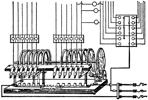
FIGURE 160.
Flashers are made up in a variety of forms, one
of them being shown in Figure 160. The manner
of wiring to the sign will be readily understood by
reference to the figure. The neutral wire is carried
direct to the sign and fuses for that wire are often
installed up in the sign, while those for the other
side of the circuits must be close to the flasher to
comply with the rule which requires fuse protection
where a small wire is tapped off from a larger one,
unless the fuse in the larger wire is below the carrying
capacity of the smaller.
National Electrical Code Rule for Flashers.
Time switches, sign flashers, and similar appliances
must be of approved design and enclosed in
approved cabinets.
[261]
Flat Irons.
Flat Irons.—See Heaters.
Flexible Cord.
Flexible Cord.—The ordinary flexible cord should
not be used in any part of a theater. It is recommended
that only those cords described below be
used, each of course in its proper place. Approved
reinforced cord for pendants. Approved asbestos-covered
cord for portable heaters. Approved Stage
and Border Cables on Stage.
See “Stage Cables.”
Flexible Tubing.
Flexible Tubing.—Flexible tubing is not permissible
in theaters.
Floor Pockets.
Floor Pockets.—These are always a source of
trouble and their use should be avoided as much as
possible. If it is necessary to use any they must
be of a type approved by the inspection department
having jurisdiction.
Fly Floor.
Fly Floor.—This is the name given to that part of
the gallery above the stage upon which those employes,
whose duty it is to raise and lower curtains
and scenery, work. No great illumination is required,
but the lights should be arranged so as to be convenient
to the men for reading during long waits.
If this is not done there will always be considerable
objectionable cord wiring found in this place. Fly-floor
and rigging-loft lights should be provided with
three way switches so that lights may be turned on
or off either at the stage switchboard or on the fly
floor.
Footlights.
Footlights.—These form the most important and
effective part of the permanently located stage
lights. To locate them properly requires careful consideration.
If they are brought too high they will
obstruct the view of the audience; if located too low
they will not illuminate the lower part of the stage.
[262]
Opinion is somewhat divided as to whether they
ought to be arranged in circular form or be laid out
straight across the stage. In large theaters there
is a circular space between the front seats and
the front of the stage. A circular stage will utilize
this space and this form of stage with footlights arranged
in a similar manner will also allow the actors
to approach more closely to the audience and will
procure for them some illumination from the side.
The difficulty of making up a circular strip of footlights
is somewhat greater than that of making them
up in a straight line.
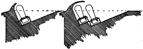
FIGURE 161. FIGURE 162.
The footlights are generally made to extend nearly
the full opening of the stage and the lights should
be crowded into them as closely as possible. The
lighting should be divided into three groups suitable
for three colors. It is customary to have about half
of the lights white and the remaining half divided
into two equal parts for different colors. A small part
of the white lights should be arranged upon a separate
circuit so that they may be used for rehearsals
or other purposes, when not very much light is needed.
No very definite recommendations concerning the
type of lamp to be used can be given. In some theaters
the stage is very solid and tungsten lamps are
used to advantage; in others the jarring prevents[263]
their use. The white lights should be arranged so
that their light need not pass through the colored
lamps. In vaudeville houses some protection in the
form of chains or guards is often provided to prevent
objects from being rolled or thrown against the lights.
Figures 161 and 162 show types of footlights and
the manner of installing the sockets.
The National Electrical Code Rules for Wiring Footlights.
Must be wired in approved conduit or armored
cable, each lamp receptacle being enclosed within an
approved outlet box, or the lamp receptacles may
be mounted in an iron or steel box, metal to be of a
thickness not less than No. 20 U. S. sheet metal
gauge treated to prevent oxidation and so constructed
as to enclose all the wires. Wires to be soldered to
lugs of receptacles. Must be so wired that no set
of lamps requiring more than 1,320 watts nor more
than 26 receptacles shall be dependent upon one
cut-out.
Fuses.
Fuses.—See “Cut-outs.”
Gallery Lighting.
Gallery Lighting.—The proper lighting of galleries
is a difficult matter where there is another gallery
above. In such a case the ceiling is always very
low. An even distribution of light requires the use
of many small incandescent lamps evenly distributed.
This will make the wiring expensive. The light should
be taken pretty well from the rear so as to avoid
placing lights in the range of visions of the audience.
Emergency lights should be provided here as well
as in the main auditorium.
Gallery Pockets.
Gallery Pockets.—Pockets for arc lamps are often
provided, as it often happens that a moving-picture[264]
machine must be placed in the gallery. The stage
pockets should be wired with number 6 B. & S. gauge
wire, this being the smallest wire allowed to feed
a moving-picture arc. The stage pocket should be
controlled by a switch on the switchboard. It often
happens that the operator at the lamp has a wrong
cue and his light can then be controlled by the stage
manager at the stage switchboard.
Gas Lighting.
Gas Lighting.—Electric gas lighting is very little
used at the present time, but in many theaters the
emergency lighting is by gas and, in order to save
the time necessary to light these by hand before
every performance, an automatic gas lighting system
has been installed in some theaters. A diagram
of such a system is shown in Figure 163. A battery
of considerable capacity is necessary and also a
spark coil S. At each gas jet a magnet M is installed
which, when energized, is capable of turning the gas
on and at the same time producing a spark. This
magnet is also capable of turning the gas off. Two
buttons are provided, one to turn the gas on and
the other to turn it off.
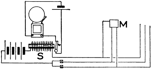
FIGURE 163.
As the wiring is always used in connection with
gas piping, grounds are of frequent occurrence, and[265]
in order to indicate a ground as soon as it comes
on, the bell and battery shown are provided. If a
ground causes a continuous current, the spark coil
will attract the armature, thus causing the bell to
ring continuously.
National Electrical Code Rule for Gas Lighting.
Electric gas lighting, unless it is the frictional
system, must not be used on the same fixtures with
the electric light.
Grid Floor.
Grid Floor.—This is the term given to the framework
which supports the pulleys over which the cables
for handling curtains and scenery run. It is usually
made up of parallel iron slats or bars; hence the
name. A fairly good illumination should be provided
here and all of the lights should be arranged on
three-way switches. One light for every 400 square
feet will be sufficient.
National Electrical Code Rule for Ground Clamps.
Connections to grounded pipes and to conduit must
be exposed to view or be readily accessible, and
must be made by means of approved ground clamps
to which the ground wire must be soldered.
National Electrical Code Rule for Grounding.
The metal of conduit, armored cable, or metal
molding must be permanently and effectually
grounded to water piping, gas piping, or other suitable
grounds, provided that, when connections are
made to gas piping, they must be on the street side
of the meter. If the conduit system consists of several
separate sections, the sections must be bonded
to each other, and the system grounded; or each
section may be separately grounded, as required
above.
[266]
Conduits and gas pipes must be securely fastened
in outlet boxes, junction boxes, and cabinets, so as
to secure good electrical connections.
If conduit, couplings, outlet boxes, junction boxes,
cabinets, or fittings, having protective coating of non-conducting
material such as enamel, are used, such
coating must be thoroughly removed from threads of
both couplings and conduit and such surfaces of
boxes, cabinets and fittings where the conduit or
ground clamp is secured in order to obtain the requisite
good connection. Grounded pipes must be
cleaned of rust, scale, etc., at place of attachment
of ground clamp.
Connections to grounded pipes and to conduit must
be exposed to view or readily accessible, and must be
made by means of approved ground clamps to which
the ground wires must be soldered.
Ground wires must be of copper, at least No. 10
B. & S. gauge (where largest wire contained in conduit
is not greater than No. 0 B. & S. gauge), and
need not be greater than No. 4 B. & S. gauge (where
largest wire contained in conduit is greater than
No. 0 B. & S. gauge). They shall be protected from
mechanical injury.
The ground on the conduit system is not to be considered
as a ground for a secondary system.
Guards.
Guards.—A guard rail should be provided around
the stage switchboard to prevent actors from coming
in contact with any live part of the switchboard.
All incandescent lamps about the stage, dressing
rooms, fly-floor, grid-floor, etc., should be provided
with guards.
Hanger-Boards.
Hanger-Boards.—Hanger-boards are not compulsory[267]
but where not used, arc lamps must be hung
from insulating supports other than their conductors.
National Electrical Code Rule for Hanger-Boards for Series Arc Lamps.
Hanger-boards must be so constructed that all
wires and current-carrying devices thereon will be
exposed to view and thoroughly insulated by being
mounted on a non-combustible, non-absorptive, insulating
substance. All switches attached to the same
must be so constructed that they shall be automatic
in their action, cutting off both poles to the lamps,
not stopping between points when started, and preventing
an arc between points under all circumstances.
Heaters.
Heaters.—Heaters are used sometimes in cold dressing
rooms, in box offices and in other small spaces
where other adequate heating arrangements have not
been made. The fire hazard incident to the use of
electric heaters is considerable and they should be
carefully installed according to the rules given below.
From one-half to three watts per cubic foot will be
required to heat a room. The quantity of heat necessary
to be supplied depends largely upon the ventilation.
It will be small in closed dressing rooms and
large, for instance, in the box office. Always place
a heater where the air enters a room; never where
it leaves.
National Electrical Code Rules for Electric Heaters.
Each heater of more than 6 amperes or 660
watts capacity must be protected by a cut-out, and
controlled by a switch or plug connector plainly indicating
whether “on” or “off” and located within[268]
sight of the heater. Heaters of 6 amperes or 660
watts capacity, or less, may be grouped under the
protection of a single set of fuses, provided the rated
capacity of the fuses does not exceed 10 amperes;
or may be connected individually to lighting circuits.
Flexible conductors for smoothing irons and sad
irons, and for all devices requiring over 250 watts,
must have an approved insulation and covering.
With portable heating devices, approved plug connectors
must be used so arranged that the plug
may be pulled out to open the circuit without leaving
any live parts so exposed as to render likely accidental
contact therewith. The connector may be located at
either end of the flexible conductor or inserted in
the conductor itself.
Smoothing irons, sad irons, and other heating devices
that are intended to be applied to combustible
articles, must be provided with approved stands.
Stationary heaters such as radiators, ranges, plate
warmers, etc., must be so located as to furnish ample
protection between the device and surrounding combustible
material.
Must each be provided with a name-plate, giving
the maker’s name and the normal capacity in volts
and amperes.
High Potential.
High Potential.—The National Electrical Code
classifies all voltages below 550 as low. Nevertheless
voltages above 220 should not be considered in the
auditorium, stage, or dressing rooms of any theater.
And this voltage only in connection with a three-wire
system where the high voltage exists only between
the outside wires, and 110 volts are used for
lamps and other devices. High potential systems
should be used only on the outside.
[269]
Illumination.
Illumination.—Illumination is more an art than a
science and the rules that can be given have only a
very general application. The best practice, where
really good illumination is desired, is to install a
large number of circuits in proportion to the number
of lights, so that lamps of large candle power may
be used wherever desirable. The quantity of light
needed in theaters varies greatly with the color of
decorations and with their condition. Dust accumulates
rapidly in theaters and may absorb half of the
light. If there is plenty of capacity the candle power
of lamps may be changed to suit conditions and obtain
any result desired.
The number of sockets installed in the auditorium
varies widely. In some of the cheaper theaters one
light for each twenty seats is considered sufficient;
while in elaborately lighted houses, there are cases
where the number of sockets is equal to about half
the number of seats. Good illumination requires
that the light come from the back, but very often the
purpose is to obtain a brilliant effect by placing lights
in front of the audience. In such cases, however, the
lamps are always of low candle power and should be
frosted.
Incandescent Lamps.
Incandescent Lamps.—Practically all incandescent
lamps are now rated in watts. They can be obtained
in voltages ranging from 2 to 250 and may be operated
in series or in multiple. All but the tantalum
lamp operates equally well on alternating or direct
current. The tantalum cannot be recommended for
alternating-current circuits. No incandescent lamps
will operate well on frequencies lower than forty
cycles. The natural distribution of light is mostly[270]
in the horizontal plane and for good illumination
reflectors should be provided.
The color value is in the following order: Tungsten,
tantalum, graphitized filament, carbon filament. None
are equal for color-matching purposes to the intensified
arc or the Moore tube.
The life of all incandescent lamps varies inversely
with the voltage. An increase in voltage will produce
an increase in the efficiency of the lamp but
shorten its life. The efficiency decreases with continued
use, and it is generally considered that the
useful life of a lamp is over when its efficiency
has fallen to 80 per cent of its original value. Frosting
or coloring shortens the life of lamps from 30
to 50 per cent and reduces the candle power from
3 to 10 per cent, but the lamp yields a more pleasing
light. Frosting is ordinarily used only where lamps
are placed so as to come in the line of vision. Bowl
frosting does not materially reduce the life of a lamp.
Efficiency of Lamps.
With incandescent lamps the term “efficiency” has
a meaning quite different from that usually given,
it being the number of watts per candle power. The
lower the efficiency of an incandescent lamp, the
better it is and the more light it yields per watt
consumed.
Mazda Lamp.
The Mazda lamp has an efficiency of about 1.25 and
is the most efficient of all. It may be recommended in
all places where lamps may be suspended vertically;
where there is not too much jarring; where there is
ordinary care in handling; and where the lamps are[271]
burning a large part of the time. The operating
expense of this lamp is low, but the initial cost is
high and the breakage is likely to be considerable.
If lamps are much handled and not burned much,
the cost of broken lamps may exceed the saving in
energy. It is best not to clean Mazda lamps when
cold. Shock absorbers should be used where there
is much jarring. The illumination should be laid
out for the use of lamps not smaller than 60 watts.
The lamps should not be used for temporary work
or for coloring. Arrange lamps as far as possible to
be controlled by switches. Broken filaments can
often be united again by shaking the lamps gently
until the broken ends come together. The current
will then weld them. When a bank of Mazda lamps is
turned on there is an excessive current for an instant.
Tantalum Lamp.
The efficiency of this lamp is from 1.8 to 2 watts
per candle power. This lamp is much used for
street-car and similar illumination because it stands
jarring very well. It should not be used on alternating-current
circuits. The filament can often be
united in the same manner as the Mazda.
Graphitized Filament Lamp.
This lamp has an efficiency of 2.5 watts per candle
power.
Carbon Filament Lamp.
This lamp used on 110-volt circuits has an efficiency
of from 3 to 3.2 watts per candle power. The efficiency
of the smaller sizes is from 4 to 5 watts per
candle power. The carbon filament lamp is the most[272]
expensive of all to operate, but on account of the
strength and cheapness of the lamp it can be recommended
in places where the breakage is liable to be
great or where the light is used for comparatively
brief periods.
National Electrical Code Rules for Incandescent Lamps.
Must be provided with guards when liable to come
in contact with inflammable material or subject to
rough usage. Must be protected by vapor-proof
globes where inflammable gases exist.
National Electrical Code Rules for Insulating Joints.
When supported at outlets in metal conduit,
armored cable, or metal molding systems, or from gas
piping or any grounded metal work; or when installed
on metal walls or ceilings, or on plaster walls
or ceilings containing metal lath, or on walls or ceilings
in fireproof buildings, fixtures must be insulated
from such supports by approved insulating joints
placed as close as possible to the ceilings or walls.
The insulating joint may be omitted in conduit, armored
cable, or metal molding systems with straight
electric fixtures in which the insulation of conductors
is the equivalent to insulation in other parts of the
system, and provided that approved sockets, receptacles,
or wireless clusters are used of a type having
porcelain or equivalent insulation between live metal
parts and outer metal shells, if any.
Where insulating joints are required, fixture canopies
of metal must be thoroughly and permanently
insulated from metal walls or ceilings, or from plaster[273]
walls or ceilings on metal lathing, and from outlet
boxes.
Canopy insulators must be securely fastened in
place, so as to separate the canopies thoroughly and
permanently from the surfaces and outlet boxes from
which they are designed to be insulated.
Inverted Lighting.
Inverted Lighting.—In this method of lighting the
light is first thrown upward against the ceiling and
then reflected back. This method can be used to
advantage with light colored ceilings only. It is
especially suited for low ceilings and with high
ceilings the advantage disappears. The light obtained
in this manner is very even and almost shadowless.
Much light is lost through absorption but, owing to
the fact that the light is of such an even quality,
the eye readily accommodates itself to a lower quantity
and the net increase in energy required to illuminate
suitable spaces is not so very great. Those
who wish to go into the subject of illumination thoroughly
will find it treated fully in “Modern Illumination
Theory and Practice”.
Joints.
Joints.—Methods of making joints are illustrated
in Figure 164. Be careful not to overheat, especially
at points where there is a strain on the wire.
National Electrical Code Rule for Joints.
Wires must be so spliced or joined as to be both
mechanically and electrically secure without solder.
The joints must then be soldered unless made with
some form of approved splicing device, and covered
with an insulation equal to that on the conductors.
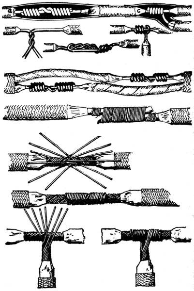
FIGURE 164.
Stranded wires (except in flexible cords) must be
soldered before being fastened under clamps or binding
screws; and, whether stranded or solid, when they[274
275]
have a conductivity greater than that of No. 8 B. &
S. gauge they must be soldered into lugs for all
terminal connections, except where an approved solderless
terminal connector is used.
Junction Boxes.
Junction Boxes.—Junction boxes are installed in
conduit systems for the purpose of facilitating the
drawing in of the wire or of branching off from a
main run. See “Conduit Work.”
Lamps.
Lamps.—See “Incandescent Lamps.”
Lobby.
Lobby.—The lobby generally requires a number of
lights and the aim often is to create a lavish display.
Very often a cut-out center is arranged at some
convenient place. The exit and emergency lights
must be controlled from the lobby. Sometimes outlets
are provided for electric bulletin boards or small
signs.
Lugs.
Lugs.—For solderless lugs, such as are used on
rheostats or for arc lamps, see “Portable Stage Equipment.”
National Electrical Code Rule for Lugs.
For fuses rated over 30 amperes lugs, firmly
screwed or bolted to the terminals and into which
the conducting wires are soldered, must be used.
On rheostats, resistances, etc., lugs will not be required
when leads are provided as a part of the
device.
Switches for current of over 30 amperes must be
equipped with lugs, firmly screwed or bolted to the
switch, and into which the conducting wires shall be
soldered. For the smaller sized switches simple
clamps can be employed, provided they are heavy
enough to stand considerable hard usage.
Where lugs are not provided, a rugged double-V[276]
groove clamp is advised. A set screw gives a contact
at only one point, is more likely to become loosened,
and is almost sure to cut into the wire. For the
smaller sizes, a screw and washer connection with
up-turned lugs on the switch terminal gives a satisfactory
contact.
National Electrical Code Rules for Metal Moldings.
Must not be used on stage side of proscenium wall.
Must not be used for circuits carrying more than
1,320 watts.
Wire used must be standard rubber covered, but
may be single braid.
Must never be concealed or run in damp places.
Must not be used where the difference of potential
exceeds 300 volts.
Must be continuous from outlet to outlet, to junction
boxes, or approved fittings designed especially
for use with metal moldings, and must at all outlets
be provided with approved terminal fittings which
will protect the insulation of conductors from abrasion,
unless such protection is afforded by the construction
of the boxes or fittings.
Such molding where passing through a floor must
be carried through an iron pipe extending from
the ceiling below to a point five feet above the floor,
which will serve as an additional mechanical protection
and exclude the presence of moisture often prevalent
in such locations.
Where the mechanical strength of the molding itself
is adequate, this ruling may be modified to require
the protecting piping from the ceiling below to
a point at least three inches above the flooring.
[277]
Where such moldings pass through a partition the
iron pipe, required for passing through floors, may
be omitted and the molding passed directly through,
providing the partition is dry and the molding is in
a continuous length with no joint or coupling within
the partition.
Backing must be secured in position by screws or
bolts, the heads of which must be flush with the
metal.
Must have the metal of molding permanently
and effectually grounded to water piping, gas piping,
or other suitable grounds, provided that when connections
are made to gas piping, they must be on
the street side of the meter. If the metal molding
system consists of several separate sections, the sections
must be bonded to each other and the system
grounded, or each section may be separately grounded,
as required above.
Metal moldings and gas pipes must be securely fastened
to outlet boxes, junction boxes, and cabinets,
so as to secure a good electrical connection. Molding
must be so installed that adjacent lengths of molding
will be mechanically and electrically secured at all
points.
If metal molding, couplings, outlet boxes, junction
boxes, cabinets, or fittings having protective coating
of non-conducting material such as enamel are used,
such coating must be thoroughly removed from
threads of couplings and metal moldings, and from
the surfaces of boxes, cabinets, and fittings, where
the metal molding or ground clamp is secured in
order to obtain the requisite good connection.[278]
Grounded pipes must be cleaned of rust, scale, etc.,
at the place of attachment of the ground clamp.
Connection to grounded pipes and to metal moldings
must be exposed to view, or readily accessible,
and must be made by means of approved ground
clamps, to which the wires must be soldered.
Ground wires must be of copper, at least No. 10
B. & S. gauge. They shall be protected from mechanical
injury.
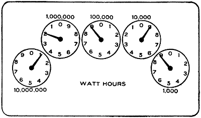
FIGURE 165.
Must be installed so that for alternating-current
systems the two or more wires of a circuit will be in
the same metal molding. It is suggested that this be
done for direct-current systems also so that they may be
changed to the alternating-current system at any time,
induction troubles preventing such change if the wires
are in separate moldings.
Meters.
Meters.—A good job of meter setting requires that
the meter fittings which are now on the market be
used. Two separate meters will be required in each
theater; one for the general lighting and one for
the emergency system.
Meter Reading.
Meter Reading.—Meter readings are indicated by[279]
pointers, arranged to move over dials as shown in
Figure 165. The various pointers are connected together
by gearing in such a manner, that alternate
pointers move in opposite directions, as indicated by
the figures on the dials. The gearing moving the
pointers in Figure 165 is of such proportions that
a total revolution of any pointer represents one-tenth
of a revolution of the pointer to the left of it. Thus
ten revolutions of one pointer causes one revolution
of the one at the left.
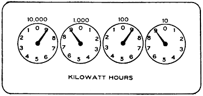
FIGURE 166.
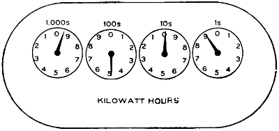
FIGURE 167.
At the top of each dial the value of the reading
of that dial is shown. Where the figures given are
followed by the letter “s”, as in Figures 167 and
168, it signifies that each division of the dial represents[280]
the amount of energy indicated by the figures
at the top. For instance, in Figure 168 each division
of the dial at the right represents one-tenth of one
kilowatt hour and a total revolution of the pointer
ten-tenths, or one kilowatt hour.
If the figures given at the top of the dial are not
followed by the letter “s”, or as shown in Figure
166, each division of the dial represents one-tenth
of the amount shown at the top of the dial, the dial
at the right of Figure 166 indicating nine-tenths of
ten kilowatts or nine kilowatts.
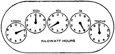
FIGURE 168.
The meter must always be read from right to left,
the lowest indicating dial being the one at the extreme
right, and the lower reading ones always
being used to check the higher ones just at the left.
The following example will illustrate the manner of
reading meters:
In Figure 165 the right-hand pointer registers
nine-tenths of 1000, or 900 watt hours; the pointer
next to it registers eight, since it cannot be considered
as fully up to any number unless the pointer at the
right of it has just arrived at or passed 0. By the
same token the middle pointer also registers 8 and
as the middle pointer has not reached 0 the one at[281]
the left of it must be read as one, the last dial also
indicates one and the total reading is 1,188,900. On
some types of meters a multiplier is used. This
is generally given on the meter dial and the readings
given by the pointers must be multiplied by this
number to obtain the correct reading of the meter.
Motors.
Motors.—Motors are used in theaters for ventilation,
for raising and lowering the steel curtain in
cities where such are required, and also in some
cases for operating drop curtains, but for this last
purpose they have not found much favor. In some
localities motors are required to keep up a certain
water pressure to be used in case of fire. Voltages
higher than 550 are not considered in theater work.
National Electrical Code Rules for 550-volt Motors and Less.
Motors operating at a potential of 550 volts or
less must be thoroughly insulated from the ground
wherever feasible. Wooden base frames used for
this purpose, and wooden floors, which are depended
upon for insulation where, for any reason, it is necessary
to omit the base frames, must be kept filled to
prevent absorption of moisture, and must be kept
clean and dry. Where frame insulation is impracticable
special permission in writing may be given
for its omission, in which case the frame must be
permanently and effectively grounded.
The motor leads or branch circuits must be designed
to carry a current at least 25 per cent
greater than that for which the motor is rated. Where
the wires under this rule would be over-fused in order
to provide for the starting current, as in the case of
many of the alternating-current motors, the wires[282]
must be of such size as to be properly protected by
these larger fuses.
Each motor and resistance box must be protected
by a cut-out and controlled by a switch; said switch
plainly indicating whether “on” or “off”.
Small motors may be grouped under the protection
of a single set of fuses, provided the rated capacity
of the fuses does not exceed 6 amperes. With
motors of one-fourth horse power or less, on circuits
where the voltage does not exceed 300, single-pole
switches may be used. The switch and rheostat
must be located within sight of the motor, except in
cases where special permission to locate them elsewhere
is given, in writing.
Where the circuit-breaking device on the motor-starting
rheostat disconnects all wires of the circuit,
the switch called for in this section may be omitted.
Overload-release devices on motor-starting rheostats
will not be considered to take the place of the cut-out
required by this section. An automatic circuit-breaker
disconnecting all wires of the circuit may
serve as both switch and cut-out.
Auto starters, unless equipped with tight casings
enclosing all current-carrying parts, in all wet, dusty,
or linty places, must be enclosed in dust-tight, fireproof
cabinets. Where there is any liability of short
circuits across their exposed live parts being caused
by accidental contacts, a railing must be erected
around them.
Must not be run in series-multiple or multiple-series,
except on constant-potential systems, and then
only by special permission.
Must, when combined with ceiling fans, be hung
from insulated hooks, or else there must be an insulator[283]
interposed between the motor and its support.
Must each be provided with a name-plate, giving
the maker’s name, the capacity in volts and amperes,
and the normal speed in revolutions per minute.
All varying (or variable) speed alternating-current
motors except those used for railway service must
be marked with the maximum current which they can
safely carry for 30 minutes, starting cold.
Terminal blocks when used on motors must be
made of approved non-combustible, non-absorptive,
insulating material such as slate, marble, or porcelain.
Adjustable-speed motors, unless of special and appropriate
design, if controlled by means of field
regulation, must be so arranged and connected that
they cannot be started under weakened field.
The use of soft rubber bushings to protect the
lead wires coming through the frames of motors is
permitted, except when installed where oils, grease,
oily vapors, or other substances known to have rapid
deleterious effect on rubber are present in such quantities
and in such proximity to motors as may cause
such bushings to be liable to rapid destruction. In
such cases hardwood properly filled, or preferably
porcelain or micanite bushings must be used.
The following table shows the sizes of wire recommended
to be used with motors of the horsepower
given. This table is an extract from the rules of the
Department of Gas and Electricity of the City of
Chicago. The column headed “Mains” may be used
when there are a number of motors fed by a single
line. For all lines which supply a single motor only,[284]
the column headed “Branches” must be used.
The difference between the two is due to the fact
that it is not believed that several motors fed by a
single line will all be started at the same time; hence
it is not necessary to provide the overload capacity
for all of the motors as it is where but a single motor
is installed.
| DIRECT CURRENT |
| |
110 Volts |
220 Volts |
| H. P. |
Full-
load
Current |
Size
of
Wire
Mains |
Size
of
Wire
Branches |
Full-
load
Current |
Size
of
Wire
Mains |
Size
of
Wire
Branches |
| 1 |
|
8 |
14 |
14 |
4 |
14 |
14 |
| 2 |
|
15 |
14 |
12 |
8 |
14 |
14 |
| 3 |
|
23 |
10 |
8 |
12 |
14 |
14 |
| 4 |
|
30 |
8 |
6 |
15 |
14 |
12 |
| 5 |
|
38 |
6 |
6 |
19 |
12 |
10 |
| 7 |
.5 |
56 |
5 |
4 |
28 |
8 |
8 |
| 10 |
|
75 |
3 |
1 |
38 |
6 |
6 |
| SINGLE-PHASE |
| 1 |
|
12 |
... |
12 |
6 |
... |
14 |
| 2 |
|
23 |
... |
8 |
11 |
... |
12 |
| 3 |
|
33 |
... |
6 |
16 |
... |
10 |
| 4 |
|
44 |
... |
4 |
22 |
... |
8 |
| 5 |
|
53 |
... |
3 |
26 |
... |
6 |
| THREE-PHASE |
| 1 |
|
... |
... |
... |
3 |
14 |
14 |
| 2 |
|
... |
... |
... |
5 |
14 |
14 |
| 3 |
|
... |
... |
... |
8 |
14 |
14 |
| 4 |
|
... |
... |
... |
10 |
14 |
14 |
| 5 |
|
... |
... |
... |
13 |
14 |
12 |
| 7 |
.5 |
... |
... |
... |
19 |
12 |
8 |
| 10 |
|
... |
... |
... |
26 |
8 |
6 |
[285]
Music Stands.
Music Stands.—Music stands are used by the
musicians and are generally placed between the first
row of seats and the stage. Each musician should
be provided with an individual stand, although if
necessary, two or three can get along with one stand.
No first-class theater should be fitted up with less
than twenty outlets for musicians’ lights. In the
Metropolitan Opera House of New York there are
one hundred. Houses used exclusively for vaudeville
do not, however, need that many. In houses devoted
to grand opera, often as many as one hundred or
more musicians are employed at the same time. To
take care of such a number, the music stands should
be wired with pin-plug connectors so that connections
may be made from one to the other. Long
flexible connections are necessary for most music
stands.
Sometimes it is necessary to crowd the orchestra
under the stage and at other times, with musical
comedies, for instance, they must be brought out
where they can see the movements of the actors.
The more the circuits are subdivided, and the different
lights made independent of each other, the
better it will be and the less the annoyance in case
a fuse blows. The fuses should always be arranged
at the switchboard so that it will not be necessary for
the electrician to work in front of the audience in
cases of trouble. For this reason extra stands should
also be kept on hand.
A main switch controlling the lights should be
placed where one of the musicians can handle it. In
dark scenes these lights must often be turned out.
If these lights are left under the control of the stage
electrician they will be more likely to be forgotten[286]
at the critical moment than if under the control of
the men who need them.
An eight candle-power lamp for each stand will be
sufficient and this is usually placed inside a special
reflector which allows the light to fall upon the music
sheet only. Stage cable of good quality should be
used for the connections; there is too much rough
handling for reinforced cord. The use of the ordinary
attachment plug should be avoided; use approved
pin-plug connectors.
Open Work.
Open Work.—Open work is not allowed in theaters.
Operating Room.
Operating Room.—See special chapter on “Operating
Room.”
Panel Boards.
Panel Boards.—Panel boards are really small
switchboards, the switches and cut-outs being mounted
usually upon slate. The slate must be free of metal
seams; these, if present, often manifest themselves
by heating. Panel boards, unless located in the
immediate vicinity of the main switchboard, and
where they are enclosed in a compartment, must
always be placed in standard metal cabinets.
National Electrical Code Rules for Panel Boards.
The following specifications are intended to apply
to all panel and distributing boards used for the
control of light and power circuits, but not to such
switchboards in central stations, sub-stations, or isolated
plants as directly control energy derived from
generators or transforming devices.
Design.
The specifications for construction of switches and
cut-outs given in the following pages must be followed
as far as they apply.
[287]
In the relative arrangement of fuses and switches,
the fuses may be placed between the bus-bars and the
switches, or between the switches and the circuits,
except in the case of service switches. When the
branch switches are between the fuses and the bus-bars,
the connections must be so arranged that the
blades will be dead when the switches are open.
When there are exposed live-metal parts on the
back of a board, a space of at least one-half inch
must be provided between such live metal parts and
the cabinet in which the board is mounted.
Spacings.
| |
Between Parts of
Opposite Polarity,
Except at
Switches and
Link Fuses |
Between Parts of
Same Polarity
at Link Fuses |
When Mounted
on the Same
Surface |
When Held
Free in Air |
| Not over 125 volts |
|
3⁄4 inch |
|
1⁄2 inch |
|
1⁄2 inch |
| Not over 250 volts |
1 |
1⁄4 inch |
|
3⁄4 inch |
|
3⁄4 inch |
| Not over 600 volts |
2 |
3⁄4 inch |
1 |
3⁄4 inch |
|
At switches or enclosed fuses, parts of the same
polarity may be placed as close together as convenience
in handling will allow. It should be noted
that the above distances are the minimum allowable,
and it is urged that greater distances be adopted
wherever the conditions will permit.
The spacings given in the first column apply to the
branch conductors where enclosed fuses are used.[288]
Where link fuses or knife switches are used, the
spacings must be at least as great as those given in
the following section on fuse spacing. The spacings
given in the second column above apply to the distance
between the raised main bars and between these
bars and the branch bars over which they pass. The
spacings given in the third column are intended to
prevent the melting of a link fuse by the blowing of
an adjacent fuse of the same polarity.
Panel boards of special design, in which the insulation
and separation between the bus-bars, and between
the other current-carrying parts is secured by
means of barriers or insulating materials instead of
by the spacings given above, must be submitted for
special examination and approved before being used.
Fuse Spacings.
Spacings must be at least as great as those given in
Table X, which applies only to plain, open link
fuses. The spaces given are correct for fuse blocks
to be used on direct-current systems, and can therefore
be safely followed in devices designed for alternating
currents. If the copper fuse tips overhang
the edges of the fuse block terminals, the spacings
should be measured between the nearest edges of
the tips.
A space must be maintained between fuse terminals
of the same polarity of at least one-half of an inch for
voltages up to 125 and of at least three-quarters of an
inch for voltages from 125 to 250. This is the minimum
distance allowable, and greater separation should
be provided when practicable.
For 250 volts, boards, or blocks with the ordinary
front-connected terminals, except where these have[289]
a mass of compact form equivalent to the back-connected
terminals usually found in switchboard work,
a substantial barrier of insulating material, not less
than one-eighth of an inch in thickness, must be
placed in the “break” gap—this barrier to extend
out from the base at least one-eighth of an inch farther
than any bare live part of the fuse-block terminal,
including binding screws, nuts and the like.
For three-wire systems cut-outs must have the
break-distance required for circuits of the potential
of the outside wires.
| Not over 125 volts: |
Minimum Separation
of Nearest Metal
Parts of Opposite
Polarity |
Minimum
Break
Distance |
| 10 amperes or less |
|
3⁄4 inch |
|
3⁄4 inch |
| 11-100 amperes |
1 |
3⁄4 inch |
|
3⁄4 inch |
| 101-300 amperes |
1 |
3⁄4 inch |
1 |
3⁄4 inch |
| 301-1,000 amperes |
1 |
1⁄4 inches |
1 |
1⁄4 inches |
| Not over 250 volts: |
Minimum Separation
of Nearest Metal
Parts of Opposite
Polarity |
Minimum
Break
Distance |
| 10 amperes or less |
1 |
1⁄2 inches |
1 |
1⁄4 inches |
| 11-100 amperes |
1 |
3⁄4 inches |
1 |
1⁄4 inches |
| 101-300 amperes |
2 |
3⁄4 inches |
1 |
1⁄2 inches |
| 301-1,000 amperes |
2 |
1⁄2 inches |
2 |
3⁄4 inches |
Switch Spacings and Dimensions.
When designed with 250-volt spacings between adjacent
blades, triple-pole switches must be marked
250 volts and may be used on 3-wire D. C. or single-phase
systems having not more than 250 volts between
adjacent wires and not more than 500 volts
between the two outside wires.
[290]
Spacings and dimensions must be at least as great
as those given below:
| Not Over 125 Volts D. C. and A. C. |
| Current |
Width and Thickness |
Minimum Separation
of Nearest Metal
parts of Opposite
Polarity |
Minimum
Break
Distance |
| |
Blades |
Clips and
Hinges |
| 30 amp. |
1⁄2 inch by
5⁄64 inch |
1⁄2 inch by
3⁄64 inch |
1 |
1⁄4 inch |
|
3⁄4 inch |
| 60 amp. |
1 |
1⁄4 inch |
1 |
3⁄4 inch |
| Not Over 125 Volts D. C. and A. C. |
| |
|
|
|
Inch |
Inch |
Inch |
Inch |
| 30 |
|
amperes |
1⁄2 by 5⁄64 |
1⁄2 by 3⁄64 |
1 |
1⁄4 |
1 |
|
| 60 |
and |
100 |
amperes |
|
1 |
1⁄2 |
1 |
1⁄4 |
| 200 |
|
amperes |
|
2 |
1⁄4 |
2 |
|
| 400 |
and |
600 |
amperes |
|
2 |
3⁄4 |
2 |
1⁄2 |
| 800 |
and |
1000 |
amperes |
|
3 |
|
2 |
3⁄4 |
A 300-ampere switch with the spacings of the 200-ampere
switch above may be used on switchboards.
| 250 Volts Only D. C. and A. C. |
| |
|
|
|
Inch |
Inch |
Inch |
Inch |
| 30 amperes |
1⁄2 by 5⁄64 |
1⁄2 by 3⁄64 |
1 |
3⁄4 |
1 |
1⁄2 |
[291]
| Not Over 250 Volts D. C. nor Over 500 Volts A. C. |
| |
|
|
|
Inch |
Inch |
Inch |
Inch |
| 30 |
|
amperes |
5⁄8 by 1⁄8 |
5⁄8 by 1⁄16 |
2 |
1⁄4 |
2 |
|
| 60 |
and |
100 |
amperes |
|
2 |
1⁄4 |
2 |
|
| 200 |
|
amperes |
|
2 |
1⁄2 |
2 |
1⁄4 |
| 400 |
and |
600 |
amperes |
|
2 |
3⁄4 |
2 |
1⁄2 |
| 800 |
and |
1000 |
amperes |
|
3 |
|
2 |
3⁄4 |
A 300-ampere switch with the spacings of the 200-ampere
switch above may be used on switchboards.
Cut-out terminals on switches for over 250 volts
must be designed and spaced for 600-volt fuses.
| Not Over 600 Volts D. C. and A. C. |
| |
|
|
|
Inch |
Inch |
Inch |
Inch |
| 30 |
|
amperes |
5⁄8 by 1⁄8 |
5⁄8 by 1⁄16 |
4 |
|
3 |
1⁄2 |
| 60 |
|
amperes |
|
4 |
|
3 |
1⁄2 |
| 100 |
|
amperes |
|
4 |
1⁄2 |
4 |
|
Paint Bridge.
Paint Bridge.—The paint bridge is usually a scaffold
which can be raised and lowered, and which
serves the purpose of carrying scene painters at work
on the curtains. A long strip is the best means of illumination
and it must be connected with long stage
cable so as to be portable.
Paint Room.
Paint Room.—Rooms in which paints are stored
should not contain switches or cut-outs. Lamps
should be incased in vapor-tight globes.
Program Board.
Program Board.—A simple form of program board
is shown in Figure 169. Except at the top and the
bottom, where three lamps are shown together in
one compartment, each lamp is incased by itself. In
front of the lamps is usually colored glass, bearing
numbers or letters. The lamp behind any number[292]
being turned on, that number becomes visible. The
top and bottom are usually labeled, “Special”, or
“Extra”.
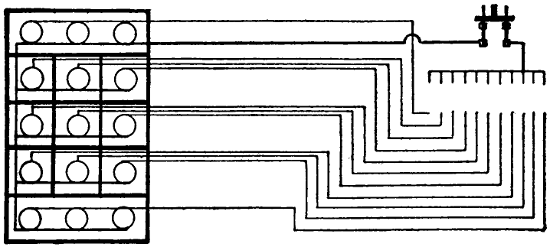
FIGURE 169.
Another form of program board is shown in Figure
170. This requires much more wiring. Each lamp
on the board is connected to a plug or switch at the
operator’s station. Whichever switch is closed on the
small board at the right causes a corresponding light
on the large board to appear.
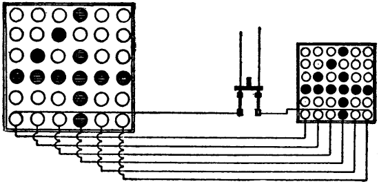
FIGURE 170.
Two program boards are usually installed, one at
each side of the stage, facing the audience at angles,[293]
so that one can be seen from the extreme right, the
other from the extreme left.
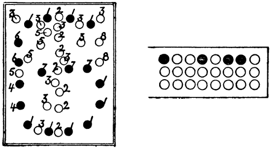
FIGURE 171.
A system that is often used for carriage call is
shown in Figure 171. The lights are arranged on
circuits as indicated by numbers. All lamps bearing
the same number being connected to one wire leading
to the controlling station. Thus there are eight controlling
or switch wires and there is one wire common
to all. A special switch is provided which has
a contact point for each wire. Paper cards, perforated
specially for the numbers they represent, are used.
If a card bearing a certain number is inserted in the
proper place and the switch closed, the number
printed on the card will appear on the sign. If, for
instance, the shaded circles in the card at the left of
the figure allow contact to be made, the lights indicated
by black circles will light up and make the
figure “6”.
Another form of program or call board is shown
in Figure 172. This requires more wires than the
one just described, one wire being carried to the controlling
board from each lamp. The connections may[294]
be made in various ways. Sometimes they are made
with knife switches. If it is desired to make the
figure 1, for instance, only the three lights in a
vertical row in the center need be lighted, and to do
this the three wires from those lamps must be connected
to one switch. To make the figure 2, seven
lamps would have to be lit by another switch. It is
capable of making any letter or number and when
used as a program board only may be somewhat
simplified.
FIGURE 172.
In connection with these signs a large number of
wires may be required and attention should be given
to the following rule:
National Electrical Code Rule for Wiring Program and Call Boards.
Except in the case of stage pockets the same conduit
must never contain more than four two-wire,
or three three-wire circuits of the same system except
by special permission, and must never contain circuits
of different systems.
Proscenium Side Lights.
Proscenium Side Lights.—These lights are located
on each side of the stage, as near as possible to the[295]
edge of the proscenium opening and often in front
of the steel curtain. They are of more use in musical
productions, where choruses spread over the whole
stage, than in dramatic productions where the interest
is more in the center of the stage. In some theaters
the proscenium side lights extend the full height
of the opening and are arranged for three colors in
the same manner as footlights and borders. Very
often, however, only ten or twelve lights are arranged
on each side of the stage.
The construction rules are the same as those governing
foot-lights.
Lamps must be protected by strong wire mesh.
This is essential as in many cases actors are very
likely to back into them while passing off the stage.
Portable strips are sometimes used as proscenium side
lights.
Receptacles.
Receptacles.—See “Stage Pockets”.
Retiring Rooms.
Retiring Rooms.—In these places a quiet subdued
illumination is usually desired. There are also often
quaint objects and effects to be illuminated. A large
number of outlets conveniently located for the use of
table lamps, fire places, and illumination of pictures,
should be provided.
Rheostats.
Rheostats.
National Electrical Code Rules for Rheostats.
Location.
Must be placed on a switchboard, or at a distance
of at least one foot from combustible material, or
separated therefrom by a slab or panel of non-combustible,
non-absorptive, insulating material such as
slate, soapstone, or marble, somewhat larger than the
rheostat, which must be secured in position independently[296]
of the rheostat supports. Bolts for supporting
the rheostat shall be countersunk at least one-eighth
inch below the surface at the back of the slab
and the bolt heads shall be covered with insulating
material. For proper mechanical strength, slab should
be of a thickness consistent with the size and weight
of the rheostat, and in no case to be less than one-half
inch.
If resistance devices are installed in rooms where
dust or combustible flyings would be liable to accumulate
on them, they must be equipped with dust-proof
face plates.
Materials.
Must be made entirely of non-combustible materials,
except such minor parts as handles, magnet insulation,
etc. All segments, lever arms, etc., must be
mounted on non-combustible, non-absorptive, insulating
material.
Connections.
Clamps for connecting wires to the terminals must
be so designed as to insure a thoroughly good connection
and must be sufficiently strong and heavy to
withstand hard usage. For currents above 30 amperes,
lugs into which the connecting wires may be soldered,
or approved solderless connectors must be used.
Clamps or lugs will not be required when leads are
provided as a part of the device.
No-Voltage Release.
Motor-starting rheostats must be so designed that
the contact arm cannot be left on intermediate segments,
and for direct-current circuits must be provided
with an automatic device which will interrupt[297]
the supply circuit before the speed of the motor falls
to less than one-third of its normal value. In motor-starting
rheostats for alternating-current circuits the
automatic interrupting device may be omitted.
Overload Release.
Overload-release devices which are inoperative during
the process of starting a motor will not be approved,
unless other circuit-breakers or fuses are installed
in connection with them.
Signals.
Signals.—Signals are necessary between the manager’s
office and the stage electrician’s station; for
this purpose telephones are generally used. In many
cities a fire-alarm signal system is also required and
it is specified to what part of the house it shall lead.
In addition to the above, a means of signalling the
fly floor and the orchestra leader must be provided.
Buzzers are used for these signals. It is best to use
batteries for all these signals instead of attempting
to run them from lighting circuits. Means of signalling
the arc-lamp station in the gallery or the balcony
should also be provided for use in connection with
lantern slides, etc. Telephone connection to this point
will also be very useful in order to give instructions
to the lamp operator. Return-call systems are advisable
in all places so that the electrician can be
called from any point.
In some cities the local laws require these wires to
be in conduit so as to preclude any possibility of
their communicating fire to anything. At any rate
the wires should be very carefully installed.
Signs.
Signs.—In nearly all electric signs used about
theaters the letters are outlined by incandescent
lamps. Small candle-power lamps are always used.[298]
They are not only economical but much more attractive
because the glare from too much light is very
annoying. Many signs are equipped with low candle-power
tungsten lamps wired in series. In order that
the letters should show to full advantage they should
be glossy white and be kept clean. Such letters will
show as bright as the lamps. It is best to wire the
sign so that either side can be used independent of
the other. In many cases, also, signs are wired so
that each letter is independent of the others for use
with flashers.
Attraction signs are used to advertise the attractions
which appear from time to time. Independent
portable letters are used and changed as often as the
attractions change. Each letter must be fitted with
cable and attachment plug of some kind and should
have a separate circuit. Cut-outs are generally located
on the frame and must be protected from the
weather.
Sockets.
Sockets.—Sockets must be of approved construction.
Key sockets must not be used for emergency
or exit lighting. Sockets with fiber linings must not
be used unless protected by insulating joints. In
damp places weatherproof sockets must be used.
Where inflammable gases exist, lamps must be incased
in vapor-proof globes. Porcelain sockets should not
be used in theaters. Weatherproof sockets are generally
used for portable purposes because they have
no screws, etc., to work loose.
Stage Cable.
Stage Cable.—Stage cables are allowed in theaters
only where flexible conductors are absolutely necessary.
All wiring that can possibly be installed in
conduit or strip construction should be so arranged.
By the use of plugging boxes the quantity of stage[299]
cable necessary can be much reduced. Plugs for arc
and incandescent lights must not be interchangeable.
Stage Flues.
Stage Flues.—In most cities stage flues, as described
in the chapter on “Theater Buildings”, are
required. The requirement is also, often, that they
be released by electrical means. The rule below contemplates
a circuit containing an electro-magnet and
at least two switches in series. The magnet must be
energized to hold the ventilator closed. If the current
fails or a switch is opened the dampers must fly
open at once. Where direct current is available the
magnet is usually wound for 110 volts and connected
to a circuit that is always alive. In case of an isolated
plant which is shut down at night some arrangement
for tying the dampers down should be made, but
it is not always advisable, as once tied they are likely
to remain so and sure to fail when needed. Magnets
do not work well on alternating currents and in such
cases the magnet should be wound for a small current
to be obtained from a gravity battery which may be
allowed to be always working. Locate the battery
where it will not freeze.
National Electrical Code Rules for Control of Stage Flues.
In cases where dampers are released by an electric
device, the electric circuit operating same must be
normally closed. Magnet operating dampers must be
wound to take full voltage of circuit by which it is
supplied, using no resistance device, and must not
heat more than normal for apparatus of similar construction.
It must be located in loft above scenery,
and be installed in a suitable iron box with a tight,
self-closing door.
[300]
Such dampers must be controlled by at least two
standard single-pole switches mounted within approved
iron boxes provided with self-closing doors
without lock or latch, and located, one at the electrician’s
station and the others as designated.
Stage and Gallery Pockets.
Stage and Gallery Pockets.—Stage pockets are usually
located on each side of the stage just far enough
from the center to be safely back of the scenery. The
more pockets there are the better it will be. Each
pocket usually contains four circuits, and one of these
at least should be for incandescent lights. It will be
convenient if the stage pockets are divided into four
groups, each group under control of a separate switch
and the whole again under control of a main switch.
This will enable the operator to throw off all of the
pockets at once, if necessary, or to make any combination
desired.
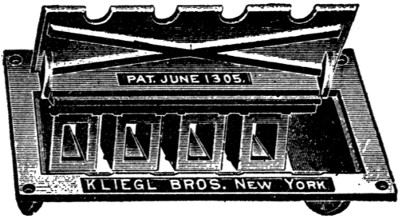
FIGURE 173.
Sometimes lights fed through stage pockets require
to be dimmed; but it is hardly practicable to arrange
dimmers for apparatus carried by traveling companies,
since a dimmer must be selected with respect
to the amperage it is to control.
In addition to the rules given below, some cities
require the bottom of stage pockets to be open, so as[301]
to avoid an accumulation of dust. This is a very essential
precaution, as otherwise the pockets soon fill
up or require very frequent cleaning. The covers
must be substantial as heavy trucks are sometimes run
over them. Two illustrations of stage pockets are
given in Figures 173 and 174. The plugs used with
these boxes are shown in Figure 175.
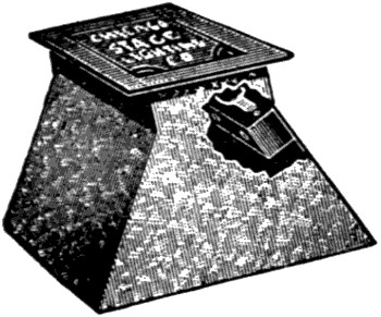
FIGURE 174.
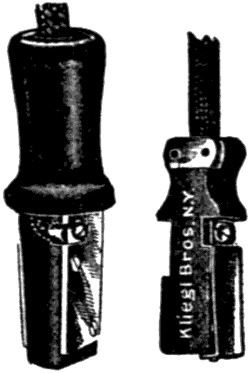
FIGURE 175.
Gallery pockets are not usually laid in the floor
but along the railing. The gallery pockets should
be under separate control from the stage switchboard.
National Electrical Code Rules for Stage and Gallery Pockets.
Must be of approved type, insulated from ground
and controlled from switchboard, each receptacle to
be of not less than 35-ampere rating for arc lamps
nor 15-ampere for incandescent lamps, and each receptacle
to be wired to its full capacity. Arc pockets
to be wired with wire not smaller than No. 6 B. & S.
gauge and incandescent pockets with not less than
No. 12 B. & S. gauge. Plugs for arcs and incandescent
pockets must not be interchangeable.
Switches.
Switches.—All knife switches should be enclosed in[302]
cabinets unless they are located on a switchboard. In
exposed places, flush switches should be used. The
usual height at which scattered switches are located
is about four and one-half feet above floor. Door
switches are of use principally in dressing rooms.
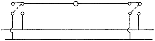
FIGURE 176.
Diagrams of three-way switches are given in Figures
176 and 177. In Figure 177, the wiring by
which a light can be controlled from three different
points is shown. The middle switch must be a pole-changing
switch. In this case a throw-over knife
switch is wired to perform this function. Omitting
the knife switch we have two three-way switches controlling
the light. When both switches (indicated
by broken lines) connect to the same wire the light
burns.
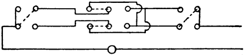
FIGURE 177.
In Figure 176, when both switches connect to the
same polarity the light is out; when one of them is
connected to the other pole the light burns. Under
certain conditions this arrangement is more economical
in wire but has the disadvantage which the other
method avoids, of bringing both poles to each switch.[303]
This method cannot be used with direct-current arc
lamps. Three-way switches are useful on stairways,
enabling one to turn on a light at the bottom of the
stairway and turn it off when at the top or vice
versa.
National Electrical Code Rules for Switches and Connections.
Switches.
Must be placed on all service wires, either overhead
or underground, in the nearest readily accessible
place to the point where the wires enter the building,
and arranged to cut off the entire current. Departure
from this rule may be authorized only under special
permission in writing. Switches controlling emergency
lighting must be located only in the lobby.
Must when used for service switches, indicate, on
inspection, whether the current be “on” or “off”.
Switch cabinets must be deep enough to allow the
door to be closed when 30 ampere branch-circuit
switches are in any position, and when larger single-throw
switches are thrown open as far as their construction
and installation will permit.
Must, for constant-current systems, close the main
circuit and disconnect the branch wires when
turned “off”; must be so constructed that they shall
be automatic in action, not stopping between points
when started, and must prevent an arc between the
points under all circumstances. They must indicate
whether the current be “on” or “off”. Service cut-out
and switch must be arranged to cut off current
from all devices including meters.
Must always be placed in dry, accessible places,
and be grouped as far as possible. Single-throw knife[304]
switches must be so placed that gravity will not tend
to close them. Double-throw knife switches may be
mounted so that the throw will be either vertical or
horizontal as preferred, but if the throw be vertical
a locking device must be provided, so constructed as
to insure the blades remaining in the open position
when so set.
When practicable switches must be so wired that
blades will be “dead” when the switch is open.
When switches are used in rooms where combustible
flyings would be likely to accumulate around them,
they must be enclosed in dust-tight cabinets.
Up to 250 volts and thirty amperes, approved indicating
snap switches are suggested in preference
to knife switches on lighting circuits.
Single-pole switches must never be used as service
switches nor for the control of outdoor signs
or circuits located in damp places, nor placed in the
neutral wire of a three-wire system, except in the two-wire
branch or tap circuit supplying not more than
660 watts.
Where flush switches or receptacles are used,
whether with conduit systems or not, they must be
enclosed in an approved box constructed of iron or
steel, in addition to the porcelain enclosure of the
switch or receptacle.
Hinges of knife switches must not be used to carry
current unless they are equipped with spring washers,
held by lock-nuts or pins, or their equivalent, so arranged
that a firm and secure connection will be
maintained at all positions of the switch blades.
Spring washers must be of sufficient strength to
take up any wear in the hinge and maintain a good
contact at all times.
[305]
Connections.
Switches for currents of over thirty amperes must
be equipped with lugs, firmly screwed or bolted
to the switch, and into which the conducting wire
shall be soldered. For the smaller sized switches
simple clamps can be employed, provided they are
heavy enough to stand considerable hard usage.
Where lugs are not provided, a rugged double-V
groove clamp is advised. A set screw gives a contact
at only one point, is more likely to become loosened,
and is almost sure to cut into the wire. For the
smaller sizes, a screw and washer connection with up-turned
lugs on the switch terminal gives a satisfactory
contact.
Spacings.
See “Panel Boards”.
Switchboards.
Switchboards.—The stage switchboard is usually
located on the right-hand side of the stage. This position
enables the operator to watch cues easily and
handle his switches with the right hand. This side
is also the one from which the stage manager prefers
to work. It is preferable to have the board raised
high enough above stage level to allow all space on
the stage to be used by actors. If the switchboard is
located on stage level it takes up much room that is
valuable and makes stage exits for actors difficult.
The wiring of a good switchboard should be divided
into three parts, each part independent of the
others, so that any one part can be entirely cut off
without interfering with the other. All of the house
lights should be fed through one main switch, and all
of the stage light connected to another set of bus-bars,
but it is best not to have the stage side of the[306]
board as a whole controlled by a main switch. If the
stage side of the board is controlled by a single switch
there exists the possibility that this switch may be
used to cut off everything for a dark scene and when
light is again wanted a part of the lighting of the
previous setting may be left on and possibly interfere
with the new scene.
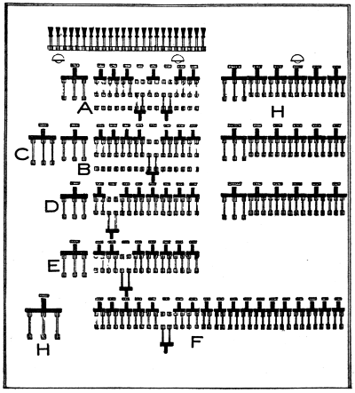
FIGURE 178.
The stage lighting is usually divided into four
groups, viz.: three color groups and a group of stage[307]
pockets. The number of white lights is usually equal
to that of all of the colors.
Figure 178 shows a well laid out switchboard. All
of the lights in the auditorium are controlled by
switches shown in the upper right-hand corner and
all of these are under the control of the main switch.
The house lights are usually thrown on or off as a
whole and this main switch must be convenient for
the operator.
The stage pockets are controlled by the bank of
switches shown at E. Lights burning off the stage
pockets generally are controlled by special operators
on the stage or by actors, and need not be so very
convenient to the switchboard operator. They must,
however, be under his control when necessary; but
here also a main switch is not advisable.
In addition to the three groups of lights spoken of
above, there are a number of lights which should be
controlled from the switchboard but must be so connected
that they will be left on, no matter what is
done with either house or stage light.
In this group belong a few lights mounted at the
top of the switchboard which enable the operator to
see his switches when all else is dark. These lights
are generally shielded so as to throw no light in the
direction of the stage opening. The orchestra lights
also belong in this group, but a special switch may,
with advantage, be arranged on this circuit to bring
it under the control of one of the musicians. In some
dark scenes these lights are turned out for a short
time, but it is very important that they be turned on
again at the proper moment, and this is more certainly
assured, by giving the musicians control, than by[308]
leaving it to an electrician on the stage who may be
very busy with other matters at the time.
The lights on the fly floor and in the rigging loft,
as well as those in dressing rooms and basement, must
also be independent. Fan motor circuits should also
be independent of the house circuit. They are often
needed when the house lights are thrown off.
With the switchboard illustrated in Figure 178 we
have shown only the switches governing the house and
stage proper. The switches governing the other lights
are usually worked into the vacant spaces between
the two groups. Each switch should be labeled in
such a manner that a new operator can learn the
board easily.
The most important part of the board is that part
governing the stage lighting, and this should always
be placed as conveniently as possible to the operator.
A stage switchboard is like a house in that no one is
wholly satisfied with the one he has, but thinks he
could improve it a little if he could build it over
again. The arrangement shown in Figure 178 is,
however, quite satisfactory for general purposes. The
white lights predominate in the ratio of two to one
and are laid out in two groups A and B. Both groups
are controlled by the switch C. The switches A and
B do not control the lights at all if the smaller throw-over
switches at the right are thrown downward. A
diagram of these switch connections is given in Figure
179 where the switches B and C are indicated.
The object of the switches A and B is to help in quickly
increasing or decreasing the illumination on the stage.
If in the beginning of a certain scene, for instance,
only a small quantity of light is wanted, while a little
later full illumination is desired, the low illumination[309]
may be obtained by throwing the proper switches
down; the additional illumination which will be
needed a few minutes later may be prepared for by
setting the other switches needed to the upward position
and at the proper moment closing switch B; this
will instantly produce the effect which otherwise
would be possible only by operating a number of
switches in succession. In the same way, by a reversal
of this process, the illumination may be reduced
in any amount. This feature is very valuable
in many stage settings.
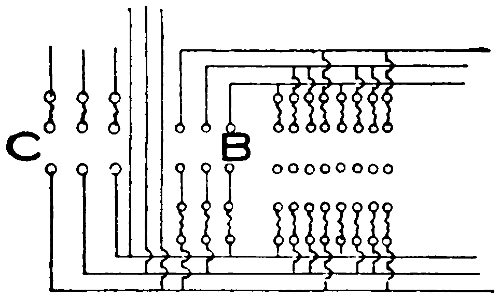
FIGURE 179.
To throw off all of the white lights the switch C
must be opened. The switches D and F are main
switches controlling colored lamps. All lamps of one
color should be connected to one or the other of these
groups unless some special color effect is desired.
From the three groups of switches, circuits extend
into the foot lights, into every border, and into the
proscenium side-light strips so that the color scheme
may be carried out in any of these.
The handles of all switches in a row should be of
the same height so that the operator may more readily
accustom himself to catch them quickly. It is better
to have switches of some excess capacity, as the heavy[310]
metal stands the arcing much better.
A main switch by which the whole board may be
cut off should be installed but this need not be on the
front of the board.
[311]
CHAPTER XIX.
PORTABLE STAGE EQUIPMENT.
The general rule is that all wires in theaters must
be in conduit or armored cable. Metal molding is not
considered suitable for the stage side of the theater.
There are, however, stage requirements which make
the use of some sort of flexible and portable connection
necessary and for such purposes stage cables are
allowed. All wiring that can be permanently fastened
to battens or fastened in other ways; or that is run
inside of posts or statuary, must be in conduit or
armored cable.
The National Electrical Code Rules are quoted in
this chapter wherever they apply and should be followed,
not only because these rules outline the best
practice but because, throughout the country, inspections
will generally be governed by these requirements.
Even where the local rules vary somewhat
from these rules, it will be found that all apparatus
constructed according to them will be favored to a
considerable extent.
Anvil Sparks.
Anvil Sparks.—These are sometimes produced by
arranging the anvil as one pole of a circuit and the
hammer as the other. When the hammer leaves the
anvil, the spark occurs. A resistance must always
be inserted in the circuit if a light or power circuit
is employed. One of the most successful methods of
producing anvil sparks is shown in Figure 180. When
the hammer strikes the anvil the spring follows and
strikes the head of the hammer; and when it rebounds[312]
the spark occurs. If it is not desired to use a power
circuit the spark may be obtained from batteries by
the use of a spark coil. Sparks in dueling scenes may
be produced in much the same manner.
In some cities the inspection laws require all arcs
or sparks, used on the stage, to be enclosed. So far
as the authors are aware no really satisfactory method
of enclosing anvil sparks has ever been made up. If
such an enclosure is to be constructed it must be
borne in mind that it must not spoil the illusion nor
mar the tone in case the anvil is tuned for use in
singing acts. A special combination of metals is on
sale at stage-supply dealers by which sparks can be
produced without the use of current.
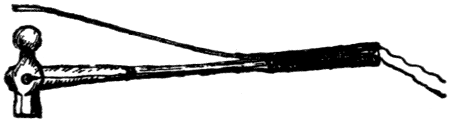
FIGURE 180.
Arc Lamps.
Arc Lamps.—In Figure 181, there is shown an open
or flood lamp, also known as the “Olivet”. This
style of lamp is used on the stage only for general illumination.
As the light from this lamp spreads in
all directions it must be brought close to the part to
be illuminated and this usually brings it close to the
scenery.
All portable stage lamps are hand feed and require
close attention on the part of operators. While traveling
it sometimes occurs that only high voltage such
as 500 or 600 volts is available and in such a case a
suitable number of lamps must be connected in series.
Hand-feed arc lamps are difficult to start under such
circumstances and the following method is often resorted
to: Place the carbons of all the lamps connected[313]
in series the proper distance apart and connect
a small fuse across each gap. When the current
is turned on it will melt the fuses and establish the
arc.
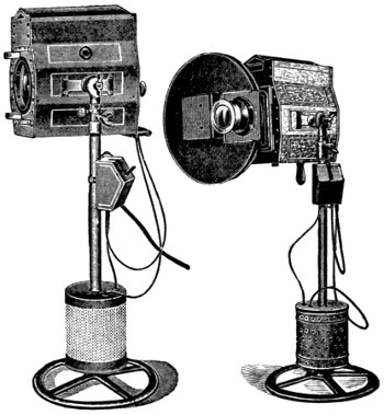
FIGURE 181.FIGURE 182.
In Figure 182 we have an illustration of what is
known as the spot or lens lamp. This style of lamp
is used on the stage, on bridges, or “in front” (in
front being the term by which the balcony or galleries
are designated in this case). In the figure a
“Sciopticon” attachment is shown which is removable.[314]
Even very unpretentious shows carry at least
one spot lamp and the largest shows often carry 30
or 40 open and spot lamps. Arc lamps are often
imitated by an incandescent lamp placed within a
suitable globe with the hood made up in the shape
of an arc lamp.
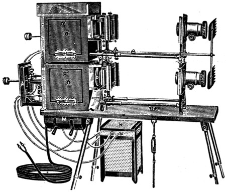
FIGURE 183.
Figure 183 is a cut of a stereopticon outfit. Dissolving
views require at least two lamps and sometimes
three, the third being for the purpose of providing
a frame for the views or adding an extra effect,
such as falling snow. Two lamps at least are always
in use at the same time and it is necessary to provide
cables of sufficient carrying capacity for two or three
lamps, as the case may be.
[315]
The National Electrical Code Rules for Arc Lamps to be Used on the Stage.
Must be constructed entirely of metal except where
the use of approved insulating material is necessary.
Must be substantially constructed, and so designed
as to provide for proper ventilation, and to prevent
sparks being emitted from lamps when same
are in operation; and mica must be used for frame
insulation.
Front opening must be provided with self-closing
hinged door frame, in which wire gauze or glass
must be inserted, except in the case of lens lamps,
where the front may be stationary, and a solid door
be provided on back or side.
Must be so constructed that neither carbons nor
live parts will be brought into contact with metal
of hood during operation, and arc-lamp frames and
standards must be so installed and protected as to
prevent the liability of their being grounded.
Switch on standard must be so constructed that
accidental contact with any live portion of same will
be impossible.
All stranded connections in lamp and at switch
and rheostat must be provided with approved lugs.
Rheostats must be plainly marked with their rated
capacity in volts and amperes, and, if mounted on
a standard, must be raised to a height of at least
three inches above the floor. Resistance must be enclosed
in a substantial and properly ventilated metal
case which affords a clearance of at least one inch
between the case and the resistance element.
A competent operator must be in charge of each
arc lamp, except that one operator may have charge[316]
of two lamps, when they are not more than ten feet
apart and are so located that he can properly watch
and care for both lamps.
Each lamp should be provided with its own fuses
and switch.
Baby Spot Lamp.
Baby Spot Lamp.—This is the name given to a
small lens lamp in which an incandescent lamp is
used instead of an arc lamp. Such a lamp cannot
be used for projection very well but is well suited to
illuminate parts of an act that do not require very
bright illumination. It is sometimes used to take
the place of proscenium side lights. In one well-known
production twelve such lamps were used upon
scaffolding directly above the proscenium opening.
The incandescent lamp is movable for the purpose of
focusing; but it not being a “point source”, no such
accurate focusing is possible as with arc lamps.
Batteries.
Batteries.—Both primary and secondary, or storage,
batteries are extensively used upon the stage.
Small dry cells are often used to ring bells or light
miniature lamps in the hair or clothes of the chorus.
The electromotive force of a cell is independent of
the size and depends only upon the materials used;
but the current which a battery can deliver varies directly
with its size. If we wish to increase the voltage
we must connect several cells in series, as indicated
in Figure 184; if we have sufficient voltage but lack
current we must connect, as in Figure 185. As a general
rule, in any circuit, we must connect the battery
so that its resistances shall most nearly equal the resistance
of the device which it feeds. This means that
if the resistance of the device is greater than that of
the battery we must connect our battery in series; if[317]
it is less we must connect the cells in multiple, as indicated
by Figure 185.
When connecting cells in multiple those of the same
kind should always be selected. Any cell whose electromotive
force is not fully equal to the others will
absorb energy and be charged by the others. The resistance
of small cells is high and it is best, where
size is not objectionable, to use large cells. Storage,
or secondary batteries, have low resistance and are
capable of delivering very strong currents, even
though the voltage be low. The heat is proportional
to the square of the current and a certain amperage,
with two volts back of it, will produce just as much
heat in given resistance as the same amperage with
several hundred volts. The sparking in case of a
broken circuit or a fuse blowing would, however, be
hardly noticeable with the low voltage.
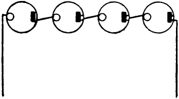
FIGURE 184.
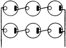
FIGURE 185.
No definite rule is given concerning the fusing of
low-voltage storage batteries, but it is good practice
to insert a double-pole fuse in each branch circuit;
the fuse to be small enough to protect the smallest
wire fed through it. The capacity of storage batteries
is usually given in “ampere hours”. A 60-ampere-hour
battery, for instance, can deliver three
amperes for twenty hours or ten amperes for six
hours. With every battery there is, however, a certain[318]
maximum rate of discharge which should not be
exceeded. The battery should not be allowed to run
down too low and should be kept well charged. It is
best to follow the instructions which the makers send
out with them.
Bells.
Bells.—Electric bells are used on the stage for
many purposes. Sometimes they are used as musical
instruments, the gongs being properly tuned; at other
times they are provided to ring in connection with
certain acts; and they are also used for the purpose
of signaling. When signals are to be given, which
the audience must not hear, it is better to provide
buzzers.
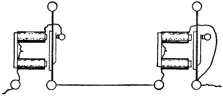
FIGURE 186.
Bells can be arranged to operate from power circuits
by placing an incandescent lamp, or some other
suitable resistance, in series with them; but it is not
advisable to do so. It is not safe from a fire-hazard
point of view, and also not very practical, since in
many places alternating current only can be had and
the ordinary bell does not operate well with it. Batteries
should always be used for bells and other low-voltage
devices.
Where it is desired to operate a number of bells
together, they may be arranged in series, as shown
in Figure 186, in which the vibrator of one bell is[319]
cut out of circuit so that the vibrations of this bell
are governed by those of the other. Sets of bells
properly tuned are often scattered about and controlled
from a keyboard. There are usually eighteen
bells in such a set.
Blinding Lights.
Blinding Lights.—In certain acts it is necessary for
the actor to work part of the time unseen by the audience.
This may easily be arranged for by the use of
a number of bright lights placed between him and
the audience. These lights, when burning, blind the
audience so that they cannot see beyond them. The
lamps must be placed in reflectors which throw all
light toward the audience. They are arranged either
upon the floor of the stage or around cabinets or other
devices. The blinding effect depends upon the contrast
between the front and the rear of the lamps.
Lights should be very bright but the quantity of light
must not be sufficient to cause reflected light from
the front to illuminate the back of the stage. Where
emergency lights are kept burning during the performance
it is quite difficult to carry out the blinding
effect for any considerable length of time.
Brackets.
Brackets.—Brackets are made up in any of the
three ways shown in Figure 187. If the stem is large
enough to admit the cable, which should be used to
the pin-plug connector, no splice of any kind will be
necessary. If the bracket stem is too small for this,
fixture wire must be used and a connection from it to
the cable must be made. If this is made, as at the
extreme right, the back of the canopy must be enclosed
in substantial metal. On no account should fixture
wire be allowed to extend outside of the stem.
The bracket must have some provision by which it
can be made to hold its proper position when in place.[320]
Sometimes hooks are provided for this purpose and
at other times it is held in place by screws in the
scenery, as suggested by the back of the canopy shown
at A.
National Electrical Code Rule for Lights on Scenery.
Where brackets are used they must be wired entirely
on the inside; fixture stem must come through
to the back of the scenery and end of stem be properly
bushed.
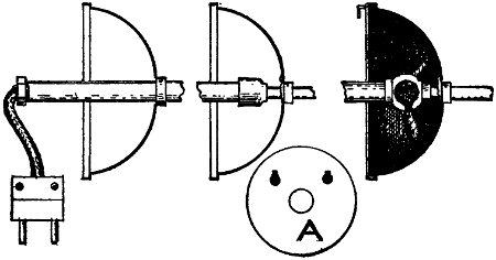
FIGURE 187.
Bunch Lights.
Bunch Lights.—Bunch lights are made up according
to the plans shown in Figure 188. They are used
only on the stage. No very brilliant illumination can
be obtained from them. In one well-known production
a bunch light containing one hundred 32 c.-p.
lamps was used without obtaining the result desired.
The light cannot be concentrated as can that from
arc lamps. Bunch lights, however, have the advantage
of not requiring so much attention as arc lamps
and can often be used on a shallow stage where arc
lamps would be out of place. Bunch lights are sometimes[321]
made double, two on one stand; two colors can
thus be used at the same time and certain color
changes facilitated. Color effects or changes in colors
are brought about by inserting colored gelatine slides
in front of the lights.
National Electrical Code Rules for Bunch Lights.
Must be substantially constructed of metal and
must not contain any exposed wiring.
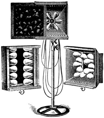
FIGURE 188.
The cable, feeding same, must be bushed in an
approved manner where passing through the metal,
and must be properly secured to prevent any mechanical
strain on the connection.
Chandeliers.
Chandeliers.—The rule which requires all wiring
about brackets to be enclosed, naturally would apply
here also. In connection with chain fixtures, which[322]
are at present very popular, this requirement is generally
overlooked if good reinforced cord is used.
Ordinary fixture wire or flexible cord should not be
used. The weakest part of a chain fixture is indicated
in Figure 189 by the arrow. The opening at this
place is, as a rule, too small and not well reamed out.
Fixtures used on the road are constantly giving way
at this point. The opening should be large enough to
pass reinforced cord and should be well reamed out.
If the opening cannot be made large enough to give
the wire a little free movement, it is advisable to wrap
tape around the wire and the metal in such a way as
to prevent all motion of the wire at this point. The
same observations also apply to the other end where
the cord enters the socket.
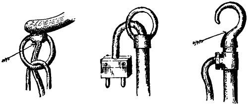
FIGURE 189.FIGURE 190.FIGURE 191.
Another frequent source of trouble with chandeliers
is found at the end of the stem where connection
is made to the cable which feeds the fixture. See
Figure 190. Very often fixture wire is brought out
here, but this will soon break. The stage cable, or reinforced
cord, should be run down to the bottom of
the fixture and connections there made to the wires
leading to the various arms. There are many fixture[323]
hooks made up after the manner shown in Figure 191
which have a small opening for the wire at the point
indicated by the arrow. This opening is always too
small and in such a case it is best to arrange a tee as
shown. A chandelier must always be hung in such a
manner as to avoid strain coming on the electrical
conductors.
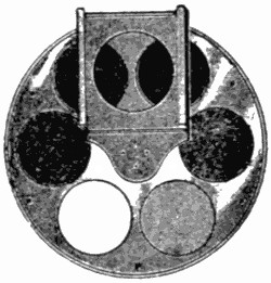
FIGURE 192.
Colors.
Colors.—Where a certain color is wanted, during
the whole show, from a certain light source, the incandescent
lamps themselves may be colored. Prepared
colors for this purpose are on the market and
it is best to use them. Where the colors in a scene
change rapidly there must be some colored material
available which can be quickly interposed between
the light and the scene. The manner in which this is
done for bunch lights is indicated in Figure 188. The
same method is also used in connection with open-arc
lamps, but for spot lights there is another method,
shown in Figure 192. This is a so-called color wheel
and the colors can be changed by simply revolving
the wheel until the proper color is in front of the
lens. An automatic color wheel is on the market
which allows the operator to control colors at a distance
by means of an electric circuit and magnet.
This device cannot be used with flood lamps and has[324]
the further disadvantage of casting unavoidable
shadows during the change of colors. Where detachable
color holders are used, it is possible to change
from one color to another by almost imperceptible
degrees by holding the frame in the hand and bringing
it gradually from a distance to the front of the
lamp. In this manner the shadows cast by the frame
can be avoided and the color brought very gradually
into the scene.
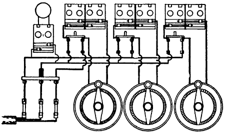
FIGURE 193.
Dimmer Box.
Dimmer Box.—The dimmer box, as the name implies
is a box which contains the resistances required
for dimming lights used on the stage. It comes into
service only with the more pretentious shows which
carry foot-lights or border-lights. A typical wiring
diagram is shown in Figure 193. This diagram supposes
that not more than three colors are used. A
small candle power incandescent lamp should always
be installed in the box so that the operator may see
what is necessary in dark scenes. This lamp should
have its own fuse protection. This is a point very
often overlooked by operators. The box is usually[325]
made of wood and lined with metal. It should be
deep and nearly square, so as to occupy a minimum
of space. If a shallow box is used, it will be necessary
to place the switches in a separate compartment
from the fuses, so that the latter may be always
enclosed, even while the dimmers and fuses are being
operated.
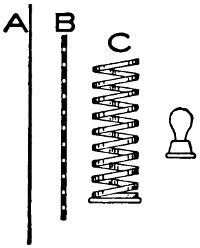
FIGURE 194.
Provisions should be made for the cables to lead
out through suitable bushings at the side instead of
over the top of the box as is so often done. In some
dimmer boxes the slip connectors are fitted into the
side of a box so that the male end may be inserted
from outside. This makes it unnecessary to bush the
cables through the box.
Electric Sign Imitations.
Electric Sign Imitations.—These are used mostly
in representations of city night scenes. A flasher sign
can be imitated by cutting small round holes in the
curtain to outline the reading matter on the sign.
Behind these holes a moon box is placed, the lamps
in it being on a flasher or controlled by “skeedoodle”
sockets, thus giving the effect of an electric sign on[326]
a flasher. In case the effect of a steady burning
sign is wanted the flasher is omitted.
Electric signs imitating falling water have in turn
been imitated according to the plan outlined in Figure
194. On the side nearest the audience is the
curtain A, upon which the sign is painted and in
which there are a number of holes representing the
electric lamps in the original sign; behind this curtain
is a grating B, also full of holes; and behind this
revolves a spiral C, so arranged as to obstruct intermittently
the light which is behind it. The object is
to imitate, as nearly as possible, the action of the
lights in the original sign.
Electric Stage Effects.
Electric Stage Effects.—A large number of stage
effects can be produced by properly painted mica
discs which are caused to move in front of the lens of
a spot light arranged for the purpose. A view of such
a contrivance is given in Figure 182 and is known
as the “Sciopticon”. The effects are changed by
clockwork which is adjustable as to speed. The device
is arranged to slip in front of the lenses and can
be attached in a moment.
A list of some of the effects obtainable is given
below:
- Avalanche
- Climbing monkeys
- Cyclone with flying objects
- Falling leaves
- Fireworks
- Flame
- Flowing water
- Flying birds
- Lightning
- Moving clouds
- Niagara Falls
- Ocean waves
- Rainbow
- Rain
- Rising fire and smoke
- Rolling lava
- Sand storm
- Snow storm
- Swimming fish
- Twinkling stars
- Volcano
- Water falls
The above list is given to illustrate the possibilities
of this method of producing effects. They are, however,[327]
rather expensive and some of them require several
machines to be in operation at the same time.
Explosions.
Explosions.—Nearly all explosions are set off by
the melting of a fuse through an electrical short circuit.
The explosive powder is placed above, encloses
the fuse, and is ignited when the fuse blows.
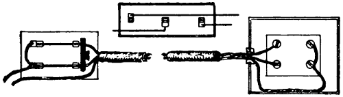
FIGURE 195.
Such explosions are often forbidden by inspectors
but there is no danger from them if the powder, etc.,
is enclosed in a suitable wire mesh open on all sides.
This will not interfere with the explosion and will
prevent the flame, which lasts but an instant, from
coming in contact with scenery or people. Where
such explosions are used they are generally the most
important part of the act, and every possible precaution
must be taken to avoid the chance of failure.
They are, therefore, often arranged on two circuits
with a throw-over switch so that in case one fuse fails
the circuit can be immediately closed on the other.
See Figure 195. It requires some time to throw-over
a switch, and in order to make doubly sure that the
fuse will blow at the right time, two fuses and two
separate wires may be used and connected at the same
time by a simple double-pole switch. The latter arrangement
has the disadvantage that one of the wires
might be broken, or the contacts bad, without the defect
ever being noticed until the other wire also fails
and the explosion misses entirely.
[328]
It is best to use the throw-over switch and to use
the wires for the first connection in alternation so
that a defect may be noticed at once. If the same
wire were used each time the throw-over switch would
be open to the same objection as the double-pole
switch. In selecting fuses for this work it must be
borne in mind that the powder which is placed over
the fuse has a certain cooling and conducting effect,
and that often, therefore, a fuse which would
readily blow if in the open would not blow if covered
with metallic powder.
Face-O-Graph.
Face-O-Graph.—This is an arrangement of two
powerful arc lamps with the necessary lenses and
objective by which the face of an actor can be projected
upon a screen. This effect is very trying to
the face and eyes of the actor. The face must be
brought very close to the arc lamps and must be held
upside down during the performance. From forty
to fifty amperes are used in each arc lamp. The
optical principle is explained in another chapter.
Festoons.
Festoons.—Festoons should be made up as shown
in Figure 196. Weatherproof sockets are generally
used because the common brass shell sockets have too
many parts that are liable to work loose on account
of the constant handling the festoons are subjected
to with traveling productions. The use of porcelain
sockets, however, should be avoided; mica sockets
seem to be generally preferred. The soldering also
should be carefully done and only at the end, as
indicated by the arrow in the cut. The branch
wires are often taped to the main cable as indicated,
but often also, circular loom is slipped over the cable
in such a manner that the branch wires are supported
by it. Short lengths of loom must be slipped[329]
on the cable before the tapes are made. A really well
made festoon will last a long time and give very
little trouble; while a poorly made one will cause
much annoyance and much unfavorable comment
from inspectors. Most of the festoon troubles are
due to poor support of the branch wires. A single
festoon does not often carry more than ten or twelve
lights and usually not more than six or eight.
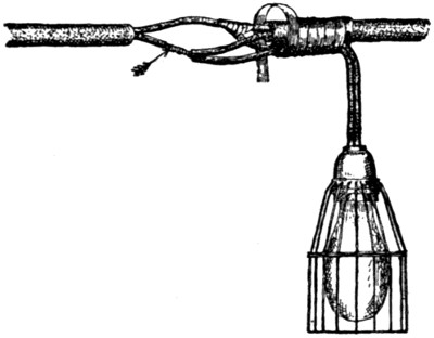
FIGURE 196.
A certain style of shade is very much in vogue in
connection with festoon lamps and this shade makes
the use of lamp guards impossible. If the shade is
made of gelatine there will be but little need for the
guard, but celluloid shades should not be allowed.
All combustible material that is to come near the
lamp or the socket should be fireproofed.
The National Electrical Code Rule for String or Festooned Lights.
Wiring of same must be of approved type; joints
to be properly made, soldered, and taped, and staggered
where practicable. Where lamps are used in[330]
lanterns or similar devices, approved guards must
be employed.
Fire Dance.
Fire Dance.—This effect is generally illuminated
from below the stage, the light being thrown upward
through glass. Special arc lamps, equipped with
powerful reflectors, are often used and generally several
of them are required to produce the proper effect.
If spot lamps are to be used they should not
be turned upward but instead reflectors placed at an
angle of forty-five degrees, should be provided to
throw the light upward. See Figure 197. If a spot
lamp is turned upward, the heat of the arc rising will
be great enough to make condenser breakage a very
serious problem. It is also difficult to keep a horizontal
arc working properly.
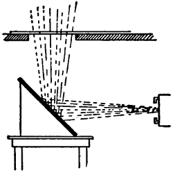
FIGURE 197.
Fireflies.
Fireflies.—The “fireflies” are miniature incandescent
lamps strung about among the scenery and on
the clothing or in the hair of performers. No attempt
should be made to operate these from any
other source than a low-voltage, low-amperage battery.
It is best to subdivide them as much as possible
to avoid short circuits. A short circuit on one lamp
would put out a group of one hundred as quickly as[331]
it would ten. Such lamps are often arranged on a
keyboard by which single lamps or small groups may
be lighted intermittently, thus giving the effect of
fireflies flitting about.
Fireplaces.
Fireplaces.—The commonest and best fireplace is
made up of a few lights arranged in regular strip
fashion, the strip being placed in a practical fireplace
filled with coal or large pieces of glass, such as broken
pieces of lenses. For a very simple effect, red colored
globes are used. The effect can be enhanced by
using lamps of amber, red, and white and connecting
each lamp to a dimmer which can be worked off the
stage. This is capable of producing a flaming effect.
A further enhancement of the effect is sometimes produced
by placing colored asbestos about the lights.
This or other suitable material can be made to represent
glowing ashes very nicely. Very often the illumination
of the fireplace is by means of colored
globes strung about among the logs. For this purpose
they must be equipped with strong guards and
wired with stage cable. Actual gas flames are also
often mixed in with the electric illumination. In a
mechanical way the effect of flame is often imitated
by colored cloth so arranged that a small fan motor
placed beneath it can blow it upward.
In a certain well-known production, an imitation
of the crater of a volcano is made by arranging a
number of fan motors under a large piece of silk
which rests upon a frame and revolves over the
motors. Parts of this silk are provided with pockets
and are loose so that they may be blown upward to
represent flame while the major portion only undulates,
representing a sea of molten lava. Strips with
red lights are used to intensify the effect.
[332]
A small motor operating a suitable ratchet has
been used to imitate the sounds of wood crackling in
the fire. “Chemical smoke” is also often used to enhance
the effect. This can be purchased of supply
houses.
Flat Irons.
Flat Irons.—See “Heaters”.
Flowers.
Flowers.—On the vaudeville stage, electrically
lighted flowers are sometimes used. These are often
wired by simply running fixture wire or flexible cord
along a wire stem and fastening a small socket to it.
Flowers lighted in this manner, however, will not be
allowed in theaters where there is inspection. A
better method is shown in Figure 198. Armored cord
is used for the stem and a miniature socket is placed
at the end. All splices are within the junction box
which supports the stems. Instead of the armored
cord ordinary fixture tubing may be used. Baskets
of flowers and small bouquets are generally lighted
from batteries.
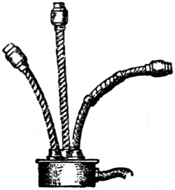
FIGURE 198.
Fountains.
Fountains.—The illumination for electrically
lighted fountains is sometimes obtained from incandescent
lamps, but no very showy effects can be produced[333]
with them. Where they are used in a manner
which subjects them to moisture they must be wired
in waterproof conduit and fittings and the lamps must
be covered by a watertight globe. For brilliant effects
arc-lamp illumination is necessary and the arc
must of course be below the water. As arc lamps
when tilted upward break condensers very rapidly,
the light is usually reflected upward by means of
mirrors set as indicated in Figure 197.
Fuses.
Fuses.—There is no part of the electrical equipment
of a traveling production so much abused as
the fuse. It is provided primarily for the protection
of apparatus and should never be of greater capacity
than is needed to carry the load put upon it. There
is nothing whatever gained by the use of larger fuses.
If the load is not in excess of six amperes, a six ampere
fuse will carry it as readily as a twenty ampere fuse.
If a short circuit occurs the twenty ampere fuse will
blow as readily as the six ampere fuse and, in addition,
will cause destruction of a socket or whatever
may be the cause of the trouble as well as an increased
fire hazard. Notwithstanding the above, it is a rare
exception when one finds the circuits of a traveling
outfit properly fused. For this there are two reasons.
One is that, owing to frequent handling and moving,
fuses work loose; and thus, to the natural heat produced
by the load, there is added a certain amount of
heat produced in the poor contacts. Trouble of such
a nature can be lessened by the use of larger fuses,
but only to a very small extent. It is far better to
go over one’s fuses two or three times a week and
tighten the screws and contacts to avoid this trouble
than to use over-large fuses.
Another reason for the overfusing, of plugging[334]
boxes especially, is found in the fact that arc and incandescent
plugs are interchangeable. If, therefore,
each circuit is fused at thirty amperes one need not
worry about which pocket an arc lamp is connected
to. This practice is, however, very bad, a table
lamp, for instance, with a thirty-ampere fuse behind
it would be likely to cause flash and smoke enough
to alarm an audience. Some provisions should be
made so that one can easily distinguish between arc
and incandescent pockets or divisions in plugging
boxes. The main requisite which determines the
style of fuse to be installed for stage effects is that
of quick renewal in case of blow-out.
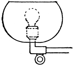
FIGURE 199.
Gas Globes.
Gas Globes.—Electric light is so convenient on the
stage that even gas light is imitated by it. In one
production in which it was desirable to show the
front of a theater illuminated by gas, the gas globes
were made up of cloth cut as shown in Figure 199.
Behind each imitation globe a small incandescent
lamp was arranged.
Glass Shades.
Glass Shades.—An imitation of these for small desk
or table lamps is often made by placing a strip of
colored gelatine between two layers of wire mesh.
The wire screen keeps the gelatine straight and the
whole is more serviceable than glass and less liable
to break.
[335]
Heaters.
Heaters.—Under this head come flatirons and water
heaters. Flatirons are carried by many actors who
cause much trouble by connecting them to lighting
circuits. In many places the house electrician prevents
their use by fusing his lighting circuits so low
that the addition of a flatiron immediately blows the
fuse. If used at all, the flatirons should be of the
smaller kind. Small heaters are also extensively used
upon the stage.
National Electrical Code Rule for Electric Heaters.
It is often desirable to connect in multiple with
the heaters and between the heater and the switch
controlling the same, an incandescent lamp of low-candle
power, as this shows at a glance whether or
not the switch is open, and tends to prevent its being
left closed through oversight.
Must be protected by a cut-out and controlled by
indicating switches. Switches must be double-pole
except when the device controlled does not require
more than 660 watts of energy.
Must never be concealed; but must at all times
be in plain sight. Special permission may be given
in writing, by the Inspection Department having
jurisdiction, for departure from this rule.
Flexible conductors for smoothing irons and sadirons
and for all devices requiring over 250 watts
must have an approved insulation and covering.
For portable heating devices the flexible conductors
must be connected to an approved plug device,
so arranged that the plug will pull out and open
the circuit in case any abnormal strain is put upon
the flexible conductor. This device may be stationary,
or it may be placed in the cord itself. The cable or[336]
cord must be attached to the heating apparatus in
such a manner that it will be protected from kinking,
chafing, or like injury at or near the point of connection.
Smoothing irons, sadirons, and other heating appliances
that are intended to be applied to inflammable
articles, such as clothing, must conform to the
above rules so far as they apply. They must also be
provided with an approved stand, on which they
should be placed when not in use.
Stationary electric heating apparatus, such as radiators,
ranges, plate warmers, etc., must be placed
in a safe location, isolated from inflammable materials,
and be treated as sources of heat. Devices of
this description will often require a suitable heat-resisting
material placed between the device and its
surroundings. Such protection may best be secured
by installing two or more plates of tin or sheet steel
with a one-inch air space between or by alternate
layers of sheet steel and asbestos with a similar air
space.
Must each be provided with name-plate, giving the
maker’s name and the normal capacity in volts and
amperes.
Lighthouse Effect.
Lighthouse Effect.—To increase the effect of a lighthouse
painted upon the scenery, a strip of suitable
length with one light at each end is provided. The
strip circuit contains a flasher so that both lights are
turned on and off at regular intervals. One lamp
must be behind the head of the lighthouse, the other
where the reflection of the upper light would appear
in the water.
Lightning.
Lightning.—The standard method of producing
lightning effects upon the stage is by means of the[337]
device shown in Figure 200. A magnet and the arc-striking
carbons are arranged in series and take current
through a resistance. Normally the carbons are
in contact and when the switch is closed the current
passes through the magnet and carbons. The current
energizes the magnet and causes the upper
carbon to separate from the lower, thus striking the
arc. The arrangement must be such that the arc is
immediately broken, thus de-energizing the magnet;
this allows the movable carbon to close the circuit
again, thus repeating the operation. This device if
uninterrupted will give a rapid succession of lightning
effects and it may be suspended in the wings as
it is entirely automatic. At the right of Figure 200
is shown another lightning striker which is operated
by hand.
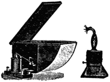
FIGURE 200.
Where it is not prohibited, a very good lightning
effect can be obtained by arranging a file and a piece
of carbon as opposite poles of the circuit and scraping
them together. It is a bad practice, however, to
strike an open arc on any stage. There should always
be wire mesh around it to prevent the escape
of sparks.
Automatic strikers can be purchased which will[338]
make an open arc lamp produce good lightning effects.
Another method of producing lightning is that
of flashing some of the border lights. This will do
in an emergency but does not compare with the other
methods. Sometimes the effect of a bolt of lightning
striking a certain place is imitated by an arc sliding
swiftly down a wire. In order to strike the arc at
the proper moment, the apparatus being somewhere
up in the flies, a small fuse is connected from one
carbon to the other. The current when turned on
passes through the fuse, melts it, and establishes the
arc. The carbons are incased in a very small wire-mesh
enclosure and the whole device is made to slide
swiftly down a tight wire leading to the proper place.
The more pretentious shows often use several lightning
machines to avoid the monotonous effect of all
lightning strokes coming from the same direction.
One resistance may be made to serve for any number
of lightning machines provided only one machine
is used at a time.
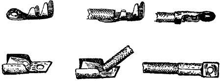
FIGURE 201.
Lugs.
Lugs.—Lugs must be provided for all leads where
more than 30 amperes are used. It is even more
necessary to follow this rule in connection with
portable theater equipment than with other wires
because they are more apt to work loose.
[339]
For the connections to the arc lamp and rheostats
it is not practicable to use soldered lugs because no
solder will stand the heat. Two styles of lugs that
may be used are shown in Figure 201. The cuts will
also explain the manner of connecting the lugs. At
the left, the bare lugs are shown; in the center the
copper of the conductors is shown inserted into the
lugs, and at the right the whole conductor is shown
bent back, the metal of the lug catching over the insulation
to keep it from fraying out. The wires feeding
arc lamps are always asbestos covered and this
covering fits loosely to the wire and must be held in
some such manner. A stock of such lugs should always
be carried, as the leading-in wires to arc lamps,
using heavy currents, frequently burn off.
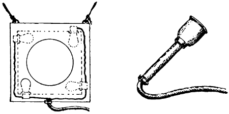
FIGURE 202.
Moon Boxes.
Moon Boxes.—These boxes are generally made up
as shown at the left in Figure 202. The opening is
from twelve to fourteen inches in diameter. Four
lamps give very good illumination. The frame must
be provided with hooks so that it may be suspended
at any desired part of the scenery. It is always hung
close behind a curtain and must be so arranged that
the lamps cannot touch the curtain. The wires should[340]
be entirely enclosed in metal of No. 20 sheet metal
gauge after the manner of strips. Very cheap productions
often carry moon boxes made up of an incandescent
lamp fastened in a tin dish, similar to the
one shown at the right in Figure 202.
Moonlight on Water.
Moonlight on Water.—This and all similar effects
can be produced through the “Sciopticon” but this
requires the use of an arc lamp and is expensive. A
cheap way of producing the effect is illustrated in
Figure 203, which represents a metal cylinder, perforated
as shown, inside of which there are a number
of incandescent lamps colored to suit. The cylinder
is slowly revolved and the moving shadows and
streams of light thrown upon the scene produce the
effect.
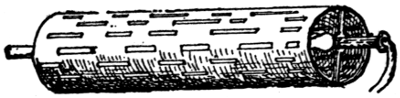
FIGURE 203.
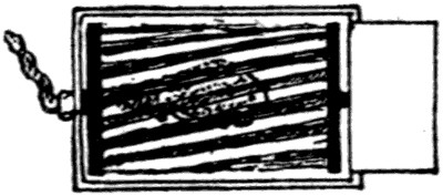
FIGURE 204.
A somewhat similar method of producing this effect,
as also that of a waterfall, is illustrated in Figure
204. In this case a spiral capable of being moved
by clock work is revolved about an electric lamp and
gives the effect of falling water. Both of these devices
work behind curtains.
Musical Acts.
Musical Acts.—There are numerous musical acts
upon the road in which the beat of the music is
emphasized by lighting colored lamps in time with[341]
the tunes. It is advisable to arrange all such acts
to operate by batteries. In many places inspectors
will not allow high-voltage contacts to be used open,
and it is often difficult to enclose them in a practical
manner. By using dry batteries the apparatus is
taken out of the jurisdiction of inspectors and all
danger of fire is also eliminated.
Musical Bells.
Musical Bells.—Sets of musical bells properly
tuned and connected to a keyboard from which they
can be operated electrically are carried in stock by
dealers in theatrical supplies. Sets are usually made
up of eighteen bells and they may be played from
a distance.
Oil Lamps.
Oil Lamps.—These have been imitated by arranging
a small battery inside of the base of the lamp.
This battery would supply current only during the
short time that the lamp was being carried about.
The base of the lamp is also fitted with electrical
contacts which rest upon similar contacts fitted into
the table, and through which the lamp is kept burning
by a storage battery while it is resting upon the
table. A small dry battery, such as is placed in the
base of an oil lamp, would not keep the light burning
for a long enough time.
Pin-Plug Connectors.
Pin-Plug Connectors.—These are provided to connect
cables to effects used on the stage. The essential
points of a good connector are: It should grip the
whole cable, thus making it unnecessary to strip the
outer braid from any exposed part of the cable; and
it should offer no live screws or contacts on the outside.
These conditions are fulfilled by the connector
shown in Figure 205. In some of these connectors,
however, the part that grips the cable (indicated by
the arrow) is made of metal, and this, if forced down[342]
too tight, may cut into the cable and cause a short
circuit. Several instances of this kind have been
known to occur. Pin-plug connectors must always be
connected so that the projecting pins are dead when
the plug is disconnected.
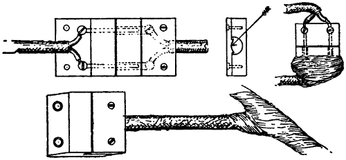
FIGURE 205.
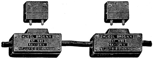
FIGURE 206.
A special warning against the use of such connectors
as are illustrated at the right of Figure 205
is necessary. Their cheapness brings them into use
very often, especially with acts that do not carry
competent electricians. The wires are always working
loose; projecting ends are bare, and if the connector
is twisted, a short circuit results. Where they
must be used in an emergency, they should be heavily
taped, the tape being placed between the conductors
and all around the plug, as shown in the figure.
[343]
Branch-off connectors such are shown in Figure
206 are often used to tap off lights from the main
cable. Where plug connectors are used for arc lamps
they must be made up as shown in Figure 207. The
asbestos-covered wires necessary to be used with arc
lamps cannot be used in cable but must be separately
connected.
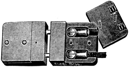
FIGURE 207.
The National Electrical Code Rules for Pin-Plug Connectors.
Must be of an approved type, so installed that the
female part of the plug will be on the live end of the
cable, and must be so constructed that tension on the
cable will not cause serious mechanical strain on the
connections.
Plugging Boxes.
Plugging Boxes.—Plugging boxes are used to obviate
the necessity of running a large number of wires
over the stage to the different stage pockets. They
are also a necessity because many theaters are not
equipped with a sufficient number of stage pockets to
accommodate all of the devices large productions
carry. The plugging box should be fireproof; should
have self-closing doors so that there may be no liability[344]
of open fuses being left among the scenery
where they are used. Most of the plugging boxes in
use at the present time are arranged for link fuses.
A link fuse, however, requires more time to install
than a cartridge fuse and the latter would therefore
seem much more desirable. A cut of a much-used
plugging box is shown in Figure 208.
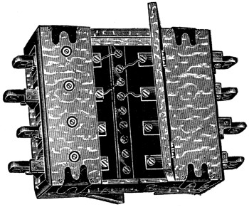
FIGURE 208.
The National Electrical Code Rules for Portable Plugging Boxes.
Must be constructed so that no current-carrying
part will be exposed, and each receptacle must be
protected by approved fuses mounted on slate or
marble bases and enclosed in a fireproof cabinet
equipped with self-closing doors. Each receptacle
must be constructed to carry thirty amperes without
undue heating, and the bus-bars must have a carrying
capacity equivalent to the current required for[345]
the total number of receptacles, and approved lugs
must be provided for the connection of the master
cable.
Rheostats.
Rheostats.—Portable stage equipment being intended
for use in all parts of the country must be
adjustable to all kinds of lighting systems. For this
reason it is not practicable to use auto-transformers
as is commonly the case where arc lamps are fed
from alternating-current circuits. Simple rheostats
or resistances are therefore always used. With these
it is immaterial whether the current be alternating
or direct except in so far as the quantity is concerned.
Alternating current being less efficient in the production
of useful light than direct current, the amperage
must be greater and this produces a greater loss
in voltage, the loss being always proportional to the
product of current times resistance. The drop in
voltage over a certain resistance is therefore always
greater, when an alternating-current arc is used, than
it is with direct; but as the alternating-current arc
operates at a lower voltage than the direct this is
not objectionable and simple resistances give satisfactory
results whether used with one kind of current
or the other. The traveling show must also be
prepared for different voltages and a suitably arranged
group of resistances is very convenient in
this respect.
Figure 209 shows a box made by the Chicago Stage
Lighting Company containing a number of resistances
which may be connected in various ways to obtain
different results. In Figure 210 at A is given a
diagram representing the wire in a single section.
One such section placed in series with an arc lamp
will give a certain current. If we connect two of[346]
them in parallel, as in B, we shall obtain not quite
double the current, since this arrangement does not
affect the resistance of the arc which also influences
the current strength. If the connections are made as
in C, we shall have but half the current obtainable
by the use of one section, or the same current in case
we are dealing with double the voltage. If A is
suitable for 110 volts, then C is suitable for 220 volts
and D for 550. In E we have the connection which
would give us, for 220 volts, the same current B
would give with 110. It can thus be seen that a group
of such resistances can be made to fit an arc lamp to
almost any voltage that is likely to be met with.
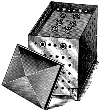
FIGURE 209.
Nothing but metal and porcelain must be used in
the construction of these resistances and they must
be on stands which raise them well above the floor.
The connections to the resistances should ordinarily[347]
be made with asbestos cable. It is necessary to
keep close watch of the wire used to make up the
resistance especially if it becomes very hot during a
run. A resistance in which the wire becomes red hot
should not be used. There are productions in which
it is necessary to place the arc lamps and their rheostats
directly in the way of flying paper used to make
“snow”. In such cases the resistances must be tightly
enclosed. This destroys the ventilation and they will
readily become overheated. For use with such productions
resistances may be specially wound and arranged,
or they may be made separate from the arc
and placed in a safe location.
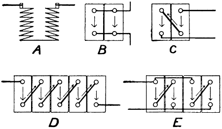
FIGURE 210.
Stage Cables.
Stage Cables.—Stage cables are subject to very
rough usage, but there are some very good makes on
the market, and by purchasing the best, one can expect
long service. Cuts of various kinds of cable
likely to be used upon the stage are given in Figure
211. A is the ordinary stage cable; B is used for
heaters; C is reinforced cord; and D is the parallel
cord. The last two must not be used on the floor.[348]
The size of the wire to be used depends upon the
apparatus which the cable must supply and can be
determined from Table VII which gives the carrying
capacities. Only approved cables should be used.
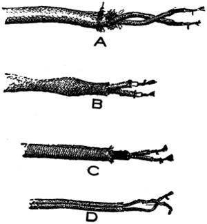
FIGURE 211.
Strips.
Strips.—Strips are used for the illumination of
special parts of the scenery. They usually contain
from one to twelve lights. A strip is subject to rough
usage and should be strongly made. Cuts of several
kinds of strips are given in Figure 212. The chief
trouble with strips is found to be in the working
loose of screws which hold the sockets in place, and
the connection at the point at which the cable leaves
the strip.
[349]
The National Electrical Code Rules for Strips.
Must be constructed of steel of a thickness not less
than No. 20 U. S. sheet metal gauge, treated to prevent
oxidation, and suitably stayed and supported
and so designed that flanges will protect the lamps.
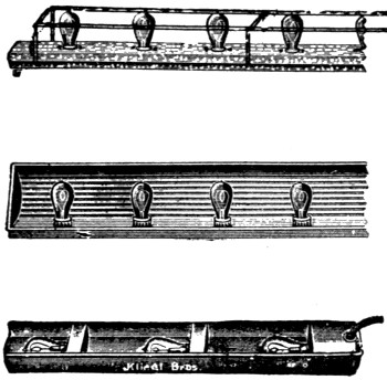
FIGURE 212.
Cables must be bushed in a suitable manner where
passing through the metal, and must be properly
secured to prevent serious mechanical strain on the
connections.
Must be wired in approved conduit or armored
cable, each lamp receptacle being enclosed within
an approved outlet box, or the lamp receptacles may
be mounted in an iron or steel box, metal to be of a
thickness not less than No. 20 U. S. sheet metal gauge,
treated to prevent oxidation, so constructed as to enclose
all wires. Wires to be soldered to lugs of receptacles.
[350]
Sunrise.
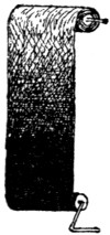
FIG. 213.
Sunrise.—Sunrise effects may be produced
by means of the Sciopticon, but a cheaper
method is often resorted to. This is illustrated
in Figure 213 and consists of a roll of
suitably colored silk which may be unrolled
in front of an arc lamp. To produce sunrise
it is unrolled in one direction, the darkest
colors coming first and gradually giving way
to lighter. For sunset it is worked the other way.
In special cases a similar sheet of colored silk wide
enough to cover open arcs has been stretched from
the floor to the top of the scenery and several arc
lamps arranged behind it in such a manner that they
could be gradually raised, thus producing the same
effect with more impressiveness, but with a much
greater quantity of light.
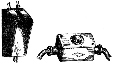
FIGURE 214.FIGURE 215.
Switches.
Switches.—Knife switches on the stage are generally
required to be enclosed. It is not sufficient to
provide a box with a cover that can be closed, but
the switch should be in a box which need not be
opened to operate the switch. See Figure 214. Often
it is necessary to install switches in a length of stage
cable so that the switch may be portable. Such[351]
switches should be installed as shown in Figure 215,
in which a flush switch is shown in a regular metal
enclosure.
FIGURE 216.
Table Lamps.
Table Lamps.—The table lamp is a small device,
but it causes a great deal of annoyance and trouble.
The bottom of the lamp should be enclosed with
metal, especially if there are any splices. The stem
where the wire enters should be well reamed out (see
the arrow in Figure 216) and there should be a strong
well-fastened bushing where the wire leaves the lamp.
The hard-rubber bushings which come with the common
table lamps do not remain in place very long
and are frequently broken or lost. Stage cable is
generally required upon the stage, but it is customary,
in connection with these lamps, to allow a good
grade of reinforced cord or even fine silk-covered
cord, provided it is not long enough to trail on the
floor where it might be stepped upon. The glass
shades which are often called for in connection with[352]
the lamps also cause much trouble; and to avoid this
trouble, colored gelatine has been used, backed up
with fine wire screen to keep it in place. This of
course cannot always be done because many lamps
are not suited to it.
Time Beaters.
Time Beaters.—This is a small keyboard located at
the orchestra leader’s stand; it controls the light which
may be back of the stage and indicates the time to the
chorus behind scenes.
Water Falls.
Water Falls.—The devices shown in Figure 204 for
use as moonlight on the water can also be used to
produce the effect of a waterfall or of water rippling
downstream.
[353]
CHAPTER XX.
USEFUL FACTS AND FORMULAS.
One turn of the crank runs off 1 foot of film.
One foot of film contains 16 pictures.
The audience sees about 960 different pictures in
every minute that a film is being run.
The relative number of revolutions made by two
pulleys connected together by belting or friction is
in proportion to their diameters.
The relative number of revolutions made by two
gears connected together is in proportion to their
number of teeth.
A theater seat occupies from 4 to 5 square feet.
One 25-watt tungsten lamp or its equivalent provided
for every 20 seats will give fairly good illumination
in a small theater.
3 to 5 watts per cubic foot will be required to heat
small spaces by electricity.
Ohm’s Law.
Direct current equals e.m.f. divided by resistance.
Alternating current equals e.m.f. divided by impedance.
Electromotive force, d.c., equals current time resistance.
Electromotive force, a.c., equals current time impedance.
Resistance equals e.m.f. divided by current.
Impedance equals e.m.f. divided by current.
The joint resistance of two conductors connected[354]
in parallel is equal to the product of their resistances
divided by their sum:
r = (r1 × r2) ÷ (r1 + r2)
The joint resistance of any number of resistances
connected in parallel is the reciprocal of the sum of
the reciprocals. The reciprocal of a number is 1
divided by that number:
r = 11r1
+ 1r2
+ 1r3
+ . . . . .
The total resistance of a number of resistances in
series is equal to the sum of all of them:
r = r1 + r2 + r3 + . . . . .
The heating of a rheostat is proportional to the
square of the current it carries.
Drop in voltage is proportional to the product of
the current and resistance for a direct-current circuit,
and the product of current and impedance for
an alternating-current circuit.
If a reactance is used in place of a rheostat in an
alternating-current circuit, the loss of energy is
greatly reduced.
If the same intensity of illumination is to be provided
for pictures of different sizes, the amperage
must vary about as:
(W × 1.2)2
where W is the width of picture on screen.
[355]
For a given power the current in conductors is:
| for direct current |
I = WE |
| for single-phase a.c. |
I = WE × p. f. |
| for two-phase a.c. |
I = .5 × WE × p. f. |
| for three-phase a.c. |
I = .58 × WE × p. f. |
in which I is the current in amperes, W is the watts,
E is the voltage, and p. f. is the power factor.
Lens Formulas.
To find the size of a picture obtainable under given
conditions and lens: Multiply distance from center
of lens to screen by one dimension of slide or film
and divide by e.f. focal length of lens, taking all
measurements in inches.
Example: Slide 23⁄4 inches. Length of throw 360
inches. e. f. 10 inches
23⁄4 × 360 ÷ 10 = 99 inches.
To find focal length needed for a given slide or film
to produce a given size of picture: Multiply slide
or film dimension by length of throw and divide by
dimension of picture, taking all measurements in
inches.
Example: Same dimensions as above:
23⁄4 × 360 ÷ 99 = 10 inches.
To find length of throw needed to obtain a certain[356]
size of picture: Multiply required picture dimension
by focal length of lens and divide by slide or film
dimension.
Example: Same dimensions as above:
99 × 10 ÷ 23⁄4 = 360 inches.
To find slide size necessary to produce a certain
size of picture under fixed conditions: Multiply focal
length of lens by size of picture and divide by length
of throw.
Example: Same dimensions as above:
10 × 99 ÷ 360 = 23⁄4 inches.
Measurement of Surfaces.
To find the area of a parallelogram: Multiply the
base by the altitude.
To find the area of a triangle when base and altitude
are given: Multiply the base by the altitude
and take half the product.
To find the area of any angular surface: Divide
it into triangles and find the area of the different
triangles and add them together.
To find the circumference of a circle: Multiply
the diameter by π, or 3.1416.
To find the diameter of a circle when the circumference
is given: Divide the circumference by π,
or 3.1416.
To find the area of a circle when the radius is
given: Multiply the square of the radius by 3.1416.
When diameter is given: Multiply the square of the
diameter by .7854.
To find the radius of a circle when the area is
given: Divide the area by 3.1416 and extract the
square root of the quotient.
[357]
Measurement of Solids.
To find the lateral area of a right prism: Multiply
the perimeter of the base by the altitude.
To find the lateral area of a right cylinder: Multiply
the circumference of the base by the altitude.
To find the volume of a cylinder or prism: Multiply
the area of the base by the altitude.
To find the lateral area of a right pyramid: Multiply
the perimeter of the base by the slant height
and take half the product.
To find the lateral area of a cone: Multiply the
circumference of the base by the slant height and
take half the product.
To find the volume of a pyramid or cone: Multiply
the area of the base by the altitude and take one-third
of the product.
To find the surface of a sphere: Multiply the
square of the diameter by 3.1416.
To find the volume of a sphere: Multiply the cube
of the diameter by one-sixth of 3.1416 or .5236.
In a right-angled triangle, the sum of the squares
of the base and the perpendicular equals the square
of the hypotenuse. To find the length of the hypotenuse:
Extract the square root of the sum of the
squares of the base and the perpendicular.
To find the base or the perpendicular: From the
square of the hypotenuse subtract the square of the
other given side and extract the square root of the
remainder.
[358]
CHAPTER XXI.
GLOSSARY OF ELECTRICAL, MECHANICAL, AND OPTICAL WORDS, TERMS, AND PHRASES.
Aberration.—The convergence to different foci, by
a lens or mirror, of rays of light emanating from
one and the same point or the deviation of such
from a single focus.
a. c.—An abbreviation for alternating current.
Accumulator.—A term often used to designate a
storage battery.
Achromatic.—Free from false coloration.
Achromatic Lens.—A lens which does not show
color in the light which it projects; usually a combination
of lenses of different kinds of glass.
Actinic Rays.—The rays of light that cause chemical
changes.
Airdome.—A theater arranged in the open air.
Alloy.—Any compound of two or more metals.
Alternating Current.—An electric current undergoing
periodical changes in direction.
Amalgam.—A compound of mercury with other
metals.
Ammeter.—An instrument used for measuring the
value of an electric current.
Amperage.—The number of amperes; the current
strength in the circuit; not the quantity but the rate
of flow.
Ampere.—The unit of current strength. It is
equal to a rate of flow of electricity of one coulomb
per second.
[359]
Ampere Hour.—One ampere flowing for one hour;
or its equivalent.
Anamorphosis.—A grossly distorted image, such
as can be obtained from a curved mirror.
Angular Velocity.—The rate at which a body revolves
around a fixed axis, usually measured in
radians per second. The radian is equal to
360 ÷ 2 × π degrees.
Annular Space.—The space between an inner and
an outer ring or cylinder.
Annunciator.—An electric device provided with
one or more magnets and indicators, which serve
to indicate the points at which one or more electric
contacts have been closed.
Anode.—The positive pole; a term used mostly
with electrolytic devices, also with the mercury arc
rectifier and the electric arc.
Aplanatic.—Free from spherical aberration.
Apparent Power.—The product of volts and amperes
in an alternating-current circuit. The true
power in an alternating-current circuit is always
less than the apparent power if pressure and current
are not in phase.
Arbor.—An axle or spindle on which a wheel
turns.
Arc, Electric.—The heated portion of an electric
circuit between two electrodes where the current
passes from one to the other; the source of light of
the electric arc lamp.
Armature.—That part of a generator, in which
the electrical pressure is generated, which causes
a current if the armature winding forms part of a
closed circuit.
Automatic.—A term applied to machinery in[360]
which certain movements, usually made by hand,
are made by the machine.
Auto-Transformer.—A transformer provided with
only one winding; a part of the winding being
traversed by both the primary and secondary currents.
Axis.—The straight line, real or imaginary, which
passes through a body, and on which the body revolves,
or may be supposed to revolve.
Axis of Lens.—The straight line passing through
its center and perpendicular to its surface.
Axle.—A transverse bar connecting opposite
wheels.
Babbitt Metal.—A soft white antifriction metal of
varying composition; as 4 parts of copper, 8 of antimony,
and 24 or 96 of tin. The larger the amount
of tin, the harder the resultant alloy.
Baby Spot Lamp.—An incandescent lamp placed
within a hood similar to that of a theater arc lamp;
also usually provided with a lens.
Back Focus.—This term is used to designate the
distance from the lens nearest the slide to the position
of the slide when the picture is in focus on the
screen. See also Equivalent Focus.
Balance Wheel.—A wheel added to machinery for
the purpose of preventing too sudden variations in
speed; also called fly wheel.
Ball Bearing.—A journal fitted with balls upon
which the shaft turns.
Balsam, Canadian.—A cement used to cement
lenses, etc.
Band.—A small belt passing over two pulleys.
Battery.—A term used to describe a number of[361]
voltaic cells connected so as to act as a single cell;
should never be used in reference to a single cell.
Bayonet.—A pin which plays in and out of holes
made to receive it and serves to engage parts of
machinery.
Bearing.—That part of a machine in contact with
which a shaft moves; the journal boxes.
Bed.—The foundation or main fixed part of a
machine.
Bell Crank.—A rectangular lever by which the
direction of rotation is changed through an angle
of ninety degrees.
Belt.—A strap or band of flexible material passing
around two or more wheels and communicating
motion to them.
Bevel Gear.—A gear in which the two wheels
working together lie in planes that are not parallel.
Bifocal.—Having two foci.
Binocular.—Pertaining to both eyes, as binocular
vision in microscope or telescope.
Blinding Lights.—Lights used on the stage in
certain acts to blind the audience; thus allowing
persons to work behind them unseen by the audience.
Boss.—The enlarged part of a shaft on which a
wheel is keyed.
Brace.—A curved tool of iron or wood adapted to
turn and hold bits.
Brake.—A piece of mechanism adapted to stop
or hold parts of machinery.
Brushes.—That part of a dynamo by which the
current is taken to or from the commutator.
Buffer.—A cushion, with springs or other material,
arranged to deaden the blow of a moving body.
[362]
Buffing Wheel.—A rapidly revolving wheel adapted
to buff or polish materials.
Burner; Automatic, Electric.—An electric device,
for turning on and lighting gas, which may be operated
from a distance by pressing a button.
Bushing.—The lining of a hole with a ring or a
perforated substance of metal or other material.
Calipers.—A compass with curved legs; used for
measuring round bars or openings, the thickness of
objects, and the distance between two points.
Cam.—A projecting part of a wheel or other moving
piece, so shaped as to give an alternating or
variable motion to another piece pressing against it.
Cam Wheel.—A wheel, or part of a wheel, of irregular
outline employed to produce a variable or
alternating motion in machinery.
Canadian Balsam.—A cement used to cement
lenses, etc.
Candle Power.—This term, as commonly used, denotes
the light-giving power of a lamp in terms of
a standard candle. Its meaning is not very definite
unless qualified by some of the following terms:
apparent candle power; equivalent candle power;
mean horizontal candle power; mean lower hemispherical
candle power; mean spherical candle power;
maximum candle power; mean zonular candle
power. All of these terms are fully explained in
“Modern Electric Illumination, Theory and Practice.”
Carbons.—The rods of artificial carbon used as
electrodes in arc lamps.
Carbons, Cored.—Carbons, as above, but provided
with a core of softer material.
Case Hardening.—The act or process of converting[363]
the surface of iron into steel while leaving the
center soft and malleable.
Cathode.—The negative pole. A term usually used
in connection with electrolytic apparatus, mercury
arc rectifiers, and electric arcs.
Cell, Voltaic.—A cup or jar containing electrodes
and an electrolyte either for producing an electromotive
force or electrolysis. In the latter case it is
called an electrolytic cell. A number of cells connected
together make a battery.
Centi.—As a prefix it means the hundredth part;
as centimeter.
Choke Coil.—A coil of wire wound upon an iron
core in such a manner as to acquire a very high
self-inductance; similar to a reactance.
Chuck.—A contrivance fixed to the mandril of a
turning lathe for holding the material to be worked
upon.
Clutch.—A projecting tooth, or other piece of machinery,
for connecting shafts with each other or
with wheels in such a manner as to be readily disengaged.
Cog Wheel.—A wheel with cogs or teeth.
Collar.—A ring-like part of a machine usually
fastened to some part of it and used for keeping
something in place.
Commutator.—That part of a dynamo-electric machine
to which all of the armature wires are connected
and in which the alternating-electromotive
force, actually generated in the armature winding,
is made to appear as a direct-electromotive force in
the external circuit.
Compasses.—An instrument for describing circles,
measuring, etc., consisting of two pointed branches[364]
fastened together at the top by a rivet or screw.
Compensarc.—A trade term used to describe a
transformer or an auto-transformer; used in connection
with projection-arc lamps.
Compound Winding.—A generator, in which the
fields are provided with a shunt winding and in
addition with a series winding which carries all
of the current around the fields; is said to be compound
wound, and the winding is referred to as a
compound winding.
Concave.—Curved and hollow; the inside of a hollow
sphere or cylinder.
Concentric.—Having a common center.
Condenser.—A lens or a set of lenses, used to
gather the divergent rays from a source of illumination
and bring them to a focus.
Conductor.—Any substance used to carry electricity.
Most of the commercial conductors are of
copper.
Cone.—A solid body having a plane for its base
and a point for its top, the surface being formed
by line segments joining every point of the outline
of the base to the point top.
Conical.—Approximating a cone in shape.
Conjugate Foci.—The two points in the principal
axis of a lens and at opposite sides of it; one point
being the light source and the other the point at
which rays of light from this source are brought to
a focus.
Controller.—A resistance used for controlling the
speed of a motor or the field strength of a dynamo.
Converter.—Any apparatus used for changing
from one form of current to another; generally used
to indicate a synchronous or rotary converter.
[365]
Convex.—Rising or swelling; the outside of a
sphere or cylinder.
Convexo-Plano.—Convex on one side and plane on
the other; plano-convex is more often used.
Cooling Plate.—The metal around the projection
aperture of a motion-picture machine which protects
the film from the rays of light.
Cotter.—A wedge-shaped piece of wood, iron, or
other material used for fastening the parts of a
structure; a key.
Cotter Pin.—A pin made up of doubled wire expanded
at top and bottom so as to hold its place
when inserted in a hole.
Coulomb.—The unit of quantity of electricity. It
is equal to the current multiplied by the time that
it flows; viz., ampere times second.
Countershaft.—A secondary shaft driven from another
shaft; not the main or driving shaft.
Countersink.—A drill or cutting tool used to enlarge
the outer edges of a hole in countersinking.
Crown Wheel.—A wheel, with cogs or teeth set
at right angles to its plane.
Cycle.—A complete recurrence of any periodic
change. The two immediately succeeding half
waves of an alternating current or e.m.f. constitute
a cycle.
Damping Coils, Dampers.—Coils of wire or bars
of copper placed on, or imbedded in, the pole pieces
of a dynamo-electric machine; used mostly in connection
with synchronous motors or rotary converters
to prevent hunting.
Dead Center.—Either of the two opposite points,
in the orbit of a crank, at which the crank and a
driving rod lie in a straight line.
[366]
Diffusing Globes.—Globes of ground glass or
other medium which causes diffusion of light. Used
to reduce the intrinsic brilliancy of illuminants.
The light is emitted from a larger surface and is
less trying to the eyes.
Diffusion.—The scattering of light by diffuse reflection,
as from an irregular surface such as ground
glass.
Diffusion Projection.—A method of projection
sometimes resorted to when condensers are broken.
Ground glass is used in place of the condensers.
Direct Current.—A current of electricity maintained
in one direction as distinguished from an alternating
current which is regularly alternating in
direction.
Dog.—A part of machinery acting as a catch or
a clutch.
Dovetail.—To unite by a tenon, in the form of a
pigeon’s tail spread out, let into a board or timber.
Dowel Pin.—A pin of wood or metal used for
joining two pieces; part of its length entering one
piece, and the rest entering a corresponding hole in
the other.
Dowser.—A hand shutter arranged in front of the
lens of an arc lamp by which the light may be
shut off.
Drift.—A conical tool of steel for enlarging or
shaping a hole in metal by being driven into or
through it.
Drill.—A pointed instrument used for boring
holes; especially in hard substances.
Drop in Potential.—A term often used to designate
a loss of electrical pressure. In d.c. circuits[367]
it is equal to current times resistance. In a.c. circuits
it is equal to current times impedance.
Drum.—A short cylinder revolving on an axis.
Dynamo.—A dynamo electric machine for converting
electrical energy into mechanical, or vice versa.
When the transformation is from electrical to mechanical
energy the machine is operating as a motor;
and when the transformation is from mechanical
to electrical energy the machine is operating as
a generator.
e. f.—Abbreviation for equivalent focus.
e. m. f.—Abbreviation for electromotive force. The
unit of electromotive force. The unit of electromotive
force is the volt.
Eccentric.—A wheel or disc having its axis of
revolution out of its center; used to convert circular
motion into reciprocating.
Economizer.—A trade name applied to a transformer
or auto-transformer, used in connection with
projection-arc lamps.
Economy Coils.—An auto-transformer. This term
is used very much in connection with auto-transformers,
and also transformers used in connection
with arc lamps.
Efficiency of Incandescent Lamps.—The efficiency
of incandescent lamps is expressed in watts per
candle power. The lower the numerical expression
for efficiency, the greater is the light obtained per
unit of energy.
Electrodes.—The terminals of an electric source;
in an arc lamp, the two carbons.
Electrolysis.—Chemical decomposition by an electric
current. The positive pole, or anode, is eaten[368]
away with direct current; the effect with alternating
current is very slight.
Emergency Lights.—Those lights arranged in
theaters, the object of which is to furnish the necessary
illumination by which the audience may leave
the theater in case of a failure of the regular illumination.
Emergency and exit lights are generally
grouped together but must not be confused with
each other.
Equivalent Focus.—The distance from the center
of a set of lenses to the slide, when the picture on
the slide is in focus on the screen.
Exit Lights.—The lights placed directly above
exits; usually colored red.
Expansion Bolt.—A bolt adapted to be inserted
into a socket which, expanded by the insertion, thus
holds the bolt in place.
Face Plate.—The disc attached to the revolving
spindle of a lathe to which the work is often fastened.
Feeders.—The main wires extending from the supply
to the distributing center.
Field.—A term commonly used to designate the
space traversed by the lines of the force of magnetism
which is supposed to exist. The fields of a
dynamo consist of the pole pieces around which the
exciting current circulates.
Fire Trap.—The arrangement of rollers and their
enclosure, usually placed on magazine or film tanks,
through which the film is led, to prevent a flame
from following the film in case of fire.
Flange.—A projecting edge or rim on a wheel or
shaft by which it may be kept in place or fastened.
Flasher.—The term by which a contrivance for[369]
regularly, and at frequent intervals, turning lights
on and off is described; used mostly in connection
with electric signs.
Flicker.—The unsteady illumination of a motion
picture; caused mostly by insufficient speed of film
or too brilliant illumination.
Fly Floor.—A floor above the stage upon which
the scene shifters, whose duty it is to raise and
lower the curtains, work.
Footlights.—A row of lights placed at the stage
level and directly in front of the actors.
Forging.—A piece of metal shaped by hammering;
not a casting.
Framing Device.—A device attached to every motion-picture
machine by which the relative position
of the film to the optical system may be adjusted
to make the picture appear in its proper place on
the screen.
Frequency.—The number of cycles per second;
also spoken of as the periodicity. The most common
frequencies are 25 and 60 cycles per second.
Gearing.—The parts by which motion given to one
part of a machine is transmitted to other parts. In
a narrower sense it refers only to cog wheels.
A spur gear is one in which the teeth are arranged
either on the outside or inside of the rim in the
direction of radii from the center of the wheel.
A bevel gear is one in which the shafts of the
two gears are not parallel.
A friction gear is one in which friction takes the
place of the teeth.
A worm gear is one in which one of the members
is in the form of a screw. The pitch of the screw[370]
may, or may not, be such as to prevent it from
being turned by the other.
A herring-bone gear is one in which the teeth are
cut across the face of the wheel at an angle. The
teeth may be made to converge toward the center
of the face or may be cut in a line across it. This
gear is used where noiseless operation is required.
Generator.—A term frequently used to describe
a dynamo-electric machine used in converting mechanical
energy into electrical energy.
Geneva.—A form of intermittent movement first
used in Geneva, Switzerland; hence the name. It is
the form of intermittent mechanism most used.
Governor.—A contrivance used in connection with
machinery to regulate the speed.
Grid, or Grid Floor.—This term refers to the topmost
floor above the stage of a theater where the
pulleys and the cables, by which scenery is raised
and lowered, are placed. It is usually made up of
iron bars with spaces between them; hence the
name.
Ground.—-This term is used to describe any connection
of an electrical conductor to any conducting
medium, other than that to which it belongs, which
may be common to other conductors or which may
convey current to the opposite pole in a manner not
desired.
Gudgeon.—The piece of iron in the end of a
wooden shaft on which it turns in a collar or on a
gudgeon block.
Heat Shield.—A part of a motion-picture machine
which shields the film and adjacent parts from the
heat of the light.
Helix.—See Solenoid.
[371]
Horsepower.—A unit or standard by which the
capability of machinery is measured. Power sufficient
to raise one pound 33,000 feet in one minute
is called one horsepower. Electrically it is equal
to 746 watts.
Hunting.—This term describes the regular and
persistent changes in the speed of synchronous apparatus
running in parallel, which are due to fluctuations
in the load on the generators or in the
speed of the prime mover; and causes cross currents.
In theaters they would be noticeable only
in connection with rotary converters which are
sometimes used to convert a.c. into d.c. for arc
lamps.
Idler.—A wheel placed between two other wheels
to convey motion from one to the other without
changing the direction of motion.
Impedance.—Impedance is to an alternating-current
circuit what resistance is to a direct-current
circuit. The e.m.f. divided by the impedance equals
the current. The symbol for impedance is Z.
Impressed e.m.f.—The electromotive force
brought to bear on any circuit to produce a current
therein; the applied e.m.f.
Index of Refraction.—The index of refraction, or
the refraction index, is the ratio the sine of the
angle of incidence bears to the sine of the angle
of refraction. For glass the index of refraction is
about 1.5.
Indirect Lighting.—A system of illumination in
which all of the light is first thrown to the ceiling
and reflected therefrom.
Inductance.—That property of an electric circuit
which causes a current in it to create lines of force[372]
and thus generate a counter e.m.f. when the current
changes in value.
Induction Motor.—A much used alternating-current
motor in which there is no electrical connection
between the primary and secondary or rotor
and stator windings. It may be either single or
polyphase.
Intermittent Movements.—There are numerous
types of intermittent movements but the Geneva
and the pin cross are the only ones used with the
latest types of motion-picture projection machines.
The other movements have mostly come into use
in connection with cameras. The beater movement
is one in which a certain length of film is pushed
to one side at each movement. The claw movement
is one in which claws reach up and pull down a
fixed amount of film at each movement. Other intermittent
movements are known as, the drunken
screw; ratchet; pitman and grip. They have mostly
only a historical interest.
Intrinsic Brilliancy.—This term refers to the candle
power per unit area of a source of light. A
light having a large candle power in proportion to
its size is said to have a high intrinsic brilliancy.
Lamps of high intrinsic brilliancy should never be
placed in the line of vision.
Inverted Lighting.—Synonymous with indirect
lighting.
Key.—A wedge-shaped piece of wood or metal
used, to hold something in place; a cotter.
Key Seat.—A groove cut into a shaft to fit a similar
groove in a wheel or flange, and into which a
key may be fitted.
Key to Curtain.—A fictitious article, in quest of[373]
which novices employed in theaters are often sent;
a hoax.
Kilowatt.—1000 watts.
Lagging Current.—A current, the maximum value
of which occurs later than that of the e.m.f. producing
it.
Laminated.—Made up of sheets. All iron parts
subject to the influence of alternating fields must
be laminated to reduce the losses due to Foucault
or eddy currents.
Leading Current.—A current, the maximum value
of which occurs earlier than that of the e.m.f. producing
it. In connection with synchronous converters
the current may be made either lagging or
leading by adjusting the field excitation.
Lens.—A piece of glass, or other transparent substance,
ground with two opposite regular surfaces.
In practice the curved surfaces are generally spherical
but sometimes they are made cylindrical.
Of spherical lenses there are six varieties: plano-concave;
double-concave; plano-convex; double-convex;
meniscus; and concave-convex.
A double-convex lens, with one radius six times
that of the other, is called a crossed lens.
A multiplying lens or glass is one consisting of a
number of plane faces on one side and a convex
surface on the other. The plane faces are inclined
to one another and each presents a different picture;
thus giving the appearance of the multiplication
of images.
A polyzonal lens is one that is made up of a large
number of pieces arranged in zones or rings. This
kind of lens is used only for sizes in which it is[374]
difficult to use pieces large enough to have the lens
in one piece.
Lime Light.—A light produced by means of a cylinder
of lime which is subjected to a flame of gas
or of oxygen and hydrogen.
Lines of Force.—Every magnetic field is supposed
to be made up of imaginary lines called lines of
force. The number of these lines per unit area
perpendicular to the field is a measure of the
strength of the field.
Lost Motion.—Refers to the loss or irregularity
of motion caused by wear of machinery or poor adjustment.
Magic Pane.—This is a condenser formed of a
sheet of glass, one side of which is covered by pieces
of tin foil with spaces left between. The spaces
between may be arranged to represent any design
and on the discharge of the condenser the design
is illuminated by the sparks which jump over the
spaces.
Male Thread or Coupling.—In connection with
piping, hose, etc., a coupling arranged to enter into
another, is spoken of as “male”; that part which
is entered into is known as “female.”
Mandrel.—A bar of metal inserted in the work
to hold it, as in a lathe, during the process of manufacture.
Also the spindle which carries the center
chuck of a lathe, an arbor.
Matched Lenses.—The lenses in two stereopticon
lamps to be used together must be matched to give
the same size of picture.
Micrometer.—An instrument used for measuring
very small diameters or thicknesses, the adjustments
being made by a screw arranged to indicate very[375]
slight changes in the opening in which the object is
inserted.
Mil.—The one-thousandth part of an inch. The
circular-mil area of a circular area, such as the
cross section of a wire, can be found by squaring
the diameter.
Mirage.—An optical illusion due to an unequal
refraction in the lower atmosphere which causes
remote objects to be seen double and suspended in
the air. A mirage can be arranged for by a prism
or by a piece of beveled glass.
Miter Wheels.—A pair of bevel wheels of equal
diameter working together, usually with their axes
at right angles.
Motion Head.—By this term the whole of the motion-picture
machine is usually designated.
Motor.—See dynamo.
Motor Generator.—A generator driven by a motor.
Multiple Series.—A system of wiring in which
several lamps are connected in series and a number
of such series combinations connected in multiple.
Neutral Wire.—The wire of a three-wire system
which ordinarily carries no current. In a three-wire
system it is usually run in the center.
Ohm.—The ohm is the unit of electrical resistance.
Ohmic Drop.—This is the loss of potential due to
the resistance, as distinguished from that due to
the reactance. It is always equal to the current
multiplied by the resistance, the current being
measured in amperes and the resistance in ohms.
Ohm’s Law.—This is a statement defining the relations
existing between electrical pressure, current,
and resistance.
[376]
The current is equal to the electrical pressure divided
by the resistance.
The resistance is equal to the electrical pressure divided
by the current.
p. d.—An abbreviation for difference of potential.
Pawl.—A short movable piece or bar connected at
one end, by a joint, with some part of a machine;
while the other end falls into notches or teeth on
another part, in such a manner as to permit motion
in one direction only.
Period.—The time required for one complete cycle.
Photometer.—An instrument used for comparing
or measuring the candle power of illuminants.
Pinion.—A small wheel with leaves or teeth working
into the teeth of a larger wheel or rack; especially
such a wheel having its leaves formed of the
substance of the arbor or spindle on which it turns;
a toothed arbor.
Pitch.—The distance from center to center of any
two adjacent teeth of gearing measured on the
pitch line. The distance measured on a line parallel
to the axis between two adjacent threads or convolutions
of a screw.
Pitch Line.—A circle concentric with the circumference
of a toothed wheel and cutting its teeth at
such a distance from their points as to touch the
corresponding circle of the gear working with it.
The two circles must have a common velocity.
Plunger.—A part of machinery which is subject
to a plunging motion.
Polarity.—A difference of polarity exists between
any two wires, or points in one wire, where there
is any tendency to produce a current. In practice,[377]
however, the term is used to designate wires pertaining
to the two opposite poles of a system.
Polyphase.—Referring to more than one phase,
multiphase.
Power.—This term designates the rate of doing
work.
Power Factor.—This term expresses the ratio of
the true power in an alternating-current circuit to
the apparent power. It is always less than 1. The
apparent power (product of volts and amperes measured
by independent instruments) must be multiplied
by the power factor to obtain the true power
in alternating-current circuits.
Primary Battery.—A battery in which the p.d.
is produced by primary action of the ingredients
used, instead of by secondary action as in secondary
batteries or accumulators.
Primary Coil.—That coil of a transformer, induction
motor, or induction coil which is connected to
the source of electrical energy.
Prism.—A transparent body usually having three
rectangular faces and triangular ends. It is used
in experiments on optics to show refraction and
may also be made to produce total reflection.
Prismatic Colors.—The seven colors into which
sunlight is resolved when passed through a prism.
An achromatic prism is one made up of two kinds
of glass of different dispersive powers by which a
ray of light may be refracted without showing
color.
Pulley.—A broad-rimmed wheel used for transmitting
power by means of a belt.
A narrow-rimmed wheel with a groove used for
the same purpose is termed a sheave[378].
A cone pulley is a pulley made in the shape of a
cone and used in conjunction with a similar pulley
and a belt connecting them for the purpose of varying
the velocity.
A fast pulley is one which is rigidly attached to
the shaft.
A loose pulley is one which is used in conjunction
with another pulley of the same size to carry the
belt while the shaft attached to the other is still.
Pulsating Current.—A current of electricity varying
regularly in strength but not in direction.
Rack and Pinion.—A straight bar with teeth on
its edge to work with the teeth of a pinion which
is to drive or follow it.
Ratchet.—A bar or piece of mechanism turning
upon a pivot while the other end falls into the
teeth of a wheel or rack allowing the latter to move
in one direction only. It may be used for preventing
backward motion in machinery or for converting
reciprocating motion into forward motion.
Ratchet Drill.—A drill attached to a ratchet.
Ratchet Wheel.—A wheel having teeth by which
it may be moved forward as by a lever and catch,
or by a pawl arranged to engage the teeth. The
pawl may also be arranged to engage the teeth for
the purpose of preventing backward motion.
Reactance Coil.—See Choke Coil.
Reactive Drop.—The drop in potential caused
through the presence of reactance in the circuit, as
distinguished from that caused by ohmic resistance
which is known as the ohmic drop.
Rectifier.—Any apparatus used to change an alternating
current to a direct current by periodically
interrupting or changing the direction of the alternating[379]
current so that the derived current is always
in the same direction.
Relay.—A device actuated by an electric current
to open or close another circuit.
Rheostat.—An adjustable resistance.
Rock Shaft.—A shaft that vibrates or oscillates
instead of making complete revolutions. Called also
rocker or rocking shaft.
Rotary Converter.—A rotating machine having a
field excited by a direct current and an armature
winding connected to a commutator and a set of
collector rings. It is used to convert alternating
current into direct, or vice versa; also called synchronous
converter.
Rotor.—The moving part of an alternating-current
generator or motor.
Secondary Battery.—A storage battery; an accumulator.
Secondary Coil.—The coil of a transformer or an
induction coil into which currents are induced; the
coil which is not connected to the source of energy.
Series Connection.—A connection in which a number
of devices are joined so that the same current
passes through all of them.
Series Multiple.—A system of wiring in which a
number of devices are connected in multiple and
several of such groups then connected in series.
The same current must pass through each group.
Shaking Coil.—A coil used in connection with a
mercury-arc rectifier for tilting or shaking the tube
and starting the apparatus.
Shunt.—A by-pass. A wire which carries part or
all of the current in a circuit around some other
device connected in the circuit.
[380]
Single-Phase.—An alternating-current system using
only two wires and only one e.m.f. It is sometimes
termed uniphase or monophase.
Slip of Induction Motor.—The difference in the
number of revolutions made by the revolving field
and the rotor of the motor. It is usually expressed
in per cent of the synchronous speed which is that
of the revolving field.
Solenoid.—A round coil of wire generally used
to control an iron core; an electromagnetic helix.
Spider.—A casting or part of a machine having
projections or arms radiating from it so as somewhat
to resemble a spider.
Spindle.—The revolving arbor of a machine tool;
an axis.
Spiral Gear or Gearing.—A gearing consisting of
wheels working together with their axes at an angle
to each other double that of the angle of the teeth
with the axes. It is sometimes used in light machinery
in place of bevel gearing.
Spiral Wheel.—A wheel having its teeth cut at
an angle with its axis or so that they form small
parts of screws or spirals.
Spline.—A rectangular piece fitting the key seats
of a hub and shaft so that, while the one may slide
endwise on the other, both must revolve together.
Spur Wheel.—A wheel in which the teeth are
perpendicular to the axis and in the direction of
the radii.
Static Electricity.—The name usually given to
electricity generated by friction, as from belting
in machine shops, etc.
Stator.—The stationary part of an alternating-current
motor or generator.
[381]
Stay Bolt.—A bolt connecting opposite plates to
keep them from bulging.
Stepdown Transformer.—A transformer used for
reducing voltage.
Stepup Transformer.—A transformer used for increasing
voltage.
Striking the Arc.—The act of bringing the carbons
of an arc lamp together and immediately separating
them and establishing the arc is called striking
the arc.
Stud.—A projection of a bolt adapted to hold a
lug or connection of some kind.
Stud Bolt.—A bolt with threads on both ends, to
be screwed into a fixed part at one end and receive
a nut upon the other.
Sustaining Coil.—The name sometimes given to
a reactance used in connection with a mercury-arc
rectifier to cause an overlapping of the two currents
from the anodes.
Swivel or Swivel Joint.—A joint, the two pieces
of which can be turned around independently of
each other.
Synchronism.—Being in time or occurring at the
same time in regular order with some other event.
Synchronous Converter.—See rotary converter.
Tap Bolt.—A bolt with a head on one end and a
thread on the other to be screwed into some part
instead of passing through and being fastened with
a nut.
Three-Phase.—Refers to a system of electrical distribution
making use of three separate currents.
These currents may be superimposed and generally
only three wires are used in the transmission.
[382]
Thumb Screw.—A screw arranged so that it can
be set up with the fingers. Similar to a wing nut.
Thumb Spot.—A distinguishing mark usually
placed on stereopticon slides so as to mark the spot
at which the thumb of the right hand should be
placed when inserting the slide to insure its proper
placing in the holder.
Travel Ghost.—The peculiar hazy appearance
often seen in a motion picture; it is produced by the
improper setting of the revolving shutter.
Trunnion.—Projection lugs on the sides of some
piece of machinery upon which it is supported and
upon which it can move.
Two-Phase.—This term refers to an a.c. system
of electrical distribution making use of two currents
of different phase. It may be arranged with three
or four wires.
Unbalanced.—This term is used in connection with
three-wire and three-phase systems.
The three-wire system is said to be unbalanced
when one of the outside wires is carrying more
current than the other.
The three-phase system is said to be unbalanced
when the load is unevenly distributed over the three-phase
wires.
Universal Joint.—A contrivance used for joining
two shafts or parts of machinery endwise so that
one may give rotary motion to the other while at an
angle.
Volt.—The unit of electromotive force.
Voltmeter.—An instrument used for measuring
potential difference.
Water Rheostat.—A resistance in which water is
used to carry the current. Plates of metal proportional[383]
to the current to be used are inserted in the
water and by inserting them to a greater extent or
moving them closer together the current can be
increased.
Watt.—The unit of power.
Wattless Current.—That part of an alternating
current which is either ahead of or behind the
e. m. f. of the circuit.
Watt Meter.—An instrument used for measuring
electrical energy.
Yoke.—A clamp resembling an ox yoke somewhat
and adapted to join two pieces of a machine.
[384
385]
INDEX
| |
PAGE |
| Aberration, chromatic, |
51 |
| Aberration, spherical, |
51 |
| Adjusting intermittent sprocket, |
100 |
| Aisle lights, |
218 |
| Aligning machine, |
96 |
| Alternating current, |
218 |
| Alternating current motor, |
215 |
| Amperage for projection, |
43, 44 |
| Amperage, determination of, |
45, 46 |
| Anchoring machine, |
97 |
| Anvil sparks, |
311 |
| Arc, color of, |
19, 20, 31 |
| Enclosed, |
23 |
| Form of carbons, |
22 |
| Length of, |
21 |
| Low tension, |
20 |
| Open, |
23 |
| Resistance of, |
20 |
| Upside down, |
22 |
| Arc lamps, |
19, 218, 312 |
| Automatic, |
25 |
| Edison, |
36 |
| Hand feed, |
25 |
| Kliegl, |
35, 36 |
| McIntosh, |
34 |
| Motiograph, |
37 |
| Operation of, |
25, 27 |
| Powers, |
37 |
| Testing of, |
28 |
| Arc light, injurious, |
21 |
| Armored cable, |
222 |
| Asbestos, |
226 |
| Attachment plugs, |
226 |
| Auto-starters, |
227 |
| Automatic fire shutter, |
62, 70, 71, 101 |
| Axis of lens, |
360 |
| Baby spot lamp, |
316 |
| Balconies, |
228 |
| Batteries[386], |
316 |
| Bells, |
228, 318 |
| Blinding lights, |
319 |
| Borders, |
229 |
| Brackets, |
232, 319 |
| Branch circuits, |
232 |
| Branch-off connectors, |
343 |
| Bunch lights, |
320 |
| Bus-bars, |
234 |
| Cabinets, |
235 |
| Cables, |
235 |
| Call-board, |
293 |
| Canopies, |
236 |
| Camera lucida, |
152 |
| Carbons, adjusting of, |
31 |
| Best to use, |
29 |
| Cored, |
53 |
| Setting of, |
31, 32, 34 |
| Testing of, |
28 |
| Care of sprockets, |
99 |
| Carriage call, |
293 |
| Carrying capacity, |
237 |
| Ceiling fans, |
237 |
| Chandeliers, |
237, 321, 322 |
| Chromatic aberration, |
51 |
| Cleaning machine, |
98 |
| Circuit breakers, |
239 |
| Colors for arc lamps, |
323 |
| Colored pictures, |
59 |
| Comparison of stereopticon and motion picture machine pictures, |
49 |
| Concavo-convex lens, |
146 |
| Concave meniscus lens, |
146 |
| Concealed work, |
240 |
| Condensers, |
38, 153 |
| Breakage, |
40 |
| Diameter of, |
51 |
| Focal length of, |
50 |
| Conduit work, |
240 |
| Conjugate foci of lens, |
143 |
| Conjugate foci of mirror, |
133 |
| Contacts, |
245 |
| Convexo-concave lens, |
146 |
| Convex meniscus lens, |
146 |
| Cord, |
245 |
| Corrected lenses, |
148 |
| Cover for machine, |
104 |
| Critical angle of refraction[387], |
140 |
| Current control for arc lamps, |
190 |
| Auto-transformer, |
195 |
| Mercury-arc rectifier, |
207 |
| Motor generators, |
198 |
| Reactances, |
193 |
| Resistances, |
190 |
| Rotary converters, |
202 |
| Transformation, |
194 |
| Current required for projection, |
43, 44 |
| Current taps, |
245 |
| Cut-outs, |
246 |
| Damp places, |
249 |
| Decorative lighting systems, |
249 |
| Dimmers, |
250 |
| Dimmer box, |
324 |
| Door switches, |
251 |
| Double concave lens, |
146 |
| Double convex lens, |
146 |
| Dressing rooms, |
168, 251 |
| Drop lights, |
252 |
| Edengraph motion head, |
83, 86 |
| Edison motion head, |
64, 84 |
| Efficiency of incandescent lamps, |
270 |
| Electric sign imitations, |
325 |
| Electric stage effects, |
326 |
| Emergency lighting system, |
253 |
| Equivalent focal length, |
50 |
| Exit lights, |
256 |
| Explosions, |
327 |
| Eye, the, |
124 |
| Mixing of impressions, |
125 |
| Regaining of vision by aged, |
125 |
| Face-o-graph, |
161, 328 |
| Fan motors, |
256 |
| Festoons, |
328 |
| Film, |
89 |
| Box for, |
108 |
| Burning of, |
90, 173, 177 |
| Emulsion on, |
89 |
| Fire, |
110 |
| Gate, |
62, 69, 70, 102 |
| Inspection of, |
105 |
| Leaders and tails, |
106, 107 |
| Mender, |
94 |
| Patching, |
91, 93 |
| Pictures, per foot, |
57 |
| Pinning of[388], |
110 |
| Receptacle for, |
106 |
| Rewinding, |
108 |
| Shields, |
62, 83 |
| Steadier drum, |
62, 69 |
| Fire alarm, |
256 |
| Fire dance, |
330 |
| Fire hazard, |
11 |
| Fire flies, |
330 |
| Fire places, |
331 |
| Fire proof film, |
90 |
| Fire traps, |
62, 67, 97 |
| Testing of, |
68 |
| Fish work, |
256 |
| Fixtures, |
257 |
| Flashers, |
259 |
| Flexible cord, |
261 |
| Flexible tubing, |
261 |
| Flood lamps, |
24 |
| Floor pockets, |
261 |
| Flowers, |
332 |
| Fly door, |
261 |
| Focal length of concave mirror, |
133 |
| Focusing, |
42 |
| Foot-lights, |
261, 262 |
| Formulas, |
353 |
| Fountains, |
332 |
| Framing, |
102 |
| Framing device, |
62, 82 |
| Friction rollers, |
62, 69 |
| Fuses, |
333 |
| Fuse spacings, |
288 |
| Gallery lighting, |
263 |
| Gallery pockets, |
263, 300 |
| Gas globes, |
334 |
| Gas lighting, |
264 |
| Generators, management of, |
213 |
| “Geneva” movement, |
76, 77 |
| Getting ready for the show, |
104 |
| “Ghost”, |
42 |
| Glass shades, |
334 |
| Glossary of mechanical, electrical and optical words, terms and phrases, |
358 |
| Grid floor, |
265 |
| Ground, |
11 |
| Grounding, |
265 |
| Guards, |
266 |
| Hanger boards[389], |
266 |
| Heat, |
115 |
| Heaters, |
267, 335 |
| High potential, |
268 |
| Hints on management of projecting arcs, |
52 |
| Hissing voltage of arc, |
29 |
| Illumination, |
269 |
| Illusions, optical, |
155 |
| Dissolving living pictures, |
157 |
| Face in clouds, |
161 |
| Figure floating in air, |
157 |
| Head resting on table, |
160 |
| Head suspended in air, |
158 |
| Magic cabinet, |
159 |
| Of motion, |
55 |
| Multiplication of images, |
160 |
| Trick mirror, |
160 |
| Seeing through a brick, |
161 |
| Image inversion, by lens, |
144 |
| By pin hole, |
123 |
| By prism, |
151 |
| Incandescent lamps, |
269 |
| Index of refraction, |
138 |
| Inspecting films, |
105 |
| Inspecting machine, |
97 |
| Inspection memoranda, |
112 |
| Insulating joints, |
272 |
| Interior conduit, |
242 |
| Intermittent sprocket, |
62, 75 |
| Inversion of images, |
123, 144, 151 |
| Inverted lighting, |
273 |
| Iris, the, |
124 |
| Joints, |
273 |
| Junction boxes, |
275 |
| Kinemacolor process, |
59 |
| Lens lamp, |
24 |
| Lenses, conjugate foci of, |
143 |
| Double concave, |
145 |
| Double convex, |
141, 142 |
| Focal length of, |
142 |
| Heating of, |
40 |
| Inversion of image by, |
144 |
| Measuring focal length, |
49 |
| Objective, |
149 |
| Principal focus of, |
142 |
| Selection of, |
46 |
| Tables of, |
47, 48 |
| Types of[390], |
146 |
| Life hazard, |
13 |
| Light, |
113 |
| Infra red rays of, |
117 |
| Intensity of, |
120 |
| Interference of, |
120 |
| Law of inverse squares, |
121 |
| Reflection of, |
121, 127 |
| Re-composition of, |
118, 148 |
| Source best for projection, |
39 |
| Ultra violet rays of, |
117 |
| Vibratory, theory of, |
114 |
| Waste of, in projection, |
45 |
| Wave lengths, |
116 |
| Lighthouse effect, |
336 |
| Lightning, |
336 |
| Lobby, |
275 |
| Lower feed loop, |
62, 79 |
| Lower magazine, |
62 |
| Lower steady feed sprocket, |
62, 79 |
| Lugs, |
275, 338 |
| Magnifying glass, |
145 |
| Metal molding, |
276 |
| Meters, |
278 |
| Meter reading, |
279 |
| Mirrors, |
128 |
| Concave, |
132 |
| Convex, |
132, 135 |
| Conjugate foci of, |
133 |
| Principal focus of, |
133 |
| Moon boxes, |
339 |
| Moonlight on water, |
340 |
| Motiograph motion head, |
85 |
| Motion pictures, |
55 |
| Motion picture machine, |
62 |
| Diagram of, |
63 |
| Discussion of parts of, |
66 |
| Gearing of, |
65 |
| Motors, |
281 |
| Operation of, |
214 |
| Starting boxes for, |
215 |
| Musical acts, |
340 |
| Musical bells, |
341 |
| Music stands, |
285 |
| Objective lenses, |
149 |
| Ohm’s law, |
353 |
| Oiling machine[391], |
98 |
| Oil lamps, imitation of, |
341 |
| Open work, |
286 |
| Opera glass, |
150 |
| Operating room, |
172 |
| Color of, |
180 |
| Construction of, |
176 |
| Entrance and exit, |
177 |
| Equipment of, |
176 |
| Fire shutters for, |
181 |
| Floor of, |
178, 179 |
| Shutter, strings for, |
183 |
| Tools for, |
185 |
| Ventilation of, |
176 |
| Wiring for, |
186, 189 |
| Operation of motors, |
214 |
| Operation of motion picture machines, |
96 |
| Optical illusions, |
155 |
| Optical instruments, |
147 |
| Optical system of projecting arcs, |
38 |
| Panel boards, |
286 |
| Paint bridge, |
291 |
| Paint room, |
291 |
| Persistence of vision, |
56, 124 |
| “Pin cross” movement, |
77, 78 |
| Pin plug connectors, |
341 |
| Plano-concave lens, |
146 |
| Plano-convex lens, |
146 |
| Plugging boxes, |
343 |
| Portable stage equipment, |
311 |
| Powers motion head, |
86 |
| Presser rollers, |
69 |
| Principles of vision, |
122 |
| Prisms, |
117, 118, 141, 147, 151 |
| Program board, |
291 |
| Projection, |
31 |
| Projecting arc lamps, |
38, 52 |
| Proscenium side lights, |
167, 294 |
| Reactances, |
193 |
| Reading glass, |
144, 145 |
| Reflection, |
126 |
| Inversion of image by, |
129, 130 |
| Multiplication of image by, |
130, 131 |
| Refraction, |
137 |
| Critical angle of, |
140 |
| Index of, |
138 |
| Paths of rays of light, |
139 |
| Refraction and reflection combined[392], |
140 |
| Retiring rooms, |
295 |
| Resistance, |
190 |
| Resuscitation, |
15 |
| Revolving shutter, |
62, 72, 101 |
| Setting of, |
75 |
| Rewinding, |
108 |
| Rheostats, |
295, 345 |
| Rigging loft, |
168 |
| Sciopticon, |
313 |
| Screens, |
173 |
| Signals, |
297 |
| Signs, |
297 |
| Size of picture, |
38 |
| Simplex motion head, |
87 |
| Slides, |
109 |
| Sockets, |
298 |
| Solar spectrum, |
118 |
| Spectrum analysis, |
118 |
| Spherical aberration, |
51 |
| Spot on gate, size of, |
41 |
| Stage cable, |
298, 347 |
| Stage flues, |
299 |
| Stage, plan of, |
167 |
| Pockets, |
168, 300 |
| Switchboard, |
167, 305 |
| Stereopticon lamps, |
314 |
| Stereoscope, reflecting, |
151 |
| Refracting, |
151 |
| Strips, |
348 |
| Sunrise, |
350 |
| Switch board, |
167 |
| Switches, |
301, 350 |
| Knife, |
301 |
| Spacings of, |
289 |
| Three way, |
302 |
| Table of amperage for projection, |
44 |
| Capacity of bus-bars, |
235 |
| Capacity of wires, |
238 |
| Drop due to 6 amperes, |
233 |
| Fuse spacings, |
289 |
| Motion picture lenses, |
47 |
| Of multiple reflections, |
132 |
| Panel board spacings, |
287 |
| Size of wire for motors, |
284 |
| Stereopticon lenses, |
48 |
| Waste of energy by resistance, |
191 |
| Table lamps[393], |
351 |
| Take up, |
62, 79, 103, 104 |
| Telescope, |
150 |
| Tension springs, |
62, 70, 103 |
| Testing arc lamps, |
28 |
| Carbons, |
28, 29 |
| Fire traps, |
68 |
| Theater buildings, |
163 |
| For motion pictures, |
171 |
| Wiring of, |
218 |
| Three-wire system, |
10 |
| Time beaters, |
352 |
| Tools for operating motion picture machine, |
96 |
| Transformers, |
194 |
| Trick mirror, |
160 |
| Two-wire system, |
9 |
| Upper feed reel, |
66 |
| Upper loop, |
62, 69 |
| Upper magazine, |
62, 66, 97 |
| Upper steady feed sprocket, |
62, 68 |
| Useful light of projecting arc, |
40 |
| Ventilating flues, |
178 |
| Vision, persistence of, |
56 |
| Visitors, |
110 |
| Water falls, |
352 |
| Waterproof film, |
90 |
| Wire systems, |
9 |
Books That Really Teach
you the things you want to know, and in a
simple, practical way that you can understand
Our illustrated catalogue, which will be sent you free upon
request, tells all about the Practical Mechanical Books for
Home Study that we publish.
There are popular priced
books on the operation of
trains and station work, practical
mechanical drawing and
machine designing, pattern
making, electrical railroading,
power stations, automobiles,
gas engines, electrical wiring,
armature and magnet winding,
dynamo tending, elementary
electricity, wireless telegraphy
and telephony, carpentry and
architecture, concrete construction,
plumbing and heating,
sign and house painting,
amusements, etc., etc.
No matter what your ambition
or desire for knowledge
may be, we publish books written by authorities in
their different lines that will give you just the training and
information that you want and need.
Write today for this up-to-date and complete illustrated
catalogue and popular price list. It is free.
FREDERICK J. DRAKE & CO.
PUBLISHERS OF SELF-EDUCATIONAL BOOKS
1325 Michigan Avenue CHICAGO
FREDERICK J. DRAKE & CO.’S
PRACTICAL MECHANICAL BOOKS
FOR
HOME STUDY
| |
Price. |
| Titles. |
Cloth. |
Lea. |
| Air Brake Practice, Modern—Dukesmith. Illustrated |
1.50 |
... |
| Air Brake, Complete Examinations, Westinghouse and New York. |
... |
2.00 |
| Air Brake, Westinghouse System. |
2.00 |
... |
| Air Brake, New York System. |
2.00 |
... |
| American Homes, Low Cost—Hodgson. Illustrated |
1.00 |
... |
| Architectural Drawing, Self-Taught—Hodgson. Illustrated |
2.00 |
... |
| Architecture, Easy Steps to—Hodgson. Illustrated |
1.50 |
... |
| Architecture, Five Orders—Hodgson. Illustrated |
1.00 |
... |
| Armature and Magnet Winding—Horstmann & Tousley. |
... |
1.50 |
| Artist, The Amateur—Delamotte. |
1.00 |
... |
| Automobile Hand Book—Brookes. Illustrated |
... |
2.00 |
| Automobile, The Mechanician’s Catechism—Swingle |
... |
1.25 |
| Blacksmithing, Modern—Holmstrom. Illustrated |
1.00 |
... |
| Boat Building, for Amateurs—Nelson. Illustrated |
1.00 |
... |
| Bricklayers’ and Masons’ Assistant, The 20th Century—Hodgson. Illustrated |
1.50 |
... |
| Bricklaying, Practical, Self-Taught—Hodgson. Illustrated |
1.00 |
... |
| Bungalows and Low Priced Cottages—Hodgson |
1.00 |
... |
| Calculation of Horse Power Made Easy—Brookes. Illustrated |
.75 |
... |
| Carpentry, Modern. Vol. I—Hodgson. Illustrated |
1.00 |
... |
| Carpentry, Modern. Vol. II—Hodgson. Illustrated |
1.00 |
... |
| Chemistry, Elementary, Self-Taught—Roscoe. Illustrated |
1.00 |
... |
| Concretes, Cements, Plasters, etc.—Hodgson. Illustrated |
1.50 |
... |
| Correct Measurements, Builders’ and Contractors’ Guide to—Hodgson. |
1.50 |
... |
| Catechism, Swingle’s Steam, Gas and Electrical Engineering |
... |
1.50 |
| Cabinet Maker, The Practical, and Furniture Designer—Hodgson. Illustrated |
2.00 |
... |
| Dynamo Tending for Engineers—Horstmann & Tousley. Illustrated |
1.50 |
... |
| Dynamo—Electric Machines—Swingle. Illustrated |
1.50 |
... |
| Electric Railway Troubles and How To Find Them—Lowe |
1.50 |
... |
| Electric Power Stations—Swingle |
2.50 |
... |
| Electrical Construction, Modern. Illustrated |
... |
1.50 |
| Electrical Dictionary. Handy, Weber. |
.25 |
.50 |
| Electrical Wiring and Construction Tables—Horstmann & Tousley. |
... |
1.50 |
| Electricity, Easy Experiments in—Dickinson. Illustrated |
1.00 |
... |
| Electricity Made Simple—Haskins. Illustrated |
1.00 |
... |
| Electric Railroading—Aylmer-Small. Illustrated |
... |
3.50 |
| Electro-Plating Hand Book—Weston. Illustrated |
1.00 |
1.50 |
| Elementary Electricity, Up To Date—Aylmer-Small |
1.25 |
... |
| Estimator, Modern, for Builders and Architects—Hodgson |
1.50 |
... |
| Examination Questions and Answers for Locomotive Firemen—Wallace. Illustrated |
... |
1.50 |
| Examination Questions and Answers for Marine and Stationary Engineers—Swingle. Illustrated |
... |
1.50 |
| Elevators, Hydraulic and Electric—Swingle. Illustrated |
1.00 |
... |
| Electrician’s Operating and Testing Manual—Horstmann & Tousley. Illustrated |
... |
1.50 |
| Farm Engines and How to Run Them—Stephenson. Illustrated |
1.00 |
... |
| Furniture Making, Home—Raeth. Illustrated |
.60 |
... |
| First Steps in Electricity, or Electricity for Beginners—Harrison |
1.00 |
... |
| Gas and Oil Engine Hand Book—Brookes. Illustrated |
1.00 |
1.50 |
| Hand Book for Engineers and Electricians—Swingle. Illustrated. Pocket Book Style |
... |
3.00 |
| Hardwood Finishing, Up-to-date—Hodgson. Illustrated |
1.00 |
... |
| Horse Shoeing, Correct—Holmstrom. Illustrated |
1.00 |
... |
| Hot Water Heating, Steam and Gas Fitting—Donaldson. Illustrated |
1.50 |
... |
| Heating and Lighting Railway Passenger Cars—Prior |
1.25 |
... |
| Locomotive Breakdowns, with Questions and Answers—Wallace. Illustrated |
... |
1.50 |
| Locomotive Fireman’s Boiler Instructor—Swingle |
... |
1.50 |
| Locomotive Engineering—Swingle. Illustrated. Pocket Book Style. |
... |
3.00 |
| Machine Shop Practice—Brookes. Illustrated |
2.00 |
... |
| Mechanical Drawing and Machine Design—Westinghouse. Illustrated |
2.00 |
... |
| Motorman, How to Become a Successful. Aylmer-Small. Illustrated |
... |
1.50 |
| Motorman’s Practical Air Brake Instructor—Denehie. |
... |
1.50 |
| Modern Electric Illumination, Theory and Practice—Horstmann & Tousley. Illustrated |
... |
2.00 |
| Millwright’s Practical Hand Book—Swingle. Illustrated |
2.00 |
... |
| Modern American Telephony In All Its Branches—Smith. Illustrated |
... |
2.00 |
| Operation of Trains and Station Work—Prior. Illustrated |
... |
1.50 |
| Painting, Cyclopedia of—Maire. Illustrated |
1.50 |
... |
| Pattern Making and Foundry Practice—Hand. Illustrated |
... |
1.50 |
| Picture Making for Pleasure and Profit—Baldwin. Illustrated |
1.25 |
... |
| Plumbing, Practical, Up-to-Date—Clow. Illustrated |
1.50 |
... |
| Railway Roadbed and Track, Construction and Maintenance of—Prior. Illustrated |
... |
2.00 |
| Railway Shop Up-to-Date—Haig. Illustrated |
2.00 |
... |
| Sheet Metal Workers’ Instructor—Rose. Illustrated |
2.00 |
... |
| Signist’s Book of Modern Alphabets—Delamotte |
1.50 |
... |
| Sign Painting, The Art of—Atkinson |
3.00 |
... |
| Stair Building and Hand Railing—Hodgson. Illustrated |
1.00 |
... |
| Steam Boilers—Swingle. Illustrated |
... |
1.50 |
| Steel Square, A Key to—Woods. |
1.50 |
... |
| Steel Square, Vol. I—Hodgson. Illustrated |
1.00 |
... |
| Steel Square, Vol. II—Hodgson. Illustrated |
1.00 |
... |
| Steel Square, A B C—Hodgson. |
.50 |
... |
| Steel Construction, Practical—Hodgson. Illustrated |
.50 |
... |
| Storage Batteries—Niblett |
.50 |
... |
| Sho’ Cards, A Show At—Atkinson and Atkinson |
3.00 |
... |
| Stonemasonry, Practical, Self-Taught—Hodgson. Illustrated |
1.00 |
... |
| Telegraphy Self-Taught—Edison. Illustrated |
1.00 |
... |
| Telephone Hand-Book—Baldwin. Illustrated |
1.00 |
... |
| Timber Framing, Light and Heavy—Hodgson |
2.00 |
... |
| Toolsmith and Steel Worker—Holford. Illustrated |
1.50 |
... |
| Turbine, The Steam—Swingle. Illustrated |
1.00 |
... |
| Walschaert Valve Gear Breakdowns and How to Adjust Them—Swingle. Illustrated |
1.00 |
... |
| Wiring Diagrams, Modern—Horstmann & Tousley. Illustrated |
... |
1.50 |
| Wireless Telegraphy and Telephony—V. H. Laughter |
1.00 |
... |
| Wood Carving, Practical—Hodgson. Illustrated |
1.50 |
... |
THE RED BOOK SERIES OF TRADE SCHOOL
MANUALS
By F. Maire
16 mo., Cloth, Illustrated.
Price, each, $0.60
Exterior Painting, Wood, Iron and Brick.
Interior Painting, Water and Oil Colors.
Colors, What They Are and What to Expect
from Them.
Graining and Marbling.
Carriage Painting.
The Wood Finisher.
THE AUTOMOBILE HAND-BOOK
OVER 200,000 SOLD
By ELLIOTT BROOKES, Assisted by Other Well-Known Experts
Revised and Enlarged New Edition—The largest and most practical
work published. Used by all up-to-date automobile schools as
their every-day text-book.over 720 pages and
over 329 illustrations. Full Leather Limp, Round
Corners, Red Edges. Price, $2.00.
At the present time nearly all automobile
troubles or breakdowns may, in almost
every case, be traced to the lack of knowledge
or carelessness of the owner or operator
of the car, rather than to the car itself.
The automobile hand book is a work of
practical information for the use of owners,
operators and automobile mechanics, giving
full and concise information on all
questions relating to the construction, care
and operation of gasoline and electric automobiles,
including road troubles, motor
troubles, carburetor troubles, ignition
troubles, battery troubles, clutch troubles,
starting troubles. With numerous tables,
useful rules and formulæ, wiring diagrams
and over 329 illustrations.
Special efforts have been put forth to
treat the subjects of ignition, and ignition
devices, in a manner befitting their
importance. A large section has been
devoted to these subjects, including batteries,
primary and secondary, magnetos,
carburators, spark plugs, and in fact all devices used in connection with
the production of the spark. Power transmission is thoroughly discussed,
and the various systems of transmitting the power from the motor to the
driving axle are analyzed and compared.
The perusal of this work for a few minutes when troubles occur, will
often not only save time, money, and worry, but give greater confidence
in the car, with regard to its going qualities on the road, when properly
and intelligently cared for.
A WORD TO THE WISE
The time is at hand when any person caring for and operating any
kind of self-propelling vehicle in a public or private capacity, will have to
undergo a rigid examination before a state board of examiners and secure
a license before they can collect their salary or get employment.
Already New York State has enacted such a law and before long, with
a positive certainty every state in the Union will pass such an ordinance
for the protection of life and property.
Remember this is a brand new book from cover to cover, just from
the press—New Edition—and must not be confounded with any former
editions of this popular work.
Sent prepaid to any address upon receipt of price
FREDERICK J. DRAKE & CO., Publishers
1325 Michigan Avenue···CHICAGO, U. S. A.
Complete Examination
Questions and Answers
for Marine and
Stationary Engineers
By Calvin F. Swingle, M. E. Author of Swingle’s Twentieth
Century Hand Book for Steam Engineers and Electricians.
Modern Locomotive Engineering Handy Book, and
Steam Boilers—Their construction, care and management
This book is a compendium of
useful knowledge, and practical
pointers, for all engineers,
whether in the marine, or stationary
service. For busy men and for
those who are not inclined to spend
any more time at study than is absolutely
necessary, the book will
prove a rich mine from which they
may draw nuggets of just the kind
of information that they are looking
for.
The method pursued by the author
in the compilation of the work
and in the arrangement of the subject
matter, is such that a man in
search of any particular item of information
relative to the operation
of his steam or electric plant, will
experience no trouble in finding
that particular item, and he will not
be under the necessity of going
over a couple of hundred pages,
either, before he finds it because
the matter is systematically arranged
and classified.
The book will be a valuable addition to any engineer’s library, not
alone as a convenient reference book, but also as a book for study. It
also contains a complete chapter on refrigeration for engineers. 367
pages fully illustrated, durably bound in full Persian Morocco limp,
round corners, red edges.
PRICE-----$1.50
Sold by Booksellers generally or sent postpaid to
any address upon receipt of price by the Publishers
FREDERICK J. DRAKE & CO.
CHICAGO. U. S. A.
Transcriber’s Notes
The structure of the printed book regarding headings, sections and (sub-)sub-sections was inconsistent and occasionally unclear.
As a consequence, there are some sub-sub-sections that are not part of sub-sections (for example, sub-sub-section national code rules
for grounding, where there is no sub-section grounding).
Inconsistent spacing of abbreviations, capitalisation, spelling and hyphenation have been retained.
The alphabetic order of sections in Chapters XVIII and XIX is not always correct, this has not been changed.
On various pages there are references to other sections and rules of the National Electric Code. These sections and rules are not
listed as such, and it is therefore unclear whether the section or rule referred to is given in this work.
Page 38, see Optics: it not clear to which chapter this refers, no link has been provided.
Page 319: ... which should be used to the pin-plug connector ...: there is probably a word missing (“connect” or similar).
Advertisement Automobile Hand-Book, ... over 720 pages: there is probably a word missing.
Changes made to the text:
Illustrations have been moved out of paragraphs; footnotes have been moved to directly below the paragraph they refer to.
Obvious minor typographical and punctuation errors have been corrected silently.
Other changes:
Page 10: ... lights turned on ... changed to ... lights be turned on ...
Page 25, footnote: author’s changed to authors’
Page 26: misplaced line moved to proper place on page
Page 193: author’s changed to authors’
Page 55: aperature changed to aperture (2x)
Page 209: “Y” changed to Y as other reference letters
Page 238, last row, column 25-Watt, 110 V.: 7430 changed to 3740
Page 373: misplaced line moved to proper place on page.
*** END OF THE PROJECT GUTENBERG EBOOK 45231 ***