THE HISTORY OF
DR. WILLIAM ROBINSON'S INVENTION
OF THE TRACK CIRCUIT
THE FUNDAMENTAL UNIT WHICH MADE
POSSIBLE OUR PRESENT AUTOMATIC
BLOCK SIGNALING AND INTERLOCKING
SYSTEMS
SIGNAL SECTION
AMERICAN RAILWAY ASSOCIATION
NEW YORK 1922
Believing that no more fitting memorial can be prepared in honor of Dr. William Robinson than to reproduce the salient points relating to his great achievement as written and published by himself in 1906 under the title of "History of Automatic Electric and Electrically Controlled Fluid Pressure Signal Systems for Railroads," the committee has accordingly drawn largely from this pamphlet for the material contained in Part I.
Part II is devoted to W. A. Baldwin, formerly General Superintendent of the Pennsylvania Railroad, who was responsible for the first installations of automatic block signals controlled by track circuits.
As this memorial would not be complete without a description of the track circuit, its principle and operation under present day signaling practices, Part III is accordingly devoted to this subject.
HERBERT S. BALLIET, Chairman;
KEITH E. KELLENBERGER,
HENRY M. SPERRY,
Committee.
| Resolution | 1 | |
| I | ||
| The Invention Of The Track Circuit | 3 | |
| Robinson's Patent | 42 | |
| Robinson's Description of His Invention | 50 | |
| Dr. Robinson's Record, Wesleyan University | 59 | |
| Dr. Robinson's Record, A.I.E.E. | 60 | |
| II | ||
| William A. Baldwin | 68 | |
| III | ||
| The Track Circuit | 76 | |
| Its Principle | 77 | |
| Its Characteristics | 85 | |
| The Extent of its Use | 98 | |
| IV | ||
| The Track Circuit in Great Britain and on rhe Continent, by T. S. Lascelles | 103 | |
| Some of the First Installations | 106 | |
| Track Circuits on the Continent | 109 | |
"Perhaps no single invention in the history of the development of railway transportation has contributed more toward safety and despatch in that field than the track circuit. By this invention, simple in itself, the foundation was obtained for the development of practically every one of the intricate systems of railway block signaling in use today wherein the train is, under all conditions, continuously active in maintaining its own protection.
"In other words, the track circuit is today the only medium recognized as fundamentally safe by experts in railway signaling whereby a train or any part thereof may retain continuous and direct control of a block signal while occupying any portion of the track guarded by the signal."
Adopted at Annual Meeting of Signal Section, A.R.A. Chicago, June, 1921
Whereas, Almighty God, in the exercise of His Divine will, has removed from this world our late honorary member, Dr. William Robinson, and,
Whereas, Dr. Robinson, well called the "father of automatic block signaling" because of his basic invention of the closed track circuit August 20, 1872, began the development of an automatic signal system in 1867 and installed the so-called "open circuit" system at Kinzua, Pa., on the Philadelphia & Erie, now the Pennsylvania Railroad, in 1870, and,
Whereas, he worked on the development of fiber for insulated rail joints in 1876 and also developed the channel pin about the same time, and,
Whereas, one of the first signals controlled by more than one track circuit was installed under his direction at the Tehauntepec tunnel in California in 1877, and,
Whereas, his death at Brooklyn, N.Y., on January 2, 1921, at the age of 80, is an irreparable loss to the Association.
Therefore, we, members of the Signal Section, American Railway Association, pay our last sad tribute to his memory and express our deep appreciation of the many and lasting obligations that our members and friends owe to him, and by words and outward token express our sincere sorrow for the irreparable loss the Association has sustained.
Therefore, be it Resolved, that a fitting memorial to the memory of Dr. William Robinson, commemorating the 50th anniversary of his invention of the closed track circuit, be prepared and presented to this Association at the Annual Meeting in 1922.
Resolved, that these resolutions be spread upon the records of the Association.
About 1867 William Robinson, then a recent graduate from college, entered actively upon the development of an automatic signal system for preventing accidents of various kinds on railroads. His attention was called to the subject by the consideration of certain railroad accidents which had occurred, and for the prevention of which there were no adequate means known.
From this starting point he developed such a system, and in 1869, constructed an elaborate model illustrating the same, which he exhibited at the American Institute Fair in New York City, in 1870.
This system was what is now known in the art as a "wire" or "open circuit" system; that is, there were circuit-instruments in proximity to the track which were actuated by the wheels of a car. The action of the wheels on a lever at one point closed the circuit through a relay, whose magnet was so arranged that the instant it was magnetized it attracted its armature and kept its own circuit closed. The circuit of the magnet which directly actuated or controlled the signal was under control of the relay, which operated to open and close the signal circuit directly.
When the train or car proceeded to the proper point beyond, it actuated a reversing lever, thus opening the relay circuit and reversing the signal.
In the model described the reversing lever operated to open the relay circuit by cutting off the battery therefrom by short circuiting.
This model was in continuous and perfect operation throughout the duration of the fair.
At the close of the fair Mr. Robinson had some of his descriptive circulars left over. These he immediately sent out to railroad companies at random.
One of these circulars, at least, was as seed sown in good ground. It elicited an immediate response from Mr. William A. Baldwin, general superintendent of the Philadelphia and Erie railroad, with the result that Mr. Baldwin, who was an old telegraph operator and a very able and progressive railroad man, on looking into the system was so impressed with its practicability and importance that he at once arranged with Mr. Robinson to make an installation of the system on his road. This was in 1870.
At that time Mr. Theodore N. Ely, now chief of motive power (1906) of the Pennsylvania railroad, was assistant superintendent of the Philadelphia & Erie, and, under direction of Mr. Baldwin, furnished Mr. Robinson with all the facilities and material necessary for prosecuting the work of installation.
This installation was made at Kinzua, Pa., and after a little experimenting was soon in perfect working order, performing all claimed for it, and considered satisfactory by the railroad company.
This was a normally open-circuit wire system, however, controlled by track levers, as above described, in connection with the model.
As soon as it was found to be working perfectly and accomplishing all claimed for it, Mr. Robinson, who aimed to be the most severe critic of his own work, entered systematically into a deeper study of the system from the standpoint of a railroad man, with a view of finding the weak points in it, if any existed.
He soon discovered the following serious defects, which are inherent in all normally open circuit or wire systems of automatic signaling, without exception.
Such systems are extremely limited in their functions, and may, under certain circumstances, show a SAFETY signal when the danger actually exists which they are designed to avert, as in the following cases:
First: A train enters regularly upon the section and sets the signal at danger; the train breaks in two, the forward part passes off the section, reverses the signal and shows ALL CLEAR behind that portion of the train remaining on the section; and a following train, lured on by the false signal ALL CLEAR, dashes into the stalled portion of the preceding train left standing on the section. This is extremely liable to happen on sharp curves and grades, where breaks are not of uncommon occurrence.
Second: A train may enter within the section from the opposite end or from a siding, thus blocking the track, while the signal, not having been affected, shows ALL CLEAR as before, a false signal again.
Third: If a line wire break or other connection be interfered with accidentally or maliciously, or the battery fail from any cause, the signal will invariably show ALL CLEAR, under every train passing over the section, a false signal again.
Mr. Robinson at this early date recognized the above serious objections as inseparable from open circuit system of signaling, apparently, before these defects were recognized by any one else, and at once entered upon the solution of the problem presented, of eliminating these objections by producing a signal system which would meet all the requirements of safe and efficient railroading.
He reasoned, first, that to accomplish this result every car and every pair of wheels in the train must have controlling power over the signal throughout every inch of the block section, and second, the signal should go to danger by gravity, the electric current being used to hold it at safety.
Could these two results be accomplished? Could the rails be used in any way to carry the primary current in a reliable manner? Manifestly not by any open circuit means, for the reason that sections of rails of even moderate length, on open circuit, would form a good ground, especially in damp or wet weather, thus keeping the circuit closed continuously and preventing any operation of any kind.
He at once cast aside this open rail circuit idea as fruitless, and having previously, in 1869-70, used the short circuiting principle in his model, as above stated, he concluded that this principle presented the only possible solution of the problem.
He then made drawings of the closed rail circuit system substantially as it is used today, and in 1871 applied for a patent thereon, broadly covering the closed rail circuit system.
In 1872 he made an exhibition of this system at the State Fair, held at Erie, Pa. Here he placed a large gong on the end of one of the buildings, on the outside, and inside he had a track made in sections placed in a long water tank made for the purpose. The track was covered several inches deep with water and the running gear of the car model was similarly immersed.
The system was connected on the short circuit principle through the rails. Wires connected the gong with the back contact of the track relay.
The water had no perceptible effect on the operation of the apparatus, and when the car was run on the signal section it short circuited the current from the relay, which, releasing its armature, closed circuit through its back contact and thus through the magnet of the gong circuit, thus setting the gong ringing loud enough to be heard all over the grounds.
On running the car off the section the current returned to the relay energizing the same and thus opening the gong circuit at the back contact of the relay, thereby causing the gong to cease ringing.
The whole operation was perfect, demonstrating the successful operation of the closed circuit system, and attracted great crowds of people as well as the marked attention of practical railroad men.
It will be understood, of course, that the local circuit may be normally open as above described and used, or normally closed as now commonly used, according to the exigencies or requirements, or preferences of the parties using the same, and when desired, a visual signal may be substituted for the audible signal above described. These are all minor details not involving separate invention.
Mr. Robinson had previously explained the new closed rail circuit system to Mr. Baldwin, who was greatly interested and expressed his confidence in it and requested Mr. Robinson to install the system at Kinzua, where he had already installed the open circuit wire system.
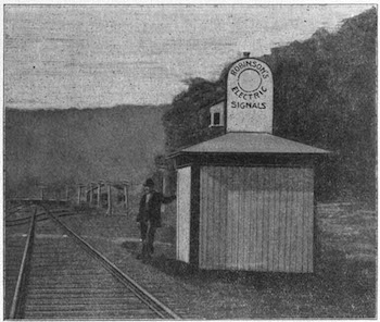
Fig. 1.
Robinson's Closed Rail Circuit System. Philadelphia & Erie Railroad,
1872.
As all the signal apparatus, relays, batteries, office switches and overlapping devices were already in operation there, it took but a short time to convert this open circuit system into a closed rail circuit system.
The first experiments proved conclusively that the system would work. The track, however, was in a fearfully unsuitable condition for the purpose. The light rails were fished together by a four foot wooden bar on the outside, and a twelve inch fish plate on the inside. There were two holes through the iron fish plate, allowing one bolt for each rail and four holes through the wooden bar, two for each rail. However, with a little care he managed to get the current working through the whole length of the section about a mile and a quarter in length.
It was evident, however, that on such a section as this a rail bond of some kind would be necessary for reliable, continuous service, and here, at this time, in 1872 Mr. Robinson conceived the invention of the bond wire method of electrically connecting the rails, now in universal use, or its equivalent, on every electric railway throughout the world using the rails for a return.
As it had been determined to lay new rails at Kinzua, another installation of the closed rail circuit system was ordered and immediately made at Irvineton, Pa. This signal is illustrated in Fig. 1.
It will be observed that the above installation, like that at Kinzua, not only displays a visual block signal, but also operates in connection therewith a loud gong which has been easily heard at a distance of a half mile, and was really heard by passengers in trains passing, with closed windows. An engineer could not possibly pass without hearing it.
A wire is seen at the upper part of the signal box, running out to the right. This is an overlapping signal wire.
A tell-tale bell was also placed in the station, indicating the actual position of the signal, and also a manual switch, whereby the agent could at any time cut off or short circuit the track battery and expose the danger signal against a train and instantly receive a return signal when the danger signal was actually exposed.
The Irvineton installation worked perfectly from the first never failing. The locomotive engineers were delighted with it and soon gave it the name of "The old reliable."
THE ROBINSON CLOSED RAIL CIRCUIT.
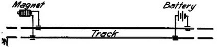
Fig. 2.
Wm. Robinson, 1871, Patented in France, February 29, 1872, and
United States August 20, 1872. Re-issued July 7, 1874. No. 5958.
The Robinson closed rail circuit, which now forms the basis, according to the best information, of every efficient automatic electric, electro-pneumatic and electrically controlled fluid pressure system throughout the world, is illustrated in its simplest form, in Fig. 2.
This figure shows the railroad track divided into sections, a mile more or less in length, the section rails being insulated from adjacent sections. A light battery has its terminals connected to the opposite rails at one end of the section and at the other end a relay magnet has its terminals connected to the opposite rails. Thus the current passes through the whole length of the section, keeping the relay on continuously closed circuit and magnetized as its normal condition. The relay thus keeps the secondary circuit, which directly controls the signal, normally closed, whereby the signal is normally held in a position indicating safety.
When a train enters upon the section, the wheels and axles, connecting the opposite rails thereof, short circuit the current from the relay, which instantly releases its armature, thus opening the signal circuit. The signal is then instantly thrown to the danger position by means of a counterbalance.
The signal may be of the enclosed disk type, electro-mechanical, electro-pneumatic, electrically controlled gas, or of any other kind. The Robinson patented system is broad, basic and a generic creation; it is not limited to any specific construction or arrangement of signal but covers all kinds.
In expounding the early history of the art of automatic signaling, the following photographic reproductions from some of Robinson's early circulars and patents will be of interest.
The following sections on Curve, Tunnel, Station, Switch and Draw-Bridge Signals are a photographic reproduction from a circular issued by Mr. Robinson in 1870:
CURVE AND TUNNEL SIGNALS.
A train approaching a curve will throw up a red signal around the curve as a warning to trains from the opposite direction, and will also exhibit a signal in its rear. Thus, collisions from front or rear are guarded against. These signals may be used throughout the whole extent of a road.
In entering a tunnel a train will exhibit a signal at the other end to indicate its entry, and when it gets through it will lower the signal and ring a bell at the opposite end to indicate its exit.
STATION SIGNALS.
A train when it leaves a station, and at various points as it passes, will indicate to the stations along the line, its Location, Direction, Rapidity and Length. Thus all necessary information regarding moving trains will be automatically announced every few minutes at the stations.
SWITCH AND DRAW-BRIDGE SIGNALS.
If a switch or draw-bridge is misplaced an approaching train will set an alarm ringing at the station and will also exhibit a red signal ahead of the train as a warning to the engineer that the switch is misplaced.
The following heading and sections are photographic reproductions of parts of a circular issued by Mr. Robinson at the time of its date, "September, 1872."
It will be observed that certain of these sections are the same as above reproduced from the circular of 1870.
It will be noted also that the description of the system begun after the heading is not here completed, for the reason that a full description is found elsewhere in this history.
For Switches, Draw-bridges, Crossings, Curves, Cuts, and Tunnels; also, to indicate the Location, Direction, Rapidity, and Length of Trains.
IMPORTANT IMPROVEMENTS.—ELECTRIC SIGNALING WITHOUT TRACK INSTRUMENTS, OR LINE WIRES.
THE NEW SYSTEM.
The operation of this system is as follows: A railroad track is divided into sections of any desired length, say one mile, more or less, by separating the abutting rails from metallic contact with the adjacent sections, but preserving metallic continuity throughout the length of the section. The insulation of the abutting rails is accomplished
CURVE AND TUNNEL SIGNALS.
A train approaching a curve throws up a red signal around the curve, as a warning to trains from the opposite direction, and also exhibits a signal in its rear. Thus, collisions from front or rear are guarded against. These signals may be used throughout the whole extent of a road.
In entering a tunnel a train exhibits a signal at the other end to indicate its entry, and when it gets through it exhibits a signal at the opposite end to indicate its exit.
STATION SIGNALS.
A train when it leaves a station, and at various points as it passes, indicates to the stations along the line, its Location, Direction, Rapidity, and Length. Thus all necessary information regarding moving trains is automatically announced every few minutes at the stations.
The batteries for operating the signals will last for months without attention, and one man can readily attend to all the signals and batteries throughout the whole extent of a road.
In all cases, where practicable, the signal wire should be carried through the coils of a bell-magnet in the nearest office. By this means the operator is informed when the battery power is decreasing, and warned that it requires renewing.
Office connections can be made, when desired, so that the signals may be operated by a telegraph key from the office, as well as by passing trains.
The signal wires may be tapped at intervals all along the line, and led into small cast iron boxes placed conveniently on the telegraph poles. Conductors of all trains, furnished with keys to these boxes, can, in case of special accident, go to the nearest box, touch a key within the same, and thus set danger signals at some distance in front and rear of their trains. The telegraph keys in these boxes not only set the danger signals as described, but they also place the said signals, for the time being, entirely out of control of moving trains.
THE CLOSED CIRCUIT.
The new system, as described, with closed circuit, is the best ever devised for "block-signaling," since the failure of the battery through neglect or otherwise, cannot possibly be productive of disastrous results to the train, however implicitly the signals may be relied on.
From the French of Feb. 1872 [Translation].
88th claim. "Connecting a battery B5, and a magnet M5 with the rails a9, b9, of a section of railroad track C5 in such a manner that when said rails are joined by a metallic bridge, the electric current will be diverted from the magnet M5, but so that when said bridging device is removed from said section C5 the electric current will be free to pass through and charge the magnet M5."
93d. "A signal or signals audible or visual in combination with the battery B5 and the rails of a railroad track, the whole being arranged to actuate the signal or signals, substantially as described."
William Robinson.
St. Petersburg, Clarion County, Pa., September, 1872.
It will be observed that some of the foregoing sections refer to the open circuit system, some specifically to the closed circuit system and some are applicable to either or both.
The following is a photographic reproduction of a postal card issued and distributed broadcast by Mr. Robinson at the time of its date, "May, 1873." It needs no comments.
ROBINSON'S
WIRELESS ELECTRIC SIGNALS,
THE SIMPLEST, CHEAPEST, and
Only Absolutely SAFE Electric Signals in Existence,
NOW IN SUCCESSFUL OPERATION ON THE
BALTIMORE AND OHIO,
PHILA., WILMINGTON & BALTIMORE,
PHILADELPHIA AND ERIE,
AND OTHER RAIL ROADS.
They work as AUTOMATIC BLOCKS with tell-tale alarms, OFFICE, STATION, ROAD CROSSING and SWITCH SIGNALS, and BROKEN RAIL DETECTORS. These signals have worked uninterruptedly through last winter regardless of rain, snow, slush or sunshine.
Descriptive circulars on application.
May 1873.WM. ROBINSON, St. Petersburg, Pa.
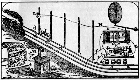
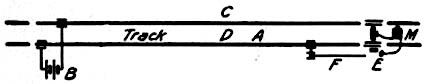
Fig. 3.
Illustration from Robinson's Circular of "January, 1874," showing
the Closed Rail Circuit, Relay and Overlapping System.
It is pointed out that the above illustration of January, 1874, shows the Robinson closed track circuit, as heretofore described, the relay R and the track battery I forming a part thereof, the signal actuating magnet E, the signal C operated thereby, the circuit wires of said magnet E connected to, and controlled by, the relay R, and the overlapping or distant signal L, with its circuit H controlled absolutely by the position of the signal C, the whole showing a complete closed track circuit overlapping system, with home and distant signals.
The following sections are from this circular of January, 1874:
"When it is desired to operate a secondary signal thrown forward or back of the primary, a line wire H is used, attached to the primary signal C in such a way that the secondary signal cannot possibly operate unless the primary signal C is first exposed, thus closing circuit on the wire H. The primary signal battery K is used to operate the secondary signal."
"To set the signal from an intermediate station a wire from each rail of the section A is run into the station. When these wires are connected by a key, the current from the battery I is placed on short circuit, and the signal exposed as before." (See Fig. 7.)
"The following functions may be embraced in the signals of a single section. BLOCK SIGNALING, both automatic and manipulated, SWITCH, DRAWBRIDGE, ROAD-CROSSING, and STATION-APPROACH SIGNALING, and BROKEN RAIL DETECTING."
"In this system it will be observed that, since the signal is exposed mechanically, any tampering with the rails or connections, or failure of the battery, will invariably result in exposing the signal; any error therefore which may occur from any cause will be in behalf of safety. It is impossible to show safety when the danger exists which the signal is designed to avert."
During the early seventies Mr. Robinson made other closed rail circuit installations on the Philadelphia & Erie and other railroads in Pennsylvania and Maryland.
Visit of the Pennsylvania R.R. Officials
On October 24, 1873, a special inspection train of the Pennsylvania railroad passed over the Philadelphia & Erie railroad, westward. The Pennsylvania R.R. officials aboard were: Mr. A. J. Cassatt, at that time general manager; Mr. Gardner, general superintendent; Mr. Lewis, controller; Mr. Robert Pitcairn, superintendent western division, and Mr. Frank Thomson, superintendent motive power.
Mr. Wm. A. Baldwin, general superintendent of the P. & E. road, was of the party, and Mr. Robinson joined the party on the latter road, and continued with it through to Erie, which was reached in the evening.
Stops were made at Ridgway on the Middle division and at Irvineton on the Western division to examine the Robinson closed circuit rail system of signals, which were in full operation at those points. A thorough examination and various tests were made, to all of which the signals responded promptly and perfectly.
The following is from a letter by Mr. Robinson to his brother on October 25, 1873:
"Mr. Baldwin could not say enough in favor of the signals." * * * "Of course I remained in the background, except, as to giving explanations. After a while Cassatt, Pitcairn and Thomson got into a discussion of the battery and other points, and called me into the ring to enter into the discussion, and it was quite animated for some time. Pitcairn proceeded to give his idea of what a signal should be, and Mr. Baldwin and the rest proceeded to show him that this, was exactly his ideal."
"Mr. Gardner, after learning modus operandi from diagrams &c. proceeded to lay down the law to the rest, demonstrating how they would have 'prevented those accidents.'"
"They were all very much pleased with the signals but their operation seemed such a surprise that I judge it will take them several days to think over and realize the actual operation and importance of the thing."
Robinson's Work in New England
In December, 1875, Mr. Robinson went to Boston and took up his residence there.
In January, 1876, he made an installation of his closed rail circuit system between Elm street and North avenue, West Somerville, on a branch of the Boston and Lowell railroad. This installation worked perfectly from the beginning.
The Emperor of Brazil Examines the Robinson Signal System
In June, 1876, His Imperial Majesty, Dom Pedro II, Emperor of Brazil, being then in Boston, graciously accepted an invitation from Mr. Robinson to examine his Wireless Signal System in operation on the Boston & Lowell railroad. Accordingly, on June 14, they proceeded together by special train to West Somerville for the purpose.
The following is an account of the visit, from the Boston Post of June 15, 1876:
"DOM PEDRO II.
"His Majesty Witnesses the Operations of Railroad Signals.
"Though the visit of His Majesty, the Emperor of Brazil, to this city has been a brief one, yet it is not hazardous to say that no other crowned head or representative of royalty who has ever appeared in Boston has more closely inspected the places where centre arts, sciences and manufacturers than he.
"In compliance with an invitation, the Dom proceeded yesterday morning to witness the workings of Robinson's Wireless Signal System, now in operation on a portion of the Lowell railroad. The Emperor and several members of his suit took passage on board a special train on the Lowell railroad soon after 8 o'clock yesterday morning and arrived at the West Somerville station about 8:30, where they were met by Professor Robinson, who at once began to explain to the royal party his system. At Elm street a large visual signal is placed which is controlled by the current from a single cell of a battery connected with the rail sections at North avenue, no line wires whatever being used. While the Emperor watched the signal at Elm street trains were run over the whole length of the signal section in both directions. As soon as the train entered upon the section at either end, the signal, without a moment's delay, showed the track "blocked," and when the train passed off the section it instantly changed the signal to "all clear." Then a rail was torn up, and almost instantly thereafter the signal denoted "danger" and remained so until the rail was restored and properly coupled up, when it as quickly changed to "all right." Mr. Robinson gave various other demonstrations illustrating the working of the system. To all the tests the signal instantly responded. His Majesty was much interested, and entered into a somewhat lengthy discussion with Professor Robinson in regard to the operations which he had witnessed. The Emperor's questions displayed profound scientific knowledge, and he fully comprehended the system. At the conclusion of the experiment Dom Pedro thanked Professor Robinson for his kindness in explaining and illustrating his system, and invited him to communicate with the Brazilian government with a view to introducing the system in Brazil. On the return of the party to the Lowell depot in Boston, the Emperor was received with great applause, which he politely acknowledged by waving his hat."
It will be interesting to note that on June 14, 1876, the day the Emperor inspected the Robinson Signal System at West Somerville, the battery had been in operation exactly 180 days without any attention whatever except that on two occasions a little water had been added to make up for evaporation, the signal working perfectly all that time and the battery with full strength.
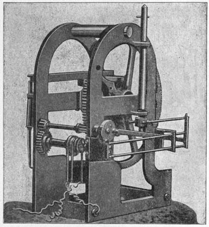
Fig. 4.
Robinson's Electro-Mechanical Signal in Operation at West Somerville
when Inspected by the Emperor of Brazil in 1876.
The following is from a report on the above signal by the station agent at Elm street, dated June 2, 1877, eighteen months after it had been installed:
"Robinson's Electric Signal at this place has been working uninterruptedly since it was first put in operation. * * * The signal is entirely reliable."
The above signal continued to work perfectly for a number of years until the signal post, which was of wood, rotted down.
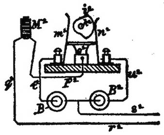
Fig. 4a.
The signal mechanism used on the Robinson signal at Elm street was of the electro-mechanical type.
Figure 4 is a half tone of the identical signal mechanism in operation there when the Emperor of Brazil examined the system with Mr. Robinson, on June 14, 1876.
It is pointed out that the above signal mechanism, Fig. 4, shows a battery or pole changing attachment which is more clearly shown in Fig. 4a, reproduced from Robinson's British patent No. 3479 of August 29, 1879.
In this device the movement of the cam i2 not only changes the battery but changes the polarity through the magnet M2, which may be placed anywhere and used for any purpose.
A special device for the same purpose was used not only in connection with the relay on the West Somerville signal, but on many others installed by Mr. Robinson.
This battery and pole changing device is more fully described in Robinson's U.S. patent, August 25, 1874, No. 154,520, Automatic Commutator; Application filed July 18, 1873.
The following extract therefrom, and claim, may be interesting:
"It will be observed also, that while the actual change of battery may be caused to take place when the magnet attracts its armature, yet I prefer to arrange it so that no change of connections shall take place when the armature is attracted, the actual change taking place only during the reverse movement of the armature, caused by the retractile force of the spring. Furthermore, when desired, the batteries may be so connected in circuit that reverse currents shall be passed through the magnets every time the batteries are changed."
Claim 2. "In combination with the electro-magnetic commutator having the described circuit connections, the rail sections A'A*, the one closing the circuit through the commutator, and thereby determining the battery to be connected to the other rail section, substantially as and for the purpose set forth."
It must be admitted that there does not seem to be a very long step between the disclosures of this patent and the present method of operating a distant signal by reversing current through a rail section.
It will be observed that in this patent one rail is used as a return for a plurality of batteries connected to independent opposite rail sections.
In an autograph letter addressed to the author by Professor Henry, secretary of the Smithsonian Institution, under date of October 14, 1875, the Professor discusses Robinson's peculiar method of using batteries in signaling by which he obtained the above wonderful durability of 180 days or more without renewal, and pronounced the results obtained "very remarkable." His discussion of the subject is somewhat suggestive of the principles of the storage battery.
Switches
In 1876, 7 and 8, Mr. Robinson made a number of installations on the Boston and Providence, Old Colony and the Boston, Lowell and Nashua railroads.
On the latter road, at Wilmington Junction, he equipped two parallel sections of the double track, including six switches, in this short space, five of them connected with one of the blocks. These sections were arranged as regular closed circuit blocks, operative under the moving trains. The switches were also connected up in such a way that every switch had to be closed and locked for the main line or the danger signal would be exposed against approaching trains. This installation was made in 1876.
The switch connection applied to these switches is shown in Fig. 5 and a general plan of the same is illustrated in Fig. 6. Both of these figures are reproductions from Robinson's aforesaid British patent of 1879.
Fig. 5.
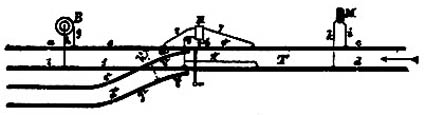
Fig. 6.
It will be observed that when the switch is on the main line the wires 7, 8 are connected by the plug 6 on the switch connection, thus completing a working circuit through the rails and around the switch, but when the switch is placed for a siding the wires 7 and 9 are connected by the plug 5, thus short circuiting the current from the magnet M, thus producing the same effect as would the presence of a train on the section. It is always better to short circuit the current than trust to the mere opening of circuit since short circuiting is sure to produce instantaneous results.
It will be observed, however, that in the above case the movement of the switch connection both opens the rail circuit and short circuits the current from the relay.
It may be here stated that Mr. Robinson equipped three switches in one closed circuit block, in the manner described above, on the Philadelphia and Erie railroad in 1873.
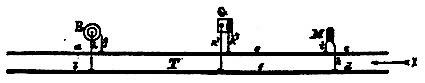
Fig. 7.
Fig. 7, from Robinson's English patent of 1879, aforesaid, shows the switch G arranged to operate the signal by hand from an office, station or telegraph post by the roadside, as heretofore described.
Drawbridges
About the time he made the Wilmington installations above described, Mr. Robinson made an installation of his system also on the Old Colony railroad, in which one block signal section at Somerset included a drawbridge. He included the track rails of the drawbridge in the track circuit in such a way that the withdrawing or loosening of any one of the bridge lock-bolts would display the danger signal, which remained exposed until the bridge and its lock-bolts were all restored to their normal condition insuring safety.
Tunnels
Long wet tunnels present peculiar difficulties to the reliable operation of the rail circuit; and yet these difficulties are readily overcome by including one or more additional relays in the signal section, as shown in Fig. 8, which illustrates the application of the Robinson track circuit system as applied to the Tehauntepec tunnel in California.
Mr. Robinson forwarded the signals and necessary instructions, and the installation was made by Mr. Stephen D. Field, secretary of the Electrical Construction and Maintenance Co. of San Francisco.
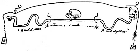
Fig. 8.
Figure 8 is from a sketch made by Mr. Field in a letter dated San Francisco, March 21, 1877, addressed to Mr. Robinson.
In this letter Mr. Field says: "I am just in the receipt of yours of the 12th. I had anticipated your diagram and have the signals arranged as you show.
"I use the system connected up as follows:
"In the tunnel the rails are buried in wet mud; outside no moisture touches them for six months of the year."
It will be noted that in the above case the signal section is two miles long, the tunnel being one mile long, with its rails "buried in wet mud," and the section extending one-half mile at either end of the tunnel. An extra relay and battery are placed in the center of the section connected up as shown. Thus, where conditions require, a signal section may be divided up into a number of sub-sections.
Later advices showed that the above signals worked perfectly and gave entire satisfaction.
Insulated Joints
In 1872 and the early seventies Mr. Robinson insulated the rail joints to form the sections by wooden bars, substantially as shown in Fig. 9.
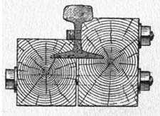
Fig. 9.
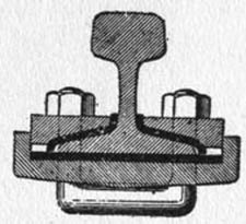
Fig. 10.
In 1876 and later he usually insulated the joints as shown in Fig. 10, using the Fisher & Norris trussed joint as a basis. Vulcanized fiber is placed between the bottom of the rail ends and the base plate, and fiber is placed between the flanges of the rails and the forelocks, and fiber, the shape of the rail section is placed between the ends of the adjacent rails, all as shown in Fig. 10. This makes an excellent insulated joint, both mechanically and electrically.
Rail Bonding
Dry rust forming between the fish plates and the rails of the track, at the joints, makes a poor conductor, and hence the low current, from only one or two cells of battery used in the rail circuit for signaling is very liable to find sufficient resistance at the joints from this cause to prevent the continuous passage of the current through the rails to the relay.
Mr. Robinson discovered this difficulty in his first experiments in rail signaling in 1872 and the necessity for making a reliable electrical connection from rail to rail in order to insure the reliability of his closed circuit signal system.
As heretofore stated, therefore, he at that time conceived the invention of the bond wire, Fig. 11, for this purpose, the connection to be made by drilling holes in the adjacent rails, driving the ends of the wires tightly into these holes, and making the connection so close that there would be no room for moisture to penetrate or rust to form. And as an alternative form he proposed to secure the ends of the wire, or of a plate, to the adjacent rails by soldering, as shown in Fig. 12.
In those early days there were serious technical objections to both of these methods.
First: The difficulty and expense of boring holes in all the rails of the section and connecting them up, and the difficulty of getting the railroad company to consent to such an innovation to test what at that time might be regarded as an experiment, and
Second: Soldering seemed impracticable on account of the difficulty of heating up the rail quickly enough at the required point.
Mr. Robinson, therefore, postponed the application of the bond wire until he could secure better facilities for applying and using it.
He, meantime, experimented along other lines, however, for the purpose of securing good electrical connection between adjacent rails without boring holes therein. One of these methods was very successful. It consisted in the use of elastic split springs having their ends resting on the flanges of the adjacent rails, and held in place by small blocks secured to the ties. The passing of a train depressing the rails slightly caused a slight frictional movement between the rails and the springs, thus preserving good electrical contact.
In the West Somerville installation, near Boston, made in January, 1876, as heretofore described, Mr. Robinson used the bond wire shown in Fig. 11. In applying this, holes were bored in the rails and the wire, fitting the holes as closely as possible, were forced in. A semi-circular punch was then carefully used to set the metal up close around the wire.
There has been no better bond wire devised since then except in mechanical construction. Bonds of various designs have been made heavier, and with heavier end plugs for mechanical connection to the rails.
These are good features as they render the bond less liable to breakage, and, as is well known, for electric railroads they should be much heavier than required in signaling, for the sake of conductivity.
A bond wire, to get best results, should be homogeneous, made of a single piece of metal, or if made of several pieces, all the pieces should be welded, or at least, soldered together. They should be of sufficient length to insure flexibility without disturbing the connection if the rails should move relatively to each other, and the whole circumferential surface of the plug end, or its equivalent, when possible, should be in the closest possible direct contact with the rail, that is, the bond plug should make connection with the rail as nearly as possible—homogeneous. Welding would be the ideal connection but it is not always practicable.
The reason for the above is obvious: that there should be no room left between the bond and rail for rust to form. It follows then that a bond held in position by an independent plug which renders it necessary for the current to pass from the bond to the intermediate plug and from that plug to the rail, is not the best form of bond, for the reason that it presents a double surface on which rust may form.
Figures 11 and 12 show Robinson's bond wires and strips of 1872, Fig. 12 showing the bond soldered to the rail.
In 1876, 7 and 8 he used on various roads in the vicinity of Boston, the bond shown in Fig. 11. In 1876 he used on the Boston and Providence road the bond shown in Figs. 11, 13 and 14.
In the form shown in Fig. 13, holes are bored through the upper ends of the plugs, which were slightly tapering. The wire was forced through these holes, and the wire and plugs were then soldered together with hard solder. The plugs being materially larger than the wire, could readily be driven home with a good deal of force, thus insuring an excellent electrical connection without endangering the wire.
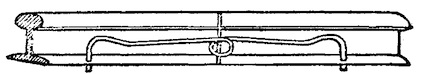
Fig. 11.
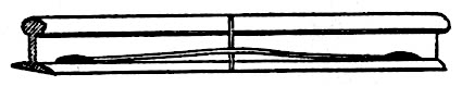
Fig. 12.
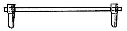
Fig. 13.
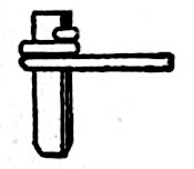
Fig. 14.
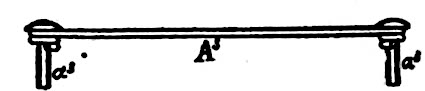
Fig. 15.
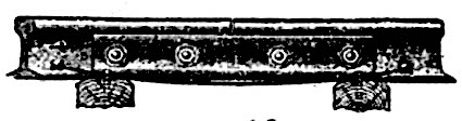
Fig. 16.
In Robinson's British patent No. 3479, of August 29, 1879, aforesaid, he illustrated the form of bond shown in Figs. 15 and 16, which is an equivalent of that shown in Fig. 14, used by him in 1876.
Mr. Robinson claimed the bond wire broadly in this British patent, in the following claims:
10. "The wire A3 in combination with the rails B3, B3, and securely fastened thereto, for the purpose described.
11. "In combination the wire A3, the rails B3, B3, and the rivets a3, a3, the whole arranged substantially as described for the purpose of securing electrical continuity between said rails."
The above is believed to be the first disclosure of means for electrically connecting rails by a bond wire in any patent, although Robinson had disclosed it to various parties, and used it on installations years before.
On the subject of rail bonding the following bit of evidence may be of interest:
In a letter dated Baltimore, October 29, 1874, addressed to Mr. Robinson by Mr. J. H. C. Watts, of Watts & Co., manufacturers of Robinson's signal apparatus, he says:
"Am afraid your idea of soldering a strip of copper to the rails will prove very troublesome in carrying out, as it is a most difficult matter to heat so large a body of iron sufficiently to make a sure joint such as you require, or that will stand the jarring of passing trains, &c., to say nothing of sneak thieves who abound wherever copper is lying around loose. I know however you scoff at theory so will 'dry up.'"
The electric dynamo of today has removed the above pointed out difficulty. Bond wires or strips are now welded to the adjacent rails for the purpose of securing reliable electrical connection between them. Welding is soldering, according to the definition of the term. Thus, the Encyclopedic dictionary gives the definition: Solder: "To unite or cement together in any way. * * * In autogenous soldering the two pieces are directly united by the partial fusion of their contiguous surfaces."
Thus, more than thirty years ago Robinson proposed to solder bond wires or strips to the rails for the purpose of securing good electrical continuity between the same. But it became necessary to wait some twenty years for the development of a commercially practical process for accomplishing this result. This is found in the modern electric welding process.
Robinson's object was to secure a perfectly homogeneous joint or connection between the bond and the rail. His invention, in this connection, consisted in a metallic bond arranged for electrically connecting adjacent rails of the track and means for forming a homogeneous connection between the bond and the rails. This embraces any mode of accomplishing that result. Robinson had simply anticipated the electric process by some twenty years, but that process now accomplishes the result in a simple manner impossible thirty years ago.
The splice bars now welded to opposite sides of street rails in many places are used primarily for the purpose of electrically bonding the rails; incidentally they serve the double purpose of also making a good joint mechanically. Every electric railroad uses the bond wire or plate in some form, originally invented and used by Robinson, for electrically bonding rails together.
Thus, it is clear, this simple invention of Robinson made more than thirty years ago, an outgrowth of his original creation of the closed rail circuit system, has made possible the electric railroading of today, and the method of rail-bonding is now used on every electric railway using a rail return, throughout the world.
ROBINSON'S LATEST ELECTRIC SIGNALING APPARATUS.
Fig. 17.
Rings a Bell on the Engine when Track ahead is all Clear.
Figure 17 is a reproduction from a postal card dated September, 1875, and issued at that time. It illustrates means for operating a positive safety signal in the cab of a locomotive when the track ahead is clear and safe, the operative current passing through the rails from the distant end of the track section upon which the train is entering.
This system is elaborated in Robinson's British patent of August 29, 1879, where it is shown operatively applied to a single track in such a manner as to operate a signal on a locomotive approaching from either direction, the operative current coming from the opposite end of the section—no line wires being used.
It is not thought necessary, therefore, to more fully describe the system here.
In General
The scriptural injunction, "Prove all things, hold fast that which is good," is the key note of scientific progress. He who would discover truth must not accept anything because it is popularly accepted, or reject anything because it is popularly rejected; nor must he regard anything as impossible because never heretofore accomplished, although perhaps attempted by the most able scientists. While giving full weight to principles and laws demonstrated and verified by original investigations, he must bear in mind that those principles and laws may be capable of various combinations and interpretations; that the popular interpretation may not be capable of general application, and if not, it must be erroneous. In short, he must enter upon his investigations systematically, independently and untrammeled by prejudice.
These remarks apply to electrical science with great force at the present time. Those who enter this field to advantage should be men of culture, of theoretical knowledge, and eminently practical.
These facts are illustrated by the efforts heretofore put forth in Europe and the United States to develop systems of rail signaling. Such efforts, in the early days, appear to have been exerted principally by theorists whose propositions and complications prove them to be not only ignorant of some of the fundamental principles of electrical science, but also, some of them, extremely unpractical. That the efforts in this direction may be fairly understood we will direct attention to a few of the systems of rail signaling proposed,—those which have elicited most attention—giving outline illustrations of some of the circuits which form their bases, and pointing out their defects and merits.
Early Rail Systems
So far as we have knowledge, the idea of using the rails as conductors for electric signaling purposes was first suggested in an English patent of 1848. This was merely a suggestion, however, and no attempt was made to describe any specific method of using the rails for the purpose.
In 1853, however, an English patent was granted to George Dugmore and George Millward, in which is described a method proposed for using the rails as conductors. The design of the invention is to communicate between trains on the same line, and between trains and stations, for which purpose it is proposed to use long sections of rails. The unpractical part of this system is that to make it operate it is necessary, as the inventors say, to insulate the opposite wheels of all the carriages from each other, in order that electrical connection may not be established between the opposite rail line by the wheels and axle.
Imagine one of our gigantic locomotives having its opposite drivers electrically insulated from one another!
Figure 18 represents the signal system described in William Bull's English patent of October 31, 1860. In this system, it will be observed, the rail sections used are short, "twenty feet, more or less," and are the terminals of line wires which connect with the battery and magnet at the station. The signal at the station is visual and consists of an indicator operated by wheel work actuated or controlled by the electro-magnet M shown in the diagram. The signal as described, moved in one direction only, by a step-by-step movement.
In the following diagram M represents magnet and B battery.
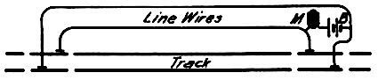
Fig. 18.
William Bull's British Patent, October 31, 1860, and Frank L. Pope's
Experiment at Charlestown, Mass., in 1871.
Mr. Bull says: "At the stations at which it is required that the progress of the train shall be indicated, a battery is fixed and in connection therewith a dial or indicator, both of which are also connected with the line permanent way wire, the terminals of which are the pairs of insulated rails, as before described.
"When the train arrives at the contact points on the line, the electric circuit would be completed by the wheels of the engine connecting the two insulated rails, when the current would flow and actuate the electro-magnetic armature," &c.
The mode of insulating the rails from each other is described by Bull as follows:—"Between the end of the rails, and also between the joint plates and rail ends, I insert a thin piece of leather, mill-board, gutta percha, or other suitable substance, suitable for cutting off metallic contact, and thereby insulate one rail of twenty feet, more or less, as may be necessary."
In Pope, in a description of his experiment at Charlestown, in a paper read by him before the New York Society of Practical Engineers—of which, by the way, Mr. Robinson was a charter member—and subsequently published, admits that he did not use the "rail circuit" at all in any proper sense of the term. On the contrary, he used line wires forming his main circuit terminating in short sections of rails, forty-two feet in length according to my recollection, that is, the length of one rail.
The train passing over the short rail section at one point closed the circuit through the line wires, thus exposing the signal, which was held in place by a "detent." The train, having reached a distant point, passed over another similar short section of rails, closing circuit through another magnet which released the "detent" and reversed the signal.
It will be observed that the essential features of the device used in Pope's experiment, on which he laid great stress, and described in Bull's patent, are identical, that is, the circuit closer consists, in the one case of a section of rails "twenty feet long, more or less," on open circuit, and the other identically the same, but with a rail section forty-two feet long, both using line wires.
Pope and his friends heralded this experiment—a revival of Bull's device—as demonstrating a wonderful invention on the part of Pope.
What Robinson Has Done in Automatic Electric Signaling
It is an invention so unique and profoundly philosophical that those best skilled in the electrical art at the time it was made, declared that it was contrary to all known laws of electrical action and could not possibly work.
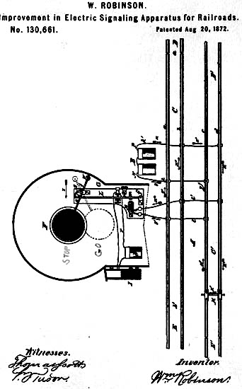
W. ROBINSON.
Improvement in Electric Signaling Apparatus for Railroads.
No. 130,661. Patented Aug 20, 1872.
Be it known that I, William Robinson, of Brooklyn, in the county of Kings and State of New York, have invented a new and useful Electric Signaling Apparatus for Railways, of which the following is a full, clear, and exact description, reference being had to the accompanying drawing forming part of this specification.
The figure represents a top view of a double-track railway, with suitable sections and wire connections, together with an elevation of the signal-box with its face removed to show the signal within, the whole being arranged to illustrate my invention.
The object of this invention is to operate electric signals, audible or visible, by means of moving or standing vehicles or trains without the use of ordinary track connections for closing or breaking circuits, and without the use or with a limited use of line-wires for conducting the electric current, the rails of the track being used for the latter purpose. The invention consists in an improved signal of very simple construction, by which great ease of action is secured. It also embraces certain peculiarities in the arrangement of wires from the signal and battery to the track. A in the drawing represents a double-track railroad. C is a section of track, which may be a mile long, more or less, and having its rails a b separated from metallic contact with the rails of the sections D and E, as shown at a' b'. In like manner the section C' of the other track has its rails separated from metallic contact with the rails of the sections D' and E'. The rails a b c d should each have metallic continuity throughout the length of its section. The signal-box F is constructed of any suitable material, and is provided with an orifice, preferably in the center, covered with glass windows capable of illumination, through which the signal may be seen when exposed, day or night. Within this signal-box is placed the signal G, consisting of a disk, S, attached to the lever e, which, pivoted at f, turns on a horizontal axis. To the lever e or its arbor is fixed the small projection or lever, preferably segmental, g. A cord, link, chain, or delicate elastic spring, i, is attached to the lever g and to the upper part of the long lever L, in such a manner that when the armature m, which is attached to the lever L, is attracted by its magnet M and the upper part of said lever L swings in the direction of the arrow z, the upper part of the segmental lever g moves forward and downward, thus permitting the chain i to work closer to the pivot f. By this arrangement it will be seen that the greatest leverage-power is secured for moving the signal when the armature m is the greatest distance from its magnet and the magnetic force is consequently weakest, the leverage-power diminishing gradually as the armature approaches the magnet. The vertical lever L moves on a horizontal axis, f', and is prevented from swinging too far back from the magnet by the adjustable stop s, which may be so adjusted as to bring the armature m a greater or less distance from its magnet M, as may be found necessary. The levers L and e may be made of any suitable material and in any manner; but are preferably constructed of thin tubular metal for the purpose of securing great strength and rigidity with minimum weight and friction of parts. Furthermore, the disk S is counterbalanced by an adjustable weight, w, and by making that part of the lever e embraced between the pivot f and the disk S of considerable length, the disk S is brought from a state of concealment to a state of exposure, or the reverse, by passing through a comparatively small angle, and by arranging the disk-lever e, as shown in the drawing, in such a manner that in bringing the disk from a state of concealment to a state of exposure, or the reverse, said lever e shall swing to and beyond a horizontal position, the greatest uniformity of motion with the least possible loss of power are secured.
Having thus described the construction of the visual signal G, it will be seen that when the electro-magnet M is charged it attracts the armature m to itself, thus swinging the upper end of the lever L in the direction of the arrow z, and carrying the upper end of the lever g forward, at the same time turning the same together with the lever e on the axis f, and carrying the disk S down into the position indicated in dotted outline. Now connect one pole of the battery B with the rails a and c, and the other pole with the rails b and d of the sections C and C' by means of the wires k and k', respectively. In like manner connect the ends of the coils of the magnet M, the one end with the rails a and c and the other end with the rails b and d of the same sections C and C' by the wires l and l', as shown in the drawing, and the apparatus is operative. The wires from the battery and the signal to the track are preferably insulated.
Before describing the operation of the apparatus as a whole, it may be stated that the electric current will follow a naked metallic conductor if of sufficient surface, even when immersed in a river or in the mud at the bottom of a river, because the metal offers less resistance to its passage than either water or mud. Much more will it follow the rails of a railroad track when they are made a part of the circuit, since the rails present a large surface of good conducting material, which offers much less resistance to its passage than any surrounding mediums; and it is well known that when several courses are presented the electric current will follow that course which offers least resistance to its passage.
The mode of operation is as follows: Suppose the sections C and C' to be entirely clear of cars; then the electric current from the positive pole P of the battery B will pass as indicated by the arrows x x, through the wire k', rail b, wire l', and magnet M, charging the same, and return through the wire l, rail a, and wire k, as indicated by the arrows y' y, to the negative pole N of the battery. The magnet M, being thus charged, attracts its armature and swings the signal-disk S into the position of concealment shown in dotted outline, and holds it in that position as long as the sections C C' are clear. Now let a train enter upon C or C', as indicated at H C', and the wheels and axles of the same will bridge over the rails c and d, and thus, by offering a large conducting-surface, will present to the electric current a complete circuit, which offers much less resistance to its passage than that through the magnet M. The electricity now takes the course over the wire k', rail d, wheels and axle H, returning, by the rail c and wire k, to the battery, as indicated by the arrows x x' y, using the rails c and d, as will be seen, with their bridge, and entirely avoiding the magnet M, which, being thus demagnetized, lets go its armature, and the counterpoise w, which slightly overbalances the disk S, carries the same up in front of the orifice, into a position of exposure, where it remains, as shown, while a train is on section C or C'. When, however, the train has run off, leaving sections C and C' clear, the magnet M is instantly charged again and the signal-disk is removed and kept concealed until the track is again blocked by the presence of another train, when the same process is repeated. When the signal-disk is in a position of exposure, as shown, the lever l may serve to close an additional circuit through the battery B, which may be used to operate an alarm, I, in conjunction with the signal S, or to actuate another signal at a distant point. Furthermore, the concealment of the signal S may serve to close another circuit for exposing another signal, or the reverse. Instead of using the signal G, constructed as herein minutely described, a signal of any suitable construction may be used without affecting the spirit of the invention. Furthermore, instead of using the magnet M to actuate the signal directly, it may be used as a relay, operating, when charged, to keep the circuit which directly actuates the signal open or closed, as desired. It is evident that an alarm may be used either in conjunction with or independently of a visual signal. The drawing shows an application particularly adapted to road-crossing signals on a double track. The signals may be used, also, on a single track and be applied as block signals and for other purposes on single or double tracks. When used as a block-signal or for other purposes, it may be desirable to indicate at a distant station when the signal is operative. To accomplish this object, carry one of the wires from the magnet M to the distant station. Here let the wire be passed through the coils of a bell-magnet or other signaling device, and thence be carried to the track and attached to the same, as already described. The office signal will operate simultaneously with the signal S. Thus any desired number of signals may be operated simultaneously, at different points, from a single section of track.
By a slight modification of the plan described an efficient switch and drawbridge signal may be operated, the rails being used as conductors. Thus half a mile, more or less, from a switch may be placed a signal-box and signal, substantially as described, and connected with the rails, as shown. Near this point let the rails be divided, taking care that the signal and battery wire are connected to the section toward the switch. Now, while the switch is on the main line, the bars connecting the rails of the switch will act as a bridge to divert the electricity from the signal-magnet. But when the switch is misplaced the metallic connection of the rails of the track will be interrupted. The signal-magnet will thus become charged and the position of the signal changed. In this case the signal should be exposed when the magnet M is charged. In like manner a cross-bar may bridge the rails on a draw-bridge. The displacing of the draw-bridge or withdrawing of the bolt or bolts which hold the same in position will allow the signal-magnet to become charged and the signal to be changed, substantially as described, in connection with a switch.
It is not necessary in all cases that the rails a and b, section C, should both be separated from metallic contact with the sections D and E. It may often, if not always, be sufficient to separate only one of said rails from such metallic contact with the adjacent sections.
What I here claim as new, and desire to secure by Letters Patent, is—
WILLIAM ROBINSON.
Witnesses:
John Rooney,
Van Wyck Foster.
Data Notes
Originator and patentee (basic patents, 1872) of the Closed Track Circuit System of Automatic Electric Signaling, the basis of practically every automatic electric block signal system in use on railroads today.
The following brief description and comments on this Robinson closed track circuit system are from the Third Annual Report of the Block Signal and Train Control Board to the Interstate Commerce Commission, dated November 22, 1910, pages 177 et seq.
"The Track Circuit
"Perhaps no single invention in the history of the development of railway transportation has contributed more toward safety and despatch in that field than the track circuit. By this invention, simple in itself, the foundation was obtained for the development of practically every one of the intricate systems of railway block signaling in use today wherein the train is, under all conditions, continuously active in maintaining its own protection.
"In other words the track circuit is today the only medium recognized as fundamentally safe by experts in railway signaling whereby a train or any part thereof may retain continuous and direct control of a block signal while occupying any portion of the track guarded by the signal."
"Invention of the Rail Circuit
"To Mr. William Robinson the Patent Office records concede the honor of having devised the first practical track or 'rail circuit.' This comprised what is termed the closed track circuit in distinction from the open form that preceded it." * * *
"Closed track circuits are very reliable, wholly safe in principle, and simple of application and maintenance."
* * * "Attention is therefore directed to the closed track circuit—the basis of all modern automatic signal systems that are entitled to recognition as embodying the highest attainments in the matter of safety."
"The Closed Track Circuit
"The closed track circuit in its simplest form consists of the two rails of a section acting as prime conductors, a generator maintaining a difference of potential between them when the rails are unoccupied, and one or more relays connected across the rails."
* * * "The closed track circuit maintains the relay, normally, in an energized state, and the influence of the train upon the rails is to totally de-energize it by shunting or short-circuiting the generator—a thing as effectively done by a single car or locomotive as by a train of any length, for all practical purposes."
* * * "A failure of the generator or a break in the circuit, whether in the rails themselves or in other parts of the circuit, produces the same effect upon the relay as that of a train upon the rails.
"This is in full conformity with the accepted principles of safe signaling, which give heed not alone to the action of the devices of the system under normal conditions, but embrace also an equal regard for safe results following derangements of them."
Historical Notes
In this connection a few historical notes on the origin and introduction of the closed rail circuit system of automatic electric block signaling on railroads may prove of interest.
In 1870 Mr. William Robinson exhibited at the American Institute Fair held in New York City, an elaborate working model of an automatic electric signal system for railroads. This was a road crossing signal operated by trains approaching in either direction. When at a suitable distance the train set a gong ringing at the road crossing ahead, which continued sounding an alarm until the train had passed, when it ceased ringing. In this model the relays were de-energized by short circuiting, although the signal was operated on the normally open circuit plan. This is believed to be the first case in which short-circuiting had been used in the operation of railway signals.
In 1871 Mr. Robinson installed this system as an automatic block signal on a block over a mile in length, at Kinzua, Pa., on the Philadelphia and Erie Railroad. This installation embodied a relay, a large visual signal under control of the relay, a heavy electric gong operated in conjunction with the visual signal, all at the signal station. From this station an overlap extended to the agent's station a mile ahead. Here a signal bell was provided so that when the visual signal was actually in the danger position it closed circuit on the bell magnet in the agent's station, the hammer remaining against the bell until the reversal of the distant signal opened the circuit of this check signal.
This system worked perfectly, performing all claimed for it; but it was a normally open circuit system, the only principle ever dreamed of up to that time for operating an automatic electric railway signal.
Immediately on the completion of this open circuit installation Mr. Robinson began to look for weak points about it, and soon discovered several now well known as inherent in all normally open circuit systems, not the least of which was that if the circuit were broken or the current failed from any cause the signal would remain at safety, thus showing a false signal although danger might be imminent, a radical error in principle fatal to the reliability of any normally open circuit system of signaling.
He therefore, after much study, devised the closed track circuit system, the construction and operation of which are clearly described above by the Interstate Commerce Commission.
In devising this system Mr. Robinson reasoned that to make an efficient and reliable system every pair of wheels in the train must control the signal, whereby a single car on the block, or a break in any part of the circuit, or loss of current from any cause affecting the relay, would keep the signal at danger as effectively as the presence of a whole train on the block.
These considerations led him to the invention of the closed track circuit operating as heretofore clearly described by the Interstate Commerce Commission.
Before making tests of the system, however, he applied for and was allowed basic patents on the closed track circuit system in the United States and France, the United States patent dated August 20, 1872, No. 130,661, and the French patent February 29, 1872, No. 94,393.
Having all the signal apparatus in operation at Kinzua, in the open circuit system, as above described, it was a simple matter for him to test the closed circuit system at this point. He therefore divided the opposite rails of the track into sections insulated from the adjacent continuous track rails and connected the relay terminals to these sections at one end and similarly connected a battery thereto at a suitable distance from the relay, thus forming a closed track circuit.
This being done, the first train that passed connected the opposite rail lines through the wheels and axles, short circuited the relay, thus operating all the signal circuits under its control, thereby practically demonstrating the feasibility of the system. This was in 1872. This block was extended to the agent's station over a mile from the signal, at which station the track battery was placed and also a switch for the manual operation of the signal, and also an overlapping telltale signal showing to the agent when the distant main signal was actually exposed at danger. The signal also indicated to the agent the approach of a train when a mile away.
Another installation was immediately ordered to be made at Irvineton on the same road. This was completed early in 1873 and worked perfectly from the beginning, performing all the functions described in connection with the installation at Kinzua. The locomotive engineers were greatly interested and soon christened the Irvineton signal "The Old Reliable." This was followed by other installations on this road and in 1873 Mr. Robinson had made installations of his closed rail circuit system of signaling on four different railroads, followed by various installations on many other railroads in the following years, as he was the sole owner of the system for about nine years, that is, until about 1880 or 1881, when the Westinghouse people obtained control of the system by the purchase of Robinson's interests. This was promptly followed by a reorganization under the name of the Union Switch and Signal Company, the terms "Union" and "Signal" representing the Robinson interests in the reorganization. This company thus became the sole owner of the Robinson Closed Circuit System of signaling until the expiration of his patents, when all other signal companies adopted the Robinson system as the basis of their signal work.
The original name of the Robinson Company was The Union Electric Signal Company, which Robinson organized and owned in 1878. In the reorganization the word "Electric" was canceled from this title and the words "Switch and" substituted, thus forming the present title: "The Union Switch and Signal Company."
Rail Bonding
Experience at Kinzua with a very poor track demonstrated the necessity of a rail bond to secure reliable electrical continuity throughout the rails constituting the block. Here, in 1872, Mr. Robinson conceived the invention of the bond wire as used today.
In an effort, however, to avoid the handicap of having to bore two holes in every rail of long sections of track, he equipped a signal section in 1873 with elastic steel plates bearing on the adjacent rails at the joints. This did not prove as satisfactory, however, as the bond wire. He therefore used bond wires made after his original conception, on every installation he made after 1873.
He made his bond wire in two forms. In the second form he made studs slightly tapering, bored holes through them, inserted the ends of the wire in these holes, brazed them together and drove these studs securely into holes bored in the adjacent rails. An examination of these bonds after several years' service showed that they were apparently in as good condition mechanically and electrically as when first put in place.
The Rail Bond is now an essential basic feature of practically every one of the electric railway systems now in operation, since they all use the track for a return, and the track rails must be securely bonded in order to insure indispensable electrical continuity of the circuit.
In addition to his signal system, therefore, Dr. Robinson is clearly entitled to the credit of having made, before the inception of electric railroading, a simple basic invention in his bond wire, which has made modern electric railroading possible, an invention indispensable to the successful operation of electric railroading as practiced today.
This invention has saved the electric roads untold millions of dollars and enabled them to accomplish results in a simple manner which could not otherwise be as well secured at any cost, by the only alternative method, of running return contact conductors in the air.
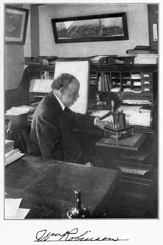
William Robinson.
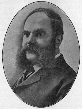
William Robinson, Ph.D.; E. & M.E.
Original inventor and patentee of the Automatic Electric Signal
Systems now in use on the leading railroads in the United States and
Foreign Countries.
William Robinson, B.A., 1865; M.A., 1868, Alpha Delta Phi. Ph.D. Boston University, 1907. Born November 22, 1840, in Ireland.
Principal of High School, Ansonia, Conn., 1865-66. In the oil region, Pennsylvania, 1866. Taught in Stamford, Conn., 1867. Principal of Spring Valley Academy, N.Y., 1867-69. Engaged in the oil business in Pennsylvania, 1869-72. President and General Manager of the Robinson Electric Railway Signal Company, 1873. Engaged in business in Boston, Mass., 1875-81. Organized the Union Electric Signal Company, 1878. Traveled in Europe, Egypt and Palestine for fifteen months, 1879-80. Inventor of the Robinson wireless electric railway signal system, of the Robinson radial car truck, of the coaster brake used on bicycles, of roller bearing skates, and of a repeating telephone. Engaged in developing and practising electric engineering. Author: History of Automatic Electric and Electrically Controlled Fluid Pressure Signal Systems for Railroads.
Died January 2, 1921, Brooklyn, New York.
Copy of Dr. Robinson's record made from original application No. 1265 to the American Institute of Electrical Engineers, 33 West 39th Street, New York City. (Record filed July, 1909.)
References given by Dr. Robinson:
WILLIAM ROBINSON (A.M., Ph.D.)
ELECTRICAL AND MECHANICAL ENGINEER
Born November 22, 1840, North of Ireland, of Scotch-Irish descent on paternal side and English on maternal side.
Eligible for Transfer: Under clauses (a) and (c).
Education: Graduate of Wesleyan University, full Academic course, receiving the degrees of A.B. in 1865 and A.M. in 1868.
Post-Graduate of Boston University in 1907, with degree of Doctor of Philosophy; course including Electrical and Mechanical Engineering.
Occupation and Work Done: Engaged in developing and practising electrical engineering from prior to 1870 up to the present time (1909).
Original inventor and patentee of the automatic electrical and electrically controlled fluid pressure signal systems for railroads now in universal use on the leading railroads in the United States and foreign countries, wherever and by whomsoever installed, throughout the world.
1870. Received four United States patents on this system; applications filed earlier.
1870. Exhibited an elaborate working model of the system at the American Institute in New York, showing the automatic signal system in operation under control of passing cars.
1871-2. Original inventor and patentee of the closed track circuit system of signaling. Received basic United States and French patents covering same, in 1872. Applications filed, 1871.
1870-71. Original inventor and patentee of the automatic electro-pneumatic signal systems for railroads in use for many years past. Received basic British patent covering this system in 1871. So far as I have been able to ascertain on careful investigation, this patent appears to be the first ever issued anywhere on this subject.
The following brief historical excerpt is taken from a United States patent granted to me on October 20, 1908, No. 901,383, on an electric railway system. This patent is one of a bunch of eight taken out by me on the same date, on the same subject. The excerpt relates to my work in signaling.
"The block signal system herein disclosed is an embodiment of the Robinson electro-pneumatic system now in extensive operation on the Pennsylvania railroad and many other leading railroads in this and other countries, embodying the closed circuit rail system for which a basic U.S. patent was granted to me on August 20, 1872, No. 130,661 (reissued July 7, 1874), the electro-pneumatic signal system disclosed in my British patent of August 30, 1871, No. 2280, the subject matter of both of which patents is disclosed in my French patent of February 29, 1872, No. 94,393. The electro-pneumatic signal system disclosed in the above named patents is also disclosed in my United States patent dated November 7, 1882, No. 267,259. As above indicated the block signal system herein described comprises the system described in my above named patents and now in general use on leading steam railroads, but modified and improved in a way adapting it for reliable and efficient use in connection with electric railroads of the sectional third rail type."
The admission of the above brief history in the above described, and substantially in two other patents of the same date, is, of course, a complete verification of its historical accuracy by the Patent Office.
1872. In 1872 I put the closed track circuit system of signaling in practical and successful operation at several points on different divisions of the Philadelphia and Erie railroad, and on other roads.
1872-79. In 1872 to '79 I installed the closed circuit rail system of automatic signaling on various railroads in Pennsylvania, New England and elsewhere. I perfected the system and put it in as perfect and efficient and durable operation at that time as it is in today, including all its functions of block, switch, road-crossing, overlapping, rear and front, tell-tale and broken rail detector.
1878. Organized and owned the Union Electric Signal Company, based solely on my signal patents, at that time nine in number. Some time afterwards George Westinghouse and his associates bought the controlling interest in the Union Electric Signal Company and reorganized the company under the name of the Union Switch and Signal Company. Thus, the automatic signal system of the Union Switch and Signal Co. consists, in every essential particular, of the Robinson system, pure and simple.
It may be here pointed out that all the railway signal companies now in operation, installing automatic signals under whatever name, are using the Robinson system bodily, and have been since the expiration of Robinson's basic patents. There is no other system, as a system, in use.
History: Several years ago I published a "History of Automatic Electric and Electrically Controlled Fluid Pressure Signal Systems for Railroads," the only authentic history ever published on the subject.
This was written and published at the instance of engineering friends, in the interest of indisputable historical accuracy.
Telephone Experiments
1876. As a matter of more or less interest I may here state that I carried on a conversation by telephone, in 1876, through a railroad track, the circuit consisting of the two rail lines constituting a closed circuit signal block.
1877-8. Delivered numerous illustrated lectures on the telephone, and at this time discovered the principle of the wireless telephone and actually transmitted speech clearly back and forth across an open space of several inches to and from a telephone having but one terminal grounded and the other free in the air. The free, uninsulated wire (except at supports) extended several hundred feet through the air. The instruments used were large magneto telephones of my own special designing, and made by me for the special purpose of illustrating lectures. No battery was used.
Electric Railway Systems
Outside of automatic signaling I have done considerable work along original electrical lines.
In addition to other work of importance I have for more than fifteen years devoted much time to developing a radically new departure in electric railroading.
On this system I have applied for more than twenty patents, extending over a series of years, fourteen of which patents have already been issued.
What This System Accomplishes
The system is elaborate, providing for safety on and off the trains, economy of current, simplicity and certainty in action, dispenses largely with electrolytic action, and when alternating propulsion current is used the return is confined to the length of the block. It is believed that the system will prevent all danger to passengers and trains from the direct action of the propulsion current.
President Roosevelt called the attention of the Interstate Commerce Commission to my electrical and mechanical inventions for making railroading safe.
Mechanical Engineering
I have done considerable original work in mechanical engineering.
In this connection I may mention the well known Robinson Radial Car Truck, which is in quite extensive operation on electric railways. This is the only car truck, I believe, ever designed and constructed on correct mechanical principles. It is so constructed that every axle in the car or train becomes exactly radial to any curve around which it passes, all the axles becoming parallel on straight lines only. This prevents wear and tear and grinding and derailment on curves. It also greatly economizes current.
One of these radial cars, in St. Louis, having a 28-ft. body, exclusive of platforms, equipped with a radial truck having a 15-ft. wheel-base and two motors, stopped in the middle of a street corner curve and started with the same power as on a straight line, as shown by careful tests with volt and ammeters. The test was made by officials of the company without my knowledge at the time. I believe this is the coming truck for electric locomotives.
(I forward by same mail a catalogue of the Robinson Radial Car Truck, fully illustrated, for the information of the Board.)
Coaster Hub
I am also the inventor of the back pedal braking and coasting bicycle hub, which has been in general use for many years. My application for a basic patent covering this hub has been pending in the Patent Office for twelve years, held back nine years by interference litigation in the Patent Office, owing to an effete interference system which has no apology to offer to justify its existence.
Turbine Engines
In turbine engines I have made some important improvements.
In one the engine is reversible by the movement of a single lever in either direction.
In a second the steam is utilized a second time under conditions doubling the original efficiency, and balancing the end thrust perfectly.
In a third improvement the engine develops more than three times as much power as any other turbine of its class occupying the same floor space. Patents allowed but not yet issued.
I figure that ocean steamers should furnish a large field for these machines.
Respectfully submitted,
(Signed) William Robinson.
276 Stuyvesant Ave., Brooklyn, N.Y.
Part II
The progressive ideas of William Ashbridge Baldwin were responsible for the first tests of the closed track circuit under actual operating conditions. It was through his confidence in this invention of Dr. William Robinson that the possibilities of the application of the closed track circuit to the safety of train operation was proved. Mr. Baldwin, at the time the first signal installations were made at Kinzua, Pa., and Irvineton, was general superintendent of the Philadelphia and Erie, now part of the Northern Grand division, Central region, Pennsylvania System, and because he made possible the development of signaling to its present standard by his interest and active co-operation in the 70's in making train movements safer, it is but fitting that he should be given a place in the memorial to Dr. William Robinson.
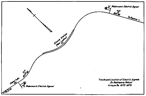
Tracks and Location of Electric Signals Dr. Robinson's Patent Kinzua Pa. 1872-1873.
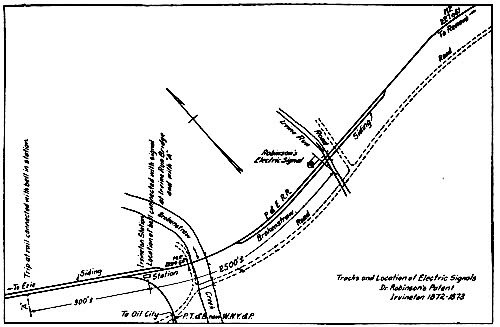
Tracks and Location of Electric Signals Dr. Robinson's Patent Irvineton 1872-1873.
Before stating Mr. Baldwin's railroad activities it will be well to describe briefly the way in which he became interested in Dr. Robinson and his work. Dr. Robinson shortly after being graduated from college began work on a signal system to prevent train accidents which were of numerous occurrence, and made a model of his open wire system which was exhibited at the fair held by the American Institute of Electrical Engineers in New York in 1870. At the close of the fair, he sent out circulars to officers of various railroad companies explaining his system. The one received by Mr. Baldwin interested him to such an extent that he arranged for Dr. Robinson to make an installation at Kinzua, Pa., in 1870. This installation was of the normally open wire circuit controlled by track levers. After the installation, Dr. Robinson seeing that it had many serious defects began studying how to correct them. This was accomplished by the invention of the closed track circuit. He then exhibited his closed track circuit system of signaling at the State Fair held at Erie, Pa., in 1872, where he had his track circuits operating under water in a long tank. Dr. Robinson had previously explained the principles of the closed track circuit to Mr. Baldwin who requested him to make such an installation at Kinzua, Pa., in place of the open wire circuit. After this was in service, Mr. Baldwin ordered another installation to be made at Irvineton, Pa., and because of the good service rendered, this signal soon came to be called the "Old Reliable" by the locomotive enginemen. (A picture of this signal appears in Part I.)
Old Employees Describe First Installations
Through the courtesy of A. J. Whitney, general superintendent, Northern Grand division, Central region, Pennsylvania System, and A. H. Rudd, chief signal engineer of the Pennsylvania System, the following information was developed from interviews with Wm. Metzger, 88 years old, of Irvineton, Pa., once an engineer on the Philadelphia & Erie; Associate Judge J. W. Hughes, of Warren, Pa., formerly yard master at Irvineton; John Christie, car inspector at Irvineton, and J. C. Curtis, formerly a train dispatcher on the Renovo division. "About 1872, Dr. Robinson, who probably came from Altoona, erected a signal governing westward movements, near Irvineton. This signal was located just west of Irvine Run bridge, on the north side of the main track (this track is now an eastward track), in a small frame building adjacent to the track and was electrically operated back of a circular opening about two feet in diameter, by display of a red flag during the day and a light in the rear of the flag by night. A bell was also located in the signal shanty and another bell in the telegraph office of the station, located at the junction of the two railroads (see sketch). A trip device, operated by the wheel flange, forced contact with wires carried on the telegraph poles and operated the signal and bell in the signal shanty as well as bell in the telegraph office. The signal was known as the "Old Reliable" and the words "Dr. Robinson's Patent" were painted around the circular opening.
"Another pair of signals was installed by Dr. Robinson at Kinzua, now Ludlow, for protection of trains stopping at Kinzua (Ludlow) station. These signals were operated by overhead wires as at Irvineton. When a train was opposite one of the signals, it set both signals to red indication by operating a red flag within a circular opening in the daytime and a light in the rear of the flag at night. A loud gong was also installed in each shanty which rang coincident with the signal going to the red indication. When the rear of the train passed the signal in advance both signals returned to clear and the bells stopped ringing. This system was operated with batteries and was removed in less than a year on account of the difficulty of maintaining the batteries."
Biographical Sketch of W. A. Baldwin
The biographical sketch of Mr. Baldwin, as given below is taken from the Biographical Directory of the Railway Officials of America—Edition of 1906.
Baldwin, William Ashbridge, president, Cleveland & Marietta Ry. Office, Pittsburgh, Pa.
Born June 28, 1835, at Philadelphia, Pa. Entered railway service November, 1851, as chainman, engineer corps, Coal Run Road, in Schuylkill county, Pennsylvania, since which he has been consecutively, March, 1852 to 1854, assistant engineer on the same road; 1854 to March, 1857, leveler and topographer, Lackawanna & Bloomsburg Road; March, 1857, to December, 1858, assistant engineer, leveler and topographer, Honduras Inter-Oceanic Road, at Honduras, Central America; December, 1858, to November, 1859, clerk to superintendent, Western division, Pennsylvania; January, 1860, to February, 1862, assistant engineer, Pennsylvania; February 7, 1862, to March 13, 1868, superintendent, Western division, Philadelphia & Erie (Pennsylvania, lessee); March 13, 1868, to May 7, 1870, assistant general superintendent, same road; May 7, 1870, to October 1, 1873, general superintendent, Philadelphia & Erie division, Pennsylvania; October 1, 1873, to September 1, 1881, general superintendent, same division, same road, and S. & S. divisions, Northern Central Ry.; September 1, 1881, to May 1, 1882, manager, Pennsylvania Co., and Pittsburgh, Cincinnati & St. Louis Railway Lines; May 1, 1882, to March 31, 1888, manager, Pennsylvania Co.'s lines; April 1, 1888, to April, 1892, vice-president and general manager, Buffalo, Rochester & Pittsburgh; November, 1893, to date, president, Cleveland & Marietta Ry.; November, 1893, to December 31, 1899, also general manager same road. Retired from that road on April 30, 1906, at the age of 70 years, under the pension rules of the Pennsylvania Lines West of Pittsburgh, of which the Cleveland & Marietta was a part.
Mr. Baldwin died on February 17, 1911, at Sewickley, Pa., at the age of 75. His obituary, as appearing in the Railway Age for February 24, 1911, appears below.
"William Ashbridge Baldwin, former president of the Cleveland & Marietta, which is now a part of the Pennsylvania System, died in Sewickley, Pa., February 17. Mr. Baldwin was born on June 28, 1835, at Philadelphia, and began railway work in November, 1851, with a party of engineers making surveys in Schuylkill County, Pa. In March, 1857, he went to Honduras, Central America, as assistant engineer, leveler and topographer on the Honduras Inter-Oceanic Railway. In December of the following year he returned to this country and entered the employ of the Pennsylvania Railroad. In 1862 he was appointed superintendent of the Western division of the Philadelphia & Erie. By May, 1870, he had become general superintendent of the Philadelphia & Erie division, and in September, 1881 he was appointed manager of the Pennsylvania Lines West of Pittsburgh. In 1888 he went to Buffalo, Rochester & Pittsburgh as vice-president and general manager, but five years later he returned to the Pennsylvania System and was made president of the Cleveland & Marietta."
Part III
"Perhaps no single invention in the history of the development of railway transportation has contributed more towards safety and despatch in that field than the track circuit. By this invention, simple in itself, the foundation was obtained for the development of practically every one of the intricate systems of railway block signaling in use today wherein the train is, under all conditions, continuously active in maintaining its own protection.
"In other words, the track circuit is today the only medium recognized as fundamentally safe by experts in railway signaling whereby a train or any part thereof may retain continuous and direct control of a block signal while occupying any portion of the track guarded by the signal."
"To Mr. William Robinson the Patent Office records concede the honor of having devised the first practical track or 'Rail circuit'. This comprised what is termed the closed track circuit. * * * Closed track circuits are very reliable, wholly safe in principle, and simple of application and maintenance."
The above paragraphs, quoted from the third annual report of the Block Signal and Train Control Board to the Interstate Commerce Commission under date of November 22, 1910, ably express in a few words what the invention of the track circuit has meant to the railroads of this and other countries. In order, however, that those who are not familiar with the principles of the track circuit may have some general knowledge of them, a simple, non-technical description is given, as prepared some years ago by Mr. J. P. Coleman, of the Union Switch & Signal Company.
Historical information on the development and use of direct current and alternating current track circuits for roads using electricity for propulsion purposes and those using steam will be found in a report on this subject made by Committee X to the Railway Signal Association in 1910.
By J. P. Coleman.
Assuming that it is clearly understood that the current is generated at the battery; that it flows from thence through the conductors (of which the coils of the magnet form part) and back again to the battery, and that the magnet is simply a device interposed in the circuit for the purpose of transforming electrical energy into mechanical (magnetic) energy, and that the latter can exist in an electro-magnet only with the presence of the former, we are now prepared to make clear the principle of an electric track section.
To assist in this, let us state an invariable law governing the flow of currents: If two or more paths be presented an electric current, it immediately becomes divided, and flows in each in quantities directly in proportion to the conductivity of each.
The unit of electrical resistance, whereby the comparative merits of various materials and sizes of materials as conductors are designated, is called an ohm, (just as the unit of lineal measurement whereby the comparative lengths and sizes of various objects are designated, is termed a foot) and we will therefore use that term in reference to the resistance of a conductor.
Fig. 1
Figure 1 represents an ordinary gravity battery, the conductors from it, and the electro-magnet to which they connect; also the armature as attracted by the magnet and overcoming the spring which tends to withdraw it from the magnet.
Now, as long as the current flows through the magnet, this condition of things remains unaltered; but let a second path be presented to the current several hundred times less in resistance than the original one, and the result is that several hundred parts of the current will leave the magnet for the "short circuit," and consequently leave so little remaining in the original one that the effect will be practically to demagnetize the magnets.
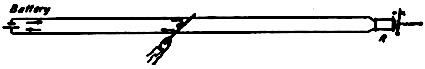
Fig. 2
Figure 2 will render this very apparent if we will assume the wire of the magnet R to possess a resistance of 10 ohms, and the conductors themselves a resistance so low as to be inappreciable and unworthy of consideration.
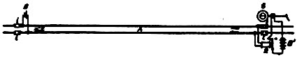
Fig. 3
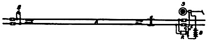
Fig. 4
Now, assume the current to be flowing and the magnet to be charged, and let us take a piece of metal which has an electrical resistance of 1/100 of an ohm, and lay it across the conductors at any point between the battery and the magnet. The result is, that instead of flowing through 10 ohms resistance via the magnet, it follows the invariable rule, and takes that offering but 1/100 of an ohm; or, more to the point, if we assume the conductors referred to to be one mile of steel rails each (Fig. 3), and again leave their resistance (which would be about one ohm each) out of consideration entirely, leaving that of the magnet as first stated, and assume the bar of 1/100 of an ohm to be an axle and pair of wheels (a) of a train (Fig. 4), which possess the same resistance, we can readily see that the result would be exactly the same, i.e., instead of all the current passing through the magnets, as when the rails were unoccupied, the presence of the wheels upon them would cause 999/1000 of the current to leave the magnet and pass through them; they offering but 999/1000 of the resistance of the magnets, and thus leaving but 1/1000 of the whole current passing through them, which being so small a part of so feeble a current is imperceptible and without sufficient influence to hold the magnet charged. Therefore, it follows that the instant that a pair of wheels enters upon a pair of rails which thus form part of the conductors of an electrical current holding charged a magnet, that magnet becomes practically demagnetized, and consequently loses all power to overcome any opposing force in its armature.
When the armature of a magnet is arranged upon a small lever, by motion of which a second circuit is closed or opened, or two or more circuits are otherwise controlled, the entire device is termed a relay. In all forms of this instrument, as is the case with almost every other electrical instrument, the armature is so arranged as to fall by gravity, or by tension of a small spring suitably arranged, away from the cores of the magnets when they become demagnetized.
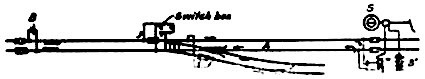
Fig. 5
When switches are included in a track section (Fig. 5), it becomes necessary for safety to have them control the track section in such a way that unless they are properly set (and locked, if desired) for the main track, the continuity of the rail circuit is interrupted and the signal is thereby held at danger. To render more certain this result, the circuit controller (switch box) at the switch is arranged in such a way that the track circuit is not only interrupted beyond the switch, but is also short-circuited by it when the switch is not properly set. It is also necessary for safety that the side track from the switch points back to the fouling point (Fig. 5) be included in the track section: thus insuring that all trains on these tracks are out of danger of collision with the main track when a "clear" signal is displayed on it.
In dividing tracks into distinct electrical sections, it becomes necessary to insulate the rail ends at the terminal of each, from those of the adjacent sections. If this were not done the current of each section would traverse the next, and continue on indefinitely, influencing each other so as to interfere with or totally prevent the operation of all.
In order that we may fully comprehend the nature of an insulation, let us make clear a few facts concerning conductors in general. All materials conduct electricity to a certain extent; but some with much more freedom than others. Thus, silver, copper, gold, zinc, platinum, iron, steel, mercury, and other pure metals permit the passage of an electric current through them with but slight resistance, (although all offer a certain amount,) and are therefore termed conductors. The following liquids are classed as conductors: concentrated and diluted acids, saline liquids and water, although they are much less efficient as such than the metals.
To this list might be added the earth itself and the various ingredients forming it, the nature of which ingredients determines very much its efficiency as a conductor. Thus at points abounding in mineral deposits the earth would be far superior as a conductor to those parts in which none exist, but at best should be regarded as a poor conductor.
Next comes a class of materials which offer a great resistance to the current, and which from that reason are termed non-conductors, or insulators; of this class, rubber, glass, leather, resin, wood, brimstone and dry air are the most common.
Wood being a non-conductor, it is very evident that the cross-ties under the steel rails form an insulation between them and the ground; also, that if a piece of the same or similar material be placed between the rail ends, and that if two other pieces of sufficient strength be substituted for the iron fish-plates at that point, a secure insulation will be formed between the rails.
It is precisely in this way that the insulation of one rail from another is effected (Fig. 6) and the long, practical use of many hundred joints of this sort, has proved it to be a method both economical and thoroughly efficient.
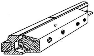
Fig. 6
A much more secure joint, however, is obtained by insulating the existing iron fish-plates from the rails by means of heavy fiber plates, and their bolts from the rails by fiber bushings (Fig. 7). While this method is superior to the first mentioned one in that it makes a more secure rail joint, it is no more efficient as an insulation.
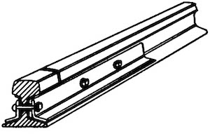
Fig. 7
One would naturally suppose that owing to the large surface of contact existing between the rails and their connecting or fish-plates, and from the apparent security of that contact obtained by the bolts through them, no trouble would be experienced by the current in passing from one rail to the other. This, however, is not the case, as the bolts and even the plates themselves frequently become loose, even when provided with the best of nut locks, and the rust and dirt settling between them and the rails oftentimes increase the resistance of a track section to a serious extent. Again, even when tightly bolted and locked, these plates form but an imperfect contact, owing to the scale or rust upon them. Therefore, to insure that the resistance of a track section may be as low and as constant as possible, we have found it absolutely necessary to connect each two adjacent rail ends together by means of a short piece of very strong wire (Fig. 8).
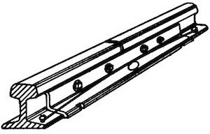
Fig. 8
These wires are termed "track wires" (bond wires) and are provided with a button-head rivet at each end, which is securely soldered thereto, for the purpose of securing them to the rails. (Bond wires are now attached to the rails by channel pins or are welded on.) The connections from the rails to the battery and relay of a track section are secured to the rails in the same manner. The battery is usually located in a chute or well sunk in the ground at the terminal of each section, which is provided with an elevator in which the battery is placed and by which it may be raised and lowered at will. All wires when placed underground are run in grooved lumber in order that they may be secure from injury.
Even in very wet or snowy weather a single jar of gravity battery is generally found to furnish sufficient current to properly work the relay at the other end of any section less than three-quarters of a mile in length; although it frequently happens on longer sections and occasionally on those of ordinary length that two jars are necessary. A greater number of jars is never advisable since by increasing the intensity of the current, the liability of its leaking from one rail to the other during wet weather is correspondingly increased, and as this is attended with some uncertainty in the working of the relay of the section—due to the varying intensity of the current—it should be carefully guarded against. As two jars of gravity battery are not sufficient to operate a signal, lock, bell or any similar instrument with any degree of certainty, it becomes necessary to have a second set of batteries of a greater number of jars for that purpose. The armature of the magnet controlled by the track section is therefore made to control a second circuit using a battery of this sort (Figs. 3, 4 and 5) and which includes the magnet of the signal mechanism. The use of a relay on a track section is therefore necessary; and when it becomes necessary to control two or more devices, each requiring independent circuits, by one track, the use of a relay is indispensable.
While the fundamental principles of the track circuit are the same today as they were when it was originally invented by Dr. Robinson in 1872, it has been found that it is not as simple a device as was formerly supposed to be the case and many problems have arisen which have required and is requiring the careful study of the signal engineers. Accordingly, it is well to present briefly some of the track circuit characteristics as they are known today. In the following presentation, information has been collected from many different sources, including abstracts from papers presented on the track circuit by Mr. A. R. Fugina, signal engineer, and Mr. J. B. Weigle, signal inspector on the Louisville & Nashville.
There are two general classes of track circuits, direct current and alternating current, which may be further subdivided between single or double rail circuits. The essential feature of the track circuit is the insulation of each section of track from the adjoining sections. Each rail in the section is connected to the one adjoining by bond wires, for the purpose of making a continuous conductor from one end of the section to the other.
Rail Bonding
Under the present methods of bonding, the angle bar carries the greater part of the current, and bond wires frequently carry as little as 20 per cent. of it and sometimes even less. The rail resistance is lowest with new rails, but it gradually gets higher, due to rust and dirt formations between the angle bar and the rail. But even with new rail, the rail resistance varies greatly at different periods and even at different times during any twenty-four hours. This variation is entirely due to the fact that the angle bars carry more of the current than the bond wires, and that the bond wires under any condition are only large enough to carry the smaller part of the current from the battery. The lower the resistance of the bonds the less variable will be the rail resistance.
The resistance of the angle bars increases greatly as rail resistance increases, as a result of which the angle bars rapidly carry less of the current.
It is not infrequent to find the rail resistance to be as high as 0.20 ohms per 1,000 ft. of track, and we have known it to run as high as 0.264 in new rail, where especial attention had been given to obtaining as good bonding as possible. Under such conditions the angle bar carries very little of the current, the capacity of the bond is not sufficient to carry the current, and the net result is a failing track circuit, which is probably attributed to bad ballast, zinc treated ties or other causes.
The principal defect in the track circuit is that of improper bonding. The only explanation as to why No. 8 iron wires became standard for bonding appears to be that the bond wires were cut from this size iron telegraph wire which was in general use at the time rails began to be bonded. It is important to obtain better bonding to obtain a minimum constant rail resistance.
It has been recommended that:
First—The use of galvanized wire bonds should be eliminated.
Second—Forty per cent. copper clad bond wires should be used as a temporary expedient to replace galvanized bond wires.
Third—Except for theft and crystallization, copper bond wires would be much more advisable.
Fourth—Larger bond wires should be used, these bonds to be at least equal in carrying capacity to two 46-in. No. 6 solid copper or to two No. 2, 40 per cent. copper clad wires.
Until recently it has been the general opinion of all experts on the track circuit that the rail resistance was rather an unimportant factor and that, as a general rule, the change in rail resistance could be disregarded in making track circuit investigations and calculations.
Many bad track circuit conditions have been laid to bad ballast conditions, zinc treated ties, wet track, etc., which, if carefully analyzed, would have shown the trouble to be due to extremely high rail resistance. These faulty conclusions are being drawn nearly every day.
Single rail track circuits, so called from the fact that but one rail is insulated, are also used. Installations of this kind are made to avoid the expense of two insulated joints or where one rail is needed for another circuit. Such track circuits are more liable to failure than those having both rails insulated for the reason that the break-down of one insulated joint will extend the circuit beyond the proper limit and cause interference of neighboring circuits or extended shunting of the relay, due to the presence of a train beyond the insulated joint.
A track circuit may be made to perform two separate functions in which the direction or polarity as well as the presence of current is made use of in the relay, provided the first or principal function actuated by the presence or absence of current does not interfere with the secondary function, actuated both by the presence of current and its polarity.
Where switches occur in a track circuit, special means must be employed to prevent short-circuiting through the switch rods and leakage of current to the turn-out rail. The usual method is the use of insulated switch rods with insulated joints in the leads of the turnout and at the fouling point of the turnout. The switch points are bonded to the stock rails to insure shunting by a pair of wheels on any part of the track.
None of the methods employed in running track circuits through switches show any protection against an open switch. In order to obtain this protection a switch instrument or switch box is used. This consists of a device with electrical contacts, the whole mounted on a switch timber and connected to the switch point by means of a rod so arranged that when a switch slips open or is thrown open the movement of the rod actuates contacts which, on being closed, form a closed path from one rail to the other through wires connecting the rails to the contacts, thus when the contacts are closed by a switch being opened, the same effect is produced as if a train was on the circuit, shunting it out.
On electrically operated roads where tracks are bonded for the return propulsion current with heavy copper bonds, no additional bond wires are necessary.
The Track Battery
The usual form of track circuit has a primary battery at one end of the insulated track section, with the positive terminal of the battery connected to one rail and the negative terminal to the other, while a relay at the other end of the section is connected to the rails in a similar manner. Current flows from the positive side of the battery through the one rail, the relay and the other rail back to the battery, thus keeping the relay energized.
For d.c. track circuits, four types of cells have been used to a greater or less extent, the gravity cell; Lalande (soda) cell; storage cell and dry cell. The gravity cell has a voltage of about 0.8 or 0.9 volts, the resistance varying with the manner in which the cell is maintained and averaging about 3 ohms. It will remain active for long periods on closed circuits without appreciable polarization. Because of this high internal resistance usually no external resistance is necessary to be connected between it and the rail of the track. The e.m.f. of the Lalande (soda) cell may vary from about 0.67 volts to 0.88 volts while the internal resistance will range between 0.019 ohm to 0.4 ohm. Because of the low internal resistance of these cells it is necessary to use an external resistance of the proper value between the cell and the rail. The storage cell is made in various capacities and a fully charged cell on open circuit has a voltage of approximately 2.1 volts which, when placed on discharge, becomes approximately 2 volts and drops to about 1.8 volts when completely discharged. The voltage in this type of cell varies with the density of the electrolyte and to a certain extent with temperature. It has practically a negligible internal resistance and it is also necessary to use an external resistance in the leads between the cell and the track to prevent a flow of excessive current when a train occupies the track. The dry cell is used only in emergency cases or occasionally for open circuit track circuits of 2 or 3 rail lengths, which are sometimes used as annunciator starts to announce the approach of a train to a tower-man. It is designed primarily for open circuit work and will polarize when current beyond a certain figure is drawn continuously from it.
The Track Relay
The track relay is a development of the instrument of the same name used in telegraph service. It consists of an electro-magnet of the horseshoe type with a pivoted armature, carrying one or more fingers for making or breaking electric circuits for the control of signal apparatus.
Track relays with resistances of 2 and 4 ohms are usually employed. From experience with two-ohm relays on the L. & N., covering a great many of them on all kinds of circuits, the following conclusions are reached:
The two-ohm relay is more suitable for general use on track circuits than the four-ohm, provided not less than the R.S.A. recommended limiting resistance is used between the battery and track.
The two-ohm relay will operate satisfactorily where the four-ohm will not on bad track circuits, and with considerably less current consumption.
The two-ohm relay will operate equally as well on good track circuits of average length as the four-ohm, there being little difference in current consumption on this class of circuit. Under the same conditions longer track circuits may be operated with the two-ohm relay.
The two-ohm relay is at least as safe as the four ohm. It should be thoroughly understood that it is as important with the four-ohm relay as it is with the two-ohm relay to have not less than the R.S.A. recommended limiting resistance between the battery and track. This is important with any kind of low internal resistance battery, and under certain conditions with gravity battery also.
In one case assume a train to be passing from the relay end to the battery end of a track section and in the other case from the battery end to the relay end. The effect accomplished is the same except that the relay will not release so quickly when the train passes from the battery end towards the relay end, and this is in part due to the self-induction of the circuit through the relay coils, the rails and the axles of the train. It is due more, however, to small current leakage from the adjacent section and the effects of stray currents which are always present to a greater or less degree. A broken rail will also generally open the circuit and de-energize the relay. Circuits for the control of the various signal devices are broken through the contact points of the track relay.
Track Circuit Maintenance
Cross ties have a relatively high resistance to the passage of electric current, but when a large number connect the rails many multiple paths are introduced into the circuit through which the current may flow from one rail to the other, and, considering them as a whole, the resistance they offer to the passage of the current reaches a relatively low value. Consequently there is always a current leakage from rail to rail through the cross ties and ballast. Every effort should be made to secure and maintain the best ballast and drainage possible on d.c. as well as a.c. track circuits. Cinders, dirty sand, soft water-logged ties and ballast not well cleaned away from the base of the rail will produce track circuit trouble, particularly during wet weather, while good rock ballast, sound ties and clean track give the greatest efficiency.
The use of ties freshly treated with zinc chloride also reduces the ballast resistance. If too many such ties are used in a track circuit the current leakage between rails becomes so great that not enough current reaches the relay to hold it closed, the effect being the same as if a train is on the track circuit shunting out the relay. For good results, the number of zinc-treated ties installed per year in any track circuit should not be greater than 15 per cent. of the total number of ties in that circuit.
Track Circuit Troubles
Some of the common track circuit ailments are relay and track battery troubles, defective track connections, poor bonding and broken rails, short circuits or shunts, excessive leakage and defective insulated joints, all of which will cause the signals to be set in the danger position, while defective relays, foreign current and poor wheel contact may result in a false proceed signal indication with a train in the block section.
It was the quite general practice to operate bad track circuits by piling on gravity battery, either in multiple or multiple-series arrangements to obtain operating results without any regard to the safety of the circuit and, no doubt, many false proceed failures were caused thereby.
The effect of temperature changes on track circuit operation are of considerable importance. The track relay, which is generally housed in a cast or sheet iron box, probably is affected more by changes in temperature than any other part of the track circuit. The resistance of a 2-ohm relay, which is 2 ohm at 70 degrees F., will be 2.22 ohm at 120 degrees F., and 1.69 ohm at 0 degrees F., a variation of .53 ohm. The pick up and release of the relay, .2 and .1 volt, respectively, at 70 degrees F., will be .22 and .11 volt at 120 degrees F., and .17 and .085 volt at 0 degrees F. A relay, with a normal resistance of 4 ohm at 70 degrees F., will be 4.45 ohm at 120 degrees F. and 3.38 ohm at 0 degrees F., a variation of 1.07 ohm. The pick up and release, .3 and .14 volt, respectively, at 70 degrees F., will be .33 and .16 volt at 120 degrees F. and .25 and .12 volt at zero.
The point which is intended to be brought out by these figures is that when the temperature of the relay increases, a correspondingly higher voltage is required to pick up the armature, and when the temperature decreases the armature will hold up with lower voltage across the coils. This indicates that a track relay is more liable to fail to release due to an imperfect train shunt in cold weather than at any other time.
Some of the best preventatives that may be provided to guard against false proceed signals due to track relays failing to release with a train in the circuit, are:
Aside from these simple remedies no definite rule can be given to combat foreign current. If it is so troublesome that these methods do not overcome it, the circuit affected must be carefully studied to determine the source of the foreign current and its path to the rails, then special means can usually be provided to overcome it.
Ballast Resistance and Leakage
The importance of ballast resistance has long been recognized, and this always has been considered the great variable, whereas, investigations show that the ballast resistance is at least no more variable than the rail resistance, and that of the two it is more important to reduce the rail resistance to a minimum, and especially to establish it as a constant.
When the ballast leakage problem was first taken up (on the L. & N.), various kinds of ballast were measured in both wet and dry weather, the intention being to determine the lowest possible resistance per 1000 ft. for each kind of ballast. It was proposed in this way to establish a standard minimum resistance per 1000 ft. for each kind of ballast. For instance, if a number of measurements in wet weather showed 8 ohms per 1000 ft. as a minimum for track circuits with crushed rock ballast, it was the intention to adopt 8 ohms as the standard minimum ballast resistance per 1000 ft. for all track circuits where crushed rock ballast was in use. If a number of wet weather measurements showed 4 ohms per 1000 ft. as a minimum for cinder ballast, it was the intention to adopt 4 ohms as the standard minimum ballast resistance per 1000 ft. for all track circuits where cinder ballast was used. It was the intention to follow out the same process and establish a standard for all kinds of ballast in use. This was soon found to be impracticable.
After making many ballast resistance measurements, it was noticed that the variation of the resistance on any track circuit, as between wet and dry weather, generally followed quite a definite rule. For instance: If the resistance per 1000 ft. of dry ballast was found to be 28 ohms or more, it would be not less than 8 ohms per 1000 ft. when wet; or if resistance of dry ballast was found to be between 22 and 28 ohms per 1000 ft., it would be not less than 6 ohms per 1000 ft. when wet.
Once a relay is picked up or energized, but a small amount of current is required to maintain it in that condition. This is one reason why it is important to keep the ballast clear of the rails and it is because of the condition which may cause a relay to remain energized that rules are in force requiring the signalmen to disconnect a track relay when track forces are changing out rails.
Combined Rail and Bond Wire Resistance
On circuits newly bonded with two 46-in. galvanized iron wires a joint, the combined rail and bond wire resistance was found (on the L. & N.) to vary from .02 ohm per 1000 ft. of track on some circuits to .265 ohm on others, a difference of over 1300 per cent. This was rather puzzling. After a great many measurements had been made on different circuits it was found that no two measurements gave the same results, notwithstanding the fact that in many circuits the size of rail, length of bond wires, and age of bonding were exactly the same. On account of the bonding being new and the channel pins well driven, the contact between the bond wire and rail was above suspicion. The only other part of a track circuit that could possibly be the cause of this difference was in the contact between the angle bars and rails, and this later proved to be the case. Actual measurements made in the field proved that when the rail is new and the joint bolts tight, nearly all of the current flowing from rail to rail passes through the angle bars, whereas when the rails get old a coating of rust and dirt forms between the rail and angle bars, forcing practically all of the current through the bond wires. On most of the circuits measured on the L. & N. the combined rail and bond wire resistance was found to be less than .1 ohm per 1000 ft. of track, although many were found to be between .10 and .30 ohm per 1000 ft. It is interesting to note that two circuits were found bonded with two 52-in. iron wires, for which the combined rail and bond wire resistance measured .410 ohm, and that by adding two 40 per cent. copper clad bond wires to each joint the combined resistance was reduced to .144 ohm.
The Growth of the Track Circuit
Unfortunately there exists little or no data regarding the mileage of track circuits installed from the time the first installation was made by Dr. Robinson at Kinzua, Pa., and Irvineton up to about 1905. During the period between January 1, 1905, and September 30, 1906, the total automatic block signal mileage installed was 1,710.6, which brought the total up to 6,826.9 for the United States. Between September 30, 1906, and January 1, 1908, 3,976.1 miles of automatic signals were installed, which increased the above total to 10,803.0 miles.
The Block Signal and Train Control Board, seeing the need for accurate data in the signal field, started the tabulation of such statistics when it compiled and issued Block Signal Statistics as of January 1, 1908. After this board went out of existence, the Bureau of Safety of the Interstate Commerce Commission continued the collection and publication of these data yearly. Perhaps no better word picture can be given of what Dr. Robinson's invention has meant to the railroads than to present the story in the form of a table showing the miles of road and the track equipped with the track circuit since January 1, 1908. In addition to the table, the accompanying chart presents the information in a graphical form.
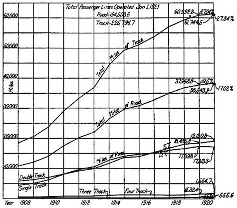
Progress Chart of Automatic Signal Installations
Since January 1, 1908.
Track Circuit Mileage for Automatic and Controlled Manual Signals in the United States as Taken from I.C.C. Reports
| Automatic | Controlled Manual | |||||
| Miles of Road |
Miles of Track |
Miles of Road | Miles of Track | |||
| Track Circuits at Station |
Continuous Track Circuits |
Track Circuits at Station |
Continuous Track Circuits |
|||
| January 1, 1908 | 10,819.3 | 18,534.1 | 726.7 | 212.0 | 2118.0 | 410.8 |
| January 1, 1909 | 12,174.3 | 20,590.9 | 407.6 | 572.2 | 978.0 | 1413.0 |
| January 1, 1910 | 14,238.9 | 23,771.3 | 385.8 | 491.5 | 953.5 | 1371.3 |
| January 1, 1911 | 17,709.8 | 29,151.6 | 483.9 | 439.4 | 1119.3 | 739.9 |
| January 1, 1912 | 20,300.0 | 33,343.8 | 402.0 | 295.9 | 955.6 | 496.0 |
| January 1, 1913 | 22,196.6 | 36,873.0 | 370.2 | 228.3 | 868.9 | 380.3 |
| January 1, 1914 | 26,569.3 | 44,461.2 | 275.7 | 180.3 | 625.3 | 281.6 |
| January 1, 1915 | 29,863.5 | 49,442.1 | 250.5 | 145.1 | 549.3 | 185.7 |
| January 1, 1916 | 30,942.5 | 51,119.7 | 255.1 | 125.1 | 549.6 | 179.3 |
| January 1, 1917 | 32,954.6 | 53,799.8 | 230.3 | 132.0 | 524.8 | 155.5 |
| January 1, 1918 | 35,193.1 | 57,083.6 | 208.1 | 131.2 | 451.6 | 154.8 |
| January 1, 1919 | 36,989.4 | 59,458.2 | 221.2 | 256.9 | 483.8 | 441.2 |
| January 1, 1920 | 37,968.8 | 60,992.3 | 196.3 | 129.2 | 413.3 | 151.4 |
| January 1, 1921 | 38,543.9 | 61,744.5 | 206.8 | 125.7 | 422.6 | 166.4 |
The first yearly report of the Bureau of Safety, I.C.C., on block signals to contain information as to the miles of road and miles of track on which alternating current track circuits were installed, was that issued as of January 1, 1914. Data taken from that report up to the last one issued is presented in the table below.
Alternating Current Track Circuit Mileage
| Miles of Road | Miles of Track | |
| January 1, 1914 | 3,289.2 | 4,144.6 |
| January 1, 1915 | 2,728.2 | 5,814.9 |
| January 1, 1916 | 3,186.7 | 6,679.0 |
| January 1, 1917 | 3,336.2 | 6,823.6 |
| January 1, 1918 | 3,748.0 | 7,530.1 |
| January 1, 1919 | 4,496.6 | 8,620.2 |
| January 1, 1920 | 4,676.5 | 9,026.0 |
| January 1, 1921 | 4,786.1 | 9,120.2 |
Alternating current track circuits have certain advantages over direct current track circuits, particularly in respect to their immunity to the dangerous effects of foreign direct current to which d.c. track circuits in some communities are subjected. The above table is therefore of interest as it shows the application of alternating current as made to Dr. Robinson's invention of the closed track circuit.
Part IV
No satisfactory records appear to have been kept as to the origin and development of track circuiting outside the United States, which renders it very difficult to arrive at any conclusions that could serve as a basis for a real historical sketch upon this interesting subject. In view of the fact that the Signal Section of the American Railway Association proposes to publish a memorial to the late Dr. William Robinson, generally regarded as the inventor of the closed track circuit and certainly the first to utilize it in the control of an automatic block system, the following brief remarks may prove of interest to the writer's fellow members of the Signal Section. It is not suggested that they are in any sense complete, as to make a complete survey would require considerable investigation. They really represent the writer's present general understanding of the subject and are open to such criticism and correction as anyone may be able to offer to them, in England or elsewhere.
There is no doubt but that track circuits were thought of and actually experimented with in England a great many years ago—probably as far back as the earliest American attempts—but the want of satisfactory records make it very difficult to decide on what actually took place. However, it is certain that the late W. R. Sykes, well-known throughout the railway world for his controlled manual block and other inventions, endeavored to use the track circuit in the sixties and that Bull, the inventor of the bull-headed rail employed in England for the chaired track universally found there, clearly had the idea of a track circuit in his mind, for he refers to it in a patent obtained in 1860. It was apparently in the early part of the sixties that W. R. Sykes fixed a track circuit experimentally at Briseton on the old London, Chatham and Dover Railway, and shortly after also at the Crystal Palace Station on the same line. The apparatus employed must necessarily have been rather primitive. In the seventies, track circuit was installed by him at St. Paul's station, also on the Chatham Railway. At that time very little was known about the track circuit theoretically and the construction of the relay was very different from our modern types. Sykes' relay completed the control circuit by the insertion of a contact point into a mercury trough. It was also, the writer believes, built on the solenoid principle. So far as is known it was not suggested at this time and at all events not attempted to make an automatic block system controlled by track circuits, such schemes for signaling of this type as were put forward being always based on the intermittent or track instrument control plan.
It must be remembered that the conditions obtaining in England, widely different from those seen in the United States, were not such as to give much encouragement to the development of automatic signaling, while over and above this, the English conservative nature always looked askance at automaticity in railway apparatus. Automatic signals, worked on a track instrument plan, were put into regular work on the Liverpool Overhead Railway in 1893, but it was not till 1902 that automatic signals controlled by continuous closed track circuits were to be seen in operation on an English main line railway. Before this, however, track circuits had made some progress, though not very much; the most important instance of its application was in the Kings Cross tunnels, just outside the London terminal of the Great Northern Railway, in the early nineties. This installation, which was used under none too favorable circumstances from the point of view of successful operation, proved to the English what the track circuit could do and heralded the day when its place in the safe working of railways should be better appreciated. By this time in the United States, largely under the influence of the pioneer work of Dr. Robinson, automatic signaling had made quite considerable progress and the potentialities of the track circuit had been fairly realized.
It may occur to Americans to ask why it was that progress in England was so slow and this is a question which cannot be answered by a single reason since a combination of circumstances was the cause. In the first place the older type of English signal officer was extraordinarily conservative regarding signaling practice of other countries as he had that peculiar type of contempt which generally comes from want of knowledge. Anyone who, like the writer, listened for instance to the objections brought forward by some of these men to controlled manual block, will know to what absurd lengths they could go in resisting improvements in working. Although this spirit, which has markedly diminished during the last 15 years, must have accounted to some extent for the slow development of the track circuit in England, there were yet some reasons of a more sensible kind which must be borne in mind. The English light weight four-wheeled freight car without air brakes was and still is a bother to the track circuit engineer because of the difficulty of getting a satisfactorily low shunt under all circumstances. Then again the Mansell disc wheel made it necessary to resort to bonding between the tire and the hub before a vehicle would shunt the track circuit at all and this was an expense to which the companies were loath to go, especially if they had or contemplated very few track circuits, though the use of even one circuit really necessitated the whole of these wheels being so treated. There was no great demand for automatic signaling, as the manual system was giving good results and was also cheap at that time, owing to the low wages paid to railway men. This and the other reasons just given combined to render the progress in England extremely slow.
Some of the First Installations
Nevertheless, in 1902 the British Pneumatic Railway Signal Company, who had in the previous year installed its first low pressure pneumatic interlocking at Grateley, on the London and South Western Railway, brought into use between that station and Andover an automatic block system controlled by continuous track circuits, the distance being about six miles. The signals were worked by low pressure air. The success of these systems led to the adoption of them shortly afterwards on the widened four-track main line between Woking and Basingstoke on the South Western, a distance of 24 miles. The Grateley-Andover installation has now been removed, not because it was at all unsatisfactory, but because it was felt traffic and other circumstances did not warrant its further employment. In 1905, Hall electro-gas automatic signals were brought into use on the North Eastern main line between Alne and Thirsk, a distance of 11 miles. In 1907, semi-automatic signals were installed between Pangbourne and Goring, a distance of 2¾ miles, four track, by the Great Western Railway to divide up a long manual block section and a few similar installations have been made on the Midland, the Great Central, the Belfast and County Down and other roads.
By this year, track circuiting had begun to be extensively used in England. The British Pneumatic Signal Company had installed a series of low-pressure plants near Manchester on the Great Central and track circuits were used throughout while the same thing had been done at Clapham Junction on the South Western. The Westinghouse Company had supplied the District Railway, London, with automatic signals and were actively engaged in fitting similar apparatus to the tube lines; they soon afterwards commenced work on the Metropolitan Railway.
The main steam lines began to apply track circuits at various places in conjunction with ordinary manual signaling and this process received an added impetus from the terrible disaster which befell the Midland Company's Scotch Express near a station called Hawes Junction, when, in emerging from a tunnel it crashed into two light engines that had been forgotten and had entered the block under the signals set for the express. Several other bad accidents, notably one at Pontypridd, on the Taff Vale Railway, due to trains and engines being overlooked by signalmen while standing at adverse signals, emphasized the necessity for paying serious attention to the question of track circuiting and for undertaking a really earnest study of the matter to see whether the difficulties due to the light freight car, etc., could not be overcome or at least considerably minimized.
Considerable progress had been made by the time the war broke out and quite a number of track circuits had come into existence on all the principal roads, although no extension work worth noticing was made to purely automatic block systems on steam roads, this class of work being confined to the suburban electric lines. Unfortunately, in this as in so many things the war had a retarding effect and caused the postponement of many plans. The increased price of wages and materials has hampered progress a great deal and it will be some time yet before any great improvement is noticeable. On the other hand, the great increase in wages has caused a demand on the railways for a reduction of operating costs with the result that signal engineers are endeavoring to produce schemes which will enable signal towers to be abolished or closed at intervals where they were formerly kept continuously in service and in this and other ways to dispense with unnecessary staff. It is in this that the track circuit will help very considerably. Its further extension on English lines is a certainty and simply a question of time and money. Since the inception of the Institution of Railway Signal Engineers a great amount of work has been done in discussing and studying requisites and so on for track circuit work, both of the direct current and alternating current types. All this has resulted in increased confidence on the part of the traffic officers in track circuit and allied apparatus and caused them to look more and more to the signal engineer to help them in their work and to accord him the respect and credit he deserves.
The writer is aware that these lines can only convey a very imperfect idea of the actual state of affairs, but he prefers to write them now as a preliminary account, not yet being in a position to furnish the figures which the Signal Section desires.
Track Circuits on the Continent
Turning to the continent, the writer must necessarily speak in very general terms since there is less published on this subject by continental journals than by English and, of course, the field is rather a wide one, embracing so many lands and tongues. The track circuit is, of course, known there fairly well, but there are no very great installations of automatic block to be found. In the case of France, the Paris, Lyons & Mediterranean had, before the war, an installation between Larsche and Auperre, 24 miles, and some semi-automatic sections in various places. The Midi Railway had also the Hall disc system from Bordeaux to Langon, 26 miles, and the writer believes extensions to this have since been made. The Est Railway began trials before the war and during the war, owing to shortage of staff and having greatness of traffic to the eastern military area, installed automatic signaling on the Paris-Nugent line. The writer has been told that it is under consideration to equip the whole line to Avricourt, where it connects with the Alsace-Lorraine system. The writer is not aware whether the other companies in France have any automatic blocks, but he believes not. They all have, however, track circuits installed at various places in connection with the ordinary signaling. Owing to the lower standard of living and the employment of women operators at many points, there is not so great an incentive to the adoption of automatic devices, as in some other countries. French engineers, however, know what Americans have done in this way and some very complete accounts of American systems have appeared in "La Revue generale des chemins de fer." The Paris Metropolitan line is automatically signaled by an intermittent contact system without track circuit.
In Germany, the track circuit for steam lines is not looked on with much favor, as owing to the extensive employment of the Siemen's controlled manual and the peculiar station masters' system of control, called "Station Block," always used in that country (with, it must be admitted, a very high record for safety,) the Germans think they would not gain much by any great use of track circuit or automatic signals. The writer has just had this view confirmed by a friend returned from visiting the important works of the German Railway Signal Company at Bruchsal, Baden. Automatic signaling is used on certain important sections of the Berlin Elevated and Underground Road, installed before the war by the Westinghouse Company, of London, with a.c. double rail track circuits and this will be extended eventually to cover the remaining sections still worked by the Siemen's controlled manual. Dr. Kemmann, a member of the General Railway Direction, Berlin, published last year a very interesting book describing his work with accounts also of the London Underground and New York Subway installations, showing that foreign systems are studied in Germany. But for steam roads the writer believes from what he has studied of German methods and ideas on the subject that the manual system will remain in use and that the track circuit will not be much adopted.
The same remarks apply generally to Austria, Holland and Scandinavia, though in the latter case English ideas are more in evidence and it is probable that the track circuit, already in use to some extent, will be developed as time goes on. In Austria automatic signaling was certainly tried on a small scale on the Southern Railway, but with what results the writer cannot say. In Switzerland the extended use of iron ties is against the track circuit. In Belgium the Hall system was at one time in use between Ghent and Wondelgem, but as the course of the line was changed, these signals were removed. The section was about 3¼ miles long. Automatic signals do not exist there now but the track circuit is used at certain stations, notably throughout the all-electric power installation at and close to Brussles Nord. The writer does not believe it likely that automatic signaling will be used on the steam roads in Belgium, at all events for some time yet. With regard to Italy, Spain and Portugal, the writer does not possess details, but believes it likely that the track circuit is only in use, if at all, at a few important stations. The new Metropolitan line in Madrid is equipped with an intermittent contact system, probably copied from the Paris Metropolitan.
Although a little outside the scope of these notes, the writer would emphasize that in the English colonies and in South America (especially, however, the former) the track circuit is being much used and its value appreciated. Automatic signaling is in use in Victoria, Queensland, South Australia and New South Wales. The operating conditions in these countries no doubt much resemble American circumstances and the adoption of automatic signals is a natural development.
Summing up, the writer would say, that the earliest experiments of W. R. Sykes in England are probably as old as those of Dr. Robinson, but owing to the different circumstances in which the former inventor was placed, he had little encouragement to continue them and thus American development at first went on far ahead of English, while owing to the vastness of the American continent it must always present a larger field to the signal engineers' ingenuity and activity. In later years, however, the English signalmen awoke to the importance of the question and installations were constructed which, if smaller, showed as great a degree of technical perfection as any in America. The future will doubtless see more such installations.
It is not known to the writer whether anyone on the continent had the idea of a track circuit as far back as Sykes' or Robinson's experiments or when the first attempts were made. It would require much investigation to find this out. Track circuit possibilities are now well known there and no doubt its use will extend, but in certain countries, notably Germany and Switzerland, there are local circumstances which act rather strongly against it at present. The writer cannot give statistics on the subject now. There are some figures which he possesses, but they should be verified and amplified before being used by the Signal Section for publication. The preceding notes are, he is too fully aware, very incomplete and general, but he hopes they may be of some present use.
Transcriber's Note:
Minor typographical errors have been corrected without note.
Irregularities and inconsistencies in the text have been retained as printed.
The cover of this ebook was created by the transcriber and is hereby placed in the public domain.