*** START OF THE PROJECT GUTENBERG EBOOK 45083 ***
THE CHILDREN'S LIBRARY OF WORK AND PLAY.
Mechanics, Indoors and Out
THE CHILDREN'S LIBRARY
OF WORK AND PLAY
| Carpentry and Woodwork |
| By Edwin W. Foster |
| |
| Electricity and Its Everyday Uses |
| By John F. Woodhull, Ph.D. |
| |
| Gardening and Farming |
| By Ellen Eddy Shaw |
| |
| Home Decoration |
| By Charles Franklin Warner, Sc.D. |
| |
| Housekeeping |
| By Elizabeth Hale Gilman |
| |
| Mechanics, Indoors and Out |
| By Fred T. Hodgson |
| |
| Needlecraft |
| By Effie Archer Archer |
| |
| Outdoor Sports, and Games |
| By Claude H. Miller, Ph.B. |
| |
| Outdoor Work |
| By Mary Rogers Miller |
| |
| Working in Metals |
| By Charles Conrad Sleffel |
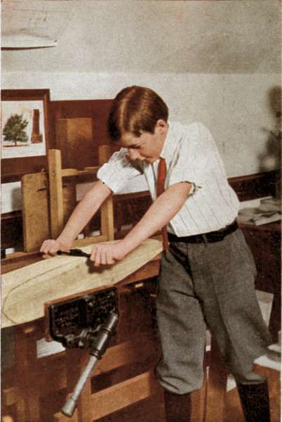
Photograph by Underwood & Underwood
A Motor Boat Model
"In the making of little models of this kind, you will encounter many
things that will tax your skill and ingenuity, as amateur workmen."
MECHANICS, INDOORS
AND OUT
BY FRED T. HODGSON
Garden City New York
DOUBLEDAY, PAGE & COMPANY
1911
ALL RIGHTS RESERVED, INCLUDING THAT OF TRANSLATION
INTO FOREIGN LANGUAGES, INCLUDING THE SCANDINAVIAN
COPYRIGHT, 1911, BY DOUBLEDAY, PAGE & COMPANY
ACKNOWLEDGMENT
The publishers wish to acknowledge their indebtedness
to the Horace Mann School for their
courtesy in permitting certain of the photographs
to be taken for this volume.
CONTENTS
PART I
| CHAPTER | | PAGE |
| I. |
A Pathway of Cement
Purchasing property, River Passaic—Removing rocks
and other obstacles—Preparing for cement sidewalk—Digging
trench and purchasing materials—Making, laying,
and properly placing concrete—The lever and roller and
application—Moving heavy bodies with lever and roller—Finishing
the cement sidewalk—How to make good concrete
walks. |
3 |
| II. |
Building of a Boat House
Qualities of the inclined plane—Dismantling an old
barn and out-houses—Blocks and tackle, ropes and pulleys—Strength
and care of ropes—Building a boat-house, using
old materials—Strength of timber floors—Method of
construction—Holding power of nails—Doors and windows
for boat-house—The use of rollers in moving heavy weights—Sliding
ways for boat—How heavy stones were raised to
tops of Egyptian Pyramids. |
36 |
| III. |
Bridge and Boat Work
Dimensions of the launch—Arrival of The Mocking-Bird—An
interesting boat talk—A sail on the river—Building
a small foot-bridge—The same completed—Some
rules for sailing a launch—Fitting up boat-house and dock—Preparing
block for keel—The winch and its construction—The
wheel and axle as a mechanical power—The fusee,
and what it means—Some problems solved.
|
65 |
| IV. |
Making a Gasolene Launch
Arrival of boat material—Laying keel and keelson—Setting
up the boat and giving her shape—Laying engine
bed—Installing engine and propeller—Nailing on planking—Table
of offsets—Gasolene engine and carburetor—Dimensions
of engine and propeller—Gas engines, generally—Danger
of using gasolene—The proper use of yacht flags
for signalling.
|
84 |
| V. |
A Talk About Engines
Water around the cylinder—The carburetor and spark
coil—Running the engine in boat-house—Varnishing the
boat—A steamboat on the river—A story of the first
steam engine—How the steam acted in the case—The slide
valve, piston and steam chest—Internal and external
engine heaters—Horse-power and how calculated—Foot
pounds, dry steam and condensation—Expansion of gases,
turbines—Gilding the name—Constructing picnic tables
and seats—Height of tables, chairs and benches.
|
110 |
| VI. |
Propeller and Other Screws
The launch of the Caroline—Trial of the new boat—Description
of the screw as a power—The wheel and worm
and endless screw—Formula for counting power of wheel
and worm screws of various kinds—Archimedian screw and
water lifter—Some data of power of "wheel and worm"—The
screw propeller, with data—How to calculate force
of propeller screws—Finding pitch and other lines for propeller—The
screw auger or boring tool—Adhesion of
ordinary wood screws—How to loosen and withdraw rusty
screws.
|
136 |
| VII. |
Aeroplanes
Seats for riverside—Model aeroplane for the "Fourth"—Dimension
on construction of planes—Why a monoplane
rises from the earth—The gyroscope as a balancer—The
biplane and its construction—Aeroplanes generally—The
French aeroplane "Demoiselle"—How to make a
model aeroplane—Illustrations and details of model
aeroplane—Some general remarks.
|
158 |
| VIII. |
Kites, Sundials, Patents
The theory of kite-flying—The highest kite ascent—The
flat plane kite—The kite a small aeroplane—A box
kite of common type—Cellular kites of various kinds—Pairs
and bevies of kites—Bird flight and motion—War
kites of various kinds—Wind gauges and wind force—Patents
and how to secure them—A simple sundial—How
to make an oval flower bed.
|
185 |
| IX. |
Tides
The "why" of the tides explained—Globular form of
the earth proved—Day and night—Phases of the moon—Attraction
of the sun and moon—Newton's theory of the
tides—Height of tides—A simple hygrometer—The
Australian boomerang—Theory of the pump.
|
212 |
| X. |
Wall Making and Plumbing
Protecting the river bank—Concrete retaining walls—Big
dams in the West—Galveston sea wall—The great
dam across the Nile—Proposed irrigation works in Babylon—Some
properties of light and sound—Hints on amateur
plumbing—The peppermint test—Barometers of various
kinds—Thermometers, and their uses—Something about
steel springs—How to make a cross-bow—The gyroscope
and its uses.
|
237 |
PART II |
| I. |
Some Practical Advice
The inventor, ancient and modern—Barriers to mechanical
progress in the past—Laws of gravitation—How to adjust
sewing machines.
|
271 |
| II. |
Mechanical Movements
Coffee mills—Pulleys—Pumps—Pistons—Levers—Steam
engine and water wheel governors, etc.
|
306 |
| III. |
The Weather and Indoor Work
How to make a rain gauge—Hail—Snow—Designing,
making and inflating paper balloons—Magnetized
watches—A boy's wheelbarrow—Vacuum cleaners.
|
349 |
| IV. |
Motors and Typewriters
Motors, gasolene and steam—Automobile frames—The
modern typewriter—Directions for securing copyrights.
|
387 |
ILLUSTRATIONS
| A Motor-Boat Model |
Frontispiece |
| | FACING PAGE |
| Boat-House and Workshop |
42 |
| The Creek |
70 |
| Making a Motor Launch |
88 |
| Finishing the Motor Launch |
112 |
| The Monoplane Model Complete |
160 |
| Making an Aeroplane Model |
180 |
| Making Kites |
190 |
| A Sundial Made of Concrete |
208 |
PART I
[3]
I
A PATHWAY OF CEMENT
I do wish papa would buy the land from Mr.
Breigel. The weather will soon be fine enough
to play out of doors!"
So said Jessie Gregg, a rosy-cheeked girl of twelve,
to her eldest brother, Fred, one evening in March,
as they stood in the porchway of their home, situated
near the bank of the Passaic River, a few miles from
the city in which Mr. Gregg had his business offices.
"Why, Jessie," said Fred, "papa told me this
morning, at breakfast, he expected to close the
deal, that is, get the deed of the property, this
afternoon. I am just as anxious as you are to have
the matter settled, for if he gets the land, I will
have a lot of work to do, and I want to commence
it right away. The land must be ours, for papa is
later than usual this evening. Oh! there's the train
just coming in; he will be here in a few minutes,
and then we'll know."
"Oh, Fred! he and George are coming now. I
see them at the turn of the road. I'll run to meet
[4]
them." Away she scampered, and almost upset
her father by jumping into his arms, as she was
quite a plump, husky girl and evidently a pet,
for her father kissed her fervently as she slid from
his arms to the ground. Then the three trudged
homeward.
"Jessie," said George, a younger brother, "I
have a secret for you if you won't tell Fred, until
papa has told him."
"What is it?"
"Papa has bought the land, and has got it in his
pocket."
"Oh! I am so glad," said Jessie, "but how can he
have it in his pocket."
"George means that I have there the papers,
deeds, conveyances, and receipts, giving me the
sole ownership of the land, and all that is on it,
including the trees, old barn, and other structures;
so, girlie, you can get down to the river now
without having to climb a fence."
Fred met his father on his arrival at the house,
but was too well behaved to ask him about the land,
though he was as anxious to know as he could be.
His father saw the boy's anxiety and after tea asked
him to go with him into his den, a little room nicely
fixed up some time previous, containing many
[5]
articles of wood, brass, and plaster of Paris, Fred
and George had made during the past winter.
Jessie, also, had contributed many little things toward
the decoration of "the lion's den," as
she called the room into which her father retired
to have his evening smoke, to take a friend, or to
do a little private business.
When seated, Mr. Gregg called Fred to his desk,
and talked over some home affairs before he said:
"Now, my boy, since I have secured the property
behind us, as you children desired, I shall expect
you and George to help by your labour, and by the
knowledge you obtained at the training school,
in making the improvements on the land and the
water front we have talked of so often. I am sure,
with my advice and assistance, you will be able
to do most of the work, or at least to superintend
it in such a way that the labour and expenditure
will not be wasted. You know, Fred, I am not a
rich man, so cannot afford to waste money on experiments."
"Indeed, father," said Fred, "I will do all I can.
You may count on my giving my best attention to
whatever work and improvements you entrust me
with."
"That is well said, my boy, and what I expected
[6]
from you. We will begin operations by putting
down a cement pathway from the walk now leading
to the house from the street, and continue it to the
river, where you must build a small boat
house and workshop, as I intend either to
purchase a small gasoline launch for our own
use, or have you build one, if you feel equal
to that."
"Oh! father, you are so good," said Fred. "There
is nothing I'd like better than to do this work,
and particularly to build a boat. I'm sure I can
do that with your help and advice. As to putting
down the pathway, that I can do very well, after my
good training in cement works."
"All right, my son. We'll see in the morning
what old material we have on the two places which
can be used. There must be quite a quantity of
lumber, timber, bricks, hard mortar, and plaster
in and about the old barn and the smaller buildings."
The next morning George evidently had something
on his mind, and seemed to be on the point of
explosion. Mrs. Gregg noticed this and said to
him, "Why are you so restless this morning? Why
don't you finish your breakfast?"
"Oh! mother," he exclaimed, "I am too glad.
I am so full of the good things Fred told me last
[7]
night and this morning I haven't any room for
breakfast."
"What did Fred say to you?" asked the mother.
"Oh! he told me he was going to build a cement
walk right from the door here to the river, and do
lots of other things; and best of all, mother, he is
going to build a boat, a real boat, that will be driven
by a gasoline engine, just like Walter Scott's.
That will be glorious! I can take you and Jessie
up the river to Belville to see aunty, whenever you
want to go."
"Very well, George; we will see about that after
the boat is ready to take on passengers."
Breakfast over, the whole family walked out to
see the newly acquired property. They had all
seen and walked over the grounds often, but never
before with that feeling of pride in ownership
which possession creates.
As there could be no objection to the removal
of the line fence between the newly acquired property
and the homestead, Fred got a handsaw, and cut
down a part of it, making an opening some nine or
ten feet wide, so that all could pass into the new
place without climbing or stumbling.
The old barn was the first thing examined, and
it was found to be in a state of good preservation,
[8]
and quite large. It had been built—perhaps in
Colonial times—of heavy timber, oak, chestnut,
and pine, and it contained enough timber and lumber
to build two or three small cottages. There
was a big pile of broken bricks and mortar lying
against one side of the barn; and another large pile
of bowlders, or field stones, near the fence. "These,"
Fred said, "will be fine to build a little landing
place or pier for the boat. The broken bricks and
hard mortar will make grand stuff for the foundation
of the cement pathway."
There were also two or three small buildings
on the place. One had been used for a poultry
house, another for a tool house, and a third seemed
to have been a sort of cattle shed. Mr. Gregg
suggested their removal, of which all approved.
There were quite a number of good-sized trees
on the grounds, and these rendered it a little difficult
to set out a straight line to the river for the
cement walk, without cutting down several, which
could not be considered. There was one direction,
however, that would admit of a walk, about
four feet wide, but there were some big rocks or
bowlders in the way, that would have to be removed
before a straight path could be made. Still it was
decided to put it there.
[9]
"The rocks," said the father, "can be removed
by blasting, by lifting them out of their beds and
rolling them aside, or moving them down to the
river, where they will form a good protection against
both current and ice."
"I think they can be moved," said Fred, "if I
can get levers and rollers; and they will make
fine breakwater stones."
Jessie found two suitable trees, upon which
Fred promised to put up a strong rope swing, as
soon as the place could be cleaned up and made tidy.
"Now, Fred," said the father, "this cement walk
should be commenced at once, so that it will be dry
and hard before you go on with other work. I
will employ a labouring man to help you, one who
will do the heavy work, as I do not want you to
over-exert yourself. You have a number of tools
now in the shed, and, when I come home from the
office this evening, we will make out a list of the
other tools and materials you will require to finish
the intended work. In the meantime you and
George can be making a number of wooden stakes,
about eighteen inches long and two inches square.
Point them sharply at one end so that they may be
driven into the ground their whole length. You
will require thirty or forty of these. After getting
[10]
them, take a clothes line, old halyard, or any rope
or heavy string your mother can find for you, and
stretch it from the house down to the river, at the
point we decided upon. Drive in a stake near the
river, tie one end of the rope to it, pull tightly, and
stretch the rope from the river to the house. It
will then show you where one edge of the walk is
to be. After that is done, get another rope or string
and, starting from the house end of the walk, measure
off four feet for the proposed width. Drive in a
stake at that point, and tie one end of the second
rope to it; then go toward the river with the other
end, making the rope extend the whole length of
the path and drive in another stake which must
be four feet from the first rope. To this stake tie
the end of the rope and make it tight. Be sure to
have the two ropes exactly four feet apart at each
end, as well as along the whole length. You will
find it to your advantage to get a straight strip of
wood, say, one or two inches thick both ways, and
cut it exactly four feet long. It can then be used as
a measuring stick or gauge, for the distance between
the ropes, which is to be the width of the walk,
and by using it you will have a parallel and uniform
path from start to finish."
Mr. Gregg had passed an examination in the
[11]
Massachusetts School of Technology, and had won
a position as civil engineer in New York which
later he abandoned for the profession of law; hence
his knowledge of practical mechanics and engineering.
After Jessie and George had gone to school,
Fred started on his new undertaking with enthusiasm.
He found quite a number of pieces of wood,
out of which he made over forty stakes, and pointed
them nicely with the large hatchet he always kept
sharp and in good order. By tying several pieces
together, it did not take him long to find cord enough
to set out the whole walk. An old halyard that
had been taken from the flag pole and replaced by
a new one answered the purpose admirably. Driving
a stake into the ground, near the house, he tied
one end of his cord to that, and stretched it down
to the river bank to the point chosen for the end
of the walk, where another stake was driven in and
the cord tied to it. The long stretch between the
two stakes would not allow the cord to be tight
enough to make a straight line between the two
points, but Fred left it as it was, to be adjusted
when his father came. With his rod he measured off
four feet from the first stake, across the intended
path, and drove in another stake to which he attached
another cord. Then going down to the river
[12]
he measured off the width of the walk from the long
cord, and drove in another stake. He was now
ready to have his father examine the work he had
done, and to make suggestions or changes if such
were deemed necessary.
Jessie and George arrived home from school,
having run most of the way, "to help Fred make
the walk," and were quite disappointed to be told
there was nothing they could do until the work was
further advanced.
"We might, perhaps, commence taking down the
old buildings," said Fred, "and pile the lumber
where it will be snug and dry."
"All right," said George; so the three of them went
over to the poultry house and Fred began by taking
out the two or three small windows, and removing
the doors by unscrewing the hinges. George's
desire to pull, tear, and smash the old material was
held in check by Fred, who advised him to be careful,
and not break or destroy anything that could
be used. After the doors had been taken off
and laid nicely away—"to be used on the boat
house"—and the windows and frames placed in
a dry spot, Fred began to remove the old siding,
or clapboards. He found this a rather difficult
job, as they were nailed on with old-fashioned
[13]
wrought-iron nails which could not readily be drawn,
and, in trying to get the boards loose, the ends kept
breaking and splitting; so he stopped, went inside
the building, and took off the lining there; this also
was a little difficult to do, but, as the boards were
an inch thick, he did not split many of them.
He then sawed off the boards alongside the
studs, on the corners, and at the doorways to relieve
the siding at the ends, and give him a good
chance to wedge off the boards wherever they were
nailed. With the help of George, he succeeded in
getting most of them loose without serious damage.
Of course, he had to begin tearing the boards off
at the top of the wall, as they lapped over each
other like the scales of a fish.
Mr. Gregg arrived, went over the ground, and was
well pleased with the results of Fred's day's work.
He assisted in straightening the long cords, and
made a number of suggestions for the boys to follow.
He had a strong-looking man with him, who he
told Fred was to help him. He was an Italian,
named Nicolo, called "Nick" for short, a kindly
fellow, who could speak English fairly, for he had
been employed in Newark, as a handy labouring
man for years. He, Fred, and George soon became
good companions, and even Jessie, though a little
[14]
shy at first, soon became quite friendly toward
him. When it was explained what was wanted
of him, he was quite satisfied, and agreed to begin
work in the morning.
Next day Fred and George were at work before
their father was out, and soon Nick arrived, bringing
a spade, a crowbar, and a pick. He was immediately
set to work by Fred, digging a shallow
trench for the pathway, a little over four feet wide
and about eight inches deep. The stretched cord
and the four-foot rod were the guides.

Fig. 1. Section of sidewalk
There were a number of rocks to be removed from
the trench, one of them near the river bank weighing
over a ton. These were left to be removed
later. Their father, on coming out, was glad to
see them all at work; he showed Fred and Nick
how to prepare the edges of the trench by putting
planks along them, as shown in Fig. 1. The boards,
about twelve inches wide, and from twelve to sixteen
feet long, had been taken from the old barn.
[15]
After breakfast Fred worked along with his man,
and got the trench well cleaned out, except for a
few of the larger rocks. The smaller bowlders were
wheeled down to the river and rolled over the
bank to the water's edge. Near one side of the walk
grew a large tree, whose main root ran under the
proposed path. Mr. Gregg had noticed this in the
morning and had told Fred to see that the root was
cut off close to the line on both sides and pulled
out altogether. "If it isn't cut off, it will grow larger,
lift up the cement flags, and perhaps break them."
Fred saw the force of this, so had the root cut off
and taken out. The operation would not kill
the tree, though it might do it some injury.
Now came the process of taking out the big stones,
and a lever, ten or twelve feet long, was brought
from the barn, in the shape of a red cedar pole,
five or six inches in diameter at the larger end.
Nick took an axe and chopped the big end a little
flat on two sides, so that it could be shoved under
the stone. A flat plank was next laid behind the
stone on the ground, on which a fulcrum was to be
placed, in order to get what is termed by workmen
a "purchase." On the side of the stone next to
the river, three planks taken from the floor of the
barn were laid down flat at the bottom of the
[16]
trench. Three other planks were laid on the top
of the first layer, thus making a bed in the trench,
two planks in thickness, on which the big stone was
to be rolled. A fulcrum, consisting of an old fence
post, was laid upon the plank, and forced up as
close to the stone as possible. Everything was
now ready for lifting the bowlder out of the bed,
where it had lain perhaps for thousands of years.
As had been arranged, the work at this stage
was suspended, and other work gone on with, until
Mr. Gregg made his appearance. Upon his arrival
all hands went to the stone, Jessie included. Having
approved what had been done, the father suggested
that rollers be placed between the two
thicknesses of plank to increase the ease of moving
the stone to the river when it was started. Fred
and Nick went to the barn, and among a big pile
of old planks, boards, and timber found eight or
ten old fence posts, six or eight inches in diameter,
and long enough to make two rollers, each three
feet long, when cut in two. These were quickly
stripped of bark by George and Jessie, while Nick
and Fred, with axe and hatchet, soon had a number
of them round enough to serve as rollers. The
father then directed that the ends nearest the river,
of the top layer of planks, be raised up, and one
[17]
of the rollers placed between the two layers of
plank near the stone, while the ends of planks nearest
the stone should be left resting on the bottom ones.
Another roller was placed nearer the river end of
the planks, and all was made, as shown at Fig. 2—where
fulcrum, lever, stone, planks, and rollers
may be seen.

Fig. 2. Raising rock with lever
All was now ready; the lever was adjusted in
place under the stone and on the fulcrum. Mr.
Gregg, Nick, and the children were gathered about
the lever, each one pushing down, and the stone
began to move, as the top end of the lever came
down, much to the delight of Jessie and George,
who kept shouting, "There she goes! Up she
goes!" Finally the great stone turned over on the
plank, and was moved to near the centre. Now
came the labour of getting the monster down to
the bank. This was made easier by raising the
ends of the upper planks under the stone and
[18]
inserting another roller, five or six feet from the
end. The planks holding the stone were now resting
on rollers, as seen in Fig. 3, and it was found
easy to move, but in order to get it to the bank of
the river the "runway," or lower planks, had to be
laid down that distance; this would take too many
planks, so it was decided to lay only a second length
on the ground, and then when the load had travelled
to this length, the plank behind the stone should be
carried forward and laid down again. This was
continued until the load was slid into the water.
Mr. Gregg called the children and told them to
push against the stone, and they all were filled with
wonder to see this great stone move along so easily
on the rollers.

Fig. 3. Moving rock on rollers
Fred and Nick got more rollers to put between
the planks as the stone was pushed forward, for,
[19]
of course, these were continually coming out at the
rear end of the loaded planks. The rollers had also
to be watched and kept square across the plank
or they would slide, making it hard to move the load.
When the river bank was reached, Fred and Nick
made a rough slide of old timber down to its side
from the trench. Getting the lever properly adjusted
under the planks and stone, the latter was
turned over on the slide, when it plunged into the
river with a great splash, causing the water to fly
and sprinkle each one of the workers, much to the
delight of George, who thought it fine fun to see his
father, Fred, and Nick get a wetting.
It was decided that the stone as it lay in the
water should form the end of the pier for the boat,
as it was nicely situated and the proper distance
out, being about a foot out of the water at high tide.
The other stones were easily removed from the trench
by Fred and his man, and were either rolled or
wheeled down to the river, where Nick built them
as well as he could on both sides of the big rock,
leaving a hollow space between the walls, to be filled
in afterward with small stones, mortar, and broken
bricks, for the making of a good, strong boat pier.
Mr. Gregg then took out his note-book and
pencil, and figured out the quantity of cement,
[20]
sand, and gravel required to complete the cement
work. He found there was good sand, clean and
sharp, on one corner of the new lot. A big pile of
gravel and broken stones out on the street had been left
over from the building of a two-story concrete house
nearby, so he concluded to buy it, if not too dear.
Measuring the trench, he found it to be 300 feet
long, by 4 feet wide, making a surface of 1,200 feet
to be laid with cement, concrete, and gravel, or
broken stones. He calculated that every 100 superficial
feet of the concrete walk would require about
a barrel and a third of Portland cement; and that
the top dressing of cement and sand, or fine crushed
stone, required another third of a barrel; which
totaled up to 20 barrels, all told. The concrete
to be used was to be proportioned as follows: One
part of cement, two parts of good, clean sand, and
five parts of gravel, or broken stones, which should
be small enough to pass through a ring having a
diameter of not more than two inches. This mass
should be well mixed, dry, on a wooden floor or movable
platform, and then wetted just enough to have
stones, sand, and cement, well moistened. All should
be again mixed before being placed in the trench,
and it should not be thrown in place, but shovelled
in gently.
[21]
Mr. Gregg ordered the cement by telephone,
to be delivered at once, either in barrels or bags;
and he got into communication with the owner of
the gravel, and bought the whole pile. He then
engaged a team of horses, wagon, and driver, to
commence work the next day. By this time Nick
had gone home, and the children came rushing into
the house, anxious to tell their mother all the work
they had done that day.
The keen appetites of the younger folks gave
positive proof of their having earned their supper,
by actual work, and, when the meal was over, the
father invited Jessie and the boys into his little room.
George was asked to take with him his portable
blackboard, some chalk, and a ruler, and all marched
into their father's den.
"Now," said Mr. Gregg, "I have often told you
I would explain to you some things about the
mechanical powers, and this seems to be the most
appropriate time to begin, as you have fresh in your
minds the application of the lever as we used it
to-day in raising and moving the big rock. I
am glad to see that Fred grasped the idea so readily,
for that encourages me to let him use his own judgment
while doing this job.
"The lever is known to accomplished mechanics,
[22]
as 'the first mechanical power', and Archimedes said
of it, if he only had one long and strong enough,
together with a suitable fulcrum, he could, alone,
lift the earth from its place.
"This Archimedes was a celebrated Greek philosopher
and mathematician, who lived from about
287 to 212 B. C. The discovery of the law of
specific gravity, which I will some day tell you about,
is attributed to him. I think George can tell you
something about this great man, as I saw him and
Jessie the other day reading Plutarch's 'Lives,'
in which he is mentioned.

Fig. 4. Principle of lever and fulcrum
"A lever may be formed of any strong, stiff
material, wood, iron, steel, or similar stuff, and it
may be of any length, or dimensions, according
to the purpose for which it is to be used. In theory,
it is supposed to have no weight, and is simply
figured as a straight line having neither breadth
nor thickness. In practice, however, a lever may be
a handspike, a pry, a crowbar, a fire poker, a windlass
bar, or any other appliance or instrument that
can be used for prying. While we may not
know the proper name of the little steel tool the
dentist employs when preparing one's teeth to
receive the filling, by cleaning out the cavities,
we are safe in calling it a small lever. When your
[23]
mother stirs the fire in the grate, she makes a lever
of the poker, and bars of the fireplace become
fulcrums. The fulcrum is the fixed point on which
the lever rests when in use. The force applied is
called the power and the object to be acted upon
is called the weight. The spaces from the power
and the weight, respectively, to the fulcrum, are
called the arms of the lever. There are three
different ways of using the lever, according to the
relative positions of power, weight, and fulcrum.
This rough sketch I am drawing on the blackboard
(Fig. 4) shows the lever being used to raise
one end of a heavy stone. Suppose W is a big
rock, C will be the fulcrum, B the end of the lever
under the stone, and O the power. The weight
thrown on the lever by the man at O, raises the stone
so that it can be blocked up, the lever and fulcrum
arranged for another lift, and the process repeated.
This can be continued until the stone is raised to
[24]
the height required, or until it is turned over.
This method applies to the raising of any sort of
weight, engine, boiler, heater, etc.
"In this sketch the distance from B to C shows
the short arm of the lever, and the distance from
C to O shows the length of the long arm.

Fig. 5. Lever as a mechanical
power
"A lever, used in this way, is called a lever of the
first kind, because of its simplicity and easy adaptation
to many purposes. I saw George digging in
the garden the other day, making a flower bed for
his mother. The spade he used formed an excellent
lever. He forced it into the ground to its full
depth, pried the handle toward him, and broke
loose the soil, after which he turned over the earth
in the bed. Now, in this case, the top of the blade
or foot-plate of the spade, rested on the hard ground,
which was the fulcrum; the
soil dug up was the weight,
and George's hand at the
top of the spade handle,
furnished the power. I am sure you all understand
the working of a lever of this kind, but I will
give you another illustration.
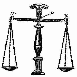
Fig. 6. Double lever as scales
"Here's another sketch (Fig. 5), in which A,B,C,
together show the lever, also the power A, the
fulcrum B, and the weight C. If I should place the
[25]
fulcrum B so that it would be in the middle between
the ends A C, there would be what is termed an
equilibrium between the weight and the power, and
if they are equal there will be a perfect balance
maintained. It is on this principle that scales for
druggists are made, the lever being suspended in
the centre of its length, as I show in the sketch
(Fig. 6). These scales
are very nicely adjusted,
and the chains
and receivers are made
as nearly alike in
weight as possible.
The arms of the lever
being of equal length
from the centre, or
pivot, permit the lever
to stand in a perfectly
horizontal position, unless disturbed by having a
weight placed in either one or other of the receivers.
In this case, the pivoted point P is the fulcrum,
and the two points O and X may be taken as the
power and the weight. If one pound is placed in
the receiver at O, it will tip the scale down, and that
will become the weight, while any commodity placed
in the receiver at X, until the lever is again brought
[26]
level, or horizontal, may be called the power. As
another illustration I'll tell you of something that
took place the other day. In the vacant lot are
several piles of bricks, stones, and planks. George,
seeing this, took one of the planks and threw it
across several others, making a 'Teeter Tauter,'
or, as some children call it, a 'Seesaw.' He balanced
the plank nicely, and then invited Jessie and her
cousin to sit on it, one at each end. The two girls
were about the same weight, and George held the
plank until both were seated. It remained level
and balanced, until George got on the top of it, and
stood on the centre of its length, placing his feet
so that one was on one side of the centre, or fulcrum,
and the other on the other. By causing his weight
to rest on his right foot, the right end of the plank
would dip downward; then by throwing his weight
on his left foot, the movement of the plank would
be reversed, and the motion continued until George
ceased to exert any extra pressure on either of his
feet. What do you call the boy or girl who stands
on the plank?"
"Sometimes," said Jessie "we call him a 'candlestick'
and sometimes 'the balancer'."
"This teeter tauter and the explanation of the
druggist scales," said the father, "show you that
[27]
many of our conveniences are due to the lever
in one way or another. These are but a few of the
thousands of instances I could name. Take a
nut-cracker, for instance. There we have a sort of
double lever, the joint being the fulcrum, the nut
the weight, and the two handles the combined
power or lever. By pressing the handles or levers,
we crack the nut or overcome the weight, by crushing
it. We owe many of our amusements to the
lever in one form or another. Even our pianos
would be impossible were it not for the combination
of levers in the adjustment of the keys. Machinery
and all kinds of moving instruments, including
watches, clocks, and other fine mechanism, could
not be perfected without the lever. The common
every-day wheelbarrow is a good illustration of
the use of the lever combined with the wheel.
George fills up his barrow with stones or other
materials that weigh two or three times the amount
he could lift easily. Yet he gets away with the
load, apparently with very little trouble. The
handles form the lever or power, the wheel the fulcrum,
and the stones the weight. George raises
the handles, and throws the greater part of the
weight on the fulcrum, which is the wheel, and this
latter, acting as a roller, is easily moved around
[28]
its own axle, thus enabling George to move his threefold
load with ease.
"This example shows you how, by a simple
combination of mechanical devices, labour may be
reduced. The roller is related to the wheel and
axle class—another of the mechanical powers.
"In your bicycles you have a fine illustration of
the application of the roller principle, in the ball-bearings.
The little round balls, over which the
axle of the wheel runs, are simply rollers rounded
in every direction, and placed there to destroy
friction, which they do almost entirely.
"Another excellent illustration of the use of the
roller is seen in the hanging of the grindstone we have
in our back shed. The axle passing through the stone
rests on two pairs of wheels or rollers, one pair at each
side of the stone. If you turn the stone on its axis,
you will notice the wheels turn also, and the effort
required to turn the stone is hardly noticeable.
If the grindstone were well balanced and true, and
the little wheels the same, so that they could be
run without friction on their bearings, the stone,
by giving it one good turn with the hand, would
keep revolving a very long time. So you see how
much we are indebted to the mechanical powers
for our present state of civilization."
[29]
Next morning being Saturday, George was up
early, put on a pair of overalls his mother had
bought, and, when breakfast was over, all but the
mother went out to the new property. They found
Nick helping a teamster to unload gravel, also a
load of cement, which was placed in a dry and
convenient place, for once damp or wet in the least
it becomes of little use, unless worked up immediately.
George was full of glee. He got his wheelbarrow
and wanted to commence work without delay.
The father took Fred and Nick to the trench and
explained what was to be done and the way to do
it. "The trench is now eight inches deep," he said,
"and you must wheel gravel, broken bricks, hard
mortar, or cinders into it so that there will be about
five inches of it in the trench from one end to the
other. Put all the larger stones at the bottom,
but before throwing in any, tamp or pound the
ground at the bottom of the trench until it is solid
and hard, making a good bottom for the stones to
rest on, and ensuring the walk from settling or
sinking in spots. Where the big root and rocks
are taken out, the holes must be filled up level,
and tamped solid. Rake off the largest of the
gravel, and let George wheel as much of it as he
can, and dump it in the trench, while Nick or you
[30]
wheel in the balance. Finish the top of the gravel
off with smaller sized stones, and after you have
filled in about five inches, throw water on the whole
with the garden hose until quite wet, and then pound
the gravel down until it is compact and firm. This bed
forms a good foundation for the concrete which must
be laid on it about four inches thick, and well tamped.
"After you have raked off the larger gravel,
take a wire sieve, with meshes not larger than four
to the inch, and sift the finer gravel out, to save
for the top finish. Before filling in the concrete,
strips of wood having straight edges on top must
be nailed to the stakes on both sides of the walk,
as I showed you on the blackboard in Fig. 1, marked
A A. These strips must be placed at proper grade
in their length, and level across from one to the
other. A straight edge made of wood, and long
enough to reach over the walk, and the strips as
well, must be provided, and it may be notched out
as I show at X, in Fig. 1. This straight edge is to
be used in levelling off the top or finishing coat, by
keeping both ends on the strips A A, and moving
it along lengthwise of the walk. If the top of the
walk is to be below the edges of the strips, you may
notch the ends, as shown, to suit whatever depth
may be required."
[31]
Fred told his father he thoroughly understood
the process as far as explained, and the latter then
left. By this time Nick and George—and, we
might add, Jessie—had wheeled into the trench
quite a lot of gravel, but for the want of a proper
"tamper" they had to stop. So Fred cut two pieces
off a fence post, each about a foot long, and with
an auger or boring tool, made a hole in the centre
of the end of each, about eight inches deep, into
which he inserted a round wooden handle, about
three feet long. These made excellent "tampers,"
not too heavy for George to use. Jessie, persuaded
Fred to make her "just a little one," but he told
her not to use it much or her hands would get sore
and too stiff to practise her music.
The strips for the stakes were prepared, nailed on,
and properly adjusted, and then it was time to commence
the real work. Nick had nailed some boards
on three pieces of scantling about six feet long,
which made a good mixing table for the concrete.
This was carried up near the top end of the walk,
and placed where it would be handy. A pailful
of cement was put on the board, next two pailfuls
of nice clean sand, and then five pails of gravel
that had no stones in it larger than would pass
through a ring having a clear diameter of two
[32]
inches. All this gravel, sand, and cement being
in one heap on the board, Fred and Nick worked
at it steadily for more than ten minutes, mixing
it up until the sand and cement were thoroughly
and evenly blended with the gravel. Fred then
sprinkled the mixture with clean water from the
hose, while Nick kept shovelling it over and over
until the whole was damp, but not so much so that
the cement and sand were washed from the gravel.
The whole mass looked like a pile of dirty stones
that had just been under a light shower.
"This," said Fred to Nick, "is a very important
process, for if we make the stuff too wet, it will
starve the concrete by washing away the cement,
and if we leave it too dry the work will be rotten
and crumble away."
Fred might also have added that the proper
proportioning of the materials was as essential as
the proper mixing, and in this case, where we are
making it one of cement, two of sand, and five
of gravel—all by measurement—we must adhere
closely to the rule or the walk will be uneven in
texture and colour.
The concrete being properly mixed, Fred and
Nick began to shovel it into the trench, spread it
to about four inches in thickness, and tamped it
[33]
down until the top mass looked sloppy and muddy.
While in this condition, a new lot of cement mixture
was made, consisting of one part of cement and
two parts of sand and the fine of the gravel that
had been sifted. All were mixed thoroughly while
dry, and afterward wet to the consistency of thick
mortar. This was spread over the concrete to
about one inch in thickness and levelled down by
the notched straight edge until the proper thickness
and level were obtained. The surface was then
ready to smooth, or "float," as the workman calls
it, which always
gives to the top of
the work a nice,
even, level appearance,
and makes it
solid and firm. The
"floating" is done
with a tool made of wood, as shown in Fig. 7, and
may be finished off with a plasterer's steel float,
merely to give the surface a better finish.
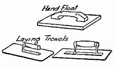
Fig. 7. Floats and trowels
The floating operation is laborious, for it must
be done at once, while the operator is on his knees.
Fred and Nick, however, worked away at it until
they made a good job of the portion that they were
putting down. All of the walk they could finish
[34]
at one time was about sixteen or eighteen feet,
so that the whole job required a number of days
to complete.
The first instalment being done, so far as the
floating was concerned, it was now in order to make
joints in the walk across the face, firstly for the
purpose of marking it off into flag sizes, four feet
square; secondly to prevent expansion. If there
were no joints made in the walk, it would "lift"
up, crack, break, and ultimately be destroyed.
Fred, who knew that the walk would contract in
cold and expand in warm weather, explained this
peculiarity to George and Nick, and having a
"jointer" along with the floats which the father
had sent, he, with Nick's help, ran some joints, at
four-foot intervals, across the walk, while Nick
pushed his spade through the joints to the ground,
actually cutting cement and concrete into sections
of four feet each. This would allow for expansion
or contraction, and even admit the raising of some
of the sections above the others, without cracks
or breaks occurring.
The first instalment of the walk being made, it
was left to George to wheel damp sand and scatter
it over the face of the walk about an inch thick,
to keep the sun and rain from injuring it.
[35]
Then he received instructions to wet the surface
every morning for a week. At the end of two or
three days the cement was hard, or "set" enough
to bear walking on, and in a week it was cleaned off
for use. One peculiarity about concrete or cement
work is, that it improves and gets stronger with
age.
The walk was complete in due time, in sections
of about sixteen feet long, and proved quite satisfactory.
Mr. Gregg was pleased with it, and he
explained to Fred, George, and Jessie that it might
have been made more ornamental, as there were
many tools for rounding off the edges, indenting
the surface, to make it less slippery, or for laying
the flags off in panels; but in this case all were
pleased with the way the boys had finished it.
[36]
II
BUILDING OF A BOAT HOUSE
The cement walk being finished to the satisfaction
of all concerned, and the admiration
of the neighbours, Fred turned his
thoughts to the building of a boat house and workshop.
It was decided to make it 16 feet wide
and 22 feet long, as these dimensions would suit
the timbers in the old barn, and be ample for stowing
away the boat and allowing space for a work bench.
Lines for a foundation were set out, and stakes
driven in the ground at the corners, alongside the
cement walk and pier. A trench about two feet
deep was dug on the two sides and ends; and in
this were laid large rocks and stones, in a single
course all round. Nick, who was quite handy at
this kind of work, built up a wall of smaller stones
laid in cement mortar. This mortar was composed of
one part of cement to five of sand, and made quite
thin and easy to spread. When the wall was high
enough, about level with the highest part of the
ground, it was levelled off by using smaller stones
[37]
and plenty of cement mortar. The level was obtained
by laying a straight plank flat on the top
of the cement finishing, and then applying an ordinary
spirit-level. Any errors in the level of the
wall showed at once, and were made right by adding
more mortar, or by taking some off the top of the
wall.

Fig. 8. Framing studding
Timbers from the old barn were next pressed
into service, chestnut wood that had served as
girths and beams. Two pieces were cut, 22 feet
long, and two of 16 feet. The ends were then
halved, as shown in Fig. 8—the simplest method
of framing a corner—and the timbers were spiked
and so squared as to make right angles at the
corners.
Fred then took the old window and door frames,
and measured off on the foundation timbers the
outside distance where each one was to be placed.
He put the double doors in the end of his boat
house, next to the river front. The other door and
[38]
windows were set in the best places to provide
an entrance opening on the cement walk, light
above the work bench, and views over the river
and grounds. Fred decided to build his house
ten feet high; so a quantity of studding, 2 × 4
inches in section, was taken out from the walls
of the barn, and cut exactly ten feet long. These
were to form the side walls between the corners,
doors, and windows. Heavier studs were found
in the barn, and Fred wisely used them next to the
windows and doors.

Fig. 9. Side of boat house frame
These heavy studs were set up in the places
marked on the timber sills, also at the four corners,
and were toe-nailed at the bottom to hold them in
place. They were then made vertical or plumb,
by aid of a spirit-level, and the corners were
[39]
braced temporarily to hold them in that position.
The picture (Fig. 9) shows how the side of the
building next to the cement work looked when the
studding was all in place. The dark ends shown
are the joists on which the floor is laid. The
lower joists were
made from timbers
taken from
the barn floor, 2 ×
8 inches wide and
long enough to
reach across the
building. The
joists on top were
2 × 6 inches, by
16 feet long.
These latter floor
beams were set
about 15 inches
apart, ready to receive the flooring plank, which was
nailed solid to them. You will notice that cross pieces
of studding are nailed between the studs at the window
openings. These form the tops and bottoms of
the window frames. The spaces above and below
are also filled in with short pieces of studding, to
nail the clapboards to, as shown. The ends of the
[40]
building were finished as shown in Fig. 10, a small
window being left in each to admit light and air,
also lumber, poles, or other stuff that could be
put into the loft through these openings. Inside
the building a trapdoor was to be left, so that
Fred or George could get up to take in or hand
out the stuff.
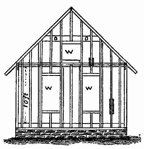
Fig. 10. End of boat house frame
The end (Fig. 10) shows how Fred and Nick,
with George's help, built that portion, the collar
beam, O O, and the rafter being seen, while the
details in Fig. 8 give larger sketches of the manner
of doing the work. The stone-work, as built by Nick,
for foundation walls, is shown in both Figs. 9 and 10.
All the clapboards having been taken off the
barn and old sheds, the better portions were selected
for covering the outside of the new frame, and a
lot of old boards were used for lining the inside of
the walls and nailing on to the rafters. The next
thing was to lay on the shingles. These had been
provided some days before by Mr. Gregg, who had
figured out the number required. He found the
roof would measure 24 feet in length, including
the projections over the ends of gables, and that
the length of the rafters was 17 feet each, including
the overhanging eaves or cornice. This made
the whole stretch of length on both sides of the roof
[41]
34 feet. Multiplied by 24 feet, the length of the
roof, this was 816 feet. To cover an area of 816
feet about 8,000 shingles would be required, as 100
surface feet require nearly 1,000 shingles, laid 4
inches to the weather, according to the usual custom.
Mr. Gregg explained to Fred what is meant by the
term "weathering," applied to shingles, clapboards,
slates, or anything similar. The "weathering" part
of a shingle is that portion of it exposed to the
weather, when in place on the roof. It makes no
difference how wide or how narrow a shingle may be,
it is that portion showing from the lower end of one
shingle to the lower end of the next one above it,
that is the "weathering." This is generally four
inches wide and it runs from end to end of the roof.
Another thing Mr. Gregg explained—the term,
"a square of shingling." "In this case, as in flooring,
clapboarding or similar work, a square is an
area 10 × 10 feet; or 100 superficial feet. In
nailing down shingles," went on Mr. Gregg, "the
nails should be driven so that the next course or
layer will cover up the nail heads, thus protecting
them from rain and damp, and preventing them
from rusting. When laying the shingles, after
the first courses are on, which should be laid double
at the eaves, a string or chalk line must be stretched
[42]
from one end of the roof to the other, four inches
up from the ends of the first courses. This string
or chalk line may first be rubbed over with chalk
or soft charcoal, and when drawn tight from each
end, it may be 'struck' or 'snapped' by raising
it up in the middle and letting it strike the roof
suddenly so that a mark will be left on the shingles
from end to end. This will be the guide for the
thick ends of the shingles to be laid against when
nailing on the next course, and the process must
be continued until the ridge, or top of the roof,
is reached. When you paint your boat house,
don't forget the roof, for a good coat of paint on
the shingles will lengthen the life of the roof fully
five years."
Fred, to whom these instructions were more
particularly given, told his father he understood
the whole matter, and he was directed to go on
with the work. In the meantime the father ordered
the shingle-nails required; five pounds for
each thousand shingles, or forty pounds altogether.
The building being small, the whole work was
soon completed, windows put in, doors hung, and
floors laid; and Mr. Gregg was greatly pleased
with the manner in which Fred had managed the job.

Photograph by Frank H. Taylor
Boat House and Workshop
"A Good Coat of Paint on the Shingles Will Lengthen the Life of the Roof
Fully Five Years."
The next thing was to take down the heavy
[43]
timbers of the barn, still standing. Fred saw at
once that they were too heavy to be removed
without mechanical aid or more human help, so
he brought from his father's stable a rope and set
of pulley-blocks like the ones shown in Fig. 11.
Nick, who had seen some service at sea, hooked
the block into a loop formed by a short piece of
rope tied over a limb projecting from one of the
trees. The question of lifting the timber now
was an easy one, as another short rope was tied to
the heavy post W, in this case the weight P being
the power. Each of the blocks shown contains
pulleys which make the relation of the weight to
the power as one to four. The weight being sustained
by six cords, each bears a sixth and a weight
of six pounds will be kept in equilibrium by a power
of one pound. The blocks used in a system of this
character are called single if there is one pulley
in each, double if there are two, treble if there
are three, and quadruple if there are four.
Fred, George, Nick, and Jessie who liked to
help whenever she could, counted for four times
their number when they all pulled together on the
rope P. It was astonishing to the youngsters how
easily the heavy timbers were taken down and
piled in a nice heap.
[44]
Two timbers, each about twenty-five feet long,
were chosen and marked, to be used for slides
or ways, on which the proposed boat could be
hauled in and out of the boat house. It was quite
a distance from the timber to the river end of the
boat house, and, the former being heavy, Fred
decided to make an inclined plane of planks—of
which there was an abundance—so that the timbers
could be slid or rolled down to the river. It
took but a few minutes to lay the planks, and as
the incline was gentle, rollers were used and the
timbers went down as easily as the big rock had
done. This pleased the younger children very
much.
"When papa comes home," said Jessie, "I'm
going to get him to tell me about the 'inclined
plane' as well as the ropes and pulleys."
The two timbers were rolled into the river and
floated to the boat house, where one end of each was
raised to the floor level at the doorway and made
fast; the other end sank to the bottom, where Nick
dug down and made a bed for it to rest in. These
beds were made deep enough to bury the ends,
and large stones were then thrown in to keep them
from moving, but these were not allowed to reach
within 18 inches of the surface of the water, which
[45]
was then at its lowest mark. The timbers were kept
about three feet apart, ample space to admit of any
ordinary launch or row boat being taken into the
boat house.
"Oh, Fred," said Jessie, "do you think those
two sticks will be strong enough to hold the boat
while you are pulling it up?" "Why, yes; strong
enough to hold a dozen boats no larger than the
one we intend having made. I don't know how
much weight these timbers will support, nor how
heavy our boat will be with the engine in it, but
I'm sure the timbers are strong enough."
Jessie's question, however, caused Fred to think
over the matter, and he set to work to find out
how to tell the strength of timber beams. He
discovered that to be able to determine the strength
of beams and wooden pillars under all sorts of
conditions required considerable training in mechanics
and mathematics, but that the case before
him was comparatively easy. A general rule for
finding the safe carrying capacity of wooden beams
of any dimensions, for uniformly distributed loads,
is to multiply the area of section in square inches,
by the depth in inches, and divide their product
by the length of the beam in feet. If the beam
is of hemlock, this result is to be multiplied by
[46]
seventy, ninety for spruce and white pine, one
hundred and twenty for oak, and one hundred and
forty for yellow pine. The product will be the
number of pounds each beam will support. For
short-span beams, the load may be increased
considerably. Fred, who had some knowledge on
the subject, acquired at the training school, determined
to pursue his studies in this direction.
In talking over the matter of nails with his father,
their holding power was mentioned, and Mr. Gregg
told Fred of a test that had been made some time
ago by the U. S. Ordnance Department, where cut
and wire nails had been tested respectively, showing
a decided superiority for the former, both in spruce,
pine, and hemlock. Thus in spruce stock nine series
of tests were made, comprising nine sizes of common
nails, longest 6 inches, shortest 13⁄8 inches; the cut
nails showed an average superiority of 47.51 per cent.;
in the same wood six series of tests, comprising
six sizes of light common nails, the longest 6 inches
and the shortest 11⁄8 inches, showed an average superiority
for cut nails of 47.40 per cent.; in 15 series
of tests, comprising 15 sizes of finishing nails,
longest 4 inches and shortest 11⁄8 inches, a superiority
of 72.22 per cent. average was exhibited by the
cut nails; in another six series of tests, comprising
[47]
six sizes of box nails, longest 4 inches and shortest
11⁄4 inches, the cut nails showed an average superiority
of 50.88 per cent.; in four series of tests, comprising
four sizes of floor nails, longest 4 inches and
shortest 2, an average superiority of 80.03 per cent.
was shown by the cut nails. In the 40 series of
tests, comprising 40 sizes of nails, longest 6 inches
and shortest 11⁄8 inches the cut nails showed an
average superiority of 60.50.
Speaking of the ropes used in blocks, while taking
down the old barn timbers, Mr. Gregg suggested
that it would not be a bad idea if the boys were
taught a few general items concerning hempen
ropes; so he asked them to memorize the following:
A rope 1⁄4 inch in diameter will carry 450 pounds,
and 50 feet of it will weigh one pound. If 5⁄8 inch
in diameter, it will carry 3,000 pounds and 7 feet
will weigh one pound. When a rope is 3⁄4 inch in
diameter, it will carry 3,900 pounds, and 6 feet will
weigh 1 pound. A rope one inch in diameter, the same
as we have in our blocks, will carry 7,000 pounds, and
3 feet 6 inches will weigh one pound. "It is not
likely that sizes greater than these will ever be used
by you. If they are, you can obtain a fair knowledge
of their strength by finding their areas, and comparing
them with the areas of the ropes given,
[48]
taking the rope having one inch in diameter, as
a constant example."
Wire ropes are much stronger than hempen
ones, whether made of steel, brass, or bronze. The
care and preservation of ropes is deserving of
consideration, particularly in localities where the
atmosphere is destructive to hemp fibre. Such
ropes should be dipped when dry into a bath containing
20 grains of sulphate of copper per gallon
of water, and kept soaking in this solution some
four days, before they are dried. The ropes will
thus have absorbed a certain quantity of sulphate of
copper, which will preserve them for some time,
both from the attacks of animal parasites and
from rot. The copper salt may be fixed in the
fibres by a coating of tar or by soapy water. In
order to do this the rope is passed through a hot
bath of boiled tar, drawn through a ring to press
back the excess of tar, and suspended afterwards
on a staging to dry and harden.
The figures given are intended for new manila
ropes, and do not hold good for ropes made of
inferior hemp. It is always safer never to load
a rope to more than 60 per cent. of its capacity,
and not even this much when it is old and weathered.
Jessie reminded her father of his promise to
[49]
give them some information regarding the power of
blocks and tackle and the qualities of the inclined
plane. Accordingly, Fred, George, and Jessie joined
their father in his den after supper, and George
placed his blackboard in a convenient place with
chalk, rule, and other requisites.
When all were seated, the father said: "Some
time ago I tried to explain to you the uses of the
lever in quite a number of different
situations; to-night I'm going to
show you how the various ropes and
pulley blocks are made to do service
for mankind. These devices are
used very generally, especially in
building operations, where heavy
beams, girders, or blocks of stone
have to be raised. On board ship,
it is the favourite mechanical power
by which rigging is raised, cords and
ropes tightened, and goods lifted
from or lowered into the hold.

Fig. 11. Blocks and
tackle
"The pulley, the main feature of
the third mechanical power, may be
explained almost on the same principle as the lever,
as you will see upon examining the sketch (Fig. 11)
I now make on the blackboard.
[50]
"The pulleys seen in the blocks around which
the rope runs may be considered so many levers
whose arms are equal, and whose centres are
fulcrums.
"In describing this power, it will perhaps be
better to begin with the first and simplest form of
the combination. The pulley, weight, and rope
I show now (Fig. 12) is the simplest form of making
use of this power. It is called a snatch-block
and often employed for drawing water
from wells, or for hoisting light weights.
It is very handy, but we do not get
any additional power from it, though
we get a change of direction and quick
movement. From its portable form,
its low cost, and the handiness with
which it can be applied, this arrangement
is one of the most useful of our
mechanical contrivances.
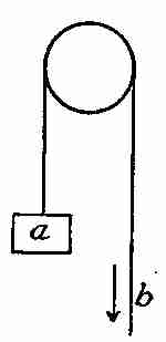
Fig. 12. Theory of
block and tackle
"When pulleys are adjusted, as I show you in
this sketch (Fig. 13), the block which carries the
weight is called a movable pulley, and the whole, as
shown, a system of pulleys.

Fig. 13. Double block and tackle
"In this illustration, suppose the weight is 20
pounds. It is supported by two cords, A and B;
that is, the two sections of the cord support 10
[51]
pounds each. Now, the cord being continuous,
the power must be 10 pounds.
"We leave out of consideration
the weight of
pulley and the friction of
the various parts.
"We have seen that the
weight is sustained by two
cords; if, therefore, it has
been raised two feet, each
cord must be shortened
two feet. To do this, the
power P must run down
four feet. To get the full value of this machine
the cords must be parallel.
"If we increase the number of movable pulleys,
as sketched at Fig. 14, to three, the relation of
P to W will be as 1 to 8 and the distance through
which P will travel will be eight times that through
which W is raised.

Fig. 14. Multiple blocks
and tackle
"If we apply this principle to the sketch (Fig. 11),
which illustrates the blocks you used to-day in
lifting the large timbers, and which is the usual
form of pulley employed to lift heavy weights,
you will notice that there is a four-sheave block
at the top, and a three-sheave block at the bottom,
[52]
with the end of the rope fixed from the top block.
The three-sheave block is movable. A power of
10 pounds will, with this form of pulley, balance
a weight of 60 pounds.
"Suppose a block of stone weighing 8,000 lbs.
is to be raised to the top of a wall and we use a
system of pulleys where each of the two blocks has
four pulleys; we shall find that it will require a
power of 1,000 pounds to raise it.
"Now, as to the inclined plane: this is called
the fourth mechanical power, and it is not in any
way related to the lever, but
is a distinct principle. Some
writers on the subject reduce
the number of mechanical
powers to two, namely, the
lever and the inclined plane.
The advantages gained by
this are many for just so much
as the length of the plane exceeds
its perpendicular height
is an advantage gained. Suppose
A B C (Fig. 15), I make
in the sketch, is a plane standing
on the table. If length
A B is three times greater than the perpendicular
[53]
height C B then a cylinder at R P may be supported
upon the plane A B by a power equal to a
third of its own weight.
That is, a block of that
weight would prevent
the roller or cylinder
from going farther.
From this we gather that
one third of the force
required to lift any given
weight in a perpendicular
direction will be quite sufficient to raise
it the same height on the plane; allowance, of
course, must be made for overcoming the friction,
but then, you see, you will have three times
the space to pass over, so that what you gain in
power, you will lose in time. We see the use of
the inclined plane every day we pass a building
under construction, where the workmen wheel
bricks, mortar, and other materials from the street
to the floors above, using long planks for the plane
or tramway. Merchants, too, often make use of
an inclined plane when rolling heavy boxes and
packages from the street to the floors of their warehouses.
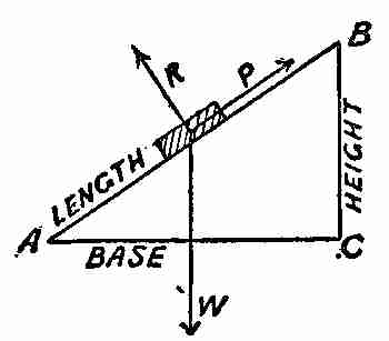
Fig. 15
"An excellent, practical illustration was given
[54]
you to-day when Nick and Fred built the ways
on which the proposed boat is to be slid into the
new house. It would require five or six strong
persons to lift the boat bodily into the new house;
but I expect two or three will easily slide it up
into the building on the ways; and by arranging
a winch—another mechanical contrivance—at one
end of the boat house, Fred, or George, for that
matter, will be able to haul the boat up. The
winch for this purpose will be a very simple affair,
merely a ready adaptation of the wheel and axle,
as I will show you later. Now, however, we are
talking about inclined planes, and to illustrate
its early application to the building arts, it is only
necessary to tell a few things we know regarding
the moving and raising of the great stones used in
building the Pyramids. For centuries it was a
mystery how the heavy stones in these structures
had been placed in their present positions. Recent
investigations have led many scientific men
to believe the stones were taken up inclined planes,
on rollers, and then put in place by the workmen,
who moved them to the different sides of the building
on strong timber platforms, where rollers, or
rolling trucks, carried the load. According to one
authority, there are the remains of the approach
[55]
to an inclined plane near the Great Pyramid,
which, if continued at the angle, as now seen, would
rise to the apex. According to this writer, the
foot of the plane was more than a mile from the
building, fifty or sixty feet wide, and had been one
huge embankment, formed of earth, sand, and the
clippings and waste of stone made by the workmen.
This, of course, would be an expensive and a tedious
method, but in those days time and labour went
for little. Every time a course of stones was laid
and completed, the plane was raised another step,
to the height of the next tier of stones. The same
angle of incline was probably maintained during
the whole period of erection, and this angle, you
may rest assured, was made as low and easy as
possible; for the Egyptian engineers were not slow
in adapting the easiest and quickest methods
available.
"This method of conveying the heavy stones to
their places in the Pyramids was simple and effective,
with no engineering difficulties that could not
be readily overcome. Moreover, it was really
the very best method considering the narrow limits
of their appliances.
"You may ask, 'How were these big stones
carried to the foot of the inclined plane?' The
[56]
quarries, in some cases, were five hundred miles distant,
and most of the stones had to be brought
across the Nile to the works. We know from the
monuments, and from the papyrii that have come
down to us from remote periods, that many of the
stones were brought down the river on large rafts
or floats, and on barge-like vessels; and we also
know that many of the larger ones were hauled or
dragged down from the quarries at Assowan to
Memphis, alongside the river, a distance of 580
miles. This is particularly true of the obelisks,
for all along an old travelled road evidences have
lately been found that these stones had been taken
that way, and that resting places for the labourers
had been provided at stations about twelve miles
apart, along the whole distance. It has been estimated
that a gang of men—say forty—well
provided with rollers, timbers, ropes, and necessary
tools, could easily roll an obelisk like that in Central
Park, New York, twelve miles in twelve hours;
and doubtless this was the system employed in
conveying those immense stones that great distance.
"A large number of obelisks were erected near
Memphis, though there are none there now, for
the Greek and Roman engineers, at the command
of the rulers, took a number down and carried
[57]
them to the city of Alexandria; but we have less
knowledge of how these later engineers transferred
the stones to the newer city, than we have of the
methods of the older. The beautiful column known
as Pompey's Pillar was once an obelisk, and was
transformed into a pillar, by either Greek or Roman
artisans, it is not clear which. The work of putting
those huge stones in place was not easy, as Commander
Gorringe discovered when he stood the
New York obelisk in the place it now occupies.
"But let us get back to our inclined plane.
"I have shown you how a weight or roller acts
on the incline, but I did not explain it clearly,
nor in a scientific way, as I do not want to puzzle
or confuse you with terms and problems you cannot
understand. I will, however, give you another
illustration or two on the subject, in which another
factor plays a part, namely—gravitation. Let
us suppose you have two golf balls laid on a table
that is perfectly horizontal or level in every direction;
they will remain at rest wherever placed,
but if we elevate the table so that the raised end
is half the length of the top higher than the lower
end, the balls will require a force half their weight
to sustain them in any position on the table. But
suppose they are on a plane perpendicular to the
[58]
table top, the balls would descend with their whole
weight, for the plane would not contribute in any
respect to support them; consequently they would
require a power equal to their whole weight to hold
them back. It is by the velocity with which a
body falls that we can estimate the force acted upon
it, for the effect is estimated by the cause. Suppose
an inclined plane is thirty-two feet long, and its
perpendicular height sixteen feet, what time should
a ball take to roll down the plane, and also to fall
from the top to the ground by the force of gravity
alone? We know that by the force of attraction
or gravitation, a body will be one second in falling
sixteen feet perpendicularly, and as our plane in
length is double its height at the upper end, it will
require two seconds for the ball to roll down from
top to bottom. Suppose a plane sixty-four feet
in perpendicular height, and three times sixty-four
feet, or one hundred and ninety-two feet long;
the time it will require a ball to fall to the earth
by the attraction of gravitation will be two seconds.
The first it falls sixteen feet, and the next forty-eight
feet will be travelled in the same time, for
the velocity of falling bodies increases as they
descend. It has been found by accurate experiments
that a body descending from a considerable
[59]
height by the force of gravitation, falls sixteen
feet in the first second, three times sixteen feet in
the next; five times sixteen feet in the third; seven
times sixteen feet in the fourth second of time;
and so on, continually increasing according to the
odd numbers, 1, 3, 5, 7, 9, 11, etc. Usually, the
increase of velocity is somewhat greater than this,
as it varies a trifle in different latitudes. In the
example before us we find that the plane is three
times as long as it is high on a perpendicular line;
so that it will take the ball to roll down that distance
(192 ft.) three times as many seconds as
it took to descend freely by the force of gravity, that
is to say, six seconds.
"The principle of the inclined plane is made
use of in the manufacture of tools
of many kinds, as in the bevelled
sides of hatchets, axes, chisels and
other similar tools, the examples
of which are in a great measure
related to this power, though many
of them partake largely of the
wedge, of which we shall now
have something to say.

Fig. 16. Action of
the wedge
"The wedge may be a block of wood, iron, or
other material, tapered to a thin edge, forming a
[60]
sort of double inclined plane, A P B, (Fig. 16)
where their bases are joined, making A B the
whole thickness of the wedge at the top. In splitting
wood as is shown in the illustration, R R being
the wood, the wedge must be driven in with a large
hammer or heavy mallet which impels it down
and forces the fibres of the wood to separate and
open up. The wedge is of great importance in
a vast variety of cases where the other mechanical
powers are of no avail, and this arises from the
momentum of the blow given it; which is greater
beyond comparison than the application of any
dead weight or pressure employed by the other
mechanical powers. Hence, it is used in splitting
wood, rocks, and many other things. Even the
largest ships may be raised somewhat by driving
wedges below them. Often, in launching a vessel,
wedges are used to start it on its way. And they
are also used for raising beams or floors of houses
where they have given way by reason of having
too much weight laid upon them. In quarrying
large stones, it is customary to wedge or break
off the rock by first drilling a number of holes on
the line of cleavage. Wooden wedges are then
driven tightly into these and left there until they
get wet, when they expand and split off the rock
[61]
as required. This method of quarrying large stones
was well known to the old Egyptians, and employed
by them in quarrying their famous obelisks.
"Owing to the fact that the power applied to
force a wedge is not continuous, but a series of
impulses, the theory of the wedge is less exact
than that of the other mechanical powers. Considering
the power and the resistance on each side,
however, as three forces in equilibrium, it may
be demonstrated that the
Resistance (R) equals P × Length of equal side/Back of wedge
Then the mechanical advantage will be—
R/P equals Length of equal side/Back of wedge
So that by diminishing the size of the back and increasing
the length of the side—that is, diminishing
the angle of penetration—the mechanical power of
the wedge is increased. While I did not intend to
inflict you with arithmetical or algebraical formulæ,
I have been compelled to give you that simple example
which I know you can all work out, as it is
concise, and the same would be long and tedious if
rendered in text."
Next morning, as Fred and his father were out
[62]
on the new place early, looking over the boat
house, the slide for the boat, and some other matters,
Mr. Gregg suggested that a winch be placed
at the upper end of the house, to haul the boat out
of the water. He also suggested that Fred prepare
for work on the boat at once, and provide himself
with all the tools and materials necessary. He
promised to call on a friend of his in the city, who
is a noted boat builder, and ask him the best method
to adopt in building the craft.
"Perhaps," said the father, "it might be a good
plan to buy a full set of shapes or patterns from
some one of the professional boat builders who advertise
such. They are sold at a very low rate—being
made of paper—and many firms sell all the
material that is required to build a boat complete;
with the sweeps, ribs, and curved stuff cut out
to the required shape and numbered all ready to
set up.
"What we want, Fred," continued the father,
"is a boat sixteen or eighteen feet long, just the
size of the one belonging to your friend, Walter
Scott; that is plenty large enough for all our
purposes. His boat can stand as a kind of a model
for you to work after in case you do not thoroughly
understand the patterns you are to get, or the
[63]
manner of arrangement. The gasolene motor we'll
order from some manufacturer, with whom we'll
arrange to install it, with a suitable propeller and
necessary attachments."
Fred was quite satisfied with all his father had
said and started to get ready. Jessie began to
question him about several things she did not fully
understand in her father's talk the night previous.
Fred explained matters, made them quite clear to
her, and then asked her to get her memorandum
book and write down the following, which
he said, she would often find useful: "There are
six mechanical powers, two of which father has
not told us about, but will no doubt do so, before
long. These are called, the Lever, Pulley, Wheel
and Axle, Inclined Plane, Wedge, and Screw.
The Screw and the Wheel and Axle, you have
yet to hear about. Now, study carefully the following
rules:
"The Lever.—Rule: The power required is to the
weight as the distance of the weight from the fulcrum
is to the distance of the power from the
fulcrum.
"The Pulley.—A fixed pulley gives no increase
of power. With a single movable pulley the power
required will equal half the weight, and will move
[64]
through twice the distance. Increasing the number
of pulleys, diminishes the power required. Rule:
The power is equal to the weight, divided by
the number of folds of rope passing between the
pulleys.
"The Wheel and Axle.—Rule: The power is to
the weight as the radius of the axle is to the length
of the crank or radius of the wheel.
"The Inclined Plane.—Rule: The power is to
the weight as the height of the plane is to the
length.
"Wedge.—Rule: Half the thickness of the head
of the wedge is to the length of one of its sides as
the power which acts against its head is to the effect
produced on its side.
"The Screw.—Rule: As the distance between
the threads is to the circumference of the circle described
by the power, so is the power required to
the weight."
Fred told George also to copy the foregoing in
his memorandum book, so that he would be able
to work out any problems for himself.
[65]
III
BRIDGE AND BOAT WORK
The next day Fred and his father talked over
the proposed boat, the result being that
Walter Scott was asked over the telephone
if he would come down in his launch to the Gregg
property in the evening, as Mr. Gregg and Fred
would like to see the craft, hear all about it, and find
out if it had any defects that might be avoided
in the building of another one. Walter said he'd
be glad to sail down, and would take his sister to
see Jessie. In the meantime some addresses of
boat builders were handed to Fred, with instructions
to write and ask for catalogues, prices of materials,
and the other information usually sent out to prospective
customers. Fred immediately wrote to
a number of firms, including several who manufactured
motors and other requisites for small
launches.
A little after the city clock struck four, Jessie,
who was home from school, saw The Mocking-Bird
sailing down the river at good speed, with
[66]
Walter, his sister Grace, and their mother on board.
Fred went down to the water's edge, and helped
Walter haul the boat to the unfinished landing place,
where Mrs. Scott and Grace were safely landed.
Fred and Walter soon became deep in "boat talk,"
and kept it up until the arrival of Mr. Gregg, who
began to make inquiries regarding the speed, capacity,
and safety of The Mocking-Bird. All his
questions were intelligently and favourably answered
by Walter, a bright and earnest little fellow. He was
some months the senior of Fred, but was not so
strong or robust looking.
"She's just 18 feet long over all," said he, "with
a 5-foot beam, a draft aft of about 18 inches, and a
forward draft of 1 foot. She is fitted with a 6-horse-power
gasolene engine, and her speed is from 8 to 9
miles an hour."
An illustration of her, as she appeared when partly
built, is shown in Fig. 17, where a plan and a section
of her length may be seen. The manner of
her construction is also shown, also the lines of ribs,
portion of inside lining, position of motor, rudder,
and propeller.

Fig. 17. Plan and section of The Mocking-Bird
Mr. Gregg also ascertained from Walter that his
father had sent to a firm who made a business of
preparing the complete wood-work for many kinds
[67]
of boats on the "knockdown" system, selling the
whole material ready to set up without the aid of
an expert. Printed instructions came along with
each boat, so that the buyer would have but little
difficulty in setting up the wood-work and making
it ready for use. An expert workman had been
engaged by Walter's father to install the engine,
line up the propeller shaft, and connect the wheel and
shaft to the engine. On the arrival of the materials—within
a week after the order was sent—Walter
had gone to work; and inside of fourteen days, The
Mocking-Bird took to the water.
So fully and so satisfactorily did Walter explain
to Mr. Gregg all that he asked about, that Fred
was able at once to order the material for a similar
launch, to be sent on immediately. In order to hurry
matters, a cheque was inclosed with the order, and
Fred, Walter, and George walked over to the postoffice
with the letter, so that it went by the night
mail.
On returning, it was suggested that the boys,
Grace, and Jessie go for a sail on the river, and all
were soon at the landing. Walter adjusted his
engine and made all ready as George and the girls
got on board, while Fred cast off the rope which
held the boat to the dock, then stepped after them.
[69]
The engine was started, Fred took the tiller, and
they were soon afloat, sailing with the tide in their
favour at a rapid speed, and returning to the landing
place inside of an hour, well pleased with their
little outing. Fred showed Walter his new boat-house
and workshop, explained to him how Nick
and he, with the help of George and the advice
of his father, had completed the work and the
building. He also pointed out other work he was
going to do as soon as his boat was finished.
Though not yet dark, it was getting rather late,
and Walter's mother advised that they start for
home as soon as he was ready. So wishing Fred
every success in the building of his boat, Mrs. Scott,
her daughter, and Walter left for home.
"Well, Fred," said Mr. Gregg, when his family were
all seated in the living room, "you are now in for
quite a job, one that will test your working qualities;
but I am sure you will come out with flying colours.
You will meet difficulties, but you must overcome
them, and when the boat is finished, painted, and
ready to name, you can have some of your friends
up for the launching. Mother will have a special tea
for you all, and we'll christen the new craft. Meantime
we must think over the matter of a name,
and decide upon one we shall all like."
[70]
Next morning, Fred and his father went down
to the river's edge to examine the little ravine that
had been cut out by the spring and fall freshets.
It was a small affair, only about six feet deep and
ten or twelve feet wide. At present, the opposite
side was reached by crossing a couple of planks,
safe enough while the land had been in a measure
unoccupied. To leave it so now would be a different
matter, as Jessie or her mother, attempting
to cross, might easily fall over; so it was decided to
have a foot-bridge built over the creek, which was
nearly dry the greater part of the year. There was
plenty of material on the ground for the purpose,
and Fred was asked by his father to get Nick to
help, so that the bridge might be ready as soon as
possible.
Fred felt he was getting to be quite an important
person when his father trusted him with work
which must necessarily entail considerable expense,
but he accepted the responsibility with pleasure,
and promised to commence at once, so as to have
it finished by the time the material for the boat
arrived. So, when Nick arrived, operations began
immediately.

The Creek
Taking a tape line, Fred sent the Italian to the
other end of it, and they picked out a favourable
[71]
location to measure across, making it over 11 feet
at the narrowest spot from one edge to the other.
Allowance was then made for bearings five feet on
either side of the span, so that timbers 21 feet long
would be required to cross the chasm. This width
would require three string-pieces, or chords, to run
across, one on each side, and one in the centre.
These, covered with three-inch plank from end
to end, would make a good, solid deck sufficient
for all purposes. The planks were cut off seven feet
long, to have the deck of the bridge, over all, exactly
seven feet wide.
Among the timbers taken from the old barn
were nine pieces, measuring 22 feet in length, 8 × 10
inches in section, so Fred decided to make use of
three of these just as they were, without cutting,
and to place them on their edges to get the most
strength out of them. He then had six posts cut
off the old cedar fence posts, about two feet long,
which were sunk into the ground their whole length,
as shown in Fig. 18, three on each side of the creek,
and the tops made level, so that a flat timber or
plank would rest on them, touching each one. This
plank was made nine feet long, so as to project
over the posts about a foot at each end. This
was, of course, the same at each end of the bridge.
[72]
After the flat timbers had been laid on the ends of
the posts and fastened with spikes, there were
laid the three long timbers spanning the gully. The
spaces between were equally divided, and then
covered with three-inch planks taken from the floor
of the old barn. The boards were cut off to the
proper length and fastened down on the three
timbers with spikes five inches long, the planks not
laid close together, but kept about three-eighths of
an inch apart, in order to let the water run off after
a rain, as well as to allow air to circulate underneath
and between the joints to prevent the planks from
decay.

Fig. 18. Frame of foot-bridge
In order to make the bridge safe, it was necessary
to build a rail on each side. Two pieces of timber
about 20 feet long and 6 × 6 inches square were
used for the rails, while posts and braces were made
[73]
of timber of about the same dimensions. The bottoms
of the posts were halved, so that they could be
spiked or nailed to the long outside string-pieces,
as shown in the illustration. Tenons were made
on the top of these posts, and these fitted
into mortises made in the top rails, and all
were then put together and fastened with wooden
pins.
Nick dug away the surplus earth from the approaches
to the bridge, and made an easy grade to
its deck. This completed the work all but the
painting, which was left to be done some other
day.
Mr. Gregg inspected the bridge, pronounced it all
right, and congratulated Fred on his workmanship,
at the same time saying a good word to Nick and
George, both of whom had helped very much to
make the effort a success.
In the evening Mr. Gregg told Fred and George
that a friend of his had given him a copy of
the rules to be observed when running a
launch, so he asked the boys to get their note-books,
and take these down as he read
them out. Even Jessie, too, he thought, ought
to be acquainted with the rules, as she might be
called upon some time to make use of them, so
[74]
three pencils were soon at work, as the father
read out the following:
-
"1. When at the wheel, remember as a first consideration,
that you cannot entertain the boat's occupants as well as
steer.
-
"2. Keep your course, and know what that course is.
-
"3. Regulate your speed to the company you are in.
Marine motors are, as a rule, very flexible.
-
"4. Do not cut corners.
-
"5. When approaching a landing, learn to judge exactly
the distance your boat will travel after your propeller has
stopped, so as to run alongside without using your reverse
gear. This requires some practice, but is amply rewarded by
time saved, in the long run, and decrease of wear and tear on
engine, gear, and propeller. Any one can get to a landing in
time by alternately running full speed ahead and then
astern.
-
"6. When aboard your boat, and facing the bow your
right hand is starboard, your left, port. Keep to the
right. Should you be overtaking any one, it is your duty
to pass clear on their left. The above applies only to narrow
waters.
-
"7. When going up or down stream, should you wish to
cross over to the other side and return, and another boat is
overtaking you on your left, don't attempt to cross its bow;
slow down until it has passed.
-
"8. Keep clear of non-engined crafts. You have greater
freedom of action than they; it costs you nothing, and their
occupants appreciate your courtesy.
-
"9. Do not tow canoes or skiffs alongside. If towed
at all, they should be right aft with as short a towline as
possible.
-
[75]
"10. Finally; remember the rules of the road—
-
"'Green to green or red to red
Perfect safety—go ahead
If to starboard red appear
'Tis your duty to keep clear.
When upon your port is seen
A steamer's starboard light of green,
There's not so much for you to do
As green to port keeps clear of you.'"
The children all promised to memorize these rules.
As the stuff for the boat was not expected for
some days, Fred and Nick kept at work about the
new boat house, and building up the landing dock.
The former fitted up a work bench, and put his little
shop in readiness for actual use. Fred also hunted
for a nice stick of timber among the old barn ruins,
on which to set up the boat. A good piece found,
he cut it to a length of 20 feet, and then he and
Nick got it into the boat house, where Fred planed
it off a little with a rough jack plane, keeping a
sharp lookout for nails, sand, or gravel. Nothing
destroys the cutting edges of tools more than nails,
bits of iron, glass, sand, or small pebbles, which
sometimes escape the vigilance of the workman.
Especially is this true of saws, which Fred knew quite
well since he had once run a good sharp saw against
a nail, while cutting a piece of timber in two. This
[76]
taught him a lesson he never forgot, and whenever
he had to cut up old material, he was always careful
to examine it all round, and to scrape or brush off
all the dirt and sand from the parts through which
the saw teeth had to travel. In planing, or "dressing"
the stick of timber, the same precautions were
taken, and the surface of the wood was made as
clean and free from dirt and sand as it possibly
could be. Notwithstanding all this, Fred found
it almost impossible to keep the cutting iron of his
jack plane sharp enough to take off shavings. He
had to sharpen it every few minutes. This is nearly
always the case when working up wood which has
previously been used. However, he managed to
"dress" his stick very nicely, and after finishing
it, laid it down along the middle of the floor of the
shop, putting blocks of wood under it here and there
to raise it up from the floor five or six inches. It
was then made level on top and fastened down so
that it would not move or get out of line. This was
about all they could do on the boat until the
materials arrived. Nick had managed to fill in
the space between the two walls of the little pier
with heavy bowlders, and had strengthened the
whole with coarse rubble-stone work in such a manner
that there was little danger of injury from floating
[77]
ice or flood tides; and he had covered the whole
over with small stones, gravel, and a good thick
layer of cement concrete, which made it correspond
with the cement walk.
The question of a winch was then taken up with
Mr. Gregg and it was decided to construct a simple
affair at the end of the boat-house opposite the
large doors, where the boat would have to enter.

Fig. 19. Winch and crank
Mr. Gregg suggested, in order to make the end
of the building strong enough, that two upright
posts be set up, well
braced by being fastened
to both floor
and ceiling, and that
the winch be attached
to them in a way
that would be easy to
work, as shown in Fig.
19, room enough being
left between the posts
and the wall for the
crank to turn without
the hand of the operator
striking the
boards. The cylinder around which the rope
should wind ought to be about six inches in diameter,
[78]
and the crank or handle on the end, not less
than fifteen or sixteen inches long. The longer the
crank, the less force it would require to haul in
the boat. If desired, a crank could be fitted to
the other end of the cylinder so that two persons
could work at one time, pulling in the weight.
In the evening Mr. Gregg asked the boys and
Jessie to visit his room, and he would try to explain
the principle and advantages of the wheel and axle,
as the winch they were to make was in a measure
related to that principle. Mr. Gregg began by
saying: "The wheel and axle is merely a modification
of the lever and consists of a couple of cylinders
turning on a common axis, the larger cylinder is
usually called the wheel, the lesser one the axle.
This arrangement, which I draw on the blackboard
herewith, forms a kind of lever of the first or second
class. Considered as a lever, the fulcrum is at the
common axis, while the arms of the lever are the
radii of the wheel and of the axle.

Fig. 20. Wheel and axle
"The fulcrum is at C, the centre. The arm of
the weight is W W, and the arm of the power is
A C. In Fig. 20 the arm of the power is the spoke
of the wheel, while the arm of the weight is the
radius of the axle. Fig. 19 shows the ordinary
winch, often used in well-digging for hauling up
[79]
dirt and rock, and also for raising planks, shingles,
rafters, and other light stuff, to the roofs and upper
floors of buildings. Often it is made more powerful
by adding spur or
geared wheels to the
end of the shaft, consisting
of a pinion
and a larger spurred
wheel. The crank
or handle is attached
to the pinion,
and the power is increased according to the
difference in diameters of the spur wheels.
The machine is then called a 'crab' and it is often
used for lifting safes and other heavy weights to
elevated situations. In Fig. 20 the length of the
crank (in a straight line) is the arm of the power.
"The mechanical advantage of the wheel and axle
equals the ratio between the diameter of the wheel
and of the axle.

Fig. 21. Capstan and hand bars
"It is not necessary that an
entire wheel be present. In
the case of the windlass and
the capstan (Fig. 21), the
power may be applied to a
single arm or to a number of arms placed in the
[80]
holes shown. The cable or rope on the barrel of
the capstan is hauled in by turning the capstan on
its axis, with handspikes or bars. The capstan is
prevented from turning back by a pawl attached
to its lower part, working in a circular ratchet on
the base.

Fig. 22. Compensating fusee
"As an illustration of the lever action, and of
work put into and got out of a machine, there is
no better illustration
than the ingenious
contrivance termed
the fusee (Fig. 22).
In good watches
and clocks, where
the elastic force of a
coiled spring is used to drive the works, the fusee
compensates the gradually diminishing pull of the
uncoiling spring. The driving of the works at
a constant rate is the object for which a watch
or clock is designed. This usually entails a
constant resistance to be overcome, but since
one of the most compact and convenient forms
of mechanism into which mechanical force can
be stored is that of the coiled spring, and since
the very nature of the spring is such that its
force decreases as it uncoils, we must employ some
[81]
compensating device between this variable driving
force and the constant resistance. The fusee does
this in a most accurate and complete manner. As
the fusee to the right is to compensate for the loss of
force of the spring as it uncoils itself, the chain
is on the small diameter of the fusee when the watch
is wound up, as the spring has then the greatest force.
"In the differential, or Chinese windlass (Fig. 23),
different parts of the cylinder have different diameters,
the rope winding upon the larger and unwinding
from the smaller. By one revolution the
load is lifted a distance equal
to the difference between the
circumference of the two
parts.

Fig. 23. Chinese winch and
pulley
"There are many other
contrivances and appliances
of the wheel and axle for performing
various services, but
I think the examples I have shown you will be sufficient
to enable you to make use of the device to
perform any duty you may be called upon to attempt
in ordinary life, but, should you enter
professional life as civil, mechanical, naval, or mining
engineer or architect, you will be obliged to pursue
the study of these subjects further.
[82]
"Before closing I may add a few problems for
you to solve at your leisure by the application of
the rules I have given you when describing the other
mechanical powers.
"The pilot wheel of a boat is 3 feet in diameter;
the axle is 6 inches; the resistance of the rudder is
240 pounds. What power applied to the wheel
will move the rudder? Here the difference between
the axle and wheel is 18 inches.
"Four men are hoisting an anchor of 3,000 pounds'
weight; the barrel of the capstan is 8 inches in
diameter; the circle described by the handspikes is
7 feet 6 inches in diameter. How great a pressure
must each of the men exert?
"With a capstan four men are raising a 1000-pound
anchor; the barrel of the capstan is a foot
in diameter; the handspikes used are 5 feet long;
friction equals 10 per cent. of the weight. How much
force must each man exert to raise the anchor?
"The circumference of a wheel is 8 feet; that of
its axle is 16 inches; the weight, including friction,
is 85 pounds. How great a power will be required
to raise it?
"A power of 70 pounds on a wheel whose diameter
is 10 feet balances 300 pounds on the axle. Give
the diameter of the axle.
[83]
"An axle 10 inches in diameter fitted with a winch
18 inches long is used to draw water from a well.
How great a power will it require to raise a cubic
foot of water, which weighs 621⁄2 pounds?"
The first mail in the morning brought word that
the whole of the partly prepared stuff for the boat
had been shipped by "fast freight," and that it
would reach its destination in the course of a few
days. The paper patterns, directions, and all
necessary instructions for building would be mailed
at once.
[84]
IV
MAKING A GASOLENE LAUNCH
Two or three days after Mr. Gregg had talked
over the principles of the wheel and
axle, with the children, Fred received
notice that a consignment of wood-work was at
the station awaiting his orders. Mr. Gregg made
immediate arrangements with the railway people,
and by the time he got home from his office, the stuff
was being unloaded by the boys, who carried it
piece by piece into the workshop, each section
being laid by itself in the order in which it was to
be put in place in the boat. Printed instructions
were in the equipment for laying the keel, setting
up the frames, and even for taking the stuff out of
the packages and putting it in heaps, so that it
could be readily picked out when wanted for use.
Each rib was numbered, and marked or stamped
"right" or "left," and all the pieces were cut off
to the right length and to the right bevel or angle
to suit the positions they were to occupy, as specified
in the printed instructions. This made the
[85]
setting up an easy matter, requiring only care,
patience, and a fair knowledge of the use of wood-working
tools. That Fred possessed these qualities,
was partly due to the training he had received in
the technical school, and partly to his natural
aptitude for picking up methods, ideas, and new
applications.
Fred, George, and Mr. Gregg himself, were much
interested in the selection of the various materials,
and when the plank that was to form the keel had
been unpacked, George was anxious that it should
be laid down on the bed that had been prepared for
its reception. He was quite disappointed when he
found it considerably shorter than he had expected
the boat to be. It was explained to him, however,
that the overhanging of the stern, and therefore
shortening of the forefoot, or stem, necessitated
the keel being shorter than the boat would be when
measured over all on top. The keel was found to
be a fine piece of tough oak, nicely dressed, made
the proper shape at each end, bored and gained
to receive the stern post, the stern ribs, and side
stanchions. Everything was marked, and each
timber was sized so that it would fit in place snugly
without using a tool on it, except a hammer or mallet.
At tea time George felt it difficult to keep reasonably
[86]
quiet, he was so enthusiastic about the boat—much
to the amusement of his father, who knew
exactly how the boy felt.
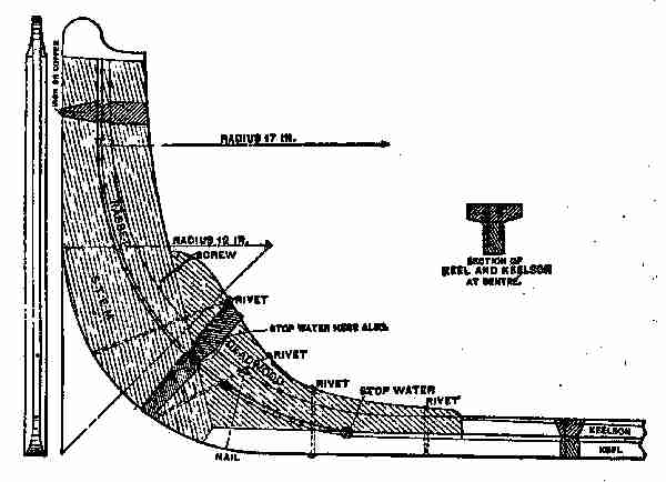
Fig. 24. Stem of launch
After tea, all walked to the boat house, and the
father assisted Fred to set up the keel, which was
in two pieces, halved together midway and well
fastened with screws. The joint was painted with
a heavy coat of white lead and linseed oil paint,
before being put together and screwed up. The
keel is the lowest timber in a boat or ship, and it
runs nearly the length of the craft. Sometimes
there is a keelson placed on the top of the keel,
[87]
and the ribs of the boat, or stanchions, are made
fast to that timber, as shown in the illustration,
(Fig. 24,) in which the gains for the ribs or moulds are
made. This portion of the boat was put together
temporarily, so Fred had no difficulty in assembling
the various pieces. The stem, keel, keelson, and
deadwood were all made of oak, and looked strong.
The keel and keelson were properly laid and adjusted,
and after some explanations by Mr. Gregg the manner
of setting up the ribs was thoroughly understood.
Fred decided to telephone Walter Scott
to come down next day, as it was Saturday, and
help him to set up the skeleton.
As the weather was getting warm, the whole
family spent the evening on the veranda and George
introduced the question of naming the boat. He
suggested Red Bird, but this did not seem to
take well, and several others were proposed but
none seemed to suit everybody. Jessie sat quietly
on the steps till asked by Fred what her choice
would be.
"I would like it called after mamma, Caroline."
"That's a good idea, Jessie," said her father,
"and if the boys or your mother don't object, I
think we'll settle on Caroline."
Early next morning the boys were out watching
[88]
for The Mocking-Bird, which very soon made its
appearance. Fred and Walter tied the boat up to
the new dock and went into the boat house, where
the latter began to examine the boat stuff, and to
explain the manner of setting it up and fastening
it in place.
Nick, who was on hand to help, did the heavy
work, and helped to put up the stanchions. Walter
seemed quite familiar with the work, and he and
Fred soon had the boat so well in hand that it
seemed to grow under their fingers. The ribs were
easily selected, as they were tied together in pairs
and numbered. They were then set in their places
according to their numbers and were fastened to
the keelson with the strong copper nails. All the
nails required for the boat were of copper, because
that metal is less likely to corrode than iron or steel.
It was found necessary to brace the ribs in order
to keep them in line. Thin pieces of lath were tacked
on the tops to hold the ribs the proper distance apart,
and longer and stronger strips of wood were used
for bracing the boat sideways. These were nailed
to the joints in the ceiling or high up on the walls
of the boat house.
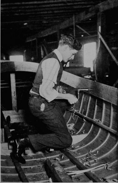
Copyright, 1911, by Underwood & Underwood, N. Y.
Making a Motor Launch
"All the Nails Required for the Boat Were of Copper, Because That Metal
is Less Likely to Corrode Than Iron or Steel"

Fig. 25. Section of launch—abeam
At noon the boys had the skeleton of the boat well
advanced, and to one standing in front of the bow,
[89]
it presented an appearance like the sketch shown
at Fig. 25.

Fig. 26. Methods of sheathing
The launch might be called "carvel ribbon built,"
or nearly so, and it
would have a displacement
of 14 or
15 hundred-weight
when fairly loaded.
This weight would
bring her down to
the third W. L., as
shown in the end sketch. To load her to the fourth
W. L., would give her a load far beyond these figures.
The sections had to be closely spaced, and
the ribbons or slats let into the temporary section
moulds before the outside boarding could be put on,
[90]
the edges of the boarding being clinch fastened, as
shown in the ribbon carvel, Fig. 26. Other styles of
sheathing boats, as shown, are often used, but the
Caroline was "ribbon carvel."
It is usual to lay off the sheer profile on a suitable
floor, and line in the rebate line, scarf of stem,
deadwoods, fork timbers, etc., making thin moulds
of each member to be lined off, sawn, and bolted
together. The section moulds, from which the boat
derives its shape, are also laid off, and the planking,
3⁄8-in. thick, deducted when making them.
The stem, of crooked oak, was 21⁄4 in. thick by
about 3 in., shaped as shown in Fig. 24. The fore
deadwood was 21⁄2 in. thick, moulded about 3 in.,
and through-bolted to the stem and keel with 3⁄8-in.
copper bolts; and the stern-post, 31⁄2 in. thick,
was wrought to shape, as shown. The centre line
of the shaft, as shown, is subject to alteration, since
different makes of motors have different sizes of
propellers and flywheels. The fork timbers were
let into the stern-post, and carried the transom,
wrought out of a flitch of elm 31⁄2 in. thick. The
planking, of 3⁄8-in. cedar, was closely jointed and
varnished, and secured to the ribbons. The timbers
were of rock elm, 7⁄8 in. by 1⁄2 in., steamed
and bent or sawn to shape, and through-fastened
[91]
at the top and bottom edges of the planking. These
were spaced on 71⁄2-in. centres, with two clinch
nails into the ribbons between them. Three or
four solid floorings should be worked into the motor
space; fitting of the motor bed thwartships gives
great support to the boat.
The thwarts were of oak, 8 in. wide and 1 in.
thick, with the side seats, 7⁄8 in. thick, supported
by turned legs of oak. The decks at each end
should be of 1⁄2-in. oak or cherry reeded into 3 in.
widths, and filled with marine glue. The covering
board, 21⁄2 in. wide, with a nosing worked on the
edges, and 1⁄2 in. thick, was carried by a clamp or
binding stake, 21⁄2 in. by 5⁄8 in., through-fastened
at every timber. The knees were of oak, 1 in.
thick, about 10 in. on the foot by about 3 in. at
the head, and through-fastened. A breast hook
2 in. thick should be fitted. The floor boards may
be of 3⁄4-in. spruce, elm, or ash grating, as preferred.
The centre of the motor was at No. 6 section, as
indicated, the gasolene being stored in a strong tank
under the forward deck, just high enough to feed
by gravitation. After being cleaned off and sandpapered,
a coat of good shellac varnish, may be
followed, if desired, by three coats of best yacht
varnish. The spacing of the sections was: No. 1,
[92]
from face to stem, 1 foot 2 in.; No. 2, from No. 1,
is 1 ft. 2 in., the other sections to No. 11 each 1 ft.
6 in.; No. 12 was 1 ft. 1 in. from No. 11 (see Fig. 25).
The water-lines were 5 in. apart, and the buttock-lines,
A and B, 1 ft. and 1 ft. 9 in. respectively from
the middle line.
The boys followed these directions, and with the
help of the following table, managed to get the boat
ready to varnish and finish up. The following table,
which refers more particularly to the section shown
in Fig. 25, shows the sheer lines, counting from
L W L (low water line). While all the work and
calculations regarding the plan had been already
done, Mr. Gregg, who had watched the work's progress
[93]
for a week, thought they should know the
principles on which the craft was being built, and
therefore advised them to examine the illustration
and table, so that they would have some knowledge
of the science required to build a boat intelligently.
Fred and George did this, and were helped
along by Walter, who seemed to have mastered the
subject pretty thoroughly.
TABLE OF OFFSETS
| | Stem | Section Numbers |
| | | 1 | 2 |
3 | 4 |
| |
ft. | in. | ft. | in. | ft. | in. |
ft. | in. | ft. | in. |
| Sheer heights above L.W.L. |
1 | 7 | 1 | 6 | 1 | 5 |
1 | 41⁄8 | 1 | 31⁄4 |
| L.W.L. to rebate line |
| | | 7 | | 83⁄4 |
| 9 | | 91⁄4 |
| Half-breadths at gunwale |
| | | 81⁄4 | 1 | 31⁄8 |
1 | 91⁄2 | 2 | 11⁄8 |
| Half-breadths at 4 W.L. |
| | | 67⁄8 | 1 | 11⁄2 |
1 | 8 | 2 | 01⁄2 |
| Half-breadths at 3 W.L. |
| | | 57⁄8 | | 115⁄8 |
1 | 63⁄8 | 1 | 11 |
| Half-breadths at L.W.L. |
| | | 43⁄8 | | 93⁄8 |
1 | 35⁄8 | 1 | 83⁄4 |
| Half-breadths at 1 W.L. |
| | | 21⁄2 | | 53⁄4 |
| 101⁄2 | 1 | 3 |
| Buttock A from L.W.L. |
| | | | | 51⁄2 |
| 41⁄8 | | 63⁄8 |
| Buttock B from L.W.L. |
| | | | | |
| | | 3⁄8 |
TABLE OF OFFSETS. Continued
| | Section Numbers |
| | 5 | 6 | 7 |
8 | 9 |
| |
ft. | in. | ft. | in. | ft. | in. |
ft. | in. | ft. | in. |
| Sheer heights above L.W.L. | 1 | 23⁄4 | 1 | 21⁄4 |
1 | 21⁄8 | 1 | 21⁄8 | 1 | 21⁄2 |
| L.W.L. to rebate line | | 91⁄2 | | 97⁄8 |
| 10 | | 101⁄2 | | 103⁄4 |
| Half-breadths at gunwale | 2 | 31⁄2 | 2 | 41⁄2 |
2 | 43⁄8 | 2 | 35⁄8 | 2 | 21⁄8 |
| Half-breadths at 4 W.L. | 2 | 27⁄8 | 2 | 4 |
2 | 37⁄8 | 2 | 31⁄4 | 2 | 13⁄4 |
| Half-breadths at 3 W.L. | 2 | 2 | 2 | 31⁄4 |
2 | 31⁄4 | 2 | 21⁄2 | 2 | 03⁄4 |
| Half-breadths at L.W.L. | 2 | 0 | 2 | 11⁄2 |
2 | 11⁄2 | 2 | 05⁄8 | 1 | 91⁄2 |
| Half-breadths at 1 W.L. | 1 | 63⁄4 | 1 | 81⁄2 |
1 | 81⁄2 | 1 | 61⁄2 | 1 | 07⁄8 |
| Buttock A from L.W.L. |
| 75⁄8 | | 8 | | 8 |
| 71⁄2 | | 51⁄4 |
| Buttock B from L.W.L. |
| 33⁄8 | | 43⁄4 |
| 43⁄4 | | 31⁄2 | | 3⁄8 |
TABLE OF OFFSETS. Continued
| | Section Numbers | End of
Transome |
| | 10 | 11 | 12 |
|
| |
ft. | in. | ft. | in. |
ft. | in. | ft. | in. |
| Sheer heights above L.W.L. | 1 | 3 | 1 |
35⁄8 |
1 | 41⁄4 | 1 | 6 |
| L.W.L. to rebate line | | 11 | | |
| | | |
| Half-breadths at gunwale | 2 | 0 | 1 | 91⁄2 |
1 | 63⁄4 | | |
| Half-breadths at 4 W.L. | 1 | 113⁄8 | 1 | 71⁄4 |
| | | |
| Half-breadths at 3 W.L. | 1 | 91⁄4 | | 81⁄2 |
| | | |
| Half-breadths at L.W.L. | 1 | 21⁄8 | | |
| | | |
| Half-breadths at 1 W.L. | | 53⁄4 | | |
| | | |
| Buttock A from L.W.L. | | 1 |
| 6 | | 113⁄4 | | |
| Buttock B from L.W.L. | | |
| | | | | |
It was necessary, before installing the motor,
that a foundation should be laid for it, so varnishing
and the final finish were left over until the
engine and propeller should be put in and tried.

Fig. 27. Starboard side of motor Fig. 28. Port side of motor
The engine was brought to the boat house from
Newark, and the expert, engaged by Mr. Gregg
some time previous, came along with it, bringing
such tools as he might want. He examined the bed
for the engine, and saw that all was properly fastened
and in good condition to place the engine and the
propeller shaft. Mr. Watts (the machinist) laid
off a line for the propeller shaft and with a long
auger bored a hole from the engine bed through to
the stern-post, large enough to permit the shaft
of the propeller to revolve in it easily. A bearing,
or "box," was adjusted to the stern-post in which
the shaft ran, and the "box" was made water-tight
to prevent any inflow. The propeller was
[94]
made of bronze, had been nicely fitted to the shaft
before it came, and had a set screw in its hub to
hold it firmly on the shaft. The diameter of the
propeller wheel measured 15 inches and it had two
blades. The shaft and wheel being properly adjusted,
the next thing was to place the engine,
which weighed about 200 lbs. The blocks and
tackle used in taking down the old barn were
rigged up to the ceiling by cutting a hole through
the floor, laying a short timber across the joists,
hitching a rope around the timber, and letting a
loop hang down through the hole made in the floor.
The hook of the upper block was attached to the
loop, a sling was fastened to the engine, the whole
was hoisted by Nick with the greatest ease, and the
[95]
machine dropped on its bed. As it did not lie quite
level, it was raised again and held suspended until
the bed was trued up, when it was permanently
lowered into place and fastened down. Two views
of the engine are shown in Figs. 27 and 28.

Fig. 29. Carburetor
In "shop talk," the engine may be described as
follows—Bore of cylinder 41⁄2 in. Stroke 41⁄2 in.
Crank shaft 13⁄8 in. Revolutions per minute
from 60 to 750. Propeller
shaft one inch.
About 15 or 16 horse-power.
A float-feed
carburetor, Fig. 29,
was installed at the
same time. This carburetor
is an excellent
one. It insures
a regular supply of
gasolene and air, in proper proportion, and prevents
trouble when the motor is in use. The float guarantees
an even level of gasolene in the float chamber
at all times. The proper balance of the cork
float closes the supply of gasolene automatically
when it reaches the proper level. This prevents
waste of fuel, every drop being thoroughly vaporized
and mixed with the proper amount of air. The
[96]
spraying nozzle is higher than the gasolene in the
float chamber, and prevents the gasolene from
getting into the engine, unless it is running. The
throttle valve on the carburetor gives the operator
the power to change instantly the speed, without
changing the timer, and affords him absolute
control of the engine.
When all the machinery was in place, and the
propeller attached, Mr. Watts told the boys that he
would finish up the work of installing the next day,
and would then run the engine "dry" for an hour
or two, to get everything working nicely before
declaring the Caroline ready for sea.
It was just two weeks from the day the stuff
arrived when the engine was finally installed.
"That's pretty quick work," declared Walter,
"and if the boat were varnished, we could have
her in the water in a couple of days."
In the evening, as all the Greggs were seated on
the veranda, Fred tried to explain to his father
the installation of the engine, but he failed to
make himself quite clear.
Mr. Gregg said to him: "You seem to have
grasped the theory of the matter, but I see you don't
understand some important points, so I think a
few suggestions may be of use to you. I will not
[97]
confine myself to marine motors altogether, as
gasolene engines are used for many purposes, more
and more every day. With regard to installing
an engine in a boat, the first question is the bed,
as you have seen in your own case, where your
foundation is made good and solid.
"Small engines may be supported upon a single
cross piece at each end of the bed, but this method
should be employed only for the smallest sizes.
"The heaviest, and in most cases the hardest,
pipe to fit up is the exhaust. It runs from the
exhaust nozzle on the engine to the muffler and
thence outboard.
"The muffler is commonly placed in the stern
with the outlet directly outboard. It may, however,
be in any convenient position, like under the
seats in the standing room, and the piping led
outboard. In any case, the piping for the exhaust
should be as direct and as free from sharp bends as
possible.
"When the motor is near the middle of the boat,
a good practice is to lead the exhaust pipe out
through the bottom, and along it to a point near
the stern, where it again enters the boat and connects
with the muffler. The outlet from the muffler
then leads directly outboard as before. This method,
[98]
especially on a large cabin boat, avoids much
loss of space and the disagreeable heat of the exhaust
pipe. The surrounding water quickly cools the
exhaust, reduces the pressure and makes the exhaust
almost noiseless.
"The particular function of the muffler is to
afford a comparatively large space into which the
exhaust may pass and expand, greatly reducing
the pressure. The gas, under the reduced pressure,
then passes out with little disturbance. The muffler
need be of no particular shape, as long as the volume
is sufficient. It is usually made of cast iron in
the smaller sizes and of sheet iron in the larger.
In many cases a long piece of rather large pipe will
answer the same purpose.
"The muffler may be dispensed with and much
space saved by carrying the exhaust directly through
the bottom of the boat and exhausting under water.
Although this is a very convenient and many times
satisfactory way, great care must be used or poor
results will be obtained. When the exhaust leads
directly out, a certain amount of pressure is used
in displacing the water. This pressure is, of course,
supplied by the piston and is a 'back pressure,'
retarding the piston and decreasing its power.
"A small expansion chamber or muffler should
[99]
be provided between the engine and the outlet,
in order to break up the violent pulsations and make
the flow fairly constant. Some form of shield
should be fitted over the outer end of the exhaust
pipe to guide the stream of the exhaust aft and
prevent the water being forced into it by the movement
of the boat. Several forms of these are on
the market in the shape of brass castings which
bolt on to the outside of the hull and have a thread
on the inside to take the exhaust pipe.
"When the under water exhaust is fitted, a pet
cock should be put in the exhaust pipe near the
engine. This is opened when the engine is stopped,
thus preventing the water from being drawn up
into the cylinders by the vacuum caused by the
cooling of the gases in the pipe and cylinders.
"The under water exhaust is a very neat and
simple method, when correctly installed, as all
noise and heat from the exhaust pipe are avoided.
The exhaust may be considerably cooled and the
noise reduced by dispersion.
"With regard to stationary engines, used for
domestic or other purposes, any old place is considered
good enough to put them in. Now, this is
one of the biggest and most expensive mistakes
one can make, for as soon as some small screw gets
[100]
loose in the far corner, the engine, salesman and
manufacturer are unjustly blamed, simply because
the present owner has not left enough room to make
the small adjustments necessary in every engine
and piece of machinery. Therefore, it pays always
to install the engine in a light, dry place, easy of
access and with sufficient space all round to enable
all parts to be reached and to give plenty of room
for turning the fly wheels in starting. Whenever
possible, place the engine on the ground floor.
On an upper floor, the necessary provision should
be made to avoid vibration; if installed in the
basement, place it in the best light.
"Without a good foundation, an engine may be
expected to give more or less trouble from vibration,
since it is subjected to forces, suddenly and repeatedly
exerted, which produce violent reactions. Care
should be taken to excavate down to good soil and
to line the bottom with a substantial thickness
of concrete in order to form a single mass of artificial
stone. The foundations may then be built
up of either concrete, brick, or stone. Anchor
plates should be extended to the bottom of the
masonry and fastened so as to prevent turning
while the nuts are being screwed up. Place gas
pipes or tubes with an inside diameter twice the
[101]
diameter of the bolts around them, while the foundation
is being built; this allows the bolts to be
adjusted, and any variations between the tubes
may be filled with thin cement after the engine is
set.
"The top of the foundation should be finished
perfectly flat and level with a dressing of cement,
and after this is thoroughly dry the engine may be
placed in position. When bolting down the engine,
it is better to draw each bolt down a little at a
time until all are tight and thus avoid straining
the engine crank. After the nuts are drawn tight,
if the crank turns unreasonably hard without
loosening the main bearing caps, it may indicate
an uneven foundation, which is a strain in the engine
bed casting.
"When setting up large engines, for farm or
other purposes, especial care must be taken to
avoid straining the bed castings. Foundations
hung from an upper floor, or built upon it, should
be placed as close to the wall as possible. For the
smaller sizes of engines it is a good plan to lay
wooden beams on top of the foundations and then
to place the engine on top of them so that when
the frame is bolted down it beds itself into the
timber. The timber cap often saves an annoying
[102]
vibration when it can be overcome in no other way.
"All the connections should be as short and as
free from turns as possible, and no mistake can be
made by having plenty of unions, so as to disconnect
with ease. The gasolene tank should be set
as near the engine as is convenient, with the top
of the tank, preferably, not more than a foot or two
below the base of the engine. In cases where the
gasolene tank must be set from forty to fifty feet
away, it is necessary to place a check valve in the
suction pipe near the tank. Both suction and
overflow pipes must have a gradual rise all the way
from the tank to the pump and should be as straight
as possible to avoid the air traps, which prevent a
steady flow of gasolene. It is most essential to
clean thoroughly all pipes and fittings before they
are put together, by hammering lightly to loosen any
scale and washing out with gasolene, as solid matter
of this nature may be responsible for some of the
simple, but hard-to-get-at troubles common to
gasolene engines.
"Shellac is best for joints in gasolene piping, but
when this cannot be obtained common laundry
soap will answer the purpose just about as well.
Remember, also, that gasolene is a rubber solvent,
and should never be applied to joints where rubber
[103]
is used. In some cases it will be found advisable
to use gravity feed instead of a pump, except in
the case of the tank, which must be so arranged
that its lowest point is slightly above the generator
valve.
"The exhaust pipe must be of full size, free from
turns and short as possible, since the shorter it is
the more economically the engine will run. It
will be found advisable to place the muffler and
exhaust piping away from combustible material,
and never to turn the exhaust into any chimney or
flue.
"There are two general methods of supplying the
water, the first being that of the cooling tank commonly
used with small engines. For convenience
in piping, the tank should be slightly elevated,
and both pipes, having as few bends as possible,
should slope from the tank to the engine, a valve
being placed in the bottom pipe near the tank.
By using a circulating pump, fitted to the engine
or shaft, water may be used from an underground
cistern or tank.
"The other method is to use a continuous cooling
stream from water-works or other source. When
city water is used, it is a good plan to have a break
and funnel inserted in the drain pipe so that the
[104]
current of water flowing through the cylinder
jacket may be seen. For making joints in
water pipes, either thick lead or graphite may be
used with almost equal success. It may be well
to place particular emphasis on the fact that it will
pay to get into the habit of always shutting off the
water at the tank and draining the cylinder every
time the engine is stopped—not necessary in summer,
but absolutely essential in winter—as a fair
percentage of gasolene users know to their cost.
"The greatest care must be employed in using
and handling gasolene, as it is dangerous and highly
explosive. It has been known to explode when
20 or 30 feet from light, the vapours having reached
the fire in the way of a gas, igniting and firing the
liquid. And, now, right here, let me impress on you
this warning; never handle gasolene near a fire or
light under any circumstances, and be very careful
with it under all conditions.
"Fortunately, there are few accidents resulting
from gasolene, when we consider the large amount
used since it has become almost a universal fuel
for engines, and it is also used largely for
domestic heating and lighting.
"It is a product of petroleum, of which in its crude
form about 76 per cent. is turned into kerosene, 11
[105]
per cent. into gasolene, 3 per cent. into lubricating
oils, and the balance into vaselines, paraffine, coke
and so forth.
"Different petroleums produce different proportions
of the various products, some of them being
considerably richer in gasolene than 11 per cent.
"Gasolene is usually designated according to its
specific gravity by an arbitrary measure, known as
Baume's hydrometer scale. This designation is
in degrees, the most common gasolene ranging between
65 degrees and 85 degrees, and the average
being 70 degrees, the usual density used in engines.
"You will find it somewhat difficult at first to
start up your engine when you wish to, so I will
give you a few hints to show how this difficulty may
often be overcome.
"There is always a reason why a gas engine refuses
to obey the behest of its driver.
"In the first place, see that the compression is
right and the admission valve so tight that it will
admit only enough of the mixture (gasolene and air)
to make a charge that will take fire from the sparker
and move the piston forward. Next see that the
sparker is clean, that it will make a bright spark
at white heat when the contact is broken, and at
the right time. 'In time' means to go if everything
[106]
else is right, and 'out of time' means not to go even
when everything else is right.
"The valve of the engine must be kept well
ground down with emery and oil so as to preclude
the possibility of a leak, as one would very seriously
weaken the power of the engine even after it had
started. The spark must be made when the connecting
rod of the engine is on the 'up stroke,'
with the crank shaft about three inches below the
horizontal line of the centre of the index, and herein
lies the whole secret of the greatest efficiency from
the least amount of gasolene. As there is an interval
of time after the spark is made until it ignites
the charge, it is very evident that the movement
of the machinery continues and the moment of
ignition should take place when the compression
is greatest. This will be when the piston is on its
farthest 'in stroke,' i. e., in perfect line with the
centre of the cylinder. But if the charge be ignited
at this point the engine will not develop the greatest
power, as the interval spoken of will elapse and the
piston will have started on its 'out stroke', thereby
not getting its full force of the expansive gases
liberated by combustion of the air and gasolene.
"So you will readily see that you must allow for
the interval spoken of, if you would get full returns
[107]
for the energy used in propelling the motor. I
have tried to make this plain, and I hope my efforts
will help you out with your engine, either in starting
or developing the power at which it is rated."
It was not yet late, so the boys took down from
the book shelf a code of yacht flag signals, and found
the following:
"There are no hard and fast rules regarding
shapes and colours of yacht bunting, but the following
are generally accepted by the prominent
clubs in the United States and in foreign countries.
1. The "pennant" (a triangular shaped flag)
is used for the club burgee.
2. The "shallow tail" is adopted for the private
signal.
3. The rectangular flag is chiefly used for a flag
officer's signal.
4. The shape, consequently, at once denotes
whether a flag is that of a club, a flag officer, or a
member.
5. The majority of flag officers' signals are
coloured: Blue for commodore, red for vice-commodore,
and white for rear-commodore.
6. The international code of signals enables
yachts to communicate with each other, and is also
used for dressing ship.
[108]
The ensign should be flown from the peak of the
main-sail on a sailing yacht, when under way, and
from a stern flag pole when moored.
On a yawl, it should be hoisted at the mizzen
truck.
On a steamer, launch, or dinghy, it should be
flown from a stern flag pole, when under way or
at anchor.
Club Burgee.—The burgee should measure
in length about one-half inch for each foot of height
of truck from the water; width to be two-thirds
of the length. Private signals may be smaller.
The burgee should be flown from the mast-head
or truck of a cutter, sloop, or cat-rigged yacht, the
main truck of a yawl, the fore truck of a schooner
and steamer, and from the bow pole of a launch
or dinghy.
Flag officers' and private signals should be flown
from the truck of a cutter, sloop, or cat-rigged yacht,
the main truck of a schooner, yawl, or steamer,
and from the bow pole of a launch or dinghy.
The following flags are not considered as colours:
Night Pennant (blue).—Is hoisted at the main
truck from sundown to 8 A. M.; also occasionally
used as a tell-tale when racing or sailing.
Owner's Absent Flag (blue rectangular).—Is flown
[109]
from the main starboard spreader when yacht is
at anchor only. It denotes owner is not on board,
but should never be flown when under way.
Owner's Meal Flag (white rectangular).—Is flown
from the main starboard spreader, and denotes
the owner is at meals—boarding a yacht when
this flag is flying is considered bad form.
Crew Meal Flag (red triangular).—Is flown from
the foreport spreader on schooners and main-port
spreader on single-masted yachts. This denotes
that the crew is at meals.
The Ensign.—Displayed on a vessel indicates
distress and want of assistance.
Flag "B," of the International Code of Signals,
is used for a protest flag, and is conspicuously
displayed in the rigging of a yacht protesting during
a race.
A yacht, on withdrawing from any race, should
at once lower its racing colours, and allow yachts
still competing the right of way.
This code was studied by the boys until both of
them thoroughly understood its full meaning, and
George became so enthusiastic over it that he
exclaimed: "Fred, I am going to be an admiral of
the navy!"
[110]
V
A TALK ABOUT ENGINES
Mr. Watts was early at the Gregg residence
next day, and busied himself preparing
the engine to start up. A big tub was
taken to the boat house filled with water by a hose
attached to the suction pipe, and dropped into the
water. This was a mystery to George, who inquired
about the use of the water and the other attachments.
It was explained to him, that outside the cylinder
there was a hollow space, called the "water jacket,"
extending over the top of the cylinder, and this
had to be kept full of cold water by continual
circulation. It was pumped in by the engine and
forced out by the same means, a simple contrivance
being arranged for the purpose. This circulation
of water is necessary to keep the inside of the
cylinder cool, otherwise the walls would soon become
red hot, on account of the rapid explosions
of gas and air employed in the cylinder to keep the
piston moving to and fro.
George seemed to grasp the idea thoroughly.
[111]
Mr. Watts also explained the use of the carburetor,
the spark coil, the battery, and the method of contact
to produce a spark at the proper moment.
After some screwing of bolts, adjusting the piston,
and trying the valves, the tank in the carburetor
was supplied with gasolene and Mr. Watts tried the
engine for a few revolutions, as gently as it could
be done. It was a little stiff at first, some of the
connections fitting too tight, and the piston, being
new and harsh, did not work smoothly. By the
judicious use of good lubricating oil and a few turns
of some of the nuts on the bolts, a little more freedom
was given to the machine and the starting was easy
and smooth. George and Jessie were delighted
with the rapid movement of the machine, the buzz
of the propeller, and particularly interested in the
movement of the water in the tub.
Mr. Watts allowed the engine to run quite a little
while, and arranged the exhaust so as to beat regularly
and to "pop! pop!" as little as possible. He
then called Fred into the boat and taught him how
to run the machine, arrange the contact breaker,
and regulate the feeding of fuel. The engine was
stopped to cool and to be examined again by Mr.
Watts, who pronounced it all right. Mr. Gregg,
who had arrived just before the engine was stopped,
[112]
examined all its parts and watched it work for a
minute or so.
Fred arranged his pots and brushes, and he and
George went to work varnishing, so that before
sunset the Caroline looked quite smart and
trim. The boys were very careful in applying the
varnish to put it on light and thin so as not to let
the coats lap over one another as they went along.
They finished each "streak" from end to end, before
starting on the next, and following this method they
obtained a nice, even surface. The varnish did not
look "blotchy" or patched, as it would have done
had the ends of the varnish lapped. To avoid
"lapping" is one of the most essential operations
in varnishing, when a nice piece of work is desired.

Copyright, 1911, by Underwood & Underwood, N. Y.
Finishing the Motor Launch
"To Avoid 'Lapping' is One of the Most Essential Operations in Varnishing"
It was decided to give the little craft two more
coats of shellac varnish before launching her, and
the following spring to give her a good coat of marine
varnish. Mr. Gregg thought that in another week,
say the following Wednesday, the Caroline might
be launched with safety, as the varnish would
get dry and hard, and the inside paint would also
be hard enough. Jessie and the boys were given
permission to invite a few friends each to the boat
launching, and were promised suitable refreshments
to be served on the new grounds, if the weather was
[113]
favourable. Fred asked his father if he could not
build up some temporary picnic tables and seats
for the occasion, as there was plenty of material
still left unused from the old barn stuff. Permission
was granted, and after counting up the number
that would probably be present, it was found that
three tables, each about fifteen feet long, with necessary
seats, would give ample room for the accommodation
of the proposed guests, with a good allowance
for overflow.
Just then the whistle of a small steam tug, that
often plied on the river, gave warning of her approach;
and all went down to the river edge to watch
her pass and to see what effect her "wash" would
have on the new pier and the boat house "skid"
or slides. She came up stream rapidly against
the tide—which was on the ebb—and there was
a considerable "wash" from her wheel, but it struck
the bank, the pier, and the "skids" without doing
the least harm or giving any evidence that trouble
would result from any reasonable wash. The little
steamer's exhaust, as she passed, made quite a noise
and Jessie was somewhat puzzled at this, as the
exhaust from the gas engine of the Caroline
only made a plaintive puff in comparison. Her
father promised to explain the reason after tea.
[114]
Returning to the boat house, George suggested
that the name of the boat be painted on both sides
of the bow, in large letters, but Mr. Gregg and Fred,
thought it better to have "Caroline" placed on
the second streaks of sheathing, in gold, the letters
to be not more than two inches over all. This was
agreed upon, and a young artist, who was a near
neighbour, was suggested as the person to do the
work.
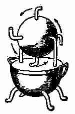
Fig. 30. Hero's
steam engine
After tea, Jessie and the boys followed their
father into the den, where Mr. Gregg gave the
children a brief history of the steam engine, as far
back as known, commencing with the
Colipyle, the invention of Hero of
Alexandria about 130 B.C. An illustration
of this is shown in Fig. 30.
It was simply a pot or boiler, partly
filled with water, the lid or cover being
fastened down tightly. On the top of
this was attached a hollow bent tube
having a tap fitted to it, which supported and
communicated with a hollow metal ball hung on
another tube or bearing on the other side in such a
manner that the ball could revolve easily. Attached
to this hollow ball or sphere were four other hollow
tubes, so fastened as to project from the surface two
[115]
or three inches, and these were bent at their outer
end, as shown in the illustration. These tubes were
of course attached and bent in a direction at right
angles to the axis of rotation. The tap leading to
the hollow ball, when turned open, allowed the steam
from the boiler to rush into the ball and fill it up.
If it was closed entirely, the ball would remain still,
but the steam exerting an equal pressure on all
points of the inner surface, and finding the openings,
escaped through with a rush and noise as it condensed
in the air, which it pressed against, causing the ball
to revolve in an opposite direction to the outflow
of steam. This Hero engine or Colipyle, was doubtless
the beginning of steam motors, but during the
2,000 or more years since Hero's toy engine was invented,
great strides have been made toward bringing
the steam engine to its present efficiency.
"But I do not intend," said Mr. Gregg, "to give
a history of the growth and development of the
machine, at this time. There are numerous works
on the subject, obtainable in any fairly-equipped
library."
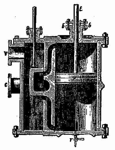
Fig. 31. Steam cylinder and piston
Steam, as everybody knows, is generated by heat
being applied to a closed metal kettle or boiler containing
water. This boiler must be strong and
properly arranged so as to admit more water—which
[116]
is usually injected with a force pump—and
it must have an outlet for the release of the
steam to the cylinder of the engine. Generally,
there is a small dome on the top of the boiler, called
the "steam dome," and to this the steam outflow
pipe is attached. The actual use of this dome is to
hold a volume of steam that will remain unmixed
with water, as it is placed considerably above water
level. On the top of the dome there is an automatic
arrangement called a "safety valve," so that when
there is too much pressure of steam in the boiler,
it will open and allow the over-pressure to escape,
and thus prevent the boiler from exploding or being
over strained. This valve is controlled by a simple
device, somewhat similar to a steelyard. A movable
weight is arranged to slide on a long arm which is
loosely fixed to the valve flange by a bolt and nut,
and extends some distance past the seat of the valve.
The arm or lever has an iron pin attached to it
directly over the valve seat, which holds down the
valve and keeps the steam from escaping. The
movable weight on the arm is adjusted so as to
regulate the pressure on the valve. When there is
too great a pressure, the valve forces up the lever,
and at the same time opens a passage for the extra
pressure of steam to escape. There are several
[117]
other contrivances for relieving the boiler of over
stress, but the one described, or rather the principle
on which it is built, is most in use on this country.
There are many kinds of boilers, or steam generators,
but the best, and very likely the strongest, are those
employed on our first-class railway locomotives.
These are frequently
under a pressure of 200
or more pounds to
the square inch, which
seems an enormous load
for a hollow shell to
carry, yet, so near perfection
are they, we
rarely hear of a locomotive
boiler explosion.
As there are many
kinds of boilers, so also
are there many kinds of
steam engines, but all of these latter, with very few
exceptions, have a cylinder and piston for converting
the force of the steam into useful and effective motion.
The manner of using this force and keeping it under
proper control is somewhat complex and difficult
to describe briefly, without elaborate diagrams, but
Mr. Gregg explained, in his own way, how the
[118]
great force was converted into motion. On the
blackboard he drew a rough diagram of a cylinder
and valve or steam-chest, with piston and slide-valve,
about as shown in Fig. 31, which gives a
longitudinal section of the whole arrangement.
Here we see near each end, the opening of a double
conduit aa, made in the thickness of the side;
these are the openings by which the steam
comes alternately to work on one end, then on the
other, of the piston. These are called the steam-ports.
These two open outward on a well-polished
surface, and between the two a third opening, E, is
seen, which serves to let the steam escape when it has
done its work, and is called for that reason the exhaust
port. C is the pipe by which the steam gains
access to the open air or to the condenser, where it
parts with its elastic force.
Here is shown by what contrivance the distribution
is effected, consisting, as it does, of two partial
operations; the admission of the steam and its escape,
which must be repeated twice to obtain a complete
phase of the to-and-fro movement of the slide-valve.
There are various methods employed according
to different engines—but the first described is the
one represented by the illustration.
In the valve chest, BB, is seen a prismatic box,
[119]
open on one side, called the slide-valve, and this
is applied by its open face to the well-polished
plane on which, as mentioned before, the three
ports open. The space BB, is called the valve or
steam chest. The steam coming from the boiler
by the pipe C spreads out freely in it, but the
inside of the slide-valve, on the contrary, is always
closed to the entering steam, though constantly
in communication with the escape pipe and also
with first one then the other of the entrances to
the cylinder. Lastly, the movement of the slide-valve
is produced by the engine itself, aided by a rod
and an eccentric fixed to the shaft of the fly-wheel.

Fig. 32. Steam valves—different positions
[120]
By following the successive and alternating motions
of the slide-valve, as represented in Fig. 32,
we can easily comprehend the different phases of
the distribution of the steam.
This is the machinery for the distribution of
steam generally. There are other engines, such as
rotary and oscillating, that are supplied by other
contrivances, but most of these have fallen, or are
fast falling into disuse, as they are not so satisfactory
as the ordinary slide-valve. It will be seen
upon examination of the sketch, shown in Fig. 32,
how the steam enters and leaves the cylinder and
the position of the piston under the various positions
of the valves. The arrows show the direction of
the slide, also the direction of the piston and its
position when the slide covers the ports X, or leaves
them open, or partly so. The ports for egress
or ingress are shown at X, the slide-valve at V, and
the cylinder at C. When the piston is near one end
of the cylinder, the steam is admitted and forces
the piston in the opposite direction, while the valve
is so arranged that when the piston starts in that
other direction, it begins to open the port at the
other end of the cylinder through which the
exhausted steam escapes. This makes the noise
Jessie asked her father about. There are some
[121]
engines so devised that the exhaust is made to assist
in driving another engine.
Of course, there are many kinds of steam engines,
but all are run on the same principle, or nearly so.
As you know, steam is generated in boilers by fire
being applied to the outside and the water made
hot enough to raise steam. A steam engine is said
to be externally heated, while gas, oil, and other
similar engines are internally heated, because
instead of the steam driving the piston, the gas,
oil, or other explosive matter is admitted into the
clearance or space between the piston and the end
of the cylinder, where it is exploded by an electric
spark from a battery provided for the purpose,
and this is called the "ignition." The explosion
causes the gas and air in the cylinder to expand,
bringing a great pressure on the piston, forcing
it to move toward the other end of the cylinder,
and making the whole machine move. One great
advantage of employing a gas engine is that no
boiler is required, a very important matter, as
boilers take up a great deal of space. The coal
or wood necessary to keep up steam also takes space
that could be used for other purposes, all of which
make the use of steam objectionable when it is
possible to employ suitable gas engines. Besides,
[122]
the make-up of a steam engine is of such a character
that it is very expensive, while the first cost of
gas engines is much lower.
All gas, oil, or other explosive engines are internal
heaters, because the heat is generated in the
cylinder at each explosion, and this is one of the
main features that distinguishes the gas from the
steam engine. Of course, there are many attachments
and connections to steam and gas engines
that would take too long to describe, and in a great
measure be unnecessary. A few items may prove
both useful and profitable and it is well to know
firstly: How to estimate the horse-power of an
engine.
When steam engines were first introduced they
were largely used to take the place of the horses
previously employed for raising water from mines.
Naturally people inquired, when buying an engine,
what amount of work it would perform as compared
with horses. The earliest engine builders found
themselves very much at a loss to answer this
question so they had to ascertain how much a horse
could do.
The most powerful draught horses and the best
of any then known were the London brewers' horses.
These, it was ascertained, were able to travel at
[123]
the rate of two and a half miles per hour and work
eight hours per day. The duty, in this case, was
hoisting a load of 150 pounds out of a mine shaft
by means of a cable. When a horse moves two and
a half miles per hour, he travels 220 feet in a minute,
and, of course, at the speed named, the 150-pound
load would be raised vertically that distance. That
is equal to 300 pounds lifted 110 feet per minute,
or, 3,000 pounds lifted 11 feet or 33,000 pounds lifted
one foot high in one minute. That is the standard of
horse-power, as we all know. It is much more,
however, than the average horse can do, and therefore
the builders were confident that the engines
would take the place of fully as many horses as the
horse-power would indicate that they should.
Of course, 33,000 pounds lifted 1 foot per minute
is much more convenient for calculation than 150
pounds lifted 220 feet, and therefore the former
rate has been adopted. The amount of work, or
number of "foot-pounds," is the same in either case.
A foot-pound represents the amount of power required
to lift one pound one foot high. To find the
number of horse-power in any engine, we multiply
the area of the piston by the average pressure per
square inch upon it; multiply this result by the
distance which the piston travels per minute in
[124]
feet and the result is the number of foot-pounds
per minute which the engine can raise. Divide by
33,000 and the result will be the number of horse-power.
The number of feet per minute travelled
by the piston is twice the number of strokes per
minute multiplied by the length of the stroke.
This gives the amount of horse-power sufficiently
accurate for all practical purposes.
It necessarily takes time to do work, but the
amount of work done has nothing whatever to do
with the time taken to do it.
If a man, weighing 150 pounds, walks up the 900
steps leading to the highest attainable level in the
Washington Monument, 500 feet high, he does work
against gravity equal to 75,000 foot-pounds, irrespective
of the time taken in the ascent. Then the
work done in a given time, divided by the time,
is called the power of activity.
Power is the time rate of doing work. In the
English gravitational system, the unit of power is
the horse-power (H.P.); it is the rate of doing work
equal to 33,000 foot-pounds a minute, or 550 foot-pounds
a second.
In the centimetre-gramme-second (C.G.S.) system
(in which the unit is 1 gramme moving at
the rate of 1 cm. a second), the unit of power is
[125]
the watt. It equals work done at the rate of one
joule (10,000,000 ergs) a second.
One horse-power is equivalent to 746 watts.
A kilowatt (K.W.) is 1,000 watts.
It is therefore nearly 11⁄3 horse-power.
To convert kilowatts into horse-power add one-third;
to convert horse-power into kilowatts, subtract
one-fourth.
For example, 60 K.W. equals 80 H.P. and 100
H.P. equals 75 K.W.
The expression foot-pound is in general use among
English-speaking engineers, and as explained it
is the unit of work done by a force of one pound
working through a distance of one foot. It is not
a fixed standard of measurement, since the weight
of a pound is not the same in all heights above sea
level, and on this ground it is open to objection.
It is the nearest constant, however, we have yet
discovered, hence its general adoption.
"Dry steam" is the steam in which no condensation
is visible, and it may generally be obtained at
a 10-pound pressure per inch, but no exact dividing
line of pressure can be defined between dry steam
and wet. If care is taken in covering pipes and
cylinders, to prevent condensation, a pressure of
10 pounds should make steam as dry as gas, and if
[126]
the steam pipe is carried through a good, hot fire
at some point, the fire will superheat the steam and
render it more dry. Wet steam, of course, is steam
that can be seen, through having been more or less
condensed by contact with air or cold. There can be
no steam without heat, but steam does not require
as much heat as is generally supposed. Suppose we
take one pound of water at 32 degrees Fahrenheit
and apply a fixed and known quantity of heat until
it boils; we will assume that it takes 20 minutes, and
we have supplied the water 180 heat units, which,
added to the 32 contained in the water at the start,
makes 212 degrees Fahrenheit or heat units, and is
the sensible heat of steam at atmospheric pressure.
Now let us continue the same quantity of heat per
minute until all the water has evaporated into steam,
and we will then find that it has taken five and one-third
times as long, or 107 minutes to do this work.
Consequently we have used five and one-third times
180 or 960 heat units; or, to be exact, 966 heat units.
Now the temperature of the steam is the same
as the water from which it has evaporated, or 212
degrees Fahrenheit, and this 966 heat units is the
latent heat of steam at atmospheric pressure. All
steam has a sensible heat corresponding with the
temperature of the water it has evaporated from.
[127]
If you boil water under a pressure of five atmospheres,
or 75 pounds pressure, the sensible heat is 306
degrees Fahrenheit, the boiling point at that pressure,
but the latent heat has decreased by the same number
of heat units that the boiling point increased, so
the total is the same in all cases. In the first instance
we have 212 degrees minus 32, plus 966, or
1,146; and in the second 306 degrees minus 32, plus
872 or 1,146 heat units. This may be considered
a fair description of latent heat.
The most useful quality of steam yet discovered
is its power of expansion. It follows what is known
as Marriott's Law of Expanding Gases, which means
one-half the pressure double the volume. So if
we let steam into an engine cylinder, at 80 pounds'
pressure, and cut it off at one-fourth stroke, it is
at 80 pounds up to the point of cut-off. At one-half
stroke, because it has doubled its volume, it is
reduced to one-half pressure, or 40 pounds; while
at three-fourths stroke the volume has trebled and
the pressure has dropped to nearly 27 pounds, and
this is why it is economical to run engines that use
steam expansively. Steam at 27 pounds' pressure
is very much cooler than steam at 80 pounds, and
this difference in temperature has been converted
into mechanical work by our steam (heat) engine.
[128]
There are many other peculiarities about steam
and steam engines that a young boy should know,
and the information can readily be obtained from
books in any good library.
The steam turbine, of which so much has been
heard lately, is not constructed like an ordinary
steam engine with cylinder, slide-valve and other
attachments; but more like the Hero engine, with
this difference that the steam jet or jets act on a
wheel having vanes or blades, the expansion producing
a velocity which rotates the wheel containing
the vanes. A modern turbine, of the Parsons
type, such as are employed on the great Atlantic
steamers, is a tremendously high speed engine.
It does not derive its power from the static force
of steam expanding behind a piston, as in a reciprocating
engine. In this case the expanding steam
produces kinetic energy of the steam particles,
which receive a high velocity by virtue of the expansion,
and, acting upon the vanes of a wheel,
force it around at a high speed of rotation in the
same manner as a stream of water rotates a water-wheel.
The expansion produces velocity in a jet
of steam, and this is the main difference between the
ordinary engine and the modern steam turbine.
Among gas and internal explosion engines there
[129]
exist some differences, both in construction and in
the manner of supplying fuel. The gas-producing
engine may be considered the better class, though
it has not as yet gained the popularity of the gasolene
one. The gas by which this style of engine
is operated is produced by a special process, namely,
by passing air and steam through a fire of hot coals.
After generation the gas passes over a flash-boiler
and a portion of its great heat is withdrawn, thus
permitting it to enter a scrubber—a cylinder filled
with coke and sawdust—while fairly cool. In
passing over the flash-boiler the great heat raises
all the steam necessary for the production of gas
required in the operation of the engine and plant.
In passing through the scrubber the gas is not only
cooled, but is freed from particles of suspended
matter, the coke removing the heavier particles, and
the sawdust, the tar, or any other volatile matter
that may be left.
One of the most important requirements in a
gas-producer is that it shall be adapted to the work
it has to do. Its construction should be compact
and simple, so as to permit the easy removal of worn
out parts. The feeding device should be such as
to secure a uniform distribution of fuel.
The blast should be so introduced as to burn out
[130]
all the carbon in the ash zone, and yet not produce
localized combustion along the walls. The construction
should permit the easy removal of ashes,
and render the machine safe, while the entire process
of gasification should be clean. The radiation
loss should be low, and the producer must be made
efficient to insure satisfaction.
It should be borne in mind that because of the
presence of carbon monoxide, producer gas will
always be more or less poisonous. The carbon
monoxide has a specific toxic effect on the human
system, and when inhaled enters into direct combination
with the blood, and brings about very dangerous
effects.
As water is always required for cooling purposes
when running a gasolene engine, it is well to know
about how much will be required. One authority
says: "The quantity of water required at the ordinary
temperature of 60 degrees F. inlet and 150
degrees outlet, to keep the cylinder of gas engines
cool is 4.5 to 5 gallons per indicated horse-power-hour.
The jacket pipe should be from 1 to 2 inches
diameter for engines up to 20 horse-power, while for
larger engines the sizes are generally 2 to 3 inches
for the inlet and 2.5 to 3.5 inches for the outlet.
Tanks for circulating the water are generally made
[131]
with a capacity for furnishing 20 to 30 gallons per
indicated horse-power. This rule may be taken
as about correct, but, if anything, it is rather an
over-estimation of quantity necessary."
All the foregoing was made as clear as possible
to the listeners by Mr. Gregg before the children
went to bed.
Next morning Fred called up his artist friend, and
got him to come down to gild the name "Caroline"
on the boat before the next coat of varnish should
be applied. The artist made an outline of the
name while George and Jessie stood by and watched
the process with considerable interest. They saw
him measure off each letter, outline it with a
pencil lightly, and then paint inside the lines with a
substance known as "gold size," obtained from any
store dealing in painters' supplies. While the size
was still sticky the artist applied "gold leaf," which
he had brought in a little book along with him. Jessie
was surprised to see him cut the gold with a thin
pallette knife, having a blunt but smooth edge.
She watched him pick up the small pieces of gold
with a camel's hair brush, which he rubbed in his
own hair now and again whenever it would not pick
up the gold. The metal was applied bit by bit over
and beyond the lines of the letters, and a light puff
[132]
of breath forced it down to the size. When one side
of the boat was finished, so far as laying on the coat
of gold was concerned, Jessie was very much disappointed,
as the name seemed merely a smudge.
She could not make out the letters, but the artist
told her to wait until to-morrow and he would show
her how well they could be seen. Next day with
a flat camel's hair brush he dusted away the surplus
gold, and the letters showed up in good style, much
to the gratification of Jessie and George. This
part of the work being done, the boys took down
their varnish pots, and gave the little craft another
coat, to make her quite spruce and gay.
Fred, and Nick, who was still in the employ
of Mr. Gregg, laid off a space on the ground for
tables and seats to accommodate the young folks
who were coming to the launch on the following
Wednesday. Nick found a number of old cedar
posts, and with a saw cut off 18 pieces about two feet
long and as many more twice that length. The
first were intended to place the seats on; the second
lot were to sustain the tables. The spots for the
tables were chosen, measured off, and small stakes
driven into the ground to show where the posts
were to be placed. Five posts were intended for each
table—two at each end, two feet apart, and nine
[133]
feet apart in the length of the table. The single
post was placed in the centre of the table both ways.
When the stakes were all in place, Nick made holes
deep enough to take in the posts so that their tops
measured just two feet and two inches above the
level of the ground. The tables were to be two feet
and six inches high when finished, as that is the
regulation height. It was attained, in this case, as
follows—First by the height of the posts from the
ground, two feet two inches; then by a plank two
inches thick laid across the two posts, making the
height two feet four inches, and the table top,
two inches thick, laid on these cross planks, which
brought it up to the required height. A piece of
plank the same thickness was nailed on the centre
post across, so that it would support the table top.
Planks that had been used in the loft of the old barn
did service for the table tops, bearing pieces, and
the bench seats. The last were constructed in the
same manner as the tables, the short posts being let
into the ground—three under each seat—and
fourteen inches above ground so that when the
plank seat was nailed on top of them, the seats were
just sixteen inches, the regulation height of stools,
benches, and chairs, though it is sometimes varied
to suit conditions. The benches were placed about
[134]
four inches out from the edge of the table and were
found to be "just the thing."
When Nick had planted the first post for the
tables and got it the right height, he took that one
for his guide and by the aid of a long parallel
straight edge which he laid on the guide post and
the one he was setting, and also a spirit-level on the
straight edge, he managed to get all the posts alike
in height and this made the tops of the three tables
nice and level. It was quite an achievement to
have three large tables and six long seats placed in
"picnic style" at so small a cost and with so little
effort.
In order to have the tables and seats neat and
clean, George turned on the garden hose and gave
them a good wash off, and when they were dry again
the place was as inviting as a country hotel dining-room.
When Mrs. Gregg, Jessie, and Grace Scott
had the tables set and garnished for the launch,
the lay out was charming, none the less so because
it was a little rustic.
Another coat of varnish, the third, was given
the boat the day before she was to be launched,
and Fred had a strong rope attached to the winch,
with a heavy iron hook fastened to the end of it.
A stout iron ring was bolted to the stern of the
[135]
boat and made secure. Mr. Gregg had purchased
a number of small flags and "burgees" and had one
made with the name "Caroline" in large letters
wrought on it, ready to be unfurled when the
launch was made, and Walter Scott, his mother and
sister Grace, and others had been invited to attend.
A number of temporary swings were fixed up by
Nick and Fred to the trees, some for the large folks,
others for the smaller ones, and everything was at
last ready for the great event, which was to take
place the next day at two o'clock.
[136]
VI
PROPELLER AND OTHER SCREWS
Wednesday morning was light and
sunny and the boys were up and dressed
somewhat earlier than usual, so, while
waiting for breakfast, they took a stroll down to the
river, where they found their father looking over the
grounds and examining tables, benches, swings,
and particularly the foot-bridge; for, as he told
Fred, "it was very likely all the guests might be
on the bridge at one time and the combined weight
would be rather trying if it had not been securely
put together." He satisfied himself, however, that
the bridge was strong enough to support three
times the weight it would be called upon to sustain.
Everything else seemed to be sufficiently strong,
to apprehend little danger, no matter how much the
children romped.
Nick had the grounds nicely raked off; the decayed
branches and shrubs he moved, and made everything
about the place as clean and as neat as possible.
Flags and other decorations were hung or placed
[137]
about the grounds, on the trees and buildings, but
particularly about the tables and the boat house.
Newspapers were spread over the tables, linen
covers above them, and the whole surroundings
took on a most festive appearance.
It was just 11 o'clock when The Mocking-Bird
arrived and tied up to the new dock. On board
were Mrs. Scott, Grace, and the maid, who came to
help, besides several of the invited guests whom
Walter had brought down with him. All were
welcomed by Fred, Jessie, and George and then
the women visitors went to the house to assist Mrs.
Gregg.
Mr. Gregg came home from his office earlier than
usual and took a half holiday in honour of the
occasion. The guests, in little groups, arrived on
time, and before the clock struck two Nick had
everything prepared for the launch. He and Fred
and George had the Caroline nicely placed on
the skid, ready to "let go" the winch, and a flag
pole was fixed up on the bow of the boat. To this
the flag with the name on it was lightly tied, in such
a manner that when a string was pulled it would
unfurl, and show the name. The string looping
up the flag was left long enough to enable Mr. Gregg,
standing on the dock, to hold the end in his hand,
[138]
and by pulling it to loosen the flag as soon as the
boat touched the water.
Everything being ready, Walter Scott invited
as many of the young people to get into the Mocking-Bird
as could crowd on board with comfort,
and each was provided with a whistle or a horn,
as he ran his boat half way across the river. The
children on shore were also given horns and whistles,
and all were told to blow as loud as they pleased
when the boat touched the water. Mr. Gregg,
having Mrs. Gregg and Mrs. Scott standing beside
him, gave the word, "Ready!" Nick and Fred
answered, "Aye, aye, sir!" and the master of ceremonies
called out in a loud voice: "Let her go!"
Nick freed the winch, Fred and George gave a
little push, and the Caroline slid down the skids,
into the water, without the least hitch. The horns
and whistles made a great din, and when the flag
was let free to open up and show the name "Caroline"
there was another blast of noise by horns and
whistles, mingled with voices of the younger people,
who cried out with all their might, "Hurrah for the
Caroline!"
The launch being over, and everything having
gone all right, the young people were called to
lunch. They all sat at the tables which were nicely
[139]
garnished and well supplied, and there was plenty of
small talk, and much laughter and jollity. After
lunch, Fred, Walter and George boarded the Caroline,
supplied her with gasolene, and tried to run her.
They found a little difficulty in starting, but after
the engine was warmed up a little, she went off
beautifully, and answered her tiller in fine style.
The boys ran her up and down the river for a while,
then tied her to the dock, and Walter and Fred invited
all the girls to "Come and have a sail." The
boys were promised one when the two boats returned,
which they did in the course of half an hour. The
swings were put in use, dancing and romping began,
and the afternoon was passed in fun and frolic.
In the evening, Mr. Gregg, Jessie, and the boys
took a trip, and Mr. Gregg was well pleased with
the boat's performance, particularly with the working
of the screw. In mentioning this, he awakened
the curiosity of George, who reminded his father
that he had not yet explained to them about the
screw as a mechanical power.

Fig. 33. Theory of screw
That evening George was told to bring his blackboard
and equipment into the den, and the father at
once began explaining the mechanical qualities of the
screw. He told of its great usefulness in the industrial
arts. As one of the mechanical powers,
[140]
it may be considered an inclined plane, wrapped
spirally round a solid cylinder. The advantage
gained by it depends on the slowness of its forward
or backward progress, that is, on the number of
turns or threads, as they are called, in a given
distance. It is always used in combination with a
lever of some sort. When employed as a lifting
machine it has great power, and is used to produce
compression or to raise or
move heavy weights. If a
screw is formed on the inside
surface of a hollow cylinder,
it is called a nut, and used
to overcome a resistance;
either the screw or the nut
may be fixed and the other
movable. The acting force is
generally applied at the end
of a lever or wrench or rim
of a wheel. Fig. 33 represents
a screw and nut operated by a lever
or length of radius r; p is the pitch of the screw
or height of the inclined plane for one revolution
of the screw. W is the resistance at the
nut and P is the force at the end of the lever
r. Remembering that, while the resistance W
[141]
is raised the distance p the force P revolves
around a complete circle and moves a distance
2πν. Let us now apply the condition
Σwork = 0
and we have
P2πν - Wp = 0 or — = P2πν/p (6).

Fig. 34. Worm wheel and screw
The worm gear (Fig. 34) is a special case of screw
and nut, where the
latter is replaced by
a toothed wheel
called a worm wheel.
The teeth work in
with the thread of
the screw or worm,
and thus, as the worm
revolves, the worm
wheel revolves about
its axis. P is the
force acting on the
worm at a radius r.
r´ is the pitch radius
of the teeth in the
worm wheel and r´´ is the radius of the drum on
which W acts. Let K, corresponding to W in
equation W P (6), be the force at the pitch circle and
worm threads due to the force P; then
K = P2W/p (7).
[142]
Now apply Σm = 0 to the worm wheel and we
have
Kr´´ = Wr´´ or K = wr´´ (8).
Substituting the
value of K in (7) in equation (8) we have
P2πν = Wr´´ or
P2πν = Wr´´p (9).
Now it is evident that
the distance p´ moved by W while K moves through
the distance p is to p as r´´ is to r´ or p´ : p :: r´´ : r´
or
p´ = pr´´/r´ (10).
Substituting this value of pr´´/r´ in
equation (9) we have P2πν = Wp´ or the condition
Σwork = 0, since 2πν is the distance moved by
(P) while W moves the distance p´.
No provision for friction has been made in any
of the examples given, so that allowance must be
made for this propensity whenever any of the foregoing
rules are applied to practice. The amount
of allowance required will vary and must be made
to suit conditions.
An endless screw is sometimes used as a component
part of graduating machines, counting machines,
etc. It is also employed in conjunction with a wheel
and axle to raise heavy weights. The distance
between the threads of the screw is called the
pitch or step. These threads are sometimes square,
sometimes acutely pointed or edged, sometimes
rounded off on the edges. Power is often applied
by means of a lever or other contrivance attached
[143]
to the end of the screw, or by a long handled wrench
(a monkey wrench for instance), which, when turned,
moves forward in the direction of its axis, overcoming
resistance. In the case of the screw-jack,
it may be used to raise a heavy weight. The relation
between the force applied and the resistance to
be overcome is important to note, for every time
the screw performs one revolution it moves forward
through a distance equal to the space between one
thread and the next.
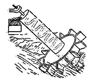
Fig. 35. Archimedian
screw
The Archimedian screw
we have read and heard so
much about is simply a hollow
pipe wound around a cylinder.
It was often used in olden
times for raising water, but is
now only occasionally applied.
The lower end of the spiral
pipe is, of course, left open and
immersed in water, as shown
in the illustration (Fig. 35),
a device for raising water, the supply stream
being the motive power. The oblique shaft
of the wheel has extending through it a spiral
passage, the lower end of which is immersed in water;
and the stream, acting upon the wheel at its lower
end, produces its revolution, by which the water
[144]
is conveyed upward continuously through the
spiral passage and discharged at the top. An
arrangement like this could easily be constructed
at the edge of most rivers to raise water to irrigate
the grounds, if so desired, and the little flutter
wheel at the bottom of the inclined shaft would be
powerful enough to lift all the water required. Fred
thought that would be a great scheme, and determined
to try his hand at it one of these days, but
he was told that a wheel of that kind could only
work at intervals, as the river's flow was often
running in opposite directions owing to the inflow
of the tidal water.

Fig. 36. Spiral
conveyor
These Archimedian water raisers are often fitted
with a crank handle on top, and a man, standing on
a platform, turns the crank and thus
lifts up all the water the machine
will carry. The Archimedian screw
is used for many other purposes than
raising water. With wide, thin wings,
similar to the construction shown
at Fig. 36, and enclosed in a case
or jacket, it is employed by millers to convey
grain and other mill requirements, and it is also good
for moving coal, ore, gravel, and like material, but
when used for these coarser purposes the propelling
[145]
blades are made of steel, riveted or bolted to a
strong iron shaft. The case or jacket containing
the revolving blades, if horizontal, need not be
covered on top, as the blades will propel the material
without jamming or clogging, if the jacket is smooth
inside, and fits fairly close to the blades.
This style of a
screw may be used
as a sort of turbine
water wheel,
if cased in a cylindrical
penstock or
tube, and a body
of water allowed to
fall into the upper end of the tube. The force of the
water will give a rotary motion to the blades and
shaft, and, the latter having a geared wheel or pulley
attached to its top, motion is imparted to other
shafts and wheels.

Fig. 37. Theory of screw and gear
Another application of the screw is shown at
Fig. 37, where one is arranged on a shaft or axle
to give a rotary motion. This device is called a
"worm and wheel," and is frequently used in the
make-up of machine engines and mathematical
instruments. The illustration shows how the power
or force of a screw may be conceived. For instance,
[146]
suppose the wheel C has a screw on its axis working
in the teeth of the wheel D, having 48 teeth. It
is plain that for every time the wheel C and screw
are turned round by the handle or crank A, the
wheel D will be turned once round. Then, as the
circumference of a circle, described by the crank A,
is equal to the circumference of a groove round the
wheel D, the velocity of the crank will be 48 times
as great as the velocity of any given point in the
groove. Consequently, if a line C goes round the
groove, and has a weight of 48 pounds hung to it,
a power equal to one pound at the handle will
balance and support the weight. To prove this by
experiment, let the circumference on the grooves
of the wheels C and D be equal to one another;
and then if a weight H, of one pound, is suspended
by a line going round the groove of the wheel C,
it will balance a weight of 48 pounds hanging by
the line G; and a small addition to the weight H
will cause it to descend, and to raise the other weight.
If a line C, instead of going round the groove of
the wheel D, goes round its axle I, the power of the
machine will be as much increased as the circumference
of the groove exceeds the circumference of the
axle, supposing which to be six times 8, then one
pound at H will balance 288 pounds, hung to the
[147]
line on the axle; thus showing the advantage of
this machine as being 288 to 1. A man who can
lift by his natural strength alone, 100 pounds, by
making use of this combination, will be able to raise
28,800 pounds alone, and if a system of pulleys
were applied to the cord H, the power would be
further increased to an amazing degree.
When a screw and wheel are attached, as shown,
the screw is sometimes called a "worm" and sometimes
an "endless screw."
The propeller wheel (Fig. 38) is a screw having
a large helical dimension. The example shown has
four blades, each of which, when rotated, may be
said to make one quarter of a revolution and when
at work in the water has the same effect
as the working of a nut, producing
motion in direction of the axis and
so propelling the boat or vessel. The
action of the wheel pressing backward
against the water tends to push
the craft forward.

Fig. 38. Complete
screw propeller
This figure shows a propeller with
four blades, but two and three bladed ones,
particularly for small craft, are mostly used.
The Caroline carries a two bladed screw and
her performances will be entirely satisfactory.
[148]
The blades, of course, are exactly in line with
each other on the shaft, and equally balanced,
or of equal weight. A three-bladed propeller
should have its extreme points in a horizontal
plane, so that they will form an equilateral triangle.
The principal features of a propeller may be
described as: diameter, pitch, area, speed of revolution,
and slip. The diameter is that of the
circle described by the tips of the blades. The
pitch, considering the propeller to be a portion of
a screw, is the amount which it advances in one
turn, supposing it to travel in a solid medium.
The blade area is the actual area of all the
blades.
The speed of the revolution is customarily reckoned
in turns per minute. The slip is the difference
between the amount which the propeller actually
advances per turn and the amount which it would
advance if turning in a solid medium. For example,
if the pitch of a screw is 30 in. it would advance
30 in. at each turn if there were no slip. Suppose
that it only advances 20 in. per turn, then the slip
is 10 in. per turn, or as usually figured, 331⁄3 per
cent. As a further example, suppose a propeller
of 30 in. pitch, turning 300 turns per minute, drives
[149]
a boat at the rate of 6 miles per hour. The advance
of the propeller in feet per minute is 30/12 × 300 = 750
while the advance of the boat is 6 × 5,280/60 = 528 ft.
per minute. The slip is then 750 - 528 = 222, or
as a percentage, 222/750 = 29.6 per cent. It might
seem at first sight, that a perfect screw propeller
should have no slip; but this is a practical and
theoretical impossibility.
The most important dimension, from the standpoint
of the absorption of power, is the blade area.
A certain blade area may be obtained by a relatively
wide blade on a small diameter, or by a narrow
blade on a relatively large diameter. In the former
case the area of the blades bears a greater proportion
to the area of the circle through the tips than
in the latter case. There are certain limits for this
proportion of blade to disc area for well-designed
wheels, beyond which it is not well to go. These
are as follows:
For two blades .20 to .25.
For three blades .30 to .40.
For four blades .35 to .45.
This means that for a 24 in. diameter propeller,
whose disc area is 452 sq. in. the blade area should
[150]
not, for ordinary use, be made greater than these
proportions, as the blades then become so wide as
to interfere one with another. Of course where a
propeller, for shallow draft, must be unusually small
in diameter, the proportion of blade area can be increased,
but with some loss in economy. Strictly
speaking, for a well balanced propeller, the blade
area fixes the amount of power which the propeller
can deliver, while the pitch, combined with the turns
per minute, governs the speed. As a matter of
fact, for the average propeller the two are closely
related, each having a certain influence upon the
other. To illustrate, a propeller may have a small
blade area and so great a pitch that the blades act
somewhat like fans and simply churn the water,
offering great resistance and absorbing the power
of the engine, but doing little effective work toward
driving the boat.
To get the measurements for a wheel required
to perform a given service, say a three-bladed
propeller for a small boat or tug of 20 nominal or
75 indicated horse-power:— assume that the size
determined on is 4 ft. 6 in. in diameter and 7 ft.
6 in. pitch, the diameter of loss may be assumed
to be 8 in. swelled to be 11 in. in the middle, and
11 in. long. The tug would be, say, 60 ft. long,
[151]
12 ft. beam, and 7 ft. deep. First delineate the
path of the point and root of one blade through
half a revolution as in Fig. 39. This should be
drawn to a scale of not less than 11⁄2 in. to 1 ft.
by the ordinary method of projecting a screw
thread. The semicircle shows the half plan with
twelve equal divisions, and the half elevation is
divided into the same number
of equal parts. The
helix or thread is then obtained
by drawing the curves
through the intersections of
similar divisions. Then a
b will be the helix for point
of the blade, and c d the
helix for the root of the
blade. These will be found
to be practically straight lines
which might have been obtained in a simpler manner
if intended for a working drawing only; but it
is useful to have demonstrated the proper nature
of the full curve.

Fig. 39. Diagram screw lines
The practical way of setting off the blade follows:
First for dimensions: as 20-in. (pitch) is to 11 in.
(length of boss and therefore virtual length of
propeller), so is 169.6 in. (circumference due to
[152]
outer diameter) to the length of circumference
occupied by the blade, 169.6 × 11/9 = 20.73, say 203⁄4 in.
In Fig. 40 describe a circle equal to the diameter
of the propeller, and on each side of the centre line
step off 203⁄4 in. to half the scale, making the whole
length of arc to scale 203⁄4 in. Draw vertical lines
from the ends of the arc, and from the arc on the
centre line set up a height
of 11 in. and draw horizontal
lines. Join a b, and
this will be the angle of
the end of the blade. On
the elevation of the propeller
circle describe a
small circle equal in diameter
to the faces of the
boss; draw radial lines
from the ends of the arc first found, and from the
intersection with the boss circle draw vertical lines to
cut the horizontal lines of the plan of boss. Join c d,
and this will be the angle of the blade at the root.

Fig. 40. Part of screw blade
Now describe an arc at every three inches from the
circumference within the radical lines; or for large
propellers every 6 in. Draw vertical lines from the
intersections of the arcs with the radical lines to
[153]
meet a c and b d, as shown, and joining the points
thus found, the diagonal lines will represent the
plan or angle of the blade to each 3 in. difference
of radius—in other words, its real width at the
different points, supposing it to be a plain geometrical
portion of a screw thread. As a matter of fact,
the blades are always more complex than this, the
edge being curved to enter the water more easily,
to avoid vibration, and also to lessen the risk of
fracture in the event of striking any object in the
water. Sometimes the blades are curved in the
opposite direction, as if the
points were being left behind
while the blade is advancing.

Fig. 41. Plan of screw blade
The next step is to draw a
flattened elevation or development
of one of the blades,
in order to give the actual
curves of its outline, and afterward
its thickness at various
points. Draw a horizontal line
from c and f (Fig. 41), and through this a centre line.
This will give the length of the blade from the boss, and
the centre line of the propeller shaft may be added below.
Then take the lengths a b and c d from Fig. 40, and
set them off on Fig. 43, as shown, joining all four points.
[154]
This figure would be the true outline of the blade if
there were no curves. The actual outline is found
by drawing the curves according to the dimensions.

Fig. 42. Propeller lines complete
Lay out the propeller, as shown in Fig. 42, which
will give the elevation of the blades, all being alike.
To find the area of a propeller blade, mark it off
in parallel lines, say 3 in. apart, and note the width
[155]
at the centre of each portion. Add the widths together,
and divide by the number of widths. This
will give the mean width, which must then be multiplied
by the length of blade to obtain the area.
If the measurements are all in inches, the result
should be divided by 144 to give the area in square
feet, and then be multiplied by the number of
blades to give the total
area.

Fig. 43. Angle of propeller blade
To measure the pitch of
a propeller, lay it down on
a level surface, hold a
straight edge level across
centre of blade with a square up from the lower
edge, as in Fig. 43. Measure the distance B and H
and the radius R from the centre to the part where
the measurement is taken; then B : 2wR :: H to
pitch, P or P = 2wRH/B. The measurements may be
made in more than one place and the average taken,
as the blades are sometimes twisted slightly.
Scaling only from the drawing, P = 2wRH/B
2 × 3.1416 × 1.6 × 1/1.27 = 7.74, say 7 ft. 9 in. pitch,
whereas the intended pitch was 7 ft. 6 in.
[156]
A good illustration of the use of the screw may
be seen in the carpenter's auger, used for making
or boring holes in wood. These tools are provided
with a small tapered screw on their points, and this
is followed by cutting edges and a larger spiral.
The larger spiral is for the purpose of drawing up
the chips or shavings. Another tool is made having
two blades attached to the bottom of an iron bar
formed like the blades of a propeller, which is sometimes
employed for boring or digging post holes in
clayey or soft soil. The machine is turned by a
cross handle on top, and is frequently drawn up to
bring out the soil until the hole is deep enough.
The ordinary wood screw is one of the most useful
of contrivances for fastening wood together, and for
attaching to surfaces, hardware, ornaments, or other
materials. The adhesive strength of nails is already
shown, and the adhesive strength of wood screws,
according to Bevan, is set down as follows:
WOOD SCREWS
The following are the thicknesses or diameters corresponding to the list
numbers. Other thicknesses can be interpolated, each size varying in succession
1⁄64 in.—
| No. | 00 | 0 | 1 |
5 | 10 | 14 | 18 |
22 | 27 | 32 | 40 |
| Thicknesses in parts of inches |
1⁄32 | 3⁄64 | 1⁄16 | 1⁄8 |
3⁄16 | 1⁄4 | 5⁄16 | 3⁄8 |
7⁄16 | 1⁄2 | 5⁄8 |
[157]
An ordinary 2-in. wood screw, driven through a
1⁄2-in. board into hard wood, was found to be
790 lbs., and a force of about 395 lbs. was required
to extract it from soft wood.
When screws are hard to drive or screw in place,
a long screw-driver should be used, as screw-drivers
with long handles seem to have a much greater
leverage than short handled ones in driving screws
home. Screws, however, are often split at the head,
if care is not taken when using a long driver.
If a screw is rusted, hard to move or withdraw,
it can be loosened by applying a hot iron to the head
and making it hot. The heat expands the screw and,
of course, makes the hole larger, and when the screw
cools it contracts a trifle so that it may be withdrawn
quite easily.
[158]
VII
AEROPLANES
George and Fred were so much interested
in the Caroline that they neglected to
do some work Mr. Gregg had suggested,
but a hint or two from him reminded them that
sailing the new boat every day would get so monotonous
it would cease to be a pleasure. Fred, therefore,
set to work to put the new property in apple-pie
order, by cleaning up the grounds, burning the
rubbish, and tidying the place generally. Nick,
not being needed longer, was allowed to go, with
the promise that whenever a man was required
about the place, he would be chosen. His departure
left all the work to Fred and George, both
of whom gladly accepted the duty.
The first thing was to set up three or four long
benches on the river bank. These were built
exactly in the same manner as the seats alongside
the tables. Three short posts were let into the
ground for each seat, and a good, sound plank
spiked solid to their tops. One of the seats was
[159]
made four or five inches lower than those at the
tables, so as to accommodate the smaller children.
The two boys did the work well, though they found
it a little hard to dig the holes in the ground and
saw off the posts. George's hands became a
little blistered and sore, but his mother soon cured
them, though she warned him against working
too hard or too long at a kind of labour to which
he was not accustomed.
After tea was over, it being a fine, warm, spring
evening, the whole family went down to the river's
edge to sit on the new seats and enjoy the view.
Noticing the current of the river, Jessie questioned
her father about its going one way sometimes, and
then turning in the other direction. Her father
explained that it was the movement of the tide
that made the water flow against the stream at
times, and that when there was no tide, the current
took its natural course. This explanation did not
seem to satisfy Jessie, and she asked why there were
any tides. So Mr. Gregg promised to explain
all that was known about tides to her in the near
future. "I wish you would," said George, "and tell
us about kites, balloons, and flying machines."
"Oh, yes," said the father, "I'll try to do that
to-morrow night."
[160]
"I'm glad, father," said Fred, "as I want to try
and make a model for George before the Fourth
if I can, so he can have one to fly across the river
that day, instead of fooling with fire-crackers and
other dangerous fireworks."
"That's a good idea, Fred," said the father.
"A model aeroplane, decorated with silk flags
would give a great deal more real pleasure than
firing off all the fire crackers in the state. It would
be quite easy, now you have a boat, for one of
you to be on this side of the river, the other
on the opposite side, and to keep a number
of little machines going to and fro across the
water."
George seemed delighted at the prospect. Walter
Scott had also been stricken with the aeroplane
fever, and was busy making models, though, as yet,
he had not finished any. Both Fred and George
were anxious to hear all their father had to say
concerning these machines, as they knew he would
be thorough, and make it all plain. Mr. Gregg
told the boys that to explain fully the theory and
practice of building an aeroplane of any kind would
take some time, but he would willingly give it for
their benefit, and would discuss the subject of
aeronautics at length so as to give them some pointers
[161]
about the design and practical making of flying
machines.
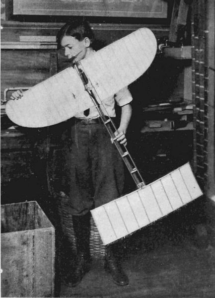
Copyright, 1911, by Underwood & Underwood, N. Y.
The Monoplane Model Complete
"A Model Aeroplane, Decorated with Silk Flags Would Give a Great Deal
More Pleasure Than Firing off All the Fire Crackers in the State"
On the following evening, Jessie did not forget
to remind her father of his promise to tell them all
about "air-ships and things," as she put it.
"All right, my dear," said Mr. Gregg, "I'll take
you all into the 'lion's den' shortly after tea.
But tell me, why is it you are so anxious to know
all about 'air-ships and things'?"
"Oh! that's all right, papa; Fred is going to
build a great big ship, as soon as he knows how,
and he has promised to take me up to the clouds
in it for a ride."
"Well, my dear, it will take some time to tell
you all about these things but I will make an attempt.
For ages man has wanted to fly, and the
Greeks tell us of a mythical personage named
Icarius, and another named Dædalus, who flew
to the sun. There have been many attempts to
fly, both with and without mechanical aid, but
history gives us nothing definite on the subject
until about the year 1785, when two Frenchmen,
named Montgolfiers, built a balloon sixty feet high
and forty-three feet in diameter, and filled it with
heated air. Attached to the bottom was a light
cage made of wicker-work, into which were placed
[162]
a lamb, a duck, and a rooster. The balloon was cut
from its moorings and rose to a height of over
1,400 feet so that these animals were the first that
ever went up in a machine made by hands.
"The Montgolfiers attained considerable notoriety,
and out of their experiments grew the present
dirigible Zeppelin, which measures 446 feet in
length, over 42 feet in diameter, and is capable
of carrying eight able-bodied men a distance of
over 900 miles. This great machine is charged
with gas, and driven by four three-bladed propellers,
which are run by two gas engines of 110 horse-power.
This is simply a monster balloon, suspended
in the air by 529 to 700 cubic feet of hydrogen, or
coal gas, which is much lighter than ordinary air.
"It may be said there are four distinct kinds of
flying machines, each unlike the other in construction
and in principle. The first is the old-fashioned
balloon which has an envelope or covering of some
air-tight fabric, and is inflated with a light gas. To
it is attached a framework of some kind called a
Nacelle, that carries the aviator, the steering gear,
and the necessary engines to operate the propeller
or propellers.
"The second kind of flier is the aeroplane, which,
as its name indicates, is supplied with 'air planes,'
[163]
that give it the power of rising and falling at the
will of the operator when the machine is in motion.
These planes play a very important part in the
successful operation of the machine, as I will explain
later. The first type of machine is classed
as a 'lighter-than-air' machine or a balloon, while
the planes of all kinds are classed as 'heavier-than-air'
machines. Among other types of 'fliers,'
there is the helicoptere, which is raised by screws
or propellers on vertical shafts. These revolve
rapidly, and drive the machine upward, just as
the propeller on the Caroline drives her forward
when in rapid motion. Another type, nearly abandoned,
is called the ornithoptere, or 'wing flyer.'
These machines are built to operate like the wings
of a bird, and are provided with the necessary
contrivances to work the wings, both vertically
and horizontally. This type, like the helicoptere,
is not considered practicable, and is virtually
abandoned, so that the field is now left altogether to
the 'lighter-than-air,' and the aeroplane machines.
I do not intend giving you any instruction regarding
balloons, or dirigibles, as I think such is unnecessary,
but will confine myself altogether to the discussion
of aeroplanes.

Fig. 44. Aero-curves
"It must not be supposed because of the name
[164]
aeroplane, that the so-called plane is a real plane;
it is not. The front edge of an air-ship plane must
always be curved, as shown in Fig. 44, so that
the air strikes the under surface and is forced under
the plane, to buoy up the machine as it moves forward;
or, to put it another way, there must be a
current of air either natural or artificial on which
the machine must float, or it will be drawn by gravitation
to the earth. While we cannot see air or
wind, we know from experience that it has great
power, and for thousands of years ships have been
propelled across the seas by this force, acting on
sails of some kind. We know how difficult it is
to travel against a high wind, and it is this quality
in the air that makes it possible to travel through
it. The resistance of the atmosphere makes it
possible for the aviator to hold his machine suspended
in opposition to the laws of gravity, and
to drive it forward and upward by means of the
[165]
revolving propeller acting against this resistance,
the motor acting on the same principle and manner
as the wheel or propeller of a boat when it is urged
forward. If, as I have seen George do, we take
a flat stone, a piece of slate, or flat metal, and throw
it along the face of the river, in such a manner that
its flat surface strikes the surface of the water, it
will skim along, striking the water at intervals in its
course, until the force given by the hand that
threw it is exhausted, when it will drop and sink.
The water, though lighter in equal bulk than the
stone, is aided by the force given by the hand
to buoy up the stone until the force is expended.
The curve on the front edge of the planes, when the
machine is in motion, really takes in more air than
the space allowed for it under normal conditions,
and it may be said to be compressed to some extent.
If the wind be blowing in the 'teeth' of the machine,
the resistance of the air will be greater, and
the buoyancy of the machine increased. So, also,
if the machine is travelling rapidly, the motion will
increase the resistance and the buoyancy at the same
time. The moment the propellers stop, gravitation
grasps the machine, and if the planes are kept
evenly balanced it will quietly and gently descend
to the earth. You must particularly bear in mind
[166]
that wind blowing in the face of a machine tends
to hold it up, and that a machine flying rapidly
makes its own wind, so that the results are the same.
"The curve on the front of the planes may be
called an 'aero-curve,' and much of the success
of the machine depends on this curvature of the
planes, which gives to the inside of the plane a
concave shape of a peculiar character, and to the
outside a convex form.

Fig. 44a. Maxim's aero-curve
"If you examine the rough drawing I made for
you on the blackboard (Fig. 44) you will notice
that the upper or convex curve is different from
the under or concave one, and it is upon this difference
in curvatures that many of the flying qualities
of the machine depend. This little section showing
the different curves is the one used by many of
the successful aviators, though some prefer the
form invented by Sir Hiram Maxim, shown in
Fig. 44a, which does not differ very materially from
the previous section
shown. In all cases,
however, the accepted
plane is one of a
curved vertical section
in which the convex side is uppermost and the
upper surface more curved than the lower. Although
[167]
different authorities disagree as to why
this shape of plane is best, all agree that it is so.
Sir Hiram Maxim's theory is that the air follows
both the upper and lower surfaces of the plane, as
shown in Fig. 44a, while Phillips holds that the air
follows the lower surface of the plane, and, striking
the hump, shown at A, Fig. 44, is reflected off the
upper surface of the plane, thus forming a partial
vacuum on the upper surface, which gives an additional
upward pull to the plane. There is,
however, little doubt that most of the work is done
by the force exerted on the lower surface of the
plane.
"Another consideration that enters into the design
of the plane is the aspect ratio, or the ratio
between the depth of the plane fore and aft, and the
width or span. Authorities do not agree about
this latter consideration. A practical aspect ratio,
one states, is 6 to 1, as, for instance, a plane 39
feet spread by 6 feet 6 inches in depth. In Santos
Dumont's Demoiselle the aspect ratio is only 3
to 1. The ideal plane, however, would be a plane of
great length and little depth, but this is impossible
in the practical machine, as a plane of excessive
length would greatly weaken the construction of
the machine. Again, the different authorities do
[168]
not agree as to the shape of the ends of the planes.
Lanchester says that an efficient plane must be of
rectangular form, and the Voisin and Curtiss planes
are rectangular, whereas the wings of the Blériot
and the Wright planes are decidedly curved at the
tips.
"I will show in other illustrations the method
of placing the planes on such machines, as made
by Curtiss and some other noted aviators.
"I think I have said sufficient to give you a fair
idea of the reason why an aeroplane can be made
to navigate the air, but I have not told you how
its direction can be controlled. No doubt, if the
air were always still and not subject to change,
there would be but little difficulty in controlling
the direction of the machine, but, unfortunately,
this is not the case, so provision has to be made
to meet various changes as they occur. A downward
current of air causes the plane to change its
inclination to the horizontal, so that it will not
support the weight, and the machine falls to the
ground. To overcome this unsatisfactory state
of things, small auxiliary planes are used to counteract
the effect of varying air currents. They
control the movements of the main planes so
that they always bear the same inclination to the
[169]
horizontal, and they are also used to elevate the
machines so as to clear small obstacles. If any
great increase in altitude is desired, the speed of
the engine must be increased and the planes driven
more rapidly through the air, thus giving them more
lifting power.
"It may be that in a short time, additional
balancing planes will not be necessary, as some
other scheme may be invented that will regulate
the balance of the aeroplane. Already an Australian
inventor, called Roberts, has applied the
gyroscope to the aeroplane in order to solve the
problem of making it balance automatically. It
exerts a balancing force equal to 300 pounds, placed
18 inches on either side of the centre of gravity.
The gyroscope is driven by electricity, and controlled
by a pendulum which swings right or left, according
to the tilt of the aeroplane. Mr. Roberts is also
working on a small aeroplane which is to be controlled
by wireless telegraphy. His inventions are
being tested by the British War Office. There
are many other inventors on three continents
busily employed in trying to solve the balance
problem.
"A very important matter in the construction
of the aeroplane is the position of the screw propeller.
[170]
Sir Hiram Maxim advocates placing it
at the rear of the planes, and this construction is
carried out in the Wright, Curtiss, Voisin and
Baldwin-McCurdy machines, while the tractor screw
is used on the Blériot, Antoinette, and Roe fliers.
Sir Hiram's theory is that if the screw is placed
in front, the backwash strikes the machine, which
offers a good deal of resistance to the passage of
the air, and retards action; but if the propeller
is placed in the rear, the resistance of the machine
imparts a forward motion to the air with which
it comes in contact, and the screw, running in air
that is moving forward, has less slip, and is, therefore,
more efficient than the tractor screw.
"While the construction of the aeroplane is yet
in an experimental stage, it is progressing quite
rapidly, and though no definite rules covering
the whole ground of construction and management
can yet be laid down, the following points may
be well considered before any steps are taken in
making or using any make of aeroplane: (1)
That it is useless to construct the planes of flat
vertical section, as much lift is lost in doing so, and
they are best constructed after the manner shown
in Figs. 44 and 44a. (2) That the most practical
aspect ratio is about 6 to 1. (3) That the angle
[171]
of incidence of the inclined planes ought to be somewhere
between 1 in 10, and 1 in 20 (i. e., the angle
by which they are inclined to the horizontal, the
forward or entering edge of the plane of course
being the higher). (4) That a reliable motor, one
that is immune from involuntary stoppages, is absolutely
essential to prevent accidents. (5) That
automatic stability of the machine is the theory
of aeronautics that all inventors should study most
carefully.

Fig. 45. Blériot monoplane
"The illustration I show here (Fig. 45) represents
the monoplane in which the Frenchman,
Blériot, crossed over the sea from France to England.
The thick curved lines, shown at A, exhibit
the main plane which gives the machine its name
of "monoplane"—one plane—and B shows the
rear auxiliary plane, which is also of curved section
[172]
and curved ends. The plane A has an area of 150
square feet, and B has an area of 17 square feet,
while the rudder C has an area of 41⁄2 square feet.
The total length of the machine is 25 feet, the sweep
of the rudder 6 feet 6 inches. The rudder is a
plane, pure and simple, and may be constructed
of any light material that is
strong enough to stand a
reasonable wind pressure.
The planes must be covered
on both sides with some
light fabric, silk preferred,
and all the framework made
as light as possible, consistent with safety.
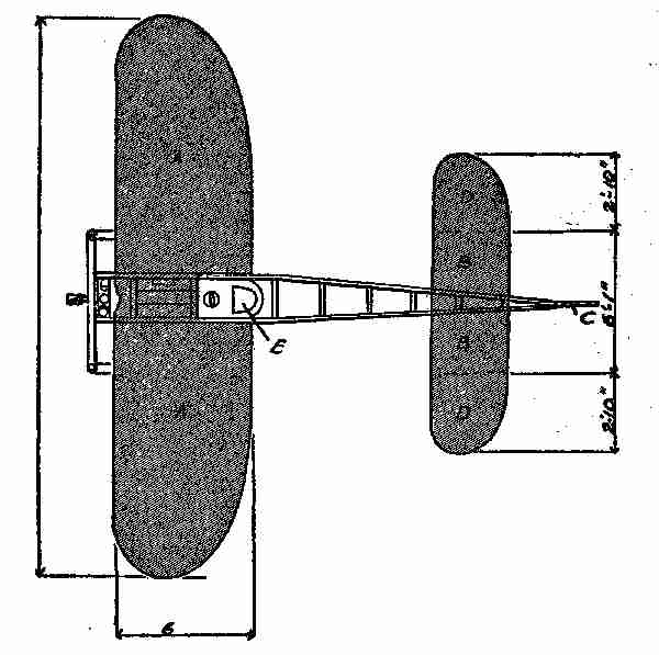
Fig. 46. Plan of Blériot machine
"The plan I show at Fig. 46 will give you a
[173]
good idea of the form of this machine, if you were
looking from above at it. E is the point where
the aviator sits, and where the 30 horse-power
engine is placed. The ends of the planes are rounded
off, and the ends of the rear plane at DD, are made
adjustable so that the machine may be made easier
to manage when in motion.
"All engines used in aeroplanes are of the internal
combustion type, made purposely for aerial
flight, and are as strong and as light as it is
possible to make them.

Fig. 47. Biplane
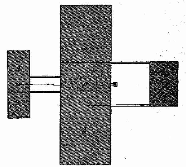
Fig. 48. Voisin biplane
"The biplane, or two plane machine, is fitted
up on somewhat the same lines as the monoplane,
having two planes one above the other, as I show
you in Fig. 47. The dark portion A A, shows the
positions and curvature of the planes. The plane
B is called the elevator because it keeps up the
[174]
head of the machine. C shows the tail with a
single plane. D is the part containing the mechanism
and the aviator's seat. E shows the vertical
planes, made of some light fabric stretched over
a bamboo frame. The propeller is shown at F,
and it is about six feet in diameter. The two carrying
wheels, shown at G G, are simply light bicycle
wheels which tend to ease the landing of the machine
[175]
when it comes to the earth. It will be seen
that machines may differ in the style of construction
and yet, so long as they contain the principles I have
described, they will fly with more or less success.
The illustration, (Fig. 48), shows the plan of the
biplane, which is somewhat different in arrangement
from the monoplane. This sketch is of the Voisin
biplane and shows the tail-piece, something not
used in machines of the Wright type. The Voisin
machine is quite popular in Europe, particularly
in France. It is not very difficult to construct
or easy to control; at least, it has that reputation.
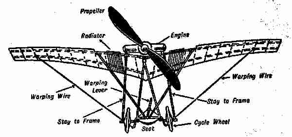
Fig. 49. The Santos-Dumont monoplane
"The Santos Dumont monoplane, Demoiselle,
shown in Fig. 49, is said to be the smallest and
lightest known practical machine, and there are
no patents on it, the inventor having published
sketches and drawings of all its details. Contrary
to the usual plan, the aviator, in this machine, sits
below the motor, so that the propeller blades cut
across the line of sight; but as it revolves very
rapidly the vision is not affected. The whole
machine, when complete, weighs only about 250
pounds. Its length is about 20 feet and its total
width over the planes 18 feet, and it is about 7 feet
6 inches high. It is quite easy to build, as the framework,
or chassis, is fixed to a bent piece of ash or
[176]
elm—like a sleigh runner—which answers very
well, because when the machine begins to move
the rear end rises first. If desired, the frame can
be made so that the whole thing can be taken apart.
Sockets, like those used on finishing rods, may be
attached at the joints and junctions to hold the
structure together. The two spars that constitute
the main support of the planes are formed
of ash, this having been found the best material
for the purpose, as it is also for the making of the
propeller blades. One of the spars should be fixed
about nine inches from the front edge, and the
other about twelve inches from the back. Bamboo
cross pieces are fastened about nine or ten inches
apart between the two main spars. All is covered
with oiled silk, applied in two thicknesses. The
[177]
area of the main plane is some 115 square feet, and
that of the tail-piece about 50 square feet. To
cover all this would require about 400 square feet
of silk.
"I have heard it said that aeroplanes are hard
to manage, difficult to drive, and extremely dangerous.
This is not true entirely, but there is some
truth in it. An amateur has to go through a
'course of sprouts' and must learn all about his
machine before beginning to use it practically.
Once he becomes master of it and can keep it well
under control, he need not fear accidents, if he
does not lose his head, nor venture out in half a
gale. When we consider the number of experiments
that have been made from time to time
with imperfect machines, we find that fatal accidents
have been very few, less, indeed, than the
number recorded in the early stages of automobile
history.
"I have been compelled to draw a number of
the points I have given you from many sources,
particularly from the writings of Messrs. Fetherstonhaugh
and Lanchester, which does not detract
from what I have told you, but rather guarantees
its correctness.
"Well, children—it is getting late, but, before
[178]
bidding you good-night, I think I should finish
my talk on aeroplanes by showing you how to make
a small model of a flying machine, if you are not
too tired to listen further?"
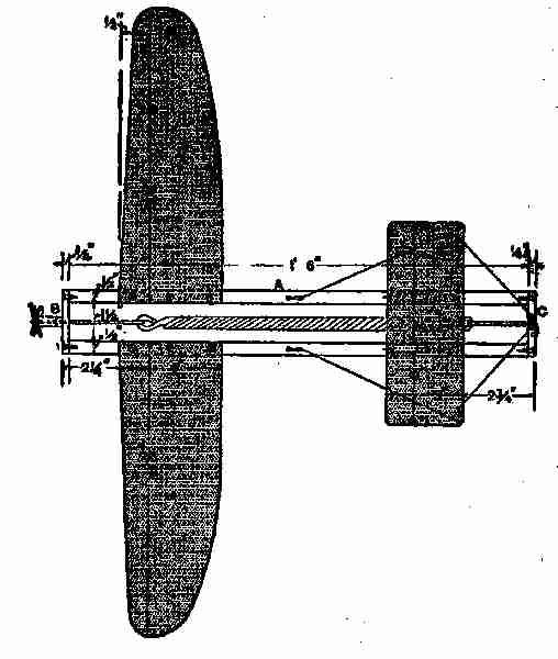
Fig. 50. A model aeroplane
"Please, father," said Fred, "do keep on."
George, also, wanted to hear more, so Mr. Gregg
decided to continue.

Fig. 51. Section model aeroplane
[179]
"I have given you an outline of the reason why
an aeroplane can be made to rise from the ground
and navigate the air; but I have not told you of
all the kinds of machines that can be made to fly,
for there are many others than those I have spoken
of. One is the glider, which does not carry an
engine, but, as its name indicates, glides along in
the air at a distance not far from the earth. These
are not capable of travelling very far and, therefore,
are not likely to come into general use. They
have to be started either by gliding off a high
tower, by sliding down a hill or by being propelled
by hand or towed by some rapidly moving machine.
Some day, perhaps, a machine will be evolved on
the same or similar lines as the glider, that can be
propelled by natural forces, but the time is not
yet. Beside the monoplane and the biplane, there
[180]
is the triplane, constructed on the same lines as
the other flying planes, that is to say, the three
planes used on the machine are made the same as
the planes on the others, each having a convex and
concave side of different curvatures.

Fig. 52. Blade of propeller
"The monoplane which I am about to describe
and illustrate, and which I show in Figs. 50-51-52,
can be easily and cheaply
made, and can be guaranteed
to fly, after a little
experimenting to get the
correct balance and angle
of the planes. The frame
A will first be treated.
Get two pieces of yellow
or white pine (the lightest
and most easily procured
wood), cut them to the shape shown, 1 foot 6
inches long, 1⁄2 inch by 13⁄16 inches in the middle, and
thickened at the ends to take the screws from the
end bars B and C (Fig. 50). Take great care to
make them exactly alike. The end pieces B and C,
which are 21⁄2 inches by 7⁄16 inch by 1⁄4 inch can then
be screwed to the side pieces A, and a rectangular
frame is the result. Should the screws split the
wood in the slightest degree, new pieces must be
[181]
made, as the plane is sure to get rough usage in
falling on the ground a few times.

Photograph by Brown Brothers
Making an Aeroplane Model
"If the Screws Split the Wood in the Slightest Degree, New Pieces Must be Made"
"The planes are also made of yellow pine. They
must be exactly equal to one another in weight,
one being right handed and the other left. The
wood must not be more than 1⁄22 inch thick, and, if
possible, even thinner. A large circular chip box
will be the best thing from which to make these.
Gum a piece of tracing cloth on top of the planes,
and allow about 2 inches to overlap at the large
ends, to twist and glue round the main frame when
fixing. The cloth will fulfil two useful and necessary
purposes. It will strengthen the planes and
curve them to a very large extent. This curvature
is essential to the flight of the machine. A wooden
block curved to suit, and inclined at about 5 degrees,
is fixed between the back planes and the frame.
"The front or small plane is 8 inches by 3 inches,
and made in the same way as the others. It must
be adjustable, and is, therefore, mounted on two
wooden blocks, 2 inches by 1⁄4 inch by 1⁄2 inch and
fastened by means of copper wire which acts as a
hinge. Four silk cords are fixed to the movable
end of the plane, two being fastened to nails at the
rear end of the frame and two to the front, to hold
the plane at any desired angle.

Fig. 53. Connections
of
propeller
blade
[182]
"The propeller blades (Fig. 52) are made of thin
aluminum. Two sheets are cut out the same size
and shape, and placed with their ends overlapping
(see Fig. 53). A piece of steel wire 1⁄16 inch in diameter
is bent and placed between
them to form the shaft. The whole is
then fixed in a piece of light copper
tube, which is slotted by means of a
hack saw or fret saw to receive them.
The blades are bound crosswise to the
tube by means of thin wire or strong
thread; then twisted to a pitch of about 6 inches.
It is also advisable to place a washer between
the copper tube and the end bar of the
frame.
"This method of fixing the propeller blades is
not the same as that shown in Fig. 50 but it is
the better way.
"The drive for the propeller is elastic (a rubber
band), which, when twisted and released, will
rapidly revolve the shaft for a short time. The
best kind to use is the gray variety, and when in
the form of bands, say 3⁄8 inch by 1⁄16 inch by 6
inches, is ready for use without jointing. The wire
carrying the elastic should be made so that the
elastic is just in tension when untwisted.
[183]
"The monoplane, when complete, should be
tested without the propeller until it will glide perfectly.
The front of the plane will need weight
added if there is a tendency to somersault; but if
the back rises ahead of the forward end, more
weight is necessary there. The best glide to be
expected is about a 1 in 6 slope. The propeller
should then be tried, and a flight of 50 or 100 feet,
or more, should result. If there is a tendency to
twist, owing to the side pull of the propeller, a
screw should be fixed to the end of the plane to
counteract it.
"A much longer flight can be given the model,
if the spring is made so that the tension may continue
a longer period. Sometimes a rubber attachment
can be applied and twisted so that the
propeller can be kept running long enough to
carry the machine a much greater distance than
here stated. The dimensions of all the parts of
the machine are marked on the illustrations, so
that you will find no difficulty whatever in making
a model monoplane that will fly from the
start. In the making of little models of this
kind, you will encounter many things that will
tax your skill and ingenuity, as amateur workmen.
[184]
"Now, children, I have told you all about aeroplanes
that I intended, though I may take up the
subject again, when I try to explain the recognized
theory of flight, and the making and flying of
kites."
[185]
VIII
KITES, SUNDIALS, PATENTS
The next day, just as Mr. Gregg returned
from his office, Fred, Jessie, and George
landed on their new dock from the Caroline.
They had been for a sail on the river,
and Jessie was quite enthusiastic over the trip.
"Fred was a real good captain. Why, papa,
he let me steer the boat all by myself, and taught
me so well I didn't have any collisions."
An hour or so later the boys, Jessie, and Mr.
Gregg, retired to the den.
After questioning the boys regarding the previous
talk, to discover if they remembered the main
points, Mr. Gregg said he would now tell them
something of kites and kite flying.
"The highest kite ascent yet recorded was made
at the aeronautical observatory at Lindenburg,
(Prussia) on November 25, 1905, 21,100 feet being
attained. Six kites were attached to one another
with a wire line of nearly 16,000 yards in length.
The minimum temperature recorded was 13 degrees,
[186]
F.; at starting the reading was 41 degrees. The
wind velocity at the surface of the earth was eighteen
miles an hour, and the maximum altitude
it reached was fifty-six miles an hour. The previous
height record by a kite was nearly 1,100 feet
lower, and it had been reached from a Danish
gunboat in the Baltic. These ascents were wonderful,
for it is not an easy matter to train a kite higher
than a given altitude, for several reasons. The
higher a kite rises the more string it will require,
and this tends to weight down the plane or kite.
The wind, too, acting on the string, tends to
retard the upward flight and to cut short further
ascent. When an ordinary kite reaches a height
of 1,200 or 1,500 feet, it is doing very well; and
few exceed this height. When Benjamin Franklin
angled in the clouds for lightning, his kite did
not attain an altitude of more than 1,000 feet,
which was quite sufficient for the purpose he had
in view. When Franklin flew his kite, he was so
afraid of ridicule that he took a small boy with
him to carry the kite and string, in order to prevent
his neighbours from thinking he was going
'kite flying.' In these days when a man is seen
flying a kite, people very naturally imagine him
to be an aeronaut, studying the science for the
[187]
purpose of improving or inventing a flying machine
of some kind—for which there seems to be ample
room.

Fig. 54. Science of kite-flying
"The first thing a beginner in the science of
aeronautics will want to know is, 'Why does the
kite or machine lift itself off the ground?' If
you take a kite and hold it in an inclined position,
the wind on the lower side will have a tendency
to blow it backward; but as it is held by the kite
string, this movement is impossible, and so it
is inclined to rise in the air (see Fig. 54). If we
construct a large plane and equip it with a motor
operating a screw which pushes or pulls the plane
along through the air, the result is the same as if
the plane were anchored, and the wind hits the
lower surface of the inclined plane, thus forcing
it up. Also, we find, within certain limits, the
more you incline a plane the more lift or upward
thrust will it give; but it will take more power
[188]
to drive it through the air, and the faster the plane
is driven through the air the less surface is required
to support the weight. A matter of great
importance in the construction is the shape of the
plane, and the shape of the vertical section through
the same. The shape of these planes has been
explained in Figs. 43 and 44, and the reasons were
given why these shapes were considered the proper
ones for the purpose.
"It does not follow," said Mr. Gregg, "that all
kites should have the same kind of a surface or
plane, though the flat planes of the toys of our
school days were all of the flat surface kind; these
being of various shapes and sizes from the lozenge
to the square, bow top, octagon, and many others,
according to the whim or skill of the maker. One
of the conditions of these planes or flat kites, was
that each one must have at least one tail attached
to the bottom of it. This tail was flexible, simply a
piece of string having paper similar to 'curl papers'
tied to it at intervals. The tail was a necessity,
for without it the equipoise would be impossible.
In China and Japan, where the natives have been
kite-flying for more than twenty centuries, they
make kites that fly and maintain the aerial equipoise
without having tails hung to them, no matter
[189]
whether the shape be that of a dragon, a lion, or
an eagle.

Fig. 55. Box kite
"A kite is simply an aeroplane on a small scale,
and should be considered as such, as it has a fixed
fulcrum in the belly band, a constant pressure
when flying, and an angle which is varied in proportion
to the load it may have to carry. The
common kite is easily made, but it does not always
fly as desired; for it seems almost impossible to make
two kites that will fly in the same manner under
similar conditions. Box kites are the most reliable,
and not so very difficult
to make, as you will discover
by examining Figs.
55, 56, and 57 and following
the directions I
give you. First, procure
four straight strips of light
wood, preferably spruce, 2 ft. 6 in. by 3⁄8 in. by
1⁄8 in.; these dimensions should be full (see
Fig. 55.) Obtain also four other pieces, each 1
ft. 71⁄2 in. long, but 1⁄16 in. wider and thicker
than the foregoing, and halve their ends to a
depth of 1⁄8 in. by 1⁄4 in., in order that when
the false end A (Fig. 56) is tightly bound on, these
cross sticks will firmly grip the long pieces edgewise,
[190]
the sides of the cells being indicated by the
dotted lines. The long sticks should be notched
at a distance of 4 in. from their
ends to receive the forks of the
cross sticks.

Fig. 56. Making a
kite
"The width of the cloth or paper
cells should be 8 in., and they should
be separated by a distance of 1 ft. 1
in. or 1 ft. 2 in., their edges being
bound with fine twine. The easiest way to make the
cells is to cut two strips of the material, 10 in. wide
and 4 ft. 81⁄2 in. long. Turn over the edges 1⁄2 in.
along each side, and insert fine strong twine! If
paper is used, glue the fold; if cloth, stitch the
hem. When completed, either glue or stitch the
ends of the strip with a 3⁄4 in. lap, so as to form a
continuous band. By folding, divide this accurately
into four equal parts and at
each of the creases glue one of
the long sticks edgewise (see Fig.
56). When dry, the whole can
be put together and the flying
line attached, without a bridle,
as in Fig. 55. For additional
clearness an enlarged detail of one end of the kite
is shown at Fig. 57.

Fig. 57. Single box kite

Photograph by Brown Bros
Making Kites
"Box Kites Are the Most Reliable, And Not so Very Difficult to Make"
[191]
"It is advisable in all cases to make the cross
pieces a trifle too long, to insure their straining
the band tightly. They may also be shortened
by cutting away the shoulder formed by the halving.
"These kites are easy to fly. Avoid an enclosed
space, where the wind whirls in invisible eddies;
having let out 20 yds. or 30 yds. of line, get some
one to throw up the kite in the usual fashion. If
several large kites are sent up in tandem, steel
wire should be used.

Fig. 58. Square cellular kite
"Another kind of a kite, known as the cellular
kite is shown in Fig. 58. This is made by forming
two square frames N. O., divided into nine compartments
each and connected together by a light rod
at r, the fulcrum or string being at P, the air pressure
at T. The whole forms a good, strong kite, but
it is not able to carry much weight, on account of
the equipoise being self adjusted in accordance with
[192]
the constant pressure and surface. The equipoise
is due to the current being cut by the edges a a´,
and diverted into the cellular divisions of each
area. This being the case, any upward or downward
tendency of a a´, would be counterbalanced
by the effect on the other side and the kite would
naturally adjust itself on the opposite side. We
are not dependent upon any particular shape for
obtaining a good serviceable kite—like the plane
made kite, the cellular one may be of any shape.
I show you one here, at Fig. 59, having a circular
rim, with thin tubes inserted in such a manner that
the current of wind
will rush through when
the machine is in the
air. The two portions,
A and B, are held together
by a rod in a
similar manner to the square kites, and the cord
or fulcrum is fastened to the rod at R.

Fig. 59. Circular cellular kite
"A number of kites may be sent up at once, all
attached to the same string, if properly adjusted.
Here are six square cellular kites looped together,
shown at Fig. 60. They may be made of any
suitable size, but need not be all of one size, though
each pair would be better if made the same size.
[193]
They may be looped up, as shown, and the point
S may be loaded lightly; it will help to steady the
kite and keep it from swaying.

Fig. 60. Group of kites
"A peculiar kite, called 'a
war kite,' is very popular in
some parts of Europe, and
in some parts of our country
also. It is easily made and
gives good results. It is on the principle of the
'cellular' or 'box' kite, being cubical or box-shaped, and,
when used for carrying weights, usually has several
cells built together, or several kites may be coupled
when a heavy load, such as that of a man, is to be
raised. These kites are made of light wood or
cane covered with nainsook or fine cotton, and
strengthened with cross pieces which hold the
frames tight and keep the kite in shape. They
can be taken to pieces and the covering material
rolled up so that they occupy very little space.
Two forms of box kites are shown in Figs. 61 and
62, and it will be seen that an attachment is made
each side of the frame. This is fine steel wire,
very light compared with its strength, wound on
a drum by means of a small engine. Large kites
of the ordinary form can be used for the same
[194]
purpose, but their lifting power is not equal to that
of the box kite. A small box kite is used for
taking photographs, a camera being carried by a
separate wire connection to the attachment wire,
and the shutter released at the proper time by an
ingenious arrangement, similar to the pieces of
paper called 'messengers' which boys used to
send up on the cords of ordinary kites. This kite
is a little more expensive to make than most of those
shown, but it gives an excellent result when
properly handled.

Fig. 61. Sextuple kite Fig. 62. War kite
"In making kites of any kind, the lightest materials
consistent with sufficient strength, should
be employed. The frames should be split bamboo
or cane. The joints may be lashed together with
fine wire or silk thread, and the envelope in each
case should be fine silk or similar material that
[195]
would be close, light, and strong. These qualities,
in all sorts of kites and aeroplanes, are absolutely
essential to accomplish the best results.
"Before leaving the subject of aeronautics, I
think it would not be amiss to tell you something
of bird flight. There are different modes of flying,
just as men have different gaits in walking or running.
"Rapid wing movement does not always imply
speed in flight, any more than does rapid leg movement
imply speed in walking or running. With
us it is the length of the stride that tells ultimately.
What tells, correspondingly, in the flight of the
bird is not known.
"Speaking broadly, long-winged birds are strong
and swift fliers; short-winged birds are feeble
in flight. When we consider that a cumbrous,
slow-moving bird like the heron moves its wings
twice per second when in flight, it is evident that
many birds have a very rapid wing movement.
Most small birds have it, combined with feeble
powers of flight. The common wren and the chipping
sparrow, for instance, have a flight like that
of a young bird.
"What can give one more exquisite pleasure
than to watch seagulls swooping round the edge
[196]
of a cliff, to see them drift down wind with wings
motionless, then suddenly dart downward, turn
to meet the breeze, and beat up against it with all
their ingenuity and skill?
"The beauty of a ship depends on the way it
glides through the water. Watch a liner, and you
can see that it is being driven by its screws, but
look at a racing yacht: there is no sense of effort
whatever. She seems to move like a bird, by
natural means.
"Here is the secret of the beauty of the aeroplane.
It seems to be completely master of the
element in which it moves. It flies with no visible
effort and at a little distance one could imagine it
endowed with magic power, moving by natural
force, like a bird.
"All the early attempts at flying were made on
the theory of wing motion, and the failures resulting
were doubtless due to careless study of what nature
could teach. There was a great deal more to be
learned from nature than from mathematics. An
examination of the different types of birds testifies,
among other things, to their rigid backs, and
to the fact that nearly all their bones are hollow
and have air cavities. An erroneous deduction had
been drawn from this that the hollows were purely
[197]
for the sake of lightness, and that the cavities
were for hot air to make the bird light when it
wanted to fly. The amount of lightness so obtained,
however, was so small as not to be worth
consideration. The passages are simply reservoirs
for air, and they allow the bird more energy than
a less freely breathing animal. The wing of the
bird does a double duty: it is an aeroplane and a
propeller combined. The valvular action has nothing
at all to do with the flight. Some explanation
of how a sparrow can rise from the gutter to the
eaves may be seen by the difference in the construction
of its wings from those of the swallow,
which cannot rise from the ground like a sparrow,
but has to get initial velocity. The swallow, however,
has much more mastery over its movements
in the air than the sparrow has. These, and many
other things in connection with bird flight, under
proper methods of scientific investigation, may
show us the whole theory of aviation. I am inclined
to think that scientific men will soon be able
to solve the problem, and to give us better control
of the coming aeroplanes, or even direct their flight
by the aid of electric waves or other natural forces.
"In kite-flying, it is well to know something of
the wind and its pressure, and, in this connection,
[198]
the following short table will give some idea of
the force exercised on objects in its path: A light
air current presses 0.004 lbs. per square foot.
| Light wind has a pressure of |
0.125 |
lbs. per sq. foot |
|
| Light breeze |
0.246 |
lbs. per sq. foot |
| Moderate breeze |
0.406 |
lbs. per sq. foot |
|
| Strong breeze |
2.00 |
lbs. per sq. foot |
|
| Moderate gale |
2.98 |
lbs. per sq. foot |
|
"This last should be the limit, as a kite or aeroplane
of any kind will find it hard to manœuvre
in a breeze stronger than a moderate gale. Of
course, there are winds sometimes that have a
velocity of 60 to 75 miles an hour, and a pressure
of over 40 pounds to the square foot, but these
would prove disastrous to any kind of a flying
machine, if it was in action."
"Father," asked Fred, "how can one tell the
velocity of the wind, without one of those expensive
machines I see at the weather office, an anemometer,
I think it is called?"
"I am glad," said the father, "that you have
noticed those and other instruments for gauging
and foretelling weather conditions. It is an indication
that you keep your eyes open when you visit
such places, and to learn by observation is almost
as effectual as to obtain knowledge by experience.
[199]
I have in mind a very simple contrivance you can
make yourself, for measuring wind pressure from
a couple of ounces to four pounds to the foot. I
will make a sketch of it, which I am sure you will
understand.
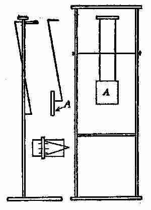
Fig. 63. Wind gauge
"It consists of a light pine or cedar wood frame
on a strong stand, supporting on a centre two bent
wires, carrying at one end a 3-in. square of thin
wood, A, and on the other a thin bar of wood, to the
centre of which is attached a fine string tied to a
spring balance scaled to 1⁄8 of an ounce and up to 4
ounces (Fig 63). As the
square of 3 inches is the 16th
of a foot, each ounce on the
spring is equal to 1 lb. pressure
on the square foot.
The latter balance slides in
the V-frame at the back so
as always to keep the square
parallel to the face of the
frame, whether the wind is
strong or light, and the balance
must be slidden in or
out until the face of the square is so placed
before registering the force of the wind. By attention
to this it will register very truly up
[200]
to 4 lbs., which is the extent of an ordinary spring
balance. There is also a front view, a side view,
and a bird's-eye view, also one of the bent wires
and the 3-inch square. I think this requires no
further explanation."
Fred was satisfied with the description of the
register and promised to make one at an early date.
The following evening when they were all sitting
on the river bank, Fred suddenly asked his
father if it was difficult, or costly, to secure patents.
He wanted to know, because he had been thinking
of making a kite on a new principle—that of a
funnel, and he was so sure it would prove a success
that he would like to have it patented.
Mr. Gregg thought the scheme rather an ambitious
one, but, while he could not see it as Fred
did, he determined not to say anything that would
be likely to discourage the boy. So he explained,
as well as he could, the patent laws: "In order to
apply for a patent it is necessary to file in the Patent
Office at Washington, D. C., a petition, affidavit
of invention, drawings, and specifications, all of
which must be prepared in legal form and in accordance
with official rules and practice of the
office.
"This can best be done by a reliable attorney
[201]
but an applicant should understand some of the
requirements as well.
"The Patent Office does not require a model to
be furnished in order to apply for a patent, but if
the attorney is not near enough to see the one made
by the inventor, then one should be sent him,
unless good photographs and drawings can be
supplied.
"Since the drawing attached to the specifications
and claims is to be on a sheet of a special size,
no attention need be paid to having the original
sketches of a uniform size. When ready to apply
for a patent, secure as much evidence as possible
of the reliability of some attorney you have heard
of and consult him about the matter, explaining
as much as is necessary for him to prepare an outline
that will suffice for a preliminary search through
the records in the Patent Office to see that no interference
will take place should the application be
made.
"This usually costs $5.00, and an attorney often
supplies copies of existing patents that look the
most like the one in question.
"If it is thought that there will be no interference,
the case is then prepared for the examiners, and
the application duly made.
[202]
"The drawings should be made and lettered, so
that the specifications can be written up, including
the proper reference to the different parts.
"The drawings should be made upon paper stiff
enough to stand in a portfolio, the surface of which
must be calendered and smooth. The best kind is
patent office bristol, though there is a style on
the market printed with margin and headings all
ready for use, but the surface is not of the best.
"The size of the sheet on which a drawing is
made should be exactly 10 × 15 inches with margin
lines one inch from all the edges, leaving a clear
space of 8 × 13 inches.
"One of the smaller sides is regarded as its top,
and measuring downward from the margin, or
border line, a space of not less than 11⁄4 inches is to
be left blank for the insertion of title, name, number
and date, to be put in by the patent officials.
"All drawings must be made with the pen only,
using the blackest India ink. Every line and
letter, including the signature must be absolutely
black.
This applies to all lines, however fine, to shading
and to lines representing cut surfaces in sectional
views. All lines must be clean, sharp, and solid,
and they must not be too fine or crowded.
[203]
"Surface shading, when used, should be left very
open. Sectional shading should be by oblique
parallel lines, which may be about one-twentieth
of an inch apart. Drawings should be made with
the fewest lines possible consistent with clearness,
for the drawings are subjected to photographic
reduction, which decreases the space between the
lines.
"Shading (except on special views) should be used
only on convex and concave surfaces, and there
sparingly, or it may be dispensed with if the drawing
is otherwise well made.
"The plane on which a sectional view is taken
should be indicated on the general view by a broken
or dotted line.
"Heavy lines on the shade sides of objects should
be used, except where they tend to thicken the
work and obscure the reference letters.
"The light is always supposed to come from the
upper left hand corner, at an angle of forty-five
degrees.
"Imitations of wood or surface graining should
not be attempted.
"The scale to which a drawing is made ought
to be large enough to show the mechanism without
crowding, and two or more sheets should be used
[204]
if one does not give sufficient room to accomplish
this end; but the number of sheets must never be
increased unless it is absolutely necessary.
"Sometimes the invention, although constituting
but a small part of a machine, has to be represented
in connection with other and much larger
parts. In a case of this kind, a general view on
a small scale is recommended, with one or more
of the invention itself on a much larger scale.
"Letters or figures may be used for reference,
but they should be well made, and when at all
possible should not be less than one eighth of an
inch in height, that they may bear reduction to
one twenty-fourth of an inch; or they may be
much larger when there is sufficient space.
"Reference letters must be so placed in the close
and complex parts of a drawing as not to interfere
with a thorough understanding of the same, and
to this end should rarely cross or mingle with the
lines.
"The illustrations on pages of current topics
under the head of new patents show the manner
of putting in the reference lines from the letters
to the part indicated.
"These are carried out some distance, but if
placed on the face of the object where sectioned,
[205]
a blank space should be left in the shading for the
letter.
"If the same part of the invention appears in
more than one view, it should always be represented
by the same letter.
"Great care should be exercised in the matter
of drawings, or they will be returned to the applicant,
but, at his suggestion and cost, the officials
will make the necessary corrections.
"The time required to procure an allowance
of a patent averages from six weeks to two months.
"United States patents are granted for a term
of seventeen years, and cannot be extended. The
patent remains good whether the invention is
worked or not, and no additional payments are
required beyond the cost of first taking out the
patent. Patents are not subject to taxation. Reissues
of patents are granted whenever one is inoperative
or invalid, by reason of a defective or
insufficient specification, or by reason of the patentee
claiming more than he had a right to claim as new,
provided the error arose by inadvertence, accident, or
mistake, without fraudulent intent. A fee of $30.50
must be forwarded upon application for patent.
"As stated before, a patent is obtained by a
petition to the Commissioner of Patents accompanied
[206]
by a description, including drawings and a
model, when the invention will admit of these. A
fee of $15 is required when the application is made,
and a further fee of $20 when the patent is issued.
Postage on model is at the rate of 1 cent per ounce.
"A patent for a design is granted to any person
who has invented or produced any new and original
design for the printing of woollen, silk, cotton,
or other fabrics; any new and original impression,
ornament, pattern-print, or picture to be printed,
painted, cast, or otherwise placed on or worked
into any article of manufacture; or any new,
useful, and original shape or configuration of any
article of manufacture, the same not being known
or used by others before this invention or production
thereof, or patented or described in any printed
publication, upon payment of the duty required
by law, and other required proceedings the same
as in cases of inventions or discoveries. These
are granted for three and one-half years, seven
years or fourteen years, for which the respective
fees of $10, $15, and $30 are paid the government.
"A caveat is a provisional protection to any person
who has thought of an invention and desires
the time to complete or perfect the same. It is
procured at an expense of $10, and runs for one
[207]
year with the permission of renewal from year
to year.
"In Canada the patent office is a branch of the
Department of Agriculture, and the Minister of
Agriculture for the time being is the Commissioner
of Patents.
"Any intending applicant for a patent who has
not yet perfected his invention, and is in fear of
being despoiled of his idea, may file in the patent
office a description of his invention so far, with,
or without plans, of his own will, and the Commissioner,
on payment of the prescribed fee, shall
cause the said document, which shall be called a
caveat, to be preserved in secrecy, and, if application
is made by any other person for a patent
interfering in any way therewith, the Commissioner
shall forthwith give notice, by mail, of such
application to the person filing such caveat, who
shall, within three months thereafter, if he wishes
to avail himself of the caveat, file his petition, and
take the other steps necessary on application for
a patent. The application for the patent must
be made within one year from the filing of caveat,
otherwise the Commissioner is relieved from the
obligation of giving notice.
"The following fees are payable: Full fee
[208]
on patent for 18 years, $60.00; partial fee for 12
years, $40.00; partial fee for 6 years, $20.00;
on filing caveat, $5.00; on registering assignment
patent, $2.00; for copy of patent, with specification,
$4.00.
"The disbursements for filing an application in
Great Britain are $25.00; France, $20.00; Germany,
$5.00, and $7.50 before issuing patent;
Australia, $20.00; Russia, $75.00; British India,
$20.00. The German and French patents cover
not only Germany and France but their colonies
also. The Russian patent extends to all of the
Russian possessions.
"The disbursements for filing an application in
the Australian states, namely, Queensland, Victoria,
New South Wales, South Australia, Western
Australia and Tasmania are $5.00 on filing the
application, $10.00 on allowance of same, and
$25.00 for preparation of the sealing of patent;
New Zealand, $20.00; Mexico, $75.00; Natal,
$50.00; Japan, $75.00; Jamaica, $150.00."
This talk on patents was quite interesting to
Fred, and very instructive to George, and they
thanked their father for it.

Photographs by C. M. D'Enville
A Sun Dial Made of Concrete
An excellent illustration of the possibility which concrete offers in ornamental as well as practical construction.
This sun dial, complete, cost approximately ten dollars, and may be duplicated by any clever
boy. See formula for concrete on
page 20.
"Boys," he said to them next morning, "why
not try your hands on a sundial? You will find it
[209]
easy to make, and if properly set up it will keep
accurate time. There is a nice place for one near
the bridge on the new grounds, as there is a stump
there, the top of which can be cut off smooth, and
it stands out full in the sun.

Fig. 64. Sundial
"Go to our jeweller in the city and get him to
give you an old tin clock-dial, like the one shown
in Fig. 64. If you cannot get one, make a dial out
of cardboard yourself, printing the hours in ink.
Slit the dial from the centre
to a point directly underneath
the number 12, if
you have Arabic numerals
on your dial.
"Then cut out a triangular
blade or gnomon, like
the one shown. If your
dial is of tin, make the
blade of tin, or cardboard
if your dial is of cardboard.
"Insert the blade in the slit of the dial and secure
it to the top of the stand you have selected—with
tacks if your dial is cardboard, with small
nails if it is tin. Then your sundial will be completed
and ready for business.
"At 12 o'clock, there will be only the shadow
[210]
of the thin edge of the blade over the dial, but as
the sun moves, so will the shadow, so as to tell
always the correct time of day. You will find this
not only a useful but a quaint and artistic addition
to the grounds, and not at all expensive."
"Papa," said George, "mamma wants a flower bed
made in the front garden, and she would like
to have it an oval or elliptical shape. I have
promised to make it for her, but I do not know
how to make the shape, and I wish you would tell
me."
"Certainly, my boy, I will show you. It can
be done easily with a string and two wooden pegs.
Follow the lines I make on the blackboard. First
we must decide on the length and width of the oval
or rather ellipse required. Then draw two straight
lines, A B and C D, Fig. 65, equal to the two axes,
and bisect or halve each at right angles. Set off
from C half the length of the great axis at E and
F, which are the two foci of the ellipse. Take
an endless string, as long as the three sides of the
triangle, C E F, fix two pins or nails in the two
foci, one at E and one at F. Lay the string around
E and F, stretch it with a marker G, and it then
will describe the desired ellipse.
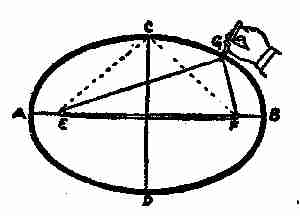
Fig. 65. Drawing an ellipse
"This is not at all difficult, and will answer for
[211]
any kind of an ellipse, short or long, narrow or wide.
This is called the "gardener's method." The main
thing is to get the two
points, E and F. This
distance is always half
of the long diameter A
B, no matter what that
may be, and this distance
is then transferred by
taking C as the starting
point, measuring from there until the other point
of measurement cuts the long diameter, as at E
and F.
"The ellipse has many peculiar and useful qualities,
which you will doubtless discover before
long."
[212]
IX
TIDES
Now, papa!" said Jessie the following evening,
after Mr. Gregg and the family had
strolled down to the river bank to enjoy
the cool air, "you promised to tell me about the
tides and the moon—when you could spare time.
Haven't you got time now?"
"I may as well say all I intended now, my dear,
and leave some other matters for future consideration.
As this subject may tax your patience, I
hope you, Fred, and George, will give me your
earnest attention.
"In order to have a clear understanding of the
movements of the tides and their supposed causes,
you must know something of the moon's influence
over them; as this knowledge will aid you very much
in remembering what I am about to say.
"The earth is a globular body. One reason for
this belief, among many others, is that sailors or
others who go to sea soon observe that as they sail
from shore, the lower portions of mountains, steeples
[213]
or other high objects, are gradually lost sight of
while the higher parts do not so soon disappear.
Persons on shore first notice the upper portions of
masts, and the smoke-stacks of approaching vessels,
which would not be the case, if the earth were a
plane, but is very easily accounted for, on the supposition
of its being a sphere, as you can readily
understand by looking at Fig. 66. Several navigators
have sailed completely round the earth by
continuing in the same direction, and coming at
last to the same place from which they started.
The earth, however, is not a perfect sphere but a
spheroid like an orange; having its equatorial
longer than its polar diameter or axis. It is flattened
at the poles, and more protuberant at the equator.
The diameter at the equator is 7,977 miles, and at
the poles 7,940, a difference of 37 miles.

Fig. 66. Proof of earth's rotundity
"You know that the cause of day and night is the
rotation of the earth on its own axis. It shows a
large portion of its surface to the sun continually,
or in other words, the sun is always shining on some
[214]
portion of the earth's surface. You are also aware
of the earth and its satellite, the moon, both being
held in their orbits by the sun's attraction, the
moon being further kept in her orbit by the attraction
of the earth. Now the earth is composed of
three main elements, air, water, and land, and if
you consider, for a moment, that the daily rotatory
movement of the earth is something like 1,000
miles an hour, this rapid speeding through space
must have some effect on air and water in assisting
or retarding their flow.

Fig. 67. Phases of the moon
"Nature has divided time, and man has named
and subdivided it into years, months, and days.
The natural month, however, does not consist of
four weeks, nor is the natural year made up of the
twelve calendar months given us by the almanac.
A natural, or lunar, month is the time the moon takes
to perform her journey round the earth, which is
27 days 7 hours, and 43 minutes; this is called the
periodical month, while the average calendar or
synodical month consists of 29 days 12 hours and
44 minutes. The light of the moon is borrowed
from the sun, for if it were her own light, she would
shine all the time and not be subject to her present
phases. The moon is seen by means of the light
which comes to it from the sun being reflected from
[215]
it. Its changes, or phases, depend upon its relative
position to the earth and the sun. When
the moon is in opposition to the sun at A (Fig. 67)
the lighted side is turned toward the earth, as
A, and it appears full. When the moon is in conjunction
at E with the sun, its dark side is turned
toward us, and it is invisible,
as at e. As it proceeds
in its orbit, as at
F, a small part of the
light side is seen, and
then we have what is
called a new moon; and
we continue to see more
and more of the light
side, as the moon approaches
at G and H,
to the state of opposition
or full moon. The waning
or decreasing of the moon takes place in the
same manner, but in a contrary order. The
earth must perform the same office to the moon
that the moon does to us; and it will appear to the
inhabitants of the moon (if there be any), like a very
magnificent moon, being to them about thirteen times
as large as the moon is to us and it will also have
[216]
the same changes or phases. Hence it is evident,
that one half of the moon is never in darkness, the
earth constantly affording it a strong light, during
the absence of the sun; but the other half has a
fortnight's light and darkness by turns.
"The moon's orbit is elliptical, and she also rotates
on her axis and takes the same time to circle the earth,
consequently every part of the moon is successively
presented to the sun, yet the same hemisphere is
always turned to the earth. This has been discovered
by observation with good telescopes. The
length of a day and night in the moon is more than
twenty-nine and a half days of ours; and while her
year is the same length as ours, being measured
by her journey around the sun with us, so she has
but twelve days and a third in a year. Another
remarkable circumstance is that the moon's hemisphere
next the earth is never in darkness, for when
it is turned from the sun, it is illuminated by light
reflected from the earth in the same manner as
we are lighted by a full moon. The other hemisphere
of the moon however, has a fortnight's light
and darkness by turns. If there are inhabitants
in the moon, which is doubtful, the satellite will
appear to them to be about thirteen times as
large as the moon does to us, and when it is
[217]
new moon to the earth, it is full earth to the
moon.
"There are many things regarding our relationship
to the moon that would be of interest, if I had
time to explain them, such as eclipses, the moon's
surface as seen through telescopes, its supposed
influence on the weather, etc., but I fear too much
moon might prove tiresome. Beside I have shown
you sufficient to enable you to understand the
relationship existing between the moon and the
tides, generally accepted as the true theory.
"If we agree that the tides are occasioned by the
attraction of sun and moon, more particularly the
latter, we can readily understand their dependence
on some known and determinate laws. Our almanacs
published long in advance give the exact time of
high water at any prominent port in the United
States on the morning and afternoon for every day
in the year; and seafaring men can tell you when
the tide will be high or low, notwithstanding the
fact that these movements are not fixed. They
know from experience that the time of ebb and
flow varies about three quarters of an hour each
day.
"The first person who clearly pointed out the
accepted cause of the tides and showed its agreement
[218]
with the effects, was Sir Isaac Newton. He
discovered a relationship between the moon and the
tides, and by the application of his new principles
of geometry, the attraction was made clear.
"The ocean, it is well known, covers more than
one half the globe; and this large body of water is
found to be in continual motion, ebbing and flowing
alternately, without the least intermission. For
instance, if the tide is now at high water mark, in
any port or harbour which lies open to the ocean,
it will presently subside, and flow regularly back
for about six hours, when it will be found at low
water mark. After this it will again gradually
advance for six hours; and then recede in the same
time to its former situation, rising and falling alternately
twice a day, or in the space of about
twenty-four hours. The interval between its ebb
and flow is not precisely six hours, for there is a
little difference in each tide; so that the time of
high water does not always happen at the same hour,
but is about three quarters of an hour later each day,
for about thirty days, when it again recurs as before.
For example, it is high water to-day at noon, it
will be low water at eleven minutes after six in the
evening; and, consequently, after two changes
more, the time of high water the next day will be
[219]
at about three quarters of an hour after noon; the
day following it will be at about half an hour after
one, the day following that at a quarter past two,
and so on for thirty days; when it will again be found
to be high water at noon, as on the day the observation
was first made. This exactly answers to the
motion of the moon which rises every day about
three quarters of an hour later than upon the preceding
one, and by moving in this manner round the
earth, completes her revolution in about thirty
days, and then begins to rise again at the same time
as before.
"To make the matter still plainer; suppose, at
a certain place, it is high water at three o'clock in
the afternoon, upon the day of the new moon; the
following day it will be high water at three quarters
of an hour after three; the day after that at half an
hour past four; and so on till the next new moon,
when it will again be high water exactly at three
o'clock, as before. By observing the tides continually
at the same place, they will always be found
to follow the same rule; the time of high water,
upon the day of every new moon, being exactly at
the same hour, and three-quarters of an hour later
every succeeding day.
"The change of the tides is in such exact conformity
[220]
with the motion of the moon that, independently
of mathematical calculations, a thoughtful
person would certainly be induced to look to her
as their cause.
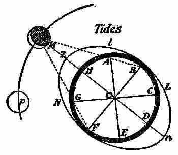
Fig. 68. Theory of the tides
"The waters at Z, on the side of the earth, A, B,
C, D, E, F, G, H, next the moon M, (Fig. 68) are
more attracted by the moon than the central
parts of the earth, O, and the central parts are more
attracted by her than the waters on the opposite
side of the earth at n; and therefore the distance
between the earth's centre
and the waters on
its surface under and
opposite to the moon
will be increased. Let
there be three bodies
at H, O, and D; if they
are all equally attracted
by the body M, they will
all move equally fast toward it, their mutual
distance from each other continuing the same.
If the attraction of M is unequal, then that body
which is most strongly attracted will move
most quickly and will increase its distance from the
other body. M will attract H more strongly than
does O, by which the distance between H and O
[221]
will be increased, and a spectator on O will perceive
H rising higher toward Z. In like manner,
O being more strongly attracted than D, it will
move farther toward M than D does; consequently
the distance between O and D will be increased;
and a spectator on O, not perceiving his own motion,
will see D receding farther from him towards N;
all effects and appearances being the same, whether
D recedes from O, or O from D.
"Suppose now there is a number of bodies, as
A, B, C, E, F, G, H, placed round O, so as to form a
flexible or fluid ring; then, as the whole is attracted
toward M, the parts at H and D will have
their distance from O increased; whilst the parts at B
and F being nearly at the same distance from M as
O is, these parts will not recede from one another;
but rather by the oblique attraction of M, they will
approach near to O. Hence, the fluid ring will
form itself into an ellipse Z, n, L, N, whose longer
axis n, O, Z, produced will pass through M, and its
shorter axis B, O, F, will terminate in B and F. Let
the ring be filled with fluid particles, so as to form
a sphere round O; then, as the whole moves toward
M, the fluid sphere being lengthened at Z and n
will assume an oblong or oval form. If M is the
moon, O the earth's centre, A, B, C, D, E, F, G, H, the
[222]
sea covering the earth's surface, it is evident, by the
above reasoning, that whilst the earth by its gravity
falls toward the moon, the water directly below
at B will swell and rise gradually toward her; also
the water at D will recede from the centre, (strictly
speaking, the centre recedes from D) and rise on the
opposite side of the earth; whilst the water at B
and F is depressed, and falls below the former level.
Hence as the earth turns round its axis from the
moon to the moon again in 243⁄4 hours, there will
be two tides of flood and two of ebb in that time,
as we find by experience.
"That this doctrine may be still more clearly
understood, let it be considered that, although the
earth's diameter bears a considerable proportion
to the distance of the earth from the moon, yet
this diameter is almost nothing when compared to
the distance of the earth from the sun. The difference
of the sun's attraction, therefore, on the sides
of the earth under and opposite to him, will be much
less than the difference of the moon's attraction
on the sides of the earth under and opposite to her;
and, for this reason, the moon must raise the tides
much higher than they can be raised by the sun.
The effect of the sun's influence, in this case, is
nearly three times less than that of the moon.
[223]
The action of the sun alone would, therefore, be
sufficient to produce a flow and ebb of the sea; but
the elevations and depressions caused by this means
would be about three times less than those produced
by the moon.
"The tides, then, are not the sole production of
the moon, but of the joint forces of the sun and moon
together. Or, properly speaking, there are two
tides, a solar one and a lunar one, which have a
joint or opposite effect, according to the situation
of the bodies which produce them. When the actions
of the sun and moon conspire together, as at the time
of new and full moon, the flow and ebb become more
considerable; and these are then called the spring
tides. But when one tends to elevate the waters
while the other depresses them, as at the moon's
first and third quarters, the effect will be exactly
the contrary: the flow and ebb, instead of being
augmented, as before, will now be diminished; and
these are called the neap tides.
"To explain this more completely, let Fig. 69
represent the sun, Z, H, R, the earth, and F and C
the moon at her full and change. Then, because
the sun S, and the new moon C, are nearly in the
same right line with the centre of the earth O,
their actions will conspire together, and raise the
[224]
water above the zenith Z, or the point immediately
under them, to a greater height than if only one of
these forces acted alone.
But it has been shown that
when the ocean is elevated to
the zenith Z, it is also elevated
to the opposite point, or
nadir, at the same time; and
therefore in this situation of
the sun and moon, the tides
will be augmented. And again,
whilst the full moon F raises
the waters at N and Z, directly
under and opposite to her,
the sun S, acting in the same
right line, will also raise the
waters at the same point Z
and N, directly under and opposite
to him. Therefore, in
this situation also, the tides
will be augmented; their joint
effect being nearly the same
at the change as at the full;
and in both cases they occasion
what are called the spring tides.

Fig. 69. Attractions of the
moon
"On this theory, the tides ought to be highest
[225]
directly under and opposite to the moon; that is,
when the moon is due north and south; but we find
that in open seas, where the water flows freely, the
moon is generally past the north and south meridian
of the place where it is high water. The reason is
obvious; for though the moon's attraction were
to cease altogether when she was past the meridian,
the motion of ascent communicated to the water
before that time would make it continue to rise for
some time after; much more must it do so when
the attraction is only diminished. A little impulse
given to a moving ball will cause it still to move
farther than otherwise it could have done; and
experience shows that the day is hotter about three
in the afternoon than when the sun is on the meridian,
because of the increase made to the heat
already imparted.
"Tides do not always answer to the same distance
of the moon from the meridian at the same place,
but are variously affected by the action of the sun,
which brings them on sooner when the moon is
in her first and second quarters, and keeps them
back later when she is in her third and fourth;
because, in the former case, the tide raised by the
sun alone would be earlier than the tides raised by
the moon; and in the latter case, later.
[226]
"The sea, being put in motion, would continue
to ebb and flow for several times, even though the
sun and moon were annihilated, and their influences
at an end, on the same principle that if a basin of
water is once agitated, the water will continue to
move for some time after the basin is left to stand
still. A pendulum, put in motion by the hand,
continues to make several vibrations without any
new impulse. When the moon is at the equator,
the tides are equally high in both parts of the lunar
day, or time of the moon's revolving from the
meridian to the meridian again, which is 24 hours
50 minutes. But as the moon declines from the
equator toward either pole, the tides are alternately
higher and lower at places having north or
south latitude. One of the highest elevations,
which is that under the moon, follows her toward
the pole to which she is nearest, and the other
declines toward the opposite pole; each elevation
describing parallels as far distant from the equator,
on opposite sides, as the moon declines from it to
either side; and consequently the parallels described
by those elevations of the water are twice as many
degrees from one another as the moon is from the
equator; then increase their distance as the moon
increases her declination, till it is at the greatest,
[227]
when these parallels are, at a mean state, 47 degrees
from one another; and on that day the tides are most
unequal in their heights. As the moon returns
toward the equator, the parallels described by the
opposite elevations approach toward each other,
until the moon comes to the equator, and then they
coincide. As the moon declines toward the opposite
pole, at equal distances, each elevation describes
the same parallel in the other part of the
lunar day which its opposite elevation described
before. Whilst the moon has north declination,
the great tides in the northern hemisphere are when
she is above the horizon; and the reverse whilst her
declination is south.
"In open seas, the tides rise to very small heights
in proportion to what they do in wide-mouthed
rivers, opening in the direction of the stream of
tide. In channels growing narrower gradually,
the water is accumulated by the opposition of the
contracting bank—like a gentle wind, little felt
on an open plain, but stronger and brisk in a street;
especially if the wider end of the street is next the
plain, and in the way of the wind.
"The tides are so retarded in their passage through
different shoals and channels, and otherwise so
variously affected by striking against capes and
[228]
headlands, that in different places they happen at
all distances of the moon from the meridian, consequently
at all hours of the lunar day.
"There are no tides in lakes because they are
generally so small that when the moon is vertical
she attracts every part of them alike; and, therefore,
by rendering all the waters equally light, no
part of them can be raised higher than another.
The Mediterranean and Baltic Seas suffer very small
elevations, because the inlets by which they communicate
with the ocean are so narrow that they cannot,
in so short a time, receive or discharge enough
to raise or sink their surface sensibly.
"Air being lighter than water and the surface
of the atmosphere being nearer to the moon than
the surface of the sea, it cannot be doubted that the
moon raises much higher tides in the air than in
the sea. Therefore many have wondered why the
mercury does not sink in the barometer when the
moon's action on the particles of air makes them
lighter as she passes over the meridian. But we
must consider, that as these particles are rendered
lighter, a greater number of them are accumulated,
until the deficiency of gravity is made up by the
height of the column; and then there is an equilibrium,
consequently an equal pressure upon the
[229]
mercury as before; so that it cannot be affected by
the aerial tides. It is probable, however, that stars
seen through an aerial tide of this kind will have
their light more refracted than those which are seen
through the common depth of the atmosphere; and
this may account for the supposed refractions of
the lunar atmosphere that have been sometimes
observed.
"You see now how the tides are caused; while
there may be some influences at work other than
those exerted by the sun and moon, the latter are
the chief ones, so I will not attempt to explain any
other.
"Here, on the Passaic River, we do not have
excessive tides, as the highest on the coast near us
seldom rise over ten or twelve feet. As a rule, tides
rise highest and strongest in those places that are
narrowest. In the Black Sea and the Mediterranean,
the tides are scarcely perceptible, while at the
mouth of the Indus, in the Bay of Fundy, and other
places, they rise thirty or more feet at times. The
general rise, however, in mid-ocean, is from eleven
to twelve feet.
"The diameter of our moon is nearly 2,200 miles,
and her distance from the earth is about 240,000
miles; so you see it is not her size, but her proximity
[230]
to the earth that gives her so much influence
over the tides; for the sun, which is many times
larger than the earth and moon combined, because
of its being some ninety-three millions of miles away,
exerts only one sixth of the attraction on the earth
that the moon does.
"These facts, children, should be remembered, as
you may often be called upon to make use of them.
"Oh, papa!" said Jessie "how many wonderful
things there are in this world."
"But I have not told you all, my dear. There is
much more to learn, but I hope the knowledge you
have now acquired will act as an incentive, and
cause you to pursue this study further."

Fig. 70. Hygrometer
Next morning Fred asked his father to enlighten
himself and George regarding the making of a
few simple meters, such as barometer, hygrometer,
and a thermometer. He also wished to know if
it would be possible for him to make a boomerang.
Mr. Gregg told him he would be pleased to help
him, and that there would be no difficulty in making
a boomerang if he went to work at it earnestly.
On the arrival of his father that evening, the
subject was again introduced, and Mr. Gregg using
the blackboard, laid out the following drawing
and wrote the accompanying instructions.
[231]
"The best hygrometer of absorption is (according
to Deschanel) that of De Saussure, consisting
of a hair deprived of
grease, which by its
contractions moves
a needle. When the
hair relaxes, the needle
is caused to move in
the opposite direction
by a weight which
serves to keep the
hair always tight as
seen in the illustration,
Fig. 70. The
hair contracts as the
humidity increases.
In the accompanying
illustration A A and B
B represent the frame;
e f, the scale; a, screw
for tightening the hair;
b, the hair; O, weight;
H, thermometer.

Fig. 71. Index of Hygrometer
"A neater hygrometer, and one on the same
principle, may be made by taking an old tooth
powder box (as deep a one as possible, since the
[232]
longer the string, the more sensitive it is), and boring
a hole through the centre of the top and bottom.
Paste a kind of dial in paper on the top of the box;
take a piece of catgut, or small fiddle string, and
push it up through the hole in the bottom and
out at the one in the lid. Glue the bottom end
immovably, and let the top end move freely: make
a small index of a strip of whalebone (Fig. 71);
bore a hole in the centre, and fix it on the catgut
with glue. Wet the catgut, see
which way it turns, and mark
'wet' and 'dry', accordingly on
the dial.
"So much for the hygrometer.
Now about that curious
thing, the boomerang. If the
following directions are closely
adhered to, and the proper
shape followed, a regular Australian boomerang
will result. It is not difficult to make. Take a
piece of hard wood, the natural shape of one of the
segments of an ordinary wheel felloe, or bend in
the wood; let it be 1⁄4 inch thick, shaped as at Fig. 72,
to be held in the right hand at A, which shows the
way the edges of the side facing the left hand must
be bevelled off. It requires a slight curve on the
[233]
flat side; so that, if on a table, each end would turn
about 1⁄8 inch. It is then a part of a very fine pitch
screw, in motion similar to a piece of slate jerked into
the air, the sole difference
being due to
the slight curve in
the back, which
gives the screw motion, in conjunction with the
forward and rotatory motion given by the hand.
Sheet-iron would not do, as there would not
be thickness to show the bevelled edge. The
boomerang was made in the form of a cross,
with four legs of equal length, bevelled, but it does
not work as well as the regular form. You must be
careful in throwing it as it may strike you on return."

Fig. 72. Boomerang
George asked his father to describe one and to
explain its uses. Mr. Gregg told the boys that a
boomerang, as used by the aborigines of Australia
for a weapon or missile of war or in the chase,
consisted of a flat piece of hard wood bent or curved
in its own plane, and from 16 inches to 2 feet long.
Generally, but not always, it is flatter on one side
than on the other. In some cases the curve from
end to end is nearly an arc of a circle; in others it
is rather an obtuse angle than a curve, and in a
few specimens there is a reverse curve toward each
[234]
end. In the hand of a skilful thrower, the boomerang
can be projected to a great distance, and made
to ricochet almost at will. It can be thrown in a
curved path, somewhat as a ball can be "screwed"
or "twisted," and it can be made to return to the
thrower, striking the ground behind him. It is
capable of inflicting serious wounds.
"It is very good of you, father," said Fred, "to
tell and show us all these things; I'd like very much
to have a very common, every-day matter explained:
the theory of the pump." The following questions
also were asked by one or another on the same line:
What is the greatest distance or height a pump of
any type can be placed away from the water? Is
there any limit to the length of the delivery pipe to
the tank? What is the difference between a lift and a
plunger or force pump? Is it the sucker of the pump
that draws the water up, or does it flow because the
air being drawn out of the pump barrel and forced
on the water outside, causes it to flow into the pump?
Mr. Gregg started in at once to give them the
facts desired: "Theoretically, the greatest height a
pump can be fixed above the water level depends
on certain conditions: the atmospheric temperature,
and the altitude the pump is to be fixed above the
sea-water level. The higher the temperature, and
[235]
the greater the altitude, the less distance the height
of the pump can be above the water. The height
to which water can be drawn from the source to
the top of the bucket, or under side of a piston or
plunger, when at the top of the stroke, or what is
termed the 'height of suction,' cannot reach more
than about 33 feet when the pump is at the sea level.
If a tube about 34 feet long is immersed in a well,
and the air is extracted by means of an air pump
at the upper so that a vacuum is formed, the water
will not rise in the tube until the air is expelled,
when it will not rise more than 33 feet, even though
there is a complete vacuum formed in the upper end
of the tube. The reason why the water will not
rise in the tube higher than this, is that the height
of the water counterbalances the pressure of the
atmosphere. This height is the theoretically greatest
height that water will rise in a suction pipe. For the
pump to discharge water, it is necessary for the water
to be in motion, and to set and keep it in motion
a portion of the water will rise, due to the atmospheric
pressure. The shorter the suction pipe,
the more certain the pump is of being completely
filled at every stroke of the pump handle.
"The action of the pump is as follows: The
bucket on moving upward attracts the air, so that
[236]
the atmospheric pressure on the surface of the
water in the well causes the water to follow the
bucket up the suction pipe, through the suction
valve, into the working barrel. On the return
stroke, the suction valve will close, the valve in the
bucket will open, and the water which before was
under the bucket will pass through it to the top
side. When the bucket is again raised, the water
will be lifted through the delivery valve into the
delivery pipe. There is practically no limit to the
height of lift, which may be any height consistent
with the strength of the pump and the available
power. The ordinary pump used for raising water
to the level of the top of the bucket, is termed a
lift pump; for raising water above this, a force
pump or a plunger pump must be used, when the
water is displaced by a solid plunger on its downward
stroke, when the quantity of water raised
will be equal to the volume of the plunger. This
system may be repeated when water is to be lifted
more than ordinary heights."
[237]
X
WALL MAKING AND PLUMBING
A few evenings later, Mr. Gregg and his
little family were gathered together on
the river's bank, watching the movements
of a number of pleasure boats and launches, when
a good-sized tugboat came along and made quite
a "wash" as she steamed past the Gregg domain.
Mr. Gregg noticed that this had actually carried
down a portion of the bank near the new pier, and
he called Fred's attention to it. The two, followed
by George, walked to the pier, and, to their alarm,
found that quite a piece of the bank had been carried
away by the current, the tides, and the frequent
wash of passing steamers.
"This will never do," said Mr. Gregg. "We must
protect the bank at this point, or the water will
soon undermine and demolish our pier, for you see
it is only near the landing where the bank shows
signs of injury, and it is as badly damaged on one
side as the other. This is caused by projection of
the pier into the river, which prevents the water
[238]
from flowing in its regular course, and causes it
to rush into the angle formed by the junction of
the pier with the bank, thus cutting away the
latter."
"Perhaps it will be best to build a sort of retaining
wall against the bank for ten or twelve feet each side
of the pier to prevent this rush of water from cutting
away the earth. If we had field stones enough on
the ground, it would be cheaper to use them, though
they would not make as good a 'job' as either cut
stones or concrete; since we haven't the stones, we'll
build it of concrete, as you have some knowledge of
that material, and I will engage Nick to help you."
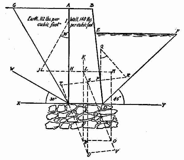
Fig. 72a. Retaining wall
The next day Mr. Gregg ordered Portland cement
and all the other materials required to build the
wall, and engaged Nick, who promised to come the
following morning. In the evening, Mr. Gregg
had the boys in his den, and explained to them how
to go about constructing the wall. He decided to
have it built of concrete blocks about 12 × 24 × 12
inches, to be faced with good, strong, cement mortar
on the face and ends, which would give the exposed
wall a nice, smooth appearance. Mr. Gregg
explained that there must be a foundation of stone
under the concrete, formed by large bowlders or
"fielders," laid as closely together as possible,
[239]
the joints filled in with smaller stones and, when
possible, cement mortar, to bind the whole into a
solid mass—as shown by dotted lines in the illustration
which he made on the blackboard. The
blocks for the work were to be cast in wooden moulds
or forms, which Fred and George could easily make
out of boards taken from the dismantled barn.
At the points where the wall was wanted, the bank
was about 8 feet high from the bottom of the river,
[240]
and it was determined to make the wall 8 feet high,
2 feet wide at the top and 3 feet at the bottom, with
the batter on the water side, the weight of the wall
being 140 pounds per cubic foot. It is always best
to have the inclined surface on the side of the wall
where the water will be. The water at high tide
rises to a level of 6 feet above the base C D.
"In designing such a retaining wall," said the
father, "for water one side, and earth the other, or
determining its stability, the principles generally
followed may easily be worked out by Fred, or even
by George.
"Taking the earth side first, as shown in diagram
Fig. 72a, W C X, angle of repose of earth to be retained—30
degrees; G C, the line of rupture; G C A,
the wedge of earth at 112 pounds per cubic foot
to be accounted for, the weight of which equals—
(GA × AC)/2 × 112 lb. = (4' 7" × 8')/2 × 112 lb. = 2,053 lb.
"This will act at a point one-third the height of
the wall H. From H erect a perpendicular H I
equal to 2,053 lb. Set out the angle H I J equal
to angle of repose, 30 degrees. From H erect
a perpendicular to A C, cutting I J in J. Then
J H equals the direction and magnitude of the weight
of the earth acting on the wall.
[241]
"Produce J H through the wall toward the water
side. Find centre of gravity of wall in K and the
weight of the wall, which in this illustration equals—
(AB + CD)/2 × AC × 140 lb. = (2 + 3)/2 × 8/1 × 140 lb. = 2,800 lb.
"From where J H produced meets a vertical line
drawn through the centre of gravity, K, in L set of
L N equal to 2,800 lb.; make L M equal to J H;
complete parallelogram L M O N, when L O equals
resultant of earth and wall.
"The magnitude and direction of P R can be
found as in the first part of this article. Produce
R P through the wall, and from where it cuts the
resultant L O in S make S T equal R P. Let the
diagonal L O now be produced so as to make S V
equal to L O. Complete the parallelogram S T U
V, when the resultant S U equals the combined
resultant of earth, water, and wall, and as it passes
within the middle third it can be considered safe.
"Now, boys," said Mr. Gregg, "I have not only
told you how to build a retaining wall, I have also
told you how to make all the necessary calculations
for designing it, as the same figuring and diagraming,
on this principle, will answer for any sea wall requiring
like conditions.
"I know you both understand figures and geometry
[242]
enough to make such calculations, if you
are ever called upon to do so."
The next morning, before the boys had finished
their breakfast, Nick was on hand ready to go to
work, equipped with a pair of hip rubber boots
which would enable him to wade in water two feet
deep and remain dry.
Fred and George were soon ready and Mr. Gregg
went out to tell them the proper way to commence.
The foundation was the first consideration, so an
examination of the site and was made, the length of
the proposed walls measured off. While waiting for
the tide to ebb to its lowest point, Nick and the
boys busied themselves gathering up stones for the
foundation and wheeling them to the point nearest
where they were to be used.
After gathering all the stones thought necessary,
the question of making the moulds for the concrete
blocks was considered, and, as the greatest bulk
of the blocks would be simply blocks with square
ends and square faces, the moulds for these would be
a box having inside dimensions of 12 inches deep,
12 inches wide, and 24 inches long. These dimensions
would then allow of blocks being made in the
moulds that will contain exactly 2 cubic feet. The
mixed concrete was dropped gently in the mould
[243]
and lightly tamped so as to make it solid. The
mixture consisted of not less than 3 of cement, 5
of sand, and 7 of very fine gravel or broken stone,
no piece being larger than a white bean. It was
mixed in the same manner and in accordance with
the rules given for making concrete for the sidewalk
in Chapter I.
The mould should rest on a smooth block of stone,
wood, or other suitable material, while being filled
and tamped, and when full the surplus should be
levelled off, by a straight-edge—wood or iron—drawn
over the top of the mould, until all the surplus
is removed. The mould is then allowed to
stand a little while until the concrete "sets" fairly
hard, when the mould may be removed. To make
it easy to take the block out of the mould, the
inside should be well sprinkled with neat cement
before the concrete is put in, and the box itself
might be made slightly tapering to permit the block
to move out easy. This method, however, is not
to be recommended, as the blocks do not fit so well
in a wall as when left perfectly square. There are
a number of devices for making moulds so that
delivery of blocks may be easy. One of the best
is to hinge one corner of the mould with heavy hinges,
while the opposite diagonal corner is left loose but
[244]
held in place by a strong hasp and staple. When the
box or mould is full and the block ready to remove,
the hasp is loosened, the mould opens across at the
two corners and frees the block. Should there be
any holes or defects on the face of the blocks, they
can be filled with cement mortar made with 2 of
cement and 3 of clean sand. Blocks of this size
should season not less than 4 or 5 days, to set hard
before being used.
A portion of these blocks must have a bevel face
on them to form the batter on the front of the wall.
There must also be a proper proportion of them
having their ends bevelled to the batter of the
wall, to use as "headers." A header in brick, stone,
or concrete, is a unit, or piece, that is laid in the
wall with its ends showing through on the face,
while a "stretcher" shows its whole length on the
face of the wall. Other portions of brick or stone,
when built in a wall, are called "closers."
The batter on the blocks is formed by making
one side of the mould lower than the other. In
this case, the difference in the width of the sides
of the mould would be 11⁄2 inches; because the height
of the wall being 8 feet, the blocks 1 foot thick, and
the batter 1 foot, there would be a falling off on
each block of 11⁄2 inches in order to have the top
[245]
front of the wall 12 inches back from the bottom
front. The ends of the header blocks may be battered
by placing in the ends of the mould a piece
of wood 12 inches wide, and the lower edge 11⁄2 inches
thick, and the top edge planed to a thin wire edge.
The end or section of the plank will then have the
appearance of a wedge 12 inches long, 11⁄2 inches
thick on one end, and tapered to nothing at the other
end. When the block is taken from the mould, and
the wedge piece removed, the block will show the
same batter on its end as the stretchers do on their
face, and they can be built in together without
showing any difference in the slope, if the work is
carefully done.
Nick, who had had some experience in this kind
of work, found no difficulty in understanding the
whole process.
At low tide he set to work to make a solid bed
for the foundation, while the boys handed him the
stone and the prepared mortar as he required it,
so that before the tide rose one side of the stone
foundation was ready to receive the concrete blocks.
During the interim between tides, Nick and the
boys made the moulds, prepared for mixing the
concrete, and got old timbers and lumber for a
temporary scaffolding. After the moulds were made
[246]
and some concrete mixed, Nick began on the blocks.
It was not long before he had a sample, which seemed
all right, and before he stopped quite a number of
them were ranged on boards "setting."
On the sixth day after it had been commenced,
the job was entirely finished. The joints in the wall
had been nicely "pointed" up with cement mortar
by aid of a fine-pointed trowel. The back, or ground
side of the wall was filled in with earth, and danger
to the pier was entirely removed.
That night Mr. Gregg told the boys and Jessie—who
had watched closely the growth of the wall—quite
a lot about Portland cement and concrete,
which interested them very much. Portland cement
as we have it now was unknown a hundred years
ago, but an Englishman invented the method of
making it and properly proportioning the various
materials used. Fifty years ago there was scarcely
any made in this country, the little that was used
being imported from England, and later from Belgium;
but now more of it is made and used in the
United States than anywhere else in the world.
He pointed out that the building of the Panama
Canal was made much easier and less costly because
of cement, and that the largest dam ever built had
just been suggested, to dam the Mississippi near
[247]
Keokuk, Iowa. This would be over 5,800 feet
long and nearly 40 feet high and from 25 to 35 feet
thick. He told of the various big storage dams
being built and contemplated by the United States,
in Montana, Arkansas, Nebraska, Wyoming, New
Mexico, Dakota, Texas, and many other places, at
a cost of hundreds of millions of dollars—which
never would have been attempted if concrete had
not been available. He also made mention of the
great wall that now protects Galveston from the
ravages of the sea. It is not many years since
Galveston was almost destroyed by tidal waves
that caused an enormous loss of life, and destruction
of property amounting to over $17,000,000. The
wall was built to prevent a recurrence of similar
disasters. It is 17,503 feet long, 17 feet high, and
16 feet thick at the base. Another recent work
is the enormous dam built by English engineers
across the river Nile at Assiout, about 250 miles
above Cairo in Egypt, which increases the area
of good land some 300,000 acres. Ancient Babylon
is again to blossom and become a beautiful country
to live in, for British engineers are laying out plans
for building storage dams and irrigating canals
in these now sandy and barren lands. All, or nearly
all, of these works and proposed works would never
[248]
have been thought of, if Portland cement had not
been in existence.
Mr. Gregg, after finishing his talk on concrete,
noticed that George had two fingers on his right
hand tied up, and on inquiry was told that George
had his fingers hurt by a concrete block falling on
them just as the retaining wall was being finished.
The father insisted on seeing the bruised fingers and
found they were not badly hurt, though the skin in
one place was broken. George explained that his
mother had washed his hand, dressed the wound,
and applied an antiseptic to it, so that it was all
right now and did not pain him.
"You were wise to go to your mother and have
your bruise attended to immediately, otherwise
you might have had something serious happen to
you, as lockjaw frequently comes from wounds of
that kind, if deep enough and not attended to immediately.
It is often said that lockjaw or tetanus
is caused by a wound made by a rusty nail. It
is certainly bad to be wounded with a rusty nail—or
any other rusty iron—and tetanus may follow;
but it does not follow because the nail is rusty, but
because the tetanus microbe that may be on the
nail, or on the skin when the wound is made, is
carried into a favourable place for development.
[249]
"This tetanus microbe, which has a long name,
is very plentiful and is scattered broadcast by every
gust of wind. It is a microbe of dirt, and the
ground and street abound with it. Its first home and
breeding place is in the intestines of horses and other
domestic animals, but its greatest danger to the
human family is when it gets into the blood by way
of a wound. Cleanliness, in this as in many other
cases, is both a preventive and a cure."
"Father," said Jessie, "I saw a very funny thing
to-day while watching Nick and the boys finish
the wall. The train across the river came to a
standstill for some reason or other, and, as I was
watching it, I saw three puffs of steam go out of
its boiler, and a short time after I heard three loud
whistles. This seemed to me quite curious, but
while I was thinking over it, there were three more
jets of steam, followed by three more 'toots.' How
was it that I saw the toots before I heard them?"
"This is a question, my dear, that will require
some little time and thought to answer properly.
In the first place, you must understand that light
travels very much faster than sound and that sounds
do not reach you until some time has elapsed, if
you are a little distance away. You see a flash of
lightning, and a little while after you hear the
[250]
thunder; and if you count 1, 2, 3, in the ordinary
way, between seeing the flash and hearing the
thunder, you may be fairly satisfied the source of
the thunder is well on to three miles away. This, of
course, is not exactly correct, but approximately
so. Every time you count one, it stands for a mile.
According to science, light travels 186,000 miles a
second, while sound only travels at the rate of
1,090 feet per second at a temperature of 32 degrees
Fahrenheit, or freezing, its velocity being increased
at the rate of one and one tenth feet per second for
every degree above this temperature. So you see
light travels nearly a million times faster than sound,
and this accounts for your seeing the puffs quite
a little while before you heard the 'toots', as you
call them. There are many curious and interesting
things about light and sound which I'd like
to describe to you sometime.
"Sound travels in dry air at 32 degrees, 1,090 feet
per second, or about 170 miles per hour; in water,
4,900 feet per second; in iron, 17,500 feet; in copper,
10,378 feet; and in wood, from 12,000 to 16,000 feet
per second. In water, a bell heard at 45,000 feet,
could be heard in the air out of the water but 656
feet. In a balloon, the barking of dogs can be
heard on the ground at an elevation of four miles.
[251]
Divers on the wreck of the Hussar frigate, 100 feet
under the water, at Hell Gate, near New York,
heard the paddle wheel of distant steamers hours
before they hove in sight. The report of a rifle
on a still day may be heard at 5,300 yards; a military
band at 5,200 yards. The fire of the English,
on landing in Egypt, was distinctly heard 130 miles.
Dr. Jamieson says he heard, during calm weather,
every word of a sermon at a distance of two miles.
The length of the sound waves in the air is sometimes
many feet, while the length of the longest
light wave is not more than .0000266 of an inch;
it is no longer a mystery why we can hear, but cannot
see, around a corner."
The children were greatly interested by these
familiar marvels and made their father promise
that he would resume the talk some other evening
and tell them about thermometers and barometers.
The late afternoon next day was taken up with
an excursion on the Caroline down the river to
Newark, where Fred induced his father to purchase
a full soldering outfit, as the boys wanted to try
some plumbing and soldering work. There had
been a plumber at the Gregg home nearly all that
day doing repair work of various kinds, and Fred,
who had watched the workman, concluded he could
[252]
have made the repairs himself if he had had the
proper tools.
An hour or two in the city, then a pleasant sail
home, proved a fine ending for a day's labour.
The next day, after school, George and Jessie
assisted their mother "making garden," planting
flowers, trimming bushes, and destroying weeds,
while Fred gave the Caroline another coat of
varnish, and finished painting his little workshop,
which now looked very snug and tidy. He soldered
up all the leaks in every kitchen utensil he found
defective, much to the delight of his mother and
the maid. Fred found many things about the
house wanting more or less attention, so he determined
to try to put them in order. He discovered
that to make a good job of soldering, he must
first make the metal to be fastened together, perfectly
clean and free from rust, dirt, or grease,
the parts around the leak being scraped bright and
smooth. He found some little difficulty in getting
the solder to the exact place he wanted. In the
outfit his father bought him, was not only a soldering
iron,—which is not iron but copper—but a
scraper, a lump of solder, a box of rosin, a piece of
chamois leather, a bottle of muriatic acid, and a
piece of sal-ammoniac, to be crushed fine and
[253]
dusted over any surface that is to be finished bright.
Fred had no trouble in soldering holes of small
size in teakettles, tins, or such things as he could
handle easily, for the impaired portions could be
placed in a horizontal position before him and the
solder applied readily. A leak in an upright water
pipe in the shed, however, gave him a hard time,
for he could not get the solder either to run up hill
or to stay on the place where it was put. He got
over this difficulty, however, by making a clay
dam, a "tinker's dam"—mixing clay until it was
soft, then winding a strip of it around the pipe
just below the leak and applying the solder until
the hole or crack was entirely covered, when a
good solid job resulted. Of course, before applying
any solder, all the water was drained from the pipe,
and the defective part was thoroughly scraped.
When the work was done, there was an edge of
solder left projecting from the pipe, which Fred
rasped away with a course rasp, leaving just enough
solder to cover the leak properly. He then sandpapered
the work and it looked almost as "good as
new."
It is easy enough to solder across the work when
level, even if the article being soldered is round,
because the metal can be worked across the top
[254]
and down the sides; but on the under side, it may be
necessary to make use of a clay dam. A plumber's
work covers a lot of things, among which may be
mentioned metal roofing, wall flashings, water-pipes
of all kinds, drain connections, hot water
and steam fittings, hot-air and ventilation fittings,
stove and range settings, and many other things
connected in some way or another with the foregoing.
Many times an offensive odour is noticeable
in the cellar, or near the line of drainage, and
it is often difficult to locate the source, so that
expensive excavations are made before the trouble
is remedied. Plumbers and drainage men often
use what is termed "the peppermint test," to
find where the leakage exists, and this is particularly
suitable for the examination of existing soil
pipes and drainage fittings. This test consists in
pouring a small quantity of oil of peppermint or other
substance possessing a pungent, penetrating, and distinctive
odour, into the pipe or drain. The defective
pipe or joint is then located by the escaping odour.
It is very important that defects of this kind
should be located and repaired immediately, for
odours emanating from drains or soil pipes carry
with them germs of the kind most dangerous to
human health and life.
[255]
Some taps in the bath room and over the kitchen
sink were not working freely, and others were "dropping"
a little. Fred, after cutting off the water
from the main, unscrewed these and put new rubber
washers in some, wound cotton twine around
the plugs of others, and made the tight ones work
easy by removing worn out washers and cut strings.
He also fixed the hydrants on the lawn in the same
manner, and made all the taps in and about the
house work tightly and smoothly.
When Mr. Gregg arrived home, Fred told him
all he had done, showing the tin pans and the
leaky pipe he had soldered, and he straightened up
with pride at being told that he was already "quite
a plumber."
After tea, the family went down to the river's
bank and chatted awhile on home matters; then
shortly after the sun went down, they adjourned
to "the lion's den."
"Now," said George, "father will tell us about
barometers and thermometers, as he promised."
"Well," said Mr. Gregg, "I'm pleased to know
you are so ready to listen to my talks, and I hope
you'll remember some of the facts I've been telling
you.
"There are many kinds of barometers, but all
[256]
are constructed about on the same principle, and
on the old theory that 'nature abhors a vacuum'.
There may have been some kind of an instrument
that did service as a barometer in the early ages,
but we have no knowledge of it. The instrument
as we now know it had its beginning with Galileo,
Torricelli, and Pascal, but was not perfected until
about 1650. Good barometers require the greatest
possible care in their construction, and there ought
to be two or more standing together as checks on
one another in order to obtain correct results.
The mercury used must be pure and good, free
from all other substances and from air bubbles or
films of air on the sides of the
bulb. Simple barometers, suitable
for ordinary purposes, can
be easily made. I will describe
one, and make a sketch of it
on the blackboard.

Fig. 73. Simple barometer
"This simply consists of a
wide-mouthed glass bottle filled
with ordinary drinking water up
to the point indicated by the
letter A (Fig. 73); in this is
dipped an inverted glass flask, or an incandescent
light bulb, the extremity of the neck being allowed
[257]
to dip just below the surface of the
water.
"The flask should be inverted quite empty
during wet weather, and as long as the atmosphere
remains in a stormy condition, no change in the
water takes place; but immediately the weather
becomes finer, the water will rise in the neck of the
inverted flask, and, if a continuance of fine weather
be probable, will rise to the point indicated by
letter B.
"I have found this simple contrivance to give
sure and early warning of the approach of rain,
and I need hardly remark that the principle upon
which this little weather glass acts is exactly similar
to that of the ordinary mercury barometer,
for the rise and fall of the water is due to the respective
increase or decrease of atmospheric pressure.
"By dividing the neck A B into six or eight divisions,
with the aid of a diamond or piece of flint,
and then marking the lines so cut, with ink, an
approximate graduation of degrees of pressure
may easily be obtained.
"I show you a water barometer here, (Fig. 74)
that is somewhat less hard to construct than the
one I have already described, as the parts are easier
to obtain.

Fig. 74.
Barometer
[258]
"It consists of a bottle, containing water, inverted
and suspended with its mouth in the jar of the same
fluid. It is capable of roughly indicating atmospheric
changes in a similar way to
the mercurial barometer. When the
atmosphere becomes denser, the greater
pressure on the surface of the
water in the jar causes it to rise in
the bottle; while with a lesser density
it falls. As with the mercurial barometer,
temperature makes a slight
difference, which, strictly speaking,
should be allowed for; but, as the arrangement
is of such a simple character,
this may be ignored. Water, also, is more subject
to evaporation than mercury, besides going stagnant,
and will require occasional changing and
replenishing.
"A barometer of a more scientific character,
and more presentable, is, I think, within your range
of skill, and it may be made as follows: Obtain a
glass tube, closed at one end, about two feet ten
inches long and three eighths of an inch thick, with
a bore of about three sixteenth inch. A circular
turned wood box, one and one half inches in diameter
and one and one fourth inches deep, is required for
[259]
the cistern. Cut out the bottom and glue on instead
a piece of leather, sagging loosely. Then
cut the lid in two, and make an opening in the
centre to receive the tube.

Fig. 75. Thermometer
"The mahogany base, shown in two halves by
A and B (Fig. 75), is 3 feet 1 inch long, 33⁄4 inches
at its greatest width, 2 inches at its least width,
and 3⁄4 inch thick. Make a groove down the
centre to admit the tube, and cut an opening 2
inches square right through the wood at the round
end. Glue at the back
of this a circular piece
of pine or cedar, 3 inches
in diameter and 1⁄2 inch
thick, and screw a semicircular
piece of the
same thickness at the
other end, with a ring
for hanging.
"Fill the tube by degrees
with pure mercury,
boiling each portion, as
introduced, by holding
the tube in a nearly horizontal position over a spirit
lamp, taking care not to crack it by too sudden
heating. Half fill the wooden cistern with mercury,
[260]
and when the tube is full, place a finger over the
end, carefully raise it to a vertical position, and
lower the open end below the surface of the mercury
in the cistern. While some one holds the tube,
glue on the two halves of the box lid and seal up
the opening round the tube with wax or cement.
Then fasten the tube to the base with brass clips
and screws, and secure the cistern from shifting
by gluing in wedges of wood. A thumb screw,
with washer, for regulating the height of the
mercury, is fixed at the bottom; this presses
on a cork washer glued to the leather of the
cistern.
"A hollowed hardwood boss is screwed over the
top end of the tube, and a hollowed circular turned
boss of mahogany, C, is glued over the bottom. The
ivory or cardboard scale D, is of inches and tenths,
from twenty-six and one half inches to thirty-one
inches, the distance being measured approximately
from the surface of the mercury in
the cistern. A vernier having a scale of eleven-tenths
of an inch, divided into ten parts, works in
a slot on the scale and should be attached as shown
at D.
"Before screwing on the scale, fix its correct
position by comparison with the standard barometer.
[261]
It is usual to place a small thermometer on the
other side.
"With regard to the thermometers, it would be
quite out of place here to discuss them at length,
or to offer you a scientific explanation of the principles
governing their construction. I may say
however, that, as the barometer is intended to measure
the different degrees of density of the atmosphere,
so the thermometer is designed to mark the
changes in its temperature, with regard to heat and
cold. The first thermometers, so far as we know,
were made less than three hundred years ago, and
water, spirits of wine, or alcohol, and oil were used
to fill the bulbs, in the order given. It was the
great Halley, of 'Halley's Comet' fame, who first
made use of mercury or quicksilver in these instruments,
because of its being highly susceptible to
expansion and contraction, and capable of showing
a more extensive scale of heat. It is owing to this
quality of expansion and contraction that the degrees
of heat and cold can be measured. If you put
your thumb on the bulb, you will notice the quicksilver
in the little tube gradually rise until it reaches
the limit of the thumb's heat. Thermometers, in
this and nearly all English-speaking countries,
make use of the Fahrenheit scale, which is different
[262]
from those used in some other places; and this often
causes trouble and annoyance.
"The scale of Reamur prevails in Germany. He
divides the space between the freezing and boiling
points into 80 degrees. France uses that of Celsius,
who graduated his scale on the decimal system.
The most peculiar scale of all, however, is that of
Fahrenheit, the renowned German physicist, who,
in 1714 or 1715, composed his scale, having ascertained
that water could be cooled under the freezing
point without congealing. He, therefore, did
not take the congealing point of water, which is
uncertain, but composed a mixture of equal parts
of snow and sal-ammoniac, about fourteen degrees R.
This scale is preferable to both those of Reamur
and Celsius, or, as it is called, Centigrade, because:
(1) The regular temperature of the moderate zone
moves within its two zeros and can, therefore, be
written without + or -. (2) The scale is divided
so finely that it is not necessary to use fractions
whenever careful observations are to be made.
These advantages, although questioned by some,
have been considered so weighty that both Great
Britain and America have retained this scale, while
nations on the Continent of Europe use the other
two. The conversion of any one of these scales
[263]
into another is very simple. (1) To change a
Fahrenheit temperature into the same given by
the Centigrade scale, subtract 32 degrees from
Fahrenheit's degrees and multiply the remainder
by 5⁄9. The product will be the temperature in
Centigrade degree. (2) To change from Fahrenheit
to Reamur's scale, subtract 32 degrees from
Fahrenheit's degrees and multiply the remainder
by 4⁄9. The product will be the temperature in
Reamur's degrees. (3) To change a temperature
given by the Centigrade scale into the same given
by Fahrenheit, multiply the Centigrade degrees
by 9⁄5 and add 32 degrees to the product. The
sum will be the temperature by Fahrenheit's scale.
(4) To change from Reamur's to Fahrenheit's
scale, multiply the degree on Reamur's scale by
9⁄4 and add 32 degrees to the product. The sum
will be the temperature by Fahrenheit's scale. A
handy table can easily be figured out from the data
given."
Mr. Gregg concluded his conversation for the
night at this point, but promised to take it up again
the first available evening.
Two or three nights afterward it was very wet
and dreary. The boys and Jessie were called into
the den by Mr. Gregg, where a brisk fire, made of
[264]
limbs and branches gathered by the boys, was
burning in the little fireplace, and the room looked
bright and cheerful. The young folks all drew up
around the fire to listen.
"I have so many things to talk to you about,"
said he, "that I scarcely know where to begin;
however, I promised to tell you something concerning
springs, so I will make these useful contrivances
my theme to-night."

Fig. 76. Car-spring
"There are many kinds of springs, but I will
only talk of steel or other metal springs; and even
then must limit myself to a few. The carriage or
laminated spring is probably the most in use, as
it is an important factor in the construction of all
classes of railway trucks and carriages, locomotives,
automobiles, road carriages and light wagons
of all kinds. These are also much used in the manufacture
of invalids' chairs, children's perambulators,
and many other things. The springs used
in the construction of the largest locomotives are
big affairs and often weigh over 500 pounds. These
are bearing springs and carry the whole weight of
engine and boiler. There are, of course, a number
of these springs to each engine. Springs on the
coaches and carriages are somewhat lighter and
more flexible than those on the heavier trucks.
[265]
The double spring, shown at Fig. 76, is known
in railroad parlance as a 'draw-spring.' One of
these is secured at each end of the car, and used
to attach or couple the cars together, or to attach
the engine to the train, the object being to lessen
the bump or impact of the blow when the engine and
cars come together. The effect is the same when
the engine starts a train;
the springs in the first
car draw out, then the
springs on the second
car do likewise, and
this causes the load of
the whole train to fall
on the engine gradually,
a matter of great
importance in railway
economy. If it were not
for bearing springs on the trucks and carriages,
it would be almost impossible to use railroads for
passenger traffic or for carrying fine goods, as
the jolting and pounding on the iron rails
would shake things to pieces, destroy the carriages,
and pound the roadbed and bridges to bits in a
very short time. Now, by the aid of steel springs,
you ride in a Pullman as smoothly almost as
[266]
in a boat, so you see how useful springs are to
mankind.

Fig. 77. Cross-bow spring
"There are many kinds of bearing springs, but all
are built in the same manner, of steel leaves, made
of different dimensions to suit conditions. As
you will see in the diagram, the sheets of steel are
laid over each other, like the scales of a fish, and
made shorter as they approach the top. All the
leaves are fastened together by having an iron
buckle driven onto the middle, as shown, while
hot, and when this cools, it shrinks and clasps the
whole so tight it cannot be taken off until heated
or cut. I could tell you of many other kinds of
springs—watch springs, gun springs, trap springs,
spiral springs—used for various purposes, but I
will end this subject by describing to you something
you can make for yourself, if you wish; namely,
a cross-bow, which is very simple. I make on
the blackboard a diagram, (Fig. 77), with A representing
the stock, 5 feet long; B, the bender, 6
feet long, which should be made in four pieces.
The front piece should be 3⁄4 inch thick, the
three inner pieces 1⁄2 inch thick. C are brass
ferrules to keep the leaves of the bender from
shifting; D the string, which should be very strong.
The bender should be cut out of straight well-seasoned
[267]
ash, rock elm, or hickory. Instead of
brass ferrules, strong brass or copper wire can
be used, properly
twisted at the
joints.

Fig. 78. Gyroscope
"The gyroscope
has become quite
famous of late, because
of its having
been employed as
a steadier for the
monorail car, and
proposed as a regulator
or governor
for aeroplanes, so that I think it will not be
amiss to tell you that a study of this toy is well
worth any time and labour you may spend on
it. There are great possibilities within this
little instrument and its applications. I do not
intend dealing with its principles, or with rotation
problems generally, as they would, I fear, be beyond
your present comprehension, but I will confine myself
to describing the toy and showing you how it
can be made, though it would be much cheaper to
buy one from a dealer. The instrument consists
of a ring of brass or other metal, like a curtain ring,
[268]
and a smaller brass ring attached to a thick disc
of white metal, or a metal disc with a thickened
rim, as shown in Fig. 78. This disc is securely
fixed to a metal pin, which is passed through two
holes in the outer brass ring, and
at one side a small rounded nut
or ball of brass is screwed on the
outer ring. The metal disc is at
right angles to the outer ring.
If a cord is wound several times
round the metal pin, the outer ring held in the left
hand, the pin and metal disc will revolve at a very
high speed, while the outer ring remains stationary.
The gyroscope can be placed on the knob, and while
the disc is revolving the outer ring can be placed
at any angle, and will remain stationary. It is
also possible to balance it at any angle on the top
of a support, such as the tip of a stick."
[269]
PART II
EVERYDAY MACHINES
[271]
I
SOME PRACTICAL ADVICE
Some of our inventions and some of our discoveries
are of comparatively recent date,
but most of them had their beginnings centuries
before historical times, as many of our greatest
inventions are the result of gradual growth and development.
The early discovery, by some unknown
persons or persons, of the making of bronze and the
hardening of it, led up to stone and woodcutting,
perhaps to the breaking-up and smelting of iron
ore, and the extraction of the metals. This again
opened the way for the making of steel, a discovery
that placed in the hands of man a source
of power which enabled him to overcome many
natural difficulties. One improvement led the way
to another, and made other improvements possible.
Take locomotives and steamboats for instance.
The making of a raft, no doubt, suggested the canoe,
and this led to the built-up boat, and the ship.
The paddle and the oar doubtless led up to the sidewheeler,
[272]
and the scull to the propeller. The
crude steam engine of Hero very likely suggested
the steam engines now in use, and this new power
rendered it easy for Stephenson and Fulton to
perform their work; but, if either of these inventors
were to come back to the earth and examine
the great steamers of to-day, or the perfect
and powerful locomotives now in use, they would
be surprised to think that the present tractable
monsters, were the outgrowth of their early
efforts.
In the same manner may be traced the same gradual
growth in all the arts and sciences; for step by step, in
every department of life, have completeness and perfection
come to us. It is not yet one hundred years
since Congreve invented or rather completed the
invention of the "Parlor match," called in his
day, the "Lucifer match." This grand achievement
was accomplished after many failures in
the efforts of chemists for ages. The perfection of
the match was a great blessing to humanity, as the
old methods of making a light or fire were tiresome
and very uncertain. So it is with many of the blessings
we enjoy to-day: they are simply the results
of the struggles of many unknown minds, the threads
of which were gathered up and pieced together by
[273]
one master mind, so as to be made useful and profitable
to mankind.
In the early and middle ages, the inventor was
looked upon as a wizard, a sort of inferior demon,
or, at best, an uncanny kind of man, and a proper
subject for the stake. When, by superior wisdom
and skill, he invented some machine or device, or
discovered some new and better method of accomplishing
a useful end, he was at once looked upon as
a necromancer in league with his Satanic majesty,
and, therefore, unfit to associate with or be recognized
as a Christian. History records many instances
of inventors and progressive men being
persecuted—and executed—because of their having
discovered or invented something which would
interfere with some vested or imaginary rights.
The new inventions must be destroyed or put
away out of sight and hearing, and the most powerful
influences were employed to bring about this result.
The stories told of Friar Bacon, Papin, Crompton, and
hundreds of other inventors, give us a few of the
reasons why so little progress was made in the arts
and sciences previous to the sixteenth century.
Down to a period within the past few years the
term invention has been considered almost synonymous
with the word chance. An inventor, was a
[274]
lucky individual, who had happened to hit
upon some new idea, not so much by his own great
ability as by good fortune, similar to that which
brings success to the purchaser of a lottery ticket.
In many cases this was really the true state of
affairs. Men who experimented in various mechanical
pursuits often stumbled upon results,
which they perceived to be useful and valuable,
and, if they protected the invention by patent,
they often became wealthy.
At the present time this meaning of the word
invention must be greatly modified, if not altogether
abandoned. The law which controls the action
of the forces of nature is becoming so well understood
among all classes of mechanics that chance
invention, in the early sense of the term, has almost
become an impossibility. Success can be assured
only to the man who has tried to win it by the
acquirement of the necessary knowledge, to be obtained
by steady application and hard study. In
the pursuit of discovery, the old saying, "knowledge
is power," never has had more force than when
applied to unravelling the tangled web of nature's
mysteries. "Science," says Lord Brougham, "is
knowledge reduced to a system."
A man may have a lifetime of practical experience
[275]
and amass a fund of knowledge of great
use to himself, but entirely unavailable for others.
But if his experience be combined with that of other
men and systematized into a regular order, it
becomes part of the science of that branch of industry,
and although the person himself may have
a profound contempt for science and theory his
work may be quite scientific.
Ignorance, in the past centuries, was another
great factor in preventing mechanical progress.
New machines and labour-saving devices were looked
upon by the great mass of workers as contrivances
designed to deprive them of the means of making
an honest livelihood, and this point of view caused
the people to smash and burn many machines that
had cost great labour and expense to the unfortunate
inventor. But, as public schools became more
numerous and learning increased, the way of the
inventor became smoother. The more enlightened
nations encouraged inventors and inventions, and
now our country has on its statute books laws for
this purpose, the most liberal in the world.
The opportunities for obtaining mechanical and
scientific knowledge and technical instruction are
now so many and so easy of access that inventors
have but little trouble in acquiring the data and
[276]
facts essential to their purposes. The earliest
students had nothing but their own observations
and experiences to build on, and even as late as
the eighteenth century, men had to grope in the
dark for the data required to carry out their
ideas. A brief examination of the early treatises
on mechanics and the rude illustrations
in the works of Leopold, Amoutons, and Desaguliers
will reveal the germs of many modern
machines.
The inventor of to-day, however, must proceed
by a different path from his predecessor, if he expects
to succeed in the present advanced state of
mechanical arts. The demonstration of the mechanical
equivalent of heat, the discovery of the
correlation of the physical forces, and the development
of the sciences of thermo-dynamics have furnished
powerful weapons for the advancement of
mechanical science, and he who does not use them
is at a woeful disadvantage in the fight. There
is no "royal road" to success for the inventor, and
I hope you will always bear this in mind when attending
to your studies, for you must remember
that it is nearly always necessary to use formulæ
and symbols to express relations, which are hardly
within the range of words, and often a combination
[277]
of data obtained from different sources may be
used to derive entirely new relations.
It is here that invention, in the modern sense of the
term, comes in to hold a place midway between theory
and practice, and may be properly called a science.
THE LAWS OF GRAVITATION
Suppose a one-pound weight is suspended by a
string: there is a tensile stress in the string, varying
slightly at different parts of the earth, but always
the same at the same place, say, Newark, for the
variation is very slight within a pretty wide area.
If we take a spring balance and graduate it in
pounds at Newark, such a balance will accurately
indicate forces in pounds wherever it may be used.
The stress produced in a string carrying a one-pound
weight at Newark is the unit of force. If the
string with its weight is hung from a nail, the nail
is pressed on its upper side with a force of one pound.
The same pressure may be produced by pushing
the nail downwards from above, using a short piece
of stick; in such circumstances, the stick bears a
compression stress of one pound. This is a good,
common-sense definition of force, though it does
not by any means cover the whole subject. The
word force is used in a different sense by persons
[278]
who speak of the force of gravity. When a one-pound
weight is suspended by a string, as stated
in the foregoing, the attraction between the mass
of the weight and the mass of the earth is balanced
by the stress in the string. We can double the
stress by doubling the weight, and in this way, by
adding weights, we can make the force of gravity
very great. But the force of gravity is spoken of
as an invariable thing, and it is said to be equal to
32 (roughly). If any weight whatever be allowed
to fall freely (for reasonable heights and neglecting
the effect of the resistance of the air) it will be
found that at the end of the first second it will
have a velocity of 32 feet per second; at the end of
the second second it will have a velocity of 64
feet per second; and generally at the end of any
number of seconds its velocity will be 32, and the
rate of increase of velocity (acceleration) is 32 feet
per second, all of which has been previously explained.
It is found convenient to call this acceleration
gravity—it is inaccurately called the
force of gravity, it varies at different places on the
earth. It is usual to designate the acceleration by
the letter g, and we speak of the g, or gravity, of the
place. This seems to cover the point of inquiry
completely.
[279]
The subject of specific gravity is a far-reaching
one, and includes the testing of liquors for revenue
purposes and many other things of a scientific
nature; but when we speak of specific gravity in
an ordinary way we mean the comparative weight,
bulk for bulk, of water at a certain temperature.
The specific gravity of a substance like coal can be
ascertained experimentally. By means of a specially
adapted and delicate balance, the sample of
coal is first weighed in the ordinary way, after which
it must be weighed suspended in a vessel of water.
Weighed in water, it will be found the coal does not
weigh so much. If the loss of weight, or the difference
between the first and second weighings be
taken, and the first weighing divided by this loss
of weight, we obtain the specific gravity of coal.
For example, suppose a sample of coal weighs in
the ordinary way 20 ounces, and in the water only
four ounces, showing a loss of weight of 16 ounces.
Divide 20 by 16, and we get the specific gravity of
the sample of coal, viz., 1.25.
The use of specific gravity is of great importance
in mining, with regard to analysis of the minerals
worked, for with a class of coal having the same
relative composition, qualities, and calorific power
per ton of coal employed for different purposes,
[280]
yet having a higher specific gravity, the room required
for storage or transport will be less. This
is an important factor, where there is limited space,
as in depots and naval vessels. It is also employed
in the arts and industries for many purposes, and is
particularly useful to workers in precious metals,
as the amount of alloy or baser metal may be determined
by it that have been used in the manufacture
of jewellery, plate, and similar articles.
To put it briefly: Specific gravity is the ratio
of the heaviness of any substance to that of water.
The specific gravity of water is taken as unity,
and that of any other substance is expressed as a
decimal. Tables of the weight and specific gravity
of substances can be found in any good hand-book
of engineering.
HOW TO ADJUST SEWING MACHINES.
Sewing machines often get out of order, and it
is not always that an expert is at hand to adjust
them, so a few general observations on the subject
of these household machines may prove useful and
interesting to every one who is at all mechanically
inclined.
There are several distinct types of machines, but
we shall confine our remarks to the Singer vibrating
[281]
shuttle, the hook shuttle types, and one or two
others. To secure a perfect stitch in the vibrating
shuttle machine, and to keep it from puckering thin
goods, such as Japanese silks, muslins, and voiles,
though possible, is difficult. Success depends entirely
on the careful fitting of parts and the skilful
adjustment of the machine to the particular fabric.
In the first place, it is essential that a machine
should work quite freely, a point not of such great
importance if it is used for rougher classes of work.
Machines used for domestic purposes, like the V.
S. (vibrating shuttle), often stand unused for weeks
together, so that the oil thickens and makes a machine
run somewhat heavily and unevenly. This
may indirectly affect the regularity of the tension,
especially with thin goods. Therefore, it is important
to keep a machine clean and regularly oiled.
Important parts are often overlooked during the
operation; in fact, many users of machines do not
know how nor where to oil one properly. Therefore
Figs. 79 and 80 will be helpful, as they show
the location of oil holes and parts to be oiled, and
the illustrations will serve as a guide to other
machines. In these figures, it will be seen that there
are a number of parts to oil which could very easily
be overlooked. When a machine has been unworked
[282]
for a length of time, the application of a little paraffin
will cleanse the parts which should afterwards
be oiled thoroughly with a good quality of machine
oil. The shuttle raceway, where the shuttle works,
should be wiped out with an oily rag. Any lint
or dirt which has accumulated inside the shuttle
at the nose end should be withdrawn, as such might
retard the unwinding of the bobbin. It is imperative
that the cotton should pull evenly, that is,
free from jerks; this refers to the upper as well as
to the lower tension.

Fig. 79. Section showing oil holes
For silk and similar materials, best results can
be obtained if fine cottons are used. Numbers 60,
70, or 80 would be preferable to No. 40. A good
quality of fine silk is even better. It must be remembered
that when working on thin silk, say two
[283]
thicknesses, a coarse cotton cannot be locked
centrally. Fine cotton will need a fine needle,
which necessitates a fine hole needle plate.

Fig. 80. Action of shuttle in the race
If, after the foregoing points have been attended
to, the machine runs easily, the parts fit properly,
there is no end play to the upper shaft and the
cottons pull evenly, yet the tensions are erratic,
attention should be given to the loop as it draws
off the shuttle heel. In machines of the C. B.,
O. S., and especially the V. S. class, there is a
tendency for the loop to hang on the heel of the
carrier, or to become trapped between the shuttle
and the carrier heel. In the two former types
of machines, the heel of the carrier should
be rounded so as to induce the cotton to pass
off as freely as possible. Sometimes it is necessary
to time the shuttle a little later, that
is, put the carrier back a little to allow the loop
[284]
to draw off more in a line with the hole in the
needle plate.
In V. S. machines the carrier is already rounded
off at the heel. By referring to Fig. 80, the action
of the shuttle in the raceway can be seen, which
is from A to B. The shuttle, having just entered
the loop, is about to move to B. This movement
can be regulated by an eccentric screw and nut
(Fig. 80). When a machine has been taken to
pieces and cleaned, this screw is not always replaced
to the best advantage. If the shuttle moves too
much toward B, the loop is carried by the heel
of the carrier, and, at the same time, the shuttle
cotton, by bearing tightly on the needle plate,
pulls the shuttle toward the carrier heel, thus
making it difficult for the loop to release itself.
More tension is applied, perhaps more pressure is
put on the take-up spring, yet the uneven tension
is not overcome, and owing to the softness of the
fabric, it is drawn up or puckered. The remedy
is to turn the screw C (Fig. 80), until the carrier is
in a position to allow the loop a free exit.
For such soft materials as mentioned it may be
necessary to slacken both tensions. It should be
remembered that the upper tension is generally
somewhat tighter than the under one, and this
[285]
should be a guide to the adjustment of the latter,
according to the fabrics to be stitched.
To prevent puckering when the tensions are
correct, reduce the pressure of the foot by loosening
the thumbscrew D (Fig. 79). Use a small
size stitch—set the feed so that the teeth are just
above the needle plate. Do not have the teeth
too sharp, and if necessary, rub off the knife edge
with F emery-cloth. Make the foot to bear squarely
on the needle plate, and the feed square to the
presser foot. Round off all sharp edges from the
under side of the foot, especially the back edge.
Special feeders are made for silk goods in machines
used for factory work, which overcome the difficulty
of puckering.
By attention to the foregoing instructions, a
machine should work easily, especially if the fabric
is slightly pulled from behind the pressure foot.
In C. B. machines, attention should also be
given to the loop as it passes over the bobbin case
and off the stop pin, it being necessary sometimes
to round off the latter. If the tension spring screw
projects too high or is rough, it may occasionally
catch the cotton.
The machine shown at Fig. 81 is of the "Rotary
Hook"—zigzag type. Its uses are similar to
[286]
that of the oscillating shuttle type, but its construction
is rather more complicated.

Fig. 81. Rotary hook—Zigzag type

Fig. 82. Rocking
frame
The machine may be said to consist chiefly of
an upper and a lower shaft, each having two cranks.
In the vertical portion of the arm are two links
which connect the shafts, causing them to work in
unison with each other. The upper shaft gives
motion by means of a cam and link to the needle
bar and take-up lever; while the lower shaft, by
means of three gear wheels, gives the rotary movement
to the hook or shuttle, and by an eccentric
cam and segment lever the necessary motion is
[287]
given to the feed or stitch mechanism. Figure 82
shows the rocking frame into which the needle bar
is fitted at A and B, while, at C and D, it is recessed
to receive the taper ends of two screws, which pass
through the face plate end of the machine arm.
These screws are held secure by lock nuts, so
screwed in as to allow the frame to rock freely. A
ball-headed screw is fitted at E, to which is fastened
a connection rod extending to a switch lever situated
about the centre of the arm. This lever, by means
of a cam movement, gives the vibrating motion
to the needle bar, which can be regulated according
to the relative position of the connection rod and
lever. When the rod is at the bottom
of the lever, a wide throw is
obtained. By raising the rod a
narrower throw is given, and if raised
to the position shown in Fig. 81 no
vibration will be given to the needle
bar. The needle bar can be raised
or lowered by loosening the screw
that secures it to its link collar,
which will be better seen by removing
the face plate. Most needle
bars have two marks upon them, and they should be
set as follows: Remove the face plate, and turn the
[288]
hand wheel F (Fig. 81) toward you until the
needle bar link has reached its lowest point of
travel.
Loosen the set screw of the needle bar collar, and
set the needle bar so that its highest mark will
be just level with the bottom of the rocking frame
(Fig. 82). Then tighten the set screw, give the
hand wheel a spin round, and again examine the
position of the mark when the needle bar has
reached its lowest point of travel, to make sure
that no mistake has been made. Of course, it is
necessary when parts are badly worn to set the
needle bar a trifle lower, but this can be done after
the foregoing rule has been adopted and proved a
failure. In case of any unnecessary looseness in
the middle bar or any of its connecting parts, they
should be taken out and new parts fitted. The
position of the needle may be altered to the right
or left by loosening the screws G and H (Fig. 81),
and adjusting the connection rod. Care should
be taken not to set the connection rod too low down,
or the needle may strike on the needle plate and
cause trouble.

Fig. 83. Section
showing face plate
removed from machine
Fig. 83 shows the face plate removed from the
machine arm, A being a tension release lever.
When the presser foot is lifted to its highest position,
[289]
the end of the lever goes between the tension disc,
thus releasing all tension, so that materials can be
taken from the machine without drawing slack
cotton, or putting any unnecessary strain on the
needle. When the presser foot is lowered, this
lever should withdraw itself from the disc, thus
allowing the proper tension to be put
on the cotton. In some machines the
withdrawal of this lever depends on
a stud screw, fastened to the needle
bar and projecting through the face
plate. In the downward course of
the needle bar this stud screw touches
a spring, and causes the lever to trip
backward. Should the spring become
strained, or the stud screw become
raised up a little, the release
lever may remain between the disc
and cause trouble. Sometimes it is necessary to
bend the lever forward or backward to ensure
its proper action.
Fig. 84. Hook
ring

Fig. 85. Hook
guide
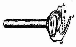
Fig. 86. Hook driver
The hook or shuttle is rotary in motion. The
hook (Fig. 84), is fitted to a ring, which is fixed
to the hook guide (Fig. 85) by means of three small
pins, and it is prevented from falling out by a steel
cap secured with two screws and springs. The
[290]
hook is carried round by a driver (Fig. 86). Much
depends on the hook, driver, and hook guide,
so that a little detailed information is necessary.
The hook driver must be a perfect fit
in its bearings and free from sharp
places where it comes in
contact with the hook.
The body of this driver is
generally hardened, but the
prong J (Fig. 86) is left
soft so that it can be bent to meet requirements.
When a machine is stitching, the hook driver
rotates, and the prong J draws a given amount
of slack cotton from the bobbin case. The farther
this prong stands out, the more slack cotton it
draws off the bobbin. The prong may be bent
inward, as shown by the
dotted lines, but care must
be taken not to drive it
in so far as to allow the
needle when descending, to
strike on it, or to deviate
from its true vertical position.
Points K and L fit between the nose and
neck of the hook, while M comes against the heel.
The hook is driven alternately by points K and M.
[291]
When the hook is just entering the loop formed by the
needle, it (the hook) is being driven by the driver
wheel or M, and an opening is being made between
point K and the hook nose for the free passage of
the cotton. When the loop is being drawn off the
hook by the take-up lever, the hook is driven by
point K, and an opening is made between M and
the heel of the hook for the exit of the cotton.
There must always be sufficient clearance at points
K, L, and M for the cotton or thread being used. As
the heel of the driver M wears, the space at K will
be reduced. Sometimes this can be remedied by
bending the driver in at M, by giving it a blow with
a hammer, placing a brass punch at M, but this
should not be attempted if the driver is very hard.
There is a means of adjustment provided in the
hook guide (Fig. 85). This part is held in position
by two set screws N and O. At the left of O is
a small adjusting screw P. Supposing there is
not sufficient space at point K (Fig. 86), for the
cotton to pass, loosen the screw O (Fig. 85),
and slightly tighten the screw P. This will tilt
the hook guide and give more space. Should the
screw P be turned in too far, the point L (Fig. 86),
will be brought in contact with the narrow part
of the hook near the neck, and this will impede
[292]
its freedom, so that if allowed to run at much speed,
the probable result will be the breaking of the hook
off at the neck. This should be noticed in fitting
a new hook, as the adjusting screw P (Fig. 85)
will in all probability require loosening. The screws
at N and O, however, must be kept quite tight.
At each side of N is a small screw hole. The
screws which fit here are for adjusting the hook
closer to or farther from the needle. As an example,
supposing a very fine needle has been used
in the machine, and it is now required to take a
very coarse one on account of the thick material
to be stitched, the hook in all probability would
strike the needle, indicating that the hook guide
requires moving back a little. To do this, loosen
the two small adjusting screws and tighten the set
screw in N. Afterward try the set screw in O
to ascertain if it is secure. In this way, the hook
is thrown farther from the needle. Loosening the
screw at N, and tightening the adjusting screws,
will bring the hook forward. If the hook stands
too far from the needle, it is likely to miss the loop.
The hook nose must be well pointed and perfectly
smooth, roughness or sharpness removed from any
part of the hook over which the cotton passes during
the formation of a stitch.
[293]
Hook rings are made in three sizes, numbers
1, 2, and 3. Number 1 is for a new hook, numbers
2 and 3 are for fitting as the hook wears. No
matter what size of ring is used the hook must
have perfect freedom. Sometimes the three pins
in the guide draw the ring, and cause the hook to
bind. It is best, therefore, to fix the ring to the
guide, and then test the hook. If it is at all tight,
grind it on the rim by means of an emery wheel or
a grindstone. If neither is available, use number
1 or number 11⁄2 emery cloth first, finishing with
number 00 emery cloth. It is better to have the
hook a little loose, even sluggish, than too tight.
The timing of the hook will be dealt with later on.

Fig. 87. Bobbin case

Fig. 88. Bobbin case in position

Fig. 89. Bobbin in position
in bobbin case—Method of
threading
The bobbin case (Fig. 87), fixes to a stud in the
centre of the hook. It is held in position, that is,
kept from revolving with the hook,
by means of a stop pin, Q, fitting
between a holder. The tension is
obtained by a spring, R, which is
regulated by turning a small screw,
S, to the right to tighten and to the
left to loosen. Fig. 88 shows the
bobbin case in position, with the holder raised ready
for taking it out of the machine. Fig. 89 shows the
bobbin in position in the bobbin case and method
[294]
of threading, and Fig. 91, the direction the cotton
should draw off the bobbin when it is in the machine.
It will be noticed that the
cotton pulls in the opposite
direction to which the hook
travels, as shown by an arrow
in Fig. 88. The bobbin case
holder (Fig. 91), should prevent
the bobbin case from
revolving with the hook.
As parts wear, the bobbin
case is liable to slip past the holder, causing the
cotton to be stranded and broken. When such is
[295]
the case the holder should be bent as shown by
(Fig. 92), but it must not fit so tightly against
the bobbin case as to cause the
cotton to become trapped. The
holder is held rigid by means of
a catch and spring T (Fig. 88).
Should the catch or holder become
worn, fit new parts by driving out
the pins U and V. Any sharpness or
roughness on the forked part of the holder should be
removed. Should the stop pin Q (Fig. 87) become
loose, it should be soldered and
well cleaned with an emery cloth.
The centre tube of the bobbin case
should also be kept quite firm. Should
it become loose, place it over some
hard substance, rivet it until tight,
and thoroughly smooth with very fine
emery cloth.

Fig. 90. Direction
cotton should draw
off

Figs. 91 and 92.
Bobbin case holders

Fig. 93. Take-up
spring
The take-up spring (Fig. 93) is attached to
the face plate, and is shown in position in Fig.
83. Replace a new one as follows: First take
out the set screw W (Fig. 93), and remove the
complete thread controller from the face plate.
Then take out the screw and withdraw the old
spring. Place the ring part of the new spring in
[296]
the recess between plate Y and back plate Z, and
replace the screw X, being careful not to get the
spring fastened under the screw head. This done,
fix the spring and other parts on the
face plate. A small barrel with a
slot in it receives the coiled portion
of the spring. See that the part of
the spring that is turned in enters
the slot in the barrel, then replace
the screw W, but before tightening
this screw, see that the hooked part
of the spring A´ rests on the regulator
B´, which determines the amount of action given
to the take-up spring. By raising it, less action
is given. The amount of pressure on the spring
is regulated by adjusting the barrel in the face
plate. Take off the face plate, loosen the screw C
[297]
(Fig. 83), fix a screw-driver in the rear of the barrel
(seen inside the face plate), turn it toward
you for more pressure, and backward for less and
tighten the set screw C.

Figs. 94, 95, 96. Presser foot with details
Presser feet are made solid for ordinary purposes,
although alternating feet can be fitted when desired.
Figs. 94, 95, and 96 show a pressure foot, collar,
and spring. To fix this foot, remove the ordinary
presser foot, turn the foot bar round by loosening
the set screw, so that the groove made for the reception
of the presser foot is directly behind the
needle. Put on the collar (Fig. 95), then turn
the foot (Fig. 94), and screw it in position. Next
place the spring each side at the points
D´ (Fig.
94), press down the collar (Fig. 95), and secure
it by its set screw. The springs will act on each
half of the foot, and keep them firm, though the
material be uneven. The foot is particularly useful
when overseaming a hem or the top band of
a lady's boot, etc. To time the hook and needle,
raise the connection rod so as to produce no throw,
and tighten the screw as in Fig. 81. Then take
off the needle plate and remove the slide E´
(Fig. 81) under which will be seen a crank and screws.
Now turn the machine back as at Fig. 88, lift
up the bobbin case holder by pressing the catch T,
[298]
and remove the bobbin case. Take off the hook
guide cap by removing the two screws. Turn the
hand wheel F (Fig. 81), toward you, until the
needle bar has descended to its lowest point of
travel, and loosen the crank screw farthest from you.
Having done this, continue turning the hand wheel
until the needle bar has risen. With the lowest
mark level with the rocking frame casting, at this
point, examine the hook, the point of which should
be just up to the needle. If otherwise, loosen the
other screw in the crank under the plate E´ (Fig.
81). Be sure the needle bar mark is level with the
rocking frame, place the hook with its point just
up to the needle, and tighten the crank set screw,
being careful to have no end play to the short shaft.
Again examine the needle bar and hook and if in
proper time finally secure crank set screws and replace
the fittings previously removed. Thread the
machine as indicated (Fig. 81). Set the needle
as high in the bar as it will go, with the long groove
facing the operator, and thread the needle from the
long groove side. The stitch regulator will be found
at F´ (Fig. 81). The raising of it will shorten and
the lowering of it will lengthen the stitch. The
feed should be set about one thirty-second of an
inch above the needle plate when at its highest
[299]
point. To raise the feed, turn the machine back
as in Fig. 88. Near to the part G (Fig. 88) will
be found a large set screw. Loosen it and press
the lever H (Fig. 88) upward raising the feed
bar J as high as required, and tighten the set screw
at G firmly. To remove the feed for cleaning and
sharpening, take off the needle plate, under which
will be seen two feed set screws. By unscrewing
these, the feed can be lifted out.
One of the modern machines on the market is
the Wheeler and Wilson, known as the Number 61,
which is of rotary hook principle. The hook forms
part of the under shaft, somewhat similar to that
known as the D9 W and W. This hook and shaft
revolves in two long bearings, and is held in position
by a fluted wheel, which forms a collar at the right-hand
end; thus when set properly no end play is
permitted. This is an advantage over the boat-shaped
shuttle machine. In the latter, the shuttle
rocks about, becomes worn on the surface, often
blunt pointed by striking the needle. As it wears,
it becomes loose in the carrier, thus giving it freedom
to roll away from or toward the needle, as well as
making its action with relation to the needle very
uncertain; and on account of the number of little
loosenesses in fittings that this uncontrolled shuttle
[300]
produces, missed stitches are frequent, and difficult
to remedy, unless a number of new fittings are
obtained or old ones repaired.
If there is any alteration required in the time of
the rotary hook referred to, it can be made to the
smallest fractional part of an inch very quickly and
easily, and the movement can be relied on. The
shaft to which it is secured is positive in its action
(no variable motion), and at every stitch will meet
the needle at exactly the same spot. This is an
improvement over the boat-shaped shuttle, which
has to have a certain amount of play or slackness
to allow the loop to extricate itself; and this slackness
increases as the machine is worked, so that
the shuttle action often becomes very erratic.
Sometimes a carrier becomes sprained at one end,
thus allowing the shuttle too much freedom. If
at the heel end, the carrier should be removed
and placed in a vise (heel uppermost). The heel
should be given a light blow with a hammer, thus
bending it into correct position, but it must never
be allowed to incline toward the shuttle; it should
stand perfectly square, and have the upper corners
rounded off. If inclined toward the shuttle, the
loop may occasionally hang on the heel, and cause
an irregular tension.

Fig. 97. Bobbin case
holder
[301]
In some machines the bobbin case holder (Fig.
97) rests on the casting seen in Fig. 81. It is
secured by a large set screw, D (Fig. 97).
For general use, this screw should be adjusted to
allow number 40 cotton to pass
freely over the bobbin case. The
holder should not be removed, except
when adjustment or repair is
needed. The vertical portion is
hinged to the base, and is kept upright
by a lock spring and stud. If
the spring is pressed from the stud, the vertical or
ring part can be drawn back for placing in or
taking out the bobbin case. The face of this
portion must be perfectly square
with the bottom of the base, otherwise
it may cause considerable
trouble. A slight adjustment can
be made by loosening the two
screws and moving the lock spring. A set square,
E, should be used for testing the accuracy of this
part as shown (Fig. 98), F representing the bobbin
case holder.
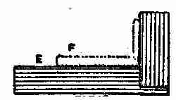
Fig. 98. Set square
The thread controller is similar in design to
several others, but its movement is regulated by a
small lever (Fig. 99) which receives its motion
[302]
from a link attached to the foot bar bracket set
screw, and this may be seen through a hole in the
face plate. At G (Fig. 99), this lever engages
with a stop washer located behind the thread controller
plate. The washer is recessed to form a
stop, at the same time to give sufficient clearance
for the action of the spring; thus as
the foot bar rises and falls, so does
the thread controller spring. It is a
common practice when cleaning a
machine to remove the face plate, thus detaching
the link referred to, and not connecting it again
when replacing the face plate. From this, trouble
arises. The tension pulley should be placed on its
stud, the large boss being toward the face plate.

Fig. 99. Lever
Thread a machine as follows: From the reel
pin to nipper F (Fig. 81), round tension pulley
G as the arrow indicates, down and into thread
controller H up to take-up lever, threading over the
roll and through the slot from the top of lever, then
down the thread guide J, into guide K, and through
the needle-eye from right to left.
In the ordinary boat-shaped shuttle, the looping
up of the thread is not difficult. The needle, as
it descends, enters an opening or cavity in the carrier,
one side of which forms a support for the needle
[303]
and guards it from contact with the shuttle point.
Now, it is important that there be clearance for
the needle. If the carrier stands so prominent
as to spring the needle out of its true vertical line
it will carry it away from the shuttle, and give the
latter a chance to miss the loop.

Fig. 100 A, B, C, D. Carriers and drivers
Then there are carriers and drivers of varying
heights. Those of the raised kind are preferable,
if properly fitted. By "raised" is meant that they
are higher, so as to form a better guard for the
needle, as previously referred to (Fig. 100 A, in
which E indicates the portion of raised carrier,
F the shuttle point, and G the needle). But sometimes
they are too
high, and permit
the needle-eye to be
buried in the carrier,
thus preventing
the proper formation
of the loop.
This can be so bad
as to cause very
frequent missing; or it may be of such a slight
character as to cause a miss-stitch only now
and then. Occasionally, a needle bar has
to be lowered, and that is sufficient to cause
[304]
the same fault. The eye of the needle should always
be about one thirty-second of an inch above the
upper edge of the carrier, and the latter should be
shaped so as to allow that amount of clearance
the whole of the time the needle is rising to form the
loop, until the shuttle point has well entered the
same. Fig. 100 B shows how a carrier is hollowed
to give the necessary clearance to the needle eye.
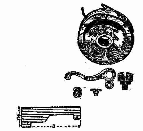
Fig. 101. Sewing machine items
When a machine is reasonably tight in all parts,
gauges and setting marks may be adhered to for
the preliminary adjustments; and then if the machine
works erratically, other adjustments must be
made. Where no marks or gauges are furnished
[305]
for the adjustment of the needle bar, it should be
so set as to allow the shuttle or hook to enter the
bold part of the loop formed from the needle. A
good rule is to set the needle bar so that the needle-eye
is about 1⁄32 inch below the point of the shuttle
M (Fig. 100 C) when the latter is up to the centre
of the needle groove. But this may have to be
varied from 1⁄64-inch to 3⁄32-inch. In boat-shaped
and similar shuttle machines, a good rule is to
set the needle so that the eye N will pass just below
the lower side of the shuttle O as the latter is passing
through the loop as in Fig. 100 D, P, indicating
the level of the bed plate.
[306]
II
MECHANICAL MOVEMENTS
What is meant by this term is that these
devices are intended for the transmission
of motion. Motion in mechanics may be
simple or compound. Simple motions are those
of straight translation, which if of indefinite duration
must be reciprocating, or what is called
oscillating or helical.
Compound motions consist of combinations of
any of the simple motions. Perpetual motion is
an incessant motion conceived to be attainable
by a machine supplying its own motive forces independently
of any action from without, or which
has within itself the means, when once set in motion,
of continuing its motion perpetually, or until
worn out, without any new application of external
force. The machine by means of which it has been
attempted, or supposed possible to produce such
motion, is an invention much sought after, but
physically impossible.

Fig. 102. Coffee mill and details
The illustrations herewith exhibit a number of
[307]
devices of various kinds, well known to the practical
mechanician and professional engineer, and usually
called mechanical movements. It is estimated
there are no less than 1,500 of these movements
doing service at the present day; but many of them
are, of course, quite complex, and difficult to master.
In this book, I show about one hundred of the simplest
sort, or those in common use. Their usefulness
will at once be appreciated if we refer to Fig.
102, which shows a machine for grinding or breaking
up substances within its capacity. It contains
within itself the true principle of the little mill
used to grind coffee. The word "grind" in this
connection is scarcely the right one, as the mill
rather "crushes" or breaks up, than grinds. You
will notice coffee, ready for use, is coarse and unlike
flour in texture, the latter being "ground" fine and
smooth. In grinding, the abrading surfaces are
brought very much closer together than in the
breaking or crushing processes. In a coffee mill,
the berries or grains drop into a vacancy, left between
the revolving cone and the walls of the mill.
The vacancy between the walls and the cone is a
little less at the bottom where the crushed coffee
is discharged, and this enables the small and
large grounds to fall into the drawer. The detailed
[308]
plan in illustration (Fig. 102) shows a mill complete, as
well as the various parts. It will be noticed that
the cone (Fig. 5), is corrugated or grooved as
shown (Fig. 4). Figs. 6 and 7 show sections of
lining at B and C (Fig. 3). A shows the hopper
into which the coffee berries are placed before
grinding. Figure 9 shows the crank detached,
and Figs. 8 and 10 show the remaining parts of
the machine, while Figs. 1 and 2 show the handle
and drawer. The latter is to receive the ground
or crushed coffee after it has gone through the
mill. Further description is unnecessary if we
take for example the movement represented at
Fig. 150, which is a sort of ball-bearing motion,
[309]
only instead of small balls wheels are used. Besides
being made use of in bicycles in small balls, it is
used as depicted for "hanging" grindstones, and
for many other similar purposes.
The device also shown at Fig. 139, is one in common
use. It is a modification of the sprocket wheel
on the bicycle. Many of the devices shown herewith
are rarely noticed because of our familiarity with
them.
The action of pumps, the working of pistons, the
changing of motion, and many other things are
shown and explained in the little illustrations given
in these descriptions, which do not pretend to be
exhaustive, or even full.
Fig. 103. In this the lower pulley is movable.
One end of the rope being fixed, the other has to
move twice as fast as the weight, and a corresponding
gain of power is consequently effected.
Fig. 104 is a simple pulley used for lifting weights.
In this the power must be equal to the weight to
obtain equilibrium.
Fig. 105. Blocks and tackle. The power obtained
by this contrivance is calculated as follows:
Divide the weight by double the number of pulleys
in the lower block; the quotient is the power required
to balance the weight.
[310]
Fig. 106 represents what are known as "White's
pulleys", which can be made with separate loose
pulley; or a series of grooves can be cut in a solid
block, the diameters being made in proportion to
the speed of the rope; that is, 1, 3, and 5 for one
block, and 2, 4, and 6 for the other. Power as 1 to 7.
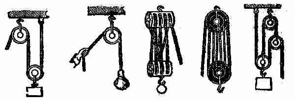
Figs. 103, 104, 105, 106, 107. Various phases of block and tackle
Figs. 107-108 are what are known as Spanish
bartons.
Fig. 108 is a combination of two fixed and one
movable pulley.
Figs. 111-113 are different arrangements of
pulleys. The following rule applies to these: In
a system of pulleys where each is embraced by a
cord attached to one end of a fixed point, and at the
other to the centre of the movable pulley, the effect
of the whole will be the number 2 multiplied by
itself as many times as there are movable pulleys
in the system.

Figs. 108, 109, 110, 111, 112. Other combinations of blocks and pulleys
Fig. 114. Endless chain for maintaining power
on going barrel, to keep a clock going while winding,
[311]
as during that operation the action of the weight
or mainspring is taken off the barrel. The wheel
to the right is the going wheel, and that to the
left the striking wheel. P is a pulley fixed to the
great wheel of the going part, and roughened to
prevent a rope or chain hung over it from slipping.
A similar pulley rides on another arbour, p, which
may be the arbour of the great wheel of the striking
part, attached by a ratchet and click to that wheel,
or to the clock frame if there is no striking part.
The weights are hung as may be seen, the small
one being only large enough to keep the rope or
chain on the pulleys. If the part b of the rope or
chain is pulled down, the ratchet-pulley runs under
the click, and the great weight is pulled up by c,
without taking its pressure off the going wheel at all.
Fig. 115. Triangular eccentric, giving an intermittent
reciprocating rectilinear motion, often used
for the valve motion of steam-engines.
[312]
Fig. 116. Ordinary crank-motion.
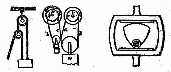
Figs. 113, 114, 115. Blocks and rocker
Fig. 117. In this, rotary motion is imparted to
the wheel by the rotation of the screw, or rectilinear
motion of the slide by the rotation of the wheel.
Used in screw cutting and slide lathes.
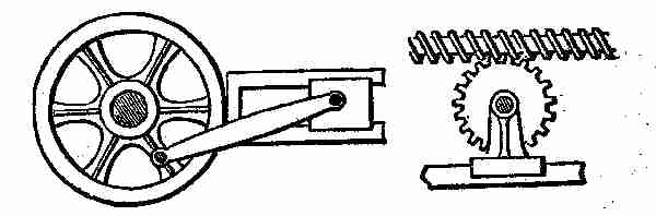
Figs. 116, 117. Crank and rotary motion
Fig. 118. Uniform circular into uniform rectilinear
motion; used in spooling frames for leading or
guiding the thread on to the spools. The roller
is divided into two parts, each having a fine screw-thread
cut upon it, one a right and the other a left-handed
screw. The spindle, parallel with the roller,
has arms which carry two half nuts, fitting to the
[313]
screw, one over the other under the roller. When
one half nut is in, the other is out of gear. By
pressing the lever to the right or left the rod is
made to traverse in either direction.
Fig. 119. A system of crossed levers, termed
"lazy tongs." A short, alternating rectilinear
motion of rod at the right will give a similar, but
much greater motion to the rod at the left. It is
frequently used in children's toys. It has been
applied to machines for raising sunken vessels;
also applied to ship pumps three quarters of a
century ago.
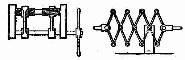
Figs. 118, 119. Rectilinear motion
Fig. 120. Centrifugal governor for steam engines.
The central spindle and attached arms and balls
are driven from the engine by the bevel gears at
the top, and the balls fly out from the centre by
centrifugal force. If the speed of the engine increases,
the balls fly out from the centre, raise the
slide at the bottom, and thereby reduce the opening
[314]
of the regulating valve, which is connected with
the slide. A diminution of speed produces an
opposite effect.
Fig. 121. Water-wheel governor acting on the
same principle as Fig. 120, but by different means.
The governor is driven by the top horizontal shaft
and bevel gears, and the lower gears control the
rise and fall of the shuttle or gate over or through
which the water flows to the wheel. The action
is as follows: The two bevel gears on the lower
part of the centre spindle, which are furnished with
studs, are fitted loosely to the spindle, and remain
at rest so long as the governor has a proper velocity;
but immediately the velocity increases, the balls
flying farther out, draw up the pin, which is attached
to a loose sleeve which slides up and down the
spindle, and this pin, coming in contact with the
stud on the upper bevel gear, causes that gear to
rotate with the spindle, and to give motion to the
lower horizontal shaft in such a direction as to make
it raise the shuttle or gate, and so reduce the quantity
of water passing to the wheel. On the contrary,
if the speed of the governor decreases below that
required, the pin falls and gives motion to the lower
bevel gear, which drives the horizontal shaft in the
opposite direction, and produces a contrary effect.
[315]
Fig. 122. Another arrangement for a water-wheel
governor. In this the governor controls the shuttle
or gate by means of the cranked lever, which acts
on the strap or belt in the following manner: The
belt runs on one of three pulleys, the middle one of
which is loose on the governor spindle, and the upper
and lower ones fast. When the governor is running at
the proper speed the belt is on the loose pulley, as
shown; but when the speed increases, the belt is
thrown on the lower pulley, and thereby caused to
act upon suitable gearing for raising the gate or
shuttle and decreasing the supply of water. A
reduction of the speed of the governor brings the
belt on the upper pulley, which acts upon the gearing
for producing an opposite effect on the shuttle or
gate.
Fig. 123. Another form of steam-engine governor.
Instead of the arms being connected with a
slide working on a spindle, they cross each other,
are elongated upward beyond the top, and connected
with the valve-rod by two short links.
Figs. 124, 125. Diagonal catch and hand-gear used
in large blowing and pumping engines. In Fig.
124 the lower steam valve and upper eduction
valves are open, while the upper steam valve and
lower eduction valve are shut; consequently the
[316]
piston is ascending. In the ascent of the piston
rod the lower handle will be struck by the projecting
tappet, and being raised will become engaged
by the catch, so as to shut the upper eduction
and lower steam valves; at the same time the upper
handle will be disengaged from the catch, the back
weight will pull the handle up and open the upper
steam and lower eduction valves, when the piston
will consequently descend. Fig. 125 represents the
position of the catches and handles when the piston
is at the top of the cylinder. In going down, the
tappet of the piston rod strikes the upper handle,
and throws the catches and handles to the position
shown in Fig. 124.

Figs. 120, 121, 122, 123. Governors for steam-engines
Fig. 126. A mode of driving a pair of feed rolls,
the opposite surface of which require to move in
the same direction. The two wheels are precisely
similar, and both gear into the endless screw,
[317]
which is arranged between them. The teeth of
one wheel only are visible, those of the other being
on the back or side which is concealed from view.

Figs. 124, 125, 126. Valve Regulation and Feed Rolls
Fig. 127. Link-motion valve gear of a locomotive;
two eccentrics are used for one valve, one for the forward
and the other for the backward movement of
the engine. The extremities of the eccentric rods
are jointed to a curved slotted bar, or, as it is termed,
a link, which can be raised or lowered by an arrangement
of levers terminating in a handle, as
shown. In the slot of the link is a slide and pin
connected with an arrangement of levers terminating
in the valve stem. The link, in moving with the
action of the eccentrics, carries with it the slide,
and thence motion is communicated to the valve.
Suppose the link raised so that the slide is in the
middle, then the link will oscillate on the pin of the
slide, and consequently the valve will be at rest.
If the link is moved so that the slide is at one of
[318]
the extremities, the whole throw of the eccentric
connected with that extremity will be given to it,
the valve and steam ports will be opened to the full,
and it will only be toward the end of the stroke
that they will be totally shut; consequently the
steam will have been admitted to the cylinder during
almost the entire length of each stroke. But
if the slide is between the middle and the extremity
of the slot, as shown in the figure, it receives only a
part of the throw of the eccentric and the steam
ports will only be partially opened, and quickly
closed again, so that the admission of steam ceases
some time before the termination of the stroke, and
the steam is worked expansively. The nearer the
slide is to the middle of the slot the greater will be
the expansion, and vice versa.

Figs. 127, 128. Link and other motions
Fig. 128 represents a mode of obtaining motion
from rolling contact. The teeth are for making
the motion continuous, or it would cease at the
[319]
point of contact shown in the figure. The fork
catch is to guide the teeth into proper contact.
Fig. 129. What is called the Geneva-stop, used
in Swiss watches to limit the number of revolutions
in winding-up; the convex curved part of the
wheel serving as the stop.
Fig. 130. A continuous rotary motion of the large
wheel gives an intermittent rotary motion to the
pinion-shaft. The part of the pinion shown next
the wheel is cut of the same curve as the plain
portion of the circumference of the wheel, and
therefore serves as a lock while the wheel makes a
part of a revolution, and until the pin upon the
wheel strikes the guide-piece upon the pinion, when
the pinion-shaft commences another revolution.

Figs. 129, 130. Stop and rotary motions
Fig. 131. The two crank-shafts are parallel in
direction, but not in line with each other. The
revolution of either will communicate motion to the
other with a varying velocity, for the wrist of one
[320]
crank working in the slot of the other is continually
changing its distance from the shaft of the latter.

Figs. 131, 132, 133. Irregular Motions
Figs. 132 and 133. These are parts of the same
movement, which has been used for giving the
roller motion in wool-combing machines. The roller
to which the wheel F, (Fig. 132) is secured, is required
to make 1⁄3 revolution backward, then 2⁄3 revolution
forward, when it must stop until another
length of combed fibre is ready for delivery. This
is accomplished by the grooved heart-cam C, D, B,
e, (Fig. 133) the stud working in the said groove;
from C to D it moves the roller backward, and from
D to e it moves it forward, the motion being transmitted
through the catch G, to the notch wheel F,
on the roller-shaft H. When the stud A arrives at
the point e in the cam, a projection at the back
of the wheel, which carries the cam, strikes the projecting
piece on the catch G, and raises it out of the
notch in the wheel F, so that while the stud is
[321]
travelling in the cam from e to C, the catch is passing
over the plain surface between the two notches
in the wheel F, without imparting any motion; but
when stud A arrives at the part C, the catch has
dropped in another notch and is again ready to
move wheel F and roller as required.
Fig. 134. An arrangement for obtaining variable
circular motion. The sectors are arranged on different
planes, and the relative velocity changes according
to the respective diameters of the sectors.
Fig. 135. Intermittent circular motion of the
ratchet-wheel from vibratory motion of the arm
carrying a pawl.

Figs. 135, 134, 137, 136. Movements of various kinds
Fig. 136. This represents an expanding pulley.
On turning pinion d to the right or left, a
similar motion is imparted to wheel c, by means
of curved slots cut therein, which thrust the studs
fastened to arms of pulley outward or inward,
thus augmenting or diminishing the size of the pulley.
[322]
Fig. 137 represents a chain and chain pulley.
The links being in different planes, spaces are left
between them for the teeth of the pulley to enter.
Fig. 138. Another kind of chain and pulley.
Fig. 139. Another variety.
Fig. 140 shows two different kinds of stops for
a lantern-wheel.

Figs. 140, 138, 139. Chain pulleys and lantern-wheel
Fig. 141. Intermittent circular motion is imparted
to the toothed wheel by vibrating the arm
B. When the arm B is lifted, the pawl C is raised
from between the teeth of the wheel, and travelling
backward over the circumference again drops between
two teeth on lowering the arm, and draws
with it the wheel.
Fig. 142. The oscillating of the tappet-arm produces
an intermittent rotary motion of the ratchet-wheel.
The small spring at the bottom of the tappet-arm
keeps the tappet in the position shown in the
drawing, as the arm rises, yet allows it to pass the
teeth on the return motion.
[323]
Fig. 143. A nearly continuous circular motion is
imparted to the ratchet-wheel on vibrating the
lever a to which the two pawls b and c are attached.

Figs. 141, 142, 143. Intermittent circular motion
Fig. 144. An arrangement of stops for a spur-gear.
Fig. 145. A reciprocating circular motion of the
top arm makes its attached pawl produce an intermittent
circular motion of the crown-ratchet,
or ray-wheel.

Figs. 144, 145. Intermittent circular motion
Fig. 146 represents varieties of stops for ratchet-wheel.
Fig. 147. Intermittent circular motion is imparted
[324]
to the wheel A by the continuous circular
motion of the smaller wheel with one tooth.

Figs. 146, 147. Ratchet motion
Fig. 148. A dynamometer, or instrument used
for ascertaining the amount of useful effect given
out by any motive power. It is used as follows:
A is a smoothly turned pulley, secured on a shaft
as near as possible to the motive power. Two
blocks of wood are fitted to this pulley, or one
block of wood and a series of straps fastened to a
band or chain, as in the drawing, instead of a common
block. The blocks, or block and straps, are so
arranged that they may be made to bite or press
upon the pulley by means of the screws and nuts
on the top of the lever D. To estimate the amount
of power transmitted through the shaft, it is only
necessary to ascertain the amount of friction of
the drum A when it is in motion, and the number of
revolutions made. At the end of the lever D is
hung a scale B, in which weights are placed. The
[325]
two stops C C are to maintain the lever as nearly
as possible in a horizontal position. Now, suppose
the shaft to be in motion, the screws are to be tightened
and weights added in B, until the lever takes the
position shown in the drawing, at the required
number of revolutions. Therefore the useful effect
would be equal to the product of the weights,
multiplied by the velocity at which the point or
suspension of the weights would revolve if the
lever were attached to the shaft.

Figs. 148, 149. Dynamometer—Pantagraph
Fig. 149 represents a pantagraph for copying,
enlarging and reducing plans. One arm is attached
to and turns on the fixed point C. B is an
ivory tracing point, and A the pencil. Arranged
as shown, if we trace the lines of a plan with the
point B, the pencil will produce it double the size.
By shifting the slide attached to the fixed point C
and the slide carrying the pencil along their respective
arms, the proportions to which the plan is
traced will be varied.
[326]
Fig. 150. Anti-friction bearing. Instead of a
shaft revolving in an ordinary bearing, it is sometimes
supported on the circumference of wheels.
The friction is thus reduced to the least amount.
Fig. 151. Releasing hook used in pile-driving
machines. When the weight W is sufficiently raised,
the upper ends of the hooks A, by which it is suspended,
are pressed inward by the side of the slot
B, in the top of the frame; the weight is thus suddenly
released, and falls with accumulating force
on to the pile-head.
Fig. 152. A and B are two rollers which require
to be equally moved to and fro in the slot C. This
is accomplished by moving the piece D, with oblique
slotted arms, up and down.
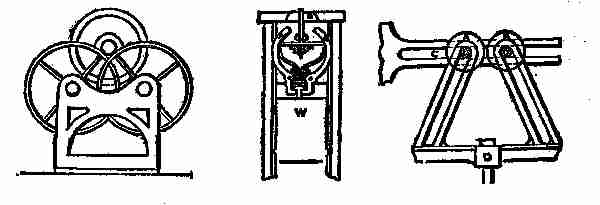
Figs. 150, 151, 152. Anti-friction—Drop hook—Regular motion
Fig. 153. Centrifugal check-hooks, for preventing
accidents in case of the breakage of machinery
which raises and lowers workmen, or ores, in mines.
A is a framework fixed to the side of the shaft of
[327]
the mine, and having fixed studs D, attached.
The drum on which the rope is wound is provided
with a flange B, to which the check-hooks are
attached. If the drum acquires a dangerously
rapid motion, the hooks fly out by centrifugal force,
and one or other, or all of them, catch hold of the
studs D, arrest the drum, and stop the descent of
whatever is attached to the rope. The drum
ought besides this, to have a spring applied to it,
otherwise the jerk arising from the sudden stoppage
of the rope might produce a worse effect than
its rapid motion.
Fig. 154. A sprocket-wheel to drive or to be
driven by a chain.
Fig. 155. A combination movement, in which
the weight W moves with a reciprocating movement,
the down-stroke being shorter than the
up-stroke. B is a revolving disc, carrying a drum
which winds around itself the cord D. An arm C
is jointed to the disc and to the upper arm A, so
that when the disc revolves, the arm A moves up
and down, vibrating on the point G. This arm
carries with it the pulley E. Suppose we detach
the cord from the drum, tie it to the fixed point,
and then move the arm A up and down. The
weight W will move the same distance, and in
[328]
addition the movement given it by the cord, that
is to say, the movement will be doubled. Now,
let us attach the cord to the drum, and revolve the
disc B, and the weight will move vertically with
the reciprocating motion, in which the down-stroke
will be shorter than the up-stroke, because the drum
is continually taking up the cord.

Figs. 153, 154, 155. Hooks—Sprocket—Combination movement
Figs. 156, 157. The first of these figures is an
end view, and the second is a side view of an arrangement
or mechanism for obtaining a series of
changes in velocity and direction. D is a screw on
which is placed eccentrically the cone B, and C is
a friction roller, which is pressed against the cone
by a spring or weight. Continuous rotary motion,
at a uniform velocity of the screw D carrying the
eccentric cone, gives a series of changes of velocity
and direction to the roller C. It will be understood
that during every revolution of the cone the
roller would press against a different part of the cone,
[329]
and that it would describe thereon a spiral motion,
the movement in one direction being shorter than
that in the other.

Figs. 156, 157. Change of speed
Fig. 158. An engine governor. The rise and fall
of the balls K are guided by the parabolic curved
arms B, on which the anti-friction wheels L run.
The rods F, connecting the wheel L with the sleeve,
move it up and down the spindle C D.
Fig. 159. Toe and lifter for working poppet-valves
in steam engines. The curved toe on the
rock-shaft operates on the lifter attached to the
lifting rod to raise the valve.
Fig. 160. Mercurial compensation pendulum. A
glass jar of mercury is used for the bob or weight.
As the pendulum-rod is expanded lengthwise by
increased temperature, the expansion of mercury
in the jar carries it to a greater height therein,
and so raises its centre of gravity relatively to the
[330]
rod sufficiently to compensate for downward expansion
of the rod. As rod is contracted by a
reduction of temperature, contraction of mercury
lowers it relatively to rod. In this way the centre
of oscillation is always kept in the same place, and
the effective length of pendulum always the same.

Figs. 158, 159, 160. Governor, lifter, and pendulum
Fig. 161. Compound bar compensation pendulum.
C is a compound bar of brass and iron,
or steel brazed together with brass downward.
As brass expands more than iron, the bar will bend
upward as it gets warmer, and will carry the weights
W, W, up with it, raising the centre of the aggregate
weight M, to raise the centre of oscillation as
much as elongation of the pendulum-rod would
let it down.
Fig. 162. Watch regulator. The balance-spring
is attached at its outer end to a fixed stud R, and
at its inner end to staff of balance. A neutral
point is formed in the spring at P, by inserting it
[331]
between two curb-pins in the lever, which is fitted
to turn on a fixed ring concentric with staff of
balance, and the spring only vibrates between this
neutral point and staff of balance. By moving
lever to the right, the curb-pins are made faster,
and by moving it to the left, an opposite effect is
produced.

Figs. 161, 162. Compound bar—Hair spring
Fig. 163. Compensation balance. t, a, t´ is the
main bar of balance, with timing screws for regulation
at the ends. t and t´ are two compound
bars, of which the outside is brass and the inside
steel, carrying weights b, b´. As heat increases,
these bars are bent inward, diminishing the inertia
of the balance. As the heat diminishes, an opposite
effect is produced. This balance compensates
both for its own expansion and contraction,
and that of the balance-spring.
Fig. 164. Parallel ruler, consisting of a simple
[332]
straight ruler B, with an attached axle C, and a
pair of wheels A A. The wheels, which protrude
but slightly through the under side of the ruler,
have their edges nicked to take hold of the paper
and keep the ruler always parallel with any lines
drawn upon it.

Figs. 163, 164. Balance—Ruler
Fig. 165. Compound parallel ruler, composed of
two simple rulers A, A, connected by two crossed
arms pivoted together at the middle of their length,
each pivoted at one end to one of the rulers, and
connected with the other one by a slot and sliding
pin, as shown at B. In this the ends as well as
the edges are kept parallel. The principle of
construction of the several rulers represented is
taken advantage of in the formation of some parts
of machinery.
Fig. 166. A simple means of guiding or obtaining
a parallel motion of the piston rod of an engine.
The slide a moves in and is guided by the vertical
[333]
slot in the frame, which has been planed to a true
surface.

Figs. 165, 166. Ruler—Parallel motion
Fig. 167. Parallel motion for direct-action engines.
In this, the end of the bar B C is connected
with the piston-rod, and the end B slides in a fixed
slot D. The radius bar F A is connected at F
with a fixed pivot, and at A midway between the
ends of B C.

Figs. 167, 168, 169. Parallel motion methods
Fig. 168. Oscillating engine. The cylinder has
trunnions at the middle of its length, working in
fixed bearings, and the piston rod is connected
directly with the crank, and no guides are used.
[334]
Fig. 169. Inverted oscillating or pendulum engine.
The cylinder has trunnions at its upper end,
and swings like a pendulum. The crank shaft is
below, and the piston rod connected directly with
crank.
Fig. 170. Section of disc-engine. Disc-piston,
seen edgewise, has a motion substantially like a
coin when it first falls after being spun in the air.
The cylinder heads are cones. The piston rod is
made with a ball to which the disc is attached,
said ball working in concentric seats in cylinder-heads,
and the left-hand end is attached to the
crank arm or fly-wheel on end of shaft at left.
Steam is admitted alternately on either side of
piston.
Fig. 171. The gyroscope, or rotascope, an instrument
illustrating the tendency of rotating bodies
to preserve their plane of rotation. The spindle
of the metallic disc C is fitted to return easily in
bearings in the ring A. If the disc is set in rapid
rotary motion on its axis, and the pintle F at one
side of the ring A is placed on the bearing in the
top of the pillar G, the disc and ring seem indifferent
to gravity, and instead of dropping begin to revolve
about the vertical axis.
Fig. 172. Bohnenberger's machine, illustrating
[335]
the same tendency of rotating bodies. This consists
of 3 rings, A, A´, A2, placed one within the
other, and connected by pivots at right angles to
each other. The smallest ring, A2, contains the
bearings for the axis of a heavy ball B. The ball
being set in rapid rotation, its axis will continue in
the same direction, no matter how the position of
the rings may be altered; and the ring A2, which
supports it, will resist a considerable pressure tending
to displace it.

Figs. 170, 171, 172. Disc-engine and gyroscopes
Fig. 173. What is called the gyroscope governor,
for steam-engines, introduced by Alban Anderson
in 1858. A is a heavy wheel, the axle B B´ of
which is made in two pieces connected together
by a universal joint. The wheel A is on one piece
B, and a pinion I on the other piece B´. The
piece B is connected at its middle by a hinge-joint
with the revolving frame H, so that variations in
the inclination of the wheel A will cause the outer
[336]
end of the piece B to rise and fall. The frame H
is driven by bevel gearing from the engine, and
by that means the pinion 1 is carried round the
stationary toothed circle G, and the wheel A is thus
made to receive a rapid rotary motion on its axis.
When the frame H and wheel A are in motion, the
tendency of the wheel A is to assume a vertical
position, but this tendency is opposed by a spring
L. The greater velocity of the governor, the
stronger the tendency, above mentioned, and the
more it overcomes the force of the spring, and the
reverse. The piece B is connected with the valve
rods by rods C, D, and the spring L is connected
with the said rods by levers N and rod P.

Figs. 173, 174, 175. Governor—Reverse motions
Fig. 174. Pair of edge runners or chasers for
crushing or grinding. The axles are connected
with vertical shaft, and the wheel or chasers run
in an annular pan or trough.
Fig. 175. Rotary motion of shaft from treadle
[337]
by means of an endless band running from a roller
on the treadle to an eccentric on the shaft.
Fig. 176. Tread-wheel horse-power turned by the
weight of an animal attempting to walk up one
side of its interior; has been used for driving the
paddle-wheels of ferry-boats and many other purposes.
The turn-spit dog used also to be employed
in such a wheel in ancient times for turning meat
while roasting on a spit.
Fig. 177. The treadmill, employed in jails in
some countries for exercising criminals condemned
to labour, and employed in grinding grain; turns by
weight of person stepping on tread-boards on
periphery. This is supposed to be a Chinese invention,
and it is still used in China for raising
water for irrigation.

Figs. 176, 177, 178. By different sources of power
Fig. 178. A. B. Wilson's four-motion feed, used
in Wheeler and Wilson's, Sloat's, and other sewing
machines. The bar A is forked, and has a second
bar B, carrying the spur or feeder, pivoted in the
[338]
said fork. The bar B is lifted by a radial projection
on the cam C, at the same time the two bars are
carried forward. A spring produces the return
stroke, and the bar B drops of its own gravity.
Fig. 179. Mechanical means of describing parabolas,
the base, altitude, focus, and directrix
being given. Lay straight edge with near side
coinciding with directrix, and square with stock
against the same, so that the blade is parallel with
the axis, and proceed with pencil in bight of thread,
as in the preceding.
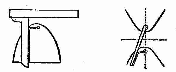
Figs. 179, 180. To describe conic sections
Fig. 180. Mechanical means of describing hyperbolas,
their foci and vertices being given. Suppose
the curves two opposite hyperbolas, the points in
vertical dotted centre line their foci. One end of
thread being looped on pin inserted at the other
focus, and other end held to other end of rule, with
just enough slack between to permit height to
reach vertex when rule coincides with centre line.
A pencil held in bight, and kept close to the rule,
[339]
while latter is moved from centre line, describes
one-half of parabola; the rule is then reversed for
the other half.
Fig. 181. Cyclograph for describing circular arcs
in drawings where the centre is inaccessible. This
is composed of three straight rules. The cord and
versed sine being laid down, draw straight, sloping
line from ends of former to top of latter; and to
these lines lay two of the rules crossing at the
apex. Fasten these rules together, and another
rule across them to serve as a brace, and insert a
pin or point at each end of chord to guide the apparatus,
which, on being moved against these points,
will describe the arc by means of pencil in the
angle of the crossing edges of the sloping rules.
Fig. 182. Proportional compasses used in copying
drawings on a given larger or smaller scale. The
pivot of compasses is secured in a slide which is
adjustable in the longitudinal slots of legs, and
capable of being secured by a set screw; the dimensions
are taken between one pair of points and
transferred with the other pair, and thus enlarged
or diminished in proportion to the relative distances
of the points from the pivot. A scale is
provided on one or both legs to indicate the
proportions.
[340]
Fig. 183. One of the many forms of rotary engine.
A is a cylinder having the shaft B pass
centrally through it. The piston C is simply an
eccentric fast on the shaft, and working in contact
with the cylinder at one point. The induction
and eduction of steam take place as indicated
by arrows, and the pressure of the steam
on one side of the piston produces its rotation and
that of the shaft. The sliding abutment D, between
the induction and eduction ports, moves
out of the way of the piston to let it pass.

Figs. 181, 182, 183. For drawing curves. Rotary engine
Fig. 184. Another form of rotary engine, in which
there are two stationary abutments D, D, within
the cylinder; and the two pistons A, A, in order to
enable them to pass the abutments, are made to
slide radially in grooves in the hub C of the main
shaft B. The steam acts on both pistons at once,
to produce the rotation of the hub and shaft. The
induction and eduction are indicated by arrows.
[341]
Fig. 185. Jonval turbine. The shutes are arranged
on the outside of a drum, radial to a common
centre, and stationary within the trunk or casing
b. The wheel c is made in nearly the same way;
the buckets exceed in number those of the shutes,
and are set at a slight tangent instead of radially,
and the curve generally used is that of the cycloid
or parabola.
Fig. 186. A method of obtaining a reciprocating
motion from a continuous fall of water, by means
of a valve in the bottom of the bucket which opens
by striking the ground, and thereby emptying the
bucket, which is caused to rise again by the action
of a counterweight on the other side of the pulley
over which it is suspended.

Figs. 184, 185, 186. Different forms of water movements
Fig. 187. Overshot water-wheel.
Fig. 188. Undershot water-wheel.
Fig. 189. Breast-wheel. This holds intermediate
[342]
place between overshot and undershot wheels; has
float-boards like the former, but the cavities between
are converted into buckets by moving in a
channel adapted to circumference and width, into
which water enters nearly at the level of axle.
Fig. 190. Horizontal overshot water-wheel.

Figs. 187, 188, 189, 190. Water-wheels
Fig. 191. A plan view of the Fourneyron turbine
water-wheel. In the centre are a number of
fixed curved chutes, or guides, A, which direct the
water against the buckets of the outer wheel B,
which revolves, and the water discharges at the
circumference.
Fig. 192. Warren's central discharge turbine,
plan view. The guides A are outside, and the wheel
B revolves within them, discharging the water at
the centre.
Fig. 193. Volate wheel, having radial vanes A,
against which the water impinges and carries
the wheel around. The scroll or volute casing B
confines the water in such a manner that it acts
against the vanes all around the wheel. By the
[343]
addition of the inclined buckets c, c, at the bottom,
the water is made to act with additional force as it
escapes through the openings of said buckets.

Figs. 191, 192, 193. Central discharge and turbine wheels
Fig. 194. Barker, or reaction mill. Rotary motion
of central hollow shaft is obtained by the
reaction of the water escaping at the ends of its
arms, the rotation being in a direction the reverse
of the escape.
Fig. 195 represents a trough divided transversely
into equal parts, and supported on an axis by a
frame beneath. The fall of water filling one side
of the division, the trough is vibrated on its axis,
and at the same time that it delivers the water
the opposite side is brought under the stream and
filled, which in like manner produces the vibration
of the trough back again. This has been used as
a water-meter.
Fig. 196. Persian wheel, used in Eastern countries
for irrigation. It has a hollow shaft and
[344]
curved floats, at the extremities of which are
suspended buckets or tubs. The wheel is partly
immersed in a stream acting on the convex surface
of its floats; and as it is thus caused to revolve, a
quantity of water will be elevated by each float
at each revolution, and conducted to the hollow
shaft at the same time that one of the buckets
carries it full of water to a higher level, where it is
emptied by coming in contact with a stationary
pin placed in a convenient position for tilting it.

Figs. 194, 195, 196. Water motors
Fig. 197. Machine of ancient origin, still employed
on the river Eisach, in the Tyrol, for raising water.
A current keeping the wheel in motion, the pots
on its periphery are successively immersed, filled,
and emptied into a trough above the stream.
Fig. 198. Application of Archimedes screw for
raising water, the supply stream being the motive
power. The oblique shaft of the wheel has extending
through it a spiral passage, the lower end
[345]
of which is immersed in water, and the stream
acting upon the wheel at its lower end produces
its revolution by which the water is conveyed
upward continuously through the spiral passage
and discharged at the top.
Fig. 199. Common lift pump. In the upper-stroke
of piston or bucket the lower valve opens
and the valve in piston shuts; air is exhausted out of
suction pipe, and water rushes up to fill the vacuum.
In down stroke lower valve is shut and valve in
piston opens, and the water simply passes through
the piston. The water above piston is lifted up,
and runs over out of spout at each up stroke. This
pump cannot raise water over thirty feet high.

Figs. 197, 198, 199. Water-wheels and pumps
Fig. 200. Ordinary force pump, with two valves.
The cylinder is above water, and is fitted with solid
piston; one valve closes outlet pipe, and other
closes suction pipe. When piston is rising suction-valve
is open, and water rushes into cylinder, outlet
[346]
valve being closed. On descent of piston suction
valve closes, and water is forced up through
outlet valve to any distance or elevation.
Fig. 201. Double-acting pump. Cylinder closed
at each end, and piston-rod passes through stuffing-box
on one end, and the cylinder has four openings
covered by valves, two for admitting water and
like number for discharge. A is suction pipe, and
B discharge pipe. When piston moves down, water
rushes in at suction valve 1, on upper end of cylinder,
and that below piston is forced through valve
3 and discharge pipe B; on the piston ascending
again, water is forced through discharge valve 4,
on upper end of cylinder, and water enters lower
suction valve 2.

Figs. 200, 201, 202. Pumps and windmill
Fig. 202. Common windmill, illustrating the production
of circular motion by the direct action of
the wind upon the oblique sails.
Fig. 203. Ordinary steering apparatus. Plan
[347]
view. On the shaft of the hand wheel, there is a
barrel on which is wound a rope, which passes
round the guide-pulleys, and has its opposite ends
attached to the tiller, or lever, on top of the rudder;
by turning the wheel, one end of the rope is wound
on and the other left off, and the tiller is moved in
one or the other direction, according to the direction
in which the wheel is turned.
Fig. 204. Capstan. The cable or rope wound
on the barrel of the capstan is hauled in by turning
the capstan on its axis by means of handspikes or
bars inserted into holes in the head. The capstan
is prevented from turning back by a pawl attached
to its lower part and working in a circular ratchet
on the base.

Fig. 203. Cable Fig. 204. Capstan
Fig. 205. Lewis bolt for lifting stone in building.
It is composed of a central taper-pin or wedge,
with two wedge-like packing pieces arranged one
on each side of it. The three pieces are inserted
[348]
together in a hole drilled into the stone, and when
the central wedge is hoisted upon it, it wedges the
packing pieces out so tightly against the sides of
the hole as to enable the stone to be lifted.

Figs. 205, 206. Lewis bolts, for lifting stones
Fig. 206. Tongs for lifting stones. The pull
on the shackle which connects the two links causes
the latter so to act on the upper arms of the tongs
as to make their points press themselves against
or into the stone. The greater the weight, the
harder the tongs bite.
[349]
III
THE WEATHER AND INDOOR WORK
The measure of rainfall varies considerably
within comparatively small areas, and this
renders it no easy matter to get correct
figures, so that the nearest records are those taken
from a number of gauges within a limited district,
and generalized. The more this is done, the less
will be the inaccuracy in referring to the rainfall
of any particular district or country.

Fig. 207. Rain-gauge
If numerous rain-gauges were established throughout
the country, and all their records sent to one
central station, what valuable information might
be collected for a particular district or country
in the course of years. Means might be found for
using the superabundant water, which falls in one
part over another part, where the rainfall is less.
Information such as this might be of special value
in the West and South. It is collected now to a
certain extent; but not done so generally as it ought
to be.

Fig. 208. A made rain-gauge

Fig. 209. A more complete rain-gauge
As the fall of rain is always measured in inches
[350]
gauges are made to indicate the equivalent of a cubic
inch of rain on the surface of the earth. The simplest
form of rain-gauge is a square or circular box
or jar with a perfectly flat bottom and perpendicular
sides (see Fig. 207). If the depth of water in such
a gauge be measured after a fall of rain, one can
ascertain in inches, or parts of an inch, the amount
of rain that has fallen on the surface of the earth.
Care must be taken to have the edge of the gauge
thin and free from dents, the sides perpendicular
and the bottom of the jar perfectly flat, for though
in one measurement these irregularities may not
make much difference, they
would lead to a very decided
error in a large number of
measurements. Evaporation is
also liable in such a gauge to
give rise to errors, and extraneous
matters are easily introduced.
The better rain-gauges
are constructed to avoid these
contingencies, as far as possible
and to depend only on the area
of entry for the accuracy of the measurements.
This area may be a square, but is usually
circular for convenience. The circle must be
[351]
accurate, and its area is then easily calculated,
so that one can estimate the amount of
rainfall, however large the receiving vessel may
be. The edge of the circle, which may be made
of copper, more durable than iron, must be
sharp, with an overlapping rim to prevent raindrops
from being whirled out of the receiver, and connected
by a shoulder to a funnel, which directs the water
into the receiver. This
may be a glass bottle fitted
with a cork to hold the
funnel firmly, and prevent
leakage between the outside
of the funnel and the neck
of the bottle (see Fig. 208).
A more convenient receiver,
and one less likely to be
broken, is a round tin case
of convenient size, with a
top fitting accurately under
the overlapping edge of the
funnel-shaped cover. In
this large receiver may be
placed a small tin mug,
with a lip just under the funnel, for conveniently
measuring small quantities of rain, and preventing
[352]
waste by evaporation. Any overflow from
the mug will be caught in the large receiver
(see Fig. 209). The circle of entry may, of
course, be of any size; but one whose diameter
is between 4 or 8 inches will be most convenient.
Make the circle determine its area by careful measurement,
using the following formula:
D2 × .7854 = area,
each square inch will give cubic inches
for area. Take this
amount of water and
pour it into a glass,
marked at the top of the
water, and then divide
the intervening space
between this mark and
the bottom into 100
equal parts. This graduated
glass will give
the rainfall in inches and
100ths of an inch. As
an inch glass is somewhat
cumbersome, a
half-inch glass is usually sent out with a rain-gauge.
It may, however, be sometimes convenient
to use an ordinary ounce measure, as
[353]
graduated glass measures, when broken, are not
always easily replaced; so that it may be necessary
to find the corresponding relation between the cubic
inches of receiving area and ounces and drachms.
To do this, we will suppose the diameter of the
circular top of gauge to be 4.7 inch; this squared
= 22.09, multiplied by .7854 = 17.349486, divided
by 1.733 (an ounce avoir. = 1.733 c. in.) = 10.011
oz. avoir.
Now if the rainfall is collected daily at a certain
time in an ounce measure, the amount may easily
be recorded in inches by reference to the accompanying
table:
| | |
inch |
| | inch |
| 10 oz. |
= | 1.0000 |
1 oz. |
= | .1000 |
| 9 " |
= |
.9000 |
7 dr. |
= | .0875 |
| 8 " |
= |
.8000 |
6 " |
= | .0750 |
| 7 " |
= |
.7000 |
5 " |
= | .0625 |
| 6 " |
= |
.6000 |
4 " |
= | .0500 |
| 5 " |
= |
.5000 |
3 " |
= | .0375 |
| 4 " |
= |
.4000 |
2 " |
= | .0250 |
| 3 " |
= |
.3000 |
1 " |
= | .0125 |
| 2 " |
= |
.2000 |
|
| |
A similar calculation can be made and table
prepared for any larger circle of entry by the same
method.
[354]
The amount of rainfall in any country is a matter
of great importance to that country, and, like the
rise of the Nile in Egypt, it indicates the coming
state of the crops. If we have too small a rainfall,
drought and withered crops follow, and if we get
too great a fall of rain, drowned out crops, and disastrous
floods occur, so you see how necessary it
is that those people who are elected to look after the
welfare of a nation, should keep posted on matters
of rainfall in all its phases. In India, China and
some other parts of the world the question of rainfall
is one of life and death to the people, and most
of the great famines of the past have been due
to the small rainfall. Hundreds of thousands of
people used to perish by famine and disease year
after year. Much of this danger from shortage of
rain has happily been avoided in India by the efforts
of the British government, which has inaugurated
and carried out great schemes of irrigation and
artificial waterways to prevent the recurrence of
famine from drought. Our own government also
is expending large sums of money on irrigation plans
now being executed in Arizona, Texas, Colorado
and other states, which will render immense territories
fit for cultivation, which would otherwise
have remained barren and of no use. The matter
[355]
of rainfall is of the highest importance to a nation
and to the men and beasts inhabiting it.
"Will it rain to-day?" is a question frequently
asked, as regards the weather, showing how important
the subject is, and while I am talking on it, it
may not be amiss to make a few remarks regarding
the formation and distribution of rain, as formulated
by learned meteorologists. We are told that the
two great causes of rain are the sun and the ocean—the
latter, of course, includes the great lakes and
rivers—and since these two factors may be taken
as constant, it follows that the rainfall over the
earth as a whole will always be constant, while the
local variations will be due to local conditions. The
rain which falls on this continent is drawn up by
the sun from the various sources, but the conditions
which cause its precipitation may be said to be
local. To your imagination may be left the tracing
of the journey of the rain drops back to the ocean
again. The starting points in considering the causes
of rain are, therefore, heat and moisture. From
the surface of land and water moisture is continually
evaporating into the atmosphere, and the higher
the temperature of the air the more watery particles
it can hold. If any reduction in the temperature
of this saturated air should take place, the
[356]
vapour becomes visible as fog, mist, or cloud, and
it is from this vapour that the rain drops are formed.
Recent research says that these watery particles
require minute dust atoms as nuclei before they
can form, and it has been estimated, by experiment,
that there are one thousand millions of them in a
cubic foot of saturated air, though their total weight
amounts to only 3 grains. Accepting these figures,
the mathematically inclined may be told that it
would require a cloud three miles thick to produce
one inch of rainfall. But before these watery particles
can fall to the earth as rain, they must first
form into rain drops, and the question arises, how
are rain drops formed?
These watery particles pass into the air by evaporation,
and there are several ways by which the
reduction in temperature necessary to render them
visible can be brought about. It may take place
through contact with a colder body of air, by expansion,
or by a reduction of pressure owing to a
rise in altitude. Clouds are said to be formed by
this last method, for a volume of hot air rises
higher and higher until it presently reaches a
point when its contained vapour condenses, and becomes
visible as a cloud. Meteorologists repeat
one of these processes in the laboratory, by releasing
[357]
from pressure damp air placed in a convenient glass
globe, and are able to see something of the methods
of cloud formation. It has been customary to speak
of a cloud as being composed of watery particles
floating motionless in the upper air; but although
it may appear unchanged in form, it is all movement.
So soon as ever a cloud is formed, its particles of
moisture commence to fall slowly, the rate of fall
being in proportion to the diameter of the particles,
and this is due to the slight resistance the air makes
to such very small atoms. In passing, it may be said
that one observer estimates the diameter of these
particles as from .00033 inch to .00025 inch. The
component parts of a cloud are always in motion
and recognizing this fact it becomes possible to
take the first step in considering the formation of
a raindrop.
An easy way out of the difficulty of explaining the
formation of a raindrop, is to say that, since clouds
are so often of two opposite electric potentials, there
is always a continuous bombardment of watery
particles taking place, and some of these must unite
and fall as rain. The meteorologist is always
tempted to call in electricity as an agency whenever
he is anxious to discover a cause for some particular
phenomenon. This often explains one mystery
[358]
by another. The production of rain, snow, and hail
has for many years been explained by vaguely
ascribing them to the action of electricity, without
any information being forthcoming as to the precise
way in which this action takes place. Meteorologists
are at present attempting to find a more
satisfactory explanation. Another theory is that
the particles of moisture in a cloud, like all other
objects, radiate heat, and, growing cold, condense
moisture upon their surfaces, thereby increasing
in weight until they assume the proportions of a
drop. This seemed a reasonable explanation of the
formation of a rain drop until modern research decided
that whenever moisture is condensed, latent
heat is set free, so that all moisture deposited on a
watery particle only serves to raise its temperature,
and cause evaporation of the moisture thus acquired.
The particles of water could not by this means grow
to the full estate of a rain drop, and the theory is
being gradually abandoned.
A rain drop is, according to modern meteorologists,
explained in a very simple way. It has been
seen how the hot, damp air is formed into a cloud,
and also how the minute particles of water at once
commence to fall slightly earthwards. Now these
little particles as they pass into a warm layer of air
[359]
would soon be evaporated, and would never reach
the earth at all. Their downward journey, however,
is often through a cloud many miles thick, and the
most modern and simple theory is that in this journey
they overtake some of their fellows, and the
joined particles increase their rate of travel, overtake
more and more particles until they presently become
heavy enough to take the final plunge to earth.
Were it possible to be just beneath a cloud, an observer
would see rain drops coming from it of all
sizes. The same process goes on in drops, which
trickle down a window pane, or in the effervescing
globules in a bottle of seltzer water. In the latter
instance, the process is reversed, for the globules
are seen overtaking one another in an upward
direction. There are many points in favour of this
theory of the formation of rain drops, and at least
it gets rid of those elaborate complications, electricity
and condensation. With respect to the
formation of rain by the impinging of clouds upon
the tops of cold mountains in the northwest, one
authority argues that moisture is in these circumstances
not condensed solely because of the contact
with the cold hills; that rain there is due to a
mechanical cause, the watery particles being
squeezed together by the grinding effect of the
[360]
clouds on the sides of the mountains in such a way
that they coalesce, and fall as drops.
A rain drop's roundness is due to the action of
capillarity. Just as a circle made by dropping a
stone into water owes its shape to the fact that the
force is able to act equally in all directions, so a
rain drop is spherical, owing to similar untrammelled
action on the part of capillarity. These are
some of the explanations of the formation of a rain
drop, but meteorologists still have the subject under
consideration.
The periods of rainfall are divided broadly into
times of drought and times of flood, and it is in
these matters that meteorology is seen in its practical
aspect. Some people ask, "Where does all the
rain come from?" Others are surprised that rainfall
totals up to such large quantities.
A fall of rain to a depth of one inch over a very
limited area, represents millions of gallons, but in
spite of this vast quantity of falling water, many
times multiplied if the annual rainfall be taken
into account, there still are water famines. The
question has often been debated whether man can
modify climate or effectively tamper with the processes
which produce rain. Rain making has not, so
far, been a success, though the firing off of heavy
[361]
guns has been tried, along with the legitimate avocations
of the meteorologist. The afforesting or
deforesting of a district has, however, a marked
effect upon rainfall. Three notable instances are
Ascension Island, Malta, and the neighbourhood of
the Suez Canal, where the planting of trees seems
to have had the result of increasing the rainfall.
The effect of trees is felt more in the storage of
rain water, while leaves and roots serve to retain
moisture that would otherwise quickly drain away.
A hill may be converted into a sponge by the
judicious planting of trees. The question of the
storage of rain water becomes more pressing each
year, and the longer the settlement is put off, the
more difficult will decision become. Engineers called
upon to prevent floods and to conserve rain water
reply, "Save our forests, cover the land with
trees."
The fact that such problems arise, serve to show
how great is the amount of water formed by the
continual falling of the tiny raindrops. As long
as this beneficent downpouring is allowed to drain
away unused or uncontrolled, so long will droughts
annoy and water famines bring distress.
In recording weather conditions, symbols are
sometimes used in order to shorten reports and,
[362]
while not universal, most nations adopt these:
The symbol for rain is ●, a small circle filled in; for
lightning ![[o]](images/lightning.png) ;
for thunder T, while the two latter
combined make T,
the symbol for a thunder-storm.
Nearly every weather component has a distinctive
symbol, and since a great part of the meteorologist's
work consists in going over records of observations
to search for the number of times the different
phenomena occur during each week or month, the
task is much simplified when observers employ the
symbols, as it is easier to pick out a symbol from a
printed or written page than it is to recognize a
word. These symbols, moreover, have been agreed
upon as a sort of international notation, and make it
easier for the meteorologists of different countries
to understand the records of foreign meteorological
services.
;
for thunder T, while the two latter
combined make T,
the symbol for a thunder-storm.
Nearly every weather component has a distinctive
symbol, and since a great part of the meteorologist's
work consists in going over records of observations
to search for the number of times the different
phenomena occur during each week or month, the
task is much simplified when observers employ the
symbols, as it is easier to pick out a symbol from a
printed or written page than it is to recognize a
word. These symbols, moreover, have been agreed
upon as a sort of international notation, and make it
easier for the meteorologists of different countries
to understand the records of foreign meteorological
services.
Everybody does not know the Russian word for
snow, or the Dutch for hail, or the Bosnian for rain,
but all who run, may read when "snow" is universally
written, and hail represented by a wedge-shaped
figure with lines drawn across. Time and
space being limited, nearly all published records of
weather merely set forth the number of days throughout
the year on which the different phenomena
occurred, and should snow, hail or thunder happen
[363]
two or three times in one day, it would still be
counted only as one day. The yearly totals, therefore,
show the number of days on which these conditions
have been observed. It is now an almost
universal custom to count .01 inches or more during
the twenty-four hours as a day of rain. Accordingly,
where observers read their rain-gauge to three
places of decimals, that on which less than .005 inch
fell would not be counted as a rainy day. Smaller
amounts would, however, be included in the total.
Dew may sometimes fall to the amount of .01 in. or
more; and that is counted as a rainy day, the rule
being to consider the amount of precipitation,
irrespective of the manner in which it has fallen.
If you wish to make these observations comparable
with published records you would do well to conform
to these rules.
HAIL
Hail, the next weather component to be considered,
presents many difficulties when the attempt
is made to explain its origin and formation. Those
who have anything to do with scientific matters
are well acquainted with the hypothesis, which explains
a given fact, and in considering the subject
of hail, the meteorologist hears of many hypotheses
[364]
which are put forward as complete explanations
of this phenomenon. Caution is, therefore, to be
exercised and every reported statement severely
questioned. Remembering the aphorism: "The
man or boy who never makes a mistake will never
make anything," meteorologists have attacked the
question of hail formation, and, although many mistakes
have probably been made, the subject has
lost a good deal of its mystery. For many years, it
was customary to be content with a recognition of
the fact that hail and lightning very often occur
together, and the conclusion was drawn that the
one was in some way responsible for the other. Sufficient
corroboration of this hypothesis was to some
meteorologists, found in the fact that thunder and
lightning are said to be almost unknown in the
Arctic regions, and this supposed companion, hail,
almost unknown. Roughly speaking, the assumption
was that lightning, as it flashed through a cloud
laden with watery particles, caused hail to form.
Such an explanation only tended to make the subject
more mysterious, and the question, How is hail
formed? practically remained unanswered. Many
simpler explanations of hail have been propounded
as the result of modern research, and, like rain and
lightning, it has been demonstrated that hail owes
[365]
its origin to the movement of the minute watery
particles found everywhere in the atmosphere.
The clouds from which hail fall are ordinarily
of great height above the earth, 40,000 feet or even
higher. These are the well-known cirrus. The first
condition necessary to the formation of hail is a
powerful ascending current of hot, moist air, which
may condense its moisture in the shape of the large
woolly cloud, known as cumulus. Such a cloud
may be 100 cubic miles in volume, and as long as
it retains its shape nothing is likely to fall from it
to the earth beneath. Before the formation of a
thunder-shower, cirriform fibres in some instances
break away from the upper portion of this cloud, the
electrical tension is lowered, and rain falls. The
coalescing of the particles of moisture has a great
deal to do with the changes which take place in a
cloud. All these changes take place in the higher
clouds in a marked degree, and the varying strata
through which the watery particles pass in ascending
to and descending from this great height bring
about the violent change essential to the formation
of hail. The necessary conditions for hail are, therefore,
a powerful, hot, ascending current of air and
great variation in the strata of the atmosphere as
regards moisture and temperature. Mountains assist
[366]
in forcing currents of air upwards, and one mass
of air impinging on another is also thrown upwards,
so that condensation of moisture rapidly takes place.
A hail cloud may be described as a tower of hot air,
from the top of which, vapor is ejected into a frosty
region. Hot plains are accordingly the most favourable
spots for the formation of hail, and in mountainous
districts, more hail falls at a distance from
the mountains than among them. Snow is observed
in all latitudes and at all heights, but hail is confined
to middle latitudes, and is rare in high latitudes.
The places most affected by hail are those in which,
the temperature and humidity of the air are high,
while above, at a great height, there is a cold area
below the temperature of freezing point; but, as
in the case of the rain drop, before anything can be
definitely stated, it must be shown how the particles
of moisture coalesce to form hail.
SNOW
Snow is frozen water which falls instead of rain
when the temperature is below the freezing point.
The ultimate constituents of snow are tiny, six-pointed
crystals of ice. They assume in combination
a thousand different figures (Fig. 210), all exceedingly
beautiful. Professor Tyndall has shown,
[367]
further, that the ultimate particles of ice are also
these six-pointed stars. The white colour of snow is
caused by the commingling
of rays of all the
prismatic colours from the
minute snow crystals.
Separately the crystals
exhibit different colours.

Fig. 210. Snow crystals
Snow is usually from
ten to twelve times as
light as water, bulk for
bulk; so that where the
snow falls pretty evenly,
the corresponding rainfall
is readily determined
by merely measuring the
depth of snow and taking one tenth of the result.
The more accurate plan, however, is to thrust
the open end of a cylindrical vessel into the snow,
invert the cylinder, and then melt the snow in it.
Snow plays an important part in the economy of
nature. In the first place, the mere transformation
of the water particles into ice is a process during
which a large amount of heat is given out; so that
we may regard the formation of snow renders the
air currents warmer than they would otherwise be.
[368]
Fallen snow serves to protect the ground, for, owing
to its loose texture, it is a bad conductor of heat; so
that, while checking the radiation of heat from the
earth into space, it does not draw off the earth's
heat by conduction. The ground is thus often 23
degrees to 30 degrees warmer than the surface of
the snow above, and sometimes the difference of
temperature has been more than 40 degrees.
Red snow and green snow have been met with,
more commonly in Arctic regions, but also in other
parts of the world. These colours are caused by the
presence of minute organisms—a species of alga
called Protococcus nivalis.
The snow line of mountains is on the slopes below
which, all the snow which falls in the year, melts
during the summer. Above the snow line, therefore,
lies the region of perpetual snow. The altitude of
the snow line depends on a variety of conditions.
The latitude of a snow range is, of course, important
in determining the position of the snow line, but
many other circumstances have to be considered, as
the shape and slope of the mountain, the aspect of
either side of the range, the character of the surrounding
country, the prevalent winds, and so
on.
The following table shows the observed height of
[369]
the snow line in feet above the sea level in different
places:
| Place |
Latitude |
Height |
| Spitzbergen |
78 | N |
0. |
| Sulitelma, Sweden |
67 | 5´ |
3.835 |
| Kamtchatka |
59 | 30 |
5.240 |
| Unalaschta |
56 | 30 |
3.510 |
| Altai |
50 | |
7.934 |
| Alps |
46 | |
8.885 |
| Caucasus |
43 | |
11.063 |
| Pyrenees |
42 | 45 |
8.950 |
| Rocky Mountains |
43 | |
12.467 |
| North Himalaya |
29 | |
19.560 |
| South Himalaya |
28 | N |
15.500 |
| Abyssinian Mts. |
13 | |
14.065 |
| Purace |
2 | 2´ |
15.381 |
| Nevades of Quito |
0 | |
15.820 |
| Arequipa, Bolivia |
16 | S |
17.717 |
| Paachata, Bolivia |
18 | |
12.079 |
| Portillo, Chili |
33 | |
14.713 |
| Cordilleras, Chili |
42 | 30 |
6.010 |
| Magellan Strait |
53 | 30 |
3.707 |
DESIGNING, MAKING, AND INFLATING PAPER
BALLOONS
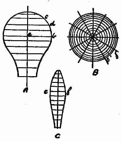
Fig. 211. Paper balloon
Draw a rough figure of the balloon, as shown at
A, (Fig. 211.)
Divide this into any number of parts (the more the
better) by horizontal lines. Take a radius of
balloon on each line, and describe circles, B.
Divide this into twelve parts by radius lines, then
make pattern as follows: Draw a perpendicular, C,
with horizontal lines at distance of horizontal lines
on A, but measured on circumference as c d. Then
set off on each line from perpendicular one half the
distance between the radius lines, B, on the corresponding
circle as e f; draw line through points
thus found, and result will be shape of each section.
Allow a little on one side when cutting out for pasting.
[370]
This will be best made with strong tissue
paper of any colour desired.

Fig. 212. An improved balloon
Another method, giving a shape somewhat different,
is shown in
Fig. 212. First
draw an elevation
of the balloon it is
intended to make,
either full size, on
the floor, or to scale.
The shape here illustrated
differs
slightly from that
of balloons usually
sold ready made,
being wider at the
mouth. This shape,
however, is not so liable to catch fire when swayed
about by the wind. Divide the elevation into any
number of parts (the more the better) by horizontal
lines as shown (No. 1). Take the radius of the
balloon on each line, as A B, describe circles (No. 2),
and divide these into twelve parts by radial lines.
Then to make a pattern, draw a perpendicular (No.
3), with horizontal lines at the distance of the horizontal
lines (No. 1,) but measured on the circumference
[371]
as C D. Then set off on each line from the
perpendicular half the distance between the radius
lines (No. 2), on the corresponding circle as E F, and
draw a line through the points thus found, and the
result will be the shape of each section. Allow a
[372]
little (say 1⁄4 inch), on one side when cutting out for
pasting. Each section will be made up of one, two,
or three pieces, according to the size of the balloon
to be made. If the pieces are cut as shown (No.
4,) a great saving of paper results. To paste these
pieces together, place them in a pile on the table or
bench with the edges flush and a piece of waste paper
under the pile. Now rub the top sheet with the
thumb nail until each piece is moved back from the
one immediately under it about one-fourth inch.
Place a piece of waste paper about the same distance
from the edge of the top sheet, and pass the
paste brush over the whole of the exposed edges.
No. 5 will explain what is meant. Now place two of
the completed sections together so as to look like No.
3, with a small part projecting as shown by the dotted
line G. Paste the edge of the under section—that
is, the part hatched—and turn it over on to the
dotted line H. When each two of the sections have
been joined in this way, proceed in the same manner
to join these together till the whole is completed.
A circular piece of paper is cut out to join the sections
at the top, and a loop of string should be pasted
to the top to suspend the balloon while inflating.
A ring of wire with two cross pieces is fitted to the
bottom of the balloon, and the inflammable material,—tow
[373]
soaked in methylated spirits—is fastened
to the junction of the cross pieces.
MAGNETIZED WATCHES
The owner of a good American watch was a little
troubled concerning it, because it had been running
irregularly for some time past. It came out that
he had visited the electric power house and had
stayed for some time examining the works and
machinery, so that parts of his watch had evidently
become magnetized by the influence of the dynamos.
The watch had been made some time ago, and had
not the power to resist, or neutralize electric influences,
that most watches have now.
To demagnetize the watch would bring it back to
its original condition, but a second visit to the
lighting plant would again spoil its time-keeping
qualities. The watchmakers now have a way of
making watches so that they are not affected by
magnetism, but comparatively few of the time pieces
in use are non-magnetic, and the average watch is
subject to these seasons of fickleness.
The exceedingly fine and exact construction of
the watch is not realized by the average possessor
of the article. An examination of the works of a
watch shows the mechanism as now constructed,
[374]
although very small in size, to be accurately planned
and executed. Changes of temperature are provided
for, so that the movement is automatically
adjusted. The mainspring and train of gears are
usually concealed, while the balance and hair springs
are in full view when the case is open. Upon the
regularity of the movement of the balance depends
the time keeping quality of the watch. On looking
closely at the balance, you will observe that it is
not a complete ring, but two halves supported at
one end. These rings bear a number of large-headed
screws, placed at irregular distances, which
give it the exact weight and balance required. These
half rings will also be found, on looking closely, to
be composed of two metals so closely joined that a
difference in colour alone gives evidence of the quality.
This arrangement of iron and brass, on account of
their different coefficients of expansion and contraction
with changes of temperature, has been so
carefully constructed that, with changes of temperature,
the balance assumes such forms as to give it
a uniform rate of motion.
The parts affected by magnetism are the balance
and springs. The balance in an ordinary watch
moves five times a second, 18,000 times an hour, and
432,000 times each day; but a slight change in the
[375]
forces that move it is necessary to make a difference
of several minutes each day. As the balance moves
back and forth, the magnetism of the mainspring is
pulling or pushing it. If this force were constant,
and always in the same direction, the watch would
run uniformly. Such, however, is not the case.
When the mainspring is tightly wound, its magnetic
poles are in a certain direction, and in unwinding
they are constantly changing, so that the direction
of this force is also constantly changed. The effect
on the balance is to cause the watch to run too fast
sometimes, and too slow at other times.
Non-magnetic watches are made with these parts
of a non-magnetic metal, so that they are not influenced
by electric machinery. For testing watches
a small compass is used. When placed over the
balance, the needle will vibrate with the motion of
the balance in proportion to its magnetism.
A BOY'S WHEEL-BARROW

Fig. 213. A boy's wheel-barrow. Perspective view
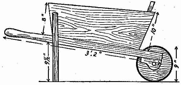
213 A. Boy's wheel-barrow. Side elevation

213 B. Finished plan

213 C. Plan of frame
The bottom, sides, and ends were about three-quarters
of an inch thick. Good white and red pine
were used for the purpose. The stiles and rails of the
bottom framework were mortised and tenoned together
as shown at Fig. 213; these may be just stubbed
together, or the tenons of the rails can go right
[376]
through the stiles. The most satisfactory job is to
groove the sides and ends together, and put all together
with oil paint in the joints. If the joints are
painted before the framework of the barrow is put
together, it will last for years; otherwise, being a
[377]
boy's wheel-barrow, it would likely often be forgotten
and left out in the rain, and the joints getting wet
would hasten decay. Two coats of good oil paint,
Indian red, will give it a very nice appearance.
This barrow, while not intended for heavy work, is
capable of carrying quite a load. The wheel was cut
out of a piece of plank about 11⁄2 inches thick, hooped
[378]
up with an iron tire made from heavy hoop iron. The
axle was made of wood with a 3⁄4-inch round iron rod
running lengthwise through it and projecting about
three inches through on each end. The arbours or
boxing, in which ran the ends of the round rod, were
formed on the ends of the handle stiles, as may be
seen in the illustration. The cost of all the
materials for this really useful article was less than
$1.50, all told.
VACUUM CLEANERS

Fig. 214. Home-made vacuum cleaner
A single hand vacuum cleaner can be made from a
powerful suction pump, as indicated in the sketch
Fig. 214. This should be connected with a metallic
box by means of a flexible armoured rubber hose,
covered at the end with a piece of fine wire gauze
to prevent large particles of dust, etc., being drawn
into the pump. To another opening of the box
should be fastened another flexible rubber tube, with
a bell-shaped metal attachment at the end. The
bell-shaped arrangement should be held closely to
the carpet while the pump is in action. Within the
box, the pipe to which the pump is attached should
be bent upward, so that the rush of air shall not
bring the dust with it; the object being to collect the
dust in the box. A lid covers the box so that it can
[379]
be emptied from time to time. The success of this
arrangement depends on the strength of the pump;
if it be a weak one,
the inrush of air
through the funnel
will be so slight that
the dust will not be
raised.
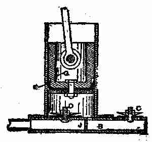
Fig. 215. Metallic vacuum cleaner

Fig. 216. Simple vacuum cleaner
Rotary pumps are
not satisfactory for
vacuum cleaners.
The best type for this work is a plunger, having a
large displacement, with a comparatively short
stroke in proportion to the diameter. A suitable
pump is shown in
the accompanying illustrations.
Fig. 214, shows
the section of a single
barrel, but should a greater
supply be required, two
barrels may be worked
and connected as shown
in Fig. 216. The pump
is easily made, and of
light construction. In Fig. 215, is a brass cylinder
with a flange at the bottom; this may be made out
[380]
of a length of 3-inch brass tube with a flange cut
from 1⁄8-inch sheet brass. The barrel is 8 inches long.
G is the plunger, which may be constructed as a
piston; but in the drawing, it is adapted to the
arrangement that is shown in Fig. 216. With a
piston will be required a guide for the rod at the top
of the cylinder. E is a hydraulic cup, its leather kept
soft and pliable by oiling. B is the base, which is
hollow, and may be built up in sheet metal. At the
centre at J, the base
is divided into two compartments,
one side
being the inlet to the
pump from the dust
box, and the other
in communication
with the outlet valve
C. C and D are two valves with guards. The
valves are discs of very soft and pliable leather,
well saturated with grease, D being the inlet from
the dust box, and C the outlet to the atmosphere.
The drawing clearly shows the construction of the
other parts. Fig. 216 shows two pumps fitted to
one base and worked by a rocking lever; both pumps
are in communication with the one inlet N. This
arrangement of pumps is easy to work, portable,
[381]
and well adapted to domestic purposes in cleaning
carpets.

Fig. 217. A motor vacuum cleaner
Fig. 217, which is reproduced from The Scientific
American, exhibits an ingenious form of vacuum
cleaner. It has recently been patented, and consists
of a suction-fan operated by a water-motor
that may be attached to the ordinary kitchen faucet.
A tube is connected with the chamber of the suction-fan,
and this terminates in a suitable nozzle, or
foot plate, which
may be moved over
a carpet or rug to
draw out the dust
and dirt. One of
the advantages of
this system is that
dirt drawn up by
the suction fan can
be carried away with the water down the kitchen
drain.
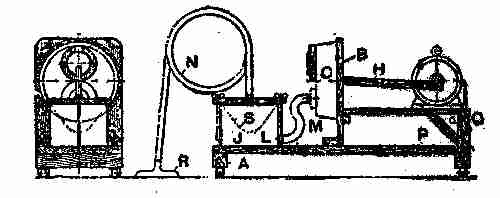
Fig. 218. Home-made power-driven vacuum cleaner
A good power-driven cleaner may be made at
home, says Popular Mechanics, by following these
directions: First take a good pine board, 1 inch
thick, 1 foot wide, and 3 feet long, and nail to each
end a 1-foot length of 2-inch by 2-inch pine, as
shown at A, Fig. 218. Next a 3⁄4-inch board, 1 foot
[382]
wide and about 1 foot, 3 inches long, should be
fastened near the centre, and at right angles to the
first board, as shown at B. Procure a tin pan measuring
about 10 inches in diameter and 3 inches deep.
This pan shown at C, must be fitted with two valves,
which are the most important and difficult part of
the work. Cut, from a smooth piece of pine, 1 inch
thick, two discs, 5 inches in diameter, with a 3-inch
hole in the centre of each. Obtain a sheet of packing
rubber, 1⁄8 of an inch thick, and cut from it two
discs, each 5 inches in diameter, and two 31⁄2 inches
in diameter. One of the discs of wood should be
fastened to the back of the pan at the top, as shown
at D, Fig. 219, with one of the 5-inch diameter rubber
discs placed between the tin and the wood, and both
secured to the tin by a row of small bolts around the
outside edge of the wood. A hole, 3 inches in diameter,
can now be cut through the tin and rubber,
using the hole in the wood as a guide. Two discs
with a diameter of 31⁄4 inches should be cut from cigar
[383]
box wood and fastened centrally on the 31⁄2-inch
rubber disc. One of
the latter pieces
should be fastened
by its top edge to
the top edge of the
5-inch disc of wood,
as shown in E. This
forms a flap valve, and great care should be
taken to see that the rubber disc covers the
opening all the way around when the valve is closed,
so that it will be air-tight. A spring will
be necessary to quicken the action of this valve.
This is best made by fastening a narrow strip of
wood across the valve opening on the inside of
the pan, as shown at F, and attaching a rubber
band to the centre of the valve and to this stick.
This completes the outlet or exhaust valve. Another
valve must now be made in the same
manner, and fastened to the bottom of the pan
on the inside, as shown. This is the inlet valve,
and works in the opposite direction to the outlet
valve just described.

Fig. 219. Home-made, power-driven
vacuum cleaner
Next procure a piece of leatherette about twelve
inches in diameter, or large enough to cover the
opening of the pan. This is to be used for the diaphragm.
[384]
Cut a round hole about 8 inches in
diameter in the upright piece B (Fig. 218), its centre
about 7 inches from the top. From a piece of
1⁄2-inch pine, cut two discs 6 inches in diameter.
Also secure a piece of hardwood H 1 inch by 1 foot
2 inches. The discs G should now be placed, one on
each side of the leather diaphragm, exactly in the
centre, and fastened to one end of the 1-foot 2-inch
piece by means of a long screw. This piece H
should exactly be in the centre of the diaphragm.
The pan can now be put in place. Set the diaphragm
over the hole in the board B, the stick projecting
through the hole. The pan is now placed
over the diaphragm, and held by means of small
bolts around the edge. The diaphragm between the
wood and the tin acts as a gasket, and makes an
air-tight joint.
Secure an air-tight tin about 8 inches in diameter
and 12 inches high, and fasten it to the
base board, as shown at J, Fig. 218. The cover of a
coffee tin should now be soldered over the inlet
valve, as shown at K, Fig. 219. Solder a hose connection
in the centre of this cover, also one in the side of
the tin, as shown at L, Fig. 218. Couple a short
piece of hose M to these connections. The strainer
S should be made of very strong and closely woven
[385]
unbleached drill. Make it in the form of bag with a
1-inch hem at the top, and place it in the tin, as
shown by the dotted line, the hem fitting closely
over the inside edge of the tin. The cover of the
tin is made from a flat pine board about one inch
thick, and is held in place by two 1⁄4-inch rods
fastened in the base board. These rods have thumb
nuts on the top, which allow the cover to be readily
removed or tightened down. It is best to place a
rubber or leather gasket between the cover and the
edge of the tin so as to make an air-tight joint.
An air-tight piece of garden hose can be used for
the suction hose N, one end being fastened in the
centre of the cover and the other to the brush or
nozzle R, Fig. 218. It is best to buy this nozzle, as
it would be rather expensive and unsatisfactory if
home-made.
This machine may be driven by an electric motor of
about 11⁄4 horse-power, which should be placed in the
position shown in Fig. 218. The end of the connecting
rod H is fastened to a crank on the motor shaft,
and allowed to have about a one and one half inch
stroke. The motor is wired up with a switch, P, and
it would be best to connect to a rheostat, to allow the
regulation of speed best suited to the machine. This
can readily be determined after the machine is
[386]
started. If an electric motor is not available, a
small water motor will do equally well; or it may even
be run by hand, by means of a long lever, fulcrumed
at P.
The machine is now ready for using. First,
however, test it all over for leakage, as its success
depends on its being perfectly air-tight. As the motor
revolves, the rod H is drawn forward, bringing with
it the diaphragm. This creates a partial vacuum
in the pan C, which opens the inlet valve, sucking
the air through the suction hose and strainer, the
air carrying with it the dust and dirt. The refuse
is left in the strainer bag while the air goes on through
the connecting hose and pan and outlet valve into
the atmosphere. After the article being cleaned
has been gone over thoroughly, care being taken to
hold the nozzle against the material, the cover may
be removed and the bag emptied.
[387]
IV
MOTORS AND TYPE-WRITERS
MOTORS, GASOLENE AND STEAM—AUTOMOBILE FRAMES—THE
MODERN TYPE-WRITER—DIRECTIONS
FOR SECURING COPYRIGHTS.
There are two classes of heat engines
in use; in one class the combustion
takes place on the inside of the cylinder
or generator, just as fire is applied to a tea-kettle,
and the heat is transmitted by conduction
through the metal walls to the part of machine
doing the work. Motors and machines of
this kind, are generally called "external combustion"
engines, of which the steam engine is a
prominent example.
Engines where the combustion takes place inside
the machine itself, and acts directly on it, are engines
of the second class, termed "internal combustion
engines." The gasolene engine is of this
type, and so are all gas and oil engines.
The principle of the motor-cycle engine, in its
action, is similar to the regular automobile engine
[388]
and the gas engine. All these are internal combustion
or explosion engines; that is, their motive power
is derived from the force exerted by the explosion
of a gas while under compression, the compressed
gas generally ignited by means of an electric spark.
In the case of gasolene motors, the gas is obtained
from the liquid gasolene, either by allowing air to
be drawn through it or by spraying the spirit through
a small hole, the latter being the method most
generally used. A great quantity of air has to be
mixed with the vapour before it will ignite. The
amount that is required varies considerably, atmospheric
conditions and the height above sea
level causing variations in the demand. The action
of the common gasolene engine is known as the
"four-stroke-cycle," that is, there are four strokes
of the piston for every impulse, one being a "power"
stroke and the other three "duty" strokes, as it
were. Each performs a certain operation that is
necessary for the correct working of the engine.
Some engines are worked on the "two-stroke-cycle"
principle; in this case, there are only two strokes
for each impulse. This type of engine has many
disadvantages, and there are very few two-stroke
engines in use for driving motor cycles.

Fig. 220. Suction stroke begun Fig. 221. Compression stroke begun

Fig. 222. Power stroke begun Fig. 223. Exhaust stroke begun
The principle of the "four-stroke-cycle" is shown
[389]
in Figs. 220 to 223. In Fig. 220 the piston A is just
beginning the downward stroke, and the valve B is
opened by the pressure of the atmosphere, or by
mechanical means. The piston in descending causes
a partial vacuum in the cylinder head or top C,
which allows the atmospheric pressure on the surface
of the gasolene in the carburetor to force some
of the liquid through the spray hole, thence through
the inlet-valve opening D, into the compression
space of the engine cylinder. The suction of the
piston does not bring in the explosive mixture of gas
and air; it is the pressure of the atmosphere that
causes the mixture of gas and air to rush into the
cylinder. Just before the piston is at the extreme
[390]
end of the downward or outward stroke, the inlet
valve B is closed by the spring shown, and the piston
begins the first upward or "compression" stroke
with both the inlet valve B and the exhaust valve
E closed. The charge is being compressed when
the piston is on its upward stroke, as shown in Fig.
221. Speaking generally, soon after the piston is
over what is known as the "dead centre," and is
about the position shown in Fig. 222, an electric
spark is made to jump across two points of the
sparking plug F; this ignites the mixture of gas and
air (which is at a pressure of about 80 lb. per sq. in.),
and the explosion causes the piston to descend on the
power stroke. Just before the piston reaches the
[391]
bottom of the power stroke, the exhaust valve E,
Fig. 223, opens, and remains open during the upward
stroke. The momentum of the flywheels, etc.,
carries the piston upward, and thus forces out the
burnt gases through the exhaust opening G, and
from there to the silencer. Immediately the piston
begins its next downward stroke, the inlet valve
opens, fresh air is drawn in, and the cycle of operations
is repeated as before. The illustrations
show a magneto gear driven by the engine.
These engines when properly arranged are made to
do service as marine motors, and are then installed
either horizontally or vertically. A vertical engine
has been shown on previous pages, but perhaps a
little further explanation may not be amiss. Engines
for boats are made with one cylinder or with
more, and there are many considerations which
make an engine of two or more cylinders particularly
desirable. It is a self-evident fact that when the
limit of size of a single-cylinder is reached, it is
necessary to add other cylinders if greater power
is desired. Even for moderate or small powers,
there are many advantages. Among these may be
noted the fact that with the proper arrangement of
cylinders the impulses may be made to occur at
shorter intervals than with a single-cylinder engine.
[392]
Thus with a two-cylinder engine, the cylinder may
be so arranged that the impulses will occur twice
for every revolution instead of once, as in a single-cylinder.
This gives a more even turning effect
to the shaft, and consequently steadier running,
and it also requires a less heavy fly-wheel. The
vibration is much less, as one set of working parts
may be made to travel upward while the other is
travelling downward, thus neutralizing the throw
of each and lessening the vibration.
In case of the disablement of one cylinder, there
is the chance of getting home on the remaining ones.
The weight, power for power, of the multiple-cylinder
engine is less than that of the single-cylinder
engine, as the weight of the fly-wheel and
other working parts is less.
While for marine work, single-cylinder engines
have been built as large as eight or ten horse-power,
they are so large as to be rather cumbersome and
the practice now is to build engines of more than
six horse-power with two or more cylinders. There
are several firms who are making double-cylinder
engines as small as four horse-power, which both
as to weight and reliability are much superior to
those of a single-cylinder.

Fig. 224. Two-cylinder engine
The original method of constructing a multiple
[393]
engine, and one which is still used by some builders,
is simply to use two or more single-cylinder engines
coupled together. This is a cumbersome method
and takes up a great amount of space. The simplest
method which can be recommended is that
shown in Fig. 224. It consists of two single-cylinders
mounted on a common base of special design, bringing
the cylinders much nearer together than when
a coupling is fitted to
connect two separate
engines—as the
shaft can be made in
one piece. This
particular engine is
of the two port
type, two vaporizers
V-V being used.
The gasolene enters
at G and branches
to each vaporizer.
The pump is shown at P with the discharge at
W, piped with a branch to each cylinder. The
cooling water outlet is at O. The exhausts are
connected to a common pipe with the outlet at E.
The igniting gear for each cylinder is independent
and on opposite ends. By means of the lever L,
[394]
which is connected to both igniting gears, the
time of ignition is regulated and kept the same on
both cylinders. This allows multiple-cylinder engines
to be built with very few extra parts, as the
cylinders, ignition gear, etc., are the same as in
the single-cylinder engine.
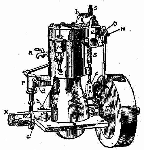
Fig. 225. Single-cylinder engine
A view of a representative single-cylinder engine
is shown at Fig. 225. The cam shaft is located at a
and is driven by the gears which are shown just in
the rear of the fly-wheel. At c are the cam and the
roller, which actuates the exhaust valve. The
cam consists of a collar with a flat projection or
[395]
toe upon its surface; the roller rests just above the
surface of the collar, and is forced upward when
struck by the projection. The roller is inserted to
lessen the friction by rolling instead of rubbing. The
valve stem extends upward into the valve chamber,
and is encircled by the coiled spring e; the stem is
guided by the guide at g. The exhaust is at E; I
is the pipe leading from the vaporizer V to the inlet
port in the valve chest. The inlet valve is directly
below the spring S and is inverted, being held in
place by the spring. The dome-shaped cap containing
the inlet valve is removable for access to
both valves. The complete cover is also removable.
It will be observed that this engine has an open
frame very similar to that of a steam engine, giving
free access to the crank-pin and main bearings; the
latter are shown fitted with oil boxes b instead of
the grease cups, as there is no pressure tending to
force the oil out along the shaft as in the two-cycle
type. This open base not only makes the bearings
more accessible, but renders it easier to lubricate
them and keep them cool. At H is the ignition
gear. P is the cooling water pump, run by the eccentric
e. The suction is piped to d and the pump
discharges through the pipe k into the cylinder.
The outlet for the cooling water is at O; N is the
[396]
cylinder oil cup for oiling the bore of the cylinder.
The compression cock R is for relieving the compression
at starting. The coupling at X is for
attaching the propeller shaft.
In this engine, the cylinder, base and bolting
flange are one casting, the upper half of the main
bearing being removable for the insertion of the
shaft. The cover is bolted on separately.
AUTOMOBILE FRAMES
The chassis for the single-cylinder, eight horse-power
motor machine shown herewith is built on the
principle of most frames, of any make and is typical
of the majority of light motor car chassis at present
in use.

Fig. 226. Eight horse-power single cylinder chassis
A diagrammatic plan of the eight horse-power,
single-cylinder chassis is shown in the accompanying
illustration (Fig. 226) in which, A indicates parts
enclosed, taking the mixture of gasolene and air from
the float-feed spray carburetor B, which has an
automatic air regulator. The purpose of this last
device is to dilute the mixture when the engine has
a light load and is inclined to race; generally speaking,
this regulator serves to proportion the ingredients
of the explosive mixture to the requirements
of the engine. Current O for the ignition of the
[398]
explosive mixture (ignition occurs once for every two
revolutions of the fly-wheel), is supplied by an accumulator
and intensified by a high-tension coil.
The products of combustion pass through the
exhaust pipe C to the muffler D, from which they
pass to the atmosphere through a series of fine holes.
The starting handle E makes a simple connection
with the end of the motor shaft F when required.
G is the fly-wheel. The drive from the engine is
through a universal joint H to the change-speed
gear J, the latter consisting of two trains of toothed
wheels, a big wheel on the primary shaft gearing
with a small one on the secondary shaft to give a
high speed, and vice versa. From the change-speed
gear, the drive is through a shaft K, having a universal
joint L at each end, to the bevel gearing
above the differential gear of the live rear axle.
Bevel gears and the differential gear are all contained
in the casings M. Three brakes are fitted, one operated
by pedal, working on a drum N secured to
the propeller shaft, the others operated by the side
lever and working on drums O O, secured to the rear
wheels. The change-speed gear gives three speeds
forward and a reverse; the frame is of pressed steel;
the rod and wheels are of the artillery type and carry
700 mm. by 85 mm. pneumatic tires. The gasolene
[400]
tank holds 41⁄2 gallons, sufficient for 200 miles, and
the lubricating oil tank holds 1 gallon, sufficient for
350 miles. Any beginner in motoring matters, who
studies the diagram, will obtain a fair idea of the
mechanism of the customary type of light car chassis.
Fig. 227. Plan of chassis of light racing car—two-cylinder motor
A chassis, suitable for a 71⁄2 horse-power quick-speed,
two-cylinder motor, is shown in Fig. 227.
It is not necessary to enter fully into the details
of construction after describing such a typical gear-driven
car as that at Fig. 226.
The frame A is of tubular steel, there are four
semi-elliptic springs, and the artillery wheels have
28-inch by 3-inch tires. The two-cylinder engine
B is one casting, with a large waterway covered by
an inspection plate C. The bore is 3.5 inches, stroke
4-inches, cylinder capacity 76.9 cubic inches, and
the piston displacement is 92.300 cubic inches per
minute. A governor automatically throttles the inlet
when the motor attempts to race, but by means
of a lever the governor can be cut out and the motor
accelerated from its normal speed of 1,200 revolutions
per minute. The balanced crank has but a
single throw; the water circulation is assured by a
motor-driven pump, and there is a belt-driven fan
behind the radiator. The commutator is easily
accessible, being mounted on a bevel shaft lying in
[401]
a sloping position and passing through the side of the
crank chamber. Ignition is high tension with wide
contact, the wiring being enclosed in a neat wooden
casing. The change-speed gear D gives three speeds
and a reverse, and its main bearings are fitted with
ring lubricators. A pressure sight feed lubricator on
the dash-board has three outlets, one to the engine,
another to the main clutch, and a third to the driving
pinion on the end of the propeller shaft. The brakes
are of the usual kind. In Fig. 227, E is the carburetor,
F the inlet and G the exhaust pipes, H the exhaust
muffler, J the brake pedal, K the clutch pedal, L the
band-brake on the propeller shaft, and M the internal
expanding brakes on the wheel hubs. A shield is
arranged under the front of the car to protect the mechanism
from mud and dust. The weight of the car
unladen is about 1,414 pounds, the wheel base is 731⁄2
inches, the track 46 inches, and the over-all dimensions
are 111 inches by 60 inches. During a 600-mile
trial this engine consumed 36 gallons, 6 pints of gasolene,
this being at the rate of 1 gallon for every 16.9
car miles; .077 gallon was consumed every ten miles.
THE MODERN TYPE-WRITER
Every home of importance contains a writing
machine of some kind, and these often require some
[402]
little adjustment or "fixing." It is within the
capacity of any bright boy to make these adjustments,
or to do the little fixings, if he tries it earnestly.
The first marketable type-writer was introduced in
the year 1875. No sooner had the type-writer acquired
a commercial value, than the fire of inventive
talent was awakened in Europe and America, and
type-writer after type-writer appeared on the market—a
few came to stay, but the many disappeared,
either during the chrysalis or experimental stage,
or shortly after it had been passed. Inventors and
investors have learned that hasty innovations and
untried experiments spell "failure" in the type-writer
field, and only patient and careful study,
backed by experience, tireless effort, and abundant
resource, have a chance of success.
By the year 1888, there were six different kinds of
machines in the market, to-day there are at least
twenty, but the favourites seem to be, "The Remington,"
"Smith Premier," "The Underwood" and
"The Oliver."
Modern type-writers may be defined as being
tabulating, book recording, card indexing, and
document writing machines. They are speedier
and produce finer and more varied work than their
predecessors.
[403]
The manner in which the type-writer performs
its work is of the simplest. The type-writer may be
considered as composed of three general parts, as
follows:
The keyboard, by which the operation of the
machine is directed.
The type mechanism, by which the desired letters
are, one after the other, in any desired sequence,
imprinted on the paper.
The carriage, which holds the paper in proper
position for writing, and which, by its regular movements,
provides for the spacing of letters and lines.
The Remington may be considered the pioneer
of writing machines. In appearance the Remington
No. 5 (introduced in 1888) is square, and strikes a
novice as being somewhat complicated. It is only
the multiplicity of parts, however, which creates
this impression. The machine is not complex, the
same parts being repeated over and over again.
The action is simplicity itself. The machine is
quite open on every side, so that its entire construction
can easily be seen. There is a japanned iron
frame enclosing and holding the working parts,
consisting of a base, four upright posts, and a top
plate. In front is a series of keys arranged in four
banks, like the keys of an organ, each key representing
[404]
the two characters, termed "upper" and "lower"
case letters. These are connected with long light
wooden levers, which, being depressed, communicate
motion by means of a rod fastened to the lever of
a type bar. At the end of each type bar is fixed the
hard metal type representing the two characters.
The type bars are arranged in a circle, therefore
the point of percussion of the type on the paper is at
a common centre. The inking is done by a ribbon,
which travels automatically across the machine,
winding and rewinding on and from spools.
The paper is inserted between two rollers; one of
rubber, called the "paper cylinder," and the other
of wood, called the "feed roll." The rollers are
held together by two elastic india-rubber bands.
As one revolves so does the other. The portion
which holds these rollers is designated the "carriage."
By a clever, yet simple piece of mechanism,
this carriage is caused to travel, simultaneously
with the return of the type or spacing bar, from right
to left, the width of a letter at each movement across
the machine. The carriage works on a sliding frame,
and this sliding mechanism is controlled by two
keys, which do not impress letters on the paper.
These change the character of the printing keys,
causing them to print capitals or small letters,
[405]
numerals or other marks at will. Depress the key
marked "upper case" and all the keys will print
capitals; remove the finger and they all print small
letters again. Moreover, the machine can be arranged
to print capitals continuously by the mere
raising of a lever, and quite independently of the
"upper case" shift key.
To obtain an impression, the required key is
struck lightly, and the type bar causes the type to
strike against the ribbon, thus leaving an imprint
on the paper held round the cylinder; the carriage
moves automatically the width of the letter, and the
operation is repeated until a word is completed.
Then the "spacing bar" at the front of the machine
is depressed at any point, thereby securing the requisite
space between the words.
When the end of a line is reached, warning is
given by the ringing of a bell, and then, by pulling
out the lever at the right-hand side of the carriage
and gently pressing to the right, the paper carriage
is advanced into position to receive the next line.
The distance between the lines and the width of the
writing can be regulated. The paper carriage being
hinged at the back allows of its being raised from the
front by the hand, so that the line that has just been
written can be inspected.
[406]
The motive power is imparted by an adjustable
coiled spring, a thin leather strap being fastened
to it and the carriage, and the uniform space is
governed by two clutches working on a rack. This
rack is fixed on a rocking shaft, and derives a swinging
motion from a universal bar fixed beneath the
light wooden key levers.
A small lever attached to the left of the carriage
holds its movements under the control of the operator.
Two scales are fixed on the machine, and these
in conjunction with the pointer, permit of head-lines
being centred, corrections made, etc.
In some machines, a special key and its accompanying
mechanism is provided for each character
or sign used—such are termed "complete" keyboard
machines. In others, each key is made to
represent the letters or signs—such are designated
"single-shift" machines. Others, again, have two
shift-keys, and each key represents not only a lower
case (small) and an upper case (capital) letter, but
a figure or other sign as well—such are known as
"double-shift" machines.
The two classes of modern type-writers may be
arranged into three groups, namely:
"Blind" writers, in which the writing remains
hidden until exposed by manipulative effort of the
[407]
operator. "Semi-visible" writers, which show only
the last lines, or only expose the centre of the paper,
hiding the writing at both ends of the line. "Visible"
writers, which expose a character directly in
front of the operator the instant it is imprinted;
the character subsequently does not pass out of
sight, by feeding behind a scale or bar, or other obstruction.
This classification and grouping is for
convenience only, and is in no way intended to
denote superiority.

Fig. 228. Remington type-writer No. 7
With regard to the Remington, many changes of
[408]
the details of construction, tending toward strength,
durability, and a greater ease and convenience of
operations, have been introduced into the machine,
which have survived the severe test of time. This is
especially the case with Remington No.7 (see Fig. 228).
The most important of these valuable improvements
are: An entirely new form of escapement, giving
increased speed and an easy touch. The carriage is
stronger and lighter, and steadier in all respects.
The annoying rubber bands, which guide the paper
around the platen have been discarded for a new form
of paper guide, which may be adjusted to any desired
point. The paper feed has been so arranged as
to render it possible to write on wide or narrow paper,
and this can be fed into the machine by a simple
movement of the hand without lifting the carriage,
and can be turned forward or backward at will.
The ribbon movement is improved and works entirely
automatically, reversing and giving a lateral
movement. The marginal stops also are improved,
and simple means provided for writing outside the
margin whenever desired. There is a keyboard lock,
locking the types at the end of the line, and thus preventing
one letter being printed over another. A
new variable line spacer is embodied, which makes
it easier to write at any point on the paper, and
[409]
prolongs the life of the platen for the reason that
the type no longer strikes in unchanging grooves.
An adjustable side guide for arranging the paper
to any desired marginal indentation is a recent addition.
A new two colour ribbon lever bearing a
disc, which signals the color which the machine is
adjusted to write is another recent addition.

Fig. 229. Smith Premier No. 4
The Smith-Premier type (Fig. 229) has six models
in the market and all nearly alike in their mechanism,
differing only in the carriage arrangements, or the
number of the characters. The machine is particularly
simple in construction, and claims, by
means of a very long and strong adjustable bearing,
to have secured a perfect and permanent alignment.
The type bars work on hardened steel
[410]
bearings, 15⁄8 inches apart, and the type bars are
the shortest of any on a "complete" keyboard
machine. But the original and exclusive feature
of the machine is the rocking shaft, which replaces
the usual wooden or metal key lever. This consists
of a circular rod, passing from the front to the
rear of the machine—one rod for each key. Projecting
from each shaft is a small bar, which is
attached at the front end to the lower portion of the
key stem. A similar projection is attached to the
rod communicating with the type bar, and the result
is that on the depression of the key the rocking
shaft is made to revolve slightly, and so raise the
free end of the type bar to the printing point. The
type bar hangers are solidly riveted to the type
ring. It will be seen that matters are so arranged
that the amount of force to imprint the character
is precisely the same in every case—a uniform, light
and elastic touch. A very noticeable feature is
its quietness in operation, due to the rigidity of its
parts, and the fact that the ball-bearing principle
is adopted wherever it can be used to advantage.
It is also equipped with a circular brush, built into
the machine, into which a handle can be immediately
inserted, when, with a turn or two, the whole
of the type can be cleaned.
[411]
The most striking recent development is the adoption
of a three-coloured ribbon device. A simple
movement of the lever in front of the machine
brings the required colour into place ready for use. A
two-colour or single colour ribbon may be employed.
If desired the ribbon can be instantly shifted
from the printing point for duplicating purposes.
The ribbon reverses automatically, and it is attached
to the spools with clamps—one on each
spool, dispensing entirely with pins and tapes.
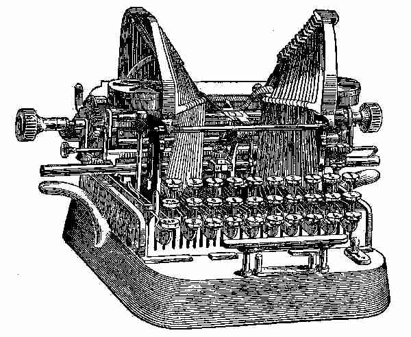
Fig. 230. The Oliver No. 3
[412]
The Oliver, Fig. 230, differs in mechanical principle
from other machines. It has a wide U-shaped steel
type bar, provided with a tool-steel axle as broad
as the bar is long, and braced joints insuring the
alignment without guides. The connection between
the type bars and the key levers is direct and perpendicular.
The type bars strike down on the
platen in a line perpendicular to its plane, thus transmitting
the maximum power with the minimum
resistance, and further, maintaining the alignment
with several sheets as with one. The type are of
steel, and lie face upward—very convenient for
cleaning. The keyboard is the "Universal," having
twenty-eight keys with a "double" shift, giving
eighty-four characters and the special model thirty-two
keys, giving ninety-six characters.
The tension and depression of the keys are light
and uniform. It may also be noted that the type
blocks decrease in weight with the increase of length
of type bar—necessary to secure a uniform stroke.
The escapement mechanism is exceedingly simple
and positive, and although very rapid is almost
frictionless. The writing is semi-visible. The carriage
is provided with three paper-feed rolls, thus
ensuring a perfect feed of the paper down to the
bottom edge of the sheet. It runs on anti-friction
[413]
travellers on guide rails, ensuring an easy and steady
motion. It is equipped with all the necessary
devices. The line space mechanism operates automatically
as the carriage is returned from the
left to the right for a new line. The machine
is compact and portable—weight about twenty
pounds.
The parts of any of the machines now in the market,
may readily be disconnected, but care must be
taken by the novice in laying aside the parts so that
they may be easily and correctly assembled. Repairs
on the various parts may be made while out,
and when made may be placed in situ. Any or all
of the parts may be cleaned when the carriage is
taken off. A little study of the machine when
sitting before a person, will enable him to understand
its mechanism, and when this is accomplished,
cleaning and repairing can be done intelligently.
The tendency of the times is to employ the type-writer
whenever possible. Special devices are from
time to time invented to meet extended uses. The
most important of recent applications is to office
work for billing and book-keeping; this work alone
has necessitated important modifications. In this
direction, the tabulator calls for review. The lack
of a practical method enabling tabular matter to
[414]
be typed with a rapidity equal to that of the ordinary
typing has long been felt to be a deficiency
in type-writers. The invention of the tabulator has
enormously increased the scope of the machine in
this direction.
The tabulator is a device by means of which,
figures or words can be written in columns, with
out employment of the space bar or carriage release
lever, or any adjustment whatever of the carriage
by hand. By its use, the carriage may be set
automatically at any point that may be required.
At present this device is an accessory to most machines,
but in the near future, it must form an integral
part of all machines, and further, enable the
carriage to be automatically placed in a proper
position to write numbers in correct relation to
each other in columns; that is, units under units,
tens under tens, and so on. The built-in tabulators
of to-day, with but two exceptions, are deficient in
this respect. The tabulator in either form does
not interfere with the use of the machine for other
work, such as correspondence, etc.
The tabulator was followed by the introduction
of a bi-chrome (two-coloured ribbon), and quite recently
the Smith Premier Typewriter Company
has advanced still further in this direction by introducing
[415]
a tri-chrome (three-colour) ribbon. By a
simple movement it is possible to vary the colour
of the impression instantaneously, so that credits,
marginal notes, footnotes, and underscoring may
be indicated in red or other colour preferred. One-colour
ribbons can be used if desired.
The machine embodying the parti-coloured ribbons
and tabulator devices are generally known as "invoicing"
machines, and by simple arrangements,
every phase—not only of correspondence, but also
of office and statistical work—can be accomplished,
with an enormous saving of time. Items can be
made on sheets, which may be taken from the
machine with absolute certainty that when re-inserted,
the subsequent entries will fall into their
proper places.
Card Indexing.—For greater convenience in card
indexing, special platens are obtainable, or the ordinary
platens can be temporarily fitted with a
metal clip. Both can be fitted to or removed from
the machine in a few seconds, and the cards can be
adjusted in an instant. The increasing use of the
card file system for a wide variety of purposes lends
special importance to the value of the type-writer
for this class of work.
Interchangeable Carriages.—For years the thousand
[416]
and one wide forms, statements, and blanks
common in every business office, have been filled
by the pen, the reason being that there was no
machine practicable for both wide and ordinary
work. The manufacturers of most of the modern
type-writers now have models embodying interchangeable
carriages, which enable any one possessing
a machine with this improvement to have at
the same time a set of carriages from the largest to
the smallest, all of which can be used upon one
machine. In one or two makes this is additional
to interchangeable platens.

Fig. 231. Interchangeable carriage
Duplicators.—The value of a mechanical contrivance
for the rapid and effective multiplication
of copies of documents is fully recognized at the
present time.
Duplicating machines have been on the market for
several years. They will produce from one typescript
[417]
original up to 3,000 copies, of any size, from a
post card to a sheet of brief, every copy having the
exact appearance of an original. While there are
various makes and styles of duplicators, the main
principle is the same throughout. The original is
prepared by the now well-known stencil process; that
is, writing the matter required with a type-writer
on a sheet of waxed paper. The pressure of the type
expels the wax out of the paper and leaves openings
through which the ink can penetrate. In the Roneo
rotary duplicator, a metal frame supports a cylinder
of thin, perforated steel. On the outer surface of
the cylinder is stretched a linen ink-pad, and over
this is placed the stencil. The pad is inked by a
rubber roller resting in an ink receptacle suspended
between the two sides of the framework. By
means of a simple lever this roller can be brought into
contact with the cylinder, and ink is thus supplied
as required. The cylinder is rotated by a handle.
Paper fed into the machine is gripped by a rubber
impression roller, which presses it against the stencil
as the cylinder revolves, and the sheet perfectly
printed, is then automatically discharged on the
other side. The rotary can be fitted with three
devices, namely a feeder, a simple contrivance, which automatically
feeds the sheet into the machine, reducing
[418]
hand labour to a minimum; an interlever, which
automatically drops an interleaving sheet as each
copy is printed—thus permitting of the use of
highly glazed or very hard paper; a cyclometer for
registering the number of copies. The rotary system
is far superior to the hand duplicators in the
matter of speed; such a machine will print ten copies
while the hand device prints one. There is no lost
motion, a copy being printed and discharged at
every revolution.
Press Copying.—At the present time, there are
four methods of letter copying in vogue, namely:
(1) The letter-book method, damping sheets and
screw press. (2) Roller process, water bath and
drying drum. (3) Carbon paper. (4) The chemical
letter copier.
The roller copies employ a water bath, and give
but little if any improvement in the regulation of
the degree of moisture. The copies are wound on
a drying drum to prevent off-setting, and subsequently
have to be cut apart for filing purposes.
The carbon process enables the answers to be
filed with the original letter.
The modern chemical letter copier offers distinct
advantages over other methods. It consists of a
simple machine designed to carry a roll of specially
[419]
prepared paper. The letter to be copied is laid on
the feed board, the handle is turned, the sheet is
fed automatically into the machine.
It will be noticed that a water bath and brush or
damping sheets, are completely dispensed with;
there is no "off-sheeting" and no drying drum.
The copy may be either filed with the letter to which
it relates, or placed, day by day, in a cover having
the appearance of an ordinary letter-book; or two
copies can be made of each letter—one for filing
and the other for the book.
(1). A type-writer should be durable. Every
part should be simple and strong and adapted to
serve its purpose with the smallest degree of wear.
Every mechanical movement must be definite,
and incapable of incomplete performance. All
wearing parts should be adjustable and interchangeable.
(2). It should possess absolutely "visible" writing.
The common-sense way to write easily and
speedily is to see what you are writing while you are
writing it.
The writing should be performed in such a part
of the machine as to be most readily seen during
progress.
(3). The keyboard—on type bar machines in
[420]
particular—should be that known as the "Universal,"
or "Standard" arrangement.
The keys on any style of keyboard should have a
light and uniform depression, so that the machine
may be operated with the minimum of fatigue.
(4). The types should present an even and regular
appearance, termed "alignment." A type bar
made of suitable material in the right way is the
keystone of typewriter construction. In all machinery,
there is some part on which falls the greatest
strain and wear; consequently on the durability
of that part rests the life of the machine. The
devices used to secure alignment are numerous and
ingenious. One machine depends on a wide pivoted
bearing and a rigid type bar; another has a bearing
composed of a continuous steel rod, with a type
bar flexible while in motion, and made rigid at the
printing point by means of guides; a third employs
a wide pivotal bearing, a flexible type bar and an
indispensable guide plate at the printing point; a
fourth employs a compound type bar and an indispensable
guide at the printing centre, and so on.
Some have wide and adjustable bearings, to enable
the wear to be taken up. These devices, however,
are not the only essentials. The type bar hangers
in machines embodying the pivotal principle need
[421]
to be rigid and solidly fixed, while the paper carriage
should be perfectly rigid and present a level and
even platen surface for the type to strike against.
(5). The type should be capable of being easily
and quickly cleaned, and in such a way as not to
injure the type or soil the hands. A device should
be embodied for rendering it impossible to batter
the face of the type when the type bars are accidentally
struck one against the other, and for preventing
the type perforating or puncturing the
platen.
(6). The mechanism controlling the movement
of the carriage should act rapidly and uniformly,
and its tension should be adjustable. The carriage
should have a sure and regular paper feed and be
capable of accommodating any smaller width of
paper; also the margin regulators and bell trip
should be easily and readily altered.
(7). The platen roll should be instantly interchangeable,
thereby allowing of a soft substance
platen being used for a single copy work and a hard
one for manifolding. If the hard platen is of reduced
diameter, more perfect alignment is secured
on machines employing a complete circle of rigid
type bars and a central top carriage.
(8). The line-spacing mechanism should be variable,
[422]
and effected by one movement at all times;
that is, the same movement that accomplishes the
line feed should be utilized to return the carriage
for a new line.
(9). The ribbon movement should consist of a
reliable feeding mechanism, and allow of the fabric
being quickly withdrawn, replaced, or adjusted. It
should bring the whole surface in contact with the type,
and also automatically reverse the endwise travel.
(10). The machine should be as noiseless in
operation as possible. Machines differ very much
in this particular. The employment of the guides
to force the alignment introduces metallic contact,
and consequent friction and noise.
COPYRIGHTS
Directions for Securing Copyrights, under the revised
act of Congress, which took effect August 1, 1874.
(1). A printed copy of the title of the book,
map, chart, dramatic or musical composition, engraving,
cut, print, photograph, or a description
of the painting, drawing, chromo, statue, statuary,
or model or design for a work of the fine arts, for
which copyright is desired, must be sent by mail
or otherwise, prepaid, addressed: Librarian of
Congress, Washington, D. C.
[423]
This must be done before publication of the book
or other article. No entry can be made of a written
title.
(2). A fee of fifty cents, for recording the title
of each book or other article, must be enclosed with
the title as above, and fifty cents in addition (or
one dollar in all), for each certificate of copyright
under seal of the Librarian of Congress, which will
be transmitted by early mail.
(3). Within ten days after publication of each
book or other article, two complete copies of the
best edition issued must be sent, to perfect the
copyright, with the address Librarian of Congress,
Washington, D. C.
The postage must be prepaid, or else the publication
enclosed in parcels covered by printed Penalty
Labels, furnished by the Librarian, in which case
they will come free by mail, according to rulings
of the Postoffice Department. Without the deposit
of copies above required the copyright is void,
and a penalty of $25 is incurred. No copy is required
to be deposited elsewhere.
(4). No copyright is valid unless notice is given
by inserting in every copy published, on the title
page or the page following, if it be a book; or if a
map, chart, musical composition, print, cut, engraving,
[424]
photograph, painting, drawing, chromo,
statue, statuary, or model or design intended to be
perfected as a work of the fine arts, by inscribing
upon some portion thereof, or on the substance
on which the same is mounted, the following words,
viz: "Entered according to act of Congress, in the
year——by——, in the office of the Librarian
of Congress, at Washington," or, at the option
of the person entering the copyright, the words:
"Copyright, 19—, by——."
The law imposes a penalty of $100 upon any person,
who has not obtained copyright, who shall
insert the notice "Entered according to act of
Congress," or "Copyright," etc., or words of the
same import, in or upon any book or other article.
(5). Any author may reserve the right to translate
or to dramatize his own work. In this case,
notice should be given by printing the words "Right
of translation reserved," or "All rights reserved,"
below the notice of copyright entry, and notifying
the Librarian of Congress of such reservation, to be
entered upon the record.
(6). Each copyright secures the exclusive right
of publishing the book or article entered for the
term of twenty-eight years. Within six months
before the end of that time, the author or designer,
[425]
or his widow or children, may secure a renewal for
the further term of fourteen years, making forty-two
years in all. Application for renewal must be accompanied
by explicit statement of ownership, in
the case of the author, or of relationship, in the case
of heirs, and must state definitely the date and place
of entry of the original copyright.
(7). The time within which any work entered
for copyright may be issued from the press is not
limited by any law or regulation, but depends upon
the discretion of the proprietor. A copyright may
be secured for a projected work as well as for a
completed one.
(8). A copyright is assignable in law by any instrument
of writing, but such assignment must be
recorded in the office of the Librarian of Congress
within sixty days from its date. The fee for this
record and certificate is one dollar, and for a certified
copy of any record of assignment one dollar.
(9). A copy of the record (or duplicate certificate)
of any copyright entry will be furnished, under
seal, at the rate of fifty cents each.
(10). In the case of books published in more than
one volume, or of periodicals published in numbers,
or of engravings, photographs, or other articles
published with variations, a copyright is to be entered
[426]
for each volume or part of a book, or number of
periodical, or variety, as to style, title, or inscription,
of any other article.
(11). To secure a copyright for a painting, statue,
or model or design intended to be perfected as a
work of fine arts, so as to prevent infringement by
copying, engraving, or vending such design, a
definite description must accompany the application
for copyright, and a photograph of the same, at
least as large as "cabinet size," should be mailed
to the Librarian of Congress within ten days from
the completion of the work or design.
(12). Copyrights cannot be granted upon Trade-marks,
nor upon Labels intended to be used with any
article of manufacture. If protection for such
prints or labels is desired, application must be made
to the Patent Office, where they are registered at
a fee of $6 for labels and $25 for trade-marks.
(13). Every applicant for a copyright must state
distinctly the name and residence of the claimant,
and whether the right is claimed as author, designer,
or proprietor. No affidavit or formal application
is required.
Office of the Librarian of Congress.
Transcriber's Notes.
- Spelling appears to be evolving between US/UK e.g. both color and colour,
vapor and vapours are seen.
- Corrected obvious typos:
guage -> gauge
decending -> descending
radical -> radial
artifical -> artificial
comtemplated -> contemplated
barometor -> barometer
p417. "namely [inserted 'a feeder'], a simple contrivance"
- Chapter headings in Contents do not always match chapter headings
in text.
II. Building a Boathouse -> II. Building of a Boat House
- Inconsistent hyphenation left as printed:
Both boat house and boat-house are used several times.
Both typewriter and type-writer are used several times.
Both Wheel-barrow and wheelbarrow are used several times.
Both EVERYDAY and every-day are used several times.
- Moved equations to single lines to make them clearer.
- Some maths errors were found in the text, they have been corrected as follows:
p126. "find that it has taken five and one-third
times as long, or 10 minutes to do this work."
10 should read 107.
p141. The equation
P2[pi][nu] - Wp = 0 or — = p2[pi][nu]/p
should read:
P2[pi][nu] - Wp = 0 or — = P2[pi][nu]/p
p241. The equation
(AB × CD)/2 × AB × 140 lb. = (2 - 3)/2 × 8/1 × 149 lb. = 2,800lb.
should read
(AB + CD)/2 × AC × 140 lb. = (2 + 3)/2 × 8/1 × 140 lb. = 2,800 lb.
p353. 1:733 -> 1.733
- p141. and p142. For clarity, the numbering of the equations has been
changed from a mixture of [N] and (N) to (N) only, and the mix
of using [N.] and [N] have been changed so all numbering and
references to the numbering have no "."
The maths in this sequence of equations has gone wrong somewhere
probably due to a mistyped w for W, r' for r'' or a missed divisor.
-
Corrected incorrect figure references:
p297. D1 -> D´ , E1 -> E´
p298. E1 -> E´
p299. G1 -> G´ , H1 -> H´ , G1 -> G, J1 -> J
p401. Fig. 2 should be Fig. 227
- Left as printed:
Inconsistent use of italics between figures and text unless needed to
make description in text unambiguous.
Inconsistent hyphenation in measurements e.g. 7-1/2-in. and 3-1/2 in.
- Fig.35 has been rotated by 45 deg. (anticlockwise)
*** END OF THE PROJECT GUTENBERG EBOOK 45083 ***