| Note: | Images of the original pages are available through Internet Archive. See https://archive.org/details/thingsboyshouldk00stjo |
 EDITION
| Chapter | Page | |
| I. | About Frictional Electricty | 7 |
| II. | About Magnets and Magnetism | 21 |
| III. | How Electricity is Generated by the Voltaic Cell, | 32 |
| IV. | Various Voltaic Cells, | 36 |
| V. | About Push-Buttons, Switches and Binding-Posts, | 43 |
| VI. | Units and Apparatus for Electrical Measurements, | 48 |
| VII. | Chemical Effects of the Electric Current, | 58 |
| VIII. | How Electroplating and Electrotyping are Done, | 60 |
| IX. | The Storage Battery, and How it Works, | 63 |
| X. | How Electricity is Generated by Heat, | 68 |
| XI. | Magnetic Effects of the Electric Current, | 71 |
| XII. | How Electricity is Generated by Induction, | 77 |
| XIII. | How the Induction Coil Works, | 80 |
| XIV. | The Electric Telegraph, and How it Sends Messages, | 84 |
| XV. | The Electric Bell and Some of its Uses, | 91 |
| XVI. | The Telephone and How it Transmits Speech, | 95 |
| XVII. | How Electricity is Generated by Dynamos, | 101 |
| XVIII. | How the Electric Current is Transformed, | 109 |
| XIX. | How Electric Currents are Distributed for Use, | 114 |
| XX. | How Heat is Produced by the Electric Current, | 124 |
| XXI. | How Light is Produced by the Incandescent Lamp, | 129 |
| XXII. | How Light is Produced by the Arc Lamp, | 135 |
| XXIII. | X-Rays, and How the Bones of the Human Body are Photographed, | 141 |
| XXIV. | The Electric Motor, and How it Does Work, | 147 |
| XXV. | Electric Cars, Boats and Automobiles, | 154 |
| XXVI. | A Word About Central Stations, | 162 |
| XXVII. | Miscellaneous Uses of Electricity, | 165 |
For the benefit of those who wish to make their own electrical apparatus for experimental purposes, references have been made throughout this work to the "Apparatus Book;" by this is meant the author's "How Two Boys Made Their Own Electrical Apparatus."
For those who wish to take up a course of elementary electrical experiments that can be performed with simple, home-made apparatus, references have been made to "Study;" by this is meant "The Study of Elementary Electricity and Magnetism by Experiment."
1. Some Simple Experiments. Have you ever shuffled your feet along over the carpet on a winter's evening and then quickly touched your finger to the nose of an unsuspecting friend? Did he jump when a bright spark leaped from your finger and struck him fairly on the very tip of his sensitive nasal organ?
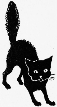
Did you ever succeed in proving to the pussy-cat, Fig. 1, that something unusual occurs when you thoroughly rub his warm fur with your hand? Did you notice the bright sparks that passed to your hand when it was held just above the cat's back? You should be able to see, hear, and feel these sparks, especially when the air is dry and you are in a dark room.
Did you ever heat a piece of paper before the fire until it was real hot, then lay it upon the table and rub it from end to end with your hand, and finally see it cling to the wall?
Were you ever in a factory where there were large belts running rapidly over pulleys or wheels, and where large sparks would jump to your hands when held near the belts?
If you have never performed any of the four experiments mentioned, you should try them the first time a chance occurs. There are dozens of simple, fascinating experiments that may be performed with this kind of electricity.
2. Name. As this variety of electricity is made, or generated, by the friction of substances upon each other, it is called frictional electricity. It is also called static electricity, because it generally stands still upon the surface of bodies and does not "flow in currents" as easily as some of the other varieties. Static electricity may be produced by induction as well as by friction.
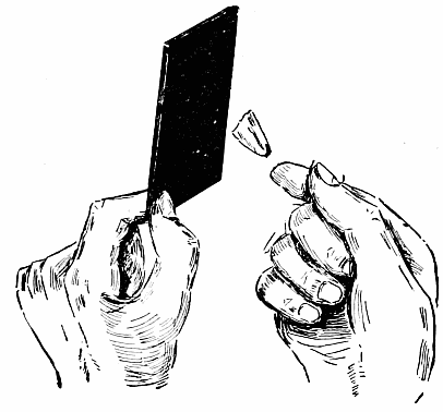
3. History. It has been known for over 2,000 years that certain substances act queerly when rubbed. Amber was the first substance upon which electricity was produced by friction, and as the Greek name for amber is elektron, bodies so affected were said to be electrified. When a body, like ebonite, is rubbed with a flannel cloth, we say that it becomes charged with electricity. Just what happens to the ebonite is not clearly understood.[9] We know, however, that it will attract light bodies, and then quickly repel them if they be conductors. Fig. 2 shows a piece of tissue-paper jumping toward a sheet of ebonite that has been electrified with a flannel cloth.
4. Conductors and Non-Conductors. Electricity can be produced upon glass and ebonite because they do not carry or conduct it away. If a piece of iron be rubbed, the electricity passes from the iron into the earth as fast as it is generated, because the iron is a conductor of electricity. Glass is an insulator or non-conductor. Frictional electricity resides upon the outside, only, of conductors. A hollow tin box will hold as great a charge as a solid piece of metal having the same outside size and shape. When frictional electricity passes from one place to another, sparks are produced. Lightning is caused by the passage of static electricity from a cloud to the earth, or from one cloud to another. In this case air forms the conductor. (For experiments, see "Study," Chapter VII.)
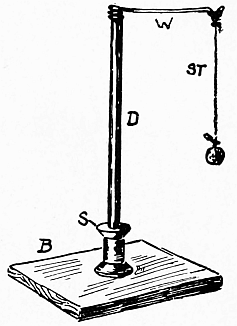
5. Electroscopes. A piece of carbon, pith, or even a small piece of damp tissue-paper will serve as an electroscope to test the presence of static electricity. The pith is usually tied to a piece of silk thread which is a non-conductor. Fig. 3 shows the ordinary form of pith-ball electroscope.
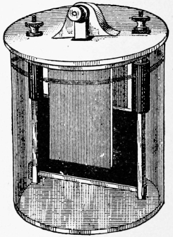
The leaf electroscope is a very delicate apparatus. Gold-leaf[10] is generally used, but aluminum-leaf will stand handling and will do for all ordinary purposes. Fig. 4 shows a common form, the glass being used to keep currents of air from the leaves and at the same time to insulate them from the earth.
Electroscopes are used to show the presence, relative amount, or kind of static electricity on a body. (See "Study," Chapter XI.)
6. Two Kinds of Electrification. It can be shown that the electrification produced on all bodies by friction is not the same; for example, that generated with glass and silk is not the same as that made with ebonite and flannel. It has been agreed to call that produced by glass and silk positive, and that by ebonite and flannel negative. The signs + and - are used for positive and negative.
7. Laws of Electrification. (1) Charges of the same kind repel each other; (2) charges of unlike kinds attract each other; (3) either kind of a charge attracts and is attracted by a neutral body.
8. Static Electric Machines. In order to produce[11] static electricity in quantities for experiments, some device is necessary.
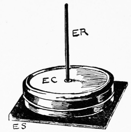
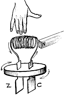
The electrophorus (e-lec-troph´-o-rus) is about the simplest form of machine. Fig. 5 shows a simple electrophorus in which are two insulators and one conductor. The ebonite sheet E S is used with a flannel cloth to generate the electricity. The metal cover E C is lifted by the insulating handle E R. The cover E C is placed upon the thoroughly charged sheet E S, and then it is touched for an instant with the finger, before lifting it by E R. The charge upon E C can then be removed by bringing the hand near it. The bright spark that passes from E C to the hand indicates that E C has discharged itself into the earth. The action of the electrophorus depends upon induction. (For experiments, details of action, induced electrification, etc., see "The Study of Elementary Electricity and Magnetism by Experiment," Chapters VIII. and IX.)
The first electric machine consisted of a ball of sulphur fastened to a spindle which could be turned by a crank. By holding the hands or a pad of silk upon the revolving ball, electricity was produced.
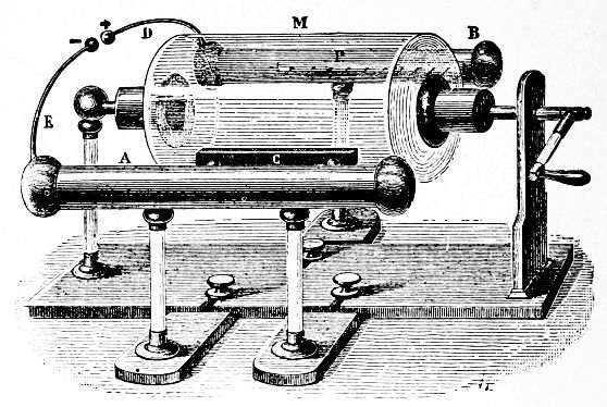
9. The Cylinder Electric Machine consists, as
shown in Fig. 6, of a glass cylinder so mounted that it
can be turned by a crank. Friction is produced by a
pad of leather C, which presses against the cylinder as it
turns. Electric sparks can be taken from the large "conductors"
which are insulated from the earth. The opposite[12]
[13]
electricities unite with sparks across D and E. If
use is to be made of the electricity, either the rubber or
the prime conductor must be connected with the ground.
In the former case positive electricity is obtained; in the
latter, negative.
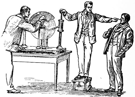
10. The Plate Electrical Machine. Fig. 7 also shows an old form of machine. Such machines are made of circular plates of glass or ebonite, two rubbing pads being usually employed, one on each side of the plate. One operator is seen on an insulated stool (Fig. 7), the electricity passing through him before entering the earth by way of the body of the man at the right.
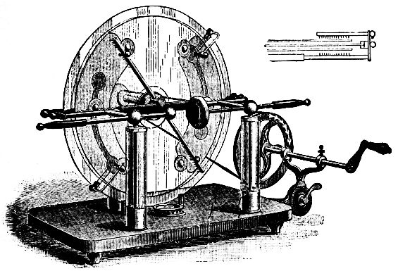
11. The Toepler-Holtz Machine, in one form, is shown in Fig. 8. The electricity is produced by the principle of induction, and not by mere friction. This machine, used in connection with condensers, produces large sparks.
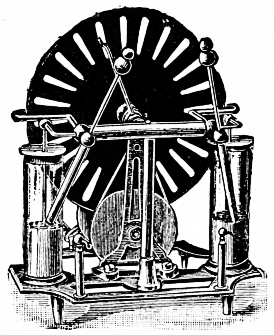
12. The Wimshurst Machine is of recent date, and not being easily affected by atmospheric changes, is very useful for ordinary laboratory work. Fig. 9 shows one form of this machine.
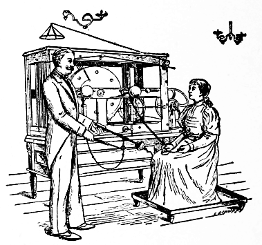
13. Influence Machines for Medical Purposes are made in a large variety of forms. A Wimshurst machine is generally used as an exciter to charge the plates of the large machine when they lose their charge on account of excessive moisture in the atmosphere. Fig. 10 shows a large machine.
14. Uses of Electrical Machines. Static electricity has been used for many years in the laboratory for experimental purposes, for charging condensers, for medical purposes, etc. It is now being used for X-ray work, and considerable advancement has been made within a few years in the construction and efficiency of the machines.
With the modern machines large sparks are produced by merely turning a crank, enough electricity being produced to imitate a small thunderstorm. The sparks of home-made lightning will jump several inches.
Do not think that electricity is generated in a commercial way by static electric machines. The practical uses of static electricity are very few when compared with those of current electricity from batteries and dynamos.
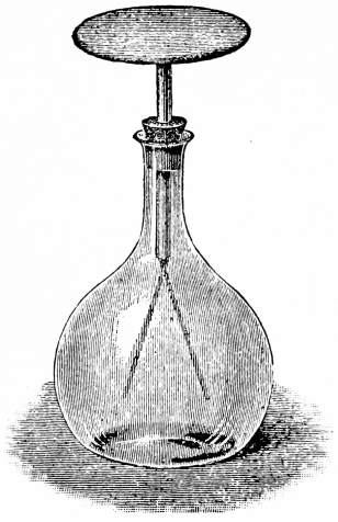
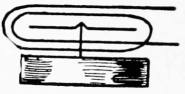
15. Condensation of Static Electricity. By means of apparatus called condensers, a terrific charge of static electricity may be stored. Fig. 11 shows the most common form of condenser, known as the Leyden jar. It consists of a glass jar with an inside and outside coating of tin-foil.
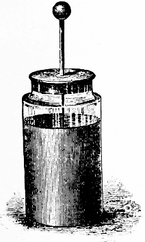
Fig. 11.
| 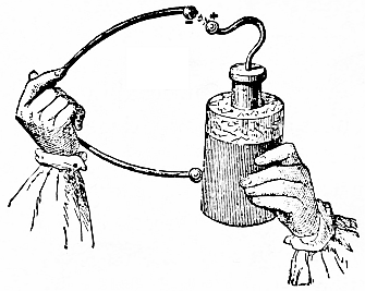
Fig. 12.
|
To charge the jar it is held in the hand so that the outside coating shall be connected with the earth, the sparks[16] from an electric machine being passed to the knob at the top, which is connected by a chain to the inside coating.
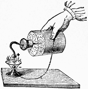
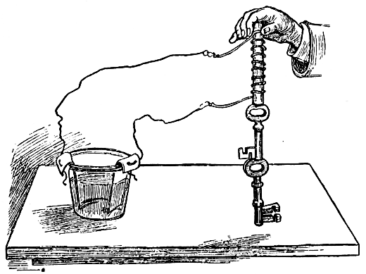
To discharge the jar, Fig. 12, a conductor with an insulating handle is placed against the outside coat; when the other end of the conductor is swung over towards the knob, a bright spark passes between them. This device is called a discharger. Fig. 13 shows a discharge through ether which the spark ignites.
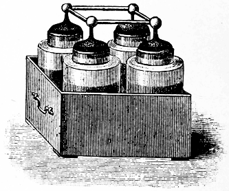
16. The Leyden Battery, Fig. 14, consists of several jars connected in such a way that the area of the inner and outer coatings is greatly increased. The battery has a larger capacity than one of its jars. (For Experiments in Condensation, see "Study," Chapter X.)
17. Electromotive Force of Static Electricity. Although the sparks of static electricity are large, the quantity of electricity is very small. It would take thousands of galvanic cells to produce a spark an inch long. While the quantity of static electricity is[17] small, its potential, or electromotive force (E. M. F.), is very high. We say that an ordinary gravity cell has an E. M. F. of a little over one volt. Five such cells joined in the proper way would have an E. M. F. of a little over five volts. You will understand, then, what is meant when we say that the E. M. F. of a lightning flash is millions of volts.
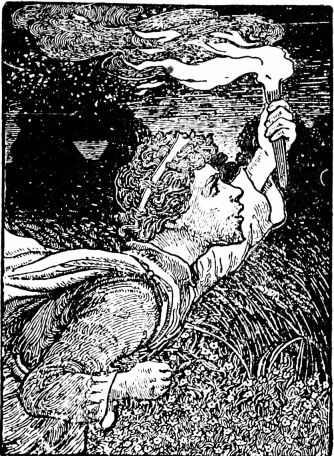
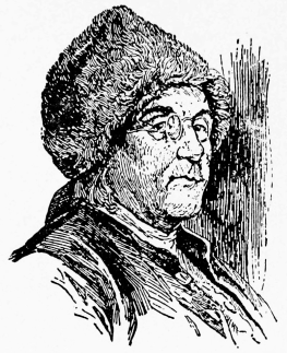
18. Atmospheric Electricity. The air is usually electrified, even in clear weather, although its cause is not thoroughly understood. In 1752 it was proved by Benjamin Franklin (Fig. 15), with his famous kite experiment, that atmospheric and frictional electricities are of the same nature. By means of a kite, the string being wet by the rain, he succeeded, during a thunderstorm, in drawing sparks, charging condensers, etc.
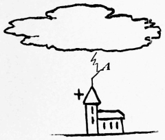
19. Lightning may be produced by the passage of electricity between clouds, or between a cloud and the earth (Fig. 16), which, with the intervening air, have the effect of a condenser. When the attraction between the two electrifications gets great enough, a spark passes. When the spark has a zigzag motion it is called chain[18] lightning. In hot weather flashes are often seen which light whole clouds, no thunder being heard. This is called heat lightning, and is generally considered to be due to distant discharges, the light of which is reflected by the clouds. The lightning flash represents billions of volts.
20. Thunder is caused by the violent disturbances produced in the air by lightning. Clouds, hills, etc., produce echoes, which, with the original sound, make the rolling effect.
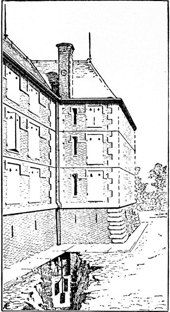
21. Lightning-Rods, when well constructed, often prevent violent discharges. Their pointed prongs at the top allow the negative electricity of the earth to pass quietly into the air to neutralize the positive in the cloud above. In case of a discharge, or stroke of lightning, the rods aid in conducting the electricity to the earth. The ends of the rods are placed deep in the earth, Fig. 17.
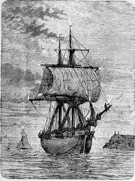
22. St. Elmo's Fire. Electrification from the earth is often drawn up from the earth through the masts of ships, Fig. 18, to neutralize that in the clouds, and, as it escapes from the points of the masts, light is produced.
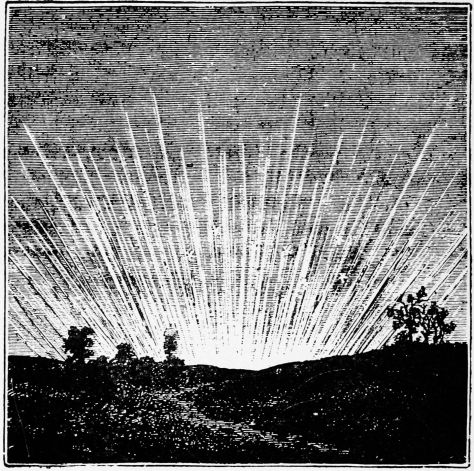
23. Aurora Borealis, also called Northern Lights, are[20] luminous effects, Fig. 19, often seen in the north. They often occur at the same time with magnetic storms, when telegraph and telephone work may be disturbed. The exact cause of this light is not known, but it is thought by many to be due to disturbances in the earth's magnetism caused by the action of the sun.
24. Natural Magnets. Hundreds of years ago it was discovered that a certain ore of iron, called lodestone, had the power of picking up small pieces of iron. It was used to indicate the north and south line, and it was discovered later that small pieces of steel could be permanently magnetized by rubbing them upon the lodestone.
25. Artificial Magnets. Pieces of steel, when magnetized, are called artificial magnets. They are made in many forms. The electromagnet is also an artificial magnet; this will be treated separately.
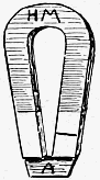
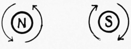
26. The Horseshoe Magnet, Fig. 20, is, however, the one with which we are the most familiar. They are always painted red, but the red paint has nothing to do with the magnetism.
The little end-piece is called the keeper, or armature; it should always be kept in place when the magnet is not in use. The magnet itself is made of steel, while the armature is made of soft iron. Steel retains magnetism for a long time, while soft iron loses it almost instantly. The ends of the magnet are called its poles, and nearly all the strength of the magnet seems to reside at the poles, the curved part having no attraction for outside bodies. One of the poles of the magnet is marked with a line, or with the letter N. This is called the north pole of the magnet, the other being its south pole.
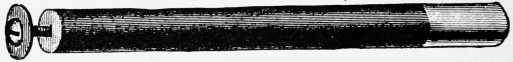
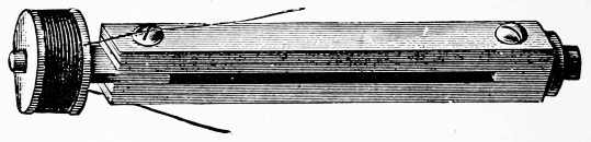
27. Bar Magnets are straight magnets. Fig. 21 shows a round bar magnet. The screw in the end is for use in the telephone, described later.
28. Compound Magnets. When several thin steel magnets are riveted together, a compound magnet is formed. These can be made with considerable strength. Fig. 22 shows a compound horseshoe magnet. Fig. 23 shows a form of compound bar magnet used in telephones. The use of the coil of wire will be explained later. A thick piece of steel can not be magnetized through and through. In the compound magnet we have the effect of a thick magnet practically magnetized through and through.
29. Magnetic and Diamagnetic Bodies. Iron, and substances containing iron, are the ones most readily attracted by a magnet. Iron is said to be magnetic. Some substances, like nickel, for example, are visibly attracted by very strong[23] magnets only. Strange as it may seem, some substances are actually repelled by strong magnets; these are called diamagnetic bodies. Brass, copper, zinc, etc., are not visibly affected by a magnet. Magnetism will act through paper, glass, copper, lead, etc.
30. Making Magnets. One of the strangest properties that a magnet has is its power to give magnetism to another piece of steel. If a sewing-needle be properly rubbed upon one of the poles of a magnet, it will become strongly magnetized and will retain its magnetism for years. Strong permanent magnets are made with the aid of electromagnets. Any number of little magnets may be made from a horseshoe magnet without injuring it.
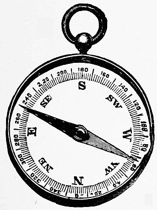
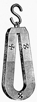
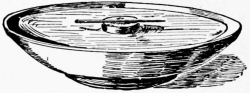
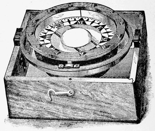
31. Magnetic Needles and Compasses. If a bar magnet be suspended by a string, or floated upon a cork, which can easily be done with the magnet made from a sewing-needle, Fig. 24, it will swing around until its poles point north and south. Such an arrangement is called a magnetic needle. In the regular[24] compass, a magnetic needle is supported upon a pivot. Compasses have been used for many centuries by mariners and others. Fig. 25 shows an ordinary pocket compass, and Fig. 26 a form of mariner's compass, in which the small bar magnets are fastened to a card which floats, the whole being so mounted that it keeps a horizontal position, even though the vessel rocks.
32. Action of Magnets Upon Each Other. By making two small sewing-needle magnets, you can easily study the laws of attraction and repulsion. By bringing the two north poles, or the two south poles, near each other, a repulsion will be noticed. Unlike poles attract each other. The attraction between a magnet and iron is mutual; that is, each attracts the other. Either pole of a magnet attracts soft iron.
In magnetizing a needle, either end may be made a north pole at will; in fact, the poles of a weak magnet can easily be reversed by properly rubbing it upon a stronger magnet.
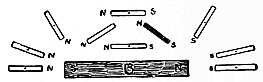
33. Theory of Magnetism. Each little particle of a piece of steel or iron is supposed to be a magnet, even before it touches a magnet. When these little magnets are thoroughly mixed up in the steel, they pull in all sorts of directions upon each other and tend to keep the steel from attracting outside bodies. When a magnet is properly rubbed upon a bar of steel, the north poles of the little molecular magnets of the steel are all made to point in the same direction. As the north poles help each other, the whole bar can attract outside bodies.
By jarring a magnet its molecules are thoroughly shaken up; in fact, most of the magnetism can be knocked out of a weak magnet by hammering it.
34. Retentivity. The power that a piece of steel has to hold magnetism is called retentivity. Different kinds of steel have different retentivities. A sewing-needle of good steel will retain magnetism for years, and it is almost impossible to knock the magnetism out by hammering it. Soft steel has very little retentivity, because it does not contain much carbon. Soft iron, which contains less carbon than steel, holds magnetism very poorly; so it is not used for permanent magnets. A little magnetism, however, will remain in the soft iron after it is removed from a magnet. This is called residual magnetism.
35. Heat and Magnetism. Steel will completely lose its magnetism when heated to redness, and a magnet[26] will not attract red-hot iron. The molecules of a piece of red-hot iron are in such a state of rapid vibration that they refuse to be brought into line by the magnet.
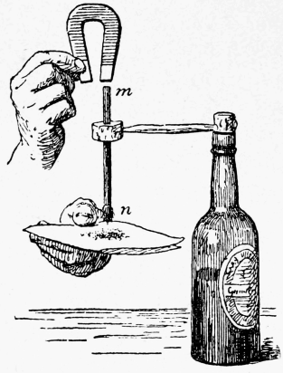
36. Induced Magnetism. A piece of soft iron may be induced to become a magnet by holding it near a magnet, absolute contact not being necessary. When the soft iron is removed, again, from the influence of the magnet, its magnetism nearly all disappears. It is said to have temporary magnetism; it had induced magnetism. If a piece of soft iron be held near the north pole of a magnet, as in Fig. 27, poles will be produced in the soft iron, the one nearest the magnet being the south pole, and the other the north pole.
37. Magnetic Field. If a bar magnet be laid upon the table, and a compass be moved about it, the compass-needle will be attracted by the magnet, and it will point in a different direction for every position given to the compass. This strange power, called magnetism, reaches out on all sides of a magnet. The magnet may be said to act by induction[27] upon the compass-needle. The space around the magnet, in which this inductive action takes place, is called the magnetic field. Fig. 28 shows some of the positions taken by a compass-needle when moved about on one side of a bar magnet.
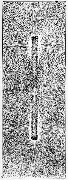
Fig. 29.
| 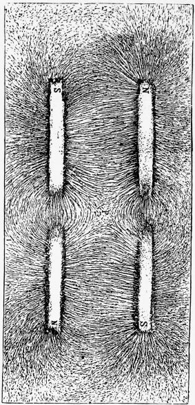
Fig. 30.
|
38. Magnetic Figures can be made by sprinkling iron[28] filings upon a sheet of paper under which is placed a magnet. Fig. 29 shows a magnetic figure made with an ordinary bar magnet. The magnet was placed upon the table and over this was laid a piece of smooth paper. Fine iron filings were sifted upon the paper, which was gently tapped so that the filings could arrange themselves. As each particle of iron became a little magnet, by induction, its poles were attracted and repelled by the magnet; and when the paper was tapped they swung around to their final positions. Notice that the filings have arranged themselves in lines. These lines show the positions of some of the lines of magnetic force which surrounded the magnet.
These lines of force pass from the north pole of a magnet through the air on all sides to its south pole.
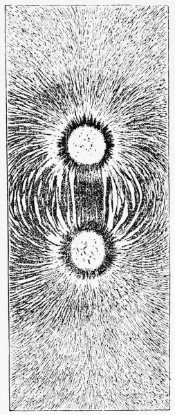
Fig. 30 shows a magnetic figure made from two bar magnets placed side by side, their unlike poles being next to each other. Fig. 31 shows the magnetic figure[29] of a horseshoe magnet with round poles, the poles being uppermost.
39. The Use of Armatures. A magnet attracts iron most strongly at its poles, because it is at the poles that the greatest number of lines of force pass into the air. Lines of force pass easily through soft iron, which is said to be a good conductor of them. Air is not a good conductor of the lines of force; in order, then, for the lines of force to pass from the north pole of a magnet to its south pole, they must overcome this resistance of the air, unless the armature is in place. A magnet will gradually grow weaker when its armature is left off.
40. Terrestrial Magnetism. As the compass-needle points to the north and south, the earth must act like a magnet. There is a place very far north, about a thousand miles from the north pole of the earth, which is called the earth's north magnetic pole. Compass-needles point to this place, and not to the earth's real north pole. You can see, then, that if a compass be taken north of this magnetic pole, its north pole will point south. Lines of force pass from the earth's north magnetic pole through the air on all sides of the earth and enter the earth's south magnetic pole. The compass-needle, in pointing toward the north magnetic pole, merely takes the direction of the earth's lines of force, just as the particles of iron filings arrange themselves in the magnetic figures.
41. Declination. As the magnetic needle does not point exactly to the north, an angle is formed between the true north and south line and the line of the needle. In Fig. 32 the line marked N S is the true north and[30] south line. The angle of variation, or the declination, is the angle A between the line N S and the compass-needle.
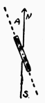
Fig. 32.
| 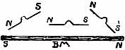
Fig. 33.
|
42. Dip or Inclination. If a piece of steel be carefully balanced upon a support, and then magnetized, it will be found that it will no longer balance. The north pole will dip or point downward. Fig. 33 shows what happens to a needle when it is held in different positions over a bar magnet. It simply takes the directions of the lines of force as they pass from the north to the south pole of the magnet. As the earth's lines of force pass in curves from the north to the south magnetic pole, you can see why the magnetic needle dips, unless its south pole is made heavier than its north. Magnetic needles are balanced after they are magnetized.
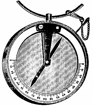
Fig. 34 shows a simple form of dipping needle. These are often used by geologists and miners. In the hands[31] of the prospector, the miner's compass, or dipping needle, proves a serviceable guide to the discovery and location of magnetic iron ore. In this instrument the magnetic needle is carefully balanced upon a horizontal axis within a graduated circle, and in which the needle will be found to assume a position inclined to the horizon. This angle of deviation is called the inclination or dip, and varies in different latitudes, and even at different times in the same place.
43. The Earth's Inductive Influence. The earth's magnetism acts inductively upon pieces of steel or iron upon its surface. If a piece of steel or iron, like a stove poker, for example, be held in a north and south line with its north end dipping considerably, it will be in the best position for the magnetism of the earth to act upon it; that is, it will lie in the direction taken by the earth's lines of force. If the poker be struck two or three times with a hammer to shake up its molecules, we shall find, upon testing it, that it has become magnetized. By this method we can pound magnetism right out of the air with a hammer. If the magnetized poker be held level, in an east and west direction, it will no longer be acted upon to advantage by the inductive influence of the earth, and we can easily hammer the magnetism out of it again. (For experiments on magnets and magnetism see "Study," Part I.)
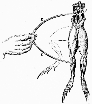
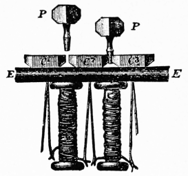
44. Early Experiments. In 1786 Galvani, an Italian physician, made experiments to study the effect of static electricity upon the nervous excitability of animals, and especially upon the frog. He found that electric machines were not necessary to produce muscular contractions or kicks of the frog's legs, and that they could be produced when two different metals, Fig. 35, like iron and copper, for example, were placed in proper contact with a nerve and a muscle and then made to touch each other. Galvani first thought that the frog generated the electricity instead of the metals.
Volta proved that the electricity was caused by the contact of the metals. He used the condensing electroscope as one means of proving that two dissimilar metals become charged differently when in contact. Volta also[33] carried out his belief by constructing what is called a Voltaic Pile. He thought that by making several pairs of metals so arranged that all the little currents would help each other, a strong current could be generated. Fig. 36 shows a pile, it being made by placing a pair of zinc and copper discs in contact with one another, then laying on the copper disc a piece of flannel soaked in brine, then on top of this another pair, etc., etc. By connecting the first zinc and the last copper, quite a little current was produced. This was a start from which has been built our present knowledge of electricity. Strictly speaking, electricity is not generated by combinations of metals or by cells; they really keep up a difference of potential, as will be seen.
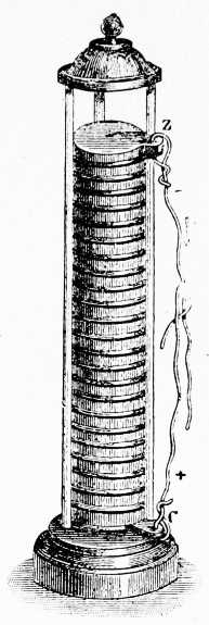
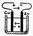
Fig. 37.
| 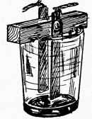
Fig. 38.
|
45. The Simple Cell. It has been stated that two different kinds of electrifications may be produced by friction; one positive, the other negative. Either can be produced, at will, by using proper materials. Fig. 37 shows a section of a simple cell; Fig. 38 shows another view. Cu is a piece of copper, and Zn a piece of zinc. When they are placed in[34] dilute sulphuric acid, it can be shown by delicate apparatus that they become charged differently, because the acid acts differently upon the plates. They become charged by chemical action, and not by friction. The zinc is gradually dissolved, and it is this chemical burning of the zinc that furnishes energy for the electric current in the simple cell. The electrification, or charge, on the plates tends to flow from the place of higher to the place of lower potential, just as water tends to flow down hill. If a wire be joined to the two metals, a constant current of electricity will flow through it, because the acid continues to act upon the plates. The simple cell is a single-fluid cell, as but one liquid is used in its construction.
45a. Plates and Poles. The metal strips used in voltaic cells are called plates or elements. The one most acted upon by the acid is called the positive (+) plate. In the simple cell the zinc is the + plate, and the copper the negative (-) plate. The end of a wire attached to the - plate is called the + pole, or electrode. Fig. 37 shows the negative (-) electrode as the end of the wire attached to the + plate.
46. Direction of Current. In the cell the current passes from the zinc to the copper; that is, from the positive to the negative plate, where bubbles of hydrogen gas are deposited. In the wire connecting the plates, the current passes from the copper to the zinc plate. In most cells, carbon takes the place of copper. (See "Study," § 268.)
47. Local Currents; Amalgamation. Ordinary zinc contains impurities such as carbon, iron, etc., and[35] when the acid comes in contact with these, they form with the zinc a small cell. This tends to eat away the zinc without producing useful currents. The little currents in the cell from this cause are called local currents. (See "Study," Exp. 111, § 273.) This is largely overcome by coating the zinc with mercury. This process is called amalgamation. It makes the zinc act like pure zinc, which is not acted upon by dilute sulphuric acid when the current does not pass. (See "Study," § 257, 274.)
48. Polarization of Cells. Bubbles of hydrogen gas are formed when zinc is dissolved by an acid. In the ordinary simple cell these bubbles collect on the copper plate, and not on the zinc plate, as might be expected. The hydrogen is not a conductor of electricity, so this film of gas holds the current back. The hydrogen acts like a metal and sets up a current that opposes the zinc to the copper current. Several methods are employed to get rid of the hydrogen. (See "Study," § 278, 279, 280.)
49. Single-Fluid and Two-Fluid Cells. The simple cell (§ 45) is a single-fluid cell. The liquid is called the electrolyte, and this must act upon one of the plates; that is, chemical action must take place in order to produce a current. The simple cell polarizes rapidly, so something must be used with the dilute sulphuric acid to destroy the hydrogen bubbles. This is done in the bichromate of potash cell.
In order to get complete depolarization—that is, to keep the carbon plate almost perfectly free from hydrogen, it is necessary to use two-fluid cells, or those to which some solid depolarizer is added to the one fluid.
50. Open and Closed Circuit Cells. If we consider a voltaic cell, the wires attached to it, and perhaps some instrument through which the current passes, we have an electric circuit. When the current passes, the circuit is closed, but when the wire is cut, or in any way disconnected so that the current can not pass, the circuit is open or broken. (See "Study," § 266.)
Open Circuit Cells are those which can give momentary currents at intervals, such as are needed for bells, telephones, etc. These must have plenty of time to rest, as they polarize when the circuit is closed for a long time. The Leclanché and dry cells are the most common open circuit cells.
Closed Circuit Cells. For telegraph lines, motors, etc.,[37] where a current is needed for some time, the cell must be of such a nature that it will not polarize quickly; it must give a strong and constant current. The bichromate and gravity cells are examples of this variety. (See "Study," § 286.)
51. Bichromate of Potash Cells are very useful for general laboratory work. They are especially useful for operating induction coils, small motors, small incandescent lamps, for heating platinum wires, etc. These cells have an E.M.F. of about 2 volts. Dilute sulphuric acid is used as the exciting fluid, and in this is dissolved the bichromate of potash which keeps the hydrogen bubbles from the carbon plate. (See "Apparatus Book," § 26.) Zinc and carbon are used for the plates, the + pole being the wire attached to the carbon.
Fig. 39 shows one form of bichromate cell. It furnishes a large quantity of current, and as the zinc can be raised from the fluid, it may be kept charged ready for use for many months, and can be set in action any time when required by lowering the zinc into the liquid. Two of these cells will burn a one candle-power miniature incandescent lamp several hours. The carbon is indestructible.
Note. For various forms of home-made cells, see "Apparatus Book," Chapter I., and for battery fluids see Chapter II.
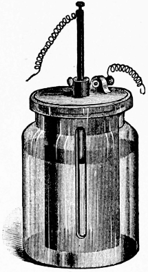
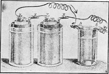
52. The Grenet Cell. Fig. 40 is another form of bichromate cell. The carbon plates are left in the fluid constantly. The zinc plate should be raised when the cell is not in use, to keep it from being uselessly dissolved.
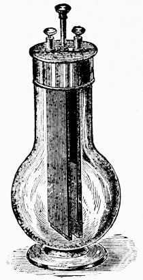
Fig. 40.
| 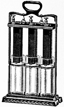
Fig. 41.
|
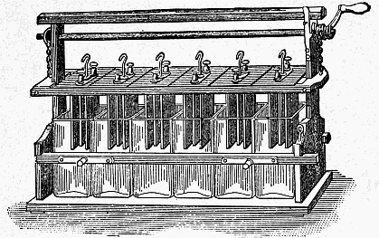
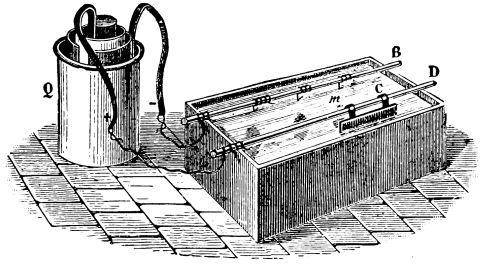
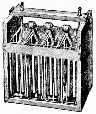
53. Plunge Batteries. Two or more cells are often arranged so that their elements can be quickly lowered into the acid solution. Such a combination, Fig. 41, is called a plunge battery. The binding-posts are so arranged that currents of different strengths can be taken from the combination. The two binding-posts on the right of the battery will give the current of one cell; the two binding-posts on the left of the battery will give the current of two cells, and the two end binding-posts will give the current of all three cells. When not in use the elements must always be hung on the hooks and kept out of the solution.
54. Large Plunge Batteries. Fig. 42, are arranged with a winch and a bar above the cells; these afford a ready and convenient means of lifting or lowering the elements and avoiding waste. In the battery shown, Fig. 42, the zincs are 4×6 inches; the carbons have the same dimensions, but there are two carbon plates to each zinc, thus giving double the carbon surface.
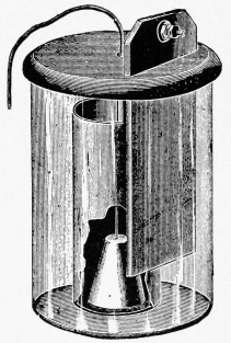
55. The Fuller Cell, Fig. 43, is another type of bichromate cell, used largely for long-distance telephone service, for telephone exchange and switch service, for running small motors, etc. It consists of a glass jar, a carbon plate, with proper connections, a clay porous cup, containing the zinc, which is made in the form of a cone. A little mercury is placed in the porous cup to keep the zinc well amalgamated. Either bichromate of potash or bichromate of soda can be used as a depolarizer.
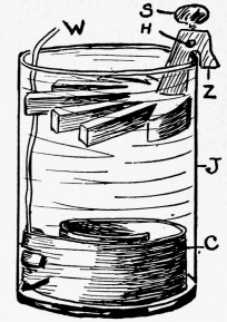
56. The Gravity Cell, sometimes called the bluestone or crowfoot cell, is used largely for telegraph, police, and fire-alarm signal service, laboratory and experimental work, or whenever a closed circuit cell is required. The E.M.F. is about one volt. This is a modified form of the Daniell cell. Fig. 44 shows a home-made gravity cell.
A copper plate is placed at the bottom of the glass jar, and upon this rests a solution of copper sulphate (bluestone). The zinc plate is supported about four inches above the copper, and is surrounded by a solution of zinc sulphate which floats upon the top of the blue solution. An insulated wire reaches from the copper to the top of the cell and forms the positive pole. (See "Apparatus Book," § 11 to 15, for home-made gravity cell, its regulation, etc. For experiments with two-fluid Daniell cell, see "Study," Exp. 113, § 281 to 286.)
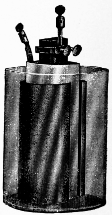
56a. Bunsen Cells, Fig. 45, are used for motors, small incandescent lamps, etc. A carbon rod is inclosed in a porous cup, on the outside of which is a cylinder of zinc that stands in dilute sulphuric acid, the carbon being in nitric acid.
57. The Leclanché Cell is an open circuit cell. Sal ammoniac is used as the exciting fluid, carbon and zinc being used for plates. Manganese dioxide is used as the depolarizer; this surrounds the carbon plate, the two being either packed together in a porous cup or held together in the form of cakes. The porous cup, or pressed cake, stands in the exciting fluid. The E. M. F. is about 1.5 volts.
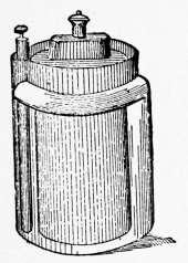
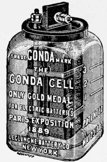
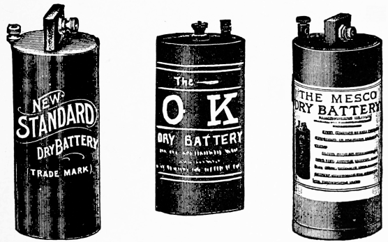
Fig. 46 shows a form with porous cup. The binding-post at the top of the carbon plate forms the + electrode, the current leaving the cell at this point.
The Gonda Prism Cell (Fig. 47), is a form of Leclanché in which the depolarizer is in the form of a cake.
58. Dry Cells are open circuit cells, and can be carried about, although they are moist inside. The + pole is the end of the carbon plate. Zinc is used as the outside case and + plate. Fig. 48 shows the ordinary forms.
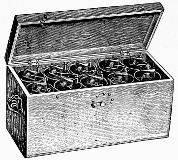
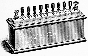
Fig. 49 shows a number of dry cells arranged in a box with switch in front, so that the current can be regulated at will.
59. The Edison-Lelande Cells, Fig. 50, are made in several sizes and types. Zinc and copper oxide, which is pressed into plates, form the elements. The exciting fluid consists of a 25 per cent. solution of caustic potash in water. They are designed for both open and closed circuit work.
60. Electrical Connections. In experimental work, as well as in the everyday work of the electrician, electrical connections must constantly be made. One wire must be joined to another, just for a moment, perhaps, or one piece of apparatus must be put in an electric circuit with other apparatus, or the current must be turned on or off from motors, lamps, etc. In order to conveniently and quickly make such connections, apparatus called push-buttons, switches and binding-posts are used.
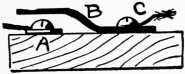
Fig. 51.
| 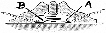
Fig. 52.
|
61. Push-Buttons. The simple act of pressing your finger upon a movable button, or knob, may ring a bell a mile away, or do some other equally wonderful thing. Fig. 51 shows a simple push-button, somewhat like a simple key in construction. If we cut a wire, through which a current is passing, then join one of the free ends to the screw A and the other end to screw C, we shall be able to let the current pass at any instant by pressing the spring B firmly upon A.
Push-buttons are made in all sorts of shapes and sizes. Fig. 52 gives an idea of the general internal construction.[44] The current enters A by one wire, and leaves by another wire as soon as the button is pushed and B is forced down to A. The bottom of the little button rests upon the top of B.
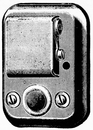
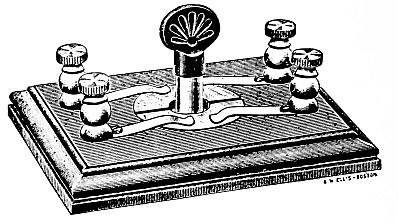
Fig. 53 shows a Table Clamp-Push for use on dining-tables, card-tables, chairs, desks, and other movable furniture. Fig. 54 shows a combination of push-button, speaking-tube, and letter-box used in city apartment houses. Fig. 55 shows an Indicating Push. The buzzer indicates, by the sound, whether the call has been heard; that is, the person called answers back.
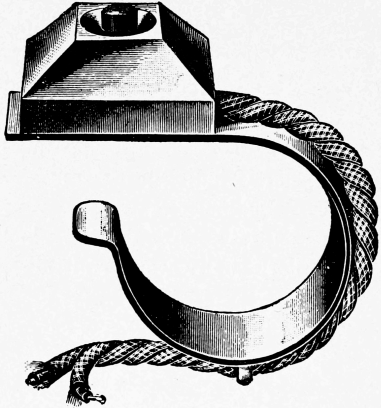
Fig. 53.
|
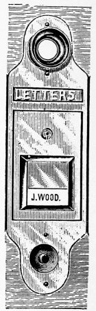
Fig. 54.
|
Modifications of ordinary push-buttons are used for floor push-buttons, on doors, windows, etc., for burglar-alarms, for turning off or on lights, etc., etc. (See[45] "Apparatus Book," Chapter III., for home-made push-buttons.)
62. Switches have a movable bar or plug of metal, moving on a pivot, to make or break a circuit, or transfer a current from one conductor to another.
Fig. 56 shows a single point switch. The current entering the pivoted arm can go no farther when the switch is open, as shown. To close the circuit, the arm is pushed over until it presses down upon the contact-point. For neatness, both wires are joined to the under side of the switch or to binding-posts.
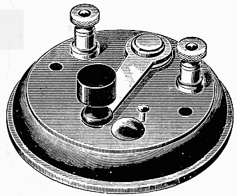
Fig. 57 shows a knife switch. Copper blades are pressed down between copper spring clips to close the circuit. The handle is made of insulating material.
Pole-changing switches, Fig. 58, are used for changing or reversing the poles of batteries, etc.
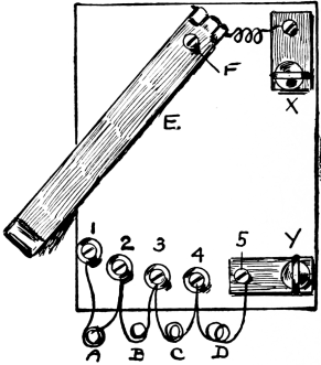
Fig. 59 shows a home-made switch, useful[46] in connection with resistance coils. By joining the ends of the coils A, B, C, D, with the contact-points 1, 2, 3, etc., more or less resistance can be easily thrown in by simply swinging the lever E around to the left or right. If E be turned to 1, the current will be obliged to pass through all the coils A, B, etc., before it can pass out at Y. If E be moved to 3, coils A and B will be cut out of the circuit, thus decreasing the resistance to the current on its way from X to Y. Current regulators are made upon this principle. (See "Apparatus Book," Chapter IV., for home-made switches.)
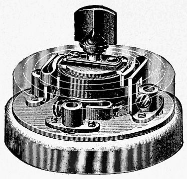
Switchboards are made containing from two or three to hundreds of[47] switches, and are used in telegraph and telephone work, in electric light stations, etc., etc. (See Chapter on Central Stations.) Fig. 60 shows a switch used for incandescent lighting currents.
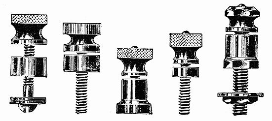
63. Binding-Posts are used to make connections between two pieces of apparatus, between two or more wires, between a wire and any apparatus, etc., etc. They allow the wires to be quickly fastened or unfastened to the apparatus. A large part of the apparatus shown in this book has binding-posts attached. Fig. 61 shows a few of the common forms used. (See "Apparatus Book," Chapter V., for home-made binding-posts.)
64. Electrical Units. In order to measure electricity for experimental or commercial purposes, standards or units are just as necessary as the inch or foot for measuring distances.
65. Potential; Electromotive Force. If water in a tall tank be allowed to squirt from two holes, one near the bottom, the other near the top, it is evident that the force of the water that comes from the hole at the bottom will be the greater. The pressure at the bottom is greater than that near the top, because the "head" is greater.
When a spark of static electricity jumps a long distance, we say that the charge has a high potential; that is, it has a high electrical pressure. Potential, for electricity, means the same as pressure, for water. The greater the potential, or electromotive force (E.M.F.) of a cell, the greater its power to push a current through wires. (See "Study," § 296 to 305, with experiments.)
66. Unit of E.M.F.; the Volt.—In speaking of water, we say that its pressure is so many pounds to the square inch, or that it has a fall, or head, of so many feet. We speak of a current as having so many volts; for example, we say that a wire is carrying a 110-volt current. The volt is the unit of E.M.F. An ordinary gravity cell has an E.M.F. of about one volt. This name was given in honor of Volta.
67. Measurement of Electromotive Force. There are several ways by which the E.M.F. of a cell, for example, can be measured. It is usually measured relatively, by comparison with the E. M. F. of some standard cell. (See "Study," Exp. 140, for measuring the E. M. F. of a cell by comparison with the two-fluid cell.)
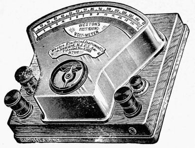
Voltmeters are instruments by means of which E. M. F. can be read on a printed scale. They are a variety of galvanometer, and are made with coils of such high resistance, compared with the resistance of a cell or dynamo, that the E. M. F. can be read direct. The reason for this will be seen by referring to Ohm's law ("Study," § 356); the resistance is so great that the strength of the current depends entirely upon the E. M. F.
Voltmeters measure electrical pressure just as steam gauges measure the pressure of steam. Fig. 62 shows one form of voltmeter. Fig. 63 shows a voltmeter[50] with illuminated dial. An electrical bulb behind the instrument furnishes light so that the readings can be easily taken.
68. Electrical Resistance. Did you ever ride down hill on a hand-sled? How easily the sled glides over the snow! What happens, though, when you strike a bare place, or a place where some evil-minded person has sprinkled ashes? Does the sled pass easily over bare ground or ashes? Snow offers very little resistance to the sled, while ashes offer a great resistance.
All substances do not allow the electric current to pass through them with the same ease. Even the liquid in a cell tends to hold the current back and offers internal resistance. The various wires and instruments connected to a cell offer external resistance. (See "Study," Chapter XVIII., for experiments, etc.)
69. Unit of Resistance. The Ohm is the name given to the unit of resistance. About 9 ft. 9 in. of No. 30 copper wire, or 39 feet 1 in. of No. 24 copper wire, will make a fairly accurate ohm.
Resistance coils, having carefully measured resistances, are made for standards. (See "Apparatus Book," Chapter XVII., for home-made resistance coils.) Fig. 64 shows a commercial form of a standard resistance coil. The coil is inclosed in a case and has large wires leading[51] from its ends for connections. Fig. 65 gives an idea of the way in which coils are wound and used with plugs to build up resistance boxes, Fig. 66.
70. Laws of Resistance. 1. The resistance of a wire is directly proportional to its length, provided its cross-section, material, etc., are uniform.
2. The resistance of a wire is inversely proportional to its area of cross-section; or, in other words, inversely proportional to the square of its diameter, other things being equal.
3. The resistance of a wire depends upon its material, as well as upon its length, size, etc.
4. The resistance of a wire increases as its temperature rises. (See "Study," Chapters XVIII. and XIX., for experiments on resistance, its measurement, etc.)
71. Current Strength. The strength of a current at the end of a circuit depends not only upon the electrical pressure, or E. M. F., which drives the current, but also upon the resistance which has to be overcome.[52] The greater the resistance the weaker the current at the end of its journey.
72. Unit of Current Strength; The Ampere. A current having an E. M. F. of one volt, pushing its way through a resistance of one ohm, would have a unit of strength, called one ampere. This current, one ampere strong, would deposit, under proper conditions, .0003277 gramme of copper in one second from a solution of copper sulphate.
73. Measurement of Current Strength. A magnetic needle is deflected when a current passes around it, as in instruments like the galvanometer. The galvanoscope merely indicates the presence of a current. Galvanometers measure the strength of a current, and they are made in many forms, depending upon the nature and strength of the currents to be measured. Galvanometers are standardized, or calibrated, by special measurements, or by comparison with some standard instrument, so that when the deflection is a certain number of degrees, the current passing through it is known to be of a certain strength.
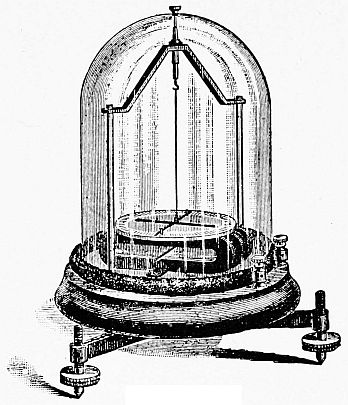
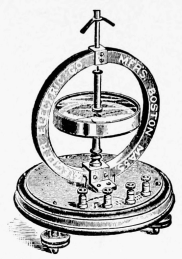
Fig. 67 shows an astatic galvanometer. Fig. 68 shows a tangent galvanometer, in which the strength of the current[53] is proportional to the tangent of the angle of deflection. Fig. 69 shows a D'Arsonval galvanometer, in which a coil of wire is suspended between the poles of a permanent horseshoe magnet. The lines of force are concentrated by the iron core of the coil. The two thin suspending wires convey the current to the coil. A ray of light is reflected from the small mirror and acts as a pointer as in other forms of reflecting galvanometers.
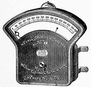
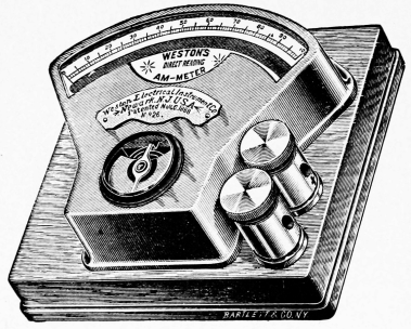
74. The Ammeter, Fig. 70, is a form of galvanometer in which the strength of a current, in amperes, can be read. In these the strength of current is proportional to the angular deflections. The coils are made with a small resistance, so that the current will not be greatly reduced in strength in passing through them.
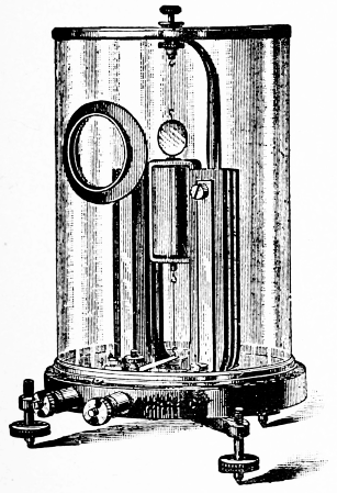
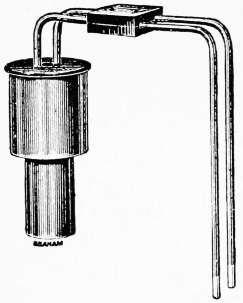
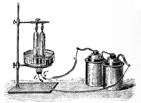
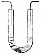
75. Voltameters measure the strength of a current by chemical means, the quantity of metal deposited or gas generated being proportional to the time that the current flows and to its strength. In the water voltameter, Fig. 71, the hydrogen and oxygen produced in a[54] given time are measured. (See "Study," Chapter XXI.)
The copper voltameter measures the amount of copper deposited in a given time by the current. Fig. 72 shows one form. The copper cathode is weighed before and after the current flows. The weight of copper deposited and the time taken are used to calculate the current strength.
76. Unit of Quantity; The Coulomb is the quantity of electricity given, in one second, by a current having a[55] strength of one ampere. Time is an important element in considering the work a current can do.
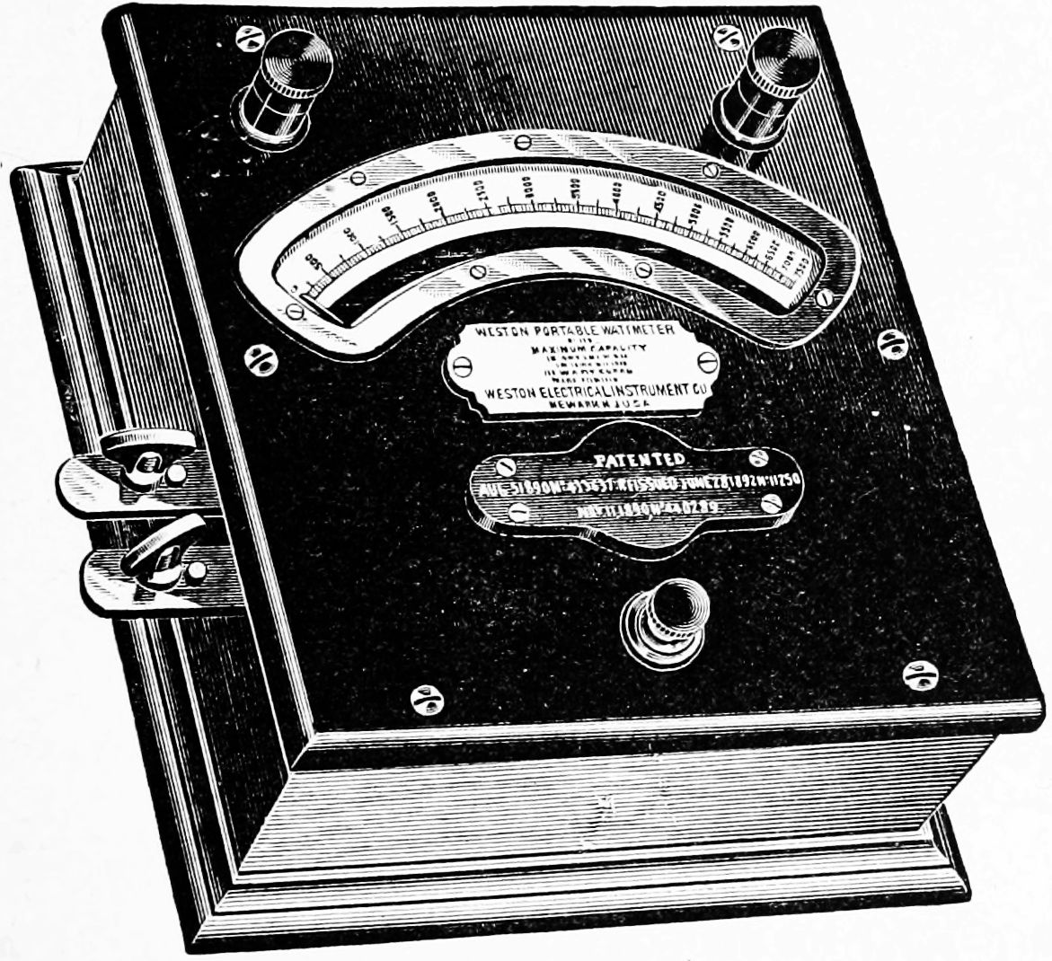
77. Electrical Horse-power; The Watt is the unit of electrical power. A current having the strength of one ampere, and an E. M. F. of one volt has a unit of power. 746 watts make one electrical horse-power. Watts = amperes × volts. Fig. 73 shows a direct reading wattmeter based on the international volt and ampere. They save taking simultaneous ammeter and voltmeter readings, which are otherwise necessary to get the product of volts and amperes, and are also used on alternating current measurements.
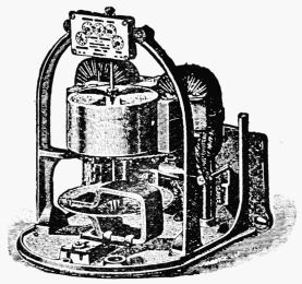
There are also forms of wattmeters, Fig. 74, in which the watts are read from dials like those on an ordinary gas-meter, the records being permanent.
Fig. 75 shows a voltmeter V, and ammeter A, so placed in the circuit that readings can be taken. D represents a dynamo. A is placed so that the whole current passes through it, while V is placed between the main wires to measure the difference in potential. The product of the two readings in volts and amperes gives the number of watts.
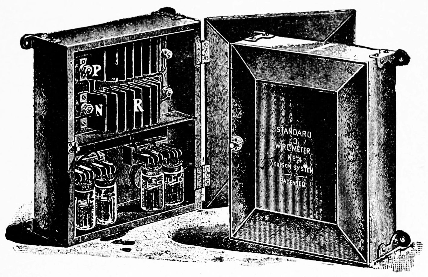
78. Chemical Meters also measure the quantity of current that is used; for example, one may be placed in the cellar to measure the quantity of current used to light the house.
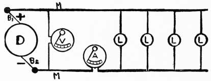
Fig. 76 shows a chemical meter, a part of the current passing through a jar containing zinc plates and a solution of zinc sulphate. Metallic zinc is dissolved from one plate and deposited upon the other. The increase in weight shows the amount of chemical action which is proportional to the ampere hours. Knowing the relation between the quantity of current that can pass through the solution to that which can pass through the meter by[57] another conductor, a calculation can be made which will give the current used. A lamp is so arranged that it automatically lights before the meter gets to the freezing-point; this warms it up to the proper temperature, at which point the light goes out again.
79. Electrolysis. It has been seen that in the voltaic cell electricity is generated by chemical action. Sulphuric acid acts upon zinc and dissolves it in the cell, hydrogen is produced, etc. When this process is reversed, that is, when the electric current is passed through some solutions, they are decomposed, or broken up into their constituents. This process is called electrolysis, and the compound decomposed is the electrolyte. (See "Study," § 369, etc., with experiments.)
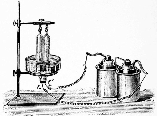
Fig. 77 shows how water can be decomposed into its two constituents, hydrogen and oxygen, there being twice as much hydrogen formed as oxygen.
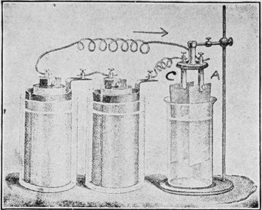
Fig. 78 shows a glass jar in which are placed two metal[59] strips, A and C, these being connected with two cells. In this jar may be placed various conducting solutions to be tested. If, for example, we use a solution of copper sulphate, its chemical formula being CuSO4, the current will break it up into Cu (copper) and SO4. The Cu will be deposited upon C as the current passes from A to C through the solution. A is called the anode, and C the cathode.
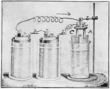
Fig. 79 shows another form of jar used to study the decomposition of solutions by the electric current.
80. Ions. When a solution is decomposed into parts by a current, the parts are called the Ions. When copper sulphate (Cu SO4) is used, the ions are Cu, which is a metal, and SO4, called an acid radical. When silver nitrate (Ag NO3) is used, Ag and NO3 are the ions. The metal part of the compound goes to the cathode.
81. Electricity and Chemical Action. We have just seen, Chapter VII., that the electric current has the power to decompose certain compounds when they are in solution. By choosing the right solutions, then, we shall be able to get copper, silver, and other metals set free by electrolysis.
82. Electroplating consists in coating substances with metal with the aid of the electric current. If we wish to electroplate a piece of metal with copper, for example, we can use the arrangement shown in Fig. 78, in which C is the cathode plate to be covered, and A is a copper plate. The two are in a solution of copper sulphate, and, as explained in § 79, the solution will be decomposed. Copper will be deposited upon C, and the SO4 part of the solution will go to the anode A, which it will attack and gradually dissolve. The SO4, acting upon the copper anode, makes CuSO4 again, and this keeps the solution at a uniform strength. The amount of copper dissolved from the copper anode equals, nearly, the amount deposited upon the cathode. The metal is carried in the direction of the current.
If we wish to plate something with silver or gold, it will be necessary to use a solution of silver or gold for the electrolyte, a plate of metallic silver or gold being used for the anode, as the case may be.
Great care is used in cleaning substances to be plated, all dirt and grease being carefully removed.
Fig. 80 shows a plating bath in which several articles can be plated at the same time by hanging them upon a metal bar which really forms a part of the cathode. If, for example, we wish to plate knives, spoons, etc., with silver, they would be hung from the bar shown, each being a part of the cathode. The vat would contain a solution of silver, and from the other bar would be hung a silver plate having a surface about equal to that of the combined knives, etc.
Most metals are coated with copper before they are plated with silver or gold. When plating is done on a large scale, a current from a dynamo is used. For experimental purposes a Gravity cell will do very well. (See "Study," § 374 to 380 with experiments.)
83. Electrotyping. It was observed by De La Rue in 1836 that in the Daniell cell an even coating of copper was deposited upon the copper plate. From this was developed the process of electrotyping, which consists in[62] making a copy in metal of a wood-cut, page of type, etc. A mould or impression of the type or coin is first made in wax, or other suitable material. These moulds are, of course, the reverse of the original, and as they do not conduct electricity, have to be coated with graphite. This thin coating lines the mould with conducting material so that the current can get to every part of the mould. These are then hung upon the cathode in a bath of copper sulphate as described in § 82. The electric current which passes through the vat deposits a thin layer of metallic copper next to the graphite. When this copper gets thick enough, the wax is melted away from it, leaving a thin shell of copper, the side next to the graphite being exactly alike in shape to the type, but made of copper. These thin copper sheets are too thin to stand the pressure necessary on printing presses, so they are strengthened by backing them with soft metal which fills every crevice, making solid plates about ¼ in. thick. These plates or electrotypes are used to print from, the original type being used to set up another page.
84. Polarization. It has been stated that a simple cell polarizes rapidly on account of hydrogen bubbles that form upon the copper plate. They tend to send a current in the opposite direction to that of the main current, which is thereby weakened.
85. Electromotive Force of Polarization. It has been shown, Fig. 71, that water can be decomposed by the electric current. Hydrogen and oxygen have a strong attraction or chemical affinity for each other, or they would not unite to form water. This attraction has to be overcome before the water can be decomposed. As soon as the decomposing current ceases to flow, the gases formed try to rush together again; in fact, if the water voltameter be disconnected from the cells and connected with a galvanoscope, the presence of a current will be shown. This voltameter will give a current with an E. M. F. of nearly 1.5 volts; so it is evident that we must have a current with a higher voltage than this to decompose water. This[64] E. M. F., due to polarization, is called the E. M. F. of polarization.
86. Secondary or Storage Batteries, also called accumulators, do not really store electricity. They must be charged by a current before they can give out any electricity. Chemical changes are produced in the storage cells by the charging current just as they are in voltameters, electroplating solutions, etc.; so it is potential chemical energy that is really stored. When the new products are allowed to go back to their original state, by joining the electrodes of the charged cell, a current is produced.
Fig. 81 shows two lead plates, A and B, immersed in dilute sulphuric acid, and connected with two ordinary cells. A strong current will pass through the liquid between A and B at first, but it will quickly become weaker, as chemical changes take place in the liquid. This may be shown by a galvanometer put in the circuit before beginning the experiment. By disconnecting the wires from the cells and joining them to the galvanometer, it will be shown that a current comes from the lead plates. This arrangement may be called a simple storage cell. Regular storage cells are charged with the current from a dynamo. (See "Study," Exp. 151.)
The first storage cells were made of plain lead plates, rolled up in such a way that they were close to each other, but did not touch. These were placed in dilute sulphuric acid. They were charged in alternate directions several times, until the lead became properly acted upon, at which time the cell would furnish a current.
A great improvement was made in 1881, by Faure, who coated the plates with red lead.
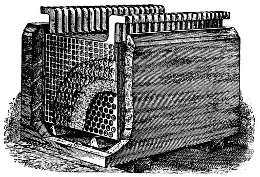
The method now generally practiced is to cast a frame of lead, with raised right-angled ribs on each side, thus forming little depressed squares, or to punch a lead plate full of holes, which squares or holes are then filled with a pasty mixture of red oxide of lead in positive plates, and with litharge in negatives. In a form called the chloride battery, instead of cementing lead oxide paste into or against a lead framing in order to obtain the necessary active material, the latter is obtained by a strictly chemical process.
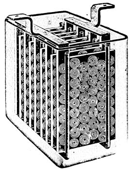
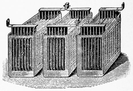
Fig. 82 shows a storage cell with plates, etc., contained in a glass jar. Fig. 83 shows a cell of 41 plates, set up in a lead-lined wood tank. Fig. 84 shows three cells joined in series. Many storage cells are used in central electric light stations to help the dynamos during the "rush" hours at night. They are charged during the day when the load on the dynamos is not heavy.
Fig. 85 shows another form of storage cell containing a number of plates.
87. The Uses of Storage Batteries are almost numberless. The current can be used for nearly everything for which a constant current is adapted, the following being some of its applications: Carriage propulsion; electric launch propulsion; train lighting; yacht lighting; carriage lighting; bicycle lighting; miners' lamps; dental, medical, surgical, and laboratory work; phonographs; kinetoscopes; automaton pianos; sewing-machine motors; fan motors; telegraph; telephone; electric bell; electric[67] fire-alarm; heat regulating; railroad switch and signal apparatus.
By the installing of a storage plant many natural but small sources of power may be utilized in furnishing light and power; sources which otherwise are not available, because not large enough to supply maximum demands. The force of the tides, of small water powers from irrigating ditches, and even of the wind, come under this heading.
As a regulator of pressure, in case of fluctuations in the load, the value of a storage plant is inestimable. These fluctuations of load are particularly noticeable in electric railway plants, where the demand is constantly rising and falling, sometimes jumping from almost nothing to the maximum, and vice versa, in a few seconds. If for no other reason than the prevention of severe strain on the engines and generators, caused by these fluctuations of demand, a storage plant will be valuable.
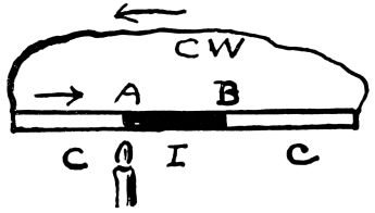
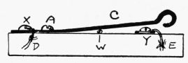
88. Thermoelectricity is the name given to electricity that is generated by heat. If a strip of iron, I, be connected between two strips of copper, C C, these being joined by a copper wire, C W, we shall have an arrangement that will generate a current when heated at either of the junctions between C and I. When it is heated at A the current will flow as shown by arrows, from C to I. If we heat at B, the current will flow in the opposite direction through the metals, although it will still go from C to I as before. Such currents are called thermoelectric currents.
Different pairs of metals produce different results. Antimony and bismuth are generally used, because the greatest effect is produced by them. If the end of a strip of bismuth be soldered to the end of a similar strip of antimony, and the free ends be connected to a galvanometer of low resistance, the presence of a current will be shown when the point of contact becomes hotter than the rest of the circuit. The current will flow from bismuth[69] to antimony across the joint. By cooling the juncture below the temperature of the rest of the circuit, a current will be produced in the opposite direction to the above. The energy of the current is kept up by the heat absorbed, just as it is kept up by chemical action in the voltaic cell.
89. Peltier Effect. If an electric current be passed through pairs of metals, the parts at the junction become slightly warmer or cooler than before, depending upon the direction of the current. This action is really the reverse of that in which currents are produced by heat.
90. Thermopiles. As the E.M.F. of the current produced by a single pair of metals is very small, several pairs are usually joined in series, so that the different currents will help each other by flowing in the same direction. Such combinations are called thermoelectric piles, or simply thermopiles.
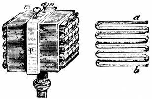
Fig. 87 shows such an arrangement, in which a large number of elements are placed in a small space. The junctures are so arranged that the alternate ones come together at one side.
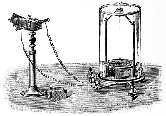
Fig. 88 shows a thermopile connected with a galvanometer.[70] The heat of a match, or the cold of a piece of ice, will produce a current, even if held at some distance from the thermopile. The galvanometer should be a short-coil astatic one. (See "Study," Chapter XXIV., for experiments and home-made thermopile.)
91. Electromagnetism is the name given to magnetism that is developed by electricity. We have seen that if a magnetic needle be placed in the field of a magnet, its N pole will point in the direction taken by the lines of force as they pass from the N to the S pole of the magnet.
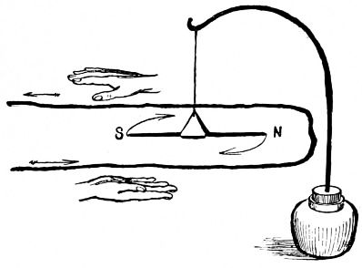
92. Lines of Force about a Wire. When a current passes through a wire, the magnetic needle placed over or under it tends to take a position at right angles to the wire. Fig. 89 shows such a wire and needle, and how the needle is deflected; it twists right around from its N and S position as soon as the current begins to flow. This shows that the lines of force pass around the wire and not in the direction of its length. The needle does not swing entirely perpendicular to the wire, that is, to[72] the E and W line, because the earth is at the same time pulling its N pole toward the N.
Fig. 90 shows a bent wire through which a current passes from C to Z. If you look along the wire from C toward the points A and B, you will see that under the wire the lines of force pass to the left. Looking along the wire from Z toward D you will see that the lines of force pass opposite to the above, as the current comes toward you. This is learned by experiment. (See "Study," Exp. 152, § 385, etc.)
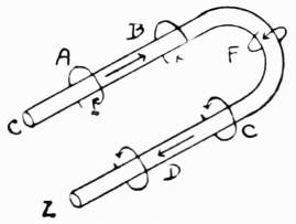
Rule. Hold the right hand with the thumb extended (Fig. 89) and with the fingers pointing in the direction of the current, the palm being toward the needle and on the opposite side of the wire from the needle. The north-seeking pole will then be deflected in the direction in which the thumb points.
93. Current Detectors. As there is a magnetic field about a wire when a current passes through it, and as the magnetic needle is affected, we have a means of detecting the presence of a current. When the current is strong it is simply necessary to let it pass once over or under a needle; when it is weak, the wire must pass several times above and below the needle, Fig. 91, to give the needle motion. (See "Apparatus Book," Chapter XIII., for home-made detectors.)
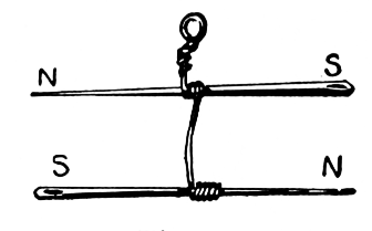
94. Astatic Needles and Detectors. By arranging two magnetized needles with their poles opposite each other, Fig. 92, an astatic needle is formed. The pointing-power is almost nothing, although their magnetic fields are retained. This combination is used to detect feeble currents. In the ordinary detector, the tendency of the needle to point to the N and S has to be overcome by the magnetic field about the coil before the needle can be moved; but in the astatic detector and galvanoscope this pointing-power is done away with. Fig. 93 shows a simple astatic galvanoscope. Fig. 67 shows an astatic galvanometer for measuring weak currents.
95. Polarity of Coils. When a current of electricity passes through a coil of wire, the coil acts very much like a magnet, although no iron enters into its construction. The coil becomes magnetized by the electric current, lines of force pass from it into the air, etc. Fig. 94 shows a coil connected to copper and zinc plates, so arranged with cork that the whole can float in a dish of dilute sulphuric acid. The current passes as shown by the arrows, and when the N pole of a magnet is brought near the right-hand end, there is a repulsion, showing that that end of the coil has a N pole.
Rule. When you face the right-hand end of the coil, the current is seen to pass around it in an anti-clockwise direction; this produces a N pole. When the current passes in a clockwise direction a S pole is produced.
96. Electromagnets. A coil of wire has a stronger field than a straight wire carrying the same current, because each turn adds its field to the fields of the other turns. By having the central part of the coil made of iron, or by having the coil of insulated wire wound upon an iron core, the strength of the magnetic field of the coil is greatly increased.
Lines of force do not pass as readily through air as through iron; in fact, lines of force will go out of their way to go through iron. With a coil of wire the lines of force pass from its N pole through the air on all sides of the coil to its S pole; they then pass through the inside of the coil and through the air back to the N pole. When the resistance to their passage through the coil is decreased by the core, the magnetic field is greatly strengthened, and we have an electromagnet.
The coil of wire temporarily magnetizes the iron core; it can permanently magnetize a piece of steel used as[75] a core. (See "Study," Chapter XXII., for experiments.)
97. Forms of Electromagnets. Fig. 95 shows a straight, or bar electromagnet. Fig. 96 shows a simple form of horseshoe electromagnet. As this form is not easily wound, the coils are generally wound on two separate cores which are then joined by a yoke. The yoke merely takes the place of the curved part shown in Fig. 96. In Fig. 97 is shown the ordinary form of horseshoe electromagnet used for all sorts of electrical instruments. (See "Apparatus Book," Chapter IX., for home-made electromagnets.)
98. Yokes and Armatures. In the horseshoe magnet there are two poles to attract and two to induce. The lines of force pass through the yoke on their way from one core to the other, instead of going through the air.[76] This reduces the resistance to them. If we had no yoke we should simply have two straight electromagnets, and the resistance to the lines of force would be so great that the total strength would be much reduced. Yokes are made of soft iron, as well as the cores and armature. The armature, as with permanent horseshoe magnets, is strongly drawn toward the poles. As soon as the current ceases to flow, the attraction also ceases.
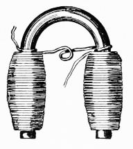
Fig. 96
| 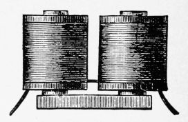
Fig. 97.
|
Beautiful magnetic figures can be made with horseshoe magnets. Fig. 98 shows that the coils must be joined so that the current can pass around the cores in opposite directions to make unlike poles. (See "Study," Exp. 164 to 173.)
99. Electromagnetic Induction. We have seen that a magnet has the power to act through space and induce another piece of iron or steel to become a magnet. A charge of static electricity can induce a charge upon another conductor. We have now to see how a current of electricity in one conductor can induce a current in another conductor, not in any way connected with the first, and how a magnet and a coil can generate a current.
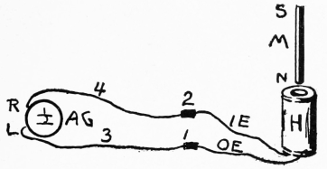
Fig. 99.
| 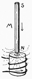
Fig. 100.
|
100. Current from Magnet and Coil. If a bar magnet, Fig. 99, be suddenly thrust into a hollow coil of wire, a momentary current of electricity will be generated in the coil. No current passes when the magnet and coil are still; at least one of them must be in motion. Such a current is said to be induced, and is an inverse one when[78] the magnet is inserted, and a direct one when the magnet is withdrawn from the coil.
101. Induced Currents and Lines of Force. Permanent magnets are constantly sending out thousands of lines of force. Fig. 100 shows a bar magnet entering a coil of wire; the number of lines of force is increasing, and the induced current passes in an anti-clockwise direction when looking down into the coil along the lines of force. This produces an indirect current. If an iron core be used in the coil, the induced current will be greatly strengthened.
It takes force to move a magnet through the center of a coil, and it is this work that is the source of the induced current. We have, in this simple experiment, the key to the action of the dynamo and other electrical machines.
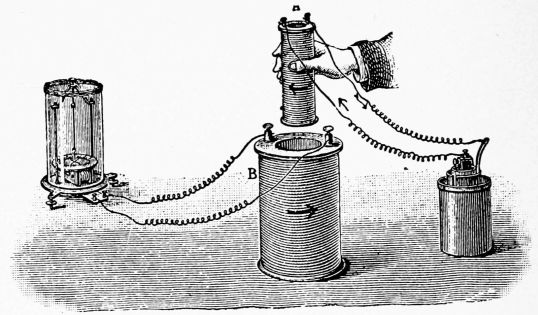
102. Current from two Coils. Fig. 101 shows two coils of wire, the smaller being connected to a cell, the larger to a galvanometer. By moving the small coil up[79] and down inside of the large one, induced currents are generated, first in one direction and then in the opposite. We have here two entirely separate circuits, in no way connected. The primary current comes from the cell, while the secondary current is an induced one. By placing a core in the small coil of Fig. 101, the induced current will be greatly strengthened.
It is not necessary to have the two coils so that one or both of them can move. They may be wound on the same core, or otherwise arranged as in the induction coil. (See "Study," Chapter XXV., for experiments on induced currents.)
103. The Coils. We saw, § 102, that an induced current was generated when a current-carrying coil, Fig. 101, was thrust into another coil connected with a galvanometer. The galvanometer was used merely to show the presence of the current. The primary coil is the one connected with the cell; the other one is called the secondary coil.
When a current suddenly begins to flow through a coil, the effect upon a neighboring coil is the same as that produced by suddenly bringing a magnet near it; and when the current stops, the opposite effect is produced. It is evident, then, that we can keep the small coil of Fig. 101 with its core inside of the large coil, and generate induced currents by merely making and breaking the primary circuit.
We may consider that when the primary circuit is closed, the lines of force shoot out through the turns of the secondary coil just as they do when a magnet or a current-carrying coil is thrust into it. Upon opening the circuit, the lines of force cease to exist; that is, we may imagine them drawn in again.
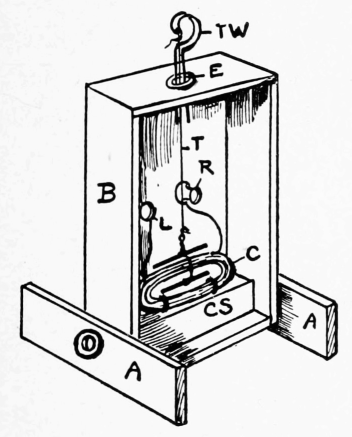
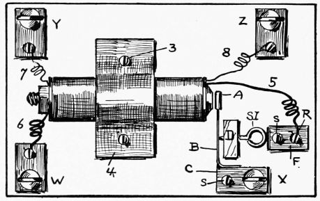
104. Construction. Fig. 102 shows one form of home-made induction coil, given here merely to explain the action and connections. Nearly all induction coils have some form of automatic current interrupter, placed in the primary circuit, to rapidly turn the current off and on.
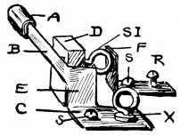
Details of Figs. 102 and 103. Wires 5 and 6 are the ends of the primary coil, while wires 7 and 8 are the terminals of the secondary coil. The primary coil is wound on a bolt which serves as the core, and on this coil is wound the secondary which consists of many turns of fine wire. The wires from a battery should be joined to binding-posts W and X, and the handles, from which the shock is felt, to Y and Z. Fig. 103 shows the details of the interrupter.
If the current from a cell enters at W, it will pass through the primary coil and out at X, after going through 5, R, F, S I, B, E and C. The instant the current passes, the bolt becomes magnetized; this attracts A, which pulls B away from the end of S I, thus automatically opening the circuit. B at once springs back to its former position against SI, as A is no longer attracted;[82] the circuit being closed, the operation is rapidly repeated.
A condenser is usually connected to commercial forms. It is placed under the wood-work and decreases sparking at the interrupter. (See "Apparatus Book," Chapter XI., for home-made induction coils.)
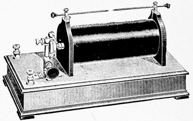
Fig. 104 shows one form of coil. The battery wires are joined to the binding-posts at the left. The secondary coil ends in two rods, and the spark jumps from one to the other. The interrupter and a switch are shown at the left.
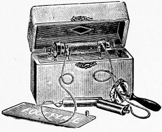
Fig. 105 shows a small coil for medical purposes. A dry cell is placed under the coil and all is included in a neat box. The handles form the terminals of the secondary coil.
105. The Currents. It should be noted that the current from the cell does not get into the secondary coil. The coils are thoroughly insulated from each other. The secondary current is an induced one, its voltage depending upon the relative number of turns of wire there are[83] in the two coils. (See Transformers.) The secondary current is an alternating one; that is, it flows in one direction for an instant and then immediately reverses its direction. The rapidity of the alternations depends upon the speed of the interrupter. Coils are made that give a secondary current with an enormous voltage; so high, in fact, that the spark will pass many inches, and otherwise act like those produced by static electric machines.
106. Uses of Induction Coils. Gas-jets can be lighted at a distance with the spark from a coil, by extending wires from the secondary coil to the jet. Powder can be fired at a distance, and other things performed, when a high voltage current is needed. Its use in medicine has been noted. It is largely used in telephone work. Of late, great use has been made of the secondary current in experiments with vacuum-tubes, X-ray work, etc.
107. The Complete Telegraph Line consists of several instruments, switches, etc., etc., but its essential parts are: The Line, or wire, which connects the different stations; the Transmitter or Key; the Receiver or Sounder, and the Battery or Dynamo.
108. The Line is made of strong copper, iron, or soft steel wire. To keep the current in the line it is insulated, generally upon poles, by glass insulators. For very short lines two wires can be used, the line wire and the return; but for long lines the earth is used as a return, a wire from each end being joined to large metal plates sunk in the earth.
109. Telegraph Keys are merely instruments by which the circuit can be conveniently and rapidly opened or closed at the will of the operator. An ordinary push-button may be used to turn the current off and on, but it is not so convenient as a key.
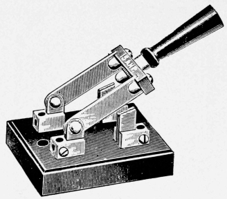
Fig. 106 shows a side view of a simple key which can be put anywhere in the circuit, one end of the cut wire being attached to X and the other to Y. By moving the lever C up and down according to a previously arranged set of signals, a current will be allowed to pass to a distant[85] station. As X and Y are insulated from each other, the current can pass only when C presses against Y.
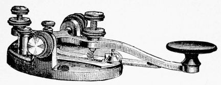
Fig. 107 shows a regular key, with switch, which is used to allow the current to pass through the instrument when receiving a message.
110. Telegraph Sounders receive the current from some distant station, and with its electromagnet produce sounds that can be translated into messages.
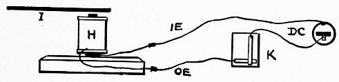
Fig. 108 shows simply an electromagnet H, the coil being connected in series with a key K and a cell D C. The key and D C are shown by a top view. The lever of K does not touch the other metal strap until it is pressed down. A little above the core of H is held a strip of iron, on armature I. As soon as the circuit is closed at K, the current rushes through the circuit, and the core attracts I making a distinct click. As soon as K is raised, I springs away from the core, if it has been[86] properly held. In regular instruments a click is also made when the armature springs back again.
The time between the two clicks can be short or long, to represent dots or dashes, which, together with spaces, represent letters. (For Telegraph Alphabet and complete directions for home-made keys, sounders, etc., see "Apparatus Book," Chapter XIV.)
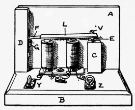
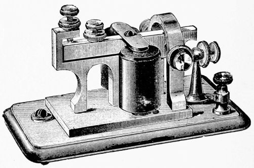
Fig. 109 shows a form of home-made sounder. Fig. 110 shows one form of telegraph sounder. Over the poles of the horseshoe electromagnet is an armature fixed to a metal bar that can rock up and down. The instant the current passes through the coils the armature comes down until a stop-screw strikes firmly upon the metal frame, making the down click. As soon as the distant[87] key is raised, the armature is firmly pulled back and another click is made. The two clicks differ in sound, and can be readily recognized by the operator.
111. Connections for Simple Line. Fig. 111 shows complete connections for a home-made telegraph line. The capital letters are used for the right side, R, and small letters for the left side, L. Gravity cells, B and b, are used. The sounders, S and s, and the keys, K and k, are shown by a top view. The broad black lines of S and s represent the armatures which are directly over the electromagnets. The keys have switches, E and e.
The two stations, R and L, may be in the same room, or in different houses. The return wire, R W, passes from the copper of b to the zinc of B. This is important, as the cells must help each other; that is, they are in series. The line wire, L W, passes from one station to the other, and the return may be through the wire, R W, or through the earth; but for short lines a wire is best.
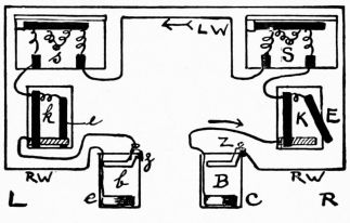
112. Operation of Simple Line. Suppose two boys, R (right) and L (left) have a line. Fig. 111 shows that R's switch, E, is open, while e is closed. The entire circuit, then, is broken at but one point. As soon as R presses his key, the circuit is closed, and the current from both cells rushes around from B, through K, S, L W, s, k, b, R W, and back to B. This makes the armatures of[88] S and s come down with a click at the same time. As soon as the key is raised, the armatures lift and make the up-click. As soon as R has finished, he closes his switch E. As the armatures are then held down, L knows that R has finished, so he opens his switch e, and answers R. Both E and e are closed when the line is not in use, so that either can open his switch at any time and call up the other. Closed circuit cells must be used for such lines. On very large lines dynamos are used to furnish the current.
113. The Relay. Owing to the large resistance of long telegraph lines, the current is weak when it reaches a distant station, and not strong enough to work an ordinary sounder. To get around this, relays are used; these are very delicate instruments that replace the sounder in the line wire circuit. Their coils are usually wound with many turns of fine wire, so that a feeble current will move its nicely adjusted armature. The relay armature merely acts as an automatic key to open and close a local circuit which includes a battery and sounder. The line current does not enter the sounder; it passes back from the relay to the sending station through the earth.
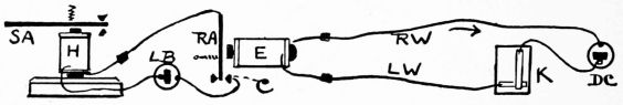
Fig. 112 gives an idea of simple relay connections. The key K, and cell D C, represent a distant sending station. E is the electromagnet of the relay, and R A is[89] its armature. L W and R W represent the line and return wires. R A will vibrate toward E every time K is pressed, and close the local circuit, which includes a local battery, L B, and a sounder. It is evident that as soon as K is pressed the sounder will work with a good strong click, as the local battery can be made as strong as desired.
Fig. 113 shows a regular instrument which opens and closes the local circuit at the top of the armature.
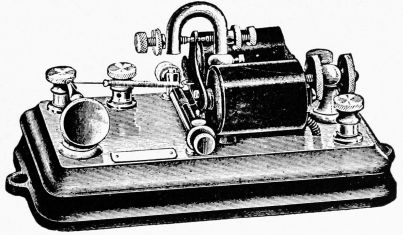
114. Ink Writing Registers are frequently used instead of sounders. Fig. 114 shows a writing register that starts itself promptly at the opening of the circuit, and stops automatically as soon as the circuit returns to its normal condition. A strip of narrow paper is slowly pulled from the reel by the machine, a mark being made upon it every time the armature of an inclosed electromagnet is attracted. When the circuit is simply closed for an instant, a short line, representing a dot, is made.
Registers are built both single pen and double pen. In the latter case, as the record of one wire is made with[90] a fine pen, and the other with a coarse pen, they can always be identified. The record being blocked out upon white tape in solid black color, in a series of clean-cut dots and dashes, it can be read at a glance, and as it is indelible, it may be read years afterward. Registers are made for local circuits, for use in connection with relays, or for direct use on main lines, as is usually desirable in fire-alarm circuits.
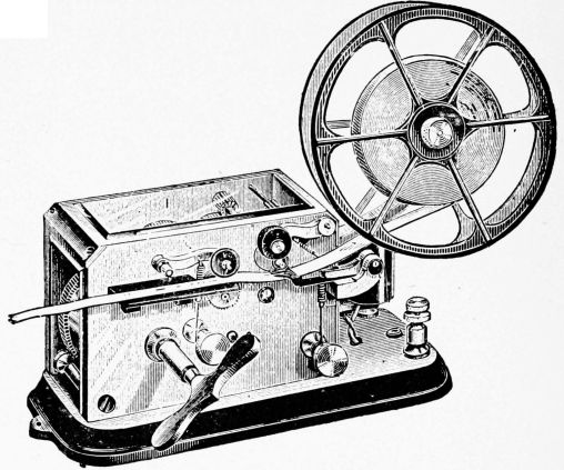
115. Automatic Current Interrupters are used on most common bells, as well as on induction coils, etc. (See § 104.) Fig. 115 shows a simple form of interrupter. The wire 1, from a cell D C, is joined to an iron strip I a short distance from its end. The other wire from D C passes to one end of the electromagnet coil H. The remaining end of H is placed in contact with I as shown, completing the circuit. As soon as the current passes, I is pulled down and away from the upper wire 2, breaking the circuit. I, being held by its left-hand end firmly in the hand, immediately springs back to its former position, closing the circuit again. This action is repeated, the rapidity of the vibrations depending somewhat upon the position of the wires on I. In regular instruments a platinum point is used where[92] the circuit is broken; this stands the sparking when the armature vibrates.
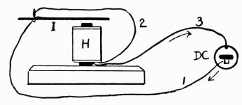
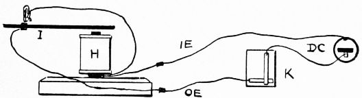
116. Electric Bells may be illustrated by referring to Fig. 116, which shows a circuit similar to that described in § 115, but which also contains a key K, in the circuit. This allows the circuit to be opened and closed at a distance from the vibrating armature. The circuit must not be broken at two places at the same time, so wires should touch at the end of I before pressing K. Upon pressing K the armature I will vibrate rapidly. By placing a small bell near the end of the vibrating armature, so that it will be struck by I at each vibration, we should have a simple electric bell. This form of electric bell is called a trembling bell, on account of its vibrating armature.
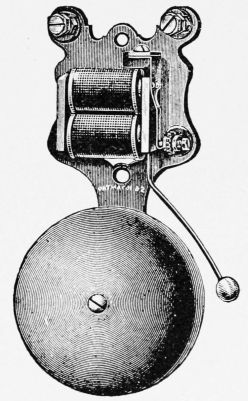
Fig. 117.
| 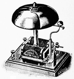
Fig. 118.
|
Fig. 117 shows a form of trembling bell with cover removed. Fig. 118 shows a single-stroke bell, used for fire-alarms and other signal work. In this the armature is attracted but once each time the current passes. As[93] many taps of the bell can be given as desired by pressing the push-button. Fig. 119 shows a gong for railway crossings, signals, etc. Fig. 120 shows a circuit including cell, push-button, and bell, with extra wire for lengthening the line.
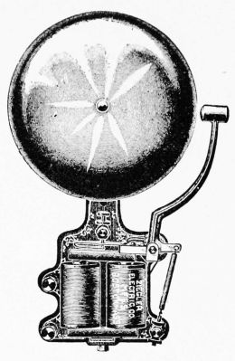
Electro-Mechanical Gongs are used to give loud signals for special purposes. The mechanical device is started by the electric current when the armature of the electromagnet is attracted. Springs, weights, etc., are used as the power. Fig. 121 shows a small bell of this kind.
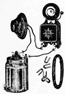
117. Magneto Testing Bells, Fig. 122, are really small hand-power dynamos. The armature is made to revolve between the poles of strong permanent magnets, and it is so wound that it gives a current with a large E. M. F., so that it can ring through the large resistance of a long line to test it.
Magneto Signal Bells, Fig. 123, are used as generator and bell in connection with telephones. The generator, used to ring a bell at a distant station, stands at the bottom of the box. The[94] bell is fastened to the lid, and receives current from a distant bell.
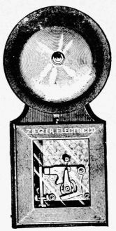
Fig. 121.
| 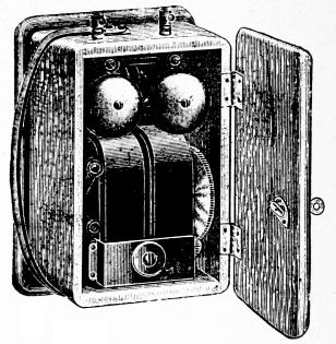
Fig. 122.
|
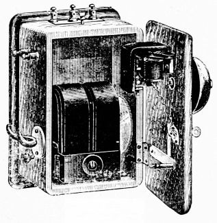
Fig. 123.
| 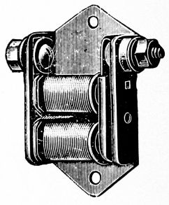
Fig. 124.
|
118. Electric Buzzers have the same general construction as electric bells; in fact, you will have a buzzer by removing the bell from an ordinary electric bell. Buzzers are used in places where the loud sound of a bell would be objectionable. Fig. 124 shows the usual form of buzzers, the cover being removed.
119. The Telephone is an instrument for reproducing sounds at a distance, and electricity is the agent by which this is generally accomplished. The part spoken to is called the transmitter, and the part which gives sound out again is called the receiver. Sound itself does not pass over the line. While the same apparatus can be used for both transmitter and receiver, they are generally different in construction to get the best results.
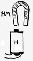
Fig. 125.
| 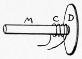
Fig. 126.
|
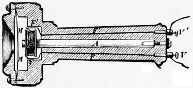
120. The Bell or Magneto-transmitter generates its own current, and is, strictly speaking, a dynamo that[96] is run by the voice. It depends upon induction for its action.
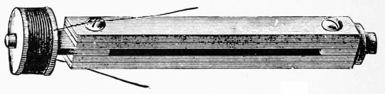
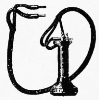
Fig. 125 shows a coil of wire, H, with soft iron core, the ends of the wires being connected to a delicate galvanoscope. If one pole of the magnet H M be suddenly moved up and down near the core, an alternating current will be generated in the coil, the circuit being completed through the galvanoscope. As H M approaches the core the current will flow in one direction, and as H M is withdrawn it will pass in the opposite direction. The combination makes a miniature alternating dynamo.
If we imagine the soft iron core of H, Fig. 125, taken out, and one pole of H M, or preferably that of a bar magnet stuck through the coil, a feeble current will also be produced by moving the soft iron back and forth near the magnet's pole. This is really what is done in the Bell transmitter, soft iron in the shape of a thin disc (D, Fig. 126) being made to vibrate by the voice immediately in front of a coil having a permanent magnet for a core. The disc, or diaphragm, as it is called, is fixed near, but it does not touch, the magnet. It is under a constant strain, being attracted by the magnet, so its[97] slightest movement changes the strength of the magnetic field, causing more or less lines of force to shoot through the turns of the coil and induce a current. The coil consists of many turns of fine, insulated wire. The current generated is an alternating one, and although exceedingly small can force its way through a long length of wire.
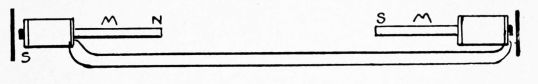
Fig. 127 shows a section of a regular transmitter, and Fig. 128 a form of compound magnet frequently used in the transmitter. Fig. 129 shows a transmitter with cords which contain flexible wires.
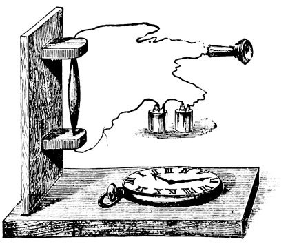
121. The Receiver, for short lines, may have the same construction as the Bell transmitter. Fig. 130 shows a diagram of two Bell receivers, either being used as the transmitter and the other as the receiver. As the alternating current goes to the distant receiver, it flies through the coil first in one direction and then in the other. This alternately[98] strengthens and weakens the magnetic field near the diaphragm, causing it to vibrate back and forth as the magnet pulls more or less. The receiver diaphragm repeats the vibrations in the transmitter. Nothing but the induced electric current passes over the wires.
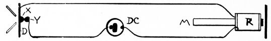
122. The Microphone. If a current of electricity be allowed to pass through a circuit like that shown in Fig. 131, which includes a battery, a Bell receiver, and a microphone, any slight sound near the microphone will be greatly magnified in the receiver. The microphone consists of pieces of carbon so fixed that they form loose contacts. Any slight movement of the carbon causes the resistance to the current to be greatly changed. The rapidly varying resistance allows more or less current to pass, the result being that this pulsating current causes the diaphragm to vibrate. The diaphragm has a constantly varying pull upon it when the carbons are in any way disturbed by the voice, or by the ticking of a watch, etc. This principle has been made use of in carbon transmitters, which are made in a large variety of forms.
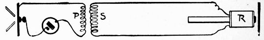
123. The Carbon Transmitter does not, in itself,[99] generate a current like the magneto-transmitter; it merely produces changes in the strength of a current that flows through it and that comes from some outside source. In Fig. 132, X and Y are two carbon buttons, X being attached to the diaphragm D. Button Y presses gently against X, allowing a little current to pass through the circuit which includes a battery, D C, and a receiver, R. When D is caused to vibrate by the voice, X is made to press more or less against Y, and this allows more or less current to pass through the circuit. This direct undulating current changes the pull upon the diaphragm of R, causing it to vibrate and reproduce the original sounds spoken into the transmitter. In regular lines, of course, a receiver and transmitter are connected at each end, together with bells, etc., for signaling.
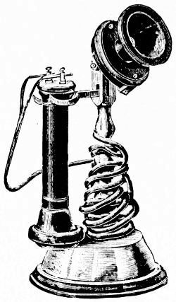
124. Induction Coils in Telephone Work. As the resistance of long telephone lines is great, a high electrical pressure, or E.M.F. is desired. While the current from one or two cells is sufficient to work the transmitter properly, and cause undulating currents in the short line, it does not have power enough to force its way over a long line.
To get around this difficulty, an induction coil, Fig. 133,[100] is used to transform the battery current, that flows through the carbon transmitter and primary coil, into a current with a high E. M. F. The battery current in the primary coil is undulating, but always passes in the same direction, making the magnetic field around the core weaker and stronger. This causes an alternating current in the secondary coil and main line. In Fig. 133 P and S represent the primary and secondary coils. P is joined in series with a cell and carbon transmitter; S is joined to the distant receiver. One end of S can be grounded, the current completing the circuit through the earth and into the receiver through another wire entering the earth.
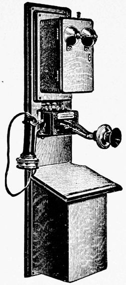
125. Various forms of telephones are shown in Figs. 134, 135, 136. Fig. 134 shows a form of desk telephone; Fig. 135 shows a common form of wall telephone; Fig. 136 shows head-telephones for switchboard operators.
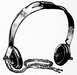
126. The Dynamo, Dynamo-Electric Machine or Generator, is a machine for converting mechanical energy into an electric current, through electromagnetic induction. The dynamo is a machine that will convert steam power, for example, into an electric current. Strictly speaking, a dynamo creates electrical pressure, or electromotive force, and not electricity, just as a force-pump creates water-pressure, and not water. They are generally run by steam or water power.
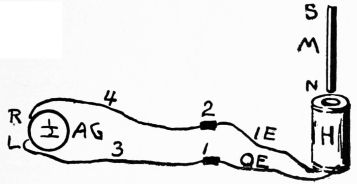
127. Induced Currents. We have already spoken about currents being induced by moving a coil of wire in a magnetic field. We shall now see how this principle is used in the dynamo which is a generator of induced currents.
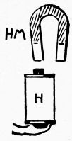
Fig. 137 shows how a current can be generated by a bar magnet and a coil of wire. Fig. 138 shows how a current can be generated by a horseshoe magnet and a coil of wire having an iron core. The ends of the coil are[102] to be connected to an astatic galvanoscope; this forms a closed circuit. The coil may be moved past the magnet, or the magnet past the coil.
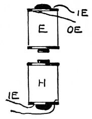
Fig. 139.
| 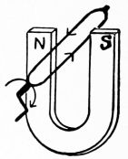
Fig. 140.
|
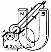
Fig. 141.
| 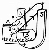
Fig. 142.
|
Fig. 139 shows how a current can be generated by two coils, H being connected to an astatic galvanoscope and E to a battery. By suddenly bringing E toward H or the core of E past that of H, a current is produced. We have in this arrangement the main features of a dynamo. We can reverse the operation, holding E in one position and moving H rapidly toward it. In this case H would represent the armature and E the field-magnet. When H is moved toward E, the induced current in H flows in one direction, and when H is suddenly withdrawn from[103] E the current is reversed in H. (See "Study," Chapter XXV., for experiments.)
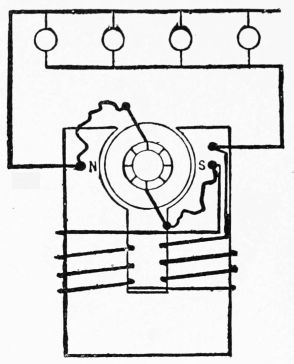
128. Induced Currents by Rotary Motion. The motions of the coils in straight lines are not suitable for producing currents strong enough for commercial purposes. In order to generate currents of considerable strength and pressure, the coils of wire have to be pushed past magnets, or electromagnets, with great speed. In the dynamo the coils are so wound that they can be given a rapid rotary motion as they fly past strong electromagnets. In this way the coil can keep on passing the same magnets, in the same direction, as long as force is applied to the shaft that carries them.
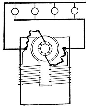
129. Field-Magnets; Armature; Commutator. What we need then, to produce an induced current by a rotary motion, is a strong magnetic field, a rotating coil of wire properly placed in the[104] field, and some means of leading the current from the machine.
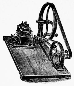
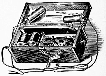
If a loop of wire, Fig. 140, be so arranged on bearings at its ends that it can be made to revolve, a current will flow through it in one direction during one-half of the revolution, and in the opposite direction during the other half, it being insulated from all external conductors. This agrees with the experiments suggested in § 127, when the current generated in a coil passed in one direction during its motion toward the strongest part of the field, and in the opposite direction when the coil passed out of it. A coil must be cut by lines of force to generate a current. A current inside of the machine, as in Fig. 140, would be of no value; it must be led out to external conductors where it can do work. Some sort of sliding contact is necessary to connect a revolving conductor with outside stationary ones. The magnet, called the field-magnet, is merely to furnish lines of magnetic force. The one turn of wire represents the simplest form of armature.
Fig. 141 shows the ends of a coil joined to two rings, X, Y, insulated from each other, and rotating with the coil. The two stationary pieces of carbon, A, B, called brushes, press against the rings, and to these are joined wires, which complete the circuit, and which lead out where the current can do work. The arrows show the direction of the current during one-half of a revolution. The rings form a collector, and this arrangement gives an alternating current.
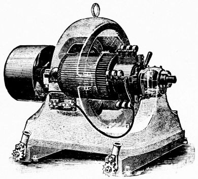
In Fig. 142 the ends of the coil are joined to the two halves of a cylinder. These halves, X and Y, are insulated from each other, and from the axis. The current flows from X onto the brush A, through some external circuit, to do the work, and thence back through brush B onto Y. By the time that Y gets around to A, the direction of the current in the loop has reversed, so that it passes toward Y, but it still enters the outside circuit[106] through A, because Y is then in contact with A. This device is called a commutator, and it allows a constant or direct current to leave the machine.
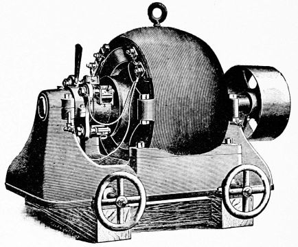
In regular machines, the field-magnets are electromagnets, the whole or a part of the current from the dynamo passing around them on its way out, to excite them and make a powerful field between the poles. To lessen the resistance to the lines of force on their way from the N to the S pole of the field-magnets, the armature coils are wound on an iron core; this greatly increases the strength of the field, as the lines of force have to jump across but two small air-gaps. There are many loops of wire on regular armatures, and many segments to the commutator, carefully insulated from each other, each getting its current from the coil attached to it.
130. Types of Dynamos. While there is an almost endless number of different makes and shapes of dynamos,[107] they may be divided into two great types; the continuous or direct current, and the alternating current dynamo. Direct current machines give out a current which constantly flows in one direction, and this is because a commutator is used. Alternating currents come from collectors or rings, as shown in Fig. 141; and as an alternating current cannot be used to excite the fields, an outside current from a small direct current machine must be used. These are called exciters.
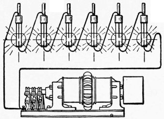
In direct current machines enough residual magnetism is left in the field to induce a slight current in the armature when the machine is started. This immediately adds strength to the field-magnets, which, in turn, induce a stronger current in the armature.
131. Winding of Dynamos. There are several ways of winding dynamos, depending upon the special uses to be made of the current.
The series wound dynamo, Fig. 143, is so arranged that the entire current passes around the field-magnet cores on its way from the machine. In the shunt wound dynamo, Fig. 144, a part, only, of the current from the[108] machine is carried around the field-magnet cores through many turns of fine wire. The compound wound dynamo is really a combination of the two methods just given. In separately-excited dynamos, the current from a separate machine is used to excite the field-magnets.
132. Various Machines. Fig. 145 shows a hand power dynamo which produces a current for experimental work. Fig. 146 shows a magneto-electrical generator which produces a current for medical use. Figs. 147, 148 show forms of dynamos, and Fig. 149 shows how arc lamps are connected in series to dynamos.
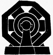
133. Electric Current and Work. The amount of work a current can do depends upon two factors; the strength (amperes), and the pressure, or E. M. F. (volts). A current of 10 amperes with a pressure of 1,000 volts = 10 × 1,000 = 10,000 watts. This furnishes the same amount of energy as a current of 50 amperes at 200 volts; 50 × 200 = 10,000 watts.
134. Transmission of Currents. It is often necessary to carry a current a long distance before it is used. A current of 50 amperes would need a copper conductor 25 times as large (sectional area) as one to carry the 10 ampere current mentioned in § 133. As copper conductors are very expensive, electric light companies, etc., generally try to carry the current on as small a wire as possible. To do this, the voltage is kept high, and the amperage low. Thus, as seen in § 133, the current of 1,000 volts and 10 amperes could be carried on a much smaller wire than the other current of equal energy. A current of 1,000 volts, however, is not adapted for lights, etc., so it has to be changed to lower voltage by some form of transformer before it can be used.
135. Transformers, like induction coils, are instruments for changing the E. M. F. and strength of currents. There is very little loss of energy in well-made transformers. They consist of two coils of wire on one[110] core; in fact, an induction coil may be considered a transformer, but in this a direct current has to be interrupted. If the secondary coil has 100 times as many turns of wire as the primary, a current of 100 volts can be taken from the secondary coil when the primary current is but 1 volt; but the strength (amperes) of this new current will be but one-hundredth that of the primary current.
By using the coil of fine wire as the primary, we can lower the voltage and increase the strength in the same proportion.
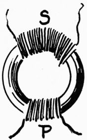
Fig. 150.
| 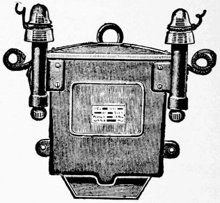
Fig. 151.
|
Fig. 150 shows about the simplest form of transformer with a solid iron core, on which are wound two coils, the one, P, being the primary, and the other, S, the secondary. Fig. 151 shows the general appearance of one make of transformer. The operation of this apparatus, as already mentioned, is to reduce the high pressure alternating current sent out over the conductors from the dynamo, to a potential at which it can be employed with convenience and safety, for illumination and other purposes.[111] They consist of two or more coils of wire most carefully insulated from one another. A core or magnetic circuit of soft iron, composed of very thin punchings, is then formed around these coils, the purpose of the iron core being to reduce the magnetic resistance and increase the inductive effect. One set of these coils is connected with the primary or high-pressure wires, while the other set, which are called the secondary coils, is connected to the house or low-pressure wires, or wherever the current is required for use. The rapidly alternating current impulses in the primary or high-pressure wires induce secondary currents similar in form but opposite in direction in the secondary coils. These current impulses are of a much lower pressure, depending upon the ratio of the number of turns of wire in the respective coils, it being customary to wind transformers in such a manner as to reduce from 1,000 or 2,000-volt primaries to 50 or 100-volt secondaries, at which voltage the secondary current is perfectly harmless.
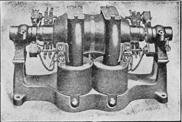
136. Motor-Dynamos. Fig. 152. These consist[112] essentially of two belt-type machines on a common base, direct coupled together, one machine acting as a motor to receive current at a certain voltage, and the other acting as a dynamo to give out the current usually at a different voltage. As they transform current from one voltage to another, motor-dynamos are sometimes called Double Field Direct Current Transformers. The larger sizes have three bearings, one bearing being between the two machines, while the smaller sizes have but two bearings, the two armatures being fastened to a common spider.
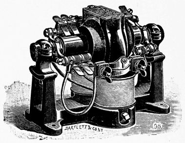
Applications. The uses to which motor-dynamos are put are very various. They are extensively used in the larger sizes as "Boosters," for giving the necessary extra force on long electric supply circuits to carry the current to the end with the same pressure as that which reaches the ends of the shorter circuits from the station.
Motor-dynamos have the advantage over dynamotors, described later, of having the secondary voltage easily[113] and economically varied over wide ranges by means of a regulator in the dynamo field.
137. Dynamotors. Fig. 153. In Dynamotors the motor and dynamo armatures are combined in one, thus requiring a single field only. The primary armature winding, which operates as a motor to drive the machine, and the secondary or dynamo winding, which operates as a generator to produce a new current, are upon the same armature core, so that the armature reaction of one winding neutralizes that of the other. They therefore have no tendency to spark, and do not require shifting of the brushes with varying load. Having but one field and two bearings, they are also more efficient than motor-dynamos.
Applications. They have largely displaced batteries for telegraph work. The size shown, occupying a space of about 8-inch cube, and having an output of 40 watts, will displace about 800 gravity cells, occupying a space of about 10 feet cube. The cost of maintenance of such a battery per year, exclusive of rent, is about $800, whereas the 1-6 dynamotor can be operated at an annual expense of $150.
Dynamotors are largely used by telephone companies for charging storage batteries, and for transforming from direct to alternating current, for ringing telephone bells. Electro-cautery, electroplating, and electric heating also give use to dynamotors.
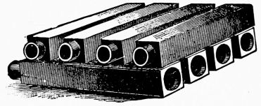
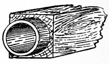
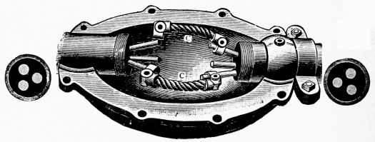
138. Conductors and Insulators. To carry the powerful current from the generating station to distant places where it is to give heat, power, or light, or even to carry the small current of a single cell from one room to another, conductors must be used. To keep the current from passing into the earth before it reaches its destination insulators must be used. The form of conductors and insulators used will depend upon the current and many other conditions. It should be remembered that the current has to be carried to the lamp or motor,[115] through which it passes, and then back again to the dynamo, to form a complete circuit. A break anywhere in the circuit stops the current. Insulators are as important as conductors.
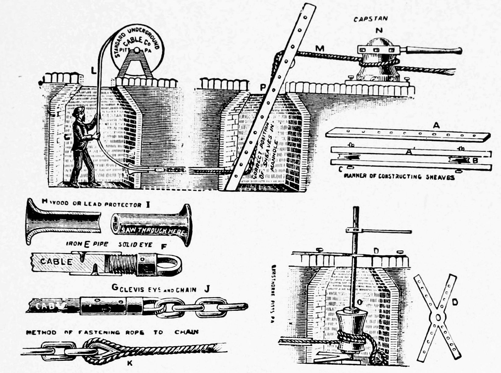
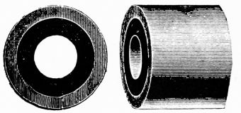
139. Mains, Service Wires, etc. From the switchboard the current flows out through the streets in large conductors, or mains, the supply being kept up by the dynamos, just as water-pressure is kept up by the constant working of pumps. Branches, called service wires, are led off from the mains to supply houses or factories, one wire leading the current into the house from one main,[116] and a similar one leading it out of the house again to the other main.
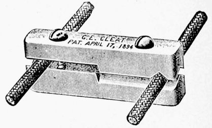
In large buildings, pairs of wires, called risers, branch out from the service wires and carry the current up through the building. These have still other branches—floor mains, etc., that pass through halls, etc., smaller branches finally reaching the lamps. The sizes of all of these wires depend upon how much current has to pass through them. The mains in large cities are usually placed underground. In some places they are carried on poles.
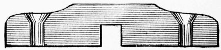
140. Electric Conduits are underground passages for[117] electric wires, cables, etc. There are several ways of insulating the conductors. Sometimes they are placed in earthenware or iron tubes, or in wood that has been treated to make it water-proof. At short distances are placed man-holes, where the different lengths are joined, and where branches are attached.
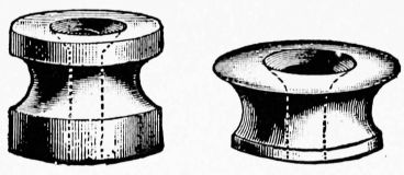
Fig. 154 shows creosoted wooden pipes; Fig. 155 shows another form of wooden pipe. Fig. 156 shows a coupling-box used to join Edison tubes. The three wires, used in the three-wire system, are insulated from each other, the whole being surrounded by an iron pipe of convenient length for handling. Fig. 157 shows sections of man-holes and various devices used in conduit work.
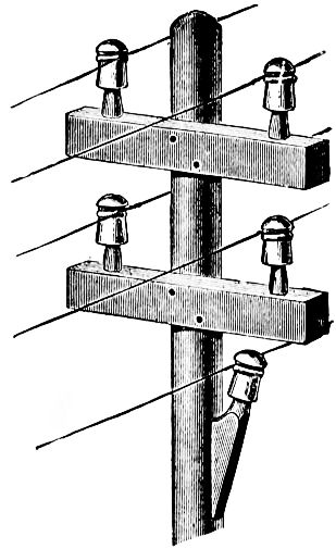
141. Miscellaneous Appliances. When the current enters a house for incandescent lighting purposes, for example, quite a[118] number of things are necessary. To measure the current a meter is usually placed in the cellar. In new houses the insulated conductors are usually run through some sort of tube which acts as a double protection, all being hidden from view. Fig. 158 shows a short length of iron tube with a lining of insulating material. Wires are often run through tubes made of rubber and various other insulating materials.
Where the current is to be put into houses after the plastering has been done, the wires are usually run through mouldings or supported by cleats. Fig. 159 shows a cross-section of moulding. The insulated wires are placed in the slots, which are then covered.
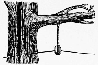
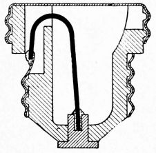
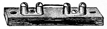
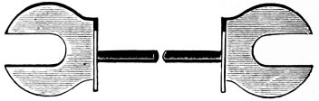
Fig. 160 shows a form of porcelain cleat. These are fastened to ceilings or walls, and firmly hold the insulated wires in place. Fig. 161 shows a wood cleat. Fig. 162[119] shows small porcelain insulators. These may be screwed to walls, etc., the wire being then fastened to them. Fig. 163 shows how telegraph wires are supported and insulated. Fig. 164 shows how wires may be carried by tree and insulated from them.
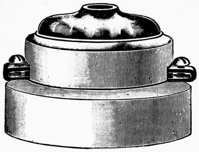
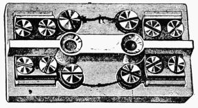
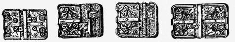
142. Safety Devices. We have seen that when too large a current passes through a wire, the wire becomes heated and may even be melted. Buildings are wired to use certain currents, and if from any cause much more current than the regular amount should suddenly pass through the service wires into the house,[120] the various smaller wires would become overheated, and perhaps melt or start a fire. An accidental short circuit, for example, would so reduce resistance that too much current would suddenly rush through the wires. There are several devices by which the over-heating of wires is obviated.
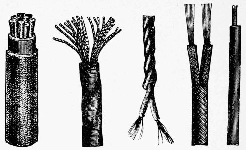
Fig. 165 shows a safety fuse, or safety cut-out, which consists of a short length of easily fusible wire, called fuse wire, placed in the circuit and supported by a porcelain block. These wires are tested, different sizes being used for different currents. As soon as there is any tendency toward over-heating, the fuse blows; that is, it promptly melts and opens the circuit before any damage can be done to the regular conductors. Fig. 166 shows a cross-section of a fuse plug that can be screwed into an ordinary socket. The fuse wire is shown black.
Fig. 167 shows a fuse link. These are also of fusible material, and so made that they can be firmly held under screw-heads. For heavy currents fuse ribbons are used,[121] or several wires or links may be used side by side. Fig. 168 shows a fusible rosette. Fig. 169 shows two fuse wires fixed between screw-heads, the current passing through them in opposite directions, both sides of the circuit being included. Fig. 170 shows various forms of cut-outs.
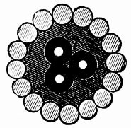
143. Wires and Cables are made in many sizes. Figs. 171 to 175 show various ways of making small conductors. They are made very flexible, for some purposes, by twisting many small copper wires together, the whole being then covered with insulating material.
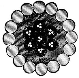
Figs. 176, 177, show sections of submarine cables. Such cables consist of copper conductors insulated with pure gutta-percha. These are then surrounded by hempen yarn or other elastic material, and around the whole are placed galvanized iron armor wires for protection. Each core, or conductor, contains a conductor consisting of a single copper wire or a strand of three or more twisted copper wires.
144. Lamp Circuits. As has been noted before, in order to have the electric current do its work, we must have a complete circuit. The current must be brought back to the dynamo, much of it, of course, having been[122] used to produce light, heat, power, etc. For lighting purposes this is accomplished in two principal ways.
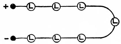
Fig. 178 shows a number of lamps so arranged, "in series," that the same current passes through them all, one after the other. The total resistance of the circuit is large, as all of the lamp resistances are added together.
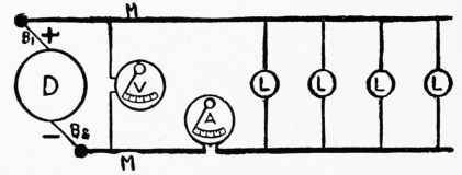
Fig. 179 shows lamps arranged side by side, or "in parallel," between the two main wires. The current divides, a part going through each lamp that operates. The total resistance of the circuit is not as large as in the series arrangement, as the current has many small paths in going from one main wire to the other. Fig. 179 also shows the ordinary two-wire system for incandescent lighting, the two main wires having usually a difference of potential equal to 50 or 110 volts. These comparatively small pressures require fairly large conductors.
The Three-Wire System, Fig. 180, uses the current[123] from two dynamos, arranged with three main wires. While the total voltage is 220, one of the wires being neutral, 110 volts can be had for ordinary lamps. This voltage saves in the cost of conductors.
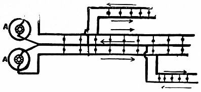
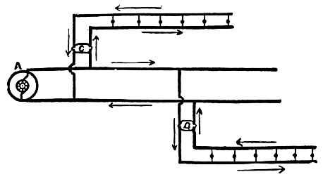
The Alternating System, Fig. 181, uses transformers. The high potential of the current allows small main wires, from which branches can be run to the primary coil of the transformer. The secondary coil sends out an induced current of 50 or 110 volts, while that in the primary may be 1,000 to 10,000 volts.
145. Resistance and Heat. We have seen that all wires and conductors offer resistance to the electric current. The smaller the wire the greater its resistance. Whenever resistance is offered to the current, heat is produced. By proper appliances, the heat of resistance can be used to advantage for many commercial enterprises. Dynamos are used to generate the current for heating and lighting purposes.
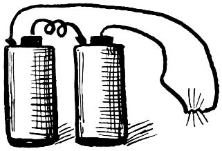
Fig. 182 shows how the current from two strong cells can be used to heat a short length of very fine platinum or German-silver wire. The copper conductors attached to the cells do not offer very much resistance.
It will be seen from the above that in all electrical work the sizes of the wires used have to be such that they do not overheat. The coils of dynamos, motors, transformers, ampere-meters, etc., etc., become somewhat heated by the currents passing through them, great care being taken that they are properly designed and ventilated so that they will not burn out.
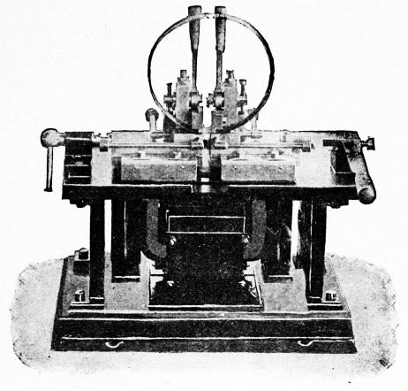
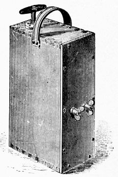
146. Electric Welding. Fig. 183 shows one form of electric welding machine. The principle involved in[125] the art of electric welding is that of causing currents of electricity to pass through the abutting ends of the pieces of metal which are to be welded, thereby generating heat at the point of contact, which also becomes the point of greatest resistance, while at the same time mechanical pressure is applied to force the parts together. As the current heats the metal at the junction to the welding temperature, the pressure follows up the softening surface until a complete union or weld is effected; and, as the heat is first[126] developed in the interior of the parts to be welded, the interior of the joint is as efficiently united as the visible exterior. With such a method and apparatus, it is found possible to accomplish not only the common kinds of welding of iron and steel, but also of metals which have heretofore resisted attempts at welding, and have had to be brazed or soldered.
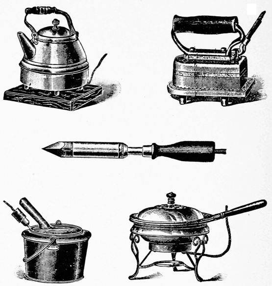
The introduction of the electric transformer enables enormous currents to be so applied to the weld as to spend their energy just at the point where heating is required.[127] They need, therefore, only to be applied for a few seconds, and the operation is completed before the heat generated at the weld has had time to escape by conduction to any other part.
Although the quantity of the current so employed in the pieces to be welded is enormous, the potential at which it is applied is extremely low, not much exceeding that of the batteries of cells used for ringing electric bells in houses.
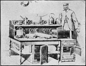
147. Miscellaneous Applications. Magneto Blasting Machines are now in very common use for blasting rocks, etc. Fig. 184 shows one, it being really a small hand dynamo, occupying less than one-half a cubic foot of space. The armature is made to revolve rapidly between the poles of the field-magnet by means of a handle that works up and down. The current is carried by wires from the binding-posts to fuses. The heat generated by resistance in the fuse ignites the powder or other explosive.
Electric soldering irons, flat-irons, teakettles, griddles,[128] broilers, glue pots, chafing-dishes, stoves, etc., etc., are now made. Figs. 185 to 189 show some of these applications. The coils for producing the resistance are inclosed in the apparatus.
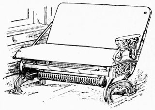
Fig. 190 shows a complete electric kitchen. Any kettle or part of the outfit can be made hot by simply turning a switch. Fig. 191 shows an electric heater placed under a car seat. Many large industries that make use of the heating effects of the current are now being carried on.
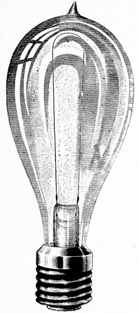
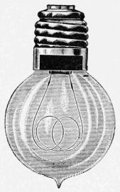
148. Incandescence. We have just seen that the electric current produces heat when it flows through a conductor that offers considerable resistance to it. As soon as this was discovered men began to experiment to find whether a practical light could also be produced. It was found that a wire could be kept hot by constantly passing a current through it, and that the light given out from it became whiter and whiter as the wire became hotter. The wire was said to be incandescent, or glowing with heat. As[130] metal wires are good conductors of electricity, they had to be made extremely fine to offer enough resistance; too fine, in fact, to be properly handled.
149. The Incandescent Lamp. Many substances were experimented upon to find a proper material out of which could be made a filament that would give the proper resistance and at the same time be strong and lasting. It was found that hair-like pieces of carbon offered the proper resistance to the current. When heated in the air, however, carbon burns; so it became necessary to place the carbon filaments in a globe from which all the air had been pumped before passing the current through them. This proved to be a success.
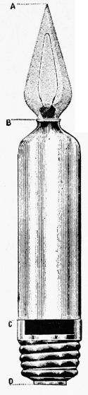
Fig. 194.
| 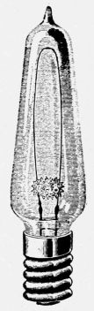
Fig. 195.
| 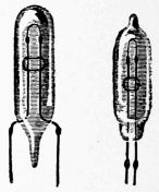
Fig. 196.
|
Fig. 192 shows the ordinary form of lamp. The carbon filament is attached, by carbon paste, to short platinum wires that are sealed in the glass, their lower ends being connected to short copper wires that are joined to the[131] terminals of the lamp. When the lamp is screwed into its socket, the current can pass up one side of the filament and down the other. The filaments used have been made of every form of carbonized vegetable matter. Bamboo has been largely used, fine strips being cut by dies and then heated in air-tight boxes containing fine carbon until they were thoroughly carbonized. This baking of the bamboo produces a tough fiber of carbon. Various forms of thread have been carbonized and used. Filaments are now made by pressing finely pulverized carbon, with a binding material, through small dies. The filaments are made of such sizes and lengths that will adapt them to the particular current with which they are to be used. The longer the filament, the greater its resistance, and the greater the voltage necessary to push the current through it.
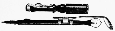
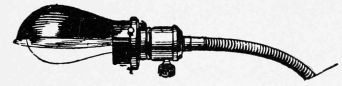
After the filaments are properly attached, the air is pumped from the bulb or globe. This is done with some form of mercury pump, and the air is so thoroughly removed from the bulb that about one-millionth only of the[132] original air remains. Before sealing off the lamp, a current is passed through the filament to drive out absorbed air and gases, and these are carried away by the pump. By proper treatment the filaments have a uniform resistance throughout, and glow uniformly when the current passes.
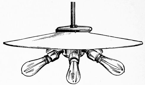
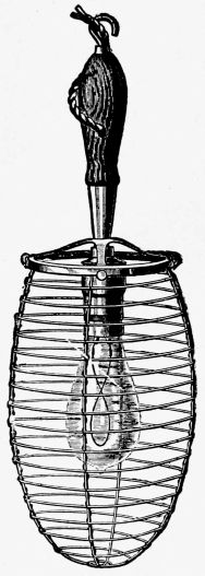
150. Candle-Power. A lamp is said to have 4, 8, 16 or more candle-power. A 16-candle-power lamp, for example, means one that will give as much light as sixteen standard candles. A standard sperm candle burns two grains a minute. The candle-power of a lamp can be increased by forcing a strong current through it, but this shortens its life.
The Current used for incandescent lamps has to be strong enough to force its way through the filament and produce a heat sufficient to give a[133] good light. The usual current has 50 or 110 volts, although small lamps are made that can be run by two or three cells. If the voltage of the current is less than that for which the lamp was made, the light will be dim. The filament can be instantly burned out by passing a current of too high pressure through it.
Even with the proper current, lamps soon begin to deteriorate, as small particles of carbon leave the filament and cling to the glass. This is due to the evaporation, and it makes the filament smaller, and a higher pressure is then needed to force the current through the increased resistance; besides this, the darkened bulb does not properly let the light out. The current may be direct or alternating.
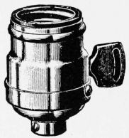
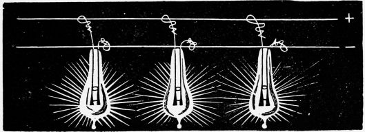
151. The Uses to which incandescent lamps are put are almost numberless. Fig. 193 shows a decorative lamp. Fancy lamps are made in all colors. Fig. 194 shows a conic candle lamp, to imitate a candle. What corresponds to the body of the candle (see figure B to C)[134] is a delicately tinted opal glass tube surmounted (see figure A to B) by a finely proportioned conic lamp with frosted globe. C to D in the figure represents the regular base, and thus the relative proportions of the parts are shown. Fig. 195 shows another form of candelabra lamp. Fig. 196 shows small dental lamps. Fig. 197 shows a small lamp with mirror for use in the throat. Fig. 198 shows lamp with half shade attached, used for library tables. Fig. 199 shows an electric pendant for several lamps, with shade. Fig. 200 shows a lamp guard. Fig. 201 shows a lamp socket, into which the lamp is screwed. Fig. 202 shows incandescent bulbs joined in parallel to the + and - mains. Fig. 203 shows how the lamp cord can be adjusted to desired length. Fig. 204 shows a lamp with reflector placed on a desk. Fig. 205 shows a form of shade and reflector.
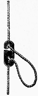
Fig. 203
| 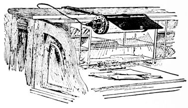
Fig. 204.
|
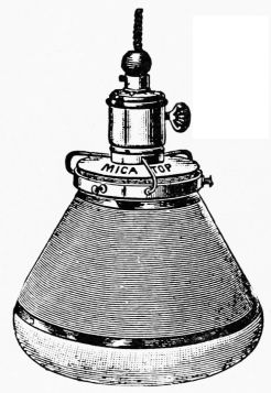
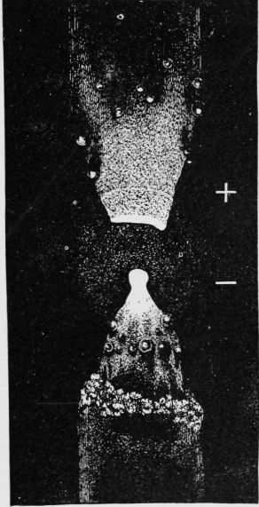
152. The Electric Arc. When a strong current passes from one carbon rod to another across an air-space, an electric arc is produced. When the ends of two carbon rods touch, a current can pass from one to the other, but the imperfect contact causes resistance enough to heat the ends red-hot. If the rods be separated slightly, the current will continue to flow, as the intensely heated air and flying particles of carbon reduce the resistance of the air-space.
Fig. 206 shows two carbon rods which are joined to the two terminals of a dynamo. The upper, or positive, carbon gradually wears away and becomes slightly hollow. The heated crater, as it is called, is the hottest part. The negative carbon becomes pointed. The arc will pass in a vacuum, and even under water.
As the electric arc is extremely hot, metals are easily vaporized in it; in fact, even the carbon rods themselves slowly melt and vaporize. This extreme heat is used for many industrial purposes.
"The phenomenon of the electric arc was first noticed by Humphrey Davy in 1800, and its explanation appears to be the following: Before contact the difference of potential between the points is insufficient to permit a spark to leap across even 1/10000 of an inch of air-space, but when the carbons are made to touch, a current is established. On separating the carbons, the momentary extra current due to self-induction of the circuit, which possesses a high electromotive force, can leap the short distance, and in doing so volatilizes a small quantity of carbon between[137] the points. Carbon vapor, being a partial conductor, allows the current to continue to flow across the gap, provided it be not too wide; but as the carbon vapor has a very high resistance it becomes intensely heated by the passage of the current, and the carbon points also grow hot. Since, however, solid matter is a better radiator than gaseous matter, the carbon points emit far more light than the arc itself, though they are not so hot. It is observed, also, that particles of carbon are torn away from the + electrode, which becomes hollowed out to a cup-shape, and some of these are deposited on the - electrode."
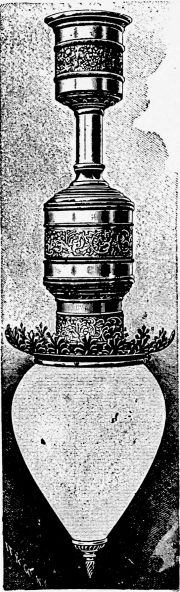
Fig. 207.
| 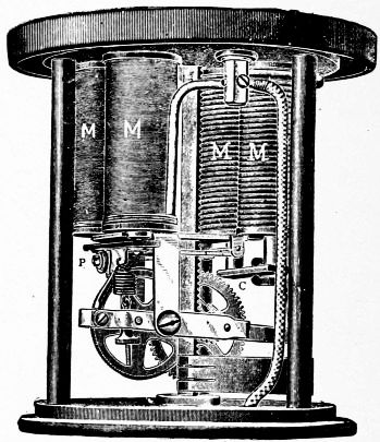
Fig. 208.
|
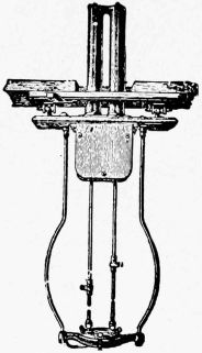
153. Arc Lamps. As the carbons gradually wear away, some device is necessary to keep their ends the right distance apart. If they are too near, the arc is very small; and if too far apart, the current can not pass and the light goes out. The positive carbon gives the more intense light and wears away about twice as fast as the - carbon, so it is placed above the - carbon, to throw the light downwards.
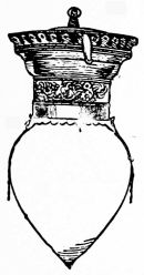
Fig. 210.
| 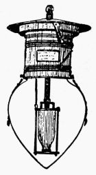
Fig. 211.
|
Arc lamps contain some device by which the proper distance between the carbons can be kept. Most of them[138] grip the upper carbon and pull it far enough above the lower one to establish the arc. As soon as the distance between them gets too great again, the grip on the upper carbon is loosened, allowing the carbon to drop until it comes in contact with the lower one, thus starting the current again. These motions are accomplished by electromagnets. Fig. 207 shows a form of arc lamp with single carbons that will burn from 7 to 9 hours.
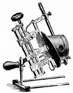
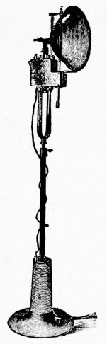
Fig. 213.
| 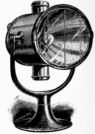
Fig. 214.
|
Fig. 208 shows the mechanism by which the carbons are regulated. Fig. 209 shows a form of double carbon, or all-night lamp, one set of carbons being first used, the other set being automatically switched in at the proper time.

Figs. 210, 211 show forms of short arc lamps, for use under low ceilings, so common in basements, etc.
Fig. 212 shows a hand-feed focussing type of arc lamp. In regular street lamps, the upper carbon only is fed by mechanism, as it burns away about twice as fast as the lower one, thus bringing the arc lower and lower. When[140] it is desired to keep the arc at the focus of a reflector, both carbons must be fed.
Fig. 213 shows a theatre arc lamp, used to throw a strong beam of light from the balcony to the stage.
Fig. 214 shows the arc lamp used as a search-light. The reflector throws a powerful beam of light that can be seen for miles; in fact, the light is used for signalling at night. Fig. 215 shows how search-lights are used at night on war-vessels.
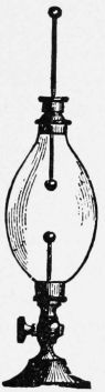
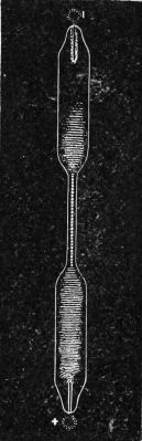
154. Disruptive Discharges. We have seen, in the study of induction coils, that a spark can jump several inches between the terminals of the secondary coil. The attraction between the two oppositely charged terminals gets so great that it overcomes the resistance of the air-space between them, a brilliant spark passes, and they are discharged. This sudden discharge is said to be disruptive, and it is accompanied by a flash of light and a loud report. The path of the discharge may be nearly straight,[142] or crooked, depending upon the nature of the material in the gap between the terminals.

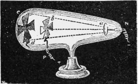
155. Effect of Air Pressure on Spark. The disruptive spark takes place in air at ordinary pressures. The nature of the spark is greatly changed when the pressure of the air decreases. Fig. 216 shows an air-tight glass tube so arranged that the air can be slowly removed with an air-pump. The upper rod shown can be raised or lowered to increase the distance between it and the lower rod, these acting as the terminals of an induction coil. Before exhausting any air, the spark will jump a small distance between the rods and act as in open air. As soon as a small amount of air is removed,[143] a change takes place. The spark is not so intense and has no definite path, there being a general glow throughout the tube. As the air pressure becomes still less, the glow becomes brighter, until the entire tube is full of purple light that is able to pass the entire length of it; that is, the discharge takes place better in rarefied air than it does in ordinary air.
156. Vacuum-Tubes. As electricity passes through rarefied gases much easier than through ordinary air, regular tubes, called vacuum-tubes, are made for such study. Fig. 217 shows a plain tube of this kind, platinum terminals being fused in the glass for connections. These tubes are often made in complicated forms, Fig. 218, with colored glass, and are called Geissler tubes. They are often made in such a way that the electrodes are in the shape of discs, etc., and are called Crookes tubes, Fig. 219. A slight amount of gas is left in the tubes.
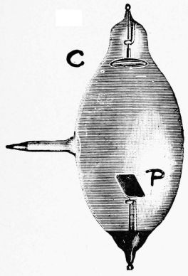
Fig. 220.
| 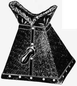
Fig. 220-A.
|
157. Cathode Rays. The cathode is the electrode of[144] a vacuum-tube by which the current leaves the tube, and it has been known for some time that some kind of influence passes in straight lines from this point. Shadows, Fig. 219, are cast by such rays, a screen being placed in their path.
158. X-Rays. Professor Roentgen of Würzburg discovered that when the cathode rays are allowed to fall upon a solid body, the solid body gives out still other rays which differ somewhat from the original cathode rays. They can penetrate, more or less, through many bodies that are usually considered opaque. The hand, for example, may be used as a negative for producing a photograph of the bones, as the rays do not pass equally well through flesh and bone.
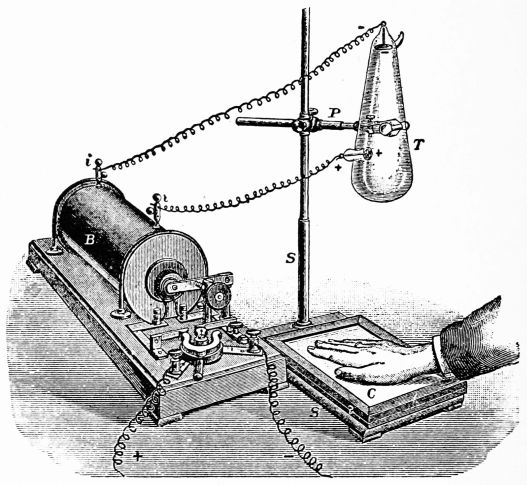
Fig. 220 shows a Crookes tube fitted with a metal plate, so that the cathode rays coming from C will strike it. The X-rays are given out from P. These rays are invisible and are even given out where the cathode rays strike the glass. Some chemical compounds are made luminous by these rays; so screens are made and coated with them in order that the shadows produced by the X-rays can be seen by the eye. Professor Roentgen named these the X-rays. Fig. 220-A shows a fluoroscope that contains a screen covered with proper chemicals.
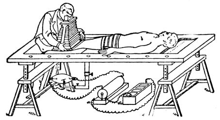
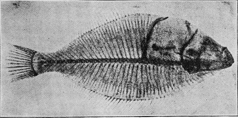
159. X-Ray Photographs. Bone does not allow the X-rays to pass through it as readily as flesh, so if the hand be placed over a sensitized photographic plate, Fig. 221, and proper connections be made with the induction coil, etc., the hand acts as a photographic negative. Upon developing the plate, as in ordinary photography, a picture or shadow of the bones will be seen. Fig. 222 shows the arrangement of battery, induction coil, focus tube, etc., for examining the bones of the human body.
Fig. 223 shows the bones of a fish. Such photographs have been very valuable in discovering the location of bullets, needles, etc., that have become imbedded in the flesh, as well as in locating breaks in the bones.
160. Currents and Motion. We have seen, Chapter XII., that when coils of wire are rapidly moved across a strong magnetic field, a current of electricity is generated. We have now to deal with the opposite of this; that is, we are to study how motion can be produced by allowing a current of electricity to pass through the armature of a machine.
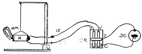
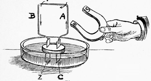
Fig. 224 shows, by diagram, a coil H, suspended so that it can move easily, its ends being joined to a current reverser, and this, in turn, to a dry cell D C. A magnet, H M, will attract the core of H when no current passes. When the current is allowed to pass first in one direction and then in the opposite direction, by using the reverser, the core of H will jump back and forth from one pole of H M to the other. There are many ways by which motion can be produced by the current, but to have it practical, the motion must be a rotary one. (See "Study," Chapter XXVI., for numerous experiments.)
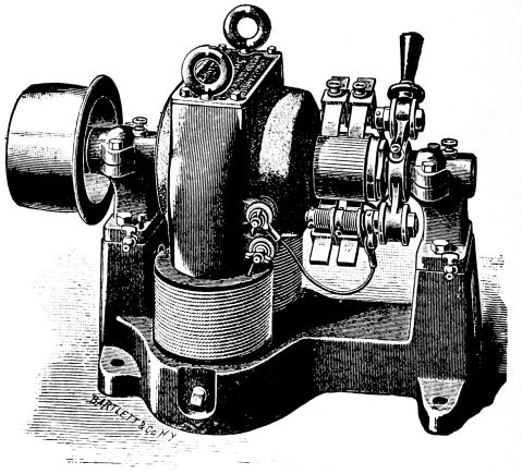
161. The Electric Motor is a machine for transforming electric energy into mechanical power. The construction of motors is very similar to that of dynamos. They have field-magnets, armature coils, commutator, etc.; in[149] fact, the armature of an ordinary direct current dynamo will revolve if a current be passed through it, entering by one brush and leaving by the other. There are many little differences of construction, for mechanical and electrical reasons, but we may say that the general construction of dynamos and motors is the same.
Fig. 225 shows a coil of wire, the ends of which are connected to copper and zinc plates. These plates are floated in dilute sulphuric acid, and form a simple cell which sends a current through the wire, as shown by the arrows.
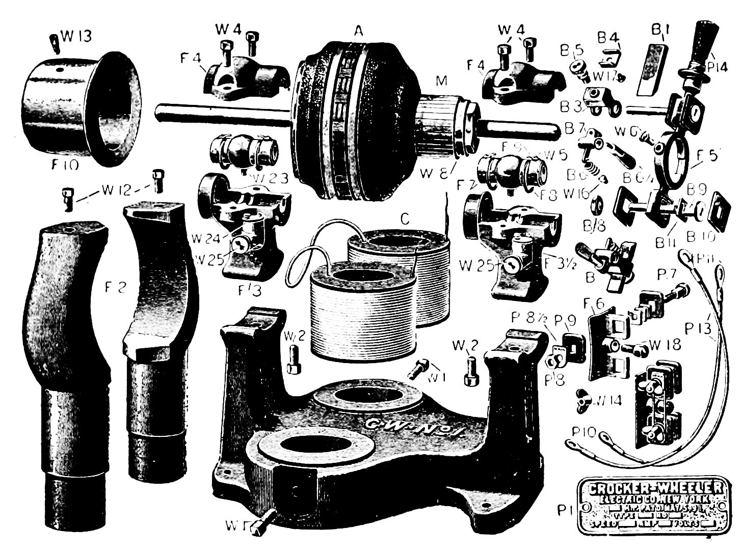
We have seen that a current-carrying wire has a magnetic field and acts like a magnet; so it will be easily seen that if a magnet be held near the wire it will be either attracted or repelled, the motion depending upon the poles that come near each other. As shown in the figure, the N pole of the magnet repels the field of the wire,[150] causing it to revolve. We see that this action is just the reverse to that in galvanometers, where the coil is fixed, and the magnet, or magnetic needle, is allowed to move. As soon as the part of the wire, marked A in Fig. 225, gets a little distance from the pole, the opposite side of the wire, B, begins to be attracted by it, the attraction getting stronger and stronger, until it gets opposite the N pole. If the N pole were still held in place, B would vibrate back and forth a few times, and finally come to rest near the pole. If, however, as soon as B gets opposite N the S pole of the magnet be quickly turned toward B, the coil will be repelled and the rotary motion will continue.
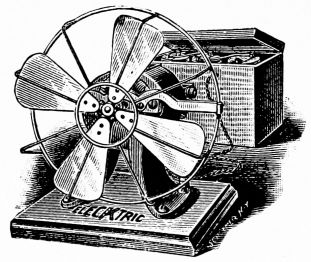
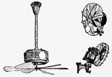
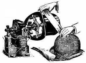
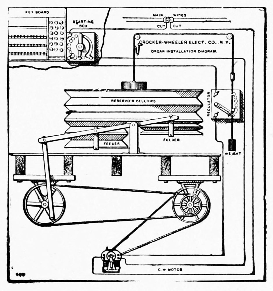
Let us now see how this helps to explain electric motors.[151] We may consider the wire of Fig. 225 as one coil of an armature, and the plates, C and Z, as the halves of a commutator. In this arrangement, it must be noted, the current always flows through the armature coil in the same direction, the rotation being kept up by reversing the poles of the field-magnet. In ordinary simple motors the current is reversed in the armature coils, the field-magnets remaining in one position without changing the poles. This produces the same effect as the above. The current is reversed automatically as the brushes allow the current to enter first one commutator bar and then the opposite one as the armature revolves. The regular[152] armatures have many coils and many commutator bars, as will be seen by examining the illustrations shown.
The ordinary galvanometer may be considered a form of motor. By properly opening and closing the circuit, the rotary motion of the needle can be kept up as long as current is supplied. Even an electric bell or telegraph sounder may be considered a motor, giving motion straight forward and back.
162. The Uses of Motors are many. It would be impossible to mention all the things that are done with the power from motors. A few illustrations will give an idea of the way motors are attached to machines.
Fig. 226 shows one form of motor, the parts being shown in Fig. 227.
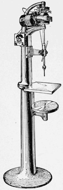
Fig. 228 shows a fan motor run by a battery. They are generally run by the current from the street. Figs. 229-231 show other forms of fan motors. Fig. 232 shows an electric hat polisher. A church organ bellows is shown in Fig. 233, so arranged that it can be pumped by an electric motor. Fig. 234 shows a motor direct connected to a drill press.
163. Starting Boxes. If too much current were[153] suddenly allowed to pass into the armature of a motor, the coils would be over-heated, and perhaps destroyed, before it attained its full speed. A rapidly revolving armature will take more current, without being overheated, than one not in motion. A motor at full speed acts like a dynamo, and generates a current which tends to flow from the machine in a direction opposite to that which produces the motion. It is evident, then, that when the armature is at rest, all the current turned on passes through it without meeting with this opposing current.
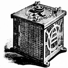
Fig. 235.
| 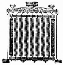
Fig. 236.
|
Fig. 235 shows a starting, stopping, and regulating box, inside of which are a number of German-silver resistance coils properly connected to contact-points at the top. By turning the knob, the field of the motor is immediately charged first through resistance, then direct, and then the current is put on the armature gradually through a series of coils, the amount of current depending upon the distance the switch is turned. Fig. 236 shows a cross section of the same.
164. Electric Cars, as well as boats, automobiles, etc., etc., are moved by the power that comes from electric motors, these receiving current from the dynamos placed at some "central station." We have already seen how the motor can do many kinds of work. By properly gearing it to the car wheels, motion can be given to them which will move the car.
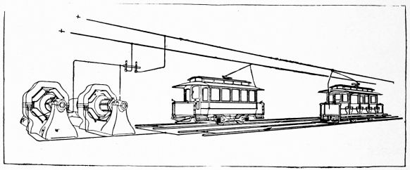
Fig. 237 shows two dynamos which will be supposed to be at a power house and which send out a current to propel cars. From the figure it will be seen that the wires over the cars, called trolley-wires, are connected to the positive (+) terminals of the dynamos, and that the negative (-) terminals are connected to the tracks. In case a wire were allowed to join the trolley-wire and track, we should have a short circuit, and current would not only rush back to the dynamo without doing useful[155] work, but it would probably injure the machines. When some of the current is allowed to pass through a car, motion is produced in the motors, as has been explained. As the number of cars increases, more current passes back to the dynamos, which must do more work to furnish such current.
Trolley-poles, fastened to the top of the cars and which end in grooved wheels, called trolley-wheels, are pressed by springs against the trolley-wires. The current passes down these through switches to controllers at each end of the car, one set being used at a time.
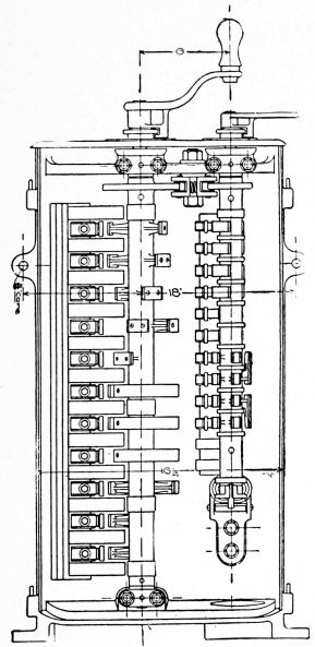
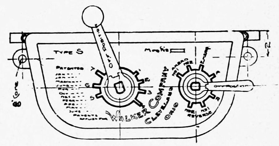
165. The Controllers, as the name suggests, control the speed of the car by allowing more or less current to pass through the motors. The motors, resistance coils and controllers are so connected with each other that the amount of current used can be regulated.
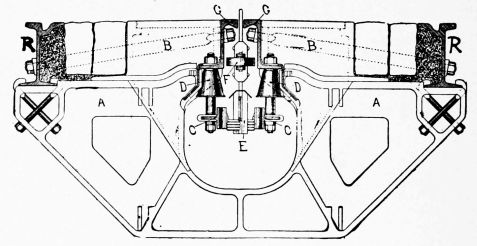
When the motorman turns the handle of the controller to the first notch, the current passes through all of the resistance wires placed under the car, then through one motor after the other. The motors being joined in series by the proper connections at the controller, the greatest resistance is offered to the current and the car runs at the slowest speed at this first notch. As more resistance is cut out by turning the handle to other notches, the car increases its speed; but as the resistance wires become heated and the heat passes into the air, there is a loss of energy. It is not economical to run a car at such a speed that energy is wasted as heat. As soon as the resistance is all cut out, the current simply passes through the motors joined in series. This gives a fairly[157] slow speed and one that is economical because all the current tends to produce motion.
By allowing the current to pass through the motors joined in parallel, that is, by allowing each to take a part of the current, the resistance is greatly reduced, and a higher speed attained. This is not instantly done, however, as too much strain would be put upon the motors. As soon as the next notch is reached, the motors are joined in parallel and the resistance also thrown in again. By turning the handle still more, resistance is gradually cut out, and the highest speed produced when the current passes only through the motors in parallel.
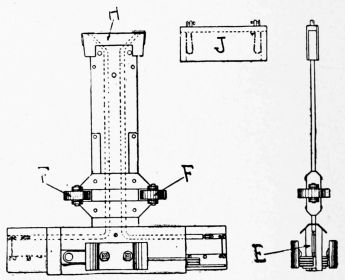
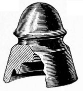
Fig. 238 represents a controller, by diagram, showing the relative positions of the controller cylinder, reversing and cut-out cylinders, arrangements for blowing out the short electric arcs formed, etc. A ratchet and pawl is provided, which indicates positively the running notches, at the same time permitting the cylinder to move with ease. Fig. 239 shows a top view of the controller.
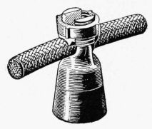
166. Overhead and Underground Systems. When wires for furnishing current are placed over the tracks, as[158] in Fig. 237, we have the overhead system. In cities the underground system is largely used. The location of the conducting wires beneath the surface of the street removes all danger to the public, and protects them from all interference, leaving the street free from poles and wires.
Fig. 240 shows a cross-section of an underground conduit. The rails, R R, are supported by cast-iron yokes, A, placed five feet apart, and thoroughly imbedded in concrete. The conduit has sewer connections every 100 feet. Conducting bars, C C, are placed on each side of the conduit, and these are divided into sections of about 500 feet. Insulators, D D, are placed every 15 feet. They are attached to, and directly under, the slot-rails, the stem passing through the conductor bar.
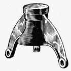
Figs. 240 and 241 show the plow E. The contact plates are carried on coiled springs to allow a free motion. Two guide-wheels, F F, are attached to the leg of the plow. The conducting wires are carried up through the leg of the plow.
167. Appliances. A large number of articles are needed in the construction of electric railroads. A few, only, can be shown that are used for the overhead system. Fig. 242 shows a pole insulator. Fig. 243 shows a feeder-wire insulator. Fig. 244 shows a line suspension. Fig. 245 shows a form of right-angle cross which allows the[159] trolley-wheels of crossing lines to pass. Fig. 246 shows a switch. In winter a part of the current is allowed to pass through electric heaters placed under the seats of electric cars.
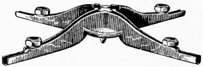
168. Electric Boats are run by the current from storage batteries which are usually placed under the seats. An electric motor large enough to run a small boat takes up very little room and is generally placed under the floor. This leaves the entire boat for the use of passengers. The motor is connected to the shaft that turns the screw. Fig. 247 shows one design.
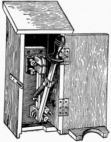
169. Electric Automobiles represent the highest type of electrical and mechanical construction. The running-gear is usually made of the best cold-drawn seamless steel tubing, to get the greatest strength from a given weight of material. The wheels are made in a variety of styles, but nearly all have ball bearings and pneumatic tires. In the lightest styles the wheels have wire spokes.
The electric motors, supported by the running-gear, are[160] geared to the rear wheels. The motors are made as nearly dust-proof as possible.
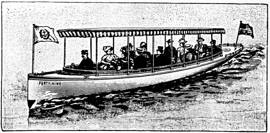
Storage batteries are put in a convenient place, depending upon the design of the carriage, and from these the motors receive the current. These can be charged from the ordinary 110-volt lighting circuits or from private dynamos. The proper plugs and attachments are usually furnished by the various makers for connecting the batteries with the street current, which is shut off when the batteries are full by an automatic switch.
Controllers are used, as on electric cars, the lever for starting, stopping, etc., being usually placed on the left-hand side of the seat. The steering is done by a lever that moves the front wheels. Strong brakes, and the ability to quickly reverse the motors, allow electric carriages to be stopped suddenly in case of accidents.
Electric automobiles are largely used in cities, or where the current can be easily had. The batteries must be re-charged after they have run the motors for a certain time which depends upon the speed and road, as well as[161] upon the construction. Where carriages are to be run almost constantly, as is the case with those used for general passenger service in cities, duplicate batteries are necessary, so that one or two sets can be charged while another is in use. Fig. 248 shows one form of electric vehicle, the storage batteries being placed under and back of the seat.
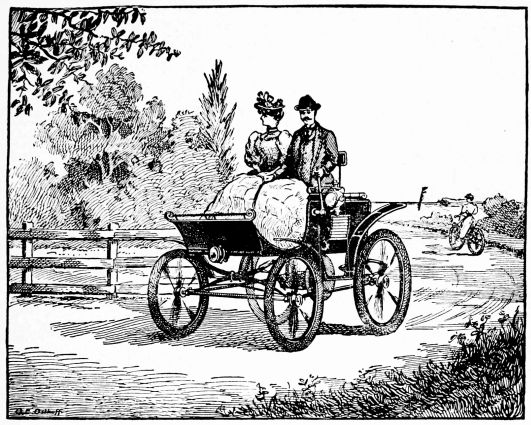
170. Central Stations, as the word implies, are places where, for example, electricity is generated for the incandescent or arc lights used in a certain neighborhood; where telephone or telegraph messages are sent to be resent to some other station; where operators are kept to switch different lines together, so that those on one line can talk to those on another, etc., etc. There are many kinds of central stations, each requiring a large amount of special apparatus to carry on the work. Fig. 249 gives a hint in regard to the way car lines get their power from a central power station. As a large part of the apparatus required in ordinary central stations has already been described, it is not necessary to go into the details of such stations.
In lighting stations, for example, we have three principal kinds of apparatus. Boilers produce the steam that runs the steam engines, and these run the dynamos that give the current. Besides these there are many other things needed. The electrical energy that goes over the wires to furnish light, heat, and power, really comes indirectly from the coal that is used to boil water and[163] convert it into steam. The various parts of the central station merely aid in this transformation of energy.
The dynamos are connected to the engines by belts, or[164] they are direct connected. Figs. 250, 251, show dynamos connected to engines without belts.
The current from the dynamos is led to large switchboards which contain switches, voltmeters, ammeters, lightning arresters, and various other apparatus for the proper control and measurement of the current. From the switchboard it is allowed to pass through the various street mains, from which it is finally led to lamps, motors, etc.
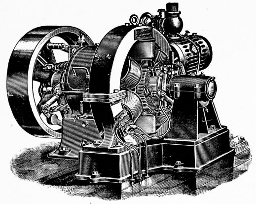
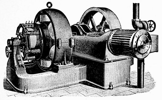
Water-power is frequently used to drive the dynamos instead of steam engines. The water turns some form of water-wheel which is connected to the dynamos. At Niagara Falls, for example, immense quantities of current are generated for light, heat, power, and industrial purposes.
171. The Many Uses to which the electric current is put are almost numberless. New uses are being found for it every day. Some of the common applications are given below.
172. Automatic Electric Program Clocks, Fig. 252, are largely used in all sorts of establishments, schools, etc., for ringing bells at certain stated periods. The lower dial shown has many contact-points that can be inserted to correspond to given times. As this revolves, the circuits are closed, one after the other, and it may be so set that bells will be rung in different parts of the house every five minutes, if desired.
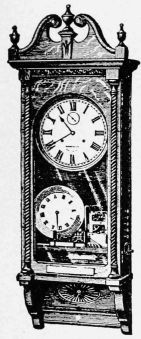
Fig. 252.
| 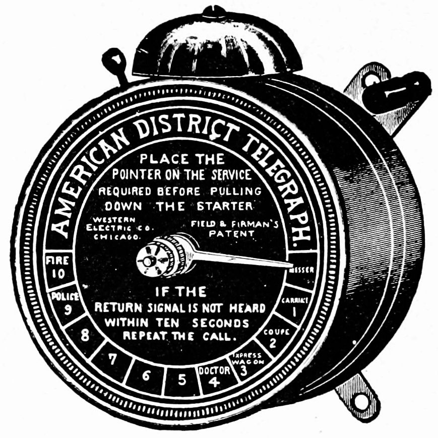
Fig. 253.
|
173. Call Boxes are used to send in calls of various[166] kinds to central stations. Fig. 253 shows one form. The number of different calls provided includes messenger, carrier, coupé, express wagon, doctor, laborer, police, fire, together with three more, which may be made special to suit the convenience of the individual customer. The instruments are provided with apparatus for receiving a return signal, the object of which is to notify the subscriber that his call has been received and is having attention.
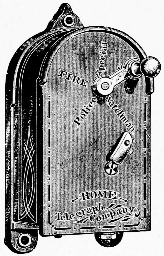
Fig. 254.
| 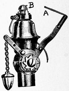
Fig. 255.
|
Fig. 254 shows another form of call box, the handle being moved around to the call desired. As it springs back to the original position, an interrupted current passes through the box to the central station, causing a bell to tap a certain number of times, giving the call and location of the box.
174. Electric Gas-Lighters. Fig. 255 shows a ratchet burner. The first pull of the chain turns on the gas through a four-way gas-cock, governed by a ratchet-wheel[167] and pawl. The issuing gas is lighted by a wipe-spark at the tip of the burner. Alternate pulls shut off the gas. As the lever brings the attached wire A, in contact with the wire B, a bright spark passes, which ignites the gas, the burner being joined with a battery and induction or spark coil.
Automatic burners are used when it is desired to light gas at a distance from the push-button. Fig. 256 shows one form. Two electromagnets are shown, one being generally joined to a white push-button for turning on the gas and lighting it, the other being joined to a black button which turns off the gas when it is pressed. The armatures of the magnets work the gas-valve. Sparks ignite the gas, as explained above.
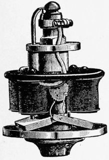
Fig. 256.
| 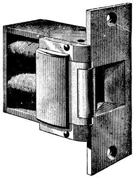
Fig. 257.
|
175. Door Openers. Fig. 257 shows one form. They contain electromagnets so arranged that when the[168] armature is attracted by the pushing of a button anywhere in the building, the door can be pushed open.
176. Dental Outfits. Fig. 258 shows a motor arranged to run dental apparatus. The motor can be connected to an ordinary incandescent light socket. In case the current gives out, the drills, etc., can be run by foot power.
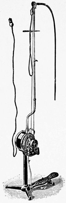
177. Annunciators of various kinds are used in hotels, factories, etc., to indicate a certain room when a bell rings at the office. The bell indicates that some one has called, and the annunciator shows the location of the call by displaying the number of the room or its location. Fig. 259 shows a small annunciator. They contain electromagnets which are connected to push-buttons located in the building, and which bring the numbers into place as soon as the current passes through them.
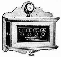
Numbers refer to paragraphs. See Table of Contents for the titles of the various chapters.
CONTENTS: Chapter I. About Frictional Electricity.—II. About Magnets and Magnetism.—III. How Electricity is Generated by the Voltaic Cell.—IV. Various Voltaic Cells.—V. About Push-Buttons, Switches and Binding-Posts.—VI. Units and Apparatus for Electrical Measurements.—VII. Chemical Effects of the Electric Current.—VIII. How Electroplating and Electrotyping are Done.—IX. The Storage Battery and How it Works.—X. How Electricity is Generated by Heat.—XI. Magnetic Effects of the Electric Current.—XII. How Electricity is Generated by Induction.—XIII. How the Induction Coil Works.—XIV. The Electric Telegraph, and How it Sends Messages.—XV. The Electric Bell and Some of its Uses.—XVI. The Telephone, and How it Transmits Speech.—XVII. How Electricity is Generated by Dynamos.—XVIII. How the Electric Current is Transformed.—XIX. How Electric Currents are Distributed for Use.—XX. How Heat is Produced by the Electric Current.—XXI. How Light is Produced by the Incandescent Lamp.—XXII. How Light is Produced by the Arc Lamp.—XXIII. X-Rays, and How the Bones of the Human Body are Photographed.—XXIV. The Electric Motor and How it Does Work.—XXV. Electric Cars, Boats and Automobiles.—XXVI. A Word About Central Stations.—XXVII. Miscellaneous Uses of Electricity.
This book explains, in simple, straightforward language, many things about electricity; things in which the American boy is intensely interested; things he wants to know; things he should know.
It is free from technical language and rhetorical frills, but it tells how things work, and why they work.
It is brimful of illustrations—the best that can be had—illustrations that are taken directly from apparatus and machinery, and that show what they are intended to show.
This book does not contain experiments, or tell how to make apparatus; our other books do that. After explaining the simple principles of electricity, it shows how these principles are used and combined to make electricity do every-day work.
Containing complete directions for making all kinds of simple electrical apparatus for the study of elementary electricity. By Professor Thomas M. St. John, New York City.
The book measures 5 × 7½ in., and is beautifully bound in cloth. It contains 141 pages and 125 illustrations. Complete directions are given for making 152 different pieces of Apparatus for the practical use of students, teachers, and others who wish to experiment.
The shocking coils, telegraph instruments, batteries, electromagnets, motors, etc., etc., are so simple in construction that any boy of average ability can make them; in fact, the illustrations have been made directly from apparatus constructed by young boys.
The author has been working along this line for several years, and he has been able, with the help of boys, to devise a complete line of simple electrical apparatus.
THE APPARATUS IS SIMPLE because the designs and methods of construction have been worked out practically in the school-room, absolutely no machine-work being required.
THE APPARATUS IS PRACTICAL because it has been designed for real use in the experimental study of elementary electricity.
THE APPARATUS IS CHEAP because most of the parts can be made of old tin cans and cracker boxes, bolts, screws, wires and wood.
CONTENTS: Chapter I. Cells and Batteries.—II. Battery Fluids and Solutions.—III. Miscellaneous Apparatus and Methods of Construction.—IV. Switches and Cut-Outs.—V. Binding-Posts and Connectors.—VI. Permanent Magnets,—VII. Magnetic Needles and Compasses.—VIII. Yokes and Armatures.—IX. Electro-Magnets.—X. Wire-Winding Apparatus.—XI. Induction Coils and Their Attachments.—XII. Contact Breakers and Current Interrupters.—XIII. Current Detectors and Galvanometers.—XIV. Telegraph Keys and Sounders.—XV. Electric Bells and Buzzers.—XVI. Commutators and Current Reversers.—XVII. Resistance Coils.—XVIII. Apparatus for Static Electricity.—XIX. Electric Motors.—XX. Odds and Ends.—XXI. Tools and Materials.
"The author of this book is a teacher and wirier of great ingenuity, and we imagine that the effect of such a book as this falling into juvenile hands must be highly stimulating and beneficial. It is full of explicit details and instructions in regard to a great variety of apparatus, and the materials required are all within the compass of very modest pocket-money. Moreover, it is systematic and entirely without rhetorical frills, so that the student can go right along without being diverted from good helpful work that will lead him to build useful apparatus and make him understand what he is about. The drawings are plain and excellent. We heartily commend the book."—Electrical Engineer.
"Those who visited the electrical exhibition last May cannot have failed to notice on the south gallery a very interesting exhibit, consisting, as it did, of electrical apparatus made by boys. The various devices there shown, comprising electro-magnets, telegraph keys and sounders, resistance coils, etc., were turned out by boys following the instructions given in the book with the above title, which is unquestionably one of the most practical little works yet written that treat of similar subjects, for with but a limited amount of mechanical knowledge, and by closely following the instructions given, almost any electrical device may be made at very small expense. That such a book fills a long-felt want may be inferred from the number of inquiries we are constantly receiving from persons desiring to make their own induction coils and other apparatus."—Electricity.
"At the electrical show in New York last May one of the most interesting exhibits was that of simple electrical apparatus made by the boys in one of the private schools in the city. This apparatus, made by boys of thirteen to fifteen years of age, was from designs by the author of this clever little book, and it was remarkable to see what an ingenious use had been made of old tin tomato-cans, cracker-boxes, bolts, screws, wire, and wood. With these simple materials telegraph instruments, coils, buzzers, current detectors, motors, switches, armatures, and an almost endless variety of apparatus were made, In this book Mr. St. John has given directions in simple language for making and using these devices, and has illustrated these directions with admirable diagrams and cuts. The little volume is unique, and will prove exceedingly helpful to those of our young readers who are fortunate enough to possess themselves of a copy. For schools where a course of elementary science is taught, no better text-book in the first-steps in electricity is obtainable."—The Great Round World.
While only 40 pieces of simple apparatus were shown in this exhibit, it gave visitors something of an idea of what young boys can do if given proper designs.

PHOTOGRAPHY is now an educational amusement, and to many it is the most fascinating of all amusements. The magic of sunshine, the wonders of nature, and the beauties of art are tools in the hand of the amateur photographer.
A great many things can be done with this outfit, and it will give an insight into this most popular pastime.
THE OUTFIT contains everything necessary for making ordinary prints—together with other articles to be used in various ways. The following things are included: One Illustrated Book of Instructions, called "Fun With Photography;" 1 Package of Sensitized Paper; 1 Printing Frame, including Glass, Back, and Spring; 1 Set of Masks for Printing Frame; 1 Set of Patterns for Fancy Shapes; 1 Book of Negatives (Patent Pending) Ready for Use; 6 Sheets of Blank Negative Paper; 1 Alphabet Sheet; 1 Package of Card Mounts; 1 Package of Folding Mounts; 1 Package of "Fixo."
CONTENTS OF BOOK:—Chapter I. Introduction.—Photography.—Magic Sunshine.—The Outfit.—II. General Instructions.—The Sensitized Paper.—How the Effects are Produced.—Negatives.—Prints.—Printing Frames.—Our Printing Frame.—Putting Negatives in Printing Frame.—Printing.—Developing.—Fixing.—Drying.—Trimming.—Fancy Shapes.—Mounting.—III. Negatives and How to Make Them.—The Paper.—Making Transparent Paper.—Making the Negatives.—Printed Negatives.—Perforated Negatives.—Negatives Made from Magazine Pictures.—Ground Glass Negatives.—IV. Nature Photography.—Aids to Nature Study.—Ferns and Leaves.—Photographing Leaves.—Perforating Leaves.—Drying Leaves, Ferns, etc., for Negatives.—Flowers.—V. Miscellaneous Photographs.—Magnetic Photographs.—Combination Pictures.—Initial Pictures.—Name Plates.—Christmas, Easter and Birthday Cards.

Children like to do experiments; and in this way, better than in any other, a practical knowledge of the elements of magnetism may be obtained.
These experiments, although arranged to amuse boys and girls, have been found to be very useful in the class-room to supplement the ordinary exercises given in text-books of science.
To secure the best possible quality of apparatus, the horseshoe magnets were made at Sheffield, England, especially for these sets. They are new and strong. Other parts of the apparatus have also been selected and made with great care, to adapt them particularly to these experiments.—From the author's preface.
CONTENTS.—Experiments With Horseshoe Magnet.—Experiments With Magnetized Needles.—Experiments With Needles, Corks, Wires, Nails, etc.—Experiments With Bar Magnets.—Experiments With Floating Magnets.—Miscellaneous Experiments.—Miscellaneous Illustrations showing what very small children can do with the Apparatus.—Diagrams showing how Magnetized Needles may be used by little children to make hundreds of pretty designs upon paper.
AMUSING EXPERIMENTS.—Something for Nervous People to Try.—The Jersey Mosquito.—The Stampede.—The Runaway.—The Dog-fight.—The Whirligig.—The Naval Battle.—A String of Fish.—A Magnetic Gun.—A Top Upsidedown.—A Magnetic Windmill.—A Compass Upsidedown.—The Magnetic Acrobat.—The Busy Ant-hill.—The Magnetic Bridge.—The Merry-go-Round.—The Tight-rope Walker.—A Magnetic Motor Using Attractions and Repulsions.
Shadow Making has been a very popular amusement for several centuries. There is a great deal of fun and instruction in it, and its long life is due to the fact that it has always been a source of keen delight to grown people as well as to children.
In getting material together for this little book, the author has been greatly aided by English, French and American authors, some of whom are professional shadowists. It has been the author's special effort to get the subject and apparatus into a practical, cheap form for boys and girls.
THE OUTFIT contains everything necessary for all ordinary shadow pictures, shadow entertainments, shadow plays, etc. The following articles are included:
One book of Instructions called "Fun with Shadows"; 1 Shadow Screen; 2 Sheets of Tracing Paper; 1 Coil of Wire for Movable Figures; 1 Cardboard Frame for Circular Screen; 1 Cardboard House for Stage Scenery; 1 Jointed Wire Fish-pole and Line; 2 Bent Wire Scenery Holders; 4 Clamps for Screen; 1 Wire Figure Support; 1 Wire for Oar; 2 Spring Wire Table Clamps; 1 Wire Candlestick Holder; 5 Cardboard Plates containing the following printed figures that should be cut out with shears: 12 Character Hats; 1 Boat; 1 Oar-blade; 1 Fish; 1 Candlestick; 1 Cardboard Plate containing printed parts for making movable figures.
CONTENTS OF BOOK: One Hundred Illustrations and Diagrams, including Ten Full-page Book Plates, together with Six Full-page Plates on Cardboard.
Chapter I. Introduction.—II. General Instructions.—III. Hand Shadows of Animals.—IV. Hand Shadows of Heads, Character Faces, etc.—V. Moving Shadow Figures and How to Make Them.—VI. Shadow Pantomimes.—VII. Miscellaneous Shadows.
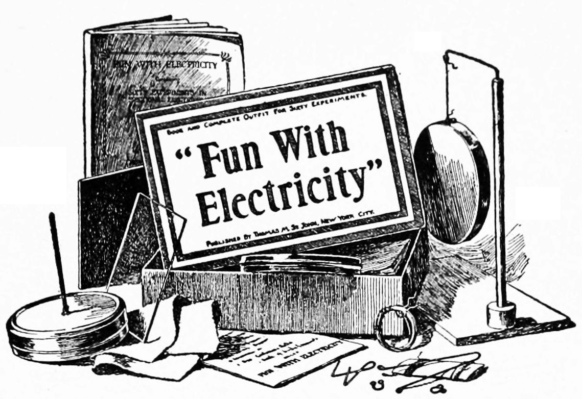
Enough of the principles of electricity are brought out to make the book instructive as well as amusing. The experiments are systematically arranged, and make a fascinating science course. No chemicals, no danger.
The book is conversational and not at all "schooly," Harry and Ned being two boys who perform the experiments and talk over the results as they go along.
"The book reads like a story."—"An appropriate present for a boy or girl."—"Intelligent parents will appreciate 'Fun With Electricity.'"—"Very complete, because it contains both book and apparatus."—"There is no end to the fun which a boy or girl can have with this fascinating amusement."
THERE IS FUN IN THESE EXPERIMENTS.—Chain Lightning.—An Electric Whirligig.—The Baby Thunderstorm.—A Race with Electricity.—An Electric Frog Pond.—An Electric Ding-Dong.—The Magic Finger.—Daddy Long-Legs.—Jumping Sally.—An Electric Kite.—Very Shocking.—Condensed Lightning.—An Electric Fly-Trap.—The Merry Pendulum.—An Electric Ferry-Boat.—A Funny Piece of Paper.—A Joke on the Family Cat.—Electricity Plays Leap-Frog.—Lightning Goes Over a Bridge.—Electricity Carries a Lantern.—And 40 Others.
The OUTFIT contains 20 different articles. The BOOK OF INSTRUCTION measures 5 x 7½ inches, and has 38 illustrations, 55 pages, good paper and clear type.
The BOOK measures 5 × 7½ inches. It is well printed, nicely bound, and contains 15 chapters, 80 pages, and 128 illustrations. The KEY is illustrated. It is bound with the book, and contains the solution of every puzzle. The COMPLETE OUTFIT is placed in a neat box with the book. It consists of numbers, counters, figures, pictures, etc., for doing the puzzles.
CONTENTS: Chapter (1) Secret Writing. (2) Magic Triangles, Squares, Rectangles, Hexagons, Crosses, Circles, etc. (3) Dropped Letter and Dropped Word Puzzles. (4) Mixed Proverbs, Prose and Rhyme. (5) Word Diamonds, Squares, Triangles, and Rhomboids. (6) Numerical Enigmas. (7) Jumbled Writing and Magic Proverbs. (8) Dissected Puzzles. (9) Hidden and Concealed Words. (10) Divided Cakes, Pies, Gardens, Farms, etc. (11) Bicycle and Boat Puzzles. (12) Various Word and Letter Puzzles. (13) Puzzles with Counters. (14) Combination Puzzles. (15) Mazes and Labyrinths.
"Fun With Puzzles" is a book that every boy and girl should have. It is amusing, instructive,—educational. It is just the thing to wake up boys and girls and make them think. They like it, because it is real fun. This sort of educational play should be given in every school-room and in every home.
"Fun With Puzzles" will puzzle your friends, as well as yourself; it contains some real brain-splitters. Over 300 new and original puzzles are given, besides many that are hundreds of years old.
Secret Writing. Among the many things that "F. W. P." contains, is the key to secret writing. It shows you a very simple way to write letters to your friends, and it is simply impossible for others to read what you have written, unless they know the secret. This, alone is a valuable thing for any boy or girl who wants to have some fun.

THE OUTFIT contains everything necessary for thousands of beautiful bubbles and films. All highly colored articles have been carefully avoided, as cheap paints and dyes are positively dangerous in children's mouths. The outfit contains the following articles:
One Book of Instructions, called "Fun With Soap-Bubbles," 1 Metal Base for Bubble Stand, 1 Wooden Rod for Bubble Stand, 3 Large Wire Rings for Bubble Stand, 1 Small Wire Ring, 3 Straws, 1 Package of Prepared Soap, 1 Bubble Pipe, 1 Water-proof Bubble Horn. The complete outfit is placed in a neat box with the book. (Extra Horns, Soap, etc., furnished at slight cost.)
CONTENTS OF BOOK.—Twenty-one Illustrations.—Introduction.—The Colors of Soap-bubbles.—The Outfit.—Soap Mixture.—Useful Hints.—Bubbles Blown With Pipes.—Bubbles Blown With Straws.—Bubbles Blown With the Horn.—Floating Bubbles.—Baby Bubbles.—Smoke Bubbles.—Bombshell Bubbles.—Dancing Bubbles.—Bubble Games.—Supported Bubbles.—Bubble Cluster.—Suspended Bubbles.—Bubble Lamp Chimney.—Bubble Lenses.—Bubble Basket.—Bubble Bellows.—To Draw a Bubble Through a Ring.—Bubble Acorn.—Bubble Bottle.—A Bubble Within a Bubble.—Another Way.—Bubble Shade.—Bubble Hammock.—Wrestling Bubbles.—A Smoking Bubble.—Soap Films.—The Tennis Racket Film.—Fish-net Film.—Pan-shaped Film.—Bow and Arrow Film.—Bubble Dome.—Double Bubble Dome.—Pyramid Bubbles.—Turtle-back Bubbles.—Soap-bubbles and Frictional Electricity.
"There is nothing more beautiful than the airy-fairy soap-bubble with its everchanging colors."
This book is designed as a text-book for amateurs, students, and others who wish to take up a systematic course of elementary electrical experiments at home or in school. Full directions are given for . . . . . . .
The experiments are discussed by the author, after the student has been led to form his own opinion about the results obtained and the points learned.
In selecting the apparatus for the experiments in this book, the author has kept constantly in mind the fact that the average student will not buy the expensive pieces usually described in text-books.
The two hundred experiments given can be performed with simple apparatus; in fact, the student should make at least a part of his own apparatus, and for the benefit of those who wish to do this, the author has given, throughout the work, explanations that will aid in the construction of certain pieces especially adapted to these experiments. For those who have the author's "How Two Boys Made Their Own Electrical Apparatus," constant references have been made to it as the "Apparatus Book," as this contains full details for making almost all kinds of simple apparatus needed in "The Study of Elementary Electricity and Magnetism by Experiment."
If you wish to take up a systematic course of experiments—experiments that may be performed with simple, inexpensive apparatus,—this book will serve as a valuable guide.
Number 1. Steel Needles; package of twenty-five.—2. Flat Cork.—3. Candle.—4-15. Annealed Iron Wires; assorted lengths.—16. Horseshoe Magnet; best quality; English.—17. Iron Filings.—18. Parts for Compass.—19, 20. Wire Nails; soft steel.—21, 22. Spring Steel; for bar magnets.—23. Iron Ring.—24. Sifter; for iron filings.—25. Spring Steel; for flexible magnet.—26, 27. Ebonite Sheets; with special surface.—28. Ebonite Rod.—29. Ebonite Rod; short.—30. Flannel Cloth.—31. Tissue Paper.—32. Cotton Thread.—33. Silk Thread.—34. Support Base.—35. Support Rod.—36. Support Wire.—37. Wire Swing.—38. Sheet of Glass.—39. Hairpin.—40. Circular Conductor.—41. Circular Conductor.—42. Electrophorus Cover.—43. Insulating Table.—44. Insulated Copper Wire.—45. Rubber Band.—46. Bent Wire Clamps.—47. Cylindrical Conductor.—48. Discharger; for condenser.—49. Aluminum-Leaf.—50. Wires.
51. Dry Cell.—52. Mercury.—53. Insulated Copper Wire; for connections.—54. Spring Connectors; two dozen.—55. Parts for Key.—56. Metal Connecting Plates.—57. Parts for Current Reverser.—58. Parts for Galvanoscope.—59. Parts for Astatic Galvanoscope.—60-63. Zinc Strips.—64. Carbon Rod.—65, 66. Glass Tumblers.—67, 68. Copper Strips.—69. Galvanized Iron Nail.—70, 71. Wooden Cross-Pieces.—72. Brass Screws; one dozen.—73. Porous Cup.—74. Zinc Rod.—75. Copper Plate.—76. Iron Strip.—77, 78. Lead Strips.—79. Parts for Resistance Coil.—80. Parts for Wheatstone's Bridge.—81. German-Silver Wire; Size No. 30.—82. German-Silver Wire; No. 28.—83—85. Plate Binding-Posts.—86. Copper Sulphate.—87. Copper Burs; one dozen.—88. Combination Rule.—89. Coil of Wire; on spool for electromagnet.—90. Coil of Wire; on spool for electromagnet.—91. Carbon Rod.—92, 93. Soft Iron Cores with Screws.—94. Combined Base and Yoke.—95. Combination Connecting Plates.—96. Long Iron Core.—97. Round Bar Magnet, 5 × 3/8 in.—98. Thin Electromagnet.—99. Degree-Card; for galvanoscope.—100. Scale for Bridge.—101, 102. Soft Iron Cores with Heads.—103, 104. Flat Bar Magnets; these are 6 × ½ × ¼ in.; highly polished steel; poles marked.—105. Compass.
This Cabinet of Electrical Experiments contains three main parts: (A) Apparatus; (B) Text-Book; (C) Apparatus List.
(A) The Apparatus furnished consists of one hundred and five pieces. Over three hundred separate articles are used in making up this set. Most of it is ready for use when received. Seven pieces, however, are not assembled; but the parts can be readily finished and put together. (Sold, also, all pieces assembled.)
(B) The Text-Book—called "The Study of Elementary Electricity and Magnetism by Experiment"—gives full directions for two hundred experiments. (See table of contents, etc.) Price, post-paid, $1.25.
(C) The Apparatus List is an illustrated book devoted entirely to this special set of apparatus. Not given with first offer.
THE APPARATUS IS SIMPLE because the designs and methods of construction have been worked out with great care.
THE APPARATUS IS PRACTICAL because it has been designed for real use in "The Study of Elementary Electricity and Magnetism by Experiment."
THE APPARATUS IS CHEAP because the various parts are so designed that they can be turned out in quantity by machinery.
| 1st Offer: Pieces 1 to 50 | $1.00 |
| 2d Offer: Pieces 51 to 105, with part (C) | 3.50 |
| 3d Offer: Pieces 1 to 105, with part (C) | 4.00 |
| 4th Offer: Complete Cabinet, parts (A), (B), (C) | 5.00 |
| 5th Offer: Apparatus only, all pieces assembled | 4.60 |
| 6th Offer: Complete Cabinet, all pieces assembled | 5.60 |
A "Special Catalogue," pertaining to the above, with complete price-list, will be mailed upon application.
TELEGRAPHY is of the greatest importance to all civilized nations, and upon it depend some of the world's most important enterprises. Every boy and girl can make practical use of telegraphy in one way or another, and the time it takes to learn it will be well spent.
THE OUTFIT.—Mr. St. John has worked for a number of years to produce a telegraph outfit that would be simple, cheap, and practical for those who wish to make a study of telegraphy. After making and experimenting with nearly one hundred models, many of which were good, he has at last perfected an instrument so simple, original, and effective that it is now being made in large quantities.
The sounders are so designed that they will work properly with any dry cell of ordinary strength, and this is a great advantage for practice lines. Dry batteries are cheap and clean, and there are no dangers from acids.
The outfit consists of the following articles, placed in a neat box: One Book of Instruction, called "Fun With Telegraphy"; one Telegraph "Key"; one Telegraph "Sounder"; Insulated Copper Wires for connections. The "key" and "sounder" are mounted, with proper "binding-posts," upon a base of peculiar construction, which aids in giving a large volume of sound.
CONTENTS OF BOOK.—Telegraphy.—The Outfit.—A Complete Telegraph Line.—Connections.—The Telegraph Key.—The Sounder.—The Battery.—A Practice Line.—A Two-instrument Line.—Operation of Line.—The Morse Telegraph Alphabet.—Aids to Learning Alphabet.—Cautions.—Office Calls.—Receiving Messages.—Remember.—Extra Parts.
ABOUT BATTERIES.—For those who cannot easily secure batteries, we will furnish small dry cells, post-paid, at 15 cents each, in order to deliver the outfits complete to our customers. This price barely covers the total cost to us, postage alone being 6 cents.
The following tool sets have been arranged especially for those who wish to make use of the designs contained in "How Two Boys Made Their Own Electrical Apparatus," "Real Electric Toy-Making for Boys," "Electric Instrument-Making," etc. It is very poor economy to waste valuable time and energy in order to save the cost of a few extra tools.
NOTE.—Save money by buying your tools in sets. We do not pay express or freight charges at the special prices below.
FOR $1.00.—One Steel Punch; round, knurled head.—One light Hammer; polished, nickel-plated, varnished handle.—One Iron Clamp; japanned, 2¼ in.—One Screw-Driver; tempered and polished blade, cherry stained hardwood handle, nickel ferrule.—One Wrench; retinned skeleton frame, gilt adjusting wheel.—One Awl; tempered steel point, turned and stained wood handle, with ferrule.—One Vise; full malleable, nicely retinned, 1-3/8 in. jaws, full malleable screw with spring.—One pair Steel Pliers; 4 in. long, polished tool steel, unbreakable, best grooved jaw.—One pair of Shears; carbonized steel blades, hardened edge, nickel-plated, heavy brass nut and bolt.—One File; triangular, good steel.—One File Handle; good wood, brass ferrule.—One Foot Rule; varnished wood, has English and metric system.—One Soldering Set; contains soldering iron, solder, resin, sal ammoniac, and directions. One Center-Punch; finely tempered steel.
FOR $2.00.—All that is contained in the $1.00 set of tools, together with the following: One pair of Tinner's Shears; cut, 2¾ in., cast iron, hardened, suitable for cutting thin metal.—One Hollow Handle Tool Set; very useful; polished handle holds 10 tools, gimlet, brad-awls, chisel, etc.—One Try Square; 6-in. blue steel blade, marked in 1/8s, strongly riveted.—One 1-lb. Hammer; full size, polished head, wedged varnished hardwood handle.—One Hack Saw; steel frame, 9½-in. polished steel blade, black enamel handle; very useful.
FOR $3.50.—Two Steel Punches; different sizes, one solid round, knurled head, polished; the other, point and head brightly polished, full nickel, center part knurled.—One Light Hammer; polished and nickel plated, varnished handle.—One regular Machinist's Hammer; ball peen, solid cast steel, with varnished hardwood handle; a superior article.—Two Iron Clamps; one opens 2¼ in., the other 3 in., japanned.—One Screw-Driver; tempered and polished blade, firmly set in cherry stained hardwood handle with nickel ferrule.—One Wrench; retinned, skeleton frame, gilt adjusting wheel.—One Awl; tempered steel blade, ground to point, firmly set in turned and stained handle with ferrule.—One Steel Vise; 2¼-in., jaws, steel screw, bright polished jaws and handle; a good strong vise.—One pair of Steel Pliers; 6 in. long, bright steel, flat nose, 2 wire-cutters, practically unbreakable.—One pair of Shears; carbonized steel blades, hardened edges, nickel plated, heavy brass nut and bolt.—One File; triangular and of good steel.—One File Handle; good wood, with brass ferrule.—One Foot Rule; varnished wood, has both the English and metric systems.—One Soldering Set; contains soldering iron, solder, resin, sal ammoniac, and directions; a very handy article.—One Center-Punch; finely tempered steel.—One pair of Tinner's Shears; these are best grade, inlaid steel cutting edges, polished and tempered, japanned handles; thoroughly reliable.—One Hollow Handle Tool Set; very useful; the polished handle holds 10 tools, gimlet, chisel, brad-awl, etc.—One Try Square; 6-in. blue steel blade, marked both sides in 1/8s, strongly riveted with brass rivets.—One Hack Saw; steel frame, 9½-in. polished steel blade, black enamel handle; very useful for sawing small pieces of wood.
FOR $5.00 will be included everything in the $3.50 offer, and the following: One Glue-Pot; medium size, with brush and best wood glue; inside pot has hinge cover.—One Ratchet Screw-Driver; great improvement over ordinary screw-drivers; well made and useful.—One Hand Drill; frame malleable iron; hollow screw top holding 6 drills; bores from 1-16 to 3-16-in. holes; solid gear teeth; 3-jawed nickel plated chuck; a superior tool, and almost a necessity.
CONTENTS: Chapter I. Toys Operated by Permanent Magnets.—II. Toys Operated by Static Electricity.—III. Making Electromagnets for Toys.—IV. Electric Batteries.—V. Circuits and Connections.—VI. Toys Operated by Electromagnets. VII. Making Solenoids for Toys.—VIII. Toys Operated by Solenoids.—IX. Electric Motors.—X. Power, Speed, and Gearing.—XI. Shafting and Bearings.—XII. Pulleys and Winding-Drums.—XIII. Belts and Cables.—XIV. Toys Operated by Electric Motors.—XV. Miscellaneous Electric Toys.—XVI. Tools.—XVII. Materials.—XVIII. Various Aids to Construction.
While planning this book, Mr. St. John definitely decided that he would not fill it with descriptions of complicated, machine-made instruments and apparatus, under the name of "Toy-Making," for it is just as impossible for most boys to get the parts for such things as it is for them to do the required machine work even after they have the raw materials.
Great care has been taken in designing the toys which are described in this book, in order to make them so simple that any boy of average ability can construct them out of ordinary materials. The author can personally guarantee the designs, for there is no guesswork about them. Every toy was made, changed, and experimented with until it was as simple as possible; the drawings were then made from the perfected models.
As the result of the enormous amount of work and experimenting which were required to originate and perfect so many new models, the author feels that this book may be truly called "Real Electric Toy-Making for Boys."
The Electric Shooting Game is an entirely new idea, and one that brings into use that most mysterious something—electricity. The game is so simple that small children can play it, and as there are no batteries, acids, or liquids of any kind, there is absolutely no danger. The electricity is of such a nature that it is perfectly harmless—but very active.
The "game-preserve" is neat and attractive, being printed in colors, and the birds and animals are well worth hunting. Each has a fixed value—and some of them must not be shot at all—so there is ample opportunity for a display of skill in bringing down those which count most.
"Electric bullets" are actually shot from the "electric gun" by electricity. This instructive game will furnish a vast amount of amusement to all.
Obvious punctuation errors were corrected.
Page 46, "turnnd" changed to "turned" (be turned to 1)
Page 66, word "a" added to text (in a glass jar)