
TOY CRAFT
LEON H. BAXTER
Director of Manual Training, Public Schools
ST. JOHNSBURY, VT.
Author of Boy Bird House Architecture, and Elementary Concrete Construction
THE BRUCE PUBLISHING COMPANY
MILWAUKEE, WISCONSIN
Copyright 1922
The Bruce Publishing Company
Printed in the United States of America
The purpose of such a book as Mr. Baxter's "Toy Craft" is to furnish definite instructions for the making of toys for boys and girls by the children themselves. Miniature furniture, wooden dolls, carts and animals—of how much greater value is one such plaything actually put together by a child than any number of toys made in a factory or imported from some foreign country? Truly a step forward has been taken in putting before the people a book which will unconsciously instill in the minds of the children the value of the hand-made in preference to the machine-made article.
Not only is Mr. Baxter peculiarly fitted to publish such a volume as "Toy Craft" in the light of his knowledge of manual training, but also because of his understanding of the spirit behind the production of toys, which bring such joy to the hearts of boys and girls.
To the satisfaction of actually making some wooden cart, or bird, or animal may be added the happiness of doing the work for some other child. It is this vision of service for others which Mr. Baxter has already caught and demonstrated, and we feel sure that this little volume will do much to promote the improved individual construction of toys by children, at the same time instilling into the hearts of the boys the joy of making something for somebody else, of experiencing the truth, "It is more blessed to give than to receive."
MABEL E. TURNER,
Field Representative for Junior Service,
New England Division, American Red Cross.
One of the hard problems in manual training, for boys up to twelve years of age, is to find worth-while things to make, within the capacity of boys of this age. Having been engaged in this kind of work for over twenty years I can appreciate the problems of the manual training instructor in the grades.
After carefully examining the cuts and directions for the various projects as given in "Toy Craft," and having seen the boys at work, as well as the completed articles, in Mr. Baxter's department, I can readily see how the great interest that is inspired in the boys is derived.
I heartily commend this book to all manual training teachers as a great help in the solution of their problems with boys.
STANLEY J. STEWARD, M. E.,
Director, St. Johnsbury Vocational School.
Each year American parents spend millions of dollars for toys for the children. In a short time a large part of these toys are broken, and lie in the corner or the back yard. This is because of the destructive habits children have developed. These same habits have been formed because, since birth, toys have cost these children nothing.
Children, like grown-ups, value things and form habits in proportion to the cost to them. They break up what costs them nothing, and cherish and keep repaired what they, themselves, have made or purchased with self-denial or self-earned money.
The breaking of toys is bad, but the effect upon the character of the child is infinitely worse. Destructive tendencies are developed, while constructive ability is allowed to lie dormant and inactive.
The remedy for this is to develop the constructive rather than the destructive in children by buying them working outfits and books of instruction with which they can make and repair things for themselves. In other words, buy tools, equipment and supplies rather than finished toys. Carlisle said, "Man without tools is nothing; man with tools is all." Education is to children what civilization is to the race.
What to buy for each particular child depends upon the age and tendencies of the child and is a matter parents must determine for themselves. The important test is, "Is it something that the child can use to make things for himself, for others and for the home?"
When purchasing tools it is an excellent plan to leave some part of the outfit for the children to make or to buy from money they themselves have earned. In other words, co-operate with the children instead of doing it all for them.
The writer speaks not only from the teacher's point of view, but from the parent's as well. The problems offered in this book are not only within the capabilities of the average child, but are all tested and proven as being worth-while and appealing strongly to the child's ideals and imagination.
LEON H. BAXTER.
St. Johnsbury, Vt.
To tell the history of toy-making from its earliest days it would be necessary to follow the story back through many centuries, for the archaeologists, in delving among the tombs of ancient Greece and Egypt, have made the surprising discovery that children played with dolls, and jointed dolls at that, more than five thousand years ago.
Moreover, by the side of these dolls scientists have unearthed other playthings that children still crave: doll's furniture, animal toys and toys with wheels, illustrating the methods of transportation of those early days.
These same scientists claim that the custom of playing with dolls and other toys is as old as the world itself and that playthings are, and always have been, just as necessary a constituent of human health and development as either food or medicine.
They claim that the reason that boys and girls crave toys is that nature requires them, and to deprive children of such playthings would be to retard their mental growth and development.
The Latin word trochus means a hoop for children. The hoops of Roman children were made of bronze and iron and were rolled by a sort of a crooked stick and sometimes had small bells attached.
Pupa, the Latin word meaning "a little girl," applies to dolls which were made from rags, wood, wax, ivory and terra cotta. When the Greek girls of that time married they dedicated their dolls to Artemis; the Roman girls, to Venus; but, if they died before marriage, their dolls were buried with them.
The Latin word crepundia meant children's playthings, such as rattles, dolls, toy hatchets and swords.
The toys made during the middle ages for the children of noble families and rich merchants, show special care and fine workmanship. Many of them were of a religious nature in the form of the Cross of the Crusaders, or military in origin, like miniature knights on horseback. The toys of this period were generally carved by goldsmiths.
The American Indians and the Esquimaux made dolls from bits of skin and fur of wild animals and gaily decorated them with shells, beads and feathers. They also carved small models of animals and human beings from wood and bone.
The oldest European toy manufacturing center is Nuremberg, Germany. This town is especially noted for its metal playthings, like the lead soldiers, which were the delight of our childhood. Sonneberg, in Germany, is the greatest European center for the manufacture of wooden toys.
Winchendon, Mass., is the greatest toy manufacturing center in the United States, nearly every enterprise in that town being toy-making.
In spite of the early origin of toys the progress of manufacturing playthings has been so slow that, even as late as one hundred years ago, the types of toys were few in number, simple in construction and extremely expensive, especially in the United States.
There was no systematic manufacture of such articles, and, as the cost of importation was very high, comparatively few persons could afford such means of amusement for their children.
The children of those days accepted more primitive things, dolls that were often merely pieces of cloth folded and pinned in such a manner as to suggest the outline that was not there.
A few other toys such as hoops, jumping-jacks, tenpins, marbles, battledore-and-shuttlecock and alphabet blocks, represented the limit of the toy-makers' stock.
In America the toy-making industry is of quite recent origin. Before 1875 more than ninety per cent of the toys sold in this country were of foreign manufacture, and those that were made here were never exported to other countries. Today, however, about five per cent of the toys sold here are made abroad and the rest are manufactured here in our own country. Up to 1875 there was not a doll factory in the United States.
Today, while we import some dainty toys from France, Germany and Switzerland, nearly all the newest, unique and mechanical productions are made in America.
Simple toys are mostly made of wood and metal, and the same principles employed by mechanical engineers, in duplicating parts of machinery, are used in making duplicate parts of toys.
When a design has been decided on, it is reduced to its most simple element. Jigs are then made so that each piece will be an exact duplicate of every similar piece, and the construction is pushed through on the American factory system.
Some toys are very elaborate, costing several hundred[Pg 13] dollars. These are readily purchased, however, by people of means.
In the author's opinion the best kind of toys are those which suggest rather than fulfill, and those with which the child can really do something. Mechanical toys, which supply their own energy, should not be allowed to take the place of those into which the child must infuse part of his own life and energy. It follows naturally, then, that the toys made by the children themselves are the ideal ones.
The following drawings vary in difficulty from those within the ability of a nine or ten-year-old child to those which should not be attempted by a child under junior high school age. Of course there are younger boys, who possess especial ability in this line of work and who can successfully carry through projects which the ordinary child of a like age would fail to satisfactorily complete. Such boys are, however, the exception.
For the younger workman the following outfit is ample:
One coping saw frame.
One dozen saw blades.
A sloyd knife or a pocket knife with a small stone to keep it sharp.
Some No. 1 sandpaper, a small can of glue and some one inch brads.
The whole outfit will cost about a dollar.
A small plane is very convenient, but it is not absolutely necessary for work for younger children.
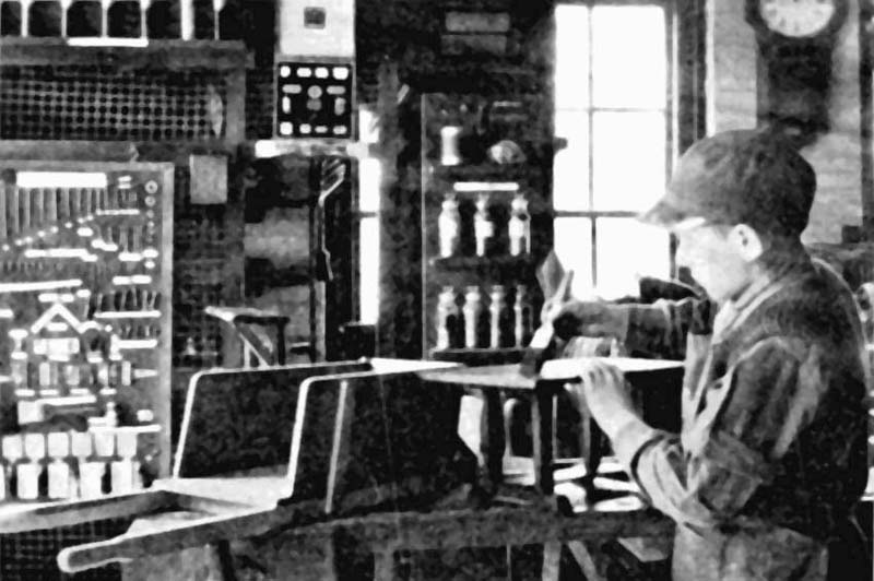
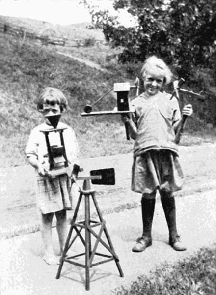
A board on which the sawing is done, to prevent marring the table, can be made from a piece of boxwood 7/8" × 6" × 12". A hole should be bored about three inches from one end and half way between the sides, and a V-shaped notch should be cut from the end of the board to the hole. The photograph on Page 20 shows the sawing board in use and illustrates two methods of constructing and holding the board. See also Plate 2 for method of making these boards. If a vise is available matters are very much simplified.
With the above described outfit, toy animals, toy furniture, jumping-jacks and other simple toys of a like nature can be made.
The material should be thin wood from the thickness of cigar box wood (which by the way is especially good to use for some of the toys), up to one-half inch in thickness.
Composition board, such as Beaver Board and similar wall board, is very good for the smaller toys but lacks strength and cannot be handled roughly.
Three-ply veneered wood may be obtained from firms which specialize in veneer. It is strong and serviceable but a little more expensive than the plain wood.
Bass and pine are excellent woods to use in toy-making, as they work very easily and are light in weight.
For the older boy, who will no doubt be handy about the house, the following tools are suggested:
1 Rip saw.
1 Turning saw.
1 Claw hammer.
1 Screw driver.
1 Half round file, No. 10.
1 Ruler.
1 Jack, or smooth, plane.
1 Brace, set of bits and countersink.
A 1/2" and 1" chisels.
1 Try square.
1 Pair of 6" dividers.
1 Knife.
This outfit should cost about $25. Other tools may be added by the boy himself as the necessity arises.
If a bench is not available at first, a temporary one may be made from a stout dry goods box and a more satisfactory one purchased later with money earned by the boy by making things for others.
Cheap tools are an expensive investment as they are never satisfactory. A few tools of good quality should be purchased to start with, and others should be added as necessity demands and funds permit.
For the young beginner it will be necessary to have patterns of animals and other toys to trace around, before cutting out the forms.
In the author's opinion originality should be always encouraged in a boy when the original designs can be successfully worked out to completion by the boy.
With beginners, however, considerable tact must be used in leading them on to work out original ideas through the medium of the sketching pencil. Only very few have the ability to carry out an idea which they may have, and if allowed to attempt it without a trial on paper the resulting product is most always a failure. As stated before, the first work should be tracings from well-designed patterns. These, then, can be successfully worked out, and the result is satisfying to the mind of the child and not a discouraging failure.
A design may be traced by placing a piece of transparent paper over the desired drawing and outlining it with a pencil. The resulting tracing is cut out, placed on a stiff piece of cardboard or fiber board, and redrawn on this. The board is then cut carefully with scissors or a sharp knife. This pattern may be used for a long time and other patterns may be made from it in a similar manner.
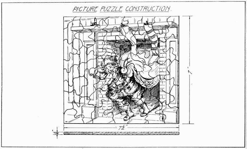
Another simple method is to place a piece of carbon paper beneath the desired drawing, carbon side down, and to go over the lines of the drawing with a medium-[Pg 15]hard pencil. This transfer may be made directly on the wood or on a piece of cardboard which is to be cut out and used as a pattern. For cut-up picture puzzles the picture is pasted directly on the wood and, after drying, is cut at random. See Plate 5.
As the child's efficiency increases and he leaves the simpler toy forms for others of increasing difficulty, he should be encouraged to read the working drawings of the article which he intends to make. Show him how to discover from the drawing the lengths, widths, thicknesses of the pieces to be made and, after carefully checking him up, let him work out his own salvation for a while. In other words, do not do it all for him. Let the result be at least 90 per cent the boy's own work. Be ready, however, to assist at the right moment and never turn a deaf ear to the persistent question, "Why"?
By following this logical method of procedure in teaching, the writer has found that the young craftsman is ready a great deal earlier to work out original ideas and designs to a practical and successful conclusion.
After all cutting with edged tools has been completed, all pieces should be carefully sanded to insure the removal of all scars, pencil lines and other imperfections.
Sandpaper should be used on a small block. Care should be taken that no paper hangs over the block, thus rounding the edges of the work being finished.
In sanding over a first coat of shellac or paint a block is not used, but the sandpaper is folded two or three times and used under the finger tips. Care must be taken especially not to wear through the finish on the edges.
Paint is difficult and unsatisfactory for younger children to use. Colors handled by beginners will run together and will be "dauby" in appearance and a detriment rather than a finish to a toy. Added to this is the likelihood of a generous application on the painter's hands and clothing.
The writer has had excellent results in using the ordinary colored wax crayons on toys. Crayon is easy to apply, has a pleasing color tone, is clean and very satisfactory for the beginner. After all of a toy has been colored a fairly heavy line may be drawn free-hand, at the point of contact of the colors, with an ordinary drafting pen and India ink. Pains should be taken to see that the ink is dry in one place before applying in another. If the crayon has been put on with pressure and uniformly deposited over the surface the ink will "take"[Pg 16] without spreading and the result is a clean-cut finished appearance.
For more advanced workers the toys should be painted with either commercial or enamel paints, which are available on the market in all colors, or with colors mixed by the boy himself. If the boy mixes his own colors much of the mystery of the ready-mixed paints is done away with.
By adding to white enamel a small amount of a selected color, ground in oil, various tones of the color may be obtained.
In painting any object a first or priming coat is applied. Flat white is an excellent all-round primer. After the priming coat has dried thoroughly on a toy, it should be sanded lightly to remove any rough places with No. 0 sandpaper and dusted. Then the final coat should be applied.
Gray is also very good for the first coat except where a white or very light colored paints are to be used for the finished coat.
When painting small toys or parts of larger toys it is economy to have a string or wire stretched between two hooks six or seven feet from the floor, on which to hang the painted article.
Drive an inch brad into some part of the toy that will not be seen, such
as the lower edge of the animal toys, and attach a short length of
string or wire to this and hang up as before described. This nail will
be handy to hold the toy by while painting and when hung up is out of
the way, is not touching anything to cause marks on the paint, and is
high enough up to be where the temperature of the room will assist in
the drying process. Remove this nail after the toy is dry. If possible
toys should dry in a special room where it is quiet, with no[Pg 17] dust
stirring or drafts blowing, and where the temperature is fairly uniform,
not falling below 60 degrees.
Paint should be applied with the tip of the brush, holding the brush nearly vertical, using a uniform stroke and taking care to prevent "tears" or surplus paint running over an edge. The brush should be in proportion to the size of the article painted, and the strokes should be outward toward the edges rather than from the edges inward.
Features and fine lines on the toys may be placed with No. 3 round sable brush or with India ink in an ordinary drafting pen. The latter method of outlining and drawing in features has proved most successful with the writer's classes, as the solidity of the pen allows a firm pressure on the surface of the work and insures a uniform line. Fine or coarse lines may be made by adjusting the pen to suit the desired need.
Considerable skill is needed to satisfactorily place lines with a fine pointed brush held in the hands of an inexperienced boy, and the drafting-pen method simplifies the problem immensely.
Adjoining colors, outlined by this method, improve the appearance of the toy fifty per cent.
Dull colors may be "livened up" by applying a coat of white shellac or varnish.
Toys having parts of various colors, such as carts, etc., should have the different parts painted before assembling.
Before attempting to stain a toy, the wood should be carefully examined to see that all scars, glue or scratches have been removed. This is very important as the stain will show up all imperfections in the wood very plainly. Enough stain should be poured in a shallow cup for the piece of work at hand and should then be applied with a brush with the grain of the wood in long narrow bands from one end of the work to the other. The stain should be wiped with a piece of waste or cloth soon after being applied, removing all surplus stain and thus bringing out the grain of the wood.
Pains must be taken when staining the edges not to allow the stain to run over on the adjacent surface. If it does the stain should be quickly wiped off with a piece of waste before it causes the surface to be unevenly stained.
There will probably be no necessity in toy construction to use filler on the wood so the method of applying this will be omitted.
Next apply a coat of white shellac (reduced by one part of alcohol to three parts of shellac), brushing it on quickly with the grain of the wood.
Do not have too much shellac on the brush. If laps or runs show, work them out with the brush.
After the shellac has dried eight or ten hours it should be rubbed lightly with No. 0 sandpaper. Be careful not to sand through the shellac, particularly on the edges. A second coat may be applied if desired.
For the last coat apply a coat of either hard or liquid wax, the latter being preferable.
Shake the can or jar before applying liquid wax. Apply evenly with a soft cloth and allow it to dry for an hour. Rub down to the proper luster with a soft clean cloth. Two or more coats of wax may be applied if desired.
If, on account of width, certain pieces of work cannot be obtained from material at hand, two pieces may have to be joined together.
One edge of each piece to be joined should be carefully planed square and straight. Keep trying the two edges together until a satisfactory joint is obtained, one so satisfactory that when the edges are placed together no joint line is visible. When such a joint is obtained we are ready to take the next step—to locate holes for dowels.
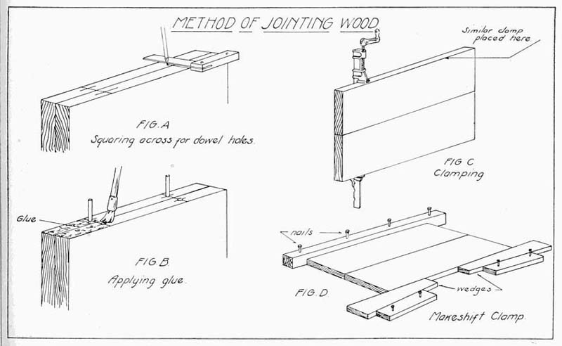
This method is shown in Plate 1, Fig. A. Here the two pieces are placed face to face and lines are squared across the two edges, planning enough space to insure a strong job. Two or three dowels are usually sufficient. Locate the centers of all these lines so that the spur of the bit will come equidistant from each edge, as shown.
Bore the holes at least twice as deep as the wood is thick. Thus for half inch stock the holes should be at least an inch deep.
For half inch and three-eighths inch wood the hole should be bored with a quarter inch bit, for wood three-quarter inch to one inch thick a half inch bit should be used.
Take extreme care in boring the holes to see that the bit is at right angles to the edge of the wood, otherwise difficulties will arise when we come to put the work together.
After all holes are bored, the round sticks called dowels should be cut, one-eighth inch shorter than the combined depths of the two holes. This allowance is made so that glue may work under the ends of the dowels and also that the dowels may not be too long and thus prevent the edges of the joint from coming together.
Apply glue to the dowels and insert them in the holes and spread glue on both of the edges, as shown in Fig. B, Plate 1.
Place the work in clamps, if available, protecting the edges of the wood from the iron of the clamps with small pieces or blocks of soft wood.
Fig. C shows the clamps in position. If no clamps are at hand a makeshift clamp may be made, as shown in Fig. D. In using this clamping arrangement a strong piece of wood should be nailed to the floor, where such nailing will do no harm, driving the nails only about three-quarters of the way in. Place the wood to be clamped against this and nail two wedge shaped pieces about an inch and a half away, as shown. Prepare other pieces, also of wedge shape, of a proper size to drive into place, as indicated.
By a careful study of Fig. D the important features of such a method of clamping will be understood.
The cold glue that comes in cans ready for use will be found most convenient for the beginner to use. The clamps should remain on the work overnight, and when removed the two surfaces of the wood must be cleaned of all glue and planed.
In Plate 2 are shown two devices for holding work while using the coping saw. Fig. A is a type of support suitable for use in a vise and is of a height that will enable the workman to stand while sawing. Fig. B is lower, and the sawing is done while sitting in a chair. This type is designed for use where there is no vise and is held secure by a clamp, as is shown in the sketch.
In making this support the following method should be followed:
The back piece is first made 7/8" × 6-3/4" × 20". The top is made 7/8" × 6-3/4 × 12" and the brace 7/8" × 3" × 8-1/2". This brace tapers to a point at the lower end.
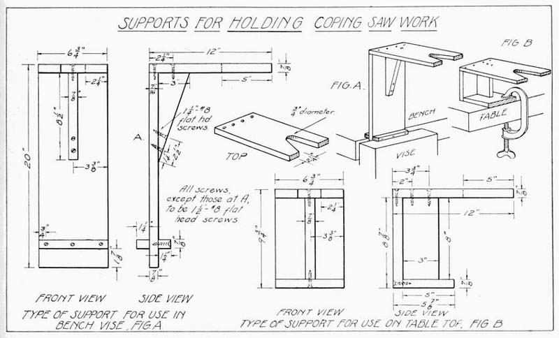
Two small cleats are 7/8" × 1-1/4" × 6-3/4" and are attached to the upright piece 1-7/8" up from the bottom edge. This allows the support to set firmly in the vise. Measure in from one end of the top piece 5" and have this point come half way between the sides. At this point a hole is carefully bored with a 3/4" bit. On this same end measure in from each edge 2-1/4". From these points draw lines tangent to the edges of the circle, as shown. Cut out this V-shaped notch.
Bore all holes shown on the drawing with a bit that will allow using 1-1/4" or 1-1/2". No. 8 flat-head screws. Have all surfaces sanded smoothly and assemble with glue and screws.
For the support shown in Fig. B, Plate 2, we make the upright 7/8" × 6-3/4" × 8-7/8". The top is cut 7/8" × 6-3/4" × 12" and the base 7/8" × 5" × 6-3/4" and the upright brace 7/8" × 3" × 8". The top has the same V-shaped notch cut in it as the other form of support. Bore all necessary holes, sandpaper and assemble. The clamp shown in the sketch answers the purpose very nicely and may be purchased for a small sum at any hardware store.
The bench hook is a very useful article to have about the work bench. It is made of hard wood, preferably maple. The drawing is shown in Plate 3. The main piece is made 7/8" × 6" × 12". Two cross cleats are made, one being 7/8" × 1-1/2" × 6" and the other 7/8" × 1-1/2" × 5". Holes are bored and countersunk at the places shown in the drawing. Great care must be taken in cutting these three pieces of wood to see that every edge is square and true. One of the cleats is attached on one side of the board even with the end, while the other is placed on the other side on the opposite end. These are held in place with glue and 1-1/4" No. 8 flat-head screws. By referring to the drawing and the sketch the idea may be readily seen. It will be noticed that the short cleat has its end even with the left-hand edge, thus leaving a space of an inch at the right. When used with this side up it is for the purpose of sawing off small pieces of wood with the back saw, and when used with the other side up, on which the long cleat is attached, it is for the purpose of planing the end of a piece of wood across the grain.
If a piece of wood is set up in a vise for end planing and the planing is done across the grain, the fibers on the further edge have no support but break away, as shown in Fig. C, Plate 3. In using the bench-hook the wood lies flat on the board and fits tight against the long cleat, and the plane is laid flat on its side and pushed back and forth. (Plate 3, Fig. A.)
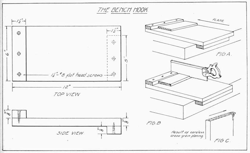
It can be readily seen that supported as it now is, the piece of wood being planed will not splinter or break on its further edge. Pains must be taken, however, to keep the plane flat on its side, not raising it on its edge at all, for by so doing the resulting planed edge will not be square. This bench-hook may be made quite easily by the beginner and besides being a good problem, is a very helpful addition to the tool outfit. It works very well when planing wood not over six or seven inches wide. Wood wider than this should be planed as follows: Place the piece of wood upright in the vise with the end grain uppermost, and plane about three-quarters of the way across the edge. Then turn the piece and plane the remaining part back in the opposite direction. By so doing the end of the wood will not be split.
Figures A and B, Plate 3, show the operation of the bench-hook for both sawing and planing.
In order to do good, clean-cut, accurate work it is very necessary that all cutting tools be kept sharp. And it is important that every boy who undertakes toy making have an elementary knowledge of the subject, especially an understanding of how to properly sharpen the knife, the chisel and the plane blade.
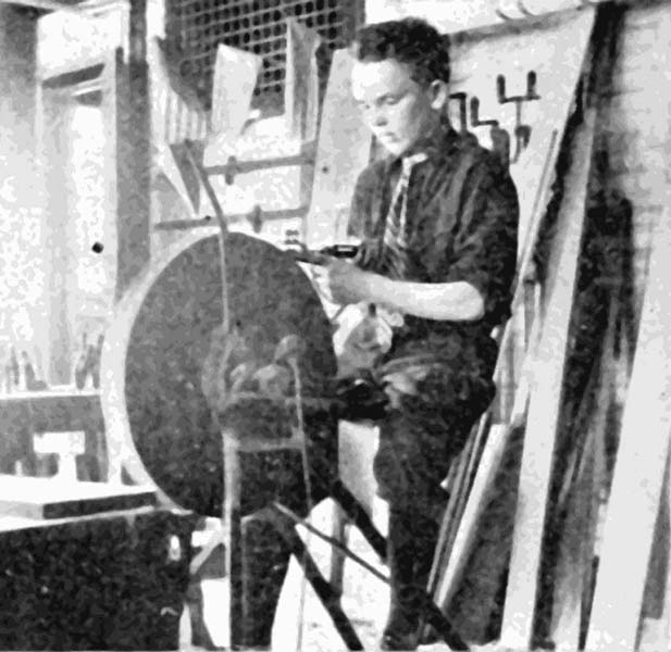
If the tool is very dull, with nicks in the cutting edge, it should be ground first on the grindstone. It is quite important that the blade be held at the proper angle, about 25 degrees on the stone. A suitable tool holder, such as is shown in the illustration on Page 26, is a very useful article to have in the tool equipment. The tool is held in place, bevel side down, by thumbscrews, and projects beyond the holder a little over half an inch.
The grindstone should be thoroughly wet to prevent heating the tool and also to insure the washing away of the fine particles of steel from the surface of the stone.
The round shape of the stone causes the bevel of the tool to be concave if held steadily in one position, as shown in Fig. A, Plate 4. Fig. B shows the incorrect result if the blade is not held evenly on the stone. It can be readily seen that the latter result will not make a very sharp cutting edge.
Care should be taken when grinding not to round the corners of the tool.
The theory of the cutting edge of the tool is the same as that of the wedge; the thinner the wedge the easier it is to drive it. However, the wedge, as well as the tool, must be thick enough to stand the strain of being driven into the wood, or the material which is to be split or cut. Too long and thin a bevel, while sharp at first, soon loses its edge through usage, while too blunt an edge makes the tool unsatisfactory to work with.
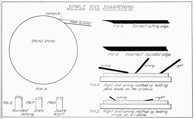
The grindstone leaves the tool edge rough, or with a wire edge, as it is called. This roughness is removed on the oil stone. One or two drops of thin stone oil should be placed on the stone and the tool placed bevel side flat on the surface of the stone. Work with a circular motion, bearing on the tool with uniform pressure. Turn the blade over, bevel side up, seeing that the blade lies perfectly flat on the stone. Work with a similar motion. Repeat these operations until the blade is as sharp as desired. Wipe the oil from the tool and test by drawing the blade lightly across the thumb. If the blade clings to the skin it will be found sharp enough.
Fig. C, on Plate 4, shows the correct and incorrect methods of oil-stoning the tool blade. Always wipe the stone dry after using, as the oil will dry and gum up the grinding surface if not kept clean.
Tool grinding is an important and rather difficult operation at first and skill comes only with continued practice.
In sharpening a knife-blade on an oilstone care should be taken to keep the blade nearly flat on the stone in order to get a thin, sharp edge. The knife should be sharpened first on one side and then on the other, until the desired edge is obtained.
Fig. D, Plate 4, shows the right and wrong methods of holding the knife blade on the stone. Figures E and F show the results of careless sharpening. Fig. G is sharpened correctly.
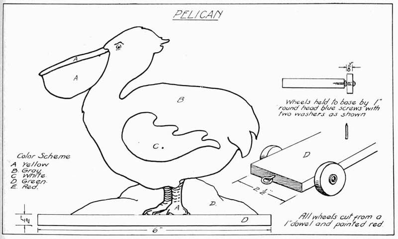
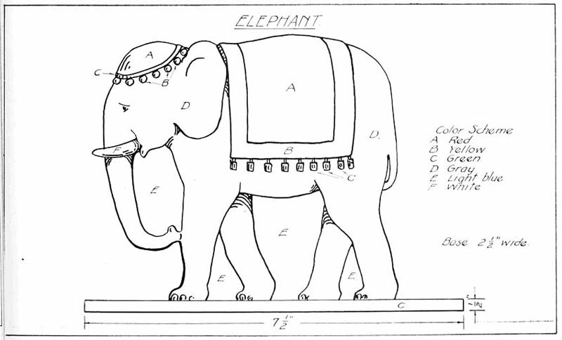
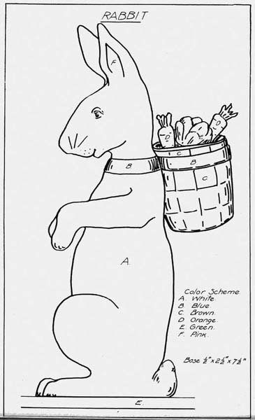
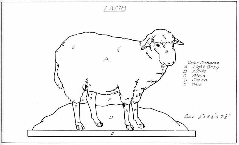
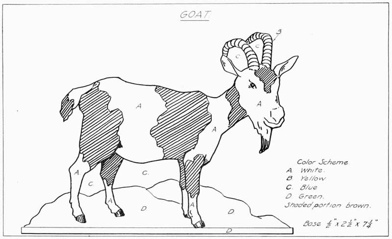
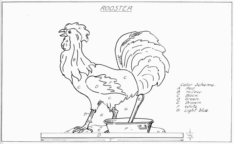
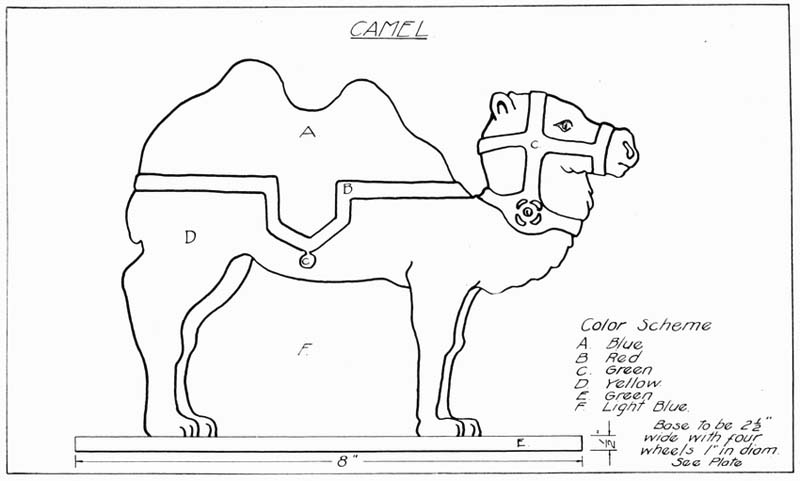
The following plates of birds and animals (Plates 6 to 17) are especially interesting to the beginner and are excellent for the novice to prove and improve his skill with the coping saw.
Wood from 1/4" to 1/2" in thickness is best for this type of toy, 3/8" being a good medium thickness to use. Pulp board, such as Beaver board, is also very good, as there is no grain and, therefore, little liability of splitting. Pulp board saws very easily and takes paint nicely.
All of these toys are mounted on a wood base, made of 1/2" wood, of a size shown on the various drawings. The animal is attached to the base with glue and 1-1/4" brads.
Wheels can be made from a round stick (called a dowel) an inch in diameter by carefully sawing off pieces 3/8" thick.
Holes are bored at the middle point of these wheels large enough to allow them to turn easily on a 1" No. 6 round-head blue screw. Washers should be placed on the screws on both sides of the wheels.
Plate 6 gives a general idea of the toy base.
Dowel sticks are very useful to the toy maker and an assortment of various sizes should be kept on hand. They are very handy in many ways in toy making and furniture construction. They come in sizes from 1/4" to 1" in diameter or larger, in 30" lengths, and cost from two to three cents apiece.
Dowel sticks are usually carried in stock by local hardware men or may be obtained from manufacturers of mill work.
The problem illustrated in Plate 5 is very interesting and especially good for the beginner.
First, select a picture of the size desired from a calendar or discarded magazine. Colored pictures are the best.
Prepare a piece of 1/4" soft wood, such as bass or pine, and glue the picture to the surface, rolling and pressing out air bubbles and smoothing away all wrinkles. Place a weight on the picture and allow it to dry overnight.
Holding the coping saw so that the blade is straight up and down, or in other words, at right angles with the surface of the work, saw out irregular shaped pieces similar to those shown in the accompanying drawing.
If these pieces are placed in a neat Christmas box, such as may be purchased at the five-and-ten-cent store, it will make a very pleasing Christmas gift.
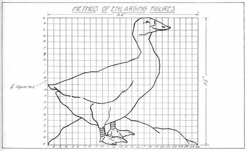
If a figure shown in a book or in any picture is to be enlarged the following method is very simple:
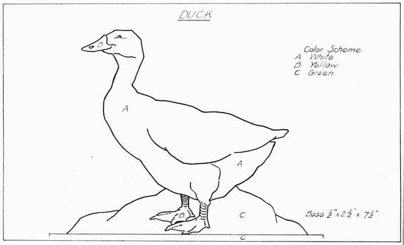
Enclose the figure in a rectangle and divide it in quarter inch squares, like the drawing of the duck in Plate 16.
If the drawing is to be enlarged twice the original size, draw a rectangle on a piece of paper or cardboard twice as large as the picture. Divide it into exactly the same number of squares, which will now be twice as large as before, or one-half inch on a side. Letter and number all parts to agree.
Start now and sketch the enlarged figure, having the lines pass through the same places in the squares of the large rectangle as in the small.
With a little patience it will be surprising how accurate a copy can be made.
A picture may be reduced by the same method.
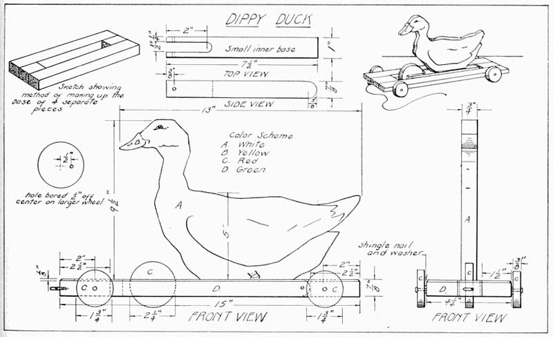
This toy is larger than the regular cut-out figure and has added action by the placing of the inner piece off-center on the larger wheel, thus causing the duck to move up and down as the toy is pulled along on the floor.
As shown in the drawing (Plate 17), the base is made of four separate pieces, because it is easier to construct it this way than to cut out the slot from a solid piece. The wood used is 7/8" pine, the two long pieces being 1-1/2" wide by 15" long and the two end pieces 1-1/4" wide by 2-1/2" long. These are glued and chamfered. A small chamfer is planed around the top edge, as shown.
The small base piece on which the duck rests is made 7/8" × 1" × 7-1/2". A hole is bored 2" from one end with a 1/2" bit and the slot is sawed out. The opposite end is rounded.
A hole is bored in the end where the slot is cut 3/8" from the end, of a size that will take a piece of 16-penny nail tightly. The nail is cut one inch long and serves as an axle for the large wheel. A similar hole is bored, 3/8" from the other end, with a larger drill so that the nail used at this point will be smaller than the hole, allowing the base piece to move easily upon it.
The large wheel is made by cutting a piece from a curtain rod 2-1/4" in diameter or by turning down a piece to this diameter on the lathe. This wheel is cut 3/8" thick. The four main wheels are 1-3/4" in diameter and 3/8" thick. These wheels have a small hole bored exactly in their center, of a size large enough to allow a shingle, or a screw, nail to turn easily within.
The wheels are attached two inches from the ends and the nails are driven in straight so as to insure the wheels turning evenly. A screw eye is placed at the front end, as shown, to which is attached a string to pull it by.
All parts should be nicely sanded before assembling and then given two coats of paint. A suggested color scheme is given on the drawing.
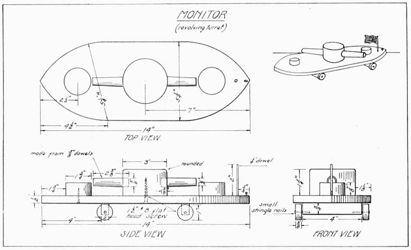
This design is what might be called an amphibious toy, which means one that is at home both on the land and water.
The base, or hull, is made from a piece of 1/2" board, 5-1/4" wide and 14" long. At a point on the long edges, 4-1/2" from the ends, a center is taken with a compass, or pair of dividers, set at 5-1/4" radius, as shown in the drawing. Strike all of these curves and cut to the line with a coping saw and finish smooth.
The main turret and the two smaller blocks are either turned on a lathe or cut from a cylindrical piece of wood. If care is used the pieces can also be cut with a turning saw from a piece of wood of the required thickness. The two smaller pieces are cut from a piece of 7/8" board and are 1-3/4" in diameter and are attached with 1" brads and glue, 1-3/4" from each end.
For the main turret, which is to be movable, a hole is bored in the hull exactly in the middle. In boring, a bit a little larger than the size of a 1-1/2" No. 8 flat-head screw is used, in order that the screw shank will move easily. This hole is countersunk on the under side. A smaller hole is started on the under side of the turret to receive the screw and, when the pieces are assembled, the screw is not screwed up tight, but enough play is left so that the turret will revolve fairly easily.
The two "guns" may be cut from 5/8" dowels, 2-3/8" long, or may be turned on a lathe. Two holes are bored, on opposite sides of the turret, 3/8" deep, to receive the guns which are glued in.
The two pieces to which the wheels are attached are made 1/2" × 3/4" × 4", and are secured in place 4" from bow and stern with shingle nails and glue.
The four wheels are cut from 1" dowels, 7/8" thick.
A hole is bored exactly in the middle of each wheel a little larger than the wire of a shingle nail, which is used to hold them in place on the base.
A small piece of 1/4" dowel about 2-1/4" long, is inserted in a hole, bored with a 1/4" bit, 3/4" from the bow. This is the flagstaff, and just in front of this is placed a small screw eye to attach the string for pulling the toy. Give the entire toy two coats of black paint.
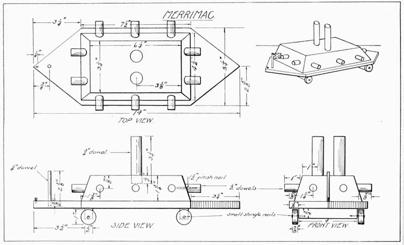
The Confederate Ironclad is a little harder to make than the Monitor, but it is well within the ability of a sixth grade boy.
The hull is made 1/2" × 5-1/4" × 14", and is sawed to a point at the bow and stern, sloping from the center point of both ends to points 3-1/4" from either end.
The upper works are made from a block of wood 1-3/4" thick, 4-1/2" wide and 7-1/2" long. This is beveled so that the top is 3-1/4" × 6-1/4".
The two smokestacks are made from pieces of 3/4" dowel, cut 3-1/4" long and inserted in holes bored 1/2" deep, 1" from the sides of the upper deck and 3-1/8" from the ends. These are held in place with glue.
The flagstaff is cut from a piece of 1/4" dowel, 2-3/8" long, inserted in a hole, bored with a 1/4" bit, 3/4" from the bow.
Just in front of this, 1/4" from the end, is placed a small screw-eye to which a string may be attached.
The ten "guns" are made from 1/2" dowels, cut 1" long, and at an angle so that the lower side is 7/8" long. This is so that they will fit against the sloping sides of the turret.
A hole is bored from end to end of each gun, in their centers, so that a 1-1/2" finish nail will fit in nicely.
The guns are held in place with these nails and with glue at the points indicated on the drawing.
The upper works and hull are held together with 1" brads and glue, in such a manner that the gun turret is equally distant from the ends and sides of the hull.
The pieces which hold the wheels are made 1/2" × 3/4" × 4" and are nailed and glued in place, 3-1/2" from bow and stern.
The wheels are 3/8" thick, cut from 1" dowels, and are held by shingle nails driven into the axle in such a way that they will turn freely.
The holes for the nails, in the wheels, are bored exactly in their centers with a bit a little larger than the nail to be used.
After sanding and assembling give the boat two coats of black or battle ship gray paint.
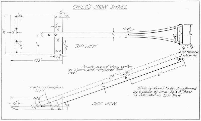
This problem is simple and of interest to young people during early winter. (Plate 20.)
The handle may be made square in section first and then gradually rounded with a plane and then filed and sanded; or a discarded handle from some other implement may be utilized. The handle should be 28" long, and a hole should be bored and a rivet inserted 11-5/8" from one end. This is to reinforce the handle where the saw cut comes. This cut is made directly along the center of the handle and stops 11" from the end. If this cut is not made exactly in the center, the spreading, when the grip is inserted, will be unequal, and the shovel will not be in balance.
The two ends of the shovel are rounded, as indicated, and the lower end is cut at an angle to fit the surface of the shovel.
The grip should be cut from a 1" dowel and then cut to fit the angle formed by the spreading sides of the shovel.
This is held in place by 1-1/4" No. 8 round-head screws with washers, as indicated.
The broad part of the shovel is cut from one piece, if possible, 1/2" × 8" × 10-1/2", and the front end cut an angle which is reinforced with a piece of zinc, 3-1/4" × 8", bent over and held by rivets and washers, as shown.
The brace under the handle is cut 3/4" × 1-5/8" × 8" and then planed from an upper edge to within an inch of the opposite lower edge and secured in place with screws. The handle is attached to the blade with rivets and washers, as shown on the drawing.
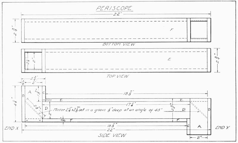
This is an interesting problem and demonstrates a scientific principle.
For a periscope of the size shown in the drawing (Plate 21), two pieces of looking glass must be first cut 2-1/4" × 2-7/8".
Pieces A are cut 3/8" × 2" × 4-1/4"; pieces B are 3/8" × 2-3/4" × 4-1/4"; pieces C, 3/8" × 1-7/8" × 2-3/4"; pieces D, 3/8" × 2" × 17-1/4"; pieces E, 3/8" × 2-3/4" × 18-7/8"; and pieces F, 3/8" × 2-3/4" × 18-7/8".
Two grooves 1/8" deep, and of a width to receive the thickness of the glass used, should be cut at an angle of 45 degrees, where indicated on the drawing. This groove is cut in pieces A only.
All pieces should be thoroughly sanded with No. 1 sandpaper and finished with No. 0. Assemble, as shown on the drawing, using glue and 1" brads.
The final finish may be stain or paint. Whatever finish is used should be of a dark color as best suited for a periscope.
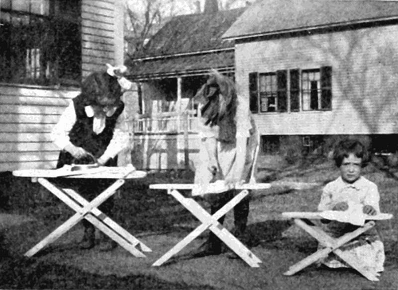
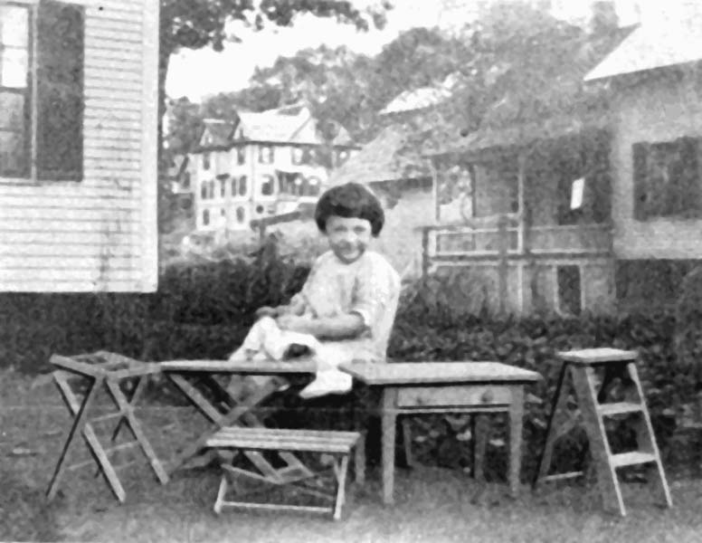
This problem has proven very popular in toy-making classes and has been one of the best sellers at toy sales. It folds up compactly and is strong and serviceable.
Plates 22, 23 and 24 show the ironing board in three sizes for children of varying ages.
Plate 22 is for children of about three years of age, and the material is prepared as follows:
The top is first made of 1/2" lumber and is 6" wide and 20" long. Set the dividers with a 3" radius and strike an arc just touching the end and two sides of the board. Do the same on the other end, using a 2-1/2" radius.
Connect these arcs with straight lines and saw and plane carefully just to the lines all around. The turning saw may be used on the ends.
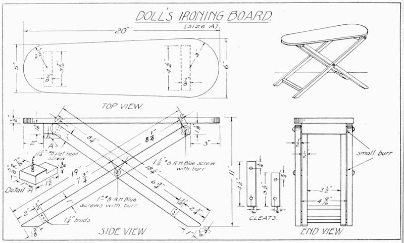
Slightly round the upper edge of the surface which is to be uppermost.
The legs are next cut to size, the two longer ones being 1/2" × 1" × 19" and the two shorter ones 1/2" × 1" × 18-3/4".
One end of each is rounded by striking an arc with a 1-1/2" radius, at the extreme end. The other ends of the legs are cut off at an angle, as shown in the drawing.
Holes are bored in the rounded ends of the long legs, 1/2" from the ends with a No. 3 bit. Another hole of similar size is bored 8-1/4" from the one previously bored. These holes are all 1/2" from the edges.
On the short legs the only holes necessary are bored 8-1/4" from the rounded end.
The long legs are attached by screws to a cleat which itself is screwed to the underside of the top of the board, as shown. This cleat is 7/8" × 1-1/8" × 4-1/2" and is glued and held to the top by 1-1/4" flat-head screws, two of them being sufficient. These are countersunk.
The separating piece at the other end of the long legs is 1/2" × 1" × 4-9/16" and is held in place by 1-1/4" brads and glue. It is attached 2" from the ends.
Two separating pieces are next made for the short legs, 1/2" × 1" × 3-1/2", and these are attached in the same manner as the piece between the long legs.
A cleat 7/8" × 1" × 3-7/16" is attached with glue and 1-1/2" flat-head screws, 2" from the small end of the board. This holds the short legs in position.
All pieces should be thoroughly sanded with No. 1/2 sandpaper before being assembled. No further finish is necessary.
The method of constructing this board is identical with the method suggested for board A. The difference is in the size of the pieces. (Plate 23.)
This type of ironing board is suitable for a child from four to six years of age.
The top is 5/8" thick, 7-3/4" wide and 24-1/2" long.
The curved ends are struck with the dividers in the same way as in the preceding problem.
The legs are next cut to dimension, the longer ones being 9/16" × 1-1/8" × 24", and the shorter 9/16" × 1-1/8" × 22-1/2".
One end of each leg is rounded by setting the dividers at 9/16" and cutting to the line and cutting the opposite ends at an angle, as shown in the drawing.
Bore holes with a No. 3 bit in the rounded ends of the long legs, 5/8" from the ends and a similar hole is bored 9-1/2" from the hole previously bored. These holes are all 9/16" in from the edges.
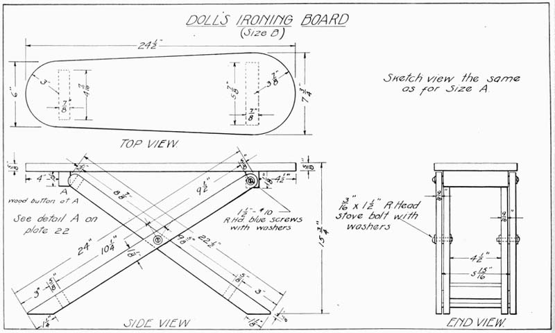
On the short legs the only holes bored are made with the same bit, 9-3/8" from the rounded ends.
The long legs are attached to a cleat by 1-1/2" No. 10 round-head blue screws, with washers under both the heads of the screws and between the screws and the cleat.
The cleat is 7/8" × 1-1/8" × 5-7/8" and is glued and screwed to the under side of the top with 1-1/2" No. 8 flat-head screws.
These are countersunk.
The separating piece at the other end of the long legs is 3/8" × 1-1/8" × 5-15/16" and is held in place by 1-1/4" brads and glue, and is attached 3" from the end.
Two separating pieces are next made for the short legs, 3/8" × 1-1/8" × 4-1/2", and these are attached in the same way as the piece between the longer legs.
A cleat 7/8" × 1-1/4" × 4-7/16" is attached with glue and 1-3/4" flat-head screws, 4" from the small end of the board. This holds the short legs in position. Refer to the detail on the drawing of the size A ironing board (Plate 22) for the method of making the button which holds the board rigid.
All pieces should be thoroughly sanded with No. 1/2 sandpaper before being assembled.
No further finish is necessary.
The method of constructing this size board is similar to the other two types. (Plate 24.)
This size board is suitable for children from six to eight years of age.
The top is made 3/4" thick, 9" wide and 30" long. The dividers are set with a 4-1/2" radius and an arc is struck to touch the end and two sides of the board. A similar arc is struck at the opposite end with a 3-1/2" radius.
These arcs are connected with a straight line, and the outline is cut with a saw and finally planed to the lines. The curved ends can be cut with a turning saw and finished with a chisel and file.
The upper edges are slightly rounded with a file and sandpaper.
The legs are next cut to size, two being 3/4" × 1-1/4" × 27-7/8", and the other two 3/4" × 1-1/4" × 29".
One end of each is rounded by striking an arc with a 5/8" radius, at the extreme end. The other ends of the legs are cut at an angle, as shown in the drawing.
Holes are bored in the rounded end of the short legs, 5/8" from the ends, of a size that will take a 1-3/4" No. 10 round-head blue screw.
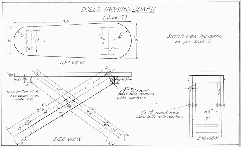
Another hole of similar size is bored 11" from this. These holes are all 5/8" from the edges.
On the other two legs the only two holes necessary are bored 12-1/2" from the rounded ends.
The shorter legs are attached by screws to a cleat which itself is screwed to the underside of the board, 4-1/2" from the large end. This cleat is 1" × 1-1/4" × 6-3/4" and is held in place with glue and 1-3/4" flat-head screws, countersunk. Two of these screws are sufficient.
The separating piece at the other end of the legs is 3/4" × 1-1/4" × 6-13/16", and is held in place by 1-1/2" brads and glue, and is attached 3-1/2" from the ends.
Two separating pieces are next made for the long legs, 3/4" × 1-1/4" × 5-1/4", and these are attached in the same manner as the pieces between the other set of legs.
A cleat 1-1/8" × 1-3/8" × 5-3/16" is attached with glue and 2" flat-head screws, 5-1/2" from the small end of the board. This holds the short legs in position.
The wood button, shown on the drawing for the Size A ironing board (Plate 22), is attached to this cleat and prevents the board from collapsing.
All pieces should be thoroughly sandpapered with No. 1/2 sandpaper before being assembled.
No further finish is necessary.
This folding clothes rack is an interesting toy and requires some skill in assembling. (Plate 25.)
The four legs are cut 3/8" × 3/4" × 13" and each end is rounded by first striking semicircles on the ends, using a 3/8" radius, and then finishing with a chisel carefully to the line.
Holes are bored in these legs with a 1/4" bit in the following places: 3/8" from the top, 4-7/8" beyond this, 3-1/4" beyond this, and 1-3/4" beyond this. Extreme care must be taken not to split the wood. Bore through from one side until the spur of the bit just starts to come through, then remove the bit and bore back from the other side.
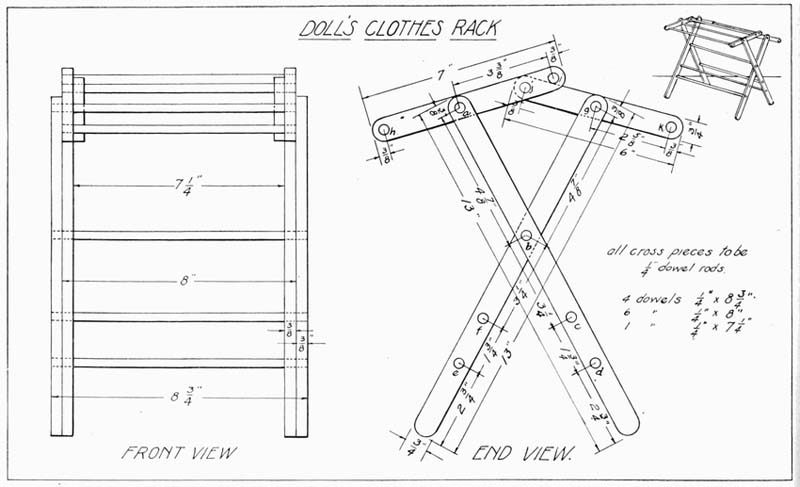
Next cut the four top pieces to size, two being 3/8" × 3/4" × 6" and two 3/8" × 3/4" × 7". These are also rounded on both ends. Holes are bored 3/8" from each end of all of these and also half way between their ends, as shown in Plate 25.
These pieces should be carefully sanded with No. 1 sandpaper.
The cross pieces are cut from 1/4" dowels as follows: Four pieces, 8-3/4" long; six pieces, 8" long; and one piece, 7-1/4" long.
The long dowel sticks are the ones that go at points a, b, c and d, Plate 25, on the outside legs. The 8" dowels go at points e, f, g, h, i, and j. The single short dowel goes at point k.
Examine the drawing carefully and see that the four top pieces are placed on the correct dowels. Hold all dowels, which are not at movable points, with 3/4" brads.
Be sure every piece is in its proper position before driving in the brads and then be positive that no brad is being driven at a point where the dowel must be free to move in the hole. It is always best to assemble the rack completely and by closing and opening it learn clearly just where the brads are to be placed.
No further finish is necessary.
This bench may be made in various sizes to fit different heights of children. The top consists of three slats and for the size bench shown in Plate 26, the slats are made 3/8" × 1-3/4" × 18". These slats have screw holes bored 2-3/8" from the ends and 3/8" from the edges, as shown. These are countersunk to receive 1" No. 6 flat-head screws.
Two braces are made 3/4" × 1/4" × 8". These are to support the slats. One inch from one end of these braces, and 5/8" from the edges, a hole is bored with a 3/8" bit. The same distance from the other end a similar hole is bored and a piece is sawed out, as shown in the drawing, to receive and support the dowel rod.
The legs of the bench are cut 3/8" × 1" × 12-3/4". One-half inch from one end a hole is bored with a 3/8" bit. One and one-half inches from the other end a similar hole is bored and 7" from the same end the third hole is bored, making three in each leg. Care must be taken in boring these holes not to split the work as the bit goes through. Bore through on one side until the spur of the bit just starts through on the opposite side. Remove the bit and place the spur point in the small hole made by the spur and bore back in the opposite direction.
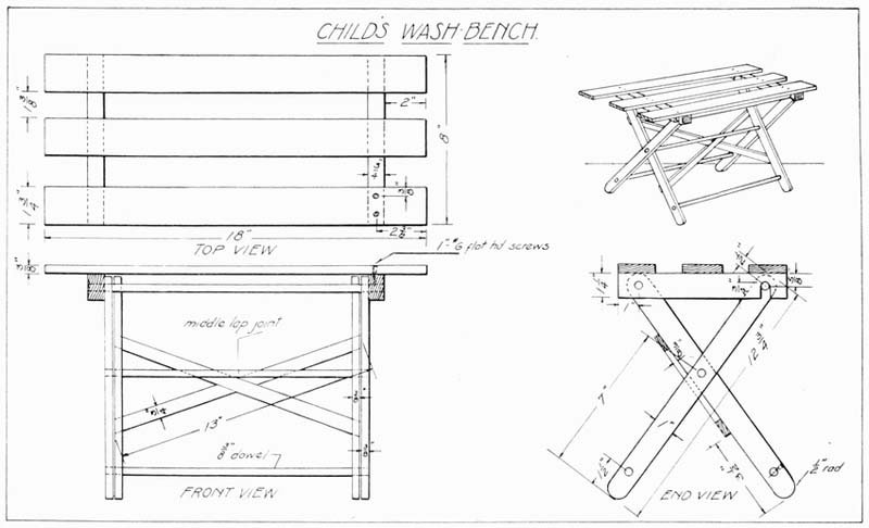
The two cross slats forming the braces are 3/8" × 3/4" × 13". A center lap joint is made by cutting through half way on both slats at such an angle as will cause the outer edge of the slats to be about five inches apart. The ends of the slats should be sawed at such an angle as will make them flush with the sides of the legs and small holes drilled and countersunk so that they may be attached with 3/4" No. 4 flat-head screws.
Two 3/8" dowel rods should next be cut, one being 12-1/2" long and the other 14" long.
These dowels should be held in place in the legs by 3/4" brads, care being taken not to nail where there is to be a moving joint.
All pieces should be carefully sanded with No. 1/2 sandpaper.
No other finish is necessary.
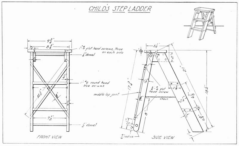
This step ladder may be made in various sizes, the one shown here being suitable for children up to seven or eight years of age. (Plate 27.)
The two front legs should be cut first, 5/8" × 2-1/4" × 21". It will be noticed that the two ends are cut off at an angle. This angle is obtained by measuring back on one side 1" and drawing to this point from the opposite corner. Make all of these angles equal and if possible cut them in a miter-box.
The two rear legs, or braces, are cut 5/8" × 1-1/8" × 17-3/4", and the two ends are rounded. The semicircle is marked out by setting the dividers, or a compass, at a 9/16" radius and striking the curve tangent to the sides and ends of the legs.
Two holes are bored with a No. 8 bit, 5/16" from one end of the rear legs and 1-1/4" from the other end, as indicated, care being taken not to split the wood.
The top step is next made 5/8" × 5-1/4" × 9-3/4", and the top edges slightly rounded.
Two holes are bored with a small drill, 1-1/2" from the ends of this step and 1" from the rear and front edges of both ends. These should be countersunk. Later, when assembled, this top is screwed to the braces with 1" No. 6 flat-head screws, as shown in the front view. (Plate 27.)
Two braces are next made 5/8" × 2" × 5-1/4", and are cut off at either end at the same angle as were the ends of the front legs. These are attached to the inside of the legs, at the top, as shown in the side view, with four 1" No. 6 flat-head screws and glue. Care should be taken to get them just even with the front and top sides of the legs. Before the braces are attached a hole should be bored with a No. 8 bit 5/8" from the top edge and 1" from the left-hand edge to receive the dowel stick on which the rear leg swings.
While boring this hole the end should be held with a clamp to prevent splitting.
The two lower steps are next made. These are 5/8" thick and are cut 3" wide. The width is greater than is needed, and is provided that the steps may be planed even with the edges of the legs later. The steps are cut 8" in length.
The next operation is cutting grooves for the steps to set into the legs, and this requires considerable care.
The lower step is 5-3/4" from the lower end of the legs. This dimension is measured off on each leg, and a line is drawn parallel with the lower end of the leg. This may be done by either using a T bevel, set at the angle of the lower end of the legs, or the dimension, 5-3/4", may be measured up on both sides of the leg and a line drawn across.
Next take the lower step and mark one end A and the other end B. Place the end A, of the lower step, evenly on this line and make a mark above the first line a little less than the thickness of the step. The groove is marked a little less than the thickness of the step so that, in case the saw cut is made a little wide, the step will not be likely to fit loosely.
Square lines across both edges of the edge from the end of the lines previously drawn and measure down from the surface a distance of 1/4" on the edges. Draw a line through this point parallel to the edge of the leg.
Next saw carefully on the lines, first drawn, down as far as this last line and cut the wood out with a half-inch chisel.
If the step will not fit in the slot, plane a very slight amount from the surface of the step until it fits snugly into the groove.
End B is fitted to the opposite leg in a similar way and the second step is placed in a like manner, 6-7/8" above the lower step.
If the drawing is examined, as these directions for placing the steps are read, the explanation will be greatly simplified.
The two narrow cross braces are next made, 3/8" × 5/8" × 15-1/2". These are crossed at their middle point in a middle-lap joint, a groove being cut half through each piece wide enough to insure a tight joint. These braces are attached to the rear legs, 2-1/2" from their lower ends, with 3/4" No. 6 flat-head screws, the holes being previously bored and countersunk.
Cut the ends of the braces even with the ends of the legs.
Holes are bored with a small bit in the grooves in the legs, 1/2" in from the sides, as shown. These holes are for the round-head screws which hold the steps in place. The steps are held in the grooves of the legs with glue and 1" No. 6 round-head blue screws.
The dowel sticks are now cut 8-3/4" long from a 1/2" dowel and, after all pieces of wood are carefully sanded with No. 1 sandpaper, the step ladder is assembled.
A 3/4" brad should be driven into the edge of the rear legs so that it will penetrate and hold the dowel in place.
A piece of small chain should be fastened to each front and rear leg, as shown, of a length sufficient to have the front legs of the ladder set flat on the ground. Also take care that the two chains are even with each other and parallel with the ground. No further finish is required.
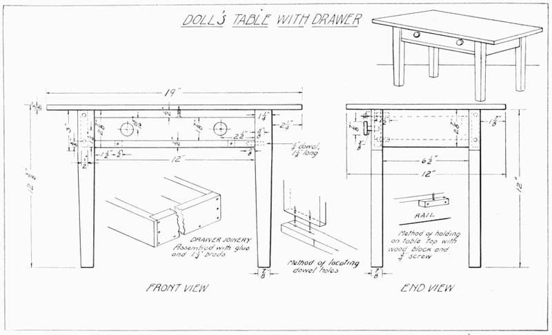
While this table may be made in various sizes, the one shown in the accompanying drawing has proven very popular.
The four legs are first made 7/8" × 1-1/4" × 12". Measure down 3" from one end and taper the legs equally from this point to a width of 7/8" at the opposite ends, as shown.
The two side rails are made 1/2" × 2-7/8" × 6-1/2". The two front rails above and below the drawer are cut 1/2" × 1/2" × 12".
On the side and rear rails, centers for dowels are located 5/8" from the top and lower edges and half way between the sides. An inch brad is driven in a short distance at these points, and the head is cut off about 1/4" above the surface of the wood. These ends are now placed so that their upper edges are even with the top of the legs. Press down lightly on the rails and a mark will be made on the surface of the legs.
Remove the brads and bore the dowel hole with a 1/4" bit, 1-1/4" deep.
The two drawer rails are treated in the same manner and the holes are bored.
The top will no doubt have to be made of two pieces of wood jointed and glued together, and reinforced with dowels.
The finished dimensions are 3/8" × 12" × 19".
Short blocks of wood are screwed to the rear and two side rails even with their tops, and screws are later put through these from their under side to hold the top in place. A 3/4" No. 6 screw is placed in the center of the upper drawer rail to assist in holding the top in place. (See Plate 28 for details of the method of attaching the top.)
Two strips of wood 1/2" wide, and thick and long enough to fit tightly between the front and rear rails, are made to serve as drawer slides.
Similar strips of wood are glued to the inner part of the end rails to cause the drawer to run evenly. These strips are just thick enough to bring their surface even with the edge of the leg.
All rails should be thoroughly sanded and then assembled with glue, screws, and brads as directed, the rails and legs being clamped for several hours to insure a tight fit.
If the various parts of the table have been accurately made, the drawer should be now constructed to the dimensions called for in the drawing. If there has been any error in the making of the several pieces, of course the drawer must be made to fit the space in that individual table.
The drawer front is 3/8" × 1-7/8" × 12". The sides are 1/4" × 1-7/8" × 11-1/2". These dimensions may all have to be trimmed down somewhat to secure an easy sliding fit. The drawer construction is clearly shown in the sketch. Bottom pieces of 1/4" wood are cut to fit, and after sanding, all pieces are glued and bradded together.
Handles of the size shown in the drawing may be turned on the lathe or made by hand, and placed as indicated.
As this type of table is patterned after the ordinary kitchen table it may be left unfinished.
This table, with the accompanying chairs shown in Plate 30, makes a very artistic and interesting problem in toy-making.
The table and chairs work up very nicely if made of oak and stained a mission brown. They may also be made of soft wood and stained or painted. Directions for staining may be found in the front part of the book.
The top (Plate 29) is made 3/8" × 11" × 16" and, if a piece of wood 11" wide is not obtainable, two narrow pieces will have to be joined. (See method of joining wood on page 18.)
The four uprights are made 1" × 1" × 6-1/4", and the four cross pieces 5/8" × 1" × 8".
The ends of the cross pieces are cut at a bevel, as shown, and notches are cut 1-1/8" from each end, 1/8" deep, to receive the ends of the upright. Care must be taken to get a snug fit. It is better to have the notches a trifle too small than too large. If cut a little small, the uprights are easily made to fit the grooves by planing a slight amount from their edges.
Four bottom pieces are made 1/4" × 1-1/4" × 1-1/4", to be attached to the lower cross piece, as shown, allowing 1/8" projection all around. They are fastened with 1/2" brads and glue. When attaching, see that the grain of the little square pieces runs the same as the cross pieces. On account of the thinness of the wood, holes may have to be bored for the brads. If no small drill is at hand a brad may be used as a drill.
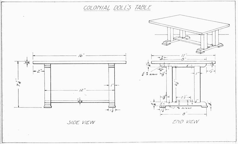
Holes are bored in the two upper cross pieces, 3/4" from their ends. These are countersunk to receive 3/4" No.6 flat-head screws, when assembling, and are to hold the top in place.
Holes are likewise bored for the same size screws, 1-5/8" from each end of the four cross pieces, which brings the holes in the center of each notch. These holes are also countersunk.
The long lower brace is made 5/16" × 2-1/2" × 12". When assembling, this piece is located as shown in the drawing and is held in place with glue and 1/2" brads.
Sand all pieces carefully with No.1 sandpaper first and finish with No. 0.
If stain is to be used, it may be found easier to stain the pieces before assembling. Assemble as previously described, using glue where necessary and turning all screws up tightly. Apply final finish as desired.
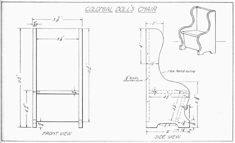
This chair goes with the Colonial Table shown in the preceding drawing (Plate 29), and at least two chairs should be made to form the set.
The sides are first cut from 3/8" material, 5" wide and 11-1/2" long.
A freehand curve, following the general design of the one shown, should be traced on a piece of paper, cut to the above size. After the outline is satisfactory, the design should be traced on the wood preparatory to cutting out. The cutting should be done with a coping saw, cutting to the line for a finish. Place the two sides together to see if they match. Variations should be trimmed down so that the pieces are exact duplicates.
The back is next made, 3/8" × 5-1/8" × 10-3/4".
The seat is made 3/8" × 4-1/2" × 5-1/8", and the front board of the seat measures 3/8" × 3-1/2" × 5-1/8". The seat is rounded on the front edge, and the front board of seat is beveled at top and bottom to set snugly under the seat, at the slight angle shown. This angle is obtained by measuring in 1-3/8" from the front, as shown in the side view.
Sandpaper all pieces thoroughly and assemble the sides and back first, with glue and 3/4" brads. Set these brads below the surface and fill the cavity with hard beeswax. Assemble the seat and front board next, and then nail these between the sides of the chair, as shown in the drawing.
Finish as desired. See Pages 15 to 18 for method of staining and painting.
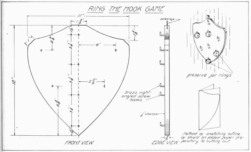
This game is very simple in construction yet affords a great deal of pleasure to young people. (Plate 31.)
The desired outline, the dimensions for which are given in the drawing, is sketched on a piece of folded paper, as is shown by the sketch, and the design is then cut out and traced on a piece of wood cut from stock 5/8" × 11" × 12".
The cutting should be roughly done with a turning saw and finished carefully to the line with a chisel and file.
A small chamfer gives a finished appearance if placed on the front edge.
The board should be thoroughly sanded with No. 1 sandpaper first, and then finished with No. 0. The final finish may be several coats of shellac or two coats of a bright lively color of paint. If a shellac finish is used, the numbers should be lettered in with water-proof India ink, after the first coat of shellac is dry, and the second coat should be applied over this.
If paint is the finish selected, the numbers may be put on with the ink after the final coat is dry.
Hooks are located at the various points shown on the drawing, and pains should be taken to get them in perpendicular to the surface of the board. Place a screw-hook at the top to hang up by.
The rings used are the ordinary preserve jar rings and ten should constitute a set.
The board should be placed on the wall, about five feet from the floor and the contestants should stand about six feet from it.
The idea is to toss the rings in such a manner that they will land over the hooks. The best results are obtained by holding the ring between the thumb and the first two fingers, at right angles to the floor. Throw in such a way that the ring will strike flat against the board. With a little practice considerable accuracy can be developed in placing the rings.
A score of one hundred should constitute a game.
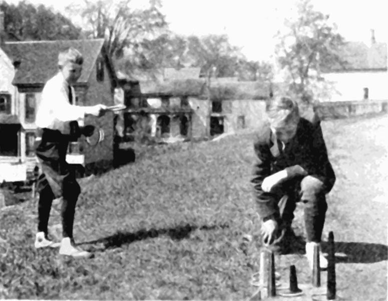
Although the game of ring toss is an old one, yet it never loses its attraction for many young people, and older ones as well.
The type of ring toss shown in the accompanying plate is a little variety from the regular form, each post being painted and numbered with the points scored by ringing that particular post. (Plate 32.)
The middle post, painted black, is a minus score, the ring falling on this causing a loss of five points.
The rings, five in number, are painted at their joining points with colors similar to the posts. If a ring falls over a post of the same color as that painted on the ring the score is doubled. A black ring on the black post doubles the loss. The board should be set on the floor about eight feet from the contestants. The best results can be obtained by holding the rings by the thick, heavy part, parallel to the floor, and tossing quite high in order that they may fall flat from a point above the posts.
The posts are made with a tenon, which fits snugly in a mortise, and are removable so that they may be taken out when not in use. The rings may be made of various materials, such as rope and rattan. A very satisfactory ring is made by the writer's classes, by using chair spline. This is a rattan, light, cheap and easily bent, and may be bought of any firm dealing in upholstery and chair-seating materials. A piece about 17" long is bent in circular form, overlapping about an inch and held with two 1/2" brads, cleated on the underside, as shown. Wrap with white friction tape.
The base of the ring toss is first cut 7/8" × 15" × 20". The center of each side and end is located and these points are connected, forming a diamond shape. Cut to this line and plane the edges smooth. Plane a 1/8" chamfer around the upper edge.
Post A is made 1" × 1" × 11-3/4"; posts B and C are 1" × 1" × 8-1/4"; post D, 1" × 1" × 5-1/4"; and post E, 1" × 1" × 6-3/4". All of these posts are chamfered about 1/8" at the top.
It will be noticed, by referring to the drawing of the side view, that each post is an inch square for a certain distance up and from that point they taper to 1/2" square at the top. These measurements are figured from the shoulder where they rest upon the board, there being a 1/2" tenon below. These tenons are cut so that they will be 1/2" square and 3/4" long.
All holes or mortises are located 1-1/2" directly in from the corner or point at which they rest, except the center post, which is at the center point of the board. These mortises should be a fairly tight fit, yet allowing for the removal of the uprights when not in use.
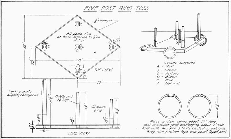
The color scheme is suggested on the drawing but may be changed to suit the individual taste. After painting or shellacking the board the first coat, the numbers should be lettered in, using waterproof India ink, and then the second coat applied.
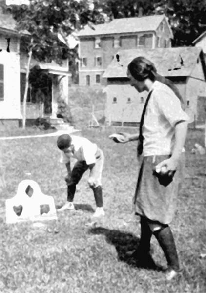
This is another very popular and interesting game and gives the girls in the domestic science course a little opportunity to show their skill in making the bags. These should be cut so that they will finish about four inches square and one end left open so that they may be filled about three-fourths full of beans, peas or small pebbles. The end is then sewed up. Burlap, ticking or any odd pieces of cloth may be used for the bags.
The board itself will, no doubt, have to be glued up from two or more boards in order to have the finished size 20" wide by 24" long. (Plate 33.) Half inch bass or whitewood is suitable.
A piece of paper should be cut 20" × 24" and folded so that it is 12" × 20". Trace the outline on this paper, cut and unfold and lay on the board and trace around this. Cut to the line, using a turning saw and chisel and perhaps a wood file on the curves.
The openings are located, as shown by the drawing. The centers are first obtained, and then the widths and lengths are measured from these center lines. Holes are next bored, as shown by the small sketch, with a 3/4" bit, and either a turning or a keyhole saw is used to cut out the pieces. If a turning saw is used, the blade must first be unfastened at one end, inserted in the hole and re tightened on the opposite side. Finish carefully to the line with chisel and file.
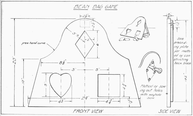
A small block 1/2" × 1-1/2" × 2-1/8" is attached to the back of the board with 3/4" No. 6 flat-head screws. This is to hold the hinge.
The long brace is made 1/2" × 2-1/8" × 18-1/2" and is held to the small block by the hinge spoken of previously. A screw-eye is placed about 2" from the lower end of this brace and a wire or stout cord runs from this to similar screw-eyes, placed on the back of the main board about 2" from the bottom edge and 3" from the side edges. The cord or wire should be of sufficient length to cause the board to tip at about 60 degrees.
After the board has been carefully sanded with No. 1 sandpaper first and then finished with No. 0, the whole board should receive a coat of white shellac. After allowing this to dry over night, it should be rubbed down lightly with fine sandpaper and the numbers 2, 3 and 5 lettered on with black waterproof India ink. Apply another coat of shellac, or two more if necessary.
Paint may be used instead of shellac as a finish, in which case the numbers should be put on with paint of a contrasting color to show up well.
The little sketch in the drawing shows the back braces made the same as those on the Dart Game Board. While this is a little more difficult than the simple screw-eye and wire arrangement, it is much more satisfactory.
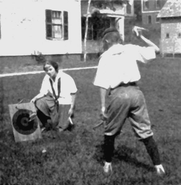
This game has proven very popular, not only with the young folks, but with the grown-ups as well. Any game where skill and accuracy may be developed has a strong appeal to both boys and girls as well.
The board illustrated in Plate 34, should be made of soft wood—bass, pine or white wood is suitable—and cut to 15" wide by 21-1/2" long, from 7/8" material. The top edge is chamfered 1/4".
The surface should be thoroughly planed and sanded and given a coat of white shellac. While this is drying, the rear supporting braces may be gotten out. The main support is 7/8" × 2-1/8" × 19". A hole is bored with a No. 10 bit, 1-9/16" from the end, and a piece is sawed out 5/8" wide from the opposite end to this hole. See the drawing for detail. A piece of 1/4" dowel is glued in the end to reinforce the piece, as shown.
The smaller piece Y is cut 7/8" × 3/8" × 17" and is held to piece X by a quarter-inch dowel, as shown. A brass cup hook is screwed into the end which is connected with a brass screw-eye placed in the back of the board, 2-1/4" from the bottom edge.
The small block X is 7/8" × 1-1/2" × 2-1/8" and is attached, as indicated, with glue and two 1-1/4" No. 8 flat-head screws.
The long brace X is attached to this by a 2" butt hinge and 1" flat-head screws.
This folding arrangement has proven very satisfactory. The board packs nicely and stands rigidly when in position for playing. However, a simpler bracing may be used. The long brace X may be a solid piece 7/8" × 2-1/8" × 19", with a screw-eye on the underside from which a wire can run to a similar screw-eye on the back of the board. The wire can be adjusted so that the board will slope at the proper angle.
After being sanded, the surface of the board should be given a coat of shellac and after drying should be rubbed down with No. 1/2 sandpaper.
The circles should now be struck with a compass and waterproof ink, the diameters given, using a fairly heavy line. After the ink is dry give another coat of shellac. When this is dry the board is ready to have the colors applied to the circles.
First paint circle A black and circle C red, painting just to the circle edge. Allow this to dry thoroughly, and then paint circle B yellow and circle D green. When these are dry, it may be necessary to strike all the circles again with ink.
Where shown, letter in the numbers to score the game. It will be noticed that the small outside circles are minus numbers.
Give the entire board and braces a finishing coat of shellac.
The darts may be whittled out by hand, but the most satisfactory ones are turned out on the lathe to the dimensions shown. A 1-1/2" brad should be driven half its length into the rounded end, the head cut off with cutting pliers, and the end pointed with a fine file.
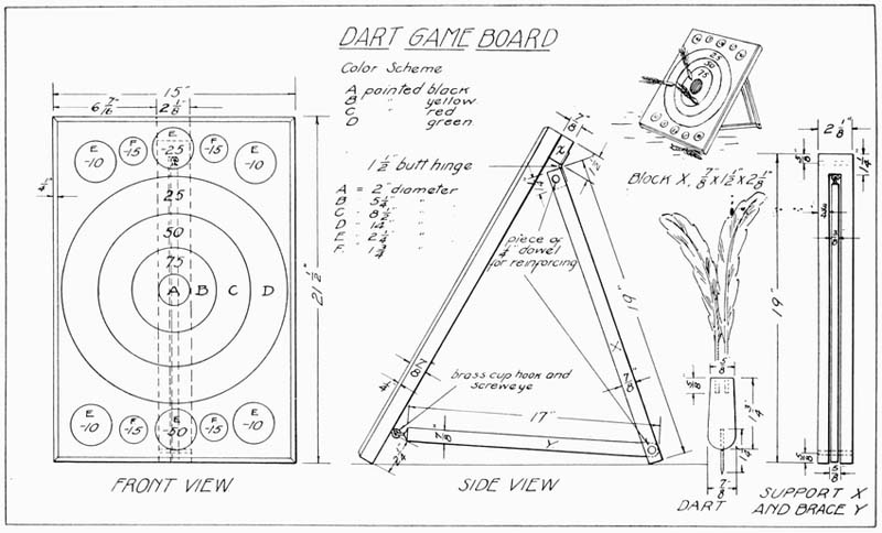
At the opposite end two holes should be drilled of a size large enough to receive the ends of wing or tail feathers of some accommodating fowl. These should be dipped in glue and pressed into place.
About six of these darts should be made and the wooden parts painted in bright colors. Birch or maple are good woods to use.
The board should be placed on the floor, about ten feet from a given station point, and each contestant should be allowed to throw the six darts. The score should then be counted. Darts landing on a line should be credited to the lower number. One dart landing on and sticking to another, doubles the score of the first dart. Darts not sticking in the board are not allowed to be re-thrown. Darts knocked out by other darts lose their score.
One thousand points should constitute a game.
The points of the darts may be sharpened from time to time with a fine file.
This is an interesting toy to place on the top of the shed or garage where the wind will have a chance to revolve the brightly colored wheel at a good rate. It also serves as a weather vane.
The main part of the mill (Plate 35) is made up of four pieces of half inch stock, two being 3-1/2" × 4-3/4" and two 2-1/2" × 4-3/4". The two larger sides taper to 2-1/2" wide at the top and the two smaller pieces to 1/2". The top piece forming the roof is made from a piece of wood 1-3/4" thick. If wood of this thickness is not available, several thinner pieces must be glued together. It is cut 3-1/2" × 3-1/2" and a line is drawn around the edge 3/8" from the lower sides. From this line the roof tapers to a point directly over the middle of the piece, as shown.
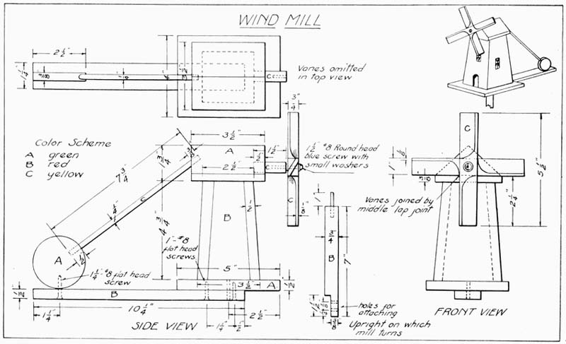
The long support, on which the mill rests, is made 1/2" × 1-1/4" × 10-1/4". Two holes are bored and countersunk for the screws which hold it to the mill base. A similar hole is bored from the opposite end for the screw which holds in place the round piece A.
The circular piece marked A on the side view, is made 3/8" × 2-1/2". A hole is bored 1/2" deep with a quarter inch bit on the edge. The piece C is a quarter inch dowel, 7-3/4" long. A hole is bored with a quarter inch bit in the roof, at a slant, as is shown in the side view. This hole is 3/8" deep.
The dowel piece C fits in these holes when assembled, being held with glue.
The smaller base piece, which is attached to the bottom of the mill with glue and 1" brads, is made 1/2" × 4" × 5". The small piece, on which the vanes of the mill turn, is made from a piece of half inch dowel, cut 1-1/2" long. A hole is bored in the roof piece 1/2" deep to receive this. A smaller hole is drilled in the outer end of this dowel to receive a 1-1/2" No. 8 round-head screw on which the vanes revolve.
A piece is now cut 3/4" × 7/8" × 7" to serve as the supporting piece on which the whole mill turns. On one end a notch is cut, as shown in the drawing, 3/8" deep and 1-1/2" long. Two screw holes are bored in this notch to allow the piece to be attached to the shed or roof. On the opposite end a hole is bored in the center, 3/4" deep and with a drill that will insure a 16-penny nail fitting very tightly. One of these nails should be driven in and the headed end cut off so as to allow a projection of 1" beyond the end of the wood. The end of this nail should be filed smooth and round.
A hole is bored to receive this in the base pieces, as shown in the drawing, extending through both pieces and large enough for the nail to turn freely within. A washer should be placed over this to insure the mill turning easily.
The two pieces for the vane of the mill are made 3/4" × 1" × 5-1/2". Each vane is chiseled at an angle, sloping in one direction at one end and in the opposite direction at the other, allowing at least 1/8" for the thickness. Considerable pains should be used in shaping these vanes to insure even balance. File and sand these smooth.
A middle lap joint is made exactly in the center of each vane, cutting half through on each piece and making a smooth, flush fit. Hold the vanes together with glue and 1/2" brads at this point and carefully bore a hole at[Pg 80] the center large enough to allow a 1-1/2" No. 8 round-head screw to turn easily.
A small washer is placed under the head of the screw and one between the rear of the vanes and the end of the supporting dowel. Turn the screw up tight enough to allow the vanes to clear nicely.
All pieces should be carefully sanded with No. 1 sandpaper first and finished with No. 0. Paint all pieces before assembling.
A suggested color scheme is shown in the drawing.
This is another interesting action toy and makes a very pleasing addition to the top of a garage or barn. (Plate 36.) Children also enjoy toys of this sort at the beaches where they can build up little villages in the sand.
The four long uprights are made 1/2" × 1/2" × 19". The top piece, which is eight sided, is first made 1/2" × 3-1/4" × 3-1/4". Then 3/4" is measured in from each corner and these points are connected and the lines cut carefully with a saw. A hole is bored in the center with a bit a little smaller than a 1-3/4" No. 8 screw.
The piece to which the long uprights are attached is next made, 1/2" × 2-1/4" × 2-1/4". Measure in from each corner, on the upper surface, 5/8", and from each corner on the lower edge measure in 1/2". Draw these sloping lines from top to bottom points and saw these corner pieces out very carefully. A hole is bored in the center of this piece similar to the hole bored in the previous piece.
Attach the long uprights to this piece with glue and 1-1/4" brads, trimming the top ends of the uprights with a chisel and file until they are flush with the surface of the top piece.
Carefully spread the uprights until they are 9-1/2" apart from outside to outside, as shown. Mark off points on the inside edges 4" up from the bottom ends and 7-1/4" above the first marks. These points are to locate the places where the cross pieces go.
Cut the eight cross braces 1/2" × 1/2" and sufficiently long to fit nicely at these points between the uprights. It will be noticed that they will have to be cut at a slight angle. Attach these braces with glue and 1-1/4" brads, seeing that they are all even and parallel with the floor when setting upright.
The angle braces are made 1/2" × 1/2" × 11" and cross each other with a halved joint, as shown. The ends are cut at an angle to conform to the slope of the uprights and are attached to them by 1" brads and glue.
Piece E is now made, 1-1/4" × 1-1/4" × 2", and is tapered to 3/4" square at the upper end. This is done by measuring in 1/4" from each upper corner and drawing to the lower corners and cutting to the line. A small hole is bored in the center of the upper end to start the screw which holds piece B in place.
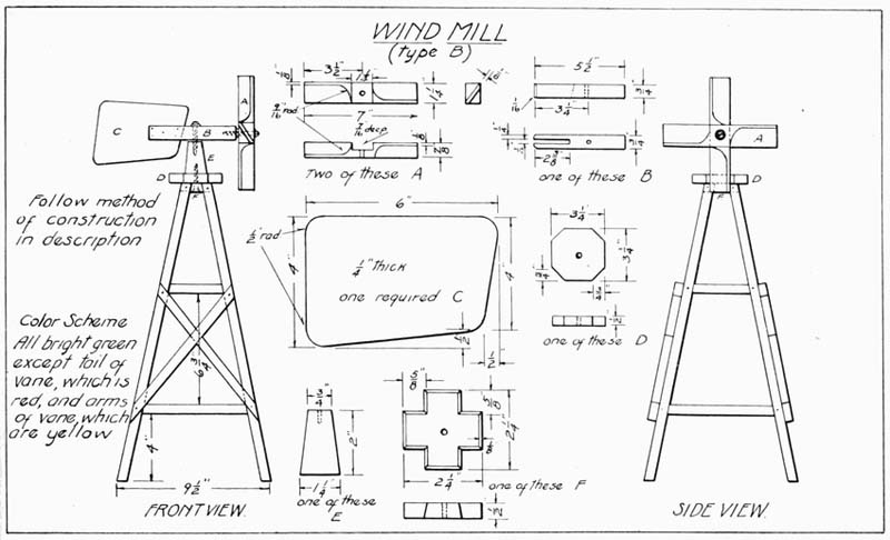
Piece B is made 3/4" × 3/4" × 5-1/2" and has a slot cut in it, 1/4" wide and 2-3/8" long, as shown. The inside end of the slot is cut at a slight angle to receive the slope of tailpiece C. A hole is bored 3-1/4" from the slot end of this piece, of a size to turn freely on a 1-1/2" No. 8 round-head screw.
Tail C is made 1/4" × 4" × 6" and then 1/2" is measured up from the lower right end corner and 1/2" measured in from this point toward the left and a dot is placed. Draw lines from this dot to the lower-left-hand corner and to the upper-right-hand corner. Round all of these corners, using a 1/2" radius and carefully finish to the lines all around.
The vanes A must be very carefully made to insure a close fit and proper balance. Two pieces are cut 7/8" × 1-1/4" × 7". The method of forming the vanes will be more easily understood by referring to the detail, where every measurement is plainly given. The two vanes are joined with a middle lap joint, which requires considerable skill in forming. Each piece is cut half way through at its middle point, seeing that the groove is no wider than the width of the piece that goes within it.
The two vanes are joined with glue and four 3/4" brads.
A hole is bored in the center, of a size that will turn easily on a 1-1/2" No. 8 round-head screw.
Sand all pieces well with No. 1/2 sandpaper.
Paint the various pieces as suggested in the color scheme and attach the tail C to piece B with glue and 1/2" brads.
The vanes A are attached to piece B with a 1-1/2" round-head screw, with washers under the screw head and between the vanes and piece B. Piece B is attached to block E with a 1-1/2" round-head screw, with washers under the screw head and between B and E.
Have all movable parts so that they will move freely.
A finish nail may be placed in the lower part of each leg to secure the mill to the desired location.
This is an interesting beach toy as either fine sand or water may be used to operate it. (Plate 37.) It is very simple to construct and is made as follows: The base is constructed of 1/2" pine, 7-1/2" wide and 7-1/2" long; and the four blocks which are glued and bradded to the corners, are 1/2" × 1" × 1". The two uprights are 3/4" × 7/8" × 8-1/4", and the two cross supports at the tops measure 3/4" × 7/8" × 2-1/2".
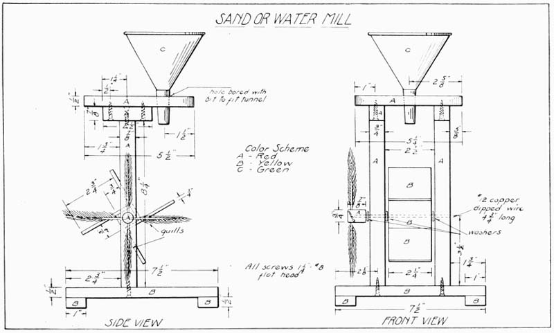
Two holes are bored in the base for the screws that hold the uprights in place. These holes are 2-3/4" from the end and 2-1/8" from the sides.
Holes are bored in the little top braces 1/2" from the two ends and one just in the middle, or 1-1/4" from the ends. These are for the screws that hold the braces to the uprights and to the top piece. All holes are bored with a drill suitable to take 1-1/4" No. 8 flat-head screws, and all are countersunk on the side where the screw enters.
The top piece is made 1/2" × 5-1/4" × 5-1/2" with the two front corners slightly rounded, as shown.
A hole is bored of a size to receive the funnel used, 1-1/2" from the front edge and 2-5/8" from the sides.
A hole is drilled in each upright piece, 3-1/2" from the lower end, of a size that will insure a driving fit to the wire used, in this case being a piece of No. 12 copper-dipped, 4-3/4" long.
A piece of 3/4" dowel is cut off 7/8" long and a similar hole is bored about two-thirds of the way through, as shown.
Four holes are bored, as indicated on the drawing, for the quills, which are later glued in place. Feathers from the poultry yard will furnish these.
Sand all pieces with No. 1 sandpaper and first assemble the top, the two uprights and the two cross supports. Paint these two coats of red paint.
Attach the cross blocks to the base with glue and 3/4" brads and paint two coats of yellow. Paint the tunnel two coats of bright green.
While these are drying construct the paddle wheel. The piece through which the wire axle runs is 3/4" × 3/4" × 2-1/4". The four blades are 1/4" × 2-1/4" × 2-3/4".
After these are sanded and a hole is bored through the center piece, nail the blades to the center piece, in the position shown in the side view. Use 3/4" brads and glue for fastening the blades. Paint two coats of yellow.
When the parts so far assembled are thoroughly dry, finish the assembly, using 1-1/4" No. 8 flat-head screws and glue.
The toy is now ready to operate.
A cradle built according to Plate 38 is suitable for a doll sixteen or seventeen inches in length.
The two sides should be first made 1/2" × 6-1/2" × 20". These are later beveled slightly on their lower edge to conform to the slope of the head and foot board.
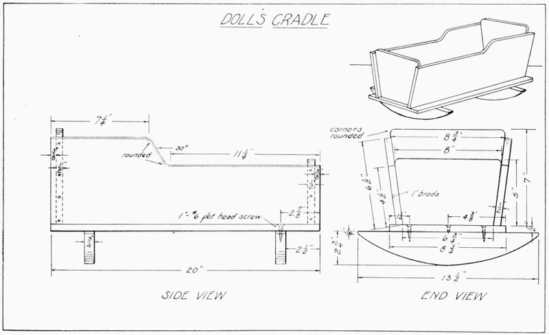
Measure from one end along the top edge 7-1/4" and from the other end 11-1/4". From this last end the width of the side is cut down to 4-1/2", as far as the 11-1/4" measurement previously made. Connect the point which is 7-1/4" from the left end with the point which is 11-1/4" from the right end. This gives a slope of approximately 30 degrees, as is shown in the side view. Slightly round the corners, as indicated.
The head board is next made 1/2" × 7" × 8-3/4".
Measure in, on one of the long edges, an inch from either corner, and from these points draw straight lines to the upper corners. Cut carefully to this line. This makes the lower edge 6-3/4" long. The upper corners are rounded, as shown.
The foot board is made in a similar manner, first cutting it 1/2" × 5" × 8". Place the head and foot board together to see if they exactly correspond. If not, plane or saw them while together so they are exactly alike, except in height.
The four pieces so far completed may now be assembled, using glue and 1" brads.
See that this frame sets flat when placed on a level surface.
The base is next made 1/2" × 8-3/4" × 20". The two rockers are cut 3/4" × 2-3/4" × 13-1/2".
It is a good plan to cut a piece of paper the above size, fold across the short way and sketch on the folded surface one-half the rocker shape. When this has been done in a satisfactory manner it may be unfolded, cut out and drawn on wood. The rocker ends have a slight shoulder of 1/8", as shown. In sloping the rockers, get them alike and make the curve such as will cause them to rock with a very slight pressure.
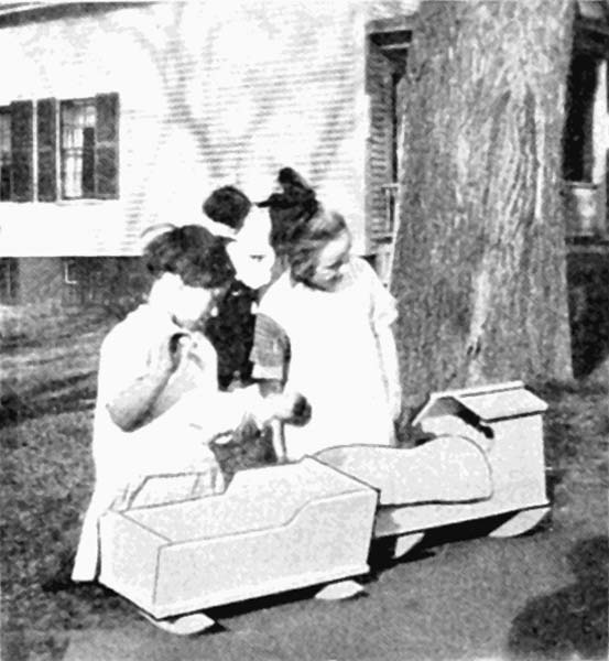
Holes are bored with a small drill in the base, 2-1/2" from the ends and 1-1/2" from the sides. A hole is also bored half way between the two, as shown, and all are countersunk on the upper side.
Attach the rockers with glue and 1" No. 6 flat-head screws.
See that they project equally on the sides and are square with the edges.
Now nail the rocker base to the upper frame previously made, using 1" brads and glue. Have the base project equally from the upper frame on each side and come flush with the ends.
All pieces should have been carefully sanded, of course, before assembling.
The next, and last step is the final finish. If paint is to be the finish, select the desired color and apply a priming and a finish coat. Follow directions in the front of the book for painting.
The type of cradle, shown in Plate 39, is similar in many ways to the one on the last plate. It is, however, more artistic and somewhat more difficult to make.
Follow directions on the last plate for making rockers, base and footboard.
The headboard is cut 1/2" × 8-3/4" × 10-7/8".
Place a center line, longways of the piece, as shown in the end view. At the top measure 1-1/4" each side of the center line and make a dot. At the base measure 3-3/8" each side of the center line and place a dot.
Measure 1-3/4" from the top edge, on each side. Connect these points, as shown in the end view. Cut carefully to the lines. Test the head and footboard to see if they compare.
Make the two sides of the cradle next 1/2" × 9-1/4" × 20".
Seven inches from one end and 6-1/4" from the lower edge strike a circle 1-3/8" in radius. From the lower edge of this circle draw a line parallel to the base. This will make the narrow part of the sides 4-1/2" wide.
From the point directly over the center of the circle, square a line to the top edge of the side. The outline of the side is now ready to be cut out. If an expansive bit is obtainable, bore the hole from the center of the circle with the bit set at 1-3/8" radius. If this bit is not obtainable, the hole must be cut out with a key-hole or a turning saw after first cutting to the circle, along the other lines previously drawn.
The short top edge of the sides should now be beveled to conform to the slope of the head board.
Next make the two top pieces which form the sloping part of the roof. These are 1/2" × 5-1/4" × 7-3/4". These must be planed at their top edge to quite a sharp bevel until they are even with the top of the head board.
The top piece is the final piece cut, and this is 1/2" × 4-3/4" × 7-3/4".
The pieces should now be carefully sanded with No. 1/2 sandpaper and the sides and ends assembled with glue and 1" brads.
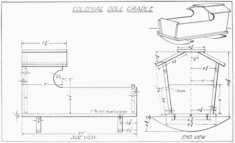
The roof pieces are next placed. Be sure that the top piece sits flat and overhangs equally on both sides.
Holes are bored in the bottom piece for screws, 2-7/8" from the ends and 1-1/2" from the sides. A third hole is bored at each end half way between the other two, as shown, and all are countersunk.
Attach the rockers with glue and 1" flat-head screws, being careful that they project equally on both sides and are at right angles with the edges of the base.
The final finish is optional, but if the cradle is to be painted or enameled it should first receive a priming coat of flat white. See directions for painting in the first part of the book.
The bed illustrated in Plate 40, is suitable for the ordinary size doll, 16" to 18" in length.
The four legs should first be cut, the two long ones being 7/8" × 7/8" × 12" and the two short ones 7/8" × 7/8" × 9-1/4".
These should be planed up square and smooth and the top edges chamfered 1/16", as shown.
The two side rails are next made 3/8" × 2-1/2" × 20-1/2".
The four cross rails, two on the head board and two on the foot board, are made 1/2" × 7/8" × 8-3/4".
Seven slats are next made 3/8" × 1-1/4" × 8".
Two long supporting slats, on which the seven slats previously made rest, are now made 3/8" × 1" × 19-1/4".
Three upright slats are now made for the head board, two being 3/8" × 1-3/4" × 8", and one 3/8" × 3" × 8". Three similar slats are made for the foot board, two 3/8" × 1-3/4" × 5-1/4" and one 3/8" × 3" × 5-1/4".
Seven holes should be carefully bored where the cross rails and legs are joined. Use a small drill about 1/8" in diameter.
These holes are 2-1/2" up from the bottom end of the legs and 1" down from the top ends. In assembling these parts, use glue, brads and 1-1/2" No. 8 round-head screws, as shown on the drawing. Next place the slats, as indicated, using glue and 1-1/4" brads. Take pains to space these properly and center them on the cross piece. All brad holes, wherever placed, should be set with a nail set and the hole filled with hard beeswax.
In nailing in the brads, rest the bottom support on the corner of the bench, so as not to strain the cross piece or legs in pounding with the hammer.
Next attach the long side rails, having their ends come flush with the outer side of the leg. Use glue and 1" brads. See that the rails are attached square with the long edges of legs. The two shorter supporting rails (3/8" × 1" × 19-1/4"), are next nailed to the lower cross pieces at the head and foot of the bed, and close up against the long side rails. A few brads, 1" long, should be driven through from the side rails into these to help secure them in place.
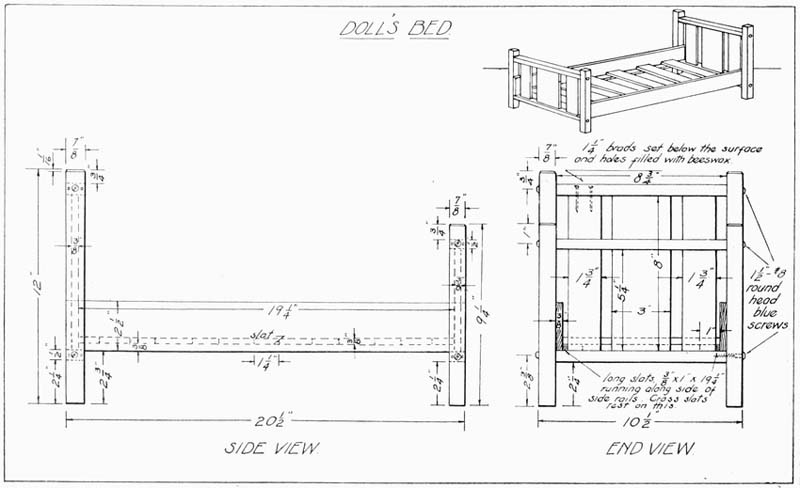
The seven cross slats are carefully spaced, glued, and nailed in place with 1/2" brads. While nailing, place a block of wood beneath the ends for a bearing.
All pieces should have been sanded previous to assembling, and the bed may now be either stained or painted. If painted, a priming coat should be applied first. After this has dried it should be carefully sanded with No. 0 sandpaper and the finish coat applied.
Considerable care should be taken in the painting to insure a good, clean-cut job. Refer back to the first of the book for necessary instructions for painting.
There is an opportunity here for the older sister to help in preparing the bedding.
(Type A Stilt.)
Most every boy knows there is a certain fascination in walking on stilts, but they may prove a dangerous pastime if not strongly made.
In this style of stilt (Type A, Plate 41) the uprights are held beneath the arm pits.
The upright pieces should be made 7/8" × 1-3/8" × 5', or as long as the boy desires. Hard pine or ash make strong, durable stilts. The edges of the upright should be slightly rounded so that they will fit the hand nicely.
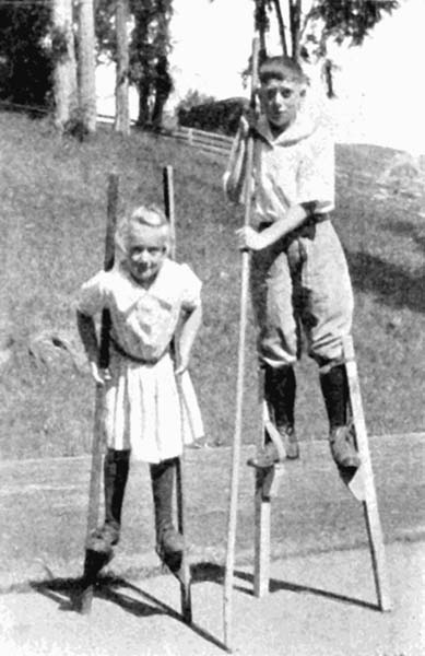
Holes are bored with a 1/4" bit, 17" from the lower end and 2-1/2" apart, as shown. The upper hole is countersunk to receive a 2-1/2" No. 12 flat-head screw.
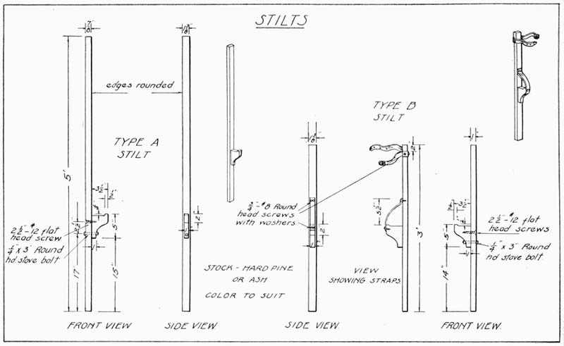
The foot rests are made 1" × 3-1/2" × 5" and shaped, as indicated on the drawing.
They are secured to the uprights with screws and 1/4" × 3" round-head stove bolts. Several holes at various eighths could be bored to allow of adjusting the foot rest to suit the user of the stilt.
The uprights can be painted red and the foot rests green, or the whole can be left plain, according to the desires of the maker. A touch of paint, however, not only adds to the appearance of any article, but also preserves it and lengthens its life.
(Type B Stilt.)
Type B stilt (Plate 41) is made shorter than Type A and is to be strapped to the leg just above the knee.
The uprights are 1" × 1-3/8" × 36", or longer if desired.
Round the edges of the uprights and bore holes at the same places and of the same size as in Type A.
A strap is screwed on, as is shown in the drawing, to support the feet, and another strap, long enough to go around the leg beneath the knee, is attached at the upper end, 2" from the top.
Sandpaper thoroughly and finish to suit.
A pole about seven feet long should be carried to balance and steady oneself.
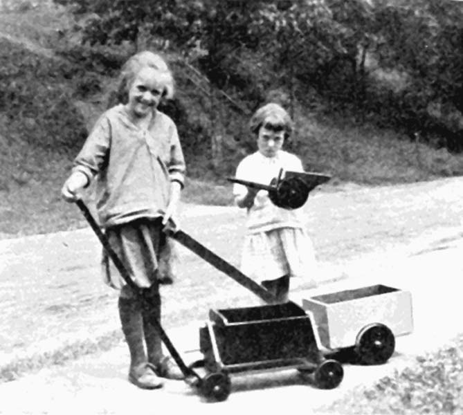
Carts always appeal to youngsters and the one given here (Plate 42) is of simple construction.
Make the side pieces first 1/2" × 6" × 10". On one long edge measure in 2-1/2" and from this point draw a line to the upper corner. Cut carefully to this line. The front piece is made 1/2" × 6" × 6" and the end piece 1/2" × 6" × 6-3/4". This end piece is beveled to conform to the top and bottom edges of the cart, as shown in the side view.
The bottom piece is made 1/2" × 6" × 6-1/2".
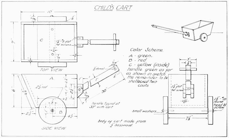
The piece to which the wheels are attached, is made 7/8" × 1" × 7-1/8". This piece has two holes bored and countersunk in it for screws, 1-1/4" from the ends and half way between the sides.
Two small blocks are made 1/2" × 1" × 2-1/2" and tapered 3/4", as shown. These blocks have holes bored and countersunk for screws. Bore the holes in such a manner that they will not come directly opposite each other, otherwise the screws will be likely to hit each other.
Holes are bored in the front piece of the cart and countersunk on the inner side. These pieces are 3" from either side, the first one being 2-1/4" from the upper edge and the second an inch below the first.
The handle measures 7/8" × 1" × 30". A hole is bored 5/8" from the front end with a half-inch bit and the extreme end of the handle is slightly chamfered for a finish. The opposite end of the handle is cut at an angle of 30°, as shown.
A piece of dowel, 1/2" in diameter and 3" long, is cut and inserted in the hole in the handle and secured by driving an inch brad in from the under side of the handle.
The wheels are 7/8" × 5" and may be cut out with a turning saw and trimmed to the line with a chisel, or, if a lathe is available, they can quickly be cut to size. If they are to be sawed out, a circle should be struck with a divider or compass set at a 2-1/2" radius and then carefully cut to the line.
The axle is attached to the bottom piece with glue and 1-1/4" No. 8 flat-head screws.
Bore a hole in the end of the axle, exactly in the center, using a drill slightly smaller than the screw that is to hold the wheels in position. Bore a hole in each wheel, at the center point, a little larger than the screw that is to be used. Attach the wheels with 1-1/2" No. 10 round-head blue screws, using a small washer under the screw head and also between the wheel and the cart body. Tighten the screw just enough to allow a little play for the wheels to turn easily.
Sand all pieces thoroughly before assembling, using No. 1 sandpaper first and finishing with No. 0. Assemble the body part of the cart with glue and 1" brads.
A suggested color scheme is given in the drawing.
This toy at once appeals to the children as it only requires a simple turn of the crank to quickly dump the load of sand.
Each part of this toy is completely detailed in Plate 44, while Plate 43 gives the assembly drawing.
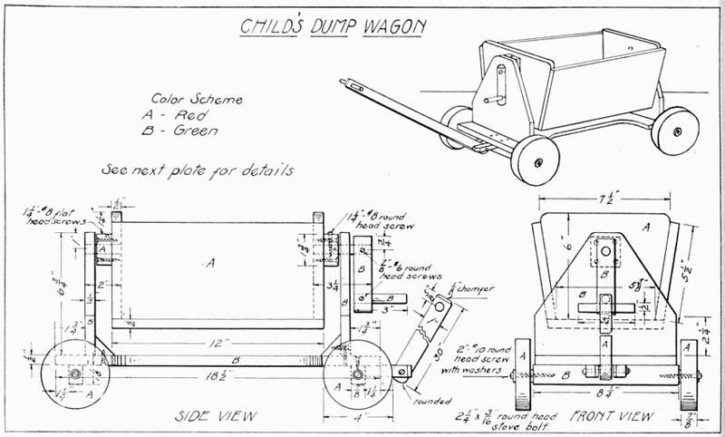
The two sides are first made 1/2" × 5-1/2" × 12", and the two ends 1/2" × 6" × 7-1/2". The sides are beveled about 1/8" on the lower edge so that they will conform to the angle of the end piece. The ends taper from 7-1/2" long at the top to 5-5/8" at the bottom. This angle is obtained by measuring in 15/16" from either side and drawing to the opposite upper corner. Saw and finish to this line and slightly round the upper corners, as shown. Bore a hole with a 1/2" bit at the point indicated.
The bottom piece is made 1/2" × 6-5/8" × 12".
Sand these five pieces and assemble, using 1-1/4" brads and glue. Plane the side edges of the bottom board to the same angle as the slope of the sides.
The two end uprights are now made 1/2" × 6-3/4" × 8". Measure up 2-1/4" on the short edges and place a dot. Connect these points with a sloping line and saw and finish to the outline shown. Bore holes with a 1/2" bit at the place indicated. Locate and bore a screw hole 1/2" up from the center of the lower edge to attach brace block.
Make two small supporting blocks 7/8" × 1-3/4" × 1-3/4". Bore a 1/2" hole carefully in the center and drill four smaller holes to receive 1-1/4" No. 8 flat-head screws, 3/8" from each other, as shown. Countersink these four holes.
Glue and screw these blocks to the end of the wagon box, 1-1/4" from the top edge, as shown.
Make two brace blocks by first cutting out a square 7/8" × 1" × 1" and cutting this in two diagonally from corner to corner. Glue and screw these blocks to the end uprights, using 1" No. 6 flat-head screws.
The underbody should next be made 1/2" × 8" × 18-1/2".
Measure in 3-1/4" from each corner on the long edge, and with the dividers set at 2-1/4", strike a quarter circle and connect these arcs with straight lines, making the width in the middle 4-1/2". Saw this out with a coping saw and finish smoothly to the line.
Locate and drill the twelve screw holes shown, with a drill the size of a No. 6 screw.
Countersink all holes, except the four holes which hold the supports for the cart handle. These four are not countersunk as 1" No. 6 round-head screws are used at these points.
Attach the end uprights to the underbody with glue and 1" No. 6 flat-head screws, eight in all.
Next make the two axles 7/8" × 1" × 8-1/4" and bore and countersink the three holes, on the narrow edge, at the points indicated. Glue and screw these in place, 1-1/4" from the front and rear ends, using 1-1/4" No. 8 flat-head screws. These axles project 1/8" beyond the sides of the underbody, on all sides, so as to allow the wheels to turn without interference.
The wheels may be made on a lathe or with a turning saw, 7/8" thick and all exactly 4" in diameter. Bore a hole in their center with a drill a little larger than the wire of a 2" No. 10 round-head screw. When assembling, use a washer on each side of the wheel.
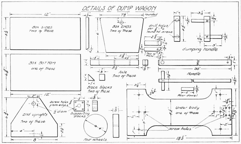
A hole should be started about 3/8" deep in the center of the ends of the axle to insure the screws going in properly.
The cart handle is made 1/2" × 1" × 30", with one end rounded and the opposite end chamfered 1/8". On the latter end measure in 5/8" on the wide side and bore a hole carefully with a 1/2" bit. Cut a piece from a 1/2" dowel, 3-1/4" long, and insert it in this hole, keeping it in place with glue and one 7/8" brad.
Bore a hole 1/2" from the rounded end with a 3/16" bit.
The two pieces which hold the handle are now made 3/4" × 7/8" × 2-3/4". A 3/16" hole is bored in the 7/8" edge of these pieces, 1/2" from the end. These holes, and the hole in the handle, are to receive a round-head stove bolt, which is 3/16" × 2-1/4".
Glue and screw these two pieces in place in the center of the front end of the underbody, leaving about 1/16" space between the handle and the edges of the blocks for freedom of movement.
The dumping handle is made of pieces of dowel, the main piece being 1" in diameter by 4-1/2" long. The other pieces are cut from a half-inch dowel, 3" and 3-1/2" long, respectively.
On the main dowel bore holes with a 1/2" bit, 3/4" from the ends, to receive the shorter dowels. Glue and insert the 3-1/4" dowel and bore a small hole to receive a 7/8" No. 6 round-head screw. Place this screw and then insert the dowel through the front upright into the front supporting block and flush with the inner surface of the front box end. Hold in place in the block with glue and a 1-1/4" No. 8 round-head screw.
Glue and screw the 3" dowel in place for the grip.
A piece of 1/2" dowel, 2" long, is similarly placed through the rear upright, thence into the rear supporting block and box end.
This is also held with glue and a 1-1/4" No. 8 round-head screw through the block.
Sand and apply two coats of paint before assembling the wheels and handle.
The Child's Wheelbarrow, shown in Plate 45, is very serviceable and quite easy to make, and, if the directions are followed carefully, the result will be a toy that will outlast a majority of the toys ordinarily found on the store shelves.
First, make the handles 7/8" × 1-1/4" × 30". Chamfer the handles, as shown, for four inches from one end.
The two sides are made 1/2" × 5-1/2" × 15" and 1-1/2" is measured in on one long edge and a line drawn from this point to the lower corner. Saw and plane to this line and round the upper corner with a chisel and file.
The end is 3/8" × 5-1/2" × 7-1/4". The bottom is first cut 1/2" × 11" × 14". On one end measure in 1-7/8" from one side and a like distance from the other side. Connect these points with the opposite extreme corners and finish to these lines. The bottom is now tapered to 7-1/4" wide at the front end.
Assemble the sides, the bottom and the end with glue and 1-1/2" finish nails, setting the front piece back 1/4" from the end of the sides, as shown in the drawing. Set all nails below the surface and fill the holes with beeswax.
Place the assembled part on the handles in such a manner that the front end of the box part of the wheelbarrow is 5" from the front end of the handles, and the handles at the front end are 2" apart inside, and at the grip end 13" apart outside.
While in this position, which is the permanent assembling position, mark the position of the six screw holes, which are bored with a drill of a size to receive a 1" No. 6 flat-head screw. Countersink these holes.
The two legs are made 7/8" × 1" × 8-3/4" and beveled 1/4" at the lower end. On the upper end a notch is cut out 3/8" deep by 1-1/4" long. Two holes are bored, as indicated, to attach the leg to the handle. This is done with glue and 1" No. 6 round-head screws.
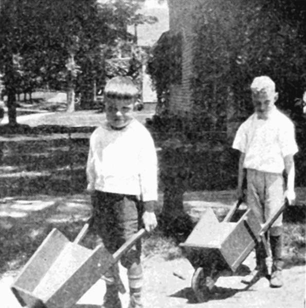
A 1/2" dowel rod runs between the legs to brace them, and a hole is bored 3/8" deep in each leg, 2-1/2" from the lower end. The dowel is 9" long and is held in place with glue, and a 3/4" brad is driven in the leg to hold it firmly in place.
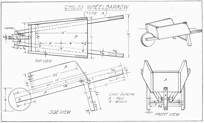
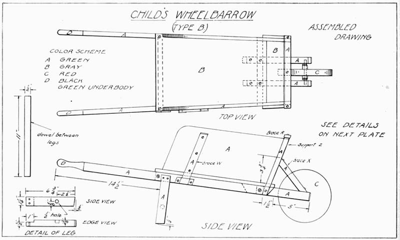
A hole is bored very carefully 1-1/4" from the front end of the handles to receive the wheel axle. It will be noticed, by referring to the top view of the drawing, that on account of the taper of the handles this hole must be bored slightly on a slant and about half way through. The bit should be of a size to allow a piece of sixteen-penny nail to turn freely, as the axle should be made of a nail of this size, cut 3" long.
The wheel is best made of hard wood, such as maple, 7/8" thick and 6" in diameter.
Bore the hole in the center with the same drill just used.
Next cut two pieces from a 1/2" dowel, 3/8" long, and bore a similar hole exactly through their center. These two pieces of dowel are glued to the wheel and serve to make it run in the center. When assembling, place a small washer between the dowels and handle, as shown.
All pieces should have been carefully sanded before assembling, and the wheel should be painted red and allowed to dry before being put in place. The remainder of the wheelbarrow should be painted bright green. Apply two coats, rubbing down the first coat when dry with No. 0 sandpaper before applying the second.
This style wheelbarrow (Plates 46 and 47) is planned exceptionally strong and sturdy and will stand a large amount of hard usage. It is made larger and stronger than Type A, and is naturally a little more difficult to make, but well within the ability of an eighth grade boy. This type has removable sideboards.
The plate of details gives exact information how to make each piece, so it will not be necessary to give the directions here.
After all pieces are correctly made and all holes are bored at the places indicated, each part should be sanded very carefully and made ready for assembling.
Care should be taken to get good tight joints on the front brace, the wheel supports and the tops of the legs.
The metal braces can be made from strips of zinc 1" × 4", bent over the braces W, allowing a little freedom for removing the sideboards. Holes should be drilled in these braces, where shown, to receive 1/2" No. 6 round-head screws.
First attach the bottom boards to the handles with 1" No. 6 flat-head screws, placing the ends of the handles even with the front of the bottom board and flush with the side edges.
Next fasten the front and rear brace in place with 1-1/2" No. 8 flat-head screws, on the under side, and with 1-1/2" No. 8 round-head screws and washers from the outside of the handle to the brace ends.
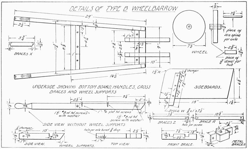
Fasten one wheel brace in its proper place with 1" No. 6 flat-head screws from the upper side of the bottom board.
Place the axle of the wheel in the hole and attach the other wheel in the same manner.
Glue and screw the front uprights in place, as indicated, with 1" No. 6 round-head screws, and place the top cross piece on these and hold in place with glue and 1" round-head blue screws.
Place the sides in position, with the front ends flush with the outer edges of the front braces. Place the metal braces over the supporting pieces and screw in place, using 1" No. 6 round-head blue screws.
Braces X, which run from the wheel supports to the front piece of the wheelbarrow, are screwed in place, as shown, using 1-1/4" No. 8 round-head screws.
It will be noticed that the hole for the dowel stick in the leg only extends in 3/8". Place one leg in position, 14-1/2" from the ends of the handles, using glue and 1" No. 6 round-head blue screws. Insert the dowel stick in this leg and also in the second leg and secure the second leg in place. The dowel should have glue placed on its ends, and, after the legs are in place, an inch brad should be driven into each leg, through the dowel, to hold it firmly in place.
The color scheme given in the drawing is a pleasing one. The wheel is painted two coats of red before being placed in position.
This has proven a very popular toy and is not hard to construct.
The legs and body may be made of pulp or Beaver board, a material which is very good, as it saws easily and will not split. Wood, however, may be used, if preferred.
The details of the body and legs are full size and these may be transferred to the wood by the tracing method described at the beginning of the book. These pieces, when done, may be painted, if desired, and allowed to dry while the rest of the parts are being made. Bore all necessary holes shown in the drawing.
The wheels are best turned on a lathe to 4" in diameter and a hole bored in the center of each of a size that will allow a 1/4" dowel to fit tightly. If no lathe is available, the wheel can be cut out with a turning saw and finished with a chisel and file. The wheels are best made from 1/4" maple. Two pieces of 3/8" dowel are cut 1/4" long and attached 1/2" above the center of the wheel, as shown. This is done on both wheels, and the piece is attached with glue and 1/2" brads. It is a good plan to bore holes for these brads and thus prevent the possible splitting of the wood. The dowel that goes between the wheels is made 1/4" × 3/4" and is glued securely in the holes in the wheels later. Another piece of 1/4" dowel is cut 4" long, and is fitted to support the body of the clown on the handle.
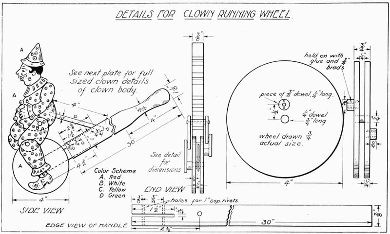
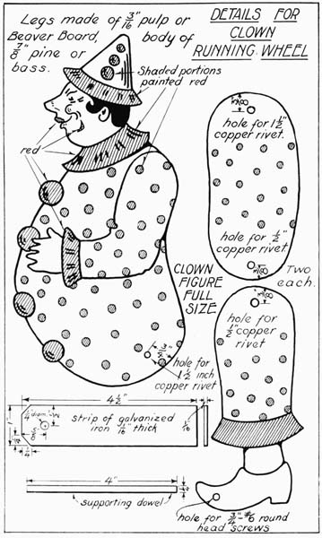
The handle is made 7/8" × 1-1/8" × 30", and the grip is rounded and shaped, as shown on Plate 48. In the opposite end of the handle a slot is cut 1/16" wide and 1-1/2" long. This is to receive the strip of zinc which runs between the wheels. This strip of zinc is made of 1/16" material, 1" wide and 4-1/2" long. Triangular pieces are cut from one end, 1/4" on a side, as shown on the detail sheet. This strip is held in the slot in the handle by first drilling through both the wood and the zinc, with a drill the size of a 3/4" brad, and afterwards gluing and bradding the zinc into position with 3/4" brads. A hole, 1/4" in diameter, is also drilled in the opposite end of the zinc, 5/8" from the end and 1/2" from the sides. This goes over the axle of the wheel.
A hole is bored with a 1/4" bit, 2-3/8" from the end of the handle, as shown on Plate 48, and at an angle, as indicated.
A similar hole is bored in the seat of the clown. The parts are now ready to sandpaper, paint, and after drying, assemble.
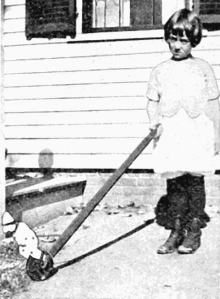
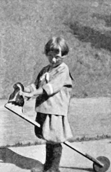
The color scheme is given on the drawing. After the paint has dried, the lines where the various colors join, should be accented with a pen, using India ink.
The upper legs of the clown are attached to the body with 1-1/2" copper rivets and the lower legs are held to the upper by 1/2" rivets. When putting the rivets in place, hold the end which has the washer against some hard, metal body and strike with a hammer, taking care[Pg 109] not to get the washer so tight that the legs will not move. A 3/4" No. 6 round-head screw holds the feet to the projecting dowel on the wheel. It is best to bore the hole for the screw in the piece of dowel a little smaller than the size of the screw so as to prevent splitting. Glue the supporting dowel in both the clown and the handle.
The Cock Horse is a modern version of the old hobby horse, and affords the children, between the ages of four and six, unlimited pleasure.
The head is made of a piece of 7/8" bass or pine, 5-1/2" wide and 9-1/2" long.
The features may be enlarged from the size drawn in Plate 50, by the method given at the beginning of the book for enlarging; or, if one is apt at free-hand drawing, the outline may be copied offhand.
Cut the features out right to the line with a coping saw and smooth the edges and surfaces with No. 1/2 sandpaper.
The stick is made 7/8" × 1" × 32", and the front end is chamfered 1/8".
Holes are bored for 1-1/2" No. 10 flat-head screws, the first 1-3/4" from the front end and the other two 1-1/2" apart.
Two smaller pieces, which are made 5/8" × 7/8" × 7-1/2", are to hold the wheel in position. Holes are bored in these two pieces to take 1-1/4" No. 8 round-head screws, the first one being 7/8" from the end and the next two 3/4" apart.
On this same end a piece is cut off at an angle, as shown.
A hole is bored at the opposite end of these two pieces to receive a 2-1/2" × 1/4" round-head stove bolt, on which the wheel turns.
The wheel is made 7/8" thick and 6" in diameter, either on a lathe or with a coping saw. A hole is bored in the center a little larger than the 1/4" × 2-1/2" stove bolt, so that the wheel will turn easily upon it.
Glue and screw the two side pieces to the long stick, using 1-1/4" round-head blue screws. Give these two coats of natural varnish.
Paint the wheel two coats of bright red.
Paint the head one coat of flat white, and after drying give one or two coats of white enamel. After this has dried thoroughly, paint the comb and wattles bright red. Paint the beak and outer circle of the eyes yellow, and the feathers about the neck black. Where the colors join, outline with a drafting pen and India ink.
A hole is bored, in the head where shown, to receive a piece of 3/4" dowel, 6" long. This serves as a handle. Glue this handle in place, taking care that it projects equally on both sides.
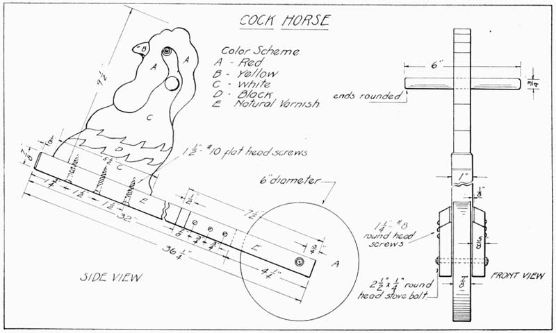
This very interesting action toy is especially suitable for children as young as two years of age. It is simple in construction and perfectly safe. (Plate 51.)
The seat board is made 7/8" × 5" × 21". Measure 6" in from one end on both long edges, and at these points narrow the front end to 3-1/2" wide by sawing out a piece on both sides 1-1/4" wide.
Round the corners where the taper comes, also the other four corners of the top. Similarly, round the upper edge of the top.
The two rockers are made 7/8" × 4-1/2" × 18". Measure down 1/4" on the two ends, and from these points carefully sketch a free-hand curve with its highest point directly in the center of the lower edge. Be sure this curve balances equally and that the two rockers are exactly alike.
The rooster's head is made 7/8" × 6" × 10-1/4" and the outline is sketched upon it similar to the one shown on the drawing.
Cut out the features with a coping saw, taking pains to have the saw at right angles to the surface of the wood at all times.
A hole is bored in the head, for the handle, about 3-3/4" from the top and 1-1/2" from the rear edge. A 3/4" bit is used.
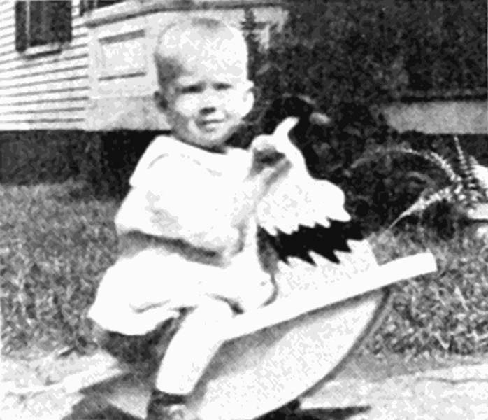
Be sure and bore this hole perfectly straight.
The handle is made 6" long and 3/4" in diameter, shaping it as shown in the front view. If this cannot be turned on a lathe, the handle may be made from a 6" piece of 3/4" dowel, rounding the ends slightly with a file.
Holes are now bored for the 1-1/2" No. 8 flat-head screws which hold the rockers and head to the top. The locations of these holes are clearly shown in the drawing. Countersink the holes on the side from which the screws enter.
The little separating block, which goes between the rockers, is made 7/8" × 1" × 2-1/2", and is held in place with glue.
Sand all pieces thoroughly.
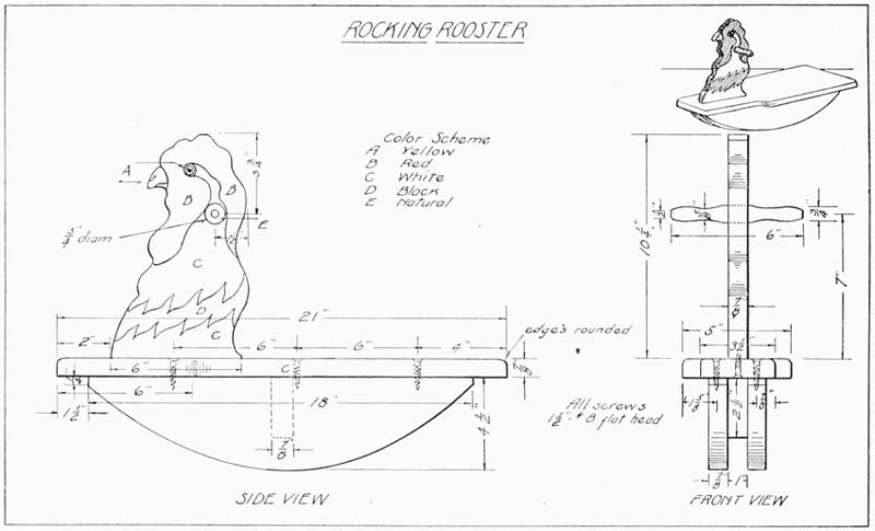
Assemble all pieces carefully, seeing that the rooster's head is centered well and placed two inches from the front end.
The rockers are attached 1-1/2" from the ends and so placed that they are just an inch apart.
Paint the whole toy one coat of flat white and sand lightly with No. 0 sandpaper when dry. Paint in the comb and wattles of the rooster bright red and the feathers on the neck, green.
After these colors have dried, apply another coat of white, where indicated, this time using white enamel. Use a small brush for the details. The beak and the circle about the eye are painted yellow and the other circle about the eye is painted black.
If the paint does not seem to have the proper sparkle when the last coat is dry, apply another coat of each color. Outline the edge of the comb and wattles with a drafting pen and India ink. Outline also, the beak and eyes. This causes a sharp contrast where the two colors meet and sets off the features.
The top and rockers are treated with two coats of white enamel on top of the priming coat.
It is hardly necessary to speak of the popularity of this toy. Its construction is well within the ability of the average eighth grade boy.
The seat board (Plate 52) is made of 7/8" stock and is first cut 7-1/2" wide and 21-1/2" long. Half the outline of the curve at the front should be traced on a folded piece of paper, the proper size, and cut out and traced on the wood. This outline should now be carefully sawed and chiseled to the correct shape.
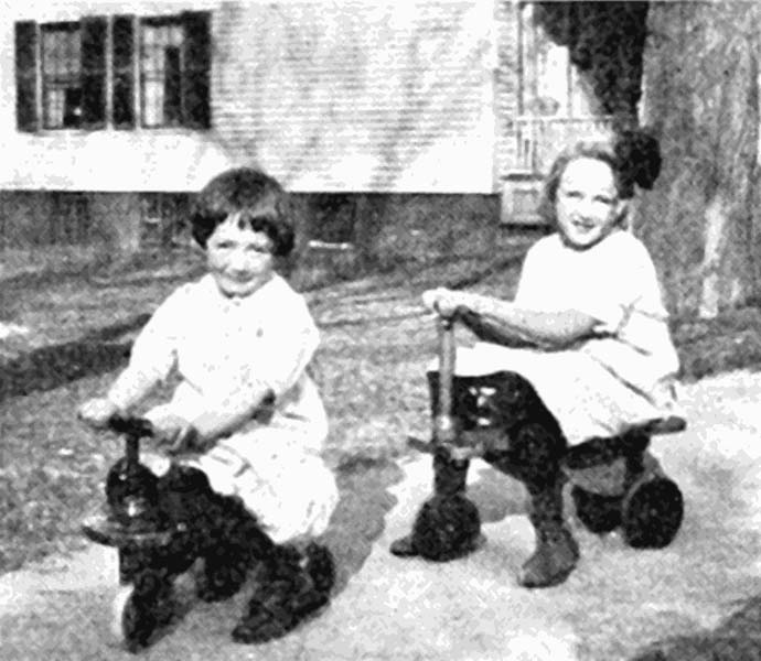
The top edge of the seat should be rounded.
The rear support should have half its outline traced on a folded piece of paper and cut out and traced on a piece of wood 7/8" × 5" × 6-1/2". Finish to the line.
The brace is cut 7/8" × 5" × 9-1/2".
Mark out the outline of the curves, as shown, and saw and chisel to the line. The wheels and steering gear should be turned on a lathe to the dimensions shown on the drawing.
A hole is bored in the seat board, 1-3/4" from the front end and half way between the sides, with a 15/16" bit. This is to allow the steering post, which is turned to 7/8" diameter, freedom to turn.
Holes are drilled through the under part of the rear brace, as shown, to secure the same to the top. Holes are likewise bored half way between the sides of this brace, to engage with the curved supporting piece.
The curved supporting piece has two holes bored 1-1/4" from the small end, 1" apart. This is for the screws that go into the top.
Holes, bored with a small bit, should be started in the lower part of the rear brace, to receive the large screws which hold the rear wheels in place. It is quite necessary to make these holes, using a bit a trifle smaller than the screw to be used, as it is very difficult to force a screw of this size into wood of this hardness. These holes must be bored exactly straight, otherwise the wheels will turn unevenly.
Washers should be used between the screw heads and the wheels and between the wheels and any part they are likely to come in contact with.
A hole is bored in the steering rod, directly below the top board, for a screw to be placed to hold the upper and lower part of the steering rod firm. Glue is also used when assembling the two parts of the steering apparatus. The handle is also held in place with a screw and glue, as shown. A hole is bored in the handle, of a size suitable to receive the steering rod.
Washers should be placed in the steering gear, above and below the seat board, to prevent wear.
In preparing the slot to receive the front wheel, a hole should first be bored with an inch bit so that the top edge of the slot comes 3-5/8" from the bottom of the steering gear.
This slot should be very carefully sawed out and smoothed up so that the wheel, which is 7/8" thick, will turn accurately.
The holes in all the wheels must center accurately and be larger than the screw or bolt which goes through them. The front wheel turns on a 1/4" × 1-3/4" round-head stove bolt.
The color scheme may be varied to suit individual tastes.
The one suggested in the drawing has red wheels with the remaining parts of the kiddie kar finished natural with spar varnish.
All parts should be thoroughly sanded before assembling. Two coats of paint should be applied to the wheels and two coats of varnish to the remainder.
Sand in between coats with No. 0 sandpaper.
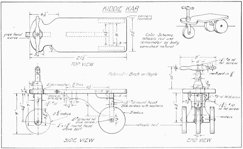
This lively toy is somewhat different from the three-wheeled Kiddie Kar and is suited for children of eight or over.
If desired, this toy may be made up with three wheels like a velocipede.
If this type is made, a piece of dowel rod, of hard wood, is cut about six or eight inches long and an inch in diameter. This dowel should go through a hole in the rear brace, and the wheels should be attached to the ends with 2" No. 12 round-head screws and washers.
The following directions are for the two-wheel Kiddie Koaster shown in Plate 53.
The front supporting piece is first made of a piece of hard wood, 2" × 2-1/4" × 19". A distance of 7" is measured up from the lower end and 7/8" is measured beyond this. From this point the remainder of the brace is thinned to one inch in thickness. The top end is rounded and the bottom end chamfered, as shown.
A hole is carefully bored with an inch bit, 5-3/4" from the lower end. An allowance of 1/2" is made for the thickness of each fork and the remaining inch is removed with a saw up to the hole previously bored.
A hole is bored for the handle, 1-1/4" from the top, with a 7/8" bit. Another hole is bored on each side, 6-1/4" from the lower end with a 3/4" bit, 1/2" deep.
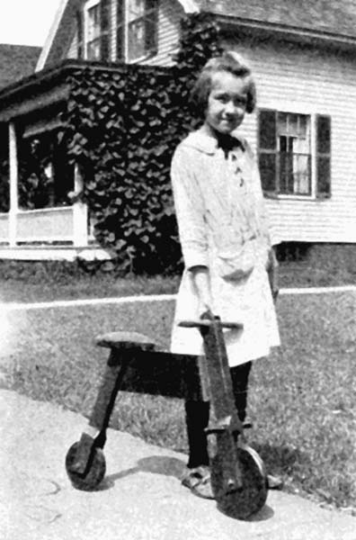
These two holes are for the foot rests. Small holes are bored one inch from the lower end to receive a 1/4" × 2-1/2" round-head stove bolt. A 1/4" bit should be used to bore these.
The rear support is made 2" × 2-1/4" × 16-3/4". From a point 6-1/2" from the lower end this is thinned down to one inch thick, the same way as the front support. At the upper end measure down on one edge 7/8" and draw to the opposite corner.
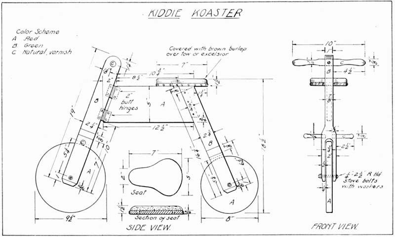
Cut off at this angle so that it will come on a line with the cross piece. A hole is bored with a 1/4" bit, one inch from the lower end to take a 1/4" × 2-1/2" round-head stove bolt.
Chamfer 3/8" from the lower end.
Bore a hole 4-3/4" from the lower end with an inch bit and remove the wood to form the rear fork, in the same manner as was done for the front.
The cross piece between the front and rear support, on which the seat rests, is first made 7/8" x 5" x 13-1/8".
Measure in two inches from the upper corner and draw a line to the lower corner. Saw squarely on this line to get the proper slant. Measure from this upper left-hand corner 9-1/2" and draw a line from here to the lower right-hand corner. Saw to this line. On this last end sawed, measure in 3/4" and make a tenon, as indicated in the side view. This tenon should be 1/2" thick. The other dimensions for the tenon are given on the drawing.
On the rear support a mortise is now cut of a size to receive the tenon tightly, and to make the top edge of the cross piece and upper end of the rear support on a line.
This tenon should be cut with a 1/2" bit, boring so as to make the mortise about 13/16" deep. Remove the extra wood with a small chisel until the tenon fits snugly within the mortise.
Later, when assembling, this joint is glued and 3/4" brads are driven in from the side to pin it in place, as indicated.
The seat is made 3/4" × 5" × 7". It is shaped, as shown in the sketch, cutting the outline with a turning saw and finishing to the line with a chisel and file. Two holes are bored and countersunk to receive 1-1/4" No. 8 flat-head screws which hold the seat in place.
The seat is stuffed with tow, excelsior or other suitable material and covered with brown burlap or with imitation leather, as desired. A piece of braid, to match the material used, is tacked around the lower edge with upholstery tacks to match.
The handles and foot rests are best turned out on a lathe, although they may be whittled out with a jack-knife. The dimensions for these are clearly shown.
The front wheel is 9-1/2" in diameter, made from wood 3/4" thick. The rear wheel is 8" in diameter, the wood being 3/4" stock.
These wheels should be made of hard wood or wood glued up three-ply. These are best turned on a lathe, although they may be cut with a turning saw and chiseled to the line and finished with a file.
A special hinge may be obtained from most any toy[Pg 119] manufacturing firm, to place between the front support and the cross-piece. In the author's classes, hinges of this special type were obtained in various sizes, without any trouble. The size indicated in the drawing is five inches long and costs fourteen cents.
If these special hinges are not used, the ordinary butt hinges may be substituted, two being used.
A groove of the proper length and depth, to fit these hinges, can be drilled and chiseled out in the front brace. A saw cut can be made in the cross piece, across the end, in which to insert the hinge. When assembled, screws should be placed so as to accurately engage with the screw holes in the hinges.
Before assembling, all pieces should be thoroughly sanded and painted two coats.
A suggested color scheme is given on the drawing.
The Ski Skooter, shown on Plate 54, is best made of ash.
The runner is first made 5/8" × 3-3/8" × 39" and thinned down, for ten inches from the front end, to 3/8" thick.
The runner is steamed, bent and grooved by the method shown in Plate 55.
The upright piece is made 7/8" × 3-1/8" × 16-1/8" and one of the bracing pieces 7/8" × 1-3/8" × 12" and the other 7/8" × 1-3/8" × 13". These are cut at an angle of 45 degrees at each end, as shown.
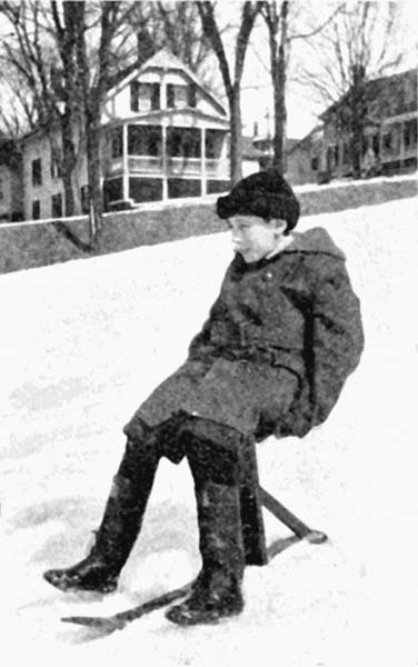
The seat is made 7/8" × 6" × 12", and the top edges are slightly rounded.
Two grips, which also have their lower edges rounded, are made 3/4" × 7/8" × 5".
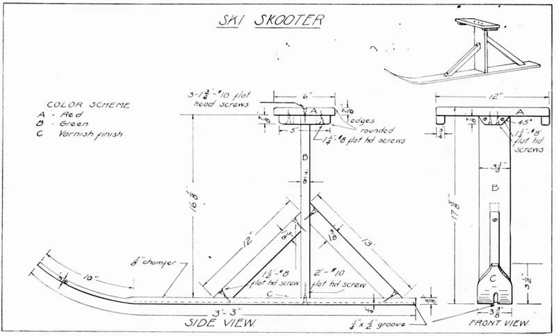
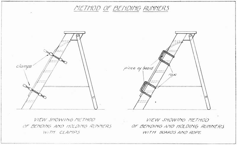
Two strengthening pieces are made 7/8" × 7/8" × 3-1/8" and their ends are cut at 45 degrees, as shown. These are attached to the upright directly under the seat.
Bore all holes, where shown in the drawing, and countersink them. Assemble with glue and screws of a size shown on the drawing.
The color scheme is given on the drawing, but may be changed to suit individual tastes. Two coats of paint are applied, sanding carefully between coats.
The seat can be upholstered if desired.
Place the ends in a washboiler, about half full of boiling water, and allow them to remain about five hours.
Place the tip, or front end of the runners, under the back edge of the top step of a step ladder. Slowly bend the runner downward until it lays flat on the front edges of the other steps.
Secure this in place either with clamps or by pieces of rope and wood. Plate 55 shows two methods of bending the runners. Regular skis may be bent in the same manner.
Leave the runners in the clamps overnight.
The Ski Skipper affords a lively form of winter amusement, and great speed can be obtained on the surface of the snow, especially when the crust is covered with a small amount of light snow.
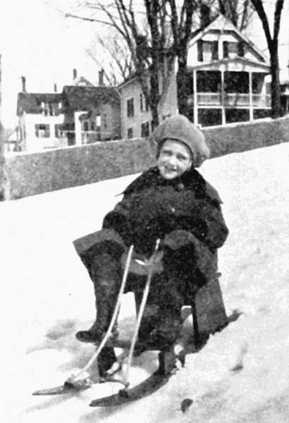
The runners are best made of white ash, from half-inch material, 2-3/4" wide and 42" long. (Plate 56.)
The front end of the runners is tapered, starting about five inches from the end. The extreme tips are blunt, being 1/2" wide.
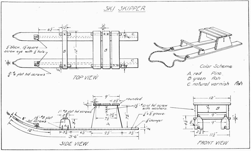
Starting about twelve inches from the front end, the runners are thinned down with a plane, on the upper surface, to 3/8" thick.
Both runners have a groove cut along their counters from the rear end to the point where they curve upward.
This groove is 1/4" deep and 1/2" wide, and may be cut by various methods. It may be cut with a grooving plane; it may be scored with a sharp-pointed gauge and the inner part removed with a chisel; or, if a power saw is available, it may be easily cut with a dado saw.
The upper edge of the runners may be chamfered about 1/8" for a finish. When the foregoing operations are completed, the runners should be bent, using the method shown in Plate 55.
The slats forming the seat top are now made 1/2" × 2-1/2" × 12", and the single slat for the foot rest 1/2" × 1-1/2" × 12".
The seat slats have holes bored and countersunk 3/4" from the edges and 1-1/4" from the ends, to receive 1" No. 8 flat-head screws. The foot slat has a similar hole bored 1-1/4" from the ends and centered between the edges.
The seat supports are first cut 7/8" × 7-1/2" × 9-1/2" and then an inch is measured in on the top edge on each side and lines are drawn to the lower corners, as shown. Saw and plane to this line, making the taper as shown in the side view. The cross brace is made 7/8" × 3" × 9".
The supports for the foot rests are first made 7/8" × 3" × 3-1/2". On the upper edge, which is 3-1/2" long, measure in 3/8" from each end and draw the sloping lines to the lower corners, making the taper, as indicated. Round these upper corners.
Bore holes in the runners for attaching the uprights at places where they will engage with the uprights, at points shown on the drawing. There should be three screws in each large upright and two in the smaller front support. Assemble with glue and 1-1/2" No. 8 flat-head screws at all places except where the cross slats are held. At these points 1" No. 8 flat-head screws will be long enough.
It will be noticed, in examining the top and front views, that the supporting uprights are not placed directly half way between the edges of the skis, but are offset so that they come nearer the outside edge of the runner. This is done so that the screw will not come in the groove.
Two blocks of wood to hold the screw eyes, to which the rope is attached, are made from 1/2" material, 1-1/2" square.
Two holes are bored in these blocks, as shown, and they are attached eight inches from the front end of the runner with 3/4" No. 6 round-head screws. A screw eye[Pg 125] is placed in each block, of a size sufficient to receive a 3/8" rope.
It is best to bore the hole for the screw eye first, in order to prevent splitting the block.
A suggested color scheme is shown in the drawing. Two coats of paint should be applied.
While this drawing (Plate 57), to all intents and purposes details a doll sleigh, yet by increasing the dimensions slightly the sleigh will be suitable for a small child.
First, make the runners of 1/2" spruce, or other suitable wood, cutting them 9" wide by 26" long.
On the upper edge measure back 1-1/2" and from this point draw to the corner of the lower edge. Saw to this line and slightly round the corners, as shown. With the dividers set at a radius of 4-1/2", strike a circle very lightly on the opposite end of the runners, so that it will be just tangent to the edges and end of the board. Measure up from the lower edge of the runner 7-1/2" and draw a line parallel to it until it strikes the circle. Cut to this line and also saw to the curve of the circle, forming the outline of the runner. Finish to the line with a chisel and file. See that the two runners are exact duplicates. Bevel slightly on the top edge to allow the runners to flare.
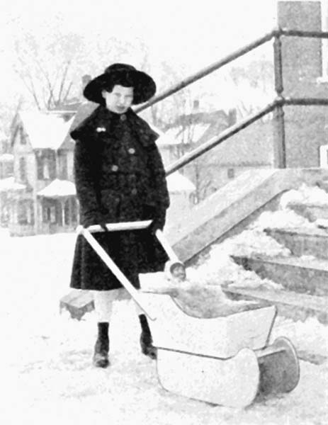
Next make the sleigh bottom 1/2" × 10" × 16-1/2". Two braces, to go below the sleigh bottom, are made 1/2" × 3" × 8-1/2".
These braces are cut at an angle at each end, as shown. The angle is obtained by measuring in 3/8" on one edge and drawing to the opposite lower corner from this point and sawing to the line.
The sides of the sleigh are made 1/2" × 8" × 22". On the top edge measure in 7-3/4" and place a dot. Measure down from the right-hand lower corner of the sides 4-1/2" and from this point, draw to the right-hand upper corner.
From the left-hand lower corner measure in 1-3/4" and place a dot. From the same corner measure up on the left-hand edge six inches and make another dot. Connect these two dots to form the slope of the front end. From the last dot placed, square a line in from the left-hand edge 1-3/4" long. From this point sketch a free-hand curve, as is shown in the side view of the sleigh (Plate 57) to the point first located on the upper edge. Cut to the outline, being sure both sides match.
The front edge of the sleigh is made 1/2" × 6" × 11" and the rear end 1/2" × 9" × 11-1/2". On the lower edge of the rear end measure in 1-5/8" from each corner and draw to the upper opposite corners. Saw and plane to these lines. This will give the taper of the rear end.
Place the board from which the front is to be cut on the backboard and trace the slope of the sides and carefully finish to the line.
The two handles are made 7/8" × 1-1/4" × 23-1/2", and the top piece, or grip, 1" × 1-1/4" × 19".
The uprights are mortised into the grips 5/8", as shown on the drawing.
Holes are bored in the center of the curve of the runners with a medium-size drill, and at these points an inch dowel is cut long enough to fit snugly between the runners, after the sleigh is assembled. The ends of the dowel are cut at a slope to conform to the pitch of the runners. This dowel is held with glue and 1-1/2" No. 10 round-head screws.
Holes are bored, where indicated in the side view (Plate 57), to hold the brace in place. Holes are also bored in the handles to attach to the body of sleigh at places most convenient.
Holes are bored in the sleigh bottom to attach the same to the cross braces, using 1" No. 6 flat-head screws. Use 1-1/4" No. 8 round-head screws on the outside of the runners. The handles are attached with 3/16" × 1-1/2" round-head stove bolts. All other parts should be secured with glue and three-penny fine finish nails.
If desired the bottom of the runners may be covered with 1/2" strap iron.
Various finishes may be used after the parts are thoroughly sanded. If stain is to be the finish, apply it according to the directions in the front of the book and, after drying eight or ten hours, apply two coats of shellac. Sand between coats with No. 0 sandpaper. After the last coat of shellac is dry apply one coat of spar varnish.
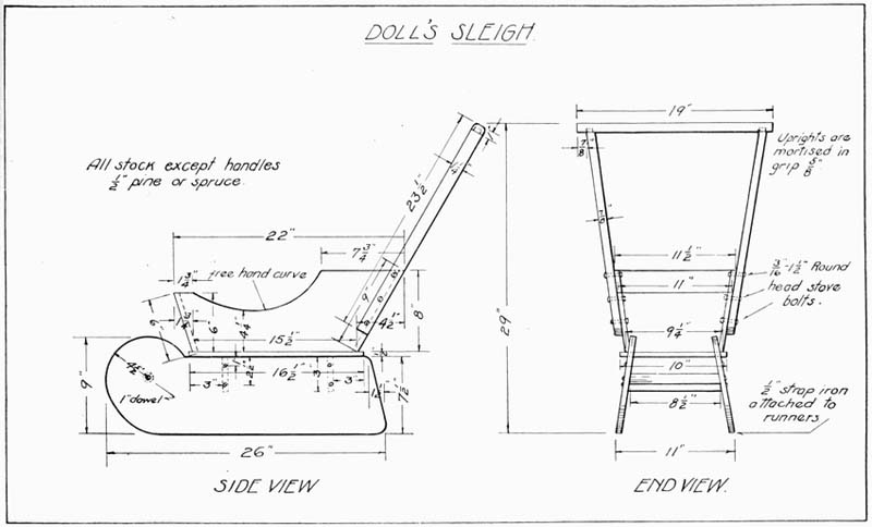
If paint is to be used as the finishing material, decide on the color scheme and apply first a priming coat of flat white, after which one or two finish coats may be applied when dry, sanding lightly between each coat.
This is a very useful and practical problem and has been made up in large numbers by seventh and eighth grade boys.
The chair shown in Plate 59 fits compactly under the table and takes up but little room.
The top is joined by gluing several boards together and finishes 30" in diameter. Basswood, 7/8" thick, is very good material to use. The boards must be carefully jointed and held together with 1/2" dowels. Hot glue is the best to use, although the cold glue will answer. Leave the pieces in the clamps overnight. The top may be cut to shape with a turning saw and finished to the line with a sharp chisel and file.
The four legs are 7/8" × 1-3/8" × 20-3/8". Two cleats, which are screwed to the underside of the table, are next made, these being 7/8" × 3" × 24".
These cross each other in the middle with a middle lap joint, as indicated at A, on the drawing. A notch is cut on the ends of these braces at C, as shown, to receive the legs.
The legs are held in place with glue and 1-3/4" No. 10 round-head blue screws.
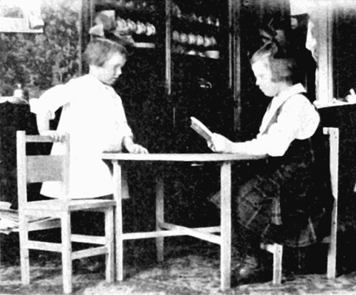
The braces are attached to the top of the table with a sufficient number of 1-1/4" No. 8 flat-head screws to insure a strong job.
The legs are notched 3/8" deep, 7" up from the bottom, to receive the lower leg braces. See sketch B, Plate 58. These lower braces are 3/4" × 1-3/8" × 23", joined at their center with a middle lap joint, the same as the top braces, and are held in the notch in the legs with glue and 1-1/2" round-head screws.
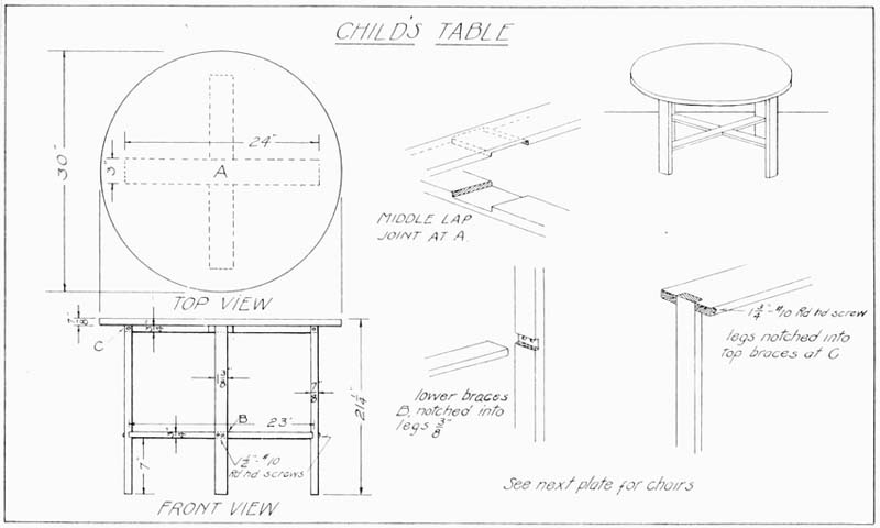
All parts should be carefully sandpapered, first with No. 1 sandpaper and then finished with No. 0.
The final finish is optional. It may be stained and varnished or it may be finished in enamel.
If enamel is used there should first be a couple of coats of flat white applied, each coat being sanded when dry, with No. 0 sandpaper, and the final coat of enamel applied.
Some appropriate design, in a grayed color, may be put on with stencil if desired.
Plate 59 gives directions for making the chairs to match the table in Plate 58.
The rear legs should first be cut out of 7/8" stock, 1-1/8" wide and 25" long. The two connecting rails are 1-1/8" × 9-5/8". The lower rail is notched into both front and rear legs, 6" from the lower ends, 3/8" deep.
The upper rail, on which the seat rests, is notched in 3/8" deep, and 4" above the lower rail. The pieces so far completed may now be sanded and assembled, using glue and 1-1/2" No. 10 round-head screws.
It is well to reinforce the joints by driving an eight-penny finish nail each side of the screws. These should be set below the surface, and the hole should be filled with hard beeswax before painting.
While this is drying, the front and rear rails can be made.
These rails, five in number, are all 7/8" × 1-1/8" × 8-1/4".
The wide back rail is made of 1/2" material, 4-1/2" wide by 8-1/4" long.
Holes should next be bored for the various screws, where indicated on the drawing.
A cross cleat, which runs between the upper side rails and helps support the seat, is made 7/8" × 3" × 8-1/4". This is attached, as shown in the sketch of the joinery of the legs and rails, and is screwed to the under side of the seat with 1-1/4" No. 8 flat-head screws.
The seat is made 7/8" × 10" × 11-1/2" and is notched at the corners to receive the rear legs. The top is rounded slightly on its rear edges.
Next assemble the two sides with glue and screws of proper size, as shown. All surfaces should be carefully sanded and the finish should be treated as described for the table.
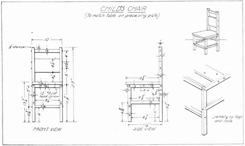
Adapting the Problem to the Boy's Ability, 15
Bean Bag Game, 72-4
Bench Hook, 22-4
Camel, 38
Child's Cart, 93-5;
Chair, 130-1;
Dump Wagon, 95-9;
Snow Shovel, 46-7;
Step Ladder, 59-63;
Table, 128-30;
Wash Bench, 57-9;
Wheelbarrow (Type A), 99-103, (Type B), 102-5
Clown Running Wheel, 105-9
Cock Horse, 109-10
Colonial Doll's Chair, 66-7;
Cradle, 87-9;
Table, 64-6
Coping Saw Work, 26-7
Darts, 75-7
Dart Board Game, 74-6
Dippy Duck, 40-1
Doll's Bed, 89-91;
Clothes Rack, 55-7;
Cradle, 84-7;
Ironing Board (Size A), 49-51, (Size B), 51-3, (Size C), 53-5;
Sleigh, 125-8;
Table with Drawer, 62-4
Dowel Sticks, 27
Duck, 30
Elephant, 33
Equipment, 13-4
Finish and Color, 15-7
Five Post Ring Toss, 68-72
Goat, 36
Goose, 31
History of Toy-Making, 11-3
Kiddie Kar, 113-15;
Koaster, 116-19
Lamb, 35
Laying Out Work, 14
Merrimac, 44-5
Method of Bending Runners, 121-2;
of Enlarging Figures, 39-40;
of Jointing Wood, 18-20
Monitor, 42-3
Pelican, 29
Periscope, 47-8
Picture Puzzle Construction, 27-8
Rabbit, 34
Rhinoceros, 32
Ring-The-Hook Game, 68-9
Rocking Rooster, 111-13
Rooster, 37
Sand or Water Mill, 82-4
Simple Tool Sharpening, 24-6
Ski Skippers, 122-5
Ski Skooter, 119-22
Staining, 17-8
Support to be Held in Vise, 20-2;
for Holding Coping Saw Work, 20;
for Table Use, 22
Transferring a Design, 14-5
Two Types of Stilts, 91-3
Wind Mill, 77-80; (Type B) 80-2
Inconsistency in hyphenation is as in the original.
"heighth" was changed to "height".
"Sonnenburg" was changed to "Sonnenberg"
Titles of Plate illustrations were taken from drawings with inconsistent punctuation and this was systematised.
Otherwise very few minor typographical errors have been corrected.