| Note: | Images of the original pages are available through the Digital Library of the Falvey Memorial Library, Villanova University. See http://digital.library.villanova.edu/Item/vudl:269146 |
HOW TO MAKE
Electrical Machines.
Containing full directions for making electrical
machines, induction coils, dynamos,
and many novel toys to be
worked by electricity.
By R. A. R. BENNETT.
FULLY ILLUSTRATED.
NEW YORK
FRANK TOUSEY, Publisher
24 Union Square
Entered according to Act of Congress, in the year 1900, by
FRANK TOUSEY,
in the Office of the Librarian of Congress at
Washington, D. C.
I propose to describe a method of making an electrical machine of small dimensions, but capable of performing all the experiments that are likely to be required of it.

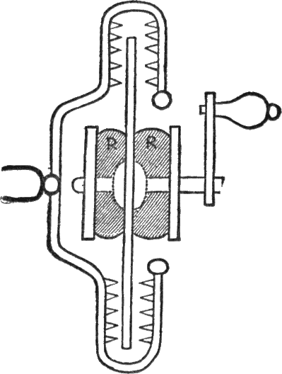
Fig 1.—Back of Rubber, Showing Position of Hole.
For the stand of the machine take a piece of wood (deal will do, but mahogany would be preferable) 14 inches in length, 8 inches in breadth, and ⅝ inch in thickness. To the bottom of this fasten two more pieces of the same wood, 1¼ inches broad, 8 inches long, and ⅝ inch in thickness at opposite ends, so that the edges are flush with the board. This forms our stand, on which we now proceed to erect the machine. Take another piece of the same wood, 7 inches long by 2½ broad, and ⅞ inch thick and fasten it firmly by four screws at the ends to the base board at a distance of half an inch from one end of its length and in the center of its breadth.
We now take two pieces of wood 14½ inches long by 2¼ inches broad and ½ inch thick, and fasten them up[Pg 4]right to the opposite sides in the center of the piece just fixed to the board. They must be fixed very firmly to it with several screws, as they have to bear a severe strain while the machine is worked.
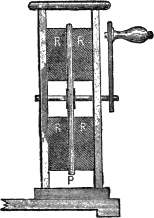
P Plate. R R R R Rubbers.
Fig. 2. Diagram Showing Position of Plate and Rubbers.
If the reader can dovetail the ends into the cross board they will be held much more firmly. At the top of these pieces another piece of wood, 3¼ inches square by ⅜ inch thick, is fastened by screws into the upright pieces, so as to hold all firmly together.
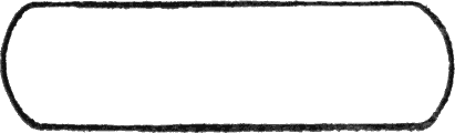
Fig. 3.—Sectional Diagram of Conductor.
The framework of the machine is now complete, and we have to provide the glass plate from which the electricity is to be produced. As we cannot make this we must apply to an electrician for it. This is 10 inches in diameter. If the maker is good at, and has appliances for, working in brass on a small scale, he can make the axle himself by taking a[Pg 5] piece of brass rod ¼ inch in diameter and 3 inches long and fastening the glass plate in the center.
This can be done by providing two circular caps of brass one and one-half inches in diameter (the side of which next the glass must be covered with cloth to prevent cracking the glass), and fastening one by solder or otherwise, on one side of the plate, the other being arranged to screw up tightly on the other side, by having the brass turned into a screw, and the center hole of the cap made with a flange to fit it. If this is beyond the reader, he must be contented with a less elaborate axle of wood instead of brass, and two wooden caps which can be firmly fastened to the axle and glued to the opposite sides of the glass plate with Prout’s elastic glue, which can be bought from any harnessmaker.
If this is used care must be taken in warming the glass not to render the glue too soft to hold it firmly when turned by the handle. To turn the axle it must be provided with a handle of wood, in the case of the wooden axle, or, in the case of the brass one, a handle is made by turning the projecting end of the axle into a screw and fitting to it a piece of flat brass three and one-half inches by one-half inch by one-eighth inch, this latter piece having another piece of brass rod three and one-half inches long fixed to the other end, on which a wooden handle is fixed (by a cap fastened at the end of the rod) so as to turn freely.
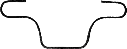
Fig. 4.—Shape of Brass Rod to collect the Electricity.
The glass plate having been thus mounted, we must turn our attention to the rubbers which generate the electricity on the plate. To make these take four pieces of wood 3 inches by 2½ inches by ⅜ inch, and on one side of them fix pieces of thick flannel (which you can get nearly ¼ inch in thickness) of the same size, and cover these over with black silk, gluing it down lightly to the wood, so as to form a thick cushion on one side of it. These four cushions have now to be fixed so as to be firmly pressed against the glass plate while it turns. This can be done by fastening them at the backs by screws to the upright pieces supporting the plate, or by gluing four small pieces of wood about ⅛ inch thick, and square in shape, to the inside of the supports.[Pg 6] The rubbers then have four holes cut in their backs to fit these pieces of wood, on which they slide when placed on the side of the glass, and are thus held firmly in position. Fig. 1 shows the position of the holes on the backs of the rubbers. The latter plan is the best for fastening the rubbers, as it allows them to be removed at any time for warming (a very essential point) or spreading fresh amalgam on them. Fig. 2 shows the position of the plate and rubbers when in their places.
R R Rubbers.
Fig. 5.—Sectional Diagram Showing Position of Collectors and Plate.
We now have the means for procuring electricity, but the method of collecting it has yet to be provided. To make this a conductor must be formed by cutting a piece of wood to the shape of Fig. 3. It should be about 6 inches from end to end, and must be carefully rounded so that no projections are left on it. It must then be covered carefully with tinfoil (which can be obtained from a chemist), the tinfoil being glued down as smoothly as possible. From the end of this conductor a piece of brass rod should be fixed,[Pg 7] shaped as shown in Fig. 4. A piece about 12 inches long will be wanted. This must be bent at the ends, so that when the conductor is mounted on a stand consisting of a piece of glass rod 6½ inches high, fixed to the center of the stand (that is 5 inches from the opposite end to that at which the supports are), the glass plate revolves between two surfaces of the brass rod. Fig. 5 explains the arrangement, which is somewhat complicated to describe. The glass rod should be about 7 inches long, to allow of half an inch being inserted into a hole in the center of the conductor, which is thus supported 6½ inches high from the stand.

Fig. 6.—The Machine When Finished.
It now only remains to fasten several small pieces of brass[Pg 8] wire about a quarter of an inch long, filed to a point, to the sides of the rod nearest the glass plate, as shown in Fig. 6, so that the plate revolves between a double row of points, which can be done with solder, and the machine is complete. The conductor can further be improved by inserting at the opposite end a small piece of brass rod two and a half inches high, surmounted by a brass ball, which is useful in some experiments. Care must be taken that the tinfoil of the conductor overlaps the brass rod at either end, and thus forms a metallic connection. If this is not done the conductor will not become charged sufficiently. If the conductor can be made of brass it will work better still, as a metallic connection is then insured. The conductor can be fastened to the glass rod on which it is supported by “Prout’s elastic glue,” or other cement, a hole being made in the center of the bottom of the conductor, and another in the stand of the machine for opposite ends of the glass rod.
The machine having been constructed, a few words will be useful in how to work it. Warmth and dryness are, above all things, essential. If the air of the room is damp it will be nearly impossible to obtain any result. Before working, the glass plate must be thoroughly warmed, taking care not to crack it, by being placed endwise before a good fire. A silk handkerchief is a useful adjunct to the machine.
The glass plate should be wiped quite free from dirt, and the glass support of the conductor must also be wiped, the handkerchief being made very hot. The rubbers must be taken off (if constructed so as to be movable, as described), and placed before the fire till quite hot. Their powers may be enormously increased by covering them with amalgam, as sold in the electrical shops, but a far better plan is to cover the cushions with tinfoil, which can be glued right round the rubbers and over the backs. This will need renewing at intervals, as the plate in turning wears it out.
Now, when the rubbers are quite hot and all the glass of the machine is dry and hot (this is necessary, because, if damp, the electricity would escape without producing any effect), the rubbers are put into their proper places on each side of the glass, and on turning the handle (which will be rendered easier if the machine is firmly clamped to the table) and approaching the knuckle to the conductor, a succession of brilliant sparks will be emitted from the conductor. If this does not happen either the glass or some part of the machine is damp, or the machine is not put together quite correctly, and must be examined to find out the fault.
A machine of the size described should give a spark an inch long when working properly. A great number of experiments may be performed with this machine with appar[Pg 9]atus capable of being made at home. I give a final illustration (Fig. 6) to show how the machine looks when completed.
To most boys electricity offers many attractions, and as I have recently constructed an induction coil out of materials which are cheap and easily obtained, I think I shall confer a benefit on many readers if I give them a short description of how this was accomplished, so that if like-minded they can proceed in the same way. Induction coils may be used for medical and scientific purposes as well as for amusement, so that a good deal of work comes within their scope. An “induction coil” is composed principally of two portions—one is the “primary” coil, the other the “secondary.” It is the secondary coil that gives the spark, and on the length of[Pg 10] this depends the power of the coil; in some instruments for scientific purposes it is composed of a wire nearly 300 miles long—but we are not going to soar to such heights as that!
To make the coil itself you want an ounce of “No. 24” cotton-covered wire, and two or three ounces of “No. 36.” This can be bought from an electrical supply dealer. If you are very ambitious, silk-covered wire can be used; this gives better effect, the insulation being more complete.
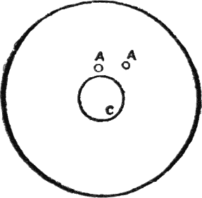
Fig. 1.—Front Disc.
AA, holes for primary wire. C, hole for core.
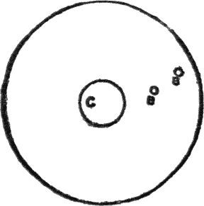
Fig. 2.—Back Disc.
BB, holes for secondary wire. C, hole for core.
To form the groundwork of the apparatus take a piece of mahogany about half an inch in thickness and polish it up to look ornamental; it should be about 4 inches by 6 inches for the sized coil I am describing. We now take another piece of mahogany about ¼ inch thick, and from it cut[Pg 11] two circular pieces about 1½ inch in circumference; these are to form the ends of the coil; they must each have a hole ⅜ inch in diameter drilled in the center for the ends of the core to pass through. In one of them, which is to form the coil, two much smaller holes are drilled with a small bradawl to allow the ends of the primary coil to pass through (Fig. 1); in the other two similar holes are drilled further from the center for the ends of the secondary coil (Fig. 2). This having been done, we proceed to form the core, and this being the most important part of the instrument, it must be made with great care. Take a length of fine iron wire (annealed) and cut it into pieces 2½ inches long.
Now take a brass tube of the same size internally as the center holes in the ends of the coil were made (⅜ inch) and push as many pieces of wire into it as are required to pack it as full as it will hold. The next thing to do is to take another piece of wire and wind it as tightly as possible round the ends of the wires, pulling them gradually out of the tube as you wind, until they are entirely out, by which time a compact bundle of iron wire will have been formed. Now file the ends of the core thus formed, quite smooth, with a fine file, and drop the whole of it, wire and all, into the hottest part of a fire. Leave it there till it is bright red hot all through, and then rake it out and bury it completely in the ashes under the grate. If this can be done over night, and the coil left to get cold as the fire goes out, instead of being placed in the ashes, so much the better, as the object is to cool it as gradually, and thus make it as soft as possible.

Fig. 3.—Core and Discs.
A, front of reel.
B, back of reel.
C, core.
PP, holes for primary wire.
SS, holes for secondary wire.
When it has become perfectly cold take some paraffin wax and melt it in a dish. When thoroughly melted, heat the core again gently, and put it into the melted wax. Leave it there for a short time till it is thoroughly saturated with the melt[Pg 12]ed wax, then take it out and hold it above the dish to let the melted paraffin run back into it. When cold you may remove the binding wire, and the wax will be found to hold all the pieces together in a solid lump. The two pieces of wood must now be fixed one at each end of the core (the holes being the same size as the bore of the brass tube, the core should fit into them quite tight), one of them (the front) being pushed a little distance over the core, so as to leave about ¼ of an inch of the core projecting from it, the other one only being pushed on sufficiently far to make the end of the coil flush with the wood (Fig. 3).
Take a sheet of thin notepaper and cut a piece exactly the width of the coil, and long enough to pass twice round it. Wind it tightly round, and fasten it, if necessary, with a little paraffin. Now the wire has to be wound on over the paper, the thickest first, to form the primary coil. Pass about three inches of one end of it through one of the holes in the disc forming the front of the coil, and then wind it evenly on the core, taking care that each coil is separate from its neighbor, and that no two coils fall one upon the other.
When the wire has reached the other end of the core, wind it back again over the first layer till it reaches the end it came in at, then pass it through the other hole and cut it off about three inches from the hole; the wire cut off will be wanted for other purposes. The secondary coil has now to be wound over the primary, first of all saturating the cotton with which the latter is covered by pouring melted paraffin over it with a spoon. All the secondary wire will be wanted; it must be wound layer above layer exactly as the primary was, first passing about three inches of the end through one of the holes in the disc at the back of the core. A thickness of notepaper should be put on between the primary and secondary coils. Everything depends on the complete insulation of one coil from another, and this is accomplished by means of the notepaper and cotton, saturated with melted wax in subsequent operations. When the whole of the secondary wire is wound on except about three inches, pass the end through the other hole in the disc.
In order to make sure that the wire has not been broken in the winding, which would entirely destroy the action of the instrument, the two ends of the coils should be joined separately with a battery and galvanometer. If the needle is deflected on joining the circuit the wire is all right. This is rather important, as it is extremely vexatious, when all the different parts have been adjusted, to find that the coil will not work owing to a fracture of the wire, which necessitates the whole coil being unwound before it can be discov[Pg 13]ered. If the galvanometer is not at hand we must take our chance; the greatest possible care must be taken in winding the secondary wire, as this thin wire is extremely brittle. The insulation must now be improved by plunging the whole coil into a deep vessel large enough to contain it, which is full of melted paraffin. This must be placed near the fire, so as to keep the wax melted, and the coils must be left in it to soak for an hour or two. When the paraffin has thoroughly permeated through it it can be taken out and held above the vessel to drain. If all the wax does not run off the ends they can be scraped afterward, taking care not to cut the wires. The appearance of the coil is vastly improved by a strip of velvet cut the right width, which can be drawn tightly and sewn in position; or the coil may be covered with a varnish made by dissolving red sealing-wax in spirits of wine by the aid of a gentle heat. The coil part of the instrument is now complete, and ready to be affixed to the base-board by means of two small screws passing through it into the discs when placed in the proper position (see Fig. 6.)
We now approach a very important and rather intricate piece of workmanship. It is necessary, in order that shocks should be obtained from the coil, that the current in the primary wire should be stopped and started again at the rate of several hundred times per minute, and the more quickly the contact between the battery wire and the primary coil is made and unmade the more powerful the shock. In order to accomplish this a “contact-breaker” becomes necessary, the method of making which is as follows:
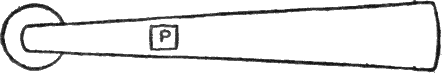
Fig. 4.—Hammer of Contact-breaker.
P, Platinum foil.
I, Soft iron fastened to opposite side.
A piece of sheet brass is taken 1½ inches long by about ⅜ of an inch at one end, gradually tapered up till it comes to a point about ⅛ of an inch broad at the other; it must be very thin, and must act as a spring when fastened tightly at one end. A small piece of soft iron is soldered to the small end of this to be attracted by the core when working. The next thing is to fasten a small piece of platinum foil about ¼ of an inch square on the opposite side of the brass to the soft iron, and a little below it (Fig. 4). This is rather a difficult operation, as it is such a small object to solder,[Pg 14] and the best way is to get it done by a tinsmith, unless you are skilled in the use of the soldering bit.
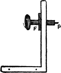
Fig. 5.—Screw of Contact-breaker.
F, Flange of paper-fastener soldered to upright brass strip.
P, Platinum tip to screw.
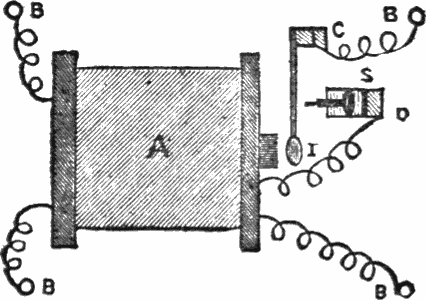
Fig. 6.—Plan of Coil Complete.
A, Coil.
B B B B, Binding screws.
C, Strip of brass supporting spring.
D, Strip of brass supporting screw.
S, Screw to adjust position of soft iron, I.
Current travels from the binding-screw to C, from C to S, thence to D and round the coil by the wire, returning to battery by screw in opposite corner.
A narrow strip of stout brass is now taken and bent at right angles near one end, so that when screwed down to the base-board by holes in the smallest leg the longest leg will stand upright. Stand it up on the base in front of the coil and note a point on the strip exactly opposite the core. Make a hole through this point large enough to admit a small[Pg 15] screw used on paper fasteners. Now take the flange part of the paper-fastener and solder it to the back of the brass strip, so that the screw will work through both (Fig. 5). This is done to avoid the trouble of making a flange in the strip, but if you can do this, so much the better.
Now, the coil having been fastened to the base by fine screws through it into the ends of the reel, nearly in the center of the base, we must find a place on the base in a straight line with the end of the core (as at C, Fig. 6), and here we fasten another piece of bent brass similar to the last. The end of the contact breaker is now soldered to this brass strip in such a way that the piece of soft iron at the other end is exactly opposite the core and about 1⁄16 inch distant from it. The screw of the paper fastener must now be tipped with platinum by cutting off the end and drilling a fine hole in it, in which hole a small piece of platinum wire can be soldered. The amount of wire and foil required, although very minute, will cost you about twenty-five cents, platinum being a very expensive substance. It can be bought from a chemist or electrician.
The screw having been prepared in this way, we must next fasten the brass strip to which the flange is soldered upright on the base, so that the platinum point of the screw, when inserted, will just come in contact with the square of foil on the spring. By turning the head of the screw the soft iron can thus be forced nearer the core, and the rapidity of its vibration is thus controlled. The coil is now complete, except the connections, which are made (preferably underneath the base by letting the wires through) by joining the ends of the thin wire to two “binding screws,” which are made for this purpose and can be obtained from the dealer. One end of the thick wire of the coil is fastened to the strip of brass supporting the contact-breaker, the other end is fastened to a binding-screw on one side of the base—the strip of brass supporting the screw being connected by a wire with another binding-screw on the other side. This sounds rather intricate, but will easily be understood if we consider that the current from the battery when the wires are connected with the binding-screw must pass through the brass strip to the screw, thence through the contact-breaker to the coil, and, having passed round the coil, back to the battery through the binding-screw attached to the other end of the wire. (See Fig. 6.)
It is now evident that when the contact-breaker is in contact with the screw a current will pass through the primary coil, and will cause the soft iron core to become a magnet and thus attract the soft iron. When this moves towards the magnet, contact is broken and the core is instantly de[Pg 16]magnetized, so that the spring flies back and contact is made again. The screw is adjusted so that the contact is broken just as the soft iron touches the core. When the battery is joined on, the contact-breaker will fly backwards and forwards with tremendous speed, making a loud, buzzing noise, while brilliant sparks will appear between the platinum wire and foil.
In order to feel the effect of the shock, two handles will be required; these can be made by simply bending two pieces of tin about two inches by four inches round a ruler and neatly soldering the joins. A wire is now fastened to the end of each tube, the other ends being inserted in the binding screws connected with the thin wire of the secondary coil, which are at the opposite corners of the base to those which are joined to the ends of the primary coil. When the coil is buzzing, if these handles are tightly held, a powerful shock will be felt, in fact, a weak battery only should be used with the coil of the dimensions given, or it may be impossible to release the handles, and this is too strong to be pleasant.
The current can be regulated by means of a “regulating tube,” that is simply a brass tube which is made to slip over the core between it and the primary coil; the farther the tube is pushed over the core, the less powerful the shock. The dimensions of the coil being the same, a little ingenuity will enable any one to affix a regulating-tube. I will only say that instead of winding the coil direct on the core a tube of brown paper is formed a little larger than the core, and on this the wire is wound. Between this tube and the core the brass tube is arranged to slip in and out, the hole in the end of the reel farthest from the contact-breaker being made larger for its accommodation.
This concludes my description of the coil, but perhaps a few hints as to suitable batteries may be useful. If a strong battery which will only work the coil for a short time is required, the bottle bichromate is a good one. It can be bought from a dealer, or one can be made in a simple form by taking a jar and filling it with a strong solution of bichromate of potassium, to which a little sulphuric acid has been added. Take two pieces of gas carbon and three pieces of sheet zinc, both cut to the right size to dip in the solution to the bottom of the jar.
At the top of the zincs and carbons bore small holes, and below these place narrow strips of wood to keep them apart when in use; these must be long enough to reach across the top of the jar when the zincs and carbons are in the solution.
Arrange them thus: zinc, wood, carbon, wood, zinc, wood, carbon, wood, zinc; bind them lightly together by means of[Pg 17] two more pieces of wood placed outside the outer zincs, and the whole tied together with string. Connect the three zincs together with one piece of wire, and the two carbons with another, taking care that the wire connecting the zincs, does not come in contact with the wire connecting the carbons. To one zinc attach a piece of covered wire, and to one carbon attach another, these two wires are connected with the binding screws of the primary coil. This battery is extremely strong, double as strong as the bottle bichromates sold, as there are more zincs and carbons employed, but it only lasts a short time before needing to be replenished.
Daniell’s battery is a weaker form, but lasts much longer, say for two or three hours in constant work. Take a deep jar and inside it place a porous jar of earthenware, which the electrician will provide. Now get a piece of sheet copper of the right size to go into the jar, and bend it round so that the porous jar will go inside it. A piece of sheet zinc will be wanted to go inside the porous jar. Both zinc and copper must be high enough to reach the level of the solutions when the jars are full. The porous jar is filled with dilute sulphuric acid, or solution of common salt; the jar outside is filled with “saturated” solution of sulphate of copper—that is, as strong as it can be made. Lumps of sulphate of copper are kept in the outer cell, which will keep the solution concentrated by slowly dissolving. Attach one wire to the zinc and another to the copper, and when these are joined to the binding screws of the primary coil the contact-breaker will begin buzzing.
The dynamo is not the most simple piece of mechanism extant, and I am inclined to think that many boys would find it rather a poser to make one. At the same time it is perfectly evident that there are heaps of our readers who are very anxious indeed to try, at all events, and as we must aim at more elaborate apparatus as we advance in electrical knowledge, it is a pity not to endeavor to supply them with the help they need.
Well, then, if, like Pears’ soap baby, they “won’t be happy till they get it,” I will do my level best to bring down the subject into the range of their capability. It will not cost them much to try the experiment, and if they don’t succeed they must not blame me, but their “vaulting ambition,”[Pg 18] which has “o’erleapt itself.” There is no reason whatever why a boy who is accustomed to metal working should not succeed in making the small machine described if he first masters the principles of its construction.
The advantage of a dynamo, I may here remark, is that by its means we are able to produce a current of voltaic electricity at any moment by turning a wheel without bothering with acids or carbons, or zincs, or any other of the various articles necessitated by the use of a battery.
Furthermore, the current goes on as long as you turn the wheel, and stops directly you stop, there being no loss between whiles. Of course, both battery and dynamo have their advantages and disadvantages—nothing in this world being perfect all round—and for some purposes the dynamo is best, for others the battery. For example, it would be absurd to use a dynamo to ring an electric bell—not that it would not do it with tremendous energy, but in the case of a bell what one wants is merely to ring it for a few seconds at long intervals, and for this work a battery in which there is little current, but which is always ready to give that little without touching it, is facile princeps. But for experiments in which a strong continuous current is required, the dynamo comes to the front, as there is no “polarization” to detract from its value, as in the case of the battery. One does not always want to be messing with chemicals in setting up a battery, when one only requires the current for a short time, and the dynamo is always ready, and merely turning the handle produces the required current in a moment. Besides this, viewed merely in the light of a magneto-electric machine, it will give a considerable shock to any one who holds two handles fixed to its terminals.
Having now enumerated the advantages of the machine, it behooves me to endeavor to describe its various parts and the method of making them. There are several methods of dynamo-making, but that which seems to be the most used and most easily followed in the case of a small machine, is that of the type known as the “Siemens” dynamo, from the inventor of the armature, which is of peculiar construction.
The action of the dynamo depends on the fact that if a piece of soft iron is surrounded by a coil of insulated wire, when the soft iron is approached to a magnet it becomes itself a magnet, and at the same time a current is generated in the coil of insulated wire which surrounds it. This current is, however, of only momentary duration, and ceases if the soft iron remains stationary; but on removing the soft iron from the magnet another current is generated in the coil of wire, but this is a current of the opposite kind of electricity, and travels in the opposite direction to that produced in[Pg 19] the former case. Now you have only to imagine that, by means of rotating in front of the poles of a magnet, a piece of soft iron is kept continually approaching and receding from the magnet, and that this soft iron is surrounded by wires in which circulate currents positive or negative according to the direction of the movement of the soft iron, and then, if we can arrange to carry off all the positive currents to one binding-screw, and all the negative currents to another binding-screw, we shall have a continuous current generated as long as the soft iron revolves. All this is practically carried out in the construction of the dynamo, and on the accuracy with which it is done the efficiency of the dynamo depends.
To make the base of the machine, take a piece of deal 5½ inches long by 3½ inches broad by ⅞ inch thick. This can be stained afterwards to make it look nicer; it must be planed well and polished up quite smooth.
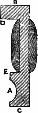
Fig. 1.—Sectional Diagram of One Side of Magnet.
The dotted lines show position of coils of wire. A, One side of hole for armature.
The greatest difficulty of the whole business has now already to be confronted—viz., the manufacture of the magnet. This is almost invariably cast in two pieces, and for those who cannot make the castings there is no help for it but to have recourse to the ironmonger, or, better still, a practical electrician. The following instructions will then assist you to put the castings together:
Supposing this difficulty to have been overcome, and two pieces of soft iron to have been cast in the form of Fig. 1, both exactly the same size and shape; the next thing to do[Pg 20] is to convert it into an electro-magnet by winding seven layers of No. 16 cotton covered wire over each leg, at the part shown by the dotted lines in the illustration.
The size of the legs of the magnet is as follows:—Total length from B to C, 4⅛ inches; thickness of top piece from B to D, ½ inch; length of top piece from B to D (half total length of top of magnet), ¾ inch; breadth of side of magnet all the way down, 1¾ inch; height from E to C, 1½ inch; thickness of the part between D and E, round which the wire is wound, ⅜ inch. When I say “breadth” in this description, I mean what you can’t see in the sectional drawing, because it recedes from you; when I say “thickness,” I mean what is shown in the drawing. It is necessary to explain this, as the terms are rather confusing. The ends of the sides between D and E are rounded to admit of the wire being more evenly wound on them.
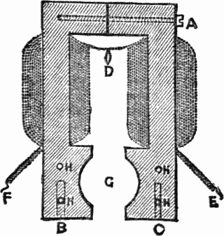
Fig. 2.—Magnet Put Together.
A B C, Screws. D, Junction of two wires. E F, Ends of coils. H H H H, Holes for screws at end. The dotted lines show position of wire, and screws fastening magnet together and to base.
It is not essential to use a permanent magnet in this machine, as a certain amount of “residual” magnetism remains in the iron when once excited; and the coils of wire on the armature being acted on by the armature, which is slightly magnetized by this residual magnetism in the magnet, have a reactionary effect, and excite the armature, which excites the magnet afresh; and thus the magnet and its coils, and the armature and its coils, go on acting on[Pg 21] each other, and mutually building up each other’s current, until the maximum effect which the machine is capable of giving is produced.
Before winding on the wire, the legs of the magnet between D and E should be covered with a band of silk soaked in melted paraffin wax to increase the insulation. New and soft wire, of the highest conductivity, should be used. Old, rinky, and hard wire will not do.
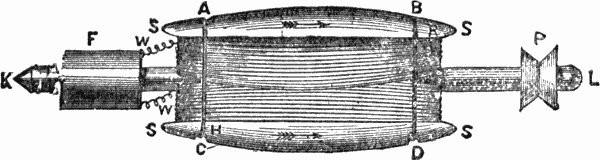
Fig. 3.—Armature of Dynamo.
S S S S, Grooved cylinder of soft iron. K L, Axle of cylinder. The wire is wound across from end to end on one side, and then from end to end in the same direction on the other side. W W, Ends of wire. A B C D, Grooves in cylinder for thread to hold wires in position. F, Wooden cylinder fixed on axle.
The wire is wound upon the legs of the magnet in such a way that when put together as shown in Fig. 2 the coils are in opposite directions, so that if the magnet were straighten[Pg 22]ed out, or the two portions placed end to end, one coil would be a prolongation of the other. This can be most easily done, in the case of this particular magnet, by winding each leg separately, and the end of the outer coil of wire of one can be joined to the end of the inner coil of wire of the other at D in the cut, the other ends of the coils being left loose as at E and F, these being long enough to go down under the base—say, about 3 inches long to allow for joining up.
The electro-magnet having been wound, may now be placed upright on the base, its two limbs fastened together by a screw at A. The magnet is now to be fastened to the base in the middle of its breadth, and about an inch from one end, by means of two screws at B and C, passing through the base into the legs of the magnet. Before it is fastened on, however, you had better drill two screw holes on each leg at H H H H in the figure, and four corresponding to them on the other side. We shall want eight screws to fit these holes presently.
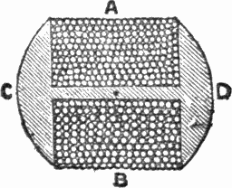
Fig. 4.—Section of End Armature.
The circles show the position of the coils of wire in the grooves A and B. C D, Ends of soft iron cylinder.
The magnet having been fixed, we now have to construct the armature, which is the next most important part of the machine.
This consists of a soft iron cylinder with an axle passing through its center, as at K L in the illustration (Fig. 3), S S S S being the soft iron cylinder. This cylinder has a deep groove cut from end to end, or is cast in that shape, and round this groove the wire is wound. The wire is number 18, cotton or silk-covered. Begin at the point marked H in the diagram, and wind over and over, from end to end, until that side is full; then cross over to the other side, going from H to R, and wind that side also in the same direction. The ends of the wire are shown at W W, and they must be left about an inch or two inches long, as we shall want to connect them with the commutator presently.
The dimensions of the armature are as follows: Length of[Pg 23] axle, 5½ inches; circumference of cylinder, 1 inch; length of cylinder, 2 inches; width of groove, ¾ inch. The axle is composed of a piece of steel rod rather more than ⅛ inch in diameter. The axle must be very truly centered in the armature, and the armature must be accurately mounted, as it has to revolve at a high rate of speed in a very limited space, between the poles of the magnet.
As it is rather difficult to explain the construction of the armature, I give another illustration (Fig. 4) of a section of the armature, which will show how the wire is wound on the groove, and the shape of the grooves themselves.
At one end of the axle is fixed the driving-pulley P, while at the other has to be fixed a small wooden roller F, over which two pieces of sheet brass have been fastened, each reaching nearly half round the surface of the roller, so that two gaps are left between them. This forms part of the commutator; but before we come to that we must consider how the armature is to be fixed between the poles of the magnet.

Fig. 5.—Support for Pulley End of Axle.
The dotted lines show position of holes for screws and axle. P P, Holes for screws.
Returning to Fig. 1, we must see that the groove A, which forms half the channel in which the armature is to revolve, is ⅞ inch semi-circle. When the two sides are fixed together as in Fig. 2, the hole between the poles should be about an inch in circumference, and the wire must be wound on the armature so that it easily slips into the cavity G, which must be made quite smooth for it to revolve in. It will be seen from the dimensions given that in diameter the armature is only a little less than the cylindrical space between the poles of the magnet, and in length it is about the same as the width of the magnet. It would be an unfortunate occurrence if the wire was to slip off the armature while revolving at a high speed, and therefore it is necessary to keep it firmly in its place. This is done by filing four small notches in the soft iron of the armature at the points marked[Pg 24] A B C D in Fig. 3. Some strong wire or small string is now wound lightly round the armature to hold the coils of wire in their proper place, the notches holding this wire or string from slipping off at the ends of the cylinder.
The armature is now to be fixed in its proper place between the poles of the magnet.
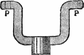
Fig. 6.—Support for Commutator End of Axle.
The dotted lines show position of holes for screws and axle. P P, Holes for screws.
To do this we shall want two supports for the axle. These are made of brass, shaped as in Figs. 5 and 6, 5 being the one at the pulley end of the axle, and 6 that at the other end. They are fastened by screws through the holes P P, into the holes H H H H in the bottom part of the side of the magnet, as previously shown in Fig. 2.
When the armature is fixed in its proper place it will appear as Fig. 7, this being a sectional diagram from above, and the top pieces of the magnet being omitted for simplicity’s sake.
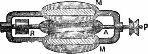
Fig. 7.—Ground Plan of Magnet and Armature when put together.
M M, Magnet. P, Driving pulley. A, Armature. R, Roller of wood covered with brass. Top of magnet and springs of commutator omitted.
The brass of which the supports are made should be about[Pg 25] ⅛ inch thick, and must, of course, be drilled in the center with a hole to admit the axle of the armature. To keep it exactly in the right place while revolving, a piece of circular brass tube, with a bore the size of the hole made to admit the armature, should be soldered to the brass supports in front of the hole; that for the pulley end of the axle should be ½ inch long. One at the other end is not necessary, but looks neater; this may be about ¼ inch long—i. e. as long as the end of the axle projecting beyond the brass support.
This much having been accomplished, we have now to consider the “commutator,” which is a piece of apparatus by which all the currents proceeding from magnet and armature are sent in one direction, and thus, instead of counteracting each other, are made available for experiments.
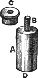
Fig. 8.—Pillar of Commutator.
A, Brass rod. B, Screw inserted at end. C, Nut fitting screw B. D, Hole for screw to fix to base.
To make this necessary adjunct to the dynamo, take a circular bar of brass rod about ⅜ inch in diameter and an inch long. Into the middle of this solder a brass screw by drilling a hole and inserting its upper end minus the head. On this screw works a brass nut about ⅜ inch long. At the other end of the rod a hole is drilled for the insertion of another brass screw, long enough to go through the base. Another pillar precisely like this has now to be made, only ½ inch high without the nut. Now cut two pieces of sheet brass 2 inches long and ½ inch broad, sufficiently stout to act as springs and not too stout to be elastic. At one end of each cut a longitudinal hole about ¾ inch long and ⅛ inch broad; that is to say, this slit must be broad enough to slip over the top of the screws above the pillars. At the other ends of the brass springs slits of equal length, but very narrow—only about 1⁄24 inch wide—may be cut, to[Pg 26] make the brass more “springy.” On the under side of this end of one spring and the upper side of the other, two pieces of thin sheet copper are fixed, the same breadth as the springs, and about ½ inch long. These are soldered by one end to the side of the spring, so as to act as springs themselves, their other ends being free.
All this being rather complicated, we must invoke the aid of the engraver once more. Fig. 8 gives you the method of making the pillars—A being the brass rod, B the screw and C the nut, the hole to admit screw to fasten the pillar to the base is made at the end D.
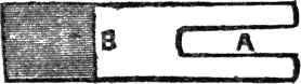
Fig. 9.—Brass Spring of Commutator.
A, Slit to fix over screw, B, in Fig. 8. The shaded part represents the copper spring, soldered at B.
Fig. 9 is the brass spring with slit, A, to slip over the screw of Fig. 8, and the copper spring soldered to one side, at the end, at the point B. Now we slip the brass spring over the screw, the screw coming through the slit, and screw down the nut C. We thus have two springs supported at the ends on pillars at a height of 1 inch and ½ inch from the base respectively. Of course, both the pillars and springs are treated alike, but in the case of the tallest the copper is on the under side, and in the other on the upper side.
Now we go back to the armature, on the axle of which you will remember that I told you to fix a small roller of wood. This is only ¾ inch long and ½ inch in diameter, and is fixed firmly to the axle so as to revolve along with the armature. This roller is soaked in melted paraffin wax for an hour or two before fixing on, or boiled in it for some time, so that it may permeate the wood. The roller can easily be turned (of boxwood, preferably) if you are possessed of a lathe, but if you have none, go to the nearest photographer (or, preferably, a dealer in photographic apparatus), and from him you can buy for 3 cents a roller long enough to cut dozens for dynamos—they are what sensitized paper is sold rolled on.
The roller having been provided, take a piece of brass tube exactly so large inside that the roller will fit tightly into it, and cut off a piece the same length as the roller, or, if anything a trifle shorter. You have now to cut, with a saw or otherwise, two diagonal lines in this tube lengthwise, so that the tube is thereby divided into two pieces. Having[Pg 27] done this the brass is replaced on the roller and fastened by minute screws, or “Prout’s elastic glue,” to each side of it, so that the roller becomes practically one of brass, with two slits in it. The screws must not project above the brass, but must be well sunk into it, so as to leave the surface smooth: and care must be taken that the screws do not touch both pieces of brass by going right through the roller—they must be very short. The object of cutting the slits in a diagonal direction is that the springs when pressing above and below the roller (see Fig. 10) shall not leave one half of the commutator before resting on the other part. If they do so the commutator will “spark” badly, which injures the fittings, and less current is obtained. Both slits are to be equidistant, and both inclined in the same direction. The roller is fixed on the axle in such a position that the middles of the lines of division are exactly in a line with the middle of the groove of the armature. When all this has been accomplished you will obviously have two conducting surfaces,[Pg 28] each reaching over half the cylinder, separated by a small distance at top and bottom, the paraffined wood, of course, being a non-conductor of electricity. The brass tube must be made to fit smoothly round the wood, the surface being free from any irregularities, so that the contact with the springs at the sides may be as perfect as possible. Care must be taken that the brass is really separate all down on both sides. It is a good plan to fasten small splinters of paraffined wood in the slits to make sure.
This having been done, the wire from one end of the coil of the armature must be soldered to one of the semi-circumferences (if I may coin a word) of brass on the wooden roller, and the wire from the other end of the coil to the other semi-circumference. This is done at the end or underneath, not at the top, or it will make the surface rough, and we want it to be as smooth as it can possibly be. The wire must be quite tight up to the end soldered on; there must be no loops, or it will catch in something and be torn off when it comes to revolve.
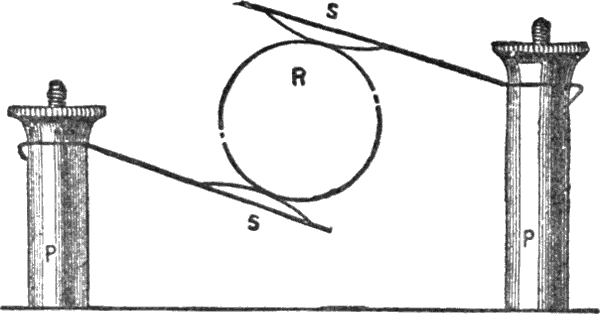
Fig. 10.—Section of Commutator Put Together.
P P, Pillars supporting springs, S S, which bear respectively on the upper and under sides of the roller, which is covered with brass except for the slits shown in the diagram.
The brass pillars supporting the springs have now to be inserted in the base, at such a distance, one on each side of the roller covered with brass, that the copper springs at the end of the brass ones are exactly one over and one under the brass roller. Of course, if they are put in a line with it, the springs can easily be shifted to the right position by slipping the slits over the screws of the pillars, and screwing down the nuts lightly when they come to the right place. This is very difficult to make intelligible, and I give another illustration of the relative positions of the parts of the commutator which I hope will make all clear. The pillars P P—which were put together as shown in Figs. 8 and 9—are fixed at such distances on opposite sides of the roller R that the springs S S are continually in contact with the brass semi-circumferences, first one and then the other as the armature revolves.
We are now within sight of the end of our task, and to guide off the current that we are going to produce we must screw in two binding-screws at opposite corners of the same end of the base (the end at which the commutator is). The ends of the wire from the magnet are to be brought down through the base and joined to the under part of these binding-screws. Placing the base so that the commutator end of the armature, and not the pulley end, is next to you, the wire from the inner coil of the magnet goes to the binding-screw on your left hand, and that from the outer coil to that on your right hand. The magnet should be wound and placed in such a position that these ends are respectively on[Pg 29] the left and right, and then they have only to be joined to the binding-screws in front of them.
But before connecting these wires up, it is necessary to give an initial magnetism to the magnet, which at present has not been magnetized at all! To do this we must make use of another dynamo or a battery and connect the wires coming from the magnet-coil to the terminals of the battery. This having been done, the magnet will attract iron filings or needles, etc., and this shows that it has really become a magnet. Two cells of the chloride battery will be enough to magnetize it as much as it can be magnetized, and enough will remain when the battery is disconnected to start the action when the armature is revolved. Two or three minutes is long enough to connect with the battery.
While the current is passing you can try the following experiment, to prove that the wire is wound on all right. If it is not wound as described there will be two north poles or two south poles, instead of one north and one south. Suppose we decide to make the leg on which the wire comes from the outside of the magnet the north pole, the wire from this must be joined to the wire coming from the zinc end of the battery, and the other coming from the inside, between the poles, joined to the wire from the carbon end. Now if, while the current is passing, a magnetized needle is approached to each pole consecutively, and one end of it is attracted and the other repelled in each case, the wire is all right; if both are attracted something is wrong. The needle must have been really magnetized beforehand, or it will deceive you; you can easily test if it is so with an ordinary permanent magnet.
Having magnetized the soft iron in the way described, we now join up the wires to the binding screws, under the base, and, the pulley being fixed on to the axle of the armature opposite to the commutator, the machine is now ready for use. To rotate the armature at a high speed it is necessary to connect the pulley by an endless band with a large, heavy wheel which can be rotated by hand.
For continuous work, as we cannot always be turning the wheel, a small steam-engine or water-motor must be employed. Worked in this way, the machine I have described can be made to light 2 5 candle-power lamps of 6 volts, and give about 12 volts of current. This is not much, of course, but by enlarging the proportions of the various parts, you can make as large a dynamo as you like; only the power required to work it naturally increases considerably. This[Pg 30] machine will do a great deal of the work of a battery—for example it will run an induction coil or an electro motor at full power. By connecting two brass handles to the binding-screws by wires, you will get a powerful shock if you hold them while some one turns the wheel connected with the pulley; in fact, the shock is too powerful, and the person turning the wheel must be prepared to stop when the victim has had enough. If these handles are dipped into a glass of water slightly acidulated with sulphuric acid (to enable the current to pass more freely), and the dynamo briskly turned, you will soon see bubbles rising from the handles—which must, of course, be placed separate from each other—consisting of oxygen and hydrogen gas, into which the water is being decomposed by the force of the current. Water being composed of two quantities of hydrogen gas to every one of oxygen, it follows that double as much hydrogen will come off the handle which evolves it as will come off the other of oxygen, and this you will soon see to be the case; the bubbles on the former being much more numerous than those on the latter.
Now take a 5 candle-power 6-volt electric lamp, and fasten it on to the wires coming from the binding-screws (removing the handles) by the platinum loops at the top. If the dynamo is now briskly turned, you will find that the lamp will light up well, and as long as the wheel is turned and the dynamo is buzzing, so long will the lamp continue to glow. By turning the dynamo by steam or water-motor we have, therefore, a means of producing a continuous light, which will not drop at the end of a few minutes as in the case of a battery. This is the method by which all public buildings, etc., are lighted.
There is said to be always sufficient residual magnetism in the soft iron core (at any rate if constructed of ordinary soft iron, not specially annealed) to act on the armature when revolved, and this, acting on the magnet, increases its magnetism so that they react on each other until the maximum effect of the dynamo is reached. This is the case with the majority of dynamos used for lighting, etc.; but if you are of an experimental turn of mind, and are possessed of a battery as well as the dynamo, you can try the effect of magnetizing the soft iron cores by sending a current from the battery through the coil.
To do this, disconnect the wires from the magnet-coil from the binding-screws, and connect them with the terminals of the battery. The whole current from the dynamo now comes from the armature, and you will find that this current is considerably increased, sparks flying about in all directions when the handles from the binding-screws are approached to[Pg 31] each other or rubbed together. The water will now be decomposed much faster, and you will be able to light an additional lamp or two, according to the strength of the battery.
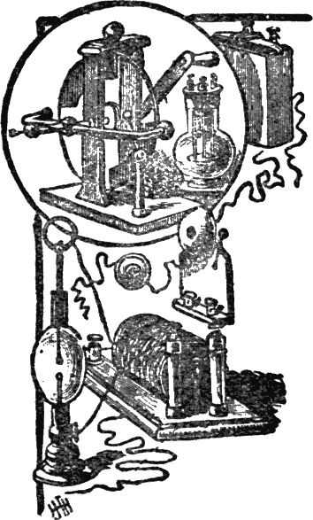
Fig. 11 gives an idea of the positions of the parts of the dynamo when complete; it is not an easy thing to draw, and I can only hope the rough sketch will be intelligible to my readers. The spring A is below the roller of contact breaker, and the spring B above it, the diagonal line on the roller representing the vacancy between the brass pieces covering the wood. The wires from the ends of the magnet-coil go through the base, round the bottoms of the pillars A and B, and join the other wire between the pillars and the binding-screws. The wire from the pole on which the wire comes from outside the magnet is joined to the binding-screw A in the figure. The other wire comes from between the poles, and is joined to the other binding-screw. If you can find out, by means of a galvanometer, which binding-screw is conveying the positive current, the wire from the south pole of the magnet is to be joined to the wire from this, and that from the north pole of the magnet to the wire conveying the negative electricity.
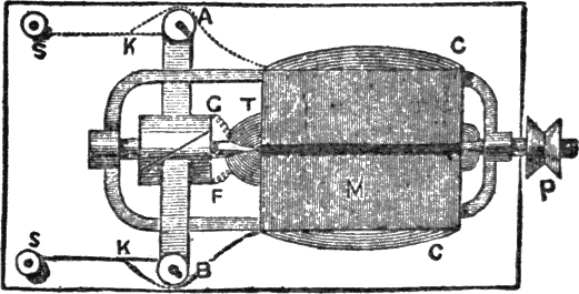
Fig. 11.—Dynamo Complete. Ground Plan.
M, Top of magnet. C C, Coils of wire around magnet. P, Driving-pulley. T, Armature. A B, Pillars of springs which take current from the roller F. S S, Binding-screws. The dotted lines show the position of the wires beneath the base. The wires from the magnet coils go round the pillars A and B, and are joined to the wires from them to the binding-screws S S at the points K K. The wires from the armature coils join the brass-covered roller at F and G.
Whenever you join the wires, be sure to scrape off all the insulating material, and twist them firmly together; a little solder is an improvement. Whenever the wires cross the iron work be sure the insulating material is quite sound at that point.[Pg 32] It is a good plan to roll paraffined silk round the wires at these places. Cut grooves under the base, in which the wires may lie, or the dynamo will not stand evenly. The dark line in the middle of the top of magnet in Fig. 11 shows where the two parts join. They should be screwed up tightly together.
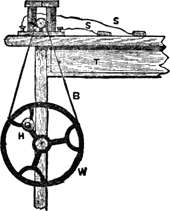
Fig. 12.—Hand-wheel Arrangement for Working Dynamo.
B, Endless band passing round pulley of dynamo. H, Handle of wheel. S S, Handles attached to binding-screws of dynamo.
As a concluding illustration, I give a diagram of my own method of turning my dynamo (Fig. 12). On the leg of an ordinary table T is fixed the heavy iron wheel W, which has a groove cut in its circumference for the reception of an endless band B. These wheels may be obtained for a few shillings from any ironmonger, as they are made for various machines, such as laths, fret-saws, sewing-machines, etc. The wheel is held by an ordinary screw fixed into the leg of the table, and revolves on the screw. The endless band (tape will do) passes over the groove and over the pulley of the dynamo placed on the table above the wheel.
It is better to let the pulley of the dynamo project beyond the end of the base, as shown in Fig. 11, in order to be able to connect it with a wheel placed below it, if required.
The best results are produced from the dynamo when the resistance of the interpolar (i. e. the lamp, or whatever it may have to work) is equal to the internal resistance of the machine. It is sometimes required to send a current through a greater resistance than this, and then it becomes necessary to employ what is familiarly termed a “shunt.” If one lamp of high resistance is coupled to the dynamo, the resistance may be too great for the current to get round the magnet in sufficient quantity to give the required electromotive force. Supposing that this is the case, we make a second pathway for it by joining on a piece of iron wire (about ten inches of No. 30) between the two binding-screws, the lamp being connected with the same binding-screws, only further off. The result of this is that the current goes round by the second pathway and excites the magnet more powerfully, and this, in its turn, excites the armature more strongly, and so on, until enough current is produced to light up the lamp. The resistance of the shunt required depends on the resistance of the lamp. If this is low no shunt will be required, if very high the resistance of the shunt must be lowered, or else enough current will not pass to magnetize the soft iron cores, and the dynamo will give no current. The lower the resistance of the shunt required, the less wire we use.
There are many toys which one meets with in the scientific stores, the making of which for themselves would give great satisfaction to enterprising devotees of the electrical art. They are for the most part easily constructed, and a great deal of amusement can be derived from them. I have my doubts whether the fathers and mothers of the amateur electrician will thank me for introducing the subject of the present article, but they must take comfort in the thought that if it works well it shows real constructive power on the part of the maker.
For the benefit of those whose capability of working in metal is limited, I am first going to describe the making of this remarkable instrument in its simplest form—a form, in fact, so simple that any one can make it and achieve success in a few hours.
First of all we want an old tooth-powder box. These are[Pg 34] all made the same size, and consequently it is unnecessary to give dimensions. The top of the tooth-powder box is to be taken, and by means of a fretsaw (this invaluable tool should be in the hands of every boy who likes carpentering; there are many uses to which it can be put quite different for what it is intended for) a circular hole is to be cut out about ⅛ inch less than the inside—that is to say, a rim of about ⅛ inch is to project all around from the rim of the lid.
We now want what is known in photography as a “ferrotype” plate—i. e., a piece of very thin sheet iron. Most dealers in photographic goods will not sell less than four or five dozen of them, and this is too many for us. A photographic friend will let us have one gratis, or a professional photographer may agree to part with one for five or ten cents if he is attacked when in a good temper.
The ferrotype plate having been procured by some means or other, the next thing is to cut from it a circle just small enough to go inside the rim of the top of the tooth-powder box. You can mark out the circle before cutting it by painting the top of the rim of the bottom of the tooth-powder box with ink and pressing it down on the ferrotype plate, when enough ink will come off to guide the scissors, and of course the circle so cut will be the exact size required.
We now have to make the motive power of the machine, for there is plenty of work done in it, though it only makes a noise—no one can “make a noise in the world” without doing plenty of work! And to make this we take a piece of soft iron rod about 1½ inch long and half an inch in diameter, and cut two circles out of cardboard 1¾ inch in diameter. The soft iron rod can be bought from any hardware store, and it ought to be quite soft enough to work at once without doing anything to it; if it is not, it must be heated red-hot in a good fire and left among the coals over-night to get cool very gradually.
Personally I have always found that the ordinary bars of soft iron bought from any hardware man are amply soft enough for any electrical work.
You must get the hardware man to file the ends of your bar flat; if they are not filed you will have to do it yourself, and a fine job it is!
Now we go back to the circles of cardboard. A hole is to be cut in each in the center exactly the size to admit the core of soft iron, then by slipping the circles over the ends we get a reel. Now a hole has to be made exactly in the center of the bottom of the tooth-powder box, and exactly so large that the core of soft iron will fit tightly into it; you can do[Pg 35] this again with the fretsaw, the wood of which tooth-powder boxes are made is delightfully easy to cut.
Now comes the adjustment of the reel. You must put the circles on the core, and putting one end of the latter through the hole at the bottom of the box you must push the iron through until the top is exactly flush with the top of the rim of the side of the box. One of your circles will now be much further on the core than the other, and the one at the end that is not pushed through the hole must be adjusted close to the edge, leaving about 1⁄16 of the core projecting, so that we have now a reel formed at one end of the core, and held in position by the bottom of the box. The more stiffly the core fits the hole the better, and if it has to be hammered into its place, better still, only take care not to split the wood of the bottom of the box.
The circles, being now in their right places, must not be moved again, but the roller has to be wound with wire, for which purpose the core will have to come out of the box temporarily. Before beginning to wind the wire, get some thin paper (French note-paper is best), and wind a piece round and round the core between the circles, fastening it and the circles at its ends to the core by means of a small quantity of mucilage.
We now have to wind the wire on to the roller. The more wire the stronger the magnet will be, but sufficient will be about two ounces. You can get the wire at most hardware stores for fifteen cents an ounce. It is generally cotton-covered, of light green color; medium thickness should be used, not too fine, as this offers too much resistance to the current, and not too coarse, or it will fill the reel too soon.
We begin by making a hole near the core in the circle which is furthest on it, and push one end of the wire through a hole from the inside of the reel. About three inches should be pushed through to allow for future manipulation, and the wire is now to be wound tightly over the paper covering the core in even coils, layer on layer, till the reel is nearly full and we have arrived at within about three inches of the other end of the wire. This is now to be passed through another hole in the same circle as before, which hole will of course be further from the center than the first. The magnet will be much stronger if two or three folds of paper are wrapped round it between each layer of wire.
The coil is now constructed, and can be replaced in the tooth-powder box, passing the ends of the wire through two holes in the side or bottom made to receive them. Before leaving this part of the instrument I may remark that care must be taken that the covering of wire is quite continuous[Pg 36] throughout, and has not got rubbed off at any points; if it has, you must wind fine silk over it to cover it up again. Should there be a break anywhere in the wire you must carefully scrape the wire off the two ends and twist the wires firmly together, if possible soldering them together and then wind fine silk over the join.
It is not necessary in this machine to soak the coil in melted paraffin, but might improve the insulation if the cover of the wire is thin. Only if there is a join and you have twisted, not soldered the wires together, you must not soak the coil in wax, or the melted wax gets between the ends of the wires and stops the current (this of course applies to all electro-magnets and should be remembered as a possible cause of failure.)
The core having been pushed through the hole again, up to the circle of cardboard, the ferrotype plate is placed in the top of the box, and the box is shut up. Now the ferrotype plate must be exactly free of the end of the core and that is all. You can test this by tapping it. If it vibrates in and out, it is all right; if the end of the core is too tightly pressed against it, there will be no possibility of moving the center in and out, and the core must be driven further through the hole till it is just free of the ferrotype plate.
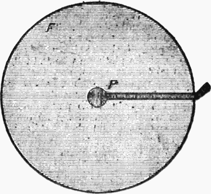
Fig. 1.—Shape of Platinum Foil, p, Fastened to Ferrotype Plate, f.
Now comes another part of the instrument, viz., the contact-breaker. The following is as good a way of arranging it[Pg 37] as any: Take a piece of sheet brass the exact length of the diameter of the top of the tooth-powder box and about half inch wide, and in the middle of it bore a hole which will admit a brass screw—with a milled head preferably. The screw should fit tightly into the hole, so as to screw easily up and down when turned. To the end of the screw, which is cut off flat, is soldered a short piece of platinum wire, inserted in a hole in the end of the screw made to receive it; it can be fastened by any other means, as long as it will screw up and down and is in contact with the brass screw. Adjust the screw so that the platinum point is within a minute distance of the ferrotype plate when the brass support is screwed down at the ends to the side of the box lid, and screw it down with small screws firmly in its position.

Fig 2.—Section of Simple Electric Trumpet Showing Details of Various Parts.
A, Tooth-powder box. B, Electro-magnet. C, Brass Screw. D, Flange for screw. E, Brass support for screw. F, Ferrotype plate. G, Wire attached to brass strip supporting screw. H, Wire from end of coil attached to platinum foil at P. I, Wire from the other end of coil passing through bottom of box.
Before this is done, however, a thin strip of platinum foil should be soldered to the upper surface of the ferrotype plate, or otherwise fastened to it—elastic glue will answer—this strip terminating in the center, and reaching to the edge of the plate, leaving a short piece over. A very thin strip will be enough, of the shape of P in Fig. 1. Now the ferrotype plate is to be placed in position again (the side of which the platinum foil is fastened being outwards, and the end of the foil going down between the edge of the ferrotype plate[Pg 38] and the wood into the inside of the box), and the end of the wire from the coil which was left inside the box is to be securely fastened, either by soldering or otherwise, to the end of the platinum foil which was left loose, so as to be in metallic connection with it. A wire can now be twisted round or soldered to the screw with the platinum point, and the instrument is complete.
It has taken some space to describe, but I made my own in about half an hour. Fig. 2 gives a general view of the parts put together.
The lid of the box should be tightly fastened down by four small screws, two of which may be those which fasten on the brass strip holding the screw.
Now to consider its action. The wire I in Fig. 2 is connected to one wire of the battery, and the wire G to the other. The current then starts from the battery, round the coil B, converting the core into a magnet, and up the wire H to the platinum foil P, along the platinum foil, which was fastened to the upper side of the ferrotype plate F, to the platinum wire which tips the screw C. It then goes up the screw C, along the brass piece E, which is fastened to the box by screws, as shown in the figure, to the wire G, and so back to the battery by the other wire.
The screw C must be therefore screwed down till the platinum wire at its tip is just in contact with the foil on the ferrotype plate. Now of course when the current goes round the coil, and thus converts the soft iron into an electro-magnet, the latter instantly attracts the ferrotype plate which is immediately above it. But the latter moving its center near the core, the platinum foil which is attached to it is thereby moved out of contact with the wire on the screw C, and the current is instantly stopped. Thereupon the attraction of the magnet ceases, and the ferrotype plate flies back to its former position and so joins the platinum wire and foil, and starts the current again, and the former process is repeated. The ferrotype plate therefore vibrates with tremendous rapidity between the core and the platinum screw. Now the vibrating armature of an ordinary coil makes quite a hum when hard at work, but of course a large plate such as this makes a much louder noise, consequently you will hear a ferocious buzzing like an army of millions of bees let loose from a hive, and on screwing the screw C up or down till you get to the correct point you will get a shrill note very like a penny whistle. If screwed up the vibrations are slower, and a deeper note is produced; if screwed down the vibrations are more rapid and a higher note is sounded. Therefore you can amuse yourself by screwing it rapidly up and down, or adjusting it by pressing the brass piece with[Pg 39] your finger, and a little practice will enable you to bring out a sort of tune produced by electricity!
When you have become tired of jingling out your tune you can fix the electric trumpet up in a permanent position, adjusting the wires from the battery so as to pass through an ordinary “press” which may be in another room. The trumpet will then begin buzzing or hooting whenever the button of the press is pushed in, and stop when the pressure is released. In this way of course the trumpet will act as a “call” instead of a bell, and as the double wire can be easily hidden under the carpet and in dark corners, and painted to match whatever wood-work it crosses, you can arrange it from an up-stairs room to a down-stairs one or vice versa with very little trouble. I give an illustration of the method of connecting the battery and trumpet with one switch or “press,” to show how to arrange the series. (See Fig. 3.)
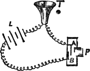
Fig. 3.—Method of Connecting Trumpet to Battery and One Press.
When the button P is pushed in, the spring A touches the metal piece B, and completes the circuit. On removing the finger from P, the spring separates from B, and the current is stopped. P, Press. L, Battery. T, Trumpet.
The trumpet made in the very simple way I have described will not produce a very loud noise, but quite loud enough, if properly put together, to attract a person’s attention who was in the room when it went off. The sound can be rendered louder by fixing a cardboard funnel or “cornucopia” to the front of the tooth-powder box to make a kind of horn.
The trumpets sold in the shops, as a rule, make a very loud noise indeed—in fact, a little of it goes a very long way with most people. The increased sound is probably due to[Pg 40] the body of the trumpet being composed of brass, which, vibrating in unison with the ferrotype plate, increases the sound. Wood will therefore not give so loud a sound, and if you can construct the case of metal you should certainly do so. The vibrations of the plate, and therefore the sound, may also be increased by using a horseshoe magnet, the two poles attracting the plate more strongly. In the bought trumpets the case is shaped like a horn, in which the magnet is placed, the platinum contact-breaker being behind (where it is in the one I have described, supposing there was no bottom to the box and the magnet was supported by a bar across from side to side, the cornucopia being placed on that side of the box, instead of the other, with the magnet inside it). I think it is unnecessary to describe their construction further, as the principle and details of construction of the simple one I have described will apply to any, and any method of structure may be adopted which suits the mind of the maker.
The trumpet having been made I will now give you a plan of fitting it up which adds enormously to the effect. We want to hide the trumpet so that no one shall know where it is. My own plan of doing this is as follows: I have made a wooden erection, of which I give a drawing which will explain itself. It consists of a back with a shelf at the bottom and a kind of canopy at the top. It can be made almost any size, small or big, to suit the occupant of the shelf. My own measurements are about as follows: From the top A to the bottom B, the length of back piece, including bracket, 1 foot 3 inches. Breadth of back 5¼ inches. Side of canopy (D), breadth 4½ inches, height 3½ inches, breadth of front (C to D) 5¼ inches; height of course the same as sides. The top piece will then be about 5¼ inches by 4½ inches. The shelf at the bottom is about the same size as the top of the canopy, and is supported by a bracket of rather thick wood, which you can carve as elaborately as you like.
Now take the electric trumpet, whether made at home or purchased, and fasten it to the under side of the canopy (this is best done before the sides are put on), and fasten a double wire behind the back (cutting a groove for it to go in) up to the back of the canopy, where it goes through and divides, one wire being fastened to one terminal of the trumpet and the other wire to the other. The double wire goes right down the back and emerges at B. Obviously if you now join your press and battery on to the double wire, when you squeeze the press the trumpet will squeak. But here we are going to practice a little innocent deception, and to that end we go to a toy shop and purchase a small and pretty doll of the male sex, and if you can get one (or dress one up) at[Pg 41]tired as a soldier or trumpeter, by all means do so. The doll is now to be fixed on to the bracket by means of a long wire—say a hairpin bent out straight, one end being pushed into the wood, the other passing up one trouser leg of the doll and into its body; the wire is thus completely hidden and is much better than glue, as it admits of the doll being placed in a natural attitude, and being removed if required. In one of his hands you must make him hold a small trumpet (this is a very expensive item; it will cost two cents) with the mouthpiece to his mouth, as represented in the picture.
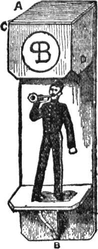
Fig. 4.—Electric Doll.
(Letters as referred to in text.)
The whole thing is now fastened to the wall in a convenient place, by driving nails through the back, and the double wire is completely hidden by passing it behind furniture, books, etc., down to the floor. There is great scope for ingenuity on the part of the worker in hiding the wire, and no definite instructions can possibly be given. In my own case I have no back piece below the shelf the support being against the wall. The wire descends behind the support (to B in the picture), and below that I have hung a “date calendar” over it, it makes a turn to the right and[Pg 42] goes down behind a chiffonier covered with books to the floor. Under these circumstances no human being could possibly tell that there was a wire at all, and there being no back piece under the bracket (so that the paper of the room can be seen), nothing but the support touching the calendar, it does not look as if any wires could possibly be hidden anywhere.
Now, if you press the button, of course the trumpet squeaks, but the doll being just underneath it, and the trumpet being in the dark under the canopy, no one thinks it is a separate instrument, but of course every one jumps to the conclusion that it is the doll blowing! Hide the battery in a corner in a black box, the wires coming through the side next the wall, and the press in a dark corner, or on the floor under a table so that you can put your foot on it while your hands are free, writing, etc.
You can of course now tell the doll to blow, at the same moment putting your foot on the press, when the trumpet blows accordingly. Of course this is mysterious to the last degree to the uninitiated friend to whom you are displaying the doll, as you may be any distance off from the doll with your hands free, speaking to him across the room.
The wooden erection to hold the doll can be painted any color; preferable the back should be black, as it shows off the doll. In front of the canopy you can paint a monogram or heraldic device. If the doll is one of those extremely pretty little specimens which can be procured at any good toy shop for about twenty-five cents, dressed as base ball players, soldiers, etc, (what our grandmothers would have thought of them in their young days it is difficult to imagine) it will really be quite an ornament to the room, independently of its electrical qualities.
This chapter has outgrown the space I meant to occupy, and I must wait for the next to tell you how to make the doll work from various parts of the room as you walk about and talk to him, and how to make the battery. The best battery to use is to Leclanche. You can use three or four cells of No. 2 size according to length of wire through which the current has to pass.
In my next chapter I will try and explain how to make an electric drum, so that you can have a kind of drum and fife band.
In part two on the “Electric Trumpet,” I promised to explain how to make an electric drum; and this promise I now propose to redeem.
The system on which it works is precisely analogous to that of the electric trumpet, and almost identical with that of the ordinary electric bell, of which I hope to say more in another chapter.
As before, we have a hammer vibrating backwards and forwards in response to pulls from a magnet, which is magnetized and demagnetized by stopping and starting an electric current. In the case of the induction coil, the hammer is only a means whereby the current is broken and started again with great rapidity, and in the case of the trumpet the vibrator is used to make the noise by its vibration, but in this instrument we must have a bona fide hammer, which must be able to beat the drum, and thus cause a stirring and martial sound.
First, then, we will devote our attention to the construction of the magnet. In former chapters (as in the case of the electro-motor for example), I have given you the method of making the magnets out of one solid piece of soft iron, in the form of a horseshoe. This time, however, we will make it of several pieces, for a change; it is far more convenient to make, and looks much neater when finished.
Take a piece of soft iron 1½ inches long by ⅝ inch broad and ⅛ inch thick, and in the middle drill a hole about 3⁄16 inch in diameter. On each side of this, on a line with it at a distance of about ¼ inch, drill two more holes of the same size. This is to form the back, or, as it is scientifically termed, the yoke of the magnet. To form the poles we require two exactly similar pieces of soft iron bar 1½ inch long and ⅜ inch in diameter. These are to be filed quite smooth at the ends after cutting, and in the middle of one end a hole is to be drilled to admit a screw which will just go through the holes on each side of the center one made in the flat piece of the soft iron. These holes are cut to receive the thread of the screw, but if you can’t do this you can simply leave out the end holes for screws, and solder the round and flat pieces of iron together. These are to be soldered or screwed together, so as to form a magnet, the hole in the middle of the flat piece serving to introduce a screw, for the purpose of attaching the magnet to a support. The best plan, if you can do it, is to drill and “tap” this hole to receive a screw which is inserted in a brass support made of a piece of brass 1⅛ inch long, ½ inch broad, and ⅛ inch thick, bent at right angles at about ½ inch from one end, this shortest end being drilled for two screws to fasten it to the base-board, while the longest end has a hole in the center about ⅛ inch from the end, to admit the screw which fits the hole in the center of the yoke. Having done[Pg 44] all this, you will have Fig. 1, which represents the magnet before it is wound.
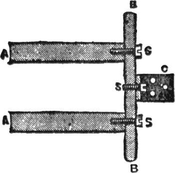
Fig. 1.—Magnet Put Together Ready for Winding.
(Sectional diagram.)
A A, Circular bars of soft Iron. B B, Flat bars of soft iron forming the “yoke.” C, Brass support for magnet. S S S, Screws fastening parts of magnet together.
The soft iron cores have now to be converted into magnets as usual, and here comes in the especial advantages of having screws to fasten the magnet together, as you can take the whole thing to bits, wind the wire on the legs in comfort, and then fasten together again. But if you have soldered the magnet together, you can achieve the same end in a different way by making two small bobbins to hold the wire, the exact size to slip on over the soft iron cores when the wire is wound on them. It is generally considered proper to wind the wire on bobbins, which can be removed from the cores if required. I should think it can seldom be required, but the bobbins are convenient in this case. I may remark parenthetically that bobbins wound and unwound, soft iron cores, and yokes, separately or together, and supports fixed to the yokes or not, can be obtained from any large electrician who sells parts of electric bells, etc.; the magnet can also be got put together complete.
We now have to make bobbins, supposing that we are not going to buy them. The elaborateness of their manufacture will depend entirely on the skill of the maker. Some construct them by sawing off top and bottom of a reel of cotton, and forming a roller of cardboard to fit the magnets, finally[Pg 45] joining the ends of the reel to this roller, to make an elongated reel of the right size. Others construct their bobbins entirely of cardboard, the ends being merely two circles of card. Others who are versed in the mysteries of wood-turning, and are lucky enough to possess a lathe with which to do it, make two bobbins of solid wood, drilled to fit the iron cores. For these no instructions are needed, as the dimensions will be as given presently. For those who only want to use the magnet for this special purpose, and do not care about the bobbins being removable, the following is the simplest way to set to work:
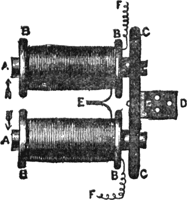
Fig. 2.—Magnet Wound and Put Together.
A A, Soft iron cores. B B B B, Ends of bobbins, on which wire is wound as shown. C C, Yoke of magnet fastened to support and held up by D, bottom of brass support, with holes for screws. E, Joined ends of wires. F F, Exterior ends of coils. The arrows show relative directions in which the two coils are wound.
Cut two circles of thick cardboard, each ⅞ inch in diameter, and in the center cut a hole the exact size to slip over the soft iron core. Now wrap several thicknesses of thin tissue paper—or preferably French note paper or tracing paper—over the magnet, between the circles of cardboard, cutting the strip about 1⅛ inch broad or ⅜ inch less than the length of the cores. Now you can fasten the two circles of cardboard at the ends of the tracing paper, and keep them in their proper places on the magnet by means of mucilage[Pg 46]—beat the soft iron before applying, and it will then adhere firmly to it. In this way, of course, you form a roller, on which we now have to wind the wire. If you have soldered the magnet’s parts together, you must have movable bobbins, as it would be simply impossible to wind the wire evenly on the cores when fixed in position, as the edges of the bobbins will be so close together that it is not possible to wind the wire on between them without the coils becoming displaced.
The method of winding the wire is simple enough. No. 24 wire is a good size to use; it can be cotton-covered or, preferably, silk-covered, as in the latter case the insulation is better. Begin by making a hole near the roller in the circle of cardboard that is next to the end where the hole for the screw has been made. Pass about three inches of wire through the hole and then wind it evenly on over the tracing paper from end to end and back again. You ought to have five or six layers of it; an ounce, or an ounce and a half, of wire will probably be enough. When it is all on, make another hole in the disc and pass out the wire. This is only to hold it safe while you wind the other bobbin. When that is finished you can put the magnet together, and ends of the two wires have now to be joined together. The two ends that are joined together must be those which come from the wire that is wound from the right to the left over one core and left to right over the other, that is to say, taking the wire when joined as one, it must be so wound on both limbs of the magnet that if they were bent into one straight bar it would all be wound in the same direction.
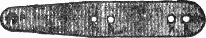
Fig. 3.—Shape of Spring for Armature.
P, Platinum foil. A A, Holes for screws to armature. H H, Holes for screws to support.
With a composite magnet, however, there is no earthly difficulty in getting it right, for you have only to connect the battery to two wires and join the other two, and if they don’t make the magnet work, join up one to the battery instead of one of those joined, and connect the other two wires; whichever gives the best result stick to. You must get all the silk or cotton off the wire, where you join them, and twist them over and over tightly together; if you can solder them, so much the better. Pull the wire tight and wind it[Pg 47] on the reels until the place where it is joined is pulled tightly and not left in a loop, which would look untidy. Fig. 2 gives an idea of the magnet completed, and I have endeavored by means of the arrows to show how the wire is wound, they are supposed to give the direction of the top layer of wire in each case; of course either may be wound from the inside, so you must also consider that in this picture the outside coils are joined. The magnet having been thus constructed, we must now turn our attention to the vibrating hammer which is to beat the drum. To make this we want another piece of soft iron of about the same size as that forming the yoke of the magnet, say, 1⅜ inch × ½ inch × ⅛ inch. We shall then require a piece of brass spring about three inches long and half an inch broad. This is made of very thin springy brass, so as to make a spring which will move the armature quickly. One end of the spring should be tapered off as shown in Fig. 3, and at the point P in the figure a small piece of platinum foil (the real thing, not tin-foil, which I am sure is often sold in cheap apparatus instead of it,) should be fastened, by solder if possible.
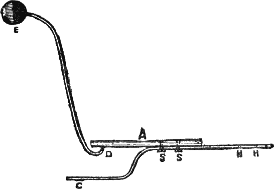
Fig. 4.—Drum Hammer Put Together.
A, A bar of soft iron. B, Brass spring of contact breaker. C, Portion of brass spring bent outwards, the platinum foil is soldered on at the point C. S S, Screws holding spring to soft iron. Holes are made at the points H H to fasten spring to support. D, Bent wire fastened to soft iron armature. E, Wooden head of drumstick.
We now want a piece of rather stout brass wire bent into the shape shown in Fig. 4. It must be about four inches[Pg 48] long, but its length will be determined by the size of the drum and the length of the magnet when it is all put together. At the end of this wire you must have a wooden knob (not brass, which doesn’t produce nearly so much noise). This you will have provided ready for you if you purchase the drum, as they will naturally supply drumsticks with it, and the head of one of these cut off and fastened to the end of the wire, by simply making a hole and sticking it in, will answer the purpose beautifully.
This wire has to be fastened to the soft iron armature, a simple way of doing which is to drill a hole the exact size and insert the end; it can then be soldered in. Or, if you cannot drill a hole, you can simply solder it on. The brass spring has the end bent outwards, as shown in Fig. 4, and is fastened to the soft iron armature by screws, as shown in the figure at S S, or simply soldered on. The point C is the end that is tapered off, and the platinum wire is fixed at that point; the spring should extend about 1¼ inch beyond the armature at the other end. Two holes are drilled in the spring at the points H H, through which screws are passed into the support. This support may be either a piece of iron ½ inch long, ¾ inch broad and ¾ inch thick, or a piece of wood will answer very well, and save drilling holes in the iron. If it is wood it had better be larger, say ¾ inch by ¾ inch by 1¼ inch.
We can now proceed to fasten all the parts together. We must have a piece of hard wood for the base, about 3½ inches by 3 inches and ⅜ inch thick. On this the magnet has to be fastened by its support being screwed firmly down. In front of it the armature has to be fastened at such a height as to be exactly in front of the poles of the magnet. The relative positions of the parts are shown in Fig. 5, so I do not think a detailed account of their exact positions on the base is at all necessary.
There is, however, one piece of the mechanism in the figure to which I have introduced you, this is the contact-screw shown at C. To make this we take a piece of brass about 1½ inch long, ½ inch broad, and rather less than ⅛ inch thick, and bend it at right angles, so that one leg is one inch long and the other ½ inch. Now in the part that is ½ inch have to be drilled three holes to fasten it with nails or screws to the base. The other part, one inch long, will then stand erect, but before fastening it in its place we put it to stand in front of the magnet and mark a point which is exactly on a level with the piece of platinum foil on[Pg 49] the spring, when the spring and magnet are fixed in position. A hole has now to be drilled through that point and tapped to admit a brass screw with a milled head, and fix the piece in which the screw works to the front hole, so that the screw will work through it.
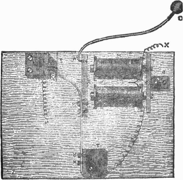
Fig. 5.—Interior Mechanism of Drum Complete.
M, Magnet. Y, Yoke of magnet. B, Brass support of magnet. A, Armature of soft iron attached to S, spring fastened to armature by screws at P, and to support by screws at H H. T, Support of spring. D, Head of drumstick. W, Wire supporting head of drumstick. C, Contact screw and support. The wire from one coil is joined to brass spring at H H. The wire X, coming from the other coil, and K, the wire from the contact-breaker, are joined to battery. Positions of screws joining parts together are shown by dotted lines. The side marked Z is placed at the bottom when fixing into the drum.
The point of the screw has now to be cut off and a very small piece of platinum wire fixed at the end. This wire[Pg 50] will now come in contact with the platinum foil on the spring, when the brass support is fixed in a certain position on the base, and it is now to be fixed in that position with screws or nails. It should be so fixed that when the screw is turned till it is nearly out of its hole the wire is just out of contact with the platinum foil on the spring. It is now evident that by turning the screw one way you make the spring vibrate more rapidly, and by turning it the other way its efforts are relaxed.
The contact-breaker screw having been fixed in its place, and the support of the spring also fixed as at T in the diagram (Fig. 5)—by screws through the base into the iron, if it is made of iron, or by nails or screws through it into the base if of wood—all the parts are now together, and all that remains to be done is to make the necessary connections. One wire that comes from the magnet is to be joined (soldered, if possible,) to the spring at H in the picture; the other wire is left loose. To the brass support of the contact screw we solder another piece of wire. Now this piece of wire is connected with the zinc of the battery and the other (coming from the coil of the magnet) with the carbon of the battery. What happens?
The electricity passes along the wire X, we will say, and round the magnet coils, thus turning the cores into magnets. It then goes down the other wire to H, up the brass spring, along the screw, and down by the brass support to the other wire, by which it returns to the battery. That is to say, it would do all this if the armature stood still, but, of course, when the cores become magnets they attract the armature, which instantly moves towards them; this breaks the circuit, the spring moving off the platinum point of the screw, and the armature springs back again, which makes the circuit complete and the magnet attracts it again, and so on. The object of the spring is to get a good deal of vibration, and it and the screw should be so adjusted that although the armature is close enough to the magnet to make it certain to “go off” directly it is meant to do so, yet there may be as much scope for the spring to work with elasticity as possible.
We have now completed the electrical part of the business, but a slightly necessary part of the apparatus has yet to be obtained—viz., the drum. You can easily make a drum if you like, by taking a broad piece of tin, twisting it round to form a hoop, and covering the ends with parchment strained tightly over them. However, I should certainly not do so, for there can hardly be any spot, I should think, which boasts of a toy-shop at all, where drums cannot be procured! For twenty-five cents you can get a very[Pg 51] superior drum, just about the right size; if you like to get a bigger one and make the mechanical part bigger, you will, of course, be rewarded by more noise.
Now, suppose you have got a 25-cent toy-drum, you must proceed to take off one end. If you look at the construction of the drum you will find (at least it is the case with my own, and I have not seen any that are differently made) that by cutting one of the double strings that fasten the wood hoops at the top and bottom together, and then loosening all the other strings with your fingers, the wooden hoop at one end will come right off, if the nails fastening the ends together are taken out, and that then the inner hoop on which the parchment is stretched will also come off and leave that side of the drum open.
Now, this is simply grand for our purpose, for when we have arranged our little dodges inside the drum, we can put on all the hoops again, replace the one double string, and no one will be an atom the wiser. If you could get off the side without breaking any strings it would save the trouble of replacing any, but I am afraid this is hardly possible. However, off comes the side of our drum, and what is to be done next? Well, the “beater” must be put bodily inside the drum, just so close to the parchment side that was taken off that the wooden head of the drumstick touches it when attracted by the magnet. You can easily find the right place in actual practice by setting the beater going and finding the spot inside the drum where it kicks up the worst racket when working. It must not be too close or it will hinder the vibration, and we want the hammer to go off instanter when required. The beater is fixed to the side of the drum with its side marked Z in the figure (5) downwards. It is easily fastened there by making two holes in the wood (in the thickness of it), and two corresponding holes in the metal side of the drum, and then screwing it down in its proper place.
Two holes are to be made in the side of the drum and two ornamental bits of silk-covered flexible copper conductor let through. They can be secured by simply tying knots inside the drum, and the copper ends are now to be fastened, one to the wire X and the other to the wire K from the contact screw support. Having done all this and made sure that the beater works when the ends of the flexible cord outside the drum are connected with the battery, we seal up our drum again, and that is then concluded.
Now as to fixing it up, I think I may fairly assume that you know how to make it work by an ordinary battery and a “press.” It is only necessary to run a double wire from battery to press and from press to drum, one wire of the[Pg 52] double conductor being fastened to the carbon end of the battery and the other to the zinc end, and the other end of one wire to one of the wires coming from the drum. The other wire coming from the drum is then joined to the bottom conductor of the press, and the upper conductor of the press is joined to the other wire of the double conductor that goes to the battery. It is all very easy to understand if you follow the course of the current and consider that it has to pass through the drum and the press when the latter is pushed down, and be stopped when it is left to spring up again.
But the more magical arrangement can be made with the drum, and I think it is well worth while to do it, if merely for the fun of mystifying people. The drum is going to be suspended by the flexible cords; therefore, let them be the same length, and cutting off all the coverings at the end of each, fasten a brass “eye” to the copper, twisting the wire well round the bottom of the eye. Now wind silk of the same color as the rest all round the join, so that the connection of wire and eye is completely hidden, and the eye appears merely fastened to the flexible cord as a means of suspending the drum. Now we want to construct a hook from which the drum can be hung.
Take two small pieces of brass wire about an inch long, and turn up the ends of each into a hook. Now get a minute piece of ebonite of the same length, and, putting one hook on one side and one on the other, bind the whole together with silk. If you cannot get ebonite easily you can use a small piece of sealing-wax in the same way; by heating the wires you can sink them into the wax and so make a neater join. Now the wires must not touch each other anywhere, but must be completely separated by the ebonite or sealing-wax. The double wire from the battery and press is now fastened, one wire to the press hook on one side, and one wire to that on the other side of the sealing-wax or ebonite. Wind silk over the whole to cover the joins, and a neat double hook is the result. The picture (Fig. 6) gives the method of making the hook, and it also gives a great deal more, which I now proceed to explain.
Supposing we can rig up a small beam of wood from which to suspend the drum, we can make matters more mysterious still. Let the double wire, being hidden by some means or other all along its course, be conducted on to the end of the beam. It can then be trained along the top of it[Pg 53] until it comes to the point from which the drum is to hang. Here there must be a hole drilled, large enough to admit the hook rather tightly. Pull the double wire through and fasten the two wires to the hooks as before described.
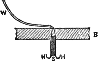
Fig. 6.—Hook From Which to Suspend the Magic Drum.
W, Double wire from battery and “press.” B, Beam of wood from which drum is suspended. H H, Brass hooks at side. S, Ebonite or sealing-wax between the hooks. The beam is, of course, shown in section.
Now you can pull back the wire and fix the hook firmly in the hole, hiding the double wire at the top of the beam (of course if it is high up no one will be able to see over the top of the beam, so you will be quite safe); the hook being thus fixed will not attract any one’s notice, and look quite unsuspicious. The chief glory of the double hook thus constructed is, of course, that you can remove the drum whenever you choose, for examination, and whenever you hang it up you have only to hitch one eye over one side of the hook and the other over the other side, and the drum will work. People who are not up in the matter cannot conceive how the electricity can get to the drum, when it is simply hung by an (apparently) ordinary cord and ordinary eyes to what looks like an ordinary hook attached to a beam in a plain and straightforward manner.
You are now possessed of an electric trumpet and an electric drum, which you can put one at one end of the room and the other at the other. By running double wires from battery and press to the trumpet, and another double wire from battery and press to the drum, you can arrange matters so that when you put one press down the trumpet works, and when the other press is put down the drum works. If you want to work both together you must either have a very powerful battery (say 6 or 7 cells, No. 2 Lechlanche) or two batteries, one for trumpet and one for drum.[Pg 54] If you want to use one battery for both you can make either work (at different times) from the same battery and presses, wherever they may be, by having a two-way switch in a dark corner of the wire.
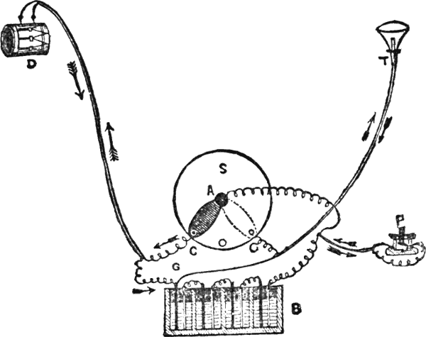
Fig. 7.—Method of Joining Switch Drum and Trumpet to Press and Battery.
S, Switch. B, Battery. P, Press. D, Drum. T, Trumpet. The arrows show the course of the current when the switch is at A C and A G respectively.
It is very confusing business setting up the wires so as to produce the right effect, which is to change the current from drum to trumpet and vice versa in a moment by merely altering the handle of the switch. Readers who are not accustomed to the work will find it most intricate, and as I have done it myself several times, they may as well have the benefit of my trouble. I therefore give an illustration of how to connect up the wires (Fig. 7), and hope it will make[Pg 55] matters clear to them. An explanation of the picture is necessary.
Suppose first of all that the switch is at A C, then the current will travel from the right-hand end of the battery, B, up one wire of the double conductor to the press, P, as shown by the lower arrow, through the press and along the wire, as shown by the top arrow, to the middle of the switch, A, down the arm of the switch to C, up one wire of the double conductor to the drum, and down by the other wire to the other end of the battery.
Now let the handle of the switch be moved to the other terminal, as shown by the dotted lines. The current will now go from the right-hand end of the battery to press and center of switch as before, it then goes down the arm of the switch up to the trumpet by the wire on the left side, and down to the other end of the battery by the wire on the right side, as shown by the arrows. Therefore when the arm of the switch is at A C the press will work the drum; when it is at A G the press will work the trumpet.
Suppose we have no press, but instead of it we have only one wire going straight from the right-hand end of the battery to the middle of the switch. Now let two incandescent lamps be substituted for the trumpet and drum. When the arm of the switch is at A C the current goes straight up from the right-hand pole of the battery to the center of the switch, along the arm, up to the lamp on the left-hand side, and down to the other pole of the battery. Now, suppose the arm of the switch is moved to A G, the current will go up as before to the center of the switch, down by the arm, up the wire to the lamp on the right-hand side, and back to the battery by the other wire. In the first case, therefore, the lamp at D lights up, in the second case the lamp at T lights up. The wires from C to D and G to T may be as long as you please, you can therefore control the lamps when they are far apart or in different parts of the house. When the arm of the switch is central neither lamp lights up, or, if you are fitting up the trumpet and drum, the press will not work either when the switch is in this position. This is an advantage, as when people get too inquisitive you can turn off the current, and then whatever they do they will not make the trumpet or drum work till you turn it on again, which you can do when you want them to work for you!
The construction of the switch is so simple that it is hardly necessary to explain the method of joining the wires, but I may say that one is to be joined to the bottom of the brass pillar in the center which supports the brass arm. The others are joined to the right and left terminals, generally by brass screws under the base, but sometimes by screw[Pg 56] terminals at the upper surface; this depends on the make of switch which is purchased.
Ingenious readers can easily make a switch for themselves; it only requires a brass arm attached at one end to a central figure, and long enough to touch two screws, or pieces of brass, fixed to the base on opposite sides of it, when turned in their direction. The end of the arm not supported by the brass pillar is provided with a small wooden handle to turn it by.
The switch should be arranged to occupy some dark corner in which you can turn on drum or trumpet to work from the “presses” at will without any one seeing you alter it.
I will only add one thing in conclusion, and that is, that you can have the double wire from the battery and center of switch to the press at the end as long as you like, and it can turn about behind furniture or under the carpet as much as you like, and it will still work instantly from the end press.
Now, by scraping the wire clean at any intermediate point, or as many points as you like, and arranging a simple spring contact fastened to the wires without breaking them so that they can be made to touch when required and spring apart directly the touch is removed (this is easily done with two springs consisting of two strips of sheet brass, one fastened to one wire and one to the other, separated by a piece of wood except at the end when pressed together), you can make the trumpet squeak or the drum roll at any part of the room you like. The springs can be hidden under the carpet so as to be absolutely undiscernible except to the initiated. The best places are under furniture with rather long legs; the foot of the operator can then be placed on the springs, and so make them meet and the trumpet or drum sound without the least chance of detection. The wires not being broken in fixing the springs as described, those springs which are closer to the battery, in no way interfere with those which are further off, as, when these are used, the current simply runs round those that intervene between them and the battery, without being in any way hindered in its course, and the press at the end of the double wire will, therefore, work just as if no intermediate springs existed.
Frictional electricity is pre-eminently a winter amusement. Not that it is not equally possible to produce the same result in summer, but then other occupations are forced[Pg 57] upon us, while in the long winter evenings, with a good fire to dry the air of the sitting-room, the conditions are particularly favorable to electrical phenomena. If a hard frost sets in the conditions will be still more favorable, as this dries the air and the ground outside, while on a wet evening a large fire and warmer room will be needed to produce as good results.
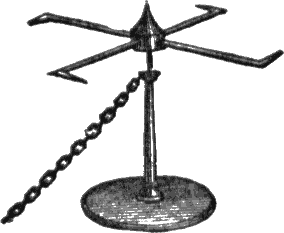
Fig. 1.—Electric Windmill or Tourniquet.
The following experiments are given as a means of amusement to those who know little or nothing of electrical phenomena. Some of them may be recognized by some readers as being standard experiments, others may possess the charm of novelty. To many, however, the whole series will be new, and it is hoped that these will find a new source of interest opened to them, and that they may possibly be impelled thereby to investigate further concerning the causes of what they see. Frictional electrical machines can be purchased from any electrical instrument makers, at a small price, and with these experiments mentioned are more readily performed. In this article I only mention experiments that can be performed with materials to be found in every house, or the necessaries for which can be procured from a shop for a nominal sum. Friction between two substances of any sort probably always produces electricity; but it can only be made visible under certain circumstances.
For instance, if a stick of sealing-wax is warmed and rubbed with a piece of flannel also warm, they both become electrified. This may be proved by holding the wax near an electrometer, which is simply a bottle through the cork of which a wire is passed which has two pieces of gold leaf fastened to its extremity, when the leaves at once diverge owing to the repelling force of the electricity. The flannel is also electrified, but the electricity soon escapes, through the hand of the operator to the ground.
We now proceed to make a simple experiment on the pro[Pg 58]duction of electricity on a larger scale. Take a piece of stout brown paper and hold it in front of a hot fire till all the moisture inherent in it is expelled, and the paper is dry and quite hot. Now take it away suddenly, and holding it against the side of the coat rub it briskly with the sleeve by holding the sleeve in the hand. Take it away and hold it against the wall of the room, to which it will instantly adhere firmly, this adherence being caused by the development of electricity over the surface of the brown paper by the friction it has undergone. The paper can be removed from the wall, and on holding it at a short distance will fly towards it and adhere again. In a short time, however, the electricity departs, and the paper falls to the ground. If the hand is spread open upon the paper as it sticks, the electricity departs at once and the paper falls. A spark can be obtained from the paper, but it is hardly strong enough to be visible. In the next experiment, however, it is plainly to be seen.
Take an ordinary tea-tray and place it on the top of four glass tumblers, which must have previously been made quite hot and dry at the fire. They must also be scrupulously clean, as dirt is a good conductor of electricity. Now take a sheet of foolscap paper, and heat it strongly at the fire until perfectly dry, as the brown paper was. Place it while hot flat on the table and rub it from side to side, from the top to the bottom, with a piece of thick india-rubber. It will now adhere firmly to the table on account of the electricity developed. Take hold of two corners, pull it up, and quickly place it on the tray. On approaching the knuckle of your closed hand to the edge of the tray you will now obtain a brilliant spark, which, if the room is dark, will appear vivid. On removing the paper from the tray, and again approaching the knuckle, another spark will pass, but not so bright as the former. The experiment can be repeated as often as wished by heating and rubbing the paper again.
Now take four more tumblers, heat them as before, and place them on the floor with a board on the top of them. Let someone stand on this board, taking care that he is completely separated from all surrounding objects of furniture, etc., and that his clothes do not touch the table while the experiment is performed. Let him place his hand on the tray while the paper is heated, rubbed, and placed thereon.
He will then become charged with electricity, and if he approaches his hand to any one else’s a spark will pass between them. (This should not be done with susceptible parts of the body, the eyes for example, as it would be rather painful.) Let some one be provided with a spoon in which a little methylated spirit is heated; if the charged person holds his[Pg 59] knuckle to this spirit it will instantly be ignited. Small pieces of paper—comic paper figures, etc.—will dance up and down briskly if he holds his hand outspread over them while lying on the table. The same thing will happen if the pieces of paper are placed between the tray and the table when the former is charged by the hot paper, or if the brown paper in the first experiment is held above them when excited.
Now take a needle and place it on the tray, its point projecting over the edge. If the room is now darkened, on placing the excited paper on the tray, the point of the needle will be seen to glow brilliantly for some seconds. This is caused by the electricity escaping into the air from the point of the needle, and is known as the “brush discharge.” The tray will consequently speedily lose its electricity. It will be found to be impossible to get a spark from the tray as long as the needle is on it, as the electricity vastly prefers to escape by the point. The escape of the electricity may be rendered still more evident by means of the following piece of apparatus.
Take two pieces of thin wire about two inches long, and bend each at right angles about an eighth of an inch from each end, both the bent portions being in the same direction. These two pieces of wire are now to be joined together at the middle at right angles by means of a piece of finer wire twisted around them. This finer wire can, with a little care, be caused to form a small cap, in which the point of a needle is inserted, the needle acting as a pivot, so that the bent wires turn freely on top of it (Fig. 1). The needle is supported by thrusting it into a large cork to act as a stand.
A fine wire is then twisted several times around the bottom of the needle, and the whole apparatus is then placed on the tray, the end of the wire attached to the needle being carefully arranged so as to touch the tray, a metallic connection with the tray being essential to success. If the needle can be soldered to a metal stand, or the cork covered with tinfoil, the wire is not needed. On rubbing the paper and placing it on the tray, the electricity passes up the wire into the needle, thence into the wire cross, and escapes by the bent portions of the wires, each of which should be filed to a point. In escaping it electrifies the surrounding air, and this, according to the law that “like electricities repel each other,” has a reacting force on the wire arms. Accordingly the windmill begins to turn, and may attain a tolerable rate of speed if the tray is strongly charged.
Another amusing experiment is that known as the “electrical head of hair.” The head of a wooden doll is taken, and either provided with a real head of hair, which must be[Pg 60] combed out straight, or a quantity of cotton is fastened to it to resemble hair.
If the head is fastened to a metal stand, and placed on the tray when the excited paper is laid upon it, the hairs become charged, and consequently repel each other, causing the whole head of hair to stand erect, each hair separate from the rest, thus presenting a most remarkable appearance. For the same reason, if a heap of small pieces of paper, feathers, etc., is laid on the tray, on placing upon it the electrified paper they will jump off in all directions, each being repelled by the others, in the same way as the gold leaves of the electroscope were repelled in the first experiment. If two pieces of pith are suspended by silk threads to a support, so as to hang close to each other, on bringing near them the electrified wax or tray they will be charged and will repel each other for some time. If when charged by the wax a heated glass rod rubbed with silk is brought near to them, they will fly to it, instead of retreating. This seems to indicate a difference between the electricities of the wax and the glass, the former of which has therefore been called negative, and the latter positive.
For giving stronger shocks than the tray is capable of, we may have recourse to the apparatus known as the Leyden jar, which may be easily charged by means of the tray and excited paper. A Leyden jar is thus easily and cheaply constructed: Take an ordinary wide-mouthed pickle bottle and a cork to fit it. Cover the outside with tinfoil, which can be fastened on with gum, and should be laid on as smoothly and as free from creases as possible. Tinfoil can be procured from any chemist. The outside being finished, the inside has to be covered also, which is a work of greater difficulty. It can best be performed by cutting another piece not quite so large as that on the outside of the bottle but of the same shape, and passing into the bottle without creasing it more than can be helped, it can be arranged inside the bottle so as to fit smoothly all round. Now a piece of brass wire is to be passed through the cork, at the end of which is a brass knob, or if simply bent round it will work, though the knob is neater. At the end of the wire which is inside the bottle a brass chain is fastened so as to touch the tinfoil inside the bottle when the cork is inserted. The tinfoil inside and outside the bottle must only reach to the bottom of the neck, leaving a space between it and the cork.
The Leyden jar is now complete, and must be thoroughly warmed before charging it. When quite hot it can be charged by bringing the knob (the jar being held by the outer coating of tinfoil) near the tray, when the excited paper is laid upon it. A spark will pass between the tray[Pg 61] and the knob, and this must be repeated several times (say twenty for a first experiment), the jar being charged more fully the more sparks are put into it. Any one now taking the jar in one hand by the outer coating and placing a finger of the other hand near the knob will receive a shock, the severity of which depends on the number of sparks put into the jar. Several people can take the shock by joining hands, the outside one on one side holding the jar, and the outside one on the other side touching the knob. Those in the middle will not feel the shock quite so strongly as those on the outside.
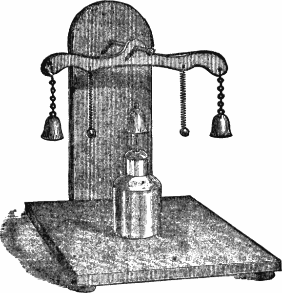
Fig. 2.—Bells Chimed by a Leyden Jar.
This is an example of the “quick discharge” of a Leyden jar. It can, however, also be discharged slowly, and the following experiment makes use of this faculty. Take three small bells, which can be procured at any toy shop, and remove the clappers. Now suspend two of them by wires at opposite ends of a piece of metal or stout wire about three[Pg 62] inches long, and suspend this wire in the center by a bent wire (or wooden, if covered with tinfoil) support, which is fixed to a thick piece of board, covered with tinfoil, to act as a base.
The tinfoil must be in communication with the supporting wire, and the height of the bells must be so adjusted that when the Leyden jar is placed between them with the third bell supported on the knob (the support of the clapper will have to be removed from the bell for this purpose), all three bells will be of equal heights and about half an inch distant from each other. (The diagram Fig. 2 will explain the arrangement.) Now suspend two small brass buttons by silk threads so as to hang between the bells when the Leyden jar is placed in the center. Charge the jar with the tray and replace it in position (of course with the bell on the top); the buttons will then begin to move backwards and forwards between the bells, and the latter will keep up a vigorous chiming until the electricity of the jar is exhausted. In this experiment it is essential that the supports be of metal, or wood covered with tinfoil, as the electricity passes from the inside of the jar to the outside while it is standing upon the tinfoil, by means of the balls, and thus causes them to vibrate.
A candle which has just been blown out, leaving the wick glowing, can easily be lighted by means of the charged Leyden jar if a piece of bent wire is held touching the outer coating and the other end on one side of the wick while the knob is approached to the other, so that the spark passes through the glowing wick. In the same way spirits of wine can be lighted, and gunpowder, guncotton, etc., exploded. To do this, it is best to have two pieces of bent wire provided with handles of glass at the middle. These wires are held by the handles, one in contact with the outer coating, and the other with the inner coating, of the charged Leyden jar. On approaching the other two ends of the wires a spark passes between them, and if a small quantity of gunpowder is placed on a table and the spark is made to pass through it by approaching the wire to either side it will be fired.
There are many other experiments which can be performed by the help of the simple apparatus described, but it would take up too much space to describe them.
THE LARGEST AND BEST LIBRARY.
Colored Covers. 32 Pages. All Kinds of Good
Stories. Price 5 Cents. Issued Weekly.
Read List Below.
No.
For sale by all newsdealers, or sent to any address on receipt of price, 5 cents per copy—6 copies for 25 cents. Address
FRANK TOUSEY, Publisher,
Old and Young King Brady, Detectives.
32 Pages of Great Detective Stories.
Handsomely Decorated Covers.
Issued Weekly. Price 5 Cents.
Containing Stories of Old King Brady, the Great Detective, assisted by Young King Brady, his faithful young pupil.
Embracing the most daring adventures, startling scenes and hairbreadth escapes ever published.
READ THE FOLLOWING LIST.
For sale by all newsdealers or sent postpaid on receipt of price, 5 cents per copy, by
FRANK TOUSEY, Publisher,
New York.
USEFUL, INSTRUCTIVE AND AMUSING.
Containing valuable information on almost every subject, such as Writing, Speaking, Dancing, Cooking; also, Rules of Etiquette, The Art of Ventriloquism, Gymnastic Exercises, and The Science of Self-Defense, etc., etc.
All the above books are for sale by newsdealers throughout the United States and Canada, or they will be sent, post-paid, to your address, on receipt of 10c. each.
Send Your Name and Address for Our Latest Illustrated Catalogue.
FRANK TOUSEY, Publisher,
24 UNION SQUARE, NEW YORK.
Transcriber's note:
Every effort has been made to replicate this text as faithfully as possible. Some changes have been made. They are listed below.
The format used for fractions in the original, where 1 1-4 represents 1¼, has been changed to the latter.
In the chapter "How to Make an Induction Coil," a section heading "PART I." was removed as there is no "PART II."
The following is a list of changes made to the original. The first line is the original line, the second the corrected one.
Page 11:
It this can be done over night,
If this can be done over night,
and the coil left to get cold as the the fire goes out,
and the coil left to get cold as the fire goes out,
Page 12:
so as to leave about ¼ of an inch of the core projectiug from it,
so as to leave about ¼ of an inch of the core projecting from it,
Page 14:
unless you are skilled in the use of the soldiering bit.
unless you are skilled in the use of the soldering bit.
Page 15:
twenty-five cents, plantinum being a very expensive substance.
twenty-five cents, platinum being a very expensive substance.
the strip of brass supporting the strew being connected by a wire
the strip of brass supporting the screw being connected by a wire
Page 16:
below these places narrow strips of wood to keep them apart
below these place narrow strips of wood to keep them apart
Page 17:
is filled with "suturated" solution of sulphate of copper
is filled with "saturated" solution of sulphate of copper
Page 18:
shock to any one who holds two handles fixed to his terminals.
shock to any one who holds two handles fixed to its terminals.
Page 19:
deal 5½ inches long ay 3½ inches broad by ⅞ inch thick.
deal 5½ inches long by 3½ inches broad by ⅞ inch thick.
Page 23:
by filling four small notches in the soft iron of the armuatre
by filing four small notches in the soft iron of the armature
Page 24:
To do this we shall wants two supports for the axle. These
To do this we shall want two supports for the axle. These
Page 28:
the base and loined to the under part of these binding-screws.
the base and joined to the under part of these binding-screws.
Page 33:
for the current to get round the magnet in sufficicent quantity
for the current to get round the magnet in sufficient quantity
Page 34:
These are all made she same size, and consequently it is unnecessary
These are all made the same size, and consequently it is unnecessary
Page 36:
The following is as good away of arranging it as any:
The following is as good a way of arranging it as any:
Page 42:
to the uninitated friend to whom you are displaying the doll,
to the uninitiated friend to whom you are displaying the doll,
In front of the conopy you can paint a monogram or heraldic device.
In front of the canopy you can paint a monogram or heraldic device.
what our grandmothers would have though of them in their young days
what our grandmothers would have thought of them in their young days
Page 44:
C, Bras support for magnet.
C, Brass support for magnet.
and here comes in the especal advantages of having screws
and here comes in the especial advantages of having screws
Page 46:
taking the wire when joined as one,-it must be so wound
taking the wire when joined as one, it must be so wound
Page 47:
is pulled tightly and left in a loop, which would look untidy.
is pulled tightly and not left in a loop, which would look untidy.
Page 51:
you will, of course, be rewerded by more noise.
you will, of course, be rewarded by more noise.
Page 52:
Now we want to construct a hook ro which the drum can be hung.
Now we want to construct a hook from which the drum can be hung.
Page 55:
Suppose we have no press. but instead of it we have only one wire
Suppose we have no press, but instead of it we have only one wire
When the arm of the switch is at A C the currrent goes straight up
When the arm of the switch is at A C the current goes straight up
Page 58:
this adherence peing caused by the development of electricity
this adherence being caused by the development of electricity
This should not be done with suspectible parts of the body,
This should not be done with susceptible parts of the body,
Page 59:
It will we found to be impossible to get a spark from the tray
It will be found to be impossible to get a spark from the tray
bend each at right angles about an eight of an inch from each end,
bend each at right angles about an eighth of an inch from each end,
Page 62:
will then begin to move backwards and forwards betweens the bells,
will then begin to move backwards and forwards between the bells,
the tinfoil, by means of the balls, and thus causes them to vibrate.
the tinfoil, by means of the bells, and thus causes them to vibrate.