Please see the Transcriber’s Notes at the end of this text.
THE
ANATOMY OF BRIDGEWORK
BY
WILLIAM HENRY THORPE
ASSOC. M. INST. C. E.
WITH 103 ILLUSTRATIONS
London
E. & F. N. SPON, Limited, 57 HAYMARKET
New York
SPON & CHAMBERLAIN, 123 LIBERTY STREET
1906
In offering this little book to the reader interested in Bridgework, the author desires to express his acknowledgments to the proprietors of “Engineering,” in which journal the papers first appeared, for their courtesy in facilitating the production in book form.
It may possibly happen that the scanning of these pages will induce others to observe and collect information extending our knowledge of this subject—information which, while familiar to maintenance engineers of experience, has not been so readily available as is desirable.
No theory which fails to stand the test of practical working can maintain its claims to regard; the study of the behaviour of old work has, therefore, a high educational value, and tends to the occasional correction of views which might otherwise be complacently retained.
60 Winsham Street,
Clapham Common, London, S.W.
October, 1906.
| CHAPTER I. | |
| INTRODUCTION—GIRDER BEARINGS. | |
| PAGE | |
| Pressure distribution—Square and skew bearings—Fixed bearings—Knuckles—Rollers—Yield of supports | 1 |
| CHAPTER II. | |
| MAIN GIRDERS. | |
| Plate webs: Improper loading of flanges—Twisting of girders—Remedial measures—Cracks in webs—Stiffening of webs—T stiffeners | 9 |
| Open webs: Common faults—Top booms—Buckling of bottom booms—Counterbracing—Flat members | 17 |
| CHAPTER III. | |
| BRIDGE FLOORS. | |
| Liability to defects—Impact—Ends of cross and longitudinal girders—Awkward riveting—Fixed ends to cross girders—Plated floor—Liberal depths desirable—Type connections—Effect of “skew” on floor—Water-tightness—Drainage—Timber floors—Jack arches—Corrugated sheeting—Ballast—Rail joints—Effect of main girders on floors | 20 |
| CHAPTER IV.[viii] | |
| BRACING. | |
| Effect of bracing on girders—Influence of skew on bracing—Flat bars—Overhead girders—Main girders stiffened from floor—Stiffening of light girders—Incomplete bracing—Tall piers—Sea piers | 34 |
| CHAPTER V. | |
| RIVETED CONNECTIONS. | |
| Latitude in practice—Laboratory experiments—Care in considering practical instances—Main girder web rivets—Lattice girders investigated—Rivets in small girders—Faulty bridge floor—Stresses in rivets—Cross girder connections—Tension in rivets—Defective rivets—Loose rivets—Table of actual rivet stresses—Bearing pressure—Permissible stresses—Proposed table—Immunity of road bridges from loose rivets—Rivet spacing | 45 |
| CHAPTER VI. | |
| HIGH STRESS. | |
| Elastic limit—Care in calculation—Impact—Examples of high stress—Early examples of high stress in steel girders—Tabulated examples—General remarks | 61 |
| CHAPTER VII. | |
| DEFORMATIONS. | |
| Various kinds—Flexing of girder flanges—Examples—Settlement deformations—Creeping—Temperature changes—Local distortions—Imperfect workmanship—Deformation of cast-iron arches | 73 |
| CHAPTER VIII.[ix] | |
| DEFLECTIONS. | |
| Differences as between new work and old—Influence of booms and web structure on deflection—Yield of rivets and stiffness of connections—Working formulæ—Set—Effect of floor system—Deflection diagrams—Loads quickly applied—“Drop” loads—Flexible girders—Measuring deflections—New method of observing deflections—Effect of running load | 85 |
| CHAPTER IX. | |
| DECAY AND PAINTING. | |
| Examples of rusting of wrought-iron girders—Girder over sea-water—Rate of rusting—Steelwork—Precautions—Red-lead—Repainting—Scraping—Girders built into masonry—Cast iron—Effect of sea-water on cast iron—Examples—Tabulated observations—Percentage of submersion—Quality of metal | 96 |
| CHAPTER X. | |
| EXAMINATION, REPAIR, AND STRENGTHENING OF RIVETED BRIDGES. | |
| Purpose—Methods of examination—Calculations—Stress in old work—Methods of reducing stress—Repair—Loose rivets—Replacing wasted flange plates—Adding new to old sections—Principles governing additions—Example—Strengthening lattice girder bracings—Bracing between girders—Strengthening floors—Distributing girders | 107 |
| CHAPTER XI.[x] | |
| STRENGTHENING OF RIVETED BRIDGES BY CENTRE GIRDERS. | |
| Principal methods in use—Method of calculation—Adjustments—Connections—Method of execution—Checks—Effect of skew on method considered—Results of calculation for a typical case—Probable error—Practical examples—Special case—Method of determining flexure curves | 122 |
| CHAPTER XII. | |
| CAST-IRON BRIDGES. | |
| Limitations of cast iron—Stress examples—Advantages and disadvantages—Foundry stresses—Examples—Want of ductility of cast iron—Repairs—Restricted possibilities | 141 |
| CHAPTER XIII. | |
| TIMBER BRIDGES. | |
| Perishable nature—Causes of decay—Sag—Lateral bracing—Piles—Uncertainty respecting decay—Examples—Conditions and practice favourable to durability—Bracing—Protection—Repair—Piles—Cost | 149 |
| CHAPTER XIV. | |
| MASONRY BRIDGES. | |
| Definition—Cause of defects or failure—Spreading of abutments—Closing in—Example—Stop piers—Example of failure—Strength of rubble arch—Equilibrium of arches—Effect of vibration on masonry—Safety centring—Methods of repair—Pointing—Rough dressed stonework | 157 |
| CHAPTER XV.[xi] | |
| LIFE OF BRIDGES—RELATIVE MERITS. | |
| Previous history—Causes of limited life—Tabulated examples of short-lived metallic bridges—Timber and masonry bridges—Durability—Maintenance charges—First cost—Comparative merits—Choice of material | 165 |
| CHAPTER XVI. | |
| RECONSTRUCTION AND WIDENING OF BRIDGES. | |
| CONCLUSION. | |
| Measuring up—Railway under-bridges—Methods of reconstruction in common use—Reconstruction of bridges of many openings—Timber staging—Traffic arrangements—Sunday work—Railway over-bridges—Widenings—Junction of new and old work—Concluding remarks—Study of old bridgework | 172 |
| INDEX | 187 |
THE
ANATOMY OF BRIDGEWORK.
No book has, so far as the author is aware, been written upon that aspect of bridgework to be treated in the following pages. No excuse need, therefore, be given for adding to the already large amount of published matter dealing with bridges. Indeed, as it too often happens that the designing of such constructions, and their after-maintenance, are in this country entirely separated, it cannot but be useful to give such results of the behaviour of bridges, whether new or old, as have come under observation.
In the early days of metallic bridges there was of necessity no experience available to guide the engineer in his endeavour to avoid objectionable features in design, and he was, as a result, compelled to rely upon his own foresight and judgment in any attempt to anticipate the effects of those influences to which his work might later be subject. How heavily handicapped he must have been under these conditions is evident from the mass of information since acquired by the experimental study of the behaviour of metals under stress, and the growth of the literature of bridgework during the last forty years. That many mistakes were made is little occasion for surprise; rather is it a cause[2] for admiration that some very fine bridges, still in use, were the product of that time. Much may be learned from the study of defects and failures, even though they be of such a character that no experienced designer would now furnish like examples.
Modern instances may, none the less, be found, with faults repeated, which should long since have disappeared from all bridgework, and are only to be accounted for by the unnatural divorce of design and maintenance already referred to. As the reader proceeds, it may appear that details are occasionally touched upon of a character altogether too crude and objectionable to need comment; but the consideration of these cases is none the less interesting, and, so far as the author’s observation goes, not altogether unnecessary.
Most of the instances cited are of bridges, or parts of bridges, of quite small dimensions; but it is these which most commonly give trouble, both because the effects of impact are in such cases most severely felt, and possibly because the smaller class of bridges is very generally designed by men of less experience, than large and imposing structures.
The particulars given relate in all cases to bridges of wrought iron, unless otherwise described.
An endeavour has been made to secure some kind of order in dealing with the subject, but it has been found difficult to avoid a somewhat disjointed treatment, inseparable, perhaps, from the nature of the matter. Finally, the reader may be assured that every case quoted has come under the writer’s personal notice.
In girder-work generally, and more particularly in plate-girders, considerable latitude obtains in the amount of bearing allowed. Clearly, the surface over which the pressure[3] is distributed should be sufficiently ample to avoid overloading and possible crushing or fracture of bedstones where these exist; but if no knuckles are introduced, this is an extremely difficult matter to insure. A long bearing may deliver the load at the extreme end of the surface on which it rests, or, more probably, near the face.
If the girder is made with truly level bearings, and the beds set level, it will certainly, when under load, throw an extreme pressure upon that part of the bearing surface immediately under the forward edge of the bearing-plate. These considerations probably account for bedstones frequently cracking, in addition to which possibility there is the disadvantage that the designer does not know where the girder will rest, and cannot truly define the span. The variation of flange-stress due to this cause may, in a girder of ordinary proportions, having bearings equal in length to the girder’s depth, be as much as 15 per cent. above or below that intended.
If great care be taken in setting beds, in the first instance, to dip toward the centre of the span an amount depending upon the anticipated girder deflection, it may be possible to insure that when under full load the girder bearing shall rest equally upon its seat; but this is evidently a difficult condition to obtain practically, is good only for one degree of loading, and may at any time be nullified by a disturbance of the supports, as, for instance, the very common occurrence of a slight leaning forward of abutment walls.
Double or treble thicknesses of hair-felt are sometimes placed beneath girder bearings, with the object of securing a better distribution of pressure, no doubt with advantage; but this practice, though it may be quite satisfactory as applied to girders carrying an unchangeable load, hardly meets the case for loads which are variable. Notwithstanding the faulty nature of the plain bearing ordinarily used[4] for girders of moderate span, its extreme simplicity commends it to most engineers. It must be admitted that no serious inconvenience need be anticipated in the majority of cases, particularly if the bearings are limited in length, do not approach nearer than 3 inches to the face of bedstones, and are furnished with hair-felt or similar packing.
Whether with long or short bearings, the forward edge should be at right angles to the girder’s length. In skew bridges it is sometimes seen that this edge follows the angle of skew. The effect on the girder is to twist it, as will be clear from a little consideration. In evidence of this the case may be quoted of a lattice girder of 95 feet effective span and 7 feet deep, which, resting on a skew abutment right up to the masonry face at a rather bad angle (about 15 degrees), was, after twenty years, found canted over at the top to the extent of 4 inches, with the further result of springing a joint in the top flange at about the middle of the girder, causing some rivets to loosen. The bedstone was also very badly broken at the face, and had to be replaced in the course of repairs (Fig. 1). This girder had, in addition to the canting from the upright position at its end, and the distortion of the top flange, a curvature in the same direction, though less in amount, at the bottom—an[5] effect very common in the main girders of skew bridges, and possibly accounted for in part by a tendency of the girder end to creep along the abutment away from the point at which it bears hardest, under frequent applications and removals of the live load, and accompanying deflections.
This tendency to travel may be aggravated in bridges carrying a ballasted road, in which there may be a considerable thickness of ballast near the bearings, by the compacting and spreading of this material taking effect upon the girder end, tending to push it outwards, being tied only by a few light cross-girders badly placed for useful effect. The movement may be prevented in new work for moderate angles of skew by carrying the end cross-girders well back, and securing them in some efficient manner; or by the introduction of a diagonal tie following the skew face, and attached to cross and main girder flanges (Fig. 2)—a method which may be applied to existing work also.
For such a case as that cited it is imperative that ballast pressure at the girder end should be altogether eliminated.
The fixing of girder ends by bolts—a practice at one time usual—hardly calls for remark, as it is now seldom resorted to unless for special reasons; but it may be well to point out the weakening effect of holes for any purpose in[6] bedstones. Bed-plates commonly need no fixing; the weight carried keeps them in position, or if, in the case of very light girders upon separate plates, it is considered well to secure these from shifting, it may best be done by letting the plate in bodily a small amount, or by means of a very shallow feather sunk into a chase.
As an improvement upon the plain bearing usually adopted, it is an easy matter so to design girder-ends as to deliver the load by a narrow strip of bearing-plate carried across the bottom flange, distributing the pressure upon the stone, if there be one, by means of a simple rectangular plate of sufficient stoutness (Fig. 3). An imperfect knuckle will by this means result, with freedom to slide, and the girder span be defined within narrow limits. A true knuckle is, of course, the best means of securing imposition of the load always in the same place; but this by itself is not sufficient where the girder is of a length to make temperature and stress variations important, in which case rollers, or freedom to slide, become necessary. Bridges exist in which roller-bearings have been adopted without the knuckle, or its[7] equivalent, but this is wholly indefensible, as it is obvious that the forward roller will in all probability take the whole load, and cannot be expected to keep its shape and roll freely under this mal-treatment. It is sometimes asserted that rollers are never effective after some years’ use; that they become clogged with dirt, and refuse to perform their office.
There is no reason why rollers should not be boxed in to exclude dirt by a casing easily removed, some attention being given to them, and any possible accumulation of dirt removed each time the bridge is painted.
To test the behaviour of rollers under somewhat unfavourable conditions for their proper action—that of the bearings of main roof trusses of crescent form, 190 feet span—the author, some thirty years since, took occasion to make the necessary observations, and found evidence of a moderate roller movement, though there was in this case no direct horizontal member to communicate motion. With girders resting upon columns, particularly if of cast iron, a roller and knuckle arrangement is most desirable for any but very small spans, as, if not adopted, the result will be a canting of the columns from side to side—a very small amount, it is true, but sufficient to throw the load upon the extreme edges of the base, though the knuckle alone will relieve the top of this danger. The author at one time took the trouble to examine, so far as it could be done superficially and without opening out the ground to make a complete inspection possible, a number of bridges crossing streets, in which girders rested upon and were secured to cast-iron columns standing in the line of kerb; and he found cracks, either at the top or bottom, in about one of every four columns.
When girders passing over columns are not continuous, it may be difficult to find room for a double roller and knuckle arrangement; but this inconvenience may be overcome by carrying one girder-end wholly across the column-top,[8] and securing the next girder-end to it in a manner which a little care and ingenuity will render satisfactory, one free bearing then serving to carry the load from both girders.
Though the wisdom of using rollers is apparent in spans exceeding some moderate length, say 80 feet—as to which engineers do not seem quite decided—and varying with the conditions, it need not be overlooked that in some cases masonry will be sufficiently accommodating to render them unnecessary; piers, if sufficiently tall and slender, will yield a small amount without injury, and though shorter, if resting upon a bottom not absolutely rigid, will rock and give the necessary relief; but it is obvious, if the resistance to movement is sufficiently great, and the girder cannot slide or roll on its bearings, bedstones will probably loosen, as, indeed, frequently happens.
It is seldom that girders of this description—or, indeed, of any other—show signs of failure from mere defect of strength in the principal parts, even though somewhat highly stressed; and instances tending to support this statement will be given in a later chapter. For the present, it is proposed to indicate peculiarities of behaviour only, generally, but not always, harmless.
Though now less often done, it was at one time common practice to load plate-girders on the bottom flange by simply resting floor timbers, rails, troughs, or cross-girders upon them. In outside girders one result of this is to cause the top flange to take a curve in plan, convex towards the road, every time the live load comes upon the floor of the bridge, upon the passing of which the flange resumes its figure, though still affected by that part of the load which is constant.
A bridge of 47 feet span, carrying two lines of way, having one centre and two outside girders, with a floor consisting of old Barlow rails, resting upon the bottom flanges, showed the peculiarity named in a marked degree.
The outside girders, under dead load only, were, as to the top flanges (see Figs. 4 and 5), 11⁄4 inch and 11⁄16 inch respectively out of straight in their length, but upon the passing of a goods engine and train curved an additional 11⁄8 inch, or 23⁄8 inches in all, for one outside girder, and 23⁄16 inches for the other.
The centre girder, having a broader and heavier top[10] flange, curved 5⁄8 inch towards whichever road might be loaded. The effect of such horizontal flexure is clearly to induce stresses of tension and compression in the flanges, which, being (for the top flange) compounded with the normal compressive stress due to load carried, results in a considerable want of uniformity across the section.
In the case under notice, the writer estimates the stresses for an outer girder top flange at 4·5 tons per square inch compression for simple loading, and 5·5 tons per square inch of tension and compression, on the inner and outer edges, due to flexure, resulting when compounded in a stress of 1 ton per square inch tension on the inside, and 10 tons per square inch compression on the outside edge. In this rather extreme case the stress on the inner edge, or that nearest the load, is reversed in character.
The effect described appears to be not wholly due to the twisting moment. It is apparent that whatever curvature may be induced by twisting alone must be aggravated in the compression flange by its being put out of line.
The writer does not attempt here to apportion the two effects in any other way than to say that the greater part of the flexure appears to be due to the secondary cause. Consistent with this view of the matter is the fact that the inclination[11] of the girder towards the rails greatly exceeded the calculated slope of the Barlow rail-ends when under load, being about five times as great. The inference is that the floor rails bore hard at their extreme ends, at which point of bearing the calculated twisting moment accounts for less than one-half of the flexure observed in the flanges.
The girders upon removal in the course of reconstruction again took the straight form, showing that the very frequent development of the stresses named had not sensibly injured the metal, though the bridge carried as many as three hundred trains daily in each direction, and had done so for very many years.
The deformation of the top flange only has been noticed, yet the same tendency exists in the bottom, though the actual amount is much less, both because the lower flanges are in tension, and are also in great degree confined by the frictional contact of the cross bearers, even where no proper ties are used. In the case dealt with the bottom flanges of the outer girders curved 1⁄8 inch outwards only.
With the broad flanges commonly adopted in English practice, twisting of the girders, under conditions similar to the above, will not generally be a serious matter; but with narrow flanges possessing little lateral stiffness it might be a source of danger.
The twisting may be limited in amount by introducing a cross-frame between the girders, from which they are stiffened; by strutting the girders immediately from the floor itself, in which case they cannot cant to a greater extent than that which corresponds to the floor deflection; or by designing the top flange to be unsymmetrical with reference to the web, as in Figs. 6 and 7, with the object of insuring that under the joint effect of vertical loading and twisting, the stress in the flange shall at maximum loads be uniform across the section, and allow it to remain straight. This may be secured by making the eccentricity of the flange section equal to that of the loading. For instance, if the load be applied 3 inches away from the web centre, the flange should have its centre of gravity 3 inches on the other side of the centre line. It can be shown that this is true throughout the length of the girder, and irrespective of the depth. An instance in which flange eccentricity being in excess, curvature outwards resulted, will be found in a later[13] chapter on deformations, etc. It will not generally be necessary to make the bottom flange eccentric, as it is commonly tied in some way; but if done, the eccentricity should be on the same side as for the top. The flanges remaining straight under these conditions are not subject to the complications of stress referred to in the case first quoted. The author has adopted both the last named details in bridges where he has been obliged to accept unfair loading of the kind discussed.
It should be remarked that by the two first methods, if the stiffening frames are wide apart and attached direct to the web, there is a liability for this to tear, under distress, rather than keep the girder in line.
There is one other possible consequence of throwing load upon the flanges of a girder of a much more alarming nature. In girders not very well stiffened, it may happen that the frequent application of load in this manner finally so injures the web-plate, just above the top edge of the bottom angle-bars, as to cause it to rip in a horizontal direction. More likely is this to happen with a centre girder taking load first on one side, then on the other, and again on both together. Cases may be cited in which cracks right through the webs 3 feet or more in length have resulted from this cause. It is very probable, however, that in some of these cases the matter was aggravated by the use of a poor iron in the webs, as at one time engineers, from mistaken notions of the extreme tenuity permissible in webs near the centre of a girder, would, if they could not be made thin enough, even encourage the use of an indifferent metal as being quite good enough for that part of the work.
An instance of web-fracture from somewhat similar causes may be here given.
In a bridge of 31 feet 6 inches effective span, and consisting of twin girders carrying rails between, as shown in Figs. 8 and 9, the load resting upon the inner ledges, formed by[14] the bottom flange, induced such a bending and tearing action along the web just above the angle-bars, as to cause a rip in one of the girders, well open for some distance, and which could be traced for 14 feet as a continuous crack.
It will be noticed in the figure that the T stiffeners occur only at the outer face of the web, and that the inner vertical strips stop short at the top edge of the angles, the result being that under load the flange would tend to twist around some point, say A, at each stiffener, inducing a serious stress in the thin web at that place, while away from these stiffeners the web would be more free to yield without tearing. The fact that at a number of the stiffeners incipient cracks were observed, some only a few inches long, suggests this view of the matter.
A case of web-failure from other influences coming under notice showed breaks at the upper part of the web extending downwards.
In this bridge, of 32 feet span, which had been in existence thirty-two years, the webs—originally 1⁄4 inch thick—were, largely because of cinder ballast in contact with them, so badly wasted as to be generally little thicker than a crown-piece, and in places were eaten through; in addition to which, the road being on a sharp curve, the rail-balks had been strutted from the webs to keep them in position, the effect of which would be to exert a hammering thrust upon the[15] face of the web at the abutting ends, and assist in starting cracks in webs already much corroded. A feature of this case, tending to show that the breaks resulted as the joint effect of waste and ill-usage by the strut members, rather than by excessive stress in the web as reduced, is to be found in the fact that the girders when removed were observed to be in remarkably good shape—i.e. the camber, marked on the original drawings to be 11⁄2 inch, still showed as a perfectly even curve of that rise, which would hardly have been the case if the lower flange had been let down by web-rupture, the result of excessive web-stresses.
Occasionally webs will crack through the solid unwasted plate, in a line nearly vertical; not where shear stress is greatest, but generally at some other place, and from no apparent cause, either of stress or ill-usage. The writer has observed this only in the case of small girders not exceeding 2 feet in depth; and, for want of any better reason, attributes these cracks to poor material, coupled with some latent defect. In a bridge having some thirty cross-girders, each 26 feet long, about every other one had a web cracked in this manner after many years’ use.
Web-cracks of the kind first indicated, are perhaps, the most probable source of danger in plate-girders, of any which are likely to occur. The fault is insidious, difficult to detect when first developed, and perhaps not seen at all till the bridge, condemned for some other reason, has the girders freely exposed and brought into broad light. The manner in which old girders are sometimes partly concealed by timberwork, or covered by ballast, makes the detection of these defects an uncertain matter, unless sufficient trouble is occasionally taken to render inspection complete.
The manner in which girders with wasted and fractured webs will still hang together under heavy loading seems to warrant the deduction that, in designing new work, it can hardly be necessary to provide such a considerable amount of web-stiffening as is sometimes seen; experience showing that defects of the web-structure do not commonly occur in the stiffening so frequently as in the plate, and then in the form of cracks.
A case of web-buckling lies, so far, without the author’s experience. There is no need to introduce, for web-stresses alone, more stiffening than that which corresponds to making the stiffeners do duty as vertical struts in an openwork girder; in which case it is sufficient to insure that the stiffeners occurring in a length equal to the girder’s depth shall, as struts, be strong enough in the aggregate to take the whole shear force at the section considered, in no case exceeding this amount on one stiffener. For thin webs in which the free breadth is greater than one hundred and twenty times the thickness, the diagonal compressive stress may be completely ignored, and the thickness determined with reference to the diagonal tension stress only.
There is one fault which frequently shows itself in stiffeners though not the result of web-stresses, and when performing an additional function—viz., the breaking of[17] T stiffener knees at the weld, where brought down on to the tops of cross-girders, due to the deflection of the floor, as shown in Fig. 10. When such knees are used, the angle may properly be filled in with a gusset-plate to relieve the weld of strain and prevent fracture.
There is some little temptation in practice to make use of the solid web as a convenient stop for ballast, or road material. Special means, perhaps at the cost of some little trouble, should be adopted, where necessary, to avoid this.
With these, as with plate-girders, deficiency of strength—i.e. of section strength—is seldom so marked as to be a reasonable cause of anxiety. In particular instances faults in design may result in stresses of an abnormal amount, though rarely to an extent occasioning any ill effects. The practice of loading the bottom flanges at a distance from[18] the centre, the bad effects of which have already been dealt with as applied to plate-girders, is not commonly resorted to in girders having open webs, nor are these so liable to be heaped with ballast in immediate proximity to essential members of the structure.
Some defects are, however, occasionally seen which may be remarked. Top booms of an inverted U section are sometimes made with side webs too thin, and having the lower edges stiffened insufficiently, or not at all. Where this is the case, the plates may be seen to have buckled out of truth, showing that they are unable, as thin plates, to sustain the compressive stress to which the rest of the boom is liable. The practice of putting the greater part of the boom section in an outer flange, characteristic of this defect, has the further disadvantage of throwing the centre of gravity of the section so near its outer edge as to make impracticable the best arrangement of rivets for connection of the web members. Further, since all the variation in boom section is thrown into the flange-plates, the centre of gravity of the section has no constant position along the boom—an additional inconvenience where correct design is aimed at.
These considerations indicate the propriety of arranging the bulk, or all, of the section at the sides, thus reducing or getting rid of the objections named.
Where the bottom boom consists of side plates, only one point demands attention. It is found that, though nominally in tension, the end bays are liable occasionally to buckle, as though under compressive stress, and need stiffening, not excepting girders which at one end are mounted on rollers. This might seem to indicate that the rollers are of no use; but it is conceivable the resistance arises from other causes, such as wind forces, or as in the case of a bridge carrying a railway, in which the rigidity of the permanent-way may be such that the bridge-structure, in extending towards the[19] roller end, cannot move it sufficiently, causing a reversal of stress on the lighter portions of the bottom boom at the knuckle end; or by the exposed girder booms becoming very sensibly hotter than the bridge floor, and by expanding at a greater rate, cause this effect, from which rollers cannot protect them.
In counterbracing consisting of flat bars it is desirable either to secure these where they cross other members, or stiffen them in some manner to avoid the disagreeable chattering which will otherwise commonly be found to occur on the passage of the live load.
Occasionally diagonal ties are made up of two flat bars placed face to face, to escape the use of one very thick member. Where this is done, the two thicknesses, if not riveted together along the edges, will be liable to open, as the result of rusting between the bars in contact, when the evil will be aggravated by the greater freedom with which moisture will enter the space.
Other matters relating to open-web girders will be more conveniently dealt with under their separate headings, particularly a further consideration of the relationship subsisting between the booms and floor structure.
The floors of bridges commonly give more trouble in maintenance, and their defects are more frequently the cause which renders reconstruction necessary, apart from reasons not concerning strength, than any other part of such structures. When it is considered that this portion of a bridge is first affected by impact of the load which comes upon it, and is usually light in comparison with the main girders further removed from the load, and to which the latter is transferred through the more or less elastic floor, the fact will be readily appreciated by those not already familiar with it.
The end attachments of cross and longitudinal girders are very liable to suffer by loosening of rivets, or, more rarely, by breaking of the angle-irons which commonly make such a connection. A not unusual defect of old work, which may also sometimes be seen in work quite new, where the cross-girder depth has from any cause been restricted, is the extremely cramped position of the rivets securing the ends. There is small chance of these ever being properly tight, if the act of riveting is rendered difficult by bad design. This is the more objectionable if it happens that cross-girder ends abut against opposite sides of the web of an intermediate main girder, and are secured by the same rivets passing through. At the best such rivets will not be well placed to insure good workmanship, and the severe treatment to which they become subject, as the cross-girders take their load and[21] deflect under it, will be very apt to loosen them. The author has seen a case of this kind (see Figs. 11 and 12)—rather extreme, it is true—in which nearly the whole of the cross-girder end rivets were loose, some nearly worn through, thus allowing the cross-girders to be carried, not by their attachments, but by resting upon the main-girder flanges, which in turn, by repeated twisting, tore the web for a length of 4 feet; there was also pronounced side flexure of the top booms. The movements generally on this bridge (of 42-feet span), whether of main or cross-girders, were very considerable and disturbing. It was removed after about twenty-three years’ use.
There is no necessity, as a rule, for the ends of cross-girders attached to the same main girder at opposite sides to be placed in line. The author prefers to arrange them to miss, by which device each connection is entirely separate,[22] the riveting can be more efficiently executed, erection is simplified, and the rivets will be more likely to keep tight. Other special cases of cross-girder ends will be dealt with under the head “Riveted Connections.”
It is sometimes contended that cross-girders attached at their ends by a riveted connection should be designed as for fixed ends, in which case they are usually made of the same flange section throughout, with a view to satisfy the supposed requirements. But a girder to be rightly considered as having fixed ends must be secured to something itself unyielding. With an outer main girder of ordinary construction, and no overhead bracing, this is so far from being the case as to leave little occasion for taking the precaution named. As the cross-girders deflect, the main girders will commonly yield slightly, inclining bodily towards the cross-girders, if these are attached to the lower part of the main girders. The force requisite to cant the main girders in this manner is usually less than that which corresponds to fixing the cross-girder ends, and is, generally, slight. It is, of course, necessary that this measure of resistance at the connection should be borne in mind for the sake of the joint itself, quite apart from any question of fixing.
Possibly, in quite exceptional cases, where very stiff main girders are braced in such a manner as to prevent canting, it may be proper to consider the cross-girder ends as fixed, or for those near the bearings of heavy main girders; but the author has not met with any example where cross-girders, apart from attachments, appear to have suffered from neglect of this consideration.
With cross-girders placed on either side of a main girder, and in line, it may also, for new work, be desirable to regard the ends as fixed, and to detail them with this in view. It does not, however, appear wise to carry this assumption to its logical issue, and reduce the flange section to any appreciable[23] extent on this account. The fixity of the ends will, in any such case, be imperfect; and when one side only of an intermediate main girder is loaded, it can have but a moderate effect in reducing flange stress at the middle of the loaded floor beam.
Similar reasons affect the design of longitudinal girder attachments to cross-girders, which, if intended to support rails, cannot of necessity be schemed to come other than in line. Where the floor is plated as one plane surface, there will not usually be any trouble resulting if no special precautions are used, as the plate itself will insure that the longitudinals act, in a measure, as continuous beams, relieving the joints of abnormal stress. If the plating is, however, designed in a manner which does not present this advantage, or if the floor be of timber, it is better to decide whether the connections shall be considered as fixed, and made so; or avowedly flexible, and detailed in such a manner as to possess a capacity for yielding slightly without injury. Those connections are most likely to suffer which are neither of the one character nor the other, offering resistance without the ability to maintain it. Figs. 13, 14, and 15 give representations of three “spring joint” methods of insuring yield in a greater or less degree. For small longitudinals it is, perhaps, sufficient to use end angles with very broad flanges against the cross-girder web; these to be riveted in the manner indicated in Fig. 15.
Liberal depth to floor beams is distinctly advantageous where it can be secured, rendering it easier to design the ends in a suitable manner, by giving room near mid-depth of the attachment to get in the necessary number of rivets; or where the ends are rigidly attached direct to vertical members of an open-work truss, the greater depth is effective in reducing the inclination of the end from the vertical, with a correspondingly reduced cant of the main girders and[24] flexure of the vertical member, with smaller consequent secondary stresses. In any case deep girders will contribute to stiffness of the floor itself, favourable in railway bridges to the maintenance of permanent-way in good order.
A point in connection with skew-bridge floors occasionally overlooked is the combined effect of the skew, and main girder camber, in throwing the floor structure out of truth, if no regard has been paid to this. The result is bad cross-girder or other connections; or, in the case of bearers running over the tops of main girders, a necessity for special packings to bring all fair (Fig. 17). The author has in such cases, where cross-girders are used, set the main girder beds at suitable levels, in order that the cross-bearers may all be horizontal (see Figs. 16 and 18). This may not always be permissible; but, however the difficulty may be met, it should be dealt with as part of the design. For small angles of skew only may it be neglected.
Rivets attaching cross-girder angles to the web will occasionally[25] loosen, probably due in most cases to bad work, together with some circumstance of aggravation, as in the case of a bridge floor consisting of girders spaced 3 feet 6 inches apart, with short timber bearers between, carrying rails. In many girders the top row of rivets, of ordinary pitch and size, had loosened, allowing the web, about 1⁄4 inch thick, a movement of 1⁄8 inch vertically. The rails being very close down upon the cross-girder tops, though not intended to touch, had at some time probably done so, and by “hammering” produced the result described.
Plated floors are often found which are objectionable on account of their inability to hold water, arising sometimes from bad work, as often from wide spacing of rivets. With rivets arranged to be easily got at, and pitched not more than 3 inches apart, a tight floor may be expected; but it is still necessary to drain the floor by a sufficient number of holes, provided with nozzles projecting below the underside of the plate, and sufficiently long to deliver direct into gutters, where these are necessary. Drain-holes should not be less frequent than one to every 50 square feet of floor, if flat, and may advantageously be more so. Gutters should[26] slope well, and care be taken to insure practicable joints and good methods of attachment—a matter too often left to take care of itself, with considerable after-annoyance as a result.
The use of asphalt, or asphalt concrete, to render a plated floor water-tight is hardly to be relied upon for railway bridges, though no doubt effective for those carrying roads. It is extremely difficult to insure that it shall stand the jarring and disturbance to which it may be subject, and under which it will commonly break up, and make matters worse by holding moisture, and delaying the natural drying of the floor. In bulk, as in troughs, it may be useful, but in thin coverings on plates it cannot be depended upon.
Floors having plated tops are sometimes finished over abutments or piers in a manner which is not satisfactory, either as regards the carrying of loads or accessibility for painting. If the plates are carried on to a dwarf wall with the intention that the free margin of the plate shall rest upon it, there will be a difficulty in securing this in an efficient manner. Commonly such a wall is built up after the girder work is in place, making it difficult to insure that the wall really supports the plate, the result being that this may have to carry itself as best it can. In any case, severe corrosion will occur on the underside, and the plate rust through much before the rest of the floor; the masonry also will usually be disturbed.
It appears preferable to form the end of the floor with a vertical skirting-plate having an angle or angles along the lower edge. This may come down to a dwarf wall, but preferably not to touch it, the skirting being designed to act as a carrying girder. A convenient arrangement is shown in Fig. 19, which may be used either for a square or skew bridge. It will be seen that the plate-girders have no end-plates, the skirting referred to being carried continuously along the[27] floor edge, and attached to each girder-web, the whole of the more important parts being open to the painter.
Trough floors consisting of one or other of the forms of pressed or rolled section present the objection that it is almost impracticable to arrange an efficient connection at the ends, if they abut against main girders, and but little connection is, as a rule, attempted, and sometimes none. The result is that the load from these troughs is delivered in an objectionable manner, and the ends being open or imperfectly closed, water and dirt escape on to the flange, or other ledge, which supports them. A description of pressed floor which promises to overcome this objection, and provide a ready means of attachment to the webs of plate-girders, or of booms having vertical plate-webs, has within the last few years been introduced. This has the ends shaped in such a manner as to close them and provide a flat surface of sufficient area for connection by rivets. Each hollow is separately drained by holes with nozzles. Whether this type of trough will develop faults of its own, due to over-straining of the metal[28] in the act of pressing, remains to be seen; but as it appears possible to produce the desired form without any material thinning or thickening of the metal, the contention that no severe usage accompanies the process appears to be reasonable.
That form of troughing in which the top and bottom portions are separately formed, and connected by a horizontal seam of rivets at mid-depth, is found in use upon railway bridges to be very liable to loosening of those rivets near the ends; less surprising, perhaps, because the sloping sides are usually thin.
It is a distinctly difficult matter to join two or more lengths of any trough flooring having sloping sides, in a workmanlike manner; the fit of covers is apt to be imperfect, and some rivets, being difficult of access, are likely to be but indifferently tight, so that if the joint occurs where it will be more than lightly stressed, trouble will probably follow. A bad place for such joints is immediately over girders supporting the troughs, as there the stress will be most severe, any leakage come directly upon the girder, and remedial measures be more difficult to carry out.
Timber floors of the best timber, close jointed, are more durable than might be supposed. The disadvantage is a difficulty in ascertaining the precise condition of the timber after many years’ use. The author has seen timbers, 9 inches by 9 inches, forming in one length a close floor, carried by three girders, and supporting two lines of way, which, when taken out, could as to a considerable part be kicked to pieces with the foot; whilst in another case, with the same arrangement of girders and close-timbered floor, the wood, after being in place for thirty-two years, was, when taken out, found to be perfectly sound, with the exception of a very few bad places of no great extent. In this instance, however, it is known that the floor—pitch-pine—was put in by a contractor who prided himself upon the quality of the timber[29] that he used; the floor being also covered with tar concrete, which had in this instance so well performed its office as to keep the timber quite dry on the top.
Jack arches between girders make an excellent floor for road bridges, though heavy; and for small bridges may be used to carry rails, if the girders are designed to be stiff under load. The apprehension that brickwork or concrete will separate from the girder-work, or become broken up under even moderate vibration, does not seem to be well founded, if the deflection is small and the brickwork or concrete good.
The use of corrugated sheeting as a means of rendering the underside of a bridge drop dry cannot be too strongly deprecated. If it must be adopted, the arrangement should be such as to permit ready removal for inspection and painting. It is evident that by boxing up the floor structure, rust is favoured, and serious defects may be developed, not to be discovered till the sheeting is removed, or something happens.
A case may be instanced in which it was found, on taking down sheeting of this description, that the floor girders, previously hidden, were badly wasted in the webs. One of these girders had cracked, as shown in Fig. 20, and others were in a condition only less bad.
In any floor carrying ballast or macadam, if means are not adopted to keep the road material from the structure of the floor, or from the main girders, corrosion may be serious in its effects. Cinder ballast is, perhaps, the worst in this respect, in its action upon steel or ironwork, being distinctly more damaging than any other kind commonly used.
Rail-joints upon bridge floors are to be avoided where practicable by the use of rails as long as can be obtained; if the bridge is small enough, crossing it in one length. At each joint there is likely to be hammering and working extremely detrimental to floor members and connections; indeed, it may happen that loose rivets will be found in the[30] neighbourhood of such joints, and nowhere else on the bridge. Where rail-joints cannot be avoided, their position should, if there be any choice, be judiciously selected, and the plate-layers taught to close the joints and jam the fish-bolts.
As rail-joints upon a bridge may injuriously affect the floor, so also will a weak floor be very trying to the rails. A remarkable instance of this has come under the writer’s notice, where a bridge (Fig. 21) of three 33-feet spans, having outer and centre main girders, with cross-girders spaced 3 feet apart, resting upon the girder flanges, but not attached, and carrying two roads, had the permanent-way in a very bad state. The rails proper, with supplementary angle-plates, rested direct upon the cross-girders, which were decidedly light, and the whole floor had much “life” in it, the ill-effect of which was shown in thirteen breaks in the angle-plates, in each case near their ends, generally at holes.
It appears probable that severe stresses may be thrown upon the parts of a floor,[31] whether placed at the level of the bottom booms or of the top, by changes of length in the booms due to stress. The author has, unfortunately, no direct evidence to offer in reference to this, tending either for or against the contention. If an unplated floor of cross and longitudinal girders of usual arrangement be at the bottom boom of a large bridge, as the boom lengthens with the imposition of load upon the bridge, all the cross-girders from the centre towards the abutments will be curved horizontally, the middle portion being restrained by the longitudinals from moving bodily with the ends. Each cross-girder except that at the centre, if there be one, will thus present a figure in plan, concave towards the abutment to which it is nearest. This will be accompanied by stressing of the connections, and a transfer to the longitudinals of as much of the tensile stress properly belonging to the booms as the stiffness of the cross-girders may communicate.
This in itself will hardly be considerable, and will be the less on account of a slight yielding which may be expected at the end connections of each longitudinal; but the effect upon the cross-girders by horizontal bending will be much marked. If the case be supposed of a 200-feet span in steel at ordinary loads and stresses, carrying one line of way, with cross-girders 20 feet apart, and having no floor-plates, it may be ascertained, neglecting for the moment any slight yielding of the longitudinal girder connections, that upon the bridge taking its full live load there will be the following approximate results: Movement at each end of the end cross-girders of 3⁄10 inch, equivalent to a force of 71⁄2 tons, tending to bend them horizontally, and a mean stress on the outer edges of the girders, 12 inches wide, of 8 tons per square inch due to flexure, which, compounded with the ordinary flange stresses, will seem to give rather alarming results. There will also be a longitudinal stress in the rail-girders, at centre part of bridge,[32] of 3⁄4 ton per square inch. Normal elongation of the longitudinal girder bottom flanges, and compression of the top, modifies the figures unfavourably as to the cross-girder top flange. Yielding of the connections named before has been neglected in arriving at these stresses. If they are sufficiently accommodating to give freely, to a mean extent, as between the top and bottom of each joint, of 1⁄29 inch, these results will disappear. It is evident, however, that we cannot rely upon good work yielding without the existence of considerable forces to cause it. In the issue it is justifiable to apprehend that the flexing and stressing of the cross-girders will be considerable.
The most favourable case has been taken; if now it is assumed that the floor has continuous plating, the results would seem to be much more astonishing. It will appear on this supposition that the boom stresses, instead of being taken wholly by the booms, are about equally divided between these and the floor structure, each cross-girder connection communicating its share of boom stress to the floor, which for the end cross-girders will approach 40 tons at each connection—considerably more than the vertical reaction under normal loads.
Palpably, these conclusions must be greatly modified by the yield of longitudinal girder ends, and slip of the floor rivets in transverse seams. If these rivets be 31⁄2 inch pitch and 3⁄4 inch in diameter, the stress at each, as estimated, would be sufficient to induce shear of about 6 tons per square inch—more than enough to cause “slip.” After making this allowance, it is still evident there must be very serious forces at work about the ends of cross-girders under the conditions supposed, probably not less than one half the amounts named, as with this reduction the floor rivets should not yield, given reasonably good work. It is to be observed that the effect of live load only has been introduced, on the presumption that the longitudinals and floor-plating have not been riveted up till[33] the main girders have been allowed to carry the major part of the dead load; but even this cannot always be conceded. The deduction appears to be that the floor and cross-girder connections should be studied with special reference to these possible effects, either with the object of rendering the communication of these forces harmless, or making the floor so that it shall take little or no stress from the main booms, by arranging joints across the floor specially designed to yield, the ends of longitudinals being schemed with the same object. Where there is no plating, the case is, perhaps, sufficiently provided for by making the cross-girders narrow, and the longitudinal girder connections flexible, or by putting these girders upon the top of the cross-girders, when stretching of the bottom flanges of the rail-bearers under load may be expected, within a little, to keep pace with the lengthening of the main booms.
It would appear that light pressed troughs running across the longitudinals would, by yielding in every section, also furnish relief, as compared with the rigidity of flat plates.
By placing the floor at a level corresponding to the neutral axis of the main girders, the communication of stress to the floor may be avoided; but it seldom happens that there is so free a choice as to floor height relative to the girders. This solution is, therefore, of limited application.
It is obvious that somewhat similar effects must obtain to those considered in detail, when the floor structure lies at the level of top booms, but with forces of compression from the booms to deal with, instead of tension.
Bracing, whether to strengthen a structure against wind, to insure the relative positions of its parts, or for any other purpose, cannot be arranged with too great care and regard to its possible effects. Forces may be induced which the connections will not stand, with loose rivets as a consequence, and inefficiency of the bracing itself; or, the connections holding good, stresses in the main structure may, perhaps, be injuriously altered.
To take a not uncommon case, let us suppose a bridge consisting of four main girders placed immediately under rails of ordinary gauge, and braced in vertical planes only, right across from one outer girder to the other. If the roads were loaded always at the same time, nothing objectionable would result; but, as a fact, this will be the exception. When one pair of girders only takes live load, and deflects, the bracing under the six-foot will endeavour to communicate some part of this load to the other pair of girders. If the bracing is so designed that some correctly calculated portion of the load can be transferred in this manner, without over-stressing the bars and riveted connections, there will be no harmful consequences; but if not, the bracings will most probably work at the ends; this, indeed, is what frequently happens. There is one other effect which will ensue, if the bracing is wholly efficient; a certain twisting movement of the bridge will occur, which increases the live load upon the outer girder on the loaded side of the[35] bridge to the extent of 10 per cent., with a corresponding lifting force at the outer girder on the unloaded side. These amounts are not serious, but wholly dispose of any advantage it is conceived will be gained by causing the otherwise idle girders to act through the medium of the bracing. In road bridges of similar arrangement, over which heavy loads may pass on any part of the surface, it is clear that the use of bracing between girders should not be taken as justifying the assumption that the load is distributed over many girders, and correspondingly light sections adopted, unless the effect of twisting on the whole bridge is also considered, and justifies this view; for, as already stated in the case of the railway bridge, the net result may be to increase the girder stresses instead of reducing them. Generally, it may be deduced that the better plan for railway bridges is to brace the girders in pairs, leaving, in the case supposed, no bracing between the two middle girders, though there will be no objection to connecting these by simple transverse members of no great stiffness, to assist in checking lateral vibration. For road bridges of more than five longitudinal girders, equally spaced, it may be advantageous to brace right across, the twisting effect with this, or a greater, number of girders not, as a rule, leading to any increase of load on any girder. Figs. 22 to 25 give the distribution of live load, placed as shown, for 3, 4, 5, and 6 girders.
It is to be observed that these statements do not apply to cases where there may be also a complete system of horizontal bracing, the effect of which, in conjunction with cross diagonals, may be greatly different, with considerable forces set up in the bracing, and a modification of girder stresses.
These effects may be so considerable as to call for special attention in design where such an arrangement is adopted.
Somewhat similar straining to that first indicated may occur in bracings placed between the girders of a bridge[36] much on the skew. If this is, on plan, at right angles to the girders, as is commonly and properly the case, the ends will evidently be attached to the girders at points on their length at different distances from the bearings, which points, even with both girders loaded, deflect dissimilar amounts, and the bracing will, if at one end attached near a rigid bearing, transfer some part of the load from one girder to[37] the other, notwithstanding that both girders may be of the same span and equal extraneous loading. It would not be difficult to ascertain the amount of load so transferred from a consideration of the relative movements if free, and the loads on the two girders necessary to render these movements equal, if the deflections were simply vertical; but as there will be some twisting and yielding of the girders on their seats, the calculation becomes involved. If the bracing is placed at about the middle of the girders, the effects noted will be greatly reduced; first, because the difference of movements near the centre will be less; second, any given difference will correspond to a smaller transference of load; and, third, because each girder will there be more free to twist than at the ends. It therefore appears that bracings between the girders of a skew bridge should not be placed near the bearings, though they may be put, with much less risk of injury, near the middle.
Cross-girders on a skew bridge are subject to forces somewhat similar to those which may affect bracing, rendering it desirable to design their attachments in a manner which shall not aggravate the matter, but rather reduce the effects of unequal vertical displacement of their ends where secured to the main girders.
Crossed flat bars as bracing members are objectionable on account of their tendency to rattle, after working loose; but as this effect only ensues in bracing which has first become loose (it being assumed that the bars in any case are connected where they cross), this objection is not itself vital, though greater rigidity is easily obtained by making all such members of a stiff section.
Defective bracing between girders, from neglect of the very considerable forces it may be called upon to communicate, is very common; the writer has seen many such cases, of which one is here illustrated in Fig. 26.
This bridge, of the section shown, and 85 feet span, had very light web structure. The bracings, of which there were two sets, were wholly inefficient, the end rivets being loose in enlarged holes. Upon the passage of a train there was a positive lurching of the girder tops from side to side.[39] The integrity of the bridge was really dependent upon such stiffness as there was in the girders, and unplated floor.
A common but indifferent method of keeping the top members of main girders in line is by the use of overhead girders alone, frequently curved to give the requisite clearance over the road. This cannot be considered as wholly inefficient, as sometimes maintained, since it is evident that the closed frame formed by the floor beams, the web members of the main girders, and the overhead girder itself, must take a greater force to distort it than would be necessary to cause deformation of a corresponding degree, in an open frame formed by the omission of the overhead girder; but it is not a method to be recommended, its precise utility is difficult to estimate, and, if the cross-girder attachments are of a rigid character, tends to increase the stresses induced at those connections. The latter consideration is, however, not applicable to this arrangement alone. All overhead bracing favours this by restraining the tendency of the top booms to cant inwards when the floor beams are loaded; and though this restraint may be quite harmless, it is desirable that close attention be given to these effects in designing bridges which make a complete frame more or less rigid in its character. “Sway” bracing, sometimes introduced at right angles to the bridge between opposite verticals, tends to emphasise these effects by rendering the cross-section of the bridge still stiffer, besides making it a matter of difficulty to ascertain how much of the wind forces on the top boom is carried to the abutment by the top system of bracing, and how much by the floor. The author does not, however, mean to suggest that it cannot be used with propriety, but rather that extreme care is desirable in considering its ultimate effect on the rest of the structure.
For girders of moderate depth there may be on these grounds a distinct advantage in abandoning overhead bracing,[40] and securing rigidity of the top boom, and adequate resistance to wind forces, by making the connection between the cross-girders and the web members sufficiently good to insure, as a whole, a stiff U-shaped frame; but this, with the ordinary type of rocker arrangement under the main girder bearings, will not be entirely free from objection, as canting of the girders due to floor loading will throw extreme pressure on the inner end of each rocker. There appears to be no reason why the cylindrical knuckle should not in this case be supplanted by a cup hinge, allowing angular movement of the girder bearing in any plane.
The efficient stiffening of light girders, as in the case of foot-bridges, from the floor, where this is at the bottom flanges, renders very narrow top booms permissible. This is a decided advantage where lightness of appearance is aimed at; but it is not unusual to see an attempt made in this direction by introducing gusset plates of very ample proportions between vertical members of the girders, and the projecting ends of flimsy transoms, carried beyond the width of the bridge proper, these being of a section wholly out of proportion to the brackets they are supposed to secure. Whatever may be the amount of strength necessary at the point A, in Fig. 27, there should not be less throughout the transom from one girder to the other. The degree of strength and stiffness required in this member, and in the vertical stiffeners is not, as a rule, great. Information to enable this question to be dealt with as a matter of calculation is somewhat scanty; but it would appear to be sufficient to insure safety that, for an assumed small amount of curvature in the compression member, the forces outwards corresponding to this curvature, due to thrust, should be resisted by verticals and transoms of strength and stiffness sufficient to restrain it from any further flexure. It will, of course, be necessary also to take care that the compression member[41] is good as a strut between the points of restraint. A simple and sufficiently precise method of dealing with this question is much needed. In cases where the floor weight rests on the flange projection, it is also necessary to give the transom additional strength to an extent enabling it to resist the twisting effort between any two of these transverse members; further, resistance to wind on the girder has to be provided in both transoms and verticals.
It may be hardly necessary to insist that bracing intended to stiffen a structure against wind, local crippling, or vibration, should be made complete, not stopping short at some point, because it cannot conveniently be carried further, as is sometimes done, unless the strength of those parts of the structure through which the forces from the bracing must be communicated to the abutments is sufficiently great, considered with reference to other stresses in those parts which have also to be endured.
Bracing stopped short in this way, making only the central part of a bridge rigid, may have the effect of increasing the forces to which the unstiffened end members would otherwise be liable. Such a structure would evidently be much stiffer against wind-gusts than if no bracing existed—the resistance to a blow would be increased; but the power to[42] maintain that greater resistance being confined to the intermediate bays, the unbraced ends would be subject to greater maximum forces than if bracing were wholly omitted. The net effect may still be better than with no bracing, the point raised being simply that of an increase of stress in particular end members.
In the bracing of tall piers, the rising members of which will be subject to any considerable stress, if the diagonal members are not finally secured when the piers are under their full load, or an initial stress of proper amount induced in those members, the effect of loading will be to render them slack; so that an appreciable amount of movement at the top may occur before it can be limited by the efficient action of the bracings. This effect under blasts of wind or continual passage of trains may, indeed, be dangerous. Similar considerations apply to the top wind bracing of deep girder bridges, influencing also the bottom bracing in a contrary manner, which calls for attention in fixing the unit stresses for such members.
The bracing of sea-piers is very liable to slacken if made with pin-and-eye ends, as is often done for round rods. The detail presents advantages in erection, but is not altogether satisfactory in practice. Such connections are continually working. In the finest weather, with the sea quite smooth but for an almost imperceptible wave movement, the lower parts of such structures will be found, as a rule, to have some slight motion. This is very trying to bracing; nor is there room for surprise when it is considered that these oscillations, occurring at about ten to each minute, never wholly cease, and amount in the course of one year to over five million in number.
Bracing attached in such a manner that there can be no initial slack, or slack due to wear under endless repetitions of small amounts of stress, will have a much better chance to[43] keep tight. The advantage presented by round rods in offering little surface to the water, is more than negatived by inefficiency of the usual attachments for such rods.
The author has observed that bracing of members possessing some stiffness, and with good end attachments to ample surfaces, appears to stand best in ordinary sea-pier work. For such structures the bracing should consist of a few good members, with a solid form of attachment, rather than of a multiplicity of lighter adjustable members, which will commonly give great trouble in maintenance; being very possibly also, in the case of sea-pier work, in unskilled hands. If round rods must be used, they will stand much better if made of large diameter.
Before leaving the subject of bracing, it may not be out of place to refer to wind pressure, as this may so much affect the proportioning of the members.
Some years since the author had occasion to examine a number of structures with respect to their stability. Of foot-bridges from 60 feet to 120 feet long, three or four, when calculated on the basis recommended by the Board of Trade as to pressures upon open-work structures, worked out at an overturning pressure of from 18 lb. to 22 lb. per square foot. These bridges had been many years in existence; it is, therefore, fair to assume that no such wind in the direction required for overturning had expended its force upon them as to the whole surface.
Particulars were taken in 1895 of a notice-board, presenting about 12 square feet of surface, which was blown down in the great storm of March 24 of that year, at Bilston, in Staffordshire. It was situated at the foot of a slight slope, over which the wind came, striking the obstruction at right angles. The board was mounted on two oak posts of fair quality and condition, which broke near the ground at bolt holes (see Fig. 28). The force required to do this, at 9000 lb.[44] modulus of rupture—a moderate value—corresponds to 50 lb. per square foot on the surface exposed above the break.
In the same neighbourhood, at the same time, considerable damage was wrought in overturning chimney stacks, to buildings and roofs; the general impression in the locality being that the storm was of exceptional, even unprecedented, violence. Bilston, it should be noted, lies high.
At Bidston Hill, near Birkenhead, on the same occasion, a pressure of 27 lb. was registered. In another part of the country it is said to have been 37 lb. Wind is so capricious in its effects over small areas as to render it probable that the maximum pressures have never been recorded; but this is a matter of little importance where general stability and strength only are concerned. The instances cited, though by themselves insufficient to throw much light on the question, may be of use in connection with other known examples.
Considerable latitude is observable in the practice of engineers in the use of rivets. Numberless experiments to determine the resistance of riveted connections have from time to time been made, but these are not to be considered by themselves as final, when the results of experience in actual construction, are available for further enlightenment.
The class of workmanship so largely influences the degree in which rivets will maintain their integrity that it is only by the observation of a large number of cases, including all degrees of workmanship, that any reliable conclusions may be drawn. In this respect laboratory experiments have an apparent advantage, as the conditions may be kept sensibly the same; but, on the other hand, no such investigation reproduces the circumstances of actual use, which alone must in the end determine the utility of any inquiry for practical application.
The author has studied the particulars of a number of cases to ascertain under what conditions as to stress, having due regard to the effects of vibration, rivets will remain tight, or become loose. Every loose rivet that may be found cannot, of course, be taken as being due to excessive stress; the more frequent cause is indifferent work, evidenced by the fact that neighbouring rivets will frequently be found quite sound, though the failure of some will cause a greater stress upon the remainder. When rivets loosen as the direct result of over-stress, it is usually by compression of the shank and[46] enlargement of the hole, or by stretching of the rivet and reduction of its diameter. Instances of failure by partial or complete shear are extremely rare; indeed, the author has never yet found one, though when a rivet has first worked loose, as a result of excessive bearing pressure or bad work, it is not uncommon to find it cut or bent as an after consequence.
In estimating stresses at which rivets have remained tight, or loosened, as the case may be, examples have generally been chosen in which there could be no reasonable doubt as to the amount of those stresses by the ordinary methods of computation. This is clearly most important, as, if any appreciable uncertainty remained as to the degree of stress, the results deduced would be of little value. For this reason those instances in which the loads upon girders, or parts of girders, may find their way to the supports by more than one route, are to be regarded with caution, as are those in which full loading possibly never obtains, but which may, on the other hand, perhaps have been frequent. The working diameter of the rivet as it fills the hole has been used in making the computations; in some cases from direct measurement from particular rivets, in others with a suitable allowance for excess diameter of hole, according to the class of work under consideration.
Dealing first with main girders, it may be said that rivets attaching the webs of plate girders to the flange angles rarely loosen, though subject to considerable stress. In illustration of this may be named a bridge for two lines of way, 85 feet effective span, having two main girders with plate webs, and cross-girders resting on the top flanges, previously referred to (see Fig. 26).
The girders, which were 6 feet 9 inches deep, had a bearing upon the abutments of 4 feet; the rivets were 7⁄8 inch in diameter and 4 inches pitch. There is in a case of this kind[47] some little uncertainty as to what is the stress on the flange angle rivets at, or very near to, the bearings; but, taking the vertical rows of rivets at the web joints near the ends as presenting less uncertainty, the stress per rivet works out at 4·8 tons, being 4 tons per square inch on each shear surface, and 11 tons per square inch bearing pressure upon the shank in the web plate, which was barely 1⁄2 inch thick. This bridge was frequently loaded upon both roads, but with one road only carrying live load, the stresses in the more heavily loaded girder would be fully 90 per cent. of those obtaining as a maximum. There was on this bridge, which had been in use 31 years, considerable movement and vibration.
It is by no means uncommon to find cases of rivets in main girders taking 11 tons per square inch bearing pressure—occasionally more—and remaining tight. As furnishing an instructive, though slightly ambiguous, instance of rivets in single shear, may be cited a bridge not greatly less than that just referred to, of about 65 feet span, carrying two lines of way, there being two outer and one centre main girder of multiple lattice type, with cross-girders in one length 4 feet apart, riveted to the bottom booms of the main girders; these rivets, by the way, were in tension. The floor was plated, the road consisting of stout timber longitudinals, chairs, and rails (Fig. 29).
It should be noted that there is in this case some difficulty in ascertaining the precise behaviour of the cross-girders, affecting the proportion of load carried by the outer and the inner main girders. Strict continuity of all the cross-girders could only obtain if the deflection of the main girders were such as to keep the three points of suspension of each cross-girder in the same straight line. A close inquiry showed that this was very far from being the case, and that while each cross-girder at the centre of the bridge would, under load, by relative depression of the middle point of[48] support, be reduced to the condition of two simple beams, those at the extreme ends of the span would behave as continuous girders.
With both roads carrying engine loads equal to those coming upon the bridge, the author estimates that for the centre main girder the shear on the rivets of the end diagonals, secured by one rivet only, was 14·9 tons per square inch, and the bearing pressure 16·3 tons; the flange stress being 7·1 tons per square inch net. The outer main girders are most heavily stressed when but one road, next to the outer girder considered, carries live load. For this condition the stresses work out at 9 tons per square inch shear on the rivets of the end diagonals, and 9 tons bearing pressure, the flange stress being 5·7 tons per square inch on the net section.
Without intending to throw any doubt upon the substantial truth of these results, it must be admitted that instances of greater simplicity of stress determination are much to be preferred. For purposes of comparison, but not as having any other value, the results have also been[49] worked out on the supposition of all cross-girders acting each as two simple beams, and also for strict continuity, and are here tabulated, together with the conclusions given above.
The cross-girders were moderately stressed, and the tension on the rivets attaching them to the main girders probably did not exceed 3 tons per square inch.
It should be pointed out that the traffic over the bridge was small. The centre main girder but seldom bore its full load, though at all times liable to receive it. Much importance cannot, therefore, be attached to the results for this girder, other than as showing how a structure may stand for many years, though liable at any time to the development of stresses which would commonly be regarded as destructive, or nearly so.
Examples of Rivet Stresses, etc., in Lattice Girders.
| — | Cross- Girders as Simple Beams. |
Cross- Girders as Con- tinuous Beams. |
Correct Results. |
|---|---|---|---|
| Stress in Tons per Square Inch. | |||
| Centre girder, 63 ft. span (both roads loaded): | |||
| Rivets in diagonals—Shear | 13·7 | 17·2 | 14·9 |
| RivetDo.diagonals—Bearing pressure | 15·0 | 18·8 | 16·3 |
| Rivets in diagonals—Flange stress | 6·8 | 8·5 | 7·1 |
| Outer girder, 66 ft. span (near road loaded): | |||
| Rivets in diagonals—Shear | 9·6 | 8·2 | 9·0 |
| RivetDo.diagonals—Bearing pressure | 9·6 | 8·2 | 9·0 |
| Rivets in diagonals—Flange stress | 5·9 | 5·1 | 5·7 |
The material and workmanship of the bridge were good. The rivets of the centre girder end diagonals, 1 inch in diameter, were originally 7⁄8 inch, but on becoming loose were[50] cut out, the holes reamered, and replaced by the larger size, which remained tight, and to which the stress figures apply. The rivets in the diagonals near the centre, 7⁄8 inch in diameter, which were subject to reversal of stress, occasionally worked loose, and were more than once replaced. The riveting in the outer girder diagonals, subject to smaller stresses, much more frequently developed, also gave trouble, particularly those liable to counter stresses.
Apart from looseness of rivets, the general appearance and behaviour of the bridge, which had been in existence about twenty years, was not suggestive of any weakness.
Of smaller girders, an example showing the necessity for care in discriminating, if it be possible, between looseness of rivets resulting from over-stress and that due to other influences may first be quoted. Two trough girders, of 11 feet effective span, each of the section shown in Fig. 30, 111⁄2 inches deep at the ends, 14 inches at the middle, with 1⁄4-inch webs, and rivets 3⁄4 inch in diameter, of 41⁄2-inch pitch, showed certain defects, of which one, it may be incidentally mentioned, was a cracked web (Fig. 31). From the nature of the arrangement the lower web rivets, which were loose, would receive the first shock of the load coming upon the span, but there were evidences indicative of original bad work. The angle bars gaped, suggesting that these had first been riveted to the bottom plate, and left sufficiently wide to allow the web to be afterwards inserted, the rivets failing to pull the work close, and then readily working loose. Here there is considerable uncertainty as to how much of the loosening is to be attributed to bad work, and how much to stress. It may, however, be remarked that whatever bearing stress was the ultimate result of the load hammering on the lower angle flanges, loosening rivets never perhaps really tight, the stress of 7 tons per square inch bearing pressure on the upper rivets, though aggravated by considerable[51] impactive force, was not sufficient to loosen these. The girders were taken out after being in place sixteen years.
An instance of undoubted excessive bearing pressure was found in the cross-girders of a bridge, mentioned on p. 15, of which so many web plates were cracked. This bridge, carrying two lines of way, had outer main girders, and long cross-girders with 1⁄4-inch webs and 3⁄4-inch rivets,[52] 4 inches pitch. The rivet stresses work out at 4·3 tons per square inch on each shear surface, and 24 tons per square inch bearing pressure. For one road only being loaded, the latter figure falls to 18·5 tons. The traffic over this bridge, twenty years old, was considerable, rapid, and heavy. It is hardly necessary to add that a large number of the rivets were loose, one of which is shown in Fig. 32.
To take another case relating to a floor system of extremely bad design (Fig. 33). The main girders were 11 feet apart, 35 feet span, the floor having two cross-girders only, spaced at 11 feet 3 inches, and 9 inches deep, supporting hog-backed trough longitudinals. The cross-girders were at their ends but 63⁄4 inches deep, the distance from the bearing of cross-girders to centre of longitudinals carrying a rail being 2 feet 10 inches, in which length were eight rivets in the web and angles at the top, and six at the bottom, all 3⁄4 inch in diameter.
The shear stress on the upper rivets works out at 7·3 tons per square inch on each shear surface, the bearing pressure 20·6 tons per square inch. On the lower rivets the[53] shear stress becomes 9·7 tons, and the bearing pressure 27·4 tons, per square inch. Care was exercised in computing these stresses, that part of the bending moment carried by the web being allowed for, but it must be admitted that the result is, probably, approximate only. The sketch here given shows the cross-girder end and section. The rivets, though in double shear, were, as might be expected, loose, notwithstanding that the traffic over the bridge was moderate, and quite slow. The floor system was remodelled after twelve years’ use.
In illustration of the behaviour of rivets in the ends of long cross-girders, both shallow and weak, and many years in use under heavy traffic, may be cited connections having end angle bars to the cross-girders, with six rivets through the web of main girders. The bearing pressure worked out at 7·8 tons per square inch. Many rivets were loose, but it should be remarked that the workmanship was not of the best class, and the cross girders flexible: a characteristic very trying to end rivets, and inducing a stretch in some, already referred to as a possible cause of loosening. This will be apparent if the probable end slope of weak girders be considered. The author concludes that this inclination should not, for ordinary cases, exceed 1 in 250; but the ratio must largely depend upon the degree of rigidity of the part to which the connection is made. It is commonly regarded as bad practice to submit rivets to tension, yet this is frequently, though unintentionally, permitted in end attachments, without any attempt to limit the amount of tension. With suitable restrictions, there appears no serious objection to rivet tension for many situations.
Another instance of cross-girder end connections of a different type is illustrated in Fig. 34.
The main girders of the bridge were 12 feet apart, each cross-girder end carrying its share of the half of one road.[54] The mean bearing pressure upon the rivet shanks works out at 5·8 tons per square inch for the six rivets of the original joint, but in the particular joint shown some of the rivets had loosened, making the bearing pressure upon the remainder about 8·7 tons per square inch. It is apparent there must have been considerable stress on the top and bottom rivets which loosened. These two rivets would also, because of difficult access, be in all likelihood insufficiently hammered up. The joints worked rather badly; the loose rivets had “cut” to a considerable extent, a process materially assisted by the gritty nature of the ballast (limestone), particles of which, getting into the joint, contributed to the sawing action; this had clearly been taking effect for some considerable time. (See Fig. 35.)
The two cases of cross-girder ends given are both rather exceptional in character, and in each case the defects appear to be due to general bad design and workmanship rather than to any serious excess of bearing pressure. This may be illustrated by taking the common case of cross-girders, 2 feet deep, carrying two roads, and having end angle irons riveted to the web and stiffeners of the main girders by ten rivets in single shear at each end. In this example, which[55] is, for old work, simply typical, and does not relate to any specific instance, the bearing pressure on the rivets will work out at from 6 to 8 tons per square inch, and will seldom be accompanied by looseness of rivets, and then only as a result of faulty work.
Some sketches of rivets taken from old bridges have already been given in connection with the cases to which they belong; a few others are here shown (Figs. 36 to 40) to further illustrate what may be the actual condition of rivets after some years’ use, and how different from the ideal rivet upon which calculations are based. These are, however, bad instances.
It should be noticed that rivets may, if in double shear, be loose in the middle thickness, due to enlargement of the hole in the central part and compression of the rivet, and yet show no sign of this by testing with the hammer. There is, however, generally marked evidence of another kind in[56] the “working” of the inner part, as, for instance, the web of a plate girder, in which case a discoloration due to rust is to be found along the edges of the angle bars, or a movement may be detected on the passage of live load. Red rust is, in fact, frequently an indication of something wrong, when no other evidence is apparent. In plate girders having T or L bars brought down and cranked on to the top of shallow cross-girders, it is not uncommon to find the rivets attaching these bars to the cross-girder tops loose, due to causes already dealt with. The riveted connection should, as to strength, bear some relation to the strength and stiffness of the parts secured, if the rivets are to remain sound.
It may be well to give here a summarised statement of the results already named, for purposes of ready reference. These by themselves are not sufficient to enable working stresses to be deduced, though they are instructive. The[57] author has found many instances of shear and bearing stresses in excess of those usually sanctioned, under which the rivets behaved well, but is not now able to give precise particulars of these.
Examples of Rivet Stresses.
| — | Span in Feet. |
Where Found. |
Shear Stress in Tons per Square Inch. |
Single or Double Shear. |
Bearing Pressure in Tons per Square Inch. |
Tight or Loose. |
||||||||
|---|---|---|---|---|---|---|---|---|---|---|---|---|---|---|
| Main girders | - | 85 | Web | 4·0 | D | 11·0 | Tight. | |||||||
| 66 | Diagonals | 9·0 | S | 9·0 | Many loose. | |||||||||
| 63 | „ | 14·9 | S | 16·3 | Tight generally. | |||||||||
| Small girders | - | 11 | Web | 1·4 | D | 7·0 | Tight. | |||||||
| 26 | „ | 4·3 | D | 24·0 | Many loose. | |||||||||
| 11 | „ | 7·3 | D | 20·6 | Loose. | |||||||||
| 11 | „ | 9·7 | D | 27·4 | Loose. | |||||||||
| End connections | - | 27 | Ends | 5·4 | S | 7·8 | Loose. | |||||||
| 12 | „ | 1·8 | D | - | 5·8 | - | Many loose. | |||||||
| 8·7 | ||||||||||||||
| (Type case) | 26 | „ | 4·8 | S | 7·0 | Tight. | ||||||||
It is probable that the fact of a rivet being in single or in double shear largely affects its ability to resist the effects of bearing pressure, as commonly estimated. In the first case, the rivet-shank must bear heavily on the half-thickness of the plates or bars through which it passes, rather than on the whole thickness; and it is to be supposed that under this condition it will work loose at a lower average stress than if it were in double shear, and the pressure better distributed.
The author has no very definite information in support of this contention, but suggests that for double shear the permissible bearing pressure may probably be as much as 50 per cent. greater than for rivets in single shear; the difference being made rather in the direction of increasing the allowable load on double-shear rivets, than in reducing that upon rivets in single shear. The propriety of this is evident when it is considered that the practice has commonly been to make no distinction, so that whatever bearing pressures are found to be sufficient for both cases may be increased for those capable of taking the greater amount. Figs. 41 and 42, here given, illustrate the behaviour of rivets under the two conditions.
With reference to the amounts of the stresses to which rivets may be subject, the author concludes, as a result of his experience, coupled with a consideration of known laboratory tests, that for all dead load these may be quite prudently higher than is frequently taken. For iron the shear stress to be 10 per cent. less than the stress of parts joined; and the bearing pressure—for single-shear rivets, 20 per cent.; and for double-shear rivets, 80 per cent. greater. For ordinary mild steel the shear stress to be 20 per cent. less than the stress in parts connected, and the bearing pressure equal to it for single-shear rivets; and 50 per cent. more for rivets in double shear, though the two latter values may probably approach those for wrought iron in steel of the higher grades sometimes used in bridge-work. For live load, or part live and part dead load, the same rules may apply, the reduction of the nominal working stress, arrived at by any one of the methods in use which may be adopted, affecting both the parts connected, and the rivets connecting them. For reverse stresses it is advisable to keep the shear stress in any rivet so low, say 3 tons per square inch, that the frictional resistance of the parts gripped by the rivets shall be sufficient to prevent any tendency to slip under the influence of the smaller of the two forces to which the part is liable, to insure that, if brought to a bearing in one direction by the greater force, it shall not go back with reversal of stress. This requirement may be open to some question with respect to good machine-riveted work, but for hand-riveted connections it may certainly be adopted with wisdom.
The following table will show at a glance how the stresses proposed vary with the unit stresses governing the main sections.
Proposed Table of Rivet Stresses.
| Unit Stress in Member. |
Shear Stress. |
Bearing Pressure for Single-Shear Rivets. |
Bearing Pressure for Double-Shear Rivets. |
|---|---|---|---|
| Wrought Iron.—Tons per Square Inch. | |||
| 3·0 | 2·7 | 3·6 | 5·4 |
| 4·0 | 3·6 | 4·8 | 7·2 |
| 5·0 | 4·5 | 6·0 | 9·0 |
| 6·0 | 5·4 | 7·2 | 10·8 |
| 7·0 | 6·3 | 8·4 | 12·6 |
| Steel.—Tons per Square Inch. | |||
| 4·0 | 3·2 | 4·0 | 6·0 |
| 5·0 | 4·0 | 5·0 | 7·5 |
| 6·0 | 4·8 | 6·0 | 9·0 |
| 7·0 | 5·6 | 7·0 | 10·5 |
| 8·0 | 6·4 | 8·0 | 12·0 |
| 9·0 | 7·2 | 9·0 | 13·5 |
Note.—Tension on rivets to be limited to one-half the permissible shear stress, the holes being slightly countersunk under snap-head.
It may be objected that the shear stresses in the proposed table are somewhat high for wrought iron and steel. This feature is intentional, and is supported by the consideration[59] that whereas there may be loss of strength in the members of a structure by waste, there is no such loss in rivets, if the work is so designed that there shall be no loosening. Any allowance that may be desirable for loose or defective field rivets is left to be dealt with as may be considered advisable for each particular case, the table as it stands being applicable only to riveting not below the standard of first-rate hand work.
Cases of loose rivets in main girders over 50 feet span, due to any cause but bad work, are extremely rare, unless resulting from the action of some other part of the structure. It may be stated broadly that for railway bridges of less than perfect design, the nearer the rail, the more loose rivets, generally at connections. This is, no doubt, largely due to the severe impact of the load, the effects of which are greater near the rail, both because of the small proportion of dead[60] load, and because this effect has been but little modified by the elasticity of any considerable length of intervening girder-work. In addition to this, it is quite usual to find the rivets more heavily stressed, even though the load be considered as “static,” in the floor system than in the main-girders, though the reverse should be the case. It is unfortunate that those parts which require the best riveting—viz., the connections—are commonly dealt with by hand; and for this reason it is the more necessary to design these with the greatest care.
Any arrangement which favours the gradual acceptance of stress by one part from another will contribute to the integrity of riveted connections, and lessen the liability of the material to develop faults. In other branches of design this is well recognised, but appears in much old bridge work to have been entirely overlooked.
Bridges carrying public roads very seldom furnish examples of loose rivets; the conditions are generally much more favourable, impact being practically absent, full loading infrequent, and the proportion of dead load to live, high.
It is, perhaps, hardly necessary to insist upon rivets being, apart from mere considerations of strength, sufficiently near together to insure close work and exclude moisture. Outside edge seams should never be more widely spaced than 16 times the thickness of the plates; 12 thicknesses apart is better. In the case of angle, tee, and channel sections, the greater stiffness of the section makes wider spacing allowable up to, say, 20 times the thickness; but this must be governed largely by the amount of riveting required to pull the parts close together. Where more than four thicknesses are to be gripped by the rivets, 3⁄4 inch in diameter is hardly sufficient to insure tight work, and quite unsuitable if the plates exceed 5⁄8 inch thick.
High stress, provided it be well below that at which immediate injury results, or possible failure, is not uniformly objectionable. It may be first considered relative to the absolute and elastic limits of strength, next with respect to the range of stress, and, finally, with regard to the frequency of application. For practical purposes—that is, for the continued efficiency of a structure—the limit of elasticity must be considered to be the limit of strength, or, more strictly, the limit for all those parts of the structure which must, so long as it lasts, be liable to the original measure of stress. There may be places in a bridge, however, over-stressed only in the earlier period of its existence, which, by being over-stressed and suffering deformation, permit the origin of this distortion to be harmlessly met in some other way. In such a case the injury done to that part does not, of necessity, lead to any culminating disaster; indeed, were it not for this plasticity it is probable a large number of bridges would fail after being in use but a short time. As for riveting, so in dealing with the amount of stress to which a member is supposed to be liable, it should be clearly understood by what method this has been arrived at, whether the value assigned is the actual measure of the stress, or simply the conventional amount arrived at in the conventional way; perhaps neglecting web section in plate girders, or without regard to the various influences which may reduce or increase the nominal amount of stress, or including only a partial recognition of[62] those influences. In any case quoted the stress named is that at which the author arrives by the ordinary methods of computation carefully applied, where these appear to be sufficiently precise, unless any qualifying remark be added. Extreme flange stress is in special cases computed, first on the gross section by estimating the moment of inertia on that basis, and deducing the stress at the holes from the ratio of net to gross section at the extreme fibres; a method more correct than by reference to the moment of inertia of the net section. Any exhaustive refinement in the study of stresses is not attempted, both because it is beyond the author’s powers of analysis, and for the reason that such results are not comparable with the results of ordinary methods of calculation in practice. Effective spans are taken at moderate values, and all exaggeration is avoided.
The effects of impact in any part vary so much with nearness to, or remoteness from, the living load, and the frequency of development of the maximum stress from all causes acting together is so much affected by the same consideration, that it is apparent a nominal stress which may be harmless in one part of a bridge may be destructive in some other, a statement borne out by observation. Stress, as ordinarily stated—i.e., at so much per square inch, uniform across a section—is seldom a cause of trouble. In nearly all cases of failure there is an accompanying localised destructive stress, either in rivets or elsewhere, with crippling or deformation of some essential part. In the tension flanges of main girders with uncomplicated stress, this may run up to an amount very considerably beyond the ordinary limits without producing signs of distress. The same remark applies to the compression flanges, if these be in themselves sufficiently stiff, or properly restrained from side flexure. In support of the above statement may be quoted the following instances relating to wrought-iron structures:—
A bridge of 60 feet effective span, having girders immediately under the rails, had a flange stress of 6·3 tons per square inch. Another of 64 feet span, carrying two lines of way, with outside main girders and cross-girders, had the flanges of the former stressed to 6·8 tons per square inch. A third, of 76 feet span, of similar construction to the last, was stressed in the main girder flanges to 7·5 tons per square inch. The webs were not included in the computation; the figures, therefore, compare with ordinary practice. In these three cases the main girders showed no signs of distress, referable to the results stated, though the top flanges in the last case were curved inwards. The effect of this flexing of the flange would be, of course, to increase the amount of compressive stress along one edge, though to what degree cannot now be stated.
A further instance of considerable flange stress occurred in a bridge of seven nearly equal continuous spans, 25 feet generally, the end and greatest span being 29 feet 6 inches, centre to centre of bearings. Some details of the bridge are given in Figs. 43 to 45. The four inner main girders under rails were 2 feet deep, with webs 1⁄2 inch thick over piers, and 3⁄8 inch at abutments, having flanges of two L bars, 3 inches by 3 inches by 5⁄8 inch. There were also two outer girders of the same depth, with single L bars. Plate diaphragms of full girder depth and particularly stiff were carried right across the bridge at the centre of the spans, and over the piers. The girders, though evidently designed to be continuous, had very poor flange joints at each bearing, of little more than one half the flange strength (see Fig. 45). It is doubtful if the girders acted with strict continuity for long after erection, as the excessive stress in the rivets of the flange joint would, for that condition, have been nearly sufficient to shear them. It is probable that this being so, the joints first yielded, relieving the bending moment over[64] the piers, and increasing it near mid-span. Whether the end spans be considered as strictly continuous with the rest, or as simple beams, the maximum bending moments would not[65] greatly differ, though occurring for continuity over the pier, for free beams at the centre. There is, however, an intermediate condition which makes the moments at these two places less than either maximum, but equal to each other; a condition of semi-continuity agreeable to a partial efficiency of the joints referred to. It is this state which has been calculated, giving the minimum stress value that can be accepted. The diaphragm has been assumed to transfer to the outer girders a due proportion of the load. With this explanation it may now be stated that, under engine loads corresponding to those running, the flange stress worked out at 7·4 tons per square inch tension, web included, or 9·7 tons per square inch without considering the web; which stresses, it is more than probable, may have been greater. The figures include the consideration of anything which may contribute to lowering the stress, and are hardly to be compared with those worked to in ordinary design of new work, in which it would be quite usual to neglect the assistance of the outer girders and the webs, to work to heaviest engine-loads, and possibly include an allowance for the effects of settlement. Dealt with in this way the girders would seem to be of about one-fourth the strength that would be required in the design of a new bridge, in which certain elements of strength would be deliberately ignored.
The ironwork was in good condition, there was no ordinary evidence of weakness apart from the calculated results, the vibration was distinctly moderate, and the deflection, though not recorded, was certainly small. The bridge did, indeed, seem somewhat inert under load, and favours a suspicion, the author entertains, that old girderwork long overstressed may have a sensibly higher modulus of elasticity than newer work at more moderate stresses. The traffic was not very considerable, and both roads, of the same spans, but seldom loaded at the same time; though with this construction[66] of bridge there would in either case be very little difference. The author recalls no reason for supposing that the piers had yielded in any sensible degree. The bridge was rebuilt after some thirty-six years’ use.
Stress of considerable amount in the flanges of a latticed main girder of 63 feet span has already been noticed in the chapter on “Riveted Connections,” which for the tension boom worked out to 7·1 tons per square inch, the flanges in this case showing no signs of weakness. An instance has also been given in dealing with a case of side flexure in which the extreme fibre stress was calculated to be 10 tons per square inch, the girder recovering its form when relieved of load.
As to stress in cross-girder flanges, an example may be quoted of a bridge of 109 feet span, carrying two roads, having outside main girders, with cross-girders between; these latter were stressed in the flanges to 6·7 tons per square inch (webs not included), if the partial distribution among the girders (which were spaced 6 feet apart) by the rails and longitudinal timbers be neglected. There is some reason to think in this instance that distribution had the effect of reducing the stress quoted, as the observed deflection of the cross-girders was materially less than that calculated for girders acting independently of each other, though this may be in part due to a cause already hinted at. Rigidity of the cross-girder ends, where attached to the heavy main girders, would also tend to moderate the stress. No very definite conclusion can therefore be deduced from this instance.
To take another case of less uncertainty, the bridge of 35 feet span (see Fig. 33), referred to in “Riveted Connections,” may again be cited. The extreme fibre stress in the cross-girder flanges worked out at 6·3 tons per square inch, web included, or 6·5 tons, exclusive of the web. It cannot[67] be said in this example that the girders showed no signs of weakness, as the deflection under live load was 1⁄2 inch on the span of 11 feet, in addition to a permanent set of 3⁄4 inch, largely due, however, to “working” rivets.
A better and altogether conclusive case of the way in which cross-girders may occasionally suffer considerable stress, and show no sign, is furnished by two cross-girders, of which some particulars are here given. These girders occurred in the floor of a very acute angled skew bridge, riveted at one end to the main girders in a manner which was very far from fixing the ends, resting at the other end on a masonry abutment. The first girder was about 19 feet effective span, 12 inches deep in the web, with angle bar and plate flanges. The girders were spaced 6 feet apart, and were connected under the rails by T-bars, cranked down to face the webs, and riveted through. Though these T’s had little stiffness, yet the frequent vertical movements of the girders relative to each other, under passing loads, had broken the majority of the T-bars at the bends, so that no notice need be taken of these as transferring load from any one cross-girder to its neighbour. The floor covering consisted of timbers about 4 inches thick, also incompetent to transfer any sensible proportion of the load on a girder to others 6 feet distant. Upon the floor was cinder ballast, with sleepers, chairs, and ordinary bull-headed rails. The stress to which the girder was liable works out at 8·4 tons per square inch, on the extreme fibres of the net section, web included; or 9·1 tons, neglecting the web, under engine-loads of a common amount. The other girder had an effective span of about 22 feet, as before 12 inches deep in the web, with angle bar and plate flanges. The stress per square inch was 10·5 tons, web included, or 11·1 tons per square inch, neglecting the web. This girder carried three rails, one of which was near to the abutment bearing, so that there was[68] no great difference in the stress induced whether all three rails were loaded or the pair only. The traffic over the bridge was very great, but of moderate speed. It must have been a common occurrence for the girders to take the full loads. The heavier engines passed scores of times in a day—lighter engines probably one hundred times. The bridge was about twenty years old, yet these cross-girders, when removed, showed no other sign of age and wear than that due to rust.
All the foregoing instances relate to wrought-iron bridges. Two cases of steel construction are here added, the first of these furnishing an example of high girder stress somewhat remarkable. This was found in a trough girder of a strange pattern, of which a section is here given (Fig. 46). The bridge to which it belonged carried a siding, over which engines of less than the heaviest class sometimes passed at a crawling pace. The larger of the two girders carrying the rails was 15 feet 8 inches effective span. The sides of the trough consisted each of two vertical plates, originally 1⁄2 inch thick, but wasted to an aggregate thickness of 5⁄8 inch. These plates 6 inches deep, were connected at their lower edges to angle bars, 3 inches by 3 inches by 1⁄2 inch, which again were riveted to a bottom plate 16 inches wide, originally 1⁄2 inch thick, wasted to 3⁄8 inch. Lying in the bottom[69] of the trough, and riveted through the inner angle flanges, was a bridge-rail. Assuming that the metal retained its elastic properties from top to bottom of the section, at whatever stress, this works out at 32 tons per square inch at the extreme top fibre, and 15 tons at the bottom, on the net section. As puddled steel, of which the girders were made, may have a tenacity of 45 to 55 tons per square inch, the assumption is probably correct. The author has no record of the deflection, but it may be remarked it was such that to stand under the girder, with a tank engine passing over, required some determination.
A point of additional interest in this little bridge is that, though made of steel, it dates as far back as 1861, having been in use thirty-two years when removed. The particular variety of steel used was known as Firth’s puddled. The evidence of this consists in correspondence showing that permission had been asked of the controlling authority, by the only users of the siding, to apply this material, with no evidence of any refusal. At about the same time this steel was also used upon the railway concerned in the top flanges of some girders of considerable span. The appearance of the trough girders to which the foregoing particulars apply was distinctly different to that which might be expected in ordinary wrought iron. The top edges of the vertical plates were wasted away, smooth, and rounded in a manner strongly suggestive of a steely character. Finally, the way in which the girders held up to their work for so long is, by itself, conclusive on the point. The bridge-rail appeared to be of wrought iron, the different modulus of elasticity of which has been included in the calculation upon which the preceding results are based. That these girders stood so well is, perhaps, largely due to the fact that the load carried by them was, though varying within wide limits, practically free from impact, which, had the load passed over quickly, would, with[70] girders so small, shallow and flexible, have been very sensible.
The second instance of steel construction in which somewhat high stress is manifest is that of some steel troughing of the Lindsay pattern, used in a bridge built in 1885. The troughs ran parallel to the rails, having an effective span of 18 feet 8 inches. The depth of the section (which is shown in Fig. 47), was 81⁄2 inches, making a ratio of depth to span of 1⁄28. The road was of ballast, sleepers, chairs, and 85-lb. rails.
Assuming this to be carried on six troughs, which corresponds to 11 feet 3 inches of width, the extreme fibre stress works out at 7·5 tons per square inch, under usual engine-loads. The bridge when examined after fourteen years’ use was in good condition, and at that time but little rusted; but the end seam rivets were, as is not uncommon with such troughing, loose. The traffic over the bridge was considerable, but not at great speed.
On the opposite page are set out the results which have been given, in tabulated form, as was done for rivet stresses, to enable ready comparison to be made.
Examples of High Stress.[71]
| — | Span in Feet. |
Part Stressed. |
Stress per Square Inch. |
Tension or Compression. |
Condition. | |||||||||
|---|---|---|---|---|---|---|---|---|---|---|---|---|---|---|
| Webs Included. |
Webs not Included. |
|||||||||||||
| Wrought-iron | main girders, | plate | 60·0 | Flange | .. | 6·3 | Tension | Good. | ||||||
| „ | „ | „ | 64·0 | „ | .. | 6·8 | „ | Good. | ||||||
| „ | „ | „ | 76·0 | „ | .. | 7·5 | „ | Fair. | ||||||
| „ | „ | „ | 29·5 | - | „ | 7·4 | 9·7 | „ | - | Good. | ||||
| „ | 6·3 | 8·3 | Compression | |||||||||||
| „ | „ | lattice | 63·0 | „ | 7·1 | Tension | Fair. | |||||||
| „ | „ | plate | 47·0 | Flange edge | 10·0 | .. | Compression | Fair. | ||||||
| Wrought-iron | cross-girders, | plate | 26·0 | Flange | .. | 6·7 | Tension | Fair. | ||||||
| „ | „ | „ | 11.0 | „ | 6·3 | 6·5 | „ | Bad; loose rivets. | ||||||
| „ | „ | „ | 19·0 | „ | 8·4 | 9·1 | „ | Good, but rusted. | ||||||
| „ | „ | „ | 22·0 | „ | 10·5 | 11·1 | „ | Good, but rusted. | ||||||
| Steel trough girder | 15.7 | - | „ | 15·0 | „ | - | Fair, but rusted. | |||||||
| Top edge | 32·0 | Compression | ||||||||||||
| Steel troughing | 18·7 | Flanges | 7·5 | .. | Tension and Compression | Fair, but rusted. | ||||||||
It would be unwise to infer from the instances which[72] have been quoted that high stress may be regarded with complaisance. In the most conscientious engineering work there should still be a liberal margin for material possibly defective, or even bad, for waste and deterioration, and for the aggregate effect of minor errors in design, any one of which considerations, except the first, by itself might not be of great importance. The conclusion which may, however, be derived from this and the previous chapters is, that bridge failures are less likely to occur from high stress of a kind readily calculated than from failure in detail, obscure and little suspected, the reason for which is not perhaps apparent, till the attention is forcibly directed to it by the refusal of the structure to sustain the forces to which it may be liable.
Instructive lessons are to be had from a study of the various alterations in form to which metallic bridgework is liable, which alterations may be due simply to the development of stress of ordinary amount, and are then generally small; or to abnormal stresses, the result of some distortion in the bridge structure itself not originally intended, and possibly extreme. In addition to these there may be deformations due to settlement, to “creeping” of parts of the structure relative to the rest, to temperature changes, to rust, and to original bad workmanship. In any instance quoted below the methods adopted to ascertain the amounts of such alterations were quite simple, even crude; but as care was exercised, and no attempt made to measure any very minute changes, the results may be accepted as practically correct.
Dismissing for the present changes of form such as are to be expected, and touched upon in other places in this work, with respect to the particular parts of bridge structures affected by them, a few instances will be adduced of alterations which, though not very surprising, are such as in the design of the work are hardly likely, in most instances, to have been contemplated.
A case has already been referred to in which, owing to eccentric loading of main girders, these were, as to the top flanges, flexed sideways a considerable amount. It is proposed to supplement this by further remarks relative to somewhat similar cases. A like effect is frequently to be[74] observed in trough or twin girders, in which the rails are supported upon longitudinal timbers resting upon projecting ledges formed by the bottom angle-bars of such troughs. In old forms of this arrangement it is common to find the two girders forming the trough connected only by bolts passing through the timbers, or just above them and below the rails; or connected by narrow strips, which serve no other purpose than to prevent the sides spreading at the bottom. The top flanges in such cases commonly curve inwards on the passage of the running load, accompanied of necessity by an increase of compressive stress upon the outer edges of the flanges, and perhaps by the working of any flange-joint which may exist. This, both as to flexing of the top flange and the working of a joint, was noticed in the case of a bridge twenty-three years old, very similar to that illustrated in Figs. 8 and 9, and described on pages 13 and 14. The top flange consisted, however, of a bridge rail riveted to the top edge of the web, butting at a joint, and covered by thick cover strips (see Fig. 48). The joint itself was poor, and depended largely upon the character of the butt, which was not sufficiently good to prevent the top member kinking at this point, under the joint influence of transverse effort and compressive stress, with possibly some help from bolts passing through timber and webs, though these being loose, the author does not think them at all responsible. Although not strictly relevant, it may be remarked in passing that it is very objectionable to use bolts as was done in this instance; for as the timber settles down on its seat, taking the bolts with it, these bear hard in the webs, enlarging or even, as in this case, tearing the holes, accompanied by injury to the bolts themselves. The practice is now almost obsolete, but the example is instructive as showing the impropriety of securing timbers by bolts passing through them at right angles to the action of the load, unless these bolts are quite free to move with the timber as it compresses.
If trough girders must be used, the better plan is to connect the two sides by a continuous bottom plate, the trough thus formed being properly drained, if the timber is not bedded in asphalt concrete; or to introduce stiff diaphragms at intervals beneath timbers, if the depth suffices.
In the case just quoted the curvature of the top members of the girders was inwards, but in the instance given below, of twin girders 26 feet effective span, with longitudinal timbers between, resting, as before, upon the inner ledge formed by the bottom flanges, the curvature was observed in three out of four girders to be 1⁄2 inch in a contrary direction, the fourth remaining straight.
An inspection of the accompanying section, Fig. 49, will, perhaps, render the reason evident when it is noticed that the top members are very unsymmetrical in form, the effect of this being to give these members, under stress, a strong tendency to flex outwards, apparently more than sufficient to counteract the tendency of an eccentric application of load on the bottom flange to bring them inwards. It is to be observed that the eccentricity of the flange appears to be not materially in excess, and is actually so, only because the thinness of the web—1⁄4 inch—renders it incompetent to keep the bottom flange up to its work, and so secure the full effect of the eccentric loading in limiting the outward tendency,[76] due to the section of the top member, the effects of which are thus more apparent than would have been the case with a stiffer web. Ties across from one bottom flange to the other prevent the want of symmetry noticed in these—which, by the way, is on the wrong side for utility—from having any particular effect.
To give one other example of the consequences of eccentric loading, a bridge of 48 feet effective span may be quoted. This bridge carried four lines of way supported by five main girders, trussed by kicking-struts in such a manner as to form a bastard arch. A part section and plan are given in Figs. 50 and 51.
The floor consisted of Lindsay’s troughing resting upon the lower flanges of the main girders, the three middle girders, subject to eccentric loading, sometimes on one side, sometimes on the other, were, with dead load only, straight; but the two outer girders, liable to loading only on one side, had, under repeated applications of such a load, assumed a permanent curve towards the rails—13⁄16 inch in one case and 1 inch in the other—which curvature, no doubt, increased when a live load came upon the contiguous roads, though this was not measured. It should be remarked in passing that, owing to settlement and the canting of the abutments, the three middle girders were also “down”—in one case 3⁄4 inch. The girders, with one near road loaded, deflected 1⁄8 inch—greatly less than would have been the case had the main girder not been trussed. The bridge, at the time these particulars were obtained, had been in existence six years.
Deformations due to settlement may be very considerable.
The author recalls two instances affecting continuous girders.
In the first of these, a bridge twenty years old, of two spans
of about 50 feet each, and with girders 4 feet 6 inches deep,
the centre pier had sunk 4 inches, reducing the spans, as
respects the dead load, practically to the condition of simple[77]
[78]
beams, just resting, but hardly bearing, upon the piers when
free of live load.
In the second case, also of two openings of about 55 feet each, with girders 8 feet deep, one abutment had sunk about 3 inches, more than doubling the stresses over the centre pier. It is manifest that continuous girders should only be adopted where settlement of the supporting points is not likely to occur to any material degree. If this cannot be relied upon, the theoretical flange sections may hardly be worked to with any prudence; it being then advisable to make a liberal allowance for settlement stresses, in which case any economical advantage that should exist will probably disappear. It is, however, to be acknowledged that so long as the girders are in touch, under dead load, with the bearings intended to support them, the stresses due to a live load are unaltered, the principal effect in this case being that the variation in stress due to the live load ranges between limits that are higher or lower in the scale of stress than is the case with bearings undisturbed; still, if it is desired that the maximum stress shall not exceed, say, 6 tons per square inch, it can hardly be a matter of indifference that settlement shall induce a maximum of, perhaps, 10 tons, as in that case the stress must be 4 tons nearer the limit of statical strength.
Before leaving this matter it may be well to point out that in the case of continuous girders of uniform section a moderate settlement of the piers may even be advantageous by reducing the moments over the piers, and possibly making them equal to those obtaining near the middle of the spans, in which case there will be less inequality of stress in the booms and a reduction of the maximum stress.
Bridges consisting of simple main girders connected by cross-girders may be very prejudicially affected by unequal settlement; for instance, if one girder bearing settles more than the others, a twist is put upon the structure very trying[79] to the floor-girder connections, and possibly to the main girders; to the web if a plate girder, or to the verticals if an open-webbed truss with rigid cross-girder attachments. Indeed, settlement of this kind may be much more destructive to a metallic bridge than to an arch of brick or masonry, the commonly accepted opinion notwithstanding.
Instances of deformations due to the creeping of some part of the structure away from its work, are within the author’s knowledge, rare; except in the case of the ends of main girders in skew bridges, already referred to.
Distortion, the result of temperature changes, is frequently to be observed in any considerable length of girder flange or parapet where there is not freedom of movement, unless due provision is made to check it.
It is quite common to see parapets out of line, either because the ends are not free, or because the light work of the parapet being more exposed to the sun’s rays than the girder work to which the lower part is attached, expanding to a greater degree, is subject to considerable compressive force, and buckles under its influence. The cure for this condition is obviously to provide such parapets with free or flexible joints at moderate distances apart, or to make the parapet sufficiently stiff to take the stresses developed, without crippling. A parapet may also go out of shape if directly attached to the top flange of a girder liable to heavy loading, particularly if the girder be shallower than the parapet, simply by its inability to maintain truth of line under the compressive stress, which it shares with the top flange of the girder proper.
Rivets spaced too far apart, by allowing the plates or other parts to spring open slightly, and permitting moisture to enter, results in the growth of rust, which, as it swells in forming, forces the parts asunder, and may set up considerable stress.
Flat bars riveted together by rivets spaced 12 inches apart may from this cause be forced asunder, as much as 1⁄2 inch, sufficient to set up a stress, with any practicable thickness of bar, much exceeding the elastic limit.
Local distortions may occur as the result of imperfect workmanship or careless erection, causing quite possibly very severe local stresses; or girder flanges may be out of straight as a result of riveting up along one side first, instead of advancing the riveting simultaneously along the whole breadth of the flange. The injury done by drifting is well known, and there is reason to think considerable damage is sometimes done to girderwork during manufacture by rough treatment to make the work come together; but the author has little to offer with respect to these matters that is not common knowledge. It may, however, be pointed out in passing that a bridge upon the design of which great care has been expended, with the idea that theoretical propriety shall not be violated, may be completely spoiled in this respect by careless construction. Fortunately, both steel and wrought iron, if of good quality, are long suffering. Incompetent erection will sometimes result in the true girder camber not appearing, or in differences as between girders supposed to be similar. This is not, of course, a deformation in the sense in which the word has previously been used, but it is desirable to bear the fact in mind as a possible cause of defective camber in dealing with questions of deformation.
The foregoing has reference chiefly to alterations of form in bridgework of wrought iron or steel, but a case of considerable interest is that of a cast-iron arched structure, of which the author made a very complete examination.
This bridge, built in 1839, and carrying two lines of railway, consisted of three spans, 100 feet each, of 10 feet rise, made up of four inner and two outer ribs, each rib being in three nearly equal parts; the floor was of timber,[81] the abutments and piers of masonry. As originally constructed there was no bracing between the ribs other than the frames indicated on the plan here given (Fig. 52),[82] stretching from outer rib to outer rib in the neighbourhood of the rib joints, which were simple butts without bolts or any equivalent means of connection. The floor was, however, braced in the horizontal plane, and the structure was also braced over the masonry piers. After forty-two years’ use supplementary distance-pieces were introduced between the ribs, but still no bracing between them, or any efficient means of checking lateral movement. A crack developing in one of the outer ribs at the crown, led to an investigation to trace the cause, the bridge then being fifty-four years old. Careful plumbing of the abutments revealed the fact that three out of four abutment pilasters were out of the vertical, as shown in Figs. 52 and 53, the greatest amount being 5⁄8 inch in 6 feet—at that corner from which the cracked rib had its springing; there was also other evidence of settlement in an old crack extending from the top of the abutment to the ground level, although this movement was very old, certainly as to the greater part. The ribs of this span were also out of plumb, that which was cracked being 21⁄2 inches out at the centre. The joints of the ribs, which, as already stated, were simple butts, in some cases opened and shut, as the load passed over, in such a way as to suggest that the ribs were acting, in a manner, as four-hinged arches, of which two hinges were at the springing, and the other two at the joints, one of which would for most positions of the load be out of use, reducing the rib to the three-hinged condition; in other words, as the rolling load passed over the span, one or other of the two joints of a rib would “gape” an appreciable amount at the bottom or at the top. Observations were taken by means of a theodolite placed below, either upon the bank or upon the tops of the masonry piers, sighting upon suitable scales attached to the ribs to ascertain the amounts of vertical and horizontal movement during the[83] passage of trains over the bridge. The principal results are set forth in the following table:—
Movements of Cast-Iron Ribs under Live Load in a Bridge
of Three 100-Ft. Spans.
| — | Fall in Inches. |
Rise in Inches. |
Lateral Movement in Inches. |
||
|---|---|---|---|---|---|
| Span No. 1. | |||||
| At | A. | Up road loaded | ·20 | ·08 | ·04 |
| „ | A. | Down road loaded | ·08 | ·03 | ·04 |
| „ | B. | Down road loaded | ·14 | No record. | ·02 |
| Span No. 2. | |||||
| At | C. | Up road loaded | ·40 | ·13 | Slight. |
| „ | C. | Down road loaded | ·10 | ·05 | „ |
| Span No. 3. | |||||
| At | D. | Up road loaded | ·22 | No record. | No record. |
| „ | D. | Down road loaded | ·15 | Slight. | Slight. |
Note.—The lateral movements are to either side of the mean position.
The particulars for spans 2 and 3 were obtained with the instrument set up on the pier between these spans. The tremor of this pier was such that no useful readings for lateral movement could be obtained. Further, as the rolling load came upon these spans, the effect was to rock the pier to an extent vitiating the readings for vertical displacement; but by sighting upon the fixed abutment, and observing the amount of this rocking, suitable corrections were made in the apparent rib movements. The figures given in the table are thus corrected. The pier rocking was equivalent, as an extreme, to an inclination from the vertical of 1 in 3200. An attempt to measure the horizontal movement of the pier-top[84] was unsuccessful, owing to the impracticability of setting up the instrument in a suitable position, sufficiently near to the pier to enable readings to be satisfactorily taken. This horizontal displacement probably amounted to about 1⁄16 inch either way. The rise and fall of the arches, and rocking either way of the piers, varied, as might be expected, in accordance with the position of the running load with respect to the spans. Summarising the results, the greatest vertical movements downwards were 0·20 inch, 0·40 inch, and 0·22 inch for spans Nos. 1, 2, and 3, the upward movements being 0·08 inch and 0·13 inch for the first and second spans, there being no recorded result of this kind for the third span. With adjacent ribs loaded, the movement of the ribs unloaded was one from one-third to one-half of the full amounts. It is to be noted that the lateral displacement in no case exceeded 0·04 inch either way, nor were the vertical movements exceptional; yet, as a matter of sensation, when seated upon the ironwork, it was a little difficult to believe them really so moderate. Observations were also made to ascertain the rise of the arches from winter to summer temperatures, with the result that this was found to be 0·45 inch, 0·45 inch, and 0·55 inch for the spans in order, the extreme temperatures being fairly representative of the English winter and summer. The structure was, as a consequence of the examination, efficiently braced by diaphragms between the ribs, and diagonals following the arch ribs round from springing to springing, with satisfactory results. The crack already referred to, and its probable causes, will be dealt with under “Cast-Iron Bridges.” Eventually this bridge was reconstructed to meet the requirements of growing engine-loads.
Deflection, considered only as a fraction of the span, and without regard to other conditions affecting it, is of very little use as an indication of a girder’s fitness for its work; but when taken with reference to the depth of the girder, the nature and amount of the load producing flexure, and, further, with regard to the quality of the workmanship and normal properties of the material of which the beam is constructed, it may be of some little service in helping to form a reliable opinion. This consideration applies with less force, perhaps, to new work than to old, in which there may be unknown influences at work, or unknown defects which by excessive deflection may be betrayed. Though too much importance should not be attached to results of deflection tests in any one instance, yet the practice of observing such movements, and considering them with reference to each case, gives a good general idea of what may be expected in a fresh instance, any material departure from which should be a reason for specific inquiry as to the cause. A further reason with new work is found in the evidence it affords as to whether the loads carried travel to the supports really as intended, or by some route not contemplated; or, in the case of floor beams, in what way the load is distributed amongst them, if, indeed, there be any such distribution.
The author has commonly found that new work gives greater deflections than old—i.e., while calculation gives the same result for each, it does not apply equally well to both. The differences may be accidental, but are probably[86] due to other causes, perhaps to the fact that new work has not by repeated applications of load lost the resilience of parts liable to considerable local stress, such as is very liable to occur at connections, so that the deflection is, whilst new, greater than after many years’ use, by which time such parts may develop a definite “set,” and contribute in a less degree, or not at all, to the total elastic deformation.
It is also possible, as already suggested, that repeated high stress may reduce the ratio of strain to stress, the material gradually becoming more rigid, the modulus of elasticity being, in fact, increased.
In girders of ordinary construction, the major part of the deflection is due to the booms, the remainder to the web; the latter is for plate girders a small amount only, and is commonly neglected, but for open web constructions it may be quite appreciable. For any given type of web arrangement the deflection due to the web will, for all depths, remain a constant quantity for the same span and unit stress; and though a moderate fraction of the whole deflection for a shallow girder, it may be a very considerable part for a girder of great depth, in which that part due to the booms is, of course, smaller, since the deflection due to these varies inversely as the girders’ depths.
Deflection, being dependent upon the elasticity of the material, is of necessity very largely influenced by the value of its modulus E, itself liable to considerable variation, and is increased in a small degree by the yield of joints and rivets, which effect, apart from the initial “set” of the girders, appears to be negligible. The stiffness of members in resisting angular distortion at connections must also, for open-web riveted structures, affect the result, making it somewhat less, and, finally, section excess at joints and gusset attachments has an influence in modifying deflection as compared with that due to the normal gross sections simply.
From these considerations it is apparent that any simple deflection formula must be largely empiric in its nature. For plate girders of uniform depth and flange stress, the writer has found the following to give good results:—
S2D × C × f = deflection in inches.
The span S and depth D are, as a matter of convenience, taken in feet; the constant C is for wrought iron 3500, and for mild steel 4000; f is the mean of the extreme tensile and compressive stresses of the booms, in tons per square inch, estimated upon the gross sections.
This, though satisfactory for plate girders, is not so suited to girders having open webs, in which the deflection will more nearly be
(3SC + S2D × C) × f,
the constant C being 3900 and 4450 for iron and steel respectively. The latter values of C correspond to normal values of the modulus of elasticity of 11,700 and 13,350 tons for iron and for steel, it being assumed that any slight rivet yield is off-set by any small section excess—say, 5 per cent.; it may, however, happen that section excess is greater than assumed, in which case some allowance may properly be made for this by increasing C.
To adapt the formulæ to girders other than those having parallel booms and uniform stress, the results, as deduced above, may be multiplied by constants given in column B of the Table given on page 93.
The practice of adopting for E in deflection formulæ a quantity much smaller than its nominal amount, with the object of allowing in riveted girder work for the yield of rivets and of joints, can hardly now be defended, whatever may have been a case at a time when workmanship was much[88] inferior, when there was no machine riveting, and joints were, owing to the small weight of plates and bars, three times as numerous.
The initial “set” of a girder consequent upon first loading is a quantity quite distinct from deflection proper, and may be so small as to be negligible, or read 10 per cent. of the true deflection, varying with design and workmanship.
No estimate of girder deflection can be even approximately true if there is, at the level of the top or bottom flanges, a plated or otherwise rigid floor system which is not taken into account, as this will have the effect of very materially reducing the boom stress. To neglect this influence, where it exists, must necessarily lead to disappointing results, and it is quite practicable in many instances to include it in the calculation.
The influence of angular distortion between the various members has been neglected. It may be pointed out, however, that the resistance accompanying these movements in girders having riveted connections, though unimportant as affecting deflection, is worth some consideration in regard to secondary stress. For girders of similar type and unit stress these angular variations will be the same in amount for any span, but will generally be of less importance in large girders than in small, because in large girders the ratio of the breadth of members to their length is commonly less.
When determining the probable deflection of any girder of exceptional figure, it will be found convenient to make a strain diagram—an old device, in which the actual alterations of length being ascertained for all members, the girder is carefully set out to a suitable scale, with the lengths of members increased or reduced by the actual estimated amounts. The distorted figure resulting will then give the probable deflection. The value of E for this purpose should never be taken at less than the normal amount, and may for[89] a considerable excess of metal in joints and gussets be made as much as 10 per cent. greater, this being a convenient means of making the necessary correction.
The effect of loads quickly applied may here be considered in connection with elastic deformations of girders of the same span, but different depths. If these be designed for similar loads and unit stresses, the deflections due to webs and booms of the girders compared will bear the same relation, each to each, as do the weights, whether in both cases the loads be inert or quickly applied, from which it follows that the mechanical “work” done by the loads in falling through the deflection heights is, neglecting inertia, always in proportion to the girderwork weights, and is a similar amount per ton, which as the total length of members remains substantially unaltered, corresponds to a similar amount of work per unit of section, or similar stress, irrespective of the depth of the girders.
But for a “drop” load, as when there is some obstruction upon a railway bridge, there will be in addition a further amount of work to be absorbed, which is to be considered the same whatever the girder’s depth, and will for deep girders be a larger amount per ton of girderwork than in those that are shallow; this, taking effect on members of the same aggregate length, but lighter, will develop a higher stress than in girders of lesser depth, more particularly in the booms.
The influence of the girder’s inertia in modifying drop-load effects will also be less marked in deep—i.e., light—girders than in girders shallow and heavy.
It is, notwithstanding all this, desirable that the depth of main girders should be liberal for economy’s sake, and also that of floor beams, for reasons already dealt with; the probability of the drop load is somewhat remote, and, though possible, would simply induce, if it occurred, an increment[90] of stress rather more important in deep girders, making it specially desirable in these to give particular attention to the detailing of any connections liable to suffer from impact effects.
It should be remarked that for short and very flexible beams, generally outside the limits of practice, there may also be, under quickly moving loads, a material increase of stress due to the centrifugal effort of the load on running round the deflection curve, and in rising upon the steep part of the curve beyond the girder’s centre. Where advisable, these effects may be modified by cambering the rail.
For pin bridges in which there may be spring in the pins, excess stress in some eye-bars due to inequalities of length, and a want of that rigidity peculiar to riveted structures, the deflection will be greater than above indicated for girders of the ordinary English type.
The method in common use for measuring the deflections of girders but a moderate distance above the ground by means of sliding-rods, though crude, gives, with care, results sufficiently accurate for most practical purposes; but some points necessary to remember may be mentioned with propriety. The lower rod should rest firmly upon something solid, say a stone, well bedded and free from any tendency to rock; the upper end should bear against some part of the girder above, presenting a hard surface, free from dirt or scale, and as the running load approaches the bridge it should be ascertained that there is no slack, that the rods bear hard at the top and bottom. The upper end having been depressed, care is to be exercised to make sure of the reading before the rods alter their relation to each other. These precautions are so self-evident that an apology is almost necessary for mentioning them.
To ascertain deflections with a single pair of rods is only allowable when the girders rest firmly on their bearings; if[91] felt has been placed under the girder ends, or if the bedstones are insecure or rocking, it is necessary to use three pairs of rods, one pair at the middle and a pair at each end, in which case the mean of the two end readings must be deducted from the reading of that at the centre to get the desired result.
In the case of a number of spans in series, each resting upon sill girders common to two sets of bearings, this method also gives results of indifferent reliability, as the depression of each end may be greater as the travelling load comes upon and leaves the span than when it is precisely over the middle, and it is in general out of the question to secure by this mode simultaneous readings for a particular position of the running load, which are what is required.
The author suggests, as a means of ascertaining deflections free from these objections, that it should be done by first measuring the slope at one end, and from this deducing the deflection at the centre.
This is to be accomplished by means of a little instrument, consisting of a telescope with cross-hair sights, and fitted with a reflecting prism at the eye-piece capable of being turned round, so that the observer has a wide choice as to the position he assumes with reference to the instrument, and may look either directly through it, or at right angles to the axis of the telescope. This is clamped at one end of the girder over the bearing, at the other end a scale is secured, to which the telescope is directed, the cross hair being made to sight on the zero of the scale, or the reading noted. For a girder supposed to deflect to uniform curvature (say, with uniform depth and uniform stress, the ordinary case) the reading observed will be four times the deflection; every 1⁄10 inch actual reading on the scale will correspond to 1⁄40 inch of girder deflection.
Apart from the deflection, this method gives a ready[92] means of observing the end slope, a quantity of equal value for purposes of comparison. As with girders of similar proportions, and similarly stressed, the deflection will at all spans be the same fraction of the span; so should the end slope be a constant quantity under similar conditions, the diagram, Fig. 54, will make the principle quite clear.
Strictly the character of the deflection curve is slightly modified by that part of the deflection due to the web; so that the depression at the centre would, in the case assumed above, be somewhat more than one-fourth part of the end reading, and generally will be a larger fraction of the reading than that deduced from a consideration of flange stress[93] simply. In Figs. 55 to 57, which are intended to explain this, it will be noticed that deflection due to the web is shown straight-lined from the bearings to the centre of the girder; this is strictly true only for a girder correctly designed for an immovable distributed load; but as there should be for girders intended for a travelling load, some excess in web members near the centre under the condition of uniform loading, the point of the figure should be rounded off to be in agreement with this case, though it is left as shown in the diagram for the sake of simplicity.
Suitable constants, including the corrections necessary, are given in column A of the table annexed for a few typical cases, and by these constants the actual readings should be multiplied to find the deflection. The constants have been worked out for depths of one-tenth the span; for greater depths they should be slightly more, and for smaller depths somewhat less, but they may be used between the limits of one-sixth and one-fourteenth, with a maximum error hardly exceeding 5 per cent., and generally much less.
The figures in column B relate to the formulæ previously stated, and apply equally well to all depths.
Tables of Multipliers for Deflection.
| Uniform Stress: | A. | B. |
| Girders of uniform depth, varying flange section | 0·27 | 1·00 |
| Hog-backed girders, ends half of centre depth, varying flange section | 0·24 | 1·08 |
| Varying Stress: | ||
| [A]Girders of uniform depth and flange section | 0·32 | 0·87 |
| [A]Hog-backed girders (as above), but uniform flange section | 0·29 | 0·97 |
| [A]Bow-string girders of uniform flange section | 0·16 | 1·30 |
[A] For uniform loading.
It is apparent that, if preferred, the scale, instead of being in inches, divided suitably, may, for each type of girder, be amplified to the proper degree, so that the amount of the deflection may be read off at once.
This method of dealing with deflections is quite independent of the character of the bearings, and is applicable to girders at any height above ground or over water; but its use would hardly be practicable for very small beams, or those in an awkward position, or near which it would be impossible to remain with a running load upon the bridge.
There is a possible source of error in the use of the instrument, most likely to occur with triangulated girders, with which, if the instrument is placed at the top of an end post, the reading observed may be the joint effect of deflection and of local flexure of the members meeting near the telescope. This may be tested, and, if necessary, allowed for, by first sighting upon a scale at the next apex, and observing the effect of the moving load. Again, as girders sometimes cant towards the running load, if the instrument is placed on one edge of a girder, and the cantings of the two ends are dissimilar, a false reading will result, which may be amended by ascertaining the amount of cant at each end, and correcting for the effect of the difference between the cants upon the observation. Only in exceptional cases is it likely that either of these considerations would need attention.
The author has secured with this instrument very promising results, notwithstanding that under a running load there is a slight haziness of the scale as seen through the telescope, due to “dither,” largely the result of imperfections which may be remedied.
Deflections may sometimes be conveniently taken, by a quick-eyed observer, with a good surveyor’s level and a specially-divided staff held at the centre of the girder. The divisions preferred by the author for this purpose are 1⁄10 inch,[95] plainly marked, which may be seen at 50 feet distance with sufficient clearness to make possible readings by estimation between the divisions to, say, 1⁄50 inch. But it is clearly desirable not to rely upon a single observation only, where all the evidence is gone so soon as the sight has been taken.
In rail-bearers, or other short girders, it may not be practicable to adopt such methods, either on account of an inability to find a suitable place for the instrument, or to read with any telescope with sufficient promptitude as the load passes rapidly over. The use of rods may also be out of the question, as the errors attending their manipulation may be serious where but a small movement has to be noted, this being complicated in some instances by the bearings being insecure, and working to an extent which obscures the measurement sought. In such cases it is preferable to use a stiff slat lying along the girder, which bears, through short blocks over the girder bearings, upon the flanges; the deflection is then read by direct measurement of the girder’s depression at the centre, relative to the slat.
The author is, unfortunately, not able to give any precise information on the effect of running-load as against a load that is stationary in connection with girder deflections. It is by no means easy in ordinary work upon a railway to secure facilities for making such comparative tests. It may, however, be confidently stated, as a result of such observations as he has made, that the deflection due to a load coming rapidly upon a bridge is, as to the main girders of, say, a 50 feet span, but little greater than that due to the same load stationary; it may be, perhaps, 5 to 10 per cent. more.
It is evident that to determine the precise difference where the quantity to be measured is so small needs apparatus of a more delicate character than that in common use, and the control of an engine, or engines, for the purpose of making the special tests, conditions which on a busy line can only be secured by special arrangements previously made.
The author has collected particulars as to the amount and rate of rusting in metallic structures which are of some interest. In all such instances it is very necessary to note the conditions which have obtained during the process of wasting, as without this, misleading conclusions may be drawn. The information given relates in all cases to wrought iron, unless otherwise stated.
A plate-girder bridge, having girders under rails, was found to be badly rusted. The atmospheric conditions were unusually trying, the air being damp and impregnated with acid fumes from adjacent steel works. That the wasting was largely due to this latter cause was indicated by the fact that the girders nearest to the steel works suffered more than those farther removed and partly sheltered from the corrosive influence.
The webs were in places eaten right through, having lost a mean amount of about 1⁄8 inch full on each surface in twenty-eight years. Painting had not been well attended to.
In a similar bridge, not a great distance from this, but sufficiently far away to modify the conditions for the better, considerable wasting was also observed, but more particularly where the girders had been built into masonry, which, loosening with the constant movement of the girder-ends, had allowed moisture to collect, and rust to develop, without the chance of repainting these surfaces. The amount of waste at the places indicated was, as in the last case, about[97] 1⁄8 inch on each face, and in the same time, other parts of the girders having suffered less.
A third plate-girder bridge, with outer main girders, cross-girders, and plated floor, carrying a road over a railway and sidings, and which was known to have been neglected in the matter of painting, was very badly rusted, both as to the cross-girders and floor-plates. The atmosphere was somewhat damp; the chief cause of deterioration was, however, the smoke and steam from locomotives, which frequently stood for some time, during shunting operations, directly under the bridge. The webs of the cross-girders, which were originally 1⁄4 inch thick, had rusted into occasional holes during fourteen years—i.e. 1⁄8 inch from each surface in that time. When removed a little later the wasting was so complete that it was possible to knock out with a light hammer the remains of the web between flanges and stiffeners, so as to leave an open frame only. One of the cross-girders was so treated by the men engaged upon the work, when it presented the appearance shown in Fig. 58.
In another case—that of a bridge with lattice girders under rails—the ends were built into masonry, which had, of course, loosened, with the usual result. The air of the locality was certainly pure, but somewhat damp. The general condition of the ironwork was good, but end-bars of the diagonal bracing, where they had been closed in, had lost 1⁄8 inch on each surface in thirty-three years. The top flanges immediately under the timber floor were in a very fair state, which is of some interest when it is considered that these[98] were made of steel of the same kind as that already noticed as being used in the construction of small girders (see Fig. 46, ante), described in the chapter upon “High Stress,” both cases dating from the year 1861. The painting upon the lattice-girder bridge had been pretty well attended to; but in the case of the small steel girders it had been greatly—perhaps altogether—neglected; this, coupled with adverse atmospheric conditions, had produced the result that the rate of rusting had for the small girders been much greater than that of the steel top flange referred to, being fully 1⁄8 inch on each surface, as against a negligible amount under the more favourable circumstances.
Girder-work over sea-water, as in piers, seems to rust at a sensibly greater rate than inland work under average conditions; but it is hardly practicable to make any strict comparison, as in either case the rate of oxidation is so much affected—even controlled—by the care bestowed upon the structures. This general conclusion is based upon the results of examination of wrought-iron girder-work over sea-water of ages varying from fourteen to forty-four years. It should be remarked, however, that in one case steel girders but five years old, and which were frequently wetted with sea-spray, were found to be wasting rather badly—the paint refusing to keep upon the surface.
It may be concluded from the above instances, and from others which have come under notice, that wrought-iron work, if not properly cared for in respect to painting, or under conditions otherwise bad, may be expected to rust at a rate which corresponds to the loss of 1⁄8 inch on each surface in from fifteen to thirty years; but with proper care as to painting, and exclusive of exceptionally bad conditions, it does not appear to waste at any measurable rate. In some instances, upon scraping the paint from girders which had been in use for thirty years, the author has found, beneath the[99] original red lead, the metallic surface bright and clean, showing no trace of rust.
Of ordinary steelwork the same cannot be said, the common experience being that mild steel is very liable to be attacked by rust. With passable care in the bridge-yard during manufacture, such that with wrought iron no after-trouble would be noticeable, steel is very liable to show, within a year of being built up, numerous little blisters on the painted surface; any one of these being broken away discloses a small rust-pit. This is more often seen on the flange surfaces (horizontal) than on web surfaces (vertical), but it is probable the position has little to do with the matter, and that it is rather due to the fact that rust has been earlier started on the flange-plates, upon being put through the drilling-machines and inundated with slurry, which occurs only to a more limited extent with webs having fewer holes. The heads of steel rivets do not show this tendency to “pit,” or to early development of rust. The riveting is about the last operation in making a girder, each rivet being freed of all rust by heating, and quickly coming under the protection of oil or paint. It may happen in this way that the heads of rivets on a girder may be exposed without protection for as many hours only as the rest of the work for weeks, which fully accounts for the difference in behaviour.
The essential point to be observed in all steelwork is to prevent, if possible, the first development of rust, for once begun it is much more difficult to arrest than in iron; for this reason, oiling of all material for a steel bridge, at a very early stage of its existence, cannot be too strongly insisted upon. This practice, however, makes the work so objectionable, and even dangerous when being lifted—because of the liability to slip—to the men engaged upon it, that it is commonly very difficult to ensure it being done sufficiently[100] soon to satisfy a careful inspector. If the work is carried out under cover, the requirement is less urgent. Strictly, all material should be oiled so soon as rolled, but the author does not remember to have seen this done at any of the mills he has visited, though it is common enough to find it specified.
Ironwork does not need the extreme care which should be bestowed upon steelwork, but it is desirable that it should be painted as soon as possible, the surfaces being first thoroughly cleaned.
There is, probably, for painting girder work nothing to beat good red lead as a protective coating; but there is considerable difficulty in getting it reasonably pure, without which quality its utility will be greatly reduced. The question of purity will, however, be found to be largely a question of price. It may be stated broadly that, whether for steel or for iron, the first protective covering is, perhaps, the most important of any it will ever receive.
In repainting old work, care should be taken to remove all traces of rust previous to laying on the new coat. It is not an altogether uncommon practice to repaint old structures by dealing only with the parts readily accessible, which, being less liable to rust, probably but little need it; leaving those parts which are difficult of access, and where rust is developing, untouched; treating the whole business as a matter of appearance simply. This, it need hardly be said, is indefensible. It is better rather to neglect the surfaces freely exposed and ventilated, and devote the whole care upon those other parts, confined and difficult to get at; taking the trouble necessary to remove ballast, timber, or whatever may obstruct the operation, in order that the bad places may be thoroughly scraped, and then painted. Those parts which most need attention may cost, perhaps, to reach—and deal with when exposed—ten times as much per yard[101] of surface as the rest of the superfices, which needs little, and is always accessible; but the cost should not deter the proper carrying out of the work, as it will prove the very worst sort of economy to deal with painting in a perfunctory manner.
It should be noted that girder work, whether of wrought or cast iron, when embedded in lime or cement concrete, or mortar, generally proves to be very well preserved, provided that close contact has obtained. Cast-iron girders, when carrying jack arches resting upon the bottom flanges, are found after long use to be in remarkably good order, when finally taken out, having, indeed, the surface appearance of new girders. Much the same remarks apply to girders of wrought iron carrying jack arches, where protected by the brickwork; provided that the girders are sufficiently stiff to minimise deflection, and allow the masonry or brickwork to adhere to the surfaces.
Such girders are in a very different condition to those previously referred to, in which the ends of the girders, carrying a light floor structure, are built into masonry where the deflection slope is greatest; though, apart from the few cases where adherence can be relied upon, building-in is an undesirable practice, and has the disadvantage that after-examination is only possible by removing portions of the masonry, which it is evident would very seldom be resorted to.
Cast iron has ordinarily—unlike wrought iron or steel—great capacity for resisting rust, and will, after many years of absolute neglect, appear but little the worse; an advantage which is the more pronounced when considered relatively to the greater thickness of the thinnest parts in cast-iron girders, the percentage of waste being proportionately lessened.
Cast iron does, however, behave somewhat badly in sea-water,[102] the metal sometimes losing its original character, and becoming in time quite soft; though, if not worn away, as by the attrition of shingle, maintaining its original bulk.
Of some forty-five cast-iron piles belonging to various structures, examined whilst engaged upon sea-pier work for Mr. St. George-Moore, though the author found somewhat diverse results, in no case did there appear to be any general softening of the whole thickness, but a distinct change for some definite distance inwards, generally to be decided without difficulty, beyond which the metal appeared to retain its original character. In all cases any material depth of softening was found close to the ground, this depth rapidly decreasing higher up, till, at a height of 5 feet, but little if any softening could be detected. At 2 feet above ground the softening was frequently but one-quarter of that at ground level. There was, too, often a considerable difference in the behaviour of different piles in the same structure under similar conditions; one pile being found to have only one-fourth part of the softening noticed in others, or possibly none at all. For six different structures the amount of softening near ground level, of about twenty-five piles examined, was as given in the table on the next page.
The greatest depth of softening found (see No. 2) was 9⁄16 inch, 1 foot above ground, in a pile thirty-six years old. The decayed material when removed was of a soft, greasy consistency, perfectly black, which a few hours later was found to have changed to a dry yellow powder, by the rapid absorption, it may be supposed, of atmospheric oxygen. It is apparent, therefore, from this example that deterioration may proceed to a considerable depth; but it should be observed that other piles of the set showed softening at ground level of 1⁄8 inch only.
Softening of Cast-Iron Piles in Sea-Water.[103]
| No. | Age. | Maximum Softening. |
Maximum Rate of Softening. |
Mean Rate of Softening. |
Quality of Metal. |
Materials Entered by Piles. |
|||||||||||
|---|---|---|---|---|---|---|---|---|---|---|---|---|---|---|---|---|---|
| 1 | 17 | years | 5⁄16 | in. | 1⁄8 | in. | in | 7 | years | 1⁄8 | in. | in | 15 | years | Soft | Extremely soft sandstone. | |
| 2 | 36 | „ | 9⁄16 | „ | 1⁄8 | „ | in | 8 | 1⁄2 | „ | No result | „ | Rubble mound. | ||||
| 3 | 32 | „ | 3⁄8 | „ | 1⁄8 | „ | in | 11 | „ | 1⁄8 | in. | in | 15 | years | Moderately hard | Fine sand. | |
| 4 | 38 | „ | 1⁄10 | „ | 1⁄8 | „ | in | 47 | „ | 1⁄8 | „ | in | 140 | „ | Hard | Extremely hard rock. | |
| 5 | 17 | „ | Small | Negligible | (?) | Sand and Shingle. | |||||||||||
| 6 | 14 | „ | Negligible | Ditto | (?) | Sand. | |||||||||||
The least rate of softening noticed, apart from those structures of a more recent date, in two of which it was[104] very slight, occurred in a pier thirty-eight years old (No. 4), where, of three piles tested, two were quite hard, and the third softened 1⁄10 inch only.
Whatever may be the precise cause of the change, it does not appear to be affected by the period or percentage of immersion during the rise and fall of tides.
This will be clear from the diagram, Fig. 59, which refers to four piles (No. 3 of table), all of the same age, in the same structure. On each pile the depth of softening is given at points in strict relation to each other, and to the tidal range. The percentages of immersion for the various heights are also given, from a study of which it will be apparent that these have no relation to the amount of softening; this, indeed, is always greatest near the ground, at whatever actual height it may be. For instance, pile A was[105] at ground-level softened 1⁄4 inch, that point being 60 per cent. of its life under water; but on pile B, at a point 74 per cent. of the time submerged, and 4 feet above a lower ground-level, no softening was apparent; further, at ground-level of this pile, the percentage being there 87, the softening was no greater than at ground-level at pile A.
It is probable that while the percentage of submersion in moving water hardly appears to affect the result, yet prolonged contact with wet sand, sea-weed, or clinging shell-fish may do so. This seems to suggest that the process of change, as between the sea-water and the iron, is slow, and to be effective must be continuous; so that it is only found to any considerable extent where the water in contact with the surface is still. In the two worst cases, Nos. 1 and 2 of the table, at points 1 foot and 6 inches above ground-level, the surface was in one pile shrouded in a thick mantle of heavy sea-weed, and in the other covered by molluscs; in both instances the surfaces being thus kept moist and undisturbed. The piles of the fourth case were in hard rock, were clean, and, where accessible, always either in moving water or quite dry.
However this may be, the power to resist softening certainly appears to vary largely with the quality of the iron. The piles, referred to above, in which deterioration proceeded at the most rapid rate were certainly of a soft metal, the first being markedly so. On the other hand, certain piles (No. 4) of hard, close-grained iron suffered very little.
It may be mentioned with respect to the last named, as a matter of interest, that the caps of the lower lengths (just above ground-level) had been cast with short pieces of wrought iron projecting—possibly for lifting purposes—which during thirty-eight years had altered in character to something very like softened cast iron, but laminated, and[106] harder. Of about 11⁄4 inch original thickness, only 3⁄16 inch remained having the semblance of wrought iron. The percentage of submersion was about 60.
A number of piles, not included in the table, varying from fifteen to forty-four years old, and of the same structure to which set No. 2 belonged, were all found to be hard, with the exception of one showing 3⁄16 inch of softening. These are omitted, because the mud surrounding them was at the time of examination unusually high, so that the more normal ground-level could not be reached, at which points testing might have disclosed different results. It is probable that for any piles standing in soft material examination below the surface would reveal more pronounced softening than where occasionally exposed.
To meet the effects of sea-water on cast-iron piles, and for other reasons, it is a common and good practice to make the lower lengths of greater thickness—say, 3⁄8 inch more—than that sufficient for the upper. Occasionally, also, the bottom lengths are filled with concrete, which no doubt adds to the length of time during which they may be relied upon.
In the preceding chapters defects of various kinds to which riveted bridgework is liable have been more particularly dealt with; it is now proposed to consider the examination of such structures, following this by a reference to methods of repair and strengthening, leaving the treatment of other classes of bridgework to be developed under their proper headings, though some of the remarks immediately following will apply to all.
The exhaustive survey of a bridge is only to be made after considerable experience in the work, but it may be stated that in looking for defects it is well to seek where they are least expected, till, with practice, one knows better where to direct attention. When examining with a view to pronouncing an opinion upon the fitness of the structure to remain in place, if in any real doubt, it is wise to give a casting vote against it; and finally it may be said that upon taking down a bridge condemned for any one or more defects, it should be examined for worse. This may seem to be somewhat pessimistic, but is based upon the teachings of experience.
Preliminary examination of a bridge may reveal such faults or weaknesses as at once to ensure its condemnation; but if this is not the case, and there is a reasonable probability that the structure may be given a fresh lease of life, it will, for the purpose of estimating the strength, or for[108] possible repairs, commonly be desirable to secure precise particulars of the existing structure independently of any drawings that may be in existence, and which will very probably be incorrect, the finished work, if old, seldom agreeing with the contract drawings. A final decision may in this case be deferred till after the measuring up has been completed, the condition of the structure becoming more familiar in the process.
It is desirable first to ascertain whether the bridge remains in good form, whether the camber of girders appears to be what might be expected, or agreeable with existing records, though much reliance must not be placed upon figured cambers, it being quite common for girders to leave the bridge yards with the camber something other than that intended. The deflections under live load will also be observed, and compared with the calculated result, or checked by judgment. The calculations upon which strength and deflections are based will, of course, refer to the actual sections, which are sometimes a little difficult to ascertain if there has been irregular rusting. In continuous girders also, levels having been taken, allowance should be made for effects of settlement, if any; and with arches evidence of movement of the piers or abutments sought for, with the like object. It is seldom that the main flanges of girders show signs of weakness, unless from flexure in the case of long and narrow top members, insufficiently stiffened; but there may be want of truth from other causes already dealt with. In plate girders the webs should be most carefully scanned for possible cracks, particularly where cross-girders are connected, and along the upper edges of bottom flange angles, if the floor rest upon the flange. All riveted connections, of course, need close attention, both for straining effects, where there is a liability to wracking, and to detect loose rivets. Loose rivets and want of tightness in other[109] parts of the work may frequently be detected at sight by a reddish bloom which appears on the neighbouring surfaces, caused by rust working out and spreading under the effects of weather; it may be seen round rivet-heads or along the edges of angle-bars, or other parts where there is movement. Loose rivets, though generally to be detected also by the hammer, may perhaps in the case of thin-webbed cross-girders be working in the web-thickness only, possibly to a considerable extent. This, if not otherwise evident, may sometimes be detected by simultaneous deflection tests—with rods—at the top and bottom flanges of a girder, at the same distance from the bearings. Any difference in the readings may indicate loose web-rivets, or possibly a tear in the web running parallel to the flange angles.
Bracings between girders are very apt to display a rich harvest of working rivets. Cross-girders and longitudinals also may have loose rivets at their connections, and be very badly wasted, with quite possibly cracks in the webs, or other defects already enlarged upon.
The condition of the road upon the bridge will frequently be an indication of the state of the floor which carries it; or the existence of rail-joints which are working badly may very properly lead to a critical examination of the girder-work immediately below, as this is a fruitful source of damage in light constructions. Floor-plates, where these exist, should be scanned for leakages, drainage nozzles, and guttering, to see that they are free, the attachments of the latter being often loose and unsatisfactory.
Trough floors may be expected to show loose rivets near the ends, with a probability of excessive leakage where they abut against the webs of supporting girders.
Floor plates resting upon abutments or piers, being very liable to serious decay, require attention, and girder-work entering masonry should receive close scrutiny, any obstruction[110] to a sufficient examination being removed so far as is judged sufficient for the purpose. The structure should, of course, be closely watched during the passage of live load for any signs of abnormal movement, excessive vibration, or lurching.
In addition to seeking for these various defects, or others which have been referred to in these pages at length, it will be well always to be alive to the possibility of faults to be seen for the first time, or of which the author has furnished no instance.
Having formed a reliable opinion as to the state of the bridge, this, if satisfactory, may leave to be determined only the question of strength relative to the loads carried. It is apparent that stress limits suitable for a new structure, which has all its life before it, of purpose moderate to cover possible deteriorations, the growth of loads, and other adverse influences, may to avoid immediate reconstruction, reasonably be permitted of a higher value for a further term of years in the case of a structure which it is known has for a considerable period behaved well, and remains in good condition. What this higher value may be will be greatly influenced by the circumstances of each case, and, being largely a matter of judgment, may be expected to vary with different engineers. Experience shows, however, that the nominal unit stress in an old bridge may be a very considerable amount in excess of that allowed for new work, without, of necessity, showing any ill effects; and the author is of opinion that for old bridges in good condition it is quite prudent to allow an excess of 33 per cent. beyond that permissible for a new design. If the structure is too weak to satisfy this modified condition, it may be possible to bring it within the stress limit by a reduction of ballast or other removable dead weight. If this expedient does not promise to be satisfactory, or the bridge shows actual signs of[111] weakness, or palpable defects, it will be necessary to deal with the question of repair, strengthening, or reconstruction.
The repair of built up bridgework resolves itself largely into a matter of replacing loose rivets by cutting these out, rhymering the holes, if desirable, and again riveting. It will often be sufficient to do this with no particular precautions as to bolting up temporarily; the rivets having been loose, may very well be spared for a time. In re-riveting cross-girder connections it may, however, be imperative to remove all the rivets, bolting up securely as this is done, in order to make a tight job, taking out each bolt in turn as required, and again filling the holes; or it may be well in a bad case first to remove all loose rivets, substituting good bolts, in order that work which has gone out of shape owing to defective rivets may first be brought true.
Cross-girder webs, cracked vertically or nearly so, are commonly repaired with splice-plates on either side; but in doing this it is undesirable to add plates of excessive thickness relative to the web—probably poor—as by an abrupt change of web section it appears not unlikely a fresh break may be favoured.
Replacing wasted flange-plates, or adding new plates to those which exist, is occasionally resorted to in the case of main girders, the flanges of which are sufficiently accessible, but the operation is difficult, takes some little time, and should only be attempted under the constant supervision of a thoroughly capable man. When done, if the girder has not been relieved of load by staging, the stress under full load will be unequally distributed between the old and the new section, the old always taking more by the amount of the dead-load stress previously carried. The method which the author has seen applied to lattice girders of about 80 feet span, having good angle-bars in the flanges, with a shallow vertical web for attachment of diagonals, consisted[112] in first cutting out the old flange rivets, and substituting bolts well screwed up, till all the rivets necessary had been removed. The new plate length having been prepared, was, on a Sunday, during a few hours’ cessation of traffic, marked off, the temporary bolts being removed for the purpose, and then replaced. After the plate had been drilled, on a later Sunday, it was finally put into position, bolted up, and riveted at leisure; cover-plates make additional trouble, but are dealt with on the same principle. The method as shown in Fig. 60 is, however, barely practicable for so many plates. It is preferable, if it is proposed to add section, to do this with as little interference as possible with existing rivets of importance. This may be accomplished, if the existing plates are not too wasted at their edges, by riveting on new strips or angle-bars (see Figs. 61 to 63). Occasionally the strength of a girder is increased by the addition to the top[113] or bottom boom of material in such a form as sensibly to increase the depth, and thus, while adding increased section to one boom, to reduce the stress in each, though to dissimilar amounts. By this device also the relief is effective only as regards the live-load stress; under dead load only the new material does no work, provided, of course, that no relief staging was used during the alterations. For girders carrying any considerable proportion of dead load the method is very inefficient, though for others, in which the live load is relatively large, the result should be more satisfactory.
As this question of adding new section to old is of much importance in dealing with repairs and strengthening operations, a few general remarks upon the subject will be pertinent. The difficulty in such work commonly is to cause the new to render any considerable assistance to the old in those cases which occur in practice. If a bar be imagined under longitudinal stress varying between 0 and a maximum, then, if the area of the piece be increased at the time when it takes no stress, its capacity for resisting the maximum amount will be increased, and for added material of similar elasticity the unit stress proportionately reduced. If, however, the load on the bar does not vary, the mere addition of metal will not relieve the original section in any degree. To take a third case, of the maximum being twice the minimum load, it will be necessary, in order to lower the maximum unit stress by 25 per cent., to double the original section of the bar if, as supposed, the extra metal has been added to the piece when under the smaller load, so that the new section is only effective in assisting to carry the remainder of the load at such times as it may be imposed. The relationship stands thus:—
Live loadLive + dead load × New areaNew + old area = relief.
These statements will be true under the conditions named, within the elastic limit of the material; but some advantage would be derived in the second case, and a more marked benefit in the third, if the load assumed to be a maximum were exceeded, or if the composite bar were tested to destruction; as, however, these effects would be outside the limiting conditions imposed, it must be a matter of judgment as to how far this reserve of strength may be considered of value.
If, instead of simply adding section to the bar, some part of the constant load is put upon the new section by the manner of attachment, the combination will, of course, be more effective.
To apply these considerations and illustrate the way in which the two methods of adding flange section work out when reduced to figures, the case will be supposed of a girder 6 feet deep, carrying a load of which one-third is dead and two-thirds live. To the flanges of this girder are added plates equal to 50 per cent. of the original areas, in order to reduce the stress of 7 tons per square inch to which the girder before strengthening is liable, the depth remaining substantially unaltered. With dead load only the original section would be stressed to 2·3 tons per square inch, the new section being then unstressed. Under full load the new and old material take 3·1 tons per square inch additional, making the modified stress on the original section 5·4 tons per square inch, as against 7 tons; or a reduction of 22 per cent. This compares with 33 per cent., the relief due to 50 per cent. increase of flange area under ordinary conditions of stress distribution.
Let the second method of strengthening the girder now be considered, using, for purposes of comparison, the same total amount of new material to increase the girder depth by an addition to the top flange. This section will be equal to[115] the area of one flange, which, though it may be applied in many different ways, giving a greater or a less increase to the depth, would probably be used in some such manner as that shown in Fig. 64, increasing the effective depth for live-load stress by nearly 10 inches.
The added material will, as in the previous case, leave the dead-load stress unaltered, or 2·3 tons per square inch. The stress in the bottom flange due to live load will, however, now be 4·1 tons per square inch, making a total stress of 6·4 tons per square inch, against 7 tons—the original stress. The reduction here is 8 per cent. only, as compared with 12 per cent., the relief due, under ordinary conditions, to an increase of effective depth from 6 feet to 6 feet 10 inches, and by the use of additional material, equal, as before, to one-half of the total flange areas before the alteration.
The effect on the top flange need not be here gone into in detail, but it may be said that, owing to the increase of gross section and of depth, the ultimate stresses of both the new and old material are greatly less than as given for the bottom flange.
Girders strengthened by the first of these two methods would, it is probable, if tested to destruction, give results more nearly in accord with the actual percentage increase of flange section, plastic deformation of the metal,[116] before failure, tending to reduce the differences of stress on the new and old material of the sections.
Web members of lattice girders may, if weak, sometimes be dealt with by the introduction of supplementary bars, parallel to and between the old members, or by the addition of strips or angles to the existing diagonals. The treatment will be largely influenced by the nature of the old detail, which may lend itself to some one arrangement much better than to any other.
End riveting of web members may, if it has become loose, be dealt with by simply rhymering the holes a size larger, and re-riveting in the best manner, if the stresses are not excessive; or it may be necessary to devise some additional attachments by which new rivets are brought into use (see Figs. 65 and 66). The effective relief due to supplementary[117] rivets will be influenced by similar considerations to those governing increase of section.
Old structures are very frequently deficient in bracing, which may, in such cases, be advantageously introduced; or girders individually weak may be rendered collectively efficient by suitable bracing. In considering the advisability of this, however, the case should be viewed with regard to the possible effects of such members, as already dealt with in the chapter relating to these questions. There it has been pointed out that bracing between a system of parallel girders may have the effect, under live load, of increasing the stress on the outer girders due to twisting of the structure as a whole, though the inner girders will, except for full loading of the whole bridge, be advantaged as to stress values, and in any event bettered by being held up to their work. The effect upon the outer girders may be met by increasing their strength, if this appears to be necessary. In all such alterations the detail should be schemed with special care to ensure simplicity in execution, smith’s work being rigorously avoided. A good arrangement for supplementary bracing between plate-girders, which gives little trouble in carrying out, is shown in Fig. 67; or where the stiffeners of such girders[118] are in line across the bridge, the detail given in Fig. 68 may involve less expenditure. Difficulties may be experienced in riveting, unless great care is taken in the positioning of rivets. Fitting-bolts are only to be relied upon as such, if they really justify the name; they are, though easy to specify, by no means easy to secure under the conditions of practical work. Weak cross-girders may make alterations—in some cases considerable—necessary, to rectify the defect of strength. The removal of old girders to make room for new is seldom resorted to, unless the existing detail renders this a simple operation; but it is not unusual to introduce new girders between the old in cases where there is no plated floor to make the work difficult. By this method there is, of course, an increase of appreciable amount in the dead load carried by the main girders, which would in many instances be objectionable. With deep and heavy main girders, having plate webs, cross-girders may be strengthened by improving the end connections by suitable gussets, and attachment to good vertical stiffeners, the fixity of the ends thus aimed at being assured by overhead struts or girders, from one main girder to its fellow, at intervals apart well considered with reference to the horizontal strength of the top flanges, the[119] whole thus making a closed frame, as shown in Fig. 69. The method appears feasible, but it should be stated that the author has not known it to be applied in its entirety as a means of strengthening an old floor.
A simple and very common device consists in substituting for the ordinary cross-sleeper road, where this exists, stout timber longitudinals under the rails, which have, where the cross-girders do not exceed 5 feet centres, a marked distributive effect, tending to reduce the maximum load upon any individual girder. With a similar object, trough girders containing longitudinal timbers are sometimes adopted where the depth available is not enough to enable sufficiently stiff timbers to be used alone. In either case the object sought is the same—to modify the effect of the heavier wheel loads upon isolated cross-girders. When the spacing is so close as 4 feet, the beneficial result of this treatment is considerable, but at 8 feet centres it can have but a moderate effect where timbers alone are used.
Occasionally, for long cross-girders, a distributing girder is placed, with the same intent, in the 6 feet way, its function being limited to this use only if the depth and strength are[120] sufficiently small to serve this object alone, as distinct from the case in which it becomes a carrying girder transferring load to the abutments. As a distributor simply, the girder has to equalise the bending moments amongst the cross-girders, to effect which it will be evident that these moments having been ascertained for the several cross-girders previous to alteration, for a position of the wheel loads such that the heaviest comes upon a centre cross-girder, the mean of these moments will, when compared with that for each girder, show the difference to be induced as a result of introducing the distributor. These differences of moment render necessary at the centre of the cross-girders reactions upwards or downwards, as the case may be, of amounts competent to induce moments below the inner rails equal to these differences.
It is these reactions which must be provided by the distributing girder at a moderate stress, and without flexure of such an amount as sensibly to modify the reactions. The greatest section necessary at any one point may then be adopted for the girder throughout. The result will commonly work out to a moderate section, but there will be no harm in a little excess in a case of this kind, the total cost being but little affected by some small addition to the weight, where labour upon the site is so considerable an item as in work of this description. The ends of the distributing girder should be carried on to the abutments or piers to ensure adequate relief of the end cross-girders. It will be found desirable in arranging for distributing girders to ascertain at an early stage, by boning or by levelling, the condition of the cross-girders as to uniformity of heights, as this may affect the length most suitable for separate sections. Between the underside of the distributor and the cross-girder tops there will commonly be spaces of varying amounts, which should be filled by packings to fit, rather than by pulling the work[121] together by force, introducing undesirable stresses of uncertain amount.
In the earlier remarks upon the strengthening of bridgework by the use of new material, it has been assumed that the modulus of elasticity of the new metal is similar to that of the old; it may, however, as in cases where wrought-iron work is reinforced by additions in steel, be necessary to take the difference of elastic properties into account, with which object the new section should be multiplied by a quantity (greater or less than unity) inversely proportional to the higher or lower modulus of the new material, that is to say, by
E of old materialE of new material
The addition of distributing girders, described in the last chapter, as a means of strengthening a bridge floor, while sufficient in many cases so far as the cross-girders are concerned, does not in any appreciable way assist the main girders. When for a two-line bridge, having outer main girders only, this result also is desired, together with a more complete relief of the floor structure, centre main girders may be used, placed either above or below the cross-girders, on the centre line of the bridge.
There are two principal ways in which such a girder may be brought into use; the easier, but generally less economical, is by making a simple attachment to the cross-girders, the old girder work still taking the whole dead load. By this method the new girder does no work but carry itself till the live load comes upon the bridge, and must be made very stiff to take any sensible portion of the running load; the second method is to make the connection adjustable, so that a part of the floor weights may be imposed upon the new girder as an initial load. In doing this the old outer girders will rise slightly, being relieved of stress, and the cross-girders also lifted at the middle, whilst the new girder is depressed as the load is brought upon it. With some part of the live load a very considerable proportion of the total may in this way be carried by a centre girder of moderate section. The whole question, by either method, turns upon[123] deflections; and it is in determining the relative movements of the girders that the problem chiefly lies.
It is convenient first to determine the percentage of load relief to be effected in the main girders, as to which it is to be observed that as this relief (distributed) is induced by the upward reaction of the new girder acting at the centre of the cross-girders, the stress relief of these will, as a rule, greatly exceed that of the outside girders. For the generality of cases, it may be taken that the relief suitable for the outside girders will be satisfactory in its effects upon the cross-girders, even though it is desired to reduce the stress in these to a greater degree.
If, however, it be thought desirable to check this, it may be done by considering a cross-girder subject to its dead and live loads acting downwards, and to reactions at the centre and ends. At the centre the reaction will be the load of which the two main girders are relieved on a length equal to the pitch of the cross-girders, or as here given:—
c × t × P = reaction at centre (1)
c being the percentage of relief; t the total load per foot run of the bridge; and P the pitch of cross-girders. The live loads carried by the cross-girders are for this purpose taken at per foot run, as for the main girders. With these data it will be easy to construct a diagram of moments, making it evident whether the relief proposed for the main girders will give a sufficient percentage of relief to the floor beams.
Granting that this proportion has been decided, and dealing first with the case in which the centre girder is simply attached to the cross-girders, and takes no dead load other than its own weight, then the live load carried by the outside girders, and previously borne wholly by them, will be reduced by the amount it is intended to transfer to the centre girder, and will become
Ll - (c × Lt) = live load on outer girders (2)
Ll being the total live load, and Lt the total dead and live load carried by the bridge. From this the deflection of the outer girders corresponding to this modified live load may be derived.
It is next necessary to ascertain the vertical movement, commonly a depression, of the cross-girders at the centre relative to their ends, when subject to the running load only, and supported at the middle and ends, the centre reaction being obtained as before indicated (1). This movement will be the difference (if any) between the deflection on the whole span of the cross-girder due to the live load, and the upward flexure of the girder due to the centre reaction, considered as separate effects. Stress values having been estimated for the two conditions, these results may readily be deduced by simple flexure formulæ, observing that while the curve of moments due to live load sufficiently approximates to that for a distributed load to justify, for this, the use of a distributed load formula as given in the chapter “Deflections,” the flexure due to the centre reaction will be but 0·80 of that which corresponds to the same stress for distributed loading. Or, the curve assumed by the girder under live load may be plotted by a method to be later explained.
The sum of the movements now determined—that is, the live-load deflection of the outer girders, and depression, as is commonly the case, of the cross-girders—will give the extreme depression (marked m in Fig. 70), from the dead-load condition of the middle cross-girders, when supported to the extent desired by a centre girder whose proportions are not yet known, but which, carrying the required percentage of the total load, must, subject to a reservation presently stated, deflect only this amount. The unit stress in the flanges of the new girder, governed by this flexure, will for a plate girder be
D × C × m S2 = f, unit stress on gross section (3)
D and S being, as before (see “Deflections”), the depth and span respectively in feet, C a constant, m the deflection in inches, and f the stress per square inch on the gross section of flange.
The gross area A, of the flange, is given by
S × c × Lt 8 × D × f = gross area of flange(4)
c × Lt, being, as in (2), the load transferred to and carried by the centre girder.
The actual stress in the flanges will, of course, be greater by an amount due to the girder’s own weight; but this does not affect the question of relief. For any ordinary case the stress per square inch will be low; but it will manifestly be useless to assume a greater stress with a view to economy, as the effect of reducing the section will simply be to make the girder too flexible, thus causing it to be less effective than primarily intended. If, as is seldom the case, there is freedom as to the depth of girder permissible, it is evident the unit stress may be made a condition, and the depth[126] deduced by a suitable modification of formula (3); the relief desired being in this way equally well assured. Indeed, in the rare instances in which any depth may be adopted, this method is—contrary to the general rule—distinctly economical, particularly if the girder may be placed below the cross-girders, which simply rest upon it, without elaborate attachments.
Considering now the second method of applying centre girders by which the new girder is made initially to carry part of the dead load, by adjustment, it will at once be recognised as a more complex matter. The measure of relief by which the old girderwork shall benefit need not be affected by the method of applying the centre girder, and may be decided on the principles already considered. The outer girders carrying a reduced load, when the bridge is fully loaded, and the cross-girders being in part supported at their centres in the manner already described, will give a resulting depression m (see Fig. 71) of the centre cross-girders, below the original dead-load position, of a similar amount determined in the same way. This extreme depression determines also the lowest position of the new centre girder, which may be designed to carry the required percentage[127] of the total bridge loads with the maximum stress and depth, as conditions, leaving the initial dead load and necessary adjustments to be ascertained. This is the common case and will be here dealt with, it being assumed to avoid ambiguity in description that the new girder lies above the cross-girders.
The centre girder of fixed depth being then required to carry a definite load at a definite flange stress, will deflect a definite amount at this stress. If this deflection equalled the extreme depression m of the old girder work, no adjustment would be necessary, the centre girder then carrying no initial dead load, as by the first method; but for centre girders designed for economical flange stress the deflection will in ordinary cases greatly exceed this, the depth generally being small, and in order to ensure that the new girder shall do its full work, some dead load must be put upon it. In the act of adjustment the cross-girders must be lifted and the centre girder depressed, till the joint movement equals the excess s of the centre girder deflection over m, when the new girder will carry the proper amount of initial load, and upon further deflection under live load give the full measure of relief. The amount of “lift” or upward flexure of the old girder work, and the depression or “drop” of the new girder, during adjustment, will depend upon relative stiffness, and may be ascertained as follows:—
For unit reactions at the centre of the cross-girders the upward flexure of these may be ascertained, as also the upward flexure of the two outer girders when subject to forces of the same total amount (one-half to each) applied at the cross-girder ends. The sum of these movements will give the total lift of the centre cross-girders, when all are subject to unit lifting forces; similarly, the depression of the centre girder for unit loads applied at the cross-girders may be determined. There will then be known the movements[128] upwards and downwards of the old and new work when being drawn together by unit forces applied as stated.
If
| l | = | lift due to unit loads, |
| lt | = | total lift due to adjustment, |
| d | = | drop due to unit loads, |
| dt | = | total drop due to adjustment, |
| s | = | deflection excess = gross adjustment, |
there will then be
d l + d × s = dt,
total drop of centre girder under adjustment,
l l + d × s = lt,
total lift of centre cross girders under adjustment,
dtd × unit load =
initial load put upon centre girder at each cross-girder.
The rise of the two outer girders for upward forces together equal to those depressing the centre girder may readily be deduced.
The act of adjustment may conveniently be effected by the arrangement shown in Fig. 72, in which each cross-girder is hung up at its centre by four bolts. At the middle of the centre girder the total amount to be screwed up will be that corresponding to the deflection excess s, but towards the ends this amount decreases, and may advantageously be represented by a diagram as Fig. 73, in which, if s represents to scale the amount to be screwed up at a centre cross-girder, the corresponding amounts for other girders may be read off direct. It will be apparent that it must be necessary to[129] place the centre girder at such a height as to leave a space between the old and the new work greater than the amount to be screwed up, this excess clearance being ultimately filled by a packing.
The precautions to be observed in carrying out this kind of work, and the practical methods of adjustment adopted by the author after some little experience, may here be given.
Great care is necessary at the outset to ascertain the true spacing of the cross-girders, to ensure that the bolt-holes in the bottom flange of the centre girder shall come where desired. The fixing of the cross-girder brackets also needs close attention to avoid after trouble, the bolt-holes in the brackets being preferably drilled on the site after fixing. It will, for masonry abutments, be necessary to fix bedstones to receive the new centre girder, which, being carried out quite possibly under adverse traffic conditions, will perhaps[130] leave the stones liable to settle slightly when the full load is carried. To eliminate the bad effect of this upon the ultimate adjustment, and to take up any initial set of the new girder work, which would be prejudicial in the same way, it is desirable, the centre girder being in place, to screw up the bolts temporarily and leave the work for a week or two. To ensure regularity in the screwing up process, it is convenient to prepare, for use at the bridge, a diagram somewhat similar to Fig. 73, giving the amount by which the new and old work are to be brought together at each cross-girder, with the number of turns for each nut to effect this. With a man at each side of the girder, the whole length is traversed, giving a half-turn to each nut; this is repeated as often as necessary, and so managed as to bring all up proportionately to the final requirement, keeping tally with chalk marks over each cross-girder as a check. The preliminary screwing up should be conducted with little less care than that adopted for the later adjustment, to avoid damage to the old work. This later adjustment having in due course been effected, it is then necessary to measure for packings to fill the spaces remaining between the old cross-girders[131] and the new centre girder. These spaces should be callipered at each of the four corners, care being taken to avoid after-confusion. The measurements ascertained will, however, be too great for the finished packings, as an allowance of not less than 1⁄10 inch (total), will commonly be wanted to cover irregularities in the surfaces. The packings, having been prepared and checked, may be slipped into place after slacking all the bolts a small amount to permit this to be done, finally screwing up tight and securing the nuts by split-pins, through holes drilled as the last operation.
As a check upon the calculations and adjustment, the “lift” of the outer girders and cross-girders, and the “drop” of the centre girder may be observed by levelling. For this purpose the author has used a staff of inches divided into tenths, with which, and a good level, very accurate readings may be taken for short distances.
No reference has been made to the effect of skew in a bridge on the above methods, the explanation given applying rather to bridges square on plan. The influence of skew on the load distribution will largely be a matter of detailed calculation. The flexure of the girders may also be sensibly affected, but may be arrived at with sufficient accuracy without any great trouble. The chief effect of skew is to modify the amount of screwing up during adjustment, which may be better understood by reference to Fig. 74, and comparing it with Fig. 73, the adjustment diagram for a square bridge.
To illustrate how these methods of strengthening work out, and compare as to weights of centre girders required, the case has been assumed of a wrought iron bridge of 60-feet span, having outer girders 5 feet deep, of 39 square inches gross flange area; and cross-girders, at 8-feet centres, 27-feet span, 1 foot 9 inches deep, with a gross flange area of twenty[132] square inches. The dead load and live load on either road are each 1·75 tons per foot run.
The stress in the outer girders previous to the alteration being 6 tons per square inch gross, it is desired to relieve this to the extent of 33 per cent. by a steel centre girder. In the table here given the quantities given in italics are fixed as primary conditions:—
Centre Strengthening Girders for 60-ft. Span.
| — | Centre Girder, Stress Unknown. |
Centre Girder, Depth Unknown. |
Adjust- ments Unknown. |
|||
|---|---|---|---|---|---|---|
| Outer Girder. | ||||||
| Deflection under modified live load | ·42 | in. | ·42 | in. | ·42 | in. |
| Lift of adjustment | nil | nil | ·153 | „ | ||
| Cross Girders. | ||||||
| Depression under live load—modified conditions of support | ·13 | in. | ·13 | in. | ·13 | „ |
| Extreme depression (m) | ·55 | „ | ·55 | „ | ·55 | „ |
| Lift of adjustment (cross-girder only) | nil | nil | ·095 | „ | ||
| Total lift of adjustment (lt) | nil | nil | ·248 | „ | ||
| Centre Girder. | ||||||
| Depth | 3·5 ft. | 8·2 ft. | 3·5 ft. | |||
| Unit stress on gross section (ex girder’s weight) | 2·14 tons | 5·0 tons | 5·0 tons | |||
| Total deflection (ex girder’s weight) | ·55 in. | ·55 in. | 1·28 | in. | ||
| Deflection excess (s) | nil | nil | ·73 | „ | ||
| Depression, or “drop” of adjustment (dt) | nil | nil | ·482 | „ | ||
| Gross area of flange | 105 sq. in. | 19·2 sq. in. | 44·5 sq. in. | |||
| Weight | 20 tons | 10·4 tons | 11·4 tons | |||
| Net flange stress (including girder’s weight) | 3·19 tons | 6·87 tons | 6·94 tons | |||
Girders subject to distributed load are treated as having[133] uniform stress, but where this is not strictly the case, as in some light girders, it will be necessary to take the fact into account. For centre girders of wrought iron, and a unit stress on the gross section of 4 instead of 5 tons, the girder weights are between 9 and 10 per cent. greater.
In the above treatment of the application of centre strengthening girders there is a source of error which should be touched upon. If, under live load, the centre girder deflects more than the outer girders, as it commonly will, there must be a want of uniformity in the behaviour of the cross-girders, those near the abutments being more relieved than the estimated amount of relief of those at the centre, which will have less than that intended; but the reduction of stress in the cross-girders will generally be so considerable that any such ambiguity of excess or defect is commonly unimportant; the effect of this also upon the main girders is much less than might be supposed, being, for the third of the cases just given, about 21⁄2 per cent. excess for the centre girder, and generally a much smaller error. With this qualification, the method can, however, be regarded as approximate only. It is possible to eliminate some part of[134] the error by lifting the end cross-girders during adjustment, a less amount than that given by the diagrams, Figs. 73 and 74, taking care that the centre girder is depressed its full amount by lifting the centre cross-girders a little more; this refinement is hardly necessary, and unless controlled by calculation cannot be depended upon for precise results.
Particulars are here given of five ordinary cases, comparing the calculated and observed results of adjustment. The operation of levelling was conducted by a quick-eyed and capable assistant, who was not made acquainted with the results expected, in order to avoid any sub-conscious tendency to match the calculated figures:—
Examples of Centre Girder Adjustments.
| — | Calculated. | Observed. | ||
|---|---|---|---|---|
| in. | in. | |||
| No. 1.—56-Ft. Span. | ||||
| Depression of centre girder | ·82 | ·84 | ||
| Lift of cross-girders at centre | ·23 | ·22 | ||
| Lift of outer girders | ·20 | ·10 and ·13 | ||
| No. 2.—57-Ft. Span. | ||||
| Depression of centre girder | ·50 | ·50 | ||
| Lift of cross-girders at centre | ·18 | ·20 | ||
| Lift of outer girders | ·11 | ·08 and ·10 | ||
| No. 3.—67-Ft. Span. | ||||
| Depression of centre girder | ·70 | ·75 | ||
| Lift of cross-girders at centre | ·15 | ·17 | ||
| Lift of outer girders | ·10 | ·09 | ||
| No. 4.—68-Ft. Span. | ||||
| Depression of centre girder | ·70 | ·65 | ||
| Lift of cross-girders at centre | ·20 | ·18 | ||
| Lift of outer girders | ·13 | ·14 | ||
| No. 5.—52-Ft. and 28-Ft. Spans continuous.[135] | ||||
| Long Span. |
Short Span. |
Long Span. |
Short Span. |
|
| in. | in. | in. | in. | |
| Depression of centre girder | ·28 | .. | ·29 | .. |
| Lift of centre girder | .. | ·04 | .. | ·03 |
| Lift of cross-girders (centre of spans) | ·17 | ·09 | ·15 | ·13 |
| Lift of outer girders | ·08 | .. | ·08 | .. |
| Depression of outer girder | .. | ·01 | .. | negli- gible. |
The method of calculation adopted for these cases was not precisely that given, though depending upon the same broad principles. The first cannot be considered a good example. The last, having continuous girders, of course needed special treatment.
Of about seventeen bridges strengthened in the manner described, the effect generally was satisfactory, in reducing deflection and vibration; but in two cases of small span, owing probably to settlement of bedstones, the results were not so good.
From first to last the work of putting in a centre girder takes some little time, owing to the slow progress generally made in fixing the brackets, preparing packings, etc. The cost of a typical case was about 23 per cent. of the cost of a new superstructure, with a 30 per cent. relief of stress.
A special case of strengthening by a centre girder, having considerable interest, may be here referred to. The primary idea involved was not the author’s. The bridge dealt with has already been noticed under “Bracing” and a section, before alteration, shown in Fig. 26. The span being 85 feet, there was no room for a centre girder of sufficient depth above the cross-girders and between the roads, nor was it considered economical to place the girder wholly below the[136] floor, because of the costly staging this would have necessitated for erection purposes, the height above ground level being very great. A girder was therefore designed, having open latticing at an angle of 60 degrees, with a bottom boom to be below the cross-girders, the top being as high above the rails as could be permitted (see Figs. 75 and 76). A temporary boom was arranged at the intersection of diagonals, the lower boom proper not being fixed till the girder having been lifted into place, with the diagonal members passing between the cross-girders, allowed this to be done. The girder for some time carried itself from bearing to bearing, with the temporary boom in tension, the deflection being then 2 inches. The permanent boom was then put in place, and the girder restored as nearly as was practicable to the camber it was intended to have when complete, but without throwing, during the process, any improper loads upon the old work.
The lower boom being finally riveted up, the cross-girders were made to bear upon it by suitable packings. There were, in addition to the new girder, two stiff frames between the old main girders, to which the new was secured.
The girder was designed with the intention that under dead load only the cross-girders should just rest, but throw no weight, upon the new work, the latter assisting to carry live load only. The floor beams being of small span, and securely riveted to the old girder tops, the centre girder was required to deflect, under its share of live load, the same amount as the old main girders under the remaining portion, the three points of support of the cross-girders thus not altering their relative levels. That this resulted was evident from the fact that, previous to connecting the cross-frames to the centre-girder, the work being otherwise complete, a space between the two of about 1⁄2 inch, afterwards filled by a packing, showed no alteration, the closest measurement failing to disclose any relative movement upon the passage of live load. The reduction of vibration was, as might be expected, very marked.
In the conduct of that class of strengthening work which has been dealt with in this chapter, it is essential, in the author’s judgment, that the man responsible for the detailed calculations and design should himself see the operations of[138] adjustment carried out, or delegate it only to one equally familiar with the requirements.
Before dismissing the subject, it will be well to refer to a method of approximately determining flexure curves, of occasional use in dealing with centre girder or similar questions. The figure assumed is plotted to an exaggerated scale, with which object the actual radius of curvature at points along the girder’s length are first ascertained by the formula
E × Df × 2 = R, radius of curvature in feet,
and the radius of curvature for the diagram by
12 × R × F2 = r, radius for plotting, in inches (5)
E being the modulus of elasticity, D the girder’s depth in feet, f the mean of the extreme flange stresses per square inch of gross area, and F the fraction indicating scale as 1⁄48, where 1⁄4 inch = 1 foot. The curve, being plotted, shows by direct scaling the movement of any point relative to its original position. Near the ends of the curve where the radii may be of considerable length, the arcs may be drawn with the help of template curves, or even set out as pieces of “straight.”
When the curve is laid down so that its chord equals the span to scale, the method involves an error of excess in the resulting deflection or droop which is as much as 7 per cent. when the mean radius for plotting equals the span as drawn, or when the droop of curve approaches one-eighth of the span. As the exaggeration of curvature is made less pronounced, this error rapidly diminishes, till for a droop of about one-sixteenth the percentage is one-fourth part of that above given. This excess in the droop of curve may be amended by the following expression:—
droop - (droop3chord2 × 3·73) = corrected droop, or deflection.
For some purposes it may be preferable to amend the radii for plotting, so that the curve, as laid down, shall be[140] correct, which may be effected by the formula here given, to be applied to each value of r, as first ascertained:—
r + (chord2 r × ·0625) = corrected plotting radius.
If, however, the length of curve is made equal to the span (the chord then being less), and the radii for plotting as given by (5) are used, the result will for most purposes be sufficiently precise, though there will now be an error of a contrary kind, which, for a curve having a droop of one-eighth, will be about 2 per cent. too little. A somewhat similar method of setting out deflection curves is described by Professor Fleeming Jenkin in the article “Bridges” of the “Encyclopædia Britannica,” but without corrections.
A careful comparison of results by the above means, with those calculated, shows that with good draughtsmanship they may be relied upon for considerable accuracy. Equally applicable to girders of varying depth and flange stress, they have also a limited use in cases of continuity.
Figs. 77 and 78 illustrate the deflection and stress diagrams for the cross-girders of the bridge supposed to have been strengthened by a centre-girder, when under the influence of live load and a centre reaction of a definite amount. As a matter of convenience, each radius length has been halved, before correction, so that the resulting droop of the curve is twice the true amount.
Cast Iron as a material for bridges has of late years fallen into disrepute. It is now entirely tabooed by the Board of Trade for railway under-bridges, unless of arched construction. This condemnation of cast iron followed, and was apparently the result of, an accident which occurred to an under-bridge on one of the southern lines, which bridge had already earned for itself an ill repute by breaking down on a previous occasion. The ultimate issue was, however, good, inasmuch as it led to a thorough overhaul of all railway under-bridges in this country, and the renewal of a great number no longer in a condition suited to the carriage of heavy or of passenger traffic; yet there is little doubt that, in the author’s judgment, many excellent cast-iron bridges were then removed at considerable cost, to be replaced by others of wrought iron or steel, which will not last so long as many of those displaced had done, or would still have lasted had they not been dismantled.
The earlier cast-iron bridges were commonly made of cold-blast iron, a material of such strength and toughness as to give an extraordinary amount of trouble in breaking up the heavier parts, when the time arrived to do this, and with which material ordinary hot-blast iron is not to be compared for reliability.
As illustrating the very considerable stress to which cast iron may be subjected, without of necessity leading to any mishap, two cases may be cited. The first, a bridge of 32[142] feet effective span, carrying two lines of way, each pair of rails being supported upon Barlow rails, forming the bridge floor, the ends resting upon the bottom flanges of inverted T-shaped girders, 2 feet 3 inches deep, as shown in Fig. 79.
The extreme fibre stress works out at 2·9 tons per square inch in tension, and 5·9 tons per square inch compression, calculated as it would be in ordinary office work; but for the actual loads, at a span as above, exceeding the clear span by 6 inches only, and without regard to the effects of eccentric application of the load. The girders when taken out showed upon examination no sign of overstrain. The practice of loading cast-iron girders in this manner cannot, however, be too strongly condemned, notwithstanding that in this case no ill resulted. It is evident that a piece of the lower flange being broken out from this cause, as occasionally happens, might so reduce the section as to result in complete failure.
The second example is that of a small railway under-bridge of two spans, continuous over the central pier, each span being 16 feet 6 inches. The rails were supported upon longitudinal timbers lying within trough-shaped girders, as shown in Figs 80 and 81.
The stress over the pier, in the extreme fibres of the top flange, is estimated at 4·7 tons per square inch in tension, but it should be noted that the effect of the timber longitudinal and rail has been neglected in arriving at this result,[143] which might possibly on this account be reduced to near 3 tons per square inch.
The case is noticeable because no evidence of high stress was apparent. The author saw nothing to suggest sinking of the central pier, the effect of which, within limits, would be to further reduce the stress as calculated; but it is quite possible some slight settlement had occurred; this, as the spans were so small, would have a sensible effect. While too much reliance should not, it is clear, be placed upon any estimated result about which there is a lingering doubt, it should be remarked that, as it would be necessary the pier should sink 3⁄16 of an inch, for each ton of reduced stress, it is not probable that the results quoted are in excess to any material degree; they are, indeed, more probably low, as no notice has been taken of impact.
Though cast-iron girders for railway under-bridges are now prohibited in this country for new works, there are still uses to which they may be applied, and it may be well to insist that girders of this material should be fairly loaded, the[144] weight being brought upon them in such a way that there shall be no serious secondary stress, such as arises when wide flanges are made to carry concentrated loads; the author has, indeed, met with no instance of a cast-iron girder breaking down under a load fairly applied. Preference is now given to steel or wrought iron for columns; while this is often quite justifiable, there remain many cases in which nothing better need be desired for this purpose than good cast iron, provided only that the column be loaded in a suitable manner—i.e., axially, and that the arrangement and details of the super-structure are such that there shall be no cross-breaking efforts, or rocking of the column due to temperature or other causes; unless, indeed, such cross-breaking or rocking is definitely taken into account in designing the work. The same care observed in the detailing of cast-iron work that is not infrequently taken in the design of structures made of rolled sections would, in suitable cases, the author has no doubt, yield results just as reliable in practice, with the advantage of greater resistance to rust, and a reduced cost in maintenance.
Good cast iron is, in fact, when used with discretion, a most excellent material, popular predjudice notwithstanding. The oldest metallic bridge in this country at the present moment is of that metal.
The one chief respect in which cast iron is at a disadvantage compared with wrought iron or steel is that it does not give premonitory warning of failure—it remains intact, or it breaks. The indications of weakness, which may be read by an experienced inspector of other metallic bridges, are in a great measure absent. There is also an objection which may exist, but is to be avoided by good design and care in the foundry—viz., internal stress due to unequal cooling. In extreme cases this may lead to fracture before the work[145] has left the maker’s hands, but it can only occur by neglect of ordinary precautions.
In a case which has already been referred to in the chapter on “Deformations,” page 80, an outer rib of a cast-iron arch fractured near the crown after fifty-four years’ use. Owing to the nature of the design, and the fact that the near abutment had closed in slightly, bringing the linear arch of necessity near the lower edges of the arch segment in question, it was possible to estimate, with a probability of truth, the extreme fibre stress (tensile) due to the load forces, at the upper edge where fracture commenced. The result was very far from explaining the occurrence of the break, but an examination of the details shown in Figs. 82 and 83 will make it apparent that, in addition to the tensile stress, as calculated, there was probably a severe initial stress of the same character due to irregular cooling in the foundry half a century before. The sum of these stresses, it is suggested, placed this particular casting in a critical condition, such that operations in the construction of a new bridge adjacent either by producing a small further settlement of the foundations, of which the author saw no evidence, or, as is more probable, the attachment of a rope to this rib for the purpose of keeping a barge in position, which certainly did occur, gave the arch rib just such an additional strain as to result in the break shown, though no one of these causes acting singly would have been sufficient to induce fracture. The inner ribs were of a much less objectionable section.
Cast-iron arches, though still allowed by the Board of Trade rules, are, indeed, liable to be seriously affected by settlement, or yielding of the abutments, unless hinges at the crown are introduced. As an instance of this may be quoted a bridge of some 45 feet span, in which the arches were cast in two pieces abutting, and very efficiently bolted together at the crown, the springing and vertical abutment member of[146] the spandrel being bolted and built solidly into heavy masonry. The arch sank at the crown, caused by, or itself the cause of, a movement of the abutment, with the result that the lower bolts at the crown joint broke away, rupturing the casting, as shown in Fig. 84. The arch must then have acted as though hinged at the crown, as effectiveness of the connection was destroyed. It had been better, evidently, if a proper hinge had originally been provided. The break happened to occur so as to leave a sufficiently good bearing[147] face at the crown; there was, indeed, no tendency for one surface to slide upon another; but in the accidental fracture of cast iron this cannot be assured, and the liability to it is a risk which should be eliminated if possible.
A second case of very much the same character has also been under the author’s observation, though in this the ends of the spandrels were not built into the brickwork of which the abutments were composed. Other instances of fracture either in the arch proper or in the spandrel work, have come under notice, though particulars cannot now be adduced; but the examples cited are by themselves sufficient to justify the conclusion that it is imprudent to construct a cast-iron arch without a central pin or its equivalent, unless the abutments, being exceptionally well founded, may be relied upon as free from any liability to move. It is, however, to be borne in mind that movement in the abutments of a small arch of any given absolute amount is more injurious than the same amount of movement in the abutments of large arches of similar design, so that what may be negligible in the latter case would perhaps be destructive in the former.
To the absence of ductility and liability to initial stress must be added yet another disadvantage to which cast-iron work is prone—viz., the possibility of concealed defects, blow-holes or cold-shuts; these in good foundry practice are not very likely to occur, but, as they are possible, cannot be overlooked in considering the suitability of cast iron for bridgework, or, indeed, any structural work liable to serious stress, and particularly tensile stress. With these remarks by way of qualification, the author reiterates his opinion that there is still a use for cast iron in bridgework.
With respect to the repair of cast-iron bridges, but little is to be said; the possibilities in this direction are very limited. Occasionally it may be desired to deal with the fracture of some member in the spandrel bracing of an arch,[148] when it is commonly sufficient, and even preferable, to limit the repair work to confining the fractured parts in such a way as to prevent displacement.
Rarely it may happen that an arch fractures as a result of settlement, or other movement, when, if it is decided that safety of the structure is not imperilled, it will in this case also be preferable to confine the parts simply by flitch-plates or other contrivance, with no attempt rigidly to make good the break, the consequences of which treatment would probably be to induce fracture in some other place. Effective strengthening of a cast-iron structure is seldom practicable, though something may occasionally be done by the negative process of lightening the dead load, or by remodelling the permanent way. Arches may, however, be rendered much more reliable by the introduction of suitable bracing where this is either wanting or inefficient.
In scheming such additions it is desirable to arrange for as little drilling of the old work as is possible; where this cannot be altogether avoided, the position of the holes should be carefully chosen with regard to the effect they may have upon the strength of the old work.
Timber bridges, though probably the most ancient in type, are yet the least durable in any particular instance. The perishable nature of the material when used for exposed construction renders it peculiarly liable to develop defects which quickly put a limit to the life of the structure. In addition to decay in the body of the main members—which may perhaps be long delayed, so that a simple beam bridge may last for many years—there is in more complex designs decay at connections and joints, which proves very detrimental to the integrity of the whole. Water running upon the surface of a member gravitates to its lower end, and, if there be a joint or other connection, settles there, to be productive of lasting mischief. From this cause, together with a very common deficiency of bearing surface relative to the forces to be met, the joints soon develop some movement; working of the structure commences under passing loads, its final destruction being then a question of time only. Each joint is, in fact, in timber bridge construction a source of serious weakness to a degree which has no parallel in well-designed metallic bridges.
Wrought-iron straps to confine the ends of raking members, or for other uses, are liable to crush into the wood, and bolts are apt to enlarge the hole through which they pass. Wood keys, where these are introduced to prevent one timber from sliding upon another, are also prone to develop cracks in the main members, and fibre crippling from excess[150] of stress. All these defects are, however, in timber-work more easily defined than efficiently remedied, as it is barely practicable for any but the harder woods to ensure, for heavy loads, a sufficiency of bearing surfaces.
The most readily detected evidence of deterioration in timber bridges is the sag of its bearing members, or trusses, for the simple reason that if there is no local trouble at the joints, there will probably be no appreciable drop at the centre of the span. The existence of such a depression may, however, be caused in rare instances by the spread of the supporting piers or abutments, particularly in the case of beams trussed by end diagonal rakers and having no tie.
Bridges formed of deep trusses, with the road upon the top, are sometimes found to be wanting in lateral bracing, the result of which is that the main trusses go out of line, leaning considerably one way or the other, being checked only by such rigidity as the joints and floor-beam attachments may have, with possibly some assistance from the end connections of the span.
The decay of piles where entering the ground or water is, of course, a fruitful source of trouble, as also is the sinking of piles, where these are insufficient in number, or have not been well driven in the first place.
A vital difficulty with timber structures generally is the uncertainty that will commonly exist as to how far decay extends in those cases where it has started. Timber does not necessarily show upon its surface the evidences of internal rotting. Memel timber may, indeed, be sometimes found to have become thoroughly unreliable, yet showing no sign of this upon its painted surface. By sounding the wood with a hammer, or by probing, its condition may commonly be ascertained. In cases of doubt, an auger-hole will make it clear as to whether the interior be good or otherwise, as[151] to the particular parts tested; but only as to those parts, leaving it a matter of guesswork as to the remainder.
A railway bridge having many of the defects which have been indicated may be quoted as an example. This structure crossed a canal, supported upon piles, some of which were in water, others carrying land spans. The canal span consisted of four trusses, one under each rail, or nearly so, framed in the manner shown in Fig. 85, precise details not, however, being now available. The trusses, apart from deflection under live load, sagged considerably—in one instance, 41⁄2 inches; one inside truss was also leaning towards the centre line of the bridge as much as 3 inches. One raker, or diagonal strut, was rotted half through its thickness, and many other timbers were badly decayed. The end connections and joints were also in a bad condition. The vertical tie-bolts of the main trusses were all slack. The piles generally, many of which were badly decayed, had sunk and inclined towards one end of the bridge about 4 inches in 7 feet of height, the ground being soft and unreliable.
Movement under a passenger train crawling over the bridge was very appreciable, but not startling. There had been introduced, from time to time, additional timbers and iron ties, with the object of rendering the spans more reliable, but leaving it somewhat difficult to determine the function of the several members. The bridge was, of course, reconstructed.
An instance may here be cited showing how badly distorted a timber structure may become without actually falling. The bridge referred to consisted of three spans of 29 feet, each span having two trusses, between which ran a colliery tramroad, 1-foot 6-inch gauge; the corves running upon this, at 4 feet 6 inch centres, weighed, when full, about 10 cwt. each. The trusses were badly out of shape, the centre span having sagged 51⁄2 inches, with one truss of[152] the same span nearly 10 inches out of line at the centre. This little bridge, of which some details are shown in Figs. 86, 87, and 88, had been in use about twenty years.
A third case which may be named is that of a road bridge, about 12 feet wide, crossing by thirteen spans a shallow river liable to floods. The construction was of a simple character, as indicated in Fig. 89, and consisted of piles supporting trussed beams, which had sagged in some instances over[153] 21⁄2 inches. The bridge had, some years previous to the author’s inspection, been heavily repaired, many new strut and stretching pieces having been introduced, the piles also being reinforced or renewed. Five years before, a traction engine, said to weigh 5 tons, had passed across the bridge in safety; but the author noticed that a coal wagon, which, with the horse, weighed about 50 cwt., when walked slowly over set up much movement. This bridge had been in use nearly thirty years, and was very much out of line from end to end.
Though timber bridges cannot at the best be considered durable, yet, by attention to certain points in design and construction, their length of life may be materially enhanced.[154] Every cut across the grain may be considered an element of weakness by exposing the material to quicker decay, for which reason the number of ends, or of joints, should be reduced to a minimum. An additional reason for reducing the number of joints or other connections is the liability of these to develop movement, as already stated, the yield of any one joint, being the cause of movement in others, which might, but for this, have remained close. These considerations lead to the conclusion that fewness of parts is, in timber construction, as in structural work generally, an excellent principle to observe. Mortising, elaborate scarf joints, recessing, or any cutting into the timber which is not essential, should be avoided, the simplest forms of connection being preferable, if at all suitable. If a step or butt surface is wanted for any member, it is commonly better to provide this by a cleat or other added piece, rather than by cutting into the timber butted against.
A complicated joint formed in the body of main timbers can only be renewed by renewal of the timber itself, whereas by the method indicated the joint is readily tightened, or re-made, without involving the main member. Bearing[155] surfaces should be ample, straps of liberal dimensions, and bolts large (with good washers), both for the sake of bearing surface in the holes, and reduction of any liability to bend under cross-stress. In trusses of the form shown in Figs. 85 and 86, it is desirable to introduce diagonal members in the middle bay, even though it may appear that the stiffness of the main beams is sufficient to render this unnecessary as a matter of strength, as without these there is apt to be, under rolling load, a slight distortion, leading to working of the joints and free entry of moisture. Lateral bracings should also, for much the same reasons, be introduced, even though they may not appear necessary in the new structure, with joints all close and effective.
Projecting ends of timbers should be carried out well beyond the requirement of strength or bearing, in order to ensure a liberal margin for that decay in the end fibres which commonly develops. Timbers resting upon abutments, or running into confined spaces, should be arranged for free ventilation and ready drying. Occasionally joints at the lower ends of timbers are protected by lead or zinc flashings to prevent water running into them, a method which should have some protective value. Whatever measures may be adopted, whether in the design or execution of timber bridge-work, will, however, be but little effective, if the timber itself is not good of its kind, and well seasoned.
Creosoting to be useful should be thorough and something more than skin deep. The timber itself should be well dried before treatment.
The repair of timber bridges very largely consists in the renewal of decaying timbers, where this is practicable, or in adding supplementary pieces where the old cannot conveniently be displaced. Joints may be tightened up by hard-wood wedges, properly secured to prevent slacking back,[156] all bolts being also screwed up tight, perhaps some additional being introduced.
Piles standing in water, which have decayed, may be strengthened by driving other piles between the old, or on either side, but not of necessity opposite to them, and by means of waling timbers bolted to the old piles, put in a position to take load, either by the walings resting upon their tops, or being bolted to them. Piles decayed where entering solid ground may generally be strengthened by bolting on supplementary timbers to reach well above and below the decayed part, or by cutting out the bad length, introducing a new piece, and fishing the butt-joints in a proper manner. But all remedial measures have generally to be considered with reference to cost, as compared with the probable increase of life of the structure. With a bridge in an advanced state of decrepitude, such repairs may prove anything but economical, and at the best defer reconstruction but a very moderate length of time.
Masonry bridges, in which description it is intended to include structures both in stone and brick, are, when well built, amongst the most durable and long-suffering of any which come under the care of a maintenance engineer; yet when developing the faults peculiar to their kind, they may be the occasion of much anxiety, and render necessary frequent inspection, or even continuous watching.
Apart from decay of mortar or material, defects may very commonly be traced to the foundations, or to earth-slips. Sinking, when uniform, may be quite harmless, though possibly inconvenient; irregular sinking of piers or abutments is quite a different matter. It is, however, remarkable to what a degree sinking may be evident, without of necessity rendering a structure unsafe. Movement of an amount and kind which would be fatal to the connections of metallic bridgework is endured by bridges of stone or brick; not, it may be, without damage, yet with no occasion for alarm. The superstructure of metallic bridges may often, however, be restored to the true level before the mischief has become serious, whereas in the case of masonry arches this is not practicable.
Spreading of the abutments is very seldom the cause of any great injury to an arch, though it is common enough to find old and flat arches slightly down at the crown; but the contrary case of abutments closing in is not very unusual when these are high, or terminate a viaduct over a deep[158] valley. Such an abutment may move during or soon after construction, throwing up the crown of the end span affected; or, if the arches are very solid and heavy, the abutment may slide forward at the base, with no sensible reduction of the opening.
When a viaduct connects the two ends of a high embankment, it may happen that the end piers are not clear of the embankment slope, in which event a pier may, should the bank slip, move with it, as to that part not in solid ground; with the result, in a bad case, that it is broken across and the superstructure imperilled.
A case of abutment movement is illustrated in Fig. 90, which represents the end arch of a masonry viaduct, one abutment of which had moved forward in the manner already referred to. From the springing upwards the arch retained its form to within a short distance of the crown, where it was forced up in the way indicated. When the movement became pronounced, heavy timber centering was introduced, with the object of preventing any mishap, the damaged portions being ultimately cut out and made good. The structure was thirty-five years old.
The practical utility of stop piers in long arched viaducts is, perhaps, rather in checking movement of the tops of piers[159] under moving load than in arresting actual failure of a series of arches. That the tops of piers do move very sensibly need not be doubted. The author has attempted to measure this in the case of piers about 60 feet to the springing, by means of a theodolite placed below, but has reached no more definite result than that a movement existed, of which he was not able to determine the amount. If in a viaduct some arches are more heavily loaded than others, each spreading slightly, the end piers of the group will move amounts which together equal the sum of the individual span spreads, with a tendency in the arches beyond those of the group overloaded to rise.
This rocking may be detrimental both to the piers and arches, and helps to account for the disintegration of mortar in arches and piers, which not infrequently happens. The soffits will sometimes be seen with a thick incrustation of lime, which has washed out of the joints, or from limestone ballast above, where this has been in use. Arches of tall viaducts may, indeed, become in so bad a condition that pieces of stone or brick will drop out, necessitating repair at heavy expense, of which scaffolding is commonly a large part.
Tall piers may be found badly out of the upright due to sinking of foundations. A marked case of this kind came under the author’s notice—a viaduct of fifteen semicircular arches, in which, though many piers were wanting in truth, one in particular was about 1 foot 4 inches out of vertical, making one side of the shaft plumb, and doubling the normal batter of the other. Inquiry showed that in this instance the pier had never been upright from its earliest history dating back thirty-six years. This makes clear the desirability, to avoid hasty conclusions, of ascertaining, when it is possible to do so, the complete record of any structure.
A bridge fifty-eight years old, of three skew spans, carrying[160] a railway over a canal, and having somewhat flat brick arches with stone quoins upon low piers, developed the somewhat unusual defect, as to the centre arch, of splitting along its length for about 10 feet, parallel to and some 7 feet from one face. In this case there was reason to believe that there had been considerable local settlement of the piers on that side of the bridge. The arches were otherwise in bad condition, the brickwork poor, and the mortar decayed. Each arch was down at the centre, and displayed a fault not unusual where bad brickwork joins up to good cut stonework, the quoins showing a tendency to separate from the brick rings. Below the bridge were coal-workings.
Brick arches built in parallel rings sometimes separate one ring from the other, demonstrating the known propriety of bonding the rings together properly, and of carrying the arch round, when building, at its full thickness.
An instance of bridge failure from a somewhat peculiar cause may be quoted as of some interest, largely because the structure was very ancient, having been in existence some 400 years. This bridge, carrying a road, was of the type usual in old masonry bridges over a river, having small arches, thick piers, and solid backings to the arches. Two[161] flood-openings at one end had, by sinking and want of care, become partly closed. The centre arch had, however, been widened about 140 years previously. During a severe flood, the swollen river, overflowing its banks, trespassed upon a timber yard a little above bridge, and washed down into the stream a large quantity of sawn timber; this, unable to get through the main arch with freedom, compacted into a serious obstruction. The flood water, thus checked in its passage, seems to have scoured below the timber, and robbed the piers of such support as they formerly had (see Fig. 91). The bridge stood in this condition till the water lowered, when the middle part of the structure broke up, and subsided into the hole which had been washed out. But for the monolithic character of the old work it is probable the bridge would have failed long before, as the gravel bed on which the piers stood had been partly undermined for very many years. The case is instructive, as showing how a slight accident—powerless by itself to work mischief—may be very damaging when allied with so powerful an agent as running water.
The enduring character of even the roughest class of masonry arch, if only the material be good and abutments stable, is shown when it becomes necessary to destroy old work of this character. Fig. 92 represents a short length of “cut and cover” arching in process of demolition, just before it fell in. The masonry was of hard sandstone rubble and had been cut away, as shown, till at the point A only a very[162] small piece of the arch remained, when the length finally broke up and dropped. Arches have commonly a great reserve of strength; tunnel linings are, indeed, often badly out of shape, closed in, and sunken; yet continue, with close watching, and occasional repairs where the work has decayed or bulged, to serve the purpose intended.
Though the equilibrium of masonry arches has been the occasion of much profound study, and the nicest calculation has sometimes been applied to the design of such work, yet it appears that when an arch is well backed up, the theoretical linear arch need have but little connection with the figure of the intrados; a statement consonant both with common-sense and the teachings of experience. With solid backing, this would indeed seem to be more important than any part of the arch ring below the top of the backing, the lower part of the ring serving chiefly to preserve the face of the solid work. Arches are frequently to be met with so out of their true shape that but for the consideration named, failure would seem to be inevitable. The masonry or brickwork does not always show evidence of damage, if the distortion has been slow; suggesting that structures of this kind have a power of accommodation with which they are not generally credited.
A noticeable cause of deterioration of masonry structures, which may be quite independent of settlement, is serious vibration. This is well known in connection with church belfries, and is also locally apparent when telegraph or other poles are attached to masonry parapets. Vibration, when caused by heavy railway traffic, acting upon arches light or originally bad, may demoralise the structure to such an extent that repair becomes exceedingly difficult, because of the extensive character of the mischief; but masonry bridges substantially built, and particularly those carrying ordinary roads, and not subject to much vibration, have great lasting powers,[163] if repaired with skill, or even let alone. Distortion of the arch may be quite consistent with practical stability, if the movement or decay with which it originated is not progressive, or has been arrested. In this connection a distinction is to be made between arches well backed, to which the foregoing remarks apply, and in which the two halves of each arch may act as separate monoliths meeting at the crown, and the case of a true arch ring independent of any outside resistance, such as backing or spandrels may give, and depending almost wholly upon the proper balance of its component voussoirs for its stability. With the latter class of structure no liberties may be taken; whilst with the former there is seldom cause for fear, if the foundations do not give way, and the work is dealt with judiciously, if at all. It must, however, be understood that there are limits as to what may be done effectively, short of rebuilding, in dealing with structures in which, perhaps, brickwork is rotten and mortar decayed and crumbling, the whole being little better than a broken mass of rubbish.
In cases where it may be prudent to introduce safety centring, as in an instance already referred to, it is commonly expedient to refrain from causing this to take any sensible part of the load till all movement has ceased, the centres being at the outset largely precautionary. The requirement with an arch in bad condition is to avoid disturbing it for the worse. If the centres are wedged up whilst movement is still going on, the effect may be to cause the arch to break up upon the centring, and precipitate repair work which might otherwise have been left to a more convenient time, when all movement had stopped or been checked by suitable measures. Viaduct arches in a bad condition, but not necessitating the use of relief centres, are commonly dealt with piecemeal by cutting out the bad places, a small part[164] at a time, and making good. The work requires the greatest care of experienced men.
Pointing masonry or brickwork is effective for little other than protective purposes, and to check further weathering; it has obviously no effect upon the interior work, and if made to cover up the evidences of internal decay, is even misleading and objectionable. In extreme cases it may be desirable to open out the road and deal with the filling, to relieve or to strengthen the outer spandrel walls, which sometimes bulge, or for other purposes, as, for example, for rebuilding inner spandrel walls, grouting up or otherwise repairing solid backing, in which operations some regard must be had to the effect of the work upon the balance of the opposing halves of the arch.
Of the different classes of masonry commonly used in bridgework, it may be well to remark that good coursed rubble, or preferably that variety bonding both vertically and horizontally, of a durable stone, perhaps quite unfit for any but rough dressing, may make a most lasting structure, the mortar, of course, being good. Each rough-dressed stone presents a durable piece, fragments removed separate from the block, probably along some line of relative weakness—there is no “nursing” of weak corners; whereas with stones reduced to a perfectly regular shape by chisel work, the plane surfaces and geometrical angles are made with partial regard only to the natural grain of the stone.
The life of bridges of differing materials has been incidentally touched upon by the examples quoted, in dealing with each class of structure. It will be useful to recapitulate some of the facts adduced, and to compare the terms of life so far as they appear to be indicated; but in doing this it is necessary to remember that the life of a bridge of any one material is inseparably connected with its own private history. The duration of any such structure may be limited by adverse conditions, peculiar to the case considered, by defects of design, material, or workmanship—present from the first—or by neglect, overloading, or accident, making up its later record.
With the exception of timber structures, it is difficult to find any class of bridges furnishing examples which have reached the limit of life, independently of the evils named, and as a result of unavoidable decrepitude. There are none the less influences at work tending to this condition, and which it is too much to expect can in all cases be foreseen or completely guarded against, such as the shifting or scouring of river-beds, settlement of foundations, natural decay, and minor faults in design, which even in the most capable hands may be expected ever to fall short of perfection. At the best, then, the life of any structure, though long, must have a limit. With bridges of more average or inferior qualities the life may be positively short, even without the destructive influence of overloading.
Dealing with instances of metallic bridges, the adjacent table gives the time each had been in existence when removed, and some indication of the reason for its condemnation. Those marked with an asterisk were cases of pronounced high stress. From a study of the table it appears that in actual practice, making no excuses of any sort, the length of life of the wrought-iron bridges specified varied between twelve and thirty-six years; but these figures applied to this collection of cases only. It is to be remarked that many other bridges outlasted these, and are likely to continue reliable. These results show, then, no more than that some wrought-iron bridges are short-lived, having, in fact, been selected as examples of this. Longer-lived exceptions are useful, as indicating that the durability of such structures is by no means so limited as the table would suggest. It is to be observed that, as design and maintenance are now better and more generally understood than when experience was largely wanting, it is to be expected that later examples will show no such poor results.
Of steel bridges little can be said, because of the limited time this material has been in use; but the generally acknowledged belief, quite in agreement with the author’s observation, that steel rusts more freely than wrought iron, suggests that such bridges will have a shorter lease of life, the more so that the surface-to-section ratio is also greater for higher unit stresses, though other adverse influences are much the same for one material as for the other.
Of cast-iron structures but few cases have been given; of these, cast-iron arches have been noticed as developing defects which led to reconstruction, or to limiting the loads to be carried. Plain cast-iron girders, on the other hand, have never, under the author’s direct observation, been removed for any other reason than because they were cast iron, or from over-stress, due to the growth of loads; never from[167] defects or wasting, though it is not suggested no such cases exist. The author has no evidence which points to what may be the limit of life of a good cast-iron girder fairly treated.
Examples of Life of Metallic Bridges.
| Description. | Span. | Age. | Defect. | Reference. | |
|---|---|---|---|---|---|
| ft. | in. | Years. | |||
| Wrought Iron. | |||||
| *Plate girders | (?) | 12 | Loose rivets | ||
| *Ditto | 35 | 0 | 12 | Ditto | p. 52 |
| *Ditto | 55 | 0 | 14 | Rust. Distortion | pp. 78 & 97 |
| *Trough girders | 11 | 0 | 16 | Loose rivets. Cracked webs | p. 50 |
| *Plate girders | (?) | 22 | Loose rivets | ||
| *Twin girders | 31 | 6 | 23 | Weak. Cracked webs | p. 13 |
| *Ditto | 35 | 6 | 23 | Weak. Distorted. | p. 74 |
| *Plate girders | 42 | 0 | 23 | Loose rivets. Cracked webs | p. 21 |
| *Ditto | 72 | 0 | 29 | Weak. Loose rivets | p. 53 |
| *Ditto | 47 | 0 | 24 | Distortion | p. 9 |
| *Ditto | 32 | 0 | 32 | Rust. Cracked webs | p. 14 |
| *Ditto | 25 | 0 | 36 | Weak | p. 63 |
| Steel. | |||||
| *Trough girders | 15 | 8 | 32 | Weak. Rusted | pp. 68 & 98 |
| Cast Iron. | |||||
| *Girders | 32 | 0 | 36 | Weak | p. 141 |
| *Girders, cast-iron piles | (?) | 44 | Ditto | ||
| *Arches | 45 | 0 | 55 | Crack. Settlement | p. 145 |
| *Ditto | 100 | 0 | 62 | Crack. Deformation | pp. 80 & 145 |
With timber bridges the length of life appears to be about twenty-five years, but this is very largely dependent upon the question of maintenance, and may range from fifteen to thirty-five years. It is manifest that repairs, when extensive and consisting of the renewal of the more essential parts of[168] the structure, border upon reconstruction, and may be continued indefinitely. The length of life in ordinary cases, and for the timbers commonly used in this country, may, for railway bridges, be taken as stated, though for highway bridges possibly longer.
Of masonry bridges little is to be said but that it is only in cases of bad work or material—with, perhaps, vibration or settlement—that these have a shortness of life comparable with that of defective metallic bridges. Where these adverse conditions obtain, heavy repairs may be necessary before the structure is many years old; but, under reasonably fair conditions, bridges of masonry may be expected to outlast structures in any other material. Apart from road-bridges which are admittedly long-lived, there are a large number of railway bridges and viaducts of masonry which, despite heavy loads and vibration, have been in use for the past seventy years.
Dealing with the cost of maintenance, this with bridges of wrought iron or steel should result simply from scraping and painting, with such other incidental work as may be necessary on the subsidiary materials used in the structure. The cost of painting will vary with the height and character of the bridge, and the amount of scaffolding, if any, and may be from 5d. to 1s. or more per square yard; this if distributed over five years, a not unusual interval between each painting, works out at an appreciable figure, which may vary from one-third to one per cent. of the first cost, per annum. The yearly cost of painting steel-work will, for shorter intervals, come to a somewhat higher figure. Serious occasional items of expense are those which should not be necessary, repairs and possibly strengthening, which may raise the total cost of maintenance very considerably.
Cast-iron bridges, being less liable to rust, cost less for painting than other metallic bridges; and if the cast iron is closed in by masonry, practically nothing; they do, indeed,[169] involve very little expenditure in the maintenance. Not being very amenable to repair or strengthening, cast-iron bridges commonly remain very much as built, or are reconstructed.
The proper care of timber bridges may become costly as the structure gains in age, and soon grow to a very wasteful expenditure. This is evident when it is considered that repairs may be necessary after ten years, and that whatever may have been the cost of any part when new, it cannot be replaced for the same amount, having regard to the labour expended in removing the old member, and the special precautions to be observed in dealing with an old structure carrying its load. In addition to ordinary repairs, there will be paint or other protective coating to be applied, though this is not always done.
The upkeep charges of masonry bridges will be practically nothing in favourable cases; but, on the other hand, where extensive repairs become necessary, may reach a considerable amount. Exceptional outlays are, however, infrequent, and may be spread over a large number of years, in those rare instances in which they become imperative.
| Durability. | Maintenance Charges. |
First Cost. |
|---|---|---|
| Masonry | Masonry | Timber |
| Cast Iron | Cast iron | Masonry |
| Wrought iron | Wrought iron | Steel |
| Steel | Steel | Cast iron |
| Timber | Timber | Wrought iron |
For purposes of ready comparison, placing bridges of the materials under review in order of durability, they would appear as in column 1 of the table above; in order of low maintenance charges, generally as in column 2; and in order of low first cost, as in column 3. With respect to the question of first cost, the arrangement of the third column applies only to small bridges, say, up to 70-foot span; and, being[170] liable to variation with the conditions, is but approximately correct. The less costly descriptions of masonry are alone considered in this connection.
It may be added that the total yearly charge of interest on first cost, redemption, and maintenance, appears to be for masonry bridges, about one-half only of the corresponding totals for bridges of wrought iron, steel, or timber; those of cast iron taking an intermediate place.
Summarising the above considerations, and dealing with the relative merits of bridges in the different materials, it may be broadly stated that for conditions at all suitable nothing seems to be superior to masonry—including in this description first-class brickwork—whether for road or railway bridges. One pronounced advantage of such bridges with respect to length of life, is that they are but little affected by increase of loads. The mass of a masonry arched structure is so great, and the margin of strength commonly so liberal, that considerable increments of load may have but little effect upon the reliability of the structure.
Cast iron has, for bridges of simple design, a strong claim to the second place, though its want of ductility is a demerit. It can, however, have but a limited use in bridge construction, being applicable only to small girder spans and skilfully-designed arched structures.
For bridges of moderate span in which the question of cost does not control the matter, wrought iron should probably come next, steel being best reserved for those of a larger size, in which weight of the structure greatly affects economy.
Timber may be regarded as a material rarely to be used in this country for structures to occupy a permanent place, unless for urgent economic reasons of the moment.
While expressing this general view of the matter, it is to be admitted that the propriety of these conclusions is somewhat discounted by the difficulty there now is in obtaining[171] cast iron of the desired toughness, or wrought iron with promptitude and sufficient variety of section at a reasonable price.
It is apparent, also, that the choice of material may be largely influenced—even determined—by considerations of headway, construction depth, or character of foundations; so that no very definite rules can be usefully laid down, though the adoption of unsuitable materials has not been so unusual as to make these suggestions altogether purposeless.
The need for the reconstruction of bridges, arising from various causes which have been treated in the preceding chapters, original weakness or faults in design, decay or defects, may also be caused by such extraneous considerations as the growth of loads, widening of the openings spanned, or improvement of the headway.
In any case, a precise survey or measuring up of the structure and its immediate surroundings is required, in the execution of which the greatest care is desirable, and with respect to which it may be well to give a few hints.
The surveying chain, when used, should be tested, the measure of accuracy required rendering this imperative in a degree peculiar to work of this class. Linen tapes should also be compared with a reliable steel tape, and used only where sufficiently accurate for the particular purpose. A careful and observant man may do very good work with a linen tape, making just that allowance in the sag of the tape which corrects for the inevitable stretch; but there is still some uncertainty involved in its use, and the author prefers to rely upon a steel tape, notwithstanding the inconvenience commonly experienced from its intractable nature and liability to damage.
Instruments used must also be in the best adjustment; as errors, which in ordinary field work may not be of great importance, are inadmissible in bridge work.
It is not necessary here to enter upon the methods of[173] small survey work, but it may be desirable to point out that abutment walls should be plumbed for verticality; girders, which are liable to be leaning, defined in position by reference to their bearings; and generally that it should never be taken for granted that there is truth in old work, or that this may be assumed as to line or level.
In cases where disputes with any local authority as to headway are likely to arise, it is prudent to supplement the information as to level of soffits by rods cut to length in strict agreement with the clear height, before removing the old superstructure.
It is apparent that in cases where the superstructure is already condemned, the detail measurements may be confined to that part of the structure which is to remain, securing only such information as to the work superseded which may be required in arranging for the new work.
In taking particulars of skew bridges, needless as the warning may seem, it is yet necessary to remark that there may be right or left-hand skews which will not reverse. The author has known a disregard of this to make serious trouble in two instances.
Dealing first with reconstruction of the superstructure of railway under-bridges, these, if small, may not give much trouble, though the demand for greater strength will, perhaps, involve some difficulty in working to the limiting construction depth—i.e., the distance from the top of rail to soffit of bridge—particularly as many old bridges have a very niggardly allowance in this respect. It may be, and quite commonly is, necessary to raise the rails a small amount, or, if headway is not restricted, to lower the soffit. Clearances between the running gauge and girder-work may also be difficult to secure, more liberal allowances being now required than formerly. Complications in the character of the permanent way, so frequently found upon old bridges, should,[174] of course, be got rid of, if possible; but the endeavour may introduce further difficulties. Regard must throughout be had to the methods to be adopted in removing old work and in erecting the new. Perhaps the simplest case to deal with is that where girders lie parallel to, and under the rails, with a timber floor upon which the permanent way is carried, as sections of the road involving pairs of girders may be readily removed, and replaced by the new girder-work (see Fig. 93). If the deck be of trough flooring or old rails, the matter may not be so simple, as regard must then be had to the position of joints in the existing floor, and the new work be schemed with respect to the number and office of girders which may be got in at any one breaking of the road. A slight slewing of rails may sometimes be resorted to on occasion, where this has the effect of releasing some part of the work not otherwise to be dealt with.
Bridges having main girders, with timber or trough flooring resting upon the bottom flanges, or suspended by bolts, will, if carrying many roads, cause some little difficulty, as the dismantling of any one span involves the disturbance of[175] others; where, however, many lines are concerned, it may be feasible to put one or more temporarily out of use, preserving the continuity of traffic over those which remain, but refraining from any diversion of the more important roads.
Somewhat similar troubles occur where main girders with cross-girders at the lower flanges are found, particularly if the cross-girders are arranged in line, the ends abutting on each side of the same main girder webs. It is seldom, however, that this construction is used in bridges of small span carrying many roads; but where it does occur, it may necessitate the use of timbering below, to carry the ends of cross-girders when freed from their supporting main girders. (See Fig. 94.)
If it is proposed to use new main and cross-girders, it is desirable to arrange these in the manner already recommended, the cross-girders not in line; this has peculiar advantages in reconstruction work, as the bolting up and riveting of the cross-girder ends is not hampered by other cross-girder attachments, leaving each piece of floor complete in itself. Twin main girders are occasionally used with the same object, and present the advantage of simplicity in erection and independence of one span from those adjoining (see Fig. 95); but the method is wasteful of space, and involves a somewhat greater total weight in the main girders.
The foregoing observations apply more generally to small[176] single-span bridges, the operations on which may be effected without any material disturbance of traffic arrangements; though this can seldom be wholly avoided, it should be confined, where practicable, to a few hours on a Sunday.
The reconstruction of bridges over 70-feet span may have to be dealt with under more elaborate arrangements, if carrying two lines only, possibly with single-line working for a period more or less protracted; or it may be necessary, having regard to the weight of main girders to be removed, to carry the whole structure upon temporary staging, supporting the road independently, cutting up and removing the old work, and later putting the new work in place, either by detailed erection in its ultimate position, or by erection at one side and drawing across. The latter method is, however, commonly reserved for cases in which no special staging is used under the old structure.
Bridges of a number of openings are usually dealt with by securing full possession of one road at a time, which for double-line bridges necessitates single-line working. It is commonly out of the question, even with moderate spans, to deal with some of these only at a time, and so avoid continuous possession of one road, for a lengthened period; and it can only, as a rule, be managed where the ends of the new main girders do not in any way interfere with those of the old, and where it is not necessary to reset bed-stones, or make other alterations in the bearings which necessitate the complete clearance of the pier-tops. In exceptional cases it may be found possible to arrange for the complete removal of a small number of moderate spans on a Sunday, and the putting in place of the new work, as in the case of small single spans.
Spans erected to one side of the final position, to be later travelled across, are commonly mounted upon gantry staging, and up to 50 tons weight may rest directly upon rails well greased. The power adopted to move the span is usually[177] that of screw or hydraulic jacks, or occasionally engine haulage, special tackle being in that case necessary to apply the engine power in the right direction. If the time is limited, or weight considerable, a more elaborate arrangement by which the load is supported upon wheels, may be necessary, with a view to reducing the resistance to a manageable amount. All work which it is possible to do before shifting into place, including the permanent way, where this is of a special character, should be executed in advance, leaving only the rail connections to be made good when the span is in position.
Where timber staging is used to carry the permanent way before dismantling an old structure, it is convenient to begin by placing stout balks of timber under the sleepers from end to end of the bridge, or directly under the rails if space is limited; the staging is then arranged to give support to the running timbers.
Metallic under-bridges of ample headway, perhaps over coal-workings (since settled down), or for some less sufficient reason made of metal, may be cheaply replaced by brick arches built below the old superstructure, the springings of the arch being checked into the face of the existing abutments. With stout walls, careful work and good material will make this an efficient and durable job.
It being a primary condition of reconstruction work to interfere but little with ordinary traffic arrangements, single-line working is avoided wherever practicable; as this, always objectionable, may necessitate the erection of special signals and signal apparatus, besides the temporary remodelling of the roads, and in this country may involve also a Board of Trade inspection—altogether a troublesome and expensive business.
Any bridgework which is accompanied by breaking or blocking the road can only be undertaken by arrangement[178] with the traffic department, after notice duly given and published in the periodical record of such matters; it is generally fixed for a Sunday. Preparatory to this, it is necessary to make all ready by getting as much done beforehand as is possible. Wherever practicable and prudent, the whole work is released from its surroundings, masonry cut away, rivets cut out and replaced by good bolts, nuts removed from holding down bolts, or the bolts cut through, etc. Particular care should be exercised to ascertain what remains to be done immediately prior to removal. It is necessary further to arrange for trucks to be in readiness to receive old material, and others containing new girder work to be conveniently stationed, having been loaded up to come right end foremost; engine power, cranes, empty and loaded trucks, being all marshalled and so placed as to be available in proper order, and as wanted. There must be no mistake as to what roads will be fouled by swinging the crane with its load, or as to the reach of the crane in effecting its work.
The whole operation to be conducted on any Sunday should be well within the resources of the men and plant engaged in it, or so managed that it is a matter of no serious importance if the whole cannot be completed as originally desired.
Possession of the roads to be blocked having been secured between certain hours, if some part only of the work to be carried out has been completed as the time grows short, any attempt to execute the remainder may result in checking trains until such time as the line may be reported clear—a contingency to be avoided—though the temptation to save another Sunday’s work by delay of a few minutes to some one train may be considerable.
In scheming any reconstruction, it may be insisted that at least one feasible method of carrying out the work must be secured, though it is the author’s experience that frequently[179] some other method than that contemplated is in the end adopted, when, some months later, the final arrangements for fixing are made. The tendency of a zealous erector is commonly to take full advantage of any facilities offered, with a view to a moderate amount of work being done at any one time, and to achieve as much more as he can himself secure by scheming, or a liberal use of labour; all Sunday work, with attendance of engines and cranes, being of necessity expensive.
Railway over-bridges do not commonly present any particular difficulties. The spans to be dealt with are usually small, and the weights to be lifted moderate. The height above rails may, however, be above the lift of any crane; and, for the purpose of raising main girders, a derrick may become necessary, the rearing and guying of which may block many roads during the time it is in use. The girders of larger spans, too unmanageable to be lifted whole, may be erected upon staging; to secure the requisite headway it may be necessary to build the girders at a level above that at which they will finally be, lowering them into position when self-supporting, and after the removal of the staging.
The widening of railway under-bridges is, as a rule, a matter of no special difficulty, but some remarks may be of use. Widenings should be planned with a regard to later reconstruction of the original bridge, if that is at all likely to be necessary, and with the object that, when complete, the whole should be a consistent piece of work.
It may, indeed, happen that widening of a bridge may involve the remodelling or reconstruction of the old work, to enable the new roads to be laid down as desired; this is more likely to be necessary where there exist main girders not competent to take any additional load, and to duplicate which would sacrifice space between the new and old roads;[180] or it may be unavoidable because of slewing of the old rails, as part of a general rearrangement.
Dealing with widenings simply, there is often some little trouble in contriving a connection between the new and the old work, as this may have to be made under, or close to, the sleeper ends of the existing roads. It is desirable to arrange this part so that no drilling of old work for rivets or bolts shall be necessary, there being, in fact, no strict connection. By judicious scheming, this may be effected, whilst securing freedom from leakage of water at the joint. (See Figs. 96 and 97.) If tying of the new and old structure is desired, this can usually be done quite simply, well below the floor at some more accessible level.
The strict jointing-up of trough flooring, new to old, at right angles to the troughs, cannot be contemplated, but may be dealt with by treating each part independently, the ends being near together, separated by the space of an inch or so. Each trough end being closed up by a diaphragm or oak block to prevent ballast dropping through, the top of the space may be covered by a loose strip, secured to prevent it shifting, the bottom provided with a gutter of liberal dimensions to take away leakage, as it is practically impossible to make this arrangement “drop dry” under the conditions common in executing work of this kind (see Fig. 98).
Where trough flooring, new and old, has to be made good parallel to the troughs, the difficulty of making a direct connection is less marked, and it is not unusual to introduce a strip cover simply; but if accessible, the work is still troublesome, as there is commonly a want of strict alignment and truth as to level, between the new and the old troughs. It is preferable to arrange for junctions of a more convenient type, as in Figs. 99 and 100.
When widening masonry arch bridges by girder-work, it is desirable to insure that any girders parallel to the masonry face shall be sufficiently far removed from it to enable painting to be executed. The space remaining between the girder and the arch may then be bridged by floor-plates, or an extension of the timber floor if that is adopted.
In effecting a junction such as this, the author has used the arrangement shown in Fig. 101, the advantage being that the piece of connecting-floor is sufficiently wide, and also sufficiently flexible, to allow the girder-work freedom to deflect without doing harm. The load carried by the width of floor is, as to one part, delivered well on to the old masonry, in preference to being imposed near to the face. If it should for any reason be imperative to place the girder close to the arch face, it is preferable to scheme the floor so that there shall be no actual contact, the new floor in that case slightly overhanging the masonry, as in Fig. 102, or dealt with as in Fig. 103, if depth is restricted.
The widening of masonry arch bridges by masonry, calls for no other remark than that the new work should be free from the old; though it may be advisable, when the widening[183] is narrow, to tie the new work to the old in such a way as to permit independent settlement.
If the widening is exceptionally narrow, there may be no choice but to bond the new and old work together, and in the best manner, with the object of minimising the risk of separation.
The above matters relative to widenings, though apparently trifling, may by neglect cause much trouble and expense in maintenance. They principally concern small bridges, the extension of larger structures coming rather in the category of independent works.
In bringing these chapters, dealing largely with questions affecting maintenance, to a close, it may be well to draw attention to the fact that economy in design (apart from improper reduction of sections) goes hand-in-hand with economy of upkeep. Given good material, that which favours low first cost, simplicity of detail, fewness of parts, absence of smithing, the use of rolled sections, and good depth to girders, favours also small expenditure in maintenance. The less complex the design, the easier will it be to keep the structure in order; the less the number of parts, the fewer will be the connections. Freedom from smithing eliminates liability to failure at cranks, or other work which has been subject to fire. It is apparent also that the free use of rolled instead of built-up sections, reduces the liability to trouble from bad riveting, or from good riveting overstressed. A liberal depth to all girders, by reducing deflections, limits the inclination of the ends and gives the connections a better chance of remaining intact. Lastly, with work of this character, the labour of scraping and painting is simplified and cheapened.
The author wishes to reiterate the statement made in the opening paragraphs of this book, that all instances of decrepitude, failure, or peculiar behaviour cited, have been under his direct observation. The fact is insisted upon simply that the reader may appreciate that the information is at first hand.
It has not been thought necessary, nor was it considered desirable, to indicate the locality of each case referred to; but it may be said that the matter of these chapters has been accumulating during many years, and relates to structures under the control of many different bodies.
The study of old bridges is strongly recommended, particularly with respect to stress and strain, which in structures new or old, occur possibly as may be expected—certainly as they must. Consideration of existing work may thus be a useful check upon the fanciful requirements of some methods of design. There is a recent tendency, for instance, in English practice to over-stiffen the webs of plate-girders, such that if the theory upon which the results are based were true, many old bridges carrying their loads with no sign of distress, should have failed long ago. Excess in riveting is a common extravagance, to which the same criticism may in a less degree apply. Considerable impact allowances for girders of large span may also be referred to as an application of empiric theory not justified by experience, which, as in all cases where such considerations fight with facts, should be modified or rejected.
LONDON: PRINTED BY WILLIAM CLOWES AND SONS, LIMITED,
GREAT WINDMILL STREET, W., AND DUKE STREET, STAMFORD STREET, S.E.
The text of the original work (including inconsistent spelling, hyphenation, formatting etc.) has been retained, except as mentioned below.
The slight differences between the Table of Contents and the text have not been changed
Changes made to the text:
Some punctuation errors and obvious typographical errors have been corrected silently.
Several illustrations have been moved to where they are described in the text.
Page 123, formula (2): the original shows an unclear superscript after the first L. As described in the following line of the text, this has been changed to Ll.

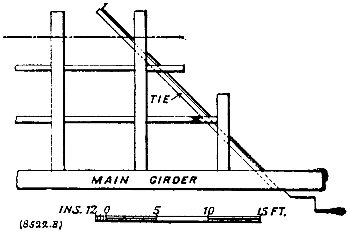

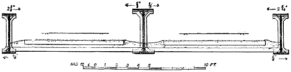
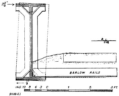
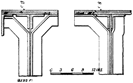
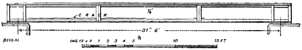
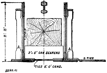
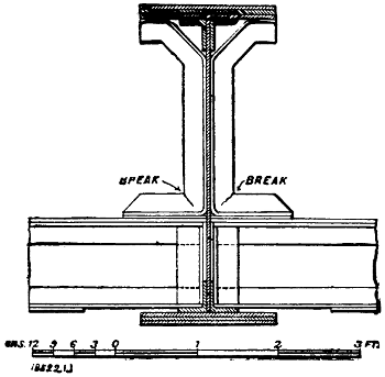
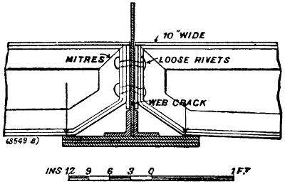
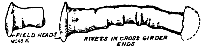
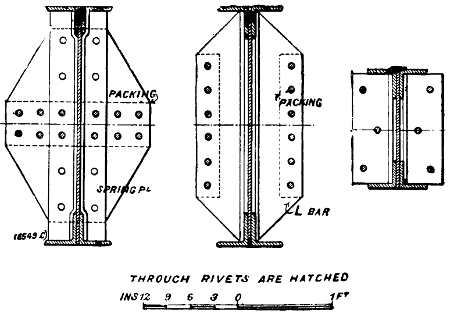
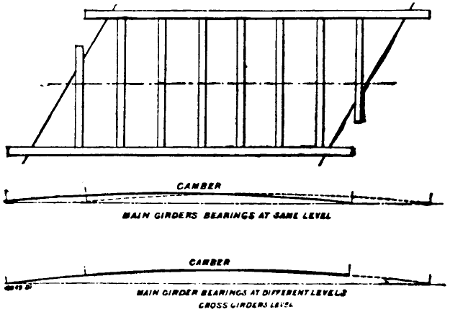
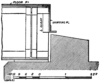
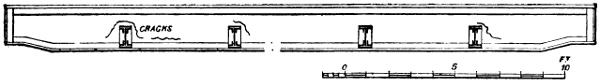
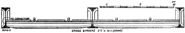
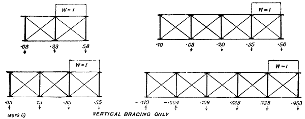
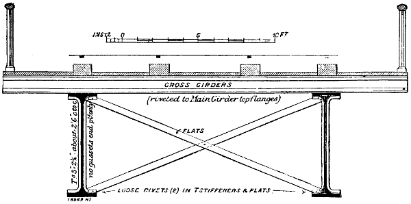
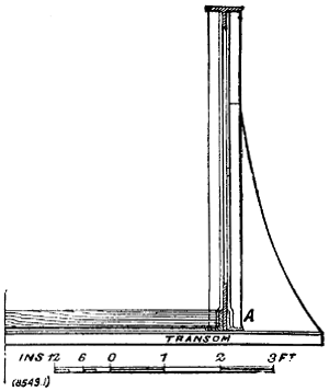
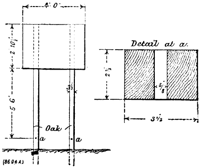
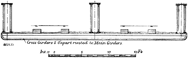
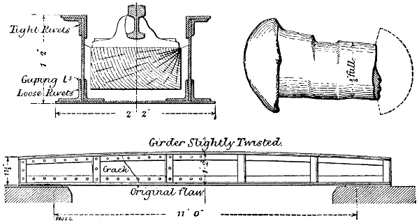
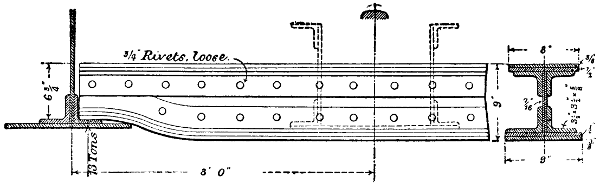
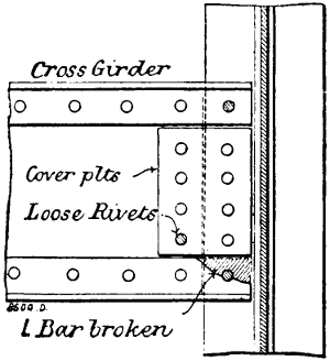
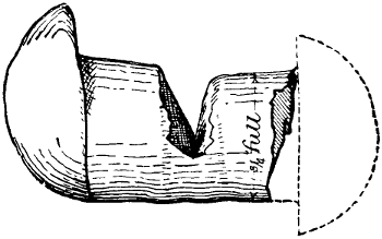
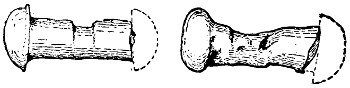
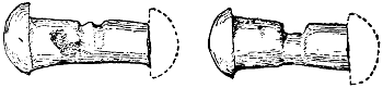
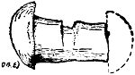
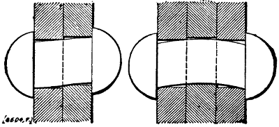
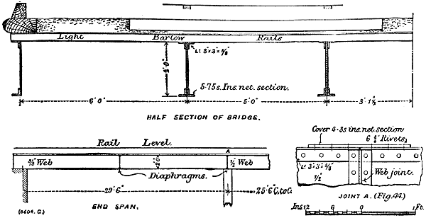
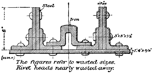
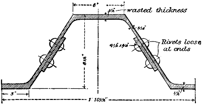
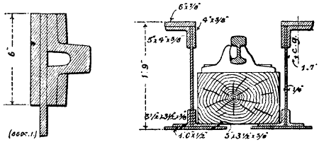
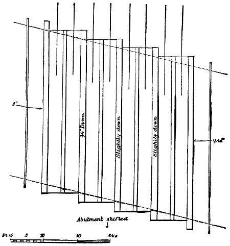
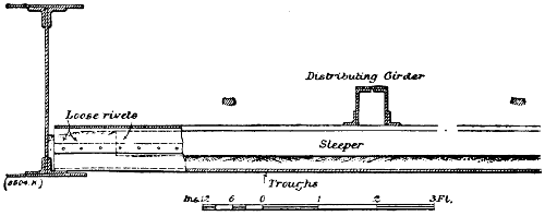

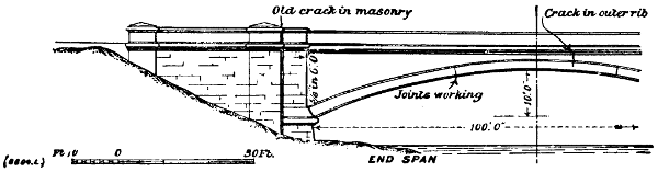
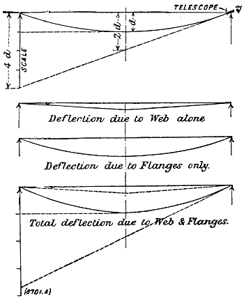
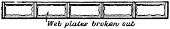
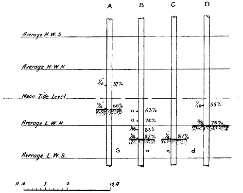
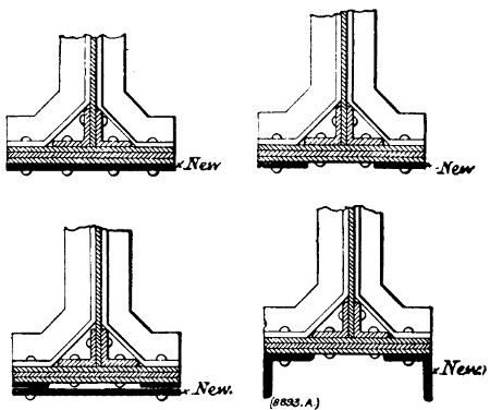
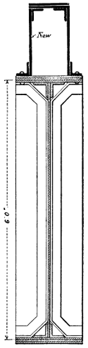
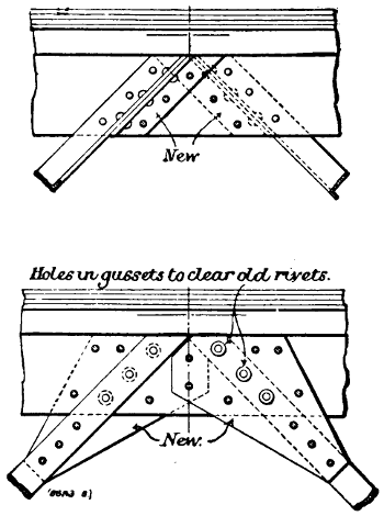
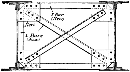
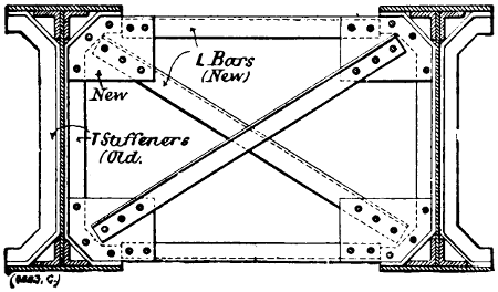
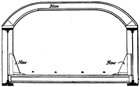
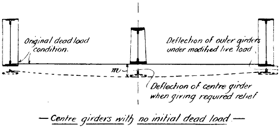
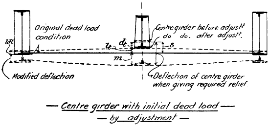
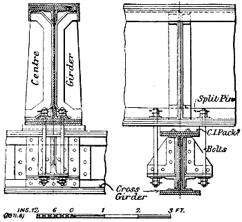
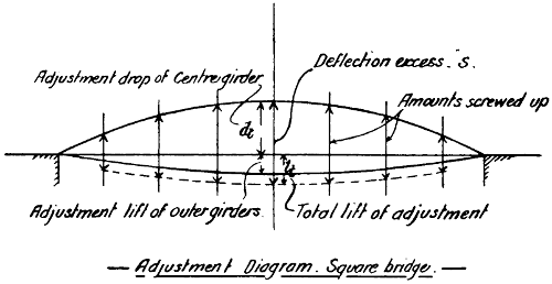
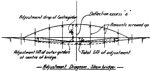
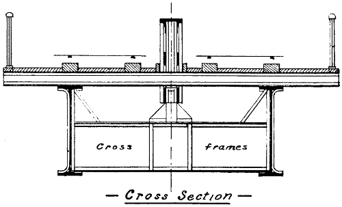
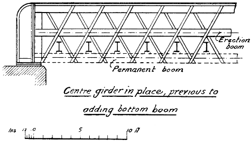
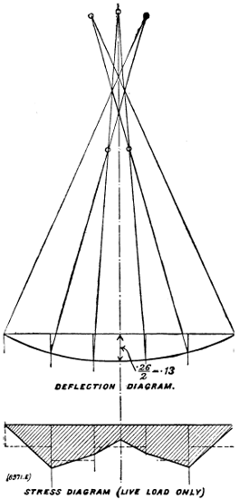
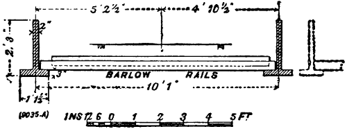
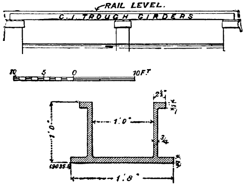
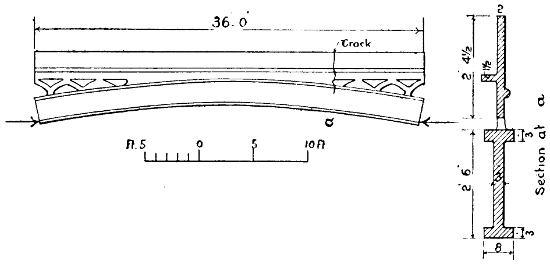
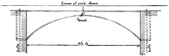
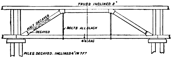
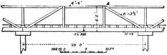
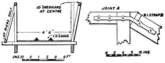
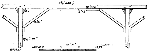

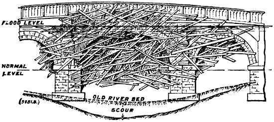
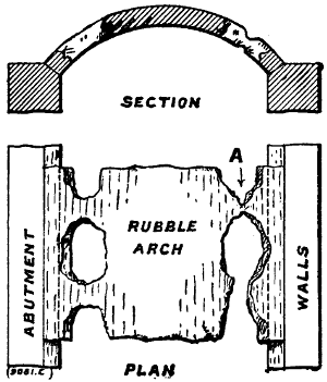
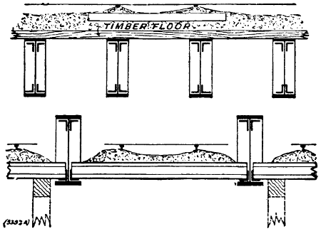
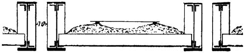
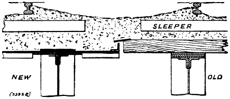
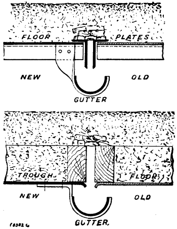
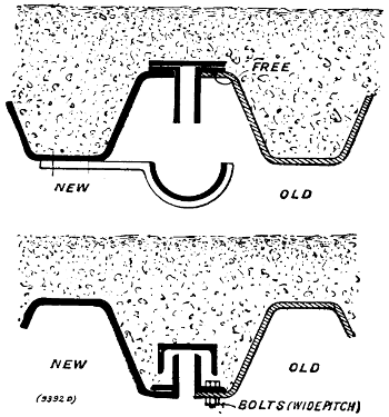
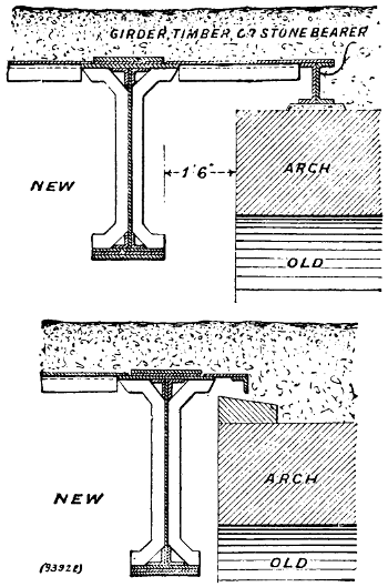
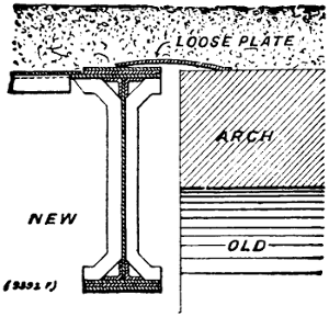
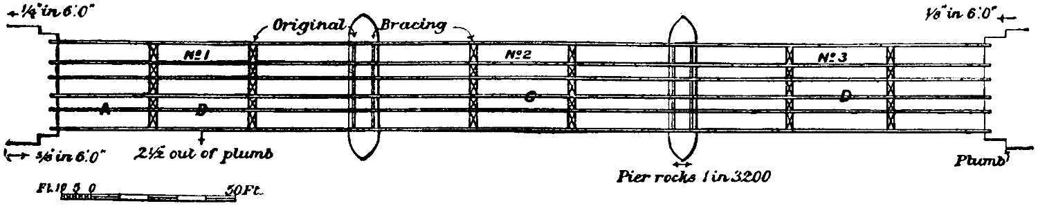