
The following Manual of Visual Signaling, prepared in the Office of the Chief Signal Officer, is approved and herewith published for the information and guidance of the Regular Army and the Organized Militia of the United States, and supersedes all other pamphlets or similar instructions heretofore issued upon the subject. Officers and men of the Signal Corps will thoroughly familiarize themselves with the instructions and suggestions contained herein.
By order of the Secretary of War.
| Page. | |
| Chapter I.—Introduction | 9 |
| Chapter II.—Visual signaling equipment. | |
| The wand | 11 |
| The flag kit: | |
| The 2-foot flag kit | 12 |
| The 4-foot flag kit | 12 |
| Care of flag material | 13 |
| Powers and limitations of flag signaling | 13 |
| The heliograph: | |
| Historical | 14 |
| Description | 14 |
| Assembling | 17 |
| Adjustment | 20 |
| Operation | 21 |
| Care of apparatus | 22 |
| Powers and limitations of the heliograph | 22 |
| The signal lantern: | |
| Acetylene | 23 |
| Calcium carbide | 23 |
| Method of gas generation | 24 |
| Description | 25 |
| Operation and care | 30 |
| Powers and limitations of the signal lantern | 35 |
| Rockets and shells: | |
| Description | 35 |
| Operation | 38 |
| Employment | 40 |
| [6]The semaphore: Description | 40 |
| The searchlight: Methods of employment | 41 |
| The Coston signals | 41 |
| Very's night signals | 42 |
| The Ardois system of signaling | 42 |
| Sound signals | 44 |
| Improvised signal methods | 44 |
Chapter III.—Alphabets or systems of signals. | |
| Signal alphabets: | |
| American Morse | 45 |
| Continental Morse | 45 |
| Army and navy | 45 |
| Abbreviations | 46 |
| Code calls | 47 |
| Execution of signal alphabets | 47 |
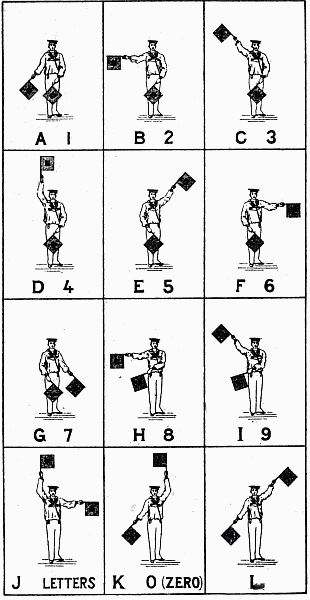
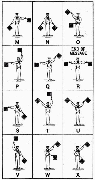
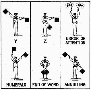
| The army and navy alphabet | 47 |
| The Morse alphabets | 49 |
| International code of signals: | |
| Description | 51 |
| Two-arm semaphore | 51 |
| The Ardois system | 52 |
| Coston signals | 54 |
| Very's night signals | 54 |
| Rocket signaling | 55 |
| Two-arm semaphore alphabet, U. S. Navy | 57 |
| Summary of signals, army and navy alphabet | 60 |
Chapter IV.—The field message. | |
| Definition | 64 |
| The blank form | 64 |
| Writing the message | 66 |
| Instructions to operators: | |
| Use of message blank | 66 |
| Duties of sending operators | 66 |
| Order of transmission | 66 |
| Duties of receiving operators | 67 |
| Communications confidential | 67 |
| [7]Checking the message | 67 |
Chapter V.—The signal station. | |
| Location of stations: | |
| General considerations | 68 |
| Backgrounds | 70 |
| Azimuth of stations | 71 |
| Altitude | 71 |
| Determination of background color | 72 |
| Choice of apparatus | 73 |
| Miscellaneous considerations | 73 |
| Intervisibility table | 74 |
| Finding a station | 75 |
| Operation of stations: | |
| Personnel | 76 |
| Calls and personal signals | 78 |
| Opening communication | 79 |
| Commencing the message | 80 |
| Sending and receiving | 80 |
| Breaking | 80 |
| Discontinuance of transmission | 81 |
| Acknowledgment of receipt | 81 |
| Station records | 81 |
| Formation of signals | 82 |
| Repeating the message | 83 |
| Signal practice | 83 |
Chapter VI.—Codes and ciphers. | |
| Codes in use | 84 |
| Employment of codes | 84 |
| Cipher code | 85 |
| The War Department Code | 86 |
| Cipher code in field work | 87 |
| Field ciphers: | |
| Description and use | 87 |
| Forms of field cipher | 88 |
| Inversions | 88 |
| Concealment of terminations | 88 |
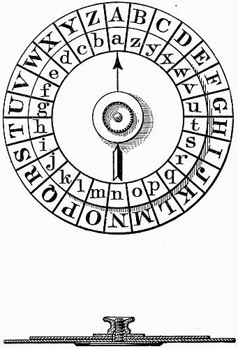
| Cipher apparatus: The cipher disk | 89 |
| The mathematical cipher | 93 |
| The route cipher | 94 |
| [8]Cipher detection: Employment of cipher disk | 96 |
Chapter VII.—Field glasses and telescopes. | |
| Reflection | 98 |
| Refraction | 98 |
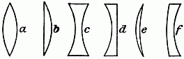
| Lenses | 98 |
| Focus | 99 |
| Optical center | 99 |
| Image | 99 |
| Conjugate foci | 99 |
| Law of foci | 100 |
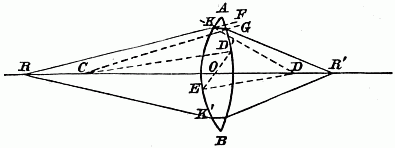
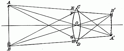
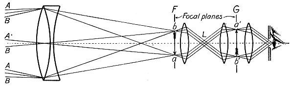
| Formation of image | 101 |
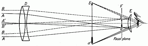
| Spherical aberration | 102 |
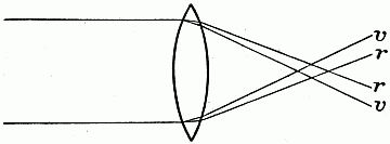
| Chromatic aberration | 102 |
| Telescopes | 104 |
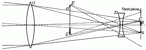
| Galilean field glasses and telescopes | 106 |
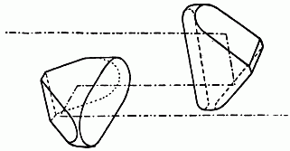
| Porro prism field glasses and telescopes | 106 |
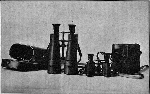
| Field glasses | 108 |
| Properties of telescopes and field glasses | 109 |
| Power | 109 |
| Light | 111 |
| Field | 114 |
| Definition | 115 |
| Field glasses and telescopes issued by the Signal Corps | 119 |
| Type A | 121 |
| Type B | 124 |
| Type C | 125 |
| Type D | 125 |
| Field-glass specifications | 126 |
While, in consequence of the development of electrical invention and improvement, visual signaling will be less frequently resorted to in future than heretofore in the service of field lines of information, it should be appreciated that the necessity for an adequate supply of apparatus of this kind, and the need for skilled manipulators to operate it, has in no wise diminished. The great celerity with which electric signals can be exchanged and their usual entire independence of local conditions has placed systems of this class foremost among the signaling methods of the world. There is scarcely any commercial industry whose successful existence does not vitally depend upon some one, perhaps several systems of signaling, and improvements of old and inventions of new signal devices are continually necessary to meet the requisite needs demanded by the progress of art and science. Railways are probably the greatest of all commercial users of signals. With them the great mass of intelligence is transmitted by the electric telegraph and telephone, but the flag, the semaphore, the signal light, and many other contrivances furnish indispensable visual adjuncts. Visual signaling is and always will be a most valuable means of transmitting information[10] in peace and war, and it is not to be imagined that it will ever be supplanted in its particular function by the introduction of other methods. Occasions will frequently occur in the field when no other means will be practicable, and then, if not before, will the value of the system be fully emphasized.
Strictly speaking, a visual signal is any visible sign by which intelligence is communicated, but in a military sense the term visual signaling has a broader meaning and includes other methods of transmitting information than those which appeal to the sense of sight.
In most systems of signals suitable for military use, each signal is composed of one or more separate units, known as elements. Having prescribed a certain number of elements, the various signals are formed by having these elements appear singly or together in different arrangements or combinations. The continental system is one of two elements, namely the dot and the dash, while the Morse system employs three elements, the dot, the dash, and the space. Having agreed upon a certain number of combinations of elements, a system of signals is formed by giving a meaning to each combination. These meanings usually include the letters of the alphabet and numerals, combinations of which being used to formulate necessary information. Combinations of elements of any system can also, however, be used to indicate any desired meaning.
With reference to period of visibility, signals are of two kinds, transient and permanent. A transient signal is one which disappears as soon as completed;[11] a permanent signal is one that remains in view for some time. Heliograph signals are transient signals, while signals made by code flags are permanent signals. Signals are divided into classes in accordance with the number of elements employed in their formation. Thus, signals using two elements are signals of the second class, signals using three elements signals of the third class, etc.
The standard apparatus used in visual signaling is fully described in a succeeding chapter. Some of the instruments employed are used wholly for day, and some wholly for night, signaling. Some devices, either with or without slight variations, are equally well adapted to day or night work. Visual signaling presents a great field for ingenious and resourceful work, and emergency will often demand the advantageous employment of other methods than those described herein.
The wand is a stick of light wood about 18 inches long and one-half inch in diameter. It is held loosely between the thumb and forefinger and waved rapidly to the right or left to indicate the elements of the alphabet. It is used for practice purposes and the signals made by it are only intended to be read at very short distances.
Two kinds of flag kits, the 2-foot kit and the 4-foot kit, are issued by the Signal Corps.
The 2-foot kit.—This kit consists of one white and one red signal flag, two three-jointed staffs, and a suitable carrying case to contain the outfit. The white flag is made of white muslin 2 feet square, with an 8-inch turkey-red muslin center. The red flag is of similar size and material, the only difference being an alternation of colors in the body and center. The means of attachment to the staff consists of a loop at the center, and two ends of white tape at each edge, of the back of the flag body. The staff is made of hickory in three joints, each 23 inches long, and is assembled by telescoping into brass ferrules. Brass eyes are provided on the first and second joints to receive the tape ends at the edge of the flag. The carrying case, of convenient size and shape to contain the two flags and staffs complete, is made of 8-ounce standard khaki bound with leather and fitted with a shoulder strap.
The 2-foot kit is essentially a practice kit, although under favorable conditions of weather and terrain it may be used to advantage as a short distance service signaling outfit. Two of these kits are issued to each troop, battery, and company for the purpose of disseminating general instruction in military signaling throughout the army.
The 4-foot kit.—This kit is of essentially the same description as the 2-foot kit except as regards size. The flags are 3 feet 9 inches square with 12-inch centers[13] and the staffs are considerably heavier, the joints being each 36 inches long. The 4-foot kit is the standard field flag kit and the range at which signals can be exchanged with it depends on a variety of factors, such as the condition of the weather, the location of stations, the proficiency of signalmen, etc. The speed for continuous signaling is seldom greater than five to six words per minute.
Care of flag material.—Signal flags should be examined at the close of drill or practice and repairs made to any rents or loose ties discovered. Flags, when soiled, should be thoroughly washed and dried in the sun. Signals made by clean flags are much more easily read than those made by dirty ones. Staffs should be handled with care, especially when jointing or unjointing. Care should be taken not to bruise the ends of the brass ferrules. If a ferrule becomes loose on a staff it should be tightened without delay.
Powers and limitations of flag signaling.—The advantages which may be claimed for this method of signaling are portability of apparatus, adaptability to varied weather conditions, and great rapidity of station establishment. The disadvantages are the lack of celerity of the signals, their impenetrability to dust or smoke, and the comparatively short ranges at which they can be read.
The heliograph is an instrument designed for the purpose of transmitting signals by means of the sun's rays.
Historical.—Experiments with the heliograph with a view to its adoption as a part of the visual signaling equipment of the United States Army were commenced as early as 1878. The reported successful use of the instrument by the British in India about this time led to the importation of two heliographs of the Mance pattern. A series of experiments with these machines conducted for the purpose of eliminating certain objectionable features finally resulted in the evolution of the present type of service heliograph.
The early English heliograph was not provided with a shutter, the flash being directed on the distant station by means of a movable mirror controlled by a key. The great objection to this type of instrument was the impossibility of maintaining accurate adjustment during the transmission of signals due to the fact that the manipulation of the mirror tended to throw the flash constantly out of alignment. To overcome this, the American heliograph has been provided with a screen designed to operate as a shutter and control the flash reflected from an immobile mirror.
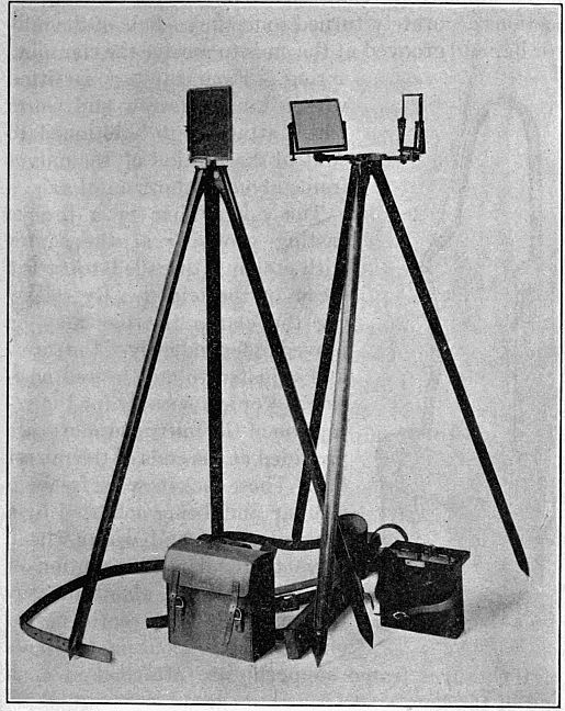
Description.—The service heliograph equipment of the Signal Corps consists of:
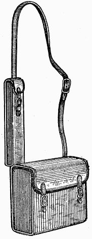
A sole-leather pouch with shoulder strap containing—
1 sun mirror. } Inclosed in a wooden box. 1 station mirror. 1 screen, 1 sighting rod, 1 screw-driver. A small pouch, sliding by 2 loops upon the strap of the larger pouch, containing 1 mirror bar.
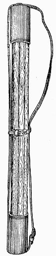
A skeleton leather case containing 2 tripods.
The mirrors are each 4½-inch squares of plate glass supported by sheet brass and cardboard backings, and mounted in brass retaining frames. At the center of[15] each mirror there is an unsilvered spot three thirty-seconds of an inch in diameter and holes corresponding to these spots are drilled in the backing. The sun mirror differs from the station mirror only in that it[16] has a paper disk pasted upon its face covering the unsilvered spot. The mirror frames are carried by brass supports provided at the bases with conical projections accurately turned to fit the sockets of the mirror bar and grooved at the ends to receive the clamping spring. Each support is fitted with a tangent screw and worm wheel attachment functioned to control the motion of the mirror frame about its horizontal axis.
The mirror bar is a bronze casting provided at the center with a clamp threaded to fit the screw of the tripod. By releasing the clamp the bar may be moved independently of the screw and adjusted to any desired position. Conical sockets for the reception of the mirror supports are provided at the ends of the mirror bar. These sockets work freely in the bar and, being actuated by a tangent screw and worm wheel, serve to regulate the motion of the mirror frame about its vertical axis. Clamp springs, for engaging and securing the ends of the mirror frame supports, are attached at each end of the bar.
The screen is a brass frame 6½ inches square, in which six segments or leaves are mounted in such a way as to form a shutter. The leaves are designed to[17] turn through arcs of 90° on horizontal axes, unanimity of movement being secured by connections made with a common crank bar. The crank bar is operated by a key and retractile spring which serve to reveal and cut off the flash. A set screw and check nut at the lower edge of the screen frame limits the motion of the crank bar and the opening of the leaves. A threaded base support furnishes the means of attaching the screen frame to the tripod.
The sighting rod is a brass rod 6½ inches long, carrying at the upper end a front sight and a movable disk. About the rod is fitted a movable bronze collar, coned and grooved to take the socket and clamping spring of the mirror bar. A milled edged bronze washer serves to clamp the collar to the rod at any desired point.
The tripods are similar in all respects, the screw of either threading into the mirror bar or screen frame. Each tripod is provided with a hook at the base of the head, allowing the suspension of a weight when great stability is required.
Assembling.—There are two ways of assembling the heliograph and the position of the sun is the guide in determining which of the two[18] should, in any given case, be employed. When the sun is in front of the operator (that is, in front of a plane through his position at right angles to the line joining the stations) the sun mirror only is required; with the sun in rear of this plane both mirrors should be used. With one mirror the rays of the sun are reflected directly from the sun mirror to the distant station; with two mirrors, the rays are reflected from the sun mirror to the station mirror, and thence to the distant station.
With one mirror: Firmly set one of the tripods upon the ground; attach the mirror bar to the tripod; insert and clamp in the sockets the sun mirror and sighting rod, the latter having the disk turned down. At a distance of about 6 inches, sight through the center of the unsilvered spot in the mirror and turn the mirror bar, raising or lowering the sighting rod until the center of the mirror, the extreme point of the sighting rod, and the distant station are accurately in line. Firmly clamp the mirror bar to the tripod, taking care not to disturb the alignment, and turn up the disk of the sighting rod. The mirror is then moved by means of the tangent screws until the "shadow spot" falls upon the paper disk in the sighting rod, after which the flash will be visible at the distant station. The "shadow spot" is readily found by holding a sheet of paper or the hand about 6 inches in front of the mirror, and should be constantly kept in view until located upon the disk. The screen is attached to a tripod and established close to, and in front of, the sighting disk, in such a way as to intercept the flash.
With two mirrors: Firmly set one of the tripods on the ground; clamp the mirror bar diagonally across the line of vision to the distant station; clamp the sun mirror facing the sun to one end of the mirror bar and the station mirror facing the distant station. Stooping down, the head near and in rear of the station mirror, turn the sun mirror by means of its tangent screws until the whole of the station mirror is seen reflected in the sun mirror and the unsilvered spot and the reflection of the paper disk accurately cover each other. Still looking into the sun mirror, adjust the station mirror by means of the tangent screws until the reflection of the distant station is brought exactly in line with the top of the reflection of the disk and the top of the unsilvered spot of the sun mirror; after this the station mirror must not be touched. Now step behind the sun mirror and adjust it by means of the tangent screws so that the "shadow spot" falls upon the center of the paper disk on the station mirror. The flash will then be visible at the distant station. The screen and its tripod are established as described in the single mirror assembling.
Alternate method with two mirrors: Clamp the mirror bar diagonally across the line of vision to the distant station, with the sun mirror and the station mirror approximately facing the sun and distant station, respectively.
Look through small hole in sun mirror and turn the station mirror on its vertical and horizontal axes until the paper disk on the station mirror accurately covers the distant station.
Standing behind sun mirror, turn it on its horizontal and vertical axes by means of the tangent screw attachments until the shadow spot falls upon the paper disk on station mirror.
Adjustment.—Perfect adjustment is maintained only by keeping the "shadow spot" uninterruptedly in the center of the paper disk, and as this "spot" continually changes its position with the apparent movement of the sun, one signalman should be in constant attendance on the tangent screws of the sun mirror. Movement imparted by these screws to the mirror does not disturb the alignment, as its center (the unsilvered spot) is at the intersection of the axes of revolution. Extra care bestowed upon preliminary adjustment is repaid by increased brilliancy of flash. With the alignment absolutely assured and the "shadow spot" at the center of the disk, the axis of the cone of reflected rays is coincident with the line of sight and the distant station receives the greatest intensity of light. Remember the distant observer is unquestionably the better judge as to the character of the flash received; and if therefore, adjustment is called for when the "shadow spot" is at the center of the disk, the alignment is probably at fault and should be looked after at once. In setting up the tripods always see that the legs have a sufficient spread to give a secure base and on yielding soil press firmly into the ground. Keep the head of the tripod as nearly level as possible and in high wind ballast by hanging a substantial weight to the hook. See that the screen completely obscures the flash; also that the flash passes entire when the screen is opened. This feature of the adjustment is partially regulated[21] by the set screw attached to the screen frame. The retractile spring should sharply return all the leaves of the screen to their normal positions when the key is released. Failure to respond promptly is obviated by strengthening or replacing the spring.
Operation.—It is of the utmost importance that uniformity in mechanical movement of the screen be cultivated, as lack of rhythm in the signals of the sender entails "breaks" and delay on the part of the receiver. Dark backgrounds should, when practicable, be selected for heliograph stations, as the signals can be most easily distinguished against them.
To find a distant station, its position being unknown, reverse the catch holding the station mirror and with the hand turn the mirror very slowly at the horizon over the full azimuth distance in which the distant station may possibly lie. This should be repeated not less than twice, after which, within a reasonable time, there being no response, the mirror will be directed upon a point nearer the home station and the same process repeated. With care and intelligence it is quite probable that, a station being within range and watching for signals from a distant station with which it may be desired to exchange messages, this method will rarely fail to find the sought-for station.
The exact direction of either station searching for the other being unknown, that station which first perceives that it is being called will adjust its flash upon the distant station to enable it when this light is observed to make proper adjustments. If the position of each station is known to the other, the station[22] first ready for signaling will direct a steady flash upon the distant station to enable the latter to see not only that the first station is ready for work, but to enable the distant station to adjust its flash upon the first station.
Smoked or colored glasses are issued for the purpose of relieving the strain on the eyes produced by reading heliograph signals.
Care of apparatus.—Minor parts of the instrument should be dismounted only to effect repairs, for which spare parts are furnished on requisition. Steel parts should be kept oiled and free from rust. Tangent screws and bearings should be frequently inspected for dust or grit. Mirrors should invariably be wiped clean before using. In case of accident to the sun mirror, the station mirror can be made available for substitution therefor by removing the paper disk. If the tripod legs become loose at the head joints, tighten the assembling screws with the screw-driver.
Powers and limitations of the heliograph.—Portability, great range, comparative rapidity of operation, and the invisibility of the signals except to observers located approximately on a right line joining the stations between which communication is had, are some of the advantages derived from using the heliograph in visual signaling.
The principal disadvantage results from the entire dependence of the instrument upon the presence of sunlight. The normal working range of the heliograph is about 30 miles, though instances of its having attained ranges many times greater than this are of record. The heliograph can be depended upon to transmit from five to twelve words per minute.
The signal lantern is an instrument designed for the purpose of transmitting signals by means of intermittent flashes of artificial light. It is the standard night visual signaling equipment furnished by the Signal Corps and depends for its illumination upon the combustion of acetylene gas.
Acetylene.—Acetylene is a pure hydrocarbon gas, producible in various ways, the commoner of which are: (a) By dropping calcium carbide into water; (b) by dropping water upon calcium carbide. This gas gives, when burning, high penetrative power, and was first described by Mr. Edmund Davy, professor of chemistry to the Royal Dublin Society, in 1836.
Calcium carbide.—In the manufacture of calcium carbide for commercial purposes the best quality of coke and quicklime are used. These two substances are powdered thoroughly, mixed in proper proportions, and then placed in an electrical furnace. Under the action of the intense heat (5,500° F.) these two refractory substances unite and form calcium carbide. Calcium carbide is of a grayish-white color, crystal in appearance, and is nonexplosive and noncombustible, being, except for its affinity for water, an absolutely inert substance. A pound of commercial carbide will produce approximately 5 cubic feet of gas. When water is brought in contact with calcium carbide, the generation of acetylene is rapid; owing to its strong affinity for water it will become air slacked and slowly lose its strength if exposed to the action of the moisture in the atmosphere; consequently, when stored or being transported it should be kept in air-tight cans.
When calcium carbide is brought in contact with water, the following occurs:
As is known, the principal components of water are oxygen and hydrogen, and calcium carbide is calcium and carbon. When brought in contact, the oxygen in the water decomposes the calcium in the carbide, and in this decomposition the hydrogen in the water is liberated and unites with the carbon of the carbide, forming a hydrocarbon gas which is acetylene. It is a pure white light of intense brilliancy and high candlepower. The spectrum analysis of acetylene shows that it is almost identical with sunlight, and in consequence delicate shades of color appear according to their true value as under the light of the sun, consequently it penetrates fog to a greater distance than other lights. Acetylene is like other gases—explosive when mixed with air in proper proportions, confined, and ignited—and the same precautions should therefore be taken in its use as would be in the handling of coal or water gas, gasoline vapor, etc. As acetylene is very rich in carbon, it will not burn in its pure state without smoking. To avoid this, burners have been constructed so that the gas is mixed with the proper proportion of air at the burner tip, to insure perfect combustion. The burners for acetylene are different from those for other gases. In order to get a flat flame, the gas is brought through two perfectly round holes at an angle which causes the two flames to impinge upon each other and thus form a flat flame.
Method of gas generation.—The method employed for producing acetylene in the signal lantern is by bringing water into contact with calcium carbide.[25] The disadvantage of this method is that when the water is not in excess and does not entirely surround and touch each piece of carbide the heat of generation will so change the chemical properties of the gas that combustion at the burners is not satisfactory.
This change is technically known as "polymerization," or the breaking up of acetylene into other hydrocarbons, such as vapors of benzine, benzole, etc. These form a tarry substance which is apt to condense at the burner tip and clog the openings. Also they deposit carbon on the burners, as they require more air for perfect combustion than does pure acetylene. Another disadvantage of this system is that after the carbide and water are in contact, generation of gas will continue until all the water is absorbed. Where, however, portability of the generating apparatus is desired and resort to this method is necessary, the objections are not important, if the apparatus is well constructed and care is taken in its use.
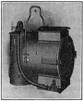
Description.—This equipment consists of a signal lantern with cartridge generator attached. The lantern is equipped with a special aplanatic lens mirror, 5 inches in diameter and about 3 inches focus. The lantern is packed complete in a wooden case with shoulder straps and the following extra parts are included, each part having its own receptacle in the case: 2 burners; 1 cover glass; 3 cartridges of calcium carbide of 5 ounces each; 1 pair of gas pliers; 1 tube white lead; 1 extra filter bag; 1 screw-driver.
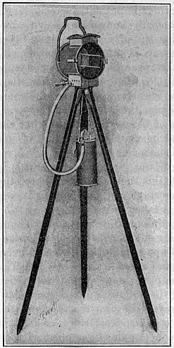
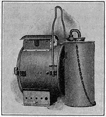
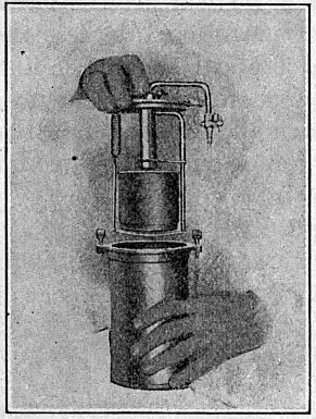
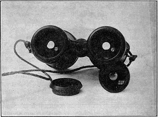
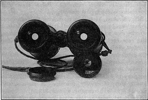
The lantern is made of brass, all parts of which are riveted. The burner is of the double tip form, consuming three-quarters of a cubic foot per hour. The[26] lantern is fitted with a hood to provide proper ventilation and at the same time to prevent the flickering of the light by the wind. The front door of the lantern is hinged and fastens with a spring clasp; it is so arranged that it can be entirely removed if necessary. The cover glass is made in three sections and is not affected by the expansion and contraction of the metal due to changes in temperature. The glass is fastened by the aid of a spring wire, so that it can be readily removed if it is necessary to replace a broken section. In the base of the lantern is a key and the adjustment for regulating the height of the flame. The key is so arranged that when not depressed but little gas is admitted through the by-pass to the burner[27] and the flame is low. By depressing the key as much gas as can be entirely consumed is admitted to the burner, which gives a bright flash. At the back of the lantern there is an adjustable handle, so that the equipment can be used as a hand lantern if desired. This form of lantern can be used with the regular heliograph tripod, the generator being either attached to the back of the lantern or suspended, as shown in figure 4. When practicable it is better to attach the generator to the lantern, as shown in figure 5. The candlepower of this lantern is about 1,900.
The generator used is known as "the cartridge generator," and while constructed on the water-feed principle, the disadvantages incident to this method are eliminated as far as possible. It is constructed of brass and has a removable top. Attached to the inside of the top is a flexible frame with a spring latch, the spring latch being hinged. (Fig. 8.) At the top of the frame is a tube or cylinder, the bottom of which is conical in shape and covered by a rubber plug. At the bottom of the frame is a hollow tube, which is the water inlet. The cartridge proper consists of a tin cylinder, having an opening at either end. A small cylinder of wire mesh extends from and connects these[28] openings. The carbide lays around this mesh on the inside of the cartridge. The rubber plug before mentioned fits into the upper opening, and the water tube into the lower opening. (See figs. 7, 8, and 9.) Inside the tube, at the top of the frame, is a filter, the function of which is to remove the dust and moisture from the gas. The outlet from this chamber is by a brass bent tube having a stopcock attached thereto.
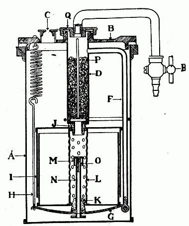
Figure 6 gives a sectional view of the generator with the cartridge in place. D F G H represent the valve frame and I the cartridge attached. The reservoir A is filled with water, and when the frame is immersed, with the valve R closed, the air contained in the cartridge and tubing can not escape, the water seal preventing, while the confined air prevents the water from rising in the tube N. When the valve at R is opened and the air is allowed to escape, part of the water from the reservoir rises into the tube N and then out through the small hole O to the carbide. Gas is immediately generated, the pressure of which prevents further ingress of the water from the tube N, and the generation of gas is suspended.
As the gas passes out through the valve at R the pressure decreases, permitting the water to again rise in the tube and flow through O. Gas is again generated, which at once exerts its pressure and cuts off the supply of water. This is the automatic action by which water is brought in contact with the calcium carbide. Thus it will be observed that the use or escape of the gas regulates the generation by the simple device of the rise and fall of a water column. There is a cap M screwed over the tube N. This is[29] used to deflect the course of the water downward, so that the carbide in the lower part of the cartridge is first attacked. There is a needle inside of cap M, which can be used for cleaning the hole O. When the gas is generated it passes through the filter D on its way to the burner through R. This filter consists of a tube loosely packed with ordinary nonabsorbent cotton, which should never cover the escape pipe leading to the valve R. In passing through this cotton filter moisture and dust are removed from the gas. In the latest model a felt filter is used instead of cotton.
The escape pipe F provides a means for the escape of gas generated and not used or generated more rapidly than consumed. Should an excess be generated, it passes down through the tube F, and, finding its way through some small holes in the bottom of this tube, escapes through the water seal and the opening at C. It will be noted that if escaping gas at C should become accidentally lighted, the flame can not strike back into the filter and cartridge because of the water seal. The[30] principal things to observe in the operation of this generator are the following:
(1) To see that the rubber plugs fit tightly into the openings of the cartridge.
(2) That the tube N, the cap M, and water hole O are not stopped up.
(3) That the cotton in the filter is changed frequently.
(4) That the stopcock R is closed before inserting the frame in the water. If this latter instruction is not complied with, it can be readily seen that the water will have free access to the carbide and excessive generation will occur.
When the charge is exhausted, the entire cartridge is taken out and thrown away. This eliminates the handling of carbide and the disagreeable task of cleaning out the residuum after the gas has been extracted.
Connection is made from the stopcock R to the hose connection on the lantern proper, and this is the passageway of the gas from the generator to the burner. As soon as the stopcock is opened the water rises through the tube and flows to the carbide. The advantage of the cartridge being submerged in the water is to reduce and absorb as much of the heat liberated by generation as is possible. These lanterns have been tested up to a distance of 10 miles with the naked eye, and under favorable conditions can be used over a range somewhat in excess of this. With a 30-power telescope the flash can be read at a distance of 30 miles.
Operation and care.—Take the lamp and generator from the case by aid of the handle attached to the[31] lamp; screw the complete outfit on a heliograph tripod, or stand the outfit on a level object; remove the cover of generator, to which is attached the flexible frame (fig. 9); detach spring from the catch of the flexible frame; tear off flaps from the ends of carbide cartridge (or pry off small caps) and attach the cartridge as shown in figure 9. Then attach to frame as shown in figure 10, being careful to see that both rubber plugs fit tightly into the holes in the cartridge; fasten the latch of the spring over the metal catch; close stopcock R on service pipe; completely fill the outer can of generator with water, the object being to have the generator level full of water when the lamp is in service, then immerse the frame and cartridge, pressing the top of the generator down tight. In doing this the water will overflow the sides of the generator tank. Now connect by rubber tubing the stopcock with the gas inlet at the bottom of the lamps, as shown in figure 4; then (1) open front door of the lamp, (2) light a match, (3) open stopcock, and (4) light the gas at the burner. In doing this hold the key open. In the new model the key and hose connection are on the side of bottom of lamp.
When the gas is ignited, the lamp is ready for signaling, and the key can be operated as is the Morse telegraph instrument, but of course not so rapidly.
In the event of the flame being too high when the key is closed, adjustment can be made by loosening the set screw (fig. 4, indicated by an arrow) and adjusting the light by turning screw b. When at the proper height, tighten the set screw which locks the by-pass in its proper position. In the new model this is[32] accomplished by aid of the regulator by-pass valve at the left-hand side of bottom of lamp. The lamp is properly adjusted when shipped and should not be changed unless absolutely necessary. Connect the rubber tube to the burner before opening the stopcock on the generator.
To recharge the generator, take the frame and the old cartridge from the case, throw away the old case and replace with a fresh one, proceeding as before. See that fresh water is put in the generator each time a new cartridge is used.
In the tube through which the service pipe passes is a felt filter for taking the dust out of the gas. If the filter clogs, unscrew the cap to which the service pipe is attached, clean the felt, or replace it with a new filter, binding it in place by a stout thread or string.
If the burner of the lamp does not produce a perfectly flat flame it has become clogged and should be cleaned with the burner cleaner furnished, or a new burner should be substituted, care being taken to put a little white lead on the nipple, if practicable, so as to insure a tight joint.
In repacking the outfit in the case, throw out the water and wipe the can and generator parts dry. You can not be too careful to keep the apparatus clean. This is especially true of the small pipe that passes up through the bottom of the cartridge, with a cap over it. The cap should always be screwed in place, as its object is to prevent the water from squirting to the top of the cartridge.
The back of the lamp can be removed by turning the small thumbscrew on the top and drawing out the pin which holds the shell into which is fitted the lens. It is not necessary to take the back out except to replace a lens, as the latter can be cleaned by opening the front door.
If it is desirable to use the lamp as a hand lantern the flame can be turned on full by turning the button in a vertical position; this locks the key open. In the new model depress the key and lock it with the latch above the key.
One charge of calcium carbide will supply gas to burn about one hour with the light turned on full, or for approximately three hours' signaling.
If signaling is to be suspended for some hours, empty the water out of the generator and close valve R.
The glass front can be replaced by taking out the wire spring. The glass cuts should be mounted in a horizontal position and, to prevent breaking, should be protected from rain when the lamp is hot. If a glass should be broken and an extra one is not available to replace it, signaling can be continued by turning the flame on full and using the heliograph shutter,[35] a cap or piece of board in front of the lantern to obscure and reveal the flash. Without the protection of the cover the flame is easily blown out when turned low, but will not be extinguished even in a strong wind if the gas is turned full on.
Old model lamps are serially numbered from 1 to 200, inclusive; the new model lamps are serially numbered from 201 upward.
Powers and limitations of the acetylene signal lantern.—As conditions are usually more uniform at night than in the daytime, the signal lantern is probably the most reliable of all visual signaling outfits. The advantages of this form of apparatus are its portability, speed of operation, and comparatively great range. The principal disadvantages are due to the interference caused by rain, fog, and moonlight. The speed attainable with the lantern is about the same as that attainable with the heliograph.
Two distinct kinds of rockets and shells are issued, one of which is adapted to day and the other to night signaling. Shells and rockets of the amber smoke type with parachutes are used in the daytime, while shells (red and white) and sequence rockets are used at night.
Description.—The shells are all single shot and are
fired from a 5-inch portable mortar, attaining a height
of about 550 feet. The report of explosion can be
heard at varying distances up to 5 miles, depending
on weather conditions. The parachute attached to
the smoke shell suspends a small light wooden tube[36]
[37]
[38]
which, after ignition, emits smoke for from four to
six seconds. The red and white shells, on bursting,
discharge a shower of red and white fire which can
be observed for some time, in fact almost until the
sparks fall to the ground.
Rockets for both day and night signaling are equipped with parachutes. The smoke rocket is of similar construction to the smoke shell. The sequence rocket is so arranged at the base that threaded sections of combustible material burning either red or white can be attached to it. Rockets ascend about 700 feet.
Each rocket and shell is supplied in a cylindrical sealed tin can, which also contains a port fire, wind matches, and for the rockets a stick in four sections. On the outside of the can is a label designating the kind of shell or rocket therein contained. These cans are easily opened by pulling a ring and require no special opening tool.
Operation.—In firing shells the mortar should be surrounded by earth or sand, preferably placed in sacks. The fuse for all shells is very rapid and should be ignited by attaching the port fire to a long stick.
All of the old type Signal Corps mortars, originally designed to withstand a pressure of 1,000 pounds per square inch, and made of ordinary iron pipe, are considered unsafe and should be immediately destroyed. The new mortars, recently made for the Signal Corps by the Ordnance Department, are of cold-drawn steel having a tensile strength of 6,000 pounds per square inch, which is more than the maximum pressure for firing any of the Signal Corps bombs. They are[39] stamped "Signal Corps, U. S. A., Model 1907," or "Rocket Gun, Watertown Arsenal, 1907."
The sequence rocket is prepared for use by attaching red or white sections to the base in such a combination as to form letters of the alphabet which it is desired to use. Letters containing the same color in sequence are very difficult to read and should be avoided whenever possible. If necessary to use them, blank sections furnished for the purpose should be inserted between the units. The base of the rocket will secure six units.
When rockets are to be fired the sticks must be firmly attached, the rocket placed upright in a trough, upon a frame, or against a post. If the fuse is beneath the paper covering the "choke" orifice, the paper should be torn off and the rocket ignited by a port fire. In the rockets now used the fuse extends through the covering and can be lighted direct. If the night be damp this fuse should be exposed only a moment before the rocket is fired. If several rockets are to be fired in succession it is well to prepare them all at the same time, and to have them all stood upright, but each separated from the other at a distance of at least 6 feet, else one may ignite the other accidentally. In firing for chronosemic signals, one rocket ought to be kept ready upon the frame and in reserve, to be fired in place of one that fails.
If a rocket misses fire it is to be taken from the stand and laid on the ground. Its place is at once supplied by a similar rocket, fired in its stead. The failing rocket is laid on the ground pointed away from the station in order that if it has only hung fire and[40] should afterwards ignite it may not disarrange the signal shown or injure any one of the party. If the wind blows freshly the rocket to be fired should be inclined slightly against the wind.
Signal rockets and shells are furnished in sealed cans and should not be removed therefrom until ready for use. Strict economy should be observed in the use of these articles and on no account should they be used for purposes of display.
Employment.—Rockets and shells are especially valuable in making preconcerted or emergency signals. On account of the great amount of ammunition required it is impracticable to spell out messages with them. These articles should be supplied to outposts, detached stations, etc., to be used for signaling the approach of the enemy or the happening of unexpected events, the necessity for promptly knowing which is important.
If signal stations are to be permanently occupied, and it is impracticable to electrically connect them, communication may be facilitated by erecting semaphores.
Semaphores, while primarily used for day signaling, can be advantageously used at night by attaching lights to the arms.
The navy semaphore consists of four arms pivoted at the ends, three on one side of the upright, or pole, and one on the other side. These arms have three positions: Horizontal; upward at an angle of 45° to the horizontal; downward at an angle of 45° to the horizontal.
Full instructions for the operation of the semaphore, and also for the use of balls, cones, drums, pennants, and whefts as distant signals, are given in the International Code of Signals.
The electric searchlight, when available, can often be successfully employed for night signaling, frequently affording efficient means of communication between ships and shore stations, when wireless working is impracticable. This system of visual signaling is practicable and especially valuable where the stations are, on account of the terrain, not intervisible.
Methods of employment.—In signaling with the searchlight the usual method of handling the shaft or beam is identical with that employed with the flag. In the first position the beam is shown vertically, while motions to the right, the left, and directly serve to indicate the elements of the alphabet. Chronosemic signals may also be used in searchlight signaling, the shaft of light being directed intermittently on some conspicuous object, such as a cloud, balloon, or high mountain top.
These signals are pyrotechnic compositions which burn with great intensity of light and color. The colors red, white, and green are found best suited for signaling. The signals are prepared in the form of cartridges and are burned from a holder. The colors burned may indicate the elements of any alphabet, or such other special signals as may be desired.
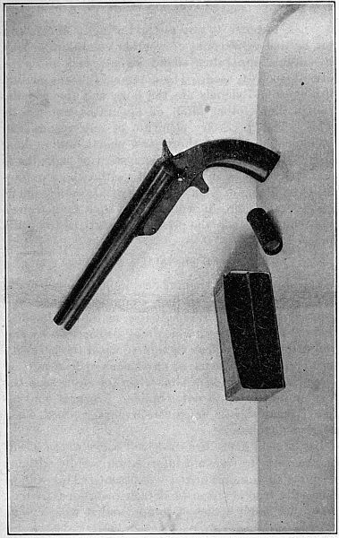
The Very system employs projected red, white, and green stars, which are shot from pistols held in the hand.
Description.—The Very pistol is a breechloading, single-shot pistol with an 8-inch steel barrel chambered to receive a 12-gauge commercial shotgun shell. Brass shells are used and are packed in boxes colored to indicate the character of stars employed in loading. The color of the star fired may indicate an element of any alphabet or any special signal which may be desired. The stars rise to a height of about 200 feet and remain visible for some time.
The Ardois system is a special system of night signaling designed to utilize combinations of red and white signal lights in forming the elements of any desired alphabet. Four signal lamps capable of displaying either red or white lights are attached at convenient intervals to a vertical cable or staff rigged between the top of a mast and the deck, if on shipboard, or the ground, if on shore. Illumination is furnished by electrical means and any desired combination of lights is automatically obtainable by operating a keyboard.
This system is valuable on vessels or at permanent shore stations, but the great expense of installation precludes its general use. Wiring diagrams and technical instructions relative to this apparatus are in all cases furnished when the same is issued.
When recourse to any method of sight signals can not be had on account of weather conditions or lack of suitable apparatus, sound signals may often be advantageously used. The commoner means of furnishing sound signals are the horn and the whistle, though many other kinds of apparatus are practicable. The necessary elements of any system can be indicated by one short, two shorts, and a long blast. The advantage of this system of signaling is that it can be used in any kind of weather, both in daytime and at night. On the other hand, sound signals are generally more difficult to read than sight signals and tend to disclose the presence of stations to hostile forces.
The object of this chapter has been to describe only the standard visual signaling equipment issued and generally utilized. Besides the methods detailed, there are many others which may be successfully employed by the ingenious signalman when the necessity for them arise. The use of any means of transmitting signals whatever is justifiable when for any reason the regular apparatus is not available. Special conventional scout signals are given in paragraph 82, Field Service Regulations.
In the field many instances will occur where it will be necessary to transmit information rapidly without recourse to the authorized equipment. This will be especially true of outposts, detached stations, patrols, and other small bodies of troops, and it will devolve[45] upon individual commanders to improvise methods of signaling best suited to the occasion and the conveniences at hand.
| AMERICAN MORSE. | CONTINENTAL MORSE. | ARMY AND NAVY. | |
| Letters— | |||
| A | - — | - — | 22 |
| B | — - - - | — - - - | 2112 |
| C | - - - | — - — - | 121 |
| D | — - - | — - - | 222 |
| E | - | - | 12 |
| F | - — - | - - — - | 2221 |
| G | — — - | — — - | 2211 |
| H | - - - - | - - - - | 122 |
| I | - - | - - | 1 |
| J | — - — - | - — — — | 1122 |
| K | — - — | — - — | 2121 |
| L | —— | - — - - | 221 |
| M | — — | — — | 1221 |
| N | — - | — - | 11 |
| O | - - | — — — | 21 |
| P | - - - - - | - — — - | 1212 |
| Q | - - — - | — — - — | 1211 |
| R | - - - | - — - | 211 |
| S | - - - | - - - | 212 |
| T | — | — | 2 |
| U | - - — | - - — | 112 |
| V | - - - — | - - - — | 1222 |
| W | - — — | - — — | 1121 |
| X | - — - - | — - - — | 2122 |
| Y | - - - - | — - — — | 111 |
| Z | - - - - | — — - - | 2222 |
| & | - - - - | ||
| [46]tion | 1112 | ||
| Numerals— | |||
| 1 | - — — - | - — — — — | 1111 |
| 2 | - - — - - | - - — — — | 2222 |
| 3 | - - - — - | - - - — — | 1112 |
| 4 | - - - - — | - - - - — | 2221 |
| 5 | — — — | - - - - - | 1122 |
| 6 | - - - - - - | — - - - - | 2211 |
| 7 | — — - - | — — - - - | 1222 |
| 8 | — - - | - - — — — - - | 2111 |
| 9 | — - - — | — — — — - | 1221 |
| 0 | ——— | — — — — — | 2112 |
| Punctuation— | |||
| . Period | - - — — - - | - - - - - - | |
| : Colon | Ko | — — — - - - | |
| ; Semicolon | Si | — - — - — - | |
| , Comma | - — - — | - — - — - —- | |
| ? Interrogation | — - - — - | - - — — - - | |
| ! Exclamation | — — — - | — — - - — — | |
| Fraction line | - | ||
| - Hyphen | Hx | — - - - - — | |
| ' Apostrophe | - — — — — - | ||
| £ Pound Sterling | — - — - - | ||
| () Parenthesis | Pn | — - — — - — | |
| " Quotation marks | Qn | - — - — - — - — | |
| Paragraph | — — — — | ||
| Brackets | Bn | ||
| Dollar mark | Sx | ||
| Dash | Dx | ||
| Underline | Ux |
The following abbreviations, conventional signals, and code calls are authorized in visual signaling:
| a | after. |
| b | before. |
| c | can. |
| h | have. |
| n | not. |
| r | are. |
| t | the. |
| u | you. |
| ur | your. |
| w | word. |
| wi | with. |
| y | yes. |
| International Code use | ICU |
| (Navy) telegraph dictionary use | TDU |
| (Navy) geographical list use | GLU |
| (Navy) general signal use | GSU |
| Navy list use | NLU |
| Vessel's numbers use | VNU |
| Cipher "A" use[a] | CAU |
| Cipher "B" use[a] | CBU |
| Cipher "C" use[a] | CCU |
[a] These calls are for preconcerted use in or with the navy.
Although the use of but one alphabet is authorized in visual signaling in the U. S. Army, emergencies may arise where it may be imperative to use either the Army and Navy, the Continental Morse, or the American Morse alphabet. Instructions for the use of either alphabet under such conditions are given.
There is one position and three motions. The position is with the flag or other appliance held vertically, the signalman facing directly toward the station with which it is desired to communicate, his body erect and feet sufficiently separated to insure stable equilibrium. The first motion ("one" or "1") is to the right of the sender, and will embrace an arc of 90°, starting with the vertical and returning to it, and will be made in a plane at right angles to the line connecting the two stations. The second motion ("two"[48] or "2") is a similar motion to the left of the sender. The third motion ("front," "three," or "3") is downward directly in front of the sender and instantly returned upward to the first position.
The beam of searchlight will be ordinarily used exactly as the flag, the first position being a vertical one.
To use the torch or hand lantern, a footlight must be used as a point of reference to the motion. The lantern is more conveniently swung out upward to the right of the footlight for "1," to the left for "2," and raised vertically for "3."
In using the heliograph, the first position is to turn a steady flash on the receiving station. The signals are made by short and long flashes. Use short flashes for "1," two short flashes in quick succession for "2," and a long, steady flash for "3." The elements for a letter should be slightly longer than in sound signals.
Each word, abbreviation, or conventional signal is followed by "3."
The full address of a message is considered as one sentence and will be followed by the signal "33."
The signal to indicate that "cipher follows" and "cipher ends" is with the flag and torch "XC3," and with other methods, except the International Code, by "XC." It will always precede and follow a cipher message or such part of a plain text message as is enciphered.
The following conventional signals are authorized in the use of the army and navy alphabet:
| End of a word | 3 |
| End of a sentence | 33 |
| End of a message | 333 |
| Numerals follow (or) numerals end | xx3 |
| Signature follows | sig. 3 |
| Error | 12 12 3 |
| Acknowledgment (or) I understand | 22 22 3 |
| Cease signaling | 22 22 22 333 |
| Cipher follows (or) cipher ends | 2122 121 3 |
| Wait a moment | 1111 3 |
| Repeat after (word) | 121 121 3 22 3 (word) |
| Repeat last word | 121 121 33 |
| Repeat last message | 121 121 121 333 |
| Move a little to the right | 211 211 3 |
| Move a little to the left | 221 221 3 |
| Signal faster | 2212 3 |
The dot is made by a motion to the right of the sender embracing an arc of 90°, starting from the vertical and returning to it, in a plane at right angles to the line connecting the two stations.
The dash is made by a similar motion to the left.
The space which occurs only between dots is made by prolonging the signal for the last dot for an interval of time equal to the time of an additional dot, the staff of the flag, the beam of the searchlight, etc., being maintained in a horizontal position for the time specified. The signal so made would therefore represent a dot and space.
The letter "C" is accordingly made thus: Right, right prolonged, right.
The long dash ("L") is distinguished from the short dash ("t") by prolonging the signal to the left for a period of time equal to one dot. The long dash representing "naught" is similarly made by prolonging the signal to the left for a period of time equal to two dots.
The "front" signal is made by lowering the flag from the vertical position to the front and immediately returning it to the vertical position.
A slight pause is made between each signal.
The following conventional signals are authorized, using the Morse alphabets:
| End of word | one front. |
| End of sentence | two fronts. |
| End of message | three fronts. |
The dot is made by pressing down the key of the shutter and immediately releasing the same.
The short dash is made by pressing down the key and holding it down for a period equal to two dots.
The long dash ("L") is made by holding down the key for a period equal to three dots while the longer dash (naught) requires the key to be held down for a period equal to four dots.
The space is made on the heliograph as in ordinary telegraphy by the absence of any signals for a period equal to the time of one dot.
On the heliograph the letter "C" is made as follows: Short flash, short flash, interval, short flash.
When the call of a station is acknowledged, both stations will adjust each on the flash of the other.[51] When adjustments are satisfactory, the station called will acknowledge and cut off its flash, and the calling station will proceed with its message.
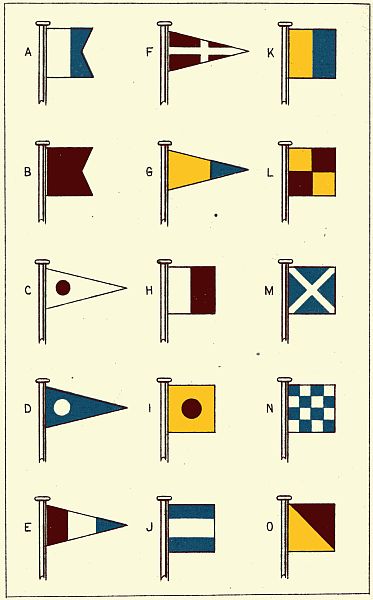
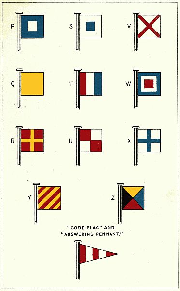
Description.—By means of the International Code of Signals people of different nationalities may communicate with each other, although neither party has knowledge of any language save his own native language. The code is, as its name indicates, international, and every seagoing vessel of every nation is equipped with its flags. The Code of Signals contemplates the use of 26 flags (figs. 14 and 15); one for each letter of the alphabet and a code pennant. Complete instructions relative to the use of this code are contained in a book issued by the Hydrographic Office, Navy Department, and known as the "The International Code of Signals." In using this system the signals are displayed by hoisting combinations of two, three, or four flags. All possible combinations represent words, expressions, or phrases, which may be found in the "International Code of Signals," referred to above.
Two-arm semaphore.—This system is frequently used by the United States Navy, the following instructions covering the use of the system:
1. To communicate with a station:
Face the station and wave the flags over the head to attract attention, making at frequent intervals the call letter of the station. When the station called is ready to receive the message, it answers by displaying its own call letter until the sender makes the[52] "alphabetical" or "numeral," as the case may be. Then proceed with the message. At the end of each word bring the flags across the lower part of the body.
2. To call a ship:
Hoist International Code letter J and make code letter of ship; then proceed as in article 1.
3. To make a general semaphore signal:
Hoist cornet; all ships answer by answering pennant; then make signal.
4. At the end of the message extend the arms horizontally and wave the flags until the receiver answers in the same manner, showing that the message is understood.
Should the receiver miss a word, he signifies the fact by waving the flag over his head. The sender will then cease signaling and wave his flags similarly to show that he understands. The receiver then makes "repeat last word," or whatever he wishes to say.
Should the sender make a mistake, he will make the "error" signal until answered by the receiver with the same signal. He then proceeds with the message.
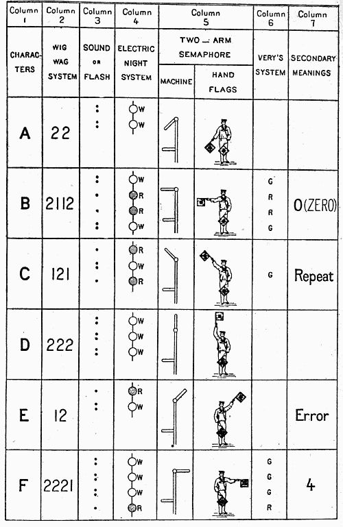
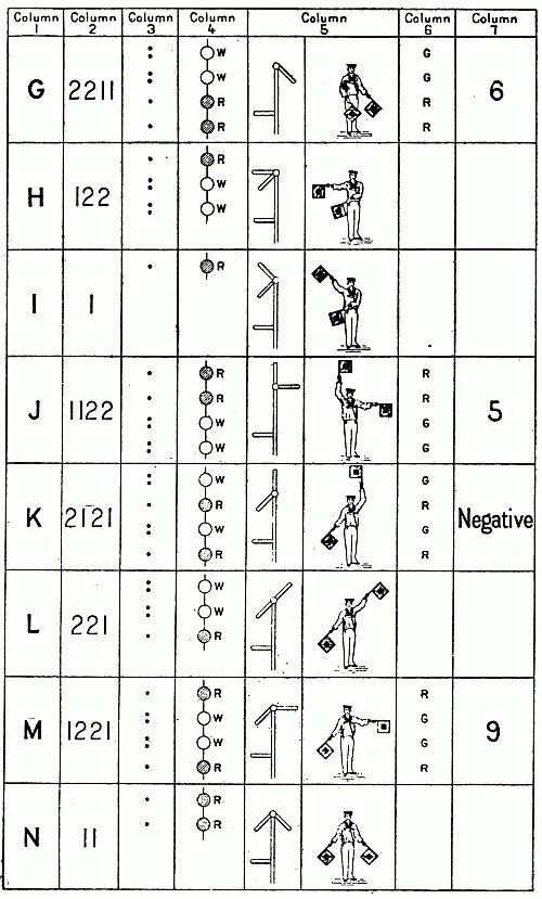
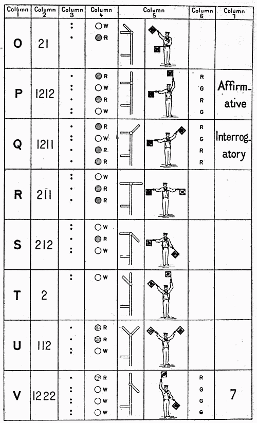
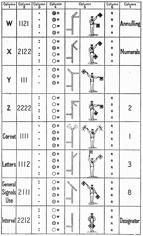
In using this system in connection with the Army and Navy Code, the red lamp indicates "1" and the white lamp "2." Four lamps are placed on a vertical staff and electrically illuminated to indicate the numerals of the Myer Code, which represents the letters of the alphabet. For instance, white-white, or "22," represents the letter "A," and white-red-red-white, or "2112," represents the letter "B," etc. In this system the lights indicating the letters of the alphabet are read from the top downward.
When the lamps are placed horizontally, they are read from the sender's right to his left, and consequently from the receiver's left to his right.
When the letters of the alphabet are to be used to indicate the meaning set opposite them in the following tabulation, the upper light of the display is pulsated. This is effected by means of a special pulsating key. Special signification is not given "I" and "T," they being represented by a single lamp.
| Steady display. | Upper light pulsated. |
| A | Cipher "A" use. |
| B | 0 (naught). |
| C | Repeat (following rule for conventional signals under wigwag code). |
| D | Telegraphic dictionary use. |
| E | Error. |
| F | 4. |
| G | 6. |
| H | Compass signals use. |
| I | |
| J | 5. |
| K | Negative. |
| L | Geographical list use. |
| M | 9. |
| N | Cipher "B" use. |
| O | Cipher "C" use. |
| P | Affirmative. |
| Q | Interrogatory. |
| R | International code use. |
| S | General signals use. |
| T | |
| U | Navy list use. |
| V | 7. |
| W | Annulling. |
| X | Numerals. |
| Y | Vessels' number use. |
| Z | 2. |
| Letters | 3. |
| Code call | 8. |
| Interval | Boat signals use. |
Before numerals are made, the distinctive signal for "numerals" "X" is shown and the upper light is pulsated, which serves still further to distinguish them from letters. The resumption of letters after using numerals will be indicated by the upper light being no[54] longer pulsated, but the display "letters" ("3") will be turned on as an additional indication.
The acknowledgment of the correct receipt of a message will be indicated by the letter "R." If the message has not been fully received, or if it is not understood, indication thereof will be made by signaling the letter "G."
The end of a word is indicated by 2212.
Letters of the army and navy alphabet may be represented at night by Coston lights, port fires, or other colored pyrotechnical lights by displaying the "red" for one and the "white" for two.
In using the Morse alphabet the "red" represents the dot and the "white" the dash.
Coston signals and other similar lights are best suited for preconcerted signals.
The navy signal book is used, to which the following explanation refers:
The letter R stands for red and the letter G for green, and each letter designates a separate star or cartridge. Bracketed stars are a pair of different colors, discharged together from two pistols. The system is based on the Army and Navy Code, red representing "1" and green "2."
| Affirmative, or "Yes" | RGRG |
| Negative, or "No" | GRGR |
| Numeral | GRGG |
| Interrogatory | RGRR |
| Annulling | RRGR |
| Divisional point, date, designator, or interval | GGRG |
| Telegraphic dictionary, | { | R | } | bracketed. |
| G |
| Geographical list, | { | R | } | followed by a rocket. |
| G |
| Boat signals, rocket followed by | { | R | } |
| G |
| Navy list | { | R | } | { | R | } |
| G | G |
| General call, rocket followed by G. | |
| Message call, G without the rocket. | |
The squadron, division, section, or ship's call, the "number" of squadron, division, section, or ship. | |
| Answering, or "I understand" | R |
| Repeating, or "I do not understand" | G |
| Danger or distress, R repeated several times in quick succession. |
In general, rockets and shells are best used in displaying preconcerted signals.
Sequence rockets may also be used to display different colored lights in sequence to represent letters or numerals of the army and navy alphabet. The method of attaching the sections in the base of the sequence rocket is described in Chapter III. In using sequence rockets in this manner, the element "1" of the army and navy alphabet is represented by a red star, while a white star represents the element "2." To send the letter "A" a rocket showing two white stars is sent up. If "B" is to be sent, a rocket showing white-red-red-white is discharged. Each star[56] burns for four to six seconds, and there is a slight interval between the visibility of each star. Between two or more stars of the same color, as "A," "N," "D," "dummies," which show no light and carry the fire to the next star to be ignited, are employed.
In the preparation of codes for signals with rockets or bombs there should always be arranged a "preparatory signal" which means "Are you ready?" etc., and an "answering signal," which means "Repeat your last signal," etc., a signal "annul," which means "Disregard last signal," and a signal to signify the correct receipt of the complete message, or "Signal seen and understood."
| CONVENTIONAL SIGNALS. | |
| End of word | see instructions. |
| End of message | see instructions. |
| Error | see instructions. |
| Repeat last word | C, 'end of word', once. |
| Repeat last message | C, 'end of word', 3 times. |
| Use paper and pencil | P, 'end of word', twice. |
| ABBREVIATIONS. | ||||
| A | "end | of | word" | after |
| B | " | " | " | before |
| C | " | " | " | can |
| H | " | " | " | have |
| N | " | " | " | not |
| R | " | " | " | are |
| T | " | " | " | the |
| U | " | " | " | you |
| UR | " | " | " | your |
| W | " | " | " | word |
| WI | " | " | " | with |
| Y | " | " | " | yes |
| PG | " | " | " | permission granted |
| NG | " | " | " | permission not granted |
| XX | " | " | " | numerals follow |
Definition.—The term "field message" is applied to all messages sent over field lines of information. All field messages for transmission over field lines of information by electrical or visual means should be plainly written by the sender on the blank forms in the United States Army Field Message Book. The practice of verbally delivering telegrams to enlisted men for transmission should invariably be discouraged.
"In framing telegrams, all words not important to the sense will be omitted. The last name of the officer addressed, or his title, and the last name of the sender are generally sufficient." (Paragraph 1198, Army Regulations.)
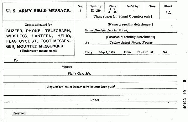
The blank form.—The United States Army Field Message Book issued by the Signal Corps is 45/8 inches wide by 6¾ inches long, and contains 40 message blanks with duplicate tissue sheets and two sheets of carbon paper.
The message is written on the yellow sheet, which can be torn out for delivery. The carbon sheet is attached to the book, and contrary to the custom in most carbon duplicating books, is placed under the tissue sheet when a message is being written. When not being used, the carbon sheet should invariably be kept in the back of the book. When the upper carbon sheet has become worn out, it should be torn out and the second carbon sheet used instead. The blank form is shown in figure 16. The back of the blank is ruled in squares and provided with scales for use in making sketches.
Writing the message.—In writing the message the name of the sending detachment should appear after the heading "from" on the upper line, as "from Headquarters 1st Brigade," while the location of the sender should appear on the second line after the heading "at." The heading "hour" on the third line should show the hour the message was written and not the hour the message was transmitted. The heading "received" at the bottom of the page is filled in by the addressee and shows the time of the receipt of the message by him.
Use of message blank.—The field message blank will be used for field messages both sent and received.
Duties of sending operators.—The sending operator will enter the time when the message is handed him for transmission in the left-hand corner at the bottom of the blank opposite the word "Received." He will enter in the proper places, at the head of the blank, the number of the message, the call letter of his station, with his personal signal, the check (number of words or groups of cipher contained in message, counting address and signature), and, after "OK" has been received, he will enter the time the message was sent, and the call letter of the receiving station, with the personal signal of the receiving operator.
Order of transmission.—To transmit a message, the operator will send: (1) The number of message and call letter of his station; (2) his personal signal; (3) the check; (4) "fm" followed by name of sending detachment; (5) "at" followed by location of sending detachment and date; (6) "Ho" followed by hour[67] (a. m. or p. m.) message was written; (7) address in full; (8) period, (- - — — - -); (9) body of message; (10) "sig" (signature follows); (11) signature.
Duties of receiving operators.—The receiving operator will add to the message received, the month, date, and year, and omit the "sig," "fm," and "at," and, after satisfying himself that the check and number of words correspond will give "OK" followed by the call letter of his station and his own personal signal. He will then enter in the proper places, at the head of the blank, the call letter of his own station, with his personal signal and the time the message was received.
Communications confidential.—Communications transmitted by telegraph or signals are always confidential and will only be revealed to those officially entitled to receive them.
Checking the message.—In preparing the "check" of the message, all words and figures written in the address, body of the message, and the signature will be counted.
In counting the check of a message, all words, whether in plain English, code, or cipher, pronounceable or unpronounceable, or initial letters, will be counted each as one word. The abbreviations for the names of places, cities, towns, villages, States, Territories, and Provinces, will be counted as if written in full. In the names of towns, counties, countries, or States, all of the words will be counted.
Abbreviations of weights and measures in common use, and cardinal points of the compass, will be counted each as one word.
To prevent liability to error, numbers and amounts should be written in words, and when not so written,[68] the receiving operator will request that it be done. If the writer declines to write the amounts in words, the message will be accepted as written, and each figure will be counted as one word.
Figures, decimal points, and bars of division, and letters will be counted each separately as one word.
In ordinal numbers, the affixes, st, d, nd, rd, and th, will each be counted as one word.
In transmitting the telegram shown in figure 16, the following would be sent by the operator:
In field operations tactical considerations will usually prescribe within certain limits the number and general location of signal stations. The general directions for deployment being given, the signalman will be called upon to demonstrate his skill in the selection of particular locations most conducive to the efficient service of information.
General considerations.—Considering all things, the
best location for a signal station is one which affords
maximum visibility and at the same time minimum
exposure to hostile observation. These conditions,
apparently paradoxical, can be more or less reconciled
by the exercise of ingenuity on the part of the
signalist. A good theoretical knowledge of the special
requisites of signal sites, together with the ability to[69]
[70]
apply it to the conditions arising in any given case,
will result in securing the best obtainable locations.
The first essential of the signal station is visibility, the second being that of concealment from hostile observation. In acquiring a mean between conflicting requirements, the following special considerations in the selection of stations should be considered.
Backgrounds.—Backgrounds are important factors in the selection of signaling sites.
Sky backgrounds are desirable as affording strong contrast and are therefore conducive to celerity in the transmission of signals. They are rare and can only be secured when stations are located on the exact crest of ridges, on mountain peaks, or on lands which bound the horizon of view from the other stations. Stations with sky backgrounds, while affording the best facilities for transmission, are little adapted to the requirement of secrecy.
Dark backgrounds are far more common and more easily obtainable than sky exposures. They afford the maximum means of concealment from hostile observation, but materially reduce the range, speed, and accuracy of signal transmission.
Mixed or broken backgrounds are those which display varied colors behind the signals. Backgrounds of this description do not accord with either of the essential requirements of the signal station and should be avoided whenever possible.
In general, sky backgrounds should always be selected for signal stations when conditions are such that the requirement of secrecy can be dispensed with; if, on the other hand, there is reason to fear that the signals may be intercepted by the enemy, dark backgrounds[71] should invariably be chosen, even though the disadvantages they impose, render them less desirable visually.
Azimuth of stations.—The azimuth of signal stations should, if possible, be such that the visual lines of information should intersect the vertical plane through the apparent course of the sun, at a considerable angle. Stations located so as to be unavoidably viewed from these directions during portions of the day are very liable to appear enveloped in a haze, and telescopes, if turned upon them, are filled with dazzling light. If the location of stations on or close to the sun line is unavoidable, sites affording sky exposures should be chosen. Exposures of this kind obviate to a great extent the difficulty of sun haze and should be secured when this difficulty is encountered and it is impracticable to change the azimuth of the station.
Altitude.—The location of signal stations at high altitudes will tend to obviate difficulties arising from smoke, haze, and dust. The undulation of the atmosphere noticeable on a hot summer's day is always less at a distance from the earth's surface, and it is often practicable to read signals from a tree or housetop when they would be unintelligible from the ground. This air undulation is less over spots well shaded than those exposed to the glare of the sun, a fact that should be borne in mind in all telescopic examinations. Another reason for locating stations at high altitudes is because the cool night air, the smoke and dust of the day, and heavy mists lie close to the ground, filling the depressions and lowlands, while the higher points remain in view. Stations on high ground are then equally well adapted to day and night signaling.[72] Sites and selections of this kind of terrain will not only often preclude the necessity for changes of location, but also will allow the continuous working of the station when signals made from lower positions would be invisible. In foggy or murky weather peaks and mountain tops are usually enveloped in mist, and under these conditions stations should be situated on lower ground.
Determination of background color.—The color of the background of a station is that color against which the signals appear to be displayed when viewed from the distant station. Having chosen a point entirely in view of the station or stations to be communicated with, and having fixed the exact position of the signaling apparatus, the color of the background should be determined as carefully as conditions of terrain will permit. If the elevation of the distant station is without doubt greater than that of the home station it is safe to assume that the color of the background will be that of the objects directly around and behind it. On the other hand, if the distant station unquestionably occupies the lower position, a sky exposure will usually result. In locating stations it is very difficult, if not impossible, especially at long ranges, to determine the color of the background as viewed from the distant station when the stations are approximately on the same level. This can only be done by proceeding in front of the home station and taking such a position that it can be viewed with the eye on the line of sight between the stations. The telescope should be established over the initial point of the home stations and directed on the distant station. The observer for background should proceed to a point[73] where his head is in the center of the field of the telescope. Looking back at the home station from this point, the color of the objects about and just behind the initial point will be the color of the background. The correct determination of background color from the vicinity of home stations is usually difficult and unsatisfactory, and it is considered the best method to establish communication with the distant station by simultaneously using several kinds of signaling apparatus, that kind producing the most intelligible signals being retained for continued use.
Choice of apparatus.—Sunlight conditions permitting, the heliograph will ordinarily be used for day signaling on account of the advantages of the great range and speed afforded by it. When its use is prohibited by weather conditions, the flag will be substituted for it. The white flag will be used against dark and the red against sky or broken backgrounds. The distant station is the better judge as to which color flag is best suited to given conditions and the color indicated by it should invariably be used. For night signaling, the acetylene lantern is usually employed. Long-range night signaling should be done with the searchlight if available. The employment of the semaphore, in daytime, and the Ardois system, at night, will be confined to more or less permanent stations. Rockets, shells, night fires, etc., are only employed for special or emergency signals.
Miscellaneous considerations.—For various reasons stations should not be located at or near camp grounds. These localities usually afford mixed backgrounds, and the presence of dust and smoke and the interference caused by moving bodies of troops and trains will[74] militate against the efficient transmission of signals. Stations located in vicinities of this kind are also subject to annoyance from noise and visits of unauthorized persons. Signal stations should be convenient for messenger service and hence as near commonly traveled roads as the physical contour of the country will permit. Locations for signal stations should be so selected that the visual lines do not cross traveled roads, camps, etc., as dust and smoke in the daytime and lights at night are factors in determining the visibility of signals. Signal stations can if necessary be artificially concealed by erecting screens constructed of limbs of trees, etc., about the flanks and rear. Sheltered positions should be utilized in windy weather.
Intervisibility table.—The following table shows the extent of horizon for different heights above the sea level—that is, it shows how far one can see an object which is itself at the level of the sea:
| Height of the eye above sea level. | Distance in statute miles. |
|---|---|
| 10 feet | 4 |
| 15 feet | 5 |
| 20 feet | 6 |
| 30 feet | 7 |
| 40 feet | 8 |
| 50 feet | 9 |
| 60 feet | 10 |
| 70 feet | 11 |
| 85 feet | 12 |
| 100 feet | 13 |
| 115 feet | 14 |
| 130 feet | 15 |
| 150 feet | 16 |
| 200 feet | 18 |
| 230 feet | 20 |
| 300 feet | 23 |
| 350 feet | 25 |
| 500 feet | 30 |
| 700 feet | 35 |
| 900 feet | 40 |
A formula to determine approximately the limits of visibility from a given height is as follows: The square root of the height of the station in feet multiplied by 1.26 equals the distance in miles at which the signal is visible.
Hence, an observer whose eye is 30 feet above the sea can distinguish an object 7 miles distant, provided it is at the sea level; but if the object is itself 15 feet above the sea he can make it out 7 + 5 = 12 miles off.
To find a signalman near any known station, note with the unaided eye some prominent landmark near which the looked-for person or object is supposed to be, and direct the telescope upon the place, as sight is taken over a gun barrel, covering the object; if the eye is now placed at the eyeglass of the telescope, the prominent or directing landmark will be found in the field of view. It will be easy then to scale the country near the marker until the signalman is found. This method is often necessary at night, when only a point of light is seen far off through the darkness, and the telescope must be turned upon it. When the compass bearing of the object sought for is known, the telescope may be aligned by a line drawn with the proper compass bearing. Commencing then with the view at the horizon, the telescope is slowly moved from side to side, taking in fresh fields of view each time a little nearer to the observer, until the whole country shall have been observed from the horizon to quite near the station. When the general direction only of the object can be given and it is sought for, the whole landscape in that direction to the horizon should be divided into sections by imaginary lines, the limits of these sections being bounded between visible landmarks through which the bounding lines are supposed to pass. Each section should be scrutinized little by little until the glass has been passed over every spot. Such search will seldom fail to be successful.
The magnetic bearings of all stations with which another station has worked should be carefully noted and made matter of record in the office directly concerned, so that advantageous use may be made of this data. In addition, guide lines may be established by driving two stakes firmly into the ground and close to each other. A prolongation of a line through the center of one post and marked on the adjacent one will strike the distant station. Under each line should be written the name of the station which it marks.
Signalers upon permanent or semipermanent stations will examine, from time to time, every prominent point within signal distance, to see if communication is attempted therefrom.
Attempts to attract the attention of a known station, in order to be successful, must be persistent. They should never be abandoned until every device has been exhausted, and they should be renewed and continued at different hours of the day and night. It must be remembered that efforts which have failed because the observer's attention has been drawn in another direction may at any other moment be successful if the observing glass chances to bear on the calling signals.
During the whole time that signals are being made to attract attention the calling station must watch closely with the telescope the station called. The watch should not be relaxed until communication is established or the station ordered abandoned.
Personnel.—At signal stations where continued
operation is required at least a squad or "set of fours"
is required. Physical and mental exhaustion always[77]
[78]
result from continuous signal duty, and as alertness
of mind and body is an indispensable factor in the
prevention of errors, two reliefs of signalmen should
be furnished each station whenever practicable.
The senior officer or enlisted man is in charge of the
station and is responsible for efficiency and discipline.
He will require from each man a strict and entire
attention to his own immediate duties, and permit
no conversation that will distract the men at work.
He will be careful not to allow persons to loiter about
the station or within the hearing of the words called
out to the signaler. The assignment of men should
be such that a continuous watch for signals is kept
and the responsibility for neglect to promptly answer
calls determined. Of the station men, one is the
sender, whose duty it is to transmit all signals to contiguous
stations. Another, the receiver, attends the
telescope and reads and calls off the signals displayed
at the distant station. A third man acts as recorder,
alternately calling off the outgoing message to the
sender or transcribing the incoming message repeated
by the receiver.
Calls and personal signals.—Each station will be assigned a call consisting of one or two letters. Each and every operator will also have a personal signal of like character. Station calls or personal signals when once given or assumed will not be changed except by order of higher authority. Every station should at all times have on hand a list of all calls and personal signals liable to be encountered in station working. The general call suited to attract the attention of any station whose regular call is unknown[79] will always be a signal represented by the letter "A" in the Morse or the letter "E" of the Army and Navy Code.
Opening communication.—To open communication with any distant station whose call is known, signal the call repeatedly, occasionally signing the call of the home station. If the regular call of the station sought is unknown the general call above prescribed should be used. As soon as the call is observed the called station will acknowledge receipt by "ii ii," or "I understand," signing thereafter its station call. These preliminaries completed, the stations are ready for working.
It is sometimes difficult to secure the attention of stations at unexpected hours. The force may not be strong enough for an uninterrupted watch. To provide, so far as possible, for this contingency, it may be concerted that if communication is required at unusual time, or is of pressing importance, certain flags shall be displayed, rockets discharged, smokes shown, or other attention-compelling signals used.
When a number of stations are in view from one station and it is desired to send a message to all or more than one station, some preconcerted signal, as a rocket, a red light, or some peculiar flag or torch signal, should be designated as a signal for general attention. Upon noticing this signal all the called stations reply, and then observe the calling station. This plan is useful when two or more stations can, at the same time, read the signals from the one station, and thus together receive any information to be transmitted from it.
When a signal station is to communicate with two or more stations, a telescope should be firmly fixed bearing on each, when practicable, and so far apart that those communicating with one station will not disturb the other party.
Commencing the message.—Every message is invariably commenced by the signal "Hr" or "Anr." Sometimes at the commencement of communication a preface will be sent in order to give some preparatory information to the receiving station regarding the number or character of messages about to be sent. For example, "Hr 8," means "I have eight for you" or "Hr ck 300" means a three hundred word message follows.
Sending and receiving.—Before the commencement of a message, care should be taken that all the letters and characters thereof are entirely and correctly understood by the signalman whose duty it is to call the same to the sending operator. The message is read off by the "reader," who first calls off a word and then spells it out letter by letter. The "reader" should observe the signals of the operator and invite his attention to any apparent errors. When the last letter of a word is announced this fact will be communicated to the sending operator.
At the receiving station the man at the telescope will call off each letter as received and not wait until the completion of a word. On reaching the end of a word announcement of this fact will be made to the recorder.
Breaking.—If the sending operator discovers that he has made an error which will probably render the[81] sense of the message unintelligible at the receiving station, he will make the signal "BK" and recommence the message, beginning at the last word correctly sent. When the receiving station fails for any reason to get correctly what is being sent, the sending station is interrupted by the signal "GA," followed by the last word correctly received. The message will then be recommenced by the sending station at the point indicated.
Discontinuance of transmission.—When all the messages on file at any station have been sent the signal "NM" in Morse or "Cease signaling" in the army and navy system, according to which code is authorized, will be the concluding signal of the sending station. When a signal station is operated only during the daytime, the signal "GN" will be transmitted after all business filed up to the hour designated for closing has been dispatched.
Acknowledgment of receipt.—No message will be considered sent until receipt for the same has been acknowledged. This is effected by making either the "I understand" of the army and navy or the "OK" of one of the Morse systems, depending upon the one authorized. In every case the receiving operator's signal is signed after acknowledgment. When a number of messages are continuously sent, one acknowledgment for all will suffice and will be so understood. In receiving messages nothing should be taken for granted and nothing considered as seen until it has been positively and clearly in view.
Station records.—Records kept at field signal stations will be confined to original files of messages sent[82] and carbon copies of messages received. Ordinarily the only available stationery will be the United States Army Field Message Book. Station records will be invariably preserved as part of the station equipment until orders for their disposition are given by higher authority. Whenever a station is in imminent danger of capture, all records should be destroyed in the discretion and under the direction of the operator in charge.
Formation of signals.—Make signals with regularity; do not send one word rapidly, the next slowly; adopt such a rate of speed as can be read by the distant signaler without causing him to "break" frequently. Make a distinct pause between letters. It is time gained to do so; it is a loss of time and an annoyance to run letters together. Nothing so distinguishes the good from the indifferent operator, visual or telegraph, as this. When signals are being made with a flag, a fraction of a second will be ample. In using the lantern or heliograph, the pause between letters should be relative to the time of display of the elements, longer than with the flag. To prevent any entangling of the flag upon its staff, skillful handling, acquired by practice, is necessary. It is accomplished by making a scoop of the flag against the wind, the movement describing an elongated figure 8, thus ∞. The motions should be made so as to display in the lateral waves the whole surface of the flag toward the point of observation.
In using the heliograph, if the receiver sees that the sender's mirror needs adjustment, he will turn on a[83] steady flash until answered by a steady flash. When the adjustment is satisfactory, the receiver will cut off his flash and the sender will resume his message.
Repeating the message.—It may happen that very important messages received by signals must be verified by repeating back from the receiving station, signal by signal, each signal used by the sending station in conveying the message. There can be no error in signals thus verified, and the correct transmission of the message is made certain. For such verification each signal must be repeated by the receiving station as soon as it is made at the sending station.
Signal practice.—Full efficiency of the signaler can be maintained only through constant practice, and those in charge of Signal Corps troops should see that sufficient practice be had to insure that accuracy and rapidity in handling messages which is so essential in time of war.
Instruction should commence with the study of the principles of signaling and the theories of their general use, and the pupil should be well grounded in this study before practice is begun. He should so memorize the alphabets to be used that no letter combination will require thought to determine its meaning.
Daily inspections should be made to insure that all signaling instruments, appliances, and materials are in readiness for instant use. Defects in the apparatus annoy the sender; to a greater extent they annoy the person to whom the messages are imperfectly sent, and delays result that may have serious consequences.
A code is a list or collection of arbitrary words or groups of letters to each of which some ordinary word, proper name, phrase, or sentence is assigned for meaning.
Ciphers embrace all means whereby writings may be transcribed into occult terms. All ciphers employ some distinct method for transcription, which method is termed a key. In practice the key is usually applied directly in enciphering and reversed in deciphering messages.
The codes of the Western Union and Postal Telegraph companies are examples of well-known codes suited to general commercial use. Besides these, many special codes have been formulated, so as to embody technical expressions especially adapted to use in particular lines of industry. The War Department Code is a military code adapted to the special needs of the military establishment in peace and war.
Codes are primarily intended for economy, but they may also be readily employed to secure secrecy. When used solely for economy, the coded message is said to be plain code; that is, the word or phrases of the message are coded by direct reference to their respective code equivalents. Thus plain code is readily translatable to anyone in possession of a code book.[85] When secrecy is desired, some method of enciphering or key is employed in such a way that only persons in possession of it can in conjunction with the code book decipher it. In such case the message is said to be in cipher code.
In all codes each expression and its equivalent in plain language is assigned a number. These numbers usually commence at unity and increase consecutively to any desired figure. Messages may be enciphered by means of a key number or series of numbers. An additive number, say 55 additive, requires that in enciphering a message, the fifty-fifth word numerically greater than the proper code word shall be used; if 55 subtractive is used, the fifty-fifth word numerically smaller than the proper code word is to be used. By agreement a single key number can be used alternately additive and subtractive, that is, first additive, second subtractive, third additive, etc.
The key numbers are used over and over until the entire message is enciphered. The key number can sometimes be expressed by a single word, as, for instance, "Grant," each letter having a value of tens in accordance with its position in the alphabet; that is, G, the seventh letter equals 70; R equals 180; A equals 10; N equals 140; and T equals 200. Or by preconcerted arrangement letters may represent units or hundreds. Security from translation by persons not having the key number is greater when the key numbers are used alternately additive and subtractive. If a cipher key word is used, it should be one of an odd number of[86] letters, as, for instance, "Jones," the numbers corresponding to the positions of the letters in the alphabet. The first number should be additive, the second subtractive, etc. By this means the first letter of the key word is additive the first time it is used, subtractive the second, additive the third, and so on. In some instances the key number, when added to or subtracted from the code number, gives a resulting number exceeding the highest code number or less than unity. In cases of this kind it should be remembered in enciphering that unity follows the highest code number in addition, and that the highest code number follows unity in subtraction. In deciphering a message the process of enciphering is reversed.
As previously stated, the War Department Code is the technical military code and contains expressions numbered consecutively from 1 to 62,000. All the code words are composed of 6 letters, which are so arranged that the vowels and consonants invariably alternate. In the formation of code words the following 13 letters only are used, viz, A, B, D, E, F, G, I, K, M, N, S, U, and X. The body of the code book is arranged as follows:
(a) Army list, containing the name of every commissioned officer in the regular establishment.
(b) Military organizations, giving all batteries, companies, troops, etc.
(c) Military posts and stations, covering Alaska, Hawaii, Philippine Islands, Porto Rico, and the United States.
(d) United States naval stations and vessels.
(e) Geographical names.
(f) Miscellaneous tables as follows:
Numerals.
Arrivals and departures.
Dates.
Indorsements.
Letter acknowledgments.
Requisitions.
Telegram acknowledgments.
Mails, shipments, and transports.
Blanks for future additions as they may be needed.
Ranks and grades of officers and men in the Army.
Wireless stations of the Army and Navy.
(g) Alphabetical list of code expressions arranged conveniently for use.
When it is desired to transmit some word or expression not to be found in the code and no suitable synonym can be discovered the word or expression should be sent in plain language or spelled out by the equivalents for letters and endings to be found on page 589.
Complete instructions for the use of the code either as a code or cipher are contained in the introductory pages of the book.
The use of cipher code in enciphering field messages will usually be practicable only between the several headquarters and other large stations supplied with code books. This method, too, is prohibitive for urgent messages when the time of enciphering and deciphering is an important factor connected with delivery.
Description and use.—Field ciphers include all systems and the apparatus connected therewith which[88] are ordinarily employed in enciphering and deciphering field messages. Field ciphers are intended for use when code books are not available, and hence the employment of cipher code is precluded. Some methods of field cipher employ simple forms of apparatus, while others require the use of no apparatus at all.
Forms of field cipher.—There are two general classes of field cipher. The first class employs the transposition or reversal of the letters or words of a message according to some preconcerted rule as a means of secrecy. The route cipher hereafter described is an example of this class. The method used in ciphers of the second class consists in the substitution of certain letters or symbols for each of the individual letters composing the words of the message. Both classes of cipher can be rendered more efficient by a judicious use of inversions and by the concealment of terminations.
Inversions.—By the inversions of the whole or certain parts of messages, according to some preconcerted arrangement, the complications of cipher can be greatly increased. If a message is to be inverted, either as a whole or by clauses, it should be inverted before the cipher letters are written over it. Messages may be further complicated by sending the letters of each word backward in various other prearranged combinations.
Concealment of terminations.—To evade the discovery of the key or keys employed, it is most important that the termination of the words of a message should be concealed. The best method to conceal the beginning, and at the same time the termination of words,[89] is to divide them into arbitrary groups of four or five letters each. This procedure will add immeasurably to the strength of the cipher and should in no way confuse one in possession of the key. For instance, the words "sufficient time" would be divided "suff" "icie" "ntti" "me," and such blind letters as may be agreed upon to fill the last two spaces of the last group. All such artifices as this will surely delay a translator not in possession of the key.
The cipher disk.—The cipher disk is composed of two disks of cardboard, leather, or other material joined concentrically, the upper disk revolving upon the lower. The alphabet, reading from left to right, and such other signals, numerals, or combinations of letters, as may be desired, are printed around the circumference of the lower disk. On the upper disk are printed the alphabet and such other signals, numerals, or combinations of letters as are printed on the lower disk. On the lower disk they are printed from left to right, while on the upper disk they are printed from right to left. If it is desired to encipher a message, the key letter or the first letter of the key word or words is set opposite "A." Let us assume it to be "J." The cipher letters to be written are those opposite the text letter when the letter "a" on the upper disk is set opposite "J" on the lower disk. For example, "Send powder" would be written "rfwg uvngfs."
Having a cipher disk as above described, this mere transposition of letters would delay but a short time[90] the deciphering of a message by one not knowing the key letter, as it would be necessary only to place, in turn, opposite "a" each of the letters of the alphabet beginning with "b" and noting the letters opposite the enciphered letters. But this simple disk can be used with a cipher word, or preferably, cipher words known only to the correspondents, and it is entirely improbable that a message so enciphered could be deciphered in time to be of any value to the enemy. Using the key words "permanent body" to encipher the message "Reenforcements will reach you at daylight," we would proceed as follows: Write out the message to be enciphered and above it write the key word or key words, letter over letter, thus:
| P | E | R | M | A | N | E | N | T | B | O | D | Y | P | E | R | M | A | N | E | N | T | B | O | D | Y | P | E | R | M | A | N | E | N | T | B | |
| R | e | e | n | f | o | r | c | e | m | e | n | t | s | w | i | l | l | r | e | a | c | h | y | o | u | a | t | d | a | y | l | i | g | h | t | |
| y | a | n | z | v | z | n | l | p | p | k | q | f | x | i | j | b | B | p | w | a | n | r | u | q | p | e | p | l | o | m | c | c | w | h | m | i |
Now bring the "a" of the upper disk under the first letter of the key word on the lower disk, in this case "P." The first letter of the message to be enciphered is "R." "Y" is found to be the letter connected with "R" and it is put down as the first cipher letter. The letter "a" is then brought under "E," which is the second letter of the key word. "E" is to be enciphered and "a" is found to be the second cipher letter. Then bring "a" to "R" and the cipher letter will represent "e," the third text letter of the message. Proceed in this manner until the last letter of the cipher words is used, and, beginning again with the letter "P," so continue until all letters of the message have been enciphered. Divided into groups of four letters, it will be as follows: "yanz vznl ppkq fxij bpwa nruq pepl omcc whmi."
To decipher the message, reverse the proceedings above described; thus the letter "a" on the upper disk is brought under the first letter of the key word "P." Following these instructions, we find the first cipher letter of the message; "a" is then brought to the next letter of the key word. In this case "E" is, of course, the next letter of the text. "R" is the next letter in the key and "a" is brought over it. The cipher letter "n" gives us the next text letter, which is "e," and so on until the completion of the message. If the letters of the key word or phrase are exhausted, begin again with the first letter and so continue until the entire message is deciphered.
With a key word, or, preferably, a key phrase of three or four words, the deciphering of a message is extremely difficult.
In a military cipher message, it may be desired to transmit numerals, the spelling out of which would require considerable time. This can be done by an arrangement of the cipher disk so that the numerals of which will appear in the same order as and follow the letters of the alphabet. Thus on the lower disk 1 is placed opposite A; 2 opposite B; 3 opposite C; 4 opposite D; 5, 6, 7, 8, 9, and 0 opposite E, F, G, H, I, and J, respectively.
On the upper disk the above numerals also appear, beginning numeral 1 opposite A; 2 opposite B, etc., 0 being opposite J.
The arbitrary sign XX will be used to indicate "numerals follow" and "numerals end." Supposing then we wish to send the following message: "Send 6,000 cavalry at once," and that the key word was[93] "Washington." Following the instructions heretofore given for enciphering, we would place the words as follows:
| W | A | S | H | I | N | G | T | O | N | W | A | S | H | I | N | G | T | O | N | W | A | S | H | I |
| S | E | N | D | X | X | 6 | 0 | 0 | 0 | X | X | C | A | V | A | L | R | Y | A | T | O | N | C | E |
| E | W | F | E | L | Q | B | K | F | E | Z | D | Q | H | N | N | Y | C | Q | N | D | M | F | F | E |
In place of a disk means may be extemporized by taking two strips of paper, on one of which the alphabet, numerals, etc., are twice written in succession. On the other, with equal spacing, the alphabet, etc., are written once, but in reverse order. By sliding these strips in juxtaposition with each other they will replace the disk.
Cipher disks should never be allowed to fall into the hands of the enemy or of anyone unauthorized to have and use them; to insure this, special instructions should be issued for their care and keeping.
This cipher is a highly efficient one for the purpose of secrecy and at the same time requires no apparatus whatever attendant upon its use. The cipher is constructed as follows: Commit to memory the alphabet by numbers, viz, A, 1; B, 2; etc. Take any key word, phrase, or sentence desired; for example, "A discovery." Suppose the message to be enciphered is "Send me powder tonight." The enciphering of the message using the key given above will be as follows:
To encipher, first write out the key, letter by letter, placing the message letter by letter beneath it. Then reduce the letters of the key and the message to the[94] numeral alphabetical equivalents. Add the individual columns and subtract unity from each. From any result thus found, which exceeds the number of letters in the alphabet, the number 26 must be subtracted. The final totals reduced to letters by numerical alphabetical equivalents will then give the cipher.
| A | D | I | S | C | O | V | E | R | Y | A | D | I | S | C | O | V | E | R |
| s | e | n | d | m | e | p | o | w | d | e | r | t | o | n | i | g | h | t |
| 1 | 4 | 9 | 19 | 3 | 15 | 22 | 5 | 18 | 25 | 1 | 4 | 9 | 19 | 3 | 15 | 22 | 5 | 18 |
| 19 | 5 | 14 | 4 | 13 | 5 | 16 | 15 | 23 | 4 | 5 | 18 | 20 | 15 | 14 | 9 | 7 | 8 | 20 |
Now add the columns and subtract unity from each. If any result so found exceeds the number of letters in the alphabet 26 must be subtracted from it.
In the example given the numerical totals are as follows:
| 20 | 9 | 23 | 23 | 16 | 20 | 38 | 20 | 41 | 29 | 6 | 22 | 29 | 34 | 17 | 24 | 29 | 13 | 38 |
| 1 | 1 | 1 | 1 | 1 | 1 | 1 | 1 | 1 | 1 | 1 | 1 | 1 | 1 | 1 | 1 | 1 | 1 | 1 |
| 19 | 8 | 22 | 22 | 15 | 19 | 37 | 19 | 40 | 28 | 5 | 21 | 28 | 33 | 16 | 23 | 28 | 12 | 37 |
| 26 | 26 | 26 | 26 | 26 | 26 | 26 | ||||||||||||
| 19 | 8 | 22 | 22 | 15 | 19 | 11 | 19 | 14 | 2 | 5 | 21 | 2 | 7 | 16 | 23 | 2 | 12 | 11 |
Translation of cipher is had by reversing the processes described.
This is a cipher in which the words or a message are retained unchanged, but are so disarranged by[95] preconcerted rules that the sense becomes unintelligible. The message as received seems to be a number of disconnected words and without meaning, but by arrangement in proper order in accordance with certain rules can be easily read. Messages enciphered in this manner may be translated by persons not in possession of the key, and therefore the information contained therein should only be of such a character as to be of little value to the enemy unless acted upon immediately. The usual method employed in arranging a message for this cipher is to write the words in vertical columns. The number of words in each column should always equal the number of columns, being made so, if necessary, by the addition of sufficient "blind" words. A preconcerted route is agreed upon, as up to the first column, down the third, up the second, etc. The message is then transmitted without reference to the columns, but is deciphered at the receiving station by column arrangement and perusal along the original route.
For example, to encipher the message "Move daylight. Enemy approaching from north. Prisoners say strength one hundred thousand. Meet him as planned," arrange as follows:
| Move | strength | planned | say |
| daylight | one | as | prisoners |
| enemy | hundred | him | north |
| approaching | thousand | meet | from |
Here the route is down the first column, up the fourth, down the second, and up the third.
General instructions.—In deciphering a message in which the same cipher letter or symbol is uniformly used to represent the same text letter, the following data will be of assistance.
The proportion of occurrence of letters of the alphabet in English words is as follows: For every 2 of the letter Q there are 4 of the letter X, 8 of K, 16 of B, 13 of C, 80 of I, N, O, and S; 85 of A, 90 of T, and 120 of letter E.
The compounds most frequently met with are NG EE LL MM TT DD and NN.
The order of frequency in which the letters of the alphabet occur as initial letters in words is as follows:
If messages are enciphered by a mere transposition of the letters of the alphabet, the cipher disk can be used to quickly decipher the message, as the following example will show: Assuming that F is used to represent A, G to represent B, H to represent C, I to represent D, J to represent E, etc., in regular sequence, and that the message to be enciphered is: "We are short of rifle ammunition; send 30,000 rounds at once."
This would be enciphered if divided into groups of four letters as follows:
| jbfo | bnyr | omra | oxub | fuls | xmxr | snbs | cmjb | smhm | yrln |
| fsco | rlsc | nfmr | sdb. |
Place "a" of the upper cipher disk under B of the lower disk and notice whether the cipher letters jbfo—the first group—are intelligible. They give "sawn," continue this for "saw," the first three letters, may be the text word. Now the next group is B N Y R and these give A O D K. We know that A does not represent B because the first 8 cipher letters give the meaningless letters "sawnaodk." Turn "a" to C and we have for the first group T B X O, which is without meaning. Turning "a" to D we get U C Y P, a meaningless jumble. Turn "a" to E and we get V D Z Q, which is meaningless. Now turn "a" under F and we find that JBFO mean "Wear," which, so far at least, gives us a part of a word, or the word "We" and part of another word. We continue to the next group B N Y R, which gives us "esho." We now have these letters "Wearesho," which at a glance we read "We are sho;" continuing to the next group O M R A the cipher disk gives us "rtof," and we read "We are short of" and know we have found the key letter, and the information hidden in the cipher is ours. Continue deciphering with "a" under F until the end of the message. Sometimes the key letter is changed after two, three, or four letters.
It is a matter of minutes only to run through the alphabet and learn the meaning of a message so enciphered.
When light falls on a transparent body, part is reflected and part is refracted. The angle which the ray makes with the normal, or perpendicular, to the surface at the point of contact is known as the angle of incidence, and the angles which the reflected and refracted rays make with the same normal are known respectively as the angle of reflection and refraction. The reflected ray makes the same angle with the normal as the incident ray, while the refracted ray, when passing from a rarer to a denser medium, is bent toward the normal, and vice versa; the denser the medium into which the ray passes the greater is the deviation. This law allows us at once to understand the action of a lens, which may be defined as a transparent medium that from the curvature of its surface causes the rays of light traversing it to either converge or diverge. The ordinary lenses have either spherical surfaces or a combination of spherical and plane surfaces. This combination will give rise to six classes (fig. 20): (a) Double convex; (b) plano convex; (c) double concave; (d) plano concave; (e) converging, and (f) diverging meniscus. Those lenses which are thicker at the center than at the edges are converging or concentrating lenses, and those which are thicker at the edges than the center are diverging.
The focus of a lens is the point where the refracted rays or their prolongation meet; if the rays themselves intersect after refraction the focus is real, and if their prolongations meet the focus is virtual. The line passing through the centers of curvature of the two surfaces of a lens is called the principal axis and contains a point known as the optical center, which has the property by virtue of which, if a ray passes through it, the ray will not be deviated. The optical center can always be found by drawing two radii parallel to each other, one from each center of the curvature of the surface until the radii intersect their respective surfaces, then draw a line joining these two points. The intersection of this last line with the principal axis will give the optical center.
Let AB be the section of a double convex lens and C and D (fig. 21) be the centers of curvature of the two surfaces. Draw the lines CD′ and DE from C and D parallel to each other, then join D′ and E by a straight line. The point O will be the optical center of the lens. Let us take a point R, on the principal axis as a source of light; the ray RD passes through the optical center and is not deviated. The ray RK on striking will be refracted in the direction KG toward the perpendicular to the surface KD in accordance with the law of refraction, as glass is denser than air. On emerging at G it is refracted away from the perpendicular to the surface CG, since it passes from a[100] denser to a rarer medium, and will intersect the ray RD at the point R′. In a like way the ray RK′ will be found to intersect the ray RD at the same point, R′, which is the focus for all rays coming from R. The point R′ is said to be the image of the object R, and when the two points are considered together they are called conjugate foci. If the incident beam is composed of parallel homogeneous light, the rays will all be brought to a focus at a point on the principal axis, called the principal focus of the lens, and the distance of this point from the optical center is the principal focal length, which is always a fixed quantity for any given lens.
There is a fixed relation between the principal focal length of a double convex lens and the position of the image of the object which may be expressed as follows: 1/i = 1/f - 1/o, in which i and o are the distances of the image and object, respectively, from the optical center and f the focal length, from which we see that for all positions of the object from an infinite distance away from the lens to double the principal focal distance,[101] the image will be on the other side, between a distance equal to the principal focal length and double this length. These are the limits of the image and object in the ordinary cases. If we place this expression in the following form: i = of/(o - f), and suppose the object to remain the same distance from various lenses, it will be seen that the image will be closer to the lens which has the shorter focal length. The principal focal distance, or, briefly, the focal length of the lens, depends on the curvature of the surfaces, and the greater the curvature the shorter the focal length.
Let us now see how an image is formed by a convex lens, and suppose that CD is the section of a double convex lens (fig. 22), O the optical center, and AB an object at a greater distance from the optical center than double the focal length. Rays will pass out in all directions from the object and some will fall on the lens. A ray from A will pass through the optical center and will not be deviated; others will be incident at various points, for example, E and G, and if we[102] apply the law of refraction we will find that AE and AG will intersect each other and AO at the point A′, provided we do not consider the figure of the lens, forming one point of the image A′ B′; similarly for rays from other points of the object, as, for example, B, we can construct the focus B′, and thus obtain the image A′ B′, which is inverted and smaller than the object AB. The relative size of the image and object will be directly as the conjugate foci, and these can be found at once from the equation of the lens.
If, however, we consider the form of the lens, we will find that all the rays emerging from one point on the object are not brought to the same focus, because the rays incident on the edges of the lens are refracted to a greater extent than those falling on the center, and will be brought to a focus at a shorter distance from the lens than those passing through the central part. This confusion or wandering of the foci from one point is called spherical aberration, or aberration of form, and is due solely to the geometrical form of the lens.
In what has been said about the visual image we have supposed that the light was monochromatic, or homogeneous. Let us see what will happen if the light is polychromatic, say, for example, sunlight, and let a beam of sunlight be intercepted on a screen after passing through a double convex lens. It will be[103] observed, as in figure 23, that the violet rays are brought to a focus nearest the lens, and the red farthest away, and circles of light will be seen on the screen; this wandering of the colored rays from a common focus is called chromatic aberration and depends on the dispersive properties of the material of which the lens is made. Here is a defect that can not be corrected by a stop, but as the refractive and dispersive properties of a substance do not vary together, it is possible to combine two substances, one with high refractive and low dispersive properties and the other with the reverse properties. If proper curves are given to them they will correct each other, thereby producing coincidence of the visible and chromatic foci. Such a combination gives an achromatic lens, which is usually composed of a double convex of crown glass cemented to a diverging meniscus of flint glass, as shown in section in figure 24. This combination is not absolutely achromatic, but sufficiently so for all general purposes.
The telescope is an optical instrument based on an object glass or reflector to form a real image of a real and distant object, and of an ocular to magnify and view the image. Telescopes are classified as refracting or reflecting according as the object glass is a lens or a reflector. The object glass must be essentially convex if the telescope is a refractor, and if a reflector, the object mirror must be concave; the ocular may be either concave or convex.
There are four types of refractive telescopes used for military purposes, viz:
Figure 26 is a section of an astronomical telescope. The object glass (D) is a combination consisting of a double convex and a double concave lens cemented together with Canada balsam. The double concave lens is added to correct for chromatic aberration. The ocular (E) is a convex-concave lens.
Rays of light from some distant object are converged by the objective (D) and form an inverted image (ab) at the focal plane (F). The eye lens (E) receives the divergent pencils from a and b and bend them so that they enter the eye as if coming apparently from the direction of a′ b′ where the apparent image is seen. From the eyepiece (E) the rays emerge in a cone of pencils of light smaller than the pupil of the eye, which enables a telescope of this type to have a large field of view. The image, however, is inverted and the astronomical[105] telescope in its original form is therefore not suitable for military purposes. In a modified form it is much used, as will be shown in a later paragraph.
Figure 27 is a section of a terrestrial telescope much used for military purposes. Glasses of this type are quite generally known as "spyglasses."
As in the case of the astronomical telescope, the first inverted image ba is formed at the focal plane (F), and the first eyeglass converges these pencils to L. Instead of placing the eye at L, as in the astronomical telescope, the pencils are allowed to cross and fall on a second eyeglass, by which the rays of each pencil are converged to a point in the second erect image a′ b′, which image is viewed by means of the third and last eyeglass.
Terrestrial telescopes have a comparatively small field of view. The barrels of this telescope are necessarily long on account of the additional lenses.
Figure 28 is a section of a Galilean telescope which differs from the astronomical telescope in having a double concave instead of a double convex, eyepiece or ocular.
In this telescope the rays from an object are converged by the object glass (O) and would normally focus at the focal plane (C) and there form the inverted image ba were it not that the double concave eyeglass or ocular (D) is so located in the barrel of the telescope as to intercept the pencils before they are focused. This double concave eyeglass diverges these pencils and forms a magnified erect image a′ b′ apparently at E. Due to the diverging action of this concave eye lens, the cone of pencils entering the eye is larger than the pupil of the eye, and therefore but a small part of the field gathered by the object glass is utilized by the eye, which causes telescopes of this type to have a comparatively small field of view.
In 1850 a French engineer, Porro, discovered a combination of prisms which, when inserted between the objective and the eyepiece of an astronomical telescope,[107] showed the image erect or in its natural position, while the same telescope without the prisms showed the image inverted. Practical use of this discovery was not made for many years after. These prisms served a twofold purpose, viz, showing the image of the object looked at in its natural position instead of reversed, and second, the shortening of the telescope by twice turning the ray of light upon itself. Each tube of the prism field glass contains two of these double-reflecting prisms. The ray of light passing through the object glass enters the first prism in such a manner as to be twice totally reflected, each time at an angle of 90°, thus emerging parallel to the entering ray, but in the opposite direction. It is thus caught by the second prism and is similarly reflected and sent on its original direction without change except in one very important point, viz, the image of the object observed, which, without the intervention of the prism, would be upside down, is now erect, and will be magnified by the simple astronomical eyepiece just as the stars and planets are magnified in large telescopes.
The field of view of the Porro prism glass is considerably larger than that of the ordinary field glass. It decreases about 12½ per cent with each magnifying power, a number 6-power glass giving a linear view of 118 feet in a thousand, while in a number 10 glass the field is but 70 linear feet. This is explained as follows:
The rays of light emerging from the ocular of the Galilean telescope are divergent and cover an area much greater than the size of the pupil of the eye. As all rays falling outside the pupil of the eye are lost, but a small field of view can be seen, as in looking through[108] an ordinary cone from the larger end. The prism glasses are constructed on the opposite principle. The rays of light gathered by the objective emerge from the eyepiece in a converging pencil of light small enough to enter the pupil of the eye, thus giving a larger field of view; theoretically, nine times the area given by the old-style instrument of the same power. With these advantages, however, the Porro prism glass has not been found in all respects satisfactory for field service. With a clear atmosphere and the object which is being viewed well illuminated, it is distinctly superior to the Galilean field-type glass in respect to light, power, and definition. The prisms having once been deranged, however slightly, satisfactory use of the glass can not be had until the prisms have been readjusted, and until very recently it was impracticable to have this done elsewhere than at the place of manufacture of the glass.
The field glass or binocular is a combination of two similar telescopes and possesses mechanical adjustments capable of focusing the two telescopes simultaneously or separately, depending upon the type considered.
Field glasses are divided into two general classes, viz, the Galilean glasses and the Porro prism glasses.
Telescopes and field glasses have four properties, viz, power, light, field, and definition. These properties are expressed in terms of the corresponding qualities of the unaided eye.
Eyes are of very different capabilities. Some people have "short" sight while others have "far" sight. There are normal, excellent, and weak eyes. In the following discussion the capabilities of the normal eye are assumed.
For each individual there is a certain distance at which objects may be most distinctly seen. This is called the "visual distance." With shortsighted eyes this distance is from 3 to 6 inches; with normal eyes, from 8 to 14 inches, and with farsighted eyes, from 16 to 28 inches.
The capabilities of the normal unassisted eye may therefore be expressed as follows: Power, 1; light, 1; field, 45°; definition, 40′′ to 3′.
Power.—At the "visual distance," all objects seen by the unaided normal eye appear in their natural size. At less than the "visual distance" they appear indistinct, blurred, and imperfectly defined; at greater than the "visual distance" objects are clear and well defined, but diminish in size, the more so as they are farther removed.
The ability of a lens to magnify the apparent diameter of an object is termed its power.
The power of a lens is defined as the ratio of the diameter of the object as seen through the lens to the diameter as viewed by the unaided eye.
The power is also defined as the ratio of the focal distance of the object glass to that of the eyepiece.
The power of a field glass can be roughly determined by focusing the instrument on a wall or a range rod, by looking at the object through the instrument with one eye and at the same object directly with the unaided eye. A comparison of the diameter of the two images gives the ratio.
The power of a telescope or a field glass can more accurately be measured by means of a dynameter, which is a microscope which can be fitted over the eyepiece end of the instrument, and which magnifies the image. The end of the dynameter next to the eyepiece of the instrument is ruled with a series of lines one-hundredth of an inch apart. On focusing the dynameter, the image of the emerging pencil appears as a sharply defined ring of light with the magnified scale of the dynameter across it.
The number of subdivisions covered by the diameter of the ring of light is noted. The diameter of the object glass is similarly measured by means of a pair of dividers and read to the hundredth part of an inch.
The ratio of the diameter of the object glass to that of the image as seen in the dynameter gives the power of the instrument. This method is not applicable in the case of the Galilean telescope or the field glass consisting of two Galilean telescopes, due to the fact that the rays from the eyepiece of the Galilean telescope are divergent.
Field glasses in which the image appears magnified from one to six diameters are known as "low-power" glasses. Field glasses which produce an image magnified over six diameters are termed "high power."
For the mounted man a glass of but 4, or at most 6, powers, can be used with advantage; on foot, with free hand, instruments of not to exceed 10 powers can be used. If more than 10 powers are desired, a holder becomes necessary, and if the holder is intended to be portable a greater power than 50 is not practicable, as the movement of the air or the slightest touch of the hand sets up vibrations that render clear vision impossible.
Field glasses with low magnifying power, which are usually preferred by ordinary observers, have their chief value in the comparatively extensive field of view; they should be used to observe extensive movements, where large tracts of country must be taken in one field of view or in sweeping the landscape to find the tents of the enemy, their wagons, etc., or other objects, to be afterwards more closely examined with the telescope.
They may be used on shipboard or in boats, where the rolling motion interferes with the use of the telescope; also on horseback or in hasty examination made on foot or in trees, and generally for all observations not critical or those to be made under circumstances where the telescope can not be conveniently handled. The field glass ought to be held by both hands when in use, and to steady it the arms should be kept close to the body.
For reading signals at short ranges, say, up to 5 miles, these glasses are better than the telescope. Flag signals have frequently been read with glasses of this description at a distance of 10 miles.
Light.—The illumination of an object when observed with the unaided eye is impressed upon the[112] retina with a brightness in strict proportion to that of the object itself. If an object be viewed under equal illuminating conditions alternately with the naked eye and with a glass, the brightness of the image seen with the naked eye may be represented by 1, while that of the image in the glass will generally differ, being greater or less.
The light of the telescope or field glass is expressed by the number which shows how many times brighter the object appears through the instrument than to the naked eye. Light is a function of the dimensions of the object glass and of the power of the instrument, and is sometimes determined by dividing the square of the objective aperture (expressed in millimeters) by the square of the power.
The light of a telescope or field glass can also be determined by means of the absorption apparatus shown in figure 30 (a) (b) (c).
This absorption apparatus operates on the principle of viewing an object through a perfectly black liquid, which absorbs all colors equally, and of increasing the thickness of the liquid layer until the object becomes invisible. The thickness of the layer of liquid will then be a measure of the relative brightness or intensity of the illumination.
The apparatus consists of two wedge-shaped vessels, made of brass, with glass windows in the sides. One of these vessels is shown in perspective in figure 30a. The sides A and the one opposite are of glass. B is tubulure for filling the apparatus, and is stopped with a cap. The operation of the apparatus is shown diagrammatically in figures 30b and 30c. The edges of[113] the two wedges which come together are divided into scales of equal parts of convenient magnitude. Each scale begins with zero; not at the extreme point of the wedge outside, but at a point, which, allowing for the[114] thickness of the glass sides, is opposite the point of the wedge of liquid inside. It will be observed in figures 30b and 30c that the sum of any two adjacent numbers, on the respective scales, over the whole overlapping portion of the wedges, is the same. Thus in figure 30b it is 11, and in figure 30c it is 7. These figures measure the relative thickness of the liquid layers in the two respective settings of the apparatus. Suppose the image is just obliterated, when looking with the unaided eye, at the setting shown in figure 30b, and when using the glass at the setting shown in figure 30c. This would mean that the illuminating power of the glass is seven-elevenths. In using the apparatus, a focusing cloth, used by all photographers, is useful in excluding stray light.
Field.—Maintaining the head and eyes as motionless as possible, the field of vision of the unaided eye or the range within which objects can be perceived by the unaided eye varies according to direction.
De Schweinitz gives the following limits: Outward, 90°; outward and upward, 70°; upward, 50°; upward and inward, 55°; inward, 60°; inward and downward, 55°; downward, 72°; downward and outward, 85°.
It may be safely said that the field or "visual angle" of the unaided eye for distinct vision is at least 45° in all directions.
The "visual angle" or "field" of a field glass is always smaller, no field glass having yet been designed which could equal the field of the unaided eye.
The field of a telescope or field glass can best be determined by the use of a transit or other instrument used in measuring horizontal angles. The glass is placed upon the telescope of the transit in such a[115] way that the axes of collimation of the transit and the telescope or field glass are parallel. The extreme limits of the field of view are marked and the horizontal angle between the markers noted on the limb of the transit.
Definition.—One of the chief qualities of the eye is its power of defining outlines and details distinctly. Relative characteristics in this respect may be determined in various ways. Thus the distance at which printed matter can be read, or the details of a distant object distinguished, will give a fair measure of the defining power of the eye; but a better method is to express the definition of sight by angular measurement—that is, by the determination of the smallest visual angle giving clear results. Experience teaches that this angle of the normal eye (with good light and favorable color conditions) is about 40′′, and it is therefore possible to determine the smallest object which can just be seen, well defined, at an arbitrary distance. For instance, at a distance of 15 feet an object can be seen which is one-twentieth of an inch high or broad; at 30 feet distance, consequently, the object must be twice the size (one-tenth of an inch) to be seen, and so on relatively, within limits, as distance increases. But as the distance becomes greater sharpness of vision is impaired materially by the interposing atmosphere, while it is also affected by color contrasts and conditions of illumination. It therefore follows that at considerable distances objects which subtend a visual angle of 40′′ are no longer clearly defined but become so only as the angle approaches 60′′, 120′′, 180′′, or more.
The most important and essential quality of a telescope or field glass is definition, i. e., the sharpness, clearness, and the purity of the images seen through it. To obtain good definition it is necessary that spherical and chromatic aberration be overcome, that the polish of the lenses be as perfect as possible, that the cement possess no inequalities, and that the lenses be well focused, that there be no dampness in the interior of the tubes, and, generally, that the instrument be without optical defect.
Faults in this direction are discovered at once by examination of definition, whereas in determining the other constants they are less noticeable. In comparing the definition of any two instruments it is ordinarily necessary only to scan distant objects and observe to what extent details may be distinguished.
The following test may also be used: Focus on printed matter at a distance just beyond that at which perfect clearness is given and gradually approach until the letters are distinctly defined. The instrument with which the print can be read at the greatest distance has the best definition.
To express definition as an absolute measure, use instead of printed matter, a white sheet of paper upon which a series of heavy lines are drawn at intervals equivalent to their thickness. Focus upon this and gradually approach from a point where the impression of a uniform gray field ceases and the black lines and white intervals begin to appear distinct and defined.
Let the distance thus found be 20 yards and the thickness of the lines and intervals between them one-tenth inch. The circumference of a circle with a radius[117] of 20 yards or 7,200 tenths inches is 14,400 by 3.1416 or 45,240 tenth inches; but a circumference equals 360° or (360 by 60 by 60) 1,296,000′′.
If, therefore, 45,240 tenths inches correspond to 1,296,000′′, then 1 tenth inch equals 1,296,000 divided by 45,240, or 28.6′′. The definition is therefore 28.6′′, or practically half a minute.
The capabilities of glasses, including telescopes, in a general way, lie between the following limits:
(1) Power between 2 and 1,000.
(2) Light may be 0.01 to 200 times that of the unaided eye.
(3) Field measures in most favorable case, 10°; in the most unfavorable, .01°.
(4) Definition varies between 40′′ and 0.1′′.
Thus, as a maximum, an object may be seen by means of a telescope, magnified 1,000 times, 200 times brighter and 400 times sharper than with the naked eye.
If these advantages could be fully utilized for military purposes the use of glasses would be extraordinary, a power of 1,000 practically effecting the same purpose as the approach of the observed object to one-thousandth of the distance. A hostile command 10 miles distant could be seen theoretically as well as if they were only 53 feet away, and the slightest movement of each single man would become visible. Of course no such wonderful effect is physically practicable, and the limiting conditions increase greatly in proportion as either one or the other of the qualities, power, field, etc., is especially sought.
While astronomers require only that the telescope be made as capable and perfect as possible in an optical point of view, making all other conditions subordinate to this one, the military, to whom the glass is simply an accessory, make other conditions of the first importance. The glass must have suitable form, small volume, little weight, and that it may be used without support, mounted or dismounted, and the image must appear as looked at by the naked eye—that is, not inverted.
The capability of the instrument, however, is thereby much limited; great powers give plain images only with relatively long tubes; glasses must be held the steadier the more they magnify; and with increasing power all vibrations become more troublesome and render minute observations very difficult or impossible. The additional lenses in terrestrial telescopes somewhat decrease power and affect also light and definition. It is clear therefore that expectations of achieving great power should not be entertained, the function of field glasses being to bring out and define objects which to the naked eye appear indistinct and doubtful.
The distinctness with which anything can be seen through the telescope depends, primarily, upon the number of straight lines of light which are collected by it from every point of the object.
Telescopes, the object glasses being equal in size, diminish light as a general rule in proportion as their magnifying power is great. The most powerful glasses are therefore to be used for minute observations on the clearest days or when there is a strong light upon the observed object. When the light is[119] fading or there is a little light upon the observed object the clearer view will be had with glasses of large field and low magnifying power.
The Signal Corps issues four standard field glasses, viz, Type A, Type B, Type C, Type D.
Field glasses issued by the Signal Corps are not supplied for the personal use of an officer and will not be used in lieu of the officer's personal field glass prescribed by paragraph 97, General Orders, 169, War Department, 1907 (Par. 1, G. O. 16, War Dept., 1910).
Under paragraph 1582, Army Regulations, as amended by paragraph I, General Orders, No. 207, War Department, October 16, 1909, the Signal Corps will sell field glasses to officers of the army for their personal use.
Application for the purchase of field glasses should be addressed to the Chief Signal Officer of the Army, Washington, D. C., inclosing post-office money order or check on the Treasurer or Assistant Treasurer of the United States for the amount, payable to the Disbursing Officer, Signal Corps, and Signal Corps Form No. 240 accomplished in duplicate.
The Government does not pay transportation charges for the shipment of articles sold to officers. Field glasses are sent from the Signal Corps General Supply Depot, Fort Wood, New York Harbor, by express, charges collect, unless purchase request is accompanied by funds so that field glasses may be sent by registered mail. Forwarding by registered[120] mail is somewhat cheaper than by express, and the amount of postage required is 40 cents for Type D glass, 46 cents for Types A and B, and 74 cents for Type C. Express charges depend upon the distance from New York.
The Signal Corps has purchased many samples of field glasses from various manufacturers with a view of testing their suitability for the military service. These samples may be examined by officers of the army at the signal office in Washington. Among these samples there are many excellent glasses especially suitable for the military service, but the higher grades are too expensive for general issue to line organizations in large quantities. Officers desiring an especially fine field glass should inspect the samples referred to; these, however, are not for sale by the Government, but information will be supplied concerning dealers and cost.
No advice or fixed rule can be stated as to what constitutes the most suitable characteristics of a field glass. No single field glass can furnish maximum results under all conditions on account of varying conditions of the atmosphere.
A high-power glass is unsuitable for use at night, hazy atmosphere, or for use of a mounted man where the glass can not be rested against a firm support. A low-power glass with large object lens to permit as much light as possible is a necessary condition for use at night. The double power glass which is issued as a part of the visual signaling outfits was designed for the military service as a compromise for conflicting conditions.
A brief description of the field glasses issued by the Signal Corps, together with the cost of the same, is given below.
Type A:
This glass is the current result of the efforts of the Signal Corps to provide a field glass that will meet the greatest variety of conditions, and insure efficient service to the greatest number of military observers. It is really two glasses in one—a day glass of medium power, and a night glass of low power.
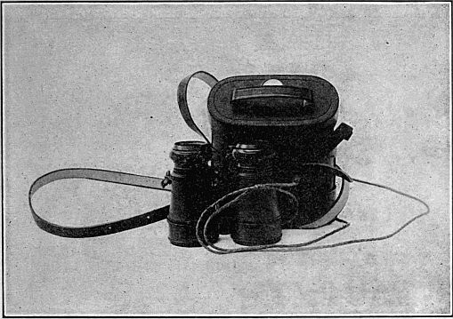
It is to be clearly understood that while this glass is considered superior for moderate ranges, it does not replace, under special conditions, for long ranges, either the porro prism glass or the telescope.
When held as shown in figure 32 with the tubes drawn out about 1 inch to secure proper focus, the glass has a power of about 5.6 diameters, and a field of about 5.4 degrees.
If the glass is turned into the position shown in figure 33, the small plus lenses, just in front of the eye pieces, drop automatically into position and reduce the power to 3.8 diameters, and increase the field to 8.3 degrees. This position requires a different adjustment, the tubes being drawn out about one-third of an inch to get the proper focus. It will be observed in the illustrations that the rear bar of the frame is not only lettered to indicate which power is being used, but the bar itself is shaped with a hump on one side, and hollowed on the other. When the hump is[123] up, the low power is in use. This is to facilitate adjustment in the dark.
The action of the small automatic lenses is free and positive. Neither the eyepieces nor the sections containing the small lenses should be unscrewed, except in case of necessity, and then not by unskilled hands.
The frame, of aluminum and brass, is composite, to give lightness and strength; and while it is constructed to withstand the rough handling of field service, no field glass is proof against careless or wanton treatment. The tubes are covered with tan leather, and a round sling cord, braided from four strands of pliable tan leather, is fastened by snaps to eyes in the frame.
The case is of tan calfskin, provided with shoulder strap, and has an efficient small compass set into the cover. Two loops are sewed to the back of the case so that it may be worn on a belt.
The glass, complete with case, cord, and straps, weighs 21.5 ounces.
Two of these glasses are issued to each company of infantry and coast artillery, Philippine Scouts, and Signal Corps, and to each troop of cavalry for use in instruction in visual signaling. Below is a brief description of the type A glass.
Magnification, 3½ and 5½ diameters; Galilean type; object lens, 1½ inches; tan leather finish; tan leather carrying case with compass; weight of glass, complete, with case, cord, and strap, 25 ounces. At a distance of 1,000 yards the field of view includes a diameter of 123 yards for the 3½ power, and 73 yards for the 5½ power. Length of glass closed, 4 inches. This glass is issued as a part of the visual signaling kit to each company of infantry, coast artillery, and Philippine Scouts, troop of cavalry, machine-gun platoon, and Signal Corps field company. Price, $12.15.
The latest issue of this glass known as the Type A, model 1910, includes provision for interpupillary adjustment, the two barrels being hinged to accommodate the glass to the distance between the pupils of the eye. The price of the model 1910 glass is $14.75.
Type B:
This field glass is similar in appearance and construction to the Type A glass, and is issued to the field artillery organizations upon requisition. The following is a brief description:
Magnification, 4½ and 6½ diameters; Galilean type; object lens, 1¾ inches; interpupillary adjustment; tan leather finish; tan leather carrying case with compass; weight of glass, complete, with case, cord, and straps, 26 ounces; length of glass closed, 4½ inches. At a distance of 1,000 yards the field of view includes a diameter of 90 yards for the 4½ power, and 60 yards for the 6½ power. This glass is issued as a part of the fire-control equipment to field artillery. Price, $17.50.
Type C:
The type C is a high power glass of the porro prism type and is issued only to certain organizations of the field artillery, Signal Corps, and to all machine-gun platoons.
Description.—Magnification, 10 diameters; prismatic type; object lens, 1¾ inches; interpupillary adjustment; tan leather finish; sunshade; tan leather carrying case; weight of glass, complete, with case, cord, and straps, 46 ounces; length of glass closed, 7¾ inches. At a distance of 1,000 yards the field of view includes a diameter of 80 yards. This glass is issued to reconnaissance officers of field artillery. Price, $39.90.
Type D: Purchase has been made for delivery in the near future of a supply of a new type of high power prismatic field glass for sale and issue. This new type of glass, to be known as type D, is considerably smaller than the type C glass, as is shown by figure 34. The glass in a tan-colored carrying case weighs 15 ounces, the field glass without the case weighing but 9 ounces. The magnification is 8 powers and the field of view (with both eyes) 5° 40′. The estimated cost will be $27.
Type A: This glass complete consists of a 2-inch prism terrestrial telescope, powers 18 and 24, with alt-azimuth, folding tripod, and carrying case.
Type B: This telescope is a 19-27 power, 2-draw terrestrial telescope, in leather carrying case with sling. The leather carrying case also includes a holder which can be screwed into a tree, post, or other stationary wooden object.
1. Preliminary.—This specification covers the design and construction of field glasses, types A and B, each having two powers as hereinafter specified.
2. Sample.—The bidder shall furnish with his proposal a sample of the glass which he will supply, and award will be made after comparison of the samples with models on file in the office of the Chief Signal Officer. The maker will be allowed to examine the model glasses in detail in the office of the Chief Signal Officer of the Army, Washington, D. C.
3. Inspection and test.—When the order under this specification is complete, the contractor will notify the Chief Signal Officer of the Army, who will cause an inspection to be made. It shall be the duty of the contractor to remedy any defects pointed out by the inspector, and the contractor will be held accountable for any imperfections which the inspector may have overlooked.
The Chief Signal Officer of the Army reserves the right to inspect any or all processes of manufacture, and unsatisfactory material will be marked for rejection by the inspector before, during, or after assembly, as occasion may arise.
Each glass will be tested for power, field, definition, and light. Any glass which is not the equal of the sample and model in all respects will be rejected. The properties above enumerated will be tested as follows:
(a) Power: In testing for power the glass will be placed upon a firm support about the height of the eye and directed upon a range rod, accurately divided into divisions of 1 foot, with alternate divisions colored red and white, respectively. The rod should be placed approximately 100 feet from the glass in a good light and with strongly contrasted background.
The rod is observed through the glass with one eye and at the same time with the other eye unaided. An accurate comparison of the two images by means of the rod scale determines the magnifying power of the glass.
(b) Field: The field will be determined by the use of a transit or any other instrument adapted to the measurement of horizontal angles. The glass will be placed upon the telescope of the transit in such a way that the axes of collimation of the telescope and field glass barrels are parallel. The extreme limits of the field of view of the glass are marked in a convenient way and the horizontal angle of view accurately measured with the transit.
(c) Definition: In determining the definition of the glass expressed in units (seconds) a target will be provided with a number of lines one-tenth inch thick with one-tenth inch spaces between them drawn on a piece of heavy white paper.
At a certain distance this target will appear uniformly gray when viewed through the glass.
The inspector will gradually approach the target, focusing the glass until he reaches the most distant point from the target where the uniform field ceases and the black and white intervals appear distinct and defined.
Assume the distance thus found to be 20 yards and the thickness of the lines and intervals between them one-tenth inch. The circumference of a circle with a radius of 20 yards or 7,200 tenths inches is 14,400 by 3.1416, or 45,240 tenths inches; but a circumference equals 360°, or (360 by 60 by 60) 1,296,000 seconds.
If, therefore, 45,240 tenths inches correspond to 1,296,000 seconds, then one-tenth inch equals 1,296,000 divided by 45,240, or 28.6 seconds. The definition is therefore 28.6 seconds, or practically half a minute.
The definition should be as follows:
| For 6.5 power glass | 30 seconds. |
| For 5.5 power glass | 35 seconds. |
| For 4.5 power glass | 40 seconds. |
| For 3.5 power glass | 55 seconds. |
(d) Light: The light of a field glass is expressed by a number which is the ratio of the amount of light which reaches the eye through the glass to the amount which enters the eye unaided. This comparison will be reached by means of the absorption apparatus[130] furnished by the Signal Corps. This apparatus consists of two wedge-shaped vessels made of brass with glass windows in the sides, and are filled with a perfectly black liquid. The sky line is first viewed through the apparatus with the naked eye and the instrument adjusted to limit of visibility. The reading of the scale is then noted. The sky line is again observed, using the glass, but in other respects as before, and a second scale reading obtained. The ratio of these readings measure the illuminating power of the glass which must conform to the standard sample.
4. Service field glass, type A.—(a) This glass shall conform in general to the model, now on file in the office of the Chief Signal Officer at Washington. The arrangement for changing automatically from the low power to the high power, and vice versa, by the interposition of the plus lens at the proper distance in front of the eyepiece, must be strictly adhered to.
(b) The low power shall be approximately 3½ diameters and the high power shall be approximately 5½ diameters. The figure of merit given by multiplying the numbers of diameters power by the number of degrees of field will be considered in the examination of samples, along with the other properties of light, sharpness of definition, and general excellence.
(c) The tubes, frame, and metal fittings shall be of aluminum or an aluminum alloy, with the exception that such metal parts as in the opinion of the maker require greater strength may be made of brass.
Tubes shall be held firmly in the frame, single draw, the draw action to be through a bearing surface of at least five-eighths of an inch of best black felt, perfectly fitted so as to preserve perfect alignment.
The exterior metal parts, except where leather covered, must be given the best and most durable, lusterless black finish. The tubes and shades will be neatly covered with best quality tanned calfskin, the leather to be sewed on, and the seams to lie flat next to the focusing standard.
The interior of all parts to be painted a perfectly dead black.
The sunshades, when drawn out, shall project at least five-eighths of an inch and not over 1 inch beyond the edge of the cell.
The focusing screw and standard should follow closely that of the sample, except that the milled focusing disk should have a face as nearly one-half inch wide as possible and the milling should be sharper.
In addition to the diaphragm upon which the automatic lens is mounted, there shall be two diaphragms in each tube, so situated and so proportioned as to cut off all stray light and all internal reflections.
The crossbar supporting the draw tubes should be shaped and engraved exactly as found in the model.
(d) The lenses must be entirely free from mechanical defects, such as specks, air bubbles, etc.; must be free from interior strain, and must be ground from the best obtainable glass for the purpose, selected for general transparency, as colorless as possible, perfectly ground and polished, and accurately centered.
The object lenses shall be composite, achromatic, and well corrected for spherical aberration, with a clear aperture of at least 1½ inches, and not exceeding 15/8 inches. Bidders will state the number and shape of the pieces used to make up this lens.
The compound lenses may be either cemented together with Canada balsam, or left uncemented, as the maker may deem best for durability and optical performance, but if left uncemented the components shall have a permanent mark to indicate their proper positions in the cell.
The eyepieces shall consist of a single double concave lens having a clear aperture of not less than three-eighths of an inch and not more than one-half of an inch.
(e) The sling cord attached to eyes in the frame by means of brass snaps with black burned finish shall be round and braided from four strands of pliable tan leather, and shall have a diameter of at least one-eighth of an inch and not over one-sixth of an inch.
(f) The case and strap must be exactly like sample, and of No. 1 stock. Care must be taken to put in only compasses that are in perfect condition. The strap buckle must be of brass. The glass, when closed, must not exceed 4 inches in length, and the glass, case, cord, and strap, complete, must not exceed 25 ounces in weight.
(g) The frame shall be constructed with jointed bars for interpupillary adjustment.
5. Service field glass, type B.—(a) The requirements of part 4, service field glass, type A, of this specification, shall be followed in the design and construction of the type B glass in so far as applicable.
(b) Power: The lower power shall be approximately 4½ and the high 6½ diameters.
(c) Object lenses: These shall have a clear aperture of at least 1¾ inches diameter.
(d) Case: Case and carrying strap shall be furnished as required in part 4 of this specification.
(e) This glass shall be constructed with jointed bars for interpupillary adjustment.
(f) The sunshade, when drawn out, shall project not less than three-eighths of an inch and not more than 1 inch beyond the edge of the cell.
6. Marking.—Glasses furnished under this specification shall be marked on one barrel with the words "Signal Corps, U. S. Army," and on the other barrel "Serial No. ——." Serial numbers will be furnished with the order. If not furnished the contractor at the time the order is placed, the Disbursing Officer of the Signal Corps should be called upon for same, and the numbers and other marking placed on the glasses prior to the delivery of the order.
Page 23, "porportions" changed to "proportions" (in proper proportions)
Page 106, "engineeer" changed to "engineer" (a French engineer)
Page 126, opening bracket added to subtitle ([Revised February 10, 1910.])