
Cover Page
Cover Page

HANDICRAFT BOOKS
BY
A. NEELY HALL
8vo. Cloth. Illustrated with hundreds of photographs
and working drawings by the author
and Norman P. Hall
THE BOY CRAFTSMAN
HANDICRAFT FOR HANDY BOYS (Revised Edition)
THE HANDY BOY (Revised Edition)
HOME-MADE TOYS FOR GIRLS AND BOYS
HANDICRAFT FOR HANDY GIRLS
CARPENTRY AND MECHANICS FOR BOYS
HOME-MADE GAMES AND GAME EQUIPMENT
(Revised Edition)
OUTDOOR BOY CRAFTSMEN
BIG BOOK OF BOYS' HOBBIES
LOTHROP, LEE & SHEPARD COMPANY
BOSTON NEW YORK

A Boy's Workshop.
THE BOY
CRAFTSMAN
Practical and Profitable Ideas
for a Boy's Leisure Hours
BY
A. Neely Hall
With more than four hundred illustrations
by the author and Norman P. Hall
BOSTON
LOTHROP, LEE & SHEPARD CO.
Copyright, 1905, by Lothrop, Lee & Shepard Company.
Published, August, 1905.
All rights reserved.
The Boy Craftsman.
Norwood Press
J. S. Cushing & Co.—Berwick & Smith Co.
Norwood, Mass., U.S.A.
—Theodore Roosevelt.
The boy of to-day is ever on the lookout for new ideas which can be adopted for his work and recreation, schemes which are practical and which are thoroughly up-to-date. They must be helpful in suggesting ways of earning money, as well as entertaining, for what boy of the present day does not feel the need of such suggestions to aid him in raising the funds necessary to carry on his work?
In none of the books published on boy's handicraft has the question entered into consideration as to how he is to obtain the means with which to buy such materials and apparatus as the work requires. A boy should not expect to draw upon his father's purse for everything his fancy desires. It is important that he learn to earn his spending money, for in doing so he becomes independent and more careful as to how he invests it. Having had the experience of working, the average boy learns to so appreciate the value of hard-earned money that it is pretty certain he will spend it only for something with which he can earn more or which will prove useful to him in his work and play.
"The Boy Craftsman" has been undertaken with a view of helping boys with their problems of earning money, as well as furnishing recreative and entertaining work, and to this end the first portion has been devoted to suggestions for the carrying on of a number of small business enterprises, and the second [Pg iv] and third parts to outdoor and indoor pastimes for all seasons of the year.
In "Profitable Pastimes" a boy will find work that will make easy the matter of earning money with which to buy such materials as he needs to carry out the suggestions offered in the book, while the practical knowledge acquired and the handiness developed in pursuing the several lines of work is certain to be helpful to him in later years.
The tools and apparatus used are such as a boy of average ability can procure with a little hustling, and can be purchased singly, or two or three at a time, as his money permits. The materials at hand can be used in thousands of different ways, and in preparing the chapters this has been taken into consideration, these odds and ends being utilized whenever it has been possible to do so.
Carpenter work is something with which every boy must familiarize himself to a certain extent in order to do anything in the line of construction, so the fitting up of a workshop and the proper handling of tools have been described in the first two chapters, in view of making it a simple matter to perform the work embodied in the rest of the book.
Technical terms and phrases have been eliminated from the text as far as possible, and where it has been deemed necessary to include them, to describe certain operations for which a boy should know the proper terms or expressions, they have generally been explained in the first chapter in which they occur. To simplify the matter of referring to the definitions of these, they have been arranged alphabetically in Chapter XXIX.
Some of the material contained in this book was originally written by the author in the form of magazine articles for The American Boy and The Boys' World, and thanks are due the[Pg v] publishers, The Sprague Publishing Company and The David C. Cook Publishing Company, for permission to reprint it. This material has been revised and enlarged upon, and is presented with new and additional illustrations.
The author is always glad to hear from his young readers, and to be of assistance to them in answering any questions they wish to ask regarding their work.
A. N. H.
Chicago, Illinois,
May 31, 1905.
PART I
PROFITABLE PASTIMES
CHAPTER I
PAGE
A Boy's Workshop3
Value of a Knowledge of Carpenter Work—Location of Shop—A Solid Work-bench—The Vise—Bench-stops—Carpenter's Horses—A Bench-hook—A Mitre-box—A Sand-paper Block—A Strop—A Plumb—Purchasing Tools—Tool-cabinets—Racks for Tools—A Carpenter's Carrying-box—A Nail-box—Receptacles for Supplies—Workshop Clothes—Care of Oily Rags and Waste.
CHAPTER II
The Proper Handling of Tools20
Care of Tools—The Cross-cut Saw and Rip-saw—Sawing—The Back-saw, Compass-saw, and Gig-saw—Kerfs—The Jack-plane, Fore-plane, and Smoothing-plane—Planing—Testing Work—The Firmer-chisel—Paring—The Framing-chisel—Chamfering and Bevelling—The Gouge—The Draw-knife—Boring—An Automatic-drill—Hatchet and Hammer—Driving Nails—Withdrawing Nails—Toe-nailing—Blind-nailing—Clinching—The Nail-set—Nails—Screw-driver for Bit-stock—Screws—The Countersink.
[Pg viii]Sharpening Tools37
Grinding Chisels, Gouges, Draw-knives, Knives and Hatchets—The Washita Oil-stone—Whetting—Stropping—Sharpening Saws.
Laying out Work42
Use of the Try-square—Gauging with Rule and Pencil—A Marking-gauge—A Mitred Try-square—The Bevel—To Divide a Board.
CHAPTER III
The Boy about the House47
Opportunities for Work—Outfit for Jobbing—The Hinge-lock—Clothes-line Reel—A Broom and Dust-pan Rack—The Fly-killer—An Ash-sifter—A Bread-board—A Plate-rack
CHAPTER IV
Suggestions for a Boy's Room57
Simple and Inexpensive Furnishings—What the Room should Contain—A Cosey-corner—Pennants—Small Posters—Picture-frames—A Writing-desk—Another Style of Desk—An Ink-stand and Pen-tray—A Couch—A Window-seat—A Curio-cabinet—Book-shelves—A Blacking-case—A Towel-rack.
CHAPTER V
How to make a Doll-house71
Store Doll-houses—Profit from making Doll-houses—The Materials Required—The Base—The Floors—Partitions and Walls—Stairways—Balustrades—Front and Rear Steps—The Gambrel Roof—The Gable-ends—The Doors and Windows—Outside Trimmings—Casters—The Chimneys—A Mantel and Fire-place—Andirons—The Interior Woodwork—Painting the House.
CHAPTER VI
Another Doll-house and a Stable91
Packing-cases and Other Material—The Floor Plans—The Partitions and Walls—The Elevator-shaft—The Windows—The Roof—The Chimney—An Elevator—The Gable-ends—The Stairway—A Balustrade—Other Details.
[Pg ix]How to make the Stable100
Dimensions of Stable—The First Story—The Roof—The Gable-ends—The Stall Partitions and Feed-troughs—Windows—Ladder to Hay-loft—Feed-hoist—The Drop-front—A Stable Door—Painting.
CHAPTER VII
Furnishing the Doll-house105
The Walls and Ceiling—Hardwood Floors—Carpets and Rugs—Window-shades and Curtains—Portieres—Pictures—A Cosey-corner—Buying Furnishings.
CHAPTER VIII
Doll-furniture109
Metal Furniture—Miniature Mission Furniture—Material—Drawing the Patterns—The Chairs—The Settee—Tables—A Side-board—A Mirror—The Grandfather's Clock—Kitchen Furniture—The Beds—The Dresser—A Wash-stand—Finishing.
Other Cigar-box Furniture122
A Folding-bed—The Dresser—A Wardrobe.
CHAPTER IX
A Boy's Printing-shop126
Location of Printing-shop—Equipment—Selection of Type—Type-cases—A Rack for Type-cases—A Composing-stick—A Composing-rule—Justifying—A Home-made Galley—"Pieing"—Proofs—The Imposing-stone—The Chase—Furniture—Locking-up a Form—Distribution—The Tympan—Overlaying—Underlaying—Gauge-pins—Inking the Press—Care of Rollers—Neatness—Receptacles for Materials—Care of Waste Paper and Oily Rags.
CHAPTER X
Amateur Journalism142
A Collection of Amateur Papers—Amateur Press Associations—Some Methods of Printing Papers—Examples of Amateur Papers—The Character of a Paper—Naming—The Frequency of Publication—The Size of Page—A Stereotyped Heading—The Choice of Type—A Cover—Binding—Advertisements—The Advertisers' Dummy—Second-class Matter.
[Pg x]CHAPTER XI
A Boy's Dark-room153
Profit in Photography—The Necessary Equipment—The Bedroom as a Dark-room—The Bath-room as a Dark-room—Another Scheme for a Dark-room—A Work-table—Running Water—A Water-tank—A Sink—A Washing-box—A Drying-rack—Another Scheme for a Drying-rack—A Cabinet—A Ruby-light—A Home-made Lantern—A Plate-lifter—Classifying and Preserving Negatives—Manila Envelopes—A Negative-case.
CHAPTER XII
A Winter Enterprise169
An Opportunity for Making Money—A Snow Plough—A Scraper—A Snow Shovel.
PART II
OUTDOOR PASTIMES
CHAPTER XIII
A Back-yard Club-house175
How Some Boys Built a Club-house—A Mysterious Letter—Drawing the Plan of a Club-house—The Material—Fishing Studs—Staking out the Building—The Studs—Boarding up the Sides—The Roof—The Floor—A Window-sash—A Batten Door—Wooden Latch—Calking up Cracks.
CHAPTER XIV
How to build a Log-cabin186
The Pioneer Cabin—The Cabin of To-day—Selection of a Site—Design and Size—The Material—Staking out the Cabin—The Lock-joint—The Sills—Construction of Roof—Ridge Boards—A Log Chimney and Fire-place—Calking—A Mud Floor—The Windows—The Cabin Door—Wooden Hinges—Wooden Latch—The Latch-string—A Mantel-shelf—Provision Cupboard—Rustic Seats—Bunks—A Camp-table—A Few Pointers about Camping—Utensils—Other Necessities—Provisions.
[Pg xi]CHAPTER XV
How to build a Canvas Canoe201
Canoeing as a Sport—Popularity of Canvas Canoes—Materials—The Bow and Stern Pieces—The Keelson—The Mould—Putting the Framework Together—The Gunwales—The Ribbands—The Deck Beams—The Ridge Pieces—The Deck Braces—The Cockpit—The Canvas Covering—The Deck—Painting—The Cockpit Coaming—The Keel—The Bilge-keels—Outside Gunwales—A Seat—How to mend Punctures—A Single Paddle.
CHAPTER XVI
Home-made Traps218
Trapping as a Pastime—The City Boy and his Country Cousin—The Figure-four Trap—A Box Trap—The Dead Fall—The Sieve Trap—The Coop Trap—A Rabbit Snare—A Twitch-up—The Professional Trapper—Wolves and Coyotes—Story of a Trapped Indian.
CHAPTER XVII
Toy Guns, Targets, and Bows and Arrows229
Ancient War Engines—New Idea for a Cross-bow—Shingle Arrows—A Toy Pistol—Cardboard Bullets—A Shot-gun—An Elastic Sling—A Boy's Barrel-hoop Target—A Simpler Target—How Points are Scored—The Bow and Arrow—Length of Bow—The Bow-string—The Arrow-shafts—Preparing Arrow-heads—Feathering—A Quiver—Proper Position for Shooting with Bow—The Indian's Bow—How his Arrows were made and Feathered—The Preparation of his Arrow-heads.
CHAPTER XVIII
An Outdoor Gymnasium243
Location for Gymnasium—A Horizontal Bar—Tumbling Mat—Parallel Bars—The Punching-bag Platform—A Pair of Jump Standards—A Vaulting Pole—A Spring-board—Hurdles—A Running Track—Method of Starting for Short Sprints—Mark for Broad Jumping—An Athletic Club—Athletic Meets.
[Pg xii]CHAPTER XIX
A Back-yard Circus255
The Ancient Roman Circus—The Circus of To-day—How Several Boys gave a Circus—Preparing the Yard for a Circus—Making the Ring—Good Circus Seats—A Tent—Decorating the Tent—A Ticket Office—A Turnstile—The Side Show—Cages for Side Show—Animated Animals—The Elephant—The Giraffe—The Two-legged Wild Horse—The Wild Man of Borneo—A Monkey's Make-up—The Ring Master—The Clown's Suit—The Attendants—Ideas for a Performance—A Slapper—Looping the Hoop on a Giraffe—A Chariot—Parades—The Advertising Signs.
CHAPTER XX
Suggestions for Fourth of July272
The First Fourth of July Celebration—Pyrotechnics Costly and Dangerous to Make—The Making of Harmless and Inexpensive Fireworks—A Fire-cracker Cannon—To fire the Cannon—A Fire-cracker Mortar—Mimic Battles with Paper Soldiers—Another Toy Cannon—To fire the Cannon—Firing Fireworks from Kites—Firing a Pack of Fire-crackers from a Kite—Shooting Nigger-chasers—Japanese Lanterns hung from Kite-strings—A Shooting-torch—A Final Set-piece.
CHAPTER XXI
Halloween281
Ancient Superstitions and Origin of Halloween—A Magazine Bean-blower—A New Style of Tick-tack—A Clockwork Tick-tack—The Goblin-man—The Disappearing Rope.
CHAPTER XXII
A Back-yard Toboggan-slide291
One Advantage of a Small Slide—Location—Length—The Platform—Framework—Railing around Platform—A Ladder—Making a Swift Slide—A Home-made Sled—The Runners—Reënforcing the Runners.
[Pg xiii]PART III
INDOOR PASTIMES
CHAPTER XXIII
A Miniature Theatre303
An Interesting Entertainment—A Picture-frame Proscenium—The Stage Framework—The Gridiron—The Stage Floor—The Drop-curtain—Lighting the Theatre—The Footlights—Floodlights—Colored Lights—Spotlights—Admission Tickets and Programmes.
CHAPTER XXIV
Scenery, Properties, and Mechanical Effects311
Materials for Scenery—An Ocean Scene—Additional Waves—Frames for Drops—A Mid-ocean Scene—A Seashore Scene—A Field Scene—The Trees—A Blockhouse Scene—Pine Boughs for Trees and Shrubbery—Moss for Mounds and Hills—Rustic Bridges—A Pond or Lake—A Street Scene—An Interior—A War Drama—Paper Soldiers—Scheme for Marching Soldiers—Separate Standards—A Jointed Figure—Stage Properties—Tents—An Indian Teepee—Battleships—Trains and Wagons—Mechanical Effects—Thunder—Rain—Wind—Lightning—The Roar of Cannon.
CHAPTER XXV
Making a Toy Railway331
The Trolley-line—Supports for Trolley-line—Power for Operating Railway—Tracks—The Cars—A Gondola Car—A Street Car—Other Cars—Operation of Railway—A Station.
CHAPTER XXVI
Clockwork Automobiles343
Procuring a Set of Clockworks—An Automobile Touring-car—The Frame—Preparation of Clockworks—The Belt—Testing the Machine—The Cardboard Sides—Wheels—Mud-guards—Lamps—The Steering-wheel—A Horn—The Brake—The Chauffeur—Painting [Pg xiv] the Machine—An Automobile Delivery Wagon—The Cardboard Sides—The Wheels—Other Portions—Painting the Wagon—A Clockwork Railway.
CHAPTER XXVII
Work to do with a Knife356
How Boots were Marked in a Penitentiary—A Home-made Fountain Pen—The Magic Pin-wheel—To Operate the Pin-wheel—A Wooden Chain and Rattle—The Chain—The Rattle—Finishing the Chain and Rattle.
CHAPTER XXVIII
Cork Toys363
Materials Required—Cork Animals—A Pig—A Horse—The Elephant—The Giraffe—A Porcupine—Other Animals—The Korka-bird—A Duck—Canoes—Small Sail-boats—Cork Furniture—A Chair—The Sofa—A Small Tabouret—A Toy Log-cabin.
CHAPTER XXIX
(In addition to more than four hundred text illustrations.)
| A Boy's Workshop | Frontispiece |
| OPPOSITE PAGE | |
| Treatment of a Boy's Room | 58 |
| Fig. 64.—A Colonial Doll-house | 78 |
| Fig. 96.—Another Style of Doll-house} Fig. 97.—Interior View of Doll-house } | 90 |
| An Amateur's Outfit | 128 |
| A Group of Amateur Papers | 142 |
| Fig. 168.—A Handy Dark-room } Fig. 172.—A Washing-box and Drying-rack} | 154 |
| In Camp for the Summer | 175 |
| A Boys' Log-cabin | 188 |
| Two Simple Cabins | 198 |
| Caught at Last | 226 |
| The Back-yard Circus | 268 |
| A Miniature Theatre | 303 |
| Fig. 330.—A Field Scene } Fig. 338.—A Blockhouse Scene} | 316 |
| Fig. 339.—A Street Scene | 320 |
| Fig. 375.—The Car completed} Fig. 376.—The Framework } | 344 |
Carpenter work should be encouraged in a boy from the time he first becomes interested in it, for besides being something with which to keep him busy, the experience gained by its practice will be useful to him all his life, no matter what branch of industry he may follow later on.
When a boy has learned the proper care and use of tools, and is able to turn out neatly executed work, he will find the occupation a profitable one, there being an unlimited number of things he can make in his shop.
Doll-houses for girl relatives, toys for brothers and cousins, and articles for the household, such as are described in following chapters, are a few of the many things he can construct. Many of these are salable articles, besides being suitable for birthday and Christmas gifts, and should bring a neat sum of money to the young carpenter.
A knowledge of carpenter work also develops in a boy a handiness for devising and putting together articles and apparatus for his own use.
[Pg 4]A boy should really have a shop where he can keep his tools and unfinished work with no danger of them being disturbed, and where he need not be afraid of littering the floor with shavings or of making too much noise.

Fig. 1.—End View of Work-bench.
The Workshop may be fitted up by the boy himself, and a suitable place can probably be found in the basement, barn, or woodshed. Here a corner large enough to contain a work-bench, carpenter's horses, and tool-cabinets, besides plenty of room to work in, should be partitioned off, and a window that will admit a good supply of light made in one side of the room, if one has not already been provided.
A Solid Work-bench, six feet long, thirty inches wide, and thirty-two inches high, should be constructed beneath the window. It is a good idea to build this on to the wall if possible, as it is easier to make a solid bench by doing so, and the firmer it is, the better.
First cut a two-by-four[Pg 5] four feet long, and spike it to the wall below the window, twenty-eight inches above the floor. Then saw two pieces of two-by-four, twenty-eight inches long, for the legs, and two pieces, thirty inches long, for crosspieces. Spike the crosspieces on to the legs and on to the piece nailed to the wall, as shown in Fig. 1. Cut three ten-inch planks, six feet long, and spike them to the crosspieces so that they project twelve inches over the ends, but are flush with the framework in front. Then cut a ten-inch board, six feet long, for an apron, and, after cutting the ends as shown in Fig. 4, nail it across the front of the bench.
For fifty cents a fifteen-inch iron or wooden bench-screw, similar to those in Figs. 2 and 3, can be purchased at a hardware store, and the rest of
The Vise is simple to make. Figures 1, 4, and 5 show the details for this.

Fig. 2.—Iron Bench-screw.

Fig. 3.—Wooden Bench-screw.
Take a board thirty inches long by six inches wide for the jaw, and bore a hole a little larger than the screw, six inches from one end. Bore another hole the same size through the apron and table-leg, six inches below the[Pg 6] bench-top (see A in Figs. 4 and 5). The portion of the iron screw marked B in Fig. 2 should be set into the hole bored in the bench-leg and screwed at E (Fig. 1), while the portion D is to be screwed to the jaw. If a wooden screw is used, the portion C in the drawing (Fig. 3) is nailed to the inside of the bench-leg.

Figs. 4-5. Details of Bench-vise.
In order to guide the bottom of the jaw, an arrangement similar to F in Fig. 5 should be made. Make a mortise two inches long by one inch wide near the[Pg 7] bottom of the bench-leg and cut a strip of wood fifteen inches long to fit loosely in it. Then shut the vise and mark upon the inside of the jaw the place where the mortise comes in the leg. Nail one end of the fifteen-inch strip to the jaw at this point, being careful to get it in such a position that the other end will slide into the mortise. Bore several holes in the strip and cut a peg to fit in them. The jaw can now be kept parallel with the side of the bench by adjusting the peg, which is very necessary in order to have the vise grip a piece of work squarely.
When you have a long board to work upon, it cannot be held steady by the vise alone. One end should be placed in the vise and the other rested upon a peg stuck in a hole bored in the side of the bench. For boards of different lengths, several holes should be bored, as shown in the illustration of the finished bench (see frontispiece), and a movable peg cut to fit in them.
A Bench-stop of some sort fastened to the top of the bench will be found useful to push work against while planing it, when it is not convenient to use the vise. Figures 6, 7, and 8 show the forms of stops most commonly used by carpenters. Of these the metal stop shown in Fig. 6 is the most satisfactory, as it can be adjusted to different heights. It costs but little and is easily put in place. A mortise is made in the top of the bench to receive the lower portion of the stop, and the plate A is set flush with the bench-top and held in[Pg 8] place with screws driven into the holes in the corners. The centre of this plate (B) is detached from the rest and mounted upon a small post, which can be adjusted to the desired height by giving the screw at C a few turns with the screw-driver. The teeth in the edge of B help to hold the work in position.
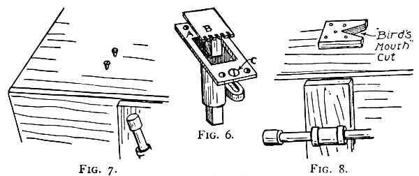
Figs. 6-8.
Some Forms of Bench-stops.
One of the simplest forms of stops is shown in Fig. 7. It consists of two screws placed in the top of the bench, which can be raised or lowered with the screw-driver to the height you desire.
The stop shown in Fig. 8 is made out of a block of wood with a "bird's mouth" cut in one side. It should be nailed to one end of the bench in such a position that the end of the work can be placed in the "bird's mouth."
While most of your work will be done on the bench, and a good portion of sawing done with the wood in the vise, large pieces, especially long boards, are generally sawn while placed across horses.
[Pg 9]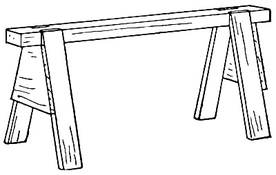
Fig. 9.
Two Carpenter's Horses will be required. A good scheme for these is shown in Fig. 9. The top is made out of a piece of two-by-four with bevelled mortises cut in two sides of each end as in Fig. 10. These mortises are made to receive the legs, and the angle of the bevel will of course determine the angle at which the legs will spread. Cut the legs out of four-inch boards, and bevel the lower ends to make them set solidly upon the floor. Nail the legs firmly in place and brace them with two boards cut and fitted in place, as in the illustration. When the pieces have been nailed together, plane off the tops of the legs to make them flush with the top of the horse, and trim the lower ends if they require it until the horse is solid.

Fig. 10.
Boring, paring, and nailing on the bench will soon make the surface uneven, unless something is placed beneath the work during such operations. You should therefore make and use
A Bench-hook, such as shown in Fig. 11. A good size is ten by twelve inches, but it may be made[Pg 10] larger or smaller if desired. Nail a strip along one edge of the under face and another strip along the opposite edge of the upper face. The latter strip should have three kerfs cut in it as shown in the drawing, one at right angles and the other two at forty-five degrees. These may be laid off with a try-square, as shown in Figs. 38 and 39 (Chapter II), or with the bevel, as shown in Fig. 42. Be careful to keep the saw on the line and in a perfectly perpendicular position in making these kerfs. The upper strip on the bench-hook serves the purpose of a stop, and the kerfs make it possible to use the bench-hook for mitring with the back-saw. Further description of the uses of this handy article will be found in the following chapter.

Fig. 11.—A Bench-hook.
You will need
A Mitre-box for cutting mitres in large work, and[Pg 11] this may be made as shown in Fig. 12. Cut two pieces of seven-eighths inch maple, or other hard wood, twenty inches long by six inches wide, and one piece twenty inches long by four inches wide. Nail the six-inch pieces to the edges of the four-inch piece as shown in the drawing, after which you are ready to cut the mitres. These should be laid out similar to those on the bench-hook, by means of the mitred try-square or the bevel. With the blade of the try-square or bevel extending across the top edges of the side-pieces, mark off forty-five degree lines at A and B, and a ninety degree line at C, after which square the lines down both inner and outer face of the side-pieces. When the lines have been accurately drawn, it is a simple matter to make the kerfs, if you have had any practice in sawing and can keep to a line.

Fig. 12.—A Mitre-box.
No matter how skilful a carpenter is with his tools, he generally depends upon his mitre-box in making mitres, for not only accuracy is obtained by its use, but time is also saved. In using one be careful not to let the saw cut into the sides of the kerfs, or the box will soon be rendered useless for making accurate mitres.
Before putting the finish upon a piece of work, the wood should be thoroughly sand-papered. In many[Pg 12] cases certain portions cannot be reached by the hand, and so
A Sand-paper Block similar to Fig. 13 should be made. Cut a block of wood five inches long, two and one-half inches wide, and seven-eighths of an inch thick. Then place it in the vise, and bevel one end and round the other as shown in the drawing. An inch and one-half from each end cut "rabbets" one inch wide across the block, and make two blocks to fit them. When this has been done, cut a strip of sand-paper two and one-half inches wide and stretch it around the block, holding it in place by driving the small blocks into the rabbets. You will find this sand-paper block very handy, as some portion of it can be got into almost every corner you will ever have occasion to sand-paper. The paper may be quickly replaced with a fresh piece when worn out.
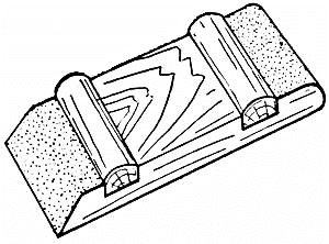
Fig. 13.—Sand-paper Block.
A Strop for putting keen edges on tools may be made out of a block of wood, with a piece of shoe-leather, or section of an old razor-strop, glued to one side of it.
A Plumb, similar to Fig. 14, is a handy article to have for outdoor work, such as erecting posts in perpendicular positions. You will have need of it in putting up such buildings as the back-yard club-house, the log-cabin, and the erection of apparatus for the outdoor gymnasium, the construction of which will be found in following chapters.
[Pg 13]It consists of a stick, the sides of which have been planed up true and parallel, with a notch in one end and a cord with a weight attached fastened to the other end. The notch should be cut in the exact centre of the end of the stick, and the nail placed in the other end directly in line with the centre of the notch. An iron nut, or some such weight, should be attached to the lower end of the cord.
By placing this stick at the side of an object, you can determine whether or not it is plumb by the position of the string, which should hang in the centre of the notch when the object is plumb. The length of the stick may be made to suit the size of the work it is to be used upon. Four or five feet is a good length for ordinary outside work.
Fig. 14.
In purchasing Tools for your workshop it is not advisable to buy them in chests, for they are almost always made of cheap material, and poor tools are of no use to the boy who intends to do good work. It is a much better plan to buy a few tools at a time, getting a good quality of steel, and to gradually increase your outfit as your money permits. Then if you really want a chest you can make it yourself. A hatchet, hammer, saw, plane, chisel, jack-knife, bit and bit-stock, screw-driver, and square are the principal tools you will require, and need be all you have to start out with. Others[Pg 14] may be got as you have need of them, and may be selected from the following list, which includes probably all the tools a boy would ever have occasion to use.
LIST OF TOOLS FROM WHICH TO MAKE YOUR SELECTIONS
1 14-inch Jack-plane.
1 18-inch Fore-plane.
1 9-inch Smoothing-plane.
1 22-inch Rip-saw.
1 20-inch Cross-cut saw.
1 12-inch Back-saw.
1 12-inch Compass-saw.
1 Gig- or Bracket-saw.
1 Ratchet Brace.
5 Auger-bits, ¼-inch, ⅜-inch, ½-inch, ¾-inch, and 1-inch.
1 Expansive-bit.
Several Gimlet Bits.
1 Screw-driver Bit.
1 Countersink.
1 Brad-awl.
2 Hand Gimlets.
1 Automatic-drill.
4 Chisels, ¼-inch, ½-inch, ¾-inch, and 1-inch.
2 Gouges, ⅜-inch and ¾-inch.
1 Draw-knife.
1 Jack-knife.
1 Hatchet.
1 Hammer.
1 Tack Hammer.
1 Mallet.
2 Nail-sets (large and small).
1 Hand Screw-driver.
1 Wood Rasp.
1 Metal File.
1 Pair Cutting Nippers.
1 Pair Pincers.
1 Grind-stone.
1 Oil-stone and oil-can.
1 Strop.
1 2-foot Folding Rule.
1 Large Steel Square.
1 7-inch Try-square.
1 Bevel.
1 Marking-gauge.
1 Compass.
The proper care and handling of these tools is fully described and illustrated in the following chapter. These directions should be carefully read before you attempt to use the tools, especially the edge tools.
A Cabinet will be found much better for an outfit of tools than a tool-chest, as it can be more easily got[Pg 15] at than a chest, where it is necessary to lift several trays before you can reach a tool which has been put in the bottom.
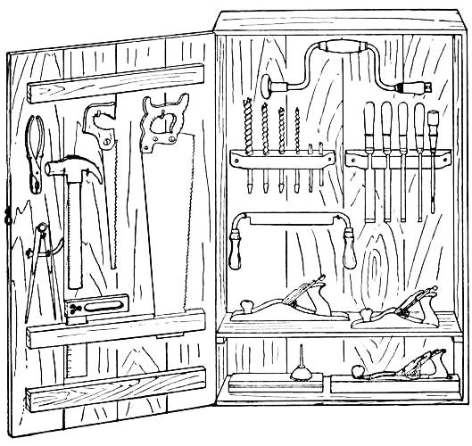
Fig. 15.—Tool-cabinet.
The cabinet shown in Fig. 15 is made out of a box about three feet long, two feet wide, and nine inches deep. Make a door from the box-cover, fastening the boards together by means of two battens placed at the top and bottom (see illustration). Nail a cleat on[Pg 16] each side of the cabinet six inches from the bottom, and make a shelf to fit upon them.
Racks for Bits and Chisels should be made similar to Fig. 16, and fastened side by side to the inside of the cabinet.
Cut a strip of wood about the size of the battens, and make two slots in it, one for the end of the saw to fit in and the other for the blade of the try-square (see Fig. 15). This strip is fastened to the cabinet door a few inches above the bottom batten.

Fig. 16.—Bit and Chisel Racks.
Hang up the other tools on brass hooks.
After completing the cabinet, paint it inside and out, and fasten either a hook or lock to the door.
When this cabinet becomes too small for your increase in tools, you can keep those you use the most in it, and make
Another Cabinet for the special and less used tools. Either screw the cabinets to the wall or support them upon brackets.
Racks may be made for any tools you wish to hang on the wall. A piece of grooved siding nailed above the bench will do nicely for the large square.
When you do outside work you will want something[Pg 17] in which to carry such tools as will be required to complete the job.
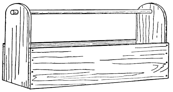
Fig. 17.—A Carpenter's Carrying-box.
A Carpenter's Carrying-box should be made. Such a box is shown in Fig. 17. The box should be about twenty-seven inches long to accommodate the saws, and it would be well to make the width eight inches and the height sixteen inches. First prepare the end-pieces, making them six by sixteen inches and rounding the tops with the compass-saw, as shown in the illustration. Then cut a board twenty-five inches long by six inches wide for the bottom and nail the end-pieces to the ends of it. Make the side-pieces twenty-seven by eight inches, and nail them to the end-pieces and to the edges of the bottom board. The handle consists of a broom-stick fitted into holes bored near the tops of the end-pieces.
This box should be used for tools only, and not have[Pg 18] nails, screws, and bolts mixed up with them, for these supplies should be kept in a special
Nail-box, with compartments for the different sizes of nails, screws, hooks, screw-eyes, hinges, etc. One of the best kinds of boxes for this purpose is a knife-box such as can be bought for ten or fifteen cents. This is divided in two and has a handle attached (see Fig. 18). The two compartments should be sub-divided into smaller boxes, either with pieces of cigar-boxes, or with pieces of tin bent at the ends and fastened to the sides of the box, as shown in the illustration.
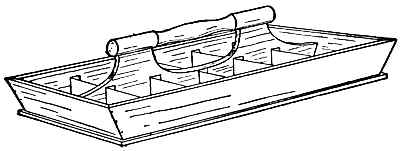
Fig. 18.—Nail-box.
Supplies of nails, brads, etc., should be kept in cans and cigar-boxes of different sizes, and it is a good idea to letter these receptacles that you may be able to put your hands upon what you want without having to hunt for it.
Shelves will be handy to keep paint-cans and these boxes on.
Workshop Clothes.—Old clothes should be worn in the shop, as carpenter work is rather hard upon them, especially[Pg 19] the trousers. Better than these is a pair of overalls and perhaps a jumper. They are easy to work in and wear better than anything else.
A Few Hooks should be placed on the wall for hats and coats, and for your working clothes, if you change them in the shop before and after work.
To prevent your tools from being carried off, and your work from being disturbed, it is advisable to have a lock upon the door and keep your shop locked up when you are away.
To avoid danger of fire, keep combustible articles, such as oily waste and rags, in covered tin cans, and do not allow shavings and rubbish to accumulate.
Before using a tool be sure you understand the proper handling of it, for there is probably nothing more easily injured than an edge tool in a sharpened condition. An inexperienced person is very apt to dull or nick a tool by striking its edge against nails or by using it for purposes other than what it was made for. For this reason a carpenter is very apt to refuse a boy, or any amateur for that matter, the use of his tools, and he is right in doing so. Just imagine the amount of work it makes for him to put the tools in shape after they have been returned in all sorts of conditions. A little rubbing on the oil-stone, with an occasional grinding, is all his tools require when he is using them, but to remove nicks made by his young friends wastes too much of his valuable time.
A good rule to observe, boys, is never to lend tools to any of your friends, for though they may be as careful in handling them as you are, the chances are they will not be. You had better be a little "grouchy" in this respect, than to have tools which are unfit to do good work with.
[Pg 21]The following directions, together with the illustrations, should make the handling of your tools perfectly clear, and you will find among these a number of hints as to the care of tools that should be carefully adhered to in order that you may keep them in good condition.
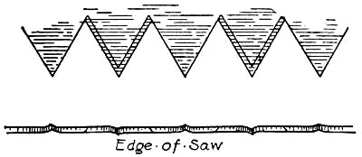
Fig. 19.—Teeth of Cross-cut Saw.
Saws.—A boy can get along with two saws, a cross-cut saw for general use and a compass-saw for finer work, such as circular sawing, and cutting thin wood where a large saw would be too coarse and apt to split the work. But you will often have need of a rip-saw, back-saw, and bracket-saw. They were therefore included in the list of tools on page 14, and you can add them to your outfit as your money permits.
The Cross-cut Saw is, of course, intended for cutting across the grain, while the rip-saw is for cutting with the grain, or ripping. The former saw can be used for rip-sawing, but the operation is much slower, and when you have much of it to do, as in ripping a six-foot board, for instance, you will find the work tedious.
The Rip-saw is not fit for cross-cutting, as it leaves the cut fibres in a very rough condition.
The difference in these two saws lies in the shape of their teeth. This can be seen by picking them up and examining their cutting edges. You will find the teeth are bent out of line, the first to the right side and the next to the left. This is known as the "set" of the teeth, and the quality of your work will depend largely[Pg 22] upon the care with which the teeth have been sharpened and set. At first you may confuse these two saws, but if you will notice that the teeth of the cross-cut saw come to sharp points and are bevelled on the sides, while those of the rip-saw are not sharpened on the sides, and instead of being pointed on the ends are chisel-shaped (see Figs. 19 and 20), you will have little trouble in distinguishing them.

Fig. 20.—Teeth of Rip Saw.
Sawing.—Small pieces may be sawn while held in the vise, but, as a rule, large work is placed across a couple of horses. It is generally the most convenient way. Grasp the saw in the right hand, and take the position shown in Fig. 21, with the left knee upon the work to hold it in place, and the left hand at the edge of the board. The thumb should be pressed against the saw-blade to guide it until the cut has been well started, as shown in Fig. 22. Without the aid of the thumb the saw is liable to slip off the mark and make an ugly cut in the wood. First use[Pg 23] a few short strokes until the saw has started to cut. Then use a long, steady stroke, putting all of the pressure upon the down stroke. Be careful to keep the saw to the line and in a perpendicular position, so that the cut will be square on all sides. If it starts[Pg 24] to run away from the line, a slight twist of the blade will return it.

Figs. 21-22.—Position for Sawing.
When a board has been sawn nearly in two, remove the weight of your knee from it, and hold the board with the left hand to prevent it from splitting off.
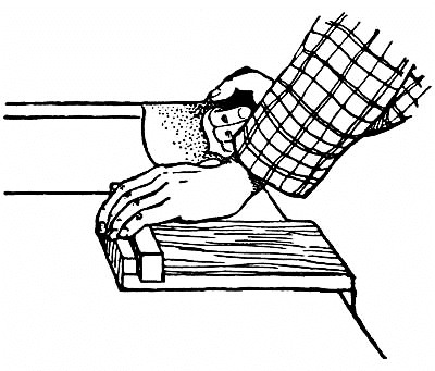
Fig. 23.—Position for using the Back-saw.
Fig. 23 shows the correct position for using
The Back-saw, which is intended for more delicate work than the larger saw, such as can be sawn on the bench-hook or in the mitre-box. It makes a finer cut, its teeth being smaller and more closely set.
The blades of
The Compass-and Gig-saws are small and narrow, the former being used for circular cutting, as the name would imply, while the latter is employed in cutting very thin wood and in making delicate curves. The blades of these saws, especially the latter, are easily broken, and must be handled with care. The teeth are arranged so as to cut with and against the grain.
The slot made by removing the fibre of the wood in sawing is known as
[Pg 25]A Kerf. The term is used a good deal in carpenter work, so it is well to know its meaning.
The carpenter of to-day is generally supplied with all manner of planes,—rabbeting-planes, beading-planes, circular-planes, ploughs, etc.,—besides the more commonly used jack-plane, fore-plane, and smoothing-plane. Each of these planes has a special form of work to do, but ordinarily a boy will have occasion to use but the last three named, and many get along with but a jack- and a smoothing-plane.
The Jack-plane is the plane you will first need to remove the rough surface of undressed lumber, and also to reduce quickly the thickness of wood. The cutting edge of the blade is ground so as to gouge the wood, removing thick shavings, but leaving ridges and hollows which must afterward be removed by a fore-plane or smoothing-plane. There is one trouble in using the smoothing-plane for this operation, however, and that lies in the danger of it following the hollows formed by the jack-plane, making a smooth but uneven surface.
The Fore-plane, on the other hand, has a long enough stock to prevent the blade from cutting the lower portions until the high portions have been removed. Although a fore-plane can be used alone for smoothing large work, it is more convenient to finish up with
The Smoothing-plane.
The Stanley iron plane, shown in Fig. 24, is a great improvement over the old-style wooden ones, and is the[Pg 26] most popular plane used to-day. It is more easily handled, as its iron is quickly put in place and adjusted. The illustration gives the names of the various parts. The cap (B) is screwed to the plane-iron (A), and both are held in the stock (F) by means of the clamp on the end of the wedge (C). The thumb-screw (D) regulates the degrees of fineness of the plane-iron, while the lever (E), which moves from side to side, straightens the position of the iron. The base of the stock is known as the sole, or face.

Fig. 24.—Stanley Iron Plane.
A. Plane-iron.
B. Plane-iron Cap.
C. Wedge or Clamp.
D. Adjusting Screw.
E. Adjusting Lever.
F. Stock.
The Bailey plane is somewhat similar to the Stanley, the upper portion being of iron with screw adjustment, but the base being of wood. Its cost is much less than that of the entire iron plane, and you will probably find it as satisfactory if you do not care to spend the additional amount for the Stanley plane.
For Planing, take the position shown in Fig. 25, with the left foot a little in advance of the right, the right hand grasping the handle of the plane and the left holding the knob on the fore part of the stock. Use a long, steady sweep, and bear with equal pressure from the beginning of a stroke to the end, to avoid the hollows that are so easily made by taking shavings of different thicknesses.[Pg 27] Do not drag the plane-iron over the work in returning it for another stroke, as it will dull its edge.
You will often come across wood with a crooked grain, which runs diagonally through the piece, terminating at the surface. There is a right way and a wrong way in planing this, just as there are two ways of stroking a cat's back, one smoothing the surface, while the other roughens it. When you find a piece of wood with this kind of uncertain grain, you will probably have to change the direction of your planing a number of times before finishing the surface, in order to plane with the grain.

Fig. 25.—Take this Position for Planing.
In planing end-wood, you will have trouble in preventing the corners of the piece from splitting off unless it is placed in the vise in front of another block of wood, the planing being done toward the block. Or one[Pg 28] corner may be chamfered with the chisel, as shown in Fig. 29.
Testing Work.—It is necessary to test work frequently while planing, in order to locate the high places and avoid taking off too much on the low places. This may be done by squinting one eye and holding the board on a level with the other eye, so that you can look down the length of it as in sighting a gun. The uneven places show up very plainly in this way.
Work is also tested by means of the try-square. Place the handle of the square against the edge of the work with the blade of the square extending across the planed surface, and move it the length of the board. Any irregularities in the surface will show themselves as the blade passes over them. In planing up a block of wood, plane up one side and, after proving it to be true, use it for the "tried edge," testing the other sides with the handle of the square pressed against its surface.
There are a number of forms of
Chisels, but the only two classes you will probably ever be in need of are the firmer-and framing-chisels. The former are intended for hand use only, while the latter are used for heavier work, such as mortising, where it becomes necessary to use the mallet.
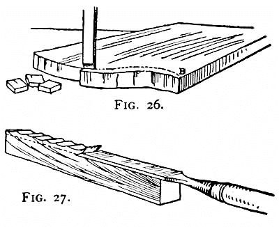
Figs. 26 and 27.—Paring.
In Using a Firmer-chisel, the work should be placed in the vise or be otherwise held in position, that both hands may be kept upon the tool, the right hand grasping the upper end of the handle and doing the pushing, while[Pg 29] the left hand holds the lower part of the handle and acts as a guide in working it.
Paring with the chisel consists in trimming a piece of wood to a given line. It is an operation very often resorted to in finishing the end of a piece of work instead of planing, and in trimming up a curved edge such as is shown in Fig. 26. Here the line AB represents the line of the finished end of a piece of work. The board is first placed in a vise and the wood removed to about one-quarter inch of AB with a compass-saw, following the curve of the line as nearly as possible. Then lay the piece upon the bench-hook (Fig. 11, Chap. I), and pare to the line with the chisel, as shown in Fig. 26.
The chisel is often used to pare down the surface of a piece of work to a given line, as shown in Fig. 27.

Fig. 28.—Bevel.
The Framing-chisel should be held in the left hand, and the blows dealt upon the handle with the mallet in the right hand. In handling the framing-chisel the bevel of the blade should be toward the work, which is just the opposite from that shown in Figs. 26 and 27. Unless this is done the chisel will not cut down squarely[Pg 30] but will cut in under, as it cannot be guided as easily as the firmer-chisel can, with both hands to hold it.
Chamfering and Bevelling are somewhat similar operations. They consist in cutting the edges of a piece of wood, as shown in Figs. 28 and 29.

Fig. 29.—Chamfering.
The corner of a block of wood is very often chamfered, when planing end-wood, to prevent the wood from splintering. It can only be done, of course, before the adjoining side has been planed up, that a square corner can be obtained again when the work is finished.
The Gouge is a chisel with a curved section, its use being for cutting grooves and curvatures in a piece of work where the chisel cannot be employed.
A Draw-knife is very handy for quickly reducing the size of material and in rounding sticks. The blade is drawn toward you instead of being pushed as in the case of a plane or chisel.
Boring.—Probably the only trouble you will have with the bit and bit-stock will be in holding the brace in a perfectly vertical position so as to bore a straight hole.
[Pg 31]The centre of the hole should first be located upon the work. Then, after selecting the right size of bit and securing it in the clutches of the bit-stock, grasp the handle of the stock with the right hand and place the left hand on the top knob. Set the point of the bit against the work and bore steadily until the point appears upon the opposite side. The bit should then be withdrawn and the rest of the hole bored from the other side. This prevents the fibre around the hole from splintering off, as it is likely to do when a hole is bored all the way through from one side. To bore a hole in a piece of work held in the vise, clamp a waste piece of wood in the vise with it, and bore straight through the work into the waste piece.
When boring hard wood or using large bits increased pressure is necessary to operate the brace and at the same time steady the bit. This can be obtained by allowing the chest to bear upon the top knob.
Holes two inches or more in diameter do not require a bit that size, for smaller holes can be bored and these trimmed to the required opening with a chisel or with the keyhole-saw. Whatever style of bit-stock you buy, get one with a fair length of arm, as a good leverage cannot be obtained with a short one.
An Automatic-drill is a handy tool to have in the shop, although not a necessity. You have probably seen carpenters use it in drilling holes in hard wood, before driving in finishing nails or screws. It beats the awl and[Pg 32] gimlet for speed, and is a tool which can be used in places where neither of these could be operated. The handle of the tool contains a number of sizes of drills.
This tool must be used with care, as the drills snap off very easily when the tool is handled roughly or twisted from side to side while boring a hole.
The Hatchet is an indispensable tool, for it can be used for a good deal of your rough work, such as splitting and paring. It requires practice to handle one successfully, however. A misplaced blow will sometimes ruin your work, either by cutting into it or striking grain which runs off into the portion to be finished. With straight grained wood it is not so difficult to pare to a line with the hatchet. The wood should be removed to within less than an eighth of an inch of the line, as the work must be dressed up afterward with the plane.
It is well to have
A Hammer with a fairly heavy head for large work, and a lighter one with which to drive small nails.

Fig. 30.—Withdrawing Nails.
Driving Nails.—The nail should first be held in position with the thumb and first two fingers, and given a few light raps with the hammer to start it. Then remove the fingers, and drive the nail home with steady blows, being careful to hit the head squarely so it will not bend.
Although a bent nail can be driven home with the proper stroke, it is generally easier and quicker to withdraw it and either hammer it out straight or use another.
[Pg 33]A pair of pincers are handy for
Withdrawing Nails, especially nails whose heads are too small to be gripped with a claw hammer; but for removing large nails a stronger leverage is necessary. This can be obtained as shown in Fig. 30. The head of the nail is gripped in the claw of the hammer and a block of wood placed beneath the head. The handle of the hammer is then pulled toward you, as shown in the illustration. The block, besides increasing the leverage, prevents the hammer-head from injuring the surface of your work, and makes it possible to withdraw the nail in a fairly straight condition.

Fig. 31.—Toe-nailing.
Toe-nailing consists in driving nails diagonally into a piece of wood. It is used in fastening the ends of uprights, as shown in Fig. 31, where the nails cannot be driven in any other way, and also where there is danger of a board springing. You will often find it convenient to use this form of nailing[Pg 34] when the nails are too long to be driven straight into the work.
Blind-nailing is a form of toe-nailing used on tongue and grooved boards in which the heads of the nails are concealed below the surface, as shown in Fig. 32.
Clinching.—When nails come through a piece of wood their ends should be clinched. This is done by having some one hold a hard surface, such as the head or blade of a hatchet, against the under side of the work, or by laying the hatchet down and resting the work upon it, while you drive the nail. The point of the nail will bend over when it strikes the hard surface and sink into the wood. This is the best method to use in fastening boards together with battens, in rough work, as the clinched nails act as rivets, preventing any possibility of the boards pulling apart.
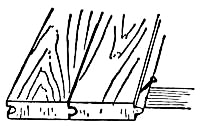
Fig. 32.—Blind-nailing.
Do not drive the head of a nail into a finished surface with the hammer, as you are likely to mar the wood in doing so. Leave this—the "setting" of the nails—until the piece of work has been put together. Then go over it and drive the heads below the surface with
The Nail-set, holding the tool as shown in Fig. 33. The holes made by the heads should be filled up with putty before the finish is put upon the wood.
Before driving nails into hard wood, holes should be made with the brad-awl or drill, to prevent them from[Pg 35] splitting the wood, and to make it easier to drive them in without bending. The holes should be a trifle smaller than the nails. Always drill a hole before driving a nail into thin wood or near the edge of a piece.
A nail can be driven more easily if its point is rubbed over a piece of soap. This is something you should remember to do when nailing hard wood.
Nails.—Iron, galvanized-iron, wire, and copper nails are manufactured, but of these the wire nail is the most commonly used for all kinds of work, it being more easily handled, not so liable to snap off, and there being less danger of splitting your work with it than with the iron nails.

Fig. 33.—Setting Nails.
You will notice the iron nails have two smooth sides and two rough ones. In using these it is necessary to drive them with the smooth sides parallel with the grain, otherwise they are sure to split the work.
Nails are classified according to their shape and gauge. The only kinds you will probably ever have[Pg 36] occasion to use are the Common, or nail for all ordinary work; the Finishing-nail, with the small head used on finish work; and the Brad, or small-sized finishing-nail. You can buy these by calling for the length you require, but it is more businesslike to use the standard terms by which all carpenters know them.
The following table gives these terms, together with the length in inches:—
2-Penny Nails (1 inch long).
3 " " (1¼ inches long).
4 " " (1½ " " ).
5 " " (1¾ " " ).
6 " " (2 " " ).
7 " " (2¼ " " ).
8 " " (2½ " " ).
9 " " (2¾ " " ).
10 " " (3 " " ).
12 " " (3¼ " " ).
16 " " (3½ " " ).
20 " " (4 " " ).
30 " " (4½ " " ).
40 " " (5 " " ).
50 " " (5½ " " ).
60 " " (6 " " ).
All nails longer than three and a half inches (20d to 60d inclusive) are known as spikes.
It is desirable to have
A Screw-driver which will set in the clutches of your bit-stock, besides the ordinary kind, for it is more quickly operated, and screws can be driven in hard wood easier on account of the greater amount of leverage you get with it.
Holes should be drilled in hard wood before driving screws into it.
Screws are made with round and flat heads. The round-headed screw is a finishing screw, and its head is left exposed on the surface of the wood; but the flat-headed[Pg 37] screw should be countersunk, that is, sunk below the surface. To do this you must drill a hole before driving in the screw with
The Countersink, which is a drill made to fit in the bit-stock, and bores a hole the shape and depth of the screw-head.
Be sure you understand the process of sharpening tools before you undertake to use the oil-and grind-stones.
All tools are not sharpened alike, and you will need to know the different ways in order to get their cutting edges the right shape to serve their different purposes.
Grinding is the most difficult part of the work, and most boys have trouble with it. One fault lies in using the grind-stone too frequently, grinding the edge of a tool when it requires only a little rubbing upon the oil-stone to put it in shape, and thus wearing down the tool unnecessarily. Again, by not keeping the stone sufficiently wet, the heat produced by the friction takes the temper out of the steel, making it soft and useless until retempered.
If you have a stone with a crank arrangement, it will be necessary to have some one turn it while you control the tool. The stone should be turned toward the grinder and the tools held upward so the stone grinds against the edge instead of from it. Move the tools sideways across the stone so as to wear it down evenly and help prevent[Pg 38] the formation of ridges in the stone, which are very easily produced.
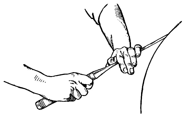
Fig. 34.—Grinding the Chisel.
Figure 34 shows the position to take in grinding
Chisels. Hold the handle of the tool in the right hand and rest the palm of the left hand upon its blade. Then lower the edge upon the stone until the bevel strikes it flatly, and bear down upon the blade with your left hand. Continue the grinding until the bright line of the dull edge has disappeared and an invisible edge has been obtained. Stop when this point is reached or the edge will become feathery and break off, necessitating regrinding. Grind upon the bevelled edge only, and hold the tool in the same relative position, to prevent the bevel from becoming rounded. The angle of the bevel should be[Pg 39] about twenty-five degrees. To keep this angle the same, it is desirable to have a rest, consisting of a board nailed to the frame of the stone, upon which to support the handle of the chisel.
Gouges and Draw-knives are ground similarly, the former being rocked from side to side, in order to grind the curved bevel uniformly.
Plane-irons are held with both hands, as shown in Fig. 35, and ground the same, except that the corners of the smoothing-and fore-plane irons are slightly rounded, while the edge of the jack-plane iron is a little higher at the corners than in the centre, to give it the qualities for removing thick shavings. It is more difficult to keep the line between the bevel and upper part of the iron straight than in grinding chisels, on account of the wider blade.

Fig. 35.—Grinding the Plane-iron.
Knives and Hatchets are ground upon both sides of the blade.
Of course, the edge of a tool is left in a very rough condition by the grind-stone, and must be rubbed up on an oil-stone before it is fit to cut with.
There are many makes of whetstones, many good ones and many worthless ones. Above all things, don't buy a cheap one, for it will be impossible to obtain keen edges upon it.
One of the best stones upon the market is
The Washita Oil-stone, a Kansas stone of medium hardness, free from grit and lumps, and of good quality through and through.

Figs. 36-37.
In rubbing up a plane-iron, grasp the end between the thumb and fingers of the right hand and place the palm of the left hand across the iron to bring the necessary pressure upon it (see Fig. 36).
Instead of holding the blade on the stone at the angle of the bevel, tip it to an angle of about thirty-five degrees, or ten degrees more than that of the bevel. With it held in this position, rub it back and forth upon the stone with a rotary motion, making a second narrow bevel along the edge of the tool (see Fig. 37). Be careful to keep the blade in the same position, to prevent the bevels from becoming rounded. By exerting a steady upward pressure against the end of the tool with the right hand, and an equal downward pressure in the centre of the blade with the left hand, this is easily accomplished.
The rough edge which appears on the back of the blade is removed by rubbing the flat side of the iron over the stone a few times. Care must be taken to keep the iron perfectly flat or a bevel will be formed.
A Strop, consisting of a piece of leather fastened to a block of wood as described in the foregoing chapter, should be used after the oil-stone, to put a fine edge upon the tool. The tool is stropped in the same way as a razor is done.
Saws require sharpening but once in a great while if proper care is taken of them. When they do become dull, or need to be set, it is advisable for you to pay an[Pg 42] experienced person to do the work rather than attempt it yourself.
A two-foot carpenter's folding-rule should generally be used in laying off measurements and a sharp-pointed pencil or brad-awl to locate the points. To connect the points it is necessary to have a straight-edge—a steel framing-square (Fig. 42) for large boards and a small try-square (Fig. 38) for smaller pieces—and a pencil or knife.
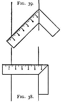
Figs. 38-39.
A pencil may be used in connecting points upon rough work, but for greater accuracy a knife should be used, as it makes a thinner and cleaner-cut line. In making knife lines, the square must be held very firmly, to prevent it from slipping and allowing the knife to run out of its course.
To draw lines across a board at right angles to one edge (which should be the straight or "tried edge" of the board) with the steel-square, place one arm of the square parallel with the tried edge and mark along the other arm. To perform the same operation with the try-square, place the handle against the tried edge, as shown in Fig. 38.
[Pg 43]Oftentimes it becomes necessary to draw a line parallel to the tried edge. This may be done roughly with the rule and pencil, as shown in Fig. 40. Grasp the rule in the left hand, with the first finger touching the tried edge of the board, and hold the pencil point against the end of the rule with the right hand. Keeping this position, with a steady hold on the rule and pencil, move your hands along the board. The result will be a line parallel to the tried edge.
At first you may have trouble in making a straight line, but with practice you will be able to hold the rule and pencil steadily.
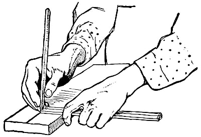
Fig. 40.—Gauging with Rule and Pencil.
For particular work, where it is necessary to get a perfectly straight and parallel line,
A Marking-gauge should be used. This is nothing[Pg 44] more than the above principles combined in a tool. It consists of a graduated shaft, or rule, with a small needle or spur in one end, which slides through a mortise made in a block of wood known as the head.
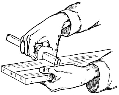
Fig. 41.—Using the Marking-gauge.
To operate the gauge, set the adjustable head at the required division on the shaft, and then grasp the head and shaft with the fingers of the right hand, as shown in Fig. 41. Place the outer face of the head against the tried edge of your work, and then, pressing the spur into the wood, move the gauge along the board, at the same time keeping the face of the head firmly against the edge of the board. The gauge is much more convenient than the other method of drawing parallel lines, for you can repeat the measurement as often as you wish,[Pg 45] having once adjusted the head, without having to lay it off again.
A Try-square with a mitred handle costs but little more than the ordinary make, and is much handier, inasmuch as it can be employed in making mitres, by placing the bevelled end against the side of the work instead of the straight side (see Figs. 38 and 39).
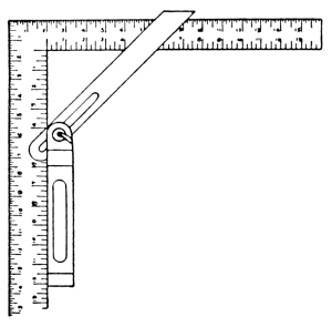
Fig. 42.
The Bevel is in reality a try-square which can be adjusted to any desired angle. To set it at an angle of forty-five degrees, place it on the steel-square, as shown in Fig. 42, with the handle against the inner edge of one arm of the square and the blade resting on both arms. Move the blade until it strikes equal distances on the arms (this is shown at four inches in the drawing) and tighten the screw while it is in this position. Other angles may be drawn out upon a piece of wood and the bevel adjusted to them so these angles can be laid off upon other pieces. You will find the bevel handy for reproducing angles. However, if you are supplied with a mitred try-square you can easily dispense with it for ordinary work.
There will be times when you wish
To Divide a Board into a number of equal parts, which may be found to be fractions of an inch that cannot be[Pg 46] easily laid off with the rule in the ordinary way. It can be accomplished with a pair of compasses, but until you become practised in their use, it will take some little time in setting them, dividing, resetting, and redividing, until the exact divisor is obtained. A much quicker method is that performed with the rule, as shown in Fig. 43.
Suppose you wish to divide a board four and three-quarters inches long into five equal parts. Place your rule across the board, as shown in the illustration, one end at one edge and the "five-inch" division at the opposite edge. Mark off the five divisions and then square the lines across the board at these points with the try-square. This will give you the required five equal parts.
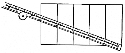
Fig. 43.—Dividing a Board Equally.
In the same way longer boards may be divided up by using two-and three-inch divisions on the rule instead of one-inch, and smaller pieces by using half-and quarter-inch divisions.
There are generally repairs of some kind to be made about the house—such as mending screens, renewing window-ropes, repairing wooden walks, patching fences, etc.—which a boy can do, besides many ingenious articles for the house which he can make in his workshop. Ideas for labor-saving devices which cannot be bought upon the market present themselves now and then, and if there is a boy in the neighborhood to carry them out, the housekeeper will be only too glad to pay him for doing the work.
For general jobbing you will require a carpenter's carrying-box (Fig. 17, Chap. I) in which to carry your tools, and a nail-box (Fig. 18) for nails, screws, hinges, and such hardware as you will need upon the job. With these you will have a complete outfit.

Fig. 44.—The Hinge Window Lock.
A few suggestions as to what you can do and what you can make are described and illustrated in this chapter, and should give you plenty of material to work upon when you open up your carpenter-shop. Besides these ideas, you will find most of the articles in the following[Pg 48] chapter suitable for the house and pieces of furniture for which it will be easy to secure orders.
The Hinge-lock, in Fig. 44, is one of the most serviceable window-locks that can be had, for it can be so placed as to allow the window to be opened a few inches for ventilation, and at the same time prevent further opening.
The hinge is screwed to the upper sash-frame several inches above the centre sash-bar, according to the distance the window is to be opened (see illustration).
It will be seen that when the hinge is opened, as in the drawing, neither sash can be opened past the hinge; but when the hinge is folded flat it will not interfere with the opening of either sash.
This lock would probably be more extensively used if people knew how simple and satisfactory it is. As the hinges cost but a few cents a pair, and are put on very quickly, a boy should realize a fair sum of money in a short time supplying these locks.
A Clothes-line Reel, such as shown in Fig. 45, is an article no housekeeper should be without. Its use does away with twisted, tangled, and knotted clothes-lines.
[Pg 49]As they require but little material, and the cost of that amounts to almost nothing, the manufacture of these time-saving devices, for the neighbors, should prove profitable.
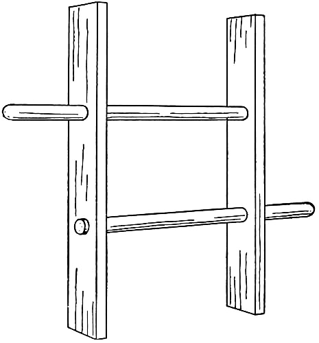
Fig. 45.—A Clothes-line Reel.
The reel consists of two strips of wood sixteen inches[Pg 50] long by three inches wide for the sides, and two pieces of broom-handles sixteen inches long for the horizontal rods (see Fig. 45). Five inches from each end of the side-pieces, bore a hole the size of the broom-handle.
With the pieces thus prepared it is a simple matter to fit them together, as in the illustration, placing the broom-handles in the holes bored for them, and fastening them so the side-pieces are nine inches apart and a handle five inches long projects on either side. It is probably needless to say that the ends of the broom-sticks are held in the hands when operating the reel.

Fig. 46.—Broom and Dust-pan Rack.
A Broom and Dust-pan Rack is a handy article for the[Pg 51] kitchen or broom-closet, and can be made as shown in Fig. 46.
A rack to hold a large and small broom, dust-pan, and brush, should measure three feet long, three inches wide, and be made out of a seven-eighths-inch board. Bevel the edges and place four brass hooks in the front, as shown in the drawing, from which to hang the broom, dust-pan, etc.
Brooms should always be dampened and put away, handle down, according to the advice of an old broom-maker, who claims that by so doing the straws are kept from becoming brittle and the broom lasts much longer. The brooms should therefore have screw-eyes placed in the handle, just above the tin binding, to hang upon the hooks, as shown in the illustration.
The rack should be screwed to the wall.

Fig. 47.—A Fly-killer.
Fly-papers and poisons are deadly enemies to the house-fly, but none are as effectual or as quick acting as
The Fly-killer, shown in Fig. 47. This simple device consists of a piece of screen-wire, about four by five inches, stuck into a slot made in the end of a stick, and fastened in place with tacks driven through the end of the handle and clinched upon the under side.
[Pg 52]If possible, cut the wire with a selvage along the front edge, and trim the roughness from the other edges to prevent scratching.
The fly-killer is hung up by a screw-eye placed in the end of the handle.

Fig. 48.—An Ash-sifter.
With the fly-killer a person can strike at a fly with almost a certainty of killing it. As the screen-wire is not easily seen by the fly, and the mesh allows the air to pass through, there is nothing to alarm him.
[Pg 53]These little things are quickly made, and when you show your customer how effective they are, you will find no trouble in disposing of them.
An Ash-sifter that is dust-proof and very satisfactory is shown in Fig. 48. It is made out of a packing-case about three feet long, eighteen inches wide, and twenty-four inches deep.
Set the box upon two-by-four stilts in the shed or yard (braced as shown in the illustration), in such a position that the bottom of the box will be on a level with the top of the alley ash-box. Then cut an opening through the shed wall and end of the box, as shown at AB, for the removal of ashes. Two strips are nailed to the sides of the box (seven inches below the top) for tracks for the sifter to run upon, and below this, at C, a board slide is placed to dump the ashes, which shake through the sifter, out of the opening in the end of the box into the ash-box. Nail one half of the cover to the top of the box and hinge the other half to it.
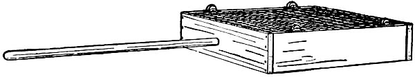
Fig. 49.—The Sifter.
Make the sifter eighteen inches square by six inches deep, using six-inch boards for the frame and one-third or one-half inch wire-mesh for the bottom (see Fig. 49)[Pg 54] Fasten four trunk-casters, such as are shown in Fig. 50, to the bottom of the frame, and fit a broom-stick in one side for a handle. A slot must be cut in the end of the box for the handle to fit in.
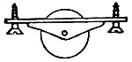
Fig. 50.
Trunk-caster.
A Bread-board may be made out of a seven-eighths inch maple board about ten by eighteen inches, with the surface planed perfectly smooth and the edges bevelled or rounded. A hole should be bored near one edge, so it may be hung up in the pantry.
The dining-room is not complete without
A Plate-rack for the display of pretty pieces of china. Figures 51 and 52 show the details for the construction of a rack of three shelves, and in size three feet long and two feet ten inches high. Although the design is very simple in outline, it is such as will make a pleasing piece of furniture when neatly carried out.
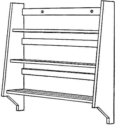
Fig. 51.—A Plate-rack.
Prepare the two side-pieces the shape and size shown in Fig. 52, and cut the shelves two feet ten inches long[Pg 55] by the widths given in the drawing (Fig. 52). One groove should be made in shelf A and two in shelves B and C, for the edges of plates to stand in. These grooves are cut with a chisel, and should be made V-shaped as shown. Narrow strips of wood may be nailed along the shelves as substitutes for the grooves if you wish, but the work required to plane up the strips will amount to about as much, and they do not present as neat an appearance.
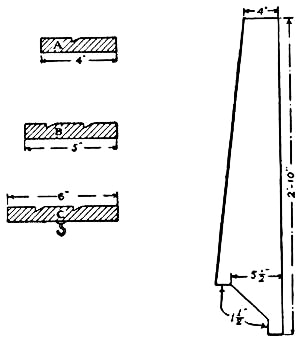
Fig. 52.
Having cut out the shelves and side-pieces, you are ready to put the rack together. For this purpose you should use finishing-nails so their heads will not make very large holes in the surface of the wood. Fasten the bottom shelf (C) between the side-pieces seven inches above the bottom, the middle shelf (B) ten inches above that, and the top shelf (A) nine inches above the middle shelf. The inner edges of the shelves should be fastened flush with the edges of the sides. In the bottom shelf place a row of brass hooks for cups to hang upon.
It is necessary to fasten three strips two inches wide between the sides in the back of the rack (as shown in[Pg 56] the drawing) for the tops of the plates to rest against. Two holes should be bored in the top strip, by which to hang the rack on nails or hooks fastened in the wall.
After completing the carpenter-work, finish the rack with a stain which will harmonize with the color scheme of the room in which it is to hang.
It is far better for a boy to spend his evenings in the house than out upon the street. He need not be without his friends there, for if he has an attractive room, with books to read, games to play, and puzzles to solve, the boys of the neighborhood will soon find it out and be only too glad to have a chance to visit him, knowing they will be sure of finding plenty of things to interest them.
The simpler the furnishings of a boy's room are the better. Plain and substantial furniture which will stand perhaps a little rougher usage than that in other rooms of the house, and handy places for storing away his traps, are what are needed.
The room should be his den where he can keep what he pleases, and arrange the fittings to suit his individual tastes. Shelves for his books and magazines, a cabinet for various collections, boxes for miscellaneous articles, and a desk at which he can study and keep his accounts, are a few of the things the room should contain. These pieces can easily be constructed in the workshop, by following the directions given in this chapter.
[Pg 58]On the opposite page is shown a scheme for a boy's room suggestive of his sports, games, and handicraft, and while everything is simple and inexpensive in the furnishings, it makes a room that will strike the fancy of the average boy.
Nothing appears more attractive than
A Cosey-corner, such as shown in the illustration, and it is a simple matter to fit one up. A home-made couch, box, or seat of some sort should be constructed to set in the corner, a shelf fastened to one wall a foot or more above it, and several shelves hung on the adjoining wall, as shown in the drawing.
Purchase several yards of a dark shade of green denim, and enclose the corner with three strips (see illustration). The upper strip is stretched across the corner at the ceiling, and the other two attached to its ends and allowed to hang to the floor. It is a good idea to make also a dado of the same material within the corner from the baseboard to the under side of the shelves.
Pennants representative of the various colleges can be made out of cheese-cloth, and a string of these hung across the corner at the ceiling will produce a pretty effect.
The walls of the room may be brightened with
Small Posters, which it is an easy matter to obtain nowadays, and small pictures mounted upon colored mats and fastened behind glass by means of passe-partout paper are always attractive.

Treatment of a Boy's Room.
Picture-frames can be made out of narrow moulding, the corners of which have been mitred in the mitre-box to make them join neatly.
A frame which has proven satisfactory for small posters and pictures not requiring glass is one made out of common laths. The ends of the laths are not mitred as is usually the case in making frames, but are fastened together with what is known as a "butt-joint"; that is, the ends of each piece are set against the ends of the adjoining pieces. The simplest way of fastening them together is by means of small strips of wood nailed across the corners on the back of the frame.
Although this frame might be expected to have a clumsy appearance, it has not, and when thoroughly sand-papered and finished with a dull green stain is very pretty.
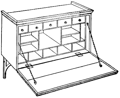
Fig. 53.—A Writing-desk.
The Writing-desk shown in Fig. 53 is constructed out of a box, and makes a pretty piece of furniture when completed.
Procure a box as free from defects as possible, and with[Pg 60] fairly wide boards, so there will be but few cracks. The cover should be in not more than two pieces, as it forms the drop-front of the desk, and it would be difficult to fasten more together. The boards must be fastened with "dowels" and cleats on the edges, as shown in Fig. 54, as cleats upon the inside of the drop would be in the way.
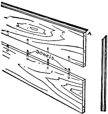
Fig. 54.
Dowelling consists in boring holes along the edge of each board and fitting pegs in them. Of course the holes must be bored in exactly the same relative positions in each piece so that the end and sides of the boards will be flush with each other when the pegs have been put in place. To get the holes correctly bored, place the boards together in the vise with two edges flush and uppermost, and square lines six inches apart across the edges, after which locate the centres of the holes on these lines. Be careful to bore the holes straight, and make them a little longer than the pegs. Cut the pegs out of hard wood and make them large enough to fit tightly in the holes.
The pegs as well as the two edges of the boards[Pg 61] should be smeared with glue before being put together. Then, after driving in the dowels, clamp the pieces together and lay them aside until the glue has thoroughly dried. In order to make a neat joint between the two boards, it is very necessary to have the two edges planed perfectly true and square.
While the boards of the drop-front are drying, you can prepare the inside of the box. A boy's desk should be supplied with plenty of pigeon-holes and drawers. They are as necessary as pockets are in his clothes. Split-up cigar-boxes may be used for these divisions, and, by making the upper ones of the right size, cigar-boxes may be fitted in them for drawers. The paper should be removed from the boxes as described in Chapter VIII. Fasten small silk-spools to the front of the drawers for knobs.
When the dowelled pieces have dried, nail a small moulding around the two end edges and one side edge, mitring the ends so as to fit together as shown at A (Fig. 54).
The drop-front should be hinged to the box with two hinges placed on the inside, as shown in Fig. 53, and brass chains attached to screw-eyes screwed into it and the inside of the box.
For the top of the box, purchase a moulding a little larger than that used around the edges of the drop-front and mitre it at the corners, as shown in the illustration.
Before putting any finish upon the desk, sand-paper[Pg 62] the wood, set the nails with a nail-set, and fill all holes and cracks with putty. A couple of coats of white enamel applied to the outside will produce a very pretty effect, and the inside may be finished with linseed oil, which makes a beautiful finish for the cigar-boxes.
The desk should be supported on two iron brackets (enamelled to match the desk), screwed to the wall and under side of the desk.
In Fig. 55 will be found
Another Style of Desk, which, though not as simple to make, may be preferred to the first design.

Fig. 55.—Another Style of Desk.
Cut two boards fifteen inches long by twelve inches wide for the sides, and taper each from twelve inches at one end to eight inches at the other end. Cut a board twelve by thirty inches for the bottom and another eight by thirty for the top, and nail them to the end pieces, after which saw the boards for the back and drop-front. Dowel and glue the drop-front boards together, nail a moulding around three edges, and hinge the piece to the desk, as in the case of the other design.
Partition off the inside of the desk as shown in the[Pg 63] illustration, and nail a moulding around the top. Finish the wood in the manner described for the other desk.

Fig. 56.—Ink-stand and Pen-tray.
An Ink-stand and Pen-tray, suitable for your desk, can be made out of a cigar-box, as shown in Fig. 56. Slope the edges with your jack-knife and cut several notches in them for pens and pencils to fit in. The wood should then be sand-papered and oiled.
A Couch for the cosey-corner of your room can be made out of two boxes about three feet long, two feet wide, and eighteen inches deep.

Fig. 57.—A Couch.
Remove one side of each box and nail the covers on, after which place the two boxes end to end and fasten them together with strips nailed across them at A, B, and C (Fig. 57). An incline about eighteen inches long should be fastened to one end, as shown in the (drawing.[Pg 64] The inside of the boxes may be partitioned off and used for storing away magazines and pamphlets.
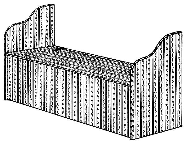
Fig. 58.—A Window-seat.
For the covering of the couch procure several yards of cretonne, some cotton batting or an old quilt to pad the top, a box of upholstering-tacks, and several dozen brass-headed tacks. After spreading the padding over the couch, cut a piece of cretonne large enough to cover it and tack it to the edge of the boxes, using the upholstering-tacks for the purpose. Make a valance of the same material, gathering the cretonne so as to form a heading at the top, and tack it around the box. Then place the brass tacks along the top of the valance about two inches apart.
[Pg 65]If a couch is too large for your room you can make
A Window-seat, such as is shown in Fig. 58. Cut the arms the shape shown in the illustration and fasten them to the ends of the box. Batten the boards forming the box-cover on the under side. Then tack cretonne on to the cover, arms, and outside of the box, placing padding underneath the cretonne to make it soft, and line the inside of the box with some dainty colored goods. When this has been done, hinge the cover to the box with large fancy brass hinges.
The appearance of the seat will be greatly improved by placing brass tacks along the edges of the arms and seat, about two inches apart. The inside of the box will make a handy receptacle for clothes and linen.
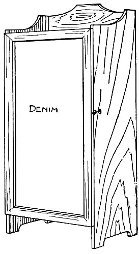
Fig. 59.—A Curio-cabinet.
For those interested in making collections of stamps, coins, stones, insects, etc.,
A Curio-cabinet, similar to Fig. 59, will make it possible[Pg 66] to keep all specimens arranged in order, each set of curios occupying a shelf by itself.
Such a cabinet should be made of bass or whitewood, as these can generally be obtained in greater widths, are cheaper, and less defective than other material. If you make your cabinet five feet high, two feet wide (inside measurement), and twelve inches deep, purchase twelve-inch boards, as these make it possible to have the sides in one piece and the back in two, a great advantage, as there will then be but one crack, and that up through the centre of the back.
After cutting the side-pieces the correct length, finish their edges as in the drawing. Then cut nine boards two feet long for the shelves, which are to be placed six inches apart.
Commencing at the top of each side-piece, lay off the thickness of a shelf, which will be about seven-eighths of an inch, and square the lines across the boards; then lay off the next shelf six inches below, and so on down to the bottom. Cut along these lines to a depth of three-eighths of an inch with a saw, and remove the wood between with a chisel. When all the grooves have been cut, slip the shelves into them one by one, and nail them to the side-pieces. After fastening the shelves, cut the two twelve-inch boards for the back and nail them in place.
While it is customary to put sash-doors on cabinets, this will be too difficult a job for you to attempt. A[Pg 67] very pretty and inexpensive door may be made as in the illustration. Make a frame out of two-inch strips to fit the opening, and stretch some green denim over it, tacking it to the inside of the frame. The ends of the strips forming the frame should be mitred and either nailed together or fastened with dowels and glue, as described in the construction of the desk (see Fig. 54). Hinge the frame to the cabinet.
To finish the cabinet, rub it down with sand-paper, set the nails with a nail-set, and putty up all holes, after which stain the wood green, a shade darker than the denim panel in the front.
Although the shelves may be simply stained, they will be much nicer for holding curios if covered with felt.
It might be well to suggest that you number each curio, and make a catalogue of these, together with the names and any data you have concerning them. The catalogue may be hung on a hook upon the inside of the door, where it can always be found.

Fig. 60.—Spool Book-shelves.
A pretty set of
Book-shelves to hang upon the wall can be made with three boards twenty-four inches long by eight inches wide, four dozen spools all of the same size, and two pieces of rope about four feet long and small enough to fit in the holes of the spools. By saving the empty spools from your mother's work-basket, and having your friends save their spools for you, it will not be very long until you have the required number.[Pg 68] Spools upon which number thirty-six cotton thread comes are of the best length.
Bore holes in the four corners of each board. Then, beginning with the board which is to form the bottom shelf, pass the ropes down through the holes on one side, across under the shelf, and up through the holes on the opposite side. String six spools on each rope and put the ropes through the holes in the next shelf; then string six more spools on each rope and run the ropes through the next or top shelf. Tie the ropes together about a foot above the top shelf, fringing the ends to form tassels. Figure 60 shows the shelves completed.
A Blacking-case made similar to Fig. 61 is a handy article for a boy to have in his room. As the friction[Pg 69] from a rag rubbed over the shoe produces a finer polish than a brush when polishing paste is used, the box is provided with an arrangement by which a rag can be rubbed over the shoe without much effort (see illustration).

Fig. 61.—A Blacking-case.
Procure a box about the size of a soap or cracker-box, and fasten a board in it for a foot-rest, as shown at A in the drawing. On each side of this place a piece of a broom-handle a little shorter than the inside width of the box, and pivot them at the ends with wire nails driven through the sides of the box, as shown in the illustration. Gimlet holes should be made in the sides of the box so the nails will fit loosely in them. Procure a strip of canton-flannel twenty-four inches long by six inches wide, and, after sewing two brass rings to each end, pass the cloth under the rollers and over the foot-rest, as shown in the illustration.
The lower part of the box will hold your boxes of blacking and the brushes. To have access to this, a board should be removed from the side of the box and hinged as at B and C in the illustration. Place a button-catch[Pg 70] just above it to keep it shut. Fasten together the boards forming the box-cover with battens, and hinge them to the end of the box. The outside of the case will be improved greatly if covered with denim.
After applying the paste to the shoe, the foot should be slipped under the cloth which passes over the foot-rest. Two fingers of each hand should then be placed in the rings and the cloth pulled back and forth over the rollers until the shoe is polished.
Fig. 62.—A Towel-rack.
A Towel-rack, such as is shown in Fig. 62, is made in four pieces,—a board about eighteen inches long for the back, two arms six inches long, and a piece of broom-handle eighteen inches long. After cutting out the arms the shape shown in Fig. 63, bore a hole large enough for a broom-handle to fit in each. Bevel the edges of the eighteen-inch board, and then nail it to the arms, driving the nails through this piece into the arms. Fit the piece of broom-handle into the holes bored for them, and trim off the ends so that about one inch projects beyond the face of each arm.

Fig. 63.
Sand-paper the wood, and either paint or varnish it. Attach screw-eyes to the top of the back board and hang the rack by these to hooks placed in the wall.
[Pg 71]
The average store doll-house is made of thin wood, which is full of defects and likely to warp, besides being put together in such a flimsy manner as to soon fall apart. The majority of these are imported houses, designed and planned in foreign styles, the exteriors being covered with clumsy ornament and gaudily painted, while the interiors are very poorly planned and proportioned. Americanized doll-houses are seldom seen in the market, and the few there are will generally be found very expensive.
There is probably nothing more interesting for a boy to make than a doll-house. It is like building your own house on a small scale, the details and proportions having to be just as carefully worked out to make a good-appearing house. Try the construction of a house for one of your girl relatives and see how much she will appreciate it. Then having completed one and learned the many little tricks there are in doing this work, you will find it quicker and easier to turn out others to sell. Neatly made houses are always salable, and it should[Pg 72] be an easy matter for you to make arrangements with a toy dealer in your town, to place some of your work in his store to sell on commission.
The doll-house designed and detailed in this chapter is easily constructed and
The Materials Required do not amount to very much. Boards ten inches wide and one-half inch thick are preferable for the general construction, with a few four-inch boards one inch thick for the base and a few other details. Basswood probably will be found the easiest wood to work with, as it is soft, straight-grained, and free from knots. Packing-cases may be used to advantage when they are of the right size, but they are generally made of a cheap grade of pine, full of knots and other defects that make it difficult to do a good job.
Cigar-boxes make the nicest material for the interior finish, and a number of all sizes should be procured for this purpose. Prepare the boxes for use as described in Chapter VIII.
Fourpenny nails should be purchased for the rough carpenter work, and brads and glue for attaching finishing-strips and all light wood. Paints and other material are specified as required.
As shown on the plans (Figs. 65, 66, and 67), the house described in this chapter is of three floors, containing nine rooms, and is in size, thirty inches wide, twenty inches deep, and three feet high.
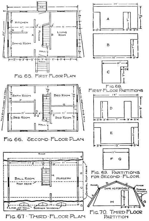
Figs. 65-70.—Plans of Doll-house and Patterns for the Partitions.
The Base, or false basement, should be made first. It [Pg 73]
[Pg 74]consists of two
four-by-one inch boards thirty inches long and two twenty inches long,
with the ends mitred and fastened together in the form of a frame. Upon
this
Lay the First Floor, allowing but one-half inch of the boards to bear on the frame on all sides. Then lay off the first-floor plan (Fig. 65) upon this floor with a pencil and square, locating the partitions by means of the dimensions given on the plan.
Make the Partitions A, B, and C, the shape and size shown in Fig. 68, and nail them to the places marked out for them on the floor.
The Stairs from first to second floors (Fig. 71) should now be constructed as described later under the head of "Stairways," as it would be difficult to set them in place after the walls are up.
Make the Front and Rear Walls twenty-nine inches wide and twenty inches high, and nail them to the edges of the floor. The outside surface of the walls should now be in line with the base. Leave the cutting of the windows until the rest of the house has been put together. The walls may be prevented from spreading by means of temporary braces nailed across the tops.
Lay the Second Floor, cutting a three by ten inch stair opening in the place indicated on the plan (Fig. 66), and fasten the boards to the front and rear walls. Draw upon this the second-floor plan, and
Cut Out Partitions D, E, F, and G, as shown in Fig. 69.
[Pg 75]
Fig. 71.—Details of Inside Stairs.
After nailing these partitions to the places marked out for them, and building in the stairs,
Lay the Third Floor (Fig. 67), cutting a three by seven inch stair opening, and fastening the boards in place as you did those of the second floor.
Stairways.—While each stairway should be built before the floor above is laid, in order that the work can more easily be done, they have been left for description here, that they might be spoken of in a general way. In Figs. 71, 72, 73, 74, and 75 will be found complete details for these.
The first things to prepare are
The Stair Stringers, or supports for the steps (treads and risers). Cut from a piece of cardboard what is known as
The Pitch-board, the pattern by which to lay out the steps (Fig. 73). Then draw a line lengthwise upon a thin strip of wood (AB in Fig. 72), and lay off the pitch-board on this as shown in Fig. 72—sixteen times for the first to second story stairs and fifteen times for the second to third story stairs. Draw the line DE parallel to AB, and the lines CD and EF as shown. Then cut out the stringer along the lines CDEF, being careful in doing so not to split off the corners. Prepare two stringers for each flight of stairs.
The Treads and Risers should be cut as shown in Fig. 74, and the
Newel-posts and Hand-rails as shown in Fig. 75. Make a small groove in the bottom of the hand-rail[Pg 77] as shown in the drawing. Toothpicks are of just the right size for

Figs. 72-75.—Details of Inside Stairs.
The Balusters.—As brads are likely to split the thin cigar-box wood, the staircases should be put together with glue. First fasten the stringers in place, cutting a slot in the edge of the floors for the tops to set in, as shown in Fig. 71. Then glue on the treads and risers, and cut the bottom of the newel-post to fit over the second step. The lower end of the toothpick balusters are set into slits cut with a knife in the treads, and the upper ends fit in the groove cut in the hand-rail.
[Pg 78]The Balustrades around the stair openings on the second and third floors are made in the same way (see Fig. 71). As finished floors are to be laid in the halls, as described later, it will be well at this point to fasten a strip from a cigar-box around the stair openings, upon which to fasten the newels and in which to stick the ends of the balusters.
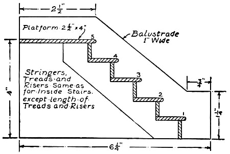
Fig. 76.—The Front Steps.
The drawings give every detail and measurement necessary for the making of these stairs, and everything will work out correctly if the directions are closely followed.

Fig. 64. A Colonial Doll-House.
The Front Steps are made as shown in Fig. 76. Cut out two balustrades the shape and size shown in the drawing. Then prepare two stringers of five steps, cutting them exactly the same as for the other stairs, and glue them to the inner faces of the balustrades. The treads and risers are the same as for the other stairs, except that they are four inches in length. Cut the top platform two and one-half inches wide.
The Rear Steps may be built similar to the front, or may be made simpler by leaving off the risers and balustrade.
The Ends of the House should measure twenty inches square. Fasten the boards together with battens at top and bottom, and hinge them to the rear wall (see plans and Fig. 64). Small hooks on the ends of the house will make it possible to fasten them shut.

Fig. 77.—Make Gable-ends like This.
The roof is what is known as
The Gambrel or Octagonal Roof, and consists of two eight and two nine inch boards thirty-four inches long. Before fastening these in place, it will be necessary to make
The Gable-ends, which are cut out as shown in Fig. 77. Make the partition between the nursery and ball-room (H) in the same way, with a door cut in it, as shown in Fig. 70.
[Pg 79]Fasten the partition and gable-ends in place, after which nail the roof boards B and C (Fig. 70) to the top, allowing them to project over each gable. The lower boards A and D should be hinged to these, so they may be raised to get at the upper story. The edges of the boards must be bevelled in order to make perfect joints.
When the work has proceeded thus far, cut
The Door and Window Openings in the places indicated upon the plans and Fig. 64, first boring holes in the four corners of each window and door space; and then connecting them with a compass-saw. With the exception of the front and rear door, and the windows in the basement and gable-ends, make all openings three by five inches, and two inches above the floor. The casement window openings in the gable-ends are to be four by five inches and extend to the floor. Cut three-by-seven-inch openings for the doors, and make the basement window openings two by three inches.
Figs. 78, 79, 80, 81, and 82 show the construction of

Figs. 78-82.—Details of Dormer Windows.
The Dormer Windows. These are made from cigar-boxes. For the three
dormers, you will require six pieces the shape of A for the sides,
three of B for the gable-ends, and six of C for the roof (see Figs.
80, 81, and 82). With the different parts cut out, it is a simple matter
to fasten them together on the roof, by means of glue and small brads.
The glass is bound to the ends of the side-pieces at D and E with
strips of [Pg 81]
[Pg 82]linen, as shown in Figs. 78 and 79, and the gable-end sets
on the top edge. The dormers should be placed directly over the lower
windows and in line with the front wall (see Fig. 79).
Old four-by-five camera plates may be used for
The Window Glass, by cutting them down to the required dimensions—three by five inches for the first and second stories, and two by three inches for the dormer and basement windows. Four-by-five plates are the right size for the casement windows.
As the basement is to represent stone, there will be no finish around the openings, and the glass will have to be held in place with cigar-box strips on the inside and putty on the outside, as shown in Figs. 83 and 84.
The glass should be fastened in the first and second story windows by means of putty and strips of cigar-boxes (see Figs. 85, 86, and 87). We will make the inside and outside trim the same to simplify matters; so cut two sets of strips for each window, making them the shape and size shown in Figs. 85 and 87. Fasten the outside strips in place first, then slip the ends of the glass into the centre of the wall and nail on the inside strips. Fill in the spaces between the glass and strips with putty to hold the glass firmly in place.
The Casement Windows (Fig. 88) are made similarly, with the addition of a quarter of an inch strip of a cigar-box glued up the centre of the glass, to give the appearance of double windows hinged to swing in.
[Pg 83]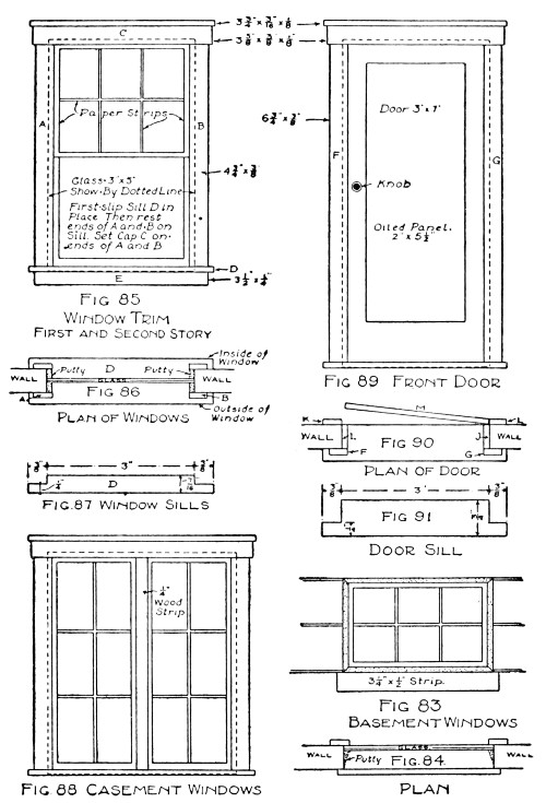
Figs. 83-91.—Details of Windows.
Narrow strips of paper glued to the glass, as shown in Figs. 78, 83, 85, and 88, will produce the effect of
Divided Glass and upper and lower sash.
The Door Trim (Figs. 89, 90, and 91) is put in place the same as the window trim, but instead of placing the door in the centre of the wall, it should be set flush with the inside trim (see K, L, and M in plan, Fig. 90), and is hinged by means of a linen strip glued to the edge of the door M and strip L. The door-jambs are cased with strips I and J.
The rear door may be made simpler than this by using a plain strip for a cap.
Make the Door out of a piece of cigar-box.
The drawings give all the necessary measurements for door and window strips, and you will find it a simple matter to cut them out with a sharp knife.
After putting the trim upon all of the windows and the doors, cut a number of strips of wood an eighth of an inch thick and half an inch wide for
Outside Trimmings, and nail them to each corner of the house, around the edges of each gable-end, and around the top of the basement. Purchase some narrow moulding for the cornice and nail it to the edges of the roof boards, being careful to make neat mitres at the corners.
The house can more easily be moved about if mounted upon
Casters. To put these on, cut four pieces of two-by-four[Pg 85] about three inches long, fasten a caster to each, and nail one block inside each corner of the foundation frame.

Fig. 92.—Construction of Chimneys.
The exterior of the house is now complete with the exception of
The Chimneys. These should be made up of four pieces, two of which should have bird's-mouth cuts made in the end, as shown in Fig. 92, to make the chimney fit over the top ridge of the roof. The side edges of the pieces should be mitred and fitted together. Nail a strip of wood, half an inch wide, around the tops of the chimneys for caps. You will find it easier to
Paint the Chimneys before fastening them to the roof. Make the brickwork red and the caps white, and with a small brush and ruler stripe off the mortar joints. When the paint has thoroughly dried, nail the chimneys on to the ridge of the roof in line with the front windows (see illustration of completed house).
[Pg 86]You will want
A Mantel and Fire-place in the living-room of the house, and it had better be built in at this point. Figure 93 shows about the simplest form of mantel you can make, and one that presents a very neat appearance. It is made out of cigar-box strips painted to represent brick, with stone hearth and mantel-shelf. It measures seven inches wide, four and five-eighths inches from the base to the top of the shelf, and has a fire-place opening four inches wide and two and one-half inches high.
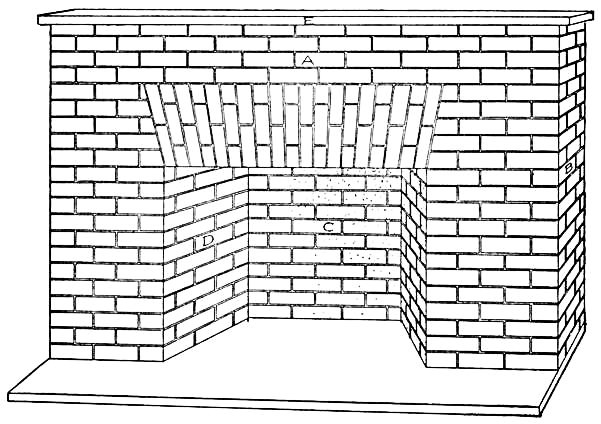
Fig. 93.—The Living-room Mantel.
Figure 94 shows the patterns for the cutting of the various pieces required to make up the mantel. A,[Pg 87] the front piece, has an opening cut in it for the fire-place, as shown in the drawing. Cut two strips similar to B for the ends of the mantel, one the size of C for the back of the fire-place, two of D for the sides of the fire-place,[Pg 88] and one of E for the mantel-shelf. These pieces, with the exception of E, should be painted red, and striped off, when dry, with white paint to represent brick. It will be much easier to do the painting before fastening the pieces in their proper places. First divide the length and breadth of the pieces into about the number of spaces shown in Fig. 93 with a lead pencil. Then with a small brush, and straight-edge for a guide, trace over the pencil lines with white lead. Be careful in striping the brick to get the courses the same upon each piece so they will correspond when the pieces are put together.

Fig. 94.—Construction of Mantel.
The Hearth is made out of a strip seven inches long by two inches wide. Upon this the mantel should be put together with the pieces prepared. Figure 93 shows the location of each piece, and with the aid of glue and some small brads it will be a simple matter to complete the mantel. The edges of the strips had best be mitred to make neat joints. Paint the hearth and mantel-shelf white.
The mantel should be fastened to the centre of partition B in the living-room (see plan, Fig. 65).
Andirons should, of course, accompany the fire-place. These may be made as shown in Fig. 95. They consist of two pieces of cigar-boxes cut the shape of A and B (A an inch and one-half by an inch and one-quarter, and B an inch and one-half long), with the end of B glued in a slot cut in the lower part of A. The feet and the[Pg 89] top of A and the foot of B are small brass-headed upholstering-tacks driven into the wood, which give the andirons a trim appearance. Paint the strips black.
Set the andirons upon the hearth with the ends projecting into the fire-place, and pile several nicely shaped twigs upon them for logs.
The Interior Woodwork remains to be put on. Cigar-boxes make excellent imitation hardwood floors, for the halls, the ball-room, and nursery. Select as large pieces as possible, and fit them on the floors with close joints. Nail them down with small brads.
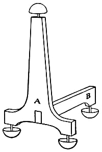
Fig. 95.—Andiron.
Make the door casings from the same material, cutting the strips the shape and size of those used for the outside doors (Fig. 89). It is not advisable to hang inside doors, as they are easily broken off, and seldom work satisfactorily.
A chair-rail should be made in the dining-room of quarter-inch strips fastened to the walls three inches above the floor.
Make baseboards in each room out of three-quarter inch strips, and picture mouldings out of strips an eighth of an inch wide.
[Pg 90]After completing the carpenter work of the house
Set all Nail-heads with your nail-set, putty these holes and all others resulting from cracks and defects, and sand-paper the rough surfaces. If the woodwork is to be finished in its natural color, by varnishing or oiling its surface, color the putty to match the wood.
Paint the House a cream color, with white trimmings and a green roof, using yellow-ochre and white lead (mixed) for the walls; white lead for the trimmings, balustrade of front steps, chimney-caps, and striping of brickwork; dark olive green for the roof, and treads and risers of the front steps; and lamp-black for striping the stonework of the basement. The painting of the chimneys and fire-place has been described.
Paint the front door on both sides with white enamel or white lead, with the exception of a panel in the centre, which should be oiled as shown in Fig. 89. This will give the appearance of a white enamelled door with a mahogany panel set in it.

Fig. 96. Another Style of Doll-House.

Fig. 97. Interior View of Doll-House.
Photographs of another style of doll-house are shown in Figs. 96 and 97. This house was built by the author for a little relative some ten years ago, and is still in perfect condition, as the photographs show.
Packing-cases were used for its construction, with cut-up cigar-boxes for window-casings, door-jambs, finished floors, etc., and small mouldings for the outside trimmings.
The inside arrangement and the general construction of the house is so nearly like the design in the preceding chapter, that most of the details and the mode of construction may be followed in building it. If boxes are used, the dimensions will have to be figured out to suit, unless the boxes are pulled apart and the boards cut to the sizes shown in the illustrations of this chapter.
The Floor Plans, which will be found in Figs. 98, 99, and 100, give the sizes of the rooms, and the patterns for the making of
The Partitions are shown in Figs. 101 and 102. In cutting out the second-floor partitions (Fig. 102), mitre[Pg 92] one edge of E and F to allow for the bedroom door opening, shown upon the plan, and mitre the edges of G to fit between them above the door. The mitring is shown in the drawings (Fig. 102).
Besides cutting a stair opening in the second floor, make an opening three by five inches in the second and third floors for
The Elevator-shaft. Care must be taken to have these openings exactly over one another. Make the opening in the second floor six by eight inches in the place indicated upon the plan. This will allow for the elevator shaft and stairway. No stairway has been built to the third story, as the elevator serves the purpose, and one would take up too much of the ball-room space.
The Side Walls should measure nineteen inches wide by twenty-four inches high, and the other two walls thirty inches wide by twenty-four inches high. That portion of
The Rear Wall enclosing the kitchen and bath-room is hinged to open (see Fig. 98), and
The Front Wall is made in two sections, each hinged to a strip of wood an inch and one-half wide nailed to the two edges of the house, as shown in Fig. 96.
The Windows are four by five inches, so four-by-five camera plates can be used for the glass.

Figs. 98-102.—Plans of Doll-house and Patterns for Partitions.
The Roof had best be made in two sections, each measuring twenty-eight
inches long by twenty-four inches wide. Fasten the boards together with
battens on the under side and, after mitring the upper edge of each,
[Pg 93]
[Pg 94]nail them to the house so that the ridge is fifteen inches above the
third floor. Then nail a board nineteen inches long by ten inches wide
in the peak of the roof (D in Fig. 104), and a narrow strip three
inches from each side wall (K and L in Fig. 100). These cut off the
triangular shape of the ball-room and give it a better appearance.
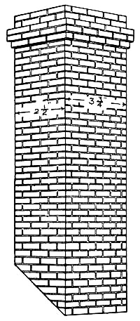
Fig. 103.
The Chimney is made the same as those for the other house, with the exception of the cap, which is built up of strips of cigar-boxes to represent corbelled brick (see Fig. 103). These strips should be three-sixteenths of an inch wide, and fastened in place by means of small brads.
An Elevator is something which is found in but few doll-houses. It was built in this house, thinking it might please the young mistress, and proved such a success that the scheme has been worked out carefully in Figs. 104, 105, 106, 107, and 108, that you may include it in the house you build.
The cutting of the elevator-shaft has already been described. For
material, procure two small pulleys, such [Pg 95]
[Pg 96]as are shown in Fig. 106,
four feet of brass chain, six feet of No. 12 wire, half a dozen
double-pointed tacks or very small screw-eyes, a short piece of lead
pipe, and a cigar-box. Make
The Car out of the cigar-box, cutting it down to two and one-quarter inches wide, three and three-quarters inches deep, and seven inches high (see Fig. 107). Place two of the double-pointed tacks or screw-eyes in each side of the car for the guide-wires to run through and another in the centre of the top from which to attach the brass chain.
The Guide-wires are made of very heavy wire that will not easily bend. Cut two of a length to reach from the first floor to the ball-room ceiling, and after running them through the tacks in the sides of the car, stick their ends into small holes bored at E, F, G, and H (Fig. 104). The upper holes should be bored through the ball-room ceiling, while the lower ones need be bored but part way through the first floor. Care must be taken to have these holes in the correct position, so the elevator will run up and down upon the wires without striking the sides of the shaft. The easiest way of fastening the wires in place is to run the upper ends through the holes, until the lower ends can be set into their sockets, and then drive two double-pointed tacks over the top of each wire, as shown at E and F in Fig. 104.

Figs. 104-108.—Details of the Elevator.
Now run the elevator up to the top of the shaft, and mark upon the ceiling where the screw-eye in the top of[Pg 97] the car strikes. At this point bore a hole through the ceiling and two inches back of it bore another hole, through which to run the weight-chain. When this has been done, cut a short block of wood to fit the peak of the roof and
Screw the Pulleys to it two inches apart (Fig. 105). Fit the block in the peak of the roof, centring the front pulley over the top of the car as nearly as possible, and drive a couple of nails through the roof boards into it to hold it in place temporarily. Then
Attach the Chain to the tack in the top of the car, slip a piece of lead pipe about an inch long over the chain, allowing it to set on the top of the car to make the latter heavier (Fig. 107), and run the chain up through the first hole in the ceiling, over the pulleys, and down through the second hole. To the end of the chain attach a piece of lead pipe for
The Elevator-weight (see Fig. 108).—This should be just heavy enough to make a perfect balance between it and the car, which can be obtained by whittling off the end of the pipe until the weight of the two is the same. Make the chain of sufficient length so the weight will rest upon the first floor when the car is at the third floor. You can now tell whether or not the pulleys are in the right positions. When they have been adjusted properly, nail the block firmly in place.
The Gable-ends.—The front gable-end consists of four pieces (A, B, C, and D, in Fig. 109), the dimensions for[Pg 98] the cutting of which are given in the illustration. After preparing these, nail A, B, and C in their proper positions in the gable of the roof, and trim the edges of D, if they need be, to fit between. To prevent the movable section from pushing in too far, it will be necessary to nail a narrow strip of wood to the roof and third floor just inside of it. The rear gable is made in one piece, and is fastened in place permanently.

Fig. 109.—The Front Gable-end.
The movable gable and all hinged portions should have
Spring-catches with which to shut up and lock the house (see the illustrations).

Figs. 110-113.—Details of Stairs.
The Stairway is shown in Fig. 104, and the details for its construction will be found in Figs. 110, 111, 112, 113. This stairway is made in two parts, with a platform between. Cut a block of wood the shape and size shown in Fig. 110 for the platform, with notches at A and B for the tops of the lower stringers to fit in. Then
[Pg 99]Prepare Two Stringers of thirteen risers similar to Fig. 111 and two stringers of five risers similar to Fig. 112, laying them off as described in the preceding chapter by means of a pitch-board similar to Fig. 113. After cutting out these pieces, fasten the tops of the lower stringers in the notches A and B in the platform, and nail the platform in its proper position in the corner of the hall. When this has been done, nail the bottoms of the upper stringers (E in Fig. 112) to the sides of the platform at C and D, and set the tops in notches cut in the edge of the second floor.
[Pg 100]The Treads and Risers are made the same as in Fig. 74 (Chap. V), except that the depth of the risers is increased to five-eighths of an inch. Cut another platform from a cigar-box to fit over the rough one.
Build a Balustrade up the side of the stairs and around the elevator enclosures, using the scheme shown in Chapter V (Figs. 71 and 75).
All Other Details not mentioned here will be the same as described in Chapter V, including the painting and finishing of the house.

Fig. 114.—Exterior of Stable.
The stable shown in Figs. 114 and 115, and in the background of Fig. 96, will go nicely with the house described in this or the preceding chapter. Its construction[Pg 101] is very simple. The dimensions are twenty-four inches wide, twelve inches deep, and twenty-two inches high, and the barn contains five stalls on the ground floor and a hay-loft above.

Fig. 115.—Interior of Stable.
To build the stable according to the drawings, a box ten by twelve by twenty-four inches should be procured for
The First Story.—If you have a box of different proportions it will be a simple matter to make such alterations in the details as it will require.
The Roof is made in two sections, each fifteen by eighteen inches, and is fastened to the top of the box so that the peak is twenty-two inches above the bottom.
[Pg 102]The Gable-end is made in four pieces, as shown in Fig. 116, A, B, and C, to be nailed in place, and D to be movable as in the case of the doll-house. Make a three-by-five-inch window in the centre of D, and fasten the glass in place with strips cut as described in Chapter V. Strips should be nailed to the roof just inside of the movable section to prevent the latter from setting in too far, and a spring catch fastened to C and D as shown, to hold the movable section in place.

Fig. 116.—Front Gable-end.
Figure 117 gives the patterns and measurements for
The Stall Partitions, four of which should be cut out and fastened to the floor of the stable four inches apart, or so they will divide the inside width into five equal stalls.
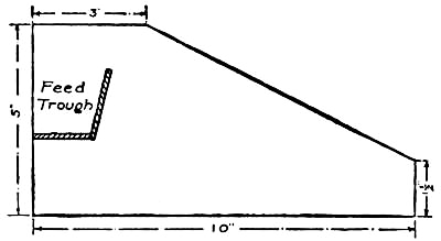
Fig. 117.—Stall Partitions.
The Feed-troughs are made out of two strips of cigar-boxes fitted between the stalls, as shown in Figs. 115 and 117, and are fastened in place by means of brads and glue. Above the stalls cut
Small Windows an inch and one-half square in the rear wall. These are the ventilating windows for the stalls, and may be left open.

Fig. 118.—Ladder to Hay-loft.
Figure 118 shows the construction of
A Ladder to the hay-loft. This is made out of two sticks twelve inches long, with strips of cigar-boxes two inches long glued to them half an inch apart, as shown in the drawing. Cut away a section of the hay-loft floor two inches square and stick the end of the ladder up through the opening, fastening the uprights to the edge of the floor (see Fig. 118).
A stick about three inches long, with a very small[Pg 104] pulley attached near the end, should be fastened in the peak of the roof for a
Feed-hoist (see Fig. 114).
The first story has
A Drop-front, as shown in Figs. 114 and 115. This is made from the box-cover. Fasten the boards together with battens placed upon the inside, and hinge it to the bottom of the stable. Nail two cleats to the under side of the floor (see Fig. 114) to lift it off the ground, just enough to allow the front to drop without springing its hinges.
When the front is down it forms an incline upon which to run the horses into the stable. For this reason it is not advisable to cut an opening in it, but merely
Represent a Stable Door on the outside (see Fig. 114). This is done with paint and a fine brush. First paint a green panel in the centre of the front, and then mark off a couple of panels within this space with black paint, and stripe them diagonally to represent beaded-boards.
With strips of wood half an inch wide make
A Simple Trim around the door, the sides of the stable, and around the gable, as shown in the illustration.
When the carpenter work has been finished,
Paint the Inside of the stable white, and the outside the same colors as used for the doll-houses (see description on page 90, Chap. V).
With the carpenter work of a doll-house completed, the finishing of the inside,—wall papering and painting,—and the selection of furniture for the various rooms, remain to be done. This requires as much care as the building of the house, and while any boy can do the work, the help of a sister will perhaps simplify matters and give to the rooms a daintier appearance.
The Walls and Ceiling of the kitchen and bath-room should be painted with white lead or white enamel. For the other rooms select paper having a small design, such as is to be found on most ceiling papers. If you have ever watched the paper-hanger at work, you have noticed he puts on the ceiling first, allowing the paper to run down the walls a little way all around instead of trimming it off. Then he hangs the wall paper, and if there is no border to cover the joints of the ceiling and wall papers he carries the wall paper up to the ceiling. Use flour paste to stick on the paper, and a cloth or photograph-print roller to smooth out the wrinkles. The dining-room should have a wainscot of dark paper below[Pg 106] the chair-rail, and a paper with little or no figure upon it above.
All Hardwood Floors, the stairs, door and window casings, baseboards, and picture mouldings should be varnished thoroughly or given several coats of boiled linseed-oil.
All floors, with the exception of the kitchen, bath-room, and hardwood floors, should be fitted with
Carpets.—If you do not happen to have suitable scraps on hand, they can be procured at almost any furnishing store where they make up carpets. Select pieces with as small patterns as possible. The floors of the bath=room and kitchen should be covered with oilcloth.
Rugs for the hardwood floors may be made out of scraps of carpet.
Window-shades may be made for each window out of linen, and tacked to the top casing so that the bottom of the curtain reaches just above the centre of the opening. Each window should also have
Lace Curtains made out of scraps of lace. They should either be tacked above the windows or hung upon poles made out of No. 12 wire, cut in lengths to fit the windows. Screw small brass hooks into the top window-casings for the poles to hang upon.
Handsome Portieres for the doorways can be made with beads and with the small hollow straws sold for use in kindergartens. For the
Bead Portieres, cut threads as long as the height of the door and string the beads upon them, alternating the[Pg 107] colors in such a way as to produce patterns. Then tie the strings together to a piece of wire the width of the doorway, and fasten the wire in the opening. The
Straw Portieres are made similarly.
From magazine illustrations you can select
Suitable Pictures for each room, but if you are handy with brush and pencil you may prefer to make the pictures yourself. These may be mounted upon cardboard and have their edges bound with passe-partout paper to give the effect of frames, or frames may be cut out of cardboard and pasted to them. Hang the pictures to the picture moulding with thread.
A Cosey-corner may be fitted up in the ball-room by fastening a strip of a cigar-box in one corner an inch and one-half above the floor for the seat, and hanging draperies on each side of it. Pillows may be made for it out of scraps of silk stuffed with cotton.
A doll-house properly proportioned in every detail, including the selection of its furniture, is pleasing to look at, and is to be desired much more than some of the specimens to be found in the stores. These very often have parlor chairs larger than the mantel, beds that either fill two-thirds of the bedroom space or are so small they are hidden from view by the chairs, and other furniture accordingly, all having been selected without any thought as to size or fitness.
Care must be taken, in buying the furniture, to have the pieces suitable to the rooms. It will no doubt[Pg 108] require more time than to purchase the first sets you come across, but when you have completed the selections, the result will be a much better appearing doll-house.
By carefully searching the toy-shops you are almost certain of finding what you want for the various rooms, as about everything imaginable in furniture has been manufactured. Porcelain bath-tubs, wash-basins with real faucets and running water, gilt furniture, chandeliers, and such articles are tempting to buy. But it is rather expensive to fit up a house in this way, for, though each piece may not amount to very much, they count up very quickly.
The suggestions for the making of cigar-box furniture in the following chapter, and the cork furniture in Chapter XXVIII, should give you plenty of material for furniture and save you the expense of buying this part of the furnishings for your house.

The metal furniture which you can buy is very pretty when it is new, but this new appearance does not last long after it has come into a youngster's possession, for the pieces are very slender and delicate, and thus easily broken.
Wooden furniture is the most durable kind, and plain and simple pieces will generally outlast the fancy ones. The designs illustrated in this chapter make very substantial pieces, as there are no spindle legs or fancy arms to break off. They follow the lines of the mission furniture, that simple style used in the early American mission schools, and which is to-day being extensively made in handsome pieces for the furnishings of modern homes. You will find the
Miniature Mission Furniture, illustrated and described in this chapter, simple to make and something which is easy to sell, for there is nothing like it at present upon the market.
Cigar-boxes furnish the nicest material for making[Pg 110] this furniture, and the various parts can be cut to the right shape and size with
A Gig-or Scroll-saw. Procure small brads and glue with which to fasten the pieces together.
To prepare the Cigar-boxes for use, place them in a tub of boiling water and let them remain there until the paper labels readily pull off. Do not use a knife in removing the paper, as it is liable to roughen the wood. The paper will come off by allowing it to soak long enough. When the boxes are clean, set them in the sun to dry, after binding the covers to the backs to prevent them from warping. Pull the boxes apart when they are thoroughly dry, and throw out such pieces as have printing upon them, for these would spoil the appearance of the furniture if used.
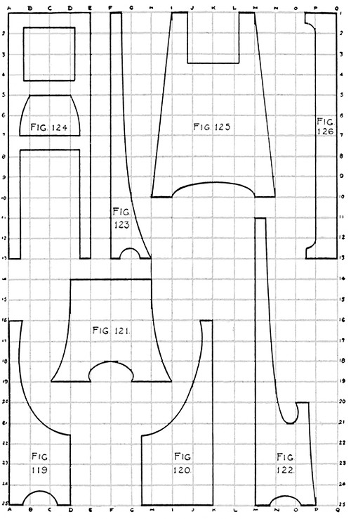
Figs. 119-126.—Patterns for Furniture.
In order to simplify the matter of cutting the parts that make the furniture, the curved pieces have been drawn out carefully on page 111, so they can be laid off upon the strips of cigar-boxes without any trouble, by the process of
Enlarging by Squares.—These drawings are shown one-quarter of their
full size (half their width and half their height). To enlarge them
procure a piece of cardboard nine by thirteen inches, or a little larger
than twice the size of the drawing each way, and divide it into squares
just twice the size of those on page 111. That will make sixteen squares
in the width of the cardboard and twenty-four in the length, each half
an inch[Pg 111]
[Pg 112] square. In order to get the squares spaced equally, it is best
to lay off the points first with a ruler along the top, bottom, and two
sides of the sheet of cardboard, and then connect the points with the
ruler and a sharp lead-pencil. Then number the squares as in the
illustration, using the figures along the sides and letters across the
top and bottom of the sheet.
With the sheet of cardboard thus prepared it is a simple matter to
Reproduce the Drawings of Figs. 119 to 126 by locating the points of the curves and corners of the pieces, as shown in the illustrations, in corresponding positions in the squares on your cardboard sheet. The curves may be drawn in by eye, after locating them with reference to their surrounding squares, but the surest way of enlarging them accurately is by laying off the points where the curve strikes each horizontal and vertical line in the illustration, upon the enlarged drawing. These points can then be connected with a curved line.

Figs 127-128.—Chairs.
Make all of the lines heavy so they can be distinguished from your guide lines, and after carefully going over the drawing, comparing it with that on page 111 to see that no mistake has been made in locating the points in enlarging, cut the various pieces apart. These give you
The Patterns with which to mark out the pieces on the wood.
[Pg 113]We will first note the construction of

Fig. 129.—A Settee.
The Chairs shown in Figs. 127 and 128. These are four and one-half inches high, two inches wide, and an inch and one-half deep. Cut the back for the chair in Fig. 127 four and three-eighths inches high and an inch and three-quarters wide, the sides by the pattern in Fig. 119, and the seat an inch and one-quarter by an inch and three-quarters. With the pieces cut out, fasten them together with brads and glue, placing the seat between the arms and back so that it is an inch and one-half above the base.
Cut the back for the other chair (Fig. 128) four and one-half inches high by two inches wide, the seat an inch and a quarter by an inch and three-quarters, and[Pg 114] the sides an inch and three-eighths wide by two and one-half high. To get the curve in the bottom edge of the side-pieces, use the pattern in Fig. 119.
The Settee (Fig. 129) should have its sides cut by the pattern of Fig. 120. Make the back-piece three and three-quarters inches wide and three and one-quarter inches high, and the seat three and three-quarters inches by an inch and one-half. Fasten the seat against the back an inch and one-half above the base.
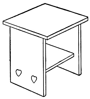
Fig. 130.—A Table.
Tables for the living-room, dining-room, bedroom, ball-room, and nursery of a doll-house may be patterned after the designs of Figs. 130 and 131. These should be two and one-half inches high to be of proper proportion for the chairs.
The pieces necessary to[Pg 115] make Fig. 130 are a top two inches square, two sides an inch and one-half wide by two and one-half inches high, and a shelf an inch and one-quarter square. Fasten the pieces together as in the illustration, placing the shelf between the side-pieces an inch from the bottom.

Fig. 131.—Another Design.
The other design (Fig. 131) will do nicely for
A Dining-room Table, or table for the centre of the living-room. The top of this should be five inches long and three inches wide. Cut the side-pieces by the pattern in Fig. 121 and, after fastening them to the under side of the table-top four inches apart, brace them with a strip three and three-quarters inches long by half an inch wide, as shown in Fig. 131.
A Side-board similar to Fig. 132 should be made for the dining-room. The pattern for the side pieces is shown in Fig. 122. After sawing these out, cut a piece seven inches long by three inches wide for the back and fasten the side-pieces to the edges of it. The location of the shelves can be obtained best by referring to Fig. 132 and the pattern in Fig. 122. Cut the bottom shelf (A in Fig. 132) three inches long by an inch and one-quarter wide and fasten it to the side-pieces[Pg 116] half an inch above the base (line 24 on pattern, Fig. 122). Make shelf B three by one inches and place it at line 22. C should be three and three-quarters inches long by an inch and one-half wide, with a small notch cut near each end with your knife, to make it fit over the side-pieces (see illustration). Cut shelf D three inches long by half an inch wide, fastening it in place at line No. 17, E three inches long by seven-sixteenths of an inch wide, fastening it at line No. 15, and F three inches long by three-eighths of an inch wide, fastening it at line No. 13. The top shelf (G) is three and three-quarters inches long and half an inch wide and is fastened to the tops of the side-pieces as shown in the drawing.
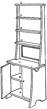
Fig. 132.—A Side-board.
The lower portion of the side-board is enclosed with two doors two inches high by an inch and one-half wide. Small pieces of cloth may be used for hinges, but it is better to use pins, running them through the shelf above and below (A and C, Fig. 132) into the doors. Stick[Pg 117] the pins near the edge of the doors and see that they are straight, so the doors will open easily. A small mirror attached to the back between shelves C and D will complete this piece of furniture.

Fig. 133.—A Mirror.
A Mirror in a frame should be made for the living-room of the doll-house. A neat and suitable design for one of these will be seen in Fig. 133. For its construction cut two sides by means of the pattern in Fig. 123, a piece five inches long by three inches wide for the back, and a strip three inches long by three-eighths of an inch wide for a shelf. Fasten the sides to the edges of the back-piece, and the shelf between the sides about three-quarters of an inch above the base. Now procure a mirror such as you can buy in a toy-shop for five or ten cents (or a piece of a broken mirror cut down to the right size will do very nicely), and attach it to the centre of the back.
The Grandfather's Clock (Fig. 134) makes an effective piece of furniture for the hall or living-room, and is easily made. Figure 124 shows the pattern for the front of this clock. The back is made the same, with the omission of the square opening cut in the front frame for the clock-face. Cut a block of wood two by two by three-quarters[Pg 118] inches to fit between the frames at the top. After nailing the pieces together, procure a face from a toy watch, and fasten it in the opening made for it in the front frame. A button suspended by means of a piece of thread from a tack placed in the bottom of the block forms the pendulum.

Fig. 134.
A Grandfather's Clock.
It will be unnecessary to give any suggestions for
Kitchen Furniture, such as chairs and tables, for these can also be made out of cigar-box wood along the same schemes illustrated in this chapter, with perhaps a few modifications which will make them simpler.
Now for the making of some pieces of bedroom furniture. You will find in Figs. 135 and 136 two designs that are easily carried out, one or both of which may be used for
The Beds of a doll-house. To make Fig. 135, cut the head and foot by means of the pattern in Fig. 125, and cut the two sides by means of the pattern[Pg 119] in Fig. 126. After preparing these pieces and fastening them together as shown in the illustration (Fig. 135), cut a few strips a quarter of an inch wide for slats and fasten them between the sides of the bed. It is[Pg 120] advisable to fasten these in place to prevent them from being lost.
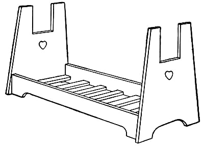
Fig. 135.—A Bed.

Fig. 136.—Another Design.
The side-pieces for the other bed (Fig. 136) are cut out with the same pattern (Fig. 126). Make the head-and foot-pieces three by four and one-half inches, cutting a piece two by an inch and one-quarter out of the top of each as shown in the drawing (Fig. 136), and using the pattern of the other bed for cutting the curve in the bottom edge. Nail the pieces together in their proper places, after which cut some slats and fasten them in the bottom.
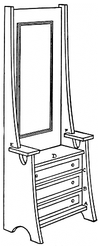
Fig. 137.—A Dresser.
The Dresser (Fig. 137) is made somewhat similar to the side-board. Cut the sides by the same pattern (Fig. 122) and fasten them to the edges of the back-piece, which should be six and one-half inches high by three inches wide. Cut shelf A three by one and one-quarter inches, B and C three by one and one-eighth, D three by one and three-sixteenths, and E and F one-half by one and one-quarter inches. Fasten shelf A between the sides at line No. 24 (see Fig. 122),[Pg 121] B at line No. 23, C at line No. 22, D at line No. 21, and notch the ends of E and F to fit over the side-pieces at line No. 20.
Drawers to fit the lower shelves of the dresser may be made out of small strips of cigar-boxes or pieces of cardboard, glued together. A small mirror fastened in the position shown in the drawing will complete the work upon this piece of furniture.
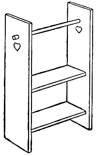
Fig. 138.—A Wash-stand.
A Wash-stand can be made for the bath-room and each of the bedrooms similar to Fig. 138. The sides for this should be five inches high by an inch and one-quarter wide, and the shelves one by three inches. Fasten the lower shelf three-quarters of an inch above the base, and the top shelf at a height of two and one-half inches. When the stand has been put together, fit a round stick, about an eighth of an inch in diameter, in holes made in the sides with a (see illustration). This forms the towel-rack. Hang a small drapery over the lower portion of the stand.
Finishing.—When the pieces of furniture have been completed, they should be rubbed down with emery-paper to remove the rough edges, and also any rough places that may have been caused by soaking the boxes[Pg 122] in water. Then give the wood several coats of linseed oil. This makes a beautiful finish for this kind of wood.
If desired, the bedroom furniture may be painted with white enamel. The little hearts may be painted upon the pieces as shown in the illustration, with a small brush and red paint, or may be cut out of red paper and glued to the wood.

Fig. 139.—A Doll's Folding-bed.
In Figs. 139 and 142 will be found some pieces of furniture that are simpler to make than that just described, and although they may not be so pretty, they present a very good appearance when neatly made.
The author constructed many pieces of this furniture when a boy, and found them suitable as presents, besides being something that was always easy to sell.
The cost of making a set amounts to but a few cents, cigar-boxes being the principal material.
[Pg 123]They are also very quickly made, as the boxes require but little cutting.
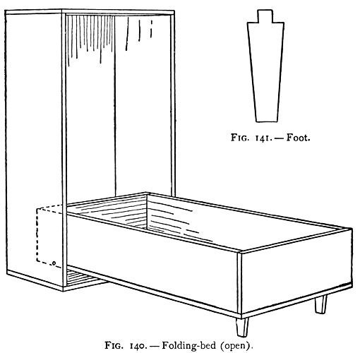
Fig. 140-141.
For the construction of
A Folding-bed, such as is shown in Figs. 139 and 140, select two cigar-boxes, one of which will fit inside the other. The smaller box should be a little shorter than the inside opening of the larger box. After removing the paper from each, place the smaller box inside the[Pg 124] larger one, as shown in Fig. 139, so that the bottom of the inner box is flush with the edge of the outer box. Then drive a brad through both boxes on each side, about three-quarters of an inch from the end as shown at A (Fig. 139). These brads should run through the outer box into the bottom of the inner box, and should be driven in carefully so as not to split the wood. The inner box should now fold down as shown in Fig. 140, moving upon the brad pivots. Purchase a five or ten cent mirror and fasten it to the front of the bed, after which cut two wooden feet similar to Fig. 141 and glue the pegs on the ends of these in gimlet holes made above the mirror. Finish the wood the same as described for the other cigar-box furniture.
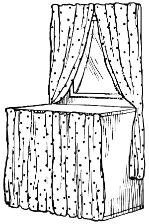
Fig. 142.—Dresser completed.
The Dresser shown in Fig. 142 is made out of a box the same size as the larger one used for the folding-bed. Saw the sides of the box in half, crosswise, and remove the upper half and the end-piece. Then nail the end across the tops of the remaining halves of the sides. When this has been done, divide up the lower portion of the box into compartments as shown in the drawing[Pg 125] (Fig. 143). This should have a small drapery hung over it. The upper portion of the dresser should have a mirror attached to it, and some lace draped over the top and sides will add greatly to its appearance.

Fig. 143.—A Doll's Dresser.
All you will have to do in making
A Wardrobe will be to fasten some small hooks inside of a cigar-box, attach the cover with a strip of linen—the same way it was attached before you soaked it off—and hang a mirror on the front.
These pieces of furniture were designed for separate sets, and would not do for doll-houses the size of those in the preceding chapters, unless the boxes were cut down to smaller proportions.
Since the manufacture of printing-presses in small sizes, printing has become so popular among boys that it is now hard to find a neighborhood in which there is not a press.
Printing is one of the best methods of mastering spelling and punctuation, and is thus a great help to a boy in his studies, besides being a pleasant occupation at which he can earn money.
If you cannot afford a large press, be satisfied with a small one for the time being at least. Get to work, learn to print neatly and accurately, and when your friends find your work is of good quality, they will gladly patronize you. Your profits should soon net you enough with which to buy a larger press and increase your equipment.
After securing a press, it will be necessary to find a place in which to keep and use it, where there will be a good light to work by and where things are not likely to be disturbed. If you have a workshop, you may be able to make room in it for your outfit.
[Pg 127]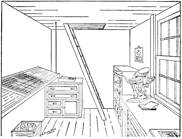
Fig. 144.—A Boy's Printing-shop.
When the author became the proud owner of a machine, he found it convenient to keep it in his room with his type-cases and material beneath the press-stand. But in the course of several years the printing-shop required more space than the room afforded, and a new office had to be secured. This was found in the woodshed, where a corner was partitioned off, a double sashed window placed in the wall, and the interior fitted up with a case-rack, imposing-table, stock-stand, and all the necessities for an enlargement of business. Figure 144 shows the arrangement of our shop a few years later, when it again became necessary to increase our floor space by adding a "mezzanine" story above, extending to the roof of the shed. This half-story was reached by means of a ladder, as shown in the drawing.
The principal equipment of a boy's shop should consist of a number of cases in which to keep the fonts of type; a rack in which these cases can be kept and at which the typesetting can be done; a work-bench, one end of which may be used for an imposing-table and the other for the press to stand upon; and two cabinets, one for stock and the other for ink, tools, and general supplies. The other materials required are: a composing-stick, composing-rule, pair of tweezers, galley, leads, rules, furniture, mitre-box, imposing-stone, quoins, shooting-stick, mallet, planer, hand-roller, and gauge-pins, besides a can of ink, an oil-can, a bottle of machine-oil for washing rollers, benzine for cleaning type, and a good supply of rags.

An Amateur's Outfit.
Small presses are usually accompanied by a few fonts of type, which are sufficient for printing small business-cards, etc., but are of so few letters as to make an ordinary job of printing impossible. With an increase of capital,
Type should be the first addition to your outfit. In making selections bear in mind the amount of money you have to spend, and buy only styles which will go together nicely and which can be used for the greatest variety of work. If possible, secure the advice of a printer in purchasing, as by his experience he can tell what you will most require better than you. You can probably obtain a specimen type-book from the type foundry in your city from which to make your selections.
Type-cases divided into small compartments for the various letters and characters, which can be bought for seventy-five cents or a dollar, provide the only satisfactory means of keeping fonts. It is advisable to spend the money for these neatly made boxes rather than attempt to make them, for the work will amount to more than what you can buy them for.
Figures 145 and 146 show the upper and lower news-cases with the systems
of "laying" generally employed in printing establishments. It will be
seen that by this method the principal letters are grouped in the
central portions of the case where they are easily reached, while the
less important letters are scattered around the sides. The central boxes
of the lower case are also[Pg 129]
[Pg 130] made larger than the others, "e" being
allotted the largest box as it is used more than any other letter in the
alphabet.

Figs. 145-146.—Scheme for Laying Cases.
As the lettering of the spaces and quads in Fig. 145 may be confusing to the beginner, it is perhaps well to explain that these are based upon the "m" quads which present a square end, the "2m" and "3m" quads being two and three "m" quads in width, and an "n" quad one-half an "m." Likewise spaces are known by the fraction they represent of an "m" quad, viz. "3m," "4m," "5m," and "8m" (more commonly known as hair-space).

Fig. 147.—The Yankee Job-case.
The upper and lower cases provide for about every character included in a complete font of type. For smaller fonts you will find the Yankee job-case very convenient, the letters being arranged the same in the lower portion, and the capitals being placed in the upper boxes (see Fig. 147).
[Pg 131]
Fig. 148.—A Type-case Rack.
It will be unnecessary to have
A Rack for the Type-cases until you have added several styles of type to your outfit. Then you will find a rack such as is shown in Fig. 148 one of the best methods of keeping the type away from the dust and at the same time in an accessible place.
This rack should be four feet in height, the width of a type-case, and twenty-eight inches deep, which is large enough for twelve cases. It is best made out of four-inch boards.
Cut the uprights A and E three feet six inches long, and B and F four feet long. The top-pieces C and G should be cut similar to Fig. 149. First lay out these pieces on four-inch boards, using the dimensions given on the drawing and being careful to get both pieces the same.[Pg 132] Having properly marked the pieces, they remain to be cut out with the rip and cross-cut saws. Cut the bottom-pieces D and H twenty-eight inches long, and prepare twenty-two inch-strips of the same length for cleats.

Fig. 149.
One of the most particular points to be looked after in making a rack of this kind is the attaching of the cleats, for unless they are perfectly horizontal and those on one side are on a level with those on the other side, the cases will not slide in satisfactorily and will be continually causing trouble. Plenty of space should also be left between the cleats to prevent the cases from sticking by the cleats swelling or warping.

Fig. 150.
In order to get the cleats in the right position, the heights should be laid off on the uprights as shown in Fig. 150 and lines squared across them. You will then have the same heights on each upright.
Having prepared the pieces above described, we are ready to put them together. Lay uprights A and B upon the ground, twenty inches apart, and with the lower ends on a line with one another. Then fasten board D to them as shown in Fig. 151, the upper edge being even with the first divisions on the upright. Drive but one nail in[Pg 133] each end of D until the other end of the frame is fastened together. Strip C should be placed as shown in Fig. 151, so that the upper edge of one end is even with the top of upright A, and the upper edge of the other end three inches above the top of upright B. This gives the proper pitch to the top of the rack. Then, after measuring the distance between uprights A and B to see that it is no more or less than twenty inches, nail C firmly to them, after which drive several more nails into the ends of D.

Fig. 151.
When this has been done, fasten the cleats in place, so that the top of each is even with the line squared across the uprights. This completes the frame. The opposite frame is made similarly.
When both frames have been made, they should be fastened together by means of the crosspieces shown in Fig. 148. Measure the width of your cases, which varies somewhat with different makes, and set the frames about half an inch farther apart than this width. Then cut the boards I, J, K, and L the correct length and nail them to the places shown upon the drawing. Strips[Pg 134] M and N should be fitted between C and G to help support the top.
The top of the rack is made to hold two cases at a time, the lower case on the front part and the upper case back of it.
Cases should be kept out of the dust as much as possible, as dirt accumulates in the boxes very quickly, and is hard to clean out. It is therefore a good plan to tack cloth or heavy wrapping-paper to the back, sides, and below the top of the rack, and provide a curtain to hang over the front when the cases are not in use. When the boxes do become dirty, the dust should be removed by means of a pair of bellows.

Fig. 152.—How to Hold the Composing-stick.
In composing, or setting type,
A Composing-stick is necessary. This should be held in the left hand, as shown in Fig. 152, while the right hand picks up the type one by one and drops them into the stick, where the left thumb shoves them into place. It will be seen by looking at the illustration that the type are set upside down and read from left to right. This may seem awkward at first, but with practice you will soon become accustomed to reading the letters in this position.
A Composing-rule, similar to Fig. 153, should be cut out[Pg 135] of a piece of brass rule. In typesetting, the rule is first placed in the stick, and the type then placed against it.
Fig. 153.—A Composing-rule.
When a line has been set and there still remains a space too small for another word, it is necessary to either place wider spaces between the words to fill out the line, or reduce the space sufficiently to make it possible to add the word. This operation, which is known as
Justifying, should be performed after each line has been set. Then place a lead against the type, lift out the composing-rule from behind the first line, and place it in front of the lead preparatory to setting a new line.

Fig. 154.—A Home-made Galley.
After composing a stick full of type, it should be emptied into
A Galley. Figure 154 shows a galley made of half-inch stuff. Cut the pieces as shown, and fasten them together so the bottom-piece is tilted sufficient to keep the lines from
"Pieing"—or falling out of line—without tying them together. Emptying a stick may prove difficult at first, but if the lines have been properly justified and are gripped at the ends with the thumb and first finger of each hand, there is but little danger of making pie.[Pg 136] The beginner will, however, doubtless pie his type a number of times, until by experience he learns the proper handling of it.
Proofs are struck while the type is in the galley, by running an ink-roller over the matter, then placing a damp sheet of paper on the type and running a dry hand-roller over the paper. The print thus obtained is known as the "first proof." It should be fully corrected by means of proof-reader's marks, which can be found in the appendix of any dictionary, after which the corrections should be made in the type and a second proof struck off.
When the matter has been fully corrected, it should be placed upon
The Imposing-stone—a piece of marble or other flat stone set upon the work table. After properly leading the type,
The Chase—an iron frame cast to hold the type for printing—should be placed over it. The space between the type and chase should then be filled out with

Fig. 155.—Locking-up a Form.
Furniture.—Metal furniture consists of hollow metal blocks of various sizes, while wooden furniture comes in strips of different widths, which may be cut up into the lengths required. Use a mitre-box similar to the one described in Chapter I in cutting the wooden furniture.
Locking-up a Form.—The type is locked-up by means of iron wedges known as "quoins." There are two[Pg 137] forms of these, those driven together by means of a "shooting-stick" and mallet, as shown in Fig. 155, and those locked by means of an iron key, such as is shown in Fig. 156. The latter kind is probably the most commonly used to-day. Before locking the form, the type should be levelled with a planer, which is nothing more than a block of hardwood with a smooth, even surface. The planer should be set upon the type and given a few light raps on the top with the hammer, until the face of the type is even. Then lock the form securely, being careful to have as equal pressure as possible on all sides, to prevent the type from springing. The form is then ready for the press.

Fig. 156.—Key and Quoins.
Distribution consists in replacing the types in their respective boxes after the form has been printed, and is no longer desired. The matter should first be thoroughly[Pg 138] washed, then unlocked. The distributer lifts out several lines of the type, holding them in his left hand, with the nicks uppermost and the letters facing him. One or more words are picked from the top line with the right hand, and each letter is dropped into its box, after which several more words are picked up and similarly distributed.
A few pointers in regard to presswork may be helpful to the beginner.
The Tympan, or metal bed upon which the paper to be printed is placed, should be padded well with paper to make a firm impression, the number of sheets required depending upon the character of the form. These sheets are held in place by means of the iron clamps which slip over the ends of the tympan (see Fig. 160).
The first print struck off probably will be imperfect, that is, some portions will be lighter than others, due to uneven impression. This is overcome by what is known as
Overlaying the form. Make several impressions, including one on the top tympan-sheet. Then cut out the light portions of a print and paste them directly over the corresponding printing on the tympan-sheet (see Fig. 160). Thin tissue-paper will be found good for building up portions requiring but little increase in pressure.
Underlaying consists in pasting strips of paper to the back of type or cuts which print unevenly, to make the low portions higher.
[Pg 139]When the form prints satisfactorily, you must prepare the marginal lines before running off the job. The margins can easily be marked off upon the tympan-sheet, as you have the impression upon it for a guide (see Fig. 160). When this has been done,

Fig. 157.—Two Forms of Gauge-pins.
Gauge-pins of some sort should be stuck into the tympan-sheet along the marginal lines as guides for placing the paper in the press for printing. Two forms of these pins, which can be bought for twenty-five or thirty cents a pair, are shown in Fig. 157. These pins must be so placed that there will be no danger of them mashing the type.
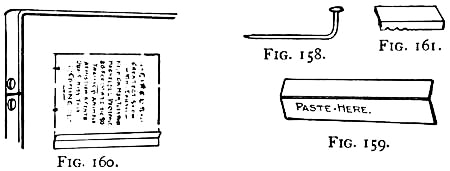
Figs. 158-161.—Home-made Gauges.
There are several forms of home-made gauges which may be used, three of which are shown in Figs. 158, 159, and 161. The first (Fig. 158) consists of an ordinary pin bent into the shape shown. The second (Fig. 159) is made out of a strip of cardboard scored and bent as[Pg 140] in the drawing. It must be pasted in place and held in position until dry, to prevent it from slipping (see Fig. 160). The third form of home-made gauge-pin consists of a quad (Fig. 161), or thin piece of furniture, pasted to the tympan-sheet.
In Inking the Press be careful to spread the ink evenly over the disk, and apply just enough to make a clear, clean copy. Too much ink will clog the type and produce a smeared print.
Ink should not be left upon the form after the latter has been removed from the press, but should be washed off immediately with benzine. The disk and rollers should also be washed after use, as the ink will not be good when hard and will become dirty.
The Life of a Roller is greatly increased by using machine-oil rather than benzine for washing it. Benzine is too drying for the composition of a roller (which is glue and molasses) and takes the elasticity out of it, causing it to crack. Keep the rollers in a cool place in the summer and not in too cold a place in the winter, for extremes in temperature also affect the composition.
Neatness is absolutely necessary in printing, and to secure this you must keep your hands clean so as not to finger-mark your prints. Care must be taken in throwing off printed sheets to see that they do not fall upon freshly printed ones if these are wet enough to mark them.
Materials should be put away in their proper places[Pg 141] after use. Do not throw type, leads, and furniture carelessly about, as they are likely to be lost or broken by doing so. Cigar-boxes make handy receptacles for pied type, until you have an opportunity to sort out and distribute it. These are useful also for keeping leads, furniture, and rules in, and a cabinet similar to that described in Chapter I (Fig. 15), or the curio-cabinet described in Chapter IV (Fig. 59), should be made to hold them.
The young printer should see to it that
Proofs and Scraps of Paper are thrown into a waste basket and not scattered about, as they accumulate rapidly, and not only make a shop look very untidy, but increase the danger of fire.
Oily Rags should be kept in a covered tin can, for they are liable to ignite spontaneously when exposed to the air; and of course oils, gasoline, and benzine should be handled away from fire and corked up after use.
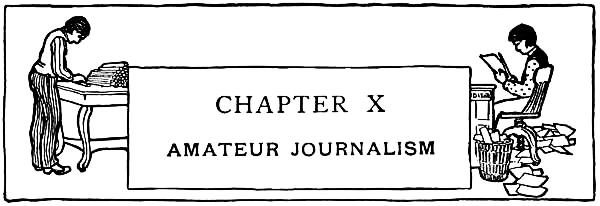
Amateur journalism is by no means a new pastime, but probably at no time in its long history has it been thought as much of as at present.
It would be a difficult matter to even roughly estimate the number of papers which have been issued in the amateur world. Mr. Edwin Hadley Smith of New York City has the largest collection now in existence. This at present consists of 22,600 amateur papers, 500 amateur books, 800 photographs of amateur journalists, 800 professional clippings, and 2,500 miscellaneous printed relics dating as far back as 1845. The collection, which is the result of many years' work, is sorted and catalogued, and will soon be placed in one of our large libraries, where the public may inspect the work that has been turned out by amateurs for the past half century.
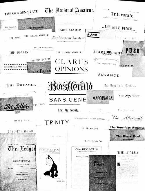
A Group of Amateur Papers.
It is said Benjamin Franklin published an amateur paper in 1723, when a lad of seventeen years; and in tracing the history of amateur journalism down to the present time, a person would be surprised to find what a large number of the most successful statesmen, writers, and scientific men this country has had were amateur journalists in their younger days.
There are at present in the neighborhood of two hundred amateur papers published in the United States. A few of these papers, representative of amateurs from all parts of the country, have been grouped together and reproduced opposite page 142, and several others are shown in Figs. 162, 163, 164, 165, and 166. It is to be regretted that lack of space forbids a larger display of these papers, many of which are quite unique and reflect credit upon their publishers.
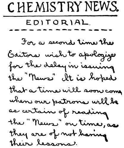
Fig. 162.—A School Paper.
32 pages. Size 2-¼" ×
2-¾".
During the centennial at Philadelphia in 1876, the National Amateur Press Association was formed for the purpose of spreading amateur journalism and bringing amateurs into closer relations with one another. The United Amateur Press Association was formed in 1897, and, while it is a younger organization than the National Amateur Press Association, has a large membership of amateurs.
[Pg 143]Every boy aspirant to the field of journalism should join one of these associations as soon as he has the proper credential—a copy of his own paper, or an original article of his published in an amateur paper. By becoming a member and getting acquainted with other amateurs through exchange of papers, a boy is greatly benefited. He has a chance to see what other amateurs are doing, finds out through the other papers what the members think of his work, and learns through these friendly criticisms wherein he can improve his publication. He also has a chance to enter his writings for the prizes awarded annually by the associations for the best poems, sketches, essays, histories, and editorials.
A great number of the members of these two associations are interested in smaller organizations, among which are the Interstate Association—consisting of the members of the East—and the Western. Again, a large number of amateurs have formed state organizations, and in large cities, where there are enough members to do so, local clubs have been formed. The city clubs hold frequent meetings, at which it is customary for the members to take part in literary programmes. The state and other organizations generally hold semi-annual meetings, and the National Amateur Press Association and the United Amateur Press Association meet annually in some city chosen the preceding year, and at this convention elect their officers,[Pg 145] make awards of prizes for the year, and have a general good time.
The boy who is owner of a printing-press is almost certain to get the publishing fever and commence the publishing of a small paper. If his press is too small for such an undertaking, it will of course be necessary for him to do such job printing as he can get to do until he has earned sufficient money to buy a larger press and such materials as he will need in publishing a paper.

Fig. 163.—Another School Paper.
But it is not always the boy who has had a taste of printing who becomes interested in amateur journalism. There are few boys nowadays who pass through their school life without devoting some of their time to this interesting and instructive work. A paper started by one boy is generally followed by several more, and in this way the number of amateur papers sent out in a town very rapidly increases.
Nothing daunts the ambitious boy. If he has not a press, and there are no prospects of him earning one for some time, he will not allow this to interfere with his plans. It only means he must devise some other way of printing. Many boys have already proven that a press is not an absolute necessity, by issuing papers printed with rubber type, written by pen and on typewriters, and printed by the mimeograph and such duplicating machines. These are all more or less tiresome operations, but ways in which the boy determined to[Pg 146] publish a paper may start. A few examples of papers printed by these methods are shown in Figs. 162, 163, and 164.
It might be interesting to know a little something about how these papers were run. The one shown in Fig. 162 was lettered by hand, and while only one copy of an issue was made, and that passed about in the school at which the publishers attended, there was a good deal of work required to get it up.
The paper shown in Fig. 163 is also a school paper, published at the Lake High School, Chicago. The copy for this was first written off on a wax sheet by means of a typewriter, and this sheet placed on the cylinder of a machine known as a "neostyle," the cylinder then being revolved and the papers printed from the wax sheet.

Fig. 164.—Printed with Rubber Type.
The paper shown in Fig. 164 was the writer's first attempt in the publishing line, and was indeed a sorry specimen of typography. A box of rubber type, a four line holder, and ink-pad constituted the printing outfit. The paper was a twelve-paged two-column affair, requiring[Pg 147] six impressions of four lines each to the column. The column ruling was done with a pen, and, after printing[Pg 148] the copies, each had to be gone over and retouched with pen and ink. It was a long and tedious job, and so wearing upon the type that they were practically useless by the time the second issue had been printed. But by this time the publishers became owners of a press with which they were able to turn out more satisfactory work.
The first thing for a boy to consider is
The Character of his paper—whether it shall contain news of the athletic field, the school, or the neighborhood, entirely, or be devoted to amateur journalism entirely, or be made up of a little of each.
The schoolroom presents so much of interest to those in and out of it, that papers managed and edited by several pupils, with the articles written by the different classes, are generally successful. Athletic news is always interesting to boys, and to have at least a portion of your paper given up to this subject might be a good plan.
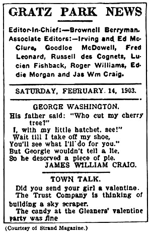
Fig. 165.
The paper shown in Fig. 165 is an example of a small paper, the size of the sheet being three by four and one-half[Pg 149] inches. It was published a few years ago by six boys living in Lexington, Kentucky. The staff, the oldest of whom was but ten years of age, consisted of the editor-in-chief, who attended to the general management, editing, and printing of the paper, and five other boys, known as the associate editors, who gathered the news and did the hustling. This paper contained mostly neighborhood news, and had a large local circulation.
The paper shown in Fig. 166 consists of twelve pages printed upon a press with a form capacity four by six inches, and is given up entirely to the publication of original stories and poems.
Some boys who do not own presses have the printing done by professionals, but simply to edit a paper gives them but half the pleasure and experience derived from executing all the work themselves,—editing, printing, binding, mailing, etc.
In Naming a paper be sure to select a suitable title for it, a name with a meaning, such as will denote the character of the publication, being desirable.

Fig. 166.
The Frequency of Publication will depend largely upon the size of sheet, number of pages, the amount of time that can be devoted to the work, and the facilities for[Pg 150] printing. Whether weekly, monthly, semi-monthly—twice a month, bi-monthly—once in two months, or quarterly, try to place each issue in the hands of subscribers as nearly on time as possible.
The Size of Page will depend largely upon your press. However, a small sheet is most desirable for an amateur paper.
The first page should be headed with the name of the paper set up in rather large type. You will find
A Stereotyped Heading cheaper to buy than a font of large type, and easier to handle on account of its being in a solid block. Below the heading should appear the volume number, date, and number of issue, on one line, followed by the title of the article and body of type.
The Choice of Type may be made by examining the sheets shown opposite page 142 and in Figs. 165 and 166, many of which are good specimens of typography. These should also help you to formulate your ideas as to the style of your paper.
The second page should be headed with the page number and name of paper—or title of story—in small caps, this line to be separated from the body of type by means of a pica brass rule.
Great care should be used in publishing a paper to have the proof thoroughly corrected before the form is printed, for typographical errors spoil the appearance of the paper and are always disgusting to the reader. Also see to it that the marginal lines correspond on each[Pg 151] sheet, and try to get uniform impressions throughout the paper.
A Cover is desirable for a small paper, as it adds to its appearance and size. If you have one, set it up in somewhat the same style as those shown opposite page 142. The cover sheets should be cut a little larger than the inside sheets, so they will cover the latter when they are bound together.
With the printing of an issue completed, the sheets are ready for
Binding.—They may be fastened together by means of wire staples, paste, or thread.
Figure 167 shows a scheme of stitching much employed in printing-offices and which is simple for an amateur to do. The sheets are first folded inside one another, as in the drawing. Then, starting at A with a needle and thread, run the needle through the sheets; carry the thread underneath the sheets from A to B, from B to C above, from C to A beneath, and up through the sheets at A. Then tie the two ends of D and E in a hard knot, with the portion of the thread marked F between them.

Fig. 167.
The cover may be bound with the rest of the sheets, or pasted to them after the sheets have been stitched.
[Pg 152]Few amateurs bother with
Advertisements, probably because it is hard to find merchants who have confidence in results from magazines with small circulations; but with cheap rates you should be able to secure enough ads. to more than defray the expenses of publishing a paper.
Before soliciting these, cut a sheet of paper the size of a page and divide it into small spaces with a pencil and ruler, making what is known as
The Advertisers' Dummy.—Show this to your prospective advertisers and let them pick out the space they wish, charging so much per inch, the rate varying according to the position the ad. will occupy.
With at least four regular issues a year, and not less than fifty per cent of the circulation paid subscriptions, you will be able to enter your paper in the post-office of your city as
Second-class Matter, which makes it possible for you to mail your papers to out-of-town subscribers at the rate of one cent per pound.
To secure these privileges write to the third assistant postmaster-general of your city for an entry blank, together with full particulars concerning second-class matter. Return the application with a copy of your paper; and when it has been passed upon, the postmaster will issue you a certificate entitling you to these rates and authorizing you to print upon your paper "Entered at the post-office at (name of town) as second-class matter."
There is no reason why an industrious boy cannot do a profitable business with a camera, when he has learned to operate it successfully, does careful and neat work, and charges a reasonable price for his pictures. The many monthly photographic competitions in the magazines should be a great help in showing where his faults lie, and when he has overcome these he should be able to make considerable money from the cash prizes offered.
An amateur should master as much of the work as possible. One of the most interesting parts is missed if you pay a professional to develop your plates, and you never know where your faults have been made in taking the pictures, by not seeing the manner in which the image appears on the negative during the development. Even though you spoil one or two plates in your first attempts at developing, your results on the whole will probably be as good as those obtained by a professional, who is very often careless with amateurs' work.
No discussion of photography has been included in[Pg 154] this book, as a complete treatise would be too lengthy, and a condensed description impractical. There are a number of excellent publications which describe the subject in detail, making it so clear that a boy cannot help but understand the principles with a little study. Few of these books, however, dwell upon the equipment of the dark-room, and none give a fellow any ideas for the making of his apparatus, generally an important item to a boy.
The Necessary Equipment for a dark-room is not large, about all you require besides your chemicals being a ruby lantern, printing frame, three trays,—one for developing, another for fixing, and a third for toning,—a two-inch camel's-hair brush for dusting plates, a drying-rack, glass graduate, funnel, set of scales, bottles for solutions, and a cabinet in which to keep your apparatus and supplies.
A Dark-room is not a necessity, although it is a great convenience, especially if you are doing much work. With the shades pulled down, you will find that your bedroom serves the purpose very well in the evening, and many boys do their work in this way.
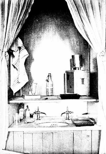
Fig. 168. A Handy Dark-Room.

Fig. 172. A Washing Box and Drying Rack.
Figure 168 illustrates how developing is carried on in a bedroom of an old-style house, where the wash-stands are set in recesses in the wall. Here a shelf made up of several boards fastened together with battens is set upon the marble slabs around the basin. In this shelf an opening four by six inches is made as shown in [Pg 155]Fig. 170, the edges of the opening being rabbeted to receive a five-by-seven camera plate. This arrangement is very complete, for the developing is performed on the shelf, the fixing on the stand below, and the washing in the basin, while light from the lantern is projected through the glass in the shelf, making it light underneath.
This scheme can be used for any wash-stand, by nailing the shelf to two pieces of board twelve inches long by the width of the shelf, these pieces being set firmly upon the wash-stand.
Some boys use
The Bath-room for their dark-room, darkening the window and shutting out any rays of light that may come through the key-hole and cracks about the door. This works splendidly, there being running water at hand and the tub in which to wash the negatives. The work-table is made out of several boards battened together, and should be set across the edges of the tub.
Figure 169 shows
Another Scheme—a dark-room fitted up in a closet, or by partitioning off a corner of the attic or cellar. In the latter case the inside of the partition should be covered with black paper or cloth to prevent light from entering cracks in the boards. The room should be provided with
A Work-table about three feet high. This should be built against the wall and strongly braced, as shown[Pg 156] in the sketch (Fig. 169). Fasten a shelf to the wall about nine inches below the table, and under this make a rack with three divisions in it for trays. The rack should be fastened to the braces, as shown in the drawing.
Running Water is a great convenience in a dark-room, as it saves the bother of having to carry water in pails, or transferring your plates to a tub or wash-basin for the final bath after development.
If it is impossible to locate your dark-room where it will be supplied with running water, the best scheme is
A Water-tank with hose attachment. This is shown in Fig. 169. To carry it out, procure from your grocer a "half-barrel," such as is used for the shipment of salt mackerel, etc., and, after thoroughly cleaning it, bore a hole in the side about two inches from the bottom. Buy at a drug-store several feet of rubber tubing, a rubber stopper with a hole cut in the centre, two pinch-stops, a six-inch piece of glass tubing bent at right angles, and a small glass funnel. Slip one end of the bent piece of glass tubing into the rubber stopper, and stick the latter in the hole made in the barrel. Then slip a short piece of the rubber tubing over the glass tubing, and place one of the pinch-stops on it to be used in regulating the supply of water from the tank (see Fig. 171). Set the barrel on one end of the table, and run the rubber tubing through a hole cut for it in the work-table.
[Pg 157]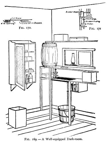
Figs. 169-171.
It is advisable to filter the water used from the barrel, that you may be sure it is free from dirt, so an[Pg 158] arrangement similar to that shown in Fig. 171 should be fastened below the work-table. It consists of a glass funnel set in a hole bored in a block of wood (see A in Fig. 171), which is suspended from the bottom of the work-table by means of a stick (B), one end of which is nailed to block A and the other end to the work-table. Keep a piece of filter-paper in the funnel. The rubber tubing should be cut just long enough to reach the funnel, and the bottom of this filter should come within an inch or two of the sink, which will be set in the shelf below.
You will find an iron drip-pan about as cheap
A Sink as can be had, considering that one twelve by seventeen inches will cost you just fifty cents—twenty-five cents for the pan and an equal amount to pay a tinsmith for soldering a three-eighths inch pipe in a hole cut in the bottom for a drain. Either fasten the sink on the shelf, boring a hole for the pipe to fit in, or set it in an opening cut in the shelf, as shown in the drawing, supporting it by the rim around its top. Slip a piece of rubber tubing over the lower end of the drain pipe and to this attach the second pinch-stop as a regulator for emptying the sink (see Fig. 169).
As the water supply would be insufficient to wash the plates thoroughly after taking them from the hypo bath, it should be used for rinsing only, and
A Washing-box, after the scheme of Fig. 172, made to hold the negatives while washing them. This box will[Pg 159] stand on the shelf beside the sink until you are through developing. The rack is made up of strips of wood fastened together with wire brads. Figure 173 clearly shows its construction. Strips A, B, C, and D should be placed three and three-quarters inches apart for four-by-five plates, and kerfs should be cut in their edges as shown. A and D are mounted upon short stilts, and B and C are nailed to the uprights supporting the handle. The plates rest upon strips nailed across the bottom pieces.

Fig. 173.—A Washing-rack.
This tray was made to hold two dozen plates, but may be made smaller if you wish.
The box should be just large enough for the tray[Pg 160] to fit in. Fill all the cracks and joints with white-lead and give the box several coats of paint to make it perfectly water tight. Then make a hole in the side near the bottom to let the water out, and procure a cork to fit it (Fig. 174).
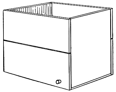
Fig. 174.—The Washing-box.
Before developing, cork up the washing-box, fill it with water, and set it in one end of the sink where the plates can be set in it after being taken from the fixing bath. When you are through developing, place the box and plates in the wash-basin or the bath-tub; remove the cork from the box and allow the water to run in at the top and out through the hole near the bottom. When the negatives have been thoroughly washed, the tray can be removed from the washing-box and used as
[Pg 161]A Drying-rack.
Another scheme for a drying-rack easily made is shown in Fig. 175. For the construction, two pieces of wood twelve inches long by four inches wide will be needed (A and B in Fig. 175), also two blocks (C and D) four inches square. Mitre one edge of A and B, and cut a right-angled bird's-mouth in C and D to receive A and B. With the pieces prepared, fasten them together as in the illustration. Then procure some corrugated straw-board, such as is used for packing glass-ware, etc., cut two pieces four by twelve inches, and tack them to A and B in such a way that the corrugations on one strip coincide with those on the other. For a simple rack this cannot be surpassed.

Fig. 175.—A Negative-rack.
For chemicals, supplies, and apparatus, make
A Cabinet similar to the one described for tools in[Pg 162] Chapter I, or the curio-cabinet in Chapter V. This makes it possible to keep everything in order and in places where they can easily be reached. Such a cabinet is shown on the wall in Fig. 169.
The best scheme for a dark-room
Ruby-light is shown in Fig. 169. This is practicable, however, only when you build the dark-room itself and can cut a window in the partition. It makes it possible to have your source of light outside of the room, and does away with the heat caused by having a lamp within, where you are working.
First, cut a ten-by-twelve-inch window opening in the partition on a level with the top of the work-table. Then make a frame a little larger than this opening and either set a piece of ruby or orange glass in it, or paste a sheet of ruby or orange paper over it. Build a track above and below the opening for the frame to slide in, doing the work neatly, so there will be no possibility of light leaking through.
The light, which may be a candle or lamp, should stand upon a shelf supported upon a bracket outside of the window. It is convenient to have the window slide, as it enables you to open it and have white light to work by when a ruby light is not necessary.
This window furnishes light for developing, which will be done upon the table, but none for the shelf below, where the sink is located and where the fixing tray should be kept (that there will be no danger of getting[Pg 163] hypo into the developer). In order to have light for this shelf, you had better follow the scheme shown in Fig. 170. Cut an opening four by six inches in the work-table directly in front of the window, and make a half-inch rabbet around its upper edge to receive a five-by-seven camera plate (see Fig. 170).
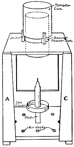
Fig. 176.—A Home-made Dark-room Lantern.
If it is not possible to have outside light for the dark room,
A Home-made Lantern, such as is illustrated in Fig. 176, will be found very satisfactory. It is made out of a wooden box about ten by ten by twelve inches. Cut two openings six inches square in two sides of the box and cover one with one sheet and the other with two sheets of orange or red paper, spreading paste over the entire surface of the paper to make it stretch tightly over the openings as it dries. The orange and red wrappers of some makes of printing papers and developing powders can be used for the covering of these openings.
For a chimney, procure a long slender baking-powder[Pg 164] can, remove the cover and bottom, and insert it in a hole cut for it in the top of the box. Then an arrangement must be made, as shown in Fig. 176, to prevent light from emitting from the top of the can. This consists of a tomato-can placed over the baking-powder can, bottom side up, with its edge fastened in kerfs cut in the ends of four wooden stilts (see illustration). Drive the stilts firmly into holes bored for them in the top of the box. The edge of the tomato-can should now be about an inch and one-half above the box, and its bottom an inch or more above the baking-powder can.

Fig. 177.
Below the chimney attach a wooden stilt to the bottom of the lantern, and tack a can cover to the top of it, as shown in the drawing. This forms a cup holder for the candle, which not only catches the drippings, but also makes the lantern fire-proof should the candle burn down to the end before you notice it. Bore a number of holes in the bottom of the box, and nail two strips to the under side, as shown.
The lamp is now completed with the exception of the[Pg 165] door, which should be made in three pieces, with the edges cut and bevelled as shown in Figs. 176 and 177. Nail strips A and C to the back of the box, and slip B between them. A screw-eye near the bottom of B will serve as a lift in opening the lantern. As the edges of the strips are cut on a slant and bevelled, a joint which cannot possibly leak light is obtained when B is slipped into place. All cracks in the box should be carefully filled with white lead.
In offering this lamp to his boy readers, the writer knows they will find it most satisfactory and a solution to the problem of making a perfect dark-lantern. The air admitted through the holes in the bottom of the box carries the heat and smoke straight into the chimney, and out through the space between the tin cans, making it impossible for the flame to ignite the wood.
If you use
A Plate-lifter you will find an old tooth-brush handle tapered at the end by means of a file one of the best that can be had.
It is well to have some scheme for
Classifying and Preserving Negatives.—To keep them in their original boxes is not a good idea, as there is always danger of scratching them and no satisfactory way of keeping track of their description, date of exposure, etc.
Manila Envelopes, with a printed form to be filled out, on the outside, are invaluable holders, as they not only[Pg 166] make it possible to file away negatives in alphabetical order, but preserve them from dust, scratches, etc.
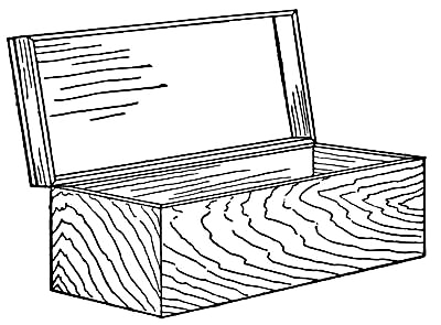
Fig. 178.—A Negative-case.
The four-by-five size can be bought for about twenty-five cents a hundred from a dealer in photograph supplies; but you can get them much cheaper by going to a paper house and asking for their four-by-five coin-cut manila envelope, which sells in half-thousand lots at about one dollar per thousand. If the quantity is more than you will need, you can probably dispose of a portion of them to your boy friends. With a printing-press or rubber type, the following form should be printed upon the outside, with a rule or space to the right in which to place the descriptions:—
NO.
DESCRIPTION
DATE
REMARKS
A Wooden Case to hold the envelopes is desirable, and such a one may be made similar to Fig. 178. For four-by-five negatives the inside of the box should measure twelve inches long, five and one-quarter inches wide, and three inches deep. It will hold about six dozen negatives.
Very light wood, about three-eighths of an inch thick, should be used for the construction of this case. Cut two pieces twelve and three-quarters by three and three-eighths inches for the sides, two pieces six by three and three-eighths for the ends, and one piece twelve by five and one-quarter for the bottom. In cutting the side-and end-pieces, mitre the edges of each so they will make neat corners. The mitre-box should be used for this purpose. Nail the pieces together with small finishing nails, after which fasten the bottom-piece between them, driving the nails through the side-pieces into it. The cover is made of a board twelve and three-quarters inches long by six inches wide, with a rim made of four inch-and-one-quarter strips nailed around its edge, as shown in the illustration. Two of the strips should be twelve and three-quarters inches long, and the other two six inches long. Their ends should be mitred and fitted together as the sides of the box were done, and the top should be nailed to their top edges. This cover fits over the plates, which project an inch above the sides. Hinge it to the back of the box, and attach a hook to the front.
If you do not keep your plates in envelopes, the sides[Pg 168] of the box should be lined with corrugated straw-board to separate them. This may be tacked or glued to the wood.
By rubbing down the outside with emery-paper, oiling, shellacking, or varnishing the wood, a very pretty case will be obtained.
You will find it a simple matter to pick out a negative by having them filed in the order of their exposure, and catalogued alphabetically in a note-book.
Boys who keep their eyes open for opportunities to make money are not long in finding that the coming of snow means money in their pockets if they are willing to do a little hustling.
A number of years ago a few boys undertook the job of keeping the walks of their neighborhood free from snow, and constructed
A Snow Plough with which to do their work. The plough proved so satisfactory that others were made, and before long every boy in the neighborhood had enlisted in the company.
By several boys joining forces in this way, and making contracts with property owners to keep their walks and steps free from snow, a good deal of ground can be covered in a short space of time, and a neat sum of money realized during the season. The work can be done before and after school, and be so divided that while several are ploughing the walks the others are cleaning the steps.
[Pg 170]A plough such as is illustrated in Fig. 179 is made in two sections, four feet long by two feet wide. After battening the boards together at A and B, as shown in the drawing, fasten the sections in place, with two ends together and the other two ends two feet apart. Nail them firmly together at the angle and brace them at the open end with strips, as shown at C and D in the illustration.

Fig. 179.—A Snow Plough.
The bottom edge of the plough should be covered with tin, to prevent it from wearing or becoming broken. Bore a hole an inch in diameter in each section at E, and fasten a broom-handle in them from which to attach the rope tugs. This being done the plough is ready for use.
A Scraper is about the best appliance that can be had for cleaning snow from the steps, especially when the snow[Pg 171] has turned to slush. For the making of one of these, prepare a seven-eighths inch board sixteen inches long by four inches wide. Bevel the lower edge and nail a two inch strip below the top, as at A in Fig. 180. Bore a hole through both thicknesses of wood at B and fit a broom-handle in it, bracing the handle with a piece of wire run from a small hole bored in the handle at C to the ends of the scraper.
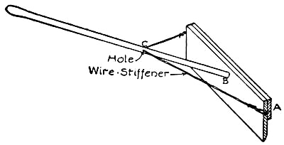
Fig. 180.—A Scraper.
Figure 181 shows a scheme for
A Snow Shovel that is easy to make, and one which will stand a good deal of wear. For this, secure two barrel staves, cut them in two, and plane up the curved edges until they are straight. Then taking three of these pieces, lay them side by side and nail a two-by-two inch strip across the top edges, as shown at A, to bind them together. The bevelled ends of the staves should be placed at the lower end of the shovel and bound in place by a strip of galvanized iron bent over the edges and[Pg 172] tacked to the staves (see B in drawing). Another iron strip should be nailed across the staves at C, to fasten them more securely together. Clinch the nails upon the under side of the shovel and drive their ends well into the wood. Procure a broom-stick for the handle and place it in a bevelled slot cut at D (Fig. 182), fastening down the end with iron pipe-straps, as shown in Fig. 181.

Figs. 181-182.
With the addition of brooms to the plough, scrapers, and shovels, your outfit will be complete and ready for business.
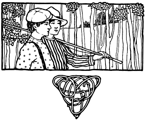

In Camp for the Summer.
For many years there stood in a city back-yard a shanty in which the boys of the neighborhood gathered after school and during vacation, to hold their club-meetings. Many a pleasant hour was spent within the walls of this little building, and it had to be enlarged year after year to hold the ever-increasing number of members.
If, during the week of school preceding the summer vacation, the boys were seen making plans and talking seriously about something evidently in connection with the house, it might well be imagined that the annual alterations were about to begin. At the close of school the neighbors were made aware of it by the appearance of half a dozen boys upon the roof of the shanty, who, with hammers and hatchets in their hands, were easily recognized as the wrecking crew.
Perhaps the roof was to be raised a foot or given a different pitch, a window changed here or a door placed there, a side extended or a partition built through the centre; but no matter whether the alterations bettered[Pg 176] the building or not, they gave the owners a chance to use their ingenuity in working out their schemes, and practice in carpenter work.
The boys' greatest difficulty was found in obtaining large enough material with which to build. The woodshed was the lumber-yard, and as this contained only a few old boards, several packing-cases, and kindling-wood, a great deal of splicing was required and many pounds of nails were necessary to fasten the many small pieces in place.
After remodelling the club-house one year, the members in way of a joke placed a "For Rent" sign upon the door, and were greatly surprised to receive the following mysterious letter:—
Mister Agent: i sea u hev a house Fur rent what u want furit im a wider with 12 children six pigs 5 chickens a mule three dogs 7 cats and ten ducks i hop the house is big enuff it dont matter bout the children but i wont crowd the pigs. i soppose will paint outside an in and put awnins at the frunt winders i'd like terry cotty shades and a stun sidewalk iF u'll put a piassie on and reduce the rent till after wurlds Fair i'll take it what you want furit please let me know soon iF u dont find me hum im like to be at mis whatnots if u dont know the way to her house just ask mis jones next door but one to me she'll tell u Good by.
Mary Jane Johnstone.
The letter was answered immediately and sent to the general delivery but was returned from the Dead Letter Office, and no trace of the large family could be found.
[Pg 177]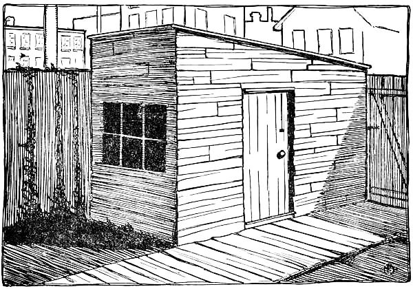
The Back-yard Club-house.
Knowing that many boys who would like to build themselves a club-house have not the money in their treasury with which to buy new lumber, this chapter will describe the manner in which a rough-and-ready house may be built. It will not be attempted to show the correct methods of putting up a framework, such as would be built if the right-sized lumber were obtainable, but the simplest way in which boys can make use of the material at hand.
Draw the Plan of the building upon a piece of paper, and before commencing work figure out exactly what material will be required. If you haven't enough lumber you will find it a great deal easier to alter the plans at first than when the work is half completed. It is best first to place in one pile all
The Material you can find; then, after drawing the plans, sort out the boards according to their lengths. Use the short boards whenever possible, so that the long pieces may be kept for places requiring long boards. Several two-by-fours should be secured for the framework. If you do not happen to have these, you can easily get what you want at some alteration job or where some frame structure is being torn down. Short two-by-fours may be spliced, or, more correctly speaking, "fished." This is very often resorted to in building when studding of a sufficient length cannot be procured. Figure 183 shows the method of
Fishing Studs.—Two fish-plates, A and B, are nailed[Pg 179] to the sides of the studs, covering the joints, while the face OD remains on a level to receive the siding.
By building the club-house in a corner of the yard, against the fence, house, or barn, it is necessary to build but two walls. Less material is required, and a much firmer structure obtained by doing this.
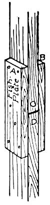
Fig. 183.
Stake out the length and width of the house upon the ground, and sink a stone or a couple of bricks at the corner to support the corner post. Then cut two two-by-fours the length of the greatest inside height of the house. Set one upon the corner stone, bracing it temporarily with boards run from it to the fence, and spike the other to the fence on a line with the corner post (see A and B in Fig. 184). Cut the end-plate C the correct length and spike it to A and B, after which cut a two-by-four the length of the shortest inside height, and spike it to the fence rails at D. Nail the boards E, F, G, H, and I to the places shown in Fig. 184.
The Studs should be placed from two to three feet apart, according to the length of boards used for siding, and additional studding should be set in where it is necessary. Fasten the ends of the studs to the boards E, F, G, H, and I. Studding should be placed around the window and door openings, as shown in the illustration.
[Pg 180]
Fig. 184.—Framework of Club-house.
After completing the framework,
Board up the Sides, fitting the boards around openings and corners as neatly as possible.
The Roof is a very important factor in a building of any kind, and care should be taken to make it of water-proof material, for a leaky roof will not only ruin the interior but make it damp and thus unhealthy. Tar-paper will be found a good roofing material, inexpensive, and easily put on. First cover the roof with boards placed about one inch apart. Then cut the tar-paper into lengths equal to the width of the roof. Commencing at the lower edge of the roof tack one strip in place. Lap a second strip two inches over the first, a third two inches over the second, and so on until the entire roof is covered. Figure 185 shows a tin cap and nail made especially for this kind of work. The cap is punched to fit over the nail, and prevents water from running into the hole made by the latter. It will be unnecessary to coat the paper with tar, as there is sufficient in its preparation to keep it water proof a long time—probably longer than the house itself will be allowed to stand.

Fig. 185.
The Floor should not be laid directly upon the ground, but be supported upon four-inch sleepers set as shown in Fig. 186, with cinders rammed in between them. The bed of cinders should not be more than three inches thick, so there will be an inch of air space between them[Pg 182] and the floor. This will help to keep the floor free from dampness. Four-inch boards stood on edge will do very well for the sleepers.

Fig. 186.—Construction of Floor.
You can probably make a bargain with a carpenter for
A Window-sash.—They very often have a number taken from old buildings, which they will gladly sell for a small sum. There are two ways in which you can easily fasten the sash in place, either with hinges so it will swing in, as shown in Figs. 187 and 188, or in tracks, to slide as described for the dark-room window in Chapter XI and illustrated in Fig. 169. If the window is made in the front of the building, as shown in the sketch of the finished club-house, the sash will necessarily have to be hinged, as there would not be room for it to slide sideways. We will therefore hinge it to swing in as shown in Figs. 187 and 188. The studding which was placed around the window opening when you erected the framework of the house forms a frame for the sash to set in. The window-sill is made out of a seven-eighths-inch board cut the width of the opening, and should be nailed to the bottom piece of the frame so it pitches slightly outwards and its edges project a[Pg 183] little beyond the wall inside and out (see Fig. 188). The pitch of the sill can be obtained by blocking the inner edge with a very thin strip of wood, as shown in the section drawing. The sash should fit the frame with but enough space around it to allow it to open freely. Place the sash in the opening with its inside surface on a line with the inside face of the two-by-four frame, as shown in Fig. 188, and nail a seven-eighths-inch window-stop around the frame outside of the sash to keep the rain and wind from entering.
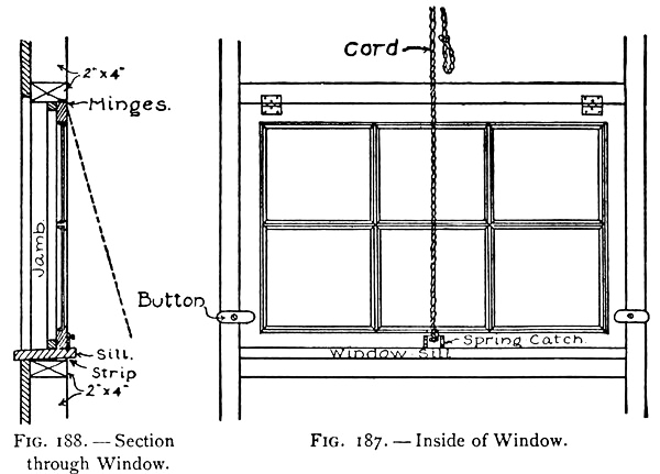
Figs. 187-188.
By hinging the sash to the top of the frame as shown in the illustration, it can be swung up out of the way when opened. A spring-catch should be screwed to[Pg 184] the bottom rail of the sash with the latch-pocket counter sunk in the window-sill, and from the knob of the catch a cord should be attached and run through a screw-eye placed in the wall near the ceiling. The sash can now be opened by pulling the cord, and may be held open by looping the end of the cord over a nail. Wooden buttons should be screwed to the inside edge of the jambs for additional locks (see Fig. 187).
A sill should be set in the bottom of the door frame, and a seven-eighths inch stop nailed to the top and to the jambs in the same way as you finished the window opening.

Fig. 189.—A Batten Door.
Make a Batten Door, fastening the boards together on the inside with battens as shown in Fig. 189, with the nails driven through from the outside face and clinched upon the battens. Hinge the door to the inside face of the jamb with strap-hinges, and either buy an iron latch for it or make the old-fashioned
Wooden Latch described and illustrated in the following chapter.
With the carpenter work of the house completed,
Calk up the Cracks, of which there will doubtless be a great number, unless matched boards have been used[Pg 185] for the walls. This may be done by rolling pieces of newspapers into wads and wedging them into the cracks with a pointed stick. Several thicknesses of wrapping-paper tacked over the inside walls will help to prevent the wind from entering, and will also make a good foundation for wall-paper should it be placed upon the walls.
Earth should be banked up around the outside of the house to keep away the water. Vines trained over the outside will help to hide the roughness of the boards.
The club-house interior may be fitted up with furniture such as is described in Chapter IV, "Suggestions for a Boy's Room."
The log-cabin marks what might be called the beginning of American architecture, for it was the first form of building built by white men upon American soil. The introduction of saw-mills was very slow, and lumber so scarce that cabins were the best shelter the colonists could build to withstand the cold winters and the merciless attacks of Indians. With the building of saw-mills, the cabin gradually gave way to the frame building, which could be more quickly built, and which was, of course, a more comfortable lodging. But this change first took place up and down the large rivers, where the mills were located, and did not extend into the interior until some time later, owing to the difficulty of hauling lumber to great distances from the mills.
To-day the log-cabin is still to be found in the timber regions and among the mountains, but mostly for temporary residences, such as summer homes, camps, and play-houses.

Fig. 190.—Plan for a Boy's Cabin.
You boys who spend the summer in the woods should not miss the
opportunity of building yourselves a small [Pg 187]
[Pg 188]cabin. Several boys can
join forces, and in this way make the work easier and quicker to
perform.
Select a Site on high ground, as near to your source of timber as possible, and then decide upon
The Design and Size to build it, which will be determined largely by the size and amount of timber you can procure. A plan for a cabin simple in construction is shown in Fig. 190, and while the details have been carefully worked out in this chapter for a cabin of this size, you will find it a simple matter to make such alterations as you wish. For the building of more pretentious cabins, the writer would refer his readers to "Log Cabins and Cottages" as the most practical book published upon this subject. In this volume its author, Mr. William S. Wicks, has not only written upon the construction and treatment of cabins, but also brought together a number of sketches showing a great variety of clever designs that have been built in different sections of the country. In carrying out the details of construction for the cabin described in this chapter, the writer has made use of a number of ideas from this book, through the courtesy of Mr. Wicks and his publishers.
Of course the most of
The Material for the cabin will be secured near at hand, but for a good roof, and the finishing of the door and window openings, a few boards should be taken along, together with several pounds of nails.
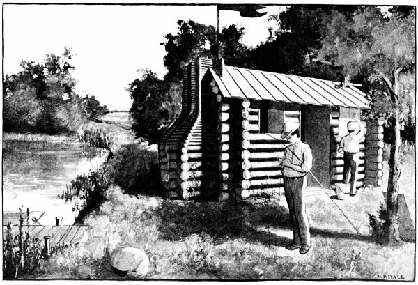
A Boys' Log-cabin.
While it is customary to lay up the walls of a cabin and then cut the door and window openings, you will find it a very much simpler matter to leave the spaces for them when laying up the logs, as it greatly decreases the number of long logs required to build the cabin. As the inside dimensions of the cabin shown in the plan of Fig. 190 are ten by twelve feet, the full-length logs—that is, those above and below the window and door openings—should be thirteen feet long for the ends of the cabin and fifteen feet for the front and rear walls.
To start the Cabin, stake out its length and breadth upon the ground, clear the space of all trees and brush, and make the ground as nearly level as possible. You will find it unnecessary to have a foundation for a cabin of this size, as it will not settle to amount to anything.
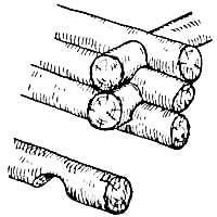
Fig. 191.—The Lock-joint.
Probably the most simple way of joining the logs together is what is known as
The Lock-joint.—As shown in Fig. 191, a notch is cut in the logs twelve inches from each end, so the surfaces of the logs will be brought together when the ends are fitted over one another, as shown in the drawing.
Select two fifteen-foot logs for
The Sills, and set them an inch or so into the ground, parallel to each
other and ten feet apart. Then after[Pg 189]
[Pg 190] cutting the notches in two
thirteen-foot logs, fit them over the sills twelve inches from the ends.
The opening for the fire-place must be left in one end of the cabin, so
mark out upon the end log the width of this opening, which should be
five feet, and cut out this section of it. Then cut two boards three
feet long, the height of the fire-place opening, and nail them to the
ends of the log just cut. These boards form the jambs of the opening.
Locate a three-foot door opening in the centre of the front sill-log,
and saw along these lines to within two inches of the ground, cutting
out the piece between. The remaining two-inch piece will form the
door-sill. Two pieces of board six feet six inches long, the height of
the door opening, should now be cut for the door-jambs and nailed to the
ends of the sill-log in the door opening.
After testing the jambs with a plumb, such as is shown in Fig. 14, Chapter I, to see that they are perpendicular, continue laying the side and end logs alternately. Fit the logs between the jambs and nail the latter to their ends, being careful not to get them out of plumb in doing so. Above the fire-place the logs will, of course, be of full length, and at a height of four feet four inches the windows will start. Locate the window openings twenty-six inches wide upon the logs laid at this height, the one opposite the fire-place in the centre of the wall, and the others twelve inches from the corners. Cut the jambs twenty-six inches long, and, after setting them in[Pg 191] place, continue laying up the logs, fitting the shorter lengths between the jambs as before.

Fig. 192.—Interior of Cabin.
When the desired height of the walls has been reached, which need not be more than seven feet, you will be ready
To construct the Roof.—There are several ways of doing this, but as simple as any is that shown in Fig. 192, and in the illustration of the finished cabin. In laying this form of roof the end logs are placed one above the other, but each tier of front and rear logs is set in a[Pg 192] little farther than the preceding pair, until they finally meet at the peak of the roof. The roofs of cabins are generally thatched or covered with bark, shingles, or boards. The thatched roof is the most artistic, and will last from ten to fifteen years when properly made; but unless the straw is put on very thickly and closely woven, it is likely to leak. If you use shingles and expose each four and one-half inches to the weather, you will require about seven quarter-thousand bunches for a roof of this size.
Boards will make the most simple and inexpensive covering. They should be put on as shown in the drawing of the completed cabin, and in Fig. 192. A layer of boards is first nailed across the roof-supports four inches apart, and other boards then lapped over these spaces and nailed in place. The roof boards should project a few inches over the side walls and gable-ends of the cabin. When all of the boards have been put in place, it will be necessary to finish off the ridge with
Ridge Boards, to prevent water from leaking through the roof at that point. As shown in Fig. 192, these consist of two boards nailed along the ridge, and the edge of one nailed to the edge of the other.
It is not advisable to build
A Log Chimney and Fire-place with the intention of using it, for unless the work is very carefully done and kept in repair, there is always danger of setting fire to the cabin. But, nevertheless, it should be built, as it[Pg 193] belongs to a cabin and adds greatly to its picturesque appearance.
With large logs build up the chimney to a height of five feet, or two feet above the fire-place opening, in the same manner as you did the cabin walls, fitting the ends against the logs of the main structure. When this has been done sink a number of stones in front of the fire-place for a hearth, as shown in Figs. 190 and 192, and also line the bottom of the fire-place with them. Then mix up some clay and line the back, sides, and jambs of the fire-place with it from ten to twelve inches thick, packing the clay until it becomes solid. The upper part of the chimney should be made of smaller logs and sticks, and the inside of the flue lined with clay as the work proceeds. The exterior of the chimney will be seen in the illustration of the finished cabin.
When the construction of the cabin has been completed,
Calk all the Spaces between the logs with clay and moss, to keep out the weather, using a pointed stick for this operation; and grade the ground up to a point just below the line of the door-sill all around the cabin, so that no surface-water will run within.
The finishing of the interior of the cabin now remains to be done. By omitting a wooden floor the cost of material will be reduced considerably, and there is really nothing objectionable to
A Mud Floor if it has been properly prepared. The[Pg 194] earth should be thoroughly dried out and packed down until hard and compact, and slightly banked up around the walls.

Fig. 193.
The sills and heads of
The Window Openings and the head of the door opening should be cased with boards the width of the jambs. If you can secure sash for the windows, hinge them to the inside edges of the jambs as shown in Fig. 190, and nail a seven-eighths-inch window-stop around the jambs outside of them, to prevent the wind and rain from getting in around the sash (see Fig. 193). If sash cannot be obtained, wooden shutters made to fit the opening will do very well, as they can be used at night and whenever you wish to close up the cabin, and when you are within the cabin in the summer you will want the windows open.
After cutting boards of the proper length for
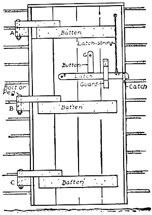
Fig. 194.—The Cabin Door.
The Cabin Door, fasten them together with battens placed at the top, bottom, and centre (see Fig. 194). Then hinge the door to the inside of the jamb with either iron strap-hinges or
Wooden Hinges such as are shown in Fig. 194. To make a set of wooden hinges, first cut three blocks of[Pg 195] wood four or five inches long and nail them to the cabin wall on a line with the three door battens (see A, B, and C in Fig. 194). Then prepare three pieces of wood eighteen inches long and two inches wide, and bore a small hole through one end of each, as shown at D in Fig. 195. When these have been made, nail them to the door above the battens so that when the door is put in place their ends will rest on blocks A, B, and C. Locate the holes in the eighteen-inch strips upon A, B, and C, and bore holes through the blocks at these points, after which set the door in place and fasten the arms of the hinges to the blocks, either with bolts, as shown in Fig. 194, or with hardwood pegs cut to fit the holes.

Figs. 195-199.—Details of Cabin Door.
You will find the old-fashioned
Wooden Latch and latch-string a very good and serviceable fastening for a cabin door, the details for the making of which are shown in Figs. 194, 196, 197, 198, and 199. It consists of three pieces of wood,—a strip[Pg 196] two feet long and two inches wide for the latch, with the ends rounded and a hole bored through it at E and another at F, as shown in Fig. 196; a guard cut similar to Fig. 197, with a slot in it about three and one-half inches long and one inch deep; and a catch similar to Fig. 198, with its upper edge rounded so the latch will easily slide into the slot. With the pieces thus prepared you will find it an easy matter to fasten them in the places shown in Fig. 194. The catch is set into the jamb of the door as shown in Fig. 198, the latch is[Pg 197] screwed to the door at E, and the guard is fastened over the latch in the position shown in Fig. 194.
The Latch-string is fastened to the latch at F, and run through a hole bored in the door above the top batten. To the outside end of the latch-string attach a weight of some kind to keep it from pulling through the hole (see Fig. 199). To lock the door from the inside, you will find a wooden button screwed to the door at G (Fig. 194) very good, as it prevents the latch from being lifted, when turned against it as shown in the illustration. As in the case of the windows, a seven-eighths-inch stop should be nailed to the door head and jambs outside of the door, for the door to swing against, and to keep out the rain and wind (see Fig. 193).
You will have need of but few pieces of furniture within the cabin, and those can be made very simple, out of material at hand.
A Mantel-shelf out of a board five feet long should be fastened above the fire-place by means of three triangular brackets, and it is a good idea to make your
Provision Cupboard to sit upon this, as shown in the drawing of the cabin interior (Fig. 192). Use a couple of the boxes in which you bring your camping outfit for this. Set them side by side, as in the illustration, place a shelf or two within them, and, after battening the cover boards together, attach them to the ends of the boxes with hinges cut out of leather.
On each side of the fire-place a comfortable
[Pg 198]Rustic Seat should be built in as shown in Figs. 190 and 192. The drawings clearly show the construction of this. The two legs are driven well into the ground, and a crosspiece is nailed to their tops to support the sticks forming the seat. Make the top of the seat about eighteen inches above the ground.
While a very comfortable bed may be made upon the ground out of pine boughs, it is well to have at least
Two Bunks for guests, who are almost certain to pay you a visit to see what kind of a time you are having, and perhaps test your cooking. These bunks may be double-decked and placed in the corner where they will be pretty well out of the way (see Figs. 190 and 192). Two six-foot poles should be driven into the ground about thirty inches from the wall, and two cross poles notched and fitted on to them as shown in Fig. 192, one six inches above the ground and the other three feet above that. Cut a number of sound sticks about three feet long and drive one end of each between the logs of the wall and fasten the other end to the crosspiece opposite. These sticks should be placed about three inches apart. In putting up this framework make everything very strong and solid, to prevent any mishaps to the occupants. The bunks should now be covered with pine boughs, cut into small pieces and spread over the sticks evenly and to a depth of two inches. When these have been properly placed, spread a doubled quilt or blanket over them, and the bunks will be completed.

Two Simple Cabins.
As we decided not to use our fire-place for fires, owing to the danger of setting fire to the cabin through some defects in the workmanship, or the cracking of the clay lining, build your camp fire-place outside of the cabin. You will find it more enjoyable to also eat in the open when the weather permits, so build
A Camp-table between the trees for this purpose. It may be made out of two eight-inch boards fastened together on the under side with battens, and supported at one end on a cleat nailed across the trunk of a tree and at the other on two poles driven into the ground. The height of this table will be determined by the height of the boxes, stools, or whatever you use for seats. It is a simple matter to make a long rustic seat on each side of the table, and if this is done make them eighteen inches high and the table twelve inches higher.
Those of you who have camped have probably had enough experience to know what utensils and provisions are required, but
A Few Pointers may be profitable to the boy who has never been initiated into camp life.
Utensils of the commonest kind should be taken along. An old frying-pan, a coffee-pot, two water pails, a tin pan and wash-basin, tin plates and drinking cups, some old spoons, knives, and forks, a can-opener, and a jack-knife are about all you will be in need of. Among
Other Necessities are blankets, towels, dish-cloths, rags,[Pg 199]
[Pg 200] soap, rope,
and string, matches, a lantern, and an axe, a saw, and nails.
For Provisions, take as much canned food as possible, as it requires but little preparation, is easily carried, and not likely to spoil. Bacon and eggs are, of course, to be included in your list, as they belong to a camper's bill o' fare, are very satisfying to a fellow's appetite when he has returned to camp hungry after a day's tramp through the woods, and a boy will have but little trouble in cooking them. Be sure you know how to prepare whatever food you take along to cook, before starting for camp, and don't experiment upon dishes you have never attempted, or you will probably make a mess of your materials, as is generally the case, the result of which will not be fit to eat. Should there be fishing near the site of your camp, learn the proper preparation of fish for your table.
Canoeing is a most delightful outdoor sport, and one of the healthiest in which a boy can indulge during his vacation days. Its popularity can plainly be seen by visiting any lake or stream, and noting what a large percentage of the small craft dotting its surface are canoes of various shapes and sizes, paddled by boys of all ages.
For speed and the ease with which it can be carried about, the birch-bark canoe has no equal, but very few boys own them, as they are expensive, and their construction is more difficult than those of other material which will satisfy a boy fully as well.
The canvas canoe is more widely used at the present time than any other form, which is no doubt due to the fact that it is very simple to make and keep in repair, and the cost of its material is small.
In building a canvas canoe there are two important things to consider,—its weight and strength. These depend upon the material used. The framework must be made stiff enough to hold its shape, as the canvas[Pg 202] adds but little to its strength, and at the same time the wood should be as light as possible. There are a great variety of
Materials from which to choose for building the framework, among which basswood, ash, spruce, and pine may be classed. The canoe described and illustrated in this chapter may have its ribs, ribbands, and gunwales made out of lattice-strips and barrel-hoops, which will save the cost of having them cut to the right size at a mill. Pine or fir lattice-strips of good sound stuff are generally easy to obtain in all locations.
1 piece of 2-inch by 8-inch plank 6 feet long for bow and stern pieces.
15 2-inch by ⅜-inch lattice strips 12 feet long for ribbands, gunwales, keel, and bilge-keels.
20 barrel-hoops for ribs and deck braces.
1 strip 8 feet long, 2 inches wide, and 1 inch thick for keelson.
2 strips 4 feet long, 2 inches wide, and ⅝-inch thick for deck ridge pieces.
2 strips 8 feet long, 4 inches wide, and ¼-inch thick for cockpit frame and coaming.
Several 6-inch and 8-inch boards from which to cut deck beams, patterns, etc.
Copper nails and brass screws should be purchased for fastening the framework together, and copper tacks for putting on the canvas. Iron nails will rust and break off, and therefore should not be used in any part of the canoe's construction. Use nails only where their ends can be clinched, and screws in all cases where this cannot be done. For covering the framework, three[Pg 203] and one-half yards of canvas forty inches wide will be required for the lower portion, and the same amount thirty inches wide will be required for the deck. Boiled linseed-oil should be purchased for filling the canvas and the best grade of mixed paint for painting it. A drab, or cream color and white trimmings, are both suitable for a canoe. If the latter is used, buy white paint, and, after pouring out enough to cover the finishing strips, mix the rest with enough yellow ochre to make a pretty shade of cream.
Below will be found a bill of the material required to build a canoe such as this chapter describes, and although the prices of canvas and a few of the fittings are likely to fluctuate somewhat, the price of the canoe should not exceed this amount, and there are locations where it may be less.
| 3-½ yards No. 10 Duck, 30 inches wide, 27 cents | $0.95 |
| 3-½ yards No. 10 Duck, 40 inches wide, 36 cents | 1.26 |
| 1-½ pounds 1-inch Copper Nails, 30 cents | .45 |
| 2 pounds ⅜-inch Copper Tacks, 35 cents | .70 |
| 2 dozen ¾-inch Brass Screws (Flat Heads), 7 cents | .14 |
| 6 dozen ⅝-inch Brass Screws (Flat Heads), 6 cents | .36 |
| 3 dozen ⅝-inch Brass Screws (Round Heads), 6 cents | .18 |
| ½ gallon Boiled Linseed-oil | .25 |
| ½ gallon Best Quality Mixed Paint | .75 |
| 15 Lattice-strips, 12 feet long | .90 |
| 1 Piece of 2-inch by 8-inch Plank 6 feet long | .20 |
| Miscellaneous Strips and Pieces (see page 202) | .50 |
| —— | |
| Total cost | $6.64 |
Having procured the necessary material for the canoe, the first things to make are

Fig. 200.—Bow and Stern Pieces.
The Bow and Stern Pieces (see Fig. 200).—The proper way of laying these out on the eight-inch plank is shown in Fig. 201. First cut the plank in half, and then place these two pieces side by side upon the floor or work-bench as shown in the drawing one piece upon which to draw the pattern, and the other upon which to locate the centre for drawing the curves. Then square the line AB across the planks, and locate the points D and E on either side of it, by means of the measurements given upon the drawing. The most satisfactory scheme for
Drawing the Curves is with a piece of cord, to one end of which a pencil has been tied (see Fig. 201). With this as your compass, hold the end of the cord at D for a centre, and with a radius of ten and one-quarter inches strike an arc cutting the line AB as at C. C is now the required centre for drawing the curves. Drive a small nail into the plank at C, and wind the end of the compass cord around it until the correct length of radius is obtained (see drawing). Describe the arc DE with a radius equal to CD, or ten and one-quarter inches.
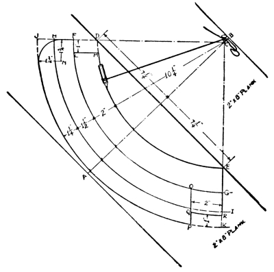
Fig. 201.
Then with a ruler lay off along the line AB the distances for the other arcs, as shown in the drawing. FG will be two inches from DE, HI an inch and one-half from FG, and JK an inch and one-quarter from HI. Having located these points and described the arcs, draw the lines CD and CE, extending them so as to cut off the arcs, as in the drawing. At the upper end of the pattern draw the line LM one inch from and parallel to FD. With a radius of an inch and three-quarters and the centre N describe an arc as shown[Pg 206] in the drawing. At the lower end of the pattern draw the line OP two inches from and parallel to GK, and the line QR one inch from and parallel to PK. Having carefully drawn out this pattern, turn over the plank and draw the same thing upon it, locating the points exactly opposite one another, by squaring lines across the sides and edge. Prepare the other piece of plank similarly. To cut out the patterns, place them in the vise of your work-bench, one at a time, and rabbet the surfaces between DE and FG, and FG and HI, as shown in the section drawing, Fig. 202. This done reverse the piece and do the same to that side. When these surfaces have been trued up carefully, remove the piece from the vise and saw the pattern from it. In doing this, first saw along the lines DJ and EK, and cut out the corners FLMD and PQRK. Then follow roughly the curves of lines DE and JP, after which place the work in the vise and trim them off nicely with a draw-knife, rounding the outer curve as shown in Fig. 202. The portion OQRG should be cut down to a plain surface as shown in Fig. 200.

Fig. 202.—Section through Bow and Stern Pieces.
With the bow and stern pieces completed, the most difficult part of your work has been accomplished.
Now pick out the eight-foot strip procured for
The Keelson.—Square off the ends so that it is exactly eight feet long, and then, commencing six inches from[Pg 207] one end, lay off mortises for the ribs (see Fig. 203). These mortises should be cut half an inch deep and the width of the barrel-hoops, and their centres should be spaced twelve inches apart.

Fig. 203.—The Keelson.
In order to give the correct shape to the canoe in putting the framework together, it will be necessary to make
A Mould similar to Fig. 204. Fasten together two boards about two feet long with battens, as shown in the drawing, and with a piece of cord to which a pencil has been attached describe a semicircle upon it, using a radius of eleven and one-half inches. Saw out the mould carefully, and in the centre of the bottom cut a mortise two inches by one-half for the keelson to fit in.
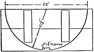
Fig. 204.—The Mould.
Everything should now be in readiness
To put the Framework together.—In order to give the keelson the proper slope of one inch between its centre and ends, nail two blocks of wood one inch thick to the work-bench eight feet apart, and rest the ends of the keelson upon them. Then fasten the ends of the keelson[Pg 208] in the mortises cut in the bottom of the bow and stern pieces. Set the mould which you have prepared over the exact centre of the keelson, and fasten it in place temporarily. When this has been done take two lattice-strips for
The Gunwales, and after locating the exact centre of each, screw them at this point to the ends of the mould just below the top. Drive these screws but part way in, as the mould is to be removed later on. Commencing at the bow end of the canoe, draw the end of one gunwale to the bow piece, and, after marking it the correct length cut it off so it will fit nicely in the rabbet cut in the side of the bow piece. Then screw the other end to the stern piece, after which attach the gunwale on the opposite side in the same way (see Figs. 200, 205, and 206).
Now take the barrel-hoops which are to be used for ribs, and fasten them in the mortises cut for them in the keelson, bending their ends until they come inside of the gunwales. Then fasten them to the gunwales and trim their ends so as to be even with the top of the canoe (see Figs. 205 and 206).
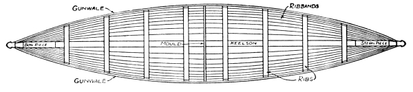
Fig. 205.—Top View of Canoe, showing Gunwales, Ribs, and Ribbands in place.

Fig. 206.—Side View of Canoe, showing Framework completed.
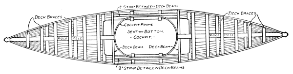
Fig. 207.—Top View of Canoe, showing Framework completed.
After fastening the ribs in place,
The Ribbands should be put on. Pick out eight of the soundest lattice-strips you have, and fasten these at their centre to the sides of the mould, placing four on each side of the keelson and spacing them at equal distances. As the mould is only temporary, do not fasten the ribbands to it securely, but drive in the nails part way.
[Pg 209]Then, beginning at the bow, draw the ends of the ribbands to the bow piece one at a time, and cut them off so they will fit neatly into the rabbet. Screw them in place, being careful to space them as equally as possible, after which attach the stern ends in the same way. Figure 205 shows the top view of the canoe at this stage of its construction.
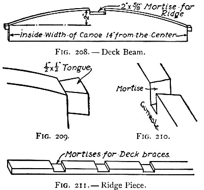
Figs. 208-211.—Details of Deck Beam and Ridge.
The Deck Beams should now be made and put in place, one each side of the cockpit, or fourteen inches from the centre of the canoe (see Fig. 207). At this point measure the exact distance between the gunwales, and lay it off upon a four-inch board (see Fig. 208). The top of this piece should be curved as shown in the drawing, and a mortise two inches wide by five-eighths of an inch deep should be cut in the edge for the deck ridge pieces to fit in. As a means of preventing the gunwales from spreading, it is best to dovetail the ends[Pg 211] of the deck beams into them (see Fig. 207). Cut a tongue half an inch long and half an inch thick on each end of the beams, as shown in Fig. 209, undercutting it slightly, as in the drawing, to make it wedge-shaped. Then, having prepared the ends, place the beams in the positions they will occupy in the framework, and mark upon the top of the gunwales the shape of the tongues. Mortise the gunwales at these points (Fig. 210), so the tongues can be slipped into them and fastened in place. By examining the corners of a drawer you will see clearly how the dovetail joint is made.
The Ridge Pieces are strips running from the deck beams to the bow and stern pieces (see Figs. 206 and 207). For this canoe, they should be made out of a strip two inches wide by five-eighths of an inch thick. Cut them of correct length to reach from the mortises in the tops of the deck beams to the mortises cut in the tops of the bow and stern pieces. Mortises two inches wide and a quarter inch deep should be cut along the top of these ridges, as shown in Fig. 211, to receive the deck braces. Securely screw the ridges in place. Then cut twelve pieces of barrel-hoops for
The Deck Braces, and fit them in the mortises made in the ridge pieces. Screw these in place and bend their ends until they can be fastened to the inside face of the gunwales. The curve of these braces should be the same as that of the deck beams, so it will be possible to put on the deck canvas neatly (see Figs. 206 and 207).
[Pg 212]The space between the deck beams is left for
The Cockpit, the frame for which we are now ready to prepare. First remove the mould, being careful that the framework does not spread in doing so. Then cut two two-inch strips to fit between the deck beams, and fasten one on each side of the cockpit two inches from the gunwale (see Fig. 207). When this has been done take the strip eight feet long, four inches wide, and one-quarter inch thick, procured for the cockpit frame, and bend it around the opening, fastening it to the sides of the deck beams and the side strips. The top edge of the frame should now be shaved off with a draw-knife, so that it will be on a line with the deck braces at every point (see Fig. 206). This is necessary in order to make the curve of the deck around the cockpit the same as elsewhere.
The framework of the canoe is now completed, and should be painted and left to dry before you go on with the rest of the work.
It is no easy matter to stretch
The Canvas Covering over the framework without having it wrinkle, but with the help of a boy friend it can be stretched fairly even, and with care and patience may be made to look neat.
Turn the framework bottom side up and, after finding the centre of the forty-inch strip of canvas, lay it along the keelson from bow to stern. Smooth it over the surface with your hands, and start a few tacks along the[Pg 213] keelson to hold it in place. As a means of keeping the canvas stretched over the bottom of the framework while working upon it, attach several weights to the edges; then, with your helper on the side opposite you, commence at the middle rib and stretch the canvas down that rib to the gunwales, starting a couple of tacks in the gunwales to hold it in place. Then work along each rib from the centre of the framework toward the bow, and then from the centre toward the stern, stretching the canvas as tightly as possible, and driving tacks along the gunwales not farther than one inch apart. You will find that the only way to get the canvas on smoothly is by removing the tacks wherever any wrinkles appear and, after restretching it, replacing the tacks. As the tacks will probably have to be removed a number of times during the operation, it is advisable to drive them in but a little way at first.
It is most difficult to make a neat job at the bow and stern, and a few wrinkles will probably remain, no matter how much pains are taken in fitting the canvas, on account of the narrowing of the canoe at these points. Fill the outer mortise made in the bow and stern pieces with paint, and, after folding the edges of the canvas, tack it in these mortises. Place the tacks as close as their heads will permit, which, together with the paint, will make a joint that water cannot penetrate. Now examine the canoe carefully, and, if you have smoothed out the wrinkles as much as possible, drive[Pg 214] home the tacks and trim the canvas close to the gunwales.
The Deck is much easier to cover. Spread the piece of thirty-inch canvas over it from bow to stern, with the centre of the canvas running along the centre of the deck, and place a tack in it at the bow and another at the stern. Stretch the canvas in the same manner as when covering the bottom of the framework, and lap it over the gunwales, tacking it along the outer edge. Cut through the canvas at the cockpit, and trim it off so there will be just enough to lap around the cockpit frame. Trim the canvas along the gunwales so that it does not project more than an inch.
After the deck has been covered, the canoe is ready for
Painting.—A coat of linseed-oil should first be applied to the canvas, to fill the pores and make a good foundation for the paint. Then allow the canvas to dry thoroughly, after which give it a coat of paint,—cream, or whatever color you have selected. When this has dried, rub it down with pumice-stone or fine emery-paper, and apply a second coat.
All that now remains to complete the canoe is the attachment of the cockpit coaming, the keel, bilge-keels, and the outside gunwales. Take the strip eight feet long, four inches wide, and one-quarter inch thick, which you procured for
The Cockpit Coaming, bend it around the frame of the[Pg 215] pit, and cut off the ends so they will join neatly. Then fasten it to the cockpit frame, allowing two inches to project above the deck, and shave off the top edge the same as you did the cockpit frame, so it will be two inches above the deck at every point.
For a small canoe built for paddling only, it is unnecessary to have anything more than a strip fastened to the bottom for
The Keel.—So cut a lattice-strip eight feet in length, and screw it along the bottom of the keelson (see Fig. 212).
The Bilge-keels are lattice-strips fastened along the sides of the canoe as a protection to the canvas, and should be attached directly over the ribbands. One of these on the centre ribband of each side will be sufficient (see Fig. 212).
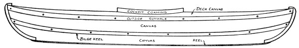
Fig. 212.—The Canvas Canoe completed.
For a finish to the upper edge of the canoe,
Outside Gunwales should be attached outside of the present ones. These will cover the joint between the canvas of the deck and the lower portion of the framework. All of these outside strips should be fastened in place with the[Pg 216] round-headed screws, after which they should be painted. Figure 212 shows the canoe completed.
A Seat is desirable for the bottom of the canoe, for comfort as well as to prevent your feet from wearing out the canvas. This seat should be movable, so it may be taken out to drain the water from the bottom of the canoe, and may be made as shown in Fig. 213. Batten together two six-inch boards upon their under face and notch the two side edges to fit over the ribs of the framework (see Fig. 207).
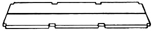
Fig. 213.—Seat.
In order to keep your canoe in good condition, do not allow it to remain in the water for any length of time when not using it, as the canvas would soon rot by doing so. After a spin, pull it out of the water, and turn it upside down to dry; then put it away under cover to remain until again wanted for use.
With the greatest of care a boy will puncture his canoe once in a while, so it is a good idea for him to know
How to mend Punctures.—There are several ways of doing this, but the best is by either sewing a piece of canvas over the puncture and then painting it with white lead, or daubing the canvas around the hole with varnish, and then laying a canvas patch over it and varnishing it.
The making of a well-shaped paddle is no easy matter[Pg 217] for an amateur to accomplish, so it is advisable for a boy to procure
A Hand-made Single Paddle, such as can be bought for a dollar and a half. This is generally made of selected spruce, with a copper-tipped end, and is nicely finished. The length of the paddle will depend upon the size of the boy who is going to use it, but should be between four feet six inches and five feet.
It may be well to warn those who build canvas canoes about the ease with which they are overturned. As long as the boy remains seated he is perfectly safe, but the moment he attempts to change his position, he need not be surprised if he receives a ducking. Upsets are common in canoe-racing, and especially in a close finish, where one paddler after another overbalances himself in his efforts to beat out his companions. But these only add to the fun of such a race, and no harm is done if the canoeist prepares for them beforehand by putting on his bathing suit.
Trapping and trap-making is, and probably always will be, a pastime which every boy enjoys. If he lives in the country or near the woods he is sure to grow fond of the wild creatures around him, and spend some time in following their tracks and watching their ways and habits. If he is a city boy he may not have these advantages, but is probably just as much interested in the study of birds and animals as his country cousin is, and when the opportunity presents itself will slip off to the nearest woods to spend the day with his little friends, and perhaps carry one or two back home to share city life with him.
When boys wish to trap animals for pets, or for eating while camping, or when they have become so numerous in a locality as to be a nuisance, it can be considered clean sport; but as soon as they begin to trap and kill them just for the fun of it, without deriving any good whatever from the act, they are guilty of a great cruelty.

Fig. 214.—Stick for the Figure-four Trap.
The various forms and schemes for home-made traps that have been devised, and which are to be found in use[Pg 219] by boys all over the country, are countless, but there are of course a number of these which are more effective than others, and some which have gained more favor among boys. Several years ago the author wrote an article upon traps, and has since been more than pleased to note the success boys have had in making and using them. With a few additions, the same schemes have been embodied in this chapter, and it is hoped that the several kinds of snares and traps will prove as satisfying to the majority of boy trappers. They are all simple to make, require but the material ordinarily at hand, and are effective for most of the smaller species of animals, and many varieties of birds.
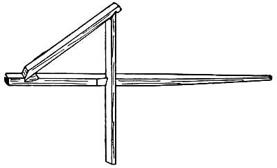
Fig. 215.—The Figure-four.
One of the oldest forms of traps, and one of which every boy should understand the construction, is
The Figure-four Trap.—It is about the simplest example, and its principle will be found in the schemes of a great many of the more complicated traps. For this the preparation of three sticks, such as are shown in Fig. 214, will be necessary. These sticks may be made[Pg 220] of any length you wish, but their proportion should be about as shown in the drawings. The illustrations show clearly how the sticks should be notched, and how one end of the trigger should be tapered for the bait. Fig. 215 will explain the manner in which these sticks are placed together in the form of a figure-four. The rest of the trap consists of a soap-or cracker-box with the cover hinged to it.

Fig. 216.—The Figure-four Trap set.
To set the trap, place the box upon the ground, cover down, and rest its upper edge upon the top of the figure-four, as shown in Fig. 216. When putting the figure-four together, it is necessary to hold the sticks until the box is set upon them, as the weight is required to hold them in position.[Pg 221] For squirrels and rabbits, for which this trap is very good, bait the trigger with a carrot, piece of apple, or cabbage leaf. It is easy to see that the slightest nibble at the bait will disarrange the sticks, and cause the box to drop over the game.
In Fig. 217 is shown an invention of the writer's, a simplified form of the much-used
Box Trap, having the principle of the figure-four involved in its trigger. This trap has proven exceptionally good for rabbits and squirrels.
A small box about the size of a cracker-or soap-box should be procured for the making of this trap. Remove one end, and, after nailing it to the cover boards, hinge the latter to the end of the box, as shown in the illustrations (Figs. 217 and 218). With no hinges at hand, the writer has found several nails driven through the[Pg 222] ends of the cover boards sufficient to hold the cover while opening and closing it. Bore two holes, one over the other, in the back of the box, and cut out the space between. This makes a rectangular slot (see D in Fig. 218). When this has been done, take a stick about eighteen inches long, and, after tapering one end, nail it to the box cover, allowing the tapered end to project about nine inches. Then prepare a trigger twelve inches long, similar to Fig. 219.

Figs. 217-219.—A Box Trap.
The trap is now ready to set, which is done by slipping the trigger into the slot at D and, after baiting it at C, catching the notch B on to the box at the top of the slot, at the same time fitting stick E into the notch at A (see cross section, Fig. 218). The weight of the cover will now hold the trigger in place until "bunny," or some one of his neighbors, attacks the inviting bait. Then the trigger will loosen its hold at B, and cause the cover to fall over the intruder. A few holes may be bored in the side of the box for ventilation, but these, as well as the slot in the back, should be protected with tin, to prevent your captive from gnawing the openings large enough to escape.
The Dead Fall is a trap commonly used for skunks, minks, muskrats, and coons, and probably cannot be excelled as a means of killing off destructive and annoying animals. Figure 220 shows a form of this trap which has been successfully employed.
First make a pen out of stakes driven well into the[Pg 223] ground in the form of a wigwam. This is a guard for the bait, and should be open on one side only, as shown in the illustration.
Place a short log in front of the opening, and at both ends of this drive a stake against the outer face of the log, as shown in the drawing. Then procure a log of the same diameter, and about six feet long, and slip it between these stakes and the wigwam, so it falls upon the first log. Cut a forked stick about twelve inches long for the bait-stick, notching one end and tapering the other, as shown in Fig. 221, and cut another stick twenty-four inches long and flatten it at both ends.

Fig. 221-220.
To set the dead fall, raise an end of the upper log and slip one end of the flattened stick under it, resting it upon the top of the stake outside of the log. Place the bait-stick, point downward, inside of the pen upon a chip[Pg 224] of wood, and set the other end of the flattened stick in the notch (see illustration). The bait-stick should now be in such a position that the log above it will fall when the bait is tackled, and strike its victim on the head or neck with sufficient force to kill it. For baiting this trap, use some food of which the animal is particularly fond.

Fig. 222.—The Coop Trap.
The Sieve Trap.—This is a most simple form of trap, consisting of a sieve and a short stick with which to prop up one side of it. Fasten a long cord to the stick, and, after scattering grain beneath the sieve, carry the end of the cord to a place of concealment to await the appearance of some birds. As soon as these are attracted by the grain, and begin feeding under the sieve, pull the cord and they will be your prisoners.
The Coop Trap, shown in Fig. 222, can be used for trapping the larger variety of birds. This is well known[Pg 225] as an effective trap for wild turkeys. It consists of a number of sticks piled up in the form of a pyramid and tied together as shown in Fig. 222. Dig away enough of the ground under one side of the coop to allow a bird to enter, and then scatter some grain inside and a little in the entrance to attract the birds.

Fig. 223-226.
A Rabbit Snare and Twitch-up.
It may seem strange to the reader, but it is nevertheless a fact, that, after entering the coop, a bird will try to fly out of the top, and will remain there until starved to death, if not released, without attempting to escape by the way it entered.
A Rabbit Snare.—This can be used to the best advantage after the first snowfall, for the footprints of a rabbit are then easy to follow. Bunny can be counted[Pg 226] upon keeping in the same path to and from his burrow, and a snare set in the centre of his path is pretty certain to catch him before very long. The snare should be made of a piece of soft wire about two feet long. Make a noose in one end about four inches in diameter, and fasten the other end to a branch projecting over the path (see Fig. 223).
This noose is commonly attached to what is known as
A Twitch-up, or a sapling bent down and held as shown in Fig. 224. One of a number of schemes employed for holding the sapling in position is here shown. Select a spot a few feet from a sapling, and there make an enclosure about twelve inches in diameter. This should be made of twelve-inch sticks driven into the ground in a circle, leaving an opening of about six inches on one side. Drive a stake into the ground on both sides of the entrance, and cut a notch in the outer face of each about six inches above the ground (see Fig. 225). Find a twig somewhat similar to the one in Fig. 226, and, after slipping it into the notches and baiting the prong, fasten the noose and sapling to it. With the trap thus set, a slight pull on the bait dislodges the crosspiece, and the sapling springs up, jerking the animal into the air, and causing its death almost instantly.

Caught at Last.
Ranchers of the Western plains and mountains are continually experiencing severe losses from the attacks [Pg 227]of wolves and coyotes upon their live-stock, and to rid themselves from the nightly raids of these animals requires unceasing warfare against them with traps. But the wolf and coyote are very crafty fellows, and extremely keen-scented, so that even professional trappers have trouble in capturing them, often resorting to every scheme they can devise without success. Steel traps are generally employed by the professional, as they are less cumbersome and quicker to set than the home-made affairs. The traps are handled with gloves, as the touch of the bare hands would be instantly detected by the wary animals, and, after being placed in a circle around the bait, are covered over with leaves and brush. In order not to leave human footprints behind him, the trapper often sets them while mounted upon horseback.
Not long ago, a trapper was hired by a rancher in New Mexico to capture some Loboe wolves which had been making serious raids upon the cattle, and one of his experiences while working there was somewhat laughable, though probably not seen in that way by all the parties concerned. Using a dead calf for bait, the trapper dragged it to a selected spot, and there surrounded it by eight or ten traps, which he chained fast to stakes, and carefully hid from view. Setting out to visit the traps as usual, on the following morning, he mounted a knoll from which he could see the location of the bait, and there plainly made out that a number of his traps had been sprung and were occupied. But upon reaching[Pg 228] the spot, his surprise and disgust can be imagined when he found a dog in one trap and a bad-tempered Indian held fast by the clutches of three others. After releasing the captives, the trapper gathered from the Indian's half-broken English that he had been riding by on the previous night, and his dog had wandered from the trail and sprung a trap. He had then dismounted to release the animal, but had not taken more than half a dozen steps before his foot became clutched in a trap, the force of which threw him forward, and, in trying to break his fall with his outstretched hands, each became securely clutched in traps. Fortunately no wolves made their appearance, and the couple were unharmed; but the Indian no doubt spent a sleepless and uncomfortable night in the position he was forced to occupy.
Some of the old war engines used in Europe before the introduction of
gunpowder were most ingeniously contrived, and were wonderfully
effective, considering that their projective force was obtained by means
of springs and levers. It is hard to find many good examples, as
authorities have badly confused them, but the writer has been fortunate
in securing drawings of what he believes to be pure types of the most
commonly used guns. These are reproduced on page 230, believing that the
average boy will be interested to see the kind of weapons that were
employed in warfare centuries ago. With a little study, the working of
these guns will be clearly understood without further explanation than
what is given upon the drawings. The catapult (Fig. 227) and the
trebuchet (Fig. 228) were used for storming fortifications, and each
hurled large stones. The trebuchet was a much later invented machine
than the catapult, and, being built on a much larger scale, was more
powerful. It is claimed that trebuchets were often built large enough to
hurl carcasses of horses into an enemy's [Pg 230]
[Pg 231]fortifications. The ballista
(Fig. 229) was in reality a large cross-bow, built to shoot long, heavy
bolts or arrows. The illustration shows a form mounted upon wheels for
field service. The cross-bow (Fig. 230) was a weapon used by the
foot-soldiers of a number of European countries. It was in use in
England for some time, but, on account of the terrible wounds inflicted
by its short barbed arrows, was finally forbidden and superseded by the
long-bow.

Figs. 227-230.—Examples of Ancient Guns.
Some ideas for the making of toy shot-guns and pistols, worked by springs and levers much the same as the ancient guns, will be appreciated by the boy who is denied the use of firearms. The schemes illustrated and described on the following pages will be found easy to carry out, and such as will furnish enjoyment for many a day in the woods or back-yard.
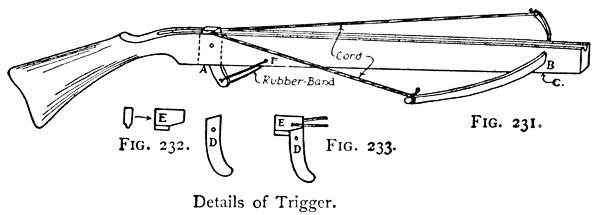
Figs. 231-233.—A Cross-bow.
Figure 231 shows a new idea for
A Cross-bow.—The stock for this should be cut out of a tongued-and-grooved board, with the groove running[Pg 232] along the top, and a mortise should be made at A in which to set the trigger. This mortise should be about two inches long and as wide as the thickness of the board will permit, and is made by boring a couple of holes through the stock at this point, and cutting out the wood between with a chisel. Select a strong barrel-hoop for the bow, and fasten it at its centre in a hole cut for it at B, driving a nail into it at C. The trigger should be made similar to D in Fig. 232. Cut block E out of a piece of tongued board, leaving the tongue to fit the groove in the gunstock. Notch the bottom to fit over D (see Fig. 233). Place a tack in each side of the block, and run cords from them to the end of the bow. These cords must be of such a length that the bow will bend almost to its limit when block E is placed over the trigger. A heavy rubber band should be attached to the lower end of the trigger, and to a tack at F. This must be strong enough to cock the trigger.
The cross-bow will shoot either pebbles or arrows, but the latter are the most satisfactory.

Fig. 234.—Shingle Arrows for Cross-bow.
Shingle Arrows are very good, as they shoot straight, and are so quickly made as to be easily replaced by a fresh lot when lost or broken. Mark them out as shown in Fig. 234, with the head at the thick edge of the shingle and the tail at the thin edge, and cut them out with your[Pg 233] jack-knife. The head and tail are made flat on one side, so as to lie flat in the groove of the gun.
A Toy Pistol can also be made out of a tongued-and-grooved board. Some such shape as shown in Fig. 235 should first be drawn upon the board, with the groove extending along the top. Cut this out with your jack-knife, and make a mortise for the trigger. Cut the trigger similar to Fig. 236, fastening it in place with a brad driven through it at A. It will be noticed that the trigger is notched at both ends. These notches are for a rubber band, which should be stretched from the upper notch of the trigger, over the muzzle, and around to the lower notch, as shown in the drawing. The rubber band lies in the groove in the top of the pistol.

Figs. 235-237.—A Toy Pistol.
The Bullets for this pistol consist of pieces of cardboard cut into small squares. To load the pistol, slip one of the squares through the rubber band as shown in Fig. 237, so that it rests on top of the groove, as shown in Fig. 235. Upon pulling the trigger the bullet will shoot out of its position, and though naturally one might think the loop of the rubber band would catch[Pg 234] the card, it is not the case. The card frees itself and travels in a straight line in the direction in which the pistol is aimed. It is advisable to keep this pistol out of range of your companions' faces.
A Shot-gun can be made on the same scheme as the pistol, by cutting a stock the size of that used for the cross-bow (Fig. 231), and fastening several rubber bands together to extend around the added length.

Fig. 238.
An Elastic Sling made with a wire framework, as shown in Fig. 238, is an improvement over the one made out of a tree crotch, as it is not easily broken. About No. 12 wire, which is the thickness of eight-penny nails, should be bought for this. With a pair of pincers, bend it into the shape shown in the drawing, with loops at A and B. Wrap the handle with cord, and attach strong rubber bands to A and B, with a piece of shoe leather or kid glove set in between, at C.
A most satisfactory scheme for

Fig. 239.—A Barrel-hoop Target.
A Boy's Target is shown in Fig. 239. It consists of a barrel-hoop, fastened by means of staples to a wooden[Pg 235] platform, as shown in the illustration. Pack the inside of the hoop with earth which has been moistened sufficiently to make it hold together, and place a piece of paper over it, pasting it to the edges of the hoop. The paper will be stretched as tight as a drumhead when dry. Five rings should then be painted upon it, as shown in the illustration. Fasten screw-eyes in the top of the platform, and hang the target by these wherever you wish to use it.
By preparing several sheets of paper, a fresh piece may be pasted over the hoop after one has been filled with holes. The earth will prevent the paper from splitting, and will be soft enough for the end of an arrow to stick into. Should the earth become too dry, it may be moistened each time a new paper is put in place.

Fig. 240.—A Simpler Target.
A Simpler Target, and a scheme which will answer a boy's purpose, if he does not care to go to the trouble of making the hoop target, is shown in Fig. 240. A circular piece of cardboard, with five rings painted upon it, is tacked to the end of a broom-handle, and this is stuck into the ground.
Points are Scored in target shooting as follows: Bull's-eye[Pg 236] 9 points; second ring, 7 points; third ring, 5 points; fourth ring, 3 points; fifth, or outside ring, 1 point.
The Bow and Arrow is always popular with boys who are forbidden the use of guns. Authorities claim that the best materials from which to make bows are mulberry, sassafras, Southern cedar, black locust, black walnut, apple, and slippery elm, in the order named; but if a boy selects what appears to be a good sound piece of wood, with straight grain, he has something which will suit the purpose.

Fig. 241.—A Boy's Bow.
The Length of the Bow should be about the height of the person using it. Figure 241 shows a five-foot bow, with the other proportions such as are on makes to be found in the stores. Cut your piece of wood five feet long, and, after placing it in the bench-vise, shape it down with a draw-knife or plane until it is one inch wide by one-half inch thick at the handle and three-quarters of an inch wide by one-quarter inch thick at the ends. The bow can be made round on the inside or face toward the archer, and flat on the outside or face away from the archer, or the two faces may be made round. Cut a notch in the bow two inches from each end, as shown in the illustration, from which to attach
[Pg 237]The Bow-string.—A cord with as little elasticity as possible should be used for this. If you care to spend the money for it, a good cotton string can be purchased from a dealer in archery goods for twenty-five cents. With a home-made bow-string, a loop should be made in one end and bound with thread, as shown in Fig. 242. Slip the loop over the upper notch, bend the bow until the centre of the string is about five inches away from the handle, and attach the loose end to the lower notch by means of a slip-knot similar to that shown in Fig. 243. The bow should be sand-papered until smooth, and thoroughly oiled with linseed-oil. A piece of velvet about three inches wide should be glued about the centre for a handle.
For a five-foot bow, cut
The Arrow-shafts twenty-four inches long and one-quarter inch thick. Whittle them out of straight-grained strips of wood, round them nicely, and cut a notch in the ends large enough to fit over the bow-strings.
It is not supposed that boys would care

Fig. 242-243.
Bow-string Ends.
To Prepare Arrow-heads of stone or bone as the Indians did, for there are other schemes that are simpler to carry out. If the wood is reasonably hard, the heads can be cut on the ends of the shaft, as shown in Fig. 244. For target practice, a wire nail driven into the end of the[Pg 238] shaft, as shown in Fig. 245, with the head of the nail filed off and pointed, has proven very good, and a thick piece of zinc or lead, cut the shape of A (Fig. 246) and set into a slot cut in the end of the shaft, with cord bound around the shaft to hold the metal in place, makes another excellent head. The metal points should be used only for target practice, and then with proper care, to prevent injury to yourself or companions.
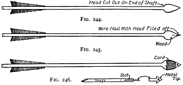
Figs. 244-246.—Schemes for Arrow-heads.
Feathering is the next operation. Turkey or goose feathers are generally used, but the former is considered the better of the two. Strip off the broader side of the vane of three feathers, and glue them to the shaft one and one-quarter inches from the notch, spacing them equidistant from one another. One feather should be placed at right angles to the notch. This is known as the cock-feather, and should always point away from the bow when the arrow is shot.
[Pg 239]A Quiver of some sort should be provided, large enough to carry a dozen or more arrows, and this should be three inches shorter than the arrows, so that their ends will project above the top. It may be made out of any thick cloth, as shown in Fig. 247. A circular piece of cardboard is placed in the bottom to which the cloth is sewed, and a piece of heavy wire, bent into a circle, fits in the top to keep the bag open. The quiver should hang on your right side, being suspended by means of a cloth strap long enough to pass over the left shoulder.

Fig. 247.—A Quiver.
To Shoot with the bow, take the position shown in Fig. 248, with both feet flat upon the ground, and the heels in line with the target. Hold the handle of the bow in the left hand and place an arrow on the left side of the bow, slipping the bow-string into the notch and letting the head of the arrow rest upon your left hand. Catch the bow-string with the first three fingers of your right hand, so that the end of the arrow comes between the first and second fingers, and draw the string until the head of the arrow rests upon the left hand; then aim quickly and let go of the arrow. By always taking the same hold upon your bow and arrow, you will soon be able to know just where the arrow is going to strike.
[Pg 240]The boy who has had the hobby of collecting Indian arrow-heads has no doubt often wondered how they were made, and also how the bows and arrows were prepared. The ways in which all uncivilized people do things is interesting, and especially when it is remembered that they had but raw materials with which to work and only such tools as they could make out of stone.

Fig. 248.—Correct Position for Shooting.
The Indian's Bow was made of different woods, and, though it varied in shape and size, was generally about forty inches in length, so as to be conveniently carried and handled on horseback. The bow-string consisted generally of a deer sinew or a strand of deer-skin rolled or twisted, and this was strung very tightly from a notch cut on one end of the bow to a notch on the opposite end. Now, while an Indian generally made the greater part of his weapons, there was always a warrior in the tribe who was skilled in the art of arrow-making, and, as the preparation required far more care than the bow, he was intrusted with this work. The arrow-shaft was made of various woods,[Pg 241] reeds being often used, as they were straight and required but little cutting. Their lengths depended largely upon that of the bows.
For the feathering of the shafts, wild turkey feathers were considered best and used when they could be had, and these were attached to the shaft with deer sinews.
A great variety of materials were used for arrow-heads, among which flint, obsidian, horn of deer, claws of eagles, and the spurs of wild turkey-cocks may be mentioned. Many of these are being picked up annually in the mountains and on the plains, which were once the battle-fields and hunting-grounds of the redmen, and in excavating for building purposes they are frequently found. A few specimens of stone heads showing a variety of the shapes and sizes used will be found in Fig. 249. The preparation of these heads was usually left to the old men who were unfit for any other work.
[Pg 242]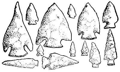
Fig. 249.—Some Specimens of Indian Arrow-heads.
In making the flint head, the Indian made a loop in a piece of buckskin which had been thoroughly wet in cold water, and then taking a piece of flint, heated it, and with the strip of buckskin chipped off what was not wanted until the head was of the correct shape and size. As hornstone is more brittle than quartz, the heads made from that material were broken and shaped by striking them against the latter. The stone heads were attached to the shaft by means of sinews, generally from deer. For hunting small birds, the Indians often made wooden arrow-heads, hardening the wood by fire after shaping it.
With a little work, and a small outlay of money chiefly for two-by-fours, and such boards as are specified in this chapter, a boy, or club of boys, can construct and set up all the necessary apparatus for an outdoor gymnasium. It is true a great many city back-yards are much too small to accommodate all of the apparatus; but there is generally a vacant lot in the neighborhood which you can obtain permission to use. Those of you boys who are fortunate enough to spend the summer months in the country have splendid opportunities for making a complete gym and should not miss the chance to fit one up.
A Horizontal Bar.—A well-made horizontal bar requires a firm standard which will not sway when swung upon. This is best attained by fastening at least one upright to the side of the barn, the fence, or some other stationary object. It is also very important to secure a strong bar free from knots and cracks. Curtain-poles are frequently used by boys, but at great risk, as there may be a dangerous knot lurking beneath the highly polished surface[Pg 244] that will break at a critical moment and cause them serious injuries.
A four-foot hickory or ash bar can be bought from a dealer in sporting goods for about a dollar and a half, but it will cost much less to have a bar turned to the right shape and size at a planing mill. The diameter of the pole should be an inch and one-half, and the ends should be two inches square (see Fig. 250).
For the uprights procure two two-by-sixes nine feet long. Mark off a square equal in size to the end of the bar, six inches from one end of each, and cut out the wood with an auger. With a chisel trim the holes square and large enough for the bar to slip through.
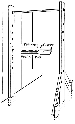
Figs. 250-251.—The Horizontal Bar.
Sink the lower ends of the uprights twelve inches[Pg 245] into the ground, A against the stationary object, whatever it may be, and B directly in front, at a distance equal to the length of the bar. Spike A to the abutting surface, and brace the base of B with two two-by-fours to make it solid (see Fig. 251). The tops of the braces should be mitred against B, and the bottoms spiked to stakes driven into the ground, as shown at C. To make it possible to adjust the bar to different heights, holes may be cut in the uprights every foot or so, in which case be careful to locate the holes exactly opposite one another.
It is well to have an old mattress beneath the horizontal bar as a guard against injury in case of a fall. This also makes a splendid
Tumbling Mat for practising rolls, hand-springs, and wrestling. If a mattress cannot be obtained, a few potato sacks stuffed with shavings or excelsior will answer the purpose.
The most satisfactory scheme for making a pair of
Parallel Bars is shown in Fig. 252. To acquire the necessary firmness without putting in bracing that would interfere with the performer, the base of the apparatus should be set underground, as indicated by the dotted lines in the illustration.
In height the parallel bars should be about four feet six inches, in length seven feet six inches, and in width twenty inches between the bars. This makes the uprights A, B, C, and D six feet long, allowing eighteen[Pg 246] inches to project into the ground. Prepare one end of each as shown in Fig. 253, notching it for the bar to fit in and cutting off the corner.

Fig. 252.—The Parallel Bars.
When this has been done, cut four two-by-fours twenty-eight inches long. Then lay the uprights A and B on the ground twenty inches apart, and spike two of[Pg 247] the two-by-fours to them at G and H (see Fig. 254). Uprights C and D should be similarly fastened together with the other two-by-fours at I and J (see Fig. 252). When these frames have been made, set them upon their bases six feet apart, and spike the two-by-fours K and L to the uprights in the places shown in Fig. 252, with braces set between them and the pieces H and J, at M, N, O, P (see Figs. 252 and 255).
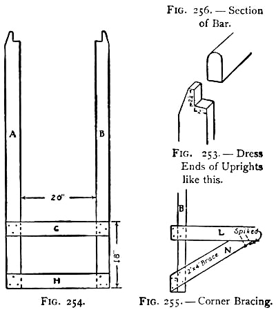
Figs. 253-256.—Details of Parallel Bars.
The bars should be seven feet six inches in length, and cut out of Georgia pine two-by-fours. Figures 252[Pg 248] and 256 show how these should be dressed, the tops rounded to fit the hands and the ends curved. First roughly shape them with the draw-knife, then smooth up with the plane, and finally scrape and rub them down with sand-paper until perfectly smooth. When the bars have been prepared, slip them into the notches cut in the uprights, and spike them in place.
With the constructive work done, it is only necessary to bury the base to complete the apparatus. Excavate a trench eighteen inches deep, and level off the bottom. Then lower the framework and, after determining that the bars are level, fill in the earth, packing it well against the uprights and braces. Boards E and F should be laid across the top of G and I, and spiked in place.
The Punching-bag Platform, illustrated by Fig. 257, should be made thirty inches square and suspended from the shed or a wall.
Nail a thirty-inch piece of two-by-four to the wall, two feet above the height at which the platform is to be placed, as at A in the drawing, and nail another on a level with the top of the platform, as shown at B.
Fasten the platform boards together with battens, using nails long enough to clinch on top of the upper face, and nail the two boards C and D to the edges, mitring the edges as in the figure. Then lift the platform to the desired height, and fasten the ends of C and D to the ends of A. Also nail the bottom of the platform to the under side of B.
[Pg 249]A swivel such as shown in Fig. 258 can be bought for forty or fifty cents, and one of these should be screwed to the bottom of the platform, from which to suspend the punching-bag.

Fig. 257.—A Punching-bag Platform.
A Pair of Jump Standards are made out of two two-by-fours about eight feet long. After planing them smooth on all sides, measure off two feet from one end of each, and mark off the remaining six feet in inches, as shown in Fig. 259.
After squaring these divisions across the poles with your try-square, bore holes three-eighths of an inch in diameter through the poles at each division. Then, with a small brush and black paint, mark off each foot with a band extending around the pole, each half foot with a[Pg 250] narrower band, and each inch with a short line, as shown in the drawings. Letter the foot divisions 1, 2, 3, 4, etc.
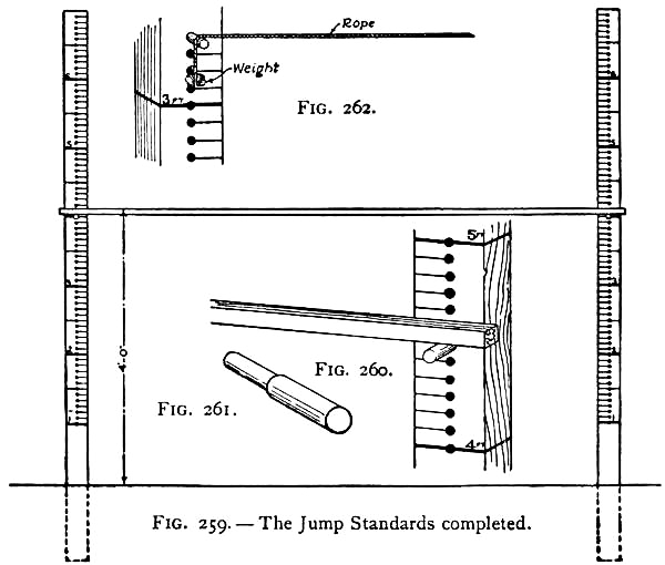
Figs. 259-262.—Details of Jump Standards.
When both standards have been finished, bury them in the ground to a depth of thirteen inches, eight feet apart. Cut two wooden pegs similar to Fig. 261 to fit the holes, and procure a nine-foot pine or hickory pole one inch thick for a cross-bar (see Fig. 260). When the bar is placed upon the pegs, the distance from its top to the ground should correspond with the figure on the upright.[Pg 251] If not the same, raise or lower the uprights until the error is corrected.
With a pair of these standards there is no danger of injury by tripping over the bar, as the latter will fall off with the slightest knock. There is one disadvantage in using a stick, however, it being easily broken if jumped upon. Because of this, a rope with a weight attached to each end, as shown in Fig. 262 is often substituted. The ends of the rope are hung over the pegs in such a way that it will slip off the pegs when struck. The weights should be just heavy enough to prevent the rope from sagging in the centre.
A Vaulting Pole should be made of a strong wood, free from knots and other defects. The regulation pole is made of selected spruce, its length varying from eight to fourteen feet. If you make your own pole, be careful to plane off all splinters and irregularities, making it round and smooth, and point one end so it will stick into the ground and prevent slipping.
Although seldom used in an outdoor gymnasium,
A Spring-board is excellent for practising the high and broad jumps, and is a piece of apparatus with which a great deal of fun may be had. Figure 263 shows a scheme for a spring-board that is easy to make. First cut three pieces of two-by-four two feet long, lay them on the ground parallel to each other eighteen inches apart, and construct a platform four feet long by two feet wide on top of them.
[Pg 252]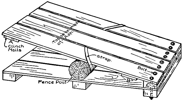
Fig. 263.—A Spring-board.

Fig. 264.
Cut another two-by-four two feet long, taper it as shown in Fig. 264, making it two inches thick on one edge and an inch and a quarter on the other, and nail it to one end of the platform. Secure a log two feet long (a cedar fence post will do very nicely), and fasten it across the centre of the platform parallel to the two-by-fours. The upper portion of the spring-board should be made of elastic boards, preferably ash. Construct a second platform six inches longer than the first, leaving about one-half inch between the boards, and battening the pieces together at A and B (see Fig. 263). Nail the battens securely in place, using nails of sufficient length to allow clinching on the under face of the battens. The clinching will prevent the boards from springing apart.
[Pg 253]This platform should be fastened to the first, with the end which has not been battened secured to the two-by-four at C. The best method of fastening the ends of these boards is with bolts long enough to extend through the two platforms and project an inch or more below the bottom two-by-four (see illustration). Large washers should be placed under the heads of the bolts to prevent the latter from cutting through the boards.
The upper platform should not be nailed to the log, but merely held to it by straps passed diagonally around the outside boards and log, as shown in the illustration.
Set the spring-board upon the spot you wish to use it, and bank up the earth behind it until a gradual slope is made from the ground to the top.
If any difficulty is experienced in keeping the spring-board in place, it may be overcome by driving stakes into the ground around the sides of the lower platform.
After setting up your gymnasium apparatus, oil the bars of the horizontal bar and parallel bars with boiled linseed-oil, and paint all the rest of the wood to keep it in good condition.
Hurdles should be lightly constructed, so as to be easily knocked over should a hurdler trip upon them. They are made similar to carpenter horses, directions for the making of which are given in Chapter I. Their height will depend upon the skill of the hurdler.
If the field is large enough,
A Running Track can be made around it, by levelling[Pg 254] off the ground, removing all stones and irregularities in its path, and banking up the corners to enable the runner to turn the curves readily.

Fig. 265.
For Short Sprints the most common method of starting is upon all fours, as illustrated in Fig. 265. Make a depression in the ground for the toe of the rear foot to press against in starting off.
For Broad Jumping, a block of wood two feet long should be sunk into the ground, as a mark from which to leap.
It is a good plan to organize
An Athletic Club among the boys of the neighborhood with which to raise money necessary to buy the material for apparatus, and
Athletic Meets may be held among the members and with other clubs.
Shortly after the founding of Rome, a large building was built within which to hold commemorations of Roman victories and anniversaries, with chariot races, bull-fights, gladiatorial contests, and athletic games; and from this building, which was called the "circus," this class of entertainment derived its name.
To keep up with the times, the circus has had to profit by every scientific discovery, adding continuously to its line of attractions, until now it is necessary for a show to produce a new, sensational, and hair-raising feat each season in order to keep in the favor of the public and compete with others in the field. The tight-rope walkers, bare-back riders, and trapeze performers were not long ago the main attractions of a circus, but these do not seem nearly as remarkable now when compared with such daring feats as looping-the-loop or looping-the-gap on a bicycle, riding down an incline on a single wheel, or diving from the peak of the tent into a small tank not more than six feet square, to be seen at the present day.
[Pg 256]When a circus came to town, it seemed but natural for the boys of our neighborhood to club together and arrange a performance on a small scale, but as nearly like that of the professionals as possible. A back-yard was transformed into training quarters, and here we worked hard for several days before the show, imitating as best we could the stunts of the circus performers. Because one fellow could walk on his hands, and turn hand-springs, besides being the owner of a pair of tights, he naturally became the chief attraction; another had a pair of riding boots, so he was chosen ring master; a third made a bargain with his sister to cut him out a cheese-cloth costume, and was chosen to take the part of a clown,—and in this way each boy helped along the performance by contributing his best efforts.
The most successful shows were those in which a week or more was spent in rehearsing the performance and getting things in shape. Tickets and programmes were neatly printed by one of the members who owned a press, and the former were distributed among the boys and their friends to sell.
The first thing to do in preparing a yard for a circus, is to
Mark out a Ring in the centre, with a diameter as large as the yard will permit. This circle may be drawn on the same principle as that shown in Fig. 201, Chapter XV, using a rope at either end of which a stake has been attached. After describing the circle, secure[Pg 257] several six-inch boards sufficiently limber to enable you to bend them around the circle, and fasten them in place by means of stakes driven into the ground outside of the boards. The enclosed space should then be filled in with several inches of shavings, which you can procure from a carpenter if you have not enough in your own workshop.
Good Circus Seats can be made out of boxes eighteen or twenty inches high, with planks laid across their tops.
To give the back-yard a real circus appearance, we always thought it necessary not only to have a ring but also a tent over it and the grandstand, so we gathered together all the old awnings, tents, and carriage covers we could scrape up, and fastening these together with pins or heavy thread made
A Large Tent.—A ten-foot pole was sunk into the ground in the centre of the ring, and ropes were run from the top of this to the fence, after which the tent was fastened to the ropes and propped with poles wherever any sagging occurred.
Bright colored cheese-cloth was used
In decorating the Tent, and for evening performances Japanese lanterns were hung about the yard.

Figs. 266-267.—Ticket Office and Turnstile.
A Ticket Office should be built at the entrance to the yard. This can be made out of two boxes, one set on top of the other, as shown in Fig. 266. Cut an opening fifteen inches square in the front for a window, round the top, and make a guard of wooden strips[Pg 258] to fit it. Cut a slot in the counter, fastening a box beneath it in which to drop tickets, and for a cash drawer fasten strips to the under side of the counter, as shown in Fig. 266, so that a cigar-box will slide upon them.[Pg 259] To the top of the ticket office fasten a board cut the shape shown in the illustration, and print the word "Tickets" upon it. These letters may be illuminated for an evening performance by boring holes through them and placing candles behind (see Fig. 266).
A Turnstile should be made in front of the ticket office, so that all are obliged to pay their admission fee and pass through the turnstile before entering the tent (see Fig. 266; also illustration opposite page 268). The stile is made with two sticks about forty inches long fastened together at their centres, as shown in Fig. 267. This joint, known as
Halving, consists in cutting away one-half the thickness and the width of each piece so that the remaining portions fit together flush. After nailing the pieces together, bore a quarter-inch hole through the centre, and screw the crosspiece at this point to the top of a piece of two-by-four driven into the ground in front of the ticket office. The crosspiece should now revolve with the screw as an axis.
The turnstile should, of course, have a lock, and an arrangement similar to that shown in Fig. 266 answers the purpose. Cut a slot in the front of the lower box on a level with the top of the stile for the arms to run through (see illustration), and then prepare four blocks, such as A, B, C, and D in Fig. 268. Screw one end of B and C to the ends of A and fasten block D between the other ends of B and C, after which nail block A to[Pg 260] the under side of the counter in the position shown in Fig. 266. Prepare a lever such as is shown in Fig. 269, cut a mortise in the top of the counter for it to fit in (see Fig. 266), and pivot it to the side of the upper box. Place a screw-eye in the end of the lever and another in D, and connect the two with a piece of cord. Figure 266 shows an arm of the turnstile held by the lock, which is released by pushing back the lever. A railing should be built in front of the turnstile to block the passage on that side.
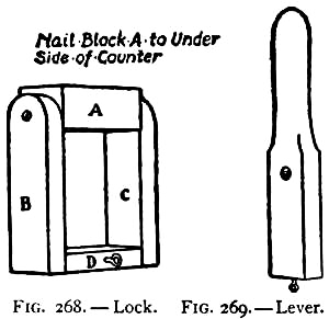
Fig. 268-269.—Lock.
The Side Show should be placed in one corner of the yard. The cages can be made out of boxes with either slats or wire-mesh fastened over the front, and the top or side hinged in place for a door. The animal performers of the circus should occupy these cages before the show commences, and to make the menagerie as large as possible, a few cages may be filled with pets borrowed for the occasion. Several closed boxes should be placed alongside of the cages, and lettered "Lion," "Tiger," or the names of some such ferocious animals as these, and the public should be informed that for their safety the management thought it best not to place these specimens on exhibition.
[Pg 261]Animated Animals generally have a place in every circus, and help out the clowns in their end of the performance. The animals are not difficult for handy boys to make, so several should be manufactured for your show. If you can get your mother or sister to do the necessary sewing, it would be well to secure her help.
The Elephant is one of the oldest forms of animated animals, and is at the same time one of the most popular. Four or five yards of gray cambric should be purchased for its covering.

Figs. 270-271.—The Elephant.
The cloth should be cut out like the pattern shown in Fig. 270, the correct measurements being secured from two boys who have taken the position shown in Fig. 271. Fold the cloth along the centre and then sew the dotted lines AA and BB together. Paper cornucopiæ[Pg 262] form the tusks, and the ears are made of gray cambric cut the shape shown in Fig. 271, and lined with heavy wrapping-paper to make them stiff.
Two boys are required for the elephant. These must bend forward, as shown in Fig. 271. The rear boy places one hand upon the front boy's back and wags the tail with the other, while the front boy runs one hand through the elephant's trunk and keeps it in motion. Fasten potato sacks on to your legs to make them as large as possible.

Figs. 272-276.—Details of Giraffe.
The Giraffe is one of the rarest of animals, and very few are to be found in captivity. In fact, a large circus claims there is only one specimen in this country, outside of a herd in their possession. So if you make a giraffe, which is not difficult to do, you will have a feature in your show that none but the very largest combines can afford. The animal's head should be drawn the shape of Fig. 272 on a board, and then cut out with the aid of a saw and draw-knife. The jaw, ears, and horns should be cut out separately, the shape of Figs. 273, 274, and 275. Bore two holes in the head at A, slanting them toward one another, and fit in them the pegs cut for the horns. The jaw should be pivoted with a small nail at B on one side of the head, and an ear should be likewise fastened at C on each side of the head. When these portions of the giraffe's anatomy have been put in place, stretch a rubber band from a tack driven in the top of the jaw to another tack driven into the neck (see[Pg 263] Fig. 272), and attach another rubber band similarly to each of the ears. These rubber bands will act as springs, causing the ears to wag and the jaw to open and close when the giraffe moves his head.

Fig. 277.—The Giraffe's Tail.
Paint the head, making the features as nearly like those of a giraffe as possible, and, when the paint is dry, mount the head on the end of a six-foot pole.
[Pg 264]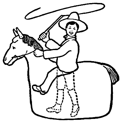
Fig. 278.—The Wild Man and the Wild Horse.
The covering for the body is made out of a large piece of tan cloth with brown spots marked upon it, as shown in Fig. 276. It is not necessary to give a pattern for this, as the illustration clearly shows how it should fit over the two boys who form the body, and hang from the headpiece. The neck should be stuffed out with excelsior. A short and a long stick should be nailed together, as shown in Fig. 277, and cloth should be sewed to the end of the short stick for the animal's tail. Stuff the tail with excelsior and fasten unravelled rope to the end, as shown in the drawings. The long stick should be held by the boy who forms the rear of the animal, so that by means of it he can manipulate the tail (see Fig. 276). As shown by the dotted lines in Fig. 276, the boy in the front portion of the animal holds the end of the pole supporting the animal's head.
[Pg 265]
Fig. 279.—Framework of Wild Horse.
An animated animal very often brought into a circus ring is the two-legged

Figs. 280-282.
Wild Horse, owned by the Wild Man of Borneo. This breed of horse is shown in Fig. 278. A framework is necessary for the body, and this is best made as shown in Fig. 279. Cut two four-foot strips for the side-pieces, fasten them two feet apart, with a barrel-hoop at either end and arch barrel-hoops over the back, as shown in the drawing. The head (Fig. 280) is made in the same manner as that of the giraffe, the jaws and the ears (Figs. 281 and 282) being cut out separately and pivoted in place similarly to those of the giraffe. Paint [Pg 266]the face, marking the eyes and nostrils, and make a mane and tail of unravelled rope. Having finished the head, mount it upon a short stick and fasten this to a crosspiece set in the framework, as shown in Fig. 279, bracing it with an upright fastened to another crosspiece. In fastening the various pieces of the framework together, it is well not only to use long enough nails to clinch, but also to bind each joint with wire or cord to make it stiff.

Fig. 283.—"Jocko."
Purchase brown or black cambric for covering the framework. Tack it to the wooden strips, leaving an opening in the top for the rider to stand in, and allow it to hang to the ground as shown in the illustration, so as to conceal the feet of the rider.
The Wild Man should wear an old slouch hat and a hunting jacket, and should have a pair of false legs fastened to him, so that while his own are inside the framework, as shown by the dotted lines in Fig. 278,[Pg 267] they appear to be astride. To make the false legs, cut off the legs of an old pair of long trousers, stuff them with excelsior, and fasten a pair of shoes to the ends. These legs should be fastened to the hips of the rider. The framework should be held to the rider by means of ropes tied to the side strips, as shown in Fig. 279. These should be long enough to cross the boy's shoulders in the same way as a pair of suspenders.

Fig. 284.—Jocko's Hat.
A Monkey's Make-up is shown in Fig. 283. The boy who is most apt at making a monkey of himself should be selected to take the part of this animal. In the first place he requires a red suit, which may be made quickly by sewing red cloth over an old coat and a pair of trousers. Cover the legs with a pair of tan stockings, and slip the feet into a pair of large gloves. The face and hands should be colored, and for this purpose buy some brown grease paint. In rubbing the paint over the face, leave a circle of white around the eyes and mouth, and make a brown mark each side of the mouth to give it a broadened effect. A tight-fitting cap should be made of cloth as nearly the shade of the brown paint as possible, to hide the hair. Figure 284 shows the monkey's hat, consisting of a tomato-can covered with red cloth, which is fastened around the monkey's chin by means of an elastic cord.[Pg 268] A piece of rope can be fastened beneath the coat for a tail.
The Ring Master should wear a high silk hat, a stand-up collar, and a pair of boots, besides being supplied with a long whip.

Fig. 285.—The Clown's Make-up.
The Clown's Suit is best made out of red and yellow cheese-cloth, this material being about as cheap as can be bought for the purpose. The suit consists of a pair of baggy trousers or bloomers, with elastic around the waist and ankles, a loose coat with large buttons, a collar, a skullcap, and a hat. Make the buttons out of red cheese-cloth and stuff them with cotton. The coat may be made of red and the trousers of yellow cheese-cloth, or both may be made of yellow with red polka dots sewed on to them, as shown in the illustration of his costume (Fig. 285). The collar is made of white cloth, lined with paper to make it stiff, and should be pleated around the neck to form a ruffle. A skull cap should be made out of white cloth to hide the hair. Make a peaked hat of stiff paper, and cover it with red cheese-cloth.
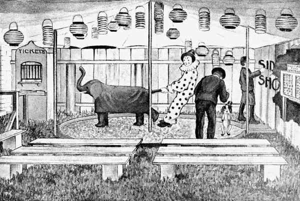
The Back-yard Circus.
When making up for a performance, the clown should powder his face, neck, and hands with magnesia, and draw expression marks upon his face with burnt cork, as shown in Fig. 285.
The Attendants for the elephant and giraffe should wear old bath robes or gowns, and have turbans made by twisting a piece of red cheese-cloth about the head.
By visiting any circus and closely watching how things are managed, it ought to be a simple matter to get enough
Ideas for a Performance that can be carried out with the animals and performers described in this chapter. The clown should, of course, have his usual supply of jokes, which he can get out of the comic papers, and should do his best to annoy the other performers. He should make himself
A Slapper, consisting of two sticks with a block slipped between at one end. This will produce a great deal of laughter among the audience, for when the slapper is struck against a performer the ends of the sticks strike together, making a loud, cracking noise, and one would hardly believe that a stinging blow had not been dealt. The clown attempts the tricks of the other performers, but always fails or gets them very badly mixed.
A startling feat to be announced upon the programme will be
Looping the Hoop on a Giraffe.—This stunt is performed by the elephant, who is given a number of barrel-hoops,[Pg 270] which he tosses by means of his trunk over the giraffe's outstretched neck. The elephant and giraffe should always be entered in a race, which will prove exciting, inasmuch as your specimens will be evenly matched.
The monkey may do almost anything and be amusing. Swinging upon a turning-pole, teasing the animals, boxing with the clown, and climbing a rope, are all his specialties. Then he should have
A Chariot within which to ride around the ring. This can be made out of a soap-box, as shown in Fig. 286. Cut down the sides, as in the illustration, attach two shafts to the bottom, and mount it upon a couple of small wagon wheels. When this has been done paint the wood a bright red, and cut stars of different sizes out of gilt paper and glue them all over the outside.
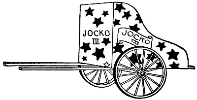
Fig. 286.—Jocko's Chariot.
The ring master acts as manager of the performance,[Pg 271] and should use his whip unsparingly upon the animals, to force them into obedience.
If a boy can turn upon a turning-pole, an apparatus such as is described in Chapter XVIII may be set up outside of the ring.
Before performances, the entire circus—animals, acrobats, and showmen—should parade about the neighborhood in circus attire. We always made the
Parades a feature of our circuses, and found them not only great sport, but the best kind of advertising. The animal cages should be placed upon wagons decorated with flags. Head the procession with a couple of drummers, and have two boys march in the rear carrying signs advertising the show.
The Advertising Signs may be painted with bluing upon large pieces of manila wrapping-paper, and should be tacked on wooden stretchers mounted on poles.
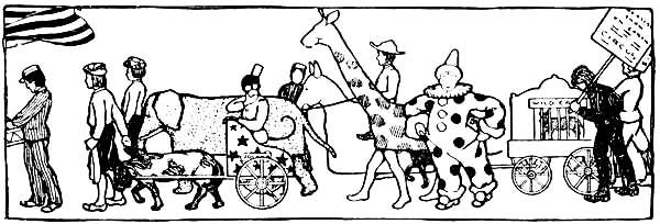
As most boys probably know, the first Fourth of July celebration took place in 1775, following the signing of the Declaration of Independence in Independence Hall, Philadelphia. When the old bell rang forth the result of the meeting of the Continental Congress, citizens gathered in the streets and displayed their great joy by shouting, beating drums, and firing muskets. The news spread very rapidly, and great rejoicing reigned everywhere. It soon became a custom to celebrate annually this famous event, and it should be every boy's privilege to have a rollicking good time upon this day, making as much noise as he pleases.
When the average boy has bought a few sky-rockets, Roman-candles, and cannon-crackers, for the Fourth, he generally finds, to his sorrow, that he has run out of pocket money. It is then that he is very apt to want to try his hand at making pyrotechnics. There are many publications which describe how amateurs may manufacture Roman-candles, sky-rockets, nigger-chasers, and such pieces, but it is hoped that no boy will venture to[Pg 273] carry out any such experiments, for, with the greatest of care, unforeseen accidents will occur which may result disastrously to him. At the same time, there is no economy in it, for the apparatus and materials will generally cost him more than to buy the fireworks ready made. This is also true of colored lights, for which there are many simple formulæ, but none of which can be made up as cheaply as the powders can be bought already prepared.
There are, however, many things a boy can make for the Fourth that are perfectly harmless, such as fire-cracker cannons and home-made set-pieces, besides different schemes for firing crackers and fireworks that he can carry out. The suggestions offered on the following pages will be found interesting, and they will probably suggest other ideas to the inventive boy.
The store toy cannon and cap-pistol are exceedingly dangerous for boys to use, and were all cities to pass laws forbidding their sale, as in the case of a great many of the larger cities, thousands of young lives would be saved from the terrible accidents resulting annually from celebrating with these toys.
In Fig. 287 is shown
A Fire-cracker Cannon with which a boy can have a great deal of fun and at the same time with no danger of injury. Cut the two gun-stocks similar in shape to Fig. 288, and the two wheels four inches in diameter (Fig. 289), after which bore holes in the gun-stocks at[Pg 274] A, and in the centres of the wheels, through which to run the axle. Procure a baking-powder can and make a couple of holes in the sides for the axle to run through (Fig. 290), and one in the bottom of the can the size of a fire-cracker fuse. Cut a conical piece of wood about two inches long and nail it to the outside of the can cover as shown in Fig. 291.
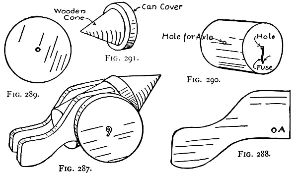
Figs. 287-291.—A Fire-cracker Cannon.
When the various pieces have been thus prepared, place them together as shown in Fig. 287, and slip a piece of heavy wire through the holes made in them, and bend over the ends of the wire to hold the wheels in place.
To fire the Cannon, place a cracker in the can with the fuse projecting through the hole in the bottom, and fit[Pg 275] the cover over the can. Then light the fuse. The exploding cracker will force off the cover, which is the projectile, and hurl it a considerable distance in the direction the cannon has been pointed.
A Toy Mortar may be made similarly, with the exception of the carriage or mortar-bed. Figures 292 and 293 show the details for this, which is different from a regular mortar, one end being enclosed for an ammunition box. Make a cover for the ammunition box to prevent sparks from igniting the packages of crackers, using pieces of leather for hinges. As shown in the section drawing (Fig. 293), the mortar-bed is mounted upon a small board, being held in place by means of a short screw, which makes it possible to swing the mortar around in any position desired.

Figs. 292-293.—A Fire-cracker Mortar.
These cannons and mortars will furnish sport not only[Pg 276] for the Fourth, but for any other day of the year, as they can be used by a crowd of boys in
Mimic Battles, with paper soldiers. The boys should divide into armies, and construct their fortifications about twenty feet apart, planting the guns upon the works and placing the paper soldiers behind. All paper soldiers knocked over are out of the game, and the side first completely killing the enemy's garrison is, of course, the winner of the day. These battles are always very exciting, especially toward the end, when there are but a few warriors remaining. In order that the projectiles may fit all the cans, it is necessary to have them all of the same size.
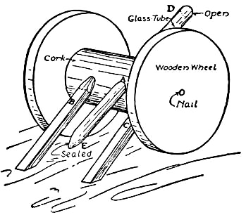
Fig. 294.—Another Toy Cannon.
Another Toy Cannon that is simple to make is shown in Fig. 294. For this, buy a short piece of glass tubing at a drug-store and have the druggist seal one end of it. Then secure a good-sized cork and cut a hole through the side large enough for the tube to run through (see A in Fig. 294). Cut out a pair of wooden wheels about three inches in diameter, and fasten them to the ends of the cork with a pin or small nail. Make the cannon shafts four inches long, point one end of each and stick[Pg 277] them into the cork at B and C. The open end of the tube should be at D and the sealed end at E.
To fire the Cannon, slip a match into the open end of the tube with the head toward E, and hold a lighted match at the closed end. As soon as the heat ignites the phosphorus, the match will shoot out of the open end of the tube.

Fig. 295.
Firing Fireworks from Kites presents a novel feature for a Fourth of July celebration, the aërial display making a very pretty spectacle, and the boy who sets off his fireworks in this manner will have something different from the rest of the neighborhood.
Figure 295 shows the manner in which a Roman-candle can be attached to a kite-string. A piece of punk about an inch and one-half long should be bound to the fuse of the candle, and as the fuse is rather short it is necessary to cut through the paper bound around it, and set the punk into the end of the candle, as shown in the drawing. Attach a piece of twine two feet long to the other end of the candle, and then, after getting your kite up, attach the end of this string to the kite-string and light the punk, being very careful in doing so not to ignite the fuse of the Roman-candle. After attaching the candle and lighting the punk, let out the kite-string as rapidly as possible, so that by the time the punk has burned down to the fuse end, the Roman-candle[Pg 278] will be well up in the air. As soon as the candle begins to explode, shake the kite-string so as to make the balls shoot into the sky in different directions.
A Pack of Fire-crackers with a piece of punk attached to the fuses may also be suspended from a kite-string and fired in mid-air.
Other fireworks may be set off similarly, and colored lights produce a fine effect.
Nigger-chasers shot into the air by means of a cross-bow, such as is described in Chapter XVII, present another novelty.
Japanese Lanterns hung from kite-strings are also a pretty sight, and, while they give somewhat the same[Pg 279] appearance as fire-balloons, they are lasting and can be saved for another year.

Fig. 296-297. Schemes for Attaching Lanterns to Kite-strings.
Fig. 298.—A Shooting-torch.
After procuring a number of lanterns of different shapes and sizes, fasten candles securely in them so that there is no possibility of them igniting the paper. Figures 296 and 297 show two ways in which the lanterns may be attached one below the other. The first method (Fig. 296) consists of pins stuck through the bottoms of the lanterns and bent over into hooks, while in the second (Fig. 297) a small hole is made in the bottom of one lantern and the wire handle of another is slipped through this hole and looped over a burnt match.
Before sending up the kite with these lanterns, make a number of small loops in the kite-string where you wish to hang the lanterns, and provide the handle of each series of lanterns with a pin-hook, as shown in Fig. 297. Then, when everything is in readiness, have one of your friends hook the lanterns to the loops while you attend to letting out the kite-string. Of course the smaller the lanterns are the greater number you can hitch in place, and if you use a team of kites you will find that they will carry a number of strings of lanterns.
A Shooting-torch, such as is shown in Fig. 298, is a scheme that is simple to carry out. It consists of a stick about eighteen inches long, with fire-crackers bound[Pg 280] around it with wire, and the fuses twisted together, as shown in the illustration. It is fired in the same way as a Roman-candle.
Fig. 299.—A Final Set-piece.
After firing all of your fireworks, you should have
A Final Set-piece with which to close the exhibition. A good scheme for such a piece is shown in Fig. 299. Mark out the letters upon a board, and, with a quarter-inch bit, bore holes about one half-inch apart along the outlines of each letter. Then cut enough sticks of punk two inches long to fit all of the holes, and put them to soak in kerosene. The oil makes the punk burn much brighter than it would in its dry state. When the punk is thoroughly soaked, stick the pieces in the holes. A candle will be found most convenient for lighting the punk.
Nail the board to a tree or post, and place several cannon-crackers in holes bored near the bottom of the board. After allowing the punk to burn for a short time, light the cannon-crackers and blow up the set-piece as a grand finish.
Halloween, or the eve of All Saints' Day, has been observed since the beginning of the Christian era. In very early times, ghosts, demons, and spirits were believed to rule the universe on this evening, and any one who ventured upon the streets after dark was doing so at the risk of his life. For companionship, as well as protection, it was customary for large numbers of friends to spend the evening together; and these gathered around the fire-place, and passed away the time drinking cider, cracking nuts, eating apples, and telling ghost stories.
While the superstitious fears of Halloween have almost entirely disappeared, the evening is generally celebrated in the same manner as in the past. This is the only evening on which a boy can feel free to play pranks outdoors without danger of being "pinched," and it is his delight to scare passing pedestrians, ring door-bells, and carry off the neighbors' gates (after seeing that his own is unhinged and safely placed in the barn). Even if he is suspected, and the next day made to remove the rubbish barricading the doors, lug back the stone carriage[Pg 282] step, and climb a tree for the front gate, the punishment is nothing compared with the sport the pranks have furnished him. There is, of course, such a thing as boys going too far with their Halloween fun and getting into malicious mischief, but the cautious boy is not likely to cause any serious trouble by his actions.
Figs. 300-301.
A Magazine Bean-blower.
Every boy who has used a bean-blower knows that the beans swell when held in the mouth, often to such an extent that they will not go through the opening, and clog the tube. Figure 300 shows a scheme for a
Magazine Bean-blower, which does away with this difficulty, inasmuch as with it the beans are not put in the mouth. The drawing shows a section taken through the centre of one the writer has before him, which works admirably. This bean-blower will cost you just two[Pg 283] cents, the price of two of the regular nineteen-inch tin tubes sold in the stores. To these add a large ribbon-spool, which can be had for the asking at almost any dry goods store, some glue, and a sheet of writing paper. Place the spool in your bench-vise, and bore a quarter-inch hole in the centre of the side of it (see A, Fig. 300). This hole should be on a slant, and extend only into the hollow part of the spool, as shown in the drawing. When this has been done, take one of the tin tubes and cut off two sections of it, one four inches long and the other three and one-half inches long. This is easily done by filing through the tin on one side with a small file, and then bending the tube back and forth until it breaks. Place the end of the four-inch tube in the hole bored in the spool at A, gluing a strip of paper around it to make it fit tightly (see B in Fig. 300). A piece of paper smeared with glue should be wrapped around the other end of this tube in the form of a funnel, as shown in Fig. 301. Press the paper around the end of the tube, as shown in the section drawing, Fig. 300, and use plenty of glue upon it to make it stiff. Glue a strip of paper around the short tube, and stick it in one end of the spool, as shown at C, Fig. 300. The little wooden mouthpiece that is furnished with bean-blowers nowadays should be slipped over the other end of the tube, as shown in the drawing. Now take the second bean-blower, and glue it in the other end of the spool, as shown at D. The bean-blower is now complete.[Pg 284] To operate it, hold the spool in one hand, and, after dropping a number of beans or peas into the magazine, place the palm of the other hand over the top of the paper funnel, and blow until the tube is emptied. It is necessary to close the opening in the top of the magazine, or the beans will blow out of it instead of from the end of tube D. Dried peas always work better than beans in a bean-blower, as they are round and never clog the tube.

Fig. 302.—A New Style of Tick-tack.
The loud drumming noise of a tick-tack rattled upon a window is enough to give any one the cold shivers, and if the guests of a Halloween party are gathered about the fire-place, telling weird ghost stories, this unearthly noise is sufficient to give even the bravest heart a conviction that the house is haunted by supernatural beings. The writer and his friends used to make

Fig. 303-304.
Details of Crank for Tick-tack.
A New Style of Tick-tack, such as illustrated in Fig. 302, which claims several advantages over the ordinary kind. In the first place it has a crank arrangement which does away with the long string that is everlastingly becoming entangled, and only one boy is necessary to operate it where two are required with the old-style affair. Again, by having the tick-tack[Pg 285] upon the end of a long pole, second-story windows can easily be reached with it. For the making of this tick-tack, procure two large spools, some heavy cord, and a long pole (perhaps you can borrow your mother's clothes-pole for the occasion). With a knife cut notches in the flanges of one spool, and fasten it to one end of the pole, driving a large nail through the hole in the centre of the spool into the pole (see Fig. 302). Place the other spool in your bench-vise and saw it in two pieces, as shown in Figs. 303 and 304, so that A is one-half the size of B, or one-third of the length of the spool. Cut a strip of wood about six inches long, bore a hole near one end a little larger than a sixteen-penny nail, and nail the strip to the end of spool A so that the hole comes exactly over the one in the spool (see Fig. 303). Attach spool B to the other end of C by means of a nail driven through the hole into the strip. The crank is now completed, and[Pg 286] should be fastened to the lower end of the pole by means of a nail driven through the hole in A. It will be seen that this tick-tack is a simple piece of apparatus. The crank at the lower end of the pole is turned and revolves the notched spool at the upper end. To keep the cord from slipping on the pole, a little resin should be rubbed upon it, and it might be well also to rub a little upon the spools.

Fig. 305. The Clockwork Tick-tack.
A Clockwork Tick-tack, such as is illustrated in Fig. 305, is another good idea, and one that can be carried out with a few minutes' work. Remove the works from an old alarm clock, and fasten them with wire or cord to the end of a pole, as shown. Attach a cord to the striker, and make it long enough to reach to the other end of the pole. Make a loop in the end of the cord, and drive a nail into the pole over which to loop the cord to keep the striker in check. This tick-tack is worked by placing the end of the pole close to the window-glass, with the striker toward the glass, and slipping the cord off its nail. The striker is controlled entirely by the cord.
The Goblin-man (Fig. 306) is easily made out of such material as you can most generally find about the house. The framework for the body of this ghostly creature is shown in Fig. 307, and consists of a pole about four feet[Pg 287] long with the centre of an eighteen-inch crosspiece nailed across it. In order to fasten these pieces firmly together, they should be halved as shown in Fig. 267, Chapter XIX. The arms consist of two sticks (A and B in Fig. 307) fastened together at right angles with small iron braces, and screwed in place near the ends of the crosspiece, as shown in the illustration. Holes should be bored through the arm pieces in order that they may work freely on the screws. Place a small screw-eye in each arm at B, and attach a short string to it. A short stick should be nailed to the four-foot pole about eighteen inches from the lower end, so that the boy who carries the framework can rest it upon his shoulder.
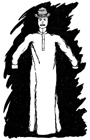
Fig. 306.—The Goblin-man.
The head of the goblin is a jack-o'-lantern made out of a piece of cardboard, bent as shown in Fig. 308, and held in this shape by means of broom-wire laced back[Pg 288] and forth across the top. Cut a hole the shape of an ear in each side, and paste a piece of red tissue-paper over the opening. For the face, take a piece of white paper a little larger than the face is going to be, mark out eyes, nose, and mouth upon it, and cut the openings for them. Paste red tissue-paper over the openings for the eyes, and mark a large black pupil in the corner of each (Fig. 309). For the mouth, paste a piece of white tissue-paper over the opening, and mark out the teeth in black (Fig. 309). A piece of red tissue-paper should be pasted over the opening for the nose. After finishing the face, paste it on to the cardboard head. The goblin's countenance is lighted up from within, by means of a candle fastened in a baking-powder can. Cut down one side of the can with a pair of tin-shears or a can-opener, and tack it to the framework about six inches above the crosspiece, as shown in Fig. 307. This can must not be put in place, however, until the head is fastened to the framework, which is done by punching[Pg 289] a hole in the cardboard large enough to admit the end of the pole. Get an old derby for a hat, and, after punching a few holes in the top for the heat and smoke of the candle to escape, sew it to the cardboard head. Cover the back of the head with black cloth in such a way that it may be opened to light the candle. To save the goblin-man the embarrassment of losing his head, drive a nail through the crown of the derby-hat into the end of the pole. For a neck, button a cuff around the pole between the crosspiece and head.
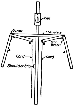
Fig. 307.—Framework of the Goblin-man.
A white suit of clothes is, of course, the correct style for the goblin to wear. This can be found in an old nightshirt, lengthened with white cloth, if necessary, to make it reach the ground when it is placed upon him. The shoulders should be padded out to hide the framework.
When the goblin-man is finished, strap the shoulder-stick[Pg 290] of the frame to your shoulder, and fasten the end of the pole to your waist with a belt. Your hands are then free to manipulate the arms, by means of the cords attached to their ends. Before starting out upon the street, have some one light the candle in the head.
As this weird-looking creature passes along the streets, with glaring eyes and other features equally brilliant, people will have to stop to reassure themselves that they are not face to face with some unearthly demon.

Figs. 308-309.—The Goblin's Head.
A trick that will furnish amusement for at least a portion of the evening is
The Disappearing Rope, which is not an entirely new idea, but one which is always popular. Procure a number of rubber bands and tie them together, end to end. Then attach one end of these to a front fence, and to the other end fasten several yards of string. After doing this, cross over the sidewalk with the string, pulling it tightly so the rubber bands will stretch, and hang a sign with the word "DANGER" printed upon it in large letters over the string where it crosses the sidewalk.
It is only natural that the person who sees this sign will make a grab for it, thinking you are blocking the sidewalk to make him walk around it. This is your opportunity to act quickly and let go of the string, which will snap back to the fence upon the contraction of the rubber bands, and disappear from view, leaving your much-astonished friend to pass on, knowing that the joke is upon him.
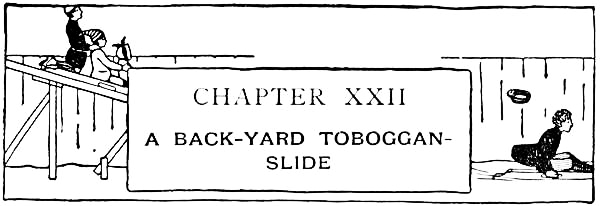
It is the misfortune of a great many boys to be deprived of one of winter's greatest sports, by living in a flat country where there are no hills upon which to coast. These boys have little use for sleds aside from "hitching," unless they can make an artificial slide. In a number of large cities, toboggan-slides on a large scale are erected in the parks each year, and thrown open to the use of the public. Although this coasting cannot equal that to be had on natural hills, it affords a great pastime to thousands of boys and girls, and is a luxurious treat to many who have never seen hills larger than the artificial park variety.
The construction of a toboggan-slide is not difficult for a boy or several boys, and though it must be limited in size, a small slide has an advantage in that there is not a long walk from the end of the run back to the starting-point.

Fig. 310.—A Back-yard Toboggan-slide.
It is a good idea to locate the toboggan-slide in a back-yard or an
enclosed lot, so that the outside fellows cannot monopolize it; and it
is well to have some firm [Pg 292]
[Pg 293]object to which the framework can be
fastened, as it saves a great deal of bracing, and materially lessens
the amount of lumber needed. The work should be done in the early part
of the fall, before the cold weather sets in. Figure 310 shows a slide
built in the corner of a yard against the fence.
The Length will be determined by the size of the yard. If the yard is short, the slide should be proportioned accordingly, to allow the sled its full run before reaching the end of the lot.
A Platform should be built in the corner, six feet square, and about seven feet above the ground. For this, cut four two-by-fours six feet nine inches long, fasten one in the angle formed by the two fences, and another five feet four inches to the right of it (A and B in Fig. 312). The third upright (C) should be nailed to the fence five feet eight inches from A, and the fourth (D) should be fastened at an equal distance from B. Then cut two pieces of two-by-four each six feet long, and nail them across the tops of A and C, and B and D, respectively, as shown at E and F in Fig. 312. The uprights should now be braced with horizontal and diagonal bracing, as shown in Fig. 312, to give the platform the necessary stiffness.
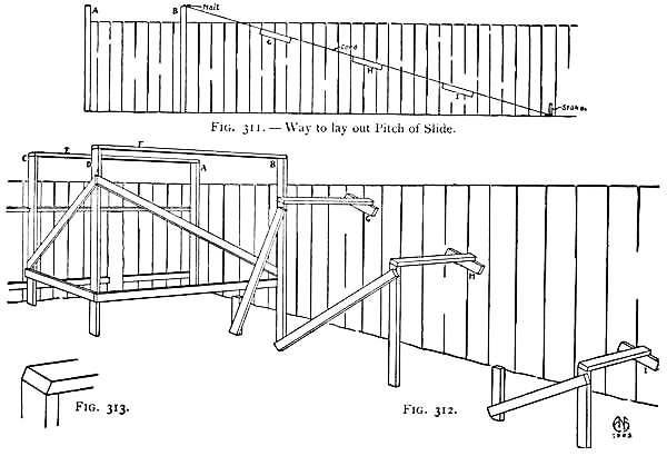
Figs. 311-313.—Framework of Toboggan-slide.
After deciding upon the length of the slide, lay off the distance upon
the ground from the bottom of upright B, and drive a stake into the
ground at the farther end. Then attach a cord to the stake and run it
along the [Pg 294]
[Pg 295]fence to a nail driven into the top of upright B. This
cord, shown in Fig. 311, marks the pitch of the slide, and will give you
a guide-line by which to work. When this has been done, cut three pieces
of two-by-four about two feet long, and spike them to the fence just
below the guide-line (see G, H, and I, Fig. 311), spacing them
about six feet apart on centres. When these have been fastened in place,
take a piece of two-by-four and mark off upon it the distance from the
ground to the top of block I. Then square a line across the
two-by-four at this point, at an angle corresponding to that at which
block I is nailed to the fence (see Fig. 313). Saw the two-by-four on
this line, and then stand it upright in front of block I, thirty or
thirty-two inches from the fence (according to whether eight-or ten-inch
boards are used upon the slide), and spike a piece of two-by-four to the
top of it and to the top of block I, as shown in Fig. 312. Cut and set
up a similar upright and crosspiece at G and at H, after which brace
all as shown in the illustration (Fig. 312).
If you are going to buy boards with which to cover the platform and slide, get twelve-foot lengths, eight or ten inches wide. By using these you will have no waste, and but little cutting to do. If, however, you have material of other dimensions on hand which you can use, the supports of the slide should be so spaced that the boards will reach from one to another. The boards should run lengthwise upon the slide, and be[Pg 296] nailed to the framework, leaving as small cracks as possible between them.
In order to prevent sleds from running off the slide, a guide should be nailed to the edge farthest from the fence, from the top to the bottom, and on the opposite side where it extends above the fence top (see Fig. 310).
After nailing the platform boards in place,
Build a Railing out of boards around three sides of it, to prevent any one from slipping off (see Fig. 310).
A Ladder, made out of two two-by-fours, with two-inch strips nailed across them, should be set against the front of the platform and spiked in place, as shown in the illustration of the completed slide (Fig. 310). This will make it easier to reach the platform than by the way of the icy slide, and also prevents those coasting from colliding with those who are returning.
Any ingenious boy will know how to make a swift slide by turning the hose upon it, and allowing the water to run over the surface until every portion is well covered.
A toboggan-sled is out of proportion for a slide of this size, and will not be found as satisfactory as a sled with runners, as the steepness of the slide will not be sufficient to make it go.
A Home-made Sled, such as that shown in Fig. 314, requires but little material, and if carefully made will prove stronger than the variety commonly sold in the shops.
[Pg 297]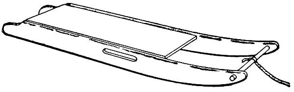
Fig. 314.—A Home-made Sled.
Figure 315 shows the pattern for the runners, which should be cut out of four-inch boards, seven-eighths of an inch thick. Round the top edges, and cut the front and rear ends as shown in the drawing. Make a slot in the place indicated for a handle, and bore a hole near the front end for the crosspiece to run through. The seat consists of a board cut twenty-two inches long and nine inches wide. This will not be nailed to the runners but to cleats, as shown in Fig. 316. Cut three cleats nine and one-quarter inches long, two inches wide, and seven-eighths of an inch thick, and fasten these between the runners, five-eighths of an inch from their tops, placing one near the end of the seat, one at the centre, and one at the front. Four two-inch iron braces should be procured, and two of these[Pg 298] screwed to the under side of the front and rear cleats, and to the sides of the runners, as shown in Fig. 316. The seat can then be nailed in place, and a broom-handle fastened in the hole bored near the ends of the runners.

Fig. 315.—Pattern for Runners.
The Best Kind of Iron Runners for a home-made sled are those that a boy can put on without the aid of a blacksmith, and such a pair of runners is shown in the drawing of this sled. They consist of what are known as half-oval iron strips, and can be had usually at a hardware store or blacksmith shop. A pair forty inches long and three-quarters of an inch wide, with five holes for countersunk screws drilled in each, can be bought for fifty cents. When they have been procured, screw them to the bottom of the runners, using one inch or one and one-quarter inch screws for the purpose.

Fig. 316.—A Section through the Sled.
Although these runners are plenty heavy enough for light coasting, they would probably prove weak for coasting upon hills of any great size. To withstand the strain brought to bear upon the runners when hill coasting, boys generally find it necessary to make them out of two-inch stuff. This, however, makes the sled heavy and clumsy, and can be done away with by following a[Pg 299] scheme which a friend of the writer's invented and found very satisfactory. It consisted of
Reënforcing the Runners with steel bars driven into holes bored vertically in them. The holes were bored while the runners were held in a vise, and the steel bars were a little larger than the holes, so that they would fit them tightly. This scheme allows the use of seven-eighths inch stuff for the runners, and sixty-penny wire nails can be filed off to the proper length and substituted for steel bars if the latter cannot be obtained.
When the sled has been completed, it should be given a good coat of paint.

A Miniature Theatre.
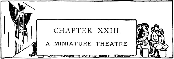
Probably nothing can be found which will make a more interesting entertainment for a winter evening, than a miniature theatre patterned as nearly as possible after a large playhouse. The construction of the stage, and preparation of miniature scenery, properties, and mechanical effects, furnish good work for disagreeable weather when it becomes necessary to remain indoors, and there is plenty of it, and of great enough variety, to occupy the attention of a number of boys.
Very little material is necessary, outside of what generally can be found in the attic, cellar, and woodshed, so that the expense incurred by making the theatre amounts to almost nothing. A gilt picture-frame makes
An Excellent Proscenium for the front of the stage, and, as it will not be marred in the least, you can probably borrow one for the occasion.
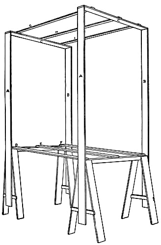
Fig. 317.—The Stage Framework.
On the opposite page is shown a miniature theatre completed, and in Fig. 317 will be seen the proper construction of
The Stage Framework, which is made of narrow boards [Pg 304]
[Pg 305]and built upon two
horses the width of the picture-frame. Make the horses as shown in Fig.
317, one two feet six inches high and the other two feet nine inches
high, using two-by-fours for the tops and narrow boards for the legs and
braces. After constructing the horses, cut four boards seven feet long
and nail two to the ends of each (A and B, Fig. 317), after which
cut two pieces to reach across the tops and nail them in place as shown
at C. Then set the horses five feet apart, with the lower one in
front, and screw three boards to the tops as shown at D, E, and F,
and three narrow strips to the top of the framework as shown at G,
H, and I. Strips G, H, and I form what is known as
The Gridiron, or supports from which the scenery drops are suspended, and should have a row of tacks driven into each edge, as shown in Fig. 317, upon which to hang the drops. By fastening the framework together with screws, it may be taken apart after a performance and packed away for another time.

Fig. 318.—View of Curtain from Stage.
The Stage Floor rests upon boards D, E, and F, and is made of laths laid close together, parallel to the front of the stage. The laths should not be nailed in place, as it is necessary to have the stage floor movable.
When the work has proceeded thus far, set the picture-frame between the uprights of the front frame so that the opening comes on a level with the stage floor, and fasten it to A and B with nails driven through screw-eyes placed in the back of the picture-frame.
[Pg 306]The Drop-curtain should be made of white muslin, and measure in width several inches wider than the opening in the picture-frame. Hem the two side edges of the cloth, and sew brass rings on to them two inches apart. Then tack the top and bottom to strips of wood. A scene may be painted upon this curtain, but you will find the result probably more successful if you paste a picture of some sort upon the cloth, as suggested in the illustration of the completed theatre.
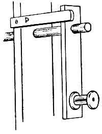
Fig. 319.—Crank for Curtain Pole.
In Fig. 318 we have a view from the stage of the arrangement by which the curtain is raised and lowered. Two heavy wires should be slipped through the rings on the curtain, and their ends fastened to four screw-eyes placed in the uprights at J, K, L, and M. These form the curtain guides. Bore two holes in uprights A and B above the picture-frame, and run a broom-stick through them for a roller, after which make a crank similar to that[Pg 307] shown in Fig. 319 and fasten it to one end. Place two screw-eyes in the crosspiece at N and O (Fig. 318) and slip two cords through them, tying one end of each to the top of the curtain and the other end to the roller. By turning the crank the string will now wind around the roller and raise the curtain. It will be necessary to screw a button on to upright A at P, as shown in Fig. 319, to lock the crank when the curtain is raised. We often had two and three drop-curtains upon our miniature theatres, which made it necessary to have additional rollers and guide-wires.

Fig. 320.—The Footlights.
The greatest precautions should be taken
In lighting the Theatre, to have all wood surrounding lights covered with tin, and not to use candles or matches around inflammable substances. Figure 320 shows a satisfactory arrangement of

Fig. 321.
The Footlights.—A piece of tin the length of the picture-frame and ten inches wide should be procured for these and bent into the shape shown in the illustration. Drive tacks through the bottom of the tin about two inches apart, and stick a short candle upon each.[Pg 308] Then fasten the tin below the picture-frame as shown in the drawing of the completed theatre, and paint it black upon the outside.
Floodlights, which are used to throw light from the wings on to the stage, may be made as shown in Figs. 321, 322, 323, and 324. The case for the light is made in the same manner as the dark-room lantern, described in Chapter XI, and illustrated by Figs. 176 and 177, except that the door is placed in the side instead of the back and no glass or paper is fastened over the front opening (see Figs. 322 and 323). Make the opening four by five inches, and fasten two grooves, formed by nailing two[Pg 309] strips of wood together, as shown in Fig. 324, above and below it, in which to slide glass plates for the purpose of throwing
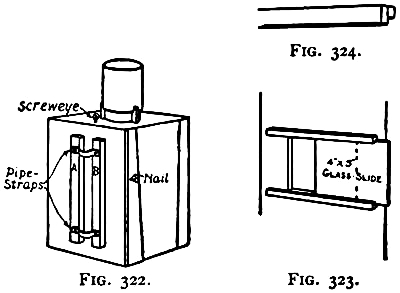
Figs. 322-324.
Details of Floodlights.
Colored Lights upon a scene. The slides consist of old four-by-five camera plates with colored tissue-paper pasted upon them, and are operated in the same manner as magic-lantern slides. The light should be mounted upon a standard, such as is shown in Fig. 321, consisting of a seven-foot pole fastened at the lower end to a board and braced with triangular blocks, as shown in the illustration. It should be so attached to the pole that it can be adjusted to any desired height, and to attain this two pipe-straps should be fastened to the back of the box, as shown in Fig. 322. First nail two vertical strips in place as at A and B in the drawing, and to these screw the two iron pipe-straps. When the straps have been attached, slip the end of the pole through them, and place a screw-eye in the box, another in the pole near its upper end, and a nail in the side of the box. Then attach a cord to the screw-eye in the box, and, after running it through the screw-eye near the top of the pole, twist it several times around the nail in the side of the box, which will hold the box in that position. One of these lights should be made for each side of the stage. In addition to them, you may have occasion to use
Spotlights to throw more light upon one portion of a scene than another. Bicycle lamps will be found handy for this purpose.
[Pg 310]If your house is wired for electricity, several miniature incandescent lamps can be procured for the footlights, while larger lamps can be used for all the other necessary lighting.
As the work of making scenery, properties, and mechanical effects is not in the same line as the construction of the stage and its framework, it has been treated in the following chapter.
Before setting up the theatre for a performance, it is well to spread a large cloth over the carpet, to catch anything that may drop from the stage. Then, with all the framework fastened together, hang draperies on each side and above and below the proscenium arch, as shown in chapter heading. This will conceal everything but the proscenium opening.
Admission Tickets and programmes should, of course, be printed with a printing-press if you have one; otherwise with rubber stamps.
Scenery for a miniature theatre will be made in much the same manner as the small drops and wings a scenic artist prepares of each scene of a play, before he commences work upon the large canvasses. Any handy boy will find it an easy matter to prepare his scenery, as it does not require a knowledge of drawing so much as it does the knack of copying scenes from pictures, and the proper placing of the various wings and drops. Several simple suggestions for water, field, street, and interior scenes, with sketches of the drops and wings necessary to complete them, have been placed on the following pages of this chapter with a view to helping you with your first attempts at making scenery. By the time you have made some of these you will have had enough practice in the work to devise other designs and work up the details more elaborately. With a little shifting of drops and wings, or substituting one for another, the appearance of the scene can be sufficiently changed to make it as good as an entirely new setting. Several examples of this will be found among the illustrations.
[Pg 312]For materials, you will require some large pieces of paper, several sheets of cardboard, a box of colored chalks, a pair of shears, and a pot of paste—add to this a bunch of laths with which to make the frames, and some nails, screws, and tacks for fastenings. The back of wall-paper presents an excellent surface for chalks, and several rolls will cost you but a few cents, as you can purchase old-style patterns. Suit and shoe boxes will furnish the necessary cardboard.

Fig. 325.—Drop for Ocean Scene.

Fig. 326.—Drop (D in Ocean Scene).
The size and proportion of the scenery will depend entirely upon those of the proscenium, and as these are governed by the size of the picture frame you procure, no attempt will be made to give you the dimensions of[Pg 313] wings and drops; but you will get a good idea as to their proper proportion from the illustrations shown of the scenes set up, as the line of the proscenium opening is dotted upon them. In the full-page illustration of the completed theatre preceding Chapter XXIII is shown
An Ocean Scene in which the entire depth of the stage is used for the setting. Here you will notice the drops have been made to extend beyond the sides and top of the proscenium opening, a thing which is necessary in order that those of your audience sitting close to the front of the theatre, or to one side of the centre of the stage, will not be able to see through the openings between the drops and wings. Figure 325 shows how the four drops necessary for this scene should be made. First sketch drop A, shading the clouds and waves with[Pg 314] colored chalks as shown in the drawing of the completed theatre. Then cut out the opening in its centre, carefully following the outlines of the clouds. Lay this sheet upon another and mark out drop B, with a smaller opening in its centre, and then, after coloring and cutting it out in the same manner as you did drop A, lay it upon a third sheet and mark out drop C, with a still smaller opening in its centre (see Fig. 325). Drop D forms the background of the scene, and should be made as shown in Fig. 326, with a horizontal line separating the sky and water. With the exception of a few white caps in the foreground, no waves should be shown upon this drop.
If wall-paper is used for the scenery, several widths will have to be pasted together for each drop.
Fig. 327.—Waves for Ocean Scene.
Additional waves should be made out of strips of paper and fastened together as shown in Fig. 327, with the crests of the waves of each strip extending a little above those of the strip in front. Prepare three sets of the waves, and, after pasting one to the bottom of each drop, bend out the crests so as to leave a little space between each strip.

Fig. 328.—Frames for Drops.
These drops should now be tacked to frames made out of laths similar to Fig. 328, with the corners nailed and braced with diagonal strips. Place a couple of tacks[Pg 315] in the top of these frames, and to these attach cords. The drops should now be hung by means of the cords to the tacks in the top strips of the stage framework. Space them about as shown in the illustration of the completed theatre, and so adjust the lengths of the cords that, from a point equal to where the centre of your audience will be located, the horizon lines of your drops will appear on a line with one another. Then having found the proper lengths of the cords, make loops in them so the drops can be quickly hung in place without further adjustment.
Fig. 329.—Rocks for a Seashore Scene.
In the foreground of the ocean scene a stone wall has been shown, which should be made upon a strip of cardboard, with the joints of the stones marked off with gray paint. This strip should be set against the bottom of the front drop. To change this setting into
A Mid-ocean Scene, it is only necessary to substitute a[Pg 316] strip of waves similar to Fig. 327 in place of the stone wall; and
A Seashore Scene can be had by making a strip of rocks similar to Fig. 329 to set against the front drop, and covering the foreground with sand to form the beach.

Fig. 331.—Drop (G in Field and Blockhouse Scene).

Fig. 332.—Drop (H in Field, Blockhouse, and Street Scene).

Fig. 330. A Field Scene.
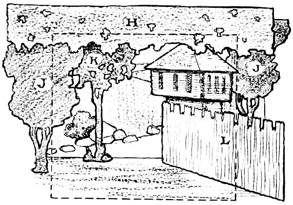
Fig. 338. A Blockhouse Scene.

Figs. 333-334.
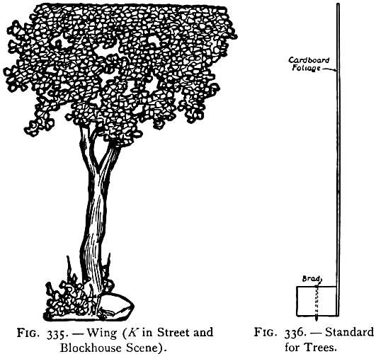
Figs. 335-336.
A Field Scene should be set up as shown in Fig. 330. Make the background drop G similar to Fig. 331, tacking it to a frame as you did the drops of the ocean scene, and prepare the foreground drop H similar to Fig. 332, tacking its upper edge to a single lath from which it can be hung in position. Draw the leaves upon drop H about as shown in the illustration, and in cutting out the strip make a few openings between the leaves as shown in the drawing. Wings I and J are shown in Figs. 333 and 334. These should be drawn upon cardboard, and then cut out with a sharp knife, with openings made in places between the leaves and branches.
Tack the bottom of
The Trees to small blocks of wood for standards (see[Pg 317]
[Pg 318] Fig. 336), and
drive brads through the blocks so they will stick into the stage floor
and prevent the trees from toppling over. In setting up this scene, as
in the case of all others, you will have to shift the pieces until all
entrances and exits are hidden by the wings. The places can then be
marked upon the stage floor. This scene will occupy but the front part
of the stage. If a greater depth is desired, it will be necessary to
prepare additional wings, which can be made similar to Figs. 333 and
334, with possibly a few changes in the form of the branches and leaves.
Figure 335 shows a tree that can[Pg 319] be used for the centre of a scene. A
little earth scattered over the stage floor will give the appearance of
ground.

Fig. 337.—Blockhouse (L in Blockhouse Scene).
By using the same background drop, G, and the foreground drop, H (Figs. 331 and 332), trees, J and K (Figs. 334 and 335), and making a blockhouse and stockade similar to L (Fig. 337), you will have the proper setting for
A Blockhouse Scene, such as is shown in Fig 338. The blockhouse should be fastened to a strip of wood in the same manner as you fastened the ends of the trees (see Fig. 336).
For outdoor scenery, and especially forest scenes, the writer remembers using

Fig. 340.—Drop (M in Street Scene).
Pine Boughs for trees and shrubbery. These were cut into pieces of the right length for trees, with their ends[Pg 320] pointed so they would stick into gimlet holes made in the laths of the stage floor; and loose pieces were thrown in between for shrubbery. Mounds and hills were made with moss. This saved the work of making so many drops, and, of course, looked a little more realistic than paper scenery, but was not as handy to set up, and caused longer delays between the scenes.

Fig. 339. A Street Scene.
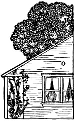
Fig. 341.—Wing (O in Street Scene).
Rustic Bridges can easily be constructed with a few twigs, as can also rustic seats and fences. A very realistic
Pond or Lake can be represented by placing a piece of a mirror upon the stage floor, and banking sand or moss around its edge.
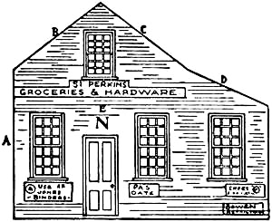
Fig. 342.—Wing (N in Street Scene).
Figure 339 shows a simple setting for
A Street Scene.—The background will be made similar to Fig. 340, and the wings N and O as shown in [Pg 321]Figs. 341 and 342, while drop H and wing K are the same as used for the other scenes (see Figs. 332 and 335). Wing O, the house upon the right of the stage, will be made in one piece, with window openings cut in it and covered with tissue-paper ruled to represent the window-sash (see Fig. 341). Show the trim around the openings and also the siding upon the building. Then fasten the back of the wing to a standard such as used for the trees (see Fig. 336). Wing N, or building upon the left of the stage, will require a number of pieces of cardboard to show its perspective correctly. Make the front of the building as shown in Fig. 342. Then fasten a piece of cardboard to edge A for the side, three pieces at_B, C, and D for the roof, and a strip across the front at E for the porch roof. The pieces can be fastened together best with strips of linen glued to their inside surfaces. The porch roof will be supported upon four posts made out of strips of cardboard as shown in Fig. 339. This building will be the village post-office, grocery, and hardware store combined, and should[Pg 322] have a number of signs to this effect painted upon the front.
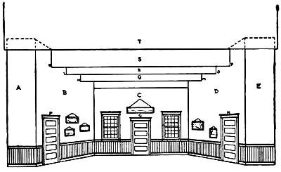
Fig. 343.—A Simple Interior Scene.
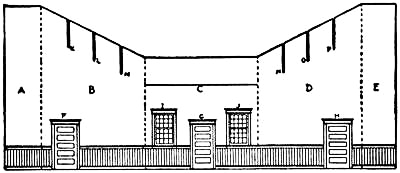
Fig. 344.—Pattern for Walls of Interior Scene.
To the several outdoor scenes already described, you should add a setting of
An Interior, as you will probably have occasion to use one in any play you produce in your miniature theatre. Figure 343 shows a simple interior, the size of which will, of course, depend upon that of the stage. However, it should not be very deep. Figure 344 shows the pattern by which to cut the five pieces of cardboard, of which the walls are made. The edges of these pieces should be glued together with strips of linen. Cut the door openings at F, G, and H, two window openings at I and J, and slots in the tops of B and D at K, L, M, N, O, and P, as shown in the drawing. Make the doors out of pieces of cardboard, hinging them to the openings with linen strips, and draw the window-sash and their[Pg 323] divisions upon tissue-paper and paste them over the openings I and J. Oil the paper if it is not very transparent, so the audience can see the villain when he passes by the windows. Make a wainscoting around the walls to the height of the window-sills, ruling the boards with a lead pencil, and draw a line across wall C a little below the bottom of slots M and N in walls B and D, as shown. If you have used white cardboard for the walls, and not injured its calendered surface when cutting the openings, it will have a good plaster appearance. Otherwise, cover the cardboard with white or tinted paper. Paint the wainscoting and the door and window trimmings brown. To set up the room, bend the walls into the shape shown in Fig. 343. Then cut three strips of cardboard several inches longer than the width of the room and slip them into the slots you have cut in the tops of the walls B and D (see Q, R, and S, Fig. 343). T is a drop like S, but is suspended in front from the gridiron. These strips form the ceiling of the room, and generally have[Pg 324] beams or mouldings painted across their bottom edges, but it will simplify matters to leave them plain, as shown in the illustration. The line which you have drawn across the rear wall corresponds with these strips. Cut a number of illustrations from a magazine for pictures, and either hang them upon the walls or paste them to the cardboard. Doll furnishings can be used to complete the scene.
There are a great variety of subjects upon which a boy can base his plays, but what probably will make the most interesting programme and one of the simplest to prepare is
A War Drama.—In this you can picture a number of battles after the descriptions you have read in your history, or dramatize one of your favorite war stories, bringing its young heroes before the footlights. This class of plays will give you an opportunity to use
Paper Soldiers for actors. Probably you have a supply of these, but if not, you can get them at any toy store. They come upon printed sheets ready to be cut out, and as they cost only a penny a sheet it pays to buy rather than make them.
Cavalry and infantry of about every nationality, Indians in various positions upon horseback and on foot, and a large assortment of American soldiers in marching order and fighting array are now to be found in these sheets. For
Marching Soldiers across the stage, tack their feet to[Pg 325] a lath as shown in Fig. 345, and then slide the lath across the stage, at the same time pushing out one of the laths forming the floor. The moving of the laths scarcely will be noticeable from the position of your audience.
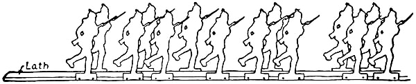
Fig. 345.—Scheme for Marching Soldiers.
Separate Standards for soldiers you wish to set about the stage should have small strips of cardboard glued to their backs and bent out in the same manner as easel-backs are made. At least four or five of the soldiers should be jointed so they can walk about the stage and appear perhaps a little more graceful in their actions than their stiff-jointed comrades who are fastened to laths. Figure 346 shows
A Jointed Figure made out of a paper soldier. Suppose you have a soldier in some such position as shown in Fig. 347. First cut off the legs along the dotted lines shown in the illustration, each leg in two pieces (see A, B, C, and D, Figs. 347 and 348). Remove also the hand projecting beyond the body at E. A small piece of cardboard of the same thickness as that upon which the soldiers are printed should be glued to the back of C and D where those pieces were cut into in cutting off[Pg 326] the legs (see F, G, and H, Fig. 348). When this has been done, pivot A and B to C and D at F and G, and then pivot the ends of C and D at H and I to the hips of the soldier (see Fig. 346). Thread should be used for pivoting these pieces together, with knots tied on either end. New arms will have to be made, as those printed upon the body cannot be cut out. These are made in two pieces similar to J and K in Fig. 348. You will find it a simple thing to make them and paint the hands flesh color and the sleeves to match the rest of the clothes. Pivot J to K at L and the end of K to the shoulder at M. The arm printed upon the side of the figure should now be painted so as to blend with the color of the coat. The white cardboard glued to the joints should also be painted to correspond with the rest of the body. You will find this method of making a jointed soldier much easier than to attempt to draw, paint, and cut out one of your own design. Figures in other positions can, of course, be jointed in the same manner.

Figs. 346-348. Scheme for making a Jointed Figure.
The movements of a jointed figure are controlled with pieces of silk-thread attached to the hands, feet, and head, as shown in Fig. 346. These threads should be carried through the top of the stage framework and loops made in their ends should slip over the fingers of your hands, in which position they can be operated. It will take a little practice beforehand to enable you to work the threads successfully, so you will not be responsible for such laughable performances as making him dance while delivering a farewell address, or leave the scene through the top of the stage during an exciting portion of the play.
In an interior scene, such as Fig. 343, the jointed figures will have to make their entrées and exits through the passages between the front walls and the proscenium, as the operating cords would interfere with them going through the other openings. The figures which pass through the doors will have to be tacked to the floor laths and shoved across the stage.
All the small movable furnishings of a scene are known as
Stage Properties.—These include such pieces as furniture, boats, carts, and trains.

Figs. 349-350.
A Tent.
Tents will be necessary properties for an encampment scene. These should be cut out of white paper the pattern of Fig. 349, then folded along the dotted lines, and edge B pasted over the flap A. The front flaps will be left open. Figure 350 shows the tent set up.
An Indian Teepee will also be required for Indian warfare. Follow the pattern shown in Fig. 351, marking it off as though it were made up of a number of skins, and place a few figures of decoration upon it. Then cut three or four short sticks and, after crossing their ends as shown in Fig. 352, fasten the paper covering over them, bending flap A along the dotted line, and pasting B over it.

Figs. 351-352.
A Teepee.
The field scene (Fig. 330) and the blockhouse scene (Fig. 338) will be used for the settings of your battle-fields. For your miniature sea-fights, the mid-ocean scene will be used.
Battleships should be made out of cardboard as shown in Fig. 353, with the masts reënforced at the back with strips of wood, and the rigging made with heavy thread. It will be well to have a number of pictures from which to work in drawing and painting the various ships of your fleet. The hull of each ship should be curved as[Pg 329] shown in the illustration, and mounted upon a cardboard rocker. Make a number of slashes along the curved edge of the hull, and bend out the little flaps alternately, first to one side and then to the other (see A in drawing), after which glue them to the rocker. Attach a cord at B, with which to pull the ship across the stage, and another cord at C, with which to guide the stern. The hull will, of course, run between the strips of waves, so as to be half concealed by them. A person cannot imagine how realistic these little battleships appear when tossing about upon the toy waves, without having seen them in operation.

Fig. 353.—A Battleship.
Trains and Wagons can be cut out of cardboard and moved across the stage by means of laths to which they have been attached in the same manner as the paper soldiers shown in Fig. 345. Toy wagons, carriages, and an automobile such as described in Chapter XXVI, may also be used in some scenes.
Rain, wind, thunder, and such stage sounds, a moon or sun-rise, and lightning, as produced on the stage, are known as
Mechanical Effects.—Most of these can easily be[Pg 330] adapted to your theatre, though the apparatus need not be as elaborate as that used by professionals.
Thunder can be produced by means of a large piece of heavy cardboard held by one corner, as shown in the chapter heading, and vibrated back and forth. The beating of
Rain upon the outside of a house is imitated with a small quantity of dried peas or beans dropped upon the head of a drum or into a cardboard box. Every time the door is opened during such a storm, the audience should hear the whistling of the
Wind, which is imitated by a few low drawn-out whistles. The stage must, of course, be dark for producing
Lightning, in order to get the best effects. The flashes can be made by igniting a small amount of flash-light powder, placed in a tin can cover.
The Roar of Cannon and firing of smaller guns can be imitated to good effect upon a drum.
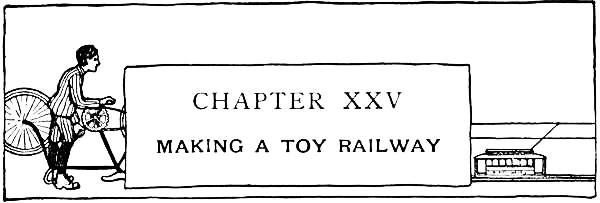

Fig. 354.
It is often thought that a toy railway is beyond a boy's ingenuity to construct, whereas, in reality, it is one of the simplest toys he can make. This applies to the tracks, stations, and cars of every description, all of which can be made with a few strips of wood, some spools, nails, cardboard, and a bottle of glue, for materials. If you have passed the age of caring for such toys as this, you will, no doubt, enjoy the making of one for your younger brother, or for one of your boy relatives.
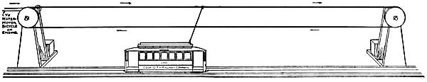
Fig. 355.—The Toy Railway in Operation.
Figure 355 shows a railway set up and in running order. As shown in the illustration,
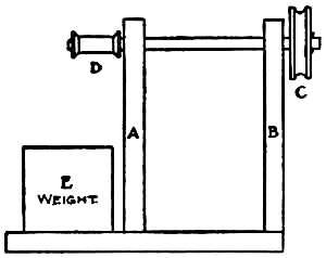
Fig. 356.—Support for Trolley-line.
The Trolley-line, or overhead cable, runs around the wheels of two supports, one at either end of the track. Prepare four pieces of wood the shape and size of that shown in Fig. 354 for the uprights of these supports, and make two wheels three inches in diameter. The wheels may be marked out with a piece[Pg 332] of string and pencil as shown in Fig. 201, Chapter XV, if you haven't a compass. When the wheels have been cut out, place them in your bench-vise, one at a time, and with a rasp make a groove around the edge as shown at C, Fig. 356. Bore a three-eighths inch hole through each upright at F, Fig. 354, and another through the centre of each wheel. Now fasten two of the uprights six inches apart upon a block of wood, as shown at A and B, Fig. 356. Whittle a shaft to fit loosely in the holes of the uprights, and, after slipping it into them, fasten one of the wheels upon one end and a small spool upon the other (see C and D in Fig. 356). A weight of some sort should be fastened to the base, as shown at E. The uprights for the other[Pg 333] support should be similarly mounted upon another block of wood. Fasten the remaining wheel to an axle run through the holes in the uprights, and, as it is unnecessary to have a spool upon the other end of the axle, cut it off short and drive a nail through it to prevent it from slipping through the holes. Having thus prepared the supports, place them as far apart as you wish to extend the railway, and run a cord around the two wheels and tie it. Then set the supports a little farther apart, if necessary, to tighten the cord. Run another cord from spool D to
A Water-motor, steam engine, or whatever power you can get with which to operate the railway. A bicycle inverted with the tire removed from its rear wheel has been used satisfactorily, as has also a sewing-machine with the belt slipped off and the cord from the spool put in its place.
A good substitute for the tin tracks ordinarily sold in shops for toy railways will be found in those shown in Fig. 357. These
[Pg 334]
Fig. 357.—The Tracks.
Tracks consist of quarter-inch strips mounted upon pieces of cardboard. Make a small gimlet-hole in one end of each stick, and drive a short finishing nail in the opposite end (see Fig. 357). Cut the cardboard strips the length of the sticks, and tack them to the sticks as shown in the illustration. If inch and one-half spools are used for the car wheels, the inside gauge of the tracks should be an inch and three-quarters. By lapping the cardboard strips over the ends of the sticks, and the sticks over the ends of the cardboard strips, and placing the nail dowels in the ends of the sticks as in the drawing, a strong track is formed when the pieces are fitted together. This may be extended to any desired length by adding more sections to it.
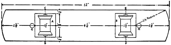
Fig. 358.—A Top View of Car Truck.
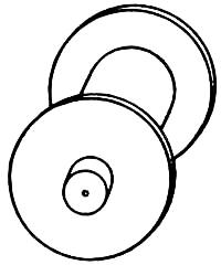
Fig. 359.—Spool Wheels.
The Cars for this railway will have their trucks constructed alike, and it is a simple matter to transform a car from one style into another. Figure 358 shows a top view of a truck. For the bed of this cut a three-eighths-inch[Pg 335] board twelve inches long by two and one-quarter inches wide, and, after rounding the ends as shown in the drawing, cut a mortise at A and B two and three-eighths inches from either end. Procure two one and one-half inch spools for wheels, and drive a wooden peg through the hole in each, cutting off the ends so they project a little beyond the hole, as shown in Fig. 359. Then bore four holes in the edges of the truck-bed with a gimlet at C, D, E, and F (see drawing), and, after setting the spools in mortises A and B, pivot them in place with small finishing nails driven into the wooden pegs. These nails should fit loosely in the gimlet holes. In order to drive them into the exact centres of the spools, it is best to locate these points upon the ends of the pegs before placing the spools in the frame. A quarter-inch hole should be bored in the top of the truck-bed at G and H (Fig. 358) in which to fasten the two uprights I and J[Pg 336] (see Fig. 360). Make the uprights four inches long and whittle a peg upon the lower ends to fit holes G and H (see Fig. 361). Bore a hole with a gimlet in the top of each and run a piece of heavy wire from one to the other, bending it as shown in Fig. 360. Fasten K between I and J, as shown. Place a small brass ring upon the wire before you fasten it in place. A small hook should be screwed into one end of the truck and a screw-eye into the other end for couplings, should you wish to hitch two or more cars together.
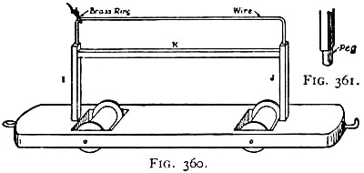
Figs. 360-361.
A Gondola Car, such as shown in Fig. 362, should have its truck made similar to Fig. 358, with the exception that it should be two inches shorter, in order that cigar-box strips can be used for the side-pieces. Cut the strips an inch and one-half high and fasten them to the bed of the car with brads. This car may be used as a trailer.

Fig. 362.—A Gondola Car.
The car shown in Fig. 360 is a rather crude affair, but with a little more work may be transformed into a better-looking car—

Figs. 363-364.
A Street Car such as is shown in Figs. 363 and 364[Pg 337] being an example of
what can be made. The sides, ends, and roof of this car are made of
cardboard, the patterns for the cutting of which are shown on page 339.
Figure 365 shows a cross section taken through the centre of the car.
The two side-pieces A should be first prepared as shown in Fig. 366.
With a ruler and lead-pencil draw in the windows about as shown in the
drawing, using double lines to indicate the sash. Then, with a sharp
knife, cut out the centre of each just inside of the inner line. These
windows may be left open or may be covered on the inside with
tissue-paper. If tissue-paper is used oil it to make it more
transparent. When the two sides have been prepared, bend each along the
dotted lines (see Fig. 366) and tack one to each side of your car truck
as shown in Fig. 365. When properly bent, the distance between the upper
part of the sides should be two and three-quarters inches. Cut the two
inner ends of the car the shape of Fig. 367, using a compass with a
radius of two and one-half inches[Pg 338] with which to describe the curve at
the top. Draw in the panels and sash lines as you did those upon the
side-pieces, being careful to get them on the same level, and cut out
the door and window openings. Fasten these end-pieces between the sides
with glue, and also tack them to the uprights of the car (I and J,
Fig. 360), which will come just inside of them. The roof is made in two
sections (B and C, Fig. 365). For B cut a piece of cardboard
twelve and one-quarter by three and three-quarter inches (Fig. 368),
draw the curved end with a compass, using the radius shown on the
drawing, and slit the corners as indicated by the dotted lines. When
this piece has thus been prepared, remove the wire from the top of the
truck (see Fig. 360). Bend the cardboard over the sides and ends of the
car, and lap corners D and E over F and G, and H and I over
J and K, tacking them with thread to hold them in place. To fasten
this part of the roof to the top of the car, cut a number of small
strips of linen, and glue them to the under side of the roof and to the
inside face of the sides and ends of the car (see Fig. 365). The upper
portion of the roof C should be made out of a piece of cardboard bent
into the shape of Fig. 369 and cut at the ends so the upper portion of
C projects a little beyond its sides. Draw the ventilation lights upon
the sides of C as shown on the drawings, and then fasten the piece
upon the top of B with strips of linen in the same manner as you
fastened B in place. C should now have the same curve to its [Pg 339]
[Pg 340]top
as B. Cut and glue a piece of cardboard in each end of C to complete
the roof. The shape of this piece is shown in Fig. 370. The outer ends
of the car should be made as shown in Fig. 371 and tacked around the
ends of the wooden truck platform, and also fastened to the under side
of the roof with strips of linen. The window openings may be cut in the
ends, but it will make a stronger car if they are simply drawn upon it.
Cut four cardboard steps similar to Fig. 372 and tack them to the sides
of the front and rear platforms. When the car has been put together,
replace the wire in the tops of uprights I and J (Fig. 360), running
the ends through the roof (see Fig. 363). Paint the sides and ends of
the car yellow with brown trimmings, and paint the roof a light gray.
Water colors can be used for the purpose. Letter the name of your
car-line upon the sides and the number of the car upon each end and
side. The route should be lettered upon strips of cardboard with pins
run through them as shown in Fig. 373, these strips to stick in the roof
of the car (see Figs. 363 and 364).
Having seen how the car is made, you will find it a simple matter to make designs for

Figs. 365-373.—Details of Toy Street Car.
Other Cars, using the same scheme for the trucks, and altering the patterns for the sides, ends, and roof, to suit the design.
Nothing has, as yet, been said about the
Operation of the Railway, and though Fig. 355 probably[Pg 341] shows sufficiently clearly how it is run, a few words may be helpful. The car or cars are placed between the wooden tracks, and the trolley (or cord attached to the ring on top of the car) is tied to the trolley-line as in the illustration. Upon starting your engine, water-motor, or whatever motive-power you have, the car will run from one end of the track to the other. When it has reached the support of the trolley-line, it will stop long enough for the cord trolley to pass around the wooden wheel, and then run in the opposite direction until the other support is reached. It will thus be seen that the trolley hangs to the upper part of the cable, or trolley-line, in running one way, and to the lower part on the return run. In changing the direction of the run, the ring to which the trolley is attached slides to the other end of the car.
Fig. 374.—The Railway Depot.
A Station such as is illustrated in Fig. 374 is made out of cardboard and mounted upon a seven-eighths-inch board large enough to form a railway platform. After cutting out the side-and end-pieces, with door and window openings placed as shown in the illustration, fasten[Pg 342] them together with strips of linen glued in the corners. Make the roof low and extend it over the platform upon each side and over the gable-ends, as shown in the illustration. Paint the sides of the depot the regulation depot red, and the roof a shingle or slate color. Paint the door and window-sash black, letter the name of the station upon the gable-ends, and with a ruler and lead-pencil rule off the boards upon the sides, and the slate or shingles upon the roof. As this is a typical railway station, two may be made of the same pattern, one for either end of your car line.
It is generally easy for a boy to get hold of a set of old clockworks, for a discarded clock of some sort is almost certain to be found in the household storeroom. If the main-spring is intact, it is highly probable that a little tinkering and cleaning will be sufficient to put the mechanism in working order, at least so that it can be used for running small engines, automobiles, and other mechanical toys that most interest boys.
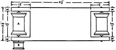
Fig. 377.—Top View of Wooden Frame.
Before taking a set of works apart, it is well to examine it carefully and note the positions of the various springs and wheels, so it will be possible to put them together again properly should you wish to do so. Without taking notice of this, you are likely to have a handful of wheels as a result, with which you can do nothing except perhaps convert them into tops.
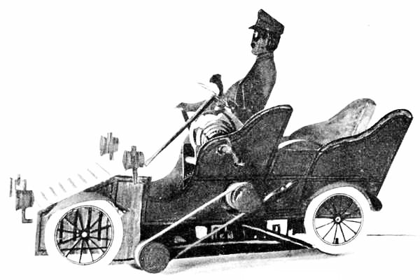
Fig. 375. The Car Completed.

Fig. 376. The Framework.
The adaption of a set of works to
An Automobile Touring-car is shown in Figs. 375 and 376, the former showing the little machine completed and the latter its frame with the clockworks fastened in place. The same scheme as that used for the cars[Pg 344] of the toy railway described in the preceding chapter will be followed in making
The Frame of the automobile, as that is about the simplest way, and makes a light, easy-running vehicle. The bed will be cut of a different pattern, however, as will be seen in Fig. 377. Lay out the piece to the dimensions shown upon this drawing, and then cut it out, making a mortise in each end for the wheels to fit in. The spool wheels should be mounted in the same manner as those of the railway cars, for which see Fig. 359, Chapter XXV, and the directions upon page 335. One end of spool A should be pivoted with a longer finishing nail than those used for the other pivots, so that when driven in place about half an inch will project beyond the frame. A small silk spool should be fastened upon this for a belt-wheel (see B, Fig. 377). The hole in one of these spools is about three-sixteenths of an inch in diameter, so, in order to make it fit tightly upon the nail, it is necessary to fill in around the nail with sealing-wax. To do this, turn the wooden frame upon its edge and place the spool over the nail, being careful to get the nail in the exact centre of the hole. Then hold a stick of sealing-wax over the spool, and with a lighted match melt the end and allow it to drip into the hole. When the hole has been partially filled, allow the wax to harden a little, and then press it down around the nail with the end of a match, being careful not to throw the spool out of centre by doing so. The hole should then be filled to the top.
We are now ready to prepare the clockworks for mounting upon the wooden
frame. The works shown in Fig. 376 are from an alarm clock, but if you
have a striking clock, or one with works a little different from those
shown in the illustration, it does not make a bit of difference in the
scheme for attaching the works. The three parts shown in the foreground
of Fig. 376 must first be removed from the works. These will be
recognized readily in any clock, as they are pivoted close together, and
regulate the speed of the other wheels. When they have been removed, the
main-spring will unwind rapidly. The frame of the works shown in the
illustration is held together with nuts, so that in removing the wheels
it was necessary to unscrew two of them, spring the frame open enough to
let the wheels drop out, and then replace the nuts again in their former
positions. If the frame of your clockworks is riveted together, the
wheels will have to be[Pg 345]
[Pg 346] broken out. A small silk spool, such as B
(Fig. 377), should be fastened upon the small pivot which originally
operated the clock's hands, for a belt-wheel. Lay the works upon a table
with the face-side down, and, after centring the hole of the spool upon
the pivot, fasten it in place with sealing-wax in the same manner as you
attached spool B.
The works should now be attached to the wooden frame. Place them with the striker uppermost, near the edge of the frame, so that the small belt-wheels are in line with one another. Then bore a number of gimlet holes in the wooden frame and run copper wire through them, passing it around the posts of the clock-frame and twisting its ends until the works are firmly fastened in place.
A rubber band about an eighth of an inch wide and long enough to reach from one belt-wheel to the other should be procured for
The Belt.—This should stretch just enough to cling upon the spools, as more than that would cause too much friction.
Figs. 378-385.—Patterns for the Automobile Touring-car.
Before going any further with the construction of the automobile

Fig. 386.
Test the Machine, to be sure that it is in perfect running order. Wind
up the main-spring, pressing a finger against one of the wheels to hold
it in check until you are ready to start the machine. When properly
made, the clockwork automobile should run a distance [Pg 347]
[Pg 348]of from twenty to
twenty-five feet upon a wooden floor, while about three-quarters of that
distance should be covered upon a floor with a fairly smooth carpet.
The Cardboard Sides and other details of the automobile should now be made. The pattern for these have been so shown in Figs. 378-385 that they can easily be laid out to the proper shape and size by means of the process of enlarging by squares described on page 110, Chapter VIII. White cardboard should be used upon which to draw these pieces, and the thinner it is the easier you will find it to work with.
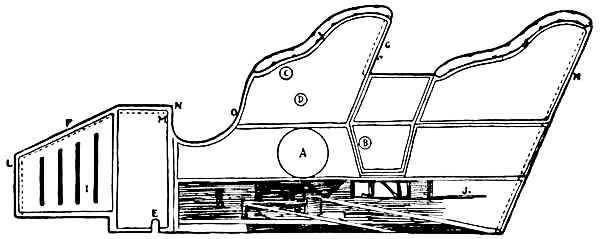
Fig. 387.—Cardboard Side of Automobile.
First prepare the two sides, cutting them out by the pattern of Fig. 378. Then glue the bottom edge of each side to the edge of the wooden frame, cutting holes in the left side for the belt-wheels and projecting posts to run through (see Fig. 375 and A, B, C, D, and E, Fig. 387). The top to the front of the car should now be cut as shown in Fig. 388, the distance between the sides being measured to get the piece of proper dimensions. Bend the edges as in Fig. 388, and glue them to the inner surfaces of the side-pieces as shown by the dotted lines in Fig. 387. In the same way cut and glue a piece of cardboard between the side-pieces at G and H (Fig. 387) for the seat-backs.[Pg 349] The bent edges of these pieces are shown by dotted lines in the illustration. Draw four
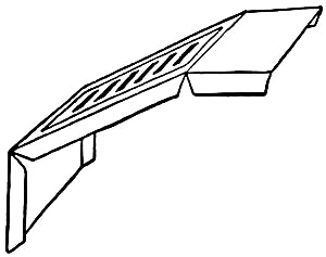
Fig. 388.
Wheels as shown in Fig. 379, using a compass with which to describe the circles, and cut them out with a sharp knife. You can cut out between the spokes, if you wish, or leave them solid. Glue the wheels to the cardboard, placing their centres about as located at I and J, Fig. 387. Four
Mud-guards should be cut like Fig. 380, with flaps made along one edge. Then bend these guards around the tops of the wheels, and, after applying glue to the flaps, press them against the cardboard side, holding your fingers upon the flaps until the glue has dried (see Fig. 375). The guards should be placed a little above the tops of the wheels. Cut four
Lamps like Fig. 381, and glue end K of two upon the front of the automobile at L (Fig. 387) and one of the other two upon each side at M. These lamps are[Pg 350] shown in position in the illustration of the completed automobile (Fig. 375). Draw and cut
The Steering-wheel similarly to Fig. 382, and, after pivoting it to the end of a strip of cardboard with a pin, as shown in Fig. 389, bend the lower end and glue it to the under side of the cardboard top F at N (see Fig. 387, also Fig. 375). Make a
Horn like Fig. 383, and glue it to the steering-wheel as shown in Fig. 389. A strip of cardboard about the size of that used for the upright of the steering-wheel should be cut for
The Brake, and glued to the inside surface of the right side of the car at O (Fig. 387).
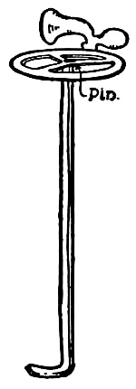
Fig. 389.—The Steering-wheel.
The Chauffeur should now be made. Cut his head and body the shape and size of Fig. 384, drawing the face upon each side with goggles over the eyes. Cut the arms in two pieces the shape of P and Q (Fig. 385), and then pivot P to Q at R and the end of Q to the shoulder of the body at S, using thread for fastening the pieces together. Paint the hat, coat, sleeves, and gloves a leather color, and the face flesh[Pg 351] color. The body should then be fastened to the hammer of the clockworks with sealing-wax, as shown in Fig. 386, while the left hand should be glued to the edge of the steering-wheel and the right to the end of the brake (see Fig. 375). By thus attaching the body to the end of the hammer, and winding up the small spring, the chauffeur will shake violently when the auto runs across the floor, showing the vibrations of the machine in a greatly exaggerated and amusing manner.
It is now only necessary to
Paint the Machine to complete it. The photograph (Fig. 375) indicates the different colors used. The lamps, and top, ends, and sides of the front portion of the car should be painted the color of brass, and the rest of the sides, with the exception of a strip along the bottom and the edge of the arms, should be painted vermilion. Paint the inside of the car and the edges of the seat-arms tan color, to represent leather upholstering. With black paint, or ink, stripe off the door and trimmings upon the sides and top of the machine, as shown in Figs. 375, 387, and 388. Blacken the brake and steering-wheel and the spokes and rims of the wheels. Along the bottom of each side roughly indicate some machinery with black paint, about as it is drawn in Fig. 387.
When you have tired of your touring-car, you can easily convert it into
[Pg 352]An Automobile Delivery Wagon, such as illustrated in Fig. 390. To make this you will require the same frame as that used for the touring-car, with the clockworks and belt-wheels attached in the same manner. If you have made the touring-car, remove the cardboard sides from its wooden frame, separating the cardboard from the wood carefully, so you can put the machine together again when you wish. If you haven't made this automobile, you will find the details for the construction of the frame in Figs. 376 and 377, and the manner of performing the work described on pages 343 to 346.
[Pg 353]The Cardboard Sides are much easier to prepare than those for the touring-car, as they are straight and require but little cutting. The outline for these is shown in Fig. 390, surrounding the drawing of the completed wagon. Lay out one side upon a piece of cardboard, using the dimensions given upon the drawing, and then place it upon a board and cut it out with your knife. Using this as a pattern, place it upon another piece of cardboard and run a pencil around its edges, thus marking out the second side. In cutting out the latter piece, run your knife a little inside of the line in order to allow for the increase in size caused by marking it out with the first cardboard side. Having prepared the two sides, draw panels upon them in some such form as shown in the illustration, separating them with three lines. Draw a small window, with its top slightly arched, near the front edge of each side, and cut an opening for it (see illustration).

Fig. 390.—An Automobile Delivery Wagon.
Glue the sides to the edges of the truck in the same manner as those of the touring-car were done, piercing holes for the posts of the clockworks to fit in, and openings for the belt-wheels to project through, in the left side. Cut a piece of cardboard for the back of the wagon, fit it between the sides, and fasten it in place by gluing a number of linen strips to it and the sides upon the inner or unexposed surfaces. Then cut a piece of cardboard for the roof, making it about two inches longer than the sides, to give it the proper[Pg 354] projection over the front of the wagon. Fasten this piece in position in the same manner as you fastened the back of the wagon.
Make the floor and footboard for the wagon out of a piece of cardboard bent as shown in Fig. 390, and fasten it across the top edges of the projecting portions of the sides with linen strips. Cut a strip for a seat, and fit it between the sides an inch and one-half above the floor.
The Wheels of an automobile wagon contain fourteen spokes, but as you have the pattern for the touring-car wheels of twelve spokes, you can just as well use it in making the wagon wheels. They should be mounted upon the sides of the wagon, a trifle above the bottoms of the spool wheels, as shown in the illustration, so they will not touch the carpet when the machine is operated.
All Other Portions of the wagon should be made of the same patterns given for the touring-car, viz. the chauffeur (Figs. 384 and 385), the steering-wheel (Figs. 382 and 389), the brake (Fig. 375), and the lamps (Fig. 381). As the legs of the chauffeur will show, it will be necessary to cut a pair out of cardboard (the drawing shows the shape clearly enough to work by) and fasten them to his body. Fasten the chauffeur upon the seat and glue his left hand to the steering-wheel, placing the latter in front of him, as shown in the drawing. Stick the lower end of the cardboard[Pg 355] upright of the steering-wheel upon a pin run through the wagon floor from the under side. Glue the upper end of the brake to the chauffeur's hand and the lower end to the side of the wagon.
Paint the Wagon with water colors, making the sides, end, and roof olive green, the steering-wheel, brake, and spokes of wheels black, and the lamps yellow or the color of brass. In painting the sides show the battery compartments upon them below what would properly be the bottom of the wagon (see illustration). Leave the cardboard white below this box, as it represents no portion of the machine, but is necessarily brought down so far to conceal the wooden frame. It will give the machine a more finished appearance if, after painting, you go over it with black paint and a fine brush and stripe the panels upon the sides, following the lines which you drew upon them with a pencil. Letter the word "Delivery" upon the centre panel of each side, and the firm name in the small panel between the lamp and window.
By attaching a set of clockworks in the same manner as described for the automobiles, you can make
A Clockwork Railway, constructing the cars similarly to the street car shown in Fig. 363, Chapter XXV, and using the schemes in the same chapter for the tracks and depots.
A number of years ago a friend of the writer paid a visit to a large penitentiary where the prisoners were engaged in the manufacture of boots and shoes. Among the workers he became particularly interested in a small German boy who was industriously marking the backs of boots with the lot numbers always to be found upon these goods. The boy didn't have an ink bottle near him, and yet, with what appeared to be a wooden stick, was marking the numbers in ink. A closer inspection disclosed the fact that the pointed stick held by the lad was nothing more or less than
A Home-made Fountain Pen.—Upon seeing that the visitor was struck with the novelty of the affair, the superintendent presented him with one of the pens and told him of its origin. The pen was the invention of a forger who was placed in this department of the prison, and when its good qualities were seen it was very quickly adopted by all of the prisoners in place of the pointed stick and ink-bottle they had been using.
The pen is shown in Fig. 391. It is made out of a[Pg 357] piece of elderberry wood about five inches long, a small glass vial, and a piece of sponge. First push out the pith of the piece of elderberry wood (this you will find easily removed), and then point one end pen-shape, as shown in the illustration, and split it back from the point about an inch in the same manner as a writing pen is made. Whittle the other end of the stick so it will fit tightly in the neck of the glass vial. This bottle, or reservoir, should be filled with ink, and a small piece of the sponge you have procured should be pushed into the hollow of the pen above the point (see illustration), as a means of preventing the ink from flowing too freely upon the point.

Fig. 391.—A Home-made Fountain Pen.
Although the pen was originally made with a coarse point for marking heavy figures, you will find that it can be made to write to a reasonable degree of fineness by whittling a fine point upon it.

Fig. 392.—The Magic Pin-wheel.
The Magic Pin-wheel represented by Fig. 392 can be made with a few minutes' work, and is something entirely new in the line of magic toys. There are probably[Pg 358] few persons who will understand this simple yet mysterious toy when they see it properly operated, until the secret is disclosed to them. As you will see by looking at the drawing, the pin-wheel consists of nothing more than a stick notched along one edge, and a thin piece of wood about an inch in length fastened through its centre to the end of the stick by means of a pin. In cutting the notches it is important to make them of the same length and depth. Locate the exact centre of the chip of wood before pivoting it to the end of the stick, and with your knife make a small hole for the pin to run through at this point. Be careful to drive the pin in straight.

Fig. 393.—How to operate the Pin-wheel.
To Operate the pin-wheel, hold the stick in the left hand as illustrated in Fig. 393, and then, taking a coin in the right hand, rub it vigorously across the notches. The vibration produced by rubbing the stick causes the small pin-wheel to revolve about its pin axis. The funny part of the performance is the fact that you can have perfect[Pg 359] control over the wheel, and change the direction of its course at will, if you but master one little trick performed with the first and second fingers of the right hand. In holding the coin between the thumb and first finger of the right hand, allow the end of the first finger to extend over the top of the stick and bring the second finger close to the side of it, as shown in the illustration (Fig. 393). To make the wheel revolve from left to right, allow the end of the first finger to rub along the top edge of the notches; then, to reverse the direction, relieve the pressure of this finger, and press the second finger against the other edge of the notches.
At first you may not be able to make the wheel obey your commands, but with a little practice you will find it a simple matter to make it change its direction without any one noticing how you perform the magical trick.
A Brass Tack driven into the stick a little below the notches, about the point where the thumb of your left hand will strike, will add to the mystic appearance of the pin-wheel. A person invariably notices this the first thing when he sees you operate the wheel (you can make it a point to press your left thumb against the tack), and thinks he has solved the trick. But when you let him have the toy, he will soon find out that all his pressing and pulling upon the tack will have no effect upon the wheel, and beg you to "put him on" to the trick.
A Wooden Chain and Rattle has long been one of the most interesting pieces of work a boy can make with his[Pg 360] jack-knife, and, inasmuch as the making of one requires careful cutting, the exercise is a good test of a boy's skill with this handy tool.

Figs. 394-396.
Details of a Wooden Chain and Rattle.
In making the first chain and rattle, you had better use a pine block, as hard wood is not so easy for a beginner to handle. Therefore, for a first attempt, select a piece of sound pine free from blemishes, and plane it down to the dimensions, seventeen inches long, two inches wide, and two inches thick. With a lead-pencil mark off ten divisions one inch apart, running the lines[Pg 361] around the four sides of the block (see Fig. 394). Then draw two lines lengthwise on each side of the block, as shown at AB and CD, making them one-half inch apart and three-quarters of an inch from each edge. With a chisel, cut out the four corners of the block down to the tenth line, as represented by the shading in Fig. 394.
The Chain is to be cut out of the remaining core, one link out of every two divisions. Commencing at the top of the block, remove the shaded portions T and U (Fig. 395), as those would form only half links; then notch out the shaded corners marked X in the drawing, and gradually cut the core into circular links. Having finished this operation, draw a circle inside of each link, and cut out the wood inside of it. Round the edges of the links as shown in the drawing of the finished chain (Fig. 396).
Your success in making a good chain will depend largely upon a good, sharp knife and careful cutting. With a dull knife you are almost certain to split the links when separating one from another.
The Rattle is to be made from the lower portion of the block. This part of the figure is more difficult to cut than the chain. First draw the two lines marked HI and JK in Fig. 394 one-half inch from the edges; then draw the cross lines LM, NO, PQ, and RS, as shown in the illustration. These lines should be similarly drawn upon the other three sides of the block. Remove the wood from the spaces shaded in the drawing, and[Pg 362] you will then have left a centre solid block from which to cut the ball. Gently round the corners of this, and then gradually separate it from the surrounding framework. When this has been accomplished, the centre block will slip up and down. Now continue cutting the block until it is a perfect round ball, but be careful not to make it small enough to fall out of the frame, for that would spoil the entire piece of work.
After completing the cutting, sand-paper the links and rattle until they are perfectly smooth. Then oil the wood or give it a coat of varnish.
It is surprising the number of small toys that can be made out of corks of different shapes and sizes with the aid of glue, pins, burnt matches, worsted, and cardboard. Even though a boy has passed the kindergarten age, he will find this work entertaining for days when the weather is disagreeable without; and though he may not care to play with them himself, his work will not have been wasted, for a younger brother will surely be glad to have some cork animals and birds to add to his menagerie, and a sister no less delighted with a small log-cabin and set of cork furniture.

Fig. 397.—The Pig.
Flat and tapered corks can probably be found about the house on old jars and bottles, while the straight variety can be procured at any drug-store. In buying the latter ask for No. 9, inch and one-half, straight, common corks, half a gross of which will cost about twenty-five cents.
Cork Animals are peculiar-looking beasts of abnormal proportions, but all sorts of magical feats are performed by toy makers, and such wonders as
[Pg 364]A Pig that can boast of a body as large as that of an elephant is commonly found among the so-called Noah's ark animals. To make a pig, first draw its head, as in the drawing of Fig. 397, upon a piece of cardboard, and then, after cutting it out, select a straight cork and make a slit in one end of it in which to stick the head. A little glue applied to the cardboard will hold the head in place. The pig's feet consist of four pieces of burnt matches pointed at the ends and stuck into the cork as shown in Fig. 397, while the tail is formed of a piece of copper wire curled at one end and stuck into the cork. When the pig has been made, paint its head and feet to match its body.

Fig. 398.—The Horse.
A Horse requires a cork of the same shape as that used for the pig. Cut the head out of cardboard and glue it in a slit made in the end of the cork (see Fig. 398). Dip the ends of four burnt matches in glue and stick them in the cork for legs, and fasten a few pieces of worsted in a hole[Pg 365] made in the end of the cork for the tail. A piece of thread should be fastened about the animal's neck for reins.
After making the horse, take another straight cork for
The Elephant, and cut the head, trunk, ears, and tusks out of a piece of cardboard as shown in the illustration (Fig. 399). Cut the tail out of another piece of cardboard, and glue it in a slit made in the end of the cork. The legs are, of course, larger around than those of the horse, and, as matches will be too slender, whittle four short wooden pegs for them. Point these pegs at one end, and, after dipping them in glue, stick them into the cork.

Fig. 399.—The Elephant.
The Giraffe is just as simple to make as any of the animals, for he is put together in the same manner, except that a tapered cork is used for the body. The head and neck are made in one piece of cardboard (see illustration), and a piece of worsted forms the tail. When you have painted the head and neck a tan color to match the cork, and marked a[Pg 366] number of brown spots upon the body, this tall and most graceful of animals will appear very life-like.

Fig. 400.—The Giraffe.
A Porcupine is simple to make out of a long, straight cork with toothpicks cut into small pieces for quills, and stuck into the cork as close as you can place them. The head and other portions of this animal can easily be made with the aid of a natural history, and it will be a simple matter to devise
Other Animals upon the same schemes as those just described, by consulting the pictures in one of these books. It is not necessary to always copy a real animal. Use your ingenuity and see what queer-looking creatures you can make. Figure 401 gives a suggestion for one of these, which we will call
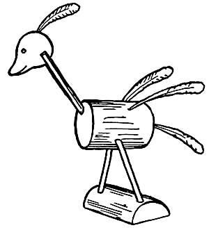
Fig. 401.—The Korka-bird.
The Korka-bird.—You will see by looking at the drawing that the two legs are made of matches, the lower ends of which are stuck into a piece of cork for a standard; and the neck consists of a burnt match stuck into the end of the cork with its upper end split to receive the cardboard head. A small chicken-feather stuck into the top of the head (the cardboard being split enough to receive it), two[Pg 367] others in the back, and a fourth in the end of the cork compose all the plumage this wonderful bird can boast of, but this lack of feathers is more than made up by a beautiful head, neck, body, and legs, which are gilded.
As a suggestion of what can be made in the way of water toys,
A Duck is shown in Fig. 402. The body for this consists of a cork split in half, the head is cut out of a piece of cigar-box, and a small tin keel is fastened to the centre of the under side of the body. A few chicken feathers will form the tail. Glue, of course, cannot be used upon the duck, as it would soften in water, so the pieces composing it will have to be fastened together by means of pins. Other water toys, such as
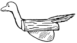
Fig. 402.—The Duck.
Canoes, consisting of a cork split in half, lengthwise, with the inside scooped out by means of your knife, are made with a few minutes' work, and these can be transformed into
Small Sail-boats by sticking a toothpick in the bow for a mast and rigging a tiny sail upon it.
Cork Furniture is not a new idea for toys, but, inasmuch as many have never heard of them, a few examples of what can be made in this line have been introduced in this chapter. For
[Pg 368]
Fig. 403.—Chair.
A Chair, such as shown in Fig. 403, find a flat cork, and stick four pins in one side for legs, and five pins fairly close together in the other side for the chair-back (see illustration). When the pins have been properly placed, take some worsted and wind it around each of the four legs, crossing from one to another as shown in the drawing, thus forming the chair-rounds. Also weave the worsted in and out around the pins forming the chair-back as in the drawing, so that all but the heads of the pins are covered when the operation is completed.
The Sofa, illustrated in Fig. 404, is made after the same manner. Split a straight cork lengthwise for the seat, placing it flat-side up, and stick pins around three edges of it upon which to wind the worsted.

Fig. 404.—Sofa.
A Small Tabouret is shown in Fig. 405. Select a straight cork for the base of this, and, after seeing that a good sharp edge is upon your knife, slice the cork lengthwise, making it hexagonal in shape. Then stick six pins[Pg 369] in the cork near the upper edge, placing one in each of the six edges (see illustration). When this has been done, weave worsted upon the pins in the same manner as the chair-back was formed.
Fig. 405. Tabouret.
A Toy Log-cabin, or slab-hut, as it would properly be called, as the building is first put up and then covered with corks split in half for slabs, is illustrated in Fig. 406. A cardboard box should be procured out of which to make this little building, the proportion of which will determine the shape and size. Turn the box bottom side up, and on it construct a gable-roof. Cut two pieces of cardboard large enough to make a good projection over the ends of the building, and fasten them to the bottom of the box as shown in the drawing, gluing a number of linen strips to the pieces to hold them securely in place. Two pieces of cardboard should be cut to fit the gable-ends, and glued in place with linen[Pg 370] strips. Cut windows in each side of the box and a door in each end. Having completed the little cardboard cabin, split enough straight corks in half lengthwise to cover the walls. Sharpen your knife well before commencing this work, so the corks will cut evenly and without breaking. Begin gluing these half corks along the bottom of the walls, fitting them end to end as shown in the drawing, and placing one row above another. Fit them neatly around the windows and door openings, and if they do not space out as evenly as shown in the illustration, cut some shorter pieces to fill in. The corks will quickly adhere to the cardboard if you press your finger against each for a second or two after placing it in position.

Fig. 406.—A Cork Log-cabin.
The roof may be painted to represent boards or shingles, and a cork stuck in it as shown in the illustration will form the chimney. Cover the window openings with paper. Tissue-paper will admit more light than ordinary writing-paper, so probably will be the better material. Hinge a piece of cardboard to the jamb of each door opening, using small pieces of linen for hinges. Rule a few vertical lines upon the doors to represent the boards. All that now remains to be done to complete the cabin is the mounting, for which a seven-eighths-inch board should be procured. Use linen strips to fasten the cabin upon this board, placing them upon the inside surfaces of the walls, which can be reached by running your hand through the door openings.
The terms and phrases used in describing the work included in this book have been arranged alphabetically in this chapter, together with their definitions. This has been done for the purpose of furnishing a boy with a handy reference, with definitions in a clear and simple form, covering only such points as apply to his particular kind of work.
Abbreviations
d stands for "penny." E. G. 16d stands for sixteen-penny nails (see page 36).
I.e. or i.e. stands for "that is."
E. G. or e.g. stands for "for example."
Viz. or viz. stands for "namely, to wit."
" stands for "inch" or "inches." E. G. 2" means two inches.
' stands for "foot" or "feet." E. G. 2' means two feet.
etc. stands for "and so forth."
Abutting Surface.—Next or adjoining.
Animated Animals.—Animals (such as those used in the back-yard circus) which are constructed and then given life. In the case of the circus animals, the boys who enclose themselves in the bodies furnish the animals with life.
Bait-stick.—A stick in a trap, upon which the bait is placed. It is also known as the trigger.
Baluster. See Balustrade.
Balustrade.—A series of small spindles or posts (Balusters), to the tops of which a bar (Hand Rail) is attached, placed along the sides of stairs and around stair openings. The hand rail is supported at either end by a post (Newel Post). E. G. See Figs. 71 and 75. Also applied to a solid wall built up the sides of a stairway and around the stair openings.
Batten Door.—A door formed by joining the boards together with battens.
Battens.—Strips of wood, or cleats, fastened across two or more boards to hold them together, as in making a cover or door. E. G. See Figs. 15, 189, and 194.
Bevel.—Formed by cutting off the sharp edge of a board or any piece of
work. E. G. See Fig. 28.
A tool used for laying out bevels
Bird's Mouth.—A notch, V-shaped, or the form of a bird's mouth, cut in a piece of work. E. G. See Fig. 8.
Blind-nailing. See page 34.
Brace.—A strip, board, or heavier piece fastened across two or more pieces to strengthen and steady them; a diagonal strip.
Bracket.—A support, generally triangular in shape, screwed or nailed to a wall or object to hold up such things as shelves and cabinets.
Broom-wire.—The fine wire which is bound around brooms to hold the straw to the end of the broom-stick.
Bull's-eye.—The centre ring of a target.
Butt-joint.—When the square end of one piece of wood butts or sets against another piece, the joint formed is known as a butt-joint. The pieces are not cut into as in the case of making other joints.
Casings.—The finishing strips placed around door and window [Pg 373] openings. E. G. See Figs. 85, 88, and 89. They are also known as Trim.
Chair Rail.—A narrow board fastened around the walls of a room at a height equal to that of an ordinary chair-back.
Chamfer.—Formed by cutting off the sharp edge of a board. It is much the same as a bevel (see Fig. 28), but the term is more often applied to cases where the bevel is stopped, instead of running the entire length of the edge, and its ends rounded up to meet the square edge of the board. This form of chamfer is used for ornamental purposes, and is known as a Stop Chamfer. Figure 29 shows a form of chamfer used in planing end-wood.
Cleats.—Strips of wood fastened to others to strengthen them; or strips secured to an object for the purpose of supporting a shelf or drawers. E. G. See Figs. 15 and 148; also descriptions relating to same.
Clinching Nails. See page 34.
Corbelled Brick.—Several courses (layers) of brick so laid that each projects a little beyond, or comes a little within, the course below. E. G. See corbelled chimney for doll-house, Fig. 103, Chapter VI.
Corner Stone.—A stone placed in the corner of a foundation.
Cornucopiæ.—The plural for cornucopia; made by rolling paper or other material into the shape of cones or funnels.
Countersunk. See Screws on page 36.
Cross-piece.—A piece that crosses another; a piece fastened in a horizontal or oblique position, and extended from one piece to another.
Cross Section. See Section.
Details.—The parts of which a thing consists; a Detailed Drawing is usually a working drawing, showing all the parts of a piece of work, with dimensions marked upon them.
Diagonal.—A strip, board, or heavier piece fastened in an [Pg 374] oblique, or slanted, position—used in bracing (see Bracing of Toboggan Platform Framework, Fig. 310); also a line drawn obliquely to another line, several lines, or an object.
Diagonally.—In a diagonal direction.
Diameter.—The distance equal to a straight line passing through the centre of a circle or a circular object, terminated at both ends by the circumference, or the curved surface.
Door Frame.—The wooden frame built in a door opening for the door to swing in. For definition of Jambs, Sill, and Head, see Window Frame.
Door-stops.—Wooden strips nailed around the Jambs and Head of a door frame, for the door to swing against, and to make a tight joint between the door and frame.
Dovetail-joint.—A tongue, undercut so as to make it wedge-shaped (somewhat the shape of a dove's tail), is prepared upon one piece, and a mortise, the shape and size of this tongue, is cut in the other piece for it to set into. E. G. See Figs. 209 and 210, and text on page 210, Chapter XV.
Dowelling.—A process of securing together two edges or faces of a piece of work with pins of wood or metal. Holes are bored in the edges or faces of the pieces, and wooden pegs are cut to fit them. These pegs are coated with glue and then driven into place. The edges or faces of the pieces are also covered with glue, and if the pieces have been properly planed so as to fit together perfectly, a tight joint will be obtained when the glue has dried. The work should be clamped until the glue has dried. E. G. See Fig. 54. For nails used as dowels, see Fig. 357.
Dowels.—The pegs or pins used in dowelling.
Dressed.—After lumber has been planed at a mill, it is known as "dressed stuff." A board may be dressed to the proper dimensions, that is, prepared either by sawing, planing, paring, or scraping.
Driving Home a Nail.—The act of applying the finishing strokes [Pg 375] of a hammer upon the head of a nail in driving it into wood (see Driving Nails, page 32).
Drop.—A piece of scenery hung from the Gridiron above the stage. E. G. See Figs. 331, 332, and 340.
Elevation.—A straight Side or End view of an object. E. G. See Fig. 206.
Em.—A square type. Used as a unit in measuring type. The letter "m" in type originally had a square end.
En.—A type half an "em" in width.
End-plate.—A timber, such as a two-by-four or two-by-six, placed across the tops of the studs in the end of a framework, for the roof rafters or the floor joists above to rest upon. E. G. See Fig. 184. When placed across the studs in the side of a framework it is known as a Side-plate.
End-wood.—Wood which has been cut across the grain and shows the ends of the grain upon its surface. E. G. The end of a stick.
Equidistant.—Equally distant.
Finishing Nail.—A nail with a small head used on surfaces to be exposed, where it is desirable to make as small nail holes as possible. The finishing nail is very handy for all kinds of small work.
Fishing.—An operation where two or more pieces are joined together, end to end, by means of strips (known as Fish-plates) nailed or screwed across the joints. It is also known as a Fish-joint, and is a common form of splice. E. G. See Fig. 183.
Flange.—A projecting rim such as the edge of a spool.
Flush.—A surface of a board is said to be flush with the surface of another when those boards are so placed together that the two surfaces are even, or extend along the same line or plane.
Font.—An assortment of type of one size and style, including [Pg 376] a certain number of each letter in the alphabet (large and small), punctuation marks, and such characters as are necessary in printing. Spaces and Quads are sold separately.
Foundation.—The base upon which a building rests. Usually made of stone, brick, or posts, and placed below the surface of the ground.
Gable-end.—That portion of a wall which extends into the angle formed by a gable or gambrel roof. E. G. See Figs. 64, 77, 96, and 109.
Gauge of Tracks.—The distance between the tracks.
Grease Paint.—A paint for the purpose of making-up the face in preparation for a circus or entertainment of some sort. Prepared of a composition easily removed, and free from injurious substances.
Gridiron.—The framework above the stage from which the scenery drops are suspended. The framework consists of a series of parallel bars resembling a gridiron.
Groove.—A channel or hollow cut in a piece of wood. In a tongued-and-grooved board it is the hollow in which the tongue fits.
Halving. See Fig. 267; also description on page 259. This joint is also known as a Halved-joint.
Hand Rail. See Balustrade.
Hem.—The edge of a piece of cloth doubled over and sewed, to strengthen it and prevent the threads from ravelling.
Hexagonal.—Six-sided.
Horizontal.—Parallel to the horizon.
Hornstone.—A variety of quartz having the appearance of flint, but more brittle.
Kerf.—The opening, or narrow slot, made in sawing.
Latch-pocket. See Spring-catch.
Lath.—A strip approximately one and one-half inches wide, [Pg 377] three-eighths of an inch thick, and four feet long. Nailed across the walls and ceiling of a room upon which to place plaster.
Locking-up.—The process of tightening a form of type so as to hold it together (see description, page 136).
Longitudinal Section. See Section.
Making-up.—Painting the face as a disguise or to show expression marks.
Mitre.—The end of a board is mitred when cut off at an angle of forty-five degrees. Although applied to other angles, the term mitre is understood to mean a forty-five degree cut, unless otherwise stated (see Bench-hook, Fig. 11, and Mitre-box, Fig. 12, Chapter I; also descriptions of their use).
Mitred Try-square.—Used for laying off mitres (see Figs. 38 and 39, Chapter II).
Mortise.—A slot or cavity made in a piece of wood to receive the end of another piece. E. G. See Figs. 208, 210, 211, Chapter XV. Bevelled Mortise.—A mortise with its bottom or sides bevelled. E. G. See Fig. 10, Chapter I.
Mould.—Something which serves to give the proper form to an object. E. G. The mould for shaping a canvas canoe, Fig. 204, Chapter XV.
Newel Post. See Balustrade.
Notch.—A hollow cut in anything; a nick; an indentation. To Notch.—To cut in small hollows, as to notch a stick. E. G. See Fig. 191, Chapter XIV, and Fig. 392, Chapter XXVII.
Obsidian.—A form of lava.
On Centres.—In spacing studs or strips of any kind, they are spoken of as being placed a certain number of inches on centres. E. G. Twelve inches on centres means that the distance from the centre of one piece to the centre of another is twelve inches.
[Pg 378]Out of Plumb.—Not vertical; not perpendicular to the horizon.
Out of Square.—Askew; oblique; not true.
Parallel.—Lines or objects are parallel to one another when they have the same direction, and all corresponding points are equidistant from one another.
Perpendicular.—Vertical; plumb; in an upright position.
Perspective.—A perspective is a drawing showing an object in the form in which it appears to the eye. The lines converge, or approach nearer together, as they go away from the eye, until they finally meet at a point on the horizon, or a line drawn to represent the horizon. E. G. In looking down a railway track the telegraph poles and tracks appear to run together on the line of the horizon.
Pica.—The standard of measurement in printing. A name given to a size of type which measures one-sixth of an inch high (measured from the nicked side to the side opposite); and seventy-two ems (see Em) measure one foot.
Pie.—A mixed assortment of type. See page 135, Chapter IX.
Pieing Type or Making Pie.—Spilling or mixing up type.
Pipe-straps.—Iron straps used mostly by pipe-fitters to fasten gas-piping in place. E. G. See Figs. 321 and 322.
Pitch.—The pitch of a board is the degree to which it has been tilted.
Plan.—A drawing showing a view of an object, looking down upon it, either on top of it (e. g. see Figs. 205 and 207), or with the upper portion sliced off (e. g. see Fig. 190. This shows a plan of the log-cabin at a level of the door and windows, with the upper portion removed).
Plank.—Lumber two inches or more in thickness is known as planks or planking. Anything of less thickness is known as boards.
[Pg 379]Plumb.—Perpendicular; vertical; true. An instrument for determining whether or not an object is plumb (see Fig. 14, Chapter I).
Proscenium.—The front portion of a stage. The Proscenium Arch is the arch or frame extending around the front of the stage of a theatre.
Pumice Stone.—A porous rock, of extreme lightness, used for polishing metals; for smoothing the surface of wood; and for smoothing the surface of a coat of paint before applying a second coat (see Painting of Canvas Canoe, page 214).
Pyrotechnics.—The art of making fireworks; fireworks; the composition and use of fireworks.
Quad.—An abbreviation for quadrat. A block of type-metal lower than the type, used for filling out lines, and for spacing between lines. A 2-em quad is two "ems" in width, and a 3-em quad three "ems" in width.
Quartz.—Glassy crystals, having the form of a six-sided prism, terminated at each end by a pyramid. It is colorless, or transparent, when pure, and more or less opaque and in various colors when impure.
Quoins.—The wedges used to tighten or lock-up a form of type. E. G. See Figs. 155 and 156.
Rabbet.—A groove or hollow cut in a piece of work, generally for the purpose of joining it with some other material. E. G. The sides of the bow and stern pieces of the Canvas Canoe described in Chapter XV are rabbeted so the ribbands and the edge of the canvas will fit in them (see Figs. 200 and 202, Chapter XV).
Radius.—The distance from the centre of a circle to any point upon its circumference. It equals one-half of the length of the diameter.
Rasp.—A file with coarse teeth, used for working upon wood.
[Pg 380]Recess.—A niche in a wall; a space or opening formed by the wall setting in a little way.
Reënforce.—To strengthen; to supply additional strength with strips or braces.
Ridge.—An edge of a roof formed by the meeting of two sloping surfaces. The top edge of a peaked roof. E. G. See Fig. 192, Chapter XIV.
Ridge-boards.—The boards fastened along the ridge of a roof to cover the joint. E. G. See Fig. 192, Chapter XIV.
Right Angle.—An angle of ninety degrees. At Right Angles.—So as to form a right angle.
Rubbing Down.—Bringing to a smooth surface by rubbing with sand-paper, emery-paper, or pumice stone.
Rustic.—Made of limbs of trees in their natural form.
Sagging.—The bending of a body by its own weight, or by a load placed upon it.
Sapling.—A young tree.
Sash.—The frame which holds the glass of a window. Also applied to the frame with the glass in place.
Scraping.—A piece of glass or the blade removed from a plane is used for scraping a piece of work to give it a smoother surface than can be obtained by using a plane upon it.
Section.—A part.
Section Drawing.—A drawing made of an object, showing it as it would
look if you were to cut it open or split it in two. The portions which
would have to be cut through, in such an operation, are shaded in a
drawing of this kind. E. G. See Fig. 218, Chapter XV; Fig. 300, Chapter
XXI; and Fig. 316, Chapter XXII.
A Cross Section is a section taken through the short way of an
object.
A Longitudinal Section is a section taken through the long way of
an object.
Selvage.—The selvage of cloth or wire-mesh is the edge which has been so woven as to prevent ravelling.
Semicircle.—Half a circle.
Set of a Saw's Teeth. See page 21, Chapter II.
Setting Nails. See page 34, Chapter II.
Shape it Down.—A term used to imply that the board or piece of work shall be gradually cut down until it approaches its finished form and size.
Shooting Stick.—An iron or wooden tool with a head on one end, used to lock-up the Quoins in a form of type. E. G. See Fig. 155, Chapter IX.
Sills.—The lowest horizontal timbers in a building of any kind on which the structure rests. See also Window Frame.
Sleepers.—The timbers supporting the lower floor of a building, distinguished from joists by being filled in between with cinders or concrete. E. G. See Fig. 186, Chapter XIII.
Slip-knot.—A noose which slips along the line or rope around which it is tied. E. G. See Fig. 243, Chapter XVII.
Slot.—A mortise, or hole, with sides square or nearly so. Made by boring several holes, and then connecting and squaring them up with a chisel.
Space.—A thin piece of type-metal, lower than the type, used between words, and for spacing out lines. A 3-em space is a third of an "em" in width, a 4-em a quarter of an "em" in width, a 5-em a fifth of an "em," and an 8-em (known as a hair space) is an eighth of an "em."
Spike.—A twentypenny nail (four inches long) and all lengths greater. See list of sizes on page 36, Chapter II. To Spike a board in place is to fasten it with spikes.
Spliced.—Two pieces are spliced when joined together, generally end to end, in such a way that they are held together and act as one piece. E. G. See Fig. 183, Chapter XIII, and Fishing.
Spring-catch.—A small lock, such as shown in Figs. 96, 114, [Pg 382] and 187. The latch is operated by a small knob, and is thrown into position by a small spring. The metal socket which is screwed in place for the latch to spring into is known as the Latch-pocket.
Sprint.—A short race run at full speed.
Squaring Lines.—By squaring lines across a board is meant the operation of drawing lines across a board with a try-square, the head of the try-square being placed against the tried-edge of the board so those lines will be at right angles to that tried-edge. E. G. See Fig. 38, Chapter II.
Staple.—A U-shaped piece of metal, with two sharp points which are driven into wood in the same way as a nail.
Stock.—Material; supplies.
The brace which holds the bit for boring; the block which holds the
blade of a plane (see Fig. 24, Chapter II); the portion of a gun which
contains the barrel and trigger.
Stops. See Door-stops and Window-stops.
Strap-hinge.—A hinge with long arms, or flaps, which extend over a larger area than those of an ordinary hinge, and give it the power of withstanding greater strains.
Studs.—The smaller pieces of timber used in the framework of a building, to which the siding is attached, or to which the laths are nailed. Known also as Studding.
Stuff.—In carpenter work this term is applied to the different sizes of lumber. E. G. Seven-eighths-inch stuff means boards seven-eighths of an inch thick; two-inch-stuff is lumber two inches thick.
Stunt.—Originally a slang word used to denote a trick or feat of some sort. It is now generally recognized as a legitimate word.
Swivel.—A fastening with a pivot which allows the object attached to it to revolve without twisting the cord, wire, or chain, by which that object is suspended. E. G. See Fig. 258, Chapter XVIII; and page 249.
Taper.—To make gradually smaller in diameter toward one end; to gradually diminish toward a point.
Temper.—Steel and iron tools are given their necessary degree of hardness by a process of heating and cooling, known as Tempering. Too much friction obtained while grinding a tool will destroy this temper, making it necessary to re-temper it.
Toe-nailing. See page 33.
Tongue.—The projecting edge of a tongued-and-grooved board. A projecting pin cut on a piece of wood to fit a mortise of the same shape cut in another piece of wood. Used in making Dovetail-joints. E. G. See Figs. 208 and 209, Chapter XV.
Tongued-and-grooved Boards.—Boards with a groove along one edge and a tongue along the opposite edge, so that the tongue of one board will fit in the groove of another, thus forming a fairly tight joint. These boards are known also as Matched Boards.
Trench.—A ditch; a long channel.
Tried-edge of Work. See Testing Work, page 28.
Trim.—The wooden Casings placed around door and window openings (see
Figs. 85, 88, and 89, Chapter V).
To dress a piece of work; to cut; to make smooth.
Turnstile.—A post upon the top of which four horizontal arms are pivoted to revolve, so as to allow but one person to pass at a time (see Fig. 266, Chapter XIX, and description of construction on page 259).
Two-by-four.—A piece two inches thick by four inches wide used for supports and the construction of frameworks. Pieces of other dimensions are also known and spoken of by their sizes inches. E. G. Two-by-sixes, two-by-eights, and two-by-tens.
Typographical.—Relating or pertaining to typography.
Typography.—The art of setting type.
Undercutting.—As the term implies, the wood is undercut, or cut under, thus making it wedge-or V-shaped. E. G. See Fig. 209, Chapter XV; also text on page 211.
Upright.—An upright is a piece of timber which is perpendicular when in place.
Valance.—A drapery for a couch or bed. E. G. See Couch in illustration of a Boy's Room, Chapter V.
Vertical.—Perpendicular to the horizon; upright; plumb; straight up and down.
Wainscot.—A lining placed upon the inside walls of a building. It was originally made of oak timbers, known as wainscot, but the term is now applied to any kind of wood, burlap, tapestry, or other material applied in the same manner. As a rule, it extends but part way up a wall, starting at the floor line.
Warped.—Twisted out of shape.
Washer.—A ring placed beneath the head of a bolt to give it a broader bearing surface, and thus prevent it from cutting into the surface of the piece of work. It is also placed under a nut to prevent it from working loose.
Wedge-shaped.—V-shaped.
Window Frame.—The wooden frame built in the window opening for the sash to fit into. The Jambs are the sides of this frame, the Sill the bottom piece upon which the Jambs rest, and the Head the top piece of the frame. E. G. See Figs. 187 and 188, Chapter XIII, and Fig. 193, Chapter XIV.
Window-stops.—Wooden strips nailed around the Jambs, Head, and Sill of a window frame to prevent rain and wind from entering between the sash and its frame.
Wing.—A piece of scenery placed at the side of the stage. E. G. See Figs. 333, 334, 335, 341, and 342, Chapter XXIV.
Transcriber's Notes:
Apparent printer's errors have been corrected. Hyphenation has been standardised. All other inconsistencies are as in the original. The author's spelling has been maintained.