
|
Note: Images of the original pages are available through Internet Archive. See https://archive.org/details/steamengineexpla00lardrich Some characters might not display in the html version. If so, the reader should consult the iso-8859-1 (Latin-1) text file 42602-8.txt (http://www.gutenberg.org/files/42602/42602-8.txt) or 42602.zip (http://www.gutenberg.org/files/42602/42602-8.zip) |

The Drawings for several of the Cuts in this Volume have been taken, by the permission of Mr. Weale, from the admirable Plates annexed to the last edition of Tredgold on the Steam Engine and on Steam Navigation. This acknowledgment is especially due for the Illustrations which abound in this Volume.
London, June, 1840.

Advanced as we are in the art of rendering knowledge popular, and cultivated as the public taste is in the appreciation of the expedients by which science ministers to the uses of life, there is still perhaps but one machine of which such a proposition can be truly predicated: it is needless to say that that machine is the STEAM ENGINE. There are many circumstances attending this extraordinary piece of mechanism which impart to it an interest so universally felt. Whether we regard the details of its structure and operation, the physical principles which it calls into play, and the beautiful contrivances by which these physical principles are rendered available;—or, passing over these means, we direct our attention to the ends which they attain, we are equally filled with astonishment and admiration. The history of the steam engine offers to our notice a series of contrivances which, for exquisite and refined ingenuity, stand without any parallel in the annals of mechanical science. These admirable inventions, unlike other results of scientific inquiry, have also this peculiarity, that, to understand their excellence and to perceive their beauty, no previous or subsidiary knowledge is necessary, save what may be imparted with facility and clearness in the progress of the explanation and development of the machine itself. A simple and clear exposition, divested of needless technicalities and aided by well-selected diagrams, is all that is necessary to render the construction and operation of the steam engine, in all its forms, intelligible to persons of plain understanding and moderate information.
But if the contrivances by which this vast power is brought to bear on the arts and manufactures, be rendered attractive by their great mechanical beauty, how much more imposing will the subject become when the effects which the steam engine has produced upon the well-being of the human race are considered. It has penetrated the crust of the earth, and drawn from beneath it boundless treasures [Pg005] of mineral wealth, which, without its aid, would have been rendered inaccessible; it has drawn up, in measureless quantity, the fuel on which its own life and activity depend; it has relieved men from their most slavish toils, and reduced labour in a great degree to light and easy superintendence. To enumerate its present effects, would be to count almost every comfort and every luxury of life. It has increased the sum of human happiness, not only by calling new pleasures into existence, but by so cheapening former enjoyments as to render them attainable by those who before could never have hoped to share them: the surface of the land, and the face of the waters, are traversed with equal facility by its power; and by thus stimulating and facilitating the intercourse of nation with nation, and the commerce of people with people, it has knit together remote countries by bonds of amity not likely to be broken. Streams of knowledge and information are kept flowing between distant centres of population, those more advanced diffusing civilisation and improvement among those that are more backward. The press itself, to which mankind owes in so large a degree the rapidity of their improvement in modern times, has had its power and influence increased in a manifold ratio by its union with the steam engine. It is thus that literature is cheapened, and, by being cheapened, diffused; it is thus that Reason has taken the place of Force, and the pen has superseded the sword; it is thus that war has almost ceased upon the earth, and that the differences which inevitably arise between people and people are for the most part adjusted by peaceful negotiation.
Deep as the interest must be with which the steam engine will be regarded in every civilised country, it presents peculiar claims upon the attention of the people of Great Britain. Its invention and progressive improvement are the work of our own time and our own country; it has been produced and matured almost within the last century, and is the exclusive offspring of British genius, fostered and sustained by British enterprise and British capital.
The steam engine is a mechanical contrivance, by which coal, wood, or other fuel is rendered capable of executing any [Pg006] kind of labour. Coals are by it made to spin, weave, dye, print and dress silks, cottons, woollens, and other cloths; to make paper, and print books upon it when made; to convert corn into flour; to express oil from the olive, and wine from the grape; to draw up metal from the bowels of the earth; to pound and smelt it, to melt and mould it; to forge it; to roll it, and to fashion it into every desirable form; to transport these manifold products of its own labour to the doors of those for whose convenience they are produced; to carry persons and goods over the waters of rivers, lakes, seas, and oceans, in opposition alike to the natural difficulties of wind and water; to carry the wind-bound ship out of port; to place her on the open deep ready to commence her voyage; to throw its arms around the ship of war, and place her side by side with the enemy; to transport over the surface of the deep persons and information, from town to town, and from country to country, with a speed as much exceeding that of the ordinary wind, as the ordinary wind exceeds that of a common pedestrian.
Such are the virtues, such the powers, which the steam engine has conferred upon COALS. The means of calling these powers into activity are supplied by a substance which nature has happily provided in unbounded quantity in every part of the earth; and though it has no price, it has inestimable value: this substance is WATER.
A pint of water may be evaporated by two ounces of coals. In its evaporation it swells into two hundred and sixteen gallons of steam, with a mechanical force sufficient to raise a weight of thirty-seven tons a foot high. The steam thus produced has a pressure equal to that of common atmospheric air; and by allowing it to expand, by virtue of its elasticity, a further mechanical force may be obtained, at least equal in amount to the former. A pint of water, therefore, and two ounces of common coal, are thus rendered capable of doing as much work as is equivalent to seventy-four tons raised a foot high.
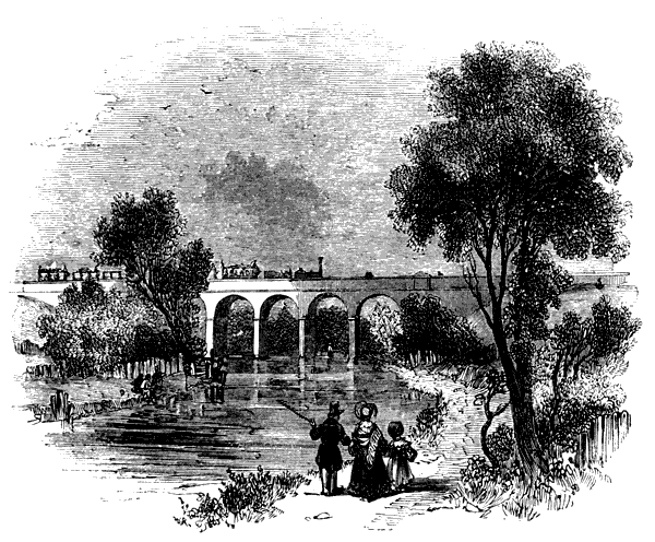
The circumstances under which the steam engine is worked on a railway are not favourable to the economy of fuel. Nevertheless a pound of coke burned in a locomotive engine [Pg007] will evaporate about five pints of water. In their evaporation they will exert a mechanical force sufficient to draw two tons weight on the railway a distance of one mile in two minutes. Four horses working in a stage-coach on a common road are necessary to draw the same weight the same distance in six minutes.
A train of coaches weighing about eighty tons, and transporting two hundred and forty passengers with their luggage, has been taken from Liverpool to Birmingham, and back from Birmingham to Liverpool, the trip each way taking about four hours and a quarter, stoppages included. The distance between these places by the railway is ninety-five miles. This double journey of one hundred and ninety miles is effected by the mechanical force produced in the combustion of four tons of coke, the value of which is about five pounds. To carry the same number of passengers daily between the same places by stage-coaches on a common road, would require twenty coaches and an establishment of three thousand eight hundred horses, with which the journey in each direction would be performed in about twelve hours, stoppages included.
The circumference of the earth measures twenty-five thousand miles; and if it were begirt with an iron railway, such a train as above described, carrying two hundred and forty passengers, would be drawn round it by the combustion of about thirty tons of coke, and the circuit would be accomplished in five weeks.
In the drainage of the Cornish mines the economy of fuel is much attended to, and coals are there made to do more work than elsewhere. A bushel of coals usually raises forty thousand tons of water a foot high; but it has on some occasions raised sixty thousand tons the same height. Let us take its labour at fifty thousand tons raised one foot high. A horse worked in a fast stage-coach pulls against an average resistance of about a quarter of a hundred weight. Against this he is able to work at the usual speed through about eight miles daily: his work is therefore equivalent to one thousand tons raised one foot. A bushel of coals consequently, as used in Cornwall, performs as much labour as a day's work of one hundred such horses. [Pg008]
The great pyramid of Egypt stands upon a base measuring seven hundred feet each way, and is five hundred feet high, its weight being twelve thousand seven hundred and sixty millions of pounds. Herodotus states, that in constructing it one hundred thousand men were constantly employed for twenty years. The materials of this pyramid would be raised from the ground to their present position by the combustion of about four hundred and eighty tons of coals.
The Menai Bridge consists of about two thousand tons of iron, and its height above the level of the water is one hundred and twenty feet. Its mass might be lifted from the level of the water to its present position by the combustion of four bushels of coal.
The enormous consumption of coals produced by the application of the steam engine in the arts and manufactures, as well as to railways and navigation, has of late years excited the fears of many as to the possibility of the exhaustion of our coal-mines. Such apprehensions are, however, altogether groundless. If the present consumption of coal be estimated at sixteen millions of tons annually, it is demonstrable that the coal-fields of this country would not be exhausted for many centuries.
But in speculations like these, the probable, if not certain progress of improvement and discovery ought not be overlooked; and we may safely pronounce that, long before such a period of time shall have rolled away, other and more powerful mechanical agents will supersede the use of coal. Philosophy already directs her finger at sources of inexhaustible power in the phenomena of electricity and magnetism. The alternate decomposition and recomposition of water, by magnetism and electricity, has too close an analogy to the alternate processes of vaporisation and condensation, not to occur at once to every mind: the development of the gases from solid matter by the operation of the chemical affinities, and their subsequent condensation into the liquid form, has already been essayed as a source of power. In a word, the general state of physical science at the present moment, the vigour, activity, and sagacity with which researches in it are prosecuted in every civilised [Pg009] country, the increasing consideration in which scientific men are held, and the personal honours and rewards which begin to be conferred upon them, all justify the expectation that we are on the eve of mechanical discoveries still greater than any which have yet appeared; and that the steam engine itself, with the gigantic powers conferred upon it by the immortal Watt, will dwindle into insignificance in comparison with the energies of nature which are still to be revealed; and that the day will come when that machine, which is now extending the blessings of civilisation to the most remote skirts of the globe, will cease to have existence except in the page of history.
In explaining the different forms of steam engine which have been proposed in the course of the progressive improvement [Pg010] of that machine from its early rude and imperfect state to its present comparatively perfect form, it will be necessary to advert to various physical phenomena and mechanical principles, which, however obvious to those who are conversant with matters of science, must necessarily be at least imperfectly known by the great majority of our readers. To refer for information on such topics to other works on Mechanics and general Physics, would be with most readers ineffectual, and with all unsatisfactory. In former editions of the present work, we consigned these necessary general principles of physics and mechanics to a preliminary chapter; but it appears, on the whole, more convenient not to remove the exposition of the principle from the place where its application is required. We shall therefore pause as we proceed, where these difficulties occur, to give such explanation and illustration as may seem best suited to render them intelligible and interesting to the unscientific reader.
The history of the arts and manufactures affords no example of any invention the credit for which has been claimed by so many different nations and individuals as that of the steam engine. The advocates of the competitors for this honour have urged their pretensions, and pressed their claims, with a zeal which has occasionally outstripped the bounds of discretion, and the contest has not unfrequently been tinged with prejudices, national and personal, and characterised by a degree of asperity altogether unworthy of so noble a cause, and beneath the dignity of science.
"When a question is clearly proposed, it is already half resolved." Let us see whether a careful attention to this maxim will aid us in the investigation of the origin of the steam engine. The source of the power of that machine is found in the following natural phenomena.
Such are the natural phenomena in which are found the original sources of all steam power. In some forms of steam engine one of these is used, and in some another, and in some the application of all of them is combined; but in no existing form of steam engine whatever is there any other source of mechanical power.
Neither these nor any other natural forces can be applied immediately to any useful purpose. The interposition of mechanism is indispensable; on the invention and contrivance of that mechanism depends altogether the useful application of these natural forces.
The world owes the steam engine then partly to discovery, and partly to invention.
He that discovered the fact, that mechanical force was produced in the conversion of water into steam, must be justly held to be a sharer in the merit of the steam engine, even though he should never have practically applied his discovery. The like may be said of him who first discovered the source of the mechanical power arising from the expansion of steam.
The discoverer of the fact, that steam being reconverted into water greatly contracted its dimensions, and thereby produced a vacuum, is likewise entitled to a share of the credit. [Pg012]
The mechanism by which these natural forces have been rendered so universally available as a moving power, is very various and complicated, and cannot be traced to one inventor. "If a watchmaker," says M. Arago, "well instructed in the history of his art, were required to give a categorical answer to the question, Who has invented watches? he would remain mute; but the question would be divested of much of its difficulty if he were required separately to declare who discovered the use of the main spring, the different forms of escapement, or the balance wheel." So it is with the steam engine. It is a combination of a great variety of contrivances, distinct from each other, which are the production of several inventors. If, however, one name more than the rest be entitled to special notice; if he is entitled to the chief credit of the invention who by the powers of his mechanical genius has imparted to the steam engine that form, and conferred upon it those qualities, on which mainly depends its present extensive utility, and by which it has become an agent of transcendant power, spreading its beneficial effects throughout every part of the civilised globe, then the universal voice will, as it were by acclamation, award the honour to one individual, whose pre-eminent genius places him far above all other competitors, and from the application of whose mental energies to this machine may be dated those grand effects which render it a topic of interest to all for whom the progress of civilisation has any attractions. Before the era rendered memorable by the discoveries of James Watt, the steam engine, which has since become an object of such universal interest, was a machine of extremely limited power, inferior in importance and usefulness to most other mechanical agents used as prime movers; but, from that epoch, it is scarcely necessary here to state, that it became a subject not of British interest only, but one having an important connection with the progress of the human race.
Hero of Alexandria, 120 B. C.
After having been allowed to slumber for nearly two thousand years, this machine has recently been revived, and engines constructed similar to it are now working in these countries. In the proper place we shall describe Avery's Rotatory Engine, which it will be seen is, not only in its principle, but almost in its details, the machine of Hero of Alexandria.
Although the elastic force of steam was not reduced to numerical measure by the ancients, nor brought under control, nor applied to any useful purpose, yet it appears to have been recognised in vague and general terms. Aristotle, Seneca, and other ancient writers, accounted for earthquakes by the sudden conversion of water into steam within the earth. This change, according to them, was effected by subterranean heat. Such tremendous effects being ascribed to steam, it can scarcely be doubted that the Greeks and Romans were acquainted with the fact, that water in passing into vapour exercises considerable mechanical power. They were aware that the earthquakes, which they ascribed to this cause, exerted forces sufficiently powerful to extend the natural limits of the ocean; to overturn from their foundations the most massive monuments of human labour; to raise islands in the midst of seas; and to heave up the surface of the land of level continents so as to form lofty mountains.
Such notions, however, resulted not as consequences of any exact or scientific principles, but from vague analogies derived from effects which could not fail to have been manifested in the arts, such as those which commonly occurred in the process of casting in metal the splendid statues which adorned the temples, gardens, and public places of Rome and Athens. The artisan was liable to the same accidents to which modern founders are exposed, produced by the casual presence of a little water in the mould into which the molten metal is poured. Under such circumstances, the sudden formation of steam of an extreme pressure produces, as is well known, explosions attended with destructive effects. The Grecian [Pg015] and Roman artisans were subject to such accidents; and the philosopher, generalising such a fact, would arrive at a solution of the grander class of phenomena of earthquakes and volcanoes.
Before natural phenomena are rendered subservient to purposes of utility, they are often made to minister to the objects of superstition. The power of steam is not an exception to this rule. It is recorded in the Chronicles, that upon the banks of the Weser the ancient Teutonic gods sometimes marked their displeasure by a sort of thunderbolt, which was immediately succeeded by a cloud that filled the temple. An image of the god Busterich, which was found in some excavations, clearly explains the manner in which this prodigy was accomplished by the priests. The head of the metal god was hollow, and contained within it a pot of water: the mouth, and another hole, above the forehead, were stopped by wooden plugs; a small stove, adroitly placed in a cavity of the head under the pot, contained charcoal, which, being lighted, gradually heated the liquid contained in the head. The vapour produced from the water, having acquired sufficient pressure, forced out the wooden plugs with a loud report, and they were immediately followed by two jets of steam, which formed a dense cloud round the god, and concealed him from his astonished worshippers.[1]
Among other amusing anecdotes showing the knowledge which the ancients had of the mechanical force of steam, it is related that Anthemius, the architect of Saint Sophia, occupied a house next door to that of Zeno, between whom and Anthemius there existed a feud. To annoy his neighbour, Anthemius placed on the ground floor of his own house several close digesters, or boilers, containing water. A flexible tube proceeded from the top of each of these, which was conducted through a hole made in the wall between the houses, and which communicated with the space under the floors of the rooms in the house of Zeno. When Anthemius desired to annoy his neighbour, he lighted fires under his boilers, and the steam produced by them rushed in such quantity and with [Pg016] such force under Zeno's floors, that they were made to heave with all the usual symptoms of an earthquake.[2]
Blasco de Garay, A. D. 1543.
Blasco de Garay, a sea captain, proposed in that year to the Emperor Charles V. to propel vessels by a machine which he had invented, even in time of calm, without oars or sails. Notwithstanding the apparent improbability attending this project, the Emperor ordered the experiment to be made in the port of Barcelona, and the 17th of June, 1543, was the day appointed for its trial. The commissioners appointed by Charles V. to attend and witness the experiment were Don Henry of Toledo, Don Pedro of Cardona, the treasurer Ravago, the vice chancellor and intendant of Catalonia, and others. The vessel on which the experiment was made was the Trinity, 200 tons burthen, which had just discharged a cargo of corn at Barcelona. Garay concealed the nature of his machinery, even from the commissioners. All that could be discovered during the trial was, that it consisted of a large boiler containing water, and that wheels were attached to each side of the vessel, by the revolution of which it was propelled. The commissioners having witnessed the experiment, made a report to the king, approving generally of the invention, particularly on account of the ease and promptitude with which the vessel could be put about by it.
The treasurer Ravago, who was himself hostile to the project, reported that the machine was capable of propelling a vessel at the rate of two leagues in three hours; but the other commissioners stated that it made a league an hour at the least, and that it put the vessel about as speedily as would be accomplished with a galley worked according to the common [Pg017] method. Ravago reported that the machinery was too complicated and expensive, and that it was subject to the danger of the boiler bursting.
After the experiment was made, Garay took away all the machinery, leaving nothing but the framing of wood in the arsenals of Barcelona.
Notwithstanding the opposition of Ravago, the invention was approved, and the inventor was promoted and received a pecuniary reward, besides having all his expenses paid.
From the circumstance of the nature of the machinery having been concealed, it is impossible to say in what this machine consisted; but as a boiler was used, it is probable, though not certain, that steam was the agent. There have been various machines proposed, of which a furnace and boiler form a part, and in which the agency of steam is not used. The machine of Amontons furnishes an example of this. It is most probable that the contrivance of Garay was identical with that of Hero. The low state of the arts in Spain in the sixteenth century would be incompatible with the construction of any machine requiring great precision of execution. But the simplicity of Hero's contrivance would have rendered its construction and operation quite practicable. As to the claims to the invention of the steam engine advanced by the advocates of De Garay, founded on the above document, a refutation is supplied by the admission, that though he was rewarded and promoted by the government of the day, in consequence of the experiment, and although the great usefulness of the contrivance in towing ships out of port, &c., was admitted, yet it does not appear that a second experiment was ever tried, much less that the machine was ever brought into practical use.
Solomon de Caus, 1615.
The treatise commences with definitions of what were then considered the four elements: earth, air, fire, and water. Air is defined to be a cold, dry, and light element, capable of compression, by which it may be rendered very violent. He says, "The violence will be great when water exhales in air by means of fire, and that the said air is enclosed: as, for example, take a ball of copper of one or two feet diameter, and one inch thick, which being filled with water by a small hole, which shall be strongly stopped with a peg, so that neither air nor water can escape, it is certain that if we put the said ball upon a great fire, so that it will become very hot, that it will cause a compression so violent, that the ball will burst in pieces, with a noise like a petard."
The effect which is here described is due to the combined pressure of the heated air contained in the ball and the high pressure steam raised from the water, but much more to the latter than to the former. It is evident, however, from the language of De Caus, that he ascribes the force entirely to the air, and seems to consider that the force of the air proceeded from the water which exhaled in it.
The first theorem is, "that the parts of the elements mix together for a time, and then each returns to its place" (the elements here referred to being apparently air and water). Upon this subject the following is an example: "Take a round vessel of copper, soldered close on every side, and with a tube, whereof one end approaches nearly to the bottom of the vessel, and the other end, which projects on the outside of the vessel, has a stop-cock; there is also a hole in the top of the vessel, with a plug to stop it. If this vessel will contain three pots of water, then pour in one pot of water, and place the vessel on the fire about three or four minutes, leaving the hole open; then take the vessel off the [Pg019] fire, and a little after pour out the water at the hole, and it will be found that a part of the said water has been evaporated by the heat of the fire. Then pour in one pot of water as before, and stop up the hole and the cock, and put the vessel on the fire for the same time as before; then take it off, and let it cool of itself, without opening the plug, and after it is quite cold pour out the water, and it will be found exactly the same quantity as was put in. Thus we see that the water which was evaporated (the first time that the vessel was put on the fire) is returned into water the second time when that vapour has been shut up in the vessel, and cooled of itself."
In the description of these experiments, the processes of evaporation and condensation are obscurely indicated; but there is no intimation that the author possessed any knowledge of the elastic force of steam. His theorem is, that the parts of the element water mix for a time with the parts of the element air; that fire causes this mixture, and that on removing the fire, and dissipating the heat, then the parts of the water mixed with air return to their proper place, forming again part of the water. There is no indication of a change of property of the water in passing into vapour. It is difficult to conceive, if De Caus had been aware that the vapour of water possessed the same violent force which he distinctly and in terms ascribes to air, or if he had been aware that in effect the vapour of the water produced by the fire was a fluid, possessing exactly the same mechanical qualities, and producing the same mechanical effects as air, that he would not have expressed himself clearly on the subject.
He proceeds to give another demonstration that heat will cause the particles of water to mix with those of air.
"After having put the measure of water into the vessel, and shut the vent-hole, and opened the cock, put the vessel on the fire, and put the pot under the cock; then the water of the vessel, raising itself by the heat of the fire, will run out through the cock; but about one sixth or one eighth part of the water will not run out, because the violence of the vapour which causes the water to rise proceeds from the [Pg020] said water; which vapour goes out through the cock after the water with great violence. There is also another example in quicksilver, or mercury, which is a fluid mineral, but being heated by fire, exhales in vapour, and mixes with the air for a time; but after the said vapour is cooled, it returns to its first nature of quicksilver. The vapour of water is much lighter, and therefore it rises higher," &c. &c.
In this second demonstration there appears to be some obscure indication of the force of steam in the words "because of the violence of the vapour which causes the water to rise," &c.
The fifth theorem is the following:—
"Water will mount by the help of fire higher than its level," which is explained and proved in the following terms:—
"The third method of raising water is by the aid of fire. On this principle may be constructed various machines: I shall here describe one. Let a ball of copper marked A; well soldered in every part, to which is attached a tube and stop-cock marked D, by which water may be introduced; and also another tube marked B C, which will be soldered into the top of the ball, and the lower end C of which shall descend nearly to the bottom of the ball without touching it. Let the said ball be filled with water through the tube D, then shutting the stop-cock D, and opening the stop-cock in the vertical tube B C, let the ball be placed upon a fire the heat acting upon the said ball will cause the water to rise in the tube B C."
In the apparatus as here described, the space enclosed in the boiler above the surface of the water is filled with air. By the action of the fire, two effects are produced: first, the air enclosed above the water, being heated, acquires increased elasticity, and presses with a corresponding force on the surface of the water. By this means a column of water will be driven up the tube A B at such a height as will balance the elasticity of the heated air confined in the boiler; but besides [Pg021] this the water contained in the boiler being heated, will produce steam, which being mixed with air contained in the boiler, will likewise press with its proper elasticity on the surface of the water, and will combine with the air in raising a column of water in the tube A B. In the above description of the machine, the force which raises the water in the tube A B is ascribed to the fire, no mention being made of the water, or of the vapour or steam produced from it having any agency in raising the water in the tube A B.
Antecedently to the date of this invention, the effect of heat in increasing the elastic force of air was known, and so far as the above description goes, the whole operation might be ascribed to the air by a person having no knowledge whatever of the elasticity of steam. M. Arago, however, who, on the grounds of this passage in the work of De Caus, claims for him a share of the honour of the invention of the steam engine, contends that the agency of steam in this apparatus was perfectly known to De Caus, although no mention is made of steam in the above description, because in the second demonstration above quoted he uses the words, "the violence of the vapour which causes the water to rise proceeds from the said water; which vapour goes out from the cock after the water with great violence." By these words M. Arago considers that De Caus expresses the quality of elasticity proper to the vapour, and that the context justifies the inference, that to this elasticity he ascribed the elevation of the water in the tube C B.
There appears to be some uncertainty attending the birthplace of De Caus. In the Biographie Universelle he is said to have been born and to have died in Normandy. M. Arago assigns Dieppe, or its neighbourhood, as his birthplace.
There was another engineer and architect, Isaac De Caus, a native of Dieppe, who published a work in folio, entitled "Nouvelle Invention de Lever l'Eau plus haut que sa Source, avec quelque Machines mouvantes, par le Moyen de l'Eau, et un Discours de la Conduite d'Icelle." This volume is without a date, but from the nature of its contents it would appear to have been published before the work of Solomon De Caus already cited. The drawings and machines described in both [Pg022] are exactly the same; but the definitions and theorems quoted above on raising water by fire are not given in the work of Isaac. It seems, therefore, that Solomon De Caus re-published, with additions, the work of Isaac De Caus. From the same birthplace being assigned to both these authors, as well as from the similarity of their pursuits, it is likely they were members of the same family, and from their christian names they were probably Jews.
The work cited above, was dedicated to Louis XIII., and in the dedication Solomon De Caus calls himself the subject of that monarch; and in the privilege prefixed to the work he is designated, "Our well-beloved Solomon De Caus, master engineer, being at present in the service of our dear and well-beloved cousin, the Prince Elector Palatine, has made known to us," &c.—"we, desiring to gratify the said De Caus, he being our subject," &c.
It is therefore certain, whatever may have been the birthplace of De Caus, that he was at least a subject of France. The circumstance of his work being written in French, though published beyond the Rhine, is also an argument in favour of his being a native of that country.
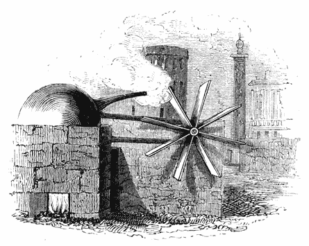
Giovanni Branca, 1629.
This method of applying the force of steam has no analogy to any application of steam in modern engines.
Edward Somerset, Marquis of Worcester, 1663.
Lord Worcester having been engaged on the side of the Royalists in the civil wars of the revolution, lost his fortune, and went to Ireland, where he was imprisoned. He escaped from thence, and reached France; from that country he ventured to London, as a secret agent of Charles II., but was detected, and imprisoned in the Tower, where he remained until the restoration, when he was set at liberty. Tradition has connected the invention of the steam engine with the following anecdote:—One day, during his imprisonment, Lord Worcester observed the lid of the pot in which his dinner was being cooked, suddenly forced upwards by the vapour of the water which was boiling in it. Reflecting on this, it occurred to him that the same force which raised the cover of the pot might be rendered, when properly applied, a useful and convenient moving power. After he recovered his liberty, he accordingly proceeded to carry into effect this conception. The contrivance to which he was ultimately led is described in the following terms in the sixty-eighth invention, in the work above named:—
"I have invented an admirable and forcible way to drive [Pg024] up water by fire; not by drawing or sucking it upwards, for that must be, as the philosopher terms it, infra sphœrum activitatis, which is but at such a distance. But this way hath no bounder if the vessels be strong enough. For I have taken a piece of whole cannon whereof the end was burst, and filled it three quarters full of water, stopping and screwing up the broken end, as also the touch-hole, and making a constant fire under it; within twenty-four hours, it burst and made a great crack. So that, having a way to make my vessels so that they are strengthened by the force within them, and the one to fill after the other, I have seen the water run like a constant fountain stream forty feet high. One vessel of water rarefied by fire driveth up forty of cold water, and a man that tends the work has but to turn two cocks; that one vessel of water being consumed, another begins to force and refill with cold water, and so successively; the fire being tended and kept constant, which the self-same person may likewise abundantly perform in the interim between the necessity of turning the said cocks."
Since the date of the publication of the "Century of Inventions" was the year 1663, the experiments here mentioned must have been made before that year. The description of the machine here given, as well as others in the same work, was intended by the author, not to convey a knowledge of the nature of the mechanism which he used, but only to express the effects produced, and to indicate the physical principle on which they depended. It should also be observed, that an air of mystery was thrown by Worcester over the accounts of all the machines which he described; and therefore any obscurity in the above description ought not to be regarded as an evidence against his claim to the discovery of the mechanical agency of steam, so far as that agency is indicated by the effects said by him to be produced. The above account is, however, sufficiently distinct and explicit to enable any one possessing a knowledge of the mechanical qualities of steam to perceive the general nature of the machine described. To render this machine, and that of De Caus, previously described, intelligible to those who are not familiar with physical science, we must here explain some general principles on which their agency depends. [Pg025]
These two species of fluids are each distinguished by peculiar mechanical properties.
Now let us suppose this solid mass of lead to be rendered liquid by being melted. The constituent particles will then be deprived of that cohesion by which they were held together; they will accordingly have a tendency to separate, and fall asunder by their gravity, and will only be prevented from actually doing so by the support afforded to them by the sides, [Pg026] A B, D C, of the vessel. They will therefore produce a pressure against the sides, which was not produced by the lead in its solid state. This pressure will vary at different depths: thus a part of the side of the vessel at P will receive a pressure proportional to the depth of the point P below the surface of the lead. If, for example, we take a square inch of the inner surface of the side of the vessel at P, it will sustain an outward pressure equal to the weight of a column of lead having a square inch for its base, and a height equal to P A. And, in like manner, every square inch of the sides of the vessel will sustain an outward pressure equal to the weight of a column of lead having a square inch for its base, and a height equal to the depth of the point below the surface of the lead.
Thus if we suppose any mechanical cause producing a pressure on the surface A D amounting to ten pounds on each square inch, the effect which would be produced, if the lead were solid, would be an additional pressure on the base B C amounting to ten pounds per square inch. But if the lead were liquid, besides this pressure on each square inch of the base B C, there would likewise be a pressure of ten pounds on every square inch of the sides of the vessel.
All that has been here stated with respect to a square or a cubical vessel will be equally applicable to a vessel of any other form. [Pg027]
If such a cover, or lid, had been placed upon a liquid, the cover would sustain no pressure from the fluid, nor would any mechanical effect be produced, save those already described in the case of the open vessel; but when the fluid contained in the vessel is elastic, as is the case with air, then the elasticity (by which name is expressed the tendency of the particles of the fluid to fly asunder) will produce peculiar mechanical effects, which have no existence whatever in the case of a liquid.
It is true that, supposing the fluid to be air or any other gas or vapour, a pressure will be produced upon the bottom B C of the vessel equivalent to the weight of such fluid, and lateral pressures will be produced on the different points of the sides by the weight of that part of the fluid which is above these points; but gases and vapours are bodies of such extreme levity, that these effects due to their weight are neglected in practice.
Putting, then, the weight of the air contained in the vessel out of the question, let us consider the effect of its elasticity. If the vessel, as already described, be supposed to contain atmospheric air in its ordinary state, the tendency of the constituent particles to fly asunder will be such as to produce on every square inch of the inner surface of the vessel [Pg028] a pressure amounting to fifteen pounds; this pressure being, as already stated, quite independent of the weight of the air. In fact, this pressure would continue to exist if the air contained in the vessel actually ceased to have weight by being removed from the neighbourhood of the earth, which is the cause of its gravity.
If the space within which an elastic fluid is enclosed be enlarged, its elasticity is found to diminish in the same proportion. Thus if the air contained in the vessel A B C D (fig. 3.) be allowed to pass into a vessel of twice the magnitude, the elasticity of the particles will cause them to repel each other, so that the same quantity of air shall diffuse itself throughout the larger vessel, assuming double its former bulk. Under such circumstances, the pressure which it would exert upon the sides of the larger vessel would be only half that which it had exerted on the sides of the smaller vessel. If, on the other hand, it were forced into a vessel of half the magnitude of A B C D, as it might be, then its elasticity would be double, and it would press on the inner surface of that vessel with twice the force with which it pressed on that of the vessel A B C D.
This power of swelling and contracting its dimensions according to the dimensions of the vessel in which it is confined, or to the force compressing it, is a quality which results immediately from elasticity, and is consequently one which is peculiar to the gases or elastic fluids, and does not at all appertain to liquids. If the liquid contained in the vessel A B C D were transferred to a vessel of twice the magnitude, it would only occupy half the capacity of that vessel, and it could not by any means be transferred, as we have supposed the air or gas to be, to a vessel of half the dimensions, since it is inelastic and incompressible.
This is a common property of all liquids. If they be exposed for a sufficient length of time to a sufficient degree of heat, they will always be converted into elastic fluids. These are usually distinguished from air and other permanent gases, which never are known to exist in the liquid form, by the term vapour, by which, therefore, must be understood an elastic fluid which at common temperatures exists in the liquid or solid state; by steam is expressed the vapour of water; and by gases, those elastic fluids which like air are never known—at least, under ordinary circumstances—to exist in any other but the elastic form.
These important physical circumstances are now only indicated in a general way. As we proceed with our account of the invention and improvement of the steam engine, they will be developed more fully and accurately.
In the case of the apparatus of De Caus (5.), the heat of the fire acting on the vessel D C (fig. 2.) will raise the temperature of the water contained in it, and also of the air confined within it above the surface of that water. This air, as it is increased in temperature, will also increase in elasticity; it will therefore press on the surface of the water with increased force, and will gradually force the water upwards in the tube; and this effect would continue until all the water in the vessel would be forced up the tube.
But at the same time that the heat acting on the vessel increases the temperature of the air above the water, it also produces a partial evaporation of the water, so that more or less steam is mixed with the air in the vessel above the surface [Pg031] of the water; and this steam possessing elasticity, unites with the air in pressing on the surface of the water, and in raising it in the tube.
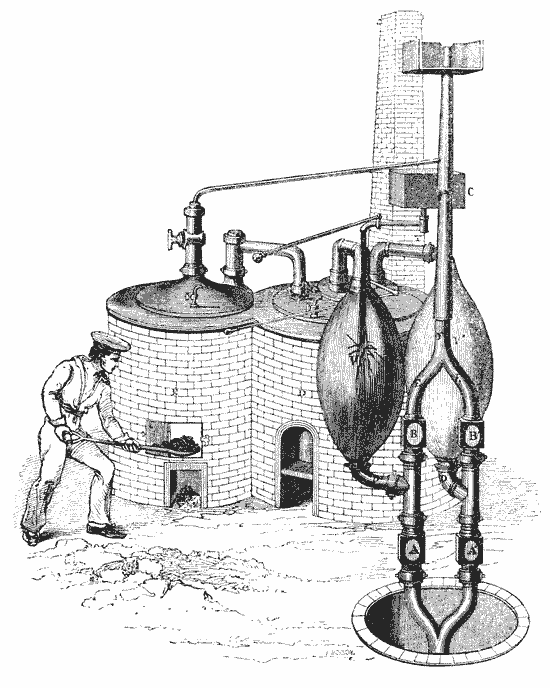
Let us now revert to the brief account of the engine of the Marquis of Worcester, described in "The Century of Inventions." We collect from that description that the vessel in which the water was evaporated was separate from those which contained the water to be elevated; also that there were two vessels of the like description, the contents of which were alternately elevated by the pressure of the "water rarefied by the fire;" in other words by steam; and that the water was raised in an uninterrupted stream, by the management of two cocks communicating with these vessels and with the boiler. The following is such an apparatus as would answer this description. Let E (fig. 4.) be the vessel containing the water to be evaporated, placed over a proper furnace A; let S be a pipe to allow the steam produced from the boiling water in E to pass into the vessels where its mechanical action is required. Let R represent a cock or regulator, having in it a curved passage, leading from S to the tube T, when the lever or handle L is in the position represented by the cut; but leading to the tube T′, when the lever L is turned one quarter of a revolution to the right, as represented in fig. 5. By the shifting of this lever, therefore, the steam pipe S may be made to communicate alternately with the tubes T and T′. The tubes T and T′ are carried respectively to two vessels V and V′, which are filled with the water required to be raised. In these [Pg032] vessels tubes enter at C and C′, descending nearly to the bottom: these tubes have valves at B and B′, opening upwards, by which water will be allowed to pass into the vertical tube F, but which will not allow it to return downwards, the valves B and B′ being then closed by the weight of the water above them.
Let G G′ be a pipe entering the sides of the vessels V and V′, for the purpose of filling them with the water to be raised: let K be a cock having a curved passage similar to the cock R, and leading to a tube by which water is supplied from the reservoir or other source from which the water to be raised is drawn. When the cock K is placed as represented in fig. 4., the water from the reservoir will flow through the curved passage in the cock K into the tube G′, and thence into the vessel V′; but when this cock is turned one quarter round, by shifting the lever to the left, it will take the position represented in fig. 6., and the water will flow through the curved passage into the tube G, and thence into the vessel V. Let us now suppose the vessel V already filled with water to be elevated, and the vessel V′ to have discharged its contents. The cock R is turned, so as to allow the steam generated in the boiler E to pass into the tube T, and thence into the upper part of the vessel V, while the cock K is turned so as to allow the water from the reservoir to pass into the tube G′, and thence into the vessel V′. The steam collecting in the upper part of the vessel V′ presses with its elastic force on the surface of the water therein, and forces the water upwards in the tube C; it passes through the valve B, which it opens by the upward pressure received from the action of the steam, and thence into the tube F, its descent into the tube C′ being prevented by the valve V′, which can only be opened upwards. As the steam is gradually supplied from the boiler E, the water in the vessel V is forced up the tube C, through the valve B, and into the tube F, until all the contents of the vessel V above the lower end of the tube C have been raised. In the meanwhile, the vessel V′ has been filled with water, through the cock K: when this has been accomplished, the man who attends the machine shifts the cocks R and K, so as to give them the position represented in fig. 5. and fig. 6. [Pg033] In this position, the steam from the boiler, being excluded from the tube T, will be conducted to the tube T′, and thence to the vessel V′, while the water from the reservoir will be excluded from the tube G′, and conducted through the tube G to the vessel V. The vessel V will thus be replenished and, by a process similar to that already described, the contents of the vessel V′ will be forced up the tube C′, through the valve B′, and into the tube F; its descent into the tube C being prevented by the valve B, which will then be closed. After the contents of the vessel V′ have thus been raised, and the vessel V replenished, the two cocks R and K are once more shifted, and the contents of V raised while V′ is replenished, and so on.
If, having comprehended the apparatus here described, the reader refers to the description of the Marquis of Worcester's machine, he will find that all the conditions therein laid down are fulfilled by it. One vessel (E) of "water rarefied by fire" may by such means "drive up forty (or more) of cold water; and the man that tends the work has but to turn two cocks, that one vessel (V) of water being consumed, another (V′) begins to force and refill with cold water, and so on successively, the fire being tended and kept constant; which the self-same person may likewise abundantly perform, in the interim between the necessity of turning the said cocks."
On comparing this with the contrivance previously suggested by De Caus, it will be observed, that even if De Caus [Pg034] knew the physical agent by which the water was driven upwards in the apparatus described by him, still it was only a method of causing a vessel of boiling water to empty itself; and before a repetition of the process could be made, the vessel should be refilled, and again boiled. In the contrivance of Lord Worcester, on the other hand, the agency of the steam was employed in the same manner as it is in the steam engines of the present day, being generated in one vessel, and used for mechanical purposes in another. Nor must this distinction be regarded as trifling or insignificant, because on it depends the whole practicability of using steam as a mechanical agent. Had its action been confined to the vessel in which it was produced, it never could have been employed for any useful purpose.
Although many of the projects contained in Lord Worcester's work were in the highest degree extravagant and absurd, yet the engine above described is far from being the only practicable and useful invention proposed in it. On the contrary, many of his inventions have been reproduced, and some brought into general use since his time. Among these may be mentioned, stenography, telegraphs, floating baths, speaking statues, carriages from which horses can be disengaged if unruly, combination locks, secret escutcheons for locks, candle moulds, the rasping mill, the gravel engine, &c.
Sir Samuel Morland, 1683.
In 1680, Sir Samuel Morland was appointed Master [Pg035] of the Works to Charles II., and in the following year was sent to France, to execute some waterworks for Louis XIV. In 1683, while in France, he wrote in the French language, a work entitled "Elevation des Eaux par toute sorte de Machines, reduite à la Mesure, au Poids et à la Balance. Presentée à sa Majesté très Chrestienne, par le Chevalier Morland, Gentilhomme Ordinaire de la Chambre Privée, et Maistre des Méchaniques du Roi de la Grande Brétagne, 1683." This book is preserved in manuscript in the Harleian Collection in the British Museum. It is written on vellum, and consists of only thirty-eight pages. It contains tables of measures and weights, theorems for the calculation of the volumes of cylinders, the weights of columns of water, the thickness of lead for pipes, and is concluded by a chapter on steam, consisting of four pages, of which the following is a translation:—
"The principles of the new force of fire invented by Chevalier Morland in 1682, and presented to His Most Christian Majesty in 1683:—
"'Water being converted into vapour by the force of fire, these vapours shortly require a greater space (about 2000 times) than the water before occupied, and sooner than be constantly confined would split a piece of cannon. But being duly regulated according to the rules of statics, and by science reduced to measure, weight, and balance, then they bear their load peaceably (like good horses), and thus become of great use to mankind, particularly for raising water, according to the following table, which shows the number of pounds that may be raised 1800 times per hour to a height of six inches by cylinders half filled with water, as well as the different diameters and depths of the said cylinders.'"
There is nothing in the description here given which can indicate the form of the machine by which Morland proposed to render the force of steam a useful mover. It is, however, remarkable, that at this early period, before experiments had been made on the expansion which water undergoes in evaporation, he should have given so near an approximation to [Pg036] the actual amount of that expansion. It is scarcely supposable that such an estimate could be obtained by him otherwise than by experiment.
The work containing the above description was not printed; but a work bearing nearly the same title, containing, however, no mention of the force of steam, was published by him in Paris in the year 1685. In this he describes various experiments made by him at St. Germains on the weight of the water of the Seine, and gives weights of the columns of water, the contents of cylinders, &c.
Soon after the publication of this work, Morland returned to England, and resided near the court till his death. The celebrated John Evelyn mentioned having paid a visit to him at his house at Hammersmith, in 1695, when he had become aged and blind, but was still remarkable for his mechanical ingenuity. "On the 25th of October," says Evelyn, "the Archbishop and myself went to Hammersmith to visit Sir Samuel Morland, who was entirely blind; a very mortifying sight. He showed us his invention of writing (short-hand), which was very ingenious; also his wooden kalendar, which instructed him all by feeling; and other pretty and useful inventions of mills, pumps, &c.; and the pump he had erected, that serves water to his garden and to passengers, with an inscription, and brings from a filthy part of the Thames near it a most perfect and pure water."[3]
He died at Hammersmith, in January 1696; and before his death, as a penance for his past life, was guilty of the eccentricity of burying in the ground six feet deep a great collection of music which he possessed.[4]
Denis Papin, 1688.
Papin was born at Blois in France. He devoted his youth to the study of medicine, in which he took a degree at Paris. The revocation of the Edict of Nantes having driven him into exile, he went to England, where the celebrated Boyle associated him in several of his experiments with the air-pump, and caused him to be elected a fellow of the Royal Society in 1681. Having been invited to Germany by the Landgrave of Hesse, he discharged during several years the duties of professor of mathematics at the university of Marbourg, where he died in 1710. Notwithstanding his discoveries respecting the agency of steam, he never received any mark of distinction in his own country. The truth is, the importance and value of these investigations were not apparent until long afterwards.
This philosopher conceived the idea of producing a moving power by means of a piston working in a cylinder, in the manner which we shall now briefly explain.
Let A B (fig. 7.) be a cylinder open at the top, and let a piston P be fitted into it, so as to move in it air tight. At the bottom of the cylinder suppose an opening provided, which can be closed at pleasure, by a stop-cock, or otherwise, so that the communication may be opened and closed at will between the interior of the cylinder and the external air. This stop-cock being opened, let the piston be drawn upwards till it reach the top of the cylinder. Let the stop-cock at the bottom be then removed, and imagine that some means can be supplied by which the air within the cylinder can be suddenly annihilated. The piston, now at the top, will have above it the pressure of the atmosphere; and having no air below, it will be resisted in its descent by no force save that arising from its friction with the cylinder. If, then, the force of the air above the piston be greater than the resistance arising from this friction, the piston will descend with the excess of this force, and will continue so to descend until it reach the bottom of the cylinder. Having attained that position, let us [Pg038] suppose the stop-cock in the bottom opened, so as to allow the external air to pass freely below the piston. The piston may now be drawn to the top of the cylinder again, offering no resistance save that of its weight, and its friction with the cylinder. Having reached the top of the cylinder once more, let the stop-cock be closed, and the air included within the cylinder once more annihilated. A second descent of the piston will take place, with the same force as before, and in like manner the process may be continued indefinitely.
Now, if it should appear that means could be provided suddenly and repeatedly to annihilate the air within the cylinder, and that the pressure of the atmosphere above the piston should exert a force compared with which the weight of the piston and its friction are trifling, it is evident that a moving power would be obtained which would be capable, by proper mechanism, of being applied to any useful purpose, but which would more especially be applicable to the working of pumps, the motion of which corresponds with that which has been just ascribed to the piston in the cylinder. Such were the first ideas of Papin. But in order to enable those who are not conversant with physical science fully to appreciate their importance, it will be necessary here to explain some of the mechanical properties of atmospheric air.
A direct demonstration of this may be given by the following experiment:—On the mouth of a flask let a stop-cock be fastened so as to be air-tight. The interior of the flask may then be put into free communication with the external air, or that communication may be cut off at pleasure, by opening or closing the stop-cock. If a syringe be applied to the mouth of the flask, the stop-cock being open a part of the air contained in it may be drawn out. After this, the stop-cock being closed, and the syringe detached, let the flask be placed in the dish of a good balance, and accurately counterpoised by weights in the other dish. This counterpoise will then represent the weight of the flask, and of the air which has remained in it. If the stop-cock be now opened, air will immediately rush in, and replace that which the syringe had withdrawn from the flask; and immediately the dish of the balance containing the flask will sink by the effect of the weight of the air thus admitted into the flask.
If the weight of quantity of air so small as to be capable of being withdrawn by a syringe from an ordinary flask be thus of sensible amount, it may be easily imagined that the vast mass of atmosphere extending from the surface of the earth upwards, to a height not ascertained with precision, but certainly not being less than thirty miles, must be very considerable. Such a force, pressing as it must constantly do, upon the surfaces of all bodies, whether solid or fluid, and resisting and modifying their movements, would play an important part in all mechanical phenomena; and it is, therefore, not sufficient merely to have recognised its existence, but it is most needful to measure its amount with that degree of certainty and precision, which will enable us to estimate its effects on those phenomena which we shall have to investigate.
Take a glass tube, A B (fig. 8.), above 32 inches long, open at one end A, and closed at the other end B, and let it [Pg040] be filled with mercury (quicksilver). Let a glass vessel or cistern C, containing a quantity of mercury, be also provided. Applying the finger at A, so as to prevent the mercury in the tube from falling out, let the tube be inverted, and the end, stopped by the finger, plunged into the mercury in C. When the end of the tube is below the surface of the mercury in C (fig. 9.), let the finger be removed. It will be found that the mercury in the tube will not, as might be expected, fall to the level of the mercury in the cistern C, which it would do were the end B open, so as to admit the air into the upper part of the tube. On the other hand, the level D of the mercury in the tube will be nearly 30 inches above the level C of the mercury in the cistern.
The cause of this effect is, that the weight of the atmosphere rests on the surface C of the mercury in the cistern, and tends thereby to press it up, or rather to resist its fall in the tube; and as the fall is not assisted by the weight of the atmosphere on the surface D (since B is closed), it follows, that as much mercury remains suspended in the tube above the level C, as the weight of the atmosphere is able to support.
If the section of the tube were equal to the magnitude of a square inch, the weight of the column of mercury in the tube above the level C would be exactly equal to the weight of the atmosphere on each square inch of the surface C.
If the apparatus be transported to any height above its ordinary position, it will have a less quantity of atmosphere above it, and therefore the surface of the mercury in the cistern will be pressed by a less weight, and consequently the [Pg041] column of mercury will fall proportionally. In virtue of this effect, such an instrument has been rendered a means of measuring heights, such as the heights of mountains, the ascents of balloons, &c. &c.
Two cubic inches of mercury weigh very nearly one pound avoirdupois.[6] Hence, when the barometric column measures thirty inches, the weight of the atmosphere resting on each square inch of surface is about fifteen pounds.
Let four glass tubes, A, B, C, D (fig. 10.), be constructed of sufficient length, closed at one end, A, B, C, D, and open at the other. Let the open ends of three of them be bent, as represented in the tubes B, C, D. Being previously filled with mercury, let them all be gently inverted, so as to have their closed ends up, as here represented. It will be found that the mercury will be sustained in all, and that the difference of the levels in all will be the same.[7] Thus, the mercury is sustained in A by the upward pressure of the atmosphere; in B, by its horizontal or lateral pressure; in C, by its downward pressure; [Pg042] and in D, by its oblique pressure: and, as the difference of the levels is the same in all, these pressures are exactly equal.
In the experiments described in (21), the space D B in the top of the barometer-tube, from which the mercury descended, is a vacuum. If, however, it were occupied by a quantity of air in a rarefied state, or any other gas or vapour, such gas or vapour would press on the surface of the mercury at D, with a force determined by its elasticity. In that case, the atmospheric pressure acting on the surface of the mercury C in the cistern, would be balanced by the combined forces of the weight of the mercurial column sustained in the tube, and the elasticity of the gas or vapour in the upper part of it. Now if we know the actual amount of the atmospheric pressure,—that is to say, the height of the column of mercury which it would be capable of sustaining,—we should then be able to determine the pressure of the rarefied air in the space C D.
For example, let us suppose that the barometric column, when B D (fig. 9.) is a vacuum, measures thirty inches: the atmospheric pressure, therefore, would be equal to the weight of a column of mercury of that height. Let us suppose that the elasticity of the gas or vapour occupying the upper part of the tube D B causes the column to fall to the height of twenty-six inches: it is evident, then, that the pressure of the air in the top of the tube would be equal to the weight of a column of mercury of four inches. In fine, to determine the pressure of the rarefied gas or vapour in the top of the tube, it is only necessary to observe the difference between the height of the column of mercury actually sustained in the tube, and the column sustained at the same time and [Pg043] place in a common barometer: the difference of the two will be the column of mercury whose weight will represent the pressure of the vapour or gas in the top of the tube.
It is by such means that water is raised in an ordinary pump. A portion of the air contained between the piston of the pump and the surface of the water below, is withdrawn by the action of the piston, and the pressure of the air remaining under the piston is thereby diminished. The superior pressure of the atmosphere upon the external surface of the water in the well then forces up a column of water in the pump-barrel, and this is continued as the air is more and more rarefied by the action of the piston. By whatever means, therefore, the air can be wholly or partially withdrawn from any space, a mechanical power will be thereby developed, proportional in its amount and efficacy to the quantity of air so withdrawn. If, however, such air be withdrawn by any mechanical process, such as by a syringe, by a common pump, or by an air-pump, the quantity of force expended in withdrawing it is always equivalent to the amount of mechanical power obtained by the vacuum or partial vacuum so produced. Indeed the power expended is greater than the power so obtained, inasmuch as the friction, leakage, &c. of the exhausting apparatus must be allowed for.
The process of filling thermometers with mercury shows one use of producing a high degree of rarefaction by heat. To construct the instrument it is necessary to fill the bulb and a part of the tube with mercury; but the bore of the tube is so small that the mercury cannot be introduced by any ordinary means. It is therefore held over flame until heated to a high temperature. The air within it gradually increasing in pressure as its temperature is raised, is forced through the small bore of the tube, until the pressure of the air within becomes no more than equal to the pressure of the external atmosphere; this air being so rarefied that quantity in the bulb bears a very small proportion to its contents at common temperatures. The mouth of the tube is then plunged into mercury, and as the bulb cools, the air within it loses its elasticity, and the superior pressure upon the external surface forces the mercury into the tube. This continues until the air remaining within the bulb has been so contracted, that its pressure combined with the weight of the mercury, shall balance the atmospheric pressure. The tube is then reversed, and the air which remained rises in a bubble to the surface, and escapes.
It is, however, apparent, from what has been already explained, that such a method of proceeding would amount to a mere transfer of power, and would not, properly speaking, be itself a moving force: the moving power would, in reality, be the force of the water by which the water-wheel would be driven; and the air-pumps, tubes, together with the piston and cylinder, would be merely means of conveying the power of the water-wheel to the objects to be moved, or the machinery to be driven. Papin states, that, long before this, he had attempted to expel the air from his cylinder by means of gunpowder; but, notwithstanding all the precautions which he could take, there always remained a considerable quantity; so much, indeed, as to deprive the vacuum of more than half its proper force. At length he adopted an expedient for the production of a vacuum which forms a most important step in the progressive invention of the steam engine, and which gives to Papin's name a high place in the history of that machine. This method is explained in the following paragraph of a work published by Papin in 1695, at Cassel, entitled "Recueil de diverses Pièces touchant quelques nouvelles Machines", p. 53.
"I have endeavoured," says he, "to attain this end (viz. the production of a vacuum in the cylinder) in another way. As water has the property of elasticity, when converted into steam by heat, and afterwards of being so completely recondensed by cold, that there does not remain the least [Pg046] appearance of this elasticity, I have thought that it would not be difficult to work machines in which, by means of a moderate heat and at a small cost, water might produce that perfect vacuum which has vainly been sought by means of gunpowder."
This remarkable passage is given in the work just cited, as an extract from the "Leipsic Acts," of August, 1690.
Let us pause here to explain more fully this important discovery.
In accordance with these ideas, Papin constructed a model consisting of a small cylinder, in which was placed a solid piston; [Pg047] and in the bottom of the cylinder under the piston was contained in a small quantity of water. The piston being in immediate contact with this water, so as to exclude the atmospheric air, on applying fire to the bottom of the cylinder, steam was produced, the elastic force of which raised the piston to the top of the cylinder; the fire being then removed, and the cylinder being cooled by the surrounding air, the steam was condensed and reconverted into water, leaving a vacuum in the cylinder into which the piston was pressed by the force of the atmosphere. The fire being applied and subsequently removed, another ascent and descent were accomplished; and in the same manner the alternate motion of the piston might be continued. Papin described no other form of machine by which this property could be rendered available in practice; but he states generally, that the same end may be attained by various forms of machines easy to be imagined.[8]
Thomas Savery, 1698.
Savery appears to have been ignorant of the publication of Papin, and stated that his discovery of the condensing principle arose from the following circumstance:—
Having drunk a flask of Florence at a tavern, and flung the empty flask on the fire, he called for a basin of water to wash his hands. A small quantity which remained in the flask began to boil, and steam issued from its mouth. It occurred to him to try what effect would be produced by inverting the flask and plunging its mouth in the cold water. Putting on a thick glove to defend his hand from the heat, he seized the [Pg048] flask, and the moment he plunged its mouth in the water the liquid immediately rushed up into the flask and filled it.
Savery stated that this circumstance immediately suggested to him the possibility of giving effect to the atmospheric pressure by creating a vacuum in this manner. He thought that if, instead of exhausting the barrel of a pump by the usual laborious method of a piston and sucker, it was exhausted by first filling it with steam, and then condensing the same steam, the atmospheric pressure would force the water from the well into the pump-barrel, and into any vessel connected with it, provided that vessel were not more than about thirty-four feet above the elevation of the water in the well. He perceived also, that, having lifted the water to this height, he might use the elastic force of steam in the manner described by the Marquis of Worcester to raise the same water to a still greater elevation, and that the same steam which accomplished this mechanical effect would serve, by its subsequent condensation, to reproduce the vacuum, and draw up more water. It was on this principle that Savery constructed the first engine in which steam was ever brought into practical operation.
[1] Arago, Eloge historique de James Watt; p. 22.
[2] Ibid., p. 21. note.
[3] Farey, Treatise on the Steam Engine, p. 93.
[4] Arago, sur les Machines à Vapeur, Annuaire, 1829, p. 165
[5] Spiritus, breath or air.
[6] Exactly 15·68 oz. = 0·98 lb.
[7] This experiment with the tube A requires to be very carefully executed, and the tube should be one of small bore.
[8] Recueil de diverses Pièces touchant quelques nouvelles Machines, p. 38.
ENGINES OF SAVERY AND NEWCOMEN.
The former apparatus in Savery's engine consists of two strong boilers, sections of which are represented at D and E in fig. 11.; D the greater boiler, and E the less. The tubes T and T′ communicate with the working apparatus, which we shall presently describe. A thin plate of metal R, is applied closely to the top of the great boiler D, turning on a centre C, so that by moving a lever applied to the axis C on the outside of the top, the sliding plate R can be brought from the mouth of the one tube to the mouth of the other alternately. This sliding valve is called the regulator, since it is by it that the communications between the boiler and two steam vessels (hereafter described) are alternately opened and closed, the lever which effects this being moved at intervals by the hand of the attendant.
Two gauge cocks are represented at G, G′, the use of which is to determine the depth of water in the boiler. One, G, has its lower aperture a little above the proper depth; and the other, G′, a little below it. Cocks are attached to the upper ends G, G′, which can be opened or closed at pleasure. The steam collected in the top of the boiler pressing on the surface of the water, forces it up in the tubes G, G′, if their lower ends be immersed. Upon opening the cocks G, G′, if water be forced from both, there is too much water in the boiler, since the mouth of G is below its level. If steam issue from both, there is too little water in the boiler, since the mouth of G′ is above its level. But if steam issue from G, and water from G′, the water in the boiler is at its proper level. This ingenious contrivance for determining the level of the water in the boiler is the invention of Savery, and is used in many instances at the present day.
The mouth of the pipe G should be at a level of a little less [Pg051] than one third of the whole depth, and the mouth of G′ at a level little lower than one third; for it is requisite that about two thirds of the boiler should be kept filled with water. The tube I forms a communication between the greater boiler D and the lesser or feeding boiler E, descending nearly to the bottom of it. This communication can be opened and closed at pleasure by the cock K. A gauge pipe is inserted similar to G, G′, but extending nearly to the bottom. From this boiler a tube F extends, which is continued to a cistern C (fig. 12.), and a cock is placed at M, which, when opened, allows the water from the cistern to flow into the feeding boiler E, and which is closed when that boiler is filled. The manner in which this cistern is supplied will be described hereafter.
Let us now suppose that the principal boiler is filled to the level between the gauge pipes, and that the subsidiary boiler is nearly full of water, the cock K and the gauge cocks G G′ being all closed. The fire being lighted beneath D, and the water boiled, steam is produced, and is transmitted through one or other of the tubes T, T′, to the working apparatus. When evaporation has reduced the water in D below the level of G′, it will be necessary to replenish the boiler D. This is effected thus:—A fire being lighted beneath the feeding boiler E, steam is produced in it above the surface of the water, which, having no escape, presses on the surface so as to force it up in the pipe I. The cock K being then opened, the boiling water is forced into the principal boiler D, into which it is allowed to flow until water issues from the gauge cock G′. When this takes place, the cock K is closed, and the fire removed from E until the great boiler again wants replenishing. When the feeding boiler E has been exhausted, it is replenished from the cistern C (fig. 12.), through the pipe F, by opening the cock M.
Let V V′ (fig. 12.) be two steam vessels communicating by the tubes T T′ (marked by the same letters in fig. 11.) with the greater boiler D.
Let S be a pipe, called the suction pipe, descending into [Pg052] the well or reservoir from which the water is to be raised, and communicating with each of the steam vessels through tubes D D′, by valves A A′, which open upwards. Let F be a pipe continued from the level of the engine to whatever higher level it is intended to elevate the water. The steam vessels V V′ communicate with the force-pipe F by valves B B′, which open upwards, through the tubes E E′. Over the steam vessels and on the force-pipe is placed a small cistern C, already mentioned, which is kept filled with cold water from the force-pipe, and from the bottom of which proceeds a pipe terminated with a cock G. This is called the condensing pipe, and can be brought alternately over each steam vessel. From this cistern another pipe communicates with the feeding boiler (fig. 11.), by the cock M.[9]
The communication of the pipes T T′ with the boiler can be opened and closed alternately, by the regulator R (fig. 11.), already described.
Now suppose the steam vessels and tubes to be all filled with common atmospheric air, and that the regulator be placed so that the communication between the tube T and the boiler be opened, the communication between the other tube T′ and the boiler being closed, steam will flow into V through T. At first, while the vessel V is cold, the steam will be condensed, and will fall in drops of water on the bottom and sides of the vessel. The continued supply of steam from the boiler will at length impart such a degree of heat to the vessel V, that it will cease to condense it. Mixed with the heated air [Pg053] contained in the vessel V, it will have an elastic force greater than the atmospheric pressure, and will therefore force open the valve B, through which a mixture of air and steam will be driven until all the air in the vessel V will have passed out, and it will contain nothing but the pure vapour of water.
When this has taken place, suppose the regulator be moved so as to close the communication between the tube T and the boiler, and to stop the further supply of steam to the vessel V; and at the same time let the condensing pipe G be brought over the vessel V, and the cock opened so as to let a stream of cold water flow upon it. This will cool the vessel V, and the steam with which it is filled will be condensed and fall in a few drops of water, leaving the interior of the vessel a vacuum. The valve B will be kept closed by the atmospheric pressure. But the elastic force of the air between the valve A and the surface of the water in the well, or reservoir, will open A, so that a part of this air will rush in, and occupy the vessel V. The air in the suction pipe S, being thus allowed an increased space, will be proportionally diminished in its elastic force, and its pressure will no longer balance that of the atmosphere acting on the external surface of the water in the reservoir. This pressure will, therefore, force water up in the tube S until its weight, together with the elastic force of the air above it, balances the atmospheric pressure. When this has taken place, the water will cease to ascend.
Let us now suppose that, by shifting the regulator, the communication is opened between T and the boiler, so that steam flows again into V. The condensing cock G being removed, the vessel will be again heated as before, the air expelled, and its place filled by the steam. The condensing pipe being again allowed to play upon the vessel V, and the further supply of steam being stopped, a vacuum will be produced in V, and the atmospheric pressure will force the water through the valve A into the vessel V, which it will nearly fill, a small quantity of air, however, remaining above it.
Thus far the mechanical agency employed in elevating the water is the atmospheric pressure; and the power of steam is no further employed than in the production of a vacuum. [Pg054] But, in order to continue the elevation of the water through the force pipe F, above the level of the steam vessel, it will be necessary to use the elastic pressure of the steam. The vessel V is now nearly filled by the water which has been forced into it by the atmosphere. Let us suppose that, the regulator being shifted again, the communication between the tube T and the boiler is opened, the condensing cock removed, and that steam flows into V. At first, coming in contact with the cold surface of the water and that of the vessel, it is condensed; but the vessel is soon heated, and the water formed by the condensed steam collects in a sheet or film upon the surface of the water in V, so as to form a surface as hot as boiling water.[10] The steam then being no longer condensed, presses on the surface of the water with its elastic force; and when that pressure becomes greater than the atmospheric pressure, the valve B is forced open, and the water issuing through it, passes through E into the force-pipe F; and this is continued until the steam has forced all the water from V, and occupies its place.
The further admission of steam through T is once more stopped by moving the regulator; and the condensing pipe being again allowed to play on V, so as to condense the steam which fills it, produces a vacuum. Into this vacuum, as before, the atmospheric pressure will force the water, and fill the vessel V. The condensing pipe being then closed, and steam admitted through T, the water in V will be forced by its pressure through the valve B and tube E into F, and so the process is continued.
We have not yet noticed the other steam vessel V′, which, as far as we have described, would have remained filled with common atmospheric air, the pressure of which on the valve A′ would have prevented the water raised in the suction pipe S from passing through it. However, this is not the case; for, during the entire process which has been described in V, similar effects have been produced in V′, which we have only omitted to notice to avoid the confusion which the two processes might produce. It will be remembered, that after the steam, in the first instance, having flowed from the boiler [Pg055] through T, has blown the air out of V through B, the communication between T and the boiler is closed. Now the same motion of the regulator which closes this, opens the communication between T′ and the boiler; for the sliding plate R (fig. 11.) is moved from the one tube to the other, and at the same time, as we have already stated, the condensing pipe is brought to play on V. While, therefore, a vacuum is being formed in V by condensation, the steam, flowing through T′, blows out the air through B′, as already described in the other vessel V; and while the air in S is rushing up through A into V, followed by the water raised in S by the atmospheric pressure, the vessel V′ is being filled with steam, and the air is completely expelled from it.
The communication between T and the boiler is now again opened, and the communication between T′ and the boiler closed by moving the regulator R (fig. 11.) from the tube T to T′; at the same time the condensing pipe is removed from over V, and brought to play upon V′. While the steam once more expels the air from V through B, a vacuum is formed by condensation in V′, into which the water in S rushes through the valve A′. In the mean time V is again filled with steam. The communication between T and the boiler is now closed, and that between T′ and the boiler is opened, and the condensing pipe removed from V′, and brought to play on V. While the steam from the boiler forces the water in V′ through B′ into the force-pipe F, a vacuum is being produced in V, into which water is raised by the atmospheric pressure.
Thus each of the vessels V V′ is alternately filled from S, and the water thence forced into F. The same steam which forces the water from the vessels into F, having done its duty, is condensed, and brings up the water from S, by giving effect to the atmospheric pressure.
During this process, two alternate motions or adjustments must be constantly made; the communication between T and the boiler must be opened, and that between T′ and the boiler closed, which is done by one motion of the regulator. The condensing pipe at the same time must be brought from V to play on V′, which is done by the lever placed upon it. Again [Pg056] the communication between T′ and the boiler is to be opened, and that between T and the boiler closed; this is done by moving back the regulator. The condensing pipe is brought from V′ to V by moving back the other lever, and so on alternately.
For the clearness and convenience of description, some slight and otherwise unimportant changes have been made in the position of the parts. A perspective view of this engine is represented at the head of this chapter. The different parts already described will easily be recognised.
The engine of Savery was very clearly described in a small work published in London in 1702, entitled, The Miner's Friend, or an Engine to raise Water by Fire described, and the Manner of Fixing it in Mines; with an Account of the several Uses it is applicable unto, and an Answer to the Objection made against it; by Thomas Savery, Gentleman. This volume was dedicated to William III. (to whom the engine had been exhibited at Hampton Court palace), to the Royal Society, and to the mining adventurers of England. The following are the uses to which Savery proposed the engine should be applied: First, to raise water for turning all sorts of mills; second, supplying palaces and houses with water, and supplying means of extinguishing fire therein by the water so raised; third, the supplying cities and towns with water; fourth, draining fens or marshes; fifth, for ships; sixth, the drainage of mines.
Dr. Harris, in his Lexicon Technicum, or Dictionary of Arts and Sciences, mentions a machine of Savery's for propelling a vessel in a calm, by paddle-wheels placed at the side; but it does not appear that Savery contemplated the application of a steam engine to work these wheels.
It is only from scattered passages in publications of the day that it can be ascertained to what extent the engines of Savery were practically applied. In his address to the Royal Society, he speaks of the "difficulties and expense which he encountered in instructing artisans to make engines according to his wish; but that after much experience the workmen had become such masters of the thing, that they bound themselves to deliver the engines 'exactly tight and fit for [Pg057] service, and such as he (Savery) dare warrant them to every one that has occasion for them.'"
In his address to the miners of England he also says, "that the frequent disorders and cumbersomeness of water engines then in use encouraged him to invent engines to work by this new force; that though they were obliged to encounter the oddest and almost insuperable difficulties, yet he spared neither time, pains, nor money, till he had conquered them."
In Bradley's Improvements of Planting and Gardening, 1718, the author thus speaks of an engine erected by Savery:—
"Supposing the situation of a house or garden to be a considerable height above any pond, river, or spring, and that it has at present no other conveniency of water than what is brought continually by men or horses to it. In this case, the wonderful invention of the late Mr. Savery, F.R.S., for raising water by fire, will not only supply the defect, by flinging up as much water as may be desired, but may be maintained with very little trouble and very small expense.
"It is now about six years since Mr. Savery set up one of them for that curious gentleman Mr. Balle, at Cambden House, Kensington, near London, which has succeeded so well that there has not been any want of water since it has been built; and, with the improvements since made to it, I am apt to believe will be less subject to be out of order than any engine whatever."
It is remarkable that, notwithstanding the high pressure steam necessary for the operation of Savery's engine, he does not appear to have adopted the obvious expedient of a safety valve. The safety valve had been previously known, having been invented about the year 1681, by Papin, for his digester, which was a close boiler, contrived by him for stewing meat and digesting bones, by submitting them to a higher temperature than that of water boiling in an open vessel.
The safety valve which has ever since been used for steam boilers of every kind is a valve which opens outwards, and is fitted to an aperture in the boiler, so as to be steam tight. It is pressed down by a weight, the amount of which is regulated by the maximum pressure to which it is intended the steam [Pg058] shall be limited. Thus, if the magnitude of the valve be a square inch, and the pressure of the steam be limited to 10 lbs. per square inch above the pressure of the atmosphere, then the valve would be loaded with a weight of 10 lbs.; but as it was found necessary to vary from time to time the limiting pressure of the steam, or the load of the safety valve, these valves were usually constructed so as to be held down by the pressure of a lever having a sliding weight upon it. By moving the weight on the arm of the lever, the pressure on the valve could be increased or diminished at the discretion of the engineer. This contrivance was first applied to Savery's engines, by Desaguliers, about the year 1717, before which year Savery died.
It is justly observed by Mr. Farey, in his treatise on the steam engine, that, "when a comparison is made between Captain[11] Savery's engine and those of his predecessors, the result will be in every respect favourable to his character as an inventor, and as a practical engineer; all the details of his invention are made out in a masterly style, and accidents and contingencies are provided for, so as to render it a real working engine; whereas De Caus, the Marquis of Worcester, Sir Samuel Morland, and Papin, though ingenious philosophers, only produced mere outlines, which required great labour and skill of subsequent inventors to fill up, and make them sufficiently complete to be put in execution."
About the year 1718 further improvements were made in the construction of Savery's engine, by Dr. Desaguliers; but it is probable that some of these were suggested by the proceedings of the inventors of the atmospheric engine, which shall presently describe.
At the time of this invention, the mines in England had greatly increased in depth, and the process of draining them had become both expensive and difficult; so much so, that it was found in many instances that their produce did not cover the cost of working them. The drainage of these mines was the most important purpose to which Savery proposed to apply his steam engine.
It has been already stated that the pressure of the atmosphere amounts to about fifteen pounds on every square inch. Now, a column of water, whose base is one square inch, and whose height is thirty-four feet, weighs about fifteen pounds. If we suppose that a perfect vacuum were produced in the steam vessels V V′ (fig. 12.) by condensation, the atmospheric pressure would fail to force up the water, if the height of the top of these vessels above the water to be raised exceeded thirty-four feet. It is plain, therefore, that the engine cannot be more than thirty-four feet above the water which it is intended to elevate. But in fact it cannot be so much; for the vacuum produced in the steam vessels V V′ is never perfect. Water, when not submitted to the pressure of the atmosphere, will vaporise at a very low temperature, as we shall hereafter explain; and it was found that a vapour possessing a considerable elasticity would, notwithstanding the condensation, remain in the vessels V V′ and the pipe S, and would oppose the ascent of the water. In consequence of this, the engine could never be placed with practical advantage at a greater height than twenty-six feet above the level of the water to be raised.
In effecting this, steam of a pressure equal to three times that of the atmosphere acts on the inner surface of the vessels V V′. One third of this bursting pressure is balanced by the pressure of the atmosphere on the external surface of the vessels; but an effective pressure of thirty pounds per square inch still remains, tending to burst the vessels. It was found that the apparatus could not be constructed to bear more than this with safety; and, therefore, in practice, the lift of such an engine was limited to about ninety perpendicular feet. In order to raise the water from the bottom of the mine by these engines, therefore, it was necessary to place one at every ninety feet of the depth; so that the water raised by one through the first ninety feet should be received in a reservoir, from which it was to be elevated the next ninety feet by another, and so on.
Besides this, it was found that sufficient strength could not be given to those engines, if constructed upon a large scale.
They were, therefore, necessarily very limited in their dimensions, and were incapable of raising the water with sufficient speed. Hence arose a necessity for several engines at each level, which greatly increased the expense.
When the steam is first introduced from the boiler into the steam vessels V V′, preparatory to the formation of a vacuum, it is necessary that it should heat these vessels up to the temperature of the steam itself; for until then the steam will be condensed the moment it enters the vessel by the cold surface. All this heat, therefore, spent in raising the temperature of the steam vessels is wasted. Again, when the water has ascended and filled the vessels V V′, and steam is introduced to force this water through B B′ into F, it is immediately condensed by the cold surface in V V′, and does not [Pg061] begin to act until a quantity of hot water, formed by condensed steam, is collected on the surface of the cold water which fills these vessels. Hence another source of the waste of heat arises.
When the steam begins to act upon the surface of the water in V V′, and to force it down, the cold surface of the vessels is gradually exposed to the steam, and must be heated while the steam continues its action; and when the water has been forced out of the vessel, the vessel itself has been heated to the temperature of the steam which fills it, all which heat is dissipated by the subsequent process of condensation. It must thus be evident that the steam used in forcing up the water in F, and in producing a vacuum, bears a very small proportion indeed to what is consumed in heating the apparatus after condensation.
Savery was the first who suggested the method of expressing the power of an engine with reference to that of horses. In this comparison, however, he supposed each horse to work but eight hours a day, while the engine works for twenty-four hours. This method of expressing the power of steam engines will be explained hereafter.
Thomas Newcomen, the reputed inventor of the atmospheric engine, was an ironmonger, or, according to some, a blacksmith, in the town of Dartmouth in Devonshire. From his personal acquaintance and intercourse with Dr. Hooke, the celebrated natural philosopher, it is probable that he was a person of some education, and therefore likely to be above the position of a blacksmith. Being in the habit of visiting the tin mines in Cornwall, Newcomen became acquainted with the engine invented by Savery, and with the causes which led to its inefficiency for the purposes of drainage.
It has been stated that Papin, about the year 1690, proposed the construction of an engine working by the atmospheric pressure acting on one side of a piston against a vacuum produced by the condensation of steam on the other side. Papin was not conscious of the importance of this principle; for, so far from ever having attempted to apply it to practical purposes, he probably never constructed, even on a small scale, any machine illustrating it. On the contrary, he abandoned the project the moment he was informed of the principle and structure of the steam engine of Savery; and he then proposed an engine for raising water, acting by the expansive force of steam similar to Savery's, but abandoning the method of working by a vacuum.
This engine is described by Papin in a work published in 1707.
A (fig. 13.) is an oval boiler, having a safety-valve B, which limits the pressure of the steam. It is connected with a cylinder C, by a curved pipe having a stop-cock at D. A pipe with a stop-cock G opens from the top of the cylinder into the atmosphere, and a safety-valve F is placed upon the cylinder. A hollow copper piston H moves freely in the cylinder, and floats upon the water. O is a funnel with a valve L in the bottom, opening downwards, through which the cylinder C may be filled with water to the level of the top of the funnel. A close air-vessel communicates with the cylinder C by the curved tube, and has a valve K opening upwards. The force-pipe through which the water is raised communicates [Pg063] with the air-vessel I. If the cock D be shut, and the cock G opened, water poured into the funnel O will rise into the cylinder C, the air which fills the cylinder escaping through the open pipe G. When the cylinder is thus filled with water, let the cock G be closed, and the cock D opened. The steam from the boiler, after heating the metal of the cylinder, will force the piston downwards, and drive the water through the curved tube into the vessel I, from which its return is prevented by the valve K, which is closed by its weight. The air which filled the vessel I will then be compressed, and by its elasticity will drive a column of water up the pipe N. After the contents of the cylinder have been thus discharged it may be refilled in the same manner, and the process repeated.
It will be perceived that this project is nothing more than a reproduction of the engine of the Marquis of Worcester. In the preface to the work containing this description, Papin gives an extract from a letter addressed by him to Leibnitz in 1698, from which it appears that he had abandoned his idea of working the piston by the atmospheric pressure acting against a vacuum, considering it to be a contrivance inferior [Pg064] to the engine now described. "We now raise water," he says, "by the force of fire, in a more advantageous manner than that which I had published some years before; for besides the suction, we now also use the pressure which the water exerts upon other bodies in dilating itself by heat; instead of which I before employed the suction only, the effects of which are more limited."
From documents which have been preserved in the Royal Society, it appears that Newcomen was acquainted with Papin's writings, and therefore probably first derived from them the suggestion which he subsequently realised in the atmospheric engine. Among some papers of Dr. Hooke's have been found notes for the use of Newcomen, on Papin's method of transmitting the force of a stream or fall of water to a distance by pipes. Hooke dissuaded Newcomen from attempting any machine on this principle, which, as first proposed by Papin, was impracticable. He exposed the fallacy of Papin's first project in several discourses before the Royal Society, and considered his improved edition of it, though free from fallacy, as impracticable.
Papin's project for producing a vacuum under a piston by condensing the steam having been published in the Actæ Eruditorum, in Latin, in 1690, and in French, at Cassel, in 1695, and subsequently, in the Philosophical Transactions, in England in 1697, cannot be supposed to be unknown to Dr. Hooke; and if known to him, would probably have been communicated to Newcomen. Dr. Hooke died in 1703, some years before the date of Newcomen's invention.
John Cawley, who was the associate of Newcomen in his experiments and inquiries, was a plumber and glazier of the same town. Newcomen and Cawley obtained a patent for the atmospheric engine in 1705, in which Savery was associated, he having previously obtained a patent for the method of producing a vacuum by the condensation of steam, which was essential to Newcomen's contrivance. It was not, however, until about the year 1711 that any engine had been constructed under this patent.
In the latter end of that year, according to Desaguliers, the patentees "made proposals to drain a colliery at Griff, in [Pg065] Warwickshire, in which work five hundred horses were constantly employed. This proposal not being accepted, they contracted, in the following March, to drain water for Mr. Back of Wolverhampton, where, after many laborious attempts, they succeeded in making their engine work; but not being either philosophers to understand the reason, or mathematicians enough to calculate the power and proportions of the parts, they very luckily, by accident, found what they sought for."
Newcomen resumed the old method of raising the water from the mines by ordinary pumps, but conceived the idea of working these pumps by some moving power less expensive than that of horses. The means whereby he proposed effecting this, was by connecting the end of the pump-rod D (fig. 14.) by a chain with the arch head A of a [Pg066] working-beam A B, playing on an axis C. The other arch head B of this beam was connected by a chain with the rod E of a solid piston P, which moved air-tight in a cylinder F. If a vacuum be created beneath the piston P, the atmospheric pressure acting upon it will press it down with a force of fifteen pounds per square inch; and the end A of the beam being thus raised, the pump-rod D will be drawn up. If a pressure equivalent to the atmosphere be then introduced below the piston, so as to neutralise the downward pressure, the piston will be in a state of indifference as to the rising or falling; and if in this case the rod D be made heavier than the piston and its rod, so as to overcome the friction, it will descend, and elevate the piston again to the top of the cylinder. The vacuum being again produced, another descent of the piston, and consequent elevation of the pump-rod, will take place; and so the process may be continued.
Such was Newcomen's first conception of the atmospheric engine; and the contrivance had much, even at the first view, to recommend it. The power of such a machine would depend entirely on the magnitude of the piston; and being independent of highly elastic steam, would not expose the materials to the destructive heat which was necessary for working Savery's engine. Supposing a perfect vacuum to be produced under the piston in the cylinder, an effective downward pressure would be obtained, amounting to fifteen times as many pounds as there are square inches in the section of the piston.[12] Thus, if the base of the piston were 100 square inches, a pressure equal to 1500 pounds would be obtained.
The condensation of steam immediately presented itself as the most effectual means of accomplishing the former; and the elastic force of the same steam previous to condensation an obvious method of effecting the latter. Nothing now remained to carry the design into execution, but the contrivance of means for the alternate introduction and condensation of the steam; and Newcomen and Cawley were accordingly granted a patent in 1707, in which Savery was united, in consequence of the principle of condensation for which he had previously received a patent being necessary to the projected machine. We shall now describe the atmospheric engine, as first constructed by Newcomen:—
The boiler K (fig. 14.) is placed over a furnace I, the flue of which winds round it, so as to communicate heat to every part of the bottom of it. In the top, which is hemispherical, two gauge-cocks G G′ are placed, as in Savery's engine, and a puppet valve V, which opens upward, and is loaded at one pound per square inch; so that when the steam produced in the boiler exceeds the pressure of the atmosphere by more than one pound on the square inch, the valve V is lifted, and the steam escapes through it, and continues to escape until its pressure is sufficiently diminished, when the valve V again falls into its seat. This valve performs the office of the safety-valve in modern engines.
The great steam-tube is represented at S, which conducts steam from the boiler to the cylinder; and a feeding pipe T, furnished with a cock, which is opened and closed at pleasure, proceeds from a cistern L to the boiler. By this pipe the boiler may be replenished from the cistern, when the gauge cock G′ indicates that the level has fallen below it. The cistern L is supplied with hot water, by means which we shall presently explain.
The cold water supplied from M, having filled the space between the two cylinders, abstracts the heat from the inner one; and condensing the steam, produces a vacuum, into which the piston is forced by the atmospheric pressure. Preparatory to the next descent, the water which thus fills the space between the cylinders, and which is warmed by the heat abstracted from the steam, must be discharged, in order to give room for a fresh supply of cold water from M. An aperture, furnished with a cock, is accordingly provided in the bottom of the cylinder, through which the water is discharged into the cistern L; and being warm, is adapted for the supply of the boiler through T, as already mentioned.
The cock R being now again opened, steam is admitted below the piston, which, as before, ascends, and the descent is again accomplished by closing the cock R, and opening the cock M, admitting cold water between the cylinders, and thereby condensing the steam below the piston.
The condensed steam, thus reduced to water, will collect [Pg069] in the bottom of the cylinder, and resist the descent of the piston. It is therefore necessary to provide an exit for it, which is done by a valve opening outwards into a tube which leads to the feeding cistern L, into which the condensed steam is driven.
That the piston should continue to be air-tight, it was necessary to keep a constant supply of water over it; this was done by a cock similar to M, which allowed water to flow from the pipe M on the piston.
On this suggestion Newcomen abandoned the external cylinder, and introduced a pipe H, furnished with a cock Q, into the bottom of the cylinder, so that, on turning the cock, the pressure of the water in the pipe H, from the level of the water in the cistern N, would force the water to rise as a jet into the cylinder, and would instantly condense the steam. This method of condensing by injection formed a very important improvement in the engine, and is still used.
When the engine is not working, the weight of the pump-rod D (fig. 14.) draws down the beam A, and draws the piston to the top of the cylinder, where it rests. Let us suppose all the cocks and valves closed, and the boiler filled to the proper depth. The fire being lighted beneath it, the water is boiled until the steam acquires sufficient force to lift the valve V. When this takes place, the engine may be started. For this purpose the regulating valve R is opened. The steam rushes in, and is first condensed by the cold cylinder. After a short time the cylinder acquires the temperature of the steam, which then [Pg070] ceases to be condensed, and mixes with the air which filled the cylinder. The steam and heated air, having a greater force than the atmospheric pressure, will open a valve placed at the end X of a small tube in the bottom of the cylinder, and which opens outwards. From this (which is called the blowing valve[14]) the steam and air rush in a constant stream, until all the air has been expelled, and the cylinder is filled with the pure vapour of water. This process is called blowing the engine preparatory to starting it.
When it is about to be started, the engine-man closes the regulator R, and thereby suspends the supply of steam from the boiler. At the same time he opens the condensing valve H[15]; and thereby throws up a jet of cold water into the cylinder. This immediately condenses the steam contained in the cylinder, and produces the vacuum. (The atmosphere cannot enter the blowing valve, because it opens outwards, so that no air can enter to vitiate the vacuum.) The atmospheric pressure above the piston now takes effect, and forces it down in the cylinder. The descent being completed, the engine-man closes the condensing valve H, and opens the regulator, R. By this means he stops the play of the jet within the cylinder, and admits the steam from the boiler. The first effect of the steam is to expel the condensing water and condensed steam which are collected in the bottom of the cylinder, through the tube Y, containing a valve which opens outwards (called the eduction valve), which leads to the hot cistern L, into which this water is therefore discharged.
When the steam admitted through R ceases to be condensed, it balances the atmospheric pressure above the piston, and thus permits it to be drawn to the top of the cylinder by the weight of the rod D. This ascent of the piston is also assisted by the circumstance of the steam being somewhat stronger than the atmosphere.
When the piston has reached the top, the regulating valve R is closed, and the condensing valve H opened, and another descent produced, as before, and so the process is continued. [Pg071]
The manipulation necessary in working this engine was, therefore, the alternate opening and closing of two valves; the regulating and condensing valves. When the piston reached the top of the cylinder, the former was to be closed, and the latter opened; and, on reaching the bottom, the former was to be opened, and the latter closed.
Besides rendering the machine independent of manual [Pg072] superintendence, this process conferred upon it much greater regularity of performance than any manual superintendence could ensure.
This contrivance of Potter was very soon improved by the substitution of a bar, called a plug frame, which was suspended from the arm of the beam, and which carried upon it pins, by which the arms of the levers governing the cocks were struck as the plug-frame ascended and descended, so as to be opened and closed at the proper times.
The engine thus improved required no other attendance except to feed the boiler occasionally by the cock T, and to attend the furnace.
Besides these defects, the power of Savery's engines was [Pg073] also very restricted, both as to the quantity of water raised and as to the height to which it was elevated. On the other hand, the atmospheric engine was limited in its power only by the dimensions of its piston. Another considerable advantage which the atmospheric engine possessed over that of Savery, was the facility with which it was capable of driving machinery by means of the working-beam. The merit, however, of Newcomen's engine, regarded as an invention, and apart from merely practical considerations, must be ascribed principally to its mechanism and combinations. We find in it no new principle, and scarcely even a novel application of a principle. The agency of the atmospheric pressure acting against a vacuum, or partial vacuum, had been long known: the method of producing a vacuum by the condensation of steam had been suggested by Papin, and carried into practical effect by Savery. The mechanical power obtained from the direct pressure of the elastic force of steam, used in the atmospheric engine to balance the atmosphere during the ascent of the piston, was suggested by De Caus and Lord Worcester. The boiler, gauge pipes, and the regulator, were all borrowed from the engine of Savery. The idea of using the atmospheric pressure against a vacuum or partial vacuum, to work a piston in a cylinder, had been suggested by Otto Guericke, an ingenious German philosopher, who invented the air-pump; and this, combined with the production of a vacuum by the condensation of steam, was subsequently suggested by Papin. The use of a working-beam could not have been unknown. Nevertheless, the judicious combination of these scattered principles must be acknowledged to deserve considerable credit. In fact, the mechanism contrived by Newcomen rendered a machine which was before altogether inefficient, highly efficient: and, as observed by Tredgold, such a result, considered in a practical sense, should be more highly valued than the fortuitous discovery of a physical principle. The method of condensing the steam by the sudden injection of water, and of expelling the air and water from the cylinder by the injection of steam, are two contrivances not before in use, which are quite essential to the [Pg074] effective operation of the engine. These processes, which are still necessary to the operation of the improved steam engine, appear to be wholly due to the inventors of the atmospheric engine.
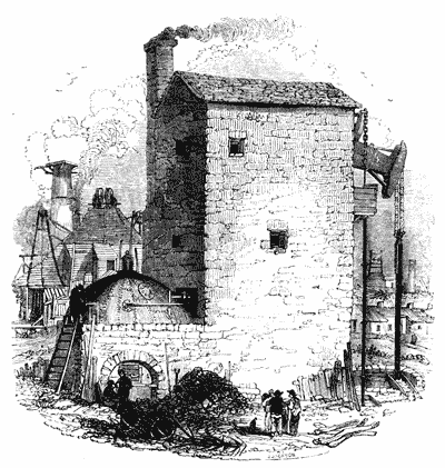
[9] This pipe is represented as proceeding from the force-pipe above the cistern C, in the perspective view of Savery's engine at the head of this chapter.
[10] Hot water being lighter than cold, floats on the surface.
[11] "Captain" is a title given in Cornwall to the superintendent of the works connected with a mine.
[12] As the calculation of the power of an engine depends on the number of square inches in the section of the piston, it may be useful to give a rule for computing the number of square inches in a circle. The following rule will always give the dimensions with sufficient accuracy:—Multiply the number of inches in the diameter by itself; divide the product by 14, and multiply the quotient thus obtained by 11, and the result will be the number of square inches in the circle. Thus, if there be 12 inches in the diameter, this multiplied by itself gives 144, which divided by 14 gives 104⁄44, which multiplied by 11 gives 115, neglecting fractions. There are, therefore, 115 square inches in a circle whose diameter is 12 inches.
[13] The external cylinder is not represented in the diagram.
[14] Also called the snifting valve, from the peculiar noise made by the air and steam escaping from it.
[15] Also called the injection valve.
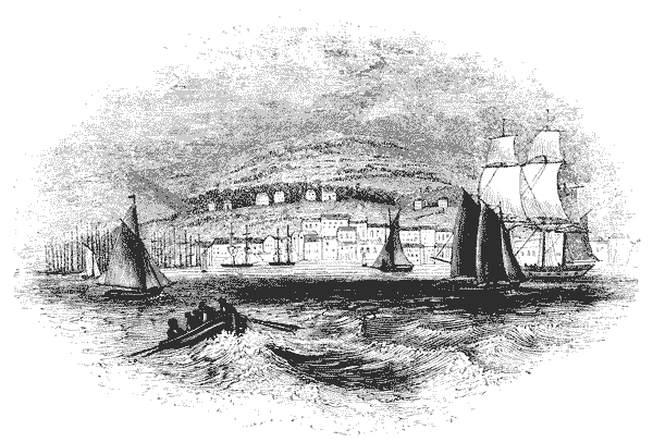
In 1759, Mr. James Brindley, whose name is so celebrated as the engineer of the Duke of Bridgewater's canal, obtained a patent for some improvements in the atmospheric engine. He proposed that the boiler should be made of wood and stone, with a stove or fire-place of cast iron within it, so that the fire should be surrounded on every side by water. The chimney was to be an iron pipe or tube, conducted through the boiler; so that the heated air, in passing from the fire, should impart a portion of its heat to the water. He also proposed a method of feeding the boiler, which, by self-acting machinery, would keep the water in the boiler at a fixed level, independently of any attention on the part of the engine-man. This was to be accomplished by a buoy or float upon the surface of the water in the boiler, which should communicate with a valve in the feed-pipe, so that when the level of the water in the boiler fell, the float or buoy, falling with it, would open the valve and supply the feed. It is stated, in the Biographia Britannica, that Mr. Brindley, in 1756, undertook to erect an engine at Newcastle-under-Lyne; but he is said to have been discouraged by the obstacles which were thrown in his way, and to have abandoned the steam engine.
The interval between the invention of the atmospheric engine, and the amelioration it received at the hands of Smeaton, has been rendered memorable by the advent of one who was destined to work a mighty change in the condition [Pg077] of the human race by the application of his vast genius to the adaptation of steam power to the uses of life.
The great-grandfather of Watt, a farmer in Aberdeenshire, was killed in one of the battles of Montrose. The victorious party, not thinking death a sufficient expiation for the political opinions in support of which he had fought and bled, punished him in the person of his son, by confiscating his little property. Thomas Watt, the son, thus deprived of support, was received by distant relations, and, for a time, applied himself to study, by which he was enabled, after the restoration of tranquillity, to establish himself at Greenock as a teacher of practical mathematics and navigation. He resided in the burgh or barony of Crawford's Dyke, and attained a position of sufficient respectability to be elected to the office of baron-baillie, or chief magistrate, and died in 1734, at the advanced age of ninety-two years.
Thomas Watt had two sons. The elder, John, adopted the profession of his father, and was a teacher of mathematics and navigation at Glasgow: he died in 1737, at the age of fifty years. The second son, James, the father of the celebrated engineer, was, during a quarter of a century, treasurer of the town council of Greenock, and a local magistrate. He was remarked for the ardent zeal and enlightened spirit with which he discharged his public duties. His business was that of a ship-chandler, builder, and general merchant; but, unhappily, notwithstanding his active industry, he lost, in the decline of his life, by unsuccessful commercial speculations, a part of the property which he had so honourably acquired. He died in 1782, at the age of eighty-four years.
James Watt, to whom the world is so largely indebted for the extension and improvement of steam power, had from his birth an extremely delicate constitution. From his mother, [Pg078] whose family name was Muirhead, he received his first lessons in reading, and he learned from his father writing and arithmetic. Although he was entered as a pupil in the grammar school of Greenock, yet such was his delicate state of health, that his attendance there was so interrupted by constant indisposition that he could derive but little benefit from the opportunities of instruction which it afforded. For a great period of the year he was confined to his room, where he devoted himself to study without the aid of instruction. It was in the retirement of the sick chamber that the high intellectual faculties of Watt, which were destined to produce such precious fruits, began to unfold themselves. He was too sickly to be subjected to the restraints which the business of education usually imposes on children. His parents, therefore, found it necessary to leave him at liberty to choose his occupations and amusements. The following anecdotes will show the use he made of this freedom.
A friend of his father found the boy one day stretched upon the hearth tracing with chalk various lines and angles. "Why do you permit this child," said he, "to waste his time so; why not send him to school?" Mr. Watt replied, "You judge him hastily; before you condemn us, ascertain how he is employed." On examining the boy, then six years of age, it was found that he was engaged in the solution of a problem of Euclid!
Having observed the tendency of his son's mind, Mr. Watt placed at his disposal a collection of tools. These he soon learned to use with the greatest skill. He took to pieces and put together, again and again, all the children's toys which he could procure; and he was constantly employed in making new ones. Subsequently he used his tools in constructing a little electrical machine, the sparks proceeding from which became a great subject of amusement to all the playfellows of the poor invalid.
Though endowed with great retentive powers, Watt would probably never have figured among the prodigies of a common school: he would have been slow to commit his lessons to memory, from the repugnance which he would feel to repeat like a parrot anything which he did not perfectly [Pg079] understand. The natural tendency of his mind to meditate on whatever came before it, would give him, to superficial observers, the appearance of dullness. Happily, however, he had a parent who was sufficiently clear-sighted, and who entertained high hopes of the growing faculties of his son. More distant and less sagacious relations were not so sanguine. One day Mrs. Muirhead, the aunt of the boy, reproaching him for what she conceived to be listless idleness, desired him to take a book and occupy himself usefully. "More than an hour has now passed away," said she, "and you have not uttered a single word. Do you know what you have been doing all this time? You have taken off, and put on, repeatedly, the lid of the tea-pot; you have been holding the saucers and the spoons over the steam, and you have been endeavouring to catch the drops of water formed on them by the vapour. Is it not a shame for you to waste your time so?"
Mrs. Muirhead was little aware that this was the first experiment in the splendid career of discovery which was subsequently to immortalise her little nephew. She did not see, as we now can, in the little boy playing with the tea-pot, the great engineer preluding to those discoveries which were destined to confer on mankind benefits so inestimable.
One of the social qualities of mind which was remarkable throughout his life, was the singular felicity and grace with which he related anecdotes. This power was manifested even in his earliest childhood. The following is an extract from a letter written by Mrs. Marion Campbell, his cousin, and the playfellow of his childhood:—
"He was not fourteen when his mother brought him to Glasgow to visit a friend of hers; his brother John accompanied him. On Mrs. Watt's return to Glasgow, some weeks after, her friend said, 'You must take your son James home; I cannot stand the degree of excitement he keeps me in; I am worn out for want of sleep. Every evening before ten o'clock, our usual hour of retiring to rest, he contrives to engage me in conversation, then begins some striking tale, and, whether humorous or pathetic, the interest is so overpowering that the family all listen to him with breathless attention, and hour after hour strikes unheeded.'" [Pg080]
Watt had a younger brother, John, who was subsequently lost by shipwreck, in a voyage from Scotland to the United States. This lad, having determined on following the business of his father, left James more completely at liberty to choose his own occupation. But such a choice was difficult for a student who commanded equal success in every thing to which he directed his attention.
The excursions which he was in the habit of making on the Scottish mountains surrounding Loch Lomond, naturally directed his attention to botany and mineralogy, in each of which he attained considerable knowledge. His love of anecdote and romance was likewise gratified by the scenery which he enjoyed in these walks; and the traditions and popular songs with which they made him acquainted. When from ill-health, as constantly happened, he was confined to the house, he devoted himself to chemistry, natural philosophy, and even to medicine and surgery. In chemistry he acquired some experimental skill, and studied with eager zeal the elements of natural philosophy by S'. Gravesande. His own unhappy maladies prompted him to read works on surgery and medicine; and to such an extent did the activity of his mind impel him on these subjects, that he was found one day dissecting, in his room, the head of a child, who had died of some unknown disease, with a view to ascertain the cause of its death.
In 1775, at the age of nineteen, at the recommendation of Dr. Dick, professor of natural philosophy in the university of Glasgow, he went to London, where he employed himself in the house of Mr. John Morgan, a mathematical instrument maker, in Finch Lane, Cornhill, to whom he apprenticed himself for three years. He remained, however, only a year, at the expiration of which (probably owing to his delicate state of health) he was released from his apprenticeship, and returned to Glasgow, with the intention of establishing himself in business as an optician and mathematical instrument maker. In the fulfilment of this intention, however, he was obstructed by the interposition of the Corporation of Trades in that town, who regarded him as an intruder, not qualified by the necessary apprenticeship to carry on business. All means of conciliation being [Pg081] exhausted, the Professors of the University interfered, and gave him the use of three apartments within the college, for carrying on his business, and likewise appointed him mathematical instrument maker to the University. Soon afterwards the opposition of the local trades seems to have given way, and he opened a shop in Glasgow for the sale of mathematical instruments.
After the celebrity at which he has arrived, it will be easily believed that every trace of his earlier connection with Glasgow college is carefully cherished. There are accordingly preserved at that place little instruments and pieces of apparatus of exquisite workmanship, which were executed entirely by the hand of Watt, at a time when he was not in a condition to command the aid of workmen under him.
At the time of obtaining this appointment in the University, Watt was in his twenty-first year. His natural talents and winning manners were speedily the means of gaining for him the esteem and friendship of all those eminent persons connected at the time with that university whose regard was most valued. Among these the earliest of his friends and patrons were—Adam Smith, the author of "The Wealth of Nations;" Black, afterwards celebrated for his chemical discoveries, and more especially for his theory of latent heat; and Robert Simson, rendered illustrious by his works on ancient geometry. In releasing Watt from the persecution of the Glasgow corporation, these distinguished persons first imagined that they were conferring a benefit merely on an industrious and clever artisan, whose engaging manners won their regard; but a short acquaintance with him was sufficient to convince them how superior his mind was to his position, and they conceived towards him the most lively friendship. His shop became the common rendezvous, the afternoon lounge, of all who were most distinguished for literary and scientific attainments among the professors and students. There they met to discuss the topics of the day in art, science, and literature. Among these students, the name which afterwards attained the highest distinctions, and among these distinctions, not the least, the lasting personal friendship and esteem of Watt himself, was Robison, [Pg082] the author of a well known work on Mechanics, and one of the contributors to the Encyclopœdia Britannica.
The following extract from an unpublished manuscript by Robison himself will show at once the estimation in which Watt was held, and will illustrate one of the most interesting traits of his personal character:—
"I had always, from my earliest youth, a great relish for the natural sciences, and particularly for mathematical and mechanical philosophy, when I was introduced by Drs. Simson, Dick, and Moor, gentlemen eminent for their mathematical abilities, to Mr. Watt. I saw a workman, and expected no more; but was surprised to find a philosopher as young as myself, and always ready to instruct me. I had the vanity to think myself a pretty good proficient in my favourite study, and was rather mortified at finding Mr. Watt so much my superior.. .. Whenever any puzzle came in the way of any of the young students, we went to Mr. Watt. He needed only to be prompted, for every thing became to him the beginning of a new and serious study, and we knew that he would not quit it till he had either discovered its insignificancy, or had made something of it. He learnt the German language in order to peruse Leupold's 'Theatrum Machinarum;' so did I, to know what he was about. Similar reasons made us both learn the Italian language. * * * When to his superiority of knowledge is added the naïve simplicity and candour of Mr. Watt's character, it is no wonder that the attachment of his acquaintances was strong. I have seen something of the world, and am obliged to say I never saw such another instance of general and cordial attachment to a person whom all acknowledged to be their superior. But that superiority was concealed under the most amiable candour, and a liberal allowance of merit to every man. Mr. Watt was the first to ascribe to the ingenuity of a friend things which were nothing but his own surmises, followed out and embodied by another. I am the more entitled to say this, as I have often experienced it in my own case."
Watt never permitted the inquiries which arose out of these reunions to interfere with the discharge of the duties of his workshop. There he passed the day, devoting the [Pg083] night to study. Every inquiry appeared to him to be attractive in proportion to its difficulty, and to have charms in proportion as it was removed from the common routine of his business. As an example of this may be mentioned the fact, that, being himself so insensible to the charms of music that he could not distinguish one note from another, he was actually induced to undertake the construction of an organ, in which he was nevertheless completely successful. The instrument he constructed, as might have been expected, contained many improvements in its mechanism; but what is much more remarkable, its tone and its musical qualities commanded the admiration of all the professional musicians who heard it. In the construction of this instrument Watt showed that vigorous spirit of investigation which characterised all the subsequent labours of his life. He made out the scale of temperament by the aid of the phenomena of beats, of which he could only obtain a knowledge by a profound but obscure work published by Dr. Robert Smith of Cambridge.
The earliest occasion on which the attention of Watt is said to have been called to the agency of steam, was in the year 1759, when his friend Robison entertained some speculations for applying that agent as a means of propelling wheel carriages; and he consulted Watt on the subject. No record, however, has been preserved of any experiments which were tried on this occasion; nor does it appear that the inquiry was carried farther than a verbal discussion, such as habitually took place on other subjects of science between Watt and his friends.
It is usual to provide, in the cabinets of experimental apparatus for the instruction of the students of universities, [Pg084] small working models of the most useful machines. In the collection for the illustration of the lectures delivered to the Natural Philosophy class in the University of Glasgow was a working model of Newcomen's atmospheric engine, applied to a pump for raising water; which, however, had never been found to work satisfactorily. The Professor of Experimental Philosophy of that day, Dr. John Anderson (the founder of the celebrated Andersonian Institution), sent this model in 1763 to Watt's workshop, to be repaired. Its defects soon disappeared, and it was made to work to the satisfaction of the professor and students.
This simple discharge of his duty, however, did not satisfy the artisan; and his wonted activity of mind rendered this model a subject of profound meditation, and led him into a course of practical inquiry respecting it, which formed the commencement of a most brilliant career of mechanical discovery. The improvement—we might almost say the creation—of the steam engine, by this great man, must not therefore be regarded, as so often happens with mechanical discoveries, as the result of fortuitous observation, or even of a felicitous momentary inspiration. Watt, on the other hand, conducted his investigation by a course of deep thought, and of experiments marked by the last refinement of delicacy and address. If he had received a more extended and liberal education, one would have thought that he had adopted for his guide the celebrated maxim of Bacon:—
"To write, speak, meditate, or act, when we are not provided with facts to direct our thoughts, is to navigate a coast full of dangers without a pilot, and to launch into the immensity of the ocean without either rudder or compass."
The model which he had repaired, had a cylinder of only two inches diameter, and six inches stroke. After he had put it in complete order, he found, that although the boiler was much larger in proportion to the cylinder than those of real engines, yet, that it was incapable of supplying the cylinder with steam in sufficient quantity to keep it at work. To enable it to continue to move, he found it necessary to lessen the quantity of water raised by its pump, so as to [Pg085] reduce the load on its piston very much below the proper standard according to the common rules for large engines.
He ascribed the great inferiority in the performance of the model, compared with the performance of the large engines, to the small size of the cylinder, and to its material. The cylinder of the model was brass, while those of large engines were of cast iron; and brass being a better conductor of heat than iron, he concluded that more heat in proportion was lost from this cause in the model, than in the larger engines. He observed that the small cylinder was so heated when the steam was admitted into it, that it could not be touched by the hand; but, nevertheless, that this heat contributed nothing to its performance, inasmuch as before the piston descended, the cylinder required to be cooled.
Still he found that the force with which the piston descended was considerably less than that which the atmospheric pressure ought to supply, supposing a tolerably perfect vacuum to be produced under the piston. This led him to suspect that the water injected into the cylinder was not perfectly effectual in condensing the steam. The experiments which he had previously made on the increased temperature at which water boils under pressures greater than that of the atmosphere, led him by analogy to the conclusion that it would boil at lower temperatures if it were submitted to a pressure less than the atmosphere, and he was aware that Dr. Cullen and others had then recently discovered that in vacuo, water would boil at so low a temperature as 100°. These notions suggested the probability that the water injected into the cylinder being heated by the condensed steam, might produce vapour of a low temperature [Pg086] and reduced pressure under the piston, which would account for the deficiency he observed in the power of the engine.
No means occurred to him by which he could ascertain, by direct experiment, the temperatures at which water would boil under pressures less than that of the atmosphere. He sought, however, to determine it by the following method. Having ascertained, by repeating and multiplying the experiments which he had tried in 1762, on high-pressure steam, he obtained a table of the temperatures at which water boils at various pressures greater than that of the atmosphere. These results he laid down in a series forming a curve, of which the abscissa represented the temperatures, and the ordinates the pressures. He then continued this curve, backwards as it were, and obtained, by analogy, an approximation to the boiling temperatures, corresponding to pressures less than that of the atmosphere. In other words, having obtained by his experiments a notion, however imperfect, of the law or rule observed by the temperatures at which water boils at different pressures greater than that of the atmosphere, he calculated by the same law or rule what the pressures would be at different pressures less than that of the atmosphere.
Applying these results to the interior of the cylinder of the atmospheric engine, he obtained an approximation to the pressure of the vapour which would be produced from the warm water formed by the cold water injected into the cylinder, and the steam condensed by it; and he accordingly found that vapour, having a pressure seriously injurious to the power of the engine would be produced in the cylinder, unless considerably more water of injection was thrown in than was customary.
It was apparent that the actual quantity of steam usefully employed in the cylinder at each stroke, was only the quantity which filled the cylinder; and therefore, in order to ascertain the quantity of steam lost by the imperfections of the machine, it was necessary to compare the actual quantity of steam transmitted by the boiler to the cylinder at each stroke, with the quantity which would just fill the cylinder. The difference would of course be wasted. But to determine [Pg087] the actual quantity of steam supplied by the boiler to the cylinder, there was no other means than by observing the quantity of water evaporated in the boiler. That being observed, it was necessary to know the quantity of steam which that water formed; and it was therefore necessary to determine the quantity or volume of steam which a given volume of water produced.
Let us suppose the piston at the top of the cylinder, and the space in the cylinder below it, filled with steam so as to balance the pressure of the atmosphere above the piston. Under such circumstances the steam, as will presently be explained, must have the temperature of boiling water. But that the steam should have, and should maintain, this temperature, it was evidently necessary that the inner surface of the cylinder in contact with it should have the same temperature: for if it had a lower temperature, it would take heat from the steam, and reduce the temperature of the latter. Now the cylinder being a mass of metal, has a quality in virtue of which heat passes freely through its dimensions, so that its inner surface could not be maintained at a temperature more elevated than that of its dimensions extending from the inner surface to the outer surface. Therefore, to maintain the steam contained in the cylinder at the proper temperature, it was essential that the whole of the solid metal composing the cylinder should be itself at that temperature.
Things being in this state, it was required that a vacuum should be produced under the piston to give effect to the atmospheric pressure above it, by relieving it from the pressure below. This, indeed, would appear to have been attained by introducing as much cold water within the cylinder as would be sufficient to reconvert the steam contained in it into water; but Watt found, in his experiments on the atmospheric model, that the piston would not descend with the proper force, unless a vastly greater quantity of water were introduced into the cylinder than the quantity which he had ascertained to be [Pg088] necessary for the reconversion of the steam into water. The cause of this he perceived and fully explained.
If we suppose as much, and no more, cold water introduced into the cylinder as would reconvert the steam contained in it into water, then we should have in the bottom of the cylinder a quantity of warm water with a vacuum above it: but the entire mass of metal composing the cylinder itself, which was previously at the temperature of boiling water, would still be at the same temperature. The warm water, resting in contact with this metal in the bottom of the cylinder, would be immediately heated by it, and would rise in its temperature, while the metal of the cylinder itself would be somewhat lowered in temperature by the heat which it would thus impart to the warm water contained in it. Under these circumstances, as we shall presently explain, steam would be produced from the water, which would fill the cylinder; and although such steam would not have a mechanical pressure equal in amount to the atmosphere, and therefore would not altogether prevent the piston from descending if it had no load to move, yet it would deprive the engine of so great a portion of its legitimate power as to render it altogether inefficient. But this defect would be removed by throwing into the cylinder a sufficient quantity of cold water, not only to destroy the steam contained in it, but also to cool the entire mass of metal composing the cylinder itself, until it would be reduced to such a temperature that the vapour proceeding from the water contained in it would have so small a pressure that it would not seriously or injuriously obstruct the descent of the piston.
The piston being made to descend with such force as to render the machine practically efficient, it would then be necessary again to make it ascend; and to accomplish this, Watt found that the boiler should supply a quantity of steam many times greater than was necessary to fill the cylinder. Mature reflection on the circumstances which have been just explained, enabled him to discover how this undue quantity of steam was rendered necessary.
Let it be recollected, that when the piston has reached the bottom of the cylinder, the whole mass of the cylinder, and [Pg089] the piston itself, are reduced to so low a temperature that the vapour of water, having the same temperature, has no pressure sufficiently great to obstruct the action of the machine. When, in order to make the piston ascend, steam is introduced from the boiler into the cylinder under the piston, this steam encounters, in the first instance, the cold surfaces of the metal forming the bottom of the cylinder and the bottom of the piston. The first effect of this is to convert the steam which comes from the boiler into water, an effect which is produced by that steam imparting its heat to the metal with which it comes into contact. This destruction of steam continues until the metal exposed to contact with it has been heated up to the temperature of boiling water. Then, and not till then, the steam below the piston will have a pressure equal to that of the atmosphere above it, and the piston will begin to ascend. As it ascends, however, the sides of the cylinder which it exposes to the contact of the steam are cold, and partially destroy the steam. Steam, therefore, must be supplied from the boiler to replace the steam thus destroyed; nor can the piston reach the top of the cylinder until such a quantity of steam shall have flowed from the boiler into the cylinder, as shall be sufficient not only to fill the cylinder under the piston, but likewise, by its condensation, to raise the whole mass of the cylinder and piston to the temperature of boiling water.
Such were the circumstances which forced themselves upon the attention of Watt, in the course of repairing, and subsequently trying, the model of the atmospheric engine, at Glasgow. Being informed generally of the uses of the engine in the drainage of mines, and of the vast expense attending its operation, by reason of the quantity of fuel which it consumed, he saw how important any improvement would be by which the extensive sources of waste which had thus presented themselves could be removed. He saw also, that all that portion of steam which was expended, not in filling the cylinder under the piston, but in heating the great mass of metal composing the cylinder and piston, from a low temperature to that of boiling water, upon each stroke of the piston, was so much heat lost, and that the proportion of the fuel expended in evaporating the steam thus wasted would be saved, if by any [Pg090] expedient he could make the piston descend without cooling the cylinder. But in order to estimate the full amount of this waste, and to discover the most effectual means of preventing it, it was necessary to investigate the quantity of heat necessary for the evaporation of a given quantity of water; also, the quantity of steam which a given quantity of water would produce, as well as other circumstances connected with the temperature and pressure of steam. He, therefore, applied himself to make experiments with a view to elucidate these questions; and succeeded in obtaining results which led to the discovery of some of the most important of those physical phenomena, on the due application of which, the efficacy of the steam engine, which he afterwards invented, depended, and which also form striking facts in the general physics of heat.
[Pg091] Having once ascertained this point, he was able, by observing the quantity of water evaporated in the boiler of the atmospheric model, to compute the volume of steam which was supplied to the cylinder. It was evident, that for every cubic inch of water evaporated in the boiler, eighteen hundred cubic inches of steam were supplied to the cylinder. Having accurately observed the evaporation of the boiler for a short time, and the number of strokes made by the piston in the same time, he found that the quantity of water evaporated in the boiler would supply about four times as much steam as the cylinder would require. He consequently inferred, that about three-fourths of the steam produced was wasted.
The next question to which he directed his experiments, was to ascertain the quantity of cold water necessary to be injected into the cylinder, in order to condense the steam contained in it. To ascertain this, he attached a pipe to a boiler, by which he was enabled to conduct the steam from the boiler into a glass jar containing cold water at fifty-two degrees of temperature. The steam, as it passed from the boiler through the pipe, was condensed by the cold water, and continued to be so condensed, until, by the heat which it imparted to the water, the latter began to boil, and would then condense no more steam. On comparing the water in the glass jar, when boiling, with the water originally contained in it at fifty-two [Pg092] degrees, the quantity was found to be increased in the proportion of six to seven, very nearly; from which he inferred, that to reduce one ounce of steam to water, it was necessary to mix about six ounces of cold water with it.
He was further led to the conclusion, that steam contains a vast quantity of heat, by the following experiment. He heated, in a close digester, a quantity of water several degrees above the common boiling point. When thus heated, by opening a stop-cock, he allowed the compressed steam to escape into a cold vessel; in three or four seconds, he found that the heat of the water in the digester was reduced from a very high temperature to the common boiling point; yet, that all the steam which escaped from it, and which carried off with it the superabundant heat, formed only a few drops of water when condensed; from which he inferred, that this small quantity of water, in the form of steam, contained as much heat as was sufficient to raise all the water in the digester from the boiling point to the temperature at which it was before the steam was allowed to escape.
Having thus ascertained the exact quantity of cold water which ought to be injected into the cylinder in order to condense the steam which filled the cylinder, he found, on comparing the quantity necessary to be injected in order to enable the piston to descend, that this quantity was about four times as great as that which was necessary to condense the steam. This led him to the conclusion, that about four times as much heat was destroyed in the cylinder as needed to be destroyed, if the object were the mere condensation of the steam. This result fully corroborated the other conclusion, deduced, from the proportion which he found between the quantity of steam supplied by the boiler and the actual contents of the cylinder.
He, therefore, eagerly sought his friend Dr. Black, to whom he communicated these results. Then, for the first time, he [Pg093] was informed, by Black, of the theory of LATENT HEAT, which had recently been discovered by him, and of which these very phenomena formed the basis.
Some passages in the works of Dr. Robison produced an erroneous impression, that a large share of the merit of the discoveries of Watt which have been just explained was due to Dr. Black, to whose instructions on the subject of latent heat Watt was represented to have owed the knowledge of those facts which led to his principal inventions and improvements. We shall here give, in the words of Watt himself, his explanation of the circumstances which led to this error. This explanation is given in a letter addressed by Watt to Dr. Brewster, in May 1814, and prefixed to the third volume of Brewster's edition of Robison's Mechanical Philosophy:—
"The representations of friends whose opinions I highly value induce me to avail myself of this opportunity of noticing an error into which not only Dr. Robison, but apparently also Dr. Black, has fallen, in relation to the origin of my improvements upon the steam engine, and which not having been publicly controverted by me, has, I am informed, been adopted by almost every subsequent writer upon the subject of latent heat.
"Dr. Robison, in the article Steam Engine, after passing an encomium upon me, dictated by the partiality of friendship, qualifies me as the 'pupil and intimate friend of Dr. Black,'—a description which not being there accompanied with any inference, did not particularly strike me at the time of its first perusal. He afterwards, in the dedication to me of his edition of Dr. Black's lectures upon chemistry, goes the length of supposing me to have professed to owe my improvements upon the steam engine to the instructions and information I had received from that gentleman, which certainly was a misapprehension; as, though I have always felt and acknowledged my obligations to him for the information I had received from his conversation, and particularly for the knowledge of the doctrine of latent heat, I never did nor could consider my improvements as originating in those communications. He is also mistaken in his assertion (p. 8. of the preface to the above work), that 'I had attended two courses [Pg094] of the doctor's lectures;' for, unfortunately for me, the necessary avocations of my business prevented me from attending his or any other lectures at college; and as Dr. Robison was himself absent from Scotland for four years at the period referred to, he must have been misled by erroneous information. In p. 184. of the lectures, Dr. Black says, 'I have the pleasure of thinking that the knowledge we have acquired concerning the nature of elastic vapours, in consequence of my fortunate observation of what happens in its formation and condensation, has contributed in no inconsiderable degree to the public good by suggesting to my friend Mr. Watt of Birmingham, then of Glasgow, his improvement on this useful engine' (meaning the steam engine of which he is then speaking). There can be no doubt from what follows in his description of the engine, and from the very honourable mention which he has made of me in various parts of his lectures, that he did not mean to lessen any merit that might attach to me as an inventor; but, on the contrary, he was always disposed to give me fully as much praise as I deserved.
"And were that otherwise doubtful, it would, I think, be evident from the following quotation from a letter of his to me, dated 13th February 1783, where, speaking of an intended publication by a friend of mine, on subjects connected with the history of steam, he says, 'I think it is very proper for you to give him a short account of your discoveries and speculations; and particularly to assert clearly and fully your sole right to the honour of the improvements of the steam engine.' And in a written testimonial which he very kindly gave me, on the occasion of a trial at law against a piracy of my invention in 1796-7, after giving a short account of the invention, he adds, 'Mr. Watt was the sole inventor of the capital improvement and contrivance above mentioned.'
"Under this conviction of his candour and friendship, it is very painful to me to controvert any assertion or opinion of my revered friend; yet, in the present case I find it necessary to say, that he appears to me to have fallen into an error; and I hope, in addition to my assertion, to make that appear by the short history I have given of my invention, in my [Pg095] notes upon Dr. Robison's essay, as well as by the following account of the state of my knowledge previous to my receiving any explanation of the doctrine of latent heat; and also from that of the facts which principally guided me in the invention.
"It was known very long before my time, that steam was condensed by coming into contact with cold bodies, and that it communicated heat to them; witness the common still, &c. &c.
"It was known, by some experiments of Dr. Cullen and others, that water and other liquids boiled in vacuo at very low heats; water below 100°.
"It was known to some philosophers that the capacity or equilibrium of heat, as we then called it, was much smaller in mercury and tin than in water.
"It was also known that evaporation caused the cooling of the evaporating liquid, and bodies in contact with it.
"I had myself made experiments to determine the following facts:—
"First, the capacities of heat for iron, copper, and some sorts of wood, comparatively with water.
"Second, the bulk of steam compared with that of water.
"Third, the quantity of water evaporated in a certain boiler by a pound of coals.
"Fourth, the elasticities of steam at various temperatures greater than that of boiling water, and an approximation to the law which it followed at other temperatures.
"Fifth, how much water in the form of steam was required every stroke by a small Newcomen's engine, with a wooden cylinder six inches diameter, and twelve inches stroke.
"Sixth, the quantity of cold water required in every stroke to condense the steam in that cylinder, so as to give it a working power of about 7 lb. on the inch.
"Here I was at a loss to understand how so much cold water could be heated so much by so small a quantity of water in the form of steam; and I accordingly applied to Dr. Black, and then first understood what was called latent heat.
"But this theory, though useful in determining the quantity of injection necessary where the quantity of water [Pg096] evaporated by the boiler, and used by the cylinder, was known, and in determining, by the quantity and heat of the hot water emitted by Newcomen's engines, the quantity of steam required to work them did not lead to the improvements I afterwards made in the engine. These improvements proceeded upon the old established fact, that steam was condensed by the contact of cold bodies; and the later known one, that water boiled in vacuo at heats below 100°, and consequently that a vacuum could not be obtained unless the cylinder and its contents were cooled every stroke to below that heat."

[16] We are indebted for many of the anecdotes of the life of Watt to the Eloge Historique, recently published by M. Arago, who was furnished with all the documents and circumstances relating to this celebrated person which were considered proper for publication, by his son, the present James Watt, Esq., of Aston Hall, near Birmingham, and to the notes added to this memoir by Mr. Muirhead, a relative of Mr. Watt.
[17] The following is the account of these experiments given in Watt's own words:—
"It being evident that there was a great error in Dr. Desagulier's calculations of Mr. Beighton's experiments on the bulk of steam, a Florence flask, capable of containing about a pound of water, had about one ounce of distilled water put into it; a glass tube was fitted into its mouth, and the joining made tight by lapping that part of the tube with packthread covered with glazier's putty. When the flask was set upright, the tube reached down near to the surface of the water, and in that position the whole was placed in a tin reflecting oven before a fire until the water was wholly evaporated, which happened in about an hour, and might have been done sooner, had I not wished the heat not much to exceed that of boiling water. As the air in the flask was heavier than the steam, the latter ascended to the top, and expelled the air through the tube. When the water was all evaporated, the oven and flask were removed from the fire, and a blast of cold air was directed against one side of the flask, to collect the condensed steam in one place. When all was cold, the tube was removed, the flask and its contents were weighed with care; and the flask being made hot, it was dried by blowing into it by bellows, and when weighed again was found to have lost rather more than four grains, estimated at 41⁄3 grains. When the flask was filled with water, it was found to contain about 171⁄8 ounces avoirdupois of that fluid which gave about 1800 for the expansion of water converted into steam of the heat of boiling water.
"This experiment was repeated with nearly the same result, and in order to ascertain whether the flask had been wholly filled with steam, a similar quantity of water was for the third time evaporated; and, while the flask was still cold, it was placed inverted with its mouth (contracted by the tube) immersed in a vessel of water, which it sucked in as it cooled, until in the temperature of the atmosphere it was filled to within half an ounce measure of water.
"In repetitions of this experiment at a later date, I simplified the apparatus by omitting the tube, and laying the flask upon its side in the oven, partly closing its mouth by a cork, having a notch on one side, and otherwise proceeding as has been mentioned.
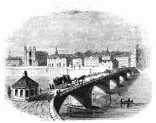
As we shall frequently have occasion to refer to the indications of a thermometer, we shall first explain the principle of that instrument as it is commonly used in this country.
The thermometer is an instrument used for the purpose of measuring and indicating the temperature or sensible heat of material substances.
Heat, like all other physical agents, can only be measured by its effects. One of these effects best suited for this purpose, is the change of dimension which all bodies undergo in consequence of their change of temperature. In general, when heat is applied to a material substance, that substance undergoes an enlargement of bulk; and if heat be abstracted from it, it suffers a diminution of bulk. This variation of magnitude is not always in the same proportion as the increase or diminution of temperature; but it is so when applied to certain substances and between certain limits. One of the substances whose expansion and contraction through an extensive range of temperature has been found to be nearly uniform, and which is attended with other convenient qualities for a thermometer, is the liquid called mercury or quicksilver. A mercurial thermometer is constructed in the following way:—
A glass tube is made with a small and uniform bore: upon the end of this tube, a bulb is blown, having a magnitude very great compared with the bore of the tube. Let us suppose this bulb and a part of the tube to be filled with mercury. If the mercury contained in the bulb be heated, it will expand, and being more susceptible of expansion than the glass which contains it, the bulb will be too small for its augmented volume: the mercury in the bulb can only, therefore, obtain room for its increased bulk by pressing the mercury in the tube upwards, which it will accordingly do. The increase of volume which the mercury in the bulb therefore undergoes, will be exhibited by the increased length of the column in the tube. Since the bore of the tube is made so exceedingly minute compared with the magnitude of the bulb, a very small quantity of mercury forced [Pg099] from the bulb into the tube, will cause a considerable increase of the length of the column. Small degrees of expansion will therefore be rendered very apparent, and may be accurately measured. The following is the method by which the thermometer called Fahrenheit's thermometer is graduated.
The tube and bulb being prepared and supplied with mercury, as already explained, let the instrument be plunged in a vessel of melting ice. It will be found that the mercury will stand in the tube at a certain point, from which it will not vary so long as any ice remains not completely melted in the vessel. Let a mark be made on the tube, or on a scale attached to the tube, at the point corresponding to the top of the column: the point thus marked is called the freezing point.
Now let the instrument be immersed in a vessel of boiling water, the barometer at the time having the height of thirty inches. It will be found that so long as the water is kept boiling, the column of mercury in the tube will remain stationary. Let the point corresponding with the top of the column be marked on the tube, or on the scale attached to it. This is called the boiling point. Let the space on the scale between the freezing and boiling points be now divided into 180 equal parts: each of these parts is called a degree. Let the same divisions be continued upon the scale below the freezing point, until thirty-two divisions be taken; let the lowest division be then marked 0, and let the successive divisions upwards from that be numbered 1, 2, 3, &c. In like manner, let the same divisions be continued above the boiling point, as far as the tube will admit.
It is evident that, under these circumstances, the freezing point will be marked by 32, and the boiling point by 212. It is usual to express the degrees of a thermometer in the same manner as the degrees of a circle, by placing a small ° above the number. Thus the freezing point is expressed by 32°, and the boiling point by 212°.
The reason the degrees were commenced at 32° below the freezing point was, because, when the thermometer was invented, that temperature was supposed to be the lowest degree of cold possible, being that of a certain mixture of [Pg100] snow and salt. This, however, has since been found to be an error, very much lower temperatures being obtained by various physical expedients.
The temperature of a body is, then, that elevation to which the thermometer would rise when immersed in that body. Thus, if in plunging the thermometer in water we found the mercury to rise or fall to the division marked 100, we should then say, the temperature of the water was 100°.
Let us suppose a spirit lamp, or other regular source of heat, applied to a bath of mercury, so as to maintain the mercury at a fixed temperature of 200°, and let another vessel, containing a quantity of ice at a temperature of 20° be immersed in the mercury. Let a thermometer be placed in the mercury, and another in the ice. The following effects will then ensue. The thermometer immersed in the ice will be observed gradually to rise from 20° upwards, until it indicates the temperature of 32°. It will then become stationary, and the ice which had hitherto remained in a solid state will begin to melt and be converted into water. This process of liquefaction will continue for a considerable time, during which the thermometer immersed in the ice will constantly be maintained at 32°. At the moment, however, when the last portion of ice is liquefied, the thermometer will begin again to rise. The coincidence of this ascent of the thermometer with the completion of the liquefaction of the ice, may be very easily observed, because the ice being lighter, bulk for bulk, than water, will float on the surface, and so long as a particle of it remains unmelted it will be distinctly seen.
Now it cannot be doubted that, during the whole of this process, the mercury, supposed to be maintained at 200°, constantly imparts heat to the ice; yet, from the moment the liquefaction begins, until it is completed, no increased temperature is exhibited by the thermometer immersed in the melting ice. If during this part of the process no heat were received by the ice from the mercury, the consequence would be, that the application of the lamp would cause the temperature of the mercury to rise above 200°, which may be easily demonstrated by withdrawing the vessel of ice from the mercurial bath during the process of liquefaction. The moment [Pg101] it is withdrawn, the thermometer immersed in the mercury, instead of remaining fixed at 200°, will begin to rise, although the action of the lamp remains the same as before; from which it is evident that the heat which now causes the mercury to rise above 200° was before received by the melting ice.
The heat which thus enters ice in the process of liquefaction, and which is not indicated by the thermometer, is for this reason called latent heat. It will be perceived that this phrase is the name of a fact, and not of an hypothesis. That heat really enters the water, and is contained in it, has been established by the experiments; and to declare that it is present there, is to declare an established fact. To call it by the name latent heat, is to declare another established fact, viz., that it is not sensible to the thermometer.
These facts show us that heat is capable of existing in bodies in two distinct states, in one of which it is sensible to the thermometer, and in the other not. Heat which is sensible to the thermometer is called, for distinction, sensible or free heat. It may be here observed, that heat which is sensible to the thermometer is also perceptible by the senses, and heat not sensible to the thermometer is not perceptible by the senses. Thus, ice at 32° and water at 32° feel equally cold, and yet we have seen that the latter contains considerably more heat than the former.
Dr. Black, who first noticed the remarkable fact to which we have now alluded, inferred that ice is converted into water by communicating to it a certain quantity or dose of heat, which enters into combination with it in a manner analogous to that which takes place when bodies combine chemically. The heat, thus combined with the solid ice, loses its property of affecting the senses or the thermometer, and the effects therefore bear a resemblance to those cases of chemical combination in which the constituent elements change their sensible properties when they form the compound.
The fact that the thermometer immersed in the ice remains stationary only as long as the process of liquefaction is going on, shows that this absorption of heat is necessarily connected with that process, and that, were it not for the conversion of [Pg102] the solid ice into liquid water, the heat which is so received would be sensible, and would cause the thermometer immersed in the ice to rise. Before the time of Black it was supposed that the slightest addition of heat would cause solid ice to be converted into water, and that the thermometer would immediately pass from the freezing temperature to higher degrees. The experiments above described, however, show the falsehood of such a supposition. If, while the mercurial bath, in which the ice is immersed, is maintained at the temperature of 200°, the length of time necessary to complete the liquefaction of the ice be observed, it would be found that that time is about twenty-eight times the length of time which it would take to raise the liquid water from 32° to 37°; and if it be assumed that the same quantity of heat is imparted to the ice, during the process of liquefaction, during each minute, as is imparted to the water, during each minute, in rising from 32° to 37°, it will follow, that to liquefy the ice requires twenty-eight times as much heat as is necessary to raise the water from 32° to 37°. It appears, therefore, that, instead of a small quantity of heat being necessary to melt the ice, a very considerable portion is absorbed in that process.
Having ascertained the remarkable fact, that heat is absorbed in a large quantity in the conversion of ice into water, without rendering the body so absorbing it warmer, let us now inquire what the exact quantity of heat so absorbed is. We have already stated that, if the quantity communicated in equal times be the same, the heat necessary to liquefy a given weight of ice would be twenty-eight times as much as would be necessary to raise the same weight of water from 32° to 37°; or, if the heat necessary to raise water through every 5° be the same, that quantity of heat would be sufficient to raise water from 32° to 172°: and hence we infer, that as much heat is absorbed in the liquefaction of a given quantity of ice as would raise the same quantity of water through 140 degrees of the thermometric scale.
Let a small quantity of water be placed in a glass flask of considerable size, and then closed so as to prevent the escape [Pg103] of any vapour. Let this vessel be now placed over the flame of a spirit lamp, so as to cause the water it contains to boil. For a considerable time the water will be observed to boil, and apparently to diminish in quantity, until at length all the water disappears, and the vessel is apparently empty. If the vessel be now removed from the lamp, and suspended in a cool atmosphere, the whole of the interior of its surface will presently appear to be covered with a dewy moisture; and at length a quantity of water will collect in the bottom of it, equal to that which had been in it at the commencement of the process. That no water has at any period of the experiment escaped from it, may be easily determined, by performing the experiment with the glass flask suspended from the arm of a balance, counterpoised by a sufficient weight suspended from the other arm. The equilibrium will be preserved throughout, and the vessel will be found to have the same weight, when to all appearance it is empty, as when it contains the liquid water. It is evident, therefore, that the water exists in the vessel in every stage of the process, but that it becomes invisible when the process of boiling has continued for a certain length of time; and it may be shown that it will continue to be invisible, provided the flask be exposed to a temperature considerably elevated. Thus, for example, if it be suspended in a vessel of boiling water, the water which it contains will continue to be invisible; but the moment it is withdrawn from the boiling water, and exposed to the cold air, the water will again become visible, as above mentioned, forming a dew on the inner surface, and finally collecting in the bottom, as in the commencement of the experiment.
In fact, the liquid has, by the process of boiling, been converted into vapour, or steam, which is a body similar in its leading properties to common air, and, like it, is invisible. It will hereafter appear that it likewise possesses the property of elasticity, and other mechanical qualities enjoyed by gases in general.
Now, it will be asked, what has become of the water? It cannot be imagined that it has been annihilated. We shall be able to answer this by adopting means to prevent the escape of any particle of matter from the vessel containing the water, into the atmosphere or elsewhere. Let us suppose that the top of the vessel containing the water is closed, with the exception of a neck communicating with a tube, and let that tube be carried into another close vessel removed from the cistern of heated mercury, and plunged in another cistern of cold water. Such an apparatus is represented in fig. 15.
A is a cistern of heated mercury, in which the glass vessel B, containing water, is immersed. From the top of the vessel B proceeds a glass tube C, inclining downwards, and entering a glass vessel D, which is immersed in a cistern E of cold water. If the process already described be continued until the water by constant ebullition has disappeared, as already mentioned, [Pg105] from the vessel B, it will be found that a quantity of water will be collected in the vessel D; and if this water be weighed, it will be found to have exactly the same weight as the water had which was originally placed in the vessel B. It is, therefore, quite apparent that the water has passed by the process of boiling from the one vessel to the other; but, in its passage, it was not perceptible by the sight. The tube C and the upper part of the vessel B, had the same appearance, exactly, as if they had been filled with atmospheric air. That they are not merely filled with atmospheric air may, however, be easily proved. When the process of boiling first commences, it will be found that the tube C is cold, and the inner surface dry. When the process of ebullition has continued a short time, the tube C will become gradually heated, and the inner surface of it covered with moisture. After a time, however, this moisture disappears, and the tube attains the temperature 212°. In this state it continues until the whole of the water is discharged from the vessel B to the vessel D.
If a thermometer be immersed in the steam which collects in the upper part of the vessel B, it will show the same temperature (of 212°) as the water from which it is raised. The heat, therefore, received from the mercury, is clearly not imparted in a sensible form to the steam, which has the same temperature in the form of steam as it had in the form of water. What has been already explained respecting liquefaction would lead us, by analogy, to suspect that the heat imparted by the mercury to the water has become latent in the steam, and is instrumental to the conversion of water into steam, in the same manner as heat has been shown to be instrumental to the conversion of ice into water. As the fact was in that case detected by mixing ice with water, so we shall, in the present instance, try it by a like test, viz. by mixing water with steam. Let about five ounces and a half of water, at the temperature of 32°, be placed in a vessel A (fig. 16.), and let another vessel B, in which water is kept constantly boiling at the temperature of 212°, communicate with A by a pipe C proceeding from the top, so that the steam may be conducted from B, and escape from the mouth of the pipe at some depth below the surface of the water in A. As the steam issues from the pipe, it will be immediately reconverted into water by the cold water which it encounters; and, by continuing this process, the water in A will be gradually heated by the steam combined with it and received through the pipe C. If this process be continued until the water in A is raised to the temperature of 212°, it will boil. Let it then be weighed, and it will be found to weigh six ounces and a half: from whence we infer, that one ounce of water has been received from the vessel B in the form of steam, and has been reconverted into water by the inferior temperature of the water in A. Now, this ounce of water received in the form of steam into the vessel A had, when in that form, the temperature of 212°. It is now [Pg108] converted into the liquid form, and still retains the same temperature of 212°; but it has caused the five ounces and a half of water with which it has been mixed, to rise from the temperature of 32° to the temperature of 212°,—and this, without losing any temperature itself. It follows, therefore, that, in returning to the liquid state, it has parted with as much heat as is capable of raising five times and a half its own weight of water from 32° to 212°. This heat was combined with the steam, though not sensible to the thermometer; and was, therefore, latent. Had it been sensible in the water in B, it would have caused the water to have risen through a number of thermometric degrees, amounting to five times and a half the excess of 212° above 32°; that is, through five times and a half 180°; for it has caused five times and a half its own weight of water to receive an equal increase of temperature. But five times and a half 180° is 990°, or, to use round numbers (for minute accuracy is not here our object), 1000°. It follows, therefore, that an ounce of water, in passing from the liquid state at 212° to the state of steam at 212°, receives as much heat as would be sufficient to raise it through 1000 thermometric degrees, if that heat, instead of becoming latent, had been sensible.
If water be boiled in an open vessel, with a thermometer immersed, on different days, it will be observed that the fixed temperature which it assumes in boiling will be subject to a variation within certain small limits. Thus, at one time, it will be found to boil at the temperature of 210°; while, at others, the thermometer immersed in it will rise to 213°; and, on different occasions, it will fix itself at different points within these limits. It will also be found, if the same experiment be performed at the same time in distant places, that the boiling points will be subject to a like variation. Now, it is natural to inquire what cause produces this variation; and we shall be led to the discovery of the cause, by examining what other physical effects undergo a simultaneous change. [Pg109]
If we observe the height of the barometer at the time of making each experiment, we shall find a very remarkable correspondence between it and the boiling temperature. Invariably, whenever the barometer stands at the same height, the boiling temperature will be the same. Thus, if the barometer stands at 30 inches, the boiling temperature will be 212°. If the barometer fall to 291⁄2 inches, the thermometer stands at a small fraction above 211°. If the barometer rise to 301⁄2 inches, the boiling temperature rises to nearly 213°. The variation in the boiling temperature is, then, accompanied by a variation in the pressure of the atmosphere indicated by the barometer; and it is constantly found that the boiling point will remain unchanged, so long as the atmospheric pressure remains unchanged, and that every increase in the one causes a corresponding increase in the other.
If the variable pressure excited on the surface of the water by the atmosphere be the cause of the change in the boiling temperature, it must happen, that any change of pressure produced by artificial means on the surface of the water must likewise change the boiling point, according to the same law. Thus, if a pressure considerably greater than the atmospheric pressure be excited on a liquid, the boiling point may be expected to rise considerably above 212°; and, on the other hand, if the surface of the water be relieved from the pressure of the atmosphere, and be submitted to a considerably diminished pressure, the water would boil below 212°.
Let B (fig. 17.) be a strong spherical vessel of brass, supported on a stand S, under which is placed a large spirit lamp L, or other means of heating it. In the top of this vessel are three apertures, in two of which are screwed a [Pg110] thermometer T, the bulb of which enters the hollow brass sphere, and a stop-cock C, which may be closed or opened at pleasure, to confine the steam, or allow it to escape. In the third aperture at the top, is screwed a long barometer tube, open at both ends. The lower end of this tube extends nearly to the bottom of the spherical vessel B. In the bottom of this vessel is placed a quantity of mercury, the surface of which rises to some height above the lower end of the tube A. Over the mercury is poured a quantity of water, so as to half fill the vessel B. Matters being thus arranged, the screws are made tight, so as to confine the water, and the lamp is allowed to act on the vessel; the temperature of the water is raised, and steam is produced, which, being confined within the vessel, exerts its pressure on the surface of the water, and resists its ebullition. The pressure of the steam acting on the surface of the water is communicated to the surface of the mercury, and it forces a portion of the mercury into the tube A, which presently rises above the point where the tube is screwed into the top of the vessel B. As the action of the lamp continues, the thermometer T exhibits a gradually increasing temperature; while the column of mercury in A shows the force with which the steam presses on the surface of the water in B,—this column being balanced by the pressure of the steam. Thus, the temperature and pressure of the steam at the same moment may always be observed by inspecting the thermometer T and the tube A. When the column in the tube A has risen to the height of 30 inches above the level of the mercury in the vessel B, then the pressure of the steam will be equivalent to double the pressure of the atmosphere, because, the tube A being open at the top, the atmosphere presses on the [Pg111] surface of the mercury in it. The thermometer T will be observed gradually to rise until it attains the temperature of 212°; but it will not stop there, as it would do if immersed in water boiled in an open vessel. It will, on the other hand, continue to rise; and when the column of mercury in A has attained the height of 30 inches, the thermometer T will have risen to 251°,—being 39° above the ordinary boiling point.
During the whole of this process, the surface of the water being submitted to a constantly increasing pressure, its ebullition is prevented, and it continues to receive heat without boiling. That it is the increased pressure which resists its ebullition, and causes it to receive a temperature above 212°, may be easily shown. Let the stop-cock C be opened; immediately the steam in B, having a pressure considerably greater than that of the atmosphere, will rush out, and will continue to issue from C, until its pressure is balanced by the atmosphere. At the same time the column of mercury in A will be observed rapidly to fall, and to sink below the orifice by which it is inserted in the vessel B. The thermometer T will also fall until it attains the temperature of 212°. At that point, however, it will remain stationary; and the water will now be distinctly heard to be in a state of rapid ebullition. If the stop-cock C be once more closed, the thermometer will begin to rise, and the column of mercury ascending in A will be again visible.
If, instead of a stop-cock being at C, the aperture were made to communicate with a valve, like the safety-valve of a steam engine, loaded with a certain weight,—say at the rate of 15 lbs. on the square inch,—then the thermometer T, and the mercury in the tube A, would not rise indefinitely as before. The thermometer would continue to rise till it attained the temperature of 251°; and the mercury in the tube A would rise to the height of 30 inches. At this limit the resistance of the valve would be balanced by the pressure of the steam; and as fast as the water would have a tendency to produce steam of a higher pressure, the valve would be raised and the steam suffered to escape; the thermometer T and the column of mercury in A remaining stationary during this process. If the valve were loaded more heavily, the phenomena would be [Pg112] the same, only that the mercury in T and A would become stationary at certain heights. But, on the other hand, if the valve were loaded at a less pressure than 15 lbs. on the square inch, then the mercury in the two tubes would become stationary at lower points.
This may be easily accomplished by the aid of an air pump. Let water at the temperature of 200° be placed in a glass vessel under the receiver of an air pump, and let the air be gradually withdrawn. After a few strokes of the pump, the water will boil; and if the mercurial gauge of the pump be observed, it will be found that its altitude will be about 231⁄2 inches. Thus the pressure to which the water is submitted has been reduced from the ordinary pressure of the atmosphere expressed by the column of 30 inches of mercury, to a diminished pressure expressed by 231⁄2 inches; and we find that the temperature at which the water boils has been lowered from 212° to 200°. Let the same experiment be repeated with water at the temperature of 180°, and it will be found that a further rarefaction of the air is necessary, but the water will at length boil. If the gauge of the pump be now observed, it will be found to stand at about fifteen inches, showing, that at the temperature of 180° water will boil under half the ordinary pressure of the atmosphere. These experiments may be varied and repeated; and it will be always found, that, as the pressure is diminished or increased, the temperature at which the water will boil will be also diminished or increased.
| Barometer. inches | Boiling Point. |
|---|---|
| 26 | 204°·91 |
| 26·5 | 205°·79 |
| 27 | 206°·67 |
| 27·5 | 207°·55 |
| 28 | 208°·43 |
| 28·5 | 209°·31 |
| 29 | 210°·19 |
| 29·5 | 211°·07 |
| 30 | 212° |
| 30·5 | 212°·88 |
| 31 | 213°·76 |
From this table it appears, that, for every tenth of an inch which the barometric column varies between these limits, the boiling temperature changes by the fraction of a degree expressed by the decimal ·176, or nearly by the vulgar fraction 1⁄6.
Let us suppose a given weight of water at the temperature of 32° to be exposed to any regular source by which heat may be supplied to it. If it be under the ordinary atmospheric pressure, the first 180° of heat which it receives will raise it to the boiling point, and the next 1000° will convert it into steam. Thus, in addition to the heat which it contains at 32°, the steam at 212° contains 1180° of heat. But if the same water be submitted to a pressure equal to half the atmospheric pressure, then the first 148° of heat which it receives will cause it to boil, and the next 1032° will convert it into vapour. Thus, steam at the temperature of 180° contains a quantity of heat more than the same quantity of water at 32°, by 1032° added to 148°, which gives a sum of 1180°. Steam, therefore, raised under the ordinary pressure of the atmosphere at 212°, and steam raised under half that pressure at 180°, contain the same quantity of heat,—with this difference [Pg115] only—that the one has more latent heat, and less sensible heat, than the other.
From this fact, that the sum of the latent and sensible heats of the vapour of water is constant, it follows that the same quantity of heat is necessary to convert a given weight of water into steam, at whatever temperature, or under whatever pressure, the water may be boiled. It follows, also, that, in the steam engine, equal weights of high-pressure and low-pressure steam are produced by the same consumption of fuel; and that, in general, the consumption of fuel is proportional to the quantity of water vaporised, whatever the pressure of the steam may be.[18]
Let A B (fig. 18.) be a tube, or cylinder, the base of which is equal to a square inch, and let a piston P move in it so as to be steam-tight. Let it be supposed, that under this piston there is, in the bottom of the cylinder, a cubic inch of water between the bottom of the piston and the bottom of the tube; let the piston be counterbalanced by a weight W acting over a pulley, which will be just sufficient to counterpoise the weight of the piston, so as leave no force tending to keep the piston down, except the force of the atmosphere acting above it. Under the circumstances here supposed, the piston being in contact with the water, and all air being excluded, it will be pressed down by the weight of the atmosphere, which we will suppose to be fifteen pounds, the magnitude of the piston being a square inch. [Pg116]
Now let the flame of a lamp be applied at the bottom of the tube; the water under the piston having its temperature thereby gradually raised, and being submitted to no pressure save that of the atmosphere above the piston, it will begin to be converted into steam when it has attained the temperature of 212°. According as it is converted into steam, it will cause the piston to ascend in the tube until all the water has been evaporated. If the tube were constructed of sufficient length, the piston then would be found to have risen to the height of about seventeen hundred inches, or one hundred and forty-two feet; since, as has been already explained, water passing into steam under the ordinary pressure of the atmosphere undergoes an increase of bulk in the proportion of about seventeen hundred to one.
Now in this process, the air above the piston, which presses on it with a force equal to fifteen pounds, has been raised one hundred and forty-two feet. It appears, therefore, that, by the evaporation of a cubic inch of water under a pressure equal to fifteen pounds per square inch, a mechanical force of this amount is developed.
It is evident that fifteen pounds raised one hundred and forty-two feet successively, is equivalent to one hundred and forty-two times fifteen pounds raised one foot. Now, one hundred and forty-two times fifteen is two thousand one hundred and thirty, and therefore the force thus obtained is equal to two thousand one hundred and thirty pounds raised one foot high. This being within about 110 pounds of a ton, it may be stated, in round numbers, that, by the evaporation of a cubic inch of water under these circumstances, a force is obtained equal to that which would raise a ton weight a foot high.
The augmentation of volume which water undergoes in passing into steam under the pressure here supposed, may be easily retained in the memory, from the accidental circumstance that a cubic inch of water is converted into a cubic foot of steam, very nearly. A cubic foot contains one thousand seven hundred and twenty-eight cubic inches,—which is little different from the proportion which steam bears to water, when raised under the atmospheric pressure. [Pg117]
1. A cubic inch of water evaporated under the ordinary atmospheric pressure, is converted into a cubic foot of steam.
2. A cubic inch of water evaporated under the atmospheric pressure, gives a mechanical force equal to what would raise about a ton weight a foot high.
In like manner, if the piston were loaded with thirty pounds in addition to the atmosphere, the whole pressure on the water being then three times the pressure first supposed, the piston would be raised to somewhat more than one third of its first height by the evaporation of the water. This would give a mechanical force equivalent to three times the original weight raised a little more than one third of the original height.
In general, as the pressure on the piston is increased, the height to which the piston would be raised by the evaporation of the water will be diminished in a proportion somewhat less than the proportion in which the pressure on the piston is increased. If the temperature at which the water is converted into steam under these different pressures were the same, then the height to which the piston would be raised by the evaporation of the water would be diminished in precisely [Pg118] the same proportion as the pressure on the piston is increased; and, in that case, the whole mechanical force developed by the evaporation of the water would remain exactly the same under whatever pressure the water might be boiled. We shall explain hereafter the extent to which the variation of temperature in the water and steam corresponding to the variation of pressure modifies this law; but, as the effect of the difference of temperatures is not considerable, it will be convenient to register in the memory the following important practical conclusion:—
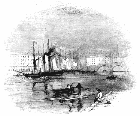
[18] The preceding paragraphs, and some other parts of the present volume on the general properties of Heat, are taken from my Treatise on Heat, in the Cabinet Cyclopœdia, to which those who desire more detailed explanation and more copious illustration should refer.
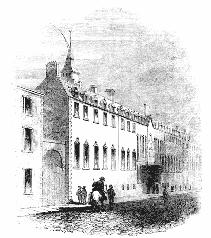
He perceived that the principal source of this wasteful expenditure of power consisted in the quantity of steam which was condensed at each stroke of the piston, in heating the cylinder previous to the ascent of the piston. Yet, as it was evident that that ascent could not be accomplished in a cold cylinder, it was apparent that this waste of power must be inevitable, unless some expedient could be devised, by which a vacuum could be maintained in the cylinder, without cooling it. But, to produce such a vacuum, the steam must be condensed; and, to condense the steam, its temperature must be lowered to such a point that the vapour proceeding from it shall have no injurious pressure; yet, if condensed steam be contained in a cylinder at a high temperature, it will return to the temperature of the cylinder, recover its elasticity, and resist the descent of the piston.
Having reflected on these circumstances, it became apparent to Watt, that a vice was inherent in the structure of the atmospheric engine, which rendered a large waste of power inevitable; this vice arising from the fact, that the condensation of the steam was incompatible with the condition of maintaining the elevated temperature of the cylinder in which that condensation took place. It followed, therefore, either that the steam must be imperfectly condensed, or that the condensation could not take place in the cylinder. It was in 1765, that, pondering on these circumstances, the happy idea occurred to him, that the production of a vacuum could be equally effected, though the place where the condensation of the steam took place were not the cylinder itself. He saw, that if a vessel in which a vacuum was produced were put into communication with another containing an elastic fluid, the elastic fluid would rush into the vacuum, and diffuse itself through the two vessels; but if, on rushing into such vacuum, this elastic fluid, being vapour, were there condensed, or restored to the liquid form, that then the space within the two vessels would be equally rendered a vacuum;—that, under such circumstances, one of the vessels might be maintained at any temperature, however high, while [Pg121] the other might be kept at any temperature, however low. This felicitous conception formed the first step in that splendid career of invention and discovery which has conferred immortality on the name of Watt. He used to say, that the moment the idea of separate condensation occurred to him,—that is, of condensing, in one vessel kept cold, the steam coming from another vessel kept hot,—all the details of his improved engine rushed into his mind in such rapid succession, that, in the course of a day, his invention was so complete that he proceeded to submit it to experiment.
To explain the first conception of this memorable invention; let a tube or pipe, S (fig. 19.), be imagined to proceed from the bottom of the cylinder A B to a vessel, C, having a stop-cock, D, by which the communication between the cylinder and the vessel C may be opened or closed at pleasure. If we suppose the piston P at the top of the cylinder, and the space below it filled with steam, the cylinder and steam being at the usual temperature, while the vessel C is a vacuum, and maintained at a low temperature. Then, on opening the cock D, the steam will rush from the cylinder A B through the tube S, and, passing into the cold vessel C, will be condensed by contact with its cold sides. This process of condensation will be rendered instantaneous if a jet of cold water is allowed to play in the vessel C. When the steam thus rushing into C, has been destroyed, and the space in the cylinder A B becomes a vacuum, then the pressure of the atmosphere being unobstructed, the piston will descend with the force due to the excess of the pressure of the atmosphere above the friction. When it has descended, suppose the stop-cock D closed, and steam admitted from [Pg122] the boiler through a proper cock or valve below the piston, the cylinder and piston being still at the same temperature as before. The steam on entering the cylinder, not being exposed to contact with any surface below its own temperature, will not be condensed, and therefore will immediately cause the piston to rise, and the piston will have attained the top of the cylinder when as much steam shall have been supplied by the boiler as will fill the cylinder. When this has taken place, suppose the communication with the boiler cut off, and the cock D once more opened: the steam will again rush through the pipe S into the vessel C, where encountering the cold surface and the jet of cold water, it will be condensed, and the vacuum, as before, will be produced in the cylinder A B; that cylinder still maintaining its temperature, the piston will again descend, and so the process may be continued.
But here a difficulty presented itself, against which it was necessary to provide. The cold water admitted through the jet to condense the steam, mixed with the condensed steam itself, would gradually collect in the vessel C, and at length choke it. To prevent this, Watt proposed to put the vessel C in communication with a pump F, which might be wrought by the engine itself, and by which the water, which would collect in the bottom of the vessel C, would be constantly drawn off. This pump would be evidently rendered the more necessary, since more or less atmospheric air, always combined with water in its common state, would enter the vessel C by the condensing jet. This air would be disengaged in the vessel C by the heat of the steam condensed therein; and it would rise through the tube S, and vitiate the vacuum in the cylinder;—an effect which would be rendered the more injurious, [Pg123] inasmuch as, unlike steam, this elastic fluid would be incapable of being condensed by cold. The pump F, therefore, by which Watt proposed to draw off the water from the vessel C, might also be made to draw off the air, or the principal part of it.
The vessel C was subsequently called a condenser; and, from the circumstances just adverted to, the pump F has been called the air-pump.
These—namely, the cylinder, the condenser, and the air-pump—were the three principal parts in the invention, as it first presented itself to the mind of Watt—and even before it was reduced to a model, or submitted to experiment. But, in addition to these, other two improvements offered themselves in the very first stage of its progress.
In the atmospheric engine, the piston was maintained steam-tight in the cylinder by supplying a stream of cold water above it, by which the small interstices between the piston and cylinder would be stopped. It is evident that the effect of this water as the piston descended would be to cool the cylinder, besides which any portion of it which might pass between the piston and cylinder and which would pass below the piston, would boil the moment it would fall into the cylinder, which itself would be maintained at the boiling temperature. This water, therefore, would produce steam, the pressure of which would resist the descent of the piston.
Watt perceived, that even though this inconvenience were removed by the use of oil or tallow upon the piston, still, that as the piston would descend in the cylinder, the cold atmosphere would follow it; and would, to a certain extent, lower the temperature of the cylinder. On the next ascent of the piston, this temperature would have to be again raised to 212° by the steam coming from the boiler, and would entail upon the machine a proportionate waste of power.
If the atmosphere of the engine-house could be kept heated to the temperature of boiling water, this inconvenience would be removed. The piston would then be pressed down by air as hot as the steam to be subsequently introduced into it. On further consideration, however, it occurred to Watt that it would be still more advantageous if the cylinder itself could be [Pg124] worked in an atmosphere of steam, having only the same pressure as the atmosphere. Such steam would press the piston down as effectually as the air would; and it would have the further advantage over air, that if any portion of it leaked through between the piston and cylinder, it would be condensed, which could not be the case with atmospheric air. He therefore determined on surrounding the cylinder by an external casing, the space between which and the cylinder he proposed to be filled with steam supplied from the boiler. The cylinder would thus be enclosed in an atmosphere of its own, independent of the external air, and the vessel so enclosing it would only require to be a little larger than the cylinder, and to have a close cover at the top, the centre of which might be perforated with a hole to admit the rod of the piston to pass through, the rod being made smooth, and so fitted to the perforation that no steam should escape between them. This method would be attended also with the advantage of keeping the cylinder and piston always heated, not only inside but outside; and Watt saw that it would be further advantageous to employ the pressure of steam to drive the piston in its descent instead of the atmosphere, as its intensity or force would be much more manageable; for, by increasing or diminishing the heat of the steam in which the cylinder was enclosed, its pressure might be regulated at pleasure, and it might be made to urge the piston with any force that might be required. The power of the engine would therefore be completely under control, and independent of all variations in the pressure of the atmosphere.
The external cylinder, within which the working cylinder was enclosed, was called THE JACKET, and is still very generally used.
Not having the command of capital, and finding it impracticable to inspire those who had, with the same confidence in the advantages of his invention which he himself felt, he was [Pg129] unable to take any step towards the construction of engines on a large scale. Soon after this, he gave up his shop in Glasgow, and devoted himself to the business of a Civil Engineer. In this capacity he was engaged to make a survey of the river Clyde, and furnished an elaborate and valuable Report upon its projected improvements. He was also engaged in making a plan of the canal, by which the produce of the Monkland Colliery was intended to be carried to Glasgow, and in superintending the execution of that work. Besides these, several other engineering enterprises occupied his attention, among which may be mentioned, the navigable canal across the isthmus of Crinan, afterwards completed by Rennie; improvements proposed in the ports of Ayr, Glasgow, and Greenock; the construction of the bridges at Hamilton, and at Rutherglen; and the survey of the country through which the celebrated Caledonian canal was intended to be carried.
"If, forgetful of my duties as the organ of this academy," says M. Arago (whose eloquent observations on the delays of this great invention, addressed to the assembled members of the National Institute of France, we cannot forbear to quote), "I could think of making you smile, rather than expressing useful truths, I would find here matter for a ludicrous contrast. I would call to your recollection the authors, who at our weekly sittings demand with all their might and main (à cor et à cris) an opportunity to communicate some little remark—some small reflection—some trifling note, conceived and written the night before; I would represent them to you cursing their fate, when according to your rules, the reading of their communication is postponed to the next meeting, although during this cruel week, they are assured that their important communication is deposited in our archives in a sealed packet. On the other hand, I would point out to you the creator of a machine, destined to form an epoch in the annals of the world, undergoing patiently and without murmur, the stupid contempt of capitalists,—conscious of his exalted genius, yet stooping for eight years to the common labour of laying down plans, taking levels, and all the tedious calculations connected with the routine of common engineering. While in this conduct you cannot fail to recognise the serenity, [Pg130] the moderation, and the true modesty of his character, yet such indifference, however noble may have been its causes, has something in it not altogether blameless. It is not without reason that society visits with severe reprobation those who withdraw gold from circulation and hoard it in their coffers. Is he less culpable who deprives his country, his fellow citizens, his age, of treasures a thousand times more precious than the produce of the mine; who keeps to himself his immortal inventions, sources of the most noble and purest enjoyment of the mind, who abstains from conferring upon labour those powers, by which would be multiplied in an infinite proportion the products of industry, and by which, with advantage to civilisation and human nature, he would smooth away the inequalities of the conditions of man."[19]
While Watt was endeavouring to overcome these and other difficulties, in the construction of the machine, his partner, Dr. Roebuck, became embarrassed, by the failure of his undertaking in the Borrowstowness coal and salt works; and he was unable to supply the means of prosecuting with the necessary vigour the projected manufacture of the new engines.
The important results of Watt's labours having happily at this time become more publicly known, Mr. Matthew Boulton, whose establishment at Soho, near Birmingham, was at that time the most complete manufactory for metal-work in England, and conducted with unexampled enterprise and spirit, proposed to purchase Dr. Roebuck's interest in the patent. This arrangement was effected in the year 1773, and in the following year Mr. Watt removed to Soho, where a portion of the establishment was allotted to him, for the erection of a foundery, and other works necessary to realise his inventions on a grand scale.
The patent which had been granted in 1769 was limited to a period of fourteen years, and would consequently expire about the year 1783. From the small progress which had hitherto been made in the construction of engines upon the new principle, and from the many difficulties still to be encountered, and the large expenditure of capital which must obviously be incurred before any return could be obtained, it was apparent that unless an extension of the patent right could be obtained, Boulton and Watt could never expect any advantage adequate to the risk of their great [Pg132] enterprise. In the year 1774 an application was accordingly made to parliament for an extension of the patent, which was supported by the testimony of Dr. Roebuck, Mr. Boulton, and others, as to the merits and probable utility of the invention. An Act was accordingly passed, in 1775, extending the term of the patent until the year 1800.
"An Act for vesting in James Watt, engineer, his executors, administrators, and assigns, the sole use and property of certain steam engines, commonly called fire engines, of his invention, throughout his majesty's dominions, for a limited time:
"And whereas the said James Watt hath employed many years, and a considerable part of his fortune, in making experiments upon steam engines, commonly called fire engines, with a view to improve those very useful machines, by which several very considerable advantages over the common steam engines are acquired; but upon account of the many difficulties which always arise in the execution of such large and complex machines, and of the long time requisite to make the necessary trials, he could not complete his intention before the end of the year 1774, when he finished some large engines as specimens of his construction, which have succeeded, so as to demonstrate the utility of the said invention:
"And whereas, in order to manufacture these engines with the necessary accuracy, and so that they may be sold at moderate prices, a considerable sum of money must be previously expended in erecting mills and other apparatus; and as several years and repeated proofs will be required before any considerable part of the public can be fully convinced of the utility of the invention, and of their interest to adopt the same, the whole term granted by the said letters patent may probably elapse before the said James Watt can receive an advantage adequate to his labour and invention:
"And whereas, by furnishing mechanical power at much less expense, and in more convenient forms, than has hitherto been done, his engines may be of great utility, in facilitating [Pg133] the operations in many great works and manufactures of this kingdom; yet it will not be in the power of the said James Watt to carry his invention into that complete execution which he wishes, and so as to render the same of the highest utility to the public of which it is capable, unless the term granted by the said letters patent be prolonged, and his property in the said invention secured for such time as may enable him to obtain an adequate recompense for his labour, time, and expense:
"To the end, therefore, that the said James Watt may be enabled and encouraged to prosecute and complete his said invention, so that the public may reap all the advantages to be derived therefrom in their fullest extent: it is enacted,
"That from and after the passing of this Act, the sole privilege and advantage of making, constructing, and selling the said engines hereinbefore particularly described, within the kingdom of Great Britain, and his majesty's colonies and plantations abroad, shall be, and are hereby declared to be, vested in the said James Watt, his executors, administrators, and assigns, for and during the term of twenty-five years," &c. &c.
It is necessary to recollect, that notwithstanding the extensive and various application of steam power in the arts and manufactures, at the time to which our narrative has now reached, the steam engine had never been employed for any other purpose save that of raising water by working pumps. The motion, therefore, which was required was merely an upward force, such as was necessary to elevate the piston of a pump, loaded with the column of water which it raised. The following then is a description of the improved engine of Watt, by which such work was proposed to be performed:—
In the cylinder represented at C (fig. 21.), the piston P moves steam-tight. It is closed at the top, and the piston [Pg134] rod, being accurately turned, runs in a steam-tight collar, B, furnished with a stuffing-box, and is constantly lubricated with melted tallow. A funnel is screwed into the top of the cylinder, through which, by opening a stop-cock, melted [Pg135] tallow is permitted from time to time to fall upon the piston within the cylinder, so as to lubricate it, and keep it steam-tight. Two boxes, A A, called the upper and lower steam boxes, contain valves by which steam from the boiler may be admitted and withdrawn. These steam boxes are connected by a tube of communication T, and they communicate with the cylinder at the top and bottom by short tubes represented in the figure. The upper steam box A contains one valve, by which a communication with the boiler may be opened or closed at pleasure. The lower valve box contains two valves. The lower valve I communicates with the tube T′, leading to the condenser D, which being opened or closed, a communication is made or cut off at pleasure, between the cylinder C and the condenser D. A second valve, or upper valve H, which is represented closed in the figure, may be opened so as to make a free communication between the cylinder C and the tube T, and by that means between the cylinder C, below the piston and the space above the piston. The condenser D is submerged in a cistern of cold water. At the side there enters it a tube, E, governed by a cock, which being opened or closed to any required extent, a jet of cold water may be allowed to play in the condenser, and may be regulated or stopped, at pleasure. This jet, when playing, throws the water upwards in the condenser towards the mouth of the tube T′, as water issues from the rose of a watering pot. The tube S proceeds from the boiler, and terminates in the steam box A, so that the steam supplied from the boiler constantly fills that box. The valve G is governed by levers, whose pivots are attached to the framing of the engine, and is opened or closed at pleasure, by raising or lowering the lever G′. The valve G, when open, will therefore allow steam to pass from the boiler through the short tube to the top of the piston, and this steam will also fill the tube T. If the lower valve H be closed, its circulation beyond that point will be stopped; but if the valve H be open, the valve I being closed, then the steam will circulate equally in the cylinder, above and below the piston. If the valve I be open, then steam will rush through the tube T′ into the condenser; but this escape of the steam will be [Pg136] stopped, if the valve I be closed. The valve H is worked by the lever H′, and the valve I by the lever I′.
The valve G is called the upper steam valve, H the lower steam valve, I the exhausting valve, and E the condensing valve.
From the bottom of the condenser D proceeds a tube leading to the air-pump, which is also submerged in the cistern of cold water. In this tube is a valve M, which opens outwards from the condenser towards the air-pump. In the piston of the air-pump N is a valve which opens upwards. The piston-rod Q of the air-pump is attached to a beam of wood called a plug frame, which is connected with the working beam by a flexible chain playing on the small arch-head immediately over the air-pump. From the top of the air-pump barrel above the piston proceeds a pipe or passage leading to a small cistern, B, called the hot well. The pipe which leads to this well, is supplied with a valve, K, which opens outwards from the air pump barrel towards the well. From the nature of its construction, the valve M admits the flow of water from the condenser towards the air-pump, but prevents its return; and, in like manner, the valve K admits the flow of water from the upper part of the air-pump barrel into the hot well B, but obstructs its return.
Let us now consider how these valves should be worked in order to move the piston upwards and downwards with the necessary force. It is in the first place necessary that all the air which fills the cylinder, the tubes and the condenser shall be expelled. To accomplish this it is only necessary to open at once the three valves G, H, and I. The steam then rushing from the boiler through the steam-pipe S, and the open valve G will pass into the cylinder above the piston, will fill the tube T, pass through the lower steam valve H, will fill the cylinder C below the piston, and will pass through the open valve I into the condenser. If the valve E be closed so that no jet shall play in the condenser, the steam rushing into it will be partially condensed by the cold surfaces to which it will be exposed; but if the boiler supply it through the pipe S in sufficient abundance, it will rush with violence through the cylinder and all the passages, and its pressure in the [Pg137] condenser D, combined with that of the heated air with which it is mixed, will open the valve M, and it will rush through mixed with the air into the air-pump barrel N. It will press the valves in the air-pump piston upwards, and, opening them, will rush through, and will collect in the air-pump barrel above the piston. It will then, by its pressure, open the valve K, and will escape into the cistern B.
Throughout this process the steam, which mixed with the air fills the cylinder, condenser and air-pumps will be only partially condensed in the last two, and it will escape mixed with air through the valve K, and this process will continue until all the atmospheric air which at first filled the cylinder, tubes, condenser and air-pump barrel shall be expelled through the valve K, and these various spaces shall be filled with pure steam. When that has happened let us suppose all the valves closed. In closing the valve I the flow of steam to the condenser will be stopped, and the steam contained in it will speedily be condensed by the cold surface of the condenser, so that a vacuum will be produced in the condenser, the condensed steam falling in the form of water to the bottom. In like manner, and for like reasons, a vacuum will be produced in the air-pump. The valve M, and the valves in the air-pump piston will be closed by their own weight.
By this process, which is called blowing through, the atmospheric air, and other permanent gases, which filled the cylinder, tubes, condenser and air-pump are expelled, and these spaces will be a vacuum. The engine is then prepared to be started, which is effected in the following manner:—The upper steam valve G is opened, and steam allowed to flow from the boiler through the passage leading to the top of the cylinder. This steam cannot pass to the bottom of the cylinder, since the lower steam valve H is closed. The space in the cylinder below the piston being therefore a vacuum, and the steam pressing above it the piston will be pressed downwards with a corresponding force. When it has arrived at the bottom of the cylinder the steam valve G must be closed, and at the same time the valve H opened. The valve I leading to the condenser being also closed, the steam [Pg138] which fills the cylinder above the piston is now admitted to circulate through the open valve H below the piston, so that the piston is pressed equally upwards and downwards by steam, and there is no force to resist its movement save its friction with the cylinder. The weight of the pump rods on the opposite end of the beam being more than equivalent to overcome this the piston is drawn to the top of the cylinder, and pushes before it the steam which is drawn through the tube T, and the open valve H, and passes into the cylinder C below the piston.
When the piston has thus arrived once more at the top of the cylinder, let the valve H be closed, and at the same time the valves G and I opened, and the condensing cock E also opened, so as to admit the jet to play in the condenser. The steam which fills the cylinder C below the piston, will now rush through the open valve I into the condenser which has been hitherto a vacuum, and there encountering the jet, will be instantly converted into water, and a mixture of condensed steam and injected water will collect in the bottom of the condenser. At the same time, the steam proceeding from the boiler by the steam pipe S to the upper steam box A, will pass through the open steam valve G to the top of the piston, but cannot pass below it because of the lower steam valve H being closed. The piston, thus acted upon above by the pressure of the steam, and the space in the cylinder below it being a vacuum, its downward motion is resisted by no force but the friction, and it is therefore driven to the bottom of the cylinder. During its descent the valves G, I, and E remained open. At the moment it arrives at the bottom of the cylinder, all these three valves are closed, and the valve H opened. The steam which fills the cylinder above the piston is now permitted to circulate below it, by the open valve H, and the piston being consequently pressed equally upwards and downwards will be drawn upwards as before by the preponderance of the pump rods at the opposite end of the beam. The weight of these rods must also be sufficiently great to draw the air-pump piston N upwards. As this piston rises in the air-pump, it leaves a vacuum below it into which the water and air collected in the condenser will be drawn through the valve M, which opens outwards. When the [Pg139] air-pump piston has arrived at the top of the barrel, which it will do at the same time that the steam piston arrives at the top of the cylinder, the water and the chief part of the air or other fluids which may have been in the condenser will be drawn into the barrel of the air-pump, and the valve M being closed by its own weight, assisted by the pressure of these fluids they cannot return into the condenser. At the moment the steam piston arrives at the top of the cylinder, the valve H is closed, and the three valves G, I, and E are opened. The effect of this change is the same as was already described in the former case, and the piston will in the same manner and from the same causes be driven downwards. The air-pump piston will at the same time descend by the force of its own weight, aided by the weight of the plug-frame attached to its rod. As it descends, the air below it will be gradually compressed above the surface of the water in the bottom of the barrel, until its pressure becomes sufficiently great to open the valves in the air-pump piston. When this happens, the valves in the air-pump piston, as represented on a large scale in fig. 22., will be opened, and the air will pass through them above the piston. When the piston comes in contact with the water in the bottom of the barrel, this water will likewise pass through the open valves. When the piston has arrived at the bottom of the air-pump barrel, the valves in it will be closed by the pressure of the fluids above them. The next ascent of the steam piston will draw up the air-pump piston, and with it the fluids in the pump barrel above it. As the air-pump [Pg140] piston approaches the top of its barrel, the air and water above it will be drawn through the valve K into the hot cistern B. The air will escape in bubbles through the water in that cistern, and the warm water will be deposited in it.
The magnitude of the opening in the condensing valve E, must be regulated by the quantity of steam admitted to the cylinder. As much water ought to be supplied through the injection valve as will be sufficient to condense the steam contained in the cylinder, and also to reduce the temperature of the water itself, when mixed with the steam, to a sufficiently low degree to prevent it from producing vapour of a pressure which would injuriously affect the working of the piston. It has been shown, that five and a half cubic inches of ice-cold water mixed with one cubic inch of water in the state of steam would produce six and a half cubic inches of water at the boiling temperature. If then the cylinder contained one cubic inch of water in the state of steam, and only five and a half cubic inches of water were admitted through the condensing jet, supposing this water, when admitted, to be at the temperature of 32°, then the consequence would be that six and a half cubic inches of water at the boiling temperature would be produced in the condenser. Steam would immediately arise from this, and at the same time the temperature of the remaining water would be lowered by the amount of the latent heat taken up by the steam so produced. This vapour would rise through the open exhausting valve I, would fill the cylinder below the piston, and would impair the efficiency of the steam above pressing it down. The result of the inquiries of Watt respecting the pressure of steam at different temperatures, showed, that to give efficiency to the steam acting upon the piston it would always be necessary to reduce the temperature of the water in the condenser to 100°.
Let us then see what quantity of water at the common temperature would be necessary to produce these effects.
If the latent heat of steam be taken at 1000°, a cubic inch of water in the state of steam may be considered for the purposes of this computation, as equivalent to one cubic inch of water at 1212°. Now the question is, how many cubic inches of water at 60° must be mixed with this, in order that the [Pg141] mixture may have the temperature of 100°? This will be easily computed. As the cubic inch of water at 1212° is to be reduced to 100°, it must be deprived of 1112° of its temperature. On the other hand, as many inches of water at 60° as are to be added, must be raised in the same mixture to the temperature of 100°, and therefore each of these must receive 40° of temperature. The number of cubic inches of water necessary to be added will therefore be determined by finding how often 40° are contained in 1112°. If 1112 be divided by 40, the quotient will be 27·8. Hence it appears, that to reduce the water in the condenser to the temperature of 100°, supposing the temperature of the water injected to be 60°, it will be necessary to supply by the injection cock very nearly twenty-eight times as much water as passes through the cylinder in the state of steam; and therefore if it be supposed that all the water evaporated in the boiler passes through the cylinder, it follows that about twenty-eight times as much water must be thrown into the condenser as is evaporated in the boiler.
From these circumstances it will be evident that the cold cistern in which the condenser and air-pump are submerged, must be supplied with a considerable quantity of water. Independently of the quantity drawn from it by the injection valve, as just explained, the water in the cistern itself must be kept down to a temperature of about 60°. The interior of the condenser and air-pump being maintained by the steam condensed in them at a temperature not less than 100°; the outer surfaces of these vessels consequently impart heat to the water in the cold cistern, and have therefore a tendency to raise the temperature of that water. To prevent this, a pump called the cold pump, represented at L in fig. 21., is provided. By this pump water is raised from any convenient reservoir, and driven through proper tubes into the cold cistern. This cold pump is wrought by the engine, the rod being attached to the beam. Water being, bulk for bulk, heavier the lower its temperature, it follows that the water supplied by the cold pump to the cistern will have a tendency to sink to the bottom, pressing upwards the warmer water contained in it. A waste-pipe is provided, by which this [Pg142] water is drained off, and the cistern therefore maintained at the necessary temperature.
From what has been stated, it is also evident that the hot well B, into which the warm water is thrown by the air-pump, will receive considerably more water than is necessary to feed the boiler. A waste-pipe, to carry off this, is also provided; and the quantity necessary to feed the boiler is pumped up by a small pump, O, the rod of which is attached to the beam, as represented in fig. 21., and which is worked by the engine. The water raised by this pump is conducted to a reservoir from which the boiler is fed, by means which will be hereafter explained.
We shall now explain the manner in which the machine is made to open and close the valves at the proper times. By referring to the explanation already given, it will be perceived that at the moment the piston reaches the top of the cylinder, the upper steam valve G must be open, to admit the steam to press it down; while the exhausting valve I must be opened, to allow the steam to pass to the condenser; and the condensing valve E must be opened, to let in the water necessary for the condensation of the steam; and at the same time the lower steam valve H must be closed, to prevent the passage of the steam which has been admitted through G. The valves G, I, and E must be kept open, and the valve H kept closed, until the piston arrives at the bottom of the cylinder, when it will be necessary to close all the three valves, G, I, and E, and to open the valve H, and the same effects must be produced each time the piston arrives at the top and bottom of the cylinder. All this is accomplished by a system of levers, which are exhibited in fig. 21. The pivots on which these levers play are represented on the framing of the engine, and the arms of the levers G′, H′, and I′, communicating with the corresponding valves G, H, and I, are represented opposite a bar attached to the rod of the air-pump, called the plug frame. This bar carries certain pegs and detents, which act upon the arms of the several levers in such a manner that, on the arrival of the beam at the extremities of its play upwards and downwards, the levers are so struck that the valves are opened and closed at the proper [Pg143] times. It is needless to explain all the details of this arrangement. Let it be sufficient, as an example of all, to explain the method of working the upper steam valve G. When the piston reaches the top of the cylinder, a pin strikes the arm of the lever G′, and throws it upwards: this, by means of the system of levers, pulls the arm of the valve G downwards, by which the upper steam valve is raised out of its seat, and a passage is opened from the steam pipe to the cylinder. The valve is maintained in this state until the piston reaches the bottom of the cylinder, when the arm G′ is pressed downwards, by which the arm G is pressed upwards, and the valve restored to its seat. By similar methods the levers governing the other three valves, H, I, and E, are worked.
The valves used in these engines were of the kind called spindle valves. They consisted of a flat circular plate of bell metal, A B, fig. 23., with a round spindle passing perpendicularly through its centre, and projecting above and below it. This valve, having a conical form, was fitted very exactly, by grinding into a corresponding circular conical seat, A B C D, fig. 24., which forms the passage which it is the office of the valve to open and close. When the valve falls into its seat, it fits the aperture like a plug, so as entirely to stop it. The spindle plays in sockets or holes, one above and the other below the aperture which the valve stops; these holes keep the valve in its proper position, so as to cause it to drop exactly into its place.
In the experimental engine made by Mr. Watt at Kinneal, he used cocks, and sometimes sliding covers, like the regulator described in the old engines; but these he found very soon to become leaky. He was, therefore, obliged to change them for the spindle valves just described, which, being truly [Pg144] ground, and accurately fitted in the first instance, were not so liable to go out of order. These valves are also called puppet clacks, or button valves.
In the earlier engines constructed by Watt, the condensation was produced by the contact of cold surfaces, without injection. The reason of rejecting the method of condensing by injection was, doubtless, to avoid the injurious effects of the air, which would always enter the condenser, in combination with the water of condensation, and vitiate the vacuum. It was soon found, however, that a condenser acting by cold surfaces without injection, being necessarily composed of narrow pipes or passages, was liable to incrustation from bad water, by which the conducting power of the material of the condenser was diminished; so that, while its outer surface was kept cold by the water of the cold cistern, the inner surface might, nevertheless, be so warm that a very imperfect condensation would be produced.
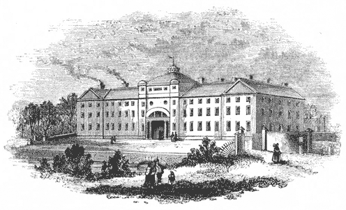
[19] Eloge, p. 308.
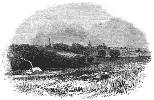
"I have made considerable alterations in our engine lately, particularly in the condenser. That which I used at first was liable to be impaired, from incrustations from bad water; therefore we have substituted one which works by an injection. In pursuing this idea I have tried several kinds, and have at last come to one, which I am not inclined to alter. It consists of a jack-head pump, shut at bottom, with a common clack bucket, and a valve in the cover of the pump, to discharge the air and water. The eduction steam pipe, which comes from the cylinder, communicates with this pump both above and below the bucket, and has valves to prevent anything from going back from the pump to the eduction pipe. The bucket descends by its own weight, and is raised by the engine when the great piston descends, being hung to the outer end of the great lever: the injection is made both into the upper part of this pump and into the eduction pipe, and operates beyond my ideas in point of quickness and perfection."
Besides the difficulty arising from incrustation, Watt found the tubulated condensers, and indeed all other expedients for condensing by cold surfaces, subject to a fatal objection. They did not condense instantaneously, and although they were capable of ultimately effecting the condensation, yet that process was not completed until a great part of the stroke of the piston was made. Thus during more or less of the stroke the uncondensed steam resisted the piston, and robbed the moving power of a part of its effect. This objection has ever attended condensation by surface.
To make the pistons move sufficiently steam-tight in these early imperfect cylinders, Watt contrived a packing formed of a collar of hemp, or tow, as represented in fig. 27. The bottom of the piston was formed of a circular plate of a diameter nearly, but not altogether equal to the interior diameter of the cylinder. The part of the piston above this was considerably less in diameter, so that the piston was surrounded by a circular groove or channel two inches wide, into which hemp or soft rope, called gasket, was run, so as to form the packing. The top of the piston was placed over this, having a rim or projecting part, which entered the circular groove and pressed upon the packing, the cover being pressed downwards by screws passing through the piston. The lower part of the groove round the piston was rounded with a curve, so that the pressure on the packing might force the latter against the inner surface of the cylinder. This packing was kept supplied with melted tallow, as already described, from the funnel, screwed into the top of the cylinder. The metallic edges of the piston were by this means prevented from coming into contact with the surface of the cylinder, which was only pressed upon by the stuffing or packing projecting beyond these.
"Mr. Wilkinson has improved the art of boring cylinders; so that I promise, upon a 72 inch cylinder, being not further distant from absolute truth than the thickness of a thin sixpence in the worst part. I am labouring to improve the regulators; my scheme is to make them acute conical valves, shut by a weight, and opened by the force of the steam. They bid fair for success, and will be tried in a few days."
The person here alluded to was Mr. John Wilkinson, of Bersham near Chester, who, about the year 1775, contrived a new machine for accurately boring the insides of cylinders. The cylinder being first obtained from the foundery with a surface as accurate as the process of casting would admit, had its inner surface reduced to still greater accuracy by this machine, which consists of a straight central bar extended along the axis of the cylinder, which was made to revolve slowly round it. During the operation of boring, the borer or cutter was fitted to slide along this bar, which being perfectly straight, served as a sort of ruler to guide the borer or cutter in its progress through the cylinder. In this manner the interior surface of the cylinder was rendered not only true and straight in its longitudinal direction, but also perfectly circular in its cross section.
The grease found to be most eligible for lubrication was the tallow of beef or mutton; but in the earlier cylinders this was soon consumed by reason of the imperfection of the boring, and the piston being left dry ceased to be steam-tight. To prevent this, Watt sought for some substance, which while it would thicken the tallow, and detain it around the piston, would not be subject to decomposition by heat. Black lead dust was used for this purpose, but was soon found to wear the cylinder. In the mean while, however, the improved method of boring supplied cylinders which rendered this expedient unnecessary.
When the inner surface of the cylinder is perfectly true and smooth, the packing of the piston is soon rendered solid and hard, being moulded to the cylinder by working, so as to fit it perfectly. When by wear it became loose, it was [Pg150] only necessary to tighten the screws by which the top and bottom of the piston were held together. The packing being compressed by those means, was forced outwards towards the surface of the cylinder, so as to be rendered steam-tight.
The advantages which the engine offered in the form in which it has been just described, were numerous and important, as compared even with the most improved form of the atmospheric engine; and it should be remembered, that that machine had also gone on progressively improving, and was probably indebted for some of its ameliorations to hints derived from the labours of Watt, and to the adoption of such of his expedients as were applicable to this imperfect machine, and could be adopted without an infraction of his patent.
In the most improved forms to which the atmospheric engine had then attained, the quantity of steam wasted at each stroke of the piston was equal to the contents of the cylinder. Such engines, therefore, consumed twice the fuel which would be requisite, if all sources of waste could have been removed. In Watt's engines, the steam consumed at each stroke of the piston amounted only to 11⁄4 times the contents of the cylinder. The waste steam, therefore, per stroke, was only a quarter of what was usefully employed. The absolute waste, therefore, of the best atmospheric engines was four times that of the improved engine, and consequently the saving of fuel in the improved engines amounted to about three eighths of all the fuel consumed in atmospheric engines of the same power. [Pg151]
These expedients, however, were all attended with a waste of fuel in relation to the work done by the engine; for it is evident that the consumption of steam was necessarily the same, whether the engine was working against its full load or against a reduced resistance.
On the other hand, in the improved engine of Watt, when the load, to work against which the engine exerted its full power, was diminished, a cock or valve was provided in the steam pipe leading from the boiler, which was called a throttle valve, by adjusting which the passage in that pipe could be more or less contracted. By regulating this cock the supply of steam from the boiler was checked, and the quantity transmitted to the cylinder diminished, so that its effect upon the piston might be rendered equal to the amount of the diminished resistance. By this means the quantity of steam transmitted to the cylinder was rendered exactly proportional to the work which the engine had to perform. If, under such circumstances, the boiler was worked to its full power, so as to produce steam as fast as it would when the engine was working at full power, then no saving of fuel would be effected, since the surplus steam produced in the boiler would necessarily escape at the safety valve. But in such case the fireman was directed to limit the fuel of the furnace until the discharge at the safety valve ceased.
By these expedients, the actual consumption of fuel in one of these improved engines was always in the exact proportion of the work which it performed, whether it worked at full power or at any degree under its regular power.
To remove such objections, great sacrifices were necessary on the part of Boulton and Watt; and they accordingly resolved to undertake the construction of the new engines without any profit, giving them to the parties requiring their use at first cost, on the condition of being remunerated by a small share of what they would save in fuel.
"We have no objection," writes Mr. Boulton, "to contract with the Carron Company to direct the making of an engine to return the water for their mills. * * * * We do not aim at profits in engine building, but shall take our profits out of the saving of fuel; so that if we save nothing, we shall take nothing. Our terms are as follows: we will make all the necessary plans, sections, and elevations for the building, and for the engine with its appurtenances, specifying all cast and forged iron work, and every other particular relative to the engine. We will give all necessary directions to your workmen, which they must implicitly obey. We will execute, for a stipulated price, the valves, and all other parts which may·require exact execution, at Soho; we will see that all the parts are put together, and set to work, properly; we will keep our own work in repair for one year, and we have no other objection to seven years than the inconvenience of the distance. We will guarantee that the engine so constructed shall raise at least 20,000 cubic feet of water twenty-four feet high with each hundred weight of coals burnt.
"When all this is done, a fair and candid comparison shall be made between it, and your own engine, or any other engine in Scotland, from which comparison the amount of savings in fuel shall be estimated, and that amount being [Pg154] divided into three parts, we shall be entitled to one of those parts, in recompense for our patent licence, our drawings, &c. &c. Our own share of savings shall be estimated in money, according to the value of your coals delivered under the boiler, and you shall annually pay us that sum, during twenty-five years from the day you begin to work; provided you continue the use of the engine so long. And in case you sell the engine, or remove it to any other place, you must previously give us notice, for we shall then be entitled to our third of the savings of fuel, according to the value of coals at such new place. This is a necessary condition, otherwise the engine which we make for you at an expense of two thousand pounds may be sold in Cornwall for ten thousand pounds.
"Such parts of the engine as we execute at Soho we will be paid for at a fair price; I conclude, from all the observations I have had an opportunity of making, that our engines are four times better than the common engines. In boilers, which are a very expensive article, the savings will be in proportion to the savings of coal. If you compare our engine with the common engine (not in size, but in power), you will find the original expense of erecting one to be nearly the same.
"Mr. Wilkinson has bored us several cylinders, almost without error; that of fifty inches diameter, which we put up at Tipton, does not err the thickness of an old shilling in any part; so that you must either improve your method of boring, or we must furnish the cylinder to you."
The reluctance of mining companies to relinquish the old engines, even on these terms, led them to propose to Mr. Watt to grant them a licence for the use of his condenser, to be applied to the atmospheric engine, without the introduction of other improvements. Such a proposition was made to him by Mr. Smeaton, in the year 1778, to which he returned the following answer:—
"I have several times considered the propriety of the application of my condensers to common engines, and have made experiments with that view upon our engine at Soho, but have never found such results as would induce me to try [Pg155] it any where else; and, in consequence, we refused to make that application to Wheal Virgin engines in Cornwall, and to some others; our reasons were, that though it might have enabled them to have gone deeper with their present engines, yet, the savings of fuel would not have been great, in comparison to the complete machine. By adding condensers to engines that were not in good order, our engine would have been introduced into that country (which we look upon as our richest mine) in an unfavourable point of view, and without such profits as would have been satisfactory either to us or to the adventurers; and if we had granted the use of condensers to one, we must have done so to all, and thereby have curtailed our profits, and perhaps injured our reputation. Besides, where a new engine is to be erected, and to be equally well executed in point of workmanship and materials, an engine of the same power cannot be constructed materially cheaper on the old plan than on ours; for our boiler and cylinder are much smaller, and the building, the lever, the chains, together with all the pump and pit work, are only the same. * * * *
"We charge our profits in proportion to the saving made in fuel by our engine, when compared with a common one which burns the same kind of coals; we ask one third of these savings to be paid us annually, or half yearly; the payment being redeemable in the option of our employer, at ten years' purchase; and when the coals are low priced, we should also make some charge as engineers. In all these comparisons our own interest has made us except your (Mr. Smeaton) improved engines, unless we were allowed a greater proportion of the savings."
Their exertions to improve the manufacture of engines at Soho is shown by the following letter from Mr. Boulton, in the same correspondence to Mr. Smeaton:—
"We are systematising the business of engine making, as we have done before in the button manufactory; we are training up workmen, and making tools and machines to form the different parts of Mr. Watt's engines with more accuracy, and at a cheaper rate than can possibly be done by the ordinary methods of working. Our workshop and apparatus will be of [Pg156] sufficient extent to execute all the engines which are likely to be soon wanted in this country; and it will not be worth the expense for any other engineers to erect similar works, for that would be like building a mill to grind a bushel of corn.
"I can assure you from experience, that our small engine at Soho is capable of raising 500,000 cubic feet of water 1 foot high with every 112 lbs. of coals, and we are in hopes of doing much more. Mr. Watt's engine has a very great advantage in mines, which are continually working deeper: suppose, for instance, that a mine is 50 fathoms deep, you may have an engine which will be equal to draining the water when the mine is worked, to 100 fathoms deep, and yet you can constantly adapt the engine to its load, whether it be 50 or 100 fathoms, or any intermediate depth; and the consumption of coals will be less in proportion when working at the lesser than at the greater depths; supposing it works, as our engines generally do, at 11 lbs. per square inch, when the mine becomes 100 fathoms deep."
"I mentioned to you a method of still doubling the effect of the steam, and that tolerably easy, by using the power of steam rushing into a vacuum, at present lost. This would do little more than double the effect, but it would too much enlarge the vessels to use it all: it is peculiarly applicable to wheel engines, and may supply the want of a condenser, where the force of steam only is used; for open one of the steam valves, and admit steam until one fourth of the distance between it and the next valve is filled with steam, then shut the valve, and the steam will continue to expand, and to press round the wheel, with a diminishing power, ending in one fourth of its first exertion. The sum of the series you will find greater than one half, though only one fourth of steam was used. The power will indeed be unequal, but this can be remedied by a fly, or by several other means."
In 1776 the engine, which had been then recently erected at Soho, was adapted to act upon the principle of expansion. When the piston had been pressed down in the cylinder for a certain portion of the stroke, the further supply of steam [Pg158] from the boiler was cut off, by closing the upper steam valve, and the remainder of the stroke was accomplished by the expansive power of the steam which had already been introduced into the cylinder.
If a body which offers a certain resistance be urged by a certain moving force, the motion which it will receive will depend on the relation between the energy of the moving force and the amount of the resistance opposed to it. If the moving force be precisely equal to the resistance, the motion which the body will receive will be perfectly uniform.
If the energy of the moving force be greater than the resistance, then its surplus or excess above the amount of resistance will be expended in imparting momentum to the mass of the body moved, and the latter will, consequently, continually acquire augmented speed. The motion of the body will, therefore, be in this case accelerated.
If the energy of the moving force be less in amount than the resistance, then all that portion of the resistance which exceeds the amount of the moving force will be expended in depriving the mass of the body of momentum, and the body will therefore be moved with continually diminished speed until it be brought to rest.
It is an error to suppose that rest is the only condition possible for a body to assume when under the operation of two or more mechanical forces which are in equilibrium. By the laws of motion the state of a body which is not under the operation of any external force must be either in a state of rest or of uniform motion. Whichever be its state, it will suffer no change if the body be brought under the operation of two or more forces which are in equilibrium; for to suppose [Pg159] such forces to produce any change in the state of the body, whether from rest to motion, or vice versâ, or in the velocity of the motion which the body may have previously had, would be equivalent to a supposition that the forces applied to the body being in equilibrium were capable of producing a dynamical effect, which would be a contradiction in terms. This, though not always clearly understood by mere practical men, or by persons superficially informed, is, in fact, among the fundamental principles of mechanical science.
Thus, if we were to suppose that after the piston had descended through three fourths of the whole length of the cylinder, and had acquired a certain velocity, the steam above it were suddenly condensed, so as to leave a vacuum both above and below it, the piston, being then subject to no impelling force, would still move downwards, in virtue of the momentum it had acquired, until the resistance would deprive it of that momentum, and bring it to rest; and if the remaining fourth part of the cylinder were necessary for the accomplishment of this, then it is evident that that part of the stroke would be accomplished without further expenditure of the moving power.
In fact, this part of the stroke would be made by the expenditure of that excess of moving power, which, at the commencement of the stroke, had been employed in putting the machinery and its load in motion, and in subsequently accelerating that motion.
Although under such circumstances the resistance, during the operation of the moving power, shall not have been at any time equal to the moving power, since while the motion was accelerated it was less, and while retarded greater than that power, yet as the whole moving power has been expended upon the resistance, the mechanical effect which the moving power has produced under such circumstances will be equal to the actual amount of that power. If in an engine of this kind the steam was not cut off till the conclusion of the stroke, a part of the moving power would be lost upon those fixed points in the machinery which would sustain the shock produced by the instantaneous cessation of motion at the end of the stroke.
Independently, therefore, of any consideration of the expansive principle, it appears that, in an engine of this kind, the steam ought to be cut off before the completion of the stroke. [Pg161]
If the space from B to C, through which the steam is here supposed to act expansively, be divided into ten equal parts, the pressure on the piston at the moment of passing each of those divisions would be calculated upon the same principle as in the cases now mentioned. After moving through the first division, the volume of the steam would be increased in the proportion of 10 to 11, and therefore its pressure would be diminished in the proportion of 11 to 10. The pressure, therefore, driving the piston at the end of the first of these ten divisions would be 10⁄11ths of a ton. In like manner, its pressure at the second of the divisions would be 10⁄12ths of a ton, and the third 10⁄13ths of a ton; and so on, as indicated in the figure.
Now if the pressure of the steam through each of these divisions were to continue uniform, and, instead of gradually diminishing, to suffer a sudden change in passing from one division to another, then the mechanical effect produced from B to C would be obtained by taking a mean or average of the several pressures throughout each of the ten divisions. In the present case it has been supposed that the force on the piston at B was 2240 pounds. To obtain the pressure in pounds corresponding to each of the successive divisions, it will therefore only be necessary to multiply 2240 by 10, and to divide it successively by 11, 12, 13, &c. The pressures, therefore, in pounds, at each of the ten divisions, will be as follows:—
| 1st | 2036·3 |
| 2d | 1866·6 |
| 3d | 1723·1 |
| 4th | 1600·0 |
| 5th | 1493·3 |
| 6th | 1400·0 |
| 7th | 1317·6 |
| 8th | 1244·4 |
| 9th | 1179·0 |
| 10th | 1120·0 |
If the mean of these be taken by adding them together [Pg163] and dividing by 10, it will be found to be 1498 pounds. It appears, therefore, that the pressures through each of the ten divisions being supposed to be uniform (which however, strictly, they are not,) the mechanical effect of the steam from B to C would be the same as if it acted uniformly throughout that space upon the piston with a force of about 1500 pounds, being rather less than three-fourths of its whole effect from A to B.
But it is evident that this principle will be equally applicable if the second cylinder had any other proportion to the first. Thus it might be twice the length of the first; and in that case, a further mechanical effect would be obtained from the expansion of the steam.
The more accurate method of calculating the effect of the expansion from B to C, would involve more advanced mathematical principles than could properly be introduced here; but the result of such a computation would be that the actual average effect of the steam from B to C would be equal to a uniform pressure through that space, amounting to one thousand five hundred and forty-five pounds, being greater than the result of the above computation, the difference being due to the expansive action through each of the ten divisions, which was omitted in the above computation.
Another expedient consisted in causing the moving power, when acting with greatest energy, to lift a weight which should be allowed to descend again, assisting the piston when the energy of the moving force was diminished. [Pg165]
Another method consisted in causing the moving force, when acting with greatest energy, to impart momentum to a mass of inert matter, which should be made to restore the same force when the moving power was more enfeebled. We shall not more than allude here to these contrivances proposed by Watt, since their application has never been found advantageous in cases where the expansive principle is used.
Subsequently, however, boilers producing steam of much higher pressure were applied, and the steam was cut off when the piston had performed a much smaller part of the whole stroke. The great theatre of these experiments and improvements has been the mining districts in Cornwall, where, instead of working with steam of a pressure not much exceeding that of the atmosphere, it has been found advantageous to use steam whose pressure is at least four times as great as [Pg166] that of the atmosphere; and instead of limiting its expansion to the last half or fourth of the stroke, it is cut off after the piston has performed one fourth part of the stroke or less, all the remainder of the stroke being accomplished by the expansive power of the steam, and by momentum.
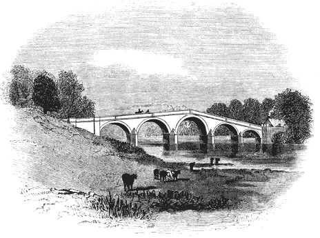

Steam may exist in two states, distinguished from each other by the following circumstances:—
1st. It may be such that the abstraction from it of any portion of heat, however small, will cause its partial condensation.
2d. It may be such as to admit of the abstraction of heat from it without undergoing any other change than that which air would undergo under like circumstances, viz. a diminution of temperature and pressure.
To explain the circumstances out of which these properties arise, let B (fig. 29.) be imagined to be a vessel filled with water, communicating by a pipe and stopcock with another vessel A, which in the commencement of the process may be conceived to be filled with air. Let D be a pipe and stopcock at the top of this vessel. If the vessel B be heated, and the two cocks be opened, the steam proceeding from the water in B will blow the air out of the vessel A through the open stopcock D, in the same manner as air is blown from a steam engine. When the vessel A by these means has been filled with pure steam, let both stopcocks be closed. If the steam in A, under these circumstances, have a pressure of 15 lbs. per square inch, its temperature will be found to be 213°. Now, if any heat be abstracted from this steam, its temperature will fall, and a portion of it will be reconverted into water.
Again, suppose the vessel A to be filled with pure steam which has been produced from the heated water in B, the stopcock C being open. Let the stopcock C be then closed, and the water in B be heated to a higher temperature, the temperature and pressure of the steam in A being observed. If the stopcock C be now opened, the steam in A will be immediately observed to rise to the more elevated temperature which has been imparted to the water in B, and at the same time it will acquire an increased pressure. [Pg169]
The increase of temperature which it has received would of itself produce an increased pressure; but that this is not the sole cause of the augmented pressure in the present case might be proved by weighing the vessel A. It would be found to have increased weight, which could only arise from its having received from the water in B an additional quantity of vapour. The increased pressure therefore, which the steam in A has acquired, is due conjointly to its increased density and its increased temperature. In general, if the water in the vessel B be raised or lowered in temperature, the steam in the vessel A will rise and fall in temperature in a corresponding manner, always having the same temperature as the water in B. If the weight of the vessel A were observed, it would be found to increase with every increase of temperature, and to diminish with every diminution of temperature, proving that the augmented temperature of the water in B produces an augmented density of the steam in A. The same pressure would be found always to correspond to the same temperature and density, so that if the numerical amount of any one of the three quantities, the temperature, the pressure, or the density, were known, the other two must necessarily be determined, the same temperature always corresponding to the same pressure, and vice versâ. And in like manner, steam produced under these circumstances of the same density cannot have different pressures. It must be observed that the steam here produced receives all the heat which it possesses from the water from which it is raised. Now it is easily demonstrable, that this is the least quantity of heat which is compatible with the steam maintaining the vaporous form; for if the stopcock C be closed so as to separate the steam in A from the water in B, and that any portion of heat, however small, be then abstracted from the steam in A, some portion of the steam will be reconverted into water.
This then, according to the definition already given, is Common Steam.
If after increasing the temperature of the steam in A, the stopcock C being shut so as to render it superheated steam, its pressure be observed, the pressure will be found to be increased, but not to that amount which it would have been increased had the steam in A been raised to the same temperature by heating the water in B to that temperature, and keeping the stopcock open. In fact, its present augmented pressure will be due only to its increased temperature, since its density remains unchanged. But if in these circumstances the stopcock C be suddenly opened, the pressure of the steam in A will as suddenly rise to that pressure which in common steam corresponds to its temperature; and if the vessel A were weighed, it would be found to have increased in weight, proving that the steam contained in it has received increased density by an increased quantity of vapour proceeding from the water in A. In fact, by opening the stopcock the steam which was before superheated steam, has become common steam. It has the greatest density which steam of that temperature can have; and consequently, if any heat be abstracted from it, a partial condensation will ensue.
To render these general principles more intelligible, let us suppose that the water in B is raised to the temperature of 213°, the stopcock C being open; the vessel A will then be filled with steam of the same temperature, and having a pressure of 15 lbs. per square inch. This will be common steam. If the stopcock be now closed, and the whole apparatus be exposed to the temperature of 243°; the steam in A will preserve the same density, but its pressure will be [Pg171] increased from 15 lbs. to a little more than 16 lbs. per square inch. Let the stopcock C be then opened and while the temperature of the steam in A shall continue to be 243°, the pressure will suddenly rise from 16 lbs. to about 26 lbs. per square inch. The weight of the steam in A will be at the same time increased in the same proportion of 16 to 26 as its pressure. The steam thus produced in A will then be common steam, and any abstraction of heat from it would be attended with partial condensation.
It may be objected that water cannot exist in the state of vapour under the usual pressures at so low a temperature as melting ice. This, however, does not hinder the application of the above law, for that law will equally hold good by computing the pressure which the vapour would have if it were a permanent gas, and if it could therefore exist in the elastic form at that low temperature.
It appears, therefore, that supposing the steam used in an engine to receive no additional heat after it leaves the boiler, however it may be changed in its density by subsequent expansion, it will still retain its character of common steam, and cannot lose any portion of heat, however small, without suffering partial condensation. The mechanical force also exerted by such steam, after expansion, must be computed in the same manner as if it were raised immediately.
In the year 1781, Hornblower conceived the notion of working an engine with two cylinders of different sizes, by allowing the steam to flow freely from the boiler until it fills the smaller cylinder, and then permitting it to expand into the greater one, employing it thus to press down two pistons in the following manner.
Let C, fig. 30., be the centre of the great working-beam, carrying two arch heads, on which the chains of the piston rods play. The distances of these arch heads from the centre C must be in the same proportion as the length of the cylinders, in order that the same play of the beam may correspond to [Pg175] the plays of both pistons. Let F be the steam-pipe from the boiler, and G a valve to admit the steam above the lesser piston. H is a tube by which a communication may be opened by the valve I, between the top and bottom of the lesser cylinder B. K is a tube communicating by the valve L, between the bottom of the lesser cylinder B and the top of the greater cylinder A. M is a tube communicating, by the valve N, between the top and bottom of the greater cylinder A; and P a tube leading to the condenser by the exhausting valve O.
At the commencement of the operation, suppose all the valves opened, and steam allowed to flow through the engine until the air be completely expelled, and then let all the valves be closed. To start the engine, let the exhausting valve O and the steam valves G and L be opened, as in fig. 30. The steam will flow freely from the boiler, and press upon the lesser piston, and at the same time the steam below the greater piston will flow into the condenser, leaving a vacuum in the greater cylinder. The valve L being opened, the steam which is under the piston in the lesser cylinder will flow through K, and press on the greater piston, which, having a vacuum beneath it, will consequently descend. At the commencement of the motion, the lesser piston is as much resisted by the steam below it, as it is urged by the steam above it; but after a part of the descent has been effected, the steam below the piston, in the lesser cylinder, passing into the greater, expands into an increased space, and therefore loses part of its elastic force. The steam above the lesser piston retaining its full force by having a free communication with the boiler by the valve G, the lesser piston will be urged by a force equal to the excess of the pressure of this steam above the diminished pressure of the expanded steam below it. As the pistons descend, the steam which is between them is continually increasing in its bulk, and therefore decreasing in its pressure, from whence it follows, that the force which resists the lesser piston is continually decreasing, while that which presses it down remains the same, and therefore the effective force which impels it must be continually increasing. [Pg176]
On the other hand, the force which urges the greater piston is continually decreasing, since there is a vacuum below it, and the steam which presses it is continually expanding into an increased bulk.
Impelled in this way, let us suppose the pistons to have arrived at the bottoms of the cylinders, and let the valves G, L, and O, be closed, and the valves I and N opened. No steam is allowed to flow from the boiler, G being closed, nor any allowed to pass into the condenser, since O is closed, and all communication between the cylinders is stopped by closing L. By opening the valve I, a free communication is made between the top and bottom of the lesser piston through the tube H, so that the steam which presses above the lesser piston will exert the same pressure below it, and the piston is in a state of indifference. In the same manner the valve N being open, a free communication is made between the top and bottom of the greater piston, and the steam circulates above and below the piston, and leaves it free to rise. A counterpoise attached to the pump-rods, in this case, draws up the piston, as in Watt's single engine; and when they arrive at the top, the valves I and N are closed, and G, L, and O, opened, and the next descent of the pistons is produced in the manner already described, and so the process is continued.
The valves are worked by the engine itself, by means similar to some of those already described. By computation, we find the power of this engine to be nearly the same as a similar engine on Watt's expansive principle. It does not, however, appear, that any adequate advantage was gained by this modification of the principle, since no engines of this construction are now made.
It is very unaccountable how a person of Mr. Woolf's experience in the practical application of steam could be led into errors so gross as those involved in the averments of this patent; and it is still more unaccountable how the experiments could have been conducted which led him to conclusions not only incompatible with all the established properties of elastic fluids, but even involving in themselves palpable contradiction and absurdity. If it were admitted that every additional pound avoirdupois which should be placed upon the safety-valve would enable steam, by its expansion into a proportionally enlarged space, to attain a pressure equal to the atmosphere, the obvious consequence would be, that a physical relation would subsist between the atmospheric pressure and the pound avoirdupois! It is wonderful that it did not occur to Mr. Woolf, that, granting his principle to be true at any given place, it would necessarily be false at another place, where the barometer would stand at a different height! Thus, if the principle were true at the foot of a mountain, it would be false at the top of it; and if it were true in fair weather, it would be false in foul weather, since these circumstances would be attended by a change in the atmospheric pressure, without making any change in the pound avoirdupois.[21]
The idea that steam was capable of being applied extensively as a prime mover, had prevailed from a very early period; and now that we have seen its powers so extensively brought to bear, it will not be uninteresting to revert to the faint traces by which its agency was sketched in the crude speculations of the early mechanical inventors.
In his work already cited, after describing his method of imparting an alternate motion to a piston by the atmospheric [Pg179] pressure acting against a vacuum produced by the condensation of steam, he stated that his invention, besides being applicable to pumping water, could be available for rowing vessels against wind and tide, which he proposed to accomplish in the following manner.
Paddle-wheels, such as have since been brought into general use, were to be placed at the sides, and attached to a shaft extending across the vessel. Within the vessel, and under this shaft, he proposed to place several cylinders supplied with pistons, to be worked by the atmospheric pressure. On the piston-rods were to be constructed racks furnished with teeth: these teeth were to work in the teeth of wheels or pinions, placed on the shaft of the paddle-wheels. These pinions were not to be fixed on the shaft, but to be connected with it by a ratchet; so that when they turned in one direction, they would revolve without causing the shaft to revolve; but when driven in the other direction, the catch of the ratchet-wheel would act upon the shaft so as to compel the shaft and paddle-wheels to revolve with the motion of the pinion or wheel upon it. By this arrangement, whenever the piston of any cylinder was forced down by the atmospheric pressure, the rack descending would cause the corresponding pinion of the paddle-shaft to revolve; and the catch of the ratchet wheel, being thus in operation, would cause the paddle-shaft and paddle-wheels also to revolve; but whenever the piston would rise, the rack driving the pinion in the opposite direction, the catch of the ratchet wheel would merely fall from tooth to tooth, without driving the paddle-shaft.
It is evident that by such an arrangement a single cylinder and piston would give an intermitting motion to the paddle-shaft, the motion of the wheel being continued only during the descent of the piston; but if several cylinders were provided, then their motion might be so managed, that when one would be performing its ascending stroke, and therefore giving no motion to the paddle-shaft, another should be performing its descending stroke, and therefore driving the paddle-shaft. As the interval between the arrival of the piston at the bottom of the cylinder and the commencement [Pg180] of its next descent would have been, in the imperfect machine conceived by Papin, much longer than the time of the descent, it was evident that more than two cylinders would be necessary to insure a constantly acting force on the paddle-shaft, and, accordingly, Papin proposed to use several cylinders.
In addition to this, Papin proposed to construct a boiler having a fireplace surrounded on every side by water, so that the heat might be imparted to the water with such increased rapidity as to enable the piston to make four strokes per minute. These projects were promulged in 1690, but it does not appear that they were ever reduced to experiment.
About this time Smeaton applied himself with great activity and success to the improvement of wind and water mills, and succeeded in augmenting their useful effect in a twofold proportion with the same supply of water. From the year 1750 until the year 1780 he was engaged in the construction of his improved water mills, which he erected in various parts of the country, and which were imitated so extensively that the improvement of such mills became general. In cases where a summer drought suspended the supply of water, horse machinery was provided, either to work the mill or to throw back the water. These improvements necessarily obstructed for a time the extension of steam power to mill work; but the increase of manufactures soon created a demand for power greatly exceeding what could be supplied by such limited means.
In the manufacture of iron, it is of great importance to keep the furnaces continually blown, so that the heat may never be abated by day or night. In the extensive ironworks at Colebrook Dale, several water-wheels were used in the different operations of the manufacture of iron, especially in driving the blowers of the iron furnaces. These wheels were usually driven by the water of a river, but in the summer months the supply became so short that it was insufficient to work them all. Steam engines were accordingly erected to [Pg182] return the water for driving these wheels. This application of the engine as an occasional power for the supply of water-wheels having been found so effectual, returning engines were soon adopted as the permanent and regular means of supplying water-wheels. The first attempt of this kind is recorded to have been made by Mr. Oxley, in 1762, who constructed a machine to draw coals out of a pit at Hartley colliery, in Northumberland. It was originally intended to turn the machine by a continuous circular motion received from the beam of the engine; but that method not being successful, the engine was applied to raise water for a wheel by which the machine was worked. This engine was continued in use for several years, and though it was at length abandoned, on account of its defective construction, it nevertheless established the practicability of using steam power as a means of driving water wheels.[23]
The hints obtained by Mr. Stewart from Papin's contrivance, before mentioned, will not fail to be perceived. In Mr. Stewart's paper he notices indirectly the method of obtaining a continued circular motion from a reciprocating motion by means of a crank or winch, which, he says, occurs naturally in theory, but in practice would be impossible, from the nature of the motion of the engine, which depends on the force of the steam, and cannot be ascertained in its length. Therefore, on the first variation, the machine would be either broken in pieces or turned back. Such an opinion, pronounced by a man of considerable mechanical knowledge and ingenuity, against a contrivance which, as will presently appear, proved in practice, not less than in theory, to be the most effectual means of accomplishing the end here pronounced to be impossible, is sufficiently remarkable. It might cast some doubt on the extent of Mr. Stewart's practical knowledge, if it did not happen to be in accordance with a judgment so generally unimpeachable as that of Mr. Smeaton. This paper of Mr. Stewart's was referred by the council of the Royal Society to Mr. Smeaton, who remarked upon the difficulty arising from the absolute stopping of the whole mass of moving power, whenever the direction of the motion is changed; and observed, that although a fly-wheel might be applied to regulate the motion, it must be such a large one as would not be readily controlled by the engine itself; and he considered that the use of such a fly-wheel would be a greater incumbrance to a mill than a water-wheel to be supplied by water pumped up by the engine. This engineer, illustrious as he was, not only fell into the error of Mr. Stewart in respect of the crank, but committed the further blunder of condemning the very expedient which has since rendered the crank effectual. It will presently appear that the combination of the crank and fly-wheel have been the chief means of establishing the dominion of the steam engine over manufactures.
The steps by which Watt proceeded to accomplish these objects have been recorded by himself as follows, in his notes upon Dr. Robison's article on the steam engine:—
"I had very early turned my mind to the producing of continued motion round an axis; and it will be seen, by reference to my first specification in 1769, that I there described [Pg185] a steam wheel, moved by the force of steam, acting in a circular channel against a valve on one side, and against a column of mercury, or some other fluid metal, on the other side. This was executed upon a scale of about six feet diameter at Soho, and worked repeatedly, but was given up, as several practical objections were found to operate against it; similar objections lay against other rotative engines, which had been contrived by myself and others, as well as to the engines producing rotatory motions by means of ratchet wheels.
"Having made my single reciprocating engines very regular in their movements, I considered how to produce rotative motions from them in the best manner; and amongst various schemes which were subjected to trial, or which passed through my mind, none appeared so likely to answer the purpose as the application of the crank, in the manner of the common turning lathe; but as the rotative motion is produced in that machine by impulse given to the crank in the descent of the foot only, it requires to be continued in its ascent by the energy of the wheel, which acts as a fly; being unwilling to load my engine with a fly-wheel heavy enough to continue the motion during the ascent of the piston (or with a fly-wheel heavy enough to equalise the motion, even if a counterweight were employed to act during that ascent), I proposed to employ two engines, acting upon two cranks fixed on the same axis, at an angle of 120° to one another, and a weight placed upon the circumference of the fly-wheel at the same angle to each of the cranks, by which means the motion might be rendered nearly equal, and only a very light fly-wheel would be requisite.
"This had occurred to me very early; but my attention being fully employed in making and erecting engines for raising water, it remained in petto until about the year 1778 or 1789, when Mr. Wasbrough erected one of his ratchet-wheel engines at Birmingham, the frequent breakages and irregularities of which recalled the subject to my mind, and I proceeded to make a model of my method, which answered my expectations; but having neglected to take out a patent, the invention was communicated by a workman employed to [Pg186] make the model, to some of the people about Mr. Wasbrough's engine, and a patent was taken out by them for the application of the crank to steam engines. This fact the said workman confessed, and the engineer who directed the works acknowledged it; but said, nevertheless, that the same idea had occurred to him prior to his hearing of mine, and that he had even made a model of it before that time; which might be a fact, as the application to a single crank was sufficiently obvious.
"In these circumstances, I thought it better to endeavour to accomplish the same end by other means, than to enter into litigation; and if successful, by demolishing the patent, to lay the matter open to every body. Accordingly, in 1781, I invented and took out a patent for several methods of producing rotative motions from reciprocating ones; amongst which was the method of the sun-and-planet wheels. This contrivance was applied to many engines, and possesses the great advantage of giving a double velocity to the fly-wheel; but is perhaps more subject to wear, and to be broken under great strains, than a simple crank, which is now more commonly used, although it requires a fly-wheel of four times the weight, if fixed upon the first axis; my application of the double engine to these rotative machines rendered the counterweight unnecessary, and produced a more regular motion."
All the methods specified in this patent were intended to be worked by the single-acting engine, already described, a counterweight being applied to impel the machinery during the returning stroke of the engine, which weight would be elevated during the descent of the piston. There were five different expedients proposed in the specification for producing a rotatory motion; but, of these five, two only were ever applied in practice. [Pg187]
This contrivance, although in the main inferior to the more simple one of the crank, is not without some advantages; among others, it gives to the sun wheel double the velocity which would be communicated by the crank; for in the crank one revolution only on the axle is produced by one revolution of the crank, but in the sun-and-planet wheel, two revolutions of the sun wheel are produced by one of the planet wheel; thus a double velocity is obtained from the same motion of the beam. This will be evident from considering that when the planet wheel is in its highest position, its lowest tooth is engaged with the highest tooth of the sun wheel; as the planet wheel passes from the highest position, its teeth drive those of the sun wheel before them, and when it comes into the lowest position, the highest tooth of the planet wheel is engaged with the lowest of the sun wheel: but then half of the sun wheel has rolled off the planet wheel, and, therefore, the tooth which was engaged with it in its highest position, must now be distant from it by half the circumference of the wheel, and must, therefore, be again in the highest position; so that while the planet wheel has been carried from the top to the bottom, the sun wheel has made a complete revolution.
This advantage of giving an increased velocity may be obtained also by the crank, by placing toothed wheels on its axle. Independently of the greater expense attending the construction of the sun-and-planet wheel, its liability to go out of order, and the rapid wear of the teeth, and other objections, rendered it inferior to the crank, which has entirely superseded it.
This change in the principle of the machine involved several other changes in the details of its mechanism.
Supposing the piston P to be at the top of the cylinder, and the cylinder below the piston to be filled with pure steam, let the valves S and C′ be opened, the valves C and S′ being closed as represented in fig. 34. Steam from the boiler will, therefore, flow in through the open valve S, and will press the piston downwards, while the steam that has filled the cylinder below the piston will pass through the open valve C′ into the exhausting-pipe leading to the condenser, and being condensed will leave the cylinder below the piston a vacuum. The piston will, therefore, be pressed downwards by the action of the steam above it, as in the single-acting engine. Having arrived at the bottom of the cylinder, let the valves S and C′ be both closed, and the valves S′ and C be opened, as represented in fig. 34. Steam will now be admitted through the open valve S′ and through the passage D′ below the piston, while the steam which has just driven the piston downwards, filling the cylinder above the piston, will be drawn off through the open valve C, and the exhausting-pipe, into the condenser, leaving the cylinder above the piston a vacuum. The piston will, therefore, be pressed upwards by the action of the steam below it, against the vacuum above it, and will ascend with the same force as that with which it had descended.
This alternate action of the piston upwards and downwards may evidently be continued by opening and closing the valves alternately in pairs. Whenever the piston is at the top of the cylinder, as represented in fig. 33., the valves S and C′, that is, the upper steam-valve and the lower exhausting-valve, are opened, and the valves C and S′, that is, the upper exhausting-valve and the lower steam-valve, are closed; and [Pg191] when the piston has arrived at the bottom of the cylinder, as represented in fig. 34., the valves C and S′, that is, the upper exhausting-valve and the lower steam-valve, are opened, and the valves S and C′, that is, the upper steam-valve and the lower exhausting-valve, are closed.
If these valves, as has been here supposed, be opened and closed at the moments at which the piston reaches the top and bottom of the cylinder, it is evident that they may be all worked by a single lever connected with them by proper mechanism. When the piston arrives at the top of the cylinder, this lever would be made to open the valves S and C′, and at the same time to close the valves S′ and C; and when it arrives at the bottom of the cylinder, it would be made to close the valves S and C′, and to open the valves S′ and C.
If, however, it be desired to cut off the steam before the arrival of the piston at the termination of its stroke, whether upwards or downwards, then the steam-valves must be closed before the arrival of the piston at the end of its stroke; and as the exhausting-valve ought to be left open until the stroke is completed, these valves ought to be moved at different times. In that case separate levers should be provided for the different valves. We shall, however, return again to the subject of the valves which regulate the admission of steam to the cylinder and its escape to the condenser.
It will presently appear that in the double-acting engine applied to manufactures, the motion of the piston was subject to more or less variation of speed, and the quantity of steam [Pg192] admitted to the cylinder was subject to a corresponding change. The quantity of steam, therefore, drawn into the condenser was subject to variation, and required a considerable change in the quantity of cold water admitted through the jet to condense it. To regulate this, the valve or cock by which the water was admitted into the condenser was worked in the double-acting engine by a lever furnished with an index, by which the quantity of condensing water admitted into the condenser could be regulated. This index played upon a graduated arch, by which the engine-man was enabled to regulate the supply.
[20] These effects are explained in my Treatise on Heat; and they have lately been verified by experiments made with locomotive engines by M. de Pambour, who found that the steam raised from the boiler of a locomotive engine, under a pressure of above 50 lbs. per square inch, was in the state of common steam as it issued from the chimney at a very diminished pressure and at a lower pressure.
[21] It is strange that this absurdity has been repeatedly given as unquestionable fact in various encyclopædias, as well as in by far the greater number of treatises expressly on the subject.
[22] Farey, Treatise on the Steam Engine, p. 122.
[23] Farey on the Steam Engine, p. 297.
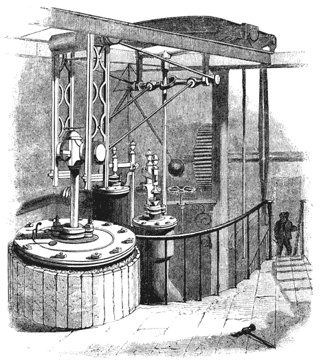
Where the mechanical action to be transmitted is a pull, and not a push, a flexible chain, cord, or strap, is sufficient; but if a push or thrust is required to be transmitted, then the flexibility of the medium of mechanical communication afforded by a chain renders it inapplicable. In the double-acting engine, during the descent, the piston-rod still pulls the beam down; and so far a chain connecting the piston-rod with the beam would be sufficient to transmit the action of the one to the other; but in the ascent, the beam no longer pulls up the piston-rod, but is pushed up by it. A chain from the piston-rod to the arch head, as described in the single-acting engine, would fail to transmit this force. If such a chain were used with the double engine, where there is no counterweight on the opposite end of the beam, the consequence would be, that in the ascent of the piston the chain would slacken, and the beam would still remain depressed. It is therefore necessary that some other mechanical connection be contrived between the piston-rod and the beam, of such a nature that in the descent the piston-rod may pull the beam down, and may push it up in the ascent.
Watt first proposed to effect this by attaching to the end of the piston-rod a straight rack, faced with teeth, which should work in corresponding teeth raised on the arch head of the beam, as represented in fig. 35. If his improved steam engines required no further precision of operation and construction than the atmospheric engines, this might have been sufficient; but in these engines it was indispensably necessary that the piston-rod should be guided with a smooth and even motion through the stuffing-box in the top of the cylinder, otherwise any shake or irregularity would cause it to work loose in the stuffing-box, and either to admit the air, or to let the steam escape. Under these circumstances, the motion of [Pg195] the rack and toothed arch head were inadmissible, since it was impossible by such means to impart to the piston-rod that smooth and equable motion which was requisite. Another contrivance which occurred to Watt was, to attach to the top of the piston-rod a bar, which should extend above the beam, and to use two chains or straps, one extending from the top of the bar to the lower end of the arch head, and the other from the bottom of the bar to the upper end of the arch head. By such means the latter strap would pull the beam down when the piston would descend, and the former would pull the beam up when the piston would ascend. These contrivances, however, were superseded by the celebrated mechanism since called the Parallel Motion, one of the most ingenious mechanical combinations connected with the history of the steam engine.
To explain the principle of the mechanism called the parallel motion, let us suppose that O P (fig. 36.) is a rod or lever moveable on a centre O, and that the end P of this rod shall move through a circular arch P P′ P″ P‴ a vertical plane, and let its play be limited by two stops S, which shall prevent its ascent above the point P, and its descent below [Pg196] the point P‴. Let the position of the rod and the limitation of its play be such that the straight line A B drawn through P and P‴, the extreme positions of the lever O P, shall be a vertical line.
Let o be a point on the other side of the vertical line A B, and let the distance of O to the right of A B be the same as the distance of o to the left of A B. Let o p be a rod equal in length to O P, moving like O P on the centre o, so that its [Pg197] extremity p shall play upwards and downwards through the arch p p′ p″ p‴, its play being limited in like manner by stops s.
Now, let us suppose that the ends P p of these two rods are joined by a link P p, the connection being made by a pivot, so that the angles formed by the link and the rods shall be capable of changing their magnitude. This link will make the motion of one rod depend on that of the other, since it will preserve their extremities P p always at the same distance from each other. If, therefore, we suppose the rod O P to be moved to the position O P‴, its extremity P tracing the arch P P′ P″ P‴, the link connecting the rods will at the same time drive the extremity p of the rod o p through the arch p p′ p″ p‴ so that when the extremity of the one rod arrives at P‴, the extremity of the other rod will arrive at p‴. By this arrangement, in the simultaneous motion of the rods, whether upwards or downwards, through the circular arches to which their play is limited, the extremities of the link joining them will deviate from the vertical line A B in opposite directions. At the limits of their play, the extremities of the link will always be in the line A B; but in all intermediate positions, the lower extremity of the link will be to the right of A B, and its upper extremity to the left of A B. So far as the derangement of the lower extremity of the link is concerned, the matter composing the link would be transferred to the right of A B, and so far as the upper extremity of the link is concerned, the matter composing it would be transferred to the left of A B.
By the combined effects of these contrary derangements of the extremities of the link from the vertical line, it might be expected that a point would exist, in the middle of the link, where the two contrary derangements would neutralise each other, and which point would therefore be expected to be disturbed neither to the right nor to the left, but to be moved upwards and downwards in the vertical line A B. Such is the principle of the parallel motion; and in fact the middle point of the link will move for all practical purposes accurately in the vertical line A B, provided that the angular play of the levers O P and o p does not exceed a certain [Pg198] limit, within which, in practice, their motion may always be restrained.
To trace the motion of the middle point of the link more minutely, let P P′ P″ P‴ be four positions of the lever O P, and let p p′ p″ p‴ be the four corresponding positions of the lever o p. In the positions O P o p, the link will take the position P p, in which the entire link will be vertical, and its middle point x will therefore be in the vertical line A B.
When the one rod takes the position O P′, the other rod will have the position o p′; and the link will have the position P′ p′. The middle point of the link will be at x′, which will be found to be on the vertical line A B. Thus one half of the link P′ x′ will be to the left of the vertical line A B; while the other half, p′ x′, will be to the right of the vertical line; the derangement from the vertical line affecting each half of the link in contrary directions.
Again, taking the one rod in the position O P″, the corresponding position of the other rod will be o p″, and the position of the link will be P″ p″. If the middle point of the link in this position be taken, it will be found to be at x″, on the vertical line A B; and, as before, one half of the link P″ x″ will be thrown to the left of the vertical line, while the other half p″ x″, will be thrown to the right of the vertical line.
Finally, let the one rod be in its lowest position, O P‴, while the other rod shall take the corresponding position, o p‴. The direction of the link P‴ p‴ will now coincide with the vertical line; and its middle point x‴ will therefore be upon that line. The previous derangement of the extremities of the rod, to the right and to the left, are now redressed, and all the parts of the rod have assumed the vertical position.
It is plain, therefore, that by such means the alternate motion of a point such as P or p, upwards and downwards in a circular arch, may be made to produce the alternate motions of another point x, upwards and downwards in a straight line.
Let the lever represented by O P in fig. 36. be conceived to be prolonged to twice its length, as represented in fig. 37., so that O P′ shall be twice O P. Let the points P p be connected by a link as before. Let a link P′ x′, equal in length to the link P p be attached to the point P′, and let the extremity x′ of this link be connected with the point p by another link, equal in length to P P′, by pivots at x′ and p, so that the figure P P′ x′ p shall be a jointed parallelogram, the angles of which will be capable of altering their magnitude with every change of position of the rods o p and O P. Thus, when the rod O P descends, the angles of the parallelogram at P and x′ will be diminished in magnitude, while the angles at P′ and p will be increased in magnitude. Now, let a line be conceived to be drawn from O to x′. It is evident that that line will pass through the middle point of the link p P, for the triangle O P x is in all respects similar to the greater triangle O P′ x′ only on half the scale, so that every side of the one is [Pg200] half the corresponding side of the other. Therefore P x is half the length of P′ x′; but P′ x′ was made equal to P p, and therefore p x is half of P p, that is to say, x is the middle point of P p.
It has been already shown, that in the alternate motion of the rods o p, O P in ascending and descending, the point x is moved upwards and downwards in a true vertical line. Now since the triangle O P x is in all respects similar to O P′ x′, and subject to a similar motion during the ascent and descent of the rods, it is apparent that the point x′ must be subject to a motion in all respects similar to that which affects the points x, except that the point x′ will move through double the space. In fact, the principle of the mechanism is precisely similar to that of the common pantograph, where two rods are so connected as that the motion of the one governs the motion of the other, so that whatever line or figure may be described by one, a similar line or figure must be described by the other. Since, then, the point x is moved upwards and downwards in a vertical straight line, the point x′ will also be moved in a vertical straight line of double the length.
If such an arrangement of mechanism as has been here described can be connected with the beam of the steam engine, so that while the point x′ is attached to the top of the steam piston, and the space through which it ascends and descends shall be equal to the length of the stroke of that piston, the point x shall be attached to the rod of the air-pump piston, the stroke of the latter being half that of the steam piston, then the points x′ and x will guide the motion of the two pistons so as to preserve them in true vertical straight lines.
The manner in which these ideas are reduced to practice admits of easy explanation: let the point O be the centre of the great working beam, and let O P′ be the arm of the beam on the side of the steam cylinder. Let P be a pivot upon the beam, at the middle point between its centre O and its extremity P′; and let the links P p, P′ x′, and P p be jointed together, as already described. Let the point or pivot o be attached to some part of the fixed framing of the engine or engine house, and let the rod o p, equal to half the arm of the beam, be attached by a pivot to the corner of the parallelogram at [Pg201] p. Let the end of the steam piston-rod be attached to the corner of the parallelogram x′, and let the end of the air-pump be attached to the middle point x of the link P p; by which arrangement it is evident that the rectilinear motion of the two piston-rods will be rendered compatible with the alternate circular motions of the points P′ and P on the beam.
Among the many mechanical inventions produced by the fertile genius of Watt, there is none which has excited such universal, such unqualified, and such merited admiration as that of the parallel motion. It is indeed impossible, even for an eye unaccustomed to view mechanical combinations, to behold the beam of a steam engine moving the pistons, through the instrumentality of the parallel motion, without an instinctive feeling of pleasure at the unexpected fulfilment of an end by means having so little apparent connection with it. When this feeling was expressed to Watt himself, by those who first beheld the performance of this exquisite mechanism, he exclaimed with his usual vivacity, that he himself, when he first beheld his own contrivance in action, was affected by the same sense of pleasure and surprise at its regularity and precision. He said, that he received from it the same species of enjoyment that usually accompanies the first view of the successful invention of another person.
"Among the parts composing the steam engine, you have doubtless," says M. Arago, "observed a certain articulated parallelogram. At each ascent and descent of the piston, its angles open and close with the sweetness—I had almost said with the grace—which charms you in the gestures of a consummate actor. Follow with your eye alternately the progress of its successive changes, and you will find them subject to the most curious geometrical conditions. You will see, that of the four angles of the jointed parallelogram, three describe circular arches, but the fourth which holds the piston-rod is moved nearly in a straight line. The immense utility of this result strikes mechanicians with even less force than the simplicity of the means by which Watt has attained it."
The parallel motion, of which there are several other varieties, depending, however, generally upon the same [Pg202] principle, formed part of a patent which Mr. Watt obtained in the year 1784, another part of which patent was for a locomotive engine, by which a carriage was to be propelled on a road. In a letter to Mr. Smeaton dated 22d October, in the same year, Watt says,—
"I have lately contrived several methods of getting entirely rid of all the chains and circular arches about the great levers of steam engines, and nevertheless making the piston-rods ascend and descend perpendicularly, without any sliding motions or right-lined guides, merely by combinations of motions about centres; and with this further advantage, that they answer equally well to push upwards as to pull downwards, so that this method is applicable to our double engines which act both in the ascent and descent of their pistons.
"A rotative engine of this species with the new motion which is now at work in our manufactory (but must be sent away very soon) answers admirably. It has cost much brain work to contrive proper working gear for these double engines, but I have at last done it tolerably well, by means of the circular valves, placed in an inverted position, so as to be opened by the force of the steam; and they are kept shut by the working gear. We have erected an engine at Messrs. Goodwyne and Co.'s brewery, East Smithfield, London."
This simple and effectual expedient of producing a continued rotatory motion by a crank was abandoned by Watt, as already explained, by reason of a patent having been obtained upon information of his experiments surreptitiously procured. To avoid litigation, he therefore substituted for the crank the sun and planet wheel already described; but at the expiration of the patent, which restricted the use of the crank, the sun and planet wheel was discontinued in Watt's engine, and the crank restored.
The other position in which the power loses its effect upon the crank is when the piston is at the top of the cylinder. In this case, the working end of the beam will be at the lowest point of its play, and the crank-pin I will be immediately below the axle K; so that K will be placed immediately between H and I. When the steam presses on the top of the piston, it will expend its force in drawing the end H of the connecting rod upwards, by which the crank-pin I will likewise be drawn upwards. It is evident that this force can have no effect in turning the crank round, but will expend its whole energy in producing an upward strain on the axle K.
If the crank were absolutely at rest in either of the positions above described, it is apparent that the engine could not be put in motion by the steam; but if the engine has been previously in motion, then the mass of matter forming the crank, and the axle on which the crank is formed, having already had a motion of rotation, will have a tendency to preserve the momentum it has received, and this tendency will be sufficient to throw the crank K I out of either of those critical positions which have been described. Having once escaped these dead points, then the connecting rod forming an angle, however obtuse or acute, with the crank, the pressure or pull upon the former will have a tendency to produce rotation in the latter. As the crank revolves, however, the influence [Pg205] of the connecting rod upon it will vary according to the angle formed by the connecting rod and crank. When that angle is a right angle, then the effect of the connecting rod on the crank is greatest, since the force upon it has the advantage of the whole leverage of the crank; but according as the angle formed by the crank and connecting rod becomes more or less acute or obtuse in the successive attitudes which they assume in the revolution of the crank, the influence of the connecting rod over the crank varies, changing from nothing at the two dead points already described, to the full effect produced in the two positions where they are at right angles. In consequence of this varying leverage, by which the force with which the connecting rod is driven by the steam is transmitted to the axle on which the crank revolves, a corresponding variation of speed would necessarily be produced in the motion imparted to the crank. The speed at the dead points would be least, being due altogether to the momentum already imparted to the revolving mass of the crank and axle; and it would gradually increase and be greatest at the points where the effect of the crank on the connecting rod is greatest. Although this change of speed would not affect the actual mechanical efficacy of the machine, and although the same quantity of steam would perform the same work at the varying velocity as it would do if the velocity were regulated, yet this variation of speed would be incompatible with the purposes to which it was now proposed that the steam engine should be applied in manufactures. In these a regular uniform motion should be imparted to the main axle.
On the main axle driven by the crank Watt placed a large wheel of metal, as represented in fig. 43., called a fly-wheel. This wheel being well constructed, and nicely balanced on its [Pg206] axle, was subject to very little resistance from friction; any moving force which it would receive it would therefore retain, and would be ready to impart such moving force to the main axle whenever that axle ceased to be driven by the power. When the crank, therefore, is in those positions in which the action of the power upon it is most efficient, a portion of the energy of the power is expended in increasing the velocity of the mass of matter composing the fly-wheel. As the crank approaches the dead points, the effect of the moving power upon the axle and upon the crank is gradually enfeebled, and at these points vanishes altogether. The momentum which has been imparted to the fly-wheel then comes into play, and carries forward the axle and crank out of the dead points with a velocity very little less than that which it had when the crank was in the most favourable position for receiving the action of the moving power.
By this expedient, the motion of revolution received by the axle from the steam piston is subject to no other variation than just the amount of change of momentum in the great mass of the fly-wheel, which is sufficient to extricate the crank twice in every revolution from the mechanical dilemma to which its peculiar form exposes it; and this change of velocity may be reduced to as small an amount as can be requisite by giving the necessary weight and magnitude to the fly-wheel.
On the other hand, supposing that no change took place in the amount of the load driven by the engine, and that the same number of machines of whatever kind would have to be continually driven, the motion imparted to the main axle would still be subject to variation by the changes inevitable to the moving power. The piston of the engine being subject to an unvaried resistance, a uniform motion could only be imparted to it, by maintaining a corresponding uniformity in the impelling power. This would require a uniform supply of steam from the boiler, which would further imply a uniform rate of evaporation in the boiler, unless means were provided in the admission of steam from the boiler to the cylinder to prevent any excess of steam which might be produced in the boiler from reaching the cylinder.
This end was attained by a contrivance afterwards called the throttle-valve. An axis A B (figs. 39, 40.) was placed across the steam pipe in a ring of cast-iron D E, of proper thickness. On this axis was fastened a thin circular plate T, of nearly the same diameter as the steam pipe. On the outer end B of this axle was placed a short lever or handle B C, by which it could be turned. When the circular plate T was turned into such a position as to be at right angles to the length of the tube, it stopped the passage within the tube altogether, so that no steam could pass from the boiler to the engine. On the other hand, when the handle was turned through a fourth of a revolution from this position, then the circular plate T had its plane in the direction of the length of the tube, so that its edge would be presented towards the current of steam flowing from the boiler to the cylinder. In that position the passage within the tube [Pg208] would be necessarily unobstructed by the throttle-valve. In intermediate positions of the valve, as that represented in figs. 39, 40., the passage might be left more or less opened, so that steam from the boiler might be admitted to the cylinder in any regulated quantity according to the position given to the lever B C.
A view of the throttle-valve taken by a section across the steam pipe is exhibited in fig. 40., and a section of it through the axis of the steam pipe is represented in fig. 39. The form of the valve is such, that, if accurately constructed, the steam in passing from the boiler would have no effect by its pressure to alter any position which might be given to the valve; and any slight inaccuracy of form which might give a tendency to the steam to alter the position would be easily counteracted by the friction of the valve upon its axle. The latter might be regulated at pleasure.
By this expedient, however the evaporation of water in the boiler might vary within practical limits, the supply of steam to the cylinder would be rendered regular and uniform. If the boiler became too active, and produced more steam than was necessary to move the engine with its load at the requisite speed, then the throttle-valve was shifted so as to contract the passage and limit the supply of steam. If, on the other hand, the process of evaporation in the boiler was relaxed, then the throttle-valve was placed with its edge more directed towards the steam. Independently of the boiler, if the load on the engine was lightened, then the same supply of steam to the cylinder would unduly accelerate the motion. In this case, likewise, the partial closing of the throttle-valve would limit the supply of steam and regulate the motion; and if, on the other hand, the increase of load upon the engine rendered necessary an increased supply of steam, then the opening of the throttle-valve would accomplish the purpose. By these means, therefore, a uniform motion might be maintained, provided the vigilance of the engine-man was sufficient for the due management of the lever B C, and provided that the furnace under the boiler was kept in sufficient activity to supply the greatest amount of steam which would be necessary [Pg209] for the maintenance of a uniform motion with the throttle-valve fully opened.
The governor is an apparatus by which the axle of the fly-wheel is made to regulate the throttle-valve, so that the moment that the axle begins to increase its velocity, it shifts the position of the throttle-valve, so as to limit the supply of steam from the boiler, and thereby to check the increase of speed. And on the other hand, whenever the velocity of the axle is diminished, the lever B C is moved in the contrary direction, so as to open more fully the passage for the steam, and accelerate the motion of the engine.
A small grooved wheel A B (fig. 41.) is attached to a vertical spindle supported in pivots or sockets C and D, in which it is capable of revolving. An endless cord works in the groove A B, and is carried over proper pulleys to the axle of the fly-wheel, where it likewise works in a groove. When this cord is properly tightened the motion of the fly-wheel will give motion to the wheel A B, so that the velocity of the one will be subject to all the changes incidental to the velocity of the other. By this means the speed of the grooved wheel A B may be considered as representing the speed of the fly-wheel, and of the machinery which the axle of the fly-wheel drives.
It is evident that the same end might be attained by substituting for the grooved wheel A B a toothed wheel, which might be connected by other toothed wheels, and proper shafts, and axles with the axle of the fly-wheel.
A ring or collar E is placed on the upright spindle, so as to be capable of moving freely upwards and downwards. To this ring are attached by pivots two short levers, E F, the [Pg210] pivots or joints at E allowing these levers to play upon them. At F these levers are joined by pivots to other levers F G, which cross each other at H, where an axle or pin passes through them, and attaches them to the upright spindle C D. These intersecting levers are capable, however, of playing on this axle or pin H. To the ends G of these levers are attached two heavy balls of metal I. The levers F G pass through slits in a metallic arch attached to the upright spindle, so as to be capable of revolving upon it. If the balls I are drawn outwards from the vertical axis, it is evident that the ends F of the levers will be drawn down, and therefore the pivots E likewise drawn down. In fact, the angles E F H will become more acute, and the angle F E F more obtuse. By these means the sliding ring E will be drawn down. To this sliding ring E, and immediately above it, is attached a grooved collar, which slides on the vertical spindle upwards and downwards with the ring E. In the grooved collar are inserted the prongs of a fork K, formed at the end of the lever K L, the fulcrum or pivot of the lever being at L. By this arrangement, when the divergence of the balls I causes the collar E to be drawn down, the fork K, whose prongs are inserted in the groove of that collar, is likewise drawn down; and, on the other hand, when, by reason of the balls I falling towards the [Pg211] vertical spindle, the collar E is raised, the fork K is likewise raised.
The ascent and descent of the fork K necessarily produce a contrary motion in the other end N of the lever. This end is connected by a rod, or system of rods, with the end M of the short lever which works the throttle-valve T. By such means the motion of the balls I, towards or from the vertical spindle, produces in the throttle-valve a corresponding motion; and they are so connected that the divergence of the balls I will cause the throttle-valve to close, while their descent towards the vertical spindle will cause it to open.
These arrangements being comprehended, let us suppose that, either by reason of a diminished load upon the engine or an increased activity of the boiler, the speed has a tendency to increase. This would impart increased velocity to the grooved wheel A B, which would cause the balls I to revolve with an accelerated speed. The centrifugal force which attends their motion would therefore give them a tendency to move from the axle, or to diverge. This would cause, by the means already explained, the throttle-valve T to be partially closed, by which the supply of steam from the boiler to the cylinder would be diminished, and the energy of the moving power, therefore, mitigated. The undue increase of speed would thereby be prevented.
If, on the other hand, either by an increase of the load, or a diminished activity in the boiler, the speed of the machine was lessened, a corresponding diminution of velocity would take place in the grooved wheel A B. This would cause the balls I to revolve with less speed, and the centrifugal force produced by their circular motion would be diminished. This force being thus no longer able fully to counteract their gravity, they would fall towards the spindle, which would cause, as already explained, the throttle-valve to be more fully opened. This would produce a more ample supply of steam to the cylinder, by which the velocity of the machine would be restored to its proper amount.
Now let it be supposed that while the pendulum P P′ continues to vibrate east and west through the arch P P′, it shall receive such an impulse from north and south as would, if it were not in a state of previous vibration, cause it to vibrate between north and south, in an arch similar to the arch P P′. This second vibration between north and south [Pg213] would not prevent the continuance of the other vibration between east and west; but the ball P would be at the same time affected by both vibrations. While, in virtue of the vibration from east to west, the ball would swing from P to P′, it would, in virtue of the other vibration, extend its motion towards the north to a distance from the line W E equal to half a vibration, and will return from that distance again to the position P′. While returning from P′ to P, its second vibration will carry it towards the south to an equal distance on the southern side of W E, and it will return again to the position P. If the combination of these two motions or vibrations be attentively considered, it will be perceived that the effect on the ball will be a circular motion, precisely similar to the circular motion of the balls of the governor already described.
Now the time of vibration of the pendulum S P between east and west will not in any way be affected by the second vibration, which it is supposed to receive between north and south, and therefore the time the pendulum takes in moving from P to P′ and back again from P′ to P will be the same whether it shall have simultaneously or not the other vibration between north and south. Hence it follows that the time of revolution of the circular pendulum will be equal to the time of similar vibrations of the same pendulum, if, instead of having a circular motion, it were allowed to vibrate in the manner of a common pendulum.
If this point be understood, and if it also be remembered that the time of vibration of a common pendulum is necessarily the same whether the arch of vibration be small or great, it will be easily perceived that the revolving pendulum or governor will have nearly the same time of revolution whether it revolve in a large circle or a small one: in other words, whether the balls revolve at a greater or a less distance from the central spindle or axis. This, however, is to be understood only approximately. When the angle of divergence of the balls is as considerable as it usually is in governors, the time of revolution at different distances from the axis will therefore be subject to some variation, but to a very small one. [Pg214]
The centrifugal force (which is the name given in mechanics to that influence which makes a body revolving in a circle fly from the centre) depends conjointly on the velocity of revolution, and on the distance of the revolving body from the centre of the circle. If the velocity of revolution be the same, then the centrifugal force will increase in the same proportion as the distance of the revolving body from the centre. If, on the other hand, the distance of the revolving body from the centre remain the same, the centrifugal force will increase in the same proportion as the square of the time of vibration diminishes, or, in other words, it will increase in the same proportion as the square of the number of revolutions per minute. It follows from this, therefore, that the greater is the divergence of the balls of the governor, and the more rapidly they revolve, the greater will be their centrifugal force. Now this centrifugal force, if it were not counterbalanced, would give the balls a constant tendency to recede from the centre; but from the construction of the apparatus, the further they are removed from the centre the greater will be the effect of their gravitation in resisting the centrifugal force.
It is evident that the ball at P will have a greater tendency to fall by gravitation towards O than it would have at p, because the acclivity of the arch descending towards O at P is greater than its acclivity at p. The gravitation, therefore, or tendency of the ball to fall towards the central axis being greater at P than at p it will be able to resist a greater centrifugal force. This increased centrifugal force, which the ball would have revolving at the distance P above what it would have at the distance p, is produced partly by the greater distance of the ball from the central axis, and partly by the greater velocity of its motion. But it will be evident that the time of its revolution may nevertheless be the same, or nearly the same, at both distances. If it should appear that the actual velocity of its motion of revolution at P be greater than its velocity at p, in the same proportion as the circles in which they revolve, then it is evident that the time of revolution would be as much increased by the greater space which P will have to travel over, as it will have to be [Pg215] diminished by the greater speed with which that space is traversed. The time of revolution, therefore, may be the same, or nearly the same, in both cases.
If this explanation be comprehended, it will not be difficult to apply it to the actual case of the governor. If a sudden increase of the energy of the moving power, or a diminution of the load, should give the machine an increased velocity, then the increased speed of the balls of the governor will give them an increased centrifugal force, which for the moment will be greater than the tendency of their gravitation to make them fall towards the vertical axis. This centrifugal force, therefore, prevailing, the balls will recede from the axis; but as they recede, their gravitation towards the vertical axis will, as has been already explained, be increased, and will become equal to the centrifugal force produced by the increased velocity, provided that velocity do not exceed a certain limit. When the balls, by diverging, get such increased gravitation as to balance the centrifugal force, then they will continue to revolve at a fixed distance from the vertical axis. When this happens, the time of the revolution must be nearly the same as it was before their increased divergence; in other words, the proportion of the moving power to the load will be so restored by the action of the levers of the governor on the throttle-valve that the machine will move at its former velocity, or nearly so.
The principle on which the governor acts, as just explained, necessarily supposes temporary disarrangements of the speed. In fact, the governor, strictly speaking, does not maintain a uniform velocity, but restores it after it has been disturbed. When a sudden change of motion of the engine takes place, the governor being immediately affected will cause a corresponding alteration in the throttle-valve; and this will not merely correct the change of motion, but it will, as it were, overdo it, and will cause a derangement of speed of the opposite kind. Thus if the speed be suddenly increased to an undue amount, then the governor being affected will first close the throttle-valve too much, so as to reduce the speed below the proper limit. This second error will again affect the governor in the contrary way, and the speed [Pg216] will again be increased rather too much. In this way a succession of alterations of effect will ensue until the governor settles down into that position in which it will maintain the engine at the proper speed.
To prevent the inconvenience which would attend any excess of such variations, the governor is made to act with great delicacy on the throttle-valve, so that even a considerable change in the divergence of the balls shall not produce too much alteration in the opening of that valve: the steam in the boiler should have at least 2 lbs. per square inch pressure more than is generally required in the cylinder. This excess is necessary to afford scope for that extent of variation of the power which it is the duty of the throttle-valve to regulate.
The governor is usually so adjusted as to make thirty-six revolutions per minute, when in uniform motion; but if the motion is increased to the rate of thirty-nine revolutions, the balls will fly to the utmost extent allowed them, being the limitation of the grooves in which their rods move; and if, on the other hand, the speed be diminished to thirty-four revolutions per minute, they will collapse to the lowest extent of their play. The duty of the governor, therefore, is to correct smaller casual derangements of the velocity; but if any permanent change to a considerable extent be made either in the load driven by the machine or in the moving power supplied to it from the boiler, then a permanent change is necessary to be made in the connection between the governor and the throttle-valve, so as to render the governor capable of regulating those smaller changes to which the speed of the machine is liable.
Steam is supplied from the boiler to the cylinder by the steam pipe S. The throttle-valve T in that pipe, near the cylinder, is regulated by a system of levers connected with [Pg217] the governor. The piston P is accurately fitted in the steam cylinder C by packing, as already described in the single-acting engine. This piston, as it moves, divides the cylinder into two compartments, between which there is no communication by which steam or any other elastic fluid can pass. The upper steam box B is divided into three compartments by the two valves. Above the upper steam valve V is a compartment communicating with the steam pipe; below the upper exhausting valve E is another compartment communicating with the eduction pipe which leads to the condenser. By the valves V and E a communication may be opened or closed between the boiler on the one hand, or the condenser on the other, and the top of the cylinder. The continuation S′ of the steam pipe leads to the lower box B′, which, like the upper, is divided into three compartments by two valves V′ and E′. The upper compartment communicates with the steam pipe, and thereby with the boiler; and the lower compartment communicates with the eduction pipe, and thereby with the condenser. By means of the two valves V′ and E′, a communication may be opened or closed between the steam pipe on the one hand, or the exhausting pipe on the other, and the lower part of the cylinder. The four valves V, E, V′, and E′ are connected by a system of levers with a handle or spanner m, which, being driven downwards or upwards, is capable of opening or closing the valves in pairs, in the manner already described (116.). The condensers, the air-pump, and the hot-water pump, are in all respects similar to those already described in the single-acting engine, except that the condensing jet is governed by a lever I, by which it is allowed to play continually in the condenser, and by which the quantity of water admitted through it is regulated. The cold-water pump N is worked by the engine as already described in the single-acting engine, and supplies the cistern in which the air-pump and condenser are submerged, so as to keep down its temperature to the proper limit. On the air-pump rod R are two pins properly placed, so as to strike the spanner m, upwards and downwards, at the proper times, when the piston approaches the termination of the stroke at the top or bottom of the cylinder. The pump L [Pg218] conducts the warm water drawn by the air-pump from the condenser to a proper reservoir for feeding the boiler. The vertical motion of the piston-rod in a straight line is rendered compatible with the circular motion of the end of the beam by the parallel motion already described. The point b, on the beam, moves upwards and downwards in a circular arch, of which the axis of the beam is the centre. In like manner the point d of the rod d c moves upwards and downwards, in a similar arch of which the fixed pivot c is the centre. The joint or bar d b, which joins these two pivots, will be moved so that its middle point e will ascend and descend nearly in a straight line, as has been already explained (120.); [Pg219] opposite this point e is attached the piston-rod of the air-pump, which is accordingly guided upwards and downwards by this means. The jointed parallelogram b d g f is attached to the beam by pivots; and, as has been explained (120.), the point g will be moved upwards and downwards in a straight line, through twice the space through which the point e is moved. To the point g the rod of the steam piston is attached. Thus, the rods of the steam piston and air-pump are moved by the same system of jointed bars, and moved through spaces which are in the proportion of two to one.
Although this system of jointed rods forming the parallel motion, appears in the figure to consist only of one parallelogram b d g f, and one rod c d, called the radius rod, it is, in fact, double, a similar parallelogram and radius rod being attached to corresponding points, and in the same manner on the other side of the beam; but from the view given in the cut, the one set of rods hides the other. The two systems of rods thus attached to opposite sides of the beam at several inches asunder, are connected by cross rods, the ends of which form the pivots or joints, and extend between the parallelograms. The ends of these rods are only visible in the figure. It is to the middle of one of these rods, the end of which is represented at e, that the air-pump piston-rod is attached; and it is to the middle of another, the end of which is represented at g, that the steam piston-rod is attached. These two piston-rods, therefore, are driven, not immediately by either of the parallelograms forming the parallel motion, but by the bars extending between them.
To the working end of the beam H is attached a rod of cast-iron O, called the connecting rod, the lower end of which is attached to the crank by a pivot. The weight of the connecting rod is so made, that it shall balance the weight of the piston-rods of the air-pump and cylinder on the other side of the beam; and the weight of the piston-rod of the cold-water pump N nearly balances the weight of the piston-rod of the hot-water pump L. Thus, so far as the weights of the machinery are concerned, the engine is in equilibrium, and the piston would rest in any position indifferently in the cylinder.
The axis of the fly-wheel on which the crank is formed is [Pg220] square in the middle part, where the fly-wheel is attached to it, but has cylindrical necks at each end, which rest in sockets or bearings supported by the framing of the machine, in which sockets the axis revolves freely. On the axle of the crank is placed the fly-wheel, and connected with its axle is the governor Q, which regulates the throttle-valve T in the manner already described.
Let us now suppose the engine to be in full operation. The piston being at the top of the cylinder, the spanner m will be raised by the lower pin on the air-pump rod, and the upper steam valve V, and the lower exhausting valve E′, will be opened, while the upper exhausting valve E and the lower steam valve V′ are closed. Steam will, therefore, be admitted above the piston, and the steam which filled the cylinder below it will be drawn off to the condenser, where it will be converted into water. The piston will, therefore, be urged by the pressure of the steam above it to the bottom of the cylinder. As it approaches that limit, the spanner m will be struck downwards by the upper pin on the air-pump rod, and the valves V and E′ will be closed, and at the same time the lower steam valve V′ and the upper exhausting valve E will be opened. Steam will, therefore, be admitted below the piston, while the steam above it will be drawn off into the condenser, and converted into water. The pressure of the steam, therefore, below the piston will urge it upwards, and in the same manner the motion will be continued.
While this process is going on in the cylinder and the condenser, the water formed in the condenser will be gradually drawn off by the operation of the air-pump piston, in the same manner as explained in the single-acting engine; and at the same time the hot water thrown into the hot well by the air-pump piston will be carried off by the hot-water pump L.
Such are the chief circumstances attending the continuance of the operation of the double-acting engine. It is only necessary here to recall what has been already explained respecting the operation of the fly-wheel. The commencement of the motion of the piston from the top and bottom of the cylinder is produced, not by the pressure of the steam upon it upwards or downwards, which must, for the reasons [Pg221] already explained, be entirely inefficient; but by the momentum of the fly-wheel, which extricates the crank from those positions in which the moving power cannot affect it.
The manner in which the motion of the crank affects the connecting rod at the dead points produces an effect of great importance in the operation of the engine. When the crank-pin is approaching the lowest point of its play, and therefore the piston approaching the top of the cylinder, the motion of the crank-pin becomes nearly horizontal, and consequently its effect in drawing the connecting rod and the working end of the beam downwards and the piston upwards, is extremely small. The consequence of this is, that as the piston approaches the top of the cylinder, its motion becomes very rapidly retarded; and as the motion of the crank-pin at its lowest point is actually horizontal, the piston is brought to a state of rest by this gradually retarded motion at the top of the cylinder. In like manner, when the crank-pin moves from its dead point upwards, its motion at first is very nearly horizontal, and consequently its effect in driving the working end of the beam upwards, and the piston downwards, is at first very small, but gradually accelerated. The effect of this upon the piston is, that it arrives at and departs from the top of the stroke with a very slow motion, being absolutely brought to rest at that point.
The same effect is produced when the piston arrives at the bottom of the cylinder. This retardation and suspension of the motion of the piston at the termination of the stroke affords time for the process of condensation to be effected, so that when the moving power of the steam upon the piston can come into action, the condensation shall be sufficiently complete. As the piston approaches the top of the cylinder, and its motion becomes slow, the working gear is made to open the lower exhausting valve; the steam enclosed in the cylinder below the piston, and which has just driven the piston upwards, presses with an elastic force of 17 lbs. per square inch on every part of the interior of the cylinder, while the uncondensed vapour in the condenser presses with a force of about 2 lbs. per square inch. The steam, therefore, will have a tendency to rush from the cylinder to the [Pg222] condenser through the open exhausting valve, with an excess of pressure amounting to 15 lbs. per square inch, while the piston pauses at the top of the cylinder. This process goes on, and when the piston has descended by the motion of the fly-wheel, a sufficient distance from the top of the cylinder to call the moving force of the steam into action, the exhaustion will be complete, and the pressure of the uncondensed vapour in the cylinder will become the same as in the condenser.
The pressure of steam in the cylinder, and of uncondensed vapour in the condenser, varies, within certain limits, in different engines, and therefore the amount here assigned to them must be taken merely as an example.
The size of the valves by which the steam is allowed to pass from the cylinder to the condenser should be such as to cause the condensation to take place in a sufficiently short time, to be completed when the steam impelling the piston is called into action.
Watt, in the construction of his engines, made the exhaustion-valves with a diameter which was one fifth of the diameter of the cylinder, and therefore the actual magnitude of the aperture for the escape of the steam was one twenty-fifth of the magnitude of the cylinder; but the spindle of the valve diminished this so that the available space for the escape of steam did not exceed one twenty-seventh of the magnitude of the cylinder. This was found to produce a sufficiently rapid condensation.
It was usual to make the steam valves of the same magnitude as the exhausting valves, but the flow of steam through the former was resisted by the throttle-valve, while no obstruction was opposed to its passage through the latter.
The rapidity with which the cylinder must be exhausted by the condenser will, however, depend upon the velocity with which the piston is moved in it. The magnitude, therefore, of the exhausting valves which would be sufficient for an engine which acts with a slow motion would be too small where a rapid motion is required.
In the single-acting steam engine, where the moving force always acted downwards on the piston, the pressure upon [Pg223] all the joints of the machinery by which the force of the piston was conveyed to the working parts, always took place in the same direction, and consequently whatever might be the mechanical connection by which the several joints were formed, the pins by which they were connected, must always come to a bearing in their respective sockets, however loosely they may have been fitted. For the same reason, however, that the arch head and chain were abandoned as a means of connecting the steam piston with the beam, and the parallel motion substituted, it was also necessary in the double-acting engine, where all joints whatever were driven alternately in opposite directions, to fit the connecting pins with the greatest accuracy in their sockets, and to abandon all connection of the parts by chains. If any sensible looseness was left in the joints, a violent jerk would be produced every time the motion of the piston was reversed. Any looseness either in the pivots or joints of the parallel motion of the working beam, the connecting rod, or crank, would, at every change of stroke, be so accumulated as to produce upon the machinery the effects of percussion, and would consequently be attended with the danger of straining and breaking the moveable parts of the mechanism.
To secure, therefore, the necessary accuracy of the joints, Watt contrived that every joint in the engine should admit of the size of the socket being exactly adapted to the size of the pin, so as always to make a good fitting by closing the socket upon the pin, when any looseness would be produced by wear. With this view, all the joints were fitted with sockets made of brass or gun-metal, capable of adjustment. Each socket was composed of two pieces, accurately fitted into a cell or groove, in which one of the brasses can be moved towards the other by means of a wedge or screw. Each brass has in it a semi-cylindrical cavity, and the two cavities being opposed to each other, form a socket for the joint-pin. One of the two brasses can always be tightened round that pin, so as to enclose it tight between the two semi-cylindrical cavities, and to prevent any looseness taking place. The brasses, and other parts of such a joint, are represented [Pg224] in fig. 44. These joints still continue to be used in the engines as now constructed.
The motion of the working beam, and the pump-rods which it drives, and of the connecting rod, ought, if the whole were constructed with perfect precision, to take place in the same or parallel vertical planes; but this supposes a perfection of execution which could hardly have been expected in the early manufacture of such engines, whatever may have been attained by improvements which have been since made. In the details of construction, Watt saw that there would be a liability to lateral strain, owing to the planes of the different motions not being truly vertical and truly parallel, and that if a provision were not made for such lateral motion, the machinery would be subject to constant strain in its joints and rapid wear. He provided against this by constructing the main joints by which the great working lever was connected with the pistons and connecting rod, so as to form universal joints, giving freedom of motion laterally as well as vertically.
The great lever, or working beam, was so called from being originally made from a beam of oak. It is now, however, universally constructed of cast-iron. The connecting rod is also made of cast-iron, and attached to the beam and to the crank by axles or pivots.
The mechanism by which the four valves are opened and closed, is subject to considerable variation in different engines. They have been described above as being opened and closed simultaneously by a single lever. Sometimes, however, they are opened alternately in pairs by two distinct levers driven by two pins attached to the air-pump rod. One pin strikes the lever, which opens and closes the upper steam valve, and lower exhausting valve; the other strikes that which opens and closes the lower steam valve and upper exhausting valve.
Since the date of the earlier double-acting engines, constructed by Boulton and Watt, a great variety of mechanical expedients have been practised for working the valves, by which the steam is admitted to and withdrawn from the [Pg225] cylinder. We shall here describe a few of these methods:—
An eccentric is a metallic circle attached to a revolving axle, so that the centre of the circle shall not coincide with the centre round which the axle revolves. Let us suppose that G (fig. 45.), is a square revolving shaft. Let a circular plate of metal B D, having its centre at C, have a square hole cut in it, corresponding to the shaft G, and let the shaft G pass through this square aperture, so that the circular plate B D shall be fastened upon the shaft, and capable of revolving with it as the shaft revolves. The centre C of the circular plate B D will be carried round the centre G of the revolving shaft, and will describe round it a circle, the radius of which will be the distance of the centre C of the circular plate from the centre of the shaft. Such circular plate so placed upon a shaft, and revolving with it, is an eccentric.
Let E F be a metallic ring, formed of two semicircles of metal screwed together at H, so as to be capable, by the adjustment of the screws, of having the circular aperture formed by the ring enlarged and diminished within certain [Pg226] small limits. Let this circular aperture be supposed to be equal to the magnitude of the eccentric B D. To the circular ring E F let an arm L M be attached. If the ring E F be placed around the eccentric B D, and that the screws H be so adjusted as to allow the eccentric B D to revolve within the ring E F, then while the eccentric revolves, the ring not partaking of its revolution, the arm L M will be alternately driven to the right and to the left, by the motion of the centre C of the eccentric as it revolves round the centre G of the axle. When the centre C of the eccentric is in the same horizontal line with the centre G, and to the left of it, then the position of L M will be that which is represented in fig. 45.; but when, after half a revolution of the main axle, the centre C of the eccentric is thrown on the other side of the centre G, then the point M will be transferred to the right, to a distance equal to twice the distance C G. Thus as the eccentric B D revolves within the ring E F, that ring, together with the arm L M, will be alternately driven, right and left, through a space equal to twice the distance between the centre of the eccentric and the centre of the revolving shaft.
If we suppose a notch formed at the extremity of the arm L M, which is capable of embracing a lever N M, moveable on a pivot at N, the motion of the eccentric would give to such a lever an alternate motion from right to left, and vice versâ. If we suppose another lever N O connected with N M, and at right angles to it, forming what is called a bell-crank, then the alternate motion received by M, from right to left, would give a corresponding motion to the extremity O of the lever N O, upwards and downwards. If this last point O were attached to a vertical arm or shaft, it would impart to such arm or shaft an alternate motion upwards and downwards, the extent of which would be regulated by the length of the levers respectively.
By such a contrivance the revolution of the fly-wheel shaft is made to give an alternate vertical motion of any required extent to a vertical shaft placed near the cylinder, which may be so connected with the valves as to open and close them. Since the upward and downward motion of this vertical shaft is governed by the alternate motion of the centre [Pg227] C to the right and to the left of the centre G, it is evident that by the adjustment of the eccentric upon the fly-wheel shaft, the valves may be opened and closed at any required position of the fly-wheel and crank, and therefore at any required position of the piston in the cylinder.
Such is the contrivance by which the valves, whatever form may be given to them, are now almost universally worked in double-acting steam engines.
Having described the general structure and operation of the steam engine as improved by Watt, we shall now explain, in a more detailed manner, some parts of its machinery which have been variously constructed, and in which more or less improvements have been made.
Of the Cocks and Valves.
Cocks or valves may be classified by the manner in which they are opened: 1st, they may be opened by a motion similar to the lid of a box upon its hinges; 2d, they may be opened by being raised directly upwards, in the same manner as the lid of a pot or kettle; 3d, they may be opened by a sliding motion, like that of the sash of a window or the lid of a box which slides in grooves; 4th, they may be opened by a motion of revolution, in the same manner as the cock of a beer-barrel is opened or closed. The term valve is more properly applied to the first and second of these classes; the third class are usually called slides, and the fourth cocks.
The extent to which such a valve should be capable of opening, ought to be such that the aperture produced by it shall be equal to the aperture which it stops. This will be effected if the angle through which it rises be about 30°.
The valve by which the air and water collected in the bottom of the air-pump are admitted to pass through the air-pump piston is a double clack, consisting of two semicircular plates, having the hinges on the diameters of these semicircles, as represented in fig. 46.
The conical steam-valves, which have been already described (116.), usually called spindle-valves, are the most common of this class. The best angle to be given to the conical seat is found in practice to be 45°. With a less inclination the valve has a tendency to be fastened in its seat, and a greater inclination would cause the top of the valve to occupy [Pg229] unnecessary space in the valve-box. The area, or transverse section of the valve-box, should be rather more than double the magnitude of the upper surface of the valve, in order to allow a sufficiently free passage for the steam, and the play of the valve should be such as to allow it to rise from its seat to a height not less than one fourth of the diameter of its upper surface.
The valves coming under this class are sometimes formed as spheres or hemispheres resting in a conical seat, and in such cases they are generally closed by their own weight, and opened by the pressure of the fluid which passes through them.
In most modern engines the passage of the steam to and from the cylinder is governed by slides of various forms, some of which we shall now explain.
In a slide constructed in this manner, the steam filling the space T H has a tendency to press the slide back, so as to break the contact of the rubbing surfaces, and thereby to cause the steam to leak from the space T H to the back of the slide. This is counteracted by the packing x, at the back of the slide.
In engines of very long stroke, the extent of the rubbing surfaces of slides of this kind renders it difficult to keep [Pg232] them in steam-tight contact and to insure their uniform wear. In such cases, therefore, separate slides, upon the same principle, are provided at the top and bottom of the cylinder, moved, however, by a single rod of communication.
It is easy to conceive various mechanical means by which, in the same engine, the point at which the steam is cut off may be regulated at pleasure.
In cases where the motion of the piston is very rapid, as in locomotive engines, it is desirable that the passages to and from the cylinder should be opened very suddenly. This is difficult to be accomplished with any form of slide consisting of a single aperture; but if, instead of admitting the steam to the cylinder by a single aperture, the same magnitude of opening were divided among several apertures, then a proportionally less extent of motion in the slide would clear the passage for the steam, and consequently greater suddenness of opening would be effected. [Pg234]
The great advantages in the economy of fuel resulting from the application of the expansive principle have, of late years forced themselves on the attention of engineers, and considerable improvements have been made in its application, especially in the case of marine engines used for long voyages, in which the economy of fuel has become an object of the last importance. The mechanism by which expansive slides are moved, is made capable of adjustment, so that the part of the stroke at which the steam is cut off, can be altered at pleasure. The working power of the engine, therefore, instead of being controlled by the throttle-valve, is regulated by the greater or less extent to which the expansive principle is applied. Steam of the same pressure is admitted to the cylinder in all cases; but it is cut off at a greater or less portion of the stroke, according to the power which the engine is required to exert.
The last degree of perfection has been conferred on this principle by connecting the governor with the mechanism by which the slide is moved, so that the governor instead of acting on the throttle-valve, is made to act upon the slide. By this means when, by reason of any diminution of the resistance, the motion of the engine is accelerated, the balls of the governor diverging shift the cam or lever which governs the slide, so that the steam is cut off after a shorter portion of the stroke, the expansive principle is brought into greater play, and the quantity of steam admitted to the cylinder at each stroke is diminished. If, on the other hand, the resistance to the machine be increased, so as to diminish the velocity of the engine, then the balls collapsing the levers of the governor shift the cam which moves the slides, so as to increase the portion of the stroke made by the piston before the steam is cut off, and thereby to increase the amount of mechanical power developed in the cylinder at each stroke. The extent to which the expansive principle is capable of being applied, more especially in marine engines, has been hitherto limited by the necessity of using steam of very high pressure, whenever the steam is cut off after the piston has performed only a small part of the stroke. A method, however, is now (March, 1840) under experimental trial, by [Pg235] Messrs. Maudsley and Field, by which the expansive principle may be applied to any required extent without raising the steam in the boiler above the usual pressure of from three to five pounds per square inch. This method consists in the use of a piston of great magnitude. The force urging the piston is thus obtained not by an excessive pressure on a limited surface, but by a moderate pressure diffused over a large surface. The entire moving force acting on the piston before the steam is cut off, is considerably greater than the resistance; but during the remainder of the stroke this force is gradually enfeebled until the piston is brought to the extremity of its play.
When the piston commences its descent, the upper steam slide is raised, so as to open the passage S, and admit steam above the piston; and the lower exhausting slide b′ is also raised, so as to allow the steam below the piston to escape through G to the condenser, the other two passages S′ and C being closed by their respective slides. The slide which governs S is lowered at that part of the stroke at which the steam is intended to be cut off, the other slides remaining unchanged; and when the piston has reached the bottom of the cylinder, the lower steam slide opens the passage S′, and [Pg237] the upper exhausting slide opens the passage C; and at the same time the lower exhausting slide closes the passage C′. Steam being admitted below the piston through S′, and at the same time the steam above it being drawn away to the condenser through the open passage C and the tube G, the piston ascends. When it has reached that point at which the steam is intended to be cut off, the slide which governs S′ is lowered, the other slides remaining unaltered, and the upward stroke is completed in the same manner as the downward.
These four slides may be governed by a single lever, or they may be moved by separate means. From the small spaces between the several slides and the body of the cylinder, it will be evident that the waste of steam by this contrivance will be very small.
In the slide valves commonly used, the packing of hemp at the back of the slide, by which the pressure necessary to keep the slide in steam-tight contact is obtained, requires constant attention from the engine-man while the engine is at work. Any neglect of this will produce a corresponding loss in the power of the engine; and accordingly it is found that in many cases where engines work inefficiently, the defect is owing either to ignorance or want of attention on the part of the engine-man in the packing of the slides. In Seaward's slides no hemp packing is used, nor is any attention on the part of the engine-man required after the slides are first adjusted. The slides receive the pressure necessary to keep them in steam-tight contact with the surfaces of the nozzles from the steam itself, which acts behind them.
The eduction and steam slides being independent of each other, they may be adjusted so that the engine shall work expansively in any required degree; and this may be accomplished either by working the slides by separate mechanism, or by a single eccentric.
One of the advantages claimed by the patentees for these slides is, that the engines are secured from the accidents which arise from the accumulation of water within the steam cylinder. If such a circumstance should occur, the action of the piston will press the water against the faces of the steam [Pg238] slides, and the play allowed to them by their connection with the rods which move them permits their faces to be raised from the surfaces of the nozzles, so that the water collected in the cylinder shall be driven into the steam pipe, and sent back from thence to the boiler.
The four-way cock is sometimes used as a substitute for the valves or slides in a double-acting steam engine to conduct the steam to and from the cylinder. If S represent a pipe conducting steam from the boiler, C that which leads to the condenser, T the tube which leads to the top of the cylinder, and B that which leads to the bottom, then when the cock is in the position (fig. 59.), steam would flow from the boiler to [Pg240] the top of the piston, while the steam below it would be drawn off to the condenser; and in the position (fig. 60.), steam would flow from the boiler to the bottom of the piston, while the steam above it would be drawn off to the condenser. Thus by turning the cock through a quarter of a revolution towards the termination of each stroke, the operation of the machine would be continued.
One of the disadvantages which is inseparable from the use of a four-way cock for this purpose is the loss of the steam at each stroke, which fills the tubes between the cock and the ends of the cylinder. This disadvantage could only be avoided by the substitution of two two-way cocks (138.) instead of a four-way cock. A two-way cock at the top of the cylinder would open an alternate communication between the cylinder and steam pipe, and the cylinder and condenser, while a similar office would be performed by another two-way cock at the other end.
The friction on cocks of this description is more than on other valves; but this is in some degree compensated by the great simplicity of the instrument. When the cock is truly ground into its seat, being slightly conical in its form, the pressure of the steam has a tendency to keep the surfaces in contact; but this pressure also increases the friction, and has a tendency to wear the seat of the cock into an elliptical shape. Consequently, such cocks require to be occasionally ground and refitted.
Let the position of the cock at the commencement of the [Pg241] descending stroke be represented in fig. 61. Steam flows from S through T to the top of the cylinder, while it escapes from B through C from the bottom of the cylinder. When the piston has arrived at that point at which the steam is to be cut off, let the cock be shifted to the position represented in fig. 62. The passage of steam from the boiler is now stopped, but the escape of steam from the bottom of the cylinder through C continues, and the cock is maintained in this position until the piston approaches the bottom of the cylinder, when it is further shifted to the position represented in fig. 63. Steam now flows from S through B to the bottom of the cylinder, while the steam from the top of the cylinder escapes through C to the condenser. When the piston has arrived at that point where the steam is to be cut off, the cock is shifted to the position represented in fig. 64. The communication between the steam and the bottom of the piston is now stopped, while the communication between the top of the cylinder and the condenser is still open. During the next double stroke of the piston the position of the cock is similarly changed, but in the contrary direction, and in the same way the motion is continued. Under these circumstances the cock, instead [Pg242] of being moved constantly in the same direction, as in the case of the common four-way cock, will require to be moved alternately in opposite directions.
Pistons.
Since, however accurately the surfaces of the piston and cylinder may be constructed, there will always be in practice more or less imperfection of form, it is evident that the contact of the surface of the piston with the cylinder throughout the stroke can only be maintained by giving to the circumference of the piston sufficient elasticity to accommodate itself to such inequalities of form. The substance, whatever it may be, used for this purpose, and by which the piston is surrounded, is called packing.
In steam pistons the material used for packing must be such as is capable of resisting the united effects of heat and moisture. Hence leather and other animal substances are inapplicable.
The packing used for steam pistons is therefore of two kinds, vegetable packing, usually hemp, or metallic packing.
The common hemp-packed piston has been already in part described (79.). The bottom of the piston is a circular plate just so much less in diameter than the cylinder as is sufficient to allow its free motion in ascending and descending. A little above its lowest point this plate begins gradually to diminish in thickness, until its diameter is reduced to from one to two inches less than that of the cylinder, leaving therefore around [Pg243] it a hollow space, as represented in fig. 65. The cover of the piston is a plate similarly formed, being in like manner gradually reduced in thickness downwards, so as to correspond with the lower plate. In the hollow space which thus surrounds the piston a packing of unspun hemp or soft rope, called gasket, is introduced by winding it round the piston so as to render it an even and compact mass. When the space is thus filled up, the top of the piston is attached to the bottom by screws. The curved form of the space within which the hempen packing is confined is such that when the screws are tightened, that part of the packing which is nearest to the top and bottom of the piston is forced against the cylinder, so as to produce upon the two parallel rings as much pressure as is necessary to render it steam-tight. When by use the packing is worn down so as to produce leakage, the cover of the cylinder must be removed, and the screws connecting the top and bottom of the piston tightened: this will force out the packing and render the piston steam-tight. This packing is lubricated by melted tallow let down upon the piston from the funnel inserted in the top of the cylinder, furnished with a stop-cock to prevent the escape of steam. The lower end of the piston-rod is formed slightly conical, the thickest part of the cone being downward. It is passed up through the piston, and a nut or wedge between the top and bottom is inserted so as to secure the piston in its position upon the rod.
The process of removing the top of the cylinder for the purpose of tightening the screws in the piston is one of so laborious a nature, that the men entrusted with the superintendence of these machines are tempted to allow the engine to work notwithstanding injurious leakage at the piston, rather than incur the labour of tightening the screws as often as it is necessary to do so.
To avoid this inconvenience, the following method of [Pg244] tightening the packing of the piston without removing the lid of the cylinder, was contrived by Woolf. The head of each of the screws was formed into a toothed pinion, and as these screws were placed at equal distances from the centre of the piston, these several pinions were driven by a large toothed wheel, revolving on the piston-rod as an axis. By such an arrangement it is evident that if any one of the screws be turned, a like motion will be imparted to all the others through the medium of the large central wheel. Woolf accordingly formed, on the head of one of the screws, a square end. When the piston was brought to the top of the cylinder, this square end entered an aperture made in the under side of the cover of the cylinder. This aperture was covered by a small circular piece screwed into the top of the cylinder, which was capable of being removed so as to render the square head of the screw accessible. When this was done, a proper key being applied to the square head of the screw, it was turned; and by being turned, all the other screws were in like manner moved. In this way, instead of having to remove the cover of the cylinder, which in large cylinders was attended with great labour and loss of time, the packing was tightened by merely unscrewing a piece in the top of the cylinder not much greater in magnitude than the head of one of the screws.
This method was further simplified by causing the great circular wheel already described to move upon the piston-rod, not as an axis, but as a screw, the thread being cut upon a part of the piston-rod which worked in a corresponding female screw cut upon the central plate. By such means, the screw whose head was let into the cover of the cylinder which turned, would cause this circular plate to be pressed downwards by the force of the screw constructed on the piston-rod. This circular plate thus pressed downwards, acted upon pins or plugs which pressed together the top and bottom of the cylinder in the same manner as they were pressed together by the screws connecting them as already described.
Metallic Pistons.
The steam-pipe from the boiler is represented cut off at B (fig. 66.); T is a spindle-valve, for admitting steam above the piston, and R is a spindle-valve in the piston; D is a curved pipe forming a communication between the cylinder and the condenser, which is of very peculiar construction. Cartwright proposed effecting a condensation without a jet, by exposing the steam to contact with a very large quantity of cold surface. For this purpose, he formed his condenser by placing two cylinders nearly equal in size, one within the other, allowing the water of the cold cistern in which they were placed to flow through the inner cylinder, and to surround the outer one. Thus, the thin space between the two cylinders formed the condenser.
The air-pump is placed immediately under the cylinder, and the continuation of the piston-rod works its piston, which is solid and without a valve. F is the pipe from the condenser to the air-pump, through which the condensed steam is drawn off through the valve G on the ascent of the piston, and on the descent this is forced through a tube into a hot well H, for the purpose of feeding the boiler through the feed-pipe I. In the top of the hot well H is a valve which opens inwards, and is kept closed by a ball floating on the surface of the liquid. The pressure of the condensed air above the surface of the liquid in H forces it through I into the boiler. When the air accumulates in too great a degree [Pg246] in H, the surface of the liquid is pressed so low that the ball falls and opens the valve, and allows it to escape. The air in H is that which is pumped from the condenser with the liquid, and from which it was disengaged.
Let us suppose the piston at the top of the cylinder: it strikes the tail of the valve T, and raises it, while the stem of the piston-valve R strikes the top of the cylinder, and is pressed into its seat. A free communication is at the same time open between the cylinder, below the piston and the condenser, through the tube D. The pressure of the steam [Pg247] thus admitted above the piston acting against the vacuum below it, will cause its descent. On arriving at the bottom of the cylinder, the tail of the piston-valve R will strike the bottom, and it will be lifted from its seat, so that a communication will be opened through it with the condenser. At the same moment, a projecting spring K, attached to the piston-rod, strikes the stem of the steam-valve T, and presses it into its seat. Thus while the further admission of steam is cut off, the steam above the piston flows into the condenser, and the piston being relieved from all pressure, is drawn up by the momentum of the fly-wheel, which continues the motion it received from the descending force. On the arrival of the piston again at the top of the cylinder, the valve T is opened and R closed, and the piston descends as before, and so the process is continued.
The mechanism by which motion is communicated from the piston to the fly-wheel is peculiarly elegant. On the axis of the fly-wheel is a small wheel with teeth, which work in the teeth of another larger wheel L. This wheel is turned by a crank, which is worked by a cross-piece attached to the end of the piston-rod. Another equal-toothed wheel M is turned by a crank, which is worked by the other end of the cross-arm attached to the piston-rod.
One of the peculiarities of this engine is, that the liquid which is used for the production of steam in the boiler circulates through the machine without either diminution or admixture with any other fluid, so that the boiler never wants more feeding than what can be supplied from the hot well H. This circumstance forms an important feature in the machine, as it allows of ardent spirits being used in the boiler instead of water, which, since they boil at low heats, promised a saving of fuel. The inventor proposed that the engine should be used as a still, as well as a mechanical power, in which case the whole of the fuel would be saved.
Various other forms of metallic pistons have been proposed, but as they do not differ materially in principle from those we have just described, it will not be necessary here to describe them.

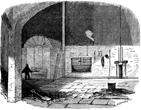
When carbon is heated to a temperature of about 700° in an atmosphere of pure oxygen, it will combine chemically with that gas, and the product will be the gas called carbonic acid. The volume of carbonic acid produced by this combination, will be exactly equal to that of the oxygen combined with the carbon, and therefore the weight of a given volume of the gas will be increased by the weight of carbon which enters the combination. It is found that two parts by weight of oxygen combined with three of carbon, form carbonic acid. The weight of the carbonic acid, therefore, produced in the combustion, will be greater than the weight of the oxygen, bulk for bulk, in the proportion of five to two, the volume being the same and the gases being [Pg253] compared at the same temperatures and under equal pressures. In this combination heat is evolved in very large quantities. This effect arises from the heat previously latent in the carbon and oxygen being rendered sensible in the process of combustion. The carbonic acid proceeding from the combustion is by such means raised to a very high temperature, and the carbon during the process acquires a heat so intense as to become luminous; no flame, however, is produced.
Hydrogen, heated to a temperature of about 1000°, in contact with oxygen will combine with the latter, and a great evolution of heat will attend the process; the gases will be rendered luminous, and flame will be produced. The product of this process will be water, which being exposed to the intense heat of combustion, will be immediately converted into steam. Hydrogen combines with eight times its own weight of oxygen, producing nine times its own weight of water.
Hydrogen gas is, however, not usually disengaged from coal in a simple form, but combined chemically with a certain portion of carbon, the combination being called carburetted hydrogen. Pure hydrogen burns with a very faintly luminous blue flame, but carburetted hydrogen gives that bright flame occasionally having an orange or reddish tinge, which is seen to issue from burning coals: this is the gas used for illumination, being expelled from the coal by the process of coking, and conducted to the various burners through proper pipes.
The sulphur, which in a very small proportion is contained in coals, is also combustible, and combines in the process of combustion with oxygen, forming sulphurous acid: it is also sometimes evolved in combination with hydrogen, forming sulphuretted hydrogen.
Atmospheric air consists of two gases, azote and oxygen, mixed together in the proportion of four to one; five cubic feet of atmospheric air consisting of four cubic feet of azote and one of oxygen. Any combustible will combine with the oxygen contained in atmospheric air, if raised to a temperature somewhat higher than that which is necessary to cause its combustion in an atmosphere of pure oxygen.
If coals, therefore, or other fuel exposed to atmospheric [Pg254] air, be raised to a sufficiently high temperature, their combustible constituents will combine with the oxygen of the atmospheric air, and all the phenomena of combustion will ensue. In order, however, that the combustion should be continued, and should be carried on with quickness and activity, it is necessary that the carbonic acid, and other products, should be removed from the combustible as they are produced, and fresh portions of atmospheric air brought into contact with it; otherwise the combustible would soon be surrounded by an atmosphere composed chiefly of carbonic acid to the exclusion of atmospheric air, and therefore of uncombined oxygen, and consequently the combustion would cease, and the fuel be extinguished. To maintain the combustion, therefore, a current of atmospheric air must be constantly carried through the fuel: the quantity and force of this current must depend on the quantity and quality of the fuel to be consumed. It must be such that it shall supply sufficient oxygen to the fuel to maintain the combustion, and not more than sufficient, since any excess would be attended with the effect of absorbing the heat of combustion, without contributing to the maintenance of that effect.
Heat is communicated from body to body in two ways, by radiation and by contact.
Rays of heat issue from a heated body, and are dispersed through the surrounding space in a manner, and according to laws, similar to those which govern the radiation of light. The heat thus radiated meeting other bodies is imparted to them, and penetrates them with more or less facility according to their physical qualities.
A heated body also brought into contact with another body of lower temperature, communicates heat to that other body, and will continue to do so until the temperature of the two bodies in contact shall be equalised. Heat proceeds from fuel in a state of combustion in both these ways: the heated fuel radiates heat in all directions around it, and the heat thus radiated will be imparted to all parts of the furnace which are exposed to the fuel.
The gases, which are the products of the combustion, escape from the fuel at a very high temperature, and consequently, in acquiring that temperature they absorb a considerable [Pg255] quantity of the heat of combustion. But besides the gases actually formed in the process of combustion, the azote forming four fifths of the air carried through the fuel to support the combustion, absorbs heat from the combustible, and rises into the upper part of the furnace at a high temperature. These various gases, if conducted directly to the chimney, would carry off with them a considerable quantity of the heat. Provision should therefore be made to keep them in contact with the boiler such a length of time as will enable them to impart such a portion of the heat which they have absorbed from the fuel, as will still leave them at a temperature sufficient, and not more than sufficient, to produce the necessary draft in the chimney.
The grate and a part of the flues are rendered visible by the removal of a portion of the surrounding masonry in which the boiler is set. The interior of the boiler is also shown by cutting off one half of the semi-cylindrical roof. A longitudinal vertical section is shown in fig. 72., and a cross section in fig. 73. A horizontal section taken above the level of the grate, and below the level of the water in the boiler, showing [Pg256] the course of the flues, is given in fig. 74. The corresponding parts in all the figures are marked by the same letters.
The door by which fuel is introduced upon the grate is represented at A, and the door leading to the ash-pit at B. The fire bars at C slope downwards from the front at an angle of about 25°, giving a tendency to the fuel to move from the front towards the back of the grate. The ash-pit D is constructed of such a magnitude, form, and depth, as to admit a current of atmospheric air to the grate-bars, sufficient to sustain the combustion. The form of the ash-pit is usually wide below, contracting towards the top.
The fuel when introduced at the fire-door A, should be laid on that part of the grate nearest to the fire-door, called the dead plates: there it is submitted to the process of coking, by which the gases and volatile matter which it contains are expelled, and being carried by a current of air, admitted [Pg257] through small apertures in the fire-door over the burning fuel in the hinder part of the grate, they are burnt. When the fuel in front of the grate has been thus coked, it is pushed back, and a fresh feed introduced in front. The coal thus pushed back soon becomes vividly ignited, and by continuing this process, the fuel spread over the grate is maintained in the most active state of combustion at the hinder part of the grate. By such an arrangement, the smoke produced by the combustion of the fuel may be burnt before it enters the flues. The flame and heated air proceeding from the burning fuel arising from the grate, and rushing towards the back of the furnace, passes over the fire-bridge E, and is carried through the flue F which passes under the boiler. This flue (the cross section of which is shown in fig. 73., by the dark shade put under the boiler) is very nearly equal in width to the bottom of the boiler, the space at the bottom of the boiler, near the corners, being only what is sufficient to give the weight of the boiler support on the masonry forming the [Pg258] sides of the flue. The bottom of the boiler being concave, the flame and heated air as they pass along the flue rise to the upper part by the effects of their high temperature, and lick the bottom of the boiler from the fire-bridge at E to the further end G.
At G the flue rises to H, and turning to the side of the boiler at I I, conducts the flame in contact with the side from the back to the front; it then passes through the flue K across the front, and returns to the back by the other side [Pg259] flue L. The side flue is represented, stripped of the masonry, in fig. 71., and also appears in the plan in fig. 74., and in the cross section in fig. 73. The course of the air is represented in fig. 74. by the arrows. From the flue L the air is conducted into the chimney at M.
By such an arrangement, the flame and heated air proceeding from the grate are made to circulate round the boiler, and the length and magnitude of the flues through which it is conducted should be such, that when it shall arrive at the chimney its temperature shall be reduced, as nearly as is consistent with the maintenance of draught in the chimney, to the temperature of the water with which it is in contact.
The method of feeding the furnace, which has been described above, is one which, if conducted with skill and care, would produce a much more perfect combustion of the fuel than would attend the common method of filling the grate from the back to the front with fresh fuel, whenever the furnace is fed. This method, however, is rarely observed in the management of the furnace. It requires the constant attention of the stokers (such is the name given to those who feed the furnaces). The fuel must be supplied, not in large quantities, and at distant intervals, but in small quantities and more frequently. On the other hand, the more common practice is to allow the fuel on the grate to be in a great degree burned away, and then to heap on a large quantity of fresh fuel, covering over with it the burning fuel from the back to the front of the grate. When this is done, the heat of the ignited coal acting upon the fresh fuel introduced, expels the gases combined with it and, mixed with these, a quantity of carbon, in a state of minute division, forming an opaque black smoke. This is carried through the flues and drawn up the chimney. The consequence is, that not only a quantity of solid fuel is sent out of the chimney unconsumed, but the hydrogen and other gases also escape unburned, and a proportional waste of the combustible is produced; besides which, the nuisance of an atmosphere filled with smoke ensues. Such effects are visible to all who observe the chimneys of steam-vessels, while the engine is in operation. When the furnaces are thus filled with fresh fuel, a large volume of [Pg260] dense black smoke is observed to issue from the chimney. This gradually subsides as the fuel on the grate is ignited, and does not reappear until a fresh feed is introduced.
This method of feeding, by which the furnace would be made to consume its own smoke, and the combustion of the fuel be rendered complete, is not however free from counteracting effects. In ordinary furnaces the feed can only be introduced by opening the fire-doors, and during the time the fire-doors are opened a volume of cold air rushes in, which passing through the furnace is carried through the flues to the chimney. Such is the effect of this in lowering the temperature of the flues, that in many cases the loss of heat occasioned is greater than any economy of fuel obtained by the complete consumption of smoke. Various methods, however, may be adopted by which fuel may be supplied to the grate without opening the fire-doors, and without disturbing the supply of air to the fire. A hopper built into the front of the furnace, with a moveable bottom or valve, by which coals may be allowed to drop in from time to time upon the front of the grate, would accomplish this.
A patent has recently been granted to Mr. Williams, one of the directors of the City of Dublin Steam Navigation Company, for a method of consuming the unburned gases which escape from the grate, and are carried through the flues. This method consists in introducing into the flue tubes placed in a vertical position, the lower ends of which being inserted in the bottom of the flue are made to communicate with the ash-pit, and the upper ends of which are closed. The sides and tops of these tubes are pierced with small holes, through which atmospheric air drawn from the ash-pit issues in jets. The oxygen supplied by this air immediately combines with the carburetted hydrogen, which [Pg261] having escaped from the furnace unburned is carried through the flues at a sufficient temperature to enter into combination with the oxygen admitted through holes in the tubes. A number of jets of flame thus proceed from these holes, having an appearance similar to the flame of a gas-lamp.
It is evident that such tubes must be inefficient unless they are placed in the flues so near the furnace, that the temperature of the unburned gases shall be sufficiently high to produce their combustion.
To facilitate the raking out of the grate, the bars are placed with their ends towards the fire-door: they are usually made of cast-iron, from two to two inches and a half wide on the upper surface, with intervals of nearly half an inch between them. The bars taper downwards, their under surfaces being much narrower than their upper, the spaces between them thus widening, to facilitate the fall of the ashes between them. The grate-bars slope downwards from the front to the back. The height of the centre of the bottom of the boiler, above the front of the grate, is usually about two feet, and about three feet above the back of it. The concave bottom of the boiler, however, brings its surfaces at the slide closer to the grate.
It was considered by Mr. Watt, but we are not aware on what experimental grounds, that from eight to ten square feet of heating surface were sufficient to produce the evaporation of one cubic foot of water per hour. The practice of engine-makers since that time has been to increase the allowance of heating surface for the same rate of evaporation. Engine-builders have varied very much in this respect, some allowing twelve, fifteen, and even eighteen square feet of surface for the same rate of evaporation. It must, however, still be borne in mind, that whether this increased allowance did or did not produce the actual evaporation imputed to it, has not been, as far as we are informed, ever accurately ascertained. The production of a given rate of evaporation by a moderate heat diffused over a larger surface, rather than by a fiercer temperature confined to a smaller surface, is attended with many practical advantages. The plates of the boiler acted upon by the fire are less exposed to oxydisation, and the boiler will be proportionally more durable.
Since it is requisite that the level of the water in the boiler shall not suffer any considerable change, it is evident that the magnitude of the feed must be equal to the quantity of water evaporated. If it were less, the level of the water would continually fall by reason of the excess of the evaporation over the feed; and if it were greater, the level would rise by the accumulation of water in the boiler. If therefore the quantity of water-space allowed in the boiler be five times the volume of water evaporated per hour, the quantity introduced by the feed per hour, whether continuously or at intervals, must be of the same amount. Since the process of evaporation is continuous, the variation of level of water in the boiler will be entirely dependent on the intervals between the successive feeds. If the feed be continuous, and always equal to the evaporation, then the level of the water in the boiler will undergo no change; but if while the evaporation is continuous the feed be made at intervals, then the change of level of water in the boiler as [Pg266] well as its change of temperature, will be subject to a variation proportional to the intervals between the successive feeds. It is manifest, therefore, that the feed should either be uninterrupted or be supplied at short intervals, so that the change of level and temperature of the water in the boiler should not be considerable.
A weight F (fig. 75.), half immersed in the water in the boiler, is supported by a wire, which, passing steam-tight through a small hole in the top, is connected by a flexible string, or chain, passing over a wheel W, with a counterpoise A, which is just sufficient to balance F when half immersed. If F be raised above the water, A being lighter will no longer balance it, and F will descend pulling up A, and turning the wheel W. If, on the other hand, F be plunged deeper in the water, A will more than balance it, and will pull it up, so that the only position in which F and A will balance each other is, when F is half immersed. The wheel W is so adjusted, that when two pins placed on its rim are in the horizontal position, the water is at its proper level. Consequently it follows, that if the water rise above this level, the weight F is lifted and A falls, so that the pins come into another position. If, on the other hand, the level of the water fall, F falls and A rises, so that the pins assume a different position. Thus, in general, the position of the pins becomes an indication of the quantity of water in the boiler.
These gauges, however, require the frequent attention of the engine-man; and it becomes desirable either to find some more effectual means of awakening that attention, or to render the supply of the boiler independent of any attention. In order to enforce the attention of the engine-man to replenish the boiler when partially exhausted by evaporation, a tube was sometimes inserted at the lowest level to which it was intended that the water should be permitted to fall. This tube was conducted from the boiler into the engine-house, where it terminated in a mouth-piece or whistle, so that whenever the water fell below the level at which this tube was inserted in the boiler, the steam would rush through it, and issuing with great velocity at the mouth-piece, would summon the engineer to his duty with a call that would rouse him even from sleep.
To remedy this a method has been invented, by which [Pg268] the engine is made to feed its own boiler. The pipe G (fig. 77.), which leads from the hot water pump, terminates in a small cistern C in which the water is received. In the bottom of this cistern, a valve V is placed, which opens upwards, and communicates with a feed-pipe, which descends into the boiler below the level of the water in it. The stem of the valve V is connected with a lever turning on the centre D, and loaded with a weight F dipped in the water in the boiler in a manner similar to that described in fig. 75., and balanced by a counterpoise A in exactly the same way. When the level of the water in the boiler falls, the float F falls with it, and pulling down the arm of the lever raises the valve V, and lets the water descend into the boiler from the cistern C. When the boiler has thus been replenished, and the level raised to its former place, F will again be raised, and the valve V closed by the weight A. In practice, however, the valve V adjusts itself by means of the effect of the water on the weight F, so as to permit the water from the feeding-cistern C to flow in a continued stream, just sufficient in quantity to supply the consumption from evaporation, and to maintain the level of the water in the boiler constantly the same.
By this arrangement the boiler is made to replenish itself, or, more properly speaking, it is made to receive such a supply, as that it never wants replenishing, an effect which no effort of attention on the part of an engine-man could produce. But this is not the only good effect produced by this contrivance. A part of the steam which originally left the boiler, and having discharged its duty in moving the piston, was condensed and reconverted into water, and lodged by the air-pump in the hot well (fig. 77.), is here again restored to the source from which it came, bringing back all the unconsumed portion of its heat preparatory to being once more put in circulation through the machine.
The entire quantity of hot water pumped into the cistern C, is not always necessary for the boiler. A waste-pipe may be provided for carrying off the surplus, which may be turned to any purpose for which it may be required; or it may be discharged into a cistern to cool, preparatory to [Pg269] being restored to the cold cistern, in case water for the supply of that cistern be not sufficiently abundant.
The mouth of the tube by which the feed is introduced should be placed at that part of the boiler which is nearest the end of the flues which issue into the chimney. By such means the temperature of the water in contact with those flues will be lowest at the place where the temperature of the heated air intended to act upon it is also lowest. The difference of the temperatures will therefore be greater than it would be if the point of the boiler containing water of a higher temperature was left in contact with this part of the flue.
If, on the contrary, the level of the mercury in B C should fall below its level in A B, the atmospheric pressure will [Pg271] exceed that of the steam, and the quantity of the excess may be ascertained exactly in the same way.
If the tube be glass, the difference of levels of the mercury would be visible; but it is most commonly made of iron; and in order to ascertain the level, a thin wooden rod with a float is inserted in the open end of B C, so that the portion of the stick within the tube indicates the distance of the level of the mercury from its mouth. A bulb or cistern of mercury might be substituted for the leg A B, as in the common barometer. This instrument is called the steam-gauge.
If the steam-gauge be used as a measure of the strength of the steam which presses on the piston, it ought to be on the same side of the throttle-valve (which is regulated by the governor) as the cylinder; for if it were on the same side of the throttle-valve with the boiler, it would not be affected by the changes which the steam may undergo in passing through the throttle-valve, when partially closed by the agency of the governor.
For boilers in which steam of very high pressure is used, as in those of locomotive engines, a steam-gauge, constructed on the above principle, would have inconvenient or impracticable length. In such boilers the pressure of the steam is equal to four or five times that of the atmosphere, to indicate which the column of mercury in the steam-gauge would be four or five feet in height. In such cases a thermometer-gauge may be used with advantage. The principle of this gauge is founded on the fact, that between the pressure and temperature of steam produced in contact with water there is a fixed relation, the same temperature always corresponding to the same pressure. If, therefore, a thermometer be immersed in the boiler which shall show the temperature of the steam, a scale may be attached to it, on which shall be engraved the corresponding pressures. Such gauges are now very generally used on locomotive engines.
To compute the force with which the piston descends, thus becomes a very simple arithmetical process. First, ascertain the difference of the levels of the mercury in the steam-gauge; this gives the excess of the steam pressure above the atmospheric pressure. Then find the height of the mercury in the barometer-gauge; this gives the excess of the atmospheric pressure above the uncondensed steam. Hence, if these two heights be added together, we shall obtain the [Pg273] excess of the impelling force of the steam from the boiler, on the one side of the piston, above the resistance of the uncondensed steam on the other side: this will give the effective impelling force. Now, if one pound be allowed for every two inches of mercury in the two columns just mentioned, we shall have the number of pounds of impelling pressure on every square inch of the piston. Then, if the number of square inches in the section of the piston be found, and multiplied by the number of pounds on each square inch, the force with which it moves will be obtained.
From what we have stated it appears that, in order to estimate the force with which the piston is urged, it is necessary to refer to both the barometer and the steam-gauge. This double computation may be obviated by making one gauge serve both purposes. If the end C of the steam-gauge (fig. 79.), instead of communicating with the atmosphere were continued to the condenser, we should have the pressure of the steam acting upon the mercury in the tube B A, and the pressure of the uncondensed vapour which resists the piston acting on the mercury in the tube B C. Hence the difference of the levels of the mercury in the tubes would at once indicate the difference between the force of the steam and that of the uncondensed vapour, which is the effective force with which the piston is urged.
To measure the mean efficient force of the piston, taking into account these circumstances, Mr. Watt invented an instrument, which, like all his mechanical inventions, has answered its purpose perfectly, and is still in general use. This instrument, called an indicator, consists of a cylinder of about 13⁄4 inch in diameter, and 8 inches in length. It is bored with great accuracy, and fitted with a solid piston moving steam-tight in it with very little friction. The rod of this piston is guided in the direction of the axis of the cylinder through a collar in the top, so as not to be subject to friction in any part of its play. At the bottom of the cylinder is a pipe governed by a stop-cock and turned in a screw, by which the instrument may be screwed on the top of the steam-cylinder of the engine. In this position, if the stop-cock of the indicator be opened, a free communication will be made between the cylinder of the indicator and that of the engine. The piston-rod of the indicator is attached to a spiral spring, which is capable of extension and compression, and which by its elasticity is capable of measuring the force which extends or compresses it in the same manner as a spring steel-yard or balance. If a scale be attached to the instrument at any point on the piston-rod to which an index might be attached, then the position of that index upon the scale would be governed by the position of the indicator-piston in its cylinder. If any force pressed the indicator-piston upwards, so as to compress the spring, [Pg275] the index would rise upon the scale; and if, on the other hand, a force pressed the indicator-piston downwards, then the spiral spring would be extended, and the index on the piston-rod descend upon the scale. In each case the force of the spring, whether compressed or extended, would be equal to the force urging the indicator-piston, and the scale might be so divided as to show the amount of this force.
Now, let the instrument be supposed to be screwed upon the top of the cylinder of a steam-engine, and the stop-cock opened so as to leave a free communication between the cylinder of the indicator below its piston and the cylinder of the steam-engine above the steam-piston. At the moment the upper steam-valve is opened, the steam rushing in upon the steam-piston will also pass into the indicator, and press the indicator-piston upwards: the index upon its piston-rod will point upon the scale to the amount of pressure thus exerted. As the steam-piston descends, the indicator-piston will vary its position with the varying pressure of the steam in the cylinder, and the index on the piston-rod will play upon the scale, so as to show the pressure of the steam at each point during the descent of the piston.
If it were possible to observe and record the varying position of the index on the piston-rod of the indicator, and to refer each of these varying positions to the corresponding point of the descending stroke, we should then be able to declare the actual pressure of the steam at every point of the stroke. But it is evident that such an observation would not be practicable. A method, however, was contrived by Mr. Southern, an assistant of Messrs. Boulton and Watt, by which this is perfectly effected. A square piece of paper, or card, is stretched upon a board, which slides in grooves formed in a frame. This frame is placed in a vertical position near the indicator, so that the paper may be moved in a horizontal direction backwards and forwards, through a space of fourteen or fifteen inches. Instead of an index a pencil is attached to the indicator of the piston-rod: this pencil is lightly pressed by a spring against the paper above mentioned, and as the paper is moved in a horizontal direction [Pg276] under the pencil, would trace upon the paper a line. If the pencil were stationary this line would be straight and horizontal, but if the pencil were subject to a vertical motion, the line traced on the paper moved under the pencil horizontally would be a curve, the form of which would depend on the vertical motion of the pencil. The board thus supporting the paper is put into connexion by a light cord carried over pulleys with some part of the parallel motion, by which it is alternately moved to the right and to the left. As the piston ascends or descends, the whole play of the board in the horizontal direction will therefore represent the length of the stroke, and every fractional part of that play will correspond to a proportional part of the stroke of the steam-piston.
The apparatus being thus arranged, let us suppose the steam-piston at the top of the cylinder commencing its descent. As it descends, the pencil attached to the indicator piston-rod varies its height according to the varying pressure of the steam in the cylinder. At the same time the paper is moved uniformly under the pencil, and a curved line is traced upon it from right to left. When the piston has reached the bottom of the cylinder, the upper exhausting-valve is opened, and the steam drawn off to the condenser. The indicator-piston being immediately relieved from a part of the pressure acting upon it descends, and with it the pencil also descends; but at the same time the steam-piston has begun to ascend, and the paper to return from left to right under the pencil. While the steam-piston continues to ascend, the condensation becomes more and more perfect, and the vacuum in the cylinder, and therefore also in the indicator, being gradually increased in power, the atmospheric pressure above the indicator-piston presses it downwards and stretches the spring. The pencil meanwhile, with the paper moving under it from right to left, traces a second curve. As the former curve showed the actual pressure of the steam impelling the piston in its descent, this latter will show the pressure of the uncondensed steam raising the piston in its ascent, and a comparison of the two will exhibit the effective force on the piston. Fig. 81. represents such a diagram as would be [Pg277] produced by this instrument. A B C is the curve traced by the pencil during the descent of the piston, and C D E that during its ascent. A is the position of the pencil at the moment the piston commences its descent, B is its position at the middle of the stroke, and C at the termination of the stroke. On closing the upper steam-valve and closing the exhausting-valve, the indicator-piston being gradually relieved from the pressure of the steam the pencil descends, and at the same time the paper moving from left to right, the pencil traces the curve C D E, the gradual descent of this curve showing the progressive increase of the vacuum. As the atmospheric pressure constantly acts above the piston of the indicator, its position will be determined by the difference between the atmospheric pressure and the pressure of the steam below it; and therefore the difference between the heights of the pencil at corresponding points in the ascending and descending stroke, will express the difference between the pressure of the steam impelling the piston in the ascent and resisting it in the descent at these points. Thus at the middle of the stroke, the line B D will express the extent to which the spring governing the indicator-piston would be stretched by the difference between the force of steam impelling the piston at the middle of the descending stroke, and the force of steam resisting it at the middle of the ascending stroke. The force therefore measured by the line B D will be the effective force on the piston at that point; and the same may be said of every part of the diagram produced by the indicator.
The whole mechanical effect produced by the stroke of the piston being composed of the aggregate of all its varying effects throughout the stroke, the determination of its amount [Pg278] is a matter of easy calculation by the measurement of the diagram supplied by the indicator. Let the horizontal play of the pencil from A to C be divided into any proposed number of equal parts, say ten: at the middle of the stroke, B D expresses the effective force on the piston, and if this be considered to be uniform through the tenth part of the stroke, as from f to g, then the number of pounds expressed by B D multiplied by the tenth part of the stroke expressed in parts of a foot, will be the mechanical effect through that part of the stroke expressed in pounds' weight raised one foot. In like manner m n will express the effective force on the piston after three fourths of the stroke have been performed, and if this be multiplied by a tenth part of the stroke as before, the mechanical effect similarly expressed will be obtained; and the same process being applied to any successive tenth part of the stroke, and the numerical results thus obtained being added together, the whole effect of the stroke will be obtained, expressed in pounds' weight raised one foot.
With a view to the economy of heat, this waste steam tube is sometimes conducted into the feeding cistern, where the steam carried off by it is condensed, and heats the feeding water.
The magnitude of the safety-valve should be such that, when open, steam should be capable of passing through it as rapidly as it is generated in the boiler. The superficial magnitude, therefore, of such valves must be proportional to the evaporating power of the boiler. In low pressure boilers the steam is generally limited to five or six pounds' pressure per square inch, and consequently the load over the safety-valve in pounds would be found by multiplying the superficial magnitude of its smallest part by these numbers. In boilers in which the steam is maintained at a higher pressure, it would be inconvenient to place upon the safety-valve the necessary weight. In such cases a lever is used, the shorter arm of which presses down the valve, and the longer arm is held down by a weight capable of adjustment, so that the pressure on the valve may be regulated at discretion. Two safety-valves should be provided on all boilers, one of which should be locked up, so that the persons in care of the engine should have no power to increase the load upon it. In such case, however, it is necessary that a handle connected with the valve should project outside the box containing it, so that it may always be possible for the engineer to ascertain that the valve is not locked in its seat, a circumstance which is liable to happen.
Sometimes also two safety-valves are provided, one loaded a little heavier than the other. The escape of steam from the lighter valve in this case gives notice to the engine-man of the growing increase of pressure, and warns him to check the production of steam. The lever by which the safety-valve is held down is sometimes acted on by a spiral spring, capable of being so adjusted as to produce any required pressure on the valve. This arrangement is adopted in locomotive engines, where steam of very high pressure is used; and in such cases also there are always provided two such valves, one of which cannot be increased in its pressure.
The pipe by which the boiler is fed with water will [Pg280] necessarily act as a safety-valve, for when the pressure of the steam increases in an undue degree, it will press the water in the boiler up through the feed-pipe, so as to discharge it into the feed-cistern, a circumstance which would immediately give notice of the internal state of the boiler. The steam-gauge, already described (fig. 79.), would also act as a safety-valve; for if the pressure of steam in the boiler should be so augmented as to blow the mercury out of the steam-gauge, the steam would then issue through the gauge, and the pressure of the boiler be reduced, provided that the magnitude of the tube forming the steam-gauge were sufficient for this purpose.
Although fusible plugs may be used, in addition to other means of insuring safety, they ought not to be exclusively relied on at the ordinary working pressure of the boiler. The fusible plug ought to be capable of more than resisting the pressure; but if it be so, its point of fusion would be one at which the steam would have a pressure of at least two atmospheres above its working pressure. The plug would therefore be capable of being fused only as soon as the steam would acquire a pressure of 30 lbs. per inch above its regular working pressure.
When a boiler ceases to be worked, and the furnace has been extinguished, the space within it appropriated to steam [Pg281] will be left a vacuum by the condensation of the steam with which it was previously filled. The external pressure of the atmosphere acting on the boiler would, under such circumstances, have a tendency to crush it inwards. To prevent this, a safety-valve is provided, opening inwards, and balanced by a weight sufficient to keep it closed until it be relieved from the pressure of the steam below.
A large aperture closed by a flange secured with screws, represented at O in fig. 71., called the man-hole, is provided to admit persons into the boiler for the purpose of cleaning or repairing its interior.
In order to vary the production of steam in proportion to the demands of the engine, it is necessary to stimulate or mitigate the furnace, as the evaporation is to be augmented or diminished.
The activity of the furnace must depend on the current of air which is drawn through the grate-bars, and this will depend on the magnitude of the space afforded for the passage of that current through the flues. A plate called a damper is accordingly placed with its plane at right angles to the flue, so that by raising and lowering it in the same manner as the sash of a window is raised or lowered, the space allowed for the passage of air through the flue may be regulated. This plate might be regulated by the hand, so that by raising or lowering it the draught might be increased or diminished, and a corresponding effect produced on the [Pg282] evaporation in the boiler: but the force of the fire is rendered uniformly proportional to the rate of evaporation by the following arrangement, without the intervention of the engineer. The column of water sustained in the feed-pipe (figs. 71, 72.) represents by its weight the difference between the pressure of steam within the boiler and that of the atmosphere. If the engine consumes steam faster than the boiler produces it, the steam contained in the boiler acquires a diminished pressure, and consequently the column of water in the feed-pipe will fall. If, on the other hand, the boiler produce steam faster than the engine consumes it, the accumulation of steam in the boiler will cause an increased pressure on the water it contains, and thereby increase the height of the column of water sustained in the feed-pipe. This column therefore necessarily rises and falls with every variation in the rate of evaporation in the boiler. A hollow float P is placed upon the surface of the water of this column; a chain connected with this float is carried upwards, and passed over two pulleys, after which it is carried downwards through an aperture leading to the flue which passes beside the boiler: to this chain is attached the damper. By such an arrangement it is evident that the damper will rise when the float P falls, and will fall when the float P rises, since the weight of the damper is so adjusted, that it will only balance the float P when the latter rests on the surface of the water.
Whenever the evaporation of the boiler is insufficient, it is evident from what has been stated, that the float P will fall and the damper will rise, and will afford a greater passage for air through the flue. This will stimulate the furnace, will augment its heating power, and will therefore increase the rate of evaporation in the boiler. If, on the other hand, the production of steam in the boiler be more than is requisite for the supply of the engine, the float will be raised and the damper let down, so as to contract the flue, to diminish the draught, to mitigate the fire, and therefore to check the evaporation. In this way the excess, or defect, of evaporation in the boiler is made to act upon the fire, so as to render the heat proceeding from the combustion as nearly as possible proportional to the wants of the engine. [Pg283]
The advantages proposed to be attained by him were those expressed in his patent:—
"First, I put the coal upon the grate by small quantities, and at very short intervals, say every two or three seconds. 2dly, I so dispose of the coals upon the grate, that the smoke evolved must pass over that part of the grate upon which the coal is in full combustion, and is thereby consumed. 3dly, As the introduction of coal is uniform in short spaces of time, the introduction of air is also uniform, and requires no attention from the fireman.
"As it respects economy: 1st, The coal is put upon the fire by an apparatus driven by the engine, and so contrived that the quantity of coal is proportioned to the quantity of work which the engine is performing; and the quantity of air admitted to consume the smoke is regulated in the same manner. 2dly, The fire-door is never opened, excepting to clean the fire; the boiler, of course, is not exposed to that continual irregularity of temperature which is unavoidable in the common furnace, and which is found exceedingly injurious to boilers. 3dly, The only attention required is to fill the coal-receiver every two or three hours, and clean the fire when necessary. 4thly, The coal is more completely consumed than by the common furnace, as all the effect of what is termed stirring up the fire (by which no inconsiderable quantity of coal is passed into the ash-pit), is attained without moving the coal upon the grate."
A circular grate is placed on a vertical revolving shaft; on the lower part of this shaft, under the ash-pit, is placed a toothed wheel driven by a pinion. This pinion is placed on another vertical shaft, which ascends above the boiler; and [Pg284] on the other end of this is placed a bevelled wheel driven by a pinion. This pinion is attached to a shaft, which takes its motion from the axis of the fly-wheel, or any other revolving shaft connected with the engine. A constant motion of revolution is therefore imparted to the circular grate, and its velocity being proportional to that of the engine, will necessarily be also proportional to the quantity of fuel which ought to be consumed. Through that part of the boiler which is over the fire-grate a vertical tube or opening is made directly over that part of the furnace which is most distant from the flues. Over this opening a hopper is placed, which contains the fuel by which the boiler is to be fed; and in the bottom of this hopper is a sliding valve, capable of being opened or closed, so as to regulate the quantity of fuel supplied to the fire-grate. The fuel dropping in in small quantities through this open valve falls on the grate, and is carried round by it, so as to leave a fresh portion of the grate to receive succeeding feeds. The coals admitted through the hopper are previously broken to a proper size; and in some forms of this apparatus there are two rollers, at a regulated distance asunder, the surfaces of which are formed into blunt angular points, and which are kept in slow revolution by the engine. Between these rollers the coals must pass before they reach the valve through which the furnace is fed, and they are thus broken and reduced to a regulated size. The valve which regulates the opening through which the feed is admitted, is connected by chains and pulleys with the self-regulating damper already described, so that in proportion as the damper is raised, the valve governing the feed may be opened. Thus, while the quantity of air admitted by the damper is increased according to the demands of the engine, the quantity of fuel admitted for the feed is increased by opening the valve in the bottom of the hopper in the same proportion. Apertures are also provided in the front of the grate, governed by regulators, by which the quantity of air necessary and sufficient to produce the combustion of the gas evolved from the fuel is admitted, these openings being also connected with the self-regulating damper.
A considerable portion of the heat imparted to the water [Pg285] in the boiler escapes by radiation from the surface of the boiler, steam-pipes, and other parts of the machinery in contact with the steam and hot water. The effects of this are rendered very apparent in marine engines, where a large quantity of water is found to be condensed in the great steam-pipes leading from the boiler to the cylinder. In stationary land boilers this loss of heat is usually diminished, and in some cases in a great degree removed, by surrounding the boiler with non-conducting substances. In some cases the boiler is built round in brick work. In Cornwall, where the economy is regarded perhaps to a greater extent than elsewhere, the boiler and steam-pipes are surrounded with a packing of sawdust, which being almost a non-conductor of heat, is impervious to the heat proceeding from the surfaces with which it is in contact, and consequently confines all the heat within the boiler. In marine boilers it has been the practice recently to clothe the boiler and steam-pipes with a coating of felt, which is attended with a similar effect. When these remedies are properly applied, the loss of heat proceeding from the radiation of the boiler is reduced to an extremely small amount. The engine-houses of some of the Cornish engines, where the boiler generates steam at a very high temperature, are nevertheless frequently maintained at a lower temperature than the external air, and on entering them they have in a great degree the effect of a cave.
The gross amount of mechanical action developed by the moving power of an engine, is expended partly on moving the engine itself, and partly on overcoming the resistance on which the engine is intended to act. That part of the mechanical energy of the moving power which is expended on the resistance or load which the engine moves exclusively, and of the power expended on moving the engine itself, is called the useful effect of the machine.
The gross effect, therefore, exceeds the useful effect by the [Pg286] amount of power spent in moving the engine, or which may be wasted or destroyed in any way by the engine.
It is usual to express and estimate all mechanical effect whatever by nature of the resistance overcome, by an equivalent weight raised a certain height. Thus, if an engine exerts a certain power in driving a mill, in drawing a carriage on a road, or in propelling a vessel on water, the resistance against which it has to act must be equal to a definite amount of weight. If a carriage be drawn, the traces are stretched by the tractive power, by the same tension that would be given to them if a certain weight were appended to them. If the paddle-wheels of a boat are made to revolve, the water opposes to them a resistance equal to that which would be produced, if instead of moving the water the wheel had to raise some certain weight. In any case, therefore, weight becomes the exponent of the energy of the resistance against which the moving power acts.
But the amount of mechanical effect depends conjointly on the amount of resistance, and the space through which that resistance is moved. The quantity of this effect, therefore, will be increased in the same proportion, whether the quantity of resistance or the space through which that resistance is moved be augmented. Thus, a resistance of one hundred pounds, moved through two feet, is mechanically equivalent to a resistance of two hundred pounds moved through one foot, or of four hundred pounds moved through six inches. To simplify, therefore, the expression of mechanical effect, it is usual to reduce it invariably to a certain weight raised one foot. If the resistance under consideration be equivalent to a certain weight raised through ten feet, it is always expressed by ten times the amount of that weight raised through one foot.
It has also been usual in the expression of mechanical effect, to take the pound weight as the unit of weight, and the foot as the unit of length, so that all mechanical effect whatsoever is expressed by a certain number of pounds raised one foot.
Whether this estimate of an average horse's power be correct or not, in reference to the actual work which the animal is capable of executing, is a matter of no present importance in its application to steam-power. The steam-engine is no longer used to replace the power of horses, and therefore no contracts are based upon such a comparison. The term horse-power, therefore, as applied to steam-engines, must be understood to have no reference whatever to the actual animal power, but must be taken as a term having no other meaning than the expression of the ability of the [Pg289] machine to move the amount of resistance above mentioned through one foot per minute.
If the steam be not worked expansively, then the whole power of the water, transmitted in the form of steam from the boiler to the working machinery, will be a matter of easy calculation, when the pressure at which the steam is worked is known. A table, exhibiting the mechanical power of a cubic foot of water converted into steam at various pressures, expressed in an equivalent number of pounds' weight raised one foot high, is given in the Appendix to this volume. Where much accuracy is sought for, the pressure at which the steam is used must be taken into account; but by reference to the table it will be seen, that when steam is worked without expansion, its mechanical effect varies very little with the pressure. It may therefore be assumed, as has been already stated, that for every cubic inch of water transmitted in the form of steam to the cylinders, a force is produced, represented by a ton weight raised a foot high. Now, as 33,000 lbs. is very nearly 15 tons, it follows that 15 cubic inches of water converted into steam per minute, or 900 cubic inches per hour, will produce a mechanical force equal to one horse. If, therefore, to 900 cubic inches be added the quantity of water per hour necessary to move the engine itself, independently of its load, we shall obtain the quantity of water per hour which must be supplied by the boiler to the engine for each horse-power, and this will be the same whatever may be the magnitude or proportions of the cylinder.
First. Steam in passing from the boiler to the cylinder is liable to lose its temperature by the radiation of the steam-pipes and other passages through which it is conducted. Since the steam produced in the boiler is in contact with water, it will be common steam (94.), and consequently the least loss of heat will cause a partial condensation. To whatever extent this condensation may be carried, a proportional loss of power, in reference to the heat obtained from the fuel, will be entailed upon the engine.
It has been said that the force necessary to move the steam from the boiler to the cylinder through passages more or less contracted, subject to the friction of the pipes and tubes through which it moves, should be taken into account in estimating the power, and a corresponding deduction made. This, however, is not the case: the steam having passed into the cylinder remains common steam, its pressure being diminished by reason of the force expended in thus moving it from the boiler to the cylinder. But its mechanical efficacy at the reduced pressure is not sensibly different from the efficacy which it had in the boiler. If at the reduced pressure its volume were the same, then a loss of effect would be sustained equivalent to the difference of the pressures; but its volume being augmented in very nearly the same proportion as its pressure is diminished, the mechanical efficacy of a given weight of steam in the cylinder will be sensibly the same as in the boiler.
Second. The radiation of heat from the cylinder and its appendages, will cause a partial condensation of steam, and thereby produce a diminished mechanical effect.
Third. The steam, which at each stroke of the piston fills the passages between the steam-valves and the piston, at the [Pg291] moment the latter commences the stroke will be inefficient. If it were possible for the piston to come into steam-tight contact with each end of the cylinder, and that the steam-valve should be in immediate contact with the side or top of the piston, then the whole of the steam which would pass through the steam-valve would be efficient; but as some space, however small, must remain between the piston and the ends of the cylinder, and between the side of the cylinder and the steam-valve, there will always be a volume of steam bearing a sensible proportion to the magnitude of the cylinder, which at each stroke of the piston will be inefficient. This volume of steam is called the clearance.
Fourth. Since the piston must move in steam-tight contact with the cylinder, it must have a definite amount of friction with the sides of the cylinder by whatever means it may be packed. This friction will produce a corresponding resistance to the moving power.
Fifth. The various joints of the machinery where steam is contained are subject to leakage, and whatever amount of steam shall thus escape must be placed to the account of power lost.
Sixth. When the eduction-valve is opened to admit the steam to the condenser, a certain force is required to expel the steam from the cylinder. This force reacts upon the piston, and counteracts to a proportional extent the moving power of the steam on the other side. Besides this the water in the condenser cannot be conveniently reduced below the temperature of about 100°, and at this temperature steam has a pressure of about 1 lb. per square inch. This vapour will continue to fill the cylinder, and will resist the moving power which impels the piston.
Seventh. Power must be provided for opening and closing the valves or slides, for working the air-pump, hot-water pump, and cold-water pump, and finally to overcome the friction on the journals and centres of the parts of the parallel motion, the main axle of the beam, the connecting rod, crank, and fly-wheel axle.
It will be apparent how very much these sources of resistances must vary in different engines, and how rough [Pg292] an approximation any general estimate must be of their gross amount.
In common low-pressure engines of the larger kind, to which class alone we at present refer, it has been usual, with the same fuel and under like circumstances, to allow from 10 to 18 square feet of heating surface in the boiler for every nominal horse-power of the engine. Within these wide limits the practice of engine-makers has varied. It is not, however, to be supposed, that the boiler with 18 square feet of surface per horse-power has the same evaporating power as that which has but 10. This difference, therefore, amounts to nothing more than different manufacturers of steam-engines putting into circulation boilers having powers really different while they are nominally the same. The magnitude of the cylinder is regulated by the nominal power of the engine, and it is usual so to regulate the evaporating power of the boiler, that the piston shall move at the average rate of 200 feet per minute. This being assumed, it is customary to allow about 22 square inches of piston [Pg293] surface for every nominal horse-power of the engine. If this power were in conformity to the standard already defined, this amount of surface moved at 200 feet per minute would be impelled by a pressure amounting to 71⁄2 lbs. per square inch. The safety-valve of the boiler of such engines is usually loaded at from 4 to 5 lbs. per square inch, and consequently the steam in the boiler will have a pressure of from 19 to 20 lbs. per square inch. If, therefore, the effective pressure on the piston be really only 71⁄2 lbs. per square inch, the pressure expended in overcoming the friction of the engine, and the loss consequent on the partial condensation of steam on one side and its imperfect condensation on the other, would amount to from 12 to 13 lbs. per square inch, or nearly double the assumed useful effect of the engine.
Messrs. Maudslay and Field are accustomed to allow an evaporation of ten gallons, or 1·6 cubic feet of water per hour, for each nominal horse-power of the engine. They also allow about 22 square inches of piston surface per nominal horse-power, the piston being supposed to move at the rate of 200 feet per second.[24]
The quantity of grate surface necessary in proportion to the power of the engine, has been equally unascertained, and engine-makers vary in their practice from half a square foot to one square foot per nominal horse-power.
The proportion which the magnitude of the heating surface of the boiler, and the fire surface of the grate bears to the evaporating power of the boiler, has not been determined by experiment, nor, so far as we are informed, by any well-ascertained practical results.
The estimates or rather conjectures of engine-makers, of the evaporation necessary to produce one horse-power, vary from one to two cubic feet of water per hour. It has been [Pg294] already shown that the evaporation of 900 cubic inches, or little more than half a cubic foot per hour, evolves a gross mechanical effect representing one horse-power; from which it appears, that if the evaporation of the boilers of steam engines were what engineers suppose them to be, the gross mechanical power produced in them for every nominal horse-power of the engine varies in actual amount from the power of two to that of four horses.
The above estimates must be understood as referring to double-acting steam engines above thirty-horse power. The circumstances attending the performance of single-acting engines applied to the drainage of mines, have been ascertained with much greater precision. This has been mainly owing to a spirited system of general inspection, which has been established in Cornwall, to which we shall hereafter more particularly advert.
The duty of a boiler is estimated by the volume of water evaporated by a given quantity of fuel, independently of the time which such evaporation may take. The duty, therefore, will be expressed by the number of cubic feet of water evaporated, divided by the number of bushels of coal necessary for that evaporation, supposing the bushel of coal to be the unit of fuel. It will be observed that the duty of an engine or boiler is entirely distinct from, and independent of, its power. One boiler may be greater than another in power to any extent, while it may be equal to or less than it in duty. A bushel of coals may evaporate the same number of cubic feet of water under two boilers, but may take twice as great a time to produce such evaporation under one than under the other. In such a case the power of one boiler will be double that of the other, while their duty will be the same.
In like manner, a bushel of coals consumed in working two engines may produce the same useful effect, but it may produce that useful effect in the one in half the time it takes to produce it in the other. In that case the duty of the engines will be the same, but the power of the one will be double that of the other. [Pg295]
In fine, power has reference to time,—duty, to fuel. The more rapidly the engine produces its mechanical effect, the greater its power will be, whatever may be the fuel consumed in working it. And, on the other hand, the greater the useful effect produced by a given weight of fuel, the greater will be the duty, however long the time may be which the fuel may take to produce the useful effect.
The proportion of the diameter to the stroke of the cylinder is very various. In engines used for steam-vessels the length of the cylinder very little exceeds its diameter. In land engines, however, the proportion of the length to the diameter is greater. It is maintained by some that the proportion of the diameter and length of the cylinder should be such as to render its surface exposed to the cooling of the external air, the smallest possible. Tredgold has maintained that since, during the stroke, the steam is gradually exposed to contact with the surface of the cylinder from the top to the bottom, the mean surface exposed in contact with steam being half that of the entire cylinder, the proportion of the diameter to the stroke should be such that the surface of half the length of the cylinder, added to the magnitude of the top and bottom, shall be a minimum. If this principle be admitted, then the best proportion of the diameter to the stroke would be that of one to two, the length of the stroke being twice the diameter of the cylinder; but since the whole surface of the cylinder is constantly exposed to the cooling effects of the air, and since in the intervals of the stroke there is no sensible change of the temperature of the surface, the loss of heat by cooling will in effect be the same, especially in double-acting engines, as if the cylinder were constantly filled with steam. If this be admitted, then the object should be to give the cylinder such a proportion, that its entire surface, including the top and bottom, shall be a minimum. [Pg296] The proportion given by this condition would be very nearly that which is observed in the cylinders of marine engines, viz. that the length of the cylinder should be equal to its diameter.
If in a low-pressure engine the pressure of steam in the cylinder be taken at 17 lbs. per square inch, then the volume of steam will be about fifteen hundred times that of the water which produces it. For every cubic foot of water, therefore, in the effective evaporation of the boiler, 1500 cubic feet of steam will be passed through the cylinder. If it be intended that the motion of the piston shall be at the rate of 25 strokes per minute, or 1500 strokes per hour, then the capacity of that portion of the cylinder between the steam-valve and the piston at the end of the stroke, must consist of half as many cubic feet as there are cubic feet per hour evaporated in the boiler. If the steam, therefore, be cut off at half stroke, the number of cubic feet of space in the cylinder will be equal to the number of cubic feet of water effectively evaporated by the boiler; and if a cubic foot of water effectively evaporated be taken as the measure of a horse-power, then there would be as many cubic feet in the capacity of the cylinder as is equal to the nominal power of the engine.
About the year 1811, a number of the proprietors of the principal Cornish mines agreed to establish this system of inspection, under the management and direction of Captain Joel Lean, and to publish monthly reports. In these reports were stated the following particulars:—1. The load per square inch on the piston; 2. The consumption of coal in bushels; 3. The number of strokes made by the engine; 4. The length of the strokes in the pumps; 5. The load in pounds; 6. The duty of the engine, expressed by the number of pounds raised one foot high by the consumption of a bushel of coals; 7. The number of strokes per minute; 8. The diameter and stroke of the cylinder, and a general description of the engine. When these reports were commenced, the number of engines brought under inspection was twenty-one. In the year 1813 it increased to twenty-nine; in 1814 to thirty-two; in 1820 the number reported upon increased [Pg298] to forty; in 1828 the number was fifty-seven; and in 1836 it was sixty-one. This gradual increase in the number of engines brought under this system of inspection, was produced by the good effects which attended it. These beneficial consequences were manifested, not only in the improved performance of the same engines, but in the gradually improved efficiency of those which were afterwards constructed.
The following table taken from the statement of the duty of Cornish engines by Thomas Lean and brother, lately published by the British Association, will show in a striking manner the improvement of the Cornish engines, from the commencement of this system of inspection to the present time. The duty is expressed by the number of pounds raised one foot high by the consumption of a bushel of coals.
| Years. | No. of Engines. | Average Duty of the Whole. | Average Duty of the best Engine. |
|---|---|---|---|
| 1812 | 21 | 19,300,000 | |
| 1813 | 29 | 19,500,000 | 26,400,000 |
| 1814 | 32 | 20,600,000 | 32,000,000 |
| 1815 | 35 | 20,500,000 | 28,700,000 |
| 1816 | 35 | 23,000,000 | 32,400,000 |
| 1817 | 35 | 26,500,000 | 41,600,000 |
| 1818 | 36 | 25,400,000 | 39,300,000 |
| 1819 | 40 | 26,300,000 | 40,000,000 |
| 1820 | 46 | 28,700,000 | 41,300,000 |
| 1821 | 45 | 28,200,000 | 42,800,000 |
| 1822 | 52 | 28,900,000 | 42,500,000 |
| 1823 | 52 | 28,200,000 | 42,100,000 |
| 1824 | 49 | 28,300,000 | 43,500,000 |
| 1825 | 56 | 32,000,000 | 45,400,000 |
| 1826 | 51 | 30,500,000 | 45,200,000 |
| 1827 | 51 | 32,100,000 | 59,700,000 |
| 1828 | 57 | 37,100,000 | 76,800,000 |
| 1829 | 53 | 41,700,000 | 77,000,000 |
| 1830 | 56 | 43,300,000 | 78,000,000 |
| 1831 | 58 | 43,400,000 | 71,100,000 |
| 1832 | 59 | 45,000,000 | 85,000,000 |
| 1833 | 56 | 46,600,000 | 84,300,000 |
| 1834 | 52 | 47,800,000 | 90,900,000 |
| 1835 | 51 | 47,800,000 | 91,700,000 |
| 1836 | 61 | 46,600,000 | 85,400,000 |
| 1837 | 58 | 47,000,000 | 87,200,000 |
| 1838 | 61 | 48,700,000 | 84,200,000 |
[Pg299] As an example of the beneficial effects produced upon the efficiency of an individual engine by the first application of this system of inspection, the case of the Stray Park engine may be mentioned. This engine, constructed by Boulton and Watt, had a sixty inch cylinder, and when first reported in 1811, its duty amounted to 16,000,000 pounds. After having been reported on for three years, its duty was found to have increased to 32,000,000; this estimate being taken from the average result of twelve months' performance. Its duty was doubled in less than three years.
It will appear, by inspection of the duties registered in the preceding table, that the augmentation of the efficiency of the engines has not been the effect of any great or sudden improvement, but has rather resulted from the combination of a great number of small improvements in the details of the operation of these machines. In these improvements more is due to the successful application of practical experience than to any new principles developed by scientific research. Mr. John Taylor, in his "Records of Mining," has traced the successive improvements on which the increased duty of engines depends, and has connected these improvements with their causes in the order of their dates. The following results, abridged from his estimates, may not be uninteresting:—
In 1769, soon after the date of the earliest discoveries of Mr. Watt, but before they had come into practical application, Smeaton computed that the average duty of fifteen atmospheric engines, working at Newcastle-on-Tyne, was 5,590,000. The duty of the best of these engines was 7,440,000, and that of the worst 3,220,000.
In 1772, Smeaton commenced his improvements on the atmospheric engine, and raised the duty to 9,450,000.
In 1776, Watt obtained a duty of 21,600,000.
At this time Smeaton acknowledged that Watt's engines gave a duty amounting to double that of his own.
In 1778-79, Watt reported a duty of 23,400,000.
From 1779 to 1788, Watt introduced the application of expansion, and raised the duty to 26,600,000. [Pg300]
In 1798, an engine by Boulton and Watt, erected at Herland, was reported as giving a duty of 27,000,000.
This engine, which was probably the best which at that time had ever been erected, attracted the particular attention of Mr. Watt, who, on visiting Cornwall, went to see it, and had many experiments tried with it. It was under the care of Mr. Murdock, the agent of Messrs. Boulton and Watt in Cornwall. When Mr. Watt inspected it he pronounced it perfect, and that further improvement could not be expected. How singular an instance this of the impossibility, even of the most sagacious, to foresee the results of mechanical improvement! In twenty years afterwards the average duty of the best engine was nearly 40,000,000, and in forty years it was above 84,000,000.
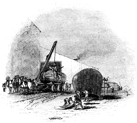
[24] If 22 square inches of piston surface be allowed to represent a horse-power, the power of an engine may always be computed by dividing the square of the diameter of the piston expressed in inches by 28. And, on the other hand, to find the diameter of piston which would correspond to any given power, multiply the number of horses' power by 28, and take the square root of the product. These rules, however, cannot be applied if the piston be supposed to move with any other velocity; since, in that case, the same amount of piston surface would cease to represent a horse-power, unless the effective pressure on the piston were at the same time changed.
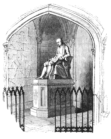
At the period when Watt, having connected himself in partnership with Boulton, went to reside at Soho, near Birmingham, a number of persons, some of whom have since attained great celebrity by their discoveries and their works, and all of whom were devoted to inquiries connected with the arts and sciences, resided in that neighbourhood. Among these may be mentioned Priestley, whose discoveries in physical science have rendered his name immortal; Darwin, the philosopher and poet; Withering, a distinguished physician and botanist; Keir, a chemist, who published a translation of Macquer, with annotations; Galton, the ornithologist; and Edgeworth, whose investigations respecting wheeled carriages and other subjects, have rendered him well known. A society was formed by these and other individuals, of which Boulton and Watt were leading members, the meetings of which were held monthly on the evening of full moon, and which was thence called the Lunar Society. At the meetings of this society, subjects connected with the arts and sciences were discussed, and out of those discussions occasionally arose suggestions not unattended with important and advantageous consequences. At one of these meetings, Darwin stated that he had discovered a pen formed with two quills, by means of which, at a single operation, an original and a copy of a letter might be produced. Watt almost instantly observed that he thought he could find a better expedient, and that he would turn it in his mind that night. By the next morning the COPYING PRESS was invented, for which he afterwards obtained a patent.
This machine, which is now so generally used in counting-houses, consists of a rolling-press, by which a leaf of thin paper, previously damped, is pressed upon the letter to be copied. The writing, of which the ink is not yet quite dry, leaves its impression upon the thin paper thus pressed upon [Pg303] it, and the copy taken in this manner is read through the semi-transparent paper. If a letter be written with ink suitable for this purpose, a copy may be taken at any time within several hours after the letter is written.
The method of heating apartments and buildings by steam, which has since been improved and brought into extensive use, was likewise brought forward by Watt. Although this contrivance had been previously pointed out by Sir Hugh Platt about the middle of the seventeenth century, and by Colonel Cooke in 1745, yet these suggestions remained barren. Mr. Watt gave detailed methods of heating buildings by steam[25]; and also invented a machine for drying linen by steam, a description of which he communicated to Dr. Brewster, which was read in December, 1824, before the Society for promoting Useful Arts in Scotland.[26]
But the circumstance, exclusive of those connected with the invention of the steam engine, which is by far the most memorable in the career of Watt, is the share which he had in the discovery of the composition of water. As this circumstance has recently excited much interest, and led to some controversy, we shall here state, as distinctly as possible, the leading facts connected with it.
Water, which was so long held to be a simple element, has, in modern times, been proved to be a substance consisting of two aeriform bodies or gases chemically combined. These two gases are those called in chemistry oxygen and hydrogen. If eight grains weight of oxygen be mixed with one grain weight of hydrogen, and the mixture be submitted to such effects as would cause the chemical combination of these two airs, it would be converted into nine grains weight of pure water.
If, on the other hand, nine grains weight of pure water be submitted to any conditions which would separate its constituent parts, the result would be eight grains weight of oxygen gas, and one grain weight of hydrogen gas. There are a variety of methods in physics by which these effects would be [Pg304] produced. It will be sufficient here to state one method of producing each of the above changes.
If eight grains weight of oxygen be inclosed in a strong vessel with one grain weight of hydrogen, all other substances being excluded, and the mixture be inflamed, an explosion will take place, the gases will disappear, and a small quantity of water will be the only substance remaining in the vessel. If this water be weighed, it will be found to weigh exactly nine grains.
It is known that the metals have a strong attraction for oxygen gas, and this attraction is promoted by elevating their temperature. If a glass tube be filled with iron wire heated to redness, and to one end of this tube a small vessel of boiling water be attached, the steam evolved from the water will force its way through the spaces between the red-hot wires in the tube, and would be expected to issue from the remote end; but if the substance issuing from the remote end of the tube be examined, it will be found to be not steam, but hydrogen gas. If the quantity of this gas be ascertained by weight, and also the quantity of weight lost by the vessel of water at the other end of the tube, it will be found that the loss of weight of the water by evaporation will be nine times the weight of the hydrogen which has issued from the remote end of the tube. If the weight of the tube with the wire contained in it be next ascertained, it will be found to be increased by eight times the weight of the hydrogen which has issued from its remote end. From this it follows that the weight of the hydrogen which has escaped from the tube, added to the increase of weight which has been given to the wire in the tube, makes up the whole weight of the water evaporated. If the wire in the tube be next examined, it will be found that it has suffered oxydation, or, in other words, that a new substance has been formed in it called the oxyde of iron,—such substance being a chemical compound formed of oxygen gas and iron.
It follows, therefore, that in this process the vapour of the water, in passing through the tube, has been decomposed, and that, having given up to the iron its oxygen, the hydrogen [Pg305] alone escaped from the other end; and for every nine grains weight of steam which passed through the tube, eight grains of oxygen have been combined with the iron, and one grain of hydrogen has escaped from the end of the tube.
Such are the class of effects on which the modern discovery of the composition of water has been based. The merit of that discovery has been shared between the celebrated English chemist, Cavendish, and the not less celebrated French chemist, Lavoisier, the chief merit, however, being ascribed to the former.
We shall now briefly state the facts which led to this discovery, with their dates, which will necessarily show the share which Watt had in it.
When pure hydrogen gas is burned in an atmosphere of common air, the process which takes place is now known to be nothing more than the chemical combination of the hydrogen with eight times its own weight of oxygen taken from the atmosphere, and the product of the combustion is a quantity of water nine times the weight of the hydrogen consumed. In the year 1776, Macquer, a well-known chemist of that day, having held a saucer of white porcelain over a flame of hydrogen which was burning at the mouth of a bottle, observed that no smoke was produced and no soot deposited on the saucer. On the other hand, he found that after the lapse of some time drops of a clear pellucid liquid were perceptible on the saucer: this liquid he submitted to analysis, and found it to be pure water. Macquer mentioned this fact without comment or inference. It did not occur to him that the water thus produced upon the saucer was a substance which contained the hydrogen, which disappeared upon combustion from the bottle.
On the 18th of April, 1781, Mr. Warltire addressed a letter to Dr. Priestley, dated Birmingham, which letter is published in Dr. Priestley's Experiments on Air, printed at Birmingham in 1781, in which Warltire informs Priestley that he had fired a mixture of hydrogen and common air in close glass vessels, and that, although previously to firing the mixture the vessels were clean and dry, a dewy deposit was [Pg306] observed afterwards on their sides. In fact, water was present which was not present before.
The mixture was in this case fired by passing an electric spark through the vessel; and it is now known that the effect produced was the combination of the hydrogen, which formed part of the mixture of airs in the vessel with the oxygen, which also formed part of the same mixture.
It appears, from expressions in Warltire's letter, that the same experiment had been previously made by Priestley, and the same result observed by him.
The inference deduced from this by Warltire, and apparently acquiesced in by Priestley, was, that whenever hydrogen was fired in atmospheric air, the moisture, which is always more or less sustained in the latter, was deposited; but neither of these chemists perceived the real cause of the production of the water.
In the beginning of 1783, and not later than the 21st of April, this experiment of Warltire and Priestley was repeated by Cavendish, with this difference, that, instead of exploding the mixture of hydrogen and common air, Cavendish exploded a mixture of hydrogen and oxygen. He observed that water was present after the explosion, but inferred nothing.
In a published paper dated April, 1783, Priestley announced a further and most important result of his experiments. This was, that in examining the weight of water produced by the explosion of a mixture of oxygen and hydrogen, that weight was found to be precisely equal to the sum of the weights of the two gases, which disappeared in the process.
Immediately on observing this, Priestley, being then, as has been already stated, Watt's near neighbour, communicated to the latter what he had observed; upon which Watt immediately, viz. by a letter dated the 26th of the same month, declared that the inevitable consequence which followed from Priestley's observations was, that water was a substance compounded of oxygen and hydrogen deprived of [Pg307] a quantity of heat which was previously latent in them.[27] The letter containing this inference was communicated immediately by Priestley to Sir Joseph Banks, then President of the Royal Society, to be laid before that body; and it is accordingly printed with its proper date in the 74th volume of the Philosophical Transactions.
About two months after the date of Mr. Watt's letter just quoted, Lavoisier made experiments on the combustion of oxygen and hydrogen, and read a memoir before the Academy of Sciences in Paris, in which his views of the formation of water by the combination of these gases were developed. This paper, by Lavoisier, was afterwards printed in the Memoirs of the Academy in the year 1784. The experiments are there stated to have been made in the month of June, 1783; and it is stated that Sir Charles Blagden, who was present at the experiments, told Lavoisier that Mr. Cavendish had already burned the same gases in close vessels, and obtained a very sensible quantity of water.
On the 15th of January, 1784, the celebrated paper by Cavendish, entitled "Experiments on Air," was read before the Royal Society, and in this paper the composition of water by the union of oxygen and hydrogen is explained.
In a controversy which afterwards ensued on the respective [Pg308] claims of Cavendish and Lavoisier to credit for the discovery of the composition of water, Sir Charles Blagden stated that he had told Lavoisier, in June, 1783, more than Lavoisier acknowledged, that he had not only told him that water was produced by the combustion of the gases, but that his information embraced the whole theory of the composition of water. This declaration of Blagden was subsequent in date to January, 1784, and there is no evidence of any explanation of this theory, verbal or otherwise, having been given by Cavendish, or any other person, antecedent to April, 1783.
From this brief statement of the facts and dates it will appear that the merit of the discovery of the FACT, that the weight of water resulting from the combustion of oxygen and hydrogen, is equal to the sum of the weights of the oxygen and hydrogen which disappear in the combustion, is due to Priestley; and that the merit of the INFERENCE from that fact, that water is a compound body, whose constituents are oxygen and hydrogen, is due to Watt.[28] Whether those who subsequently deduced the same inference, and promulgated the same theory, were or were not informed of Mr. Watt's solution of the phenomenon, or what credit may be due to any person, however eminent, who at any time posterior to Mr. Watt's letter to Priestley, asserted that they had, at a time antecedently to that, made the same inference without having published it, or communicated it in such a manner as to establish their claim upon rational and credible evidence, are questions which we shall not here discuss, being contented with establishing the right of Mr. Watt to the merit of the discovery of the THEORY which explained the FACT discovered by Priestley.
Even in his declining years, after he had withdrawn from the active pursuits of his business, the least excitement was sufficient to call into play the slumbering powers of his inventive genius. No object could present itself to his notice [Pg309] without receiving from that genius adaptation in form and construction to useful purposes. As an example of this restless activity of mind the following anecdote may be mentioned:—
A company at Glasgow had erected on the right bank of the Clyde extensive buildings and powerful engines for supplying water to the town. After this expense it was found that a source of water, of very superior quality, existed on the left bank of the river. To change the site of the establishment, after the expense which had been incurred in its erection could not be contemplated, and they therefore proposed to carry across the bottom of the river a flexible suction pipe, the mouth of which should terminate in the source from which the pure water was to be derived. This pipe was to be supported by a flooring constructed upon the bed of the river; but it was soon apparent that the construction of such a flooring on a shifting and muddy bottom, full of inequalities, and under several feet depth of water would require a greater expenditure of capital than could with propriety be afforded. In this difficulty the aged mechanician, for whom Glasgow itself had been the earliest stage of professional labour, was applied to, and instantly solved the problem. His attention is said to have been attracted by a lobster which had been served at table: he set himself about to contrive how, by mechanism, he could make an apparatus of iron with joints which should have all the flexibility of the tail of the lobster. He therefore proposed that an articulated suction-pipe, capable of accommodating itself to all the inequalities and to the possible changes of the bed of the river, should be carried across it; that this flexible pipe should be two feet in diameter, and one thousand feet in length. This project the company accordingly caused to be executed after the plans and drawings of Watt with the most complete success.[29]
[Pg310] Among the less prominent, though not less useful services rendered by Watt to his country, may be mentioned the introduction of the use of chlorine in bleaching. That invention of Berthollet was introduced into England by Watt after his visit to Paris at the close of the year 1786. He constructed all the necessary apparatus for it, directed its erection, and superintended its first performances. He then left it to his wife's father, Mr. Macgregor, to carry on the processes.
When the properties of the gases began to occupy the attention of chemists, attempts were made to apply them as a means of curing diseases of the lungs. Dr. Beddoes pursued this inquiry with great activity, and established, through the means of private subscription, at Clifton, an institution in which this method of cure was carefully investigated. The Pneumatic Institution (for so it was called) has been rendered celebrated for having at its head Humphry Davy, just then commencing his scientific career. Among its founders was also numbered James Watt. Not content, however, with affording the institution the sanction of his name, he designed and caused to be constructed, at Soho, the apparatus used for making the gases and administering them to the patients.
As the exalted powers of the mind of Watt, unfolded in his numerous mechanical and philosophical inventions and discoveries, have commanded the admiration and respect of his species, the affection and love of his fellow men would not have been less conciliated, had the qualities of his heart, as developed in his private and personal relations, been as well known as the products of his genius.
In the year 1764, Watt being then in the twenty-ninth year of his age, married his cousin, Miss Miller. At this time he had fallen into a state of despondency from his disappointments, which produced a serious attack of nervous illness. The accomplishments and superior understanding, the mildness of temper and goodness of disposition of his wife, soon restored him to health. Of this marriage four children, two sons and two daughters, were the issue. Two of these children died in infancy; another, a daughter, was married to Mr. Miller of Glasgow; and the fourth is the [Pg311] present Mr. James Watt. In September, 1773, while her husband was engaged in the design of the Caledonian canal in the North of Scotland, Mrs. Watt died in child-bed of a fifth child, who was still-born: "Would that I might here transcribe," says M. Arago, "in all their simple beauty, some lines of the journal in which he daily recorded his inmost thoughts, his fears, his hopes! Would that you could see him, after this heavy affliction, pausing on the threshold of that home, where 'His Kind Welcomer' awaited him no more; unable to summon courage to enter those rooms where he was never more to meet 'the Comfort of his Life!' Possibly, so faithful a picture of a very deep sorrow might at last put to silence those obstinate theorists, who, without being struck by the thousands of instances to the contrary, do yet refuse qualities of the heart to every man whose intellect has been fostered by the fertile, sublime, and imperishable truths of the exact sciences!"
After the lapse of some years Watt married Miss Macgregor, a person who is represented to have possessed qualities of mind which rendered her a companion every way suitable to her husband. This lady survived Watt, and died in 1832 at an advanced age. Two children were the issue of this second marriage.
In the year 1800 the extended patent right, which had been granted to Boulton and Watt for their improved engine, expired, and at this time Mr. Watt retired altogether from business. He was succeeded by his two sons, the present Mr. James Watt, and Gregory, one of the children of his second marriage. The works at Soho continued to be conducted by the present Mr. Boulton, the son of the partner of Mr. Watt, and the two Messrs. Watt. In 1804 Gregory Watt died at the age of twenty-seven, of a disease of the chest. This afflicting event was deeply felt by Mr. Watt; but he did not sink under it into that state of despondency in which he has been represented to have fallen by M. Arago. On the contrary, he continued to show the same activity of mind which had characterised his whole [Pg312] life; nor did he lose that interest which he always took in the pursuit of literature and in society. The state of his feelings under this affliction is shown by the following extracts from letters written by him at that time, which have been published by Mr. Muirhead.
"Heathfield, January 26th, 1805.
* * "I, perhaps, have said too much to you and Mrs. Campbell on the state of my mind. I, therefore, think it necessary to say that I am not low spirited; and were you here, you would find me as cheerful in the company of my friends as usual; my feelings for the loss of poor Gregory are not passion, but a deep regret that such was his and my lot.
"I know that all men must die, and I submit to the decrees of nature, I hope with due reverence to the Disposer of Events. Yet one stimulus to exertion is taken away, and, somehow or other, I have lost my relish for my usual avocations. Perhaps time may remedy that in some measure; meanwhile, I do not neglect the means of amusement which are in my power."
"Heathfield, April 8th, 1805.
* * "It is rather mortifying to see how easily the want of even the best of us is dispensed with in the world; but it is very well it should be so. We here, however, cannot help feeling a terrible blank in our family. When I look at my son's books, his writings and drawings, I always say to myself, where are the mind that conceived these things, and the hands that executed them? In the course of nature, he should have said so of mine; but it was otherwise ordered, and our sorrow is unavailing. As Catullus says:—
"But Catullus was a heathen; let us hope that he (G.) is now rejoicing in another and a better world, free from our cares, griefs, and infirmities. Some one has said, I shall not wholly die; and Gregory's name, his merits and virtues, will live at least as long as those do who knew him. You are not, from this, to conceive that we give way to grief; on the contrary, you will find us as cheerful as we ought to be, and as much disposed to enjoy the friends we have left as ever; but we should approach to brutes if we had no regrets."
Mr. Watt, at the date of these letters, had entered on his seventieth year, a period after which great mental exertions are rarely made. [Pg313]
In the summer of 1819, symptoms of indisposition manifested themselves which soon rendered Watt aware of his approaching dissolution. "I am very sensible," said he to his afflicted friends, "of the attachment you show me, and I hasten to thank you for it, as I am now come to my last illness." He died on the 25th of August, 1819. His remains were deposited in the church of Handsworth, near his estate of Heathfield. His son has raised over his grave a Gothic chapel, in the centre of which is placed a statue by Chantrey.
The personal character of Watt could not fail to excite the admiration and the love of those distinguished persons, whose pride and happiness it was to be admitted to a share in the friendship of the great engineer. Among these were reckoned some of the men who will leave upon the present age the deepest and most lasting impressions of their genius, and such persons have bequeathed to posterity the sentiments with which he inspired them. We cannot here do more justice to the personal character of the subject of this notice than by repeating the portraiture of it which has been given by three of the most distinguished of his friends, and of the most illustrious men of the present age.
At a meeting convened in 1824, for erecting a monument to Watt, Lord Brougham pronounced a speech, from which we extract the following observations:—
"I had the happiness of knowing Mr. Watt, for many years, in the intercourse of private life; and I will take upon me to bear a testimony in which all who had that gratification I am sure will join, that they who only knew his public merit, prodigious as that was, knew but half his worth. Those who were admitted to his society will readily allow that anything more pure, more candid, more simple, more scrupulously loving of justice, than the whole habits of his life and conversation, proved him to be, was never known in society. One of the most astonishing circumstances in this truly great man, was the versatility of his talents. His accomplishments were so various, the powers of his mind were so vast, and yet of such universal application, that it was hard to say whether we should most admire the extraordinary grasp of his understanding, or the accuracy of nice research with which he could bring it to bear upon the most minute objects of investigation. I forget of whom it was said, that his mind resembled the trunk of an elephant, which can pick up [Pg314] straws, and tear up trees by the roots. Mr. Watt, in some sort, resembled the greatest and most celebrated of his own inventions, of which we are at a loss whether most to wonder at the power of grappling with the mightiest objects, or of handling the most minute; so that, while nothing seems too large for its grasp, nothing seems too small for the delicacy of its touch, which can cleave rocks, and pour forth rivers from the bowels of the earth, and, with perfect exactness, though not with greater ease, fashion the head of a pin, or strike the impress of some curious die. Now, those who knew Mr. Watt, had to contemplate a man whose genius could create such an engine, and indulge in the most abstruse speculations of philosophy, and could at once pass from the most sublime researches of geology and physical astronomy, the formation of our globe, and the structure of the universe, to the manufacture of a needle or a nail; who could discuss, in the same conversation, and with equal accuracy, if not with the same consummate skill, the most forbidding details of art and the elegances of classical literature, the most abstruse branches of science and the niceties of verbal criticism.
"There was one quality in Mr. Watt which most honourably distinguished him from too many inventors, and was worthy of all imitation—he was not only entirely free from jealousy, but he exercised a careful and scrupulous self-denial, and was anxious not to appear, even by accident, as appropriating to himself that which he thought belonged to others. I have heard him refuse the honour universally ascribed to him, of being the inventor of the steam engine, and call himself simply its improver; though, in my mind, to doubt his right to that honour, would be as inaccurate as to question Sir Isaac Newton's claim to his greatest discoveries, because Descartes in mathematics, and Galileo in astronomy and mechanics, had preceded him; or to deny the merits of his illustrious successor, because galvanism was not his discovery, though, before his time, it had remained as useless to science as the instrument called a steam engine was to the arts before Mr. Watt. The only jealousy I have known him to betray, was with respect to others, in the nice adjustment he was fond of giving to the claims of inventors. Justly prizing scientific discovery above all other possessions, he deemed the title to it so sacred, that you might hear him arguing by the hour to settle disputed rights; and if you ever perceived his temper ruffled, it was when one man's invention was claimed by, or given to another; or when a clumsy adulation pressed upon himself that which he knew to be not his own."
In the preface to the Monastery Sir Walter Scott speaks of Watt in the following terms:—
"There were assembled about half a score of our northern lights. * * Amidst this company stood Mr. Watt, the man whose genius discovered the means of multiplying our national resources to a degree, perhaps, even beyond his own stupendous powers of calculation and combination; bringing the treasures of the abyss to the summit of the earth—giving the feeble arm of man the momentum of an Afrite—commanding manufactures to arise as the rod of the prophet produced water in the desert—affording the means of dispensing with that time and tide which wait for no man—and of sailing without that wind which defied the command and threats of Xerxes himself. This potent commander of the elements—this abridger of time and space—this magician, whose cloudy [Pg315] machinery has produced a change on the world, the effects of which, extraordinary as they are, are, perhaps, only now beginning to be felt—was not only the most profound man of science—the most successful combiner of powers, and calculator of numbers, as adapted to practical purposes—was not only one of the most generally well informed, but one of the best and kindest of human beings.
"There he stood, surrounded by the little band I have mentioned of northern literati, men not less tenacious, generally speaking, of their own fame and their own opinions, than the national regiments are supposed to be jealous of the high character which they have won upon service. Methinks I yet see and hear what I shall never see or hear again. In his eighty-second year, the alert, kind, benevolent old man, had his attention alive to every one's question, his information at every one's command.
"His talents and fancy overflowed on every subject. One gentleman was a deep philologist—he talked with him on the origin of the alphabet, as if he had been coeval with Cadmus; another a celebrated critic—you would have said the old man had studied political economy and belles lettres all his life. Of science it is unnecessary to speak—it was his own distinguished walk. And yet, Captain Clutterbuck, when he spoke with your countryman, Jedediah Cleishbotham, you would have sworn he had been coeval with Claverse and Burley, with the persecutors and persecuted, and could number every shot the dragoons had fired at the fugitive Covenanters. In fact, we discovered that no novel of the least celebrity escaped his perusal, and that the gifted man of science was as much addicted to the productions of your native country, in other words, as shameless and obstinate a peruser of novels, as if he had been a very milliner's apprentice of eighteen."
In the Edinburgh newspaper, called the Scotsman, of the 4th September, 1819, immediately after the decease of Watt, the following sketch was published from the pen of Lord Jeffrey:—
"This name fortunately needs no commemoration of ours; for he that bore it survived to see it crowned with undisputed and unenvied honours; and many generations will probably pass away before it shall have gathered 'all its fame.' We have said that Mr. Watt was the great improver of the steam engine; but, in truth, as to all that is admirable in its structure, or vast in its utility, he should rather be described as its inventor. It was by his inventions, that its action was so regulated as to make it capable of being applied to the finest and most delicate manufactures, and its power so increased, as to set weight and solidity at defiance. By his admirable contrivance, it has become a thing stupendous alike for its force and its flexibility—for the prodigious power which it can exert, and the ease, and precision, and ductility with which it can be varied, distributed, and applied. The trunk of an elephant, that can pick up a pin or rend an oak, is as nothing to it. It can engrave a seal, and crush masses of obdurate metal before it—draw out, without breaking, a thread as fine as gossamer, and lift a ship of war like a bauble in the air. It can embroider muslin, and forge anchors—cut steel into ribands, and impel loaded vessels against the fury of the winds and waves. [Pg316]
"It would be difficult to estimate the value of the benefits which these inventions have conferred upon this country. There is no branch of industry that has not been indebted to them; and, in all the most material, they have not only widened most magnificently the field of its exertions, but multiplied a thousand fold the amount of its productions. It is our improved steam engine that has fought the battles of Europe, and exalted and sustained, through the late tremendous contest, the political greatness of our land. It is the same great power which now enables us to pay the interest of our debt, and to maintain the arduous struggle in which we are still engaged (1819), with the skill and capital of countries less oppressed with taxation. But these are poor and narrow views of its importance. It has increased indefinitely the mass of human comforts and enjoyments, and rendered cheap and accessible all over the world the materials of wealth and prosperity. It has armed the feeble hand of man, in short, with a power to which no limits can be assigned; completed the dominion of mind over the most refractory qualities of matter; and laid a sure foundation for all those future miracles of mechanic power which are to aid and reward the labours of after generations. It is to the genius of one man, too, that all this is mainly owing; and certainly no man ever bestowed such a gift on his kind. The blessing is not only universal, but unbounded; and the fabled inventors of the plough and the loom, who were deified by the erring gratitude of their rude contemporaries, conferred less important benefits on mankind than the inventor of our present steam engine.
"This will be the fame of Watt with future generations; and it is sufficient for his race and his country. But to those to whom he more immediately belonged, who lived in his society and enjoyed his conversation, it is not, perhaps, the character in which he will be most frequently recalled—most deeply lamented—or even most highly admired. Independently of his great attainments in mechanics, Mr. Watt was an extraordinary, and in many respects a wonderful man. Perhaps no individual in his age possessed so much and such varied and exact information—had read so much, or remembered what he had read so accurately and well. He had infinite quickness of apprehension, a prodigious memory, and a certain rectifying and methodising power of understanding, which extracted something precious out of all that was presented to it. His stores of miscellaneous knowledge were immense; and yet less astonishing than the command he had at all times over them. It seemed as if every subject that was casually started in conversation with him, had been that which he had been last occupied in studying and exhausting;—such was the copiousness, the precision, and the admirable clearness of the information which he poured out upon it without effort or hesitation. Nor was this promptitude and compass of knowledge confined in any degree to the studies connected with his ordinary pursuits. That he should have been minutely and extensively skilled in chemistry and the arts, and in most of the branches of physical science, might perhaps have been conjectured; but it could not have been inferred from his usual occupations, and probably is not generally known, that he was curiously learned in many branches of antiquity, metaphysics, medicine, and etymology; and perfectly at home in all the details of architecture, music, and law. He was well acquainted, too, with most of the modern languages, and familiar with their most recent literature. Nor was it at all extraordinary to hear the great mechanician and engineer detailing and expounding, for hours together, [Pg317] the metaphysical theories of the German logicians, or criticising the measures or the matter of the German poetry.
"His astonishing memory was aided, no doubt, in a great measure, by a still higher and rarer faculty—by his power of digesting, and arranging in its proper place, all the information he received; and of casting aside and rejecting, as it were instinctively, whatever was worthless or immaterial. Every conception that was suggested to his mind seemed instantly to take its place among its other rich furniture, and to be condensed into the smallest and most convenient form. He never appeared, therefore, to be at all incumbered or perplexed with the verbiage of the dull books he perused, or to the idle talk to which he listened; but to have at once extracted, by a kind of intellectual alchemy, all that was worthy of attention, and to have reduced it, for his own use, to its true value and to its simplest form. And thus it often happened, that a great deal more was learned from his brief and vigorous account of the theories and arguments of tedious writers, than an ordinary student could ever have derived from the most painful study of the originals; and that errors and absurdities became manifest from the mere clearness and plainness of his statement of them, which might have deluded and perplexed most of his hearers without that invaluable assistance.
"It is needless to say that, with those vast resources, his conversation was at all times rich and instructive in no ordinary degree: but it was, if possible, still more pleasing than wise; and had all the charms of familiarity with all the substantial treasures of knowledge. No man could be more social in his spirit, less assuming or fastidious in his manners, or more kind and indulgent toward all who approached him. He rather liked to talk,—at least in his latter years; but though he took a considerable share of the conversation, he rarely suggested the topics on which it was to turn, but readily and quietly took up whatever was presented by those around him, and astonished the idle and barren propounders of an ordinary theme by the treasures which he drew from the mine they had unconsciously opened. He generally seemed, indeed, to have no choice or predilection for one subject of discourse rather than another; but allowed his mind, like a great cyclopædia, to be opened at any letter his associates might choose to turn up, and only endeavoured to select from his inexhaustible stores, what might be best adapted to the taste of his present hearers. As to their capacity he gave himself no trouble; and indeed such was his singular talent for making all things plain, clear, and intelligible, that scarcely any one could be aware of such a deficiency in his presence. His talk, too, though overflowing with information, had no resemblance to lecturing or solemn discoursing, but, on the contrary, was full of colloquial spirit and pleasantry. He had a certain quiet and grave humour which ran through most of his conversation; and a vein of temperate jocularity, which gave infinite zest and effect to the condensed and inexhaustible information which formed its main staple and characteristic. There was a little air of affected testiness, and a tone of pretended rebuke and contradiction, with which he used to address his younger friends, that was always felt by them as an endearing mark of his kindness and familiarity; and prized, accordingly, far beyond all the solemn compliments that ever proceeded from the lips of authority. His voice was deep and powerful, though he commonly spoke in a low and somewhat monotonous tone, which harmonised admirably with the weight and brevity of his observations, and set off to the greatest advantage the pleasant [Pg318] anecdotes, which he delivered with the same grave brow, and the same calm smile playing soberly on his lips. There was nothing of effort, indeed, or impatience, any more than of pride or levity, in his demeanour; and there was a finer expression of reposing strength, and mild self-possession in his manner, than we ever recollect to have met with in any other person. He had in his character the utmost abhorrence for all sorts of forwardness, parade, and pretensions; and, indeed, never failed to put all such impostures out of countenance, by the manly plainness and honest intrepidity of his language and deportment.
"In his temper and dispositions, he was not only kind and affectionate, but generous, and considerate of the feelings of all around him; and gave the most liberal assistance and encouragement to all young persons who showed any indications of talent, or applied to him for patronage or advice. His health, which was delicate from his youth upwards, seemed to become firmer as he advanced in years; and he preserved, up almost to the last moment of his existence, not only the full command of his extraordinary intellect, but all the alacrity of spirit and the social gaiety which had illumined his happiest days. His friends in this part of the country never saw him more full of intellectual vigour and colloquial animation—never more delightful or more instructive—than in his last visit to Scotland in autumn 1817. Indeed, it was after that time that he applied himself, with all the ardour of early life, to the invention of a machine for mechanically copying all sorts of sculpture and statuary; and distributed among his friends some of its earliest performances, as the productions of a young artist just entering on his eighty-third year.
"This happy and useful life came, at last, to a gentle close. He had suffered some inconvenience through the summer; but was not seriously indisposed till within a few weeks of his death. He then became perfectly aware of the event which was approaching; and with his usual tranquillity and benevolence of nature, seemed only anxious to point out to the friends around him, the many sources of consolation which were afforded by the circumstances under which it was about to take place. He expressed his sincere gratitude to Providence for the length of days with which he had been blessed, and his exemption from most of the infirmities of age; as well as for the calm and cheerful evening of life that he had been permitted to enjoy, after the honourable labours of the day had been concluded. And thus, full of years and honours, in all calmness and tranquillity, he yielded up his soul without pang or struggle; and passed from the bosom of his family to that of his God."
The English nation has ever shown itself insensible to the claims of genius and high intellectual endowments, except where the results have been brought directly to bear in statesmanship or war. Of this inability to appreciate the highest order of intellectual excellence Watt affords a striking example. When it was suggested to the British government by those better capable than that government was of appreciating the genius of this great man, that the nation would do itself honour by erecting a splendid monument at his own [Pg319] cost to him to whom it was so deeply indebted for the extension of its resources and the augmentation of its power, the reply was that such a measure could not be adopted as it might be drawn into a precedent in like cases thereafter! A precedent in like cases!! When will the time arrive when the world will produce a like case? The monument which has been erected in Westminster Abbey was in fact raised by private subscription, the nation having thus stigmatised itself through the act of its government with the everlasting disgrace of refusing the honour proposed to it. The other statues and monuments which have been erected to this great man, have been for the most part raised by the filial piety and the never-dying affection and veneration of the present Mr. James Watt. A statue has been presented by him to the University of Glasgow, and placed in one of the halls of that college. The inhabitants of Greenock have also erected a marble statue of Watt, for which, and for a library, a building has been erected at the expense of about 3,500l. which has been defrayed by Mr. James Watt. A colossal bronze statue has been erected on a handsome granite pedestal, standing at one of the corners of George Square, Glasgow. The monument in Westminster Abbey, erected by the subscription raised at the public meeting already alluded to, is a colossal statue of Carrara marble, by Chantrey.
Watt was elected a fellow of the Royal Society of Edinburgh in 1784; of the Royal Society of London in 1785; a member of the Batavian Society in 1787; and a corresponding member of the Institut of France in 1808. The degree of Doctor of Laws was conferred upon him by the University of Glasgow, in 1806; and in 1814, the highest scientific honour which can be attained by a philosopher, was conferred on him by the Academy of Sciences of the Institut of France, who nominated him one of its eight foreign associates.
On the pedestal of the monument in Westminster Abbey is engraved the following inscription from the pen of Lord Brougham:— [Pg320]

[25] See Buchanan on the Economy of Fuel and Management of Heat, especially as it relates to heating and drying by means of Steam.
[26] See Brewster's Edinburgh Encyclopædia, article Steam-drying Machine.
[27] The following are the words in which Watt makes this remarkable announcement to Priestley:—
"Let us now consider what obviously happens in the deflagration of the inflammable (hydrogen) and dephlogisticated air (oxygen). These two kinds of air unite with violence; they become red hot, and upon cooling, totally disappear. When the vessel is cooled, a quantity of water is found in it equal to the weight of the air employed. This water is then the only remaining product of the process; and water, light, and heat are all the products.
"Are we not then authorised to conclude, that water is composed of dephlogisticated air (oxygen) and phlogiston (hydrogen), deprived of part of their latent or elementary heat; that dephlogisticated or pure air (oxygen) is composed of water deprived of its phlogiston (hydrogen), and united to elementary heat and light; and that the latter are contained in it in a latent state, so as not to be sensible to the thermometer or to the eye; and if light be only a modification of heat, or a circumstance attending it, or a component part of the inflammable air (hydrogen), then pure or dephlogisticated air (oxygen) is composed of water deprived of its phlogiston (hydrogen), and united to elementary heat."
[28] Those who desire to investigate this controversy more in detail will find very full information on the subject in the Translation of Arago's Eloge, with notes and appendix by J. P. Muirhead, Esq. Murray, London, 1839.
[29] An account of this remarkable apparatus, accompanied by an engraving made from a drawing supplied by Watt, was communicated by Sir John Robison to the Edinburgh Philosophical Journal in 1820. See vol. iii, p. 60.
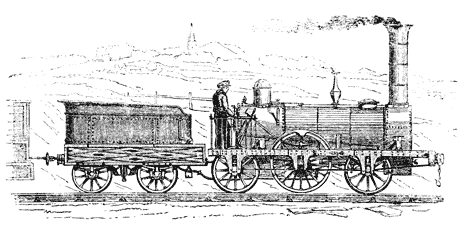
LOCOMOTIVE ENGINES ON RAILWAYS.
We are not, however, to understand that every engine, in which steam is used of a pressure exceeding that of the atmosphere, is what is meant by an high-pressure engine; for in the ordinary engines in common use, constructed on Watt's principle, the safety-valve is loaded with from 3 to 5 lbs. on the square inch; and in Woolf's engines, the steam is produced under a pressure of 40 lbs. on the square inch. These would therefore be more properly called condensing engines than low-pressure engines; a term quite inapplicable to those of Woolf. In fact, by high-pressure engines is meant engines in which no vacuum is produced, and, therefore, in which the piston works against a pressure equal to that of the atmosphere.
In these engines the whole of the condensing apparatus, viz. the cold-water cistern, condenser, air-pump, cold-water pump, &c., are dispensed with, and nothing is retained except the boiler, cylinder, piston, and valves. Consequently, such an engine is small, light, and cheap. It is portable also, and may be moved, if necessary, along with its load, and is therefore well adapted to locomotive purposes.
A (fig. 82.) is the boiler, with the furnace beneath it; C C are two cylinders with solid pistons P P′, connected with the working-beams B B′, to which are attached the pump-rods R R′, of two forcing pumps F F′, which communicate with a great force-pipe S; G is a four-way cock (66.) already described. In the position in which it stands in the figure, the steam issues from below the piston P into the atmosphere, and the piston is descending by its own weight; steam from the boiler is at the same time pressing up the piston P′, with a force equal to the difference between the pressure of the steam and that of the atmosphere. Thus the piston R of the forcing-pump is being drawn up, and the piston P′ is forcing the piston R′ down, and thereby driving water into the force-pipe [Pg324] S. On the arrival of the piston P at the bottom of the cylinder C, and P′ at the top of the cylinder C′, the position of the cock is changed as represented in fig. 83. The steam, which has just pressed up the piston P′, is allowed to escape into the atmosphere, while the steam, passing from the boiler below the piston P, presses it up, and thus P ascends by the steam pressure, and P′ descends by its own weight. By these means the piston R is forced down, driving before it the water in the pump-cylinder into the force-pipe S, and the piston R′ is drawn up to allow the other pump-cylinder to be re-filled; and so the process is continued.
A valve is placed in the bottom of the force-pipes, to prevent the water which has been driven into it from returning. This valve opens upwards; and, consequently, the weight of the water pressing upon it only keeps it more effectually closed. On each descent of the piston, the pressure transmitted to the valve acting upwards being greater than the weight of the water resting upon it, forces it open, and an increased quantity of water is introduced.
The boiler A B is a cylinder with flat circular ends. The fire-place is constructed in the following manner:—A tube enters the cylindrical boiler at one end; and, proceeding onwards near the other extremity, is turned and recurved, so as to be carried back parallel to the direction in which it entered. It is thus conducted out of the boiler, at another part of the same end at which it entered. One of the ends of this tube communicates with the chimney E, which is carried upwards as represented in the figure. The other mouth is furnished [Pg325] with a door; and in it is placed the grate, which is formed of horizontal bars, dividing the tube into two parts; the upper part forming the fire-place, and the lower the ash-pit. The fuel is maintained in a state of combustion, on the bars, in that part of the tube represented at C D; and the flame is carried by the draught of the chimney round the curved flue, and issues at E into the chimney. The flame is thus conducted through the water, so as to expose the latter to as much heat as possible.
A section of the cylinder is represented at F, immersed in the boiler, except a few inches of the upper end, where the four-way cock G is placed for regulating the admission of the steam. A tube is represented at H, which leads from this four-way cock into the chimney; so that the waste steam, after working the piston, is carried off through this tube, and passes into the chimney. The upper end of the piston-rod is furnished with a cross-bar, which is placed in a direction at right angles to the length of the boiler, and also to the [Pg326] piston-rod. This bar is guided in its motion by sliding on two iron perpendicular rods fixed to the sides of the boiler, and parallel to each other. To the ends of this cross-bar are joined two connecting rods, the lower ends of which work two cranks fixed on an axis extending across and beneath the boiler, and immediately under the centre of the cylinder. This axis is sustained in bearings formed in the legs which support the boiler, and upon its extremity is fixed the fly-wheel as represented at B. A large-toothed wheel is placed on this axis; which, being turned with the cranked axle, communicates motion to other wheels; and through them, to any machinery which the engine may be applied to move.
As the four-way cock is represented in the figure, the steam passes from the boiler through the curved passage G above the piston, while the steam below the piston is carried off through a tube which does not appear in the figure, by which it is conducted to the tube H, and thence to the chimney. The steam, therefore, which passes above the piston presses it downwards; while the pressure upwards does not exceed that of the atmosphere. The piston will therefore descend with a force depending on the excess of the pressure of the steam produced in the boiler above the atmospheric pressure. When the piston has arrived at the bottom of the cylinder, the cock is made to assume the position represented in fig. 85. This effect is produced by the motion of the piston-rod. The steam now passes from above the piston, through the tube H, into the chimney, while the steam from the boiler is conducted through another tube below the piston. The pressure above the piston, in this case, does not exceed that of the atmosphere; while the pressure below it will be that of the steam in the boiler. The piston will therefore ascend with the difference of these pressures. On the arrival of the piston at the top of the cylinder, the four-way cock is again turned to the position represented in fig. 85., and the piston again descends; and in the same manner the process is continued. A safety-valve is placed on the boiler at V, loaded with a weight W, proportionate [Pg327] to the strength of the steam with which it is proposed to work.
In the engines now described, this valve was frequently loaded at the rate of from 60 to 80 lbs. on the square inch. As the boilers of high-pressure engines were considered more liable to accidents from bursting than those in which steam of a lower pressure was used, greater precautions were taken against such effects. A second safety-valve was provided, which was not left in the power of the engine-man. By this means he had a power to diminish the pressure of the steam, but could not increase it beyond the limit determined by the valve which was removed from his interference. The greatest cause of danger, however, arose from the water in the boiler being consumed by evaporation faster than it was supplied; and therefore falling below the level of the tube containing the furnace. To guard against accidents arising from this circumstance, a hole was bored in the boiler, at a certain depth, below which the water should not be allowed to fall; and in this hole a plug of metal was soldered with lead, or with some other metal, which would fuse at that temperature which would expose the boiler to danger. Thus, in the event of the water being exhausted, so that its level would fall below the plug, the heat of the furnace would immediately melt the solder, and the plug would fall out, affording a vent for the steam, without allowing the boiler to burst. The mercurial steam-gauge, already described, was also used as an additional security. When the force of the steam exceeded the length of the column of mercury which the tube would contain, the mercury would be blown out, and the tube would give vent to the steam. The water by which the boiler was replenished was forced into it by a pump worked by the engine. In order to economise the heat, this water was contained in a tube T, which surrounded the pipe H. As the waste steam, after working the piston, passed off through H, it imparted a portion of its heat to the water contained in the tube T, which was thus warmed to a certain temperature before it was forced into the boiler by the pump. Thus a part of the heat, which was originally [Pg328] carried from the boiler in the form of steam, was returned again to the boiler with the water with which it was fed.
It is evident that engines constructed in this manner may be applied to all the purposes to which the condensing engines are applicable.
The astonishment with which such performances must be viewed, might be qualified, if the art of transport by steam on railways had been matured, and had attained that full state of perfection which such an art is always capable of receiving from long experience, aided by great scientific knowledge, and the unbounded application of capital. But such is not the present case. The art of constructing locomotive engines, so far from having attained a state of maturity, has not even emerged from its infancy. So complete was the ignorance of its powers which prevailed, even among engineers, previous to the opening of the Liverpool railway, that the transport of heavy goods was regarded as the chief object of the undertaking, and its principal source of revenue. The incredible speed of transport, effected even in the very first experiments in 1830, burst upon the public, and on the scientific world, with all the effect of a new and unlooked-for phenomenon. On the unfortunate occasion which deprived this country of Mr. Huskisson, the wounded body of that statesman was transported a distance of about fifteen miles in twenty-five minutes, being at the rate of thirty-six miles an hour. The revenue of the road arising from passengers since its opening, [Pg330] has, contrary to all that was foreseen, been nearly double that which has been derived from merchandise. So great was the want of experience in the construction of engines, that the company was at first ignorant whether they should adopt large steam engines fixed at different stations on the line, to pull the carriages from station to station, or travelling engines to drag the loads the entire distance. Having decided on the latter, they have, even to the present moment, laboured under the disadvantage of the want of that knowledge which experience alone can give. The engines have been constantly varied in their weight and proportions, in their magnitude and form, as the experience of each successive month has indicated. As defects became manifest they were remedied; improvements suggested were adopted; and each year produced engines of such increased power and efficiency, that their predecessors were abandoned, not because they were worn out, but because they had been outstripped in the rapid march of improvement. Add to this, that only one species of travelling engine has been effectively tried; the capabilities of others remain still to be developed; and even that form of engine which has received the advantage of a course of experiments on so grand a scale to carry it towards perfection, is far short of this point, and still has defects, many of which, it is obvious, time and experience will remove.
If, then, the locomotive engine, subject thus to all the imperfections inseparable from a novel contrivance—with the restrictions on the free application of skill and capital, arising from the nature of the monopolies granted to railway companies—with the disadvantage of very limited experience, the great parent of practical improvement, having been submitted to experiments hitherto only on a limited scale, and confined almost to one form of machine;—if, under such disadvantages, such effects have been produced as are now daily witnessed by the public, what may not be looked for from this extraordinary power when the enterprise of the country shall be more unfettered—when greater fields of experience are opened—when time, ingenuity, and capital have removed or diminished existing imperfections, and have brought to light new and more powerful principles? This is not mere speculation [Pg331] on abstract possibilities, but refers to what is in actual progress. The points of greatest wealth and population—the centres of largest capital and most active industry throughout the country—will soon be connected by lines of railway; and various experiments are proposed, with more or less prospect of success, for the application of steam engines on stone roads where the intercourse is not sufficient to render railways profitable.
The important commercial and political effects attending such increased facility and speed in the transport of persons and goods, are too obvious to require any very extended notice here. A part of the price (and in many cases a considerable part) of every article of necessity or luxury, consists of the cost of transporting it from the producer to the consumer; and consequently every abatement or saving in this cost must produce a corresponding reduction in the price of every article transported; that is to say, of every thing which is necessary for the subsistence of the poor, or for the enjoyment of the rich—of every comfort, and of every luxury of life. The benefit of this will extend, not to the consumer only, but to the producer: by lowering the expense of transport of the produce, whether of the soil or of the loom, a less quantity of that produce will be spent in bringing the remainder to market, and consequently a greater surplus will reward the labour of the producer. The benefit of this will be felt even more by the agriculturist than by the manufacturer; because the proportional cost of transport of the produce of the soil is greater than that of manufactures. If two hundred quarters of corn be necessary to raise four hundred, and one hundred more be required to bring the four hundred to market, then the net surplus will be one hundred. But if by the use of steam carriages the same quantity can be brought to market with an expenditure of fifty quarters, then the net surplus will be increased from one hundred to one hundred and fifty quarters; and either the profit of the farmer, or the rent of the landlord, must be increased by the same amount.
But the agriculturist would not merely be benefited by an increased return from the soil already under cultivation. Any [Pg332] reduction in the cost of transporting the produce to market would call into cultivation tracts of inferior fertility, the returns from which would not at present repay the cost of cultivation and transport. Thus land would become productive which is now waste, and an effect would be produced equivalent to adding so much fertile soil to the present extent of the country. It is well known, that land of a given degree of fertility will yield increased produce by the increased application of capital and labour. By a reduction in the cost of transport, a saving will be made which may enable the agriculturist to apply to tracts already under cultivation the capital thus saved, and thereby increase their actual production. Not only, therefore, would such an effect be attended with an increased extent of cultivated land, but also with an increased degree of cultivation in that which is already productive.
It has been said, that in Great Britain there are above a million of horses engaged in various ways in the transport of passengers and goods, and that to transport each horse requires as much land as would, upon an average, support eight men. If this quantity of animal power were displaced by steam engines, and the means of transport drawn from the bowels of the earth, instead of being raised upon its surface, then, supposing the above calculation correct, as much land would become available for the support of human beings as would suffice for an additional population of eight millions; or, what amounts to the same, would increase the means of support of the present population by about one third of the present available means. The land which now supports horses for transport would then support men, or produce corn for food.
The objection that a quantity of land exists in the country capable of supporting horses alone, and that such land would be thrown out of cultivation, scarcely deserves notice here. The existence of any considerable quantity of such land is extremely doubtful. What is the soil which will feed a horse and not feed oxen or sheep, or produce food for man? But even if it be admitted that there exists in the country a small portion of such land, that portion cannot exceed, nor indeed equal, what would be sufficient for the number of horses [Pg333] which must after all continue to be employed for the purposes of pleasure, and in a variety of cases where steam must necessarily be inapplicable. It is to be remembered, also, that the displacing of horses in one extensive occupation, by diminishing their price must necessarily increase the demand for them in others.
The reduction in the cost of transport of manufactured articles, by lowering their price in the market, will stimulate their consumption. This observation applies of course not only to home but to foreign markets. In the latter we already in many branches of manufactures command a monopoly. The reduced price which we shall attain by cheapness and facility of transport will still further extend and increase our advantages. The necessary consequence will be, an increased demand for manufacturing population; and this increased population again reacting on the agricultural interests, will form an increased market for that species of produce. So interwoven and complicated are the fibres which form the texture of the highly civilised and artificial community in which we live, that an effect produced on any one point is instantly transmitted to the most remote and apparently unconnected parts of the system.
The two advantages of increased cheapness and speed, besides extending the amount of existing traffic, call into existence new objects of commercial intercourse. For the same reason that the reduced cost of transport, as we have shown, calls new soils into cultivation, it also calls into existence new markets for manufactured and agricultural produce. The great speed of transit which has been proved to be practicable, must open a commerce between distant points in various articles, the nature of which does not permit them to be preserved so as to be fit for use beyond a certain time. Such are, for example, many species of vegetable and animal food, which at present are confined to markets at a very limited distance from the grower or feeder. The truth of this observation is manifested by the effects which have followed the intercourse by steam on the Irish Channel. The western towns of England have become markets for a prodigious quantity of Irish produce, which it had been previously [Pg334] impossible to export. If animal food be transported alive from the grower to the consumer, the distance of the market is limited by the power of the animal to travel, and the cost of its support on the road. It is only particular species of cattle which bear to be carried to market on common roads and by horse carriages. But the peculiar nature of a railway, the magnitude and weight of the loads which may be transported on it, and the prodigious speed which may be attained, render the transport of cattle, of every species, to almost any distance, both easy and cheap. In process of time, when the railway system becomes extended, the metropolis and populous towns will therefore become markets, not as at present to districts within limited distances of them, but to the whole country.
The moral and political consequences of so great a change in the powers of transition of persons and intelligence from place to place are not easily calculated. The concentration of mind and exertion which a great metropolis always exhibits, will be extended in a considerable degree to the whole realm. The same effect will be produced as if all distances were lessened in the proportion in which the speed and cheapness of transit are increased. Towns at present removed some stages from the metropolis, will become its suburbs; others, now at a day's journey, will be removed to its immediate vicinity; business will be carried on with as much ease between them and the metropolis, as it is now between distant points of the metropolis itself. Let those who discard speculations like these as wild and improbable, recur to the state of public opinion, at no very remote period, on the subject of steam navigation. Within the memory of persons who have not yet passed the meridian of life, the possibility of traversing by the steam engine the channels and seas that surround and intersect these islands, was regarded as the dream of enthusiasts. Nautical men and men of science rejected such speculations with equal incredulity, and with little less than scorn for the understanding of those who could for a moment entertain them. Yet we have witnessed steam engines traversing not these channels and seas alone, but sweeping the face of the waters round every coast in Europe. The [Pg335] seas which interpose between our Asiatic dominions and Egypt, and those which separate our own shores from our West Indian possessions, have offered an equally ineffectual barrier to its powers, and the establishment of a regular steam communication between the capitals of the Old and New World has ceased to be a question of practicability, having become merely one of commercial profit. If steam be not used as the only means of connecting the most distant points of our planet, it is not because it is inadequate to the accomplishment of that end, but because the supply of the material, from which at the present moment it derives its powers, is restricted by local and accidental circumstances.[30]
We propose in the present chapter to lay before our readers some account of the means whereby the effects above referred to have been produced; of the manner and degree in which the public have availed themselves of these means; and of the improvements of which they seem to us to be susceptible.
It is obvious that both of these effects may be partially produced; the adhesion of the wheel to the road may be insufficient to prevent slipping altogether, and yet it may be sufficient to prevent the wheel from slipping as fast as it revolves. Under such circumstances the carriage would advance and the wheel would slip. The progressive motion of the carriage during one complete revolution of the wheel would be equal to the difference between the complete circumference of the wheel and the portion through which in one revolution it has slipped.
When the construction of travelling steam engines first engaged the attention of engineers, and for a considerable period afterwards, a notion was impressed upon their minds that the adhesion between the face of the wheel and the surface of the road must necessarily be of very small amount, and that in every practical case the wheels thus driven would either slip altogether, and produce no advance of the carriage, or that a considerable portion of the impelling power would be lost by the partial slipping or sliding of the wheels. It is singular that it should never have occurred to the many ingenious persons who for several years were engaged in such experiments and speculations, to ascertain by experiment the actual amount of adhesion in any particular case between the wheels and the road. Had they done so, we should probably now have found locomotive engines in a more advanced state than that to which they have attained.
To remedy this imaginary difficulty, Messrs. Trevethick and Vivian proposed to make the external rims of the wheels rough and uneven, by surrounding them with projecting heads of nails or bolts, or by cutting transverse grooves on them. They proposed, in cases where considerable elevations were to be ascended, to cause claws or nails to project from the surface during the ascent, so as to take hold of the road. [Pg337]
In seven years after the construction of the first locomotive engine by these engineers, another locomotive engine was constructed by Mr. Blinkensop, of Middleton Colliery, near Leeds. He obtained a patent, in 1811, for the application of a rack-rail. The railroad thus, instead of being composed of smooth bars of iron, presented a line of projecting teeth, like those of a cog-wheel, which stretched along the entire distance to be travelled. The wheels on which the engine rolled were furnished with corresponding teeth, which worked in the teeth of the railroad, and, in this way, produced a progressive motion in the carriage.
The next contrivance for overcoming this fictitious difficulty, was that of Messrs. Chapman, who, in the year 1812, obtained a patent for working a locomotive engine by a chain extending along the middle of the line of railroad, from the one end to the other. This chain was passed once round a grooved wheel under the centre of the carriage; so that, when this grooved wheel was turned by the engine, the chain being incapable of slipping upon it, the carriage was consequently advanced on the road. In order to prevent the strain from acting on the whole length of the chain, its links were made to fall upon upright forks placed at certain intervals, which between those intervals sustained the tension of the chain produced by the engine. Friction-rollers were used to press the chain into the groove of the wheel, so as to prevent it from slipping. This contrivance was soon abandoned, for the very obvious reason that a prodigious loss of force was incurred by the friction of the chain.
The following year, 1813, produced a contrivance of singular ingenuity, for overcoming the supposed difficulty arising from the want of adhesion between the wheels and the road. This was no other than a pair of mechanical legs and feet, which were made to walk and propel in a manner somewhat resembling the feet of an animal.
A sketch of these propellers is given in fig. 86. A is the carriage moving on the railroad, L and L′ are the legs, F and F′ the feet. The foot F has a joint at O, which corresponds to the ankle; another joint is placed at K, which corresponds to the knee; and a third is placed at L, which corresponds to [Pg338] the hip. Similar joints are placed at the corresponding letters in the other leg. The knee-joint K is attached to the end of the piston of the cylinder. When the piston, which is horizontal, is pressed outwards, the leg L presses the foot F against the ground, and the resistance forces the carriage A onwards. As the carriage proceeds, the angle K at the knee becomes larger, so that the leg and thigh take a straighter position; and this continues until the piston has reached the end of its stroke. At the hip L there is a short lever L M, the extremity of which is connected by a cord or chain with a point S, placed near the shin of the leg. When the piston is pressed into the cylinder, the knee K is drawn towards the engine, and the cord M S is made to lift the foot F from the ground; to which it does not return until the piston has arrived at the extremity of the cylinder. On the piston being again driven out of the cylinder, the foot F, being placed on the road, is pressed backwards by the force of the piston-rod at K; but the friction of the ground preventing its backward motion, the re-action causes the engine to advance: and in the same manner this process is continued.
Attached to the thigh at N, above the knee, by a joint, is a horizontal rod N R, which works a rack R. This rack has beneath it a cog-wheel. This cog-wheel acts in another rack below it. By these means, when the knee K is driven from the engine, the rack R is moved backwards; but the cog-wheel acting on the other rack beneath it, will move the latter in the contrary direction. The rack R being then moved in the [Pg339] same direction with the knee K, it follows that the other rack will always be moved in a contrary direction. The lower rack is connected by another horizontal rod with the thigh of the leg L F′, immediately above the knee at N′. When the piston is forced inwards, the knee K′ will thus be forced backwards; and when the piston is forced outwards, the knee K′ will be drawn forwards. It therefore follows, that the two knees K and K′ are pressed alternately backwards and forwards. The foot F′, when the knee K′ is drawn forward, is lifted by the means already described for the foot F.
It will be apparent, from this description, that the piece of mechanism here exhibited is a contrivance derived from the motion of the legs of an animal, and resembling in all respects the fore legs of a horse. It is however to be regarded rather as a specimen of great ingenuity than as a contrivance of practical utility.
In 1814, an engine was constructed at Killingworth, by Mr. Stephenson, having two cylinders with a cylindrical [Pg340] boiler, and working two pair of wheels, by cranks placed at right angles; so that when the one was in full operation, the other was at its dead points. By these means the propelling power was always in action. The cranks were maintained in this position by an endless chain, which passed round two cogged wheels placed under the engine, and which were fixed on the same axles on which the wheels were placed. The wheels in this case were fixed on the axles, and turned with them.
This engine is represented in fig. 87., the sides being open, to render the interior mechanism visible. A B is the cylindrical boiler; C C are the working cylinders; D E are the cogged wheels fixed on the axle of the wheels of the engine, and surrounded by the endless chain. These wheels being equal in magnitude, perform their revolutions in the same time; so that, when the crank F descends to the lowest point, the crank G rises from the lowest point to the horizontal position D; and, again, when the crank F rises from the lowest point to the horizontal position E, the other crank rises to the highest point; and so on. A very beautiful contrivance was adopted in this engine, by which it was suspended on springs of steam. Small cylinders, represented at H, are screwed by flanges to one side of the boiler, and project within it a few inches; they have free communication at the top with the water or steam of the boiler. Solid pistons are represented at I, which move steam-tight in these [Pg341] cylinders; the cylinders are open at the bottom, and the piston-rods are screwed on the carriage of the engine, over the axle of each pair of wheels, the pistons being presented upwards. As the engine is represented in the figure, it is supported on four pistons, two at each side. The pistons are pressed upon by the water or steam which occupies the upper chamber of the cylinder; and the latter being elastic in a high degree, the engine has all the advantage of spring suspension. The defect of this method of supporting the engine is, that when the steam loses that amount of elasticity necessary for the support of the machine, the pistons are forced into the cylinders, and the bottoms of the cylinders bear upon them. All spring suspension is then lost. This mode of suspension has consequently since been laid aside.
In an engine subsequently constructed by Mr. Stephenson, for the Killingworth railroad, the mode adopted of connecting the wheels by an endless chain and cog-wheels was abandoned; and the same effect was produced by connecting the two cranks by a straight rod. All such contrivances, however, have this great defect, that, if the fore and hind wheels be not constructed with dimensions accurately equal, there must necessarily be a slipping or dragging on the road. The nature of the machinery requires that each wheel should perform its revolution exactly in the same time; and consequently, in doing so, must pass over exactly equal lengths of the road. If, therefore, the circumference of the wheels be not accurately equal, that wheel which has the lesser circumference must be dragged along so much of the road as that by which it falls short of the circumference of the greater wheel; or, on the other hand, the greater wheel must be dragged in the opposite direction, to compensate for the same difference. As no mechanism can accomplish a perfect equality in four, much less in six, wheels, it may be assumed that a great portion of that dragging effect is a necessary consequence of the principle of this machine; and even were the wheels, in the first instance, accurately constructed, it is not possible that their wear could be so exactly uniform as to continue equal.
The steam engine may be applied, by two distinct methods, to move waggons either on a turnpike road or on a railway. By the one method the steam engine is fixed, and draws the carriage or train of carriages towards it by a chain extending the whole length of road on which the engine works. By this method the line of road over which the transport is conducted is divided into a number of short intervals, at the extremity of each of which an engine is placed. The waggons or carriages, when drawn by any engine to its own station, are detached, and connected with the extremity of the chain worked by the next stationary engine; and thus the journey is performed, from station to station, by separate engines. By the other method the same engine draws the load the whole journey, travelling with it.
The Directors of the Liverpool and Manchester railroad, when that work was advanced towards its completion, employed, in the spring of the year 1829, Messrs. Stephenson and Lock, and Messrs. Walker and Rastrick, experienced engineers, to visit the different railways, where practical information respecting the comparative effects of stationary and locomotive engines was likely to be obtained; and from these gentlemen they received reports on the relative merits, according to their judgment of the two methods. The particulars of their calculations are given at large in the valuable work of Mr. Nicholas Wood on railways; to which we refer the reader, not only on this, but on many other subjects connected with the locomotive steam engine, into which it would be foreign to our object to enter. The result of the comparison of the two systems was, that the capital [Pg343] necessary to be advanced to establish a line of stationary engines was considerably greater than that which was necessary to establish an equivalent power in locomotive engines; that the annual expense by the stationary engines was likewise greater; and that, consequently, the expense of transport by the latter was greater, in a like proportion. The subjoined table exhibits the results numerically:—
| Capital, £ s. d. |
Annual Expense, £ s. d. |
Expense of taking a Ton of Goods a Mile, penny | |
|---|---|---|---|
| Locomotive engines | 58,000 0 0 | 25,517 8 2 | 0·164 |
| Stationary engines | 121,496 7 0 | 42,031 16 5 | 0·269 |
| Locomotive system less | 63,496 7 0 | 16,514 8 3 | 0·105 |
On the score of economy, therefore, the system of locomotive engines was entitled to a preference; but there were other considerations which conspired with this to decide the choice of the Directors in its favour. An accident occurring in any part of a road worked by stationary engines must necessarily produce a total suspension of work along the entire line. The most vigilant and active attention on the part of every workman, however employed, in every part of the line, would therefore be necessary; but, independently of this, accidents arising from the fracture or derangement of any of the chains, or from the suspension of the working of any of the fixed engines, would be equally injurious, and would effectually stop the intercourse along the line. On the other hand, in locomotive engines an accident could only affect the particular train of carriages drawn by the engine to which the accident might occur; and even then the difficulty could be remedied by having a supply of spare engines at convenient stations along the line. It is true that the probability of accident is, perhaps, less in the stationary than in the locomotive system; but the injurious consequences, when accident does happen, are prodigiously greater in the former. "The one system," says Mr. Walker, "is like a chain extending from Liverpool to Manchester, the failure [Pg344] of a single link of which would destroy the whole; while the other is like a number of short and unconnected chains," the destruction of any one of which does not interfere with the effect of the others, and the loss of which may be supplied with facility.
The decision of the Directors was, therefore, in favour of locomotive engines; and their next measure was to devise some means by which the inventive genius of the country might be stimulated to supply them with the best possible form of engines for this purpose. With this view, it was proposed and carried into effect to offer a prize for the best locomotive engine which might be produced under certain proposed conditions, and to appoint a time for a public trial of the claims of the candidates. A premium of five hundred pounds was accordingly offered for the best locomotive engine to run on the Liverpool and Manchester railway; under the condition that it should produce no smoke; that the pressure of the steam should be limited to fifty pounds on the inch; and that it should draw at least three times its own weight, at the rate of not less than ten miles an hour; that the engine should be supported on springs, and should not exceed fifteen feet in height. Precautions were also proposed against the consequences of the boiler bursting; and other matters not necessary to mention more particularly here. This proposal was announced in the spring of 1829, and the time of trial was appointed in the following October. The engines which underwent the trial were, the Rocket, constructed by Mr. Stephenson; the Sanspareil, by Hackworth; and the Novelty, by Messrs. Braithwaite and Ericson. Of these, the Rocket obtained the premium. A line of railway was selected for the trial, on a level piece of road about two miles in length, near a place called Rainhill, between Liverpool and Manchester; the distance between the two stations was a mile and a half, and the engine had to travel this distance backwards and forwards ten times, which made altogether a journey of thirty miles. The Rocket performed this journey twice: the first time in 2 hours 14 minutes and 8 seconds; and the second time in 2 hours 6 minutes and 49 seconds. Its speed at different parts of the journey varied: its greatest rate of motion was [Pg345] rather above 29 miles an hour; and its least, about 111⁄2 miles an hour. The average rate of the one journey was 134⁄10 miles an hour; and of the other, 142⁄20 miles. This was the only engine which performed the complete journey proposed, the others having been stopped from accidents which occurred to them in the experiment. The Sanspareil performed the distance between the stations eight times, travelling 221⁄2 miles in 1 hour 37 minutes and 16 seconds. The greatest velocity to which this engine attained was something less than 23 miles per hour. The Novelty had only passed twice between the stations when the joints of the boiler gave way, and put an end to the experiment.
This engine is represented in fig. 88. It is supported on four wheels; the principal part of the weight being thrown on one pair, which are worked by the engine. The boiler consists of a cylinder six feet in length, with flat ends; the chimney issues from one end, and to the other end is attached a square box B, the bottom of which is furnished with the grate on which the fuel is placed. This box is composed of two casings of iron, one contained within the other, having between them a space about three inches in breadth; the magnitude of the box being three feet in length, two feet in width, and three feet in depth. The casing which surrounds the box communicates with the lower part of the boiler by a pipe marked C; and the same casing at the top of the box communicates with the upper part of the boiler by another pipe marked D. When water is admitted into the boiler, therefore, it flows freely, through the pipe C, into the casing which [Pg346] surrounds the furnace or fire-box, and fills this casing to the same level as that which it has in the boiler. When the engine is at work, the boiler is kept about half filled with water; and, consequently, the casing surrounding the furnace is completely filled. The steam which is generated in the water contained in the casing finds its exit through the pipe D, and escapes into the upper part of the boiler. A section of the engine, taken at right angles to its length, is represented at fig. 89. Through the lower part of the boiler pass a number of copper tubes of small size, which communicate at one end with the fire-box, and at the other with the chimney, and form a passage for the heated air from the furnace to the chimney. The ignited fuel spread on the grate at the bottom of the fire-box disperses its heat by radiation, and acts in this manner on the whole surface of the casing surrounding the fire-box; and thus raises the temperature of the thin shell of water contained in that casing. The chief [Pg347] part of the water in the casing, being lower in its position than the water in the boiler, acquires a tendency to ascend when heated, and passes into the boiler; so that a constant circulation of the heated water is maintained, and the water in the boiler must necessarily be kept at nearly the same temperature as the water in the casing. The air which passes through the burning fuel, and which fills the fire-box, is carried by the draught through the tubes which extend through the lower part of the boiler; and as these tubes are surrounded on every side with the water contained in the boiler, this air transmits its heat through these tubes to the water. It finally issues into the chimney, and rises by the draught. The power of this furnace must necessarily depend on the power of draught in the chimney; and to increase this, and at the same time to dispose of the waste steam after it has worked the piston, this steam is carried off by a pipe L, which passes from the cylinder to the chimney, and escapes there in a jet which is turned upwards. By the velocity with which it issues from this jet, and by its great comparative levity, it produces a strong current upwards in the chimney, and thus gives force to the draught of the furnace. In fig. 89. the grate-bars are represented at the bottom of the fire-box at F. There are two cylinders, one of which works each wheel; one only appearing in the drawing fig. 88., the other being concealed by the engine. The spokes which these cylinders work are placed at right angles on the wheels; the wheels being fixed on a common axle, with which they turn.
In this engine, the surface of water surrounding the fire-box, exposed to the action of radiant heat, amounted to twenty square feet, which received heat from the surface of six square feet of burning fuel on the bars. The surface exposed to the action of the heated air amounted to 118 square feet. The engine drew after it another carriage, containing fuel and water; the fuel used was coke, for the purpose of avoiding the production of smoke.
The draught of the furnace is produced in the same manner as in the Rocket, by ejecting the waste steam coming from [Pg348] the cylinder into the chimney; the boiler, however, differs considerably from that of the Rocket. A recurved tube passes through the boiler, somewhat similar to that already described in the early engine of Messrs. Trevethick and Vivian. In the horizontal section (fig. 91.), D expresses the opening of the furnace at the end of the boiler, beside the chimney. The grate-bars appear at A, supporting the burning fuel; and a curved tube passing through the boiler, and terminating in the chimney, is expressed at B, the direction [Pg349] of the draught being indicated by the arrow; C is a section of the chimney. The cylinders are placed, as in the Rocket, on each side of the boiler; each working a separate wheel, but acting on spokes placed at right angles to each other. The tube in which the grate and flue are placed diminishes in diameter as it approaches the chimney. At the mouth where the grate was placed, its diameter was two feet; and it was gradually reduced, so that, at the chimney, its diameter was only fifteen inches. The grate-bars extended five feet into the tube. The surface of water exposed to the radiant heat of the fire was sixteen square feet; and that exposed to the action of the heated air and flame was about seventy-five square feet. The magnitude of the grate, or sheet of burning fuel which radiated heat, was ten square feet.
A is the generator or receiver containing the steam which works the engine; this communicates with a lower generator B, which extends in a horizontal direction the entire length of the carriage. Within the generator A is contained the furnace F, which communicates in a tube C, carried up through the generator, and terminated at the top by sliding shutters, which exclude the air, and which are only opened to supply fuel to the grate F. Below the grate the furnace is not open, as usual, to the atmosphere, but communicates, [Pg350] by a tube E, with a bellows D; which is worked by the engine, and which forces a constant stream of air, by the tube E, through the fuel on F, so as to keep that fuel in vivid combustion. The heated air contained in the furnace F is driven on, by the same force, through a small curved tube marked e, which circulates like a worm (as represented in fig. 93.) through the horizontal generator or receiver; and, tapering gradually, until reduced to very small dimensions, it finally issues into the chimney G. The air in passing along this tube, imparts its heat to the water by which the tube is surrounded, and is brought to a considerably reduced temperature when discharged into the chimney. The cylinder, which is represented at K, works one pair of wheels, by means of a bell-crank, the other pair, when necessary, being connected with them.
In this engine, the magnitude of the surface of burning fuel on the grate-bars is less than two square feet; the surface exposed to radiant heat is nine and a half square feet; and the surface of water exposed to heated air is about thirty-three square feet.
The superiority of the Rocket may be attributed chiefly to the greater quantity of surface of the water which is exposed to the action of the fire. With a less extent of grate-bars than the Sanspareil, in the proportion of three to five, it exposes a greater surface of water to radiant heat, in the proportion of four to three; and a greater surface of water to heated air, in the proportion of more than three to two. It was found that the Rocket, compared with the Sanspareil, consumed fuel, in the evaporation of a given quantity of water, [Pg351] in the proportion of eleven to twenty-eight. The suggestion of using the tubes to conduct through the water the heated air to the chimney is due to Mr. Booth, treasurer of the Liverpool and Manchester Railway Company.
Several methods suggest themselves to increase the surface of water in contact with a given quantity of air passing through it. This would be accomplished by causing the air to pass between plates placed near each other, so as to divide the current into thin strata, having between them strata of water, or it might be made to pass between tubes differing slightly in diameter, the water passing through an inner tube, and being also in contact with the external surface of the outer tube. Such a method would be similar in principle to the steam-jacket used in Watt's steam engines, or to the condenser of Cartwright's engine already described. But, considering the facility of constructing small tubes, and of placing them in the boiler, that method, perhaps, is, on the whole, the best in practice; although the shape of a tube, geometrically considered, is most unfavourable for the exposure of a fluid contained in it to its surface. The air which passes from the fire-chamber, being subdivided as it passes through the boiler by a great number of very small tubes, may be made to impart all its excess of heat to the water before it issues into the chimney. This is all which the most refined contrivance can effect. The Rocket engine was traversed by twenty-five tubes, each three inches in diameter; and the principle has since been carried to a much greater extent.
The abstraction of a great quantity of heat from the air before it reaches the chimney is attended with one consequence, which, at first view, would present a difficulty apparently insurmountable; the chimney would, in fact, lose its power of draught. This difficulty, however, was removed by using the waste steam, which had passed from the cylinder after working the engine, for the purpose of producing a draught. This steam was urged through a jet presented upwards in the chimney, and driven out with such force in that direction as to create a sufficient draught to work the furnace.
It will be observed that the principle of draught in the Novelty is totally distinct from this: in that engine the draught is produced by a bellows worked by the engine. The question, as far as relates to these two methods, is, whether more power [Pg353] is lost in supplying the steam through the jet, as in the Rocket, or in working the bellows, as in the Novelty. The force requisite to impel the steam through the jet must be exerted by the returning stroke of the piston, and, consequently, must rob the working effect to an equivalent amount. On the other hand, the power requisite to work the bellows in the Novelty must be subducted from the available power of the engine. The former method has been hitherto found to be the more effectual and economical.
The importance of these details will be understood, when it is considered that the only limit to the attainment of speed by locomotive engines is the power to produce, in a given time, a certain quantity of steam. Each stroke of the piston causes one revolution of the wheels, and consumes four cylinders full of steam: consequently, a cylinder of steam corresponds to a certain number of feet of road travelled over: hence it is that the production of a rapid and abundant supply of heat, and the imparting of that heat quickly and effectually to the water, is the key to the solution of the problem to construct an engine capable of rapid motion.
The method of subdividing the flue into tubes was carried much further by Mr. Stephenson after the construction of the Rocket; and, indeed, the principle was so obvious, it is only surprising that, in the first instance, tubes of smaller diameter than three inches were not used. In engines since constructed, the number of tubes vary from ninety to one hundred and twenty, the diameter being reduced to two inches or less; and in some instances tubes have been introduced, even to the number of one hundred and fifty, of one and a half inch diameter. In the Meteor, twenty square feet are exposed to radiation, and one hundred and thirty-nine to the contact of heated air; in the Arrow, twenty square feet to radiation, and one hundred and forty-five to the contact of heated air. The superior economy of fuel gained by this means will be apparent by inspecting the following table, which exhibits the consumption of fuel which was requisite to convey a ton weight a mile in each of four engines, expressing also the rate of the motion:— [Pg354]
| Engines. | Average Rate of Speed in Miles per Hour. | Consumption of Coke in Pounds per Ton per Mile. |
|---|---|---|
| No. 1. Rocket | 14 | 2·41 |
| 2. Sanspareil | 15 | 2·47 |
| 3. Phœnix | 12 | 1·42 |
| 4. Arrow | 12 | 1·25 |
Engines constructed in the form of the Rocket, were subject to two principal defects. The cylinders, being placed outside the engine, were exposed to the cold of the atmosphere, which produced a waste of heat more or less considerable by condensation. The points at which the power of the steam to turn the wheels was applied, being at the extremities of the axle and on the exterior of the wheel, a considerable strain was produced, owing to the distance of the point of application of the power from the centre of resistance. If it were possible that the impelling power could act in drawing the train at all times with equal energy on both sides of the engine, then no injurious strain would be produced; but from the relative position of the points on the opposite wheels to which it was necessary to attach the connecting rods, it was inevitable that, at the moment when one of the pistons exerts its full power in driving the wheel, the other piston must be altogether inactive. The impelling power, therefore, at alternate moments of time, acted on opposite wheels, and on each of them at the greatest possible distance from the centre of the axle.
The adoption of smaller tubes, and a greater number of them, with a view more perfectly to extract the heat from the air in passing to the chimney, rendered a more forcible draft necessary. This was accomplished by the adoption of a more contracted blast-pipe leading from the eduction-pipes of the cylinders and presented up the chimney. A representation of such a blast-pipe, with the two tubes leading from the cylinders and uniting together near the point, which is presented up the chimney, is given at p p in fig. 104. The engine thus improved is represented in fig. 94.
A represents the cylindrical boiler, the lower half of which is traversed by tubes, as described in the Rocket. They are usually from eighty to one hundred in number, and about an inch and a half in diameter; the boiler is about seven feet in length; the fire-chamber is attached to one end of it, at F, as in the Rocket, and similar in construction: the cylinders are inserted in a chamber at the other end, immediately under the chimney. The piston-rods are supported in the horizontal position by guides; and connecting rods extend from them, under the engine, to the two cranks placed on the axle of the large wheels. The effects of an inequality in the road are counteracted by springs, on which the engine rests; the springs being below the axle of the great wheels, and above that of the less. The steam is supplied to the cylinders, and withdrawn, by means of the common sliding valves, which are worked by an eccentric wheel placed on the axle of the large wheels of the carriage. The motion is communicated from this eccentric wheel to the valve by sliding rods. The stand is placed for the attendant at the end of the engine, next the fire-place F; and two levers L project from the end which communicate with the valves by means of rods, by which the engine is governed so as to reverse the motion. [Pg357]
The wheels of these engines have been commonly constructed of wood with strong iron ties, furnished with flanges adapted to the rails. But Mr. Stephenson afterward substituted, in some instances, wheels of iron with hollow spokes. The engine draws after it a tender carriage containing the fuel and water; and, when carrying a light load, is capable of performing the whole journey from Liverpool to Manchester without a fresh supply of water. When a heavy load of merchandise is drawn, it is usual to take in water at the middle of the trip.
The successive introduction of improvements in the engines, some of which we have mentioned, was accompanied by corresponding accessions to their practical power, and to the economy of fuel. In the spring of the year 1832, I made several experiments on the Manchester Railway, with a view to determine, in the actual state of the locomotive engines at that time, their powers with respect to the amount of load and the economy of fuel, from which I select the following as examples:—
I.
On Saturday, the 5th of May, the engine called the "Victory" took 20 waggons of merchandise, weighing gross 92 tons 19 cwt. 1 qr., together with the tender containing fuel and water, of the weight of which I have no account, from Liverpool to Manchester (30 miles), in 1 h. 34 min. 45 sec. The train stopped to take in water half-way, for 10 minutes, [Pg358] not included in the above-mentioned time. On the inclined plane rising 1 in 96, and extending 11⁄2 mile, the engine was assisted by another engine called the "Samson," and the ascent was performed in 9 minutes. At starting, the fire-place was well filled with coke, and the coke supplied to the tender accurately weighed. On arriving at Manchester, the fire-place was again filled, and the coke remaining in the tender weighed. The consumption was found to amount to 929 pounds net weight, being at the rate of one third of a pound per ton per mile.
Speed on the level was 18 miles an hour; on a fall of 4 feet in a mile, 211⁄2 miles an hour; fall of 6 feet in a mile, 251⁄2 miles an hour; on the rise over Chatmoss, 8 feet in a mile, 175⁄8 miles an hour; on level ground sheltered from the wind, 20 miles an hour. The wind was moderate, but direct ahead. The working wheels slipped three times on Chatmoss, and the train was retarded from 2 to 3 minutes.
The engine, on this occasion, was not examined before or after the journey, but was presumed to be in good working order.
II.
On Tuesday, the 8th of May, the same engine performed the same journey, with 20 waggons, weighing gross 90 tons 7 cwt. 2 qrs., exclusive of the unascertained weight of the tender. The time of the journey was 1 h. 41 min. The consumption of coke 1040 lbs. net weight, estimated as before. Rate of speed:—
| Level | 175⁄8 miles per hour. |
| Fall of 4 feet in a mile | 22 |
| Fall of 6 | 221⁄2 |
| Rise of 8 | 15 |
On this occasion there was a high wind ahead on the quarter, and the connecting rod worked hot, owing to having been keyed too tight. On arriving at Manchester, I caused the cylinders to be opened, and found that the pistons were [Pg359] so loose, that the steam blew through the cylinders with great violence. By this cause, therefore, the machine was robbed of a part of its power during the journey; and this circumstance may explain the slight decrease in speed, and increase in the consumption of fuel, with a lighter load, in this journey, compared with that performed on the 5th of May.
The Victory weighs 8 tons 2 cwt., of which 5 tons 4 cwt. rest on the drawing wheels. The cylinders are 11 inches diameter, and 16 inches stroke, and the diameter of the drawing wheels is 5 feet.
III.
On the 29th of May, the engine called the "Samson" (weighing 10 tons 2 cwt., with 14-inch cylinders, and 16-inch stroke; wheels 4 feet 6 inches diameter, both pairs being worked by the engine; steam 50 lbs. pressure, 130 tubes) was attached to 50 waggons, laden with merchandise; net weight about 150 tons; gross weight, including waggons, 223 tons 6 cwt. The tender weighed 7 tons, making a gross load (including the engine) of 240 tons 8 cwt. The engine with this load travelled from Liverpool to Manchester (30 miles) in 2 hours and 40 min., exclusive of delays upon the road for watering, &c.; being at the rate of nearly 12 miles an hour. The speed varied according to the inclinations of the road. Upon a level, it was 12 miles an hour; upon a descent of 6 feet in a mile, it was 16 miles an hour; upon a rise of 8 feet in a mile, it was about 9 miles an hour. The weather was calm, the rails very wet; but the wheels did not slip, even in the slowest speed, except at starting, the rails being at that place soiled and greasy with the slime and dirt to which they are always exposed at the stations. The coke consumed in this journey, exclusive of what was raised in getting up the steam, was 1762 lbs., being at the rate of a quarter of a pound per ton per mile.
The heads of the boilers are flat, and formed of iron, similar to the material of the boilers themselves. The tubes which traverse the boiler were, until recently, copper, and so inserted into the flat head or end as to be water-tight. When the boiler was heated, the tubes were found to expand in a greater degree than the other parts of the boiler; which frequently caused them either to be loosened at the extremities, so as to cause leakage, or to bend from want of room for expansion. The necessity of removing and refastening the tubes caused, therefore, a constant expense.
It will be recollected that the fire-place is situated at one end of the boiler, immediately below the mouths of the tubes: a powerful draft of air, passing through the fire, carries with it ashes and cinders, which are driven violently through the tubes, and especially the lower ones, situated near the fuel. These tubes are, by this means, subject to rapid wear, the cinders continually acting upon their interior surface. After a short time it becomes necessary to replace single tubes, according as they are found to be worn, by new ones; and it not unfrequently happens, when this is neglected, that tubes burst. After a certain length of time the engines require new tubing. This wear of the tubes might possibly be avoided by constructing the fire-place in a lower position, so as to be more removed from their mouths; or, still more effectually, by interposing a casing of metal, which might be filled with water, between the fire-place and those tubes which are the most exposed to the cinders and ashes. The unequal expansion of the tubes [Pg361] and boilers appears to be an incurable defect, if the present form of the engine be retained. If the fire-place and chimney could be placed at the same end of the boiler, so that the tubes might be recurved, the unequal expansion would then produce no injurious effect; but it would be difficult to clean the tubes, if they were exposed, as they are at present, to the cinders. The next source of expense arises from the wear of the boiler-heads, which are exposed to the action of the fire.
A considerable improvement was subsequently introduced into the method of tubing, by substituting brass for copper tubes. I am not aware that the cause of this improvement has been discovered; but it is certain, whatever be the cause, that brass tubes are subject to considerably slower wear than copper ones.
It appears that, previous to the establishment of the railway, Messrs. Walker and Rastrick, engineers, were employed by the company to visit various places where steam power was applied on railways, for the purpose of forming an estimate of the probable comparative expense of working the railway by locomotive and by fixed power. These engineers recommended the adoption of locomotive power; and their estimate was, that the transport might be effected at the rate of ·278 of a penny, or very little more than a farthing per ton per mile. In the year [Pg362] 1833, five years after this investigation took place, it was found that the actual cost was ·625 of a penny, or something more than a halfpenny, per ton per mile, being considerably above double the estimated rate. Mr. Booth very properly directed his inquiries to ascertain the cause of this discrepancy, by comparing the various circumstances assumed by Messrs. Walker and Rastrick, in making their estimate, with those under which the transport was actually effected. The first point of difference which he observed was the speed of transport: the estimate was founded on an assumed speed of ten miles an hour, and it was stated that a four-fold speed would require an addition of 50 per cent. to the power, without taking into account wear and tear. Now, the actual speed of transport being double the speed assumed in the statement, Mr. Booth holds it to be necessary to add 25 per cent. on that score.
The next point of difference is in the amount of the loads: the estimate is founded upon the assumption, that every engine shall start with its full complement of load, and that with this it shall go the whole distance. "The facts, however, are," says Mr. Booth, "that, instead of a full load of profitable carriage from Manchester, about half the waggons come back empty; and, instead of the tonnage being conveyed the whole way, many thousand tons are conveyed only half the way; also, instead of the daily work being uniform, it is extremely fluctuating." It is further remarked, that in order to accomplish the transport of goods from the branches and from intermediate places, engines are despatched several times a-day, from both ends of the line, to clear the road; the object of this arrangement being rather to lay the foundation of a beneficial intercourse in future, than with a view to any immediate profit. Mr. Booth makes a rough estimate of the disadvantages arising from these circumstances, by stating them at 33 per cent. in addition to the original estimate.
The next point of difference is the fuel. In the original estimate, coal is assumed as the fuel, and it is taken at the price of five shillings and ten-pence per ton: now the act of parliament forbids the use of coal which would produce smoke; the company have, therefore, been obliged to use coke, at [Pg363] seventeen shillings and sixpence a ton.[32] Taking coke, then, to be equivalent to coal, ton for ton, this would add ·162 to the original estimate.
These several discrepancies being allowed for, and a proportional amount being added to the original estimate, the amount would be raised to ·601 of a penny per ton per mile, which is within one fortieth of a penny of the actual cost. This difference is considered to be sufficiently accounted for by the wear and tear produced by the very rapid motion, more especially when it is considered that many of the engines were constructed before the engineer was aware of the great speed that would be required.
"What, then," says Mr. Booth, in the Report already alluded to, "is the result of these opposite and mutually counteracting circumstances? and what is the present position of the company in respect of their moving power? Simply, that they are still in a course of experiment, to ascertain practically the best construction, and the most durable materials, for engines required to transport greater weights, and at greater velocities, than had, till very recently, been considered possible; and which, a few years ago, it had not entered into the imagination of the most daring and sanguine inventor to conceive: and farther, that these experiments have necessarily been made, not with the calm deliberation and quiet pace which a salutary caution recommends,—making good each step in the progress of discovery before advancing another stage,—but amidst the bustle and responsibilities of a large and increasing traffic; the directors being altogether ignorant of the time each engine would last before it would be laid up as inefficient, but compelled to have engines, whether good or bad; being aware of various defects and imperfections, which it was impossible at the time to remedy, yet obliged to keep the machines in motion, under all the disadvantages of heavy repairs, constantly going on during the night, in order that the requisite number of engines might be ready for the morning's work. Neither is this great experiment yet complete; it is still going forward. But the most prominent difficulties have been in a great measure surmounted, [Pg364] and your committee conceive that they are warranted in expecting, that the expenditure in this department will, ere long, be materially reduced,—more especially when they consider the relative performances of the engines at the present time, compared with what it was two years ago."
In the half year ending 31st December, 1831, the six best engines performed as follows:—
| Miles. | |
|---|---|
| Planet | 9,986 |
| Mercury | 11,040 |
| Jupiter | 11,618 |
| Saturn | 11,786 |
| Venus | 12,850 |
| Etna | 8,764 |
| Making in all | 66,044 |
In the half year ending 31st December, 1833, the six best engines performed as follows:—
| Miles. | |
|---|---|
| Jupiter | 16,572 |
| Saturn | 18,678 |
| Sun | 14,552 |
| Etna | 17,763 |
| Ajax | 11,678 |
| Firefly | 15,608 |
| Making in all | 95,851 |
The external appearance of the engine and tender is shown in the engraving at the head of this chapter. In fig. 97. is exhibited a vertical section of the engine made by a plane carried through its length; and in fig. 98. is exhibited a corresponding section of its tender,—the tender being supposed to be joined on to the engine at the part where the connecting points appear to be broken in the drawing. In fig. 99. is exhibited the plan of the working machinery, including the cylinders, pistons, eccentrics, &c. which are under the boiler, by the operation of which the engine is driven. Fig. 100. represents the tender, also taken in plan.
In fig. 101. is represented an elevation of the hinder end of the engine next the fire-box; and in fig. 102. is represented a cross vertical section through the fire-box, and at right angles to the length of the engine, showing the interior of the boiler above and beside the fire-box, the rivets and bolts connecting the internal and external fire-boxes, the regulator, steam funnel, and steam dome.
In fig. 103. is represented an elevation of the front of the engine next the smoke-box, showing the cylinder covers W, buffers T, &c.; and in fig. 104. is represented a section of the interior of the smoke-box, made by a vertical plane at right angles to the engine, showing the tube plate forming the foremost end of the boiler, the branches S of the steam-pipe leading to the cylinders, the blast-pipe p, the cylinders H, and the chimney G.
The same letters of reference are placed at corresponding parts in the different figures.
The boiler, as has been explained in the engines already described, is a cylinder placed upon its side, the section of which is exhibited at A, fig. 97. The fire-box consists of two casings of metal, one within the other. The fire-grate is represented at D. The tubes by which the products of combustion are [Pg366] drawn from the fire-box to the smoke-box F are represented at E. Upon the smoke-box is erected the chimney G. In the engine from which this drawing has been taken, and which was used on the London and Birmingham Railway, the boiler is a cylinder 71⁄2 feet long, and 31⁄2 feet in diameter. It is formed of wrought-iron plates 5⁄16 of an inch in thickness, overlapping each other, and bound together by iron rivets 7⁄8 of an inch in diameter and 13⁄4 inch apart. One of these rivets, as it joins two plates, is represented in fig. 95. The boiler is clothed with a boarding of wood a, an inch in thickness, and bound round by iron hoops screwed together at the bottom. Wood being a slow conductor of heat, this covering has the effect of keeping the boiler warm, and checking the condensation of steam which would otherwise be produced by the rapid motion of the engine through the cold air.
The external fire-box, B B, is a casing nearly square in its plan, being four feet wide outside, and three feet seven and a half inches long, measured in the direction of the boiler. It is constructed of wrought-iron plates, similar to those of the boiler. This box descends about two feet below the boiler, the top being semi-cylindrical, as seen in fig. 102., of a somewhat greater diameter than the boiler, and concentrical with it. The front of the fire-box next the end of the boiler has a circular opening equal in size to the end of the boiler. To the edge of this opening the boiler is fastened by angle irons, and rivets in the manner represented in fig. 96. These rivets are seen in section in fig. 97.
The internal fire-box C, fig. 97., is similar in shape to the external, only it is flat at the top, and close every where except at the bottom. Between it and the external fire-box an open space of three inches and a half is left all round, and on the side next the boiler this space is increased to four inches. This internal fire-box is made of copper plates, 7⁄16 [Pg367] of an inch in thickness, every where except next the boiler, where the thickness is 7⁄8.
As the sides and front of the external fire-box, and all the surfaces bounding the internal fire-box, are flat, their form is unfavourable for the resistance of pressure. Adequate means are, therefore, provided for strengthening them. The plates forming the internal fire-box are bent outwards near the bottom, until they are brought into contact with those of the external fire-box, to which they are attached by copper rivets, as represented at f in fig. 97. The plates forming the bounding surfaces of the two fire-boxes are fastened together by stays represented at k in figs. 97. and 102. These stays, which are of copper, have a screw cut upon them through their whole length, and holes are made through the plates of both fire-boxes tapped with corresponding threads. The copper screws are then passed through them, and rivets formed on their heads within and without, as seen in fig. 102. These screw rivets connect all parts of the plating of the two fire-boxes which are opposed to each other: they are placed at about four inches apart over the sides and back of the internal fire-place and that part of the front which is below the boiler.
As the top of the internal fire-box cannot be strengthened by stays of this kind, ribs of wrought-iron, which are seen in their length at l, in fig. 97., and of which an end view is seen in fig. 102., are attached by bolts to it. These ribs are hollowed out, as seen in fig. 97., between bolt and bolt, in order to break their contact with the roof of the fire-box, and allow a more free passage to the heat through it. If they were in continuous contact with the fire-box, the metal composing them would become more highly heated, and would soon wear out, besides intercepting heat from the water. This part of the fire-box is subject to rapid wear, unless care be taken that the level of the water be preserved at its proper height in the boiler. Even when the boiler is properly filled, the depth of water above the roof of the fire-box is not considerable, and on the least neglect the roof may be exposed to the contact of steam, in which case it will soon be destroyed.
To prevent accidents arising from this cause, a leaden plug, [Pg368] represented at m, figs. 97. and 102., is inserted in the roof of the internal fire-box. If the water be allowed to subside, this plug will melt out before the copper is very injuriously heated, and the steam rushing out at the aperture will cause the fire to be extinguished.
Copper fire-boxes are almost universally used; but sometimes, from the consideration of cheapness, the internal fire-box is constructed of iron.
In the plating which forms the back of the external fire-box, an oval aperture is formed, as represented in the back view of the engine, fig. 101., for the fire-door g. The plating of the internal fire-box around this aperture is bent at right angles to meet that of the external fire-box, to which it is fastened by a row of copper rivets. The fire-door is formed of two plates of wrought-iron, riveted together with a space of nine inches and a half between them. The air between these plates being an imperfect conductor of heat, keeps the outer plate of the fire-door at a moderate temperature.
In that part of the surface of the internal fire-box which forms the end of the boiler, holes are made to receive the extremities of the tubes, by which the air proceeding from the fire is drawn to the smoke-box at the remote end of the boiler. These tubes are represented in longitudinal section at E, fig. 97., and their ends are seen in the surface of the internal fire-box in fig. 102., and in the remote end of the boiler where they terminate in the smoke-box in fig. 104. These tubes are formed of the best rolled brass, and their thickness in the engine, to which we now refer, is 1⁄13 of an inch. After the brass plating is bent into the form of a tube, and being overlapped, is properly soldered together, and the edges smoothed off, the tubes are made perfectly cylindrical by being drawn through a circular steel die.
The tube-plates (as those parts of the boiler ends in which the tubes are inserted are called) are bored with holes in corresponding positions, truly cylindrical, and corresponding in magnitude to the tubes, so that the tubes, when passed into them, will be just in contact with them. The length of the tubes is so regulated, that when extending from end to end of the boiler, and passing through the holes, they shall [Pg369] project at each end a little beyond the holes. The manner of fastening them so as to be water-tight is as follows:—A steel hoop or ferrule, made slightly conical, a section of which is exhibited at C. fig. 105., the smaller end of which is a little less than the internal diameter of the tube, but which increases towards the outer end, is driven in as represented in the figure. It acts as a wedge, and forces the tube into close contact with the edges of the hole in the tube-plate.
When particular tubes in a boiler are worn out, and require to be replaced, their removal is easily effected. It is only necessary to cut the steel ferrule on the inside, and to bend it off from contact with the tube, by which means it can be loosened and withdrawn, and the tube removed.
In the engine to which this description refers there were one hundred and twenty-four tubes, the external diameter of which was 15⁄8 inch. The distance between tube and tube was 3⁄4 of an inch. The number of tubes vary in different engines, some having so many as one hundred and fifty, while the number in some is less than ninety. The evaporating power of an engine greatly depends on the proper number and magnitude of its tubes; and the experience which engineers have had on railways have led them gradually to increase the number of tubes, and diminish their magnitude. In the Rocket, already mentioned as having gained the prize on the opening of the Liverpool and Manchester Railway, the number of tubes was twenty-four, and their diameter three inches; but in all the engines subsequently made their number was augmented, and their diameter diminished. The practical inconvenience which limits the size of the tubes is their liability to become choked by cinders and ashes, which get wedged in them when they are too small, and thereby obstruct the draft, and diminish the evaporating power of the boiler. The tubes now in use, of about an inch and a [Pg370] half internal diameter, not only require to be cleared of the ashes and cinders, which get fastened in them after each journey, but it is necessary throughout a journey of any length that the tubes should be picked and cleaned by opening the fire door at convenient intervals.
The substitution of brass for copper tubes, which has been already mentioned as so great an improvement in the construction of locomotive engines, is ascribed to Mr. Dixon, who suggested them in 1833, being then the resident engineer of the Liverpool and Manchester Railway. They are said to last six or eight times as long as copper tubes of the same dimensions.
When tubes fail, they are usually destroyed by the pressure of the water crushing them inwards: the water enters through the rent made in the tube, and flowing upon the fire extinguishes it. When a single tube thus fails upon a journey, the engine, notwithstanding the accident, may generally be made to work to the end of its journey by plugging the ends of the broken tube with hard wood; the water in contact with which will prevent the fire from burning it away.
Tubes of the dimensions here referred to weigh about sixteen pounds, and lose from six to seven pounds before they are worn out. Their cost is about one pound each.
The tubes act as stays, connecting the ends of the boiler to strengthen them. Besides these, there are rods of wrought iron extended from end to end of the boiler above the roof of the internal fire-place. These rods are represented at o in their length in fig. 97., and an end view of them is seen in fig. 102. The smoke-box F, fig. 97. 104., containing the cylinders, steam-pipe, and blast-pipe, is four feet wide, and two feet long. It is formed of wrought iron plates, half an inch thick on the side next the boiler, and a quarter of an inch elsewhere. The plates are riveted in the same manner as those of the fire-box already described. From the top of the smoke-box, which, like the fire-box, is semi-cylindrical, as seen in elevation in fig. 103., and in section fig. 104., rises the chimney G, fifteen inches diameter, and formed of 1⁄8 inch iron plates, riveted and bound round by hoops. It is flanged to the top of the [Pg371] smoke-box, as represented in fig. 104. Near the bottom of the smoke-box the working cylinders are placed, side by side, in a horizontal position, with the slide valves upwards. In the top of the external fire-box a circular aperture is formed fifteen inches in diameter, and upon this aperture is placed the steam-dome T (figs. 97. 101, 102.) two feet high, and attached around the circular aperture by a flange and screw secured by nuts. This steam dome is made of brass 3⁄8 inch thick. In stationary boilers, where magnitude is not limited, it has been already explained, that the space allowed for steam is sufficiently large to secure the complete separation of the vapour from the spray which is mixed with it when it issues immediately from the water. In locomotive boilers sufficient space cannot be allowed for this, and the separation of the water from the steam is effected by the arrangement here represented. A funnel-shaped tube d′ (figs. 97. 102.), with its wide end upwards, rises into the steam-dome, and reaches nearly to the top of it. This funnel bends towards the back of the fire-box, and is attached by a flange and screws to the great steam-pipe S, which traverses the whole length of the boiler. The steam rising from the boiler fills the steam-dome T, and descends in the funnel-shaped tube d′. The space it has thus to traverse enables the steam to disengage itself almost completely from the priming. The wider part of the great steam-pipe a is flanged and screwed at the hinder end to a corresponding aperture in the back plate of the fire-box. This opening is covered by a circular plate, secured by screws, having a stuffing-box in its centre, of the same kind as is used for the piston-rods of steam-cylinders. Through this stuffing-box the spindle a″ of the regulator passes, and to its end is attached a winch h′, by which the spindle a″ is capable of being turned. This winch is limited in its play to a quarter of a revolution. The other end of the spindle a″ is attached to a plate e′ seen edgeways in fig. 97., and the face of which is seen in fig. 102.: this circular plate e is perforated with two apertures somewhat less than quadrants. That part of the plate, therefore, which remains not pierced forms two solid pieces somewhat greater than quadrants. This plate is ground so as to move in steam-tight [Pg372] contact with a fixed plate under it, which terminates at the wide end of the conical mouth of the steam-pipe S. This fixed circular plate is likewise pierced with two nearly quadrantal apertures, corresponding with those in the movable plate e′. When the movable plate e′ is turned round by the winch h′, the apertures in it may be made to correspond with those of the fixed circular plate on which it moves, in which position the steam-pipe S communicates with the funnel d′ by the two quadrantal apertures thus open. If, on the other hand, the winch h′ be moved from this position through a quarter revolution, then the quadrantal openings in the movable plate will be brought over the solid parts of the fixed plate on which it moves, and these solid parts being a little more than quadrants, while the openings are a little less, all communication between the steam-pipe S and the funnel d′ will be stopped, for in this case the quadrantal openings in the fixed and movable plates respectively will be stopped by the solid parts of these plates. It will be evident that as the winch h′ of the regulator is moved from the former position to the latter, in every intermediate position the aperture communicating between the funnel d′ and the steam-pipe S will be less in magnitude than the complete quadrant. It will in fact be composed of two openings having the form of sectors of a circle less than a quadrant, and these sectors may be made of any magnitude, however small, until the opening is altogether closed.
By such means the admission of steam from the boiler to the steam-pipe S may be regulated by the winch h′.
The steam being admitted to the steam-pipe passes through it to the front end of the boiler, and the pipe being enclosed within the boiler the temperature of the steam is maintained. The steam-pipe passing through the tube-plate at the front end of the boiler is carried to a small distance from the tube-plate in the same direction, where it is flanged on to a cross horizontal pipe proceeding to the right and to the left as represented in fig. 104. This cross pipe is itself flanged to two curved steam-pipes S (fig. 104.), by which the steam is conducted to the valve-boxes V V. The lower ends of these curved arms are flanged on to the valve-boxes of the two cylinders [Pg373] at the ends nearest to the boiler. The opening of one of these is exhibited in the right hand cylinder in fig. 99. By these pipes the steam is conducted into the valve-boxes or steam-chests, from which it is admitted by slide-valves to the cylinders to work the pistons in the same manner as has been already described in the large stationary engines.
On the upper sides of the cylinders are formed the steam-chests or valve-boxes, which are exhibited at U (figs. 97. 99. 104.). These are made of cast-iron half an inch thick, and are bolted to the upper side of each cylinder. At the front end they are also secured by bolts to the smoke-box, and at the hinder end are attached to the tube-plate. These valve-boxes communicate with the passages m and n fig. 99. leading to the top and bottom of the cylinder: these are called the steam-ports. They also communicate with a passage o leading to the mouth of a curved horizontal pipe p′ connecting the front ends of the two cylinders, as seen in figs. 99. 104. These curved pipes unite in a single vertical pipe p, called the blast-pipe, seen in figs. 97. 104.: this vertical pipe becomes gradually small towards the top, and terminates a little above the base of the funnel or chimney G. In the valve-box is placed the slide-valve v to which is attached the spindle l′. This spindle moves through a stuffing-box k′, and is worked by gearing, which will be described hereafter. According to the position given to the slide, a communication may be opened between the steam-chest, or the waste-port, and either end of the cylinders. Thus when the slide is in the position represented in fig. 97. the steam-chest communicates with the front end of the cylinder, while the waste-port communicates with the hinder end. If, on the other hand, the spindle l′ being pressed forward, move the slide to its extreme opposite position, the steam-port n would communicate with the waste-port o, while the steam-chest would communicate with the steam-port m, steam would, therefore, be admitted to the hinder end of the cylinder, while the foremost end would communicate with the waste-port. It will be perceived that this arrangement is precisely similar to that of the slide-valves already described (133.). The slide-valve is represented on a larger scale in fig. 106., where A is the hinder steam-port, [Pg374] B the foremost steam-port, and C the waste-port. The surfaces D, separating the steam-ports from the waste-ports, are called the bars: they are planed perfectly smooth, so that the surfaces F and G of the slide-valve, also planed perfectly smooth, may move in steam-tight contact with them. These surfaces are kept in contact by the pressure of the steam in the steam-chest, by which the slide-valve is always pressed down. In its middle position, as represented by the dotted lines in the figure, both the steam-ports are stopped by the slide-valve, so that at that moment no steam is admitted to either end of the cylinder. On either side of this intermediate position the slide has an inch and a half play, which is sufficient to open successively the two steam-ports.
The cylinders are inserted at one end in the plate of the smoke-box, and at the other in the tube-plate of the boiler. They are closed at either end by cast iron covers, nearly an inch thick, flanged on by bolts and screws. In the cover of the cylinder attached to the tube-plate is a stuffing-box, in which the piston rod plays. The metallic pistons used in locomotive engines do not differ materially from those already described, and therefore need not be here particularly noticed. From their horizontal position they have a tendency to wear unequally in the cylinders, their weight pressing them on one side only; but from their small magnitude this effect is found to be imperceptible in practice. In the engine here described the stroke of the piston is eighteen inches, and this is the most usual length of stroke in locomotive engines. The piston, in its play, comes at either end within about half an inch of the inner surface of the covers of the cylinders, this space being allowed to prevent collision. In the foremost cover of the cylinder is inserted a cock q′ (fig. 97. 99.), by which any water which may collect in the cylinder by condensation or priming may be discharged. A cock r′ (fig. 97.), communicating with a small tube proceeding from the branches of the waste pipe p′ (fig. 104.), is likewise provided to discharge from that pipe any water which may be [Pg375] collected in it. After the steam has been admitted to work the piston through the slide-valve, and has been discharged through the waste-port by shifting that valve, it passes through the pipe p′ into the blast-pipe p, from the mouth of which it issues, with great force, up the funnel G. When the motion of the engine is rapid, the steam from the two cylinders proceeds in an almost uninterrupted current from the blast-pipe, and causes a strong draft up the chimney. The heated air which passes from the mouths of the tubes into the smoke-box is drawn up by this current, and a corresponding draft is produced in the fire-box.
The piston-rods Y terminate in a fork, by which they are attached to cross heads Z, the ends of which are confined by guide-bars A′, in which they are allowed to play backwards and forwards through a space equal to the stroke of the piston. To these cross heads Z, between the prongs of the fork in which the piston terminates, are attached the foremost ends of the connecting rods B′. These rods are, therefore, driven backwards and forwards by the motion imparted to the cross head Z by the piston-rods Y. The connecting rods B′ are attached at the hinder ends to two cranks formed upon the axles C′ of the driving wheels D′. These two cranks are formed upon the axles precisely at right angles to each other. The left-hand crank is represented in its horizontal position, in fig. 99., and the right-hand crank is seen in its vertical position. A cranked axle is represented on a larger scale in fig. 107., and the two cranks are seen in a position oblique to the plane of the figure. As this axle is the instrument by which the impelling force is conveyed to the load, and as it has to support a great portion of the weight of the engine, it is constructed with great strength and precision. It is made all in one [Pg376] piece, and of the best wrought iron called Back Barrow, or scrap iron. In the engine here described its extreme length is six feet and a half, and its diameter is five inches. At the centre part A it is cylindrical, and is increased to five inches and a quarter at C, where the cranks are formed. The sides D of the cranks are four inches thick, and the crank pins B, which are truly cylindrical, are five inches diameter, and three inches in length, the brasses at the extremities of the connecting rods which play upon them having a corresponding magnitude. The distance from the centre of the crank-pins B to the centre of the axle A must be exactly equal to half the stroke of the piston, and is, therefore, in this case precisely nine inches. Upon the parts F, which are seven inches and a half long, the great driving wheels are firmly fastened, so as to be prevented from turning or shaking upon the axle. The axle projects beyond the wheels at G, where it is reduced to three inches and an eighth diameter. These projecting parts G are five inches long, having collars at the outer ends. Brasses are fixed at the outside frame of the engine which rest upon these projections G of the axle, and upon these brasses the weight of the engine is supported. The entire axle is accurately turned in a lathe, and each of the crank-pins B is likewise turned by suspending the axle on centres corresponding with the centres of the crank-pins, and made on strong cast iron arms, which are firmly fixed on the ends of the axle, and project beyond the cranks so as to balance the axle, and enable it to turn round on the centre of the crank-pin. The axle is by such means made perfectly true, and the cranks are made of exactly the proper length, and precisely at right angles to each other. The corners of the cranks are champered off, as shown in the figure, and the ends of the cylindrical parts well rounded out.
The strength and accuracy of construction indispensable in these cranked axles, in order to make them execute their work, render them very expensive. Those which are here described cost about 50l. each. When properly constructed, however, they are seldom broken, but are sometimes bent when the engine escapes from the rails.
The proper motion to admit and withdraw the steam from [Pg377] either end of the cylinder is imparted to the slide-valves by eccentrics, in a manner and on a principle so similar to that already described in large stationary engines, that it will not be necessary here to enter into any detailed explanation of the apparatus for communicating this motion, which is exhibited in plan and section in figs. 97. 99. The eccentrics are attached to the cranked axles at E′ E″. The eccentric E′ imparts motion by a rod e″ to a lever h″, formed on an axle extending across the frame of the engine. This conveys motion to another lever l″, projecting from the same axle. This lever l″ is jointed to horizontal links m″, which at the foremost ends are attached to the spindle l′, by which the slide is driven. By these means the motion received by the eccentric from the great working axle conveys to the spindle l′ an alternate movement backwards and forwards, and the points at which it is reversed will be regulated by the position given to the eccentric upon the great axle. The eccentric is formed in two separate semicircles, and is keyed on to the great axle, and consequently any position may be given to it which may be required. The position to be given to the eccentrics should be such that they shall be at right angles to their respective cranks, and they should be fixed a quarter of a revolution behind the cranks so as to move the slides to that extent in advance of the pistons, since by the position of the levers h″ and l″, the motion of the eccentric becomes reversed before it reaches the valve spindle.
The performance of the engine is materially affected by the position of the eccentrics on the working axle. The slide should begin to uncover the steam-port a little before the commencement of the stroke of the piston, in order that the steam impelling the piston should be shut off, and the steam about to impel it in the contrary direction admitted before the termination of the stroke. Through this small space the steam, therefore, must act in opposition to the motion of the piston. This is called the lead of the slide, and the extent generally given to it is about a quarter of an inch. This is accomplished by fixing the eccentrics not precisely at right angles to the respective cranks, but a little in advance of that position. The introduction of the steam to [Pg378] the piston before the termination of the stroke has the effect of bringing it gradually to rest at the end of the stroke, and thereby diminishing the jerk or shock produced by the rapid change of motion. In stationary engines, where the reciprocations of the engine are slow, the necessity for this provision does not arise; but in locomotive engines in which the motion of the piston is changed from four to six times in a second, it becomes necessary. The steam admitted to the piston before the termination of the stroke acts as a spring-cushion to assist in changing its motion, and if it were not applied, the piston could not be kept tight upon the piston-rod. Another advantage which is produced by allowing some lead to the slide is that the waste steam which has just impelled the piston begins to make its escape through the waste-port before the commencement of the next stroke, so that when the impelling steam begins to produce the returning stroke, there is less waste steam on the other side of the piston to resist it.
When the motion of the engine is very rapid, the resistance of the waste steam, as it escapes from the blast-pipe to the piston, has been generally supposed to be very considerable, though we are not aware of any direct experiments by which its amount has been ascertained. In the account of the locomotive engine which has been here described, supplied by Mr. Stephenson for the last edition of Tredgold on the Steam Engine, he states, that the average resisting pressure of the waste steam throughout the stroke is 6 lbs. per square inch, when running at the usual rate of from 25 to 28 miles an hour, and that at greater velocities this negative pressure has been found to increase to more than double that amount. No experiments are, however, cited from which this inference has been drawn.
It has been also thought that the pressure of steam upon the piston in the cylinder, at high velocities, is considerably below the pressure of steam in the boiler; but this has not been, so far as we are informed, ascertained by any satisfactory experimental test. Mr. Stephenson likewise states, that this loss of pressure, causes the negative pressure or resistance of the waste steam to amount to [Pg379] from 30 to 40 per cent. of the positive pressure upon the piston when the engine is running very fast, and that therefore the power of the engine is diminished nearly one half.
But it will be perceived that besides the uncertainty which attends the estimate of the actual amount of pressure on the piston compared with the pressure of steam in the boiler, the inference here drawn does not appear to be compatible with what has been already proved respecting the mechanical effect of steam. No change of pressure which may take place between the boiler and the cylinder can affect the practical efficacy of the steam. As the steam passes through the engine, whatever change of pressure it may be subject to, it still remains common steam; and though its pressure may be diminished, its volume being increased in a nearly equal proportion, its mechanical effect will remain the same. The power of the engine, therefore, estimated as it ought to be, by the whole mechanical effect produced, will not be altered otherwise than by the effect of the increased resistance produced by the blast-pipe. What that resistance is, we repeat, has not, so far as we know, been ascertained by direct experiment, and there are circumstances attending it which render it probable that, even at high velocities, it is less in amount than Mr. Stephenson's estimate.
The position of the eccentrics which is necessary to make the pistons drive the engine forward must be directly the reverse of that which would cause them to drive the engine backwards. To be able, therefore, to reverse the motion of the engine, it would only be necessary to be able to reverse the position of the eccentrics, which may be accomplished by either of two expedients.
As all the moving parts of the engine require to be constantly lubricated with oil to diminish the friction, and keep them cool, oil-cups for this purpose are fixed upon them. In some engines these oil-cups are attached separately to all the moving parts: in others they are placed near each other in a row on the boiler, and communicate by small tubes with the several parts required to be lubricated. One of these is requisite for each end of the connecting rods, for each of the guides of the piston-rods, for the piston-rod itself, the spindle of the slide-valve, and other parts. An elevation of one of these oil-cups is shown in fig. 108., a vertical section in fig. 109., and horizontal plan in fig. 110. The cup A is made of brass with a cover B. This cover has a piece projecting from it turning upon a pin in a socket C at the side of the cup A, and square at the end, resting upon a small spring at the bottom of the socket to hold it either open or shut. In the bottom of the [Pg381] cup is inserted an iron tube D extending nearly to the top. This tube projects from the bottom of the cup, where it is tapped for the purpose of fixing the cup on the part of the engine which it is intended to lubricate. The hole into which the cup is screwed communicates with the rubbing surface, and some cotton thread is passed through the tube dipping into the oil in the cup at the one end and touching the moving part at the other. This thread acts as a siphon, and constantly drops oil on the rubbing surface.
The tender is a carriage attached behind the engine and close to it, carrying coke for the supply of the furnace, and water for the boiler. The coke is contained in the space R″, (fig. 98. 100.) surrounded by a tank I″ containing water to feed the boiler. The feed for the boiler is conducted from the tank through a pipe descending downwards and in a curved direction, P″ Q″, fig. 98., and connected with a horizontal pipe K, fig. 97. A cock is provided at P″, by which the supply of water to this pipe may be cut off at pleasure. Another cock is provided at t′, fig. 97., where the curved pipe joins the horizontal pipe by which the quantity of water supplied to K may be regulated by opening the cock more or less fully. The handle of this cock rises through the floor of the engine, so that the engineer may regulate it at discretion. The pipe K being conducted under the engine, as represented in fig. 97., terminates in a vertical pipe, of greater diameter, containing two valves, both of which open upwards, and between these valves to this vertical pipe is attached a force-pump, by which the water is drawn from the horizontal pipe K into the vertical pipe K′, and from the latter is driven into a delivery-pipe by which it is forced into the boiler. The details of the interior of this feed-pump are represented on a larger scale in fig. 111. The extremity of the horizontal pipe K′ is represented in section at H, where it is joined on by a screw to the bottom of the vertical pipe which is represented in fig. 97. at K, and which is here represented in section. The vertical pipe, represented in fig. 97. consists of several parts screwed together by nuts and bolts passing through flanges. The lowest piece I is attached by a flange to the piece L: within these is contained the valve Q resting in a seat made conical, so that the ball [Pg382] which forms the valve shall rest in water-tight contact with it. The ball is turned and ground to an accurate sphere, and whatever position it assumes upon its seat its contact will be perfect. It is guided in its upward and downward motion by several vertical bars which confine it, and which are united at the top, so as to limit the upward motion of the ball. A screw V′ is inserted in the bottom of the piece I, by removing which access can be obtained to the valve. The piece L is secured to the short pipe G by nuts and bolts passed through a flange. The pipe G is cast upon the end of the feed-pump A. On the foremost end of this feed-pump is constructed a stuffing-box C of the usual form, having a gland D forced against packing by nuts and screws E. The plunger B is turned so as to be truly cylindrical, and moves in water-tight contact through the gland D. The plunger not being in contact with the inner surface of the pump-barrel A, the latter need not be ground. The horizontal rod by which the plunger B is driven is attached at its foremost extremity to an arm which projects from the rod of the steam-piston, and consequently this plunger is moved through a space equal to the stroke of the steam-piston. In this case that space is eighteen inches. The [Pg383] upper end of the vertical tube G is attached by screws and a flange to a piece P containing a valve R similar in all respects to the lower valve Q, and like it opening upwards. A screw V is introduced at the top by which access may be obtained to this valve. This screw also presses on the crown of the guides of the valve, so as to hold it down by regulated pressure. At the side of this upper piece P is inserted a horizontal tube M connected with the end of the delivery-pipe N. This latter is continued to the boiler with which it communicates at the fire-box. When the plunger B is drawn out of the pump-barrel A, the spherical valve Q being relieved from its downward pressure is raised, and water passes from the pipe H through the valve Q into the vertical pipe G; the lower valve Q then closes and stops the return of the water. The plunger B returning into the pump-barrel A then forces the water against the upper valve R and drives it through the delivery-tube N, from which its return is prevented by the valve R. When the delivery-tube N is filled with water throughout its whole length, every stroke of the plunger will evidently drive into the boiler a volume of water equal to the magnitude of a part of the plunger eighteen inches in length.
Until within the last few years, locomotive engines were supported on only four wheels; they are, however, now almost universally supported on six, the driving wheels being in the middle. To give greater security to the position of the engine between the rails it is usual to construct flanges on the tires of all the six wheels. Mr. Stephenson, however, has been in the practice of constructing the driving wheels without flanges, and with tires truly cylindrical, depending on the flanges of the two pairs of smaller wheels to maintain the engine between the rails. The wheels of the engine here described are constructed in this manner. The driving wheels D′ are fixed on the cranked axle C′, and are five feet in diameter. The other wheels L′ M′, the one being placed immediately behind the smoke-box, and the other immediately behind the fire-box, are each three feet six inches in diameter, and have a flange upon their tires, which running on the [Pg384] inside of each rail keeps the engine between the rails. Each pair of these small wheels, like the driving-wheels, is fixed upon their axle. The axles are 35⁄8 inches diameter, and project beyond the wheels, the projecting part supporting the frame of the engine and turning in brasses. Upon these brasses rest springs, which bear the whole weight of the engine. These springs having nothing between them and the road but the wheels and axles intercept and equalise the sudden shocks produced by the rapid motion upon the road.
When an engine is required for the transport of very heavy loads, such as those of merchandise, the adhesion of one pair of working wheels is found to be insufficient, and, in such cases, one of the two pairs of wheels L′ M′ is made of the same diameter as the wheels which are placed upon the working axle, and a bar is attached to points on the outside of the wheels at equal distances from their centre, connecting them in such a manner that any force applied to make one pair of wheels revolve must necessarily impart the same motion to the other pair. By such means the force of the steam is made to drive both pairs of wheels, and consequently a proportionally increased adhesion is obtained.
The velocity which an engine is capable of imparting to the load which it draws depends upon the rate at which the pistons are capable of being moved in the cylinders. By every motion of each piston backwards and forwards one revolution of the driving wheels is produced, and by each revolution of the driving wheels, supposing them not to slip upon the rails, the load is driven through a distance upon the road equal to their circumference. As the two cylinders work together, it follows, that a quantity of steam sufficient to fill four cylinders supplied by the boiler to the engine will move the train through a distance equal to the circumference of the driving wheels; and in accomplishing this, each piston must move twice from end to end of the cylinder; each cylinder must be twice filled with steam from the boiler; and that steam must be twice discharged from the cylinder through the blast-pipe into the chimney.
[Pg401] If the driving wheels be five feet in diameter their circumference will be fifteen feet seven inches. To drive a train with a velocity of thirty miles an hour, it will be necessary that the engine should be propelled through a space of forty-five feet per second. To accomplish this with five-feet wheels they must be therefore made to revolve at the rate of very nearly three revolutions per second; and as each revolution requires two motions of the piston in the cylinder, it follows that each piston must move three times forwards and three times backwards in the cylinder in a second; that steam must be admitted six times per second from the steam-chest to each cylinder, and discharged six times per second from each cylinder into the blast-pipe. The motion, therefore, of each piston, supposing it to be uniform, must divide a second into six equal parts, and the puffs of the blast-pipe in the chimney must divide a second into twelve equal parts. The motion of the slides and other reciprocating parts of the machinery must consequently correspond.
This motion of the reciprocating parts of the machinery being found to be injurious to it, and to produce very rapid wear, attempts have been made to remedy the defect, and to obtain greater speed with an equal or diminished rate of motion of the piston, by the adoption of driving wheels of greater diameter, and on several of the great lines of railway the magnitude of the wheels for the passenger-engines have been increased to five feet and a half and six feet diameter; but such engines have not been sufficiently long in use to afford grounds for forming a practical estimate of their effects. Experiments of a much bolder description have, however, been tried on one of the great lines of railway by the adoption of driving wheels of much greater diameter. In some cases their magnitude has been increased even to ten feet; but from various experiments to which these engines have been submitted by myself and others, as well as from the experience which appears to be obtained from the results of their ordinary work, it does not appear that any advantages have attended them, and they have been accordingly for the most part abandoned.
The pressure of steam in the boiler is limited by two safety-valves, [Pg402] represented in fig. 97. at N and O. The valve at N is under the control of the engineer, but the valve at O is inaccessible to him. The structure of the safety-vale represented at N is exhibited on a larger scale in fig. 112., which represents its section, and fig. 113., which shows a plan of the valve-seat with the valve removed. The valve A, which is made of brass, is mitred round the edge at an angle of 45°, and has a spindle, or stalk B, cast upon it, projecting downwards from the middle of it. The valve-seat C is also made of brass, and cast with a flange at the bottom to attach it to the boiler. The mitred surface of the valve is ground into the valve-seat, so as to rest in steam-tight contact with it. Across the valve-seat, which is two and a half inches in diameter, is cast a thin piece D, seen in plan in fig. 113. and in section in fig. 112. which extends from the top to the bottom, and has a longitudinal hole through it, in which the spindle B of the valve works: by this hole it is guided when it rises from its seat. A projection E is cast upon the seat of the valve, in which a standard F is inserted. This standard is forked at the top, and receives the end of a lever G, which turns in it upon a centre. A rod H is jointed to this lever by another pin at three inches from the former, and the lower end of this rod, ground to a point, presses upon the centre of the valve A. At the other end of the lever, which is broken off in fig. 112., at a distance of three feet from the centre pin, inserted in the fork of the pillar F, the rod of a common spring-balance w, fig. 101., is attached by a finger-nut n. The bottom of this spring-balance is secured on to the fire-box. This balance is screwed up by the finger-nut on the valve-lever until the required pressure on the lever is produced through the medium of the rod H, this pressure being generally fifty pounds per square inch above the atmosphere. When the pressure of the steam in the boiler exceeds this, the valve A is raised from its seat, and the steam escapes.
It is evident that the sliding weight by which the pressure [Pg403] of the safety-valve is sometimes regulated in stationary engines would not be admissible in a locomotive engine, since the motion of the engine would constantly jolt it up and down, and cause the steam to escape. One of the disadvantages attending the use of the spring-valve is that it cannot be opened to let the steam escape without increasing its force, so that the steam, when escaping, must really have a greater pressure than that to which the valve has been previously adjusted. The longer the lever is, the greater will be this difference of pressure, inasmuch as a given elevation of the pin governing the rod H would cause a proportionally greater motion in that end of the lever attached to the spring.
The second safety-valve O is enclosed in a case, so that it is inaccessible, and its purpose is to limit the power of the engineer to increase the pressure of steam in the boiler. This valve is similar in construction to the former, but instead of being held down by a lever, is pressed upon by several small elliptical springs placed one above another over the valve, and held down by a screw which turns in a frame Y, fixed into the valve-seat. By this screw the pressure on the valve can be adjusted to any required degree; and if the open safety-valve be screwed down to a greater pressure, the steam will begin to escape from this second valve.
Also in the case where the boiler produces surplus steam faster than its escape can be effected at the valve N, the pressure will sometimes be increased until the valve O is opened, and its escape will take place from both valves.
The whole weight of the engine bears upon those parts of the six axles R′, fig. 99., which project beyond the wheels. Boxes are formed in which these parts of the axles turn, and through the medium of which the weight of the engine rests upon them. Over these boxes are constructed oil or grease cups, by means of which the axles are constantly lubricated. It is usual to lubricate the axles of the engine itself with oil: the axles of the tender, and other coaches and waggons, are lubricated with a mixture of oil and tallow. In the middle of the box in which the axle turns, and between the two oil-cups, is cast a socket, in which the end of the spindle on [Pg404] which the spring presses rests. The springs are composed of a number of steel-plates, laid, in the usual manner, one above the other, increasing in length upwards. In the engine here described, the plates forming the springs of the driving wheels are thirteen in number, each of which is four inches in width, and 5⁄16ths of an inch in thickness. The springs upon the other wheels are three inches in width. The springs of the driving wheels are below the axle, while those of the smaller wheels are above it.
Buffers D″ are placed behind the tender, which act upon a spring C (fig. 100.), to break the collision, when the waggons or carriages strike upon the tender, and similar buffers are attached to all passenger-coaches. Some of these buffers are constructed with a system of springs similar to C, but more elastic, and combined in greater number under the framing of the carriage, so that a considerable play is allowed to them. In some cases the rods of the buffers are made to act upon strong spiral springs inserted in the sides of the framing of the carriage. This arrangement gives greater play to the buffers; and as every coach in a train has several buffers, the combined effect of these is such, that a considerable shock given to either end of the train may be rendered harmless by being spent upon the elasticity of these several systems of springs.
In order to give notice of the approach of a train, a steam-whistle Z′, fig. 97. fig. 101., is placed immediately above the fire-box at the back of the engine. This is an apparatus composed of two small hemispheres of brass, separated one from the other by a small space. Steam is made to pass through a hollow space constructed in the lower hemisphere, and escapes from a very narrow circular opening round the edge of that hemisphere, rushing up with a force proportionate to its pressure. The edge of the upper hemisphere presented downwards encounters this steam, and an effect is produced similar to the action of air in organ pipes. A shrill whistle is produced, which can be heard at a very considerable distance, and, differing from all ordinary sounds, it never fails to give timely notice of the approach of a train.
The water tank I″, fig. 98. 100., which is constructed on the tender, is formed of wrought-iron plates 1⁄8 of an inch thick, [Pg405] riveted at the corners by angle iron already described. This tank is 9 feet long, 63⁄4 feet wide, and 21⁄4 feet deep. The top is covered with a board K″, and a raised platform N″ is constructed behind, divided into three parts, covered with leads, which open on hinges. The middle lid covers an opening to the tank by which water is let in: the lids at either side cover boxes in which are contained the tools necessary to be carried with the engine. The curved pipe P″, fig. 98., leading from the bottom of the tank to the pipe Q″, is of copper. The pipe Q″, connecting the latter with the feed-pipe K′, fig. 99., is sometimes formed of leather or India-rubber cloth, having a spiral spring on the inside to prevent it from collapsing. It is necessary that this pipe Q″ should have a power of yielding to a sufficient degree to accommodate itself to the inequalities of motion between the engine and tender. A metal pipe is sometimes used, supplied with a double ball and socket, and a telescopic joint, having sufficient play to allow for the lateral and longitudinal inequalities of motion of the engine and tender. The weight of an engine, such as that here described, supplied with its proper quantity of water and fuel, is about 12 tons: the tender, when empty, weighs about 31⁄4 tons; and when filled with water and fuel its weight is 7 tons. The tank contains 700 gallons of water, and the tender is capable of carrying about 800 weight of coke. This supply is sufficient for a trip of from thirty to forty miles with an ordinary load.
In a course of experiments which I made upon the engines then in use on the Grand Junction Railway in the autumn of 1838 I found that the ordinary evaporating power of these engines varied from eighty to eighty-five cubic feet per hour.
Engines of much greater dimensions, and consequently of greater evaporating power, are used on the Great Western Railway. In the autumn of 1838 experiments were made upon these engines by Mr. Nicholas Wood and myself, when we found that the most powerful engine on that line, the North Star, drawing a load of 1101⁄2 tons gross, engine and tender inclusive, at 301⁄2 miles an hour, evaporated 200 cubic feet of water per hour. The same engine drawing a load of 1941⁄2 tons at 181⁄2 miles an hour evaporated 141 cubic feet per hour, and when drawing 45 tons at 381⁄2 miles an hour evaporated 198 cubic feet of water per hour.
It has been already shown that a cubic foot of water evaporated per hour produces a gross amount of mechanical force very little less than two-horse power, and consequently the gross amount of mechanical power evolved in these cases by the evaporation of the locomotive boilers will be very nearly twice as many horse-power as there are cubic feet of water evaporated per hour. Thus the evaporation of the Hecla, in the experiments made in July, 1839, gave a gross power of about one hundred and eighty horses, while the evaporation of the North Star gave a power of about four hundred horses. In stationary engines about half the gross [Pg407] power evolved in the evaporation is allowed for waste, friction, and other sources of resistance not connected with the load. What quantity should be allowed for this in locomotive engines is not yet ascertained, and therefore it is impossible to state what proportion of the whole evaporation is to be taken as representing the useful horse-power.
It has been, until a late period, accordingly assumed that the total amount of resistance to railway trains which the locomotive engines have had to overcome was about the two hundred and fiftieth part of the gross weight of the load drawn: some engineers estimated it at a two hundred and twentieth; others at a two hundred and fiftieth; others at a three hundred and thirtieth part of the load; and the two hundred and fiftieth part of the gross load drawn may perhaps be [Pg408] considered as a mean between these much varying estimates. What the experiments were, if any, on which these rough estimates were based, has never appeared. Each engineer formed his own valuation of this effect, but none produced the experimental grounds of their opinion. It has been said that the trains run down the engine, or that the drawing chains connecting the engine slacken in descending an inclination of sixteen feet in a mile, or 1⁄330. Numerous experiments, however, made by myself, as well as the constant experience now daily obtained on railways, show that this is a fallacious opinion, except at velocities so low as are never practised on railways.
Founded on these principles, a vast number of experiments were made on planes of different inclinations, and with loads of various magnitudes; and it was found, in general, that when a train descended an inclined plane, the rate of acceleration gradually diminished, and at length became uniform; that the uniform speed thus attained depended on the weight, form, and magnitude of the train and the inclination of the plane; that the same train on different inclined planes attained different uniform speeds—on the steeper planes a greater speed being attained. From such experiments it followed, contrary to all that had been previously supposed, that the amount of resistance to railway trains had a dependence on the speed; that this dependence was of great practical importance, the resistance being subject to very considerable variation at different speeds, and that this source of resistance arises from the atmosphere which the train encounters. This was rendered obvious by the different amount of resistance to the motion of a train of coaches and to that of a train of low waggons of equal weight.
The former editions of this work having been published before the discovery which has resulted from these experiments, the average amount of resistance to railway trains, there stated, and the conclusions deduced therefrom, were in conformity with what was then known. It was stated that the resistance to the moving power was practically independent of the speed, and on level rails was at the average rate of about seven pounds and a half per ton. This amount would be equivalent to the gravitation of a load down an inclined plane falling 1⁄300, and consequently in ascending such a plane the moving power would have to encounter twice [Pg411] the resistance opposed to it on a level. As it was generally assumed that a locomotive-engine could not advantageously vary its tractive power beyond this limit, it was therefore inferred that gradients (as inclinations are called) ought not to be constructed of greater steepness than 1⁄300. It was supposed that in descending gradients more steep than this the train would be accelerated and would require the use of the brake to check its motion, while in ascending such planes the engine would be required to exert more than twice the ordinary tractive power required on level rails. As the resistance produced by the air was not taken into consideration, no distinction was made between heavy trains of goods presenting a frontage and magnitude bearing a small proportion to their gross weight and lighter trains of passenger-coaches presenting great frontage and great magnitude in proportion to their weight. The result of the experiments above explained leads to inferences altogether at variance with those which have been given in former editions of the present work, and which were then universally admitted by railway engineers. The tendency of the results of these experiments show that low gradients on railways are not attended with the advantageous effects which have been hitherto ascribed to them; that, on the contrary, the resistance produced by steeper gradients can be compensated by slackening the speed, so that the power shall be relieved from as much atmospheric resistance by the diminution of velocity as is equal to the increased resistance produced by the gravity of the plane which is ascended. And, on the other hand, in descending the plane the speed may be increased until the resistance produced by the atmosphere is increased to the same amount as that by which the train is relieved of resistance by the declivity down which it moves. Thus, on gradients, the inclination of which is confined within practical limits, the resistance to the moving-power may be preserved uniform, or nearly so, by varying the velocity.
The principle of compensation by varied speed being admitted, it will follow that the time of transit between terminus and terminus of a line of railway laid down with gradients, varying from twenty to thirty feet a mile, will be practically the same as it would be on a line of the same length constructed upon a dead level; and not only will the time of transport be equal, but the quantity of moving power expended will not be materially different. The difference between the circumstances of the transport in the two cases will be merely that, on the undulating line, a varying velocity will be imparted to the train and a varying resistance opposed to the moving power; while on the level line the train would be moved at a uniform speed, and the engine worked against a uniform resistance. These conclusions have been abundantly confirmed by the experiments made in last July with the Hecla engine above referred to. The line of railway between Liverpool and Birmingham on which the experiment was made extended over a distance of ninety-five miles, and the gradients on which the effects were observed varied from a level to thirty feet per mile, a great portion of the line being a dead level. The following table shows the uniform speed with which the train ascended and descended the several gradients, and also the mean of the ascent and descent in each case, as well as the speed upon the level parts of the line:—
| Gradient. One in |
Speed. | Mean. | |
|---|---|---|---|
| Ascending. Miles per hour. |
Descending. Miles per hour. |
||
| 177 | 22·25 | 41·32 | 31·78 |
| 265 | 24·87 | 39·13 | 32·00 |
| 330 | 25·26 | 37·07 | 31·16 |
| 400 | 26·87 | 36·75 | 31·81 |
| 532 | 27·35 | 34·30 | 30·82 |
| 590 | 27·37 | 33·16 | 30·21 |
| 650 | 29·03 | 32·58 | 30·80 |
| Level | 30·93 | ||
[Pg413] From this table it is apparent that the gradients do possess the compensating power with respect to speed already mentioned. The discrepancies existing among the mean values of the speed are only what may be fairly ascribed to casual variations in the moving power. The experiment was made under favourable circumstances: little disturbance was produced from the atmosphere; the day was quite calm. In the same experiment it was found that the water evaporated varied very nearly in proportion to the varying resistance, and the amount of that evaporation may be taken as affording an approximation to the mean amount of resistance. Taking the trip to and from Birmingham over the distance of 190 miles, the mean evaporation per mile was 3·36 cubic feet of water. The volume of steam produced by this quantity of water will be determined approximately by calculating the number of revolutions of the driving wheels necessary to move the engine one mile. The driving wheels being 5 feet in diameter, their circumference was 15·7 feet, and consequently in passing over a mile they would have revolved 336·3 times. Since each revolution consumes four cylinders full of steam, the quantity of steam supplied by the boiler to the cylinders per mile will be found by multiplying the contents of the cylinder by four times 336·3, or 1345·2.
The cylinders of the Hecla were 121⁄2 inches diameter, and 18 inches in length, and consequently their contents were 1·28 cubic feet for each cylinder: this being multiplied by 1345·2 gives 1721·86 or 1722 cubic feet of steam per mile. It appears, therefore, that supposing the priming either nothing or insignificant, which was considered to be the case in these experiments, 3·36 cubic feet of water produced 1722 cubic feet of steam, of the density worked in the cylinders. The ratio, therefore, of the volume of this steam to that of the water producing it, was 1722 to 3·36, or 512·5 to 1. The pressure of steam of this density would be 54·5 pounds per square inch.[34] Such, therefore, was the limit of the average total pressure of the steam in the cylinders. In this experiment the safety-valve of the boiler was screwed down to 60 pounds per square [Pg414] inch above the atmospheric pressure, which was therefore the major limit of the pressure of steam in the boiler; but as the actual pressure in the boiler must have been less than this amount, the difference between the pressure in the cylinder and boiler could not be ascertained. This difference, however, would produce no effect on the moving power of the steam, since the pressure of steam in the cylinders obtained by the above calculation is quite independent of the pressure in the boiler, or of any source of error except what might arise from priming. The pressure of 54·5 pounds per square inch, calculated above, being the total pressure of the steam on the pistons, let 14·5 pounds be deducted from it, to represent the atmospheric pressure against which the piston must act, and the remaining 40 pounds per square inch will represent the whole available force drawing the train and overcoming all the resistances arising from the machinery of the engine, including that of the blast-pipe. The magnitude of a 121⁄2 inch piston being 122·7 square inches, the total area of the two pistons would be 245·2 square inches, and the pressure upon each of 40 pounds per inch would give a total force of 9816 on the two pistons. Since this force must act through a space of three feet, while the train is impelled through a space of 15·7 feet, it must be reduced in the proportion of 3 to 15·7, to obtain its effect at the point of contact of the wheels upon the rails: this will give 1875 pounds as the total force exerted in the direction of the motion of the train. The gross weight of the train being 80 tons, including the engine and tender, this would give a gross moving force along the road of about 23·4 pounds per ton of the gross load, this force being understood to include all the resistances due to the engine. This resistance corresponds to the gravitation of a plane rising at the rate of 1⁄95, and therefore it appears that such would be the inclination of the plane by the gravitation of which the gross resistance would be doubled, instead of such inclination being about 1⁄300, as has been hitherto supposed.
Since the remarkable and unexpected results of this series of experiments became known various circumstances were brought to light, which were before unnoticed, and which [Pg415] abundantly confirm them. Among these may be mentioned the fact, that in descending the Madeley plane, on the Grand Junction Railway, which falls for above three miles at the rate of twenty-nine feet a mile, the steam can never be entirely cut off. But, on the other hand, to maintain the necessary speed in descending, the power of the engine is always necessary. As this plane greatly exceeds that which would be sufficient to cause the free motion of the train down it, the power of the engine expended in descending it, besides all that part of the gravitating power of the plane which exceeds the resistance due to friction and other mechanical causes must be worked against the atmosphere.
This estimate of the resistance is also in conformity with the results of a variety of experiments made by me with trains of different magnitudes down inclined planes of various inclinations.
1. Upon arriving at the foot of the plane the load is divided, and the engine carries it up in several successive trips, descending the plane unloaded after each trip. The objection to this method is the delay which it occasions—a circumstance which is incompatible with a large transport of passengers. From what has been stated, it would be necessary, when the engine is fully loaded on a level, to divide its load into two or more parts, to be successively [Pg416] carried up when the incline rises 52 feet per mile. This method has been practised in the transport of merchandise occasionally, when heavy loads were carried on the Liverpool and Manchester line, upon the Rainhill incline.
2. A subsidiary or assistant locomotive engine may be kept in constant readiness at the foot of each incline, for the purpose of aiding the different trains, as they arrive, in ascending. The objection to this method is the cost of keeping such an engine with its boiler continually prepared, and its steam up. It is necessary to keep its fire continually lighted, whether employed or not; otherwise, when the train would arrive at the foot of the incline, it should wait until the subsidiary engine was prepared for work. In cases where trains would start and arrive at stated times, this objection, however, would have less force. This method is at present generally adopted on the Liverpool and Manchester line.
3. A fixed steam-engine may be erected on the crest of the incline, so as to communicate by ropes with the train at the foot. Such an engine would be capable of drawing up one or two trains together, with their locomotives, according as they would arrive, and no delay need be occasioned. This method requires that the fixed engine should be kept constantly prepared for work, and the steam continually up in the boiler.
4. In working on the level, the communication between the boiler and the cylinder in the locomotives may be so restrained by partially closing the throttle-valve, as to cause the pressure upon the piston to be less in a considerable degree than the pressure of steam in the boiler. If under such circumstances a sufficient pressure upon the piston can be obtained to draw the load on the level, the throttle-valve may be opened on approaching the inclined plane, so as to throw on the piston a pressure increased in the same proportion as the previous pressure in the boiler was greater than that upon the piston. If the fire be sufficiently active to keep up the supply of steam in this manner during the ascent, and if the rise be not greater in proportion than the power thus obtained, the locomotive will draw the load up the incline without further assistance. It is, however, to be observed, that in this case [Pg417] the load upon the engine must be less than the amount which the adhesion of its working wheels with the railroad is capable of drawing; for this adhesion must be adequate to the traction of the same load up the incline, otherwise, whatever increase of power might be obtained by opening the throttle-valve, the drawing wheels would revolve without causing the load to advance. This method has been generally practised upon the Liverpool and Manchester line in the transport of passengers; and, indeed, it is the only method yet discovered which is consistent with the expedition necessary for that species of traffic.
In the practice of this method considerable aid may be derived also by suspending the supply of feeding water to the boiler during the ascent. It will be recollected that a reservoir of cold water is placed in the tender which follows the engine, and that the water is driven from this reservoir into the boiler by a forcing pump, which is worked by the engine itself. This pump is so constructed that it will supply as much cold water as is equal to the evaporation, so as to maintain constantly the same quantity of water in the boiler. But it is evident, on the other hand, that the supply of this water has a tendency to check the rate of evaporation, since in being raised to the temperature of the water with which it mixes it must absorb a considerable portion of the heat supplied by the fire. With a view to accelerate the production of steam, therefore, in ascending the inclines, the engine man may suspend the action of the forcing pump, and thereby stop the supply of cold water to the boiler; the evaporation will go on with increased rapidity, and the exhaustion of water produced by it will be repaid by the forcing pump on the next level, or still more effectually on the next descending incline. Indeed the feeding pump may be made to act in descending an incline, if necessary, when the action of the engine itself is suspended, and when the train descends by its own gravity, in which case it will perform the part of a brake upon the descending train.
5. The mechanical connexion between the piston of the cylinder and the points of contact of the working wheels with the road may be so altered, upon arriving at the incline, as to [Pg418] give the piston a greater power over the working wheels. This may be done in an infinite variety of ways, but hitherto no method has been suggested sufficiently simple to be applicable in practice; and even were any means suggested which would accomplish this, unless the intensity of the impelling power were at the same time increased, it would necessarily follow that the speed of the motion would be diminished in exactly the same proportion as the power of the piston over the working wheels would be increased. Thus, on the inclined plane, which rises fifty-five feet per mile, upon the Liverpool line, the speed would be diminished to nearly one fourth of its amount upon the level.
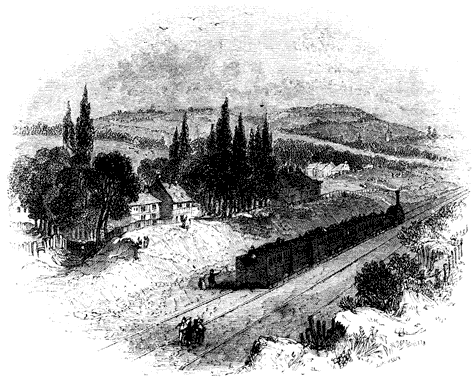
[30] Some of the preceding observations on inland transport, as well as other parts of the present chapter, appeared in articles written by me in the Edinburgh Review for October, 1832, and October, 1834.
[31] Wood on Railroads, 2d edit.
[32] The cost of coke has risen considerably since the date of this report.
[33] I am indebted to the enlarged edition of Tredgold on the Steam Engine, published by Mr. Weale, for the drawings of this engine. The details of the machine are very fully given in that work, the description of them being supplied by Mr. Stephenson himself.
[34] See Table of Pressures, Temperatures, and Volumes, in appendix.

LOCOMOTIVE ENGINES ON TURNPIKE ROADS.
But besides the greater smoothness of railways compared with stone roads, the latter have another disadvantage, the effects of which have probably been exaggerated by those who are opposed to this application of steam-power. One of the [Pg421] laws of adhesion long since developed by experiment, and established as a principle of practical science, is that the adhesion is greater between surfaces of the same than between surfaces of a different kind. Thus between two metals of the same kind, the adhesion corresponding to any given pressure is greater than between two metals of different kinds; between two metals of any sort the adhesion is greater than between metal and stone, or between metal and wood. Hence, the wheels of steam-carriages running on a railroad have a greater adhesion with the road, and therefore offer a greater resistance to slip round without the advance of the carriage, than wheels would offer on a turnpike road; for on a railroad the iron tire of the wheel rests in contact with the iron rail, while on a common road the iron tire rests in contact with the surface of stone, or whatever material the road may be composed of. Besides this, the dust and loose matter which necessarily collect on a common road, when pressed between the wheels and the solid base of the road, act somewhat in the manner of rollers, and give the wheels a greater facility to slip than if the road were swept clean, and the wheels rested in immediate contact with its hard surface. The truth of this observation is illustrated on the railroads themselves, where the adhesion is found to be diminished whenever the rails are covered with any extraneous matter, such as dust or moist clay. Although the adhesion of the wheels of a carriage with a common road, however, be less than those of the wheels of a steam-carriage with a railroad, yet still the actual adhesion on turnpike roads is greater in amount than has been generally supposed, and is quite sufficient to propel carriages drawing after them loads of large amount.
The relative facility with which carriages are propelled on railroads and turnpike-roads equally affects any moving power, whether that of horses or steam engines; and whether loads be propelled by the one power or the other, the railroad, as compared with the turnpike-road, will always possess the same proportionate advantage; and a given amount of power, whether of the one kind or the other, will always perform a quantity of work less in the same proportion on a [Pg422] turnpike-road than on a rail-road. But, on the other hand, the expense of original construction, and of maintaining the repairs of a rail-road, is to be placed against the certain facility which it offers to draught.
In the attempts which have been made to adapt locomotive engines to turnpike-roads, the projectors have aimed at the accomplishment of two objects: first, the construction of lighter and smaller engines; and, secondly, increased power. These ends, it is plain, can only be attained, with our present knowledge, by the production of steam of very high temperature and pressure, so that the smallest volume of steam shall produce the greatest possible mechanical effect. The methods of propelling the carriage have been in general similar to that used in the railroad engines, viz. either by cranks placed on the axles, the wheels being fixed upon the same axles, or by connecting the piston rods with the spokes of the wheels. In some carriages, the boiler and moving power, and the body of the carriage which bears the passengers, are placed on the same wheels. In others, the engine is placed on a separate carriage, and draws after it the carriage which transports the passengers, as is always the case on railways.
The chief difference between the steam engines used on railways, and those adapted to propel carriages on turnpike roads, is in the structure of the boiler. In the latter it is essential that, while the power remains undiminished, the boiler should be lighter and smaller. The accomplishment of this has been attempted by various contrivances for so distributing the water as to expose a considerable quantity of surface in contact with it to the action of the fire: spreading it in thin layers on flat plates; inserting it between plates of iron placed at a small distance asunder, the fire being admitted between the intermediate plates; dividing it into small tubes, round which the fire has play; introducing it between the surfaces of cylinders placed one within another, the fire being admitted between the alternate cylinders,—have all been resorted to by different projectors.
The mistake which so long prevailed in the application of locomotives on railroads, and which, as we have shown, materially retarded the progress of that invention, was shared by Mr. Gurney. Without reducing the question to the test of experiment, he took for granted, in his first attempts, that the adhesion of the wheels with the road was too slight to propel the carriage. He was assured, he says, by eminent engineers, that this was a point settled by actual experiment. It is strange, however, that a person of his quickness and sagacity did not inquire after the particulars of these "actual experiments." So, however, it was; and, taking for granted the inability of the wheels to propel, he wasted much labour and skill in the contrivance of levers and propellers, which acted on the ground in a manner somewhat resembling the feet of horses, to drive the carriage forward. After various fruitless attempts of this kind, the experience acquired in the trials to which they gave rise at last forced the truth upon his notice, and he found that the adhesion of the wheels was not only sufficient to propel the carriage heavily laden on level roads, but was capable of causing it to ascend all the hills which occur on ordinary turnpike-roads. In this manner it ascended all the hills between London and Barnet, London and Stanmore, Stanmore Hill, Brockley Hill, and mounted Old Highgate Hill, the last at one point rising one foot in nine.
The boiler of Mr. Gurney's engine is so constructed, that there is no part of it in which metal exposed to the action of the fire is out of contact with water. If it be considered how rapidly the action of an intense furnace destroys metal when water is not present to prevent the heat from accumulating, the advantage of this circumstance will be appreciated. In the boiler of Mr. Gurney, the grate-bars [Pg424] themselves are tubes filled with water, and form, in fact, a part of the boiler itself. This boiler consists of three strong metal cylinders placed in a horizontal position one above the other. A section, made by a perpendicular or vertical plane, is represented in fig. 114. The ends of the three cylinders just mentioned are represented at D, H, and I. In the side of the lowest cylinder D are inserted a row of tubes, a ground plan of which is represented in fig. 115. These tubes, proceeding from the side of the lowest cylinder D, are inclined [Pg425] slightly upwards, for a reason which I shall presently explain. From the nature of the section, only one of these tubes is visible in fig. 114. at C. The other extremities of these tubes at A are connected with the same number of upright tubes, one of which is shown at E. The upper extremities G of these upright tubes are connected with another set of tubes K, equal in number, proceeding from G, inclining slightly upwards, and terminating in the second cylinder H.
An end view of the boiler is exhibited in fig. 116., where the three cylinders are expressed by the same letters. Between the cylinders D and H there are two tubes of communication B, and two similar tubes between the cylinders H and I. From the nature of the section these appear only as a single tube in fig. 114. From the top of the cylinder I proceeds a tube N, by which steam is conducted to the engine.
It will be perceived that the space F is enclosed on every side by a grating of tubes, which have free communication with the cylinders D and H, which cylinders have also a free communication with each other by the tubes B. It follows, [Pg426] therefore, that if water be supplied to the cylinder I, it will descend through the tubes, and first filling the cylinder D and the tubes C, will gradually rise in the tubes B and E, will next fill the tubes K and the cylinder H. The grating of water-pipes C E K forms the furnace, the pipes C being the fire-bars, and the pipes E and K being the back and roof of the stove. The fire-door, for the supply of fuel, appears at M, fig. 116. The flue issuing between the tubes F is conducted over the tubes K, and the flame and hot air are carried off through a chimney. That portion of the heat of the burning fuel, which in other furnaces destroys the bars of the grate, is here expended in heating the water contained in the tubes C. The radiant heat of the fire acts upon the tubes K, forming the roof of the furnace, on the tube E at the back of it, and partially on the cylinders D and H, and the tubes B. The draft of hot air and flame passing into the flue at A acts upon the posterior surfaces of the tubes E, and the upper sides of the tubes K, and finally passes into the chimney.
As the water in the tubes C E K is heated, it becomes specifically lighter than water of a less temperature, and consequently acquires a tendency to ascend. It passes, therefore, rapidly into H. Meanwhile the colder portions descend, and the inclined positions of the tubes C and K give play to this tendency of the heated water, so that a prodigiously rapid circulation is produced, when the fire begins to act upon the tubes. When the water acquires such a temperature that steam is rapidly produced, steam-bubbles are constantly formed in the tubes surrounding the fire; and if these remained stationary in the tubes, the action of the fire would not only decompose the steam, but render the tubes red hot, the water not passing through them to carry off the heat. But the inclined position of the tubes, already noticed, effectually prevents this injurious consequence. A steam-bubble, which is formed either in the tubes C or K, having a tendency to ascend proportional to its lightness as compared with water, necessarily rushes upwards; if in C towards A, and if in K towards H. But this motion of the steam is also aided by the rapid circulation of the water which is continually maintained [Pg427] in the tubes, otherwise it might be possible, notwithstanding the levity of steam compared with water, that a bubble might remain in a narrow tube without rising. To bring the matter to the test of experiment, I have connected two cylinders, such as D and H, by a system of glass tubes, such as represented at C E K. The rapid and constant circulation of the water was then made evident: bubbles of steam were formed in the tubes, it is true; but they passed with great rapidity into the upper cylinder, and rose to the surface, so that the glass tubes never acquired a higher temperature than that of the water which passed through them.
Every part of the boiler being cylindrical, it has the form which, mechanically considered, is most favourable to strength, and which, within given dimensions, contains the greatest quantity of water. It is also free from the defects arising from unequal expansion, which are found to be most injurious in tubular boilers. The tubes C and K can freely expand in the direction of their length, without being loosened at their joints, and without straining any part of the apparatus; the tubes E, being short, are subject to a very slight degree of expansion; and it is obvious that the long tubes, with which they are connected, will yield to this without suffering a strain, and without causing any part of the apparatus to be loosened.
When water is converted into steam, any foreign matter which may be combined with it is disengaged, and is deposited on the bottom of the vessel in which the water is evaporated. All boilers, therefore, require occasional cleansing, to prevent the crust thus formed from accumulating; and this operation, for obvious reasons, is attended with peculiar difficulty in tubular boilers. In the case before us, the crust of deposited matter would gather and thicken in the tubes C and K, and if not removed, would at length choke them. But besides this, it would be attended with a still worse effect; for, being a bad conductor, it would intercept the heat in its transit from the fire to the water, and would cause the metal of the tube to become unduly heated. Mr. Gurney of course foresaw this inconvenience, and contrived an ingenious chemical method of removing it, by occasionally injecting [Pg428] through the tubes such an acid as would combine with the deposit, and carry it away. This method was effectual; and although its practical application was found to be attended with difficulty in the hands of common workmen, Mr. Gurney was persuaded to adhere to it by the late Dr. Wollaston, until experience proved the impossibility of getting it effectually performed, under the circumstances in which boilers are commonly used. Mr. Gurney then adopted a method of removing the deposit by mechanical means. Opposite the mouths of the tubes, and on the other side of the cylinders D and H, are placed a number of holes, which, when the boiler is in use, are stopped by pieces of metal screwed into them. When the tubes require to be cleaned, these stoppers are removed, and an iron scraper is introduced through the holes into the tubes, which, being passed backwards and forwards, removes the deposit.
In these engines the draught through the furnace was produced by projecting the waste steam up the chimneys as is practised in railway engines; a method so perfectly effectual, that it is unlikely to be superseded by any other. The objection which has been urged against it in locomotive engines, working on turnpike-roads, is, that the noise which it produces has a tendency to frighten horses.
In the engines on the Liverpool road, the steam is allowed to pass directly from the eduction pipe of the cylinder to the chimney, and it there escapes in puffs corresponding with the alternate motion of the pistons, and produces a noise, which, although attended with no inconvenience on the railroad, would perhaps be objectionable on turnpike-roads. In the engine used in Mr. Gurney's steam-carriage, the steam which passes from the cylinders is conducted to a receptacle, which he calls a blowing box. This box serves the same purpose as the upper chamber of a smith's bellows. It receives the steam from the cylinders in alternate puffs, but lets it escape into the chimney in a continued stream by a number of small jets. Regular draught is by this means produced, and no noise is perceived. Another exit for the steam is also provided, by which the conductor is enabled to increase or diminish, or to suspend altogether, the draught [Pg429] in the chimney, so as to adapt the intensity of the fire to the exigencies of the road. This is a great convenience in practice; because on some roads a draught is scarcely required, while on others a powerful blast is indispensable.
Connected with this blowing box is another apparatus of considerable practical importance. The pipe through which the feeding water is conducted from the tank is carried through this blowing box, within which it is coiled in a spiral form, so that an extensive thread of the water is exposed to the heat of the waste steam which has escaped from the cylinders, and which is enclosed in this blowing box. In passing through this pipe the feeding water is raised from the ordinary temperature of about 60° to the temperature of 212°. Fuel is thus economised and weight diminished; but there is another still greater advantage attending this process. The feeding water in the worm just mentioned, while it takes up the heat from the surrounding steam in the blowing box, condenses a part of the waste steam, which is thence conducted to the tank, from which the feeding water is pumped.
When steam is generated so rapidly as is necessarily the case in locomotive boilers, it rises with great violence in numerous bubbles from the bottom of the boiler to the surface of the water, and puts the liquid into a state of foaming turbulence not unlike the sea in a storm. As the steam rushes from the surface into the upper part of the boiler, under these circumstances, it carries with it a spray by which water is scattered in minute subdivision among the steam, and floats there like the spray which rises from the base of a cascade. If the steam be conducted immediately to the cylinder from the boiler in this state, it will carry with it the water which is thus suspended in it, which will pass through the cylinder, and finally be driven into the atmosphere upon the returning stroke of the piston. The hot water thus carried off possesses none of the mechanical properties of steam, and is wholly inefficient as a moving power, and is therefore an extensive source of the waste of heat. In every boiler, some means should be provided for the separation of the water thus suspended in the steam, before the steam is conducted to the cylinder. In ordinary boilers, the large space which [Pg430] remains above the surface of the water serves this purpose. The steam being there subject to no agitation or disturbance, the water mechanically suspended in it descends by its own gravity, and leaves pure steam in the upper part. In the small tubular boilers, this has been a matter, however, of greater difficulty. The contracted space in which the ebullition takes place causes the water to be mixed with the steam in a greater quantity than could happen in common boilers; and the want of the same steam-room renders the separation of the water from the steam a matter of some difficulty. These inconveniences have been attempted to be overcome by various contrivances. I have already described the rapid and regular circulation effected by the arrangement of the tubes. By this a regularity in the currents is established, which has a tendency to diminish the mixture of water with the steam. In addition to this, a method of separation is provided in the vessel I, which is a strong iron cylinder of some magnitude, placed out of the immediate influence of the fire. A partial separation of the steam from the water takes place in the cylinder H; and the steam with the water mechanically suspended in it, technically called moist steam, rises into the separator I. Here, being free from all agitation and currents, and being, in fact, quiescent, the particles of water fall to the bottom, while the pure steam remains at the top. This separator, therefore, serves all the purposes of the steam-room above the surface of the water in the large plate boilers. The dry steam is thus collected and ready for the supply of the engine through the tube N, while the water, which is disengaged from it, is collected at the bottom of the separator, and is conducted through the tube T to the lowest vessel D, to be again circulated through the boiler.
The pistons of the engine work on the axles of the hind wheels of the carriage which bears the engine, by cranks, as in the locomotives on the Manchester railway, so that the axle is kept in a constant state of rotation while the engine is at work. The wheels placed on this axle are not permanently fixed or keyed upon it, as in the Manchester locomotives; but they are capable of turning upon it in the same manner as ordinary carriage wheels. Immediately within [Pg431] these wheels there are fixed upon the axles two projecting spokes or levers, which revolve with the axle, and which take the position of two opposite spokes of the wheel. These may be occasionally attached to the wheel or detached from it; so that they are capable of compelling the wheels to turn with the axle, or leaving the axle free to turn independently of the wheel, or the wheel independent of the axle, at the pleasure of the conductor. It is by these levers that the engine is made to propel either or both of the wheels. If both pairs of spokes are thrown into connexion with the wheels, the crank shaft or axle will cause both wheels to turn with it, and in that case the operation of the carriage is precisely the same as those of the locomotives already described upon the Liverpool and Manchester line; but this is rarely found to be necessary, since the adhesion of one wheel with the road is generally sufficient to propel the carriage, and consequently only one pair of these fixed levers are used, and the carriage propelled by only one of the two hind wheels. The fore wheels of the carriage turn upon a pivot similar to those of a four-wheeled coach. The position of these wheels is changed at pleasure by a pinion and circular rack, which is moved by the conductor, and in this manner the carriage is guided with precision and facility.
The force of traction necessary to propel a carriage upon common roads must vary with the variable quality of the road, and consequently the propelling power, or the pressure upon the pistons of the engine, must be susceptible of a corresponding variation; but a still greater variation becomes necessary from the undulations and hills which are upon all ordinary roads. This necessary change in the intensity of the impelling power is obtained by restraining the steam in the boiler by the throttle-valve, as already described in the locomotive engines on the railroad. This principle, however, is carried much further in the present case. The steam in the boiler maybe at a pressure of from 100 to 200 lbs. on the square inch; while the steam on the working piston may not exceed 30 or 40 lbs. on the inch. Thus an immense increase of power is always at the command of the conductor; so that when a hill is encountered, or a rough piece of road, [Pg432] he is enabled to lay on power sufficient to meet the exigency of the occasion.
The two difficulties which have been always apprehended in the practical working of steam-carriages upon common roads are, first, the command of sufficient power for hills and rough pieces of road; and, secondly, the apprehended insufficiency of the adhesion of the wheels with the road to propel the carriage. The former of these difficulties has been met by allowing steam of very great pressure to be constantly maintained in the boiler with perfect safety. As to the second, all experiments tend to show that there is no ground for the supposition that the adhesion of the wheels is in any case insufficient for the purposes of propulsion. Mr. Gurney states, that he has succeeded in driving carriages thus propelled, up considerable hills on the turnpike roads about London. He made a journey to Barnet with only one wheel attached to the axle, which was found sufficient to propel the carriage up all hills upon that road. The same carriage, with only one propelling wheel, also went to Bath, and surmounted all the hills between Cranford Bridge and Bath, going and returning.
A double stroke of the piston produces one revolution of the propelling wheels, and causes the carriage to move through a space equal to the circumference of those wheels. It will therefore be obvious, that the greater the diameter of the wheels, the better adapted the carriage is for speed; and, on the other hand, wheels of smaller diameter are better adapted for power. In fact, the propelling power of an engine on the wheels will be in the inverse proportion of their diameter. In carriages designed to carry great weights at a moderate speed, smaller wheels will be used; while in those intended for the transport of passengers at considerable velocities, wheels of at least 5 feet diameter are most advantageous.
The weight of machinery necessary for steam carriages is sometimes urged as an objection to their practical utility. Mr. Gurney states, that, by successive improvements in the details of the machinery, the weight of his carriages, without losing any of the propelling power, may be reduced to 35 cwt., exclusive of the load, and fuel and water: but thinks that it is possible to reduce the weight still further.
A steam carriage constructed by Mr. Gurney, weighing 35 cwt., working for 8 hours, is found, according to his statement, to do the work of about 30 horses. He calculates that the weight of his propelling carriage, which would be capable of drawing 18 persons, would be equal to the weight of 4 horses; and the carriage in which these persons would be drawn would have the same weight as a common stage coach capable of carrying the same number of persons. Thus the weight of the whole—the propelling carriage and the carriage for passengers taken together—would be the same [Pg434] with the weight of a common stage coach, with 4 horses inclusive.
There are two methods of applying locomotives upon common roads to the transport of passengers or goods; the one is by causing the locomotive to carry, and the other to draw the load; and different projectors have adopted the one and the other method. Each is attended with its advantages and disadvantages. If the same carriage transport the engine and the load, the weight of the whole will be less in proportion to the load carried; also a greater pressure may be produced on the wheels by which the load is propelled. It is also thought that a greater facility in turning and guiding the vehicle, greater safety in descending the hills, and a saving in the original cost, will be obtained. On the other hand, when the passengers are placed in the same carriage with the engine, they are necessarily more exposed to the noise of the machinery and to the heat of the boiler and furnace. The danger of explosion is so slight, that, perhaps, it scarcely deserves to be mentioned; but still the apprehension of danger on the part of the passengers, even though groundless, should not be disregarded. This apprehension will be obviously removed or diminished by transferring the passengers into a carriage separate from the engine; but the greatest advantage of keeping the engine separate from the passengers is the facility which it affords of changing one engine for another in case of accident or derangement on the road, in the same manner as horses are changed at the different stages: or, if such an accident occur in a place where a new engine cannot be procured, the load of passengers may be carried forward by horses, until it is brought to some station where a locomotive may be obtained. There is also an advantage arising from the circumstance, that when the engines are under repair, or in process of cleaning, the carriages for passengers are not necessarily idle. Thus the same number of carriages for passengers will not be required when the engine is used to draw as when it is used to carry.
In case of a very powerful engine being used to carry great loads, it would be quite impracticable to place the engine [Pg435] and loads on four wheels, the pressure being such as no turnpike road could bear. In this case it would be indispensably necessary to place a part of the load at least upon separate carriages to be drawn by the engine.
In the comparison of carriages propelled by steam with carriages drawn by horses, there is no respect in which the advantage of the former is so apparent as the safety afforded to the passenger. Steam power is under the most perfect control, and a carriage thus propelled is capable of being guided with the most admirable precision. It is also capable of being stopped almost suddenly, whatever be its speed: it is capable of being turned within a space considerably less than that which would be necessary for four-horse coaches. In turning sharp corners, there is no danger, with the most ordinary care on the part of the conductor. On the other hand, horse power, as is well known, is under very imperfect control, especially when horses are used adapted to that speed which at present is generally considered necessary for the purposes of travelling. "The danger of being run away with and overturned," says Mr. Farey, in his evidence before the House of Commons, "is greatly diminished in a steam coach. It is very difficult to control four such horses as can draw a heavy stage coach ten miles an hour, in case they are frightened or choose to run away; and, for such quick travelling, they must be kept in that state of courage that they are always inclined to run away, particularly down hill, and at sharp turns in the road. Steam power has very little corresponding danger, being perfectly controllable, and capable of having its power reversed, to retard in going down hill. It must be carelessness that would occasion the overturning of a steam carriage. The chance of breaking down has been hitherto considerable, but it will not be more than in stage coaches when the work is truly proportioned and properly executed. The risk from explosion of the boiler is the only new cause of danger, and that I consider not equivalent to the danger from horses."
That the risk of accident from explosion is extremely slight, may be proved by the fact that the railway between Liverpool and Manchester has now been in operation for about ten [Pg436] years, and that other railways more extensive in length have been worked for a considerable time, and that no instance has ever yet occurred of an accident to passengers from the explosion of a boiler. Generally these machines, when they fail, are attended with no other effect than the extinction of the fire, by the water of the boiler flowing in upon it. I am not aware of more than one instance, in which a serious accident has been produced by explosion; and in that instance, the sufferers were only the engineer and stoker. In the steam-engine of Mr. Gurney, the carriage is drawn after the engine, as represented in fig. 117.
In fact, a number of thin plates of water are exposed on both sides to the most intense action of flame and heated air; so that steam of a high pressure is produced in great abundance and with considerable rapidity. The plates forming the boiler are bolted together by strong iron ties, extending across the boiler, at right angles to the plates, as represented in the figure. The distance between the plates is two inches.
There are ten flat chambers of this kind for water, and intermediately between them ten flues. Under the flues is the fire-place, or grate, containing six square feet of fuel in vivid combustion. The chambers are all filled to about two thirds of their depth with water, and the other third is left for steam. The water chambers, throughout the whole series, communicate with each other both at top and bottom, and are held together by two large bolts. By releasing these bolts, at any time, the chambers fall asunder; and by screwing them up they may be all made tight again. The water is supplied to the boiler by a forcing-pump, and the steam issues from the centre of one of the flues at the top.
These boilers are constructed to bear a pressure of 400 or 500 lbs. on the square inch; but the average pressure of the steam on the safety valve is from 60 to 100. There are 100 square feet of surface in contact with the water exposed to the fire. The stages which such an engine performs are eight miles, at the end of which a fresh supply of fuel and water are taken in. It requires about two bushels of coke for each stage.
The steam carriage of Mr. Hancock differs from that of Mr. Gurney in this—that in the former the passengers and engine are all placed on the same carriage. The boiler is placed behind the carriage; and there is an engine-house between the boiler and the passengers, the latter being placed in the fore part of the vehicle; so that all the machinery is behind them. The carriages are adapted to carry 14 [Pg438] passengers, and weigh, exclusive of their load, about 31⁄2 tons, the tires of the wheels being about 31⁄2 inches in breadth. Mr. Hancock states, that the construction of his boiler is of such a nature, that, even in the case of bursting, no danger is to be apprehended, nor any other inconvenience than the stoppage of the carriage. He states that, while travelling about nine miles an hour, and working with a pressure of about 100 lbs. on the square inch, loaded with thirteen passengers, the carriage was suddenly stopped. At first the cause of the accident was not apparent; but, on opening one of the cocks of the boiler, it was found that it contained neither steam nor water. Further examination proved that the boiler had burst. On unscrewing the bolts, it was found that there were several large holes in the plates of the water-chamber, through which the water had flowed on the fire, but neither noise nor explosion, nor any dangerous consequences, ensued.
"The base of the boiler and the summit are composed of cross pieces, cylindrical within and square without; there are holes bored through these cross pieces, and inserted through the whole is an air tube. The inner hole of the lower surface, and the under hole of the upper surface, are rather larger than the other ones. Round the air tube is placed a small cylinder, the collar of which fits round the larger aperture on the inner surface of the lower frame, and the under surface of the upper frame-work. These are both drawn together by screws from the top; these cross pieces are united by connecting pieces, the whole strongly bolted together; so that we obtain, in one tenth of the space, and with one tenth of the weight, the same heating surface and power as is now obtained in other and low-pressure boilers, with incalculably [Pg439] greater safety. Our present experimental boiler contains 250 superficial feet of heating surface in the space of 3 feet 8 inches high, 3 feet long, and 2 feet 4 inches broad, and weighs about 8 cwt. We supply the two cylinders with steam, communicating by their pistons with a crank axle, to the ends of which either one or both wheels are affixed as may be required. One wheel is found to be sufficient, except under very difficult circumstances, and when the elevation is about one foot in six to impel the vehicle forward.
"The cylinders of which the boiler is composed are so small as to bear a greater pressure than could be produced by the quantity of fire beneath the boiler; and if any one of these cylinders should be injured by violence, or any other way, it would become merely a safety valve to the rest. We never, with the greatest pressure, burst, rent, or injured our boiler; and it has not once required cleaning, after having been in use twelve months."
Dr. Church of Birmingham has obtained a succession of patents for contrivances connected with a locomotive engine for stone roads; and a company, consisting of a considerable number of individuals, possessing sufficient capital, has been formed in Birmingham, for carrying into effect his designs, and working carriages on his principle. The present boiler of Dr. Church is formed of copper. The water is contained between two sheets of copper, united together by copper nails, in a manner resembling the way in which the cloth forming the top of a mattress or cushion is united with the cloth which forms the bottom of it, except that the nails or pins, which bind the sheets of copper, are much closer together. The water, in fact, seems to be "quilted" or "padded" in between two sheets of thin copper. This double sheet of copper is formed into an oblong rectangular box, the interior of which is the fire-place and ash-pit, and over the end of which is the steam-chest. The great extent of surface exposed to the immediate action of the fire causes steam to be produced with great rapidity.
Various other projects for the application of steam engines on common roads were in a state of progressive improvement, [Pg440] when the greater advantages attending railways were considered so manifest, that considerable doubts were raised, whether, supposing the problem of the application of the steam engine on common roads to be successfully solved, it could ever be attended with the same economy and effect, as by the adoption of a railway. Among the projects which promised a successful issue, may be mentioned the locomotive engines contrived by Messrs. Maudslay and Field, by Colonel Maceroni, and by Mr. Scott Russell. These and others have, however, been abandoned, mainly, we believe, from the impression, that wherever traffic can exist, sufficiently extensive to render the application of steam power profitable, a railway must always supersede a common road; and that, even in the limited traffic to be expected on branches to the great railways, horse power applied to railways would be attended with more economy than steam power applied on stone roads.
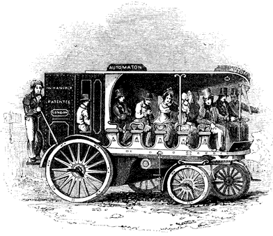
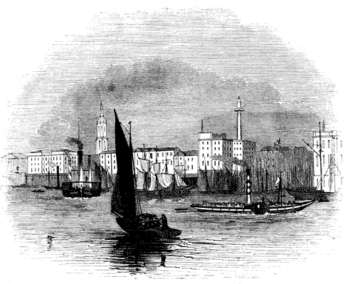
STEAM NAVIGATION.
The manner in which the steam-engine is rendered an instrument for the propulsion of vessels must in its general features be so familiar to every one as to require but short explanation. A shaft is carried across the vessel, being continued on either side beyond the timbers: to the extremities of this shaft, on the outside of the vessel, are fixed a pair of wheels constructed like undershot water-wheels, having attached to their rims a number of flat boards called paddle-boards. As the wheels revolve, these paddle-boards strike the water, driving it in a direction contrary to that in which it is intended the vessel should be propelled. The moving force imparted to the water thus driven backwards is necessarily accompanied by a re-action upon the vessel through the medium of the paddle-shaft, by which the vessel is propelled forwards. On the paddle-shaft two cranks are constructed, similar to the cranks already described on the axle of the driving wheels of a locomotive engine. These cranks are placed at right angles to each other, so that when either is in its highest or lowest position the other shall be horizontal. They are driven by two steam-engines, which are placed in the hull of the vessel below the paddle-shaft. In the earlier steam-boats a single steam-engine was used, and in that case the unequal action of the engine on the crank was equalised by a fly-wheel. This, however, has been long [Pg443] since abandoned in European vessels, and the use of two engines is now almost universal. By the relative position of the cranks it will be seen, that when either crank is at its dead points, the other will be in the positions most favourable to its action, and in all intermediate positions the relative efficiency of the cranks will be such as to render their combined action very nearly uniform.
The steam-engines used to impel vessels may be either condensing engines, similar to those of Watt, and such as are used in manufactures generally, or they may be non-condensing and high-pressure engines, similar in principle to those used on railways. Low-pressure condensing engines are, however, universally used for marine purposes in Europe and to some extent in the United States. In the latter country, however, high-pressure engines are also in pretty general use, on rivers where lightness is a matter of importance.
The arrangement of the parts of a marine engine differs in some respects from that of a land engine. The limitation of space, which is unavoidable in a vessel, renders greater compactness necessary. The paddle-shaft on which the cranks to be driven by the engine are constructed being very little below the deck of the vessel, the beam and connecting rod could not be placed in the position in which they usually are in land engines, without carrying the machinery to a considerable elevation above the deck. This is done in the steam-boat engines used on the American rivers; but it would be inadmissible in steam-boats in general, and more especially in sea-going steamers. The connecting rods, therefore, instead of being presented downwards towards the cranks which they drive, must, in steam-vessels, be presented upwards, and the impelling force received from below. If, under these circumstances, the beam were in the usual position above the cylinder and piston-rod, it must necessarily be placed between the engine and the paddle-shaft. This would require a depth for the machinery which would be incompatible with the magnitude of the vessel. The beam, therefore, of marine engines, instead of being above the cylinder and piston, is placed below them. To the top of the [Pg445] piston-rods cross pieces are attached of greater length than the diameter of the cylinders, so that their extremities shall project beyond the cylinders. To the ends of these cross pieces are attached by joints the rods of a parallel motion: these rods are carried downwards, and are connected with the ends of two beams below the cylinder, and placed on either side of it. The opposite ends of these beams are connected by another cross piece, to which is attached a connecting rod, which is continued upwards to the crank-pin, to which it is attached, and which it drives. Thus the beam, parallel motion, and connecting rod of a marine engine, is similar to that of a land engine, only that it is turned upside down; and in consequence of the impossibility of placing the beam directly over the piston-rod, two beams and two systems of parallel motion are provided, one on each side of the engine, acted upon by, and acting on the piston-rod and crank by cross pieces.
The proportion of the cylinders differs from that usually observed in land engines, for like reasons. The length of the cylinder of land engines is generally greater than its diameter, in the proportion of about two to one. The cylinders of marine engines are, however, commonly constructed with a diameter very little less than their length. In proportion, therefore, to their power their stroke is shorter, which infers a corresponding shortness of crank and a greater limitation of play of all the moving parts in the vertical direction. The valves and the gearing by which they are worked, the air-pump, the condenser, and other parts of the marine engines, do not materially differ from those already described in land engines.
These arrangements of a marine engine will be more clearly understood by reference to fig. 119.[35], in which is represented a longitudinal section of a marine engine with its boiler as placed in a steam-vessel. The sleepers of oak, supporting the engine, are represented at X, the base of the engine being secured to these by bolts passing through them [Pg446] and the bottom timbers of the vessel; S is the steam-pipe leading from the steam-chest in the boiler to the slides c, by which it is admitted to the top and bottom of the cylinder. The condenser is represented at B, and the air-pump at E. The hot well is seen at F, from which the feed is taken for the boiler; L is the piston-rod connected by the parallel motion a with the beam H, working on a centre K, near the base of the engine. The other end of the beam I drives the connecting rod M, which extends upwards to the crank which it works upon the paddle-shaft O. Q R is the framing by which the engine is supported. The beam here exhibited is shown on dotted lines as being on the further side of the engine. A similar beam similarly placed, and moving on the same axis, must be understood to be at this side connected with the cross head of the piston in like manner by a parallel motion, and with a cross piece attached to the lower end of the connecting rod and to the opposite beam. The eccentric which works the slides is placed upon the paddle shaft O, and the connecting arm which drives the slides may be easily detached when the engine requires to be stopped. The section of the boiler, grate, and flues, is represented at W U. The safety-valve y is enclosed beneath a pipe carried up beside the chimney, and is inaccessible to the engine-man; h are the cocks for blowing the salted water from the boiler; and I I the feed-pipe.
The general arrangement of the engine-room of a steam-vessel is represented in fig. 120.
The nature of the effect required to be produced by marine engines does not render either necessary or possible that great regularity of action which is indispensable in a steam-engine applied to the purposes of manufacture. The agitation of the surface of the sea will cause the immersion of the paddle-wheels to be subject to great variation, and the resistance produced by the water to the engine will undergo a corresponding change. The governor, therefore, and other parts of the apparatus, contrived for giving to the engine that great regularity required in manufactures, are omitted in nautical engines, and nothing is introduced save what is [Pg447] necessary to maintain the machine in its full working efficiency.
To save space, marine boilers are constructed so as to produce the necessary quantity of steam within the smallest possible dimensions. With this view a more extensive surface in proportion to the capacity of the boiler is exposed to the action of the fire. The flues, by which the flame and heated air are conducted to the chimney, are so constructed that the heat may act upon the water on every side in thin oblong shells or plates. This is accomplished by constructing the flues so as to traverse the boiler backwards and forwards several times before they terminate [Pg448] in the chimney. Such an arrangement renders the expense of the boilers greater, but their steam-producing power is proportionally augmented, and experiments made by Mr. Watt, at Birmingham, have proved that such boilers with the same consumption of fuel will produce, as compared with common land boilers, an increased evaporation in the proportion of about three to two.
The form and arrangement of the water-spaces and flues in marine boilers may be collected from the sections of the boilers used in some of the government steamers, exhibited in figs. 121, 122, 123. A section made by a horizontal plane passing through the flues is exhibited in fig. 121. The furnaces F communicate in pairs with the flues E, the air following the course through the flues represented by the arrows. The flue E passes to the back of the boiler, then returns to the front, then to the back again, and is finally carried back to the front, where it communicates at C with the curved flue B, represented in the transverse vertical section, fig. 122. This curved flue B finally terminates in the chimney A. There are in this case three independent boilers, each worked by two furnaces communicating with the same system of flues; and in the curved flues B, fig. 122., by which the air is finally conducted through the chimney, are placed three independent [Pg449] dampers, by means of which the furnace of each boiler can be regulated independently of the other, and by which each boiler may be separately detached from communication with the chimney. The letters of reference in the horizontal section, fig. 121., correspond with those in the transverse vertical section, fig. 122., E representing the commencement of the flues, and C their termination.
A longitudinal section of the boiler made by a vertical plane extending from the front to the back is given in fig. 123., where F, as before, is the furnace, G the grate-bars sloping downwards from the front to the back, H the fire-bridge, C the commencement of the flues, and A the chimney. An elevation of the front of the boiler is represented in fig. 124., showing two of the fire-doors closed, and the other two removed, displaying the position of the grate-bars in front. Small openings are also provided, closed by proper doors, by which access can be had to the under side of the flues between the foundation timbers of the engine for the purpose of cleaning them.
Each of these boilers can be worked independently of the others. By this means, when at sea, the engine may be worked by any two of the three boilers, while the third is being cleaned and put in order. In all sea-going steamers multiple boilers are at present provided for this purpose.
In the boilers here represented the flues are all upon the same level, winding backwards and forwards without passing one above the other. In other boilers, however, the flues, [Pg450] after passing backwards and forwards near the bottom of the boiler, turn upwards and pass backwards and forwards through a level of the water nearer its surface, finally terminating in the chimney. More heating surface is thus obtained with the same capacity of boiler.
The most formidable difficulty which has been encountered in the application of the steam-engine to sea-voyages has arisen from the necessity of supplying the boiler with sea-water instead of pure fresh water. The sea-water is injected into the condenser for the purpose of condensing the steam, and it is thence, mixed with the condensed steam, conducted as feeding water into the boiler.
But besides the deposition of salt sediment in a loose form, some of the constituents of sea-water having an attraction for the iron of the boiler, collect upon it in a scale or crust in the same manner as earthy matters held in solution by spring-water are observed to form and become incrusted on the inner surface of land-boilers and of common culinary vessels.
The coating of the inner surface of a boiler by incrustation and the collection of salt sediment in its lower parts, are attended with effects highly injurious to the materials of the boiler. The crust and sediment thus formed within the boiler are almost non-conductors of heat, and placed, as they are, between the water contained in the boiler and the metallic plates which form it, they obstruct the passage of heat from the outer surface of the plates in contact with the fire to the water. The heat, therefore, accumulating in the boiler-plates so as to give them a much higher temperature than the water within the boiler, has the effect of softening them, and by the unequal temperature which will thus be imparted to the lower plates which are incrusted, compared with the higher parts which may not be so, an unequal expansion is produced, by which the joints and seams of the boiler are loosened and opened, and leaks produced.
These injurious effects can only be prevented by either of two methods; first, by so regulating the feed of the boiler that the water it contains shall not be suffered to reach the point of saturation, but shall be so limited in its degree of saltness that no injurious incrustation or deposit shall be formed; secondly, by the adoption of some method by which the boiler may be worked with fresh water. This end can only be attained by condensing the steam by a jet of fresh water, and working the boiler continually by the same water, since a supply of fresh water sufficient for a boiler worked in the ordinary way could never be commanded at sea.
This process of blowing out, on the due and regular observance of which the preservation and efficiency of the boiler mainly depend, is too often left at the discretion of the engineer, who is, in most cases, not even supplied with the proper means of ascertaining the extent to which the process should be carried. It is commonly required that the engineer should blow out a certain portion of the water in the boiler every two hours, restoring the level by a feed of equivalent amount; but it is evident that the sufficiency of the process founded on such a rule must mainly depend on the supposition that the evaporation proceeds always at the same rate, which is far from being the case with marine boilers. An indicator, by which the saltness of the water in the boiler would always be exhibited, ought to be provided, and the process of blowing out should be regulated by the indications of that instrument. To blow out more frequently than is necessary is attended with a waste of fuel; for hot water is thus discharged into the sea while cold water is introduced in its place, and consequently all the heat necessary to produce the difference of the temperatures of the water blown out and the feed introduced is lost. If, on the other hand, the process of blowing out be observed less frequently than is necessary, then more or less incrustation and deposit [Pg453] may be produced, and the injurious effects already described ensue.
As the specific gravity of water holding salt in solution is increased with every increase of the strength of the solution, any form of hydrometer capable of exhibiting a visible indication of the specific gravity of the water contained in the boiler would serve the purpose of an indicator, to show when the process of blowing out is necessary, and when it has been carried to a sufficient extent. The application of such instruments, however, would be attended with some practical difficulties in the case of sea-boilers.
The temperature at which a solution of salt boils under a given pressure varies considerably with the strength of the solution; the more concentrated the solution is, the higher will be its boiling temperature under the same pressure. A comparison, therefore, of a steam-gauge attached to the boiler, and a thermometer immersed in it, showing the pressure and the temperature, would always indicate the saltness of the water; and it would not be difficult so to graduate these instruments as to make them at once show the degree of saltness.
If the application of the thermometer be considered to be attended with practical difficulty, the difference of pressures under which the salt water of the boiler and fresh water of the same temperature boil, might be taken as an indication of the saltness of the water in the boiler, and it would not be difficult to construct upon this principle a self-registering instrument, which would not only indicate but record from hour to hour the degree of saltness of the water. A small vessel of distilled water being immersed in the water of the boiler would always have the temperature of that water, and the steam produced from it communicating with a steam-gauge, the pressure of such steam would be indicated by that gauge, while the pressure of the steam in the boiler under which pressure the salted water boils might be indicated by another gauge. The difference of the pressures indicated by the two gauges would thus become a test by which the saltness of the water in the boiler would be measured. The two pressures might be made to act on opposite ends of the same column of [Pg454] mercury contained in a siphon tube, and the difference of the levels of the two surfaces of the mercury would thus become a measure of the saltness of the water in the boiler. A self-registering instrument founded on this principle formed part of the self-registering steam-log which I proposed to introduce into steam-vessels some time since.
The ordinary method of blowing out the salted water from a boiler is by a pipe having a cock in it leading from the boiler through the bottom of the ship, or at a point low down at its side. Whenever the engineer considers that the water in the boiler has become so salted that the process of blowing out should commence, he opens the cock communicating by this pipe with the sea, and suffers an indefinite and uncertain quantity of water to escape. In this way he discharges, according to the magnitude of the boiler, from two to six tons [Pg455] of water, and repeats this at intervals of from two to four hours, as he may consider to be sufficient. If, by observing this process, he prevents the boiler from getting incrusted during the voyage, he considers his duty to be effectually discharged, forgetting that he may have blown out many times more water than is necessary for the preservation of the boiler, and thereby produced a corresponding and unnecessary waste of fuel. In order to limit the quantity of water discharged, Messrs. Seaward have adopted the following method. In fig. 125. is represented a transverse section of a part of a steam-vessel; W is the water-line of the boiler, B is the mouth of a blow-off pipe, placed near the bottom of the boiler. This pipe rises to A, and turning in the horizontal direction, A C is conducted to a tank T, which contains exactly a ton of water. This pipe communicates with the tank by a cock D, governed by a lever H. When this lever is moved to D′, the cock D is open, and when it is moved to K, the cock D is closed. From the same tank there proceeds another pipe E, which issues from the side of the [Pg456] vessel into the sea governed by a cock F, which is likewise put in connection with the lever H, so that it shall be opened when the lever H is drawn to the position F′, the cock D′ being closed in all positions of the lever between K and F′. Thus, whenever the cock F communicating with the sea is open, the cock D communicating with the boiler is closed, and vice versâ, both cocks being closed when the lever is in the intermediate position K. By this arrangement the boiler cannot, by any neglect in blowing off, be left in communication with the sea, nor can more than a ton of water be discharged except by the immediate act of the engineer. The injurious consequences are thus prevented which sometimes ensue when the blow-off cocks are left open by any neglect on the part of the engineer. When it is necessary to blow off, the engineer moves the lever H, to the position D′. The pressure of the steam in the boiler on the surface of the water W forces the salted water or brine up the pipe B A, and through the open cock C into the tank, and this continues until the tank is filled: when that takes place, the lever is moved from the position D′ to the position F′, by which the cock D is closed, and the cock F opened. The water in the tank flows through the pipe E into the sea, air being admitted through the valve V, placed at the top of the tank, opening inwards. A second ton of brine is discharged by moving the lever back to the position D′, and subsequently returning it to the position F′; and in this way the brine is discharged ton by ton, until the supply of water from the feed which replaces it has caused both the balls in the indicator to sink to the bottom.
To save the heat of the brine, a method has been adopted in the marine engines constructed by Messrs. Maudslay and Field similar to one which has been long practised in steam-boilers, and in various apparatus for the warming of buildings. The current of heated brine is conducted from the boiler through a tube which is contained in another, through which the feed is introduced. The warm current of brine, therefore, as it passes out, imparts a considerable portion of its heat to the cold feed which comes in; and it is found that by this expedient the brine discharged into the sea may be reduced to a temperature of about 100°.
This expedient is so effectual that when the apparatus is properly constructed, and kept in a state of efficiency, it may be regarded as nearly a perfect preventive against the incrustation, and the deposition of salt in the boilers, and is not attended with any considerable waste of fuel.
This contrivance has been of late years revived by Mr. Samuel Hall of Basford, near Nottingham, with a view to supersede in marine engines the necessity of using sea-water in the boilers. Mr. Hall proposes to make marine boilers with fresh water to condense the steam without injection, by a tubulated condenser, and to provide by the distillation of sea-water the small quantity of fresh water which would be necessary to make good the waste. These condensers have been introduced into several steam-vessels: in some they have been continued, and in others abandoned, and various opinions are entertained of their efficacy. I have not been able to obtain the results of any satisfactory experiments on them, and cannot therefore form a judgment of their usefulness. Mr. Watt abandoned these condensers from finding that the condensation of the steam was not sufficiently sudden, and that consequently at the commencement of the stroke the piston was subject to a resistance which [Pg459] injuriously diminished the amount of the moving power, whereas condensation by jet was almost instantaneous, and the efficiency of the piston throughout the entire stroke was more uniform.
Mr. Watt also found that a fur collected around the tubes of the condenser, so as to obstruct the free passage of heat from the steam to the water of the cold cistern; and that, consequently, the efficiency of the condenser was gradually impaired, and could only be restored by frequent cleansing.
It is stated by Mr. Hall that a vacuum is preserved in his condensers as perfect as that which is maintained in the ordinary condensers by injection. It is objected, on the other hand, that without the injection water and the air which accompanies it being introduced into his condensers, Mr. Hall uses as large and powerful an air-pump as those which are used in engines of equal power condensing by injection; that, consequently, the vacuum which is maintained is produced, not as it ought to be altogether by the condensation of steam, but by the air-pump drawing off the uncondensed steam. To whatever extent this may be true, the efficacy of the machine, as indicated by the barometer-gauge, is only apparent; since as much power is necessary to pump away any portion of uncondensed vapour as is obtained by the vacuum produced by the absence of that vapour.
A tubular condenser of the form proposed by Mr. Hall is represented in fig. 126.; a is the upper part of the condenser to which steam is admitted from the slide after having worked the piston; k is the section of a thin plate, forming the top of the condenser, perforated with small holes, in which the tubes are inserted so as to be steam-tight and water-tight. Water is admitted to flow around these tubes between the top k and the bottom d of the condenser, so as to keep them constantly at a low temperature. The steam passes from a through the tubes to the lower chamber f of the condenser, where it is reduced to water by the cold to which it has been exposed. A supply of cold water is constantly pumped through the condenser, so as to keep the tubes at a low temperature. The air-pump g is of the usual construction, having valves in the piston opening upwards, and [Pg460] similar valves in the cover of the pump also opening upwards. The water formed by the condensed steam in f is drawn through the foot-valve, and after passing through the piston-valves, is discharged by the up-stroke of the piston into the hot well. Any air, or other permanent gas, which may be admitted by leakage through the tubes of the condenser, or by any other means, is likewise drawn out by this pump, and when drawn into the hot well is carried from thence to the feeding apparatus of the boiler, to which it is transferred by the feed-pump.
A provision is likewise made by which the steam escaping at the safety-valve is condensed and carried away to the feeding cistern.
Besides the injury arising from the deposition of salt and the incrustation on the inner surface of boilers, an evil of a formidable kind attends the accumulation of soot mixed with salt in the flues, which proceeds from the leaks. In the seams of the boiler there are numerous apertures, of dimensions so small as to be incapable of being rendered stanch by any practicable means, through which the water within the boiler filters, and the salt which it carries with it mixes with the soot, forming a compound which rapidly corrodes the boilers. This process of corrosion in the flues takes place not less in copper than in iron boilers. In cleansing the flues of a copper boiler, the salt and soot which was thrown out upon the iron-plates which formed the flooring of the engine-room, having remained there for some time, left behind it a permanent appearance of copper on the iron flooring, arising from the precipitation of the copper which had combined with the soot and salt in the flues.[36] In this case the leaks from whence the salt proceeded were found, on careful examination, so unimportant, that the usual means to stanch them could not be resorted to without the risk of increasing the evil.
Much of the efficiency of fuel must depend on the management of the fires, and therefore on the skill and care of the stokers. Formerly the efficiency of firemen was determined by the abundant production of steam, and so long as the steam was evolved in superabundance, however it might have blown off to waste, the duty of the stoker was considered as well performed. The regulation of the fires according to the demands of the engine were not thought of, and whether much or little steam was wanted, the duty of the stoker was to urge the fires to their extreme limit.
Since the resistance opposed by the action of the paddle-wheels of a steam-vessel varies with the state of the weather, the consumption of steam in the cylinders must undergo a corresponding variation; and if the production of steam in the boilers be not proportioned to this, the engines will either work with less efficiency than they might do under the actual circumstances of the weather, or more steam will be produced in the boilers than the cylinders can consume, and the surplus will be discharged to waste through the safety-valves. The stokers of a marine engine, therefore, to perform their duty with efficiency, and obtain from the fuel the greatest possible effect, must discharge the functions of a self-regulating furnace, such as has been already described: they must regulate the force of the fires by the amount of steam which the cylinders are capable of consuming, and they must take care that no unconsumed fuel is allowed to be carried away from the ash-pit.
The economy of fuel depends in a considerable degree on the arrangement of the furnaces, and the method of feeding them. In general each boiler is worked by two or more furnaces communicating with the same system of flues. While the furnace is fed, the door being open, a stream of cold air rushes in, passing over the burning fuel and lowering the temperature of the flues: this is an evil to be avoided. But, on the other hand, if the furnaces be fed at distant intervals, then each furnace will be unduly heaped with fuel, a great quantity of smoke will be evolved, and the combustion of the fuel will be proportionally imperfect. The process of coking in front of the grate, which would insure a complete combustion of the fuel, has been already described (147.). A frequent supply of coals, however, laid carefully on the front part of the grate, and gradually pushed backwards as each fresh feed is introduced, would require the fire-door to be frequently opened, and cold air to be admitted. It would also require greater vigilance on the part of the stokers than can generally be obtained in the circumstances in which they work. In steam-vessels the furnaces are therefore fed less frequently, fuel introduced in greater quantities, and a less perfect combustion produced.
When several furnaces are constructed under the same boiler, communicating with the same system of flues, the process of feeding, and consequently opening one of them, obstructs the due operation of the others, for the current of cold air which is thus admitted into the flues checks the draft and diminishes the efficiency of the furnaces in operation. It was formerly the practice in vessels exceeding one hundred horse-power, to place four furnaces under each boiler, communicating with the same system of flues. Such an arrangement [Pg464] was found to be attended with a bad draft in the furnaces, and therefore to require a greater quantity of heating surface to produce the necessary evaporation. This entailed upon the machinery the occupation of more space in the vessel in proportion to its power; it has therefore been more recently the practice to give a separate system of flues to each pair of furnaces, or, at most, to every three furnaces. When three furnaces communicate with a common flue, two will always be in operation, while the third is being cleared out; but if the same quantity of fire were divided among two furnaces, then the clearing out of one would throw out of operation half the entire quantity of fire, and during the process the evaporation would be injuriously diminished. It is found by experience, that the side plates of furnaces are liable to more rapid destruction than their roofs, owing, probably, to a greater liability to deposit. Furnaces, therefore, should not be made narrower than a certain limit. Great depth from front to back is also attended with practical inconvenience, as it renders firing tools of considerable length, and a corresponding extent of stoking room necessary. It is recommended, by those who have had much practical experience in steam-vessels, that furnaces six feet in depth from front to back should not be less than three feet in width, to afford means of firing with as little injury to the side plates as possible, and of keeping the fires in the condition necessary for the production of the greatest effect. The tops of the furnaces almost never decay, and seldom are subject to an alteration of figure, unless the level of the water be allowed to fall below them.[37]
A quantity of mercury is placed in a shallow wrought-iron vessel over a coke fire, by which it is maintained at a [Pg465] temperature varying from 400° to 500°. The surface exposed to the fire was computed at three fourths of a square foot for each horse-power. The upper surface of the mercury was covered by a very thin plate of iron in contact with it, and so contrived as to present about four times as much surface as that exposed beneath the fire. Adjacent to this a vessel of water was placed, maintained nearly at the boiling point, and communicating by a nozzle and valve with the chamber immediately above the mercury. At intervals corresponding to the motion of the piston a small quantity of water was injected from this vessel, and thrown upon the plate of iron resting upon the hot mercury. From this it received not only the heat necessary to convert it into common steam, but to give it the qualities of highly superheated steam. In fact, the steam thus produced had a temperature considerably above that which corresponded to its pressure, and was, therefore, capable of being deprived of more or less of its heat without being condensed. (94.) The quantity of water injected into the steam-chamber was regulated by the power at which the engine was intended to be worked. The fire was supplied with air by a blower subject to exact regulation. The steam thus produced was conducted to a chamber surrounding the working cylinder, and this chamber itself was enclosed by another space through which the air from the furnace passed before it reached the flue. By this contrivance the air imparted its redundant heat to the steam, as the latter passed to the cylinder, and raised its temperature to about 400°, the pressure, however, not exceeding 25 lbs. per square inch. The valves, governing the admission of steam to the piston, were adapted for expansive action.
The vacuum on the opposite side was maintained by condensation in the following manner:—The condenser was a copper vessel placed in a cistern of cold water, and the steam was admitted to it from the cylinder by an eduction pipe in the usual way. A jet was introduced from an adjacent vessel filled with distilled water, and the condensing water and condensed steam were pumped from the condenser as in common engines. The warm water thus pumped out of the [Pg466] condenser was drawn through a copper worm, carried with many coils through a cistern of cold water, so that when it arrived at the end of this pipe it was reduced nearly to the temperature of the atmosphere. The pipe was thus brought to the vessel of distilled water already mentioned, and the water supplied by it replaced. The water admitted to the condenser through the condensing jet being purged of air, a small air-pump was sufficient, since it had only to exhaust the condenser and tubes at starting, and to remove the air which might be admitted by leakage. Mr. Howard stated that the condensation took place as rapidly and perfectly as in the best engines of the common kind.
An engine of this construction was in the spring of 1835 placed in the government steamer called the Comet. It was stated, that though the machinery was not advantageously constructed, a part of the engine being old, and not made expressly for a boiler of this kind, the vessel performed a voyage from Falmouth to Lisbon, in which the consumption of fuel did not exceed a third of her former consumption when worked by Boulton and Watt's engines, the former consumption of coals being about eight hundred pounds per hour, and the consumption of Mr. Howard's engine being less than two hundred and fifty pounds of coke per hour.
The advantages claimed for this contrivance were the following: first, the small space and weight occupied by the machinery, arising from the absence of a boiler; second, the diminished consumption of fuel; third, the reduced size of the flues; fourth, the removal of the injurious effects arising from deposit and incrustation; fifth, the absence of smoke.
A section of such an engine, made by a plane passing through the two piston-rods P P′ and cylinders, is represented in fig. 127. The piston-rods are attached to a cross-head C, [Pg468] which ascends and descends with them. This cross-head drives upwards and downwards an axle D, to which the lower end of the connecting rod E is attached. The other end of the connecting rod drives the crank-pin F, and imparts revolution to the paddle-shaft G. A rod H conveys motion by means of a beam I to the rod K of the air-pump E.
By this arrangement the force by which the piston is driven in its ascent and descent is communicated to the connecting rod, not, as usual, through the intervention of a piston-rod, but directly from the piston itself by the cross-pin I, and from thence to the crank C, which it drives without the intervention of beams, cross-heads, or any similar appendage.
The slide-valves regulating the admission and eduction of steam are represented at a; the rod of the air-pump is shown at d, being worked by a crank placed on the centre of the great crank shaft.[38]
The ordinary paddle-wheel, as has been already stated, is a wheel revolving upon a shaft driven by the engine, and carrying upon its circumference a number of flat boards, called paddle-boards, which are secured by nuts and braces in a fixed position; and that position is such that the planes [Pg473] of the paddle-boards diverge nearly from the centre of the shaft on which the wheel turns. The consequence of this arrangement is that each paddle-board can only act in that direction which is most advantageous for the propulsion of the vessel when it arrives near the lowest point of the wheel. In fig. 132. let O be the shaft on which the common paddle-wheel revolves; the position of the paddle-boards are represented at A, B, C, &c.; X, Y represents the water line, the course of the vessel being supposed to be from X to Y; the arrows represent the direction in which the paddle-wheel revolves. The wheel is immersed to the depth of the lowest paddle-board, since a less degree of immersion would render a portion of the surface of each paddle-board mechanically useless. In the position A the whole force of the paddle-board is efficient for propelling the vessel; but as the paddle enters the water in the position H, its action upon the water, not being horizontal, is only partially effective for propulsion: a part of the force which drives the paddle is expended in depressing the water, and the remainder in driving it contrary to the course of the vessel, and, therefore, by its re-action producing a certain propelling effect. The tendency, however, of the paddle entering the water at H, is to form a hollow or trough, which the water, by its ordinary property, has a continual tendency to fill up. After passing the lowest point A, as the paddle approaches the position B, where it [Pg474] emerges from the water, its action again becomes oblique, a part only having a propelling effect, and the remainder having a tendency to raise the water, and throw up a wave and spray behind the paddle-wheel. It is evident that the more deeply the paddle-wheel becomes immersed, the greater will be the proportion of the propelling power thus wasted in elevating and depressing the water; and if the wheel were immersed to its axis, the whole force of the paddle-boards, on entering and leaving the water, would be lost, no part of it having a tendency to propel. If a still deeper immersion take place, the paddle-boards above the axis would have a tendency to retard the course of the vessel. When the vessel is, therefore, in proper trim, the immersion should not exceed nor fall short of the depth of the lowest paddle; but for various reasons it is impossible in practice to maintain this fixed immersion: the agitation of the surface of the sea, causing the vessel to roll, will necessarily produce a great variation in the immersion of the paddle-wheels, one becoming frequently immersed to its axle, while the other is raised altogether out of the water. Also the draught of water of the vessel is liable to change, by the variation in her cargo; this will necessarily happen in steamers which take long voyages. At starting they are heavily laden with fuel, which as they proceed is gradually consumed, whereby the vessel is lightened.
Feathering paddle-boards must necessarily have a motion independently of the motion of the wheel, since any fixed position which could be given to them, though it might be most favourable to their action in one position would not be so in their whole course through the water. Thus the paddle-board when at the lowest point should be in a vertical position, or so placed that its plane, if continued upwards, would pass through the axis of the wheel. In other positions, however, as it passes through the water, it should present its upper edge, not towards the axle of the wheel, but towards a point above the highest point of the wheel. The precise point to which the edge of the paddle-board should be directed is capable of mathematical determination. But it will vary according to circumstances, which depend on the motion of the vessel. The progressive motion of the vessel, independently of the wind or current, must obviously be slower than the motion of the paddle-boards round the axle of the wheel; since it is by the difference of these velocities that the re-action of the water is produced by which the vessel is propelled. The proportion, however, between the progressive speed of the vessel and the rotative speed of the paddle-boards is not fixed: it will vary with the shape and structure of the vessel, and with its depth of immersion; nevertheless it is upon this proportion that the manner in which the paddle-boards should shift their position must be determined. If the progressive speed of the vessel were nearly equal to the rotative speed of the paddle-boards, the latter should so shift their position that their upper edges should be presented to a point very little above the highest point of the wheel. This is a state of things which could only take place in the case of a steamer of a small draught of water, shallop-shaped, and so constructed as to suffer little resistance from the fluid. On the other hand, the greater the depth of immersion, and the less fine the lines of the [Pg476] vessel, the greater will be the resistance in passing through the water, and the greater will be the proportion which the rotative speed of the paddle-boards will bear to the progressive speed of the vessel. In this latter case the independent motion of the paddle-boards should be such that their edges, while in the water, shall be presented towards a point considerably above the highest point of the paddle-wheel.
A vast number of ingenious mechanical contrivances have been invented and patented for accomplishing the object just explained. Some of these have failed from the circumstance of their inventors not clearly understanding what precise motion it was necessary to impart to the paddle-board: others have failed from the complexity of the mechanism by which the desired effect was produced.
This paddle-wheel is represented in fig. 133. The contrivance may be shortly stated to consist in causing the wheel which bears the paddles to revolve on one centre, and the radial arms which move the paddles to revolve on another centre. Let A B C D E F G H I K L be the polygonal circumference of the paddle-wheel, formed of straight bars, securely connected together at the extremities of the spokes or radii of the wheel which turns on the shaft which is worked by the engine; the centre of this wheel being at O. So far this wheel is similar to the common paddle-wheel; but the paddle-boards are not, as in the common wheel, fixed at A B C, &c., so as to be always directed to the centre O, but are so placed that they are capable of turning on axles which are always horizontal, so that they can take any angle with respect to the water which may be given to them. From the centres, or the line joining the pivots on which these paddle-boards turn, there proceed short arms K, firmly fixed to the paddle-boards at an angle of about 120°. On a motion given to this arm K, it will therefore give a corresponding angular motion to the paddle-board, so as to make it turn on its pivots. At [Pg477] the extremities of the several arms marked K is a pin or pivot, to which the extremities of the radial arms L are severally attached, so that the angle between each radial arm L and the short paddle-arm K is capable of being changed by any motion imparted to L; the radial arms are connected at the other end with a centre, round which they are capable of revolving. Now, since the points A B C, &c., which are the pivots on which the paddle-boards turn, are moved in the circumference of a circle, of which the centre is O, they are always at the same distance from that point; consequently they will continually vary their distance from the other centre P. Thus, when a paddle-board arrives at that point of its revolution at which the centre round which it revolves lies precisely between it and the centre O, its distance from the former centre is less than in any other position. As it departs from that point, its distance from that centre gradually increases until it arrives at the opposite point of its revolution, where the centre O is exactly between it and the former centre; then the distance of the paddle-board from the former centre is greatest. [Pg478] This constant change of distance between each paddle-board and the centre P is accommodated by the variation of the angle between the radial arm L and the short paddle-board arm K; as the paddle-board approaches the centre P this gradually diminishes; and as the distance of the paddle-board increases, the angle is likewise augmented. This change in the magnitude of the angle, which thus accommodates the varying position of the paddle-board with respect to the centre P, will be observed in the figure. The paddle-board D is nearest to P; and it will be observed that the angle contained between L and K is there very acute; at E the angle between L and K increases, but is still acute; at G it increases to a right angle; at H it becomes obtuse; and at K, where it is most distant from the centre P, it becomes most obtuse. It again diminishes at K, and becomes a right angle between A and B. Now this continual shifting of the direction of the short arm K is necessarily accompanied by an equivalent change of position in the paddle-board to which it is attached; and the position of the second centre P is, or may be, so adjusted that this paddle-board, as it enters the water and emerges from it, shall be such as shall be most advantageous for propelling the vessel, and therefore attended with less of that vibration which arises chiefly from the alternate depression and elevation of the water, owing to the oblique action of the paddle-boards.
[Pg479] The theoretical effect of this wheel is the same as that of the common wheel, and experience alone, the result of which has not yet been obtained, can prove its efficiency. The number of bars, or separate parts into which each paddle-board is divided, has been very various. When first introduced by Mr. Galloway each board was divided into six or seven parts: this was subsequently reduced, and in the more recent wheels of this form constructed for the government vessels the paddle-boards consist only of two parts, coming as near to the common wheel as is possible, without altogether abandoning the principle of the split paddle.
It will be apparent that every improvement which takes place in the application of the steam-engine to navigation will modify all these data on which such an investigation must depend. Every increased efficiency of fuel, from whatever cause it may be derived, will either increase the useful tonnage of the vessel, or increase the length of the voyage of which it is capable. Various improvements have been and are still in progress, by which this efficiency has undergone continual augmentation, and voyages may now be accomplished with moderate economy and profit, to which a few years since marine engines could not be applied with permanent advantage. The average speed of steam-vessels has also undergone a gradual increase by such improvements. During the four years ending June, 1834, it was found that the average rate of steaming obtained from fifty-one voyages made by the Admiralty steamers between Falmouth and Corfu, exclusive of stoppages, was seven miles and a quarter an hour direct distance between port and port. The vessels which performed this voyage varied from 350 to 700 tons measured burden, and were provided with engines varying from 100 to 200 horse-power, with stowage for coals varying from 80 to 240 tons. The proportion of the power to the [Pg481] tonnage varied from one horse to three tons to one horse to four tons. Thus the Messenger had a power of 200 horses and measured 730 tons; the Flamer had a power of 120 horses, and measured 500 tons; the Columbia had a power of 120 horses, and measured 360 tons. In general it may be assumed that for the shortest class of trips, such as those of the Channel steamers, the proportion of the power to the tonnage should be about one horse for every two tons; but for the longer class of voyages, the proportion of power to tonnage should be about one horse-power to from three to four tons measured tonnage. These data, however, must be received as very rough approximations, subject to considerable modifications in their application to particular vessels. We have already stated that the nominal horse-power is itself extremely indefinite; and if, as is now customary in the longer class of voyages, the steam be worked expansively, then the nominal power almost ceases to have any definite relation to the actual performance of the vessel. It is usual to calculate the horse-power by assuming a uniform pressure of steam upon the piston, and, consequently, by excluding the consideration of the effect of expansion. The most certain test of the amount of mechanical power exerted by the machinery would be obtained from the quantity of water actually transmitted in the form of steam from the boiler to the cylinder. But the effect of this would also be influenced by the extent to which the expansive principle has been brought into operation.
From the reported performances of the larger class of steam-ships within the last few years, it would appear that the average speed has been increased since the estimate above mentioned, which was obtained in 1834; and on comparing the consumption of fuel with the actual performance, it would appear that the efficiency of fuel has also been considerably augmented. No extensive course of accurate experiments or observations have, however, been obtained from which correct inferences may be drawn of the probable limits to which steam-navigation, in its present state, is capable of being extended. The jealousy of rival companies has obstructed the inquiries of those who, solicitous more [Pg482] for the general advancement of the art than for the success of individual enterprises, have directed their attention to this question; and it is hardly to be expected that sufficiently correct and extensive data can be obtained for this purpose.
Iron steam-vessels on a very large scale are now in preparation in the ports of Liverpool and Bristol, intended for long sea-voyages. The largest vessel of this description which has yet been projected is stated to be in preparation for the voyage between Bristol and New York, by the company who have established the steam-ship called the Great Western, plying between these places.
Several projects for the extension of steam-navigation to voyages of considerable length have lately been entertained both by the public and by the legislature, and have imparted to every attempt to improve steam-navigation increased interest. A committee of the House of Commons collected evidence and made a report in the last session in favour of an experiment to establish a line of steam-communication between Great Britain and India. Two routes have been suggested by the committee, each being a continuation of the line of Admiralty steam-packets already established to Malta and the Ionian Isles. One of the routes proposed is through Egypt, the Red Sea, and across the Indian Ocean to Bombay, or some of the other presidencies; the other across the north part of Syria to the banks of the Euphrates, by that river to the Persian Gulf, and from thence to Bombay. Each of these routes will be attended with peculiar difficulties, and in both a long sea-voyage will be encountered.
In the route by the Red Sea it is proposed to establish steamers between Malta and Alexandria (eight hundred and sixty miles). A steamer of four hundred tons' burden and one hundred horse-power would perform this voyage, upon an average of all weathers incident to the situation, in from five to six days, consuming ten tons of coal per day. But it is probable that it might be found more advantageous to establish a higher ratio between the power and the tonnage. From Alexandria the transit might be effected by land across the isthmus to Suez—a journey of from four to five days—by caravan and camels; or the transit might be made either [Pg484] by land or water from Alexandria to Cairo, a distance of one hundred and seventy-three miles; and from Cairo to Suez, ninety-three miles, across the desert, in about five days. At Suez would be a station for steamers, and the Red Sea would be traversed in three runs or more. If necessary, stations for coals might be established at Cosseir, Judda, Mocha, and finally at Aden or at Socatra—an island immediately beyond the mouth of the Red Sea, in the Indian Ocean; the run from Suez to Cosseir would be three hundred miles—somewhat more than twice the distance from Liverpool to Dublin. From Cosseir to Judda, four hundred and fifty miles; from Judda to Mocha, five hundred and seventeen miles; and from Mocha to Socatra, six hundred and thirty-two miles. It is evident that all this would, without difficulty, in the most unfavourable weather, fall within the present powers of steam-navigation. If the terminus of the passage be Bombay, the run from Socatra to Bombay will be twelve hundred miles, which would be from six to eight days' steaming. The whole passage from Alexandria to Bombay, allowing three days for delay between Suez and Bombay, would be twenty-six days: the time from Bombay to Malta would therefore be about thirty-three days; and adding fourteen days to this for the transit from Malta to England, we should have a total of forty-seven days from London to Bombay, or about seven weeks.
If the terminus proposed were Calcutta, the course from Socatra would be one thousand two hundred and fifty miles south-east to the Maldives, where a station for coals would be established. This distance would be equal to that from Socatra to Bombay. From the Maldives, a run of four hundred miles would reach the southern point of Ceylon, called the Point de Galle, which is the best harbour (Bombay excepted) in British India: from the Point de Galle, a run of six hundred miles will reach Madras, and from Madras to Calcutta would be a run of about six hundred miles. The voyage from London to Calcutta would be performed in about sixty days.
At a certain season of the year there exists a powerful physical opponent to the transit from India to Suez: from [Pg485] the middle of June until the end of September, the south-west monsoon blows with unabated force across the Indian Ocean, and more particularly between Socatra and Bombay. This wind is so violent as to leave it barely possible for the most powerful steam-packet to make head against it, and the voyage could not be accomplished without serious wear and tear upon the vessels during these months.
The attention of parliament has therefore been directed to another line of communication, not liable to this difficulty: it is proposed to establish a line of steamers from Bombay through the Persian Gulf to the Euphrates.
The run from Bombay to a place called Muscat, on the southern shore of the gulf, would be eight hundred and forty miles in a north-west direction, and therefore not opposed to the south-west monsoon. From Muscat to Bassidore, a point upon the northern coast of the strait at the mouth of the Persian Gulf, would be a run of two hundred and fifty-five miles; from Bassidore to Bushire, another point on the eastern coast of the Persian Gulf, would be a run of three hundred miles; and from Bushire to the mouth of the Euphrates, would be one hundred and twenty miles. It is evident that the longest of these runs would offer no more difficulty than the passage from Malta to Alexandria. From Bussora, near the mouth of the Euphrates, to Bir, a town upon its left bank near Aleppo, would be one thousand one hundred and forty-three miles, throughout which there are no physical obstacles to the river-navigation which may not be overcome. Some difficulties arise from the wild and savage character of the tribes who occupy its banks. It is, however, thought that by proper measures, and securing the co-operation of the pacha of Egypt, any serious obstruction from this cause may be removed. From Bir, by Aleppo, to Scanderoon, a port upon the Mediterranean, opposite Cyprus, is a land-journey, said to be attended with some difficulty, but not of great length; and from Scanderoon to Malta is about the same distance as between the latter place and Alexandria. It is calculated that the time from London to Bombay by the Euphrates—supposing the passage to be successfully [Pg486] established—would be a few days shorter than by Egypt and the Red Sea.
Whichever of these courses may be adopted, it is clear that the difficulties, so far as the powers of the steam engine are concerned, lie in the one case between Socatra and Bombay, or between Socatra and the Maldives, and in the other case between Bombay and Muscat. This, however, has already been encountered and overcome on four several voyages by the Hugh Lindsay steamer from Bombay to Suez: that vessel encountered a still longer run on these several trips, by going, not to Socatra, but to Aden, a point on the coast of Arabia, near the Straits of Babel Mandeb, being a run of one thousand six hundred and forty-one miles, which she performed in ten days and nineteen hours. The same trip has since been repeatedly made by other steamers; and, in the present improved state of steam navigation, no insurmountable obstacles are opposed to their passage.
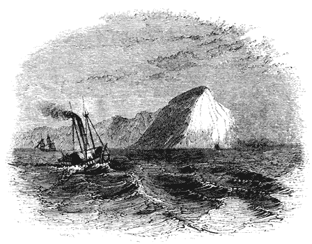
[35] This cut is taken from the plate of the engine of the Red Rover, manufactured by Boulton and Watt, given in the last edition of Tredgold on the Steam Engine.
[36] Appendix I., on Marine Boilers, by J. Dinnen; Tredgold on the Steam Engine, second edition.
[37] Tredgold on the Steam Engine, Appendix, I. p. 171.
[38] Engines on a very large scale constructed upon this principle are said to be in process of construction for an iron steam-vessel of great tonnage, which is in preparation for the New York passage. It is said that the cylinders of these engines will be one hundred and twenty inches in diameter.
[39] A patent was subsequently taken out for these by Mr. Galloway. Mr. Field did not persevere in its use at the time he invented it. It has, however, been more generally adopted since the date of Galloway's patent.

AMERICAN STEAM NAVIGATION.
The circumstances which rendered these extensive tracts of inland and coast navigation eminently suited to the application of steam power, formed so many obstructions and difficulties to the application of other more ordinary means of locomotion on water. The sheltered bays and sounds which offered a smooth and undisturbed surface to the action of the infant steamer argued the absence of that element which gave effect to the sails and rigging of the wind-propelled ship, and the rapid currents of the gigantic streams formed by the drainage of this great continent, though facilitating access to the coast, rendered the oar powerless in the ascent.
At Paris, Livingstone met Fulton, who had been previously engaged in similar speculations, and being struck with his mechanical skill, and the soundness of his views, joined him in causing a series of experiments to be made, which were accordingly carried on at Plombières, and subsequently on a still more extensive scale on the Seine, near Paris. Having by this course of experiments obtained proofs of the efficiency of Fulton's projects, sufficient to satisfy the mind of Livingstone, he agreed to obtain for Fulton the funds necessary to construct a steam boat on a large scale, to be worked upon the Hudson. It was decided, in order to give the project the best chance of success, to obtain the machinery from Bolton and Watt. In 1803, Fulton accordingly made drawings of the engines intended for this first steamer, which were sent to Soho, with an order for their construction. Fulton, meanwhile, repaired to America, to superintend the construction of the boat. The delays incidental to these proceedings retarded the completion of the boat and machinery until the year 1807, when all was completed, and the first successful experiment made at New York. The vessel was placed, for regular work, to ply between New York and Albany, in the beginning of 1808; and, from that time to the present, this river has been the theatre of the most [Pg490] remarkable series of experiments on locomotion on water which has ever been presented in the history of navigation.
The speed attained by this steam boat, when it first began to ply upon the river, did not exceed four miles an hour, but by a series of improvements its rate of motion was soon increased to six miles an hour. In the steam boats subsequently constructed by Fulton a greater speed was attained; but in the latest vessels built by him he did not exceed a speed of nine miles an hour, which he considered to be the greatest that could be advantageously obtained.
While Fulton was making his plans, and engaged in the [Pg491] construction of his first boat, Mr. Stevens of Hoboken, already mentioned, was engaged in a like project, and completed a vessel, to be propelled by a steam engine, within a few weeks after the first successful voyage of Fulton. Stevens was likewise completely successful; but the exclusive privilege of navigating the Hudson by steam having been granted to Fulton by an act of Congress, Stevens was compelled to select another theatre for his operations, and he accordingly sent his steam boat by sea to Philadelphia, to navigate the Delaware, thus securing for himself the honour of having made the first sea voyage by steam.
Fulton did not long retain the monopoly of the steam navigation of the Hudson. Fortunately for the progress of steam navigation, the act conferring upon him that privilege was declared unconstitutional; and the navigation of that noble river was thrown open to the spirit and enterprise of American genius. The number of passengers conveyed upon it became enormous beyond all precedent, and inducements of the strongest kind were accordingly held out to the improvement of its navigation. The distance between New York and Albany, ascertained by a late survey to be one hundred and twenty-five geographical miles by water, had been performed by Fulton's boats occasionally in fifteen or sixteen hours, being at the rate of about eight miles an hour, including stoppages. It became a great object to increase the speed of this trip, so that it might at all times of the year be performed between sunrise and sunset. Robert L. Stevens, the son of the person of that name already mentioned, immediately after the abolition of Fulton's monopoly, placed on the river a vessel which had been built for the Delaware, which easily performed the passage in twelve hours, being at the rate of nearly ten and a half geographical miles an hour. By this increase of speed the improved boats so entirely monopolised the day work upon the river, that the former steamers were either converted into steam tugs to draw barges laden with goods, or used for night trips between New York and Albany. In the night trips the saving of one or two hours was immaterial, it being sufficient that the vessel which left the one port at night should reach the other in the morning. [Pg492]
The river Hudson rises near Lake Champlain, the easternmost of the great chain of lakes or inland seas which extend from east to west across the northern boundary of the United States. The river follows nearly a straight course southwards for two hundred and fifty miles, and empties itself into the sea at New York. The influence of the tide is felt as far as Albany, above which the stream begins to contract. Although this river in magnitude and extent is by no means equal to several others which intersect the States, it is nevertheless rendered an object of great interest by reason of the importance and extent of its trade. The produce of the state of New York and that of the banks of the great Lakes Ontario and Erie are transported by it to the capital; and one of the most extensive and populous districts of the United States is supplied with the necessary imports by its waters. A large fleet of vessels is constantly engaged in its navigation; nor is the tardy but picturesque sailing vessel as yet excluded by the more rapid steamers. The current of the Hudson is said to average nearly three miles an hour; but as the ebb and flow of the tide are felt as far as Albany, the passage of the steamers between that place and New York may be regarded as equally affected by currents in both directions, or nearly so. The passage therefore, whether in ascending or descending the river, is made nearly in the same time.
The position and form of the machinery is likewise affected by these conditions. Without the necessity of being protected from a rough sea, it is placed on the deck in an elevated position. The cylinders of large diameter and short stroke invariably used in Europe are unknown in America, and the proportions are reversed, a small diameter and stroke of great length being invariably adopted. It is rarely that two engines are used. A single engine, placed in the centre of the deck, with a cylinder from forty to sixty inches' diameter, and from eight to ten foot stroke, drives paddle-wheels from twenty-one to twenty-five feet in diameter, producing from twenty-five to thirty revolutions per minute. The great magnitude of the paddle-wheels and the velocity imparted to them enable them to perform the office of fly-wheels, and to carry the engine round its centres, not however without a perceptible inequality of motion, which gives to the American steamer an effect like that of a row boat advancing by starts with each stroke of the piston. The length of stroke adopted in these engines enables them to apply with great effect the expansive principle, which is almost universally used, the steam being generally cut off at half stroke.
The steamers which navigate the Hudson are vessels of considerable magnitude, splendidly fitted up for the accommodation of passengers; they vary from one hundred and eighty to two hundred and forty feet in length, and from twenty to thirty feet in width of beam. In the following table is given the particulars of nine steamers plying on this river, taken from [Pg494] the work of Mr. Stevenson, and from the paper of Mr. Renwick, inserted in the last edition of Tredgold:—
| Names. | Length of Deck. | Breadth of Beam. | Draft of Water. | Drain of Wheel. |
|---|---|---|---|---|
| Ft. | Ft. | Ft. | Ft. | |
| Dewit Clinton | 230 | 28 | 5·5 | 21 |
| Champlain | 180 | 27 | 5·5 | 22 |
| Erie | 180 | 27 | 5·5 | 22 |
| North America | 200 | 30 | 5 | 21 |
| Independence | 148 | 26 | -- | -- |
| Albany | 212 | 26 | -- | 24·5 |
| Swallow | 233 | 22·5 | 3·75 | 24 |
| Rochester | 200 | 25 | 3·75 | 23·5 |
| Utica | 200 | 21 | 3·5 | 22 |
| Names. | Length of Paddles. | Depth of Paddles. | Number of Engines. | Drain of Cylinder. |
|---|---|---|---|---|
| Ft. | In. | In. | ||
| Dewit Clinton | 13·7 | 36 | 1 | 65 |
| Champlain | 15 | 34 | 2 | 44 |
| Erie | 15 | 34 | 2 | 44 |
| North America | 13 | 30 | 2 | 44·5 |
| Independence | -- | -- | 1 | 44 |
| Albany | 14 | 30 | 1 | 65 |
| Swallow | 11 | 30 | 1 | 46 |
| Rochester | 10 | 24 | 1 | 43 |
| Utica | 9·5 | 24 | 1 | 39 |
| Names. | Length of Stroke. | Number of Rev. | Part of Stroke at which it is cut off. |
|---|---|---|---|
| Ft. | |||
| Dewit Clinton | 10 | 29 | 3⁄4 |
| Champlain | 10 | 27·5 | 1⁄2 |
| Erie | 10 | 27·5 | 1⁄2 |
| North America | 8 | 24 | 1⁄2 |
| Independence | 10 | ||
| Albany | -- | 19 | |
| Swallow | -- | 27 | |
| Rochester | 10 | 28 | |
| Utica | 10 |
None of these vessels have either masts or rigging, and consequently never derive any propelling power except from the engines: they are neither manned nor commanded by persons having any knowledge of navigation: the works that are visible above their decks are the beam and framing of the engine, and the chimneys.
The engines used for steamers on the Hudson, and other great rivers and bays on the eastern coast of America, are most commonly condensing engines, but they nevertheless work with steam of very high pressure, being seldom less than twenty-five pounds per square inch, and sometimes as much as fifty. By reference to the preceding table it will be seen, that the velocity of the piston greatly exceeds the limit generally observed in Europe. It is customary in European marine engines to limit the speed of the piston to about two hundred and twenty feet per minute. Even the piston of a locomotive engine does not much exceed the rate of three hundred feet per minute. In the American steamers, however, the pistons commonly move at the rate of from five to six hundred feet per minute, while the circumference of the paddle-wheels are driven at the rate of from twenty to twenty-two miles an hour. [Pg495]
The hulls of these boats are formed with a perfectly flat bottom and perpendicular sides, rounded at the angles, as represented in fig. 135. At the bow, or cutwater, they are made very sharp, and the deck projects to a great distance over the sides. The weight of the machinery is distributed over an extensive surface of the bottom of this feeble structure, by means of a frame-work of substantial carpentry to which it is attached.
At the height of from four to six feet above the water-line is placed the deck, which is a platform, having the shape of a very elongated ellipse. The extremities of its longer axis are supported by the sternpost and the cutwater, and its sides expand in gentle curves on either hand to a considerable distance beyond the limits of the hull; those parts of the deck thus overhanging the water are called the wheel guards.
Beneath the first deck is the saloon, or dining-room, which also, as is usual in European steamers, forms the gentlemen's sleeping-room. It usually extends from end to end of the vessel. The middle of the first deck is occupied by the engine, boilers, furnaces, and chimneys, of which latter there are generally two. Between the chimneys and the stern, above the first deck, is constructed the ladies' cabin, which is covered by the second deck, called the promenade deck. The great length of these boats and the elevation of the cabins render it impossible for a steersman at the stern to see ahead, and they are, consequently, steered from the bow; the wheel placed there communicating with the helm at the stern, by chains or rods carried along the sides of the boat. Until a recent period, the wheel was connected with the stern by ropes, but some fatal accidents, produced by fire, [Pg496] in which these ropes were burnt, and the steersman lost all power to guide the vessel, caused metal rods or chains to be substituted.
The spokes, which are bolted to cast-iron flanges, are of wood. These flanges, to which they are so bolted, are keyed upon the paddle shaft. The outer extremities of the spokes are attached to circular bands or hoops of iron, surrounding the wheel; and the paddle boards, which are formed of hard wood, are bolted to the spokes. The wheels thus constructed, sometimes consist of three, and not unfrequently four, independent circles of paddle boards, placed one beside the other, and so adjusted in their position, that the boards of no two divisions shall correspond.
The great magnitude of the paddle-wheels, and the circumstance of the navigation being carried on, for the most part, in smooth water, have rendered unnecessary, in America, the adoption of any of those expedients for neutralising the effects of the oblique action of the paddles, which have been tried, but hitherto with so little success, in Europe.
In the following Table is given the dimensions of five of these vessels, all plying between New York and Providence:—
| Names. | Length of Deck. | Breadth of Beam. | Draft. | Diameter of Wheel. |
|---|---|---|---|---|
| Ft. | Ft. | Ft. | Ft. | |
| Providence | 180 | 27 | 9 | -- |
| Lexington | 207 | 21 | -- | 23 |
| Narragansett | 210 | 26 | 5 | 25 |
| Massachusetts | 200 | 29·5 | 8·5 | 22 |
| Rhode Island | 210 | 26 | 6·5 | 24 |
| Names. | Length of Paddles. | Depth of Paddles. | Number of Engines. | Diameter of Cylinder. |
|---|---|---|---|---|
| Ft. | In. | In. | ||
| Providence | -- | -- | 1 | 10 |
| Lexington | 9 | 30 | 1 | 11 |
| Narragansett | 11 | 30 | 1 | 60 |
| Massachusetts | 10 | 28 | 2 | 44 |
| Rhode Island | 11 | 30 | 1 | 11 |
| Names. | Length of Stroke. | Number of Rev. | Part of stroke at which stroke is cut off. |
|---|---|---|---|
| Ft. | |||
| Providence | 65 | ||
| Lexington | 48 | 24 | |
| Narragansett | 12 | 2 | 1⁄2 |
| Massachusetts | 8 | 26 | |
| Rhode Island | 60 | 21 |
The Narragansett, the finest of these vessels, is built of oak, strengthened by diagonal straps or ties of iron, by which her timbers are connected; she is driven by a condensing engine, and has two boilers, exposing about three thousand square feet of surface to the fire. The steam is maintained at a pressure of from twenty to twenty-five lbs. per square inch: the cylinder is horizontal.
The cabins of these sea-boats are of great magnitude, and afford excellent accommodation for passengers, containing generally four hundred berths. In the Massachusetts the chief cabin is one hundred and sixty feet long, twenty-two feet wide, and twelve feet in height, its vast extent being uninterrupted by pillars or any other obstruction. "I have dined," says Mr. Stevenson, "with one hundred and seventy-five persons in this cabin, and, notwithstanding this numerous assembly, the tables, which were arranged in two parallel rows, extending from one end of the cabin to the other, were far from being fully occupied, the attendance was good, and every thing was conducted with perfect regularity and order. There are one hundred and twelve fixed berths ranged round this cabin, and one hundred temporary berths can be erected in the middle of the floor: besides these there are sixty fixed berths in the ladies' cabin, and several temporary sleeping [Pg498] places can be erected in it also. The cabin of the Massachusetts is by no means the largest in the United States. Some steamers have cabins upwards of one hundred and seventy-five feet in length. Those large saloons are lighted by Argand lamps, suspended from the ceiling, and their appearance, when brilliantly lighted up and filled with company, is very remarkable. The passengers generally arrange themselves in parties at the numerous small tables into which the large tables are converted after dinner, and engage in different amusements. The scene resembles much more the coffee-room of some great hotel than the cabin of a floating vessel."
Mr. Stevenson states, that exclusive of the time lost in stoppages, the voyage between New York and Albany is usually made in ten hours. Dr. Renwick, however, who has probably more extensive opportunities of observation, states, that the average time, exclusive of stoppages, is ten hours and a half. The distance being 125·18 geographical miles, the average rate would therefore be 119⁄10 miles per hour. If it be observed that the average rate of some of the best sea-going steamers in Europe obtained from experiments [Pg499] and observations made by myself, more than three years ago, showed a rate of steaming little less than ten geographical miles per hour, and that since that time considerable improvements in steam navigation have been made, and further, that these performances were made under exposure to all the disadvantages of an open sea, the difference between them and the performance of the American river steamers will cease to create astonishment.
Dr. Renwick states that he made, in a boat called the "New Philadelphia," one of the most remarkable passages ever performed. He left New York at five in the afternoon, with the first of the flood, and landed at Catskill, distant 95·8 geographical miles from New York, at a quarter before twelve. Passengers were landed and taken in at seven intermediate points: the rate, including stoppages, was therefore 14·2 miles per hour; and if half an hour be allowed for stoppages, the actual average rate of motion would be fifteen miles and three quarters an hour. As the current, which in this case was with the course of the vessel, did not exceed three miles and a half an hour, the absolute velocity through the water would have been somewhat under twelve miles an hour. This speed is nearly the same as the speed obtained from taking the average time of the voyages between New York and Albany at ten hours and a half; it would therefore appear that the great speed attained in this trip must have been chiefly, if not altogether, owing to the effect of the current.
The severe storms and formidable sea encountered on the lakes render necessary for the navigation, vessels in all respects as strong and powerful as those which navigate the open ocean.
The pressure of steam used in these machines is such as is never used in European engines, even when worked on railways. A pressure of one hundred pounds per inch is here considered extremely moderate. The captain of one of these boats, plying between Pittsburg and St. Louis, told Mr. Stevenson that "under ordinary circumstances his safety valves were loaded with a pressure equal to one hundred and thirty-eight pounds per square inch, but that the steam was occasionally raised as high as one hundred and fifty pounds to enable the vessel to pass parts of the river in which there is a strong current;" and he added, by way of consolation, that "this pressure was never exceeded except on extraordinary occasions!"
The dimensions and power of the Mississippi steamers may be collected from those of the St. Louis, a boat which was plying on that river in 1837. That vessel measured two hundred and fifty feet on deck, and had twenty-eight feet breadth of beam. Her draught of water was eight feet, and her measured capacity one thousand tons. She was propelled by two engines with thirty-inch cylinders, and ten feet stroke; the safety valve being loaded at one hundred pounds per square inch.
The paddle wheels of these vessels are attached to the paddle shaft, in such a manner as to be thrown into and out of gear, at discretion, by the engineer, so that the paddle shaft may revolve without driving the wheels: by this expedient the power of the engine is used to feed the boilers while the vessel stops at the several stations. The vessel is therefore stopped, not, as is usually the case, by stopping the engines, but by throwing the wheels out of connection with the paddle shaft. The engines continue to work, but their [Pg503] power is expended in forcing water into the boiler. By this expedient the activity of the engines may, within practical limits, be varied with the resistance the vessel has to encounter. In working against a strong current, the feed may be cut off from the boilers, and the production of steam, and consequently the power of the engines, thereby stimulated, while this suspension of the feed may be compensated at the next station.
The stoppages to take in goods and passengers, and for relays of fuel, are frequent. "The liberty which they take with their vessels on these occasions," says Mr. Stevenson, "is somewhat amusing: I had a good example of this on board a large vessel, called the Ontario. She was steered close in shore amongst stones and stumps of trees, where she lay for some hours to take in goods: the additional weight increased her draught of water, and caused her to heel a good deal; and when her engines were put in motion, she actually crawled into the deep water on her paddle wheels: the steam had been got up to an enormous pressure to enable her to get off, and the volume of steam discharged from the escapement pipe at every half stroke of the piston made a sharp sound almost like the discharge of fire-arms, while every timber in the vessel seemed to tremble, and the whole structure actually groaned under the shocks."
Besides the steamers used for the navigation of the Mississippi, innumerable steam tugs are constantly employed in towing vessels between the port of New Orleans and the open sea of the Gulf of Mexico. Before the invention of steam navigation, this southern capital of the United States laboured under the disadvantage of possessing almost the only bad and inconvenient harbour in the vast range of coast by which the country is bounded. New Orleans lies at a distance of about one hundred miles from the Gulf of Mexico. The force of the stream, the frequency of shoals, and the winding course of the channel rendered it scarcely possible for a sailing vessel to pass between the port and the sea with the same wind. The anchorage was every where bad, and great difficulty and risk attended the mooring of large vessels to the banks. The steam engine has, however, overcome all [Pg504] these difficulties, and rendered the most objectionable harbour of the Union a safe and good seaport, perfectly easy of approach and of egress at all times; a small steam tug will take in tow several large ships, and carry them with safety and expedition to the offing, where it will dismiss them on their voyage, and take back vessels which may have arrived.

On the Relation between the Temperature, Pressure, and Density of Common Steam.
The following formula, proposed by M. Biot, represents with great accuracy the relation between the temperature and pressure of common steam, throughout all that part of the thermometric scale to which experiments have been extended.
Let
| a = 5·96131330259 |
| log. a1 = 0·82340688193 − 1 |
| log. b1 = −·01309734295 |
| log. a2 = 0·74110951837 |
| log. b2 = −·00212510583 |
The relation between the temperature t with reference to the centesimal thermometer, and the pressure p in millimètres of mercury at the temperature of melting ice, will then be expressed by the following formula:—
| log. p = a − a1b120 + t − a2b220 + t. (1.) |
Formulæ have, however, been proposed, which, though not applicable to the whole scale of temperatures, are more manageable in their practical application than the preceding.
For pressures less than an atmosphere, Southern proposed the following formula, where the pressure is intended to be expressed [Pg506] in pounds per square inch, and the temperature in reference to Fahrenheit's thermometer,—
| p = 0·04948 + ( | 51·3 + t | ) | 5·13 | .(2.) |
| 155·7256 | ||||
| t = 155·7256 {(p − 0·04948)1⁄5·13 − 51·3} | ||||
The following formula was proposed by Tredgold, where p expresses the pressure in inches of mercury:—
| p = ( | 100 + t | ) | 6 | . |
| 177 |
This was afterwards modified by Mellet, and represents with sufficient accuracy experiments from 1 to 4 atmospheres. Let p represent pounds per square inch, and t the temperature by Fahrenheit's thermometer,—
| p = ( | 103 + t | ) | 6 | .(3.) |
| 201·18 | ||||
| t = 201·18 p 1⁄6 − 103 | ||||
M. de Pambour has proposed the following formula, also applicable through the same limits of the scale:—
| p = ( | 98·806 + t | ) | 6 | . (4.) |
| 198·562 | ||||
| t = 198·562 p 1⁄6 − 98·806 | ||||
MM. Dulong and Arago have proposed the following formula for all pressures between 4 and 50 atmospheres:—
| p = (0·26793 + 0·0067585 t)5 | . (5.) |
| t = 147·961 p1⁄5 − 39·644 |
It was about the year 1801, that Dalton, at Manchester, and Gay-Lussac, at Paris, instituted a series of experiments on gaseous bodies, which conducted them to the discovery of the law mentioned in art. (96.), p. 171. These philosophers found that all gases whatever, and all vapours raised from liquids by heat, as well as all mixtures of gases and vapours, are subject to the same quantity of expansion between the temperatures of melting ice and boiling water; and by experiments subsequently made by Dulong and Petit, this uniformity of expansion has been proved to extend to all temperatures which can come under practical inquiries.
Dalton found that 1000 cubic inches of air at the temperature of melting ice dilated to 1325 cubic inches if raised to the temperature of boiling water. According to Gay-Lussac, the increased volume was 1375 cubic inches. The latter determination has been subsequently found to be the more correct one.[40]
It appears, therefore, that for an increase of temperature from 32° to 212°, amounting to 180°, the increase of volume is 375 parts in 1000; and since the expansion is uniform, the increase of volume for 1° will be found by dividing this by 180, which will give an increase of 2081⁄3 parts in 100,000 for each degree of the common thermometer.
To reduce the expression of this important and general law to mathematical language, let v be the volume of an elastic fluid at the temperature of melting ice, and let nv be the increase which that volume would receive by being raised one degree of temperature under the same pressure. Let V be its volume at the temperature T. Then we shall have
| V = v + nv (T − 32) = v {1 + n (T − 32)}. |
If V′ be its volume at any other temperature T′, and under the same pressure, we shall have, in like manner,
| V′ = v {1 + n (T′ − 32)}. |
Hence we obtain
| V | = | 1 + n (T − 32) | ;(6.) |
| V′ | 1 + n (T′ − 32) |
which expresses the relation between the volumes of the same gas or vapour under the same pressure and at any two temperatures. The co-efficient n, as explained in the text, has the same value for the same gas or vapour throughout the whole thermometric scale. But it is still more remarkable that this constant has the same value for all gases and vapours. It is a number, therefore, which must have some essential relation to the gaseous or elastic state of fluid matter, independent of the peculiar qualities of any particular gas or vapour.
The value of n, according to the experiments of Gay-Lussac, is 0·002083, or 1⁄480.
To reduce the law of Mariotte, explained in (97.) p. 171., to mathematical language, let V, V′ be the volumes of the same gas or vapour under different pressures P, P′, but at the same temperature. We shall then have
| VP = V′P′. (7.) |
If it be required to determine the relation between the volumes of the same gas or vapour, under a change of both temperature and pressure, let V be the volume at the temperature T and under the pressure P, and let V′ be the volume at the temperature T′ and under the pressure P′. Let v be the volume at the temperature T and under the pressure P′.
By formula (7.) we have
| VP = vP′; |
and by formula (6.) we have
| V′ | = | 1 + n(T′ − 32) |
| v | 1 + n(T − 32) |
Eliminating v, we shall obtain
| V | = | P′ | · | 1 + n(T − 32) | ; |
| V′ | P | 1 + n(T′ − 32) |
or,
| VP | = | 1 + n(T − 32) | ;(8.) |
| V′P′ | 1 + n(T′ − 32) |
which is the general relation between the volumes, pressures, and temperatures of the same gas or vapour in two different states.
To apply this general formula to the case of the vapour of water, let T′ = 212°. It is known by experiment that the corresponding value of P′, expressed in pounds per square inch, is 14·706; and that V′, expressed in cubic inches, the water evaporated being taken as a cubic inch, is 1700. If, then, we take 0·002083 as the value of n, we shall have by (8.),
| VP = | 1700 × 14·706 × {1 + 0·002083 (T − 32)} | |
| 1 + 0·002083 × 180 | ||
| = 18183{1 + 0·002083 (T − 32)}. | (9.) | |
If, by means of this formula (9.), and any of the formulæ (1.), (2.), (3.), (4.), (5.), T were eliminated, we should obtain a formula between V and P, which would enable us to compute the enlargement of volume which water undergoes in passing into steam under any proposed pressure. But such a formula would not be suitable for practical computations. By the formulæ (1.) to (5.), a table of pressures and corresponding temperatures may be computed; and these being known, the formula (9.) will be sufficient for the computation of the corresponding values of V, or the enlargement of volume which water undergoes in passing into steam.
In the following table, the temperatures corresponding to pressures from 1 to 240 lbs. per square inch are given by computation from the formulæ (2.) to (5.), and the volumes of steam produced by an unit of volume of water as computed from the formula (9.).
The mechanical effect is obtained by multiplying the pressure in pounds by the expansion of a cubic inch of water in passing into steam expressed in feet, and is therefore the number of pounds which would be raised one foot by the evaporation of a cubic inch of water under the given pressure. [Pg509]
| Total pressure in Pounds per Square Inch. | Corresponding Temperature. | Volume of the Steam compared to the Volume of the Water that has produced it. | Mechanical Effect of a Cubic Inch of Water evaporated in Pounds raised One Foot. |
|---|---|---|---|
| 1 | 102·9 | 20868 | 1739 |
| 2 | 126·1 | 10874 | 1812 |
| 3 | 141·0 | 7437 | 1859 |
| 4 | 152·3 | 5685 | 1895 |
| 5 | 161·4 | 4617 | 1924 |
| 6 | 169·2 | 3897 | 1948 |
| 7 | 175·9 | 3376 | 1969 |
| 8 | 182·0 | 2983 | 1989 |
| 9 | 187·4 | 2674 | 2006 |
| 10 | 192·4 | 2426 | 2022 |
| 11 | 197·0 | 2221 | 2036 |
| 12 | 201·3 | 2050 | 2050 |
| 13 | 205·3 | 1904 | 2063 |
| 14 | 209·1 | 1778 | 2074 |
| 15 | 212·8 | 1669 | 2086 |
| 16 | 216·3 | 1573 | 2097 |
| 17 | 219·6 | 1488 | 2107 |
| 18 | 222·7 | 1411 | 2117 |
| 19 | 225·6 | 1343 | 2126 |
| 20 | 228·5 | 1281 | 2135 |
| 21 | 231·2 | 1225 | 2144 |
| 22 | 233·8 | 1174 | 2152 |
| 23 | 236·3 | 1127 | 2160 |
| 24 | 238·7 | 1084 | 2168 |
| 25 | 241·0 | 1044 | 2175 |
| 26 | 243·3 | 1007 | 2182 |
| 27 | 245·5 | 973 | 2189 |
| 28 | 247·6 | 941 | 2196 |
| 29 | 249·6 | 911 | 2202 |
| 30 | 251·6 | 883 | 2209 |
| 31 | 253·6 | 857 | 2215 |
| 32 | 255·5 | 833 | 2221 |
| 33 | 257·3 | 810 | 2226 |
| 34 | 259·1 | 788 | 2232 |
| 35 | 260·9 | 767 | 2238 |
| 36 | 262·6 | 748 | 2243 |
| 37 | 264·3 | 729 | 2248 |
| 38 | 265·9 | 712 | 2253 |
| 39 | 267·5 | 695 | 2259 |
| 40 | 269·1 | 679 | 2264 |
| 41 | 270·6 | 664 | 2268 |
| 42 | 272·1 | 649 | 2273 |
| 43 | 273·6 | 635 | 2278 |
| 44 | 275·0 | 622 | 2282 |
| 45 | 276·4 | 610 | 2287 |
| 46 | 277·8 | 598 | 2291 |
| 47 | 279·2 | 586 | 2296 |
| 48 | 280·5 | 575 | 2300 |
| 49 | 281·9 | 564 | 2304 |
| 50 | 283·2 | 554 | 2308 |
| 51 | 284·4 | 544 | 2312 |
| 52 | 285·7 | 534 | 2316 |
| 53 | 286·9 | 525 | 2320 |
| 54 | 288·1 | 516 | 2324 |
| 55 | 289·3 | 508 | 2327 |
| 56 | 290·5 | 500 | 2331 |
| 57 | 291·7 | 492 | 2335 |
| 58 | 292·9 | 484 | 2339 |
| 59 | 294·2 | 477 | 2343 |
| 60 | 295·6 | 470 | 2347 |
| 61 | 296·9 | 463 | 2351 |
| 62 | 298·1 | 456 | 2355 |
| 63 | 299·2 | 449 | 2359 |
| 64 | 300·3 | 443 | 2362 |
| 65 | 301·3 | 437 | 2365 |
| 66 | 302·4 | 431 | 2369 |
| 67 | 303·4 | 425 | 2372 |
| 68 | 304·4 | 419 | 2375 |
| 69 | 305·4 | 414 | 2378 |
| 70 | 306·4 | 408 | 2382 |
| 71 | 307·4 | 403 | 2385 |
| 72 | 308·4 | 398 | 2388 |
| 73 | 309·3 | 393 | 2391 |
| 74 | 310·3 | 388 | 2394 |
| 75 | 311·2 | 383 | 2397 |
| 76 | 312·2 | 379 | 2400 |
| 77 | 313·1 | 374 | 2403 |
| 78 | 314·0 | 370 | 2405 |
| 79 | 314·9 | 366 | 2408 |
| 80 | 315·8 | 362 | 2411 |
| 81 | 316·7 | 358 | 2414 |
| 82 | 317·6 | 354 | 2417 |
| 83 | 318·4 | 350 | 2419 |
| 84 | 319·3 | 346 | 2422 |
| 85 | 320·1 | 342 | 2425 |
| 86 | 321·0 | 339 | 2427 |
| 87 | 321·8 | 335 | 2430 |
| 88 | 322·6 | 332 | 2432 |
| 89 | 323·5 | 328 | 2435 |
| 90 | 324·3 | 325 | 2438 |
| 91 | 325·1 | 322 | 2440 |
| 92 | 325·9 | 319 | 2443 |
| 93 | 326·7 | 316 | 2445 |
| 94 | 327·5 | 313 | 2448 |
| 95 | 328·2 | 310 | 2450 |
| 96 | 329·0 | 307 | 2453 |
| 97 | 329·8 | 304 | 2455 |
| 98 | 330·5 | 301 | 2457 |
| 99 | 331·3 | 298 | 2460 |
| 100 | 332·0 | 295 | 2462 |
| 110 | 339·2 | 271 | 2486 |
| 120 | 345·8 | 251 | 2507 |
| 130 | 352·1 | 233 | 2527 |
| 140 | 357·9 | 218 | 2545 |
| 150 | 363·4 | 205 | 2561 |
| 160 | 368·7 | 193 | 2577 |
| 170 | 373·6 | 183 | 2593 |
| 180 | 378·4 | 174 | 2608 |
| 190 | 382·9 | 166 | 2622 |
| 200 | 387·3 | 158 | 2636 |
| 210 | 391·5 | 151 | 2650 |
| 220 | 395·5 | 145 | 2663 |
| 230 | 399·4 | 140 | 2675 |
| 240 | 403·1 | 134 | 2687 |
In the absence of any direct method of determining the general relation between the pressure and volume of common steam, empirical formulæ expressing it have been proposed by different mathematicians.
The late Professor Navier proposed the following:—Let S express the volume of steam into which an unit of volume of water is converted under the pressure P, this pressure being expressed in kilogrammes per square mètre. Then the relation between S and P will be
| S = | a | , |
| b + mP |
where a = 1000, b = 0·09, and m = 0·0000484.
This formula, however, does not agree with experiment at pressures less than an atmosphere. M. de Pambour, therefore, proposes the following changes in the values of its co-efficients:—Let P express the pressure in pounds per square foot; and let
a = 10000 b = 0·4227 m = 0·00258,
and the formula will be accurate for all pressures. For pressures above two atmospheres the following values give more accuracy to the calculation:—
a = 10000 b = 1·421 m = 0·0023.
In these investigations I shall adopt the following modified formula. The symbols S and P retaining their signification, we shall have
| S = | a | ,(10.) |
| b + P |
where
a = 3875969 b = 164.
These values of a and b will be sufficiently accurate for practical purposes for all pressures, and may be used in reference to low-pressure engines of every form, as well as for high-pressure engines which work expansively.
When the pressure is not less than 30 pounds per square inch, the following values of a and b will be more accurate:—
a = 4347826 b = 618.
On the Expansive Action of Steam.
The investigation of the effect of the expansion of steam which has been given in the text, is intended to convey to those who are not conversant with the principles and language of analysis, some notion of the nature of that mechanical effect to which the advantages attending the expansive principle are due. We shall now, however, explain these effects more accurately. [Pg512]
The dynamical effect produced by any mechanical agent is expressed by the product of the resistance overcome and the space through which that resistance is moved.
Let
| P = the pressure of steam expressed in pounds per square foot. |
| S = the number of cubic feet of steam of that pressure produced by the evaporation of a cubic foot of water. |
| E = the mechanical effect produced by the evaporation of a cubic foot of water expressed in pounds raised one foot. |
Then we shall have E = PS; and if W be a volume of water evaporated under the pressure P, the mechanical effect produced by it will be WPS.
By (10.) we have
| SP = a − bS. |
Hence, for the mechanical effect of a cubic foot of water evaporated under the pressure P we have
| E = a − bS.(11.) |
Let a cubic foot of water be evaporated under the pressure P′, and let it produce a volume of steam S′ of that pressure. Let this steam afterwards be allowed to expand to the increased volume S and the diminished pressure P; and let it be required to determine the mechanical effect produced during the expansion of the steam from the volume S′ to the volume S.
Let
| E′ = the mechanical effect produced by the evaporation of the water under the pressure P′ without expansion. |
| E″ = the mechanical effect produced during the expansion of the steam. |
| E = the mechanical effect which would be produced by the evaporation under the pressure P without expansion. |
| E = the total mechanical effect produced by the evaporation under the pressure P′ and subsequent expansion. |
Thus we have
| E = E′ + E″. |
Let s be any volume of the steam during the process of expansion, p the corresponding pressure, and e″ the mechanical effect produced by the expansion of the steam. We have then by (10.)
| p = | a | − b; |
| s | ||
| ∵ de″ = | ads | − bds. |
| s |
Hence by integrating we obtain
| e″ = a log. s − bs + C; |
which, taken between the limits s = S′ and s = S, becomes
| E″ = a log. | S | − b(S − S′).(12.) |
| S′ |
But by (11.) we have
| E′ = a − bS′, | |
| E = a − bS; | |
| ∵ E′ − E = b(S − S′); | |
| ∵ E″ = a log. | S | − E′ + E; |
| S′ |
| ∵ E = E″ + E′ = a log. | S | + E.(13.) |
| S′ |
Or,
| E = a (1 + log. | S | ) − bS.(14.) |
| S′ |
Hence it appears that the mechanical effect of a cubic foot of water evaporated under the pressure P may be increased by the quantity a log. S/S′, if it be first evaporated under the greater pressure P′, and subsequently expanded to the lesser pressure P.
The logarithms in these formulæ are hyperbolic.
To apply these principles to the actual case of a double acting steam engine,
Let
| L = the stroke of the piston in feet. |
| A = the area of the piston in square feet. |
| n = the number of strokes of the piston per minute. |
| ∵ 2nAL = the number of cubic feet of space through which the piston moves per minute. |
Let
| cLA = the clearage, or the space between the steam valve and the piston at each end of the stroke. |
| ∵ The volume of steam admitted through the steam valve at each stroke of the engine will be 2n AL(1 + c). |
Let
| V = the mean speed of the piston in feet per minute, |
| ∵ 2nL = V. |
The volume of steam admitted to the cylinder per minute will therefore be VA (1 + c), the part of it employed in working the piston being VA.
Let
| W = the water in cubic feet admitted per minute in the form of steam through the steam valve. |
| S = the number of cubic feet of steam produced by a cubic foot of water. |
Hence we shall have
| WS = VA (1 + c); | ||
| ∵ S = | VA(1 + c) | .(15.) |
| W | ||
Since by (10.) we have
| P = | a | − b; |
| S |
| ∵ P = | Wa | − b.(16.) |
| VA(1 + c) |
By which the pressure of steam in the cylinder will be known, when the effective evaporation, the diameter of the cylinder, and speed of the piston, are given.
If it be required to express the mechanical effect produced per minute by the action of steam on the piston, it is only necessary to multiply the pressure on the surface of the piston by the space per minute through which the piston moves. This will give
| VAP = W | a | − VAb;(17.) |
| 1 + c |
which expresses the whole mechanical effect per minute in pounds raised one foot.
If the steam be worked expansively, let it be cut off after the piston has moved through a part of the stroke expressed by e.
The volume of steam of the undiminished pressure P′ admitted per minute through the valve would then be
| VA (e + c); |
and the ratio of this volume to that of the water producing it being expressed by S′, we should have
| S′ = | VA(e + c) | . |
| W |
The final volume into which this steam is subsequently expanded being VA(1 + c), its ratio to that of the water will be
| S = | VA (1 + c) | . |
| W |
The pressure P′, till the steam is cut off, will be
| P′ = | Wa | − b.(18.) |
| VA(e + c) |
The mechanical effect E′ produced per minute by the steam of full pressure will be
| E′ = P′AVe = | Wae | − AVbe; |
| e + c |
and the effect E″ per minute produced by the expansion of the steam will by (12.) be [Pg515]
| E″ = Wa log. | 1 + c | − bVA(1 − e). |
| e + c |
Hence the total effect per minute will be
| E = Wa{ | e | + log. | 1 + c | } − bVA.(19.) |
| e + c | e + c |
If the engine work without expansion, e = 1;
| ∵ E′ = | Wa | − bVA,(20.) |
| 1 + c |
as before; and the effect per minute gained by expansion will therefore be
| E − E′ = Wa{ | e | − | 1 | + log. | 1 + c | };(21.) |
| e + c | 1 + c | e + c |
which therefore represents the quantity of power gained by the expansive action, with a given evaporating power.
In these formulæ the total effect of the steam is considered without reference to the nature of the resistances which it has to overcome.
These resistances may be enumerated as follows:—
When the engine is maintained in a state of uniform motion, the sum of all these resistances must always be equal to the whole effect produced by the steam on the piston. The power expended on the first alone is the useful effect.
Let
| R = the pressure per square foot of the piston surface, which balances the resistances produced by the load. |
| mR = the pressure per square foot, which balances that part of the friction of the engine which is proportional to the load. |
| r = the pressure per square foot, which balances the sum of all those resistances that are not proportional to the load. |
The total resistance, therefore, being R + mR + r, which, when the mean motion of the piston is uniform, must be equal to the mean pressure on the piston. The total mechanical effect [Pg516] must therefore be equal to the total resistance multiplied by the space through which that resistance is driven. Hence we shall have
| {R(1 + m) + r}VA = Wa{ | e | + log. | 1 + c | } − VAb; |
| e + c | e + c |
| ∵ RVA(1 + m) = Wa{ | e | + log. | 1 + c | } − VA(b + r). |
| e + c | e + c |
For brevity, let
| e′ = a{ | e | + log. | 1 + c | }; |
| e + c | e + c |
| ∵ RVA(1 + m) = We′ − VA(b + r).(22.) |
By solving this for VA, we obtain
| VA = | We′ | ; |
| R(1 + m) + b + r | ||
| ∵ RVA = | We′R | .(23.) |
| R(1 + m) + b + r |
This quantity RVA, being the product of the resistance RA, of the load reduced to the surface of the piston, multiplied by the space through which the piston is moved, will be equal to the load itself multiplied by the space through which it is moved. This being, in fact, the useful effect of the engine, let it be expressed by U, and we shall have
| U = | We′R | .(24.) |
| R(1 + m) + b + r |
Or by (22.),
| U(1 + m) = We′ − VA(b + r).(25.) |
The value of the useful effect obtained from these formulæ will be expressed in pounds, raised one foot per minute, W being the effective evaporation in cubic feet per minute, A the area of the piston in square feet, and V the space per minute through which it is moved, in feet.
Since a resistance amounting to 33,000 pounds moved through one foot per minute is called one-horse power, it is evident that the horse power H of the engine is nothing more than the useful effect per minute referred to a larger unit of weight or resistance; that is to 33,000 pounds instead of one pound. Hence we shall have
| H = | U | .(26.) |
| 33000 |
Since the useful effect expressed in (24.) and (25.) is that due to a number of cubic feet of water, expressed by W, we shall obtain the effect due to one cubic foot of water, by dividing U by W. If, therefore, U′ be the effect produced by the effective evaporation of a cubic foot of water, we shall have [Pg517]
| U′ = | U | .(27.) |
| W |
If the quantity of fuel consumed per minute be expressed by F, the effect produced by the unit of fuel, called the DUTY of the engine, will, for like reason, be
| D = | U | .(28.) |
| F |
If the fuel be expressed in hundredweights of coal, then D will express the number of pounds' weight raised one foot by a hundredweight of coal.
By solving (24.) and (25.) for W, we obtain
| W = | U{R(1 + m) + b + r} | ,(29.) |
| Re′ |
| W = | 1 | {U(1 + m) + VA(b + r)}.(30.) |
| e′ |
By eliminating U, by (26.), we shall have
| W = | 33000 H{R(1 + m) + b + r} | ,(31.) |
| Re′ |
| W = | 1 | {33000 H(1 + m) + VA(b + r)}.(32.) |
| e′ |
The evaporation necessary per horse power per minute will be found by putting H = 1 in these formulæ.[41]
It will be observed that the quantities A and V, the area of the cylinder and the speed of the piston, enter all these formulæ as factors of the same product. Other things, therefore, being the same, the speed of the piston will be always inversely as the area of the cylinder. In fact, VA is the volume of steam per minute employed in working the piston, and if the piston be increased or diminished in magnitude, its speed must be inversely [Pg518] varied by the necessity of being still moved through the same number of cubic feet by the same volume of steam.
It has been already stated in the text, that no satisfactory experiments have yet been made, by which the numerical value of the quantity r can be exactly known. In engines of different magnitudes and powers, this resistance bears very different proportions to the whole power of the machine. In general, however, the larger and more powerful the engine, the less that proportion will be.
That part of this resistance which arises from the reaction of the uncondensed vapour on the piston is very variable, owing to the more or less perfect action of the condensing apparatus, the velocity of the piston, and the magnitude and form of the steam passages. M. de Pambour states, that, by experiments made with indicators, the mean amount of this resistance in the cylinder is 21⁄2 lbs. per square inch more than in the condenser, and that the pressure in the latter being usually 11⁄2 lb. per square inch, the mean amount of the pressure of the condensed vapour in the cylinder is about 4 lbs. per square inch. Engineers, however, generally consider this estimate to be above the truth in well-constructed engines, when in good working order.
In condensing low pressure engines of forty horse power and upwards, working with an average load, it is generally considered that the resistance produced by the friction of the machine and the force necessary to work the pumps may be taken at about 2 lbs. per square inch of piston surface.
Thus the whole resistance represented by r in the preceding formulæ, as applied to the larger class of low pressure engines, may be considered as being under 6 lbs. per square inch, or 864 lbs. per square foot, of the piston. It is necessary, however, to repeat, that this estimate must be regarded as a very rough approximation; and as representing the mean value of a quantity subject to great variation, not only in one engine compared with another, but even in the same engine compared with itself at different times and in different states.
In the same class of engines, the magnitude of the clearage is generally about a twentieth part of the capacity of the cylinder, so that c = 0·05.
That part of the resistance which is proportional to the load, and on which the value of m in the preceding formulæ depends, is still more variable, and depends so much on the form, magnitude, and the arrangement of its parts, that no general rule can be given for its value. It must, in fact, be determined in every particular case.
In the practical application of the preceding formulæ in condensing engines we shall have [Pg519]
| a = 3875969 b = 164 c = 0·05; |
| e′ = 3875969{ | e | + log. | 1·05 | }. |
| e + 0·05 | e + 0·05 |
In engines which work without condensation, and therefore with high pressure steam, we shall have
| a = 4347826 b = 618 c = 0·05; |
| e′ = 4347826{ | e | + log. | 1·05 | }. |
| e + 0·05 | e + 0·05 |
To facilitate computation, the values of e′ corresponding to all values of e, from e = ·10 to e = ·90, are given in the following table:—
| e | Condensing Engines e′. | Non-condensing Engines e′. | e | Condensing Engines e′. | Non-condensing Engines e′. |
|---|---|---|---|---|---|
| ·10 | 10126265 | 11359029 | ·51 | 5966367 | 6692708 |
| ·11 | 9956867 | 11169008 | ·52 | 5903837 | 6622565 |
| ·12 | 9793136 | 10985344 | ·53 | 5842288 | 6553525 |
| ·13 | 9634926 | 10807875 | ·54 | 5781693 | 6485552 |
| ·14 | 9482029 | 10636364 | ·55 | 5722024 | 6418619 |
| ·15 | 9334219 | 10470560 | ·56 | 5663251 | 6352693 |
| ·16 | 9191251 | 10310186 | ·57 | 5605353 | 6287745 |
| ·17 | 9052888 | 10154978 | ·58 | 5548297 | 6223742 |
| ·18 | 8918896 | 10004675 | ·59 | 5492064 | 6160662 |
| ·19 | 8789043 | 9859014 | ·60 | 5436628 | 6098478 |
| ·20 | 8663120 | 9717760 | ·61 | 5381969 | 6037166 |
| ·21 | 8540918 | 9580682 | ·62 | 5328065 | 5976699 |
| ·22 | 8422242 | 9447559 | ·63 | 5274896 | 5917057 |
| ·23 | 8306916 | 9318193 | ·64 | 5222444 | 5858219 |
| ·24 | 8194770 | 9192396 | ·65 | 5170684 | 5800159 |
| ·25 | 8085644 | 9069984 | ·66 | 5119605 | 5742860 |
| ·26 | 7979392 | 8950796 | ·67 | 5069186 | 5686304 |
| ·27 | 7875870 | 8834674 | ·68 | 5019410 | 5630469 |
| ·28 | 7774952 | 8721468 | ·69 | 4970263 | 5575340 |
| ·29 | 7676514 | 8611048 | ·70 | 4921727 | 5520894 |
| ·30 | 7580447 | 8503284 | ·71 | 4873790 | 5467121 |
| ·31 | 7486640 | 8398056 | ·72 | 4826434 | 5414000 |
| ·32 | 7394990 | 8295250 | ·73 | 4779648 | 5361519 |
| ·33 | 7305407 | 8194760 | ·74 | 4733417 | 5309659 |
| ·34 | 7217807 | 8096496 | ·75 | 4687728 | 5258408 |
| ·35 | 7132097 | 8000352 | ·76 | 4642569 | 5207751 |
| ·36 | 7048206 | 7906249 | ·77 | 4597928 | 5157676 |
| ·37 | 6966058 | 7814100 | ·78 | 4553794 | 5108170 |
| ·38 | 6885585 | 7723832 | ·79 | 4510155 | 5059218 |
| ·39 | 6806720 | 7635365 | ·80 | 4466999 | 5010808 |
| ·40 | 6729408 | 7548642 | ·81 | 4424317 | 4962931 |
| ·41 | 6653578 | 7463580 | ·82 | 4382096 | 4915569 |
| ·42 | 6579187 | 7380132 | ·83 | 4340332 | 4868720 |
| ·43 | 6506174 | 7298230 | ·84 | 4299010 | 4822368 |
| ·44 | 6434491 | 7217822 | ·85 | 4258120 | 4776500 |
| ·45 | 6364099 | 7138858 | ·86 | 4217658 | 4731113 |
| ·46 | 6294944 | 7061285 | ·87 | 4177613 | 4686192 |
| ·47 | 6226989 | 6985058 | ·88 | 4137974 | 4641728 |
| ·48 | 6160190 | 6910126 | ·89 | 4098737 | 4597713 |
| ·49 | 6094510 | 6836450 | ·90 | 4059893 | 4554140 |
| ·50 | 6029916 | 6763992 |
In engines which work without expansion we have
| e′ = | a | . |
| 1 + c |
For condensing engines without expansion, we shall then have
| e′ = | 3875969 | = 3691399;(33.) |
| 1·05 |
and for non-condensing engines,
| e′ = | 4347826 | = 4140787.(34.) |
| 1·05 |
As the diameters of the cylinders of engines are generally expressed in inches, the corresponding areas of the pistons expressed in square feet are given in the following table, so that the values of A may be readily found:—
| Diameter. | Area. | Diameter. | Area. |
|---|---|---|---|
| Inches. | Sq. Feet. | Inches. | Sq. Feet. |
| 10 | 07545 | 48 | 127566 |
| 11 | 07660 | 49 | 137095 |
| 12 | 07785 | 50 | 137635 |
| 13 | 07922 | 51 | 147186 |
| 14 | 17069 | 52 | 147748 |
| 15 | 17227 | 53 | 157321 |
| 16 | 17396 | 54 | 157904 |
| 17 | 17576 | 55 | 167499 |
| 18 | 17767 | 56 | 177104 |
| 19 | 17969 | 57 | 177721 |
| 20 | 27182 | 58 | 187348 |
| 21 | 27405 | 59 | 187986 |
| 22 | 27640 | 60 | 197635 |
| 23 | 27885 | 61 | 207295 |
| 24 | 37142 | 62 | 207966 |
| 25 | 37409 | 63 | 217648 |
| 26 | 37687 | 64 | 227340 |
| 27 | 37976 | 65 | 237044 |
| 28 | 47276 | 66 | 237758 |
| 29 | 47587 | 67 | 247484 |
| 30 | 47909 | 68 | 257220 |
| 31 | 57241 | 69 | 257967 |
| 32 | 57585 | 70 | 267725 |
| 33 | 57940 | 71 | 277494 |
| 34 | 67305 | 72 | 287274 |
| 35 | 67681 | 73 | 297065 |
| 36 | 77069 | 74 | 297867 |
| 37 | 77467 | 75 | 307680 |
| 38 | 77876 | 76 | 317503 |
| 39 | 87296 | 77 | 327338 |
| 40 | 87727 | 78 | 337183 |
| 41 | 97168 | 79 | 347039 |
| 42 | 97621 | 80 | 347907 |
| 43 | 107085 | 81 | 357785 |
| 44 | 107559 | 82 | 367674 |
| 45 | 117045 | 83 | 377574 |
| 46 | 117541 | 84 | 387485 |
| 47 | 127048 | 85 | 397406 |
| Diameter. | Area. | Diameter. | Area. |
|---|---|---|---|
| Inches. | Sq. Feet. | Inches. | Sq. Feet. |
| 86 | 407339 | 124 | 837863 |
| 87 | 417283 | 125 | 857221 |
| 88 | 427237 | 126 | 867590 |
| 89 | 437202 | 127 | 877970 |
| 90 | 447179 | 128 | 897361 |
| 91 | 457166 | 129 | 907763 |
| 92 | 467164 | 130 | 927175 |
| 93 | 477173 | 131 | 937599 |
| 94 | 487193 | 132 | 957033 |
| 95 | 497224 | 133 | 967479 |
| 96 | 507265 | 134 | 977935 |
| 97 | 517318 | 135 | 997402 |
| 98 | 527382 | 136 | 1007880 |
| 99 | 537456 | 137 | 1027369 |
| 100 | 547542 | 138 | 1037869 |
| 101 | 557638 | 139 | 1057380 |
| 102 | 567745 | 140 | 1067901 |
| 103 | 577863 | 141 | 1087434 |
| 104 | 587992 | 142 | 1097977 |
| 105 | 607132 | 143 | 1117532 |
| 106 | 617283 | 144 | 1137097 |
| 107 | 627445 | 145 | 1147674 |
| 108 | 637617 | 146 | 1167261 |
| 109 | 647801 | 147 | 1177859 |
| 110 | 657995 | 148 | 1197468 |
| 111 | 677201 | 149 | 1217088 |
| 112 | 687417 | 150 | 1227719 |
| 113 | 697644 | 151 | 1247361 |
| 114 | 707882 | 152 | 1267013 |
| 115 | 727131 | 153 | 1277676 |
| 116 | 737391 | 154 | 1297351 |
| 117 | 747662 | 155 | 1317036 |
| 118 | 757944 | 156 | 1327732 |
| 119 | 777236 | 157 | 1347439 |
| 120 | 787540 | 158 | 1367157 |
| 121 | 797854 | 159 | 1377886 |
| 122 | 817180 | 160 | 1397626 |
| 123 | 827516 | 161 | 1417377 |
The practical application of the preceding formulæ will be shown by the following examples.
EXAMPLES.
1. A 36-inch cylinder with 51⁄2 feet stroke is supplied by a boiler evaporating effectively 60 cubic feet of water per hour, and the piston makes 20 strokes per minute without expansion;—what is the power of the engine and the pressure of steam in the cylinder?
Let it be assumed that r = 6 × 144 = 864 and m = 0·1. Since the engine is a condensing engine, we have b = 164 and e′ = 3691399. By the formulæ (25.) and (26.) we have
| H = | We′ − VA(b + r) | ; |
| 33000(1 + m) |
and since by the data we have
| W = 1 A = 7·069 V = 2nL = 40 × 5·5 = 220, |
the formula, by these substitutions, becomes
| H = | 3691399 − 220 × 1028 × 7·069 | ; |
| 33000 × 1·1 | ||
| ∵ H = 57·6. | ||
Since e = 1, the pressure P of steam in the cylinder, by (18.), is
| P = | We′ | − b. |
| VA |
Therefore
| P = | 3691399 | − 164 = 2210; |
| 1555·18 |
which being the pressure in pounds per square foot, the pressure per square inch will be 151⁄3 lbs.
2. To find the effective evaporation necessary to produce a power of 80 horses with the same engine. Also, find the pressure of steam in the cylinder, the speed of the piston being the same.
By the formula (32.), with the above substitutions, we have
| W = | 33000 × 80 × 1·1 + 220 × 7069 × 1028 | = 1·22. |
| 3691399 |
The evaporating power would therefore be only increased 22 per cent., while the working power of the engine would be increased nearly 40 per cent.
The pressure P in the cylinder will be given, by (18.), as before.
| P = | 1·22 × 3691399 | − 164 = 2732; |
| 1555·18 |
which is equivalent to 19 lbs. per square inch. [Pg522]
3. What must be the diameter of a cylinder to work with a power of a hundred horses, supplied by a boiler evaporating effectively 70 cubic feet of water per hour, the mean speed of the piston being 240 feet per minute, and the steam being cut off at half stroke? Also, what will be the full pressure of steam on the piston?
Taking, as in the former examples, m = 0·1, b = 164, and r = 864, we shall have
| H = 100 W = 7⁄6 V = 240, |
and by the column for condensing engines, in table, p. 519, we have e′ = 6029916, where e = 0·50. Making these substitutions in
| We′ = 33000 H(1 + m) + VA(b + r), |
we shall have
| (7⁄6) × 6029916 = 3300000 × 1·1 + 240 × 1028 × A. |
Whence we find
| A = 13·8; |
and by the table, p. 520, the corresponding diameter of the cylinder will be 501⁄3 inches.
If P′ be the full pressure of the steam, we shall have, by (18.),
| P′ = | Wa | − b. |
| VA(e + c) |
Making in this the proper substitutions, we have
| P′ = | 7⁄6 × 3875969 | − 164 = 2318; |
| 240 × 13·8 × 0·55 |
which being in pounds per square foot, the pressure per square inch will be 161⁄10 lbs.
[40] M. de Pambour states that the increased volume is 1364 cubic inches.
[41] Formulæ equivalent to some of the preceding are given, with numerous others, by M. de Pambour, in his Theory of the Steam Engine. These mathematical details contain nothing new in principle, being merely the application of the known principles of general mechanics to this particular machine. M. de Pambour objects against the methods of calculating the practical effects of steam engines generally adopted by engineers in this country. Their estimates of the loss of power by friction, imperfect condensation, and other causes, are, as I have stated in this volume, vague, and can be regarded at best as very rough approximations; but, subject to the restrictions under which their methods of calculation are always applied, they are by no means so defective as M. de Pambour supposes. He proves what he considers to be their inaccuracy, by applying them in cases in which they are never intended to be applied by English engineers. Those who desire to reduce to general algebraical formulæ the effects of the different kinds of steam engines will, however, find the volume of M. de Pambour of considerable use.
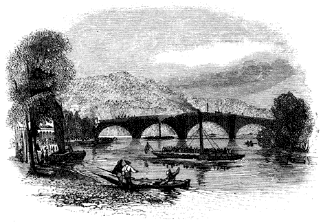
THE END.
The transcriber constructed the cover image, and hereby transfers it into the public domain.
Original spelling and grammar has mostly been retained. For example, "Cyclopœdia", "cyclopædia", "Encyclopædia", "Encyclopœdia", "guage", "gauge" have all been retained.
Figures were moved from within paragraphs to between paragraphs.
Footnotes were re-indexed and moved to the ends of chapters.
The original page numbers are embedded in the form e.g. "[Pg135]".
A link to the INDEX was inserted into the Table of Contents.
In the Table of Contents, changed "MM. Dulong and Arrago" to "MM Dulong and Arago". Also "Blinkinsop" to "Blinkensop". Also "Wasborough's" to "Wasbrough's".
Figs. 4, 5 and 6 are all in one image. Two tubes in Fig. 4 were incorrectly labeled T′; one of these has been crossed out and changed to T. Both tubes in Fig. 6 were incorrectly labeled G. One of these was crossed out and replaced by G′. Note also that Figs. 4, 5, 6 are repeated in the text on different pages; this feature has been retained.
Page 10: "it s already" to "it is already".
Page 43: "Thu if heat" changed to "Thus if heat".
Page 45: "had a diameter of only one square foot" changed to "had a diameter of only one foot".
Page 47: "immedate" to "immediate".
Page 51: "a a level" to "a level". Also, comma removed from "A gauge, pipe is inserted".
Page 53: "proportionably" to "proportionally".
Page 79: A paragraph beginning "He was not fourteen" contains three double quotation marks; this is presumably an error. Possibly there should be two double quotation marks and two single quotation marks.
Page 80: "S'. Gravesande" is retained, although this probably refers to a person known as "'s Gravesande".
Page 103: "gases n general" to "gases in general".
Page 122: comma removed from "process may, be continued".
Page 123: "two thin pipes F G of tin" to "two thin pipes F, G of tin".
Page 172: "empyrical" to "empirical".
Page 187, Fig. 32.: The text refers to "end I of the connecting rod", but this was labeled L on the Figure. This L has been crossed out and replaced by I.
Page 285: In "surrounding the boiler with iron-conducting substances", changed "iron-" to "non-".
Page 308: "exeitement" to "excitement".
There were several extended quotations, for example beginning on page 312, in which each line began with a quotation mark, with ending quotation marks at the end of each paragraph. In this edition, these passages have been marked by indentation, and all but the first and last quotation marks from each paragraph were removed.
Page 362: "acomplish" to "accomplish".
Page 366: Figs. 97-104 appeared originally between pages 385 and 399, as full-page prints. Numerically, however, they belong between Figs. 96 and 105--and therefore between pages 366 and 369. Therefore, they have been moved to a location between two paragraphs on page 367.
Page 368: "rivetted" to "riveted".
Page 419: "TREVITHECK'S INVENTION" changed to "TREVETHICK'S INVENTION", in the chapter heading. However, the references to Trevethick occur in a previous chapter, around page 324.
Page 468: Period added to end sentence "[...] piston is at the bottom of its stroke".
Page 490: Period added to end sentence "[...] therefore one eighth of its capacity".
Pages 494, 497: large data tables were split into three pieces each.
Page 505: The logarithm originally given as log x = "[=1]·82340688193", where "[=1]" represents a numeral one with a horizontal line over it, is herein changed to log x = "0·82340688193 − 1", as that is the meaning of this convention.
Page 513: "formulæ are hyberbolic" to "formulæ are hyperbolic".
The symbol ∵ (Unicode hex 2235-"BECAUSE") appears frequently in the Appendix. It is not available in all fonts.
Page 520: The table of piston area versus piston diameter was split into two tables.
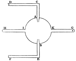
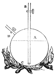

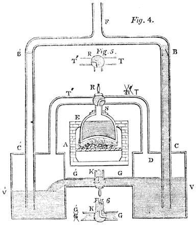

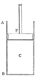
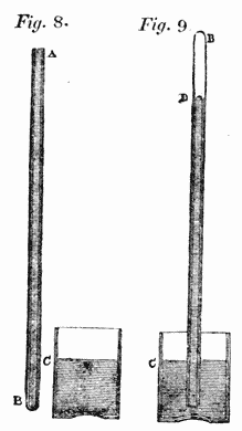
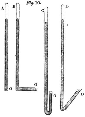


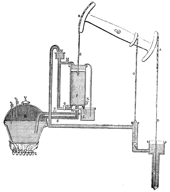
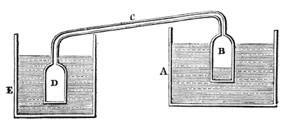


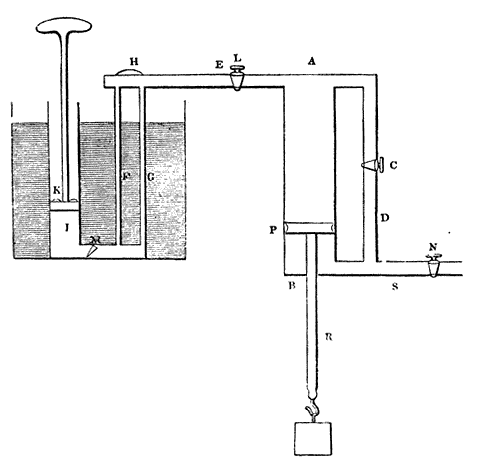

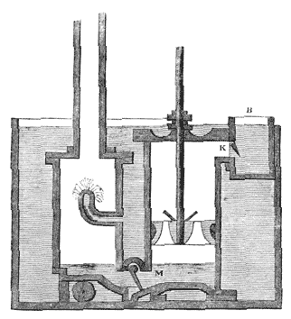
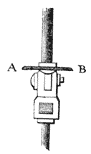
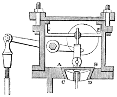
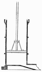


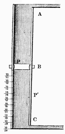


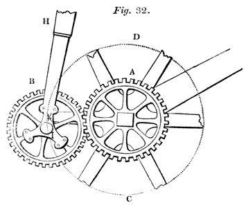
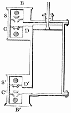
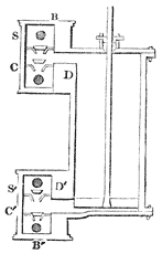


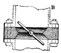
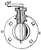
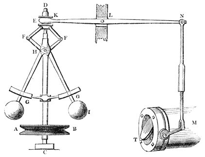

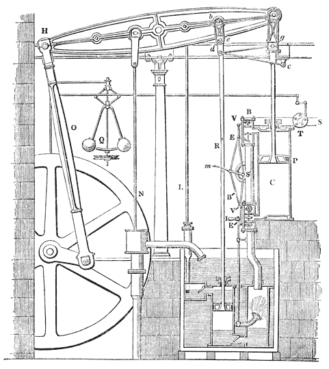

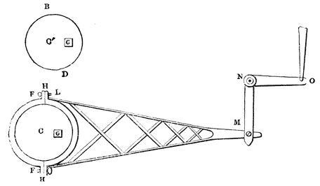

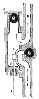


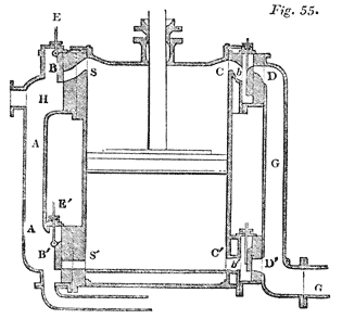
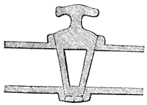
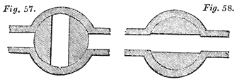
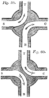
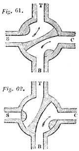

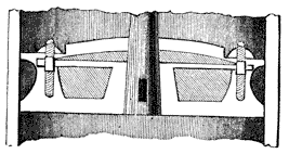

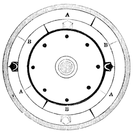
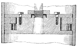
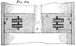
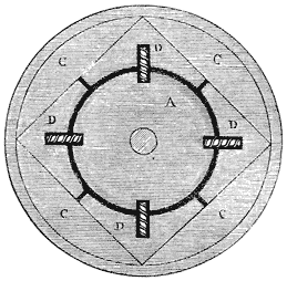

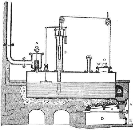

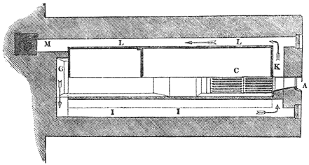
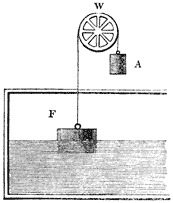
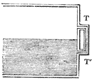
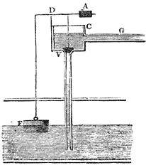

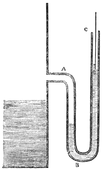
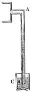
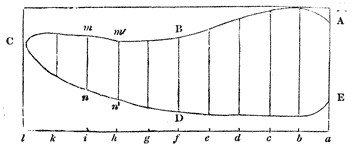
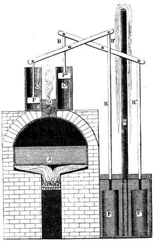


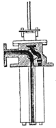
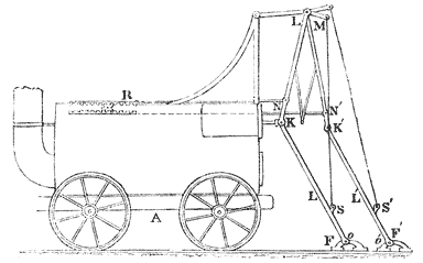
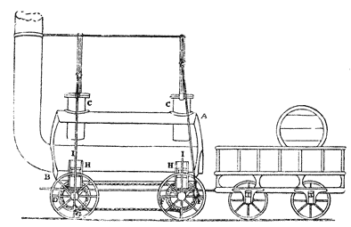
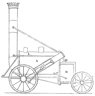
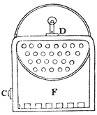
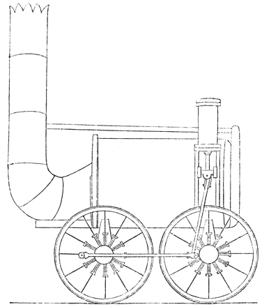


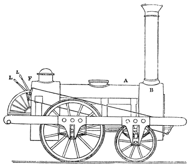

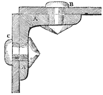
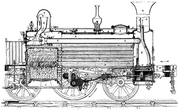


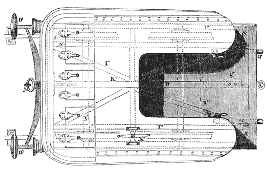

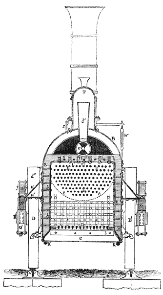
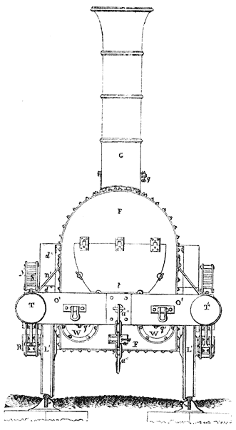
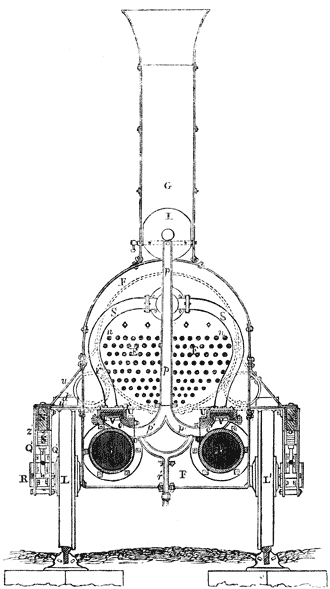


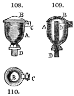

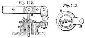
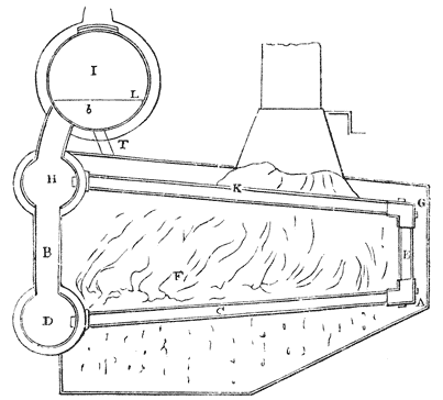
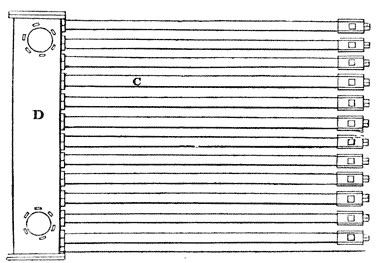
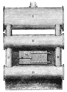
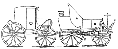
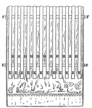

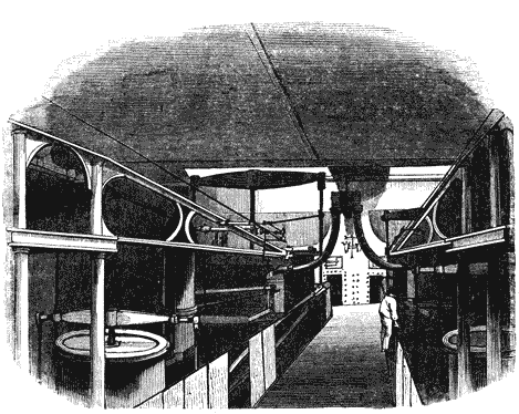


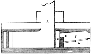
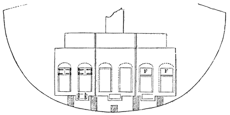
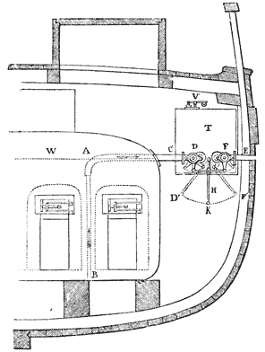

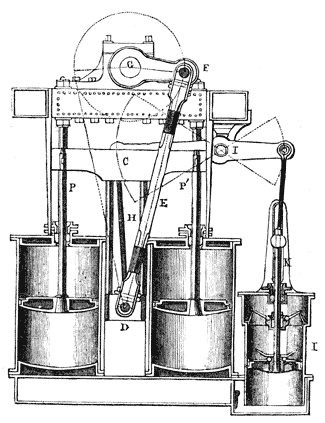
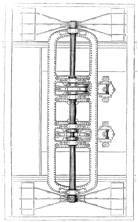
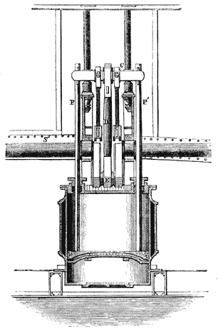
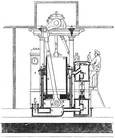
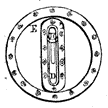
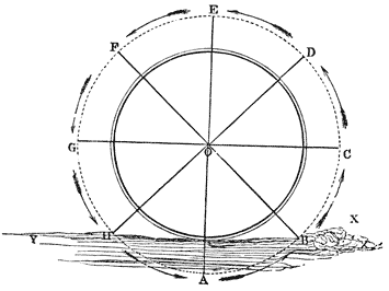


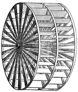
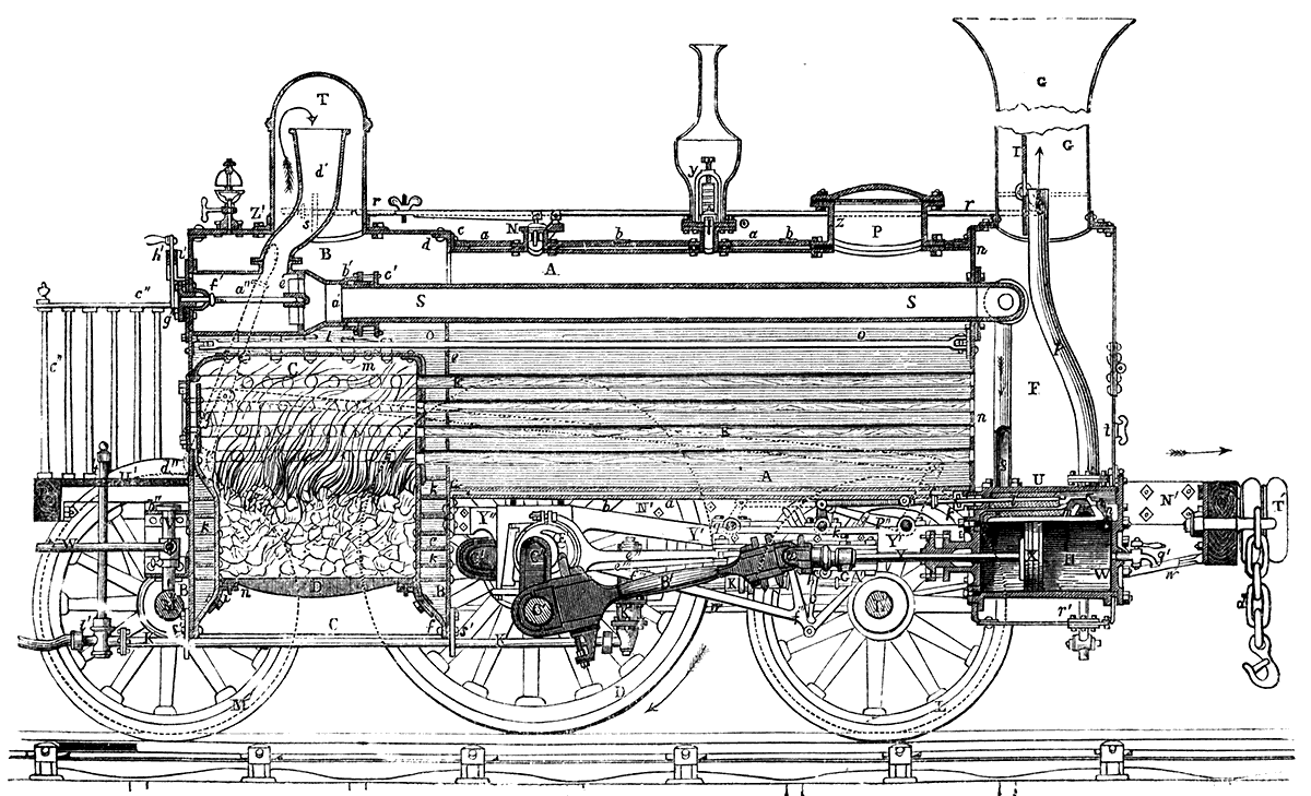
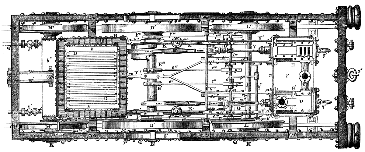