The S & C Series
No. 39
NATURAL STABILITY IN AEROPLANES
W. LeMAITRE
1s 6d Net
The Project Gutenberg EBook of Natural Stability and the Parachute
Principle in Aeroplanes, by W. LeMaitre

This eBook is for the use of anyone anywhere at no cost and with
almost no restrictions whatsoever.  You may copy it, give it away or
re-use it under the terms of the Project Gutenberg License included
with this eBook or online at www.gutenberg.org


Title: Natural Stability and the Parachute Principle in Aeroplanes

Author: W. LeMaitre

Release Date: February 4, 2013 [EBook #42018]

Language: English

Character set encoding: UTF-8

*** START OF THIS PROJECT GUTENBERG EBOOK NATURAL STABILITY IN AEROPLANES ***


Produced by Chris Curnow, Matthew Wheaton and the Online
Distributed Proofreading Team at http://www.pgdp.net (This
file was produced from images generously made available
by The Internet Archive)
The S & C Series
No. 39
NATURAL STABILITY IN AEROPLANES
W. LeMAITRE
1s 6d Net
NATURAL STABILITY
WITH 34 ILLUSTRATIONS
LONDON
E. & F. N. SPON, Ltd., 57 HAYMARKET
New York
SPON & CHAMBERLAIN, 123 LIBERTY STREET
1911
| PAGE | ||
| Frontispiece | iv | |
| Preface | ix | |
| CHAPTER | ||
| I. | The Importance of Stability | 11 |
| II. | Speed as a Means of Stability | 14 |
| III. | The Low Centre of Gravity | 17 |
| IV. | Short Span and Area | 28 |
| V. | Variable Speed and the Parachute Principle | 36 |
| VI. | The Design which Fulfils the Conditions | 39 |
Since there is nothing new under the sun, it is useless to pretend that there is anything new in the design here advocated or the theories advanced. Both are rather the result of a commonsense consideration of the different points of all flying machines, natural and artificial, and an endeavour to select from the great number of good points those which seem most likely to blend together into a practical machine. The conclusions reached are the result of a quite independent investigation, carried on over three years by means of numberless experiments, and the writer has endeavoured to make no single statement which he cannot by some experiment amply prove.
NATURAL STABILITY IN AEROPLANES
In considering the whole question of aviation, it becomes evident that the one point to strive for at the present juncture is stability. If we are ever to have a practical flying machine, that is, a machine which we can use as we do a yacht, a motor car, or a bicycle, it must be one that we can trust to keep its balance by reason of the natural forces embodied in it, and without any effort of control on the part of the pilot. It may be objected that a bicycle does not do this, and this is true, but, on the other hand, the upsetting of a bicycle is a very small matter, whereas the tilting of an aeroplane mostly means sudden death to its occupant, and it is probable that if the same consequences followed the tilting of a bicycle, bicycles would soon have been made with four wheels.
At present aeroplanes are the most unstable of all things. The least gust, the least shifting of weight,[Pg 12] the slightest difference in the density of the strata of the supporting air, and the machine sways, and if not instantly corrected by the pilot the sway becomes a tilt, the tilt a dive, and the rest is silence. The first aeroplanes, the Wrights’ for instance, were so unstable that twenty minutes in one of them was as much as the most iron-nerved man could stand, the continual strain being too exhausting to keep up for any length of time. By throwing out extensions and outriggers in all directions we have altered that to a certain extent, but only to an extent—we have not yet got rid of it. The monoplane is probably the most unstable, as might be expected from its smaller surface, but the bi-plane runs it pretty closely.
And the difficulty seems to arise chiefly from the fact that the machines are built round the propeller. In the case of a yacht or a car, the machine is built first and the propelling means is fitted on as an auxiliary. The consequence is that an aeroplane which is safe enough while the propeller is exerting a tractive force of some 250 lbs., becomes, the moment this power is for any reason stopped, merely a shapeless construction at the mercy of the wind and the force of gravitation. It is true that most machines may be made to glide if the pilot is clever enough and quick enough to steer them into the proper gliding angle, but the machine that will naturally and by reason of its design assume its proper gliding angle when the propelling force is withdrawn, has not yet been built.
Such a machine would have “Natural Stability.”
It will be recognized that this natural stability, which depends on the design of the machine, is something entirely different from “automatic stability” of which there are many systems, all having this one defect; that, depending upon working devices, movable planes, gyroscopes, compensating balancers, pendulums, etc., they are all liable to go wrong and refuse to act the moment a sudden strain makes their perfect action most important.
Considering that the propeller is the only means the aeroplane has of keeping in the air at all, the question arises: Is it possible to design a machine that will be stable to the extent of descending safely when the propeller stops, and that will yet be a good and speedy flyer?
That is the problem we have to solve.
It is recognized on all hands that speed is a great factor in the problem of stability. To begin with, a machine going at high speed would be practically untouched by gusts of wind, different densities of air strata, holes in the air, etc. Also its greater momentum would tend to keep it in a straight line, not only relative to its course but also relative to itself. That is to say, its wings being started in a horizontal plane, would tend to keep in the same plane and would not easily tilt or sway out of it. Both these effects of natural law show that a high speed machine must be more stable than a low speed machine. How then are we to design a high speed machine?
Leaving aside the question of higher power, the first point that suggests itself is to lessen the head resistance. All fast things, boats, birds, arrows, even motor-cars, are made long and narrow. It will be objected that a bird with its wings outspread is not long and narrow, but in the sense in which this illustration is meant, the bird’s wings, being merely its propelling apparatus, do not count, and when the bird is at its fastest, as in the swoop of a hawk or an[Pg 15] eagle, the wings are shut tightly to the body so as to offer no resistance to its lightning passage through the air. If we are to follow previous experience in Nature’s laws, our aeroplanes must be considerably reduced in span. To drive through the air at a high speed with a machine of 40 foot span is a practical impossibility, both because of the tremendous power it would require and also by reason of the great strength the plane must have to withstand the resistance of the air.
In reducing the span, however, we reduce the lifting surface of the machine. But on the other hand it must be remembered that the lifting efficiency is increased by increasing the speed. Lift is the product of supporting surface and speed. A small plane driven at a high speed will give as great a lift as a large plane driven at a low speed. Speed, again, is the difference between the propelling power and the head resistance, and we can increase the speed by decreasing the resistance. It follows, then, that we need not necessarily give up lifting power by reducing the span of the wings, since the shorter span gives greater speed, and the increase of efficiency by reason of the greater speed would go to make up for the loss of span.
It is, then, quite possible to design a short span machine which shall be as efficient for lift as a long span machine, and which will have the advantage of possessing, by reason of its speed, much greater stability.
But the span is not the only factor in the speed problem. In the low speed machines at present in use we have found it necessary to curve the planes to get greater efficiency. This efficiency is also gained at the expense of head resistance, and it is already recognized that the higher the speed the less is the need of camber. This is the same problem over again. A high speed flat plane will give as much lift as a low speed cambered plane, and we gain in stability with every additional mile per hour.
The third point to be considered in the problem of speed is the resistance caused by the multitude of struts and wires, the body of the pilot, the tanks, engine, and all the other impedimenta projecting in all directions from the body of the aeroplane. It has occurred to our builders that if the whole of these things could be collected together and enclosed in a light covered-in car of a proper shape, the skin friction of such a car would be much less than the total head resistance offered by the different obstructions so covered. And there is another advantage to be gained here, for if, at 40 miles per hour, the force of the wind is very seriously uncomfortable for the pilot, the position at such speeds as 70 or 100 miles per hour would be quite impossible.
The first thing that occurs to the investigator on the subject of stability is that nature offers us a sure means of keeping our machines upright by adopting the simple method of placing all the heavier parts at the bottom. In all other constructions we have adopted this plan with perfect success. In boats, yachts, cars, balloons, everything man uses in fact, the simplest, best and most obvious method of keeping a thing upright is to utilize the force of gravity, place the lighter or supporting parts above and the weight below, and the thing is done.
This simple method of obtaining stability did not escape the aeroplane designers, and we have had several machines which embodied this principle, more or less. Unfortunately, however, they all proved failures. A machine would be designed, and, with the weight high, would fly well, though it was unstable. Put the weight low and you got rid of the instability, and at the same time the machine became unmanageable. It looked as if flying and instability were interchangeable terms. So, as it was a machine that would fly the designers were after, the weight was[Pg 18] kept up and the stability was left to the pilot. The machines were made “sensitive” as it is called, that is to say, sensitive to a touch of the rudder or the balancers. They are also, it is true, equally sensitive to a gust of wind or a slight shifting of weight or pressure, and this has caused the smashing of a good many machines and some pilots; but after all this is the fortune of war, and no one is compelled to go up in an aeroplane.
The curious thing about it is that it does not seem to have occurred to our designers that if their pet design would not fly with the weight low, perhaps it might be possible to alter the design instead of altering the position of the centre of gravity, and so obtain what we are all looking for, a naturally stable machine that is yet sensitive to control.
There are two chief difficulties in the way of the low centre of gravity machine. One is that the heaviest portion of the machine being some distance below its support, it is apt to give rise to a pendulum or swaying motion. The other is that of tilting, or banking up, in turning a corner. These are really two developments of the same difficulty, i.e. pendulum motion.
If we take a strip of stiff paper to represent a plane and put a small weight in the centre of the plane, the model on being glided to earth does not tend to sway (Fig. 1). If we put our weight on a tiny piece of wire an inch or so below the plane (Fig. 2) and set the model free, it will probably acquire a[Pg 19] swinging motion as it descends. That is the whole trouble. The trouble is real enough, but the fallacy is in supposing it to be all the fault of the low centre of gravity. All ships that were ever designed have a low centre of gravity, yet some roll dreadfully and others do not, which, in itself, should be proof sufficient that it is the design of the machine and not the position of the ballast that is at fault.
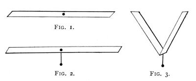
Fig. 1., Fig. 2. and Fig. 3.
Let us now try some experiments. It will be noticed that in the machines which have employed the low centre of gravity the span of the wings has usually been 30 feet or more, and the centre of gravity about 6 feet below the centre. Here is a paper model of the present aeroplane (Fig. 1). Here is the same machine with a low centre of gravity (Fig. 2). Now bend the paper upwards as in Fig. 3 and you get rid of the swaying. Also, of course, you get rid of the supporting surface. But there is probably some point of greatest efficiency where you may compromise. If you take model 2 and bend it slightly (Fig. 4) it will sway, but not much, not so much as Fig. 2. Now[Pg 20] with a pair of scissors clip the wings a bit at a time, and you will find that as the span gets shorter the swaying decreases, and that when you have the three points formed by the ends of the two wings and the weight equidistant from the centre where they meet, the plane is stable (Fig. 5). The reason is that it is not the pendulum with the weight at the bottom that swings so much, but the long wings that see-saw. By shortening the wings you have reduced the length of the see-saw, which is the same as reducing the length of the pendulum, and consequently, by pendulum law, the oscillations must be much quicker and shorter and will at once damp out. It is curious that this point seems to have escaped the designers. It is well known that all pendulum motion tends to damp out, and the shorter the pendulum the quicker it comes to rest. Hitherto the idea has been to shorten it vertically,[Pg 21] but the same effect exactly is obtained by shortening it horizontally, and the low centre of gravity remains to give stability. It was stated by some sapient objector to the low centre of gravity, that the pendulum motion once set up, increased till it turned the machine over. A pendulum which increased its swing at every stroke would be something new in the scientific world.
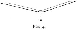
Fig. 4.
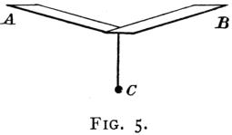
Fig. 5.
Another development of the pendulum difficulty is the probable fore and aft sway, but this may be overcome by increasing the supporting surface of the tail. Many machines do not lift with the tail at all, and those that do employ lifting tails, have them with very small surface. Consequently, the centre of gravity comes nearly under the centre of the main plane, and the whole machine, turning on its centre of gravity in all directions as on a pivot, is liable to swing fore and aft. If the supporting surface of the tail be increased and the centre of gravity carried further aft, this pendulum motion is also rendered impossible, and the machine is stable both ways.
A few illustrations may serve to make the advantages of the low centre of gravity more clear, and to avoid complications we will suppose the planes to be still and in still air. Let Fig. 6 represent an ordinary flat plane having its centre of gravity coincident with its centre of pressure, the centre of pressure of each half or wing being at A A. The plane is in equilibrium. Now allow it to tilt (Fig. 7), and it will be seen that it is still in equilibrium, since the weight is in the centre and the wing tips equidistant from it.[Pg 22] Let it tilt still more till it is vertical (Fig. 8), and the balance is still the same. It is evident, therefore, that such a plane would travel equally well in any of the positions shown, and that it can only be kept in position (Fig. 6) by the skilful manipulation of the pilot.
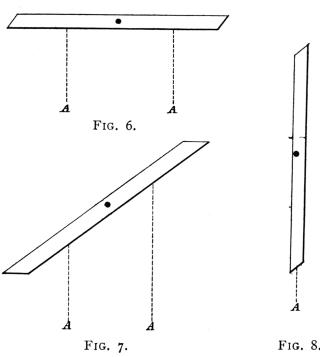
Fig. 6., Fig. 7., and Fig. 8.
In the same way, the machine having no lifting tail is longitudinally unstable, for, being balanced on its centre of pressure which would be coincident with its centre of gravity and probably about 2 feet from the trailing edge of the plane—it may assume any position (Figs. 9, 10, 11 and 12), and still be in equilibrium, when it is evident that the proper position[Pg 23] (Fig. 9) is only maintained by the constant control of the tail elevator.
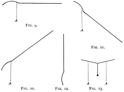
Fig. 9., Fig. 10., Fig. 11., Fig. 12., and Fig. 13.
Now take the case of a machine having a low centre of gravity. Its natural position is shown at Fig. 13, and it is at once evident that any other position such as Figs. 14 and 15 could not be maintained for a moment, since the weight being at an angle, must inevitably drag the machine back to its natural position (Fig. 13). In the same way with regard to longitudinal balance, a machine with two lifting surfaces such as Fig. 13, is in its natural position with the centre of gravity perpendicularly under the centre of pressure, any other position, such as Fig. 17, A, is impossible,[Pg 24] as the gravity pull must drag the machine along the dotted line till it resumes its proper and natural position (B).
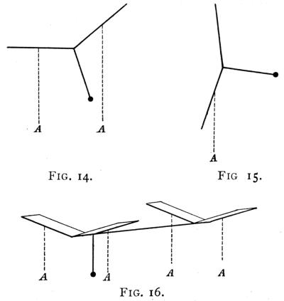
Fig. 14., Fig. 15., and Fig. 16.
The next difficulty is in the banking or tilting caused by the turning of the machine in going round a curve. In a very interesting discussion carried on in the “Aero,” it was stated that a low centre of gravity machine could not bank up, as the pull of gravity acting on the low weight would prevent it. It was also stated by another writer that the machine would bank up too much and slide down sideways, because the greatest weight having the greatest momentum would swing out too much. There is[Pg 25] evidently some confusion here. Let us consider the question.
In turning there are three forces to take into consideration:
(1) The centrifugal force, which tends to make the machine fly off at a tangent to the curve at which it is turning.
(2) The action of gravitation.
(3) The extra lift given by the wing on the outside of the curve, owing to the fact that it travels faster through the air.
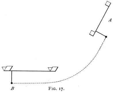
Fig. 17.
The centrifugal force acts strictly in proportion to the mass it acts on, but, at the same time it must be remembered that the greater force acting on the greater mass has the greater mass to move. That is to say, that if the top part of the machine was very[Pg 26] light and the bottom part very heavy, the force acting on the light part would be sufficient to send that part swinging out when rounding a curve, and the greater force acting on the greater mass at the bottom would be sufficient to send that out to exactly the same degree. Consequently, if only centrifugal force is considered, the whole machine would swing out without any tilting at all, retaining its upright position. But here we must take another factor into consideration, the resistance of the air. This resistance would be greater on the greater surface of the light top part than on the heavy bottom part, and consequently the bottom part would, automatically, swing out most, giving the banking effect. This would be increased by the extra lift given to the outer wing by reason of its greater speed. If we then take the force of gravitation into the problem we shall see that we have two factors—unequal speed and unequal air resistance—tending to bank up the machine, and one force—gravity—tending to pull it straight again. At a certain angle due to the amount of force exerted by each of these, the two opposing factors would balance, and the machine would be in equilibrium.
It would appear that most of the difficulties connected with the low centre of gravity machine are the result of hazy thinking and slip-shod reasoning, and that they do not exist in fact. And let it be remembered that the low centre of gravity machine with short span has not yet been tried except by the writer, who has succeeded in making a paper model on this[Pg 27] plan turn in its own length without in any way losing its stability, swaying, banking too much, turning over, sliding sideways, or doing any of the frightful things which some people declare it must do. What it does do is to recover its balance though started from the most impossible positions and always land on its feet.
Both on account of speed, and also on account of stability, with a low centre of gravity, we are forced in the direction of the short span machine. How are we to construct a machine with a span short enough to damp out swaying and yet with sufficient lifting surface to raise the machine and its load?
The position is somewhat simplified, as already pointed out, by the fact that though the lift is decreased by the decrease in span, it is to a great extent compensated by the increase in speed. Also another compensation is offered by the fact that fore and aft stability requires a lifting tail.
Lift is largely in proportion to the length of the entering edge of the plane, but it does not always follow that this entering edge must be at right angles to the direction of flight. The Dunne machine obtains its lift with an entering edge that is entirely at an angle of some 45 degrees, and its shape is an exact replica of the arrow head of prehistoric man and the paper darts of our schooldays, a design, by the way, that was patented in 1860.
At first sight it would seem that the lift on a plane[Pg 29] shaped thus (Fig. 18), would only be equal to the lift given by a plane with an edge as long as the distance between A and C, thus (Fig. 19), but this is not so. Although the lift is not so great as it would be if the edge was straight in one line (Fig. 20), it is very much greater than it would be on Fig. 19. The probability is that it is about half-way between (19) and (20), but probably nearer to (20) than (19). There are no exact data to go on, but the efficiency of the Dunne machine would seem to show this.
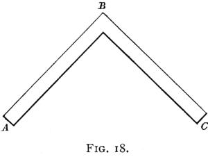
Fig. 18.
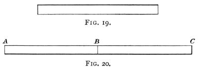
Fig. 19. and Fig. 20.
Again, in seeking for planes that offer the least resistance to the air, one of the best that suggests itself is the T-shape (Fig. 21), and this may be improved by cutting off useless corners (Fig. 22). A plane of[Pg 30] this shape lends itself to great strength of construction owing to its small extending parts. It is compact, it gives an entering edge half as long again as its span, and gives a lift in proportion to that edge, and it is in itself stable. Having thus evolved a suitable plane for the front of the machine, the best thing to do is to base the back plane on the same design, and join the two planes together to form the supporting surface of the machine, allowing sufficient space between them to avoid any interference or overlapping. The design then stands thus (Fig. 23), when the back plane is a slightly smaller copy of the front one. The position of the centre of gravity in this design would be coincident[Pg 31] with the centre of pressure longitudinally and laterally, and would be situated about at A. A paper model on these lines with a low centre of gravity may be easily constructed and will prove useful in illustrating the different points here stated. The paper should be cut out sufficiently wide to allow of a central longitudinal fold (Figs. 24 and 25), and a roll of paper should be made for ballast and pushed through the fold as shown in Fig. 26 at the point marked A.
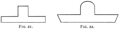
Fig. 21. and Fig 22.
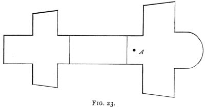
Fig. 23.
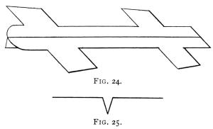
Fig. 24. and Fig. 25.
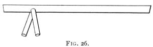
Fig. 26.
The writer, when exhibiting at Olympia this year, distributed 500 of these paper models, and the almost uncanny way in which they righted themselves when started from all sorts of impossible positions greatly[Pg 32] interested the visitors. In fact, numbers of persons spent considerable time and ingenuity in trying to force the little glider to turn over or dive, but quite without success.
In order to test the turning capacity of this design, a rudder should be fixed to the tail, and the model launched at a moderate speed, when it will be found that it turns quickly and without any pendulum motion, and without any perceptible tilt. And although the writer’s experiments with the paper model and with many larger ones on the same plan have run into thousands, none of the models have ever been induced to come down in any other position but on their feet. The largest model, which measured 6 ft. 6 in. in length, was launched both upside down and with its head pointing vertically to earth from a height of 30 ft., and in each case righted before it reached the ground and landed on its skids.
As a further lifting surface, a very simple expedient offers itself in
the shape of a duct built on the box-kite principle. The
diamond-shaped box has been proved over and over again to be a very
efficient lifting device, but it has not yet been tried on an
aeroplane (Fig. 27). It is also a great stabilizer, since the air
entering into the diamond-shaped opening is collected and compressed
into the top angle there, and the whole box is thus practically
suspended from its apex line in absolute stability. The lifting
efficiency of such a box—or rather the top portion of the box, for
the bottom part is not needed on our machine—is [Pg 33]
[Pg 34]considerably
greater than the value of the entering edge, and if run the whole
length of the machine it forms a triangular girder of great strength,
giving rigidity to the whole structure. The lifting efficiency is
doubled by allowing the centre third of the girder to be open, as the
dead air from the front part escapes, and the back part forms a new
entering edge.
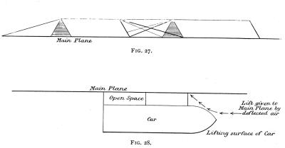
Fig. 27. and Fig. 28.
There is also another lifting factor to be considered, and this is the car. If the car is formed with a flat bottom, this at once becomes an efficient lifting plane, and if the car is suspended with an open space between it and the under surface of the plane, the loss caused by the negative angle of the upper portion of the car front is compensated for by the lift given by the deflected air to the under surface of the main plane (see Fig. 28).
It will be recognized that in the design here being gradually evolved, the great lifting surfaces of the ordinary machine have not been largely reduced, they have simply been broken up into several smaller surfaces, each of which retains its efficiency. Something of the same nature happened in prehistoric days, when our first navigators at last made up their minds to abandon the flat-bottomed raft with its huge supporting surface, for the new-fangled and dangerously narrow boat.
When all the different surfaces here mentioned are taken into consideration, it will be found that the lifting surface in a monoplane machine of this design, with a span of 20 feet, is equal to the lifting surface[Pg 35] of an ordinary bi-plane with a span of 40 feet. And as the head resistance is less than half that of the bi-plane the speed should be very much greater. At the same time the increased speed renders the planes more efficient, area for area, than the planes of the slower machine.
Hitherto, on the score of efficiency and also of stability, our investigations have led us to seek for speed as the grand panacea. But there are usually two sides to a question, and though, while in the air, speed may be most desirable, it becomes a source of considerable difficulty at both starting and landing. A machine built to fly at 80 miles per hour would have to get up something like 60 miles per hour before it could rise. And this difficulty is nothing like the problem that presents itself when we consider how it is to land in safety from a flight at such a speed. It becomes evident that some provision must be made for starting and landing at some more practicable rates; we must have a variable speed machine.
To convert a high speed machine into a low speed machine means either variable surface area, variable camber, or variable angle of incidence. Any of these is possible, but the choice must be decided by simplicity of action. To spread extra wings when rising or landing is a cumbersome suggestion full of pitfalls and liable to accidents through the failure of mechanical[Pg 37] devices, which, experience shows, always have a way of failing at inopportune moments. To vary the camber of the planes is easier, but having decided on using flat planes it would be loss of strength to make these flexible, and an increase of mechanical complications to have to flex them. It would be easy to alter the angle of incidence by having the leading edge capable of a rotary movement, and machines have been constructed employing this principle. But the easiest plan of all, since it does away with all moving parts whatever, would be to alter not the planes themselves, but the whole machine. Thus suppose the angle of incidence, in order to get an efficient lift, to be 1 in 6, the lifting plane, all in the same line, would be set on its chassis so that it presented an angle of 1 in 5. The machine would then lift at a much slower speed. Naturally, the tail being the furthest from the centre of gravity would lift first, and as soon as the speed was sufficient the pilot would alter the elevator, send down the tail on to the ground, thereby raising the leading edge of the front plane, and the machine would rise. As the speed increased the tail would continue to rise, till, at the maximum speed, the plane would be at the minimum angle with the horizontal, i.e. at its lowest angle of incidence.
This solves the problem of starting and to some extent of landing, but we have not yet come to the end of our resources. Most landings are effected by shutting off the engine and planing down. All flying machines will glide if put at the proper angle, and it[Pg 38] is the business of the pilot to attend to this when he stops the engine. But to glide with the same wing area as is used in flying, means to glide at the same rate. In order to descend slowly it is necessary to have more area. Is it possible to increase the area used for descent without interfering with the area used for flight? In the design we are engaged in considering, it is possible, and without any mechanical devices. There is a large space between the front plane and the back plane which is at present unused. It is of very little value in flight, being in apteroid aspect and having practically no entering edge. But if this space is covered in it gives no resistance in flight, and in descent it becomes a very efficient parachute. Further than this, if openings be cut in this plane immediately under the centre of the two box-kite ducts, the air under the longitudinal plane, having offered its resistance to the vertical passage of that plane, will escape into the duct and again offer considerable resistance to the descent of this closed-in surface before it escapes finally out of the end of the duct.
A model made on these lines will not need putting at any angle. It will assume its proper angle when left to itself by reason of its design and the way the weight is balanced between the supporting planes, and it will descend by partly gliding and partly parachuting at a steep angle but quite slowly. While, if the pilot so choose, he can, by raising the tail, increase the speed to a glide, which he can turn into a parachute action at any moment.
In constructing any sort of machine it is usual to first obtain the most important device and then to build up the accompanying parts to that. We have now succeeded in evolving the thing we set out to look for, i.e., a plane which will fly and lift with the minimum of head resistance, and which is absolutely stable laterally and longitudinally by reason of its construction and without any interference from the pilot or the employment of balancing devices of any description. We have now to fit the propelling apparatus, car, and chassis on to this.
Fortunately, the design is one that lends itself easily to manipulation, which is not always the case with models. The short span of the planes, for instance, with the dihedral angle, at once suggests girder construction (see Figs. 29, 30), which is, perhaps, the strongest of all devices, being an M strut girder, familiar to us in numberless bridges.
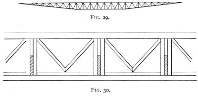
Fig. 29. and Fig. 30.
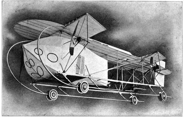
The photo which forms the frontispiece of this book, and which, by the way, makes the car look much too large owing to its position nearest the camera, represents a 6-foot model which was exhibited at the[Pg 40] Olympia Show, in order to show the construction of a full-sized machine made to the design of the paper model. This has since been considerably simplified, though the broad lines have been retained, by doing away with the struts and supports at the rear. The whole of the back plane is now supported by two curved members, which start from the girder of the leading edge and curve down to the T-section longitudinals which form the rigid part of the chassis. These longitudinals and the skids end at the leading edge of the back plane and the laminated skids and wheels are placed there. The machine is built without a wire and without a casting. It was made entirely of wood, but is so designed that it can be made entirely out of steel tube by using the ordinary screw connexions. If built of timber, the joints are made with strips of steel bolted and screwed on to the wood. The girders forming the leading edge of each[Pg 41] plane have sockets formed in the upright struts of the M into which the ribs fit (see Fig. 30), and these are solid pieces on edge tapering to the trailing edge, where they are clipped to a slight spar which holds them together. This construction, while very strong, is yet sufficiently flexible to bend considerably before it reaches breaking point. Longitudinal rigidity is secured by means of the triangular duct which forms a complete girder from end to end. A sufficient number of uprights fill the space between the plane and the two T-section longitudinals which form the rigid bottom of the machine. On these latter the floor is placed and the car is built up, enclosing all the obstructions and putting the pilot in a place of safety, enclosed on all sides in the middle of the strongest part of the machine, with the strongest portion of that part between him and the ground. The centre of gravity is situated behind the pilot in the back of the car, near the floor, and here is space for the oil and petrol tanks. The engine is in front of the pilot, who is thus able to control it and watch it, and at the same time is free from the danger of having it fall upon him in case of an accident. As the machine turns horizontally and vertically on its centre of gravity, the front part of the car forms a sort of baffle or blinker for the rudder and elevator to act against. Both these are at the tail of the machine, where they have the most leverage, and these two are controlled by the one lever, which is pushed forward or pulled backward to raise or lower the[Pg 42] elevator, and turned bicycle fashion to move the rudder. As the machine balances itself, there is no need for any balancing device either automatic or controlled.
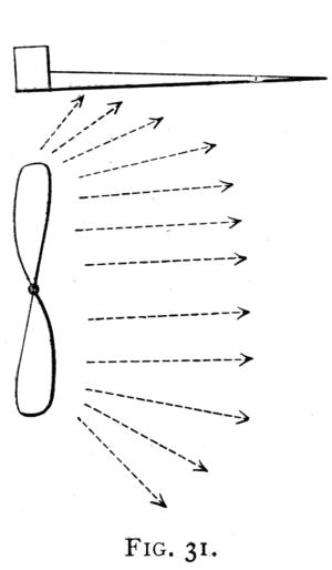
Fig. 31.
The propellers may be two or more, and those in front find a very firm fixing in the intersection of two strong struts, which join the wingtips to the bottom of the car, and the supports which run from the centre of these to the strong joint formed by the intersection of the longitudinal and lateral girder. At the back there may be two propellers fixed as in the front, or one large one at the rear of the car. They are all worked from the one engine and the thrust is slightly above the centre of gravity. Each propeller is placed just under the leading edge of a plane, Fig. 31, the idea being that a certain amount of air is always thrown out by centrifugal force all round a revolving propeller, and this air, which, ordinarily, is lost, must, when thrown upwards, exert a lift on the under surface of the plane. Also, when thrown towards the car, it must, by impinging on the slanting surface of the car, tend to impel it forward, Fig. 32. Where four propellers are used, the back pair should be of greater pitch than[Pg 43] the front pair, as they must to a certain extent, work in the stream from the front pair. There are several ways of coupling the propellers to the engine, but in the model they are shown coupled up by belts, which seems to be the most efficient and lightest device.
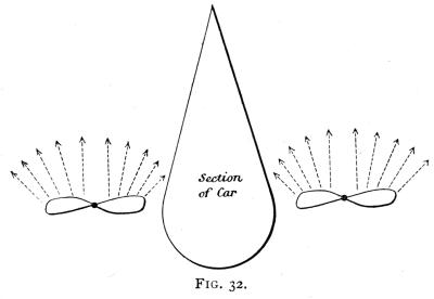
Fig. 32.
In order to cool the engine and keep the air in the car clear, a ventilating pipe is led from the front of the car to the engine, and the air, rushing through this at the speed of the machine, plays over the engine and is conducted out through a large opening and discharged at the back.
The whole of this part of the machine is rigid and braced together by means of struts, though whether made of steel tube or timber, there must always, from the nature of the construction, be a certain amount of elasticity which makes for strength, a great[Pg 44] advantage over a construction braced rigidly by non-elastic wires, which snap instead of giving to a sudden strain.
Under the two rigid T-section longitudinals there are a number of elastic laminated wood springs set at an angle, and the lower ends of these are pivoted on to a long elastic skid. This skid is made in laminations, with alternate joints, and starts from the point where the two planes intersect in the front of the machine, which is one of the strongest joints in the whole construction. From this point it bends out in a semicircle to protect the propeller and the front of the machine and car, this portion of it being very elastic by reason of the laminations having free play one upon the other. At the bottom of the semicircle the skid is joined to the slanting skids or springs depending from the bottom of the machine, and here the laminations are bolted together making the skid stiffer. The skid runs the whole length of the machine like the runner of a sledge. On this skid the wheels are sprung with a steel spring lever arrangement, Fig. 33. The shock of landing is, therefore, taken first on the wheels, and should it be sufficiently heavy to cause the skids to touch the ground there is still the series of laminated wood springs to absorb any vibrations and prevent any possible shock to the car. The car is so secure from vibration by reason of these precautions that the whole lower half of the front of it may be made of protected glass, to enable the pilot to get a clear view of his surroundings.
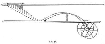
Fig. 33.
The dimensions of the full-sized machine are estimated to be as follows:—
| Span | 20 feet |
| Length | 43 feet |
| Parachuting area | 500 square feet |
| Efficient lifting area | 360 square feet |
| Weight (all up) | 800 lb. |
It will be understood that though only 360 square feet is counted as efficient for lifting, the whole 500 square feet is efficient as parachuting surface in descending. The weight of the machine compares very favourably with existing machines, and the load 2-1/4 lbs. per square foot, gives plenty of margin for passenger carrying.
The chief advantages claimed for this machine are:—
(1) Speed.
(2) Stability.
(3) Strength of construction.
(4) Shock absorbing capacity.
It is a practical impossibility for the machine to turn over or be blown over, and it will recover its balance if started at any angle. If allowed to dive vertically, either tail first or head first, it will recover its position in six times its own length, purely by its own balance, without any effort of the pilot.
LONDON: PRINTED BY WILLIAM CLOWES AND SONS, LIMITED,
GREAT WINDMILL STREET, W., AND DUKE STREET, STAMFORD STREET, S.E.
End of the Project Gutenberg EBook of Natural Stability and the Parachute
Principle in Aeroplanes, by W. LeMaitre

*** END OF THIS PROJECT GUTENBERG EBOOK NATURAL STABILITY IN AEROPLANES ***

***** This file should be named 42018-h.htm or 42018-h.zip *****
This and all associated files of various formats will be found in:
        http://www.gutenberg.org/4/2/0/1/42018/

Produced by Chris Curnow, Matthew Wheaton and the Online
Distributed Proofreading Team at http://www.pgdp.net (This
file was produced from images generously made available
by The Internet Archive)


Updated editions will replace the previous one--the old editions
will be renamed.

Creating the works from public domain print editions means that no
one owns a United States copyright in these works, so the Foundation
(and you!) can copy and distribute it in the United States without
permission and without paying copyright royalties.  Special rules,
set forth in the General Terms of Use part of this license, apply to
copying and distributing Project Gutenberg-tm electronic works to
protect the PROJECT GUTENBERG-tm concept and trademark.  Project
Gutenberg is a registered trademark, and may not be used if you
charge for the eBooks, unless you receive specific permission.  If you
do not charge anything for copies of this eBook, complying with the
rules is very easy.  You may use this eBook for nearly any purpose
such as creation of derivative works, reports, performances and
research.  They may be modified and printed and given away--you may do
practically ANYTHING with public domain eBooks.  Redistribution is
subject to the trademark license, especially commercial
redistribution.


*** START: FULL LICENSE ***

THE FULL PROJECT GUTENBERG LICENSE
PLEASE READ THIS BEFORE YOU DISTRIBUTE OR USE THIS WORK

To protect the Project Gutenberg-tm mission of promoting the free
distribution of electronic works, by using or distributing this work
(or any other work associated in any way with the phrase "Project
Gutenberg"), you agree to comply with all the terms of the Full Project
Gutenberg-tm License available with this file or online at
  www.gutenberg.org/license.


Section 1.  General Terms of Use and Redistributing Project Gutenberg-tm
electronic works

1.A.  By reading or using any part of this Project Gutenberg-tm
electronic work, you indicate that you have read, understand, agree to
and accept all the terms of this license and intellectual property
(trademark/copyright) agreement.  If you do not agree to abide by all
the terms of this agreement, you must cease using and return or destroy
all copies of Project Gutenberg-tm electronic works in your possession.
If you paid a fee for obtaining a copy of or access to a Project
Gutenberg-tm electronic work and you do not agree to be bound by the
terms of this agreement, you may obtain a refund from the person or
entity to whom you paid the fee as set forth in paragraph 1.E.8.

1.B.  "Project Gutenberg" is a registered trademark.  It may only be
used on or associated in any way with an electronic work by people who
agree to be bound by the terms of this agreement.  There are a few
things that you can do with most Project Gutenberg-tm electronic works
even without complying with the full terms of this agreement.  See
paragraph 1.C below.  There are a lot of things you can do with Project
Gutenberg-tm electronic works if you follow the terms of this agreement
and help preserve free future access to Project Gutenberg-tm electronic
works.  See paragraph 1.E below.

1.C.  The Project Gutenberg Literary Archive Foundation ("the Foundation"
or PGLAF), owns a compilation copyright in the collection of Project
Gutenberg-tm electronic works.  Nearly all the individual works in the
collection are in the public domain in the United States.  If an
individual work is in the public domain in the United States and you are
located in the United States, we do not claim a right to prevent you from
copying, distributing, performing, displaying or creating derivative
works based on the work as long as all references to Project Gutenberg
are removed.  Of course, we hope that you will support the Project
Gutenberg-tm mission of promoting free access to electronic works by
freely sharing Project Gutenberg-tm works in compliance with the terms of
this agreement for keeping the Project Gutenberg-tm name associated with
the work.  You can easily comply with the terms of this agreement by
keeping this work in the same format with its attached full Project
Gutenberg-tm License when you share it without charge with others.

1.D.  The copyright laws of the place where you are located also govern
what you can do with this work.  Copyright laws in most countries are in
a constant state of change.  If you are outside the United States, check
the laws of your country in addition to the terms of this agreement
before downloading, copying, displaying, performing, distributing or
creating derivative works based on this work or any other Project
Gutenberg-tm work.  The Foundation makes no representations concerning
the copyright status of any work in any country outside the United
States.

1.E.  Unless you have removed all references to Project Gutenberg:

1.E.1.  The following sentence, with active links to, or other immediate
access to, the full Project Gutenberg-tm License must appear prominently
whenever any copy of a Project Gutenberg-tm work (any work on which the
phrase "Project Gutenberg" appears, or with which the phrase "Project
Gutenberg" is associated) is accessed, displayed, performed, viewed,
copied or distributed:

This eBook is for the use of anyone anywhere at no cost and with
almost no restrictions whatsoever.  You may copy it, give it away or
re-use it under the terms of the Project Gutenberg License included
with this eBook or online at www.gutenberg.org

1.E.2.  If an individual Project Gutenberg-tm electronic work is derived
from the public domain (does not contain a notice indicating that it is
posted with permission of the copyright holder), the work can be copied
and distributed to anyone in the United States without paying any fees
or charges.  If you are redistributing or providing access to a work
with the phrase "Project Gutenberg" associated with or appearing on the
work, you must comply either with the requirements of paragraphs 1.E.1
through 1.E.7 or obtain permission for the use of the work and the
Project Gutenberg-tm trademark as set forth in paragraphs 1.E.8 or
1.E.9.

1.E.3.  If an individual Project Gutenberg-tm electronic work is posted
with the permission of the copyright holder, your use and distribution
must comply with both paragraphs 1.E.1 through 1.E.7 and any additional
terms imposed by the copyright holder.  Additional terms will be linked
to the Project Gutenberg-tm License for all works posted with the
permission of the copyright holder found at the beginning of this work.

1.E.4.  Do not unlink or detach or remove the full Project Gutenberg-tm
License terms from this work, or any files containing a part of this
work or any other work associated with Project Gutenberg-tm.

1.E.5.  Do not copy, display, perform, distribute or redistribute this
electronic work, or any part of this electronic work, without
prominently displaying the sentence set forth in paragraph 1.E.1 with
active links or immediate access to the full terms of the Project
Gutenberg-tm License.

1.E.6.  You may convert to and distribute this work in any binary,
compressed, marked up, nonproprietary or proprietary form, including any
word processing or hypertext form.  However, if you provide access to or
distribute copies of a Project Gutenberg-tm work in a format other than
"Plain Vanilla ASCII" or other format used in the official version
posted on the official Project Gutenberg-tm web site (www.gutenberg.org),
you must, at no additional cost, fee or expense to the user, provide a
copy, a means of exporting a copy, or a means of obtaining a copy upon
request, of the work in its original "Plain Vanilla ASCII" or other
form.  Any alternate format must include the full Project Gutenberg-tm
License as specified in paragraph 1.E.1.

1.E.7.  Do not charge a fee for access to, viewing, displaying,
performing, copying or distributing any Project Gutenberg-tm works
unless you comply with paragraph 1.E.8 or 1.E.9.

1.E.8.  You may charge a reasonable fee for copies of or providing
access to or distributing Project Gutenberg-tm electronic works provided
that

- You pay a royalty fee of 20% of the gross profits you derive from
     the use of Project Gutenberg-tm works calculated using the method
     you already use to calculate your applicable taxes.  The fee is
     owed to the owner of the Project Gutenberg-tm trademark, but he
     has agreed to donate royalties under this paragraph to the
     Project Gutenberg Literary Archive Foundation.  Royalty payments
     must be paid within 60 days following each date on which you
     prepare (or are legally required to prepare) your periodic tax
     returns.  Royalty payments should be clearly marked as such and
     sent to the Project Gutenberg Literary Archive Foundation at the
     address specified in Section 4, "Information about donations to
     the Project Gutenberg Literary Archive Foundation."

- You provide a full refund of any money paid by a user who notifies
     you in writing (or by e-mail) within 30 days of receipt that s/he
     does not agree to the terms of the full Project Gutenberg-tm
     License.  You must require such a user to return or
     destroy all copies of the works possessed in a physical medium
     and discontinue all use of and all access to other copies of
     Project Gutenberg-tm works.

- You provide, in accordance with paragraph 1.F.3, a full refund of any
     money paid for a work or a replacement copy, if a defect in the
     electronic work is discovered and reported to you within 90 days
     of receipt of the work.

- You comply with all other terms of this agreement for free
     distribution of Project Gutenberg-tm works.

1.E.9.  If you wish to charge a fee or distribute a Project Gutenberg-tm
electronic work or group of works on different terms than are set
forth in this agreement, you must obtain permission in writing from
both the Project Gutenberg Literary Archive Foundation and Michael
Hart, the owner of the Project Gutenberg-tm trademark.  Contact the
Foundation as set forth in Section 3 below.

1.F.

1.F.1.  Project Gutenberg volunteers and employees expend considerable
effort to identify, do copyright research on, transcribe and proofread
public domain works in creating the Project Gutenberg-tm
collection.  Despite these efforts, Project Gutenberg-tm electronic
works, and the medium on which they may be stored, may contain
"Defects," such as, but not limited to, incomplete, inaccurate or
corrupt data, transcription errors, a copyright or other intellectual
property infringement, a defective or damaged disk or other medium, a
computer virus, or computer codes that damage or cannot be read by
your equipment.

1.F.2.  LIMITED WARRANTY, DISCLAIMER OF DAMAGES - Except for the "Right
of Replacement or Refund" described in paragraph 1.F.3, the Project
Gutenberg Literary Archive Foundation, the owner of the Project
Gutenberg-tm trademark, and any other party distributing a Project
Gutenberg-tm electronic work under this agreement, disclaim all
liability to you for damages, costs and expenses, including legal
fees.  YOU AGREE THAT YOU HAVE NO REMEDIES FOR NEGLIGENCE, STRICT
LIABILITY, BREACH OF WARRANTY OR BREACH OF CONTRACT EXCEPT THOSE
PROVIDED IN PARAGRAPH 1.F.3.  YOU AGREE THAT THE FOUNDATION, THE
TRADEMARK OWNER, AND ANY DISTRIBUTOR UNDER THIS AGREEMENT WILL NOT BE
LIABLE TO YOU FOR ACTUAL, DIRECT, INDIRECT, CONSEQUENTIAL, PUNITIVE OR
INCIDENTAL DAMAGES EVEN IF YOU GIVE NOTICE OF THE POSSIBILITY OF SUCH
DAMAGE.

1.F.3.  LIMITED RIGHT OF REPLACEMENT OR REFUND - If you discover a
defect in this electronic work within 90 days of receiving it, you can
receive a refund of the money (if any) you paid for it by sending a
written explanation to the person you received the work from.  If you
received the work on a physical medium, you must return the medium with
your written explanation.  The person or entity that provided you with
the defective work may elect to provide a replacement copy in lieu of a
refund.  If you received the work electronically, the person or entity
providing it to you may choose to give you a second opportunity to
receive the work electronically in lieu of a refund.  If the second copy
is also defective, you may demand a refund in writing without further
opportunities to fix the problem.

1.F.4.  Except for the limited right of replacement or refund set forth
in paragraph 1.F.3, this work is provided to you 'AS-IS', WITH NO OTHER
WARRANTIES OF ANY KIND, EXPRESS OR IMPLIED, INCLUDING BUT NOT LIMITED TO
WARRANTIES OF MERCHANTABILITY OR FITNESS FOR ANY PURPOSE.

1.F.5.  Some states do not allow disclaimers of certain implied
warranties or the exclusion or limitation of certain types of damages.
If any disclaimer or limitation set forth in this agreement violates the
law of the state applicable to this agreement, the agreement shall be
interpreted to make the maximum disclaimer or limitation permitted by
the applicable state law.  The invalidity or unenforceability of any
provision of this agreement shall not void the remaining provisions.

1.F.6.  INDEMNITY - You agree to indemnify and hold the Foundation, the
trademark owner, any agent or employee of the Foundation, anyone
providing copies of Project Gutenberg-tm electronic works in accordance
with this agreement, and any volunteers associated with the production,
promotion and distribution of Project Gutenberg-tm electronic works,
harmless from all liability, costs and expenses, including legal fees,
that arise directly or indirectly from any of the following which you do
or cause to occur: (a) distribution of this or any Project Gutenberg-tm
work, (b) alteration, modification, or additions or deletions to any
Project Gutenberg-tm work, and (c) any Defect you cause.


Section  2.  Information about the Mission of Project Gutenberg-tm

Project Gutenberg-tm is synonymous with the free distribution of
electronic works in formats readable by the widest variety of computers
including obsolete, old, middle-aged and new computers.  It exists
because of the efforts of hundreds of volunteers and donations from
people in all walks of life.

Volunteers and financial support to provide volunteers with the
assistance they need are critical to reaching Project Gutenberg-tm's
goals and ensuring that the Project Gutenberg-tm collection will
remain freely available for generations to come.  In 2001, the Project
Gutenberg Literary Archive Foundation was created to provide a secure
and permanent future for Project Gutenberg-tm and future generations.
To learn more about the Project Gutenberg Literary Archive Foundation
and how your efforts and donations can help, see Sections 3 and 4
and the Foundation information page at www.gutenberg.org


Section 3.  Information about the Project Gutenberg Literary Archive
Foundation

The Project Gutenberg Literary Archive Foundation is a non profit
501(c)(3) educational corporation organized under the laws of the
state of Mississippi and granted tax exempt status by the Internal
Revenue Service.  The Foundation's EIN or federal tax identification
number is 64-6221541.  Contributions to the Project Gutenberg
Literary Archive Foundation are tax deductible to the full extent
permitted by U.S. federal laws and your state's laws.

The Foundation's principal office is located at 4557 Melan Dr. S.
Fairbanks, AK, 99712., but its volunteers and employees are scattered
throughout numerous locations.  Its business office is located at 809
North 1500 West, Salt Lake City, UT 84116, (801) 596-1887.  Email
contact links and up to date contact information can be found at the
Foundation's web site and official page at www.gutenberg.org/contact

For additional contact information:
     Dr. Gregory B. Newby
     Chief Executive and Director
     gbnewby@pglaf.org

Section 4.  Information about Donations to the Project Gutenberg
Literary Archive Foundation

Project Gutenberg-tm depends upon and cannot survive without wide
spread public support and donations to carry out its mission of
increasing the number of public domain and licensed works that can be
freely distributed in machine readable form accessible by the widest
array of equipment including outdated equipment.  Many small donations
($1 to $5,000) are particularly important to maintaining tax exempt
status with the IRS.

The Foundation is committed to complying with the laws regulating
charities and charitable donations in all 50 states of the United
States.  Compliance requirements are not uniform and it takes a
considerable effort, much paperwork and many fees to meet and keep up
with these requirements.  We do not solicit donations in locations
where we have not received written confirmation of compliance.  To
SEND DONATIONS or determine the status of compliance for any
particular state visit www.gutenberg.org/donate

While we cannot and do not solicit contributions from states where we
have not met the solicitation requirements, we know of no prohibition
against accepting unsolicited donations from donors in such states who
approach us with offers to donate.

International donations are gratefully accepted, but we cannot make
any statements concerning tax treatment of donations received from
outside the United States.  U.S. laws alone swamp our small staff.

Please check the Project Gutenberg Web pages for current donation
methods and addresses.  Donations are accepted in a number of other
ways including checks, online payments and credit card donations.
To donate, please visit:  www.gutenberg.org/donate


Section 5.  General Information About Project Gutenberg-tm electronic
works.

Professor Michael S. Hart was the originator of the Project Gutenberg-tm
concept of a library of electronic works that could be freely shared
with anyone.  For forty years, he produced and distributed Project
Gutenberg-tm eBooks with only a loose network of volunteer support.

Project Gutenberg-tm eBooks are often created from several printed
editions, all of which are confirmed as Public Domain in the U.S.
unless a copyright notice is included.  Thus, we do not necessarily
keep eBooks in compliance with any particular paper edition.

Most people start at our Web site which has the main PG search facility:

     www.gutenberg.org

This Web site includes information about Project Gutenberg-tm,
including how to make donations to the Project Gutenberg Literary
Archive Foundation, how to help produce our new eBooks, and how to
subscribe to our email newsletter to hear about new eBooks.