This Handbook contains, in a form convenient for everyday use, a number of articles on Rustic Carpentry contributed by various authors to Work—one of the journals it is my fortune to edit.
Readers who may desire additional information respecting special details of the matters dealt with in this Handbook, or instructions on kindred subjects, should address a question to the Editor of Work, La Belle Sauvage, London, EC., so that it may be answered in the columns of that journal.
| CHAPTER | PAGE | ||
| I. | — | Light Rustic Work | 9 |
| II. | — | Flower Stands, Vases, etc. | 22 |
| III. | — | Tables | 36 |
| IV. | — | Chairs and Seats | 40 |
| V. | — | Gates and Fences | 52 |
| VI. | — | Rosery Walk | 66 |
| VII. | — | Porches | 71 |
| VIII. | — | Canopy for Swing | 77 |
| IX. | — | Aviary | 83 |
| X. | — | Foot-bridges | 92 |
| XI. | — | Verandahs | 98 |
| XII. | — | Tool Houses, Garden Shelters, etc. | 106 |
| XIII. | — | Summer Houses | 126 |
| Index | 159 |
| FIG. | PAGE | ||
| 1. | — | Photograph Frame and Wall Bracket Combined | 10 |
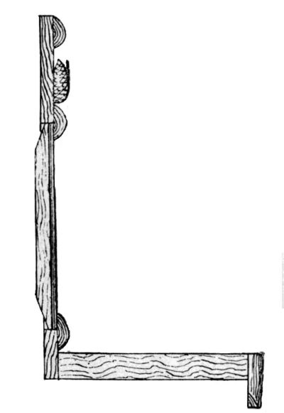
| 2. | — | Section of Bracket | 11 |
| 3. | — | Small Easel | 12 |
| 4. | — | Attaching Support to Easel | 13 |
| 5. | — | Mitred Joint | 13 |
| 6. | — | Mortise and Tenon Joint | 14 |
| 7, 8. | — | Flower Holder | 14, 15 |
| 9-11. | — | Rustic Hall Stand | 17 |
| 12, 13. | — | Plant Stool | 18 |
| 14-16. | — | Window Box | 19, 20 |
| 17. | — | Flower-pot Stand | 23 |
| 18. | — | Bending Saplings | 24 |
| 19. | — | Fixing Rails, etc., to Posts | 24 |
| 20. | — | Vase on Tripod Stand | 25 |
| 21. | — | Joint of Hexagon Sides of Vase | 25 |
| 22. | — | Securing Sides and Legs of Vase to Base | 25 |
| 23. | — | Section of Twigs at Angles of Vase | 25 |
| 24, 25. | — | Flower-pot Stan | 26 |
| 26. | — | Joining Rails to Uprights | 27 |
| 27. | — | Supporting End Shelves of Flower-pot Stand | 27 |
| 28. | — | Fixing Centre Shelves of Stand | 27 |
| 29. | — | Large Square Vase | 28 |
| 30. | — | Large Hexagonal Vase | 28 |
| 31. | — | Vase with Claw Foot | 29 |
| 32. | — | Foot of Rustic Table | 30 |
| 33. | — | Garden Plant Tub | 31 |
| 34, 35. | — | Mouldings | 32 |
| 36. | — | Plant Vase | 32 |
| 37. | — | Rectangular Garden Plant Stand | 33 |
| 38-40. | — | Rustic Pedestal | 34 |
| 41. | — | Flower-pot Stand | 35 |
| 42. | — | Square Table | 36 |
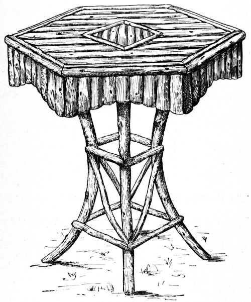
| 43. | — | Hexagon Table | 37 |
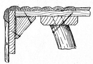
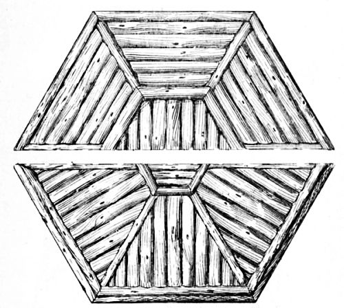
| 44, 45. | — | Top of Hexagon Table | 38, 39 |
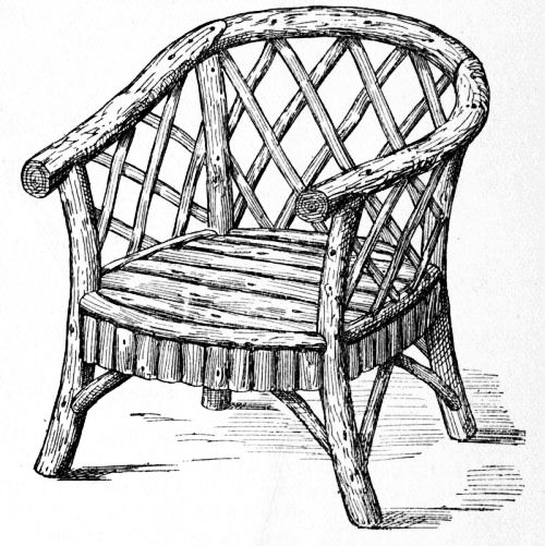
| 46. | — | Armchair | 40 |
| 47. | — | Fixing Seat Rails to Leg of Armchair | 41 |
| 48. | — | Plan of Armchair Seat Frame | 41 |
| 49, 50. | — | Garden Seat | 42, 43 |
| 51. | — | Joints of Rails and Posts | 43 |
| 52. | — | Arm-rest for Garden Seat | 44 |
| 53. | — | Part Plan of Seat | 44 |
| 54, 55. | — | Garden Seat | 44, 45 |
| 56. | — | Front Rail, Cross Rail, and Battens | 45 |
| 57. | — | Part Plan of Seat | 46 |
| 58-60. | — | Garden Seat with Canopy | 47-49 |
| 61. | — | Plan of Canopy | 50 |
| 62, 63. | — | Canopy Panels | 50 |
| 64. | — | Plan of Seat | 50 |
| 65-67. | — | Garden Gate | 52, 53 |
| 68-70. | — | Joints in Gate Frame | 54 |
| 71, 72. | — | Fixing Ends of Twigs | 54 |
| 73. | — | Closing Stile | 54 |
| 74-77. | — | Joints in Gate Frame | 55, 56 |
| 78-80. | — | Fences | 57, 58 |
| 81, 82. | — | Rustic Trellis with Seats and Gate | 59 |
| 83. | — | Vertical Section of Trellis | 60 |
| 84. | — | End Post and Trellis | 60 |
| 85. | — | Back of Seat for Trellis | 60 |
| 86. | — | Alternative Design for Gate | 61 |
| 87. | — | Hanging and Latching Gate | 62 |
| 88. | — | Catch for Gate | 63 |
| 89, 90. | — | Rustic Carriage Entrance | 64, 65 |
| 91. | — | Rosery Walk | 67 |
| 92. | — | Roof of Rosery Walk | 68 |
| 93. | — | Entrance to Rosery Walk | 69 |
| 94, 95. | — | Porch | 72, 73 |
| 96. | — | Seat and Floor of Cottage Porch | 74 |
| 97. | — | Porch at Gable | 74 |
| 98. | — | Porch at Eaves | 75 |
| 99. | — | Roof for Porch | 75 |
| 100. | — | Gable for Porch | 76 |
| 101, 102. | — | Rustic Canopy for Swing | 77, 78 |
| 103. | — | Fixing Middle Post of Canopy to Sill | 79 |
| 104. | — | Joints of Rails, Struts, and Posts for Canopy | 79 |
| 105. | — | Securing Cross Rails to Plates and Posts of Canopy | 80 |
| 106, 107. | — | Hook and Thimble for Canopy | 80 |
| FIG. | PAGE | ||
| 108, 109. | — | Fenced Seat for Canopy | 81 |
| 110. | — | Fixing Rope to Eyelet | 81 |
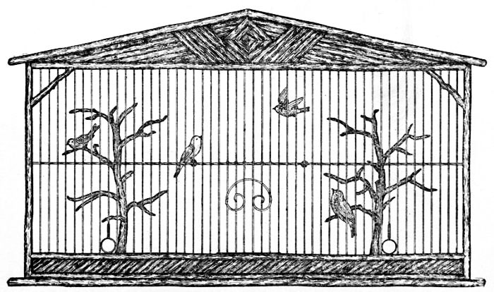
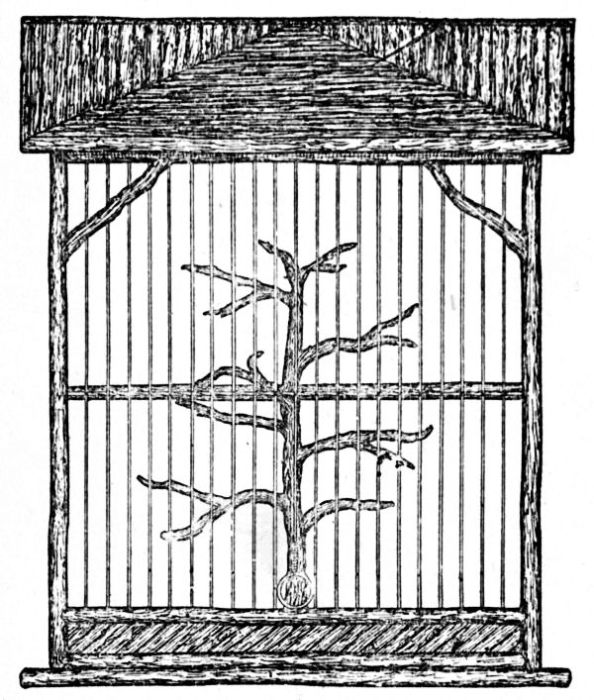
| 111, 112. | — | Aviary | 84, 85 |
| 113, 114. | — | Joint of Rails and Uprights for Aviary | 85 |
| 115. | — | Sectional Plan of Aviary | 86 |
| 116. | — | Cross Section of Aviary | 87 |
| 117. | — | Half Under View of Bottom of Aviary | 88 |
| 118. | — | Door Wires for Aviary | 88 |
| 119. | — | Part Longitudinal Section of Aviary | 89 |
| 120. | — | Half Plan of Aviary Roof | 90 |
| 121, 122. | — | Rustic Foot-bridge | 92, 93 |
| 123. | — | Girders for Foot-bridge | 93 |
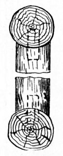
| 124, 125. | — | Joint of Post and Girder | 93 |
| 126. | — | Middle Rail and Post of Foot-bridge | 94 |
| 127, 128. | — | Joint of Strut to Post of Foot-bridge | 94 |
| 129. | — | Twig Hollowed to Fit Rail | 94 |
| 130. | — | Elevated Bridge | 95 |
| 131. | — | Girder and Post bolted to Sleeper | 96 |
| 132. | — | Elevated Foot-bridge at Lower Step (Fig. 130) | 96 |
| 133, 134. | — | Verandah | 99, 101 |
| 135. | — | Bottom of Post for Glazed Verandah | 103 |
| 136. | — | Top of Post for Glazed Verandah | 103 |
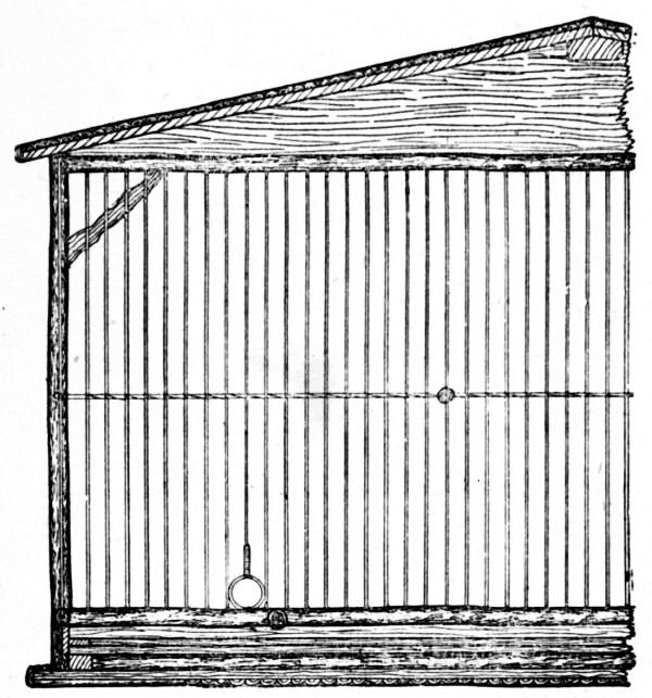
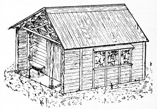
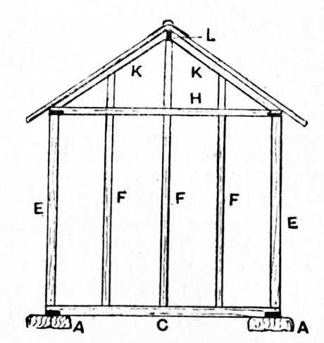
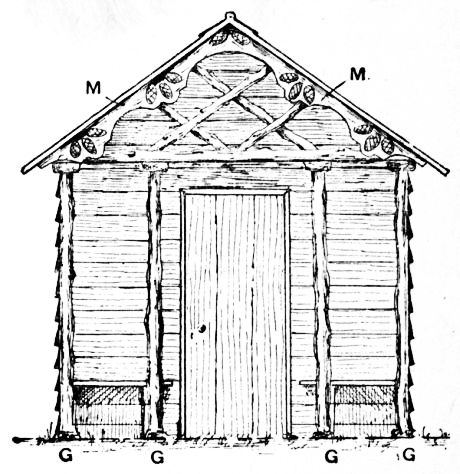
| 137, 138. | — | Rustic Tool House | 106, 107 |
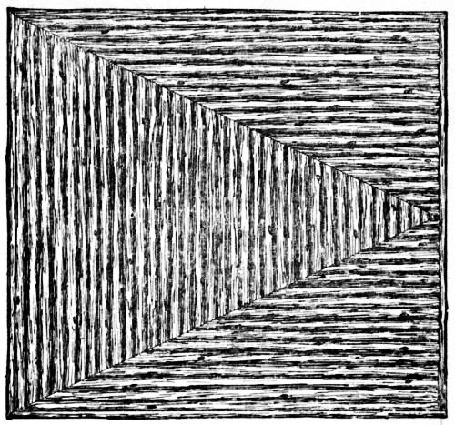
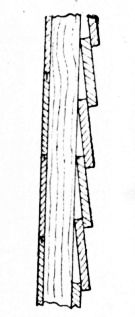
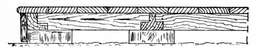
| 139. | — | Common Method of Using Slabs | 108 |
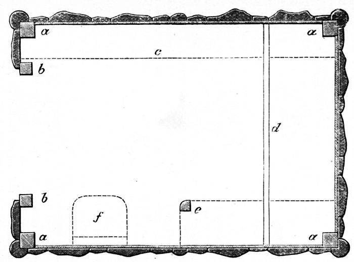
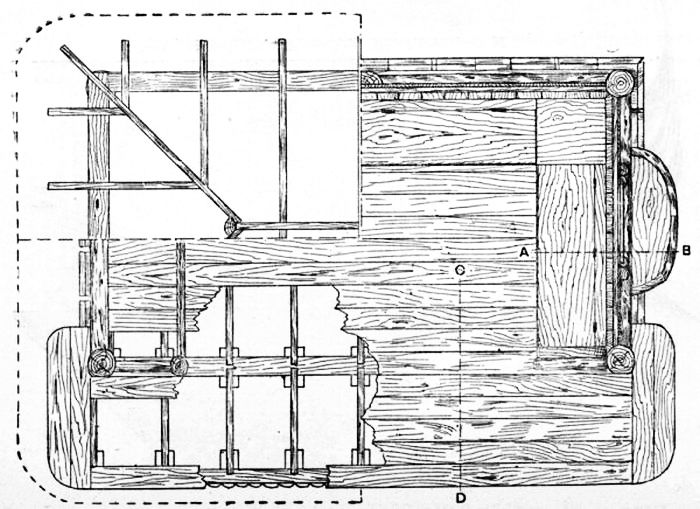
| 140. | — | Ground Plan of Rustic Tool House | 109 |
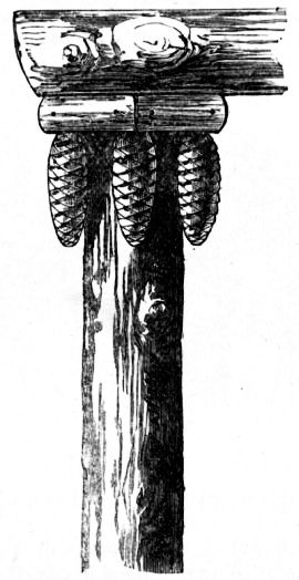
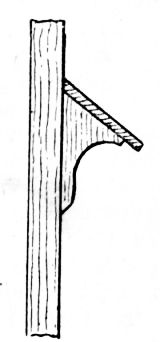
| 141. | — | Cap of Tool House Pilaster | 111 |
| 142. | — | Garden Snuggery | 112 |
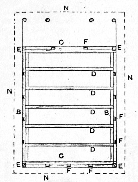
| 143. | — | Ground Framework of Garden Snuggery | 113 |
| 144. | — | Back Framework for Garden Snuggery | 113 |
| 145. | — | Snuggery Porch | 114 |
| 146. | — | Window-board | 115 |
| 147, 148. | — | Sections of Snuggery Walls | 117 |
| 149-151. | — | Garden Retreat | 118-121 |
| 152. | — | Seat of Garden Retreat | 122 |
| 153. | — | Joint of Garden Retreat at C (Fig. 151) | 123 |
| 154. | — | Detail of Front Joints (see C, Fig. 151) | 124 |
| 155. | — | Alternative Method of Joining Rails to Posts | 124 |
| 156. | — | Section of Middle Rail at A (Fig. 152) | 125 |
| 157. | — | Detail of Middle Rail at B (Fig. 152) | 125 |
| 158-161. | — | Lean-to Summer House | 126-131 |
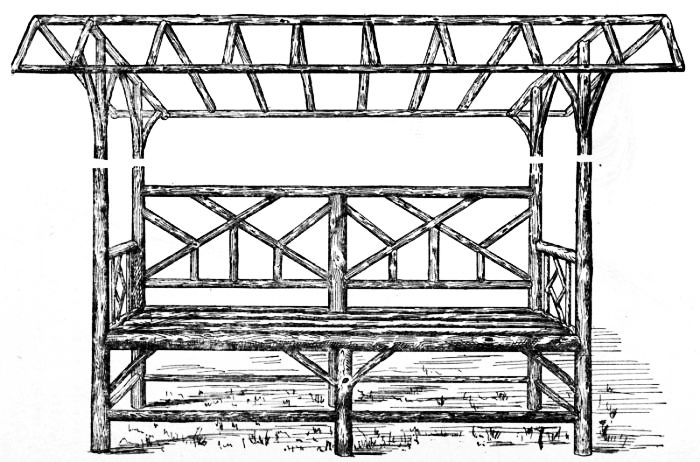
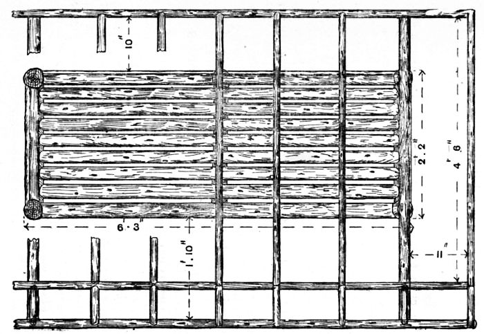
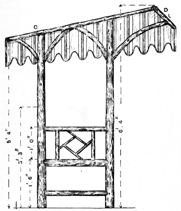
| 162-164. | — | Shelter for Tennis Lawn | 133, 134 |
| 165. | — | Connecting Plates to Corner Post | 135 |
| 166. | — | Fixing Sleeper to Posts | 135 |
| 167. | — | Section of Flooring | 135 |
| 168. | — | Finial | 135 |
| 169. | — | Garden Shelter at Front Eaves | 135 |
| 170. | — | Section of Seat | 135 |
| 171. | — | Strapping Cushion to Seat | 137 |
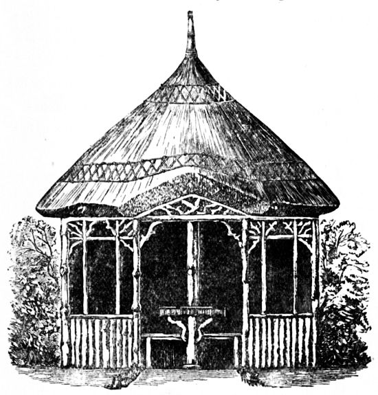
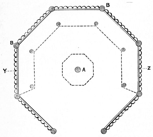
| 172-174. | — | Octagonal Summer House | 137, 139 |
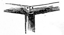
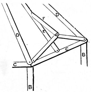
| 175. | — | Collar Posts and Ends of Wall Plates | 141 |
| 176. | — | Timbers over Entrance of Octagonal Summer House | 141 |
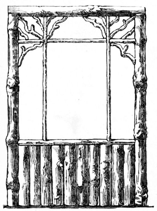
| 177. | — | Window Side of Octagonal Summer House | 143 |
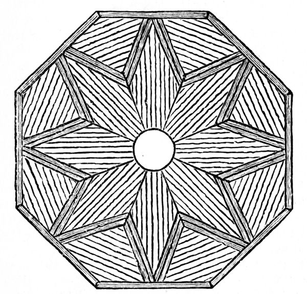
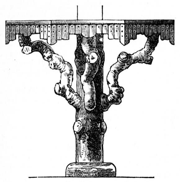
| 178, 179. | — | Table for Octagonal Summer House | 145 |
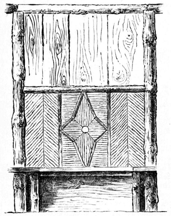
| 180. | — | Seat Side of Octagonal Summer House | 147 |
| 181. | — | Mosaic Seats | 149 |
| 182-184. | — | Octagonal Summer House with Three Gables | 151-153 |
| 185, 186. | — | Roof for Octagonal Summer House | 153 |
| 187. | — | Securing Glass to Rustic Casement | 154 |
| 188, 189. | — | Door for Octagonal Summer House | 155 |
| 190. | — | Part Plan of Octagonal Summer House | 156 |
| 191. | — | Horizontal Section through Door Posts | 156 |
| 192. | — | Part Section of Side Panel | 157 |
| 193. | — | Fixing Plate to Posts | 157 |
| 194. | — | Finial | 157 |
Rustic carpentry does not demand great skill in woodworking, but it does require a large amount of artistic perception. The tools needed are but few, and the materials employed are comparatively cheap, although in many districts they are becoming dearer every year.
It may be said that any articles made from the now popular bamboo may be made quite as effectively in light rustic work.
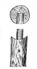
For light rustic work, sticks of hazel, cherry, yew, blackthorn, birch, larch, fir, and the prunings of many varieties of shrubs may be used; but it is necessary that the material should be cut at the proper season, and thoroughly dried before being worked up. The sticks should be cut in mid-winter, as at that time the sap is at rest; if cut in the summer time the bark will peel off. If peeled sticks are required, they should be cut in the spring, when the sap is rising, as at that time the rind will come off easily. In some districts the copses are cleared of undergrowth periodically, and the sticks (generally hazel) sold to hurdle and spar makers. A selection of these sticks would be very suitable for the purpose here described.
The sticks should be stacked in an open shed in an upright position if possible, and in such a manner that the air can freely circulate around them. When they are required for fishing rods or walking sticks they are hung up to season—this keeps them straighter; but the hanging of them up is not necessary for the work about to be dealt with. When the sticks have been put away for from six to twelve months, according to size, they will be ready for use, after being rubbed with a cloth or brushed to clean off the dust and bring up the colour of the bark. Fir cones may often be worked into a design, and bits of rough bark and the warts and burrs found on old elm trees may be collected by the rustic worker and put by for future use.
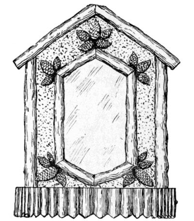
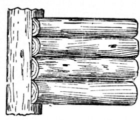
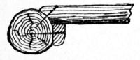
One method of treatment for designs in light rustic work is to split the sticks and use them to overlay the work with a Swiss pattern, as [Pg 11] shown by Fig. 1; another method is to work the sticks up after the manner that canes are used in bamboo furniture (see Figs. 3 and Fig. 42, pp. 12 and 36).
Fig. 1 represents a wall bracket with a photograph or mirror in the frame. To make this, the piece forming the back is first cut out of 3/8-in. deal. The shelf, of ¾-in. deal, is then nailed to the bottom edge. Some straight hazel, fir, or other sticks are next selected and split; these are nailed round the edges of the back, and round the opening at the centre. The pieces round the opening overlap the edges about ¼ in., to form a rebate for the glass. The bare spaces at the sides and top may be covered in the following manner: Take a piece of brown elm bark and run a saw into it. Catch the sawdust, and, after warming the wood, cover it with thin glue.
Sprinkle the brown sawdust on the glued surface, and sufficient will adhere to cover the deal and give the frame a rustic appearance. Cork-dust or filings may be used instead of sawdust. Bunches of fir or larch cones are nailed to the corners, as illustrated; these should be pared at the back with knife or chisel to a flat surface. The outer edge of the shelf is finished with an edging of short [Pg 13] lengths of split stick nailed on. The general construction of the bracket, and the method of fixing the glass, will be clear from Fig. 2, which is a section through the centre.
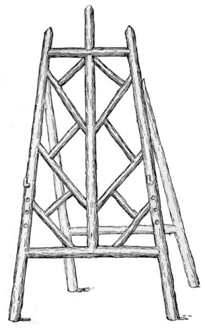
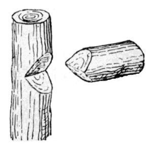
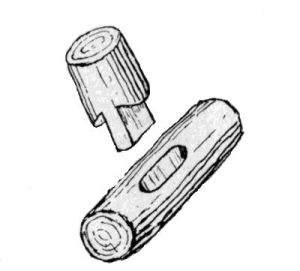
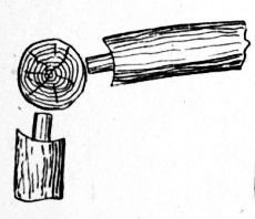
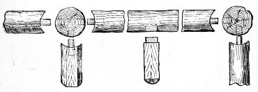
A small easel for photographs, or, if constructed larger, for a fire-screen, is shown by Fig. 3. It is made entirely of round sticks. Fig. 4 illustrates the method of attaching the back support—namely, by means of a couple of staples, which may be made out of a hairpin. In jointing round sticks together, the joints may be mitred by notching a V-shaped piece out of one stick and cutting the other to fit (Fig. 5); or a mortise and tenon, as represented by Fig. 6, may be used.
In making the easel (Fig. 3), the top and bottom bars are mitred to the sides, and the central upright to the top and bottom bars. The joints are secured by either brads or panel pins. Care must be taken to bore for the nails with a bradawl, as nothing looks worse than splits in the work. The upright piece in the centre of the top bar may be secured by driving a long panel pin into the lower upright through the top bar, filing the head to a point to form a dowel, and driving the top piece on with a hammer.
Where a small stick is joined to a larger one, as in the case of the filling-in pieces, a flat may be made with a knife or chisel on the larger stick, and the smaller one cut to fit and nailed on. In making a small easel, only a single stick attached to the [Pg 15] centre upright will be required to form a back support, but for a larger one it will be preferable to frame it as shown by Fig. 3.
The finished articles may be either stained and varnished or left plain. Cherry sticks look well if the bark is left the natural colour, and the ends, where exposed, cleaned off and varnished without being stained. Some sticks improve in colour if rubbed over with a rag moistened with linseed oil.
If a stain is required, one that is sold in bottles would be suitable, but a little vandyke brown, ground in water, and applied with a sponge, answers the purpose. Sometimes, as in the case of the table top (see Fig. 42, p. 36), it is [Pg 16] a good plan to stain the wood before nailing on the pattern work, or there will be danger, if the sticks are dark in colour, of the lighter wood showing through.
If the rustic work is intended to be placed out of doors, it should be given two or three coats of hard outside varnish.
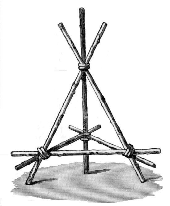
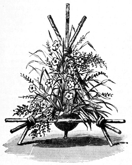
The rustic flower-holder for table decoration, shown by Fig. 7, consists simply of a gipsy tripod formed with six rustic sticks, put together in the form shown, and tied with a length of bass. There is no attempt made at finish, but the sticks must be firmly tied together at the joints, and the ends of the bass can be left, either hanging loose or tied in a bow. The holder for the flowers is a cocoanut shell, which has been sawn in two, so as to leave one part a sort of cup or egg shape; three holes are bored with a bradawl at equal distances round the edge, and it is suspended from the tripod with three more pieces of the bass, which completes the arrangement. Of course, any small receptacle can be used in place of the cocoanut shell, but that, perhaps, carries out the rustic appearance the best, and is very easily obtained. Fig. 8 is an attempt to show the tripod when decorated.
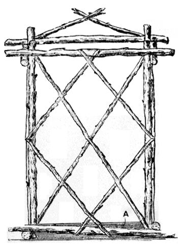
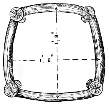
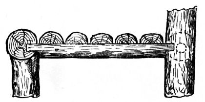
The rustic hall-stand shown by Figs. 9 to 11 was made actually from branches and twigs of an old apple tree. The uprights and principal cross-pieces are 7/8 in. thick, and the criss-cross pieces are ½ in. thick. The bottom is made of four pieces 1½ in. thick. The longer ones measure 1 ft. 8 in., and the shorter ones 1 ft. 2 in.; they are nailed together in such a manner that the ends at the two front corners each cross and project 2½ in. The front uprights are 2 ft. high, the back ones 2 ft. 2 in.; the longer cross-pieces are 1 ft. 8 in., the shorter 11 in. The ends intersect and project 3 in. at each of the front corners; only the longest piece projects 3 in. at the back corners, the shorter pieces being cut off flush with the frame to allow of the stand fitting close to a wall.
|
Figs. 9 and 10.—Front and Side Elevations of Rustic Hall Stand. |
|
|
Fig. 11.—Plan of Rustic Hall Stand, showing Umbrella Pan. |
||
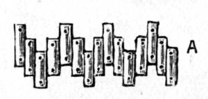
These cross-pieces are nailed to the uprights to allow the top ends of the latter to project 2 in. above them, this bringing the measurement of the oblong inner framework to 1 ft. 10 in. by 1 ft. 2 in. [Pg 18] The thin pieces are nailed on as shown in Fig. 9, being interlaced as much as possible. The back of the stand is treated in a similar manner. The whole of the wood is used as rough as possible, the bark being retained, with the knots, etc.; the ends are, however, pared off smooth with a chisel. Two coats of varnish finish the stand, save for the addition of a receptacle to catch the drainings from umbrellas, and for this the stand illustrated has a painted baking-tin A (Fig. 11).
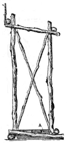
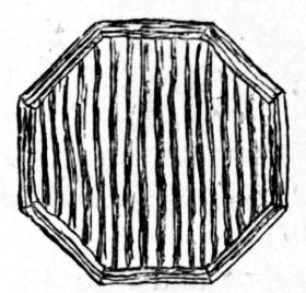
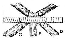
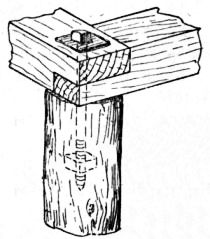
The rustic stool (Figs. 12 and 13) is intended to be made in pairs, and placed one on each side of the umbrella-stand above described, each supporting a plant, such as a fern or palm. The top of each stool is cut from 9 in. square 1-in. wood (wood from an old box answers well), and is sawn into an octagonal shape. A double row of pieces of apple, maple, or some other wood with good bark, is nailed around the edges, thicker pieces being used at the bottom than at [Pg 19] the top to give a graduated appearance. The entire top is then covered with straight pieces of stick, selected for the beauty of their bark. All pieces are nailed on with cut brads. The four legs are formed of 1-in. apple-wood 9 in. long. They are bevelled at the top to fit a square block of wood, 2 in. thick and 3 in. long, which is firmly secured to the top by two screws. This piece of wood should be fastened to the top before the rustic rods are placed in position. Two 2½-in. wire nails through each of the legs hold them quite securely to the central block. Portions of rustic wood, from ¼ in. to 3/8 in. in diameter, are then nailed across the legs, as shown in Fig. 12, the ends being allowed to cross each other and project about 1 in. all ways. The whole stool, when finished, stands 10½ in. high, and is so strong that it will support a heavy man with safety. The block of wood to which the legs are attached should be stained to match the rustic wood; permanganate of potash solution will effect this. Finally, two coats of clear varnish give a good finish to the work.
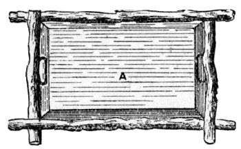
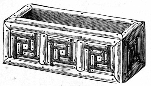
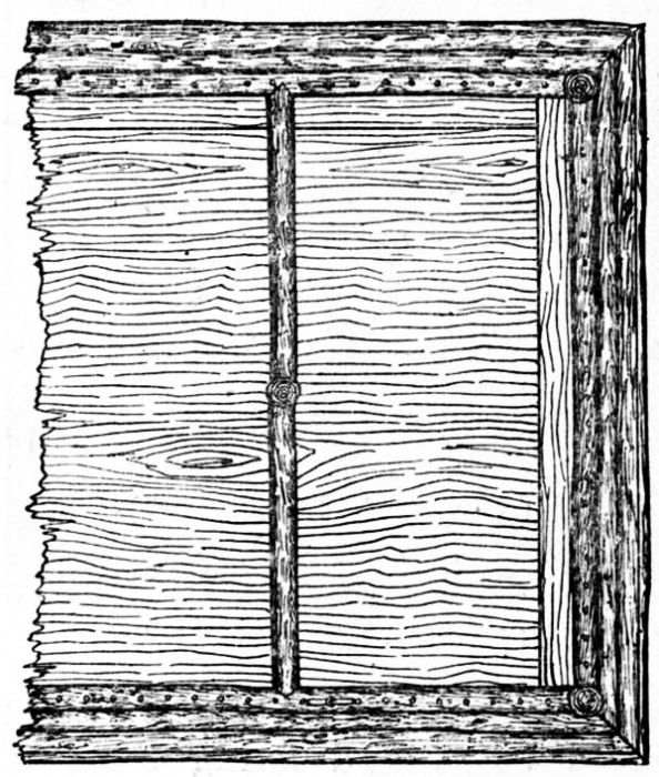
Window boxes are illustrated by Figs. 14 to 16. That shown by Fig. 14 is made from a raisin box obtained from a grocer. Such boxes are not costly, and to buy and knock these up for rough uses is often more economical than buying new material.
Take care that the boards are stout enough to hold the brads firmly. The box measures about 21 in. by 7 in. by 7 in., and is wholly covered with mosaic of dark and light strips in panels. Strips are also nailed on the upper edges.
The more elaborate window box (Figs. 15 and 16) can be made of a size to fit the window for which it is intended. A few holes should be bored in the bottom for drainage, and the front board is cut to the shape shown and the rustic ornament is nailed to the box and forms no part of the construction. In Fig. 16 wedge pieces are shown fitted to the stone sill to bring the box level; it is kept in position by two metal angle-pieces screwed both to the wood sill and to the back of the box.
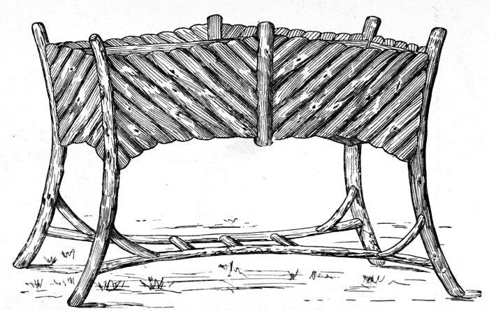
The rustic-work flower stand (Fig. 17) may be 3 ft. high by 3 ft. 6 in. long by 9 in. wide. For the legs, select four curved saplings 3 ft. 3 in. long by 2½ in. in diameter; and as some difficulty may be experienced in obtaining them with the natural curves sufficiently alike, artificial methods of bending must be resorted to. Therefore get the saplings from 2 ft. to 3 ft. longer than the finished length, and bend them to shape by means of the Spanish windlass as shown in Fig. 18. Flexible six-strand fixing wire or stout hemp cord can be used; or a straining screw and link, as employed for tightening fencing wire, will answer equally well; keep the tension on till the wood is curved permanently, the time varying with the nature and condition of the wood, and the strain being applied gradually at intervals. The rails are tenoned to fit mortises in the legs, and battens are nailed to the lower long rails, to support the flower pots (see Fig. 19). The rustic work is then fixed diagonally to the rails. The ends that abut against the legs and centre-piece are pared away so as to make a neat joint, and angle boards are fitted to the under side of the lower rails to support the rustic work where it curves downwards.
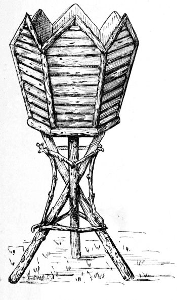
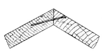
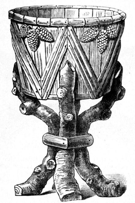
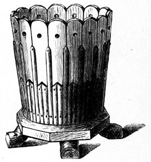
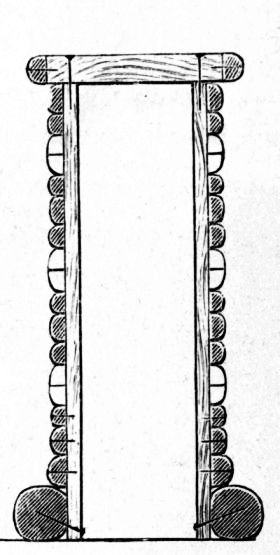
The vase shown by Fig. 20 is hexagonal in shape, with vandyked sides fixed to a base supported upon tripod legs, and stands about 3 ft. 3 in. high. Elm boards are suitable for the sides and bottom; they are 1 ft. 3 in. high by 9 in. wide at the top end, and 6½ in. wide at the bottom by 1 in. thick. Shoot the edges of the boards to a bevel of 60°, and fix them with nails driven as shown at Fig. 21. When the six sides are completed, prepare the hexagon baseboard to suit. Bore holes in it for drainage, and also bore three equidistant holes, 1¼ in. in diameter, at an angle of about 60°, for the tenons of the legs to enter (see Fig. 22). Next screw the base to the sides, and fix on the barked rustic work. The twigs for this should be seasoned at least one year before using. They are sawn in halves, straight twigs being selected for the purpose. If necessary, shoot the edges slightly, so as to obtain a closer fit when fixing them in parallel. Begin by attaching the lower border to the hexagonal base, then the upright pieces over the angles, hollowed as shown at Fig. 23; next fix the top sloping pieces, and finally the horizontal twigs. The legs are nailed at the base of the vase (see Fig. 22); and at the centre, where they cross, they are further secured with twigs, which do the duty of rungs, as shown in Fig. 20.
Figs. 24 and 25.—Side and End Elevations of Flower-pot Stand. |
|
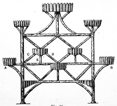
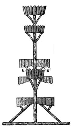
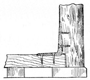
The flower stand shown in front and end view by Figs. 24 and 25 has accommodation for sixteen pots. The two uprights are 2 ft. 8 in. high by about 2½ in. in diameter. The three rails are 2 ft. 9 in. long, and are tenoned to the posts as shown by Fig. 26; the posts are also tenoned and nailed to the sills (bottom rails), and strutted, as shown in Fig. 25. The method of fixing the shelves A and B (Fig. 24) is shown in Fig. 27, which is an under-side view; struts are also fitted, as shown in Fig. 25. The method of fixing the centre shelves is indicated at Fig. 28. The shelf, and also the struts C, D, E, and E1 (Figs. 24 and 25), are fixed to the centre rail; then the top diagonal braces are nailed to both the shelf and [Pg 28] the top rail, thus keeping the whole secure. The remainder of the work calls for no special instructions. Split twigs are used for the fencing around the shelves.
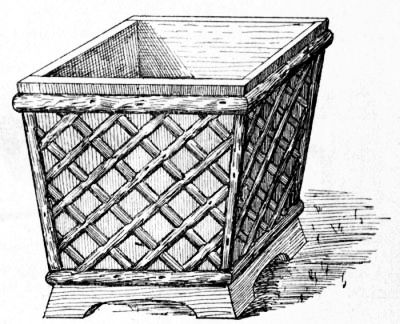
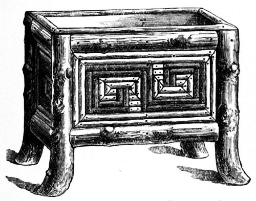
Fig. 29 shows a square vase constructed from elm boards 1¼ in. thick. A fair size for the sides [Pg 29] will be 1 ft. 8 in. at the top and 1 ft. 5 in. at the base by 2 ft. high, including the 2½-in. plinth. The split twigs forming the decoration are 1½ in. wide, and spaced about 2 in. apart edge to edge.
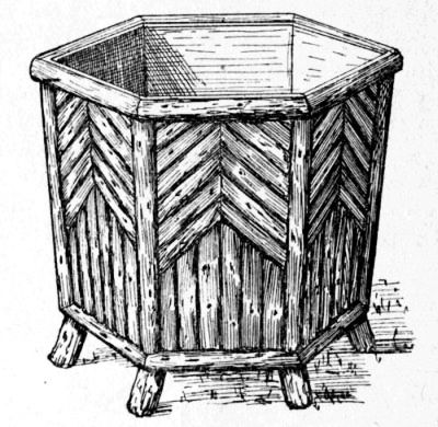
The vase shown by Fig. 30 is hexagonal in shape, the sides being 1 ft. 8 in. high by 1 ft. 2 in. wide at the top edge, and 1 ft. 0-½ in. at the base. The sides and bottom of both vases are connected as in Figs. 21 and 22. Five 1-in. holes are bored for drainage. The short feet having been secured [Pg 30] with screws driven from the inside, the split rustic work is bradded on in the same order as that described for Fig. 20.
The stands and vases should be given two coats of oil varnish, allowing the first coat to dry before applying the second.
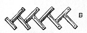
A big plant vase made from half a paraffin cask is illustrated by Fig. 31. An ordinary 40-gal. cask stands, roughly, some 3 ft. high, has a diameter of some 2 ft., and is made of good stout oak. Sawn through the middle, the paraffin barrel makes two admirable tubs. One such half is shown in Fig. 31. This it is proposed to render suitable for some large bushy plant, so it will have to be mounted on legs. The legs shown are simply so many pieces cut from rough branches. From a heap of stuff one can generally choose pieces sufficiently adapted to the purpose, though their exact contours will, of course, vary. Oak branches, technically known as "bangles," from which the bark has been taken to make tan, will do well; or if the bark is liked, apple-tree or elm boughs will be suitable. That these sticks should be rough and gnarled and knotted adds [Pg 31] to their effect. As the tub will be only partly covered with rustic mosaic work, it will be well before nailing anything upon it to paint it. A good dark brown or chocolate will go well with the natural bark. The rustic pieces will have to be cut through with the saw, the lengths being too great to be safely split with the hatchet—that is, with the exception of those round the lip, which are of thicker rod than the zig-zags; say, 1½ in. as compared with 1 in. In the zig-zags the light central strip is supposed to be of peeled withy, the darker ones on each side having the bark on, and being probably of hazel. Generally speaking, wrought brads are to be recommended for fixing rustic mosaic, but where, as in the present case, the strips have to be bent over a curved surface, small wire nails will be found more secure. Groups of fir cones, as shown, will prettily ornament the triangular spaces.
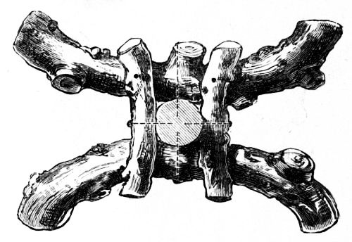
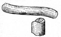
A style of foot suitable for a one-leg flower stand or table is illustrated in plan and part section by Fig. 32.
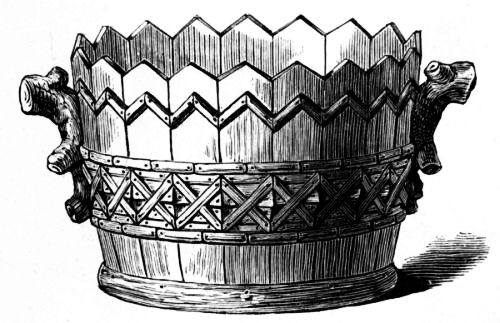
Fig. 33 shows the other half of the cask arranged for, say, a dwarf shrub, an orange-tree, [Pg 32] or the like. In small town or suburban premises, such tubs are specially useful where there is a back court into which anything green cannot otherwise be introduced. In this, it will be seen that by way of variety the tops of the staves have been sawn to a zig-zag line, which is followed a little below by a moulding of split rods. Alternative styles of moulding are shown by Figs. 34 and 35. Half-way between this and the bottom a band of mosaic is arranged in light and dark strips of withy and hazel. The bits filling the diamond-shaped centres of this pattern are cut from thicker stuff than the rest, so that they may project as bosses beyond the general level. Over the unavoidable iron hoop at bottom, from which place short strips would, if nailed, be often detached, a rough "dry-cask" wooden hoop has been fixed. At the sides two pieces of rough branch stuff have been placed to serve as handles, and to resist strain these should be secured from within by strong screws.
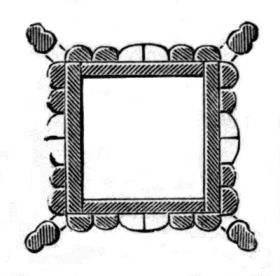
The vase shown by Fig. 36 is intended for a somewhat low-growing flowering plant—say, a large bushy geranium. In its original character [Pg 33] it is an American lard pail. As in the last tub, the staves have been sawn to a more ornamental outline, and they have also been perforated. The ornamental strips of split rod have been arranged in straight vertical lines, to avoid the difficulty of bending and keeping them in place if bent round so small a vessel. The bottom of the pail is screwed down to an octagonal slab of wood, to the under side of which four short bits of rough bough are nailed as feet. As neither this nor the last tub is wholly covered with mosaic, they should, of course, first be painted. The slab at bottom will look very well rough, as shown, but if painted it will be improved by strips of split rod nailed round its edges.
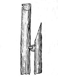
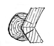
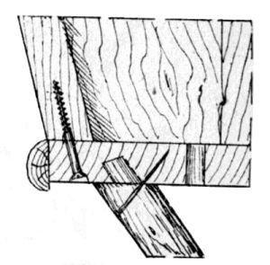
A garden plant stand, made from a soap box and mounted on legs is shown by Fig. 37. The easiest way to fix one of these legs on is to saw the piece of stuff in half to a distance from the top equal to the depth of the box, and then to cross-cut and remove one half. The corner of the box will be [Pg 34] brought to the middle of the cross-cut, and the leg nailed on to the side of the box. The piece which has been sawn off will then be cut through (quartered), and the proper quarter replaced and nailed to the end of the box. Frets, such as those shown in these two examples, are patterns of a kind well adapted to be worked out in rustic mosaic.
|
Figs. 38 to 40.—Elevation, Section, and Horizontal Section of Rustic Pedestal.
|
||
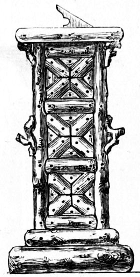
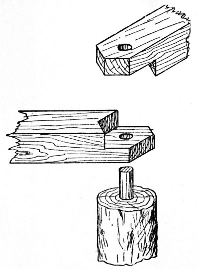
A pedestal for a sundial or flower vase is shown by Figs. 38 to 40. It is a box of 1-in. elm boards, the top being a 2-in. thick slab. [Pg 35] Suitable dimensions are 3 ft. 6 in. high, and 1 ft. square, the top being 16 in. square.
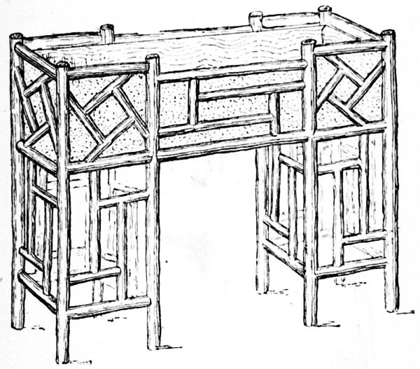
A design for a rustic flower-pot stand in imitation of bamboo is represented by Fig. 41. The height should be about 2 ft. 6 in. to the top, and the length from 3 ft. to 3 ft. 6 in. The box at the top may be about 9 in. wide and 8 in. deep. Care must be taken when putting the work together to get the frames true and square. Slovenliness in construction will completely spoil the appearance of the finished article. The box at the top is made to fit inside, and should be lined with a zinc tray. The outside may be covered with glue and brown sawdust.
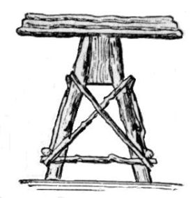
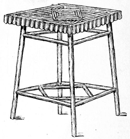
A small rustic table which may, if desired, be used as a flower-pot stand, is illustrated by Fig. 42. The top may be made of ¾-in. stuff, and should have two ledges nailed underneath to prevent twisting. The table may be 1 ft. 10 in. high, with the top 15 in. square, or, if a larger size is required, 2 ft. 1 in. high, with the top [Pg 37] 18 in. square. The design is not suitable for tables of a larger size.
The legs may be secured to the top by boring holes in the ledges and driving them in. The cross bars must be firmly secured to the legs, and, for the joints, the mortise and tenon shown at Fig. 6 (see p. 14) would be suitable. If the sticks used to form the legs are rather small, it will be better if the cross bars are kept a little higher on two of the sides, so that the mortises do not meet each other.
The top is covered with a Swiss overlay pattern, made of split sticks. The design may be set out by drawing lines from corner to corner on the top, and across the top in the centre of each side. A smaller square is then drawn in the centre of the top, with diagonals at right angles to the sides of the top. Lines drawn from the corners of the small square to the corners of the top will form a four-pointed star. The pattern should be clearly outlined with a pencil. In nailing on the sticks, those round the outer edge of the top should be put on first and mitred at the corners. Next the outside sticks of the small square should be nailed on, then the eight pieces from the corners of the small square to the corners of the top.
In working up patterns of the above description, always nail on the sticks that follow the outline of the design first. The filling-in pieces may be put on afterwards. Variety may be given to the patterns by using sticks of different colours; for instance, the design may be outlined in hazel or blackthorn, and filled in with hawthorn or peeled willow. The edges of the table top are concealed by nailing on an edging of short sticks or cones.
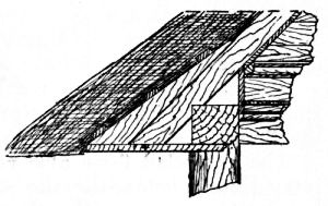
Fig. 43 shows a small hexagon-top table for use in a summer-house or on the lawn. The following dimensions are suitable: Height 2 ft. 6 in., and diameter of circle for the hexagon top 2 ft. 9 in. The top is made from two or three 7/8-in. boards cramped together to the required width and fixed underneath with two battens 3½ in. wide by 1 in. thick. The four legs are dowelled and nailed to these battens and further stiffened by the rungs and the diagonal braces which are nailed to the legs. A corona is fixed around the edges of the table top, and the method of securing the board is shown in Fig. 44. In Fig. 45 the half plans show two ways of ornamenting the top. The twigs should be sawn so that in section they are less than a semicircle, and it will be an advantage to shoot their edges slightly, as then they will fit closer and cover the rough boards that form the table top.
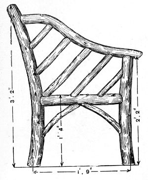
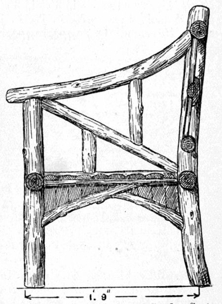
For the armchair (Fig. 46) select four slightly curved legs about 3 in. in diameter; the front pair are 2 ft. high and the back pair are 2 ft. 9 in. high. The front seat rail is 1 ft. 2 in. long by 2½ in. in diameter, the back rail is 1 ft. long, and the side rails are 1 ft. 3 in. long, their ends being trimmed to fit the legs, and fixed with inserted ash or elm dowels 7/8 in. in diameter; see Fig. 47. The height from the ground line to the [Pg 41] seat top is 1 ft. 4½ in. The battens forming the seat rest on the side rails, and cleats are fixed to the inner sides of the four legs (see Fig. 48) to support the extreme back and front battens. The arms and back are made in three parts, the scarfed joints coming immediately over the back legs. The trellis work is then added, and finally the struts and dentils are fixed around the seat. The chair can be made from unbarked wood without any dressing, or the bark may be removed and the wood, when dry, can be finished in stain and outside varnish.
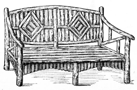
The garden-seats about to be described will look very effective if made of oak that has had the bark removed and the small twigs trimmed off clean; they should be finished in stain and varnish. In construction they are fairly simple.
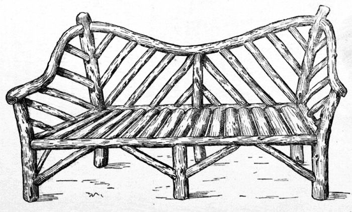
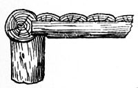
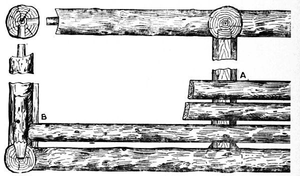
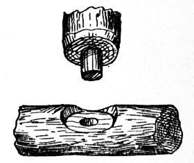
For making the seat shown by Fig. 49, first select the three back posts, with their natural curves as much alike as possible. In diameter they should be from 2½ in. to 3 in. Select also two arm-posts and one centre leg for the front. Next cut two seat rails for the back and one rail for the front, 5 ft. or 6 ft. long as desired, and cut two side rails (see Fig. 50) and one centre rail, each 1 ft. 7 in. long. Work the ends of the rails to the shape of the posts as shown by Figs. 51 and 52, so that they make a fairly good joint, and bore the posts and rails with a 7/8-in. bit 1¼ in. deep, to receive dowels made of ash or elm. These are preferable to tenons formed on the rails themselves. Now try the whole together temporarily, and make good any defects.
Then take the pieces apart, and coat the joints with a thick priming consisting of two parts of white-lead (ground in oil) and one part of red-lead thinned with boiled linseed oil. Drive the joints home and fix them with nails or screws and wipe off the surplus paint.
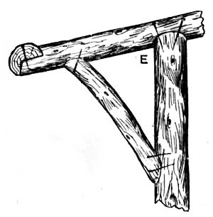
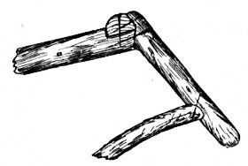
The top back rail and the arm-rest can next be fitted. The ends of the back rail are worked bird's mouth, to fit the posts. The arm-rests are treated in the same way at the back; they fit in vees cut in the front posts, and are fixed with nails.
Measure off and mark equal spaces for the struts, the ends of which are trimmed to fit the rails and posts. Secure them with two nails at each end. The seat (Fig. 53) is made up of split saplings laid as shown, with the ends pared to fit the rails and bradded on. Finally, fit the struts between the seat rails and the lower part of the posts.
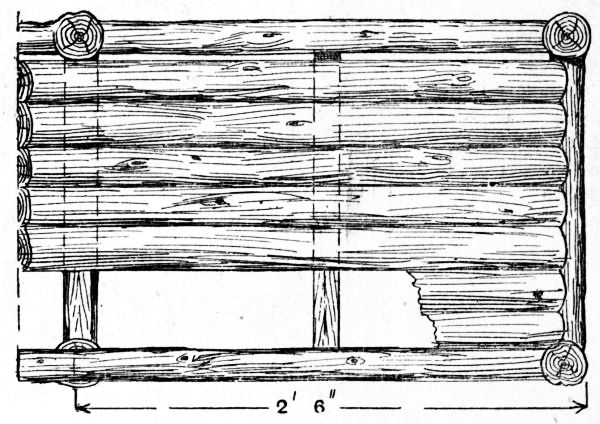
The framework for the chair shown by Figs. 54 and 55 is on the same principle as that already described. The segmental battens forming the seat run longitudinally, and their ends are shaped to fit the outer rails. The battens rest on a flat worked on the centre cross rail (see Figs. 55, Fig. 56, and Fig. 57). Fig. 56 also gives a part cross section near the centre leg, and shows the front rail placed out of centre and the cross rail resting on the leg, to which it is firmly nailed. When the seat is more than 5 ft. in length the battens require intermediate supports, which can be cut from split saplings. The panelling on the back is fixed to the top and bottom rails and supported in the centre by a wide longitudinal rail and two vertical rails at the mitres of the diamond centres. These are fitted in and secured, and then the vertical split twigs are fixed partly on them and also on the rails. Finally, struts are fixed to the seat rails and legs and covered with short twigs, with their lower ends running in a regular curve.
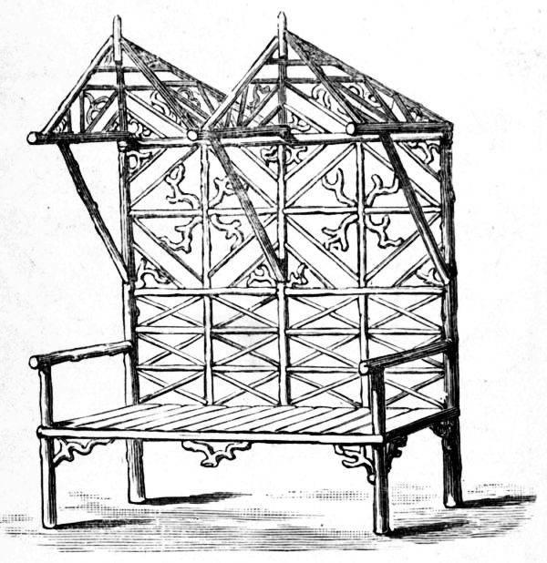
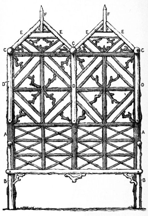
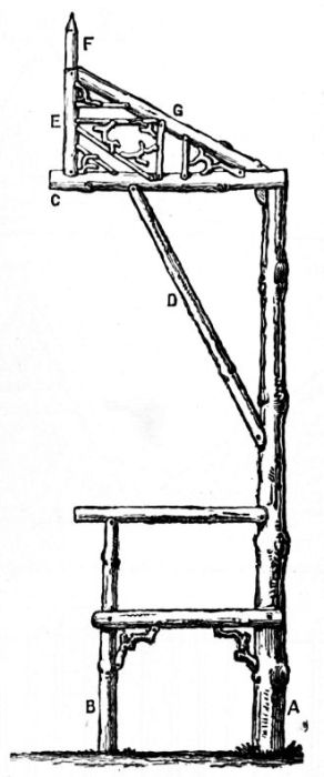
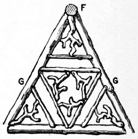
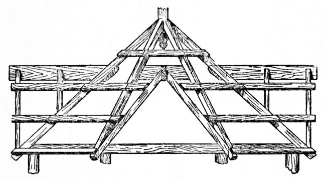
A rustic garden seat with canopy is illustrated by Fig. 58. Where shade is required, the back [Pg 47] and canopy offer facilities for securing it, as they can be covered with climbers. Fig. 58 is not drawn to scale, but the explanatory diagrams (Figs. 59 to Fig. 64) are ¾ in. to the foot.
The upright posts and all the more important pieces will best be formed of somewhat small larch stuff; the smaller straight sticks may be hazel, birch, or withy. The last named, stripped of its bark, and used in some parts only, will form a pretty contrast with the darker rods. In filling spaces in back and canopy, a few pieces of crooked stuff are used; these will probably be of apple-tree.
The two posts A, on which almost the entire weight is sustained, should be let into the ground not less than 2 ft. They rise 5 ft. above the ground-line. They are set at a distance, measuring from centre to centre, of 4 ft. apart. The smaller posts (marked B), which support the seat, stand 17 in. in advance of those last named, and should be let into the earth 1 ft. The broad seat thus given is essential to comfort when the back of the chair is upright, as it must be in this instance.
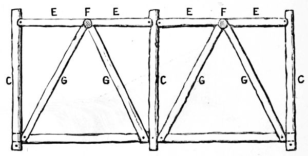
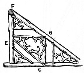
Two principal cross-pieces are nailed against the main posts. The lower one, of halved stuff, is 15 in. from the ground, and carries the back of the seat. The other is close to the top of the posts, and carries the back of the canopy. The canopy is chiefly supported on the three wall-plates, C (Fig. 59), which rest at one end on the heads of the posts, and towards the other on the struts, D (Fig. 60). Fig. 61 shows in plan the arrangement of the principal pieces forming the canopy: E E are the rafters of the gables, the lower ends of which rest on the wall-plates, and the upper against the pinnacle, F (Fig. 61). The back rafters are marked G G, and these rest their lower ends on the cross-piece and their upper against the pinnacle. Fig. 62 shows the filling-in of the two back panels of canopy; Fig. Fig. 63 that of the four side panels.
The filling-in of the back of the seat is clearly shown in Fig. 59.
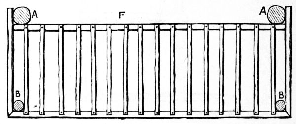
In Fig. 64 the seat proper appears in plan. Its front and ends are of halved stuff, nailed to the posts. The spars forming the seat are placed with spaces between them, that they may not hold moisture; for the same reason, it is advised that they should be of peeled withy.
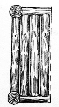
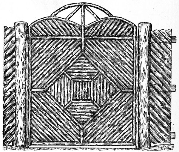
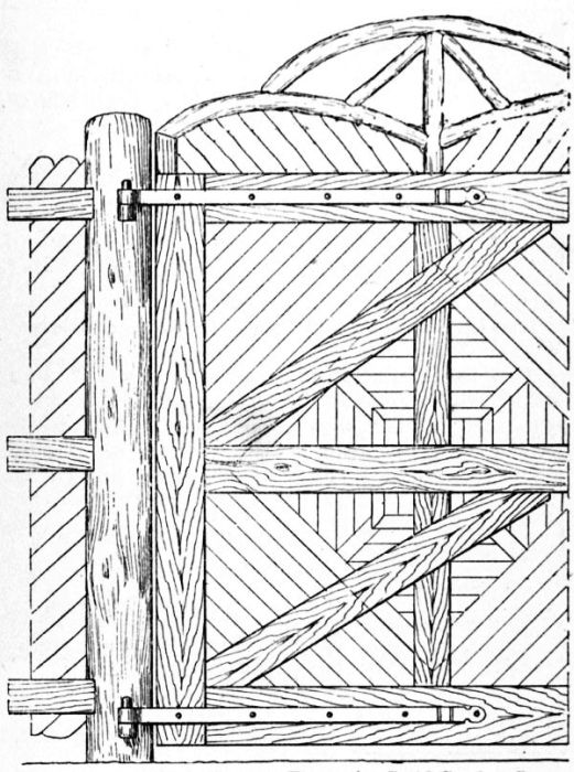
In many gardens there is a space devoted to the tool-house, potting shed, refuse head, etc. Shrubberies of course hide the unsightly appearance of this particular spot to a certain extent, but it may be found desirable to close the entrance to this part of the garden from the remainder, and the gate illustrated in front elevation by Fig. 65 [Pg 53] is, from its semi-rustic nature, particularly suitable. Fig. 66 shows a plan and Fig. 67 is a part back view. The gate is quite simple in construction, and should be of sufficient height to obstruct the view from each side.
Local circumstances will of course determine the width of the gate, but the one illustrated by [Pg 54] Fig. 65 is constructed on a framework 6 ft. square, the total height being 8 ft. The timber for the frame need not be planed.
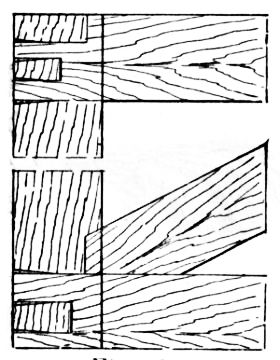
Cut the closing and hingeing stiles 6 ft. long out of stuff 6 in. wide by 2½ in. thick. The three rails are of the same dimensions, and can be halved and dovetailed to the stiles or, better, mortised, tenoned, and wedged and braced, as shown in Figs. 68, 69, and 70. Separate pieces of stuff are fixed up the centre to form a muntin for supporting the rustic work; the necessity is obvious [Pg 55] from Fig. 66, where it will be noticed the twigs are outlined on the frame. Each twig has a bearing on the frame, and can thus be nailed individually.
|
Figs. 74 and 75.—Designs for Rustic Gates. |
|
Two stout gate hinges and hooks are required, and they can be bolted on with 7/16-in. Whitworth bolts and nuts, or secured from the back with square-headed coach screws. Now commence fixing on the unbarked twigs; they should be as straight as possible and used in their natural shape, without being split in halves.
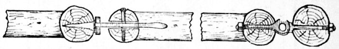
The terminations of the joints for circular stuff are slightly different from the ends of the half-round stuff; see Figs. 71 and 72. Start by fixing the outside square, then the two inner squares, and finally the diagonal filling.
The posts are 9 in. or 10 in. in diameter by 9 ft. long, 3 ft. being underground. Cut three mortises in the posts to receive the rails for the side fencing. These rails are nailed flush to the secondary posts, nails also being driven through [Pg 56] each mortise in the gate posts. Next dig the holes for the posts, these being kept at correct distances apart by nailing battens to the top and at the ground line while ramming in the posts. Two parts of old brickwork and one part of Portland cement will make a good concrete for the posts.
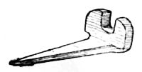
A week or more should elapse before the gate is hung to the posts. This may then be propped up fair between the two posts, and the positions should be marked for the staple of the latch, and hooks for the hinges. A rebate is formed for the gate on the posts by nailing on split sapling; see Figs. 67 and 73. Finally, a short post can be driven in the ground and fitted with a hook for retaining the gate when open wide.
|
Figs. 76 and 77.—Designs for Rustic Gates. |
|
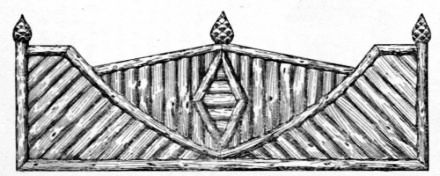
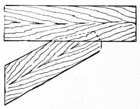
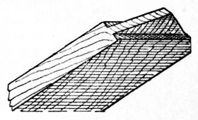
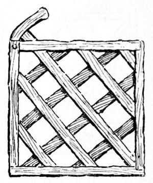
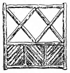
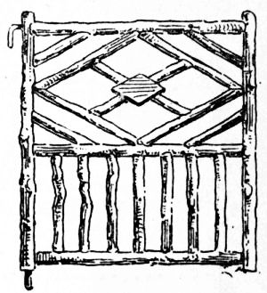
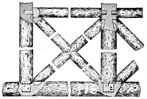
Suitable designs for small rustic gates are given by Figs. 74 to 77. The wood for making gates to the two designs (Figs. 76 and 77) should have the bark removed. The chief rails and posts are about 2 in. thick, filled in with 1½-in. or 1-in. pieces, halved and nailed together where they cross. The joints may be hidden by bosses of planed wood (see Fig. 77). If the gate is to be removable, fix a hook on the hanging stile to engage [Pg 57] with a staple in the joint, and a pin in the bottom to turn round in a socket. The gate is then easily taken out of its hangings. Varnish the wood on completion.
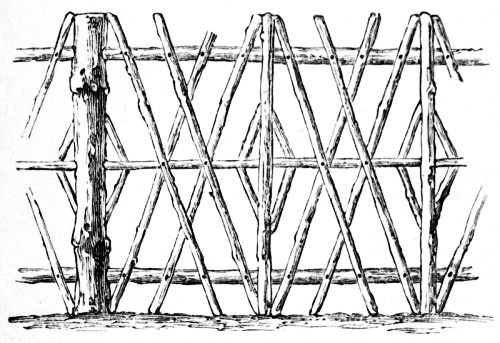
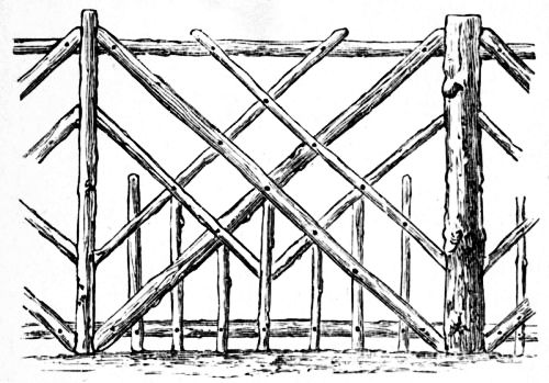
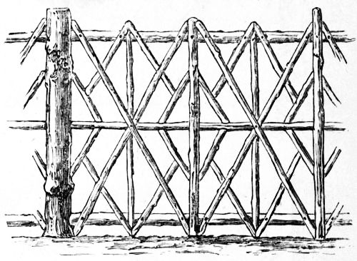
Rustic fences can be constructed as shown in Figs. 78 to 80.
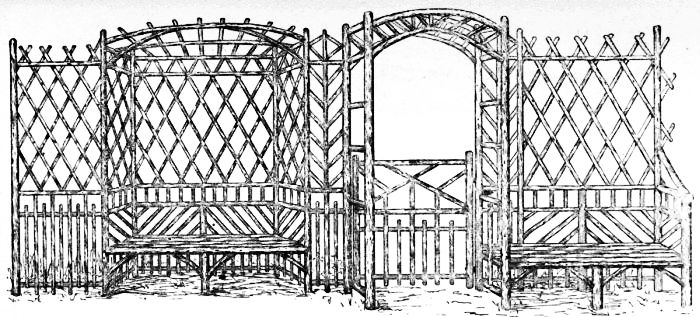
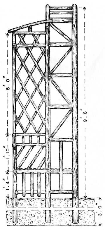
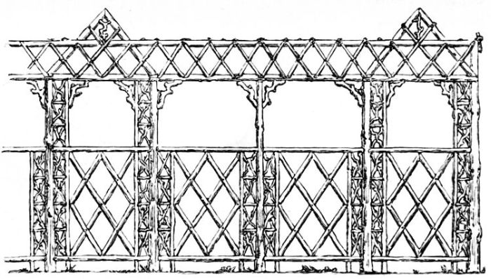
The garden trellis illustrated at Fig. 81 will [Pg 58] form an attractive addition to the grounds of a suburban or country villa residence. In the case of new houses, the existence of such a trellis, with creepers ready planted, will often prove a deciding factor in effecting a quick sale or letting. The structure extends to a length of about 20 ft., but the dimensions may readily be altered to suit requirements. The material may be fir or other straight unbarked saplings and twigs. The posts are 12 ft. long; the four for the arch being 4 in. in diameter, and the others 3 in. or 3½ in. The rails are 2½ in. in diameter, and the twigs for the trellis, etc., 1¾ in. or 2 in. The bay seat with canopy is 6 ft. long by 1 ft. 4 in. wide.
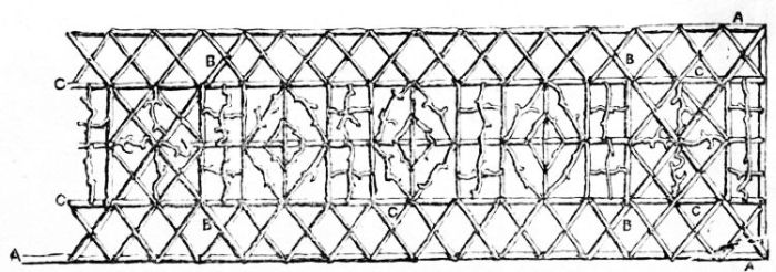
The position of the seats and posts and of the shores A, B, and C is clearly shown in the plan ( Fig. 82). The arrangement of the double posts adds materially to the stiffness of the framework, making long shores unnecessary. The shores are placed 3 ft. 6 in. above the ground line, and are inclined at an angle of 50°. The posts are sunk into the ground a distance of 3 ft., and well rammed in; rubble stones being mixed with the earth, as shown in the vertical section (Fig. 83).
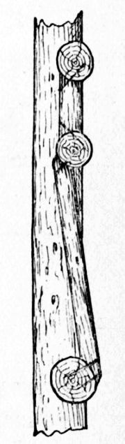
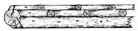
The arch may with advantage be entirely fitted together before being put in position, as a better job can thus be made of the joints of the short rails and struts. The joints in the remainder of the work, with the exception of the gate, are of the simplest description. The rail ends are bevelled and notched to the posts, and secured with nails as shown in the sectional view of the trellis at Fig. 84.
Having erected the framework in position, next sink and well ram the shores deep into the ground, and splay and nail the top ends to the [Pg 62] uprights. Also fix the shorter posts for the seats, letting them into the ground about 1 ft. 6 in. The end seat bearers are fixed to the end posts, and the centre bearers to the front and back central posts. The seat battens are saplings split in two, the flat portion being laid downwards and nailed to the bearers (see Fig. 83). Fig. 85 is an enlarged section through the seat back, showing the method of securing the smaller twigs to the rails. The fixing of the vertical pieces in the lower part, and the inclined lengths above, will complete this portion of the screen.
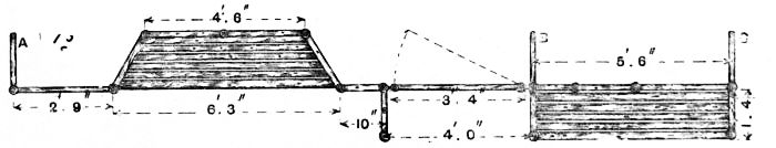
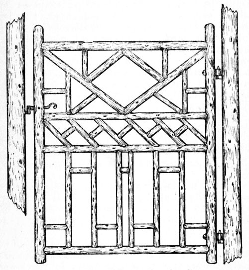
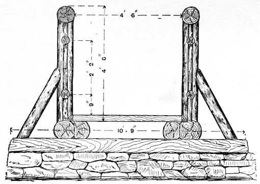
The gate, shown enlarged at Fig. 86, which gives an alternative design, is 3 ft. 9 in. wide by 4 ft. 6 in. high. The stiles are 4 ft. 9 in. long and about 2½ in. in diameter, and should be as straight as possible, with the twigs neatly trimmed on; the rails should be at least 2¼ in. in diameter, trimmed to fit the stiles, and secured with inserted hardwood dowels 1 in. in diameter, as shown at Fig. 26, p. 27.
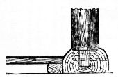
The diagonal struts in the top panel should be fitted and in place before the rails and stiles are finally secured; the vertical twigs in the lower panel should be similarly fitted and nailed before the rails are secured to the stiles. Ordinary forged hooks and eyes are used for hanging the gate; these are secured to the stile and post with nuts and washers, as shown in the enlarged horizontal section (Fig. 87).
A mortice is cut in the closing stile to receive the latch, the catch for the latter being a simple forging (see Fig. 88) with a pointed tang for driving into the post.
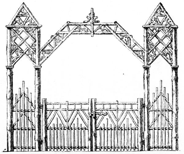
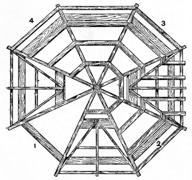
A rustic carriage entrance is shown by Fig. 89. The intention is, of course, that the rustic archway above the gates shall be more or less clothed with climbing plants. It is for roses that the structure will be best adapted, though clematis or honeysuckle will look well upon it. Ivy would look too heavy, and, if neglected, might even prove too heavy in other respects. Light as the arch may appear, the four posts grouped to form the turret on either side are so tied and braced together as to be, to all intents and purposes, a solid pillar, 30 in. square, and fully equal to resisting any outward thrust of the rafters. In the elevation (Fig. 89), to avoid confusion, no indication is given of the work forming the farther side of the arch, though something of it would necessarily be seen from the front; the two sides will be alike. Figs. 89 and 90 are drawn to a scale of ½ in. to the foot.
The posts, and at least all the more important straight pieces, should be of larch. The wood chosen for filling-in should have picturesque forks and contortions. Small oak bangles will, perhaps, be most appropriate.
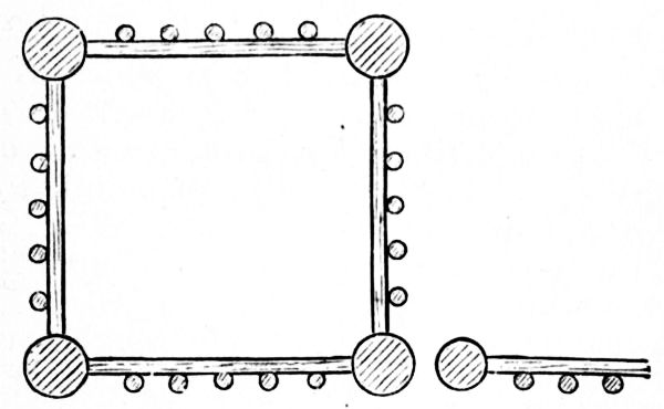
In the ground plan of the left-hand turret (Fig. 90) it will be seen that the posts used—four at each end—are some 5 in. or 6 in. in diameter, and that the largest is selected as hanging-post for the gate. From centre to centre they are set 2 ft. 3 in. apart. They are 13 ft. long—that is, 10 ft. 4 in. above ground and 2 ft. 8 in. below. The rafters of the arch spring from them 7 ft. from the ground, and at this point each post is surrounded by a cap, formed of four pieces of [Pg 64] quartered stuff nailed upon it. The rafters are not mortised into the post, but if, instead of being merely nailed, they are attached by a bolt and nut, a stronger joint will be made.
The upper rafters, back and front, are connected by five straight cross-pieces, whose ends show in Fig. 89. The spaces between these are filled up very much at random with crooked stuff.
The four posts of each turret are bound together close beneath their tops by cross-pieces [Pg 65] nailed outside them, whilst from their tops, and nailed down to them, slant four short rafters, which meet pyramid-wise in the centre. The filling up of the upper parts of the turrets, as well as of the front and back of the arch, is with a mixture of straight and crooked stuff, the arrangement of which is clearly shown in the elevation (Fig. 89).
The lower parts of the turrets and the gates must be constructed in such a way as to exclude animals; the palings are so arranged as not to leave a space between them wider than 3 in. The rails of the gates should, of course, be mortised into the heads and hinge-trees.
The rustic construction here illustrated is intended primarily as a trellis over which to train roses, and to form a shady and fragrant walk, and generally to contribute to the adornment of the flower garden. It can readily be adapted so as to form a roofed-in track from a door to the public roadway; and the means of so adapting it will be explained later.
The materials will be entirely rough wood in its natural bark. For the posts fir poles of some kind should be chosen, and larch is especially to be preferred both as regards durability and appearance. All the smaller pieces which show as straight stuff may well be of the same kind of wood as the posts, though hazel is best for the finer rods. It will be seen that in the mere filling-in much crooked stuff is used, and for this apple branches, or indeed almost anything that comes to hand, will answer.
The rosery walk (Fig. 91) is 4 ft. wide, and the rustic erection is carried on two rows of pillars or collar-posts ranged at intervals of 3 ft. These posts should be let into the ground 2 ft., and well rammed in. They should have an average diameter of 3 in. or 3½ in., except in the case of each third one, as that which in Fig. 91 is seen standing in the middle of the portion with the lower roof; such pillars may be smaller as having little weight to bear, and will look better than they would do if equal in size to the others. Resting on the line of posts lies the wall-plate (A A, Fig. 92), the top of which is 5 ft. 6 in. from the ground line.
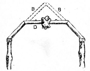
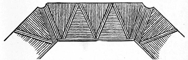
From each group of four large collar-posts rise four rafters (B, B, Fig. 92), meeting at top pyramid-wise. They rise to a height from the ground of 7 ft. 6 in., and have, therefore, to be 3 ft. 4 in. long. Half-way up them—that is, 6 ft. 6 in. from the ground line—the purlins (C, C, Fig. 92) are nailed upon them. Figs. 91 [Pg 69] and 92 alike show how the space between wall-plate and purlin is filled in, and Fig. 92 shows how the space, 7 ft. 3 in. long, stretching from one pyramidal portion to the next, is covered with a flat roof of open rustic work lying upon the purlins. This space, it will be observed, is chiefly filled in with crooked stuff.
Fig. 93 shows how the upper part of the rosery would appear at one of its ends, and explains how the roof would be in section—the shaded parts give the form of the roof in its lower portions; whilst if the cross-piece, D (which is on a level with the purlins), is supposed to be removed, there is presented with the dotted lines, B, B, a section through the middle of one of the higher pyramidal portions.
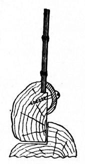
Over the middle of the entrance is a rough knot or a piece of root.
The filling-in of the sides of the rosery is plainly shown in the elevation, Fig. 91. For its better preservation from damp, this work is kept 4 in. from the ground.
Supposing that, as was suggested above, the design is to be utilised for a dry path with a covering of metal or other light material, it will be well to keep the whole roof to the level of the pyramidal portions—a ridge-piece will have to [Pg 70] be used—and the rafters, instead of following the present arrangement, will meet in pairs opposite to the pillars. Instead of round stuff, also, use halved stuff for the rafters and purlins, the sawn side being uppermost. The space between ridge-piece and purlin can then be filled in the same manner as that between purlin and wall-plate.
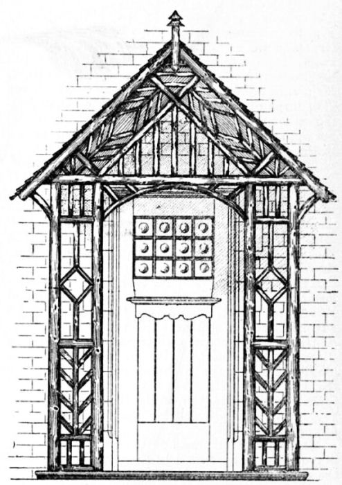
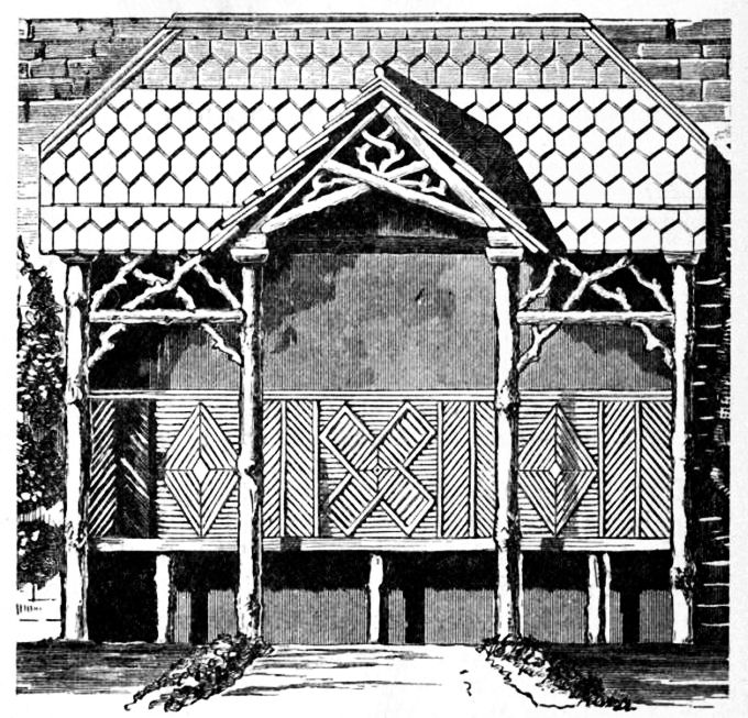
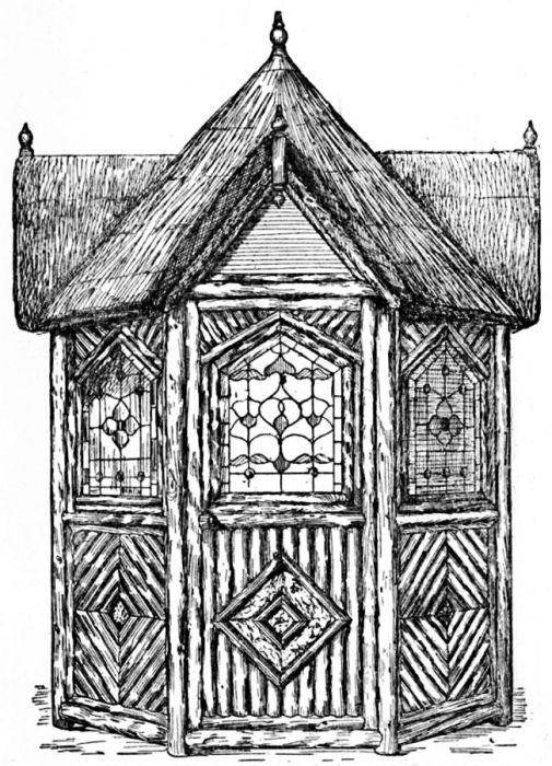
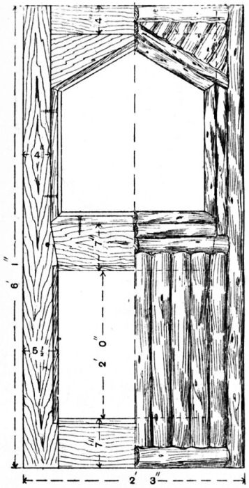
The rustic porch shown in front elevation by Fig. 94 and in vertical section by Fig. 95 is constructed from straight, well-seasoned saplings and twigs, from which, in each case, the bark has been removed. The design is eminently suitable for a farmhouse or a country cottage. The porch is of large dimensions, and is provided with seating accommodation on each side. The seats do not appear in the elevations, but one side is shown in the part plan (Fig. 96).
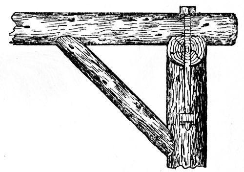
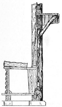
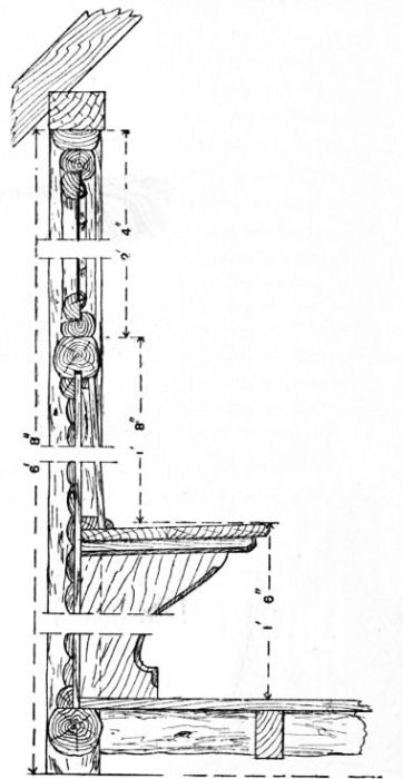
The seats are 1 ft. 6 in. high by 1 ft. 2 in. wide. The battens are 1¾ in. wide by 1½ in. thick, and are supported on cross-pieces fixed to the front posts and wall; a centre batten being fixed to the centre panel, and supported by a diagonal bracket running from the front down to the sill-piece. The floor space is 7 ft. wide, and stands out 5 ft. from the walls.
The posts are 7 ft. 6 in. long by 4 in. in diameter. The front posts are preferably dropped over metal dowels leaded into the stone floor, at 1 ft. 2 in. centres, while the side posts are at 10½ in. centres, and of smaller section—say about 3 in. in diameter. One post, 5 in. in diameter, sawn longitudinally through the centre, does duty for the two wall-posts, the flat portion being, of course, scribed to the wall, the latter having been previously plugged for the reception of the fixing nails.
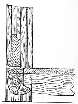
The rails are tenoned to the posts, and 1¼ in. diameter holes are bored in the posts, and also in the ends of the rails, for the reception of the inserted tenons. The ends of the rails are also [Pg 72] hollowed to fit roughly the posts (see Fig. 97). The lower rail is 10 in. up from the floor, while the centre rail is 3 ft. 4 in. up. The rail immediately below (Fig. 95) is 10 in. below the centre rail.
The top ends of the front posts are hollowed, and fitted with inserted dowels for the reception of the front rail. The six side-posts are finished off square, and have tenons which fit into the plates. The front ends of the plates are notched to the front top rail. The rafters are 5 ft. 7 in. long by 3 in. deep and 2 in. wide, wrought and [Pg 74] chamfered and birdsmouthed to the plates as shown at Fig. 98. The ridge piece, 4 in. deep by 1½ in. thick, projects 5 ft. 2 in. from the wall. On the front end of the ridge is fixed the finial, which is 2 in. square. The rafters are covered with 1-in. V-jointed, wrought, grooved and tongued boarding, cut in 5-ft. 4-in. lengths, and laid horizontally or at right angles to the rafters.
The roof may be covered with slates, with Broseley tiles, with wood shingles, or with thatch. A part plan of the roof is shown in Fig. 99. An enlarged section of the front angle of the gable is given in Fig. 100. Two boards, each 1 ft. 1 in. wide by 1¼ in. thick, are fixed to the outer rafters and run parallel with them; the heels of the two [Pg 75] boards abutting on the front top rail, to which they are nailed. The split-twig herringbone ornament is also nailed to these boards. On the inner edges of the boards are secured twigs of about 1¾-in. in diameter, which are rebated to fit to the edges as shown in Fig. 100. The front projecting ends of the roofing boards are concealed by split twigs of about 2½-in. or 3-in. diameter, which do duty as bargeboards. The method is shown at A (Fig. 100).
The panels have now to be filled with stuff ranging from 1½ in. to 2¼ in. in diameter. The [Pg 76] vertically placed twigs between the posts and rails should be fitted in place before the rails are finally jointed up to the posts. The ends are roughly hollowed, and are secured with cut nails. Alternatively, the vertical members could be fitted so that their inner edges coincided with the centre of the rails. The major portion of the twigs being on the outer side, the smaller diameter of the twigs will thus bring their front edges flush with the larger diameter edges of the rails. The herringbone and the diagonally placed twigs are quite easy to fit, the ends being simply pared off till they are sufficiently shortened to assume their correct position in the panels.
The decorative effect of the porch will be greatly improved by the addition of a suitable door, as shown in the front elevation (Fig. 94). The cost of manufacture of such a door is but slightly more than that of an ordinary six-panel door. The bottle ends in the top glazed panel form a quaint and pleasing feature of the general scheme.
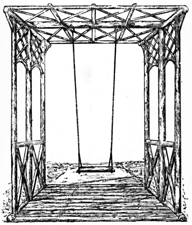
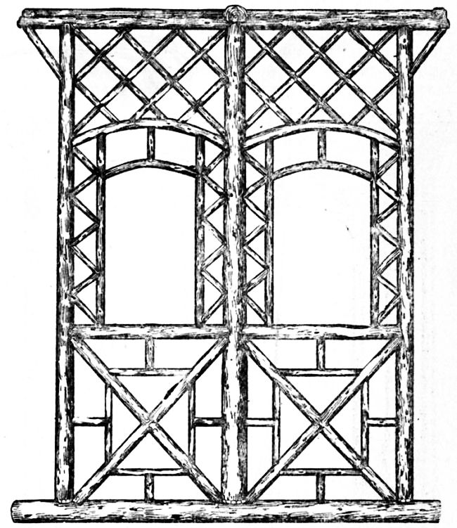
Fig. 101 is a general view of the canopy and swing, and Fig. 102 a side elevation slightly more elaborate in design than Fig. 101, the chief members, however, being exactly the same. The [Pg 78] material used is stripped fir saplings. Six of these are required for the uprights.
The middle posts are slightly larger in section, as they have to carry the cross rail supporting the swing; a good size for these is 6-in. diameter at the base by 10 ft. or 12 ft. high. The outer posts may be 4¾-in. to 5-in. diameter at the base. The posts are sub-tenoned (see Fig. 103) to elm sills 10 ft. 6 in. long by 8 in. diameter. Tenons are formed on both ends of the posts, and seatings and mortices at 4-ft. centres are made in both the sills (bottom rails) and plates (top rails) to receive them.
The short rails are 4 in. in diameter by 3 ft. 6 in. long, and are stub-tenoned and pinned to the posts at a height of 3 ft. 9 in. from the ground line. The struts also are tenoned and pinned to the middle posts and sills, as shown in Fig. 104, where, it will be noticed, the struts are in one piece and the braces in two, the latter being hollowed to fit in the angles and over the struts.
| Figs. 106 and 107.—Hook and Thimble for Canopy. | |
When all the members are ready for the final [Pg 81] drive home, the tenons of the rails should be just entered to the posts; the struts and braces are next placed in position and driven up, then the sill and plate are entered and driven home, and finally the several joints are secured with oak pins. This operation will be carried out better with the work in a horizontal position. When the two sides are so far completed, they may be erected in position and fixed with temporary battens, at a distance apart of 7 ft. 9 in. centres, while the top cross rails are being fitted.
The middle cross rail which carries the swing is 6 in. in diameter and 8 ft. 6 in. long. A seating is formed on the plates, and a shallow one upon the rails, which are secured with long 3/4-in. [Pg 82] diameter bolts and nuts; the latter are let into the posts at a distance of 8 in. from the top, as shown in Fig. 105, which is a cross section through the plate near the middle rail. Short struts may also be fixed between the posts and cross rail, as in Fig. 105; they are not shown in Fig. 101. A floor is formed of saplings, connected to the sills, thus preventing them from spreading. The trellis-work, both on the roof and sides, is now fixed. This is composed of 1¾-in. and 2-in. twigs.
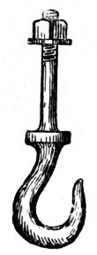
The swing hooks (Fig. 106) pass right through the rails, and are secured with nuts and washers. Collars should be forged on the shanks to prevent the hooks being drawn too far into the wood when screwing up the nuts. The shank is screwed ¾-in. Whitworth pitch thread, and the hook is 1¼ in. in diameter at the thickest part. The hemp rope is spliced around galvanised iron thimbles (see Fig. 107), which take the wear on the hooks. The rope is usually secured to the seat by simply knotting the ends.
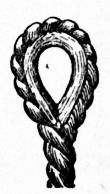
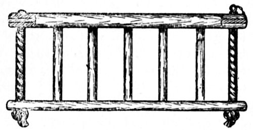
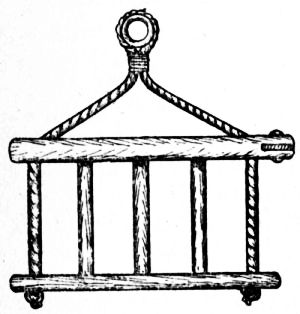
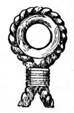
Should the swing be used for very young children, a seat provided with a fence will be necessary, as shown at Figs. 108 and 109, which are front and end views respectively. The back rail and the two side rails are fixed to the seat with the balusters; but the front rail is tenoned to open-ended mortices in the side rails, and thus made to hinge, to facilitate the lifting of the children on and off the seat, the rail being secured in its closed position with a brass pin and retaining chain. The suspending rope in this case is passed through the end rails and knotted to the seat. Fig. 110 shows the rope passed around and whipped to an eyelet.
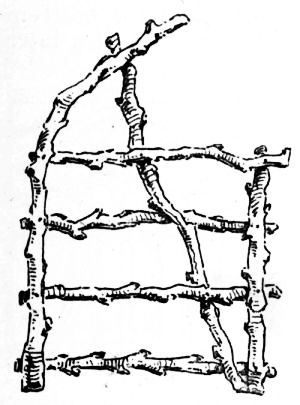
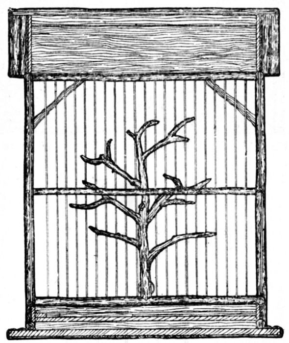
The outside dimensions of the rustic aviary shown by Figs. 111 and 112 are—length, 3 ft. 2 in.; width, 1 ft. 6 in.; height, 1 ft. 10 in.
Hazel sticks, with the bark on, should be used, the straightest obtainable being best for the frame; if at all crooked or bent, the sticks can be straightened by steaming, or, if not too dry, by the heat of a spirit lamp.
Four uprights, 1 ft. 5½ in. by 5/8 in., are first cut; then six rails, ½ in. thick, are made, with the ends shaped as shown in Fig. 113, to fit the uprights, measuring 2 ft. 10 in. inside the hollow ends when finished. Four of these should be laid on the bench side by side, and marked with a pair of compasses for the wires, which are 5/8 in. apart. They are then drilled, the holes being bored right through the two sticks for the top rails, but only half through the bottom rails. If the stuff is not too hard, the holes may be pierced with a well-sharpened brad awl.
The uprights are now secured to the rails with 2-in. wire nails, driven so as to avoid the holes (see Fig. 114), and glue is applied at the joints. The bottom rail is flush with the lower ends, the next one being placed ½ in. above it; the third is ¼ in. from the top ends. These form the front and back frames, and should be quite square and out of winding. The rails for the ends, also six in number, measure 1 ft. 3 in., and are bored and fixed to the uprights to correspond with the others in exactly the same way.
The two rails supporting the tree perches are placed about 7 in. from the ends. Before they are fixed, however, the tree perches must be arranged. These should be cut from the limb of a leafless tree, in winter, in order to retain the bark. Suitable pieces may be prepared by cutting off badly placed twigs and fixing them where required. They are then put on the perch rails, employing the same joint as the rails and upright, but securing with a strong screw.
|
Figs. 113 and 114.—Details of Joint of Rails and Uprights for Aviary. |
|
When all is ready, the perches are fixed in the framework (see Figs. 115 and 116), and narrow [Pg 86] strips of ¼-in. board are fitted between the lower rails of the back and ends, to be faced with split stuff, put on diagonally as shown in Figs. 111 and 112. The best plan would be to take a sufficient quantity of material to the nearest sawmill to be divided by a circular or band saw; the material must be free from grit, or objections will be raised against cutting it.
A stain, made by thinning down brunswick black with turps, should be at hand to stain the wood before fixing on the split stuff, which is secured with fine panel pins.
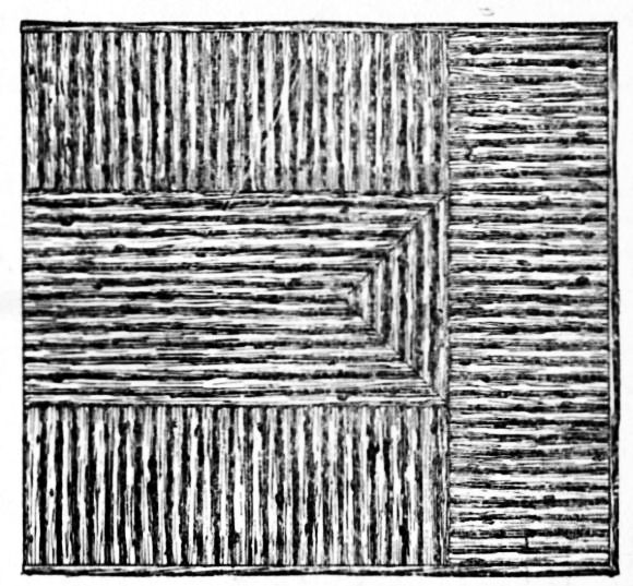
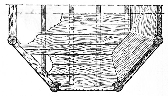
The wood bottom is 3 ft. 1½ in. by 1 ft. 5½ in. by 3/8 in.; it is planed both sides, and secured in place with screws. The top side is treated round the margin, as shown in Fig. 115, and the under side as shown in Fig. 117. The centre of the design of the under side, covering a space of 2 ft. 3 in. by 8 in., is worked first; it is worked from the centre outwards, each strip being mitred [Pg 87] as shown. The marginal strips are pieces of split cut slanting at the ends where they fit other pieces, and flush with the edge of the wood bottom, which is surrounded with the same stuff.
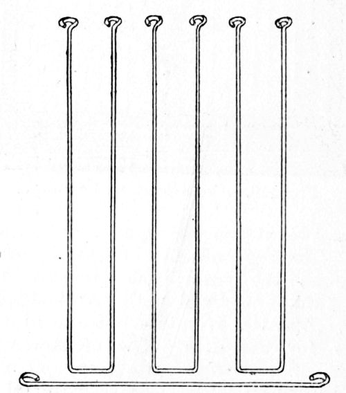
The wiring is all straightforward work. The wires are passed through the top rails to those below and clipped off level at the top. Six feeding-holes are required, one in the centre at each end, and two at the back and front close to the perches. The top ends of these wires are pushed up through the rails; the circular ends are slightly sunk and fixed with small staples. Six wires are omitted from the middle of the front to allow for the door. The cross-wires, which should be of a stronger gauge, are then put in. In the back and ends it is immaterial whether they are put inside or out, but at the front they must be inside. The six wires above the door are inserted in twos, being returned in the same manner as the lower ends of the door wires (see Fig. 118), and soldered to the cross-wire, which is afterwards bound to the others with thin pliable coil wire. In making the sliding door, the returned ends of the wires are soldered to the base wire inside, so that the ends may fit round the wires of the doorway; the top ends fit round those above the cross-wire, and when the door is in place a scroll-piece is soldered on outside (see Fig. 111).
Eight corner-pieces of the split stuff are put on close against the wires, being secured to the uprights and rails with pins. Two pieces of ¼ in. [Pg 90] board are next got out for the top, measuring 2 ft. 10 in. long, 4 in. across the centre, and slanting at the upper edge to ¼ in. at the ends. The design is worked on these in split, the boards being kept in place with pins driven through the top rails, and the back and front connected at the top point by a length of wood of 2-in. by 1-in. section (see Fig. 119). The roof-pieces, 1 ft. 5½ in. by 1 ft. 7¼ in. by ¼ in., are nailed on and covered with split stuff, as shown by Fig. 120.
A sliding bottom or tray is required for cleaning purposes; this is of ¼ in. board, and is nailed to the strip that fits between the rails in front; other strips about 1 in. wide are nailed on the upper side at the extreme ends and back edge to form a tray for the sand, runners being put in against the lower end rails. The front strip is treated with the split, and to draw out the tray, the door may be slightly raised to admit the fingers to push it forward from the inside. Two [Pg 91] additional perches put across from the wires, and fixed with staples, give strength to the front and back.
The aviary is now gone over with fine glass-paper, all white places being touched up with the stain and nicely varnished, with the exception of the perches. The aviary will stand on a table, but may be hung from the ceiling if desired. For hanging purposes, four screw-eyes are put in the top, two on the ridge, about 3 in. from the front and back, and one towards each end, placed midway to catch the rails. The four ceiling hooks should screw into the joists, the aviary being suspended with chains.
Very pleasing effects may be produced in public or private recreation grounds by the constructional use of rustic work of good design.
|
Fig. 122.—Cross Section of Foot-bridge.
Fig. 123.—Enlarged Section of Girders for Foot-bridge. Figs. 124 and 125.—Parts of Joint of Post and Girder. |
|
|
Fig. 126.—Detail of Middle Rail and Post of Foot-bridge. Figs. 127 and 128.—Joint of Strut to Post of Foot-bridge. |
||
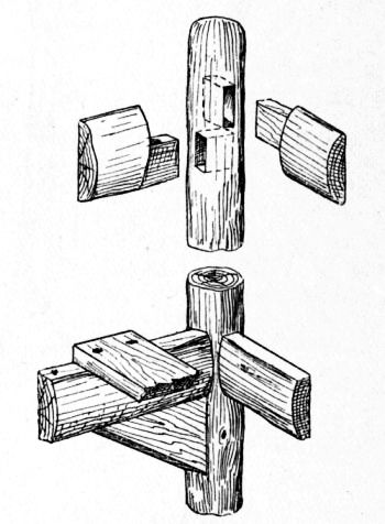
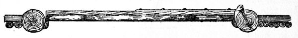
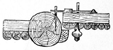
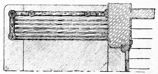
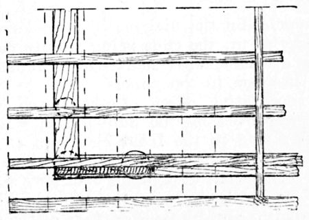
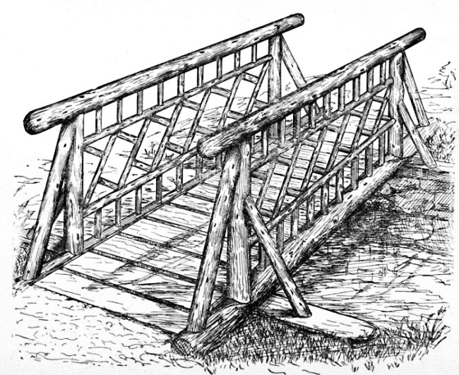
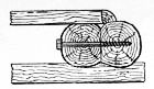
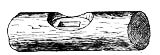
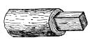
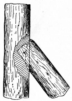
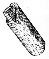
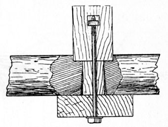
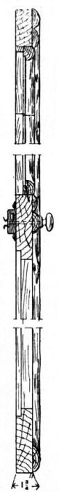
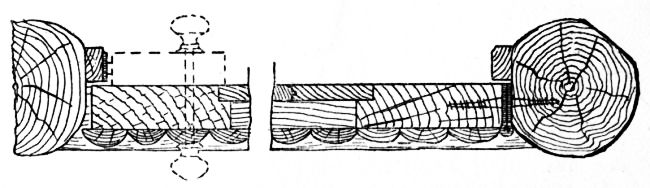
Fig. 121 is a perspective view of a rustic foot-bridge suitable for a span of 8 ft. or 12 ft. The banks of the stream to be bridged are excavated to allow of the building of a low rubble wall, on which the sleepers rest, as shown in Fig. 122. The girders are formed of spruce or larch spars. In the present instance, four are used; and they may be 8 in. or 10 in. in diameter, according to the length of the span. They are roughly adzed down to sit on the sleepers, and each girder is also worked down tolerably flat on the inner sides. The girders are then bolted together in [Pg 95] pairs with six ¾ in. diameter coach bolts, as shown by Fig. 123. The posts are tenoned and wedged to fit mortices in the girders. Figs. 124 and 125 show the mortice and tenon joint.
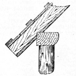
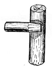
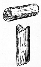
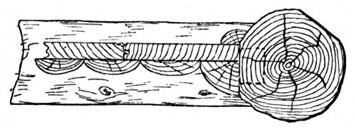
The posts and top rails are 4½ in. or 5½ in. in diameter, and the intermediate rails 3 in. in diameter. Fig. 126 indicates the method of jointing the rails to the posts. The girder spars, with posts and rails fitted, having been placed in position on the sleepers, and plumbed up and stayed, the floor battens, 11 in. by 2½ in., [Pg 96] are fixed and the struts are fitted and pinned or spiked to the posts and sleepers. The joint for the struts is shown by Figs. 127 and 128.
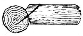
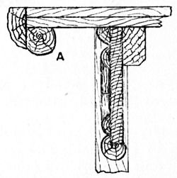
If the bridge happens to be in a locality that is subject to periodical flooding, it should be anchored to prevent its being unseated by flood water. The anchoring can be best effected by driving four short piles into the soil on the inside of both girders and near their ends. The girders can be fastened to the piles with coach bolts. The tops of the piles will be concealed by the end floor battens. The smaller twigs forming the [Pg 97] ornamentation are now fixed, and Fig. 129 shows the vertical piece hollowed to fit the rails.
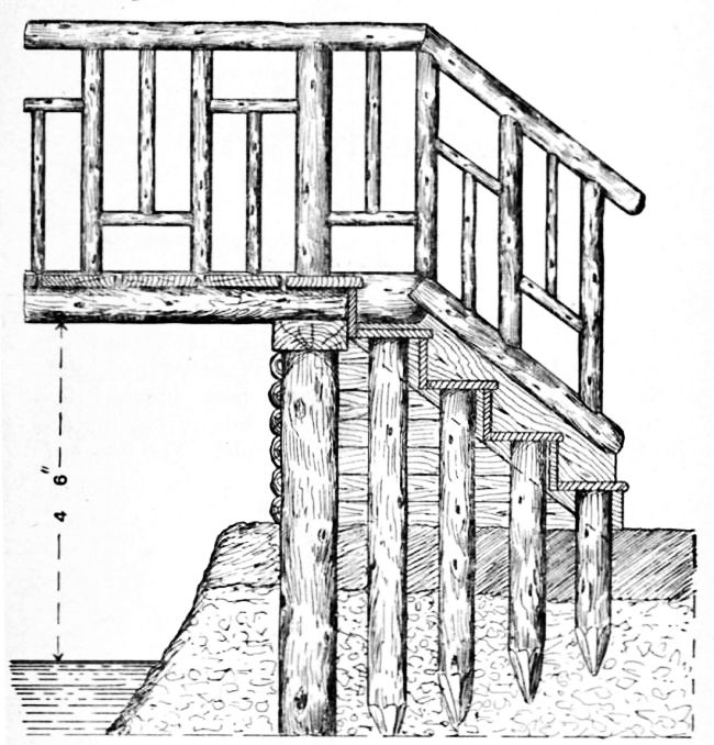
Fig. 130 gives a part view, in longitudinal section, of an elevated bridge, suitable for a span of 12 ft. to 18 ft., and raised on piles to enable small boats and canoes to pass under. Elm logs are suitable for the pile foundation. An iron ring must be fitted over the tops of the logs while they are being driven, and it will be necessary to use a pile-driver. The logs, having been sufficiently driven, are cut off to the required height from the ground line. Three piles on each side are required to carry the sleepers. The bridge is 5 ft. 6 in. wide, and the spars for girders are 12 in. in diameter. The sleepers are bolted to the piles, and the girders are also bolted to the sleepers as shown by Fig. 131. A row of smaller piles is now driven, and a plank, 11 in. by 3 in., is housed to the top ends of these piles, and also connected to the projecting ends of the girders. The treads of the steps rest upon the tops of the smaller piles, and the outer side of the piles and planks is covered with split saplings (see Fig. 130, and the cross-section, Fig. 132). The handrails and balustrades are fixed in similar manner to those in Fig. 121.
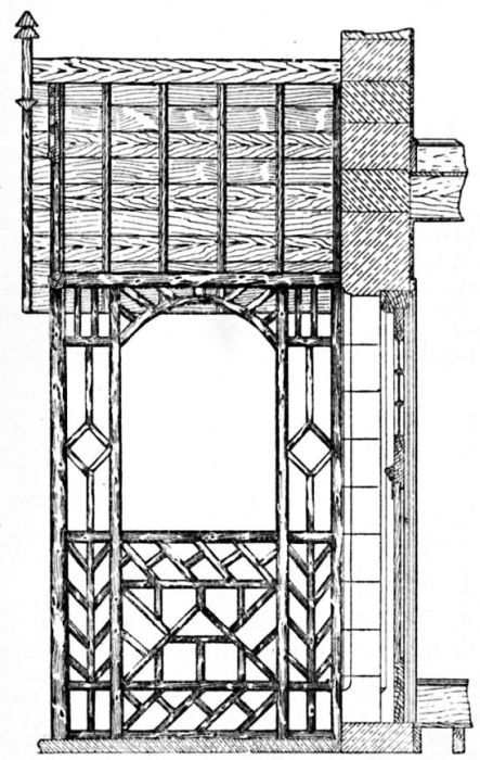
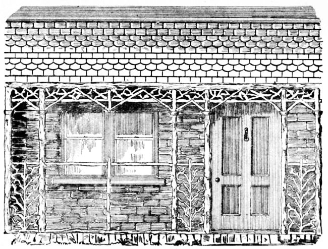
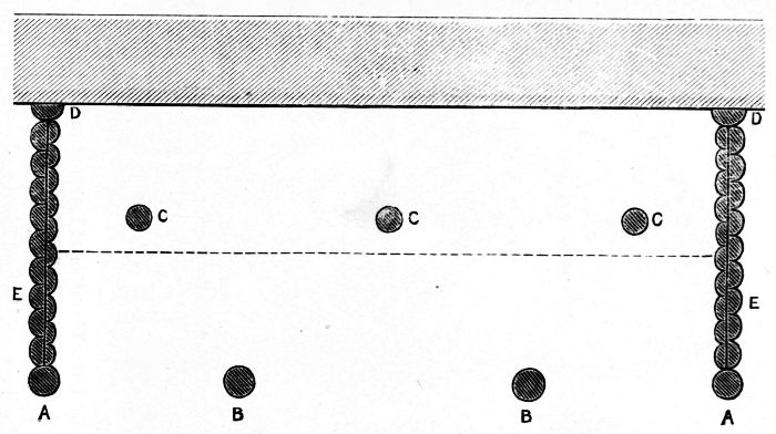
The front elevation of a rustic verandah is presented by Fig. 133, which shows a part only, which may be extended to any required length at either end. As to the width, that indicated is 3½ ft. from the wall to the middle of the collar-posts, the eaves having a further projection of 6 in. For a cottage verandah the width given is a satisfactory one. It gives sufficient room for seats on a hot day, or for a promenade on a wet one. The width, as also the height, can easily be increased to suit a larger house. The verandah is supposed to be built on a raised platform of brick or stone.
All parts of the actual framework are of straight natural wood, preferably larch; whilst the mere filling-in of rustic open-work is of small crooked stuff—probably oak or apple tree. The roof, as illustrated, is of tiles.
It will be seen that the posts which support the verandah are arranged in pairs, so that 3 in. or 3½ in. poles will suffice for them. Their bases are supposed to be dowelled to the masonry of the platform on which they stand; they are 6 ft. 6 in. high. Except at the entrances, a sill of half-stuff runs from post to post on the platform. At a height of 3 ft. 3 in. they are connected by a round bar of smaller material, and, again, by a second cross-bar of similar size to the last, at 6 in. from their upper ends. On the tops of the posts rests a lintel of half-stuff of larger diameter—say 5 in. The upper and lower cross-bars come opposite to the middles of the posts, but need not be mortised into them, for if their ends are cut V-shaped, so as to clip the posts, they can be nailed quite firmly.
The lower cross-rail is placed at a convenient height for leaning upon. At a height of 5 ft. 6 in. caps are formed by simply nailing four pieces of quartered stuff round each post. The diagonal braces which start from above the capitals pass in front of the upper cross-bars, to which and to the [Pg 100] lintel they are nailed. Fig. 133 sufficiently shows how the panels between the pairs of posts and the frieze between the upper cross-bar and lintel are filled with open-work of small crooked branches, which contrasts in a pleasing manner with the straight pieces of the framework. This open-work may be made available for, and will be found useful as, a support for climbing plants.
In so narrow a structure the rafters alone will suffice to keep all in place, without anything of the nature of a tie-beam being called for. These rafters will be of half-stuff, and for the given width a length of 5 ft. will be enough; this will allow of such a projection beyond the lintel as will give the eaves a width of 6 in.; the pitch will be rather less than a true pitch, but amply steep for the purpose. A piece of half-stuff nailed to the wall will support the upper ends of the rafters.
In forming the roof it is proposed to board over the whole space upon the rafters, and to nail the tiles or other covering upon the boards. The inside may be lined beneath the boarding with rush matting. This is an inexpensive material; its brownish-green hue is pleasing to the eye, and it is so inartificial in appearance as to harmonise well with the natural wood. After fixing the rafters, the matting is to be stretched tightly across them before the boards are nailed down. It is probable that the rafters will be arranged with intervals of about a foot between them, and to hold the matting more closely to the boards a strip of split rod may be nailed up the middle of each space, or strips may be nailed so as to form a simple ornamental pattern; an intricate one will not be desirable, as fixing it will be overhead work.
A neat, but less characteristic, ceiling may be formed by painting the boards a suitable colour and slightly ornamenting them with split strips of rod. In this case the boards should be planed. None will be better for this purpose than ¾ in. flooring boards, and these are commonly sold planed on one side. Other ways of lining the roofs of rustic buildings are discussed in Chapter XIII. For summer-houses thatch makes a good-looking roof, but a thatched verandah would scarcely be desirable unless attached to a thatched cottage. Practically the choice lies between shingles, metal, and tile or slate. A metal roof is, undoubtedly, that most easily fixed by the beginner; black sheet iron looks better than galvanised, and must be kept painted. As a matter of taste, metal looks thin and poor, but it becomes less objectionable when painted; a deep, dull red would be the colour to be preferred. Perhaps, of all available coverings, nothing will look better than tiles, as drawn. Red or buff tiles will in themselves look best, but the choice must, to an extent, be influenced by the general covering of the house. It may be, if that is of slate, that small slates will come in most appropriately; but whichever of these coverings is used, the best finish against the wall will be with a "flashing" of metal, as shown.
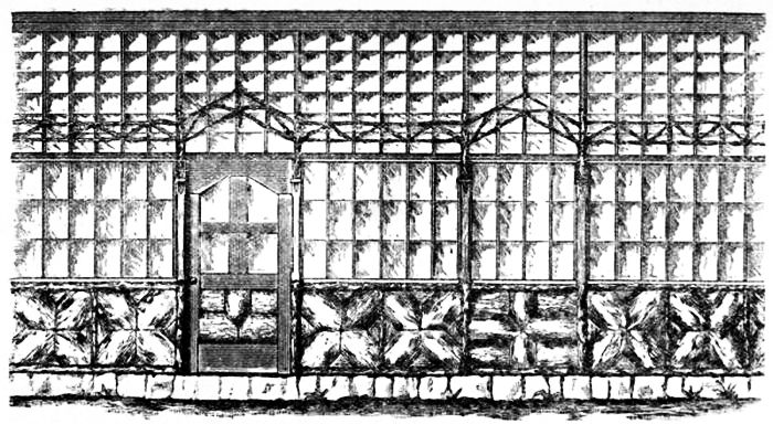
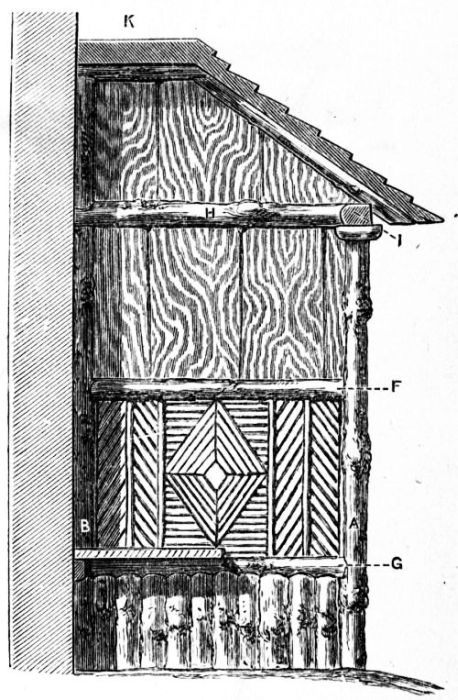
It has been asserted by some who consider themselves authorities in matters of taste that nothing of the nature of a greenhouse ever harmonises with natural surroundings, or is otherwise than an eyesore in a garden in other respects beautiful. The hard, straight lines of wood or metal, and wide surfaces of shining glass, are not pleasing, and are too suggestive of the shop and factory to accord well with natural objects. It has been suggested that the difficulty might be overcome by combining rustic work with glass. This, at the first glance, looks fairly easy; but, on consideration, it will be seen to be otherwise. Rustic carpentry is in its nature irregular, and cannot be brought to those level planes and straight [Pg 103] lines essential to glass-work; whilst for interiors, and especially those of houses intended for vines, rough bark-coloured surfaces afford too much shelter to insect pests—so that, in reality, rustic-work can only be made applicable to a very limited extent. In the grape-growing verandah shown by Fig. 134, therefore, only a limited amount of rustic-work has been introduced, and that on the outside.
Such of the materials as are of a rustic kind [Pg 104] are, for the parapet and uprights, some rather small larch poles or other tolerably straight, round stuff, and for the panels, some of those "slabs," or rough outside planks. As to the posts, and such parts as are not rustic, they are supposed to be of good deal. The sash-bars, which carry the glass both in roof and walls, are to be bought struck by steam at a lower price than they can be worked by hand, or sashes may be bought ready glazed. For glazing work of this kind, 16-oz., or sometimes 20-oz., glass is used.
As in the design for an open rustic verandah (see Fig. 133) it is intended that the collar-posts should be set upon and dowelled into a raised platform of masonry. The present structure is, of course, intended for the warmer sides of a house, south or west. The width, to meet particular cases, can be varied, but is, according to the drawings, 4½ ft. The posts are 6 ft. high and 3½ in. square. They are set with spaces between them alternately of 3 ft. and 4½ ft. On their tops rests a wall-plate of the same width as themselves, and 2½ in. deep. The rafters, which are sash-bars rebated to carry the glass, rest on this wall-plate, and against a second vertical one fixed to the house wall.
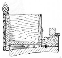
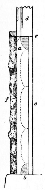
Fig. 134 is a front elevation of a portion of the verandah, whilst Fig. 135 gives a side view of the lower half of one of the collar-posts. At a, in Fig. 135, is seen the section of the upper cross-rail, which has its top 2½ ft. from the ground; at b is the lower cross-rail, or sill. Both are of quartered rough stuff, and are mortised to the post ¾ in. from its inner edge, so that when the ¾ in. boarding, c, is nailed against them, it will come flush with the inner side of the post. At d is indicated the sash-frame, with its rebate for glass, which occupies the upper part of the opening; and at e is a metal flashing between rail and sash to throw off rain. It is proposed [Pg 105] that the sashes in the narrower openings only should be made to push outwards at bottom for ventilation. At f is a piece of halved rough stuff nailed to the front of the post.
The panels, which occupy the lower part of the space between the collar-posts, are filled with pieces of rough plank or "slab," as shown in Fig. 134. These pieces should wear their natural bark as far as possible; they are nailed to the inner boarding.
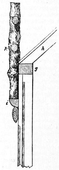
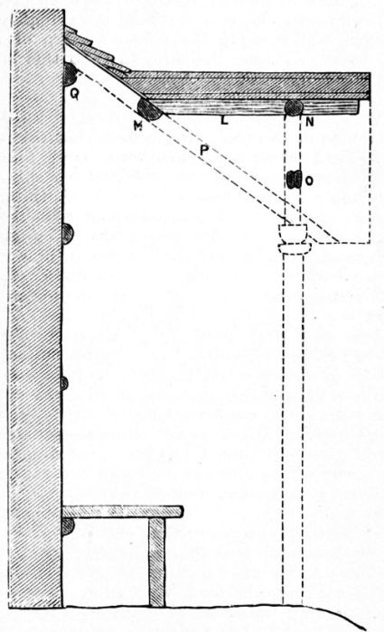
In Fig. 136 the upper part of a post is in like manner shown in profile: g is the wall-plate in section, and h is the lower end of a rafter. At i will be observed a strip of quartered stuff nailed across the post (with a fir-cone bradded beneath it), which gives a starting-point to the upright k, by which the openwork rustic parapet is supported. These uprights are of small round stuff, slightly flattened on the side towards the post. The openwork parapet is too plainly figured to need description; it is intended to break to a certain extent the straight lines, and partially to conceal the glass-work of the roof, without seriously interfering with sunshine.
So much of the planed wood-work as shows outside should be painted of a good brown, to assimilate with the rustic-work.
For the small rustic tool house shown by Figs. 137 and 138 the materials used are what are known as "slabs" or "rough planks." These are cheap, and have, when judiciously handled, a good picturesque effect. These slabs are the outside slices cut from logs of rough timber. These slabs generally retain their bark (except in the case of oak), and in most districts they will commonly be of elm. Their thickness and outlines are necessarily irregular: one end will frequently be narrower than the other; and this will account for the arrangement seen in the walls and door of the tool house. They are to be bought at saw-mills, and often sold at a fire-wood price. Where their cost is not sensibly increased by carriage, no other material comes so cheaply for building rough sheds. The ordinary country way of using them is as in the horizontal section, Fig. 139. This plan, however, is not suitable for the present ,[Pg 108] purpose. In so small a structure, rough planks on the inner side would take up too much space It is, therefore, proposed to straighten the edges, either by sawing or by chopping with the axe, according to circumstances, and lining their inner sides with thin board. If the cost be not objected to, ½ in. match-boarding will be neatest for this purpose; if economy is an object, the boards of packing-boxes, bought from the grocer, might suffice. There are, it will be seen, three sides only to be lined.
Among a lot of rough planks, it is likely that stuff may be found sufficient for the posts and other scantling. As to the six pilasters, which are added for appearance merely, it is possible that stuff might be found which would, when sawn to width, do for them; in the illustration they are supposed to be fir poles or elm saplings; four sticks only are needed to supply the six halves and four quarters used.
At the corners are four main posts, 4 in. square (see a, Fig. 140). These enclose a space of 7 ft. by 5 ft. (outside measurement). They are let into the ground 2 ft., and rise 5 ft. 3 in. above the ground line.
On their tops, and coming flush with their outer edges, rest the wall-plates, which are 3 in. deep; these are needed at the back and sides only, and not at the front. On the same three sides will also be cross-rails, 2 in. to 3 in. thick, the ends of which will be let flush into the posts about a foot from the ground. To the wall-plates and these rails the slabs are nailed. In the side elevation, Fig. 138, the nails driven into the cross-rails appear, but not those driven into the wallplate, [Pg 109] a piece of rough stuff being there shown as fixed over the latter to support the eaves of the thatch.
To the front are to be seen the two door-posts, b, b, Fig. 140, which are 2 ft. 8 in. apart, and should be about 3 in. square. As their tops are nailed to the front pair of rafters, they rise to a height of 6 ft. 6 in. The space between door-post and corner-post is filled up by a single slab nailed to the two—5 ft. 6 in. long by 10 in. broad. [Pg 110] Above these, instead of a wall-plate, comes the piece of strong slab, shown in Fig. 137 as having an opening cut in it for the head of the door. This is nailed against the door-posts, rafters, etc.
The pilasters are only a matter of ornament. As drawn, they are of halved stuff; the corner ones are so placed that their middles come opposite to the corners of the posts, on the other faces of which pieces of quartered stuff are nailed to meet them. The simple arrangement of the caps of these pilasters, with their decorations of fir cones, is shown on a larger scale in Fig. 141. The horizontal piece beneath the eaves, nailed over the slabs, has the effect of resting on the caps. Beneath the thatch at front and back corresponding pieces are fixed, those at the front being ornamented with fir cones nailed upon them.
The roof is shown in the elevations as thatched. No other covering will look so well, or be so thoroughly in keeping with other parts. The non-professional builder finds it easy to prepare for thatch, any rough stuff serving as rafters and laths, and inequalities being of no account. The rafters for thatch should be arranged about 1 ft., the laths about 6 in. apart.
Should there, however, be reasons for not employing thatch, the building may be more quickly and easily, if not more cheaply, roofed with galvanised iron; only the gables will then best be made sharp instead of blunt, as at present.
Regarding the door, its outer slabs, which appear in Fig. 137, are simply nailed to three ledgers of the same. Being of such rough materials, it will open better if hung on hooks and thimbles than on butt hinges.
The dotted line at c, Fig. 140, marks the projection of a set of shelves, about five in number, which fill the whole of the left-hand side. Of these, the lower will be for flower-pots, the upper for lines, setting-pins, trowels, etc. At d is [Pg 111] shown a strip of wood fixed across the floor to hold the wheel of the barrow from running back when that useful vehicle is tilted up against the end wall, which will be the place assigned for it. In the gable and upper part of this end will be hooks or pegs on which to hang the riddle, watering-cans, and such matters. At e is an upright let into the ground, which, at the height of 2 ft., supports rails running to side and back; these form a kind of stand for spades, forks, and tools of that description. Above, against the wall-plate, may be more hooks or pegs.
It is suggested that at f a seat might be fixed to fold down like the leaf of a table when not [Pg 112] wanted. As this building would form a snug shelter in a shower, such a seat would be a convenience; but the more important use of this space is that slightly below the level of the eaves it will be fitted with a rack for hoes, rakes, and similar implements. Such a rack is best made by boring ½ in. holes in a strip of wood at intervals of 3 in., and driving pegs into them 5 in. or 6 in. long. This has to be nailed so that the pegs will slope upwards, at an angle of about 45°. Rakes, etc., hung in a rack so made cannot fall.
Figs. 137 and 138 are 1/3 in. to the foot; Fig. 140 is ½ in. to the foot; but Figs. 139 and 141 are not drawn to scale.
The garden snuggery, of which a general view is shown at Fig. 142, and a ground plan at Fig. 143, is built chiefly of wood, and measures 10 ft. by 7 ft. 8 in. inside, not including the porch, which is 3 ft. wide; it may serve as a summer-house. A building as small as this needs but little foundation. If the ground is level, it is only necessary to lay four large flat stones on the surface, A A (Fig. 144), to carry the timbers, the floor being thus raised enough to keep it dry.
The two side sills B (Fig. 143) are each 10 ft. 8 in. long, 6 in. wide, and 4 in. thick, and rest on the stones; on them lie the end sills C C, which are 8 ft. 2 in. long. These sills are halved together at the ends, and a hole is bored through them where the middle of the collar-post will rest. This hole should be bored a couple of inches into the stone, and an iron pin or dowel 8 in. long driven in; the pin will thus stand a couple of inches above the face of the sill, and will fit into a hole in the collar post.
The joists D (Fig. 143) for supporting the floor are five in number, each being 8 ft. long, 2½ in. wide, and 3 in. deep. They are halved for a distance of 2 in. at each end to fit into slots, 1½ in. deep, made for them in the sills, and are nailed in place. When fixed their upper surfaces are level with the sills.
The four collar-posts E (Figs. 143 and 144) are [Pg 115] each 6 ft. 9 in. long and 4 in. square, and, when set up, their outer sides come flush with the sills. The uprights F (Figs. 143 and 144) are 3 in. square, and need to be 2 in. longer than the collar-posts, as their lower ends are halved for this distance to fit slots in the outer sides of the sills. There are four of such uprights at each side, three at the back and two at the front, the latter serving also as door cheeks. They are nailed in place with their outer sides flush with those of the collar-posts and sills.
For the rustic pillars of the portico G (Fig. 145) nothing will be more suitable than larch poles about 4½ in. in diameter at the base; failing larch, fairly straight pieces of any rough, round wood could be used. The pillars are shown in Figs. 142 and 145 standing upon and dowelled to pieces of stone. When in position, their tops will be level with the collar-posts and uprights, their centres being 2 ft. 4 in. in advance of the front sill.
On the collar-posts, uprights, and pillars are placed the wall plates H (Fig. 144), of which there are four belonging to the snuggery proper, each 5 in. wide and 3 in. thick. The side plates are [Pg 116] 13 ft. 4 in. long, and are halved where they rest on the collar-posts and pillars, to receive the ends of the cross-plates, which are 8 ft. 2 in. long and halved to a distance of 5 in. from their ends. The wall-plates come flush with the collar-posts and uprights on which they rest, and to which they are nailed. There is also a fifth wall-plate which lies along the tops of the pillars in the front. The best material to use for this would be half of a pole like those used for the pillars, the flat side resting on the pillar tops. It will be observed that the front ends of the side wall-plates project about 4 in. beyond this piece.
Ten rafters, K (Fig. 144), will be required for the roof, each 5 ft. long and 3 in. square. The two outer pairs come flush with the outer sides of the sills and wall-plates. A sixth pair of rafters to stand over the pillars and their wall-plates are made from a round pole cut in half, with the sawn side laid uppermost. The tops of the rafters butt against a ridge-piece L (Fig. 144), made of 1-in. board 4 in. deep and 13 ft. 4 in. long. As shown in Fig. 144, continuations of the uprights are in the back carried from the wall-plate to the roof, the front being treated in a similar manner.
The lintel of the doorway is 6 ft. above the sill, the door opening being 5 ft. 11¼ in. by 2 ft. 6 in. after the floor has been laid. The window shown in Fig. 142 is 3 ft. above the sill, and is 3 ft. high; including the two mullions, it is 5 ft. 10 in. wide. The board shown nailed in front of the window sill is sloped a little downwards to throw off the rain, whilst above there is a board 9 in. wide, nailed at a steeper slope upon brackets, as seen in Fig. 146, to shelter the window. The ¾ in. flooring boards which are used for the floor should be bought ready planed on one side, and must be well seasoned, and cramped tightly together in laying, or there will be chinks [Pg 117] between them. Similar boards may be used for the outside of the snuggery, being nailed to the uprights at the back and sides, as shown in Fig. 147. At the sides this weather-boarding will extend as far forward as the rustic pillars, thus enclosing the sides of the porch. For the inside of the snuggery use ½ in. matchboarding, as shown in Fig. 147. This may be carried up beneath the rafters to the ridge-piece. The porch may be also matchboarded throughout if desired, although this is not essential.
|
Figs. 147 and 148.—Sections of Snuggery Walls. |
|
There are several methods of making the wooden walls non-conductors of heat, the most thorough being to pack the space between the inner and outer casings with sawdust. Shavings or similar materials could also be used, but less effectually. Another plan is to tack felt over the inner side of the weather-boarding before nailing up the interior casing. But even without any packing, two thicknesses of board with an air space between make a reasonably good non-conductor. Felt is fastened over the matchboard lining of the roof before the iron is put on.
To reduce the cost, the snuggery can be cased with wood obtained from packing cases. Boards thus obtained will, of course, be in short lengths, and will involve more labour; but the design is so arranged that it will be quite practicable to carry it out with them.
The short lengths can be made to fit between the uprights instead of lying upon them, and the house will thus look as shown in Fig. 142, the section of the wall being as shown in Fig. 148, instead of as in Fig. 147. A strip of lath—that sold for tiling—1 in. wide and 5/8 in. thick, is nailed to the sides of the uprights, as shown, and to this the weather-boarding [Pg 120] and internal casing are fastened; the effect being that the walls both inside and out appear to be divided into long panels. The effect may be heightened by painting the framework a darker colour than the boarding. In boarding the roof with this material, the easiest plan will be to nail the pieces on the upper sides of the rafters, to cover them with felt, and upon that to screw the iron. The space between the two casings of the walls, although much narrower than before, can be packed with sawdust, etc.
On reference to Fig. 145 it will be seen that the caps to the rustic pillars of the porch are formed by nailing round each pillar four short pieces of rough wood quartered, the two sawn sides being placed upwards and inwards. Four rough sticks crossing each other fill the space between wall-plate and the rafters. The bargeboards M M are sawn from ¾-in. board, 9 in. wide, and are nailed to the ends of the side wall-plates and ridge-piece. They thus project some inches beyond the line of the pillars. They are shown ornamented with fir cones bradded on them; virgin cork might be used instead. The porch may also have its interior decorated with virgin cork or with rustic mosaic work. At each side of the doorway there is a seat 16 in. high and 14 in. wide. The door is made by merely nailing the boards to four cross-ledgers.
The window lights in Fig. 142 are shown filled with fancy lead work, which is the most suitable way of treating them for a building of this kind. A strip of lath is nailed around the window opening, as in Fig. 148, and the leaded light fastened in the rebate thus formed with small wire nails, a little putty being used to make the joints waterproof. It will, of course, be much cheaper to glaze each light with a single sheet of glass puttied in the rebate, but the effect will not be so good. For the roof, fourteen 6-ft. sheets of corrugated galvanised iron and a 14-ft. run of ridge capping will be needed.
The iron should be screwed, not nailed, to the rafters, and should not cost more than 40s., including 1½ gross of galvanised screws and washers. The dotted lines at N N (Fig. 143) indicate the area covered. Its low cost, the ease with which it is fixed, and the few timbers required to carry it, make an iron roof very suitable for a building erected by an amateur workman. It, however, has drawbacks, [Pg 122] the chief of which are that it conducts heat too freely, and has not a very artistic appearance. Some precautions against the first defect have already been suggested, and if the snuggery is erected where it will be shaded by trees during the hotter part of the day, this disadvantage will be somewhat overcome. Its inartistic appearance is greatly due to its colour, and some improvement may be made by painting. If surrounded by trees, an iron roof looks very well when painted a reddish-brown colour, while in other situations a buff, or a dull sage green, might be suitable. The paint needs renewing often. Another method is to cover the roof with trellis work raised a few inches above the iron, and upon this to train ivy or other climbing plants.
It will be better to paint the inside of the snuggery than to paper it, as paper would crack on the boards. Should the second and cheaper plan of boarding be adopted, the rafters, which are left exposed, might be coloured dark brown, and the intermediate spaces of the ceiling painted a buff colour, whilst on the walls a dark sage green might be used for the framework and a lighter [Pg 123] sage green for the panels. If the whole interior is lined with matchboarding, according to the first method, the simplest and perhaps best finish would be to use a varnish that had raw or burnt umber ground into it. No fireplace has been provided, but in ordinary winter weather an oil stove would suffice to warm so small a room; if more warmth is wanted, a coal stove might easily be provided, a hole for its pipe being cut through the roof. In either case a ventilator, which can be opened or closed at pleasure, should be arranged near the ridge at each end of the building.
The garden retreat shown in front view by Fig. 149, and in plan and side elevation by Figs. 150 and 151, is constructed from straight unbarked fir saplings, the small twigs of which should be carefully trimmed off. As the bark is to be left on, it should not be cut or bruised; then no artificial finish will be necessary, the bark in itself being sufficient protection against climatic conditions, and presenting the desired rustic appearance. A new feature in the design is the introduction of a roof or canopy, which may be covered with a sun blind as shown in Fig. 151; or a creeping plant may be trained over it.
The two front posts are 3 in. in diameter at [Pg 124] the base by 6 ft. high, and the back posts 3 in. in diameter by 5 ft. 6 in. high; the middle back post is 3 ft. 2 in. high, and the front leg 1 ft. 4 in. The seat rails are 2½ in. in diameter. The front rail is 6 ft. long; the back is in two parts, dowelled to the middle post, which comes between. The side rails are 1 ft. 9 in. long; it is advisable to allow a fair margin for hollowing the ends to fit the posts—3 in. on the length would probably be sufficient. After the ends of the rails have been shaped roughly to fit the posts, they are bored for the reception of 11/8-in. oak or elm dowels; these are driven into the rails, and should also be a good fit in the posts. The dowel joint is shown in the top corner of Fig. 152.
The lower rungs, arm-rests, and back rails are jointed to the posts by tapering their ends slightly, and then tapering the dowel holes to suit with a gouge, so that the rails will just drive up nicely; this joint is shown in the bottom corner of Fig. 1522. The rails, etc., are finally driven home, and secured with nails or screws inserted at suitable angles. The back and the side panels are filled with twigs about 1¼ in. in diameter, the ends of the twigs being trimmed to fit the rails, and afterwards nailed in position.
The seat battens are half-round in section, and are cut from 3-in. saplings, the flat part being [Pg 125] placed downwards. The method of fixing them is shown in Figs. 152, 156, and 157. The seat having been fitted, the struts under the seat rails are next cut and fixed in position.
The canopy must now be put together. The tops of the posts are first hollowed to form a seating for 2¼-in. saplings, 4 ft. 6 in. long; these act as principal rafters. Before nailing or screwing them to the posts, it is advisable to sight across them to see if they are in the same plane; any alteration that may be required to bring them to lie in the same angle can be effected at the seating on the top of the posts. The halved joint at each end of the principals should also be cut (before fixing up) for receiving the purlins; the principals are further steadied with struts, screwed or nailed to the posts. The purlins are about 2 in. in diameter by 8 ft. 6 in. long, and are fixed to the halved joint previously made on the principal rafters. Smaller twigs, which act as common rafters, are in turn fixed to the purlins. Fig. 153 shows the method of jointing at the back of the canopy at C (Fig. 151), and Fig. 154 is the detail of the front joints. Fig. 129 (p. 94) is the top of the post hollowed to receive the principal rafter, Fig. 155 is an alternative method of joining the rails to the posts, Fig. 156 is a section near the middle rail at A (Fig. 152), while Fig. 157 is a detail of middle rail at B (Fig. 152).
The lean-to summer-house shown by Fig. 158 is intended for a small garden. Perhaps in no better way can a dead wall or the back of some unsightly outhouse be better utilised than as the background for such a building. The dimensions of the structure are: length, 8 ft.; breadth, 3 ft. 3 in.; height, 8 ft.
Its general arrangement is seen in the ground plan (Fig. 159). Four pillars, A, B, B, A, occupy the front. These are poles 3½ in. or 4 in. in diameter. Any rough and tolerably straight wood will do, but larch is to be preferred. These rise 5 ft. above ground, and should not have less than 2 ft. below the surface. The dwarf pillars C supporting the seat are of similar stuff, but rather smaller. They show 14 in. above, and [Pg 128] should be buried about 9 in. below ground. The pilasters D are of rather larger stuff sawn in half. These are only 5 ft. long, as they need not enter into the ground, being fixed only by strong nails to the wall.
The ends of the summer-house (the space from A to D) are of smaller half-stuff, ranged side by side (as seen at E, E), and nailed to the [Pg 129] cross-pieces, F and G, which appear in Fig. 160. In this last-named figure also appears one of the wall-plates, resting on and nailed to the tops of the pillars (H, at Fig. 160), and at I is seen where one of the front wall-plates meets it. There are two of these front wall-plates, each resting on the two pillars to right and left of the entrance, and their inner ends appear in Fig. 158, where the ends of the purlins which form the small gable rest upon them. The wall-plates are of large half-stuff, with the flat side above. In Fig. 160 will be seen how the short cross-piece which carries the sloping end of the roof is supported; and Fig. 161, which is a section through the centre of the building, explains how the ridge-piece of the small gable, E, rests at its inner end on a crosspiece M from rafter to rafter, seen in section only, whilst N shows the point at which the purlins meet and support the ridge-piece towards its outer end. The intersection of the diagonal braces in the gable is indicated at O, and P shows the course of one of the rafters, and how its upper end rests against the wall, and upon a ridge-piece of half-stuff, Q, strongly nailed to the masonry.
The elevation (Fig. 158) explains pretty clearly the ornamental details of the front. They are not elaborate. It will be seen that the top of each pillar has a small cap, formed of four pieces of quartered stuff, mitred at the corners, and that across the opening on each side of the entrance, near the top, is a "transom" of straight wood, with a little arrangement of crooked bangles round it. Over the entrance are diagonal braces crossing, and also a little filling-in with bangles. The entrance is 5 ft. 10 in. high.
In order that an ornamental and appropriate lining may be given to the back of our summer-house, it is recommended to plug the wall, and nail over it a level covering of thin boards—say, [Pg 130] ½-in. matchboarding. Upon this the decorative work can be bradded. The back of the seat is shown in Fig. 158 to be of rustic mosaic. Above this, as well as under the seats, a covering of bark has been introduced. British-grown bark, such as elm, can be made to lie flat, but as in any but rural districts this may be difficult to get, virgin cork may be made to take its place.
Fig. 160 gives an inside view of one of the ends, and from this it will be seen that the ornamentation of those parts varies little from that of the back. The lower band, however, answering to the strip under the seats, is not bark, which, in this place, would be liable to be kicked and destroyed by the feet, but of smaller half-stuff, so arranged as to break joint with the outside pieces. This will be seen by referring to the ground plan. Any chinks in the ends should be neatly tucked with moss, so as to make them wind-proof.
The roof is of wooden shingles—things which any rough hand at carpentry can prepare and put on for himself. As will be seen from Fig. 158, it is easy to give an ornamental character to these. They will have a rustic look, which will go well with other parts of the structure, and, if clumsily made, the effect will be none the worse. For the present purpose, suppose the shingles to be 12 in. by 4 in. The lower ends may be sawn to a variety of ornamental shapes.
If this covering is used, instead of nailing laths across the rafters, it is proposed to cover the whole roof with similar boarding to the back, and upon this it is a simple thing to nail the shingles, placing them just as tiles might be placed. Whilst nailing them on, it will be necessary to have some person within to hold a heavy hammer against the place, otherwise the vibration will jar off the shingles as fast as they are fixed. A ¾-in. board, rather wider than half the length of the shingles, should first be nailed along the eaves to make up the required thickness.
It will be noticed that the ends of the rafters are made to project so as to give a good breadth of eaves—a desirable feature in so narrow a building, alike for shade, shelter, and the appearance of cosiness. If, however, the roof should be thatched, the projecting [Pg 132] rafters will be unnecessary, as the thatch alone will form sufficient eaves.
Down the "valleys" at the juncture of the main roof and the entrance gable a strip of zinc will, of course, be nailed before the shingles are put on, whilst along the ridges a strip of zinc will be nailed upon the shingles; and this latter will need painting to match the colour of the wood.
Various suggestions may be given for finishing the inside of the roof. Supposing that round or half-round larch stuff has been used for the rafters (the latter is to be preferred for shingles, as giving a level surface to board upon), the space between the rafters may be covered with bark—virgin cork or otherwise—the chinks being stuffed with moss. But if this is done it will be well to fix the bark with screws, as the vibration caused by driving nails would displace or loosen the shingles.
A second plan under the like circumstances would be before nailing the boards upon the rafters to stretch matting across the latter—either ordinary garden bast matting or, better, the more substantial rush matting, both of which are very inexpensive. These have a pleasant natural colour (the last-named especially, of a greenish hue), and are so unartificial in their structure as to appear in no way out of place among rustic work.
Or it may so happen that suitable larch stuff is not to hand, and that ordinary sawn scantling has to be used for the rafters. If so, the whole roof may be hung with ling; or the rush matting may be stretched across the lower side of the rafters and tacked there, being afterwards more completely secured and finished by nailing a split hazel or other rod down the middle of each rafter. This last plan makes a neat and pleasing roof.
|
Figs. 162 and 163.—Front and Side Elevations of Shelter for Tennis Lawn. |
|
It scarcely needs to be said that to make such a summer-house look its best the wall on each side ought to be covered with ivy or other creepers; and it will also be obvious that, if the height of the wall permits the floor of the summer-house to be raised a step or two above the surrounding [Pg 135] level, the structure will gain thereby both in effectiveness of appearance and in pleasantness as a place in which to sit.
|
Fig. 165.—Connecting Plates to Corner Post.
Fig. 166.—Fixing Sleeper to Posts.
Fig. 167.—Section of Flooring.
Fig. 168.—Finial.
Fig. 169.—Detail of Garden Shelter at Front Eaves.
Fig. 170.—Section of Seat.
|
||
The rustic summer-house or tennis lawn shelter illustrated in front and side elevations by Figs. 162 [Pg 136] and 163 is constructed from straight saplings and twigs that have had their bark removed, and have been subjected to a reasonable period of seasoning. A new feature in the design is the accommodation under the seats for the reception of the croquet or tennis gear, and also the extended eaves and floor (see Fig. 164) and the open front, giving at once an uninterrupted view of the game and shelter from the direct rays of the sun.
The shelter is 10 ft. long by 5 ft. 6 in. wide, the height from the floor to the eaves being 6 ft. 3 in., and from the floor to the ridge 9 ft. The four posts are 6 ft. 9 in. long by 6 in. in diameter. The middle and lower end and the back rails are tenoned to the posts, a flat being formed on the post by the mortise and a corresponding shoulder on the rails. The remaining portion is worked to fit roughly the contour of the post.
The plates are 5 in. by 5 in. in section, and are secured to the posts with long galvanised bolts and nuts and a 3½-in. square washer under the heads of the bolts. When halving the front plate, allow it to house into the side plates 1½ in.; by this method it will have a bearing on both posts. In Fig. 165 the left-hand plate represents the front. The front posts are connected at the floor line by a scantling, 4 in. by 3 in., which also forms a sleeper for the floor joists; see Figs. 166 and 167.
The structure rests on a low plinth of bricks, spaces being left for the circulation of air under the floor.
The extended floor also rests on bricks placed immediately below the joists; see Fig. 167, which is a section on C D (Fig. 164). The twig plinth nailed around the front will effectually conceal the sleeper and brick foundation.
The rafters are 2½ in. by 3 in., and the ridge and hip rafters 2 in. by 5 in., the finials (see [Pg 137] Fig. 168) being nailed between the angles of the hips. The eaves in front project 2 ft. beyond the posts, and Fig. 169 shows the method by which the additional width is obtained.
The sides are filled with 5/8-in. vee-grooved and tongued boarding, to which is attached the rustic work.
The stained glass windows are fixed, and on the outer side of the back are diagonal braces made from split saplings, while in the centre a vertical post runs from sill to plate.
The braces and post are shown in the plan (Fig. 164).
The seats are constructed to form lockers (see Fig. 170, which is a section at A B, Fig. 164), their height being 1 ft. 3 in., which, with the addition of a 3-in. cushion, will form comfortable sitting accommodation.
The cushions are retained in place by straps passing through slots and fastening over suitable studs on the under side; see Fig. 171. This method provides a means of easily removing and quickly replacing the cushions when required for use. A space of 3 in., or a distance equal to the thickness of the cushions, must be left at the sloping back, to allow the seat to open properly.
The nature of the locker is partly concealed by the rustic work of split twigs that is nailed to the front.
Next fix the lattice work between the finials and under the front plate. The short struts on the front posts are more for effect than for any real support.
The roof is boarded on the inside, the work being carried on the rafters as far as the collar ties, and continued flat on these. Moulding is fixed in the angles formed between the rafters and ties, and a cornice is fixed at the plates. The heels of the rafters and plates are also boarded around, as shown in Fig. 169.
The roof may be covered with thatch of wheat, straw, reeds, broom, or heather, and the whole of the woodwork visible should be varnished.
The summer-house illustrated by Fig. 172 is suited to a garden of moderate size, one in which space is not so restricted as to necessitate crowding the building close against a wall. This octagonal summer-house has a continuous seat some 15 ft. long. From side to side each way it measures 10 ft. Fig. 172 is an elevation of the front of the house.
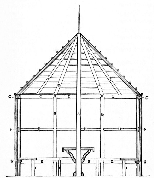 Fig. 174.
Its framework and the main part of it are of larch poles; other woods are, however, used for minor purposes. The roof is of thatch. In the arrangement of this building there is a certain resemblance to a tent. It has a central pillar, A, not unlike a tent pole, which sustains much of the weight of the roof. Being of first importance, this pillar is somewhat larger than any of the other timbers—say 6 in. in diameter near its bottom, and tapering as little as may be. A rod of iron or wood rises from its top to form the centre of the straw pinnacle seen crowning the roof in Fig. 172. This pillar shows a height of 11 ft. 2 in. above ground, and it should be let 3 ft. or more into the soil; for it will need to be firmly fixed, or it may be forced out of the perpendicular during the erection of the roof; when the roof timbers are once fixed in place, it will have little further chance of moving. The diagram Fig. 173 is a ground plan, and Fig. 174 is a section showing the timbers from the interior; both are drawn on a scale of ¼ in. to the foot.
The eight collar-posts (B, Figs. 173 and 174) at the corners of the octagon are of somewhat smaller stuff—say 4 in. They show 6 ft. above ground, and should have 2 ft. below. It will be well to gas-tar all the underground work.
The ground plan of a building in this shape is readily laid out. The space being levelled, a string is taken which has a loop at each end, and is 5 ft. 2 in. long. With a stake driven through the loop at one end as a centre, and with a stick passed through the loop at the other to serve as the travelling leg of the compasses, a circle is struck 10 ft. 4 in. in diameter, and into this pegs are driven at equal intervals (4 ft. apart) to mark the centres of the eight collar-posts. Whilst digging the holes for the posts, these points are kept by drawing two straight lines on the ground which intersect at the peg.
The cross-pieces which rest on the collar-posts, [Pg 141] and which serve as wall-plates, are a trifle smaller stuff than the posts—say 3 in. Fig. 175 shows how they are cut to fit the tops of the posts, and nailed there. In this building there are no mortise and tenon joints. On these ends above the posts rest the lower ends of the eight main rafters, D, the upper ends of which rest against and are nailed to the central pillar. The eight intermediate rafters, E, rest at the bottom on the middles of the side plates, and at top are cut to fit upon and between the tops of the main rafters.
The laths used are in this case in no way particular—any sticks will do; they will not be seen, and under thatch there is no necessity that a level surface should be formed by them, as for slates or tiles. They are nailed 6 in. or 8 in. apart.
The gable over the entrance is arranged as in Fig. 176. The laths, when nailed on, will have to run over the little ridge formed by F, instead of keeping the level, as on the other sides. This will cause no special difficulties in the thatching.
The walls are of larch poles sawn in half. To split a number of heavy poles with the handsaw [Pg 142] is tedious work, and it is better to get them run through by the nearest steam saw. The quantity of half-stuff required may be easily calculated; one of these sides will take about five and a half 6-ft. lengths of 4-in. stuff. The tops of these wall-pieces are sawn obliquely to fit against the round wall-plates to which they are nailed. In their lower parts they are nailed to the lower cross-pieces, G, G, G, Fig. 174.
These latter will best be made of rather large stuff quartered, since their upper sides on which the seat-boards rest should be level, as well as their backs, which go against the wall-pieces. The middle cross-pieces are of smaller half-stuff, and should be nailed to the wall-pieces rather than that the wall-pieces should be nailed to them; for they are in a conspicuous place, and nails driven through them and clenched would be unsightly.
The front supports of the seats are let into the ground some 6 in., and rise 14½ in. above the ground line. The seats should be cut from 1-in. board, and should be about 16½ in. wide.
In the two window sides of the octagon (see Figs. 177 and 172), the space below the windows is filled with whole poles, their bottoms resting on a sill let in level with the ground, and their tops nailed into through a cross-piece of half-stuff (K, Fig. 177). The mullions and transoms of the windows—mere sticks—are of small straight larch stuff, but the ornamental filling in above is of crooked branches—oak bangles by preference, though apple-wood would do very well. It often happens that an old apple-tree is cut down, and at once condemned as firewood; yet its stem may have grotesque knots, and its branches picturesque contortions which would make it valuable for rustic work. Whenever rustic building is contemplated, it is well that such wood should be laid by; a single tree would supply all the small [Pg 143] quantity of crooked stuff that is required in the present instance. Even the interlaced stems of ivy, when an old growth has covered a wall, have sometimes been utilised to excellent effect.
It may be observed that any chinks between the pieces beneath the windows, as well as in the walls generally, are most readily and appropriately rendered wind-proof by neatly stuffing with moss. Fig. 177 gives a full front elevation of one of the window sides (they being only seen obliquely in Fig. 172), and it is on the ½-in. scale.
Four stout crooked pieces are used as struts to support the table (drawn to 1 in. scale in Figs. 178 [Pg 144] and 179); 3/4-in. board will suffice for the top of this table, and it will probably be cut from two widths. To give proper strength to the ornamental border (seen in Fig. 179), a second thickness of the board is attached below each corner, extending 3 or 4 in. to each side, so as to allow each of the longer bits of split rod to be fixed, as shown, with two brads.
A really satisfactory material in which to finish the top of a rustic table is not easily found; it must give a level surface, and at the same time be in harmony with its surroundings. Board, planed or painted, oilcloth, or any manufactured material, is felt to be out of place; marble or slate looks cold and hard. Nothing that is absolutely level satisfies the requirements; the best alternative is rustic mosaic. By this is meant split rods of wood so bradded down as to form patterns. For the present purpose, however, the mosaic must be kept more neat and smooth than usual. Fig. 178 shows the top of the table thus treated.
The rods most in favour for rustic mosaic are those of the hazel. They are to be bought cheaply and abundantly when the undergrowth of woods is cut. They have a smooth and pretty bark, and the useful size is from ¾ in. to 1½ in. Sticks of other kinds of the same size can also be used: birch and wild cherry may be named among those with smooth bark, and wych elm and maple among those with rough; willow or withy, again, is of most common growth, and exceedingly useful. In river-side neighbourhoods it is often the cheapest and most plentiful of all woods. For mosaic work, it is always peeled, for its bark is unattractive, and its light colour when stripped makes it tell well in contrast to the dark bark of other woods. If used, as it often is, for outdoor purposes in garden carpentry, it should always be peeled. Country carpenters have a saying that withy lasts twice as long without its bark as with it; and in this there is much truth, for the loose bark holds the wet to the wood and causes it to rot. To make it peel freely, it should be cut just as the young leaves make their appearance. The like holds good with other woods; but if it is desired that the bark should hold firmly, the wood should be cut down in dead of winter, when all the sap is down.
The top of the table is supposed to be mainly composed of peeled withy. The pattern contains only the double dark line bounding the star and the single strip round the edge in hazel. So much white will not look amiss in this place, and withy is easily worked. Hazel and most woods twist so much in the grain that it is rarely safe to split them except with the saw, but withy—in short lengths like these, at least—can be split with a hatchet.
In rough carpentry there is no more pretty or interesting work than these mosaics. The backs of the seats (Fig. 180), and the seats themselves (Fig. 181), are decorated in this way. On the seats themselves, as on the table top, hazel and withy are contrasted, and form a design in alternate triangles; the separating bands, it may be noticed, have a light strip against the dark, and a dark strip against the light, triangle. Along the edge of the seats one or two strips merely are nailed lengthwise. In such a situation an ornamental edging like that round the table would be too liable to be broken. It is recommended that the back of the seats should be in dark bark-covered woods only, for the mosaic in that position will look better without any mixture of the light-coloured withy.
The upper compartments of the sides with which the backs of those sitting down will not come in contact may be more quickly and yet pleasingly covered with sheets of bark. Elm bark [Pg 147] is good for the purpose. It may be peeled in large sheets from the trunks of trees felled in spring, when the sap is rising; and whilst it is drying should have bricks or stones laid on it to press it flat. When dried, it is nailed to the walls, and any cracks which appear can be neatly filled with moss. The space beneath the seats is also shown as roughly covered with bark.
The almost conical roof is thatched. No other covering is so pleasing as thatch for a rustic building. Its colour and rough texture harmonise well with the natural wood, and all its associations are of a rustic character; no other covering so effectually excludes the summer heat, and nowhere [Pg 148] can one find a retreat so suggestive of coolness, quiet, and repose, as under the low eaves of a thatched building. Thatch has, it must be admitted, certain practical disadvantages—birds and winds are apt to scatter fragments from it, and it needs renewing at comparatively short intervals. The common saying is that a thatched roof needs re-coating every ten years. Often, no doubt, this is near the truth, yet really good work will frequently stand for almost twenty years. The materials in use in this country are reeds, straw, and stubble. Reeds make a strong thatch, but are not easily to be procured, except in fenny districts. Stubble, which is the lower and stronger part of the wheat stem, stands better than straw, which is its upper and weaker portion; to last properly, however, stubble should be cut immediately after harvest, and should not be left standing, as it frequently is, till the spring, for then the winter rains, collecting in its hollow stems, cause it to rot before it is cut. On small buildings like summer-houses especially, stubble makes a much more compact and sightly roof than straw.
Thatching is not costly or difficult work. In agricultural districts a load of stubble—sufficient to thatch three such buildings as the one illustrated—costs 30s., and a thatcher expects the wages of a first-class labourer only, not those of a mechanic. He needs an assistant, whose business it is to straighten the material into convenient bundles (called "yelvens"), and to supply him as he requires them. If he is re-thatching an old building, he merely thrusts the ends of his new material into the old thatch with a wooden spud; but if he is covering a new roof he sews down his "yelvens" to the laths and rafters with a huge needle and stout tarred string. He begins at the eaves, laying as wide a breadth as he can conveniently reach on one side of his ladder, this [Pg 149] breadth being called a "stelch." He works upwards, each new layer covering the tar-cord which secures that beneath it; and thus he goes on till he has reached the ridge.
In his second "stelch" he is careful to blend together its edge and the edge of that already laid, so that no rain may find its way between them; and in doing this completely lies much of the superiority of good over bad thatching. When laid, the thatch is smoothed down and straightened with a gigantic comb, like the head of a large rake, one end being without teeth, and serving as a handle. In the present instance, the tops of all the stelches meeting in a point are finished and capped by the little bundle of thatching material forming the pinnacle, which is tightly bound round the rod of wood or iron in its centre.
It is usual to bind thatching down with at least two belts of buckles and runners. In the summer-house (Fig. 172) two double belts are shown. The buckles have some resemblance to ladies' hair-pins on a colossal scale. They are made of slips of withy, twisted and doubled in their middles and pointed at their ends; the runners are long straight slips of the same. These latter are laid across the thatch, and the buckles, being placed over them, are pushed tightly into it—their points being driven upwards, that wet may not be let [Pg 150] into the roof by them. The short diagonal runners seen in the illustration crossing each other between the horizontal lines are used in ornamental thatching only, and are rather for appearance than for use. Lastly, the eaves are cut to shape, and trimmed with paring-knife and shears.
The roof looks most pretty and cosy within if lined with ling. The ling is fixed in a way somewhat akin to thatching. A layer is placed along the bottom opposite to the eaves, and secured by a strip of wood nailed from rafter to rafter; the layer next above hides this strip, and so the work is carried on to the apex, where a knot cut from an apple-tree trunk, a bunch of fir-cones fastened together, or some such matter, finishes the whole. In districts where ling is not to be had, gorse or furze in short pieces may serve instead, but stout gloves are required to handle it; or the ends of fir branches may do, if nothing better offers.
It is not always easy to decide on the best way of forming a floor. Boards may look out of place. A pitching of pebbles is more in character: it is dry and cleanly, and especially if some variety of colour is obtainable, and the stones are arranged in some geometrical design, it may add to the ornamental effect. Pebbles are not, however, pleasing to the feet of those who wear thin shoes. Gravel, where it is always dry, is apt to become dusty, and to disagree with ladies' dresses. If, however, gravel should be used, perhaps the best plan to prevent the rising of damp, and to obviate dust as far as possible, is to asphalt it: on the foundation of broken stones and a layer of coarse gravel to put a course of asphalt or of ordinary gas tar, and on this to sift enough fine washed gravel to hide it. Yet a wood pavement of small larch poles, cut into 5-or 6-in. billets, and pitched with some attention to geometrical arrangement, will make the most dry and comfortable of floors, and one which will not harmonise [Pg 151] badly with any of the decorative work of our summer-house.
The octagonal house illustrated by Fig. 182 is made up of varnished rustic work. The saplings and twigs should be as straight and as regular as possible, and divested of their bark.
The eight posts are 4 in. in diameter by 6 ft. 8 in. long. The short sill pieces are also 4 in. in diameter, while the middle rails are 3½ in. in diameter, and the plate is 3 in. by 4½ in. The [Pg 154] floor and roof are constructed from ordinary scantlings.
The posts form a circle 6 ft. 6 in. in diameter. They are spaced about 2 ft. 3 in. apart, except the door-posts, which are 2 ft. 7 in. centres. Flats may be worked on the posts for the better fitting of the door, panels, and casements, and the top edge of the sill is also planed flat to receive the floorboards, and a rebate is formed for the 5/8-in. matchboard (see Fig. 183).
The sill and middle rails are scribed and stub-tenoned to the posts. The plate is halved, dowelled, and nailed to the posts. The joists are 2 in. by 4 in., and are notched to the sills (Fig. 184) and covered with 1-in. floorboards.
The roof is formed with three gables, four being deemed unnecessary, as a summer-house is generally fixed with its back to a shrubbery. Eight hip rafters are required, and by fixing the heels of each pair of rafters on the sides of the plate marked 1, 2, 3, and 4 (see Fig. 185) more space is acquired for the gables. The ridges and valley-pieces of the gables are attached to a wide batten screwed to the under side of the hip rafters (see Figs. 185 and 186). Some of the small battens are omitted from Fig. 185 to give a better view of the gables, etc.
|
Fig. 188.—Half Front and Half Back View of Door for Octagonal Summer-house. Fig. 189.—Section of Door for Octagonal Summer-house. |
The roof-covering is generally wheat straw, with a top dressing of either broom or heather. The dark colour of the two latter materials harmonises [Pg 156] much better with a varnished house than does a covering wholly of straw. The four lower panels are filled in with matchboarding, which is carried right up to the plate in the three back divisions. The rustic work, excepting the back panels, is then fitted and nailed.
There are four casement windows, which open outward. A section of casement and frame enlarged is shown in Fig. 187. A shallow rebate is formed to receive the leaded lights, which are retained in position with split bamboo fixed with round-headed brass screws.
The door (Figs. 188 and 189) is 6 ft. 1 in. by 2 ft. 3 in. The rustic work is overlaid on the frame of the door. The centre of the diamond-shaped panel is filled with cork. The top panel [Pg 157] is glazed with stained glass. Three butts and a rim lock are fitted on the inside of the door, and the lower panel is filled with matchboarding.
Some further illustrations may be noted. Fig. 190 is a part plan of the octagonal summer-house; Fig. 191, horizontal section through door-posts; Fig. 192, part section of a side panel; Fig. 193, method of fixing plate to posts; and Fig. 194, finial.
A seat 13 in. wide, supported on wide battens, which in turn rest on shaped brackets, is fixed at each angle. A sloping back (see Fig. 183) is [Pg 158] fitted, which adds to the general comfort. The decoration of the inside should now receive attention. The floor may be covered with linoleum, the seats carpeted or cushioned. The sloping backs of the seats and the walls will look well if covered with Indian matting or Japanese leather paper. Split cane or bamboo may be used with good effect at the joints or angles. The under side of the roof or ceiling should be first covered by stretching canvas across the rafters, and to this is attached the decorative material.
The summer-house stands on stone slabs raised about 1 in. above the ground. The lower ends of the posts are dressed with pitch, or are stood on sheet lead. The triangular spaces in the gables can be made to open inwards if desired, and used for ventilation.
A
Anchoring Foot-bridges, 96
Armchair, 40, 41
Aviary, 83-91
——, Bottom, 86
——, Perches for, 83, 85
——, Sliding Tray for, 90
——, Wiring for, 87, 88
——, Wood for, 83
B
"Bangles," 30
Bending Wood with Spanish Windlass, 22
Boxes, Window, 19-21
Bracket for Wall, 11, 12
C
Canopied Garden Seat, 47-51
Canopy for Garden Retreat, 123, 125
—— for Swing, 77-82
Carriage Entrance, 63-65
Chair, Arm, 40, 41
Chairs and Seats, 40-51
Collar-posts, 114, 115, 140
Cottage Porch, 76
D
Door of Tool House, 110
E
Easel, Mitred Joint for, 13
——, for Photographs, 13-16
——, Stain for, 15, 16
Elevated Foot-bridges, 97
Entrance, Carriage, 63-65
F
Fenced Seat for Swing, 82
Fences, 57
Fire-screen, 13
Flower-holder, Tripod, 16
Flower-pot Stand, 27, 28, 35
Foot-bridges, 92
——, Anchoring, 96
——, Elevated, 97
——, Girders for, 94, 95
G
Gables to Octagonal Summer-house, 141, 150-158
Garden Gate, 52-56, 62
—— Plant Tub, 31, 32
—— Retreat, 123-125
—— Seat with Canopy, 47-51
—— Seats, 41-51
—— Snuggery, 112-123
—— ——, Collar-posts for, 114
—— ——, Door for, 116, 117
—— ——, Joists for, 114
—— ——, Pillars, Caps for, 120
—— ——, Rafters for, 116
—— ——, Roof, Boarding, 120
—— —— ——, Coverings for, 121, 122
—— ——, Rustic Pillars of, 115, 120
—— ——, Walls, Non-conducting, 117
Garden, Tool House for (see Tool House)
—— Trellis with Seats and Gate, 58-62
Gates and Fences, 52-65
Girders for Rustic Footbridges, 94, 95
Grape Culture, Glazed Verandah for, 104
H
Hall Stand, 16-18
Hazel Rods for Rustic Mosaic Work, 144
Hexagonal Table, 38, 39
—— Vase, 29, 30
House, Tool, Door for, 110
——, ——, Doorposts for, 109
——, ——, Folding Seat for, 111, 112
——, ——, Pilaster for, 110
——, ——, Plan of, 108, 109
——, ——, "Rough Planks" for, 106
J
Joint, Mitred, 13
Joists for Garden Snuggery, 114
L
Lean-to Summer-house, 126-134
—— —— ——, Lining for Walls of, 129
—— —— ——, Mosaic Work for Walls of, 130
—— —— ——, Roof of, 130
Lining Roof with Ling, 150
—— Summer-house Walls, 129
M
Mitred Joint, 13
Mosaic Work, 144-146
—— ——, Hazel Rods for, 144
—— ——, Withy for, 146
—— ——, for Summer-house Walls, 130
O
Octagonal Summer-house, 138-158
—— —— ——, Collar-posts for, 140
—— —— ——, Gable for, 141
—— —— ——, Ground Plan of, 140
—— —— ——, Roof for, 147
—— —— ——, Table for, 143
—— —— ——, Thatched, 138-150
—— —— ——, Three-gabled, 150-158
—— —— ——, Walls for, 141
P
Pedestal for Sundial, 35
Pilaster for Tool House, 110
Pillars of Garden Snuggery, 115, 120
Plant Stand, Rectangular, 34
—— Tub for Garden, 31, 32
—— Vase, Large, 30, 31
—— ——, Ornamental, 33, 34
Porches, 71-76
R
Rectangular Garden Plant Stand, 34
Retreat, Garden, 123-125
Roof for Garden Snuggery, 120-122
—— for Lean-to Summerhouse, 130
——, Materials for, 102
—— for Tennis Lawn Shelter, 138
—— of Tool House, 110
—— for Verandah, 100
Rosery Walk, 66-70
"Rough Planks" for Tool House, 106
S
Seats and Chairs, 40-51
Shelter for Tennis Lawn, 135
"Slabs," Fixing, 107, 108
Snuggery, Garden, 112-123
——, ——, Collar-posts for 114, 115
——, ——, Door for, 116, 117
——, ——, Joists for, 114
——, ——, Pillars for, 120
——, ——, Rafters for, 116
——, ——, Roof for, 120-122
——, ——, —— Coverings for, 121, 122
——, ——, Rustic Pillars of, 115
——, ——, Walls of, 117
Spanish Windlass for Bending Wood, 22
Stain for Easel, 15, 16
Stand, Flower, 27, 28
——, Flower-pot, in imitation of Bamboo, 35
——, Hall, 16-18
——, Rectangular Plant, 34
"Stelch" for Thatching, 148
Stool, 18, 19
Summer-house, Lean-to, 126-134
—— ——, ——, Lining for Walls, 129
—— ——, ——, Mosaic Work for Walls of, 130
—— ——, ——, Roof of, 130
—— ——, Octagonal, 138-158
—— ——, ——, Collar-posts for, 140
—— ——, ——, Floor for, 150
—— ——, ——, Gable for, 141
—— ——, ——, Ground Plan of, 140
—— ——, ——, Roof for, 147
Summer-house, Octagonal, Table for, 143, 144-147
—— ——, ——, Thatched Roof of, 147
—— ——, ——, with Three Gables, 150-158
—— ——, ——, Walls for, 141
—— ——, ——, Windows for, 142
—— ——, Thatched Octagonal, 138-150
Swing, Canopy for, 77-82
——, Fenced Seat for, 82
T
Table for Octagonal Summer-house, 143-147
——, Hexagon, 38, 39
——, Square, 36-38
Tables, 36-39
Tennis Lawn Shelter, 135-138
—— —— ——, Roof for, 138
Thatched Octagonal Summer-house, 138-150
Thatching, Cost of, 148
——, "Stelch," 148
——, Roof of Octagonal Summer-house, 147-150
——, "Yelvens," 148
Tool House, 106-112
—— ——, Door, 110
—— ——, Doorposts, 109, 110
—— ——, Folding Seat for, 111, 112
—— ——, Pilaster, 110
—— ——, Roof, 110
—— ——, "Rough Planks" for, 106
Trellis, Garden, with Seats and Gate, 58-62
V
Vase, Hexagonal, 13, 29
——, Plant, 30, 31, 33, 34
——, Square, 28, 29
——, on Tripod Stand, 22-27
Verandahs, 98-105
——, for Grape Culture, 104
——, Open, 104
——, Posts Supporting, 98, 99
——, Rafters for, 100
——, Roof for, 100
——, —— Materials for, 102
W
Walk, Rosery, 66-70
Wall Bracket, 10, 11
Windlass, Spanish, 22
Window Boxes, 19-21
Wiring Aviary, 87, 88
Withy for Rustic Mosaic Work, 144
Wood Bending with Spanish Windlass, 22
—— for Rustic Work, 9