Please see the Transcriber’s Notes at the end of this document.
STEAM AND ELECTRICITY.
The 70,000 Horse-Power Station of the Metropolitan Street Railway, New York.
BY
EDWARD W. BYRN, A.M.
“Δός που στω, και την γην κινἡσω.
”
(Give me where to stand, and I’ll move the earth.)
—Archimedes.
MUNN & CO., Publishers
SCIENTIFIC AMERICAN OFFICE
361 BROADWAY, NEW YORK
1900
Copyrighted, 1900, by Munn & Co.
——
Entered at Stationer’s Hall
——
London, England
——
ALL RIGHTS RESERVED
Printed in the United States of America by
The Manufacturers’ and Publishers’ Printing Company,
New York City.
For a work of such scope as this, the first word of the author should be an apology for what is doubtless the too ambitious effort of a single writer. A quarter of a century in the high tide of the arts and sciences, an ardent interest in all things that make for scientific progress, and the aid and encouragement of many friends in and about the Patent Office, furnish the explanation. The work cannot claim the authority of a text-book, the fullness of a history, nor the exactness of a technical treatise. It is simply a cursory view of the century in the field of invention, intended to present the broader bird’s-eye view of progress achieved. In substantiation of the main facts reliance has been placed chiefly upon patents, which for historic development are believed to be the best of all authorities, because they carry the responsibility of the National Government as to dates, and the attested signature and oath of the inventor as to subject matter. Many difficulties and embarrassments have been encountered in the work. The fear of extending it into a too bulky volume has excluded treatment of many subjects which the author recognizes as important, and issues in dispute as to the claims of inventors have also presented themselves in perplexing conflict. A discussion of the latter has been avoided as far as possible, the paramount object being to do justice to all the worthy workers in this field, with favor to none, and only expressing such conclusions as seem to be justified by authenticated facts and the impartial verdict of reason in the clearing atmosphere of time. For sins of omission a lack of space affords a reasonable excuse, and for those of commission[ii] the great scope of the work is pleaded in extenuation. It is hoped, however, that the volume may find an accepted place in the literature of the day, as presenting in compact form some comprehensive and coherent idea of the great things in invention which the Nineteenth Century has added to the world’s wealth of ideas and material resources.
In acknowledging the many obligations to friends who have aided me in the work, my thanks are due first to the Editors of the Scientific American for aid rendered in the preparation of the work; also to courteous officials in the Government Departments, and to many progressive manufacturers throughout the country.
E. W. B.
Washington, D. C., October, 1900.
The Perspective View.
Chronology of Leading Inventions of the Nineteenth Century.
The Electric Telegraph.
The Voltaic Pile. Daniell’s Battery. Use of Conducting Wire by Weber. Steinheil Employs Earth as Return Circuit. Prof. Henry’s Electro-Magnet, and First Telegraphic Experiment. Prof. Morse’s Telegraphic Code and Register. First Line Between Washington and Baltimore. Bain’s Chemical Telegraph. Gintl’s Duplex Telegraph. Edison’s Quadruplex. House’s Printing Telegraph. Fac Simile Telegraphs. Channing and Farmer Fire Alarm. Telegraphing by Induction. Wireless Telegraphy by Marconi. Statistics.
The Atlantic Cable.
Difficulties of Laying. Congratulatory Messages Between Queen Victoria and President Buchanan. The Siphon Recorder. Statistics.
The Dynamo and Its Applications.
Observations of Faraday and Henry. Magneto-Electric Machines of Pixii, and of Saxton. Hjorth’s Dynamo of 1855. Wilde’s Machine of 1866. Siemens’ of 1867. Gramme’s of 1870. Tesla’s Polyphase Currents.
The Electric Motor.
Barlow’s Spur Wheel. Dal Negro’s Electric Pendulum. Prof. Henry’s Electric Motor. Jacobi’s Electric Boat. Davenport’s Motor. The Neff Motor. Dr. Page’s Electric Locomotive. Dr. Siemens’ First Electric Railway at Berlin, 1879. First Electric Railway in United States, between Baltimore and Hampden, 1885. Third Rail System. Statistics. Electric Railways, and General Electric Company. Distribution Electric Current in Principal Cities.
The Electric Light.
Voltaic Arc by Sir Humphrey Davy. The Jablochkoff Candle. Patents of Brush, Weston, and Others. Search Lights. Grove’s First Incandescent Lamp. Starr-King Lamp. Moses Farmer Lights First Dwelling with Electric Lamps. Sawyer-Man Lamp. Edison’s Incandescent Lamp. Edison’s Three-Wire System of Circuits. Statistics.
The Telephone.
Preliminary Suggestions and Experiments of Bourseul, Reis, and Drawbaugh. First Speaking Telephone by Prof. Bell. Differences between Reis’ and Bell’s Telephones. The Blake Transmitter. Berliner’s Variation of Resistance and Electric Undulations, by Variation of Pressure. Edison’s Carbon Microphone. The Telephone Exchange. Statistics.
Electricity, Miscellaneous.
Storage Battery. Batteries of Planté, Faure and Brush. Electric Welding. Direct Generation of Electricity by Combustion. Electric Boats. Electro-Plating. Edison’s Electric Pen. Electricity in Medicine. Electric Cautery. Electric Musical Instruments. Electric Blasting.
The Steam Engine.
Hero’s Engine, and Other Early Steam Engines. Watt’s Steam Engine. The Cut-Off. Giffard Injector. Bourdon’s Steam Gauge. Feed Water Heaters, Smoke Consumers, etc. Rotary Engines. Steam Hammer. Steam Fire Engine. Compound Engines. Schlick and Taylor Systems of Balancing Momentum of Moving Parts. Statistics.
The Steam Railway.
Trevithick’s Steam Carriage. Blenkinsop’s Locomotive. Hedley’s “Puffing Billy.” Stephenson’s Locomotive. The Link Motion. Stockton and Darlington Railway, 1825. Hackworth’s “Royal George.” The “Stourbridge Lion” and “John Bull.” Baldwin’s Locomotives. Westinghouse Air Brakes. Janney Car Coupling. The Woodruff Sleeping Car. Railway Statistics.
Steam Navigation.
Early Experiments. Symington’s Boat. Col. John Stevens’ Screw Propeller. Robt. Fulton and the “Clermont.” First Trip to Sea by Stevens’ “Phœnix.” “Savannah,” the First Steam Vessel to Cross the Ocean. Ericsson’s Screw Propeller. The “Great Eastern.” The Whale Back Steamers. Ocean Greyhounds. The “Oceanic,” largest Steamship in the World. The “Turbinia.” Fulton’s “Demologos,” First War Vessel. The Turret Monitor. Modern Battleships and Torpedo Boats. Holland Submarine Boat.
Printing.
Early Printing Press. Nicholson’s Rotary Press. The Columbian and Washington Presses. König’s Rotary Steam Press. The Hoe Type Revolving Machine. Color Printing. Stereotyping. Paper Making. Wood Pulp. The Linotype. Plate Printing. Lithography.
The Typewriter.
Old English Typewriter of 1714. The Burt Typewriter of 1829. Progin’s French Machine of 1833. Thurber’s Printing Machine of 1843. The Beach Typewriter. The Sholes Typewriter, the First of the Modern Form, Commercially Developed into the Remington. The Caligraph, Smith-Premier, and Others.
The Sewing Machine.
Embroidery Machine the Forerunner of the Sewing Machine. Sewing Machine of Thomas Saint. The Thimonnier Wooden Machine. Greenough’s Double-Pointed Needle. Bean’s Stationary Needle. The Howe Sewing Machine. Bachelder’s Continuous Feed. Improvements of Singer. Wilson’s Rotary Hook, and Four-Motion Feed. The McKay Shoe Sewing Machine. Button Hole Machines. Carpet Sewing Machine. Statistics.
The Reaper.
Early English Machines. Machine of Patrick Bell. The Hussey Reaper. McCormick’s Reaper and Its Great Success. Rivalry Between the Two American Reapers. Self Rakers. Automatic Binders. Combined Steam Reaper and Threshing Machine. Great Wheat Fields of the West. Statistics.
Vulcanized Rubber.
Early Use of Caoutchouc by the Indians. Collection of the Gum. Early Experiments Failures. Goodyear’s Persistent Experiments. Nathaniel Hayward’s Application of Sulphur to the Gum. Goodyear’s Process of Vulcanization. Introduction of his Process into Europe. Trials and Imprisonment for Debt. Rubber Shoe Industry. Great Extent and Variety of Applications. Statistics.
Chemistry.
Its Evolution as a Science. The Coal Tar Products. Fermenting and Brewing. Glucose, Gun Cotton, and Nitro-Glycerine. Electro-Chemistry. Fertilizers and Commercial Products. New Elements of the Nineteenth Century.
Food and Drink.
The Nature of Food. The Roller Mill. The Middlings Purifier. Culinary Utensils. Bread Machinery. Dairy Appliances. Centrifugal Milk Skimmer. The Canning Industry. Sterilization. Butchering and Dressing Meats. Oleomargarine. Manufacture of Sugar. The Vacuum Pan. Centrifugal Filter. Modern Dietetics and Patented Foods.
Medicine, Surgery and Sanitation.
Discovery of Circulation of the Blood by Harvey. Vaccination by Jenner. Use of Anæsthetics the Great Step of Medical Progress of the Century. Materia Medica. Instruments. Schools of Medicine. Dentistry. Artificial Limbs. Digestion. Bacteriology, and Disease Germs. Antiseptic Surgery. House Sanitation.
The Bicycle and Automobile.
The Draisine, 1816. Michaux’s Bicycle, 1855. United States Patent to Lallement and Carrol, 1866. Transition from “Vertical Fork” and “Star” to Modern “Safety.” Pneumatic Tire. Automobile the Prototype of the Locomotive. Trevithick’s Steam Road Carriage, 1801. The Locomobile of To-day. Gas Engine Automobiles of Pinkus, 1839; Selden, 1879; Duryea, Winton, and Others. Electric Automobiles a Development of Electric Locomotives as Early as 1836. Grounelle’s Electric Automobile of 1852. The Columbia, Woods, and Riker Electric Carriages. Statistics.
The Phonograph.
Invention of Phonograph by Edison. Scott’s Phonautograph. Improvements of Bell and Tainter. The Graphophone. Library of Wax Cylinders. Berliner’s Gramophone.
Optics.
Early Telescopes. The Lick Telescope. The Grande Lunette. The Stereo-Binocular Field Glass. The Microscope. The Spectroscope. Polarization of Light. Kaleidoscope. Stereoscope. Range Finder. Kinetoscope, and Moving Pictures.
Photography.
Experiments of Wedgewood and Davy. Niépce’s Heliography. Daguerre and the Daguerreotype. Fox Talbot Makes First Proofs from Negatives. Sir John Herschel Introduces Glass Plates. The Collodion Process. Silver and Carbon Prints. Ambrotypes. Emulsions. Dry Plates. The Kodak Camera. The Platinotype. Photography in Colors. Panorama Cameras. Photo-engraving and Photo-lithography. Half Tone Printing.
The Roentgen or X-Rays.
Geissler Tubes. Vacuum Tubes of Crookes, Hittorf, and Lenard. The Cathode Ray. Roentgen’s Great Discovery in 1895. X-Ray Apparatus. Salvioni’s Cryptoscope. Edison’s Fluoroscope. The Fluorometer. Sun-burn from X-Rays. Uses of X-Rays.
Gas Lighting.
Early Use of Natural Gas. Coal Gas Introduced by Murdoch. Winsor Organizes First Gas Company in 1804. Melville in United States Lights Beaver-Tail Lighthouse with Gas in 1817. Lowe’s Process of Making Water Gas. Acetylene Gas. Carburetted Air. Pintsch Gas. Gas Meter. Otto Gas Engine. The Welsbach Burner.
Civil Engineering.
Great Bridges, Pneumatic Caissons, Tunnels. The Beach Tunnel Shield. Suez Canal. Dredges. The Lidgerwood Cable Ways. Canal Locks. Artesian Wells. Compressed-Air Rock Drills. Blasting. Mississippi Jetties. Iron and Steel Buildings. Eiffel Tower. Washington’s Monument. The United States Capitol.
Woodworking.
Early Machines of Sir Samuel Bentham. Evolution of the Saw. Circular Saw. Hammering to Tension. Steam Feed for Saw Mill Carriage. Quarter Sawing. The Band Saw. Planing Machines. The Woodworth Planer. The Woodbury Yielding Pressure Bar. The Universal Woodworker. The Blanchard Lathe. Mortising Machines. Special Woodworking Machines.
Metal Working.
Early Iron Furnace. Operations of Lord Dudley, Abraham Darby, and Henry Cort. Neilson’s Hot Blast. Great Blast Furnaces of Modern Times. The Puddling Furnace. Bessemer Steel and the Converter. Open Hearth Steel. Regenerative Furnace. Siemens-Martin Process. Forging Armor Plate. Making Horse Shoes. Screws and Special Machines. Electric Welding, Annealing and Tempering. Coating with Metal. Metal Founding. Barbed Wire Machines. Making Nails, Pins, etc. Making Shot. Alloys. Making Aluminum, and Metallurgy of Rarer Metals. The Cyanide Process. Electric Concentrator.
Fire Arms and Explosives.
The Cannon, the Most Ancient of Fire Arms. Muzzle and Breech Loaders of the Sixteenth Century. The Armstrong Gun. The Rodman, Dahlgren, and Parrott Guns. Breech-Loading Ordnance. Rapid Fire Breech-Loading Rifles. Disappearing Gun. Gatling Gun. Dynamite Gun. The Colt, and Smith & Wesson Revolvers. German Automatic Pistol. Breech-Loading Small Arms. Magazine Guns. The Lee, Krag-Jorgensen, and Mauser Rifles. Hammerless Guns. Rebounding Locks. Gun Cotton. Nitro Glycerine, and Smokeless Powder. Mines and Torpedoes.
Textiles.
Spinning and Weaving an Ancient Art. Hargreaves’ Spinning Jenny. Arkwright’s Roll-Drawing Spinning Machine. Crompton’s Mule Spinner. The Cotton Gin. Ring Spinning. The Rabbeth Spindle. John Kay’s Flying Shuttle and Robt. Kay’s Drop Box. Cartwright’s Power Loom. The Jacquard Loom. Crompton’s Fancy Loom. Bigelow’s Carpet Looms. Lyall Positive Motion Loom. Knitting Machines. Cloth Pressing Machinery. Artificial Silk. Mercerized Cloth.
Ice Machines.
General Principles. Freezing Mixtures. Perkins’ Ice Machine, 1834. Pictet’s Apparatus. Carré’s Ammonia Absorption Process. Direct Compression, and Can System. The Holden Ice Machine. Skating Rinks. Windhausen’s Apparatus for Cooling and Ventilating Ships.
Liquid Air.
Liquefaction of Gases by Northmore—1805, Faraday—1823, Bussy—1824, Thilorier—1834, and others. Liquefaction of Oxygen, Nitrogen and Air, by Pictet and Cailletet in 1877. Self-Intensification of Cold by Siemens in 1857, and Windhausen in 1870. Operations of Dewar, Wroblewski, and Olszewski. Self-Intensifying Processes of Solvay, Tripler, Lindé, Hampson, and Ostergren and Berger. Liquid Air Experiments and Uses.
Minor Inventions,
and
Patents of Principal Countries of the World.
Epilogue.
Standing on the threshold of the Twentieth Century, and looking back a hundred years, the Nineteenth Century presents in the field of invention a magnificent museum of thoughts crystallized and made immortal, not as passive gems of nature, but as potent, active, useful agencies of man. The philosophical mind is ever accustomed to regard all stages of growth as proceeding by slow and uniform processes of evolution, but in the field of invention the Nineteenth Century has been unique. It has been something more than a merely normal growth or natural development. It has been a gigantic tidal wave of human ingenuity and resource, so stupendous in its magnitude, so complex in its diversity, so profound in its thought, so fruitful in its wealth, so beneficent in its results, that the mind is strained and embarrassed in its effort to expand to a full appreciation of it. Indeed, the period seems a grand climax of discovery, rather than an increment of growth. It has been a splendid, brilliant campaign of brains and energy, rising to the highest achievement amid the most fertile resources, and conducted by the strongest and best equipment of modern thought and modern strength.
The great works of the ancients are in the main mere monuments of the patient manual labor of myriads of workers, and can only rank with the buildings of the diatom and coral insect. Not so with modern achievement. The last century has been peculiarly an age of ideas and conservation of energy, materialized in practical embodiment as labor-saving inventions, often the product of a single mind, and partaking of the sacred quality of creation.
The old word of creation is, that God breathed into the clay the breath of life. In the new world of invention mind has breathed into matter, and a new and expanding creation unfolds itself. The speculative philosophy of the past is but a too empty consolation for short-lived, busy man, and, seeing with the eye of science the possibilities of matter, he has touched it with the divine breath of thought and made a new world.
When the Nineteenth Century registered its advent in history, the world of invention was a babe still in its swaddling clothes, but, with a consciousness of coming power, was beginning to stretch its strong young[4] arms into the tremendous energy of its life. James Watt had invented the steam engine. Eli Whitney had given us the cotton gin. John Gutenberg had made his printing type. Franklin had set up his press. The telescope had suggested the possibilities of ethereal space, the compass was already the mariner’s best friend, and gunpowder had given proof of its deadly agency, but inventive genius was still groping by the light of a tallow candle. Even up to the beginning of this century so strong a hold had superstition on the human mind, that inventions were almost synonymous with the black arts, and the struggling genius had not only to contend with the natural laws and the thousand and one expected difficulties that hedge the path of the inventor, but had also to overcome the far greater obstacles of ignorant fear and bigoted prejudice. A labor-saving machine was looked upon askance as the enemy of the working man, and many an earnest inventor, after years of arduous thought and painstaking labor, saw his cherished model broken up and his hopes forever blasted by the animosity of his fellow men. But with the Nineteenth Century a new era has dawned. The legitimate results of inventions have been realized in larger incomes, shorter hours of labor, and lives so much richer in health, comfort, happiness, and usefulness, that to-day the inventor is a benefactor whom the world delights to honor. So crowded is the busy life of modern civilization with the evidences of his work, that it is impossible to open one’s eyes without seeing it on every hand, woven into the very fabric of daily existence. It is easy to lose sight of the wonderful when once familiar with it, and we usually fail to give the full measure of positive appreciation to the great things of this great age. They burst upon our vision at first like flashing meteors; we marvel at them for a little while, and then we accept them as facts, which soon become so commonplace and so fused into the common life as to be only noticed by their omission.
To appreciate them let us briefly contrast the conditions of to-day with those of a hundred years ago. This is no easy task, for the comparison not only involves the experiences of two generations, but it is like the juxtaposition of a star with the noonday sun, whose superior brilliancy obliterates the lesser light. But reverse the wheels of progress, and let us make a quick run of one hundred years into the past, and what are our experiences? Before we get to our destination we find the wheels themselves beginning to thump and jolt, and the passage becomes more difficult, more uncomfortable, and so much slower. We are no longer gliding along in a luxurious palace car behind a magnificent locomotive, traveling on steel rails, at sixty miles an hour, but we find ourselves nearing the beginning[5] of the Nineteenth Century in a rickety, rumbling, dusty stage-coach. Pause! and consider the change for a moment in some of its broader aspects. First, let us examine the present more closely, for the average busy man, never looking behind him for comparisons, does not fully appreciate or estimate at its real value the age in which he lives. There are to-day (statistics of 1898), 445,064 miles of railway tracks in the world. This would build seventeen different railway tracks, of two rails each, around the entire world, or would girdle mother earth with thirty-four belts of steel. If extended in straight lines, it would build a track of two rails to the moon, and more than a hundred thousand miles beyond it. The United States has nearly half of the entire mileage of the world, and gets along with 36,746 locomotives, nearly as many passenger coaches, and more than a million and a quarter of freight cars, which latter, if coupled together, would make nearly three continuous trains reaching across the American continent from the Atlantic to the Pacific Ocean. The movement of passenger trains is equivalent to dispatching thirty-seven trains per day around the world, and the freight train movement is in like manner equal to dispatching fifty-three trains a day around the world. Add to this the railway business controlled by other countries, and one gets some idea of how far the stage-coach has been left behind. To-day we eat supper in one city, and breakfast in another so many hundreds of miles east or west as to be compelled to set our watches to the new meridian of longitude in order to keep our engagement. But railroads and steam-cars constitute only one of the stirring elements of modern civilization. As we make the backward run of one hundred years we have passed by many milestones of progress. Let us see if we can count some of them as they disappear behind us. We quickly lose the telephone, phonograph and graphophone. We no longer see the cable-cars or electric railways. The electric lights have gone out. The telegraph disappears. The sewing machine, reaper, and thresher have passed away, and so also have all india-rubber goods. We no longer see any photographs, photo-engravings, photolithographs, or snap-shot cameras. The wonderful octuple web perfecting printing press; printing, pasting, cutting, folding, and counting newspapers at the rate of 96,000 per hour, or 1,600 per minute, shrinks at the beginning of the century into an insignificant prototype. We lose all planing and wood-working machinery, and with it the endless variety of sashes, doors, blinds, and furniture in unlimited variety. There are no gas-engines, no passenger elevators, no asphalt pavement, no steam fire engine, no triple-expansion steam engine, no Giffard injector, no celluloid articles, no barbed wire fences, no time-locks for safes, no self-binding[6] harvesters, no oil nor gas wells, no ice machines nor cold storage. We lose air engines, stem-winding watches, cash-registers and cash-carriers, the great suspension bridges, and tunnels, the Suez Canal, iron frame buildings, monitors and heavy ironclads, revolvers, torpedoes, magazine guns and Gatling guns, linotype machines, all practical typewriters, all pasteurizing, knowledge of microbes or disease germs, and sanitary plumbing, water-gas, soda water fountains, air brakes, coal-tar dyes and medicines, nitro-glycerine, dynamite and guncotton, dynamo electric machines, aluminum ware, electric locomotives, Bessemer steel with its wonderful developments, ocean cables, enameled iron ware, Welsbach gas burners, electric storage batteries, the cigarette machine, hydraulic dredges, the roller mills, middlings purifiers and patent-process flour, tin can machines, car couplings, compressed air drills, sleeping cars, the dynamite gun, the McKay shoe machine, the circular knitting machine, the Jacquard loom, wood pulp for paper, fire alarms, the use of anæsthetics in surgery, oleomargarine, street sweepers, Artesian wells, friction matches, steam hammers, electro-plating, nail machines, false teeth, artificial limbs and eyes, the spectroscope, the Kinetoscope or moving pictures, acetylene gas, X-ray apparatus, horseless carriages, and—but, enough! the reader exclaims, and indeed it is not pleasant to contemplate the loss. The negative conditions of that period extend into such an appalling void that we stop short, shrinking from the thought of what it would mean to modern civilization to eliminate from its life these potent factors of its existence.
Returning to the richness and fullness of the present life, we shall first note chronologically the milestones and finger boards which mark this great tramway of progress, and afterward consider separately the more important factors of progress.
1800—Volta’s Chemical Battery for producing Electricity. Louis Robert’s Machine for Making Continuous Webs of Paper.
1801—Trevithick’s Steam Coach (first automobile). Brunel’s Mortising Machine. Jacquard’s Pattern Loom. First Fire Proof Safe by Richard Scott. Columbium discovered by Hatchett.
1802—Trevithick and Vivian’s British patent for Running Coaches by Steam. Charlotte Dundas (Steamboat) towed canal Boats on the Clyde. Tantalum discovered by Ekeberg. First Photographic Experiments by Wedgewood and Davy. Bramah’s Planing Machine.
1803—Carpue’s Experiments on Therapeutic Application of Electricity. Iridium and Osmium discovered by Tenant, and Cerium by Berzelius. Wm. Horrocks applies Steam to the Loom.
1804—Rhodium and Palladium discovered by Wollaston. First Steam Railway and Locomotive by Richard Trevithick. Capt. John Stevens applies twin Screw Propellers in Steam Navigation. Winsor takes British patent for Illuminating Gas, lights Lyceum Theatre, and organizes First Gas Company. Lucas’ process making Malleable Iron Castings.
1805—Life Preserver invented by John Edwards of London. Electro-plating invented by Brugnatelli.
1806—Jeandeau’s Knitting Machine.
1807—First practical Steamboat between New York and Albany (Fulton’s Clermont). Discovery of Potassium, Sodium and Boron by Davy. Forsyth’s Percussion Lock for Guns.
1808—Barium, Strontium, and Calcium discovered by Davy. Polarization of Light from Reflection by Malus. Voltaic arc discovered by Davy.
1809—Sommering’s Multi-wire Telegraphy.
1810—System of Homœopathy organized by Hahnemann.
1811—Discovery of Metal Iodine by M. Courtois. Blenkinsop’s Locomotive. Colored Polarization of Light by Arago. Thornton and Hall’s Breech Loading Musket.
1812—London the First City lighted by Gas. Ritter’s Storage Battery. Schilling proposes use of Electricity to blow up mines. Zamboni’s Dry Pile (prototype of dry battery).
1813—Howard’s British patent for Vacuum Pan for refining sugar. Hedley’s Locomotive “Puffing Billy.” Introduction of Stereotyping in the United States by David Bruce.
1814—London Times printed by König’s rotary steam press. Stephenson’s First Locomotive. Demologos built by Fulton (the first steam war vessel). Heliography by Niépce. Discovery of Cyanogen by Gay Lussac. The Kaleidoscope invented by Sir David Brewster.
1815—Safety Lamp by Sir Humphrey Davy. Seidlitz Powders invented. Gas Meter by Clegg.
1816—The “Draisine” Bicycle. Circular Knitting Machine by Brunel.
1817—Discovery of Selenium by Berzelius, Cadmium by Stromeyer, and Lithium by Arfvedson. Hunt’s Pin Machine.
1818—Brunel’s patent Subterranean and Submarine tunnels. Electro-Magnetism discovered by Oersted of Copenhagen.
1819—American Steamer Savannah from New York first to cross Atlantic. Laennec discovers Auscultation and invents Stethoscope. Blanchard’s Lathe for turning Irregular Forms.
1820—Electro-Magnetic Multiplier by Schweigger. Discoveries in Electro-magnetism by Ampere and Arago. Bohnenberg’s Electroscope. Discovery of Quinine by Pelletier and Caventou. Malam’s Gas Meter.
1821—Faraday converts Electric Current into Mechanical Motion.
1822—Babbage Calculation Engine.
1823—Liquefaction and Solidification of Gases by Faraday, and foundation of ammonia absorption ice machine laid by him. Seebeck discovers Thermo-electricity. Silicon discovered by Berzelius.
1824—Discovery of metal Zirconium by Berzelius. Wright’s Pin Machine.
1825—First Passenger Railway in the world opened between Stockton and Darlington. Sturgeon invents prototype of Electro Magnet. Beaumont’s discoveries in Digestion (Alexis San Martin 1825-32).
1826—Discovery of Bromine by M. Balard. Barlow’s Electrical Spur Wheel. First Railroad in United States built near Quincy, Mass.
1827—Aluminum reduced by Wohler. Ohm’s Law of Electrical Resistance. Hackworth’s Improvements in Locomotive. Friction Matches by John Walker.
1828—Neilson’s Hot Blast for Smelting Iron. Professor Henry invents the Spool Electro Magnet. Tubular Locomotive Boiler by Seguin. First Artificial production of organic compounds (urea) by Wohler. Thorium discovered by Berzelius. Yttrium and Glucinum discovered by Wohler. Nicol’s prism for Polarized Light. Woodworth’s wood planer. Spinning Ring invented by John Thorp.
1829—Becquerel’s Double Fluid Galvanic Battery. George Stephenson’s Locomotive, “Rocket,” takes prizes of Liverpool and Manchester Railway. Importation of “Stourbridge Lion,” the first locomotive to run in the United States. Daguerreotype invented. Discovery of Magnesium by Bussey.
1830—Vanadium discovered by Sefstroem. Abbe Dal Negro’s Electrically operated pendulum. Ericsson’s Steam Fire Engine.
1831—Faraday discovers Magnetic Induction. Professor Henry telegraphs signals. Professor Henry invents his Electric Motor. Locomotive “John Bull” put in service on Camden and Amboy R. R. Chloroform discovered by Guthrie. McCormick first experiments with Reaper.
1832—Professor Morse conceives the idea of Electric Telegraph. First Magneto-Electric Machines by Saxton in United States and Pixii in France. Sturgeon’s Rotary Electric Motor. Baldwin’s first locomotive, “Old Ironsides,” built. Link Motion for Locomotive Engine invented by James. Chloral-hydrate discovered by Liebig.
1833—Steam Whistle adopted by Stephenson. Hussey’s Reaper patented.
1834—Jacobi’s Rotary Electric Motor. Henry Bessemer electro-plates lead castings with copper. Faraday demonstrates relation of chemical and electrical force. McCormick Reaper patented. Carbolic Acid discovered by Runge. Perkins’ Ice Machine.
1835—Forbes proves the absence of heat in Moonlight. Burden’s horse shoe Machine.
1836—The Daniell Constant Battery invented. Acetylene Gas produced by Edmond Davy. Colt’s Revolver.
1837—Cooke and Wheatstone’s British patent for Electric telegraph. Steinheil discovered feasibility of using the earth for return section of electric circuit. Davenport’s Electric Motor. Spencer’s experiments in electrotyping. Galvanized Iron invented by Craufurd.
1838—Professor Morse’s French patent for Telegraph. Jacobi’s Galvano-plastic process for making Electrotype Printing Plates. Reflecting Stereoscope by Wheatstone. Dry Gas Meter by Defries.
1839—Wreck of Royal George blown up by Electro Blasting. Jacobi builds first Electrically propelled Boat. Fox Talbot makes Photo Prints from Negatives. Professors Draper and Morse make first Photographic Portraits. Mungo Ponton applies Bichromate of Potash in Photography. Goodyear discovers process of Vulcanizing Rubber. Lanthanum and Didymium discovered by Mosander. Babbit Metal invented.
1840—Professor Morse’s United States patent for Electric Telegraph. Professor Grove makes first Incandescent Electric Lamp. Celestial Photography by Professor Draper.
1841—Artesian well bored at Grenelle, Paris. Sickel’s Steam Cut-off. Talbotype Photos. M. Triger invents Pneumatic Caissons.
1842—First production of Illuminating Gas from water (water gas) by M. Selligue. Robt. Davidson builds Electric Locomotive. Nasmyth patents Steam Hammer.
1843—Joule’s demonstration as to the Nature of Force. Erbium and Terbium discovered by Mosander. The Thames Tunnel Opened.
1844—First Telegraphic Message sent by Morse from Washington to Baltimore. Application Nitrous Oxide Gas as an Anæsthetic by Dr. Wells.
1845—Ruthenium discovered by Klaws. The Starr-King Incandescent Electric Lamp. The Hoe Type Revolving Machine.
1846—House’s Printing Telegraph. Howe’s Sewing Machine. Suez Canal Started (fourteen years building). Crusell of St. Petersburgh invents Electric Cautery. Use of Ether as Anæsthetic by Dr. Morton. Artificial Legs. Discovery of Planet Neptune. Sloan patents Gimlet Pointed Screw. Gun Cotton discovered by Schönbein.
1847—Chloroform introduced by Dr. Simpson. Nitro-Glycerine discovered by Sobrero. Time-Locks invented by Savage.
1848—Discovery of Satellites of Saturn by Lassell. Bain’s Chemical Telegraph. Bakewell’s Fac-Simile Telegraph.
1849—Bourdon’s Pressure Gauge. Lenticular Stereoscope by Brewster. Hibbert’s Latch Needle for Knitting Machine. Corliss Engine.
1850—First Submarine Cable—Dover to Calais. Collodion Process in Photography. Mercerizing Cloth. American Machine-made Watches.
1851—Dr. Page’s Electric Locomotive. The Ruhmkorff Coil. Scott Archer’s Collodion Process in Photography. Seymour’s Self-Raker[11] for Harvesters. Helmholtz invents Opthalmoscope. Maynard Breech Loading Rifle.
1852—Channing and Farmer Fire Alarm Telegraph. Fox Talbot first uses reticulated screen for Half Tone Printing.
1853—Gintl’s Duplex Telegraph invented. Electric Lamps devised by Foucault and Duboscq. Watt and Burgess Soda Process for Making Wood Pulp.
1854—Wilson’s Four Motion Feed for Sewing Machines. Melhuish invents the Photographic Roll Films. Hermann’s Diamond Drill. Smith and Wesson Magazine Firearm (Foundation of the Winchester).
1855—Bessemer Process of Making Steel. Hjorth invents Dynamo Electric Machine. Ericsson’s Air Engine. Niagara Suspension Bridge. Dr. J. M. Taupenot invents Dry Plate Photography. The Michaux Bicycle.
1856—Hughes Printing Telegraph. Alliance Magneto Electric Machine. Woodruff Sleeping Car. First commercial Aniline Dyes by Perkins. Siemens Regenerative Furnace.
1857—Rogues’ Gallery established in New York. Introduction of Iron Floor Beams in building Cooper Institute. Siemens describes principle of Self Intensification of Cold (now used in ice and liquid air machines).
1858—Phelps Printing Telegraph invented. First Atlantic Cable Laid. Paper pulp from Wood by Voelter. First use of Electric Light in Light House at South Foreland. Giffard Steam Injector. Gardner patents first Underground Cable Car System.
1859—Discovery Coal Oil in United States. Moses G. Farmer subdivides Electric Current through a number of Electric Lamps, and lights first dwelling by Electricity. Great Eastern launched. Osborne perfects modern process of Photolithography. Professors Kirchhoff and Bunsen map Solar Spectrum, and establish Spectrum Analysis.
1860—Rubidium and Caesium discovered by Bunsen. Gaston Planté’s Storage Battery. Reis’ Crude Telephone. Thallium discovered by Crookes, and Indium by Reich and Richter. Spencer and Henry Magazine Rifles. Carré’s Ammonia Absorption Ice Machine.
1861—McKay Shoe Sewing Machine. Calcium Carbide produced by Wohler. Col. Green invents Drive Well. Otis Passenger Elevator. First Barbed Wire Fence.
1862—Ericsson’s Iron Clad Turret Monitor. Emulsions and improvements in Dry Plate Photography by Russell and Sayce. The Gatling Gun. Timby’s Revolving Turret.
1863—Schultz white gunpowder.
1864—Nobel’s Explosive Gelatine. Rubber Dental Plates. Cabin John (Washington Aqueduct) Bridge finished (longest masonry span in the world).
1865—Louis Pasteur’s work in Bacteriology begun. Martin’s Process of making Steel.
1866—Wilde’s Dynamo Electric Machine. Burleigh’s Compressed Air Rock Drill. Whitehead Torpedo.
1867—Siemens’ Dynamo Electric Machine. Dynamite Invented. Tilghman’s Sulphite Process for making Wood Pulp.
1868—Brickill’s Water Heater for Steam Fire Engines. Moncrieff’s Disappearing Gun Carriage. Oleomargarine invented by Mege. Sholes Typewriter.
1869—Suez Canal Opened. Pacific Railway Completed. First Westinghouse Air-Brakes.
1870—The Gramme Dynamo Electric Machine. Windhausen Refrigerating Machines. Beleaguered Paris communicates with outer world through Micro-Photographs. Hailer’s Rebounding Gun Lock. Dittmar’s Gunpowder.
1871—Hoe’s Web Perfecting Press set up in Office New York Tribune. The Locke Grain Binder. Bridge Work in Dentistry. Mount Cenis Tunnel opened for traffic. Phosphorus Bronze. Ingersoll Compressed Air Rock Drill.
1872—Stearns perfects Duplex Telegraph. Westinghouse Improved automatic Air Brake. Lyall Positive Motion Loom.
1873—Janney Automatic Car Coupler. Oleomargarine patented in United States by Mege.
1874—Edison’s Quadruplex Telegraph. Gorham’s Twine Binder for Harvesters. Barbed Wire Machines. St. Louis Bridge finished.
1875—Lowe’s patent for Water Gas (illuminating gas made from water). Roller Mills and Middlings Purifier for making flour. Gallium discovered by Boisbaudran. Pictet Ice Machine. Gamgee’s Skating Rinks. First Cash Carrier for Stores.
1876—Alexander Graham Bell’s Speaking Telephone. Hydraulic Dredges. Cigarette Machinery. Photographing by Electric Light by Vander Weyde. Edison’s Electric Pen. Steam Feed for Saw Mill Carriages. Introduction of Cable Cars by Hallidie.
1877—Phonograph invented by Edison. Otto Gas Engine. Jablochkoff Electric Candle. Sawyer-Man Electric Lamp. Berliner’s Telephone Transmitter of variable resistance (pat. Nov. 17, ’91). Edison’s Carbon Microphone (pat. May 3, ’92). Discovery of Satellites of Mars by Professor Asaph Hall, and its so-called Canals by Schiaparelli. Liquefaction of Oxygen, Nitrogen and Air by Pictet and Cailletet.
1878—Development of Remington Typewriter. Edison invents Carbon Filament for Incandescent Electric Lamp. Gelatino-Bromide Emulsions in Photography. Ytterbium discovered by Marignac. Birkenhead Yielding Spinning Spindle Bearing. Gessner Cloth Press.
1879—Dr. Siemens’ Electric Railway at Berlin. Mississippi Jetties completed by Capt. Eads. Samarium discovered by Boisbaudran, Scandium by Nilson, and Thulium by Cleve. The Lee Magazine Rifle.
1880—Faure’s Storage Battery. Eberth and Koch discover Bacillus of Typhoid Fever, and Sternberg the Bacillus of Pneumonia. Edison’s Magnetic Ore Concentrator. Greener’s Hammerless Gun. Rabbeth Spinning Spindle patented.
1881—Telegraphing by Induction by Wm. W. Smith. Blake Telephone Transmitter. Reece Button Hole Machine. Rack-a-rock (explosive) patented.
1882—Bacillus of Tuberculosis identified by Koch, and Bacillus of Hydrophobia by Pasteur. St. Gothard Tunnel opened for traffic.
1883—Brooklyn Suspension Bridge Completed.
1884—Antipyrene. Mergenthaler’s first Linotype Printing Machine invented. Bacillus of Cholera identified by Koch, Bacillus of Diphtheria by Loeffler, and Bacillus of Lockjaw by Nicolaier.
1885—Cowles’ Process of Manufacturing Aluminum. First Electric Railway in America installed between Baltimore and Hampden. Neodymium and Praseodymium discovered by Welsbach. Welsbach Gas Burner invented. Blowing up of Flood Rock, New York Harbor. “Bellite” produced by Lamm, and “Melinite” by Turpin.
1886—Graphophone invented. Electric Welding by Elihu Thomson. Gadolinum discovered by Marignac, and Germanium by Winkler.
1887—McArthur and Forrest’s Cyanide Process of Obtaining Gold. Tesla’s System of Polyphase Currents.
1888—Electrocution of Criminals adopted in New York State. Harvey’s Process of Annealing Armor Plate. De Laval’s Rotary Steam Turbine. “Kodak” Snap-Shot Camera. Lick Telescope. De Chardonnet’s Process of Making Artificial Silk.
1889—Nickel Steel. Hall’s Process of Making Aluminum. Dudley Dynamite Gun. “Cordite” (Smokeless Powder) produced by Abel and Dewar.
1890—Mergenthaler’s Improved Linotype Machine. Photography in Colors. The Great Forth Bridge finished. Krag-Jorgensen Magazine Rifle.
1891—Parsons’ Rotary Steam Turbine. The Northrup Loom.
1892—The explosive “Indurite” invented by Professor Munroe.
1893—Acheson’s process for making Carborundum. The Yerkes Telescope. Edison’s Kinetoscope. Production of Calcium Carbide in Electric Furnace by Willson.
1894—Discovery of element Argon by Lord Rayleigh and Professor Ramsey. Thorite produced by Bawden.
1895—X-Rays discovered and applied by Roentgen. Acetylene Gas from Calcium Carbide by Willson. Krupp Armor Plate. Lindé’s Liquid air apparatus.
1896—Marconi’s System of Wireless Telegraphy. Buffington-Crozier Disappearing Gun.
1897—Schlick’s System of Balancing Marine Engines. Discovery of Krypton by Ramsey and Travers.
1898—Horry and Bradley’s process of making Calcium Carbide. Discovery of Neon and Metargon by Ramsey and Travers; Coronium by Nasini; Xenon by Ramsey; Monium by Crookes, and Etherion by Brush. Mercerizing Cloth under tension to render it Silky.
1899—Marconi Telegraphs without wire across the English Channel. Oceanic launched, the largest steamer ever built.
1900—The Grande Lunette Telescope of Paris Exposition.
The Voltaic Pile—Daniell’s Battery—Use of Conducting Wire by Weber—Steinheil Employs Earth as Return Circuit—Prof. Henry’s Electro Magnet, and First Telegraphic Experiment—Prof. Morse’s Telegraphic Code and Register—First Line Between Washington and Baltimore—Bain’s Chemical Telegraph—Gintl’s Duplex Telegraph—Edison’s Quadruplex—House’s Printing Telegraph—Fac Simile Telegraphs—Channing and Farmer Fire Alarm—Telegraphing by Induction—Wireless Telegraphy by Marconi—Statistics.
In the effort to lengthen out the limited span of life into a greater record
of results, time becomes an object of economy. To save time is
to live long, and this in a pre-eminent degree is accomplished by the
telegraph. Of all the inventions which man has called into existence
to aid him in the fulfillment of his destiny, none so closely resembles
man himself in his dual quality of body and soul as the telegraph. It too
has a body and soul. We see the wire and the electro-magnet, but not the
vital principle which animates it. Without its subtile, pulsating, intangible
spirit, it is but dead matter. But vitalized with its immortal soul it
assumes the quality of animated existence, and through its agency thought
is extended beyond the limitations of time and space, and flashes through
air and sea around the world. Its moving principle flows more silently
than a summer’s zephyr, and yet it rises at times to an angry and deadly
crash in the lightning stroke. At once powerful and elusive, it remained
for Professor Morse to capture this wild steed, and, taming it, place it
in the permanent service of man. On May 24, 1844, there went over the
wires between Washington and Baltimore the first message—“What hath
God wrought?
” This was both prayer and praise, and no more lofty
recognition of the divine power and beneficence could have been made.
It was indeed the work of God made manifest in the hands of His children.
Popular estimation has always credited Prof. Morse with the invention of the telegraph, but to ascribe to him all the praise would do great injustice to many other worthy workers in this field, some of whom are regarded by the best judges to be entitled to equal praise.
The practical telegraph as originally used is resolvable into four essential[16] elements, viz., the battery, the conducting wire, the electro-magnet, and the receiving and transmitting instruments.
The development of the battery began with Galvani in 1790, and Volta in 1800. Galvani discovered that a frog’s legs would exhibit violent muscular contraction when its exposed nerves were touched with one metal and its muscles were touched with another metal, the two metals being connected. The effect was due to an electric current generated and acting with contractile effect on the muscles of the frog’s legs.
From this phenomenon, the chemical action of acids upon metals and the production of an electric current were observed, and the voltaic pile was invented. This consisted of alternate discs of copper and zinc, separated by layers of cloth steeped in an acidulated solution. This was the invention of Volta. From this grew the Daniell battery, invented in 1836 by Prof. Daniell of London, quickly followed by those of Grove, Smee, and others. These batteries were more constant or uniform in the production of electricity, were free from odors, and did not require frequent cleaning, as did the plates of the voltaic pile, which were important results for telegraphic purposes. The Daniell battery in its original form employed an acidulated solution of sulphate of copper in a copper cell containing a porous cup, and a cylinder of amalgamated zinc in the porous cup and surrounded by a weak acid solution. In the illustration, which shows a slightly modified form, a cruciform rod of zinc within a porous cup is surrounded by a copper cell, the whole being enclosed within a glass jar.
The second element of the telegraph—the conducting wire—was scarcely an invention in itself, and the fact that electricity would[17] act at a distance through a metal conductor had been observed many years before the Morse telegraph was invented. In 1823, however, Weber discovered that a copper wire which he had carried over the houses and church steeples of Göttingen from the observatory to the cabinet of Natural Philosophy, required no special insulation. This was an important observation[18] in the practical construction of telegraph lines. One of even greater importance, however, was that of Prof. Steinheil, of Munich, who, in 1837, made the discovery of the practicability of using the earth as one-half, or the return section, of the electric conductor.
The third element of the telegraph is the electro-magnet. This, and its arrangement as a relay in a local circuit, was a most important invention, and contributed quite as much to the success of the telegraph as did the inventions of Prof. Morse. It may be well to say that an electro-magnet is a magnet which attracts an iron armature when an electric current is sent through its coil of wire, and loses its attractive force when the circuit is cut off, thereby rendering it possible to produce mechanical effects at a distance through the agency of electrical impulses only. For the electro-magnet the world is chiefly indebted to Prof. Joseph Henry, formerly of Princeton, N. J., but later of the Smithsonian Institution. In 1828 he invented the energetic modern form of electro-magnet with silk covered wire wound in a series of crossed layers to form a helix of multiple layers around a central soft iron core, and in 1831 succeeded in making practical the production of mechanical effects at a distance, by the tapping of a bell by a rod deflected by one of his electro-magnets. This experiment may be considered the pioneer step of the telegraph.
Great as was the work of Prof. Henry, he must share the honors with a number of prior inventors who made the electro-magnet possible. Electro-magnetism, the underlying principle of the electro-magnet, was first discovered in 1819 by Prof. Oersted, of Copenhagen. In 1820 Schweigger added the multiplier. Arago in the same year discovered that a steel rod was magnetized when placed across a wire carrying an electric current, and that iron filings adhered to a wire carrying a voltaic current and dropped off when the current was broken. M. Ampere substituted[19] a helix for the straight wire, and Sturgeon, of England, in 1825 made the real prototype of the electro-magnet by winding a piece of bare copper wire in a single coil around a varnished and insulated iron core of a horse shoe form, but the powerful and effective electro-magnet of Prof. Henry is to-day an essential part of the telegraph, is in universal use, and is the foundation of the entire electrical art. It is unfortunate that Prof. Henry did not perpetuate the records of his inventions in patents, to which he was opposed, for there is good reason to believe that he was also the original inventor of the important arrangement of the electro-magnet as a relay in local circuit, and other features, which have been claimed by other parties upon more enduring evidence, but perhaps with less right of priority.
The fourth and great final addition to the telegraph which crowned it
with success was the Morse register and alphabetical code, the invention
of Prof. Samuel F. B. Morse, of Massachusetts. Prof. Morse’s invention
was made in 1832, while on board ship returning from Europe. He set
up an experimental line in 1835, and got his French patent October 30,
1838, and his first United States patent June 20, 1840, No. 1647. In
1844 the United States Congress appropriated $30,000 to build a line from[20]
Baltimore to Washington, and on May 24, 1844, the notable message,
“What Hath God wrought?
” went over the wires.
Morse’s first model, his pendulum instrument of 1837, is illustrated in Fig. 5. A pendulum carrying a pencil was in constant contact with a strip of paper drawn beneath the pencil. As long as inactive the pencil made a straight line. The pendulum carried also an armature, and an electro-magnet was placed near the armature. A current passed through the magnet would draw the pendulum to one side. On being released the pendulum would return, and in this way zigzag markings, as shown at 4 and 5, would be produced on the strip of paper, which formed the alphabet. A different alphabet, known as the Morse Code, was subsequently adopted by Morse, and in 1844 the receiving register shown at Fig. 7 was adopted, which finally assumed the form shown at Fig. 8.
The alphabet consisted simply of an arrangement of dots and dashes in varying sequence. The register is an apparatus operated by the combined effects of a clock mechanism and electro-magnet. Under a roll, see Fig. 8, a ribbon of paper is drawn by the clockwork. A lever having an armature on one end arranged over the poles of an electro-magnet, carries on the other end a point or stylus. When an electric impulse is sent over the line the electro-magnet attracts the armature, and the stylus on the other end of the lever is brought into contact with the paper strip, and makes an indented impression. A short impulse gives a dot, and a long impulse holds the stylus against the paper long enough to allow the clock mechanism to pull the paper under the stylus and make a dash. By the manipulation of a key for closing the electric circuit the short or long impulse may be sent, at the pleasure of the operator.
This constituted the completed invention of the telegraph, and on comparing the work of Profs. Henry and Morse, it is only fair to say that Prof. Henry’s contribution to the telegraph is still in active use, while the Morse register has been practically abandoned, as no expert telegrapher requires the visible evidence of the code, but all rely now entirely upon the sound click of the electro-magnet placed in the local circuit and known as a sounder, the varying time lengths of gaps between the clicks serving every purpose of rapid and intelligent communication. The invention of the telegraph has been claimed for Steinheil, of Munich, and[22] also for Cooke and Wheatstone, in England, but few will deny that it is to Prof. Morse’s indefatigable energy and inventive skill, with the preliminary work of Prof. Henry, that the world to-day owes its great gift of the electric telegraph, and with this gift the world’s great nervous forces have been brought into an intimate and sensitive sympathy.
Whenever an invention receives the advertisement of public approval and commercial exploitation, the development of that invention along various lines follows rapidly, and so when practical telegraphic communication was solved by Henry, Morse, and others, further advances in various directions were made. Efforts to increase the rapidity in sending messages soon grew into practical success, and in 1848 Bain’s Chemical Telegraph was brought out. (U. S. Pats. No. 5,957, Dec. 5, 1848, and No. 6,328, April 17, 1849.) This employed perforated strips of paper to effect automatic transmission by contact made through the perforations in place of the key, while a chemically prepared paper at the opposite end of the line was discolored by the electric impulses to form the record. This was the pioneer of the automatic system which by later improvements is able to send over a thousand words a minute.
In line with other efforts to increase the capacity of the wires, the duplex telegraph was invented by Dr. William Gintl, of Austria, in 1853, and was afterwards improved by Carl Frischen, of Hanover, and by Joseph B. Stearns, of Boston, Mass, who in 1872 perfected the duplex (U. S. Pats. No. 126,847, May 14, 1872, and No. 132,933, Nov. 12, 1872). This system doubles the capacity of the telegraphic wire, and its principle of action permits messages sent from the home station to the distant station to have no effect on the home station, but full effect on the distant station, so that the operators at the opposite ends of the line may both telegraph over the same wire, at the same time, in opposite directions. This system has been further enlarged by the quadruplex system of Edison, which was brought out in 1874 (and subsequently developed in[24] U. S. Pat. No. 209,241, Oct. 22, 1878). This enabled four messages to be sent over the same wire at the same time, and is said to have increased the value of the Western Union wires $15,000,000.
In 1846 Royal C. House invented the printing telegraph, which printed the message automatically on a strip of paper, something after the manner of the typewriter (U. S. Pat. No. 4,464, April 18, 1846). The ingenious mechanism involved in this was somewhat complicated, but its results in printing the message plainly were very satisfactory. This was the prototype of the familiar “ticker” of the stock broker’s office, seen in Figs. 10 and 11. In 1856 the Hughes printing telegraph was brought out (U. S. Pat. No. 14,917, May 20, 1856), and in 1858 G. M. Phelps combined the valuable features of the Hughes and House systems (U. S. Pat. No. 26,003, Nov. 1, 1859).
Fac Simile telegraphs constitute another, although less important branch of the art. These accomplished the striking result of reproducing the message at the end of the line in the exact handwriting of the sender, and not only writing, but exact reproductions of all outlines, such as maps, pictures, and so forth, may be sent. The fac simile telegraph originated with F. C. Bakewell, of England, in 1848 (Br. Pat. No. 12,352, of 1848).
The Dial Telegraph is still another modification of the telegraph. In this the letters are arranged in a circular series, and a light needle or pointer, concentrically pivoted, is carried back and forth over the letters, and is made to successively point to the desired letters.
Among other useful applications of the telegraph is the fire alarm system. In 1852 Channing and Farmer, of Boston, Mass., devised a system[25] of telegraphic fire alarms, which was adopted in the city of Boston (U. S. Pat. No. 17,355, May 19, 1857), and which in varying modifications has spread through all the cities of the world, introducing that most important element of time economy in the extinguishment of fires. Hundreds of cities and millions of dollars have been thus saved from destruction.
Similar applications of local alarms in great numbers have been extended into various departments of life, such as District Messenger Service, Burglar Alarms, Railroad-Signal Systems, Hotel-Annunciators, and so on.
For furnishing current for telegraphic purposes the dynamo, and especially the storage battery, have in late years found useful application. In fact, in the leading telegraph offices the storage battery has practically superseded the old voltaic cells.
Telegraphing by induction, i. e., without the mechanical connection of a conducting wire, is another of the developments of telegraphy in recent years, and finds application to telegraphing to moving railway trains. When an electric current flows over a telegraph line, objects along its[26] length are charged at the beginning and end of the current impulse with a secondary charge, which flows to the earth if connection is afforded. It is the discharge of this secondary current from the metal car roof to the ground which, on the moving train, is made the means of telegraphing without any mechanical connection with the telegraph lines along the track. As, however, this secondary circuit occurs only at the making and breaking of the telegraphic impulse, the length of the impulse affords no means of differentiation into an alphabet, and so a rapid series of impulses, caused by the vibrator of an induction coil, is made to produce buzzing tones of various duration representing the alphabet, and these tones are received upon a telephone instead of a Morse register. The diagram, Fig. 12,[1] illustrates the operation.
[1] From “Electricity in Daily Life,” by courtesy of Charles Scribner’s Sons.
To receive messages on a car, electric impulses on the telegraph wire W, sent from the vibrator of an induction coil, cause induced currents as follows: Car roof R, wire a, key K, telephone b c, car wheel and earth. In sending messages closure of key K works induction coil I C, and vibrator V, through battery B, and primary circuit d, c, f, g, and the secondary circuit a, h, i, charges the car roof and influences by induction the telegraph wire W and the telephone at the receiving station.
In 1881 William W. Smith proposed the plan of communicating between moving cars and a stationary wire by induction (U. S. Pat. No. 247,127, Sept. 13, 1881). Thomas A. Edison, L. J. Phelps, and others have further improved the means for carrying it out. In 1888 the principle was successfully employed on 200 miles of the Lehigh Valley Railroad.
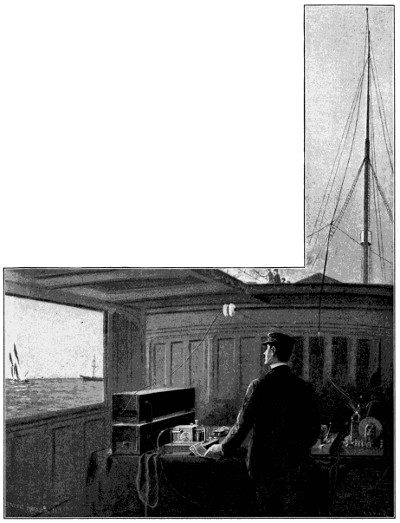
FIG. 13.—WIRELESS TELEGRAPHY, INTERNATIONAL YACHT RACES, OCTOBER, 1899.
Wireless Telegraphy, or telegraphing without any wires at all, from one point to another point through space, is the most modern and startling development in telegraphy. To the average mind this is highly suggestive of scientific imposition, so intangible and unknown are the physical forces by which it is rendered possible, and yet this is one of the late achievements of the Nineteenth Century. Many scientists have contributed data on this subject, but the principles and theories have only begun to crystallize into an art during the first part of the last decade of the Nineteenth Century. Heinrich Hertz, the German scientist, was perhaps the real pioneer in this line in his studies and observations of the nature of the electric undulations which have taken his name, and are known as “Hertzian” waves, rays, or oscillations. Tesla in the United States, Branly and Ducretet in France, Righi in Italy, the Russian savant, Popoff, and Professor Lodge, of England, have all made contributions to this art. It will[27] aid the understanding to say, in a preliminary way, that electric undulations are generated and emitted from a plate or conductor a hundred feet or more high in the air, are thence transmitted through space to a remote point, which may be many miles away, and there influencing a similar plate high in the air give, through a special form of receiving device known as a “coherer,” a telegraphic record. The “coherer,” invented by Branly in 1891, is a glass tube containing metal filings between two circuit terminals. The electric waves cause these filings to cohere, and so vary the resistance to the passage of the current as to give a basis for transformation into a record.
In March, 1899, Signor Guglielmo Marconi, an Italian student, then residing in England, successfully communicated between South Foreland, County of Kent, and Boulogne-sur-mer, in France, a distance of thirty-two miles across the English Channel. Signor Marconi used the vertical conductors and[28] the Hertz-oscillation principle, and his system is described in his United States patent. No. 586,193, July 13, 1897.
His patent comprehends many claims, a leading feature of which is the means for automatically shaking the “coherer” to break up the cohesion of the metal filings as embodied in his first claim, as follows:
“In a receiver for electrical oscillations, the combination of an imperfect electrical contact, a circuit through the contact, and means actuated by the circuit for shaking the contact.”
The Marconi system of wireless telegraphy was practically employed with useful effect April 28, 1899, on the “Goodwin Sands” light-ship to telegraph for assistance when in collision twelve miles from land and in danger of sinking. It was also used in October, 1899, on board the “Grande Duchesse” to report the international yacht race between the “Columbia” and the “Shamrock” at Sandy Hook, as seen in Fig. 13. Lord Roberts also made good use of it in his South African campaign against the Boers. According to Signor Marconi its present range is limited to eighty-six miles, but it is expected that this will be soon extended to 150 miles.
Marconi’s receiving apparatus is shown in Fig. 13A, and consists of a small glass tube called the coherer, about 11⁄2 inches in length, into the ends of which are inserted two silver pole pieces, which fit the tube, but whose ends are 1⁄50 inch apart. The space between the ends is filled with a mixture composed of fine nickel and silver filings and a mere trace of mercury, and the other ends of the pole pieces are attached to the wires of a local circuit. In the normal condition the metallic filings have an enormous resistance, and constitute a practical insulator, preventing the flow of the local current; but if they are influenced by electric waves, coherence takes place and the resistance falls, allowing the local current to pass. The coherence will continue until the filings are mechanically shaken,[29] when they will at once fall apart, as it were, insulation will be established, and the current will be broken. If, then, a coherer be brought within the influence of the electric waves thrown out from a transmitter, coherence will occur whenever the key of the transmitter at the distant station is depressed. Mr. Marconi has devised an ingenious arrangement, which is the subject of his patent referred to, in which a small hammer is made to rap continuously upon the coherer by the action of the local circuit, which is closed when the Hertzian waves pass through the metal filings. As soon as the waves cease, the hammer gives its last rap, and the tube is left in the decohered condition ready for the next transmission of waves. It is evident that by making the local circuit operate a relay, in the circuit of which is a standard recording instrument, the messages may be recorded on a tape in the usual way.
In Fig. 13B is shown the diagram of circuits. The letters d d indicate the spheres of the transmitter, which are connected, one to the vertical wire w, the other to earth, and both by wires c′ c′, to the terminals of the secondary winding of induction coil, c. In the primary circuit is the key b. The coherer j has two metal pole pieces, j1 j2, separated by silver and nickel filings. One end of the tube is connected to earth, the other to the vertical wire w, and the coherer itself forms part of a circuit containing the local cell g, and a sensitive telegraph relay actuating another circuit, which circuit works a trembler p, of which o is the decohering tapper, or hammer. When the electric waves pass from w to j1 j2 the resistance falls, and the current from g actuates the relay n, the choking coils k k′, lying between the coherer and the relay, compelling the electric waves to traverse the coherer instead of flowing through the relay. The relay n in its turn causes the more powerful battery r to pass a current through[30] the tapper, and also through the electro-magnet of the recording instrument h.
The alternate cohering by the waves and decohering by the tapper continue uninterruptedly as long as the transmitting key at the distant station is depressed. The armature of the recording instrument, however, because of its inertia, cannot rise and fall in unison with the rapid coherence and decoherence of the receiver, and hence it remains down and makes a stroke upon the tape as long as the sending key is depressed.
The principal applications of wireless telegraphy so far have been at sea, where the absence of intervening obstacles gives a free path to the electrical oscillations. The system is also applicable on land, however, and no one can doubt that if the Ministers of the Legations shut up in Pekin had been supplied with a wireless telegraphy outfit, neither the walls of Pekin nor the strongest cordon of its Chinese hordes could have prevented the long sought communication. The full story of mystery and massacre would have been promptly made known, and the civilized world have been spared its anxiety, and earlier and effective measures of relief supplied.
As the art of telegraphy grows apace toward the end of the Nineteenth Century, individuality of invention becomes lost in the great maze of modifications, ramifications, and combinations. Inventions become merged into systems, and systems become swallowed up by companies. In the promises of living inventors the wish is too often father to the thought, and the conservative man sees the child of promise rise in great expectation, flourish for a few years, and then subside to quiet rest in the dusty archives of the Patent Office. They all contribute their quota of value, but it is so difficult to single out as pre-eminent any one of those which as yet are on probation, that we must leave to the coming generation the task of making meritorious selection.
To-day the telegraph is the great nerve system of the nation’s body, and it ramifies and vitalizes every part with sensitive force. In 1899 the Western Union Telegraph Company alone had 22,285 offices, 904,633 miles of wire, sent 61,398,157 messages, received in money $23,954,312, and enjoyed a profit of $5,868,733. Add to this the business of the Postal Telegraph Company and other companies, and it becomes well nigh impossible to grasp the magnitude of this tremendous factor of Nineteenth Century progress. Figures fail to become impressive after they reach the higher denominations, and it may not add much to either the reader’s conception or his knowledge to say that the statistics for the whole world for the year 1898 show: 103,832 telegraph offices, 2,989,803 miles of wire, and 365,453,526 messages sent during that year. This wire would extend[31] around the earth about 120 times, and the messages amounted to one million a day for every day in that year. This is for land telegraphs only, and does not include cable messages.
What saving has accrued to the world in the matter of time, and what development in values in the various departments of life, and what contributions to human comfort and happiness the telegraph has brought about, is beyond human estimate, and is too impressive a thought for speculation.
Difficulties of Laying—Congratulatory Messages Between Queen Victoria and President Buchanan—The Siphon Recorder—Statistics.
Among the applications of the telegraph which deserve special mention for magnitude and importance is the Atlantic Cable. For boldness of conception, tireless persistence in execution, and value of results, this engineering feat, though nearly a half century old, still challenges the admiration of the world, and marks the beginning of one of the great epochs of the Nineteenth Century. It was not so brilliant in substantive invention, as it added but little to the telegraph as already known, beyond the means for insulating the wires within a gutta percha cable, but it was one of the greatest of all engineering works. It was chiefly the result of the energy and public spirit of Mr. Cyrus W. Field, an eminent American citizen. Three times was its laying attempted before success crowned the work. The first expedition sailed August 7, 1857, and consisted of a fleet of eight vessels, four American and four English, starting from Valentia on the Irish coast. On August 11 the cable parted, and 344 miles of the cable were lost in water two miles deep. In 1858 a renewal of the effort to lay the cable was made. Improvements were added in the paying out machinery, and a different manner of coiling the enormous load of cable on the vessels was resorted to, and provisions also[33] were made to protect the propeller from contact with the cable. On June 10 the telegraphic fleet steamed out of Plymouth harbor. It consisted of the U. S. frigate “Niagara,” with the paddle-wheel steamer “Valorous” as a tender, and the British frigate “Agamemnon,” with the paddle-wheel steamer “Gorgon” as a tender. After three days at sea, terrible gales were encountered and much damage resulted. The vessels were to proceed to midocean, and the portions of the cable carried by the “Niagara” and “Agamemnon” were to be spliced, and the two vessels were then to sail in opposite directions to their respective coasts. The first splice was made on the 26th of June. After paying out two and a half miles each, the cable parted. Again meeting and splicing, forty miles each were paid out, and the cable again parted. On the 28th another splicing was effected, and 150 miles each were paid out, and again the cable parted, and the expedition had to be abandoned. After much financial embarrassment and adverse criticism, the courageous and public-spirited directors who had control of the enterprise dispatched another expedition, which sailed July 17, 1858. The two vessels, “Niagara” and “Agamemnon,” with their tenders, proceeded to midocean, and following the same method of connecting the ends of their respective cable sections, they sailed in opposite directions. On August 5, 1858, Mr. Cyrus Field announced by telegram from Trinity Bay, on the coast of Newfoundland, that Trinity Bay in America, and Valentia in Ireland, 2,134 miles apart, had been connected, and the great Atlantic cable was an established fact.
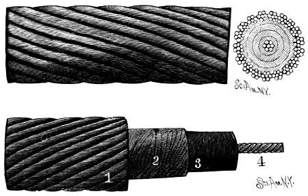
FIG. 14.—ORIGINAL ATLANTIC CABLE, FULL SIZE.
Consists of seven copper wires (4) to form the conductor, a wrapping (3) of thread, soaked in tallow and pitch, several layers (2) of gutta percha, all surrounded by a protecting coat of mail (1) of twisted wires.
On August 16, 1858, the first message came over from Queen Victoria to President Buchanan of the United States, as follows:
“To the President of the United States, Washington:
“The Queen desires to congratulate the President upon the successful completion of this great international work, in which the Queen has taken the deepest interest.
“The Queen is convinced that the President will join with her in fervently hoping that the Electric Cable which now connects Great Britain with the United States will prove an additional link between the nations whose friendship is founded upon their common interest and reciprocal esteem.
“The Queen has much pleasure in thus communicating with the President, and renewing to him her wishes for the prosperity of the United States.”
to which the President replied as follows:
“Washington City, Aug. 16, 1858.
“To Her Majesty Victoria, Queen of Great Britain:
“The President cordially reciprocates the congratulations of Her Majesty, the Queen, on the success of the great international enterprise accomplished by the science, skill, and indomitable energy of the two countries. [34]It is a triumph more glorious, because far more useful to mankind, than was ever won by conqueror on the field of battle.
“May the Atlantic Telegraph, under the blessing of Heaven, prove to be a bond of perpetual peace and friendship between the kindred nations, and an instrument destined by Divine Providence to diffuse religion, civilization, liberty and law throughout the world. In this view will not all nations of Christendom spontaneously unite in the declaration that it shall be forever neutral, and that its communications shall be held sacred in passing to their places of destination, even in the midst of hostilities?
(Signed)
“James Buchanan.”
Great rejoicing on both sides of the ocean followed, and the public print was filled with accounts of the enterprise. The following selection from the Atlantic Monthly of October, 1858, is an apostrophe in lofty sentiments of verse, which to-day stirs the Twentieth Century heart as a joyous prophecy fulfilled:
After a few months of working, the cable became inoperative, but its success was a demonstrated fact, and in 1866 a new cable was laid by the aid of that monster steamer “The Great Eastern,” since which time the cable has become one of the great factors of modern civilization.
Probably the most important of the inventions relating to submarine
telegraphs is the siphon recorder, invented by Sir William Thompson,
now Lord Kelvin (U. S. Pat. No. 156,897, Nov. 17, 1874). It is called a
siphon recorder because the record is made by a little glass siphon down
which a flow of ink is maintained like a fountain pen. This siphon is
vibrated by the electric impulses to produce on the paper strip a zigzag
line, whose varying contour is made to represent letters. In the illustration,
Fig. 15, m is an ink well, o a strip of paper, and n the ink siphon, one
end of which is bent and dips down into the ink well, and the other end of
which traces the record on the moving paper strip o. The siphon is sustained
on a vertical axis l, and its lateral vibration is effected as follows:
A light rectangular coil b b, of exceedingly fine insulated wire, is suspended
between the poles N S of a powerful electro-magnet energized by[36]
a local battery. In the coil b b is a stationary soft iron core a, magnetized
by the poles N S. The coil b b is suspended upon a vertical axis consisting
of a fine wire f f, and the delicate electrical impulses over the submarine
cable enter the coil b b through the axial wire f f as a conductor, and
cause a greater or less oscillation of the coil b b between the poles N S of
the electro-magnet. The coil b b is connected by a thread k to the siphon,
and pulls the siphon in one direction, while the siphon is pulled in the
opposite direction by a helical spring attached to an arm on the siphon
axis l. The jagged lines seen in Fig. 16 spell the words “siphon recorder
.”
To-day there lie in submerged silence, but pulsating with the life of the world, no less than 1,500 submarine telegraphs. Their aggregate length is 170,000 miles; their total estimated cost is $250,000,000, and the number of messages annually transmitted over them is 6,000,000. Thirteen cables work daily across the Atlantic, and an additional one is being laid from Germany. Messages now go across the Atlantic and are received[37] on the siphon recorder at the rate of fifty words a minute, and at a cost of twenty-five cents a word. Our guns may thunder in the Philippines, and the news by cable, traveling faster than the earth on its axis, may reach the Western Hemisphere under the paradoxical condition of several hours earlier than it occurred. Cablegrams to Manila cost $2.38 a word, and the cable tolls for our War Department alone are costing at the rate of $325,000 a year. The logical outcome is a Pacific cable, a bill for which, connecting San Francisco and Honolulu, has already passed the United States Senate.
Messages from the Executive Mansion at Washington to the battlefield at Santiago were sent and responses received within twelve minutes, while a message dispatched from the House of Representatives in Washington to the House of Parliament in London, in the chess match of 1898, was transmitted and a reply received in thirteen and one-half seconds.
To-day the cable with the still small voice, more divine than human, speaks with one accent to all the nations of the earth. Differing though they may in tongue and skin, in thought and religion, in physical development and clime, the telegraph speaks to them all alike, and by all is understood. Truly it fulfils the prophecy so gracefully expressed in the verses quoted, and has become the common bond of union among the nations of the earth.
Observations of Faraday and Henry—Magneto-Electric Machines of Pixii and of Saxton—Hjorth’s Dynamo of 1855—Wilde’s Machine of 1866—Siemens’ of 1867—Gramme’s of 1870—Tesla’s Polyphase Currents.
In the last thirty-five years of the Nineteenth Century there has grown up into the full stature of mechanical majority this stalwart son of electrical lineage. As the means for furnishing electrical power it stands to-day the great fountain head of electrical generation, and in its peculiar field ranks as of equal importance with the steam engine. Until about 1865 the voltaic battery, which generated electricity by chemical decomposition, was practically the only means for producing electricity for industrial and commercial purposes. It was through its agency that the telegraph, the electric light, and many other discoveries in electricity were made and rendered possible. Its cost and limited amount of current, however, restricted the limits of its practical application, and although its current could furnish beautiful laboratory experiments, its mechanical work was more in the nature of illustration than utilization. But with the advent of the dynamo electricity has taken a new and very much larger place in the commercial activities of the world. It runs and warms our cars, it furnishes our light, it plates our metals, it runs our elevators, it electrocutes our criminals; and a thousand other things it performs for us with secrecy and dispatch in its silent and forceful way. But what is a dynamo? To the average mind the most satisfactory answer would be—that it is simply a machine which converts mechanical power into electricity. Attach a dynamo to a steam engine, and the power of the steam engine will, through the dynamo, become transformed or converted into a powerful electric current. Any other source of mechanical power, such as a water wheel, gas engine, wind wheel, or even a horse or man, will serve to operate the dynamo; its primary and sole function being to take power and convert it into electricity.
The stepping stone to the dynamo in its development was the magneto-electrical machine. This is a machine founded upon the general principle observed by Faraday in 1831 and 1832, and also by Prof. Henry about the same time, that when a magnet is made to approach a helix of insulated[39] wire it causes a current of electricity to flow in the helix as long as the magnet advances. If the magnet is passed through the helix, the current is reversed as soon as the magnet passes the middle point. The principle is the same if the magnet be made to approach and recede from the poles of an electro-magnet having a helix wound around a soft iron core. Likewise the same result occurs if the electro-magnet with its helix is made to approach and recede from a permanent magnet, the current in the helix flowing in one direction when it approaches the permanent magnet, and in the opposite direction when leaving the said magnet. The movement of the two elements in relation to each other requires some force to overcome the repellent and attractive actions, and this force is converted into electrical energy. This is the principle of the magneto-electric machine.
Saxton in the United States and Pixii in France were the first to produce organized devices of this class for generating electricity from magnetism. Pixii’s machine (1832) consisted of a permanent horse-shoe magnet which was caused to revolve in proximity to an armature upon which was wound a coil of insulated wire. On March 30, 1852, Sonnenberg and Rechten obtained a United States patent, No. 8,843, for an electrical machine for killing whales, and on August 19, 1856, Shepard obtained U. S. Pat. No. 15,596 for the machine which came to be known as the “Alliance” machine. Both of these machines had permanent field magnets, and were early types of magneto-electric machines. The efficiency of these magneto-electric machines was necessarily limited to the strength of the inducing field magnets, which, being permanent magnets, were a positive and fixed factor. It was an easy step to substitute electro-magnets for permanent magnets, as the field or inducing magnets, and also[40] to excite the (electro) field magnet by voltaic batteries, but the important step which resulted in the machine which is called the “dynamo” (from the Greek “Δυναμις”—power) was yet to come.
This step consisted
in taking the
current induced in
the revolving helix
or armature (by the
field magnets) and
sending it back
through the coils of
the field magnets
which produced it,
thereby increasing
the energy of the
field magnet coils,
and they in turn
with an increased
efficiency and reciprocal
action induce
still stronger currents
in the armature
coils, and so a
building up process,
or principle of mutual
and reciprocal
excitation, is carried
on until the maximum
efficiency is
reached. This principle
was the discovery
of Soren Hjorth,
of Copenhagen, and
is fully described in
his British patent,
No. 806 of 1855, for
“An Improved Magneto-Electric
Battery.”
As the prototype[41]
of the dynamo, it is worthy of illustration. In the illustration,
Figs. 18 and 19, a is a revolving wheel bearing the armature
coils, C permanent magnets, d electro-magnets (field magnets), and
g the commutator. Quoting from his specifications, he says: “The permanent
magnets acting on the armatures brought in succession between their
poles, induce a current in the coils of the armatures, which current, after
having been caused by the commutator to flow in one direction, passes
round the electro-magnets (field magnets), charging the same and acting
on the armatures. By the mutual action between the electro-magnets and
the armatures an accelerating force is obtained, which in result produces
electricity greater in quantity and intensity than has heretofore been obtained
by similar means.
”
Although the principle of the dynamo was clearly embodied in the Hjorth patent, its value was not appreciated until some time later. Eleven years later Wilde (U. S. Pat. No. 59,738, Nov. 13, 1866), employed a small machine with permanent magnets to excite the coil-wound field magnets of a larger machine. But Siemens (British Pat. No. 261 of 1867), taking up the principle employed by Hjorth, dispensed with his superfluous permanent magnets, having found that the residual magnetism, which always remained in iron which has once been magnetized, was sufficient as a basis to start the building up process. Farmer, Wheatstone and Varley also recognized this fact about the same time. Siemens’ patent also was the first embodiment of what is known as the bobbin armature. Gramme and D’Ivernois (British Pat. 1,668 of 1870, and U. S. Pat. No. 120,057, of Oct. 17, 1871), were the first to bring out the continuously wound ring armature.
Active development now began in various types and by various inventors, including Weston, Brush, Edison, Thomson and Houston, Westinghouse, and others, who have brought the dynamo to its present high efficiency.
The revolving coils of the dynamo are called the armature, and the fixed electro-magnets are called the field magnets, and these latter may be two or more in number. When two are used they are arranged on opposite sides of the armature, and form what is known as the bipolar machine. A larger number constitutes the multipolar machine. The field magnets in the multipolar machine usually are arranged in radial position around the entire circumference of the revolving armature, and are held in a fixed circular frame. To give a clear idea of the principles of the dynamo, the bipolar machine is best suited for illustration, and is here given in Figs. 20 and 21, in which Fig. 20 represents the dynamo complete, and Fig. 21[42] a detail of the end of the armature and commutator. This armature consists of coils or bobbins of insulated wire, each section having its terminals connected with separate insulated plates on the hub, which plates are known as the commutator. When any section of the armature approaches the pole of a field magnet, the current induced in that section of the armature coils by the field magnet, is taken off from a corresponding plate of the commutator by flat springs, seen in Fig. 20, and known as brushes. The field magnets A and B, Fig. 20, are shown with only a few turns of wire about them for clearer illustrations of the connections, which are made as follows: The wire a is extended in coils around the field magnet B, and thence around field magnet A, and thence to the upper brush on the commutator, thence through the wire coils or bobbins of the rotary armature C, and thence by the lower brush to the wire b. The terminals of the wires a and b extend to the point of utilization of the current, whether this be electric lights, motors, or other applications. In this illustration, the circuit, it will be seen, passes through both the coils of the field magnets and the coils of the armature, involving the principle of mutual excitation.
There are two principal kinds of dynamos—those producing the alternating currents, and those producing the continuous current. In the first the current alternates in direction, or is composed of an infinite number of impulses of opposite polarity: one polarity when a section of the armature[43] coil is approaching a north field magnet pole or receding from a south pole, and the other polarity when receding from a north field magnet pole and approaching a south pole. In the continuous current machine, the commutator and brushes are so arranged as to take up all the impulses of the same polarity and conduct them away by one brush, and gathering all the impulses of the opposite polarity and conducting them away by another brush. Thus the current of each brush, in the continuous current machine, is always of the same polarity, and the polarity of one being always positive, and that of the other negative, the current flows continuously in the same direction. A third species of dynamo is the pulsatory, in which the current flow is invariable in direction, but proceeds in waves.
A change in the character of the current generated by the dynamo is made by what is known as the “transformer,” in which the principle of the induction coil is made available. In this way, for instance, the high potential currents generated by the powerful water wheels at Niagara Falls are taken twenty miles to Buffalo, and are there transformed into other currents of lower potential, suited to incandescent lighting and other various uses. A similar scheme is in process of fulfillment in the establishment of a water power electric plant near Conowingo, Maryland, on the Susquehanna River, to furnish electrical power to Baltimore, Wilmington and Philadelphia.
An important development in electrical generation and transmission is to be found in what is known as the polyphase, multiphase, or rotating current, pioneer patents for which were granted to Tesla May 1, 1888, Nos. 381,968, 381,969, 382,279, 382,280, 382,281 and 382,282.
Realizing the possibilities of the dynamo, the Legislature of New York in 1888 passed a law, which went into effect in 1889, in that State, substituting[44] death by electricity for the hangman’s noose. The criminal is strapped in the chair, seen in Fig. 22, one terminal of the wire from the dynamo is strapped upon his forehead, and the other to anklets on his legs, and like a flash of lightning the deadly energy of the dynamo performs its work.
Not the least of the applications of the dynamo is its use in electro-metallurgy for plating metals, and also for promoting chemical reactions. The electric furnace, stimulated into higher heat by the dynamo than can be otherwise obtained, has brought about many valuable discoveries, and made great advances in various arts. The metal aluminum, and the hard abrasive or polishing and grinding material known as “carborundum” are the products of the electric furnace, and so is the product known as “calcium carbide,” which, when immersed in water, gives off acetylene gas and is a product now universally used for that purpose, and rapidly increasing in commercial importance.
In Fig. 23 is seen the Acheson electric furnace for producing carborundum. The electric current traverses the furnace through a series of horizontal electrodes at each end, and highly heats a central core of carbon, which is disposed in a mass of silicious and carbonaceous material, and which latter is converted by the heat into silicide of carbon, or carborundum.[45] In Fig. 24 is shown a continuous electric furnace constructed as a revolving wheel, under the Bradley patents. Rim sections 5 are placed on the wheel on one side and filled with a mixture of carbon and lime, through which the electric current is passed from the dynamo g. The heat of the current fuses the mass and converts it into calcium carbide, and as the wheel slowly revolves the rim sections 5 are removed from the opposite side, and the mass of calcium carbide, seen at x, is broken off. The electrolytic production of copper through the agency of the dynamo amounts to 150,000 tons annually, and the commercial reduction of aluminum by the electric furnace has grown from eighty-three pounds in 1883 to 5,200,000 pounds in 1898, and its cost has been reduced to about 33 cents per pound.
The storage battery, holding in reserve its stored up electric energy, also owes its practical value entirely to the dynamo which charges it, and thus makes available a portable source of supply.
To contemplate the dynamo with its clumsy, enormous spools, it suggests
to the imagination of the average observer the gigantic toy of some
Brobdingnagian boy—but the dynamo is no toy. It is the most compact,
business-like, and dangerous of all utilitarian devices. To touch its brushes
may be instant death, for the dynamo is the prison house of the lightning,
and resents intrusion. Hidden away from public gaze in some sequestered
power house, and working night and day like some tireless, dumb,[46]
and mighty genii, it sends its magnetic thrills of force silently through the
many miles of wire extending like radii from some great nerve center
through the conduits in our streets, and stretching from pole to pole like
giant cobwebs through the air. Responding to its force, thousands of little
incandescent threads leap into radiant brightness and shed their mellow
and genial light in our offices, our stores, hotels, and homes. Brilliant
arc lamps, rivaling the sun in power, make night into day, and produce[47]
along our streets coruscations, silhouettes, and dancing shadows in spectacular
and unceasing pageants. From the towering lighthouses of our
coasts its beams are thrown seaward, and a beacon for the mariner shines
beyond all other lights. The great search light of our ships is in itself but
a hollow mockery until the dynamo whispers in its ear the word “light!
”
and then its beam, reaching for miles along the horizon, discovers a
stealthy enemy, or signals the safe return to port. The mighty force of
the dynamo entering the electric motors on the street cars turns the wheels
and transports its load with scarcely a passenger inside realizing how it is
all done. The same energy turns the electric fan, and with kindly service
soothes the weary sufferer, and at another place remorselessly takes the
life of the condemned criminal. The dynamo is one of the great factors of
modern civilization, and its potential name, like that of “dynamite,” rightly
defines its character.
Barlow’s Spur Wheel—Dal Negro’s Electric Pendulum—Prof. Henry’s Electric Motor—Jacobi’s Electric Boat—Davenport’s Motor—The Neff Motor—Dr. Page’s Electric Locomotive—Dr. Siemens’ First Electric Railway at Berlin, 1879—First Electric Railway in United States, Between Baltimore and Hampden, 1885—Third Rail System—Statistics Electric Railways and General Electric Co.—Distribution Electric Current in Principal Cities.
Although the electric motor of to-day depends for practical value entirely upon the dynamo which supplies it with electric power, nevertheless the motor considerably antedated the dynamo. The genesis of the electric motor began in 1821 with Faraday’s observation of the phenomenon of the conversion of an electric current into mechanical motion. In his experiment a copper wire was supported in a vertical position so as to dip into a cup of mercury, while a small bar magnet was anchored at one end by a thread to the bottom of the cup and floated in the mercury in upright position. The mass of mercury being connected to one pole of a battery, and the vertical wire to the other, it was found that when the circuit was completed by clipping the wire into the mercury, the floating bar magnet would revolve around the wire as a center.
In 1826 Barlow, of Woolwich, made his electrical spur wheel, Fig. 26, and in 1830 the Abbe Dal Negro, in Padua, is said to have constructed a sort of vibrating electrical pendulum, both of which devices were crude forms of magnetic engines. Dal Negro’s machine, see Fig. 27, consisted of a magnet A, movable about an axis situated about one-third of its length, and the upper extremity of which was capable of oscillating between the two branches of an electro-magnet E. A current being sent into the electro-magnet, passed through an eight-cupped mercurial commutator C, which[49] the oscillating magnet controlled by means of a rod t and a fork F. When the magnet had been attracted toward one of the poles of the electro-magnet this very motion of attraction acting upon the commutator changed the direction of the current, and the magnet was repelled toward the other branch of the electro-magnet, and so on.
In 1828 Prof. Joseph Henry produced his energetic electro-magnets sustaining weights of some thousands of pounds, and gave prophetic suggestion of the possibilities of electricity as a motive power. In 1831 he devised the electric motor shown in Fig. 28, which is described in Prof. Henry’s own words as follows:
“A B is the horizontal magnet, about seven inches long, and movable
on an axis at the center; its two extremities when placed in a horizontal[50]
line are about one inch from the north poles of the upright magnets C and
D. G and F are two large tumblers containing diluted acid, in each of
which is immersed a plate of zinc surrounded with copper; l m s t are
four brass thimbles soldered to the zinc and copper of the batteries and
filled with mercury.
“The galvanic magnet A B is wound with three strands of copper bell
wire, each about twenty-five feet long; the similar ends of these are twisted
together so as to form two stiff wires q r, which project beyond the extremity
B, and dip into the thimbles s t.
“To the wires q r two other wires are soldered so as to project in an
opposite direction, and dip into the thimbles l m. The wires of the galvanic
magnet have thus, as it were, four projecting ends; and by inspecting
the figure it will be seen that the extremity p, which dips into the cup
m, attached to the copper of the battery in G, corresponds to the extremity
r which dips into the cup t, connecting, with the zinc in battery F. When
the batteries are in action, if the end B is depressed until q r dips into the
cups s t, A B instantly becomes a powerful magnet, having its north pole
at B; this, of course, is repelled by the north pole D, while at the same time
it is attracted by C; the position is consequently changed, and o p comes in
contact with the mercury in l m; as soon as the communication is formed,
the poles are reversed, and the position again changed. If the tumblers be
filled with strong diluted acid, the motion is at first very rapid and powerful,
but it soon almost entirely ceases. By partially filling the tumblers
with weak acid, and occasionally adding a small quantity of fresh acid, a
uniform motion, at the rate of seventy-five vibrations in a minute, has been
kept up for more than an hour; with a large battery and very weak acid
the motion might be continued for an indefinite length of time.
”
Following Prof. Henry came Sturgeon’s rotary motor of 1832, Jacobi’s rotary motor of 1834, Fig. 29, which had electro-magnets both in the field and armature; Davenport’s motor of 1834, Zabriskie’s motor of 1837, in which a vibrating magnet converted reciprocating into rotary motion; Davenport’s motor of 1837 (U. S. Pat. No. 132, Feb. 25, 1837), Fig. 30; Page’s rotary motor of 1838, Walkley’s motor of 1838 (U. S. Pat. No. 809, June 27, 1838); Stimson’s motor of 1838 (U. S. Pat. No. 910, Sept. 12, 1838); Page’s motor of 1839, Cook’s of 1840 (U. S. Pat. No. 1,735, Aug. 25, 1840); Elias’ motor of 1842, invented in Holland; Lillie’s motor of 1850 (U S. Pat. No. 7,287, April 16, 1850); the Neff motor of 1851 (U. S. Pat. No. 7,889, Jan. 7, 1851), of which illustration is given in Fig. 31, and Page’s motor of 1854 (U. S. Pat. No. 10,480, Jan. 31, 1854). In 1835 Davenport constructed a small circular railway at Springfield, Mass.
In 1839 Prof. Jacobi, with the aid of Emperor Nicholas, applied his electric motor to a boat 28 feet long, carrying fourteen passengers, and propelled the same at a speed of three miles an hour. About the same time Robert Davidson, a Scotchman, experimented with an electric railway car sixteen feet long, weighing six tons, and attaining a speed of four miles an hour. In 1840 Davenport, by means of his electric motor, printed a news sheet called the Electro Magnet and Mechanics’ Intelligencer. In 1851 an electric locomotive made by Dr. Page in accordance with his subsequent patent of 1854, drew a train of cars from Washington to Bladensburg at a rate of nineteen miles an hour.
All these motors were operated by voltaic batteries, and on account of
the cost of the latter but little practical use of the electric motor was made[52]
[53]
until the dynamo was invented. In 1873 an accidental discovery led to the
rapid practical development of the electric motor. It is said that at the industrial
exhibition at Vienna in that year, a number of Gramme dynamos[54]
were being placed in position, and a workman in making the electrical connections
for one of these machines, inadvertently connected it to another
dynamo in active operation, and was surprised to find that the dynamo he
was connecting began to revolve in the opposite direction. This was the
clue that led to the important recognition of the structural identity of the[55]
dynamo and the modern type of electric motor. The dynamo and the electric
motor then grew into development together, and the same inventors
who brought the dynamo to its present high efficiency, produced electric
motors of corresponding principles and value. In the illustration, Fig. 32,[56]
is shown a modern electric motor. It is a Westinghouse two-phase machine,
of 300 horse power, of the self starting induction type, designed to
operate at a speed of 500 revolutions per minute when supplied with two-phase
currents of 3,000 alternations per minute and 2,000 volts pressure.
The most important application of the electric motor is for street car operation. The first electric railway was that of Dr. Werner Siemens, at Berlin, in 1879, an illustration of which is given in Fig. 33. The first electric railway in America was installed at Baltimore in 1885, and ran to Hampden, a distance of two miles.
The familiar overhead trolley cars, and the far superior conduit trolley system, represent perhaps the largest use made of electric motors. The motors are arranged under the cars in varying forms adapted to the structure of the car. In the overhead trolley, shown in Fig. 34, the current is taken from the overhead wire by a flexible trolley pole, and in the conduit system a trolley known as a plow extends from the bottom of the car through a narrow slot in the top of the conduit and makes a traveling contact[57] with the conductor rails within the conduit, which carry the electric current. Fig. 35 is an end view of a street car of the latter type, with the conduit and conductor rails in cross section. The current goes from one rail to one bearing surface of the plow, thence to the motor on the car and back to the other bearing surface of the plow and the other conductor rail in the conduit.
A third system, which has supplanted to some extent the use of steam
on short line railways, is the so-called third rail system, of which an example
is seen in Fig. 36. A third conductor rail is placed between the usual
track rails, and from this conductor the current is taken by a sliding shoe
on the car, and carried to the motor and thence through the car wheels to
the track rails. To reduce danger from the live rail, the third rail in some[58]
[59]
systems is made in sections, and, by an automatic switching process as the
car moves along, only the sections of the rail beneath the car are brought
into circuit, all other portions being cut out.
The use of electric motors has greatly extended, cheapened, and expedited the street car service. All the principal thoroughfares of cities and even towns are now so equipped, and radiating suburban lines extend for[60] miles from the city, affording for five cents a pleasant and cheap excursion for the poor to the green fields and fresh air of the country.
Figs. 37 and 38 show an electric motor used on street cars, as made by the General Electric Company. Externally it presents the appearance of some curious, uncouth, cast iron box, which, to the uninitiated, piques the curiosity, and when opened adds no explanation of its real character. In it, however, the electrician finds a most interesting combination of metal and magnetism.
In Fig. 39 is shown one of the most powerful electric locomotives ever constructed. It was built in 1895 by the General Electric Company for the Baltimore & Ohio Railroad, to draw trains through the long tunnel from the Camden Street Station in Baltimore, for the purpose of avoiding smoke and gas in the tunnel, which is 7,339 feet long. The locomotive weighs ninety-six tons, or twenty-five tons above the average steam locomotive. It was designed to draw 100 trains daily each way, moving passenger trains of a maximum weight of 500 tons at thirty-five miles an hour, and freight trains of 1,200 tons at fifteen miles an hour. It has two trucks, and eight drive wheels of sixty-two inches diameter. There are four motors, two to each truck, each rated at 360 horse power.
Other important applications of the electric motor are, the propelling of automobile carriages, small boats, and fish torpedoes, operating steering gear for ships, passenger elevators, rock drills in mines, running printing presses, fans, sewing machines, graphophones, and in all applications where space is limited and cleanliness a desideratum.
According to Mulhall there were in 1890 in the United States and Canada about 645 miles of street railway operated by electricity. This about concluded the first decade of the life of the electric railway. Some idea of the rapid increase in this field may be had by the statement of the same authority that there were in 1890, at the end of this first decade, forty-five additional electric railroads in course of construction, aggregating 512 miles of way, which nearly doubled the previous existing mileage.
In 1898 it was estimated that there were in the United States 14,000 miles of electric railroads, with a nominal capital of $1,000,000,000, and employing 170,000 men. In the same year a single electrical contract was entered into between the Third Avenue Railroad and the Union Railway Company of New York, acting as one, and the Westinghouse Electrical and Manufacturing Company, amounting to $5,000,000. This was for the electrical equipment of their respective railway lines, and is the largest electrical contract ever made. The change in equipment from other motive power to the electric is rapidly going on in all directions, and the rapid[61] succession of trains will doubtless cause it, for passenger traffic on short lines, to eventually supersede steam.
The eighth annual report of the General Electric Company shows for the year 1899 orders received for railway and other electrical equipment amounting to $26,323,626; goods shipped, $22,379,463.75; profit on same, $3,805,860.18. The growth of its business from 1893 to 1899 shows the following per cent. of increase: In 1893, 36 per cent. above 1892; in 1894, 126 per cent. above 1893; in 1895, 10 per cent. above 1894; in 1896, 60 per cent. above 1895; in 1897, 60 per cent. above 1896; in 1898, 21 per cent. above 1897; in 1899, 51 per cent. above 1898.
The capitalization in electrical appliances in the United States in 1898 is estimated at $1,900,000,000, most of which is devoted to industries in which the electric motor is used. The export of electrical apparatus from this country amounts to more than three million dollars annually, and it is said that there are eight times as many electric railways in the United States as in all the rest of the world combined.
The use of electrical current in twelve principal cities in the United States was distributed in 1898 as follows:
| Lamps, arcs, and motors in sixteen candle power equivalents. | |
|---|---|
| Boston | 616,000 |
| New York | 1,718,000 |
| Chicago | 1,278,000 |
| Brooklyn | 322,000 |
| Baltimore | 224,000 |
| Philadelphia | 488,000 |
| St. Louis | 303,000 |
| San Francisco | 231,000 |
| Buffalo | 125,000 |
| Rochester | 184,000 |
| Cincinnati | 201,000 |
| New Orleans | 81,000 |
Boston makes the largest use of electrical current in proportion to its population of any city in the world. Rochester is next. Both of these cities employ in electrical units of 16 c. p. equivalents, more than one electric lamp for every man, woman and child in their respective populations.
The dynamo and the electric motor have together wrought this great development. The dynamo takes mechanical power and converts it into electrical energy, and the electric motor takes the electrical energy and converts it back into mechanical power. Standing behind them both, however, is the steam engine, and these three afford a beautiful illustration of the law of correlation of forces. The force starts with the combustion of coal under the boiler of the steam engine. When carbon unites chemically with oxygen, it is an exothermic reaction that gives off heat as correlated energy. The influence of heat on the molecules of water in the boiler[62] causes them, by repellent action, to assume the qualities of an elastic gas, and this expanding as steam drives the piston of the steam engine. The steam engine overcomes by force the resistance existing between the dynamo’s field magnets and armature coil, and sets up in the latter the correlated force of an electric current, and the electric current, traveling to its remote destination by suitable conductors, enters the coils of the electric motor in reverse relation to that of the dynamo, and in producing the reverse effect between the armature and field magnets, electrical energy is converted back into mechanical power. It is not possible to obtain in the electric motor the full equivalent of the dynamo’s current, nor in the dynamo the full equivalent of the steam engine’s power, nor in the steam engine the full equivalent of the chemical energy in the combustion of coal. Loss by radiation, by conduction, by friction, and by electrical resistance precludes this, but while there is loss in a utilitarian sense there is no real loss, for force like matter, is indestructible, and the proof of this universal law by Joule, in 1843, constitutes one of the highest triumphs of philosophy and one of the most important discoveries of the Nineteenth Century.
Voltaic Arc by Sir Humphrey Davy—The Jablochkoff Candle—Patents of Brush, Weston and Others—Search Lights—Grove’s First Incandescent Lamp—Starr-King Lamp—Moses Farmer Lights First Dwelling with Electric Lamps—Sawyer-Man Lamp—Edison’s Incandescent Lamp—Edison’s Three-Wire System of Circuits—Statistics.
The popular idea of the electric light is, that it is a very recent invention, since even the younger generation remembers when there was no such thing in general use. It will surprise many readers, then, to know that the electric light had its birth in the first decade of the Nineteenth Century. In 1809 Sir Humphrey Davy discovered that when two pieces of charcoal, which formed the terminals of a powerful voltaic battery, were separated after having been brought into contact with each other, at the moment of separation a brilliant arc of flame passed from one piece of charcoal to the other, producing a temperature of 4,800° F., and that the intensity of the light exceeded all other known forms of light. Various improvements in the organization of devices were made for holding the two pieces of carbon, which in time assumed the form of two pencils in alignment, as in Fig. 40, and devices were provided for feeding one carbon toward the other as they burned away. Clock mechanism for thus regulating the feed was first employed, which served to automatically keep the carbons a definite distance apart, this being a necessary condition of the arc. For many years, however, the use of such a light was confined to laboratory illustration, for the reason that it could only be produced at great expense by a large number of voltaic batteries. Nevertheless very efficient electric lamps working by voltaic batteries were devised by Foucault, Duboscq, Deleuil and others as early as 1853. With the advent of the dynamo, however, the electric light grew rapidly and developed into conspicuous use. Even before the true dynamo was invented the magneto-electric machine was employed for producing an electric current to supply electric light. The so-called “Alliance” generator was, in 1858, used in the South Foreland lighthouse in England to supply the arc lamps, and the beams of the electric light then, for the first time, were turned seaward as a beacon for the mariner.
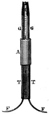
FIG. 41.—
JABLOCHKOFF CANDLE.
FIG. 42.—
WESTON ARC LAMP.
Among the early developments of the electric light was the Jablochkoff candle, see Fig. 41, brought out in 1877. In this device two parallel sticks of carbon G G were separated by a non-conducting layer of kaolin I, and were held in an asbestos ferrule A. Metal tubes T T connected the conducting wires F F to the carbons. The arc of flame passed from the top of one carbon to the other, fusing the separating layer of kaolin, and the whole burned down together as a candle. This form of electric light was extensively used in Paris in 1877, and also in London, and attracted considerable attention.
From the Jablochkoff candle the arc light has resumed the form of two vertically aligned carbons, and after passing through various forms and patterns, of which the Weston lamp, Fig. 42, is a modern type, has come into such universal and conspicuous use for lighting the streets of our cities, and is so well known to-day, that but little need be said of its development,[65] since its real character has undergone no change in principle, the improvements relating chiefly to means for regulating the feed of the carbons and maintaining them at a uniform distance apart, so as to avoid flickering. This result is obtained by automatic mechanism operated by the electric current acting upon electro-magnets, as shown in Fig. 43, in which the electro-magnets raise the upper carbon when it is too close to the lower carbon, and lower the upper carbon when the space becomes too great from burning away. Among those who have contributed to the development of the arc light the names of Brush, Weston, and Thomson and Houston are most conspicuous, and the patents of Brush, No. 203,411, May 7, 1878, and No. 212,183, Feb. 11, 1879, and Weston, No. 285,451, Sept. 25, 1883, are the most representative developments.
The applications of the arc light have been brilliant beyond the dreams of the most sanguine inventor. In the illustrations number 44, 45 and 46, is shown a gigantic electric light beacon manufactured by Henry Lepaute, of Paris, and first exhibited in this country at the Chicago World’s Fair, in 1893. It consists of two great lenses, each nine feet in diameter, between which, in their focus, is placed a 9,000 candle power arc light. The great lantern, Fig. 45, is carried by a vertical shaft, which terminates at its lower end in a hollow drum, which latter floats in a bath of mercury. Although the weight is estimated at several tons, so sensitive is its poise on the mercury that the enormous lantern may be easily rotated by the pressure of one’s finger. Each lens consists of concentric segments, see Fig. 46, 190 in number, surrounding a central disk, which together cause the rays to issue in parallel lines. The nine-foot beam of light thus projected is of 90,000,000 candle power, and if placed at a sufficient altitude to avoid the curvature of the earth’s surface, its light would be visible at the range of 146.9 nautical miles.
Better known to the patrons of our excursion boats and the visitors to our splendid battleships, are the electric search lights. The greatest example of all search lights, however, is not to be found on[66] the sea, but in the picturesque altitudes of the Sierra Madres in Southern California. At the summit of Mount Lowe, in the neighborhood of Pasadena, is the largest search light in the world, shown in illustration, Fig. 48. It is of 3,000,000 candle power, stands eleven feet high, and its total weight is 6,000 pounds. Its light may be seen for 150 miles out on the ocean, and as its powerful beam is thrown from mountain top to mountain top hundreds of miles apart, it adds the illumination of art to the sublimity of nature, and seems a fitting jewel to this lofty crown of Mother Earth.
Brilliant as is the arc lamp, far more in evidence is the incandescent lamp. The little glass bulb with its tiny thread of light we find everywhere. Popular opinion and the decision of the courts accord this invention to Thomas A. Edison. The evolution of the incandescent lamp is, however, interesting, and may be briefly sketched as follows:
In 1845 there appeared in the Philosophical Magazine a description of what was probably the first incandescent electric light. It was devised in 1840 by William Robert Grove, the inventor of the Grove battery, and is illustrated in Fig. 49. It is stated that he experimented and read by it for hours. It was described as follows:
“A coil of platinum wire is attached to two
copper wires, the lower parts of which, or those
most distant from the platinum, are well varnished;
these are fixed erect in a glass of distilled
water, and another cylindrical glass, closed at
the upper end, is inverted over them, so that its
open mouth rests on the bottom of the former
glass; the projecting ends of the copper wires are connected with a voltaic
battery (two or three pairs of the nitric acid combination), and the ignited
wire now gives a steady light. Instead of making the wires pass through
the water, they may be fixed to metallic caps well luted to the necks of a
glass globe.
”
In 1845 August King patented, in England, an incandescent lamp, having an unsealed platinum burner, and also a carbon in a vacuum. Mr. King acted as agent for an American inventor, Mr. Starr, and the lamp[67] came to be known as the Starr-King lamp, shown in Fig. 50. The burner was a thin plate or pencil of carbon B, enclosed in a Torricellian vacuum at the end of an inverted barometer tube, and held between the terminals of the connecting wires leading to a battery. In 1859 Moses G. Farmer lighted his house at Salem, Mass., by a series of subdivided electric lights, which was the first private dwelling lighted by electricity, and probably the first illustration of the feasibility of subdividing the electric current through a number of electric lamps.
In 1877 William E.
Sawyer applied for a
United States patent
for an electric engineering
and lighting system,
and in January,
1878, entered into a
partnership with Albon
Man, and the “Sawyer-Man”
lamp, see Fig. 51,
was produced. In this
an incandescent rod of
carbon was inclosed in
an atmosphere of nitrogen.
This marked the
beginning of a period
of great activity in this
field, which finally resulted
in the well
known form of electric
lamp shown in Fig. 52,
which was patented by Edison, No. 223,898, January 27, 1880. The distinctive
features of this lamp consisted in a bowed filament of carbon of
very thin, thread-like character, which was made of paper or carbonized[68]
cellulose. This, when sealed in a vacuum, would not burn away, but would
give the proper incandescence, and by its small transverse dimension and[69]
high resistance to the current, permitted a proper distribution of the electric
current to a number of lamps, without a special regulator for each
lamp; and which could also be made so cheaply that the lamp could be
thrown away when the burner was finally broken. Edison’s claim on this
feature of the electric lamp was sharply contested in an interference in the
Patent Office by Sawyer and Man, with the decisions alternating first in
favor of one and then of the other, but which finally resulted in the grant
of a patent to Sawyer and Man, on May 12, 1885. A struggle then began[70]
[71]
in the courts, which on October 4, 1892, terminated in a decision by the
United States Court of Appeals (Edison Electric Light Company vs.
United States Lighting Company), awarding the incandescent lamp to
Edison.
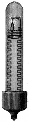
FIG. 51.—
SAWYER-MAN
LAMP.
FIG. 52.—EDISON’S ELECTRIC LAMP.
A—Exhausted globe. B—Carbon filament. CC—Wires sealed in glass. D—Line of fusion of two parts of globe. EF—Insulating material. G—Screw-threads. HI—Metal socket. J—Fixture arm K—Circuit controlling key.
In the early demonstration given by Edison great disturbance was caused in the stock exchanges among the holders of gas shares, as the sensational reportings in the press seemed to indicate that gas was to be superseded entirely. This uneasiness on the London Stock Exchange amounted on October 11, 1878, to a veritable panic, but while the electric light has more than fulfilled the prophecy made for it in many directions, gas shares still continue to be good stocks.
Closely allied to the practical use of the incandescent lamp is the method of supplying and regulating the current from the dynamo. Although the alternating current is used for arc light, only the continuous current can be used for the incandescent lights, and the relation[72] of the dynamo and the incandescent lamps is shown in Fig. 53, in which L represents the lamps between the main conducting wires leading from the dynamo, which latter has the coils of the field magnets arranged in a shunt or branch circuit, in which is interposed a regulator R in the form of a resistance coil with movable switch lever, by which more or less of the current is allowed to flow through the field magnet coils to suit the work being done. In late years automatic regulators have been provided for accomplishing this result. In Fig. 54 is shown what is known as the Edison “three wire system,” patented March 20, 1883, No. 274,290. In this two dynamos are used as at D1 D2, and the three wires emerge from the dynamos, one from the negative pole of one dynamo, another from the positive pole of the other dynamo, and the third or middle one is connected to both the other poles (positive and negative), of the two dynamos. For purposes of illustration, this may be compared to a three-storied arrangement of current, the upper wire representing the third story, the middle wire the second story, and the bottom one the first story. The fall from either story to the next represents the working energy, but from the top wire to the bottom would be equal to a fall from the third story to the first. The purpose of this arrangement is to save expense in copper wire, for while three main wires are used instead of two, the aggregate weight of the wires (when the[73] lamps are arranged as shown), may be made so much less than two heavy wires as to make a very great saving in copper.
The uses of the incandescent light are legion. Besides those which are of common observation it is used for lighting the interior of mines, caves, and the dark apartments of ships, and does not foul the air. It is also used by divers in submarine operations; in the formation of advertising signs, and in pyrotechnics, but perhaps one of the most extraordinary uses to which it has been put is in exploring the interior of the human stomach and other cavities of the body, a patent for which was granted to M. C. F. Nitze, No. 218,055, July 29, 1879.
When an electric lamp is arranged with the opposite ends of the carbon burner connected, one to the outgoing, the other to the incoming wires from a dynamo, so as to be bridged across, this arrangement is said to be “in multiple” or “in parallel,” and the lamps bear the analogy of horses drawing abreast, and when the opposite ends of the carbon burner are placed in a gap or break in either the outgoing or the incoming wire, the arrangement is said to be “in series,” and the lamps bear the analogy of horses in tandem.
Explanation of electric nomenclature can best be given by the analogy in hydrostatics of a stream of water passing in the hose pipe from a fire-engine. The “watt” indicates the sum total unit of electrical power for a definite period of time, and in the hose[74] pipe would be represented by the effective force of a definite volume of water, passing at a definite pressure, during a definite period of time. “Volt” is a pressure unit of electro-motive force, and would be represented by the power of the engine. “Ampere” would be the quantity, or volume unit, or cross section of the hose pipe, and the “ohm” would be the unit of frictional resistance. The “watt” then would be the “volt” multiplied by the “ampere”; thus 500 watts would be 10 amperes at 50 volts, or 50 amperes at 10 volts. Low tension circuits, such as are used for incandescent lights, range from 100 to 240 volts and are harmless. Trolley circuits are usually 500 volts, and will kill an animal, but are not necessarily fatal to man. High tension currents from 2,000 to 5,000 volts, such as are used for arc lights, are fatal.
Of all modern inventions, not one has advertised itself in such a spectacular way as the electric light. Those who have seen the magnificent[75] electrical displays at the Chicago Fair, the electrical celebrations in New York, and the Omaha Exhibition, need no introduction to its marvelous splendors and beauties. In the annual report for 1898 of the Edison Electric Illuminating Company of New York, its statement shows that for that city alone the gross earnings were $2,898,021. There were 9,990 users of the electric light, 443,074 incandescent lamps, and 7,353 arc lights. It is estimated that the electric light stations and plants in the United States alone amount to $600,000,000. In the year 1899 a single manufacturing concern (The General Electric Company) received orders for 10,000,000 incandescent lamps, which is about one-half of the present annual production. Sixteen years ago the lamps were $1 each; to-day they can be bought for 18 cents.
What the future has in store for the further development of the electric light no one may dare predict. Already a different form or manifestation of electric light has been demonstrated, in which neither the electric arc nor the incandescent filament is used, but a peculiar glow is seen disassociated from a direct material habitation, and produced by currents of enormous frequency and high potential, in accordance with the patent to Tesla, No. 454,622, June 23, 1891. Other worthy inventors in this field are at work, and its development will be one of the interesting problems of the Twentieth Century.
Preliminary Suggestions and Experiments of Bourseul, Reis and Drawbaugh—First Speaking Telephone by Prof. Bell—Differences Between Reis’ and Bell’s Telephones—The Blake Transmitter—Berliner’s Variation of Resistance, and Electric Undulations by Variation of Pressure—Edison’s Carbon Microphone—The Telephone Exchange—Statistics.
Τηλε (far), and φωνη (sound), are the Greek roots from which the word telephone is derived. It has the significance of transmitting sound to distant points, and is a word antedating the present speaking telephone, although this fact is generally lost sight of in the dazzling brilliancy of this latter invention. In the effort to hear better, the American Indian was accustomed to place his ear to the ground. Children of former generations also made use of a toy known as the “lovers’ telegraph”—a piece of string held under tension between the flexible bottoms of two tin boxes—which latter when spoken into transmitted through the string the vibrations from one box to the other, and made audible words spoken at a distance. These expedients simply made available the superior conductivity of the solid body over the air to transmit sound waves. The electro-magnetic telephone operates on an entirely different principle. It is a marvelous creation of genius, and stands alone as the unique, superb, and unapproachable triumph of the Nineteenth Century. For subtilty of principle, impressiveness of action, and breadth of results, there is nothing comparable with it among mechanical agencies. In its wonderful function of placing one intelligent being in direct vocal and sympathetic communication with another a thousand miles away, its intangible and mysterious mode of action suggests to the imagination that unseen medium of prayer rising from the conscious human heart to its omniscient and responsive God. The telegraph and railroad had already brought all the peoples of the earth into intimate communication and made them close kin, but the telephone transformed them into the closer relationship of families, and the tiny wire, sentient and responsive with its unlimited burden of human thoughts and human feelings, forms one of the great vital cords in the solidarity of the human family.
It is a curious fact that many, and perhaps most, great inventions have
been in the nature of accidental discoveries, the by-products of thought
directed in another channel, and seeking other results, but the telephone
does not belong to this class. It is the logical and magnificent outcome of
persistent thought and experiment in the direction of the electrical transmittal
of speech. Prof. Bell had his objective point, and keeping this
steadily in view, worked faithfully for the accomplishment of his object in
producing a speaking telephone, until success crowned his work. He
probably did not realize at first the full magnitude of the achievement, but
looking at it from the end of the Nineteenth Century, he might well exclaim
in the language of Horace: “Exegi monumentum acre perennius
.”
Prof. Bell’s conception of the telephone dates back as far as 1874. His
first United States patent, No. 174,465, was granted March 7, 1876, and
his second January 30, 1877, No. 186,787. It is generally the fate of most
inventions, even of a meritorious order, to languish for many years, and
frequently through the whole term of the patent, before receiving full recognition
and adoption by the public, but the meteoric brilliancy of this invention
at its first public announcement astonished the masses, and inspired
the admiration of the savants of the world. When exhibited at the
Centennial Exhibition in Philadelphia, in 1876, it was spoken of by Sir
William Thomson, and Prof. Henry, as the “greatest by far of all the
marvels of the electric telegraph.
”
It is always the fate of the author of any great invention to be compelled to defend himself against the claims of others. It is one of the failings of human nature to lay claim to that which somebody else has obtained, and is an old story which finds its first illustration in the squabbles of childhood. When a troop of prattling boys hunt butterflies among the daisies, and some sharp-eyed youngster has captured a prize, there are always others of his mates to cry, “I saw it first,” and men are but grown-up boys. So in the history of the telephone, Prof. Bell has found competitors for this honor, and it is astonishing to know how close some of these prior experimenters came to success without reaching it. In 1854 Bourseul, of Paris suggested an electric telephone, and in 1861 Philip Reis devised an electric telephone which would transmit musical tones. Daniel Drawbaugh, of Pennsylvania, is alleged to have made an electric telephone in 1867-1868, and his claims against the Bell interests were fought vigorously in the Patent Office, and in the courts, but without success. Elisha Gray’s claims perhaps came nearer to establishing for him a share in the honor of inventing the speaking telephone than any other, for he filed a caveat in the United States Patent Office upon the same day (February 14, 1876),[78] upon which Prof. Bell’s application for a patent was made. But in the contest in the Patent Office with Gray, Edison, Berliner, Richmond, Holcombe, Farmer, Dolbear, Volker, and others, it was decided that Prof. Bell was the first to make a practically effective speaking telephone, and this conclusion has been sustained by the courts. Reis was a poor German school teacher at Friedrichsdorf, and in 1860 he took a coil of wire, a knitting needle, the skin of a German sausage, the bung of a beer barrel, and a strip of platinum, and constructed the first electric telephone. A typical form of his transmitter, see Fig. 55, was a box covered with a vibrating membrane E, and provided with a mouth-piece at one side. A platinum strip F was attached to the membrane or vibrating diaphragm E, and a platinum pointed hammer G rested lightly on the platinum strip F. The hammer G and platinum strip F were connected to the opposite ends of a wire, which had in its circuit a battery and a receiver. Air vibrations in the nature of sound waves in the box caused the diaphragm E to vibrate, and a separating make-and-break contact between the platinum strip F and the platinum point of hammer G caused a series of separate and distinct broken impulses to traverse the battery circuit and be received upon the receiver, which latter consisted of an iron rod with a coil of wire around it. That Reis’ transmitter did alternately make and break the circuit, seems clear from his own memoir. A translation from this memoir, taken from the annual report (Jahresberichte) of the Physical Society of Frankfurt am Main for 1860-1861, reads as follows:
“At the first condensation (of air vibrations) the hammer-shaped little
wire d (G in our illustration), will be pushed back. At the succeeding
rarefaction it cannot follow the return vibration of the membrane, and the
current going through the little strip (of platinum) remains interrupted
so long as until the membrane driven by a new condensation presses the[79]
little strip against d (the hammer G) once more. In this way each sound
wave effects an opening and closing of the current.
”
Reis evidently did not know how to make the vibrations of his diaphragm translate themselves into exactly commensurate and correlated electric impulses of equal rapidity, range, and quality. If he had done this, he would have had a speaking telephone, but a make-and-break contact could never do it, and hence he in his later instruments attached to them a telegraphic key in order that the sending operator might communicate with the receiving operator. If Reis’ telephone had been a speaking telephone, this would have been unnecessary. Furthermore, it is inconceivable how the intelligent, progressive, and scientific Germans could have failed to have given to a speaking telephone in 1860 the immediate honor and attention that it deserved. In America, the Bell speaking telephone, invented in 1876, was known all over the civilized world the same year. Reis’ broken contact circuit would transmit musical tones, because musical tones vary chiefly in rapidity of vibration, rather than in range, or quality, and the chattering contacts of Reis’ telephone would transmit musical tones because said contracts could be adjusted to the practically uniform range of vibration. Prof. Bell, however, had made a special study of articulate speech, and knew that speech was not essentially musical, but was composed of an irregular and discordant medley of vowel and consonant sounds, whose vibrations varied not only in pitch or rapidity like musical tones, but also in the quality or kind of vibrations as to range and loudness. In his invention, therefore, he did not make and break the circuit as did Reis, through the contact points, but he used the more sensitive plan of a constantly closed circuit, and merely caused the current to undulate in it by a principle of magnetic induction. This principle was first discovered by Oersted, and developed into the well known fact that when a piece of iron is moved back and forth from the poles of an electro-magnet an induced current is made to oscillate in the helix of the electro-magnet. The difference between Reis’ separating make-and-break circuit, and the Bell continuous but undulating current, might be illustrated by the difference between the impulses delivered by the beating of the drum sticks on the head of a drum, on the one hand, and the alternate pulling and slackening of a kite cord, on the other. In the successive impacts on the head of a drum there could not be so sensitive a transfer of motion to the lower head of the drum as there would be transferred to the kite by the movement of the hand holding the kite cord. Reis’ plan resembled the broken drum beats, and Bell’s the kite cord, which always preserved a certain amount of tension. Bell accomplished his object by the means shown in Figs. 56 and[80] 57, in which Fig. 56 represents his first patent of March 7, 1876, and Fig. 57 his second patent of January 30, 1877. In both cases the current was a continuously closed one, and was not alternately made and broken as by the separating contacts of Reis. Prof. Bell caused the vocal air vibrations to undulate or oscillate the continuously closed circuit by the principle of magnetic induction as follows (see Fig. 56): He caused diaphragm a, when spoken against, to vibrate the armature c in front of the electro-magnet b, but without touching it, and as the armature approached and receded from the electro-magnet it induced an undulating but never broken current in the helix of this electro-magnet and along the line to and through the helix of the electro-magnet f at the distant receiver, and this undulating current, influencing the armature h, which touched the diaphragm i but not the electro-magnet, produced in the attractive influence of the magnet on this armature and diaphragm, vibrations of the same rapidity, range, and quality as those vocal vibrations that acted upon the first diaphragm a. In other words, the sequence of transference was air vibrations in A, mechanical vibrations of diaphragm a, electrical undulations traversing the line, induced vibrations in armature h and diaphragm i, and air vibrations again resolved back into sounds of articulate speech, the same as those spoken into A. It will be perceived that in the Bell telephone both transmitter and receiver were of identical construction. This is better shown in Fig. 57 of his later patent, in which the horizontal line below the electro-magnet on one side represents a metal transmitting diaphragm, and the horizontal line under the electro-magnet at the other side was the receiving diaphragm. Not only were the sounds thus reproduced, but as the circuit was continuous and never broken by any separating contacts, the extreme sensitiveness of the electric vibrations set up by magnetic induction was such that the discordant and irregular quality of the vibrations of articulate speech were transferred and reproduced with exact fidelity, as well as the musical tones, and this rendered the speaking telephone a success. In later telephones the current is actually transmitted[81] through the contacting points, but this only became practicable after the carbon microphone transmitter was invented, in which the essential undulations of the electric current were produced in another way, i. e., by the application of the important discovery that the varying of the pressure on carbon, by vibration, varied its conductivity, and in this way produced the same result of undulating a current without breaking it. This in no wise detracts from the value of the principle of the continuous undulating current discovered and employed by Prof. Bell, between which and the breaks of the hard platinum points of Reis there is a difference as wide as the difference between success and failure.
The form in which Prof. Bell’s telephone was placed before the public was not that shown in the patents, but it quickly assumed the well-known shape of an elongated cylinder forming a handle, with a flaring mouth-piece at one end. This development in form is credited to Dr. Channing in 1877, and it is the familiar form to-day, whose internal construction is shown in Fig. 58. The handle is made of hard rubber, and the cap or mouth-piece, which is screwed thereon, is also of hard rubber. The diaphragm A, of thin ferrotype plate, is clamped at its edges between the cap, or mouth-piece, and the handle. The compound magnet B is composed of four thin flat bar magnets, arranged in pairs on opposite sides of the flat end of the soft iron pole piece c at one end, and the soft iron spacing piece d at the other end, the magnets being clamped to these pieces with like poles all in one direction. The end of the pole piece c extends to within 1⁄100 to 2⁄100 of an inch of the diaphragm, or as near as possible so that the diaphragm does not touch it when it vibrates. On the pole piece c is placed a wooden spool on which is wound silk-covered wire (No. 34, Am. W. G.). This wire fills the spool, and its ends are soldered to two insulated[82] wires which pass through a flexible rubber disc f below the spool and extend respectively to the two binding posts at the opposite end of the handle. The current passes from one binding post and its connecting wire, through the wire on the spool, and thence to the other connecting wire and binding post. When used as a transmitter, vocal vibrations acting mechanically on the diaphragm A produce undulatory vibrations by magnetic induction in the spool of wire, which are transmitted to the other end of the line; and when used as a receiver, the undulatory vibrations from the remote end of the line produce mechanical vibrations in the diaphragm, which set up air vibrations that are reproductions of articulate sounds.
Although the Bell telephone is both a transmitter and receiver, in practice a more sensitive and better form of transmitter has taken its place. That most generally used and best known is the “Blake transmitter,” which was brought out about 1880. This employs two important elements. The first is the carbon microphone, which is a means for producing the undulations in the current by the variations in pressure on carbon contacts, and the second is an induction coil operated by a local battery, whose primary circuit passes through the contacts of the carbon microphone, and whose secondary circuit passes over the line. These fundamental elements of the Blake transmitter were the inventions of Berliner and Edison, and were made in 1877. The broad idea of producing electric undulations by varying the pressure between electrodes by vocal vibrations, was a large bone of contention in the Patent Office between various inventors. An application for a patent for the same was filed in the Patent Office by Emile Berliner, June 4, 1877, which was contested in an interference by Gray, Edison, Richmond, Dolbear, Holcombe, Prof. Bell, and others. After fourteen years of litigation the patent was finally awarded to Berliner. The patent granted to him November 17, 1891, No. 463,569, is a valuable one, and has become the property of the American Bell Telephone Company. The application of a low resistance conductor (carbon) in a microphone was invented by Edison as early as 1877, but his[83] patent, No. 474,230, did not issue until May 3, 1892, on account of the interference with Berliner on the broader principle.
The Blake transmitter takes its name from the inventor of its mechanical features, who has assembled in it the fundamental principles of Berliner and Edison in a sensitive and practical mechanical construction, covered by minor patents, dated November 29, 1881. It is the little box in the middle of the familiar telephone outfit into which the talking is done. Its internal construction is shown in Fig. 59. To the rear of the door is secured the cast iron circular ring A, inside of which lies the Russia iron diaphragm B, cushioned at its edges with a rubber band. A circular seat a little larger than the diaphragm is formed in the iron ring, and on this seat the diaphragm rests. A short, thin metal plate attached to the ring A on the right hand side clamps the diaphragm in position by resting squarely[84] on the rubber edge of the diaphragm. Its function is like that of a hinge, which allows the diaphragm to freely swing inward. A steel damping spring is secured to the ring at the opposite edge of the diaphragm, and has its free end provided with a rubber glove on which is cemented a thin piece of fluffy woolen material. The padded end of the damping spring rests against the diaphragm and prevents excessive vibration. The iron ring A has at its bottom a projection holding an adjusting screw, and to a similar top projection is attached by screws a brass spring, from which depends another casting C, supporting the microphone apparatus, which is best shown in the diagram, Fig. 60. In this diagram A is one terminal of the battery connected by wire S to the hinge H of the box. From the other leaf of the hinge the wire M passes to K, where it is soldered to the upper end of a German silver spring I. At K this spring is clamped and insulated from the iron work by two pieces of hard rubber. On the lower end of the spring I is soldered a short piece of thick platinum wire, whose ends are rounded into heads, one of which bears against the diaphragm N, and the other against the carbon button J. This button is attached to a small brass weight, and is supported by a spring R, clamped at its upper end to the metal support T. This spring is surrounded its entire length by rubber tubing to deaden vibration. The transmitter is adjusted by screw O, which, acting upon casting T, brings the carbon button, the platinum heads, and also the diaphragm N, against each other with a regulated pressure. The current passes from the part K to the spring I, the platinum head, carbon button J, and its supporting spring R, to metal casting T, and ring V, thence by wire L to the lower hinge G, by wire P to the pri[85]mary of the induction coil, and thence by wire Y to binding post B, the two binding posts A B being the two battery terminals. The secondary wire E of the induction coil has its ends connected by wires X and W with the two binding posts C B, which are the line terminals, or one the line terminal and the other the ground connection. It will thus be seen that the primary current passes through the transmitter, and the secondary traverses the line. The most familiar forms of the telephone are those seen in Figs. 61 and 62, but the ideal form is rigged in a cabinet or little room, which excludes all extraneous interfering sounds.
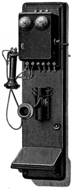
FIG. 61.—WALL TELEPHONE.
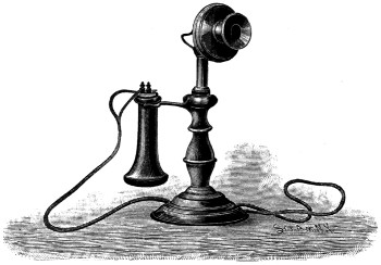
FIG. 62.—DESK TELEPHONE.
With the Bell receiver and the Blake transmitter a good practical telephone system may be constructed, but the improvements which have been made in the short life of the telephone are beyond adequate description, or even mention. They relate to the call bell, the battery, the switchboard, meters for registering calls, conductors, conduits, connections, lightning arresters, switches, anti-induction devices, repeaters, and systems. Among those most prominently identified with its development are Bell, Edison, Berliner, Hughes, Gray, Dolbear and Phelps. The activity in this field is best illustrated by the fact that the art of telephony, begun practically in 1876, has at the end of the Nineteenth Century grown into some 3,000 United States patents on the subject.
That which has given the telephone its greatest commercial value is the “exchange” system, by which at a central office any member of a telephonic community may be instantly put into communication with any other member of that community. For this purpose, see Fig. 63, a continuous switchboard is arranged along the side of a large room and occupies most of that side of the wall. It comprises a great array of annunciator drops, spring jacks with plug seats, and connecting cords with metal plugs at their opposite ends. Each subscriber is connected to his own spring jack[86] and annunciator drop, and his call to central office (from his magneto-bell) throws down the annunciator drop which bears the number of his telephone, and announces to the attendant his desire to communicate with another. To insure the attention of the attendant, a tiny electric lamp is by the same action lighted directly in front of her, which acts as a pilot signal to call her attention to the drop. The attendant now puts a plug in that spring jack, which automatically restores the drop, and she then asks the number which the subscriber wants, and, upon ascertaining this, puts the plug at the other end of the connecting cord into the spring jack of the subscriber wanted, and by this action disconnects her own telephone. As every telephone subscriber has in the central office an apparatus exclusively his own, it will be seen that a telephone community of several thousands of subscribers involves an imposing array of multiple connections, and a great expense in construction. Girls are chosen as exchange attendants because their voices are clearer. Every telephone jack, however, does not have its Jill, for each girl has charge of a hundred or more jacks, and wears constantly on her head a telephone of special shape, embracing her head like a child’s hoop comb, but terminating with an ear-piece at one end that covers one ear. She is too busy to waste time in adjusting an ordinary telephone to her ear, and so wears one of special design all the time.
In the twentieth annual report of the American Bell Telephone Company, for the year 1899, the number of telephones in use January 1, 1900, by that company alone, in the United States, was 1,580,101; the miles of wire were 1,016,777, and the daily connections for persons using the telephone were 5,173,803. The gross earnings of the company were $5,760,106.45, and it paid in dividends $3,882,945. The total number of exchange stations of the Bell Company in the principal countries of the[87] world are: United States, 632,946; Germany, 212,121; Great Britain, 112,840; Sweden, 63,685; France, 44,865; Switzerland, 35,536; Russia, 26,865; Austria, 26,664; Norway, 25,376. The United States has nearly 85,000 more than all the others put together.
Since the expiration of the Bell patents many smaller companies have sprung up, and the number of telephones in use has more than doubled in the last five years. Long distance telephony is now carried on up to nearly 2,000 miles, and one may to-day lie in bed in New York and listen to a concert in Chicago, and the vocal exchange of business and social intercourse between cities has become so large a feature of modern life as to justify the organization of a great company for this service alone.
In the Old Testament, Book of Job, xxxviii. chapter, 35th verse, it is
written: “Canst thou send lightnings that they may go and say unto thee—‘Here
we are?’
” For thousands of years this challenge to Job has been
looked upon as a feat whose execution was only within the power of the
Almighty; but to-day the inventor—that patient modern Job—has accomplished
this seemingly impossible task, for at the end of this Nineteenth
Century of the Christian Era, the telephone makes the lightning man’s
vocal messenger, tireless, faithful, and true, knowing no prevarication, and
swifter than the winged messenger of the gods.
Storage Battery—Batteries of Planté, Faure and Brush—Electric Welding—Direct Generation of Electricity by Combustion—Electric Boats—Electro-Plating—Edison’s Electric Pen—Electricity in Medicine—Electric Cautery—Electrical Musical Instruments—Electric Blasting.
A prominent factor in the electrical art is the Storage Battery, Secondary Battery, or Accumulator, as it is variously called. A storage battery acts upon the same general principle as the ordinary galvanic or voltaic battery in giving forth electrical current as the correlated equivalent of the chemical force, but differs from it in this respect, that when the elements of a primary battery are used up, the battery is exhausted beyond repair. With the storage battery, it may be regenerated at will by simply subjecting it to an electric current from a dynamo. The dynamo stores up in this battery its electric force by converting it into chemical force, which is imprisoned in chemical compounds that are formed while the power of the dynamo is being applied. These chemical compounds are, however, in a condition of unstable chemical equilibrium, which is undisturbed so long as the poles of the storage battery are not connected, but when connected through a circuit, the instability of the chemical compounds asserts itself, and in passing back to a condition of normal equilibrium the disruption gives off the correlative equivalent of electric current stored up in it by the dynamo.
Probably the earliest suggestion of a storage battery is by Ritter in 1812, in his “secondary pile.” This device consisted of alternate discs of copper and moistened card, and was capable of receiving a charge from a voltaic pile and of then producing the physical, chemical, and physiological effects obtained from the ordinary pile. The first storage battery of importance, however, was made by Gaston Planté in 1860, which consisted of leaden plates immersed in a 10 per cent. solution of sulphuric acid in water. In Fig. 64 is shown a modification of the Planté type of storage battery, composed of a series of plates shown on the left. Each of these plates is built up, as shown in detail in Fig. 65, of lead strips corrugated and arranged in layers alternately with flat strips, within perforated leaden cases. The corrugation of the leaden laminæ gives greater superficial[89] area, and the alternation of flat and corrugated strips keeps them properly spaced, so the sulphuric acid solution may penetrate and act upon the same. Each plate section has a rod to connect it with its proper terminal. When the charging current is applied, the positive lead plate becomes covered with lead peroxide (PbO2) and finely divided metallic lead is deposited on the negative plate. When the battery is being discharged the peroxide of lead gives up one of its atoms of oxygen to the spongy metallic lead deposited on the other plate, and both plates remain coated with lead monoxide (PbO).
The most important development of the storage battery was made by Camille A. Faure, in 1880 (U. S. Pat. No. 252,002, Jan 3, 1882). In the early part of 1881 there was sent from Paris to Glasgow a so-called “box of electric energy” for inspection and test by Sir William Thomson, the[90] eminent electrician. It was one of the first storage batteries of M. Faure. The illustration, Fig. 66, shows a battery of this type in which the lead plates covered with red lead (Pb3O4) replace the plain lead plates in the Planté cell. The action of the battery is that when a current of electricity is passed into the same, the red lead on one plate (the negative) is reduced to metallic lead, and that on the other is oxidized to a state of peroxide (PbO2). These actions are reversed when the charged cell is discharging itself. The elements of this battery consist of alternate layers of sheet lead, and a paste of red oxide of lead. These are immersed in a 10 per cent. solution of sulphuric acid in water. Many minor improvements have been made in the storage battery, covered by 716 United States patents, most of which relate to cellular construction for holding the mass of red lead in place. The most notable are those of Brush, to whom many patents were granted in 1882 and 1883.
The storage battery finds many important applications. For furnishing current for the propulsion of electric street cars it has proved a disappointment, on account of the vibrations to which it is subjected, and the great weight of the lead, which in batteries of suitable capacity runs up into many thousands of pounds. The storage battery finds a useful place, however, for equalizing the load in lighting and power stations, and is there brought into action to supplement the engine and dynamo during those hours of the day when the tax or load is greatest. It is also used to keep up electrical pressure at the ends of long transmission lines; for telegraphing purposes; for isolated electric lighting; for boat propulsion; the propulsion of automobile carriages; and in all cases where a portable source of electric current would find application. The great growth of automobile carriages in the past year has greatly stimulated the output of storage batteries. One large company (The Electric Storage Battery[91] Company), manufactured and sold storage batteries for the year ending June 1, 1899, to the amount of $2,387,049.91, and there are many other manufacturers.
Electric Welding was invented by Prof. Elihu Thomson, of Lynn, Mass., and patented by him August 10, 1886, No. 347,140-42, and July 18, 1893, No. 501,546. It is useful for the making of chains, tools, carriage axles, joining shafting, wires, and pipes, mending bands, tires, hoops, and lengthening and shortening bolts, bars, etc. For electric welding a current of great volume or quantity, and very low electro-motive force, is required. Thus a current of from one to two volts, and one to several thousand amperes, is best suited. Referring to Fig. 67, the current from the dynamo is conducted to one binding post of the commutator 3, which is arranged to send the current through one-sixth, one-third or one-half of the primary wire P of a transformer or induction coil. The other binding post of the commutator 3 extends to one terminal of an isolated primary[92] coil 4, and the other terminal of this coil connects with the dynamo. The coil 4 is provided with a switch to regulate the amount of current. The rods to be welded are placed in clamps C C′, C being connected with one terminal of the secondary conductor S, and the movable clamp C′ with the other. When the current is turned on C′ is moved so as to project one of the surfaces to be welded against the other, and as they come in contact they heat and fuse together, as shown at W. Larger apparatus has been devised to weld railroad joints on the roadbed, and for other applications.
The generation of electricity for commercial purposes is almost entirely dependent upon the dynamo, as this is cheaper than the voltaic battery. The dynamo, however, must be energized by a steam engine. The direct production of electric energy by the combustion of coal would be the ideal method. A process invented by Edison (Pat. No. 490,953, Jan. 31, 1893), is interesting as an effort in this direction, and is presented in Fig. 68. A carbon cylinder D is suspended in an air-tight vessel B, and is surrounded by oxide of iron F, the whole being placed above a furnace. The temperature being raised to a point where the carbon will be attacked by the oxygen, carbonic oxide and carbonic acid will be formed, which are exhausted by the suction fan E. A constant current of electricity is given off from the two electrodes through the wires, the metallic oxide being reduced and the carbon consumed.
Electrical Navigation began with Jacobi, who made the first attempt on the Neva in 1839. He used voltaic apparatus consisting of two Grove batteries, each containing sixty-four pairs of cells, but little progress was made in this field until the secondary battery was perfected. In 1881 Mr. G. Trouvé made an application of the storage battery and electric motor[93] to a small boat on the Seine. The electric motor, which was located on top of the rudder, as seen in Fig. 69, was furnished with a Siemens armature connected by an endless belt with a screw propeller having three paddles arranged in the middle of an iron rudder. In the middle of the boat were two storage batteries connected with the motor by two cords that both served to cover the conducting wires and work the rudder. Electric launches have in later years rapidly gained in popularity. Visitors to the Chicago fair will remember the fleet of electric launches, which afforded both pleasure and transportation on the water, at that great exposition, and to-day every safe harbor has its quota of these silently gliding and fascinating pleasure crafts. Fig. 70 is a longitudinal section and a general view of one of these launches.
Electro-plating is one
of the great industrial applications
of electricity
which had its origin in,
and has grown into extensive
use in, the Nineteenth
Century. It originated
with Volta, Cruikshank,
and Wollaston in the very
first year of the century.
In 1805 Brugnatelli, a pupil
of Volta, gilded two
large silver medals by
bringing them into communication by means of a steel wire with the negative
pole of a voltaic pile and keeping them one after the other immersed
in a solution of gold. In 1834 Henry Bessemer electro-plated lead castings
with copper in the production of antique relief heads. In 1838 Prof.
Jacobi announced his galvano-plastic process for the production of electrotype
plates for printing. In the same year he superintended the gilding,
by electro-plate, of the iron dome of the Cathedral of St. Isaac at St.[94]
[95]
Petersburgh, using 274 pounds of ducat gold. In 1839 Spencer described
an electrotype process and carried the date of his operations back to September,
1837. In 1839 Jordan also describes an electro-plating process.
In 1840 Murray used plumbago to make non-conducting surfaces conductive
for electro-plating. In 1840 De Le Rive made known his process of
electro-gilding, employed by him in 1828, and in the same year (1840)
De Ruolz took out a French patent for electro-gilding, and in the following
year formed electro deposits of brass from cyanides of zinc and copper.
In 1841 Smee employed his battery for electro-plating with various metals.
In 1844 there were published the electro-plating experiments of Dancer,
made in 1838. In 1847 Prof. Silliman imitated mother-of-pearl by electro-plating
process.
In the last half of the century the production of electrotype plates for printing in books, and for the production of rollers for printing fabrics, and the extensive art of electro-plating with gold, silver, nickel and copper,[96] has grown to enormous proportions, but the fundamental principles have not materially changed. The dynamo, however, has generally supplanted the voltaic battery in this art. The deposition of silver and gold on baser metals not only increases the ornamental effect, but prevents oxidation. Silver plated goods for the table and articles of vertu are to be found everywhere. Nickel is employed for cheaper ornamental effect, and copper finds a large application for electrotypes for printing and for coating iron castings as a protection against rust. In Fig. 71, which shows the interior of an electro-plating establishment, the dynamo is shown on the right connected by wires with two horizontal rods running along the wall and across the various tanks containing the plating solution. On the tanks are rods supporting the articles to be plated, which are suspended in the solution. Similar rods support the opposite electrodes of the tank. Wires connect these rods to the rods on the side of the wall, and to the opposite poles of the dynamo.
The electric pen of Edison, brought out in 1876 (U. S. Pat. No. 196,747, Nov. 6, 1877), is one of the simple applications of electricity, which for a number of years was in quite general use for making manifold copies of manuscript. In the illustration, Fig. 72, this is shown. It comprises a stylus b reciprocated in a tube a by the vibratory action of an armature k over the poles of an electro-magnet, supplied with a suitable current and vibrating contacts l h. The stylus was rapidly reciprocated, and as the operator traced the letters on the paper, the stylus produced a continuous trail of punctures which permitted the paper to be used as a stencil to make any number of copies. It has, however, been rotated out of existence by manifolding carbon paper, and the almost universal use of the typewriter.
Electricity in Medicine.—The superstitious mind is prone to resort to mysterious agencies for the cure of diseases, and for many years men of no scientific knowledge whatever have been employing this seductive instrumentality for all the ills that flesh is heir to. That it has valuable therapeutic qualities when rightly applied no intelligent person will doubt,[97] and it is unfortunate that for the most part it has been in the hands of charlatans who sell their wares, and rely upon a faith-cure principle for the result. Still there have been intelligent experimenters in this field, and it is one of much promise for further research.
In the first century of the Christian Era (A. D. 50) Scribonius Largus relates that Athero, a freedman of Tiberius, was cured of the gout by the shocks of the torpedo or electric eel. In 1803 M. Carpue published experiments on the therapeutic action of electricity. The discovery of induction currents by Faraday in 1831 brought a new era in the medical application of electricity, in the use of what is known as the Faradaic current. The first apparatus for medical use, which operated on this principle, was made by M. Pixii in France, and the first physician who employed such currents was Dr. Neef, of Frankfort. The medical battery is a well-known and useful adjunct to the physician’s outfit. Electric baths are also common and effective modes of applying the electric current. An early example of such a device is shown in the U. S. patent to Young, No. 32,332, May 14, 1861. The electric cautery and probe are also scientific and useful instruments. The cautery consists of a loop of platinum wire carried by a suitable non-conducting handle, with means for constricting the white hot loop of wire about the tumor or object to be excised. It was invented in 1846 by Crusell, of St. Petersburgh. A form of the electric cautery is shown in Fig. 73, in which a is the platinum wire loop whose branches slide through guide tubes, the ends being attached to a sliding ring B. The current enters through the wire at the binding posts at the end of non-conducting handle A, and heats the platinum loop, a, red hot. The loop, a, being around the object to be excised, is constricted by drawing down the handle ring B.
Of the various applications of electricity in body wear and appliances there is scarcely any end. There are patents for belts without number, for electric gloves, rings, bracelets, necklaces, trusses, corsets, shoes, hats, combs, brushes, chairs, couches, and blankets. Patents have also been granted for electric smelling bottles, an adhesive plaster, for electric spectacles, scissors, a foot warmer, hair singer, syringes, a drinking cup,[98] a hair cutter, a torch, a catheter, a pessary, gas lighters, exercising devices, a door mat, and even for an electric hair pin and a pair of electric garters.
Electrical Musical Instruments include pianos, banjos, and violins, all of which are to be played automatically by the aid of electrical appliances. In the illustration, Fig. 74, is shown a modern electrical piano. A small electrical motor 1, run by a storage battery or electric light wires, turns a belt 3, and rotates pulley 4 and a long horizontal cylinder 5 running beneath the keyboard. Above this cylinder is the mechanism that acts upon the keys. It consists of a series of brake shoes which, when brought into frictional contact with the cylinder 5, are made to act on small vertical rods which bring down the keys just as the fingers do in playing. The selection of the proper keys is made by a traveling strip of paper perforated with dots and dashes representing the notes, which strip of paper passes between two metal contact faces, which are terminals of an electric battery.[99] When the contacts are separated by the non-conducting paper the current does not flow, but when the contacts come together through the perforations the current is completed through an electro-magnet, and this is made to bring the proper brake shoe into position to be lifted by the cylinder 5, which rotates constantly.
Electro-blasting.—In 1812 Schilling proposed to blow up mines by the galvanic current. In 1839 Colonel Pasley blew up the wreck of the “Royal George” by electro-blasting. On Jan. 26, 1843, Mr. Cubitt used electro-blasting to destroy Round Down Cliff, and in our own time the extensive excavations in deepening the channel and removing the rocks at Hell Gate, from the mouth of New York harbor, was a notable operation in electro-blasting, and doubtless owes its success largely to the electric current employed.
Only the briefest mention can be made of the induction coil and the electrical transformer, of electric bells and hotel annunciators, of electric railway signalling, and electric brakes, of electric clocks and instruments of precision, of heating by electricity, of electrical horticulture, and of the beautiful electric fountains. These, however, all belong to the Nineteenth Century, and include interesting developments.
Electro-chemistry and the electrolytic refining of metals represent also, in the applications of electricity, a large and important field, more fully treated under the chapters devoted to chemistry and metal working.
Hero’s Engine, and Other Early Steam Engines—Watt’s Steam Engine—The Cut-Off—Giffard Injector—Bourdon’s Steam Gauge—Feed-Water Heaters, Smoke Consumers, Etc.—Rotary Engines—Steam Hammer—Steam Fire Engine—Compound Engines—Schlick and Taylor Systems of Balancing Momentum of Moving Parts—Statistics.
When the primeval man first turned upon himself the critical light of introspection, and observed his own deficiencies, there were born within him both the desire and the determination to supplement his weakness, and become the ruling factor in the world’s destiny. The strength of his arm unaided could not cope with that of the wild beast, he could not travel so fast as the animal, nor soar so high as the bird, nor traverse the waters of the sea like the fish. The magnificent power of the elements first inspired him with awe, then was worshiped as a god, and he trembled in his weakness. Then he began to invent, and seeing in physical laws an escape from his fears, and a solution for his ambitions, he trained these forces and made them subservient to his will, and established his right to rule. Out of the maze of the centuries a steam engine is born—not all at once, for that would be inconsistent with the law of evolution—but gradually growing first into practicability, then into efficiency, and finally into perfection, it stands to-day a beautiful monument of man’s ingenuity, throbbing with life and energy, and moving the world. What has not the steam engine done for the Nineteenth Century? It speeds the locomotive across the continent faster and farther than the birds can fly; no fish can equal the mighty steamship on the sea; it grinds our grain; it weaves our cloth; it prints our books; it forges our steel, and in every department of life it is the ubiquitous, tireless, potent agency of civilization. Does the ambitious young philosopher predict that electricity will supersede steam? It is not yet a rational prophecy, for the direct production of electricity from the combustion of coal is still an unsolved problem, and behind the electric generator can always be found the steam engine, modestly and quietly giving its full life’s work to the dynamo, which it actuates, and caring nothing for the credit, unmindful of the beautiful and striking manifestations of electricity[101] which astonish the world, but humbly doing its duty with a silent faith that the law of correlation of force will always lead the way back to the steam engine, and place it where it belongs, at the head of all useful agencies of man.
The Nineteenth Century did not include in its discoveries the invention of the steam engine. The great gift of James Watt was one of the legacies which it received from the past, but the economical, efficient, graceful, and mathematically perfect engine of to-day is the product of this age.
The genesis of the steam engine belongs to ancient history, for in the year 150 B. C. Hero made and exhibited in the Serapeum of Alexandria the first steam engine. It was of the rotary type and was known as the “aeolipile.” During the middle ages the spirit of invention seems to have slept, for nearly eighteen centuries passed from the time of Hero’s engine before any active revival of interest was manifested in this field of invention. Giovanni Branca in 1629, the Marquis of Worcester in 1633, Dr. Papin in 1695, Savary in 1698, and Newcomen in 1705, were the pioneers of Watt, and gave to him a good working basis. Strange as it may appear, there was in 1894 and probably still is in existence in England an old Newcomen steam engine (see Fig. 76), which for at least a hundred years has stood exposed to the weather, slowly rusting and crumbling away. It is to be found in Fairbottom Valley, half way between Ashton-under-Lyne and Oldham, and is the property of the trustees of the late Earl of Stamford[102] and Warrington. It is erected on a solid masonry pillar 14 by 7 feet at the base, which carries on its top, on trunnions, an oak beam 20 feet long and 12 by 14 inches thick. This beam is braced with iron, and has segmental ends with a piston at one end, and a balance weight at the other. The piston and pump rods are attached by chains. The cylinder is of cast iron, 27 inches in diameter, and about six foot stroke, the steam entering at the bottom only. It was formerly used for pumping a mine.
The distinct and valuable legacy, however, which the Nineteenth Century received from the past, was the double acting steam engine of James Watt, disclosed in his British Pat. No. 1,321, of 1782. Prior to this date steam engines had been almost exclusively confined to raising water, but with the invention of Watt it extended into all fields of industrial use.[103] Watt’s double acting engine is shown in Fig. 77. It comprised a cylinder A, with double acting piston and valve gear E F G H; the parallel motion R for translating the reciprocating motion of the piston into the curved oscillatory path of the walking beam; a condenser chamber K, with spray I, for condensing the exhaust steam; a pump L J to remove the water from the condenser, and also the air, which is drawn out of the water by the vacuum; a water supply pump N; the automatic ball governor D, and throttle valve B. Two pins on the pump rod L strike the lever H and work the valve gear, and a collecting rod P and crank Q convert the oscillations of the walking beam into the continuous rotation of the fly wheel.
Watt’s automatic ball governor is shown in Fig. 78 and its function is as follows: When the working strain on an engine is relieved by the throwing out of action of a part of the work being performed, the engine would run too fast, or if more than a normal tax were placed on the engine, it would “slow up.” To secure a regular and uniform motion in the performance of his engine Watt invented the automatic or self-regulating ball governor and throttle valve. A vertical shaft D is rotated constantly by a band on pulley d. Any tendency in the engine to run too[104] fast throws the balls up by centrifugal action, and this through toggle links f h, pulls down on a lever F G H, and partially closes the throttle valve Z, reducing the flow of steam to the engine. When the engine has a tendency to run too slow the balls drop down, and, deflecting the lever in the opposite direction, open the throttle valve, and increase the flow of steam to the engine. This double acting engine of Watt marks the beginning of the great epoch of steam engineering, and his patent expired just in time to give to the Nineteenth Century the greatest of all natal gifts.
Steam engines are divided into two principal classes, the low pressure engine, using steam usually under 40 pounds to the square inch, and the high pressure engine, using steam from 50 to 200 pounds. In the low pressure engine there is the expansive pressure of the steam on one side of the piston, aided by the suction of a vacuum on the opposite side of the piston, which vacuum is created by the condensation of the discharging, or exhaust steam, by cold water. As there are two factors at work impelling the piston, only a relatively low pressure in the boiler is required. In the high pressure engines there is no condensation of the exhaust steam, but it is discharged directly into the air, and this type was originally called “puffers.” Familiar examples of the low pressure type are to be found in our side wheel passenger steamers, and of the high pressure type in the steam locomotive.
One of the most important steps in the development of the steam engine was the addition of the cut-off. Prior to its adoption steam was admitted to the cylinder during the whole time the piston was making[105] its stroke from one end of the cylinder to the other. In the cut-off (see Fig. 79), when steam is being admitted through the port p, and the piston is being driven in the direction of the arrow, it was found that if the steam were cut off when the piston arrived at the position 1, the expansive action of the steam behind it in chamber a would continue to carry the piston with an effective force to the end of its stroke, or to position 2. This of course effected a great saving in steam. Various cut-offs have been devised. Perhaps that most easily recognized by most persons is the one seen in the engine room of our side wheel steamers, of which illustration is given in Fig. 80. This was invented in 1841 by F. E. Sickels, and was the first successful drop cut-off. It was covered by his patents, May 20, 1842, July 20, 1843, October 19, 1844, No. 3,802, and September 19, 1845, No. 4,201. A rock shaft s is worked by an eccentric rod e from the paddle wheel shaft. The rock shaft has lifting arms a that act upon and alternately raise the feet c on rods b b. One of these rods b works the valves that admit steam, and the other the valves that discharge steam. The valve rod that admits steam has a quick drop, or fall, to cut off the live steam before the piston reaches the end of its stroke. In Fig. 81 is shown the celebrated Corliss cut-off and valve gear, in which a central wrist plate and four radiating rods work the valves. This valve gear was covered in Corliss patents, No. 6,162, March 10, 1849, and No. 8.253, July 29, 1851.
Among other important improvements in the steam engine are those for replenishing the water in the boiler, and the Giffard Injector is the simplest and most ingenious of all boiler feeds. It was invented in 1858 and covered by French patent No. 21,457, May 8, 1858, and U. S. patent[106] No. 27,979, April 24, 1860. Prior to the Giffard Injector, steam boilers were supplied with water usually by steam pumps, which forced the water into the boiler against the pressure of the steam. The Giffard Injector takes a jet of steam from the boiler, and causes it to lift the water in an external pipe, and blow it directly into the boiler against its own pressure. So paradoxical and inoperative did this seem at first that it was met with incredulity, and not until repeated demonstrations established the fact was it accepted as an operative device. Its construction is shown in Fig. 82. A is a steam pipe communicating with the boiler, B another pipe receiving steam from A through small holes and terminating in a cone. C is a screw rod, cone-shaped at its extremity, turned by the crank M, and serving to regulate and even intercept the passage of steam. D is a water suction pipe. The water that is drawn up introduces itself around the steam pipe and tends to make its exit through the annular space at the conical extremity of the latter steam pipe. This annular space is increased at will by means of the lever L, which acts upon a screw whose office is to cause the pipe B and its attached parts to[107] move backward or forward. E is a diverging tube which receives the water injected by the jet of steam that condenses at I, and imparts to the water a portion of its speed in proportion to the pressure of the boiler. F is a box carrying a check valve to keep the water from issuing from the boiler when the apparatus is not at work. G is a pipe that leads the injected water to the boiler. H is a purge or overflow pipe, K a sight hole which permits the operation of the apparatus to be watched, the stream of water being distinctly seen in the free interval. Fig. 83 shows the application of the injector to locomotives, which are now almost universally supplied with this device.
To keep the pressure in the boiler within the limit of safety, and adjusted to the work being performed, is an important part of the engineer’s duty, and this he could not do without the steam gauge. One of the best known is the Bourdon gauge, shown in Fig. 84, constructed on the principle of the barometer invented by Bourdon of Paris in 1849 and patented in France June, 1849, and in the United States August 3, 1852, No. 9,163. A screw threaded thimble B, with stop cock A, is screwed in the shell of the boiler, and a coiled pipe C communicates at one end with the thimble and is closed at the other end E and connected by a link F, with an arm on an axle, carrying an index hand that moves over a graduated scale.[108] The coiled pipe C is in the nature of a flattened tube, as shown in the enlarged cross section, and is enclosed in a case. When the steam pressure varies in this flat tube its coil expands or contracts, and in moving the index hand over the scale indicates the degree of pressure.
In line with the development of the steam engine must be considered the efforts to economize fuel. These may be divided into the following classes: Increased steam generating surface in boiler construction; surface condensers for exhaust steam; devices for promoting the combustion of fuel and burning the smoke, and feed water heaters. Even before the Nineteenth Century Smeaton devised the cylindrical boiler traversed by a flue, but the multitubular steam boiler of to-day represents a very important Nineteenth Century adjunct to the steam engine. Our locomotives, fire engines, and torpedo boat engines would be of no value without it. Sectional steam boilers made in detachable portions fastened together by packed or screw joints also represent an important development. These permit of the removal and replacement of any one section that may become defective, and are also capable of being built up section by section to any size needed. For promoting the combustion of fuel the draft is energized by blasts of air or steam, or both, either through hollow grate bars, jet pipes in the fire box, or by discharging the exhaust steam in the smoke pipe. Surface condensers pass the exhaust steam over the great surface area of a multitubular construction having cold water flowing through it. Feed water heaters utilize the waste heat escaping in the smoke flue to heat the water that is being fed to the boiler, so that it is warm when it is[109] injected into the boiler, and the furnace is relieved of that much work.
In the reciprocating type of steam engine the inertia of the piston must be overcome at the beginning of each stroke and its momentum must be arrested at the end of each stroke, and this involves a great loss of power. If the power of the steam could be applied so as to continuously move the piston in the same direction this loss would be avoided. The effort to do this has engaged the attention of many inventors, and the devices are called rotary engines. The most successful engines of[110] this kind are those of the impact type, in which jets of steam impinge upon buckets after the manner of water on a water wheel, and which are known to-day as steam turbines. The earliest of these is Branca’s steam turbine of 1629 (see Fig. 85) and the most important of this class in use to-day are those of Mr. Parsons, of England, and De Laval, of Sweden. The internal construction of the Parsons turbine is seen in Fig. 86 and is covered by British patent No. 10,940, of 1891, and United States patent No. 553,658, January 28th, 1896. A series of turbines are set one after the other on the same axis, so that each takes steam from the preceding one, and passes it on to the next. Each consists of a ring of fixed steam guides on the casing, and a ring of moving blades on the shaft. The steam passes through the first set of guides, then through the first set of moving blades, then through the second set of guides, and then through the second set of moving blades, and so on.
In the application of his turbine to marine propulsion Mr. Parsons employs a plurality of propeller shafts and steam turbines, as seen in Fig. 87, and covered under United States patent No. 608,969, August 9, 1898.
The De Laval turbine, as shown in Fig. 88, is of very simple construction, consisting only of a steel wheel with a series of buckets at its periphery enclosed by a circular rim, and a series of steam nozzles on the side with diverging jet orifices directing steam jets against the buckets. A speed of 30,000 revolutions a minute may be attained by this construction. In Fig. 89 is shown a 300 horse-power steam turbine of the De Laval type applied to a dynamo; to which this type of engine is peculiarly adapted. The dynamo is seen on the extreme right, the steam[111] turbine on the extreme left, and the drum-shaped casing between contains cog-gearing by which the high revolution of the turbine wheel is reduced to a proper working speed for the dynamo. Within the last few years application of the Parsons steam turbine has been made to marine propulsion with very remarkable results as to speed. The small steam craft, “The Turbinia,” built in 1897, and supplied with three of Parsons’ compound steam turbines, developed a speed of 323⁄4 knots, and more recently the torpedo boat “Viper” has with steam turbines attained the remarkable speed of 37.1 knots, or over 40 statute miles an hour. About 2,000 United States patents have been granted on various forms of rotary engines.
In the transportation building of the World’s Fair at Chicago in 1893 one of the most conspicuous objects of attention was the model of the great Bethlehem Iron Co.’s steam hammer, standing with its feet[112] apart like some great “Colossus of Rhodes” and towering 91 feet high among the models of the great ocean steamers and battleships which are so largely dependent upon the work of this Titanic machine. Its hammer head, in the working-machine, weighs 125 tons, and many of the seventeen inch thick armor plates for our battleships have been forged by its tremendous blows.
In 1838, during the construction of the “Great Britain,” the largest steamship up to that time ever built, it was found that there was not a forge hammer in England or Scotland powerful enough to forge a paddle shaft for that vessel. The emergency was met by Mr. Nasmyth, of England, who invented the steam hammer and covered it in British patent No. 9,382, of 1842 (U. S. Pat. No. 3,042, April 10, 1843). A modern example of it is seen in Fig. 90. It consists of a steam cylinder at the top whose piston is attached to a block of iron, forming the hammer head and sliding vertically in guides between the two legs of the frame. Valve gear is arranged to control the flow of steam to and from the opposite sides of the piston, and so nicely adjusted is the valve gear of such a modern steam hammer that it is said that an expert workman can[113] manipulate the great mass of metal with such accuracy and delicacy as to crack an egg in a wineglass without touching the glass. To the steam hammer we owe the first heavy armor plate for our battle ships and the propeller shafts of our earlier steamships. In fact it was the steam hammer which first rendered the large steamship possible. Mr. Nasmyth not only invented the steam hammer, but the steam pile driver as well.
For quick action, nicely adjusted machinery, and showy finish the steam fire engine is a familiar and conspicuous application of steam power. A dude among engines when on dress parade, and a sprinter when on the run, it gets to work with the vim and efficiency of a thoroughbred, and is a most business-like and valuable custodian of life and property. The first portable steam fire engine was built about 1830 by Mr. Brathwaite and Capt. Ericsson in London. In 1841 Mr. Hodges produced a similar engine in New York City. Cincinnati was the first city to adopt the steamer as a part of its fire department apparatus. To-day all the important cities and towns of the civilized world rely upon the steam fire engines for their longevity and existence. Time economy in getting into action is the great objective point of most improvements of the fire-engine, and one of the most important is the keeping of the water in the boiler hot when the engine is out of action at the engine house, so that when the fire is built and the run is made to the scene of action, the water will be hot to start with. This attachment was the invention of William A. Brickill, and was patented by him August 18, 1868,[114] No. 81,132. In the illustration, Fig. 91, the two pipes passing from the engine through the trap door in the floor connect with a water heater in the basement below, which heater maintains a constant circulation of hot water in the steam boiler. Couplings in these pipes serve to quickly disconnect the engine when the run to the fire is to be made.
Among other useful applications of the steam engine are the steam plow, steam drill, steam dredge, steam press, and steam pump, of which latter the Blake, Knowles, and Worthington are representative types.
The highest type of modern steam engines is to be found in the compound multiple-expansion engine, in which three or more cylinders of different diameters with corresponding pistons are so arranged that steam is made to act first upon the piston in the smallest cylinder at high pressure,[115] and then discharging into the next larger cylinder, called the intermediate, acts expansively upon its piston, and thence, passing into the still larger low pressure cylinder, imparts its further expansive effect upon its piston. The fundamental principle of the compound engine dates back to the time of Watt, its first embodiment appearing in the Hornblower compound engine, as described in British patent No. 1,298, of 1781, but[116] modern improvements have differentiated it into almost a new invention. A fine example is shown in Fig. 92, which represents the quadruple expansion engines of the “Deutschland,” the new steamer of the Hamburg-American Line. The two high pressure cylinders, however, do not appear in the illustration, being too high for the shops. They stand vertically, however, upon the two bed plates which appear at the top of the two low pressure cylinders. In each set of six cylinders the two low pressure cylinders are in the middle, the two high pressure cylinders immediately above them or arranged tandem, while at the forward end is the first intermediate cylinder, and at the after end is the second intermediate. The low pressure cylinders are 106 inches in diameter, the intermediate cylinders are 73.6 inches and 103.9 inches respectively, and the two high pressure cylinders are 30.6 inches, and the steam pressure is 225 pounds. Its improvements comprehend the systems of Schlick, patented in the United States November 23, 1897, No. 594,288 and 594,289, and Taylor, patented November 22, 1898, No. 614,674, which embody fine mathematical principles for balancing the momentum of the great masses of moving parts, so that the engine may run up to high speed without vibrations and damaging strains upon the hull.
Mulhall gives the steam horse power of the world in 1895, not including war vessels, as follows:
| Stationary. | Railway. | Steamboat. | Total. | |
|---|---|---|---|---|
| The World | 11,340,000 | 32,235,000 | 12,005,000 | 55,580,000 |
| United States | 3,940,000 | 10,800,000 | 2,200,000 | 16,940,000 |
The increase in steam power in the United States has been from 3,500,000 horse power in 1860, to 16,940,000 horse power in 1895, or about five fold within thirty-five years.
Prof. Thurston says that in 1890 the combined power of all the steam engines of the world was not far from 100,000,000[2] horse power, of which the United States had 15,000,000, Great Britain the same, and the other countries smaller amounts. Taking the horse power as the equivalent of the work of five men, the work of steam is equivalent to that of a population of 500,000,000 working men. It is also said that one man to-day, with the aid of a steam engine, performs the work of 120 men in the last century.
[2] Prof. Thurston’s estimate doubtless includes war vessels, which Mulhall’s later estimate does not (see Mulhall’s “Industries and Wealth of Nations,” 1896, pages 4 and 379).
The influence of the steam engine upon the history and destiny of the world is an impressive subject, far beyond any intelligent computation or estimate. It has been the greatest moving force of the Nineteenth Century. The labor of 100,000 men for twenty years might build a great pyramid in Egypt, and it remains as a monument of patience only, but the genius of the modern inventor has organized a machine with muscles of steel, far more patient and tireless than those of the Egyptian slave. He gave it but a drink of water and making coal its black slave, and himself the master of both, he has in the Nineteenth Century hitched his chariot to a star and driven to unparalleled achievement.
Trevithick’s First Locomotive—Blenkinsop’s Locomotive—Hedley’s “Puffing Billy”—Stephenson’s Locomotive—The Link Motion—Stockton and Darlington Railway, 1825—Hackworth’s “Royal George”—“Stourbridge Lion”—“John Bull”—Baldwin’s Locomotives—Westinghouse Air Brakes—Janney Car Coupling—The Woodruff Sleeping Car—Railway Statistics.
The fact that more patents have been granted in the class of carriages and wagons than in any other field, shows that means of transportation has engaged the largest share of man’s inventive genius, and has been most closely allied to his necessities. The moving of passengers and freight seems to be directly related to the progress of civilization, and the factor whose influence has been most felt in this field is the steam locomotive. Sir Isaac Newton in 1680 proposed a steam carriage propelled by the reaction of a jet of steam. Dr. Robinson in 1759 suggested the steam carriage to Watt. Cugnot in 1769 built a steam carriage. Symington, in 1770, and Murdock, in 1784, built working models, and in 1790 Nathan Read also made experiments in steam transportation, but the Nineteenth Century dawned without any other results than a few abandoned experiments, and the criticism and disappointment of the inventors in this field.
The father of the locomotive and the first inventor of the Nineteenth
Century who directed his energy to its development was Richard Trevithick,
of Camborne, Cornwall. In 1801 he built his first steam carriage,
adapted to carry seven or eight passengers, which was said to have “gone
off like a bird
,” but broke down, and was taken to the home of Capt.
Vivian, who afterward became a partner of Trevithick. An old lady,
upon seeing this novel and, to her, frightful engine, is said to have cried
out: “Good gracious! Mr. Vivian, what will be done next? I can’t
compare it to anything but a walking, puffing devil.
” On the 24th of
March, 1802, Trevithick and Vivian obtained British patent No. 2,599
for their steam carriage, and a second one was built in 1803 which was
popularly known as Capt. Trevithick’s “Puffing Devil.” In 1804, at
Pen y Darran, South Wales, a third engine was built, which was the first[119]
steam locomotive ever to run on rails. It is seen in the illustration, No.
93. It had a horizontal cylinder inside the boiler, a cross head sliding
on guides in front of the engine, the cross head being connected to a crank
on a rear gear wheel, which in
turn meshes with an intermediate
gear wheel above and between
two other gear wheels on the
running wheels. A fly wheel
was on the crank shaft. The
steam was discharged into the
chimney, and the whole engine
weighed five tons, and it ran,
when loaded, at five miles an
hour. In 1808 Trevithick built
a circular railway at London
within an inclosure, and charged
a shilling for admission to his
steam circus and a ride behind his locomotive. The engine here employed
was the “Catch Me Who Can,” and had a vertical cylinder and piston,
without the toothed gear wheels shown in the illustration.
In Fig. 94 is shown Blenkinsop’s locomotive of 1811. This was employed at the Middleton Colliery in hauling coal. It had cog wheels engaging teeth on the side of the rail. The fire was built in a large tube passing through the boiler and bent up to form a chimney. Two vertical cylinders were placed inside the boiler, and the pistons were connected by cross heads, and, by connecting rods, to cranks on the axles of small cog wheels engaging with the main cog wheels. It drew thirty tons weight at three and three-quarter miles an hour.
In 1813 “Puffing Billy” was built by Wm. Hedley. There were (see Fig. 95) four smooth drive wheels running on smooth rails, which wheels were coupled together by intermediate gear wheels on the axle, and all propelled by a gear wheel in the middle, driven by a connecting rod from the walking beam overhead. Hedley’s locomotive was used on the Wylam railway, and was said to have been at work more or less until 1862.
Most prominent among those who took an active interest in the development of the locomotive were George Stephenson and his son, Robert. Stephenson’s first locomotive was tried on the Killingworth Railway on July 27, 1814. In 1815 Dodds and Stephenson patented an arrangement for attaching the connecting rods to the driving wheels, which took the place of cog wheels heretofore employed, and in the following year Stephenson, in connection with Mr. Losh, patented the application of steam cushion-springs for supporting the weight of the locomotive in an elastic manner.
In 1825 the Stockton and Darlington Railway, in England, was opened for traffic, with George Stephenson’s engine, “Locomotion,” and was put permanently into service for the transportation of freight and passengers.
In 1827 Hackworth produced the “Royal George” (see Fig. 96), whose cylinders were arranged vertically at the rear end of the boiler, and whose pistons emerged from the cylinders at the lower ends of the latter, and imparted their power through connecting rods to cranks on the opposite ends of the axle of the rear driving wheels in a more direct manner than heretofore, and doing away with the overhead mechanism heretofore[122] employed in most engines. Hackworth also improved the steam blast, put on the bell, and greatly simplified and modernized the appearance of the locomotive.
In 1829 the Liverpool and Manchester Railway was completed, and the directors offered a prize of £500 for the best locomotive. George Stephenson’s “Rocket,” shown in Fig. 97, attained a speed of 241⁄6 miles an hour, and took the prize. Its success, however, was marred by the[123] first railroad fatality, for it ran over and killed a man on this occasion. It embodied, as leading features, the steam blast and the multitubular boiler, which latter was six feet long and had twenty-five three-inch tubes. The fire box was surrounded by an exterior casing that formed a water jacket, which, by means of pipes, was in open communication with the water space of the boiler.
The first practical locomotive to run on a railroad in the United States was the “Stourbridge Lion,” seen in Fig. 98. This was imported from England, and arrived in New York in May, 1829, and was tried in that year on a section of the Delaware & Hudson Canal Company’s railroad. The boiler was tubular, and the exhaust steam was carried into the chimney by a pipe in front of the smoke stack as shown. It had vertical cylinders of thirty-six inch stroke, with overhead grasshopper beams and connecting rods.
In Fig. 99 is shown the “John Bull,” now in the National Museum at Washington, D. C. It was built by Stephenson & Co. for the Camden & Amboy Railroad, and was brought over from England and put into service in 1831. During the Columbian Exposition at Chicago in 1893, after a long rest in the Washington Museum, it made its way under its own steam to Chicago, drawing a train of two cars a distance of 912 miles without assistance. It further distinguished itself while there by carrying 50,000 passengers over the exhibition tracks, and although sixty-two years of age at the time, showed itself quite capable of performing substantial work.
Most of the early locomotives used in America were imported from England, but our inventors soon commenced making them for themselves. The Baldwin Locomotive Works, of Philadelphia, has had a notable career in the field of locomotive construction. “Old Ironsides,” built in 1832,[124] was the first Baldwin locomotive, and it did duty for over a score of years. It is shown in Fig. 100. It had four wheels and weighed a little over five tons. The drive wheels were 54 inches in diameter, and the cylinder 91⁄2 inches in diameter, 18 inches stroke. The wheels had heavy cast iron hubs with wooden spokes and rims and wrought iron tires, and the frame was of wood placed outside the wheels. The boiler was 30 inches in diameter and had 72 copper flues 11⁄2 inches in diameter, 7 feet long. The price of the locomotive was $4,000, and it attained a speed of 30 miles an hour, with its train.
In Fig. 101 is shown a standard type of passenger locomotive of the period of 1863, and in Fig. 102 is illustrated the period of 1881, which latter represents perhaps the greatest epoch of railroad building in the history of the world. According to Poor’s Manual, $1,000,000 a day was the estimated cash outlay on this account for the three years up to the close of 1882, during which period 28,019[125] miles of railroad were opened up in the United States, or more than enough to girdle the entire earth. Some idea of the wonderful growth of the railroad industry during this period is given by the following tables, which represent the yearly production of locomotives by the Baldwin Company alone for forty years prior to this period:
| 1842 | 14 | 1856 | 59 | 1870 | 280 |
| 1843 | 12 | 1857 | 66 | 1871 | 331 |
| 1844 | 22 | 1858 | 33 | 1872 | 442 |
| 1845 | 27 | 1859 | 70 | 1873 | 437 |
| 1846 | 42 | 1860 | 83 | 1874 | 205 |
| 1847 | 39 | 1861 | 40 | 1875 | 130 |
| 1848 | 20 | 1862 | 75 | 1876 | 232 |
| 1849 | 30 | 1863 | 96 | 1877 | 185 |
| 1850 | 37 | 1864 | 130 | 1878 | 292 |
| 1851 | 50 | 1865 | 115 | 1879 | 398 |
| 1852 | 49 | 1866 | 118 | 1880 | 517 |
| 1853 | 60 | 1867 | 127 | 1881 | 555 |
| 1854 | 62 | 1868 | 124 | 1882 | 563 |
| 1855 | 47 | 1869 | 235 | 1883 | 557 |
The present capacity of the Baldwin works is one thousand locomotives a year, and they have built up to this date about fifteen thousand locomotives, or nearly one-half of all the locomotives in use in the United States.
The successive steps of the development in detail of the various features of the locomotive are distributed over a long period, and are somewhat difficult to trace. The turning of the exhaust steam into the smoke stack was done by Trevithick as early as 1804, but its effect was greatly increased by Hackworth about 1827, who augmented its power by directing it into the chimney through a narrow orifice. This and the tubular locomotive boiler by Seguin in 1828, the link-motion in 1832, the steam whistle by Stephenson in 1833, the Giffard injector in 1858, and the Westinghouse air brake of 1869, are the most prominent features of the locomotive.
The link motion has been claimed both for the younger Stephenson and W. T. James, of New York, the latter being probably its real inventor. Its purpose is to reverse the engine and also to cut off steam in either direction, so that it may act expansively. The form of link motion most generally used is shown in Fig. 103, and is known as Stephenson’s. A B are two eccentrics projecting in opposite directions from the center of the common drive shaft, their rods being connected at their outer ends by a curved and slotted link C D. In the slot of this link plays a pin E, carried by a pendent swinging lever G F, which lever is jointed at its lower end to the slide valve rod H. A T-shaped lever I L K M has one arm at I connected by a rod with the slotted link at C. The opposite arm is provided with a counter weight at K to balance the weight of the link C D and eccentric rods, and the upright arm is connected at M to a rod operated by a hand lever P within easy access of the engineer. When the link C D is lowered the eccentric B imparts its throw to pendent lever G F and valve rod H, and the eccentric A will only swing the end C of the link without imparting any effect to the valve. When link C D is drawn up so that pin E is in the bottom of the slot, the eccentric A is active and B inactive, and as A has an opposite throw to B, the action of the valve is reversed. If link C D be drawn half way up, the pin E becomes the center of the oscillation of the link, and the valve rod is not moved at all. By adjusting the link nearer to or further from the central position, the throw of[128] the slide valve may be made shorter or longer, and the steam cut off at a later or earlier period in the stroke of the piston.
Fig. 104 is a type of the best modern express locomotive. This is the famous 999 of the New York Central & Hudson River Railroad. Its cylinders are 19 × 24 inches, driving wheels 861⁄2 inches in diameter, weight 62 tons, steam pressure 190 pounds. This engine hauls the Empire State Express at a speed of 64.22 miles an hour, excluding stops, or more than a mile a minute.
In securing a higher efficiency and a greater economy in the use of steam, the most recent developments in the locomotive have been in the application of the principle of the compound expansion engine, in which two or more cylinders of different diameters are used, the steam at high pressure acting in the smaller cylinder, and being then exhausted into and acting expansively upon the piston of the larger cylinder. A fine example of the compound locomotive is shown in Fig. 105. The cylinders are arranged in pairs, the small high pressure cylinder above, and the larger low pressure cylinder below, both piston rods engaging a common cross head. The application of this principle of the compound engine is said to involve a saving in coal of over 25 per cent.
Prominent among modern improvements in steam railways is the air brake. This invention is chiefly the result of the ingenuity of Mr. George Westinghouse, Jr., who, beginning his experiments in 1869, took out his first patents on the automatic air brake March 5, 1872, Nos. 124,404 and 124,405, which have since been followed up by many others in perfecting the system. The principle of the air brake is to store up compressed air in a reservoir on the locomotive by means of a steam pump. This air passing through a train pipe connected by hose couplings between cars charges an auxiliary reservoir under each car. This reservoir is arranged beside a cylinder having a piston and a triple valve. Pressure in the train pipe is maintained constantly, and the power to work the piston to apply the brakes comes from the auxiliary reservoir beside it, which is set into action by a sudden reduction of pressure in the train pipe by the engineer through a special form of valve on the locomotive. The air brake is capable of stopping a train at average speed within the distance of its own length, and so great a safeguard to life and property is it, that its application to a certain number of cars on every train is made compulsory by law.
The automatic car coupling is another important life-saving improvement. Many thousands of these have been patented, but the “Janney” coupling, patented April 29, 1873, No. 138,405, is the most representative[130] type. The year 1900 is to witness the compulsory adoption of automatic car couplings on all cars. The “block system” of signals, by which no train is admitted on to a given section of track until the preceding train has left that section, improved switches, which are not dependent upon the memory of men, and steel rails, which constitute nine-tenths of all tracks and serve[131] to increase the stability of the track, are further modern safeguards against danger.
Sleeping cars were invented by Woodruff, and patented Dec. 2, 1856, Nos. 16,159 and 16,160. These, with the palace cars of Pullman and Wagner, the special refrigerator cars for perishable goods, cars for cattle, and cars for coal, multiply the equipment, swell the traffic, and supply every want of the great railroad systems of modern times.
The first railroad in the United States was built near Quincy, Mass., in 1826. The Pacific Railway, the first of our half a dozen transcontinental railways, was completed in 1869. The great Trans-Siberian Railway is nearing completion, and in the Twentieth Century a Trans-Sahara Railway will probably relieve the burdens of the camel, as it has already done those of the horse.
At the end of the year 1898 there were in use in the United States 36,746 locomotives, 1,318,700 cars, and the mileage in tracks, including second track and sidings, was 245,238.87, which, if extended in a straight line, would build a railway to the moon. The money investment represented in capital stock and bonds was $11,216,886,452. The gross earnings for the year 1898 were $1,249,558,724. The net earnings were $389,666,474. Tons of freight moved were 912,973,853. Receipts from freight were $868,924,526. Number of passengers carried was 514,982,288. Receipts from passengers were $272,589,591, and dividends paid were $94,937,526. Add to the above the elevated railroads and street railroads, which are not included, and the immensity of the railroad business in the United States becomes apparent. In 1898 the United States exported 468 locomotives, worth $3,883,719. Mulhall estimates that the steam horse power of railroads in the world amounted in 1896 to 40,420,000, of which the United States had more than one-third. He also states that the railways in the United States carry every day, in merchandise, a weight equal to that of the whole of the seventy millions of persons constituting its population; that the total railway traffic of the world in 1894 averaged ten million passengers and six million tons of merchandise daily; and that the total railway capital of the world reached in that year, 6,745 million sterling, or about thirty-three billion dollars.
It is said that the highest railway speed ever attained by steam prior to 1900 was by locomotive No. 564 of the Lake Shore & Michigan Southern Railroad, made during part of a run from Chicago to Buffalo. In this run 86 miles were made at an average rate of 72.92 miles an hour. The train load was 304,500 pounds, and the 86 mile run included one mile at 92.3 miles an hour, eight miles at 85.44 miles an hour, and thirty-three[132] miles at 80.6 miles an hour. On May 26, 1900, however, an experiment on the Baltimore & Ohio Railroad, made by Mr. F. U. Adams between Baltimore and Washington, demonstrated that by sheathing the train to prevent retardation by the air, an average speed of 78.6 miles an hour was obtained, and for five miles on a down grade a speed of 102.8 miles an hour was reached.
The largest and most powerful locomotives in the world are those being built for the Pittsburg, Bessemer & Lake Erie Railroad for hauling long trains of iron and ore, one of which has just been completed. Its cylinders are 24 × 32 inches; drive wheels, 54 inches diameter; weight, 125 tons; draw bar pull 56,300 pounds, and hauling capacity 7,847 tons. One of these mammoth engines is capable of drawing a train of box cars, loaded with wheat, and more than a mile long, at a speed of ten miles an hour. This load of wheat would represent the yield of 14 square miles of land. No doubt it would greatly astonish our forefathers to know that at the end of the century we would have iron horses capable of carting away, at a single load, the products of 14 square miles of the country side, and do it at a gait faster than that of their local mail coach.
Early Experiments—Symington’s Boat—Col. John Stevens’ Screw Propeller—Robt. Fulton and the “Clermont”—First Trip to Sea by Stevens’ “Phœnix”—“Savannah,” the First Steam Vessel to Cross the Ocean—Ericsson’s Screw Propeller—The “Great Eastern”—The Whaleback Steamers—Ocean Greyhounds—The “Oceanic,” Largest Steamship in the World—The “Turbinia”—Fulton’s “Demologos,” First War Vessel—The Turret Monitor—Modern Battleships and Torpedo Boats—Holland Submarine Boat.
The application of steam for the propulsion of boats engaged the attention of inventors along with the very earliest development of the steam engine itself. Blasco de Garay in 1543, the Marquis of Worcester in 1655, Savary in 1698, Denys Papin in 1707, Dr. John Allen in 1730, Jonathan Hulls in 1737, Bernouilli and Genevois in 1757, William Henry (of Pennsylvania) in 1763, Count D’Auxiron and M. Perier in 1774, the Marquis de Jouffroy in 1781, James Rumsey (on the Potomac) in 1782, Benjamin Franklin and Oliver Evans in 1786 and 1789, John Fitch in 1786, and also again in 1796, and William Symington in 1788-89 were the early experimenters. Papin’s boat was said to have been used on the Fulda at Cassel, and was reported to have been destroyed by bargemen, who feared that it would deprive them of a livelihood. Allen, Rumsey, Franklin, and Evans (1786) proposed to employ a backwardly discharged column of water issuing from a pump. Jonathan Hulls and Oliver Evans (1789) had stern wheels. Bernouilli, Genevois, and the Marquis de Jouffroy used paddles on the duck’s foot principle, which closed when dragged forward, and expanded when pushed to the rear. Fitch’s first boat employed a system of paddles suspended by their handles from cranks, which, in revolving, gave the paddles a motion simulating that which the Indian imparts to his paddle. Symington’s boat of 1788 (Patrick Miller’s pleasure boat) had side paddle wheels. Symington’s next boat, built in 1789, and also owned by Patrick Miller, was of the catamaran type, i. e., it had two parallel hulls with paddle wheels between them.
Such was the state of this art when the Nineteenth Century commenced its wonderful record. No practical steam vessel had been constructed, as[134] the efforts in this direction were handicapped by the crudeness of all the arts, and were to be regarded as experiments only, most of which had to be abandoned. The seed of this invention, however, had been sown in the fertile soil of genius, conception of its great possibilities had fired the zeal of the inventors in this field, and the new century was shortly to number among its great resources a practical and efficient steamboat.
The first steamboat of the Nineteenth Century was the “Charlotte Dundas,” built by William Symington in 1801, see Fig. 106, and used on the Forth and Clyde Canal in 1802. She had a double acting “Watt engine,” which transmitted power by a connecting rod to a crank on the paddle-wheel shaft. The boat had a single paddle wheel in the middle near the stern, and was intended only for canal use, in the place of horses. It was abandoned for fear of washing the banks.
In 1804 Col. John Stevens constructed a boat on the Hudson, driven by a Watt engine, and having a tubular boiler of his own invention and a twin screw propeller. The engine, boiler, and twin screws are shown in Fig. 107. The same year Oliver Evans used a stern paddle wheel boat on the Delaware and Schuylkill rivers. It was driven by a double acting high pressure engine, and geared so as to rotate wagon wheels by which it was transported on land, as well as the paddle wheels when on the water. It was in primitive form both a locomotive and a steamboat.
In 1807 Robert Fulton built the “Clermont,” and permanently established steam navigation on the Hudson River between New York and Albany. Fulton in 1802-1803, while living in Paris with Mr. Joel Barlow, and with the aid and encouragement of Chancellor Livingston, of New Jersey, had built an earlier steamboat 86 feet long, and although it broke down owing to defects in the strength of the hull, he was so encouraged[135] that he ordered Messrs. Boulton & Watt, of England, to send to America a new steam engine, and upon his return to America he built the “Clermont.” This vessel, although not the first steamboat, was nevertheless the first to make a voyage of any considerable length, and to run regularly and continuously for practical purposes, and Fulton was the first inventor in this field whose labors were not to be classed as an abandoned experiment. The “Clermont” as originally built was quite a different looking boat from that usually given in the histories. A model of the original construction is to be found in the National Museum at Washington. In the winter of 1807-8 she was remodeled as shown in Fig. 108. She then appeared as a side wheel steamer, whose wheels were provided with outer guards and enclosed in side wheel houses, and whose shaft had outer bearings in the guards, which were not in the original boat. The hull was 133 feet long, 18 feet beam, and 7 feet depth. The “Clermont’s” engines were coupled to the crank shaft by a bell crank, and the paddle wheel shaft was separated from the crank shaft, but connected with it by gearing. The cylinders were 24 inches in diameter, and 4 foot stroke. The paddle wheels had buckets 4 feet long with a dip of 2 feet. She made the first trip from New York to Albany of 150 miles in 32 hours, and returned in 30 hours, which was the first voyage of any considerable length ever made by steam power.
The honor of inventing the steamboat has been claimed for many inventors, and that many worthy experimenters had been working in this field, and that Fulton had the benefit of their experience is true. The fact[136] is, however, that the evolution of any great, invention is a slow and cumulative process, the product of many minds, and while the proposers, suggesters, and experimenters are entitled to their share of the credit, it is the man who achieves success and gives to the public the benefit of his labors whom the world honors, and in this connection the name of Fulton stands pre-eminent, for although the “Clermont” was 264 years later than the steamboat of Blasco de Garay, the “Clermont” marks the beginning of practical steam navigation, and whatever the claims of other inventors may be, it is certain that steam navigation, established by Fulton in 1807, on the Hudson, preceded the practical use of the steamboat in any other country by at least five years, for it was not until 1812 that Henry Bell, of Scotland, built the “Comet,” that plied between Glasgow and Greenock, on the Clyde, and not until 1814 was a steam packet used for hire on the Thames in England.
At the same time that Fulton was in Paris making his first experiments with the steamboat, Col. John Stevens, the most celebrated boat builder and engineer of his day, was actively experimenting in America in the same line. Having in 1804 made the first application of steam to the screw propeller, he in 1807 built the “Phœnix,” which was driven by paddle wheels. The “Phœnix” was constructed shortly after Fulton’s boat, but was barred from use on the Hudson by the exclusive monopoly obtained by Fulton and Livingston from the State Legislature, and she was accordingly taken from New York to Philadelphia by sea, which was the first ocean voyage by a steam vessel.
The first steamboat on the Mississippi was the “Orleans,” of 100 tons, built at Pittsburg by Fulton and Livingston in 1811. She had a stern wheel, and went from Pittsburg to New Orleans in 14 days.
Although the first trip out to sea was made in 1808 by Col. Stevens’ son in taking the “Phœnix” from New York to Philadelphia, no attempt had been made to cross the ocean until 1819. In this year the “Savannah,” an American steamer of 380 tons, performed this feat, and had the honor of being the first steam vessel to cross the Atlantic. In 1824 the “Enterprise,” an English steamer, rounded the Cape of Good Hope and went to India.
The screw propeller employed by Colonel Stevens in 1804 was not a new invention with him, as popularly supposed, but had its origin early in the preceding century, being a mere development of the ancient wind wheel. In 1836 it was further developed by Francis P. Smith and by Capt. John Ericsson, then living in England. Ericsson took out British patent No. 7,149, of 1836, and United States patent No. 588, of Feb. 1, 1838, and built several screw steamers, and through Capt. Robert F. Stockton, of the United States Navy, succeeded in having a screw steamer, the “Robert F. Stockton,” built in accordance with the plans of his patent and sent to the United States. The arrangement of her machinery is seen in Fig. 109. She had two propellers on the same axis, but revolving in opposite directions, one being on the central shaft and the other on a concentric tube. The engines were coupled directly to the propeller shafts, which feature was one of Ericsson’s improvements, and has continued to be the approved form to this day.
In the early history of steam navigation the side wheel steamer was the favorite, and was employed for ocean travel as well as for inland waters.[138] In 1840 the “Brittania,” the first Cunarder, commenced the career of that celebrated line. This vessel had side wheels, as did also the “United States,” shown in Fig. 110, which was the first American steamer built expressly for the Atlantic trade. In 1852 the United States mail steamer “Arctic,” of the Collins line, was regarded as the greyhound of the Atlantic, her time being 9 days, 17 hours and 12 minutes. She also had side wheels.
Side wheel steamers for inland waters, and screw propellers for sea service, however, in time established their fitness for their respective scenes of action. In side wheel steamers the most notable improvements have been in stiffening the hull by braces, and the adoption of feathering paddle wheels, whose function is to cause the paddles to enter and leave the water in vertical position without dragging dead water. Manley in 1862, and Morgan in 1875, patented practical forms of the feathering paddle wheel. In screw propellers, Woodcroft in 1832, and Griffiths at a later period, made valuable improvements. The surface condenser was used by Hall in 1838 on the steamship “Wilberforce,” and Sickels in 1841 invented the drop cut-off.
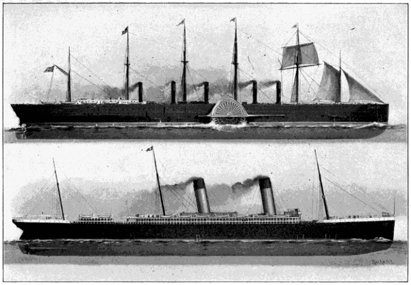
| FIG. 111.— | “GREAT EASTERN,” SCREW AND PADDLE WHEELS, 1858. LENGTH, 692 FEET, SPEED 12 KNOTS. | |
| “OCEANIC,” TWIN SCREW, 1899. LENGTH, 704 FEET, SPEED, 20 KNOTS. |
In 1854 the “Great Eastern” was begun and was finished in 1858. This
was the largest steam vessel ever built up to this time, and has continued to
hold the record for size up to the year 1899, when her dimensions were
exceeded by the “Oceanic,” which ships are put in comparison in Fig. 111.
The length of the “Great Eastern” was 692 feet, beam 83 feet, depth 57[139]
[140]1⁄2
feet, draft 251⁄2 feet, displacement 27,000 tons, and speed 12 knots. She
was designed by the English engineer Brunel, and was intended for the
Australian trade. She had both a screw propeller and paddle wheels at the
side, with four engines coupled to each. The paddle wheel engines had
steam cylinders 74 inches in diameter, with 14 foot stroke, and those of the
screw engines were 84 inches in diameter and 4 foot stroke. Collectively
they were of 10,000 horse power. The paddle wheels were 56 feet in
diameter, and the screw propeller 24 feet. On her first voyage to New
York, across the Atlantic, in 1860, she carried from 15 to 24 pounds of
steam and consumed 2,877 tons of coal. Her cost was $3,831,520. This
mammoth vessel was too large and unwieldy for the uses for which she
was designed, and proved a bad investment. She served, however, a most
useful purpose, by virtue of her great bulk, steadiness, and carrying capacity,
for relaying the Atlantic cable in 1866, and others in 1873-1874.
In 1874 the “Castalia” was built. This was a steamer with two parallel hulls, decked across, and designed for greater steadiness in crossing the English Channel. The “Bessemer” steamer, designed for the same purpose, and built about the same time, had four paddle wheels, and the entire cabin was hung on pivots, so that it could not partake of the sea motion.
In later years great improvements have been made in reducing the weight of the engines, in forced blast, steam steering gear, anchor hoisting devices, water-tight bulkheads, surface condensers, electric lights, and signalling devices. By the year 1880 the standard form of marine engine for large powers had become the compound double cylinder type, expanding steam from an initial pressure as high as 90 pounds. In 1890 triple expansion engines had become common, employing three cylinders, and using steam with an initial pressure as high as 180 pounds. In 1890 McDougal’s whale-back steamers were introduced. See United States patents No. 429,467 and 429,468, June 3, 1890, and No. 500,411, June 27, 1893.
In no country in the world are such fine examples of side wheel steamers
to be found as in the United States, and in no country are there such
splendid reaches of inland waters as theatres for their performances. The
“Priscilla,” shown in Fig. 112, of the Fall River Line, plying on Long
Island Sound, and the “Adirondack,” on the Hudson, are fine examples of
this type. The “Priscilla,” which is said to be the largest river boat in the
world, is 440 feet 6 inches long and 93 feet breadth over the guards. She
is driven by double compound inclined engines, has feathering paddle
wheels 35 feet in diameter and 14 feet face, and her speed is over 20 miles
an hour. The “Adirondack,” whose engines and feathering paddle wheel
are shown in Fig. 113, is 412 feet long and 90 feet breadth over guards.[143]
[144]
The engines and paddle wheels of the “Adirondack” are distinctly representative
of the modern American side wheel steamer.
The largest and in many respects the highest type of marine architecture is to be found in the modern ocean greyhound for transatlantic trade. In recent years the rival companies have vied with each other in the effort to excel, and steamships of larger size, greater speed, and more perfect equipment have followed each other, until it would seem that the limit had been reached. In the accompanying table the largest and most recent steamers are placed in comparison with the “Great Eastern.”
| DIMENSIONS OF THE LARGEST OCEAN STEAMERS. | ||||||||||||
|---|---|---|---|---|---|---|---|---|---|---|---|---|
| NAME OF SHIP. | DATE. | LENGTH OVER ALL. |
BEAM. | DEPTH. | DRAUGHT. | DIS- PLACE- MENT. |
MAXIMUM SPEED. |
|||||
| FEET. | FEET. | FEET. | FEET. | TONS. | KNOTS. | |||||||
| Great Eastern | 1858 | 692 | 83 | 57 | 1⁄2 | 25 | 1⁄2 | 27,000 | 12 | |||
| Paris | 1888 | 560 | 63 | 42 | 26 | 1⁄2 | 13,000 | 20 | ||||
| Teutonic | 1890 | 585 | 57 | 1⁄2 | 42 | 26 | 12,000 | 20 | ||||
| Campania | 1893 | 625 | 65 | 41 | 1⁄2 | 28 | 19,000 | 22 | ||||
| St. Paul | 1895 | 554 | 63 | 42 | 27 | 14,000 | 21 | |||||
| Kaiser Wilhelm der Grosse | 1897 | 649 | 66 | 43 | 29 | 20,000 | 22 | .35 | ||||
| Oceanic | 1899 | 704 | 68 | 49 | 32 | 1⁄2 | 28,500 | 20 | ||||
| Deutschland | 1900 | 686 | 1⁄2 | 67 | 1⁄3 | 44 | 29 | 22,000 | 23 | 1⁄2 | ||
The “Kaiser Wilhelm der Grosse,” owned by the North German Lloyd Company, and built in 1897, is shown in Fig. 114, and for three years held the record as the fastest steamship afloat. The “Kaiser Wilhelm” was followed by the “Oceanic,” in 1899, of the White Star Company, which is the largest ocean steamer ever built, exceeding the proportions of the “Great Eastern.” Just what the dimensions of the “Oceanic” mean, as given in the preceding tables, can be best illustrated by the accompanying Fig. 115, in which she is juxtaposed with several blocks of large buildings on Broadway, New York, opposite City Hall Park. If the “Oceanic” were placed on end beside Washington’s Monument, at the United States Capital, she would tower 150 feet above the top of the same. An ordinary brick house four rooms deep and three stories high could be built with its length crosswise[145] in her hull. There is accommodation for 410 first-class passengers, 300 second-class passengers, and 1,000 third class, and as her crew will number 390, the total number of souls on board, when she carries her full complement, will be 2,100.
The latest achievement in marine architecture, however, is the “Deutschland,” built for the Hamburg-American Company. The “Deutschland” is not quite so large as the “Oceanic,” but is of higher speed, her maximum speed of 231⁄2 knots an hour exceeding that of any other ocean steamer. The “Savannah,” the first steam vessel to cross the Atlantic, made the trip in 1819 in 26 days. The “Deutschland” in her eastward trip September 4, 1900, crossed the Atlantic in 5 days 7 hours and 38 minutes, which is the fastest time on record. The “Deutschland” is of 35,640 horse power, her two bronze propellers are 23 feet diameter, and weigh 30 tons, and her propeller shafts are 25 inches in diameter. The cranks of her propeller shafts, like those of the “Kaiser Wilhelm” and the “Oceanic,” are set according to the Schlick system, to reduce vibration. The “Deutschland’s” engines are seen in Fig. 92, and in general appearance the ship resembles the “Kaiser Wilhelm.” Still larger and possibly swifter steamships are in process of construction, viz.: the “Kaiser Wilhelm II.,” by the North German Lloyd Company, and a mammoth unnamed ship by the White Star Line, whose length of 750 feet will exceed all others.
It may be interesting to note in familiar terms what these enormous traveling palaces comprehend in equipment. For the safety and comfort of passengers, the great length reduces the pitching, bilge keels prevent rolling, and the Schlick system of cranks neutralizes vibration in the engine. Strong bulkheads, and double bottoms with air-tight compartments, impart buoyancy in case of collision. Boilers are placed in separate water-tight compartments, so that damage to one does not disable the others. Powerful pumps are arranged to discharge inflowing water, and the best of life boats are provided. Spacious dining rooms, promenade decks, drawing rooms, pianos, library, smoking room, state rooms, cabins for children, toilets, baths, medicine stores, a printing office, and electric lights everywhere, furnish every want and satisfy every luxurious taste. The cuisine includes a refrigerating plant, the finest ranges, and provisions galore. It may be interesting to the housewife to see the market list of a modern transatlantic steamer. A specimen is partially represented in the following: 25,450 pounds of fresh meat, 3,250 pounds of fish, 6,370 pounds of game and poultry, 12,715 pounds of bread, 43 barrels of flour, 3,938 pounds of butter, 1,307 pounds of coffee, 2,790 pounds of sugar, 102[146] pounds of tea, 7,220 pounds of fresh fruit; 1,230 gallons of milk, 26,106 eggs, 29,180 oranges and lemons, 7,033 bottles of mineral water, 1,800 bottles of beer, 2,688 gallons of beer in casks, 1,240 bottles of wine, 630 bottles of champagne, 1,600 heads of lettuce, 800 jars of preserved fruits, and other things in proportion.
In the matter of size the “Oceanic” surpasses all previous efforts in ship building, but ocean steamers do not reach the highest speed attainable. The little “Turbinia,” a 40 ton craft equipped with a compound rotary steam turbine of the Parsons type, has attained a speed of 323⁄4 knots an hour. An even greater speed has recently been attained by the larger boat, “Hai Lung,” constructed in England for the Chinese Government, which vessel was equipped with reciprocating engines, and is credited with having made a run of 181⁄2 knots at an average speed of 35 knots an hour. The highest speed ever attained, however, is by the British torpedo boat “Viper,” which is 210 feet long, and, like the “Turbinia,” is equipped with the Parsons steam turbines. In a recent trial the “Viper” covered a measured mile at the rate of 37.1 knots, or about 43 miles an hour.
In many respects the most important branch of steam navigation in recent years has been its war vessels. The great navies of the world at the end of 1898[3] ranked as follows: England, 1,557,522 tons; France, 731,629 tons; Russia, 453,899 tons; United States, 303,070 tons; Germany, 299,637 tons; Italy, 286,175 tons, and they all owe their efficiency entirely to steam. The first steam war vessel was built in 1814 by Fulton for the defence of New York Harbor, during the then existing war times. She was known as the “Demologos” (voice of the people), or “Fulton the First.” As shown in the original designs, Fig. 116, she is a double ender, whose sides were to be 5 feet thick. In her middle was a channel way or well containing a protected paddle wheel 16 feet in diameter, 14 feet wide, and having a dip of 4 feet. A single cylinder engine turned the paddle wheel on one side, and was balanced by the boiler on the other side. Although intended to have only twenty guns, she was equipped, when finished, with thirty long 32-pounder guns and two Columbiad 100-pounders. It was proposed also to have submarine guns suspended from each bow. An engine was also to be used to discharge hot water on the enemy, and a furnace was to be provided for heating the cannon balls red hot. She was 156 feet long, 20 feet deep, and 56 feet broad, and was regarded as a very formidable vessel. Her cost was $278,544. Iron-clad floating batteries were[147] first used in 1855 in the Crimean war, and shortly afterward the French built the first sea-going iron-clad, “Gloire,” followed in 1859 by the British iron-clad, “Warrior.”
[3] The figures represent a selective list which excludes about 15 per cent. of old and inefficient vessels.
The civil war in 1861 brought with it a novel and striking form of war vessel known as the “Monitor.”[4] It was built from plans of Capt. Ericsson,[148] an engineer of the ripest experience, skill, and attainments, who had then come to make his home in the United States. He undertook to construct for the Navy Department of the United States some form of iron clad steam batteries of light draft, suitable to navigate the rivers and harbors of the Confederate States. The “Monitor” was the result. The salient features, shown in vertical cross section in Fig. 117, are a low deck projecting but a few inches above the water line, so as to present as little target as possible to the enemy, and a revolving and heavily armored turret containing the battery of guns. In 1862 the Confederate forces had reconstructed a steam vessel with a chicken-coop-shaped covering of armor, that proved a formidable engine of war, which was practically invulnerable to the attacks of ordinary war vessels, and was doing great damage to the Union vessels. In the spring of 1862 the “Monitor” met the “Merrimac” in engagement in Hampton Roads, and established the great value of the turret monitor.
[4] The revolving turret was invented and patented by Theodore R. Timby, No. 35,846, July 8, 1862, and No. 36,593, September 30, 1862.
Vessels of the “Monitor” type still form useful parts of the United States Navy, in which the “Monterey” and “Monadnock” are its most representative types. The “Monadnock,” which is a double-turret coast defence monitor, is shown in Fig. 118. Although regarded by some as unseaworthy on account of the low seaboard and small buoyancy, the monitor has cleared itself of such suspicion, for in the recent war with Spain both the “Monadnock” and “Monterey” sailed across the Pacific Ocean by way of Honolulu to Manila, a distance of 7,000 miles, and joined the fleet of Admiral Dewey without mishap or delay.
No patriotic American citizen would expect to read an account of
modern war vessels without finding special mention of those two splendid[149]
[150]
types of their class, the battleship “Oregon” and the armored cruiser
“Brooklyn,” whose performances during the late war with Spain contributed
so much to the honor and glory of the United States Navy, and
demonstrated the skill and efficiency of our American shipbuilders. Before
the war began the “Oregon” was stationed on the Pacific Coast, where she
had been built, and it was desired that she should join the fleet of Admiral
Sampson in Cuban waters. Leaving Puget Sound on March 6, 1898, this
floating fortress of steel, weighted with her enormous guns and 18-inch
thick armor, made the long journey of over 14,500 miles around the
southern end of the western continent, and up to Jupiter Inlet on the
Florida coast, arriving there on the 24th day of May, and was not delayed
an hour on account of her machinery, the only stops being made for coal.
Immediately after coaling at Key West she took her place in the blockading
line at Santiago, and in the great battle of July 3 quickly developed a
power greater than that attained on her trial trip and a speed only slightly
less, easily distancing all other ships immediately engaged except the
“Brooklyn,” and in connection with the “Brooklyn” forced the fleetest of
the Spanish cruisers to surrender.
The “Oregon” is shown in Fig. 119. She is an armored battleship of the first class, built by the Union Iron Works of San Francisco, and launched Oct. 26, 1893. Her length is 348 feet, beam 691⁄4 feet, draft 24 feet, displacement 10,288 tons, maximum speed 16.79 knots, and coal capacity 1,594 tons. Her side armor is of steel plates 18 inches thick, and[151] her deck is, 23⁄4 inches thick. On the turrets the armor is from 6 to 15 inches thick, and on the barbettes it is from 6 to 17 inches thick. Her engines are of the twin screw, vertical triple expansion direct acting inverted cylinder type. The stroke is 42 inches, and the diameters of the cylinders are 341⁄2, 48, and 75 inches, respectively. The battery consists of four 13-inch breech loading rifles, eight 8-inch breech loading rifles, four 6-inch, twenty 6-pounder rapid fire guns, six 1-pounder rapid fire, two Colts, one 3-inch rapid fire field gun, and three torpedo tubes. The 13-inch guns weigh 136,000 pounds each, are 39 feet 91⁄4 inches long, are set 18 feet above the water, can be moved through an arc of 270 degrees, and throw a projectile of 1,100 pounds a distance of 12 miles, and with a power which at 1,000 yards would perforate a mass of steel 21⁄2 feet in thickness. The cost of the “Oregon” was $3,180,000.
The “Brooklyn” is shown in Fig. 120, and enjoys the distinction of having borne the brunt of the fight of July 3, 1898, having been hit over forty times in that engagement without being disabled. She was built by the William Cramp & Sons Ship and Engine Building Company, of Philadelphia, was launched Oct. 2, 1895, and cost $2,986,000. She is an armored cruiser, and is one of the latest and most speedy of that type. She is 400 feet 6 inches long, 64 feet 8 inches breadth, 24 feet draft, 9,215 tons displacement. Her engines are the twin-screw vertical triple expansion type, imparting a speed of 21.91 knots an hour. Her maximum indicated horse power is 18,769, and her coal capacity is 1,461 tons. Her battery consists of eight 8-inch breech loading rifles, twelve 5-inch rapid fire guns, twelve 6-pounder rapid fire, four 1-pounder rapid fire, four Colts, two 3-inch rapid fire field guns, and four Whitehead torpedo tubes. Her side[152] armor is 3 inches thick, her turrets 51⁄2 inches, her barbettes from 4 to 8 inches, and her deck from 3 to 6 inches. She also has a water line protection of cocoa fibre to automatically close up an opening made by a shot.
Although not a steam vessel, it would be regarded as an omission not to mention among war vessels the “Holland” submarine boat, brought into notice in 1898 by the Spanish American war, and designed to dive below the surface and make attack below the water level. Torpedo boats of this type have been acquired by, and now form a part of, the United States Navy.
Among all the types of steam war vessels which have claimed popular attention the most interesting in proportion to its size is the torpedo boat, for none represent such concentrated pent-up energy and deadly effect as this little demon of the sea. A mere shell in construction, with engine and boiler built for highest speed, and crew suffering untold discomforts and dangers below, this modern engine of destruction, with the speed of an express locomotive, and the helplessness and deadly intent of a scorpion, darts up to the monster battleship under cover of darkness, and before being discovered discharges a torpedo and delivers a mortal wound in the side of the big ship which sends her to the bottom, perishing perhaps itself in the destruction which it works. The United States has 37 of these torpedo boats. The torpedo boat destroyer is a larger and swifter boat, whose special duty it is to overtake and destroy this dangerous little fighter.
The growth of steam navigation during the present generation has been wonderfully rapid. The accompanying diagram, Fig. 121, from Mulhall’s “Industries and Wealth of Nations,” shows in 1860 30 per cent. of[153] steam to 70 per cent. of sailing vessels, while in 1894 the ratio is 80 per cent. of steam to 20 of sailing vessels. The same authority estimated the total horse power of steam vessels in the merchant marine of the world in 1895 to be 12,005,000. Add to this the growth of the past five years, and about 4,000,000 horse power for the steam war vessels of the world’s navies, which were not included, and the total horse power of the steam vessels of the world would not be far from twenty million.
This cursory review, in a single chapter, cannot adequately treat this great subject, for a whole library is needed to cover the field. Suffice it to say, however, that among the great scenes and acts in the theatre of human action, no figure has occupied so much attention, and none played so important a part in the drama of life, as the steam vessel. Its stage setting has been the majestic waters of the earth, and on it the play of the great warships has vied in power and grandeur with the flash and vehemence of the lightning, and the whirl and turmoil of the elements. Tense with a deep meaning which no stage simulation could approximate, and with the smoke of conflict for a drop curtain, it has laid tragedies upon the pages of history, and changed the maps of the world; while behind the scenes the great passenger steamers, with their uninterrupted traffic of human freight, are more silently, but none the less surely, stirring the peoples of the earth into the homogeneous ferment of civilization, and slowly moulding nations into the solidarity of a common brotherhood.
Early Printing Presses—Nicholson’s Rotary Press—The Columbian and Washington Presses—König Rotary Steam Press—The Hoe Type Revolving Machine—Color Printing—Stereotyping—Paper Making—Wood Pulp—The Linotype—Plate Printing—Lithography.
The art preservative of all arts it has been rightfully called. Before its birth generation after generation of the human family lived and died, and each was but little wiser, and but little better than its predecessor. Tradition was the misty, vague, and sometimes wholly false dependence of the living, and the experiences of mankind were, in the words of an eminent writer, but like the stern lights of a vessel, which only illumined the pathway over which each had passed. But printing gives to the present the cumulative wisdom of the past, and marks a great era of growth in civilization. It conserves and preserves man’s thoughts and makes them immortal, so that each generation comes into existence with a richer legacy of ideas, and is guaranteed a higher plane of existence, and a more exalted destiny.
Printing from letters engraved on blocks of wood is an ancient art, having had its origin in China many centuries before the Christian era. The Chinese method, which is still followed, was to write their characters with a brush on a sheet of paper, and while still wet, the piece of paper was laid face downward on a smooth piece of board to transfer the ink lines, and then all except the ink lines on the board was cut away. Thus they have one type plate for each book page. Printing with movable type, i. e., with a separate type for each letter, which may be repeatedly set up into forms of varying composition, is practically the beginning of the modern art of printing. This invention is usually ascribed to Johann Gutenberg, of Mentz, about 1436.
In the earliest printing presses the form was locked up in a tray, and
placed upon a platform, and the platen was then brought down upon it by
turning a screw in a cross bar above. The first printing press of this type
was made by Blaew, of Amsterdam, in 1620, which had a spring to cause
the screw to fly back after the impression was taken. The press upon which
Benjamin Franklin worked in London in 1725 is of this pattern, and is to[155]
[156]
be seen in the National Museum at Washington. It is almost entirely of
wood, and is shown in Fig. 122. About the beginning of the Nineteenth
Century Lord Stanhope invented a press entirely of cast iron, in which the
oscillating handle operated a toggle to force down the platen in taking the
impression. The bed traveled on guide ways, and the tympan and frisket
were hinged to fold back and lay in elevated position.
The “Columbian” press was the first important American improvement. It was invented by George Clymer, of Philadelphia, and is shown in his British Pat. No. 4,174 of 1817. A compound lever was employed for applying the power. The “Washington” press was patented in the United States by Samuel Rust, April 17, 1829. In this press (see Fig. 123) the platen is forced downwardly by a compound lever applied to a toggle joint and is raised by springs on each side. The bed is run in and out by turning a crank on a shaft which has a pulley and belt passing around it.
As so far described the presses were worked by hand power. An important
step in the advancement of this art was made by the introduction
of power presses worked by steam. These arranged the type on the surface
of a cylinder. Probably the earliest form of rotary cylinder press is
that invented by Nicholson, British Pat. No. 1,748 of 1790. Its main features
are described as follows: “The types, being rubbed or scraped narrower
toward the foot, were to be fixed radially upon a cylinder. This cylinder
with its type was to revolve in gear with another cylinder covered
with soft leather (the impression cylinder), and the type received its ink
from another cylinder, to which the inking apparatus was applied. The
paper was impressed by passing between the type and the impression cylinder.
”
The first practical success, however, in rotary steam presses was achieved by König, a German, who in 1814 set up for the London Times two machines, by which that newspaper was printed at the rate of 1,100 impressions per hour. He obtained British Pat. No. 3,321 of 1810, No. 3,496 of 1811, No. 3,725 of 1813, and No. 3,868 of 1814. König’s machine was in 1827 succeeded by that of Applegath and Cowper, which was simpler and more rapid.
Many improvements upon the methods for handling the paper were
subsequently devised, and double cylinder presses were made which were
able to print 4,000 sheets an hour. In 1845 the firm of R. Hoe & Co., which
had already been for years engaged in the manufacture of printing presses,
brought out the Hoe Type Revolving Machine. The first one of these was
placed in the office of the Philadelphia Ledger in 1846, and had four impression
cylinders, printing 8,000 papers per hour. The constantly increasing
circulation of newspapers, however, continued to make insatiable demands
for more rapid work, and to meet this demand the Hoe company in
1871 brought out their continuous web press, in which the paper was furnished
to the machine in the form of a roll, and after being printed was separated
into sheets. This principle of action gave promise of unlimited
speed, and required important reorganization in all parts of the machine.
To meet these conditions of increased speed more rapid drying ink had to
be produced to prevent blurring, paper of uniform quality and strength
had to be made, means had to be devised for printing the opposite side of
the web, and severing devices for cutting the web into sheets were needed,
but perhaps the most important feature was the device called a gathering
and delivering cylinder, whereby the papers could be gathered and disposed
of as fast as they could be printed, and much faster than human
hands could work. This was the invention of Stephen D. Tucker, and it is
the mechanism upon which the speed of the modern press depends, for it
would obviously be useless to print papers faster than they could be taken
from the machine in proper condition. Many patents were taken by
Messrs. Hoe & Tucker covering various improvements, prominent among
which were No. 18,640, Nov. 17, 1857; No. 25,199, Aug. 23, 1859 (re-issue
No. 4,429); No. 84,627, Dec. 1, 1868 (re-issue No. 4,400); No. 113,769,
April 18, 1871; No. 124,460, March 12, 1872; No. 131,217, Sept. 10, 1872.
The first rapid printing press of the Hoe Company was set up in the office
of the New York Tribune in 1871, and its maximum output was 18,000 an
hour. This marked the great era of rapid newspaper printing, and following
it many further improvements, such as devices for folding and counting
the papers automatically, have been added, until to-day the great Hoe[158]
[159]
Octuple Press, shown in Fig. 124, is the wonder of the Nineteenth Century.
It prints 96,000 papers of four, six, or eight pages in an hour, or at
the rate of 1,600 a minute, and these papers are not only printed, but in the
same operation and by the same machine are cut, pasted, folded, and
counted automatically. Fifty miles of paper of the width of an ordinary
newspaper pass through it each hour from its several rolls. The machine
weighs over 60 tons, and is composed of about 16,000 parts, and yet its
touch is so deft, and its members so delicately and accurately adjusted that
it does not tear the tender sheet as it flies through the machine—so fast
that one-fifth of a second only is required to print a page.
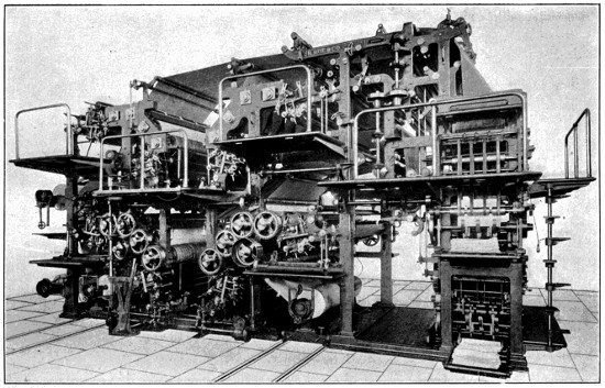
FIG. 124.—HOE OCTUPLE PRESS. PRINTS, CUTS, PASTES, FOLDS AND COUNTS NEWSPAPERS AT RATE OF 1,600 A MINUTE.
The latest development in the printing press has been in color printing, which has recently been introduced in the illustration of some of the largest daily newspapers. Such a press contains from 50,000 to 60,000 parts, and its cost is from $35,000 to $45,000.
Collateral with the development of the printing press are three important branches of the art—stereotyping, paper making, and type setting.
Stereotyping was the invention of William Ged, of Edinburgh, in 1731, and was introduced into the United States by David Bruce, of New York, in 1813. The stereotype is simply a moulded duplicate of the type face as set up, the duplicate being cast in the form of a single block of metal, by first taking an impression in plastic material from the faces of the type, after being set up, to form the mould, and then casting, in an easily fusible metal, an exact duplicate of this type face in this mould. This art prevents the wear on the movable type involved in printing, and also avoids the locking up into permanent forms of a large body of valuable type, since a form may be set up, stereotyped, and the type then distributed and set up into another form. Stereotyping, although used in book printing, was not thought practical for newspaper work until about 1861, because of the length of time required for the formation and drying of the mould and the casting of the plate; but about this time great expedition in the formation of the plate was attained by the employment of a steam bed to dry the mould, and a novel form of papier maché matrix, or mould, which could be conveniently disposed around the cylinders of type. The dampened and plastic papier maché sheets are beaten into the face of the type form by means of brushes, are then removed, dried, and used as moulds to cast the stereotype plate from. A stereotype plate can now be made in about seven minutes.
Paper Making is an important adjunct of the printing art, and its formation cheaply into long rolls of uniform strength is an essential condition of success in the rapid web-perfecting printing press. A Frenchman named Louis Robert about 1799 was the first to make a continuous web of paper,[160] and in 1800 he received from the French Government a reward of 8,000 francs for his discovery. His invention was subsequently taken up and carried to a success by the great English paper makers, the Fourdrinier Brothers, whose name has been given to the machine. In the Fourdrinier process rags are ground to a pulp by a revolving beater (Fig. 125) working in a tank of water. The pulp, duly beaten, refined, screened, and diluted with water, is then piped into the “flow-box” of the Fourdrinier machine. The “flow-box,” shown on right of Fig. 126, is a deep rectangular chamber extending across the full width of the machine, from which the pulp flows out in a thin stream onto an endless belt of 70-mesh wire cloth which runs over end rollers. To prevent the stream of pulp from flowing laterally over the edges of the belt, two endless rubber guides or bands, two inches square in cross section, travel with the belt over the first twenty feet of its length, and run over two pulleys above the wire cloth. The upper half of the wire cloth belt is supported by and runs over a series of closely juxtaposed rollers. As the pulp passes from the “flow-box” the particles of fibre float in it just as an innumerable multitude of particles of cotton fibre would float in a stream of water. To unite and interlace the fibres the wire cloth belt is given a lateral oscillating or shaking movement, which serves to interlock the fibres. Meanwhile the water strains through the wire cloth, leaving a thin layer of moist interlaced fibre spread in a white sheet over the surface of the belt. The separation of the water is further assisted by suction boxes which extend across close beneath the upper run of the belt and are connected to suction pumps.
The wire cloth with its layer of moist pulp now passes below a roll which compresses the fibre, and then leaving the machine seen in Fig. 126 it passes below a second and larger roll covered with felt, which presses out more of the water. The fibre next passes to the “first press,” where it is caught up on an endless belt and passed between two rollers where more[161] water is pressed out of the sheet. Then it passes through a “second press,” and finally the sheet commences a long journey up and down over a series of steam-heated drying rolls, by which the sheet is dried.
Wood-Pulp.—When a purchaser of one of the New York dailies reads the morning’s voluminous edition, he little realizes that he holds in his hands the remains of a billet of wood as large as a good-sized club, yet such is the case. Originally made from the fibres of the papyrus plant, and later from rags beaten into a pulp, paper for the printing of books and newspapers is now made almost entirely of wood. In the formation of paper pulp from wood two processes are employed, one known as the soda process, and the other the sulphite process. In both cases the wood is cut into fine chips, and then digested in great drums with chemicals to extract the resinous matter and leave the pure fibrous cellulose, which resembles raw cotton in texture. This industry was developed by Watt and Burgess in 1853 (U. S. Pat. No. 11,343, July 18, 1854), who invented the soda process; by Voelter (U. S. Pat. No. 21,161, Aug. 10, 1858), who devised means for comminuting or shredding the wood; and by Tilghman (U. S. Pat. No. 70,485, Nov. 5, 1867), who invented the sulphite process.
The logs, usually of spruce or poplar,
are first split, as seen at the bottom
of Fig. 127, then placed in the chipper,
where a revolving disc with knives cuts
them into small chips, which are fed to
an elevator and raised to a screening[162]
device, seen at the top, to remove saw-dust, dirt and knots. In the
sulphite process the chips are then delivered into the digesters shown[163]
[164]
in Fig. 128, which are supplied with sulphurous acid generated in a plant
shown in Fig. 129. In the digesters the gummy and resinous matters are
dissolved by the heat and chemicals, and the woolly fibre left behind is
bleached, washed, and dried, and afterwards made into paper upon the
Fourdrinier machine.
It was stated by the Paper Trade Journal in 1897 that the increase in paper making in the United States during the 15 years preceding amounted to 352 per cent., due chiefly to the growth of the wood pulp industry. The Androscoggin Pulp Mill, established in Maine in 1870, was one of the pioneers in this field. In that State the industry had grown in 1897 to over $13,000,000 and gave employment to more than 5,000 men, but the State of Maine is excelled by both New York and Wisconsin in this industry, for in the same year New York mills had a daily capacity of 1,800,000 pounds; Wisconsin, 670,000; Maine, 665,000, and other States a less capacity. There are over 1,000 paper mills in the United States, and their combined daily capacity amounts to over 13,000 tons. In 1898 the United States exported over five million dollars’ worth of paper, and over fifty million pounds of wood pulp. Of the total amount of paper produced in the world Mulhall estimated it in 1890 to be 2,620,000,000 tons annually. This amount is greatly increased at the present time, and by far the larger part of it is manufactured from wood.
In 1891 the Philadelphia Record in an experimental test as to speed, cut trees from the forest, converted them into paper, and then into printed newspapers, all within the space of 22 hours. At a later period in Germany, where the wood pulp art began, even this expeditious work has been excelled. The trees were felled in the morning at 7:35, converted into paper, and presented at 10 A. M. in the form of printed newspapers, with a record of the news of the forenoon. The great naval edition of the Scientific American of April 30, 1898, consumed a hundred tons of wood pulp paper, and was therefore built upon a material foundation of 125 cords of wood, which cleared off over six acres of well-set spruce timber land. It is mainly wood pulp that has enabled books and newspapers to be made so cheaply, for they are now furnished at a less price than the cost of the paper made in the old way from rags.
The Linotype.—The most revolutionary and perhaps the most important development in the printing art of this century has been the linotype machine. The laborious, painstaking, and expensive feature of printing has always been the setting and redistribution of the types, since each little piece had to be separately selected and placed in the composing stick, and the line afterwards “justified,” which means an apportionment of the space between the words so as to make each line of type about the same length in the column. The same separate handling of each piece was again involved in restoring the type to the case. Machines for thus setting and distributing the type had been devised, but the operation was so involved, and required so nearly the discretion of the thinking mind, that[166] all automatic machinery proved too complicated and impracticable. In 1886, however, a machine was placed in the office of the New York Tribune whose performances astonished and alarmed the old-time compositor. It rendered it unnecessary to handle the type, or even to have any separate[167] type at all. It was the Mergenthaler Linotype machine, which automatically formed its own type by casting a whole line of it at a time. The first machine was invented in 1884, and patented in 1885, but it was subsequently reorganized and greatly improved in Pats. No. 425,140, April 8, 1890; Nos. 436,531 and 436,532, Sept. 16, 1890, and No. 438,354, Oct. 14, 1890. It is shown in the accompanying illustration (Fig. 130). By manipulating the keyboard, which resembles that of a typewriter, each lettered key is made to bring down from an inclined elevated magazine a little brass plate of the shape shown in Fig. 131, and which plate is called a matrix, because it bears on its edge at x a mould of the type letter. There is a matrix plate for every letter and character used. These little matrices are spaced by wedges, as seen in Fig. 132, and are assembled, as in Fig. 133, along the side of a mould wheel having a slot in it which forms a channel between the aligned type-moulds or matrices on one side and the discharge mouth of a melting pot, in which molten type metal is maintained in a fluid state by a subjacent gas-burner. In the melting pot there is a cylinder and plunger, and when the plunger descends, it forces the molten metal up through the discharge spout into the slot of the mould wheel, and against the letter mould x of each one of the composed or aligned matrices. The wheel is then turned with the matrices, and the metal in its slot is afterwards discharged in the form of a linotype slug, seen in Fig. 134, which is a metal plate bearing[168] on its edge a completely moulded line of type ready for setting up in the form for printing. The jagged notches in the tops of the matrices (Fig. 131) are for co-operation with a distributer bar (not easily explained) for restoring the matrices to their appropriate magazines after being used. There are altogether about 1,500 of the little brass matrices. The machine is about five feet square, weighs 1,750 pounds, and costs $3,000 each. Notwithstanding this expense these Linotype machines have to-day made their way into nearly all the daily newspaper offices of the civilized world, even to Australia and the Hawaiian Islands. In the composing rooms of the daily newspapers and the larger book printing offices we find great rows of these Linotype machines, each doing the work of from four to five men. There are now in use in America something over 5,000 Linotype machines; and in other countries about 2,000, making 7,000 in all. Each machine may be adjusted in five minutes to produce any size or style of type, and it gives new, clean faces for each day’s issue, with none of the ordinary troubles of distributing type. The cheapness of composition, due to the machine, has led to an enormous increase in the size of papers, in[169] the frequency of the editions, and has correspondingly increased the demand for labor in all the attendant lines, such as paper-making, press-making, the attendants on presses, stereotyping, etc. In the Boston Library, which keeps its catalogues printed up to within 24 hours of date, the Linotypes print in 23 languages.
When the Linotype machine was first patented it was not regarded by printers generally as a practical machine, but only one of the many complicated, theoretical, but impracticable organizations which the Patent Office has to deal with. Its history, however, has been unique. It is practically the product of the brain of a single man, Ottmar Mergenthaler, a most ingenious and indefatigable inventor living in Baltimore. It was exploited under the powerful patronage of a syndicate of newspaper men, and hundreds of thousands of dollars were spent in perfecting it before any practical results were obtained. To-day it stands a triumph of human ingenuity, ranking in importance with the rotary web-perfecting press, and is probably the most ingenious piece of practical mechanism in existence.
Of the three forms of printing attention has been given thus far only to the leading branch of the art, which is type printing, or “letter press,” as it is called, in which the characters are raised in relief and receive ink on their raised surfaces only. A second branch of the art is plate printing, in which the lines and characters are engraved in intaglio in a plate, and which, being covered with ink, and the surface of the plate wiped clean, leaves the ink in the undercuts, which is taken up by the paper when pressure is applied through a roller. Plate printing is a very old art, the plate printing press having been ascribed to Tomasso Finiguerra, of Florence, in 1460. The reciprocating table bearing the engraved plate, and the superposed pressure roller turned by hand through its long radial arms, is an ancient and familiar form of press which has been in use for many years. This method of printing finds application in fine line engraving in works of art, card invitations, and bank note engraving. Very ingenious automatic machines have been invented and were in use a few years ago by the United States Government for printing its bank notes, but have since been displaced by the old hand machines. To the credit of the machine, it should be said, that it was from no fault in the machine that this retrograde step was taken, but rather the disfavor of the labor organizations.
Lithography is another and quite important branch of the printing art, in which the lines and characters are drawn upon stone with a kind of oily ink to which printers’ ink will adhere, while it is repelled from the other moistened surfaces of the stone. Lithography was invented in 1798 by Alois Senefelder, of Munich. It finds its greatest application in artistic and fanciful work in inks of various colors, and its development into chromo-lithography in the Nineteenth Century has grown into a fine art. Our beautifully colored chromos, prints, labels, maps, etc., are made by this process. A more recent and quite important development of this art is photo-lithography, which will be more fully considered under photography.
Many collateral branches of the printing art are interesting in their development, such as calico printing, the printing of wall papers, of oil cloth, printing for the blind, book binding, type founding, and folding and addressing machines, but lack of space forbids more than a casual mention.
Printing is perhaps the greatest of all the arts of civilization, and the libraries and newspapers of the Nineteenth Century attest its value. If Benjamin Franklin could wake from his long sleep and enter the composing rooms of our great dailies, and witness the imposing array of linotype machines, more resembling a machine shop than a printing office, and then visit the press room and see the avalanche of finished papers flying at the rate of 1,600 a minute, neatly folded, and counted for delivery, he would doubtless be overwhelmed with emotions of wonder and incredulity, for broad-minded man as he was, he could have no conception of such progress.
Old English Typewriter of 1714—The Burt Typewriter of 1829—Progin’s French Machine of 1833—Thurber’s Printing Machine of 1843—The Beach Typewriter—The Sholes Typewriter, the First of the Modern Form, Commercially Developed Into the Remington—The Caligraph—Smith-Premier—The Book Typewriter and Others.
Occupying an intermediate place between the old-fashioned scribe and the printer, the typewriter has in the latter part of the Nineteenth Century established a distinct and important avocation, and has become a necessary factor in modern business life. Chirography, or hand writing, reflecting, as it did, the idiosyncrasies of each writer, was not only slow, but when employed was, in most cases, in the haste and press of active business reduced to an illegible scrawl. For the use of reporters and others requiring extra speed, stenography, or short hand, was resorted to, but there was a distinct need for some easy, quick, legible, and uniform record of the busy man’s correspondence and copy work, and this the modern typewriter has supplied.
Like most other important inventions, the typewriter did not spring into existence all at once, for while the practical embodiment in really useful machines has only taken place since about 1868, there had been many experiments and some success attained at a much earlier date. The British patent to Henry Mills. No. 395 of 1714, is the earliest record of efforts in this direction. At this early date no drawings were attached to patents, and the specification dwells more on the function of the machine than the instrumentalities employed. No record of the construction of this machine remains in existence, and it may fairly be considered a lost art. In quaint and old-fashioned English, the patent specification proceeds as follows:
“ANNE, by the grace of God, &c., to all whom these presents shall
come, greeting: WHEREAS, our trusty and well-beloved subject, Henry
Mills, hath by his humble peticon represented vnto vs, that he has by his
greate study, paines, and expence, lately invented, and brought to perfection
“An Artificial Machine or Method for the Impressing or Transcribing
Letters Singly or Progressively one after another as in Writing[172],
whereby all Writing whatever may be Engrossed in Paper or Parchment
so Neat and Exact as not to be Distinguished from Print, that the said
Machine or Method, may be of greate vse in Settlements and Publick
Recors, the Impression being deeper and more Lasting that any other
Writing, and not to be erased, or Counterfeited without Manifest Discovery,
and having therefore humbly prayed vs to grant him our Royall Letters
Patents, for the sole vse of his said Invention for the term of fourteen
yeares.”
“Know Yee, that wee,” etc.
The first American typewriter of which any record remains is that described in the patent granted to W. A. Burt, July 23, 1829. It was called a “Typographer.” It had a segment bearing the letters of the alphabet and corresponding notches acting as an index. A superposed lever, which could be worked up and down, and also moved laterally, was provided with a series of type, arranged in a segmental curve, so that any type could be brought into place on the subjacent paper by swinging the lever over to and down into the proper notch in the index segment below. A restored model of this is to be found in the U. S. Patent Office.
The first organized typewriter in which separate key levers were provided for each type is a French invention. It is to be found in the French patent to M. Progin (Xavier), of Marseilles, No. 3,748, Sept. 6, 1833 (Brevets d’Invention, Vol. 37, 1st Series, pl. 36). It was called a Typographic Machine, and is shown in the illustration (Fig. 135). Upright key levers s are arranged in a circle around a circular plate n. They have[173] hook-shaped handles at the upper end, and terminate below in forks that are pivoted to the shanks of type hammers, to raise and lower them. These hammers are inked from a pad, and at a central point deliver a printing blow on the paper below. The paper is held stationary, and the whole nest of levers was moved over the paper for each letter printed. The circular index plate n had marked on it opposite the respective levers the letters and characters represented by said levers. Besides printing letters, the device was to be used for printing music, and for making stereotype plates.
On Aug. 26, 1843, Charles Thurber, of Worcester, Mass., took out Pat. No. 3,228 for a Printing Machine. Under the patent he constructed the machine shown in Fig. 136. This differed somewhat from the form shown in his patent, in that the machine shows a paper feed roller which does not appear in the patent. This machine was found among the effects of Mr. Thurber after having lain neglected and unnoticed for many years, and its damaged parts were restored by Mr. H. R. Cummings, of Worcester. The types are carried on the lower ends of a circular series of depressible bars, which are spring seated in a horizontal rotatable wheel. By turning the wheel any type can be brought to the front, and a stationary guide controls its descent as it makes the impression. An inking roller is seen on the right, which inks the faces of the type. In front of the type wheel[174] is a horizontal roller to which the sheet of paper is attached by clips. Finger pawls, working into ratchets at the ends of the roller, serve to rotate it after each line is printed. By means of a handle, seen projecting from the right hand side of the frame, the roller is shifted longitudinally on its axis rod after each letter has been printed. This appears to be the first embodiment of the feed roller rotating to bring a new line into range, and having also a longitudinal feed, but as these movements were required to be separately executed by the operator, the work of the machine was necessarily very slow. Just at what time this old Thurber machine was constructed it is impossible to state in the light of present information, but as the feed roller did not appear in Thurber’s patent of 1843, it is possible that the claim to authorship of the feed roller having both a rotary and a longitudinal movement may be maintained in behalf of J. Jones, whose Pat. No. 8,980 of June 1, 1852, appears to be the first dated record of such a feed roller. Jones was also the first to provide a spring to automatically retract the paper carriage to the position for beginning a new line, the spring being put under tension by the movement of the paper carriage in printing.
Prominent among those whose genius has served to perfect the typewriter occurs the name of A. E. Beach, for many years of the firm of Munn & Co., and well known to the readers of the Scientific American. Mr. Beach’s first model of a typewriter was made in 1847. It printed upon a sheet of paper supported on a roller, carried in a sliding frame worked by a ratchet and pawl. It had a weight for running the frame, letter and line spacing keys, paper feeding devices, line signal bell, and carbon tissue. It had a series of finger keys connected with printing levers which were arranged in a circle, and struck at a common center. This machine was said to have worked well, but was laid aside for further improvement. In the meantime he constructed a typewriter to print in raised letters, without ink. This machine, which was intended primarily for the use of the blind, is illustrated in Figs. 137 and 138. It was first publicly exhibited in operation at the Crystal Palace Exhibition of the American Institute in the fall of 1856, where it attracted great attention and took the gold medal. The embossed letters were printed on a ribbon of paper which ran centrally through the machine. The printing levers were arranged in a circle in pairs, one riding on the top of the other. When the operator pressed a key, the two printing levers of each pair answering to the letter key were brought together, the paper being between them. The printing type were at the extremities of the levers, one lever having a raised letter, and its mate a sunken or intaglio letter, which, seizing the paper strip between them, like the jaws of a pair of pincers, impressed therein an embossed let[175]ter. The patent for this machine was granted June 24, 1856, No. 15,164, but the machine showed a much higher degree of development than appeared in the patent. This machine was the earliest representative of the circular basket of radially swinging type levers, combined with finger keys assembled in a keyboard at one side, which is now an almost universal feature, and the suggestion which it handed down to subsequent inventors has doubtless done much to make the typewriter the practical machine that it is to-day.
Up to the year 1868, however, typewriting machines were mere illustrations of sporadic genius occuring here and there as the pet hobby of some[176] humanitarian seeking to help the blind, or supplement the deficiencies of the tremulous fingers of the paralytic. It had not yet come to be regarded as of any special use, nor had even the demand for such a device been forcibly felt, until the last quarter of the Nineteenth Century began to accumulate its wonderful momentum of progress and prosperity. The man whose genius finally brought forth a practical typewriter, and made a permanent place for it in the daily business of the world, was C. Latham Sholes. As joint inventor with C. Glidden and S. W. Soule, all of Milwaukee, he took out patents No. 79,265, of June 23, 1868, and No. 79,868, of July 14, 1868. These, together with Sholes’ Pat. No. 118,491, of Aug. 29, 1871, formed the working basis of the first typewriters that went into office use. These typewriters were first introduced to the general public under the management of the original inventors (Sholes, Soule and Glidden) about 1873, and at first used only capital letters. On Aug. 27, 1878, a further patent. No. 207,559, was granted to Sholes, and about this time, after five years of uncertain and precarious business existence, the machine was taken for manufacture to E. Remington & Sons, at Ilion, N. Y. Since this time the well-known “Remington” has built up for itself a reputation and a commercial importance that has given it first place among typewriters. In the nine years from 1873 to 1882, it is said that less than 8,000 machines had been manufactured. In the year 1882 Wyckoff, Seamans & Benedict obtained control of the machine, and during the fourteen years following it is said that nearly 200,000 “Remingtons” were made and sold.[177] It is said that 1,000 men are now employed in making this machine, and that the present output is about 800 machines a week, despite the fact that it has a half dozen worthy competitors for public favor. The modern Remington, seen in Fig. 139, is too well known to require special description. Besides the Sholes patents, it embodies the improvements covered by patents to Clough & Jenne, No. 199,263, Jan. 15, 1878; Jenne, No. 478,964, July 12, 1892, and No. 548,553, Oct. 22, 1895, and also a patent to Brooks, No. 202,923, April 30, 1878, a characteristic feature of which latter is the location of both a capital and small letter on the same striking lever, and the shifting of the paper roller by a key to bring either the large or small letter into printing range.
The earliest rival of the Remington was the Caligraph, made by the American Writing Machine Co. This well-known machine, introduced in the decade of the eighties, was made under the patents of G. Y. N. Yost, March 18, 1884, No. 295,469; March 17, 1885, No. 313,973; and July 30, 1889, No. 408,061. The most modern form of the Caligraph is known as the “New Century,” which is shown in the accompanying illustration, Fig. 140. The Caligraph uses a separate type lever and key for each letter, and by a system of compound key levers the touch is rendered easy, even, and elastic, and perfect alignment and freedom from noise are among the objects sought in its mechanical construction.
Next among the earlier typewriters is to be mentioned the “Hammond,” made under the patents to J. B. Hammond, No. 224,088, Feb. 8, 1880, and 290,419, Dec. 18, 1883. A distinguishing feature of the machine is that the printed work is in full view, so that the operator can see what he is doing. The impression is made by an oscillating type wheel, to which a variable throw is imparted by the key letters to bring any desired letter into printing position. When the letter is brought into printing position a hammer, arranged in the rear of the sheet of paper, is made to force the latter against the type to produce the impression by the same movement of the key that brought the type wheel into printing position.
Of later machines, none has met with more popular favor than the Smith-Premier, manufactured under the patent to A. T. Brown, No. 465,451, Dec. 22, 1891, and others. A leading feature of this is the type-bar[179] ring of its printing mechanism. In all typewriters accurate location of the impression is essential to proper alignment of the letters, and proper alignment is the sine qua non of typewriting. The old pivoted type bars were liable to wear at the joint, and the slightest looseness at this point would so multiply the lateral play at the end carrying the type that the letters would soon become irregularly placed and out of alignment. In the Smith-Premier this is reduced to a minimum by making a short type bar, and arranging[180] each upon an oscillating rock shaft, the bearings at whose ends are so widely separated as to permit little or no lateral play in the type bar. A view of this type bar ring with tangentially arranged rock shafts disposed in circular series is seen in Fig. 141, while the full machine is given in Fig. 142. In this latter view there is also shown the cleaning brush for quickly cleaning at one operation all of the types of the outer ring. It is simply a circular brush mounted upon the end of a tool resembling a carpenter’s brace, and is a useful and convenient adjunct to the machine.
In 1891 the “Densmore” typewriter first made its appearance before the public. It was named after James and Amos Densmore, who had been connected with typewriting interests from the time of Sholes’ first practical machine. The Densmore is made under patents to A. Densmore, No. 507,726 and 507,727, of Oct. 31, 1893. It has ball-bearing type bar joints, giving accurate alignment and light key action, the platen rolls to show the work, and the carriage locks at the end of the line, protecting the writing.
Noted for its clear, sharp print, the “Yost” typewriter comes in for its share of praise. It is made under the patent to Felbel and Steiger, March 26, 1889, No. 400,200. It does not employ an inked ribbon interposed between the type and the paper, as do most typewriters, but its type-bearing levers, when at rest, occupy a position in which the type are all arranged within and bear against a circular inking ring or pad, and when a key is struck, its lever, by a peculiar and ingenious movement, leaves the inking pad, moves inward and backward toward the center, and then rises and strikes an upwardly directed blow in the center, and prints the letter on the paper. As the printing is done directly from the type, the letters are formed with sharp and clear outlines that give beauty and neatness to the print. Alignment is insured by a center guide hole through which the type end of the lever passes in striking the paper.
Among machines of simple organization may be mentioned the Blickensderfer, which is a wonderfully simple and effective little machine, first made under the patent to Blickensderfer, No. 472,692, April 12, 1892. Like the Hammond, it belongs to the class of typewriters which employ a rotary type wheel, which is given a variable throw, from the depression of the keys, to bring the proper letter into printing position; but unlike the Hammond, its type wheel advances to contact with the paper, a little felt ink-roller being brought into contact with the type wheel to ink it as the latter moves. The printed work is in full view, the line spacing may be varied to any fractional adjustment, and the action is quite free from noise. With its mechanism reduced to the fewest and simplest parts, the whole machine weighs only six pounds, and it differs in many respects from the ordinary[181] typewriter. Since its introduction a few years ago, its growth in popularity has been very rapid.
Another recently appearing machine is the “Oliver.” This has type bars which are normally above the work. Each bar is loop shaped, hinged at its lower ends, and bearing the type letter on the bend at the upper end. They are arranged in two series, one on each side of the center, and in printing each loop swings down like the wing of a bird. As the printing is from the top, and the ribbon is moved away from in front of the line immediately after the printing blow, the writing is always visible to the operator. This machine is manufactured under various patents to Thomas Oliver, the first of which was No. 450,107, granted April 7, 1891. Further improvements are covered by subsequent patents, Nos. 528,484, 542,275, 562,337, and 599,863. The Oliver has made many friends for itself by its fine alignment and visible writing, and shares with the other standard machines a considerable patronage.
It is not practicable to give a full illustration of the state of the art in typewriters, as it has grown to an industry of large proportions. Nearly 1,700 patents have been granted for such machines, and more than 100 useful and meritorious machines have been devised and put upon the market. Among these may be mentioned the Hall, Underwood, Manhattan, Williams, Jewett, and many others.
Besides the regular typewriters, various modifications have been made to suit special kinds of work. The “Comptometer” used in banks is a species of typewriter, as is also the Dudley adding and subtracting machine, known as the “Numerograph,” and covered by patents Nos. 554,993, 555,038, 555,039, 579,047 and 579,048. Typewriters for short hand characters, and for foreign languages, and for printing on record and blank books, are also among the modern developments of this art. In the latter the whole[182] carriage and system of type levers move over the book. The Elliott & Hatch book typewriter, Fig. 143, is a well-known example. In attachments, holders for the copy have received considerable attention, and simple and practical billing and tabulating attachments have been devised which expedite and facilitate the statements of accounts and other work requiring numeration in columns. The Gorin Tabulator is one of those in practical use.
In point of speed the typewriter depends entirely upon the aptness of the operator. For ordinary copying work, where much time is occupied in deciphering the illegible scrawl, probably forty words a minute is the average work. When taken from dictation, seventy-five words a minute may be written, and in special cases, when copying from memory, a speed of 150 words a minute has been maintained for a limited time. It was estimated that there were in use in the United States in 1896 150,000 typewriters, and that up to that time 450,000 had been made altogether. In the last four years this number has been greatly increased, and a fair estimate of the present output in the United States is between 75,000 and 100,000 yearly. In 1898 there were exported from the United States typewriting machines to the value of $1,902,153.
The typewriter has not only revolutionized modern business methods, by furnishing a quick and legible copy that may be rapidly taken from dictation, and also at the same time a duplicate carbon copy for the use of the writer, but it has established a distinct avocation especially adapted to the deftness and skill of women, who as bread winners at the end of the Nineteenth Century are working out a destiny and place in the business activities of life unthought of a hundred years ago. The typewriter saves time, labor, postage and paper; it reduces the liability to mistakes, brings system into official correspondence, and delights the heart of the printer. It furnishes profitable amusement to the young, and satisfactory aid to the nervous and paralytic. All over the world it has already traveled—from the counting house of the merchant to the Imperial Courts of Europe, from the home of the new woman in the Western Hemisphere to the harem of the East—everywhere its familiar click is to be heard, faithfully translating thought into all languages, and for all peoples.
Embroidering Machine, the Forerunner of the Sewing Machine—Sewing Machine of Thomas Saint—The Thimonnier Wooden Machine—Greenough’s Double Pointed Needle—Bean’s Stationary Needle—The Howe Sewing Machine—Bachelder’s Continuous Feed—Improvements of Singer—Wilson’s Rotary Hook and Four-Motion Feed—The McKay Shoe Sewing Machine—Buttonhole Machines—Carpet Sewing Machine—Statistics.
In 1844 Thomas Hood wrote and published his famous “Song of the Shirt,” in which the drudgery of the needle is portrayed with pathetic fidelity. It is not to be supposed that any relation of cause and effect exists between the events, but it is nevertheless a singular fact that about this time Howe commenced work on his great invention, which was patented in 1846, and was the prototype of the modern sewing machine. If the sewing machine had appeared a few years earlier, the “Song of the Shirt” would doubtless never have been written.
From the time of Mother Eve, who crudely stitched together her fig leaves, sewing seems to have been set apart as an occupation peculiarly belonging to women, and it may be that this was the reason why in the history of mechanical progress the sewing machine was so late appearing, for women are not, as a rule, inventors, and none of the sewing machines were invented by women.
In all the preceding centuries of civilization hand sewing was exclusively employed, and it was reserved for the Nineteenth Century to relieve women from the drudgery which for so many centuries had enslaved them.
Embroidery machines had been patented in England by Weisenthal in 1755, and Alsop in 1770, and on July 17, 1790, an English patent, No. 1,764, was granted to Thomas Saint for a crude form of sewing machine, having a horizontal arm and vertical needle. In 1826 a patent was granted in the United States to one Lye for a sewing machine, but no records of the same remain, as all were burned in the fire of 1836. In 1830 B. Thimonnier patented a sewing machine in France, 80 of which, made of wood, were in use in 1841 for sewing army clothing, but they were destroyed by a mob, as many other labor-saving inventions had been before. Between 1832 and 1835 Walter Hunt, of New York, made a lock-stitch sewing machine, but abandoned it. On Feb. 21, 1842, U. S. Pat. No. 2,466 was granted to J. J. Greenough for a sewing machine having a double pointed needle with an eye in the middle, which needle was drawn through the work by pairs of traveling pincers. It was designed for sewing leather, and an awl pierced the hole in advance of the needle. On March 4, 1843, U. S. Pat. No. 2,982 was granted to B. W. Bean for a sewing machine in which the needle was stationary, and the cloth was gathered in crimps or folds and forced over the stationary needle. In 1844, British Pat. No. 10,424 was granted to Fisher and Gibbons for working ornamental designs by machinery, in which two threads were looped together, one passing through the fabric, and the other looping with it on the surface without passing through.
The great epoch of the sewing machine, however, begins with Elias Howe and the sewing machine patented by him Sept. 10, 1846, No. 4,750. Almost everyone is familiar with the modern Howe sewing machine, and it will be therefore more interesting to present the form in which it originally appeared. This is shown in Fig. 144. A curved eye-pointed needle was carried at the end of a pendent vibrating lever, which had a motion simulating that of a pick-ax in the hands of a workman. The needle took its thread from a spool situated above the lever, and the tension on the thread was produced by a spring brake whose semicircular end bore upon the spool, the pressure being regulated by a vertical thumb screw. The work was held in a vertical plane by means of a horizontal row of pins projecting from the edge of a thin metal “baster plate,” to which an intermittent motion was given by the teeth of a pinion. Above, and to one side of the “baster plate” was the shuttle race, through which the shuttle carrying the second thread was driven by two strikers, which were operated by two arms and cams located on the horizontal main shaft. As will be seen, this machine bears but little resemblance to any of the modern machines, but it embodied the three essential features which characterize most all practical machines, viz.: a grooved needle with the eye at the point, a shuttle[185] operating on the opposite side of the cloth from the needle to form a lock stitch, and an automatic feed.
Howe first commenced his work on the sewing machine in 1844, and although he had made a rough model of that date, he was too poor to follow it up with more practical results until a former schoolmate, George Fisher, provided $500 to build a machine and support his family while it was being constructed, in consideration of which Mr. Fisher was to receive a half interest in the invention. In April, 1845, the machine was completed, and in July he sewed two suits of clothes on it, one for Mr. Fisher[186] and the other for himself. Notwithstanding the success of his machine, which on public exhibition beat five of the swiftest hand sewers, he met only discouragement and disappointment. He, however, built a second machine, which was the basis of his patent, and is the one shown in the illustration. After obtaining his United States patent Howe went to England with the hope of introducing his machine there, but, failing, he returned to America, some years later, only to find that his invention had been taken up by infringers, and that sewing machines embodying his invention were being built and sold. These infringers sought to break his patent by endeavoring to prove, but without success, that Howe’s invention was anticipated by the abandoned experiments of Walter Hunt in 1834. Howe won his suit, and the infringers were obliged to pay him royalties, which, for a time, amounted to $25 on each machine. Howe then bought the outstanding interest in his patent, established a factory in New York, and from the profits of his manufacture, and the royalties, he soon reaped a princely fortune of several million dollars. In six years his royalties had grown from $300 to $200,000 a year, and in 1863 his royalties were estimated at $4,000 a day.
A patent that occupied an important place in sewing machine feeds was that granted to Bachelder May 8, 1849, No. 6,439, in which a spiked and endless belt passed horizontally around two pulleys. This patent contained the first continuous feed, and it was re-issued and extended, and ran with dominating claims on the continuous feed, until 1877.
In connection with the development of the sewing machine the name of A. B. Wilson stands next in rank to that of Howe. Wilson invented the rotary hook carrying a bobbin, which took the place of the reciprocating shuttle. This was patented by him June 15, 1852, No. 9,041, and is shown in Fig. 145. He also invented the far more important improvement of the four-motion feed, which is a characteristic feature of nearly all practical family sewing machines. This four-motion feed was pooled in the early sewing machine combination with the Bachelder and other patents, and earned for its promotors a far greater pecuniary return than the original Howe sewing machine itself. Estimates place this profit high in the millions. The four-motion feed was patented December 19, 1854, No. 12,116, and it is a comparatively simple affair. Divested of its operating mechanism, it consists simply of a little metal bar serrated with forwardly projecting saw teeth on its upper surface, to which bar, by means of an operating cam, a motion in four directions in the path of a rectangle is given. The serrated bar first rises through a slot in the table, then moves horizontally to advance the cloth, then drops below the table, and finally moves back again horizontally below the table to its starting point.
Upon these two important features—the rotating hook patented by Wilson in 1852, and the four-motion feed, patented in 1854—a large and important business was built. In this business Mr. Nathaniel Wheeler was associated with Mr. Wilson, and the well-known Wheeler & Wilson machines are the result of their enterprise and ingenuity.
Contemporaneous with the Wheeler & Wilson machine were other excellent machines, among which may be mentioned the Singer machine, patented Aug. 12, 1851, No. 8,294, by Isaac M. Singer, the original model of which is shown in Fig. 146. The Singer machine met the demands of the tailoring and leather industries for a heavier and more powerful ma[188]chine. A characteristic feature was the vertical standard with horizontal arm above the work table, which was afterwards adopted in many other machines. Singer was the first to apply the treadle to the sewing machine for actuating it by foot power in the place of the hand-driven crank wheel. In 1851 W. O. Grover and W. E. Baker patented a machine which made the double chain stitch, characteristic of the Grover & Baker machine. James E. A. Gibbs invented and covered in several patents from 1856 to 1860 the single-thread rotating hook, which was embodied in the Wilcox & Gibbs machine. In addition to these, the “Weed” machine, made under Fairfield’s patents; the “Domestic” machine, made under Mack’s patents; and the “Florence” machine, made under Langdon’s patents, were other representative machines, which, in a few years after Howe’s patent, helped to revolutionize the art of tailoring, introduced the great era of ready-made clothing and ready-made shoes, emancipated women from the drudgery of the needle, and increased the efficiency of one pair of hands fully ten fold.
In 1856 the owners of the original sewing machine patents formed the famous “sewing machine combination,” for the establishment of a common license fee, and for the protection of their mutual interests. The combination included Elias Howe, the Wheeler & Wilson Manufacturing Company, the Grover & Baker Sewing Machine Company, and I. M. Singer & Co. The following summary of machines made by the leading companies from 1853 to 1876 illustrates the early growth of this industry:
| Manufacturer. | 1853. | 1859. | 1867. | 1871. | 1873. | 1876. |
|---|---|---|---|---|---|---|
| Wheeler & Wilson Manufacturing Co. | 799 | 21,306 | 38,055 | 128,526 | 119,190 | 108,997 |
| The Singer Manufacturing Company | 810 | 10,953 | 43,053 | 181,260 | 232,444 | 262,316 |
| Grover & Baker Sewing Machine Co. | 657 | 10,280 | 32,999 | 50,838 | 36,179 | .... |
| Howe Sewing Machine Company | .... | .... | 11,053 | 134,010 | 90,000 | 109,294 |
| Wilcox & Gibbs Sewing Machine Co. | .... | .... | 14,152 | 30,127 | 15,881 | 12,758 |
| Domestic Sewing Machine Company | .... | .... | .... | 10,397 | 40,114 | 23,587 |
From the foregoing table it will be seen that as far back as a quarter of a century ago the output of machines was over a half a million a year. By[189] 1877 all of the fundamental patents on the sewing machine had expired, but the continued activity of inventors in this field is attested by the fact that to-day there are many thousands of patents relating to the sewing machine and its parts. Besides those relating to the organization of the machine itself there is an endless variety of attachments, such as hemmers, tuckers, fellers, quilters, binders, gatherers and rufflers, embroiderers, corders and button hole attachments. Every part of the machine has also received separate attention and separate patents, all tending to the perfection of the machine, until to-day, with all fundamental principles public property, and endless improvements in details, it is difficult to discriminate as to comparative excellence.
There is to-day a great variety of sewing machines on the market, standard machines for ordinary work, and special machines for numerous special applications. It is said that one concern alone manufactures over four hundred different varieties of sewing machines.
One of the most important and revolutionary of the applications of the sewing machine is for making shoes. Prior to 1861 shoemaking was confined to the slow, laborious hand methods of the shoemaker. Cheap shoes could only be made by roughly fastening the soles to the uppers by wooden pegs, whose row of projecting points within has made many a man and boy do unnecessary penance. Hand sewed shoes cost from $8 to $12 a pair, and were too expensive a luxury for any but the rich. With the McKay shoe sewing machine in 1861, however, comfortable shoes were made, with the soles strongly and substantially sewed to the uppers, at a less price even than the coarse and clumsy pegged variety. The McKay machine was the result of more than three years patient study and work. It was covered by United States patents No. 35,105, April 29, 1862; No. 35,165, May 6, 1862; No. 36,163, Aug. 12, 1862; and No. 45,422, Dec. 13, 1864, and its development cost $130,000 before practical results were obtained. A modern form of it is shown in Fig. 147. In preparing a shoe for the machine, an inner sole is placed on the last, the upper is then lasted and its edges secured to the inner sole. An outer sole, channeled to receive the stitches, is then tacked on so that the edges of the upper are caught and retained between the two soles. The shoe is then placed on the end of a rotary support called a horn, which holds it up to the needle. A spool containing thread coated with shoemakers’ wax is carried by the horn, and the thread, with its wax kept soft by a lamp, runs up the inside of the horn to the whirl. The latter is a small ring placed at the upper end of the horn, and through which there is an opening for the passage of the needle. The needle has a barb, or hook, and as it descends through the sole the whirl lays the thread in[190] this hook, and as the needle rises it draws the thread through the soles and forms a chain stitch in the external channel of the outer sole. As the sewing proceeds, the horn is rotated so as to bring every part of the margin of the sole under the needle. With this machine a single operator has been able to sew nine hundred pairs of shoes in a day of ten hours, and five hundred to six hundred pairs is only an average workman’s output. It is said that up to 1877 there were 350,000,000 pairs of shoes made on this machine in the United States, and probably an equal or greater number in Europe. Shoes made on this machine were strongly made and comfortable, but they could not be resoled by a shoemaker, except by pegging or nailing, and the soles were furthermore somewhat stiff and lacking in flexibility. To meet these difficulties, a new machine known as the “Goodyear Welt Machine,” was patented in 1871 and 1875, and brought out a little later. This sewed a welt to an upper, which welt in a subsequent operation was sewed by an external row of stitches to the sole. This gave much greater flexibility, and the further advantage of enabling a shoemaker to half sole the shoe by the old method of hand sewing. This advanced the art of shoemaking in the finer varieties of shoes, and to-day nearly all men’s fine shoes are made in this way. The introduction of the sewing machine into the shoe industry made a new era in foot wear, and it is said that no nation on earth is so well and cheaply shod as the people of the United States.
A buttonhole does not strike the average person as a thing of any importance whatever. The needlewoman, however, who has to patiently stitch around and form the buttonholes, knows differently, and when this needlewoman, working in the great shirt factories and shoe factories, is confronted with the many millions of buttonholes in collars, cuffs, shirts and shoes, the great amount of this painstaking and nerve destroying labor becomes appalling. For cheapening the cost of buttonholes, and reducing[191] the hand labor, various buttonhole machines and attachments to sewing machines have been devised. Patents Nos. 36,616 and 36,617, to Humphrey, Oct. 7, 1862, covered one of the earliest forms, but the Reece buttonhole machine, which is specially devised for the work, is one of the most modern and successful. It was patented April 26, 1881, Sept. 21, 1886, and Aug. 20, 1895. These machines mark an important departure, which consists in working the buttonhole by moving the stitch forming mechanism about the buttonhole, instead of moving the fabric. An illustration of the machine is given in Fig. 148. Upon this machine 10,010 button holes have been made in nine hours and fifty minutes. The machine first cuts the buttonhole, then transfers it to the stitching devices, which stitch and bar the buttonhole, finishing it entirely in an automatic manner. The saving involved to the manufacturer by this machine over the hand method is several hundred per cent., but the relief to the needlewoman is of far greater consequence.
Many striking applications of the sewing machine to various kinds of work have been made. A recent one is the automatic power carpet sewing[192] machine, made and sold by the Singer Manufacturing Company. It was patented by E. B. Allen in 1894. This machine in general appearance resembles a miniature elevated railroad. It consists of an elevated track about thirty-six feet long, sustained every three or four feet upon standards, and having clamping jaws, which hold together the upper edges of the two lengths of carpet to be sewed together. A compact little stitching apparatus, not larger than a tea-pot, is actuated by an endless belt from an electric motor at one end. The little machine runs along and stitches together the upper edges of the suspended carpet lengths, and as it crawls along at its work, it strikingly reminds one of the movements of a squirrel along the top of a rail fence. This machine will sew five yards of seam every minute, fastening together evenly and strongly ten yards of carpet, and entirely dispensing with all hand labor in this roughest and most trying of all fabrics.
Probably no organized piece of machinery has ever been so systematically exploited, so thoroughly advertised, so persistently canvassed, and so extensively sold as the sewing machine. With their main central offices, their branch offices, sub-agencies and traveling canvassers in wagons, every city, village, hamlet, and farmhouse has been actively besieged, and with the enticing system of payment by instalments there is scarcely a home too humble to be without its sewing machine. The retail price of sewing machines bears no proper relation to their cost, but this price to the consumer results from the liberal commissions to agents, and the expensive methods of canvassing. In the early days of the sewing machine its sales were chiefly for family use, but this is now no longer the case. While almost every family owns a sewing machine, it is only brought into requisition for finer and special varieties of work, since nearly all the clothing of men, women and children can now be purchased ready made, at a price much less than the cost of the material and the labor of making it up. A man to-day buys a ready-made shirt for fifty cents, which fifty years ago would have cost him $2. This has largely transferred the sphere of action of the sewing machine from the family to the factory. Great factories now make ready-made clothing for men, women and children, shirts, collars and cuffs, shoes, hats, caps, awnings, tents, sails, bags, flags, banners, corsets, gloves, pocketbooks, harness, saddlery, rubber goods, etc., and all these industries are founded upon the sewing machine, which may be seen in long rows beside the factory walls, busily supplying the demand of the world. With this transition in the sewing machine foot treadles are no longer relied on, but the machines are run by power from countershafts. This, in turn, has opened up possibilities of much higher speed and greater[193] efficiency in the machine. Inventors have found, however, that high speed is handicapped with certain limitations. Beyond a certain speed the needle gets hot from friction, which burns off the thread and draws the temper. Cams and springs, moreover, are not positive enough in action, as the resilience of the spring does not act quickly enough, and so more positive gearings, such as eccentrics and cranks, must be employed. Despite these difficulties, however, the modern factory machine has raised the speed of the old-time sewing machine from a few hundred stitches a minute to three and four thousand stitches a minute.
The United States is the home of the sewing machine, and New York City is the center of the industry, probably 90 per cent. of the sewing machine trade being managed and handled there. German manufacturers are making great efforts to compete in this field, but American machines are generally regarded as the best in the world.
Among those prominently interested in the machine in its early days were Orlando B. Potter and the law firm of Jordan & Clarke. The latter were attorneys representing some of the prominent inventors in litigation, and in this way Mr. Edward Clarke became interested in the business, and it was he who in 1856 instituted the system of selling on the instalment plan. For some years before his death Mr. Clarke was the president of the Singer Company.
Recent statistics in relation to the sewing machine industry are difficult to obtain, partly by reason of the great extent and ramifications of the business, and partly by reason of the unwillingness of the larger companies to give out data for publication. At the Patent Centennial in Washington, in 1891, Ex-Commissioner of Patents Butterworth made the statement that “Cæsar conquered Gaul with a force numerically less than was employed in inventing and perfecting the parts of the sewing machine.” The great Singer Company, with headquarters at New York, operates not only a factory at Elizabethport, N. J., employing 5,000 men, but also other factories in Europe and Canada, the one at Kilbowie, Scotland, employing 6,000 men. Of the total of 13,500,000 machines made by this company from 1853 to the end of 1896, nearly 6,000,000 have been made in factories located abroad, but directly controlled and managed by the New York office. It is stated that the present output of the American factory of the Singer Company amounts to over 11,000 weekly, or more than half a million annually. Although so many sewing machines are made abroad, the exports from the United States for 1899 amounted to $3,264,344.
In the early days of the Howe sewing machine it was denounced as a menace to the occupations of the thousands of men and women who[194] worked in the clothing shops, and the struggles of the inventor against this opposition and discouragement form an interesting page of history. But it had come to stay and to grow. Some 7,000 United States patents attest the interest and ingenuity in this field, in the neighborhood of 100,000 persons make a living from the manufacture and sale of the machine, millions find profitable employment in its use, and from 700,000 to 800,000 machines are annually manufactured in the United States. The output of all countries is estimated to be from 1,200,000 to 1,300,000 annually.
The sewing machine has for its objective result only the simple and insignificant function of fastening one piece of fabric to another, but its influence upon civilization in ministering to the wants of the race has been so great as to cause it to be numbered with the epoch-making inventions of the age. It has created new industries. It has given useful employment to capital, has extended the lists of the wage earner, and increased his daily pay. It has clothed the naked, fed the hungry, and warded off the ravages of cold and death; but, best of all its tuneful accompaniment has lightened the heart and smoothed the pathway of life for Hood’s weary working woman, to whose tired fingers and aching eyes it has brought the balm of much-needed rest.
Early English Machines—Machine of Patrick Bell—The Hussey Reaper—McCormick’s Reaper and Its Great Success—Rivalry Between the Two American Reapers—Self Rakers—Automatic Binders—Combined Steam Reaper and Threshing Machine—Great Wheat Fields of the West—Statistics.
In the harvest scenes upon the tombs of ancient Thebes the thirsty reaper is depicted, with curved sickle in hand, alternately bending his back to the grain and refreshing himself at the skin bottle. For more than thirty centuries did man thus continue to earn his bread by the sweat of his brow. Even to the present time the scythe, with its cradle of wooden fingers, is occasionally met with, and it is to the older generation a familiar suggestion of the sweat, toil, bustle and excitement of the old harvest time. But all this has been changed by the advent of the reaper, and ere long the grain cradle will hang on the walls of the museum as an ethnological specimen only.
The first reaper of which we find historical evidence is that described by Pliny in the first century of the Christian Era (A. D. 70). He says: “The mode of getting in the harvest varies considerably. In the vast domains of the province of Gaul a large hollow frame, armed with comb-like teeth, and supported on two wheels, is driven through the standing grain, the beasts being yoked behind it (in contrarium juncto), the result being that the ears are torn off and fall within the frame.”
This crude machine has in late years been many times re-invented, and it finds a special application to-day for the gathering of clover seeds, and is called a “header.”
The first attempt of modern times to devise a reaper was the English machine of Pitt, in 1786, which followed the principle of the old Gallic implement, in that it stripped the heads from the standing grain. The Pitt machine, however, had a revolving cylinder on which were rows of comb teeth, which tore off the heads of grain and discharged them into a receptacle. In 1799 Boyce, of England, invented the vertical shaft, with horizontally rotating cutters. In 1800 Mears devised a machine employing[196] shears. In 1806 Gladstone devised a front-draft, side-cut machine, in which a curved segment-bar with fingers gathered the grain and held it while a horizontally revolving knife cut the same. In 1811 Cumming introduced the reel, and in 1814 Dobbs described a wheelbarrow arrangement of reaper in which he used the divider. In 1822 the important improvement of the reciprocating knife bar was made by Ogle, which became a characteristic feature of all subsequent successful reapers. It was drawn by horses in front. The cutter bar projected at the side. It had a reel to gather the grain to the cutter, and the grain platform was tilted to drop the gavel. In 1826 Rev. Patrick Bell, of Scotland, devised a reaper that had a movable vibrating cutter working like a series of shears, a reel, and a traveling apron, which carried off the grain to one side. This machine was pushed from behind, and, with a swath of five feet, cut an acre in an hour. It was, however, for some reason laid aside till 1851, when it was reorganized and put in service at the World’s Fair in London in competition with the American machines. All the earlier experiments in the development of the reaper were made in England. Grain raising was in its infancy in the United States, and near the end of the Eighteenth Century the Royal Agricultural Society of England had stimulated its own inventors by offering a prize for the production of a successful reaper, and continued thus to offer it for many years. There is no evidence, however, that the[197] preceding machines attained any practical results, and it remained for the fertility of American genius to invent a practical reaper which satisfactorily performed its work, and continued to do so. Quite a number of patents for reapers were granted to American inventors in the early part of the century, among which may be mentioned that to Manning, of Plainfield, N. J., May 3, 1831, which embodied finger bars to hold the grain and a reciprocating cutter bar with spear-shaped blades.
Cyrus H. McCormick, of Virginia, and Obed Hussey, of Maryland, were the men who brought the reaper to a condition of practical utility. The commercial development of their machines was practically contemporaneous, and their respective claims for superiority had about an equal number of supporters among the farmers of that day. Hussey, originally of Cincinnati, but afterwards of Maryland, was the first to obtain a patent, which was granted December 31, 1833. An illustration of the patent drawing is given in Fig. 149. It embodied a reciprocating saw tooth cutter f sliding within double guard fingers e. It had a front draft, side-cut, and a platform. The cutter was driven by a pitman from a crank shaft operated through gear wheels from the main drive wheels. His specification provided for the locking or unlocking of the drive wheels; also for the hinging of the platform, and states that the operator who takes off the grain may ride on the machine.
On June 21, 1834, Cyrus H. McCormick, of Virginia, obtained a patent on his reaper. In Fig. 150 appears an illustration of his patent drawing.[198] This had two features which were not found in the Hussey patent, viz., a reel on a horizontal axis above the cutter, and a divider L, at the outer end of the cutter, which divider projected in front of the cutter, and separated in advance the grain which was to be cut from that which was to be left standing. McCormick’s machine had two cutters or knives, reciprocated by cranks in opposite directions to each other. This feature he afterward abandoned, adopting the single knife, described by him as an alternative. This machine was to be pushed ahead of the team, which was hitched to the bar C of the tongue B in the rear, but provision was made for a front draft by a pair of shafts in front, shown in dotted lines. The curved dotted line beside the shafts indicated a bowed guard to press the standing grain away from the horse. The divider L had a cloth screen extending to the rear of the platform.
Neither Hussey nor McCormick appears at that time to have been
cognizant of the prior state of the art, and as the patent law of 1836 had
not yet been enacted, there was little or no examination as to novelty, and
no interference proceedings as to priority of invention, and consequently
their respective claims were drawn to much that was old, and probably
much that would have been in conflict with each other under the present
practice of the Patent Office. In the Scientific American, of December
16 and 23, 1854, in a most interesting series of articles on the reaper, the
Hussey machine is fully described. The first public trial was on July 2,
1833, before the Hamilton County Agricultural Society, near Carthage,
O., and its success was attested by nine witnesses. Great stress was laid
by Mr. Hussey on the double finger bar, i. e., a finger bar having one
member above and the other below the knife. The Scientific American
said the machine was a success from the first; that “in 1834 the machine
was introduced into Illinois and New York, and in 1837 into Pennsylvania,
and in 1838 Mr. Hussey moved from Ohio to Baltimore, Md., and
continued to manufacture his reapers there up to the present time.
”
In 1836 Hussey was invited by the Maryland Agricultural Society for the Eastern Shore to exhibit his machine before them. On July 1 he did so, and made practical demonstration of its working to the society at Oxford, Talbot County, and again on July 12 at Easton. On the following Saturday it was shown at Trappe, and it was afterwards used on the farm of Mr. Tench Tilghman, where 180 acres of wheat, oats and barley were cut with it. The report of the Board of Trustees of the society was an unqualified commendation of the practicability, efficiency and value of the machine, and a handsome pair of silver cups was awarded to the inventor. The report was signed by the following well-known residents of the Eastern[199] Shore: Robert H. Goldsborough, Samuel Stevens, Samuel T. Kennard, Robert Banning, Samuel Hambleton, Sr., Nichol Goldsborough, Ed. N. Hambleton, James L. Chamberlain, Martin Goldsborough, Horatio L. Edmonson, and Tench Tilghman.
Hussey made and sold his machine for years. In the American Farmer, of October, 1847, an agricultural journal printed at Baltimore, the advertisement of his machine appears with full price lists of the different sizes of machines, and also of an improvement in the manner of disposing of the grain, which was the invention of Mr. Tench Tilghman, and was adopted by Hussey on his reaper.
While Hussey was at work at his reaper, McCormick also was busily engaged with his, and he took his second patent January 31, 1845, No. 3,895. This related to the cutter bar, the divider, and reel post. McCormick’s next patent was dated October 23, 1847, No. 5,335, and in this the raker’s seat was to be mounted on the platform as shown in Fig. 151. McCormick’s last named patent also covered the arrangement of the gearing and crank in front of the drive wheel, so as to balance the weight of the raker. In the same year Hussey took out his patent of August 7, 1847, No. 5,227, for the open top and slotted finger guard, which is an important part of all successful cutter bars.
The rivalry between the McCormick and Hussey machines continued for many years, and they were frequently in competition both in America and England. The stimulus of this rivalry doubtless had much to do with the development and success of the reaper. Both Hussey and McCormick[200] asked for extensions of their patents, but they failed to get them. In 1848, pending McCormick’s extension proceedings, facts were introduced by him to show that his invention of the reaper antedated Hussey’s, and that he had made his machine as early as 1831, and had used it then on the farm of Mr. John Steele, in Virginia. This claim to priority was supported by the publication of a description of the machine, and certificate of its use, in the Union, a newspaper published at Lexington, Va., September 28, 1833, and although no adjudication was ever made on this issue, this fact, together with Mr. McCormick’s success in the contest in England in 1851, and his subsequent persistence and activity in improving, developing and introducing the reaper, has so distinguished him in this connection, that to-day his name is as commonly associated with the reaper as is Fulton’s with the steamboat, or that of Morse with the telegraph. To Mr. McCormick more than to anybody else the perfection of the reaper is due. In the spring of 1851 McCormick placed his reaper on exhibition at the World’s Fair in London. Hussey also had his machine there, and they were the only ones represented. The machines were tested in the field, and astonished all who saw them operate. The Grand Council medal, which was one of four special medals awarded for marked epochs in progress, was given to McCormick, and the judges referred to the McCormick machine as being worth to the people of England “the whole cost of the exposition.” It is only fair to state that Hussey was not present to direct the[201] trial of his machine, and that in a subsequent trial another jury decided in his favor, and His Royal Highness, Prince Albert, ordered two of Hussey’s machines in 1851—one for Windsor and the other for the Isle of Wight. The Duke of Marlborough also gave his personal testimonial to Mr. Hussey as to the excellence of his machine. In 1855, at a competitive trial of reapers near Paris, three machines were entered. The American machine cut an acre of oats in twenty-two minutes, the English machine in sixty-six minutes, and the Algerian in seventy-two. In 1863, at the great International Exposition at Hamburg, the McCormick reaper again took the grand prize. While in Paris in 1878 Mr. McCormick was elected a member of the French Academy of Sciences as “having done more for the cause of agriculture than any living man.” Mr. McCormick continued to the end of his days, in 1884, to devote his entire energies to the development of the reaper, and well deserved the princely fortune that resulted from his indefatigable labors, a good portion of which fortune he spent during his life in the cause of education and acts of philanthropy. The inventory of his estate, filed in the Probate Court of Cook County, Ill., showed $10,000,000 as the reward of his genius and industry, and is an object lesson of the reward of merit for the ambitious youth of the Twentieth Century.
In the development of the reaper one of the first deficiencies to be supplied was automatic mechanism for taking the grain from the platform.[202] In November, 1848, F. S. Pease took out patent No. 5,925 for a rake whose teeth projected up through slots in the platform, and moved back and forth to deposit the grain upon the ground. On June 19, 1849, J. J. & H. F. Mann took out patent No. 6,540 on a machine employing the principle of an endless band for carrying the cut grain to the side of the machine, where it passed up an inclined plane and accumulated in a receptacle to form a gavel, which was clumped upon the ground. This machine is shown in Fig. 152. On July 8, 1851, W. H. Seymour took out patent No. 8,212 for a self-raker, and this machine marks the beginning of the era of self-raking reapers, which for a quarter of a century in various modifications continued to be used, until displaced by subsequent improvements in binding devices. In 1853 the Sylla and Adams machine was brought out, the patents for which were bought by the Aultmans, and the Aultman and Miller, or “Buckeye” harvester, was manufactured thereunder. The general form of the modern harvester has followed along the lines of the Mann machine of 1849. The development began by replacing the gavel receptacle on the right of that machine (Fig. 152) with a platform on which stood men who rode on the machine as they bound the grain. An early and important example of a harvester of this class is given in the Marsh machine, patented August 15, 1858, No. 21,207, and shown in Fig. 153. To this type of machine the self-binding devices were subsequently applied, but before they materialized many other improvements in self-rakers were made and applied, among which may be mentioned the combined rake and reel of Owen Dorsey, of Maryland (1856), sweeping horizontally across the quadrantal platform; the McClintock Young revolving reel, carrying a rake; the Henderson rake (1860) used on the Wood machine; the Seiberling dropper (1861), which consisted of a slotted platform which moved to discharge the gavel; and the various improvements covered by Whiteley’s patents, which were embodied in the Champion reaper, of Springfield, O., and which is shown[203] in Fig. 154. This machine had a combined rake and reel of the Dorsey type, whose arms moved over a circular inclined and stationary cam, and whose rakes had a horizontal sweep over the platform, and a vertical return over the wheels.
The next step, and, perhaps the most important one, in the development of the reaper, was in providing automatic devices for binding the gavels of grain into sheaves. John E. Heath, of Ohio, in patent No. 7,520, of July 22, 1850, was the pioneer, and he used cord. Watson, Renwick & Watson, in patent No. 8,083, of May 13, 1851, and C. A. McPhitridge, in patent No. 16,097, of November 18, 1856, quickly followed in the attempt to provide such a device, the former using cord and the latter wire. But the problem was not an easy one to solve. On November 16, 1858, W. Grey took out patent No. 22,074, for starting the binding mechanism by the weight of the bundle. Probably the first to complete a binding attachment that was partly automatic, and to attach it to a reaping machine, were H. M. & W. W. Burson, of Illinois. On June 26, 1860, and October 4, 1864, W. W. Burson patented a cord binder, and in 1863 one thousand machines were built. These machines, however, used wire, and being assisted in their operations by hand labor, were not truly automatic. On February 16, 1864, Jacob Behel, of Illinois, obtained a patent, No. 41,661, for a very important invention in binders. He showed and claimed for the first time the knotting bill, which loops and forms the knot, and the turning cord holder for retaining the end of the cord. On May 31, 1870, George H. Spaulding took out patent No. 103,673 for a binder which[204] automatically regulated the bundles to a uniform size. Sylvanus D. Locke, of Wisconsin, was the next inventor who undertook to solve the problem. He took out patents No. 121,290, November 28, 1871, and No. 149,233, March 31, 1874, and many others. In 1873 he associated himself with Walter A. Wood, and they built and sold probably the first automatic self-binding harvester that was ever put upon the market. The Locke wire binder of 1873 is shown in Fig. 155. The use of wire, however, for binding grain, involved certain objections in that it required a special cutting tool for cutting the sheaves at the thresher, and it was not easy to remove the wire, and parts of it were likely to go through the thresher. Inventors accordingly concentrated their attention on the use of twine or cord. Marquis L. Gorham, of Illinois, built a successful twine binder, and had it at work in the harvest field in 1874. This machine, covered by patent No. 159,506, February 9, 1875, not only bound by cord, but produced bundles of the same size. The grain in this machine is delivered by the elevator of the harvester upon a platform, where it is seized by packers and carried forward into a second chamber, where it is compacted by the packers against a yielding trip, so that when sufficient grain is accumulated, the trip will yield and start the binding mechanism into operation. The ball of cord carried on the machine has one end threaded through the needle and fastened in a holder. The grain is forced against the cord by the packers, and when the binder starts the needle encircles the gavel, carrying the cord to a knotting bill, and the end is again seized by the rotating holder, the loop formed, the ends of the band severed, and the bound bundle is discharged from the machine. A gate, which has in the meantime shut off[205] the flow of grain, is now drawn back, and the operation is repeated. On February 18, 1879, John F. Appleby took out a patent, No. 212,420, for an improvement on the Gorham binder. In Fig. 156 is shown a modern automatic self-binding reaper which embodies the fundamental principles of McCormick and Hussey, the inclined elevator and platform shown by Marsh, and the automatic binding devices of Behel, Gorham and Appleby.
This machine, under favorable conditions, with one driver, cuts twenty acres of wheat in a day, binds it, and carries the bound bundles into windrows, and with one shocker, performs the work of twenty men, and does it better, the saving in the waste of grain over hand labor being sufficient to pay for the twine used in binding. It is said that the self-binding reaper has reduced the cost of harvesting grain to less than half a cent a bushel.
It is estimated that more than 180,000 machines of the self-binding type are now produced yearly, the manufacturers in Chicago alone turning out more than three-fourths of this number. It is not possible to do justice to all the worthy workers in this great industry. Nearly 10,000 patents have been granted on reaping and mowing machines, and the conspicuous names of Whiteley, Wood, Atkins, Manny, Yost, and Ketchum, in addition to those already mentioned, are only a small part of the great army of inventors who have contributed to the development and perfection of the reaper.
In 1840 it is said there were but three reapers made. To-day the total number of self-binding harvesters, reapers and mowers in use is estimated to be two millions. The growth of this industry in the four earlier decades is as follows (the relatively small increase between 1860 and 1870 being accounted for by the Civil War):
| 1840. | 1850. | 1860. | 1870. | 1880. | |
|---|---|---|---|---|---|
| Machines made | 3 | 3,000 | 20,000 | 30,000 | 60,000 |
Immediately succeeding this period the automatic cord binder was put into use, and within five years the increase in output of reapers and mowers was very great. In 1885 more than 100,000 self-binding harvesters and 150,000 reapers and mowers were built and sold. In 1890 two manufacturing establishments in Chicago made more than 200,000 machines, half of which were self-binders and the other half reapers and mowers, and these two institutions alone employed in their various branches of manufacturing and selling 10,000 employees. In 1895 the output[206] of the largest of these manufacturing establishments was 60,000 self-binding harvesters, fitted with bundle carriers and trucks, 61,000 mowers, 10,000 corn harvesters, and 5,000 reapers, making 136,000 machines in all. In 1898 the output of this one factory for the year was 74,000 self-binding harvesters, 107,000 mowers, 9,000 corn harvesters, and 10,000 reapers, amounting to 200,000 machines. This output, together with 75,000 horse rakes, also made, averaged a complete machine for every forty seconds in the year, working ten hours a day. The estimated annual production of all factories in this class of agricultural implements is 180,000 self-binding harvesters, 250,000 mowing machines, 18,000 corn harvesters, and 25,000 reapers.
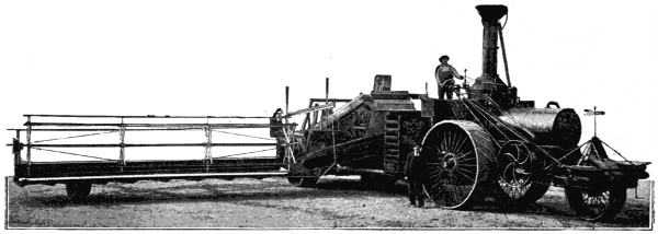
FIG. 157.—STEAM HARVESTER AND THRESHER.
The wheat is headed, threshed, cleaned and sacked by this machine in one continuous operation.—
Cutter,
26 feet wide; Capacity, 75 acres per day.
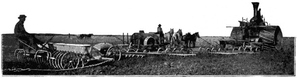
FIG. 158.—FIFTY HORSE POWER STEAM PLANTING COMBINATION.
Traction engine pulling sixteen 10-inch plows, four 6-foot harrows, and a drill.
There were exported in the year 1880 about 800 self-binding harvesters, 2,000 reapers, and 1,000 mowers. In 1890 this was increased to 3,000 self-binding harvesters, 4,000 reapers, and 2,000 mowers. The total value[207] of mowers and reapers exported in 1890 was $2,092,638. The growth subsequent to 1890 is well attested by the exports for 1899, which for mowers and reapers was $9,053,830, or more than four times what it was in 1890. These exported machines harvest the crops of the Argentine Republic, Paraguay, and Uruguay, of South America; carry their labor-saving values to Australia and New Zealand; traverse the wheat fields along the banks of the Red Sea and the Volga, and are used throughout all the continent of Europe.
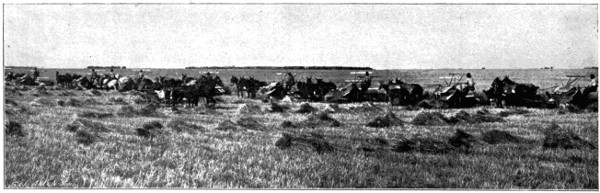
FIG. 159.—A WESTERN HARVEST SCENE (LEFT SECTION OF VIEW).
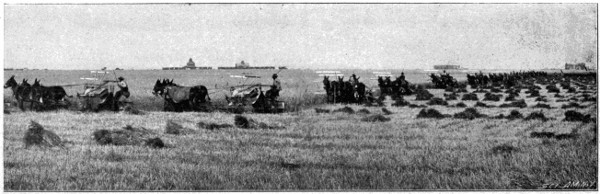
FIG. 159.—A WESTERN HARVEST SCENE (RIGHT SECTION OF VIEW).
With the self-binding harvester performing the work of twenty men,
cutting and binding the grain, and arranging the bundles in windrows, it
would seem that perfection in this art had been reached, but the tendency
of the age is to do things on a constantly increasing scale, and so the latest
developments in harvesters comprise a mammoth machine (Fig. 157) propelled
across the grain fields by steam, and which by the same power cuts
a swath from 26 to 28 feet wide, threshes it at once as it moves along,
blows out the chaff, and puts the grain in bags at the rate of three bags
per minute, each bag containing one hundred and fifteen pounds, and requiring
two expert bag sewers to take the grain away from the spout, sew
the bags, and dump them on the ground. Seventy-five acres a day is its
task. A companion piece to this machine is illustrated in Fig. 158, which
shows the same power utilized for planting. A powerful steam traction
engine of fifty horse power hauls across the field a planting combination of
sixteen ten-inch plows, four six-foot harrows and a seeding drill in the
rear. Such great reaping machines only find useful application in the
enormous wheat fields of California and the Pacific Coast States, where
the dry climate permits the grain to ripen and dry sufficiently while standing
in the field. Moreover, only the heads of the grain are cut, the straw
being left standing. Some conception of the enormous scale upon which
grain is raised in the Western States may be gotten from the dimensions
of the farms. It is said that Dr. Glenn’s wheat farm comprises 45,000
acres; the Dalrymples’, in North Dakota, 70,000; and Mr. Mitchell, in the
San Joaquin Valley, in California, has 90,000 acres. The Dalrymple
farms in 1893 had 54,000 acres in wheat, and employed 283 self-binding
reapers to harvest the crop. There is a single unbroken wheat field on the
banks of the San Joaquin River, near the town of Clovis, in Madera
County, California, which comprises 25,000 acres, or nearly forty square
miles of wheat—a veritable sea of waving grain. The field is nearly
square; each side is a little over six miles long. If its shape were changed
to the width of one mile, the field would then be forty miles long. It has
been said of the grain fields of the West, that the men and teams eat breakfast[208]
[209]
at one end of a furrow, take dinner in the middle of the row, and at
night camp and sup at the end of the same row. With a field of such proportions
it is not difficult to see how this may be true. The cultivation and
garnering of crops from such vast areas can only be appreciated by comparisons.
If it were one man’s work to plow such a field, even with a
double gang plow, cutting a furrow twenty-four inches wide, he would
travel 105,600 miles, which would be equivalent to going around the world
four times. If he plowed twenty miles a day, it would take 5,280 days.
To harrow would require as long, and to plant would take about the same
time, or about forty-three years altogether. A full lifetime would be required
to plant the crop, and a second generation would be required to reap
it. But great results require great agencies, and so great labor-saving
machines, operated by armies of men, are brought into requisition, and
with these the crop is both planted and reaped. A long procession of self-binding
harvesters, following close one behind the other, makes quick work
of it, and before the weather changes this great field is mowed, its crop garnered,
and bread supplied for the hungry of all lands.
The exports of wheat to foreign lands in 1898 were 148,231,261 bushels, worth $145,684,659, and the exports of wheat flour for the same year were 15,349,943 barrels, worth $69,263,718. The total yield of wheat in the United States for 1898 was 675,148,705 bushels.
With the fertile earth, and its prolific inventors, the United States has become the richest country in the world. What its future is to be no man may say, but its destiny is not yet fulfilled, and it is pregnant with potential possibilities.
Early Use of Caoutchouc by the Indians—Collection of the Gum—Early Experiments Failures—Goodyear’s Persistent Experiments—Nathaniel Hayward’s Application of Sulphur to the Gum—Goodyear’s Process of Vulcanization—Introduction of His Process Into Europe—Trials and Imprisonment for Debt—Rubber Shoe Industry—Great Extent and Variety of Applications—Statistics.
Most all important inventions have grown into existence by slow stages of development, and by successive contributions from many minds, not a few having descended by gradual processes of evolution from preceding centuries. Vulcanized rubber, however, is not of this class. It belongs exclusively to the Nineteenth Century, and owes its existence to the tireless energy of one man. The value of the crude gum had been previously speculated upon, and for years attempts had been made to utilize it, but not until Goodyear invented his process of vulcanizing it did it have any real value. This process was an important, distinct and unique step, entirely the work of Mr. Goodyear, and it has never been superseded nor improved upon to any extent. Charles Goodyear was born in New Haven, December 29, 1800, and his life, beginning two days in advance of the Nineteenth Century, furnishes an extraordinary illustration of the struggles and trials of the inventor against adverse fortune, and is a pathetic example of self denial, indefatigable labor, and unrequited toil. Of feeble health, small stature, poor, and frequently in prison for debt, he made the development of this art the paramount object of his life, and with a pious faith and unfaltering courage for thirty years he devoted himself to this work. Money he cared nothing for, except in so far as it was necessary to carry on his work, and he died July 1, 1860, poor in this world’s goods, but rich in the consciousness of the great benefit conferred by his invention upon the human race.
India rubber, or caoutchouc, as it is more properly called, is a concentrated gum derived from the evaporation of the milky juice of certain trees found in South America, Mexico, Central America and the East Indies. The South American variety is called Jatropha elastica, and the East Indian[211] variety the Ficus elastica. The South American Indians called it cahuchu. The province of Para, south of the equator, in Brazil, furnishes the largest part and best quality of gum. The tree from which the gum exudes grows to the height of eighty, and sometimes to one hundred feet. It runs up straight for forty or fifty feet without a branch. Its top is spreading, and is ornamented with a thick and glossy foliage. The gum is collected by chopping through the bark with a hatchet and placing under each series of cuts a little clay cup formed by the hands of the workman. About a gill of the sap accumulates in each cup in the course of a day, and it is then transferred to receiving vessels and taken to camp. The first use of the gum was made by the South American Indians, who made shoes, bottles, playing balls and various other articles from it. Their method for making a shoe was to take a crude wooden last, which they covered with clay to prevent the adhesion of the gum. It was then dipped in the sap, or the latter was poured over it, which gave it a thin coating. It was then held over a smoky fire, which gave it a dark color and dried the gum. When one coating became sufficiently hard another was added, and smoked in turn, and so successive coatings were applied until a sufficient thickness was obtained. When the work was completed it was exposed for some days in the sun, and while still soft the shoes were decorated as the fancy or taste of the maker suggested. The clay forms were then broken out, and the shoe stuffed with grass to keep it in shape for use or sale. In 1820 a pair[212] of these clumsy shoes was brought to Boston and exhibited as a curiosity. They were covered with gilding, and resembled the shoe of a Chinaman. Subsequently considerable numbers of these shoes were brought from South America, and being sold at a large price, they served to stimulate Yankee ingenuity into devising methods of making them from the raw material, which being brought as ballast in the ships from Brazil, could be had cheaply. In France some attention had been given to the material, and the rubber bottles of the Indians had been cut into narrow threads which were woven into strips of cloth to form suspenders and garters. In England an application of it in thin solution had been made by a Mr. Macintosh, who spread it between two thicknesses of thin cloth to form Macintosh water-proof coats. The first practical use of the gum on a large scale was instituted by Mr. Chaffee in Roxbury, Mass., about 1830. He dissolved the gum in spirits of turpentine and invented steam-heated rolls for spreading it upon cloth. Companies were formed to exploit the products, and in the fall and winter of 1833 and 1834 many thousands of dollars’ worth of goods were made by the Roxbury Company, but the business proved a total failure, for in the summer the goods melted, decomposed and became so offensive as to be worse than useless, while the cold of winter rendered them stiff and liable to crack. With a knowledge of these facts and conditions Charles Goodyear commenced his experiments, believing that there was a great future for this material if it could only be prevented from melting in summer and stiffening in winter. He tried mixing it with many materials, first using magnesia, which, however, proved ineffective. On June 17, 1837, he took out patent No. 240, in which he proposed to destroy the adhesive properties of caoutchouc by superficial application of an acid solution of the metals, nitric acid with copper or bismuth being specially recommended. He also claimed the incorporation of lime with the gum to bleach it. Under this process Mr. Goodyear made various articles in the form of fabrics, toys and ornamental articles, using the fabric to make clothing for himself, which he wore to demonstrate its value and wearing qualities. A striking word picture of Mr. Goodyear at this time is given by the reply of a gentleman who, being asked by a man looking for Mr. Goodyear as to how he might recognize him, replied, “If you meet a man who has on an India rubber cap, stock, coat, vest, and shoes, and an India rubber money purse in his pocket, without a cent of money in it, that is he.”
Many useful and artistic articles were made under this first patented process, including maps, surgical bandages, etc., and were brought by Mr. Goodyear to the notice of President Jackson, Henry Clay and John C.[213] Calhoun, from whom he received very encouraging letters. His efforts, however, to introduce his process commercially were not attended with success. Capitalists and manufacturers had been rendered so conservative by the large loss of money in the Roxbury Company, that they were disinclined to have anything further to do with it. Practically alone he was obliged to continue his work. By the kindness of Mr. Chaffee and Mr. Haskins he was allowed the use of the valuable machinery standing idle in their factory at Roxbury, and he made shoes, piano covers, table cloths and carriage covers of superior quality, and from the sale of these, and of licenses to manufacture, he for the first time was able to support his family in comfort. Mr. Goodyear had not yet discovered, however, the process of vulcanization, upon which the rubber industry is founded. In 1838 Mr. Nathaniel Hayward, of Woburn, Mass., who had been employed in the bankrupt rubber company, discovered that the stickiness of the rubber could be prevented by spreading a small quantity of sulphur on it. The same result had also been noticed by a German chemist. On Feb. 24, 1839, Mr. Hayward procured the patent, No. 1,090, on his process, and assigned it to Mr. Goodyear. The patent covered a process of dissolving sulphur in oil of turpentine and mixing it with the gum, and also included the incorporation of the dry flowers of sulphur with the gum, the product afterwards being treated by Mr. Goodyear’s metallic salt process. This was the starting point of vulcanization, for vulcanization consists simply in admixing sulphur with the rubber, and then subjecting it for six to eight hours to a temperature of about 300°. Its effect is to so change the nature of the gum to prevent it from melting or becoming sticky under the influence of heat, or of hardening and becoming stiff under the influence of cold, the vulcanized gum remaining elastic, impervious, and unchangeable under all ordinary conditions. This great discovery of the influence of heat on the sulphur treated gum was quite accidental and wholly unexpected. Heat above all things was the agency which in all previous observations was most to be feared, for it was this more than anything else that melted down, decomposed and destroyed all of his manufactured articles. While sitting near a hot stove engaged in an animated discussion concerning his experiments, a piece of the gum treated with sulphur, which he held in his hand, was, by a rapid gesture, thrown upon the stove. To his astonishment, he found that this relatively high heat did not melt it, as heretofore, and while it charred slightly, it was not made at all sticky. He nailed the piece of gum outside the kitchen door in the intense cold, and upon examining it the next morning found it as perfectly flexible as when he put it out. Goodyear had discovered the process which afterwards[214] came to be known as “vulcanization.” The discovery was made in 1839, but was not accepted by those to whom it was submitted as possessing any importance. Prof. Silliman, of Yale College, however, in the fall of 1839 testified to the results claimed for it by Mr. Goodyear—that it did not melt with heat, nor stiffen with the cold. On June 15, 1844, Mr. Goodyear took out his celebrated patent, No. 3,633, covering this process, in which he not only used sulphur, but added a proportion of white lead. The proportions named were 25 parts of rubber, 5 parts of sulphur, and 7 parts of white lead, the ingredients either to be ground in spirits of turpentine, or to be incorporated dry between rolls. The odor imparted by the sulphur was to be destroyed by washing with potash or vinegar. This patent was reissued in two divisions Dec. 25, 1849, and again on Nov. 20, 1860, and was extended for seven years from June 15, 1858, which was the end of the first term. Under this patent two kinds of rubber were made and sold—“soft rubber,” containing only a small proportion of sulphur, while the other, known as the “vulcanite,” “ebonite,” or “hard rubber,” had from 25 to 35 per cent. of sulphur and was subjected to a longer heat.
The history of this patent is a remarkable one. Immensely valuable as it was, Goodyear reaped but a small share of the profit, for in the midst of his poverty and necessities he was obliged to sell licenses and establish royalties at a figure far below the real value of the rights conveyed. Some idea of the great value of the business which Mr. Goodyear had developed may be had from the fact that the companies who held rights under the patent for the manufacture of shoes paid at one time to Daniel Webster the enormous fee of $25,000 for defending their patent interests.
With the idea of extending his invention Mr. Goodyear visited England in 1851, where he found that Thomas Hancock, of the house of Macintosh & Co., had forestalled him, although not the inventor. A peculiar provision of the English patent law, which gives the patent to the first introducer, permitted this. Nothing daunted, however, he organized a magnificent exhibit for the Great International Exhibition held in Crystal Palace at Hyde Park, London, in 1851. This exhibit cost him $30,000, and he called it the Goodyear Vulcanite Court. It comprehended an elegantly constructed suite of open rooms made of hard rubber ornamented with handsome carvings, and furnished with rubber furniture, musical instruments, and globes made of rubber, and it was also carpeted with the same material. For his exhibit he received the “Grand Council Medal,” which was one of the highest testimonials of the exposition. This exhibit was afterwards moved from London to Sydenham, where it was exposed and used as an agency for some years for the sale of rubber goods.
Mr. Goodyear had obtained a French patent for his invention, and at
the Exposition Universelle in Paris, in 1855, he fitted up at an expense of
$50,000 two elegant courts with India rubber furniture, caskets and rich
jewelry, and for this exhibit he had conferred upon him by the Emperor
Napoleon the “Grand Medal of Honor” and the “Cross of the Legion of
Honor.” It was a singular instance of the irony of fate that the decoration
of the “Cross of the Legion of Honor” should have been conveyed to
him while imprisoned for debt in “Clichy,” the debtors’ prison in Paris.
The lofty courage of the man was well illustrated at this time in his reply
to his wife’s solicitous inquiries as to how he had spent the night while in
prison. He said, “I have been through nearly every form of trial that human[216]
flesh is heir to, and I find that there is nothing in life to fear but sin.
”
The declining years of his life were full of sorrow, pain and affliction,
and at his death in 1860 his estate was $200,000 in debt. He lived long
enough, however, to see his material applied to nearly five hundred uses,
giving employment in England, France and Germany to 60,000 persons,
and producing in this country alone goods worth $8,000,000 a year.
The greatest of all applications of rubber are to be found in the manufacture of boots and shoes. The number of attacks of cold, rheumatism, and death-dealing diseases from wet feet, that have been averted by the use of rubber shoes, can never be estimated, but perhaps it is safe to say that the rubber shoe has done more to conserve the health of the human family than any other single article of apparel.
In the manufacture of shoes the finest quality of rubber is received in wooden boxes 4 × 2 × 11⁄2 feet, containing about 350 pounds in lumps of 1 to 75 pounds. These lumps are cut to suitable size, and are then ground and washed in the machine shown in Fig. 161, water and steam being sprayed on the rubber during the operation. It is then worked into sheets[217] or mats between rolls. From the grinding room the sheets are taken to the mixing room, where lampblack, sulphur and other ingredients are added, and worked into it by being passed many times between heated rolls, the sheets being finally reduced to a thickness of less than 1⁄32 of an inch. The rubber sheets are then applied to a cloth backing by cloth calendering rolls, shown in Fig. 162, which are steam heated and by great pressure serve to incorporate the sheets of rubber and cloth into intimate and inseparable union. Out of this rubber fabric, which is made of different thicknesses for the upper, sole and heel, the patterns for the shoe are cut, and the parts are deftly fitted around the forms by girls, and secured by rubber cement, as shown in Fig. 163. The shoes are then covered with a coat of rubber varnish, and are put into cars and run into the vulcanizing ovens, where they remain from six to seven hours at a temperature of about 275°. The goods are then taken out, and after being inspected are boxed for the market. The vulcanizing is a very important part of the manufacture of a rubber shoe, for it is absolutely necessary in order to give them stability and wearing qualities. A shoe that had not been vulcanized would mash down, spread, become sticky and go to pieces after a few hours’ wear.
The rubber shoe industry of the United States is carried on by about fifteen large companies, representing an investment of many millions of dollars, most of which companies are located in Massachusetts, Rhode Island and Connecticut.
Some idea of the immensity of this industry may be obtained from the import statistics. In 1899 the United States alone imported crude rubber to the extent of 51,063,066 pounds, as much as 1,000,000 pounds a month coming from the single port of Para. The export of manufactured rubber goods for the same year amounted to $1,765,385. The statistics for Great Britain for 1896 showed the imports of rubber to that country to be one-third more than the imports of the United States. Germany also is a large consumer. The great Harburg-Vienna factories cover sixty-seven acres, are capitalized at 9,000,000 marks, and employ 3,500 hands. Much fine technical apparatus, toys, and balls are made here, the daily output of balls reaching 8,000. These, with the Noah’s arks of India rubber animals, are the delight of the little ones all over the world.
Although so much in evidence about us, India rubber is not by any means a cheap material. Costing only five cents a pound when Goodyear commenced his experiments, it is now worth a dollar a pound, and is therefore much more expensive than any of the ordinary metals, woods, or building materials. Many substitutes in the form of compositions of various ingredients have been devised and patented, but no real substitute[218] for nature’s product has yet been found. For many years old and worn out rubber goods were thrown away as worthless. Now all such rubber is reclaimed, and used in many grades of goods which do not require a pure gum. Insatiable as the demands of the trade may appear, there is no need to fear a rubber famine, for the forests of trees in South America and the East Indies are practically inexhaustible, and in the rich alluvial soil of their habitat nature’s processes of growth rapidly restore the decimation.
Since the time of Goodyear, the amplification of this art and the multiplication of uses for rubber, and its increased commercial importance, have gone on at such a rate of increase that to-day we may be said to be living in the rubber age. Its uses and applications are legion, and they extend literally from the cradle to the grave. When the baby comes into the world its introduction to India rubber begins at once with the nursing bottle and the gum cloth, and when the aged invalid takes leave of the[219] world his last moments are soothed with the water bag and the rubber bed, and between these extremes we find it in evidence everywhere about us. In wearing apparel it extends from the crown of the head to the sole of the foot—rubber cap, coat, gloves, and shoes. The man has it in his suspenders and his pipe stem, the woman in her garters and dress shields, and the baby in its teething ring and rattle. The soldier stands on picket duty in the rain, and the rubber blanket protects him from rheumatism. If wounded, the surgeon dresses his mangled limb with rubber bandages, and when he gets well he has a rubber cushion on the end of his crutch, or on the foot of his artificial leg. If wounded in the mouth perhaps the government gives him a set of artificial teeth on a rubber plate. The rubber mat greets you at the front door, a little pad cushions the door stops and the backs of chairs, and a ring seals the mouth of the fruit jar. The whole array of toilet articles, including combs, brushes, mirrors, shoe horns, etc., are made from it. In the parlor it is found in picture frames and the piano cover; in the bath room the wash rag, water bag, rubber cup, and hose pipe of the shower bath are all made of it; in the play room are found rubber balls and toys of all kinds; in the kitchen the clothes wringer and the table cloth; in the dining room the handles of knives, and the tea tray, and what is more useful and more ubiquitous in the office than the rubber band, the rubber ruler, the pencil eraser, or the fountain pen? But these are only a few of the personal and indoor uses and applications. Rubber belting for machinery, fire engine and garden hose, steam engine packing, car springs, covers for carriages and the big guns of the navy, life preservers, billiard table cushions, and chemical and surgical apparatus in endless variety. The electrical world is almost entirely dependent upon it for the insulation of our ocean cables and electric light wires, for battery cups, and the insulating mountings of all electrical apparatus. The pneumatic bicycle tire could not exist without rubber, and the modern application of it to this use alone amounts to nearly four million pounds annually. Every automobile carriage takes twenty-five pounds of rubber for each tire, or 100 pounds altogether. This great and growing industry, together with the now common use of rubber tires on horse-drawn vehicles, raises the sum total of rubber employed in the arts to an enormous figure.
That the sap of an uncultivated tree in a swampy, tropical, and malarial
forest, thousands of miles from civilization, should cut so great a figure in
the necessities of modern life, seems strange and unaccountable on any
basis of probabilities. It is only another illustration of the possibilities of
the patient and persistent work of the inventor. Charles Goodyear took
this nearly worthless material, and made of it, as Parton said in 1865—“not[220]
a new material merely, but a new class of materials, applicable to a
thousand divers uses. It was still India rubber, but its surface would not
adhere, nor would it harden at any degree of cold, nor soften at any degree
of heat. It was a cloth impervious to water; it was a paper that would
not tear; it was a parchment that would not crease; it was leather which
neither rain nor sun would injure; it was ebony that could be run into a
mould; it was ivory that could be worked like wax; it was wood that never
cracked, shrunk nor decayed. It was metal, ‘elastic metal,’ as Daniel
Webster termed it, that could be wound round the finger, or tied into a
knot, and which preserved its elasticity like steel. Trifling variations in
the ingredients, in the proportion and in the heating, made it either pliable
as kid, tougher than ox hide, as elastic as whalebone, or as rigid as flint.
”
Its Evolution as a Science—The Coal Tar Products—Fermenting and Brewing—Glucose, Gun Cotton and Nitro-Glycerine—Electro-Chemistry—Fertilizers and Commercial Products—New Elements of the Nineteenth Century.
The foundation stones of empirical discovery, upon which this science is based, had been crudely shaped by the workmen of preceding centuries, but the classification and laying of them into the structure of an exact science is the work of the Nineteenth Century. The glass of the Phœnicians, and the dyes and metallurgical operations of the Egyptians, involved some chemical knowledge; much more did the operations of the alchemists, who vainly sought to convert the baser metals into gold, but these were only the crude building stones, out of which the great complex modern structure has been raised. In the Sixteenth Century the study of chemistry, apart from alchemy, began, and some attention was given to its application to the uses of medicine. Aristotle’s four elements—fire, air, earth and water—were no longer accepted as representing a correct theory, and new ones were proposed only to be found as erroneous, and to be superseded in time by others.
Briefly traversing the more important of the earlier steps, there may be mentioned the phlogiston theory of Stahl in the earlier part of the Eighteenth Century; the discovery of the composition of water by Cavendish in 1766; of oxygen by Priestly and Scheele in 1774; the electro-chemical dualistic theory of Lavoisier in the latter part of the Eighteenth Century, followed by a rational nomenclature established by Guyton de Morveau, Berthollet and Fourcroy; the doctrine of chemical equivalents by Wenzel in 1777 and Richter in 1792; Dalton’s atomic theory; Wollaston’s scale of chemical equivalents; Gay Lussac’s law of combining volumes; Berzelius’ system of chemical symbols and theory of compound radicals; contributions of Sir Humphrey Davy and Faraday in electro-chemistry,[222] and Thenard’s grouping of the metals. These interesting phases of development of the old chemistry have been followed by the new theory of substitution, by Dumas and others. This change, beginning about 1860 and running through a period of nearly twenty years, has gradually supplanted the old electro-chemical dualistic theory and established the present system.
Among the important and interesting achievements of chemistry in the Nineteenth Century is the artificial production of organic compounds. All such compounds had heretofore been either directly or indirectly derived from plants or animals. In 1828 Wohler produced urea from inorganic substances, which was the first example of the synthetic production of organic compounds, and it was for many years the only product so formed. Berthelot, of Paris, by heating carbonic oxide with hydrate of potash produced formiate of potash, from which formic acid is obtained; by agitating olefiant gas with oil of vitriol a compound is produced from which, upon the addition of water and distillation, alcohol is formed; he also re-combined the fatty acids with glycerine to form the original fats.
In the classification of this science, it has been divided into inorganic chemistry, relating to metals, minerals and bodies not associated with organic life, and organic chemistry, which was formerly limited to matter associated with or the result of growth or life processes, but which is now extended to the broader field of all carbon compounds. In later years the most remarkable advances have been made in the field of organic chemistry. The four elements carbon, hydrogen, oxygen and nitrogen have been juggled into innumerable associations, and in various proportions, and endless permutations, have been combined to produce an unlimited series of useful compounds, such as dyes, explosives, medicines, perfumes, flavoring extracts, disinfectants, etc.
The most interesting of these compounds are the coal tar products. Coal tar, for many years, was the waste product of gas making. Forty years ago about the only use made of it was by the farmer, who painted the ends of his fence posts with it to prevent decay, or by the fisherman, who applied it to the bottoms of his boats and his fishing nets. To-day the black, offensive and unpromising substance, with magical metamorphosis, has been transformed by the chemist into the most beautiful dyes, excelling the hues and shades of the rainbow, the most delightful perfumes and flavoring extracts, the most useful medicines, the most powerful antiseptics, and a product which is the very sweetest substance known. The aniline dyes represent one of the great developments in this field. In 1826 Unverdorben obtained from indigo a substance which he called “Crystalline.[223]” In 1834 Runge obtained from coal tar “Kyanol.” In 1840 Fritzsch obtained from indigo a product which he called “Aniline,” from “Anil,” the Portuguese for indigo. Zinin soon after obtained “Benzidam.” All these substances were afterward proved to be the same as aniline. Perkins’ British patent, No. 1,984, of 1856, is the first patented disclosure of the aniline dyes, and represents the beginning of their commercial production. This combines sulphate of aniline and bichromate of potash to produce an exquisite lilac, or purple color. The first United States patent was in 1861, and now there are about 1,400 patents on carbon dyes and compounds, the most of which belong to the coal tar group. In dyes artificial alizarine, by Graebe and Lieberman (Pat. No. 95,465, Oct. 5, 1869); aniline black, by Lightfoot (Pat. No. 38,589, May 19, 1863); naphthazarin black, by Bohn (Pat. No. 379,150, March 6, 1888); artificial indigo, by Baeyer (Pat. No. 259,629, June 13, 1882); the azo-colors, by Roussin (Pat. No. 210,054, Nov. 19, 1878); and the processes for making colors on fibre, by Holliday (Pat. No. 241,661, May 17, 1881), are the most important. The artificial production of salicylic acid, by Kolbe (Pat. No. 150,867, May 12, 1874), marks an important step in antiseptics. Artificial vanilla, by Fritz Ach (Pat. No. 487,204, Nov. 29, 1892), represents flavoring extracts; and artificial musk, by Baur (Pat. No. 536,324, March 26, 1895), is an example of perfumes. In medicines a great array of compounds has been produced, such as antipyrin, the fever remedy, by Knorr (Pat. No. 307,399, Oct. 28, 1884); phenacetin, by Hinsberg (Pat. No. 400,086, March 26, 1889); salol, by Von Nencki (Pat. No. 350,012, Sept. 28, 1886), and sulfonal by Bauman (Pat. No. 396,526, Jan. 22, 1889). To these may be added antikamnia (acetanilide), the headache remedy, and saccharin, by Fahlberg (Pat. No. 319,082, June 2, 1885), which latter is a substitute for sugar, and thirteen times sweeter than sugar. Among the more familiar products of coal tar or petroleum are moth balls, carbolic acid, benzine, vaseline, and paraffine.
In the commercial application of chemistry the work of Louis Pasteur in fermenting and brewing deserves special notice as making a great advance in this art. His United States patent, No. 141,072, July 22, 1873, deals with the manufacture of yeast for brewing.
The manufacture of sugar and glucose from starch is an industry of great magnitude, which has grown up in the last twenty-five years. Water, acidulated with 1⁄100th part of sulphuric acid, is heated to boiling, and a hot mixture of starch and water is allowed to flow into it gradually. After boiling a half hour chalk is added to neutralize the sulphuric acid, and when the sulphate of lime settles the clear syrup is drawn off, and either[224] sold as syrup, or is evaporated to produce crystallized grape sugar, which latter is only about half as sweet as cane sugar. Glucose syrup, however, has largely superseded all other table syrups, and is extensively used in brewing, for cheap candies, and for bee food. Our exports of glucose and grape sugar for 1899 amounted to 229,003,571 pounds, worth $3,624,890.
An important discovery, made in 1846, was that carbohydrates, such as starch, sugar, or cellulose, and glycerine, when acted upon by the strongest nitric acid, produced compounds remarkable for their explosive character. Gun cotton and nitro-glycerine are the most conspicuous examples. Gun cotton is made by treating raw cotton with nitric acid, to which a proportion of sulphuric acid is added to maintain the strength of the nitric acid and effect a more perfect conversion. Besides its use as an explosive, gun cotton when dissolved in ether has found an important application as collodion in the art of photography. Nitro-glycerine only differs in its manufacture from gun cotton in that glycerine is acted upon by the acids, instead of cotton. Pyroxiline, xyloidine, and celluloid are allied products, which have found endless applications in toilet articles and for other uses, as a substitute for hard rubber.
The applications of chemistry in the commercial world have been in recent years so numerous and varied that it is not possible to do more than to refer to its uses in the manufacture of soda and potash, of alcohol, ether, chloroform, and ammonia, in soap making, washing compounds and tanning, the production of gelatine, the refining of cotton seed and other oils, the art of oxidizing oils for the manufacture of linoleum and oil cloth, the manufacture of fertilizers, white lead and other paints, the preparation of proprietary medicines, of soda water and photographic chemicals, the manufacture of salt and preserving compounds, in the fermentation of liquors and brewing of beer, the preparation of cements and street pavements, the manufacture of gas, and the embalming of the dead.
The most interesting and, in many respects, the most important, development of the last twenty-five years has been in electro-chemistry. Electro-chemical methods are now employed for the production of a large number of elements, such as the alkali and alkaline earth metals, copper, zinc, aluminum, chromium, manganese, the halogens, phosphorus, hydrogen, oxygen, and ozone; various chemicals, including the mineral acids, hydrates, chlorates, hypochlorites, chromates, permanganates, disinfectants, alkaloids, coal tar dyes, and various carbon compounds; white lead and other pigments; varnish; in bleaching, dyeing, tanning; in extracting[225] grease from wool; in purifying water, sewerage, sugar solutions, and alcoholic beverages. The present low price of aluminum, reduced from $12 per pound in 1878 to 33 cents now, is due to its production by electrical methods. Among the earliest successful processes is that described in patents to Cowles and Cowles, No. 319,795, June 9, 1885, and No. 324,658, August 18, 1885, in which a mixture of alumina, carbon and copper is heated to incandescence by the passage of a current, the reduced aluminum alloying with the copper. This has now been superseded by the Hall process (Pat. No. 400,766, April 2, 1889), in which alumina, dissolved in fused cryolite, is electrolytically decomposed. Practically all the copper now produced, except that from Lake Superior, is refined electrolytically by substantially the method of Farmer’s patent (Pat. No. 322,170, July 14, 1885). All metallic sodium and potassium are now obtained by electrolysis of fused hydroxides or chlorides (Pats. No. 452,030, May 12, 1891, to Castner, and No. 541,465, June 25, 1895, to Vautin). The production of caustic soda, sodium carbonate, and chlorine by the electrolysis of brine, is carried on upon a large scale, and will probably supersede all other methods. Nolf’s process (Pat. No. 271,906, Feb. 6, 1883), and Caster’s (No. 528,322, Oct. 30, 1894), employ a receiving body or cathode of mercury, alternately brought in contact with the brine undergoing decomposition, and with water to oxidize the contained sodium. Carborundum, or silicide of carbon, is largely superseding emery and diamond dust as an abradant. It is produced by Acheson (Pat. No. 492,767, Feb. 28, 1893), by passing a current of electricity through a mixture of silica and carbon. Calcium carbide, a rare compound a few years ago, is now cheaply produced by the action of an electric arc on a mixture of lime and carbon, as described by Willson (Pats. Nos. 541,137, 541,138, June 18, 1895). Calcium carbide resembles coke in general appearance, and it is used for the manufacture of acetylene gas, for which purpose it is only necessary to immerse the calcium carbide in water, and the gas is at once given off by the mutual decomposition of the water and the carbide.
Agricultural chemistry is another one of the practical developments of the Nineteenth Century. A hundred years ago the farmer planted his crops, prayed for rain, and trusted to Providence for the increase; he was not infrequently disappointed, but was wholly unable to account for the failure. To-day the intelligent farmer understands the value of nitrogen, has ascertained how it may be fed to his crops through the agency of nitrifying organisms, or he has his soil analyzed at the Agricultural Department, finds out what element it lacks for the crop desired, and in chemically prepared fertilizers supplies that deficiency. The chemical analysis[226] of drinking water has also contributed much to the knowledge of right living and to the avoidance of disease and death, which our forefathers were accustomed to regard as dispensations of Providence.
America has furnished some eminent chemists in the Nineteenth Century, who have made valuable contributions to the science, notably in the field of metallurgy. It is a fact, however, which must be admitted with regret, that America has not in the field of chemical research occupied the leading place she has in mechanical progress. The European laboratory is the birthplace of most modern inventions in the chemical field, and this is so simply by reason of the fact that these more patient investigators have set themselves studiously, systematically and persistently to the work of chemical invention. It is said that some of the large commercial works in Germany have over 100 Ph. D.’s in a single manufacturing establishment, whose work is not directed to the management of the manufacture, but solely to original research, and the making of inventions. The laboratories in such works differ from those in the universities only in being more perfectly equipped, and more sumptuously appointed. The result of this is seen in the fact that in 1899 the United States imported coal tar dyes alone to the extent of $3,799,353, and 5,227,098 pounds of alizarine, most of which came from Germany, and for which we paid a good price, since the German manufacturers control the United States patents. The alizarine dyes are for the most part the artificial kind made by German chemists. Prior to 1869 the red alizarine dye was of plant origin, being obtained from madder root, and it cost $2 a pound. The German chemist produced an artificially made product, which took the place of the madder dye, and was sold at $1.20 a pound. At the end of the patent term (seventeen years) the price fell to 15c. a pound, showing that the product was produced at a profit of more than $1.05 a pound, and as millions of pounds were imported annually, it is estimated that $35,000,000 was the price paid the German chemists for their foresight in combining science with business. Many United States patents granted to foreign chemists are still in force, and the rich reward of their skill is reaped at our expense.
Discovery of elements.—In the early days of chemical knowledge, fire, air, earth and water constituted the insignificant category of the elements, which was as faulty in classification as it was small in size. Gradual splitting up of compounds, and an increase in the number of elements, has gone on progressively for some hundreds of years, until to-day the list extends well on to one hundred elementary bodies. Those which belong to the credit of the Nineteenth Century are given in the table following, with the name of the discoverer, and the date of its discovery.
| ELEMENTS DISCOVERED IN THE NINETEENTH CENTURY. |
||||
|---|---|---|---|---|
| ELEMENTS. | DISCOVERER. | YEAR. | ||
| Columbium | Hatchett | 1801 | ||
| Tantalum | Ekeberg | 1802 | ||
| Iridium | Tenant | 1803 | ||
| Osmium | Tenant | 1803 | ||
| Cerium | Berzelius | 1803 | ||
| Palladium | Wollaston | 1804 | ||
| Rhodium | Wollaston | 1804 | ||
| Potassium | Davy | 1807 | ||
| Sodium | Davy | 1807 | ||
| Barium | Davy | 1808 | ||
| Strontium | Davy | 1808 | ||
| Calcium | Davy | 1808 | ||
| Boron | Davy | 1808 | ||
| Iodine | Courtois | 1811 | ||
| Cyanogen | Gay Lussac | 1814 | ||
| (Comp. rad.) | ||||
| Selenium | Berzelius | 1817 | ||
| Cadmium | Stromeyer | 1817 | ||
| Lithium | Arfvedson | 1817 | ||
| Silicon | Berzelius | 1823 | ||
| Zirconium | Berzelius | 1824 | ||
| Bromine | Balard | 1826 | ||
| Thorium | Berzelius | 1828 | ||
| Yttrium | Wohler | 1828 | ||
| Glucinum | Wohler | 1828 | ||
| Aluminum | Wohler | 1828 | ||
| Magnesium | Bussey | 1829 | ||
| Vanadium | Sefstroem | 1830 | ||
| Lanthanum | Mosander | 1839 | ||
| Didymium | Mosander | 1839 | ||
| Erbium | Mosander | 1843 | ||
| Terbium | Mosander | 1843 | ||
| Ruthenium | Claus | 1845 | ||
| Rubidium | Bunsen | 1860 | ||
| Caesium | Bunsen | 1860 | ||
| Thallium | Crookes | 1862 | ||
| Indium | Reich | 1863 | ||
| Richter | ||||
| Gallium | Boisbaudran | 1875 | ||
| Ytterbium | Marignac | 1878 | ||
| Samarium | Boisbaudran | 1879 | ||
| Scandium | Nilson | 1879 | ||
| Thulium | Cleve | 1879 | ||
| Neodymium | Welsbach | 1885 | ||
| Praseodymium | Welsbach | 1885 | ||
| Gadolinium | Marignac | 1886 | ||
| Germanium | Winkler | 1886 | ||
| Argon | Raleigh | 1894 | ||
| Ramsey | ||||
| Krypton | Ramsey | 1897 | ||
| Travers | ||||
| Neon | Ramsey | 1898 | ||
| Travers | ||||
| Metargon | Ramsey | 1898 | ||
| Travers | ||||
| Coronium | Nasini | 1898 | ||
| Xenon | Ramsey | 1898 | ||
| Monium | Crookes | 1898 | ||
| Etherion (?) | Brush | 1898 | ||
Whether or not these so-called elements are really true elementary forms of matter, which are absolutely indivisible, is a problem for the chemists of the coming centuries to solve. The classification has the approval of the present age. What new elements may be found no one may predict. Mendelejeff’s periodic law, however, suggests great possibilities in this field. Allotropism, in which the same element will present entirely different physical aspects, is also a significant and suggestive phenomenon, for in it we see carbon appearing at one time as a crude, black and ungainly mass of coal, and at another it appears as the limpid and flashing diamond. In more than one mind there is a lurking suspicion that there may, after all, be only one form of primordial matter, from which all others are derived by some wondrous play of the atoms, and if so the old idea of the alchemist as to the transmutation of metals may not be entirely wrong. The Twentieth Century may give us more light.
The Nature of Food—The Roller Mill—The Middlings Purifier—Culinary Utensils—Bread Machinery—Dairy Appliances—Centrifugal Milk Skimmer—The Canning Industry—Sterilization—Butchering and Dressing Meats—Oleomargarine—Manufacture of Sugar—The Vacuum Pan—Centrifugal Filter—Modern Dietetics and Patented Foods.
If called upon to name the most important of all factors of human existence, that which underlies and sustains all others, even to life itself, everyone must agree that it is food. A remarkable fact in this connection is that all animal life lives and thrives by eating some other thing that is or has been alive, or is the product of organic growth. The vegetarian may pride himself upon his higher ideals of living, but after all his fruit, vegetables, and cereals belong to the great category of living organisms, and are to a certain extent sentient and conscious, for even the plant will turn to the sun. The beasts of the field and fowls of the air live by preying upon other weaker animals and birds, these upon plants and grasses, and the plants and grasses upon the decaying mosses and organic mould of the soil, and the mosses upon still lower organisms. The big fish of the sea eat the little fish, the little fish the small fry, and these in turn live upon worms and animalcula, and so on all the way down to protoplasm. Omniverous man, in spite of his boasted civilization and enlightment, not only eats them all, flesh, fowl, fish, grain and plants, but lives exclusively upon them. But he can only live on that which has been produced by the mysterious agency of life, and this furnishes a significant suggestion for the philosopher, for it may be that life itself is only an accumulated active power or unitary force regenerated in some metamorphic way from vital force stored up in the bacteria of organic food, and necessarily connected therewith in an endless chain of reproductions, and if this be true, the hope of the scientist as to the synthesis of food from its elements must ever remain a philosophic dream, because the scientist cannot create a bacterium.
It has been said that when a man eats meat he thinks meat, and when he eats bread he thinks bread, and when he eats fruit he thinks fruit. It is not clear that the quality or character of man’s food is so closely correlated[229] to his thought, but that it has its influence cannot be doubted. It would be safer to say, however, that when a man eats meat he acts meat, and when he eats bread he acts bread, for the muscular energy and aggressive potentiality appear to be much more closely related to the quality of his food than are his thoughts. May it not be that the powerful achievement of the British Empire was directly related to its roast beef? Is not the listless apathy of the Chinese due to a diet of rice? Is not the dominant and masterful power of the lion or the eagle related to a carniverous diet, and the mild and placid temper of the ox the reflex expression of his vegetable food? It is quite true that our potentialities are largely represented by what we eat, and our food therefore becomes a most interesting topic, not only by virtue of its indispensable quality, but by reason also of the possibilities of development in the betterment and elevation of the human race.
From the earliest times even down to the present day man’s food has been the same—flesh, fish, cereals, fruits and vegetables. The development of the present century has not extended this category, but it has been directed to an increase in the supply, an improvement in quality, the preservation against decay and waste, and its intelligent selection and adaptation to the special needs of the body. Progress manifests itself in the great field of agriculture, in improved processes and machines for milling; in butchering, packing and handling meats; in preserving and drying fruits; in the preparation of canned goods, in dairy appliances, in cake and cracker machines; in the manufacture of sugar; in the great advance in cookery; in the science of dietetics, and in thousands of minor industries.
In agriculture the raising of grain has extended in the Nineteenth Century to enormous proportions. More than ten thousand patents for plows, as many for reapers, and a proportionate number of planters, cultivators, threshers, and other implements and tools represent the extent to which inventive genius has been directed to the increase of the yield in the harvest field.
This yield in the United States for the year 1898 was:
| Corn | 1,924,184,660 | bushels |
| Wheat | 675,148,705 | bushels |
| Oats | 730,906,643 | bushels |
| Rye | 25,657,522 | bushels |
| Barley | 55,792,257 | bushels |
| Buckwheat | 11,721,927 | bushels |
| Potatoes | 192,306,338 | bushels |
For converting the grain into flour, the inventors of the Nineteenth[230] Century have made revolutionary changes. Milling processes within the last twenty-five years have been completely transformed by the introduction of the roller mill and middlings purifier. Formerly two horizontal disk-shaped stones or burrs were employed, the lower one stationary and the upper one revolving in a horizontal plane and crudely crushing the grain between them. In all modern mills these have been entirely displaced by porcelain rolls revolving on horizontal axes and crushing the grain between them. The first of these roller mills is shown in pat. No. 182,250, to Wegmann, Sept. 12, 1876. (See Fig. 164). The outer rolls d e are pressed against the inner ones a c by a system of weighted levers, and scrapers below remove the crushed grain from the periphery of the rolls. Many subsequent[231] improvements have been made, one type of which employs a succession of rolls which act in pairs on the grain one after the other and reduce it by successive gradations.
The middlings purifier, see Fig. 165, comprehends a flat bolt or shaker screen b, of bolting cloth, arranged as a horizontal partition in an enclosing case through which passes an upward draft of air produced by suction fan D at the top. This air passing up through the bolting screen lifts the bran specks and fuzz from the shaken material as it passes downward through the screen, brushes K being arranged below to keep the screen constantly clean. A representative and pioneer type of this machine is seen in Pat. No. 164,050 to George T. Smith, June 1, 1875, from which the view is taken. The useful effect of the roller mill and middlings purifier is to save the most nutritious and valuable part of the grain, which lies between the outer cuticle and the white starch within, and which breaks up in fine grains and is of a golden hue. This portion of the grain was formerly unseparated, and was mixed with the middlings and bran as an inferior product. Modern analysis has disclosed its superior food value, and the roller mill and middlings purifier have provided means by which it can be separated from the bran and incorporated with the flour, thereby greatly adding to its wholesome character and nutritive value, and imparting to the flour the rich creamy tint which characterizes all higher grades.
Minneapolis, Minn., is the great center of the milling interests of the United States. The Pillsbury Mills are located there, and the “Pillsbury A.” which is said to be the largest in the world, has a capacity of 7,000 barrels per day.
In 1877-78 disastrous flour dust explosions at Minneapolis brought[232] about the development of the dust collector, for withdrawing from the air of the mills the suspended particles of flour dust, which not only invited explosion, but rendered the air unfit to breathe. Washburn’s Pat. No. 213,151, March 11, 1879, is an early example.
The use of crushing rolls has also developed a great variety of new foods, such as cracked wheat, oatmeal grits, etc. These crushing rolls have sometimes been made hollow, and are steam heated, and as they crush the grain they simultaneously effect the cooking or partial conversion of the starch, and the product is known as hominy flake, ceraline, coralline, etc., which furnish popular breakfast foods when served with cream.
In the field of cookery such activity has been displayed that the average kitchen to-day is a veritable museum of modern inventions. Egg beaters, waffle irons, toasters, broilers, baking pans, apple parers, cherry stoners, cheese cutters, butter workers, coffee mills, corn poppers, cream freezers, dish washers, egg boilers, flour sifters, flat irons, knife sharpeners, can openers, lemon squeezers, potato mashers, meat boilers, nutmeg graters, sausage grinders, and frying pans in endless array; all patented and clustered[233] around the modern cooking range as a central figure, and all presenting points of excellence in the matter of economy and convenience, or the betterment of result. The most extensive application of inventive genius is to be found in the large manufacturing bakeries, which make and sell the millions of pounds of crackers and cakes that fill the bins and shelves of the grocery store. In these manufactories the dough is prepared by a mixer, see Fig. 166, which consists of a spiral working blade revolving in a trough, and capable of handling half a dozen barrels of flour at a time. It is then put through a kneading machine, called a “brake,” shown in Fig. 167, and is then ready to be converted into crackers or cakes on a great machine 25 feet long, which finishes the crackers and puts them in the pan ready for the oven. This machine, see Fig. 168, receives the dough at A, where it is coated with flour and flattened into a sheet between rolls. It is then received on a traveling apron B, has the flour brushed off by a rotary brush C, and is then cut into crackers or cakes by vertically reciprocating dies D. At E a series of fingers press the cakes down through the sheet of dough, while the surrounding scraps are raised on a belt F and delivered into a suitable receptacle. The separated cakes at B′ are then delivered into pans at G, the pans being fed on the subjacent belt at G′. Such machines, costing nearly a thousand dollars, produce from forty to sixty barrels of crackers a day, enabling them to be sold at about 5 cents a pound at retail.
Dairy Appliances have come in for a large share of attention at the hands of the Nineteenth Century inventor. There are about sixteen million milch cows in the United States, and their contribution to the food stuffs of the day in milk, butter, and cheese is no insignificant factor. There have been over 2,700 patents granted for churns alone, and besides these there are milk coolers, cheese presses, milk skimmers, and even cow milkers. The centrifugal milk skimmer is an interesting type of this class of machine.[234] In the old way the milk was set for the cream to rise, which it did slowly from its lighter specific gravity. In the centrifugal skimmer the milk is continuously poured in through a funnel, and the cream runs out continuously through one spout, and the skimmed milk at the other. An[235] illustrative type of this machine is shown in Fig. 169. A steam turbine wheel near the base turns a vertical shaft bearing at its upper end a pan which rotates within the outer case. The milk enters through the faucet at the top, and as the pan within rotates, the heavier milk, by its greater specific gravity, is thrown to the outer part of the pan and passes out through the larger of the two spouts, while the lighter cream is crowded to the center and passes out of the upper spout, which opens into the center of the pan. Patents to Lefeldt & Lentsch, No. 195,515, Sept. 25, 1877, and Houston and Thomson, No. 239,659, April 5, 1881, represent pioneer milk skimmers of this type.
Closely allied to the dairy appliances are the incubator and the bee hive, both of which have claimed a large share of attention, and for which many patents have been granted.
One important and characteristic feature of the present age is the conservation of waste in perishable foodstuffs. Fruits, vegetables, fish and oysters were suitable food to our forefathers only when freshly taken, and any superabundance in supply was either wasted by natural processes of decay, or was fed to the hogs. To-day thousands of patented fruit dryers, cider mills, and preserving processes save this waste and carry over for valuable use through the unproductive winter months these wholesome and valuable articles of diet. Even more important is the canning industry, by[236] which not only fruits are maintained in a practically fresh condition for an indefinite time, but oysters, meats, fish, soups, and vegetables are also put up in enormous quantities. To-day the grocer’s shelves present an endless array of canned tomatoes, peaches, corn, peas, beans, fish, oysters, condensed milk, and potted meats, which constitute probably three-fourths of his staple goods. The tin can is in itself a very insignificant thing, not entitled to rank with any of the great inventions, but in the every-day campaign of life it is playing its part, and working its influence to an extent that is little dreamed of by the casual observer. It renders possible our military and exploring expeditions; it holds famine and starvation in abeyance; it gives wholesome variety to the diet of both rich and poor; and it transfers the glut of the full season to the want of future days. Perhaps no single factor of modern life has so great an economic value. Simple as is the tin can, quite complex machines are required to make it. Originally such machines were operated by hand or foot power, but within the last 25 years power machines have been devised which automatically convert a simple blank or plate of sheet metal into a finished can. Of the many patents granted for such machines the most representative ones are 243,287, 250,096, 267,014, 384,825, 450,624, 465,018, 480,256, 495,426, 489,484.
In the process of putting up canned goods the products are filled into the cans, and the caps, or heads, are soldered on. These caps have a minute hole in the center for the escape of air and steam in the process of cooking and sterilizing, which is conducted as follows: A large number of cans are placed on a tray swung from a crane and the cans lowered into one of a series of great cooking boilers. The cover of the boiler is then closed and fastened by lugs, and steam turned on until the goods in the can are thoroughly heated through. During this process the air and steam escape through the little vent hole from the interior of each can. The cans are then removed, the vent hole closed by a drop of solder, and the goods thus hermetically sealed in a cooked or sterilized condition will keep for a long period of time.
Sterilizing.—During the last quarter of the century, which has witnessed the growth of the wonderful science of bacteriology, a class of devices known as sterilizers has come into existence, whose primary function is to kill the germs of decay by heat. This has had in the canning industry an important commercial application. An example is found in the patent to Shriver, No. 149,256, March 31, 1874. In some of these devices the receptacles containing the food stuffs are in large numbers placed within the heating chamber, and by devices operated from the outside the cans or[237] bottles are opened and shut while within the steam filled chamber. A late illustration is found in patent to Popp et al., 524,649, August 14, 1894.
Butchering and Dressing Meats.—Chicago is the leading city of the world in this industry, and Armour & Co. the largest packers. In the year ending April 1, 1891, they killed and dressed 1,714,000 hogs, 712,000 cattle, and 413,000 sheep. They had 7,900 employees, and 2,250 refrigerating cars were employed for the transportation of their products. The ground area covered by their buildings was fifty acres, giving a floor area of 140 acres, a chill room and cold storage area of forty acres, and a storage capacity of 130,000 tons. In addition to its meat packing business the firm has separate glue works, with buildings covering fifteen acres, where 600 hands are employed, their production in 1890 being 7,000,000 pounds of glue, and 9,500 tons of fertilizer. Since 1891 this great business has increased until to-day it is said that the army of workmen employed is greater than that of Xenophon, that the firm pays out in wages alone, half a million dollars every month, that four thousand cars are required to carry the products of their factory, and whose business amounts to the enormous sum of one hundred million dollars annually.
There are from forty to fifty million cattle raised in the United States, and an equal amount of sheep. The number of hogs raised has diminished somewhat in the past few years, but from 1889 to 1892 more than fifty million were maintained. The process of slaughtering and dressing pork, as practiced to-day, is a continuous one, and is well illustrated in Fig. 170, in 13 operations. The animals are driven into a catching pen at 1, where they are strung up by one leg, and secured to a traveling pulley on an overhead rail. At 2 the animal is instantly killed by a knife thrust that reaches the heart; at 3 he is dumped into a vat of scalding water, kept hot by steam pipes, where the hair is loosened (see detail view Fig. 171). A series of oscillating curved arms, shaped like a horse hay-rake, dips the carcass out of the scalding vat and deposits it upon the table 4 (Fig. 170), where it is attached to an endless cable that drags it through a scraping machine at 5. This takes off the hair, as shown in detail view Fig. 172. At 6 (Fig. 170) the remnants of hair are removed by hand, and at 7 the skin is washed clean. At 8 the carcass is inspected, and the throat cut across; at 9 the entrails are removed; at 10 the leaf lard is taken out; at 11 the heads are severed and tongues removed; at 12 the carcass is split into halves, and at 13 the sections are ready to be run into the cooling room.
From 10 to 15 minutes only are required to convert the living animal
into dressed pork. Every part of the animal is utilized. The lungs, heart,
liver and trimmings go to the sausage department. The feet are pickled or[238]
[239]
converted into glue. The intestines are stripped and cleaned for sausage
casings. The soft parts of the head are made into so-called cheese, and
the fat is rendered into lard. The finer quality of bristles goes to the brushmakers,
and the balance is used by upholsterers for mixing with horse
hair. The blood is largely used for making albumen for photographic
uses, as well as in sugar refining, for meat extracts, and for fertilizers.
The bones are ground for fertilizer, and even the tank waters are concentrated
and used for the same purpose.
Oleomargarine.—About 1868 M. Mege, a French chemist, commissioned by his government to investigate certain questions of domestic economy, was led into the study of beef fat, and to make comparisons of the same with butter. He found that when cows were deprived of food containing fat they still continued to give milk yielding cream or fatty products. He therefore concluded that the stored-up fat in the animal was then converted into cream, and that it was practicable, therefore, to convert beef fat into butter fat. Physiology taught that in the living animal the change was wrought through the withdrawal of the larger part of the stearine by respiratory combustion, while the oleomargarine was secreted by the milk glands, and its conversion into butyric oleomargarine effected in the udder under the influence of the mammary pepsin. In the process of making butter by the ordinary method of churning the cream,[240] the finely divided butter fat globules are united into masses, containing by mechanical admixture from 12 to 14 per cent. of water or buttermilk carrying a fractional per cent. of cheese. This buttermilk contributes somewhat to the flavor, but at the same time furnishes a ferment which ultimately spoils the butter by making it rancid. It is a purely accidental ingredient, and one not at all desirable. To some extent the same may be said of the soluble fats which give to the butter its variable though characteristic flavor. They are unstable compounds, decomposing readily, and furnish the acrid products which make “strong” butter. M. Mege sought to imitate the natural process of butter-making, which was first to separate from the oily fat of suet the cellular tissue and excess of stearine or hard fat; second, to add to the oil a sufficient proportion of butyric compounds to give the necessary flavor, and third, to consolidate the butter fat without grain, and to add at the same time the requisite proportion of water, salt, and coloring matter, to make a compound substantially the same in composition, flavor, and appearance, as butter churned from the cream, and all this without adding to the original fat anything dietetically objectionable, and without submitting it to any process capable of impairing its wholesome quality. These objects were fairly obtained in the product known as oleomargarine, the United States patent for which was granted to Mege Dec. 30, 1873, No. 146,012.
The process in brief is to take fresh beef fat, which is first chopped up[241] and thoroughly washed. It is then placed in melting tanks at a temperature of 122° to 124° F, and the clear yellow oil is drawn off and allowed to stand until it granulates. The fat is then packed in cloths set in moulds and a slowly increasing pressure squeezes out the pure amber colored oil, leaving the stearine behind. This sweet and pure yellow oil is then churned with milk for 20 minutes until the oil is completely broken up, and a small quantity of annato, a vegetable coloring matter, is added to give a yellow color. The product is then cooled in ice, and after a second churning with milk it is salted and finished like butter. Chemical analysis shows oleomargarine to have substantially the same constituents and in almost the identical proportions of pure butter. It is equally wholesome, and while it does not have the same rich flavor, it has the advantage that it keeps better, and is not so liable to become rancid or strong. The oleomargarine industry is closely related to the beef packing industries of the United States, and its growth has been enormous. Notwithstanding the stringent laws on the subject, much of the oleomargarine made is sold for, and by the average purchaser is not distinguishable from, pure butter. In 1899 there were 80,495,628 pounds of oleomargarine made in the United States, or more than a pound for every man, woman, and child in the country. The internal revenue tax paid on it was $1,609,912.56. The exports for the year 1899 were 5,549,322 pounds of the artificial butter, and 142,390,492 pounds of the oleo oil prepared for conversion into the complete product by simply churning with milk.
Sugar.—Sugar-cane, beets, and the sap of the maple constitute the sources from which sugar is extracted, but the cane furnishes by far the largest supply. When crushed between rolls it yields 65 per cent. of its weight as juice, and 18 per cent. of this juice is sugar. It is concentrated by evaporation at a low temperature, the crystallized portion being known as “raw” or brown sugar, which is subsequently refined, while the uncrystallized portion forms molasses.
In the process of refining, 2 or 3 parts of raw sugar, with one of water containing a little lime, ground bone black, and the serum of bullocks’ blood, is heated by the passage of steam through it. The albumen of the serum coagulates and rises to the surface in a scum which entangles the impurities and bone black, leaving the syrup light in color. The latter is then filtered through bone black until it is colorless and is then evaporated in the vacuum pan, which is the important invention of the century in sugar making. Heat has the effect of converting the crystallized sugar into the uncrystallized variety, and hence the evaporation must, to prevent this, be conducted at a low temperature. Contact with the air is also objectionable.[242] These conditions are provided for by conducting the evaporation in a vacuum, which lowers the evaporating temperature and avoids contact with the air. The vacuum pan was the invention of Howard, an Englishman. (British Pat. No. 3,754, of 1813). As constructed to-day it is an enormous vessel (see Fig. 173), capable of holding 7,000 or more gallons, and yielding 250 barrels of sugar at a strike. In this a vacuum is maintained by a condenser, the vapors passing from the pan to the condenser through the great curved pipe rising from the top, which pipe is five feet in diameter. A gentle heat is applied through internal steam-heated coils which connect[243] with an external series of steam inlet pipes on one side, and a corresponding series of steam outlet pipes on the other. A large discharge valve for the concentrated syrup closes the bottom of the pan. After concentration the crystallized sugar is separated from the syrup by a centrifugal filter, in which the liquid is thrown from the crystallized sugar by centrifugal action. The first centrifugal filter is shown in British patent to Joshua Bates, No. 6,068, of 1831. This, however, revolved about a horizontal axis. The present form of centrifugal filter is a cylinder revolving about a vertical axis, the sides of the cylinder being formed of filtering medium, through which the liquid is thrown by centrifugal action, while the sugar is retained within. This was the invention of Joseph Hurd, of Mass., U. S. Pat. No. 3,772, Oct. 3, 1844; re-issue No. 607, Sept. 29, 1858, which patent was extended for seven years, from Oct. 3, 1858. The diffusion process, which extracts the juice by cutting the cane in slices and soaking in water; the bagasse furnace, which dries and burns the expressed cane stalks as fuel, and the manufacture of glucose and grape sugar by the reaction of sulphuric acid on starch, are interesting allied features of this industry which can only be briefly mentioned. Most of the sugar consumed in the United States is imported, much raw sugar being imported and refined here. The imports for the year 1899 were 3,980,250,569 pounds, and the per capita consumption in 1898 was 61.1 pounds a year.
Aids to Digestion.—It is only during the last part of the Nineteenth Century that the world has learned how to live. “What is one man’s food is another man’s poison” has been a trite old saying for many years, but the reason why has only in late years been fully understood. The physiology of digestion, the relative digestibility of different articles of food, and their nutritive values, have received of late years the earnest attention of physicians and students of dietetics and have contributed much to the quality and kind of food, and a knowledge of when and how to eat it. We know that the starchy foods are digested by the saliva, which is an alkaline digestion; that meat, fish, eggs, cheese and the albumenoids are digested in the stomach by the gastric juices (pepsin and hydrochloric acid) which is an acid digestion, and that the remaining portions of starch, the sugars, and fats are digested in the intestines, and that this is also an alkaline digestion, and this has helped to solve the problem for us. We also know that starch is an excellent food, provided the vital powers are sufficiently stimulated by fresh air, sunlight, and exercise to digest it, as do the horse and the ox when they eat corn, but we know furthermore that the sedentary occupations of modern life leave many stomachs in a condition unable to assimilate starch, and so bread, oatmeal, potatoes and such simple staples,[244] instead of nourishing the body, ferment in the enfeebled stomach, produce acids and gas, and lay the foundation for serious chronic diseases. The student of chemistry and dietetics knows to-day that one part of diastase will effect the conversion of 2,000 parts of starch into grape sugar, as a preliminary step to its digestion, and so by treating starchy matter with substances containing diastase (derived from malt) a partial transformation is effected which will materially shorten and assist its digestion. This fact has been largely made use of in the preparation of easily soluble or pre-digested foods, examples of which are found in patent to Horlick (malted milk), No. 278,967, June 5, 1883; to Carnrick (milk-wheat food), Dec. 27, 1887, No. 375,601; and Boynton and Van Patten (cereals and diastase), 344,717, June 29, 1886.
Beverages.—Pure water, nature’s own gift, has ever supplied every legitimate need of the human race, but civilized life has greatly extended its list of drinks, much to its own detriment. Soda water, whiskey, beer, ginger ale, tea, coffee, and chocolate represent enormous industries, and probably all do more harm than they do good. Much inventive genius in the Nineteenth Century has been bestowed upon the soda water fountain, on stills, and processes for aging liquors and processes for brewing beer, on cider and wine presses, on bottling machines and bottle stoppers, on devices for carbonating waters, and in coffee and teapots. The trend of the times is shown in the following figures, which represent the per capita consumption of beverages in the United States for 1898: tea, .91 of a pound; coffee, 11.45 pounds; wines, .28 of a gallon; distilled spirits, 1.10 gallons; and malt liquors 15.64 gallons. The largest per capita increase since 1870 has been in malt liquors, and the next in coffee. In tea and distilled spirits there has been a decrease, while the consumption of wines is the smallest of all and has varied but little.
Discovery of Circulation of the Blood by Harvey—Vaccination by Jenner—Use of Anæsthetics the Great Step of Medical Progress of the Century—Materia Medica—Instruments—Schools of Medicine—Dentistry—Artificial Limbs—Digestion—Bacteriology, and Disease Germs—Antiseptic Surgery—House Sanitation.
In the early gropings through the uncertain light of first progress, man was accustomed to ascribe the ills of his flesh to the anger of the gods, and in his craven and abject superstition made peace offerings. Later he learned to locate the cause within himself, and constructed the theory that the fluids of the body had become disordered. The characteristic feature of progress in the Nineteenth Century, in this field, has been in the accurate tracing of the relation of cause and effect, and with the discovery of true causes has grown efficient means of treatment. The old expedients of charms, incantations, conjuration and exorcism gave place first to intelligent medication, and this in turn is rapidly giving way to the prevention of disease by improved conditions of sanitation and right living. The ounce of prevention has been found to be worth more than the pound of cure. With the improved knowledge of physiology, anatomy, chemistry and biology, which the century has brought, the intelligent physician was able to make a logical and for the most part a correct diagnosis, but supplemented with the microscope, that great revealer of the unseen world of small things, corporeal existence itself becomes an open book, and from the principles of organic evolution to the germ theory of disease the mystery of life and death is being slowly revealed.
When the Eighteenth Century gave birth to the Nineteenth, its great natal gift in medicine was vaccination. Jenner in 1798 for the first time announced his discovery of this great boon to the human race. In 1799 Dr. Benjamin Waterhouse, in Boston, obtained virus from Jenner and vaccinated four of his children, and in 1801 Dr. Valentine Seaman obtained virus from Dr. Waterhouse and performed the first vaccination in New York. During the Seventeenth and Eighteenth Centuries the annual death rate from smallpox in London ranged from 2 to 4 per 1,000 of population. In 1892 it was only 0.073 per 1,000.
It is also stated on good authority that the mortality from smallpox in England alone, was 20,000 a year less after the introduction of vaccination than it was in the preceding century, and that its benefits to the world at large have been so great that the lancet of Jenner has saved more lives than were sacrificed by the sword of Napoleon.
Each century in modern history has been marked by some important discovery in the field of medicine. The Seventeenth Century was notable for the discovery of the circulation of the blood by Harvey; the Eighteenth Century brought with it vaccination by Jenner. The Nineteenth Century’s greatest gift in this field has been anæsthesia, or insensibility to pain. Nature has wisely endowed man with nerves of sensation as danger signals for the conservation of life. Accident and disease, however, are the inseparable concomitants of human existence, and suffering and pain the ineffaceable legacies of mortality. Sometimes these nerves of sensation are no longer useful as monitors, and in the unavoidable emergency of accident, surgical operations, child birth, and certain diseases, suffering can do no good, and then pain—that Prince of Terrors—thrusting his presence upon the hapless victim, racks body and limb, calling forth groans, and shrieks and writhings, till the poor sufferer, possessed with a dominating agony which displaces all thought of life, memory of friends, and love of God, breaks down in unutterable distress, and prays for death and oblivion. To this poor sufferer insensibility is next to heaven. For the past half century all the formidable operations of the surgeon have been performed with the aid of anæsthetics and without suffering to the patient, producing happy recoveries, and greatly contributing to the success of the result by relieving the surgeon of the distraction of the patient’s pain, and the interference of his involuntary movements. Quite a number of anæsthetics are known and used to-day. Those more generally employed are—naming them in the order of their first application—nitrous oxide gas, ether, and chloroform. Nitrous oxide gas is chiefly used for the extraction of teeth. Sir Humphrey Davy, in 1800, was the first to observe the peculiar quality of nitrous oxide gas, which gave it the name of “laughing gas,” from the fact that it caused those inhaling it to act in a manner exhibiting an abnormal exhilaration. Dr. Horace Wells, a dentist of Hartford, Conn., in 1844, had the gas administered, experimentally, to himself during the operation of extracting a tooth, and was the discoverer of its useful application as an anæsthetic.
The greatest discovery, however, in anæsthetics is the application of ether for this purpose. Ether as a chemical product has been known for several centuries, and as early as 1818 Faraday pointed out the similarity[247] between the effects of ether and nitrous oxide gas. Dr. Morton, a dentist, of Boston, first applied it as an anæsthetic Oct. 16, 1846, being guided largely in its selection and use by Dr. Jackson, an eminent chemist of the same city. On Nov. 12, 1846, U. S. Pat. No. 4,848 was issued to them for this invention. In the latter part of December of the same year Dr. Liston, an eminent English surgeon, performed the operation of amputating the thigh while the patient was under the influence of ether.
Chloroform, discovered by Guthrie in 1831, was first applied as an anæsthetic by Sir James Y. Simpson, of Edinburgh, in 1847. Of the two leading anæsthetics, ether is more generally used in the United Sates and chloroform in Europe. Ether is less dangerous, but its administration is more difficult and disagreeable. It is said on the highest authority that in the Crimean War chloroform was administered 25,000 times without a single death, and ether is even safer than chloroform. In the hands of a skillful physician practically no danger is to be apprehended from the use of either of the two agents. A little over fifty years ago any severe or prolonged surgical operation involved such irresistible pain that the patient’s writhings were required to be restrained by powerful muscular assistants, and by straps which bound the patient to the table, and when it is remembered that a false cut of a hundredth part of an inch might be fatal, the haste, the disquieting influence upon the surgeon, and the interference with the accuracy of his hand, added greatly to the percentage of unsuccessful operations, as well as to the prolonged agony of the patient. Contrast this with the present methods of using anæsthetics, and we find the patient dropping into a quiet and peaceful sleep before the operation, and awakening thereafter to find, to his astonishment, that it is all over, and that recovery is only a question of careful nursing.
Materia Medica.—Many important contributions have been made to the pharmacopœia in the century. In 1807 the remedy known as ergot was brought to the notice of the profession by Dr. Stearns, and named by him pulvis parturiens. Iodine was first used as a medicine in 1819 by Dr. Coindet, Sr., of Geneva. Quinine was discovered by Pelletier and Caventou in 1820, although Peruvian bark had long been used for the same purpose. Chloral hydrate, discovered by Liebig in 1832, was applied in medicine in 1869 by Dr. Liebreich, of Berlin. Carbolic acid was discovered in 1834 by Runge. Artificial seidlitz powders were first put up under Savory’s British Pat. No. 3,954, of 1815. Veratrum viride, lobelia, worm seed, and chloroform were all introduced in the first part of the century. The sulphates of morphia, strychnia, atropia and other alkaloids are of comparatively recent addition to the pharmacopœia, and the iodide of potash, tincture of[248] iron, digitalis, bichloride of mercury, sub-nitrate of bismuth, boracic acid and gallic acid, chlorate of potash and Dover’s powders have become standard remedies within a hundred years. In the latter part of the century the new remedies derived from coal tar have occupied an important place. Of these may be mentioned antipyrine, by Knorr (pat. Oct. 28, 1884), phenacetin, by Hinsberg (pat. March 26, 1889), salol, by Von Nencki (pat. Sept. 28, 1886), sulfonal, by Bauman (patented Jan. 22, 1889), antikamnia (acetanilide), and many others, besides new and valuable antiseptic compounds, such as salicylic acid and formalin. A characteristic feature of the modern practice of medicine is in improved forms of its administration. Sugar-coated pills, gelatine capsules and cod liver oil emulsions make the remedy much less disagreeable to take, and very ingenious and effective machines have been devised for putting up remedies in such forms.
Instruments.—Laennec’s discovery in 1819 of auscultation, and the stethoscope, for determining internal conditions by sound, was a great step in diagnosing diseases. The binaural stethoscope was invented by Cammann in 1854, and a later improvement is the phonendoscope, by Bianchi. The opthalmoscope is an instrument for inspecting the interior of the eye, which was invented by Prof. Helmholtz, and described by him in 1851. The laryngoscope, for obtaining a view of the larynx, was said to have been constructed by Mr. John Avery, of London, as early as 1846. The opthalmometer, Fig. 174, is a comparatively recent invention. It is designed to ascertain variations in corneal curvature for the correction of corneal astigmatism. Electric lights with reflectors are arranged on each side of the patient’s head, while the operator looks into the eye with a telescope. The sphygmograph, a little instrument to be strapped on to the wrist to record the action of the pulse, was first reduced to a practically useful form by Marey in 1860. A later development of these devices, by Verdin, known as the sphygmometrograph, is shown in Fig. 175. The endoscope, for looking into the urethra, and the cystoscope, for looking into the bladder, are other useful instruments of the modern practitioner. Greater than them all, however, is the modern X-ray apparatus, for locating foreign substances in the body and making visible the bones through the flesh, for which see special chapter. The use of the thermometer in recording the progress of fevers is also a valuable modern application, and the list of instruments and small tools is beyond enumeration. There are series of obstetrical appliances, instruments relating to bone surgery, to the taking up of arteries, cupping instruments, trepanning instruments, speculums, hypodermic syringes, electric cauteries, fracture appliances, instruments for lithotrity, bandages for varicose veins, atomizers, breast pumps, inhalers, nasal douches, trusses, pessaries, catheters, abdominal supporters, and an endless variety of proprietary[250] articles, such as electric baths and belts, plasters, chest protectors, liver pads, and so forth, all of which are practically the products of the Nineteenth Century. The surgeon of to-day can straighten the eyes of a cross-eyed man, or take the bow out of his bandy legs, can make him a new nose of his own flesh, patch his skull with a silver plate, remove the stone from his bladder, supply him with a wind-pipe, wash out his stomach, and perform many other operations even more difficult. Among such more important operations may be mentioned ovariotomy, which was first performed by Dr. Ephraim McDowell, of Danville, Kentucky, in 1809, and the tying of the great arteries. The operation of lithotrity, for removing stone from the bladder by crushing the stone, was introduced by Civiale, 1817-1824, who devised successful instruments and modes of using them. In 1836 to 1840 Richard Bright, an English physician, made important researches and discoveries in relation to the functions and diseases of the kidneys, and established the nature of the so-called “Bright’s disease.”
Schools of Medicine.—While the regular school of medicine (called by some “Allopathy”) has held the leading place in medicine, various other schools have sprung up in the Nineteenth Century, all of which represent advances in a knowledge of the laws of health, and the modes of preventing and curing diseases. Hahnemann, in his “Organon der Rationellen Heilkunde,” in 1810, gave homœopathy its name, and reduced it to a system. The doctrine of similia similibus curantur (like cures like), has gained great popularity in the latter part of the century. Hydropathy, as a school, also made its appearance in the early part of the Nineteenth Century. Priessnitz was its first disciple, and the Grafenberg cure, established in 1826, was a noted institution for many years. The useful application of water in the form of baths and cold packs, has been known for centuries, and will always be used as a valuable agency in sickness and in health. The “Thompsonian” system of treating diseases was covered by patents in 1813, 1823 and 1836, and attained considerable notoriety in the early half of the century. Sweating by hot bricks and hot tea made of “Composition Powders,” vomiting with lobelia to produce relaxation, and a fiery liquid for cramps, called “No. 6,” were the chief remedies, and very few boys who had once taken the treatment were ever willing afterwards to admit that they were sick. In the latter part of the Nineteenth Century electro-therapeutics has received a large share of attention, many forms of medical batteries have been devised, and probably no more promising field of study and research exists in the whole domain of medicine.
Dentistry.—George Washington had false teeth, and it is said that the teeth of some of the mummies of Egypt had gold fillings, but it remained[251] for the Nineteenth Century to establish dentistry as an art, and its influence in securing better mastication and digestion of food, more sanitary mouths and shapely faces, cannot be estimated. Few people can be found to-day who have not either filled teeth, bridge work, gold caps, or artificial sets of teeth. The most important advance in the art was in the invention of the rubber plate for holding the porcelain teeth. This was the invention of J. A. Cummings, and was covered by him in his patent No. 43,009, June 7, 1864. In more recent years “bridge-work” represents the most important advance. In this practice one or more artificial teeth are firmly held in the place of missing teeth by a strong bridge-piece of metal, which at its ends is anchored to the adjacent natural teeth. This was first done by Bing (British Pat. No. 167, of 1871), and was afterwards patented in somewhat different form in the United States by J. E. Lowe, No. 238,940, March 15, 1881, No. 313,434, March 3, 1885, and Richmond, May 22, 1883, No. 277,933. Porcelain and gold crowns and dental pluggers run by electricity represent other important advances in this art. It is said that there are 20,425 dentists in the United States, and that in 1899 they employed in their practice 20,499,000 false teeth.
Artificial Limbs.—With the successful work of the surgeon came the effort to repair, as far as possible, the loss of the limb. Until about the middle of the Nineteenth Century the survivor of an operation was an unsymmetrical, unique, and pitiful object. The peg-leg of Peter Stuyvesant lives in history, and the arm-hook of Capt. Cuttle is familiar to every reader. The first United States patent for an artificial leg was granted to B. F. Palmer, Nov. 4, 1846, No. 4,834. Wooden legs with a restricted back and forward ankle motion and a spring, were constructed by A. A. Marks from 1853 to 1863. On Dec. 1, 1863, a patent, No. 40,763, was granted to Mr. Marks for the use of sponge rubber for constructing artificial feet and hands that dispensed with the articulated joints, and made a great improvement. In patent No. 366,494, July 12, 1887, to G. E. Marks, the foot and leg portion of a wooden leg are made from wood which grows with a crook, as at the root of a tree, where the strength and lightness of a continuous natural grain is obtained at the instep. About 300 patents have been granted for artificial legs and arms. Modern improvements have extended to every detail of construction, and so perfect to-day is the average wooden leg that it is hardly to be detected. Men with wooden legs ride horseback, are expert users of the bicycle, and have even performed feats on the tight rope. The inventor’s genius has not stopped at repairing limbs, however, for artificial eyes, artificial ear drums, the audiphone, foot extensions for short legs, crutches, braces, abdominal supporters,[252] and various other applications to supplement the defects of the body have been devised.
Digestion.—The physiology of digestion had, perhaps, the first real light shed upon it by Beaumont’s observations from 1825 to 1832. A Canadian boatman, Alexis San Martin, was wounded in the abdomen from a charge of buckshot, and the wound healed, leaving a permanent opening in the stomach, through which the operation of digestion could be observed. This furnished visible evidence of the relative digestibility of different kinds of foods, and the general functions of the stomach. The peculiar and different conditions governing the digestion of the starch foods, the albumenoids (such as meat and fish), and the sugars and fats, have been clearly ascertained, and “what is one man’s food is another man’s poison” is now susceptible of intelligent diagnosis and effective adjustment. Of late years the stomach has been greatly aided in its functions by prepared or predigested foods. The action of diastase, in converting starch into grape sugar, has been taken advantage of, and cereals treated with diatase, malted milk, lactated and peptonized foods, have proven a boon to the enfeebled digestion, while the intelligent study of dietetics has done much to relieve the physician and promote the health of the individual by right living.
Bacteriology.—Although Leeuwenhoeck discovered the bacterium in 1668-1675, up to 100 years ago disease and death were largely regarded as dispensations of Providence, and with fatuous resignation were accepted as inevitable. The microscope and the study of bacteriology, however, have revealed to us the presence of minute living organisms or germs, which are everywhere around us, infesting the air, the earth, the water, our food, our bodies, and all organic matter in countless millions. These infinitely small beings multiply with a rapidity and fecundity that bewilders the imagination. Their method of multiplication is by fissiparism—that is to say, each splits into two independent beings that separate and afterwards lead independent lives. It is said that there is one species in which not more than six or seven minutes are required for the division to take place. A single individual might consequently produce more than a thousand offspring in an hour, more than a million in two hours, and in three hours more than the number of inhabitants on the globe. They are known as micro-organisms, of which the bacteria are the most important. The bacteria are further divided into species, and names are given them to distinguish the different forms. The little rod-shaped ones are called bacilli: the spheroidal ones micrococci or cocci. If they cling together in chains they are called streptococci; if of a spiral or corkscrew[253] form they are called spirallae. The curved bacilli are called “comma” bacilli, from their resemblance to the punctuation mark of that name. The presence of peculiar forms of these bacteria in diseases has so suggested the relation of cause and effect as to have given rise to the so-called “germ theory” of disease. Now we know with reasonable certainty that cholera, diphtheria, typhoid fever, whooping cough, mumps, cerebro-spinal meningitis, pneumonia, tuberculosis, hydrophobia, and many other diseases have each its specific cause in the form of a microbe.
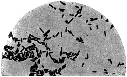
BACILLUS OF TYPHOID FEVER.
(Photo-Micrographs, 1,000 diam., by William M. Gray, M. D.)
BACILLUS OF TUBERCULOSIS IN SPUTUM.
BACILLUS OF DIPHTHERIA (KLEBS-LOEFFLER).
BACILLUS OF TYPHOID FEVER.
FIG. 176.
Henle, a German physiologist, as early as 1840, maintained the doctrine of contagium vivum, or contagion by the transmission of living germs.[254] Certain classes of diseases have also long been known as zymotic, or ferment diseases. Louis Pasteur’s work, however, marks the first definite and important results in the study of bacteriology, and he is the father of the “germ theory” of disease. He exploded the previously held theories of scientists concerning the spontaneous generation of living things, and clearly established and promulgated the knowledge of disease germs. Commencing his great work about 1865 with the investigation of the silk worm plague in France, he discovered it to be due to parasites, and checked it. He also gave great attention to the subject of fermentation, proving it to be caused by micro-organisms. Taking up the diseases of men and animals, he gave practical value to the truths of his theory in the treatment of hydrophobia, diphtheria, and other diseases, using the principle of vaccination to destroy or render innocuous the toxins or disease-producing poisons derived from living germs. Working along the same lines must be mentioned Dr. Koch, whose success in detecting the microbes which cause consumption and cholera has made him famous the world over. Of the great variety of these little microbes which have been separately identified, many are innocuous, and, in fact, subserve many important and useful purposes in nature, while others are to be as much dreaded as the deadly cobra or the rattlesnake. A few typical examples of the latter are given in Figs. 176 and 177, multiplied 1,000 diameters. The illustrations[255] represented in Fig. 177 show the parasites that cause malaria, or fever and ague. The dark bean-shaped cells are the normal blood corpuscles, and the few speckled cells are those infested with the malarial parasites. It is now believed that the mosquito is the active factor in the dissemination of malaria, and it is, therefore, to be remembered that this pestiferous little insect not only inflicts a painful and disagreeable sensation with his puncture, but innoculates the system with poisonous malarial germs at the same time.
FIG. 177.—BLOOD OF MAN. SHOWING PARASITE OF MALARIA (LAVERAN).
(Photo-Micrographs, 1,000 diam., by William M. Gray, M. D.)
TERTIAN FORM.
AESTIVO-AUTUMNAL FORM.
FIG. 177.—BLOOD OF MAN. SHOWING PARASITE OF MALARIA (LAVERAN).
(Photo-Micrographs, 1,000 diam., by William M. Gray, M. D.)
FIG. 178.
TUBE CONTAINING CULTURE OF BACILLI OF TUBERCULOSIS.
TUBE CONTAINING CULTURE OF COMMA BACILLI OF CHOLERA.
TUBE CONTAINING CULTURE OF BACILLI OF TUBERCULOSIS.
TUBE CONTAINING CULTURE OF COMMA BACILLI OF CHOLERA.
FIG. 178.
For the study of bacteria they are propagated artificially in a test tube—i. e., a substance called a “culture” is prepared from some organic material which, like the substances of the human body, is favorable to their propagation. Such culture media are found in beef blood, gelatine, beef extracts, meat broth, milk, etc. An ordinary test-tube is supplied with some of the culture medium, and is then sterilized over the fire to destroy all interfering germs. Material infected with the microbe is then placed in the test-tube by a sterilized platinum wire and the tube closed by raw cotton. It is then placed in an incubator oven and is subjected to a gentle heat. In a little while the microbes begin to develop and increase, forming colonies, in which they swarm by the million, and present the clotted appearance seen in Fig. 178. The separation of different bacteria existing in the same material, so as to isolate each species and get what is called a “pure culture,” has been greatly promoted by Prof. Koch’s method of plate culture. In this the propagation of bacteria is effected upon a sterilized glass plate under a bell jar in such a thin layer as to facilitate the segregation of species, enabling them to be counted under the microscope and picked out and sown in another culture to get an unmixed crop of a[256] definite species. Such a culture so multiplies the same microbe, to the exclusion of others, as to permit it to be easily identified and studied.
According to the practice in modern municipal health regulations, the test as to when a child recovering from diphtheria is incapable of disseminating the disease is by test culture. A swab of cotton is rubbed against the interior walls of the child’s throat to secure the germs (if present), and the swab is then placed in a “culture” in a test-tube and the tube put in an incubator. If, after the period of incubation, no colonies of the germs develop, it is accepted as evidence that the diphtheria germs are no longer present in the throat, and the child is released from quarantine.
It is the presence of these specific microbes in the fluids or solids of the system which constitutes the disease, and for the cure of the same the intelligent physician of to-day looks less to medication, and more for some agent that will destroy the germ, neutralize its effect, or render the body tolerant thereto. Out of the knowledge of disease germs has grown the great era of antiseptic surgery, inaugurated by Sir Joseph Lister, about 1865. Carbolic acid, the bichloride of mercury, and formalin are the most efficient weapons against the dreaded microbe. To-day every surgeon in the civilized world sterilizes his knife, and conducts the treatment of wounds and all operations by antiseptic methods, in accordance with a knowledge of the deadly influence of the ubiquitous microbe, and the result has been to so reduce the risk to life that even capital operations are no longer coupled with the apprehensions of death. Every hospital, board of health, and organized medical and sanitary body predicates its laws and modes of treatment upon the principles of bacteriology.
House Sanitation.—The permanent home of the microbe is the sewer, and sanitary plumbing, designed to exclude from the house the germ-laden and disease-breeding gases from the sewer, constitutes one of the great advances of the century. About 3,500 patents have been granted for water closets and bath appliances, and about 900 patents on sewerage alone, the most of which are directed to improved conditions of sanitation.
An illustration of the plumbing and sewer connections of a modern house is given in Figs. 179 and 179A. The sewer pipes are shown in solid black, the unshaded pipes (in outline only) are air ventilation pipes, the single black lines are cold water pipes, and the dotted lines hot water pipes. The important sanitary feature in modern plumbing is to keep all sewer gas and disease germs out of the house. For this purpose traps have long been used under the wash basins, closet hoppers, and sinks; but the back pressure of sewer gas would sometimes bubble through the trap into the house, and besides the water in passing out from a basin would sometimes, by a siphon effect, pass entirely out of the trap, leaving it unsealed. Both these results are prevented by the air ventilation pipes which connect with the discharge side of every trap in the house and lead to a stack extending out through the roof. This prevents pressure of sewer gas on the water seal of the trap, destroys the siphon action of the trap and allows a circulation of air to be taken in from the sidewalk on the house side of the running trap and through the sewer pipe of the house, and thence through the air vent pipes to the roof.
The great science of bacteriology, dealing with these smallest of living things, only came into existence with the microscope, and it was a field which was not only wholly unknown and unexplored a few years ago, but there was no suggestion visible to the eye to direct attention to it, until the lens began to reveal the secrets of microcosm. What development the future may bring no one can predict, but to the biologist and the physician no more promising field exists. Certain it is that the knowledge already gained is of incalculable benefit, and constitutes one of the greatest eras of progress the world has known, for with the noble army of patient, devoted, and self-sacrificing physicians, the discoveries of the scientist, our boards of health, our hospitals and asylums for the insane, our quarantine laws, our modern plumbing and improved sanitation in the home and public departments, there is no reason why the life of man should not be extended far beyond the three-score and ten years, and the 50 per cent. of population dying in childhood saved for useful lives and citizenship.
The Draisine, 1816—Michaux’s Bicycle, 1855—United States Patent to Lallement and Carrol, 1866—Transition from “Vertical Fork” and “Star” to Modern “Safety”—Pneumatic Tire—Automobile, the Prototype of the Locomotive—Trevithick’s Steam Road Carriage, 1801—The Locomobile of To-day—Gas Engine Automobiles of Pinkus, 1839; Selden, 1879; Duryea, Winton and Others—Electric Automobiles a Development of Electric Locomotives as Early as 1836—Grounelle’s Electric Automobile of 1852—The Columbia, and Other Electric Carriages—Statistics.
However superior to other animals man may be in point of intellect, it must be admitted that he is vastly inferior in his natural equipment for locomotion. Quadrupeds have twice as many legs, run faster, and stand more firmly. Birds have their two legs supplemented with wings that give a wonderfully increased speed in flight, and fish, with no legs at all, run races with the fastest steamers; but man has awkwardly toddled on two stilted supports since prehistoric time, and for the first year of his life is unable to walk at all. That he has felt his inferiority is clear, for his imagination has given wings to the angels, and has depicted Mercury, the messenger of the gods, with a similar equipment on his heels. We see the ambition for speed exemplified even in the baby, who crows in exhilaration at rapid movement, and in the boy when the ride on the flying horses, the glide on the ice, or the swift descent on the toboggan slide, brings a flash to his eye and a glow to his cheeks.
A characteristic trend of the present age is toward increased speed in everything, and the most conspicuous example of accelerated speed in late years is the bicycle. It has, with its fascination of silent motion and the exhilaration of flight, driven the younger generation wild with enthusiasm, has limbered up the muscles of old age, has revolutionized the attire of men and women, and well-nigh supplanted the old-fashioned use of legs. It is the most unique and ubiquitous piece of organized machinery ever made. The thoroughfares and highways of civilization fairly swarm with thousands of glistening and silently gliding wheels. It is to be found[260] everywhere, even to the steppes of Asia, the plains of Australia, and the ice fields of the Arctic.
The true definition of the bicycle is a two-wheeled vehicle, with one wheel in front and the other in the rear, and both in the same vertical plane. Its life principle is the physical law that a rotating body tends to preserve its plane of rotation, and so it stands up, when it moves, on the same principle that a top does when it spins or a child’s hoop remains erect when it rolls.
A form of carriage adapted to be propelled by the muscular effort of the rider was constructed and exhibited in Paris by Blanchard and Magurier, and was described in the Journal de Paris as early as July 27, 1779, but the true bicycle was the product of the Nineteenth Century. It was invented by Baron von Drais, of Manheim-on-the Rhine. See Fig. 180. It consisted of two wheels, one before the other, in the same plane, and connected together by a bar bearing a saddle, the front wheel being arranged to turn about a vertical axis and provided with a handle for guiding. The rider supported his elbows on an arm rest and propelled the device by striking his toes upon the ground, and in this way thrusted himself along, while guiding his course by the handle bar and swivelling front wheel. This machine was called the “Draisine.” It was patented in France for the Baron by Louis Joseph Dineur, and was exhibited in Paris in 1816. In 1818 Denis Johnson secured an English patent for an improved form of this device, but the principle of propulsion remained the same. This device, variously known as the “Draisine,” “vélocipède,” “célérifère,[261]” “pedestrian curricle,” “dandy horse,” and “hobby-horse,” was introduced in New York in 1819, and was greeted for a time with great enthusiasm in that and other cities.
On June 26, 1819, William K. Clarkson was granted a United States patent for a vélocipède, but the records were destroyed in the fire of 1836. In 1821 Louis Gompertz devised an improved form of “hobby-horse,” in which a vibrating handle, with segmental rack engaging with a pinion on the front wheel axle, enabled the hands to be employed as well as the feet in propelling the machine. Such devices all relied, however, upon the striking of the ground with the toes. Their fame was evanescent, however, and for forty years thereafter little or no attention was paid to this means of locomotion, except in the construction of children’s carriages and velocipedes having three or more wheels.
In 1855 Ernst Michaux, a French locksmith, applied, for the first time, the foot cranks and pedals to the axle of the drive wheel. A United States patent, No. 59,915, taken Nov. 20, 1866, in the joint names of Lallement[262] and Carrol, represented, however, the revival of development in this field. Lallement was a Frenchman, and built a machine having the pedals on the axle of the drive wheel, and it was at one time believed that it was he who deserved the credit for this feature, but it is claimed for Michaux, and the monument erected by the French in 1894 to Ernest and Pierre Michaux at Bar le Duc gives strength to the claim. The bicycle, as represented at this stage of development, is shown in Fig. 181. In 1868-’69 machines of this type went extensively into use. Bicycle schools and riding academies appeared all through the East, and notwithstanding the excessive muscular effort required to propel the heavy and clumsy wooden wheels, the old “bone-shaker” was received with a furor of enthusiasm.
In 1869 Magee, in Paris, made the entire bicycle of iron and steel, solid rubber tires and brakes followed, and the front wheel began to grow to larger size, until in 1879 the bicycle presented the form shown in Fig. 182. This placed the weight of the rider more directly over the drive wheel, and was known as the “vertical fork.” It gave good results but for the accidents[263] from “headers,” to which it was especially liable. Means to overcome the danger were resorted to, and the “Star” bicycle represented such a construction. In this the high wheel was behind and the small one in front, and straps and ratchet wheels connected the pedals to the axle. In 1877 Rousseau, of Marseilles, removed the pedals from the wheel axle and applied the power to the axle by a chain extending from a sprocket wheel on the pedal shaft to a sprocket wheel on the wheel axle. By gradual steps, initiated in Starley’s “Rover” in 1880, (see Fig. 183), the high front wheel was reduced in size, until the proportions of the modern “Safety” (Fig. 184) have been obtained. Strange to say, these proportions have, through nearly a century of evolution, gone back to those employed in the old “Draisine,” where the two wheels were of the same size. The modern “Safety,” however, is quite a different machine. Its diamond frame of light but strong tubular steel, its ball bearings, its suspension wheels and pneumatic tires impart to the modern bicycle strength with lightness, and beauty with efficiency, to a degree scarcely attained by any other piece of organized machinery designed for such trying work.
The most important of all modern improvements on the bicycle was perhaps the pneumatic tire. This was not originally designed for the bicycle, but was patented in England by R. W. Thompson in 1845 and in the United States May 8, 1847, No. 5,104. Its application to the bicycle was made in 1889 by Dunlop, United States patent No. 435,995, Sept. 9, 1890, and 453,550, June 2, 1891. It furnishes not only an elastic bearing which cushions the jar, but also makes a broader tread that renders cycling on the soft roads of the country at once practical and delightful. The chainless wheel, which connects the axle of the pedal crank with the axle[264] of the rear wheel by a shaft with bevel gears, is the most recent form exploited by the manufacturers, but it is doubtful whether it presents any points of superiority over the chain type. All of the parts of the bicycle have come in for a share of attention at the hands of inventors, differential speed gears and brakes having received especial attention. The Morrow hub brake, which applies friction to the rear wheel hub by back pressure on the pedal, is a popular modern form. The first back-pedal brake is shown in United States Pat. No. 418,142, to Stover & Hance, Dec. 24, 1889.
Among the many modifications of the bicycle as used to-day may be mentioned the drop frame, which has made cycling possible for ladies, the tandem, for two riders, the sextet or octet, carrying six or eight riders and resembling a centipede in movement and an express train in speed: the ice velocipede, in which two runners are combined with a spiked driving wheel, and the hydrocycle, or water velocipede, in which the drive wheel, formed with paddles, is used to propel a buoyant hull through the water.
In point of speed there seems to be no limit to the bicycle. In a test made on the Long Island Railroad in the summer of 1899 between a wheel and an express train, the bicyclist, riding on a plank road between the rails and protected behind the train by a wind break, covered a mile in 574⁄5 seconds, and while going at top speed of more than a mile a minute, overtook the train, was caught by his friends on a rear platform and pulled on board, bicycle and all. This is the first instance on record of overtaking[265] and boarding an express train going at the rate of sixty-four miles an hour, and yet it is said that the rider (Murphy) was not doing his best.
Nearly 5,000 patents have been granted on velocipedes and bicycles. Most of them were for bicycles which, as improved to-day, are not only as fleet as the birds, but almost as countless in numbers. It is estimated that in 1889 the total product of bicycles in this country reached 200,000 machines annually. In 1892, after the general adoption of the pneumatic tire, a great increase followed, which has grown from year to year until in the year 1899 a conservative estimate for the output in the United States is 1,000,000 wheels annually, worth from thirty to fifty million dollars. Each bicycle tire takes about two pounds of pure rubber, or four pounds to the wheel. The annual output in wheels consequently consumes about 4,000,000 pounds, or 2,000 tons of rubber. Ten years ago there were not more than twenty-five legitimate manufacturers of bicycles in the United States. In 1897 there were over 200 concerns in the business. It is estimated that there are to-day between 150 and 155 regular manufacturers, exclusive of the mere assemblers of parts. The Pope Manufacturing Company, which occupies the leading place, employed in 1888 about 500 hands. To-day their shops give employment to 3,800 workmen, which furnishes a significant object lesson as to the importance and growth of the industry.
The Automobile.—Gliding silently along our city streets without the customary accompaniment of the clatter of the horse’s hoofs, the automobile suggests to the average observer a very recent invention. This is, however, not the case. The automobile is older even than the locomotive, and is, in fact, the early model from which the rail locomotive was evolved. As early as 1680 Sir Isaac Newton proposed a steam carriage in which the propelling power was the reactionary discharge of a rearwardly directed jet of steam. Cugnot, in 1769, built a steam carriage, which is still preserved in the museum of the Conservatoire des Arts et Métiers in Paris. Hornblower also in the same year devised a steam carriage. Watt’s patents of 1769 and 1784 contemplated the application of his steam engines to carriages running on land. Symington in 1770, and Murdoch in 1784, built experimental models. In 1787 Oliver Evans obtained a patent in Maryland for the exclusive right to make steam road wagons. Nathan Read in 1790 also patented and built a steam carriage.
Of these, Cugnot represents the pioneer in the heavier forms of self-propelled vehicles, but the steam carriage which best deserves to be regarded as the prototype of the modern passenger automobile is that[266] of Trevithick, in England, who may also be considered as the father of the locomotive. On Christmas eve, 1801, this steam carriage made its experimental trip along the high road carrying seven or eight passengers. The next day the party, with Trevithick in charge of the engine, visited Tehidy House, the home of Lord Dunstanville. They met with an accident, however, and the carriage turned over. It was placed under shelter, and while the party were at the hotel regaling themselves with roast goose and popular drinks, the water in the engine boiled away, the iron became red hot, and nothing combustible was left either of the carriage or the building in which it was sheltered. On March 24, 1802, Trevithick and Vivian obtained a British patent, No. 2,599, on this device, and another carriage was built, and in the spring of 1803 started a run from Camborne to Redruth, but it stuck in the mud. It was popularly known as Capt. Trevithick’s “Puffing Devil.” It was subsequently reconstructed in London and run upon the streets of that city. Fig. 185 presents an illustration of the first steam automobile. The cylinders and pistons were enclosed within the fire box in the rear. Clutches (called striking boxes) on the axle of the front gear wheel allowed either running wheel to move independently of the other in turning. A pair of small front steering wheels was arranged to turn about a vertical axis and was manipulated by a handle bar. A brake was provided for in the specification, as were also variable gears for changing speed, and an automatic blower for the fire. The carriage had an elevated coach body mounted on springs, and the running wheels were of large size, adapted to the higher speed and lighter uses of passenger traffic.
It is not possible to trace the succeeding steps in steam carriage development by James and Anderson, by Gurney, in 1822, by Marcerone and Squire in 1833, by Russel in 1846, and many others; it is sufficient to[267] know that bad roads and the success attending the steam locomotive on rails diverted attention from the steam road carriage, and not until the latter part of the Nineteenth Century was there any marked revival of interest in this field. Then came first the ponderous road engine, known as a traction engine, and used for heavy hauling; and this in the last decade has been followed by the modern steam motor carriage, an example of which is seen in Figs. 186 and 186A, which represent the “Locomobile” and its actuating mechanism. The fuel used is gasoline, stored in a three-gallon tank under the footboard. The boiler, which is arranged under the seat, is a vertical cylinder wrapped with piano wire for greater tensile strength, and contains 298 copper tubes. The engine, which is seen in Fig. 186A, is arranged in upright position under the seat, in front of the boiler, has two cylinders, 21⁄2-inch diameter and 4-inch stroke, a Stephenson link-motion and an ordinary D-valve. Sprocket wheels and a chain connect the engine shaft to the rear axle. The engine runs from 300 to 400 revolutions per minute and develops from[268] four to five horse power. It has a muffle for the steam exhaust and the whole weight is 550 pounds. It is one of the lightest and cheapest of automobiles, runs easily at ten to twelve miles an hour, and is an efficient hill-climber. Although naming the steam automobile first because of its earlier genesis, it is not to be understood as representing at present the most popular type of motor carriage, although it bids fair to become so.
In France and the continent of Europe the type employing an explosive mixture of gasoline and air is most frequently found, and in England and the United States the electric motor with the storage battery is chiefly used.
In automobiles of the explosive gas type probably the earliest example is found in the British patent to Pinkus, No. 8,207, of 1839. In France Lenoir, in 1860, is credited with being the pioneer. Among modern applications the patent to George B. Selden, No. 549,160, occupies a prominent place. This was only granted Nov. 5, 1895, but the application for the patent was filed in the Patent Office May 8, 1879 so that the invention described has quite an early date, and some broad claims have been allowed to the inventor. In the last decade many applications of the explosive gas engine to road carriages and tricycles have been made, especially in France. Representative motor carriages of this type are to be found in the United States in the Duryea and the Winton. An illustration of the latter is given in Fig. 187. The form shown represents a phaeton weighing 1,400 pounds; the motor is of the single hydrocarbon type, and is simple, powerful and compact.[269] It is also free from noise and vibration, and is under control at all times. The maximum speed is eighteen miles an hour.
Probably the most popular type of the automobile in the United States is the “electric.” The application of the electric motor to the propulsion of vehicles dates back to quite an early period. It is said that as far back as 1835 Stratingh and Becker, of Groeningen, and in 1836 Botto, of Turin, constructed crude electric carriages. Davenport, in 1835, Davidson, in 1838, and Dr. Page, in 1851, built electric locomotives which ran on rails. The prototype of the electric automobile[270], however, is best represented in the French patent to M. Grounelle, No. 7,728, Feb. 7, 1852 (2 Ser., Vol. 25, p. 220, pl. 46.) This shows a perfectly equipped electric automobile. It did not have a practical electric generator, however, for the storage battery was not then known. A large sulphate of copper battery was employed, which could through the agency of a train of gears give only a very slow speed. This road carriage, however, only needed a storage battery to make it a well organized and efficient electric automobile. It is believed by many that electricity fulfills more of the necessary conditions of a successful motive power for motor carriages than any other power. It is clean, compact, noiseless, free from vibration, heat, dirt and gases, and is under perfect control. Its chief objection is that it is only possible to recharge it where electric power is available, and in this respect it is inferior to the gasoline motor, whose supply may be conveniently obtained at every city, village, and country store. The Columbia two-seated Dos-a-Dos[271] (Fig. 188), Woods’ Victoria Hansom Cab, and the Riker Electric Delivery Wagon are representative types of the modern electric automobile.
All of the motor carriages illustrated are of American make, and for lightness, grace, and efficiency they have no superiors. A peculiar and recent type which attracted much attention and took the gold medal at the Motor Carriage Exposition at Berlin, held in September, 1899, is the Pieper double motor carriage. It has both a benzine motor and an electric motor, which can be worked separately or together, and yet is said to be lighter than most electric carriages. On a long journey, remote from electrical supply, the benzine motor is used not only to propel the carriage, but by running the electric motor as a dynamo or generator, recharges the storage battery. On level, easy roads, where the power required falls below the maximum power exerted by the benzine motor, the electric motor changes automatically to a dynamo and the surplus force of the benzine motor is converted into current and stored. In running down hill or stopping the carriage, the momentum of the vehicle is also received by the electric motor acting as a dynamo and brake, and is stored as electricity in the battery, which is thus in an ordinary journey kept constantly charged.
It is not probable that man will ever be able to get along without the horse, but the release of the noble animal from the bondage of city traffic, which was begun only a few years ago with mechanical street car propulsion, promises now to be extensively advanced by the substitution of the motor carriage and the auto-truck for team-drawn vehicles. The rapidity with which this industry has grown, and its promise for the future may be realized when it is remembered that so far as practical results are concerned it has all grown up in the last decade of the Nineteenth Century, and yet to-day it is said that there are already in the United States about 200 incorporated concerns with an aggregate capitalization of some $500,000,000, organized to build automobiles, to say nothing of the vast number of individuals who are experimenting in this field. The greatest activity, however, is to be found in France, which claims over 600 manufacturers and has in use 6,000 automobiles out of a total of 11,000 in all of Europe.
The most significant suggestion for the future of the automobile is that the cost of maintenance and all things considered, it is in some applications cheaper than the horse-drawn vehicles of the same efficiency. In a consular report of Oct. 16, 1899, forwarded to the State Department by Mr. Marshal Halsted, consul at Birmingham, Mr. E. H. Bayley, an English authority, is quoted as saying that in operating[272] heavy motor vehicles for hauling, the cost is three half-pence (three cents) per net ton per mile, as compared with 18 to 24 cents per net ton per mile by horse-drawn vehicles. In England much attention is being given to this subject.
As before stated, the modern automobile cannot be considered as a new invention so far as fundamental principles are concerned. Its success, in late years, is to be credited to the perfection of the arts in general, and as essential factors contributing to this may be named the refinement of steel, giving increased strength with lightness, the increased efficiency of motive power, the vulcanization of rubber, the mathematical nicety of mechanical adjustment, the reduction of friction by ball bearings, the wonderful developments in electricity and improvement in roads.
Invention of Phonograph by Edison—Scott’s Phonautograph—Improvements of Bell and Tainter—The Graphophone—Library of Wax Cylinders—The Gramophone.
Following closely upon the discovery of the telephone the phonograph came, literally speaking for itself, and adding another surprise to the wonderful inventions of that prolific period. It was in the latter part of 1877 that Thomas A. Edison showed to a few privileged friends a modest looking little machine. He turned the crank, and to the astonishment of those present it said. “Good morning! How do you do? How do you like the phonograph?” Its voice was a little metallic, it is true, but here was presented an insignificant looking piece of mechanism which was undeniably a talking machine and one with an unlimited vocabulary. So-called talking machines had been made before, of which the Faber machine was a type. These, by an arrangement of bellows to furnish air, and flexible pipes in imitation of the larynx and vocal organs, made laborious and wheezy efforts to imitate the mechanical functions of the throat and tongue in articulate speech, but the method was fundamentally faulty and no success was attained. Edison followed no such leading. His phonograph made no attempt at imitating in construction the complex organization of the human throat, but was as wonderful in its divergence therefrom and in its simplicity as it was in the success of its results. The machine was patented by him Feb. 19, 1878, No. 200,521, and its life principle is simply and clearly defined in the first claim of the patent, as follows:
“The method herein specified of reproducing the human voice, or other sounds, by causing the sound vibrations to be recorded substantially as specified, and obtaining motion from that record as set forth for the reproduction of sound vibrations.”
The invention was a striking and interesting novelty and at once attracted the attention of scientific men as well as the general public. Its first public exhibition was about the latter part of January, 1878, before the Polytechnic Association of the American Institute, at New York. It[274] spoke English, French, German, Dutch, Spanish and Hebrew with equal facility. It imitated the barking of a dog and crowing of a cock, and then catching cold, coughed and sneezed and wheezed until it is said a physician in the audience proposed sending a prescription for it. It was also suggested by an irreverent man that it might take the place of preachers in the rendition of sermons, while another thought that as it reproduced music with equal facility it might take the place of preacher and choir both. In the spring of 1878 it was exhibited at Washington by Edison and his assistant, Mr. Batchelor. Mr. Edison was the guest of Mr. U. H. Painter, and in his parlors it was shown to a party of gentlemen.
From Mr. Painter’s house the machine was taken to the office of the Assistant Secretary of the Interior, thence to the Academy of Sciences, in session at the Smithsonian Institution, and at night it was taken to the White House and exhibited to President and Mrs. Hayes.
The form of the first phonograph is shown in Fig. 189. It consisted of three principal parts—the mouthpiece A, into which speech was uttered, the spirally grooved cylinder B, carrying on its periphery a sheet of tin foil, and a second mouthpiece D. The cylinder B and its axial shaft were both provided with spiral grooves or screw threads of exactly the same pitch, and when the shaft was turned by its crank its screw threaded bearings caused the cylinder to slowly advance as it rotated. The mouthpiece A had adjacent to the cylinder a flexible diaphragm carrying a little point or stylus which bore against the tin foil on the cylinder. When the mouthpiece A was spoken into and the cylinder B was turned, the little stylus, vibrating from the voice impulses, traced by indentations[275] a little jagged path in the tin foil that formed the record. To reproduce the record in speech again, the mouthpiece A was adjusted away from the cylinder, the cylinder run back to the starting point, and mouthpiece D was then brought up to the cylinder. This mouthpiece had a diaphragm and stylus similar to the other one, only more delicately constructed. This stylus was adjusted to bear lightly in the little spiral path in the tin foil traced by the other stylus, and as the tin foil revolved with the cylinder its jagged irregularities set up the same vibrations in the diaphragm of mouthpiece D as those caused by the voice on the other diaphragm, and thus translated the record into sounds of articulate speech, exactly corresponding to the words first spoken into the instrument. In Fig. 190 is shown a further development of the phonograph, in which a single mouthpiece with diaphragm and stylus serves[276] the purpose both of recorder for making the record and a speaker for reproducing it, a trumpet or horn being used, as indicated in dotted lines, to concentrate the vibrations in recording and to augment the sound in reproducing.
The phonograph is in reality a development of the phonautograph, which was an instrument invented by Leon Scott in 1857 to automatically record sounds by diagrams. There is a model of Scott’s phonautograph in the National Museum at Washington, D. C, and it consists of a chamber to catch the sound waves and an elastic diaphragm with stylus working on a revolving cylinder bearing a sheet of paper coated with lampblack. The phonograph’s record-making mouthpiece, with its diaphragm and stylus, is substantially a phonautograph, but instead of simply causing the stylus to trace a record on carbon-coated paper and stopping with this result, Edison traced a record in a substance—tinfoil—which was capable of mechanically translating that record into sound again by a mere reversal of the function of the stylus and diaphragm. This was the very essence of simplicity and logical reasoning. All records had been heretofore traced for visual inspection only. Edison’s record was not for visual inspection, but was endowed with the mechanical function of reproducing sound.
From the first Edison believed that his phonograph was to fill an important place in the business activities of the world, since here seemed a silent but faithful stenographer which reproduced the words of the speaker with absolute fidelity, even to the quality of emphasis and inflection, and which made no mistakes, was always even with the speaker in its work, and asked no questions. For a number of years, however, the invention lay dormant and served no other purpose than that of a scientific curiosity or an amusing toy. The difficulty of its practical application largely existed in the perishable form of the record, which, being in tinfoil, was liable to be mutilated and distorted, and was not well adapted for storage or transportation.
A few years after the announcement of Mr. Edison’s invention. Dr. Alexander Graham Bell, the distinguished inventor of the telephone, with his associates, Messrs. Chichester A. Bell and Charles Sumner Tainter, directed their attention to the improvement of the phonograph. Dr. Bell had received from the French government, upon the recommendation of the French Academy of Sciences, the Volta prize of 50,000 francs as a recognition of his successful work in acoustics and the invention of the telephone, and with this sum he built the Volta Institute in Washington and carried on the work of developing the phonograph.
On May 4, 1886, Chichester A. Bell and Sumner Tainter obtained patents Nos. 341,214 and 341,288, which covered a great improvement in the record of the phonograph. This invention substituted for the tinfoil sheet a surface of wax, which was finally fashioned into a cylinder, and instead of merely indenting the record on tinfoil the stylus cut a distinct groove or kerf in the wax cylinder as it revolved, dislodging therefrom a minute filament or shaving and forming a record which was not only far more positive in its translating effect and more easily transported and stored, but was also less perishable, and besides it could be easily effaced without loss of the cylinder by simply smoothing off the surface of the cylinder again when it was desired to make a new record. This invention quickly grew into practical use, and is known as the “Graphophone.”
In Fig. 191 is shown on the left a cross section of the diaphragm, recording stylus, and wax cylinder, of the graphophone, the stylus plowing a tiny groove in the wax cylinder in the act of recording the speech, and on the right is shown the reproducing stylus traversing the record groove in the wax cylinder, and the diaphragm chamber with which the ear tubes are connected. The grooves in the wax, although giving[278] forth mechanical movement that is translated into sound, are very minute, being only 6⁄10,000 of an inch deep.
When the possibilities of the graphophone became known, capital was quickly supplied for its commercial exploitation, and the Columbia Phonograph Company was organized. At the present time, owing to the great increase in the business, the control of the graphophone business is vested in two branches, the Columbia Phonograph Company, which has charge of the selling, and which has offices throughout all the principal cities of this country and some of the larger ones of Europe, and the American Graphophone Company, which attends to the manufacturing branch, and whose factory is located at Bridgeport, Conn., where, it is said, that in 1898 the production of the factory reached the point of one graphophone for every minute of the day, making a total daily output of 600 machines. Although the Bell and Tainter patents of 1886 represent the basic principles of the graphophone, its development and perfection have been contributed to in many subsequent improvements by Messrs. Bell, Tainter, McDonald, and others. The more important of these are covered by patents No. 375,579, Dec. 27, 1887; No. 380,535, April 3, 1888; No. 527,755, Oct. 16, 1894, and No. 579,595, March 30, 1897.
At the beginning of this industry it was thought that the principal use of the instrument would be found in business applications, to take the place of the stenographer, but it proved difficult to revolutionize office methods, especially as the earlier machines were somewhat intricate, and the business man had no time to divide in engineering a machine. These difficulties, however, have been so far overcome by modern improvements and simplification of the machine that its use in business houses as an amanuensis has become quite common. The greatest use of the graphophone is, however, for amusement purposes. Its songs, orchestral and solo renditions, and its humorous monologue reproductions constitute to-day a great library of wax cylinders, regularly catalogued and sold by the thousands. It will readily be understood that the formation of the cylinders must constitute a great business of itself when it is remembered that many record cylinders accompany each graphophone, and that the latter are turned out at the rate of one a minute by a single company. Many thousands of these cylinders are made daily. Some are sent out simply as plain wax cylinders, onto which the records are made by the voice of the purchaser, while others have records made for them of popular music, monologues in dialect, humorous speeches, etc. The waxy composition, which is in reality a species of soap, is melted[279] in huge pots, and then passes from one floor to another, undergoing a refining process in its progress, and finally reaches the molds. These molds are arranged in rows around a horizontal wheel about eight feet in diameter. The wheel is kept revolving, and a man on one side is kept constantly busy in filling the molds with the molten material as they reach him. A half revolution of the wheel brings the filled molds to the other side of the room, and by that time the material has hardened sufficiently to enable another attendant, stationed there, to remove the cylinders from the molds. Thus the wheel is kept going, receiving at one side a charge of the melted wax and discharging at the other molded cylinders, which are afterwards turned true on the surface. The record-making department is both unique and interesting. Here the records of music are produced, and they are made by bands and performers engaged for the purpose, many of which, operating at the same time, produce such a medley as to be scarcely distinguishable to the visitor. The records are tested by about half a hundred women, each of whom has a little compartment or booth framed in by glass partitions. The duty of the tester is to decide upon the merits of the record by actually listening to it on the graphophone.
A very important feature in record-making, from a commercial standpoint, is in means for cheaply duplicating records. If every record cylinder had to be made by the separate act of a performer such records would be very expensive. An original record is first made by some celebrated musician or speaker, and this record is afterwards multiplied and reproduced in large numbers. For this purpose an original record by suitable mechanism is made to take the place of the speaker or singer, and so multiplies and reproduces the original record. The duplicating of records was contemplated by Edison from the first, as seen in his British patent, 1,644 of 1878, and later appliances for accomplishing such results are covered under Tainter’s patent, No. 341,287, Bettini’s, No. 488,381, and McDonald’s, No. 559,806. The diaphragms used in the recorders and reproducers are made of French rolled plate glass, thinner than a sheet of ordinary writing paper. The recording stylus is shaped like a little gouge to cut the little grooves in the wax, while the corresponding stylus of the reproducer has a ball-shaped end to travel in the groove. Both the recording stylus and reproducing ball are made of sapphire, chosen on account of its hardness, to resist the great frictional wear to which they are subjected. When a record is to be effaced from a cylinder, it is turned off smooth on a sort of lathe, and the cutting tool or knife for this purpose is also made of sapphire.
The latest, loudest, and most impressive form of the talking machine is the “Graphophone Grand.” This has a horn attachment exceeding the big horn of a brass band in size, and the wax cylinder is about four inches in diameter. Its reproductions in music and speech are so full and strong as to be clearly heard at the most remote part of a large hall, and its versatile voice lends effective rendition to all sorts and kinds of sounds, from the inspiring chords of “A Choir Invisible” to the grandiloquent and facetious rattle of a noisy and hustling auctioneer.
It is not to be understood, however, that the graphophone is the only speaking machine on the market, for about 250 patents have been granted on phonographs and graphophones. The National Phonograph Company, under many later patents granted to Mr. Edison, manufactures and sells the phonograph shown in Fig. 192, which is a very ingenious and effective instrument. This modern form of phonograph is actuated either by electricity or spring power, is regulated by a speed governor, and bifurcated ear tubes connect with the diaphragm case, which tubes are placed in the ears when the instrument is operated.
The gramophone is also another speaking machine. This is the invention of Mr. E. Berliner and covered by him in patent No. 372,786, Nov. 8, 1887. An illustration of the gramophone recorder is given in[281] Fig. 193. Instead of a wax cylinder this machine employs a flat disc on which the record is formed as a volute spiral groove, gradually drawing toward the center. It is produced as follows: A zinc disc is covered by a thin film of acid resisting material, such as wax or grease, and is placed in a horizontal pan, mounted to revolve as a turn table about a vertical axis. A stylus and diaphragm, with speaking tube attached, are arranged above the disc, and when spoken into the vibrations of the diaphragm cause, through the stylus, a record to be traced through the wax, down to the zinc. As the waxed disc and pan are revolved, the stylus and diaphragm are gradually moved by gears toward the center of the disc. While the record is being traced the waxed disc is kept flooded with alcohol from a glass jar, seen in the cut, to soften the film and prevent the clogging of the stylus. The disc, when completed, is then rinsed off and etched with acid, chromic acid being used, to prevent liberation of hydrogen bubbles. The etched disc is then electrotyped to form a matrix, and from this electrotype hard rubber duplicates of the[282] original record are molded, which are capable of giving 1,000 reproductions. These rubber discs are placed on the reproducing instrument, which is arranged to cause the stylus to freely trail along in the spiral groove, and when the disc is rotated under the said stylus its record is converted into articulate speech. Such flat disc records give quite loud reproductions, are not easily destroyed, and may be compactly stored and transported. In the gramophone the diaphragm stands at right angles to the record disc and the stylus does not vibrate endwise to make a path of varying depth, as in the phonograph and graphophone, but the stylus vibrates laterally and traces a little zigzag line.
The cost of a talking machine is from $5 to $150. The wax cylinders cost from 25 cents to $3.00, and the cylinders will hold a record of from 800 to 1,200 words, equivalent to about three or four pages of print in an octavo volume. An important part of such machines is the motor, which must maintain a uniform rate of speed, and much ingenuity has been displayed on this part of the machine. Probably the largest use of the phonograph or graphophone is for home amusement and exhibition purpose. The coin operated, or “nickel-in-the-slot” machine, finds a popular demand, while its utilitarian use as an amanuensis, or stenographer, is as yet a subordinate one.
Although twenty-one years of age, and of full growth, the phonograph is ever a wonderfully new and impressive device. When listening to it for the first time the conflict of emotions which it excites is difficult to analyze. A voice full of human quality, of clear and familiar enunciation, and speaking in the most matter of fact way about the most matter of fact things, proceeds from an insignificant and insensible bit of metal, presenting the apparently anomalous condition of speech without a speaker. When convinced that there is no trick, astonishment struggles with admiration and a desire for a personal introduction. We speak into it, and have the unique experience of listening to our own voice emanating from a different part of the room, instead of our own mouths. It is really difficult to believe one’s own senses, and no wonder that it inspires the superstitious with a feeling of awe. If Mr. Edison had lived a few centuries earlier, and had produced such an instrument, his life might have paid the penalty of his ingenuity, for without doubt he would have been classed as a wizard, and of close kin to the evil one.
The phonograph is the truth-telling and incontrovertible witness whose memory is never at fault, and whose nerves are never discomposed by any cross-examination. As evidence in court its word cannot be doubted, and the witness confronted by his own utterances from the[283] phonograph must yield to its infallible dictum. The dying father, unable to write, may dictate to it his last will and testament, and leave a message for his loved ones, and long after the sod is green on his grave, that message would still be audible, and fresh and true to all the tender inflections of the heart’s emotions. By its aid the Holy Father, at Rome, may give his personal and audible blessing to his children throughout the world, though separated by thousands of miles. Who can tell what stories of interesting and instructive knowledge would be in our possession if the phonograph had appeared in the ages of the past, and its records had been preserved? The voices of our dead ancestors, whose portraits hang on the wall, and the eloquent words of Demosthenes and Cicero would be preserved to us. In fact, we should be brought into vocal contact with the world’s heroes, martyrs, saints, and sages, and all the great actors and teachers whose personalities have made history, and whose teachings have given us our best ideals. But perhaps the most practical and best characterization of the phonograph is given in Mr. Edison’s own terse words. He says: “In one sense it knows more than we know ourselves, for it retains the memory of many things which we forget, even though we have said them. It teaches us to be careful of what we say, and I am sure makes men more brief, more businesslike, and more straightforward.”
Early Telescopes—The Lick Telescope—The Grande Lunette—The Stereo-Binocular Field Glass—The Microscope—The Spectroscope—Polarization of Light—Kaleidoscope—Stereoscope—Range Finder—Kinetoscope and Moving Pictures.
“And God said, Let there be light: and there was light. And God saw the light that it was good; and God divided the light from the darkness.” Thus early in the account of the creation is evidenced man’s appreciation of the value of vision. Of all the senses which place man in intelligent relation to his environment none is so important as sight. More than all the others does it establish our relation to the material world. When the babe is born, and its little emancipated soul is brought in contact with the world, its wondering gaze sees the panorama of visible things touching its eyes, and it stretches forth its tiny arms in the vain effort to pluck the stars, apparently within its reach. Distance and time add their values to light and vision, and as his life expands to greater fullness, the perspective of his existence creeps into his consciousness, and he finds himself farther away, but still peering beyond into the infinity of distance, searching for the visible evidence of knowledge. From the earliest times man learned to spurn the groveling things of earth, and to delight his soul with the marvelous infinity of the sky and its heavenly bodies. Nunc ad astra was his ambitious cry, and in no field has his quest for knowledge been more skillfully directed, faithfully maintained, or richly rewarded than in the study of astronomy. Many important discoveries in this field have been made in the Nineteenth Century, among which may be named the discovery of the planet Neptune by Adams, Leverrier and Galle in 1846; the satellites of Neptune in 1846, and those of Saturn in 1848 by Mr. Lassell; the two satellites of Mars by Prof. Asaph Hall in 1877; and the discovery of the so-called canals of Mars by Schiaparelli in 1877. But the purpose of this work is to deal with material inventions rather than scientific discoveries, and the leading invention in optics is the telescope.
Who invented the telescope is a question that cannot now be answered.[285] For many years Galileo was credited in popular estimation with having made this invention in 1609. But it is now known that, while he built telescopes, and discovered the mountains of the moon, the spots on the sun’s disk, the crescent phases of Venus, the four satellites of Jupiter, the rings of Saturn, and made the first important astronomical observations, the invention of the telescope, as an instrument, could not be rightly claimed for him. Borelli credits it to Jansen & Lippersheim, spectacle makers, of Middelburg, Holland, about 1590; Descartes credits it to James Metius; Humboldt says Hans Lippershey (or Laprey), a native of Wesel and a spectacle maker of Middelburg in 1608, naming also Jacob Adriansz, sometimes called Metius and also Zacharias Jansen.
The great impetus given to the study of astronomy by Galileo, in 1609, was followed up by Huygens in 1655 with his improvement, by Gregory’s reflecting telescope of 1663, and Newton’s in 1668. In 1733 Chester More Hall invented the achromatic object glass of crown and flint glass. In 1758 John Dolland reinvented and introduced the same in the manufacture of telescopes. In 1779 Herschel built his reflecting telescope, and in March, 1781, he discovered the planet Uranus. In 1789 he built his great reflector. It was while the latter telescope was exploring the heavens that the Nineteenth Century began, and in the early part of this century Herschel laid before the Royal Society a catalogue of many thousand nebulæ and clusters of stars. Among the great telescopes of the Nineteenth Century may be mentioned that made in London in 1802 for the observatory of Madrid, which cost £11,000; the great reflecting telescope of the Earl of Rosse, erected at Parsonstown, in Ireland, in 1842-45. This was 6 feet diameter, 54 feet focal length, and cost over £20,000; the magnificent equatorial telescopes set up at the National Observatories at Greenwich and Paris in 1860; Foucault’s reflecting telescope at Paris, 1862, whose mirror was 311⁄2 inches diameter, and focal length 173⁄4 feet; Mr. R. S. Newall’s telescope, set up at Gateshead by Cookes, of York, in 1870; object glass, 25 inches, tube, 30 feet; Mr. A. Ainslie Common’s reflecting telescope, Ealing, Middlesex, 1879, mirror, 371⁄2 inches diameter, tube, 20 feet; the telescope at the United States Observatory, at Washington, 1873, object glass, 26 inches, tube, 33 feet long; and the large refracting telescope by Howard Grubb, at Dublin, for Vienna, 1881.
In more recent times the great refracting telescope by Alvan Clark &
Sons, for the Lick Observatory on Mount Hamilton, California, in 1888,
attracted attention as superior to anything in existence up to that time.
This is shown in Fig. 194. The supporting column and base are of iron,
weighing twenty-five tons. This rests on a masonry foundation, which[286]
[287]
forms the tomb of James Lick, its founder. The tube is 52 feet long, 4 feet
diameter in the middle, tapering to a little over 3 feet at the ends. The object
glass is 36 inches in diameter, and weighs, with its cell, 530 lbs. The
steel dome is 75 feet 4 inches in diameter, and the weight of its moving
parts is 100 tons. This instrument was perfectly equipped with all gauges,
scales, photographic and spectroscope accessories, and fulfilled the condition
imposed in the trust deed of James Lick, of being “superior to and
more powerful than any telescope made.” It is a giant among instruments
of precision, and its ponderous aspect still asserts the dignity of its purpose,
and impresses even the frivolous visitor with a silent and thoughtful respect.
It is not to be understood, however, that the great Lick telescope still maintains its supremacy. The Yerkes telescope, which was exhibited at the World’s Fair Exposition in 1893, at Chicago, had an object glass of 3.28 feet in diameter and a focal distance of 65 feet, and it moved around a central axis in a vast cupola or dome 78 feet in diameter. The Grand Equatorial of Gruenewald, at the recent Berlin Exposition, was even still larger, since its object glass was 3 feet 7 inches, or nearly 2 inches larger than the Yerkes.
Even these great instruments have now been excelled in the Grande Lunette, of the Paris Exposition, in 1900. When it is remembered that an increase in the diameter of any circular body causes, for every additional inch, a vastly disproportionate increase in the cross-sectional area and weight, it will readily be seen how handicapped the instrument maker is in any increase in the power of such a telescope. An increased diameter of a few inches in the glass lens means an enormous increase in the cross section, its weight and the difficulties attending its successful casting free from imperfections, and the perfect grinding and polishing of the lens. An increased length of the tubular case of the telescope is liable to involve, from the great weight, a slight bending or springing out of axial alignment when supported near the middle for equatorial adjustment, and a few feet increase in the diameter of the massive and movable steel dome add greatly to the weight and incidental difficulties of constructing and delicately adjusting it. The great Lunette, see Fig. 195, changes entirely the method of manipulating the telescope, and also, in a measure, its principle of action, so as to avoid some of these difficulties. Its tube, instead of being pointed upwardly through the slot of a movable dome, and made adjustable with the dome, is laid down horizontally on a stationary base of supporting pillars, and an adjustable reflecting mirror and regulating mechanism, called a “siderostat,” is[288] arranged at one end, to catch the view of the star, or moon, and reflect it into the great tube, and through its lenses on to the screen at the other end. The tube is 197 feet long, and the object glass or lens is a fraction over 4 feet in diameter. There are two of these, which together cost $120,000. The siderostat is supported on a large cast iron frame, and is provided with clockwork and devices for causing the mirror to follow the movement of the celestial object which is being viewed. The entire weight of the siderostat and base is 99,000 pounds, the movable part weighs 33,000 pounds, and the mirror and its cell weigh 14,740. The mirror itself is of glass, weighs 7,920 pounds, is 6.56 feet in diameter,[289] and 10.63 inches thick. To facilitate the free and sensitive adjustment of this great mirror its base floats in a reservoir of mercury. The entire cost of the instrument is said to be over 2,000,000 francs. With the wonderful strides of improvement in all fields of invention, it is not unreasonable to suppose that the revelations in astronomy may keep pace with those of mundane interest, and that great discoveries may be made in the near future. The average individual does not bother himself much about the calculation of eclipses, or the laws which govern the movements of an erratic comet. He is, however, intensely personal and neighborly, and what he wants to know is, Is Mars inhabited? and if so, are its denizens men, and may we communicate with them? The wonderful regularity of the so-called canals, of apparently intelligent design, already discovered on the surface of Mars, has stimulated this neighborly curiosity into an expectant interest, and who knows what marvelous introductions the modern telescope may bring about?
Many minor improvements have been made in recent years in the form of the telescope known as field and opera glasses. Probably the most important of these is the Stereo-Binocular, invented by Prof. Abbe, of Germany, and patented by him in that country in 1893, and also in the United States, June 22, 1897, No. 584,976. This gives a much increased field, and also an increased stereoscopic effect, or conception of relative distance, by having the object glasses wider apart than the eyes of the observer. The field is also flatter, the instrument rendered very much smaller and more compact, and no change of focus is required for changing from near-by to remote objects. The rays of light, see Fig. 196, enter the object glasses, strike a double reflecting prism, and are first thrown away from the observer,[290] and then striking another double reflecting prism, arranged after Porro’s method, are returned to the observer in line with the eye-piece.
The Microscope.—Just as the telescope reveals the infinity of the great world above and around us, so does the microscope reveal the infinity of the little world around, about, and within us. Its origin, like the telescope, is hidden in the dim distance of the past, but it is believed to antedate the telescope. Probably the dewdrop on a leaf constituted the first microscope. The magnifying power of glass balls was known to the Chinese, Japanese, Assyrians and Egyptians, and a lens made of rock crystal was found among the ruins of Ninevah. The microscope is either single or compound. In the single the object is viewed directly. In the compound two or more lenses are so arranged that the image formed by one is magnified by the others, and viewed as if it were the object itself. The single microscope cannot be claimed by any inventor. The double or compound microscope was invented by Farncelli in 1624, and it was in that century that the first important applications were made for scientific investigation. Most of the investigations were made, however, by the single microscope, and the names of Borelli, Malpighi, Lieberkuhn,[291] Hooke, Leeuwenhoek, Swammerden, Lyonnet, Hewson and Ellis were conspicuous as the fathers of microscopy. For more than two hundred and fifty years the microscope has lent its magnifying aid to the eye, and step by step it has been gradually improved. Joseph J. Lister’s aplanatic foci and compound objective, in 1829, was a notable improvement in the first part of the century, and this has been followed up by contributions from various inventors, until the modern compound microscope, Fig. 197, is a triumph of the optician’s art, and an instrument of wonderful accuracy and power. Its greatest work belongs to the Nineteenth Century.
Multiplying the dimensions of the smallest cells to more than a thousand times their size, it has brought into range of vision an unseen world, developed new sciences, and added immensely to the stores of human knowledge. To the biologist and botanist it has yielded its revelations in cell structure and growth; to the physician its diagnosis in urinary and blood examinations; in histology and morbid secretions it is invaluable; in geology its contribution to the knowledge of the physical history of the world is of equal importance; while in the study of bacteriology and disease germs it has so revolutionized our conception of the laws of health and sanitation, and the conditions of life and death, and is so intimately related to our well being, as to mark probably the greatest era of progress and useful extension of knowledge the world has ever known. In the useful arts, also, it figures in almost every department; the jeweler, the engraver, the miner, the agriculturalist, the chemical manufacturer, and the food inspector, all make use of its magnifying powers.
To the microscope the art of photography has lent its valuable aid, so that all the revelations of the microscope are susceptible of preservation in permanent records, as photomicrographs. A curious, but very practical, use of the microscope was made in the establishment of the pigeon-post during the siege of Paris in 1870-71. Shut in from the outside world, the resourceful Frenchmen photographed the news of the day to such microscopic dimensions that a single pigeon could carry 50,000 messages, which weighed less than a gramme. These messages were placed on delicate films, rolled up, and packed in quills. The pigeons were sent out in balloons, and flying back to Paris from the outer world, carried these messages back and forth, and the messages, when reaching their destination, were enlarged to legible dimensions and interpreted by the microscope. It is said that two and a half million messages were in this way transmitted.
The Spectroscope.—To the popular comprehension, the best definition of any scientific instrument is to tell what it does. Few things, however, so tax the credulity of the uninformed as a description of the functions and possibilities of the spectroscope. To state that it tells what kind of materials there are in the sun and stars, millions of miles away, seems like an unwarranted attack upon one’s imagination, and yet this is one of the things that the spectroscope does. A few commonplace observations will help to explain its action. Every schoolboy has seen the play of colors through a triangular prism of glass, as seen in Fig. 198, and the older generation remembers the old-fashioned candelabras, which, with their brilliant pendants of cut glass cast beautiful colored patches on the wall, and whose dancing beauties delighted the souls of many a boy and girl of fifty years ago. This spread of color is called the spectrum, and it is with the spectrum that the spectroscope has to deal. The white light of the sun is composed of the seven colors: red, orange, yellow, green, blue, indigo, and violet. When a sunbeam falls upon a triangular prism of glass the beam is bent from its course at an angle, and the different colors of its light are deflected at different angles or degrees, and consequently, instead of appearing as white light, the beam is spread out into a divergent wedge shape, that separates the colors and produces what is called the spectrum. This discovery was made by Sir Isaac Newton, in 1675.
In 1802 Dr. Wollaston, in repeating Newton’s experiments, admitted[293] the beam of light through a very narrow slit, instead of a round hole, and noticed that the spectrum, as spread out in its colors, was not a continuous shading from one color into another, but he found black lines crossing the spectrum. These black lines were, in 1814, carefully mapped by a German optician, named Fraunhofer, and were found by him to be 576 in number. The next step toward the spectroscope was made by Simms, an optician, in 1830, who placed a lens in front of the prism so that the slit was in the focus of the lens, and the light passing through the slit first passed through the lens, and then through the prism. This lens was called the “Collimating” lens. With these preliminary steps of development, Prof. Kirchhoff began in 1859 his great work of mapping the solar spectrum, and he, in connection with Prof. Bunsen, found several thousand of the dark lines in the spectrum, and laid the foundation of spectrum-analysis, or the determination of the nature of substances from the spectra cast by them when in an incandescent state.
The form of Kirchhoff’s spectroscope is given in Fig. 199. The slit forming slide is seen on the far end of the tube A, and is shown in enlarged detached view on the right. The collimating lens is contained in the tube A. The beam of light entering the slit at the far end of the tube A, passes through the lens in that tube, and then passes successively through the four triangular prisms on the table, and is successively bent by these and thrown in the form of a spectrum into the telescopic tube B,[294] and is seen by the eye at the remote end of said tube B. The greater the number of prisms the wider is the dispersion of the rays and the longer is the spectrum, and the more easily studied are the peculiar lines which Wollaston and Fraunhofer found crossing it. It was the presence of these black lines on the spectrum which led to the development of the spectroscope and established its significance and value. The work which the spectroscope does is simply to form an extended spectrum, but this spectrum varies with the different kinds of light admitted through the slit, the different kinds of light showing different arrangement of colored bands and dark lines, and such a definite relation between the light of various incandescing elementary bodies and their spectra has been found to exist, that the casting of a definite spectrum from the sun or stars indicates with certainty the presence in the sun or stars of the incandescing element which produces that spectrum. This application of the spectroscope is called spectrum-analysis, and by rendering any substance incandescent in the flame of a Bunsen burner, and directing the light of its incandescence through the spectroscope, its spectrum gives the basis of intelligent chemical identification. So delicate is its test that it has been calculated by Profs. Kirchhoff and Bunsen that the eighteen-millionth part of a grain of sodium may be detected.
The useful applications of the spectroscope are found principally in astronomy and the chemical laboratory, but some industrial applications have also been made of it in metallurgical operations, as, for instance, in determining the progress of the Bessemer process of making steel, and also for testing alloys. Many hitherto unknown metals have also been discovered through the agency of the spectroscope, among which may be named caesium, rubidium, thallium, and indium.
The field of optics is so large that many interesting branches can receive only a casual mention. The polarization of light, first noticed by Bartholinus in 1669, and by Huygens in 1678, in experiments in double refraction with crystals of Iceland spar, were followed in the Nineteenth Century by the discoveries of Malus, Arago, Fresnel, Brewster, and Biot. Malus, in 1808, discovered polarization by reflection from polished surfaces; Arago, in 1811, discovered colored polarization; Nicol, in 1828, invented the prism named after him. The Kaleidoscope was invented by Sir David Brewster in 1814, and British patent No. 4,136 granted him July 10, 1817, for the same. The reflecting stereoscope was invented by Wheatstone in 1838, and the lenticular form, as now generally used, was invented by Sir David Brewster in the year 1849.
Among the more recent inventions of importance in optics may be[295] mentioned the Fiske range finder (Patent No. 418,510, December 31, 1889), for enabling a gunner to direct his cannon upon the target when its distance is unknown, or even when obscured by fog or smoke. The Beehler solarometer (Patent No. 533,340, January 29, 1895), is also an important scientific invention, which has for its object to determine the position, or the compass error, of a ship at sea when the horizon is obscured. There is also in late years a great variety of entertaining and instructive apparatus in photography, and improvements in the stereopticon and magic lantern.
The most interesting of the latter is the Kinetoscope, for producing the so-called moving pictures, in which the magic lantern and modern results in the photographic art, have wrought wonders on the screen. The old-fashioned magic lantern projections were interesting and instructive object lessons, but modern invention has endowed the pictures with all the atmosphere and naturalness of real living scenes, in which the figures move and act, and the scenes change just as they do in real life.
The foundation principle upon which these moving pictures exist is that of persistence of vision. If a succession of views of the same object in motion is made, with the moving object in each consecutive figure changed just a little, and progressively so in a constantly advancing attitude in a definite movement, and those different positions are rapidly presented in sequence to the eye in detached views, the figures appear to constantly move through the changing position. The theory of the duration of visible impressions was taught by Leonardo da Vinci in the fifteenth century, and practical advantage has been taken of the same in a variety of old-fashioned toys, known as the phenakistoscope, thaumatrope, zoetrope, stroboscope, rotascope, etc.
The phenakistoscope was invented by Dr. Roget, and improved by
Plateau in 1829, and also by Faraday. A circular disk, bearing a circular
series of figures is mounted on a handle to revolve. The figures following
each other show consecutively a gradual progression, or change in position.
The disk has radial slits around its periphery, and is held with its
figured face before a looking glass. When the reflection is viewed in the
looking glass through the slits, the figures rapidly passing in succession
before the slits appear to have the movements of life. The thaumatrope,
which originated with Sir John Herschel, consists of a thin disc, bearing
on opposite sides two associated objects, such as a bird and a cage, or
a horse and a man. This, when rotated about its diameter, to bring
alternately the bird and cage into view, appears to bring the bird into
the cage, or to put the rider on the horse’s back, as the case may be.[296]
[297]
The zoetrope, described in the Philosophical Magazine, January, 1834,
employs the general principle of the phenakistoscope, except that, instead
of a disc before a looking glass, an upright rotating drum or cylinder is
employed, and has its figures on the inside, and is viewed, when rotating,
through a succession of vertical slits in the drum.
The earliest patents found in this art are the British patent to Shaw, No. 1,260, May 22, 1860; United States patents, Sellers, No. 31,357, February 5, 1861, and Lincoln, No. 64,117, April 23, 1867. In Brown’s patent, No. 93,594, August 10, 1869, the magic lantern was applied to the moving pictures, and Muybridge’s photos of trotting horses in 1872, followed by instantaneous photography, which enabled a great number of views to be taken of moving objects in rapid succession, laid the foundation for the modern art.
FIG. 200.
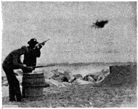
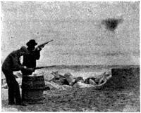
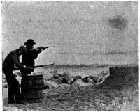
SHOOTING GLASS BALLS.
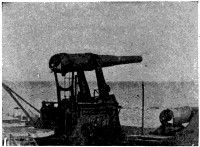
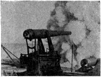
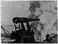
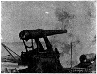
FIRING DISAPPEARING GUN.
FIG. 200.
In Fig. 200 is shown a succession of instantaneous photographs of a sportsman shooting a glass ball, and the firing of a disappearing gun. A multiplicity of views extending through all the phases of these movements, when successively presented in order, before a magic lantern projecting apparatus, gives to the eye the striking semblance of real movements. In practice these views are taken by special cameras, and are printed on long transparent ribbons that contain many hundreds, and even thousands of the views. Edison’s Kinetoscope is covered by patent No. 493,426, March 14, 1893, and his instrument known as the Vitascope, is one of those used for projecting the views upon a screen. In Fig. 201 a similar instrument, called the Biograph, is shown, in which the seeming approach of the locomotive makes those who witness it shudder with the apparent danger.
To secure the best results, the ribbon with its views should remain with a figure the longest possible time between the light and the lens, and the shifting to the next view should be as nearly instantaneous as possible. This problem has been admirably solved by C. F. Jenkins, who, in 1894, devised means for accomplishing it, and was one of the first, if not the first, to successfully project the views on a large screen adapted to public exhibitions. His apparatus is shown in Fig. 202. An electric motor, seen on the left, drives, through a belt and pulley, a countershaft, and also through a worm gear turns another shaft parallel to the countershaft, and bearing a sprocket pulley, whose teeth penetrate little marginal holes in the ribbon of views, and, drawing it down from the reel above, deliver it to the receiving reel on the right. On the end of the countershaft, just in front of the sprocket wheel, is a revolving crank pin or spool, which intermittently beats down the ribbon of views, causing the[298] latter to advance through the vertical guides in front of the lens by a succession of jerks. This holds each view for a maximum period before the lens, and then suddenly jerks the ribbon to bring the next view into position. In the Kinetoscope the animated pictures not only present the[299] movements of life, but, by a combination with the phonograph, the audible speech, or music fitting the occasion, is also presented at the same time, making a marvelous simulation of real life to both the eye and the ear.
Among the latest promises of the inventor is the “Distance Seer,” or telectroscope, which, it is said, enables one to see at any distance over electric wires, just as one may telegraph or telephone over them. The surprises of the Nineteenth Century have been so many and so astounding, and the principles of this invention are so far correct, that it would be dogmatic to say that this hope may not be realized.
To the sum total of human knowledge no department of science has contributed more than that of optics. With the telescope man has climbed into the limitless space of the heavens, and ascertained the infinite vastness of the universe. The flaming sun which warms and vitalizes the world, is found more than ninety millions of miles away. The nearest fixed stars visible to the naked eye are more than 200,000 times the distance of the sun, and their light, traveling at the rate of 190,000 miles a second, requires more than three years to reach us. Although so far away, their size, distance, and constitution have been ascertained, and their movements are scheduled with such accuracy that the going and coming thereof are brought to the exactness of a railroad time table. The astronomer predicts an eclipse, and on the minute the spheres swing into line, verifying, beyond all doubt, the correctness of the laws predicated for their movements.[300] The wonders of the telescope, the microscope, and the spectroscope are, however, but suggestions of what we may still expect, for science abundantly teaches that the eye may yet see what to the eye is now invisible, and that light exists in what may now seem darkness.
No man may say with certainty what thought was uppermost in
Goethe’s mind when, grappling in the final struggle with the King of
Terrors, he exclaimed “Mehr licht!
” It may be that it was but the wish
to dispel the gathering gloom of his dimming senses, or perchance the
unfolding of an illuminated vision of a brighter threshold, but certain it
is that no words so voice the aspirations of an enlightened humanity as
that one cry of “More light!”
Experiments of Wedgewood and Davy—Niépce’s Heliography—Daguerre and the Daguerreotype—Fox Talbot Makes First Proofs from Negatives—Sir John Herschel Introduces Glass Plates—The Collodion Process—Silver and Carbon Prints—Ambrotypes—Emulsions—Dry Plates—The Kodak Camera—The Platinotype—Photography in Colors—Panorama Cameras—Photo-Engraving and Photo-Lithography—Half Tone Engraving.
“Art’s proudest triumph is to imitate nature.
”
When nature paints she does so with the brush of beauty, dipped in the pigment of truth. The tender affection of a ray of light touches the heart of a rose, brings a blush to its cheek, and life, becoming the bride of chemical affinity, blooms into surpassing beauty and loveliness. Photography is closely allied to nature’s painting, for just as light brings into existence nature’s living beauties, so does light fix, preserve, and perpetuate these beauties by the same subtile and mysterious agency of a quickened chemical affinity. Photography is both an art and a science, and as such is both beautiful and true. It is an art intimately associated with the tenderest affections of the human heart in keeping alive its precious memories. By it the youthful sweetheart of long ago, the loving face of the departed mother, and the cherished form of the dead child are brought back to us in familiar presence, while our great men have become the every-day friends and ideals of the common people. What an enrichment and satisfaction it would have added to our lives if the art had been coeval with history, and all the world’s exalted scenes and faces had come to us through the camera with the knowledge of absolute truth and fidelity. But not only in portraiture is photography a great art, for it catches the stately pose of the mountain, the grandeur of the sea, the beauty of the forest, or the majesty of Niagara Falls, and brings them all home to us, even to the vision of the bed-ridden invalid. The camera alike records the secrets of the starry heavens and the bacteria of the microscopic world. Hanging on the tail of a kite it photographs the face of mother earth, and, acting quicker than the lightning, it catches and defines the path[302] of that erratic flash. It plays the part of a private detective, and its testimony in court is never doubted. The architect, engineer, and illustrator find it in constant requisition. By the aid of the Roentgen Rays, it locates a bullet in a wounded soldier, and takes a picture of one’s spinal column. In fact, it sees and records things both visible and invisible, acts with the rapidity of thought, and is never mistaken.
The art of photography, named from the two Greek words φωτος γραφη (the writing of light), is a comparatively new one, and belongs entirely to the Nineteenth Century. It was known to the ancient alchemists that “horn silver” (fused chloride of silver) would blacken on exposure to light, but there was neither any clear understanding of the nature of this action, nor any application made of it prior to the year 1800. We now know that the art of photography is dependent upon the actinic effect of certain of the rays of the spectrum upon certain chemical salts, notably those of silver and chromic acid, in connection with organic matter. The rays which have this effect are the blue and violet rays at one end of the spectrum, and even invisible rays beyond the violet, the red and yellow rays having little or no such actinic effect.
That which made photography possible for the Nineteenth Century was the philosophical observation of Scheele, in 1777, upon the decomposing influence of light on the salts of silver, and the superior activity of the violet rays of the spectrum over the others in producing this effect. In 1801 Ritter proved the existence of such invisible rays beyond the violet end of the visible spectrum by the power they possessed of blackening chloride of silver.
Earliest Application of Principles.—The first attempt to render the blackening of silver salts by light available for artistic purposes, was made by Wedgewood and Davy in 1802. A sheet of white paper was saturated with a solution of nitrate of silver, and the shadow of the figure intended to be copied was projected upon it. Where the shadow fell the paper remained white, while the surrounding exposed parts darkened under the sun’s rays. There was, however, no means of fixing such a picture, and in time the white parts would also turn black.
Introduction of Camera.—The camera obscura, a very old invention designed for the use of artists in copying from nature, was at a very early period brought into this art, but it was found that the chemicals employed by Wedgewood and Davy were not sufficiently sensitive to be affected by its subdued light. In 1814, however, Joseph Nicéphore Niépce, of Chalôns, invented a process that utilized the camera, and which was called “Heliography,” or sun drawing. In 1827 he discarded the[303] use of silver salts, and employed a resin known as “Bitumen of Judea” (asphaltum). A plate was coated with a solution of this resin and exposed. The light acting upon the plate rendered the resin insoluble where exposed, and left it soluble under the shadows. Hence, when treated with an oleaginous solvent the shadows dissolved out, and the lights, represented by the undissolved resin, formed a picture, which was in reality a permanent negative. The process, however, was slow, requiring some hours.
The Daguerreotype.—In 1829 Niépce and Daguerre became partners, and in 1839, after the death of the elder Niépce, the process named after Daguerre was perfected (British patent No. 8,194, of 1839). He abandoned the resin as a sensitive material, and went back to the salts of silver. He employed a polished silver surfaced plate, and exposed it to the action of the vapors of iodine, so as to form a layer of iodide of silver upon the surface, which rendered it very sensitive. By a short exposure in the camera an effect was produced, not visible to the eye, but appearing when the plate was subjected to the vapor of mercury. This process reduced the time required from hours to minutes, and as it involved the production of a latent image, which was subsequently developed by a chemical agent, it represented practically the beginning of the photographic art as practiced to-day. Daguerre sought also to permanently fix his pictures, but this was accomplished only imperfectly until 1839, when Sir John Herschel made known the properties of the hyposulphites for dissolving the salts of silver. In 1844 Hunt introduced the protosulphate of iron as a developer.
Production of Positive Proofs from Negatives.—This was first done by Mr. Fox Talbot, of England, between 1834 and 1839. In his first communication to the Royal Society, in January, 1839, it was directed that the paper should be dipped first in a solution of chloride of sodium, and then in nitrate of silver, which, by reaction, produced, on the face of the paper, chloride of silver, which was more sensitive to the light than nitrate of silver. The object to be reproduced was laid in contact with the prepared paper, and exposed to the light until a copy was produced which was a negative, having the lights and shadows reversed. A second sheet was then prepared, and the first or negative impression was laid upon it, and used as a stencil to produce a second print which, by a reversal of the lights and shadows, formed an exact reproduction of the original. In 1841, British patent No. 8,842 was obtained by Mr. Talbot, for what he called the “Calotype,” and which was afterward known as the “Talbotype.” A sheet of paper was first coated with iodide[304] of silver, by soaking it alternately in iodide of potassium and nitrate of silver, and was then washed with a solution of gallic acid containing nitrate of silver, by which the sensitiveness to light was increased. An exposure of some seconds or minutes, according to the brightness of the light, produced an impression upon the plate, which, when treated with a fresh portion of gallic acid and nitrate of silver, developed into the image. After being fixed it formed a negative from which any number of prints might be obtained. The Talbot process represented a great advance in this art. Glass plates to retain the sensitive film were introduced by Sir John Herschel in 1839, and were a great improvement over the paper negatives, which latter, from lack of transparency and uniformity in texture, had prevented fine definition and sharpness of outline. Blue printing was also invented by Sir John Herschel in 1842, and he was the first to apply the term “negative” in photography. In 1848 M. Niépce de St. Victor, a nephew of Daguerre’s former partner, applied to the glass a film of albumen to receive the sensitive silver coating.
Collodion Process.—The most important step in the preparation of the negative was the application of collodion. This is a solution of pyroxilin in ether and alcohol, which rapidly evaporates and leaves a thin film adhering to the glass. M. Le Gray, of Paris, was the first to suggest collodion for this purpose, but Mr. Scott Archer, of London, in 1851, was the first to carry it out practically. A clean plate of glass is coated with collodion sensitized with iodides of potassium, etc., and is then immersed in a solution of nitrate of silver. Metallic silver takes the place of potassium, forming insoluble iodide of silver on the film. The plate is then exposed and the latent image developed by an aqueous solution of pyrogallic acid, or protosulphate of iron. When sufficiently developed, the plate is washed, and the image fixed by dissolving the unacted-upon iodide of silver with a solution of cyanide of potassium or hyposulphite of soda. This completed the negative or stencil from which the positives are printed by passing rays of light through it upon sensitive paper.
The Ambrotype succeeded the Daguerreotype, and was produced by making a very thin negative by under exposure on glass, using the collodion process, and, after drying, backing the glass with black asphaltum varnish or black velvet, causing the dense portions of the negative to appear white by reflected light, and the transparent portions black. Such pictures were quickly made, and were much in vogue forty years ago, but are now obsolete. A modification of the ambrotype, however, still survives in what is known as the “tin-type” or “ferro-type.” In the tin-type the collodion picture is made directly upon a very thin iron plate,[305] covered with black enamel, which both protects the plate from the action of the chemicals in the bath, and forms the equivalent of the black background of the ambrotype.
Silver Printing.—A sheet of paper, previously treated with a solution of chloride of sodium and dried, is sensitized in an alkaline bath of nitrate of silver. When the paper is exposed under a negative, the light through the transparent parts of the negative reduces the silver, converting the chloride, it is supposed, into a metallic sub-chloride of silver which becomes dark or black, and constitutes the main portion of the picture. The image is then fixed by dissolving out the chloride of silver unaltered by light in a bath of hyposulphite of soda. After fixation, the image is well washed in several changes of water to eliminate all traces of the hyposulphite of soda and prevent the subsequent fading of the darkened portions of the picture and the yellowing of the whites. If the printed image is immediately fixed, it will have a red color. To avoid this it is washed first in water and then immersed in a chloride of gold toning bath and fixed.
The Platinotype Process is one in which potassium chloroplatinite and ferric oxalate are converted by light into the ferrous state, and metallic platinum is reduced when in contact with the ferrous oxalate of potash solution. The unacted upon portions are dissolved out by dilute hydrochloric acid, leaving a black permanent image. This process is characterized by simplicity, sensitiveness in action, permanence of print, and a peculiarly soft and artistic quality in the picture. British Patent No. 2,011, of 1873, to Willis, is the first disclosure of the platinotype.
Carbon Printing is a process in which lampblack or other indestructible pigment is mixed with the chemicals to render the photograph more stable against fading from the gradual decomposition of its elements. Mungo Ponton, in 1838, discovered the sensitive quality of potassium bichromate, which led up to carbon printing. Becquerel and Poitevin, in Paris, in 1855, were the first to experiment in this direction, and Fargier, Swan, and Johnson were successors who made valuable contributions.
Emulsions.—A photographic emulsion is a viscous liquid, such as collodion or a solution of gelatine, containing a sensitive silver salt with which the glass plate is at once coated, instead of coating the plate with collodion or gelatine, and then immersing it in a sensitizing bath. The desirability of emulsions was recognized as early as 1850 by Gustave Le Gray, and in 1853 by Gaudin. Collodion emulsion with bromide of silver was invented by Sayce and made known in 1864. In 1871 Maddox published his first notice of gelatine emulsion, and in 1873 the gelatine emulsions[306] of Burgess were advertised for sale. In 1878 Mr. Charles Bennett brought out gelatino-bromide emulsion of extreme sensitiveness, by the application of heat, and from this time gelatine began to supersede all other organic media.
Dry Plates were a great improvement over the old wet process, with its tray for baths, its bottles of chemicals, and other accessories. Especially was this the case with out of door work, which heretofore had involved the carrying along of much unwieldy and inconvenient paraphernalia. With the dry plate process only the camera and the plates were needed, and this step marks the beginning of the spread of the art among amateurs, and the great snap-shot era of photography, growing into a distinct movement about the year 1888, has since spread over the entire world. The first practical dry plate process (collodion-albumen) was published in 1855 by Dr. J. M. Taupenot, a French scientist. Russell, in 1862; Sayce, in 1864; Captain Abney, for photographing the transit of Venus in 1874; Rev. Canon Beechey, of England, in 1875; Prof. John W. Draper, of the University of New York, and the Eastman Walker Company, of Rochester, were the chief promoters of dry plate photography. The practical introduction began about 1862 with the application of the alkaline developer.
The progress of the photographic art may be approximately noted as follows:
| Process. | Time Required. | Introduced. | |
|---|---|---|---|
| Heliography | 6 | hours’ exposure | 1814 |
| Daguerreotype | 30 | minutes’ exposure | 1839 |
| Calotype or Talbotype | 3 | minutes’ exposure | 1841 |
| Collodion process | 10 | seconds’ exposure | 1851 |
| Collodion emulsion (dry plate) | 15 | seconds’ exposure | 1864 |
| Gelatine emulsion (dry plate) | 1 | second exposure | 1878 |
Mechanical Development.—The photographic camera is but an adaptation of the optical principles of the old camera obscura, which has been credited to various persons, including Roger Bacon in 1297, Baptista Porta about 1569, and others. The essential elements of the camera obscura are a dark chamber, having in one end a perforation containing a lens, and opposite it on the back of the chamber a screen upon which an image of the object is projected by the lens for the purpose of enabling it to be directly traced by a pencil. The photographic camera, introduced by Daguerre in 1839, adds to the camera obscura some means for adjusting the distance between the lens and the screen on which the image falls. This was accomplished by making the dark chamber adjustable in length[307] by forming it in two telescopic sections sliding over each other, and in later years by the well-known bellows arrangement. A luminous image of any object placed in front of the lens is thrown in an inverted position upon the screen, which is of ground glass, to permit the image to be seen in focusing. When the proper focus on this ground glass is obtained a sensitive plate is put in the plane of this screen to receive the image.
It is not possible to trace all the steps of development of the camera which have brought it to its present perfection. Most of the improvements have had relation to the lens in correcting chromatic and spherical aberration, and in shutters for regulating exposure, in stops for shutting out the oblique rays and holders for the sensitive plate.
The “Iris” shutter, so-called from its resemblance in function to the iris of the eye, consists of a series of tangentially arranged plates which open or close a central opening symmetrically from all sides.
The ordinary camera of the photographic artist is too familiar an object to require special illustration. It has been looked into by the rich and the poor, and the high and the low, all over the whole world. Between the traveling outfit, and the “look pleasant, please!” of the peripatetic artist, and the handsome studios of the cities, it is hard to find an[308] individual in the civilized world who has not posed before its lens. Through its agency the great man of the day has found himself in evidence everywhere; the country maiden has many times experienced the delicious thrill of satisfied vanity as she posed before it, and the superstitious savage is paralyzed with fear lest the mysterious thing should steal his soul.
In 1851 the first instantaneous views were made by Mr. Cady and Mr. Beckers, of New York, and also by Mr. Talbot, who employed as a flash light a spark from a Leyden jar. In 1864 magnesium light was employed by Mr. Brothers, of Manchester, for photographic purposes, and about 1876-8 Van der Weyde made use of the electric light for the same purpose.
The roller slide, or roll film, was invented by A. J. Melhuish, in England, in 1854 (British patent No. 1,139, of 1854). The films were, however, of paper. In 1856 Norris produced sensitized dry films of collodion or gelatine (British patent No. 2,029, of 1856). In later years apparatus for utilizing the roll film has been greatly improved and extensively applied by Eastman, Walker & Co., of Rochester, N. Y.
About 1888 a new thing in the photographic world made its appearance. It was a little black leather-covered rectangular box, about six inches long, with a sort of blind eye at one end closed by a cylindrical[309] shutter, substantially as seen in Fig. 203. This shutter was wound up by a spring operated by a pull cord. In the back of the box was a film or ribbon of sensitized paper wound upon one spool, and unwinding therefrom and winding onto another spool, and being distended as it passed so as to form a flat surface which was directly in rear of the lens. A thumb piece or key on the top, and a push button on the side, were the only suggestions of the operative mechanism within. When the button was pressed the shutter for an instant passed from in front of the lens, and as quickly covered it again, but in this brief interval an image had been flashed upon the sensitive ribbon or film, and a snap-shot picture was taken. By a simple movement of the thumb piece or key, the receiving roll was made to take up the exposed section of the sensitive film and bring another section into the range of the lens, for a repetition of the operation. This little instrument was slung in a case looking like a cartridge box, and its sensitive roll was able to receive 100 successive pictures. When the roll was exhausted, it was removed and developed in a dark room. The device was placed upon the market by the Eastman Company, and it was called the “Kodak.” The advertisement of the company, that “You press the button and we do the rest,” was soon realized to be founded in fact, and in a short while the great era of snap-shot photography had set in. To-day this form of camera is a part of the luggage of every tourist, traveler, scientist, and dilletante. In fact, it has become the familiar scientific toy of man, woman, and child, interesting, instructive, and useful to all. In Fig. 204 is shown a modern form of Kodak, which is made in various sizes and is foldable for compact and convenient portability.
A very convenient and useful development in films is to be found in the cartridge system, by which the film may be placed in and removed from the camera in broad daylight. The film has throughout its length a backing of black paper which extends far enough beyond the ends of the film to allow it to be unwound, so far, in making connection with the roll holder, without exposing the film to light, and also to allow it to be removed without exposure to light, after all the exposures have been made.
Among the many other ingenious and useful hand cameras may be mentioned the “Premo,” made by the Rochester Optical Company, and[310] shown in Fig. 205. The “Premo” is arranged for either snap-shot or time exposure, is adapted to be either held in the hand or mounted upon a tripod, and is furnished for use either with glass plates or roll films. In Fig. 206 is shown the “Premo” for stereoscopic work, in which two pictures are taken at once, a sufficient distance from each other to produce the effect of binocular vision and give the appearance of relief when viewed through the stereoscope. Brett’s British patent No. 1,629, of 1853, appears to be the earliest description of a stereoscopic camera.
There have been 2,000 United States patents granted in photography, most of which have been taken in the past thirty years, and great efficiency and detail in both the chemical and mechanical branches of the art have been obtained.
The useful applications of the art have been numerous and varied. Portrait making is probably the largest field. This was first successfully accomplished in 1839 by Professor Morse, of telegraph fame, working with Prof. John W. Draper, of the University of New York.
Celestial Photography began with Prof. Draper’s photograph of the moon in March, 1840, and Prof. Bond, of Cambridge, Mass., in 1851. In 1872 Prof. Draper photographed the spectra of the stars, and in 1880-81 the nebulæ of Orion, and in 1887 the Photographic Congress of Astronomers of the World, organized in Paris, began the work of photographing the entire heavens. In late years notable work has been done at the Lick Observatory by Prof. Holden. In 1861 Mr. Thompson, of Weymouth, photographed the bottom of the sea, and Prof. O. N. Rood, of Troy, N. Y., the same year described his application of it to the microscope. In 1871 criminals were ordered to be photographed in England, and in America the Rogues’ Gallery became an institution in New York as early as 1857, ambrotypes being first used. In 1876 the Adams Cabinet for holding and displaying the photos was invented. To-day the New York collection amounts to nearly 30,000, while that of the National Bureau of Identification at Chicago approximates 100,000. It is a striking illustration of the law of compensation that the counterfeiter who invokes the aid of photography to copy a bank note is, by the same agency of his photo in the Rogues’ Gallery, identified and convicted.
Photography in Colors has been the goal of artists and scientists in[311] this field for many years. Robt. Hunt, in England, in 1843, and Edmond Becquerel, in France, in 1848, made evanescent photographs in colors, but little progress was made until about the last decade of the Nineteenth Century. Franz Veress in 1890, F. E. Ives (United States patent No. 432,530, July 22, 1890), W. Kurtz (United States patent No. 498,396, May 30, 1893), Gabriel Lippmann in 1892 and 1896, Ives in 1892, M. Lumière in 1893, Dr. Joly in 1895, M. Villedien Chassagne, and Dr. Adrien, M. Dansac and M. Bennetto, all in 1897, represent active workers in this field.
Among recent developments of the camera may be mentioned the wide angle lens, which permits larger images to be made on the plate from small near-by objects, and the telephotographic camera, which gives a large image of remote objects, such as an enemy’s fort, and the panorama camera, which is designed to cover a broad field. For this purpose the lens is movably mounted for a semi-circular swing, and the image is flashed across a curved film in the case. The Eastman Panoram-Kodak, seen in Fig. 207, is an external illustration of this type, and in Fig. 207A is shown a sectional view of another make of panorama camera which clearly shows the internal construction.
As allied branches of the photographic art, photo-engraving, photo-lithographing, and half-tone engraving are important developments of the Nineteenth Century.
Photo-engraving is a process by means of which photographs may be used in forming plates from which prints in ink can be taken. The process depends upon the property possessed by bichromate of potassium, and other chemicals, of rendering insoluble under the action of light, gelatine or some similar substance. A picture is thus produced on a metal plate, and the blank spaces are etched out by acid, leaving the lines in relief as printing surfaces. When the operation is reversed, and only the darks are etched in intaglio, to be filled with ink, as in copper-plate engraving, it is called photo-gravure. Mungo Ponton, in 1839, discovered the sensitive quality of a sheet of paper treated with bichromate of potash. In 1840 Becquerel discovered that the sizing had an important function, and Fox Talbot, in 1853, discovered and utilized the insolubility of gelatine exposed to light in presence of bichromate of potash. In 1854 Paul Pretsch observed that the exposed parts of the gelatine did not swell in water. One of the first suggestions of photo-engraving appears in the British patent No. 13,736, of 1851, of James Palmer. In recent times great perfection in details has been obtained by Mr. Moss, of the Photo-Engraving Company, and others. The Albert-type and Woodbury-type are early modifications of this art.
In photo-lithography the photograph is transferred to the stone, and the latter then used to print from, as in lithography. The operation consists: 1, in making the photographic negative; 2, printing with it upon transfer paper coated with gelatine and bichromate of potash: 3, the transfer paper is then given a coat of insoluble fatty transfer ink from an inking stone; 4, all ink on surfaces not reached by the light being on a soluble surface is washed off, leaving the insoluble lines acted upon by light forming the picture; 5, the washed transfer sheet is then applied to the stone, and the remaining inked lines of the design are transferred to the stone; 6, the stone with transferred lines will now receive ink from the ink rolls on these lines, and repels ink from all other surfaces, which latter are[313] made repellent by being kept constantly wet, as in ordinary lithography. The first attempts in this art were by Dixon, of Jersey City, and Lewis, of Dublin, in 1841, who used resins. Joseph Dixon, in 1854, was the first to use organic matter and bichromate of potash upon stone to produce a photo-lithograph. In 1859 J. W. Osborne patented in Australia, and in 1861 in the United States, a transfer process which gave such great impetus to the art that he may be considered its founder and chief promotor. His United States patents are No. 32,668, June 25, 1861, and No. 33,172, August 27, 1861.
For photo-lithography only line drawing, type print, or script, without any smooth shading, can be employed. The most extensive application of photo-lithography is in the reproduction of the Patent Office drawings, which amount to about 60,000 sheets weekly. The contracting firm, which is probably the largest in the world, also prints each week by photo-lithography 7,000 copies of the Patent Office Gazette, of about 165 pages each, including both drawings and claims, and also reproduces specifications without errors or proof reading, thus saving about 200 per cent. in cost over type setting. This art is also largely employed for printing maps, and the reproduction of the pages of books by this process has flooded the stores and news stands with cheap literature.
Half-tone engraving enables a photograph to be reproduced on a printing press, and for faithfulness in reproduction and low cost has revolutionized the art of illustrating, as nearly all books, magazines, and newspapers are now illustrated by this process. Before its introduction it was not possible to reproduce cheaply in printers’ ink shaded pictures like photographs, brush drawings, paintings, etc. Half-tone engraving renders it possible to thus print on a press, with printers’ ink, reproductions of photographs or any shaded picture, in which the soft shadows fade away in depth to white by an imperceptible tenuity. It does so by breaking up the soft shadows into minute stipples which form inkable printing faces in relief, by the interposition of a fine reticulated screen between the camera lens and the sensitive plate. This forms a sort of stencil negative through which the copper plate is etched, which latter is thus converted into a relief plate whose raised surfaces left by the etching may receive ink and print like an ordinary relief plate. By making the screen lines very fine (80 to 250 meshes to the inch), the visible effect of the shading is so far preserved that the photograph may be reproduced in printers’ ink with but little depreciation. At first, bolting cloth was used for the screen, but at present two glass plates, with closely ruled lines, laid crosswise upon each other, form the screen. A characteristic distinction of half-tone work is the regularly stippled surface, formed[315] by the stenciling out of a portion of the picture by the screen, which may be easily seen with any magnifying glass. It is called half-tone process because half of the tones or shadows are preserved, the other half being stenciled out. The use of gauze screens was first described by Fox Talbot in British patent No. 565, October 29, 1852.
In the making of a half-tone negative, the photograph, painting, or wash drawing which is to be reproduced, is set up in front of the camera, which is arranged on an inclined runway, as seen in Fig. 208, and an exposure is made on a plate prepared by the wet collodion process (see page 304). The shadows of the picture are broken up into stipples or dots by the interposition of a cross-lined screen arranged in the plate holder between the lens and the sensitive plate, so that the picture taken is “half-toned” or stippled. Fig. 209 illustrates the relation of the parts, in which the picture to be copied is seen on the right, the camera lens in the middle, and the cross-lined screen on the left in front of the sensitive plate.
The image on the plate is then developed and fixed, and in order to secure a printed image exactly like the copy as to right and left position it is necessary to reverse the negative. This is done by cutting the[316] film square, as seen in Fig. 210, and then peeling it off the glass, as seen at Fig. 211, and transferring it to another glass plate in reversed relation. The copper printing plate is produced as follows: The plate is first polished, as seen at the top of Fig. 213, and is then sensitized with a solution of organic matter and an alkaline bichromate. The face of the reversed negative is laid flat against and in direct contact with the face of the sensitized copper plate, and tightly held thereto by the screw clamps of the half tone printing frame. The printing on the sensitized copper face through the stippled or half-tone negative is then effected either by daylight or by the electric light. The application of the electric light for this purpose is shown in Fig. 212. The copper plate is then taken out and subjected to the three lower operations seen in Fig. 213. It is first developed under a stream of water from a faucet, seen on the left, and is then taken in a pair of pliers and held over a gas stove, as seen at the bottom, to “burn-in” the image, and then placed in a tray containing an etching bath of chloride of iron seen on the right, by which the copper is eaten away around the little stipples, and the latter, representing the half tones of the original picture, are left raised, or in relief, to form the inkable surfaces of the printing plate. So fine are these stipples, however, that the picture is[317] to the eye perfectly reproduced. The several views illustrating this process are made in this way, the lines of the reticulated screen being 175 to the inch. The plate is next subjected to the mechanical operation of “routing out” or cutting away the undesirable portions by a routing machine, seen in Fig. 214. It then receives further mechanical treatment[318] to correct imperfections and finish its edges, and is finally mounted upon a block ready for the printer.
The most striking application made of photography in recent years is in the production of so-called moving pictures, in which a series of photographic figures thrown upon the screen have all the motion of animated scenes which have been caught and imprisoned by the swiftly acting and never failing memory of the camera, to be again turned loose in active play through the Kinetoscope or Biograph. Perhaps the most valuable contribution to science at the end of the century made by this art is in surgery, for photographing through opaque bodies by the aid of the Roentgen rays, but for the latter subjects treatment in separate chapters must be reserved.
Geissler Tubes—Vacuum Tubes of Crookes, Hittorf and Lenard—The Cathode Ray—Roentgen’s Great Discovery in 1895—X-Ray Apparatus—Salvioni’s Cryptoscope—Edison’s Fluoroscope—The Fluorometer—Sun Burn from X-Rays—Uses of X-Rays.
The majority of people have been accustomed to regard light as something to be excluded and controlled by opaque screens just as effectively as rain is excluded by a tin roof, or cold is kept out by a brick wall. The shady retreat furnished relief from the garish day to the primitive man, and the opaque shades and Venetian blinds of modern civilization exclude the excess of light at our windows. Sunshine and shadow have, in fact, been correlated conditions to the ordinary observation of man since time began. The last few years of the Nineteenth Century, however, were to witness the discovery of a new kind of light ray which, in its behavior, subverted all previous conception of the nature and action of light. It was a species of electric light, which we are accustomed to regard as brilliant, but this light ray was invisible to the eye. It could not be refracted or bent from its course by a prism or lens, and it was so subtle, penetrating and insidious, that it could not be barred out like sunlight, but passed readily through many opaque substances, such as wood, flesh tissue, paper (even a book of 1,000 pages), as well as some of the metals. The lighter the weight of the substance, or less its density, the easier these rays passed through it, or the more transparent such bodies were to the rays. The heavier metals, like platinum, gold and lead, were practically opaque, or allowed none of the rays to pass through them, while the very light metal aluminum was about as transparent to these rays as was glass to ordinary light, and for that reason this metal could form window panes for such rays, while excluding other light. Most organic substances are transparent or semi-transparent to these rays, and hence such rays readily pass through the body of an individual, being only intercepted in part by the denser parts of the anatomy, such as the bones, so that a man in such light no longer casts a well-defined shadow of his outline, but[320] the shadow disclosed is that of a skeleton, by virtue of the greater density of the bones. Any object of higher density, such as a ring upon the finger, clearly establishes its shadow by virtue of its greater density. Likewise, any foreign object in the body, such as a bullet from a gun-shot wound, or a foreign body accidentally swallowed, is perfectly disclosed and located by the shadow which it casts. As these light rays have been characterized as invisible, it may be difficult to understand how invisible rays can cast a visible shadow, and it should be here stated that when these unseen rays fall upon certain chemical substances the latter are made to glow with a peculiar fluorescence, and a screen made of such fluorescing materials will light up where the rays fall upon it, and remain dark at the points where the rays are intercepted by a substance opaque to such rays, thus outlining a shadow.
Not only do these light rays in passing through the body tissues (transparent to them) cast a shadow of the bones or any foreign objects, but by the application of photography to these shadow pictures a species of photograph, called a radiograph, or skiagraph, may be taken, and thus any foreign body, such as a bullet, may be definitely located in the human body and quickly extracted, without the element of doubt which beset the old method of diagnosis, which, at best, was only intelligent guessing. Not only are foreign bodies so located, but the fractures of the bones may also be accurately observed, studied and adjusted. Stone in the bladder may be discovered, and the condition and movements of the heart and lungs ascertained.
This new kind of light ray was discovered November 8, 1895, by Prof. W. C. Roentgen, of the Royal University of Wurzburg, and was named by him the “X-Ray,” probably because the letter x in algebraic formula represents the unknown quantity, and the hitherto unknown and elusive quality of this light suggested to Prof. Roentgen this appropriate name.
As before stated, a peculiar quality of the X-Rays is that they are not visible to the eye. A beam of X-Rays, thrown into a dark chamber through an aluminum window, would produce no illumination whatever in the room, but such rays would still penetrate the room, and if a fluorescing screen were placed in their path it would instantly light up. It is not surprising, therefore, that these subtle rays should have so long eluded the observation of the scientist.
A brief sketch of the conditions leading up to the discovery of the rays is necessary to a proper understanding of the same.
Every student of physics remembers the old-time lecture room experiments[321] in which the Geissler tubes, with their beautiful play of colored lights, illustrated the action of the electrical discharge from the glass plate machine or the Ruhmkorff coil, on rarified gaseous media. Electrical experiments in high vacua by Sir William Crookes, and by Hittorf and Lenard, have greatly added to the present knowledge in this field, and paved the way to the discovery of Prof. Roentgen. It was known that a vacuum tube, variously called after the names of these scientists, as a Crookes, Hittorf, or Lenard tube, having platinum electrodes sealed in its ends, would, under the static discharge of electricity through it, give peculiar manifestations of light. One of the conducting terminals of such tubes was called, in electrical parlance, the “anode,” from the Greek ανα (up) ὁδος (way), meaning the way up or into the tube, and referring to the entering path of an electric current, or its positive pole; while the other was called the “cathode,” from κατα (down), ὁδος (way), meaning the way down or out, and referring to the outgoing path of an electric current, or its negative pole. When such glass tube, partially exhausted of air, received through its anode and cathode terminals a discharge of static electricity, a peculiar manifestation of light is seen between the anode and cathode terminals. At the anode it appears as a peach blossom glow, and at the cathode it appears as a bluish green light. If the exhaustion of the air in the tube is carried very high, approaching a perfect vacuum, or to about one millionth of the atmospheric pressure, the glow light at the anode disappears, and that at the cathode increases until it fills the entire tube with its characteristic light. This is called the “cathode ray,” or “cathodic ray,” an illustration of which is given in Fig. 215, where the cathode ray is seen in a Crookes tube emanating from the negative pole N or cathode a, and casting a shadow of the Maltese cross b into the end of the tube, as seen at d. Many of the characteristics of the cathode ray had been observed prior to Prof. Roentgen’s discovery, which, briefly stated, grew out of the following[322] observation: He noticed that when a vacuum tube illumined by the cathode ray was completely masked or covered up by an external shield of black paper, so that no illumination of the tube was visible to the eye, there still passed through it certain subtle rays of light, invisible to the eye, but which would instantly illuminate a sheet of paper coated on one side with barium platino-cyanide, even at a distance of two yards or more, and that these invisible light rays were capable of passing through many substances opaque to ordinary light. He also discovered that these rays could be made to take a shadow photograph on a sensitive plate without even exposing the plate in the usual way, the X-Rays passing freely through the opaque ebonite or pasteboard screen of the plate holder. It did not take the scientific world long to realize the immense importance of this discovery, and to-day X-Ray apparatus constitutes the greatest addition to the surgeon’s resources that has ever been made in the form of mechanical appliances, since by its aid any foreign body in the human frame of greater density than the flesh may be at once definitely located and extracted, or any fracture of the bone disclosed, as the case may be. In the illustration, Fig. 216, is shown an X-Ray photograph of the hand of a gentleman whose thumb bone has been destroyed by disease.
Soon after the announcement of Prof. Roentgen’s discovery, apparatus was devised for seeing with the naked eye the image formed by the shadow of the X-Rays. Prof. Salvioni constructed such a device and[323] described it before the Rome Medical Society as early as February 8, 1896. He called it the “cryptoscope.” It was quite a simple affair, and consisted of an observation tube with a lens, having in front of it a screen of fluorescing material, such as platino-cyanide of barium. When the object to be examined, the hand, for instance, was held in front of the fluorescing screen, and the X-Rays from the vacuum tube fell upon the hand, located between the vacuum tube and the fluorescing screen, a shadow of the bones was cast on the fluorescing screen by virtue of the greater density of the bones, which shadow was clearly discernible to the eye at the end of the observation tube. By this device one was able to see his own bones through the flesh. A device, invented by Edison and called the “fluoroscope,” was constructed on substantially the same principle. This used a tapered observation tube like the old-fashioned stereoscope box, which had at its outer wide end the fluorescing screen, and[324] its small end fashioned to fit the forehead and strapped thereto so as to enclose both eyes. This device is shown in Fig. 217, in which an X-Ray vacuum tube is housed in a wooden box, on which the hand of the patient, or other part to be viewed, is laid, the X-Rays passing readily through the top of the box and casting a shadow of the bones of the hand, or foreign body, on the fluorescing screen of the observation tube. Edison’s experiments also led him in constructing his fluorescing screen, after testing a great number of substances, to select the chemical known as calcium tungstate, instead of the barium platino-cyanide, since the calcium tungstate appeared to give better results in fluorescing. Many other chemicals can be used, however, for making the fluorescing screen, such as the sulphides of calcium, barium and strontium. A recently discovered and powerful fluorescing substance is the double fluoride of ammonium and uranium, discovered by Dr. Mecklebeke. Such fluorescing materials are spread in a thin layer on the side of the screen next to the observer in the viewing apparatus.
It is not to be understood that such viewing apparatus is necessary in taking a surgical photograph. In such case only the X-Ray tube, means for exciting it, the patient’s body, and the sensitive photographic plate, are essential factors, the patient’s limb or body being interposed between the light tube and photographic plate, so as to cause the X-Rays emanating from the tube to cast the shadow of the patient’s bones, the bullet in his body, or other foreign object, directly upon the photographic plate, the sensitive and conscious plate obeying the will of these subtle rays, and receiving the impress of their actinic effect under conditions which it denies to ordinary light.
For exciting the vacuum tube any electrical machine capable of throwing a series of sparks across a gap of about five inches is sufficient. Various electrical machines may be used for this purpose, the Holtz, or the Wimshurst glass plate machine, the Ruhmkorff, or induction coil, or even the high frequency transformer. A good example of a complete X-Ray apparatus is that in use at the Army Medical Museum at Washington, made by Otis Clapp & Son, and shown in Fig. 218. The electrical generator is of the Wimshurst type, and is shown in a large glass-enclosed cabinet on the right. The glass disks within are rotated either by a small electric motor shown on the floor, or by a hand crank above. The X-Ray tube, of globular or bulb shape, is shown just above the patient’s hip, and its opposite poles are connected by wires to the opposite electrodes of the generator. When the current is switched on by the operator, the bulb is illuminated with the cathode rays, and the X-Rays, proceeding[325] therefrom through the clothing and flesh of the patient, cast a shadow of the patient’s hip joint upon the photographic plate placed on the cot beneath the patient.
In the effort to secure greater sharpness in the image cast by the X-Rays, various forms of vacuum tubes have been devised. That shown in Fig. 219 represents one of the most important improvements. K is the cathode plate, formed of a concave disk of aluminum, which focuses the rays at a point near the center of the bulb. At this point a plate of platinum A, which metal allows practically none of the X-Rays to pass through it, is mounted on the anode in such an angular position that it gathers the focused rays and reflects them through the side of the tube. They thus make a sharper shadow than when radiating from the more extended surface of the glass.
In Fig. 220 is shown an X-Ray tube, as applied for locating a foreign body in the brain cavity, in which view the patient’s head is interposed between the X-Ray tube and the fluorescing screen, or photographic plate, as the case may be; while Fig. 221 shows the application of the same devices to the body. In both these views the particular form of X-Ray apparatus is known as the “Fluorometer,” made under the Dennis Patent, No. 581,540, April 27, 1897, and it is devised with reference to more accurately locating the foreign object by its shadow, for which purpose adjustable bracket-sights, seen in Fig. 221 on opposite sides of the body, are provided for bringing the X-Rays into proper alignment for projecting the shadow of the foreign body in true indicative position on the fluorescing screen, while a cross hatched grating behind the body, graduated in aliquot spaces of an inch, furnishes a measured field, and forms an easy and quick means of platting the position of said object. In the position of parts in the two figures the horizontal line, on which the foreign object lies, would be determined, but it would not indicate how deep in the object was, i. e., whether it was in the middle,[327] or on one side. To determine this the fluorescing screen and grating are placed under the patient, and the X-Ray tube above, and the vertical line of the object is thus obtained. Both the vertical line and horizontal line having been obtained, it will be obvious that the foreign object will lie at the intersection of these two lines, which establishes for the surgeon its definite location.
It has been observed by Prof. Elihu Thomson, and also by Dr. Kolle, that the X-Rays are not absorbed and destroyed by the sensitive chemicals of a single photographic plate, but so potent and penetrating is their influence that the rays pass through and produce an image on a number of plates, placed one behind the other, thus affording means for multiplying the image at one exposure.
Among other uses of the X-Ray may be mentioned its capacity to detect spurious from genuine gems, the diamond giving a distinct color from its imitations, as do also most other precious stones.
A peculiar physiological effect of the X-Rays is their capacity to produce[328] a severe effect on the skin, somewhat resembling sunburn. Such result, produced by long and continued exposure, has sometimes so deranged the skin tissues as to make sores that resulted in the entire loss of and renewal of the skin.
The discovery of the X-Ray by Prof. Roentgen may be fairly considered one of the most wonderful scientific achievements of the century, and his first memoir in 1895 is so full, clear and exact, as to have left very little more to be said about it. It is to-day, as it was found by him in 1895, the same mysterious, unseen, but positive force, a species of electrical energy without a domicile, and needing no conductor, a form of light passing through closed doors, invisible itself, and yet lighting up certain substances with a halo of glory, and radically changing and decomposing others. Rivaling the sun in actinic power, and writing its autograph with an unseen hand, it is truly called the X-, or unknown, ray.
Early Use of Natural Gas—Coal Gas Introduced by Murdoch—Winsor Organizes First Gas Company in 1804—Melville in United States Lights Beaver-Tail Lighthouse With Gas in 1817—Lowe’s Process of Making Water Gas—Acetylene Gas—Carburetted Air—Pintsch Gas—Gas Meter—Otto Gas Engine—The Welsbach Burner.
For many centuries the going down of the sun marked a cessation of man’s labors, and among his first efforts toward increasing his efficiency was the prolongation of his hours of vision by artificial illumination. Beginning with a shell for a lamp, a rush for a wick, and the fat of his game for oil, the first crude lamp was made, and while it shed but a feeble and flickering light, man ceased to go to sleep with the fowls and the beasts, and continued his labors and amusements into the night. For many centuries the lamp held its exclusive sway, and probably will ever find a useful place; but with the discovery of coal gas and its practical manufacture the nights of the Nineteenth Century have been made to represent illuminated illustrations of the world’s progress. Coal gas can hardly be claimed as an invention, however, for natural gas from the bowels of the earth had been observed and used in China from time immemorial. The holy fires of Baku on the shores of the Caspian and elsewhere were also thus supplied. The first steps toward its artificial production began in the latter part of the Seventeenth Century with Dr. Clayton. Bishop Watson, in 1750, and Lord Dundonald, in 1786, also experimented with combustible gas made from coal, but the man who more than any other contributed to its practical manufacture and introduction was Mr. Murdoch, of Redruth, Cornwall, England. In 1792 Murdoch erected a gas distilling apparatus, and lighted his house and offices by gas distributed through service pipes. In 1798 he so lighted the steam engine works of Boulton & Watt, at Soho, near Birmingham; and in 1802 made public illumination of the works by this means on the occasion of a public celebration. In 1801 Le Bon, of Paris, used a gas made from wood for lighting his house. In 1803-4 Frederick[330] Albert Winsor lighted the Lyceum Theatre, took out a British patent No. 2,764, of 1804, for lighting streets by gas, and established the National Light and Heat Company, which was the first gas company. In 1804-5 Murdoch lighted the cotton factory of Phillips & Lee at Manchester, the light being estimated as equal to 3,000 candles, and this was the largest undertaking up to that date. In 1807 Winsor lighted one side of Pall Mall, London, and this was the first street lighting. A disastrous explosion occurred shortly afterwards, and such eminent men as Sir Humphrey Davy, Wollaston, and Watt expressed the opinion that it could not be safely used; but the so-called “coal smoke” had come to stay, and in 1813 Westminster Bridge and the Houses of Parliament were lighted with gas. In 1815 there was general adoption of gas in the streets of London, and shortly afterwards in Paris. In 1805-6 David Melville, of Newport, R. I., invented a gas apparatus and lighted his house with it. He took out United States patent March 18, 1813, and in 1817 contracted with the United States to supply for a year the Beaver Tail Lighthouse. In 1815 James McMurtrie proposed the lighting of the streets of Philadelphia; Baltimore commenced the use of gas in 1816, Boston in 1822, and New York in 1825.
In Fig. 222 is shown a diagrammatic illustration of the principal features of a gas works, as employed throughout the greater part of the Nineteenth Century. On the left is seen the furnace, in which is arranged above the fire a series of retorts, which are in the nature of horizontal closed cast iron boxes. Only one of the series is visible in the[331] view. Their ends project out beyond the furnace walls, and have doors for giving access to the interior, and each retort outside the furnace is connected by an upright pipe to an elevated cylinder called a hydraulic main. When the retort is charged with coal through its end door, and is heated red hot by the subjacent fire of the furnace, a heavy gas is driven off from the coal, which passes up the pipe to the hydraulic main, where it partially condenses and leaves its heavier portions in the form of coal tar and ammoniacal liquor. The gas then passes through the series of bent pipes, which form a condenser, where other remaining portions of the tar and other impurities are condensed, and drawn off from time to time in the little well shown on the left of the coil. From the condenser coils the gas passes into the purifier, shown on the right of the coils as an enclosed case having a series of shelves on which is spread slaked lime, which takes up from the gas impurities in the form of sulphuretted hydrogen and carbonic acid. From this purifier the gas passes downwardly through a pipe into a large gas holder whose lower end is sealed in a water tank, and which gas holder is balanced by weights and chains passing over pulleys. With the gas holder, the distributing mains of the city are made to connect to receive their supply. When the gas holder is full it is buoyed up by the lighter gas, and occupies an elevated position, and as its supply is used up, the gas holder settles down into the water.
In the operation of gas making many valuable secondary products are formed. The coal in the retorts is not entirely consumed, but is reduced to the condition of coke, and in this form is sold for fuel. The ammoniacal condensations are purified to form ammonia, while the coal tar, which but a few years ago was little more than a waste material, is now a valuable commercial product, being extensively used in the manufacture of the aniline, phenol, and naphthalene dyes, also in medicines and perfumes, and being used in crude form also as an important element in street paving compositions.
Water Gas.—In 1875 an important era in gas making was inaugurated by the introduction of what is known as “water gas,” so called for the reason that water in the form of steam is decomposed and its hydrogen, mixed with carbonic oxide gas, is mingled with a heavier carbon gas from oil, and is converted at a high temperature into a permanent, stable illuminating gas, at a much lower cost than coal gas.
Fontana was the first to notice the decomposition of steam by incandescent carbon to form hydrogen and carbonic oxide. Ibbetson’s British patent, No. 4,954, of 1824, represents the first application of this principle.[332] This was followed by Alexander Selligue, who, in 1834, obtained a French patent, No. 9,800, and in 1842 produced water gas at Batignolles, a suburb of Paris. Sanders’ United States patent, 21,027, July 27, 1858, was the basis of an experiment tried at the Girard House in Philadelphia. These, with Siemens’ British patents, Nos. 2,861, of 1856, and 972, of 1863, for methods of constructing furnaces, constitute the earlier steps in the development of water gas, although many other patents were granted prior to the latter date for various methods and forms of apparatus. The practical production and successful commercial use of water gas, however, began with T. S. C. Lowe, who obtained United States patent No. 167,847, September 21, 1875, and revolutionized the gas making industry. In less than a dozen years from the date of his patent 150 cities and towns in the United States were using water gas, and in 1886 the Franklin[333] Institute gave to Mr. Lowe a grand medal of honor for his invention, which of those exhibited that year was believed to contribute most to the welfare of mankind by cheapening the cost of light. Fig. 223 represents an illustration of the Lowe apparatus as shown in his patent, and whose operation is as follows: Valves 9 and 10 being open, an anthracite coal fire in generator chamber 1 gives off carbonic oxide gas, which passes down pipe 2 and enters the base of superheater 3, where mixing with air coming down pipe 4, it burns to form an intense heat. The chamber, 3, is filled with loose pieces of fire brick, which are soon heated white hot. Valves 9 and 10 are then closed and steam is taken from an upright boiler, 6, and carried by a small pipe, 7, to the incandescent mass in chamber 3, and passing down through it is superheated. This superheated steam passes from the bottom of chamber 3 to the bottom of chamber 1, and then up through the mass of red hot coal. The intensely hot steam is thus decomposed into hydrogen and oxygen, and the oxygen unites with the carbon of the coal to form carbonic oxide gas. As hydrogen and carbonic oxide burn with only a feeble blue flame, these gases are now made richer in light giving carbon at this point by the addition of oil contained in an elevated tank, 8. This, dripping on the incandescent coal in chamber 1, is volatilized, and at the same time enriches and combines with the hydrogen and carbonic oxide to form a permanent illuminating gas (water gas) that passes up pipe 5 and through the flues in boiler 6, to outlet 13, and thence on in the usual way to the condenser, scrubber and gas holder, which are not shown, and merely act to purify the gas. As the excessively hot water gas passes through the boiler flues it furnishes the necessary heat to generate the steam. The air used in the process is forced at 12 into a drum in the smokestack, 11, and is heated by the escaping products of combustion. In practical operation there are two (or more) of the steam superheating chambers 3, working alternately, and one of them is being heated up while the other is superheating the steam.
Water gas has neither the illuminating nor the heating qualities of coal gas, and it is also much more poisonous. According to O. Wyss, one-tenth of 1 per cent. of uncarburetted water gas renders the air of a room injurious to health, and 1 per cent. is fatal to all warm-blooded animals. Notwithstanding these facts, however, its extreme cheapness and fairly satisfactory light have carried it into such general use that to-day it is said that two-thirds of all gas made in the United States is carburetted water gas.
Acetylene Gas is a combination of two parts carbon and two parts[334] hydrogen. It was discovered in 1836 by Edmond Davy, who produced carburet of potassium, and evolved acetylene gas therefrom by decomposing it with water. It was long known as klumene, and when burned it produced an intense white light. For a long time it was only produced in a small way in the laboratory. It is now made commercially by the mutual decomposition of water and calcium carbide, the latter giving off, when brought in contact with the water, acetylene gas, which rises in bubbles. In the reaction the carbon of the carbide unites with a portion of the hydrogen of the water, producing acetylene gas (C2H2), while the calcium of the carbide unites with the oxygen of the water and the remaining portion of the hydrogen and forms calcium hydrate, or slaked lime, which precipitates as a slush.
The union of carbon with an alkali metal, first accomplished by Davy in 1836, was followed in 1861 by the combination of carbon with calcium by Wohler. It was not, however, until the electrical furnace became an agency in chemical reaction that calcium carbide was made on a commercial scale. The production of acetylene gas for illuminating purposes began with the operations of Thomas L. Willson in 1893, and his patents, Nos. 541,137 and 541,138, of June 18, 1895, and 563,527 and 563,528 of July 7, 1896, cover the chemical process, the product, and the mode of operating. The reaction is a very simple one. A mixture of lime and carbon is subjected to the heat of an electric arc, and the carbon combines with the calcium of the lime to form calcium carbide, which appears on the market as dirty black stone-like lumps. The simplicity of the method of generating acetylene gas from this substance by merely bringing it in[335] contact with water has greatly stimulated invention in this field. The art began practically in 1895, and since that time more than 500 patents have been granted for acetylene gas apparatus.
A very simple apparatus for the purpose is shown in Fig. 224, in which a vessel containing water has an inverted bell or cylinder within it, open at its lower end. A basket or cage is suspended within the inner cylinder, and contains a few lumps of calcium carbide, which are first immersed in the water by being forced down by the rod supporting the same, which passes through a stuffing box. Acetylene gas is immediately generated and its pressure forces the level of the water down in the inner cylinder, causing it to rise in the annular space between said cylinder and the case. As the water level descends in the inner chamber it passes out of contact with the calcium carbide, and the generation of gas is discontinued[336] until some of the gas is drawn off or consumed at the burners, whose pipe is shown connecting with the gas space of the inner cylinder. When so drawn off, the pressure in the inner cylinder is relieved, and the water therein rises to contact again with the calcium carbide and renews the generation of gas. This principle of automatic action is a very old one, and will be recognized by the student as that of the Dobereiner lamp of the chemical laboratory, invented by Prof. Dobereiner, of Jena, in 1824.
In acetylene gas apparatus a great variety of methods are employed for bringing the water and carbide into contact. Instead of the automatic pressure level principle described, many devices discharge a regulated quantity of powdered calcium carbide into the water, while in another form the water is discharged upon the calcium carbide. An example of the latter is given in Fig. 225, which represents the Criterion generator. A number of receptacles containing charges of calcium carbide are made to successively receive a regulated quantity of water, the gas being collected in a rising and falling holder.
Acetylene gas finds its principal uses for isolated plants, and in country houses. One form of using it is to compress it under high tension in cylinders, but this method has been attended with some disastrous explosions, and is discriminated against by the insurance companies.
Calcium carbide is now made in a large way by the Willson Aluminum Company, at Spray, N. C., and also at Niagara Falls and at Sault St. Marie, Mich., and its cost is between 3 and 4 cents per pound.
Acetylene gas has an acrid, garlicy odor, and burns with an intensely white flame, and so superior is it to coal gas in illuminating power that it only requires a pipe of one-third the diameter of that used for coal gas to produce the same illuminating effect.
Carburetted Air is another form of illuminating gas which has found some useful applications. This consists simply of air forced through some light hydrocarbon, such as naphtha, benzine or gasoline, and so saturated with the vapors of these volatile substances as to become an inflammable mixture. Many patents have been granted for apparatus operating on this principle, and it has been put to some practical use in country houses, and seaside resorts.
Pintsch Gas is another special application. It is a gas made from oil and compressed in storage cylinders by means of pumps for portable use. It is stored under a pressure sometimes as high as 150 pounds to the inch, its pressure being reduced at the burners through the agency of pressure regulators. It is used for lighting railway cars, buoys, and lightships.
Gas making has probably been the most extensive and important of all the commercial chemical operations of the Nineteenth Century, and with it has come a great array of minor inventions as accessories. Among these first came the gas meter and pressure regulator. With the introduction of gas into houses some means of determining the amount consumed as a basis of payment was required, and for this purpose the gas meter was devised. The first gas meters were known as wet meters, and effected a measurement by passing the gas through a liquid and rotating a wheel therein. The wet meter was invented by Clegg (British patent No. 3,968, of 1815), and the dry meter, by Malam (British patent No. 4,458, of 1820), and improved by Defries (British patent. No. 7,705, of 1838). The gas regulator is simply a little automatic apparatus whereby the variation of pressure in the gas main is reduced and the flow rendered perfectly uniform at the burner. It effects a saving of gas by preventing it from blowing when the pressure is too great, and also gives a more steady and uniform light.
Among the great number of mechanical devices which have grown out of the use of gas may be mentioned the gas range for heat, the gas engine for power, and the Welsbach burner for light. The gas range has contributed much to the domestic economy of the city house. It gives an immediate heat in the kitchen for all culinary and domestic purposes, without the incidental objections of having to transport fuel and remove ashes. It is put into or out of action in an instant, saves labor and time, and avoids the heat and discomfort of a coal stove during the hot months of summer. It is organized in principle after the Bunsen burner, whereby a perfect combustion of the carbon is obtained with maximum heating effect and without smoke or deposits of lampblack.
The Otto gas engine, seen in Fig. 226, is a pioneer and representative type of a great number of explosive gas engines, which in recent years have become active competitors of the steam engine where only small[338] power is required. The Otto engine is covered by patent No. 194,047, August 14, 1877. Patents No. 222,467, 297,329, 336,505, 358,796, 320,285, 386,211 and 549,160 represent important developments in this art.
The Welsbach burner for improving the quality of gaslight, and economizing its consumption, is also well and favorably known. It utilizes the Bunsen burner principle to make a very perfect combustion of the gas, with the greatest possible heat and the least smoke, and then directs its great heat on to a refractory body which will not burn, but glows with a brilliant white incandescence. The Welsbach burner was brought out in 1885. The United States patent therefor was granted October 7, 1890, to Carl Auer Von Welsbach, No. 438,125. The Welsbach light is a development of the Drummond, or limelight, invented by Lieut. Drummond, of England, in 1826. This latter exposed a piece of quick lime to the intensely hot flame of the oxy-hydrogen blow pipe, which was invented by Dr. Robt. Hare in 1802. The piece of lime glows with an intense brilliancy approximating that of the electric light. The Welsbach burner, see Fig. 227, operates on the same general principle, except that the refractory body, which is heated to incandescence, is a tubular sleeve of netted fabric first steeped in a solution of the salts of refractory earths, and then incinerated by heat to burn out the textile fibre and leave the refractory earthy oxides as a skeleton of the fabric, and which is called a “mantle.” This mantle is suspended above the flame arising from a proper admixture of air and gas, and is heated thereby to a brilliant incandescence which furnishes the light. In the Welsbach burner the light seen does not proceed directly from the combustion of the gas, but from the white hot mantle. The light is a very pure white one, does not distort or falsify colors, and effects a great saving of gas. An important improvement upon the mantle is covered by Rawson’s patent, July 30, 1889, No. 407,963, for coating the mantles with paraffine or analogous[339] material to toughen them and prevent them from breaking in packing and transportation.
Natural Gas.—No review of gas lighting would be complete without some reference to the development incident to the use of the natural gas flowing from the internal reservoirs of the earth. Such gas has been known and utilized for centuries in China, and was conveyed by the Chinese in bamboo pipes to points of utilization. The discovery of coal oil in the United States in 1859, and the great advances made in the methods and apparatus for sinking oil wells, have resulted in the discovery of numerous wells of natural gas, whose values were quickly perceived and utilized by their owners. The village of Fredonia, N. Y., was probably the first to be lighted by natural gas, and a flow from a well at West Bloomfield, N. Y., opened in 1865, was carried in a wooden main more than twenty miles to the city of Rochester. Many wells of natural gas have since been found at various points, and so extensive has been its use for cooking, heating, lighting and metallurgical processes, that thousands of patents have been taken for various forms of burners, pressure regulators and other appliances for utilizing the same. The annual production of natural gas in the United States for 1888 was valued at $22,629,875. There has, however, been a steady decrease in the past ten years. The amount produced in 1897 was $13,826,422. The insatiable demands of modern civilization must some day exhaust the supply, and what will take place when the subterranean chambers are relieved of their burden is a question for the geologists to answer.
Great Bridges—Pneumatic Caissons—Tunnels—The Beach Tunnel Shield—Suez Canal—Dredges—The Lidgerwood Cableway—Canal Locks—Artesian Wells—Compressed Air Rock Drills—Blasting—Mississippi Jetties—Iron and Steel Buildings—Eiffel Tower—Washington’s Monument—The United States Capitol.
Almost entirely of an outdoor character, and necessarily on public exhibition, the engineering achievements of the Nineteenth Century have always been conspicuously in evidence, challenging the admiration of the public eye. They represent man’s attack upon the obstacles presented by nature to his irrepressible spirit of progress. Difficulties apparently insuperable have confronted him, only to melt away under his persistent genius until nothing seems impossible. He has connected continents with the telegraph, has crosshatched the land with railroads, penetrated the bowels of the earth with artesian wells, opened communication between oceans with the Suez Canal, reclaimed territory from the sea in Holland, pierced mountain ranges with tunnels, drained marshes, irrigated deserts, reared lofty structures of masonry and steel, spanned waters with magnificent bridges, opened channel-ways to the sea, built beacons for the mariner, and breakwaters for the storm beaten ship.
Probably the most important branch of engineering work is railroad construction, already considered under steam railways. Closely related to the railroad, however, is bridge building, and many of these noble structures hang between heaven and earth, conspicuous monuments of the engineer’s skill.
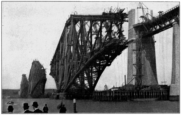
FIG. 228.—THE FORTH BRIDGE. LARGEST VIADUCT IN THE WORLD. FROM A PHOTOGRAPH WHEN IN PROCESS OF CONSTRUCTION. LENGTH, 8,290 FEET; HEIGHT ABOVE WATER, 361 FEET; MAIN SPANS, 1,710 FEET LONG, 150 FEET HIGH.
The Forth Bridge.—This massive structure, of the cantilever type, is
shown in Fig. 228. It was begun in 1882 and finished in 1890, and is the
largest and most costly viaduct in the world. It is built across the Firth
of Forth, and is the most important link in the direct railway communication
of the North British Railway, and associated roads, between Edinburgh
on the one side, and Perth and Dundee on the other. The total
length of the viaduct is 8,296 feet, or nearly 15⁄8 miles. The extreme[341]
[342]
height of the structure is 361 feet above the water level, and the foundations
extend 91 feet below the water level. The two main spans are
1,710 feet, and these both give a clear headway for navigation of 150 feet
height. There are over 50,000 tons of steel in the superstructure, and
about 140,000 cubic yards of masonry and concrete in the foundation piers.
The three main piers consist each of a group of four masonry columns
faced with granite, 49 feet in diameter at the top, and 36 feet high, which
rest on solid rock, or on concrete carried down in most cases by means
of caissons of a maximum diameter of 70 feet to rock or boulder clay.
No intelligent conception of the enormous size of this great structure can be obtained except by comparison. Estimating from the bottom of the masonry piers to the towering heights of the cantilevers, it reaches above the dome of St. Peter’s at Rome, and is only a little short of the height of the greatest of the pyramids of Egypt. The cost of the bridge is given as £3,250,000 or nearly $16,000,000.
The Brooklyn Bridge.—Having for its successful construction and maintenance the same foundation principle upon which the spider builds its web, this magnificent bridge of steel wires spans the East River between New York and Brooklyn, with a total length of 5,989 feet, and in length of span and cost is second only to the great Forth Bridge. It is shown in Fig. 229, and among suspension bridges it ranks first. It has a central span of 1,5951⁄2 feet between the two towers, over which the suspension cables are hung, and has a clear headway beneath of 135 feet. It has two side spans of 930 feet each between the towers and the shore.
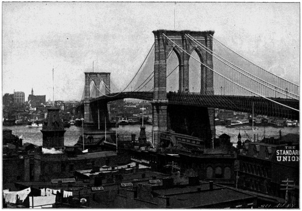
FIG. 229.—THE BROOKLYN BRIDGE. LONGEST SUSPENSION BRIDGE IN THE WORLD. TOTAL LENGTH, 5,989 FEET; SPAN BETWEEN TOWERS, 1,595 FEET 6 INCHES.
The suspension towers stand on two piers founded in the river on solid rock at depths of 78 and 45 feet below high water, and they rise 277 feet above the same level. There are four suspension cables 151⁄2 inches in diameter, each composed of 5,282 galvanized steel wires, placed side by side, without any twist, and arranged in groups of 19 strands bound up with wire. These cables have a dip in the center of the large span of 128 feet, rest on movable saddles on the top of the towers to allow for slight movement of the cables due to expansion and contraction, and are held down at the shore ends by massive anchorages of masonry. The bridge has a width of 85 feet, and has two roadways, two lines of railway, and a foot way. It was begun in 1876 and opened for traffic in 1883, and its cost was about $15,000,000. It fulfills a great function for the busy metropolis, and it hangs in the air a monument in steel wire to the genius of the Roeblings.
Masonry Bridges.—The largest and finest single span of masonry in
America, and believed to be the largest in the world, is to be found about[343]
[344]
9 miles northwest of the city of Washington. It is known as the Washington
Aqueduct or Cabin John Bridge, and is seen in Fig. 230. It
extends across the small stream known as Cabin John Creek, and carries
an aqueduct 9 feet in diameter, that supplies the National Capital
with water, its upper surface above the water conduit being formed into
a fine roadway. It is 450 feet long. Its span is 220 feet, the height of
the roadway above the bed of the stream is 100 feet, and the width of
the structure is 20 feet 4 inches. Gen. Montgomery C. Meigs was the
engineer in charge of its construction. It was begun in 1857 and finished
in 1864, with the exception of the parapet walls of the roadway, which
were added in 1872-3. Its cost was $254,000. Only one other masonry
arch has ever been built which equalled this in size. The Trezzo Bridge,
built in the fourteenth century, over the Adda in North Italy, and subsequently
destroyed, is said to have had a span of 251 feet, but the Washington
Aqueduct Bridge at Cabin John is a noble work in masonry, and
when standing beneath its majestic sweep, and viewing the regular courses
of masonry hanging nearly a hundred feet high in the air, and springing
more than a hundred feet from the embankment upon either side, one[345]
loses sight of the principles of the arch, and the fear that the mass may
fall upon him gives way to the impression that nature has bowed to the
genius of man, and suspended the law of gravity.
FIG. 230.—CABIN JOHN BRIDGE, NEAR WASHINGTON, D. C. LARGEST MASONRY ARCH IN THE WORLD. LENGTH, 450 FEET; SPAN OF ARCH, 220 FEET; HEIGHT, 100 FEET.
Among the patents granted for bridges the most important are those relating to the cantilever type, among which may be mentioned those to Bender, Latrobe, and Smith, No. 141,310, July 29, 1873; Eads, No. 142,378 to 142,382, September 2, 1873, and Clarke, No. 504,559, September 5, 1893.
Caissons.—For submarine explorations the ancient diving bell, which was said to have been used more than 2,000 years ago, has given place to diving armor, while for more extensive local work the pneumatic caisson is employed. The latter was invented by M. Triger, a French engineer, in 1841. An early example of it is also given in Cochrane’s British patent No. 3,226, of 1861. It consists of a vertical cylinder divided into compartments, its lower open end resting on the river bottom. Compressed air forced into the lower compartment forces the water back, while the men are at work, the intermediate chamber forming an air lock, by which entrance to, or egress from, the lower working chamber is obtained. The pneumatic caissons of Eads (patents Nos. 123,002, January 23, 1872, and 123,685, February 13, 1872) and Flad (patent No. 303,830, August 19, 1884) are modern applications of the same principle. The sinking of shafts through quicksand, by artificially freezing the same and then treating it as solid material, is an ingenious modern method shown in patents to Poetsch, No. 300,891, June 24, 1884; and Smith, No. 371,389, October 11, 1887.
Tunnels.—Less conspicuous than bridges, by virtue of their underground character, but none the less important, are these mole-like means of communication. Especially difficult of construction for the reason that the nature of the soil or rock is largely unknown, and for the reason also that the work may have to encounter faults in rocks, and springs or quicksands in the earth; nevertheless the demands of the railroads for shortening the distance of travel and economizing time have stimulated the engineer to expend millions of dollars in piercing the earth with these great underground passageways.
The Mont Cenis Tunnel was constructed to establish railway communication between France and Italy through the Alps. It was begun in 1857, and after having been in progress of construction for thirteen years, was opened for traffic in 1871. This tunnel was commenced by hand borings, being for the most part through solid rock, and its progress up to 1862 was so slow that it was estimated that thirty years would be[346] required for its construction. Its earlier completion was due to the introduction of rock drills operated by compressed air, which trebled the rate of advance, and which device made a new epoch in all rock-boring and mining operations. This tunnel was cut from both ends at the same time, and so accurate were the surveys in establishing the alignment of the two headings through the mountain mass, that, although the tunnel was more than 71⁄2 miles long, when the two headings came together in the middle, only a difference of one foot in level existed between them. When it is remembered that most of the 71⁄2 miles of tunnel was cut through solid rock, by boring and blasting, the immensity of the undertaking can be appreciated. As completed the tunnel is 8 miles long, and wide enough for a double track railway.
The St. Gothard Tunnel is another tunnel through the Alps, which involved even a longer and deeper cut through the mountains than the Mont Cenis Tunnel. This is 91⁄4 miles long, and it was begun in 1872, the headings joined in 1880, and the tunnel opened for traffic in 1882. Although by far the largest undertaking yet made, the improvement in rock-boring machinery enabled it to be constructed much more rapidly and at less expense.
The Arlberg is still another Alpine tunnel. It is 61⁄2 miles long, was commenced in 1880, and opened for traffic in 1884.
Tunneling under rivers presents many more difficulties than driving through the hardest rock. This is so by reason of the inflow of water. Among successful tunnels of this kind may be named the Mersey and Severn tunnels in England, opened in 1886, and the St. Clair tunnel between the United States and Canada. The histories of the abandoned Detroit and Hudson river tunnels are object lessons of the difficulties encountered in this class of work.
An important engineering invention for tunneling through silt or soft soil is the so-called “shield.” This was first employed by the engineer Brunel in the construction of the Thames tunnel, which was begun in 1825 and opened as a thoroughfare in 1843. The shield, as now used, is a sort of a cylinder or sleeve as large as the tunnel, which sleeve, as the excavation proceeds in front of it, is forced ahead to act both as a ring-shaped cutter and a protection to the workmen, its advance being effected by powerful hydraulic jacks or screws which find a back bearing against the completed wall of the tunnel. As the digging proceeds the shield is advanced, and a section of tunnel is built behind it which, in turn, furnishes a bearing for the jacks in the further advance of the shield.
This latter improvement was the invention of the late Alfred E. Beach,[347] of the Scientific American, and was covered by him in patent No. 91,071, June 8, 1869, and was used in driving the experimental pneumatic subway constructed by him under Broadway, New York, in 1868-9, and also in the St. Clair River tunnel and the unfinished Hudson River tunnel and other works.
Subsequent improvements made upon the shield by J. H. Greathead of England and covered by him in United States patents Nos. 360,959, April 12, 1887; and 432,871, July 22, 1890, have greatly added to the value and efficiency of this device, and made it one of the leading instrumentalities in tunnel construction.
Suez Canal.—It is said that the undertaking of connecting the Mediterranean and Red Seas was considered as long ago as the time of Herodotus, and a small channel appears to have been opened twenty-five centuries ago, but was subsequently abandoned. In 1847 the subject was again taken up for serious consideration, the work begun in 1860, and finished in 1869, at a cost of £20,500,000, or more than a hundred million dollars. The canal starts at Port Said, on the Mediterranean, a view of which with its ships of all nations and the canal reaching far away in the distance is seen in Fig. 231. The canal extends nearly due south to Suez on the Red Sea, a distance of about 100 miles, through barren wastes of sand and an occasional lake. It was originally formed with a bottom width of 72 feet, spreading out to 196 to 328 feet at the top, and of a depth of 26 feet, but has since been increased in transverse dimension to accommodate the great increase in travel.
FIG. 231.—PORT SAID ENTRANCE TO SUEZ CANAL, SHOWING HARBOR WITH SHIPS OF ALL NATIONS, AND THE CANAL REACHING AWAY IN THE DISTANCE.
Sixty great dredges were employed on the work, and the dredged material
was discharged in chutes on to the bank. The canal was the work
of M. De Lesseps, the eminent French engineer, and has proved a great
success from both an engineering and financial standpoint. The stock
is mainly held in England, having been bought from the Khedive of
Egypt. In 1898 the ships passing through the canal during the year
reached the remarkable number of 3,503. The rate of tolls is 10 francs
(about $2) per net ton. The gross tonnage of ships passing through in
1898 was 12,962,632, the net tonnage 9,238,603. The total receipts for
the year were 87,906,255 francs (about $17,500,000), and the net profit
63,441,987 francs (about $12,500,000). An average size ocean liner pays
about $5,000 for the privilege of sailing through this great ditch. Admiral
Dewey’s ship, the “Olympia,” returning from the Philippines, paid
for her toll $3,516.04, and the “Chicago,” $3,165.95. Going the other
way, our supply ship “Alexander” paid $4,107.99, while the “Glacier” paid
$5,052.38. Ships making the passage through the canal move slowly on[348]
[349]
account of the washing of the banks, about 22 hours being required,
but the shortening of the travel of ships going east and west, and the
saving of life, property, and time, involved in avoiding the circuitous
and stormy passage around the Cape of Good Hope, has been of incalculable
benefit to the world.
With the construction of canals and harbors, great improvements have been made in dredges. Some of these are of the clam-shell type, some employ the scoop and lever, others an endless series of buckets. An example of the latter, used on the Panama Canal, is seen in Fig. 232. Still another form, and the most recent if not the most important is the hydraulic dredger, which, by rotating cutters, stirs and cuts the mud and silt, and by powerful suction pumps and immense tubes draws up the semi-fluid mass and sends it to suitable points of discharge. The best known of the latter type is the Bowers hydraulic dredge, covered by many patents, of which Nos. 318,859 and 318,860, May 26, 1885; 388,253, August 21, 1888; and 484,763, October 18, 1892, are the most important.
For surface excavations in solid earth the Lidgerwood Cableway is an important and labor saving device. A track cable is stretched from two distant towers, and a bucket holding well on to a ton of earth is made to travel on a trolley running on said cable track, rising at one end out of the excavation, and dumping at the other end to fill in the excavation as[350] the cutting progresses, all in a continuous and economical manner. This device is made under the patent to M. W. Locke, No. 295,776, March 25, 1884, and comprehends many subsequent improvements patented by Miller, Delaney, North and others. The Chicago Drainage Canal is a work just completed, which largely employed these devices. This canal was designed to connect the Chicago River with the Mississippi River, so as to send the sewage of Chicago down the Mississippi instead of into Lake Michigan. Although it cost $33,000,000 and required seven years for completion, the labor-saving cableways greatly cheapened its cost and shortened the time of its construction.
Among the leading inventions relating to canal construction may be mentioned the bear-trap canal-lock gate (patents Nos. 229,682, 236,488 and 552,063), and the Dutton pneumatic lift locks. The latter provide ease and rapidity of action by a principle of balancing locks in pairs, and are covered by his patent No. 457,528, August 11, 1891, and others of subsequent date.
Artesian Wells represent an important branch of engineering work, and they are so called from the province of Artois, in France, where they have for a long time been in use. Extending several thousand feet into the subterranean chambers of the earth, they have brought abundant water supply to the surface all over the world, from the desert sands of Sahara to the hotels of the modern city; they have contributed oil and gas in incredible quantities to supply light and heat, and have made valuable additions to the salt supply of the world.
They are driven by reciprocating a ponderous chisel-shaped drill within an iron tube, six inches more or less in diameter, which is built up in sections, and moved down as the cutting descends. The drill is reciprocated by a suspending rope from machinery in a derrick, and in order to give a hammer-like blow to the chisel a pair of ponderous iron links coupled together like those of a chain, and called a “drill jar” connect the drill to the rope. As the sections of the link slide over each other they come together with a hammer blow at the moment of lifting that dislodges the drill from the rock, and on the descending movement they come together with a hammering blow immediately after the drill touches the rock to drive it into the same. The first United States patent for a drill jar is that to Morris, No. 2,243, September 4, 1841. When an oil well ceases to flow, it is rejuvenated by being “shot,” which is quite contrary to the ordinary conception of prolonging life. For this purpose a dynamite cartridge is exploded at the lower end of the well, which shatters the rock, and, in[351] opening up new channels of flow for the oil, renews the yield. Many patented inventions have been made in the field of well boring, and the discovery of coal oil in the United States in 1859 has developed a great industry and built up enormous fortunes. The amount of petroleum produced in the United States in 1896 was 60,960,361 barrels, the largest yield on record. In 1897 the amount was 60,568,081 barrels.
Of less consequence than the artesian well, but finding many useful applications, is the drive well. A metal tube with a perforated lower end is driven down by hammers into the ground, and furnishes a quick and cheap source of water supply. This was invented by Col. Green in 1861, in meeting the necessities of his military camp during the civil war, and was patented by him January 14, 1868, No. 73,425.
Rock Drills.—In mining and tunneling through rock, the rock drill has been the implement of paramount importance and utility. For boring by rotary action the diamond drill is most effective. This uses bits set with diamonds which, by their extreme hardness, cut through the most refractory rock with great rapidity. It was invented by Hermann and patented by him in France, June 3, 1854.
More important, however, is the compressed air rock drill, in which a piston has the drill bit directly on its piston rod and cuts by a reciprocating action. The piston is actuated by compressed air admitted alternately to its opposite sides in an automatic manner by valves. The compressed air conveyed to the drill in the tunnel or mine not only operates the drill, but helps to ventilate the tunnel. As early as 1849 Clarke and Motley, in England, invented a machine drill, and in 1851 Fowle devised a similar machine, having the drill attached directly to the piston cross head. The Hoosac and Mont Cenis tunnels greatly stimulated invention in this field, and among the notable drills of this class may be named the Burleigh, Ingersoll, and Sergeant. The Burleigh drill was brought out in 1866, and was covered by patents Nos. 52,960, 52,961 and 59,960 of that year, and 113,850 of 1871, and the Ingersoll drill, by patents No. 112,254, and No. 120,279, of 1871.
Blasting.—The discovery of nitro-glycerine in 1846, followed by its convenient commercial preparation in the form of dynamite, gave a great impetus to blasting. Notable as the largest operation of the kind in the century is the blowing up of Flood Rock, in the path of commerce between New York City and Long Island Sound. The dangerous character of this and other rocks in this vicinity gave long ago to this channel the significant name of Hell Gate. The undermining of the rocks by shafts and galleries is seen in Fig. 233, and the final blowing up of the same[352] in a single blast was the culmination of a series of similar operations at this point tending to safer navigation. On October 10, 1885, 40,000 cartridges, containing 75,000 pounds of dynamite and 240,000 pounds of rack-a-rock, were, by the touching of a button and the closing of an electric circuit, simultaneously exploded. In the twinkling of an eye nine acres of solid rock were shattered into fragments by the prodigious force, and a vast upheaval of water 1,400 feet long, 800 feet wide, and 200 feet high, sprang into the air in tangled and gigantic fountains. As the termination of the most stupendous piece of engineering of the kind the world has ever seen, and with spectacular features fitting the enormous expense of $1,000,000, which the work cost, this final scene put an end to the menaces of Flood Rock, and wiped out of existence the worst dangers of Hell Gate.
Mississippi Jetties.—The broad bar and shallow waters at the mouth of the Mississippi involved such an obstruction to commerce that in 1872 it received the attention of Congress, resulting in the building, by Capt. Eads, of the celebrated jetties. They were begun in 1875 and finished in 1879, and cost $5,250,000. The channel obtained was 30 feet deep and 200 feet wide. Its construction involved the building across the bar and out into the Gulf of Mexico two long reaches of parallel embankments, called jetties. This was effected by sinking mattresses of willow branches bound together and weighted with stone. These were laid in four layers, and when submerged, and resting upon the bottom, were covered with a layer of loose stone, and this in turn was surmounted with a capping of concrete blocks, as seen in cross section in Fig. 234. These jetties so[353] concentrated the flow of waters into a narrow channel as to cause its increased velocity to wash out the mud and silt and deepen the channel. The immensity of the work may be measured by the quantity of material used in its construction, which included 6,000,000 cubic yards of willow mattresses, 1,000,000 cubic yards of stone, 13,000,000 feet (board measure) of lumber, and 8,000,000 cubic yards of concrete. The mattresses were laid 35 to 50 feet wide at the bottom, which width was considerably increased by the superimposed layer of stone, and the jetties extended 21⁄4 miles into the sea. Their influence upon commerce is indicated by the fact that before their construction the annual grain export from New Orleans was less than half a million bushels, and in 1880, the year following their completion, it was increased to 14,000,000 bushels.
High Buildings.—A distinct feature of modern architecture is the enormously tall steel frame building known as the “sky scraper.” The increasing value of city lots first brought about the vertical extension of buildings to a greater number of stories, and the necessity for making them fireproof, coupled with the desire to avoid loss of interior space, due to thick walls at the base, made a demand for a different style of architecture. To meet this a skeleton frame of steel is bolted together in unitary structure, the floors being all carried on the steel frame, and the outer masonry walls being relatively thin, and carrying only their own weight. In Fig. 235 is shown an example of the interior structure of such a building. The vertical columns are erected upon a very firm foundation, and to them are bolted, on the floor levels, horizontal I-beams and girders, stayed by tie rods, which I-beams receive between them hollow fireproof tile to form the floor. The outer masonry walls are built around the skeleton frame, as seen in Fig. 236, and the details of connections for the floor members appear in Fig. 237.
FIG. 236.—ENCLOSURE OF STEEL FRAME BY MASONRY.
FIG. 237.—DETAILS OF INTERNAL CONSTRUCTION.
The construction of iron buildings began about the middle of the[354] century. In 1845 Peter Cooper erected the largest rolling mill at that time in the United States for making railroad iron, and at this mill wrought iron beams for fireproof buildings were first rolled. In the[355] building of the Cooper Institute in New York City in 1857 he was the first to employ such beams with brick arches to support the floors. The unifying of the iron work into an integral skeleton frame, for relieving the side walls of the weight of the floors is, however, a comparatively recent development, and this has so raised the height of the modern office building as to cause it to impress the observer as an obelisk rather than a place of habitation. An earthquake-proof steel palace for the Crown Prince of Japan is one of the modern applications of steel in architecture. It is being built by American engineers, and is to cost $3,000,000.
FIG. 239.—WASHINGTON’S MONUMENT. HEIGHT 555 FEET, 51⁄2 INCHES. HIGHEST MASONRY STRUCTURE IN THE WORLD.
Eiffel Tower.—Loftiest among the high structures of the world, and significant as indicating the possibilities of iron construction, the Eiffel Tower of the Paris Exposition of 1889 was a distinct achievement in the engineering world. It is seen in Fig. 238. It is 984 feet high, and 410 feet across its foundation, and has a supporting base of four independent lattice work piers. In the top was constructed a scientific laboratory surmounted by a lantern containing a powerful electric light. The total[356] weight of iron in the structure is about 7,000 tons, the weight of the rivets alone being 450 tons, and the total number of them 2,500,000. The level of the first story is marked by a bold frieze, on the panels of which, around all four faces, were inscribed in gigantic letters of gold the names of the famous Frenchmen of the century. The summit of the tower was reached by staircases containing 1,793 steps, and by hydraulic elevators running in four stages. The cost of this structure was nearly $1,000,000.
FIG. 239.—WASHINGTON’S MONUMENT. HEIGHT 555 FEET, 51⁄2 INCHES. HIGHEST MASONRY STRUCTURE IN THE WORLD.
Washington’s Monument.—Next in height to the Eiffel Tower, and being, in fact, the tallest masonry structure in the world, this noble obelisk, by its simplicity, boldness and solidity, challenges the admiration of every visitor, and gratifies the pride of every patriot. It is seen in Fig. 239, and is 555 feet 51⁄2 inches high, 55 feet square at the base, and 34 feet square at the top. The walls are 15 feet thick at the base, and 18 inches at the top, and its summit is reached by an internal winding staircase and a central elevator. At the height of 504 feet the walls are pierced with port holes, from which a magnificent view is had of the capital city and surrounding country. The summit is crowned with a cap of aluminum, inscribed Laus Deo. The foundation of rock and cement is 36 feet deep and 126 feet square, and the total cost of the monument was $1,300,000.[357] The corner stone was laid in 1848. In 1855 the work was discontinued at the height of 152 feet, from lack of funds. In 1878 it was resumed by appropriation from Congress, and completed and dedicated in 1885, under the direction of Col. Thomas L. Casey, of the United States Corps of Engineers.
The Capitol Building.—Representing
the heart of the great American Republic,
and overlooking its Capital City, this
grand building, shown in Fig. 240, is a
poem in architecture. Massive, symmetrical
and harmonious, its highest point
reaches 3071⁄2 feet above the plaza on the
east. It is 751 feet 4 inches long, 350 feet
wide, and the walls of the building
proper cover 31⁄2 acres. Crowning the
center of the building is the imposing
dome of iron, surmounted by a lantern,
and above this is the bronze statue of
Freedom, 19 feet 6 inches high, and[358]
[359]
weighing 14,985 pounds, the latter being set in place December 2, 1863.
The dome is 135 feet 5 inches in diameter at the base, and the open space
of the rotunda within is 96 feet in diameter and 180 feet high.
The corner stone of the original building was laid in 1793 by Washington. The first session of Congress held there was in 1800, while the building was still incomplete. The original building was finished in 1811. In 1814 it was partly burned by the British. In 1815 reconstruction was begun, and completed in 1827. In 1850 Congress passed an act authorizing the extension of the Capitol, which resulted in the building of the north and south wings, containing the present Senate Chamber and Hall of the House of Representatives. The corner stones of the extension were laid by President Fillmore in 1851, Daniel Webster being the orator of the occasion, and the wings were finished in 1867. Since this time handsome additions in the shape of marble terraces on the west front have added greatly to the beauty and apparent size of the building.
FIG. 240.—THE UNITED STATES CAPITOL. LENGTH, 7511⁄3 FEET; WIDTH, 350 FEET; HEIGHT, 3071⁄2 FEET; BUILDING COVERS 31⁄2 ACRES.
It is not possible to give anything like an adequate review of the engineering inventions and achievements of the Nineteenth Century in a single chapter, and only the most noteworthy have been mentioned. The modern life of the world, however, has been replete with the resourceful expedients of the engineer, and the ingenious instrumentalities invented by him to carry out his plans. There have been about 1,000 patents granted for bridges, about 2,500 for excavating apparatus, and about 1,500 for hydraulic engineering. In mining the safety-lamp of Sir Humphrey Davy, in 1815, has been followed by stamp mills, rock-drills, derricks, and hoisting and lowering apparatus, and lately by hydraulic mining apparatus, by which a stream of water under high pressure is made to wash away a mountain side. Apparatus for loading and unloading, pneumatic conveyors, great systems of irrigation, lighthouses, breakwaters, pile drivers, dry-docks, ship railways, road-making apparatus, fire escapes, fireproof buildings, water towers, and filtration plants have been devised, constructed and utilized. Many gigantic schemes, already begun, still await successful completion, among which may be named the draining of the Zuyder Zee, the Siberian railway, the Panama and Nicaraguan Canals, the Simplon tunnel, the new East River Bridge, and the Rapid Transit Tunnel under New York City; while a bridge or tunnel across the English Channel, a ship canal for France, connecting the Bay of Biscay with the Mediterranean, a tunnel under the Straits of Gibraltar, and a ship canal connecting the great lakes with the Gulf of Mexico, are among the possible achievements which challenge the engineer of the Twentieth Century.
Early Machines of Sir Samuel Bentham—Evolution of the Saw—Circular Saw—Hammering to Tension—Steam Feed for Saw Mill Carriage—Quarter Sawing—The Band Saw—Planing Machines—The Woodworth Planer—The Woodbury Yielding Pressure Bar—The Universal Woodworker—The Blanchard Lathe—Mortising Machines—Special Woodworking Machines.
Surrounded as we are in the modern home with beautiful and artistic furniture, and installed in comfortable and inexpensive houses, one does not appreciate the contrast which the life of the average citizen of to-day presents to that of his great-grandfather in the matter of his dwelling house appointments. A hundred years ago most of the dwellings of the middle and poorer classes were crudely made, with clap-boards and joists laboriously hewn with the broad ax, and the roof was covered with split shingles. Uncouth and clumsy doors, windows and blinds, were framed on the simplest utilitarian basis, and a scanty supply of rude hand-made furniture imperfectly filled the simple wants of the home. To-day nearly every cottage has beautifully moulded trimmings, paneled doors, handsomely carved mantels and turned balusters, all furnished at an insignificant price, and art has so added its æsthetic values to the furniture and other useful things in wood, that beautiful, artistic and tasteful homes are no longer confined to the rich, but may be enjoyed by all. This great change has been brought about by the sawmill, the planing machine, mortising and boring machines, and the turning lathe.
Pre-eminent in the field of woodworking machinery, and worthy to be called the father of the art, is to be mentioned the name of Gen. Sir Samuel Bentham, of England, whose inventions in the last decade of the Eighteenth Century formed the nucleus of the modern art of woodworking.
The Saw was the great pioneer in woodworking machinery, and the circular saw has, in the Nineteenth Century, been the representative type. Pushing its way along the outskirts of civilization, its glistening and apparently[361] motionless disk, filled with a hidden, but terrific energy, and singing a merry tune in the clearings, has transformed trees into tenements, forests into firesides, and altered the face of the earth, the record of its work being only measured by the immensity of the forests which it has depleted. It is not possible to fix the date of the first circular saw, for rotary cutting action dates from the ancient turning lathes. The earliest description of a circular saw is to be found in the British patent to Miller, No. 1,152, of 1777. It was not until the Nineteenth Century, however, that it was generally applied, and its great work belongs to this period. The preceding saws were of the straight, reciprocating kind. The old pit-saw is the earliest form, and in course of time the men were replaced by machinery to form the “muley” saw, the man in the pit being replaced by a mechanical “pitman,” which accounts for the etymology of the word. With the “muley” saw the log was held at each end, and each end shifted alternately to set for a new cut. The first development was along the lines of this form of saw, and to increase its efficiency the saws were arranged in gangs, so as to make a number of cuts at one pass of the log. This type was especially used in Europe, but on the up stroke there was no work being done, and hence half of the time was lost. This and other difficulties led finally to the adoption of the circular type, whose continuous cut and high speed saved much time and presented[362] many other advantages. A representative example of the circular saw is given in Fig. 241.
With the increased diameter and peripheral speed of the circular saw, however, a grave difficulty presented itself. The saw would heat at its periphery, and its rim portion expanding without commensurate expansion of the central portion, would cause the saw to crack and fly to pieces under the tremendous centrifugal force. This difficulty is provided for by what is known as “hammering to tension,” i. e., the saw is hammered to a gradually increasing state of compression from the rim to the center, thus causing an initial expansion or spread of the molecules of metal of the central parts of the saw, which is stored up as an elastic expansive force that accommodates itself to the tension caused by the expansion of the rim, and prevents the unequal and destructive strain, due to the expansion of the rim from the great heat of friction in passing through the log.
Mounted upon a portable frame, this machine was put to its great work upon the logs in the forests of America, and for many years this type of sawmill held its sway, and an enormous amount of work was done through its agency. Among its useful accessories were the set-works for adjusting the log holding knees to the position for a new cut, log turners for rotating the log to change the plane of the cut, and the rack and pinion feed, by which the saw carriage was run back and forth. Following the rack and pinion feed came the rope feed, in which a rope wrapped around a drum was carried at its opposite ends over pulleys and back to the opposite ends of the carriage, which was thereby carried back and forth by the forward or backward movement of the drum.
The greatest advance in sawmills in recent years, however, has been the steam feed, in which a very long steam cylinder was provided with a piston, whose long rod was directly attached to the saw carriage, and the latter moved back and forth by the admission of steam alternately[363] to opposite sides of the piston. This type of feed, also known as the shot gun feed, from the resemblance of the long cylinder to a gun barrel, was invented about twenty-five years ago, by De Witt C. Prescott, and is covered by his patent, No. 174,004, February 22, 1876, later improvements being shown in his patent, No. 360,972, April 12, 1887. The value of the steam feed was to increase the speed and efficiency of the saw, by expediting the movement of its carriage, as many as six boards per minute being cut by its aid from a log of average length. An example of a modern steam feed for sawmill carriages is seen in Fig. 242. With the modern development of the art the ease and rapidity of steam action have recommended it for use in most all of the work of the sawmill, and the[364] direct application of steam pistons working in cylinders has been utilized for canting, kicking, flipping and rolling the logs, lifting the stock, taking away the boards, etc.
Beautifully finished furniture in quartered oak has always excited the pleasure, and piqued the curiosity of the uninformed as to how this result is obtained. Fig. 243 illustrates the method of sawing to produce this effect. The log is simply divided longitudinally into four quarters, and the quarter sections are then cut by the vertical plane of the saw at an oblique angle to the sawed sides, which brings to the surface of the boards the peculiar flecks or patches of the wood’s grain so much admired when finished and polished.
The Band Saw is an endless belt of steel having teeth formed along one edge and traveling continuously around an upper and lower pulley, with its toothed edge presented to the timber to be cut, as seen in Fig. 244, which represents a form of band saw made by the J. A. Fay & Egan Company, of Cincinnati. A form of band saw is found as early as 1808, in British patent No. 3,105, to Newberry. On March 25, 1834, a French patent was granted for a band saw to Etiennot, No. 3,397. The first United States patent for a band saw was granted to B. Barker, January 6, 1836, but it remained for the last quarter of the Nineteenth Century to give the band saw its prominence in woodworking machines. That it did not find general application at an earlier period was due to the difficulty experienced in securely and evenly joining the ends of the band. For many years the only moderately successful band saws were made in France, but expert mechanical skill has so mastered the problem that in recent years the band saw has gone to the very front in wood-sawing machinery. To-day it is in service in sizes from a delicate filament, used for scroll sawing and not larger than a baby’s ribbon, to an enormous steel belt 50 feet in peripheral measurement, and 12 inches wide, traveling over pulleys 8 feet in diameter, making 500 revolutions per minute,[365] and tearing its way through logs much too large for any circular saw, at the rate of nearly two miles a minute. A modern form of such a saw is seen in Fig. 245. Prescott’s patents, Nos. 368,731 and 369,881, of 1887; 416,012, of 1889, and 472,586 and 478,817, of 1892, represent some of the important developments in the band saw.
When the band saw is applied to cutting logs the backward movement of the carriage would, if there were any slivers on the cut face of the log, be liable to force those slivers against the smooth edge of the band saw, and distort and possibly break it. To obviate this the saw carriage is provided with a lateral adjustment on the back movement called an “off-set,” so that the log returns for a new cut out of contact with the saw. Examples of such off-setting are found in patents to Gowen, No. 383,460, May 29, 1888, and No. 401,945, April 23, 1889, and Hinkley, No. 368,669, August 23, 1887. A modern form of the band saw, however, has teeth on both its edges, which requires no off-setting mechanism, but cuts in both directions. An example of this,[366] known as the telescopic band mill, is made by the Edward P. Allis Company, of Milwaukee.
A saw which planes, as well as severs, is shown in patents to Douglass, Nos. 431,510, July 1, 1890, and 542,630, July 16, 1895. Steam power mechanism for operating the knees is shown in patent to Wilkin, No. 317,256, May 5, 1885. Means for quarter sawing in both directions of log travel are shown in patent to Gray, No. 550,825, December 3, 1895. Means for operating log turners and log loaders appear in patents to Hill, No. 496,938, May 9, 1893; No. 466,682, January 5, 1892; No. 526,624, September 25, 1894, and Kelly, No. 497,098, May 9, 1893. A self cooling circular saw is found in patent to Jenks, No. 193,004, July 10, 1877; shingle sawing machines in patents to O’Connor, No. 358,474, March 1, 1887, and No. 292,347, January 22, 1884, and Perkins, No. 380,346, April 3, 1888; and means for severing veneer spirally and dividing it into completed staves, are shown in patent to Hayne, No. 509,534, November 28, 1893.
Planing Machines.—While the saw plays the initial part of shaping the rough logs into lumber, it is to the planing machine that the refinements of woodworking are due. Its rapidly revolving cutter head reduces the uneven thickness of the lumber to an exact gauge, and simultaneously imparts the fine smooth surface. The planing machine is organized in various shapes for different uses. When the cutters are straight and arranged horizontally, it is a simple planer. When the cutters are short and arranged to work on the edge of the board they are known as edgers; when the edges are cut into tongues and grooves it is called a matching machine; and when the cutters have a curved ornamental contour it is known as a molding machine, and is used for cutting the ornamental contour for house trimmings and various ornamental uses.
The planing machine was one of the many woodworking devices invented by General Bentham. His first machine, British patent No. 1,838, of 1791, was a reciprocating machine, but in his British patent No. 1,951, of 1793, he described the rotary form along with a great variety of other woodworking machinery.
Bramah’s planer, British patent No. 2,652, of 1802, was about the first planing machine of the Nineteenth Century. It is known as a transverse planer, the cutters being on the lower surface of a horizontal disc, which is fixed to a vertical revolving shaft, and overhangs the board passing beneath it, the cutters revolving in a plane parallel with the upper surface of the board. The planing machine of Muir, of Glasgow,[367] British patent No. 5,502, of 1827, was designed for making boards for flooring, and represented a considerable advance in the art.
With the greater wooded areas of America, the rapid growth of the young republic, and the resourceful spirit of its new civilization, the leading activities in woodworking machinery were in the second quarter of the Nineteenth Century transferred to the United States, and a phenomenal growth in this art ensued. Conspicuous among the early planing machine patents in the United States was that granted to William Woodworth, December 27, 1828. This covered broadly the combination of the cutting cylinders, and rolls for holding the boards against the cutting cylinders, and also means for tongueing and grooving at one operation. The revolving cutting cylinder had been used by Bentham thirty-five years before, and rollers for feeding lumber to circular saws were described in Hammond’s British patent No. 3,459, of 1811, but Woodworth did not employ his rolls for feeding, as a rack and pinion were provided for that, but his rolls had a co-active relation with a planer cylinder, or cutter head, in holding the board against the tendency of the cutter head to pull the board toward it. A patent was granted to Woodworth for these two features in combination, which patent was reissued July 8, 1845, twice extended, and for a period of twenty-eight years from its first grant, exerted an oppressive monopoly in this art, since it covered the combination of the two necessary elements of every practical planer.
Following the Woodworth patent came a host of minor improvements, among which were the Woodbury patents, extending through the period of the third quarter of the Nineteenth Century, and prominent among which is the patent to J. P. Woodbury, No. 138,462, April 20, 1873, covering broadly a rotary cutter head combined with a yielding pressure bar to hold the board against the lifting action of the cutter head.
In modern planing machinery the climax of utility is reached in the so-called universal woodworker. This is the versatile Jack-of-all-work in the planing mill. It planes flat, moulded, rabbeted, or beaded surfaces; it saws with both the rip and crosscut action; it cuts tongues and grooves; makes miters, chamfers, wedges, mortises and tenons, and is the general utility machine of the shop.
In Fig. 246 is shown a well known form of planing machine. Its work is to plane the surfaces of boards, and to cut the edges into tongues and groves, such as are required for flooring. This machine planes boards up to 24 inches wide and 6 inches thick, and will tongue and grove 14 inches wide.
Wood Turning.—To this ancient art Blanchard added, in 1819, his very ingenious and important improvement for turning irregular forms. A few efforts at irregular turning had been made before, but in the arts generally only circular forms had been turned. With Blanchard’s improvement, patented January 20, 1820, any irregular form, such as a shoe-last, gun-stock, ax-handle, wheel-spokes, etc., could be smoothly and expeditiously turned and finished in any required shape. In the ordinary lathe the work is revolved rapidly, and the cutting tool is held stationary, or only slowly shifted in the hand. In the Blanchard lathe the work is hung in a swinging frame, and turned very slowly to bring its different sides to the cutting action, and the cutting tool is constructed as a rapidly revolving disk, against which the work is projected bodily by the oscillation of the swinging frame, to accommodate the irregularities of the form. In order to do this automatically, a pattern or model of the article to be turned was also hung in the swinging frame, and made to slowly revolve and bear against a pattern wheel, which, acting upon the swinging frame carrying the work, caused it to advance to or recede from the cutting disc exactly in proportion to the contour of the model, and thus cause the revolving cutters to cut the block as it turns synchronously with the model, to a shape exactly corresponding to said model.
In Fig. 247 is shown a perspective view of Blanchard’s lathe, as patented January 20, 1820. H is a swinging frame, carrying the model T of a shoe last, and a roughed-out block U, partly converted into a shoe last. A sliding frame, fed horizontally by a screw, carries a pattern[369] wheel K, that bears against the pattern T, and a rotary cutter E, acting against the roughed-out block U. The revolving disk-shaped cutter E is rotated by a pulley and belt from a drum, which latter is made long enough to accommodate the travel of the frame. The pattern T and block U are advanced to contact respectively, with pattern wheel K and cutter E by the swinging action of frame H, and as the pattern T and block U are slowly revolved, the travel of T against K is made to react on frame H and regulate the advance of U against E, with the result that the rough block U is cut to the identical shape of the pattern T.
Among modern developments in this art may be mentioned the patents to Kimball, No. 471,006, March 15, 1892, and No. 498,170, May 23, 1893, the latter showing ingenious means whereby shoe lasts of the same length, but varying widths, may be turned. A polygonal-form lathe is shown in patent to Merritt, No. 504,812, September 12, 1893; a multiple lathe in patents to Albee, No. 429,297, June 3, 1890, and Aram, No. 550,401, November 26, 1895; a tubular lathe in patent to Lenhart, No. 355,540, January 4, 1887; and a spiral cutting lathe in patent to Mackintosh, No. 396,283, January 15, 1889.
Mortising Machines have exercised an important influence in mill work in the joining of the stiles in doors, sashes and blinds, and in the making of furniture. The Fay & Egan machine is seen in Fig. 248. The self acting mortising machine was among the numerous early contributions of Gen. Bentham in woodworking machinery, and was described in his British patent No. 1,951, of 1793, a number of them having been made by him for the British Admiralty. Brunel’s mortising machine for[370] making ships’ blocks is another early form described in British patent No. 2,478, of 1801. As representing novel departures in this art, the endless chain mortising machine shown in Douglas patent, No. 379,566, March 20, 1888, may be mentioned, and reissue patent, No. 10,655, October 27, 1885, to Oppenheimer, and No. 461,666, October 20, 1891, to Charlton, are examples of mortising augers.
Special Woodworking Machines.—Of these there have been great numbers and variety. No sooner does an article become extensively used than a machine is made for turning it out automatically. Indeed, machines for cheaply turning out articles have, in many cases, led the way to popular use of the article by the extreme cheapness of its production.
Among various automatic machines for making special articles may be mentioned those for making clothes pins, scooping out wood trays, pointing skewers, dovetailing box blanks, cutting sash stile pockets, cutting and packing toothpicks, making matches, boxing matches, duplicating carvings, cutting bungs, cutting corks, making umbrella sticks, making brush blocks, boring chair legs, screw-driving machines, box nailing machines, making cigar boxes, nailing baskets, wiring box blanks, applying slats, gluing boxes, gluing slate frames, making veneers, bushing mortises, covering piano hammers, making staves and barrels, making fruit baskets, etc.
It is impossible to give in any brief review a proper conception of the immensity of the woodworking industry in the United States. It is estimated in the Patent Office that about 8,000 patents have been granted for woodworking machines. Besides this there are about 5,000 patents in the separate class of wood sawing, about an equal number for woodworking tools, and these, with other patented inventions in wood turning, coopering, or the making of barrels, wheelwrighting, and other minor classes, give some idea of the activity in this great field of industry.
The exports of wood and wooden manufactures from the United States in 1899 amounted to $41,489,526, of which $15,031,176 were for finished boards, $4,107,350 for barrels, staves and heads, and $3,571,375 for household furniture, but this is only an insignificant portion, for with a prosperous country, an abundance of wood, and a thrifty and ambitious nation of home builders, the home consumption has been incalculable.
Early Iron Furnace—Operations of Lord Dudley, Abraham Darby and Henry Cort—Neilson’s Hot Blast—Great Blast Furnaces of Modern Times—The Puddling Furnace—Bessemer Steel and the Converter—Open Hearth Steel—Siemens’ Regenerative Furnace—Siemens-Martin Process—Armor Plate—Making Horse Shoes—Screws and Special Machines—Electric Welding, Annealing and Tempering—Coating with Metal—Metal Founding—Barbed Wire Machines—Making Nails, Pins, etc.—Making Shot—Alloys—Making Aluminum, and Metallurgy of Rarer Metals—The Cyanide Process—Electric Concentrator.
Take away iron and steel from the resources of modern life, and the whole fabric of civilization disintegrates. The railroad, steam engine and steamship, the dynamo and electric motor, the telegraph and telephone, agricultural implements of all sorts, grinding mills, spinning machines and looms, battleships and firearms, stoves and furnaces, the printing press, and tools of all sorts—each and every one would be robbed of its essential basic material, without which it cannot exist. Steam and electricity may be the heart and soul of the world’s life, but iron is its great body. King among metals, it gives its name to the present cycle, as the “Iron Age,” and the Nineteenth Century has crowned it with such refinements of shape, and endowed it with such attributes of utility, and such grandeur of estate, that its powers in organized machinery have, for effective service, risen to all the functions and dignity of human capacity—except that of thought.
A crude gift of nature, in the mountain side, it remained, however, a sodden mass until extracted, refined, and wrought into shape by the genius of man. Yielding to the magical touch of invention, it has been cast in moulds into cannon, mills, plowshares, and ten thousand articles; it has been drawn into wire of any fineness and length to form cables for great suspension bridges; it has been rolled into rails that grill the continents; into sheets that cover our roofs; and into nails that hold our houses together. It has been wrought into a softness that lends its susceptible nature to the influence of magnetism, and has been hardened into steel to form the sword and cutting tool. From the delicate hair[372] spring of a watch to the massive armor plate of a battleship, it finds endless applications, and is nature’s most enduring gift to man—abundant, cheap, and lasting.
Metallurgy is an ancient art, and the working of gold, silver and copper dates back to the beginning of history. Being found in a condition of comparative purity, and needing but little refinement, they were, for that reason, the first metals fashioned to meet the wants of man. Iron, somewhat more refractory, appeared later, but it also has an early history, and is mentioned in the Old Testament of the Bible (Genesis iv., 22), in which reference is made to Tubal Cain as an artificer in brass and iron. The iron bedstead of Og, King of Bashan, is another reference. That it was known to the Egyptians and the Greeks at least 1000 B. C., seems reasonably certain. The Assyrians were also acquainted with iron, as is clearly established by the explorations of Mr. Layard, whose contributions to the British Museum of iron articles from the ruins of Ninevah include saws, picks, hammers, and knives of iron, which are believed to be of a date not later than 880 B. C.
Iron ore is usually found in the form of an oxide (hematite), and its reduction to the metallic form consists in displacing the oxygen, which is effected by mixing carbon in some form with the ore, and subjecting the mixture to a high heat by means of a blast. The carbon unites with the oxygen and forms carbonic acid gas, which escapes, while the metallic iron fuses and runs out at the bottom of the furnace, and when collected in trough-shaped moulds, is known as pig iron.
The first iron furnaces were known as air bloomeries, and had no[373] forced draft. The first step of importance in iron making was the forced blast. An early form of blast furnace is shown in Fig. 249, which represents an iron furnace of the Kols, a tribe of iron smelters in Lower Bengal and Orissa. An inclined tray terminates at its lower end in a furnace inclosure. Charcoal in the furnace being well ignited, ore and charcoal resting on the tray are alternately raked into the furnace. The blowers are two boxes, connected to the furnace by bamboo pipes, and provided with skin covers, which are alternately depressed by the feet and raised by cords from the spring poles. Each skin cover has a hole in the middle, which is stopped by the heel of the workman as the weight of the person is thrown upon it, and is left open by the withdrawal of the foot as the cover is raised. The heels of the workman, alternately raised, form alternately acting valves, and the skin cover, when depressed, acts as a bellows. The fused metal sinks to a basin in the bottom of the furnace, and the slag or impurities run off above the level of the basin at the side of the furnace.
The great modern art of iron working dates from Lord Dudley’s British patent, No. 18, of 1621, which related to “The mistery, arte, way and meanes of melting iron owre, and of makeing the same into cast workes or barrs with seacoales or pittcoales in furnaces with bellowes of as good condicon as hath bene heretofore made of charcoale.”
The next step of importance after the blast furnace was the substitution of coke for coal for the reduction of the ore, which was introduced by Abraham Darby, about 1750.
Next came the conversion of cast iron into wrought iron. This was mainly the work of Mr. Henry Cort, of Gosport, England, who, in 1783-84, introduced the processes of puddling and rolling, which were two of the most important inventions connected with the production of iron since the employment of the blast furnace. Mr. Cort obtained British patents No. 1,351, of 1783, and No. 1,420, of 1784, for his invention. His first patent related to the hammering, welding, and rolling of the iron, while in his second patent he introduced what is known as the reverberatory furnace, having a concave bottom, into which the fluid metal is run from the smelting furnace, and which is converted from brittle cast iron, containing a certain per cent. of carbon, into wrought iron, which has the carbon eliminated, and is malleable and tough. This process is called puddling, and consists in exposing the molten metal to an oxidizing current of flame and air. The metal boils as the carbon is burned out, and as it becomes more plastic and stiff it is collected into what are called blooms, and these are hammered to get rid of the slag, and are reduced[374] to marketable shape as wrought iron by the process described in his previous patent. Mr. Cort expended a fortune in developing the iron trade, and was one of the greatest pioneers in this art.
The first notable development of the Nineteenth Century was the introduction of the hot air blast in forges and furnaces where bellows or blowing apparatus was required. This was the invention of J. Beaumont Neilson, of Glasgow, and was covered by him in British patent No. 5,701 of 1828. This consisted in heating the air blast before admitting it to the furnace, and it so increased the reduction of refractory ores in the blast furnace as to permit three or four times the quantity of iron to be produced with an expenditure of little more than one-third of the fuel.
An illustration of a modern blast furnace plant is given in Fig. 250. A is the furnace, in which the iron ore and fuel are arranged in alternate layers. The hot air blast comes in through pipes t at the bottom, called tuyeres. As gas escapes through the opening b at the top, it is first cleared of dust in the settler and washer B, and then passes through the pipe C to the regenerators D D D, where it is made to heat the incoming[375] air. The gas mixed with some air burns in the regenerators, and, after heating a mass of brick within the regenerators red hot, escapes by the underground passageway to the chimney on the right. When the bricks are sufficiently hot in one of the regenerators, gas is turned off therefrom, and into another regenerator, and fresh air from pipe H is passed through the bricks of the heated regenerator, and being heated passes out pipe F at the top and thence to the pipe G and tuyeres t, to promote the chemical reactions in the blast furnace.
In the earlier blast furnaces a vast amount of heat was allowed to escape and was wasted. The utilization of this heat engaged the attention of Aubertot in France, 1810-14; Teague in England (British patent No. 6,211, of 1832); Budd (British patent No. 10,475, of 1845), and others. To enable the escaping hot gases to be employed for heating the hot blast regenerators a charging device is now used, as seen at a in Fig. 250, in which the admission of ore and fuel is regulated by a large conical valve, and the gases are compelled to pass out at b and be utilized.
Among the world’s largest blast furnaces may be mentioned the Austrian Alpine Montan Gesellschaft, which concern owns thirty-two furnaces. This is said to be the largest number owned by any one concern in the world, but most of them are of small size and run on charcoal iron. The furnaces of the United States are, however, of the largest yield, and the leading ones of these are:
| No. Furnaces. |
Annual capacity in tons. |
|
|---|---|---|
| Carnegie Steel Co. | 17 | 2,200,000 |
| Federal Steel Co. | 19 | 1,900,000 |
| Tennessee Coal and Iron Co. | 20 | 1,307,000 |
| National Steel Co. | 12 | 1,205,000 |
The present annual output of pig iron in the United States is about ten million tons, of which these four companies make about one-half.
When the iron runs from the bottom of the blast furnace it is allowed to flow into trough-like moulds in the sand of the floor, and forms pig iron. Pig iron can be remelted and cast into various articles in moulds, but it cannot be wrought with the hammer, nor rolled into rails or plates, nor welded on the anvil, because it is still a compound of iron and carbon with other impurities, and is crystalline in character. To bring it into wrought iron, which is malleable and ductile, it is puddled and refined, which involves chiefly the burning out of the carbon and silicon. The pig iron is remelted (see Fig. 251) in the tray-shaped hearth b from the heat of the[376] fire in the reverberatory furnace a, the reverberatory furnace being one in which the materials treated are exposed to the heat of the flame, but not to contact with the fuel. The hot flame mixed with air beating down upon the melted iron on hearth b for two hours or so, burns out the silicon and carbon, the process being facilitated by stirring and working the mass with tools. During the operation the oxygen of the air combines with the carbon and forms carbonic acid gas, which, in escaping from the metal, appears to make it boil. When the iron parts with its carbon it loses its fluidity and becomes plastic and coherent, and is formed into balls called blooms. These blooms consist of particles of nearly pure iron cohering, but retaining still a quantity of slag or vitreous material, and other impurities, which slag, etc., is worked out while still, hot by a squeezing, kneading, and hammering process to form wrought iron that may be worked into any shape between rolls or under the hammer.
Bessemer Steel.—Steel is a compound of iron and carbon, standing between wrought iron and cast iron. Wrought iron has, when pure, practically no carbon in it, while cast iron has a considerable proportion in excess of steel. Steel making consists mainly in so treating cast iron as to get rid of a part of the carbon and other impurities. Of all methods of steel making, and in fact of all the steps of progress in the art of metal working, none has been so important and so far reaching in effect as the Bessemer process: It was invented by Henry Bessemer, of England, in 1855. About fifty British patents were taken by Mr. Bessemer relating to various improvements in the iron industry, but those representing the pioneer steps of the so-called Bessemer process are No. 2,321, of 1855;[377] No. 2,768, of 1855, and No. 356, of 1856. The process is illustrated in Figs. 252, 253 and 254. The converter in which the process is carried out is a great bottle-shaped vessel 15 feet high and 9 feet wide, consisting of an iron shell with a heavy lining of refractory material, capable of holding eight or more tons of melted iron, and with an open neck at the top turned to one side. It is mounted on trunnions, and is provided with gear wheels by which it may be turned on its trunnions, so that it may be maintained erect, as in Fig. 252, or be turned down to pour out the contents into the casting ladle, as in Figs. 253 and 254. At the bottom of the converter there is an air chamber supplied by a pipe leading from one of the trunnions, which is hollow, and a number of upwardly discharging air openings or nozzles send streams of air into the molten mass of red hot cast iron. The red hot cast iron contains more or less carbon and silicon, and the air uniting with the carbon and silicon burns it out, and in doing so furnishes the heat for the continuance of the operation. When the pressure of air is turned into the mass of molten iron a tongue of flame increasing in brilliancy to an intense white, comes roaring out of the mouth of the converter, and a violent ebullition takes place within, and throws sparks and spatters of metal high in the air around, producing the impression and scenic effect of a volcano in eruption. In fifteen minutes the volume and brilliancy of the flame diminish, and this indicates the critical moment of conversion into tough steel, which must be adjusted to the greatest nicety. When the carbon is sufficiently burned out the blast is stopped and the converter turned down to receive a quantity of ferro-manganese or spiegeleisen (a compound of iron containing manganese), which unites with and removes the sulphur and oxide of iron, and then the lurid monster, with its breath of fire abated, and its energy exhausted, bows its head and vomits forth its charge of boiling steel, to be wrought or cast into ten thousand useful articles.
Like most all valuable inventions, Mr. Bessemer’s claim to priority for the invention was contested. An American inventor, William Kelly, in[378] an interference with Mr. Bessemer’s United States patent, successfully established a claim to the broad idea of forcing air into the red hot cast iron, and United States patent No. 17,628, June 23, 1857, was granted to Mr. Kelly. The honor of inventing and introducing a successful process[379] and apparatus for making steel by this method, however, fairly belongs to Mr. Bessemer, to whose work was to be added the valuable contribution of Robert F. Mushet (British patent No. 2,219, of 1856) of adding spiegeleisen, a triple compound of iron, carbon and manganese, to the charge in the converter. This step served to regulate the supply of carbon and eliminate the oxygen, and completed the process of making steel. The Holly converter, covered by United States patents No. 86,303, and No. 86,304, January 26, 1869, represented one of the most important American developments of the Bessemer converter.
The importance of Bessemer steel in its influence upon modern civilization is everywhere admitted. It has so cheapened steel that it now competes with iron in price. Practically all railroad rails, iron girders and beams for buildings, nails, etc., are made from it at a cost of between one and two cents per pound.
In recognition of the great benefits conferred upon humanity by this process, Queen Victoria conferred the degree of knighthood upon the inventor, and his fortune resulting from his invention is estimated to have grown for some time at the rate of $500,000 a year. In a historical sketch of the development of his process, delivered by Sir Henry Bessemer in December, 1896, before the American Society of Mechanical Engineers at New York, Mr. Bessemer was reported as saying that the annual production of Bessemer steel in Europe and America amounted to 10,000,000 tons. The production of Bessemer steel in the United States for 1897 was for ingots and castings 5,475,315 tons, and for railroad rails 1,644,520 tons. The extent to which steel has displaced iron is shown by the fact that in the same year iron rails to the extent of 2,872 tons only were made, as compared with more than a million and a half tons of Bessemer steel.
In the popular vote taken by the Scientific American, July 25, 1896, as to what invention introduced in the past fifty years had conferred the greatest benefit upon mankind, Bessemer steel was given the place of honor.
A recent improvement in the handling of iron from the blast furnace is shown in Fig. 255. Heretofore, the iron was run in open sand moulds on the floor and allowed to cool in bars called “pigs,” which were united in a series to a main body of the flow, called a “sow.” To break the “pigs” from the “sow,” and handle the iron in transportation, was a very laborious and expensive work. The illustration shows two series of parallel trough moulds, each forming an endless belt, running on wheels. The molten cast iron is poured direct into these moulds, and as they travel along they pass beneath a body of water, which cools and solidifies the iron into pigs,[380] and then carries them up an incline and dumps them directly into the cars.
Open Hearth Steel is not so cheap as Bessemer steel, but it is of a finer and more uniform quality. Bessemer steel is made in a few minutes by the most energetic, rapid and critical of processes, while the open hearth steel requires several hours, and its development being thus prolonged it may be watched and regulated to a greater nicety of result. For railroad rails and architectural construction Bessemer steel still finds a great field of usefulness, but for the finest quality of steel, such as is employed in making steam boilers, tools, armor plate for war vessels, etc., steel made by the open hearth process is preferred. It consists in the decarburization of cast iron by fusion with wrought iron, iron sponge, steel scrap, or iron oxide, in the hearth of a reverberatory furnace heated with gases, the flame of which assists the reaction, and the subsequent recarburization or deoxidation of the bath by the addition, at the close of the process, of spiegeleisen or ferro-manganese. The period of fusion lasts from four to eight hours. The advantages over the Bessemer process are, a less expensive plant and the greater duration of the operation, permitting, by[381] means of sampling, more complete control of the quality of the product and greater uniformity of result.
The British patents of Siemens, No. 2,861, of 1856; No. 167, of 1861, and No. 972, of 1863, for regenerative furnaces, and the British patents of Emile and Pierre Martin, No. 2,031, of 1864; No. 2,137, of 1865, and No. 859, of 1866, represent the so-called Siemens-Martin process, which is the best known and generally used open hearth process.
The Siemens Regenerative Furnace, in which this process is carried out, is seen in Fig. 256. Four chambers, C, E, E′, C′, are filled with fire brick loosely stacked with spaces between, in checker-work style. Gas is forced in the bottom of chamber C, and air in bottom of chamber E, and they pass up separate flues, G, on the left, and being ignited in chamber D above, impinge in a flame on the metal in hearth H, the hot gases passing out flues F on the right, and percolating through and highly heating the checker-work bricks in chambers E′ and C′. As soon as these are hot, gas and air are shut off by valves from chambers C and E, and gas and air admitted to the bottoms of the now hot chambers C′ and E′. The gas and air now passing up through these chambers C′, E′, become highly heated, and when burned above the melted iron on hearth H produce an intense heat. The waste gases now pass down flues G, and[382] impart their heat to the checker-work bricks in chambers C and E. When the bricks in E′ C′ become cooled by the passage of gas and air, the valves are again adjusted to reverse the currents of gas and air, sending them now through chambers C and E again. In this way the heat[383] escaping to the smoke stack is stored up in the bricks and utilized to heat the incoming fuel gases before burning them, thus greatly increasing the effective energy of the furnace, saving fuel, and keeping the smoke stack relatively cool.
Armor Plate.—In these late days of struggle for supremacy between the power of the projectile and the resistance of the battleship, the production of armor plate has become an interesting and important industry.
Three methods are employed. One is to roll the massive ingots directly into plates between tremendous rolls, a single pair of which, such as used in the Krupp works, are said to weigh in the rough as much as 100,000 pounds. Usually there are three great rollers arranged one above the other, and automatic tables are provided for raising and lowering the plates in their passage from one set of rolls to the other. The man in charge uses a whistle in giving the signals which direct these movements, and without the help of tongs and levers the glowing blocks move easily back and forth between the rollers. The men standing on both sides of the rollers have only to wipe off the plates with brooms and occasionally turn the plates.
The second method utilizes great steam hammers weighing 125 tons, and striking Titanic blows upon the yielding metal. The most modern method, however, is by the hydraulic press forge, now used in the shops of the Bethlehem steel works in the production of Harveyized armor plate. In Fig. 257 is seen the great 14,000-ton hydraulic press-forge squeezing into shape a port armor plate for the battleship “Alabama.” After leaving the forge, the plate is trimmed to shape by the savage bite of a rotary saw and planer, seen in Figs. 258 and 259, whose insatiable appetites tear off the steel like famished fiends. The plate is then taken to be Harveyized by cementation, hardening, and tempering, as seen in Figs. 260, 261, and 262. The 125-ton mass of metal representing the plate in the rough, and weighing more than a locomotive, is thus handled and brought to shape with an ease and dispatch that inspires the observer with mixed emotions of admiration and awe.
Making Horse Shoes.—Anthony’s patent, April 8, 1831; Tolles’, of October 24, 1834, and H. Burden’s, of November 23, 1835, were pioneers in horse-shoe machines. Mr. Burden took many subsequent patents, and to him more than any other inventor belongs the credit of introducing machine-made horse shoes, which greatly cheapened the cost of this homely, but useful article. Nearly 400 United States patents have been granted for horse-shoe machines.
Making Screws, Bolts, Nuts, Etc.—Screw-making according to[384]
[385]
modern methods began between 1800-1810 with the operations of Maudsley.
Sloan, in 1851, and Harvey, in 1864, made many improvements in
machines, operating upon screw blanks. The gimlet-pointed screw, which[386]
allows the screw to be turned into wood without having a hole bored for
it, was an important advance in the art. It was the invention of Thomas
J. Sloan, patented August 20, 1846, No. 4,704, and was twice re-issued
and extended. In later years the rolling of screws, instead of cutting the
threads by a chasing tool, has attained considerable importance, and provides
a simpler and cheaper method of manufacture. Knowles’ United
States patent of April 1, 1831, re-issued March 1, 1833, described such a
process, while Rogers, in patents No. 370,354, September 20, 1887; No.
408,529, August 6, 1889; No. 430,237, June 17, 1890, and No. 434,809,
August 19, 1890, added such improvement in the process as to make it
practical.
In the great art of metal working the names of Bramah, Whitworth, Clements and Sellers appear conspicuously in the early part of the century as inventors of planing, boring and turning machinery for metals. Our present splendid machine shops, gun shops, locomotive works, typewriter and bicycle factories, are examples of the wonderful extensions of this art. In later years the field has been filled so full of improvements and special machines for special work, that only a brief citation of a few representative types is possible, and even then selection becomes a very[387] difficult task. Many special tools, particularly those designed for bicycle work, have been devised, as exhibited by patent to Hillman, August 11, 1891, No. 457,718. In turning car wheels, an improvement consists in bringing the wheel to be dressed into close proximity to the edge of a rapidly revolving smooth metal disk, whereby the surface of the wheel is melted away without there being any actual contact between the wheel surface and the disk. This is shown in patent to Miltimore, August 24, 1886, No. 347,951. In metal tube manufacture three processes are worthy of mention: (1) Passing a heated solid rod endwise between the working faces of two rapidly rotating tapered rolls, set with their axes at an angle to each other, as shown in Mannesmann’s patent, April 26, 1887, No. 361,954 and 361,955. (2) Forcing a tube into a rapidly rotating die, whereby the friction softens the tube, and the pressure and rotation of the die spin it into a tube of reduced diameter, shown in patent to Bevington, January 13, 1891, No. 444,721. (3) Placing a hot ingot in a die and forcing a mandrel through the ingot, thereby causing it to assume the shape of the interior of the die, and greatly condensing the metal, shown in patents to Robertson, November 26, 1889, No. 416,014, and Ehrhardt, April 11, 1893, No. 495,245.
In welding, the employment of electricity constitutes the most important departure. This was introduced by Elihu Thomson, and is covered in his patents Nos. 347,140 to 347,142, August 10, 1886, and No. 501,546, July 18, 1893. In annealing and tempering, electricity has also been employed as a means of heating (see patent to Shaw, No. 211,938, February 4, 1879). It supplies an even heat and uniform temperature, and is much used in producing clock and watch springs. The making of iron castings malleable by a prolonged baking in a furnace in a bed of metallic oxide was an important, but early, step. It was the invention of Samuel Lucas, and is disclosed in his British patent No. 2,767, of 1804.
The Harvey process of making armor plate is an important recent development in cementation and case hardening, and is covered by his United States patents No. 376,194, January 10, 1888, and No. 460,262, September 29, 1891. It consists, see Fig. 260, in embedding the face of the plate in carbon, protecting the back and sides with sand, heating to about the melting point of cast iron, and subsequently hardening the face. The Krupp armor plate, now rated as the best, is made under the patent to Schmitz and Ehrenzberger, No. 534,178, February 12, 1895.
In coating with metals, the so-called “galvanizing” of iron is an important art. This was introduced by Craufurd (British patent No. 7,355, of April 29, 1837), and consisted in plunging the iron into a bath of[388] melted zinc covered with sal ammoniac. In more recent years the tinning of iron has become an important industry, and machines have been made for automatically coating the plates and dispensing with hand labor, examples of which are found in patents No. 220,768, October 21, 1879, Morewood; No. 329,240, October 27, 1885, Taylor, et al., and No. 426,962, April 29, 1890, Rogers and Player.
In metal founding the employment of chill moulds is an important step. Where any portion of a casting is subjected to unusual wear, the mould is formed, opposite that part of the casting, out of metal, instead of sand, and this metal surface, by rapidly extracting the heat at that point by virtue of its own conductivity, hardens the metal of the casting at such point. The casting of car wheels by chill moulds, by which the tread portion of the wheel was hardened and increased in wearing qualities, is a good illustration. Important types are found in patents to Wilmington, No. 85,046, December 15, 1868; Barr, No. 207,794, September 10, 1878, and Whitney, re-issue patent, No. 10,804, February 1, 1887.
In wire-working great advances have been made in machines for making barbed wire fences. The French patent to Grassin & Baledans, in 1861, is the first disclosure of a barbed wire fence. This art began practically, however, with the United States patent to Glidden and Vaughan for a barbed wire machine, No. 157,508, December 8, 1874, re-issued March 20, 1877, No. 7,566, and has assumed great proportions. A machine for making wire net is shown in patent to Scarles, No. 380,664, April 3, 1888, and wire picket fence machines are shown in patents to Fultz, No. 298,368, May 13, 1884, and Kitselman, No. 356,322, January 18, 1887. Machines for making wire nails were invented at an early period, but the product found but little favor until about 1880, when they began to be extensively used, and have almost entirely supplanted cut nails for certain classes of work, since their round cross section and lack of taper give great holding power and avoid cutting the grain of the wood. In 1897 the wire nails produced in the United States amounted to 8,997,245 kegs of 100 pounds each, which nearly doubled the output of 1896. The output of cut nails for the same year was 2,106,799 kegs.
The bending of wire to form chains without welding the links has long been done for watch chains, etc., but in late years the method has extended to many varieties of heavy chains. The patents to Breul, No. 359,054, March 8, 1887, and No. 467,331, January 19, 1892, are good examples.
An interesting class of machines, but one impossible of illustration on account of their complication, are machines for making pins. In earlier[389] times pins had their heads applied in a separate operation. Making pins from wire and forming the heads out of the cut sections began in the Nineteenth Century with Hunt’s British patent No. 4,129, of 1817. This art received its greatest impetus, however, under Wright’s British patent No. 4,955, of 1824. A paper of pins containing a pin for every day in the year, and costing but a few cents, gives no idea to the purchaser of the time, thought and capital expended in machines for making them, and yet were it not for such machines, rapidly cutting coils of wire into lengths, pointing and heading the pins, and sticking them into papers, the world would be deprived of one of its most ubiquitous and useful articles. Many tons of pins are made in the United States weekly, and it is said that 20,000,000 pins a day are required to meet the demand.
In the metal working art the making of firearms and projectiles has grown to wonderful proportions. Cutlery and builders’ hardware is an enormous branch; wire-drawing, sheet metal-making, forging, and the making of tools, springs, tin cans, needles, hooks and eyes, nails and tacks, and a thousand minor articles, have grown to such proportions that only a bird’s-eye view of the art is possible.
In the making of shot, the old method was to pour the melted metal through a sieve, and allow it to drop from a tower 180 feet or more in height. David Smith’s patent, No. 6,460, May 22, 1849, provided an ascending current of air through which the metal dropped, and which, by cooling the shot by retarding its fall and bringing a greater number of air particles in contact with them, avoided the necessity of such high towers. In 1868, Glasgow and Wood patented a process of dropping the shot through a column of glycerine or oil. Still another method is to allow the melted metal to fall on a revolving disk, which divides it into drops by centrifugal action.
Alloys.—Over 300 United States patents have been granted for various alloys of metals. The so-called babbit metal was patented in the United States by Isaac Babbit, July 17, 1839, and in England, May 15, 1843, No. 9,724. This consists of an antifriction compound of tin, 10 parts, copper, 1 part, and antimony, 1 part, and is specially adapted for the lubricated bearings of machinery. Phosphor bronze, introduced in 1871, combines 80 to 92 parts copper, 7 of tin, and 1 of phosphorus (see United States patents to Lavroff, No. 118,372, August 22, 1871, and Levi and Kunzel, No. 115,220, May 23, 1871). The addition of phosphorus promotes the fluidity of the metal and makes very clean, fine and strong castings. In alloys of iron, chromium steel is covered by patents to Baur, No. 49,495, August 22, 1865; No. 99,624, February 8, 1870, and[390] No. 123,443, February 6, 1872; manganese steel, by Hadfield’s patent, No. 303,150, August 5, 1884; aluminum steel, by Wittenström’s patent, No. 333,373, December 29, 1885, and phosphorus steel, by Kunkel’s patent, No. 182,371, September 19, 1876. The most recent and perhaps most important, however, is nickel steel, used in making armor for battleships. This is covered by Schneider’s patents, Nos. 415,655, and 415,657, November 19, 1889.
In 1878 England led the world in the iron industry with a production of 6,381,051 tons of pig iron, as compared with 2,301,215 tons by the United States. In 1897 the United States leads the world in the following ratios:
| Tons Pig Iron. |
Tons Steel. |
|
|---|---|---|
| United States | 9,652,680 | 7,156,957 |
| Great Britain | 8,789,455 | 4,585,961 |
| Germany | 6,879,541 | 4,796,226 |
| France | 2,472,143 | 1,312,000 |
The United States made in that year 29.30 per cent. of the world’s production of pig iron, and 34.58 per cent. of its steel. The total output of the whole world in that year was 32,937,490 tons pig iron, and 20,696,787 tons of steel.
Metallurgy of Rarer Metals.—Although less in evidence than iron, this has engaged the attention of the scientist from the earliest years of the century. The full list of metals discovered since 1800 may be found under “Chemistry.” The more important only are here given. Palladium and rhodium were reduced by Wollaston in 1804. Potassium and sodium were first separated in metallic form by Sir Humphrey Davy in 1807, through the agency of the voltaic arc; barium, strontium, calcium and boron by the same scientist in 1808; iodine by Courtois in 1811; selenium by Berzelius in 1817; cadmium by Stromeyer in 1817; silicon by Berzelius in 1823, and bromium by Balard in 1826. Magnesium was first prepared by Bussey in 1829. Aluminum was first separated in 1828 by Wohler, by decomposing the chloride by means of potassium. Oersted, in 1827, preceded him with important preliminary steps, and Deville, in 1854, followed in the first commercial applications. In late years the metallurgy of aluminum has made great advances. The Cowles process heats to incandescence by the electric current a mixture of alumina, carbon and copper, the reduced aluminum alloying with the copper. This process is covered by United States patents to Cowles and Cowles, No. 319,795, June 9. 1885, and Nos. 324,658 and 324,659, August 18, 1885. It has, however, for the most parts been superseded by the process patented[391] by Hall, April 2, 1889, No. 400,766, in which alumina dissolved in fused cryolite is electrically decomposed.
In the metallurgy of the precious metals probably the most important step has been the cyanide process of obtaining gold and silver. In 1806 it was known that gold was soluble in a solution of cyanide of potassium. In 1844 L. Elsner published investigations along this line, and demonstrated that the solution took place only in the presence of oxygen. McArthur and Forrest perfected the process for commercial application, and it is now extensively used in the Transvaal and elsewhere. It is covered by their British patent, No. 14,174, of 1887, and United States patents No. 403,202, May 14, 1889, and No. 418,137, December 24, 1889, which describe the application of dilute solutions of cyanide of potassium, not exceeding 8 parts cyanogen to 1,000 parts of water: the use of zinc in a fine state of division to precipitate the gold out of solution, and the preparatory treatment of the partially oxidized ores with an alkali or salts of an alkali. By this solution-process gold, in the finest state of subdivision, which could not be extracted by other processes from the earthy matters, may be recovered and saved in a simple, practical and cheap way.
In the working of ores of gold and silver the old method of comminution of the rock and the separation of the gold and silver by amalgamation[392] with mercury has given birth to thousands of inventions in stamp mills, amalgamators, ore washers, concentrators and separators. In the treatment of iron ores, and especially those of low grade, the magnetic concentrator is an interesting and striking departure. This method goes back to the first half of the Nineteenth Century, an example being found in the patent to Cook, No. 6,121, February 20, 1849. Edison’s patent, No. 228,329, June 1, 1880, is however, the basis of the first practical operations in which magnets, operating by attraction upon falling particles of iron ore, are made to separate the particles rich in iron from the sand. In Fig. 263 is shown the Edison magnetic concentrating apparatus. The ore, in masses of all sizes up to boulders of five or six tons weight, is dumped between the giant rolls, and these enormous masses are crunched and comminuted more easily than a dog crunches a bone. These gigantic rolls are six feet in diameter, six feet long, and their surfaces are covered with crushing knobs. They weigh with the moving machinery seventy tons, and when revolved at a circumferential speed of 3,500 feet in a minute, their insatiable and irresistible bite soon chews the rock into fragments that pass into similar crushing rolls set closer together until[393] reduced to the desired fineness. The sand is then raised to the top of the concentrating devices, shown in Fig. 264, and is allowed to fall in sheets from inclined boards in front of a series of magnets, of which four sets are shown in the figure. These magnets deflect the fall of the particles rich in iron (which are attracted), while the non-magnetic particles of sand drop straight down. A thin knife-edge partition board, arranged below the falling sheets of sand, separates the deflected magnetic particles from the straight-falling sand. These magnetic particles are then collected and pressed into little bricks, which are now so rich in iron, by virtue of concentration, as to make the final reduction of the iron in the blast furnace easy and profitable. More recent developments in this art are shown in patents to Wetherill, No. 555,792, March 3, 1896, and Payne, No. 641,148, January 9, 1900.
In the production of copper the well-known Bessemer process for refining iron is now largely used, as shown in patent to Manhes, No. 456,516, July 21, 1891, in which blasts of air are forced through the melted copper to remove sulphur and other impurities. Electrolytic processes of refining copper are also largely used, as described in Farmer’s patent, No. 322,170, July 14, 1885.
The production of metals, other than iron, in the United States for the year 1897, was as follows:
The Cannon the Most Ancient of Firearms—Muzzle and Breech Loaders of the Sixteenth Century—The Armstrong Gun—The Rodman, Dahlgren and Parrott Guns—Breech Loading Ordnance—Rapid Fire Breech Loading Rifles—Disappearing Gun—Gatling Gun—Dynamite Gun—The Colt and Smith & Wesson Revolvers—German Automatic Pistol—Breech Loading Small Arms—Magazine Guns—The Lee, Krag-Jorgensen, and Mauser Rifles—Hammerless Guns—Rebounding Locks—Gun Cotton—Nitro-Glycerine and Smokeless Powder—Mines and Torpedoes.
Strange as it may appear, the evolution of an enlightened civilization and the deadly use of firearms have developed in parallel lines. What relation there may be between the adoption of the teachings of Christ to men to love one another, and the invention of increased facilities among men for killing one another, is a problem for the philosopher. Is it because killing at long range is less brutal, or does the deterrent influence of this increased facility operate as a check appealing to the fear of the individual, or is the cannon one of God’s missionaries in working out the great law of the survival of the fittest? Whatever it may be, there does seem to be some relation of cause and effect between the two factors, and doubtless all three of the causes have exercised a contributory influence. In the olden days the wage of battle was almost universally decided by the strength of brawn, and the higher qualities of mind were subservient. The advent of firearms has changed all this. It has made the weakest arm equal to the strongest when supported by the same or a superior mental equipment, and this has made a great step toward the supremacy of the intellectual against the attack of the physically strong. In the fifth century the great civilization of Rome fell under the ruthless attack of the northern barbarian. Could such a thing have been possible with the gates defended by Gatling guns, magazine rifles, and dynamite shells? On the contrary, we find to-day a handful of trained soldiers equipped with modern firearms putting to flight a horde of ignorant savages. The history of modern wars is filled with illustrations of the shifting of the contest among men from an issue of brute force to a contest of brains, and of the support rendered the latter by firearms.[395] But is war really necessary, and may we not hope that it shall cease? We can only say that the ideal sentiment of beating the sword into the plowshare is as yet the dream of the optimist, for man has gone right along in perfecting the arts of war and raising the execution of firearms to such a deadly efficacy, that the Nineteenth Century in a paramount degree has been conspicuously notable for its advances in this art. Invention after invention has followed in such rapid succession, even to the last years of the Nineteenth Century, until war now assumes the conditions of suicide and annihilation.
No coherent history of firearms and explosives is possible in any short review. The cannon, bombard or mortar, musket, pistol and petard, all belong to former centuries, and in one form or another extend back to the most ancient times, but they have grown in the Nineteenth Century into such accuracy and distance of range, into such rapidity of action, into such multiplied efficiency in repeating systems, into such energy of explosives, and such convenient embodiment and penetration of projectile, that these subjects must needs be considered in separate divisions.
The Cannon is the most ancient of all firearms, and, like gunpowder, is believed to have had its origin with the Chinese. In the Eleventh Century the vessels of the King of Tunis, in the attack on Seville, are said to have had on board iron pipes from which a thundering fire was discharged. Condé, in his history of the Moors in Spain, speaks of them as used in that country as early as 1118. Ferdinand, in 1309, took Gibraltar from the Moors by cannon, and in 1346 the English used them at the battle of Crécy, and from that time on they became a common weapon of warfare. In the first cannon used the balls were of stone, and some of them were of[396] enormous size. The bronze cannon of Mohammed II., A. D., 1464, had a bore of 25 inches, and threw a stone ball of 800 pounds. The Tsar-Pooschka, the great bronze gun of Moscow, cast in 1586, was even larger, and had a bore 36 inches in diameter. Early in the history of the cannon the breech-loading feature was introduced. In Figs. 265 and 266 are shown illustrations from the Sixteenth Century, Fig. 265 representing a muzzle loader, and Fig. 266 a breech-loader.
Passing through various stages of development, the cannon came down to the Nineteenth Century, and was known generally as ordnance or artillery, and specifically as cannon or heavy guns, mortars for throwing shell at a great elevation, and howitzers for field, mountain, or siege, and which latter are lighter and shorter than cannon, and designed to throw hollow projectiles with comparatively small charges. The feature of importance in the cannon which contributed most to its efficiency was the rifling of the bore with spiral grooves. This, by giving a rotating effect to the projectile, caused it to maintain a truer flight by taking advantage of the law of physics that a rotating body tends to preserve its plane of rotation. The rifling of the barrels of firearms is, however, of very ancient origin. The British patent to Rotsipen, No. 71, of 1635, is an early disclosure of this art. The patent was granted him for
“Fourteen yeares if he live soe long.” * * * “To draw or to shave barrells for pieces of all sortes straight even and smooth, and to make anie crooked barrell perfectly straight with greate ease, and to rifle cutt out or screwe barrells as wyde or as close or as deepe or as shallowe as shalbe required, with greate ease.”
The rifle grooves, however, were first made spiral or “screwed” by[397] Koster, of Birmingham, about 1620, while straight grooves are said to have been in use as far back as 1498. In Berlin there is a rifled cannon of 1664 with thirteen grooves. Rifled cannon were first employed in actual service in Louis Napoleon’s Italian campaign of 1859, and were first introduced in the United States service by General James in 1861.
About the middle of the Nineteenth Century a great impetus was given to the development of artillery by the Crimean War, followed by the Civil War of the United States.
In England the Armstrong gun was introduced about 1855, and was covered by British patents No. 401, of 1857; No. 2,564, of 1858; No. 611, of 1859, and No. 743, of 1861. This originally consisted of an internal tube of wrought iron or gun metal, with cylindrical casings of wrought iron shrunk on. It was afterwards improved in what was known as the Fraser gun. In Germany the operations of Krupp as a gun maker began to be notable about this period. In the United States, Colonel Rodman devised a means of casting guns of large calibre, by having a hollow core through which water was circulated to rapidly cool and harden the metal in the vicinity of the bore, and to relieve the unequal strain in cooling. He obtained patent No. 5,236, August 14, 1847, for the same. The Dahlgren gun was patented August 6, 1861, Nos. 32,983, 32,984, and 32,985, by Admiral Dahlgren, U. S. N. The improvement covered the adjustment of the thickness of the metal at the breech of the gun to the varying pressure strains along the bore. These guns were distinguishable by the smooth bulbous breech of great thickness and curvilinear contour. The Parrott gun, patented October 1, 1861, No. 33,401, and May 6, 1862, No. 35,171, comprehended a form of hooped ordnance in which the breech was re-enforced by an encompassing hoop or sleeve, which was shrunk on.
Breech-Loading Ordnance.—While the breech-loading cannon is several centuries old, and was, in fact, one of the first forms of that firearm, it is to this principle of action that the rapid fire and great execution of the modern weapon are chiefly due. The earliest of existing forms of breech mechanism is that which comprehends the channeling of the breech transversely to receive a tapered plug, which permits the charge to be placed in the open rear end of the gun in front of the channel, and the transverse plug then closed behind the charge. This is described in Hadley’s British patent No. 577, of 1741; was first patented in the United States in a modified form by Wright and Gould, No. 22,325, December 14, 1858, and afterwards came to be known as the Broadwell system, being developed by him and covered in patents No. 33,876, of December 10, 1861; No. 43,553, July 12, 1864, and No. 55,762, June 19, 1866. This general principle is[398] still employed by Krupp in some of his guns, and as used by him is shown in Fig. 267. The transverse channel through the breech is tapered, and the sliding breech block X is slightly wedge-shaped to fit tightly therein. When the breech block is withdrawn for loading, as shown, a sleeve S, shown in dotted lines, is temporarily arranged in alignment with the bore and gives smooth passage way to the charge to a position in front of the breech block. This sleeve is then withdrawn, the breech block forced in, and is there locked by a turn of the threads of a locking screw b into the corresponding recesses a in the breech. A detachable wrench e may be applied either to the screw d b to turn it to lock or unlock, or to the traversing screw c, which, by engaging with a nut (not shown), runs the breech block in and out.
By far the most popular principle of the breech block, however, is that of the interrupted thread, shown in Fig. 268, in which the plug, when closed, has its axis in alignment with the axial bore of the gun. Its threads are interrupted by longitudinally arranged channels, and the breech of the gun has corresponding threads and channels. When the plug is pushed into the gun, the screw threads of the plug enter the channels of the breech, and a rotary turn of the screw plug then locks its threads into those of the breech. The screw plug is supported by a carrier hinged at one side to the gun, and arranged to swing the plug into axial alignment with the bore, or be thrown to one side to admit the charge. The patents to Chambers, No. 6,612, July 31, 1849 (re-issue No. 237, April 19, 1853), and to Cochran, No. 26,256, November 29, 1859, are the earliest American examples of this principle of action, and are believed to be the original inventions of the same.
In one form or another this construction enters into most all modern breech mechanisms. Among the forms used by the United States are the Driggs-Seabury, the Dashiell, and the Vickers-Maxim. To prevent the expanding gases from driving through the crevices of the breech block, expanding or swelling rings, known as gas checks, are arranged on the[399] front of the breech block. De Bange’s patent, No. 301,220, July 1, 1884, covers the most popular form.
The elements of efficiency of the modern rapid-fire breech-loading rifle are to be found in the following features: First, in the increased length of the gun, which, for a 6-inch gun is now as much as 25 feet, the increased length lending a longer period of expansion for the explosion of the powder charge, and imparting a correspondingly higher momentum; secondly, in the fixed ammunition, which means a cartridge case in which a metallic shell encloses the powder charge, and is connected with the projectile, and third, in the great improvement and rapidity of action of the breech mechanism, which permits as many as eight rounds per minute to be fired. In Fig. 269 is shown a 6-inch rapid-fire gun of the United States Navy, loaded, and being sighted for fire. Rapid-fire guns of this class represent the most effective form of modern ordnance. It was largely such rapid fire batteries of Admiral Dewey’s squadron that swept the Spanish fleet out of existence at Manila, and that demolished the fleet of Cervera at Santiago by the awful hail of shells poured into his ships. These relatively small guns throw a shell six miles, and the striking energy of their projectiles at the muzzle is equal to the penetration of iron plate 21 inches thick, or 16 inches of steel. When the gun is loaded, it is held in the forward position by coil springs, inclosed in cylinders and holding a recoil seat for the trunnions, and also has two pistons traveling in cylinders filled with glycerine. When the gun is fired, the recoil causes it to slide back,[400] carrying the pistons, and the recoil is checked by the resistance of the glycerine traveling through an opening past the pistons. After full recoil, the gun is automatically returned to its forward position by the action of the coil springs, which are compressed during the recoil. The gun crew is protected by Harveyized steel plate 4 inches thick, and the gun is so delicately mounted on ball bearings that its great weight of 71⁄2 tons responds readily to the slight pressure in training the same.
Powerful as these guns appear to be, their big brothers in the revolving turrets are far more so. While not so nimble in action, the great power of these guns of the main battery, and the elaboration and completeness of mechanism for operating them, for supplying them with ammunition, and for rotating the turrets, constitute a complete world in ordnance in itself. As the gun increases in size, its cost both in construction and service increases in a greatly disproportionate ratio. A 6-inch breech-loading[401] rifle costs $64.40 for each discharge, while a 12-inch gun costs $458 for each discharge. The largest guns of our battleships are of 13 inch calibre, and about 40 feet long, but larger ones are employed for sea coast defenses. The great 16-inch 126-ton gun, now building for the United States at the Watervliet arsenal, is 491⁄4 feet long, over 6 feet in diameter at the breech, and it will have an extreme range of over twenty miles. Its projectile will weigh 2,370 pounds, and it will cost $865 to fire the gun once. The accompanying view, Fig. 270, will give graphic illustration of the range of this gun. If fired at its maximum elevation from the battery at the south end of New York in a northerly direction, its projectile would pass over the city of New York, over Grant’s Tomb, Spuyten Duyvil, Riverdale, Mount St. Vincent, Ludlow, Yonkers, and would land near Hastings-on-the-Hudson, nearly twenty miles away, as shown in our map, Fig. 271. The extreme height of its trajectory would be 30,516 feet, or nearly six miles. This means that if Pike’s Peak, of the Western Hemisphere, had piled on top of it Mont Blanc, of the Eastern Hemisphere, this gun would hurl its enormous projectile so high above them both as to still leave space below its curve to build Washington’s Monument on top of Mont Blanc, as shown in Fig. 270.
The Disappearing Gun.—The importance of secreting the location of the battery in coast defences, and the better protection of the gunners, have suggested a species of gun carriage which would permit the gun to be normally hidden behind and under the protection of the parapet, and be only temporarily elevated to a position above the parapet while firing. Various forms of this have been devised. General R. E. De Russy, Corps Engineers, U. S. A., devised such a carriage in 1835. Moncrieff, of England, was one of the first to put in practice such a form of carriage. United States patents covering this invention were granted him as follows:[402] No. 83,873, November 10, 1868; No. 115,502, May 30, 1871, and No. 144,120, October 28, 1873. Its principle of operation was to utilize the force of the recoil as a power to raise the gun into firing position. The gun is fulcrumed in a lever frame provided with a counterpoise which more than balances the gun. When the gun is fired the recoil raises the counterweight, and the gun descends and is locked in its lower position. When loaded and released the counterpoise raises the gun again to firing position.
Among later gun carriages of this type of American construction may
be mentioned those devised by Spiller, Gordon, Howell, and others, but the
one most generally known is the Buffington-Crozier, covered by patents
No. 555,426, February 25, 1896, and No. 613,252, November 1, 1898.
This carriage, sustaining the 8 and 10 inch breech-loading rifles at Fort
Wadsworth for the defence of New York harbor, is shown in Figs. 272[403]
[404]
[405]
and 273, Fig. 272 representing it in its lowered position, and Fig. 273 in
its elevated position for firing. The trunnions of the gun rest in bearings
at the upper ends of the pair of levers, which latter are fulcrumed near the
middle to horizontally sliding carriages connected to hydraulic cylinders
that move backward as the gun recoils. These cylinders move over stationary
pistons which have orifices that allow the liquid to pass from one
side of the piston to the other. As the gun recoils and the levers turn to
the horizontal position, the forward ends of the levers are made to raise
vertically an immense leaden counterweight, weighing 32,000 pounds,
which ordinarily over-balances the weight of the gun on the levers. This
cylindrical counterweight is seen raised on the left of Fig. 272. In firing,
the energy of the recoil is absorbed partly by raising the counterweight,
and partly by the resistance of the hydraulic cylinders, and when the gun
reaches its lowest position it is caught and retained by pawls. After loading
the pawls are tripped, and the greater gravity of the counterweight
raises the gun to firing position again. Ten shots from an 8-inch gun on
this carriage have been fired in 12 minutes 21 seconds.
The Machine Gun.—During the Civil War a gun made its appearance which, although of small calibre, rivaled in its deadly effectiveness the wholesale slaughter of the cannon. It was a new type, and was known as the machine gun, or battery gun, in which balls of comparatively small size were discharged uninterruptedly and in incredible succession. It was the invention of Dr. R. J. Gatling, and was covered by him in patents No. 36,836, November 4, 1862, and No. 47,631, May 9, 1865, and in many subsequent patents for minor improvements, and is now universally known as the Gatling gun. It consisted of a circular series of barrels mounted on a central shaft, and revolved by suitable gears and a hand crank. The cartridges were automatically and successively fed into the chambers of the barrel, and its several hammers were so arranged in connection with the barrels that the whole operation of loading, closing the breech, discharging and expelling the empty cartridge cases was conducted while the barrels were kept in a continuous revolving movement by turning the hand crank. In Fig. 274 is shown a modern example of the Gatling gun equipped with the Accles feed. Ordinarily the gun has ten barrels, with ten corresponding locks, which revolve together during the working of the gun. When the gun is in action there are always five cartridges going through the process of loading, and five empty shells in different stages of being extracted, and many hundred shots a minute can be fired. Many modifications of this gun have been made by Hotchkiss and others. Maxim, Nordenfelt, and Benet[406] have each made valuable inventions in machine guns of a somewhat different type, some of which utilize the force of the exploding charges to react on the feed and firing mechanism, and thus furnish the power to continue the consecutive operation of the gun, so that no hand crank is required, but the gun works itself with an incessant hail of balls until its supply of cartridges is exhausted.
The Dynamite Gun.—Most impressive to the layman, and most demoralizing to the enemy, is this latter day form of ordnance. The first efforts to hurl dynamite shells from a gun were made with compressed air for fear of prematurely exploding the sensitive dynamite in the gun, which would be more disastrous to the gunners themselves than to the enemy. The Zalinski dynamite gun was of this class, and the first which attained any notoriety. Foolhardy as it might appear, Yankee genius was led to believe that dynamite shells could be fired with powder charges, and this is now done in a practical and safe way in the Sims-Dudley Dynamite Gun. This is manufactured under the fundamental patents of Dudley, Nos. 407,474, 407,475, 407,476, of July 23, 1889, which cover a method of exploding a charge of powder in one gun barrel, and causing it to compress the air in front of it, and force it into another barrel behind the dynamite shell, so that this relatively cool body of air is interposed between the hot powder[407] gases and the dynamite. Fig. 275 represents Dudley’s patent drawing. C is the powder charge in barrel A, and H is the dynamite shell in barrel G. The front of barrel A is connected to the rear of barrel G behind the dynamite shell by the tube F. When the powder C explodes, all the air in barrel A and tube F is driven out and acts on the dynamite shell H to discharge it without allowing it to come in contact with the hot powder gases. A frangible plate D closes the end of barrel A, but blows out above a certain pressure to avoid bursting strain in the gun. The Sims patent, No. 619,025, February 7, 1899, covers a more simple and practical form of constructing a gun on this principle, and the gun as used in the United States is constructed in accordance with this latter improvement.
Small Arms.—Pistols and guns are the two classes into which the layman divides small arms, although in latter years this classification has been much disturbed by the western frontiersman, who calls his pistol a gun, and by the artillerist, who also calls his cannon a gun.
The pistol may be defined as a small arm held in one hand to be fired. It is an ancient weapon, but had attained no special importance or popularity prior to the Nineteenth Century. The duelling pistol, with its long barrel, its hair trigger and inlaid stock, and the derringer, with its short barrel of large bore, were the popular forms. Not until the revolver made its appearance did the pistol attain any importance. Colt is popularly credited with having invented this, but it is really a very old principle.[408] In the Alte Deutscher Drehling Der Ruckladungs Gewehre, by Edward Zernin, 1872, Darmstadt and Leipzig, is shown an ancient form of match lock revolver, said to belong to the period 1480-1500. It is probably the same as the match-lock revolver in the museum of the Tower of London, which is also credited to the Fifteenth Century. In the British patent to Puckle, No. 418, of 1718, is shown and described a well-constructed revolver carried on a tripod, and of the dimensions of the modern machine gun. The inventor naïvely states that it has round chambers for round balls, designed for Christians, and square chambers, with square balls, for the Turks. The first revolving firearm in the United States was made by John Gill, of Newberne, N. C., in 1829. It had fourteen chambers, and was a percussion gun, but was never patented. The first revolver patented in the United States was that to D. G. Colburn, June 29, 1833. The revolver of Col. Samuel Colt was patented February 25, 1836, (re-issue No. 124, October 24, 1848), and again August 29, 1839, No. 1,304; September 3, 1850, No. 7,613, and September 10, 1850, No. 7,629. It was the first practical invention of this kind, and it embodied as a leading feature the automatic rotation of the cylinder in cocking by a pawl on the hammer engaging a ratchet on the end of the cylinder.
Various types followed, such as the old pepper box, patented by Darling April 13, 1836; the self-cocking pepper box, patented by Allen, No. 3,998, April 16, 1845; the four sliding barrels of Sharp, No. 6,960, December 18, 1849, and many others. The most popular and successful, however, of the succeeding types is that of Smith & Wesson, shown in Fig. 276, and covered by many patents. One of its most important[409] features is the simultaneous extraction of the shells by an ejector, having a stem sliding through the cylinder. This was the invention of W. C. Dodge, patented January 17, 1865, No. 45,912, re-issue No. 4,483, July 25, 1871. In Fig. 277 is shown Smith & Wesson’s latest pattern of Hammerless Safety Revolver, with automatic shell extractor and rebounding lock.
The latest development in this class of arms is the automatic magazine pistol, designed for the use of the officers of the German army, and adapted to fire ten shots in as many seconds. Only a slight pressure on the trigger is necessary, as it is not required to perform the work of turning any other part by the trigger, as is the case in the self-cocking revolver. The pressure of gas at each explosion does all the work of pushing back the closing piece of the breech through the recoil of the shell, extracts and ejects the shell, cocks the hammer, and also compresses recuperative springs, which effect the reloading and closing of the weapon, all of these functions being performed in proper sequence at each explosion in a fraction of a second. The act of firing thus prepares the pistol for the next shot automatically. In Fig. 278 are shown two makes of pistol of this type. No. 1 is known as the Mauser (United States patent No. 584,479, June 15, 1897); No. 2 shows it with an extemporized stock, to be used as a carbine in firing from the shoulder. This stock is hollow and forms the holster or case for the pistol. At No. 3 is shown the Mannlicher pistol (United States patent No. 581,296, April 27, 1897), which is another form of the same type. In the Mauser the breech moves to the rear during recoil. In the Mannlicher the barrel moves to the front, leaving space for a fresh cartridge to come up from the magazine below.[410] The calibre of this pistol is 0.3 inch, and the initial velocity 1,395 feet. At 33 feet the ball passes through 103⁄4 inches of spruce, at 490 through 5 inches, and its extreme range is 3,000 feet, or more than half a mile. When empty it is quickly re-charged with cartridges, which are made up in sets of ten in a case and inserted in one movement.
Breech-Loading Guns.—Although the breech-loading principle was well known prior to the Nineteenth Century, it remained for this period to give it effective development. The first United States patent for a breech-loading gun was to Thornton and Hall, May 21, 1811. It was a flint lock, and many of these arms were made at Harper’s Ferry Armory in 1814, and issued to the troops, one being given by order of Congress to each member of Congress to take home with him to show to his constituents. The present style of break-down gun was invented by Pauly, in France, and is to be found in his British patent No. 3,833, of 1814. Lefaucheux, of Paris, however, made this form of gun practical. Minesinger, in United States patent No. 6,139, February 27, 1849, supplied the important improvement of making the front edge of the metallic cartridge shell thinner than elsewhere, so as to expand by the pressure of the exploding charge, and swell to a tight fit of the barrel. The Maynard rifle, first patented May 27, 1851, No. 8,126, was one of the earliest practical forms of breech-loaders.
Magazine Guns.—Walter Hunt’s United States patent No. 6,663, August 21, 1849, was the first on a magazine firearm of modern type. It had a sliding breech block carrying the main spring and firing pin. The Spencer rifle was one of the early ones that came into use. This had a row of cartridges in the stock, and was first patented March 6, 1860, No. 27,393. It was this weapon which in the Civil War gave proof of the deadly efficacy of the breech-loading magazine gun, and its superiority to the old style military arm. Another type of magazine firearm which in the last half century has gained great prominence and popularity is the so-called “Winchester.” This has its cartridges arranged in a tube below and parallel with the barrel, and they are fed in a column to the rear by a helical spring as fast as they are used up at the breech. The pioneer of this type is the arm patented by Smith & Wesson February 14, 1854, No. 10,535, re-issued December 30, 1873, No. 5,710. This was subsequently improved as to the extractor by B. F. Henry in patent No. 30,446, October 16, 1860, re-issued December 7, 1868, No. 3,227, and was manufactured and favorably known for many years as the Henry rifle. This rifle was also used in the Civil War. O. F. Winchester subsequently re-organized it in patent No. 57,808, September 4, 1866, and the arm in late years has taken his name.
The Needle Gun, of Prussia, represents an early form of breech loader, and may be considered the prototype of the modern bolt gun. The needle gun has in the place of the swinging hammer a rectilinearly sliding bolt, carrying in front a needle which pierces the charge and ignites the fulminate[412] by its friction. Its construction permits the fulminate to be placed in advance of the powder, which thus burns from the front, and is entirely consumed in the gun, instead of being partially blown out of the gun, as may occur when ignited in the rear. The needle gun was invented by Dreyse in 1838, was first introduced about 1846, and gave effective service in the Prusso-Austrian war of 1866. The Chassepot, brought out in 1867, United States patent No. 60,832, was a French development of the Prussian needle gun.
About 1879 two forms of magazine guns appeared which have become types for most all subsequent guns of this class. Both of them employed the bolt system as previously embodied in the needle gun, but added to it the magazine principle and changed the method of supplying and feeding the cartridges. One was the invention of James Lee, and the other was the joint invention of Colonel Livermore, of the Corps of Engineers, and Major Russell, of the Ordnance Department, U. S. A. In the Lee, whose name has been much in evidence in late years, there was a relatively small detachable box (see Fig. 279) capable of holding five cartridges and designed to be filled and then placed in a slot opening centrally under the gun, below the receiver, and directly in front of the trigger guard. A spring within the magazine fed the cartridges up into alignment with the barrel. Lee’s first patent was No. 221,328, November 4, 1879.
The Livermore-Russell gun, patented October 28, 1879, No. 221,079, had a magazine opening transversely in the upper edge of the stock behind the bolt, and the cartridges were fed to the barrel beneath the bolt. The important feature of the gun, however, was a cartridge case slotted on its side and detachable from the gun, and each bearing a group of five cartridges, which were to be thus made up in small packets and carried in the belt or cartridge box of the soldier. This idea was subsequently developed by Livermore and Russell in patent No. 230,823, August 3, 1880, and this feature, viewed in the light of the importance subsequently attained by the “clip” in the Mauser and Mannlicher guns, may be fairly considered the pioneer of this idea of grouping cartridges in made-up packets for bolt guns. Its great advantage is the large number of shots[413] that may be fired in a short space of time without an excessive weight in the gun itself.
Subsequent patents for improvements were taken by Lee as follows: No. 513,647, January 30, 1894, and No. 547,583, October 8, 1895, and the gun used by the United States Navy is modeled along the lines of Lee’s invention.
The Krag-Jorgensen Magazine Rifle was patented June 10, 1890, No. 429,811, and February 21, 1893, No. 492,212. It is the arm adopted by the United States infantry service, and is seen in Fig. 280. The fixed magazine chamber, shown in the cross section, passes through the breech laterally below the barrel, and is filled with cartridges on one side of the gun, which cartridges pass through the breech laterally, and, turning a curve, enter the barrel from the opposite side. When the bolt is drawn back by the knob handle a cartridge is fed up into position to enter the barrel, and when pushed forward the cartridge is forced into the bore of the gun, and at the same time a spiral spring is put under tension to set the hammer of the gun, which carries a firing pin at its front end. When the trigger is pulled the hammer and firing pin plunge forward to explode the cap in the cartridge, and when the handle of the bolt is drawn back again to extract the empty shell, a fresh cartridge rises to take its place.
The Mauser Rifle is shown in Fig. 281. This is the arm of which so much was heard during the recent war with Spain, and against which our soldiers had to contend. Five cartridges are carried in a magazine immediately in front of the trigger, and are fed up by a subjacent spring, one at a time, centrally through the breech into line with the barrel, as the bolt with the knobbed handle is worked back and forth. The cartridges are carried by the soldier in groups of five in a “clip,” which is a simple strip of metal with inturned parallel edges, which enclose the flanged heads of the cartridges as they project at right angles to the clip. To[414] transfer the cartridges to the magazine, the clip with its cartridges is placed above the barrel, and the cartridges forced down out of the clip into the magazine. In the Mannlicher gun, adopted by the German army, the clip which holds the cartridges is itself inserted into the magazine, along with the cartridges.
The modern trend of development in firearms has been toward the reduction of calibre, the standard for small arms being 30⁄100. The lead bullets are covered with a seamless jacket of harder metal (Geiger’s patents, No. 306,738 and 306,739, October 21, 1884), which prevents the “leading” and fouling of the gun, and the distortion of the bullet. Modern magazine guns permit twenty-five to thirty shots a minute as single loaders, and besides they hold in reserve five cartridges. They have a killing range of a mile, and the cost of the cartridge is 3.2 cents. At a trial at the Washington Navy Yard a few years past a steel projectile 1.07 inches long and 32⁄100 calibre penetrated solid iron 1.15 inch thick, fired at an angle of 80°. It also penetrated 50 inches of pine boards, and its range was estimated at three miles.
Hammerless Guns.—Among improvements in shot guns the so-called “hammerless” feature is a noteworthy departure. This hides the hammers in the breech and cocks them by the act of breaking down the gun. In Fig. 282 is given a section and plan view of the Greener mechanism, which was patented July 6, 1880, No. 229,604, and was one of the first guns of this kind put on the market. The hammers A are constructed as elbow levers. Their upper ends have each a round point adapted to strike through a small hole in the breech onto the cap of the cartridge. The lower front portions of the hammers are extended forward and curved inwardly toward each other, so that their inner ends nearly meet. C is a pendent hook jointed to the barrel, and when the latter is tilted, as shown in dotted lines, the hook acting upon the forwardly projecting arms of the hammers turns them backward to the cocked position, in which they[415] are retained by the dogs B engaging with their notches. As the hammers move back the mainspring is compressed, and when the dog B is removed from the notch by pulling on the trigger, the hammers are released and the gun fired.
The rebounding lock, now universally applied to shot guns, is another comparatively recent improvement. This promotes safety by causing the hammers to be normally and automatically held away from the firing pins. The first practical form of this lock was patented by Hailer, July 26, 1870, No. 105,799, in which a single spring serves to deliver the blow of the hammer and also withdraws the hammer from the firing pin. A marked tendency in shot guns in late years is toward a reduction in bore, many sportsmen now using a 28 gauge in preference to the old regulation 12.
Nearly 5,000 patents have been granted in the United States for firearms, and about 2,400 for projectiles. The most important of the latter is the torpedo, of which the Whitehead, or fish torpedo, which supplies its own means of propulsion, is the best known and most used. It was first brought out in 1866 by Whitehead, at Fiume, a port of Hungary. The Gathmann aerial torpedo, weighing 1,800 pounds and carrying 625 pounds of wet gun cotton, is designed to be fired from a gun 44 feet long and 18 inch bore, and is supposed to have a range of ten miles. Tests are about to be made under special appropriation of Congress, and if its claim can be substantiated, it may become the most destructive engine of warfare known.
Explosives.—The invention of gunpowder is ascribed to the Chinese,[416] and at a period so far back that its origin is buried in antiquity. It is believed to have been known since the time of Moses, something very like it being mentioned in the ancient Gentoo laws of India 1,500 to 2,000 B. C. For many years it was thought that Roger Bacon invented it in 1249, but it is now known that he was only a factor in its development. Most likely the saltpetre of the plains of China came first in accidental contact with the charred embers of a prehistoric fire, and to the observant man the oxygen-giving saltpetre furnished the charcoal with its means of energetic combustion for the first time.
Gunpowder consists of about 75 parts of saltpetre (nitrate of potash), 15 of charcoal, and 10 of sulphur, the proportions varying somewhat with the use to which it is to be applied. In ordinary combustion the air supplies the necessary oxygen. In gunpowder the presence of the air is not necessary, as the saltpetre has imprisoned in its composition a large quantity of oxygen which furnishes to the carbon and sulphur the means for its combustion, gasification and enormous expansion. Originally, gunpowder was pulverulent, like that used in fire works, and had but little propelling force. The making of it in grains (“corned”) is ascribed to Berthold Schwarz, a German monk, about 1320, and this, by promoting the rapidity of its burning, added greatly to its effective force, and gave a new impetus to firearms.
In the early part of the Nineteenth Century there were but few improvements in either the composition or manufacture of gunpowder. The introduction of the percussion cap, which exploded the charge by a blow, in the place of the old flint lock, was, however, a notable advance. Alexander John Forsyth, a Scotch clergyman, was the first to apply a percussion or detonating compound, as set forth in his British patent No. 3,032, of 1807. The embodiment of such compounds in the little copper caps was made about 1818, and has been claimed by various parties. Manton’s British patent No. 4,285, of 1818, describes a thin copper tube filled with fulminate and struck sidewise by the hammer to explode it. Joshua Shaw took a United States patent on a percussion gun, June 19, 1822, and the copper percussion cap was said to have been introduced in the United States by him in 1842. The embodiment of the charge of powder and ball in brass and copper shells was done in France by Galay Cazalat as early as 1826. Drawn metallic shells were made by Flobert and Lefaucheux, in 1853, and Palmer, in 1854. Drawn copper cartridges with center fire were introduced in the United States, and patented by Smith & Wesson August 8, 1854, No. 11,496, and solid headed shells by Hotchkiss, August 31, 1869, No. 94,210.
In 1846 a new and distinct development in explosives was made in the discovery of gun cotton by Schönbein, and of nitro-glycerine in 1847 by Sobrero. The former is made by the reaction of nitric acid, aided by sulphuric acid, on ordinary raw cotton, which, while changing the physical aspects of the cotton but little, gives to it a terrific explosive energy. Nitro-glycerine is made in a somewhat similar way by treating glycerine with nitric and sulphuric acids. At first it found no practical applications, except as a homœopathic medicine for headache, but about 1864 Nobel commenced its manufacture for explosive uses, and since that time nearly all the great blasting operations have been performed through its agency. Its most familiar form is dynamite, or giant powder, Nobel’s patent, No. 78,317, May 26, 1868, which is simply nitro-glycerine held in absorption by some inert granular solid, such as infusorial earth, and is thus rendered safer to handle and more convenient to use. A suggestive application of the terrible power of these explosives is in submarine mines. The instantaneous and dastardly destruction of our battleship, “The Maine,” with 250 of her crew, in Havana harbor, February 15, 1898, by one of these agencies, is a harrowing illustration. Fig. 283 represents one of these submarine mines carrying 250 pounds of dynamite, and Fig. 284 is an instantaneous photograph at the moment of explosion.
White gunpowder, or wood powder, was invented by Captain Schultz,
of the Prussian army. It is made by treating granulated wood with a
mixture of nitric and sulphuric acids, which, acting upon the cellulose
of the wood, convert it into an explosive something of the nature of gun
cotton. The grains are afterward saturated with saltpetre. This was
patented in the United States June 2, 1863, No. 38,789, and in Great
Britain, No. 900, of 1864. Dittmar’s powder is another of the same general[418]
[419]
nature, covered by United States patents No. 98,854, January 18,
1870; No. 99,069, January 25, 1870, and No. 145,403, December 9, 1873.
Among the high explosives of more recent date may be mentioned:
In recent years smokeless powders have largely superseded all others. These contain usually nitro-cellulose (gun cotton), or nitro-glycerine, or both, made up into a plastic, coherent, and homogeneous compound of a gluey nature, and fashioned into horn-like sticks or rods by being forced under pressure through a die plate having small holes, through which the plastic material is strained into strings like macaroni, or else is molded into tablets, pellets, or grains of cubical shape. Prominent among those who have contributed to this art are the names of Turpin, Abel and Dewar, Nobel, Maxim, Munroe, Du Pont, Bernadou and others.
In the recent years of the Nineteenth Century great activity has been manifest in this field of invention. In the United States more than 600 different patents have been granted for explosives, the larger portion of them being for nitro-compounds, which partake in a greater or less degree of the qualities of gun cotton or nitro-glycerine. The influence exerted by them has been incalculable. Subtile as is the force imprisoned in inter-atomic relation, it has been the power behind the boom of the cannon; it has lent itself to the driving of great tunnels through the solid rock; it has lifted the coal and ore from the solid embrace of the mountain, and the building stone from its sleep in the quarry; it has opened up channels to the sea, canals on land, and in both war and peace has been one of the great agencies of civilization.
Spinning and Weaving an Ancient Art—Hargreaves’ Spinning Jenny—Arkwright’s Roll-Drawing Spinning Machine—Crompton’s Mule Spinner—The Cotton Gin—Ring Spinning—The Rabbeth Spindle—John Kay’s Flying Shuttle and Robert Kay’s Drop Box—Cartwright’s Power Loom—The Jacquard Loom—Crompton’s Fancy Loom—Bigelow’s Carpet Looms—Lyall Positive Motion Loom—Knitting Machines—Cloth Pressing Machinery—Artificial Silk—Mercerized Cloth.
Far back in the obscuring gloom of a prehistoric antiquity, man wore probably only the hirsute covering which nature gave him. As he emerged from barbarism, sentiments of modesty marked the evolution of his mind, and this, together with the need for a more sufficient protection against cold and heat, suggested an artificial covering for his body. At first he robbed the brute of his fleecy skin and wore it bodily. Later he learned to spin and weave; next to food and drink, clothing became a fundamental necessity, for without it his life could not extend outside of the limited zone of the tropics. Food and drink were to be found as nature’s free gifts, but clothing had to be made, and its manufacture constituted probably the oldest of all the living arts. The making of cloth may be said to be coeval with history. The Old Testament of the Bible is replete with references to spinning and weaving, and the cloths wrapped about the mummies of ancient Egypt, although thousands of years old, were of exceeding regularity and fineness.
So old an art, and so great and continuous a need for its products necessarily must have resulted in much development and progress. When the Nineteenth Century began, the world already enjoyed the results of Hargreaves’ spinning-jenny, Arkwright’s roll-drawing spinning machine, the mule spinner, the cotton gin, and the power loom, all of which were most radical inventions, equaling in importance, perhaps, any that have followed.
Prior to the invention of the spinning-jenny, the loose fibre was spun into yarns and thread by hand on the old-fashioned spinning wheel, each[421] thread requiring the attention of one person. In 1763 Hargreaves invented the spinning-jenny (see Fig. 285), in which a multiplicity of spindles was employed, whereby one person could attend to the making of many threads simultaneously. For this purpose the spindles were set upright at the end of the frame, and the rovings or strips of untwisted fibre were carried on bobbins on the inclined frame. The rovings extended from these bobbins to a reciprocating “clasp” held in the left hand of the workman, and thence extended to the spindles at the end of the frame. The workman drew out the rovings by moving the clasp back and forth, and at the same time turned the crank with his right hand to rotate the spindles. Hargreaves’ machine is shown and described in his British patent, No. 962 of 1770.
The next important step in spinning was the introduction of drawing rolls, which were a series of rolls running at different speeds for drawing out or elongating the roving as it was spun into a thread. This was mainly due to Arkwright, a contemporary of Hargreaves. The principle of the drawing rolls had been foreshadowed in the British patents of Louis Paul, No. 562, of 1738, and No. 724, of 1758, but Arkwright made[422] the first embodiment of it in practically useful machines, which were covered by him in British patents No. 931, of 1769, and No. 1,111, of 1775. Arkwright’s spinning machine is shown in Fig. 286, the drawing rolls being shown at the top of the figure.
Following these important inventions came the mule spinner. This was invented by Crompton between 1774 and 1779, but was never patented. It combined the leading features of Hargreaves and Arkwright. The spindles were mounted on a wheeled carriage that traveled back and forth a considerable distance from the drawing rolls, which were mounted in bearings in a stationary frame. The long travel of the carriage back and forth, and the simultaneous twisting and drawing of the yarns, produced threads of great fineness and regularity. The value of the long travel of the carriage may be briefly noted as follows: When the threads or slivers emerge from the drawing rolls they are not absolutely of uniform size, and the thick portions do not twist as tightly as the thinner portions. The stretching and drawing of these thicker parts down to a uniform size by the receding of the carriage is the distinctive feature of its action. As the thread has greater tensile strength at the thinner hard-twisted parts than it has at the thicker untwisted parts, it will be seen that the stretching action is localized on the thicker untwisted parts of the thread, which are thus brought down to uniform size by elongation. The drawing and twisting of the thread is effected as the carriage runs out, and when the carriage runs in these twisted lengths are wound around the spindles. The rendering of the action of the mule automatic or self-acting in its travel back and forth was the invention of Richard Roberts, of England,[423] and was covered by him in British patents No. 5,138 of 1825, and No. 5,649 of 1830. The mule spinner shown in Fig. 287 is a good modern example of this machine.
One of the most important of the early inventions in the textile art was the cotton gin. This was the invention of Eli Whitney, of Massachusetts, and was patented by him March 14, 1794. Prior to its use the picking of the cotton fibre from the bean-like seed with which it is compactly stored in the boll was entirely effected by hand, and it was a slow and tedious process, and about 4 pounds per day was the average work of one man. The cotton gin, shown in Fig. 288, is a device for doing this by machinery in a rapid, thorough, and expeditious manner. The cotton, mixed with seed, is fed to the roll box J, in which a sort of reel F continually turns the cotton. The bottom of the roll box is formed with a grating of parallel ribs E, between which project the teeth of a gang of circular saws C, which pull the fibre through between the ribs and deliver it to the revolving brush B, which beats the fibre off the teeth of the saws and produces a blast that discharges the fleece through the rear of the gin. The cotton seed, which[424] are too large to pass between the ribs with the fibre, drop out the bottom of the roll-box. With the aid of the cotton gin the efficiency of one man is raised from four pounds per day to several thousand pounds per day, and the culture and manufacture of cotton fibre was revolutionized and greatly stimulated by providing a mode of putting it into merchantable condition at a reasonable price. It is said that the crop of cotton increased from 189,316 pounds in 1791 to 2,000,000,000 pounds in 1859. The cotton gin, as invented by Whitney more than a hundred years ago, is still in use, substantially unchanged in principle, but its efficiency has been raised from 70 pounds per day to several thousands. The cotton crop of the United States for 1899, which was handled by the modern gins at this rate, amounted to 11,274,840 bales, of about 500 pounds each, or more than five thousand million pounds. But for the cotton gin this great staple would have only a very limited use, and one of the greatest of the world’s industries would have practically no existence.
A modern step of importance in spinning was the ring frame. Ring spinning was invented by John Thorp, of Rhode Island, who took out two patents for the same November 20, 1828. The leading feature of the ring frame is the substitution of a light steel hoop or traveler running upon the upper edge of a ring surrounding the spindle in lieu of the flyer formerly employed. The thread passes through the hoop as it is wound upon the spindle. In modern times ring spinning has attained considerable proportions, especially in cotton manufactures.
Nearly 3,000 United States patents have been granted in the class of spinning, and many valuable improvements in the details of construction in spinning machinery have been made in recent years. The most important, perhaps, are those relating to spindle structure, whereby the speed and efficiency of spinning machines have been greatly increased. Prior to 1878 the speed of the average spindle was limited to 5,000 revolutions a minute. In 1878 improvements were made which doubled its working speed and permitted as high as 20,000 revolutions a minute. This result was accomplished by making a yielding bolster. The bolster is an upright sleeve bearing, in which the spindle revolves, and against which is sustained the pull of the band that drives the spindle. By making this bolster or sleeve bearing to yield laterally by means of an elastic packing which surrounds it, a much greater freedom and speed of revolution were obtained. The preliminary step in this direction was made by Birkenhead in patent No. 205,718, July 9, 1878. In the same year this idea was perfected by Rabbeth. The bolster was placed loosely in a bolster case of slightly larger diameter than the bolster, and the bottom of the spindle had a free lateral movement as well as the top, as shown in his patent No. 227,129, May 4, 1880. With such perfect freedom of movement, the spindle at high speed could find its own center of revolution, and an indefinitely high speed and quadrupled efficiency were attained. The Draper Spindle is shown in Fig. 289 as one of the most modern and representative of spinning spindles. Considering the great speed of the modern spindle and the fact that a single workman attends a thousand or more of them, the record of progress in this art becomes impressive. In 1805 there were only 4,500 cotton spindles at work in the United States. In 1899 there were 18,100,000.
Weaving.—A woven fabric consists of threads which run lengthwise,[426] called the “warp,” crossed by threads running transversely, called the “woof,” “weft,” or “filling,” which latter are imprisoned or locked in by the warp. In a simple loom the warp threads are divided into two groups, the threads of one group alternating with those of the other, and means are provided for separating these groups to form a wedge-shaped space between them called a “shed.” Through this shed the shuttle which carries the woof or filling thread is sent crosswise the warp threads. Means are provided for changing the inclination and position of the two groups of warp threads in relation to each other, so as to lock in the filling, and put the warp threads in position to receive the next filling thread. For this purpose the warp threads, usually horizontal, are each passed through a loop, and every alternate loop is attached to a frame called a “heddle.” The intervening loops and threads are attached to another frame or “heddle,” and the two heddles by being worked, one up and the other down, separate the warp threads to form the shed. Formerly the shuttle was thrown by hand through the shed. In 1733 John Kay, of England, took out British patent No. 542, for the flying shuttle and picking stick, by which the shuttle was struck a hammer-like blow and driven like a ball from a bat across the warp, and was struck by a similar stick on the other side, to be returned in the same way. This gave a much more rapid action than could be obtained by hand-throwing, and enabled one weaver to do the work of two or three. In 1760 Robert Kay invented the drop box, by which different shuttles carrying different colors of thread were employed.
The power loom, however, marked the first great growth in the art of weaving. The enormously increased quantity of cotton spun by Arkwright’s machinery made a demand for increased facilities for weaving it into cloth. Dr. Cartwright, of England, foresaw and met this demand in his power loom, in which all of the intricate operations were performed by power-driven machinery. His invention was not extensively introduced until about the beginning of the Nineteenth Century. One difficulty experienced was that the warp threads, from their fuzzy nature, had to be dressed with size, and this required the loom to be stopped from time to time, and necessitated the services of a man to dress or size the warp threads. This difficulty was overcome, however, by Johnson & Radcliffe, about 1803, by the sizing and dressing of the yarns by passing them between rollers and coating them with a thin layer of paste before being put into the loom. Dr. Cartwright was granted British patents No. 1,470, of 1785; No. 1,565, of 1786; No. 1,616, of 1787, and No. 1,676, of[427] 1788, but being unable to maintain any monopoly under his patents he was compensated by Parliament with a grant of £10,000.
Jacquard Loom.—This most notable step in the art of weaving was made at the very beginning of the Nineteenth Century. It enabled all kinds of fabrics, from the finest to the coarsest, to be cheaply woven into[428] patterns having figured or ornamental designs. Jacquard, a native of Lyons, conceived the plan of his great invention in the last decade of the Eighteenth Century, and on December 28, 1801, took out French patent No. 245, on the same. His invention was not, in fact, a new form of loom, but rather an attachment to a loom which was universally applicable to all looms. Before his invention, figured patterns of cloth could only be made by slow and laborious processes. Jacquard’s invention consisted in individualizing and differentiating the movement of the warp threads, instead of operating them in constant groups. This individualizing of the movement of the warp threads allowed any warp thread to be held up automatically any length of time, or let down, according as was necessary to form the figure of the pattern. This was accomplished by making a chain of articulated cards, like a slatted belt, and perforating these cards with varying arrangements of holes. The cards were successively and intermittently fed to a set of needles, which latter, by rising and falling, raise or lower the warp threads attached to the same. By perforating these cards differently, and arranging them so that when one card was brought in front of the needles it would let certain needles through the perforations and hold the others back, it will be seen that each card controlled the action of a different set of needles, and the sequence of the series of cards effected the necessary change in the needles and movement of the warp threads to form the growth of the figure in the fabric.
In Fig. 290 is seen a modern form of Jacquard loom, showing at the far end the chain of perforated cards. Jacquard received a bronze medal at the French Exposition in 1801, was decorated with the Cross of the Legion of Honor, and the gratitude of his countrymen was attested by a pension of 6,000 francs, and a statue erected to his memory at Lyons in 1840.
Subsequent improvements and developments of the Jacquard loom have carried its work to great nicety and refinement of action. In the chain of pattern cards it is said that as many as 25,000 separately punched cards or plates are sometimes used in weaving a single yard of brocade. The great variety of elaborate designs of delicate tracery in silk, rich patterns in brocades, and gorgeous figures in carpets, attest the value of Jacquard’s important step in this art.
Nearly 5,000 United States patents have been granted in the class of weaving. In the early part of the century much notable work was done. Steam was applied to looms by William Horrocks (British patent No. 2,699, 1803). From 1830 to 1842 there were brought out the fancy[429] looms of Crompton, the application of the Jacquard mechanism to the lace frame by Draper, and the carpet looms of Bigelow. In 1853 Bonelli sought to improve on the Jacquard mechanism by employing electro-magnets to effect the selection of the needles, instead of perforated cards (British patent No. 1,892, of 1853).
Among more recent developments is the Positive Motion loom of Lyall, patented December 10, 1872, No. 133,868, re-issue No. 9,049, January 20, 1880. The distinguishing feature of this is that the shuttle is not thrown or impelled as a projectile through the wedge-shaped space (shed), between the two sets of warp threads, but is positively dragged back and forth through the same by an endless belt attached to the shuttle carriage and running first in one direction and then in the other to drag the shuttle through.
It is not to be understood that the positive motion loom has superseded the flying shuttle. The latter is still the leading type, of which the Crompton fancy loom, shown in Fig. 291, is a representative illustration.
The tendency in late years in the art of weaving has been toward labor-saving devices, a reduction in the cost to the consumer of all kinds of textile fabrics, and the extension of the loom to the weaving of new kinds of materials. Prominent among these are the inventions in the loom for weaving plain fabrics made between the years 1881 and 1895, shown in patents to Northrop, No. 454,810, June 23, 1891; No. 529,943, November 27, 1894, and Draper, No. 536,948, April 2, 1895. This loom, as usual, employs a single shuttle, but as the weft becomes exhausted another[430] bobbin is automatically supplied to the shuttle without stopping the operation of the machine. During the year 1895 the first loom for weaving an open mesh cane fabric having diagonal strands was invented. Patents to Morris, No. 549,930, and to Crompton, No. 550,068, November 19, 1895, were obtained for this. Prior to this time two distinct machines were necessary to produce this fabric, and the operation was slow and expensive. Between 1893 and 1895 two machines were invented, upon either of which the well-known Turkish carpets can be woven. Patents to Youngjohns, No. 510,755, December 12, 1893, and to Reinhart von Seydlitz, No. 533,330, January 29, 1895, disclose this. The drawing of warp threads into the eyes of the heddles and through the reed of a loom requires great skill, and prior to 1880 was performed by hand at great expense. In 1882, however, a machine for doing this was invented, thereby dispensing with the old hand method and cheapening the operation. Patents to Sherman and Ingersoll, No. 255,038, March 14, 1882, and Ingersoll, No. 461,613, October 20, 1891, were granted for this machine.
To-day the shuttle flies at the rate of 180 to 250 strokes a minute, and yet the complex organization of the machine works with an energy, a uniformity, an accuracy and a continuity that leaves far behind the strength of the arm, the memory of mind, and the accuracy of the human eye, and yet, if the tiny thread breaks, the whole organization instantly stops and patiently waits the remedial care of its watchful master.
Knitting Machines.—Knitting differs from weaving, braiding, or plaiting in the following respects: In weaving there are longitudinal threads called warp threads, which are crossed on a separate weft or filling thread. In braiding or plaiting all the threads may be considered warp threads, since they are arranged to run longitudinally, and instead of locking around a separate transverse thread at right angles, they extend diagonally and are interwoven with each other. In netting and knitting, however, there is but a single thread, which, in netting, is knotted into itself at definite intervals to leave a mesh of definite size, while in knitting the single thread is merely looped into itself without any definite mesh. Knitted goods have the peculiarity of great elasticity in consequence of this formation of the fabric, and for that reason find a special application in all garments which are required to snugly conform to irregular outlines, such as stockings for the feet, gloves for the hands, and underwear for the body.
Weaving, braiding, and netting are very old arts, but the art of knitting is comparatively modern. It is believed to have originated about[431] the year 1500 in Scotland. In 1589 William Lee, of England, is credited with making the first knitting machine. It is said that the girl with whom he was in love, and to whom he was paying his attention, was so busy with her work of hand knitting that she could not give him the requisite attention, and he invented the knitting machine that they might have more time to devote to their love affairs. Another version is that he married the girl and invented the machine to relieve her weary fingers from the work of the knitting needle, and still another is that the machine was the leading object of his affections, to the neglect of his sweetheart, who “gave him the mitten” before he had knitted one on his machines.
The earliest circular knitting machine was by Brunel, described in British patent No. 3,993, of 1816. Power was applied to the knitting frame by Bailey in 1831, and the latch needle was patented in the United States by Hibbert, January 9, 1849, No. 6,025. This patent was extended for seven years from January 9, 1863, and covered a very important and universally used feature of the knitting machine. Research has shown, however, that the latch was not broadly new with Hibbert, as it appeared in the French patent to Jeandeau, No. 1,900, of April 25, 1806. Among the earlier knitting machines, the straight reciprocating type was most in evidence, and of which the Lamb machine was a popular form. The increased speed and capacity of the circular machine have, however, caused it to largely supersede the others. In the circular machine a circular series of vertical parallel needles slide in grooves in a cylinder, and are raised and lowered successively by an external rotating cylinder which has on the inner side cams that act upon the needles. The Branson 15⁄16 Automatic Knitter, shown in Fig. 292, is a good modern illustration. It performs automatically fifteen-sixteenths of the various movements which ordinarily would be performed by hand on a hand machine. Its salient features are covered by patents No. 333,102, December 29, 1885, and No. 519,170, May 1, 1894. About 2,000 United States patents have been granted in the class of knitting and netting, and the value of hosiery and knit goods in the United States in 1890 was $67,241,013.
An important branch of the textile art is cloth finishing, whereby the rough surface of the cloth as it comes from the loom is rendered soft and smooth. One method is to raise the nap of the cloth by pulling out the fibre by a multitude of fine points. Originally this was done by combing it with teasles, a sort of dried burr of vegetable growth, having a multitude of fine hook-shaped points. Machines with fine metal card teeth are now largely used for this purpose, and of which the planetary napping machine of Ott, patent No. 344,981, July 6, 1886, is an example. Another method of finishing the cloth is to iron or press it. Plate presses were first used in which smooth plates were folded in alternate layers with the cloth and pressure then applied, but in later years continuous rotary presses have been employed, that of Gessner, patent No. 206,718, August 6, 1878, re-issue No. 9,076, 9,077, February 17, 1880, is one of the earliest examples of a continuous rotary press. The old Gessner presses of Saxony were the pioneers in this field. A modern Gessner cloth press is seen in Fig. 293.
In the field of textiles there are many related arts and machines. There are hat felting and finishing machines, darning machines, quilting[433] machines, embroidering machines, processes and apparatus for dyeing and sizing, machines for printing fabrics, machines for making rope and cord, machines for winding and working silk, and in treating the raw material there are cotton-pickers, cotton baling presses, cotton openers and cleaners, flax brakes and hackling machines, feeding devices, wool carding and cleaning apparatus, all in variety and numbers that defy both comment and count.
In fabrics every class of fibre has been called into requisition. Flax, wool, silk, and cotton have been supplemented with the fibres of metal, of glass, of cocoanut, pine needles, ramie, wood-pulp, and of many other plants, leaves and grasses.
Artificial silk is made out of a chemically prepared composition, and the fibres are spun by processes simulating not only the act of the silkworm, but its product in quality. Vandura silk was spun from an aqueous solution of gelatine by forcing it through a fine capillary tube, but it attained little or no practical value. A far more important artificial silk is[434] covered by the patents to De Chardonnet, No. 394,559, December 18, 1888; No. 460,629, October 6, 1891, and No. 531,158, December 18, 1894, and also in subsequent patents to Lehner and to Turk. These all relate to the manufacture of artificial silk by spinning threads or filaments from pyroxiline (solution of gun cotton), collodion, or some such glutinous solution which evaporates rapidly, leaving a tiny thread, having most of the characteristics of silk and produced by the same method employed by the silk worm when it expresses and draws out its viscid liquid. The De Chardonnet artificial silk took a “Grand Prix” at the Paris Exposition in 1889, and the industry is growing to considerable proportions. Large works are in operation at Besançon, in France, producing 7,000 pounds per week, and it is said that the plant is to be increased to a capacity of 2,000 pounds a day. Similar works at Avon, near Coventry, England, have an equal capacity, and other factories are about to be established in Belgium and Germany.
Polished or diamond cotton is a lustrous looking article of a soft silky nature, formed by plating the threads with a liquid emulsion of a waxy and starchy substance, and polishing the threads with rapidly revolving brushes.
Mercerized Cloth.—In late years a distinct novelty has appeared on the shelves of the dry goods stores. Beautiful, filmy fabrics, and lustrous embroidery thread, not of silk, but so close to it in appearance as to be scarcely distinguishable, have gained much popularity and attained a large sale. They are known as mercerized goods. About the middle of the century John Mercer, of England, found that when cotton goods were treated with chemicals (either alkalies or acids), a change was produced in the fibre which caused it to shrink and become thicker, and which imparted also an increased affinity for dyes. He took out British patent No. 13,296, of 1850, for his invention, but practically nothing further was done with the process. Recently the important step of Thomas and Prevost of mercerizing under tension gave some new and wonderful results. United States patents No. 600,826 and No. 600,827, of May 15, 1898, disclose this process. The cloth or thread, while being treated chemically, is at the same time subjected to a powerful tension that causes the fibres (softened and rendered glutinous by the chemicals) to be elongated or pulled out like fibres of molten glass, giving it the same striated texture and fine luster that silk has, and by substantially the same mechanical agency, for it is the elongation of the plastic glutinous thread from the silk worm that gives the thread its silky luster, by a[435] process which has a familiar illustration in the molecular adjustment that imparts luster to spun glass or drawn taffy.
Standing in the light of the Twentieth Century, and looking back through past ages, we find the art of spinning and weaving in an ever present and unbroken thread of evidence all along the path of history—through wars and famine, floods and conflagrations; through the progress and decay of nations, through all phases of change, and the vicissitudes of centuries, it has never been relegated to the domain of the lost arts, but has remained a persisting invention. It has been a paramount necessity to the human race, indissolubly locked up with its continuity and welfare, and will ever continue to supply its work in maintaining the greater fabric of human existence.
General Principles—Freezing Mixtures—Perkins’ Ice Machine, 1834—Pictet’s Apparatus—Carré’s Ammonia Absorption Process—Direct Compression and Can System—The Holden Ice Machine—Skating Rinks—Windhausen’s Apparatus for Cooling and Ventilating Ships.
Very few people have any correct conception of the principles of ice-making. Most persons have heard in a vague sort of way that chemicals are employed in its manufacture, and many a fastidious individual has been known to object to artificial ice on the ground that he could taste the chemicals, and that it could not therefore be wholesome. Such is the power of imagination, and such the misconception in the public mind. Nothing could be more erroneous, nor more amusing to the physicist, since no chemicals ever come in contact with either the water or the ice. An intelligent understanding of the operations of an ice machine involves only a correct appreciation of one of the physical laws governing the relation of heat to matter, and the forms which matter assumes under different degrees of heat. We see water passing from solid ice to liquid water and gaseous steam, by a mere rise in temperature, and conversely, by abstraction of heat, steam passes back to water, and then to ice.
When one’s hands get wet they get cold. A commonplace, but convenient proof of this is to wet the finger in the mouth and hold it in the air. A sensible reduction of temperature is instantly noticeable. A more pronounced illustration is to wet the hands in a basin of water, and then plunge them in the blast of hot, dry air coming from a furnace register. Instead of warming the hands, as many would suppose, this will, as long as the hands are wet, produce a distinct sensation of increased cold. It is due to rapid evaporation, which in changing the water from a liquid to a gaseous form, abstracts heat from the hands.
Evaporation may be effected in two ways. The common one is by applying extraneous heat, as under a tea kettle, in which case the evaporated vapor is hot by virtue of the heat absorbed from the fire. The other way is to reduce pressure or produce a partial vacuum over the[437] liquid without any application of heat, in which case the vapor is made cold. As early as 1755 Dr. Cullen observed this, and discovered that the cold thus produced was sufficient to make ice. An incident of evaporation is the passing from the limited volume of a liquid to the greatly increased volume of a gas. Water, for instance, when it changes to a vapor, increases in volume about 1,700 times; that is, a cubic inch of water makes about a cubic foot of steam, and when evaporation takes place from a reduction of pressure, this involves a dissipation of heat throughout the increased volume, and the corresponding production of cold. When, however, matter changes from a liquid to a gas, or from a solid to a liquid, a peculiar phenomenon manifests itself, in that a great amount of heat is absorbed and, so far as the evidence of the senses goes, disappears in the mere change of state. It is called latent heat. In such case the heat becomes hidden from the senses by being converted into some other form of intermolecular force not appreciable as sensible heat, and producing no elevation of temperature. In illustration, if a pound of water at 212° F. be mixed with a pound of water at 34° (both being matter in the same state), there results two pounds of water at the mean temperature of 123°. If, however, a pound of water at 212° be mixed with a pound of ice at 32° (matter in another state), there will not be two pounds of water at the mean temperature of 122°, as might be expected, but two pounds at 51° only, an amount of heat sufficient to raise two pounds of water 71° being absorbed in the mere change of ice to water without any sensible raise in temperature. This absorbed heat is called latent heat, and it plays an important part in artificial freezing. A familiar illustration of the absorption of heat in changing from a solid to a liquid is found in the admixture of salt and ice around an ice-cream freezer. These two solids, when brought together, liquefy rapidly with an absorption of heat that produces in a limited time a far greater degree of cold than that which could be obtained from the ice by mere conduction, since the reduction of temperature proceeds faster by liquefaction than can be compensated for by the absorption of heat from the air. Were this not true, ice cream could not be frozen by a mixture of salt and ice. Many such freezing mixtures are known, and a few have been made commercially available, but they cannot be economically employed in ice-making, and it is therefore only necessary to consider the development of the more common principle of evaporation and expansion, in which the change from a liquid to a gas occurs. The volatile liquid which was first employed was water, but as it did not vaporize as readily as some other liquids, more volatile substitutes were soon found, among[438] which may be named ether, ammonia, liquid carbonic acid, liquid sulphurous acid, bisulphide of carbon and chymogene, which latter is a petroleum product lighter and more volatile than benzine or gasoline. As these liquids were expensive, it is obvious that their vaporization could not be allowed to take place in the open air, since the reagent would thus be quickly dissipated and lost, and hence means were devised to condense and save this valuable volatile liquid to be used over again. The vaporization of the volatile liquid to produce cold, and its re-condensation to liquid form to be used over again in an endless cycle of circulation, seems to have been first effected by Mr. Perkins, of England, whose British patent No. 6,662, of 1834, affords a simple and clear illustration of the fundamental principles of most modern ice machines. His apparatus is shown in Fig. 294. A tank a is filled with water to be frozen or cooled. A refrigerating chamber b, submerged in the water, is charged internally with some volatile liquid, such as ether. When the piston of suction pump c rises a partial vacuum is formed beneath it, and the volatile liquid in b being relieved of pressure, evaporates and expands[439] into greater volume, the vapor passing out through pipe f and upwardly opening valve e. This vapor is rendered intensely cold by expansion, and this cold is imparted to the water in tank a to freeze it. A more scientific statement, however, is that the cold vapor absorbs the heat units of the water, and taking them away with it, lowers the temperature of the water to the freezing point. When the piston of pump c descends, valve e closes, and the vapor, laden with the heat units absorbed from the water, is forced through the downwardly opening valve e′, and through pipe g to a cooling coil d, around which a body of cold water is continually flowed. This water, in turn, takes the heat units from the vapor, and passes off with them in a constant flow, while the vapor of ether is condensed into a liquid again by the cold water, and passing through a weighted valve h, goes into the evaporating or refrigerating chamber to be again vaporized in an endless circuit of flow. It will be seen that the heat units from the water in tank a are first handed over to the cold ether vapors passing out from chamber b, and by this vapor are then transferred to the flowing body of water surrounding the coil d. The result is that the heat units carried off by the water flowing around coil d are the same heat units abstracted from the water in tank a, which water is thus reduced to congealation.
Among later ice machines of this type the Pictet machine was a conspicuous example. This employed anhydrous sulphurous acid as the volatile agent, and is described in United States patent No. 187,413, February 13, 1877; French patent No. 109,003, of 1875.
In Fig. 295 is represented a vertical longitudinal and also a vertical transverse section of a Pictet ice machine. A is a double acting suction and compression pump, D and E are two cylinders which are similarly constructed in the respect that they are both provided with flue pipes and heads for a double circulation of fluids, one fluid passing through the pipes while the other passes through the spaces between the pipes, much like the condenser of a steam engine. The cylinder D is the refrigerator where the volatile liquid is evaporated to produce cold, and the cylinder E is the condenser where the gasified vapor is cooled and condensed again to liquid form to be returned to the refrigerator. The action is as follows: The pump A by pipe B draws from the chamber in the refrigerator D containing the volatile liquid, causing it to evaporate and produce an intense degree of cold which is imparted to the liquid surrounding it and filling the tank. This liquid is either brine, or a mixture of glycerine and water, or a solution of chloride of magnesium, or other liquid which does not freeze at a temperature considerably below the freezing point of[440] water. Now, this non-congealable liquid being below the freezing point, it will be seen that if cans H be filled with pure water, and are immersed in this intensely cold non-congealable liquid, the water in the cans will freeze. This is exactly what takes place, and this is how the ice is formed. As the volatile liquid is drawn out of the refrigerator D through pipe B by the pump A it is forced by the pump through pipe C and into the chamber of the condenser E. A current of cold water is kept flowing around the pipes in E, coming in through a pipe at one end and passing out through a pipe at the other end. The compressed and relatively hot gases are by the contact of this cold water along the sides of the pipes cooled and condensed into a liquid again, which passes up the small curved pipe F and is returned to the refrigerator D, to be again evaporated by the suction of the pump to continue the production of cold. In large plants the non-congealable liquid and cans of water to be frozen are (in order to get larger capacity) carried to a large floor tank in a removed situation.
One of the earliest methods of producing ice in a limited quantity was by evaporating water by a reduction of pressure and causing the vapor to be absorbed by sulphuric acid, which has a great affinity for the water[441] vapor. Mr. Nairne, in 1777, was the first to discover the affinity that sulphuric acid had for water vapor, and in 1810 Leslie froze water by this means. In 1824 Vallance obtained British patents No. 4,884 and 5,001, operating on this principle, in which leaden balls were coated with sulphuric acid to increase the absorbing surfaces, and which apparatus was effective in freezing considerable quantities of ice.
The carafes frappees of the Parisian restaurant were decanters in which water was frozen by being immersed in tanks of sea water whose temperature was reduced below freezing by the vaporization of ether in a reservoir immersed in the sea water. Edmond Carré’s method of preparing carafes frappees involved the use of the sulphuric acid principle of absorption, and to that end the aqueous vapor was directly exhausted from the decanter by a pump, and the said vapor was absorbed by a large volume of sulphuric acid so rapidly as to freeze the water remaining in the decanter.
Probably the earliest practical ice machine to be organized on a commercial basis was the ammonia absorption machine of Ferdinand Carré, which was a continuously working machine. It is disclosed in French patents Nos. 81 and 404, of 1860, and No. 75,702, of 1867; United States patent No. 30,201, October 2, 1860. In this case advantage is taken first of the very volatile character of anhydrous ammonia, in the expansion part of the process, and, secondly, of the great affinity which water has for absorbing such gas. Strange as it may appear, the production of ice in the Carré process begins with the application of heat. It must be understood, however, that this forms no part of the refrigerating process proper, but only a means of driving off or distilling the anhydrous ammonia gas (the refrigerant) from its aqueous solution. Ammonia dissolved in water, known as aqua ammonia, is placed in a boiler or still above a furnace. The pure ammonia gas is thus driven off from the water by heat under pressure, similar to that in a steam boiler, and passes direct to a condenser, where, by cold water flowing through pipes, the pure gas is liquefied under pressure. The liquefied gas is then admitted to the evaporating or refrigerating chamber, where it expands to produce the cold, and is afterward re-absorbed by the water from which it was originally driven off in the still, to be used over again. Machines of this type are known as absorption machines, for the reason that the volatile gas is after expansion re-absorbed by the liquid in which it was dissolved, and is continuously driven off therefrom by the heat of a still. Absorption machines were the outgrowth of Faraday’s observations in 1823. A bent glass tube was prepared containing at one end a quantity of[442] chloride of silver, saturated with ammonia and hermetically sealed. When the mixture was heated, the ammonia was driven over to the other end of the tube, immersed in a cold bath, and the ammonia gas became liquefied. It was found by him then that if the end containing the chloride was plunged in a cold bath and the end containing liquid ammonia was immersed in water, the heat of the water made the ammonia rapidly evaporate, the chloride at the other end of the tube absorbed the ammonia vapors, and the water around the end of the tube containing the liquefied ammonia was converted into ice, by the loss of its heat imparted to the ammonia to volatilize it. It only needed the substitution of water for the chloride of silver, as an absorbing agent for the ammonia, and mechanical means for economically working the process in a continuous way to produce the Carré absorption machine. The most common form of ice machine to-day is, however, what is known as the compression or direct system, in which the absorption principle is dispensed with, the ammonia being compressed by powerful steam pumps, then cooled to liquid form by condensers, and then allowed to expand from its own pressure through pipes immersed in brine in a large floor tank, in which cans containing pure water are immersed, and the water frozen. Fig. 296[5] shows the compression pumps, and Fig. 297 the floor tanks, of such a system. Many[443] hundred cans filled with pure water are lowered into the cold brine of the tank, and their upper ends form a complete floor, as seen in Fig. 297. When the water in the cans is frozen, the cans are raised out of the floor by a traveling crane and carried to one of the four doors seen at the far end of the room. The ice in the can is then loosened by warm water, and the block dumped through the door into a chute, whence it passes into the storage room below, seen in Fig. 298. In the can system the water is frozen from all four sides to the center, and imprisons in the center any air bubbles or impurities that may exist in the water. The plate system freezes the water on the exterior walls of hollow plates, which contain within them the freezing medium. In freezing the water externally on these plates all impurities and air bubbles are repelled and excluded, and the ice rendered clear and transparent.
[5] By courtesy of “Ice and Refrigeration.”
An ice plant, employing what is known as the “can” system and capable of producing 100 tons of ice in twenty-four hours, requires a building about 100 feet wide and 150 feet long, on account of the great floor space needed to accommodate the freezing tank, and the great number of cans which are immersed in the same. A radical departure from this style of plant is presented in the Holden ice machine. This does not require a multitude of cans and a great floor space, but a lot 25 by 50 feet is sufficient, for the ice is turned out in a continuous process like[444] bricks from a brick machine. The machine works on the ammonia absorption principle, but the freezing is done on the outer periphery of a revolving cylinder, from which the film of ice is scraped off automatically and the ice slush carried away by a spiral conveyor to one of two press molds, in which a heavy pressure solidifies the ice into blocks, which are successively shot down from the presses on a chute to the storage room, as seen in Fig. 299.
The foregoing examples of ice machines give no idea of the great activity in this field of refrigeration in the Nineteenth Century. Over 600 United States patents have been granted for ice machines alone, to say nothing of refrigerating buildings, refrigerator cars, domestic refrigerators, and ice cream freezers, etc. Among the earlier workers in ice machines, in addition to those already named, may be mentioned the names of Gorrie, patent No. 8,080, May 6, 1851, followed by Twining, 1853-1862; Mignon and Rouart, in 1865; Lowe, in 1867; Somes, in 1867-1868; Windhausen, in 1870; Rankin, in 1876-1877, and many others.
An application of the ice machine which attracted much attention and attained great popularity for a while was that made in the production of artificial skating rinks, in which a floor of ice was frozen by means of a system of submerged pipes, through which the cold liquid from the ice machine was made to circulate. The earliest artificial skating rink is to[445] be found in the British patent to Newton, No. 236, of 1870, but it was Gamgee, in 1875 and 1876, who devised practical means for carrying it out and brought it into public use. His inventions are described in his British patents No. 4,412, of 1875, and No. 4,176, of 1876, and United States patent. No. 196,653, October 30, 1877, and others in 1878.
The Windhausen machine was one of the earliest applications for cooling and ventilating ships. This machine operated upon the principle of alternately compressing and expanding air, and is described in United States patents No. 101,198, March 22, 1870 (re-issue No. 4,603, October 17, 1871), and No. 111,292, January 24, 1871. To-day every ocean liner[446] is equipped with its own cold storage and ice-making plant, refrigerator cars transport vast cargoes of meats, fish, etc., across the continent, and bring the ripe fruits of California to the Eastern coast; every market house has its cold storage compartments, and to the brewery the refrigerating plant is one of its fundamental and important requisites.
The great value of refrigerating appliances is to be found in the retardation of chemical decomposition or arrest of decay, and as this has relation chiefly to preserving the food stuffs of the world, its value can be easily understood. This branch of industry has grown up entirely in the Nineteenth Century, and the activity in this field is attested by the 4,000 United States patents in this class.
Liquefaction of Gases by Northmore, 1805; Faraday, 1823; Bussy, 1824; Thilorier, 1834, and Others—Liquefaction of Oxygen, Nitrogen and Air by Pictet and Cailletet in 1877—Self-Intensification of Cold by Siemens in 1857, and Windhausen in 1870—Operations of Dewar, Wroblewski, and Olszewski—Self-Intensifying Processes of Solvay, Tripler, Lindé, Hampson, and Ostergren and Berger—Liquid Air Experiments and Uses.
Until quite recently the physicist divided gaseous matter into condensable vapors and permanent vapors. To-day it is known that there are no permanent gases, since all the so-called permanent gases, even to the most tenuous, such as hydrogen, may be made to assume the liquid and even the solid form. The average individual knows very little about hydrogen, but he is very well acquainted with air, and when he was told that the air that he breathes—the gentle zephyr that blows—the wind that storms from the north, or twists itself into the rage of a cyclone in Kansas—may be bound down in liquid form, and imprisoned within the limits of an open tumbler, or be bottled up in a flask or even frozen solid, he was at first impressed with the suspicion of a fairy story. Seeing is believing, however, to him, and the striking experiments from the lecture platform, the approval of the scientists, and the sensational accounts of it in the press, have not only been convincing, but have completely turned his head and made him a too willing victim of the speculator. Liquid air is a real achievement, however, and while it is astonishing to the layman, the physicist looks upon it in the most matter-of-fact way, for it is only a fulfilment of the simplest of nature’s laws, and entirely consonant with what he has been led to expect for many years.
The liquefaction of gases has engaged the attention of the scientist almost from the beginning of the century. In 1805-6 Northmore liquefied chlorine gas. This was done again in 1823 by Faraday. In 1824 Bussy condensed sulphurous acid vapors to liquid form. In 1834 Thilorier made extensive experiments and demonstrations in the liquefaction of carbonic acid gas. In 1843 Aime experimented with the liquefaction[448] of gases by sinking them in suitable vessels to great depths in the ocean. Natterer, in 1844, greatly advanced the study of this subject by both novel methods and apparatus. Liquefaction of air was attempted as early as 1823 by Perkins, and again in 1828 by Colladon, but it was not accomplished until 1877. In this year the liquefaction of oxygen, by Pictet, of Geneva, and Cailletet, of Chatillon-sur-Seine, was independently accomplished. Pictet used a pressure of 320 atmospheres and a temperature of -140°, obtained by the evaporation of liquid sulphurous acid and liquid carbonic acid. Cailletet used a pressure of 300 atmospheres and a temperature of -29°, which latter was obtained by the evaporation of liquid sulphurous acid. In 1883 Dewar, Wroblewski and Olszewski commenced operations in this field, and greatly advanced the study of this subject. In January of 1884, Wroblewski confirmed the liquefaction of hydrogen, which had been imperfectly accomplished by Cailletet before. In the liquefaction of oxygen and nitrogen, the principal component gases of air, the liquefaction of air itself followed immediately as a matter of course.
Air has usually been held to consist of four volumes of nitrogen and one volume of oxygen, with a very small proportion of carbonic acid gas and ammonia. Recent discoveries have definitely identified new gases in it, however, chief among which is argon. For all practical purposes, however, air may be considered simply a mixture of the two gases; nitrogen, which is inert and neither maintains life nor combustion; and oxygen, which performs both of these functions in a most energetic way. Air is more dense at the surface of the earth, and becomes continually more rarified as the altitude increases, until it becomes an indefinitely tenuous ether. Light as we are accustomed to regard it, the weight of a column of air one inch square is 15 pounds, and this tenuous and unfelt covering presses upon our globe with a total weight of 300,000 million tons.
Liquid air is simply air which has been compressed and cooled to what is called its critical temperature and pressure, i. e., the temperature and pressure at which it passes into another state of matter, as from a gas to a liquid. To liquefy air it is compressed until its volume is reduced to 1⁄800, that is to say, 800 cubic feet of air are reduced to one cubic foot. This requires a pressure of 1,250 to 2,000 pounds to the square inch.
The important step in liquefying air cheaply and on a large scale was accomplished by the discovery of what is known as the self-intensifying action. This dispenses with auxiliary refrigerants, and causes the expanding gases to supply the cold required for their own liquefaction by an entirely mechanical process. It consists in compressing the air (which produces heat), then cooling it by a flowing body of water, then passing[449] it through a long coil of pipes and expanding the cool compressed air by allowing it to escape through a valve into an expansion chamber, where its pressure falls from 1,250 pounds to 300 pounds, which produces a great degree of cold; then taking this very cold current of air back in reverse direction along the walls of the coil of pipes, and causing said returning cold air to further cool the air flowing from the compressor to the expansion tank, and finally delivering the cold return flow to the compressors and compressing it again from a lower initial point than it started with on the first round, and so continuing this cycle of circulation through the alternating compressing and cooling stages until the air condenses in liquid form in the bottom of the expansion chamber. This successive reduction of temperature by the air acting upon itself is called self-intensification of cold, and it has an analogy in the regenerative furnace, where the augmentation of heat corresponds to the augmentation of cold in the self-intensifying action.
This principle of self-intensification was first announced by Prof. C. W. Siemens in the provisional specification of his British patent No.[450] 2,064, of 1857, but it does not seem at that time to have been carried out with any practical result. The first embodiment of the principle in a refrigerating apparatus is by Windhausen—United States patent No. 101,198, March 22, 1870. Solvay, in British patent No. 13,466, of 1885, gave further development to the idea, and following him came the operations of Prof. Tripler, who was the first to liquefy large quantities of air and to introduce it to the American people. Lindé, Hampson and Ostergren and Berger are more recent operators in this field of self-intensification, and Lindé’s British patent, No. 12,528, of 1895, may be regarded as a representative exposition of the principle. A simplified form of the Lindé apparatus is seen in Fig. 300. C is an air compressing pump, whose plunger descending compresses the air and forces it out through valve I, pipe 2, and coil 3. The coil 3 is immersed in a flowing body of water in the condenser W, the water entering at Y and passing out at Z. The cold compressed air then passes through pipes 4 and 5, pipe 5 being arranged concentrically within a larger coil 7. The cold air flowing down pipe 5 escapes through a valve adjusted by handle 6, into the subjacent chamber L, and expanding to a larger volume, produces a great degree of cold; this cold expanded air then passing up the larger and outer pipe 7 flows back over the incoming stream of air in pipe 5, chilling it still lower than the condenser W did, and this cold return flow then passing from the top of coil 7 descends through pipe 8 to the compressing pump C, and as its piston rises, it enters the pump through the inwardly opening valve 9, and here it undergoes another compression and circuit through the pipes 2, 3, 4, 5, but it is compressed on its second round of travel at a lower temperature than it had initially, and so this circulation of air going to the chamber L, expanding, and returning over the inlet flow pipe 5, successively cooling the latter and also successively entering the compressor at a continually lower temperature at each cycle of circulation, finally issues through the valve at the lower end of pipe 5, and expands to such a low temperature that it condenses in chamber L in liquid form. Fresh accessions of air are furnished to the apparatus through valve 10 as fast as the air is liquefied. The inlet flow to the liquefying chamber is shown by the full line arrows, and the return flow to the compressor by the dotted arrows, and the explanation of the term self-intensification is to be found in the cooling of the incoming air in pipe 5 by the outflowing air in the surrounding pipe 7, and the repeated reductions of temperature at which the air is returned to the compressor.
In Fig. 301 is shown the liquefier of a modern liquid air plant, in[451]
[452]
which liquid air is being drawn into a pail from the liquefier. Liquid air
evaporates very rapidly, and produces the intense cold of 312° below
zero. There is no known way to preserve it beyond a limited time, for, if
put in strong, tightly closed vessels, it would soon absorb enough heat to
vaporize, and in time would acquire a tension of 12,000 pounds per
square inch, and would burst the vessel with a disastrous explosion. If
left exposed to the air, which is the only safe way to transport it, it is
quickly dissipated. A shipment of eight gallons from New York to
Washington for lecture purposes shrunk to three gallons in two days’
time. It may usually be kept longer than this, however, as the jarring
of a railway train promotes its evaporation and loss. A small quantity,
such as a half pint, will boil away in twenty-five to thirty minutes. The
only way to preserve it for any length of time is to surround it with a
heat-excluding jacket. The simplest and most effective means for doing
this in the laboratory is to surround it with a vacuum. Fig. 302 shows
a specially devised vessel for the commercial transportation of liquid air.[453]
A double walled globular vessel has between its walls air spaces and
non-conducting packing. The liquid air in the interior chamber vaporizes
gradually, and escaping through the outwardly opening valve at the
top, expands around the air space surrounding the inner vessel. From
this space it reaches the outer air by a valve at the bottom of the outer
vessel. The liquid air in evaporating is thus carried around the body
of liquid air in the center, and surrounding it with an intensely cold envelope,
prevents the transmission of heat to the inner vessel. To withdraw
the liquid air, a pipette or so-called siphon tube, shown in detached
view, is substituted for the valve at the top.
FIG. 303.—SEPARATION OF LIQUID AIR INTO ITS CONSTITUENTS.
Evaporation of Nitrogen.
Evaporation of Nitrous Oxide.
Evaporation of Pure Oxygen.
FIG. 303.—SEPARATION OF LIQUID AIR INTO ITS CONSTITUENTS.
As to the uses of liquid air it may be said that up to the present time it has attained little or no practical application. There are two principal ways in which it may be utilized; one is to employ its enormous expansive force to produce mechanical power, and the other is as a refrigerant. As a means for obtaining motive power it is a fallacy to suppose that any more power can be obtained from its expansion than was originally required to make it. It is like a resilient spring in this respect, that it can give out no more power than was required to compress it. In some special applications, however, as for propelling torpedoes, where its cost is entirely subordinate to effective results, it might prove to be of value. For blasting purposes also it presents the promise of possible utilization.[454] As a refrigerant for commercial purposes, and for supplying a dry, cool temperature to the sick room, and for the preparation of chemicals requiring a low temperature to manufacture, it might find useful application. Inasmuch as the nitrogen of liquid air evaporates first, and leaves nearly pure liquid oxygen, it may also be employed as a means for producing and applying oxygen. Good illustration of this is given in Fig. 303, in which at 1 is shown a vessel filled with liquid air. The gas first evaporating is nitrogen, and a lighted match applied to the surface of the liquid is quickly extinguished, since nitrogen does not support combustion. As the level of the liquid falls by evaporation, the remaining portions become richer in oxygen and poorer in nitrogen, and nitrous oxide gas is then given off, which supports combustion as seen at 2; and when the last portions of the liquid are being evaporated, as at 3, it is[455] practically pure oxygen, which gives a brilliant combustion of a carbon pencil, or even of a steel spring when the latter is heated red hot. Already Prof. Pictet has formulated a plan for the commercial production and separation of the ingredients of liquid air—the nitrogen, carbonic acid, and oxygen being separated by their different evaporating temperatures with a view to applying them to various industrial uses. All of the commercial applications of liquid air, however, depend upon its cost of production, which seems at present an uncertain factor. According to the claims of some it may be produced at a cost of a few cents a gallon. More conservative physicists say that it costs $5 a gallon.
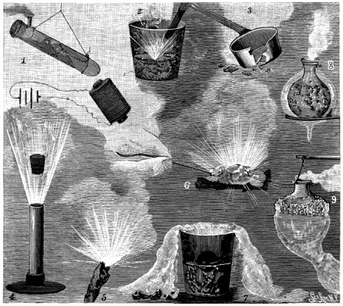
FIG. 304.—LIQUID AIR EXPERIMENTS.
1. Magnetism of oxygen. 2. Steel burning in liquid oxygen. 3. Frozen sheet iron. 4. Explosion of confined liquid air. 5. Burning paper. 6. Explosion of sponge. 7. Freezing rubber ball. 8. Double walled vacuum bulb. 9. Boiling liquid air.
However this may be, the phenomena which it presents are both interesting and instructive. In Figs. 304 and 305 are shown some of the experiments. At No. 1 a test tube containing liquid air, from which the nitrogen has escaped, is strongly attracted by an electro-magnet, showing the magnetic quality of oxygen. At No. 2 is shown the combustion of a heated piece of steel in liquid air, which has become rich in oxygen by the evaporation of the nitrogen. At No. 3 a tin dipper, which has been immersed in liquid air, has become so cold and crystalline that it breaks like glass when dropped. At No. 4 liquid air imprisoned in a tube and tightly corked up, blows the stopper out in a few minutes with[456] explosive effect. At No. 5 a piece of paper saturated with liquid air burns with great energy, and at No. 6 a piece of sponge or raw cotton similarly saturated explodes when ignited. At No. 7 a rubber ball floated on liquid air in a tumbler is frozen so hard that when dropped it flies into fragments like a glass ball. The white, snow-like vapor seen falling over the edges of the tumbler is intensely cold and heavier than ordinary air. At No. 8 is illustrated the preservation of liquid air by surrounding it with a vacuum in a Dewar bulb. At No. 9 a flask of liquid air is made to boil by the mere heat of the hand. A more striking experiment still of the same kind is to place a tea kettle containing liquid air on a block of ice. The block of ice is relatively so much hotter than the liquid air that the liquid air in the kettle is made to boil. At No. 10, Fig. 305, a heavy weight is suspended by a link composed of a bar of mercury frozen solid in liquid air. So hard is the mercury frozen that a hammer made of it will drive a tenpenny nail up to its head in a pine board. In No. 11 a layer of liquid air on water at first floats because it is lighter than water. As the lighter nitrogen evaporates, the heavier oxygen sinks in drops through the water. At No. 12 a tumbler of whiskey is frozen solid by immersing a tube containing liquid air in it. The frozen block of whiskey with the cavity formed by the tube is shown on the left. It is a whiskey tumbler made out of whiskey. A more sensational experiment is to substitute a tapering tin cup for the tube, then fill it with liquid air and immerse it in water. In a few minutes the tapering tin cup has frozen on its outer walls a tumbler of ice. This may be carefully removed, and the ice tumbler is then filled with liquid air rich in oxygen, which, by maintaining the cold of the ice tumbler, keeps it from melting. A carbon pencil or a steel spring heated to redness will now, if dipped in the liquid oxygen in the ice tumbler, burn with vehement brilliancy and beautiful scintillations, involving the anomalous conditions of a white hot heat and active combustion in the center of a tumbler of ice, without melting the tumbler. In experiment 13, Fig. 305, a jet of carbonic acid gas directed into a dish floating in a glass of liquid air is immediately frozen into minute flakes, producing a miniature snow storm of carbonic acid. In experiment 14 an electric light carbon heated to a red heat at its tip, is plunged vertically into a deep glass of liquid oxygen. A most singular combustion takes place. The heat of the carbon evaporates the oxygen in its immediate vicinity, and the carbon burns with great brilliancy and violence, forming carbonic acid, which is largely frozen in the liquid before it reaches the surface, and falls back to the bottom of the dish, so that the combustion is maintained and its products retained within the dish. A beefsteak may be frozen in liquid air to such[457] brittleness that it is shattered like a china plate when struck a slight blow. The intense cold of liquid air does not destroy the vitality or germinating power of seed, but produces serious so-called burns on the flesh that destroy the tissues and do not heal for many months, and yet for a moment the finger may be dipped in liquid air with impunity because of the gaseous envelope with which the finger is temporarily surrounded.
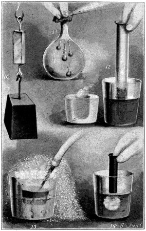
FIG. 305.—LIQUID AIR EXPERIMENTS.
10. Frozen mercury. 11. Liquid oxygen in water. 12. Frozen whisky. 13. Carbonic acid snow. 14. Combustion of carbon pencil.
If the reader has been patient enough to have reviewed the preceding pages, the impression may have been formed that the notable inventions referred to represent all that is worth while to consider in this great field of human achievement. It would be a fallacy to entertain such a thought, for the little stars out-number the big ones, and the twigs of the tree are far more numerous than its branches. The great things in life are comparatively few and far between, and the bulk of human existence is made up of an unclassified mass of little things, sown like sands along the shore of time between the boulders of great events. So also in invention is its warp and woof made up of a multitude of little threads behind the gorgeous patterns of meteoric genius. Every hour of the day of modern life is replete with the achievements of invention. Look around the room, and there is not a thing in sight that does not suggest the material advance of the age; the books, the furniture, the carpets, the curtains, the wall paper, the clock, the mantels, the house trimmings, the culinary utensils, and the clothing, all represent creations of this century. So full is the daily life of these things, and so much of a necessity have they all become, that their commonplace character dismisses them from conspicuous notice. Take the most matter-of-fact and prosy half hour of the day, that at the time of rising, and see what a faithful account of the average man’s everyday life would present. The awakening is definitely determined by an alarm clock, and the sleepy Nineteenth Century man rolling over under the seductive comfort of a spring bed, takes another nap, because he knows that the rapid transit cars will give him time to spare. Rising a little later his bare feet find a comfortable footing on a machine-made rug, until thrust into full fashioned hose, and ensconced in a pair of machine-sewed slippers. Drawing the loom-made lace curtains, he starts up the window shade on the automatic Hartshorn roller and is enabled to see how to put in his collar button and adjust his shirt studs. He awakens[459] the servant below with an electric bell, calls down the speaking tube to order breakfast, and perhaps lights the gas for her by the push button. He then proceeds to the bath, where hot and cold water, the sanitary closet, a gas heater, and a great array of useful modern articles present themselves, such as vaseline, witch hazel, dentifrices, cold cream, soaps and antiseptics, which supply every luxurious want and every modern conception of sanitation. His bath concluded, he proceeds to dress, and maybe puts in his false teeth, or straps on an artificial leg. Donning his shirt with patented gussets and bands, he quickly adjusts his separable cuff buttons, puts on his patented suspenders, and, winding a stem-winding watch, proceeds down stairs to breakfast. A revolving fly brush and fly screens contribute to his comfort. A cup of coffee from a drip coffee-pot, a lump of artificial ice in his tumbler, sausage ground in a machine, batter cakes made with an egg beater, waffles from a patented waffle iron, honey in artificial honey comb, cream raised by a centrifugal skimmer, butter made in a patented churn, hot biscuits from the cooking range, and a refrigerator with a well stocked larder, all help to make him comfortable and happy. The picture is not exceptional in its fullness of invented agencies, and one could just as well go on with our citizen through the rest of the day’s experience, and start him off after breakfast with a patented match, in a patented match case, and a patented cigarette, with his patented overshoes and umbrella, and send him along over the patented pavement to the patented street car, or automobile, and so on to the end of the day.
Some of the minor inventions are really of too much importance to be passed without comment. The cable car is a factor which has cut no small figure in the activities of city life. The first patent on a slotted underground conduit between the rails, with traction cable inside and running on pulleys, was that to E. A. Gardner, No. 19,736, March 23, 1858. Hallidie, in San Francisco, in 1876, directed his energies to a development of this system, and brought it to a degree of perfection and general adoption that made it for many years the leading system of street car propulsion. To-day, however, it represents but a decadent type, being largely supplanted by the superior advantages of electricity.
Passenger elevators constitute one of the conspicuous features of modern locomotion. Without them the tall office buildings, hotels, and department stores would have no existence; the Eiffel Tower would never have been dreamed of, and the expenditure of vital force in stair climbing would have been greatly augmented. The passenger elevator has for its prototype the ancient hoist or lift for mines, but in the latter half of the Nineteenth Century it has developed into a distinct institution—a luxurious little[460] room, gliding noiselessly up and down, actuated by a power that is not seen, and supplied with every appliance for safety and comfort, such as governors, safety catches, automatic stops, mirrors and cushioned seats. The principle of the screw, of balance weights, of the lazy tongs, and other mechanical powers have each found application in the elevator, but steam, hydraulic power, and electricity constitute the moving agencies of the modern type. The patent to E. G. Otis, No. 31,128, January 15, 1861, marks the beginning of its useful applications.
Of close kin to the elevator are the fire escape, dumb waiter and grain elevator, each of which fills a more or less important function in the life of to-day.
What more ubiquitous or ingenious illustration of modern progress than the American stem winding watch! Up to the middle of the century all watches were made by hand throughout. Each watch had its own individuality as a separate creation, and only the privileged few were able to carry them. In 1848 Aaron L. Dennison, a Boston watch maker, began making watches by machinery, and the foundation of the system of interchangeable parts was laid. A small factory at Roxbury, Mass., was established in 1850, which four years later was moved to Waltham. In 1857 it passed into the hands of Appleton, Tracy & Co., and was subsequently acquired by the American Watch Co. As presenting some idea of the great elaboration involved in this art, it was estimated a few years ago that 3,746 distinct mechanical operations were required to make an ordinary machine made watch. A single pound of steel wire is sometimes converted into a couple of hundred thousand tiny screws, and another pound of fine steel wire furnishes 17,280 hair springs, worth several thousand dollars. The absolute uniformity and perfect interchangeability of parts in the American watch have been obtained by substituting the invariable and mathematical accuracy of the machine for the nervous fingers and dimming eyes of the old time watchmaker, and the American machine made watch, discredited as it was at first, stands to-day the greatest modern advance in horology.
Friction Matches.—In 1805 Thenard, of Paris, made the first attempt to utilize chemical agencies for the ordinary production of fire. In 1827 John Walker, an English druggist, made friction matches called “congreves.” In 1833 phosphorus friction matches were introduced on a commercial scale by Preschel, of Vienna. In 1845 red phosphorus matches (parlor matches) were made by Von Schrotter, of Vienna, and in 1855 safety matches, which ignited only on certain substances, were made by Lundström, of Sweden. Prior to the Nineteenth Century, and in fact until[461] about 1833, the old flint and steel and tinder box were the clumsy and uncertain means for producing fire. To-day the friction match is turned out by automatic machinery by the million, and constitutes probably the most ubiquitous and useful of all the minor inventions.
Step into any of the great department stores and the genius of the inventor confronts you in the cash carrier whisking its little cars back and forth from the cashier’s desk to the most remote corners of the great building. The first of these mechanical carriers adapted for store service was patented by D. Brown, July 13, 1875, No. 165,473. Not until about 1882, however, was there any noticeable adoption of the system, when practical development was given in Martin’s patents, No. 255,525, March 28, 1882; No. 276,441, April 24, 1883, and No. 284,456, September 4, 1883. Go to the lunch counter, and the cash register reminds you that the millenium of absolute honesty is not yet realized. The bell punch on the street car and the burglar proof safe with its combination locks are other suggestions in the same line. The first fire proof safe is disclosed in the British patent to Richard Scott, No. 2,477, of 1801. The time lock, which prevents the safe from being opened by anyone except at a certain period of daylight, was invented by J. V. Savage, and was covered by him in United States patent No. 5,321, October 9, 1847. The practical adoption of time locks began about 1875 with the operations of Sargent, Stockwell and others, and to-day they constitute one of the most important features of bank safes and vaults, and represent a marvelously beautiful and accurate example of mechanical skill.
The Otto gas-engine, and the Ericsson air-engine are important developments in power producing motors, and the improvements in pavements and in street sweepers for cleaning them, contribute to the cleanliness, sanitation, and æsthetic values of city life. The cigarette machine, which continuously curls a ribbon of paper around a core of tobacco to form a rope, and then cuts it off into cigarettes, is an important invention in the tobacco industry, however doubtful its hygienic value to the world may be. The lightning rod has brought protection to homes and lives, and the incubator has become the hen’s wet nurse. In agriculture, the reaper has been supplemented with threshing machines, seeders, drills, cultivators, horse rakes and plows. In the farm yard appear the improved carriage and wagon, the well pump, the wind wheel, the fruit drier, the bee hive, and the cotton and cider press. In the kitchen, the washing machine, the churn, the cheese press, ironing machine, wringer, the rat trap, and fruit jar. In the house, the folding bed, tilting chair, carpet sweeper, and the piano. In heating appliances, steam and water heating systems, base burning and[462] Latrobe stoves, hot air furnaces, gas and oil stoves. In plastics there are brick machines, pressed glass ware, enameled sheet iron ware, tiles, paper buckets, celluloid and rubber articles. In hydraulics there are rams, water closets, pumps, and turbine water wheels. In mining there are stamp mills, ore crushers, separators, concentrators, and amalgamators. In the leather and boot and shoe industry there is a great variety of machines and appliances. The paper industry, with book binding machines, and paper box machines, is a fertile field of invention. Steam boilers, metallurgical appliances, soap making, chemical fire extinguishers, fountain pens, the sand blast, bottle stoppers, and a thousand other things present themselves in miscellaneous and endless array. These are, however, only some of the things which the limitation of space precludes from individual treatment, but which are none the less important in making up the great resources of modern life, and, for the most part, represent the contributions of the Nineteenth Century not heretofore considered.
The observant and thoughtful reader finds just here occasion to inquire the meaning of this great rising tide of progress which has so distinguished the Nineteenth Century. It is largely due to the Patent Law, which justly regards the inventor as a public benefactor, and seeks to make for him some protection in the enjoyment of his rights. If a man be in the possession of a legacy by the accident of birth, the law of inheritance rules that it is rightfully his. The finding of a thing, whether by jetsam, flotsam, or the lucky accident of a first discovery, this also makes good his title, if there be no other owner. There is, however, a right of property which is higher than all others, and in which there is coupled with the possession of the thing the sacred function of its creation. The right of a mother to her child is of this nature, and like unto it is the right of the inventor to the creation of his genius. In the last two centuries of the world’s history this right has been recognized by an enlightened civilization, and provision made for its enjoyment in the grant of patents, and if there be any right more strongly entrenched than another in the eternal verities of equity and justice it is this. Our first crude patent law was enacted in 1790, but not until 1836 was the present system adopted. Our own and comparatively new country has, therefore, not yet had a hundred years of existence under our present Patent System, and yet to-day it outstrips the world both in its material resources and in its wealth of patented inventions. The accompanying diagram, Fig. 306, illustrates in a graphic way just what relation the United States bears to the other leading countries of the world in the matter of patents granted, and when it is remembered that under our system a patent can only be granted for a[463] new invention, while in some of the other countries it is not essential to the grant, the richness in invention of the United States, with its six hundred and fifty thousand patents, can be better appreciated. This is a greater number than has been issued by Great Britain and France put together. Connecticut is the most productive State in invention in proportion to its people, and Edison is the most prolific inventor. From 1870 to 1900 he has taken 727 United States patents, and there are from twenty-five to thirty other American inventors each of whom has taken 100 or more patents.
The year 1790 was notable in two events, the birth of our patent system and the death of Benjamin Franklin. That grand old philosopher, with a prescience of future greatness to come from the genius of the inventor, is said to have expressed the wish before he died that he might be sealed up in a cask of old Madeira and be brought to life a hundred years in the future, that he might witness the growth of the world. Who can tell what his emotions would be if he were with us to-day? It is said, when he first saw the fibres of the string diverge, and the spark pass from the cord of his kite, and the lightning was for the first time obedient to the will of man, that he uttered a deep sigh and wished that that moment were his last. To this poor knowledge of electricity he would now have added all the wonders and powers of the telegraph, the dynamo, the telephone,[464] and the great modern electrical science; to his primitive hand press he would have contrasted the Octuple perfecting press, turning out papers at the rate of 1,600 a minute; his modest type-setting case would be replaced by a great array of linotype machines, and he would find several acres of woodland sacrificed to produce the wood-pulp paper of a single edition of a New York daily. Would he not realize indeed that truth is stranger than fiction, and fact more wonderful than fancy’s dream!
Whatever the future centuries may bring in new and useful inventions, certain it is that the Nineteenth Century stands pre-eminent in this field of human achievement, so far excelling all other like periods as to establish on the pages of history an epoch as remarkable as it is unique. Never before has human conception so expressed itself in materialized embodiment, never has thought been so fruitfully wedded to the pregnant possibilities of matter, never has the divine function of creation been so closely approximated, never has such an accretion of helpful instrumentalities and material resources been added to the world’s wealth—not merely the miserly and inert wealth of gold and gems, but the wealth of an enlarged human existence. This life itself is but a limited span; beginning in infancy, expanding to highest achievement in middle age, and declining at the end, it quickly passes away, and another generation follows. Growth and decay with all living things mark the immutable law of nature, and the inevitable fate of mortality. The rose blossoms into beauty, fades, and decays. The bird in the air, and the beast in the field, each plays his part and passes to the great unknown, leaving no record; man himself is mortal, but his work is immortal. The inspired conception of his best thought, the materialized embodiment of his work in useful agencies, and the subjugation of the laws of nature to his service, all endure and live forever in his inventions. These partake of the breath of life, and in their immortality are of kin to the soul. Cities may grow up and vanish, civilizations may decay, and man himself may degenerate, but the principle of the lever and the screw, once discovered, is for all time perfect, invariable and immortal. Every invention made is another permanent gift to posterity. All of enduring wealth that the present gets from the past are its ideas reduced to a working basis. All else is but dross, or evanescent dreams which vanish into oblivion in the light of a larger knowledge. But ideas wrought into practical, substantive things, tried and proven true, these are inventions—immortal creations—and of these the Nineteenth Century has borne fruit in[466] paramount abundance, and this legacy it now bequeaths to the coming century.
To follow conventional methods, the final chapter of a book should be an “In conclusion” with a “finis” and a dismantled torch, but the history of invention will ever be a continued story. There is no end in this field. The trusteeship of the Twentieth Century man is great, and great his responsibilities; but his restless and dominant spirit knows no decadence, and his mental endowment and material equipment, without parallel in history, are a guarantee of future achievements. Will not the chemist learn how to produce electricity direct from the combustion of coal, or solve the problem of the synthesis of food? Will not the American continent be parted by an inter-oceanic canal, or the rough waters of the English Channel be avoided with a submarine tunnel? May not a ship canal through France to the Mediterranean give to that country the connected enjoyment of riparian rights, without passing the frowning battlements of Gibraltar, or might not a tunnel under the Straits of Gibraltar put Europe and Africa in direct railway communication? The relation of electricity to life is a field of pregnant possibilities, and may we not also learn to swap the surplus heat of summer for the winter’s cold, and by an equalization of their two extremes bring eternal spring and joy to the animated world? Shall we not yet stand on the North Pole, or looking away into space may we not extend a neighborly welcome to our brothers in Mars, if any there be? It is permitted to dream in this field, for it is this reaching out into the unknown that plats the boundaries of an extended world, and adds to the possessions of man.
The old man in his dreams of the past rejoices in his achievements, for he has stolen the fires of Prometheus and forged anew the thunderbolts of Jove for the arts of peace. Delving into the secret recesses of the earth, he has tapped the hidden supplies of nature’s fuel, has invaded her treasure house of gold and silver, robbed Mother Earth of her hoarded stores, and possessed himself of her family record, finding on the pages of geology sixty millions of years’ existence. Peering into the invisible little world, the infinite secrets of microcosm have yielded their fruitful and potent knowledge of bacteria and cell growth. Pain has been robbed of its terrors by anæsthesia; the heat of the sun has been brought down in the electric furnace, and the cold of inter-stellar space in the ice machine and liquid air. With telescope and spectroscope he has climbed into limitless space above, and defined the size, distance, and constitution of a star millions of miles away. The north star has been made his sentinel on the sea. The lightning is made his swift messenger, and thought flashes in[467] submarine depths around the world. Dead matter is made to speak in the phonograph, the invisible has been revealed in the X-Rays, coal has been made his black slave, steam the breath of the world’s life, and all of nature’s forces have been made his constant servants in attendance.
With such a retrospect, the sage of the Nineteenth Century may lie down to quiet rest, with an assuring faith that what God hath wrought is good, and what is not may yet be.

The influence of invention on modern life can be very justly estimated by a perusal of “The Progress of Invention in the Nineteenth Century.” It is, of course, well known that inventors are necessarily assisted in the prosecution of their applications for patents in the Patent Office by patent attorneys. It gives Messrs, Munn & Co. pleasure to announce that they have prosecuted, during a period of over fifty years, some of the most important patent cases which have ever been sent to the Patent Office. During this long period they have filed and prosecuted over one hundred thousand applications for patents. Their reputation is such that inventors have found that they may submit their ideas with entire confidence that their trust will not be betrayed, and that their interests will be protected to the fullest extent. They secure patents, trade-marks, caveats and copyrights. A little book entitled “Hand-Book on Patent Practice” will be sent free to any address, and any questions relating to patents will be cheerfully answered by return mail without charge. Thousands of clients all over the United States, many of them the most successful inventors which this country has produced, have had the professional services of Messrs. Munn & Co. in the preparation and prosecution of their patent applications before the United States and foreign patent offices. The integrity of this firm, and their attention to this branch of their business, has resulted in the largest practice of any firm of patent attorneys in the United States. Inventors are invited to write freely regarding their inventions, and their sketches will be carefully and promptly examined. All communications of this kind are treated as strictly confidential. The readers of “The Progress of Invention in the Nineteenth Century” may also be interested to know that Munn & Co. have offices in both New York and Washington, and thus are able to keep in close touch with the work of the Patent Office. They have unsurpassed facilities for examining and reporting on the probable patent-ability of inventions, and they render opinions on questions of infringement and validity of patents; and they also have been most successful in the prosecution of interferences.
Further particulars may be obtained by addressing
MUNN & CO.,
Branch Office:
625 F Street,
Washington, D. C.
SCIENTIFIC AMERICAN OFFICE,
361 Broadway,
New York City.
Scientific American
THE MOST POPULAR SCIENTIFIC PAPER
IN THE WORLD
Established 1845.
Weekly, $3.00 a Year; $1.50 Six Months
This unrivalled periodical is now in its FIFTY-SIXTH YEAR, and, owing to its ever increasing popularity, it enjoys the largest circulation ever attained by any scientific publication. Every number contains sixteen large pages, beautifully printed, handsomely illustrated; it presents in popular style a descriptive record of the most novel, interesting and important developments in Science, Arts and Manufactures. It abounds in fresh and interesting subjects for discussion, thought or study. It provides material for experiment at home and in the laboratory, and it enables the intelligent reader to keep informed as to the industrial and scientific development of the country. To the inventor it is invaluable, as every number contains a complete list of all patents and trade marks issued weekly from the Patent Office. It promotes industry, progress, thrift and intelligence in every community where it circulates.
The Scientific American should have a place in every dwelling, shop, office, school or library. Workmen, foremen, engineers, superintendents, directors, presidents, officials, merchants, farmers, teachers, lawyers, physicians, clergymen—people in every walk and profession in life, will derive satisfaction and benefit from a regular reading of The Scientific American.
As an instructor for the young it is of peculiar advantage. TRY IT.—Subscribe for yourself—it will bring you valuable ideas; subscribe for your sons—it will make them manly and self-reliant; subscribe for your workmen—it will please and assist their labor; subscribe for your friends—it will be likely to give them a practical lift in life. Terms, $3.00 a year; $1.50 six months. Specimen copies free. Remit by postal order or check.
Scientific American Supplement
Established 1876
This journal is a separate publication from The Scientific American, and is designed to extend and amplify the work carried on by the parent paper. In size and general make-up it is uniform therewith, covering sixteen pages of closely printed matter, handsomely illustrated. It has no advertising pages, and the entire space is given up to the scientific, mechanical and engineering news of the day. It differs from The Scientific American in that it contains many articles that are too long to be published in the older journal or of a more technical nature. College professors and students find this edition especially adapted to their wants. It contains reports of the meetings of the scientific societies, both in this country and abroad, and abstracts of many papers read before such societies. It has a page of short notes concerning the electrical, engineering and general scientific news of the day, together with a column of selected formulæ. Each number contains much foreign scientific news, and, when taken in connection with The Scientific American, it places before the reader a weekly review of the latest and most important discoveries and the most advanced technical and scientific work of the times all over the world.
PRICE FOR THE SUPPLEMENT, $5 A YEAR, or one copy of The Scientific American and one copy of Supplement, both mailed to one address, for one year, for $7. Address and remit by postal order or check.
MUNN & CO., Publishers,
SCIENTIFIC AMERICAN OFFICE
361 Broadway, New York
The SCIENTIFIC AMERICAN,
ARCHITECTS’ and BUILDERS’ EDITION.
$2.50 a Year
Single copies, 25 cts.
This is a special edition of the Scientific American, issued monthly—on the first day of the month. Each number contains about forty large quarto pages, equal to about 200 ordinary book pages, forming, practically, a large and splendid Magazine of Architecture, richly adorned with elegant plates in colors and with fine engravings, illustrating the most interesting examples of modern architectural construction and allied subjects. A special feature is the presentation in each number of a variety of the latest and best plans for private residences, city and country, including those of very moderate cost, as well as the more expensive. Drawings in perspective and in color are given, together with plans, specifications, costs, etc. No other building paper contains so many plans and specifications, regularly presented, as the Scientific American. Thousands of dwellings have already been erected on the various plans we have issued, and many others are in process of construction.
Architects, builders and house owners will find this work valuable in furnishing fresh and useful suggestions. All who contemplate building or improving homes, or erecting structures of any kind, have before them in this work an almost endless series of the latest and best examples from which to make selections, thus saving time and money.
Many other subjects, including sewerage, piping, lighting, warming, ventilating, decorating, laying out of grounds, etc., are illustrated. An extensive Compendium of manufacturers’ announcements is also given, in which the most reliable and approved building materials, goods, machines, tools and appliances are described and illustrated, with addresses of the makers, etc.
The fulness, richness, cheapness and convenience of this work have won for it the largest circulation of any architectural publication in the world.
Fiftieth Anniversary Number
OF THE
SCIENTIFIC AMERICAN.
In commemoration of the fiftieth year of the publication of the weekly edition of the SCIENTIFIC AMERICAN, its publishers on July 25th, 1896, issued a memorial edition which forms a valuable resumé of the progress of science and invention during the past fifty years. Among the subjects treated are:
THE EFFECT OF INVENTION ON THE PEOPLE’S LIFE. THE PATENT SYSTEM. THE TRANSATLANTIC STEAMSHIP. RAILROADS AND BRIDGES. THE TELEGRAPH. PHYSICS. MEN OF PROGRESS. THE TEXTILE INDUSTRIES OF THE UNITED STATES SINCE 1846. THE SUBMARINE CABLE. FIFTY YEARS OF PHOTOGRAPHY. CHEMISTRY. THE PHONOGRAPH. THE PROGRESS MADE IN THE GENERATION OF ELECTRIC ENERGY AND ITS APPLICATION TO THE OPERATION OF MOTORS DURING THE PAST FIFTY YEARS. THE AMERICAN LOCOMOTIVE. THE BICYCLE. THE SEWING MACHINE. AGRICULTURAL MACHINERY. NAVAL AND COAST DEFENSE. FIFTY YEARS IN THE PRINTING BUSINESS. THE PRIZE ESSAY OF THE SEMI-CENTENNIAL ANNIVERSARY NUMBER—“THE PROGRESS OF INVENTION DURING THE LAST FIFTY YEARS.” STEEL. DISTINGUISHED INVENTORS. AMERICAN SHIPBUILDING. DEVELOPMENT OF THE ASTRONOMICAL TELESCOPE IN FIFTY YEARS. THE TELEPHONE. FIFTY YEARS OF THE “SCIENTIFIC AMERICAN.”
The number is fully illustrated and contains fifty pages. In it is printed “The Progress of Invention During the Last Fifty Years,” for which a prize of $250 was offered. It is interesting to note that this prize was won by Edward W. Byrn, the author of “The Progress of Invention in the Nineteenth Century.” Never before has so much valuable information of historical interest and importance been published in so condensed and popular a form. It forms a valuable addition to any library, and copies of the Anniversary Number can be supplied at 25 cents per copy.
MUNN & CO., Publishers,
SCIENTIFIC AMERICAN OFFICE
361 Broadway, New York
Experimental Science.
By GEORGE M. HOPKINS.
TWENTIETH EDITION, REVISED AND GREATLY ENLARGED.
914 Pages. 820 Illustrations. Handsomely Bound in Cloth.
Price by mail, postpaid, $4.00; Half Morocco, $5.00.
The new matter comprises eighty pages of text in the form of an appendix, including among other subjects
A Complete Article on the X-Ray.
Wireless Telegraphy.Liquefaction of Air.
Acetylene Gas Apparatus.Artificial Spectrum.
And other articles which bring the work fully up to date.
This is a book full of interest and value for teachers, students and others who desire to impart or obtain a practical knowledge of Physics.
THE MOST POPULAR SCIENTIFIC BOOK OF THE DAY.
What the press says of “EXPERIMENTAL SCIENCE.”
“The electrical chapters of the book are notably good, and the practical instruction given for building simple electrical machinery may be safely carried out by those—not a few—who like to make their own apparatus.”—Electrical World.
“The author has avoided repeating the hackneyed illustrations which have been passed from one book to another so long, and, instead, offers a set of experiments which are largely of a novel character and very striking.”—Engineering and Mining Journal.
“It is a treat to read a book of this kind, that sets forth the principles of physics so fully, and without the use of mathematics.”-The Locomotive.
“All teachers of science are aware that real knowledge is acquired best by the student making experiments for himself, and anyone who points out how those experiments may be easily made is doing excellent work.”—English Mechanic and World of Science.
“The work bears the stamp of a writer who writes nothing but with certainty of action and result, and of a teacher who imparts scientific information in an attractive and fascinating manner.”—American Engineer.
Mr. Thomas A. Edison says: “The practical character of the physical apparatus, the
clearness of the descriptive matter, and its entire freedom from mathematics, give the
work a value, in my mind, superior to any other work on elementary physics of which I am
aware.
”
Send for Illustrated Circular and Complete Table of Contents.
☛ Send for our New and Complete Catalogue of Books, sent free to any address.
MUNN & CO., Publishers,
SCIENTIFIC AMERICAN OFFICE
361 Broadway, New York
THE SCIENTIFIC AMERICAN
Cyclopedia of Receipts
NOTES AND QUERIES
12,500 RECEIPTS, 708 PAGES
Edited by ALBERT A. HOPKINS
This splendid work contains a careful compilation of the most useful Receipts and Replies given in the Notes and Queries of correspondents as published in the Scientific American during the past fifty years; together with many valuable and important additions.
OVER TWELVE THOUSAND selected receipts are here collected; nearly every branch of the useful arts being represented. It is by far the most comprehensive volume of the kind ever placed before the public.
12,500 RECEIPTS, 708 PAGES.
The work may be regarded as the product of the studies and practical experience of the ablest chemists and workers in all parts of the world; the information given being of the highest value, arranged and condensed in concise form, convenient for ready use.
Almost every inquiry that can be thought of, relating to formulae used in the various manufacturing industries, will here be found answered.
Instructions for working many different processes in the arts are given.
Many of the principal substances and raw materials used in manufacturing operations are defined and described. No pains have been spared to render this collateral information trustworthy.
Those who are engaged in any branch of industry will probably find in this book much that is of practical value in their respective callings.
Those who are in search of independent business or employment, relating to the home manufacture of salable articles, will find in it hundreds of most excellent suggestions.
It is impossible within the limits of a prospectus to give more than an outline of a few features of so extensive a work. To those interested, a fully descriptive circular will be sent free upon application.
Price, $5.00 in Cloth; $6.00 in Sheep; $6.50 in Half Morocco; Postpaid.
MUNN & CO., Publishers,
SCIENTIFIC AMERICAN OFFICE
361 Broadway, New York
A Complete Electrical Library.
By Prof. T. O’CONOR SLOANE, A.M., E.M. Ph.D.
An inexpensive library of the best books on Electricity. Put up in a neat folding box. For the student, the amateur, the workshop, the electrical engineer, schools and colleges. Comprising five books, as follows:
| Arithmetic of Electricity, 138 pages | $1.00 |
| Electric Toy Making, 140 pages | 1.00 |
| How to Become a Successful Electrician, 189 pages | 1.00 |
| Standard Electrical Dictionary, 682 pages | 3.00 |
| Electricity Simplified, 158 pages | 1.00 |
Five volumes, 1,300 pages, and over 450 illustrations. A valuable and indispensable addition to every library.
Our Great Special Offer.—We will send prepaid the above five volumes handsomely bound in blue cloth, with silver lettering, and inclosed in a neat folding box, at the Special Reduced Price of $5.00 for the complete set. The regular price of the five volumes is $7.00. A special circular will be sent free to any address on application.
| MAGIC. | Stage Illusions and Scientific Diversions INCLUDING TRICK PHOTOGRAPHY. |
COMPILED AND EDITED BY
ALBERT A. HOPKINS,
Editor of “Scientific American Cyclopedia of Receipts. Notes and Queries,” etc.
WITH AN INTRODUCTION BY HENRY RIDGELY EVANS.
Author of “Hours with the Ghosts; or, XIX. Century Witchcraft,” etc.
568 Pages. 420 Illustrations. Price, $2.50.
This work appeals to old and young alike, and it is one of the most attractive holiday books of the year. The illusions are illustrated by the highest class of engravings, and the exposés of the tricks are in many cases furnished by the prestidigitateurs themselves. Conjuring, large stage illusions, fire eating, sword-swallowing, ventriloquism, metal magic, ancient magic, automata, curious toys, stage effects, photographic tricks, and the projection of moving photographs are all well described and illustrated, making a handsome volume. It is tastefully printed and bound. Acknowledged by the profession to be the STANDARD WORK ON MAGIC. Send for large illustrated circular, sent free to any address.
MUNN & CO., Publishers,
SCIENTIFIC AMERICAN OFFICE
361 Broadway, New York
Mechanical Movements,
POWERS, DEVICES AND APPLIANCES.
By GARDNER D. HISCOX, M. E.
Author of “Gas, Gasoline, and Oil Engines.”
Large 8vo. 402 Pages. 1649 Illustrations, with Descriptive Text. Price, $3.00.
A Dictionary of Mechanical Movements, Powers, Devices and Appliances, embracing an illustrated description of the greatest variety of mechanical movements and devices in any language. A new work on illustrated mechanics, mechanical movements, devices and appliances, covering nearly the whole range of the practical and inventive field, for the use of Machinists, Mechanics, Inventors, Engineers, Draughtsmen, Students and all others interested in any way in the devising and operation of mechanical works of any kind.
| THE CHAPTERS TREAT OF: | |
|---|---|
| I. | Mechanical Powers. |
| II. | Transmission of Power. |
| III. | Measurement of Power. |
| IV. | Steam Power—Boilers and Adjuncts. |
| V. | Steam Appliances. |
| VI. | Motive Power—Gas and Gasoline Engines. |
| VII. | Hydraulic Power and Devices. |
| VIII. | Air Power Appliances. |
| IX. | Electric Power and Construction. |
| X. | Navigation and Roads. |
| XI. | Gearing. |
| XII. | Motion and Devices Controlling Motion. |
| XIII. | Horological. |
| XIV. | Mining. |
| XV. | Mill and Factory Appliances. |
| XVI. | Construction and Devices. |
| XVII. | Draughting Devices. |
| XVIII. | Miscellaneous Devices. |
Send for descriptive Circular.
GAS ENGINE CONSTRUCTION,
A PRACTICAL TREATISE DESCRIBING IN EVERY DETAIL THE ACTUAL BUILDING OF A GAS ENGINE.
By HENRY Y. H. PARSELL, Jr., Mem. A. I. Elec. El., and ARTHUR J. WEED, M. E.
Large 8vo. Handsomely Illustrated and Bound. 300 Pages. Price, $2.50.
This book treats of the subject more from the standpoint of practice than that of theory. The principles of operation of Gas Engines are clearly and simply described, and then the actual construction of a half-horse power engine is taken up, step by step, showing in detail the making of a Gas Engine. First come directions for making the patterns; this is followed by all the details of the mechanical operations of finishing up and fitting the castings, and is profusely illustrated with beautiful engravings of the actual work in progress, showing the modes of chucking, turning, boring and finishing the parts in the lathe, and also plainly showing the lining up and erection of the engine. Dimensioned working drawings give clearly the sizes and forms of the various details. The entire engine, with the exception of the fly-wheels, is designed to be made on a simple eight inch lathe, with slide rest. The book closes with a chapter on American practice in Gas Engine design, and gives simple rules so that anyone can figure out the dimensions of similar engines of other powers. Every illustration in this book is new and original, having been made expressly for this work.
SEND FOR DESCRIPTIVE CIRCULAR.
MUNN & CO., Publishers,
SCIENTIFIC AMERICAN OFFICE
361 Broadway, New York
Transcriber's notes
This text uses the text from the original work, including inconsistencies in spelling, hyphenation, punctuation, etc., except as mentioned below. The spelling of English (omniverous, millenium), non-English words (licht, tuyeres, frappees) and names (Swammerden, Mege) has not been corrected either, except as listed below.
This text has been optimised for Internet browsers. Depending on the hard- and software and their settings used to read this text, not all characters, illustrations, lay-out and symbols may display properly or display at all.
Remarks on the text:
Changes made:
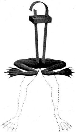
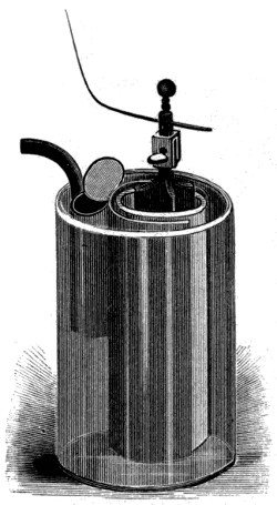
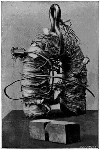
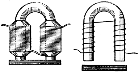
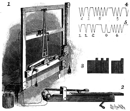
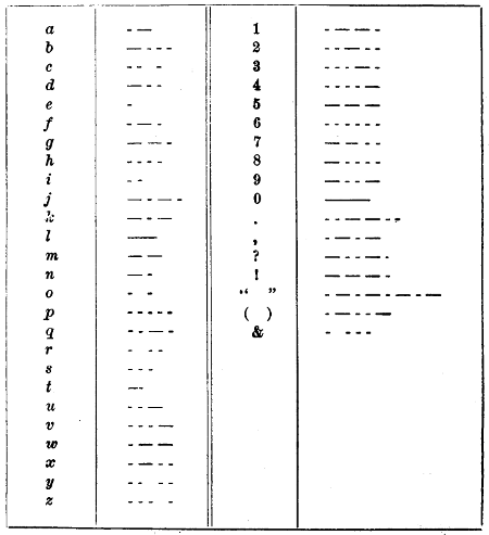
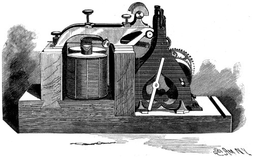
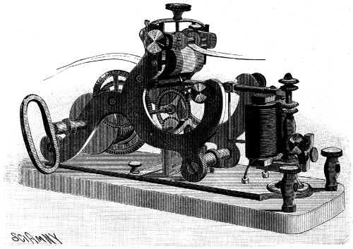
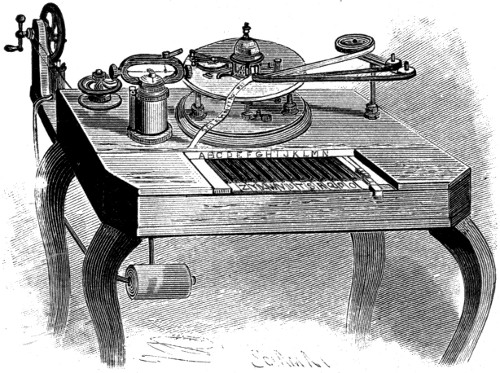
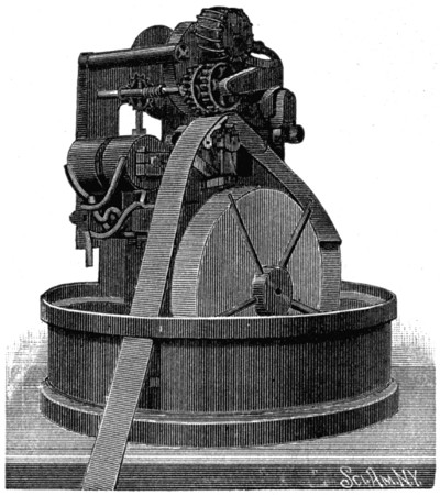

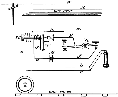
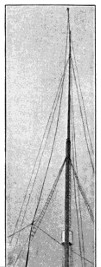
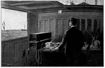
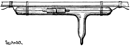
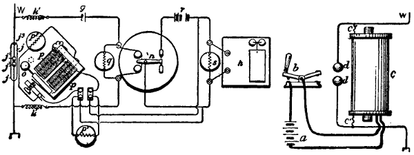
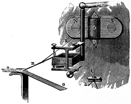
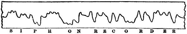
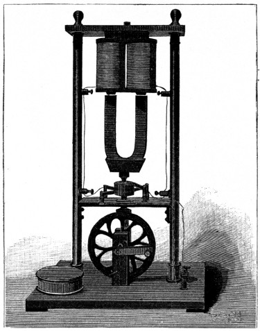
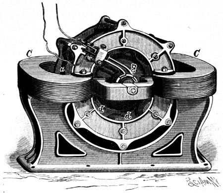
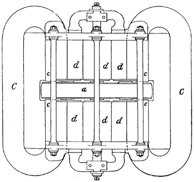
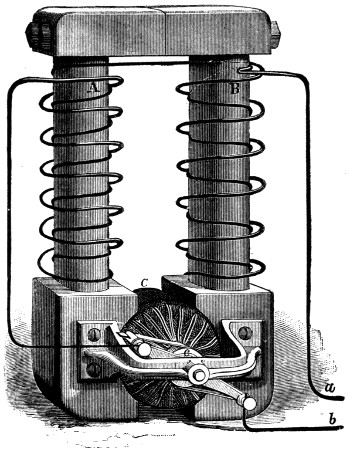
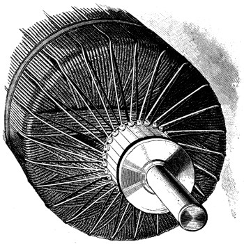
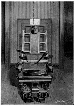
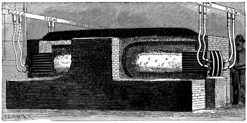
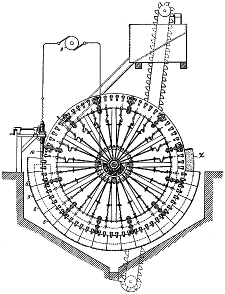
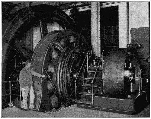
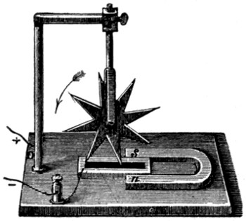
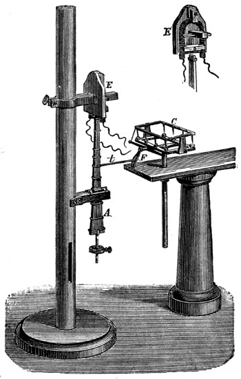
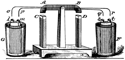
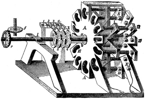
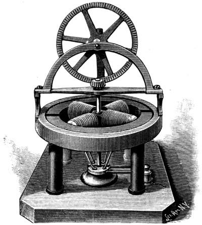
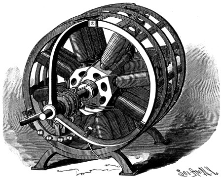
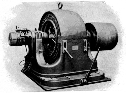
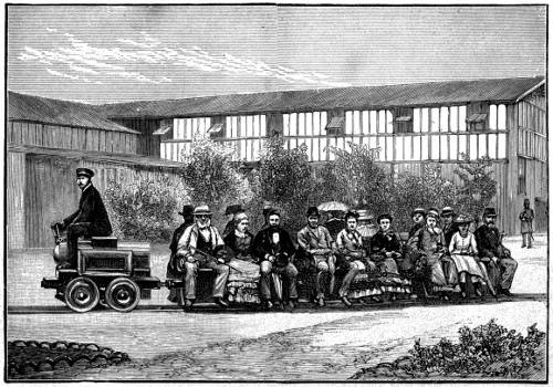
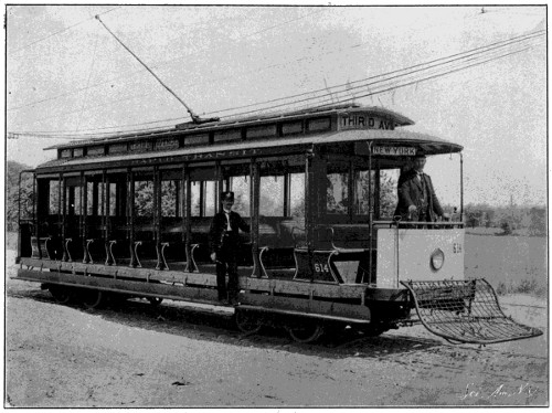
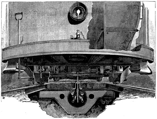
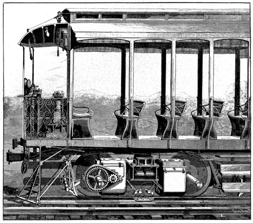
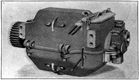
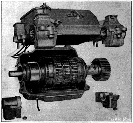
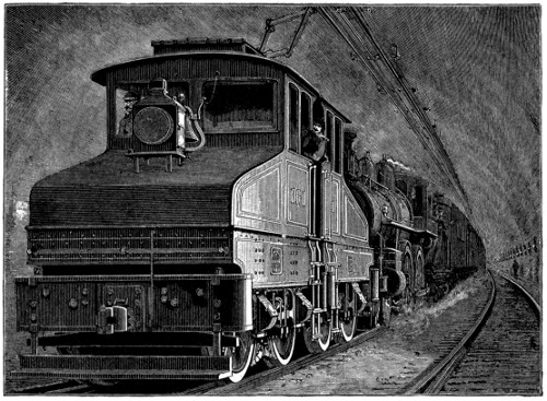
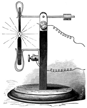
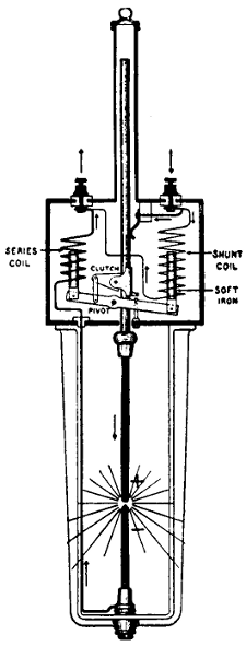
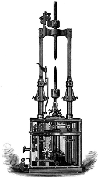
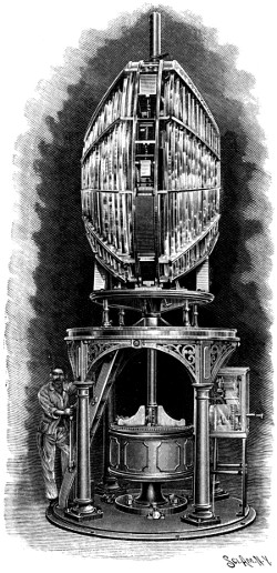
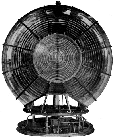
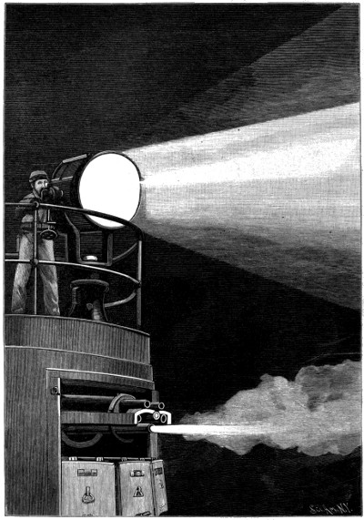
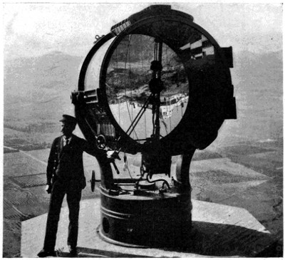
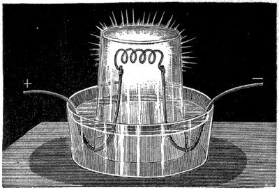
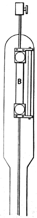
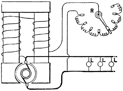
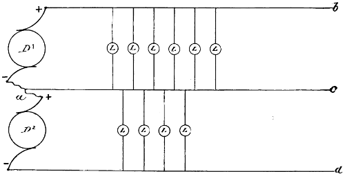
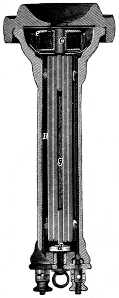
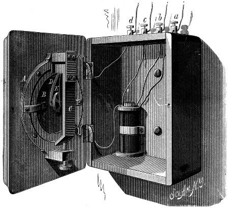
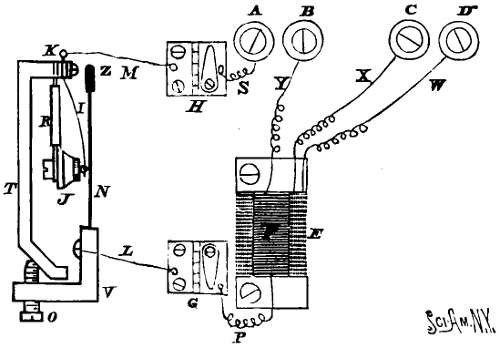
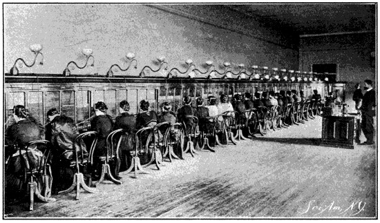
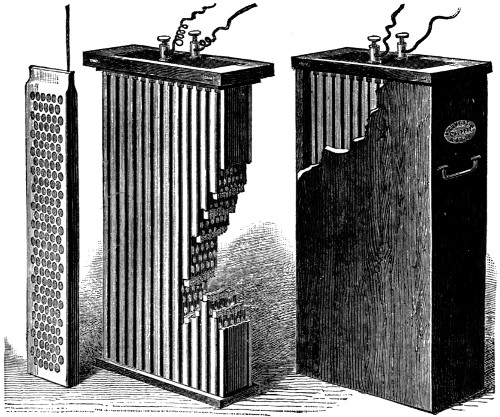
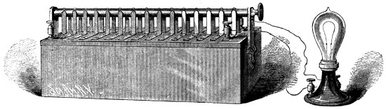
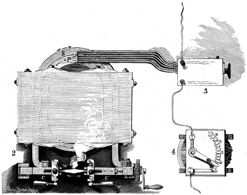
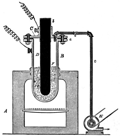
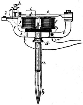
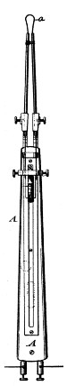
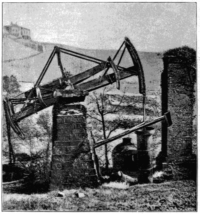
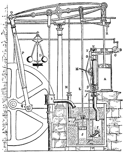
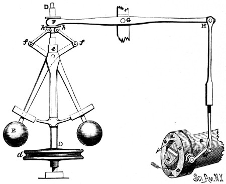
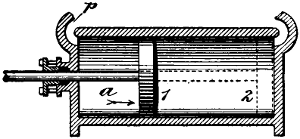
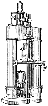
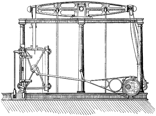
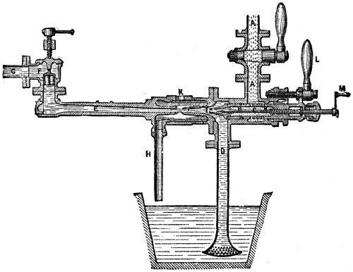
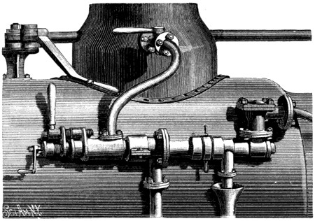
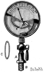
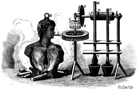
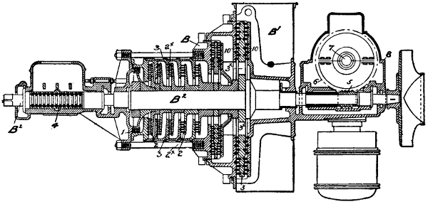
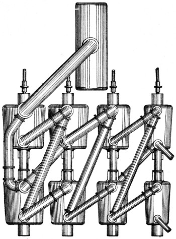
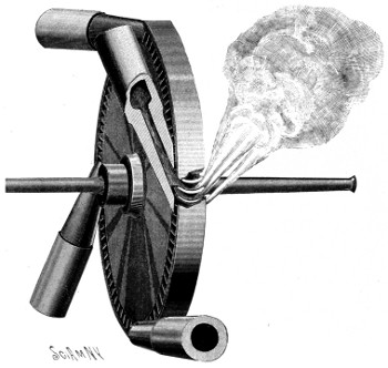
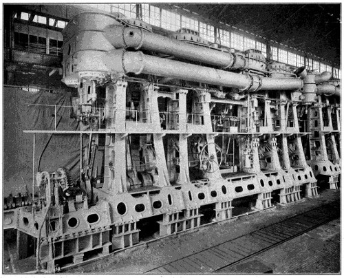
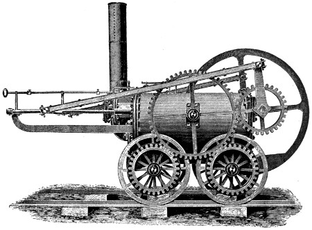
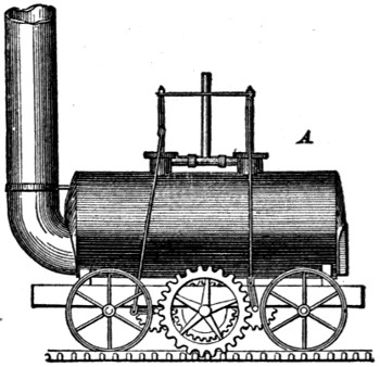
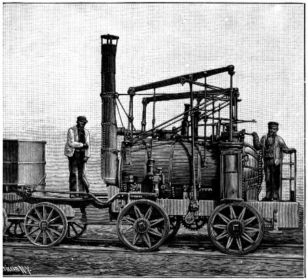
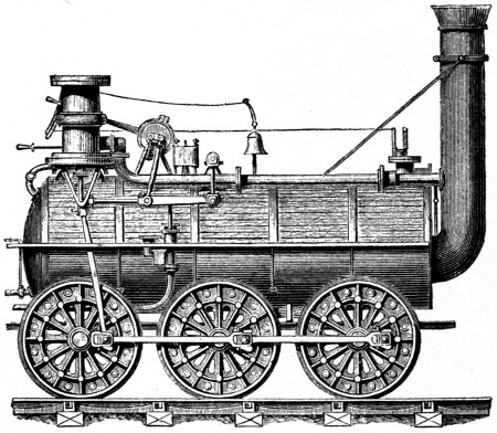
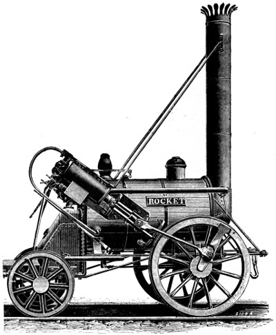
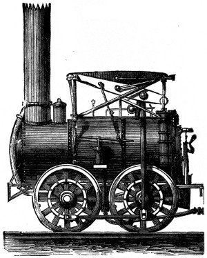
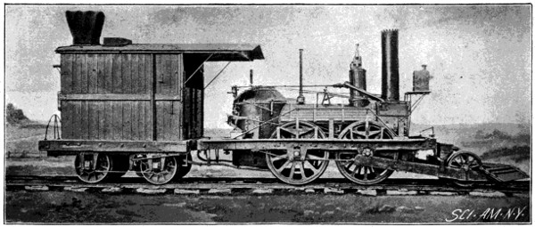
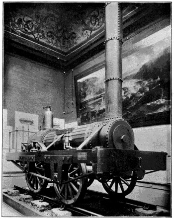
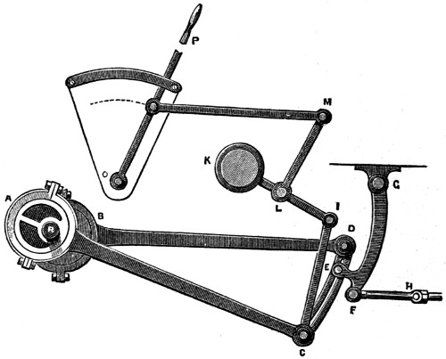
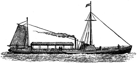
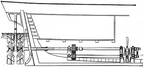
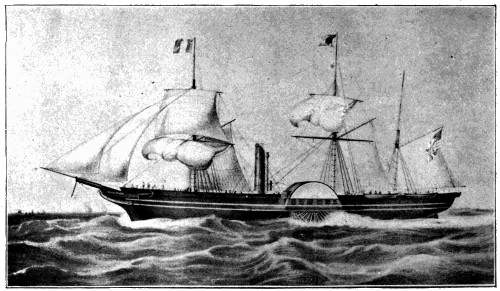
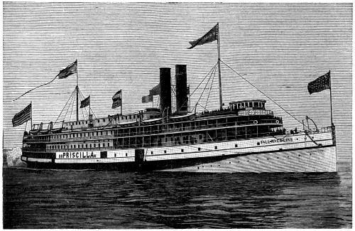
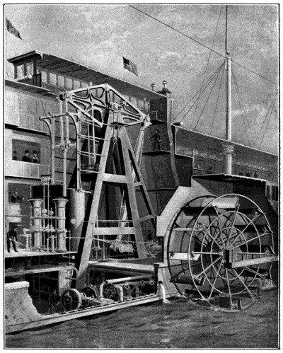
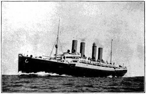
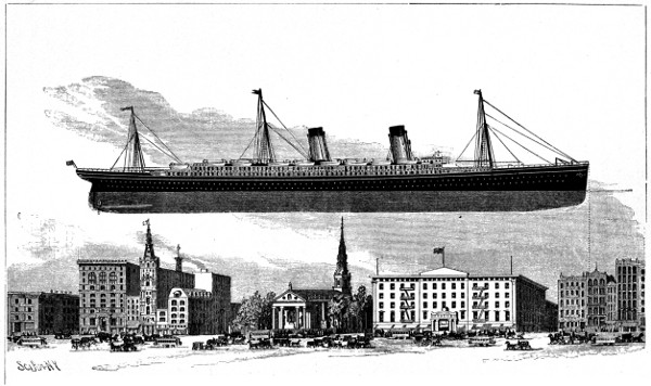
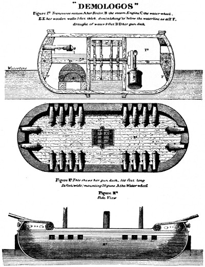
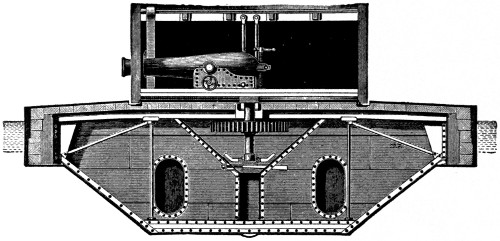
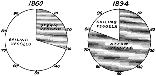
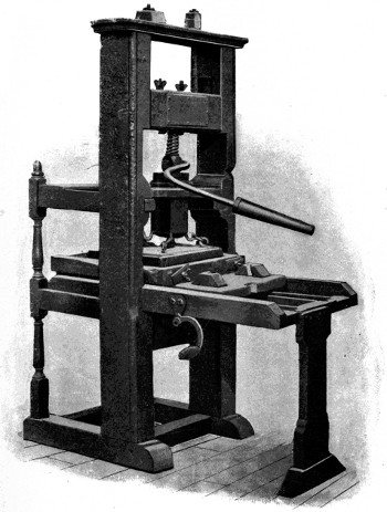
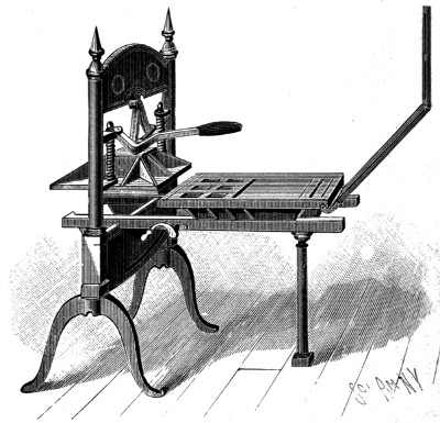
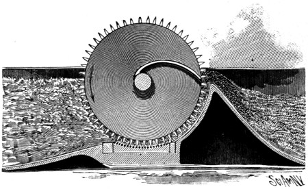
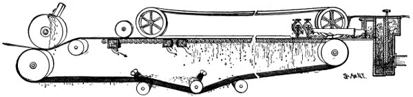
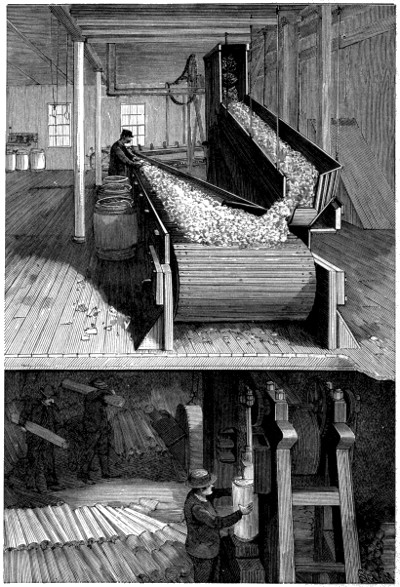
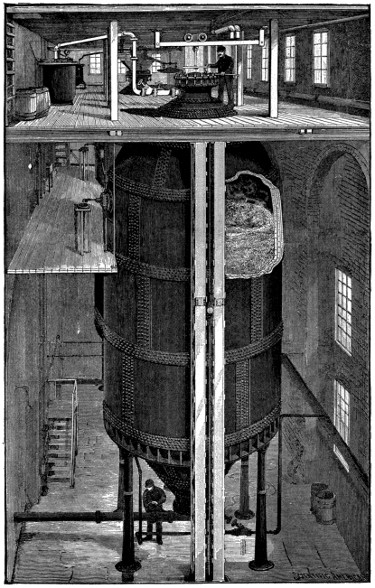
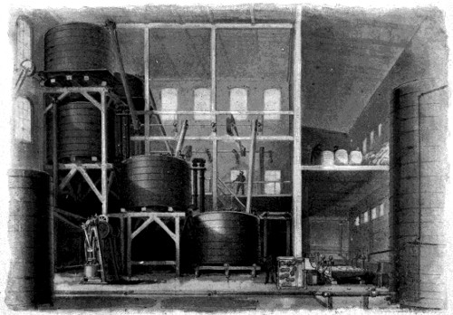
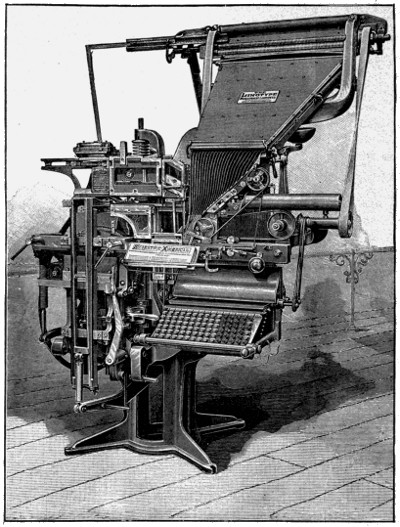
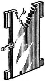
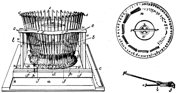
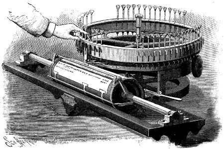
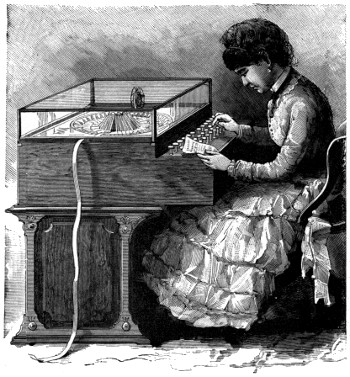
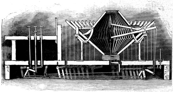
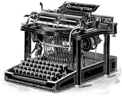
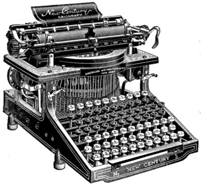
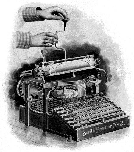
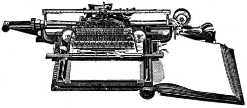
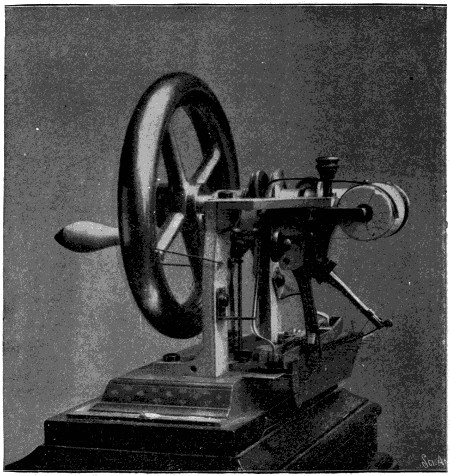
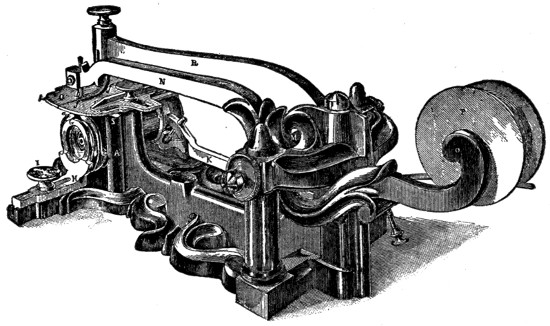
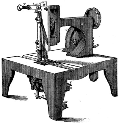
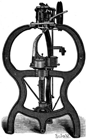
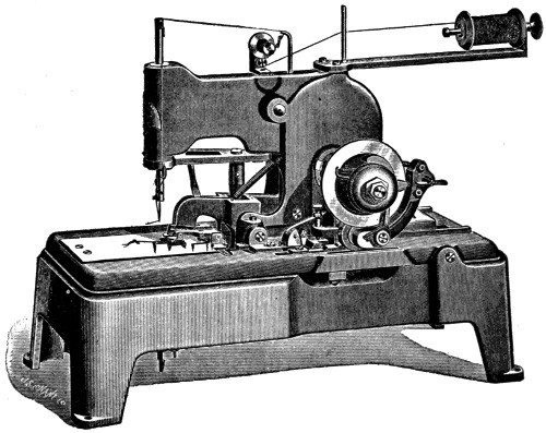
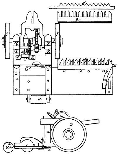
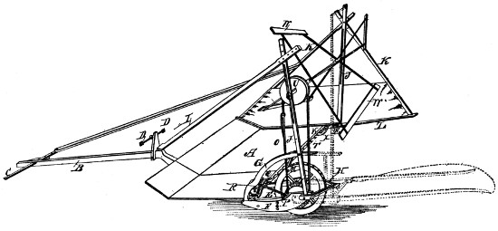
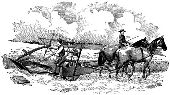
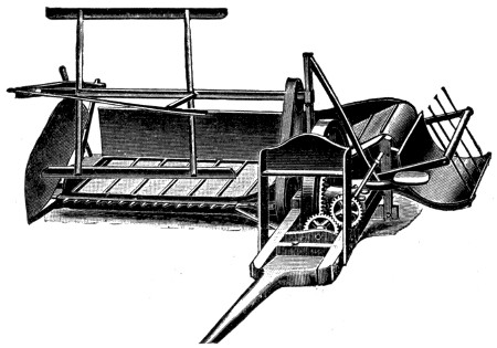
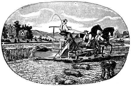
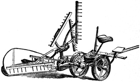
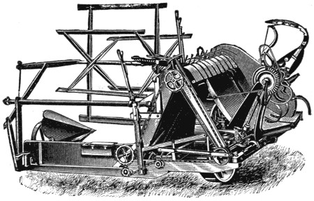
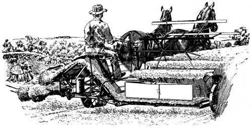
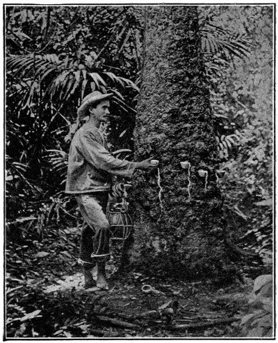
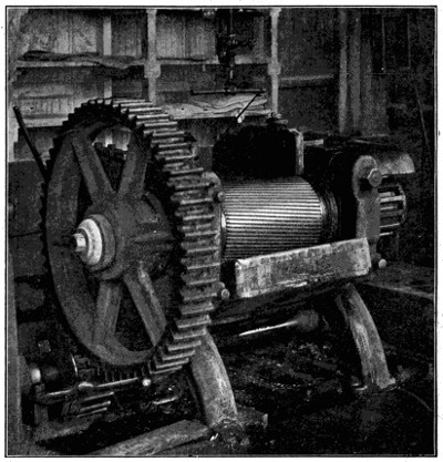
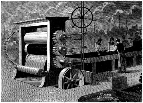
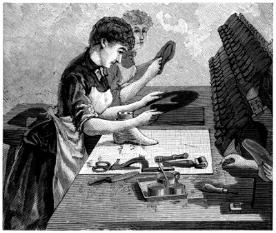
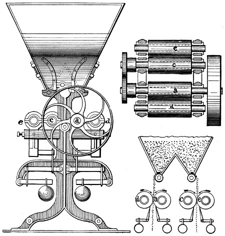
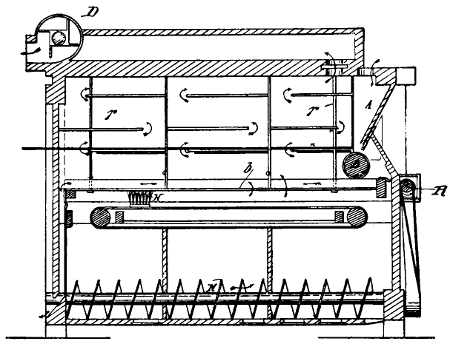
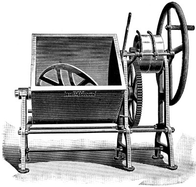
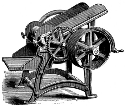
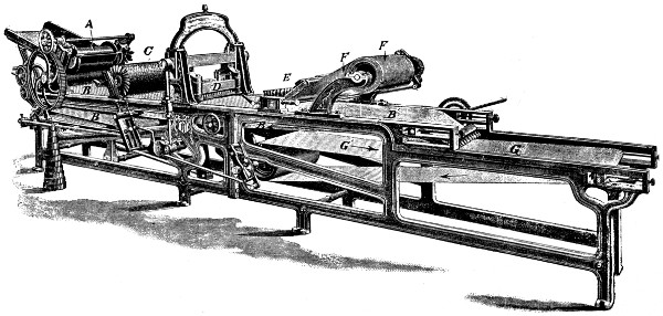
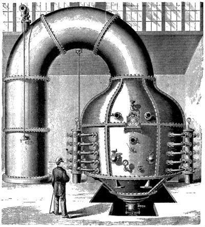
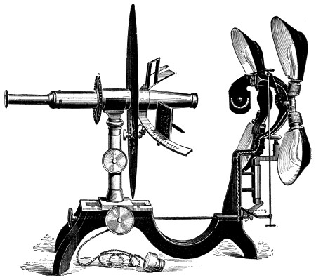
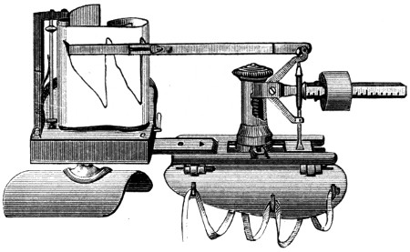
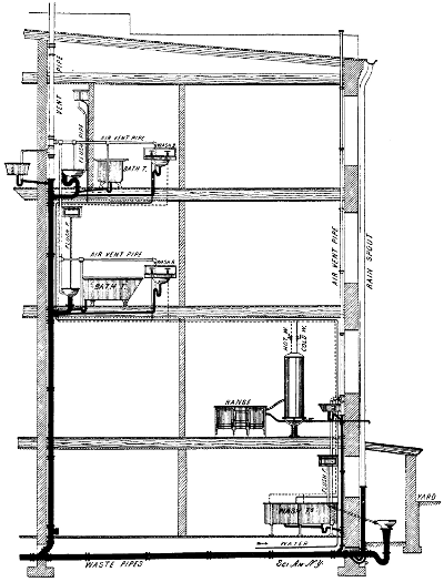
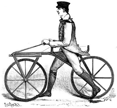
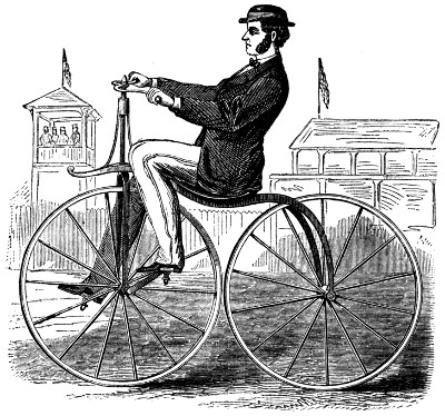
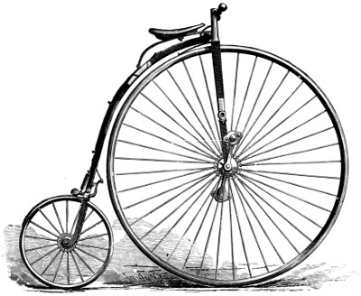
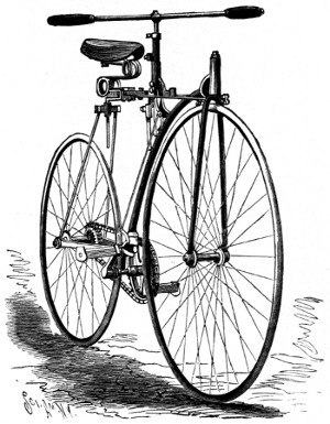
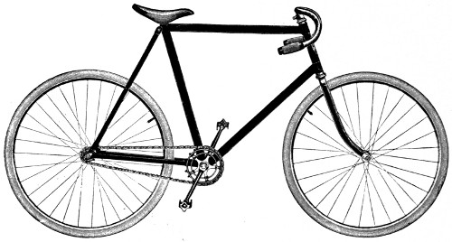
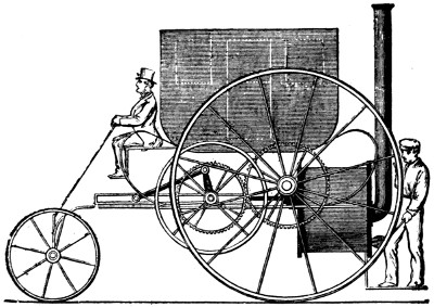
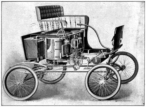
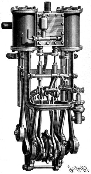
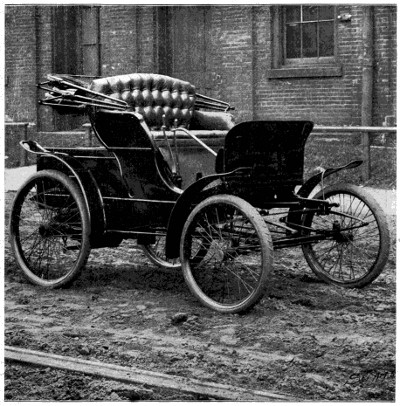
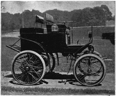
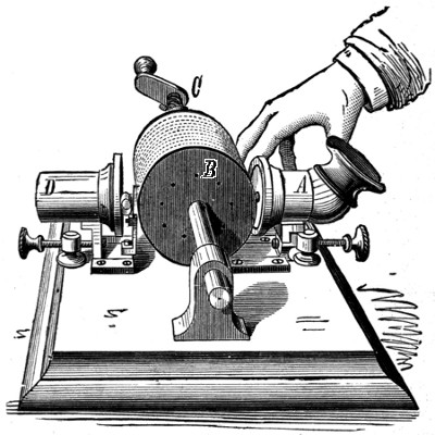
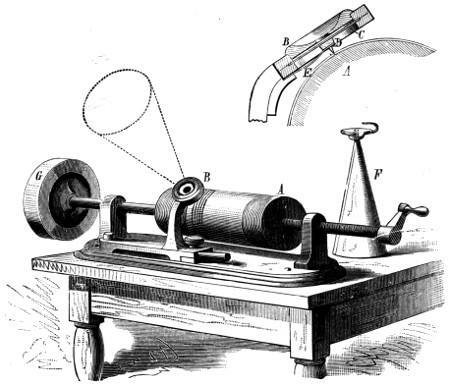
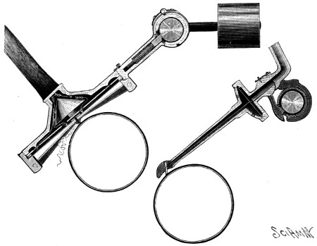
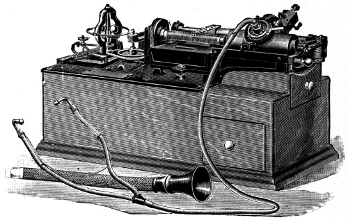
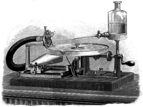
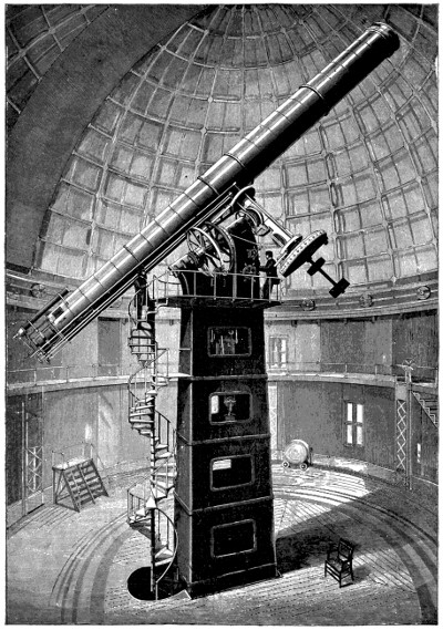
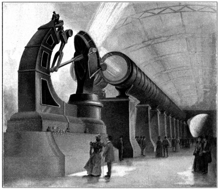
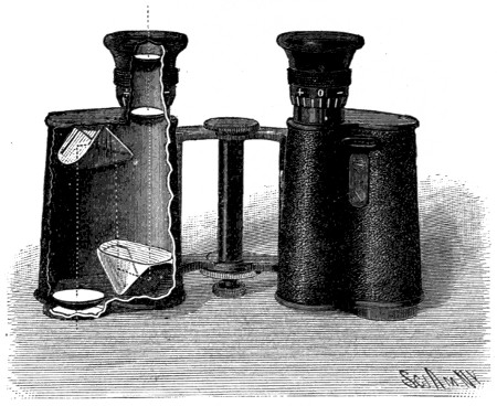
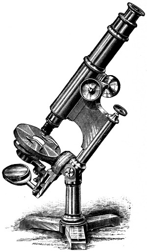
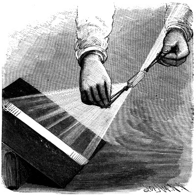
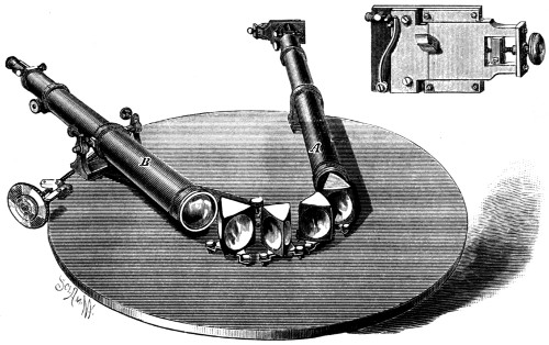
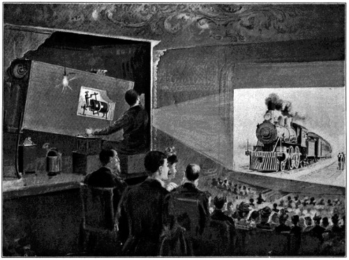
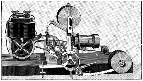
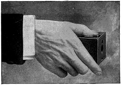
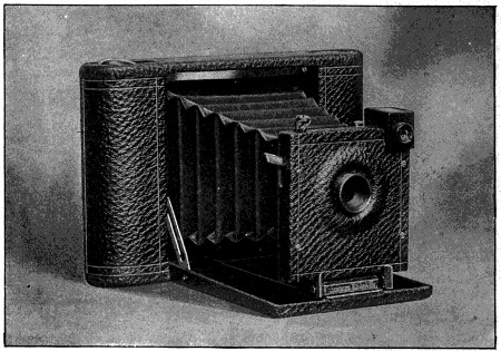
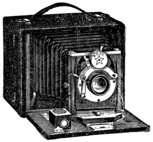
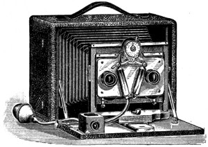
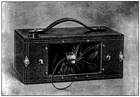
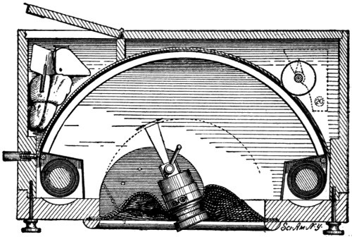
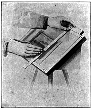
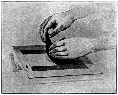
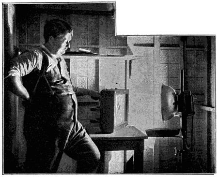
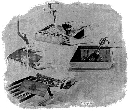
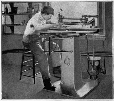
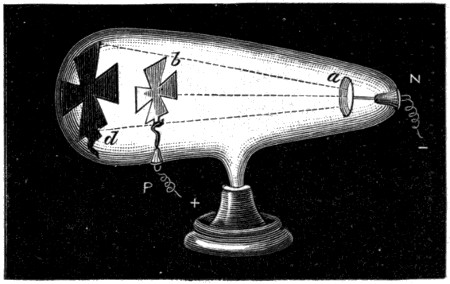
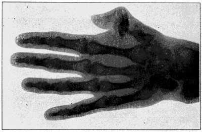
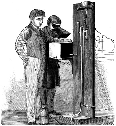
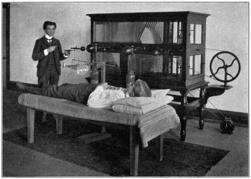
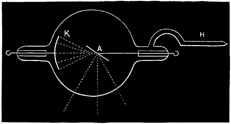
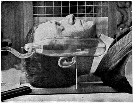
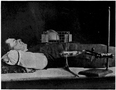
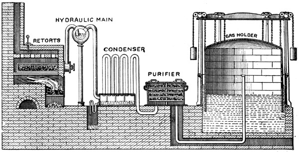
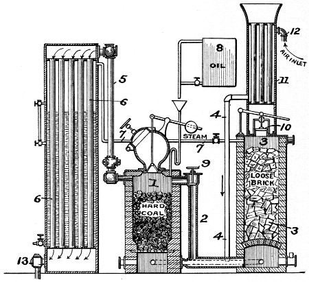
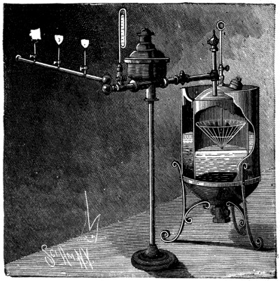
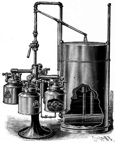
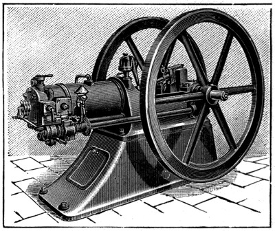

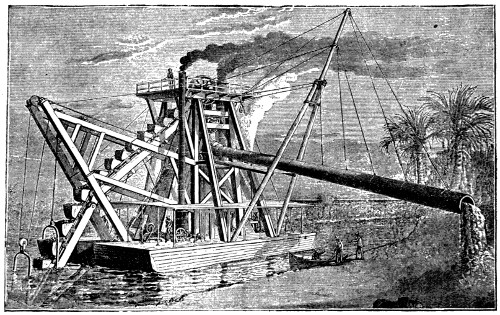
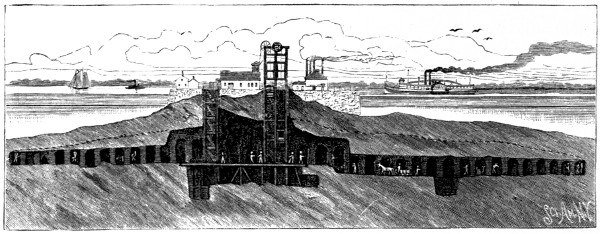
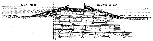
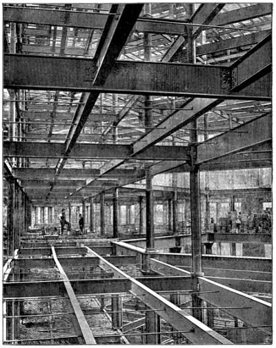
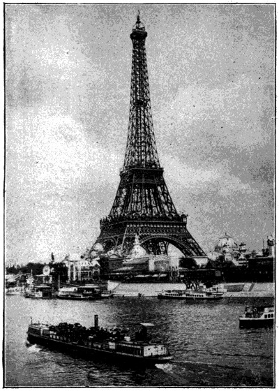
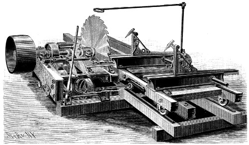
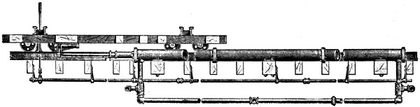
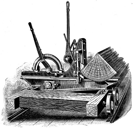
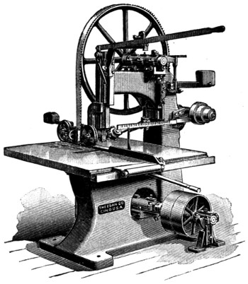
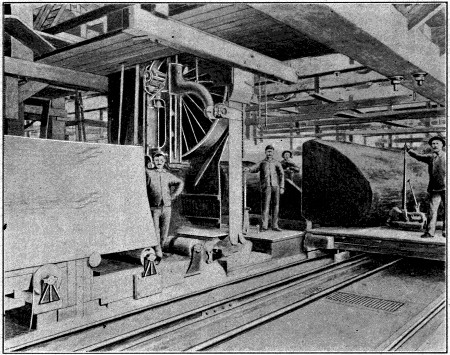
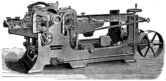
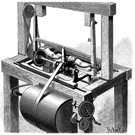
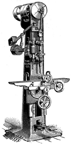
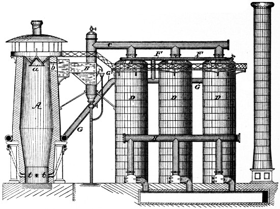
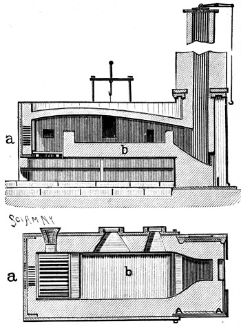
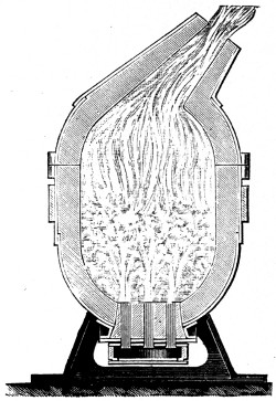
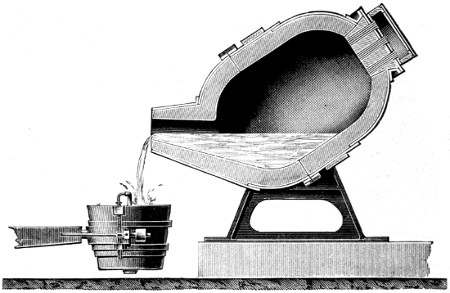
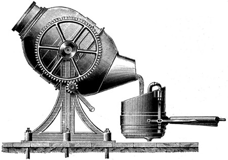
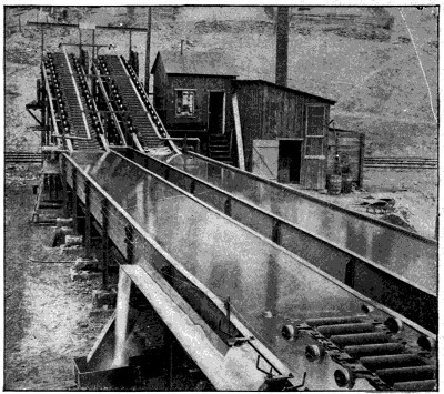
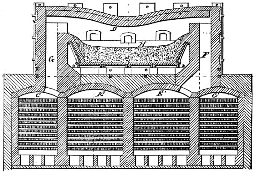
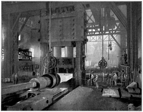
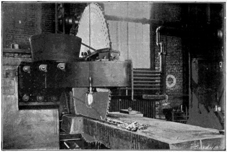
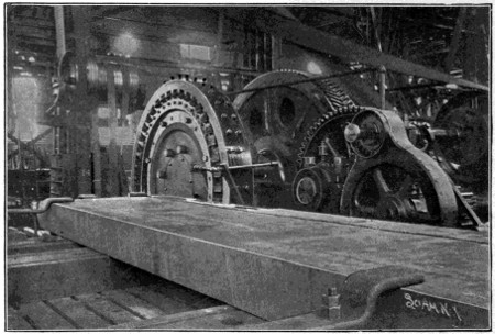
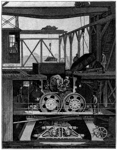
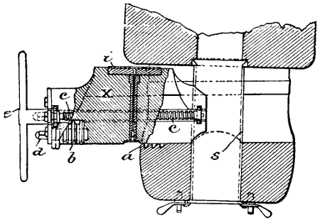
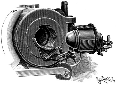


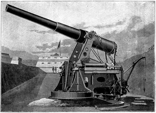
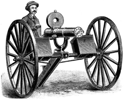
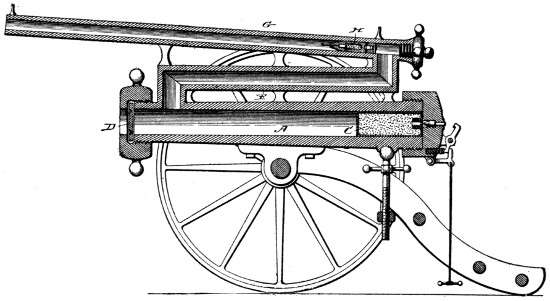
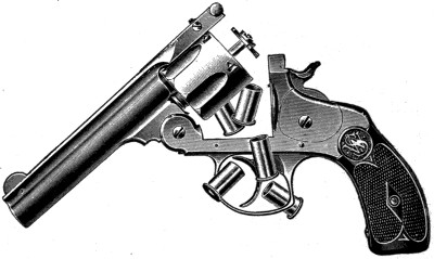
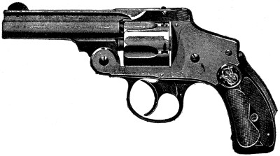
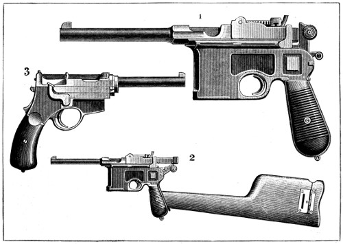
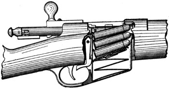
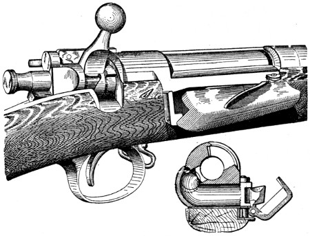
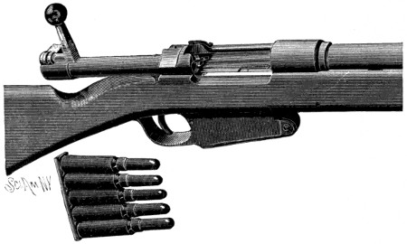
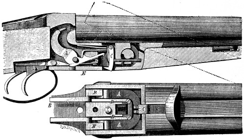
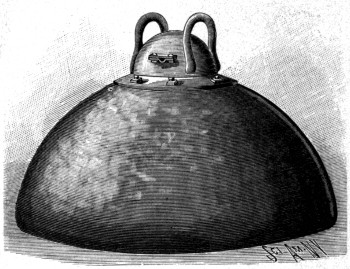
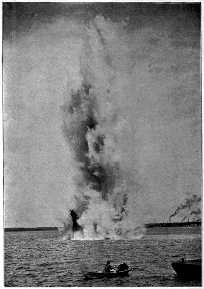
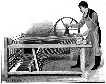
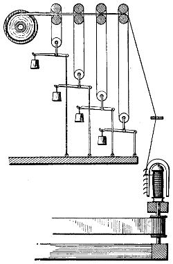
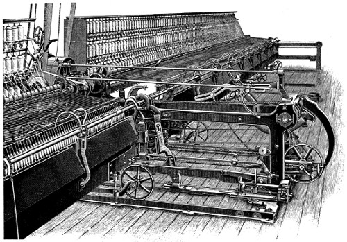
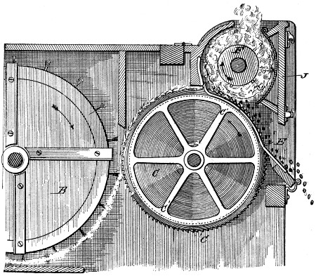
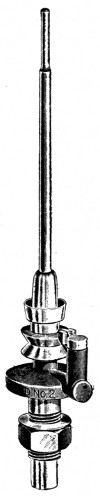
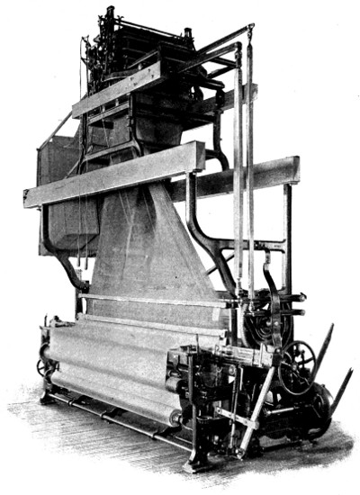
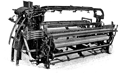
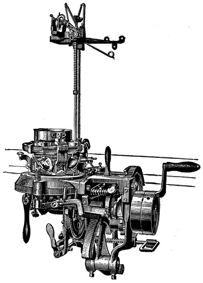
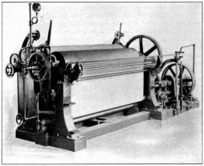
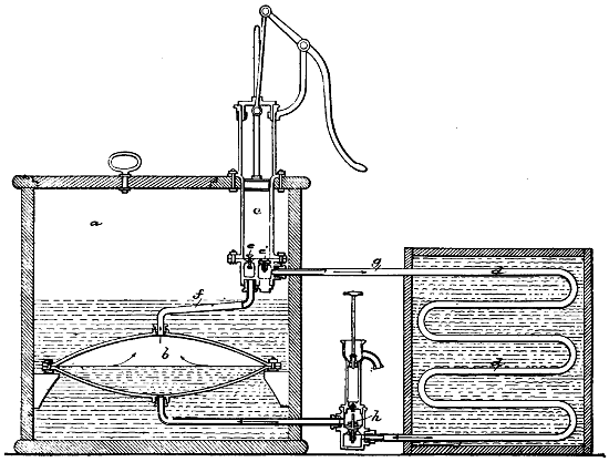
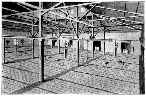
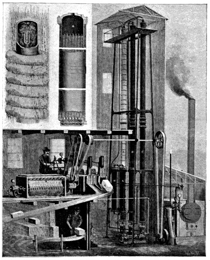
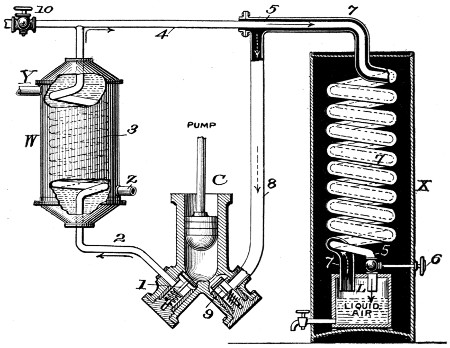
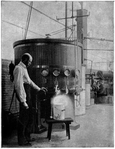
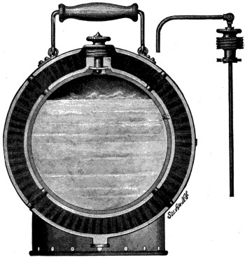
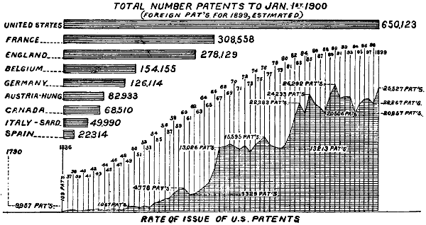
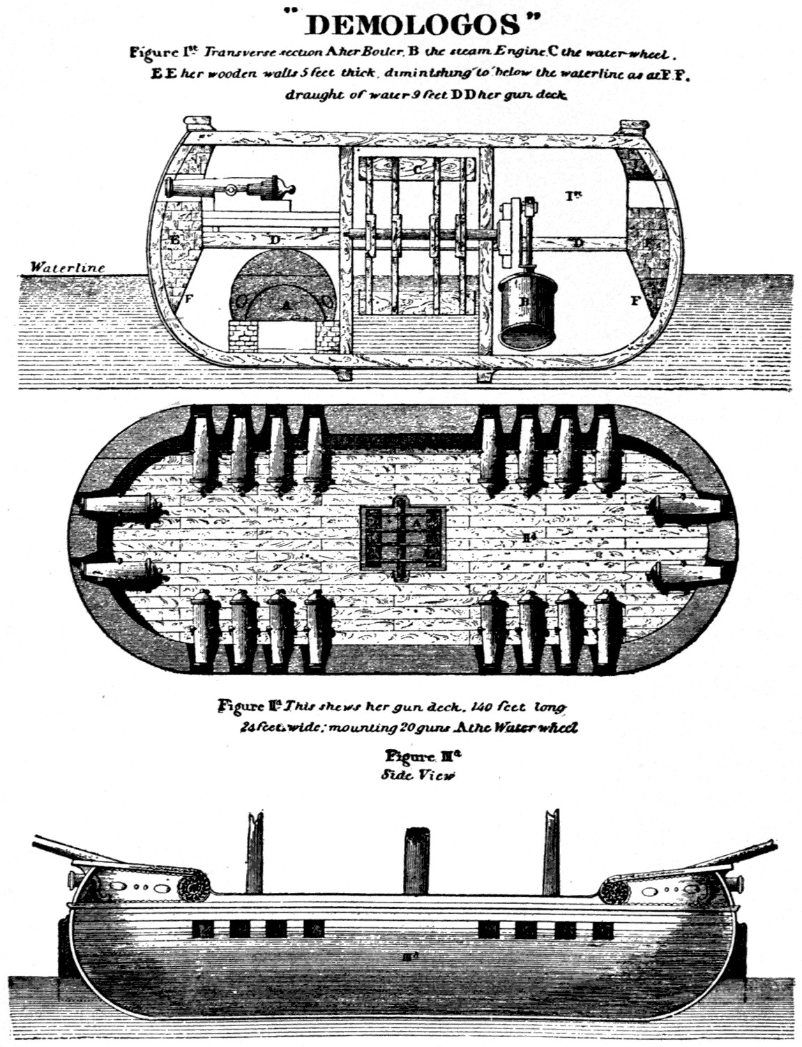
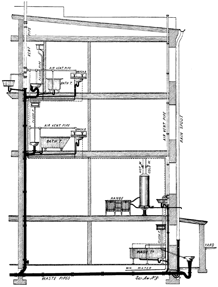