Compiler's Notes
Bulletin 240 was compiled from individual Papers posted on Project Gutenberg and the Index for this volume:
Paper 34
Paper 35
Paper 36
Paper 37
Paper 38
Paper 39
Paper 40
Paper 41
Paper 42
Paper 43
Paper 44
Transcriber's Notes for each Paper and the Index follows the text of that Paper/Index.
SMITHSONIAN INSTITUTION
UNITED STATES NATIONAL MUSEUM
BULLETIN 240
SMITHSONIAN PRESS
Publications of the United States National Museum
The scholarly and scientific publications of the United States National Museum include two series, Proceedings of the United States National Museum and United States National Museum Bulletin.
In these series, the Museum publishes original articles and monographs dealing with the collections and work of its constituent museums—The Museum of Natural History and the Museum of History and Technology—setting forth newly acquired facts in the fields of anthropology, biology, history, geology, and technology. Copies of each publication are distributed to libraries, to cultural and scientific organizations, and to specialists and others interested in the different subjects.
The Proceedings, begun in 1878, are intended for the publication, in separate form, of shorter papers from the Museum of Natural History. These are gathered in volumes, octavo in size, with the publication date of each paper recorded in the table of contents of the volume.
In the Bulletin series, the first of which was issued in 1875, appear longer, separate publications consisting of monographs (occasionally in several parts) and volumes in which are collected works on related subjects. Bulletins are either octavo or quarto in size, depending on the needs of the presentation. Since 1902 papers relating to the botanical collections of the Museum of Natural History have been published in the Bulletin series under the heading Contributions from the United States National Herbarium, and since 1959, in Bulletins titled “Contributions from the Museum of History and Technology,” have been gathered shorter papers relating to the collections and research of that Museum.
The present collection of Contributions, Papers 34-44, comprises Bulletin 240. Each of these papers has been previously published in separate form. The year of publication is shown on the last page of each paper.
Frank A. Taylor
Director, United States National Museum
| Page | ||
| 34. | The 1893 Duryea Automobile Don H. Berkebile |
1 |
| 35. | The Borghesi Astronomical Clock Silvio A. Bedini |
29 |
| 36. | The Engineering Contributions of Wendel Bollman Robert M. Vogel |
77 |
| 37. | Screw-Thread Cutting by the Master Screw Method Since 1480 Edwin A. Battison |
105 |
| 38. | The Earliest Electromagnetic Instruments Robert A. Chipman |
121 |
| 39. | Fulton’s “Steam Battery”: Blockship and Catamaran Howard I. Chapelle |
137 |
| 40. | History of Phosphorus Eduard Farber |
177 |
| 41. | Tunnel Engineering—A Museum Treatment Robert M. Vogel |
201 |
| 42. | The “Pioneer”: Light Passenger Locomotive of 1851 John H. White |
241 |
| 43. | History of the Division of Medical Sciences Sami Hamarneh |
269 |
| 44. | Development of Gravity Pendulums in the 19th Century Victor F. Lenzen and Robert P. Multhauf |
301 |
Produced by Colin Bell, Joseph Cooper, Stephanie Eason, and the Online Distributed Proofreading Team at http://www.pgdp.net.
Contributions from
The Museum of History and Technology:
Paper 34
The 1893 Duryea Automobile
In the Museum of History and Technology
Don H. Berkebile
| EARLY AUTOMOTIVE EXPERIENCE | 5 |
| CONSTRUCTION BEGINS | 6 |
| DESCRIPTION OF THE AUTOMOBILE | 16 |
| INDEX |
Figure 1.—Duryea automobile in the Museum of History and Technology, from an 1897 photograph. The gear-sprockets were already missing when this was taken, and the chain lies loosely on the pinion. Shown at the right, the Duryea vehicle following the recent restoration (Smithsonian photo 34183).
Don H. Berkebile
THE 1893 DURYEA AUTOMOBILE
In the Museum of History and Technology
During the last decade of the nineteenth century a number of American engineers and mechanics were working diligently to develop a practical self-propelled vehicle employing an internal-combustion engine as the motive force. Among these men were Charles and Frank Duryea, who began work on this type of vehicle about 1892. This carriage was operated on the streets of Springfield, Massachusetts, in 1893, where its trials were noted in the newspapers. Now preserved in the Museum of History and Technology, it is a prized exhibit in the collection of early automobiles.
It is the purpose of this paper to present some of the facts discovered during the restoration of the vehicle, to show the problems that faced its builders, and to describe their solutions. An attempt also has been made to correlate all this information with reports of the now almost legendary day-to-day experiences of the Duryeas, as published by the brothers in various booklets, and as related by Frank Duryea during two interviews, recorded on tape in 1956 and 1957, while he was visiting the Smithsonian.
The Author: Don H. Berkebile is on the staff of the Museum of History and Technology, in the Smithsonian Institution's United States National Museum.
Of the numerous American automotive pioneers, perhaps among the best known are Charles and Frank Duryea. Beginning their work of automobile building in Springfield, Massachusetts, and after much rebuilding, they constructed their first successful vehicle in 1892 and 1893. No sooner was this finished than Frank, working alone, began work on a second vehicle having a two-cylinder engine. With this automobile, sufficient capital was attracted in 1895 to form the Duryea Motor Wagon Company in which both brothers were among the stockholders and directors. A short time after the formation of the company this second automobile was entered by the company in the Chicago Times-Herald automobile race on Thanksgiving Day, November 28, 1895, where Frank Duryea won a victory over the other five contestants—two electric automobiles and three Benz machines imported from Germany.
In the year following this victory Frank, as engineer in charge of design and construction, completed the plans begun earlier for a more powerful automobile. During 1896 the company turned out thirteen identical automobiles, the first example of mass production in American [4] automotive history.[1] Even while these cars were under construction Frank was planning a lighter vehicle, one of which was completed in October of 1896. This machine was driven to another victory by Frank Duryea on November 14, 1896, when he competed once again with European-built cars in the Liberty-Day Run from London to Brighton. The decision to race and demonstrate their autos abroad was the result of the company's desire to interest foreign capital, yet Frank later felt they might better have used their time and money by concentrating on building cars and selling them to the local market. Subsequently, in the fall of 1898, Frank arranged for the sale of his and Charles' interest in the company, and thereafter the brothers pursued separate careers.
Figure 2.—Workmen in the Duryea
factory in Springfield, Mass.,
working on some of the thirteen
1896 motor wagons. (Smithsonian photo 44062.)
Frank, in 1901, entered into a contract with the J. Stevens Arms and Tool Company, of Chicopee Falls, Massachusetts, which built automobiles under his supervision. This association led in 1904 to the formation of the Stevens-Duryea Company, of which Irving Page was president and Frank Duryea was vice president and chief engineer. This company produced during its 10-year existence a number of popular and well-known models, among them a light six known as the Model U, in 1907; a larger 4-cylinder called the Model X, in 1908; and a larger six, the Model Y, in 1909. In 1914 when Stevens withdrew from the company, Frank obtained control. The following year he sold the plants and machinery, liquidated the company, and, due to ill health, retired.
Charles, in the meantime, located in Reading, [5] Pennsylvania, where he built autos under the name of the Duryea Power Company.[2] Here, and later in Philadelphia under the name of the Duryea Motor Corporation and other corporate names, he continued for a number of years to build automobiles, vacuum cleaners and other mechanical devices. Until the time of his death in 1938, he practiced as a consulting engineer.
Figure 3.—Admittance card
of C. E. Duryea to the U.S. Patent Office, 1887.
(Gift of Rhea Duryea Johnson.)
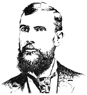
Figure 4.—Charles E. Duryea, about 1894,
as drawn by George Giguere from a photograph.
(Smithsonian photo 48335-A.)
Born in 1861 near Canton, Illinois, Charles E. Duryea had learned the trade of a mechanic following his graduation from high school, and subsequently turned his interests to bicycle repair. He and his brother James Frank, eight years younger, eventually left Illinois and moved to Washington D.C., where they were employed in the bicycle shop of H. S. Owen, one of that city's leading bicycle dealers and importers. While in Washington, Charles became a regular reader of the Patent Office Gazette,[3] an act which undoubtedly influenced his later work with automobiles. A short time later, probably in 1889, Charles contracted with a firm in Rockaway, New Jersey, to construct bicycles for him, but their failure to make delivery as promised caused him to go to Chicopee, Massachusetts, where he contracted with the Ames Manufacturing Company to do his work. Moving there in 1890, he obtained for his brother a position as toolmaker with the Ames Company. Thus, Frank Duryea, as he was later known, also became located in Chicopee, a northern suburb of Springfield.
During the summer, 1891, Charles found the bicycle business left him some spare time, and the gasoline-powered [6] carriages he had read of earlier came constantly into his mind in these periods of idleness.[4] He and Frank studied several books on gasoline engines, among them one by an English writer (title and author now unknown);[5] this described the Otto 4-stroke cycle as now used. Some engineers, however, were concerned because this engine, on the completion of the exhaust stroke, had not entirely evacuated all of the products of combustion. The Atkinson engine, patented in 1887, was one of the attempts to solve this as well as several other problems, thus creating a more efficient cycle. This engine was designed so that the exhaust stroke carried the piston all the way to the head of the engine, while the compression stroke only moved the piston far enough to sufficiently compress the mixture. The unusual linkage necessary to create these unequal strokes in the Atkinson engine made it seem impractical for a carriage engine, where compactness was desired.
Figure 5.—Advertisement
of Duryea bicycle company,
Scientific American, September 9, 1893.
Going to Hartford, Connecticut, possibly on business relating to his bicycle work, Charles visited the Hartford Machine Screw Company where the Daimler-type engine was being produced,[6] but after examining it he felt it was too heavy and clumsy for his purpose. Also in Hartford he talked over the problem of a satisfactory engine with C. E. Hawley, an employee of the Pope Manufacturing Company, makers of the Columbia bicycle. Hawley, searching for a way to construct an engine that would perform in a manner similar to the Atkinson, yet would have the lightness and compactness necessary for a carriage engine, suggested an idea that Charles believed had some merit. This idea, involving the use of what the Duryeas later called a "free piston," was eventually to be incorporated in their first engine.[7]
Figure 6.—J. Frank Duryea,
about 1894,
as drawn by George Giguere from a photograph.
(Smithsonian photo 48335.)
Back in Chicopee again, Charles began planning his first horseless carriage. Frank later stated that they leaned heavily on the Benz patents in their work;[8] but while the later engine and transmission show evidence of this, only the Benz manner of placing the engine and the flywheel seem to have been employed in the original Duryea plan. Charles reversed the engine so that the flywheel was to the front, rather than to the rear as in the Benz patent, but made use of Benz' vertical crankshaft so that the flywheel rotated in a horizontal plane. Previously most engines had used vertical flywheels; Benz, believing that this practice would cause difficulty in steering a propelled [7] carriage, explained his reason for changing this feature in his U.S. patent 385087, issued June 26, 1888:
In motors hitherto used the fly-wheels have been attached to a horizontal shaft or axle, and have thus been made to revolve in a vertical plane, since the horizontal shaft is best adapted to the transmission of power. If, however, in this case we should use a heavy rotating mass, corresponding to the power employed and revolving rapidly in a vertical plane, the power to manage the vehicle or boat would become very much lessened, as the flywheel continues to revolve in its plane. I therefore so design the apparatus that its crank shaft x has a vertical position and its fly-wheel y revolves in a horizontal plane…. By this means the vehicle is not only easily controlled, but also the greatest safety is attained against capsizing.
To the Duryea plan, Benz may also have contributed the idea for positioning the countershaft, though its location is sufficiently obvious that Charles may have had no need for copying Benz. Charles wisely differed from Benz in placing the flywheel forward, thus eliminating the need for the long driving belt of the Benz carriage. Yet he did reject the bevel gears used by Benz, which might well have been retained, as Frank was later to prove by designing a workable transmission that incorporated such bevel gears. The initial plan, as conceived by Charles, also included the details of the axles, steering gear, countershaft with its friction-drum, the 2-piece angle-iron frame upon which the countershaft bearings were mounted, and the free piston engine with its ignition tube, since hot-tube ignition was to be employed. No provision was made, however, for a burner to heat the tube; nor had a carburetor been designed, though it had been decided not to use a surface tank carburetor. The plans called for no muffler or starting arrangement.[9] Many engines of the period were started simply by turning the flywheel with the hands, and Charles felt this method was sufficient for his carriage.
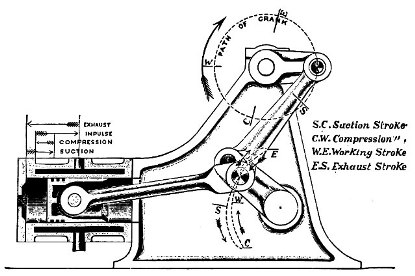
Figure 7.—Drawing showing
principle of the Atkinson engine; this feature
is what the
Duryeas were trying to achieve with their free-piston engine, by
substituting the free piston for the unusual linkage of the Atkinson.
(Smithsonian photo H3263-A.)
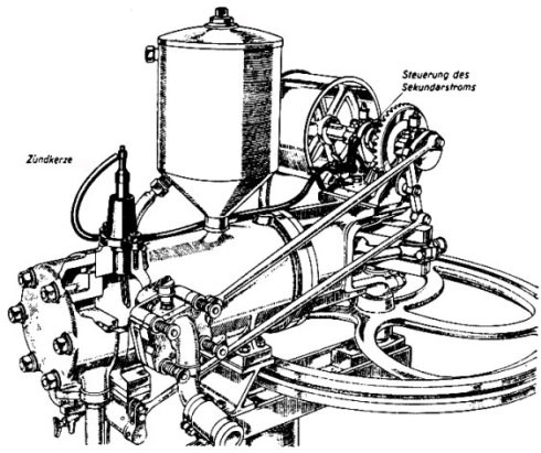
Figure 8.—Drawing of
1885 Benz engine, showing
similarity in general appearance
to Duryea engine. From
Karl Benz und sein Lebenswerk, Stuttgart,
1953.
(Daimler-Benz Company publication.)
The Ames plant customarily had a summer shutdown during August; thus, during August of 1891 Charles and Frank had access to a nearly empty plant in which they could carry on experiments and make up working drawings of the proposed vehicle. It cannot now be conclusively stated whether any parts were made for the car during August or the remainder of the year. It is more likely that the brothers attempted to complete a set of drawings. Frank Harrington, chief draftsman at Ames, may have helped out at this time; from Charles' statement of April 14, 1937, it is learned that he did prepare drawings during 1892.
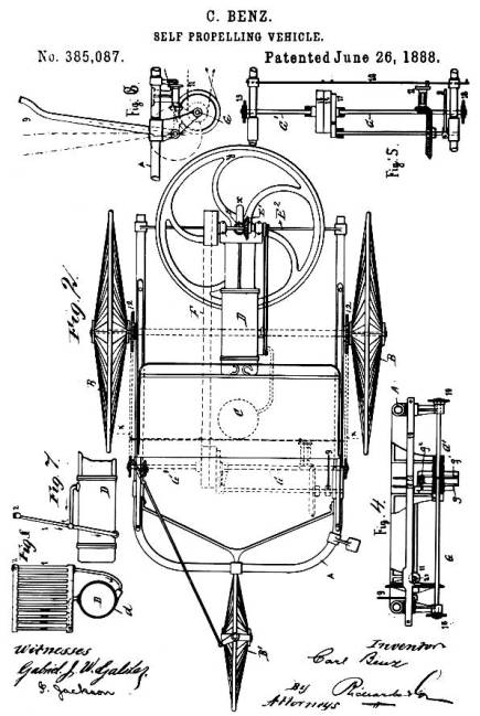
Figure 9.—Illustration from U.S. patent 385087,
issued to Carl Benz, showing the horizontal plane
of the flywheel, a feature utilized by the Duryeas in their machine.
The first contemporary record of any work on vehicles is a bill, dated January 21, 1892, for a drawing made by George W. Howard & Company. This drawing was made in the fall of 1891 by Charles A. Bartlett, a member of the Howard firm and a neighbor of Charles Duryea, according to a statement by Charles in the Automobile Trade Journal of Jan. 10, 1925. He was then also of the opinion that this drawing may not have had anything to do with the carriage they were about to assemble, but a notation found by Charles at a later date has led him to believe that it possibly concerned a business type vehicle he had discussed with an unidentified Mr. Snow.
By early 1892 Charles needed capital to finance his venture, an old carriage to attach his inventions to, a place to work, and a mechanic to do the work. On March 26, he stopped by the Smith Carriage Company and looked over a selection of used buggies and phaetons. He finally decided on a rather well-used ladies' phaeton which he purchased for $70. The leather dash was in so deplorable a state it would have to be recovered before the carriage went onto the road, and the leather fenders it once possessed had previously been removed; yet the upholstery appeared to be in satisfactory condition, and the candle lamps were intact.
Figure 10.—Phantom illustration
of Benz' first automobile.
(From Carl Benz,
Father of the Automobile Industry, by L. M. Fanning, New York, 1955.)
Two days later, Charles was able to interest Erwin F. Markham, of Springfield, sufficiently to obtain his financial aid in the project. A contract was [9] drawn up between the two men, which stated that Mr. Markham was to put up $1000 for which he received a five-tenths share of the venture. When the $1000 had been used, he then had the option to continue his aid until the project had been carried to a successful climax, and retain his half share, or to refuse further funds and relinquish four of his five-tenths interest in the business.[10] Had he eventually chosen the latter, Charles would obviously have had to seek assistance elsewhere.
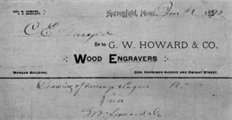
Figure 11.—The Howard & Co. bill
showing the first work performed
toward a motor vehicle. While
this may not refer specifically
to the machine now in the museum,
it is evidence of early work.
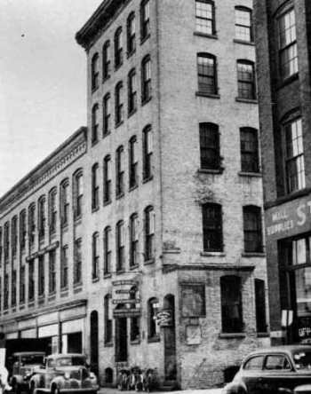
Figure 12.—The shop of John Russell & Sons.
It was on the second floor of this building that
Charles and Frank Duryea built their first motor vehicle.
(Courtesy of the Springfield Union.)
That same day, March 28, Charles found working space and machinery available at John W. Russell & Sons Company in Springfield.[11] The Russells had recently completed a large government order of shells for the famous dynamite guns later used on board the cruiser Vesuvius in the Spanish-American War, and this left an entire second floor, approximately 35 × 85 feet, virtually unoccupied, according to an affidavit of William J. Russell of April 30, 1926. Now ready to begin the actual work, Charles hired his brother Frank to start construction. Frank started about the first of April, receiving a raise of about 10 percent over the salary he had received at Ames. Before the vehicle was completed a number of other men performed work on some of the parts, among them William Deats who had been hired by Charles primarily to work on [10] bicycles in the same area, but who occasionally assisted on the carriage. Russell Company records show time charged against Charles Duryea by six other Russell employees: W. J. Russell, P. Colgan, C. E. Merrick, T. Shea, L. J. Parmelee, and A. A. Poissant.
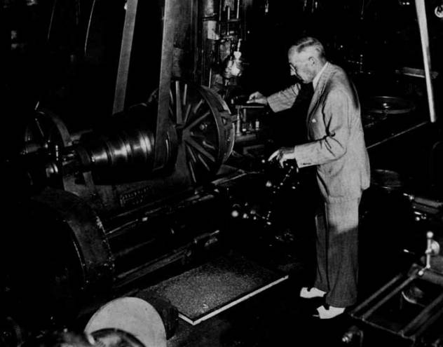
Figure 13.—J. Frank Duryea
looking over the Russell shop lathe
on which he turned parts
for the first Duryea vehicle.
Photo taken about 1944.
(Courtesy of the Springfield Union.)
It is Frank Duryea's remembrance that he started work on Monday, April 4. He first removed the body, with its springs, and placed it on a pair of wooden horses where it remained until the summer of the following year. The next step was to remove the rear axle and take it to a blacksmith shop where the old axle spindles were cut off and welded to a new drop-center axle. Following this the front axle spindles were removed, the ends of the axle slotted, and a webbed, C-shaped piece carrying the kingpin bearings was fitted into each slot, braced from underneath by short brackets which were riveted and brazed in place. The old spindles then were welded to the center of offset kingpins which in turn were mounted in their bearings in a manner similar to that in which the frame of the Columbia high-wheeled bicycle was mounted in its fork. Arms welded to the lower end of the kingpins were connected by the tie rods to an arm on the lower end of the vertical steering column, located on the center of the axle.
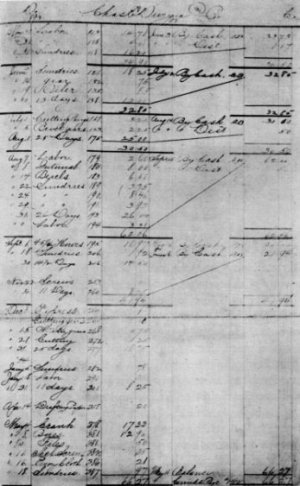
Figure 14.—A portion of the Russell shop
records showing charges made against
Charles Duryea during 1893-1894.
While work on the running gear advanced, some progress was made in the construction of the engine. [11] Patterns for the castings were fabricated, most of them by Charles Marshall on Taylor Street,[12] and castings were poured. The body or main casting of the engine resembled a length of cast-iron pipe: it had no bosses or lugs cast on, nor any water jacket, for they thought the engine would be kept cool merely by being placed in the open air. The front end of the engine was secured to the vehicle by four bolts which passed through the halves of the bearings and onto four projections on the open end of the engine. As the crankshaft of this engine was retained in constructing the present engine, it is logical to assume that the bearings were the same also. The head was cast as a thick disc, with both intake and exhaust valves located therein, and was bolted onto the flanged head end of the engine.
Inside the cylinder was the strange arrangement previously suggested by C. E. Hawley. To the connecting rod was attached a rather ordinary ringed piston, over which was fitted a free, ringless piston, machined to fit closely the cylinder bore. This floating piston could move freely a distance equal to the compression space. The intention was that on the intake stroke, suction would open the intake valve, which had no positive opening arrangement, and draw in the mixture which then was compressed as in a regular Otto engine. Fired by the hot-tube ignition system, the force of the explosion would drive both pistons down, forcing the outer one tight against the head of the smaller one, and at the end of the stroke the longer wall of the outer piston would strike an arm projecting into the cylinder near the open end, moving forward the exhaust valve rod to which the arm was attached, thus pushing open the valve in the head.[13] On the exhaust stroke the unrestrained outer piston moved all the way to the head, expelling all of the products of combustion and pushing the exhaust valve shut again. With a bore of four inches or less, this engine, Charles believed, should develop about three horsepower and run at a speed between 350 to 400 revolutions per minute.[14]
As no ignition system had yet been provided, they prepared a 4½-inch length of one-quarter inch iron pipe, closed at one end, and screwed the open end into the head. Heating this tube with an alcohol burner would cause ignition of the mixture when a portion of it was forced into the heated tube toward the end of the compression stroke. No attempt was made at this time to use the electrical make-and-break circuit used in their second engine, as the free piston would have wrecked the igniter parts on the exhaust stroke, and the push rod located on the end of the piston would have prevented the piston from closing the exhaust valve.
After keying the flywheel to the lower end of the crankshaft, Charles and Frank decided to make an [12] attempt to run the engine. Carrying it into a back room, probably during July or August, 1892, they blocked it up on horses. A carburetor had not yet been constructed, so they attempted to start the engine by spinning the flywheel by hand, at the same time spraying gasoline through the intake valve with a perfume atomizer previously purchased at a drugstore in the Massasoit House. Repeated efforts of the two men to start the engine resulted in failure.
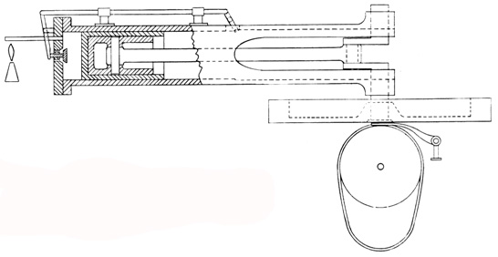
Figure 15.—Conjectural drawing of the free-piston engine used in the Museum vehicle prior to the present engine. (Drawing by A. A. Balunek.)
In the belief that the defects, whatever they might be, could be remedied after the engine was installed, the Duryeas went ahead and mounted the engine in the carriage. To do this they shortened the original reach of the carriage, allowing the engine itself to become the rear continuation of the reach. The four ears on the front, or open end of the engine, were bolted to the centrally located frame, with the bearing blocks in between. This frame, the same one now in the vehicle, was constructed of two pieces of angle iron, riveted and brazed together. Greater rigidity was obtained by a number of half-inch iron rods running from the frame to both front and rear axles. Because of the absence of any mounting brackets on the engine casting itself, a wooden block with a trough on top to receive the body of the engine was fitted between the engine and the axle, while two U-shaped rods secured it with clip bars and nuts underneath.
Beneath the flywheel was mounted the friction transmission of Charles' design. This consisted of a large drum, perhaps 12 inches in diameter, equal in length to the diameter of the flywheel and keyed to a shaft directly under the center of the crankshaft and parallel to the axles. (Diameter of drum estimated by examination of existing features.) In view of the four projections of the frame extending downward and just in front of the jackshaft position, it is likely that these supported the four jackshaft bearings. Being a bicycle manufacturer, Charles saw the need for a differential or balance gear. Accordingly, he purchased from the Pope Manufacturing Company a very light unit of the type formerly used on Columbia tricycles, and installed it somewhere on the jackshaft. A small sprocket on each end of the shaft carried a chain from the larger sprockets clamped to the spokes of each rear wheel. The lower surface of the flywheel had been machined so as to form a friction disc, with a one-quarter inch depression 3 inches in diameter turned in the center. The drum was positioned so that its upper surface was one-quarter inch below the face of the flywheel. Hanging loosely around the drum was an endless belt, one and one-half inches wide, first made of rather soft rubber packing material. The belt lay on the drum surface between the fingers of a shipper fork. While it lay under the 3-inch depression in the center of the flywheel, the belt and the drum were at rest, but when it was moved away from that depression the belt wedged itself tightly between the drum and flywheel, the resulting friction causing the drum to turn and setting the vehicle into motion. The farther the belt was moved toward the outer edge of the wheel, the faster the drum and the vehicle moved.
In September 1892, Charles, who had contracted with a Peoria, Illinois, firm to have bicycle parts manufactured, decided to move to that city. Departing on the 22d of September, he did not return to Springfield for over two years, and thus was not able to participate in the completion and testing of the [13] carriage. At the time of his departure several units on the carriage were incomplete. A carburetor had not been built, nor had a satisfactory burner or belt-shifting device. Charles had experimented with various shifting levers just before leaving Springfield: however, as he reported later, he did not succeed in designing a workable mechanism.[15] Frank Duryea, now left to finish the work unassisted, continued the experiments with the belt shifter. He finally worked out a fork mounted on a carriage that was supported by two rods, each of which slid in two bearings. Although the short distance between the two bearings caused the shifter carriage to bind occasionally, the device was thought to be sufficient and was installed just in front of the frame. Connected to a system of cables, arms, and rods, possibly similar to the present cam-bar shifter, the shipper-fork carriage was moved from side to side by raising or lowering the tiller.
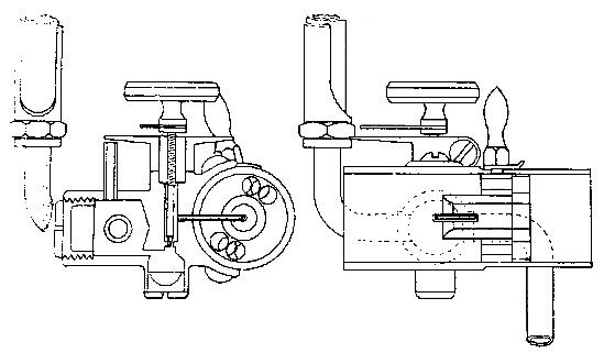
Figure 16.—Drawing
of the carburetor used on both Duryea engines, 1893-1894,
showing sight feed on left and choke mechanism on right.
(Smithsonian photo 13455.)
Turning now to an efficient burner for heating the ignition tube, Frank started with an ordinary wick-type kerosene lamp with a small metal tank. Wishing to use gasoline in the lamp, he found it necessary to fabricate a number of burner units before he found a type that gave him a clean blue flame. He then found the flame to be very sensitive to drafts and easily extinguished, and devised a small shield or chimney to afford it some protection.
Early in October, while still working with the burner, Frank developed a severe headache. He felt the fumes of the lamp had probably caused it, and went to his room in the home of a Mr. and Mrs. Patrick on Front Street in Chicopee. After he noticed no improvement, a doctor's examination showed he had typhoid fever, and on October 5 he was admitted to the Springfield Hospital. Here he remained for one month, being discharged on November 5. Returning to his room he was informed that because of the fear that he might be a typhoid carrier, the Patricks preferred him to find other lodgings. He readily accepted the invitation of Mr. and Mrs. D. H. Nesbitt of Chicopee to take a room with them. After several weeks recuperation in their home, he left Springfield to visit his mother in Wyoming, Illinois.
After a restful visit at home Frank Duryea returned to Springfield and finished the work on his burner. Now only the lack of a carburetor prevented a trial of the vehicle. He recalls that he studied several gasoline-engine catalogs and in one of them, a Fairbanks catalog he believes,[16] he saw a design that seemed to suit his needs. He decided to simplify the construction and operation of his carburetor and had a small bronze casting made to form the body of it. Inside was a gasoline chamber with two tapped openings, one to receive a pipe from the 2-gallon gasoline tank mounted above the engine, the other taking a pipe to the overflow tank underneath the engine, thus maintaining the gasoline level without the use of a float valve. This latter tank had a hand pump on one end so that the overflow gasoline could at times be pumped again into the main tank. Gasoline passed from the carburetor chamber through a needle valve, adjusted by a knob on top, then through a tiny tube that entered the pipe leading to the intake valve. It is not certain whether this intake pipe was at first fitted with the choke arrangement later used with the second engine.
Frank, hoping at last to be rewarded for his efforts by the sound of explosions from the engine, was ready to give the carriage an indoor trial. Standing astraddle of the reach and facing to the rear, he spun the flywheel with both hands, taking care not to get his hands caught between the wheel and the frame. His efforts were in vain, as there was complete failure to obtain ignition. He then made a new ignition tube, nearly twice as long as the original 4-½-inch tube, and turned down its wall as thin as he thought safety allowed. The thinner wall did not conduct the heat off so rapidly and thus kept the tube hot enough to permit ignition. After this slight change, he was able to get a few occasional explosions but he does not now believe that the engine ever operated continuously. Each explosion was accompanied by a [14] loud knock, due, undoubtedly, to the movement of the free piston. Had the engine operated continuously, it is likely that the action of the free piston would have shortly wrecked the engine. Further efforts appeared unwarranted until alterations could be made.
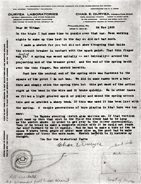
Figure 17.—Letter explaining
the circuit breaker spring and the brass
projection on top of the ignition chamber.
Mr. Mitman was, at the time,
curator of engineering in the U.S. National Museum.
View Larger Image
of Letter Text of Letter
The two pistons were first pinned together into a single unit which was probably ringless, since it is believed the walls of the outer piston were too thin to admit rings. Because the piston no longer struck the exhaust valve, a short rod had to be screwed into the pistonhead; this pushed the valve shut at the completion of the exhaust stroke. The remaining problem, the opening of the exhaust valve, was solved by screwing a device to the side of the cylinder which operated from the sidewise motion of the connecting rod. This device shifted a small spacer between the piston and the striker arm of the exhaust-valve rod, permitting the piston to push open the exhaust valve. On alternating strokes the spacer shifted back out of the cylinder; therefore, no contact was made between piston and striker arm. Sometime in February 1893, the altered engine was successfully started.
At last the transmission could be tested. Will Russell had come upstairs to watch the trial, and according to a statement by him, given April 30, 1926, Frank, standing to the right of the engine and behind the rear axle, reached forward and with the combination tiller-belt-shifter, moved the belt into driving position. The carriage started forward, but as it approached the wall of the building Frank discovered that he could not get the belt back into the neutral position. In desperation, he grasped the rear axle with both hands and was dragged a short distance, attempting to stop the machine, before it struck the wall. He had, however, sufficiently retarded it so that no damage was done.
This short trial demonstrated some of the weaknesses in the friction transmission. Since the speed of the surface of the flywheel, in feet per second, increased in proportion to the distance of the point of contact from the center, the outer edge of the belt attempted to run faster than the inner edge. This conflict of forces not only put an undue load on the motor causing a great loss of power, but it also created a tendency for the belt to work towards the outer edge of the flywheel. Conversely, when the operator desired to return the belt to neutral, it strongly resisted any efforts to slide it toward the center of the wheel, as Frank had learned from the wall-bumping incident. Furthermore, the rubber belt on the friction drum had worn so badly that it had to be replaced at least once during the brief experiments.
At this point, Frank and Markham felt that the carriage was anything but satisfactory. While they were trying to decide what steps should be taken next, Frank added one last improvement to the engine. Fearing that the uncooled cylinder might suffer damage from the excessive heat, he constructed a copper water jacket in two halves, drew them together around the cylinder with clamping rings and soldered the seams. Asbestos packing sealed the end joints where the jacket contacted the cylinder. Thinking back, Frank does not recall that he ever used a water tank with this engine, though he does remember adding water through the upper jacket opening. The engine was run only for a few brief periods following this addition.
Obviously this collection of patchwork could not fulfill their needs for an engine. First, it would be next to impossible to start if the body was placed on the running gear, as the flywheel then would be practically inaccessible. The absence of rings on the piston caused a further loss of power to the already overloaded engine. The flywheel was too light. The absence of any form of governor left the operator with no control over the engine speed. Ignition was poor, partly owing to the hot-tube arrangement, and partly to the excessive distance between the engine and the carburetor. Frank wrote his brother Charles on February 6[17] that in his opinion the mixing chamber was so far from the engine that the gasoline could not be drawn into the cylinder as liquid, and it was too cold to vaporize and go in as gas. Thus he had difficulty in getting the engine started. When it did start the explosions were unmuffled. Less important to him than these defects, however, was the awkward and unsightly wooden engine mount.
Sometime in the early part of March, Frank convinced Markham that he could construct a new and practical engine, using only previously tried mechanical principles.[18] Drawing up new plans for this engine, he took them to Charles Marshall who began work on the patterns for the new engine castings. After the patterns had been delivered to the foundry, Frank left Springfield for a short vacation in Groton, Connecticut, where he visited with his fiancée. On May 17, 1893, several weeks after his return to Springfield, they were married.
The engine castings were undoubtedly received from the foundry prior to Frank Duryea's marriage, and the work of machining and assembling the parts went on through the spring and summer. This engine, still on the carriage in the Museum of History and Technology, is cased with a water jacket, and has bases on top to support the front and rear bearings of the starting crankshaft, and a base with port on the upper right side where the exhaust-valve housing was to be bolted. On the underside are two flanges, forming a base for seating the engine on the axle. A separate combustion chamber is cast and bolted to the head. Inside this chamber are located the igniter parts of Frank's electric ignition system. The fixed part, an insulated electrode, is screwed into the right side of the chamber and is connected with the ignition switch outside, to which one of the ignition wires is attached. A breaker arm inside is pinned to a small shaft extending through the top of the chamber. Around the breaker-arm shaft is a small coil spring (originally a spiral spring, according to the letter of Charles Duryea shown in fig. 17), anchored below to a thin brass finger extending toward the right side of the car, and above to a nut screwed tightly onto the shaft. This nut is also the terminal for the other ignition wire. The action of the spring keeps the breaker arm and the electrode in constant contact until the push rod on the end of the piston strikes the arm and separates the two parts. Breaking contact then produces the ignition spark. Since the mechanism would spark at the end of both the exhaust and compression strokes, the battery current is conserved by a contact strip, on the underside of the larger exhaust-valve gear, by means of which the flow of current is cut off during the greater part of the cycle.
On the left side of the combustion chamber is bolted the housing containing the tiny intake valve. A comparatively weak spring seats this valve in order that the suction created by the piston can easily pull it open. Clamped onto the valve housing is the intake pipe, enclosing the choke and carrying the carburetor on its forward side. The choke consists of two discs which block the pipe, each with four holes at the edges and one in the center. Turning one disc by means of a small handle outside, so that the four outer holes cannot coincide with those in the other disc, decreases the flow of air and causes all air to rush through the center hole, where the tiny carburetor tube passes through. The present carburetor was transferred over from the first engine. When Frank later installed the engine on the carriage he noticed the close proximity of the intake pipe to the open end of the muffler. Believing that the fumes might choke the engine, he attached a long sheet-metal tube to the intake pipe so that fresh air would be drawn in from a point farther forward on the vehicle.
Moving to the right side of the engine brings the exhaust-valve assembly into view. This valve is contained in a casting bolted over the exhaust port in the side of the cylinder, and from the casting a pipe leads to the muffler underneath. The valve is pushed open by a rod connected to a crank which is pinned to the lower end of a shaft carrying an iron gear on top. This gear is in mesh with a fiber gear, keyed to the upper end of the crankshaft, with half the number of teeth. This ratio permits the opening of the exhaust valve on every other revolution.
The crankshaft of the first engine was retained for the new engine, thus giving the two engines the same stroke of 5-⅜ inches, but the bore was increased slightly to 4⅜ inches. With this larger bore and with the engine speed increased to 500 rpm, Frank rated this engine at 4 hp.[19] A heavier flywheel, with a governor resting in the upper recess, was pressed onto the crankshaft. As the operator of the vehicle had no control over the carburetor once he climbed into the seat, this governor was necessary to maintain regular engine speed. Its function was to move a slide on the exhaust-valve unit to prevent the valve from closing. Thus the engine, with the suction broken, could not draw a charge on the next revolution. During the recent restoration of this carriage it was found that while [17] most parts are still intact, nearly all of the governor parts are missing. A description of them must therefore be based on the recollections of Frank Duryea, along with certain evidences seen on the engine.
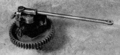
Figure 19.—Under side of exhaust valve mechanism showing electrical contacts that give spark only on every other revolution.
Just on top of the flywheel, and surrounding the crankshaft, rest two rings, 3⅞ inches in diameter. Into the opposing surfaces of these rings are cut a series of small inclined planes, appertinent to each other. On the outer circumference of the upper ring two pins pass through a pair of lugs mounted in the flywheel, causing the ring to rotate with the flywheel, yet permitting vertical movement. Underneath, the other ring is allowed to turn slightly when, by means of two connecting links, the arms of the governor push against them. These two arms, each constructed like a right angle and pivoted at the apex, are arranged directly opposite each other far out in the flywheel recess. As a weight on one angle of the arm presses outward by centrifugal force against a spring, the other angle presses inward against the connecting link mentioned above. The turning of the lower set of inclined planes against the fixed set above raises the upper ring and the fork resting on it. The upward movement of this fork, which is a continuation of an arm pivoted to a bracket midway between the crankshaft and the slide carrying the exhaust valve stop, causes the other end of the arm to drop, pulling the slide down with it. In this manner the closing of the exhaust valve is blocked, preventing the intake of the next charge, and therefore the engine misses one or more explosions until it slows to its normal speed.
A starting shaft is mounted above the engine casting by a cast-iron bracket on either end. The front end of the shaft has a bevel gear which is held by a coil spring behind the front bracket, just out of contact with a bevel gear pressed onto the upper end of the crankshaft. The short rear portion of the shaft is a tube which slides over the main shaft. Fitting the removable handcrank to the squared end of the hollow shaft and turning the crank clockwise, will advance the forward section of shaft through the medium of a pair of inclined collars. With the bevel gears now engaged the engine may be cranked. When ignition begins, the inclined collars slide back down each other's surfaces, the shaft is again shortened, and its bevel gear springs free of the one on the crankshaft.
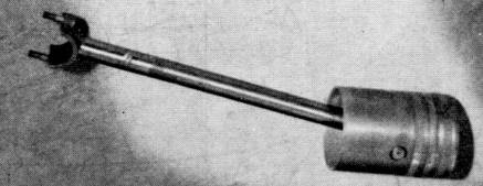
Figure 20.—Piston and connecting rod of second engine. Screw on rod is where oil is poured into connecting rod to lubricate wrist pin and crankshaft.
While Frank worked on his engine, he realized that certain parts of the old running gear would need to be altered or replaced. In view of the heavier and more powerful engine, he felt the old wheels, probably having compressed band hubs, were inadequate. He procured a set of new, heavier wheels[20] with Warner-type, cast-iron reinforced hubs. The angle iron frame, apparently sturdy enough to carry the added weight, was retained, but it was decided to install a heavier rear axle.[21] The front axle assembly was at first allowed to remain unchanged, as was the steering apparatus. A short time later when the engine and friction transmission were bolted in place on the running gear, Frank saw that the rigidity of the framework had an undesirable effect. When the vehicle passed over any unevenness in the shop floor, the framework was distorted and caused the jackshaft bearings to bind tightly enough on the shaft to prevent its being turned by hand. In order to provide the 3-point suspension necessary to eliminate this distortion, Frank attached the forward parts of the framework to an extra wooden spring bar, installing between this bar and the front axle a vertical fifth wheel of the type ordinarily used in a horizontal position in any light carriage.
Frank next calculated that with the faster running engine the speed of the vehicle would be about 15 miles an hour, too much for the heavily loaded wheels. As he intended to make use of the original transmission, he decided to decrease the speed by increasing the size of the friction drum. He accomplished this by sliding a heavy fiber tube over the original drum, bringing its diameter to approximately 14 inches. The original shipper fork carriage was improved by separating the original bearings to a greater distance, and eliminating one of the two bearings on one end. This permitted a smooth and free operation of the small sliding carriage.
In August 1893, possibly as a result of indoor experiments, Frank discovered that the chains running from the small 5-tooth[22] jackshaft sprockets to the large, bronze, wheel sprockets were tight at some times and loose at others. This caused considerable unnecessary noise. The difficulty apparently was the result of the sprockets being cast and not machined. The patternmaker had said he believed he could make the pattern accurately enough so that no machining of the castings would be necessary. Nice castings were produced, but "these sprockets were the reason why an unusual construction was put on the crankshaft [meaning jackshaft]," explained Frank Duryea during an interview at the National Museum on November 9, 1956. Elaborating further, in reply to the queries of E. A. Battison, of the Museum's division of engineering, Duryea told of the problem and the solution when he explained that the sprockets had places where the shrinkage was not even. The hot metal, contracting as it cooled, did not seem to contract uniformly, creating slightly unequal distances between teeth. This resulted in the chain hanging quite loose in some places and in others the tightness prevented adjustment. He contacted Will Russell, foreman of the Russell shop, where the automobile was made, and Russell showed him a device, built by George Warwick, who had made the Warwick bicycle. It was an internal-cut gear, according to Duryea's description, with sprocket teeth on its periphery. With sprockets outside and normal teeth inside, the wheels were about 6 inches in diameter, externally.
These little internal-gear sprockets were hung on double-shrouded pinions secured to each end of the jackshaft. A solid disc or housing fitted against both ends of the pinion to prevent the internal gear from working off sideways. Duryea explained the function of these unique little parts: "as soon as tension came on that ring gear that we talked about, it not only tightened the chain hanging on this sprocket on the upper side, but it tightened it on both sides. [The sprocket] rocks right out: both sides of the chain are tight."
This feature is one rarely encountered elsewhere, and Duryea, later in the interview said, "To tell you the truth, I think I was just a little bit ashamed about the thing, because I had to pull it off. I didn't like the looks of it after I got it on."
Two small tanks, each with a capacity of approximately two gallons, were mounted over the engine in the positions they still occupy, the one on the left for gasoline,[23] the other for water. The small fitting under the gasoline tank has a thumbscrew shutoff and a glass-sight feed tube, leading to the carburetor. The water tank, an inch longer than the gasoline tank, communicates with the water jacket of the engine through two pieces of half-inch pipe, entering the jacket from above and below. The overflow tank, holding just over a gallon, is suspended between the rear axle and the flywheel.
A number of mufflers were constructed for the engine.[24] The first experimental one was built of wood, being a box 6 × 6 × 15 inches with a hole for the exhaust pipe in one end and a series of small holes in the opposite end. Inside, Frank arranged metal plates which were somewhat shorter than the depth of the box. Every other one was attached to the bottom of the box; the intermediate plates were fastened to the top. This contrivance muffled the sound considerably, but, as might be expected, soon began to smoke. There can be little doubt that it was replaced before any of the outdoor trials began. Another type consisted of a cylindrical metal shell, perhaps six inches in diameter and ten or twelve inches long. Here a series of perforated baffle plates were inserted, with alternating solid plates having parts of their external edges cut away. Two bolts running the length of the muffler held on the cast-iron heads in a manner quite similar to the Model-T Ford mufflers of later years. Though partially satisfactory, Frank, in a November 6, 1957, interview, complained that it [19] made a metallic sound. Perhaps this was the muffler he used from September to November 1893.
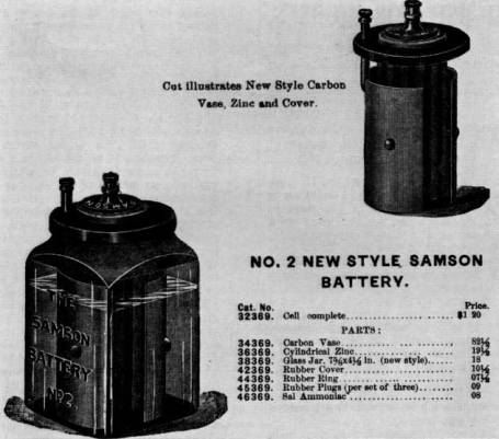
Figure 21.—Illustration of
the no. 2 Samson battery
used
by the Duryeas in their vehicle. (Smithsonian photo 46858.)
On August 28 Frank wrote to Charles saying the carriage was almost ready for the road and that he hoped to take it out for a test on the coming Saturday, "off somewhere so no one will see us…."[25] There is no evidence showing whether the amount of remaining work permitted the proposed trial on September 2. The body was finally replaced on the running gear, at which time it was found necessary to raise the seat cushion several inches by the insertion of a framework made of old crating boards. This allowed sufficient room between the seat and the frame to suspend the batteries and coil. Six no. 2 Samson batteries were contained in this space, three on each side, in rows parallel to the side of the vehicle. The Samson battery consisted of a glass jar containing a solution of ammonia salts and water, with a carbon rod in the center, housing a zinc rod. It is difficult to understand why they used Samson batteries rather than dry cells; perhaps they were concerned with the mounting cost of the machine and were making use of parts already on hand.[26] A coil, possibly from an old gaslight igniter system, accompanied the Samson batteries under the seat. This original coil is now missing.
The iron dash frame, previously recovered and provided with a rain apron to be pulled up over the knees in the event a heavy rain blew in under the carriage top, was bolted back in place. Frank and Mr. Markham gave the carriage a quick painting; later Frank admitted, "the machine never had a good job of painting."[27] Before the motor wagon actually got onto the road, a reporter on the Springfield Evening Union got some statistics on it and an item appeared on September 16, giving the first public notice of the machine.
Toward the latter part of the following week, Frank was ready to give the product of his labors its first road trial. On September 21 the completed carriage was rolled onto the elevator at Russell's shop. Seeing that the running gear was too long for the elevator, they raised the front of the machine, resting the entire weight of 750 pounds on the rear wheels. Once outside the building, they pushed it into an area between the Russell and Stacy buildings. After dark, "so no one will see," Will Bemis, Mr. Markham's son-in-law, brought a horse and they pulled the phaeton out to his barn on Spruce Street.[28] There, on Spruce and Florence Streets the first tests were made. The next day Frank wrote his brother saying, "Have tried it (the carriage) finally and thoroughly and quit trying until some changes are made. Belt transmission very bad.[29] Engine all right." He did admit the engine seemed to be well loaded most of the time. He also had an idea in mind to replace the poor transmission, [21] explaining the plan to Charles: "The three gears[30] on secondary shaft have friction clutches, the two bevel gears on same shaft are controlled by a clutch which frees one and clutches the other at will. This provides a reverse."
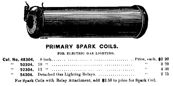
Figure 23.—Type of
spark coil the Duryeas are believed to have used in
their electrical circuit,
as shown in a catalog illustration.
(Smithsonian photo 46858-A.)
The Springfield Evening Union of September 22 carried a notice of the trial. This report, too, commented on the faulty transmission and the plan already in Frank's mind for the new transmission.
… The friction belt allowed of the speed being steadily increased or diminished at the will of the driver and caused no sudden forward motion of the carriage, but while this arrangement has many advantages it uses up the power so that the two-horse power furnished by the motor [somewhat less than the rating Frank gave the engine] was reduced to less than three-fourths horse power on reaching the main shaft. This would not be sufficient to propel the carriage up steep grades but would be sufficient to run the carriage on level road.
The inventors will do away with this belt in favor of a clamp gear and will make the drum wheel smaller. By this means there will be very little power lost in transmission to the shaft and by a patented arrangement the carriage may be started gradually but the speed must be increased by shifting the clamp gear to a succession of gears on the driving wheel of the motor. The speed of the carriage will be fixed permanently according to the size of the gear that the smaller one is shifted to. The test of the machine with the gear arrangement will be made soon.
In October Frank decided on another vacation and went to Chicago to see the Columbian Exposition. Charles had come up from Peoria to see the fair and the two talked over the progress on their motor wagon, and discussed the transmission problem. They gave particular attention to everything relating to engines and motor carriages, and Frank recalls seeing a Daimler quadricycle that impressed him with its performance.[31] Just what decisions the two might have made there are unknown, yet it is likely that they agreed to give the old transmission one more chance to prove itself.
Returning to Springfield, probably in the first week of November, Frank gave the friction drive its final test, this time substituting a leather belt for the rubber one first used.[32] Mr. Markham, though intensely interested in the experiments, apparently was dubious concerning the safety of the carriage. It had no brakes, and fearing failure of the transmission on a downgrade, he was reluctant to ride in the machine. On November 9 he asked Will Bemis to try it for him. The following day the Springfield Morning Union gave a description of the run:
Residents in the vicinity of Florence street flocked to the windows yesterday afternoon astonished to see gliding by in the roadway a common top carriage with no shafts [22] and no horse attached. The vehicle is operated by gasoline and is the invention of Erwin Markham and J. F. Duryea. It has been previously described in The Union and the trial yesterday was simply to ascertain the practical value of a leather friction surface which has been substituted for the rubber one previously used. The vehicle, which was operated by Mr. Bemis, started from the corner of Hancock avenue and Spruce street and went up the avenue, up Hancock street and started down Florence street, working finely, but when about half-way down the latter street it stopped short, refusing to move. Investigation showed that the bearing had been worn smooth by the friction and a little water sprinkled upon it put it in running condition again. The rest of the trip was made down Florence and down Spruce street, to the residence of the inventors. They hope to have the vehicle in good working condition soon.
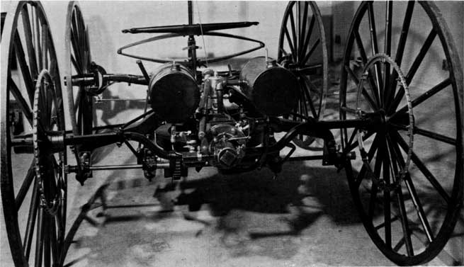
Figure 24.—Running
gear of Duryea vehicle,
showing the
second engine and
other parts as used in January 1894.
The same evening, the late edition ran a brief paragraph stating that "the test was made to determine the value of a leather friction surface for propelling the wagon, that had been substituted in place of the rubber surface, used in the former test." Bemis, according to Frank Duryea's recollection, was not impressed with the performance of the machine, saying "the thing is absolutely useless," and for a time it appeared that further support from Markham would not be forthcoming. Frank, believing eventual success to be near, drew up plans showing his geared transmission, and with these managed to gain Markham's partial support. Money for material and use of the shop was to continue, but Frank was to complete the work on his own time.
Now receiving no salary, Frank worked hurriedly on the transmission throughout late November, December, and the first two weeks of January. First discarding the old friction drum and shaft, and the shipper-fork carriage, he bolted a rawhide bevel gear to the lower surface of the flywheel. This turns two bevel gears, in opposite directions, on a countershaft directly underneath, approximately in the position of the old jackshaft. The right bevel gear is secured to the main countershaft on which two clutches are mounted, one on each side of the crankshaft. On a sleeve turning freely around the countershaft is mounted the reverse bevel gear and clutch. Three free-running clutch drums, the right one carrying the high-speed gear, the two on the left carrying the combination low speed and reverse gear between them, complete the countershaft [23] assembly. The clutch assemblies are of Frank Duryea's design, having internal arms, expanding outward to press leather-faced shoes against the inner surface of the drum, thus securing the drum and its gear to the shaft. Behind this machinery is the jackshaft with its small differential on the right, two laminated rawhide gears[33] meshing with the iron gears of the countershaft, and the internal-gear sprockets hanging on the small pinions at either end. A sliding cam bar, mounted nearly in the position of the former shipper-fork carriage, is operated by the vertical movement of the tiller handle to engage any one of the three clutches. With the tiller depressed, the vehicle is in reverse. Elevating it slightly puts it into low gear, and raising it still higher runs the machine at its highest speed.
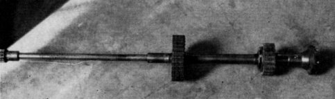
Figure 25.—Half of Jackshaft, showing rawhide gears, double shrouded pinion and half of the Columbia differential.
Figure 27.—Cam bar in
foreground, operated by tiller,
actuates the various clutches of the transmission. The overflow
gasoline tank
with the hand pump can be seen in the rear.
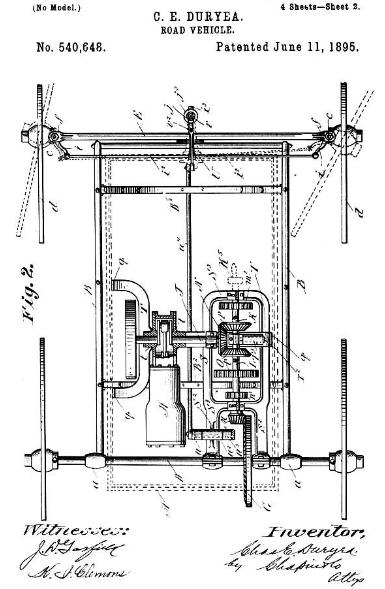
Figure 28.—A drawing and the
first page of the specifications of the
first patent issued to C. E. Duryea.
It can be readily seen that
this drawing was not made after the plan of the first vehicle.
Larger size rotated image.
As the work moved nearer completion Frank realized that the final tests would have to be conducted on roads made icy by falling snows. He had considerable doubt whether the narrow iron tires would have enough traction to move the phaeton. Soon he devised an expedient for this situation, communicating to Charles on December 22 that he was "having Jack Swaine [a local blacksmith] make a couple of clutch rims so we can get over this snow and ice…. Our detachable rims referred to will be of ⅛ iron 1¾ wide and drawn together at one point by two screws, one on either side of felloe. It will be studded with calks in two rows."[34]
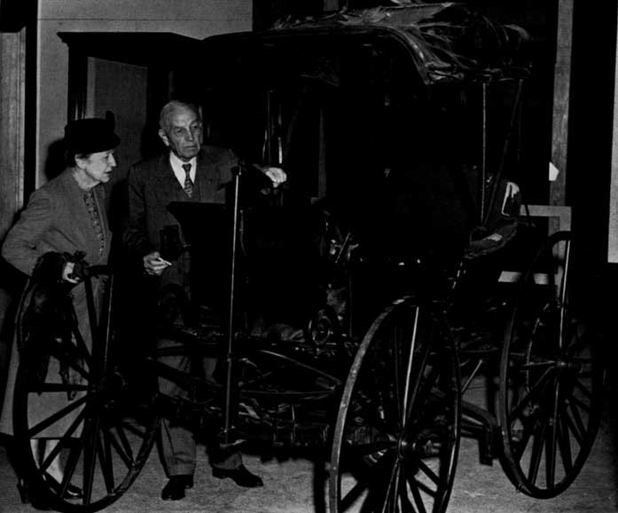
Figure 29.—Mr. and Mrs.
Frank Duryea examining vehicle in
the Smithsonian
Institution before restoration.
January 18, 1894, was a day of triumph for Frank Duryea. Writing Charles about his success the next day he said, "Took out carriage again last night and gave it another test about 9 o'clock." The only difficulty he mentioned was a slight irregularity in the engine, caused by the tiny leather pad in the exhaust-valve mechanism falling out.[35] Speaking of this trip, Frank recalled in 1956:
When I got this car ready to run one night, I took it out and I had a young fellow with me; I thought I might need him to help push in case the car didn't work…. We ran from the area of the shop where it was built down on Taylor Street. We started out and ran up Worthington Street hill,[36] on top of what you might call "the Bluff" in Springfield. Then we drove along over level roads from there to the home of Mr. Markham who lived with his son-in-law, Will Bemis, and there we refilled this tank with water. [At this point he was asked if it was pretty well emptied by then.] Yes, I said in my account of it that when we got up there the water was boiling furiously. Well, no doubt it was. We refilled it and then we turned it back and drove down along the Central Street hill and along Maple, crossed into State Street, dropped down to Dwight, went west along Dwight to the vicinity where we had a shed that we could put the car in for the night. During that trip we had run, I think, just about six miles, maybe a little bit more. That was the first trip with this vehicle. It was the first trip of anything more than a few hundred yards that the car had ever made.
Now Frank could give demonstration rides with the motor carriage, hoping to encourage more investors to back future work. Cautious Mr. Markham finally got his ride, though Frank had to assure him that the engine of the brakeless vehicle would hold them back on any hill they would descend. The carriage on which he had spent so many hours was to see little use after that. Its total mileage is probably less than a hundred miles. Little additional work is known to have been performed on the carriage after January 1894; there is, however, a letter[37] Frank sent his brother on January 19 which tells of contemplated muffler improvements. Another message was dispatched to Charles on March 22, mentioning the good performance of the phaeton on Harrison Avenue hill.[38] This was possibly the last run of the machine, for no further references have been discovered.
Frank spent the months of February and March in preparing drawings, some of which accompanied their first patent application,[39] while others were to be used in the construction of an improved, 2-cylinder carriage. Work on the new machine started in April. The old phaeton, in the absence of used-car lots, was put into storage in the Bemis barn.[40] Later, on the formation of the Duryea Motor Wagon Company in 1895, it was removed to the barn of D. A. Reed, treasurer of the company.[41] There it remained until 1920, when it was obtained by Inglis M. Uppercu and presented to the U.S. National Museum.
[1] S. H. Oliver, Automobiles and Motorcycles in the U.S. National Museum (U.S. National Museum Bulletin 213, Washington: Smithsonian Institution, 1957), p. 24.
[2] G. R. Doyle, The World's Automobiles (London: Temple Press Limited, 1959), p. 67.
[3] Recorded interview with Frank Duryea in the U.S. National Museum, November 9, 1956.
[4] Charles Duryea's statement to Springfield Daily Republican, April 14, 1937.
[5] Frank Duryea, America's First Automobile (Springfield, Mass.: Donald Macaulay, 1942), p. 4.
[6] Letter from Charles Duryea to Alfred Reeves, March 25, 1920; copy in Museum files.
[7] History notes dictated by Charles E. Duryea in the office of David Beecroft, editor of Automobile Trade Journal, on January 10, 1925. Copy in Museum files. Hereinafter, these notes are referred to as "history."
[8] Frank Duryea in statement made to the Senate Committee on Public Administration of Massachusetts, February 9, 1952.
[9] Duryea, op. cit. (footnote 5), p. 6.
[10] Copy of contract in Museum files.
[11] Affidavit of William Rattman, March 19, 1943, states that the Russell ledgers give that date.
[12] Recorded interview with Frank Duryea in U.S. National Museum, November 6, 1957.
[13] Letter from Frank Duryea to David Beecroft, November 15, 1924; copy in Museum files.
[14] Letter from Charles Duryea to C. W. Mitman, March 21, 1922; copy in Museum files.
[15] See "history" (footnote 7), p. 6.
[16] Duryea, op. cit. (footnote 5), p. 8.
[17] Copy of letter in Museum files.
[18] Duryea, op. cit. (footnote 5), p. 12.
[19] Letter from Frank Duryea to Charles Duryea, November 3, 1893, states that the engine could be run at 700 as well as 500 rpm. Copy in Museum files.
[20] Duryea, op. cit. (footnote 5), p. 14. Also in letter from Charles Duryea to C. W. Mitman, January 11, 1922; copy in Museum files.
[21] Letter from Charles Duryea to C. W. Mitman, January 11, 1922; also letter from Frank Duryea to David Beecroft, November 15, 1924. Copies in Museum files.
[22] Letter from Charles Duryea to F. A. Taylor, December 5, 1936, says he "thought" they had five teeth. Copy in Museum files.
[23] Frank later wrote his brother, January 1894, that he fixed the tank so it would not draw sediment from the bottom. Copy of letter in Museum files.
[24] The number of mufflers Frank Duryea constructed is not known. He wrote Charles, December 22, 1893, that he "will try a new muffler also."
[25] Selden Patent Evidence, vol. 9, p. 110.
[26] See "history" (footnote 7), p. 2. Charles wrote, "Some parts of these [referring to the batteries], like the jars, I had on hand for six or eight years, and did not need to buy."
[29] Frank stated in this letter that the friction drum originally had two belts, forward and reverse, but since they tended to foul each other, he removed the reverse belt and left the other to serve for both directions. How the shipper fork might have handled two belts is not understood.
[30] As actually constructed there are only two gears on the secondary shaft. He obviously discovered that one gear secured to two clutches would serve for both forward and reverse. Space was also limited.
[31] Recorded interview with Frank Duryea in U.S. National Museum, November 9, 1956.
[32] Letter from Frank Duryea to Charles Duryea, November 8, 1893. Copy in Museum files.
[33] Frank Duryea, in a recorded interview in the U.S. National Museum on November 6, 1957, said that he believed these had been purchased from Rochester Rawhide Company.
[34] Letter from Frank Duryea to Charles Duryea, December 22, 1893. Also letter from Frank Duryea to David Beecroft, November 15, 1924. Copies in Museum files.
[35] Telling of the first use of the car in later days, Frank Duryea mentions the many noises and vibrations that accompanied the trip: the vibrating tiller, the tinny sounding muffler, the clattering chains. He later reported speeds of 3 mph in low gear and 8 mph in high gear.
[36] Letter from Frank Duryea to Charles Duryea, Jan. 19, 1894, says they went up hill via Summer and Armor Streets, then out Walnut to Bemis' at Central Street School.
[37] The letter read: "I have designed a new muffler and we will proceed to make it before long, in a day or two. Instead of one shell ⅛-inch thick I shall put a shell 11⁄16-inch thick inside another of equal thickness, but about 1 inch greater diameter i.e., one chamber within another so as to cause sound to turn corners to get out. Still another shell will be added if it prove insufficient, making it turn about again—taking care in each case to give ample room for expansion—outer one need not be more than 1⁄32 inch possibly. Will let two threaded rods with nuts hold heads on both or on three cases, if the 3d be essential."
[38] This letter gives further proof that the car never had a brake. Frank said the car came back down the hill with no brake, but that the engine held the vehicle back.
[39] Duryea, op. cit. (footnote 5), p. 37.
[40] It is possible that a few parts were removed at this time to be used on the two-cylinder car. The muffler may have been one of these, and even more likely, the governor parts. Charles Duryea wrote to C. W. Mitman December 27, 1921, stating that his younger brother Otho and a Henry Wells had put in a battery and gasoline in 1897 and started the engine. Because the chains were not on the car they could not attempt to operate it; but the engine ran too fast, and finally something broke, probably the engine frame, found to be broken during the recent restoration. Charles thought the engine ran too fast because some of the governor parts were already missing.
[41] Recorded interview with Frank Duryea in the U.S. National Museum, November 9, 1956. On the formation of the Duryea Motor Wagon Company, Mr. Markham was rewarded for his part of the venture. He had invested nearly $3000 in the work, and sold out his rights in the company for approximately a $2000 profit.
Text of Letter (page 14)
24 Nov 1920
Dear Mr Mitman
On the train I had some time to puzzle over that car. Been working nights to make up time lost in the day so did not hav much.
I made a sketch for you but did not show the spring that holds the circuit breaker in contact with the spark point. That thin finger was part of it. A spring was wound spirally--not helically--around the projecting end of the breaker pivot and the end of the spring hookt over the thin finger. See sketch herwith.
Just how the central end of the spring wire was fastened to the square of the pivot I do not kno. We did in some cases bore a hole thru and simply stick the spring thru but this put most of the action right at the bend in the wire and it broke quickly. So in other cases we fitted a light grooved spool or pulley and wound the spring around this and so avoided a sharp bend. If this was used it has been lost with the spring. A couple generations of boys playing in that barn was too many.
The Haynes steering sketch also worries me. If that vertical post came up thru that slot in the floor the crank had to be long as the sketch shows in order to get over to the driver conveniently. Then if he tried to make a complete circle with it he could not reach far enuf forward to do it easily. And he had to make a turn or two be cause H shows bevel gears of about same size so the post had to make same number of turns the worm made. Sketch herewith to illustrate my thought.
Text of Article (page 20)
NO USE FOR HORSES.
Springfield Mechanics Devise a New Mode of Travel.
Ingenious Wagon Now Being Made in This City for Which the Makers Claim Great Things.
A new motor carriage, which, if the preliminary tests prove successful as is expected, will revolutionize the mode of travel on highways, and do away with the horse as a means of transportation, is being made in this city. It is quite probable that within a short time one may be able to see an ordinary carriage in almost every respect, running along the streets or climbing country hills without visible means of propulsion. The carriage is being built by J. F. Duryea, the designer and B. F. Markham, who have been at work on it for over a year. The vehicle was designed by C. E. Duryea, a bicycle manufacturer of Peoria, Ill., and he communicated his scheme to his brother, who is a practical machanic in this city.
The propelling power is furnished by a two-horse power gasoline motor situated near the rear axle and which, when started, runs continuously to the end of the trip, notwithstanding the number of times the carriage may be stopped. The speed of the motor is uniform, being about 500 revolutions a minute, and is so arranged that it gives a multiplied power for climbing hills and the lower the rate of speed the greater power is furnished by the motor. The slowest that the carriage can be driven is three miles an hour and the speed can be increased to fourteen or fifteen miles an hour. The power is transferred from the driving wheel of the motor, which runs horizontally with the main shaft by an endless friction belt running on a drum wheel. The belt is controlled by a lever within easy reach of the driver and is shifted along the drum wheel to increase or decrease the speed. The driving wheel is about twenty inches in diameter, having in its center a depression to which the belt is shifted to stop the carriage.
The carriage can be reversed by shifting the belt from the end of the drum, which gives the forward motion to the opposite side beyond the depression in the driving wheel. The power which has been transferred to the driving shaft from the motor is in turn transferred to the two rear wheels of the carriage by a combination gear and sprockets. An endless chain connects the sprockets on the carriage wheels to the sprocket wheels on the driving shaft. All of the motive power is located under the body of an ordinary phaeton, the hight of which is not increased by the machinery. The motor is started by a crank which is easily applied to a shaft in the rear of the carriage and the gasoline is ignited in the cylinder by electricity. An automatic device stops the flow of gasoline into the cylinder when the motor ceases running. The gasoline is carried in tanks, which hold about two gallons, and which will run the carriage for about eight hours. The wagon is guided by a bicycle bar, and the speed is also controlled by this bar.
The method employed in this is as follows: To start the carriage press the lever down; to reverse it throw the lever up and to guide the wagon turn the lever either to the right or left. The front axle instead of turning horizontally plays up and down, in order that the machinery may be on a level with the rear wheels, while the front wheels are set on the axle by a pivotal joint and are connected with the guiding lever by bars with ball bearings. The carriage complete weighs about 220 pounds, and the essential features are already covered by patents while others are pending.
It is estimated that the carriages can be sold for about $400, and a stock company will probably be formed to manufacture them.
Text of Patent Letter (page 24)
United States Patent Office.
CHARLES E. DURYEA, OF PEORIA, ILLINOIS.
ROAD-VEHICLE.
SPECIFICATION forming part of Letters Patent No. 540,648, dated June 11, 1895.
Application filed April 30, 1894. Serial No. 509,466. (No model.)
To all whom it may concern:
Be it known that I, Charles E. Duryea, a citizen of the United States, residing at Peoria, in the county of Peoria and State of Illinois, have invented new and useful Improvements in Road-Vehicles, of which the following is a specification.
The object of this invention is to produce a road vehicle which shall be self-propelled, not unduly heavy, simple and easy of control and comparatively inexpensive, together with such minor objects as will become hereinafter apparent.
The invention more particularly relates to the construction and arrangement of parts for constituting the driving gearing and to the means for controlling the action thereof; to an improved manner of mounting the front, or steering, wheels upon the front axle, and of mounting the said axle relative to the running gear frame, and to the means for effecting the steering; to the appliances for the support of the motor and driving mechanism in an advantageous and efficient manner, and, generally, to improved and simplified details of construction throughout the vehicle, all as will hereinafter be rendered more apparent, and the invention consists in constructions and combinations of parts, all substantially as will hereinafter fully appear and be set forth in the claims.
Reference is to be had to the accompanying drawings, in which—
Figure 1 is a sectional elevation from front to rear of the improved road-vehicle. Fig. 2 is a plan view of the running and driving gear, the vehicle-body being understood as removed. Fig. 3 is a front elevation of the vehicle. Fig. 4 is a perspective view of the support and suspension devices for the driving mechanism. Fig. 5 is a vertical sectional view, longitudinally, through the shiftable driving-gear, the controlling devices employed in conjunction with this mechanism being seen in side elevation. Figs. 6 and 7 show the above-mentioned controlling devices as in operative relations differing the one from the other and also from that of Fig. 5.
Similar letters of reference indicate corresponding parts in all of the views.
The parts will now be described in detail with reference to said drawings, and A represents the body which is spring supported on the frame, B, of the running gear. This frame, as shown, is rectangular, and has the body-supporting springs, B2, similar to those found in common carriages. This frame has, affixed thereto, at its rear ends, sleeves, a, a, which loosely embrace the rear wheel axle, D, which is the driven axle of the vehicle. The axle, E, for the front wheels is centrally secured to the running gear frame, B, by the horizontal king-bolt, b, whereby such axle may have a swinging movement relative to the frame in a vertical plane, but it has no swinging movement horizontally, the wheels being swivel-mounted on the ends of this axle peculiarly, as will shortly hereinafter be set forth.
The body, as shown, is in the form of an inverted box, the motor, H, and driving gear being accommodated within the downwardly opening inclosure constituted thereby, and the body also has the upwardly open box-like forward extension, or pit, A2, for the accommodation of the feet of the rider, the rider's seat being constituted by the top forward portion of the box body. Some other suitable design of body may, of course, be used in lieu of this one shown.
The front wheels, d, d, are hung to the front axle, E, so that the center of each wheel base is in a line coincident with the axis of the pivotal connection which is provided between the journals for the wheels and the axle, which arrangement practically destroys any tendency to deflection from the course that might otherwise arise from striking an obstacle, and so renders the steering easier. In order to effect this the axle is formed with yoked ends, the yoke members, f, f, being above and below the longitudinal line of the axle. The short journal, g, shown for each wheel, has at its inner end an upwardly and downwardly extended arm, h, which is return-bent to be loosely embraced by the axle yoke, f, f. The cone pointed screws, c, passed through the yoke members, f, and into sockets therefor in the arms, h, of the journals, g, constitute the means for the swivel connection between said parts. The lock-nuts, c2, manifestly, are employed with utility in this connection.
It will be perceived that inasmuch as in the arrangement shown, the pivotal connections
Paper 34 - Transcriber's Note
Letters printed upside down have been corrected. The transcriptions retain all typographical and gramatical errors.
Contributions from
The Museum of History and Technology:
Paper 35
The Borghesi Astronomical Clock
In the Museum of History and Technology
Silvio A. Bedini

Figure 1.—The dial plate of the Borghesi clock, showing the horary and astronomical indications which are automatically presented.
Silvio A. Bedini
The Borghesi Astronomical Clock
In the Museum of History and Technology
The history of the 18th-century Borghesi astronomical clock is described here from contemporary source material. The evolution of its design by Father Francesco Borghesi and the building of the complex mechanism devised by the clockmaker, Bartolomeo Antonio Bertolla, is a story of the vision of one man turned into reality by another. The result of their collaboration is the unique, astronomical timepiece now in the Museum of History and Technology.
The Author: Silvio A. Bedini is curator of mechanical and civil engineering in the Smithsonian Institution's Museum of History and Technology.
“… All this work I had performed eagerly, so that, while in my room, I might contemplate leisurely, both during the day and in the night, the true face of the heavens and of the seas unobscured by clouds, even though I had no astronomical equipment.” [1]
With these words, Father Francesco Borghesi (1723-1802) of Mechel described the reasons which inspired him to invent a unique astronomical clock which is now in the horological collection of the Museum of History and Technology.
This complicated mechanism, which performs a multitude of functions, was designed by Father Francesco Borghesi, a secular priest in Venezia Tridentina. It was constructed in 1764 under his direction by a provincial clockmaker named Bartolomeo Antonio Bertolla (1702-1789) of Mocenigo di Rumo. It was the second of two complicated astronomical clocks which Father Borghesi designed and which Bertolla constructed. According to contemporary sources, this clock was presented to the Empress Maria Theresa of Austria soon after its completion.
Its history is rather hazy, except for the fact that in 1780 this second Borghesi timepiece was still in the Imperial Palace in Vienna. The clock was again noted in 1927 when it was sold at a public auction in New York. [2] Subsequently, it was acquired for the Smithsonian Institution.
Development of Astronomical Clocks
The history of the great theoretical and mechanical achievement which the Borghesi clock represents has been most adequately covered elsewhere.[3] Consideration of the development of equation and astronomical clocks is required here only for the purpose of relating the Borghesi timepiece with the other significant developments in this branch of horology.
The invention of the anchor escapement in about 1670, and the consequent greater accuracy in time-telling, led to increased preoccupation with precision. Daily differences in time as recorded by sundials and clocks became more noticeable. Finally, in the second half of the 17th century, some attempt was made to construct mechanical clocks combined with sundials as well as astronomical clocks.
With the improvement of precision time-telling, it became necessary to reconcile the actual difference between true and mean time. Although a great variety of time-equation tables were produced, there was a considerable margin for error in their use. This led to the construction of mechanical clocks in which the equation of time was automatically accomplished. A few were produced late in the 17th and early 18th century at considerable cost and, consequently, with little popularity. Equation sundials were also developed which were elaborately ingenious, but they were not completely practical. Inevitably, they were supplanted by the mechanical equation clock.
Probably the first documented mention of an equation clock is in the diary of John Evelyn who recorded that in 1666 he visited the Royal Society where he witnessed a curious clock, which showed the equation of time, being presented by a certain Mercator. More data on the subject appeared in the first two decades of the 18th century, when Henry Sully, Joseph Williamson, Daniel Quare, and Thomas Tompion—who were among the foremost English clockmakers of all time—produced elaborate examples of these timepieces. Another significant maker was Dowe Williamson, who became Court Clockmaker to Emperor Charles VI of Austria. In London, Joseph Williamson produced some of the finest astronomical timepieces of this type that have been known. The interest in the subject next shifted to France where many fine examples were produced during the first half of the 18th century.
Just after the middle of the 18th century, the subject of astronomical clocks suddenly became a major horological preoccupation in another region, namely, Austria, where the work in this field was apparently done exclusively by members of the clergy. The earliest was Father Philipp Matthäus Hahn (1739-1790) of Württemberg. [4] Father Hahn considered the equation of time as only one part of a plan to represent astronomical occurrences by means of clockwork. In addition to planetaria and similar mechanisms, Father Hahn produced two extraordinary astronomical, tall-case clocks, both of which survive in public museums.

Figure 2.—Portrait of Father Francesco Borghesi, inventor and designer of the astronomical clock in the Museum of History and Technology.
Another of the clerical clockmakers was Father Aurelianus à San Daniele (1728-1782), an Augustine monk in the monastery of the Imperial Court at Vienna.[5] His four complicated astronomical clocks, which exist in museums at present, are comparable to those produced by Father Hahn. The third cleric was Brother David à San Cajetano (1736-1796) in the same Augustine order to which Father Aurelianus belonged. He achieved note as the author of various publications, including Neue Rädergebäude [6] [New Construction of Wheels] relating to planet-wheels, or gear-trains containing epicyclic elements. He constructed a clock based on an elaborate astronomical design which was substantially different from the others. The fourth of the ecclesiasts who designed astronomical clocks in this period was Father Klein of Prague, who produced a complicated astronomical timepiece in about 1738.
The fact that such important and outstanding examples of astronomical clocks were produced exclusively by ecclesiasts in Austria during the second half of the 18th century is especially significant. It is particularly so when a fifth cleric is added to the group, also an Austrian subject although Italian by heritage, in the person of Father Francesco Borghesi.
Although only Father Borghesi's second astronomical clock is now known, it is apparent that this example in the Museum of History and Technology represents an experiment in astronomical time-telling comparable to any of the timepieces produced by Father Hahn, Father Aurelianus, Brother David à San Cajetano or Father Klein.
This combination of five clerical clockmakers who lived in the same region during the same period of time is sufficiently unusual. However, the fact that each of them apparently worked without association with any of the others leads to the conjecture that a common factor must have led them to their individual preoccupation with astronomical horology. What the link may have been is not apparent from the surviving records of the lives and works of these clerics. Certainly it was not an interest in astronomy or clockmaking per se, because other than the astronomical clocks, none of these horological inventors—with the possible exception of Father Hahn—worked in any other aspect of the fields of astronomy or horology. However, after a comprehensive study of Father Borghesi's writings, there is little doubt of the religious basis of his own inspiration.
Father Borghesi's story takes place in the picturesque mountainous region of what was then known as Venezia Tridentina (since 1947, Trentino-Alto Adige) in northern Italy, along the Tyrolean border of Austria. Because of its strategic position as the passage between Innsbruck and Verona, the possession of the Tridentina was contested again and again in the European wars, but during Father Borghesi's lifetime, the Tridentina was under Austrian domination.

Figure 3.—Panorama of the village of Mechel in the valley of the Non, birthplace of Father Borghesi.
Deep within this mountainous district is the romantic valley of the Non, or Anáuni, with its great forests and ancient castles. Most maps do not mark it, and the tourist guides ignore it. [7] One of the chief communities is Cles, with its historic Renaissance buildings. The major city of the region is Trent on the Adige River, with its surviving Roman relics and Romanesque and Renaissance architecture.
The little villages scattered throughout the valley of the Non played no part in history, but such names as Mechel and Mocenigo di Rumo reflect the interchange of sovereignty. It was in the little village of Mechel that Francesco Borghesi was born in 1723. [8] Local records are meager and inadequate, and many of the details of Borghesi's life must be assumed. Inasmuch as the village was in a rural, agricultural district, Borghesi may have come from a family of farmers, vintners, or village tradesmen. Borghesi sought an education by entering the priesthood and was ordained a secular priest in Salzburg. He was first assigned as curate to the village parish of Rumo in the valley of the Non, a short distance from his birthplace. [9] Later, he was transferred to his native Mechel. He was inherently a man of simple tastes and of great piety. He tended to the needs of his mountain villagers and attended the births, weddings and deaths of his parishioners. It was during his assignment in this tiny community that Father Borghesi met and became friendly with the clockmaker, Bartolomeo Antonio Bertolla of nearby Mocenigo di Rumo.
Bartolomeo Antonio Bertolla was born in Mocenigo di Rumo, a short distance from Mechel, in 1702. [10] Nothing is known of his boyhood, other than the fact that he was mechanically inclined. At the age of 17 he was apprenticed to become a clockmaker with the master, Johann Georg Butzjäger of Neulengbach, a small village on the edge of the great Vienna woods. [11] This region was then part of the domain of the Archduke of Austria, of which Sankt Pölten was the capital.
Figure 4.—Portrait of Bartolomeo Antonio Bertolla, clockmaker, of Mocenigo di Rumo. The canvas in oils is owned by descendants. In the upper left-hand corner is an inscription, now hardly legible, indicating that the portrait may have been painted after Bertolla's death on January 15, 1789. Translated, it states: "Bartolomeo Antonio Bertola [sic] Celebrated Mechanician and Inventor of various Instruments. Repairer of the clocks of Venice, Verona, Trent, and other localities. Maker of the Work which combines the Copernican and Ptolemaic Systems devised by Father Francesco Borghesi of Mechel, Laureate Mathematician, and humbly offered to Her Imperial Majesty Maria Theresa. Died in piety in his home at Rumo on 15 January 1789 at the age of 86." (Courtesy of Sig. Luigi Pippa of Milan.)

Figure 5.—The village of Mocenigo di Rumo in the valley of the Non. Arrow points to Bertolla's home and workshop at far left.

Figure 6.—Certificate of apprenticeship awarded to Bartolomeo Antonio Bertolla upon completion of his 3-year apprenticeship at Neulengbach, dated December 27, 1722.
Bertolla began his apprenticeship with Butzjäger under the auspices of the Corporation of Blacksmiths of Sankt Pölten in 1719. His training was supervised by two master locksmiths, Johann Christian Winz and Peter Wisshofer, who were members of the Corporation, and were assigned to serve as patrons for the apprentice. It was their obligation to make certain that he received good care and adequate instruction from his master. While he worked in Butzjäger's shop, Bertolla lived with the master's family in their home.
Bertolla's 3 years at Neulengbach passed quickly as he sought to absorb all that his master could teach him. Butzjäger was considered to be a good craftsman in the region, yet today there is not even a mention of his name in the lists of clockmakers. He specialized in the production and repair of "great clocks" which included tall-case, domestic timepieces, and tower clocks. Butzjäger treated his apprentice well, and in return Bertolla rewarded him by being diligent and honest. His subsequent work is sufficient indication that he developed into an extremely skilled craftsman, and he became the equal of any clockmaker of his time.
The 3 years of apprenticeship were completed and [37] on December 27, 1722, Bertolla received a certificate from the Corporation of Blacksmiths which assured whomever it might concern of Bertolla's skill, diligence and honesty, and permitted him to open his own shop as a clockmaker under the auspices of the Corporation. This document, which has been preserved by Bertolla's descendants, is an interesting record of the organization of the trade guilds in the 18th century, and, for that reason, has been translated from the original German:
We, the Superiors and other masters of the honorable corporation of municipal blacksmiths, armorers, and of smiths, in the Imperial City of St. Pölten in Austria by the river Enns, Declare by these Presents put in force by this document to anyone who waits to hear…. That the honorable and able Bartolomeo Antonio Bertolla of Rumo in Lentzberg, the Tyrol, on the 27th day of the month of December of the year 1719 was consigned as apprentice for three years, in the presence of two sponsoring masters for the purpose, the honorable Johann Christian Winz and Peter Wisshofer, both of them master locksmiths representing the entire honorable Corporation and others of open shop—to the honorable Johann Georg Butzjäger, incorporated with us, citizen and master clockmaker for large clocks in the merchant-village of Neulengbach in Wienerwald, as his master of the art, would have therefore perfectly and rightfully worked and learned, and
that afterwards, on the day and year noted at the bottom, he will be newly declared free and independent before us, representative of an entire and honorable Corporation and with open shop, of his above-mentioned master and of the two sponsoring masters mentioned,
and since he eagerly requested a truthful certificate of apprenticeship for his honest service as an apprentice and for his good behavior, and we having great pleasure as well as the duty of favoring the truth and well knowing that the aforesaid Bartolomeo Antonio Bertolla has learned honestly the art of clockmaking for great clocks from his aforesaid master, and that he has always behaved with honesty, obedience, faithfulness and diligence both towards his master and towards us to our complete satisfaction and, therefore, we cannot in any manner refuse his request, rather we wish to grant it with a clear conscience.
We Therefore Address to Everyone and to anyone in whatever state and rank, but particularly to those interested in our branch of this art, our respectful and courteous entreaty and request to consider Bartolomeo Antonio Bertolla well recommended for his honest apprenticeship and his good behavior, and to desire to favor him in every way, in such a manner that will assure our gratitude whenever an occasion presents itself.
For this purpose, we issue, as we have declared we wish to issue to you, Bartolomeo Antonio Bertolla, this certificate of apprenticeship, attaching to it the seal of our Corporation.
Executed in the city of St. Pölten on 27 December 1722. [12]
His apprenticeship over, Bertolla returned to his native region where he soon established a reputation for himself as one of the most skillful clockmakers in the Tridentina and produced timepieces of fine quality in some quantity. No records have survived concerning his personal life, but it is believed that he married probably soon after his return. He had no children of his own. To expand his business, he eventually took into his shop two nephews, the sons of a brother and a sister, as apprentices.
Bertolla's work brought him a sufficient number of clients, and he produced elaborate clocks for his more wealthy patrons.
In 1752, it is recorded that he repaired the great clock in the campanile of the Church of the Assumption of the Virgin Mary in Cles, the regional capital of the valley of the Non. The clock dated probably from the 16th century, and it seems likely that Bertolla replaced the original two-wheel train with a three-wheel movement, and that he added the present anchor escapement. [13]
It is not possible to determine when Father Borghesi first made Bertolla's acquaintance, but it may be assumed that they had become friends in the late 1750's.
After he had come to know Bertolla, Father Borghesi apparently spent many hours in the clockmaker's shop. He was fascinated by mechanics in any form, and the complications of clockwork particularly intrigued him. Bertolla was patient with the young priest, explaining the tools he had and their uses, the clocks he produced or repaired, and the principles which were involved. Father Borghesi listened willingly and as his understanding of timepieces grew, his curiosity increased.
In spite of himself, the priest could not be satisfied with the ordinary aspects of his friend's work and wanted to learn more. From a casual pastime, the study of time became an obsession with him. There was but one recourse: he went back to studying once again. This time it was not theology, however, but the sciences. Every moment he could spare went into the perusal of books on mathematics, astronomy, and [38] associated subjects. He progressed rapidly, driven by his overpowering interest and aided by his quick intellect.
Little by little, Borghesi managed to acquire the basic texts that explained this new world to him, probably borrowing them from old seminary friends. As each new book came into his hands, he devoured it in his desire to master its contents. He discussed each new principle or precept that he learned with Bertolla. Together, they attempted to apply his new learning to the calculations necessary for a timepiece which would demonstrate the astronomical theories in visual form. Borghesi taught himself slowly, step by step, and the result was a profound understanding of astronomical science. He conceived the project of constructing a great astronomical clock which he felt could be accomplished by combining Bertolla's mechanical skills with his own recent mastery of astronomy and mathematics.
It is not difficult to visualize the two men, the priest and the clockmaker, as they sat together night after night working out their plans. Father Borghesi would painstakingly outline the astronomical principles he wished to have the clock exhibit and the mathematical principles which would be involved to operate them. Bertolla concentrated on them and tried to transcribe the principles into functional mechanical terms, visualizing each operation in terms of wheels and gears. Little by little the two men coordinated the numerous elements and welded them into an operating entity. They adjourned either to the stark simplicity of the rectory or, probably more often, to Bertolla's little home workshop, the priest standing over his friend while the latter worked at his bench in the dark paneled interior illuminated only by the several lamps on the work benches.
This first clock which the two men combined to create is a monument to the great scientific knowledge of the self-taught priest and the technical ability of the clockmaker—a unity combining astronomical science, mechanics, and artistry. The story of the project is told in a little book, Novissima Ac Perpetua Astronomica…, which Borghesi later published. Explaining the incentive which inspired him, and the premises from which he began his work, he wrote:
From the foundation of astronomical science long ago, innumerable [and] repeated observations of both ancient and modern astronomers, emerged at last from their hiding places. Made light of by the jests of so many outstanding intellects, they have so successfully brought to light the paths of the stars and their motions, which are more complicated to us than the Gordian knots. Now it is possible for even an amateur in astronomy, sufficiently instructed, to predict for any given time not only the mean position of the planets, but also their true longitude and latitude, and even the true time of their conjunctions, and their ecliptic oppositions, with all the attendant circumstances. Yet, until now, no hypothesis has been devised which would force an automaton to show to us, before our very eyes, the eclipses of the planets in their true and certain times.
For though there have been men seeking with all their might to bind by laws their artificial heavens, by I know not how many and how great calculations, and to systematize the complexities of the rotations of celestial bodies; nevertheless, all of them, as if by common agreement, considered themselves to have made great contributions to mechanico-theoretical astronomy. However, they have only attained, even though closely, the mean locations of the secondary mobiles, and those by a certain rather crude calculation. Some attained by more, some by less, but all by some degree of wandering from the truth, either worn out by the intricacies of the motions, or deceived and deceiving by the errors of their calculations. This fact those well know, who, setting about to collect information of this kind, even those publicized not long ago, with true astronomical calculation, have been bored to death while digging out by the most elementary and superficial arithmetical torture, the worst of fallacies spontaneously erupting from thence.
It would seem that true calculations alone can be desired in mechanico-astronomics. Long study had not only convinced me that an automaton was within the realm of possibility, but that there were many mechanical systems by which it could be achieved. I girded myself for a new project and developed it theoretically from the ground up, but under such unhappy auspices that not only did all hope fail that anyone would ever appear who might have seemed willing to set his hand to the work, but that the new discovery itself was scoffed at by many as altogether a nightmarish delirium of an unbridled imagination.
The first months of the project must have seemed like an inspired dream to the two men, and then must have followed a period of hopeless depression. Bertolla undoubtedly felt many times that the clock was an aspiration far beyond their combined abilities and means, but the priest would not be thwarted in his ambition and refused to abandon the project. He felt that it was a work that they were destined to produce. [39] Many times, he wrote, he chided and begged and shamed his erstwhile partner into resuming the project where it had been last abandoned. Little by little, the first clock began to take form. As each new difficulty was encountered, the two men would go back over the notes and sketches to trace the problem to its source. Often a new part of the mechanism would nullify another which had thus far operated successfully, and a complete rearrangement would be required.
Figure 7.—Title Page of Father Borghesi's first book. The translation in its entirety is: "The Most Recent, Perpetual, Astronomical Calendar Clock: Theoretical—Practical: by means of which besides the hours, the minutes and seconds; the current year, the month; the day of the month and the day of the week; the dominical letter, epact, and thence, the day of all the feastdays, both fixed and movable; the solar cycle; the golden number; the Roman indiction; the dominant planet of any year and its sign; the phases of the moon and its mean age: and all the motions of the sun and the moon as to longitude, latitude, eccentricity, etc., are immediately seen, so accurately that [not only] the true new full moons and the true quadrature, etc., of the sun and moon appear, but also, all solar and lunar eclipses—both visible and invisible; as in heaven, so on the clock, they are conspicuously celebrated in their true times, and those of the past and those of the future, with their circumstances of time and duration, magnitude, etc., can be quickly determined. All this was devised and brought to light by the author, Francesco Borghesi of Anáuni, a secular priest of Trent, A.A.L.L. & Doctor of Philosophy. (Trent: From the printshop of Giovanni Battista Monauni, With Permission of Superiors.)" (Title page reproduced by permission of the Biblioteca della Citta di Trento.)
Again and again, Bertolla threw up his hands in despair and begged Father Borghesi to abandon the enterprise. He protested that he was not capable of producing such a complicated mechanism; he had neither the tools nor the skill. The priest wished to produce a clock such as the world had never seen before, such as the greatest scientists and clockmakers of all time had never been able to make. But Bertolla felt that he was only a provincial craftsman who could not hope to surpass them all with only his simple tools and training.
In his book on the first clock, Novissima Ac Perpetua Astronomica…, Father Borghesi wrote that when he had finally come within a few weeks of the embryo stage in the development of his clock, he was faced with the problem of bolstering the sagging enthusiasm of Bertolla. The clockmaker's original enthusiasm had shown promise of great results, but as the days passed and the problems of the multiplex and generally unfamiliar apparatus to be forged for the workings of the automaton became more complex, his ardor decreased. Finally, Bertolla became so discouraged by the scoffers and frustrated by the fact that the work was insufficiently organized that Father Borghesi [40] wrote that "it almost became a harder task for me to bolster up by daily opportunity and importunity the failing patience of the artisan, frightened away from the work already begun, than it was for me to extract from the inner recesses of mathematics and astronomy, without light and without a guide, the whole fabric of the machine itself!"
In spite of Bertolla's protests, Father Borghesi prevailed, reviving his friend's interest once more until the two were deep in the project again. Months passed as they worked together on the mechanism and it seemed as if they lived for no other purpose. Inevitably, Bertolla's health began to suffer, undermined as it was by the constant nervous tension, and he eventually became ill from mental strain. He was forced to spend some time in bed, and for many weeks the subject of the clock was not discussed. Bertolla's other work, by which he made his living, suffered and it was several months before he was able to return to his little shop.
One year passed into another and the work progressed slowly. The first clock, which easily should have been finished in less than a year, was not completed until after three full years had passed. However, when the priest and the clockmaker put the finishing touches to their great clock, the result surpassed the greatest possible expectations, for it was truly a masterpiece. Not only did it illustrate the ecliptic phenomena of the moon, the sun and earth occurring in their proper time, as well as many other things, but it showed these operations as they succeeded in proper order, taking place through the centuries.
With mutual feelings of great pride, the two friends surveyed the result of their three years of endeavor. Bertolla realized that he had reached a point of maximum achievement in his work. He probably felt that now he could relax again, that his sleep would no longer be troubled by confused nightmares of wheels and gears that did not mesh together. Time was to prove otherwise.
PUBLISHED DESCRIPTION OF THE FIRST CLOCK
Father Borghesi soon came to the conclusion that it would be desirable to have a written description to explain the mechanism of the clock and its many indicators. He thereupon wrote out the story of how the clock was made, the reasons for embarking on the enterprise, the difficulties he had encountered, and the success which had crowned his and Bertolla's mutual labors. Finally, he described the operation of the clock's mechanism and the functions of its array of indicators.
The little book was written in Latin and only a few copies were printed, presumably at the priest's own expense, on a handpress by Giovanni Battista Monauni, printer to the Bishop in Trent. The little volume was stated by contemporary writers to have been published in 1763, although no date appears on the title page. The title translated is, in part, The Most Recent, Perpetual Astronomical Calendar Clock, Theoretical—Practical…. The work begins with an introduction for the reader in which Father Borghesi stated that:
… the little work, which, as far as I was concerned could easily have been finished in a year, was only completed after about three years. Fortunately, however, it was so far beyond the expectations of most, that not only am I able to foretell with certainty all the lunar ecliptic phenomena and the solar, or rather terrestrial, phenomena, carefully worked out in their true periods, among many other matters exhibited by the machine; but also, within a few hours, I can exhibit by altogether tangible evidence to the skeptics and the doubting those very same phenomena, occurring within the space of many years, or even centuries, and succeeding one another in proper order, with their many attendant circumstances. I was not much concerned about the other eclipses, such as those of Mercury, Venus, and the other stars wandering through the zodiac, or about the other solar eclipses from the transit of Mercury or Venus, since they are altogether undiscernible to the naked eye, and very few compilers of ephemerides wish them to be noted, probably for the same reason.
Do not, however, expect, star-loving reader, that here anything at all that you may wish can be drawn forth as from its source, for to demand this would be almost the same as to seek to drain as from a cup all the vast knowledge of the many arithmetical sciences from the narrow confines of one book. You will understand how impossible that is when, through prolonged labor, you have grown somewhat more mature in this kind of learning.
Wherefore, rather fully, and out of consideration for you, I have decided, setting aside these prolixities, with completely synoptic brevity and with all possible clarity to expound for you simply the proportion of the movements, the description of the machine, and its usage. As a result, when you have progressed a little in theoretical mechanics, you will not only be able to reduce all these things to their astronomical principles, but you may find the way more smoothly laid out for you even for perfecting the machine itself. And, thus, you may be [41] more effectively encouraged to a successful conclusion. Let it be so now for you through the following 10 chapters!
After these rather hopeful assurances, Father Borghesi proceeded to provide a detailed description of the clock dial and functions in the 10 short chapters which he had promised, under a separate section entitled "Synopsis Totius Operis Mechanici," which is translated in its entirety in the appendix.
As Father Borghesi prepared his little volume about his first clock, and described its unusual features and outlined its functions, which were primarily to place in evidence the celestial constellations, it occurred to him that it would now be easier after the experience he had acquired with his first timepiece, to construct another clock, which would present the motions of the two astronomical systems, the Ptolemaic and the Copernican. In this first book, he promised the reader that he would undertake the second project. It is fortunate that Father Borghesi undertook this project for the second clock is the only example of his work that is known to exist today. Extensive research has not shown what happened to the first clock, although several sources state that both timepieces were presented to Empress Maria Theresa sometime between 1764 and 1780.

Figure 8.—The Borghesi clock in the Museum of History and Technology, constructed in 1764 by Bartolomeo Antonio Bertolla of Mocenigo di Rumo from the designs of Father Francesco Borghesi of Rumo and Mechel.
Father Borghesi lost no time in initiating the project of the second clock. The first and most important step was to inform Bertolla and enlist his assistance. Bertolla was adamant: he had had enough of complicated astronomical movements. He was delighted by the prospect of returning to his former simple life, producing simple, domestic, elementary movements for his country clients. Father Borghesi begged and cajoled. The second clock would be a much simpler one to construct, he persisted. After all, they had gained invaluable experience from the production of the first clock. Furthermore, he had already completed its design.
Bertolla apparently wavered in his resolve and, unwillingly and against his better judgment, he allowed the priest's inducements to prevail. Once again, the two friends yielded their leisure hours to a study of the priest's books and drawings as Father Borghesi enthusiastically elaborated his design for the timepiece, and Bertolla attempted to transcribe astronomical indications into terms of wheel counts. The second clock was, as Borghesi had promised, much easier of execution. Within a year, it was completed and functioned with complete success.
This is the clock now in the Museum of History and Technology. It is housed in a tall case of dark-red mahogany veneered on oak, with restrained carving featuring ribands and foliate motifs. Gilt-brass decorations flank the face of the hood, which is surmounted by three gilt-brass finials in the form of orbs. A wide door in the waist may be opened to attend the weights. The case is 7 feet 8 inches high, 201/2 inches wide at the waist, and 14 inches in depth.
The dial is of gilt brass, measuring 21 inches high and 15 inches in width, with a number of supplementary silvered dials visible through its openings. Instead of hands, the dial utilizes three concentric rings moving around a central disc, the indications of which are read at two bisecting gilt lines inscribed in the glass face. Twelve separate functions are performed by the chapter ring assembly alone, and there are 14 openings on the dial. It is estimated that the clock performs 30 separate functions, including striking and chiming. Of the multiple chapter rings, the outermost is 11/8 inches wide, the center ring is 3/8 inch wide, and the innermost ring measures 11/4 inches in width.
THE DIAL-PLATE ENGRAVINGS
The gilt dial is incised throughout with figures and inscriptions in engraving of the very finest quality, as is evidenced in the illustrations. The frontispiece is surmounted at its center by the crowned double eagle of the House of Hapsburg, indicating the identity of the sovereign in whose reign it was made, Emperor Francis I or the Empress Maria Theresa of Austria. Below the eagle at either side are flying cherubs supporting ribands with inscriptions. Centered at the bottom of the frontispiece immediately above the chapter rings is the moving silvered orb representing the sun. Surrounding it is a tableau of the Holy Trinity, with the Virgin Mary being crowned by Christ holding a cross at the left and God with a sword in hand at the right, and a dove representing the Holy Spirit hovering over the Virgin's head. Father S. X. Winters, S.J., considers it reminiscent of the triptych "The Coronation of the Virgin" by Fra Lippo Lippi.
|
Figure 10.—Diagram
of the dial plate.
|
Figure 11.—Dial
plate of the Borghesi clock.
|
In the upper spandrels of the dial are two more cherubs bearing ribands with inscriptions. In the lower left corner is a magnificent engraving of Atlas upholding the globe of the world, inscribed with the zodiac, over his head. The lower right corner features the figures of two noblemen apparently examining and discussing an orb upon a table, the significance of which is not clear.
THE INSCRIPTIONS
Beginning with the uppermost part of the frontispiece, there are nine inscriptions in Latin on the dial plate. The topmost is Franciscvs I sit plan. Dominator aeternvs. The phrase has reference to Francis I, who was Emperor of the Holy Roman Empire, from 1745-1765, and husband of Empress Maria Theresa of Austria. The phrase may be translated as "May Francis I be the eternal ruler by favor of the planets" or more simply "Long Live Francis I, Emperor." [14] Although the dial plate of the Borghesi clock is inscribed with his name, the records indicate that the clock was presented to Maria Theresa. Francis I may have already died before the presentation was made.
From the left to right over the tableau of the Holy Trinity is the phrase "Lavs sacrosanctae Triadi Vni Deo, et Deiparae" (Praise [be] to the most Holy Trinity, to the one God, and to the Mother of God).
Within the upper left and right spandrels is inscribed:
Isthaec, Signum grande apparvit in Coelo * sancta Dei genitrix amicta sole * Illibato pede Lvnae et serpentis nigra premens Cornva * bis senis pvlcherrime Coronata syderibvs * Tempe indesinenter clavsa, scatvrigo signata * Cedrvs in Libano, Cypresvs in Monte Sion * Mater pvrae Dilectionis sanctaeqve spei * Chara patris aeterni proles, Verbi Mater, sponsaqve procedentis *, gratiae et gloriae circvmdata varietate.
This inscription is a eulogy to the Virgin Mary assembled from the texts of Holy Scripture. In addition, each lemma, contained within asterisks, carries out the chronogram 1764, the year the clock was completed. Each lemma is translated and identified from the Douay-Rheims version of the Bible:
This woman: a great sign appeared in Heaven (Apocalypse 12:1) * The Holy Mother of God clothed with the sun (Apocalypse 12:1) * And with unharmed foot crushing the black horns of the moon (Apocalypse 12:1) and the serpent (Genesis 3:15) * Most beautifully crowned with twice-six (Apocalypse 12:1) * A garden [Tempe [15]] enclosed, sealed with a fountain [spring of water] (Song of Songs 4:12) * Like a cedar in Lebanon, and a cypress tree on Mount Zion; (Ecclesiasticus 24:17) * Mother of pure love and of holy hope: Beloved daughter of the Eternal Father, Mother of the Word, Spouse of the Holy Spirit: (Ecclesiasticus 24:24) * Surrounded with a diversity of grace and glory (Psalms 44:10).
At the lower left corner below the figure of Atlas upholding the world is the phrase, Assidvo proni donant di cvncta labori. (The favorable gods willingly grant all things to the assiduous laborer.) The same phrase is quoted by Father Borghesi in the text of his second volume. The last inscription appears at the lower right corner under the figures of the two noblemen, Diligit avdaces trepidos fortvna repellet. (Fortune favors the daring and rejects the timid.) The last two inscriptions are in dactylic hexameter. They appear to be original compositions inasmuch as no classical prototypes have been identified.

Figure 16.—Detail of frontispiece of the Borghesi clock, showing the apertures for calendar indicators and the details of the engraving.
CENTER DIAL INSCRIPTIONS
In addition to the inscriptions previously noted on the outer dial plate, there are three major inscriptions in the central dial. The outermost states Circulus horarius Soli, Lunae, Fixis, Nodis, Aestuique marino communis (the hour circle, common to the sun, the moon, the fixed stars, the nodes and to the sea tide). This inscription is divided into four parts by the insertion of four divisions for the day into canonical hours: [Horae] Nocturnae (night hours); Matutinae (morning hours); Diurnae (daytime hours) and Vespertinae (evening hours).
The next section of the central dial is inscribed Intumescite—Detumescite (rise and fall of the tides) repeated at intervals of approximately every six hours. Within the next section is the following inscription, inscribed continuously around the ring:
Lege fluunt, refluunt, dormitant hac maris undae: Ad Phoebi et Phoebes concordia iussa moventur Aequora; discordi iussu suspensa quiescunt.
Translated, this is:
By this law the sea waves ebb and flow and lie dormant: When Phoebus and Diana agree in their commands, the waters are moved; when they disagree, the waters lie silent. [16]
Within the central boss of the dial plate, the name of the maker is inscribed:
Bvrghesio Doctore, et Bertolla Limatore Annaniensibvs*
Translated, this is:
[By] Doctor Borghesi and Bertolla, mechanician citizens of Anáuni.
INDICATORS IN THE FRONTISPIECE
There are 12 windows in the frontispiece, through each of which appears an indication relating to time. Beginning at the top of the frontispiece of the dial, the first opening occurs on the breast of the imperial eagle. This indicates the dominating planet, represented by its symbol, and its house.
The opening in the eagle's left claw, labeled "Lit. Dom." is the dominical letter. The first seven days in the month of January are each assigned one of the letters a through g in order of appearance. The letter which coincides with the first Sunday within this period is called the dominical letter, and it serves for the following year. In leap year, two letters are required, one to February 29th and the letter next proceeding for the remainder of the year. This letter is used in connection with establishing the date of Easter Sunday. The date of Easter regulates the dates of the other movable feasts.
The eagle's right claw is labeled "Cyc. EpEC" and represents the epact, or the age of the moon on January 1st. It serves to find the moon's age by indicating the number of days to be added to each lunar year in order to complete a solar year. Twelve lunar months are nearly 11 days short of the solar year, so that the new moons in one year fall 11 days earlier than they did the preceding year. However, 30 days are deducted as an intercalary month since the moon has made a revolution in that time, and the remainder, 3, would be the epact.
Below the imperial eagle two winged cherubs support a riband with three indictions of the Julian period. This period of 7980 years is the product derived from multiplying together the sums of 28, which represents the cycle of the sun; 19, representing the cycle of the moon; and 15, which represents the Roman indiction. The Julian period is reckoned to have begun from 4713 B.C. so that the period will be completed in A.D. 3267. The first of the three openings is marked "Ind. Rom." or "Roman indiction," which was an edict by the Emperor Constantine in A.D. 312, providing for the assessment of a property tax at the beginning of each 15-year cycle. It continues to be used in ecclesiastical contracts. The second opening, which occurs immediately below the eagle, is marked "Cyc. Sol." (cycle of the sun). This cycle takes a period of 28 years, after which the days of the week once again fall upon the same days of the month as they did during the first year of the former cycle. There is no relationship with the course of the sun itself, but was invented for the purpose of determining the dominical letter which designates the days of the month on which the Sundays occur during each year of the cycle. Since cycles of the sun date from 9 years before the Christian era, it is necessary to add the digit 9 to the digits of the current year and then divide the result by 28. The quotient is the number of cycles which has passed, and the remainder will be the year of the cycle answering to the current year. The third opening on the riband is labeled "Num. Aur." (golden number). [48] Meton, an astronomer of Athens, discovered in 432 B.C. that after a period of 19 years the new and the full moons returned on the same days of the month as they had before, and this is called the cycle of the moon. The Greeks were so impressed with this calculation that they had it inscribed in letters of gold upon stone, hence the golden number. The First Council of Nicaea in A.D. 325 determined that Meton's cycle was to be used to regulate the movable feasts of the Church.
Immediately above the chapter rings is an opening through which the orb of the sun is visible.
THE CHAPTER-RING ASSEMBLY
In a separate chapter in his second volume, entitled "Descriptio Authomatis Summa totius Operis Mechanici" (Description of the Automaton—Summary of the Complete Mechanism), Father Borghesi provided a description of the functions of the various indicators, prefixing it with the short poem shown in figure 18. He then continues:
In the middle of the frontispiece, as at the center of the universe, the terraqueous globe of the week revolves, with a daily motion turning from right to left, bringing with it from the round window the coming day and at the circumference the circle of hours common to the sun, to the moon, to the fixed stars, to the head and tail of the dragon, and to the raging sea.
The second circle revolves the synodic-periodic measure of the raging sea, the days of the median lunar-synodic age, the signs and individual degrees of the signs of the distance of the moon from the middle of the sun within the time of 29 terrestrial revolutions, hours 12.44.3.13. This circle revolves likewise from right to left around the center of the earth. In this second circle, another little orb revolves, bringing with it the epicycle of the moon, in which the little circle of the moon (whose illuminated middle always faces towards the sun), running from left to right through the signs of the anomaly; within 13 revolutions of the earth, hours 18.39.16. It descends from apogee to perigee and in just as many others it returns from perigee to apogee, to be carried down thus to true, back and front from the longitude and distance from the sun and from the middle of the earth.
The third circle (on which I have tried to indicate astronomically-geometrically in their places, the degrees of lunar latitude both in the south and in the north, and some fixed stars, those, namely, which can be separated by us from the moon which goes between) from left to right turns around the center of the earth, stretching out the head and tail of the dragon, on the inside above the second circle for noting and measuring the sun (but I should rather say the earth), and the eclipses of the moon, within 346 revolutions of the earth, hours 14.52.23.
The fourth circle, in which the heaven of the fixed stars, reduced to the correct ascent of our times, the signs of the zodiac and the individual degrees of the signs, the months of the year and the single days of the month can be seen, likewise makes its journey around the earth from left to right in 365 terrestrial revolutions, hours 5.48.56.; that is, within a median astronomical year. Above this annual orb, the sun, in its small epicycle, gliding through the 12 signs of the anomaly, within the space of 182 terrestrial revolutions, hours 15.6.58., from left to right, falls from apogee to perigee; and, within the same time, rises from perigee to apogee, and brings with it, the index, namely its central radius, inhering to the axis of the equatorial orb and cutting the four greatest circles from the center.
When the sun has been moved around, Iris shows from six windows the era, that is, the current year. Two winged youths take their place next to Iris, carrying the Julian period: namely, the Roman indiction, the cycle of the sun and the golden number, on a leaf of paper held between them. The imperial eagle stands out on top (as if added to the frontispiece) carrying on its breast the dominating planet and in its talons the ecclesiastical calends (that is, the dominical letter and the epact).
ATTACHMENTS FOR ADJUSTMENT
Two attachments, in the form of small superimposed dials are situated at the base of the dial plate, at either side and immediately below the fourth chapter ring. In his second volume, Father Borghesi stated that they "are not moved from inside the clock, but the one at the right [inscribed concitat and retardat] serves for loosening [accelerating] and tightening [retarding] time; that is, the reins of the perpendicular."
In other words, the purpose of this attachment is for adjusting the pendulum to make the clock operate fast or slow. The second attachment, which appears at the left, and which is inscribed "Claudit" (close) and "Aperit" (open) serves the purpose of "… preparing the mechanism in a moment, as swiftly as you wish, for sustaining the astronomical experiments of which you will hear later; when these things have been done, it restores the mechanism to its natural motion at the same speed."
This adjustment relates to the final section of Father Borghesi's second book, entitled "Chronologo-Astronomicus Usus Authomatis" (Chronological-Astronomical Use of the Automaton), which is translated from the Latin in its entirety:
With one glance at this automaton, you can quickly answer these questions: What hour the sun shows, the moon, any fixed star, the head and tail of the dragon. Is the sea swelling with periodic heat [at high tide?] or is it deflated [low tide], or quiescent? How many days is it from mean new moon or full moon? By how many signs and degrees is the moon distant from the sun, and from its nodes? What sign of the zodiac does the sun occupy, the moon, the head and tail of the dragon? Is the sun or the moon, in apogee or perigee, ascending or descending? What is the apparent speed of the sun and of the moon? What is the apparent magnitude of the solar and lunar diameter, and of the horizontal parallax of the umbra and penumbra of the earth? What is the latitude of the moon? Is it north or south? Does the moon hide [occult eclipse] any of the fixed stars from the earth dwellers, and which of these does it obscure? Is there a true new or full moon? Is the sun in eclipse anywhere on earth? What is the magnitude, and the duration of this eclipse, with respect to the whole earth? Can it be seen in the north or in the south? Is the moon in eclipse? Total or partial? Of what magnitude, etc.? What limb of the moon is obscured? How many years have passed from a given epoch? Is this year a leap year, or a common year—first, second, or third after leap year? What is the current month of the year, and what day of the month and of the week? Which of the planets is dominant? What days of the year do the various feasts fall on, and the movable feasts during the ecclesiastical year? And many other similar questions, which I pass over here for the sake of brevity.
Besides, this device can be so arranged for any time whatsoever, past or future, and for the longitude of any region, and can be so manipulated by hand, that within the space of a very short time there can be provided in their proper order, the various orbits of the luminous bodies, their alternating eclipses, as many as have taken place through the course of many years, or even from the beginning of the world; or those that will be seen as long as the world itself shall last, with all their attendant circumstances (year, month, day, duration, magnitude, etc.). All these can be seen with great satisfaction of curiosity and of learning, and hence with great pleasure to the soul. In the meanwhile, the little bells continually play, at their proper, respective times. So that, all exaggeration aside, a thousand years pass, in the sight of this clock, as one day!
I am aware of your complaints, O star-loving reader—that my description is too meager and too succinct. Lay the blame for this on those cares, hateful both to me and to you, more pressing, which forbid me and deprive you of a methodical explanation of the work.
THE CLOCK MOVEMENT
Father Borghesi specified that the entire mechanism was equal in weight to a seventh part of a Centenarii Germanici, a Germanic hundredweight. This is probably the Austrian centner which is equivalent to 123.4615 pounds. Therefore, the clock mechanism weighs approximately 17.6 pounds.
The clock operated for a hundred days and more at a single winding, according to Father Borghesi, and by means of a pendulum with a leaden bob weighing 60 Viennese pounds, attached at a height of 5 feet. Father Borghesi stated the weight of the pendulum to be 60 librarum Viennensium, but the Viennese libra does not appear among the weights of the Austrian Empire. However, using the average libra, an ancient Roman unit of weight equal to 0.7221 pound, it may be assumed that the driving weight should be approximately 45 pounds.
Father Borghesi, however, does not venture to provide any description whatsoever of the movement of his second clock in his book. He gave the following reasons:
But beyond this, I entirely omit [a description of] the further apparatus of the very many wheels, etc., inside the clock which carry on its functions, lest I become too verbose for some persons. To explain more thoroughly the internal labyrinth of the entire mechanism, from which the movement of the circles or heavens, etc., are derived, would seem to entangle in too many complicated perplexities…. Therefore, that I might not delay longer, and perhaps to no purpose, I have thought it better to leave the whole work to the proportionate calculus of the arithmeticians and the technical skill of mechanics. If they have any desire to construct a similar mechanism, they will follow the aforesaid motions of the heavens, etc., not only by one means alone but by many, more swiftly through thoughtful study than by any amount of instruction.
For whoever is well versed in the theory of calculus and sets to work at any given project, will discover any desired motion by a thousand and more ways, by one or another gearing of wheels; which an industrious mechanic will carry out in actuality and without too much difficulty. Nor is there any reason for anyone to be discouraged, so long as he is not disgusted by the amount of labor for there is nothing truer than the old saying "The favorable gods grant everything to the assiduous laborer."
Nay, further, even this little work itself can be improved on and surpassed by new inventions. Otherwise that other old adage, almost as old as the world, would prove false, "What you have found already done, you can easily repeat, nor is it difficult to add to what has already been invented." Relying on this principle, I have already conceived some new things to be added to the present little work.

Figure 17.—Movement of Borghesi clock viewed from the right side, with details of chiming mechanism.
THE BELLS
There is a discrepancy between Father Borghesi's written description in his second book of the number of bells and those which currently exist in the clock. At the present time, there are two sets of bells attached to the upper part of the movement. While Father Borghesi indicated that there were two sets of bells in the clock, he described the first set by stating that:
… there are three bells inside the clock: The largest, when struck by a little hammer at each mean new moon, signifies the new moon. The smallest indicates in the same way the full moon at the time of the mean full moon, by automatic sound. When on the equatorial earth, the sun appears anywhere in eclipse, two bells (the largest and the medium) sounding together automatically, announce that eclipse at the time of the mean new moon. (I think it is evident that eclipses of the sun occur at new moons and eclipses of the moon at full moon.)
When the moon is eclipsed, the smallest and the medium bells, simultaneously and automatically, announce the event to the ear at the time of the mean full moon. Besides, at the proper time and automatically, the largest of these bells announces the current solar hour and the smallest bell strikes the quarter hours.
In the clock today, the first set consists of a smaller bell fixed within a larger one. It is presumably these bells that indicate the eclipses and also strike the hours and quarter hours. A pull cord attached to the striking mechanism repeats the current hour and quarter hours at will. The second set consists of nine meshed bells struck with individual hammers operated by means of a pinned cylinder as in a music box. On the hour, the chimes play one of two melodies, which may be changed at will. While not identified, these appear to be Tyrolean folk melodies. The largest of this set of bells is dissimilar to the other chimes, and may be the third bell described by Father Borghesi to signify the new moon.
CHRONOGRAMS
One of the most curious aspects of the second clock produced by Father Borghesi and Bertolla, as well as of the second published volume, is the presence of chronograms which occur repeatedly on the clock dial and throughout the Novissimum Theorico-Practicum Astronomicum Authoma from the title page to the end of the book. Interestingly enough, Father Borghesi did not utilize this device even once in his first little book.

Figure 18.—A chronogram in the text of Father Borghesi's second volume, indicating the year 1764. The poem is translated as: "In the Mount of 'Anáuni,' the inscrutable heavens are led, You learn from these all the labors of the sun and the moon. Here you are shown and hear the conjunction of the moon: And a bell brings to the ears by its sound, all eclipses."
Webster defines a chronogram as an inscription, sentence, or phrase in which certain letters express a date or epoch. The method used by Father Borghesi for forming chronograms was a simple one. He used combinations of uppercase and lowercase letters in two sizes in the inscriptions on the clock dial and in his writings. At first this curious combination in the inscriptions on the dial plate was a source of considerable speculation. The extremely fine quality of the engraving and artistry was such that these combinations could only be deliberate in nature and not the accidental whims or accidents of the engraver. Accordingly, they must be chronographic in intention. Such proved to be the case.
Borghesi used the larger size of uppercase letters to form the chronogram, and each chronogram was complete within a phrase or line. He accomplished this by using for this purpose those letters of the alphabet which form the Roman numerals. The uppercase letters found within words are copied off in the order in which they appear in the inscription or phrase. These are then converted into their numerical equivalents, and totaled. Taking the [52] uppermost inscription on the clock dial as the first example:
FranCIsCVs I sIt pLan.
DoMInator aeternVs
The letters which are intended to form the chronogram are:
C I C
V I I L D M I V
100 1 100 5 1 1 50 500 1000 1 5
These figures added together total 1764.
The second inscription on the clock dial which forms a chronogram is
LaVs saCrosanCtae TrIaDI VnI Deo, et DeIparae
L V C C I D I V I D D I
50 5 100 100 1 500 1 5 1 500 500 1 = 1764.
The third inscription required a little more planning, because of its greater length. Accordingly, Father Borghesi divided it into nine parts, each of which is separated from the other by means of asterisks. Each of the nine parts of the inscription formed a chronogram which, in every instance, totals to the date 1764, the year in which the second clock was completed. The same procedure was followed with the inscriptions in the lower left and the lower right corners of the dial as well as with the maker's inscription within the central disk. This inscription is
BVrghesIo DoCtore, et BertoLLa LIMatore AnnanIensIbVs
V I D C L L L I M I I V
5 1 500 100 50 50 50 1 1000 1 1 5 = 1764.
The inscriptions within the chapter ring are not utilized for chronograms, however. It is apparent that Father Borghesi was required to make a most careful selection of the texts for his inscriptions in order that none of the phrases included any additional letters which formed Roman numerals than would total to the date he desired to indicate, namely, 1764. Where it was necessary, he employed an asterisk to separate parts of texts so that each would produce the same total. Any letter that did not form a Roman numeral, even if capitalized or used in a larger size, did not interfere with the formation of the chronograms.
In spite of his ingenuity in designing a text which would include only such of the letters representing the Roman numerals which would provide the chronograms for 1764, Father Borghesi experienced some difficulties, particularly in place names. He accordingly changed them in order to avoid the inclusion of letters that would have disturbed his totals. Examples are MEGGL instead of MECHL, which had an extra C, and RVNNO instead of RVMO, which had an extra M.
PUBLISHED DESCRIPTION OF THE SECOND CLOCK
When the clock had been completed and proved to work successfully, Borghesi once more reduced a description of the clock and its function to published form in a second little volume published by Monauni. This second work was also in Latin, the title of which is translated as The Most Recent Theoretical-Practical Astronomical Clock According to the Equally Most Recent System of the World. As with his first book, Father Borghesi devoted a number of pages to a preface addressed to the reader, which is translated from the Latin:
This mechanical instrument was far from being ready for public notice. A great deal of time and work remained to produce a machine of this new system from the very foundations; then, by a most accurate calculation to bring the motions of many wheels up-to-date with the most recent astronomical observations; and, finally, to fashion it with the craftsman's file, often enough with a weary hand. All this work I had performed eagerly, so that, while in my room, I might contemplate leisurely, both day and night, the true face of the heavens and the seas unobscured by clouds, even though I had no astronomical equipment. But, then I remembered that, in my book on the first clock, I had promised a description of a new (at least, as far as is known to me) clock. Moreover, friends with astronomical interest, who took part in the oft-repeated astronomical experiments concerning this clock, persuaded me that the intellectual world would enjoy having a greater knowledge and a description of this work. However, it was not only the promises nor the desires of many which moved me to write this work, but I also thought it was necessary to set forth, before the description of the clock, an exposition of the astronomical system according to which this clock was constructed, so that the complete work would be evident to all. I was concerned about making this timepiece more acceptable and more understandable to those people who are far distant and unable to see it, so that this present exposition would obtain credulity among all. I could find no better method than to set forth for the reader the theory of the universe which I figured out after many sleepless nights.
In testing this theory day after day, it not only appeared to be complete, and true, but each day it appeared more conformable to reality; it captured my mind in such a way that I finally adhered to it. I desired, while I lived, to erect this work as a monument to the theory. To do this, I digressed a bit from the true-to-life pattern to the mechanical order so that I could transfer all the movements of the heavens, etc. (which I enjoyed thinking about more), to the plane surface of the clock's face. In this way, the ecliptical spectacles of the stars, etc., would appear at their proper times clearly before the eyes of the viewer. I could also avoid many difficulties which otherwise, perhaps, even the hands of the most skillful craftsmen could never solve.
Figure 20.—Title page of Father Borghesi's second book. The translation in its entirety is: "The Most Recent Theoretical-Practical Astronomical Clock According to the Equally Most Recent System of the World. Author: Francesco Borghesi of Mechel of Anáuni * Priest of Trent, Doctor of Philosophy * (The System of the Clock) Ingeniously connected to new theoretical laws published 1764: and the constructor, Bartholomeo Antonio Bertolla of Rumo, similarly from Anáuni * who skillfully produced this work * in this same current year of Our Lord * which is the year 5713 [sic] since God created this earth. (Trent: From the Printshop of Giovanni Battista Monauni, With Permission of the Superiors.)" (Title page reproduced by courtesy of the Biblioteca della Citta di Trento.)
You ought to know, therefore, that as a result of my nightly meditations, I have rejected, after much consideration, all the explanations of the universe thus far published. All other theories of the make-up of the universe, however admirable, and however many there are, turn the sun and earth around in an ecliptic in an annual movement. Thus, Philolaus was the first to move the earth from the center of the universe and move it through the void; afterwards, Aristarchus of Samos and then Copernicus moved the earth with the moon. The Egyptians, as well as Pythagoras, Ptolemy, Tycho, Riciolus, Longomontanus, etc., thought that the sun moved through the degrees of the ecliptic each year. But I attributed this movement to neither earth nor sun for the movement of both is only apparent. I did not vainly surmise the annual equilibrium in all astronomical observations to be from the daily movement of the same axis moved at the poles of the heavens. Nor, in like manner, is there a better way to satisfy physical experiments. To you, then, most cultured reader: If you, perhaps, can make any use or draw pleasure from this most faithful description of my new theory and the mechanical instrument, refer it first to God on High from whom is everything that is best, and then to those avidly awaiting this little work. Lastly, if you find any statement less fitting; in your humanity, do not disdain to excuse it.
Borghesian Theory of the Universe
In Father Borghesi's second volume, there is a separate chapter entitled "An Exposition of the Latest Theory of the Universe." This follows the introduction to the reader, and in it Father Borghesi proposed:
That you might rightly conceive my new system of the world and mechanically, as it were, construct it, imagine for yourself, beneath that most happy seat of the Blessed and above all other heavens, a kind of spherical convexity, everywhere equidistant from the center of the earth, and endowed with absolutely no motion.
On the inside, at two points diametrically opposite each other, this convexity has two most sturdy poles (to speak mechanically), projecting towards the center (which you call the poles of the heavens), and the largest immobile semicircle, in some manner is drawn from the center of one pole to the center of the other. This semicircle in the middle, namely at a point equidistant from each pole, is thought to be secured by some sign, for example, by that "o," for arranging more perceptibly the seat of the sun (as will be shown later). This much must be conceived first.
You must understand that imposed on these poles is the first mobile [Primum Mobile], everywhere convex, and divided, into 12 equal parts [Dodecatemoria], by the 6 greatest circles, intersecting each other at the centers of the poles. Then it is divided by another equally great circle, everywhere equidistant from the poles, into two hemispheres. One hemisphere of 12 parts, proceeding in order from west [setting] to east [rising] should be assigned the respective signs of the zodiac; that is, one to Aries, the next to Taurus, and so on, etc. The circle which cuts those 12 parts transversely in the middle, you call the ecliptic. Then, these capital spaces of the Primum Mobile are subdivided by degrees, minutes, etc., both in longitude and in latitude, so that this heaven represents a kind of great spherical net, extended to capture the longitude and latitude of the stars, and Mobile on the aforementioned poles. Note, however (and this is almost the leading point of the system), in that circle of longitude which divides the sign of Gemini from Cancer and Arcitenens [Sagittarius] from Capricorn, you must conceive two points, directly opposite each other and removed about twenty-three and a half degrees from the poles: Boreal [the northern] between Gemini and Cancer; Austral [the southern] between Sagittarius and Capricorn. These two points by some power (imagine it is magnetic power), equal between them, hold the terraqueous orb suspended in the middle, by acting on the axis of the same orb (imagine it is iron) in such a way that the earth is continually drawn to those two points as to two opposite centers. It is never nearer to one, for as it is about to move towards one, the opposite power is constantly drawing it back. Thus, both those points and the axis of the earth are always held in one common line, wherever those points happen to be carried by the rotation of this heaven.
Again, it is necessary for you to conceive in this heaven, first, two great circles, bisecting each other at right angles in the centers of these two magnets. One of these circles, passing through the first point of Aries and Libra in the ecliptic, is called equinoctial colure: the other circle, passing consequently between the first point of Cancer and Capricorn, is called solstitial colure. Beneath these are likewise imagined many other great circles, in the centers of the magnets dividing crosswise in the shape of an "X." But if, receding from these magnets, you describe circles (parallel to each other and ever greater and greater, up to the greatest circle which you will perceive is called the equator), equidistant from each magnet and obliquely splitting the ecliptic in the equinoctial colure, you can then behold a great, new, woven net in this heaven of the Primum Mobile. This net most beautifully expands to extract the straight ascent and descent of the stars, etc., from the vast ocean of the heavens, catching the straight ascent in the greatest circles and, in other unequal circles, parallel to each other and obliquely cutting across, most safely catching the descent.
Immediately below the Primum Mobile place the heaven of the fixed stars (and, that the idea might be clearer), revolving separately on the same poles on which the Primum Mobile revolves. Through this heaven, the filaments of the little nets, etc., seem to the eyes of you on earth as if they shine. In this heaven, you should conceive in their fixed places, the fixed stars, a proportionate, inviolable distance from each other, and, indeed, if you will, the heavenly images, etc., depicted, and all carried along at the same time with their heaven by one motion.
Conceive a straight line running from the center of the earth to that sign "o" noted in the semicircle of the supreme immobile heaven. On this line, greatly below the heaven of the fixed stars, place the center of the solar epicycle, holding an area in common with the ecliptic and subject to absolutely no motions, but at such a distance from the center of the earth that the semidiameter of the earth has little, if any, proportion with the distance of the solar epicycle from the earth. Around the sun, moving continually in this epicycle (its immobile palace) through the degrees of the anomaly, you can revolve, with motions proportionate to the system, the five planets: Mercury and Venus (the nearest barons of the sun), then Mars, Jupiter and, most remote, Saturn, with its respective satellites, etc., eccentrically surrounding the earth itself and the moon in their immense ambit and wandering by their proper motions through the zodiac.
Nevertheless, not far from the earth you should imagine fabricated, as from most refined crystal, the heaven of the moon everywhere equidistant from the center of the earth and revolving separately on the same poles (prolonged even to this place) on which the Primum Mobile and the heaven of the fixed stars revolve. In the middle of this, that is, in some point equally removed from the poles, you place the center of the lunar epicycle, movable also by the common rotation of the lunar heaven. I refrain from the other movements of the moon in latitude, etc., as also those of the five planets, etc., which the theory in no way excludes, lest by a variety of congested motions explained too abundantly, either you might be confused about the fundamental concept of the system or, while adorning the theory and trying to embellish the least things more widely, you might reject also the things which are capital.
Here you already have the whole machine, but still inert and to be animated for the first time by motions accommodated to the system. Nevertheless, before I assign motion to the individual parts of the world, so that the thing might later appear more clearly to you, I arrange all things thus: first, as if by hand, I turn the Primum Mobile until the Boreal magnetic point comes to the level or the area of the semicircle described in the supreme immobile convexity; then I turn the heaven of the fixed stars until, for example, the heel of Castor (a star of the third magnitude), almost in the ecliptic and indeed in our time not far distant from the solstitial colure, likewise falls nearly at the level of the aforesaid semicircle. Later, I turn the lunar heaven until I bring the center of the lunar epicycle to the same level. Then, I turn the earth until some predetermined city, for example, Trent, situated in the northern zone with a latitude of about forty-six degrees, is brought to the oft-mentioned level.
From things arranged in this way and from what has gone before, it is evident (with the motions of the luminaries in epicycles left out, however, lest you be distracted by the explanation) that at Trent, just as in the whole northern hemisphere, it is the summer solstice; and, conversely, in the southern hemisphere, it is the winter solstice. The reason is because the northern magnetic point together with the northern half of the earthly axis is at its highest point towards the sun, immovably residing in a line sent through the level of the highest semicircle; and, conversely, the southern magnetic point with the corresponding half of the axis is most removed from the same. It further follows, that noonday and the new moon coincide, and the heel of Castor almost reaches the summit, etc.
Now, beginning from this hypothetical situation of the whole world as from the root of the motions, I move all things in their circles so that the earth turns on its axis with a revolving motion from west to east in each 24 hours of median time. The lunar heaven completes one circle around its poles likewise from west to east in the time of 29 terrestrial revolutions, hours 12.44.3.13.1. The sphere of the fixed stars on the same poles revolves once from east to west within 365 revolutions of the earth, hours 6.9.29.1. The Primum Mobile on the poles (common to the heaven of the fixed stars and the heaven of the moon), is moved once in the same way from east to west, a little faster, however, than the heaven of the fixed stars, yet within 365 revolutions of the earth, hours 5.48.56; that is, within a median astronomical year.
Now, behold for yourself a new world supported on new poles and provided with new motions and laws. Now you, reader and lover of the stars, turn it, and revolve it as long as it pleases you, and compare it astronomically and physically with the Copernican or the Tychonian systems or with whatever one pleases you more, and judge which one seems more consonant with nature when all things are examined. But if you aren't able to reconcile this theory with some astronomical observations or physical experiments and think it should be [57] eliminated from the group of theories, see that I might know this while life is still my companion, so that I might think with you, if this is possible. Also, so that, in gratitude for the detected or perhaps hidden error, I might speak or write, and you won't have to shout in vain in bold ridicule and with no applause after the fleeing shades of the dead and the mute ashes. But, if you object that the daily motion of the revolving earth and the annual motion of its whirling axis do not sufficiently agree with certain texts of Sacred Scripture, and if those things which the Copernicans and the Longomontanists say do not convince you, then reject my whole system as an old wives' tale.
There is a break in the story of Borghesi and Bertolla for the next five years. The second clock may have been the last project on which the priest and the clockmaker worked together, for very good reasons. The two clocks must have represented a considerable financial investment in materials and in time, and neither of the men was in sufficiently affluent circumstances to undertake the luxury of such a hobby without some form of recompense. The publication of the two little volumes must have also been done at Father Borghesi's expense. The income of the parish priest in a small mountain village could not have been equal to the relatively great costs of the projects that had been completed. It seems probable that the priest attempted to sell his clocks to a wealthy patron, perhaps the Baron of Cles, or he may have attempted to obtain some form of recompense for the continuation of his research. However, no records can be found of such patronage if it existed. If Borghesi had received financial assistance while the projects were in progress, he would certainly have made adequate mention of the patron's name and assistance in one or the other of the two volumes which he published. [17]
The next record relating to Borghesi which has been found is the description of a letter written by an anonymous mathematician late in 1768 or early in 1769. It was 28 pages in length, written in Latin, in the form of a reply to the writer's brother, on the subject of the clock invented by Borghesi. It consisted primarily of a criticism launched against Borghesi's first little volume published in 1763.
The anonymous letter is without date, place, or signature. This writer claimed that Father Borghesi had made many errors in his book, presumably in the description of the clock's functions, and in the basic theories upon which the priest had predicated his research. No complete copy of the letter's text has been found for study, although it is described at length in Tovazzi's Biblioteca Tirolese. Tovazzi noted that four copies of the letter existed at that time, and that he personally had filed one in the Biblioteca di Cles in Trent. However, every attempt to locate a copy at the present time has been unsuccessful.
If the anonymous letter was brought to the attention of Father Borghesi, it must have introduced a disturbing note into his life and cost the priest many unhappy moments. He was not, however, dissuaded from his preoccupation with horology. Several years later, in 1773, Father Borghesi was working on yet another astronomical clock, this time presumably without the assistance of Bertolla. This third clock was reported by Tovazzi to have been "of minimum expense but of maximum ingenuity."
No subsequent information relating to it has come to light, and there is no record that it was actually completed.
Again there is a period of silence in the life of Father Borghesi which no amount of research has yet been able to pierce. Whatever the circumstances may have been, it is reported by several of the sources noted that both the first and the second clock did, in fact, become the property of the Empress Maria Theresa in Vienna. The presentation was made sometime during the period between the completion of the second clock in 1764 and the year 1780. There is some discrepancy in the contemporary accounts as to whether Father Borghesi presented one or two clocks to the Empress, but all the sources with but one exception record that both clocks were acquired by the Empress.
It is doubtful that Father Borghesi had originally intended to give his clocks to the Empress at the time that they were made, for he would most certainly have made some mention of such an intention in the two little volumes which he published about them. If he saw the letter published by the anonymous mathematician in late 1768 or 1769, it is possible that he decided to make the presentation in expiation of his sense of guilt for the amount of his time which the creation of the timepieces had consumed. On the other hand, it is just as possible that Father Borghesi may have forwarded copies of his two little volumes to the Imperial Court at Vienna, and that the [58] Empress expressed a desire to acquire the clocks.
Father Tovazzi states that in 1780 "the clock invented by him [Borghesi] was preserved in Vienna, Austria, at the Imperial Court from which the inventor was receiving an annual pension of 400 florins." No records in the Palace archives relating to the clock have yet been found, nor records of payment of an annuity to Father Borghesi. However, a more exhaustive investigation of the Furniture Depository of the Imperial Court may bring forth related records. It was the implication in Father Tovazzi's account that the second clock had been presented to the Empress prior to the publication of the anonymous, critical letter in 1768 or 1769. He believed that it was envy of Father Borghesi's ingenuity, fame and financial benefit that had caused the anonymous mathematician to publish his letter, for Tovazzi asked "Who would have encountered opposition to such a marvel? Envy is not yet dead, and has always reigned."
This last-mentioned theory about the presentation may be the most likely one. Some evidence may be found in the second clock itself which bears out this assumption. The multiple chapter ring, with its many inscriptions, is engraved and silvered in a relatively crude manner, presumably by Bertolla himself. The main dial plate, however, which is of gilt brass, is engraved with the utmost skill by one of the great masters of the art. The inscription below the Imperial Hapsburg eagle relates to Francis I, Emperor of the Holy Roman Empire. It is entirely possible that although Father Borghesi originally had no intention of giving the clock to the Emperor or the Empress at the time that it was made, he later changed his mind. Accordingly, he may have commissioned a master engraver, possibly in Trent or in Vienna itself, to produce a dial plate which would be of such a quality as to be worthy of the Emperor himself. If so, this was done shortly after the clock was completed, for the Emperor died in August of the following year. Perhaps by the time that the clock was ready, the Emperor had already died, and Father Borghesi gave the clock instead to Maria Theresa without revising the inscription.
The acceptance of the clocks by the Empress, and the annuity which was his reward, would have constituted considerable honor even for one of the foremost clockmakers of the Empire, but for a humble parish priest in a little village, such notable Imperial recognition was overwhelming. Possibly as a result of it, a change was noted in Father Borghesi in the next few years. His conscience began to bother him, and he began to question whether he had done right in spending so much of his time and thought on his horological research. He became more and more confused in his own mind. Had he spent too much time in mechanical studies to the neglect of his ecclesiastical duties? If this had been the case, he had committed the most grievous sin.
Exaggerated though these thoughts may appear, they were undoubtedly of the most critical importance to the middle-aged priest. His mental turbulence and confusion increased daily, and it soon became apparent to others around him. By June 1779, he was completely in the grip of his obsession, and his parishioners began to whisper amongst themselves that their pastor was being tortured by the devil. They were unable to help him, and he became more and more preoccupied with his problem. The years passed slowly as the pastor became more vague and more tortured by his conscience. [18]
There probably was continued contact between Father Borghesi and Bertolla for at least some time after the development of his illness. Bertolla had retired from active work, but continued to pursue his interests in his clockshop as much as his health and advanced years permitted. A clock which he made at the age of 80 survives and is described and illustrated in the following section on "The Clocks of Bartolomeo Antonio Bertolla." Finally, on January 15, 1789, Bertolla passed away and Father Borghesi was left alone, deprived of the companionship he had enjoyed with the older man for the past two or three decades. One of Bertolla's nephews continued to work in the master clockmaker's workshop, but there did not appear to be any association between the younger man and Father Borghesi.
At last, in 1794, Father Borghesi lost his sanity completely, and he was forced to relinquish his pastoral duties to a curate. For the remaining eight years of his life, he continued to live in the rectory of the little parish church in Mechel where most of his life had been spent, his needs undoubtedly attended by the parishioners he could no longer serve. During this period, until his death at the age of 79 on June 12, 1802, Father Borghesi lived on, oblivious of those around him. Seemingly, he retired to another world; perhaps to that universe which he had tried to reproduce in his second clock.
The Clocks of Bartolomeo Antonio Bertolla

Figure 21.—Tall-case clock by Bertolla in the Episcopal Palace in Trent, made for Bishop Cristoforo Sizzo di Noris. A striking and repeating clock with lunar phases. (Courtesy of Museo Nazionale della Scienza e della Tecnica, Milan.)
The ingenuity displayed in the Borghesi clock by its constructor, Bartolomeo Antonio Bertolla, requires a consideration of the other examples of his work that have survived. The most important of his clocks are probably the one in the Episcopal Palace at Trent and another made for the Baron of Cles.
The one which survives in the Episcopal Palace to the present time, is extremely tall and is housed in an elaborately decorated narrow case of black or ebonized wood approximately 9 to 10 feet in height. The upper part of the case is decorated with elaborately carved and gilt rococo motifs. The movement operates for one year at a winding, indicates and strikes the hours, and shows the lunar phases. It has an alarm, and will repeat the strike at will, indicating the number of the past hour and the quarters. The gilt brass dial is decorated with silver-foliated scrollwork in relief at the corners, inside the chapter ring, and within the broken arch. Featured above the chapter ring is the coat of arms, executed in silver, of the patron for whom the clock was made, Cristoforo Sizzo di Noris. Di Noris was Bishop of Trent for 13 years, from 1763 to 1776.
The clock which Bertolla made for the Baron of Cles is a tall, narrow, case clock of ebony or ebonized pearwood which is approximately 91/2 feet in height. The decoration of the case is considerably more conservative than the one made for Di Noris, but the black wood is decorated with silver trim and carved designs in the wood itself. The dial is decorated with silver scrollwork and spandrels within and around a raised chapter ring. The clock operates for one month at each winding, has an alarm, indicates and strikes the hours, and will repeat the quarters. This handsome timepiece is still in the possession of the descendants of the Baron of Cles.
According to Pippa, [19] certain characteristics become apparent in a study of the surviving clocks by Bertolla. The tall-case clocks are narrow and range in height from 73/4 feet to 101/2 feet. The cases had this excessive height in order to obtain the greatest fall for the month and year movements which Bertolla constructed. For the weight assembly, he substituted a drum wound with a key at the point of the driving wheel in place of the customary pulley. The addition of an intermediate wheel augmented the drop of the weight.

Figure 22.—Interior of Bertolla's workshop, showing detail of ceiling. (Courtesy Museo Nazionale della Scienza e della Tecnica, Milan.)

Figure 23.—Interior of Bertolla's workshop, showing the main workbench and the collection of clockmakers' tools. (Courtesy of Museo Nazionale della Scienza e della Tecnica, Milan.)

Figure 24.—Fusee cutter used by Bertolla. Now in the collection of the Museo Nazionale della Scienza e della Tecnica, Milan.

Figure 25.—Interior of Bertolla's workshop, showing details of paneling and floor case with Bertolla manuscripts. (Courtesy of Museo Nazionale della Scienza e della Tecnica, Milan.)
Bertolla's movements were solidly constructed from well-hammered brass and iron. He favored the recoil anchor escapement in his clocks and the Graham dead-beat anchor escapement with a seconds' pendulum. The escapement was not always placed in the traditional location in the upper center between the plates. Bertolla occasionally displaced the pendulum to one side, to the lower part of the movement or placed it entirely between two other small plates. [20]
He utilized every type of striking work, including the music-box cylinder common in the clocks of the Black Forest and the rack and snail. Bertolla most frequently employed the hour strike and grand sonnerie. He often used a single hammer on two bells of different sound with the rack and snail. An example of this type is the clock he produced at the age of 80. To achieve the necessary axis of rotation for the hammer, which is perpendicular to the plate when it strikes the hours, it moves to an oblique position and displaces one of the two long pins in an elongated opening.
Bertolla's dial plates were generally well executed, [63] with a raised or separate chapter ring applied to a brass or copper plate, such as a copper-plate repoussé and gilt with baroque motifs, or upon a smooth brass plate with spandrels of repoussé work usually of silver, in relief and attached. The engraving of the chapter rings was excellent. The hands were well executed in steel or perforated bronze, and occasionally of repoussé copper; gilt was applied to the hands made of forged steel.
In the course of time, Bertolla's home workshop passed from one generation to another within the family. Inevitably, it underwent many modifications until the only original part of the building that remained intact from Bertolla's time was his clockshop.
Within the last few years, the workshop room was acquired complete with contents from Bertolla's descendants, and installed in the Museo Nazionale della Scienza e della Tecnica in Milan as an exhibit of a typical 18th-century clockmaker's shop. The original workshop was dismantled in Mocenigo di Rumo and completely rebuilt in the museum, including the walls, ceiling and floor. The paneling and woodwork of the walls and ceiling, which have been preserved intact, are hand-cut fir, with columns, trim and moldings carved by hand. A small painting is featured in the center of the coffered ceiling. The original shop benches and chests of drawers are set around the reconstructed shop and Bertolla's tools and equipment laid out as they had been originally. Other clockmaker's tools and equipment in the museum's collection are also displayed. Approximately 40 percent of the tools are the original items [64] from Bertolla's shop. Parts of clocks and works in progress are on view on the benches as they were in Bertolla's time. [21] Also preserved in the museum are sketches found in Bertolla's manuscripts, some of which are reproduced on the following pages.

Figure 28.—Detail of wall of Bertolla's workshop, with regulatory clock made by his nephew, Alessandro Bertolla of Venice. Note wheel layouts, etc., scribed in the paneling. (Courtesy of Museo Nazionale della Scienza e della Tecnica, Milan.)

Figure 29.—Table clock by Bertolla in the collection of Doctor Vittorio dal Lago of Bergamo. The dial indicates the days of the week and of the month, the names of the months and lunar phases. The clock strikes the hours and quarters and repeats. (Courtesy of Sig. Luigi Pippa of Milan.)
The shop contains two completed clocks made by Bertolla. One is a weight-driven lantern clock typical of the 18th century, Italian style with brass dial, plates and posts, anchor escapement, and striking work. The dial is engraved in the usual style of Bertolla's baroque design, and the hands are of pierced bronze. Another clock associated with Bertolla and found in the shop, was made by his nephew, Alessandro Bertolla, who worked in Venice after his apprenticeship with his uncle had been completed. This clock is a regulator with a seconds' pendulum and sweep hand on an enameled dial. The original case has not survived.

Figure 30.—Layout of the wheelwork of a clock made by Bertolla for His Excellency Paulo Dona, inscribed "Design No. 1." (Courtesy of Museo Nazionale della Scienza e della Tecnica, Milan.)

Figure 31.—Pendulum arrangement sketch for an unidentified clock found in Bertolla's workshop. (Courtesy of Museo Nazionale della Scienza e della Tecnica, Milan.)

Figure 32.—Striking clock sketch found in Bertolla's manuscripts. (Courtesy of Museo Nazionale della Scienza e della Tecnica, Milan.)

Figure 33.—Fifteen-day striking clock sketch, inscribed "Design No. 3," found in Bertolla's workshop. (Courtesy of Museo Nazionale della Scienza e della Tecnica, Milan.)
One of the most interesting of Bertolla's clocks, and probably the last one which he produced, was found in his workshop. This timepiece indicates the hours, minutes and quarters by means of a single hand or index. The weight-driven clock strikes the hours and quarters on two bells with a single hammer. The chapter ring, which is soldered to the dial plate, is marked for the minutes on the outer rim and for the four quarters inside it. Over the center of it, is a semicircular opening in the dial plate through which is visible a revolving disk attached behind the dial plate. This disk is marked with the hours and revolves from right to left, the current hour being indicated by a projection from the minute ring. The brass dial plate is engraved with simple floral designs in the corners and around the broken arch. There is no comparison between this crude and simple decoration and the extremely fine quality of the engraving on the dial plate of the Borghesi clock, for instance. In the center of the dial plate is engraved the following:
"Questo orologio l'ideai e lo feci nella mia avanzata età d'anni 80. Barto Anto Bertolla"
(I designed and made this clock at my advanced age of 80 years. Bartolomeo Antonio Bertolla.)
[1] Borghesi, Novissimum Theorico-Practicum Astronomicum Authoma Juxta Pariter Novissimum Mundi Systema…, pp. 8-9.
[2] Wenham, "Tall Case Clocks," p. 33.
[3] Von Bertele, "The Development of Equation Clocks," parts 1 through 5.
[4] Engelmann, Philipp Matthäus Hahn; Vischer, Beschreibung mechanischer Kunstwerke….
[5] Lloyd, Some Outstanding Clocks Over Seven Hundred Years, 1250-1950, pp. 116, 118, 120.
[6] San Cajetano, Praktische Anleitung für Künstler….
[7] Franch, La Valle di Non.
[8] Bonomi, Naturalisti, Medici e Tecnici Trentini, p. 16
[9] Ambrosi, Scrittori ed Artisti Trentini, pp. 132, 525.
[10] Ibid.
[11] Pippa, "Antonio Bartolomeo Bertolla," pp. 22-23.
[12] Ibid., p. 22.
[13] Ibid., p. 23.
[14] The abbreviation in the inscription "pLan" is difficult to interpret. According to Father F. X. Winters, S.J., it may represent "sit planetis" or "sit planetarum." The use of an abbreviation was necessary to prevent the addition of another letter I or M, which would have disturbed the formation of the chronogram desired. Literally, "sit planetis" means "May he be eternal ruler by [or through] favor of the planets," while "sit planetarum" is to be translated "May he be eternal ruler of the planets." Father Winters considered both versions somewhat overexaggerated and proposed that the best translation might be "Long Live Francis I, Emperor."
[15] The word "Tempe" refers to the Vale of Tempe, in Thessaly, through which the Peneus River flows. It is between Mounts Olympus and Ossa, and is situated between the town of Larissa and the sea. In mythology, it is told that these mounts were originally joined and Hercules separated them to allow the river to pass between them. The word "Tempe" is also used to mean any pleasant place. Thus, the inscription "Tempe indesinenter clausa, Scaturigo signata" is literally translated "Tempe always closed, A fount of water sealed up" or, freely translated, as "A garden enclosed, a fountain sealed up."
[16] "Phoebi" or Phoebus, called Apollo, the sun god; Phoebes or Diana, the moon goddess, sister of Apollo.
[17] Pippa, op. cit. (footnote 11), pp. 23-25.
[18] Perini, Statistica del Trentino, Biblioteca Communale del Trentino, vol. 2, p. 57 (cons. 6, carta 9); Tovazzi, Biblioteca Tirolese, pp. 406-407.
[19] Pippa, op. cit. (footnote 11), pp. 24-25.
[20] Piamonte, La Nauna Descritta al Viaggiattore.
[21] Esposti, "La Sala 'Innocente Binda' al Museo della Scienza e della Tecnica di Milano," pp. 18-21.
Appendix
SYNOPSIS OF THE COMPLETE MECHANICAL WORKS OF THE FIRST CLOCK
[Translated from the section entitled "Synopsis Totius Operis Mechanici" in Francesco Borghesi's first book Novissima Ac Perpetua Astronomica Ephemeris Authomatica Theorico-Practica….]
I
Of three movable indices, the farthest from the center of the dial is fitted with an index on either side and marked with four segments of a circle. Immediately below are five numbers, divided into the days of setting the measure of the mean-synodic age of the moon, and into signs, degrees of the signs, and of the distance of the moon from the sun. These, in each revolution, revolve once around the solar disk superimposed on the mean synodic-lunar disk, and also around the lunar disk. The upper indices, meanwhile, in the two external greatest orbits, measure the time continuously, in the accustomed manner of the Germans—the middle index measuring by hours and the uppermost by the first minutes [of hours].
II
Inside these three circles, perpendicular above their center, is a small index of the seconds of minutes. At each first minute of time, being the fastest of all, it describes the smallest orbit. Next to this are two other slightly larger circles divided into 30 degrees, one [rotating?] from the right, the other from the left. These two indices are arranged in such a fashion that the one rotating from the observer's left completes its period 12 times during one, mean, solar-astronomical year. The one [rotating] from the right likewise completes its cycle 12 times during the period of one mean-synodic moon. In between these, there is placed another small sphere, divided into 40 arbitrary parts, whose dial does not move automatically, but is moved by hand for speeding up or slowing down the course of the time, or of the perpendicular.
III
Diagonally from the sides of the center of the three larger indices, six other indices revolve: three on the left from one center, and three on the right from another. The uppermost of the three which are on the right of the observer [and which are] decorated with a small disk of the sun, runs its cycle once during a mean solar-astronomical year. The second measures the distance of the sun from its apogee. The third revolves 12 times, with each lunar revolution from one node to the same [repeated] node. Under the point of the uppermost index, first lie the months of the year which are inscribed, and the days of each month, but having only 28 days assigned to February; then the signs of the zodiac, and their several degrees. The circle corresponding to the middle index, extending through the first semicircle from apogee to the lower perigee and returning through the second semicircle to the upper locations of apogee, shows the true equation or eccentricity of the sun, joined with the little equation of the moon in syzygy. [These equations are] measured by geometric-astronomic proportion [72] for each distance of the sun from its apogee or perigee in degrees, and in sufficiently small parts of degrees, with the title added above in their proper places, whether an addition is to be made to the mean location of the sun or a subtraction from the same, so that the true longitude of the sun may be calculated. Three circles are assigned to the lowest index, of which 30 degrees of distance of the moon from its nodes comprise the larger. The middle circle is based on the hypothesis of the mean invariable diameters (that is, of the sun, the moon, and the terrestrial shadow), and is divided into hours and quarters of duration. The last circle is divided by the trigonometric laws into the inches of magnitude of lunar eclipses. Lying between these circles, there is another eccentric circle (black with a spot) exhibiting the shadow of the earth, in which the little moon sinks itself, carried by the lowest index. In any ecliptic full moons, the patent number of inches of immersion somehow affects the minds of the cultured, but also the scheme of maximum obscuration affects the eyes of the illiterate themselves.
IV
Of the three indices which revolve from the left, the uppermost completes its cycle within 12 hours, just as the hour index. The middle one with two pointers on diametrically opposite sides, carries the marks of conjunction and opposition of the luminous bodies, with a movement equal to the course of the sun from lunar apogee or perigee. The lowest index, fitted with a single pointer, indicates the motion of the moon from its apogee or perigee. Under these three indices, there is situated a common circle, divided into 12 parts, each of which are further divided into 30 parts through its outer circumference. I have said a common circle, for, with respect to the first index, the division represents 12 hours, and the double subdivision representing the double set of minutes of the hours serves for an excitator for anytime at all, at will. For as often as the little index reaches the twelfth hour, first being moved by hand wherever you prefer, a little hammer strikes the little bell many times. But if you observe the second or the third index, the first division provides the signs, and the subdivision of the signs gives the individual degrees of the distance of the sun from the lunar apogee, or of the moon from its apogee, respectively. To this is added two other interior circles from the same center: to the larger is inserted the equation of the center of the moon in its conjunctions and oppositions; and on the smaller the equation of the same moon in its quarters, astronomically-geometrically proportioned to the distance of the moon from its apogee or perigee. In the first case, the equation is to be subtracted from the mean longitude of the moon, descending from apogee to perigee; in the second case, to be added to the mean longitude of the moon ascending from perigee to apogee; and, in the third semicircle of the index, as the rubric directs, common to both equations, added around the center.
V
Perpendicularly under the center of the machine, two other indices are carried about one and the same center. The one nearer to the observer—bearing in one of two points diametrically opposite the small disk of the sun, in the other the disk of the moon—runs a course equal to the motion of the sun from the head or the tail of the dragon (Draco). The other, of simple construction, marked with a small moon, signifies in like manner the motion of the moon from the head or the tail of the dragon.
Immediately below, there is a larger circle, common [referring] to both these indices, which is divided into 12 parts. Each of these parts in turn, in the outer periphery, is subdivided further into 30 parts, which are the 12 signs of the zodiac and the individual degrees of the signs of distance of the sun and the moon from the head of the dragon.
In the second circle is read the latitude of the moon, measured by degrees, etc., on a trigonometric scale, by signs and degrees of distance of the moon from its nodes, that is, from the head or tail of the dragon. When the second index is descending from the head of the dragon to the tail, the latitude will be to the north of the solar path; that is, the ecliptic. On the other hand, it will be south of the ecliptic when the same index is returning upward from the tail to the head of the dragon as advised by the title inscribed on the third circle.
Finally, on the fourth and last circle are seen more prime minutes of the circle for reducing the orbit of the moon to the ecliptic. That the true longitude of the moon may be obtained more accurately, these must be subtracted from the longitude of the moon [73] already calculated in the first and third quadrant of the circle of the second index. On the other hand, they are to be added to the same in the second and fourth quadrant, as is noted in their respective places, according to the theory of right ascensions.
Here, then, [you have] as finally completed, delineation of the great index which was partially described before in this book.
From two points of that index which perpendicularly correspond to the center of these circles, a pair of compasses, by an unvaried aperture up to the circumference of the first larger circle, has marked off four segments of a circle. The two larger segments, equal among themselves, in one aperture refer to the sun, and the two smaller in the other, likewise equal, refer to the moon. The one pointer is for determining the solar eclipses; the other, for lunar. Both segments of each division, like little wings of the index, stretch to the extent of the degree of distance of the moon from its nodes, and to which that determined latitude corresponds. On one side, that latitude precisely equals the radii of the earth, the sun, and the moon, as the termini of solar eclipses; and, on the other side, precisely equals the radii of the earth's shadow and of the moon, as the confines of lunar eclipses. The apexes of the last index, diametrically limited [opposite], indicate the age of the moon, and its mean distance from the sun; one pointer, upon which the sun sits, measuring the mean days and degrees from the full moon; the other, on which the moon sits, measuring the mean days and degrees from the new moon.
VI
Besides the larger and smaller indices already mentioned, all [of which] revolve within the periphery of the three largest circles, six dials in this clock also revolve within the same circles which are to be seen through six openings of the frontispiece. The first of these, intended to indicate the phases of the moon by an unusual method (completely black, and decorated with the characters of the principal aspects of the moon) continually revolves interiorly around the center of the machine and at the new moon, it completely removes from sight the face of the moon through the round window. It continually recedes through the first half of the circle until, at the time of the full moon, it restores the moon, looking out with a full star. Soon again, too slow to be observed, it returns through the other half of the circle, so that in the next conjunction, the whole face of the moon may have a covering of darkness, once again to be removed.
The other dials are moved by spontaneous advances at stated times. The first of these shows, through a square opening, the day of the month; the second, through another opening, shows the current day of the week with the characters of the seven planets which, according to ancient superstition, preside over each day of the week (now, by a truer form of religion divided by the Church into ferias, etc.); that is, the sun, the moon, Mars, Mercury, Jupiter, Venus and Saturn, to which I have added the numbers of the ferias. These two little dials are advanced daily, by a sudden movement at midnight. The remaining three are changed automatically only once a year on the first of January.
The first of these dials contains five little cells, opening from a common window: in the first cell, at the edge of the dial, is found the dominical letter; in the second, the cycle of the sun; in the third, the character; in the fourth, the sign; and, in the fifth, the house of the planet dominating the year. The second dial shows the epacts, with the golden number. The third, and last of all, shows the Roman cycle.
Finally, as indicated by the epact and the dominical letter in an immovable table added outside, are the feastdays and other movable events of the year; that is, Easter, the four seasons, the Rogation Days, etc.
VII
But lest the various movements of the indices and the various beginnings of the divisions tend to cause some fatigue, the precaution has been taken, that all the indices by common law are moved from the top towards the right of the observer, and from thence all the arithmetic divisions of the circles take their beginning. And lest the multitude of different figures should deceive the eye, the larger divisions of the circles have been marked by Roman numbers, that is, by capital letters of the alphabet; others, in other places, by differently colored numbers. Thus, the movements of the indices, the distribution of the circles and the multitude of numbers not only do not disturb the eyes and the mind, but rather marvelously delight them.
VIII
After having completed briefly the description of the dial and the indices and their motions, I have not without reason delayed in satisfying the desires of many who wish to learn at least the method by which, from this mechanism, may be calculated the true times of new and full moons, and their ecliptics. In order to make these matters clearer, it is necessary that they be explained here at greater length.
With the indices, then, adjusted astronomically-geographically to the longitude of any given region, and to the mean time whether past, present or future, and assuming the clock to be in normal operation (as at present it has been for a whole year and more), then the moon will be in conjunction with the sun in the heavens. When the equations on the mechanism are examined, the sun and moon shall be found to be in the same degree of longitude, and in the same part of a degree. There will also be an ecliptic new moon that is in conjunction with a solar eclipse, or rather with a terrestrial eclipse. This will occur if, at that time, both apexes of the first index, located below the center of the clock, are hidden by the two segments of the circle extending from the center of the mechanism through the lowest index.
And the eclipse will be greater and greater and, consequently, visible in more regions of the earth, the more deeply the two pointers, indicating the distance of the sun from its apogee, are hidden in the center of the segments.
But whether the eclipse takes place in the head or in the tail of the dragon, or whether it is north or south, is indicated by the small disk of the sun attached to one of the two pointers hidden by the segments of the circle. If, at that time, the little disk shall be found in the head of the dragon inscribed on the plane of the dial, then the sun has been snatched from the earth and ingloriously entombed, as it were, in the huge jaw of the dragon. Then, … the heavens themselves will lend aid to the woeful pomp of the senseless funeral in full darkness by suddenly lighting the unhappy lamps of the fixed stars. However, if the little disk occupies the tail of the dragon on the mechanism, then the sun in the heavens also, as if freed from the toils of the immense dragon's tail, will emerge without difficulty.
The center of the eclipse will traverse the hemisphere of the earth north of the solar path, always nearer to the pole of the ecliptic, in proportion to the inclination of the disk to the north. On the other hand, if the little disk inclines to the left semicircle, then the people south of the solar path will enjoy the spectacle of the total central eclipse.
But if the little disk remains neutral (inclining neither way) and remains halfway between the two sections of the circle, then the greatest solar eclipse will take place at the equator and those who live near the poles of the ecliptic will not enjoy a trace of that eclipse. This is because the half of the equatorial diameter enormously outmeasures even the greatest apparent semidiameters of the sun and of the moon, even taking as a norm the smallest horizontal parallax of the moon.
What has been said about the true new moon is to be understood also, proportionately, about the true full moon. For when, with respect to the equations of the centers, the moon shall be distant on the mechanism by a full semicircle from the sun (also in the heavens it will be truly in opposition to the sun) there will be a true full moon. Likewise, the moon in the heavens will be in eclipse if, at the time of opposition, the pointers of the little index (which we mentioned before) situated below the center of the clock are so far away from the belly of the dragon that they are forced to lie under the two smaller segments of the circle which, in all full moons, are always to be moved from the index of the synodic moon to the region of that little index. As a matter of fact, the closer the little pointers approach to the middle of the segments, the more obscured it will be.
You will know, furthermore, that the eclipse of the moon occurs in the head of the dragon if the disk of the little moon, attached to the other point of the little index, is raised to the head of the dragon; conversely, when the little disk of the moon inclines to the tail, the eclipse is taking place in the tail of the dragon.
And, accordingly, when you observe the little moon of the index inclined to one or other section of the circle, so also in the heavens, the eclipse of the moon is only partial and the northern or the southern part of the moon is illuminated.
The current time will indicate whether the lunar eclipse is visible or not. As the new moon ecliptic falls during the day, the eclipse will not be visible, since the earth denies a sight of the moon which is below the horizon. But, conversely, if there are no clouds, the eclipse will be visible anywhere, if the [75] luminous bodies are ecliptically in opposition at night.
Since lunar eclipses appear to all people as being of the same magnitude and duration, and begin and dissipate at the same absolute moment of time, I decided to reveal another facet of this spectacle on the right side of the center of the clock (see chapter III above). There, at the time of the true ecliptic full moon, as the pointer of the third little index shows, you can ascertain the hours, etc., of duration, and the inches of greatest obscuration. The little moon attached to the index is a model of the actual eclipsed moon.
IX
Thus, with the aid of this machine, solar and lunar eclipses of the past can be recalled and future ones can be foreseen. Indeed, if the index of prime minutes is speeded up by hand, whose wheel imparts motion to the other indices and shields, then, the dials and openings will foretell the year, month, day, hour, etc., of any future eclipse. I foresaw that the times would thus be evolved too slowly, and that the clock wheels would be considerably worn by repeated experiments (if, for instance, by the rotation of the index of prime minutes, to whose period only a single hour corresponds, the future new and full moon ecliptics were being investigated). Therefore, I took care that the wheel which immediately communicates motion to the index of the synodic moon should be so fitted internally to the mechanism that by the reversal of any external index, the wheel would be removed from its proper position; whenever desired, it could be quickly and most accurately restored to its proper place.
In this way, since the close meshing of the wheels is released, you can extend the experiment for many years, even for many centuries. You have only to guide with your hand the index of the synodic moon on the circles, always intently observing whether, in the passage which this index makes over the little index, both pointers of the little index are hidden by the segments of the circle. Having observed this, look at the index moved by hand, for if this has carried the solar disk halfway between the two larger segments of the circle to the region of the hidden little index, then you will know that eclipse will be a solar eclipse. On the other hand, you will know that it will be a lunar eclipse, if the index (moved by hand) has carried the moon, situated between the two smaller segments of the circle, to the same region (i.e., the hidden part of the circle). The solar disk and the lunar disk alternately will reveal to you the circumstances of both eclipses. The current year will be given by the Julian period, reducible to any desired epoch, and, contained in the solar cycle, the golden number and the Roman cycle. The month of the year and also the day of the month will be indicated by the pointer of the little index, first on the right side of the clock. And what I have said of future eclipses should be equally understood of past eclipses, so long as the index, which can be moved either way at will, is moved in reverse.
Finally, though 55 wheels were employed to carry so many dials, all are driven by one source of power not exceeding the third part of a Germanic hundred-weight which, suspended at the geometric height of five feet (about the ordinary stature of a man), keeps the whole machine in operation for a hundred days and more.
Although the machine repeats hours and quarter hours at will and, consequently, the number of wheels and the rest of the apparatus necessary for these functions is thereby increased, it has not grown to an unwieldy size, however much one might erroneously imagine it to be. It does not exceed the bulk of ordinary clocks hanging from a wall; indeed, it scarcely equals these.
The entire machine, ready for operation, does not weigh more than 156 ounces, although it is made of steel or brass throughout and further weighted with two bells and a rather large brass dial-plate.
Of course, there are many more things to be said, especially about the mechanical structure of the wheels, but fearing to tire my kind reader unduly by exceeding the bounds of a summary, I am forced to put an end, though unwillingly, to this sufficiently shortened explanation of the work. I have hope of giving satisfaction to many more when I shall have communicated to the learned world another and completely new automatic work, grander than this present one. It is already theoretically completed in all its calculations, but still to be worked out mechanically from the very beginning, if but God, thrice Best and Greatest, bless the undertaking and mercifully grant life and health—to whom be in, and from, and through all things, all honor and glory in eternity and beyond.
The following works have been used in compiling the material for this paper. They are frequently referred to in the text in shortened form.
Ambrosi, Francesco. Scrittori ed artisti Trentini. Trent: Giovanni Zippel, 1883.
Bonomi, L. Naturalisti, medici e tecnici Trentini. Trent: privately printed, 1930.
Borghesi, Francesco. Novissima ac Perpetua Astronomica Ephemeris Authomatica Theorico-Practica. Trent: Giovanni Battista Monauni, 1763(?).
—— Novissimum Theorico-Practicum Astronomicum Authoma Juxta Pariter Novissimum Mundi Systema. Trent: Giovanni Battista Monauni, 1764.
Engelmann, Max. Philipp Matthäus Hahn. Berlin: Verlag Fischer, 1923.
Esposti, Alfredo degli. La sala 'Innocente Binda' al Museo della Scienza e della Tecnica di Milano. La Clessidra (July 1960), anno 16, no. 7, pp. 18-21.
Franch, Leone. La Valle di Non. Trent, 1953.
Lloyd, H. Alan. Some outstanding clocks over seven hundred years, 1250-1950. London: Leonard Hill, 1958.
Mosna, Ezio. Trento. Trent, 1914.
Perini, Agostino (compilatore). Statistica del Trentino, Biblioteca Communale del Trentino. Vol. 2, p. 57 (cons. 6, carta 9).
Piamonte, Guiseppe. La nauna descritta al viaggiattore. Milan, 1829.
Pippa, Luigi. Antonio Bartolomeo Bertolla. La Clessidra (January 1961), anno 17, no. 1, pp. 22-25.
San Cajetano, David à. Praktische Anleitung für Künstler, alle astronomische Perioden durch brauchbare bisher noch nie gesehene ganz neue Räderwerke mit Leichtigkeit vom Himmel unabweichlich genau auszuführen, sammt Erweiterung der Theorie des neuen Rädergebäudes. Vienna: privately printed, 1793.
Tovazzi, Giangrisostomo. Biblioteca Tirolese. Vol. 2, art. 329, MS. 168, pp. 406-407. Trent, 1780.
Vischer, George F. Beschreibung mechanischer Kunstwerke, welche unter der Direktion und Anweisung M. Philipp Matth. Hahn, Pfarrers in Kornwestheim…. Stuttgart: Mezler, 1774.
Von Bertele, Hans. The development of equation clocks. La Suisse Horologere (1959-1961), parts 1 through 5.
Wenham, Edward. Tall case clocks. The Antiquarian Magazine (May 1927), vol. 8, no. 4, p. 33. [The Borghesi clock is illustrated only from a photograph of the Anderson Art Galleries in New York, and mislabeled "Astronomical Clock made in Jena, 1656, in elaborate mahogany case."]
Paper 35 - Transcriber's Note
Footnotes have been moved to the end of the main section of the paper, and illustrations have been moved to eliminate breaks in paragraphs. Minor punctuation errors have been corrected without note. The following typographical errors have been corrected:
p. 41 … Bertolla
apparently wavered in … [Had 'waivered'.]
p. 45 … Assidvo
proni donant di cvncta labori. [Had 'ronip'.]
Footnote 4: Philipp
Matthäus Hahn [Had 'Matthaus'.]
Contributions from
The Museum of History and Technology:
Paper 36
The Engineering Contributions
of Wendel Bollman
Robert M. Vogel
| EARLY CAREER | 80 |
| THE BOLLMAN TRUSS | 85 |
| W. BOLLMAN AND COMPANY | 91 |
| FINAL USE OF THE BOLLMAN TRUSS | 95 |
| KNOWN BOLLMAN WORKS | 99 |
| BIBLIOGRAPHY | 104 |
| INDEX |
Robert M. Vogel
THE ENGINEERING CONTRIBUTIONS OF WENDEL BOLLMAN
The development of structural engineering has always been as dependent upon the availability of materials as upon the expansion of theoretical concepts. Perhaps the greatest single step in the history of civil engineering was the introduction of iron as a primary structural material in the 19th century; it quickly released the bridge and the building from the confines of a technology based upon the limited strength of masonry and wood.
Wendel Bollman, self-taught Baltimore civil engineer, was the first to evolve a system of bridging in iron to be consistently used on an American railroad, becoming one of the pioneers who ushered in the modern period of structural engineering.
The Author: Robert M. Vogel is curator of civil engineering in the Smithsonian Institution’s Museum of History and Technology.
Wendel Bollman’s name survives today solely in association with the Bollman truss, and even in this respect is known only to a few older civil and railroad engineers. The Bollman system of trussing, along with those of Whipple and Fink, may be said to have introduced the great age of the metal bridge, and thus, directly, the modern period of civil engineering.
Bollman’s bridge truss, of which the first example was built in 1850, has the very significant distinction of being the first bridging system in the world employing iron in all of its principal structural members that was used consistently on a railroad.
The importance of the transition from wood to iron as a structural and bridge building material is generally recognized, but it may be well to mention certain aspects of this change.
The tradition of masonry bridge construction never attained the great strength in this country which it held in Europe, despite a number of notable exceptions. There were several reasons for this. From the very beginning of colonization, capital was scarce, a condition that prevailed until well into the 19th century and which prohibited the use of masonry because of the extremely high costs of labor and transport. An even more important economic consideration was the rapidity with which it was necessary to extend the construction of railways during their pioneer years. Unlike the early English and European railways, which invariably traversed areas of dense population and industrial activity, and were thus assured of a significant financial return almost from the moment that the first rail was down, the [80] Baltimore and Ohio and its contemporaries were launched upon an entirely different commercial prospect. Their principal business consisted not so much in along-the-line transactions as in haulage between principal terminals separated by great and largely desolate expanses. This meant that income was severely limited until the line was virtually complete from end to end, and it meant that commencement of return upon the initial investment was entirely dependent upon the speed of survey, graduation, tunneling, and bridging.

Figure 2.—Model of B. H. Latrobe’s truss, built in 1838, over the Patapsco River at Elysville (now Daniels), Maryland. (Photo courtesy of Baltimore and Ohio Railroad.)
The need for speed, the general attenuation of capital, and the simple fact that all the early railroads traversed thickly forested areas rendered wood the most logical material for bridge and other construction, both temporary and permanent.
The use of wood as a bridge material did not, of course, originate with the railroads, or, for that matter, in this country. The heavily wooded European countries—Switzerland in particular—had a strong tradition of bridge construction in timber from the Renaissance on, and naturally a certain amount of this technique found its way to the New World with the colonials and immigrants.
America’s highway system was meager until about the time the railroad age itself was beginning. However, by 1812 there were, along the eastern seaboard, a number of fine timber bridges of truly remarkable structural sophistication and workmanship.
It was just previous to the advent of the railroads that the erection of highway bridges in this country began to pass from an art to a science. And an art it had been in the hands of the group of skilled but unschooled master carpenters and masons who built largely from an intuitive sense of proportion, stress, and the general “fitness of things.” It passed into an exact science under the guidance of a small number of men trained at first in the scientific and technical schools of Europe, and, after about 1820, in the few institutions then established in America that offered technical instruction.
The increasing number of trained engineers at first affected highway bridge construction not so much in the materials used but in the way they were assembled. In a bridge designed by a self-taught constructor, the cheapness of wood made it entirely feasible to proportion the members by enlarging them to the point where there could be no question as to their structural adequacy. The trained engineer, on the other hand, could design from the standpoint of determining the entire load and then proportioning each element according to the increment of stress upon it and to the unit capacity of the material.
By the time railroads had started expanding to the West there had been sufficient experience with the half dozen practical timber truss systems by then evolved, that there was little difficulty in translating them into bridges capable of supporting the initial light rail traffic.
In spite of its inherent shortcomings, wood was so adaptable that it met almost perfectly the needs of the railroads during the early decades of their intense expansion, and, in fact, still finds limited use in the Northwest.
Wendel Bollman was born in Baltimore of German parents in 1814. His father was a baker, who in the same year had aided in the city’s defense against the [81] British. Wendel’s education, until about the age of 11, was more or less conventionally gained in public and private schools in Baltimore. He then entered into informal apprenticeship, first to an apothecary in Sheperdstown, Virginia (now West Virginia), and then to one in Harpers Ferry. In 1826 or 1827 he became ill and returned to Baltimore for cure. From that time on his education was entirely self-acquired.
It is of interest, in light of his later career, to note that on the Fourth of July 1828, he marched with other boys in a procession that was part of the Baltimore and Ohio Railroad’s cornerstone-laying ceremony. Shortly afterward, he apprenticed himself to a carpenter for a brief time, but when the work slacked off he obtained work with the B. & O. The right-of-way had been graded for about five miles by that time, but no rail was down. The boy was at first given manual work, but soon advanced to rodman and rapidly rose as he gained facility with the surveying apparatus. In the fall of 1829 he participated in laying the first track. As his mother was anxious that he continue his education in carpentry, he left the railroad in the spring of 1830 to again enter apprenticeship. He finished, became a journeyman, helped build a planter’s mansion in Natchez, and returned to Baltimore in 1837 to commence his own carpentry business. The next year, while building a house in Harpers Ferry, he was asked to rejoin the B. & O. to rebuild parts of its large timber bridge over the Potomac there, which had fallen victim to various defects after about a year’s use.

Figure 4.—Simple beam of 50-foot span with three independent trussing systems. Bollman’s use of this method of support led to the development of his bridge truss. This drawing is of a temporary span used after the timber bridge at Harpers Ferry was destroyed during the Civil War. (In Baltimore and Ohio Collection, Museum of History and Technology.)
Shortly after the Harpers Ferry bridge reconstruction, Bollman was made foreman of bridges. It is apparent that, on the basis of his practical ability, [82] enhanced by the theoretical knowledge gained by intense self-study, he eventually came to assist Chief Engineer Benjamin H. Latrobe in bridge design. He later took this work over entirely as Latrobe’s attentions and talents were demanded in the location and extension of the line between Cumberland and Wheeling.
The B. & O. did not reach its logical destination, Ohio (actually Wheeling, West Virginia, on the east bank of the Ohio River) until 1853. In the years following Bollman’s return to the railroad, the design of bridges was an occupation of the engineering staff second in importance only to the location of the line itself. During this time Bollman continued to rise and assume greater responsibilities, being appointed master of road by Latrobe in 1848. In this position he was responsible for all railroad property that did not move, principally the right-of-way and its structures, including, of course, bridges.
The recognition of Bollman’s abilities was in the well-established tradition of the B. & O., long known as America’s first “school of engineering,” having sponsored many early experiments in motive power, trackwork, and other fundamental elements of railroad [83] engineering. It furnished the means of expression for such men as Knight, Wright, Whistler, Latrobe, and Winans.

Figure 6.—Plan of Harpers Ferry bridge as built by Latrobe. The second Winchester track was later removed.
Of these pioneer civil and mechanical engineers, some were formally trained but most were self-taught. Bollman’s career on the B. & O. is of particular interest not only because he was perhaps the most successful of the latter class but because he was probably also the last. He may be said to be a true representative of the transitional period between intuitive and exact engineering. Actually, his designing was a composite of the two methods. While making consistent use of mathematical analysis, he was at the same time more or less dependent upon empirical methods. For years, B. & O. employees told stories of his sessions in the tin shop of the railroad’s main repair facility at Mount Clair in Baltimore, where he built models of bridges from scraps of metal and then tested them to destruction to locate weaknesses. It seems most likely, however, that the empirical studies were used solely as checks against the mathematical.

Figure 7.—Recent model of Bollman’s Winchester span. Only two of the three lines of trussing are shown. The model is based on Bollman’s published description and drawings of the structure. (USNM 318171; Smithsonian photo 46941.)
In the period when Bollman began designing—about 1840—there were fewer than ten men in the country designing bridges by scientifically correct analytical methods, Whipple and Roebling the most notable of this group. By 1884, the year of Bollman’s death, [84] the age of intuitive design had been dead for a decade or longer.

Figure 8.—The Baltimore and Ohio Railroad’s Potomac River crossing at Harpers Ferry, about 1860. Bollman’s iron “Winchester span” of 1851 is seen at the right end of Latrobe’s timber structure of 1836, which forms the body of the bridge. (Photo courtesy of Harpers Ferry National Historical Park.)
The B. & O. was in every way a truly pioneer enterprise. It was the first practical railroad in America; the first to use an American locomotive; the first to cross the Alleghenies. The spirit of innovation had been encouraged by the railroad’s directors from the outset. It could hardly have been otherwise in light of the project’s elemental daring.
The first few major bridges beyond the line’s starting point on Pratt Street, in Baltimore, were of rather elaborate masonry, but this may be explained by the projectors’ consciousness of the railroad’s significance and their desire for permanence. However, the aforementioned economic factors shortly made obvious the necessity of departure from this system, and wood was thereafter employed for most long spans on the line as far as Harpers Ferry and beyond. Only the most minor culverts and short spans, and those only in locations near suitable quarries, were built of stone.
In addition to the economic considerations which prompted the company to revert to timber for the major bridges, there were several situations in which masonry construction was unsuitable for practical reasons. If stone arches were used in locations where the grade of the line was a relatively short distance above the surface of the stream to be crossed, a number of short arches would have been necessary to avoid a very flat single arch. In arch construction, [85] the smaller the segment of a circle represented by the arch (that is, the flatter the arch), the greater the stress in the arch ring and the resulting horizontal thrust on the abutments.

Figure 9.—Bollman skew bridge at Elysville (now Daniels), Maryland, built in 1853-1854. (Photo courtesy of Maryland Historical Society.)
The piers for the numerous arches necessary to permit an optimum amount of rise relative to the span would have presented a dangerous restriction to stream flow in time of flood. By the use of timber trusses such crossings could be made in one or two spans with, at the most, one pier in the stream, thus avoiding the problem.
The principal timber bridges as far west as Cumberland were of Latrobe’s design. These were good, solid structures of composite construction, in which a certain amount of cast iron was used in joints and wrought iron for certain tension members. They were, however, more empirical than efficient and, for the most part, not only grossly overdesigned but of decidedly difficult fabrication and construction.
What is interesting about the Latrobian timber trusses, however, is the effect they appear to have had upon Bollman’s subsequent work in the design of his own truss. This effect is evidenced by the marked analogy between the primary structural elements of the two types. The Latrobe truss at Elysville (fig. 2) was only partially a truss, inasmuch as the greater part of the load was not carried from panel to panel, finally to appear at the abutments as a pure vertical reaction, but was carried from each panel (except the four at the center) directly to the bearing points at the piers by heavy diagonal struts, after the fashion of the famous 18th-century Swiss trusses of the Grubenmanns. It was a legitimate structural device, and the simplest means of extending the capacity of a spanning system. However, it was defective in that the struts applied considerable horizontal thrust to the abutments, requiring heavier masonry than would otherwise have been necessary.
It is quite likely that Latrobe did not have absolute confidence in the various pure truss systems already patented by Town, Long, and others, and preferred for such strategic service a structure in which the panel members acted more or less independently of one another. It will be seen that, similarly, the individual panel loads in Bollman’s truss were carried to the ends of the frame by members acting independently of one another.
There had never been any question about the many serious inadequacies of wood as a bridge material. Decay and fire risk, always present, were the principal ones, involving continuous expenditure for replacement of defective members and for fire watches. It was, in fact, understood by the management and engineering staff of the B. & O. that their timber bridge superstructures, though considered the finest in the country, were more or less expedient and were eventually to be replaced. In this regard it is not surprising that Latrobe, a man of considerable foresight, had, at an early date, given serious thought to the possible application of iron here.

Figure 10.—Potomac River crossing of the Baltimore and Ohio at North Branch, Maryland, built in 1856. There are three Bollman deck trusses. (Photo courtesy of Baltimore and Ohio Railroad.)
The world’s first major iron bridge, the famed cast-iron arch at Coalbrookdale, England, had been constructed in 1779. Its erection was followed by rather sporadic interest in this use of the material. The first significant use of iron in this country was in a series of small trussed highway arches erected by Squire Whipple over the Erie Canal in the early 1840’s, over 60 years later. In these, as in most of the earlier iron structures, an arch of cast iron was the primary support. The thrust of the arches was counteracted by open wrought-iron links with other wrought- and cast-iron members contributing to the truss action.
The Whipple bridges promoted a certain amount of interest in the material. In the B. & O.’s annual report for the fiscal year 1849 appears the first record of Latrobe’s interest in this important matter. In the president’s message is found the following, rather offhand, statement:
$6,183.19 have been expended toward the renewal of the Stone Bridges on the Washington Branch, carried off by the flood of Oct. 7th, 1847. Preparations are made and [88] contracts entered into, for the reconstruction of the large Bridges at Little Patuxent and at Bladensburg which will be executed in a few months…. It is proposed to erect a superstructure of Iron upon stone abutments, at each place—with increased span, for greater security against future floods.
It is interesting to note that it was indeed Bollman trusses to which the president of the railroad had referred. How much earlier than this date Bollman had evolved his peculiar trussing system is not clear. The certain influence of Latrobe’s radiating strut system of trussing has been mentioned. As likely an influence was another basic technique commonly used to increase the capacity of a simple timber beam—that of trussing—i.e., placing beneath the beam a rod of iron that was anchored at the ends of the beam and held a certain distance below it at the center by a vertical strut or post. This combination thus became a truss in that the timber portion was no longer subject to a bending stress but to a simple one of compression, the rod absorbing the tensile stress of the combination. The effect was to deepen the beam, increasing the distance between its extreme fibers and—by thus reducing the bending moment—reducing the stress in them (see fig. 3).

Figure 13.—The four Bollman spans at Harpers Ferry that survived the Civil War. The spans were completed in 1862-1863. (Photo courtesy of Baltimore and Ohio Railroad.)
It apparently occurred to Bollman that by extending the number of rods in a longitudinal direction, this effect could be practically amplified to such an extent as to be capable of spanning considerable distances. He almost certainly did not at first contemplate an all-iron system, but rather a composite one such as described. It is entirely likely that such trussed beams, with multiple systems of tension rods, were used by Bollman as bridging in temporary trestlework along the line as early as 1845 (see fig. 4).
It is impossible to say whether Bollman himself, or Latrobe, was struck with the logic of further elaborating upon the system and, simultaneously, translating the timber compression member into one of cast iron. Cast iron would naturally have been selected for a member that resisted a compressive stress, as it was considerably cheaper than wrought iron. But more important, at that time wrought iron was not available in shapes of sufficient sectional area to resist the appreciable buckling stresses induced in long compression members. The cost of building up members to sufficient size from the very limited selection of small shapes then rolled would have been prohibitive.
The trussing rods, subjected to tension, were of wrought iron inasmuch as the sectional area had only to be sufficient to resist the primary axial stress.
The first all-iron Bollman truss was constructed over the Little Patuxent River at Savage Factory, near Laurel, Maryland, in 1850. In the chief engineer’s report for the year 1850, Latrobe was able to state that the truss had been completed and was giving [89] “much satisfaction.” He went on at some length to praise the “valuable mechanical features” embodied therein, and expressed great confidence that iron would become as important a material in the field of civil engineering as it was in mechanical engineering.

Figure 14.—The Harpers Ferry bridge as completed after the Civil War. It was used by the Baltimore and Ohio until 1894, and as a highway bridge until 1936. (Photo 690, Baltimore and Ohio Collection, Museum of History and Technology.)
The cost of this first major Bollman bridge was $23,825.00. Its span was 76 feet. Latrobe’s confidence was well placed. The Savage span and another at Bladensburg may be considered successful pilot models, for, in spite of a certain undercurrent of mistrust of iron bridges within the engineering profession—due mainly to a number of failures of improperly designed spans—Latrobe felt there was sufficient justification for the unqualified adoption of iron in all subsequent major bridge structures on the B. & O.
Almost immediately following completion of the Savage Bridge, Bollman undertook the design of replacements for the large Patapsco River span at Elysville (now Daniels), Maryland, and the so-called Winchester span of the B. & O.’s largest and most important bridge, that over the Potomac at Harpers Ferry. Harpers Ferry bridge, a timber structure, had been designed by Latrobe and built in 1836-1837 by the noted bridge constructor Lewis Wernwag. It was peculiar in having a turnout, near the Virginia shore, whereby a subsidiary road branched off to Winchester (see fig. 6). Only the single span on this line, situated between the midriver switch and the shore, was slated for replacement, as the other seven spans of the bridge had been virtually reconstructed in the decade or so of their history and were in sound condition at the time.
The Winchester span (fig. 8), which was the first Bollman truss to embody sufficient refinement of detail to be considered a prototype, was completed in 1851. Bollman was extremely proud of the work, with perfect justification it may be said. The 124-foot span was fabricated in the railroad’s extensive Mount Clair shops. It was subdivided into eight panels by seven struts and seven pairs of truss rods. An interesting difference between this span and Bollman’s succeeding bridges was his use of granite rather than cast iron for the towers. The span consisted of three parallel lines of trussing to accommodate a common road in addition to the single-track Winchester line.
The distinctive feature of the Bollman system was the previously mentioned series of diagonal truss links in combination with a cast-iron compression chord, which Bollman called the “stretcher.” The spacing between the chord and the junction of each pair of [90] links was maintained by a vertical post or strut, also cast.

Figure 15.—North Street (now Guilford Avenue) bridge, Baltimore. In this transitional composite structure cast iron was used only in the relatively short sections of the upper chord. For the long unsupported compression members of the web system, standard wrought-iron angles and channels were built up into a large section. The decorative cast-iron end posts were non-structural. (Photo in the L. N. Edwards Collection, Museum of History and Technology.)
Much of the appeal of this design lay unquestionably in the sense of security derived from the fact that each of the systems acted independently to carry its load to the abutments. The lower chords, actually nonfunctional in the primary structure, were included merely to preserve the proper longitudinal spacing between the lower ends of the struts. A certain lack of rigidity was inherent in the system due to that very discontinuity which characterized its action; however, this was compensated for by a pair of light diagonal stay rods crossing each panel. These rods served the additional function of distributing concentrated loads to adjacent struts much in the manner of the bridging between floor joists in a building.
In the Winchester span the floor system was of timber for reasons of economy. This was a very minor weakness inasmuch as any stick could be quickly replaced, and without disturbing the function of the structure. Bollman received a patent for his truss in January 1852, and in the same year published a booklet describing his system in general and the Harpers Ferry span in particular. Here, he first calls it a “suspension and trussed bridge,” which is indeed an accurate designation for a system which is not strictly a truss because it has no active lower chord. (The analogy to a suspension bridge is quite clear, each pair of primary rods being comparable to a suspension cable.) Thereafter, Bollman’s invention was generally termed a suspension truss.
INFLUENCE OF THE TRUSS
Bollman’s 1852 publication was widely disseminated here and abroad and studied with respectful interest by the engineering profession. Its drawings of the structure were copied in a number of leading technical journals in England and Germany. Although there is no record that the type was ever reproduced in Europe, there can be little doubt that this successful structural use of iron by the most eminent railroad in the United States and its endorsement by an engineer of Latrobe’s status gave great impetus to the general adoption of the material. This influence was certainly equal to that of Stephenson’s tubular iron bridge of 1850 over the Menai Strait, or Roebling’s iron-wire suspension bridge of 1855 over Niagara gorge. The Bollman design had perhaps even greater influence, as the B. & O. immediately launched the system with great energy and in great numbers to replace its timber spans; on the other hand, Roebling’s structure was never duplicated in railroad service, and Stephenson’s only once.


Figure 16.—Left: conjectural section of Bollman’s segmental wrought-iron column, about 1860, and section of the standard Phoenix column; right: Phoenix column as used in truss-bridge compression members.
EVALUATION OF THE TRUSS
By the late 1850’s iron was well established as a bridge material throughout the world. Once the previous fears of iron had been stilled and the attention of engineers was directed to the interpretation of existing and new spanning methods into metal, the Bollman truss began to suffer somewhat from the comparison. Although its components were simple to fabricate and its analysis and design were straightforward, it was less economical of material than the more conventional panel trusses such as the Pratt and Whipple types. Additionally, there was the requisite amount of secondary metal in lower chords and braces necessary for stability and rigidity.
A factor difficult to assess is Bollman’s handling of his patent, which was renewed in 1866. There is sufficient evidence to conclude that he considered the patent valuable because it was based upon a sound design. Therefore, he probably established a high license fee which, with the truss’s other shortcomings, was sufficient to discourage its use by other railroads. As patron, the B. & O. had naturally had full rights to its use.
An additional defect, acknowledged even by Bollman, arose because of the unequal length of the links in each group except the center one. This caused an unevenness in the thermal expansion and contraction of the framework, with the result that the bridges were difficult to keep in adjustment. This had the practical effect of virtually limiting the system to intermediate span lengths, up to about 150 feet. For longer spans the B. & O. employed the truss of another of Latrobe’s assistants, German-born and technically trained Albert Fink.
The Fink truss was evolved contemporaneously with Bollman’s and was structurally quite similar, being a suspension truss with no lower chord. The principal difference was the symmetry of Fink’s plan, which was achieved by carrying the individual panel loads from the panel points to increasingly longer panel units before having them appear at the end bearings. This eliminated the weakness of unequal strains. The design was basically a more rational one, and it came to be widely used in spans of up to 250 feet, generally as a deck-type truss (see fig. 11).
Bollman resigned from the Baltimore and Ohio in 1858 to form, with John H. Tegmeyer and John Clark, two of his former B. & O. assistants, a bridge-building firm in Baltimore known as W. Bollman and Company. This was apparently the first organization in the United States to design, fabricate, and erect iron bridges and structures, pioneering in what 25 years later had become an immense industry. The firm had its foundation at least as early as 1855 when advertisements to supply designs and estimates for Bollman bridges appeared over Tegmeyer’s name in several railroad journals (see fig. 12).
Bollman’s separation from the B. & O. was not a complete one. The railroad continued its program of replacing timber bridges with Bollman trusses, and contracted with W. Bollman and Company for design [92] and a certain amount of fabrication. There is some likelihood that eventually fabrication was entirely discontinued at Mount Clair, and all parts subsequently purchased from Bollman.
The firm prospered, erecting a number of major railroad bridges in Mexico, Cuba, and Chile. Operations ceased from 1861 to 1863 because of difficult wartime conditions in the border city of Baltimore. Following this, Bollman reentered business as sole proprietor of the Patapsco Bridge and Iron Works.

Figure 17.—Chicago, Burlington and Quincy Railroad bridge over Quincy Bay (branch of the Mississippi River) at Quincy, Illinois. The pivot draw-span was formed of two Bollman deck trusses supported at their outer ends by hog chains. The bridge was built in 1867-1868 by the Detroit Bridge and Iron Co., Bollman licensee. (Clarke, Account of the Iron Railway Bridge … at Quincy, Illinois.)
The most noteworthy of Bollman’s works in this period was a series of spans at Harpers Ferry. The B. & O.’s timber bridge had been destroyed by Confederate forces in June 1861, and the crossing was thereafter made upon temporary trestlework. This was a constant source of trouble, with continuing interruptions of the connection from high water, washouts, and military actions. The annoyance and expense of this became so great that the company decided to risk an iron bridge at the crossing. In July and August 1862, two sections of Bollman truss, spans no. 4 and no. 5 were completed. As this occurred during the time when W. Bollman and Company was inoperative, the work was produced at Mount Clair to Bollman’s design and, undoubtedly, erected under his supervision. Five weeks later, on September 24, these and Bollman’s famous Winchester span of 1851 were blown up by the Confederates, and the line’s business was again placed at the mercy of trestling.
The spirit of the B. & O. administration indeed seems to have been unshakable when, in the face of such heartbreaking setbacks, it determined to again bridge the river with iron, even at the height of the hostilities. In November, span no. 5 was erected, and by April 1863 nos. 3, 4, and 6 also. These were the four straight spans in midriver between the “wide” (or “branch,” or “wye”) span and the span on the Maryland shore over the Chesapeake and Ohio Canal (see fig. 13). Although the wood floor system of these spans was burned for strategic reasons by U.S. troops later in 1863, they survived the war.
In 1868 the remaining trestlework was replaced with Bollman trusses. This magnificent structure served the railroad until 1894 when the right-of-way was realigned at Harpers Ferry. However, the half used by the common road remained in use until carried away by the disastrous flood in 1936. The piers may still be seen.
During the prewar years, Bollman evolved a structural development of most profound importance, which is usually associated with the Phoenix Iron Works and its founder, Samuel J. Reeves. In the erection of a high trestlework viaduct for the Havana Railroad, Bollman apparently became concerned with the tensile weakness of cast iron when applied in long, unsupported columns. Although a column is normally subjected to compressive stresses, when the slenderness ratio—that is, the length divided by the radius of gyration of the cross section—becomes great, a secondary bending stress may be produced. If this stress becomes great enough, the value of the tensile stress in one side of the column may actually exceed the principal compressive stress, and a net effect of tension result.

Figure 18.—Ohio River crossing of the Baltimore and Ohio at Benwood, West Virginia, completed in 1870. Bollman deck trusses were used in the approaches on both sides. (Photo 693, Baltimore and Ohio Collection, Museum of History and Technology.)

Figure 19.—Patapsco River crossing of the Baltimore and Ohio between Thistle and Ilchester, Maryland. (Photo 695, Baltimore and Ohio Collection, Museum of History and Technology.)
As already mentioned, the few available rolled-iron shapes were of relatively small area and quite unsuitable for use as columns unless combined and built up in complex fabrications. The normal practice at the time was to use cast compression members in iron bridges and structures, with their sectional area so proportioned to the length that a state of tension could not exist. In the case of long members, this naturally meant that an excessive amount of material was used.


Figure 20.—Two views of Bollman-built “water-pipe truss” that carries Lombard Street over Jones Falls in Baltimore. Built in 1877.
Bollman was conscious of the problem from his experience with the stretchers and struts of his truss, and he must have been aware of the great advantage which would be obtained by a practical method of forming such members in wrought iron, the tensile resistance of which is equivalent to the compressive. He eventually developed the forerunner of what came to be known as the Phoenix form by having special segmental wrought-iron shapes rolled by Morris, Tasker and Company of Philadelphia, these shapes being combined into a circular section with out [95] standing flanges for riveting together. The circular section is theoretically the most efficient to bear compressive loading. A column of any required diameter could be produced by simply increasing the number of segments, the individual size of which never exceeded contemporary rolling mill capacity (see fig. 16).
The design exhibits the inspired combination of functional perfection and simplicity that seems to characterize most great inventions.

Figure 21.—The Harpers Ferry bridge toward the end of its career, carrying a common road over the Potomac. The westernmost line of trussing and span no. 1 had been removed long before. View through the Winchester span looking toward Maryland in 1933. (Photo courtesy of Harpers Ferry National Historical Park.)
It may have been because he had no facilities for rolling that Bollman communicated his idea to Reeves, although this seems illogical. At any rate, Reeves and his associates patented the system extensively, and the Phoenix column was eventually employed to the virtual exclusion of cast-iron and other types of wrought-iron columns. By the end of the 19th century it began to pass from use, as mills became capable of producing larger sections with properties relatively favorable to column use and more adaptable to connection with other members.
Final Use of the Bollman Truss
The Bollman truss found occasional use elsewhere than on the B. & O. lines, but generally only when erected on contract by Patapsco Bridge and Iron Works. However, the fact that Bollman could profitably erect this bridge in the severely competitive 1870’s indicates that the harsh criticism of the system by authorities of such stature as Whipple was not necessarily justified. Bollman’s advertisements, in fact, refer to the favorable recommendations of other [96] such renowned engineers as Herman Haupt and M. C. Meigs.

Figure 22.—Bollman deck trusses in the North River Bridge built in 1873 at Mount Crawford, Virginia, on the Valley Railroad of Virginia (B. & O.). Each end span is 98 ft. 6 in.; the river span is 148 ft. 9 in. (Photo 756, Baltimore and Ohio Collection, Museum of History and Technology.)
An interesting application of the system was in a drawbridge, formed of two Bollman deck spans, over an arm of the Mississippi at Quincy, Illinois (see fig. 17). The first iron bridge in Mexico was erected by Bollman over the Medellín River about 1864. Another work of this period, which attracted considerable attention, was a pair of bridges that Bollman erected over North Carolina’s Cape Fear River in 1867-1868. These bridges were notable for their foundation on cast-iron cylinders, sunk pneumatically. This was one of the first instances of the use of the process in America, and the depth of 80 feet below the water surface reached by one cylinder was considered remarkable for years afterward.
In the last active decade or so of his career, Bollman produced hundreds of minor bridges and other structures. In 1873 he supplied the castings for the splendid iron dome of Baltimore’s City Hall and erected the ingenious water-main truss which carries Lombard Street over Jones Falls in that city. In this structure the top and bottom chords of the central line of trussing are cast-iron water mains, bifurcated at the abutments, and joined by cast- and wrought-iron web members (see fig. 20).
In the mid 1870’s Bollman saw his truss pass into obsolescence. This was due primarily to the generally increasing distrust of cast iron for major structural members due to its brittleness, but advances in structural theory, availability of a greater variety of rolled structural shapes, and the increasing loading patterns of the period all contributed.

Figure 23.—The only surviving Bollman truss bridge, at Savage, Maryland. The bridge was built elsewhere in 1852 and was moved to this now-abandoned Baltimore and Ohio industrial siding in about 1888.
Although no Bollman trusses were built by Bollman or the B. & O. after 1875, those in use were only removed as required by heavier motive power. The Harpers Ferry span, as noted, remained in full main-line service until 1894. Bollman trusses on feeder lines were continued in use until much later; a number of them on the Valley Railroad of Virginia (see fig. 22) were not removed until 1923. However, only on the most isolated spurs was the Bollman truss permitted to reach really ripe age. The sole known remaining example (fig. 23) stands on such a branch—ironically, at Savage, over the Little Patuxent, the site of the first Bollman span. This is not the 1850 bridge, but one built in 1852 and moved to the present site 30 years later. The fate of the first span is not known.

Figure 24.—Hot-water and chocolate pitchers of the 10-piece, silver tea service presented to Bollman by his fellow employees when he resigned from the Baltimore and Ohio in 1858. A railroad motif was used throughout, each piece being circled at top and bottom by a track, complete with rail of accurate section and ties. Spouts are in simulation of hexagonal sheet-iron chimneys, with seams riveted, and the handles are in the form of a surveyor’s telescope. On the various pieces are engraved the designs of the more important B. & O. bridges. Throughout is a wonderful profusion of bits and objects of railroadiana in low relief, high relief, and fully modeled. In Board of Directors Room, Baltimore and Ohio Railroad Company, Baltimore, Md. (Photo courtesy of Baltimore and Ohio Railroad.)
(All B. & O. works listed were designed by Bollman and built by the railroad, unless otherwise indicated.)
| Dates of service | Location | Type | No. spans / length of each | Remarks |
| 1850-? | Savage, Md., Little Patuxent River | Bollman through truss | 1/76' | First Bollman truss erected; granite towers; cost, $23,825. B. & O. RR. |
| 1851-? | Bladensburg, Md., Anacostia River | Bollman through truss | 1/? | Second Bollman truss erected; granite towers; cost, $19,430. B. & O. RR. |
| 1851-1862 | Harpers Ferry, Va., Potomac River | Bollman through truss | 1/124' | Winchester span; first major Bollman truss; three lines of truss; granite towers; blown up by Confederate Army on September 24, 1862. B. & O. RR. |
| 1851-? | Baltimore, Md., Carey Street | Trestle | — | Wood trestle bents with wrought-iron diagonals. First use of iron structural members in trestlework. Total length 76 feet. B. & O. RR. |
| 1852- | Savage, Md., Little Patuxent River | Bollman through truss | 2/?80' | Still standing. Moved to Savage in 1888; original location unknown. This and succeeding Bollman trusses use iron towers. B. & O. RR. |
| 1852 (or 1853)-? | Marriottsville, Md., Patapsco River | Bollman truss | 1/50' | One of first Bollman trusses with iron towers. B. & O. RR. |
| 1853-? | Zanesville, Ohio, Muskingum River | Bollman truss | 4/124' (or 5/160') | Double track, Central Ohio RR. Designed by Bollman; built by Douglas, Smith & Co., Zanesville. |
| 1854-1870(?) | Elysville (now Daniels), Md., Patapsco River | Bollman through truss | 3/97'9" | Upper bridge, skew. Cost, $24,477.59. B. & O. RR. |
| 1854-1862 | Monocacy, Md., Monocacy River | Bollman truss | 3/119' | Blown up September 8, 1862; rebuilt in 1864. Cost, $22,722.59. B. & O. RR. |
| 1854-? | Eastern Ohio | Bollman truss(?) | 1/40' | C. O. RR. Section 76 adjacent to 300-ft. tunnel. |
| 1855-? | Bridgeville, Ohio, Salt Creek | Bollman deck truss | 1/71' | C. O. RR. |
| Pre-1855-? | Buffalo, N.Y. | — | — | Unidentified. Mentioned by George Vose in Railroad Advocate (June 9, 1855). |
| 1856-? | Elysville, Md., about 11/4 miles east of 1854 bridge, Patapsco River | Bollman through truss | 3/111' | Lower Bridge. B. & O. RR. |
| [100] Pre-1856-? | Marriottsville, Md. | Bollman truss(?) | 1/48'9" | Referred to as “Tunnel Bridge” in B. & O. RR. annual report, 1856. |
| 1856-? | Near Ijamsville, Md., Bush Creek | Iron girders | 3/23'9" | Possibly trussed beams; mentioned in B. & O. RR. annual report, 1856. |
| 1856-? | Near Ijamsville, Md., Bush Creek | Iron girders | 2/23'9" | As above. |
| 1856-c.1862 | North Branch, Md., Potomac River | Bollman deck truss | 3/142' | Partially destroyed in Civil War. B. & O. RR. |
| 1860-1906 | Chile, Angostura River | Bollman truss(?) | 4/115' | Chilean Railways. Designed and built by Bollman. Replaced by bridge built by French firm of Schneider, Cruesot & Co. |
| 1860-1910 | Chile, Paine River | Bollman truss(?) | 1/? | As above. |
| Post-1860-? | Ilchester, Md., Patapsco River | Bollman through truss | 1/? | B. & O. RR. |
| Pre-1861-? | Cuba | Bridges and station house | — | All bridges on Havana RR., including iron station house and bridge at Guines. Designed and built by Bollman. |
| Pre-1861-? | Cuba | Bridges | — | All bridges on Cienfuegos RR., Cárdenas RR., and Havana & Matanzas RR. Designed and built by Bollman. |
| Pre-1861-? | Cuba | Trestle | — | Trestle with wrought-iron columns (the first such ever constructed). Havana RR. Designed and built by Bollman. |
| 1862-1862 | Harpers Ferry, Va., Potomac River | Bollman through truss | 2/160' | Span no. 3 (July 24) and span no. 4 (August 21). Blown up September 24, 1862. B. & O. RR. |
| 1862-1936 | Harpers Ferry, Va., Potomac River | Bollman through truss | 1/160' | Span no. 5 (November). B. & O. RR. |
| 1863-1936 | Harpers Ferry, Va., Potomac River | Bollman through truss | 3/160' | Spans nos. 3, 4, and 5. Constructed previous to April 1863. B. & O. RR. |
| 1863-? | Berwyn, Md., Paint Branch | Bollman truss(?) | ? | Iron bridge mentioned in B. & O. RR. annual report, 1863 |
| 1863(4?)-? | Clinton, Iowa, Mississippi River | Pivot draw | 1/360' | Built by Detroit Bridge & Iron Works. It was the longest in the world at time of completion. Designed by Bollman. |
| 1864-? | [101] Laurel, Md., Patuxent River | Bollman truss | ? | Replaced stone arch that had been washed out. B. & O. RR. |
| c. 1864-? | Near Veracruz, Mexico, Medellín River | Bollman hrough truss | 1/115' | Veracruz & Jucaro RR. First iron bridge in Mexico. Designed and built by Bollman. |
| 1864-? | Near Point of Rocks, Md., Back Creek | Bollman truss(?) | 1/80'(?) | Iron bridge mentioned in B. & O. RR. annual report, 1864. The span length given is that of previous stone arch. |
| 1864-? | Bladensburg, Md., Anacostia River | Bollman truss | 1/? | Span for second track, to match 1851 span. B. & O. RR. |
| 1868-? | Cape Fear, N.C., Northeast Branch, Cape Fear River | Bollman truss(?) | 2/146'6" 1/164' pivot draw/150' | Wilmington Railway Bridge Co. This bridge was connected to that over the Northwest Branch by 21/2 miles of timber trestling. Designed and built by Bollman. |
| 1868-? | Cape Fear, N.C., Northwest Branch, Cape Fear River | Bollman truss(?) | 1/217'(?) pivot draw/150' | See above. |
| 1868-? | Quincy, Ill., Quincy Bay (in Mississippi River) | Bollman deck truss | 4/85' pivot draw/190' | Chicago, Burlington & Quincy RR. The pivot draw was formed of two 85-ft. simple Bollman deck spans whose outer ends hung from hog chains. Designed by Bollman; built by Detroit Bridge & Iron Works. |
| 1869-c.1892 | Baltimore, Md., over Jones Falls, B. & O. RR., and Northern Central RR. | Warren truss | 2/100' 2/55'6" |
North Avenue Bridge. Composite double intersection truss; timber top chord and posts, wrought-iron lower chord and ties. In 55-ft. spans, both chords timber. Cost, $73,588. Built by Bollman. |
| c.1869-1936 | Harpers Ferry, Va., Potomac River | Bollman through truss | 4/? | Canal span (no. 8), Wide span (no. 2), Winchester span, and West End span. Destroyed by flood in 1936. B. & O. RR. |
| 1870-.1895 | Baltimore, Md., Jones Falls | Iron “Isometrical truss” (probably Pratt type) | 1/108' | Charles Street Bridge. Three lines of trussing.Cost, $20,297. Built by Bollman. |
| 1870-1893 & 1900 | Bellaire, Ohio-Benwood W. Va., Ohio River | Bollman deck truss | 9/107'-125' | In approaches; 2 spans on Ohio side; 7 on West Virginia side. B. & O. RR. |
| 1870-c.1895 | [102] Belpre, Ohio-Parkersburg, W. Va., Ohio River | Bollman deck truss | 16/? | In approaches; 7 spans on Ohio side; 9 on West Virginia side. B. & O. RR. |
| 1870-? | Elysville, Md., Patapsco River | Bollman through truss | 4/? | Skew; replacement of Upper Bridge(?). B. & O. RR. |
| 1871-c.1895 | Baltimore, Md., Jones Falls | Timber and iron truss | ? | Decker Street (now Maryland Avenue) Bridge. Cost, $24,975. Built by Bollman. |
| 1871-c.1892 | Baltimore, Md., over Northern Central RR. at Jones Falls | Warren truss | 1/100' | North Avenue Bridge. Composite double intersection truss; cast-iron top chord and posts; wrought-iron bottom chord and ties. West span. Built by Bollman. |
| 1873-1923 | Cave Station, Va., Middle River | Bollman deck truss | 1/98'7" 1/63'5" |
Valley Railroad of Virginia (B. & O.) Bridge no. 120. The main span was a Whipple deck truss. Replaced with plate girders. Designed by Bollman. |
| 1873-1923 | Mount Crawford, Va., North River | Bollman deck truss | 2/98'6" 1/148'9" |
Valley Railroad of Virginia (B. & O.) Bridge no. 117. Designed by Bollman. |
| 1873-1923 | Verona, Va., North River | Bollman deck truss | 3/98'7" | Valley Railroad of Virginia (B. & O.) Bridge no. 129. The main span was a 147-ft. Whipple deck truss. Designed by Bollman. |
| 1873-? | Wadesville, Va., Opequon Creek | Bollman through truss | 1/147'8" | Span length given is that of previous wood span that burned in 1862. B. & O. RR. |
| c. 1873- | Baltimore, Md. | Iron roof trusses | ? | First Presbyterian Church. Built by Bollman; possibly designed by him. |
| 1873- | Baltimore, Md. | Cast-iron stairs | City Hall. Cost, $12,840. Designed by George A. Frederick, architect; built by Bollman. | |
| 1873- | Baltimore, Md. | Cast-iron framework | Dome of the City Hall. Cost, $70,525. Designed by George A. Frederick; built by Bollman. | |
| 1875-c.1913 | Baltimore, Md., Jones Falls | Iron truss | 1/? | Fayette Street Bridge. Cost, $9,396. Built by Bollman. |
| 1876-c.1913 | Baltimore, Md., Jones Falls | Single-beam iron bridge (truss?) | 1/? | Canton Avenue (now Fleet Street) Bridge. Cost, $8,904. Built by Bollman. |
| 1876-c.1913 | Baltimore, Md., Jones Falls | Single-beam iron bridge (truss?) | 1/? | Eastern Avenue Bridge. Cost, $12,382. Built by Bollman. |
| 1877- | Baltimore, Md., Jones Falls | Pratt and bowstring truss | 1/88'6" | Lombard Street Bridge. Three lines of truss; two outer trusses, composite cast- and wrought-iron polygonal Pratt type; center composite bowstring with Pratt-system web. Both chords are cast-iron water mains, bifurcated at the end bearings; cast-iron posts and wrought-iron ties. In service. Cost, $7,632. Designed by Jas. Curran, Baltimore water department; built by Bollman. |
| 1877-c.1913 | [103] Baltimore, Md., Jones Falls | Iron truss | 1/? | Bath Street Bridge. Cost, $4,172. Built by Bollman. |
| 1879-? | Baltimore, Md. | Drawbridge | 1/? | Over entrance to City Dock. Cost, $13,182. Built by Bollman. |
| 1879-c.1930 | Baltimore, Md., over Jones Falls and railroad tracks | Warren truss | 2/173'9" | North Street (now Guilford Avenue) Bridge. Composite trusses; cast-iron top chord and end posts; wrought-iron bottom chord and web members. Cost, $38,772.45. Built by Bollman; designed by Latrobe. |
| 1881-1960 | Baltimore, Md., (Woodberry), Jones Falls | Wrought-iron Pratt truss | 1/? | Union Avenue Bridge. Built by Bollman; possibly designed by him. |
| ?-? | Harpers Ferry, Va., Arsenal Canal | Bollman through truss | 1/148' | Arsenal Branch, B. & O. RR. Skew type. Span length is that of previous timber span. |
| ?-? | Baltimore, Md., Gwynns Falls | Bollman through truss | 2/? | B. & O. RR. |
A history and description of the Baltimore and Ohio Railroad by a citizen of Baltimore. Baltimore, 1853.
Baltimore and Ohio Railroad Company. A list of the officers and employees of the Baltimore and Ohio Railroad for November, 1857. Baltimore, 1857.
——. Third annual report of the president and directors to the stockholders of the Baltimore and Ohio Rail Road Company. Baltimore: 1829. (Also the fourth through 38th annual reports. Baltimore, 1830-1864.)
——. Baltimore and Ohio exhibits at the Century of Progress. Chicago, 1934.
Biographical cyclopedia of representative men of Maryland and the District of Columbia. Baltimore, 1879.
Bollman, Wendel. Iron suspension and trussed bridge as constructed for the Baltimore and Ohio Rail Road Co. at Harper’s Ferry, and on the Washington branch of this road. Baltimore, 1852.
——. Letter to John W. Garrett dated June 17, 1862. In files of Division of Mechanical and Civil Engineering, United States National Museum, Washington, D.C.
——. Report of Mr. Bollman in relation to Central Ohio Rail Road. Baltimore, 1854.
Bryant, William C. Picturesque America. New York, 1874.
Clarke, Thomas Curtis. An account of the iron railway bridge across the Mississippi River at Quincy, Illinois. New York, 1869.
Colburn, Zerah. American iron bridges. Minutes of the proceedings of the Institution of Mechanical Engineers (1863), vol. 22, pp. 540-573.
Condit, Carl. American building art:—The nineteenth century. New York: Oxford Press, 1960.
Gray, George E. Notes on early practice in bridge building. Transactions of the American Society of Civil Engineers (1897), vol. 37, pp. 2-16.
Greiner, John E. The American railroad viaduct—Its origin and evolution. Transactions of the American Society of Civil Engineers (1891), vol. 25, pp. 349-372.
Lang, Philip George. Bollman trusses on Valley of Virginia Branch will soon be memories. Baltimore and Ohio Magazine (October 1923), pp. 18-19.
——. The old Baltimore and Ohio bridge crossing the Potomac River at Harpers Ferry, West [sic] Virginia. Engineering News-Record (September 17, 1931), p. 446.
Malezieux, Emile. Travaux publics des Etats-Unis d’Amerique en 1870. Paris, 1873.
McDowell, W. H. Unpublished engineer’s report to the president and directors of Wilmington Railway Bridge Company, Wilmington, North Carolina, dated March 12, 1868. Typewritten copy in files of Division of Mechanical and Civil Engineering, U.S. National Museum, Washington, D.C.
Smith, Charles Shaler. Comparative analysis of the Fink, Murphy, Bollman and triangular trusses. Baltimore, 1865.
Smith, William P. The book of the great railway celebrations of 1857. Baltimore, 1858.
Tyrrell, Henry G. History of bridge engineering. Chicago, 1911.
Whipple, Squire.
Bridge building. Albany, New York, 1869.
Transcription of Figure 12 for screen readers.
WENDEL BOLLMAN’S
Patent Iron Suspension Railroad Bridge.
The undersigned would inform the officers of Railroads and others, that he is prepared to furnish Drawings and Estimates for Bridges, Roofs, etc., on the plan of Bollman’s Patent.
The performance of these bridges, some of which have been in use for six years, has given entire satisfaction. Their simplicity of construction renders repairs easy and cheap, and by a peculiar connection of the Main and Panel Rods at the bottom of the Posts, all danger from the effects of expansion, which has heretofore been the chief objection to Iron Bridges, is entirely removed.
J. H. TEGMEYER,
Baltimore, Md.
Paper 36 - Transcriber’s Note
Inconsistencies in punctuation have been corrected without note. Inconsistent hyphenation is as per the original.
Contributions from
The Museum of History and Technology:
Paper 37
Screw-Thread Cutting by the
Master-Screw Method Since 1480
Edwin A. Battison
Edwin A. Battison
SCREW-THREAD CUTTING BY THE
MASTER-SCREW METHOD SINCE 1480
Among the earliest known examples of screw-thread cutting machines are the screw-cutting lathe of 1483, known only in pictures and drawings, and an instrument of the traverse-spindle variety for threading metal, now in the Smithsonian Institution, dating from the late 17th or early 18th century. The author shows clearly their evolution from something quite specialized to the present-day tool. He has traced the patents for these instruments through the early 1930’s and from this research we see the part played by such devices in the development of the machine-tool industry.
The Author: Edwin A. Battison is associate curator of mechanical and civil engineering in the Smithsonian Institution’s Museum of History and Technology.
Directness and simplicity characterize pioneer machine tools because they were intended to accomplish some quite specialized task and the need for versatility was not apparent. History does not reveal the earliest forms of any primitive machines nor does it reveal much about the various early stages in evolution toward more complex types. At best we have discovered and dated certain developments as existing in particular areas. Whether these forms were new at the time they were first found or how widely dispersed such forms may have been is unknown. Surviving evidence is in the form of pictures or drawings, such as the little-known screw-cutting lathe of 1483 (fig. 1) shown in Das mittelalterliche Hausbuch.
This lathe shows that its builder had a keen perception of the necessary elements, reduced to bare essentials, required to accomplish the object. Present are the coordinate slides often credited to Henry Maudslay. His slides are not, of course, associated with the spindle; neither is there any natural law which compels them to guide the tool exactly parallel with the axis of revolution. In this sense the screw-cutting lathe in the Hausbuch is superior because it is in harmony with natural law and can generate a true cylinder, whereas Maudslay’s lathe can only transfer to the work whatever accuracy is built into it.
In principle this machine shown in the Hausbuch is very advanced as we see when we follow the design [107] through to the present time. The artist, whose drawings give us our only knowledge of the machine, himself was obviously not very familiar with the details of its function. Reference to figure 1 shows that the threads on the lead screw and on the work, wind in opposite directions. This must be an error in delineation since the two are closely coupled together without any intervening mechanism so that the only possible result on the work must be a thread winding in the same direction as on the original screw. The work also is shown threaded for its entire length; this cannot be accomplished with any one location of the cross-slide. We are left with the question of whether this slide was used in two locations or whether the artist, possibly working from notes or an earlier rough sketch, failed to show an unthreaded portion on one end or the other of the work.

Figure 1.—Earliest representation found of a master-screw type of thread-cutting machine. From the inconsistencies, such as right- and left-hand threads on master and work, it appears that the artist had scant insight into actual function. From plate 62 of Das mittelalterliche Hausbuch, nach dem Originale im Besitze des Fürsten von Waldburg-Wolfegg-Waldsee, im Auftrage des Deutschen Vereins für Kunstwissenschaft, herausgegeben von Helmuth Th. Bossert und Willy F. Storck (Leipzig: E. A. Seemann, 1912).
Of at least equal importance with the lead screw and work and their relationship to each other is the tool-support with its screw-adjusted cross-slide (fig. 2). Just how this was attached to the frame of the machine so that it placed the tool at a suitable radius is again a questionable point. The very well-developed cutting tool is sharpened to a thin, keen edge totally unsuited for cutting metal but ideal for use on a softer, fibrous substance: undoubtedly wood, in this instance. Unfortunately, the angle at which the artist chose to show us this cutter is not a view from which it is possible to judge whether or not the tool has been made to conform to the helix angle of the thread to be cut. This cross-slide, in conjunction with the traversing work spindle, gives us a machine having two coordinate slides yielding the same effect as the slide rest usually attributed to Henry Maudslay at the end of the 18th century. Actually, an illustration of coordinate slides independent of the spindle had been published as early as 1569 by Besson [1] and knowledge of them widely disseminated by his popular work on mechanics. These slides are shown as part of a screw-cutting machine with a questionably adequate connection, by means of cords, between the master screw and the work.
It was the author’s pleasure recently to obtain for the Smithsonian Institution and identify a small, nicely made, brass instrument which had been in two collections in this country and one collection in Germany as an unidentified locksmith’s tool (fig. 3). [108] This proved to be an instrument of the traverse-spindle variety for threading metal. Fortunately, all essential details were present including a cutter (A in figure 4); this instrument was identified by the signature “Manuel Wetschgi, Augspurg.” The Wetschgis were a well-known family of gunsmiths and mechanics in Augsburg through several generations. Two bore the given name Emanuel: the earlier was born in 1678 and died in 1728. He was quite celebrated in his field of rifle making and became chief of artillery to the Landgrave of Hesse-Kassel shortly before his death in his 51st year. Little is known of the later Emanuel Wetschgi except that he was at Augsburg in 1740. Tentative attribution of the instrument has been made to the earlier Emanuel, chiefly on the basis of his recognized position as an outstanding craftsman.

Figure 2.—Cross-slide for the thread-cutting lathe of Das mittelalterliche Hausbuch, shown in figure 1. It is remarkable not only for its early date, but also for its high state of development with a crossfeed screw which had not become universally accepted 300 years later. The cutter, shown out of its socket, is obviously sharpened for use on wood.
In several respects this little machine differs from its predecessor of the Hausbuch, as might be expected when allowance is made for the generations of craftsmen who undoubtedly worked with such tools over the roughly 200 years of time separating them. Another factor to consider when comparing these two machines is that one was used on metal, the other probably only on wood. Therefore, it is not surprising to find on the later machine an outboard or “tailstock” support for the work. The spindle of this support has to travel in unison with the work-driving spindle so that it is not an unexpected discovery to find that it is spring-loaded. Figure 5 shows how this spring may be adjusted to accommodate various lengths of work by moving the attachment screw to various holes in both the spring and in the frame. Also visible in the same illustration is a rectangular projection at the other end of the spring which engages a mating hole in the “tailstock” spindle to prevent its rotation.

Figure 3.—Small thread-cutting lathe which was made to be held in a vise during use. It was found as shown here, with only the operating crank missing. The overall length is approximately 12 inches, depending on the adjustment of parts. (Smithsonian photo 46525B.)
Figure 6 shows the traversing spindle and nut removed from the machine. Provision has been [109] made for doing this so easily that there is every reason to believe that, originally, there were various different spindle and nut units which could be interchangeably used in the machine. Additional evidence tending to support this concept exists in the cutting tool (fig. 4), which must have been intended for serious work as it has been carefully fitted in its unsymmetrical socket. The cutting blade of this tool, which works with a scraping rather than a true cutting action, is too wide to form a properly proportioned thread when used with the existing lead screw. This may well indicate that the tool was made for use with a lead of coarser pitch, now lost.
Perhaps the most startling feature of this machine when compared with the machine of the Hausbuch, is the absence of a cross-slide for adjusting the tool. Possibly this can be explained by the blunt scraping edge on the tool. In actual use, recently, to cut a sample screw, using a tool similar to the one found in the machine (fig. 7), it was found advantageous to be free of a cross-slide and thus be able to feed the tool into the work by feel rather than by rule, as would be done with a slide rest. In this way, it was possible to thread steel without tearing, as the cutting pressure could readily be felt and the tool could release itself from too heavy a cut. Size on several screws could be repeated by setting the tool to produce the desired diameter when its supporting arm came to rest against the frame of the machine. The screws used in the machine itself were apparently made in just such a way. They were not cut with a die as the thread blends very gradually into the body of the screw without the characteristic marks left by the cutting edges of a die. Threads cut with a single-point tool controlled by a cross-slide usually end even more abruptly than those cut by a die, while it would be quite simple with a machine of the nature we are considering to bring the thread to a gentle tapering end as seen in figure 8 (another view of the screw A in fig. 3) by gradually releasing the pressure [110] necessary to keep the tool cutting as the end of the thread was approached.

Figure 5.—Spring for keeping the follower spindle against the work, showing the method and range of adjustment. Note the rectangular projection to engage a mating socket in the spindle, to prevent spindle rotation. (Smithsonian photo 46525.)

Figure 6.—Work spindle and its nut removed from the machine to illustrate how easily another spindle and nut of different pitch could be substituted. (Smithsonian photo 46525C.)
That machines of this general type having the lead screw on the axis of the work were competitive with other methods and other types of machines over a long period of time may be seen from figures 9 and 10. The machine, left front in figure 9 and in more intimate detail in figure 10, can be seen to differ little from that shown in Das mittelalterliche Hausbuch of 1483. The double work-support is, of course, a great improvement, while the tool-support is regressive since it lacks a feed screw.
The development of engineering theory, coupled with the rising needs of industry, particularly with the advent of the Industrial Revolution, brought about accelerated development of screw-cutting lathes through the combination of screw-cutting machines with simple lathes as seen in figure 9 and in detail in figure 11. [111] One important advance shown here is driving the machine by means of a cord or band so that any means of rotary power could be applied, not just hand or foot power. Of greater interest and technical importance to this study is the provision, seen to better advantage in figure 11, for readily changing from one master lead screw to another. This had already been achieved in the Manuel Wetschgi machine, as far as versatility is concerned, although not in quite such a convenient way.

Figure 7.—Thread of modern form recently cut, using the old screw and nut but with a new tool. The material threaded is carbon-steel drill rod. (Smithsonian photo 49276A.)
Figure 12, the headstock of another and more advanced lathe than shown in figures 9 and 11 but of the same type, shows “keys” (D), each of which is a partial nut of different pitch to engage with a thread of mating pitch. The dotted lines in figure 13 show the engaged and disengaged positions of one of these keys, and figure 14 shows the spindle with the various leads, C. At D is a grooved collar to be engaged by the narrow key shown in operating position at the left in figure 12 for the purpose of controlling the endwise movement of the spindle when used for ordinary turning instead of thread-cutting. In return for greater convenience and freedom from the expense of the many separate spindles, as typified by the Wetschgi machine, a sacrifice has been made in the length of the thread which can be cut without interruption.

Figure 8.—Binding screw seen at A in figure 3, showing the long smooth fadeout of the thread below the shoulder. (Smithsonian photo 49276.)

Figure 9.—Making screws in France in the third quarter of the 18th century. From L’Encyclopédie, ou dictionnaire raisonné des sciences, des arts et des métiers … receuil de planches sur les sciences, les arts libéraux, et les arts méchaniques, avec leur explication (Paris: 1762-1772), vol. 9, plate 1.

Figure 10.—Details of the machine in the left foreground of figure 9, showing the crude tool-support without screw adjustment. From L’Encyclopédie, vol. 9, plate 2.
This reduction in the length that could conveniently be threaded was no great drawback on many classes of work. This can be realized from figure 16 which shows a traverse-spindle lathe headstock typical of the mid-19th century. During the years intervening between the machines of figures 12 and 16, the general design was greatly improved by removing the lead screws from the center of the spindle. This made possible a shorter, much stiffer spindle and supported both ends of the spindle in one frame or headstock rather than in separate pieces attached to the bed. The screws were now mounted outside of the spindle-bearings, one at a time, while the mating nuts were cut partially into the circumference of a disk which could be turned to bring any particular nut into working position as required. With this arrangement, a wide variety of leads either right or left hand could be provided and additional leads could be fitted at any future time. Screw-cutting lathes of this design were popular for a very long time with instrument makers and opticians who had little need to cut screws of great length.

Figure 11.—Details of the threading lathe seen in the right foreground of figure 9 showing the method of drive and support for the work. From L’Encyclopédie, vol. 9, plate 1.
The demands of expanding industry for greater versatility in the production of engineering elements late in the 18th century set the stage for the evolution of more complex machines tending to place the threaded spindle lathes in eclipse. Maudslay’s lathe of 1797-1800 (fig. 15) appeared at this time when industry was receptive to rapid innovation. Unfortunately, the gearing which once existed to connect the headstock spindle with the lead screw has long been lost. At this time it is quite difficult to say with certainty whether the original gear set offered a variety of ratios, as was true of slightly later Maudslay lathes, or a fixed ratio. The plausibility of the fixed ratio theory is supported by the very convenient means, seen in figure 15, for removing the lead screw in preparation for substitution of one of another pitch. All that is required is to back off its supporting center at the tailstock end and withdraw the screw from its split nut [2] and from the driving clutch near the headstock. This split nut also would have to be changed to one of a pitch corresponding to that of the screw. While more expensive than a solid nut, it neatly circumvents the need (and saves the time involved) to reverse the screw in order to get the tool back to the point of beginning preliminary to taking another cut. David Wilkinson’s lathe of 1798 (fig. 17) which was developed in Rhode Island at the same time shows the same method of mounting and driving the master screw. At least in the United States, this method of changing the lead screw instead of using change gears remained popular for many years. Examples of this changeable screw feature are to be found in the lathes constructed for the pump factory of W. & B. Douglas Company, Middletown, Connecticut, [3] in the 1830’s. Middletown, at that time one of the leading metal-working centers in one of the chief industrial States, had been for many years [114] the site of the Simeon North arms factory which rivaled Whitney’s. In this atmosphere, it is reasonable to expect that machinery constructed by local mechanics, as was the custom in those days, would reflect the most accepted refinements in machine design.

Figure 12.—Well-developed example of lathe headstock having several leads on the spindle and provision for mounting the work or a work-holding chuck on the spindle. Adapted from L’Encyclopédie, vol. 10, plate 13.

Figure 13.—End view of the headstock seen in figure 12, showing the keys or half nuts which engage the threaded spindle, in engaged and disengaged positions. From L’Encyclopédie, vol. 10, plate 13.

Figure 14.—Spindle of figures 12 and 13, showing the several leads and the many-sided seat for the driving pulley. Note the scale of feet. From L’Encyclopédie, vol. 10, plate 16.
Roughly twenty years later, Joseph Nason of New York patented [4] the commercially very important “Fox” brassworker’s lathe (fig. 18). While this does have a ratio in the pair of gears connecting the work spindle and master screw, it is clear from the patent that various pitches are to be obtained by changing screws, not by changing gears. The patent sums it up as follows:
A nut upon the end of the stud … is unscrewed when the guide screw is to be removed or changed. The two wheels … should have in their number of teeth a common multiple. They are seldom or never removed and their diameters are made dissimilar only for the purpose of giving to the guide screw a slower rate of motion than that of the mandrel whereby it may be made of coarser pitch than that of the screw to be cut and its wear materially lessened.
The introduction of gearing between the spindle and the lead screw, for whatever purpose, could not help but introduce variable factors caused by inaccuracies in the gears themselves and in their mounting. These were of little consequence for common work, particularly when coupled to a screw which, itself, was of questionable accuracy. The increasing refinements demanded in scientific instruments and in machine tools themselves after they had reached a relatively stable form dictated that attention be dedicated to improved accuracy of the threaded components.

Figure 15.—Maudslay’s well-known screw-cutting lathe of 1797-1800, showing the method of mounting and driving changeable master screws. (Photo courtesy of The Science Museum, London.)

Figure 16.—Headstock of a German instrument-maker’s lathe, typical of the mid-19th century, showing the traverse spindle, interchangeable lead screws, and semicircumferential nut containing several leads. The nut may be brought into engagement by the lever at top rear of the headstock. This releases the end thrust control on the spindle simultaneously with engagement of the nut. (Smithsonian photo 49839.)

Figure 17.—David Wilkinson’s screw-cutting lathe, patented in the United States in 1798. Note the ready facility with which the lead screw may be exchanged for another and the same means of supporting and driving as in figure 15. (U.S. National Archives photo.)
An attack on this problem, which interestingly reverts to the fundamental principle of motion derived from a master screw without the intervention of other mechanism (fig. 19), is covered by a patent [5] issued to Charles Vander Woerd, one-time superintendent of the Waltham Watch Company. The problem is well stated in the patent:
This invention relates to the manufacture of leading screws to be used for purposes requiring the highest attainable degree of correctness in the cutting of the screw-threads of said screw … as, for example, in machines for ruling lines in glass plates to produce refraction [sic] gratings for the resolution of the lines of the solar spectrum, such machines being required to rule many thousands of lines on an inch of space by a marking device which is reciprocated over the glass plate and is fed by the action of a leading screw after the formation of each line. Great difficulty has been experienced in constructing a leading screw for this and other purposes, in which the thread is so nearly correct as to produce no perceptible variation in the microscopic spaces between the ruled lines or gratings…. Various causes prevent the formation of a thread on the rod or blank, which is absolutely uniform and accurate from end to end of the rod. Among other causes are the variations of temperature from time to time, the [117] imperfections of the operating leading screw, the springing of the leading screw and of the rod that is being threaded, and other unavoidable causes, all of which, although apparently trivial and producing only slight variations in the thread at different parts of the rod or blank, are of sufficient moment to be seriously considered when a screw of absolute accuracy is desired.

Figure 18.—Nason’s lathe, patented in 1854, showing a master lead screw driven at less than work speed so that the master could be of a coarser and more durable pitch than the work. U.S. patent 10383.
It is interesting to note in figure 19 that Vander Woerd’s machine, to avoid the problems outlined in his patent, has returned to a starkly simple design. We are not told, however, how he originated this master screw which is used to produce the accurately threaded work pieces. Later generations, in the search for ever-greater accuracy, also returned to the fundamental simplicity of a master screw as we shall see when we consider the refinements in mechanism necessary to the extended development of the automobile and the airplane.

Figure 19.—Vander Woerd’s patent, seen here, covered the combination of a master screw, toolslide and work in a rigid frame to be supported and driven by outside means of no required precision. U.S. patent 293930 dated February 1884.
As the power and speed of automobiles and aircraft increased, critical parts became more highly stressed. Gears and threaded parts were particularly troublesome details of the mechanism because of the stresses concentrated in them, and, in the case of gears, because of the internal and external stresses originating in minute deviations from the ideal of tooth form and spacing. The problems were not entirely [118] new but had hitherto been solved by increasing the size of the parts, an avenue of limited utility to designers in these fields where total weight as well as the effects of mass and inertia are so important. By making these parts of heat-treated steel, the strength could be made suitable while the size and mass of the parts were kept within bounds. The necessary processes of heat-treating were not always applicable to finished parts as they sometimes destroyed both finish and accuracy. Grinding, which was well developed for the simple plane, cylindrical, and conical surfaces so widely used in mechanisms, had to be extended to threads and gears so that they could be finished after heat-treating. Sometimes the gear teeth themselves were ground; for other applications it was sufficient to improve the accuracy of the gear cutters.

Figure 20.—A hob-grinding machine patented in 1932 and incorporating the master-screw principle. Carl G. Olson’s U.S. patent 1874592.
Attempts to produce gear hobs free of the imperfections and distortions introduced by heat treatment led to another return to the use of the master lead screw. Figure 20 illustrates a machine having this feature which was patented in 1932 by Carl G. Olson. [6] In speaking of the spindle-driving mechanism disclosed in earlier patents, the patent goes on to say:
This driving mechanism includes an integral spindle 20, one extremity thereof being designed for supporting a hob 22 and the other extremity thereof being formed so as to present a lead screw 24. The spindle 20 is mounted between a bearing 26 and a bearing 28, the latter bearing providing a nut in which the lead screw 24 rotates…. From the description thus far given it will be apparent that the rotation of the lead screw 24 within the bearing or nut 28 will cause the hob to be moved axially, the lead of the screw 24 being equal to the lead of the thread in the hob.
Claim 8 which concludes the descriptive portion of the patent states in part:
In a hob grinding machine of the class described, a rotary work supporting spindle, means for effecting [119] longitudinal movement of the spindle, a tool holder for supporting a grinding wheel in operative position with respect to the work supported by the spindle during the rotary and longitudinal movement thereof, …
Even before this patent was applied for, another patent was pending for the purpose of modifying the pitch of the lead screw without the use of change gears in spite of the wide acceptance of such gear mechanisms for over a hundred years.

Figure 21.—A hob-grinding machine of 1933, showing use of the master screw with a modifier but without change gears. Carl G. Olson’s U.S. patent 1901926.

Figure 22.—A sine-bar device to modify the effective lead of a master lead screw without introducing a complex mechanism which would be both difficult to make and to operate within the required close limits. Carl G. Olson’s (1933) U.S. patent 1901926.
Figure 21 shows a plan view [7] of the machine, and figure 22 a detailed view of the sine-bar mechanism actuated by the master screw, 6, to modify the effective pitch of the lead screw in accordance with the realities of practice as stated in the preamble of the patent:
This invention relates to material working machines, and particularly to machines such as hob grinders and the like, wherein the work is reciprocated through the agency of a lead screw.
In the manufacture of hobs it is common practice to employ the same machine for grinding hobs of varied diameters, and in order to employ such a machine in this manner the pitch of the lead screw, thereof, which actuates the work carrier, must conform to the axial pitch of the hob to be ground. This will be readily apparent when it is understood that the helix angles of hobs vary in accordance with their diameters and, consequently, the difference between the normal pitch and the axial pitch correspondingly varies. While the requirement for the normal pitch may be the same for hobs of different diameters, it is necessary to change the axial pitch in accordance with a change in the hob diameter, and this axial pitch of the hob is equal to the pitch of the lead screw which actuates the work carrier in grinding machines heretofore used. Hence, in order to adapt such machines to cover a wide range of leads, it is necessary to provide a large number of interchangeable lead screws and obviously this represents a large investment, and the interchanging of these screws requires the expenditure of considerable time in setting up the machine for each job.
Thread-grinding machines were being designed concurrent with the development of hob-grinding machines. Many were entirely concerned with features peculiar to the problems of wheel-dressing and to automatic characteristics. An invention to embody the use of a master screw and concerned with the precision grinding of worm threads, for use in gearing, was patented by Frederick A. Ward in this era. [8] That part of the invention pertaining to the use of a master screw, “a rotary work holder mounted on said carriage and provided with a driving spindle, an exchangeable master screw and stationary nut detachably secured to said spindle and head, …” is shown in figure 23.

Figure 23.—Details of a work spindle with work, showing the use of a master lead screw to control the pitch of a precision worm thread being ground. From the 1933 U.S. patent 1899654, of F. A. Ward’s worm-grinding machine.
Machines embodying the principle of the master lead screw are found in constant use by industry at the present time for specialized application. Whenever technological changes again reopen the topic of thread-cutting to a new degree of accuracy or call for a reevaluation of popular methods for any other reason, we may expect to see another resurgence of the master-screw method, for no other design eliminates so many variables or rests on such firm and fundamental natural principles as the machine of Das mittelalterliche Hausbuch of 1483, the earliest such machine now known.
[1] Jacques Besson, Des instruments mathématiques, et méchaniques, servants à l’intelligence de plusieurs choses difficiles, & nécessaires à toutes républiques, 1st ed. (Orleans, 1569). [Also available in later editions in French, German, and Spanish.]
[2] J. Foster Petree, introduction, Henry Maudslay, 1771-1831, and Maudslay Sons and Field, Ltd. (London: The Maudslay Society, 1949).
[3] American Machinist (September 28, 1916), vol. 45, no. 13, pp. 529-531.
[4] U.S. patent 10383 issued to Joseph Nason of New York, January 3, 1854.
[5] U.S. patent 293930 issued to Charles Vander Woerd of Waltham, Massachusetts, February 19, 1884.
[6] U.S. patent 1874592, filed June 8, 1929, issued to C. G. Olson of Chicago, Illinois, August 30, 1932, and assigned to the Illinois Tool Works, also of Chicago.
[7] U.S. patent 1901926, filed February 16, 1928, issued to C. G. Olson of Chicago, Illinois, March 21, 1933, and assigned to the Illinois Tool Works, also of Chicago.
[8] U.S. patent 1899654, filed August 31, 1931, issued to F. A. Ward of Detroit, Michigan, February 28, 1933, and assigned to the Gear Grinding Company of Detroit, Michigan.
Paper 37 - Transcriber’s Note
Page 110: “… the spindle, to prevent …” (had “pindle”)
Page 120: “… servants à l'intelligence de plusieurs choses difficiles, & nécessaires …” (had “a,” “plusiers,” “necessaires”)
Produced by Chris Curnow, Joseph Cooper, Louise Pattison and the Online Distributed Proofreading Team at http://www.pgdp.net
">
Contributions from
The Museum of History and Technology:
Paper 38
The Earliest Electromagnetic Instruments
Robert A. Chipman

Figure 1.—Models of various electromagnetic instruments created by Schweigger, Poggendorf and Cumming in 1821, made for an exhibit in the Museum of History and Technology, Smithsonian Institution. (Smithsonian photo 49493.)
[123]Robert A. Chipman
THE EARLIEST ELECTROMAGNETIC INSTRUMENTS
The history of the early stages of electromagnetic instrumentation is traced here through the men who devised the theories and constructed the instruments.
Despite the many uses made of voltaic cells after Volta’s announcement of his “pile” invention in 1800, two decades passed before Oersted discovered the magnetic effects of a voltaic circuit. As a result of this and within a five-month period, three men, apparently independently, announced the invention of the “first” electromagnetic instrument. This article details the merits of their claims to priority.
The Author: Robert A. Chipman is chairman of the Department of Electrical Engineering at the University of Toledo in Toledo, Ohio, and consultant to the Smithsonian Institution.
Electrostatic Instruments before 1800
It is the fundamental premise of instrument-science that a device for detecting or measuring a physical quantity can be based on any phenomenon associated with that physical quantity. Although the instrumentation of electrostatics in the 18th century, for example, relied mainly on the phenomena of attraction and repulsion and the ubiquitous sparks and other luminosities of frictional electricity, even the physiological sensation of electric shock was exploited semiquantitatively by Henry Cavendish in his well-known anticipation of Ohm’s researches. Likewise, Volta in 1800 [1] described at length how the application of his pile to suitably placed electrodes on the eyelids, on the tongue, or in the ear, caused stimulation of the senses of sight, taste and hearing; on the other hand, he reported that electrodes in the nose merely produced a “more or less painful” pricking feeling, with no impression of smell. The discharges from the Leyden jars of some of the bigger frictional machines, such as van Marum’s at Leyden, were found by 1785 to magnetize pieces of iron and to melt long pieces of metal wire. [2]
The useful instruments that emerged from all of this experience were various deflecting “electrometers” and “electroscopes” (the words were not carefully distinguished in use), including the important goldleaf electroscope ascribed to Abraham Bennet in 1787. [3]
In 1786, Galvani first observed the twitching of the legs of a dissected frog produced by discharges of a nearby electrostatic machine, thereby revealing still another “effect” of electricity. He then discovered that certain arrangements of metals in contact with the frog nerves produced the same twitching, implying something electrical in the frog-metal situation as a whole. Although Galvani and his nephew Aldini drew from these experiments erroneous conclusions involving “animal electricity,” which were disputed by Volta in his metal-contact theory, it is significant from the instrumentation point of view that the frog’s legs were unquestionably by far the most sensitive detector of metal-contact electrical effects available at the time. Without their intervention the development of this entire subject-area, including the creation of chemical cells, might have been delayed many years. Volta himself realized that the crucial test between his theory and that of Galvani required confirming the existence of metal-contact electricity by some electrical but nonphysiological detector. He performed this test successfully with an electroscope, using the “condensing” technique he had invented more than a decade earlier.
Instrumenting Voltaic or Galvanic Electricity, 1800-1820
In his famous letter of March 20, 1800, written in French from Como, Italy, to the president of the Royal Society in London, Volta made the first public announcement of both his “pile” (the first English translator used the word “column”), and his “crown of cups” (the same translator used “chain of cups” for Volta’s “couronne de tasses”). The former consisted of a vertical pile of circular disks, in which the sequence copper-zinc-pasteboard, was repeated 10 or 20 or even as many as 60 times, the pasteboard being moistened with salt water. The “crown of cups” could be most conveniently made with drinking glasses, said Volta, with separated inch-square plates of copper and zinc in salt water in each glass, the copper sheet in one glass being joined by some intermediate conductor and soldered joints to the zinc in the next glass.
Volta considered the “crown of cups” and the “pile” to be essentially identical, and as evidences of the electrical nature of the latter, said:
… if it contains about 20 of these stories or couples of metal, it will be capable not only of emitting signs of electricity by Cavallo’s electrometer, assisted by a condenser, beyond 10° or 15°, and of charging this condenser by mere contact so as to make it emit a spark, etc., but of giving to the fingers with which its extremities (the bottom and top of the column) have been touched several small shocks, more or less frequent, according as the touching has been repeated. Each of these shocks has a perfect resemblance to that slight shock experienced from a Leyden flask weakly charged, or a battery still more weakly charged, or a torpedo in an exceedingly languishing state, which imitates still better the effects of my apparatus by the series of repeated shocks which it can continually communicate. [4]
The “effects” provided by Volta’s pile and crown-of-cups are therefore electroscope deflection, sparks, and shocks. Later in the letter, he describes the stimulation of sight, taste, and hearing as noted earlier, but nowhere does he mention chemical phenomena of any kind, or the heating of a wire joining the terminals of either device. Hence, except for the additional physiological responses, he adds nothing to the catalog of observations on which instruments might be based. His familiarity with the moods of the torpedo (electric eel) seems to be intimate.
The reading of Volta’s letter to the Royal Society on June 26, 1800, its publication in the Society’s Philosophical Transactions (in French) immediately thereafter, and its publication in English in the Philosophical Magazine for September 1800, [5] gave scientists throughout Europe an easily constructed and continuously operating electric generator with which innumerable new physical, chemical, and physiological experiments could be made. Editor-engineer William Nicholson read Volta’s letter before its publication and, by the end of April, he and surgeon Anthony Carlisle had built a voltaic pile. Applying [125] a drop of water to improve the “connection” of a wire lying on a metal plate, they happened to notice gas bubbles forming on the wire, and pursued the observation to the point of identifying the electrical decomposition of water into hydrogen and oxygen.
Within two or three years innumerable electrochemical reactions had been described, some of which, one might think, could have served as operating principles for electrical instruments. Although the phenomena of gas formation and metal deposition were in fact widely used as crude indicators of the polarity and relative strength of voltaic piles and chemical cells during the period 1800-1820 (and the gas bubbles were made the basis of a telegraph receiver by S. T. Soemmering), the quantitative laws of electrolysis were not worked out by Faraday until after 1830, and not until 1834 was he satisfied that the electrolytic decomposition of water was sufficiently well understood to be made the basis for a useful measuring instrument. Describing his water-electrolysis device in that year, he wrote:
The instrument offers the only actual measurer [italics his] of voltaic electricity which we at present possess. For without being at all affected by variations in time or intensity, or alterations in the current itself, of any kind, or from any cause, or even of intermissions of actions, it takes note with accuracy of the quantity of electricity which has passed through it, and reveals that quantity by inspection; I have therefore named it a VOLTAELECTROMETER. [6]
In passing, Faraday commented that the efforts by Gay-Lussac and Thenard to use chemical decomposition as a “measure of the electricity of the voltaic pile” in 1811 had been premature because the “principles and precautions” involved were not then known. He also noted that the details of metal deposition in electrolysis were still not sufficiently understood to permit its use in an instrument. [7]
The heating of the wires in electric circuits must have been observed so early and so often with both electrostatic and voltaic apparatus, that no one has bothered to claim or trace priorities for this “effect.” The production of incandescence, however, and the even more dramatic combustion or “explosion” of metal-foil strips and fine wires has a good deal of recorded history. Among the first to burn leaf metal with a voltaic pile was J. B. Trommsdorff of Erfurt who noted in 1801 the distinctly different colors of the flames produced by the various common metals. In the succeeding few years, Humphry Davy at the Royal Institution frequently, in his public lectures, showed wires glowing from electric current.
Early electrical instrumentation based on the heating effect took an unusual form. Shortly after 1800, W. H. Wollaston, an English M.D., learned a method for producing malleable platinum. He kept the process secret, and for several years enjoyed an extremely profitable monopoly in the sale of platinum crucibles, wire, and other objects. About 1810, he invented a technique for producing platinum wire as fine as a few millionths of an inch in diameter, that has since been known as “Wollaston wire.” For several years preceding 1820, no other instrument could compare the “strengths” of two voltaic cells better than the test of the respective maximum lengths of this wire that they could heat to fusion. One can sympathize with Cumming’s comment in 1821 about “the difficulty in soldering wires that are barely visible.” [8]
Electrical Instrumentation, 1800-1820
The 20 years following the announcement of the voltaic-pile invention were years of intense experimental activity with this device. Many new chemical elements were discovered, beginnings were made on the electrochemical series of the elements, the electric arc and incandescent platinum wires suggested the possibilities of electric lighting, and various electrochemical observations gave promise of other practical applications such as metal-refining, electroplating, and quantity production of certain gases. Investigators were keenly aware that all of the available means for measuring and comparing the electrical aspects of their experiments (however vaguely these “electrical aspects” may have been conceived), were slow, awkward, imprecise, and unreliable.
The atmosphere was such that prominent scientists everywhere were ready to pounce immediately on any reported discovery of a new electrical “effect,” to explore its potentialities for instrumental purposes. Into this receptive environment came H. C. Oersted’s [126] announcement of the magnetic effects of a voltaic circuit, on July 21, 1820. [9]

Figure 2.—“Galvanometer” was the name given by Bischof to this goldleaf electrostatic instrument in 1802, 18 years before Ampère coupled the word with the use of Oersted’s electromagnetic experiment as an indicating device.
Many writers have expressed surprise that with all the use made of voltaic cells after 1800, including the enormous cells that produced the electric arc and vaporized wires, no one for 20 years happened to see a deflection of any of the inevitable nearby compass needles, which were a basic component of the scientific apparatus kept by any experimenter at this time. Yet so it happened. The surprise is still greater when one realizes that many of the contemporary natural philosophers were firmly persuaded, even in the absence of positive evidence, that there must be a connection between electricity and magnetism. Oersted himself held this latter opinion, and had been seeking electromagnetic relationships more or less deliberately for several years before he made his decisive observations.
His familiarity with the subject was such that he fully appreciated the immense importance of his discovery. This accounts for his employing a rather uncommon method of publication. Instead of submitting a letter to a scientific society or a report to the editor of a journal, he had privately printed a four-page pamphlet describing his results. This, he forwarded simultaneously to the learned societies and outstanding scientists all over Europe. Written in Latin, the paper was published in various journals in English, French, German, Italian and Danish during the next few weeks.[10]
In summary, he reported that a compass needle experienced deviations when placed near a wire connecting the terminals of a voltaic battery. He described fully how the direction and magnitude of the needle deflections varied with the relative position of the wire, and the polarity of the battery, and stated “From the preceding facts, we may likewise collect that this conflict performs circles….” Oersted’s comment that the voltaic apparatus used should “be strong enough to heat a metallic wire red hot” does not excuse the 20-year delay of the discovery.
Beginnings of Electromagnetic Instrumentation
The mere locating of a compass needle above or below a suitably oriented portion of a voltaic circuit created an electrical instrument, the moment Oersted’s “effect” became known, and it was to this basic [127] juxtaposition that Ampère quickly gave the name of galvanometer. [11] It cannot be said that the scientists of the day agreed that this instrument detected or measured “electric current,” however. Volta himself had referred to the “current” in his original circuits, and Ampère used the word freely and confidently in his electrodynamic researches of 1820-1822, but Oersted did not use it first and many of the German physicists who followed up his work avoided it for several years. As late as 1832, Faraday could make only the rather noncommittal statement: “By current I mean anything progressive, whether it be a fluid of electricity or vibrations or generally progressive forces.” [12]
Nevertheless, whatever the words or concepts they used, experimenters agreed that Oersted’s apparatus provided a method of monitoring the “strength” of a voltaic circuit and a means of comparing, for example, one voltaic battery or circuit with another.
It was perfectly clear, from Oersted’s pamphlet, that if a compass needle was deflected clockwise when the wire of a particular voltaic circuit lay above it in the magnetic meridian, the same needle would also be deflected clockwise if the wire was turned end-for-end and placed below the compass needle, without changing the rest of the circuit. Anyone perceiving this fact might deduce, as a matter of logic, that if the wire of the circuit was first passed above the needle, in the magnetic meridian, then folded and returned in a parallel path below the needle, the deflecting effect on the needle would be repeated, and a more sensitive indicator would result, assuming that any additional wire introduced has not affected the “circuit” excessively.
Since 1821, historical accounts of the origins of electromagnetism seem to have limited their credit assignments for the conception and observation of this electromagnetic “doubling” effect (or “multiplying” effect, if the folding is repeated) to three persons. Almost without exception, however, these accounts have given no specific information as to precisely what each of these three accomplished, what physical form their respective creations took, what experiments they performed, and what functional understanding they apparently had of the situation. The usual statement is simply that a compass needle was placed in a coil of wire. [13] The main purpose of the present review is to recount some of these details.
The following are the three candidates whose names are variously associated with the “invention” of the first constructed electromagnetic instrument, or “multiplier,” or primitive galvanometer.
Johann Salomo Christoph Schweigger (1779-1857) in 1820 had already been editor for several years of the Journal für Chemie und Physik, and was professor of chemistry at the University of Halle.
Johann Christian Poggendorf (1796-1877) in 1820 had only recently entered the University of Berlin as a student following several years as an apothecary’s apprentice and a brief period as an apothecary. Four years later, he succeeded Gilbert as editor of the influential Annalen der Physik, a position he held for more than 50 years.
James Cumming (1771-1861) in 1820 was professor of chemistry at Cambridge University.
The earliest established date in the “multiplier” record is September 16, 1820, when Schweigger read his first paper to the Natural Philosophy Society of Halle. There seems to be no reason to doubt that this report justifies the frequently used label “Schweigger’s multiplier.”
In an exuberant support of Schweigger’s position, Speter [14] with no mention of Cumming and no hint of “invention” details, shows that Poggendorf in 1821 admitted Schweigger’s priority, but suffered some lapse of memory 40 years later when writing sections of his biographical dictionary, leaving a distinct [128] suggestion that the invention was his. Further confusion for later generations resulted from some ambiguous entries in the Allgemeine Deutsche Biographie of 1888. The name “multiplier” seems not to have originated with Schweigger himself. Speter credits it to Meineke as “working” editor of Schweigger’s Journal, but Seebeck seems to have used it much earlier. [15]
Conceding priority of conception to Schweigger (Cumming has not been a real competitor on this point) does not alter the fact that all three seem to have reached their results independently of one another, that the first work of each on this subject was published within a period of five months, that there were significant differences in their conceptions of the uses and the optimum design of their devices and that between them they provided an adequate foundation for the subsequent development of the galvanometer to become the primary electrical-measuring instrument.
In the matter of publication, Schweigger, as editor of what was popularly called Schweigger’s Journal, had an obvious advantage, and presented his experiments beginnings on page 1 of the first volume of his Journal for 1821, published January 1 of that year. [16] Oersted’s paper had appeared two volumes previously. He began by referring to Oersted’s discovery as “the most interesting to be presented in a thousand years of the history of magnetism.” He was, in fact, so impressed with the epochal nature of Oersted’s achievement that he commemorated it by giving his Journal a second title so that “volume one” of the new title could begin in the year after Oersted’s publication.
Poggendorf, as a relatively junior student, had no such easy access to publicity, but he had a staunch admirer in one of his professors, Paul Erman at the University of Berlin. Erman added a seven-page postscript on Poggendorf’s invention to his book Outline of the Physical Aspects of the Electro-chemical Magnetism Discovered by Professor Oersted, published before April 1821, [17] with an introductory paragraph:
Herr Poggendorf, who is one of the most excellent ornaments of the lecture room and laboratory of the University here, carried out a very coherent and well-conceived investigation of electro-chemical magnetism, leading step-by-step to a method of amplifying this activity-phenomenon by means of itself.
The postscript begins by referring to the “condenser [Kondensator] just brought to my attention by Herr Poggendorf” and explains that he cannot release his treatise “without preliminary announcement of this subject of the highest importance.” (It can be inferred from the text that the name “condenser” was chosen because of the device’s enhancing of magnetic measurements analogously to the enhancing of electric measurements by Volta’s electrostatic “condenser.”)
Immediately on reading the book, Schweigger published extracts, mainly of the postscript, with indignant comments on Erman’s remissness (or worse) in having failed to mention Schweigger’s prior work. [18]
However, Erman was not alone in his unawareness, if it was that, of Schweigger’s discovery.
Rival editor Gilbert of the Annalen der Physik reviewed Erman at much greater length than Schweigger, reprinting most of the postscript with evident enthusiasm, and stating in his preamble that the invention is attributed to “a young physicist studying here in Berlin, Herr Poggendorf.” [19] Only in a footnote is the reader directed to another footnote in the next article in the volume, where Gilbert finally states that he “cannot leave unmentioned the fact that this amplifying apparatus seems to be due to Herr Professor Schweigger.” He then quotes rather fully from Schweigger’s first two papers.[16] Oersted in 1823 explained the situation thus: “The work of M. Poggendorf, having been mentioned in a book [129] on electromagnetism by the celebrated M. Erman published very shortly after its discovery, became known to many scientists before that of M. Schweigger. This is the reason for the same apparatus carrying different names.” [20]
The same confusion is well illustrated by the paper to which Gilbert attached his confessional footnote mentioned above. Written by Professor Raschig of Dresden, on April 3, 1821, the paper is entitled “Experiments with the Electro-magnetic Multiplier,” but the device, throughout the paper, is repeatedly referred to in the phrase “Poggendorf’s condenser, or rather multiplier,” an awkward combination that suggests editorial intervention. [21]
The work of James Cumming at Cambridge is described in two papers which he read to the Cambridge Philosophical Society in 1821, which were then duly published in the Transactions of that Society. The first, “On the Connexion of Galvanism and Magnetism,” was read April 2, 1821, [22] and the second, “On the Application of Magnetism as a Measure of Electricity,” was read a few weeks later on May 21st. [23]
Though he quotes some unrelated 18th-century experiments by Ritter in Germany, an 1807 publication of Oersted’s, and electromagnetic experiments with solenoids performed by Arago and Ampère in late 1820, Cumming makes no mention of Schweigger or Poggendorf, and never uses the word “multiplier.” It, therefore, seems probable that his work was done without knowledge of the German publications or inventions.
Original Electromagnetic Multipliers
Of the three sets of instruments made, respectively, by Schweigger, Poggendorf and Cumming, those of Schweigger are the most elementary, and the least realistic from a practical point of view. He makes little effort to investigate the effect of any design parameters, but presents some odd conductor configurations that involve unimportant variations of the basic principle. The following extracts from his first three papers[13] contain the major references to his conception, construction, and use of his multiplier.
PAPER READ IN HALLE, SEPTEMBER 16, 1820
That a powerful voltaic pile is required for these experiments (of Oersted) I have confirmed in my physics lectures, using an electric pile that was so strong it would easily produce potassium metal the second and third day after it was built. However, I soon saw that the electromagnetic effect was related, not to the pile, but to the simple circuit, and I was thereby led to perform the experiment with much greater sensitivity. To amplify these electromagnetic phenomena of the simple circuit it seemed to me necessary to adopt a different arrangement from that initiated by Volta, in order that the electrical phenomena of his simple circuit might be raised to a higher degree.
Since a reversal of the effect occurs according to whether the connecting-wire lies over or under the needle, and likewise according to whether the wire leads from the positive or negative pole, thence I say it is an easy inference that a doubling of the effect is attainable, which is verified in practice.
I present to the Society the simple “doubling apparatus” [Verdoppelungs-Apparat], where the compass is placed between two wires passing around it. A multiplication of the effect is easily obtained when the wire is not just once but many times wound around. A single turn suffices, however, to demonstrate Oersted’s experiments, using small strips of zinc and copper dipped in ammonium-chloride solution.
Amid innumerable, rambling theorizations (such as, that “hydrogenation affects magnetism as oxidation affects galvanism,” or “sulphur, phosphorous and carbon are especially significant in magnetism, since iron in combination with any of these inflammable materials becomes a magnet-material”), Schweigger announces that he looked for the reactive force of the needle on the connecting wire in the simple Oersted experiment, and that he used his “amplifying apparatus” to look for magnetic effects from an electrostatic machine, but without success in both cases. He suggests that he will continue with many more electromagnetic experiments because “with the use of the doubling-apparatus, the needle, instead of needing for excitation a cell capable of generating sparks, approaches more closely the sensitivity of a twitching nerve.” However, “additional special experiments are required to find to what limits the amplification can be increased by the method I have created in the construction of this doubling-apparatus, using multiple turns of wire.”

Figure 3.—This wire “bow-pattern” was the first illustration Schweigger gave of his “doubling apparatus,” though he had presented a verbal description of a single-coil arrangement somewhat earlier. The purpose of the bow pattern was to show that compass needles at the centers of the two loops deflected in opposite directions. (From Journal für Chemie und Physik.)
PAPER READ IN HALLE, NOVEMBER 4, 1820
[The first half of this paper describes successful observations of the reaction-force of a magnetic needle on the connecting wire of a voltaic circuit, achieved by pivoting the connecting wire in the form of brass needles above and below the compass needle. Though the multiplier configuration of needle and wire is in fact present here, Schweigger does not mention it, evidently regarding this as a separate project. He continues.]
In my lecture of September 16th, I showed that Oersted’s results depend, not on the voltaic cell, but only on the connecting circuit. The principle I have used for amplification of the effects, for the construction of an electromagnetic battery as it were, was the winding of wire around the compass, and I now present to the Society a bow-pattern of multiple-wound, wax-insulated wire, Figure 3. [There were no illustrations with Schweigger’s first paper.] While a single wire, using the weak electric circuit here, deflects the magnetic needle only 30° or 40°, if the compass is placed in one of the openings of this pattern, the needle is deflected 90° to the east, or in the other opening 90° to the west, using the same weak electric circuit….
The “bow-pattern” device has novelty interest only, adding nothing to the elucidation of the multiplier phenomenon. The same is true of Schweigger’s next proposal, shown in figure 4. “… I will now add another apparatus, which is just an extension of the previous one, whereby the needle can take up any angle from 0° to 180°.” A short length of circular glass tubing, of inside diameter large enough to contain a compass needle, stands with its axis vertical and has single or multiple loops of wire wound on it in vertical diametral planes. In the illustration, successive plane coils are inclined at 30° to one another. “… the electric current flows through the whole wire, and the needle moves under all of these currents, and coming always into another loop can take any desired angle.”
With much further theorizing about “the correlation of magnetism with the cohesion of bodies,” Schweigger states again his evaluation of his discovery: “Oersted succeeded in electromagnetic research by using a spark-producing cell, which could make a wire glow. My amplifying electromagnetic device needs only a weak circuit of copper, zinc, and ammonium chloride solution.” [24]

Figure 4.—Schweigger made this peculiar construction of wire coils, wound endwise on a short vertical section of glass tubing with a compass needle inside, merely to startle his Halle audience with the fact that the compass needle could rest in any of several stable positions. (From Journal für Chemie und Physik.)

Figure 5.—Schweigger’s suggestion of one possible design for an amplifying electromagnetic indicator. The components are wooden rods and insulated wire. Position b referred to in the text is at the bottom of the diagram between the letters a and c. (From Journal für Chemie und Physik.)
“FURTHER WORDS ABOUT THE NEW MAGNETIC PHENOMENA”
[This was presumably written between November 4, 1820, and the January 1, 1821, publication date of his Journal.]
These wonderful new electrical effects [25] are most easily rendered perceptible with the help of the previously described wire loops. To focus attention on just one of the windings of Figure 3, we sketch a new drawing, Figure 5…. Since it is of major importance that these loops be made of silk-covered wire lying evenly on one another, it is convenient to wind the loops on two small slotted sticks of wood, although it is also possible to hold the wires together with wax or shellac, or to tie them together in an orderly manner with silk thread….
In Figure 5, Aa and Cc represent little slotted rods of wood on which the silk-covered wire is wound. Only three windings are shown in the figure, but I generally adopt three times that many. Now t is connected with the copper and d with the zinc, and the compass B set between the rods Aa and Cc with the coil perpendicular to the magnetic meridian and the terminals d, t at the east.
The instant Z and K are dipped in the ammonium chloride solution, the needle turns around and stays with the north pole point south….
If now the compass is taken out of the coil and put in position b, all effects are reversed, and are considerably weaker, for obvious reasons….
It is of the same significance whether we bring the compass from B to b in Figure 5, or from mesh 1 to mesh 2 in Figure 3, only that in the latter case, because the compass is enclosed by the two sides, a stronger effect results….
If now the coil is rotated … so that the face previously north now faces south, then on connecting the electric circuit there is absolutely no trace of effect on the needle, assuming that the terminal wires are not reversed….
It seems unnecessary to note that our magnetic coil can be placed in the direction of the magnetic meridian or at any arbitrary angle with it….
Following several pages of further talk about the relation of “cohesion to magnetism” and about “unipolar and bipolar conductors,” the only additional item of interest is the observation that discharges of a Leyden jar (Kleistichen Flasche) strong enough to burn strips of leaf gold and to magnetize an iron rod in a coil, produced no compass-needle deflections, even with the help of the “amplifying apparatus.”
Schweigger, therefore, described the basic multiplier idea clearly enough in his first paper, but offered no sketch of the simplest construction until the third paper. In the second paper, meanwhile, he had illustrated two peculiar designs involving the principle in less elementary ways.
His indifference to whether the wire loops lie in the magnetic meridian (fig. 3) or perpendicular to it (fig. 5) or “at any other arbitrary angle to it,” reveals a poor appreciation of the measuring-instrument potentialities. His conception seems to be primarily that of a detector.
Poggendorf’s invention, as first reported by Erman and presented to a wider audience by Gilbert [26] was described as consisting of typically 40 to 50 turns of 1/10-line diameter, silk-covered copper wire tied tightly together, with the whole pressed laterally to form an elliptical opening in which a pivoted compass needle could move freely while maintaining clearance of about 2 lines from the wire at all points. [27]
“This magnetic condenser can be a great boon to electro-chemistry,” said Erman, for “it avoids all the difficulties of electric condensers.” He noted that, using the condenser, Poggendorf had already established the electric series for a great number of bodies, discovered various anomalies about conductivities, and found a way of detecting dissymmetry of the poles of a compass needle. On the other hand, even with the condenser, no magnetic effects have so far been obtainable from a strong tourmaline, or from a 12,000-pair, Zamboni dry cell.
Poggendorf’s own account of his work finally appeared as a very long article in the journal known as “Oken’s Isis.” [28] The editorial controversies mentioned earlier may have occasioned this use of a periodical of such minor status in the fields of physics and chemistry.
The source of Poggendorf’s vision of the multiplier principle was a little different from Schweigger’s inspiration. Aiming at some detailed analysis of Oersted’s observation, Poggendorf ran the connecting wire of his cell-circuit along a vertical line to just above or below the pivot-point of the compass needle, then, after a right-angle bend, horizontally above or below one of the poles of the needle. As he studied the deflections produced for all four possible positions of such a wire, with both cell polarities, he came to realize that if a rectangular wire loop in a vertical plane enclosed a compass needle, all parts of the horizontal sides of the loop would produce additive deflections. By a separate experiment, he showed that the vertical sides of the loop would also increase the deflections. He saw at the same time that the effect of additional turns would be cumulative.
The multiple surrounding of the needle by a silk-covered wire, in a plane perpendicular to the long axis of the needle, affords the physicist a very simple and sensitive means of detecting the slightest trace of galvanism, or of magnetism produced by it, so that I have given the name of magnetic condenser to this construction, though I attach no special value to this name …
In analyzing the astonishingly increased power which the condenser gives to the magnetic effect of a circuit, the first question that arises is how the effect varies with the number of turns, whether it increases indefinitely or reaches a maximum beyond which additional turns have no effect. The answer to this first question is linked to the solution of another, viz, whether the degrees deflection are a direct expression of the measure of the magnetic force or not.
To instruct myself on this point I made use of three separate circuits, each containing an 8-turn condenser, and put these as close together as possible in the magnetic [133] meridian … with the needle between the windings. Each single circuit … gave a deflection of 45° … When two were connected the deflection was 60°, and when finally all three were put in magnetic operation, the deflection grew to only 70°. It appears clearly from this that the angle of deflection is not in a simple ratio with the magnetic force acting on the needle….
Neither Poggendorf nor Schweigger seems to have ruled out, on logical grounds alone, the possibility of deflections greater than 90°, with the loop-plane in the magnetic meridian, though Poggendorf does add a vague note that if the needle deflected too far it would encounter forces of the opposing sign.
Poggendorf experimented with the size of the circuit wires, finding that larger wires led to greater deflections. He noted that the size of the cell plates and the nature of the cell’s moist conductors would certainly have a great effect, but that to investigate these in detail would take undue time, and he therefore proposed to keep this part of the apparatus constant, using one pair of zinc and copper plates 3.6 inches in diameter, separated by cloth soaked in ammonium-chloride solution.
Poggendorf’s principal quantitative study of his magnetic condenser used 13 identical coils, each with 100 turns. In order that the turns should all be at approximately the same distance from the needle, the coils were wound of the finest brass wire that could be silk-insulated, the wire diameter being 0.02 lines. On adding coils one at a time across the cell (i.e., connecting them in parallel), the deflections were as follows:
| Turns | 100 | 200 | 300 | 400 | 500 | 600 | 700 | 800 | 900 | 1000 | 1100 | 1200 | 1300 |
| Deflection in degrees |
45 | 50 | 55 | 59-60 | 62 | 63 | 64 | 65 | 651/2 | 66 | 66 | 66 | 66 |
Adding some coils with fewer turns, and connecting various combinations “as a continuum” (i.e., in series), the deflections using the same cell were:
| Turns | 1 | 5 | 10 | 25 | 50 | 75 | 100 | 200 | 300 | 400 | 500 | 600 | 700 | 800 | 900 | 1000 |
| Deflection in degrees |
10 | 22 | 27 | 30 | 35-40 | 40 | 40 | 40 | 40 | 40 | 41 | 40 | 40 | 40 | 40 | 40 |
Making a few coils from wire with 1/8-line diameter, the deflections, again using the same cell were:
| Turns | 5 | 25 | 50 | 100 | Over 100 |
| Deflection in degrees |
20-22 | 40-45 | 45 | 65 | 65 |
Since the needle used in these experiments was almost as long as the inside clearance of the coils, no simple tangent law can be applied, and it is not possible to discover an equivalent circuit in modern terms. However, the constancy of the deflections for large numbers of turns in each case indicates that the cell voltage and resistance were fairly constant, and a rough estimate suggests that the cell resistance was comparable to the resistance of one of the 100-turn coils of fine wire. Such a value means that cell resistance limited the maximum deflections for the parallel-connected multipliers, while coil resistance fixed the limit in the series case.
For all of these reasons, it was impossible that any useful functional law could be obtained from the data.
Poggendorf concluded only that “the amplifying power of the condenser does not increase without limit, but has a maximum value dependent on the conditions of plate area and wire size.” He added two other significant comments derived from various observations, that the basic Oersted phenomenon is independent of the earth’s magnetism, and that the phenomenon is localized, i.e., is not affected by distant parts of the circuit.
Only a small fraction of Poggendorf’s paper is devoted to elucidating the properties of the condenser. A similar amount is concerned with refuting various proposals, such as those of Berzelius and Erman, about distributions of magnetic polarity in a conducting wire to account for Oersted’s results. More than half of the paper describes results obtained by using the condenser to compare conductivities and cell polarities under conditions where no effect had previously been detectable. Notable is the observation of needle deflections in circuits whose connecting wires are interrupted by pieces of graphite, manganese dioxide, various sulphur compounds, etc., materials which had previously been considered as insulators in galvanic circuits. Poggendorf gives these the name of “semi-conductor” (halb-Leiter).

Figure 6.—Electromagnetic instruments of James Cumming, used at Cambridge in 1821. One is a single-wire “galvanometer,” following Ampère’s definition. Cumming called the multiple-turn construction “galvanoscopes.” He showed how to increase their sensitivity by partial cancellation of the earth’s magnetism at the location of the compass needle. (From Transactions of the Cambridge Philosophical Society, vol. 1, 1821.)
Cumming’s first mention of the multiplier phenomenon, in his paper of April 2, 1821,[22] is quite casual, and describes only a one-turn construction. He speaks first of single-turn ring of thick, brass wire, and after noting that the sides of a circuit produce additive effects on a needle, he comments that a flattened rectangular loop produces nearly quadruple the effect of a single wire. The paper is primarily a review of Oersted’s work, with references to electromagnetic observations before Oersted, and accounts of various related but nonmultiplier experiments that Cumming has made. His second paper, of May 21st, contains a fine plate (fig. 6) illustrating arrangements used in investigating the subject of the paper’s title “The Application of Magnetism as a Measure of Electricity.” (Neither Poggendorf nor any of his commentators ever illustrated his “condenser.”)
Although this plate is never referred to in the paper itself, a nearby “Description” gives a few comments. The two wire patterns shown are noted as simply “forms of spiral for increasing the electromagnetic intensity.” The mounted wire loop, with enclosed compass needle and terminal mercury cups, is clearly identical in principle with the devices of Schweigger and Poggendorf, and is called a “galvanoscope.” The largest structure illustrated does not involve the multiplying effect. It is called a “galvanometer,” consistent with Ampère’s definition of that word. To use it, two leads of a voltaic circuit are inserted into the mercury cups AC and BD, and the board EFGH carrying the cups is moved vertically until some “standard” deflection is obtained on the compass needle below. The relative “strength” of the circuit is then given by the calibrated position of the sliding section. Uncertainties are undoubtedly introduced [135] by the arbitrary positions of the connecting wires from the test circuit to the mercury cups, but Cumming drew some interesting conclusions from various measurements he made.
Observing needle deflections for various positions of the wire A-B, with a “constant” voltaic circuit, he found that “the tangent of the deviation varies inversely as the distance of the connecting wire from the magnetic needle.” Here is a combination of the deflection law for a needle in a transverse horizontal field and the magnetic-force law for a long, straight wire. The latter had been determined experimentally by Biot and Savart, in November 1820, by timing the oscillations of a suspended magnet. [29]

Figure 7.—“Schweigger multiplier” used by Oersted in 1823. A thin magnetic needle is held in a light, paper sling at F, suspended by a fine, vertical fiber. (From Annales de Chimie et de Physique.)
Cumming considers his straight-wire calibrated “galvanometer” to be a device for “measuring” galvanic electricity; on the other hand, his multiple-loop “galvanoscopes” are for “discovering” galvanic electricity. With the multiplier instrument, he found galvanic effects (i.e., needle deflections) using copper and zinc electrodes with several acids not previously known to create galvanic action. A potassium-mercury amalgam electrode created a powerful cell with zinc as the positive electrode, establishing both the metallic nature of potassium and the fact that it is the most negative of all metals.
In a third paper, presented April 28, 1823, [30] Cumming reports use of the galvanoscope in experiments on the thermoelectric phenomena recently discovered by Seebeck. His note that “for the more minute effects a compass was employed in the galvanoscope, having its terrestrial magnetism neutralized …” seems to be the earliest mention of this version of the astatic principle, a technique whose dramatic effects were especially valuable in low-resistance thermoelectric circuits, where the extra resistance of additional multiplier turns largely offsets their magnetic contribution. In detail, “the needle is neutralized by placing a powerful magnet North and South on a line with its center; and another, which is much weaker, East and West at some distance above it: by means of the first the needle is placed nearly at right angles to the meridian, and the adjustment is completed by the second.”
On varying the length of the connecting wire of the circuit, Cumming found the deflections of the multiplier needle to be in a nearly reciprocal relation. He speaks of the “conducting power of the wire,” and seems not far from visualizing Ohm’s law, of which no published form appeared until 1826. Ohm’s own experiments were made with very similar apparatus.
An effort has been made to show that electrical experimenters prior to Oersted’s discovery in 1820 were in desperate need of some electrical instrument for galvanic or voltaic circuits that would combine sensitivity, simplicity, reliability, and quick response. [136] The nearly simultaneous creation by Schweigger, Poggendorf and Cumming of an arrangement consisting of a coil of wire and a compass needle provided the first primitive version of a device to fill that need.

Figure 8.—Completely useless arrangement of vertical coil and horizontal, unmagnetized needle, presented in the Edinburgh Philosophical Journal of 1821 as “Poggendorf’s Galvano-Magnetic Condenser.” Almost every aspect of Poggendorf’s instrument has been incorrectly represented.
It appears that Schweigger is clearly entitled to credit for absolute priority in the discovery, but the original sources suggest that both his understanding of the device and the subsequent researches he performed with it were markedly inferior to those of the other independent discoverers. In using the generic label, “Schweigger’s Multiplier,” there have been historical examples of attributing to Schweigger considerably more sophistication than is justified. Figure 7 shows an instrument designed by Oersted in 1823, [20] which he says “differs in only minor particulars from that of M. Schweigger.” On comparing figure 7 with figures 3, 4, or 5, the remark seems overly generous.
The history of the multiplier instruments has had its fair share of erroneous reports and misleading clues. A fine example is the illustration of figure 8, taken from what is often quoted as the first report in English on Poggendorf’s “Galvano-Magnetic Condenser.” [31] The sketch is the editor’s interpretation of a verbal description given him by a visiting Danish chemist who, in turn, had received the information in a letter from Oersted. It incorporates, faithful to the description, a “spiral wire … established vertically,” with a needle “in the axis of the spiral,” yet by misunderstanding of the axial relations and of the ratio of length to diameter for the coil, a completely meaningless arrangement has resulted. The confusion is compounded by the specifying of an unmagnetized needle.
Schweigger and Poggendorf, through their editorial positions, were among the best known of all European scientists for several decades. On one basis or another their reputations are firmly established. Comparison of the accounts of the early “multipliers,” however, suggests that the Reverend James Cumming, professor of chemistry at the University of Cambridge, was a very perceptive philosopher. This was well understood by G. T. Bettany who wrote in the Dictionary of National Biography that Cumming’s early papers “though extremely unpretentious,” were “landmarks in electromagnetism and thermoelectricity,” and concluded that: “Had he been more ambitious and of less uncertain health, his clearness and grasp and his great aptitude for research might have carried him into the front rank of discoverers.”
I wish to thank Dr. Robert P. Multhauf, chairman of the Department of Science and Technology in the Smithsonian Institution’s Museum of History and Technology, for encouragement in the writing of this paper and for the provision of opportunity to consult the appropriate sources. To Dr. W. James King of the American Institute of Physics, I am grateful for many provocative discussions on this and related topics.
[1] A. Volta, “On the Electricity Excited by the Mere Contact of Conducting Substances of Different Kinds,” Philosophical Transactions of the Royal Society of London (1800), vol. 90, pp. 403-431.
[2] Some little-known but delightful observations in the prehistory of electromagnetism are described in a letter written by G. W. Schilling from London to the Berlin Academy on July 8, 1769, published as “Sur les phénomènes de l’Anguleil Tremblante” [Nouveaux Mémoires de l’Académie Royale des Sciences et Belles-Lettres, 1770 (Berlin, 1772), pp. 68-74], translated to French from the original German. The letter recounts a multitude of experiments with various electric eels. The two observations of electromagnetic interest are that a piece of iron held by the hand in the eel’s tank could be felt quivering even when the fish was stationary several inches away, and a compass needle showed a deflection, both in the water near the fish, and outside the tank, also with the fish stationary.
[3] Abraham Bennet, Philosophical Transactions of the Royal Society of London (1787), p. 26.
[4] Op. cit. (footnote 1), p. 403.
[5] Philosophical Magazine (1800), vol. 7, pp. 289-311. [For a facsimile reprint, see Galvani-Volta (Bern Dibner’s Burndy Library Publication No. 7), Norwalk, Connecticut, 1952.]
[6] Michael Faraday, Experimental Researches in Electricity, vol. 1 (London, 1839), paragraph 739, dated January 1834.
[7] Ibid., sec. 741.
[8] James Cumming, “On the Application of Magnetism as a Measure of Electricity,” Transactions of the Cambridge Philosophical Society (1821), vol. 1, pp. 282-286. [Also published in Philosophical Magazine (1822), vol. 60, pp. 253-257.]
[9] H. C. Oersted, Experimenta Circa Effectum Conflictus Electrici in Acum Magneticam (Copenhagen, July 21, 1820).
[10] Full details of Oersted’s work and publications are in Oersted and the Discovery of Electromagnetism (Bern Dibner’s Burndy Library Publication No. 18), Norwalk, Connecticut, 1961. The original Latin version and first English translation are reproduced in Isis (1928), vol. 34, pp. 435-444.
[11] A. M. Ampère, Annales de Chimie et de Physique (1820), vol. 15, p. 67. The word “galvanometer” had been used much earlier by Bischof, “On Galvanism and its Medical Applications,” The Medical and Physical Journal (1802), vol 7, p. 529, for a form of goldleaf electroscope shown here in figure 2, but this use of the word does not seem to have been adopted by others.
[12] Op. cit. (footnote 6), paragraph 283, dated January 1833. A similar attitude was expressed in the same year by Christie, Philosophical Transactions of the Royal Society of London (1833), vol. 123, p. 96: “I adopt the word current as a convenient mode of expression, … but I would not be considered as adopting any theoretical views on the subject….”
[13] Some prominent examples of this brevity of treatment are in E. Hoppe, Geschichte der Elektrizität (Leipzig, 1884); O. Mahr, Geschichtliche Einzeldarstellungen aus der Elektrotechnik (Berlin, 1941); R. S. Whipple, “The Evolution of the Galvonometer,” Journal of Scientific Instruments (1934), vol. 7, pp. 37-43; William Sturgeon, Scientific Researches (Bury, 1850); A. W. Humphreys, “The Development of the Conception and Measurement of Electric Current,” Annals of Science (1937), vol. 2, pp. 164-178.
[14] M. Speter, “Klärung der Multiplikator-Prioritätsfrage Schweigger-Poggendorf,” Zeitschrift für Instrumentenkunde (1937) vol. 57, pp. 29-32.
[15] T. Seebeck, “Über den Magnetismus der Galvanischen Kette,” Abhandlungen der Koenigliche Akademie der Wissenschaften zu Berlin (1820-1821), pp. 289-346. The phrase “Schweigger’s multiplier” is used on page 319. The many experiments described in this paper added little or nothing to contemporary appreciation of the multiplier as an instrument.
[16] J. S. C. Schweigger, Journal für Chemie und Physik (1821), vol. 31, pp. 1-18, 35-42. Pages 1-6 are the paper presented in Halle on September 16, 1820; pages 7-18 are the paper presented in Halle on November 4, 1820, and pages 35-42 are “a few additional words.” The preface to the whole volume is dated January 1, 1821. A somewhat earlier public announcement referring to Schweigger’s discovery appeared in the Allgemeine Literatur-Zeitung (November 1820), no. 296, cols. 622-624, but this was lacking in detail and seems not to have been noticed by any scientists.
[17] P. Erman, Umrisse zu den physischen Verhältnissen des von Herrn Prof. Oersted entdeckten elektro-chemischen Magnetismus (Berlin, 1821). Hoppe (footnote 13) states that Erman’s book was published in May; however, it is referred to in a letter dated April 3, 1821, by Raschig, Annalen der Physik (1821), vol. 67, pp. 427-436.
[18] Op. cit. (footnote 16), vol. 32, pp. 38-50.
[19] Annalen der Physik (1821), vol. 67, pp. 382-426, and footnote on pages 429-430 of same volume. The footnote accompanies the article by Raschig mentioned in footnote 17.
[20] H. C. Oersted, “Sur le Multiplier electro-magnetique de M. Schweigger, et sur quelques applications qu’on en a faites,” Annales de Chimie et de Physique (1823), vol. 22, pp. 358-365.
[21] “Versuche mit dem electrisch-magnetischen Multiplicator,” Annalen der Physik (1821), vol. 67, pp. 427-436.
[22] Transactions of the Cambridge Philosophical Society (1821), vol. 1, pp. 269-278.
[23] Op. cit. (footnote 8).
[24] The German word Kette has been translated as “circuit” throughout. Although the equivalence of these words is clear, for example, in Ohm’s work of 1826, the context in which Kette is sometimes used in 1820 and 1821 indicates that the concept of a “circuit,” in the sense of the wiring external to the source of electricity, has not been established. The wiring is regarded more as something incidental, used to “close” the cell, the cell being considered essentially the whole of the apparatus. This view underlies the many attempts to correlate the Oersted phenomena with cell materials and design, and with the use of such terms as “chemical magnetism” by Erman and others.
[25] The reference here is to the Oersted-type experiments described in two papers by authors other than Schweigger on pages 19 to 34 of the volume.
[26] Op. cit. (footnote 19), pp. 422-426.
[27] One “line” seems to have been about 1/12 inch.
[28] J. G. Poggendorf, “Physisch-chemische Untersuchungen zur näheren Kenntniss des Magnetismus der voltaischen Säule,” Isis von Oken (1821), vol. 8, pp. 687-710. Most of Poggendorf’s numerical data is also in C. H. Pfaff, Der Elektromagnetismus (Hamburg, 1824), along with some of Pfaff’s own work.
[29] Reported in Annales de Chimie et de Physique (1820), vol. 15, pp. 222-223.
[30] “On the Development of Electro-Magnetism by Heat,” Transactions of the Cambridge Philosophical Society (1823), vol. 2, pp. 47-76.
[31] “Account of the New Galvano-Magnetic Condenser invented by M. Poggendorf of Berlin,” Edinburgh Philosophical Journal (July 1821), vol. 5, pp. 112-113.
Paper 38 - Transcriber’s Note
The following assumed typographical errors have been corrected:
Page 125: J. B. [Johann Bartholomacus] Tromsdorff—should be Johann Bartholomäus Trommsdorff
Page 134: “paper of April 2, 1821,[22] is quite”—had “1921.”
Footnote 13: “Geschichte der Elektrizität”—had “Elektrizitat.”
Footnote 16: “Journal für Chemie und Physik”—had “and.”
One questionable spelling has been retained as follows:
Footnote 20: “Sur le Multiplier electro-magnetique”—should be “Multiplicateur”?
">
Contributions from
The Museum of History and
Technology:
Paper 39
Fulton’s “Steam Battery”:
Blockship and Catamaran
Howard I. Chapelle

Figure 1.—Scale model of Fulton's Steam Battery in the Museum of History and Technology. (Smithsonian photo P-63390-F.)
Howard I. Chapelle
FULTON’S
“STEAM BATTERY”:
BLOCKSHIP and CATAMARAN
Robert Fulton’s “Steam Battery,” a catamaran-type blockship, was built during the War of 1812. Until recently, not enough material has been available to permit a reasonably accurate reconstruction of what is generally acknowledged to be the first steam man-of-war.
With the discovery, in the Danish Royal Archives at Copenhagen, of plans of this vessel, it is now possible to prepare a reconstruction and to build a model.
This article summarizes the history of the vessel, describes the plans and the reconstruction, and also evaluates its design with particular attention to the double-hull construction.
The Author: Howard I. Chapelle is curator of transportation in the Smithsonian Institution’s Museum of History and Technology.
The identity of the first steam man-of-war has been known for many years, and a great deal has been written and published on the history of this American vessel. Until recently, the only available drawing of the ship has been a patent drawing made for Robert Fulton. This does not comply with contemporary descriptions of the steamer and the drawing or plan is out of proportion with the known dimensions. The lack of plans has heretofore made it impossible to illustrate the vessel with any degree of precision, or to build a scale model.
The discovery in 1960 of some of the plans of this historic ship in the Danish Royal Archives at Copenhagen now makes possible a reasonably accurate reconstruction of the vessel and also clarifies some of the incomplete and often confusing descriptions by contemporary writers.
Of the numerous published accounts of the ship that are available, the most complete is David B. Tyler’s “Fulton’s Steam Frigate.” [1] A contemporary description of the vessel by the British Minister to Washington, 1820-23, Stratford Canning, was published by Arthur J. May. [2] In Naval and Mail Steamers of the United States, by Charles B. Stuart, [3] and The Steam Navy of the United States, by Frank M. Bennett, [4] the history of the ship and some descriptive facts are given. Stuart, in an appendix, gives in full the report of the Supervisory Committee (set up to administer the building contract). Tyler and Stuart, and the Committee Report are the principal sources from which the following summary of the ship’s history is drawn.

Figure 2.—“Demologos,” a wood engraving based on the sketch which Robert Fulton showed to President Madison in 1813. This wood engraving appears as plate 1 in Charles B. Stuart’s Naval and Mail Steamers of the United States, and illustrates the section on Naval Steamers, from which the account “The Demologos; or, Fulton the First,” is here reproduced (pp. 167-171). Stuart obtained the sketch, assumed to have been made for Fulton’s patent on the design of the Steam Battery, from the files of the U.S. Navy Department.
On December 24, 1813, Robert Fulton invited a group of friends—prominent merchants, professional men and naval officers—to his home in New York City and there presented a proposal for a project of great local interest. At that time the War of 1812 was in its second year and the economic effect of the British naval blockade was being felt severely. The blockade cut off seaborne trade and posed a constant threat of attack upon New York and other important ports, particularly Baltimore. To defend the ports, it had been proposed to build mobile floating batteries or heavily built and armed hulks with small sailing rigs, but the high cost of these and their doubtful value in helping to break the blockade, compared to the value and action of a very heavy, large frigate, or a 74-gun ship, caused authorities to hesitate to proceed with the construction of any blockships or floating batteries.
Fulton’s proposal concerned a floating battery propelled by steam power. He believed that steam propulsion not only would give it effective maneuverability with no loss of gunpower, but also would allow a successful attack upon the Royal Navy blockading ships during periods of protracted calm, when sailing men-of-war were nearly helpless. The blockaders then could be attacked and picked off, one by one, by the heavily armed steamboat.
Among those present at the meeting was Major General Henry Dearborn, a leading citizen and soldier who was later to become noted in American political history. The first step taken during this meeting was the founding of the Coast and Harbor Defense Company with Dearborn as president, Fulton as engineer, and Thomas Morris as secretary. Next, a committee was established to raise funds from Federal, State, and New York City governments as well as from individual contributors to build the battery. The members of this committee consisted of General Dearborn, Commodore Stephen Decatur, U.S.N.; General Morgan Lewis; Commodore Jacob Jones; U.S.N.; Noah Brown, shipbuilder; Samuel L. Mitchill; Henry Rutgers; and Thomas Morris.
The committee proved cumbersome and was reduced to General Lewis, Issac Bronson, Henry Rutgers, Nathan Sanford, Thomas Morris, Oliver Wolcott, and John Jacob Astor. Known as the Coast Defense Society and with the name of Pyremon given the ship in prospectus, they attempted, unsuccessfully, to raise funds privately.
The estimated sums to build a battery 130 feet long, with a 50-foot beam, capable of a speed of 5 mph, and carrying 24 long guns (18-pdr.), was $110,000. Fulton, still the chief engineer, in an effort to interest the Federal Government, built a model of the proposed vessel and submitted it to some prominent naval officers—Commodore Stephen Decatur, Jacob Jones, James Biddle, Samuel Evans, Oliver Perry, Samuel Warrington, and Jacob Lewis. All gave their support to the Society in a written statement and this recommendation proved helpful to the project in Congress and in the Navy Department. In the process of passing a bill which went to the Senate Naval Affairs Committee calling for $250,000 for the construction of the floating battery, the sum was raised to $1,500,000 for the construction of “one or more” floating batteries and passed on March 9, 1814.
To supervise the start of construction, the Coast Defense Society appointed a committee consisting of Dearborn, Wolcott, Morris, Mitchill, and Rutgers, with Fulton as engineer, and a model and drawing of the proposed vessel was submitted to the Patent Office. The Secretary of the Navy, although supporting the project, delayed action until he had weighed the importance of the batteries in relation to other war needs, for at this time the naval shipbuilding program on the Great Lakes was considered of prime importance. He also raised some technical questions concerning the design of the batteries, which Fulton answered with a description of the vessel as 138 feet on deck, 120 feet on the keel, 55 feet beam (each hull to have a 20-foot beam and the “race” between to be 15 feet wide), draft 8 or 9 feet loaded, and the intended speed was to be 41/2 to 5 mph. The ship was to carry 24 long guns (32-pdr.), the engine was to be 130 hp, and the total cost, $200,000. In his letters to the Secretary of the Navy, Fulton stated that Adam and Noah Brown would build the hull for $69,800 and that he would build [142] the engine, machinery and boilers for $78,000, a total of $147,800. He intended to have the boilers, valves, fastenings, and air pumps of brass or copper, which would raise the machinery costs 59 percent above that of stationary engines and boilers then in use.
On May 23, 1814, the Secretary of the Navy authorized the Coast Defense Society and its committee to act as Navy agents and to enter into the contracts required to build a vessel, and to draw on the Navy storekeepers or Navy Yard commandants for such stores or articles on hand needed for construction. The contracts were prepared and the committee now was officially empowered to act for the Society, with Rutgers, Wolcott, Morris, Dearborn, Mitchill, and Fulton. On June 4, Dearborn asked the Navy Department for $25,000 advance, for work had started. On the 6th, he informed the Secretary that he had been ordered to assume command of the defenses of Boston and that Rutgers had been appointed chairman of the construction committee in his place.
It is apparent that the Navy Department was pressed for funds, due to the very extensive shipbuilding programs on Lakes Erie, Ontario, and Champlain in addition to the seagoing vessels being built in some of the coastal ports. This was certainly one cause for the Secretary of the Navy’s reluctance to carry out the requirements of the bill passed by Congress immediately after its signature and, also, this reluctance caused the supervisory committee much embarrassment in its administration of the contract.
Another factor which caused difficulty in the administration of the contract was the position of Adam and Noah Brown. The brothers were deeply involved in the shipbuilding program on the Lakes, in which they were associated at times with Henry Eckford. The Browns constructed a blockhouse, shops, and quarters at Erie; in addition to Perry’s two brigs and five of his schooners, they also built some of the Lake Ontario vessels and, later, the Saratoga on Lake Champlain. In their New York yard, whose operation continued throughout the war, they built some large letter-of-marques: the General Armstrong, Prince de Neufchatel, Zebra, Paul Jones, and some smaller vessels. They also cut down the 2-decked, merchant ship China into a single flush-deck letter-of-marque, renamed Yorktown; and they had a contract to build the sloop-of-war Peacock. It is remarkable that the Browns could undertake and complete so much work between 1813 and 1815 and still be able to build the steam battery in a very short time.
With the contracts in order, the Browns began building. The keels of the battery were laid June 20, 1814. It is apparent that the Browns prepared the original hull plans, undoubtedly before the building authority was obtained. The vessel required only about four months to build; she was launched October 29, 1814, at 9 a.m. This was an excellent performance, considering the size of the vessel, the amount of timber required and handled in her massive construction, and the other work being done by the builders. During the ship’s construction, sightseers were a nuisance and finally guards had to be obtained. During the building of the steam battery, work had to be practically stopped on the sloop-of-war Peacock at one period after she had been partially planked.
There were difficulties in obtaining metalwork for the vessel during her construction, due to the blockade and the demand for such material for other shipbuilding at New York. On November 21, 1814, the ship was towed from the Browns’ yard on the East River by Fulton’s Car of Neptune and Fulton, each lashed to the sides of the battery, and taken to Fulton’s works on the North River. There Fulton supervised in person the completion of the vessel and construction of her machinery. Undoubtedly only a little of his time was required in inspection of the Browns’ work on the battery, for the shipbuilders had been closely associated with Fulton throughout the life of the project and were fully capable as ship designers. The work on the machinery was another matter, however, for men capable of working metal were scarce and few workmen could read plans. Fulton had some of the work done outside of his own plant, particularly the brass and copper work (mostly by John Youle’s foundry). As a result, Fulton was required to move from plant to plant, keeping each job under almost constant observation and personally supervising the workmen. The equipment then available for building a large engine was inadequate in many ways. The large steam cylinder presented a problem: it had to be recast several times and some of the other parts gave trouble, either in casting or in machining and fitting.

Figure 3.—Scale model of Steam Battery, showing double hull, in the Museum of History and Technology. (Smithsonian photo P-63390-D.)
Guns for the battery were another problem. Only 3 long guns (32-pdr.), were available at the Navy Yard. The Secretary of the Navy promised some captured guns then at Philadelphia. Because of the blockade, these had to come overland to New York. The captured guns thus obtained were probably English, [144] part of the cargo of the British ship John of Lancaster captured by the frigate President early in the war. Apparently 24 guns were obtained this way; only 2 were obtained from the Navy Yard. In July the Supervising Committee carried out some experimental damage studies, in which a 32-pdr. was fired at a target representing a section of the topsides of the battery. Drawings of the result were sent to the Secretary of the Navy.
Further problems arose over the delays of the government in making payments: the banks discounted the Treasury notes, so the Committee members had to advance $5,000 out of their own pockets. There was fear that British agents might damage the vessel, and although the project was undoubtedly known to the British, no evidence of any act of sabotage was ever found. Captain David Porter was assigned to the command of the battery in November, and it was upon his request that the vessel was later rigged with sails.
With the Steam Battery approaching completion, the Secretary of the Navy became more enthusiastic and the construction of other batteries of this type was again proposed. Captain Stiles, a Baltimore merchant, offered to build a steam battery, the hull to cost $50,000; the entire cost of the vessel, $150,000, was raised in Baltimore and the frames of a battery erected. Another battery was projected at Philadelphia and the Secretary of the Navy wanted one or more built at Sackett’s Harbor, but naval officers and Fulton objected. A bill put before Congress to authorize another half million to build steam batteries passed the first reading January 9, 1815, went to the House February 22, 1815, but the end of the war prevented any further action on it.
On February 24, 1815, Fulton died. He had been to Trenton, New Jersey, to attend a hearing on the steamboat monopoly and, on the way back, the ferry on North River was caught in the ice. Fulton and his lawyer, Emmet, had to walk over the ice to get ashore. On the way, Emmet fell through and Fulton got wet and chilled while helping him. After two or three days in bed Fulton went to his foundry to inspect the battery’s machinery causing a relapse from which he died. This resulted in some delay in completing the machinery and stopped work on the Mute, an 80-foot, manually propelled, torpedo boat that Fulton was having built in the Browns’ yard.
It was decided to suspend work on the Baltimore battery after an expenditure of $61,500, but the New York battery was to be completed to prove the project was practical. The final payment of $50,000 was made four months after it was requested.
Charles Stoudinger, Fulton’s foreman or superintendent, was able to complete and install the ship’s machinery. On June 10, 1815, the vessel was given a short trial run in the harbor with Stoudinger and the Navy inspector, Captain Smith, on board. This trial revealed the need of some mechanical alterations; sails were not used, and it was found she could stem the strong tide and a fresh headwind. The vessel also was visited by the officers of French men-of-war at anchor in the harbor.
On July 4, 1815, she was given another trial. She left Fulton’s works at Corlear’s Hook at 9 a.m., ran out to Sandy Hook Lighthouse, bore west and returned, a total of 53 miles under steam, reaching her slip at 5:20 p.m. She was found to steer “like a pilot boat.” This prolonged trial revealed that the stokehold was not sufficiently ventilated and more deck openings were required. The windsails used in existing hatches were inadequate. The paddle wheel was too low and had to be raised 18 inches, and there were still some desirable modifications to be made in the machinery.
On September 11, 1815, she was again given a trial run. All alterations had been made, including the addition of hatches and raising the paddle wheel, and her battery was on board with all stores, supplies, and equipment. She had 26 long guns (32-pdr.), mounted on pivoted carriages, and now drew 10 feet 4 inches. On this day she left her slip at 8:38 a.m. and went through the Narrows into the Lower Bay, where she maneuvered around the new frigate Java at anchor there. The battery then was given a thorough trial under steam and sail and, with the ship underway, her guns were fired to see if concussion would damage the machinery. The vessel was found to be a practical one, capable of meeting the government’s requirements in all respects; her speed was 51/2 knots. However, the stokehold temperature had reached 116° Fahrenheit! She returned to her slip at 7:00 p.m.
On December 28, 1815, the Committee in a written report to the Secretary of the Navy, [5] gave a description of the vessel and praised her performance. At this time a set of plans was made by “Mr. Morgan,” [145] of whom no other reference has appeared, and sent to the Navy Department. These cannot now be found. The Committee recommended the battery be commissioned and used for training purposes. This suggestion was not followed.
The ship remained in her slip during the winter, and in June 1816 she was turned over to the Navy and delivered to Captain Samuel Evans, commandant of the New York Navy Yard. Captain Joseph Bainbridge was assigned to her command. However, she was not commissioned and soon after her delivery she was housed over and placed “in ordinary,” that is, laid up. The final settlement showed that the Committee, as Navy agents, had paid out $286,162.12 with $872.00 unpaid, as well as a claim for $3,364.00 by Adam and Noah Brown, making a total of $290,398.12.
The following year, on June 18, 1817, she was unroofed and put into service with a small crew. With President James Monroe on board, she left the Navy Yard about noon for a short trip to the Narrows and then to Staten Island and returned in the evening. The next day she was again placed “in ordinary.”
Four years later, in 1821, when her guns and machinery were removed, it was found that she was rapidly becoming rotten. She was then utilized as a receiving ship. At 2:30 p.m. on June 4, 1829, she blew up, killing 24 men and 1 woman, with 19 persons listed as injured. Among those killed was one officer, Lt. S. M. Brackenridge. Two lieutenants and a Sailing Master were hurt, four midshipmen were severely injured, and five persons were listed as missing. The explosion of 21/2 barrels of condemned gunpowder was sufficient, due to her rotten condition, to destroy the ship completely. A Court of Inquiry blamed a 60-year-old gunner, who supposedly entered a magazine with a candle to get powder for the evening gun. It was stated to the court that about 300 pounds of powder in casks and in cartridges was on board the ship at the time.[3]
She was not replaced until the coast-defense steamer Fulton was built in 1837-38, though in 1822 the Navy purchased for $16,000 a “steam galliot” of 100 tons, the Sea Gull, to be used as a dispatch boat for the West Indian squadron engaged in suppressing piracy during 1823. In 1825 she was laid up at Philadelphia, and in 1840 she was sold for $4,750.
It is a curious fact that the battery did not receive an official name, as did the sailing blockship on the ways at New Orleans, which at the end of the War of 1812 was officially listed as the Tchifonta. Nor was the battery given a number, as were the gunboats. In official correspondence and lists, the steam battery is referred to as the “Fulton Steam Frigate,” or as the “Steam Battery,” but in later years she was referred to as the “Fulton” or “Fulton the First.” Perhaps the explanation is that as she was the only one of her kind she was not numbered, and as she was not considered fit for coastal or extended ocean voyages, she was not given a name.
Surviving Designs for Floating Batteries
The designs of American blockships that have survived are those of the Tchifonta, [6] 145 feet long, 43-foot moulded beam, 8-foot 6-inch depth in hold, and about 152 feet 9 inches on deck. She was to carry a battery of 22 long guns (32-pdr.), on the main deck 12 carronades (42-pdr.), on forecastle and quarter decks. She was to have been rigged to rather lofty and very square topgallant sails, and would have been capable of sailing fairly well, though of rather shoal draft, drawing only about 8 feet 6 inches when ready for service. She was sold on the stocks at the end of the war and her later history is not known.
Another and earlier design for a blockship, or floating battery, was prepared by Christian Bergh for Captain Charles Stewart in 1806. This was a sailing vessel for the defense of the port of New York, planned to mount 40 guns (32-pdr.), on her two lower decks and 14 carronades (42-pdr.), on her spar deck. She was to be 103 feet 6 inches between perpendiculars, a 44-foot moulded beam, 10-foot depth of hold, and drawing about 9 feet when ready for service. She was intended to be ship-rigged, but was never built. [7] A few small sloop-rigged block vessels also were built during Jefferson’s administration. The sloop-of-war Saratoga, built on Lake Champlain by the Browns, in 1813, was practically a blockship. A plan for a proposed “Guard Ship,” or “Floating Battery,” was made by James Marsh at Charleston, South Carolina, in 1814. This was an unrigged battery, 200 feet extreme length, 50-foot moulded beam, 9-foot depth of hold, to mount 32 guns (42-pdr.), on a flush deck, with a covering deck above.[8]

Figure 4.—Design for an unrigged floating battery proposed by James Marsh, Charleston, South Carolina, March 14, 1814.
Through the courtesy of the trustees of the National Maritime Museum, Greenwich, England, the Rigsarkivet, Copenhagen, Denmark, and the Statens Sjöhistoriska Museum, Stockholm, Sweden, the author has been able to illustrate in this article the designs of some of the early floating batteries.
In the last quarter of the 18th century and later, the Danes had built sail-propelled floating batteries or blockships, which were employed in the defense of Copenhagen. The British built at least one sail-propelled battery, the Spanker, in 1794. This was a scow of very angular form with overhanging gun-deck, bomb-ketch-rigged, and about 120 feet overall 42-foot 4 inches moulded beam and 8-foot depth of hold. She is said to have been a failure due to her unseaworthy proportions and form; the overhanging gun deck and sides were objected to in particular. She is called a “Stationary Battery” in her plans, which are in the Admiralty Collection of Draughts, National Maritime Museum, Greenwich.
The contemporary descriptions of the Fulton Steam Battery do not agree. This was in part due to differences between the dimensions given out by Fulton during the negotiations with the Federal Government, and after the ship’s construction was authorized. From the context of various statements concerning the projected vessel, such as that of the naval officers, the changes in the intended dimensions of the ship can be seen. For example, the officers state the model and plan shown them would produce a battery carrying 24 guns (24- and 32-pdrs.), and a letter from Fulton to Jones, [9] shows she was to be 138 feet on deck and 55-foot beam. The final reported dimensions, given by the Supervisory Committee, [10] are 156 feet length, 56 feet beam, and 20 feet depth.
In addition there are a few foreign accounts which give dimensions and descriptions. The most complete was probably that of Jean Baptiste Marestier, a French naval constructor who visited the United States soon after the end of the War of 1812 and published a report on American steamboats in 1824. [11] The Steam Battery is barely mentioned though a drawing of one of her boilers is given. Marestier made another report on the American Navy, however. Extensive searches have been made for this in Paris over the last 14 years, but this paper has not been found in any of the French archives. References to the original text indicate that the naval report dealt very extensively with the Steam Battery. Some of his comments on the battery appeared in Procès-verbaux des Séances de l’Académie des Sciences. [12] Marestier considered the powers of the battery to have been overrated due to fanciful accounts of some laymen writers. He was aware of the shortcomings of the double hull in a steam vessel at the then-possible speeds, but he apparently thought two engines, one in each hull and each with its boilers would be better than Fulton’s arrangement of boilers in one hull and engine in the other. He noted that the paddle wheel turned 16-18 rpm and that steam pressure sustained a column of mercury 25 to 35 centimeters. The safety valve was set at 50 centimeters. Fuel consumption was 35/8 cords of pine wood per hour.
In view of the access Marestier is known to have had to American naval constructors, shipbuilders, and engineers, it is highly probable that he not only obtained the building plan of the ship but also some of the earlier project plans from the builders and from Fulton’s superintendent, Stoudinger. It is, therefore, a great misfortune that his lengthy report on the Battery cannot be produced.
A French naval officer who investigated the ship, M. Montgéry, also wrote a description, published in “Notice sur la Vie et les Travaux de Robert Fulton.”[13]


Figure 5.—Floating battery Spanker built, in England by William Barnard, at Deptford on the Thames, and launched June 14, 1794. Rigged as a bomb ketch, its length is 111 feet 7 inches in the keel, extreme beam 42 feet 4 inches, depth of hold 8 feet. Upper deck plan also shown.
It should be noted in regard to what Montgéry wrote about the Battery, that in 1821 it had been considered desirable to disarm the ship. The engineer in charge, William Purcell, had reported that as there were not proper scuppers, dirt and water had entered the hull and had collected under the engine and boilers, causing damage to the hull, and also that with guns removed, the Battery would float too high for the paddle wheel to propel the vessel; so it had [149] been decided to remove all machinery as well as the armament.
 Figure 5.
Montgéry’s description, published in 1822, was taken from his report to the Minister of Marine and Colonies. It noted the battery was made of two hulls separated by a channel, or “race,” 151/2 feet wide, running the full length of the vessel. The two hulls were joined by a deck just above the waterline, as well as by an upper deck, and also connected at their keels by means of 12 oak beams each 1 foot square. The vessel was 152 feet long, 57 feet beam, and 20 feet deep. Sides were 4 feet 10 inches thick, and the ends of the hull were rounded and alike. There were two rudders at each end, one on each hull, alongside the race. The eight paddle blades, each 141/2 feet by 3 feet, turned in either direction by stopping the engine piston at half-stroke and reversing the flow of steam. Rigged with two lateen sails and two jibs, the ship sailed either end first. The engine of 120 hp was in one hull and two boilers were in the other. Other sources, Marestier, and Colden in Procès-verbaux des Séances de l’Académie des Sciences, [14] gave additional information (some of it incorrect): the engine was inclined, with a 4-foot-diameter cylinder, 5-foot stroke, direct-connected to the paddle wheel, which was turned at 18 rpm. The boilers were 8 × 22 feet with the fireboxes in inside cylinders, each about 5 feet in diameter, and extending about half the length of the boiler from the fire doors. Two fire tubes, each about 3 feet in diameter, returned the gases from the inside end of the fireboxes to the stacks at the firing end. Except at the fire-door end, the firebox was completely surrounded by water. The boiler pressure of about 6 psi was not maintained, varying somewhat with each stroke of the engine.
Water level in the boilers was indicated by try cocks. The safety valve was controlled by a counterbalanced lever. A jet of salt water was injected into the exhaust trunk to form a vacuum by condensation. An air pump transferred condensate and sea water into a tank from which it passed overboard. Only about a tenth of this water was returned to the boilers.
Montgéry stated also that only the lower or gun deck was to be armed. No bulwarks were on the spar deck, only iron stanchions to which were fastened a breastwork of wet cotton bales when the Steam Battery was in action.
The Battery was designed to carry 30 guns (32-pdr.), with 3 guns in each end and 12 on each side, but no guns in the wake of paddle wheel and machinery. Hatches to give air to the stokehold were located amidships. The Battery was to have been supplemented at the ends of each hull by a Columbiad “submarine gun” (100-pdr.), Fulton’s invention, but these were not fitted. Provision was to be made in the fireboxes for heating shot, and a force pump with a cylinder 33 inches in diameter was employed to throw a stream of cold water, about 60-80 gallons per minute, for a distance of about two hundred feet. This could be done only when the paddle wheel was not in operation. The paddle wheel was housed, the top fitted with stairs to the spar deck. The gun deck, over the race, was used in part for staterooms, of which the bulkheads were permanent. Hammocks for the complement of 500 men were to be slung on the rest of the gun deck. The ship drew 10 feet 4 inches, with the port sills about 51/2 feet above the loadline. Burning wood, the vessel could carry about 4 days’ supply of fuel; burning coal, she carried 12 days’ supply.
Montgéry said that the vessel would be vulnerable to bombshells and hot shot, and that furthermore she could be boarded. The displacement of the ship, at service draft, was 1,450 tons, a figure Montgéry [150] obtained from a copy of the original plan given him by Noah Brown.

Figure 6.—French sketch, in Rigsarkivet, Copenhagen, of inboard profile and arrangement of Fulton’s Steam Battery, showing details of the Fulton engine, probably taken from one of his preliminary designs.
In 1935, Lieutenant Ralph R. Gurley, USN, attempted a reconstruction in sketches of the vessel published in his article “The U.S.S. Fulton the First” in the U.S. Naval Institute Proceedings. [15] This reconstruction was based on the Patent Office drawing prepared for Fulton, and published by Stuart and Bennett, and the foregoing French sources. The Patent Office drawing showed the engine was an inclined cylinder and Lt. Gurley shows this in his sketch; in his text (p. 323) he says, “The engine was an inclined, single-cylinder affair with a 4-foot base and a 5-foot stroke.” Gurley’s attempt to reconstruct the Steam Battery is the only one known to the author.
In 1960, Kjeld Rasmussen, naval architect of the Danish Greenland Company, was requested by the author to inspect in the Danish Royal Archives at Copenhagen a folio of American ship plans, the index of which had listed some Civil War river monitors. Mr. Rasmussen found the monitor plans had been withdrawn but discovered that three plans of Fulton’s Steam Battery existed, as well as plans of the first Princeton, a screw sloop-of-war.
Copies of the Steam Battery’s plans were obtained at Copenhagen in September 1960 through the courtesy of the archivist, and were found to consist of the lines, copied in 1817, an inboard profile and arrangement, and a sail and rigging plan. From these the reconstruction for a scale model was drawn and is presented here with reproductions of the original drawings upon which the reconstruction is based.
It is apparent that Montgéry’s description is generally accurate. The vessel is a catamaran, made of two hulls, double-ended and exactly alike. The outboard sides are “moulded,” with round bilges, the inboard sides are straight and flat, as though a [151] hull had been split along the middle line and then planked up flat where split. The hulls are separated by the race, in which the paddle wheel is placed at mid-length. The topsides are made elliptical at the ends, and the midsection shows a marked tumble-home over the thick topside planking but less on the moulded lines.
The lines plan agreed rather closely to Montgéry’s description of the hull. After careful fairing it was found the lines drawing would produce a vessel 153 feet 2 inches overall outside the stems, or about 151 feet over the planked rabbets, with a moulded beam of 56 feet and extreme beam of 58 feet. The moulded depth was 22 feet 9 inches and the width of the race was 14 feet 10 inches, plank to plank. The room and space of framing shown was 2 feet. The designed draft appears to be 13 feet and this would bring the port sills 5 feet 6 inches above the loadline and the underside of the gun-deck beams about 2 feet 9 inches above the loadline.
The lines plan is a Danish copy, probably of the building plan by Noah Brown, and may be based on the plan Montgéry obtained from Brown. The spar deck has the iron stanchions (Gurley translated these as “chandeliers”) which are set inboard 4 feet from the plank-sheer. This gives room for cotton bales, outboard the stanchions, to form a barricade. As will be seen by comparing the original Danish drawing with the model drawing, the construction indicates that the iron stanchions should be carried around the ends of the hull in the same manner as along the sides, since the lower ends of the iron stanchions pass through the spar deck and are secured to the inside of the inner ceiling of the gun deck. The rudders are as shown in the Danish drawing, and it is supposed that they were operated ferryboat fashion, one at each end of the vessel. Hence, each pair of rudders was toggled together by a cross-yoke. This was probably operated by a tiller (possibly the cross-yokes and tillers were of iron) pivoted under the beams of the gun deck [152] close to the ends of the ship. Tiller ropes led from a tackle under the gun-deck through trunks to the spar deck, where the wheels were placed. This allowed proper sweep to the tillers and operation of each pair of rudders. The paddle wheel was apparently of iron, with wooden blades, and agrees with Montgéry’s description. In the plan for the model it is shown raised 18 inches above the original design position, to agree with trial requirements.
It should be observed that the close CL-to-CL frame spacing created a hull having frames touching one another, at least to above the turn of the bilge, so the vessel was almost solid timber, before being planked and ceiled, from keel to about the loadline. The sides are not only heavily planked but, after the frames were ceiled with extraordinarily heavy, square timbering, a supplementary solid, vertical framing was introduced inboard and another ceiling added. The sides scale about 5 feet from outside the plank to the inboard face of the inner ceiling at the level of the gunports.
The hulls were tied together athwartship by the deck beams of the gun deck and spar deck, except in the wake of the paddle wheel. Knees were placed along the sides of the race at alternate gun-deck beams. In addition, the 12 1-foot-square timbers, crossing the race at the rabbets of the hulls, (mentioned by Montgéry) are shown. These must have created extraordinary resistance, even at the low speed of this steamer. The deck details shown are the results of reconstruction of the inboard works.

Figure 7.—Original lines of Robert Fulton’s Steam Battery, a Danish copy dated September 12, 1817; found in Rigsarkivet, Copenhagen.
The use of catamaran hulls, or “double-hulls,” has been periodically popular with ship designers since the time of Charles II of England. The earliest of such vessels known in the present day were four sloops or shallops designed 1673-1687 by Sir William Petty, who was an inventor in the field of naval architecture and received some attention from Charles II and from the Royal Society.
The first Petty experiment, the Simon & Jude, later called Invention I, was launched October 28, 1662. She was designed with two hulls cylindrical in cross section, each 2 feet in diameter, and 20 feet long. A platform connected the hulls, giving the boat a beam of a little over 9 feet. She had a 20-foot mast stepped on one of the crossbeams connecting the hulls, with a single gaff sail. In sailing trials she beat three fast boats: the King’s barge, a large pleasure boat, and a man-of-war’s boat. This [153] “double-bottom,” also called a “sluiceboat” or “cylinder,” was later lengthened at the stern to make her 30 feet overall.
The King did not support Petty, to the latter’s great disappointment, and Petty next built a larger double-bottom, Invention II. This catamaran was lapstrake construction. Not much is known of this boat except that she beat the regular Irish packet boat, running between Holyhead and Dublin, in a race each way, winning a £20 wager. She was launched in July 1663; what became of her was not recorded.
A third and still larger boat, the Experiment, launched December 22, 1664, appears to have been a large sloop. This vessel sailed by way of the Thames in April 1665 and went to Oporto, Portugal. She left Portugal October 20, 1665, for home, but apparently went down with all hands in a severe storm.

Figure 8.—Danish copy of original sail plan of Robert Fulton’s Steam Battery, dated September 12, 1817, in Rigsarkivet, Copenhagen.

Figure 9.—Lines of Fulton’s Steam Battery, as reconstructed for a model in the Museum of History and Technology.

Figure 10.—A reconstruction of inboard works of the Steam Battery, for construction of the model in the Museum of History and Technology.
For 18 years Petty did no more with the type, but finally, in July 1684, he laid down a still larger sloop [155] with two decks and a mast standing 55 feet above her upper deck. She was named St. Michael the Archangel and is probably the design in Pepys’ Book of Miscellaneous Illustrations in Magdalene College, Cambridge, England. This vessel proved unmanageable and was a complete failure.
Though the double canoes of the Pacific Islands were probably known to some in Europe in 1662, there is no evidence that Petty based his designs on such craft. He appears to have produced his designs spontaneously from independent observations and resulting theories. Before Petty concluded his experiments, a number of double-hull craft had been produced by others; however, some “double” craft, such as “double shallops” may have been “double-enders,” as shown by a “double-moses boat” of the 18th century and later. [16]
The use of two canoes, joined by a platform or by poles was common in colonial times; in Maryland and Virginia, dugouts so joined were used to transport tobacco down the tidal creeks to vessels’ loading. Such craft were also used as ferries. M. V. Brewington’s Chesapeake Bay Log Canoes [17] and Paul Wilstack’s Potomac Landings [18] illustrate canoes used in this manner. A catamaran galley, two round-bottom hulls, flat on the inboard side (a hull split along the centerline and the inboard faces planked up), 113 feet long and each hull a 7-foot moulded beam, 6-foot 6 inches moulded depth, and placed 13 feet apart, was proposed by Sir Sidney Smith, R.N., in the 1790’s, and built by the British Admiralty. Named Taurus, she is shown by the Admiralty draught to have been a double-ender, with cabins amidships on the platform, an iron rudder at each end (between the hulls) steered with tillers (to unship), and with a ramp at one end. The plans are undated, signed by Captain Sir Sidney Smith, and a field-carriage gun is shown at the ramp end of the boat. This, and the heavy rocker in the keels, suggests the Taurus was intended for a landing boat. No sailing rig is indicated, but tholes for 12 oars or sweeps on each side are shown. The oarsmen apparently sat on deck, or on low seats, with stretchers in hatches [156]between each pair of tholes (Admiralty Collection of Draughts, The National Maritime Museum, Greenwich, England).

Figure 12.—General plan of the Taurus, a catamaran galley gunboat proposed by Sir Sidney Smith, R.N., to the British Admiralty in the early years of the French Revolution. From the Admiralty Collection of Draughts, National Maritime Museum, Greenwich.
Another experimenter with the double-hull type of vessel was a wealthy Scot named Patrick Miller who was particularly interested in manual propulsion of vessels, employing geared capstans to operate paddle wheels. In a letter dated June 9, 1790, Miller offered Gustav III of Sweden a design for a double-hulled 144-gun ship-of-the-line (rating as a 130-gun ship) propelled by manually operated capstans connected to a paddle wheel between the hulls. She was rigged to sail, with five masts and was to be 246 feet long, 63 feet beam, and 17 feet draft; the hulls were 16 feet apart.
This project was submitted by the King to Fredrik Henrik af Chapman, the great Swedish naval architect, who made an adverse report. Chapman pointed out in great detail that the weight of the armament, the necessary hull structure, the stores, crew, ammunition, spars, sails, rigging and gear, would greatly exceed Miller’s designed displacement. He also pointed out the prime fault of catamarans under sail—slow turning in stays. He suggested that the speed under sail would be disappointing. He doubted that a double-hull ship of such size could be built strong enough to stand a heavy sea. He remarked that English records showed that a small vessel of the catamaran type had been built between 1680 and 1700 which had sailed well (this may have been one of Petty’s boats), and that “36 years ago” he had seen 8 miles from London, a similar boat that had been newly built by Lord Baltimore and was about 50 feet long; this was a failure and was discarded after one trial. Therefore, said Chapman, the Miller project was not new but rather an old idea. Chapman’s final remark is perhaps the best illustration of his opinion of the catamaran, “Despite all this, two-hull vessels are completely sound when the theory can be properly applied; that is in vessels of very light weight, and of small size, with crews of one or two men.”
A “model” of such a double-hull ship—the Experiment, built at Leith, Scotland, in 1786 by J. [157] Laurie—was sent to Sweden by Miller. She was 105 feet long, 31 feet beam, and cost £3000. This vessel arrived in the summer of 1790 and King Gustav in a letter dated July 26 ordered Col. Michael Anckerswärd to welcome the vessel at Stockholm. The King presented Miller with a gold snuffbox and a painting was made of the vessel. The Experiment had five paddle wheels in tandem between her hulls, operated by geared capstans on deck. These gave her a speed of 5 knots but caused the crew to suffer from exhaustion in a short time. The vessel was badly strained in a storm and was finally abandoned at St. Petersburg, Russia.[19]
Miller later turned to the idea of employing steam instead of manual power and built a 25-foot double-hulled pleasure boat of iron fitted with a steam engine built by William Symington. Also named Experiment, she was an apparent success, so Miller had a 60-foot boat built of the double-hull design and fitted with an engine built by Symington. She reached a speed of 7 mph on the Forth and Clyde Canal. However, Miller lost interest when he found that the Symington engine was unreliable and that Great Britain showed very little public support for such projects.
Fulton was acquainted with Symington’s work and probably had heard of Miller’s vessels. At any rate, he employed the double-hull principle in his steam ferryboats, the first of which was the Jersey, a 188-ton vessel built by Charles Browne, which began service July 2, 1812. The next year he had a sister ship built, the York. These vessels were based on his patent drawing of 1809. In 1814 he had another vessel of this type built, the Nassau. It was, therefore, logical that he should apply this design to the Steam Battery. The double-hull design had worked well in these ferries, and the design would give protection from shot to the paddle wheel. The Battery would have the ability to run forward or astern so as not to be exposed to a raking fire from the enemy while maneuvering in action. The application of this “ferryboat” principle to the Battery reduced the need for extreme maneuverability, the catamaran’s weakest point, even at low speed.
The resistance factors in the design are of relatively small importance, for the speed possible under steam in this period was very low. However, the plans show an apparently efficient hull form for the power available, aside from the drag of the beams across the race in the vicinity of the keel. The displacement was adequate. The height of the gun-deck above the water at the race made the Battery unsuitable for rough-water operation, but there is no evidence that Fulton or the sponsors of the vessel considered the Battery as a coastwise or seagoing steamer. However, the clearance of the gun deck above the water and the dip of the paddle wheel would have made the additional weight of an upper- or spar-deck battery prohibitive even had experience in action proven it desirable.

Figure 13.—Lines of Taurus. From the Admiralty Collection of Draughts, National Maritime Museum, Greenwich.
The sail and rigging plan is likewise a Danish copy and shows the two-masted lateen rig employed. The hull is shown with bulwarks and gunports on the spar deck but no other evidence that the Battery was finished in this manner has been found. The rig resembles that of some of Josiah Fox’s designs for Jeffersonian gunboats—double-enders designed to sail in either direction but without the jibs. The topmasts [159] do not appear to be more than signal poles and apparently were not fitted with sails; however, some European lateeners did have triangular topsails over a lateen and it is possible the Battery may have carried such sails. Considering the stability and displacement of the Battery, the rig is very small and not sufficiently effective. Shrouds were not required; the masts were supported by runners that were shifted when the yards were reversed, and in tacking. Apparently the jibstays also could be slacked off so that the lateen yards would not have to be dipped under them.

Figure 14.—Rudder detail of Taurus. From the Admiralty Collection of Draughts, National Maritime Museum, Greenwich.
The inboard profile is on tracing paper and the notes are in French. This drawing is of a simplified hull form having flat-bottom hulls with chines. It is possible that this is a tracing of a preliminary drawing obtained by Marestier or Montgéry, but no documentation can be found. Its importance is that it shows in some detail the engine and boilers, as well as the wheelbox, and another drawing of the paddle wheel, more or less duplicating the wheel shown in the Danish plan. No details of the deck arrangements are shown in any of the plans, except for the dome skylight over the fireroom in the boiler hull.
Both the lines plan and the inboard drawing show construction midsections and hull connections. These plans show that the engine was not inclined, but rather was vertical, contrary to Fulton’s patent drawing. The piston rod and the crosshead obviously passed through its gun deck in a large hatch. Also it is plain that there must have been large hatches afore and abaft the wheelbox to make the stepped wheelbox construction desirable. There also must have been a hatch in the gun deck under the domed skylight. It is improbable that the engine and skylight hatches were used for ladderways, passing scuttles, or companionways.
The boilers are shown in the inboard profile about as described and drawn by Marestier but with two stacks on each boiler, one to each flue; Marestier’s sketch in his report on American steamships shows the flues of each boiler trunked into a single stack. The battery had two boilers and the stacks are at the boilers’ fire-door end. The steam lines came off the crown of the boilers and probably passed through the ends of the wheelbox to the engine; a trunk for the steam lines would undoubtedly have been necessary.

Figure 15.—Sketch of 130-gun ship proposed by Patrick Miller to King Gustav III of Sweden in 1790. In Statens Sjöhistoriska Museum, Stockholm.

Figure 16.—Patrick Miller’s manually propelled (paddle-wheel) catamaran ship Experiment, built at Leith, Scotland, 1786. Scale drawing in Statens Sjöhistoriska Museum, Stockholm
The engine is shown to have had counterbalanced side levers, one on each side, and a single flywheel on the outboard side. The cylinder is over the condenser or “cistern,” connected by the steam line and valve box on the side. The cylinder crosshead is shown in the inboard profile to have reached the underside of the beams of the upper deck. The crosshead was connected by two connecting rods to the side levers. These levers operated the paddle wheel by connecting rods to cranks on the paddle-wheel shaft. There is [161] another pair of connecting rods from the side levers to the crosshead of the air pump. All connecting rods are on one arm of the side levers, the other end having only a counterbalance weight beyond the fulcrum bearing. The flywheel has a shaft fitted with two gears, and is driven through idler gears from gears on the paddle-wheel shaft; it turns at about twice the speed of the paddle wheel. No other pumps or fittings are shown in the engine hull, although manual pumps were probably fitted to fill and empty the boilers. Piping is not shown.
The four rudders, toggled in pairs, are shown in both the lines and inboard drawings, but the shape is different in the two plans. Operation must have been by a tiller under the gun-deck beams. The outer end of the tiller may have been pivoted on the toggle bar and the inboard end fitted, as previously described, with steering cable or chain tackles. This seems to be the only practical interpretation of the evidence.
In the model it was necessary to reconstruct the deck arrangements without enough contemporary description. The outboard appearance and hull form, rig, and arrangement of armament require no reconstruction, for all that is of importance is shown in the lines and rig drawings, or in the inboard profile. The masts are shown to have been stepped over the race on the gun deck. The iron stanchions are shown in the lines drawing and in the construction section. However, their position at the ends of the Battery are apparently incorrectly shown in the original lines plan. The construction section shows these stanchions to have been stepped on the inside face of the inner ceiling and, as the ceiling structure was carried completely around the ship, the stanchions in the ends must have been placed inboard, as along the sides. The bowsprit was above deck and would probably be secured in the knighthead timbers at [162] the ends of the hull, as well as by the heel bitts shown in the Danish lines drawing. With the riding bitts shown inboard of the heel bitts at each end of the vessel, it is obvious that she would work her ground tackle at both ends and would therefore require two capstans; the wheelbox would prevent effective use of a single one. The capstans might be doubleheaded, as in some large frigates and ships-of-the-line.

Figure 18.—Sail plan of Fulton’s Steam Battery as reconstructed for model in the Museum of History and Technology.
As to the remaining deck fixtures, hatches and fittings, these must be entirely a matter of speculation. Ladderways, passing scuttles, hatches, trunks, galley, heads and cabins were obviously required in a fighting ship and can only be located on the theory that, when completed, the Battery was a practical vessel.
It has been stated that the officers’ cabins were over the race; the logical place for the heads, galley, wardroom and mess also would be over the race, giving the remaining part of the gun deck for the necessary hatches, ladderways, trunks, etc., in the two hulls, space required for armament, and to sling the hammocks of a watch below. As the vessel was never fully manned, apparently, the space for hammocks is not a serious problem in a reconstruction. If the vessel had been manned as proposed by 500 men, hammocks for over 200 would have been required, which would give very crowded quarters in view of the limited space available.
Though no specific requirements were stated in the reports of the trials, it seems reasonable to suppose that additional hatches were cut in the decks to improve the fireroom ventilation. In the reconstruction drawings, these hatchways as well as the other deck openings and deck fittings—such as bilge pumps, companionways, skylights, binnacles, wheels and wheel-rope trunks, cable trunks, steampipe casings, and stack fiddleys—have been located in an effort to meet the imagined requirements of the working of a ship of this unusual form.

Figure 19.—Model of Steam Battery in the Museum of History and Technology. (Smithsonian photo 63990-E.)

Figure 20.—Lines of steamer Congo, built in 1815-1816 for the British Admiralty and converted to a sailing survey vessel. From Admiralty Collection of Draughts, National Maritime Museum, Greenwich.
There are some unanswered questions that arose in the preparation of the reconstruction drawings. As has been shown, the original inboard arrangement plan found in Copenhagen shows four smokestacks, while Marestier’s sketch of the vessel’s boilers shows [165] trunked flues indicating that two stacks were used. It is possible that the boilers were first fitted so that four stacks were required; alterations made as a result of steaming trials may well have included the introduction of trunked flues and the final use of two stacks in line fore-and-aft. This would have required a rearrangement of the fiddley hatches amidships.
Another troublesome question was the doubtful arrangement of the four companionways on the spar deck. Perhaps only two were fitted, one on each side of the officers’ staterooms while the ladderways at the crew’s end of the ship were simple ladder hatches.
The decision to use four bilge pumps is based upon the lack of drag in the keel of the hulls, which would prevent accumulation of bilge water at one end of the hull. The use of four single-barrel pumps instead of four double-barrel pumps may be questioned, for chain pumps requiring two barrels would have been practical.
Allowance for stores was made by use of platforms in the hold. It is known from statements made to the Court of Inquiry, that the magazines were amidships and that a part of these was close to the boilers. Fuel and water would be in the lower hold under the platforms; hatches and ladderways are arranged to permit fueling the ship.
A few prints or drawings of the ship, aside from the patent drawing, have been found. There are two prints that show the launch of the vessel. One, a print of 1815, is in possession of the Mariners’ Museum, Newport News, Va., and is reproduced in Alexander Crosby Brown’s Twin Ships, Notes on the Chronological History of the Use of Multiple Hulled Vessels.[20] A poor copy of this print appears on page 13 of Bennett’s Steam Navy of the United States, and another and inaccurate sketch is shown on page 8. These pictures were of no use in the reconstruction as they show no details that are not in the Copenhagen plans. The patent drawing does not show deck details and in fact does not represent the vessel as built in any respect other than in being a catamaran with paddle wheel amidships between the hulls.
The Steam Battery did not have any particular influence on the design of men-of-war that followed her. In the first place, steampower was not viewed with favor by naval officers generally. This was without doubt due to prejudice, but engines in 1820-30 were still unreliable when required to run for long periods, as experienced by the early ocean-going steamers. The great weight of the early steam engines and their size in relation to power were important, and also important were practical objections that prevented the design of efficient naval ocean steamers until about 1840; even then, the paddle wheels made them very vulnerable in action. Until the introduction of the screw propellor it was not possible to design a really effective ocean-going naval steamer; hence until about 1840-45, sail remained predominant in naval vessels for ocean service, and steamers were accepted only in coast defense and towing services, or as dispatch vessels.
No immediate use of the double hull in naval vessels of the maritime powers resulted from the construction of the Steam Battery. The flat-bottom chine-built design employed by Fulton in North River, Raritan, and other early steamboats was utilized in the design for a projected steamer by the British Admiralty in 1815-16. This vessel was about 76 feet overall, 16-foot beam, and 8-foot 10 inches depth in hold. Her design was for a flat-bottom, chine-built hull with no fore-and-aft camber in the bottom, a sharp entrance, and a square-tuck stern with slight overhang above the cross-seam. Her side frames were straight and vertical amidships, but curved as the bow and stern were approached. She was to be a side-paddle-wheel steamer, and her hull was diagonally braced; the wheel and engine were to be about amidships where she was dead flat for about 14 feet. However, the engine and boilers were not installed; the engine was utilized ashore for pumping, and the vessel was completed in the Deptford Yard as a sailing ship. Under the name Congo she was employed in the African coast survey. Her plan is in the Admiralty Collection of Draughts, at the National Maritime Museum, Greenwich, England.
The double hull continued to be employed in both steam and team ferryboats in the United States and in England and France. A few river and lake steamers were also built with this design of hull. Continued efforts to obtain fast sailing by use of the double hull produced a number of sailing catamarans; of these the Herreshoff catamarans of the 1870’s showed high speed when reaching in a fresh breeze.
Designs for double-hulled steamers appeared during the last half of the 19th century; in 1874 the Castalia, a large, double-hull, iron, cross-channel steamer, was built by the Thames Iron-works Company at [166] Blackwall, England. She was 290 feet long, and each hull had a beam of 17 feet. The paddle wheel was placed between the hulls and, ready for sea, she drew 61/2 feet. She ran the 22 miles between Dover and Calais in 1 hour and 50 minutes, a speed much slower than that of the paddle-wheel, cross-channel steamers having one hull. Another double-hull steamer was built for this service by Hawthorn, Leslie and Company, Newcastle-on-Tyne, Scotland, in 1877. First named Express, she was renamed Calais-Douvres when she went into service in May 1878. Her length was 302 feet, her extreme beam 62 feet, and each hull had a beam of 18 feet, 3 inches. She drew 6-foot 71/2 inches ready for sea and the paddle wheel was between the hulls. On her trials she made 14 knots and burned coal excessively. Sold to France in 1880, she was taken out of service in 1889. Though popular, she was not faster than the single-hull steamers in this service and had been a comparatively expensive vessel to build and operate.
The many attempts to produce a very fast double-hull steamer and large sailing vessels have led to disappointment for their designers and sponsors. In the history of naval architecture, since Petty’s time, there have been a number of periods when the new-old idea of the double hull has become popular. Craft of this type have been commonly well publicized but, on the whole, their basic designs have followed the same principles over and over again and have not produced the sought-for increase in speed and handiness.
In very recent years there has been a revival in interest in sailing double-hull boats that is enthusiastic as to very small craft and somewhat restrained as to large boats. A few projects are under development for double-hull craft, power and sail, of over 90-foot length, including an oceanographic research vessel. In general, however, the performance of double-hull boats has shown that Chapman’s estimate of the type was reasonably correct and that there are limitations, particularly in maneuverability in the double-hull craft that could have been found by reference to the history of past experiments with the type.
[1] The American Neptune (1946), vol. 6, pp. 253-274.
[2] The American Neptune (1944), vol. 4, pp. 327-329.
[3] New York, 1853, pp. 13-17.
[4] Pittsburgh, 1896, pp. 8-16.
[5] See pages 172 through 176 for this report, which is reproduced from Charles B. Stuart, Naval and Mail Steamers of the United States (New York, 1853), app., pp. 155-159.
[6] National Archives, Navy Records Plans, 80-7-14; and Howard I. Chapelle, History of the American Sailing Navy (New York: W. W. Norton & Co., 1949), pp. 293-295.
[7] National Archives, Navy Records Plans, 80-7-9; and Chapelle, History of the American Sailing Navy, pp. 226, 228.
[8] National Archives, Navy Records Plans, 80-7-15.
[9] National Archives, Naval Records Collection, Miscellaneous Letters, 1819, II.
[10] See p. 169, reproduced from Charles B. Stuart, Naval and Mail Steamers of the United States (New York, 1853), p. 15.
[11] Jean Baptiste Marestier, Mémoire sur les bateaux à vapeur des États-Unis d’Amérique, avec un appendice sur diverses machines relatives à la Marine (Paris: L’imprimerie Royal, 1824).
[12] 1820-1823, vol. 7, p. 437.
[13] Annales de l’industrie nationale et étrangère, ou Mercure Technologique (Paris, 1822), pp. 760-762.
[14] January 27, 1823, vol. 7, pp. 436-438.
[15] January-March 1935, vol. 61, pp. 322-328.
[16] Howard I. Chapelle, American Small Sailing Craft (New York: W. W. Norton & Co., Inc., 1951), pp. 29, 31.
[17] Newport News, Va.: The Mariners’ Museum, 1937, p. 23.
[18] Indianapolis, Ind.: Bobbs Merrill, 1932, p. 291.
[19] Henry William Edward, The Double Bottom or Twin Hulled Ship of Sir William Petty (Oxford: The Roxburghe Club, 1931).
[20] Publication No. 5 (Newport News: The Mariners’ Museum, 1939), p. 22.
Paper 39 - Transcriber’s Note
P. 152: ‘the Simon & Jude, later’—was ‘the Simon & Jude, latter’.
Transcription of the text in Figure 2.
Plate No. 1.
‘DEMOLOGOS’
Figure Ist Transverse section A her Boiler. B the steam Engine. C the water wheel. E E her wooden walls 5 feet thick, diminishing to below the waterline as at F.F draught of water 9 feet D D her gun deck
Figure IId This shews her gun deck, 140 feet long 24 feet wide, mounting 20 guns. A the Water wheel
Figure IIId Side View
ROBERT FULTON November 1813.
S Mc Elroy del. "Stuart's Naval & Mail Steamers U.S." Sarony & Major. Eng. N.Y.
Contributions from
The Museum of History and Technology:
Paper 40
History of Phosphorus
Eduard Farber
Eduard Farber
HISTORY OF PHOSPHORUS
The “cold light” produced by phosphorus caused it to be considered a miraculous chemical for a long time after its discovery, about 1669. During the intervening three centuries numerous other chemical miracles have been found, yet phosphorus retains a special aura of universal importance in chemistry. Many investigators have occupied themselves with this element and its diverse chemical compounds. Further enlightenment and insight into the ways of nature can be expected from these efforts.
Not only is the story of phosphorus a major drama in the history of chemistry; it also illustrates, in a spectacular example, the growth of this science through the discovery of connections between apparently unrelated phenomena, and the continuous interplay between basic science and the search for practical usage.
The Author: Eduard Farber is a research professor at American University, Washington, D.C., and has been associated with the Smithsonian Institution as a consultant in chemistry.
When phosphorus was discovered, nearly three centuries ago, it was considered a miraculous thing. The only event that provoked a similar emotion was the discovery of radium more than two centuries later. The excitement about the Phosphorus igneus, Boyle’s Icy Noctiluca, was slowly replaced by, or converted into, chemical research. Yet, if we would allow room for emotion in research, we could still be excited about the wondrous substance that chemical and biological work continues to reveal as vitally important. It is a fundamental plant nutrient, an essential part in nerve and brain substance, a decisive factor in muscle action and cell growth, and also a component in fast-acting, powerful poisons. The importance of phosphorus was gradually recognized and the means by which this took place are characteristic and similar to other developments in the history of science. This paper was written in order to summarize these various means which led to the highly complex ways of present research.
The Element from Animals and Plants
It was a little late to search for the philosophers’ stone in 1669, yet it was in such a search that phosphorus was discovered. Wilhelm Homberg (1652-1715) described it in the following manner: Brand, [179] “a man little known, of low birth, with a bizarre and mysterious nature in all he did, found this luminous matter while searching for something else. He was a glassmaker by profession, but he had abandoned it in order to be free for the pursuit of the philosophical stone with which he was engrossed. Having put it into his mind that the secret of the philosophical stone consisted in the preparation of urine, this man worked in all kinds of manners and for a very long time without finding anything. Finally, in the year 1669, after a strong distillation of urine, he found in the recipient a luminant matter that has since been called phosphorus. He showed it to some of his friends, among them Mister Kunkel [sic].”[1]
Neither the name nor the phenomenon were really new. Organic phosphorescent materials were known to Aristotle, and a lithophosphorus was the subject of a book published in 1640, based on a discovery made by a shoemaker, Vicenzo Casciarolo, on a mountain-side near Bologna in 1630.[2] Was the substance new which Brand showed to his friends? Johann Gottfried Leonhardi quotes a book of 1689 in which the author, Kletwich, claims that this phosphorus had already been known to Fernelius, the court physician of King Henri II of France (1154-1189).[3] To the same period belongs the “Ordinatio Alchid Bechil Saraceni philosophi,” in which Ferdinand Hoefer found a distillation of urine with clay and carbonaceous material described, and the resulting product named escarbuncle.[4] It would be worth looking for this source; although Bechil would still remain an entirely unsuccessful predecessor, it does seem strange that in all the distillations of arbitrary mixtures, the conditions should never before 1669 have been right for the formation and the observation of phosphorus.

Figure 1.—The alchemist discovers phosphorus. A painting by Joseph Wright (1734-1779) of Derby, England.
For Brand’s contemporaries at least, the discovery was new and exciting. The philosopher Gottfried Wilhelm von Leibniz (1646-1716) considered it important enough to devote some of his time (between his work as librarian in Hanover and Wolfenbüttel, his efforts to reunite the Protestant and the Catholic churches, and his duties as Privy Councellor in what we would call a Department of Justice) to a history of phosphorus. This friend of Huygens and Boyle tried to prove that Kunckel was not justified in claiming the discovery for himself.[5] Since then, it has been shown that Johann Kunckel (1630-1703) actually worked out the method which neither Brand nor his friend Kraft wanted to disclose. Boyle also developed a method independently, published it, and instructed [180] Gottfried Hankwitz in the technique. Later on, Jean Hellot (1685-1765) gave a meticulous description of the details and a long survey of the literature. [6]

Figure 2.—Galley-oven, 1869. The picture is a cross section through the front of the oven showing one of the 36 retorts, the receivers for the distillate, and the space in the upper story used for evaporating the mixture of acid solution of calcium phosphate and coal. (According to Anselme Payen, Précis de Chimie industrielle, Paris, 1849; reproduced from Hugo Fleck, Die Fabrikation chemischer Produkte aus thierischen Abfällen, Vieweg, Braunschweig, 1862, page 80 of volume 2, 2nd group, of P. Bolley’s Handbuch der chemischen Technologie.)
To obtain phosphorus, a good proportion of coal (regarded as a type of phlogiston) was added to urine, previously thickened by evaporation and preferably after putrefaction, and the mixture was heated to the highest attainable temperature. It was obvious that phlogiston entered into the composition of the distillation product. The question remained whether this product was generated de novo. In his research of 1743 to 1746, Andreas Sigismund Marggraf (1709-1782) provided the answer. He found the new substance in edible plant seeds, and he concluded that it enters the human system through the plant food, to be excreted later in the urine. He did not convince all the chemists with his reasoning. In 1789, Macquer wrote: “There are some who, even at this time, hold that the phosphorical (‘phosphorische’) acid generates itself in the animals and who consider this to be the ‘animalistic acid.’”[7]
Although Marggraf was more advanced in his arguments than these chemists, yet he was a child of his time. The luminescent and combustible, almost wax-like substance impressed him greatly. “My thoughts about the unexpected generation of light and fire out of water, fine earth, and phlogiston I reserve to describe at a later time.” These thoughts went so far as to connect the new marvel with alchemical wonder tales. When Marggraf used the “essential salt of urine,” also called sal microcosmicum, and admixed silver chloride (“horny silver”) to it for the distillation of phosphorus, he expected “a partial conversion of silver by phlogiston and the added fine vitrifiable earth, but no trace of a more noble metal appeared.” [8]
Robert Boyle had already found that the burning of phosphorus produced an acid. He identified it by taste and by its influence on colored plant extracts serving as “indicators.” Hankwitz [9] described methods for obtaining this acid, and Marggraf showed its chemical peculiarities. They did not necessarily establish phosphorus as a new element. To do that was not as important, at that time, as to conjecture on analogies with known substances. Underlying all its unique characteristics was the analogy of phosphorus with sulfur. Like sulfur, phosphorus can burn in two different ways, either slowly or more violently, and form two different acids. The analogy can, therefore, be extended to explain the results in both groups in the same way. In the process of burning, the combustible component is removed, and the acid originally combined with the combustible is set free. Whether the analogy should be pursued even further remained doubtful, although some suspicion lingered on for a while that phosphoric acid might actually be a modified sulfuric acid. Analogies and suspicions like these were needed to formulate new questions and stimulate new experiments. They are cited here for their important positive value in the historical development, and not for the purpose of showing how wrong these chemists were from our [181] point of view, a point of view which they helped to create.
The widespread interest in the burning of sulfur and of phosphorus, naturally, caught Lavoisier’s attention. In his first volume of Opuscules Physiques et Chimiques (1774), he devoted 20 pages to his experiments on phosphorus. He amplified them a few years later [10] when he attributed the combustion to a combination of phosphorus with the “eminently respirable” part of air. In the Méthode de Nomenclature Chimique of 1787, the column of “undecomposed substances” lists sulfur as the “radical sulfurique,” and phosphorus, correspondingly, as the “radical phosphorique.” The acids are now shown to be compounds of the “undecomposed” radicals, the complete reversion of the previous concept of this relationship. A part of the old analogy remained as far as the acids are concerned: sulfuric acid corresponds to phosphoric; sulfurous acid to phosphorous acid with less oxygen than in the former. [11]
In the 18th century, phosphorus was a costly material. It was produced mostly for display and to satisfy curiosity. Guillaume François Rouelle (1703-1770) demonstrated the process in his lectures, and, as Macquer reports, he “very often” succeeded in making it. [12] Robert Boyle had the idea of using phosphorus as a light for underwater divers. [13] A century later, “instant lights” were sold, with molten phosphorus as the “igniter,” but they proved cumbersome and unreliable. [14] Because white phosphorus is highly poisonous, an active development of the use in matches occurred only after the conversion of the white modification into the red had been studied by Émile Kopp (1844), by Wilhelm Hittorf (1824-1914) and, in its practical application, by Anton Schrötter (1802-1875). [15]

Figure 3.—Distillation apparatus (1849) for refining crude phosphorus. The crude phosphorus is mixed with sand under hot water, cooled, drained, and filled into the retort. The outlet of the retort, at least 6 cm. in diameter, is partially immersed in the water contained in the bucket. A small dish, made from lead, with an iron handle, receives the distilled phosphorus. (From Hugo Fleck, Die Fabrikation chemischer Produkte … page 90.)
The most exciting early use, however, was in medicine. It is not surprising that such a use was sought at that time. Any new material immediately became the hope of ailing mankind—and of striving inventors. [16] Phosphorus was prescribed, in liniments with fatty oils or as solution in alcohol and ether, for external and internal application. A certain Dr. Kramer found it efficient against epilepsy and melancholia (1730). A Professor Hartmann recommended it against cramps. [17] However, in the growing [182] production of phosphorus for matches, the workers experienced the poisonous effects. In the plant of Black and Bell at Stratford, this was prevented by inhaling turpentine. Experiments on dogs were carried out to show that poisoning by phosphorus could be remedied through oil of turpentine. [18]

Figure 4.—Apparatus for converting white phosphorus into the red allotropic form, 1851. Redistilled phosphorus is heated in the glass or porcelain vessel (g) which is surrounded by a sandbath (e) and a metal bath (b). Vessel (j) is filled with mercury and water; together with valve (k), it serves as a safety device. The alcohol lamp (l) keeps the tube warm against clogging by solidified vapors. Because of hydrogen phosphides, the operation, carried out at 260° C., had to be watched very carefully. (According to Arthur Albright, 1851; reproduced from Hugo Fleck, Die Fabrikation chemischer Produkte …, page 112.)
Chemical Constitution of Phosphoric Acids
In a long article on phosphorus, Edmond Willm wrote in 1876: “For a century, urine was the only source from which phosphorus was obtained. After Gahn, in 1769, recognized the presence of phosphoric acid in bones, Scheele indicated the procedure for making phosphorus from them.”[19] Actually, Gahn used at first hartshorn (Cornu cervi ustum), and Scheele doubted, until he checked it himself, that his esteemed friend was right. A few years later, Scheele corrected Gahn’s assumption that the sal microcosmicum was an ammonia salt; instead, it is “a tertiary neutral salt, consisting of alkali mineralifixo (i.e., sodium), alkali volatili, and acido phosphori.” [20]
In the years after 1770, phosphorus was discovered in bones and many other parts of various animals. Treatment with sulfuric acid decomposed these materials into a solid residue and dissolved phosphoric acid. Many salts of this acid were produced in crystalline form. Heat resistance had been considered one of the outstanding characteristics of phosphoric acid. Now, however, in the processes of drying and heating certain phosphates, it became clear that three kinds of phosphoric acids could be produced: ortho, pyro, and meta.
Berzelius cited these acids as examples of compounds which are ISOMERIC. This word was intended to designate compounds which contain the same number of atoms of the same elements but combined in different manners, thereby explaining their different chemical properties and crystal forms. It was in 1830 that Berzelius propounded this companion of the concept, ISOMORPHISM, which was to collect all cases of equal crystal form in compounds in which equal numbers of atoms of different elements are put together in the same manner. Together, the two concepts of isomerism and isomorphism seemed to cover all the known exceptions from the simplest assumption as to specificity and chemical composition.
However, only a few years later Thomas Graham (1805-1869) proved that the three phosphoric acids are not isomeric. He used the proportion of 2 P to 5 O in the oxide which Berzelius had thought justified at least until “an example of the contrary could be sufficiently established.”[21] Refining the techniques of Gay-Lussac (1816) and several other investigators, Graham characterized the three phosphoric acids as “a terphosphate, a biphosphate, and phosphate of water.” Actually, this was the wrong terminology for what he meant and formulated as trihydrate, bihydrate, and monohydrate of phosphorus oxide. In [183] his manner of writing the formulas, each dot over the symbol for the element was to indicate an atom of oxygen; thus, he wrote:
| … | :: | . . | … | . | . | [22] | ||
| H3 | P | H2 | P | and | H | P. |

Figure 5.—Oven for the calcination of bones, about 1870. “The operation is carried out in a rather high oven, such as shown…. The fresh bones are thrown in at the top of the oven, B. First, fuel in chamber F is lighted, and a certain quantity of bones is burnt on the grid D. When these bones are burning well, the oven is gradually filled with bones, and the combustion maintains itself without addition of other fuel. A circular gallery, C, surrounds the bottom of the oven and carries the products of combustion into the chimney, H. The calcined bones are taken out at the lower opening, G, by removing the bars of grid B.” (Translation of the description from Figuier, Merveilles de l’industrie, volume 3, 1874, page 537.)

Figure 7.—Florida hard-rock phosphate mining. (From Carroll D. Wright, The Phosphate Industry of the United States, sixth special report of the Commissioner of Labor, Government Printing Office, Washington, 1893, plate facing page 43.)
Graham had come to this understanding of the phosphoric acids through his previous studies of “Alcoates, definite compounds of Salts and Alcohol analogous to the Hydrates” (1831). Liebig started from analogies he saw with certain organic acids when he formulated the phosphoric acids with a constant proportion of water (aq.) and varying proportions of “phosphoric acid” (P) as follows:
2 P 3 aq. phosphoric acid
3 P 3 aq. pyrophosphoric acid
6 P 3 aq. metaphosphoric acid.
Salts are formed when a “basis,” i.e., a metal oxide, replaces water. When potassium-acid sulfate is neutralized by sodium base, the acid-salt divides into Glauber’s salt and potassium sulfate, which proves the acid-salt to be a mixture of the neutral salt with its acid. Sodium-acid phosphate behaves quite differently. After neutralization by a potassium “base” (hydroxide), the salt does not split up; a uniform sodium-potassium phosphate is obtained. Therefore, phosphoric acid is truly three-basic![23]
This result has later been confirmed, but the analogy by means of which it had been obtained was very weak, in certain parts quite wrong.
The acids from the two lower oxides of phosphorus were also considered as three-basic. Adolphe Wurtz (1817-1884) formulated them in 1846, according to the theory of chemical types:
(PO) · · ·
O3 phosphoric acid
H3
(PHO) · ·
O2 phosphorus acid
H2
(PH2O) ·
O hypophosphorous acid.[24]
H
Further proof for these constitutions was sought in the study of the esters formed when the acids react with alcohols.
Among the analogies and generalizations by which the research on phosphoric acid was supported, and to the results of which it contributed a full share, was the new theory of acids. Not oxygen, Lavoisier’s general acidifier, but reactive hydrogen determines the character of acids. In this brief survey, it seems sufficient just to mention this connection without describing it in detail.
The study of phosphoric acids led to important new concepts in theoretical chemistry. The finding of polybasicity was extended to other acids and formed the model that helped to recognize the polyfunctionality in other compounds, like alcohols and amines. The hydrogen theory of acids was fundamental for further advance. In another dimension, it is particularly interesting to see that large-scale applications followed almost immediately and directly from the new theoretical insight. The first and foremost of these applications was in agriculture.
One hundred years after the discovery of “cold light,” the presence of phosphorus in plants and animals was ascertained, and its form was established as a compound of phosphoric acid. This knowledge had little practical effect until the “nature” of the acid, in its various forms, was explained through the work of Thomas Graham. From it, there started a considerable technical development.
At about that time (1833), the Duke of Richmond proved that the fertilizing value of bones resided not in the gelatin, nor in the calcium, but in the phosphoric acid. Thus, he confirmed what Théodore de Saussure had said in 1804, that “we have no reason to believe” that plants can exist without phosphorus. Unknowingly at first, the farmer had supplied this element by means of the organic fertilizers he used: manure, excrements, bones, and horns. Now, with the value of phosphorus known, a search began for mineral phosphates to be applied as fertilizers. Jean Baptiste Boussingault (1802-1887), an agricultural chemist in Lyons, traveled to Peru to see the guano deposits. Garcilaso de la Vega (ca. 1540 to ca. 1616) noted in his history of Peru (1604) that guano was used by the Incas as a fertilizer. Two hundred years later, Alexander von Humboldt revived this knowledge, and Humphry Davy wrote about the benefits of guano to the soil. Yet, the application of this fertilizer developed only slowly, until Justus Liebig sang its praise. Imports into England rose and far exceeded those into France where, between 1857 and 1867, about 50,000 tons were annually received.
The other great advance in the use of phosphatic plant nutrients started with Liebig’s recommendation (1840) to treat bones with sulfuric acid for solubilization. This idea was not entirely new; since 1832, a production of a “superphosphate” from bones and sulfuric acid had been in progress at Prague. At[186] Rothamsted in 1842, John Bennet Lawes obtained a patent on the manufacture of superphosphate. Other manufactures in England followed and were successful, although James Muspratt (1793-1886) at Newton lost much time and “some thousands of pounds” on Liebig’s idea of a “mineral manure.”

Figure 8.—Florida land-pebble phosphate mining. (From Carroll D. Wright, The Phosphate Industry of the United States …, plate facing page 58.)
It was difficult enough to establish the efficacy of bones and artificially produced phosphates in promoting the growth of plants under special conditions of soils and climate; therefore, the question as to the action of phosphates in the growing plant was not even seriously formulated at that time. The beneficial effects were obvious enough to increase the use of phosphates as plant nutrients and to call for new sources of supply. Active developments of phosphate mining and treating started in South Carolina in 1867, and in Florida in 1888.[25]
In a reciprocal action, more phosphate application to soils stimulated increasing research on the conditions and reactions obtaining in the complex and varying compositions called soil. The findings of bacteriologists made it clear that physics and chemistry had to be amplified by biology for a real understanding of fertilizer effects. After 1900, for example, Julius Stoklasa (1857-1936) pointed out that bacterial action in soil solubilizes water-insoluble phosphates and makes them available to the plants.[26]

Figure 9.—Florida river-pebble phosphate mining. (From Carroll D. Wright, The Phosphate Industry of the United States …, plate facing page 64.)
The insight into the importance of phosphorus in organisms, especially since Liebig’s time, is reflected in the work of Friedrich Nietzsche (1844-1900). This “re-valuator of all values” who modestly said of himself: “I am dynamite!” once explained the human temperaments as caused by the inorganic salts they contain: [187]“The differences in temperament are perhaps caused more by the different distribution and quantities of the inorganic salts than by everything else. Bilious people have too little sodium sulfate, the melancholics are lacking in potassium sulfate and phosphate; too little calcium phosphate in the phlegmatics. Courageous natures have an excess of iron phosphate.” (See volume 12 of Nietzsche’s Works, edit. Naumann-Kröner, Leipzig, 1886.) In this strange association of inorganic salts with human temperaments, the role of iron phosphate as a producer of courage is particularly interesting. What would a modern philosopher conclude if he followed the development of insight into the composition and function of complex phosphate compounds in organisms?
From Inorganic to Organic Phosphates
By the middle of the 19th century, the source of phosphorus in natural phosphates and the chemistry of its oxidation products had been established. The main difficulty that had to be overcome was that these oxidation products existed in so many forms, not only several stages of oxidation, but, in addition, aggregations and condensations of the phosphoric acids. Once the fundamental chemistry of these acids was elucidated, the attention of chemists and physiologists turned to the task of finding the actual state in which phosphorus compounds were present in the organisms. It had been a great advance when it had been shown that plants need phosphates in their soil. This led to the next question concerning the materials in the body of the plant for which phosphates were being used and into which they were incorporated. Similarly, the knowledge that animals attain their phosphates from the digested plant food called, in the next step of scientific inquiry, for information on the nature of phosphates produced from this source.
The method used in this inquiry was to subject anatomically separated parts of the organisms to chemical separations. The means for such separations had to be more gentle than the strong heat and destructive chemicals that had been considered adequate up to then. The interpretation of the new results naturally relied on the general advance of chemistry, the development of new methods for isolating substances of little stability, of new concepts concerning the arrangements of atoms in the molecules, and of new apparatus to measure their rates of change.

Figure 10.—Electric furnace for producing elemental phosphorus, invented by Thomas Parker of Newbridge, England, and assigned to The Electric Construction Corporation of the same place. The drawing is part of United States patent 482,586 (September 13, 1892). The furnace was patented in England on October 29, 1889 (no. 17,060); in France on June 23, 1890 (no. 206,566); in Germany on June 17, 1890 (no. 55,700); and in Italy on October 23, 1890 (no. 431). The following explanation is cited from the U.S. patent:
Figure 1 [shown here] is a vertical section of the furnace, and Fig. 2 is a diagram to illustrate the means for regulating the electro-motive force or quantity of current across the furnace.
F is the furnace containing the charge to be treated. It has an inlet-hopper at a, with slides AA, by which the charge can be admitted without opening communication between the interior of the furnace and the outer air.
B is a screw conveyer by which the charge is pushed forward into the furnace.
c´c´ are the electrodes, consisting of blocks or cylinders or the like of carbon fixed in metal socket-pieces c c, to which the electric-circuit wires d from the dynamo D are affixed. The current, as aforesaid, may be either continuous or alternating. c2c2 are rods of metal or carbon, which are used to establish the electric circuit through the furnace, the said rods being inserted into holes in conductors c3 (in contact with the socket-pieces c) and in the furnace, as shown.
g is the outlet for the gas or vapor, h the slag-tap hole, and x the opening for manipulating the charge, the said openings being closed by clay or otherwise when the furnace is at work.
I use coke or other form of carbon in the charge between the electrodes c´, the said coke being in contact with the said electrodes, so that complete incandescence is insured.
A means for varying the electro-motive force or quantity of current across the furnace with the varying resistance of the charge is illustrated by the diagram, Fig. 2. c´ c2 indicate the electrodes in the furnace, as in Fig. 1, and D is the dynamo and T its terminals. E represents the exciting-circuit. R R are resistances, and R S is the resistance-switch, which is operated to put in more or less resistance at R as the resistance of the charge in the furnace lessens or increases. This switch may be automatically operated, and a suitable arrangement for the purpose is a current-regulator such as is described in the specification of English Letters Patent No. 14,504, of September 14, 1889, granted to William Henry Douglas and Thomas Hugh Parker.

Figure 11.—Dipping of matchsticks in France, about 1870. The frame which holds the matches so that one end protrudes at the bottom, is lowered over a pan containing molten sulfur. The sulfur-covered matches are then dropped into a phosphorous paste. See figure 12. (From Figuier, Merveilles de l’industrie, volume 3, 1874, page 575.)

Figure 12.—Pan for dipping matchsticks into phosphorus paste, about 1870. The letters on the picture are: A, matches; B, water bath; C, frame; D, plate; E, phosphorus paste; F, oven. The phosphorus paste of Böttger, 1842, contained 10 phosphorus, 25 antimony sulfide, 12.5 manganese dioxide, 15 gelatin. According to Figuier (page 579), R. Wagner substituted lead dioxide for the manganese dioxide. (From Figuier, volume 3, 1874, page 576.)
In the system of chemistry, as it developed in the first half of the 19th century, the new development can be characterized as the turn from inorganic to organic phosphates, from the substance of minerals and strong chemical interactions to the components in which phosphate groups remained combined with carbon-containing substances.
The important phosphorus compounds in organisms are much more complex than the simple salts, to which Nietzsche attributed such influence on man’s character. Long before he wrote, it was known that phosphoric acid combines not only with inorganic bases to form salts, but with alcohols to form esters. In the middle of the 19th century, Théophile Juste Pelouze (1807-1867) extended this knowledge to an ester of glycerol. This proved to be significant in several respects. Glycerol had been shown by Michel Chevreul (1786-1889) as the substance in fats that is released in the process of soap boiling, when the fatty acids are converted into their salts. That it has the nature of an alcohol had been demonstrated by Marcellin Berthelot. Instead of one “alcoholic” hydroxyl group, OH, like ethanol (the alcohol of fermentation), or two hydroxyl groups (like ethylene glycol), glycerol contains three such groups. It was the only “natural” alcohol known at that time. That this alcohol would combine with phosphoric acid could be predicted, but that the ester, as obtained by Pelouze, still contained free acidic functions and formed a water-soluble barium salt was a new experience.

Figure 13.—Survey of alcoholic fermentation, 1951. The “well-known scheme of alcoholic fermentation” according to Albert Jan Kluyver (1888-1956), presented before the Society of Chemical Industry in the Royal Institution, March 7, 1951. In Chemistry & Industry, 1952, page 136 ff., Kluyver restates that “… the fermentation of one molecule of glucose is indissolubly connected with the formation of two molecules of adenosine triphosphate (ATP) out of two molecules of adenosine diphosphate (ADP).”
Shortly after this experience had been gained, it became valuable for understanding the chemical nature of a new substance extracted from a natural organ. This substance was named lecithin by its discoverer, Nicolas Théodore Gobley[27] (1811-1876), because he obtained it from egg yolk (in Greek, lékidos). He used ether and alcohol for this extraction. Had he used water and mineral acid instead, he would not have found lecithin, but only its components. As Gobley and, slightly later, Oscar Liebreich (1839-1908), subjected lecithin to treatment with boiling water and acid, they separated it into three parts. One of them was the glycerophosphoric acid of Pelouze, the second was the well-known stearic acid of Chevreul, but the third was somewhat mysterious. This third substance was the same as one previously noticed when nerves had been subjected to an extraction by boiling water and acid and, therefore, called nerve-substance or neurine. Adolf Friedrich Strecker (1822-1871) established the identity of this neurine with a product he had extracted from bile and which went under the name of choline. Adolphe Wurtz (1817-1884) succeeded in synthesizing this substance from ethylene oxide, CH2.O.CH2 and trimethylamine N(CH3)3.[28] Thus, all three parts were identified, and Strecker put them together to construct a chemical formula for lecithin, glycerophosphoric acid combined with a fatty acid and with choline (a hydrate of neurine).
| { | OH | } | ||
| N | (CH3)3 | Choline | ||
| C2H4O | ||||
| C18H33O2 | } | HO | } | ||
| PO | |||||
| C16H31O2 | C3H5O | ||||
| Fatty Acids | Glycerophosphate | ||||
| '—————v————' | |||||
| Lecithin | |||||
| according to Strecker | |||||
This formula was not quite correct. Richard Willstätter showed that an internal neutralization takes place between the amino group and the free acidic residue. This is expressed in his lecithin formula of 1918.

Lecithin (1918)
When the aim was to distill elementary phosphorus out of an organic material, it did not matter whether this was fresh or putrified. For obtaining lecithin out of egg yolk and similar materials, it was essential to use it in fresh condition. Otherwise, enzymes would have decomposed it. Through more recent work, four enzymes have been separated, which act specifically in decomposing lecithin. Enzyme A removes one fatty acid and leaves a complex residue, called lysolecithin, intact. Enzyme B attacks this residue and splits off the remaining fatty acid group from it, enzyme C liberates only the choline from lecithin, and enzyme D opens lecithin at the ester bond between glycerol and phosphoric acid. This is shown in the following diagram.
| Enzymatic Splitting of Lecithins | ||
|---|---|---|
| Enzyme | Substrate | Products |
| A | Lecithin | Lysolecithin and fatty acids. |
| B | Lysolecithin | Glycero-phospho-choline and fatty acids. |
| C | Lecithin | Phosphatidic acid and choline. |
| D | Lecithin | Phosphoryl choline and diglyceride. |
Several fatty acids can be present in lecithin from various sources: palmitic and oleic acid, besides the stearic acid which at first had been thought the only one involved. In another group of extracts from brain or nerve tissue, amino-ethanol H2NCH2CH2OH is found instead of the choline of lecithin. The variations include the alcohol, to which the fatty acids and choline phosphate are attached. For example, glycerol can be replaced by the so-called meat-sugar, inositol, which has six hydroxyl groups in its hexagon-shaped molecule C6H6(OH)6.

Figure 14.—Eduard Buchner (1860-1917) received the Nobel Prize in Chemistry for his discovery of cell-free fermentation, the first step in finding the role of phosphate in fermentations (1907).
The generally similar behavior of these phosphate-and fat-containing substances was emphasized by Ludwig Thudichum (1829-1901). He coined the name phosphatides for this group of substances from seeds and nerves.[29] His work on the phosphates in brain substance aroused particular interest. When William Crookes drew his highly imaginative picture of an “evolution” of the chemical elements, he put into it “phosphorus for the brain, salt for the sea, clay for the solid earth….” [30] But phosphatides occur in many places of organisms, in bacteria, in leaves and roots of plants, in fat and tissues of animals. And where phosphatides are found, there are also enzymes that specifically act on them. They are called phosphatases to imply that they split the phosphatides. In addition, enzymes are present, which transfer phosphate groups from one compound to another. They are more abundant in seeds of high fat content than in the more starch-containing seeds, but even potatoes and orange juice have phosphatases. [31]
Thus, from phosphatides, phosphoric acid is generated, and they could also be called phosphagens. Since 1926, however, the name phosphagens has been reserved for a group of organic substances that release their phosphoric acid very readily. The link between phosphorus and carbon is provided by oxygen in the phosphatides, by nitrogen in the phosphagens. In vertebrates, the basis for the phosphoric acid is creatine, whereas invertebrates have arginine instead.
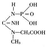 Creatine Phosphate
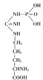 Arginine phosphate
All parts of an organism are essential for life. Only with this in mind does it make sense to say that the most important part of the cell is its nucleus. From the nuclei of cells in pus and in salmon sperm, Johann Friedrich Miescher (1811-1887) obtained a peculiar kind of substance, which he named nuclein (1868). Its phosphate content was easily discovered, but to find the exact proportions and the nature of the other components required special methods of separation from phosphatides and other proteins. It was difficult to develop such methods at a time when little was known about the properties, and particularly[193] the stability, of a nuclein. For preparing nuclein from yeast cells, Felix Hoppe-Seyler (1825-1895) described the following details: Yeast is dispersed in water to extract soluble materials, like salts or sugars. After a few hours, the insoluble material is separated, washed once more with water, and then extracted with a very dilute solution of sodium hydroxide. The slightly alkaline solution, freed from insoluble residues, is slowly added to a weak hydrochloric acid. A precipitate forms which is separated by filtration, washed with dilute acid, then with cold alcohol, and finally extracted by boiling alcohol. The dried residue is the nuclein.[32] It contains six percent phosphorus. A little more washing with water, a slightly longer treatment with acid or alcohol gives products of lower phosphorus content. Many experimental variations were necessary to establish the procedure that leads to purification without alteration of the natural substance.
This was also true for the methods of chemical degradation, carried out in order to find the components of nucleins in their highest state of natural complexity. It was learned for example, that the special kind of carbohydrate present in nucleins was very susceptible to change under the conditions of hydrolysis by acids. Phoebus Aaron Theodor Levine (1869-1940), therefore, used the digestion by a living organism. With E. S. London, he introduced a solution of nucleic acid into, e.g., the gastrointestinal segment of a dog through a gastric fistula and withdrew the product of digestion through an intestinal fistula. Fortunately, the products obtained in such degradations were not new in themselves. The carbohydrate in this nucleic acid proved to be identical with D-ribose, which Emil Fischer had artificially made from arabinose and named ribose to indicate this relationship (1891). The nitrogenous products of the degradation were identical with substances previously prepared in the long study of uric acid. In the course of this study, Emil Fischer established uric acid and a number of its derivatives as having the elementary skeleton of what he called “pure uric acid,” abbreviated to purine. Out of Adolf Baeyer’s work on barbituric acid came the knowledge of pyrimidine and its derivatives.

Figure 15.—Albrecht Kossel (1853-1927) received the Nobel Prize in Medicine and Physiology in 1910 for his work on nucleic substances, which contain a high proportion of phosphorus. The chemical bonds of this phosphorus in the molecules of nucleic substances were determined in later work. (Photo courtesy National Library of Medicine, Washington, D.C.)
From these findings, together with what Oswald Schmiedeberg (1838-1921) had established concerning the presence of four phosphate groups in the molecule (1899), Robert Feulgen (1884-1955) constructed the following scheme of a nucleic acid. Feulgen’s formula of 1918 is:
Phosphoric acid—Carbohydrate—Guanine
Phosphoric acid—Carbohydrate—Cytosine
Phosphoric acid—Carbohydrate—Thymine
Phosphoric acid—Carbohydrate—Adenine
Of the four basic components on the right, thymine occurs in the
nucleic
acid from the thymus gland. Yeast contains uracil instead. The
difference between these two bases is one methyl group: thymine is a
5-methyluracil. In all of these basic substances, the structure of urea
 is involved, and they form pairs of oxidized and reduced states:
| Purine | Pyrimidine | |
| (reduced) Adenine | + | (oxidized) Thymine |
| (oxidized) Guanine | + | (reduced) Cytosine |
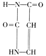
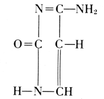
The carbohydrate is ribose or deoxyribose.
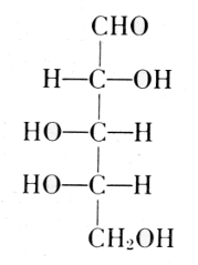
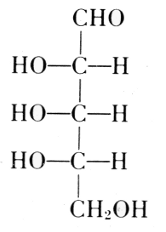
Fischer and Piloty, 1891
The exact position of phosphoric acid was established after long work and verified by synthesis.[33]
A compound of adenine, ribose, and phosphoric acid was found in yeast, blood, and in skeletal muscle of mammals. From 100 grams of such muscle, 0.35-0.40 grams of this compound were isolated. If the muscle is at rest, the compound contains three molecules of phosphoric acid, linked through oxygen atoms. It was named adenosine triphosphate or adenyltriphosphoric acid,[34] usually abbreviated by the symbol ATP. It releases one phosphoric acid group very easily and goes over in the diphosphate, ADP, but it can also lose 2 P-groups as pyrophosphoric acid and leave the monophosphate, AMP.

This change of ATP was considered to be the main source of energy in muscle contraction by Otto Meyerhof.[35] The corresponding derivatives of guanine, cytosine, and uracil were also found, and they are active in the temporary transfer of phosphoric acid groups in biological processes.
Thus, the study of organic phosphates progressed from the comparatively simple esters connected with fatty substances of organisms to the proteins and the nuclear substances of the cell. The proportional amount of phosphorus in the former was larger than in the latter; the actual importance and function in the life of organisms, however, is not measured by the quantity but determined by the special nature of the compounds.

Figure 16.—Otto Meyerhof (1884-1951) received one-half of the Nobel Prize in Medicine and Physiology in 1922 for his discovery of the metabolism of lactic acid in muscle, which involves the action of phosphates, especially adenosine duophosphates. (Photo courtesy National Library of Medicine, Washington, D.C.)


Figure 17.—Arthur Harden (1865-1940), left, and Hans A. S. von Euler-Chelpin (b. 1875), right, shared the Nobel Prize in Chemistry in 1929. Harden received it for his research in fermentation, which showed the influence of phosphate, particularly the formation of a hexose diphosphate. Euler-Chelpin received his award for his research in fermentation. He found coenzyme A which is a nucleotide containing phosphoric acid.

Figure 18.—George de Hevesy (b. 1885) received the Nobel Prize in Chemistry in 1943 for his research with isotopic tracer elements, particularly radiophosphorus of weight 32 (ordinary phosphorus is 31).


Figure 19.—Carl F. Cori (b. 1896) and his wife, Gerty T. Cori (1896-1957) received part of the Nobel Prize in Medicine and Physiology in 1947 for their study on glycogen conversion. In the course of this study, they identified glucose 1-phosphate, now usually referred to as “Cori ester,” and its function in the glycogen cycle. (Photo courtesy National Library of Medicine, Washington, D.C.)
The study of this function is the newest phase in the history of phosphorus and represents the culmination of the previous efforts. This newest phase developed out of an accidental discovery concerning one of the oldest organic-chemical industries, the production of alcohol by the fermentative action of yeast on sugar. A transition of carbohydrates through phosphate compounds to the end products of the fermentation process was found, and it gradually proved to be a kind of model for a host of biological processes.
Specific phosphates were thus found to be indispensable for life. In reverse, the wrong kind of phosphates can destroy life. As a result, an important part of the new phase in phosphorus history consisted in the study—and use—of antibiotic phosphorus compounds.
Phosphates in Biological Processes
The first indication that phosphorus is important for life came from the experience that plants take it up from the substances in the soil. They incorporate it in their body substance. What makes phosphorus so important that they cannot grow without it? The next insight was that animals acquire it from their plant food. It is then found in bones, in fat and nerve tissue, in all cells and particularly in the cell nuclei. What are its functions there?
The answers to such questions were developed from the study of a long-known process, the conversion of carbohydrates into carbon dioxide and alcohol by yeast. It started with Eduard Buchner’s discovery of 1890, that fermentation is produced by a preparation from yeast in which all living cells have been removed. When yeast is dead-ground and pressed out, the juice still has the ability to produce fermentation.
It is strange, but in many ways characteristic for the process of science, that the “riddle” of phosphorus in life was solved by first eliminating life. In such “lifeless” fermentations, Arthur Harden found that the conversion of sugar begins with the formation of a hexose phosphate (1904). The “ferment” of yeast, called zymase, proved to be a composite of several enzymes. Hans von Euler-Chelpin isolated one part of zymase, which remains active even after heating its solution to the boiling point. From 1 kilogram of yeast, he obtained 20 milligrams of this heat-stable enzyme, which he called cozymase and identified as a nucleotide composed of a purine, a sugar, and phosphoric acid.[36] In the years between the two World Wars, zymase was further resolved into more enzymes, one of them the coenzyme I, which was shown to be ADP connected with another molecule of ribose attached to the amide of nicotinic acid, or diphosphopyridine nucleotide:
Its function is connected with the transfer of hydrogen between intermediates formed through phosphate-transferring enzymes. Fermentation proceeds by a cascade of processes, in which phosphate groups swing back and forth, and equilibria between ATP with ADP play a major role.
Many of the enzymes are closely related to vitamins. Thus, cocarboxylase A, which takes part in the separation of carbon dioxide from an intermediate fermentation product, is the phosphate of vitamin B1. Others of the B vitamins contain phosphate groups, for example those of the B2 and B6 group, and in B12, one lonely phosphate forms a bridge in the large molecule that contains one atom of cobalt: C63H90N14O14PCo. The formation of vitamin A from carotine occurs under the influence of ATP.
The first stages in fermentation are like those in respiration, which ends with carbon dioxide and water. These two are the materials for the reverse process in photosynthesis. When light is absorbed by the chlorophyll of green plants, one of the initial reactions is a transfer of hydrogen from water to a triphosphopyridine nucleotide, which later acts to reduce the carbon dioxide. Under the influence of ATP, phosphoglyceric acid is synthesized and further built up by way of carbohydrate phosphates to hexose sugars and finally to starch. In many starchy fruits, a small proportion of phosphate remains attached to the end product.
The synthesis of proteins is under the control of deoxyribonucleic acid or ribonucleic acid, abbreviated by the symbols DNA and RNA. The genes in the nucleus are parts of a giant DNA molecule. RNA is a universal constituent of all living cells. Where protein synthesis is intense, the content in RNA is high. Thus, the spinning glands of silkworms are extraordinarily rich in RNA.[37]
In his research on the radioactive isotope P32, George de Hevesy gained some insight into the surprising mobility of phosphates in organisms: “A phosphate radical taken up with the food may first participate in the phosphorylation of glucose in the intestinal mucose, soon afterwards pass into the circulation as free phosphate, enter a red corpuscle, become incorporated with an adenosine triphosphoric-acid molecule, participate in a glycolytic process going on in the corpuscle, return to circulation, penetrate into the liver cells, participate in the formation of a phosphatide molecule, after a short interval enter the circulation in this form, penetrate into the spleen, and leave this organ after some time as a constituent of a lymphocyte. We may meet the phosphate radical again as a constituent of the plasma, from which it may find its way into the skeleton.”[38] Much has been added in the last 30 years to complete this picture in many details and to extend it to other biochemical processes, including even the changes of the pigments in the retina in the visual process, or in the conversion of chemical energy to light by bacteria and insects.
In the delicate balance of these processes, disturbances may occur which can be remedied by specific phosphate-containing medicines. Thus, adenosine phosphate has been recommended in cases of angina [199] pectoris and marketed under trade names like sarkolyt, or in compounds named angiolysine. A considerable number of physiologically active organic phosphates can be found in the patent literature.[39] Yeast itself is considered to be a valuable food additive.
On the other hand, there are phosphate compounds that act as poisons. One group of such compounds was discovered in 1929 by W. Lange, who wrote: “Of interest is the strong action of mono-fluorophosphate esters on the human body—the effect is produced by very small quantities.”[40] Diisopropyl fluorophosphate has since become a potential agent for chemical warfare. It inactivates an enzyme which controls the transmission of nerve impulses to muscle, acetylcholine esterase.
Organic esters of phosphoric acids are used as insecticides. The hexa-ethylester of tetraphosphoric acid, prepared by Gerhard Schrader by heating triethylphosphate with phosphorus oxychloride,[41] actually contains tetraethylpyrophosphate (TEPP) among others. Bayer’s Dipterex, the dimethyl ester of 2,2,2-trichloro-1-hydroxyethyl-phosphonate, has been modified to dimethyl-2,2-dichlorovinyl-phosphate and is especially active against the oriental fruit fly.[42]
Bayer's L 13/59
(Dipterex)
Schradan
Octamethylpyrophosphoramide

Figure 22.—Arthur Kornberg (b. 1918) and Severo Ochoa (b. 1905) shared the Nobel Prize in Medicine and Physiology in 1959. Kornberg received it for research on the biological synthesis of deoxyribonucleic acid. In particular, he found that four triphosphate components and a small amount of the end product as a “template” had to be present for the enzymatic synthesis. Ochoa received his share of the prize for research in ribonucleic acid and deoxyribonucleic acid. In particular, Ochoa synthesized polyribonucleotides and used the radioactive isotope, P32. The synthetic polyribonucleotides were found to resemble the natural substances in all essentials.

Figure 23.—Melvin Calvin (b. 1911) received the Nobel Prize in Chemistry in 1961 for his research in photosynthesis, in which he specified the function of phosphoglyceric acid as an intermediate in the synthesis of carbohydrates from carbon dioxide and water by green plants.
The story of phosphorus, which began 300 years ago, has acquired new importance in this century. Many scientists have contributed to it: 13 of them have received Nobel Prizes for work directly bearing on the chemical and biological importance of phosphorus compounds. In chronological order, they are: Eduard Buchner, Albrecht Kossel, Otto Meyerhof, Arthur Harden, Hans von Euler-Chelpin, George de Hevesy, Carl F. Cori, Gerty T. Cori, Fritz Lipmann, Lord Alexander Todd, Arthur Kornberg, Severo Ochoa, and Melvin Calvin. The developers of industrial production and commercial utilization of phosphate compounds have had other rewards.
Some impression of the continuing growth in this field [43] can be gained from the following data.
Phosphate Rock
annually “sold or used by producer” in the United States
in million long tons (2,240 lbs.)
| 1880 | 0. | 2 |
| 1890 | 0. | 5 |
| 1900 | 1. | 5 |
| 1910 | 2. | 655 |
| 1920 | 4. | 104 |
| 1930 | 3. | 926 |
| 1940 | 4. | 003 |
| 1945 | 5. | 807 |
| 1950 | 11. | 114 |
| 1955 | 12. | 265 |
| 1955 | (world: about 56) | |
| 1960 | 17. | 202 |
| 1962 | 19. | 060 |
Sources: U.S. Bureau of the Census. Historical Statistics of the United States 1789-1945 (1949); Statistical Abstract of the United States.
Elemental Phosphorus
annually produced in the United States
in short tons (2,000 lbs.)
| 1939 | 43,000 |
| 1944 | 85,679 |
| 1950 | 153,233 |
| 1956 | 312,200 |
| 1958 | 335,750 |
| 1959 | 366,350 |
| 1960 | 409,096 |
| 1961 | 430,617 |
| 1962 | 451,970 |
Source: U.S. Department of Commerce.
[1] Wilhelm Homberg, Mémoires Académie, 1666-1699 (Paris, 1730), vol. 10, under date of April 30, 1692, pp. 57-61.
[2] Fortunio Licetus, Lithiophosphorus sive de lapide Bononiensi (Venice, 1640).
[3] Cited in Peter Joseph Macquer Chymisches Wörterbuch, 2nd ed. (Leipzig: Weidmann, 1789), vol. 4, p. 508, footnote “c” as “Kletwich (de phosph. liqu. et solid. 1689, Thes. II).”
[4] Ferdinand Hoefer, Histoire de la Chimie (Paris, 1843), vol. 1, p. 339.
[5] G. W. von Leibniz, Mémoires Académie (Paris, 1682); Akademie der Wissenschaften, Miscellanea Berolinensia (Berlin, 1710), vol. 1, p. 91.
[6] Jean Hellot, Mémoires Académie 1737 (Paris, 1766), under date of November 13, 1737, pp. 342-378.
[7] Macquer, op. cit. (footnote 3), p. 551.
[8] A. S. Marggraf, Akademie der Wissenschaften, Miscellanea Berolinensia (Berlin, 1743), vol. 7, 342 ff.; see also Wilhelm Ostwald Klassiker der Exakten Naturwissenschaften (Leipzig: Engelmann, 1913), no. 187.
[9] G. Hanckewitz, [Hankwitz], Philosophical Transactions of the Royal Society of London, 1724-1734, abridged (London, 1809), vol. 7, pp. 596-602.
[10] Antoine Laurent Lavoisier, “Sur la Combustion du Phosphore de Kunckel, Et sur la nature de l’acide qui resulte de cette Combustion,” Mémoires Académie 1777, (Paris, 1780), pp. 65-78.
[11] Guyton de Morveau and others, Méthode de Nomenclature Chimique, Proposée par MM. de Morveau, Lavoisier, Bertholet, & de Fourcroy (Paris, 1787), plate 9.
[12] Macquer, op. cit. (footnote 3), p. 513.
[13] Marie Boas, Robert Boyle and Seventeenth Century Chemistry (New York: Cambridge University Press, 1958), p. 226; see also Wyndham Miles, “The History of Dr. Brand’s Phosphorus Elementarus,” Armed Forces Chemical Journal (November-December 1958), p. 25.
[14] Archibald Clow and Nan L. Clow, The Chemical Revolution (London: Batchworth Press, 1952), p. 451.
[15] Émile Kopp, Comptes-rendus hebdomadaires des Séances de l’Académie des Sciences, Paris (1844), vol. 18, p. 871; Wilhelm Hittorf, Annalen der Chemie und Pharmazie, suppl. to vol. 4, p. 37; Anton Schrötter, Annales de Chimie et de Physique, series 3, vol. 24 (1848), p. 406; see also Schrötter’s report on “Phosphor und Zündwaaren” in A. W. von Hofmann, Bericht über die Entwicklung der Chemischen Industrie (Braunschweig: Vieweg, 1875), pp. 219-246.
[16] R. Glauber, Furni Novi Philosphici (Amsterdam, 1649), vol. 2, pp. 12 ff.
[17] Hermann Schelenz, Geschichte der Pharmazie (Berlin: Springer, 1904), p. 598.
[18] J. Personne, Comptes-rendus …, Paris (1869), vol. 68, pp. 543-546.
[19] A. Wurtz, Dictionnaire de Chimie (Paris, 1876), vol. 2, part 2, p. 951.
[20] Karl W. Scheele, Nachgelassene Briefe und Aufzeichnungen, edit. A. E. Nordenskiöld (Stockholm: Norstedt, 1892), pp. 38, 144.
[21] J. J. Berzelius, Lehrbuch, transl. F. Wöhler (Dresden, 1827), vol. 3, part 1, p. 96.
[22] Thomas Graham, Philosophical Transactions of the Royal Society of London (1833), pp. 253-284.
[23] Justus Liebig’s Annalen der Pharmacie (1838), vol. 26, p. 113 ff.
[24] A. Wurtz, Annales de Chimie et de Physique, series 3, vol. 16 (1846), p. 190.
[25] Carroll D. Wright, The Phosphate Industry in the United States, sixth special report of the Commissioner of Labor (Washington, 1893).
[26] J. Stoklasa, Biochemischer Kreislauf des Phosphat-Ions im Boden, Centralblatt für Bakteriologie … (Jena: Fischer, March 22, 1911), vol. 29, nos. 15-19.
[27] N. T. Gobley, Comptes-rendus …, Paris (1845), vol. 21, p. 718.
[28] A. Wurtz, Comptes-rendus …, Paris (1868), vol. 66, p. 772.
[29] L. Thudichum, Die chemische Constitution des Gehirns des Menschen und der Tiere (1901); see also H. Wittcoff, The Phosphatides (New York: Reinhold, 1951).
[30] William Crookes, British Association for the Advancement of Science, Reports (1887), sec. B, p. 573.
[31] J. E. Courtois and A. Lino, Progress in the Chemistry of Organic Natural Products, edit. L. Zechmeister (Vienna: Springer Verlag, 1961), vol. 19, p. 316-373.
[32] A. Wurt, Dictionnaire de Chimie, supp. part 2, [n.d.] p. 1087; A. Kossel, Zeitschrift für physiologische Chemie, series 3 (1879), p. 284.
[33] Alexander Todd, Les Prix Nobel en 1957 (Stockholm).
[34] Hans von Euler-Chelpin, Les Prix Nobel en 1929 (Stockholm).
[35] O. Meyerhof and E. Lundsgaard, Naturwissenschaften (Berlin, 1930), vol. 18, pp. 330, 787.
[36] K. Lohmann, Naturwissenschaften (Berlin, 1929), vol. 17, p. 624; C. H. Fiske and Y. Subbarow, Science (Washington, 1929), vol. 70, p. 381 f.
[37] J. Brachet, Scientia, Revista di Scienza (1960), vol. 95, p. 119.
[38] George de Hevesy, Les Prix Nobel en 1940 (Stockholm). See also Eduard Farber, Nobel Prize Winners in Chemistry, 2nd ed. (New York: Schuman, 1963), p. 179.
[39] See, e.g., Chemical Week, vol. 77 (September 3, 1955), p. 79 f.; J. Bolle, Chimie et Industrie (1960), vol. 83, p. 252.
[40] W. Lange, Berichte der Deutschen Chemischen Gesellschaft (Berlin, 1929), vol. 62, p. 793; vol. 65 (1932), p. 1598.
[41] Gerhard Schrader, U.S. patent 2,336,302 of 1943 (priority in Germany, 1938); S. A. Hall and M. Jacobson, Industrial and Engineering Chemistry (1943), vol. 40, p. 694.
[42] A. M. Mattsen and others, Journal of Agriculture and Food Chemistry (1955), vol. 3, p. 319.
[43] John B. Van Wazer, Phosphorus and its Compounds, 2 vols. (vol. 1, Chemistry; vol. 2 Technology, Biological Functions and Applications), New York: Interscience, 1958, 1961.
Paper 40 - Transcriber’s Note
The following typographical errors have been corrected:
Page 180 “Abfällen, Vieweg, Braunschweig,” - had “Viewig”.
Page 192 “But phosphatides occur” - had “phosphatide soccur”.
Page 193 “the nucleic acid from the thymus” - had “nucleidic”.
Page 199 “acetylcholine esterase.” - had “acetylcholin”.
Page 200 “George de Hevesy, Carl F. Cori,” - comma added after Hevesy.
Footnote 39: “See, e.g., Chemical Week, vol. 77” - had “See. e.g.”
The spelling of “Bertholet” [Claude Louis Berthollet] is as given on the original title page of the work referenced in this paper.
Inconsistent hyphenation of chemical names has been retained.
Contributions from
The Museum of History and Technology.
Paper 41
Tunnel Engineering—A Museum Treatment
Robert M. Vogel
| INTRODUCTION | 203 |
| ROCK TUNNELING | 206 |
| SOFT-GROUND TUNNELING | 215 |
| BIBLIOGRAPHY | 239 |
| FOOTNOTES | |
| INDEX |
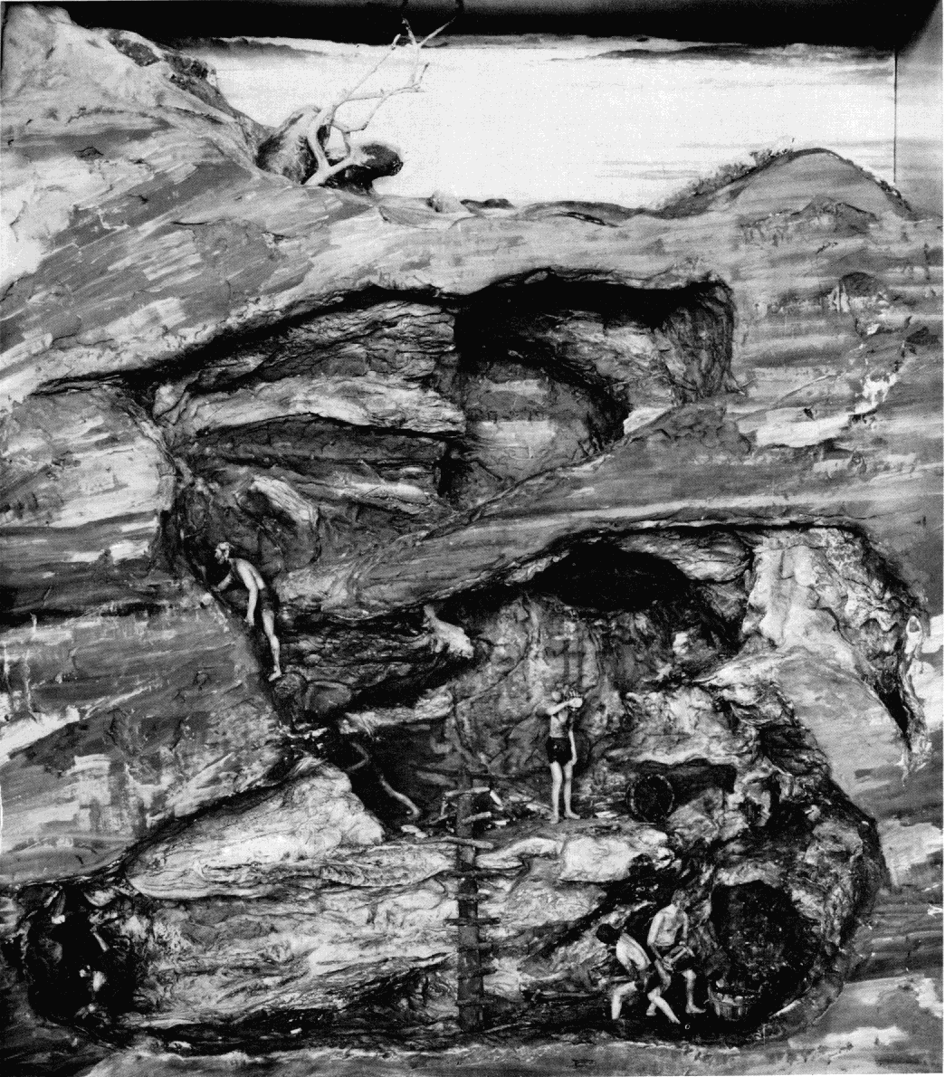
Figure 1.—Mining by early European civilizations, using fire setting and hand chiseling to break out ore and rock. MHT model—3/4" scale. (Smithsonian photo 49260-H.)
Robert M. Vogel
TUNNEL ENGINEERING—A MUSEUM TREATMENT
During the years from 1830 to 1900, extensive developments took place in the field of tunneling, which today is an important, firmly established branch of civil engineering. This paper offers a picture of its growth from the historical standpoint, based on a series of models constructed for the Hall of Civil Engineering in the new Museum of History and Technology. The eight models described highlight the fundamental advances which have occurred between primitive man’s first systematic use of fire for excavating rock in mining, and the use in combination of compressed air, an iron lining, and a movable shield in a subaqueous tunnel at the end of the 19th century.
The Author: Robert M. Vogel is curator of heavy machinery and civil engineering, in the Smithsonian Institution’s Museum of History and Technology.
With few exceptions, civil engineering is a field in which the ultimate goal is the assemblage of materials into a useful structural form according to a scientifically derived plan which is based on various natural and man-imposed conditions. This is true whether the result be, for example, a dam, a building, a bridge, or even the fixed plant of a railroad. However, one principal branch of the field is based upon an entirely different concept. In the engineering of tunnels the utility of the “structure” is derived not from the bringing together of elements but from the separation of one portion of naturally existing material from another to permit passage through a former barrier.
In tunneling hard, firm rock, this is practically the entire compass of the work: breaking away the rock from the mother mass, and, coincidently, removing it from the workings. The opposite extreme in conditions is met in the soft-ground tunnel, driven through material incapable of supporting itself above [204] the tunnel opening. Here, the excavation of the tunneled substance is of relatively small concern, eclipsed by the problem of preventing the surrounding material from collapsing into the bore.

Figure 2.—Hoosac Tunnel. Method of working early sections of the project; blast holes drilled by hand jacking. MHT model—1/2" scale. (Smithsonian photo 49260-L.)
In one other principal respect does tunnel engineering differ widely from its collateral branches of civil engineering. Few other physical undertakings are approached with anything like the uncertainty attending a tunnel work. This is even more true in mountain tunnels, for which test borings frequently cannot be made to determine the nature of the material and the geologic conditions which will be encountered.
The course of tunnel work is not subject to an overall preliminary survey; the engineer is faced with not only the inability to anticipate general contingencies common to all engineering work, but with the peculiar and often overwhelming unpredictability of the very basis of his work.
Subaqueous and soft-ground work on the other hand, while still subject to many indeterminates, is now far more predictable than during its early history, simply because the nature of the adverse condition prevailing eventually was understood to be quite predictable. The steady pressures of earth and water to refill the excavated area are today overcome with relative ease and consistency by the tunneler.
In tunneling as in no other branch of civil engineering did empiricism so long resist the advance of scientific theory; in no other did the “practical engineer” remain to such an extent the key figure in establishing the success or failure of a project. The Hoosac Tunnel, after 25 years of legislative, financial, and technical difficulties, in 1875 was finally driven to successful completion only by the efforts of a group who, while in the majority were trained civil engineers, were to an even greater extent men of vast practical ability, more at home in field than office.
DeWitt C. Haskin (see p. 234), during the inquest that followed the death of a number of men in a blowout of his pneumatically driven Hudson River Tunnel in 1880, stated in his own defense: “I am not a scientific engineer, but a practical one … I know nothing of mathematics; in my experience I have grasped such matters as a whole; I believe that the study of mathematics in that kind of work [tunneling] has a tendency to dwarf the mind rather than enlighten it….” An extreme attitude perhaps, and one which by no means adds to Haskin’s stature, but a not unusual one in tunnel work at the time. It would not of course be fair to imply that such men as Herman Haupt, Brunel the elder, and Greathead were not accomplished theoretical engineers. But it was their innate ability to evaluate and control the overlying physical conditions of the site and work that made possible their significant contributions to the development of tunnel engineering.
Tunneling remained largely independent of the realm of mathematical analysis long after the time when all but the most insignificant engineering works were designed by that means. Thus, as structural engineering has advanced as the result of a flow of new theoretical concepts, new, improved, and strengthened materials, and new methods of fastening, the progress of tunnel engineering has been due more to the continual refinement of constructional techniques.
A NEW HALL OF CIVIL ENGINEERING
In the Museum of History and Technology has recently been established a Hall of Civil Engineering [205] in which the engineering of tunnels is comprehensively treated from the historical standpoint—something not previously done in an American museum. The guiding precept of the exhibit has not been to outline exhaustively the entire history of tunneling, but rather to show the fundamental advances which have occurred between primitive man’s first systematic use of fire for excavating rock in mining, and the use in combination of compressed air, iron lining, and a movable shield in a subaqueous tunnel at the end of the 19th century. This termination date was selected because it was during the period from about 1830 to 1900 that the most concentrated development took place, and during which tunneling became a firmly established and important branch of civil engineering and indeed, of modern civilization. The techniques of present-day tunneling are so fully related in current writing that it was deemed far more useful to devote the exhibit entirely to a segment of the field’s history which is less commonly treated.
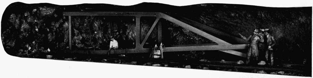
Figure 3.—Hoosac Tunnel. Working of later stages with Burleigh pneumatic drills mounted on carriages. The bottom heading is being drilled in preparation for blasting out with nitroglycerine. MHT model—1/2" scale. (Smithsonian photo 49260-M.)
The major advances, which have already been spoken of as being ones of technique rather than theory, devolve quite naturally into two basic classifications: the one of supporting a mass of loose, unstable, pressure-exerting material—soft-ground tunneling; and the diametrically opposite problem of separating rock from the basic mass when it is so firm and solid that it can support its own overbearing weight as an opening is forced through it—rock, or hard-ground tunneling.
To exhibit the sequence in a thorough manner, inviting and capable of easy and correct interpretation by the nonprofessional viewer, models offered the only logical means of presentation. Six tunnels were selected, all driven in the 19th century. Each represents either a fundamental, new concept of tunneling technique, or an important, early application of one. Models of these works form the basis of the exhibit. No effort was made to restrict the work to projects on American soil. This would, in fact, have been quite impossible if an accurate picture of tunnel technology was to be drawn; for as in virtually all other areas of technology, the overall development in this field has been international. The art of mining was first developed highly in the Middle Ages in the Germanic states; the tunnel shield was invented by a Frenchman residing in England, and the use of compressed air to exclude the water from subaqueous tunnels was first introduced on a major work by an American. In addition, the two main subdivisions, rock and soft-ground tunneling, are each introduced by a model not of an actual working, but of one typifying early classical methods which were in use for centuries until the comparatively recent development of more efficient systems of earth support and rock breaking. Particular attention is given to accuracy of detail throughout the series of eight models; original sources of descriptive and graphic information were used in their construction wherever possible. In all cases except the introductory model in the rock-tunneling series, representing copper mining by early civilizations, these sources were contemporary accounts.
The plan to use a uniform scale of reduction throughout, in order to facilitate the viewers’ interpretation, unfortunately proved impractical, due to the great difference in the amount of area to be encompassed in different models, and the necessity that the cases holding them be of uniform height. The related models of the Broadway and Tower Subways represent short sections of tunnels only 8 feet or so in diameter enabling a relatively large scale, 11/2 inches to the foot, to be used. Conversely, in order that the model of Brunel’s Thames Tunnel be most effective, [206] it was necessary to include one of the vertical terminal shafts used in its construction. These were about 60 feet in depth, and thus the much smaller scale of 1/4 inch to the foot was used. This variation is not as confusing as might be thought, for the human figures in each model provide an immediate and positive sense of proportion and scale.
Careful thought was devoted to the internal lighting of the models, as this was one of the critical factors in establishing, so far as is possible in a model, an atmosphere convincingly representative of work conducted solely by artificial light. Remarkable realism was achieved by use of plastic rods to conduct light to the tiny sources of tunnel illumination, such as the candles on the miners’ hats in the Hoosac Tunnel, and the gas lights in the Thames Tunnel. No overscaled miniature bulbs, generally applied in such cases, were used. At several points where the general lighting within the tunnel proper has been kept at a low level to simulate the natural atmosphere of the work, hidden lamps can be operated by push-button in order to bring out detail which otherwise would be unseen.
The remainder of the material in the Museum’s tunneling section further extends the two major aspects of tunneling. Space limitations did not permit treatment of the many interesting ancillary matters vital to tunnel engineering, such as the unique problems of subterranean surveying, and the extreme accuracy required in the triangulation and subsequent guidance of the boring in long mountain tunnels; nor the difficult problems of ventilating long workings, both during driving and in service; nor the several major methods developed through the years for driving or constructing tunnels in other than the conventional manner. [1]
While the art of tunneling soft ground is of relatively recent origin, that of rock tunneling is deeply rooted in antiquity. However, the line of its development is not absolutely direct, but is more logically followed through a closely related branch of technology—mining. The development of mining techniques is a practically unbroken one, whereas there appears little continuity or relationship between the few works undertaken before about the 18th century for passage through the earth.
The Egyptians were the first people in recorded history to have driven openings, often of considerable magnitude, through solid rock. As is true of all major works of that nation, the capability of such grand proportion was due solely to the inexhaustible supply of human power and the casual evaluation of life. The tombs and temples won from the rock masses of the Nile Valley are monuments of perseverance rather than technical skill. Neither the Egyptians nor any other peoples before the Middle Ages have left any consistent evidence that they were able to pierce ground that would not support itself above the opening as would firm rock. In Egypt were established the methods of rock breaking that were to remain classical until the first use of gun-powder blasting in the 17th century which formed the basis of the ensuing technology of mining.
Notwithstanding the religious motives which inspired the earliest rock excavations, more constant and universal throughout history has been the incentive to obtain the useful and decorative minerals hidden beneath the earth’s surface. It was the miner who developed the methods introduced by the early civilizations to break rock away from the primary mass, and who added the refinements of subterranean surveying and ventilating, all of which were later to be assimilated into the new art of driving tunnels of large diameter. The connection is the more evident from the fact that tunnelmen are still known as miners.
COPPER MINING, B.C.
Therefore, the first model of the sequence, reflecting elemental rock-breaking techniques, depicts a hard-rock copper mine (fig. 1). Due to the absence of specific information about such works during the pre-Christian eras, this model is based on no particular period or locale, but represents in a general way, a mine in the Rio Tinto area of Spain where copper [207] has been extracted since at least 1000 B.C. Similar workings existed in the Tirol as early as about 1600 B.C. Two means of breaking away the rock are shown: to the left is the most primitive of all methods, the hammer and chisel, which require no further description. At the right side, the two figures are shown utilizing the first rock-breaking method in which a force beyond that of human muscles was employed, the age-old “fire-setting” method. The rock was thoroughly heated by a fierce fire built against its face and then suddenly cooled by dashing water against it. The thermal shock disintegrated the rock or ore into bits easily removable by hand.
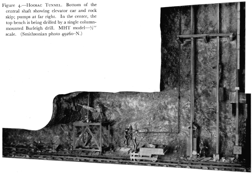
Figure 4.—Hoosac Tunnel. Bottom of the central shaft showing elevator car and rock skip; pumps at far right. In the center, the top bench is being drilled by a single column-mounted Burleigh drill. MHT model—1/2" scale. (Smithsonian photo 49260-N.)
The practice of this method below ground, of course, produced a fearfully vitiated atmosphere. It is difficult to imagine whether the smoke, the steam, or the toxic fumes from the roasting ore was the more distressing to the miners. Even when performed by labor considered more or less expendable, the method could be employed only where there was ventilation of some sort: natural chimneys and convection currents were the chief sources of air circulation. Despite the drawbacks of the fire system, its simplicity and efficacy weighed so heavily in its favor that its history of use is unbroken almost to the present day. Fire setting was of greatest importance during the years of intensive mining in Europe before the advent of explosive blasting, but its use in many remote areas hardly slackened until the early 20th century because of its low cost when compared to powder. For this same reason, it did have limited application in actual tunnel work until about 1900.
Direct handwork with pick, chisel and hammer, and fire setting were the principal means of rock removal for centuries. Although various wedging systems were also in favor in some situations, their importance was so slight that they were not shown in the model.
HOOSAC TUNNEL
It was possible in the model series, without neglecting any major advancement in the art of rock tunneling, to complete the sequence of development with only a single additional model. Many of the greatest works of civil engineering have been those concerned directly with transport, and hence are the product of the present era, beginning in the early 19th century. The development of the ancient arts of route location, bridge construction, and tunnel driving received a powerful stimulation after 1800 under the impetus of the modern canal, highway, and, especially, the railroad.
The Hoosac Tunnel, driven through Hoosac Mountain in the very northwest corner of Massachusetts between 1851 and 1875, was the first major tunneling work in the United States. Its importance is due not so much to this as to its being literally the fountainhead of modern rock-tunneling technology. The remarkable thing is that the work was begun using methods of driving almost unchanged during centuries previous, and was completed twenty years later by techniques which were, for the day, almost totally mechanized. The basic pattern of operation set at Hoosac, using pneumatic rock drills and efficient explosives, remains practically unchanged today.
The general history of the Hoosac project is so thoroughly recorded that the briefest outline of its political aspects will suffice here. Hoosac Mountain was the chief obstacle in the path of a railroad projected between Greenfield, Massachusetts, and Troy, New York. The line was launched by a group of Boston merchants to provide a direct route to the rapidly developing West, in competition with the coastal routes via New York. The only route economically reasonable included a tunnel of nearly five miles through the mountain—a length absolutely without precedent, and an immense undertaking in view of the relatively primitive rock-working methods then available.
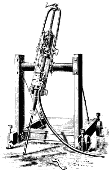
Figure 5.—Burleigh rock drill, improved model of about 1870, mounted on frame for surface work. (Catalog and price list: The Burleigh Rock Drill Company, 1876.)
The bore’s great length and the desire for rapid exploitation inspired innovation from the outset of the work. The earliest attempts at mechanization, although ineffectual and without influence on tunnel engineering until many years later, are of interest. These took the form of several experimental machines of the “full area” type, intended to excavate the entire face of the work in a single operation by cutting one or more concentric grooves in the rock. The rock remaining between the grooves was to be blasted out. The first such machine tested succeeded in boring a 24-foot diameter opening for 10 feet before its total failure. Several later machines proved of equal merit. [2] It was the Baltimore and Ohio’s eminent chief engineer, Benjamin H. Latrobe, who in his Report on the Hoosac Tunnel (Baltimore, Oct. 1, 1862, p. 125) stated that such apparatus contained in its own structure the elements of failure, “ … as they require the machines to do too much and the powder too little of the work, thus contradicting the fundamental principles upon which all labor-saving machinery is framed … I could only look upon it as a misapplication of mechanical genius.”
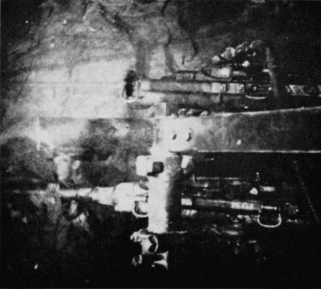
Figure 6.—Hoosac Tunnel. Flash-powder photograph of Burleigh drills at the working face. (Photo courtesy of State Library, Commonwealth of Massachusetts.)
Latrobe stated the basic philosophy of rock-tunnel work. No mechanical agent has ever been able to improve upon the efficiency of explosives for the shattering of rock. For this reason, the logical application of machinery to tunneling was not in replacing or altering the fundamental process itself, but in enabling it to be conducted with greater speed by mechanically drilling the blasting holes to receive the explosive.
Actual work on the Hoosac Tunnel began at both ends of the tunnel in about 1854, but without much useful effect until 1858 when a contract was let to the renowned civil engineer and railroad builder, Herman Haupt of Philadelphia. Haupt immediately resumed investigations of improved tunneling methods, both full-area machines and mechanical rock drills. At this time mechanical rock-drill technology was in a state beyond, but not far beyond, initial experimentation. There existed one workable American machine, the Fowle drill, invented in 1851. It was steam-driven, and had been used in quarry work, although apparently not to any commercial extent. However, it was far too large and cumbersome to find any possible application in tunneling. Nevertheless, it contained in its operating principle, the seed of a practical rock drill in that the drill rod was attached directly to and reciprocated by a double-acting steam piston. A point of great importance was the independence of its operation on gravity, permitting drilling in any direction.
While experimenting, Haupt drove the work onward by the classical methods, shown in the left-hand section of the model (fig. 2). At the far right an advance heading or adit is being formed by pick and hammer work; this is then deepened into a top heading with enough height to permit hammer drilling, actually the basic tunneling operation. A team is shown “double jacking,” i.e., using two-handed hammers, the steel held by a third man. This was the most efficient of the several hand-drilling methods. The top-heading plan was followed so that the bulk of the rock could be removed in the form of a bottom bench, and the majority of drilling would be downward, obviously the most effective direction. Blasting was with black powder and its commercial variants. Some liberty was taken in depicting these steps so that both operations might be shown within the scope of the model: in practice [210] the heading was kept between 400 and 600 feet in advance of the bench so that heading blasts would not interfere with the bench work. The bench carriage simply facilitated handling of the blasted rock. It was rolled back during blasts.
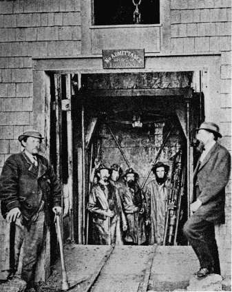
Figure 7.—Hoosac Tunnel. Group of miners descending the west shaft with a Burleigh drill. (Photo courtesy of State Library, Commonwealth of Massachusetts.)
The experiments conducted by Haupt with machine drills produced no immediate useful results. A drill designed by Haupt and his associate, Stuart Gwynn, in 1858 bored hard granite at the rate of 5/8 inch per minute, but was not substantial enough to bear up in service. Haupt left the work in 1861, victim of intense political pressures and totally unjust accusations of corruption and mismanagement. The work was suspended until taken over by a state commission in 1862. Despite frightful ineptitude and very real corruption, this period was exceedingly important in the long history both of Hoosac Tunnel and of rock tunneling in general.
The merely routine criticism of the project had by this time become violent due to the inordinate length of time already elapsed and the immense cost, compared to the small portion of work completed. This served to generate in the commission a strong sense of urgency to hurry the project along. Charles S. Storrow, a competent engineer, was sent to Europe to report on the progress of tunneling there, and in particular on mechanization at the Mont Cenis Tunnel then under construction between France and Italy. Germain Sommeiller, its chief engineer, had, after experimentation similar to Haupt’s, invented a reasonably efficient drilling machine which had gone into service at Mont Cenis in March 1861. It was a distinct improvement over hand drilling, almost doubling the drilling rate, but was complex and highly unreliable. Two hundred drills were required to keep 16 drills at work. But the vital point in this was the fact that Sommeiller drove his drills not with steam, but air, compressed at the tunnel portals and piped to the work face. It was this single factor, one of application rather than invention, that made the mechanical drill feasible for tunneling.
All previous effort in the field of machine drilling, on both sides of the Atlantic, had been directed toward steam as the motive power. In deep tunnels, with ventilation already an inherent problem, the exhaust of a steam drill into the atmosphere was inadmissible. Further, steam could not be piped over great distances due to serious losses of energy from radiation of heat, and condensation. Steam generation within the tunnel itself was obviously out of the question. It was the combination of a practical drill, and the parallel invention by Sommeiller of a practical air compressor that resulted in the first workable application of machine rock drilling to tunneling.
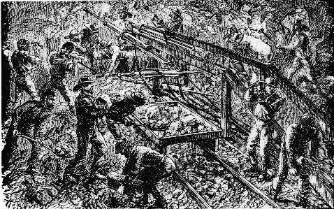
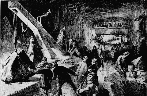
Figures 8 & 9.—Hoosac Tunnel. Contemporary engravings. As such large general areas could not be sufficiently illuminated for photography, the Museum model was based primarily on artists' versions of the work. (Science Record, 1872; Leslie's Weekly, 1873.)
The Sommeiller drills greatly impressed Storrow, and his report of November 1862 strongly favored their adoption at Hoosac. It is curious however, that not a single one was brought to the U.S., even on trial. Storrow does speak of Sommeiller’s intent to keep the details of the machine to himself until it had been further improved, with a view to its eventual exploitation. The fact is, that although workable, the Sommeiller drill proved to be a dead end in rock-drill development because of its many basic deficiencies. It did exert the indirect influence of inspiration which, coupled with a pressing need for haste, led to renewed trials of drilling machinery at Hoosac. Thomas Doane, chief engineer under the state commission, carried this program forth with intensity, seeking and encouraging inventors, and himself working on the problem. The pattern of the Sommeiller drill was generally followed; that is, the drill was designed as a separate, relatively light mechanical element, adapted for transportation by several miners, and attachable to a movable frame or carriage during operation. Air was of course the presumed power. To be effective, it was necessary that a drill automatically feed the drill rod as the hole deepened, and also rotate the rod automatically to maintain a round, smooth hole. Extreme durability was essential, and usually proved the source of a machine’s failure. The combination of these characteristics into a machine capable of driving the drill rod into the rock with great force, perhaps five times per second, was a severe test of ingenuity and materials. Doane in 1864 had three different experimental drills in hand, as well as various steam and water-powered compressors.
Success finally came in 1865 with the invention of a drill by Charles Burleigh, a mechanical engineer at the well-known Putnam Machine Works of Fitchburg, Massachusetts. The drills were first applied in the east heading in June of 1866. Although working well, their initial success was limited by lack of reliability and a resulting high expense for repairs. They were described as having “several weakest points.” In November, these drills were replaced by an improved Burleigh drill which was used with total success to the end of the work. The era of modern rock tunneling was thus launched by Sommeiller’s insight in initially applying pneumatic power to a machine drill, by Doane’s persistence in searching for a thoroughly practical drill, and by Burleigh’s mechanical talent in producing one. The desperate need to complete the Hoosac Tunnel may reasonably be considered the greatest single spur to the development of a successful drill.
The significance of this invention was far reaching. Burleigh’s was the first practical mechanical rock drill in America and, in view of its dependability, efficiency, and simplicity when compared to the Sommeiller drill, perhaps in the world. The Burleigh drill achieved success almost immediately. It was placed in production by Putnam for the Burleigh Rock Drill Company before completion of Hoosac in 1876, and its use spread throughout the western mining regions and other tunnel works. For a major invention, its adoption was, in relative terms, instantaneous. It was the prototype of all succeeding piston-type drills, which came to be known generically as “burleighs,” regardless of manufacture. Walter Shanley, the Canadian contractor who ultimately completed the Hoosac, reported in 1870, after the drills had been in service for a sufficient time that the techniques for their most efficient use were fully understood and effectively applied, that the Burleigh drills saved about half the drilling costs over hand drilling. The per-inch cost of machine drilling averaged 5.5 cents, all inclusive, vs. 11.2 cents for handwork. The more important point, that of speed, is shown by the reports of average monthly progress of the tunnel itself, before and after use of the air drills.
| Year | Average monthly progress in feet |
| 1865 | 55 |
| 1866 | 48 |
| 1867 | 99 |
| 1868 | — |
| 1869 | 138 |
| 1870 | 126 |
| 1871 | 145 |
| 1872 | 124 |
The right portion of the model (fig. 3) represents the workings during the final period. The bottom heading system was generally used after the Burleigh drills had been introduced. Four to six drills were [213] mounted on a carriage designed by Doane. These drove the holes for the first blast in the center of the heading in about six hours. The full width of the heading, the 24-foot width of the tunnel, was then drilled and blasted out in two more stages. As in the early section, the benches to the rear were later removed to the full-tunnel height of about 20 feet. This operation is shown by a single drill (fig. 4) mounted on a screw column. Three 8-hour shifts carried the work forward: drilling occupied half the time and half was spent in running the carriage back, blasting, and mucking (clearing the broken rock).
The tunnel’s 1028-foot central shaft, completed under the Shanley contract in 1870 to provide two additional work faces as well as a ventilation shaft is shown at the far right side of this half of the model. Completed so near the end of the project, only 15 percent of the tunnel was driven from the shaft.
The enormous increase in rate of progress was not due entirely to machine drilling. From the outset of his jurisdiction, Doane undertook experiments with explosives as well as drills, seeking an agent more effective than black powder. In this case, the need for speed was not the sole stimulus. As the east and west headings advanced further and further from the portals, the problem of ventilation grew more acute, and it became increasingly difficult to exhaust the toxic fumes produced by the black powder blasts.
In 1866, Doane imported from Europe a sample of trinitroglycerine, the liquid explosive newly introduced by Nobel, known in Europe as “glonoïn oil” and in the United States as “nitroglycerine.” It already had acquired a fearsome reputation from its tendency to decompose with heat and age and to explode with or without the slightest provocation. Nevertheless, its tremendous power and characteristic of almost complete smokelessness led Doane to employ the chemist George W. Mowbray, who had blasted for Drake in the Pennsylvania oil fields, to develop techniques for the bulk manufacture of the new agent and for its safe employment in the tunnel.
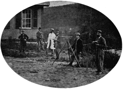
Figure 11.—Hoosac Tunnel survey crew at engineering office. The highest accuracy of the aboveground and underground survey work was required to insure proper vertical and horizontal alignment and meeting of the several separately driven sections. (Photo courtesy of State Library, Commonwealth of Massachusetts.)
Mowbray established a works on the mountain and shortly developed a completely new blasting practice based on the explosive. Its stability was greatly increased by maintaining absolute purity in the manufacturing process. Freezing the liquid to reduce its sensitivity during transport to the headings, and extreme caution in its handling further reduced the hazard of its use. At the heading, the liquid was poured into cylindrical cartridges for placement in the holes. As with the Burleigh drill, the general adoption of nitroglycerine was immediate once its qualities had been demonstrated. The effect on the work was notable. Its explosive characteristics permitted fewer blast holes over a given frontal area of working face, and at the same time it was capable of effectively blowing from a deeper drill hole, 42 inches against 30 inches for black powder, so that under ideal conditions 40 percent more tunnel length was advanced per cycle of operations. A new fuse and a system of electric ignition were developed which permitted simultaneous detonation and resulted in a degree of effectiveness impossible with the powder train and cord fusing used with the black powder. Over a million pounds of nitroglycerine were produced by Mowbray between 1866 and completion of the tunnel.
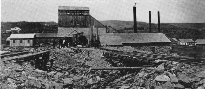
Figure 12.—Works at the central shaft, Hoosac Tunnel, for hoisting, pumping and air compressing machinery, and general repair, 1871. (Photo courtesy of State Library, Commonwealth of Massachusetts.)
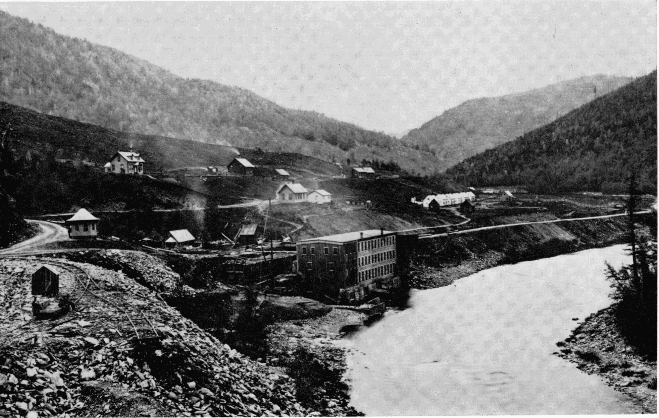
Figure 13.—Hoosac Tunnel. Air-compressor building on Hoosac River near North Adams. The compressors were driven partially by waterpower, derived from the river. (Photo courtesy of State Library, Commonwealth of Massachusetts.)
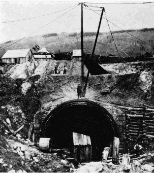
Figure 14.—West portal of Hoosac Tunnel before completion, 1868, showing six rings of lining brick. (Photo courtesy of State Library, Commonwealth of Massachusetts.)
When the Shanleys took the work over in 1868, following political difficulties attending operation by the State, the period of experimentation was over. The tunnel was being advanced by totally modern methods, and to the present day the overall concepts have remained fundamentally unaltered: the Burleigh piston drill has been replaced by the lighter hammer drill; the Doane drill carriage by the more flexible “jumbo”;nitroglycerine by its more stable descendant dynamite and its alternatives; and static-electric blasting machines by more dependable magnetoelectric. But these are all in the nature of improvements, not innovations.
Unlike the preceding model, there was good documentation for this one. Also, the Hoosac was apparently the first American tunnel to be well recorded photographically. Early flashlight views exist of the drills working at the heading (fig. 6) as well as of the portals, the winding and pumping works at the central shaft, and much of the machinery and associated aspects of the project. These and copies of drawings of much of Doane’s experimental apparatus, a rare technological record, are preserved at the Massachusetts State Library.
So great is the difference between hard-rock and soft-ground tunneling that they constitute two almost separate branches of the field. In penetrating ground lacking the firmness or cohesion to support itself above an opening, the miner’s chief concern is not that of removing the material, but of preventing its collapse into his excavation. The primitive methods depending upon brute strength and direct application of fire and human force were suitable for assault on rock, but lacked the artifice needed for delving into less stable material. Roman engineers were accomplished in spanning subterranean ways with masonry arches, but apparently most of their work was done by cut-and-cover methods rather than by actual mining.
Not until the Middle Ages did the skill of effectively working openings in soft ground develop, and not until the Renaissance was this development so consistently successful that it could be considered a science.
RENAISSANCE MINING
From the earliest periods of rock working, the quest for minerals and metals was the primary force that drove men underground. It was the technology of mining, the product of slow evolution over the centuries, that became the technology of the early tunnel, with no significant modification except in size of workings.
Every aspect of 16th century mining is definitively detailed in Georgius Agricola’s remarkable De re Metallica, first published in Basel in 1556. During its time of active influence, which extended for two centuries, it served as the authoritative work on the subject. It remains today an unparalleled early record of an entire branch of technology. The superb woodcuts of mine workings and tools in themselves constitute a precise description of the techniques of the period, and provided an ideal source of information upon which to base the first model in the soft-ground series.
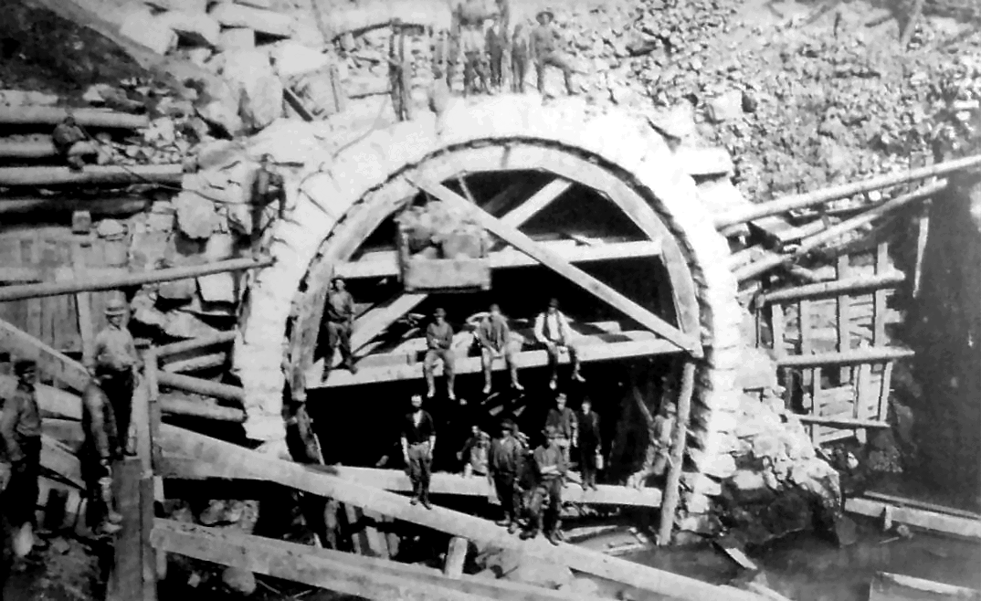
Figure 15.—Centering for placement of finished stonework at west portal, 1874. At top-right are the sheds where the lining brick was produced. (Photo courtesy of State Library, Commonwealth of Massachusetts.)
The model, representing a typical European mine, demonstrates the early use of timber frames or “sets” to support the soft material of the walls and roof. In areas of only moderate instability, the sets alone were sufficient to counteract the earth pressure, and were spaced according to the degree of support required. In more extreme conditions, a solid lagging of small poles or boards was set outside the frames, as shown in the model, to provide absolute support of the ground. Details of the framing, the windlass, and all tools and appliances were supplied by Agricola, with no need for interpretation or interpolation.
The basic framing pattern of sill, side posts and cap piece, all morticed together, with lagging used where needed, was translated unaltered into tunneling practice, particularly in small exploratory drifts. It remained in this application until well into the 20th century.
The pressure exerted upon tunnels of large area was countered during construction by timbering systems of greater elaboration, evolved from the basic one. By the time that tunnels of section large enough to accommodate canals and railways were being undertaken as matter-of-course civil engineering works, a series of nationally distinguishable systems had emerged, each possessing characteristic points of favor and fault. As might be suspected, the English system of tunnel timbering, for instance, was rarely applied on the Continent, nor were the German, Austrian or Belgian systems normally seen in Great Britain. All were used at one time or another in this country, until the American system was introduced in about 1855. While the timbering commonly remained in place in mines, it would be followed up by permanent masonry arching and lining in tunnel work.
Overhead in the museum Hall of Civil Engineering [217] are frames representing the English, Austrian and American systems. Nearby, a series of small relief models (fig. 19) is used to show the sequence of enlargement in a soft-ground railroad tunnel of about 1855, using the Austrian system. Temporary timber support of tunnels fell from use gradually after the advent of shield tunneling in conjunction with cast-iron lining. This formed a perfect support immediately behind the shield, as well as the permanent lining of the tunnel.
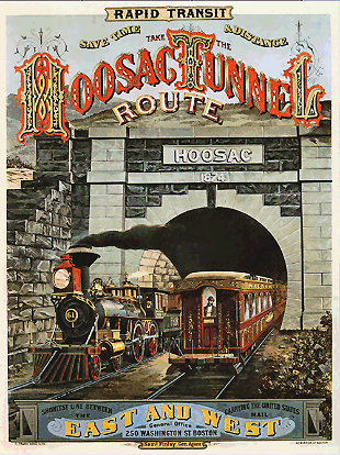
Figure 16.—West portal upon completion, 1876. (Photo courtesy of New-York Historical Society.) Click on image for a color version of poster.
BRUNEL’S THAMES TUNNEL
The interior surfaces of tunnels through ground merely unstable are amenable to support by various systems of timbering and arching. This becomes less true as the fluidity of the ground increases. The soft material which normally comprises the beds of rivers can approach an almost liquid condition resulting in a hydraulic head from the overbearing water sufficient to prevent the driving of even the most carefully worked drift, supported by simple timbering. The basic defect of the timbering systems used in mining and tunneling was that there was inevitably a certain amount of the face or ceiling unsupported just previous to setting a frame, or placing over it the necessary section of lagging. In mine work, runny soil could, and did, break through such gaps, filling the working. For this reason, there were no serious attempts made before 1825 to drive subaqueous tunnels.
In that year, work was started on a tunnel under the Thames between the Rotherhithe and Wapping sections of London, under guidance of the already famous engineer Marc Isambard Brunel (1769-1849), father of I. K. Brunel. The undertaking is of great interest in that Brunel employed an entirely novel apparatus of his own invention to provide continuous and reliable support of the soft water-bearing clay which formed the riverbed. By means of this “shield,” Brunel was able to drive the world’s first subaqueous tunnel. [3]
The shield was of cast-iron, rectangular in elevation, and was propelled forward by jackscrews. Shelves at top, bottom, and sides supported the tunnel roof, floor, and walls until the permanent brick lining was placed. The working face, the critical area, was supported by a large number of small “breasting boards,” held against the ground by small individual screws bearing against the shield framework. The shield itself was formed of 12 separate frames, each of which could be advanced independently of the others. The height was 22 feet 3 inches: the width 37 feet 6 inches.
The progress was piecemeal. In operation the miners would remove one breasting board at a time, excavate in front of it, and then replace it in the advanced position—about 6 inches forward. This was repeated with the next board above or below, and the sequence continued until the ground for the entire height of one of the 12 sections had been removed. The board screws for that section were shifted to bear on the adjacent frames, relieving the [218] frame of longitudinal pressure. It could then be screwed forward by the amount of advance, the screws bearing to the rear on the completed masonry. Thus, step by step the tunnel progressed slowly, the greatest weekly advance being 14 feet.
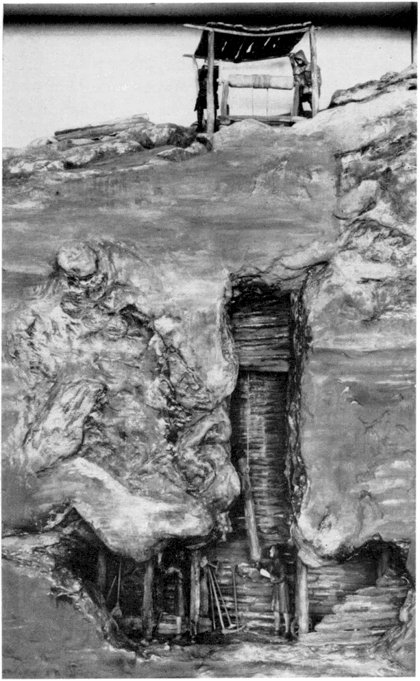
Figure 17.—Soft-ground tunneling. The support of walls and roof of mine shaft by simple timbering; 16th century. MHT model—3/4" scale. (Smithsonian photo 49260-J.)
In the left-hand portion of the model is the shaft sunk to begin operations; here also is shown the bucket hoist for removing the spoil. The V-type steam engine powering the hoist was designed by Brunel. At the right of the main model is an enlarged detail of the shield, actually an improved version built in 1835.
The work continued despite setbacks of every sort. The financial ones need no recounting here. Technically, although the shield principle proved workable, the support afforded was not infallible. Four or five times the river broke through the thin cover of silt and flooded the workings, despite the utmost caution in excavating. When this occurred, masses of clay, sandbags, and mats were dumped over the opening in the riverbed to seal it, and the tunnel pumped out. I. K. Brunel acted as superintendent and nearly lost his life on a number of occasions. After several suspensions of work resulting from withdrawal or exhaustion of support, one lasting seven years, the work was completed in 1843.
Despite the fact that Brunel had, for the first time, demonstrated a practical method for tunneling in firm and water-bearing ground, the enormous cost of the work and the almost overwhelming problems encountered had a discouraging effect rather than otherwise. Not for another quarter of a century was a similar project undertaken.
The Thames Tunnel was used for foot and light highway traffic until about 1870 when it was incorporated into the London Underground railway system, which it continues to serve today. The roofed-over top sections of the two shafts may still be seen from the river.
A number of contemporary popular accounts of the tunnel exist, but one of the most thorough and interesting expositions on a single tunnel work of any period is Henry Law’s A Memoir of the Thames Tunnel, published in 1845-1846 by John Weale. Law, an eminent civil engineer, covers the work in incredible detail from its inception until the major suspension in late 1828 when slightly more than half completed. The most valuable aspect of his record is a series of plates of engineering drawings of the shield and its components, which, so far as is known, exist nowhere else. These formed the basis of the enlarged section of the shield, shown to the right of the model of the tunnel itself. A vertical section through the shield is reproduced here from Law for comparison with the model (figs. 21 and 23).
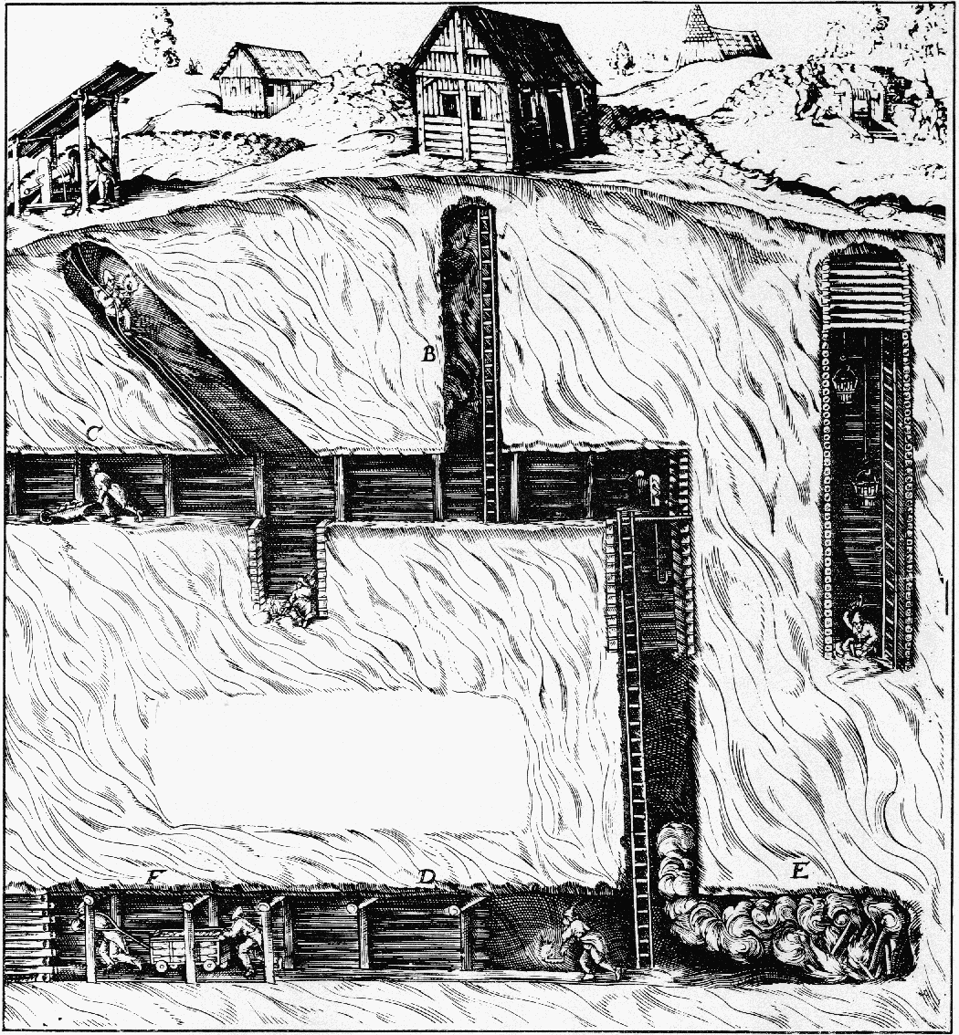
Figure 18.—Soft-ground tunneling. The model of a 16th century mine in the Museum of History and Technology was constructed from illustrations in such works as G. E. von Löhneyss' Bericht vom Bergwerck, 1690, as well as the better known ones from De re Metallica.
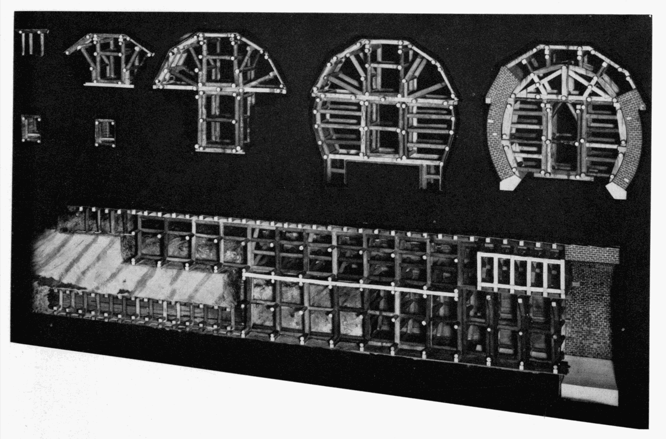
Figure 19.—The successive stages in the
enlargement of a mid-19th century railroad tunnel,
using the Austrian system of timbering. MHT model.
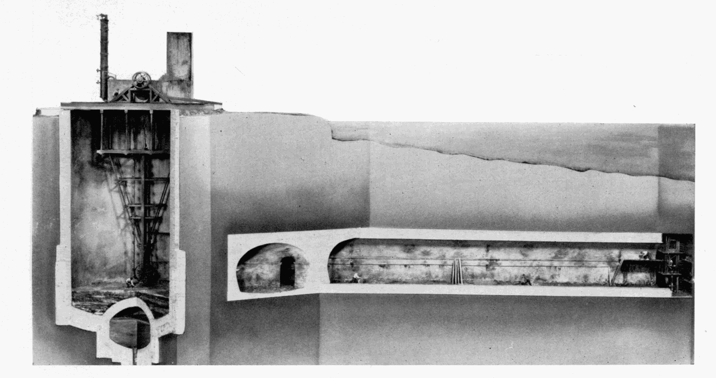
Figure 20.—M. I. Brunel's Thames Tunnel,
1825-1843, the first driven beneath a body of water.
MHT model—1/4"
scale. (Smithsonian photo 49260-F.)
THE TOWER SUBWAY
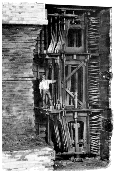
Figure 21.—Enlarged detail of Brunel's tunneling shield, vertical section. The first two and part of the third of the twelve frames are shown. To the left is the tunnel's completed brick lining and to the right, the individual breasting boards and screws for supporting the face. The propelling screws are seen at top and bottom, bearing against the lining. Three miners worked in each frame, one above the other. MHT model—3/4" scale. (Smithsonian photo 49260-G.)
Various inventors attempted to improve upon the Brunel shield, aware of the fundamental soundness of the shield principle. Almost all bypassed the rectangular sectional construction used in the Thames Tunnel, and took as a starting point a sectional shield of circular cross section, advanced by Brunel in his original patent of 1818. James Henry Greathead (1844-1896), rightfully called the father of modern subaqueous tunneling, surmised in later years that Brunel had chosen a rectangular configuration for actual use, as one better adapted to the sectional type of shield. The English civil engineer, Peter W. Barlow, in 1864 and 1868 patented a circular shield, of one piece, which was the basis of one used by him in constructing a small subway of 1350 feet beneath the Thames in 1869, the first work to follow the lead of Brunel. Greathead, acting as Barlow’s contractor, was the designer of the shield actually used in the work, but it was obviously inspired by Barlow’s patents.
The reduction of the multiplicity of parts in the Brunel shield to a single rigid unit was of immense advantage and an advance perhaps equal to the shield concept of tunneling itself. The Barlow-Greathead shield was like the cap of a telescope with a sharpened circular ring on the front to assist in penetrating the ground. The diaphragm functioned, as did Brunel’s breasting boards, to resist the longitudinal earth pressure of the face, and the cylindrical portion behind the diaphragm bore the radial pressure of roof and walls. Here also for the first time, a permanent lining formed of cast-iron segments was used, a second major advancement in soft-ground tunneling practice. Not only could the segments be placed and bolted together far more rapidly than masonry lining could be laid up, but unlike the green masonry, they could immediately bear the full force of the shield-propelling screws.
Barlow, capitalizing on Brunel’s error in burrowing so close to the riverbed, maintained an average cover of 30 feet over the tunnel, driving through a solid stratum of firm London clay which was virtually impervious to water. As the result of this, combined with the advantages of the solid shield and the rapidly placed iron lining, the work moved forward at a pace and with a facility in startling contrast to that of the Thames Tunnel, although in fairness it must be recalled that the face area was far less.
The clay was found sufficiently sound that it could be readily excavated without the support of the diaphragm, and normally three miners worked in front of the shield, digging out the clay and passing it back through a doorway in the plate. This could be closed in case of a sudden settlement or break in. Following excavation, the shield was advanced 18 inches into the excavated area by means of 6 screws, and a ring of lining segments 18 inches in length bolted to the previous ring under cover of the overlapping rear skirt of the shield. The small annular space left between the outside of the lining and the clay by the thickness and clearance of the skirt—about an inch—was filled with thin cement grout. The tunnel was advanced 18 inches during each 8-hour shift. The work continued around the clock, and the 900-foot river section was completed in only 14 weeks. [4] The entire work was completed almost without incident in just under a year, a remarkable performance for the world’s second subaqueous tunnel.
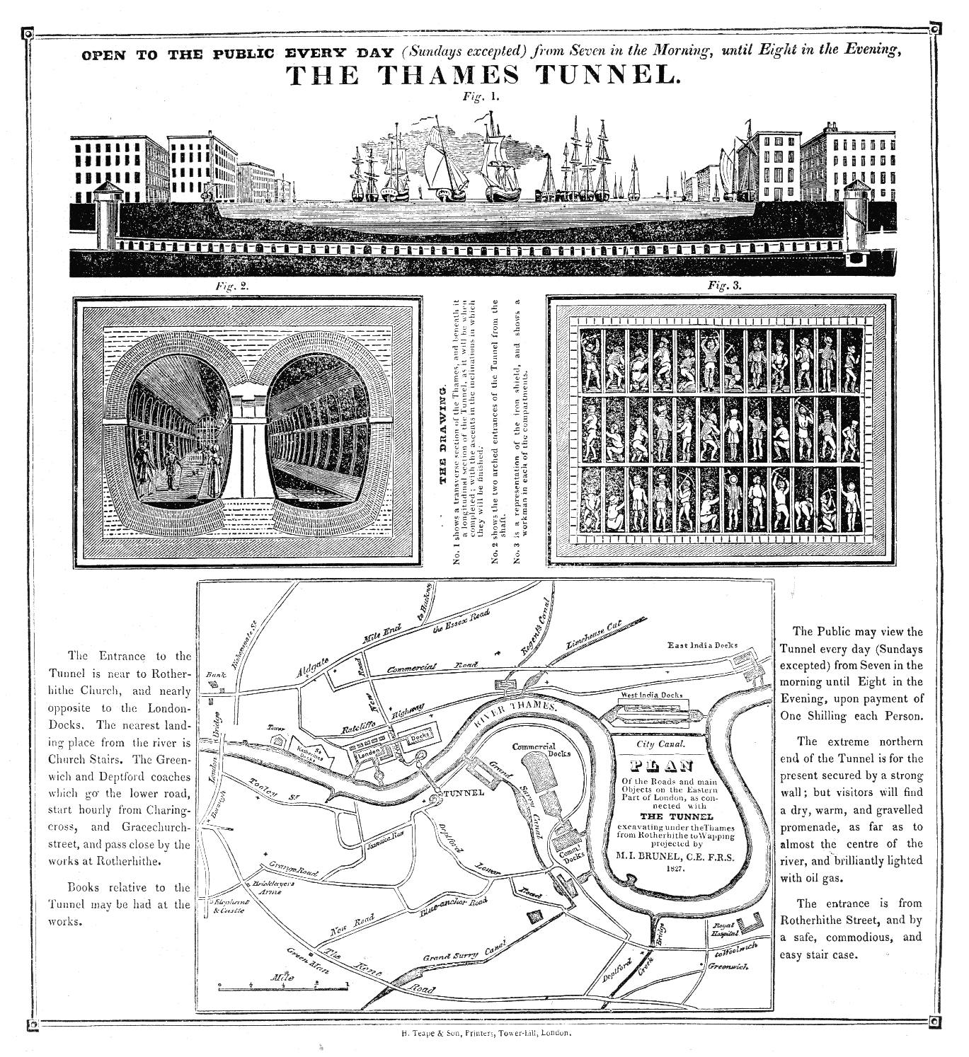
Figure 22.—Broadside published after commencement of work
on the Thames Tunnel, 1827.
(MHT collections.)
Transcription of the text is
presented in the Transcriber's Notes below.

Figure 23.—Vertical section through Brunel's shield. The long lever, x, supported the wood centering for turning the masonry arches of the lining. (Law, A Memoir of the Thames Tunnel.)
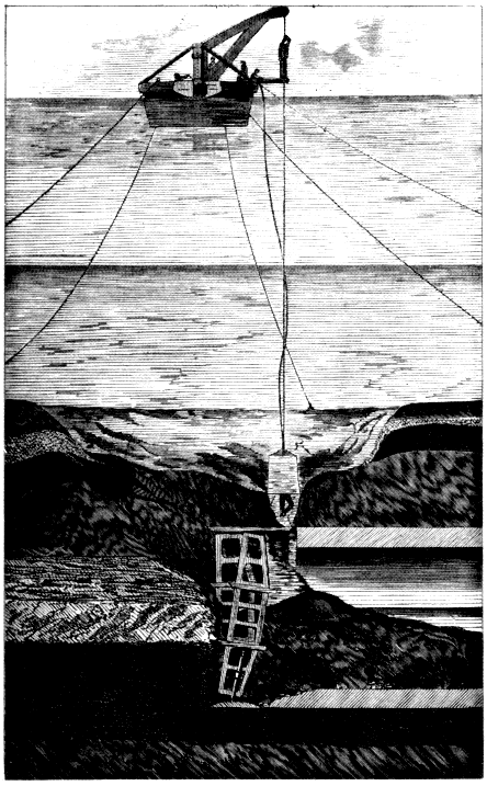
Figure 24.—Thames Tunnel. Section through riverbed and tunnel following one of the break-throughs of the river. Inspection of the damage with a diving bell. (Beamish, A Memoir of the Life of Sir Marc Isambard Brunel.)
The Tower Subway at first operated with cylindrical cars that nearly filled the 7-foot bore; the cars were drawn by cables powered by small steam engines in the shafts. This mode of power had previously been used in passenger service only on the Greenwich Street elevated railway in New York. Later the cars were abandoned as unprofitable and the tunnel turned into a footway (fig. 32). This small tunnel, the successful driving due entirely to Greathead’s skill, was the forerunner of the modern subaqueous tunnel. In it, two of the three elements essential to such work thereafter were first applied: the one-piece movable shield of circular section, and the segmental cast-iron lining.
The documentation of this work is far thinner than for the Thames Tunnel. The most accurate source of technical information is a brief historical account in Copperthwaite’s classic Tunnel Shields and the Use of Compressed Air in Subaqueous Works, published in 1906. Copperthwaite, a successful tunnel engineer, laments the fact that he was able to turn up no drawing or original data on this first shield of Greathead’s, but he presents a sketch of it prepared in the Greathead office in 1895, which is presumably a fair representation (fig. 33). The Tower Subway model was built on the basis of this and several woodcuts of the working area that appeared contemporaneously in the illustrated press. In this and the adjacent model of Beach’s Broadway Subway, the tunnel axis has been placed on an angle to the viewer, projecting the bore into the case so that the complete circle of the working face is included for a more suggestive effect. This was possible because of the short length of the work included.
Henry S. Drinker, also a tunnel engineer and author of the most comprehensive work on tunneling ever published, treats rock tunneling in exhaustive detail up to 1878. His notice of what he terms “submarine tunneling” is extremely brief. He does, however, draw a most interesting comparison between the first Thames Tunnel, built by Brunel, and the second, built by Greathead 26 years later:
| FIRST THAMES TUNNEL | SECOND THAMES TUNNEL (TOWER SUBWAY) |
| Brickwork lining, 38 feet wide by 221/2 feet high. | Cast-iron lining of 8 feet outside diameter. |
| 120-ton cast-iron shield, accommodating 36 miners. | 21/2-ton, wrought-iron shield, accommodating at most 3 men. |
| Workings filled by irruption of river five times. | “Water encountered at almost any time could have been gathered in a stable pail.” |
| Eighteen years elapsed between start and finish of work. | Work completed in about eleven months. |
| Cost: $3,000,000. | Cost: $100,000. |
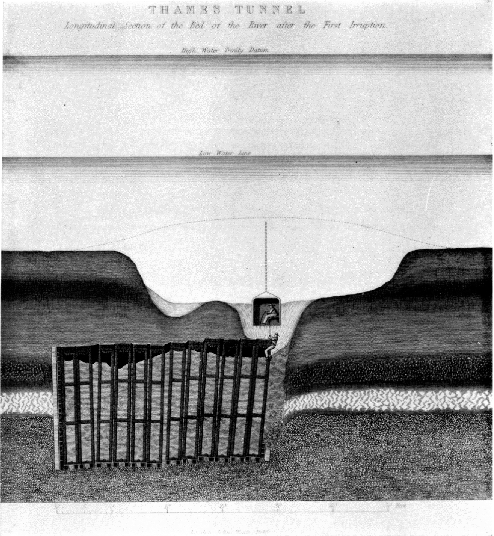
Figure 25.—Transverse section through shield, after inundation. Such disasters, as well as the inconsistency of the riverbed's composition, seriously disturbed the alignment of the shield's individual sections. (Law, A Memoir of the Thames Tunnel.)
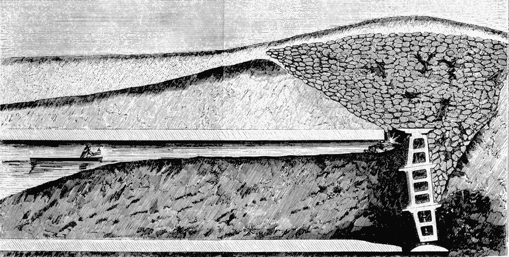
Figure 26.—Longitudinal section through Thames Tunnel after sandbagging to close a break in the riverbed. The tunnel is filled with silt and water. (Law, A Memoir of the Thames Tunnel.)
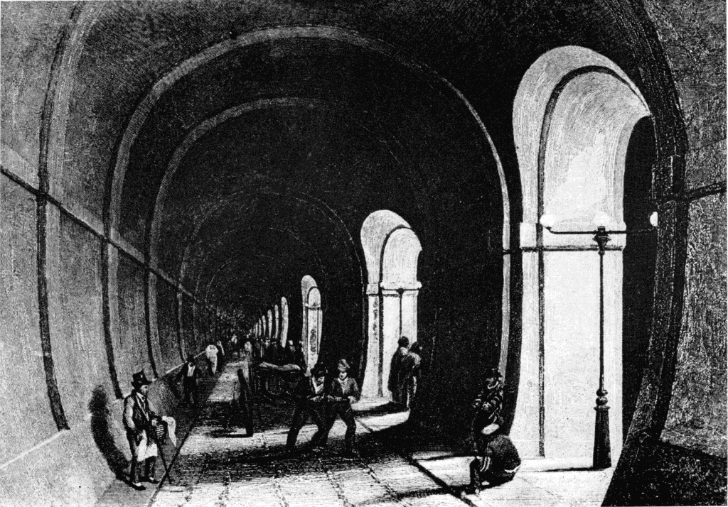
Figure 27.—Interior of the Thames Tunnel shortly after completion in 1843. (Photo courtesy of New York Public Library Picture Collection.)
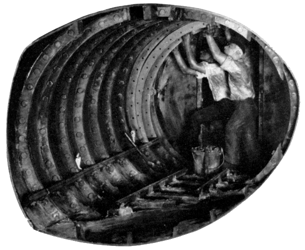
Figure 29.—Placing a segment of cast-iron lining in Greathead's Tower Subway, 1869. To the rear is the shield's diaphragm or bulkhead. MHT model—11/2" scale. (Smithsonian photo 49260-B.)
BEACH’S BROADWAY SUBWAY
Almost simultaneously with the construction of the Tower Subway, the first American shield tunnel was driven by Alfred Ely Beach (1826-1896). Beach, as editor of the Scientific American and inventor of, among other things, a successful typewriter as early as 1856, was well known and respected in technical circles. He was not a civil engineer, but had become concerned with New York’s pressing traffic problem (even then) and as a solution, developed plans for a rapid-transit subway to extend the length of Broadway. He invented a shield as an adjunct to this system, solely to permit driving of the tunnel without disturbing the overlying streets.
An active patent attorney as well, Beach must certainly have known of and studied the existing patents for tunneling shields, which were, without exception, British. In certain aspects his shield resembled the one patented by Barlow in 1864, but never built. However, work on the Beach tunnel started in 1869, so close in time to that on the Tower [228] Subway, that it is unlikely that there was any influence from that source. Beach had himself patented a shield, in June 1869, a two-piece, sectional design that bore no resemblance to the one used. His subway plan had been first introduced at the 1867 fair of the American Institute in the form of a short plywood tube through which a small, close-fitting car was blown by a fan. The car carried 12 passengers. Sensing opposition to the subway scheme from Tammany, in 1868 Beach obtained a charter to place a small tube beneath Broadway for transporting mail and small packages pneumatically, a plan he advocated independently of the passenger subway.
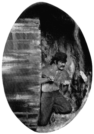
Figure 31.—Excavation in front of shield, Tower Subway. This was possible because of the stiffness of the clay encountered. MHT model—front of model shown in fig. 29. (Smithsonian photo 49260-A.)
Under this thin pretense of legal authorization, the sub-rosa excavation began from the basement of a clothing store on Warren Street near Broadway. The 8-foot-diameter tunnel ran eastward a short distance, made a 90-degree turn, and thence southward under [229] Broadway to stop a block away under the south side of Murray Street. The total distance was about 312 feet. Work was carried on at night in total secrecy, the actual tunneling taking 58 nights. At the Warren Street terminal, a waiting room was excavated and a large Roots blower installed for propulsion of the single passenger car. The plan was similar to that used with the model in 1867: the cylindrical car fitted the circular tunnel with only slight circumferential clearance. The blower created a plenum within the waiting room and tunnel area behind the car of about 0.25 pounds per square inch, resulting in a thrust on the car of almost a ton, not accounting for blowby. The car was thus blown along its course, and was returned by reversing the blower’s suction and discharge ducts to produce an equivalent vacuum within the tunnel.
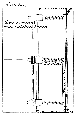
Figure 33.—Vertical section through the Greathead shield used at the Tower Subway, 1869. The first one-piece shield of circular section. (Copperthwaite, Tunnel Shields and the Use of Compressed Air in Subaqueous Works.)
The system opened in February of 1870 and remained in operation for about a year. Beach was ultimately subdued by the hostile influences of Boss Tweed, and the project was completely abandoned. Within a very few more years the first commercially operated elevated line was built, but the subway did not achieve legitimate status in New York until the opening of the Interborough line in 1904. Ironically, its route traversed Broadway for almost the length of the island.
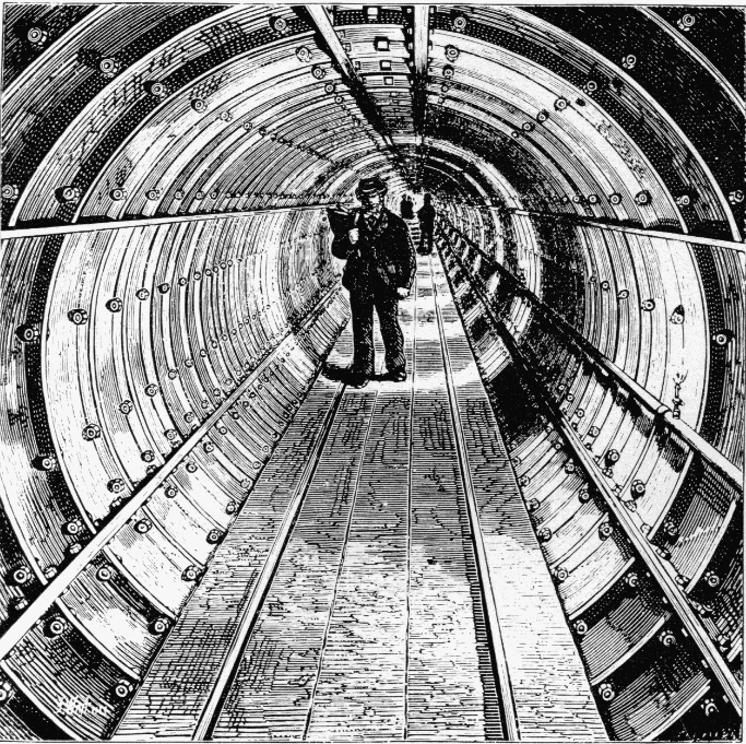
Figure 32.—Interior of completed Tower Subway. (Thornbury, Old and New London, 1887, vol. 1, p. 126.)
The Beach shield operated with perfect success in this brief trial, although the loose sandy soil encountered was admittedly not a severe test of its qualities. No diaphragm was used; instead a series of 8 horizontal shelves with sharpened leading edges extended across the front opening of the shield. The outstanding feature of the machine was the substitution for the propelling screws used by Brunel and Greathead of 18 hydraulic rams, set around its circumference. These were fed by a single hand-operated pump, seen in the center of figure 34. By this means the course of the shield’s forward movement could be controlled with a convenience and [230] precision not attainable with screws. Vertical and horizontal deflection was achieved by throttling the supply of water to certain of the rams, which could be individually controlled, causing greater pressure on one portion of the shield than another. This system has not changed in the ensuing time, except, of course, in the substitution of mechanically produced hydraulic pressure for hand.
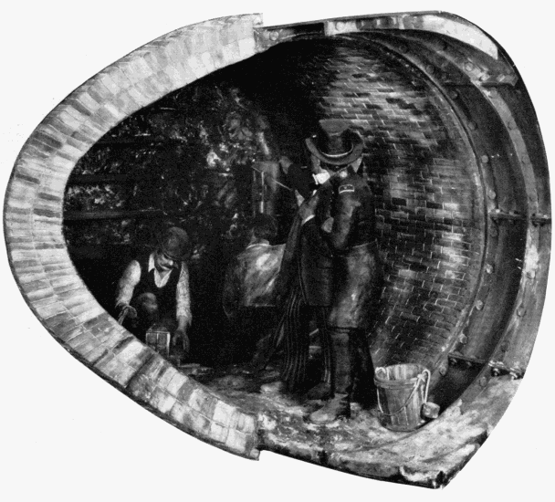
Figure 34.—Beach's Broadway Subway. Advancing the shield by hydraulic rams, 1869. MHT model—11/2" scale. (Smithsonian photo 49260-E.)
Unlike the driving of the Tower Subway, no excavation was done in front of the shield. Rather, the shield was forced by the rams into the soil for the length of their stroke, the material which entered being supported by the shelves. This was removed from the shelves and hauled off. The ram plungers then were withdrawn and a 16-inch length of the permanent lining built up within the shelter of the shield’s tail ring. Against this, the rams bore for the next advance. Masonry lining was used in the straight section; cast-iron in the curved. The juncture is shown in the model.
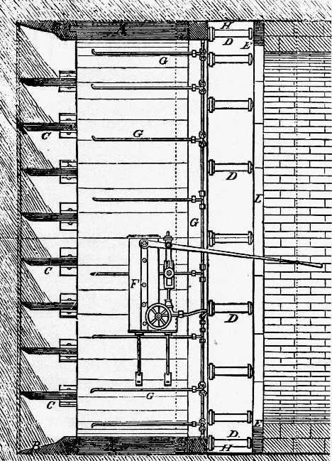
Figure 35.—Vertical section through the Beach shield used on the Broadway Subway, showing the horizontal shelves (C), iron cutting ring (B), hydraulic rams (D), hydraulic pump (F), and rear protective skirt (H). (Scientific American, March 5, 1870.)
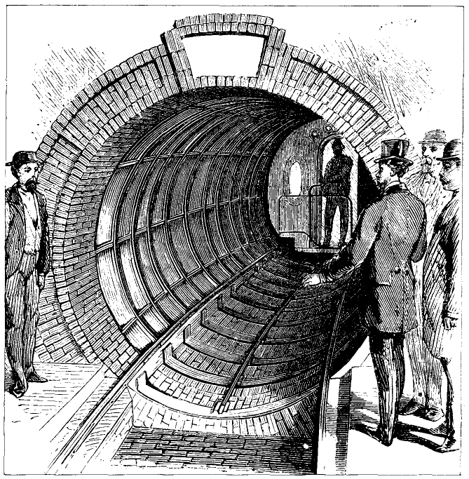
Figure 36.—Interior of Beach Subway showing iron lining on curved section and the pneumatically powered passenger car. View from waiting room. (Scientific American, March 5, 1870.)
Enlarged versions of the Beach shield were used in a few tunnels in the Midwest in the early 1870’s, but from then until 1886 the shield method, for no clear reason, again entered a period of disuse finding no application on either side of the Atlantic despite its virtually unqualified proof at the hands of Greathead and Beach. Little precise information remains on this work. The Beach system of pneumatic transit is described fully in a well-illustrated booklet published by him in January 1868, in which the American Institute model is shown, and many projected systems of pneumatic propulsion as well as of subterranean and subaqueous tunneling described. Beach again (presumably) is author of the sole contemporary account of the Broadway Subway, which appeared in Scientific American following its opening early in 1870. Included are good views of the tunnel and car, of the shield in operation, and, most important, a vertical sectional view through the shield (fig. 35).
It is interesting to note that optical surveys for maintenance of the course apparently were not used. The article illustrated and described the driving each night of a jointed iron rod up through the tunnel roof to the street, twenty or so feet above, for “testing the position.”
THE FIRST HUDSON RIVER TUNNEL
Despite the ultimate success of Brunel’s Thames Tunnel in 1843, the shield in that case afforded only moderately reliable protection because of the fluidity of the soil driven through, and its tendency to enter the works through the smallest opening in the shield’s defense. An English doctor who had made physiological studies of the effects on workmen of the high air pressure within diving bells is said to have recommended to Brunel in 1828 that he introduce an atmosphere of compressed air into the tunnel to exclude the water and support the work face.
This plan was first formally described by Sir Thomas Cochrane (1775-1860) in a British patent of 1830. Conscious of Brunel’s problems, he proposed a system of shaft sinking, mining, and tunneling in water-bearing materials by filling the excavated area with [232] air sufficiently above atmospheric pressure to prevent the water from entering and to support the earth. In this, and his description of air locks for passage of men and materials between the atmosphere and the pressurized area, Cochrane fully outlined the essential features of pneumatic excavation as developed since.
In 1839, a French engineer first used the system in sinking a mine shaft through a watery stratum. From then on, the sinking of shafts, and somewhat later the construction of bridge pier foundations, by the pneumatic method became almost commonplace engineering practice in Europe and America. Not until 1879 however, was the system tried in tunneling work, and then, as with the shield ten years earlier, almost simultaneously here and abroad. The first application was in a small river tunnel in Antwerp, only 5 feet in height. This project was successfully completed relying on compressed air alone to support the earth, no shield being used. The importance of the work cannot be considered great due to its lack of scope.
In 1871 Dewitt C. Haskin (1822-1900), a west coast mine and railroad builder, became interested in the pneumatic caissons then being used to found the river piers of Eads’ Mississippi River bridge at St. Louis. In apparent total ignorance of the Cochrane patent, he evolved a similar system for tunneling water-bearing media, and in 1873 proposed construction of a tunnel through the silt beneath the Hudson to provide rail connection between New Jersey and New York City.

Figure 39.—Haskin's pneumatically driven tunnel under the Hudson River, 1880. In the engine room at top left was the machinery for hoisting, generating electricity for lighting, and air compressing. The air lock is seen in the wall of the brick shaft. MHT model—0.3" scale. (Smithsonian photo 49260.)
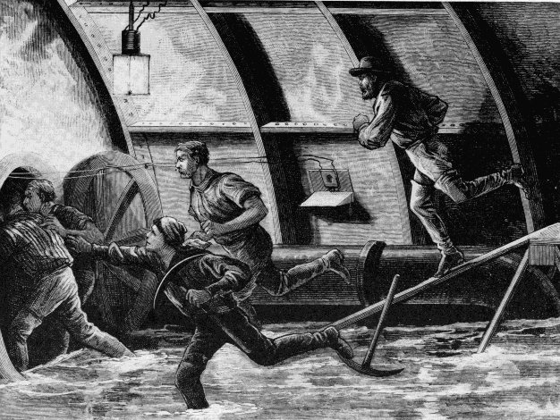
Figure 40.—Artist's conception of miners escaping into the air lock during the blowout in Haskin's tunnel.
It would be difficult to imagine a site more in need of such communication. All lines from the south terminated along the west shore of the river and the immense traffic—cars, freight and passengers—was carried across to Manhattan Island by ferry and barge with staggering inconvenience and at enormous cost. A bridge would have been, and still is, almost out of the question due not only to the width of the crossing, but to the flatness of both banks. To provide sufficient navigational clearance (without a drawspan), impracticably long approaches would have been necessary to obtain a permissibly gentle grade.
Haskin formed a tunneling company and began work with the sinking of a shaft in Hoboken on the New Jersey side. In a month it was halted because of an injunction by, curiously, the D L & W Railroad, who feared for their vast investment in terminal and marine facilities. Not until November of 1879 was the injunction lifted and work again commenced. The shaft was completed and an air lock located in one wall from which the tunnel proper was to be carried forward. It was Haskin’s plan to use no shield, relying solely on the pressure of compressed air to maintain the work faces and prevent the entry of water. The air was admitted in late December, and the first large-scale pneumatic tunneling operation launched. A single 26-foot, double-track bore was at first undertaken, but a work face of such diameter proved unmanageable and two oval tubes 18 feet high by 16 feet wide were substituted, each to carry a single track. Work went forward with reasonable facility, considering the lack of precedent. A temporary entrance was formed of sheet-iron rings from the air lock down to the tunnel grade, at which point the permanent work of the north tube was started. Immediately behind the excavation at the face, a lining of thin wrought-iron plates was built up, to provide form for the 2-foot, permanent brick lining that followed. The three stages are shown in the model in about their proper relationship of progress. The work is shown passing beneath an old timber-crib bulkhead, used for stabilizing the shoreline.
The silt of the riverbed was about the consistency of putty and under good conditions formed a secure barrier between the excavation and the river above. It was easily excavated, and for removal was mixed with water and blown out through a pipe into the shaft by the higher pressure in the tunnel. About half was left in the bore for removal later. The basic scheme was workable, but in operation an extreme precision was required in regulating the air pressure in the work area. [5] It was soon found that there existed an 11-psi difference between the pressure of water on the top and the bottom of the working face, due to the 22-foot height of the unlined opening. Thus, it was impossible to maintain perfect pneumatic balance of the external pressure over the entire face. It was necessary to strike an average with the result that some water entered at the bottom of the face where the water pressure was greatest, and some air leaked out at the top where the water pressure was below the air pressure. Constant attention was essential: several men did nothing but watch the behavior of the leaks and adjusted the pressure as the ground density changed with advance. Air was supplied by several steam-driven compressors at the surface.
The air lock permitted passage back and forth of men and supplies between the atmosphere and the work area, without disturbing the pressure differential. This principle is demonstrated by an animated model set into the main model, to the left of the shaft (fig. 39). The variation of pressure within the lock chamber to match the atmosphere or the pressurized area, depending on the direction of passage, is clearly shown by simplified valves and gauges, and by the use of light in varying color density. In the Haskin tunnel, 5 to 10 minutes were taken to pass the miners through the lock so as to avoid too abrupt a physiological change.
Despite caution, a blowout occurred in July 1880 due to air leakage not at the face, but around the temporary entrance. One door of the air lock jammed and twenty men drowned, resulting in an inquiry which brought forth much of the distrust with which Haskin was regarded by the engineering profession. His ability and qualifications were subjected to the bitterest attack in and by the technical press. There is some indication that, although the project began with a staff of competent engineers, they were alienated by Haskin in the course of work and at least one withdrew. Haskin’s remarks in his own defense indicate that some of the denunciation was undoubtedly justified. And yet, despite this reaction, the fundamental merit of the pneumatic tunneling method had been demonstrated by Haskin and was immediately recognized and freely acknowledged. It was apparent at the same time, however, that air by itself did not provide a sufficiently reliable support for large-area tunnel works in unstable ground, and this remains the only major subaqueous tunnel work driven with air alone.
After the accident, work continued under Haskin until 1882 when funds ran out. About 1600 feet of the north tube and 600 feet of the south tube had been completed. Greathead resumed operations with a shield for a British company in 1889, but exhaustion of funds again caused stoppage in 1891. The tunnel [236] was finally completed in 1904, and is now in use as part of the Hudson and Manhattan rapid-transit system, never providing the sought-after rail link. A splendid document of the Haskin portion of the work is S. D. V. Burr’s Tunneling Under the Hudson River published in 1885. It is based entirely upon firsthand material and contains drawings of most of the work, including the auxiliary apparatus. It is interesting to note that electric illumination (arc, not incandescent, lights) and telephones were used, unquestionably the first employment of either in tunnel work.
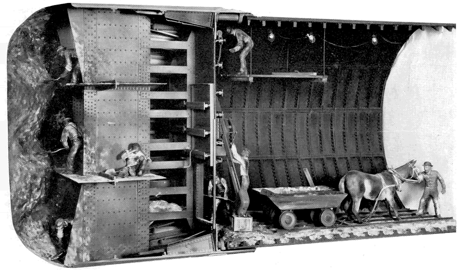
Figure 42.—St. Clair Tunnel. View of front of shield showing method of excavation in firm strata. Incandescent electric illumination was used. 1889-90. MHT model—1" scale. (Smithsonian photo 49260-D.)
THE ST. CLAIR TUNNEL
The final model of the soft-ground series reflects, as did the Hoosac Tunnel model for hard-rock tunneling, final emergence into the modern period. Although the St. Clair Tunnel was completed over 70 years ago, it typifies in its method of construction, the basic procedures of subaqueous work in the present day. The Thames Tunnel of Brunel, and Haskin’s efforts beneath the Hudson, had clearly shown that by themselves, both the shield and pneumatic systems of driving through fluid ground were defective in practice for tunnels of large area. Note that the earliest successful works by each method had been of very small area, so that the influence of adverse conditions was greatly diminished.
The first man to perceive and seize upon the benefits to be gained by combining the two systems was, most fittingly, Greathead. Although he had projected the technique earlier, in driving the underground City and South London Railway in 1886, he brought together for the first time the three fundamental elements essential for the practical tunneling of soft, water-bearing ground: compressed-air support of the work during construction, the movable shield, and cast-iron, permanent lining. The marriage was a happy one indeed; the limitations of each system were almost perfectly overcome by the qualities of the others.
The conditions prevailing in 1882 at the Sarnia, Ontario, terminal of the Grand Trunk Railway, both operational and physical, were almost precisely the same as those which inspired the undertaking of the [237] Hudson River Tunnel. The heavy traffic at this vital U.S.—Canada rail interchange was ferried inconveniently across the wide St. Clair River, and the bank and river conditions precluded construction of a bridge. A tunnel was projected by the railway in that year, the time when Haskin’s tribulations were at their height. Perhaps because of this lack of precedent for a work of such size, nothing was done immediately. In 1884 the railway organized a tunnel company; in 1886 test borings were made in the riverbed and small exploratory drifts were started across from both banks by normal methods of mine timbering. The natural gas, quicksand, and water encountered soon stopped the work.
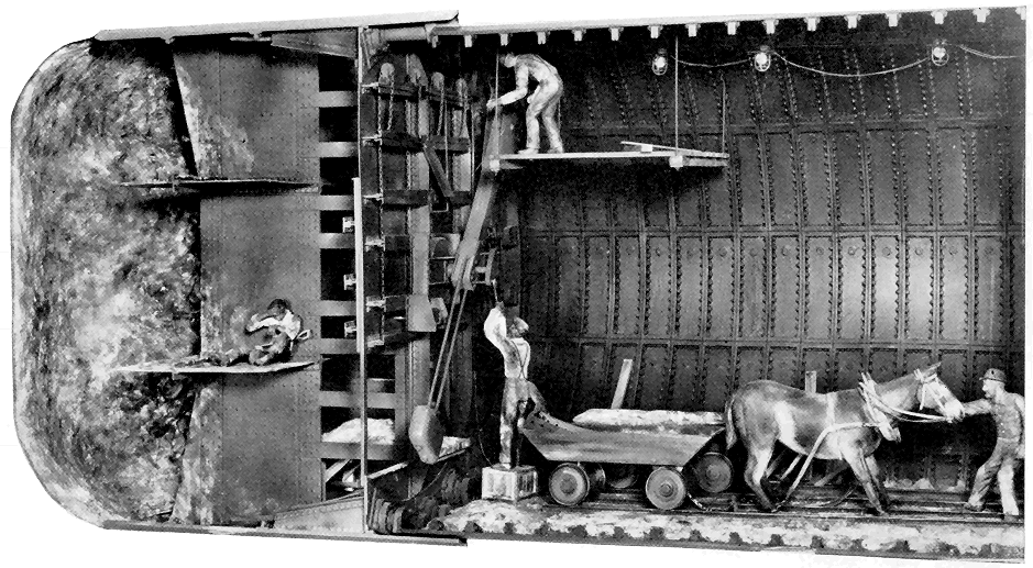
Figure 43.—Rear view of St. Clair shield showing the erector arm placing a cast-iron lining segment. The three motions of the arm—axial, radial, and rotational, were manually powered. (Smithsonian photo 49260-C.)
It was at this time that the railway’s president visited Greathead’s City and South London workings. The obvious answer to the St. Clair problem lay in the successful conduct of this subway. Joseph Hobson, chief engineer of the Grand Trunk and of the tunnel project, in designing a shield, is said to have searched for drawings of the shields used in the Broadway and Tower Subways of 1868-9, but unable to locate any, he relied to a limited extent on the small drawings of those in Drinker’s volume. There is no explanation as to why he did not have drawings of the City and South London shield at that moment in use, unless one considers the rather unlikely possibility that Greathead maintained its design in secrecy.
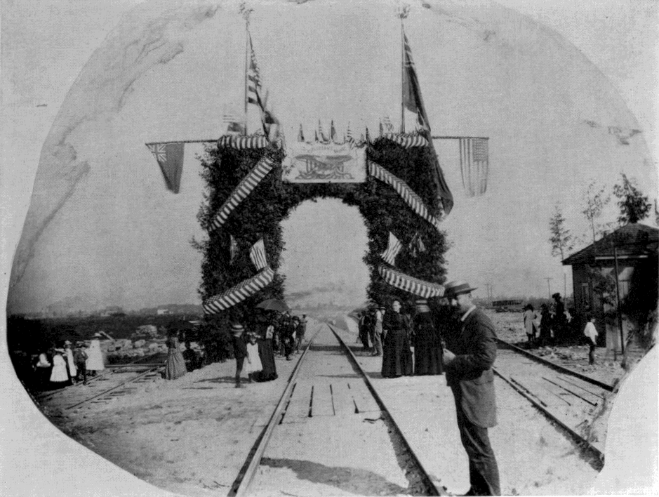
Figure 44.—Opening of the St. Clair Tunnel, 1891. (Photo courtesy of Detroit Library, Burton Historical Collection.)
The Hobson shield followed Greathead’s as closely as any other, in having a diaphragm with closable doors, but a modification of Beach’s sharpened horizontal shelves was also used. However, these functioned more as working platforms than supports for the earth. The machine was 211/2 feet in diameter, an unprecedented size and almost twice that of Greathead’s current one. It was driven by 24 hydraulic rams. Throughout the entire preliminary consideration of the project there was a marked sense of caution that amounted to what seems an almost total lack of confidence in success. Commencement of the work from vertical shafts was planned so that if the tunnel itself failed, no expenditure would have been made for approach work. In April 1888, the [238] shafts were started near both riverbanks, but before reaching proper depth the almost fluid clay and silt flowed up faster than it could be excavated and this plan was abandoned. After this second inauspicious start, long open approach cuts were made and the work finally began. The portals were established in the cuts, several thousand feet back from each bank and there the tunneling itself began. The portions under the shore were driven without air. When the banks were reached, brick bulkheads containing air locks were built across the opening and the section beneath the river, about 3,710 feet long, driven under air pressure of 10 to 28 pounds above atmosphere. For most of the way, the clay was firm and there was little air leakage. It was found that horses could not survive in the compressed air, and so mules were used under the river.
In the firm clay, excavation was carried on several feet in front of the shield, as shown in the model (fig. 42). About twelve miners worked at the face. However, in certain strata the clay encountered was so fluid that the shield could be simply driven forward by the rams, causing the muck to flow in at the door openings without excavation. After each advance, the rams were retracted and a ring of iron lining segments built up, as in the Tower Subway. Here, for the first time, an “erector arm” was used for placing the segments, which weighed about half a ton. In all respects, the work advanced with wonderful facility and lack of operational difficulty. Considering [239] the large area, no subaqueous tunnel had ever been driven with such speed. The average monthly progress for the American and Canadian headings totaled 455 feet, and at top efficiency 10 rings or a length of 15.3 feet could be set in a 24-hour day in each heading. The 6,000 feet of tunnel was driven in just a year; the two shields met vis-a-vis in August of 1890.
The transition was complete. The work had been closely followed by the technical journals and the reports of its successful accomplishment thus were brought to the attention of the entire civil engineering profession. As the first major subaqueous tunnel completed in America and the first in the world of a size able to accommodate full-scale rail traffic, the St. Clair Tunnel served to dispel the doubts surrounding such work, and established the pattern for a mode of tunneling which has since changed only in matters of detail.
Of the eight models, only this one was built under the positive guidance of original documents. In the possession of the Canadian National Railways are drawings not only of all elements of the shield and lining, but of much of the auxiliary apparatus used in construction. Such materials rarely survive, and do so in this case only because of the foresight of the railway which, to avoid paying a high profit margin to a private contractor as compensation for the risk and uncertainty involved, carried the contract itself and, therefore, preserved all original drawing records.
While the engineering of tunnels has been comprehensively treated in this paper from the historical standpoint, it is well to still reflect that the advances made in tunneling have not perceptibly removed the elements of uncertainty but have only provided more positive and effective means of countering their forces. Still to be faced are the surprises of hidden streams, geologic faults, shifts of strata, unstable materials, and areas of extreme pressure and temperature.
Agricola, Georgius. De re Metallica. [English transl. H. C. and L. H. Hoover (The Mining Magazine, London, 1912).] Basel: Froben, 1556.
Beach, Alfred Ely. The pneumatic dispatch. New York: The American News Company, 1868.
Beamish, Richard. A memoir of the life of Sir Marc Isambard Brunel. London: Longmans, Green, Longmans and Roberts, 1862.
Burr, S. D. V. Tunneling under the Hudson River. New York: John Wiley and Sons, 1885.
Copperthwaite, William Charles. Tunnel shields and the use of compressed air in subaqueous works. New York: D. Van Nostrand Company, 1906.
Drinker, Henry Sturgess. Tunneling, explosive compounds and rock drills. New York: John Wiley and Sons, 1878.
Latrobe, Benjamin H. Report on the Hoosac Tunnel (Baltimore, October 1, 1862). Pp. 125-139, app. 2, in Report of the commissioners upon the Troy and Greenfield Railroad and Hoosac Tunnel. Boston, 1863.
Law, Henry. A memoir of the Thames Tunnel. Weale’s Quarterly Papers on Engineering (London, 1845-46), vol. 3, pp. 1-25 and vol. 5, pp. 1-86.
The pneumatic tunnel under Broadway, N.Y. Scientific American (March 5, 1870), pp. 154-156.
Report of the commissioners upon the Troy and Greenfield Railroad and Hoosac Tunnel to his excellency the governor and the honorable the executive council of the state of Massachusetts, February 28, 1863. Boston, 1863.
Storrow, Charles S. Report on European tunnels (Boston, November 28, 1862). Pp. 5-122, app. 1, in Report of the commissioners upon the Troy and Greenfield Railroad and Hoosac Tunnel…. Boston, 1863.
The St. Clair Tunnel. Engineering News (in series running October 4 to December 27, 1890).
[1] There are two important secondary techniques for opening subterranean and subaqueous ways, neither a method truly of tunneling. One of these, of ancient origin, used mainly in the construction of shallow subways and utility ways, is the “cut and cover” system, whereby an open trench is excavated and then roofed over. The result is, in effect, a tunnel. The concept of the other method was propounded in the early 19th century but only used practically in recent years. This is the “trench” method, a sort of subaqueous equivalent of cut and cover. A trench is dredged in the bed of a body of water, into which prefabricated sections of large diameter tube are lowered, in a continuous line. The joints are then sealed by divers, the trench is backfilled over the tube, the ends are brought up to dryland portals, the water is pumped out, and a subterranean passage results. The Chesapeake Bay Bridge Tunnel (1960-1964) is a recent major work of this character.
[2] In 1952 a successful machine was developed on this plan, with hardened rollers on a revolving cutting head for disintegrating the rock. The idea is basically sound, possessing advantages in certain situations over conventional drilling and blasting systems.
[3] In 1807 the noted Cornish engineer Trevithick commenced a small timbered drift beneath the Thames, 5 feet by 3 feet, as an exploratory passage for a larger vehicular tunnel. Due to the small frontal area, he was able to successfully probe about 1000 feet, but the river then broke in and halted the work. Mine tunnels had also reached beneath the Irish Sea and various rivers in the coal regions of Newcastle, but these were so far below the surface as to be in perfectly solid ground and can hardly be considered subaqueous workings.
[4] Unlike the Brunel tunnel, this was driven from both ends simultaneously, the total overall progress thus being 3 feet per shift rather than 18 inches. A top speed of 9 feet per day could be advanced by each shield under ideal conditions.
[5] Ideally, the pressure of air within the work area of a pneumatically driven tunnel should just balance the hydrostatic head of the water without, which is a function of its total height above the opening. If the air pressure is not high enough, water will, of course, enter, and if very low, there is danger of complete collapse of the unsupported ground areas. If too high, the air pressure will overcome that due to the water and the air will force its way out through the ground, through increasingly larger openings, until it all rushes out suddenly in a “blowout.” The pressurized atmosphere gone, the water then is able to pour in through the same opening, flooding the workings.
Paper 41 - Transcriber’s Note
All obvious typographical errors corrected. Formatting inconsistancies and spelling were standardized. Paragraphs split by illustrations were rejoined.
Transcription of the text in Figure 22. The text was transcribed with a slight modification to the figure description portion.
OPEN TO THE PUBLIC EVERY DAY (Sundays excepted)
from Seven in the Morning, until Eight in the Evening,
THE THAMES TUNNEL.
Fig. 1 shows a transverse section of the Thames, and beneath it a longitudinal section of the Tunnel, as it will be when completed; with the ascents in the inclinations in which they will be finished.
Fig. 2 shows the two arched entrances of the Tunnel from the shaft.
Fig. 3 is a representation of the iron shield, and shows a workman in each of the compartments.
The Entrance to the Tunnel is near to Rotherhithe Church, and nearly opposite to the London-Docks. The nearest landing place from the river is Church Stairs. The Greenwich and Deptford coaches which go the lower road, start hourly from Charing-cross, and Gracechurch-street, and pass close by the works at Rotherhithe.
Books relative to the Tunnel may be had at the works.
The Public may view the Tunnel every day (Sundays excepted) from Seven in the morning until Eight in the Evening, upon payment of One Shilling each Person.
The extreme northern end of the Tunnel is for the present secured by a strong wall; but visitors will find a dry, warm, and gravelled promenade, as far as to almost the centre of the river, and brilliantly lighted with oil gas.
The entrance is from Rotherhithe Street, and by a safe, commodious, and easy stair case.
H. Teape & Son, Printers, Tower-hill, London.
[241]
[ToC]
Contributions from
The Museum of History and Technology.
Paper 42
The “Pioneer”: Light Passenger Locomotive of 1851
In the Museum of History and Technology
John H. White
| THE CUMBERLAND VALLEY RAILROAD | 244 |
| SERVICE HISTORY OF THE “PIONEER” | 249 |
| MECHANICAL DESCRIPTION OF THE “PIONEER” | 251 |
| FOOTNOTES | |
| INDEX |

Figure 1.—The “Pioneer,” built in 1851, shown here as renovated and exhibited in the Museum of History and Technology, 1964. In 1960 the locomotive was given to the Smithsonian Institution by the Pennsylvania Railroad through John S. Fair, Jr. (Smithsonian photo 63344B.)
[243]John H. White
The “PIONEER”:
LIGHT PASSENGER LOCOMOTIVE
of 1851
In the Museum of History and Technology
In the mid-nineteenth century there was a renewed interest in the light, single-axle locomotives which were proving so very successful for passenger traffic. These engines were built in limited number by nearly every well-known maker, and among the few remaining is the 6-wheel “Pioneer,” on display in the Museum of History and Technology, Smithsonian Institution. This locomotive is a true representation of a light passenger locomotive of 1851 and a historic relic of the mid-nineteenth century.
The Author: John H. White is associate curator of transportation in the Smithsonian Institution’s Museum of History and Technology.
The “Pioneer” is an unusual locomotive and on first inspection would seem to be imperfect for service on an American railroad of the 1850’s. This locomotive has only one pair of driving wheels and no truck, an arrangement which marks it as very different from the highly successful standard 8-wheel engine of this period. All six wheels of the Pioneer are rigidly attached to the frame. It is only half the size of an 8-wheel engine of 1851 and about the same size of the 4—2—0 so common in this country some 20 years earlier. Its general arrangement is that of the rigid English locomotive which had, years earlier, proven unsuitable for use on U.S. railroads.
These objections are more apparent than real, for the Pioneer, and other engines of the same design, proved eminently successful when used in the service for which they were built, that of light passenger traffic. The Pioneer’s rigid wheelbase is no problem, for when it is compared to that of an 8-wheel engine it is found to be about four feet less; and its small size is no problem when we realize it was not intended for heavy service. Figure 2, a diagram, is a comparison of the Pioneer and a standard 8-wheel locomotive.
Since the service life of the Pioneer was spent on the Cumberland Valley Railroad, a brief account of that line is necessary to an understanding of the service history of this locomotive.
The Cumberland Valley Railroad
The Cumberland Valley Railroad (C.V.R.R.) was chartered on April 2, 1831, to connect the Susquehanna and Potomac Rivers by a railroad through the Cumberland Valley in south-central Pennsylvania. The Cumberland Valley, with its rich farmland and iron-ore deposits, was a natural north-south route long used as a portage between these two rivers. Construction began in 1836, and because of the level valley some 52 miles of line was completed between Harrisburg and Chambersburg by November 16, 1837. In 1860, by way of the Franklin Railroad, the line extended to Hagerstown, Maryland. It was not until 1871 that the Cumberland Valley Railroad reached its projected southern terminus, the Potomac River, by extending to Powells Bend, Maryland. Winchester, Virginia, was entered in 1890 giving the Cumberland Valley Railroad about 165 miles of line. The railroad which had become associated with the Pennsylvania Railroad in 1859, was merged with that company in 1919.
By 1849 the Cumberland Valley Railroad was in poor condition; the strap-rail track was worn out and new locomotives were needed. Captain Daniel Tyler was hired to supervise rebuilding the line with T-rail, and easy grades and curves. Tyler recommended that a young friend of his, Alba F. Smith, be put in charge of modernizing and acquiring new equipment. Smith recommended to the railroad’s Board of Managers on June 25, 1851, that “much lighter engines than those now in use may be substituted for the passenger transportation and thereby effect a great saving both in point of fuel and road repairs….”[1] Smith may well have gone on to explain that the road was operating 3- and 4-car passenger trains with a locomotive weighing about 20 tons; the total weight was about 75 tons, equalling the uneconomical deadweight of 1200 pounds per passenger. Since speed was not an important consideration (30 mph being a good average), the use of lighter engines would improve the deadweight-to-passenger ratio and would not result in a slower schedule.
The Board of Managers agreed with Smith’s recommendations and instructed him “… to examine the two locomotives lately built by Mr. Wilmarth and now in the [protection?] of Captain Tyler at Norwich and if in his judgment they are adequate to our wants … have them forwarded to the road.” [2] Smith inspected the locomotives not long after this resolution was passed, for they were on the road by the time he made the following report [3] to the Board on September 24, 1851:
In accordance with a resolution passed at the last meeting of your body relative to the small engines built by Mr. Wilmarth I proceeded to Norwich to make trial of their capacity—fitness or suitability to the Passenger transportation of our Road—and after as thorough a trial as circumstances would admit (being on another Road than our own) I became satisfied that with some necessary improvements which would not be expensive (and are now being made at our shop) [245] the engines would do the business of our Road not only in a manner satisfactory in point of speed and certainty but with greater ultimate economy in Expenses than has before been practised in this Country.

Figure 2.—Diagram comparing the Pioneer (shaded drawing) with the Columbia, a standard 8-wheel engine of 1851. (Drawing by J. H. White.)
|
Columbia |
Pioneer |
After making the above trial of the Engines—I stated to your Hon. President the result of the trial—with my opinion of their Capacity to carry our passenger trains at the speed required which was decidedly in favor of the ability of the Engines. He accordingly agreed that the Engines should at once be forwarded to the Road in compliance with the Resolution of your Board. I immediately ordered the Engines shipped at the most favorable rates. They came to our Road safely in the Condition in which they were shipped. One of the Engines has been placed on the Road and I believe performed in such a manner as to convince all who are able to judge of this ability to perform—although the maximum duty of the Engines was not performed on account of some original defects which are now being remedied as I before stated.
Within ten days the Engine will be able to run regularly with a train on the Road where in shall be enabled to judge correctly of their merits.
An accident occurred during the trial of the Small Engine at Norwich which caused a damage of about $300 in which condition the Engine came here and is now being repaired—the cost of which will be presented to your Board hereafter. As to the fault or blame of parties connected with the accident as also the question of responsibility for Repairs are questions for your disposal. I therefore leave the matter until further called upon.
The Expenses necessarily incurred by the trial of the Engines and also the Expenses of transporting the same are not included in the Statement herewith presented, the whole amount of which will not probably exceed $400.00.
These two locomotives became the Cumberland Valley Railroad’s Pioneer (number 13) and Jenny Lind (number 14). While Smith notes that one of the engines was damaged during the inspection trials, Joseph Winters, an employee of the Cumberland Valley who claimed he was accompanying the engine enroute to Chambersburg at the time of their delivery, later recalled that both engines were damaged in transit.[4] According to Winters a train ran into the rear of the Jenny Lind, damaging both it and the Pioneer, the accident occurring near Middletown, Pennsylvania. The Jenny Lind was repaired at Harrisburg but the Pioneer, less seriously damaged, was taken for repairs to the main shops of the Cumberland Valley road at Chambersburg.

Figure 3.—“Pioneer,” about 1901, showing the sandbox and large headlamp. Note the lamp on the cab roof, now used as the headlight. (Smithsonian photo 49272.)
While there seems little question that these locomotives were not built as a direct order for the Cumberland Valley Railroad, an article[5] appearing in the Railroad Advocate in 1855 credits their design to Smith. The article speaks of a 2—2—4 built for the Macon and Western Railroad and says in part:
This engine is designed and built very generally upon the ideas, embodied in some small tank engines designed by A. F. Smith, Esq., for the Cumberland Valley road. Mr. Smith is a strong advocate of light engines, and his novel style and proportions of engines, as built for him a few years since, by Seth Wilmarth, at Boston, are known to some of our readers. Without knowing all the circumstances under which these engines are worked on the Cumberland Valley road, we should not venture to repeat all that we have heard of their performances, it is enough to say that they are said to do more, in proportion to their weight, than any other engines now in use.
The author believes that the Railroad Advocate’s claim of Smith’s design of the Pioneer has been confused with his design of the Utility (figs. 6, 7). Smith designed this compensating-lever engine to haul trains over the C.V.R.R. bridge at Harrisburg. It was built by Wilmarth in 1854.

Figure 5.—An early broadside of the Cumberland Valley Railroad.
According to statements of Smith and the Board of Managers quoted on page 244, the Pioneer and the Jenny Lind were not new when purchased from their maker, Seth Wilmarth. Although of recent manufacture, previous to June 1851, they were apparently doing service on a road in Norwich, Connecticut. It [247] should be mentioned that both Smith and Tyler were formerly associated with the Norwich and Worcester Railroad and they probably learned of these two engines through this former association. It is possible that the engines were purchased from Wilmarth by the Cumberland Valley road, which had bought several other locomotives from Wilmarth in previous years. It was the practice of at least one other New England engine builder, the Taunton Locomotive Works, to manufacture engines on the speculation that a buyer would be found; if no immediate buyers appeared the engine was leased to a local road until a sale was made.[6]
Regarding the Jenny Lind and Pioneer, Smith reported[7] to the Board of Managers at their meeting of March 17, 1852:
The small tank engines which were purchased last year … and which I spoke in a former report as undergoing at that time some necessary improvements have since that time been fairly tested as to their capacity to run our passenger trains and proved to be equal to the duty.
The improvements proposed to be made have been completed only on one engine [Jenny Lind] which is now running regularly with passenger trains—the cost of repairs and improvements on this engine (this being the one accidentally broken on the trial) amounted to $476.51. The other engine is now in the shop, not yet ready for service but will be at an early day.

Figure 6.—The “Utility” as rebuilt to an 8-wheel engine, about 1863 or 1864. It was purchased by the Carlisle Manufacturing Co. in 1882 and was last used in 1896. (Smithsonian photo 36716F.)

Figure 7.—The “Utility,” designed by Smith A. F. and constructed by Seth Wilmarth in 1854, was built to haul trains across the bridge at Harrisburg, Pa.

Figure 8.—The earliest known illustration of the Pioneer, drawn by A. S. Hull, master mechanic of the Cumberland Valley Railroad in 1876. It depicts the engine as it appeared in 1871. (Courtesy of Paul Westhaeffer.)
The Pioneer and Jenny Lind achieved such success in action that the president of the road, Frederick Watts, commented on their performance in the annual report of the Cumberland Valley Railroad for 1851. Watts stated that since their passenger trains were rarely more than a baggage car and two coaches, the light locomotives “… have been found to be admirably adapted to our business.” The Cumberland Valley Railroad, therefore, added two more locomotives of similar design in the next few years. These engines were the Boston and the Enterprise, also built by Wilmarth in 1854-1855.
Watts reported the Pioneer and Jenny Lind cost $7,642. A standard 8-wheel engine cost about $6,500 to $8,000 each during this period. In recent years, the Pennsylvania Railroad has stated the Pioneer cost $6,200 in gold, but is unable to give the source for this information. The author can discount this statement for it does not seem reasonable that a light, cheap engine of the pattern of the Pioneer could cost as much as a machine nearly twice its size.
Service History of the Pioneer
After being put in service, the Pioneer continued to perform well and was credited as able to move a 4-car passenger train along smartly at 40 mph.[8] This tranquility was shattered in October 1862 by a raiding party led by Confederate General J. E. B. Stuart which [251] burned the Chambersburg shops of the Cumberland Valley Railroad. The Pioneer, Jenny Lind, and Utility were partially destroyed. The Cumberland Valley Railroad in its report for 1862 stated:
The Wood-shop, Machine-shop, Black-smith-shop, Engine-house, Wood-sheds, and Passenger Depot were totally consumed, and with the Engine-house three second-class Engines were much injured by the fire, but not so destroyed but that they may be restored to usefulness.
However, no record can be found of the extent or exact nature of the damage. The shops and a number of cars were burned so it is reasonable to assume that the cab and other wooden parts of the locomotive were damaged. One unverified report in the files of the Pennsylvania Railroad states that part of the roof and brick wall fell on the Pioneer during the fire causing considerable damage. In June 1864 the Chambersburg shops were again burned by the Confederates, but on this occasion the railroad managed to remove all its locomotives before the raid. During the Civil War, the Cumberland Valley Railroad was obliged to operate longer passenger trains to satisfy the enlarged traffic. The Pioneer and its sister single-axle engines were found too light for these trains and were used only on work and special trains. Reference to table 1 will show that the mileage of the Pioneer fell off sharply for the years 1860-1865.
Table 1.—Yearly Mileage of the Pioneer
(From Annual Reports of the Cumberland Valley Railroad)
| Year: | Miles |
| 1852 | [a] 3,182 |
| 1853 | [b] 20,722 |
| 1854 | 18,087 |
| 1855 | 14,151 |
| 1856 | 20,998 |
| 1857 | 22,779 |
| 1858 | 29,094 |
| 1859 | 29,571 |
| 1860 | 4,824 |
| 1861 | 4,346 |
| 1862 | ( [c] ) |
| 1863 | 5,339 |
| 1864 | 224 |
| 1865 | 2,215 |
| 1866 | 20,546 |
| 1867 | 5,709 |
| 1868 | 13,626 |
| 1869 | 1,372 |
| 1870 | … |
| 1871 | 2,102 |
| 1872 | 4,002 |
| 1873 | 3,721 |
| 1874 | 3,466 |
| 1875 | 636 |
| 1876 | 870 |
| 1877 | 406 |
| 1878 | 4,433 |
| 1879 | … |
| 1880 | 8,306 |
| 1881 | ( [d] ) |
| Total | [e] 244,727 |
[a] Mileage 1852 for January to September (no record of mileage recorded in Annual Reports previous to 1852).
[b] 15,000 to 20,000 miles per year was considered very high mileage for a locomotive of the 1850’s.
[c] No mileage reported for any engines due to fire.
[d] Not listed on roster.
[e] The Pennsylvania Railroad claims a total mileage of 255,675. This may be accounted for by records of mileages for 1862, 1870, and 1879.
In 1871 the Pioneer was remodeled by A. S. Hull, master mechanic of the railroad. The exact nature of the alterations cannot be determined, as no drawings or photographs of the engine previous to this time are known to exist. In fact, the drawing (fig. 8) prepared by Hull in 1876 to show the engine as remodeled in 1871 is the oldest known illustration of the Pioneer. Paul Westhaeffer, a lifelong student of Cumberland Valley R. R. history, states that according to an interview with one of Hull’s descendants the only alteration made to the Pioneer during the 1871 “remodeling” was the addition of a handbrake. The road’s annual report of 1853 describes the Pioneer as a six-wheel tank engine. The report of 1854 mentions that the Pioneer used link motion. These statements are enough to give substance to the idea that the basic arrangement has survived unaltered and that it has not been extensively rebuilt, as was the Jenny Lind in 1878.
By the 1870’s, the Pioneer was too light for the heavier cars then in use and by 1880 it had reached the end of its usefulness for regular service. After nearly thirty years on the road it had run 255,675 miles. Two new passenger locomotives were purchased in 1880 to handle the heavier trains. In 1881 the Pioneer was dropped from the roster, but was used until about 1890 for work trains. After this time it was stored in a shed at Falling Spring, Pennsylvania, near the Chambersburg yards of the C.V.R.R.
Mechanical Description of the Pioneer
After the early 1840’s the single-axle locomotive, having one pair of driving wheels, was largely [252] superseded by the 8-wheel engine. The desire to operate longer trains and the need for engines of greater traction to overcome the steep grades of American roads called for coupled driving wheels and machines of greater weight than the 4—2—0. After the introduction of the 4—4—0, the single-axle engine received little attention in this country except for light service or such special tasks as inspection or dummy engines.
There was, however, a renewed interest in “singles” in the early 1850’s because of W. B. Adams’ experiments with light passenger locomotives in England. In 1850 Adams built a light single-axle tank locomotive for the Eastern Counties Railway which proved very economical for light passenger traffic. It was such a success that considerable interest in light locomotives was generated in this country as well as in England. Nearly 100 single-axle locomotives were built in the United States between about 1845-1870. These engines were built by nearly every well-known maker, from Hinkley in Boston to the Vulcan Foundry in San Francisco. Danforth Cooke & Co. of Paterson built a standard pattern 4—2—4 used by many roads. One of these, the C. P. Huntington, survives to the present time.
The following paragraphs describe the mechanical details of the Pioneer as it appears on exhibition in the Smithsonian Institution’s new Museum of History and Technology.
BOILER
The boiler is the most important and costly part of a steam locomotive, representing one-fourth to one-third of the total cost. A poorly built or designed boiler will produce a poor locomotive no matter how well made the remainder of mechanism. The boiler of the Pioneer is of the wagon-top, crownbar, fire-tube [253] style and is made of a 5/16-inch thick, wrought-iron plate. The barrel is very small, in keeping with the size of the engine, being only 27 inches in diameter. While some readers may believe this to be an extremely early example of a wagon-top boiler, we should remember that most New England builders produced few locomotives with the Bury (dome) boiler and that the chief advocates of this later style were the Philadelphia builders. By the early 1850’s the Bury boiler passed out of favor entirely and the wagon top became the standard type of boiler with all builders in this country.
Sixty-three iron tubes, 17/8 inches by 85 inches long are used. The original tubes may have been copper or brass since these were easier to keep tight than the less malleable iron tubes. The present tube sheet is of iron but was originally copper. Its thickness cannot be conveniently measured, but it is greater than that of the boiler shell, probably about 1/2 to 5/8 inch. While copper tubes and tube sheets were not much used in this country after about 1870, copper was employed as recently as 1950 by Robert Stephenson & Hawthorns, Ltd., on some small industrial locomotives.
The boiler shell is lagged with wooden tongue-and-groove strips about 21/2 inches wide (felt also was used for insulation during this period). The wooden lagging is covered with Russia sheet iron which is held in place and the joints covered by polished brass bands. Russia sheet iron is a planish iron having a lustrous, metallic gray finish.

Figure 13.—Advertisement of Seth Wilmarth appearing in Boston city directory for 1848-1849.
Click here for transcription of advertisement.

Figure 14.—The “Fury,” built for the Boston and Worcester Railroad in 1849 by Wilmarth. It was known as a “Shanghai” because of its great height. (Smithsonian Chaney photo 6443.)

Figure 15.—The “Neptune,” built for the Boston and Worcester in 1847 by Hinkley and Drury. Note the similarity of this engine and the Fury.

Figure 16.—The “Pioneer” as first exhibited in the Arts and Industries building of the Smithsonian Institution prior to restoration of the sandbox. (Smithsonian photo 48069D.)
[BOILER continued]
The steam dome (fig. 18) is located directly over the firebox, inside the cab. It is lagged and jacketed in an identical manner to the boiler. The shell of the dome is of 5/16-inch wrought iron, the top cap is a cast-iron plate which also serves as a manhole cover offering access to the boiler’s interior for inspection and repair.

Figure 18.—“Pioneer” locomotive, (1) Safety valve, (2) spring balance, (3) steam jet, (4) dry pipe, (5) throttle lever, (6) throttle, (7) crown bar, (8) front tube sheet, (9) check valve, (10) top rail, (11) rear-boiler bracket, (12) pedestal, (13) rocker bearing, (14) damper, (15) grate, (16) bottom rail, (17) pump heater valve, (18) cylinder lubricator, (19) reversing lever, (20) brake shoe, (21) mud ring, (22) blowoff cock, (23) ashpan. (Drawing by J. H. White.)
A round plate, 20 inches in diameter, riveted on the forward end of the boiler, just behind the bell stand, was found when the old jacket was removed in May 1963. The size and shape of the hole, which the plate [258] covers, indicate that a steam dome or manhole was located at this point. It is possible that this was the original location of the steam dome since many builders in the early 1850’s preferred to mount the dome forward of the firebox. This was done in the belief that there was less danger of priming because the water was less agitated forward of the firebox.
The firebox is as narrow as the boiler shell and fits easily between the frame. It is a deep and narrow box, measuring 27 inches by 28 inches by about 40 inches deep, and is well suited to burning wood. A deep firebox was necessary because a wide, shallow box suitable for coal burning, allowed the fuel to burn so quickly it was difficult to fire the engine effectively. With the deep, narrow firebox, wood was filled up to the level of the fire door. In this way, the fire did not burn so furiously and did not keep ahead of the fireman; at the same time, since it burned so freely, a good fire was always on hand. The Pioneer burned oak and hickory.[14] For the firebox 5/16-inch thick sheet was used, for heavier sheet would have blistered and flaked off because of the intense heat of the fire and the fibrous quality of wrought-iron sheet of the period. Sheet iron was fabricated from many small strips of iron rolled together while hot. These strips were ideally welded into a homogeneous sheet, but in practice it was found the thicker the sheet the less sure the weld.
The fire grates are cast iron and set just a few inches above the bottom of the water space so that the water below the grates remains less turbulent and mud or other impurities in the water settle here. Four bronze mud plugs and a blowoff cock are fitted to the base of the firebox so that the sediment thus collected can be removed (figs. 17, 18).
The front of the boiler is attached to the frame by the smokebox, which is a cylinder, bolted on a light, cast-iron saddle (not part of the cylinder castings nor attached to them, but bolted directly to the top rail of the frame; it may be a hastily made repair put on at the shops of the C.V.R.R.). The rear of the boiler is attached to the frame by two large cast-iron brackets, one on each side of the firebox (fig. 18). These are bolted to the top rail of the frame but the holes in the brackets are undoubtedly slotted, so that they may slide since the boiler will expand about 1/4 inch when heated. In addition to the crown bars, which strengthen the crown sheet, the boiler is further strengthened by stay bolts and braces located in the wagon top over the firebox, where the boiler had been weakened by the large hole necessary for the steam dome. This boiler is a remarkably light, strong, and compact structure.
BOILER FITTINGS
Few boiler fittings are found on the Pioneer and it appears that little was done to update the engine with more modern devices during its many years of service. With the exception of the steam gauge, it has no more boiler fitting than when it left the builder’s shop in 1851.
The throttle valve is a simple slide valve and must have been primitive for the time, for the balance-poppet throttle valve was in use in this country previous to 1851. It is located directly below the steam dome even though it was common practice to place the throttle valve at the front of the boiler in the smokebox. Considering the cramped condition inside the smokebox, there would seem to be little space for the addition of the throttle valve; hence its present location. The dry pipe projects up into the steam dome to gather the hottest, driest steam for the cylinders. The inverted, funnel-like cap on the top of the dry pipe is to prevent priming, as drops of water may travel up the sides of the pipe and then to the cylinders, with the possibility of great damage. After the steam enters the throttle valve it passes through the front end of the valve, through the top of the boiler via the dry pipe (fig. 18), through the front tube sheet, and then to the cylinders via the petticoat pipes. The throttle lever is a simple arrangement readily understood from the drawings. It has no latch and the throttle lever is held in any desired setting by the wingnut and quadrant shown in figure 18. The water level in the boiler is indicated by the three brass cocks located on the backhead. No gauge glass is used; they were not employed in this country until the 1870’s, although they were commonly used in England at the time the Pioneer was built.
While two safety valves were commonly required, only one was used on the Pioneer. The safety valve is located on top of the steam dome. Pressure is exerted on the lever by a spring balance, fixed at the forward end by a knife-blade bearing. The pressure can be adjusted by the thumbscrew on the balance. The graduated scale on the balance gave a general but uncertain indication of the boiler pressure. The valve itself is a poppet held against the face of the valve seat by a second knife blade attached to the [259] lever. The ornamental column forming the stand of the safety valve is cast iron and does much to decorate the interior of the cab. The pipe carrying the escaping steam projects through the cab roof. It is made of copper with a decorative brass band. This entire mechanism was replaced by a modern safety valve for use at the Chicago Railroad Fair (1949). Fortunately, the old valve was preserved and has since been replaced on the engine.
The steam gauge is a later addition, but could have been put on as early as the 1860’s, since the most recent patent date that it bears is 1859. It is an Ashcroft gauge having a handsome 4—4—0 locomotive engraved on its silver face.
The steam jet (item 3, fig. 18) is one of the simplest yet most notable boiler fitting of the Pioneer, being nothing more than a valve tapped into the base of the steam dome with a line running under the boiler jacket to the smokestack. When the valve is opened a jet of steam goes up the stack, creating a draft useful for starting the fire or enlivening it as necessary. This device was the invention of Alba F. Smith in 1852, according to the eminent 19th-century technical writer and engineer Zerah Colburn.[15]
The two feedwater pumps (fig. 20) are located beneath the cab deck (1, fig. 17). They are cast-iron construction and are driven by an eccentric on the driving-wheel axle (fig. 27). The airchamber or dome (1, fig. 27) imparts a more steady flow of the water to the boiler by equalizing the surges of water from the reciprocating pump plunger. A steam line (3, fig. 18), which heats the pump and prevents freezing in cold weather, is regulated by a valve in the cab (figs. 18, 27). Note that the line on the right side of the cab has been disconnected and plugged.
The eccentric drive for the pumps is unusual, and the author knows of no other American locomotive so equipped. Eastwick and Harrison, it is true, favored an eccentric drive for feed pumps, but they mounted the eccentric on the crankpin of the rear driving wheel and thus produced in effect a half-stroke pump. This was not an unusual arrangement, though a small crank was usually employed in place of the eccentric. The full-stroke crosshead pump with which the Jenny Lind (fig. 22) is equipped, was of course the most common style of feed pump used in this country in the 19th century.
Of all the mechanisms on a 19th-century locomotive, the feed pump was the most troublesome. If an engineer could think of nothing else to complain about, he could usually call attention to a defective pump and not be found a liar. Because of this, injectors were adopted after their introduction in 1860. It is surprising that the Pioneer, which was in regular service as late as 1880 and has been under steam many times since for numerous exhibitions, was never fitted with one of these devices. Because its stroke is [260] short and the plunger is in less rapid motion, the present eccentric arrangement is more complex but less prone to disorder than the simpler but faster crosshead pump.
[BOILER FITTINGS continued]
The check valves are placed slightly below the centerline of the boiler (fig. 18). These valves are an unfinished bronze casting and appear to be of a recent pattern, probably dating from the 1901 renovation. At the time the engine was built, it was usual to house these valves in an ornamental spun-brass casing. The smokestack is of the bonnet type commonly used on wood-burning locomotives in this country between about 1845 and 1870. The exhaust steam from the cylinders is directed up the straight stack (shown in phantom in fig. 27) by the blast pipe. This creates a partial vacuum in the smokebox that draws the fire, gases, ash, and smoke through the boiler tubes from the firebox. The force of the exhausting steam blows them out the stack. At the top of the straight stack is a deflecting cone which slows the velocity of the exhaust and changes its direction causing it to go down into the funnel-shaped outer casing of the stack. Here, the heavy embers and cinders are collected and prevented from directly discharging into the countryside as dangerous firebrands. Wire netting is stretched overtop of the deflecting cone to catch the lighter, more volatile embers which may defy the action of the cone. The term “bonnet stack” results from the fact that this netting is similar in shape to a lady’s bonnet. The cinders thus accumulated in the stack’s hopper could be emptied by opening a plug at the base of the stack.
While the deflecting cone was regarded highly as a spark arrester and used practically to the exclusion of any other arrangement, it had the basic defect of keeping the smoke low and close to the train. This was a great nuisance to passengers, as the low trailing smoke blew into the cars. If the exhaust had been allowed to blast straight out the stack high into the air, most of the sparks would have burned out before touching the ground.

Figure 21.—“Pioneer” on exhibit in old Arts and Industries building of the Smithsonian Institution. In this view can be seen the bonnet screen of the stack and arrangement of the boiler-frame braces and other details not visible from the floor. (Smithsonian photo 48069A.)

Figure 22.—“Jenny Lind,” sister engine of the Pioneer, shown here as rebuilt in 1878 for use as an inspection engine. It was scrapped in March 1905. (Photo courtesy of E. P. Alexander.)
Figures 25 and 26.—Cylinder with valve box removed, showing valve face.
FRAME
The frame of the Pioneer defies an exact classification but it more closely resembles the riveted- or sandwich-type frame than any other (figs. 18, 27). While the simple bar frame enjoyed the greatest popularity in the last century, riveted frames were widely used in this country, particularly by the New England builders between about 1840 and 1860. The riveted frame was fabricated from two plates of iron, about 5/8-inch thick, cut to the shape of the top rail and the pedestal. A bar about 2 inches square was riveted between the two plates. A careful study of photographs of Hinkley and other New England-built engines of the period will reveal this style of construction. The frame of the Pioneer differs from the usual riveted frame in that the top rail is 13/4 inches thick by 41/8 inches deep and runs the length of the locomotive. The pedestals are made of two 3/8-inch plates flush-riveted to each side of the top rail. The cast-iron shoes which serve as guides for the journal boxes also act as spacers between the pedestal plates.
The bottom rail of the frame is a 11/8-inch diameter rod which is forged square at the pedestals and forms the pedestal cap. The frame is further stiffened by two diagonal rods running from the top of each truck-wheel pedestal to the base of the driving-wheel pedestal, forming a truss. Six rods, riveted to the boiler shell and bolted to the frame’s top rail, strengthen the frame laterally. Four of these rods can be seen easily as they run from the frame to the middle of the boiler; the other two are riveted to the underside of the boiler. The attachment of these rods to the boiler was an undesirable practice, for the boiler shell [264] was thus subjected to the additional strain of the locomotive’s vibrations as it passed over the road. In later years, as locomotives grew in size, this practice was avoided and frames were made sufficiently strong to hold the engine’s machinery in line without using the boiler shell.
The front and rear frame beams are of flat iron plate bolted to the frame. The rear beam had been pushed in during an accident, and instead of its being replaced, another plate was riveted on and bent out in the opposite direction to form a pocket for the rear coupling pin. Note that there is no drawbar and that the coupler is merely bolted to the beams. Since the engine only pulled light trains, the arrangement was sufficiently strong.
RUNNING GEAR
The running gear is simply sprung with individual leaf springs for each axle; it is not connected by equalizing levers. To find an American locomotive not equipped with equalizers is surprising since they were almost a necessity to produce a reasonably smooth ride on the rough tracks of American railroads. Equalizers steadied the motion of the engine by distributing the shock received by any one wheel or axle to all the other wheels and axles so connected, thus minimizing the effects of an uneven roadbed. The author believes that the Pioneer is a hard-riding engine.
The springs of the main drives are mounted in the usual fashion. The rear boiler bracket (fig. 18) is slotted so that the spring hanger may pass through for its connection with the frame. The spring of the leading wheels is set at right angles to the frame (fig. 27) and bears on a beam, fabricated of iron plate, which in turn bears on the journal boxes. The springs of the trailing wheels are set parallel with the frame and are mounted between the pedestal plates (fig. 18).
The center of the driving wheel is cast iron and has spokes of the old rib pattern, which is a T in cross section, and was used previous to the adoption of the hollow spoke wheel. In the mid-1830’s Baldwin and others used this rib-pattern style of wheel, except that the rib faced inside. The present driving-wheel centers are unquestionably original. The sister engine Jenny Lind (fig. 22) was equipped with identical driving wheels. The present tires are very thin and beyond their last turning. They are wrought iron and shrunk to fit the wheel centers. Flush rivets are used for further security. The left wheel, shown in figure 17, is cracked at the hub and is fitted with an iron ring to prevent its breaking.
The truck wheels, of the hollow spoke pattern, are cast iron with chilled treads. They were made by Asa Whitney, one of the leading car-wheel manufacturers in this country, whose extensive plant was located in Philadelphia. Made under Whitney’s patent of 1866, these wheels may well have been added to the Pioneer during the 1871 rebuilding. Railroad wheels were not cast from ordinary cast iron, which was too weak and brittle to stand the severe service for which they were intended, but from a high-quality cast iron similar to that used for cannons. Its tensile strength, which ranged from 31,000 to 36,000 psi, was remarkably high and very nearly approached that of the best wrought-iron plate.
The cylinders are cast iron with an 81/2-inch bore about half the size of the cylinders of a standard 8-wheel engine. The cylinders are bolted to the frame but not to the saddle, and are set at a 9° angle to clear the leading wheels and at the same time to line up with the center of the driving-wheel axle. The wood lagging is covered with a decorative brass jacket. Ornamental brass jacketing was extensively used on mid-19th-century American locomotives to cover not only the cylinders but steam and sand boxes, check valves, and valve boxes. The greater expense for brass (Russia iron or painted sheet iron were a cheaper substitute) was justified by the argument that brass lasted the life of the engine, and could be reclaimed for scrap at a price approaching the original cost; and also that when brightly polished it reflected the heat, preventing loss by radiation, and its bright surface could be seen a great distance, thus helping to prevent accidents at grade crossings. The reader should be careful not to misconstrue the above arguments simply as rationalization on the part of master mechanics more intent on highly decorative machines than on the practical considerations involved.
The valve box, a separate casting, is fastened to the cylinder casting by six bolts. The side cover plates when removed show only a small opening suitable for inspection and adjustment of the valve. The valve box must be removed to permit repair or removal of the valve. A better understanding of this mechanism and the layout of the parts can be gained from a study of figures 23-26, 28 (8, 8A, and 8B).

Figure 27.—“Pioneer” locomotive. (1) Air chamber, (2) reversing lever, (3) counterweight, (4) reversing shaft, (5) link hanger, (6) rocker, (7) feedwater line to boiler, (8) link block, (9) link, (10) eccentric, (11) pump plunger, (12) pump steamheater line, (13) feedwater pump, (14) wire netting [bonnet], (15) deflecting cone, (16) stack, (17) stack hopper. (Drawing by J. H. White.)
Click on image to view larger sized.

Figure 28.—Rear elevation of Pioneer and detail of valve shifter; valve face and valve. (Drawing by J. H. White.)
Click on image to view larger sized.
Both crossheads were originally of cast iron but one of these has been replaced and is of steel. They run into steel guides, bolted at the forward end to the rear cylinder head and supported in the rear by a yoke. The yoke is one of the more finished and better made pieces on the entire engine (fig. 27). The main rod is of the old pattern, round in cross section, and only 11/2 inches in diameter at the largest point.
VALVE GEAR
The valve gear is of the Stephenson shifting-link pattern (see fig. 27), a simple and dependable motion used extensively in this country between about 1850 and 1900. The author believes that this is the original valve gear of the Pioneer, since the first mention (1854) in the Annual Report of the Cumberland Valley Railroad of the style of valve gear used by each engine, states that the Pioneer was equipped with a shifting-link motion. Assuming this to be the original valve gear of the Pioneer, it must be regarded as an early application, because the Stephenson motion was just being introduced into American locomotive practice in the early 1850’s. Four eccentrics drive the motion; two are for forward motion and two for reverse. The link is split and made of two curved pieces. The rocker is fabricated of several forged pieces keyed and bolted together. On better made engines the rocker would be a one-piece forging. The lower arm of each rocker is curiously shaped, made with a slot so that the link block may be adjusted. Generally, the only adjustment possible was effected by varying the length of the valve stem by the adjusting nuts provided. A simple weight and lever attached to the reversing shaft serve as a counterbalance for the links and thus assist the engineer in shifting the valve motion. There are eight positions on the quadrant of the reversing lever.

Figure 29.—“Pioneer” on exhibit in old Arts and Industries building, showing the tank and backhead. (Smithsonian photo 48069E.)
MISCELLANEOUS NOTES
The cab is solid walnut with a natural finish. It is very possible that the second cab was added to the locomotive after the 1862 fire. A brass gong used by the [267] conductor to signal the engineer is fastened to the underside of the cab roof. This style of gong was in use in the 1850’s and may well be original equipment.
The water tank is in two sections, one part extending below the deck, between the frame. The tank holds 600 gallons of water. The tender holds one cord of wood.
The small pedestal-mounted sandbox was used on several Cumberland Valley engines including the Pioneer. This box was removed from the engine sometime between 1901 and 1904. It was on the engine at the time of the Carlisle sesquicentennial but disappeared by the time of the St. Louis exposition. Two small sandboxes, mounted on the driving-wheel splash guards, replaced the original box. The large headlamp (fig. 3) apparently disappeared at the same time and was replaced by a crudely made lamp formerly mounted on the cab roof as a backup light. Headlamps of commercial manufacture were carefully finished and made with parabolic reflectors, elaborate burners, and handsomely fitted cases. Such a lamp could throw a beam of light for 1000 feet. The present lamp has a flat cone-shaped piece of tin for a reflector.
The brushes attached to the pilot were used in the winter to brush snow and loose ice off the rail and thus improve traction. In good weather the brushes were set up to clear the tracks.
After the Pioneer had come to the National Museum, it was decided that some refinishing was required to return it as nearly as possible to the state of the original engine. Replacing the sandbox was an obvious change.[20] The brass cylinder jackets were also replaced. The cab was stripped and carefully refinished as natural wood. The old safety valve was replaced, [268]as already mentioned. Rejacketing the boiler with simulated Russia iron produced a most pleasing effect, adding not only to the authenticity of the display but making the engine appear lighter and relieving the somber blackness which was not characteristic of a locomotive of the 1850’s. Several minor replacements are yet to be done; chiefly among these are the cylinder-cock linkage and a proper headlamp.
The question arises, has the engine survived as a true and accurate representation of the original machine built in 1851? In answer, it can be said that although the Pioneer was damaged en route to the Cumberland Valley Railroad, modified on receipt, burned in 1862, and operated for altogether nearly 40 years, surprisingly few new appliances have been added, nor has the general arrangement been changed. Undoubtedly, the main reason the engine is so little changed is that its small size and odd framing did not invite any large investment for extensive alteration for other uses. But there can be no positive answer as to its present variance from the original appearance as represented in the oldest known illustration of it—the Hull drawing of 1871 (fig. 8). There are few, if any, surviving 19th-century locomotives that have not suffered numerous rebuildings and are not greatly altered from the original. The John Bull, also in the U.S. National Museum collection, is a good example of a machine many times rebuilt in its 30 years of service.[21] Unless other information is uncovered to the contrary, it can be stated that the Pioneer is a true representation of a light passenger locomotive of 1851.
[1] Minutes of the Board of Managers of the Cumberland Valley Railroad. This book may be found in the office of the Secretary, Pennsylvania Railroad, Philadelphia, Pa., June 25, 1851. Hereafter cited as “Minutes C.V.R.R.”
[2] Ibid.
[3] Minutes C.V.R.R.
[4] Franklin Repository (Chambersburg, Pa.), August 26, 1909.
[5] Railroad Advocate (December 29, 1855), vol. 2, p. 3.
[6] C. E. Fisher, “Locomotives of the New Haven Railroad,” Railway and Locomotive Historical Society Bulletin (April 1938), no. 46, p. 48.
[7] Minutes C.V.R.R.
[8] Evening Sentinel (Carlisle, Pa.), October 23, 1901.
[9] Norwich Bulletin (Norwich, Conn.), July 24, 1879. All data regarding A. F. Smith is from this source unless otherwise noted.
[10] Railway Age (September 13, 1889), vol. 14, no. 37. Page 600 notes that Tyler worked on C.V.R.R. 1851-1852; Smith’s obituary (footnote 9) mentions 1849 as the year; and minutes of C.V.R.R. mention Tyler as early as 1850.
[11] Minutes C.V.R.R.
[12] A. F. Holley, American and European Railway Practice (New York: 1861). An illustration of Smith’s superheater is shown on plate 58, figure 13.
[13] John H. White, “Introduction of the Locomotive Safety Truck,” (Paper 24, 1961, in Contributions from the Museum of History and Technology: Papers 19-30, U.S. National Museum Bulletin 228; Washington: Smithsonian Institution, 1963), p. 117.
[14] Annual Report, C.V.R.R., 1853.
[15] Zerah Colburn, Recent Practice in Locomotive Engines (1860), p. 71.
[16] Railroad Gazette (September 27, 1907), vol. 43, no. 13, pp. 357-360. These notes on Wilmarth locomotives by C. H. Caruthers were printed with several errors concerning the locomotives of the Cumberland Valley Railroad and prompted the preparation of these present remarks on the history of Wilmarth’s activities. Note that on page 359 it is reported that only one compensating-lever engine was built for the C.V.R.R. in 1854, and not two such engines in 1852. The Pioneer is incorrectly identified as a “Shanghai,” and as being one of three such engines built in 1871 by Wilmarth.
[17] The author is indebted to Thomas Norrell for these and many of the other facts relating to Wilmarth’s Union Works.
[18] Railroad Gazette (October 1907), vol. 43, p. 382.
[19] Boston Daily Evening Telegraph (Boston, Mass.), August 11, 1854. The article stated that one engine a week was built and that 10 engines were already completed for the Erie. Construction had started on 30 others.
[20] The restoration work has been ably handled by John Stine of the Museum staff. Restoration started in October 1961.
[21] S. H. Oliver, The First Quarter Century of the Steam Locomotive in America (U.S. National Museum Bulletin 210; Washington: Smithsonian Institution, 1956), pp. 38-46.
Paper 42 - Transcriber’s Note
P. 259: ‘1880 and has been under steam’—was ‘1880 and has been under stream.’
P. 267: ‘made with parabolic reflectors’—was ‘made with parobolic reflectors.’
Transcription of Advertisement on Pg. 254
   UNION WORKS, SOUTH BOSTON, SETH WILMARTH, Proprietor,
   MANUFACTURER OF LOCOMOTIVES, STATIONARY STEAM ENGINES AND STEAM
   BOILERS, OF THE VARIOUS SIZES REQUIRED, Parts connected with
   Railroads, including Frogs, Switches, Chairs and Hand
   Cars.MACHINISTS' TOOLS, of all descriptions, including TURNING
   LATHES, of sizes varying from 6 feet to 50 feet in length, and
   weighing from 500 pounds to 40 tons each; the latter capable of
   turning a wheel or pulley, thirty feet in diameter. PLANING
   MACHINES, Varying from 2 feet to 60 feet in length, and weighing
   from 200 lbs. to 70 tons each, and will plane up to 55 feet long
   and 7 feet square. Boring Mills, Vertical and Horizontal Drills,
   Slotting Machines, Punching Presses, Gear and Screw Cutting
   Machines, &c. &c. Also, Mill Gearing and Shafting.
   JOBBING AND REPAIRS, and any kind of work usually done in Machine
   Shops, executed at short notice.
Contributions from
The Museum of History and Technology:
Paper 43
History of the Division of Medical Sciences
Sami Hamarneh

Figure 1.—Early View of the United States National Museum, known for the last quarter of a century as the Arts and Industries building. Completed in 1881, it housed the Division of Medical Sciences from its establishment in 1881 as a Section of Materia Medica to the time of the writing of this paper. While the medical collection remained in the Department of Arts and Industries, by the end of June 1912 practically all other collections belonging to the fields of natural history and anthropology were transferred to the then new Natural History building.
[271]Sami Hamarneh
HISTORY of the DIVISION of MEDICAL SCIENCES
In The Museum of History and Technology
This paper traces, for the first time, the history of the Division of Medical Sciences in the Museum of History and Technology from its small beginnings as a section of materia medica in 1881 to its present broad scope. The original collection of a few hundred specimens of crude drugs which had been exhibited at the centennial exhibition of 1876 at Philadelphia, has now developed into the largest collection in the Western Hemisphere of historical objects related to the healing arts.
The Author: Sami Hamarneh is the curator of the Division of Medical Sciences in the Smithsonian Institution’s Museum of History and Technology.
By the early 1870’s, leading figures from both the health professions and the general public had begun to realize the necessity for having the medical sciences represented in the Smithsonian Institution. The impetus behind this new feeling resulted from the action of a distinguished American physician, philanthropist, and author, Joseph Meredith Toner (1825-1896), and came almost a decade before the integration of a new section concerned with research and the historical and educational aspects of the healing arts in the Smithsonian Institution.
In 1872, Dr. Toner established the “Toner Lectures” to encourage efforts towards discovering new truths “for the advancement of medical science … for the benefit of mankind.” To finance these lectures, he provided a fund worth approximately $3,000 to be administered by a board of trustees consisting of the Secretary of the Smithsonian Institution, the Surgeon General of the U.S. Navy, the Surgeon General of the U.S. Army (only in some years), and the president of the Medical Society of the District of Columbia. The interest from this fund was to compensate physicians and scholars who were to deliver “at least two annual memoirs or essays” based on original research on some branch of the medical sciences and containing information which had been verified “by experiments or observations.” [1]
The Secretary of the Smithsonian Institution agreed to have these lectures published by the Institution in its Miscellaneous Collections. The first lecture given by the Assistant Surgeon of the U.S. Army, “On the[272] Structure of Cancerous Tumors and the Mode in which Adjacent parts are Invaded,” deserves credit even by current standards of scientific research.[2] Only 10 lectures were given between 1873 and 1890 (see bibliography), despite the recommendation for at least two every year. [3]

Figure 2.—Dr. Joseph M. Toner, a leading physician in Washington,
D.C., and founder of the “Toner Lectures” for the promotion and
advancement of medical education and research. In 1873, Dr. Toner became
president of the American Medical Association and, in 1874, he became
president of the American Public Health Association. He was a physician
to St. Joseph’s Male Orphan Asylum and St. Ann’s Infants’ Asylum in
Washington, D.C. In addition, he was instrumental in establishing
Providence Hospital in the District of Columbia. He also provided a
workable plan for the American Medical Association’s library in
Washington, D.C. (1868-1871). Among his several publications are:
Contributions to the Annals of Medical Progress and Medical Education
in the United States before and during the War of Independence
(Washington: Government Printing Office, 1874) and Medical Men of the
Revolution (1876). In 1882, he donated his large library, consisting of
44,000 books and pamphlets on topics related mainly to medicine and
history, to the Library of Congress. (Photo courtesy of National
Library of Medicine.)
A more direct factor, which not only contributed to the establishment of a section on the healing arts, but also had a greater effect upon the Smithsonian Institution than any other event since its founding, was the 1876 centennial exhibition in Philadelphia.
This magnificent international fair commemorated the hundredth anniversary of the adoption of the Declaration of Independence. The finest exhibits of 30 foreign countries and various States of the Union participating in the fair were finally donated to the Smithsonian Institution as the official depository of historical and archeological objects for this country. As a result, the Institution’s collections increased to an extent far beyond the capacity of the first Smithsonian building. This led to the erection of the National Museum, known for the last two decades and until date of publication as the Arts and Industries building, which was completed on March 4, 1881, and was used that evening for the inaugural reception of incoming President James A. Garfield.
Section of Materia Medica (1881-1898)
Throughout the 19th century, the study of materia medica (dealing with the nature and properties of [273] drugs of various kinds and origins, their collection and mode of administration for the treatment of diseases, and the medicinal utilization of animal products) held an increasingly important place among the medical sciences. In the United States, as in other civilized countries, this topic was greatly emphasized in the curriculum of almost every school teaching the health professions. Today, the subject matter contained in this branch of science is taught under the heading of several specialized fields, such as pharmacology, pharmacognosy, and drug analysis of various types. However, when the decision was made in 1881 to promote greater knowledge and interest in the healing arts by creating a section devoted to such pursuits in the U.S. National Museum, the title of Section of Materia Medica was adopted. Added to this, was the fact that the bulk of the first collections received in the Section was a great variety of crude drugs, which constituted much of the material then taught in the academic courses of materia medica.
The new Section was included in the Department of Arts and Industries, then under the curatorship of Assistant Director G. Brown Goode. From its beginning and for two decades, however, the Section of Materia Medica was sponsored and supervised by the U.S. Navy in cooperation with the Smithsonian Institution. For this reason, the Navy decided not to establish a similar bureau for a health museum as did the Army in starting the Medical Museum (of the Armed Forces Institute of Pathology) in 1862 through the efforts of Dr. William Alexander Hammond. The Smithsonian did, however, provide a clerk to relieve the curator of much of the routine work. The Section’s early vigorous activities were the result of the ingenuity of the first honorary curator, Dr. James Milton Flint (1838-1919), an Assistant Surgeon of the U.S. Navy. From the establishment of the Section, in 1881, to 1912, Dr. Flint was curator during separate periods for a total of nearly 25 years. For three of his tenures (1881-1884; 1887-1891; 1895-1900), he was detailed to the Smithsonian Institution by the Surgeon General of the U.S. Navy. During the interim periods, other naval doctors were detailed as curators. Finally, in 1900, Dr. Flint retired from the Navy with the rank of Rear Admiral and volunteered to continue his services to the National Museum. The proposal was gladly accepted and he continued as a curator until his retirement from the Smithsonian Institution in 1912.

Figure 3.—Rear Admiral James M. Flint, U.S. Navy surgeon and first honorary curator of the Section of Materia Medica. (Photo courtesy of the Library of Congress.)
The Section commenced with a wealth of material. After the close of the 1876 centennial exhibition, its materia medica collection had been stored with the other collections in a warehouse, awaiting an appropriation by Congress for transfer and installation. This collection was gradually brought into the new National Museum after that building’s completion in 1881. Many other materia medica specimens were transferred from the Department of Agriculture. In addition to these large collections of crude drugs, generous contributions came from several prominent pharmaceutical firms such as Parke, Davis & Company of Detroit, Michigan; Wallace Brothers of Statesville, North Carolina; and Schieffelin and Company of New York City. These manufacturing houses are mentioned here because they and their agents abroad were the first to take interest and donate to the Section, complete assortments of contemporary remedial agents then in common use throughout the United States and[274] Europe, besides many hundreds of “rare and curious drugs.” Thus, in spite of difficulties encountered from bringing several collections into the building at one time, the materia medica exhibition got off to a good start.
It was Dr. Flint, the first curator, who stated in 1883 that remedial agents used by a nation or a community are as indicative of the degree of their cultural development and standard of living as is the nature of their food, the character of their dwellings, and their social and religious traditions. Therefore, he felt that collections of drugs and medical, surgical and pharmaceutical instruments and appliances should not be thought of or designed as instructive to the specialist only, but should also possess a general interest for the public. Because of these objectives, Dr. Flint added, this section was conceived as a departmental division for the collecting and exhibiting of objects related to medicine, surgery, pharmacology, hygiene, and all material related to the health field at large. [4]
During his first term of curatorship (1881-1884), Dr. Flint devoted much of his time to sorting, examining, identifying, and classifying the materia medica specimens. [5] In 1881, he issued a memorandum of instructions to be followed by collectors of drugs and urged them to give detailed and accurate information regarding acquired specimens so that they might be “more than mere museum curiosities.” In addition, in 1883, he prepared a brief manual of classification of the materia medica collection in the Museum as well as a useful, detailed catalog of informational labels of the individual objects on exhibition. The unpublished catalog is still the property of the Smithsonian Institution Archives, Division of Medical Sciences’ Library.
It was Dr. Flint’s ambition to obtain a comprehensive, worldwide collection of all substances used as remedies. Then, in order to identify drugs from foreign countries, he tried to collect illustrated works on medical botany and printed pharmacopoeias of all nations having them. He rightly defined an official pharmacopoeia as “a book containing directions for the identification and preparation of medicines prepared and issued with the sanction of a government or organized and authorized medical and pharmaceutical societies. Its purpose is to establish uniformity in the nomenclature of remedies and in the character and potency of the pharmaceutical preparations. It is enacted by legislation, and thus becomes binding on all who prepare drugs or sell them for medication.” By soliciting the help of various American consuls and Navy officers abroad, about 16 such official pharmacopoeias were collected, making an almost complete international representation of all available, official, drug standards. With these sources of information, Dr. Flint compiled and arranged an international list of materia medica specimens, indicating the authorized preparations of each. By so doing, the first curator of this Section took the initiative at least in proposing and, to some extent acting, on the preparation of an international pharmacopoeia of drugs used in existing authorized formularies giving “official synonyms, and tables showing the constituents and comparative strength of all preparations.” [6] This undertaking is of special importance in the history of American pharmacy, since it was probably the first attempt of its kind in the United States.[7] In addition, colored plates and photographs of medicinal plants were collected, forming the nucleus of the Division’s current collection of pictorial and photographic material related to the history of the health field.
Dr. Flint also put on exhibition 630 Chinese materia medica specimens from the 1876 Philadelphia centennial. These had been collected originally by the Chinese Imperial Customs Commission for the centennial and were subsequently given to this country.
In 1881, the numbered objects in the Section’s register amounted to 1,574 entries. In the following year, 1,590 more specimens were added, most of them drugs in their crude state. By the end of 1883, the total collection had reached 4,037, out of which 3,240 individual drugs in good condition were classified and put on display. Of these, about 500 specimens with beautiful illustrations of parts of their original plants had been mounted for exhibition. The drug exhibitions also included materials transferred from the Department of Agriculture in 1881, which originally had been brought from Central America and South America for the 1876 centennial exhibition, a variety of opium specimens from Turkey, and a number of rare drugs listed in the official formulary which were acquired from the Museum of Karachi in what was then India.
Dr. Flint commented in the Smithsonian Annual Report for 1883 that the collection of cinchona barks was especially complete. It was comprised of specimens of nearly all the natural cinchona barks of South America and every known variety of the cultivated product from the British government plantations in India. In addition, there were specimens from Java, Ceylon, Mexico, and Jamaica. The Indian and Jamaican barks were accompanied by herbarium specimens of the leaf and flower (and, in some cases, the fruit) of each variety of tree from which the bark was obtained.[8]
In an attempt to protect specimens liable to attack by insects, a small piece of blotting paper moistened with chloroform was inserted underneath the stopper in each bottle. Later on, bichloride of mercury was found to be a better insecticide.
These early collections of the Section were brought into admirable condition and received compliments for their organization and completeness. In the Smithsonian Annual Report for 1883, the collections were praised as “superior to any other in the United States and scarcely excelled by any in Europe.”

Figure 4.—Dr. Henry Gustav Beyer, the second honorary curator of the Section of Materia Medica (1884-1887). (Photo courtesy of American Physiological Society.)
In spite of the apparent emphasis on the displaying of drugs, the first curator of the Section had envisioned that the exhibits eventually would embrace the entire field of the healing arts. In the Smithsonian Annual Report for 1883, Dr. Flint noted that “in the establishment of a museum designed to illustrate man and his environment, it is proper that the materials and methods used for the prevention and cure of disease should have a place.” However, his plans were temporarily interrupted when his first term as honorary curator ended in 1884.
On June 4, 1884, Dr. Henry Gustav Beyer was detailed by the Department of the Navy to become the second honorary curator of the Section of Materia Medica. As a young man, Dr. Beyer (1850-1918) had come from Saxony, Germany, to the United States and, in due course, became a naturalized citizen. He[276] was graduated from the Bellevue Hospital Medical College of New York City in 1876.
Because of his interest in physiological experimental research, Dr. Beyer enrolled at the Johns Hopkins University, where he was awarded a Ph. D. degree in 1887. Unlike his predecessor, Dr. Beyer was primarily interested in carrying on research on the physiological action of certain drugs and in pharmacology. This was evident from the original scientific papers mentioned in the Smithsonian Annual Reports and published by him during the period of his curatorship from 1884 to 1887.
Despite the pressure of his postgraduate studies at Johns Hopkins University, Dr. Beyer helped in arranging and classifying the materia medica collection without trying to extend materially the scope of the Section.
After the term of Dr. Beyer expired in 1887, Dr. Flint returned to take charge of the Section. Surprisingly, at this time, it seems that he showed less enthusiasm and devotion to the work of the Museum which he had previously served so well. It could have been a disappointment resulting from a lack of evidence of any real progress in the Section since he had left it three years before. Whatever the reasons may have been, the Smithsonian Annual Reports show that only a few hundred specimens were added to the materia medica collections between 1887 and 1890, bringing the total to 5,915 preserved in good condition. Further curtailment of the Section’s activities began in November 1891 when Dr. Flint was again transferred to other duties for the U.S. Navy. From November 1891 to May 24, 1895, curatorship of the Section was charged to five physicians of the U.S. Navy: Drs. John C. Boyd (from November 1891 to April 6, 1892); William S. Dixon (April 1892 to January 5, 1893); C. H. White (January 1893 to July 15, 1893); C. U. Gravatt (July 1893 to January 22, 1894); R. A. Marmion (January 22, 1894 to June 15, 1894); and to Medical Inspector Daniel McMurtrie (June 1894 to May 24, 1895). During this interim of nearly three and a half years, there were neither literary contributions nor additions made to the collections of the Section that were of any significance. The reason is obvious, for all of these curators averaged less than seven months of service which is not enough time, even for a well-trained individual, to accomplish very much in a museum. Therefore, it is easy to imagine that when the Secretary of the Navy detailed Dr. Flint for a third time to take charge of the Section, he was rather discouraged. Nevertheless, at the Cotton States and International Exposition in Atlanta, Georgia, from September 18 to December 31, 1895, the materia medica was represented by two displays: one on mineral waters and amounts of solid constituents in pure state; and another showing the quantities of minerals after analysis of the composition of the human body.
A similar project was undertaken in 1897 at the Tennessee Centennial Exposition (May 1 to October 31) in Nashville, where there were two displays of materia medica. One showed several kinds of the cinchona barks and the medicinal preparations made from them, and another containing the commercial varieties of the alkaloids of opium.
At this time, Dr. Flint’s attention turned to a new phase of medical exhibition. He felt the need for a program of exhibits on the practice and the historical development of the healing arts. A change of the Section’s name was deemed necessary and, thus, in 1898 the more comprehensive title of Division of Medicine was adopted.
Division of Medicine (1898-1939)
The statement by L. Emmett Holt of the Rockefeller Institute for Medical Research, that before 1906, the Smithsonian Institution was never a beneficiary to medicine in any form,[9] is not entirely applicable. The previous discussion has clearly shown that the U.S. National Museum’s cooperation with the Navy contributed materially towards encouraging and promoting medical knowledge. Furthermore, Dr. Flint tried to bring many of his plans for this medical division of the Museum to a practical fulfillment. He devised a program for presenting medical history in a way which would be of interest both to the public and to the profession. In order to best illustrate the history of the healing art, he divided his subject matter into five provisional classifications according to the Report upon the Condition and Progress of the U.S. National Museum during 1898:
1. Magical medicine including exorcism, amulets, talismans, fetishes and incantation;
2. Psychical medicine including faith cures, and hypnotism;[277]
3. Physical and external medicine including baths, exercise, electricity, massage, surgery, cautery, and blood-letting;
4. Internal medicine including medications and treatment used by the ancient Egyptians, Greeks, Hindus, Arabians, and Chinese; and
5. Preventive medicine including beverages, food, soil, clothing and habitation.
It is certainly to Dr. Flint’s credit that from its early conception, first as Section of Materia Medica and thereafter as Division of Medicine, he planned for an all-embracing exhibition and reference collection of the medical sciences. Until the end of the 19th century and the early years of the 20th century, crude drugs as well as primitive and magic medicine held a more prominent place than medical instruments in the exhibits and collections. In 1905, Flint issued his last, known, literary contribution, “Directions for Collecting Information and Objects Illustrating the History of Medicine,” in Part S of Bulletin of the U.S. National Museum, no. 39. The emphasis he put upon this shows Dr. Flint’s interest in collecting medical and pharmaceutical objects and equipment of historical value. Consequently, he arranged new exhibits including one on American Indian medicine. A medical historian, Fielding H. Garrison, inspected these about 1910 and, in his “An Introduction to the History of Medicine,” wrote of their novelty and appeal. “In the interesting exhibit of folk medicine in the National Museum at Washington,” he commented, “a buckeye or horse chestnut (Aesculus flavus), an Irish potato, a rabbit’s foot, a leather strap previously worn by a horse, and a carbon from an arc light are shown as sovereign charms against rheumatism. Other amulets in the Washington exhibit,” he added, “are the patella of a sheep and a ring made out of a coffin nail (dug out of a graveyard) for cramps and epilepsy, a peony root to be carried in the pocket against insanity, and rare and precious stones for all and sundry diseases.” It had been Dr. Flint’s intention, besides presenting an educational display on the history of the medical arts, to warn the public against the perils of quackery and the faults of folk medicine, as well as to expose evils in drug adulteration. Today, we can see actual fulfillment of these intentions in the present exhibit at the medical gallery which has been executed recently on the basis of scientific, historical research.
After Dr. Flint’s retirement from the Smithsonian Institution in 1912, there was no replacement for over five years. Therefore, the Division of Medicine was placed, for administrative purposes, under the supervision of the curator of the newly reestablished (1912) Division of Textiles, Frederick L. Lewton. During these years, he fought against the dispersal of the medical and materia medica collections. Thus, for lack of a curator of its own, almost all new activities in the Division of Medicine were curtailed until 1917.
On January 31, 1917, Lewton addressed members of the American Pharmaceutical Association inviting them to cooperate in gathering up and preserving at the National Museum the “many unique and irreplaceable objects” connected with the early history of pharmacy in this country which could still be saved.[10] Then, on March 14, 1917, an examination was announced by the Civil Service (held May 2) for an assistant curator for the Division of Medicine, and the position was filled by Joseph Donner on August 16, 1917. Donner was the first full-time employee paid by the Smithsonian Institution for the curatorship of this Division. He held the post until January 31, 1918, when he was inducted into the Sanitary Corps of the United States Army. No significant activities in the Division of Medicine were reported during these few months.
Mr. Donner was followed by a second, full-time, museum officer who promoted a great amount of good will towards the Division during his curatorship of a little over 30 years. Dr. Charles Whitebread (1877-1963), the first pharmacist to head the Division, joined the Smithsonian in 1918 and remained until his retirement in 1948, the longest service, thus far, of any individual in the Division.
Dr. Whitebread received his degree of Doctor of Pharmacy from the School of Pharmacy at George Washington University in Washington, D.C., in 1911. He entered government service late in 1915, but it was not until April 2, 1918, that he agreed to become assistant curator of the Division of Medicine.
Curator Whitebread’s first year was an active and challenging one, for in this new position he began to develop a deep interest in the history of the healing arts. He made a number of important acquisitions, most of them pertaining to pharmaceutical products, synthetic chemicals and crude drugs. He found that many specimens from the older drug collections had deteriorated to such an extent as to be worthless, and he began replacing them with freshly marketed drugs.[278]

Figure 5.—Curator Charles Whitebread inspecting, with admiration, five drug containers from the Squibb collection (1945). (Photo courtesy of the American Pharmaceutical Association.)
Plans were completed for the opening of new medical exhibits and adopting, with some modifications and additions, earlier classifications set by Dr. Flint. Dr. Whitebread grouped these into the following classes: the evaluation of the healing arts; a picture display of medical men prominent in American history;[11] a materia medica display including the history of pharmacy; and an exhibition on Sanitation and Public Hygiene[12] which was later to evolve into the Hall of Health.
In 1920, Dr. Whitebread added a number of specimens of medical-dosage forms and pharmaceutical preparations to the Division’s collections. He also acquired other gifts to complete existing exhibits illustrating the basic principles of the various schools of medicine, such as homeopathy and osteopathy—their methods, tools, and ways of thought.
In 1921, a tablet machine by the Arthur Colton Company of Detroit, Michigan, was acquired, and an exhibit illustrating vaccine and serum therapy was installed in the medical gallery. This was followed, in 1922, by a collection arranged to tell the story of the prevention and cure of specific diseases by means of biological remedies.
During the following two years, two more exhibits related to hospital supplies and sanitation were added to the rapidly developing Hall of Health exhibition which was opened in 1924. A third exhibit in 1925 consisted of 96 mounted color transparencies illustrating services provided by hospitals to promote public health. Plans for the further development of the Hall of Health continued during 1926, and contacts were made with organizations interested in the educational aspects of the healing arts. As a result, several new exhibits were added. In 1926, the American Optometric Association helped in the installation of an exhibit on conservation of vision or the care of the eyes under the slogan “Save your vision,” as a phase of health work. Other exhibits in the Hall at this time were: what parasites are; water pollution and how to obtain pure water; waste disposal; ventilation and healthy housing, and the importance of recreation; purification of milk and how to obtain pure milk; transmission of diseases by insects and animals; how life begins; prenatal and postnatal care and preschool care; duties of the public health nurse; and social, oral and mental hygiene.
With the acquiring of more medical appliances and the widening of the scope of the exhibits, more and more space was needed, and attention was turned to the area of the medical gallery which had been occupied by the materia medica collection for almost four decades. To gain more exhibit space, it was decided that the greater part of the crude drugs should be removed from the exhibits and be kept as a reference collection and for research.[13]

Figure 6.—Exhibit on Egyptian and Hebrew medicine, installed about 1924, which was illustrated by graphs and drugs mentioned in extant records of this ancient period. (Smithsonian photo 30796-C.)

Figure 8.—Exhibit on remedies derived from drugs of vegetable origin, displayed about mid-1930’s. (Smithsonian photo 30439.)
In 1926, original patent models including those related to pharmacy, medicine, and dentistry, were transferred from the U.S. Patent Office to the National Museum. These patent models, together with other apothecary tools and the machines used in drug production took up most of the available space. This unfortunate situation led Dr. Whitebread to turn down significant medical and pharmaceutical collections offered the Museum between 1927 and 1930. Since the patent models were devised for inventions designed to simplify the practice of the health professions, three cases of these models were displayed in the medical gallery in the early 1930’s. Other exhibits shown during this decade included the deception of folk medicine with warnings against superstitions, and an exhibition on osteopathy,[14] as well as dioramas on the manufacture of medicines and their use in scientific medical treatment.
In the meantime, Dr. Whitebread was an active contributor to the literature of the health field in various periodicals, as well as in pamphlets issued by the Museum and other governmental agencies (see bibliography). His literary contributions, guided by the exhibits he designed and the collections he acquired, were focused on the Division’s collections, such as primitive and psychic medicine and warnings against reliance on magic and superstitions in treatment, medical oddities, and the utilization of drugs of animal origin, both past and present.
Division of Medicine and Public Health (1939-1957)
After taking charge of the Division of Medicine in 1918, Dr. Whitebread gave special attention to public health displays. His activities in this area were accelerated after 1924 when the health exhibit at the [282]Smithsonian Institution was inaugurated. As the exhibits in this field increased, the Division, in 1939, took the more comprehensive title of Division of Medicine and Public Health. Also, in 1939, Dr. Whitebread was promoted to the rank of associate curator.

Figure 9.—Exhibit on methods of treatment of diseases through mental impressions and psychic conditions as displayed about 1925. (Smithsonian photo 30796-B.)

Figure 10.—An exhibit on superstitions, empiricism, magic, and faith healing in the light of scientific medicine, completed in 1962, is in sharp contrast with that shown in figure 9.
He continued his efforts to collect more specimens of interest to medical history and to contribute to the literature. Among exhibited specimens in 1941 were a powder paper-crimping machine, a portable drug crusher, an odd device for spreading plaster on cloth, a pill-coating apparatus, various suppository molds, a lozenge cutter, and an ingenious Seidlitz powder machine. The derivation of medicinal drugs from animal, vegetable, and mineral sources was also depicted, as were synthetic materials and their intermediates. Basic prescription materials were displayed, and rows of glass-enclosed cases held samples of crude botanical drugs from almost every part of the globe with explanatory cards giving brief, concise descriptions. The exhibition provided medical and pharmaceutical students about to take state-board examinations, the opportunity to study the subject in detail, especially the enormous collection of materia medica samples.[15] Also in 1941, Eli Lilly and Company donated an exhibit on the medical treatment of various types of anemia. In the same year, a diorama including a hypochlorinator for purification of water on a farm was installed in the gallery. In 1942, the first Emerson iron lung (developed in 1931 by John Haven Emerson) for artificial respiration was acquired by the Division. The Division acquired, in 1944, the first portable x-ray machine known to have been operated successfully on the battlefield, as well as other x-ray equipment and early medicine chests.

Figure 11.—Old public health exhibition installed in the gallery about 1924. (Smithsonian photo 19952.)

Figure 12.—The Hall of Health, reestablished and opened in November 1957. (Smithsonian photo 44931.)

Figure 13.—Early exhibit on homeopathy showing its history, methods and remedies which was installed about 1929. (Smithsonian photo 27049.)
Without a doubt, the most outstanding accession in the field of pharmaceutical history during Dr. Whitebread’s years of service was the acquisition of the E. R. Squibb and Sons old apothecary shop. Most of the baroque fixtures, including the stained-glass windows with Hessian-Nassau coats of arms and wrought-iron frames, were part of the mid-18th-century cathedral pharmacy “Münster Apotheke” in Freiburg im Breisgau, Germany. It was offered for sale in September 1930 by Dr. Jo Mayer of Wiesbaden, Germany, who was an enthusiastic collector of antiques, especially those related to the health professions. Earlier that year, a historian of pharmacy and chemistry, Fritz Ferchl of Mittenwald, Germany, had published a series of scholarly and informative articles on the Meyer collection in which the outstanding specimens were beautifully portrayed and thoroughly described (see bibliography).
As a result of Dr. Mayer’s efforts to sell his collection, the impact of Ferchl’s illustrated articles, and the uniqueness of the collection, E. R. Squibb and Sons purchased it in 1932 and brought it to the United States “with the thought that it would provide for American pharmacy, its teachers and students, a museum illuminating the history, growth, and development of pharmacy, its interesting background and struggle through the ages.” It was displayed at the Century of Progress exposition held in Chicago during 1933 and 1934; subsequently, it was assembled in the Squibb Building in New York City as a private museum where, for about 10 years, it was visited by many interested in pharmacy, ceramics, and art. Charles H. LaWall, who was originally engaged to prepare a descriptive catalog on the exhibit, gave it the title “The Squibb Ancient Pharmacy.”
Late in 1943, E. R. Squibb and Sons offered the collection as a gift to the American Pharmaceutical Association if the latter would provide museum space [286] for it. The offer was accepted, but the Association finally found it difficult to spare the needed space for the collection and decided to take up the matter with the U.S. National Museum.

Figure 14.—This early exhibit on osteopathy was renovated several times prior to the early 1940’s. (Smithsonian photo 19250.)
At this point, it should be stated that since 1883 the members of the American Pharmaceutical Association have been keenly interested in having the National Museum serve as the custodian for all collected objects and records of historical interest to pharmacy. In 1944, the Association officially offered to deposit on permanent loan, the Squibb’s pharmacy collection in the Smithsonian Institution with the understanding that a suitable place would be provided for prompt and permanent display. The offer was accepted, and during April and May of 1945, the entire collection was transferred to the Smithsonian Institution, and construction to recreate the original two rooms for the old, 18th-century, European “Apotheke” was underway.
By August 1946, the exhibit was completed. In the large room where the pharmacist met his customers, the shelves were filled with 15th- to 19th-century, European pharmaceutical antiques. These included Renaissance mortars; 16th- and 17th-century nested weights; beautiful Italian, French, Swiss, and German majolica and faience drug jars; Dutch and English delft; drug containers made of flint or opal glass with fused-enamel labels with alchemical symbols; rare, 16th-century, wooden drug containers, each with the coat of arms of the city in which each was made; and two glass-topped, display tables contained franchises issued and signed by Popes or state rulers, medical edicts, dispensatories, herbals, pharmacopoeias, and pharmaceutical utensils.
On the walls in the small laboratory room, which also had been used as a workshop and a study, were a stuffed crocodile, shark’s head, tortoise, fish, and salamander, parts of which were utilized as remedial agents. Their presence provided tangible evidence that the pharmacy dispensed genuine drugs and not substitutes.
The pharmaceutical profession in this country hailed the outstanding exhibition, and the November 1946 issue of the [287] Journal of the American Pharmaceutical Association, Practical Pharmacy Edition, devoted its front cover to depicting one corner of the study and laboratory room of the shop.[16] Also, in a letter dated January 2, 1947, addressed to Dr. Alexander Wetmore, then Secretary of the Smithsonian Institution, Dr. Robert P. Fischelis, the secretary of the American Pharmaceutical Association, considered the completion of the deposited exhibition a triumph and “as one of the highlights of the accomplishments of the Association in 1946.”
From 1946 to 1948, the Division’s collection was further enriched with a number of historical specimens, among which was a “grosse Flamme” x-ray machine with induction-coil tube and stand developed by Albert B. Koett. It is one of the earliest American-made machines of its kind, producing a 12-inch spark, the largest usable at that time with 180,000-volt capacity, and a forerunner of later autotransformers. Other accessions included two 19th-century drug mills, an electric belt used in quackery, two medicine chests, three sets of Hessian crucibles used in a pioneer drugstore in Colorado, a drunkometer, mineral ores, and purely produced chemical elements.

Figure 15.—Late 16th-century, wooden drug container with coat-of-arms, in the Squibb collection. The inscription Ungula Alcis (the hoof of the elk) suggests a superstitious attitude in medical practice and the wide use of animal organs in medical treatment. (Courtesy of the American Pharmaceutical Association.)
In the spring of 1948, Associate Curator Whitebread retired after 30 years of service with the U.S. National Museum. He was a pioneer in the field of health museums and during his curatorship had developed a moribund section into a Division of field-wide importance. Dr. Whitebread was succeeded by George S. Thomas, also a pharmacist, who served as associate curator from August 1948 until early 1952.

Figure 17.—The Apothecary Shop as seen in the Arts and Industries building (1946-1964). (Courtesy of the American Pharmaceutical Association.)

Figure 18.—View of the laboratory and study room of the apothecary shop. On the left, the German-Swiss bronze mortar and pestle (1686) sign and above it an 18th-century German painting on canvas of Christ, “the apothecary of the soul.” The drug containers represent “the fruits of the spirit,” faith, patience, charity, etc., and the scales represent justice. Underneath is the verse from Matthew, 11:28, “Come unto me, all ye that labour and are heavy laden, and I will give you rest.” (Courtesy of the American Pharmaceutical Association.)
During his almost-three and a half years of service, Thomas acquired hearing-aid appliances from which he designed an exhibit on the development of these aids, surgical sutures, early samples of Aureomycin, and a static-electricity machine made by Henkel about 1840. He also published three short articles under the title, “Now and Then,” in the National Capital Pharmacist (1950), no. 1, pp. 8-9; no. 2, pp. 18-19, 29; and no. 3, pp. 15-16. In early 1952, Dr. Arthur O. Morton presented to the Division, a Swiss-made keratometer which he had purchased in 1907, and it is believed to be one of the first used in the United States to measure the curves of the cornea.
The achievements of the Division reached their highest point, thus far, in significantly increasing the national collection, as well as in contributing to the scientific, historical, and professional literature, under the curatorships of George B. Griffenhagen (December 8, 1952, to June 27, 1959) and John B. Blake (July 1, 1957, to September 2, 1961). Their reorganization of exhibits and collections, their competence and industry, fulfilled the hopes, plans, and purposes laid down by earlier curators for the Division.
Immediately after assuming the responsibilities of the Division and throughout 1953, Mr. Griffenhagen (M.S. in pharmaceutical chemistry from the University of Southern California) undertook to develop the collections still further. He increased the emphasis not only on historical pharmacy, but also on medicine, surgery, and dentistry. He also renovated the exhibits in the medical gallery.
In 1954, several antibiotics were donated to the Division including a mold of Penicillium notatum prepared and presented to the Smithsonian Institution by Sir Alexander Fleming (1881-1955), the discoverer of penicillium (1929), and a few Petri dishes used by botanist Benjamin M. Daggar who, while working for Lederle Laboratories, developed Aureomycin (chlortetracycline) in 1948. The Forest D. Dodrill—G.M.R. mechanical heart (1952), the first machine reported to be used successfully for the complete bypass of one side of the human heart during a surgical operation, [17] was presented to the Smithsonian Institution.
The following year, 1955, the Division acquired one of the earliest Einthoven string galvanometers (named after the Dutch physiologist Willem Einthoven, 1860-1927) made in the United States in 1914 by Charles F. Hindle for an electrocardiograph. Also added to the Division’s collections was the electrocardiograph used by Dr. Frank E. Wilson of the United States, a pioneer educator in this field. Two temporary exhibits on allergy and surgical dressings were installed in the gallery. In the same year, Curator Griffenhagen published Early American Pharmacies, a catalog on 28 pharmacy restorations in this country.
In 1956, among many publications of interest in the fields of medical and pharmaceutical history, was Curator Griffenhagen’s Pharmacy Museum, with a foreword by Laurence V. Coleman, who termed it a useful catalog and “a good reflection of the history of the museum movement at large.” A third x-ray tube of Wilhelm Konrad Roentgen (1845-1922) was added to the collection in 1957 as well as a complete set of hospital-ward fixtures of about 1900 from the Massachusetts General Hospital, rare patent medicines, 18th-century microscopes, and a 13th-century mortar and pestle made in Persia.
In 1957, Mr. Griffenhagen published a series of illustrated articles in the Journal of the American Pharmaceutical Association, Practical Pharmacy Edition, which were later reprinted by the Association in a booklet entitled, Tools of the Apothecary. In it, he described several pharmaceutical specimens in the collection and their place in history.
Division of Medical Sciences (1957 to Present)
The U.S. National Museum was reorganized on July 1, 1957, into two units, the Natural History Museum and the Museum of History and Technology. At the same time, and in view of the widening scope of the Division, its more scientifically based planning, and the constantly increasing collection with equal emphasis on all branches of the healing arts, the Division’s title was changed to the Division of Medical Sciences—the title it still bears in 1964. With the reorganization, the Department of Engineering and Industries, under which the Division fell administratively, was renamed the Department of Science and Technology of the Museum of History and Technology. It was also the first time since its establishment in 1881 that the Division had two curators, for on July 1, 1957, Dr. John B. Blake joined the staff.[291]

Figure 19.—Curators John B. Blake and George Griffenhagen examine the newly acquired (1957) electromagnetic, Morton-Wimshurst-Holz Influence Machine. It was manufactured by the Bowen Company of Providence, Rhode Island (1889). With the discovery of x-ray, it was used for making x-ray photographs until early in the 20th century.
As a result of these changes, the Division was subdivided into a Section of Pharmaceutical History and Health and a Section of Medical and Dental History. The former was planned to encompass the collections of materia medica, pharmaceutical equipment, and all material related to the history of pharmacy, toxicology, pharmacology, and biochemistry, as well as the Hall of Health which was opened November 2, 1957, and which emphasizes man’s progressing knowledge of his body and the functions of its major organs. [18] The latter Section was planned to include all that belongs to the development of surgery, medicine, dentistry, and nursing, especially in relation to hospitals.
In October 1957, the Division acquired a collection of rare, ceramic, drug jars which included two, 13th-century, North Syrian and Persian, albarello-shaped, majolica jars; a 15th-century, Hispano-Moresque drug container; and a 16th-century, Italian faience, dragon-spout ewer. During the following two years, Curator Griffenhagen periodically toured museums and medical and pharmaceutical institutions in this country, South America, and Europe gathering specimens and information for the Division and for publication, respectively. However, on June 27, 1959, he resigned his curatorship to join the staff of the American Pharmaceutical Association in Washington, D.C. Dr. Blake became the curator in charge of the Division and Mr. Griffenhagen was succeeded on September 24, 1959, by the author of this paper as associate curator in charge of the Section of Pharmaceutical History and Health.
Dr. Blake, as curator of the Section of Medical and Dental History, acquired a large number of valuable and varied specimens for the Division’s collections. They included optometric refracting instruments, an early 1920’s General Electric, portable, x-ray machine, the Charles A. Lindbergh and Alexis Carrel pump (designed in 1935 to perfuse life-sustaining fluids to the organs of the body), the Sewell heart pump (1950) to control delivery of air pressure and suction to the pumping mechanism, and a large and valuable collection of dental equipment formerly at the universities of Pennsylvania and Illinois. Dr. Blake wrote the explanatory material and supervised the design and production of the majority of exhibits in the renovated hall of medical and dental history. He also contributed several scholarly articles and a book (see bibliography) on the history of the healing arts and public health in particular. He resigned on September 2, 1961, to join the staff of the National Library of Medicine as chief of the History of Medicine Division, and was succeeded by the author as curator of the Division. From the summer of 1962 to April 1964, the Division benefited from the expert advice of Dr. Alfred R. Henderson as consultant in the preparation and designing of the surgical and medical exhibits of the Museum of History and Technology.
During the period from 1961 to May 1964, the Division’s collections expanded greatly through its [292]medical, dental, and pharmaceutical acquisitions. Specimens of antiques acquired from 1961 through 1963 numbered up to 1,539 and included gifts from leading institutions and individual philanthropists. The scope of these gifts and acquisitions ranges from electronic resuscitators, microscopes, x-ray equipment, and spectacles, to patent medicines, amulets, apothecary tools, dental instruments, and office material of practitioners.

Figure 20.—Exhibit on spectacles, lorgnettes, optometers, and refraction, completed in 1960. It features a cross section of the Division’s large collection of eyeglasses. (Smithsonian photo 47943-D.)
In the last decade, the interest in the national endeavor for promoting research and scholarship in the history of medicine has increased greatly. It was most appropriate, therefore, for the Smithsonian Institution to play host on May 2 for two sessions of the 37th annual meeting of the American Association for the History of Medicine held in the Washington, D.C., area from April 30 through May 2, 1964. In welcoming the members to the morning session in the auditorium of the new Museum of History and Technology, Frank A. Taylor, director of the United States National Museum, expressed the feeling that the meeting of the Association was, in a sense, a dedication of the new auditorium and an opportunity for the Smithsonian to reaffirm its deep interest and commitment in fostering research and furthering the appreciation of scholarly endeavor in the history of the healing arts.
A New Dimension For the Healing Arts
“One day the United States will have a National Museum of science, engineering, and industry, as most large nations have.” This was the prediction made in 1946 by the director of the U.S. National Museum, Mr. Frank A. Taylor, then curator of the Division of Engineering. [19] It was in 1963, that the new $36,000,000 building of the Museum of History [293] and Technology was completed, and opened to the public in 1964. The offices of the Division of Medical Sciences as well as the reference and study collections were moved to the fifth floor of the new building. The exhibits, however, will be displayed in the gallery at the southwest corner of the first floor. These exhibits, it is hoped, will show a new dimension and an unprecedented approach in displaying the development of the healing arts throughout the ages and the instruments and equipment associated with health professions. They also present the expanding objectives and plans of the Division’s growth as an integral part of the Smithsonian Institution. Conveniently, the exhibits form four, closely connected halls in one large gallery which will be open to the public in the summers of 1965 to 1966.

Figure 21.—Exhibit on the development of blood-pressure instruments and the early 20th-century sphygmomanometers which was completed in 1960. (Smithsonian photo 47943-M.)
1. The Hall of Health displays models and graphic and historical exhibit materials to demonstrate the function of the various healthy organs of the human body. The main topics emphasized are: embryology and childbirth; tooth structure; the heart and blood circulation; respiration; the endocrine glands; kidneys and the urinary-excretory system; the brain and the nervous system; the ear; and vision and the use of eyeglasses.
The most appreciated exhibit of all in this Hall is the “transparent woman” figure which rotates, automatically, every 15 minutes with a recorded message describing the function of each major organ of the body at the same time that the organ is electronically lighted, so that the viewer can see its place in the body.

Figure 22.—Hearing-aid exhibit designed in 1962. It includes otologist Julius Lempert’s personal memorabilia and original surgical instruments used in the fenestration operation for restoring hearing. (Smithsonian photo 49345-C.)
2. The Hall of Medicine and Dentistry will depict the history of these two sciences with exhibits of the equipment used through the centuries. In the medical field, early trephining and other surgical instruments will be displayed along with a diorama of an 1805 surgical operation performed by Dr. Philip Syng Physick in the amphitheater of the Pennsylvania Hospital. Diagnostic instruments such as stethoscopes, endoscopes, speculums, and blood-pressure measuring devices will be exhibited with a series of microscopes illustrating the development of these instruments. Exhibits of original galvanometers and other apparatus will trace the development of cardiography. The early use of anesthesia will be shown by apparatus of William Morton and Crawford W. Long, American pioneers in this field. The development of the devices of modern medicine and surgery will be shown by exhibits of the iron lung and x-ray tubes, including a tube used by W. K. Roentgen. Medicine chests and surgical kits of different periods will graphically summarize the state of medical science in the period each represents.
Exhibits on the development of dentistry and dental surgery will display examples of tooth-filling and extracting tools, drilling apparatus from the early hand and foot engines to the first ultrasonic cutting instrument (1954), and the original contra-angle, [295] hydraulic and air-turbine handpiece model [20] which revolutionized the field of instrumentation for dental surgery (with speeds of 200,000 to 400,000 rpm). This hydraulic turbine of Dr. Robert J. Nelson and associates of the National Bureau of Standards set the design pattern for the remarkable and successful high-speed, air-turbine handpiece developed by Paul H. Tanner and Oscar P. Nagel of the U.S. Naval Dental School in 1956. Also underway is the reconstruction of the offices of famous dentists such as G. V. Black and the father of American orthodontia, Edward H. Angle, using their original equipment and instruments. In addition, an exhibit is planned to include x-ray tubes and the electric dental engine, the first to be operated in a human mouth by the pioneer dentist on dental skiagraphy, Charles E. Kells (1856-1928). [21]

Figure 23.—Exhibit on nursing bottles and measures to promote child health to counteract the once-common diseases of childhood. This display was completed in 1962. (Smithsonian photo 49345-G.)
3. The Hall of Pharmaceutical History will feature exhibits on the reconstruction of two pharmacy shops: an 18th-century apothecary shop, originally from Germany, with a very elegant collection of drug jars, decorated medicinal bottles, balances, mortars and pestles, and other tools and documents pertaining to the apothecary art, and a late 19th-century American drugstore with shelves filled with patent medicines and drug containers of various sizes and shapes. The window will also feature symbols of pharmacy and beautiful show globes. Displays will show the development of antibiotics and the early tools used in the manufacture of the so-called “miracle drugs,” including a mold from Sir Alexander Fleming, the discoverer of penicillin. In addition, a platform will be reconstructed to display a variety of pharmaceutical apparatus used in the preparation and manufacture of [296] drugs, such as tablet and capsule machines and drug mills and percolators. Recently, with the assistance of Professor Glenn Sonnedecker, the Division acquired a fine collection of pharmaceutical equipment and devices from the School of Pharmacy of the University of Wisconsin.

Figure 24.—The origins of drugs from the three natural kingdoms, drug synthesis, and the increase in the manufacture of vitamins. This display was completed in 1962 and is now on display at the Museum of History and Technology. (Smithsonian photo P6316.)
Since the Division houses the largest collection of materia medica in the country, a representative cross section of crude drugs will be displayed in alphabetical order as well as a display illustrating the role of cinchona and antimalarial drugs in the fight against disease. An exhibit will portray the “origin of drugs” from the three natural kingdoms, animal, vegetable, and mineral, together with synthetic drugs including the manufacture of vitamins.
Plans are being made for an elaborate exhibit of weights and balances used in many countries throughout the centuries, their impact on accuracy of dosage and weighing of drugs, and their use in the apothecary art.
The Division will also display pictorial and printed materials, as well as artifacts from all periods and all countries. These collections are intended to help in presenting a more complete picture of the story of the medical sciences for educational purposes and research, and to increase man’s knowledge in fighting disease and promoting health.
Thus, from a few hundred specimens of crude drugs in the Section of Materia Medica of 83 years ago, there has developed a Museum Division today which embraces the evolution of the health professions through the ages. This Division now has the largest collection in the Western Hemisphere of historical objects which are related to the healing arts. The reference collections are available to the researcher and scholar, and the exhibits are intended for pleasure and educational purposes in these fields. The plans for expansion have no limitation as we keep pace with man’s progress in the medical sciences and continue to collect materials that contributed to the historical development in the fight against diseases and the attempts to secure better health for everyone.
The Annual report of the Board of Regents of the Smithsonian Institution from 1872 to date and the Proceedings of the United States National Museum from 1881 to date were used extensively as sources in this survey. In the latter, see in particular, the year 1881, pp. 545-546; 1882, pp. 1-2; and 1884, pp. 431-475.
Atkinson, William B. The physicians and surgeons of the United States. Philadelphia, 1878. [On Dr. Toner.]
Blake, John B. Dental history and the Smithsonian Institution. Journal of the American College of Dentists (1961), vol. 28, pp. 125-127.
—— Public health in the town of Boston, 1630-1822. Cambridge, Mass.: Harvard University Press, 1959.
[Braisted, William C.] The biography of Dr. Beyer. Page 94 in Dictionary of American medical biography, by Howard A. Kelly and Walter L. Burrage; New York: D. Appleton and Co., 1928.
Clark, Leila F. The library of the Smithsonian Institution. Science (1946), vol. 104, p. 143.
Coleman, Laurence Vail. The museum in America: A critical study. 3 vols. Baltimore: Waverly Press, 1939. [Printed for the American Association of Museums, Washington, D.C.] See vol. 1, pp. 3, 11-12, 32-33, 143-146, 222, 318; vol. 3, p. 471.
Daukes, S. H. The medical museum: modern developments, organization and technical methods based on a new system of visual teaching. London: Wellcome Foundation Ltd., 1929.
Dodrill, Forest D., and others. Pulmonary volvuloplasty under direct vision using the mechanical heart for a complete bypass of the right heart in a patient with congenital pulmonary stenosis. Journal of Thoracic Surgery (1953), vol. 26, pp. 584-595.
—— Temporary mechanical substitution for the left ventricle in man. Journal of the American Medical Association (1952), vol. 150, pp. 642-644.
Dunglison, Robley. A dictionary of medical science. Rev. ed. Pp. 629-630. Philadelphia: Lea, 1874.
Edwards, J. J., and Edwards, M. J. Medical museum technology. London: Oxford University Press, 1959. [See in particular, pp. 33-62, 142-159.]
Ferchl, Fritz. Die Mörser der Sammlung Jo Mayer—Wiesbaden; Libri rari et curiosi der Sammlung Dr. Jo Mayer—Wiesbaden; Bildnisse und Bilder der Sammlung Jo Mayer—Wiesbaden; Kuriositäten und Antiquitäten der Sammlung Jo Mayer—Wiesbaden; and Gläser, Majoliken und Faensen der Sammlung Jo Mayer—Wiesbaden. Pharmazeutische Zeitung (Berlin, 1930), vol. 75: January 4, no. 2, pp. 19-24; February 15, no. 14, pp. 219-223; March 8, no. 20, pp. 309-314; April 19, no. 32, pp. 487-489; and June 21, no. 50, pp. 735-740.
Flint, James M. Classification and arrangement of the materia medica collection. Proceedings of the United States National Museum (1881), vol. 4, app. no. 6.
—— Classification of the materia medica collection of the United States National Museum, and catalogue of specimens. Proceedings of the United States National Museum (1883), vol. 6, app. 19, pp. 431-475.
—— Directions for collecting information and objects illustrating the history of medicine. Part S of Bulletin of the United States National Museum (1905). No. 39.
—— Memoranda for collectors of drugs for the materia medica section of the National Museum.[298] Proceedings of the United States National Museum (1881), vol. 4, app. 8.
Foley, Matthew O. Smithsonian Institution devotes much space to hospital exhibit. Hospital Management (April 1929), pp. 271-287.
Galdston, Iago. Research in the United States. Ciba Symposia (June-July 1946), vol. 8, nos. 3 and 4, p. 366.
Garrison, Fielding H. An introduction to the history of medicine. 2d ed. p. 38. Philadelphia: Saunders, 1917.
Gebhard, Bruno. From medicine show to health museum. Ciba Symposia (March 1947), vol. 8, no. 12, p. 579.
Goode, George Brown. The Smithsonian Institution (1846-1896): The history of its first half century. Pp. 325-329, 362-363. Washington, 1897.
Griffenhagen, George. Pharmacy museums. Madison, Wis.: American Institute of the History of Pharmacy, 1956.
—— and Hughes, Calvin H. The history of the mechanical heart. Annual report of the Board of Regents of the Smithsonian Institution for the year ended June 30, 1955 (Washington, 1956), pp. 339-356.
Hamarneh, Sami. At the Smithsonian … exhibits on pharmaceutical dosage forms. Journal of the American Pharmaceutical Association (1962), new ser., vol. 2, pp. 478-479.
—— For the collector, facts and artifacts. Pharmacy in History (1961), vol. 6, p. 48.
—— Historical and educational exhibits on dentistry at the Smithsonian Institution. Journal of the American-Dental Association (July 1962), vol. 65, pp. 111-114.
—— New dental exhibits at the Smithsonian Institution. Journal of the American Dental Association (May 1963), vol. 66, pp. 676-678.
Haynes, William. Out of alchemy into chemistry. The Scientific Monthly (November 1952), vol. 75, p. 268.
Holt, L. Emmett. A sketch of the development of the Rockefeller Institute for Medical Research. Science (July 6, 1906), new ser., vol. 24, no. 601, p. 1.
Howell, William H. The American Physiological Society during its first twenty-five years. Pp. 21-22 [biography of Dr. Beyer] in History of the American Physiological Society semicentennial, 1881-1937; Baltimore, 1938.
[Klein, Allen.] He directs pharmacy exhibits at the Smithsonian Institution. Modern Pharmacy (July 1941), vol. 25, pp. 20-21.
LaWall, Charles H. Ancient pharmacy on display. Pacific Drug Review (1933), vol. 45, p. 18.
—— The curious lore of drugs and medicines. Garden City, N.Y.: Garden City Publishing Co., Inc., 1927. [See p. 453 on Division of Medical Sciences’ collection.]
Lewton, Frederick L. A national pharmaceutical collection. Journal of the American Pharmaceutical Association (1919), vol. 8, pp. 45-46.
—— The opportunity for developing historical pharmacy collections at the National Museum. Journal of the American Pharmaceutical Association (1917), vol. 6, pp. 259-262.
Long, Esmond R. The Army Medical Museum. Military Medicine (May 1963), vol. 128, pp. 367-369.
Monell, S. H. “Dental Skiagraphy” (pp. 313-336 in A system in x-ray methods and medical uses of light hot-air, vibration and high-frequency currents by Monell; New York: Pelton, 1902).
Murray, David. Museums, their history and their use. Glasgow: MacLehose, 1904. [See vol. 1, pp. 13-77.]
Nelson, Robert J.; Pelander, Carl E.; and Kumpula, John W. Hydraulic turbine, contra-angle handpiece. Journal of the American Dental Association (September 1953), vol. 47, pp. 324-329.
Official Catalogue of the Cotton States and International Exposition: Atlanta, Georgia, September 18 to December 31, 1895. Atlanta: Claflin and Mellichamp, 1895. [See p. 204.]
Packard, Frances R. History of medicine in the United States. New York, 1931. [See vol. 1, pp. 5-6, 37-51, 168-176, 602-607 on Dr. Toner.]
Pickard, Madge E. Government and science in the United States: Historical background. Journal of the History of Medicine and Allied Sciences (1946), vol. 1, nos. 2 and 3, pp. 265-266, 289, 446-447, 478.
Purtle, Helen R. Notes on the Medical Museum of the Armed Forces Institute of Pathology. Bulletin of the Medical Library Association (1956), vol. 44, no. 3, pp. 300-305.
Rathbun, Richard. A descriptive account of the building recently erected for the Departments of Natural History of the United States National Museum. (U.S. National Museum Bulletin 80.) Washington, 1913. [See pp. 7-15.]
Rhees, William J. The Smithsonian Institution; documents relative to its origin and history, 1835-1899. 2 vols. (Smithsonian Miscellaneous Collections: vol.[299] 42, 1835-1881; vol. 43, 1881-1899.) Washington, 1901.
Shufeldt, R. W. Suggestions for a national museum of medicine. Medical Record (March 22, 1919), pp. 4-5. [Also reprinted, 1919, by William Wood and Co., New York.]
Sigerist, Henry E. Primitive and archaic medicine. (Vol. 1 of A history of medicine, by Sigerist.) New York: Oxford University Press, 1951. [See pp. 525-531.]
Silver, Edwin H. Description of the exhibit on conservation of vision placed in the United States Museum at Washington, D.C. The Optical Journal and Review of Optometry (February 3, 1927), vol. 59, no. 5, pp. 39-40.
[Sonnedecker, Glenn.] Apothecary shop nears completion. Journal of the American Pharmaceutical Association, Practical Pharmacy Edition (1946), vol. 7, pp. 157.
—— Dr. Charles Whitebread, pharmacist and museum curator. Journal of the American Pharmaceutical Association, Practical Pharmacy Edition (1946), vol. 7, p. 203.
—— Old apothecary shop. Journal of the American Pharmaceutical Association, Practical Pharmacy Edition (1945), vol. 6, pp. 184-187.
—— Old apothecary shop opened. Journal of the American Pharmaceutical Association, Practical Pharmacy Edition (1946), vol. 7, p. 427.
Taylor, Frank A. A national museum of science, engineering and industry. The Scientific Monthly (1946), vol. 63, pp. 359.
—— The background of the Smithsonian’s Museum of Engineering and Industries. Science (1946), vol. 104, no. 2693, pp. 130-132.
Toner Lectures:
1. J. J. Woodward. On the structure of cancerous tumors and the mode in which adjacent parts are invaded. No. 266 in Smithsonian Miscellaneous Collections, vol. 15; Washington, 1878. [Lecture given on March 28, 1873.]
2. C. E. Brown-Séquard. Dual character of the brain. No. 291 in Smithsonian Miscellaneous Collections, vol. 15; Washington, 1878. [Lecture given on April 22, 1874.]
3. J. M. Da Costa. On strain and over-action of the heart. No. 279 in Smithsonian Miscellaneous Collections, vol. 15; Washington, 1878. [Lecture given on May 14, 1874.]
4. H. C. Wood. A study of the nature and mechanism of fever. No. 282 in Smithsonian Miscellaneous Collections, vol. 15; Washington, 1878. [Lecture given on January 20, 1875.]
5. William W. Keen. On the surgical complications and sequels of the continued fevers. No. 300 in Smithsonian Miscellaneous Collections, vol. 15; Washington, 1878. [Lecture given on February 17, 1876.]
6. William Adams. Subcutaneous surgery: Its principles, and its recent extension in practice. No. 302 in Smithsonian Miscellaneous Collections, vol. 15; Washington, 1878. [Lecture given on September 13, 1876.]
7. Edward O. Shakespeare. The nature of reparatory inflammation in arteries after ligatures, acupressure, and torsion. No. 321 in Smithsonian Miscellaneous Collections, vol. 16; Washington, 1880. [Lecture given on June 27, 1878.]
8. George E. Waring. Suggestions for the sanitary drainage of Washington City. No. 349 in Smithsonian Miscellaneous Collections, vol. 26; Washington, 1883. [Lecture given on May 26, 1880.]
9. Charles K. Mills. Mental over-work and premature disease among public and professional men. No. 594 in Smithsonian Miscellaneous Collections, vol. 34; Washington, 1893. [Lecture given on March 19, 1884.]
10. Harrison Allen. A clinical study of the skull. No. 708 in Smithsonian Miscellaneous Collections, vol. 34; Washington, 1893. [Lecture given on May 29, 1889.]
True, Webster P. The Smithsonian Institution. (Vol. 1 of the Smithsonian Scientific Series.) Washington, 1929.
Urdang, George, and Nitardy, F. W. The Squibb ancient pharmacy. New York, 1940. [Out of print, but remaining catalogs were given to the Division of Medicine to “be reserved for pharmaceutical educators, foreign dignitaries, pharmacists of national and international reputation, and pharmaceutical historians,” according to a letter from Mr. Nitardy in 1945.]
Whitebread, Charles. Animal pharmaceuticals of the past and present. Journal of the American Pharmaceutical Association (1933), vol. 22, pp. 431-437.
—— An old apothecary shop of 1750. National Capital Pharmacist (September 1946), vol. 8, pp. 11-13, 35.
—— Early American pharmaceutical inventions.[300] Journal of the American Pharmaceutical Association (1937), vol. 26, pp. 918-928.
—— Handbook of the health exhibits of the United States National Museum. Baltimore: Lord Baltimore Press [1924].
—— Health superstitions. Journal of the American Pharmaceutical Association, Practical Pharmacy Edition (1942), vol. 3, pp. 268-274.
—— Medicine making as depicted by museum dioramas. Journal of the American Pharmaceutical Association (January 1936), vol. 25, pp. 40-46.
—— Superstition, credulity and skepticism. Journal of the American Pharmaceutical Association (1933), vol. 22, pp. 1140-1145.
—— The Indian medical exhibit of the Division of Medicine in the United States National Museum. Article 10 in vol. 67 of Proceedings of the U.S. National Museum; Washington, 1926.
—— The magic, psychic, ancient Egyptian, Greek, and Roman medical collections of the Division of Medicine in the United States National Museum. Article 15 in vol. 65 of Proceedings of the U.S. National Museum; Washington, 1925.
—— The odd origin of medical discoveries. Journal of the American Pharmaceutical Association, Practical Pharmacy Edition (1943), vol. 4, p. 321.
—— The United States National Museum pharmaceutical collection, its aims, problems, and accomplishments. Journal of the American Pharmaceutical Association (1930), vol. 19, pp. 1125-1126.
Winters, S. R. Magic medicine. Hygeia (July 1937), vol. 15, pp. 630-633.
[1] Annual Report of the Board of Regents of the Smithsonian Institution for the Year 1882 [hereinafter referred to as the Smithsonian Annual Report], pp. 101-103; and introductory “advertisement” to the lectures published by the Smithsonian Institution in its Miscellaneous Collections (see bibliography).
[2] Dr. J. J. Woodward’s lecture explained the progress of medical knowledge of morbid growth and cancerous tumors from 1865 to 1872. It cautioned that uncertain methods of diagnosis at that time allowed charlatans and uneducated practitioners to report cures of cancer in instances where nonmalignant growths were “removed by their caustic pastes and plasters.”
[3] The two longest intervals were in preparing the last two lectures: the ninth in 1884, and the tenth, 1889. Both came after the establishment in 1881 of the Section of Materia Medica in the U.S. National Museum, to display the development and progress of the health professions.
[4] Annual Report of the Secretary of the Navy for the year 1883, pp. 190, 614-615.
[5] For classifying chemical compounds, Dr. Flint relied on the work of H. E. Roscoe and C. Schorlemmez, A Treatise on Chemistry, 2 vols. (New York: D. Appleton, 1878-1800.)
[6] Annual Report of the Secretary of the Navy for the year 1882, vol. 2, part 2, pp. 100, 228, 656-657. Dr. Flint in his article “Report on Pharmacopoeias of All Nations,” ibid., pp. 655-680, remarks that there were then 19 official pharmacopoeias in the world, besides three semiofficial formularies in certain localities in Italy. The pharmacopoeias collected represent Austria, Belgium, France, Germany, Great Britain, Greece, Holland, India, Mexico, Norway, Portugal, Spain, Sweden, Switzerland (two), and the United States.
[7] The Universal Formulary, by R. Eglesfeld Griffith, first edited in March 1850 (3rd ed. rev. and enlarged by John M. Maisch, Philadelphia: Lea, 1874) should not be considered an international drug standard. It was mainly concerned with compiling a great number of formulas and recipes, methods of preparing and administering official and other medicines, and tables on weights and measures for utilization by the U.S. practitioners of the time.
[8] Other elaborate arrangements were also made to improve and expand the Section’s activities and services, though some have never materialized. For example, a herbarium was suggested from which specimens could be obtained for display of the actual drug with painted pictures of its plant next to it. Consideration was given to displaying enlarged drawings to show the minute structure of the specimen for better identification. In addition, an exhibition of several 10-liter vessels of the most popular mineral waters was planned. The amount of saline substances which analysis had shown to be present in each vessel was to be listed in a table to be attached to that vessel, or the same amount of minerals was to be put in a small bottle beside it. This plan was carried out to the best advantage at the Cotton States and International Exposition held in 1895 in Atlanta, Georgia.
[9] Holt, “A Sketch of the Development of the Rockefeller Institute for Medical Research,” p. 1. A similar comment was voiced by Galdston, ” Research in the United States,” p. 366.
[10] Journal of the American Pharmaceutical Association (1918), vol. 7, pp. 376-377, 466.
[11] Two decades later, Dr. Whitebread designed a panel showing photographs of famous medical pioneers of all nationalities. See his article, “The Odd Origin of Medical Discoveries,” p. 321.
[12] Gebhard, “From Medicine Show to Health Museum,” p. 579. The original plan for this Hall of Health was to feature exhibits on public health for popular educational purposes, including an illustrated exhibit on hospital care. See Foley, “Smithsonian Institution Devotes Much Space to Hospital Exhibit,” pp. 43-44.
[13] Lack of space notwithstanding, valuable accessions were added about 1930, including a collection of early x-ray tubes and personal memorabilia of Drs. William T. G. Morton (1819-1868), Crawford W. Long (1815-1878), and William Gorgas (1854-1920).
[14] D. Riley Moore published a series of short reports under the title “Committee on Osteopathic Exhibits in the U.S. National Museum,” in the Journal of the American Osteopathic Association (1933-1946), vols. 33-46, regarding the exhibit on osteopathy.
[15] [Klein], “He Directs Pharmacy Exhibits at the Smithsonian Institution,” pp. 20-21.
[16] Several other journals reported the exhibition with illustrations: Drug Topics (July 8, 1946), vol. 90, no. 2, pp. 2, 79; National Capital Pharmacist (September 1945), vol. 7, p. 11, and (September 1946), vol. 8, pp. 11-13; and The Scientific Monthly (November 1952), vol. 75, p. 268.
[17] Dodrill, and others, “Temporary Mechanical Substitution for the Left Ventricle in Man,” pp. 642-644, and “Pulmonary Volvuloplasty under Direct Vision using the Mechanical Heart for a Complete Bypass of the Right Heart in a Patient with Congenital Pulmonary Stenosis,” pp. 584-595.
[18] For the design, expert arrangement of the exhibits, and the legends that accompany each exhibit in the Hall of Health, we are indebted to Drs. Bruno Gebhard, Richards H. Shryock, Thomas G. Hull, James Laster, Walle J. H. Nauta, Leslie W. Knott, Theodore Wiprud, and other physicians, dentists, and scholars who have offered their advice, assistance, and expert skills.
[19] Taylor, “A National Museum of Science, Engineering and Industry,” p. 359.
[20] Nelson, Pelander, and Kumpula, “Hydraulic Turbine, Contra-angle Handpiece,” pp. 324-329.
[21] Monell, “Dental Skiagraphy,” pp. 313-336.
Paper 43 - Transcriber's Note
P. 277 ‘the basis of scientific, historical’—was ‘the bases of scientific, historical’
Contributions from
The Museum of History and Technology:
Paper 44
Development of Gravity Pendulums in the 19th Century
Victor F. Lenzen and Robert P. Multhauf
GALILEO, HUYGENS, AND NEWTON 304
FIGURE OF THE EARTH 306
EARLY TYPES OF PENDULUMS 309
KATER’S CONVERTIBLE AND INVARIABLE PENDULUMS 314
REPSOLD-BESSEL REVERSIBLE PENDULUM 320
PEIRCE AND DEFFORGES INVARIABLE, REVERSIBLE PENDULUMS 327
VON STERNECK AND MENDENHALL PENDULUMS 331
ABSOLUTE VALUE OF GRAVITY AT POTSDAM 338
APPLICATION OF GRAVITY SURVEYS 342
SUMMARY 346
Victor F. Lenzen and
Robert P. Multhauf
DEVELOPMENT OF GRAVITY PENDULUMS
IN THE 19th CENTURY

Figure 1.—A study of the figure of the earth was one of the earliest projects of the French Academy of Sciences. In order to test the effect of the earth’s rotation on its gravitational force, the Academy in 1672 sent Jean Richer to the equatorial island of Cayenne to compare the rate of a clock which was known to have kept accurate time in Paris. Richer found that the clock lost 2 minutes and 28 seconds at Cayenne, indicating a substantial decrease in the force of gravity on the pendulum. Subsequent pendulum experiments revealed that the period of a pendulum varied not only with the latitude but also regionally, under the influence of topographical features such as mountains. It became clear that the measurement of gravity should be made a part of the work of the geodetic surveyor.
The history of gravity pendulums dates back to the time of Galileo. After the discovery of the variation of the force of gravity over the surface of the earth, gravity measurement became a major concern of physics and geodesy. This article traces the history of the development of instruments for this purpose.
THE AUTHORS: Victor F. Lenzen is Professor of Physics, Emeritus, at the University of California at Berkeley and Robert P. Multhauf is Chairman of the Department of Science and Technology in the Smithsonian Institution’s Museum of History and Technology.
The intensity of gravity, or the acceleration of a freely falling body, is an important physical quantity for the several physical sciences. The intensity of gravity determines the weight of a standard pound or kilogram as a standard or unit of force. In physical experiments, the force on a body may be measured by determining the weight of a known mass which serves to establish equilibrium against it. Thus, in the absolute determination of the ampere with a current balance, the force between two coils carrying current is balanced by the earth’s gravitational force upon a body of determinable mass. The intensity of gravity enters into determinations of the size of the earth from the angular velocity of the moon, its distance from the earth, and Newton’s inverse square law of gravitation and the laws of motion. Prediction of the motion of an artificial satellite requires an accurate knowledge of gravity for this astronomical problem.
The gravity field of the earth also provides data for a determination of the figure of the earth, or geoid, but for this problem of geodesy relative values of gravity are sufficient. If g is the intensity of gravity at some reference station, and Δg is the difference between intensities at two stations, the values of gravity in geodetic calculations enter as ratios (Δg)/g over the surface of the earth. Gravimetric investigations in conjunction with other forms of geophysical investigation, such as seismology, furnish data to test [304] hypotheses concerning the internal structure of the earth.
Whether the intensity of gravity is sought in absolute or relative measure, the most widely used instrument for its determination since the creation of classical mechanics has been the pendulum. In recent decades, there have been invented gravity meters based upon the principle of the spring, and these instruments have made possible the rapid determination of relative values of gravity to a high degree of accuracy. The gravity meter, however, must be calibrated at stations where the absolute value of gravity has been determined by other means if absolute values are sought. For absolute determinations of gravity, the pendulum historically has been the principal instrument employed. Although alternative methods of determining absolute values of gravity are now in use, the pendulum retains its value for absolute determinations, and even retains it for relative determinations, as is exemplified by the Cambridge Pendulum Apparatus and that of the Dominion Observatory at Ottawa, Ontario.
The pendulums employed for absolute or relative determinations of gravity have been of two basic types. The first form of pendulum used as a physical instrument consisted of a weight suspended by a fiber, cord, or fine wire, the upper end of which was attached to a fixed support. Such a pendulum may be called a “simple” pendulum; the enclosure of the word simple by quotation marks is to indicate that such a pendulum is an approximation to a simple, or mathematical pendulum, a conceptual object which consists of a mass-point suspended by a weightless inextensible cord. If l is the length of the simple pendulum, the time of swing (half-period in the sense of physics) for vibrations of infinitely small amplitude, as derived from Newton’s laws of motion and the hypothesis that weight is proportional to mass, is T = π√(l/g).
The second form of pendulum is the compound, or physical, pendulum. It consists of an extended solid body which vibrates about a fixed axis under the action of the weight of the body. A compound pendulum may be constituted to oscillate about one axis only, in which case it is nonreversible and applicable only for relative measurements. Or a compound pendulum may be constituted to oscillate about two axes, in which case it is reversible (or “convertible”) and may be used to determine absolute values of gravity. Capt. Henry Kater, F.R.S., during the years 1817-1818 was the first to design, construct, and use a compound pendulum for the absolute determination of gravity. He constructed a convertible pendulum with two knife edges and with it determined the absolute value of gravity at the house of Henry Browne, F.R.S., in Portland Place, London. He then constructed a similar compound pendulum with only one knife edge, and swung it to determine relative values of gravity at a number of stations in the British Isles. The 19th century witnessed the development of the theory and practice of observations with pendulums for the determination of absolute and relative values of gravity.
Galileo, Huygens, and Newton
The pendulum has been both an objective and an instrument of physical investigation since the foundations of classical mechanics were fashioned in the 17th century. [1] It is tradition that the youthful Galileo discovered that the period of oscillation of a pendulum is constant by observations of the swings of the great lamp suspended from the ceiling in the cathedral of Pisa. [2] The lamp was only a rough approximation to a simple pendulum, but Galileo later performed more accurate experiments with a “simple” pendulum which consisted of a heavy ball suspended by a cord. In an experiment designed to confirm his laws of falling bodies, Galileo lifted the ball to the level of a given altitude and released it. The ball ascended to the same level on the other side of the vertical equilibrium position and thereby confirmed a prediction from the laws. Galileo also discovered that the period of vibration of a “simple” pendulum varies as the square root of its length, a [305] result which is expressed by the formula for the time of swing of the ideal simple pendulum. He also used a pendulum to measure lapse of time, and he designed a pendulum clock. Galileo’s experimental results are important historically, but have required correction in the light of subsequent measurements of greater precision.
Mersenne in 1644 made the first determination of the length of the seconds pendulum, [3] that is, the length of a simple pendulum that beats seconds (half-period in the sense of physics). Subsequently, he proposed the problem to determine the length of the simple pendulum equivalent in period to a given compound pendulum. This problem was solved by Huygens, who in his famous work Horologium oscillatorium … (1673) set forth the theory of the compound pendulum. [4]
Huygens derived a theorem which has provided the basis for the employment of the reversible compound pendulum for the absolute determination of the intensity of gravity. The theorem is that a given compound pendulum possesses conjugate points on opposite sides of the center of gravity; about these points, the periods of oscillation are the same. For each of these points as center of suspension the other point is the center of oscillation, and the distance between them is the length of the equivalent simple pendulum. Earlier, in 1657, Huygens independently had invented and patented the pendulum clock, which rapidly came into use for the measurement of time. Huygens also created the theory of centripetal force which made it possible to calculate the effect of the rotation of the earth upon the observed value of gravity.
The theory of the gravity field of the earth was founded upon the laws of motion and the law of gravitation by Isaac Newton in his famous Principia (1687). It follows from the Newtonian theory of gravitation that the acceleration of gravity as determined on the surface of the earth is the resultant of two factors: the principal factor is the gravitational attraction of the earth upon bodies, and the subsidiary factor is the effect of the rotation of the earth. A body at rest on the surface of the earth requires some of the gravitational attraction for the centripetal acceleration of the body as it is carried in a circle with constant speed by the rotation of the earth about its axis. If the rotating earth is used as a frame of reference, the effect of the rotation is expressed as a centrifugal force which acts to diminish the observed intensity of gravity.
From Newton’s laws of motion and the hypothesis that weight is proportional to mass, the formula for the half-period of a simple pendulum is given by T = π√(l/g). If a simple pendulum beats seconds, 1 = π√(λ/g), where λ is the length of the seconds pendulum. From T = π√(l/g) and 1 = π√(λ/g), it follows that λ = l/T2. Then g = π2λ. Thus, the intensity of gravity can be expressed in terms of the length of the seconds pendulum, as well as by the acceleration of a freely falling body. During the 19th century, gravity usually was expressed in terms of the length of the seconds pendulum, but present practice is to express gravity in terms of g, for which the unit is the gal, or one centimeter per second per second.

Figure 2.—This drawing, from Richer’s Observations astronomiques et physiques faites en l’isle de Caïenne (Paris, 1679), shows most of the astronomical instruments used by Richer, namely, one of the two pendulum clocks made by Thuret, the 20-foot and the 5-foot telescopes and the large quadrant. The figure may be intended as a portrait of Richer. This drawing was done by Sebastian Le Clerc, a young illustrator who made many illustrations of the early work of the Paris Academy.
Figure of the Earth
A principal contribution of the pendulum as a physical instrument has been the determination of the figure of the earth. [5] That the earth is spherical in form was accepted doctrine among the ancient Greeks. Pythagoras is said to have been the first to describe the earth as a sphere, and this view was adopted by Eudoxus and Aristotle.
The Alexandrian scientist Eratosthenes made the first estimate of the diameter and circumference of a supposedly spherical earth by an astronomical-geodetic method. He measured the angle between the directions of the rays of the sun at Alexandria and Syene (Aswan), Egypt, and estimated the distance between these places from the length of time required by a caravan of camels to travel between them. From the central angle corresponding to the arc on the surface, he calculated the radius and hence the circumference of the earth. A second measurement was undertaken by Posidonius, who measured the altitudes of stars at Alexandria and Rhodes and estimated the distance between them from the time required to sail from one place to the other.
With the decline of classical antiquity, the doctrine of the spherical shape of the earth was lost, and only one investigation, that by the Arabs under Calif Al-Mamun in A.D. 827, is recorded until the 16th century. In 1525, the French mathematician Fernel measured the length of a degree of latitude between Paris and Amiens by the revolutions of the wheels of his carriage, the circumference of which he had determined. In England, Norwood in 1635 measured the length of an arc between London and York with a chain. An important forward step in geodesy was the measurement of distance by triangulation, first by Tycho Brahe, in Denmark, and later, in 1615, by Willebrord Snell, in Holland.
Of historic importance, was the use of telescopes in the triangulation for the measurement of a degree of arc by the Abbé Jean Picard in 1669. [6] He had been commissioned by the newly established Academy of Sciences to measure an arc corresponding to an angle of 1°, 22′, 55″ of the meridian between Amiens and Malvoisine, near Paris. Picard proposed to the Academy the measurement of the meridian of Paris through all of France, and this project was supported by Colbert, who obtained the approval of the King. In 1684, Giovanni-Domenico Cassini and De la Hire commenced a trigonometrical measure of an arc south of Paris; subsequently, Jacques Cassini, the son [307] of Giovanni-Domenico, added the arc to the north of Paris. The project was completed in 1718. The length of a degree of arc south of Paris was found to be greater than the length north of Paris. From the difference, 57,097 toises [7] minus 56,960 toises, it was concluded that the polar diameter of the earth is larger than the equatorial diameter, i.e., that the earth is a prolate spheroid (fig. 3).

Figure 3.—Measurements of the length of a degree of latitude which were completed in different parts of France in 1669 and 1718 gave differing results which suggested that the shape of the earth is not a sphere but a prolate spheroid (1). But Richer’s pendulum observation of 1672, as explained by Huygens and Newton, indicated that its shape is that of an oblate spheroid (2). The disagreement is reflected in this drawing. In the 1730’s it was resolved in favor of the latter view by two French geodetic expeditions for the measurement of degrees of latitude in the equatorial and polar regions (Ecuador—then part of Peru—and Lapland).
Meanwhile, Richer in 1672 had been sent to Cayenne, French Guiana, to make astronomical observations and to measure the length of the seconds pendulum. [8] He took with him a pendulum clock which had been adjusted to keep accurate time in Paris. At Cayenne, however, Richer found that the clock was retarded by 2 minutes and 28 seconds per day (fig. 1). He also fitted up a “simple” pendulum to vibrate in seconds and measured the length of this seconds pendulum several times every week for 10 months. Upon his return to Paris, he found that the length of the “simple” pendulum which beat seconds at Cayenne was 11/4 Paris lines [9] shorter than the length of the seconds pendulum at Paris. Huygens explained the reduction in the length of the seconds pendulum—and, therefore, the lesser intensity of gravity at the equator with respect to the value at Paris—in terms of his theory of centripetal force as applied to the rotation of the earth and pendulum. [10]
A more complete theory was given by Newton in the Principia. [11] Newton showed that if the earth is assumed to be a homogeneous, mutually gravitating fluid globe, its rotation will result in a bulging at the equator. The earth will then have the form of an oblate spheroid, and the intensity of gravity as a form of universal gravitation will vary with position on the surface of the earth. Newton took into account gravitational attraction and centrifugal action, and he calculated the ratio of the axes of the spheroid to be 230:229. He calculated and prepared a table of the lengths of a degree of latitude and of the seconds pendulum for every 5° of latitude from the equator to the pole. A discrepancy between his predicted length of the seconds pendulum at the equator and Richer’s measured length was explained by Newton in terms of the expansion of the scale with higher temperatures near the equator.
Newton’s theory that the earth is an oblate spheroid was confirmed by the measurements of Richer, but was rejected by the Paris Academy of Sciences, for it contradicted the results of the Cassinis, father and son, whose measurements of arcs to the south and north of Paris had led to the conclusion that the earth is a prolate spheroid. Thus, a controversy arose between the English scientists and the Paris Academy. The conflict was finally resolved by the results of expeditions sent by the Academy to Peru and Sweden. The first expedition, under Bouguer, La Condamine, and Godin in 1735, went to a region [308] in Peru, and, with the help of the Spaniard Ullo, measured a meridian arc of about 3°7′ near Quito, now in Ecuador. [12] The second expedition, with Maupertuis and Clairaut in 1736, went to Lapland within the Arctic Circle and measured an arc of about 1° in length. [13] The northern arc of 1° was found to be longer than the Peruvian arc of 1°, and thus it was confirmed that the earth is an oblate spheroid, that is, flattened at the poles, as predicted by the theory of Newton.

Figure 4.—The direct use of a clock to measure the force of gravity was found to be limited in accuracy by the necessary mechanical connection of the pendulum to the clock, and by the unavoidable difference between the characteristics of a clock pendulum and those of a theoretical (usually called “simple”) pendulum, in which the mass is concentrated in the bob, and the supporting rod is weightless.
After 1735, the clock was used only to time the swing of a detached pendulum, by the method of “coincidences.” In this method, invented by J. J. Mairan, the length of the detached pendulum is first accurately measured, and the clock is corrected by astronomical observation. The detached pendulum is then swung before the clock pendulum as shown here. The two pendulums swing more or less out of phase, coming into coincidence each time one has gained a vibration. By counting the number of coincidences over several hours, the period of the detached pendulum can be very accurately determined. The length and period of the detached pendulum are the data required for the calculation of the force of gravity.
The period from Eratosthenes to Picard has been called the spherical era of geodesy; the period from Picard to the end of the 19th century has been called the ellipsoidal period. During the latter period the earth was conceived to be an ellipsoid, and the determination of its ellipticity, that is, the difference of equatorial radius and polar radius divided by the equatorial radius, became an important geodetic problem. A significant contribution to the solution of this problem was made by determinations of gravity by the pendulum.
An epoch-making work during the ellipsoidal era [309] of geodesy was Clairaut’s treatise, Théorie de la figure de la terre. [14] On the hypothesis that the earth is a spheroid of equilibrium, that is, such that a layer of water would spread all over it, and that the internal density varies so that layers of equal density are coaxial spheroids, Clairaut derived a historic theorem: If γE, γP are the values of gravity at the equator and pole, respectively, and c the centrifugal force at the equator divided by γE, then the ellipticity α = (5/2)c - (γP - γE)/γE.
Laplace showed that the surfaces of equal density might have any nearly spherical form, and Stokes showed that it is unnecessary to assume any law of density as long as the external surface is a spheroid of equilibrium. [15] It follows from Clairaut’s theorem that if the earth is an oblate spheroid, its ellipticity can be determined from relative values of gravity and the absolute value at the equator involved in c. Observations with nonreversible, invariable compound pendulums have contributed to the application of Clairaut’s theorem in its original and contemporary extended form for the determination of the figure and gravity field of the earth.
Early Types of Pendulums
The pendulum employed in observations of gravity prior to the 19th century usually consisted of a small weight suspended by a filament (figs. 4-6). The pioneer experimenters with “simple” pendulums changed the length of the suspension until the pendulum beat seconds. Picard in 1669 determined the length of the seconds pendulum at Paris with a “simple” pendulum which consisted of a copper ball an inch in diameter suspended by a fiber of pite from jaws (pite was a preparation of the leaf of a species of aloe and was not affected appreciably by moisture).
A celebrated set of experiments with a “simple” pendulum was conducted by Bouguer [16] in 1737 in the Andes, as part of the expedition to measure the Peruvian arc. The bob of the pendulum was a double truncated cone, and the length was measured from the jaw suspension to the center of oscillation of the thread and bob. Bouguer allowed for change of length of his measuring rod with temperature and also for the buoyancy of the air. He determined the time of swing by an elementary form of the method of coincidences. The thread of the pendulum was swung in front of a scale and Bouguer observed how long it took the pendulum to lose a number of vibrations on the seconds clock. For this purpose, he noted the time when the beat of the clock was heard and, simultaneously, the thread moved past the center of the scale. A historic aspect of Bouguer’s method was that he employed an “invariable” pendulum, that is, the length was maintained the same at the various stations of observation, a procedure that has been described as having been invented by Bouguer.
Since T = π√(l/g), it follows that T12/T22 = g2/g1. Thus, if the absolute value of gravity is known at one station, the value at any other station can be determined from the ratio of the squares of times of swing of an invariable pendulum at the two stations. From the above equation, if T1 is the time of swing at a station where the intensity of gravity is g, and T2 is the time at a station where the intensity is g + Δg, then (Δg)/g = (T12/T22) - 1.
Bouguer’s investigations with his invariable pendulum yielded methods for the determination of the internal structure of the earth. On the Peruvian expedition, he determined the length of the seconds pendulum at three stations, including one at Quito, at varying distances above sea level. If values of gravity at stations of different elevation are to be compared, they must be reduced to the same level, usually to sea level. Since gravity decreases with height above sea level in accordance with the law of gravitation, a free-air reduction must be applied to values of gravity determined above the level of the sea. Bouguer originated the additional reduction for the increase in gravity on a mountain or plateau caused by the attraction of the matter in a plate. From the relative values of gravity at elevated stations in Peru and at sea level, Bouguer calculated that the mean density of the earth was 4.7 times greater than that of the cordilleras. [17] For greater accuracy in the study of the internal structure of the earth, in the 19th century the Bouguer plate reduction [310] came to be supplemented by corrections for irregularities of terrain and by different types of isostatic reduction.
La Condamine, who like Bouguer was a member of the Peruvian expedition, conducted his own pendulum experiments (fig. 4). He experimented in 1735 at Santo Domingo en route to South America, [18] then at various stations in South America, and again at Paris upon his return to France. His pendulum consisted of a copper ball suspended by a thread of pite. For experimentation the length initially was about 12 feet, and the time of swing 2 seconds, but then the length was reduced to about 3 feet with time of swing 1 second. Earlier, when it was believed that gravity was constant over the earth, Picard and others had proposed that the length of the seconds pendulum be chosen as the standard. La Condamine in 1747 revived the proposal in the form that the length of the seconds pendulum at the equator be adopted as the standard of length. Subsequently, he investigated the expansion of a toise of iron from the variation in the period of his pendulum. In 1755, he observed the pendulum at Rome with Boscovich. La Condamine’s pendulum was used by other observers and finally was lost at sea on an expedition around the world. The knowledge of the pendulum acquired by the end of the 18th century was summarized in 1785 in a memoir by Boscovich. [19]
Figure 5.—An apparatus for the practice measurement of the length of the pendulum devised on the basis of a series of preliminary experiments by C. M. de la Condamine who, in the course of the French geodetic expedition to Peru in 1735, devoted a 3-month sojourn on the island of Santo Domingo to pendulum observations by Mairan’s Method. In this arrangement, shown here, a vertical rod of ironwood is used both as the scale and as the support for the apparatus, having at its top the brass pendulum support (A) and, below, a horizontal mirror (O) which serves to align the apparatus vertically through visual observation of the reflection of the pointer projecting from A. The pendulum, about 37 inches long, consists of a thread of pite (a humidity-resistant, natural fiber) and a copper ball of about 6 ounces. Its exact length is determined by adjusting the micrometer (S) so that the ball nearly touches the mirror. It will be noted that the clock pendulum would be obscured by the scale. La Condamine seems to have determined the times of coincidence by visual observation of the occasions on which “the pendulums swing parallel.” (Portion of plate 1, Mémoires publiés par la Société française de Physique, vol. 4.)

Figure 6.—The result of early pendulum experiments was often expressed in terms of the length of a pendulum which would have a period of one second and was called “the seconds pendulum.” In 1792, J. C. Borda and J. D. Cassini determined the length of the seconds pendulum at Paris with this apparatus. The pendulum consists of a platinum ball about 11/2 inches in diameter, suspended by a fine iron wire. The length, about 12 feet, was such that its period would be nearly twice as long as that of the pendulum of the clock (A). The interval between coincidences was determined by observing, through the telescope at the left, the times when the two pendulums emerge together from behind the screen (M). The exact length of the pendulum was measured by a platinum scale (not shown) equipped with a vernier and an auxiliary copper scale for temperature correction.
When, at the end of the 18th century, the French revolutionary government established the metric system of weights and measures, the length of the seconds pendulum at Paris was considered, but not adopted, as the unit of length. (Plate 2, Mémoires publiés par la Société française de Physique, vol. 4.)
The practice with the “simple” pendulum on the part of Picard, Bouguer, La Condamine and others in France culminated in the work of Borda and Cassini in 1792 at the observatory in Paris [20] (fig. 6). The [312] experiments were undertaken to determine whether or not the length of the seconds pendulum should be adopted as the standard of length by the new government of France. The bob consisted of a platinum ball 161/6 Paris lines in diameter, and 9,911 grains (slightly more than 17 ounces) in weight. The bob was held to a brass cup covering about one-fifth of its surface by the interposition of a small quantity of grease. The cup with ball was hung by a fine iron wire about 12 Paris feet long. The upper end of the wire was attached to a cylinder which was part of a wedge-shaped knife edge, on the upper surface of which was a stem on which a small adjustable weight was held by a screw thread. The knife edge rested on a steel plate. The weight on the knife-edge apparatus was adjusted so that the apparatus would vibrate with the same period as the pendulum. Thus, the mass of the suspending apparatus could be neglected in the theory of motion of the pendulum about the knife edge.

Figure 7.—Results of experiments in the determination of the length of the seconds pendulum at Königsberg by a new method were reported by F. W. Bessel in 1826 and published in 1828. With this apparatus, he obtained two sets of data from the same pendulum, by using two different points of suspension. The pendulum was about 10 feet long. The distance between the two points of suspension (a and b) was 1 toise (about six feet). A micrometric balance (c) below the bob was used to determine the increase in length due to the weight of the bob. He projected the image of the clock pendulum (not shown) onto the gravity pendulum by means of a lens, thus placing the clock some distance away and eliminating the disturbing effect of its motion. (Portion of plate 6, Mémoires publiés par la Société française de Physique, vol. 4.)
In the earlier suspension from jaws there was uncertainty as to the point about which the pendulum oscillated. Borda and Cassini hung their pendulum in front of a seconds clock and determined the time of swing by the method of coincidences. The times on the clock were observed when the clock gained or lost one complete vibration (two swings) on the pendulum. Suppose that the wire pendulum makes n swings while the clock makes 2n + 2. If the clock beats seconds exactly, the time of one complete vibration is 2 seconds, and the time of swing of the wire pendulum is T = (2n + 2)/n = 2(1 + 1/n). An error in the time caused by uncertainty in determining the coincidence of clock and wire pendulum is reduced [313] by employing a long interval of observation 2n. The whole apparatus was enclosed in a box, in order to exclude disturbances from currents of air. Corrections were made for buoyancy, for amplitude of swing and for variations in length of the wire with temperature. The final result was that the length of the seconds pendulum at the observatory in Paris was determined to be 440.5593 Paris lines, or 993.53 mm., reduced to sea level 993.85 mm. Some years later the methods of Borda were used by other French investigators, among whom was Biot who used the platinum ball of Borda suspended by a copper wire 60 cm. long.
Another historic “simple” pendulum was the one swung by Bessel (fig. 7) for the determination of gravity at Königsberg 1825-1827. [21] The pendulum consisted of a ball of brass, copper, or ivory that was suspended by a fine wire, the upper end of which was wrapped and unwrapped on a horizontal cylinder as support. The pendulum was swung first from one point and then from another, exactly a “toise de Peru” [22] higher up, the bob being at the same level in each case (fig. 7). Bessel found the period of vibration of the pendulum by the method of coincidences; and in order to avoid disturbances from the comparison clock, it was placed at some distance from the pendulum under observation.
Bessel’s experiments were significant in view of the care with which he determined the corrections. He corrected for the stiffness of the wire and for the lack of rigidity of connection between the bob and wire. The necessity for the latter correction had been pointed out by Laplace, who showed that through the circumstance that the pull of the wire is now on one side and now on the other side of the center of gravity, the bob acquires angular momentum about its center of gravity, which cannot be accounted for if the line of the wire, and therefore the force that it exerts, always passed through the center. In addition to a correction for buoyancy of the air considered by his predecessors, Bessel also took account of the inertia of the air set in motion by the pendulum.

Figure 8.—Mode of suspension of Bessel’s pendulum is shown here. The iron wire is supported by the thumbscrew and clamp at the left, but passes over a pin at the center, which is actually the upper terminal of the pendulum. Bessel found this “cylinder of unrolling” superior to the clamps and knife edges of earlier pendulums. The counterweight at the right is part of a system for supporting the scale in such a way that it is not elongated by its own weight.
With this apparatus, Bessel determined the ratio of the lengths of the two pendulums and their times of vibration. From this the length of the seconds pendulum was calculated. His method eliminated the need to take into account such sources of inaccuracy as flexure of the pendulum wire and imperfections in the shape of the bob. (Portion of plate 7, Mémoires publiés par la Société française de Physique, vol. 4.)

Figure 9.—Friedrich Wilhelm Bessel (1784-1846), German mathematician and astronomer. He became the first superintendent of the Prussian observatory established at Königsberg in 1810, and remained there during the remainder of his life. So important were his many contributions to precise measurement and calculation in astronomy that he is often considered the founder of the “modern” age in that science. This characteristic also shows in his venture into geodesy, 1826-1830, one product of which was the pendulum experiment reported in this article.
The latter effect had been discovered by Du Buat in 1786, [23] but his work was unknown to Bessel. The length of the seconds pendulum at Königsberg, reduced to sea level, was found by Bessel to be 440.8179 lines. In 1835, Bessel determined the intensity of gravity at a site in Berlin where observations later were conducted in the Imperial Office of Weights and Measures by Charles S. Peirce of the U.S. Coast Survey.
Kater’s Convertible and Invariable Pendulums

Figure 10.—Henry Kater (1777-1835), English army officer and physicist. His scientific career began during his military service in India, where he assisted in the “great trigonometrical survey.” Returned to England because of bad health, and retired in 1814, he pioneered (1818) in the development of the convertible pendulum as an alternative to the approximation of the “simple” pendulum for the measurement of the “seconds pendulum.” Kater’s convertible pendulum and the invariable pendulum introduced by him in 1819 were the basis of English pendulum work. (Photo courtesy National Portrait Gallery, London.)
Figure 11.—The attempt to approximate the simple (theoretical) pendulum in gravity experiments ended in 1817-18 when Henry Kater invented the compound convertible pendulum, from which the equivalent simple pendulum could be obtained according to the method of Huygens (see text, p. 314). Developed in connection with a project to fix the standard of English measure, Kater’s pendulum was called "compound" because it was a solid bar rather than the fine wire or string with which earlier experimenters had tried to approximate a "weightless" rod. It was called convertible because it is alternately swung from the two knife edges (a and b) at opposite ends. The weights (f and g) are adjusted so that the period of the pendulum is the same from either knife edge. The distance between the two knife edges is then equal to the length of the equivalent simple pendulum.
The systematic survey of the gravity field of the earth was given a great impetus by the contributions of Capt. Henry Kater, F.R.S. In 1817, he designed, constructed, and applied a convertible compound pendulum for the absolute determination of gravity at the house of Henry Browne, F.R.S., in Portland Place, London. [24] Kater’s convertible pendulum (fig. 11) consisted of a brass rod to which were attached a flat circular bob of brass and two adjustable weights, the smaller of which was adjusted by a screw. The convertibility of the pendulum was constituted by the provision of two knife edges turned inwards on opposite sides of the center of gravity. The pendulum was swung on each knife edge, and the adjustable weights were moved until the times of swing were the same about each knife edge. When the times were judged to be the same, the distance between the knife edges was inferred to be the length of the equivalent simple pendulum, in accordance with Huygens’ theorem on conjugate points of a compound pendulum. Kater determined the time of swing by the method of coincidences (fig. 12). He corrected for the buoyancy of the air. The final value of the length of the seconds pendulum at Browne’s house in London, reduced to sea level, was determined to be 39.13929 inches.
The convertible compound pendulum had been conceived prior to its realization by Kater. In 1792, on the occasion of the proposal in Paris to establish the standard of length as the length of the seconds pendulum, Baron de Prony had proposed the employment of a compound pendulum with three axes of oscillation. [25] In 1800, he proposed the convertible compound pendulum with knife edges about which the pendulum could complete swings in equal times. De Prony’s proposals were not accepted and his papers remained unpublished until 1889, at which time they were discovered by Defforges. The French decision was to experiment with the ball pendulum, and the determination of the length of the seconds [315] pendulum was carried out by Borda and Cassini by methods previously described. Bohnenberger in his Astronomie (1811), [26] made the proposal to employ a convertible pendulum for the absolute determination of gravity; thus, he has received credit for priority in publication. Capt. Kater independently conceived of the convertible pendulum and was the first to design, construct, and swing one.
After his observations with the convertible pendulum, Capt. Kater designed an invariable compound pendulum with a single knife edge but otherwise similar in external form to the convertible pendulum [27] (fig. 13). Thirteen of these Kater invariable pendulums have been reported as constructed and swung at stations throughout the world. [28] Kater himself swung an invariable pendulum at a station in London and at various other stations in the British Isles. Capt. Edward Sabine, between 1820 and 1825, made voyages and swung Kater invariable pendulums at stations from the West Indies to Greenland and Spitzbergen. [29] In 1820, Kater swung a Kater invariable pendulum at London and then sent it to Goldingham, who swung it in 1821 at Madras, India. [30] Also in 1820, Kater supplied an invariable pendulum to Hall, who swung it at London and then made observations near the equator and in the Southern Hemisphere, and at London again in 1823. [31] The same pendulum, after its knives were reground, was delivered to Adm. Lütke of Russia, who observed gravity with it on a trip around the world between 1826 and 1829. [32]

Figure 12.—The Kater convertible pendulum in use is placed before a clock, whose pendulum bob is directly behind the extended “tail” of the Kater pendulum. A white spot is painted on the center of the bob of the clock pendulum. The observing telescope, left, has a diaphragm with a vertical slit of such width that its view is just filled by the tail of the Kater pendulum when it is at rest. When the two pendulums are swinging, the white spot on the clock pendulum can be seen on each swing except that in which the two pendulums are in coincidence; thus, the coincidences are determined. (Portion of plate 5, Mémoires publiés par la Société française de Physique, vol. 4.)

Figure 13.—This drawing accompanied John Goldingham’s report on the work done in India with Kater’s invariable pendulum. The value of gravity obtained, directly or indirectly, in terms of the simple pendulum, is called “absolute.” Once absolute values of gravity were established at a number of stations, it became possible to use the much simpler “relative” method for the measurement of gravity at new stations. Because it has only one knife edge, and does not involve the adjustments of the convertible pendulum, this one is called “invariable.” In use, it is first swung at a station where the absolute value of gravity has been established, and this period is then compared with its period at one or more new stations. Kater developed an invariable pendulum in 1819, which was used in England and in Madras, India, in 1821.

Figure 14.—Vacuum chamber for use with the Kater pendulum. Of a number of extraneous effects which tend to disturb the accuracy of pendulum observations the most important is air resistance. Experiments reported by the Greenwich (England) observatory in 1829 led to the development of a vacuum chamber within which the pendulum was swung.
While the British were engaged in swinging the Kater invariable pendulums to determine relative values of the length of the seconds pendulum, or of gravity, the French also sent out expeditions. Capt. de Freycinet made initial observations at Paris with three invariable brass pendulums and one wooden one, and then carried out observations at Rio de Janeiro, Cape of Good Hope, Île de France, Rawak (near New Guinea), Guam, Maui, and various other places. [33] A similar expedition was conducted in 1822-1825 by Captain Duperry. [34]
During the years from 1827 to 1840, various types of pendulum were constructed and swung by Francis Baily, a member of the Royal Astronomical Society, who reported in 1832 on experiments in which no less than 41 different pendulums were swung in vacuo, and their characteristics determined. [35] In 1836, Baily undertook to advise the American Lt. Charles Wilkes, who was to head the United States Exploring [318] Expedition of 1838-1842, on the procurement of pendulums for this voyage. Wilkes ordered from the London instrument maker, Thomas Jones, two unusual pendulums, which Wilkes described as “those considered the best form by Mr. Baily for traveling pendulums,” and which Baily, himself, described as “precisely the same as the two invariable pendulums belonging to this [Royal Astronomical] Society,” except for the location of the knife edges.

Figure 15.—One of Francis Baily’s pendulums (621/2 inches long), shown on the left, is now in the possession of the Science Museum, London, and, right, two views of a similar pendulum (375/8 inches long) made in the late 19th century by Edward Kübel, Washington, D.C., which is no. 316,876 in the collection of the U.S. National Museum. Among a large number of pendulums tried by Baily in London (1827-1840), was one which resembles the reversible pendulum superficially, but which is actually an invariable pendulum having knife edges at both ends. The purpose was apparently economy, since it is equivalent to two separate invariable pendulums. This is the type of pendulum used on the U.S. Exploring Expedition of 1838-1842. It is not known what use was made of the Kübel pendulum.
The unusual feature of these pendulums was in their symmetry of mass as well as of form. They were made of bars, of iron in one case, and of brass in the other, and each had two knife edges at opposite ends equidistant from the center. Thus, although they resembled reversible pendulums, their symmetry of mass prevented their use as such, and they were rather equivalent to four separate invariable pendulums. [36]
Wilkes was taught the use of the pendulum by Baily, and conducted experiments at Baily’s house, where the latter had carried out the work reported on in 1832. The subsequent experiments made on the U.S. Exploring Expedition were under the charge of Wilkes, himself, who made observations on 11 separate occasions, beginning with that in London (1836) and followed by others in New York, Washington, D.C., Rio de Janeiro, Sydney, Honolulu, “Pendulum Peak” (Mauna Loa), Mount Kanoha, Nesqually (Oregon Territory), and, finally, two more times in Washington, D.C. (1841 and 1845).
Wilkes’ results were communicated to Baily, who appears to have found the work defective because of insufficient attention to the maintenance of temperature constancy and to certain alterations made to the pendulums. [37] The results were also to have been included in the publications of the Expedition, but were part of the unpublished 24th volume. Fortunately they still exist, in what appears to be a printer’s proof. [38]
The Kater invariable pendulums were used to investigate the internal constitution of the earth. Airy sought to determine the density of the earth by observing the times of swing of pendulums at the top and bottom of a mine. The first experiments were made in 1826 at the Dolcoath copper mine in Cornwall, and failed when the pendulum fell to the bottom. [319] In 1854, the experiments were again undertaken in the Harton coalpit, near Sunderland. [39] Gravity at the surface was greater than below, because of the attraction of a shell equal to the depth of the pit. From the density of the shell as determined from specimens of rock, Airy found the density of the earth to be 61/2 times greater than that of water. T. C. Mendenhall, in 1880, used a Kater convertible pendulum in an invariable manner to compare values of gravity on Fujiyama and at Tokyo, Japan. [40] He used a “simple” pendulum of the Borda type to determine the absolute value of gravity at Tokyo. From the values of gravity on the mountain and at Tokyo, and an estimate of the volume of the mountain, he estimated the mean density of the earth as 5.77 times greater than that of water.
In 1879, Maj. J. Herschel, R.E., stated:
The years from 1840 to 1865 are a complete blank, if we except Airy’s relative density experiments in 1854. This pause was broken simultaneously in three different ways. Two pendulums of the Kater pattern were sent to India; two after Bessel’s design were set to work in Russia; and at Geneva, Plantamour’s zealous experiments with a pendulum of the same kind mark the commencement of an era of renewed activity on the European continent. [41]
With the statement that Kater invariable pendulums nos. 4 and 6 (1821) were used in India between 1865 and 1873, we now consider the other events mentioned by Herschel.
Repsold-Bessel Reversible Pendulum
As we have noted, Bessel made determinations of gravity with a ball (“simple”) pendulum in the period 1825-1827 and in 1835 at Königsberg and Berlin, respectively. In the memoir on his observations at Königsberg, he set forth the theory of the symmetrical compound pendulum with interchangeable knife edges. [42] Bessel demonstrated theoretically that if the pendulum were symmetrical with respect to its geometrical center, if the times of swing about each axis were the same, the effects of buoyancy and of air set in motion would be eliminated. Laplace had already shown that the knife edge must be regarded as a cylinder and not as a mere line of support. Bessel then showed that if the knife edges were equal cylinders, their effects were eliminated by inverting the pendulum; and if the knife edges were not equal cylinders, the difference in their effects was canceled by interchanging the knives and again determining the times of swing in the so-called erect and inverted positions. Bessel further showed that it is unnecessary to make the times of swing exactly equal for the two knife edges.
The simplified discussion for infinitely small oscillations in a vacuum is as follows: If T1 and T2 are the times of swing about the knife edges, and if h1 and h2 are distances of the knife edges from the center of gravity, and if k is the radius of gyration about an axis through the center of gravity, then from the equation of motion of a rigid body oscillating about a fixed axis under gravity T12 = π2(k2 + h12)/gh1, T22 = π2(k2 + h22)/gh2. Then (h1T12 - h2T22)/(h1 - h2) = (π2/g)(h1 + h2) = τ2.
τ is then the time of swing of a simple pendulum of length h1 + h2. If the difference T1 - T2 is sufficiently small, τ = (h1T1 - h2T2)/(h1 - h2). Prior to its publication by Bessel in 1828, the formula for the time of swing of a simple pendulum of length h1 + h2 in terms of T1, T2 had been given by C. F. Gauss in a letter to H. C. Schumacher dated November 28, 1824.[43]
The symmetrical compound pendulum with interchangeable knives, for which Bessel gave a posthumously published design and specifications,[44] has been called a reversible pendulum; it may thereby be distinguished from Kater’s unsymmetrical convertible pendulum. In 1861, the Swiss Geodetic Commission was formed, and in one of its first sessions in 1862 it was decided to add determinations of gravity to the operations connected with the measurement—at different points in Switzerland—of the arc of the meridian traversing central Europe. [45] It was decided further to employ a reversible pendulum of Bessel’s design and to have it constructed by the firm of A. Repsold and Sons, Hamburg. It was also decided to make the first observations with the pendulum in Geneva; accordingly, the Repsold-Bessel pendulum (fig. 16) was sent to Prof. E. Plantamour, director of the observatory at Geneva, in the autumn of 1864. [46]
The Swiss reversible pendulum was about 560 mm. in length (distance between the knife edges) and the time of swing was approximately 3/4-second. At the extremities of the stem of the pendulum were movable cylindrical disks, one of which was solid and heavy, the other hollow and light. It was intended by the mechanicians that equality of times of oscillation about the knife edges would be achieved by adjusting the position of a movable disk. The pendulum was hung by a knife edge on a plate supported by a tripod and having an attachment from which a measuring rod could be suspended so that the distance between the knife edges could be measured by a comparator. Plantamour found it impracticable to adjust a disk until the times of swing about each knife edge were equal. His colleague, Charles Cellérier, [47] [321] then showed that if (T1 - T2)/T1 is sufficiently small so that one can neglect its square, one can determine the length of the seconds pendulum from the times of swing about the knife edges by a theory which uses the distances of the center of gravity from the respective knife edges. Thus, a role for the position of the center of gravity in the theory of the reversible pendulum, which had been set forth earlier by Bessel, was discovered independently by Cellérier for the Swiss observers of pendulums.
In 1866, Plantamour published an extensive memoir “Expériences faites à Genève avec le pendule à réversion.” Another memoir, published in 1872, presented further results of determinations of gravity in Switzerland. Plantamour was the first scientist in western Europe to use a Repsold-Bessel reversible pendulum and to work out methods for its employment.
The Russian Imperial Academy of Sciences acquired two Repsold-Bessel pendulums, and observations with them were begun in 1864 by Prof. Sawitsch, University of St. Petersburg, and others. [48] In 1869, the Russian pendulums were loaned to the India Survey in order to enable members of the Survey to supplement observations with the Kater invariable pendulums nos. 4 and 6 (1821). During the transport of the Russian apparatus to India, the knives became rusted and the apparatus had to be reconditioned. Capt. Heaviside of the India Survey observed with both pendulums at Kew Observatory, near London, in the spring of 1874, after which the Russian pendulums were sent to Pulkowa (Russia) and were used for observations there and in the Caucasus.
The introduction of the Repsold-Bessel reversible pendulum for the determination of gravity was accompanied by the creation of the first international scientific association, one for geodesy. In 1861, Lt. Gen. J. J. Baeyer, director of the Prussian Geodetic Survey, sent a memorandum to the Prussian minister of war in which he proposed that the independent geodetic surveys of the states of central Europe be coordinated by the creation of an international organization. [49] In 1862, invitations were sent to the various German states and to other states of central Europe. The first General Conference of the association, initially called Die Mittel-Europäische Gradmessung, also L’Association Géodésique Internationale, was [322] held from the 15th to the 22d of October 1864 in Berlin. [50] The Conference decided upon questions of organization: a general conference was to be held ordinarily every three years; a permanent commission initially consisting of seven members was to be the scientific organ of the association and to meet annually; a central bureau was to be established for the reception, publication, and distribution of reports from the member states.

Figure 16.—From a Design Left by Bessel, this portable apparatus was developed in 1862 by the firm of Repsold in Hamburg, whose founder had assisted Bessel in the construction of his pendulum apparatus of 1826. The pendulum is convertible, but differs from Kater’s in being geometrically symmetrical and, for this reason, Repsold’s is usually called “reversible.” Just to the right of the pendulum is a standard scale. To the left is a “vertical comparator” designed by Repsold to measure the distance between the knife edges of the pendulum. To make this measurement, two micrometer microscopes which project horizontally through the comparator are alternately focused on the knife edges and on the standard scale.
Under the topic “Astronomical Questions,” the General Conference of 1864 resolved that there should be determinations of the intensity of gravity at the greatest possible number of points of the geodetic network, and recommended the reversible pendulum as the instrument of observation. [51] At the second General Conference, in Berlin in 1867, on the basis of favorable reports by Dr. Hirsch, director of the observatory at Neuchâtel, of Swiss practice with the Repsold-Bessel reversible pendulum, this instrument was specifically recommended for determinations of gravity. [52] The title of the association was changed to Die Europäische Gradmessung; in 1886, it became Die Internationale Erdmessung, under which title it continued until World War I.
On April 1, 1866, the Central Bureau of Die Europäische Gradmessung was opened in Berlin under the presidency of Baeyer, and in 1868 there was founded at Berlin, also under his presidency, the Royal Prussian Geodetic Institute, which obtained regular budgetary status on January 1, 1870. A reversible pendulum for the Institute was ordered from A. Repsold and Sons, and it was delivered in the spring of 1869. The Prussian instrument was symmetrical geometrically, as specified by Bessel, but different in form from the Swiss and Russian pendulums. The distance between the knife edges was 1 meter, and the time of swing approximately 1 second. The Prussian Repsold-Bessel pendulum was swung at Leipzig and other stations in central Europe during the years 1869-1870 by Dr. Albrecht under the direction of Dr. Bruhns, director of the observatory at Leipzig and chief of the astronomical section of the Geodetic Institute. The results of these first observations appeared in a publication of the Royal Prussian Geodetic Institute in 1871. [53]
Results of observations with the Russian Repsold-Bessel pendulums were published by the Imperial Academy of Sciences. In 1872, Prof. Sawitsch reported the work for western Europeans in “Les variations de la pesanteur dans les provinces occidentales de l’Empire russe.”[48] In November 1873, the Austrian Geodetic Commission received a Repsold-Bessel reversible pendulum and on September 24, 1874, Prof. Theodor von Oppolzer reported on observations at Vienna and other stations to the Fourth General Conference of Die Europäische Gradmessung in Dresden.[54] At the fourth session of the Conference, on September 28, 1874, a Special Commission, consisting of Baeyer, as chairman, and Bruhns, Hirsch, Von Oppolzer, Peters, and Albrecht, was appointed to consider (under Topic 3 of the program): “Observations for the determination of the intensity of gravity,” the question, “Which Pendulum-apparatuses are preferable for the determination of many points?”
After the adoption of the Repsold-Bessel reversible pendulum for gravity determinations in Europe, work in the field was begun by the U.S. Coast Survey under the superintendency of Prof. Benjamin Peirce. There is mention in reports of observations with pendulums prior to Peirce’s direction to his son Charles on November 30, 1872, “to take charge of the Pendulum Experiments of the Coast Survey and to direct and inspect all parties engaged in such experiments and as often as circumstances will permit, to take the field with a party….” [55] Systematic and important gravity work by the Survey was begun by Charles Sanders [323] Peirce. Upon receiving notice of his appointment, the latter promptly ordered from the Repsolds a pendulum similar to the Prussian instrument. Since the firm of mechanicians was engaged in making instruments for observations of the transit of Venus in 1874, the pendulum for the Coast Survey could not be constructed immediately. Meanwhile, during the years 1873-1874, Charles Peirce conducted a party which made observations of gravity in the Hoosac Tunnel near North Adams, and at Northampton and Cambridge, Massachusetts. The pendulums used were nonreversible, invariable pendulums with conical bobs. Among them was a silver pendulum, but similar pendulums of brass were used also. [56]

Figure 17.—Repsold-Bessel reversible pendulum apparatus as made in 1875, and used in the gravity work of the U.S. Coast and Geodetic Survey. Continental geodesists continued to favor the general use of convertible pendulums and absolute determinations of gravity, while their English colleagues had turned to invariable pendulums and relative determinations, except for base stations. Perhaps the first important American contribution to gravity work was C. S. Peirce’s demonstration of the error inherent in the Repsold apparatus through flexure of the stand.

Figure 18.—Charles Sanders Peirce (1839-1914), son of Benjamin Peirce, Perkins Professor of Astronomy and Mathematics at Harvard College. C. S. Peirce graduated from Harvard in 1859. From 1873 to 1891, as an assistant at the U.S. Coast and Geodetic Survey, he accomplished the important gravimetric work described in this article. Peirce was also interested in many other fields, but above all in the logic, philosophy, and history of science, in which he wrote extensively. His greatest fame is in philosophy, where he is regarded as the founder of pragmatism.
In 1874, Charles Peirce expressed the desire to be sent to Europe for at least a year, beginning about March 1, 1875, “to learn the use of the new convertible pendulum and to compare it with those of the European measure of a Degree and the Swiss and to compare” his “invariable pendulums in the manner which has been used by swinging them in London and Paris.” [57]
Charles S. Peirce, assistant, U.S. Coast Survey, sailed for Europe on April 3, 1875, on his mission to obtain the Repsold-Bessel reversible pendulum ordered for the Survey and to learn the methods of using it for the determination of gravity. In England, he conferred with Maxwell, Stokes, and Airy concerning the theory and practice of research with pendulums. In May, he continued on to Hamburg and obtained delivery from the Repsolds of the pendulum for the Coast Survey (fig. 17). Peirce then went to Berlin and conferred with Gen. Baeyer, who expressed doubts of the stability of the Repsold stand for the pendulum. Peirce next went to Geneva, where, under arrangements with Prof. Plantamour, he swung the newly acquired pendulum at the observatory. [58]
In view of Baeyer’s expressed doubts of the rigidity of the Repsold stand, Peirce performed experiments to measure the flexure of the stand caused by the oscillations of the pendulum. His method was to set up a micrometer in front of the pendulum stand and, with a microscope, to measure the displacement caused by a weight passing over a pulley, the friction of which had been determined. Peirce calculated the correction to be applied to the length of the seconds pendulum—on account of the swaying of the stand during the swings of the pendulum—to amount to over 0.2 mm. Although Peirce’s measurements of flexure in Geneva were not as precise as his later measurements, he believed that failure to correct for flexure of the stand in determinations previously made with Repsold pendulums was responsible for appreciable errors in reported values of the length of the seconds pendulum.
The Permanent Commission of Die Europäische Gradmessung met in Paris, September 20-29, 1875. In conjunction with this meeting, there was held on September 21 a meeting of the Special Commission on the Pendulum. The basis of the discussion by the Special Commission was provided by reports which had been submitted in response to a circular sent out by the Central Bureau to the members on February 26, 1874. [59]
Gen. Baeyer stated that the distance of 1 meter between the knife edges of the Prussian Repsold-Bessel pendulum made it unwieldy and unsuited for transport. He declared that the instability of the stand also was a source of error. Accordingly, Gen. Baeyer expressed the opinion that absolute determinations of gravity should be made at a control station by a reversible pendulum hung on a permanent, and therefore stable stand, and he said that relative values of gravity with respect to the control station should be obtained in the field by means of a Bouguer invariable pendulum. Dr. Bruhns and Dr. Peters agreed with Gen. Baeyer; however, the Swiss investigators, Prof. Plantamour and Dr. Hirsch reported in defense of the reversible pendulum as a field instrument, as did Prof. von Oppolzer of Vienna. The circumstance that an invariable pendulum is subject to changes in length was offered as an argument in favor of the reversible pendulum as a field instrument.
Peirce was present during these discussions by the members of the Special Commission, and he reported that his experiments at Geneva demonstrated that the oscillations of the pendulum called forth a flexure of the support which hitherto had been neglected. The observers who used the Swiss and Austrian Repsold pendulums contended, in opposition to Peirce, that the Repsold stand was stable.
The outcome of these discussions was that the Special Commission reported to the Permanent Commission that the Repsold-Bessel reversible pendulum, except for some small changes, satisfied all requirements for the determination of gravity. The Special Commission proposed that the Repsold pendulums of the several states be swung at the Prussian Eichungsamt in Berlin where, as Peirce pointed out, Bessel had made his determination of the intensity of gravity with a ball pendulum in 1835. Peirce was encouraged to swing the Coast Survey reversible pendulum at the stations in France, England, and Germany where [325] Borda and Cassini, Kater, and Bessel, respectively, had made historic determinations. The Permanent Commission, in whose sessions Peirce also participated, by resolutions adopted the report of the Special Commission on the Pendulum. [60]
During the months of January and February 1876, Peirce conducted observations in the Grande Salle du Meridien at the observatory in Paris where Borda, Biot, and Capt. Edward Sabine had swung pendulums early in the 19th century. He conducted observations in Berlin from April to June 1876 and, by experiment, determined the correction for flexure to be applied to the value of gravity previously obtained with the Prussian instrument. Subsequent observations were made at Kew. After his return to the United States on August 26, 1876, Peirce conducted experiments at the Stevens Institute in Hoboken, New Jersey, where he made careful measurements of the flexure of the stand by statical and dynamical methods. In Geneva, he had secured the construction of a vacuum chamber in which the pendulum could be swung on a support which he called the Geneva support. At the Stevens Institute, Peirce swung the Repsold-Bessel pendulum on the Geneva support and determined the effect of different pressures and temperatures on the period of oscillation of the pendulum. These experiments continued into 1878. [61]
Meanwhile, the Permanent Commission met October 5-10, 1876, in Brussels and continued the discussion of the pendulum. [62] Gen. Baeyer reported on Peirce’s experiments in Berlin to determine the flexure of the stand. The difference of 0.18 mm. in the lengths of the seconds pendulum as determined by Bessel and as determined by the Repsold instrument agreed with Peirce’s estimate of error caused by neglect of flexure of the Repsold stand. Dr. Hirsch, speaking for the Swiss survey, and Prof. von Oppolzer, speaking for the Austrian survey, contended, however, that their stands possessed sufficient stability and that the results found by Peirce applied only to the stands and bases investigated by him. The Permanent Commission proposed further study of the pendulum.
The Fifth General Conference of Die Europäische Gradmessung was held from September 27 to October 2, 1877, in Stuttgart. [63] Peirce had instructions from Supt. Patterson of the U.S. Coast Survey to attend this conference, and on arrival presented a letter of introduction from Patterson requesting that he, Peirce, be permitted to participate in the sessions. Upon invitation from Prof. Plantamour, as approved by Gen. Ibañez, president of the Permanent Commission, Peirce had sent on July 13, 1877, from New York, the manuscript of a memoir titled “De l’Influence de la flexibilité du trépied sur l’oscillation du pendule à réversion.” This memoir and others by Cellérier and Plantamour confirming Peirce’s work were published as appendices to the proceedings of the conference. As appendices to Peirce’s contribution were published also two notes by Prof. von Oppolzer. At the second session on September 29, 1877, when Plantamour reported that the work of Hirsch and himself had confirmed experimentally the independent theoretical work of Cellérier and the theoretical and experimental work of Peirce on flexure, Peirce described his Hoboken experiments.
During the discussions at Stuttgart on the flexure of the Repsold stand, Hervé Faye, president of the Bureau of Longitudes, Paris, suggested that the swaying of the stand during oscillations of the pendulum could be overcome by the suspension from one support of two similar pendulums which oscillated with equal amplitudes and in opposite phases. This proposal was criticized by Dr. Hirsch, who declared that exact observation of passages of a “double pendulum” would be difficult and that two pendulums swinging so close together would interfere with each other. The proposal of the double pendulum came up again at the meeting of the Permanent Commission at Geneva in 1879. [64] On February 17, 1879, Peirce had completed a paper “On a Method of Swinging Pendulums for the Determination of Gravity, Proposed by M. [326] Faye.” In this paper, Peirce presented the results of an analytical mechanical investigation of Faye’s proposal. Peirce set up the differential equations, found the solutions, interpreted them physically, and arrived at the conclusion “that the suggestion of M. Faye … is as sound as it is brilliant and offers some peculiar advantages over the existing method of swinging pendulums.”
In a report to Supt. Patterson, dated July 1879, Peirce stated: “I think it is important before making a new pendulum apparatus to experiment with Faye’s proposed method.” [65] He wrote further: “The method proves to be perfectly sound in theory, and as it would greatly facilitate the work it is probably destined eventually to prevail. We must unfortunately leave to other surveys the merit of practically testing and introducing the new method, as our appropriations are insufficient for us to maintain the leading position in this matter, which we otherwise might take.” Copies of the published version of Peirce’s remarks were sent to Europe. At a meeting of the Academy of Sciences in Paris on September 1, 1879, Faye presented a report on Peirce’s findings. [66] The Permanent Commission met September 16-20, 1879, in Geneva. At the third session on September 19, by action of Gen. Baeyer, copies of Peirce’s paper on Faye’s proposed method of swinging pendulums were distributed. Dr. Hirsch again commented adversely on the proposal, but moved that the question be investigated and reported on at the coming General Conference. The Permanent Commission accepted the proposal of Dr. Hirsch, and Prof. Plantamour was named to report on the matter at the General Conference. At Plantamour’s request, Charles Cellérier was appointed to join him, since the problem essentially was a theoretical one.
The Sixth General Conference of Die Europäische Gradmessung met September 13-16, 1880, in Munich. [67] Topic III, part 7 of the program was entitled “On Determinations of Gravity through pendulum observations. Which construction of a pendulum apparatus corresponds completely to all requirements of science? Special report on the pendulum.”

Figure 19.—Three pendulums used in early work at the U.S. Coast and Geodetic Survey. Shown on the left is the Peirce invariable; center, the Peirce reversible; and, right, the Repsold reversible. Peirce designed the cylindrical pendulum in 1881-1882 to study the effect of air resistance according to the theory of G. G. Stokes on the motion of a pendulum in a viscous field. Three examples of the Peirce pendulums are in the U.S. National Museum.
The conference received a memoir by Cellérier [68] on the theory of the double pendulum and a report by Plantamour and Cellérier. [69] Cellérier’s mathematical analysis began with the equations of Peirce and used the latter’s notation as far as possible. His general discussion included the results of Peirce, but he stated that the difficulties to be overcome did not justify the employment of the “double pendulum.” He presented an alternative method of correcting for flexure based upon a theory by which the flexure caused by the oscillation of a given reversible pendulum could be determined from the behavior of an auxiliary pendulum of the same length but of different weight. This method of correcting for flexure was recommended to the General Conference by Plantamour and Cellérier in their joint report. At the fourth session of the conference on September 16, 1880, the problem of the pendulum was discussed and, in consequence, a commission consisting of Faye, Helmholtz, Plantamour (replaced in 1882 by Hirsch), and Von Oppolzer was appointed to study apparatus suitable for relative determinations of gravity.
The Permanent Commission met September 11-15, 1882, at The Hague, [70] and at its last session appointed Prof. von Oppolzer to report to the Seventh General Conference on different forms of apparatus for the determination of gravity. The Seventh Conference met October 15-24, 1883, in Rome, [71] and, at its eighth session, on October 22, received a comprehensive, critical review from Prof. von Oppolzer entitled “Über die Bestimmung der Schwere mit Hilfe verschiedener Apparate.” [72] Von Oppolzer especially expounded the advantages of the Bessel reversible pendulum, which compensated for air effects by symmetry of form if the times of swing for both positions were maintained between the same amplitudes, and compensated for irregular knife edges by making them interchangeable. Prof. von Oppolzer reviewed the problem of flexure of the Repsold stand and stated that a solution in the right direction was [327] the proposal—made by Faye and theoretically pursued by Peirce—to swing two pendulums from the same stand with equal amplitudes and in opposite phases, but that the proposal was not practicable. He concluded that for absolute determinations of gravity, the Bessel reversible pendulum was highly appropriate if one swung two exemplars of different weight from the same stand for the elimination of flexure. Prof. von Oppolzer’s important report recognized that absolute determinations were less accurate than relative ones, and should be conducted only at special places.
The discussions initiated by Peirce’s demonstration of the flexure of the Repsold stand resulted, finally, in the abandonment of the plan to make absolute determinations of gravity at all stations with the reversible pendulum.
Peirce and Defforges Invariable, Reversible Pendulums
The Repsold-Bessel reversible pendulum was designed and initially used to make absolute determinations of gravity not only at initial stations such as Kew, the observatory in Paris, and the Smithsonian Institution in Washington, D.C., but also at stations in the field. An invariable pendulum with a single knife edge, however, is adequate for relative determinations. As we have seen, such invariable pendulums had been used by Bouguer and Kater, and after the experiences with the Repsold apparatus had been recommended again by Baeyer for relative determinations. But an invariable pendulum is subject to uncontrollable changes of length. Peirce proposed to detect such changes in an invariable pendulum in the field by combining the invariable and reversible principles. He explained his proposal to Faye in a letter dated July 23, 1880, and he presented it on September 16, 1880, at the fourth session of the sixth General Conference of Die Europäische Gradmessung, in Munich. [73]
As recorded in the Proceedings of the Conference, Peirce wrote:
But I obviate it in making my pendulum both invariable and reversible. Every alteration of the pendulum will be revealed immediately by the change in the difference of the two periods of oscillation in the two positions. Once discovered, it will be taken account of by means of new measures of the distance between the two supports.
Peirce added that it seemed to him that if the reversible pendulum perhaps is not the best instrument to determine absolute gravity, it is, on condition that it be truly invariable, the best to determine relative gravity. Peirce further stated that he would wish that the pendulum be formed of a tube of drawn brass with heavy plugs of brass equally drawn. The cylinder would be terminated by two hemispheres; the knives would be attached to tongues fixed near the ends of the cylinder.
During the years 1881 and 1882, four invariable, reversible pendulums were made after the design of Peirce at the office of the U.S. Coast and Geodetic Survey in Washington, D.C. The report of the superintendent for the year 1880-1881 states:
A new pattern of the reversible pendulum has been invented, having its surface as nearly as convenient in the form of an elongated ellipsoid. Three of these instruments have been constructed, two having a distance of one meter between the knife edges and the third a distance of one yard. It is proposed to swing one of the meter pendulums at a temperature near 32° F. at the same time that the yard is swung at 60° F., in order to determine anew the relation between the yard and the meter. [74]
The report for 1881-1882 mentions four of these Peirce pendulums.
A description of the Peirce invariable, reversible pendulums was given by Assistant E. D. Preston in “Determinations of Gravity and the Magnetic Elements in Connection with the United States Scientific Expedition to the West Coast of Africa, 1889-90.” [75] The invariable, reversible pendulum, Peirce no. 4, now preserved in the Smithsonian Institution’s Museum of History and Technology (fig. 34), may be taken as typical of the meter pendulums: In the same memoir, Preston gives the diameter of the tube as 63.7 mm., thickness of tube 1.5 mm., weight 10.680 kilograms, and distance between the knives 1.000 meter.
The combination of invariability and reversibility in the Peirce pendulums was an innovation for relative determinations. Indeed, the combination was criticized by Maj. J. Herschel, R.E., of the Indian Survey, at a conference on gravity held in Washington in May 1882 on the occasion of his visit to the United States for the purpose of connecting English and American stations by relative determinations with three Kater invariable pendulums. These three pendulums have been designated as nos. 4, 6 (1821), and 11. [76]

Figure 20.—Support for the Peirce pendulum, 1889. Much of the work of C. S. Peirce was concerned with the determination of the error introduced into observations made with the portable apparatus by the vibration of the stand with the pendulum. He showed that the popular Bessel-Repsold apparatus was subject to such an error. His own pendulums were swung from a simple but rugged wooden frame to which a hardened steel bearing was fixed.
Another novel characteristic of the Peirce pendulums was the mainly cylindrical form. Prof. George Gabriel Stokes, in a paper “On the Effect of the [329] Internal Friction of Fluids on the Motion of Pendulums” [77] that was read to the Cambridge Philosophical Society on December 9, 1850, had solved the hydrodynamical equations to obtain the resistance to the motions of a sphere and a cylinder in a viscous fluid. Peirce had studied the effect of viscous resistance on the motion of his Repsold-Bessel pendulum, which was symmetrical in form but not cylindrical. The mainly cylindrical form of his pendulums (fig. 19) permitted Peirce to predict from Stokes’ theory the effect of viscosity and to compare the results with experiment. His report of November 20, 1889, in which he presented the comparison of experimental results with the theory of Stokes, was not published. [78]
Peirce used his pendulums in 1883 to establish a station at the Smithsonian Institution that was to serve as the base station for the Coast and Geodetic Survey for some years. Pendulum Peirce no. 1 was swung at Washington in 1881 and was then taken by the party of Lieutenant Greely, U.S.A., on an expedition to Lady Franklin Bay where it was swung in 1882 at Fort Conger, Grinnell Land, Canada. Peirce nos. 2 and 3 were swung by Peirce in 1882 at Washington, D.C.; Hoboken, New Jersey; Montreal, Canada; and Albany, New York. Assistant Preston took Peirce no. 3 on a U.S. eclipse expedition to the Caroline Islands in 1883. Peirce in 1885 swung pendulums nos. 2 and 3 at Ann Arbor, Michigan; Madison, Wisconsin; and Ithaca, New York. Assistant Preston in 1887 swung Peirce nos. 3 and 4 at stations in the Hawaiian Islands, and in 1890 he swung Peirce nos. 3 and 4 at stations on the west coast of Africa. [79]
The new pattern of pendulum designed by Peirce was also adopted in France, after some years of experience with a Repsold-Bessel pendulum. Peirce in 1875 had swung his Repsold-Bessel pendulum at the observatory in Paris, where Borda and Cassini, and Biot, had made historic observations and where Sabine also had determined gravity by comparison with Kater’s value at London. During the spring of 1880, Peirce made studies of the supports for the pendulums of these earlier determinations and calculated corrections to those results for hydrodynamic effects, viscosity, and flexure. On June 14, 1880, Peirce addressed the Academy of Sciences, Paris, on the value of gravity at Paris, and compared his results with the corrected results of Borda and Biot and with the transferred value of Kater. [80]
In the same year the French Geographic Service of the Army acquired a Repsold-Bessel reversible pendulum of the smaller type, and Defforges conducted experiments with it. [81] He introduced the method of measuring flexure from the movement of interference fringes during motion of the pendulum. He found an appreciable difference between dynamical and statical coefficients of flexure and concluded that the “correction formula of Peirce and Cellérier is suited perfectly to practice and represents exactly the variation of period caused by swaying of the support, on the condition that one uses the statical coefficient.” Defforges developed a theory for the employment of two similar pendulums of the same weight, but of different length, and hung by the same knives. This theory eliminated the flexure of the support and the curvature of the knives from the reduction of observations.
Pendulums of 1-meter and of 1/2-meter distance between the knife edges were constructed from Defforges’ design by Brunner Brothers in Paris (fig. 21). These Defforges pendulums were cylindrical in form with hemispherical ends like the Peirce pendulums, and were hung on knives that projected from the sides of the pendulum, as in some unfinished Gautier pendulums designed by Peirce in 1883 in Paris.

Figure 21.—Reversible pendulum apparatus of Defforges, as constructed by Brunner, Paris, about 1887. The clock and telescope used to observe coincidences are not shown. The telescope shown is part of an interferometer used to measure flexure of the support. One mirror of the interferometer is attached to the pendulum support; the other to the separate masonry pillar at the left.

Figure 22.—Because of the greater simplicity of its use, the invariable pendulum superseded the convertible pendulum towards the end of the 19th century, except at various national base stations (Kew, Paris, Potsdam, Washington, D.C., etc.). Shown here are, right to left, a pendulum of the type used by Peirce at the Hoosac Tunnel in 1873-74, the Mendenhall 1/2-second pendulum of 1890, and the pendulum designed by Peirce in 1881-1882.

Figure 23.—The overall size of portable pendulum apparatus was greatly reduced with the introduction of this 1/2-second apparatus in 1887, by the Austrian military officer, Robert von Sterneck. Used with a vacuum chamber not shown here, the apparatus is only about 2 feet high. Coincidences are observed by the reflection of a periodic electric spark in two mirrors, one on the support and the other on the pendulum itself.

Figure 24.—Thomas C. Mendenhall (1841-1924). Although largely self-educated, he became the first professor of physics and mechanics at the Ohio Agricultural and Mechanical College (later Ohio State University), and was subsequently connected with several other universities. In 1878, while teaching at the Tokyo Imperial University in Japan, he made gravity measurements between Tokyo and Fujiyama from which he calculated the mean density of the earth. While superintendent of the U.S. Coast and Geodetic Survey, 1889-94, he developed the pendulum apparatus which bears his name.
Von Sterneck and Mendenhall Pendulums
While scientists who had used the Repsold-Bessel pendulum apparatus discussed its defects and limitations for gravity surveys, Maj. Robert von Sterneck of Austria-Hungary began to develop an excellent apparatus for the rapid determination of relative values of gravity. [82] Maj. von Sterneck’s apparatus contained a nonreversible pendulum 1/4-meter in [332] length, and 1/2-second time of swing. The pendulum was hung by a single knife edge, which rested on a plate that was supported by a tripod. The pendulum was swung in a chamber from which air was exhausted and which could be maintained at any desired temperature. Times of swing were determined by the observation of coincidences of the pendulum with chronometer signals. In the final form a small mirror was attached to the knife edge perpendicular to the plane of vibration of the pendulum and a second fixed mirror was placed close to it so that the two mirrors were parallel when the pendulum was at rest. The chronometer signals worked a relay that gave a horizontal spark which was reflected into the telescope from the mirrors. When the pendulum was at rest, the image of the spark in both mirrors appeared on the horizontal cross wire in the telescope, and during oscillation of the pendulum the two images appeared in that position upon coincidence. In view of the reduced size of the pendulum, the chamber in which it was swung was readily portable, and with an improved method of observing coincidences, relative determinations of gravity could be made with rapidity and accuracy.
By 1887 Maj. von Sterneck had perfected his apparatus, and it was widely adopted in Europe for relative determinations of gravity. He used his apparatus in extensive gravity surveys and also applied it in the silver mines in Saxony and Bohemia, by the previously described methods of Airy, for investigations into the internal constitution of the earth.
On July 1, 1889, Thomas Corwin Mendenhall became superintendent of the U.S. Coast and Geodetic Survey. Earlier, he had been professor of physics at the University of Tokyo and had directed observations of pendulums for the determination of gravity on Fujiyama and at Tokyo. Supt. Mendenhall, with the cooperation of members of his staff in Washington, designed a new pendulum apparatus of the von Sterneck type, and in October 1890 he ordered construction of the first model. [83]
Like the Von Sterneck apparatus, the Mendenhall pendulum apparatus employed a nonreversible, invariable pendulum 1/4-meter in length and of slightly more than 1/2-second in time of swing. Initially, the knife edge was placed in the head of the pendulum and hung on a fixed plane support, but after some experimentation Mendenhall attached the plane surface to the pendulum and hung it on a fixed knife edge. An apparatus was provided with a set of three pendulums, so that if discrepancies appeared in the results, the pendulum at fault could be detected. There was also a dummy pendulum which carried a thermometer. A pendulum was swung in a receiver in which the pressure and temperature of the air were controlled. The time of swing was measured by coincidences with the beat of a chronometer. The coincidences were determined by an optical method with the aid of a flash apparatus.

Figure 25.—Mendenhall’s 1/4-meter (1/2-second) apparatus. Shown on the left is the flash apparatus and, on the right, the vacuum chamber within which the pendulum is swung. The flash apparatus consists of a kerosene lantern and a telescope, mounted on a box containing an electromagnetically operated shutter. The operation of the shutter is controlled by a chronograph (not shown), so that it emits a slit of light at regular intervals. The telescope is focused on two mirrors within the apparatus, one fixed, the other attached to the top of the pendulum. It is used to observe the reflection of the flashes from these mirrors. When the two reflections are aligned, a “coincidence” is marked on the chronograph tape. The second telescope attached to the bottom of the vacuum chamber is for observing the amplitude of the pendulum swing.
The flash apparatus was contained in a light metal box which supported an observing telescope and which was mounted on a stand. Within the box was an electromagnet whose coils were connected with a chronometer circuit and whose armature carried a long arm that moved two shutters, in both of which were horizontal slits of the same size. The shutters were behind the front face of the box, which also had a horizontal slit. A flash of light from an oil lamp or an electric spark was emitted from the box when the circuit was broken, but not when it was closed. When the circuit was broken a spring caused the arm to rise, and the shutters were actuated so that the three slits came into line and a flash of light was emitted. A small circular mirror was set in each side of the pendulum head, so that from either face of the pendulum the image of the illuminated slit could be reflected into the field of the observing telescope. A similar mirror was placed parallel to these two mirrors and rigidly attached to the support. The chronometer signals broke the circuit, causing the three slits momentarily to be in line, and when the images of the slit in the two mirrors coincided, a coincidence was observed. A coincidence occurred whenever the pendulum gained or lost one oscillation on the beat [334] of the chronometer. The relative intensity of gravity was determined by observations with the first Mendenhall apparatus at Washington, D.C., at stations on the Pacific Coast and in Alaska, and at the Stevens Institute, Hoboken, New Jersey, between March and October 1891.

Figure 26.—Vacuum receiver within which the Mendenhall pendulum is swung. The pressure is reduced to about 50 mm. to reduce the disturbing effect of air resistance. When the apparatus is sealed, the pendulum is lifted on the knife edge by the lever q and is started to swing by the lever r. The arc of swing is only about 1°. The stationary mirror is shown at g. The pendulum shown in outline in the center, is only about 9.7 inches long.
Under Supt. Mendenhall’s direction a smaller, 1/4-second, pendulum apparatus was also constructed and tested, but did not offer advantages over the 1/2-second apparatus, which therefore continued in use.
In accordance with Peirce’s theory of the flexure of the stand under oscillations of the pendulum, determinations of the displacement of the receiver of the Mendenhall apparatus were part of a relative determination of gravity by members of the Coast and Geodetic Survey. Initially, a statical method was used, but during 1908-1909 members of the Survey adapted the Michelson interferometer for the determinations of flexure during oscillations from the shift of fringes. [84] The first Mendenhall pendulums were made of bronze, but about 1920 invar was chosen because of its small coefficient of expansion. About 1930, Lt. E. J. Brown of the Coast and Geodetic Survey made significant improvements in the Mendenhall apparatus, and the new form came to be known as the Brown Pendulum Apparatus. [85]

Figure 27.—The Michelson interferometer. The horizontal component of the force acting on the knife edge through the swinging pendulum causes the support to move in unison with the pendulum, and thereby affects the period of the oscillation. This movement is the so-called flexure of the pendulum support, and must be taken into account in the most accurate observations.
In 1907, the Michelson interferometer was adapted to this purpose by the U.S. Coast and Geodetic Survey. As shown here, the interferometer, resting on a wooden beam, is introduced into the path of a light beam reflected from a mirror on the vacuum chamber. Movement of that mirror causes a corresponding movement in the interference fringes in the interferometer, which can be measured.
The original Von Sterneck apparatus and that of Mendenhall provided for the oscillation of one pendulum at a time. After the adoption of the Von Sterneck pendulum in Europe, there were developed stands on which two or four pendulums hung at the same time. This procedure provided a convenient way to observe more than one invariable pendulum at a station for the purpose of detecting changes in length. Prof. M. Haid of Karlsruhe in 1896 described a four-pendulum apparatus, [86] and Dr. Schumann of Potsdam subsequently described a two-pendulum apparatus. [87]

Figure 28.—Apparatus which was developed in 1929 by the Gulf Research and Development Company, Harmarville, Pennsylvania. It was designed to achieve an accuracy within one ten-millionth of the true value of gravity, and represents the extreme development of pendulum apparatus for relative gravity measurement. The pendulum was designed so that the period would be a minimum. The case (the top is missing in this photograph) is dehumidified and its temperature and electrostatic condition are controlled. Specially designed pendulum-lifting and -starting mechanisms are used. The problem of flexure of the case is overcome by the Faye-Peirce method (see text) in which two dynamically matched pendulums are swung simultaneously, 180° apart in phase.
The multiple-pendulum apparatus then provided a method of determining the flexure of the stand from the action of one pendulum upon a second pendulum hung on the same stand. This method of determining the correction for flexure was a development from a “Wippverfahren” invented at the Geodetic Institute in Potsdam. A dynamometer was used to impart periodic impulses to the stand, and the effect was observed upon a pendulum initially at rest. Refinements of this method led to the development of a method used by Lorenzoni in 1885-1886 to determine the flexure of the stand by action of an auxiliary pendulum upon the principal pendulum. Dr. Schumann, in 1899, gave a mathematical theory of such determinations,[88] and in his paper cited the mathematical methods of Peirce and Cellérier for the theory of Faye’s proposal at Stuttgart in 1877 to swing two similar pendulums on the same support with equal amplitudes and in opposite phases.

Figure 29.—The Gulf pendulum is about 10.7 inches long, and has a period of .89 second. It is made of fused quartz which is resistant to the influence of temperature change and to the earth’s magnetism. Quartz pendulums are subject to the influence of electrostatic charge, and provision is made to counteract this through the presence of a radium salt in the case. The bearings are made of Pyrex glass.
In 1902, Dr. P. Furtwängler[89] presented the mathematical theory of coupled pendulums in a paper in which he referred to Faye’s proposal of 1877 and reported that the difficulties predicted upon its application had been found not to occur. Finally, during the gravity survey of Holland in the years 1913-1921, in view of instability of supports caused by the mobility of the soil, F. A. Vening Meinesz adopted Faye’s proposed method of swinging two pendulums on the same support. [90] The observations were made with the ordinary Stückrath apparatus, in which four Von Sterneck pendulums swung two by two in planes perpendicular to each other. This successful application of the method—which had been proposed by Faye and had been demonstrated theoretically to be sound by Peirce, who also published a design for its [338] application—was rapidly followed for pendulum apparatus for relative determinations by Potsdam, [91] Cambridge (England), [92] Gulf Oil and Development Company, [93] and the Dominion Observatory at Ottawa. [94] Heiskanen and Vening Meinesz state:
The best way to eliminate the effect of flexure is to use two synchronized pendulums of the same length swinging on the same apparatus in the same plane and with the same amplitudes but in opposite phases; it is clear then the flexure is zero. [95]
In view of the fact that the symmetrical reversible pendulum is named for Bessel, who created the theory and a design for its application by Repsold, it appears appropriate to call the method of eliminating flexure by swinging two pendulums on the same support the Faye-Peirce method. Its successful application was made possible by Maj. von Sterneck’s invention of the short, 1/4-meter pendulum.

Figure 30.—The accumulated data of gravity observations over the earth’s surface have indicated that irregularities such as mountains do not have the effect which would be expected in modifying gravity, but are somehow compensated for. The most satisfactory solution to this still unanswered question has been the theory of isostasy, according to which variations in the density of the material in the earth’s crust produce a kind of hydrostatic equilibrium between its higher and lower parts, as they “float” on the earth’s fluid core. The metals of different density floating in mercury in this diagram illustrate isostasy according to the theory of Pratt and Hayford.
Absolute Value of Gravity at Potsdam
The development of the reversible pendulum in the 19th century culminated in the absolute determination of the intensity of gravity at Potsdam by Kühnen and Furtwängler of the Royal Prussian Geodetic Institute, which then became the world base for gravity surveys. [96]
We have previously seen that in 1869 the Geodetic Institute—founded by Lt. Gen. Baeyer—had acquired a Repsold-Bessel reversible pendulum which was swung by Dr. Albrecht under the direction of Dr. Bruhns. Dissatisfaction with this instrument was expressed by Baeyer in 1875 to Charles S. Peirce, who then, by experiment and mathematical analysis of the flexure of the stand under oscillations of the pendulum, determined that previously reported results with the Repsold apparatus required correction. Dr. F. R. Helmert, who in 1887 succeeded Baeyer as director of the Institute, secured construction of a building for the Institute in Potsdam, and under his direction the scientific study of the intensity of gravity was pursued with vigor. In 1894, it was discovered in Potsdam that a pendulum constructed of very flexible material yielded results which differed markedly from those obtained with pendulums of [339] greater stiffness. Dr. Kühnen of the Institute discovered that the departure from expectations was the result of the flexure of the pendulum staff itself during oscillations. [97]
Peirce, in 1883, had discovered that the recesses cut in his pendulums for the insertion of tongues that carried the knives had resulted in the flexure of the pendulum staff. [98] By experiment, he also found an even greater flexure for the Repsold pendulum. In order to eliminate this source of error, Peirce designed a pendulum with knives that extended from each side of the cylindrical staff, and he received authorization from the superintendent of the Coast and Geodetic Survey to arrange for the construction of such pendulums by Gautier in Paris. Peirce, who had made his plans in consultation with Gautier, was called home before the pendulums were completed, and these new instruments remained undelivered.
In a memoir titled “Effect of the flexure of a pendulum upon its period of oscillation,” [99] Peirce determined analytically the effect on the period of a pendulum with a single elastic connection between two rigid parts of the staff. Thus, Peirce discovered experimentally the flexure of the staff and derived for a simplified case the effect on the period. It is not known if he ever found the integrated effect of the continuum of elastic connections in the pendulum. Lorenzoni, in 1896, offered a solution to the problem, and Almansi, in 1899, gave an extended analysis. After the independent discovery of the problem at the Geodetic Institute, Dr. Helmert took up the problem and criticized the theories of Peirce and Lorenzoni. He then presented his own theory of flexure in a comprehensive memoir. [100] In view of the previous neglect of the flexure of the pendulum staff in the reduction of observations, Helmert directed that the Geodetic Institute make a new absolute determination of the intensity of gravity at Potsdam. For this purpose, Kühnen and Furtwängler used the following reversible pendulums which had been constructed by the firm of A. Repsold and Sons in Hamburg:
1. The seconds pendulum of the Geodetic Institute procured in 1869.
2. A seconds pendulum from the Astronomical Observatory, Padua.
3. A heavy, seconds pendulum from the Imperial and Royal Military-Geographical Institute, Vienna.
4. A light, seconds pendulum from the Imperial and Royal Military-Geographical Institute.
5. A 1/2-second, reversible pendulum of the Geodetic Institute procured in 1892.
Work was begun in 1898, and in 1906 Kühnen and Furtwängler published their monumental memoir, “Bestimmung der Absoluten Grösze der Schwerkraft zu Potsdam mit Reversionspendeln.”
The acceleration of gravity in the pendulum room of the Geodetic Institute was determined to be 981.274 ± 0.003 cm/sec2. In view of the exceptionally careful and thorough determination at the Institute, Potsdam was accepted as the world base for the absolute value of the intensity of gravity. The absolute value of gravity at some other station on the Potsdam system was determined from the times of swing of an invariable pendulum at the station and at Potsdam by the relation T12/T22 = g2/g1. Thus, in 1900, Assistant G. R. Putnam of the Coast and Geodetic Survey swung Mendenhall pendulums at the Washington base and at Potsdam, and by transfer from Potsdam determined the intensity of gravity at the Washington base to be 980.112 cm/sec2. [101] In 1933, Lt. E. J. Brown made comparative measurements with improved apparatus and raised the value at the Washington base to 980.118 cm/sec2. [102]
In view of discrepancies between the results of various relative determinations, the Coast and Geodetic Survey in 1928 requested the National Bureau of Standards to make an absolute determination for Washington. Heyl and Cook used reversible pendulums made of fused silica having a period of approximately 1 second. Their result, published in 1936, was interpreted to indicate that the value at Potsdam was too high by 20 parts in 1 million. [103] This estimate was lowered slightly by Sir Harold Jeffreys of Cambridge, England, who recomputed the results of Heyl and Cook by different methods. [104]

Figure 31.—Map showing the distribution of gravity stations throughout the United States as of December 1908.
In 1939, J. S. Clark published the results of a determination of gravity with pendulums of a non-ferrous Y-alloy [105] at the National Physical Laboratory at Teddington, England, and, after recomputation of results by Jeffreys, the value was found to be 12.8 parts in 1 million less than the value obtained by transfer from Potsdam. Dr. Hugh L. Dryden of the National Bureau of Standards, and Dr. A. Berroth of the Geodetic Institute at Potsdam, have recomputed the Potsdam data by different methods of adjustment and concluded that the Potsdam value was too high by about 12 parts in a million. [106] Determination of gravity at Leningrad by Russian scientists likewise has indicated that the 1906 Potsdam value is too high. In the light of present information, it appears justifiable to reduce the Potsdam value of 981.274 by .013 cm/sec2 for purposes of comparison. If the Brown transfer from Potsdam in 1933 was taken as accurate, the value for the Washington base would be 980.105 cm/sec2. In this connection, it is of interest to note that the value given by Charles S. Peirce for the comparable Smithsonian base in Washington, as determined by him from comparative methods in the 1880’s and reported in the Annual Report of the Superintendent of the Coast and Geodetic Survey for the year 1890-1891, was 980.1017 cm/sec2. [107] This value would appear to indicate that Peirce’s pendulums, observations, and methods of reduction of data were not inferior to those of the scientists of the Royal Prussian Geodetic Institute at Potsdam.
Doubts concerning the accuracy of the Potsdam value of gravity have stimulated many new determinations of the intensity of gravity since the end of World War II. In a paper published in June 1957, A. H. Cook, Metrology Division, National Physical Laboratory, Teddington, England, stated:
At present about a dozen new absolute determinations are in progress or are being planned. Heyl and Cook’s reversible pendulum apparatus is in use in Buenos Aires and further reversible pendulum experiments have been made in the All Union Scientific Research Institute of Metrology, Leningrad (V N I I M) and are planned at Potsdam. A method using a very long pendulum was tried out in Russia about 1910 and again more recently and there are plans for similar work in Finland. The first experiment with a freely falling body was that carried out by Volet who photographed a graduated scale falling in an enclosure at low air pressure. Similar experiments have been completed in Leningrad and are in progress at the Physikalisch-Technische Bundesanstalt (Brunswick) and at the National Research Council (Ottawa), and analogous experiments are being prepared at the National Physical Laboratory and at the National Bureau of Standards. Finally, Professor Medi, Director of the Istituto Nazionale di Geofisica (Rome), is attempting to measure the focal length of the paraboloidal surface of a liquid in a rotating dish. [108]
Application of Gravity Surveys
We have noted previously that in the ancient and early modern periods, the earth was presupposed to be spherical in form. Determination of the figure of the earth consisted in the measurement of the radius by the astronomical-geodetic method invented by Eratosthenes. Since the earth was assumed to be spherical, gravity was inferred to be constant over the surface of the earth. This conclusion appeared to be confirmed by the determination of the length of the seconds pendulum at various stations in Europe by Picard and others. The observations of Richer in South America, the theoretical discussions of Newton and Huygens, and the measurements of degrees of latitude in Peru and Sweden demonstrated that the earth is an oblate spheroid.

Figure 33.—Gravity characteristics of the globe. Deductions as to the distribution of matter in the earth can be made from gravity measurements. This globe shows worldwide variations in gravity as they now appear from observations at sea (in submarines) as well as on land. It is based on data from the Institute of Geodesy at Ohio State University.
The theory of gravitation and the theory of central forces led to the result that the intensity of gravity is variable over the surface of the earth. Accordingly, [343] determinations of the intensity of gravity became of value to the geodesist as a means of determining the figure of the earth. Newton, on the basis of the meager data available to him, calculated the ellipticity of the earth to be 1/230 (the ellipticity is defined by (a-b)/a, where a is the equatorial radius and b the polar radius). Observations of the intensity of gravity were made on the historic missions to Peru and Sweden. Bouguer and La Condamine found that at the equator at sea level the seconds pendulum was 1.26 Paris-lines shorter than at Paris. Maupertuis found that in northern Sweden a certain pendulum clock gained 59.1 seconds per day on its rate in Paris. Then Clairaut, from the assumption that the earth is a spheroid of equilibrium, derived a theorem from which the ellipticity of the earth can be derived from values of the intensity of gravity.

Figure 34.—An exhibit of gravity apparatus at the Smithsonian Institution. Suspended on the wall, from left to right, are the invariable pendulums of Mendenhall (1/2-second), Peirce (1873-1874), and Peirce (1881-1882); the double pendulum of Edward Kübel (see fig. 15, p. 319), and the reversible pendulum of Peirce. On the display counter, from left to right, are the vacuum chamber, telescope and flash apparatus for the Mendenhall 1/4-second apparatus. Shown below these are the four pendulums used with the Mendenhall apparatus, the one on the right having a thermometer attached. At bottom, right, is the Gulf apparatus (cover removed) mentioned in the text, shown with one quartz pendulum.
Early in the 19th century a systematic series of observations began to be conducted in order to determine the intensity of gravity at stations all over the world. Kater invariable pendulums, of which 13 examples have been mentioned in the literature, were used in surveys of gravity by Kater, Sabine, Goldingham, and other British pendulum swingers. As has been noted previously, a Kater invariable pendulum was used by Adm. Lütke of Russia on a trip around the world. The French also sent out expeditions to determine values of gravity. After several decades of relative inactivity, Capts. Basevi and Heaviside of the Indian Survey carried out an important series of observations from 1865 to 1873 with Kater invariable pendulums and the Russian Repsold-Bessel pendulums. In 1881-1882 Maj. J. Herschel swung Kater invariable pendulums nos. 4, 6 (1821), and 11 at stations in England and then brought them to the United States in order to make observations which would connect American and English base stations. [109]
The extensive sets of observations of gravity provided the basis of calculations of the ellipticity of the earth. Col. A. R. Clarke in his Geodesy (London, 1880) calculated the ellipticity from the results of gravity surveys to be 1/(292.2 ± 1.5). Of interest is the calculation by Charles S. Peirce, who used only determinations made with Kater invariable pendulums and corrected for elevation, atmospheric effect, and expansion of the pendulum through temperature.[110] He calculated the ellipticity of the earth to be 1/(291.5 ± 0.9).
The 19th century witnessed the culmination of the ellipsoidal era of geodesy, but the rapid accumulation of data made possible a better approximation to the figure of the earth by the geoid. The geoid is defined as the average level of the sea, which is thought of as extended through the continents. The basis of geodetic calculations, however, is an ellipsoid of reference for which a gravity formula expresses the value of normal gravity at a point on the ellipsoid as a function of gravity at sea level at the equator, and of latitude. The general assembly of the International Union of Geodesy and Geophysics, which was founded after World War I to continue the work of Die Internationale Erdmessung, adopted in 1924 an international reference ellipsoid, [111] of which the ellipticity, or flattening, is Hayford’s value 1/297. In 1930, the general assembly adopted a correlated International Gravity Formula of the form γ = γE(1 + β(sin2 φ) + ε(sin2 2φ)) where γ is normal gravity at latitude φ, γE is the value of gravity at sea level at the equator, β is a parameter which is computed on the basis of Clairaut’s theorem from the flattening value of the meridian, and ε is a constant which is derived theoretically. The plumb line is perpendicular to the geoid, and the components of angle between the perpendiculars to geoid and reference ellipsoid are deflections of the vertical. The geoid is above the ellipsoid of reference under mountains and it is below the ellipsoid on the oceans, where the geoid coincides with mean sea level. In physical geodesy, gravimetric data are used for the determination of the geoid and components of deflections of the vertical. For this purpose, one must reduce observed values of gravity to sea level by various reductions, such as free-air, Bouguer, isostatic reductions. If g0 is observed gravity reduced to sea level and γ is normal gravity obtained from the International Gravity Formula, then Δg = g0 - γ is the gravity anomaly. [112]
In 1849, Stokes derived a theorem whereby the distance N of the geoid from the ellipsoid of reference can be obtained from an integration of gravity anomalies over the surface of the earth. Vening Meinesz further derived formulae for the calculation of components of the deflection of the vertical.
Geometrical geodesy, which was based on astronomical-geodetic methods, could give information only concerning the external form of the figure of the earth. The gravimetric methods of physical geodesy, in conjunction with methods such as those of seismology, enable scientists to test hypotheses concerning the internal structure of the earth. Heiskanen and Vening Meinesz summarize the present-day achievements of the gravimetric method of [346] physical geodesy by stating [113] that it alone can give:
1. The flattening of the reference ellipsoid.
2. The undulations N of the geoid.
3. The components of the deflection of the vertical ζ and η at any point, oceans and islands included.
4. The conversion of existing geodetic systems to the same world geodetic system.
5. The reduction of triangulation base lines from the geoid to the reference ellipsoid.
6. The correction of errors in triangulation in mountainous regions due to the effect of the deflections of the vertical.
7. Geophysical applications of gravity measurements, e.g., the isostatic study of the earth’s interior and the exploration of oil fields and ore deposits.
With astronomical observations or with existing triangulations, the gravimetric method can accomplish further results. Heiskanen and Vening Meinesz state:
It is the firm conviction of the authors that the gravimetric method is by far the best of the existing methods for solving the main problems of geodesy, i.e., to determine the shape of the geoid on the continents as well as at sea and to convert the existing geodetic systems to the world geodetic system. It can also give invaluable help in the computation of the reference ellipsoid. [114]
Summary
Since the creation of classical mechanics in the 17th century, the pendulum has been a basic instrument for the determination of the intensity of gravity, which is expressed as the acceleration of a freely falling body. Basis of theory is the simple pendulum, whose time of swing under gravity is proportional to the square root of the length divided by the acceleration due to gravity. Since the length of a simple pendulum divided by the square of its time of swing is equal to the length of a pendulum that beats seconds, the intensity of gravity also has been expressed in terms of the length of the seconds pendulum. The reversible compound pendulum has served for the absolute determination of gravity by means of a theory developed by Huygens. Invariable compound pendulums with single axes also have been used to determine relative values of gravity by comparative times of swing.
The history of gravity pendulums begins with the ball or “simple” pendulum of Galileo as an approximation to the ideal simple pendulum. Determinations of the length of the seconds pendulum by French scientists culminated in a historic determination at Paris by Borda and Cassini, from the corrected observations with a long ball pendulum. In the 19th century, Bessel found the length of the seconds pendulum at Königsberg and Berlin by observations with a ball pendulum and by original theoretical considerations. During the century, however, the compound pendulum came to be preferred for absolute and relative determinations.
Capt. Henry Kater, at London, constructed the first convertible compound for an absolute determination of gravity, and then he designed an invariable compound pendulum, examples of which were used for relative determinations at various stations in Europe and elsewhere. Bessel demonstrated theoretically the advantages of a reversible compound pendulum which is symmetrical in form and is hung by interchangeable knives. The firm of A. Repsold and Sons in Hamburg constructed pendulums from the specifications of Bessel for European gravity surveys.
Charles S. Peirce in 1875 received delivery in Hamburg of a Repsold-Bessel pendulum for the U.S. Coast Survey and observed with it in Geneva, Paris, Berlin, and London. Upon an initial stimulation from Baeyer, founder of Die Europäische Gradmessung, Peirce demonstrated by experiment and theory that results previously obtained with the Repsold apparatus required correction, because of the flexure of the stand under oscillations of the pendulum. At the Stuttgart conference of the geodetic association in 1877, Hervé Faye proposed to solve the problem of flexure by swinging two similar pendulums from the same support with equal amplitudes and in opposite phases. Peirce, in 1879, demonstrated theoretically the soundness of the method and presented a design for its application, but the “double pendulum” was rejected at that time. Peirce also designed and had constructed four examples of a new type of invariable, reversible pendulum of cylindrical form which made possible the experimental study of Stokes’ theory of the resistance to motion of a pendulum in a viscous fluid. Commandant Defforges, of France, also designed and used cylindrical reversible pendulums, but of different length so that the effect of flexure was eliminated in the reduction of observations. Maj. Robert von Sterneck, of Austria-Hungary, initiated a new era in gravity research by the invention of an apparatus with a short pendulum for relative determinations of gravity. Stands were then constructed in Europe on [347] which two or four pendulums were hung at the same time. Finally, early in the present century, Vening Meinesz found that the Faye-Peirce method of swinging pendulums hung on a Stückrath four-pendulum stand solved the problem of instability due to the mobility of the soil in Holland.
The 20th century has witnessed increasing activity in the determination of absolute and relative values of gravity. Gravimeters have been perfected and have been widely used for rapid relative determinations, but the compound pendulums remain as indispensable instruments. Mendenhall’s replacement of knives by planes attached to nonreversible pendulums has been used also for reversible ones. The Geodetic Institute at Potsdam is presently applying the Faye-Peirce method to the reversible pendulum. [115] Pendulums have been constructed of new materials, such as invar, fused silica, and fused quartz. Minimum pendulums for precise relative determinations have been constructed and used. Reversible pendulums have been made with “I” cross sections for better stiffness. With all these modifications, however, the foundations of the present designs of compound pendulum apparatus were created in the 19th century.
[1] The basic historical documents have been collected, with a bibliography of works and memoirs published from 1629 to the end of 1885, in Collection de mémoires relatifs a la physique, publiés par la Société française de Physique [hereinafter referred to as Collection de mémoires]: vol. 4, Mémoires sur le pendule, précédés d’une bibliographie (Paris: Gauthier-Villars, 1889); and vol. 5, Mémoires sur le pendule, part 2 (Paris: Gauthier-Villars, 1891). Important secondary sources are: C. Wolf, “Introduction historique,” pp. 1-42 in vol. 4, above; and George Biddell Airy, “Figure of the Earth,” pp. 165-240 in vol. 5 of Encyclopaedia metropolitana (London, 1845).
[2] Galileo Galilei’s principal statements concerning the pendulum occur in his Discourses Concerning Two New Sciences, transl. from Italian and Latin into English by Henry Crew and Alfonso de Salvio (Evanston: Northwestern University Press, 1939), pp. 95-97, 170-172.
[3] P. Marin Mersenne, Cogitata physico-mathematica (Paris, 1644), p. 44.
[4] Christiaan Huygens, Horologium oscillatorium, sive de motu pendulorum ad horologia adaptato demonstrationes geometricae (Paris, 1673), proposition 20.
[5] The historical events reported in the present section are from Airy, “Figure of the Earth.”
[6] Abbé Jean Picard, La Mesure de la terre (Paris, 1671). John W. Olmsted, “The ‘Application’ of Telescopes to Astronomical Instruments, 1667-1669,” Isis (1949), vol. 40, p. 213.
[7] The toise as a unit of length was 6 Paris feet or about 1,949 millimeters.
[8] Jean Richer, Observations astronomiques et physiques faites en l’isle de Caïenne (Paris, 1679). John W. Olmsted, “The Expedition of Jean Richer to Cayenne 1672-1673,” Isis (1942), vol. 34, pp. 117-128.
[9] The Paris foot was 1.066 English feet, and there were 12 lines to the inch.
[10] Christiaan Huygens, “De la cause de la pesanteur,” Divers ouvrages de mathematiques et de physique par MM. de l’Académie Royale des Sciences (Paris, 1693), p. 305.
[11] Isaac Newton, Philosophiae naturalis principia mathematica (London, 1687), vol. 3, propositions 18-20.
[12] Pierre Bouguer, La figure de la terre, déterminée par les observations de Messieurs Bouguer et de La Condamine, envoyés par ordre du Roy au Pérou, pour observer aux environs de l’equateur (Paris, 1749).
[13] P. L. Moreau de Maupertuis, La figure de la terre déterminée par les observations de Messieurs de Maupertuis, Clairaut, Camus, Le Monnier, l’Abbé Outhier et Celsius, faites par ordre du Roy au cercle polaire (Paris, 1738).
[14] Paris, 1743.
[15] George Gabriel Stokes, “On Attraction and on Clairaut’s Theorem,” Cambridge and Dublin Mathematical Journal (1849), vol. 4, p. 194.
[16] See Collection de mémoires, vol. 4, p. B-34, and J. H. Poynting and Sir J. J. Thomson, Properties of Matter (London, 1927), p. 24.
[17] Poynting and Thomson, ibid., p. 22.
[18] Charles M. de la Condamine, “De la mesure du pendule à Saint Domingue,” Collection de mémoires, vol. 4, pp. 3-16.
[19] Père R. J. Boscovich, Opera pertinentia ad Opticam et Astronomiam (Bassani, 1785), vol. 5, no. 3.
[20] J. C. Borda and J. D. Cassini de Thury, “Expériences pour connaître la longueur du pendule qui bat les secondes à Paris,” Collection de mémoires, vol. 4, pp. 17-64.
[21] F. W. Bessel, “Untersuchungen über die Länge des einfachen Secundenpendels,” Abhandlungen der Königlichen Akademie der Wissenschaften zu Berlin, 1826 (Berlin, 1828).
[22] Bessel used as a standard of length a toise which had been made by Fortin in Paris and had been compared with the original of the “toise de Peru” by Arago.
[23] L. G. du Buat, Principes d’hydraulique (Paris, 1786). See excerpts in Collection de mémoires, pp. B-64 to B-67.
[24] Capt. Henry Kater, “An Account of Experiments for Determining the Length of the Pendulum Vibrating Seconds in the Latitude of London,” Philosophical Transactions of the Royal Society of London (1818), vol. 108, p. 33. [Hereinafter abbreviated Phil. Trans.]
[25] M. G. de Prony, “Méthode pour déterminer la longueur du pendule simple qui bat les secondes,” Collection de mémoires, vol. 4, pp. 65-76.
[26] Collection de mémoires, vol. 4, p. B-74.
[27] Phil. Trans. (1819), vol. 109, p. 337.
[28] John Herschel, “Notes for a History of the Use of Invariable Pendulums,” The Great Trigonometrical Survey of India (Calcutta, 1879), vol. 5.
[29] Capt. Edward Sabine, “An Account of Experiments to Determine the Figure of the Earth,” Phil. Trans. (1828), vol. 118, p. 76.
[30] John Goldingham, “Observations for Ascertaining the Length of the Pendulum at Madras in the East Indies,” Phil. Trans. (1822), vol. 112, p. 127.
[31] Basil Hall, “Letter to Captain Kater Communicating the Details of Experiments made by him and Mr. Henry Foster with an Invariable Pendulum,” Phil. Trans. (1823), vol. 113, p. 211.
[32] See Collection de mémoires, vol. 4, p. B-103.
[33] Ibid., p. B-88.
[34] Ibid., p. B-94.
[35] Francis Baily, “On the Correction of a Pendulum for the Reduction to a Vacuum, Together with Remarks on Some Anomalies Observed in Pendulum Experiments,” Phil. Trans. (1832), vol. 122, pp. 399-492. See also Collection de mémoires, vol. 4, pp. B-105, B-112, B-115, B-116, and B-117.
[36] One was of case brass and the other of rolled iron, 68 in. long, 2 in. wide, and 1/2 in. thick. Triangular knife edges 2 in. long were inserted through triangular apertures 19.7 in. from the center towards each end. These pendulums seem not to have survived. There is, however, in the collection of the U.S. National Museum, a similar brass pendulum, 375/8 in. long (fig. 15) stamped with the name of Edward Kübel (1820-96), who maintained an instrument business in Washington, D.C., from about 1849. The history of this instrument is unknown.
[37] See Baily’s remarks in the Monthly Notices of the Royal Astronomical Society (1839), vol. 4, pp. 141-143. See also letters mentioned in footnote 38.
[38] This document, together with certain manuscript notes on the pendulum experiments and six letters between Wilkes and Baily, is in the U.S. National Archives, Navy Records Gp. 37. These were the source materials for the information presented here on the Expedition. We are indebted to Miss Doris Ann Esch and Mr. Joseph Rudmann of the staff of the U.S. National Museum for calling our attention to this early American pendulum work.
[39] G. B. Airy, “Account of Experiments Undertaken in the Harton Colliery, for the Purpose of Determining the Mean Density of the Earth,” Phil. Trans. (1856), vol. 146, p. 297.
[40] T. C. Mendenhall, “Measurements of the Force of Gravity at Tokyo, and on the Summit of Fujiyama,” Memoirs of the Science Department, University of Tokyo (1881), no. 5.
[41] J. T. Walker, Account of Operations of The Great Trigonometrical Survey of India (Calcutta, 1879), vol. 5, app. no. 2.
[42] Bessel, op. cit. (footnote 21), article 31.
[43] C. A. F. Peters, Briefwechsel zwischen C. F. Gauss und H. C. Schumacher (Altona, Germany, 1860), Band 2, p. 3. The correction required if the times of swing are not exactly the same is said to have been given also by Bohnenberger.
[44] F. W. Bessel, “Construction eines symmetrisch geformten Pendels mit reciproken Axen, von Bessel,” Astronomische Nachrichten (1849), vol. 30, p. 1.
[45] E. Plantamour, “Expériences faites à Genève avec le pendule à réversion,” Mémoires de la Société de Physique et d’histoire naturelle de Genève, 1865 (Geneva, 1866), vol. 18, p. 309.
[46] Ibid., pp. 309-416.
[47] C. Cellérier, “Note sur la Mesure de la Pesanteur par le Pendule,” Mémoires de la Société de Physique et d’histoire naturelle de Genève, 1865 (Geneva, 1866), vol. 18, pp. 197-218.
[48] A. Sawitsch, “Les variations de la pesanteur dans les provinces occidentales de l’Empire russe,” Memoirs of the Royal Astronomical Society (1872), vol. 39, p. 19.
[49] J. J. Baeyer, Über die Grösse und Figur der Erde (Berlin, 1861).
[50] Comptes-rendus de la Conférence Géodésique Internationale réunie à Berlin du 15-22 Octobre 1864 (Neuchâtel, 1865).
[51] Ibid., part III, subpart E.
[52] Bericht über die Verhandlungen der vom 30 September bis 7 October 1867 zu Berlin abgehaltenen allgemeinen Conferenz der Europäischen Gradmessung (Berlin, 1868). See report of fourth session, October 3, 1867.
[53] C. Bruhns and Albrecht, “Bestimmung der Länge des Secundenpendels in Bonn, Leiden und Mannheim,” Astronomisch-Geodätische Arbeiten im Jahre 1870 (Leipzig: Veröffentlichungen des Königlichen Preussischen Geodätischen Instituts, 1871).
[54] Bericht über die Verhandlungen der vom 23 bis 28 September 1874 in Dresden abgehaltenen vierten allgemeinen Conferenz der Europäischen Gradmessung (Berlin, 1875). See report of second session, September 24, 1874.
[55] Carolyn Eisele, “Charles S. Peirce—Nineteenth-Century Man of Science,” Scripta Mathematica (1959), vol 24, p. 305. For the account of the work of Peirce, the authors are greatly indebted to this pioneer paper on Peirce’s work on gravity. It is worth noting that the history of pendulum work in North America goes back to the celebrated Mason and Dixon, who made observations of “the going rate of a clock” at “the forks of the river Brandiwine in Pennsylvania,” in 1766-67. These observations were published in Phil. Trans. (1768), vol. 58, pp. 329-335.
[56] The pendulums with conical bobs are described and illustrated in E. D. Preston, “Determinations of Gravity and the Magnetic Elements in Connection with the United States Scientific Expedition to the West Coast of Africa, 1889-90,” Report of the Superintendent of the Coast and Geodetic Survey for 1889-90 (Washington, 1891), app. no. 12.
[57] Eisele, op. cit. (footnote 55), p. 311.
[58] The record of Peirce’s observations in Europe during 1875-76 is given in C. S. Peirce, “Measurements of Gravity at Initial Stations in America and Europe,” Report of the Superintendent of the Coast Survey for 1875-76 (Washington, 1879), pp. 202-337 and 410-416. Peirce’s report is dated December 13, 1878, by which time the name of the Survey had been changed to U.S. Coast and Geodetic Survey.
[59] Verhandlungen der vom 20 bis 29 September 1875 in Paris Vereinigten Permanenten Commission der Europäischen Gradmessung (Berlin, 1876).
[60] Ibid. See report for fifth session, September 25, 1875.
[61] The experiments at the Stevens Institute, Hoboken, were reported by Peirce to the Permanent Commission which met in Hamburg, September 4-8, 1878, and his report was published in the general Bericht for 1878 in the Verhandlungen der vom 4 bis 8 September 1878 in Hamburg Vereinigten Permanenten Commission der Europäischen Gradmessung (Berlin, 1879), pp. 116-120. Assistant J. E. Hilgard attended for the U.S. Coast and Geodetic Survey. The experiments are described in detail in C. S. Peirce, “On the Flexure of Pendulum Supports,” Report of the Superintendent of the U.S. Coast and Geodetic Survey for 1880-81 (Washington, 1883), app. no. 14, pp. 359-441.
[62] Verhandlungen der vom 5 bis 10 Oktober 1876 in Brussels Vereinigten Permanenten Commission der Europäischen Gradmessung (Berlin, 1877). See report of third session, October 7, 1876.
[63] Verhandlungen der vom 27 September bis 2 Oktober 1877 zu Stuttgart abgehaltenen fünften allgemeinen Conferenz der Europäischen Gradmessung (Berlin, 1878).
[64] Verhandlung der vom 16 bis 20 September 1879 in Genf Vereinigten Permanenten Commission der Europäischen Gradmessung (Berlin, 1880).
[65] Assistants’ Reports, U.S. Coast and Geodetic Survey, 1879-80. Peirce’s paper was published in the American Journal of Science (1879), vol. 18, p. 112.
[66] Comptes-rendus de l’Académie des Sciences (Paris, 1879), vol. 89, p. 462.
[67] Verhandlungen der vom 13 bis 16 September 1880 zu München abgehaltenen sechsten allgemeinen Conferenz der Europäischen Gradmessung (Berlin, 1881).
[68] Ibid., app. 2.
[69] Ibid., app. 2a.
[70] Verhandlungen der vom 11 bis zum 15 September 1882 im Haag Vereinigten Permanenten Commission der Europäischen Gradmessung (Berlin, 1883).
[71] Verhandlungen der vom 15 bis 24 Oktober 1883 zu Rom abgehaltenen siebenten allgemeinen Conferenz der Europäischen Gradmessung (Berlin, 1884). Gen. Cutts attended for the U.S. Coast and Geodetic Survey.
[72] Ibid., app. 6. See also, Zeitschrift für Instrumentenkunde (1884), vol. 4, pp. 303 and 379.
[74] Report of the Superintendent of the U.S. Coast and Geodetic Survey for 1880-81 (Washington, 1883), p. 26.
[75] Report of the Superintendent of the U.S. Coast and Geodetic Survey for 1889-90 (Washington, 1891), app. no. 12.
[76] Report of the Superintendent of the U.S. Coast and Geodetic Survey for 1881-82 (Washington, 1883).
[77] Transactions of the Cambridge Philosophical Society (1856), vol. 9, part 2, p. 8. Also published in Mathematical and Physical Papers (Cambridge, 1901), vol. 3, p. 1.
[78] Peirce’s comparison of theory and experiment is discussed in a report on the Peirce memoir by William Ferrel, dated October 19, 1890, Martinsburg, West Virginia. U.S. Coast and Geodetic Survey, Special Reports, 1887-1891 (MS, National Archives, Washington).
[79] The stations at which observations were conducted with the Peirce pendulums are recorded in the reports of the Superintendent of the U.S. Coast and Geodetic Survey from 1881 to 1890.
[80] Comptes-rendus de l’Académie des Sciences (Paris, 1880), vol. 90, p. 1401. Hervé Faye’s report, dated June 21, 1880, is in the same Comptes-rendus, p. 1463.
[81] Commandant C. Defforges, “Sur l’Intensité absolue de la pesanteur,” Journal de Physique (1888), vol. 17, pp. 239, 347, 455. See also, Defforges, “Observations du pendule,” Mémorial du Dépôt général de la Guerre (Paris, 1894), vol. 15. In the latter work, Defforges described a pendulum “reversible inversable,” which he declared to be truly invariable and therefore appropriate for relative determinations. The knives remained fixed to the pendulums, and the effect of interchanging knives was obtained by interchanging weights within the pendulum tube.
[82] Papers by Maj. von Sterneck in Mitteilungen des K. u. K. Militär-geographischen Instituts, Wien, 1882-87; see, in particular, vol. 7 (1887).
[83] T. C. Mendenhall, “Determinations of Gravity with the New Half-Second Pendulum …,” Report of the Superintendent of the U.S. Coast and Geodetic Survey for 1890-91 (Washington, 1892), part 2, pp. 503-564.
[84] W. H. Burger, “The Measurement of the Flexure of Pendulum Supports with the Interferometer,” Report of the Superintendent of the U.S. Coast and Geodetic Survey for 1909-10 (Washington, 1911), app. no. 6.
[85] E. J. Brown, A Determination of the Relative Values of Gravity at Potsdam and Washington (Special Publication No. 204, U.S. Coast and Geodetic Survey; Washington, 1936).
[86] M. Haid, “Neues Pendelstativ,” Zeitschrift für Instrumentenkunde (July 1896), vol. 16, p. 193.
[87] Dr. R. Schumann, “Über eine Methode, das Mitschwingen bei relativen Schweremessungen zu bestimmen,” Zeitschrift für Instrumentenkunde (January 1897), vol. 17, p. 7. The design for the stand is similar to that of Peirce’s of 1879.
[88] Dr. R. Schumann, “Über die Verwendung zweier Pendel auf gemeinsamer Unterlage zur Bestimmung der Mitschwingung,” Zeitschrift für Mathematik und Physik (1899), vol. 44, p. 44.
[89] P. Furtwängler, “Über die Schwingungen zweier Pendel mit annähernd gleicher Schwingungsdauer auf gemeinsamer Unterlage,” Sitzungsberichte der Königlicher Preussischen Akademie der Wissenschaften zu Berlin (Berlin, 1902) pp. 245-253. Peirce investigated the plan of swinging two pendulums on the same stand (Report of the Superintendent of the U.S. Coast and Geodetic Survey for 1880-81, Washington, 1883, p. 26; also in Charles Sanders Peirce, Collected Papers, 6.273). At a conference on gravity held in Washington during May 1882, Peirce again advanced the method of eliminating flexure by hanging two pendulums on one support and oscillating them in antiphase (“Report of a conference on gravity determinations held in Washington, D.C., in May, 1882,” Report of the Superintendent of the U.S. Coast and Geodetic Survey for 1881-82, Washington, 1883, app. no. 22, pp. 503-516).
[90] F. A. Vening Meinesz, Observations de pendule dans les Pays-Bas (Delft, 1923).
[91] A. Berroth, “Schweremessungen mit zwei und vier gleichzeitig auf demselben Stativ schwingenden Pendeln,” Zeitschrift für Geophysik, vol. 1 (1924-25), no. 3, p. 93.
[92] “Pendulum Apparatus for Gravity Determinations,” Engineering (1926), vol. 122, pp. 271-272.
[93] Malcolm W. Gay, “Relative Gravity Measurements Using Precision Pendulum Equipment,” Geophysics (1940), vol. 5, pp. 176-191.
[94] L. G. D. Thompson, “An Improved Bronze Pendulum Apparatus for Relative Gravity Determinations,” [published by] Dominion Observatory (Ottawa, 1959), vol. 21, no. 3, pp. 145-176.
[95] W. A. Heiskanen and F. A. Vening Meinesz, The Earth and its Gravity Field (McGraw: New York, 1958).
[96] F. Kühnen and P. Furtwängler, Bestimmung der Absoluten Grösze der Schwerkraft zu Potsdam mit Reversionspendeln (Berlin: Veröffentlichungen des Königlichen Preussischen Geodätischen Instituts, 1906), new ser., no. 27.
[97] Reported by Dr. F. Kühnen to the fifth session, October 9, 1895, of the Eleventh General Conference, Die Internationale Erdmessung, held in Berlin from September 25 to October 12, 1895. A footnote states that Assistant O. H. Tittmann, who represented the United States, subsequently reported Peirce’s prior discovery of the influence of the flexure of the pendulum itself upon the period (Report of the Superintendent of the U.S. Coast and Geodetic Survey for 1883-84, Washington, 1885, app. 16, pp. 483-485).
[98] Assistants’ Reports, U.S. Coast and Geodetic Survey, 1883-84 (MS, National Archives, Washington).
[99] C. S. Peirce, “Effect of the Flexure of a Pendulum Upon its Period of Oscillation,” Report of the Superintendent of the U.S. Coast and Geodetic Survey for 1883-84 (Washington, 1885), app. no. 16.
[100] F. R. Helmert, Beiträge zur Theorie des Reversionspendels (Potsdam: Veröffentlichungen des Königlichen Preussischen Geodätischen Instituts, 1898).
[101] J. A. Duerksen, Pendulum Gravity Data in the United States (Special Publication No. 244, U.S. Coast and Geodetic Survey; Washington, 1949).
[102] Ibid., p. 2. See also, E. J. Brown, loc. cit. (footnote 85).
[103] Paul R. Heyl and Guy S. Cook, “The Value of Gravity at Washington,” Journal of Research, National Bureau of Standards (1936), vol. 17, p. 805.
[104] Sir Harold Jeffreys, “The Absolute Value of Gravity,” Monthly Notices of the Royal Astronomical Society, Geophysical Supplement (London, 1949), vol. 5, p. 398.
[105] J. S. Clark, “The Acceleration Due to Gravity,” Phil. Trans. (1939), vol. 238, p. 65.
[106] Hugh L. Dryden, “A Reexamination of the Potsdam Absolute Determination of Gravity,” Journal of Research, National Bureau of Standards (1942), vol. 29, p. 303; and A. Berroth, “Das Fundamentalsystem der Schwere im Lichte neuer Reversionspendelmessungen,” Bulletin Géodésique (1949), no. 12, pp. 183-204.
[107] T. C. Mendenhall, op. cit. (footnote 83), p. 522.
[108] A. H. Cook, “Recent Developments in the Absolute Measurement of Gravity,” Bulletin Géodésique (June 1, 1957), no. 44, pp. 34-59.
[110] C. S. Peirce, “On the Deduction of the Ellipticity of the Earth, from Pendulum Experiments,” Report of the Superintendent of the U.S. Coast and Geodetic Survey for 1880-81 (Washington, 1883), app. no. 15, pp. 442-456.
[111] Heiskanen and Vening Meinesz, op. cit. (footnote 95), p. 74.
[112] Ibid., p. 76.
[113] Ibid., p. 309.
[114] Ibid., p. 310.
[115] K. Reicheneder, “Method of the New Measurements at Potsdam by Means of the Reversible Pendulum,” Bulletin Géodésique (March 1, 1959), no. 51, p.72.
Paper 44 - Transcriber’s Note
Formatting of equations has been altered from the original to display them ‘in line,’ and brackets have been added to clarify expressions where necessary.
Footnotes have been moved to the end of the paper. Illustrations and the Glossary of Gravity Terminology section have been moved to avoid breaks in paragraphs. Minor punctuation errors have been corrected without note. Typographical errors and inconsistencies have been corrected as follows:
P. 320 ‘difference T1 - T2 is sufficiently’—had ‘sufficlently.’
P. 321 ‘faites à Genève avec le pendule à réversion’—had ‘reversion.’
P. 326 ‘Schwere mit Hilfe verschiedener Apparate’—had ‘verschiedene.’
P. 328 ‘between the yard and the meter.’—closing quote mark deleted.
P. 334 ‘Mendenhall apparatus were part of’—‘was’ changed to ‘were.’
P. 342 ‘of the Geodetic Institute at Potsdam’—had ‘Postdam.’
P. 345 ‘The gravimetric methods of physical’—had ‘mtehods.’
Footnote 1 ‘Société française de Physique’—had ‘Française.’
Footnote 3 ‘Cogitata physico-mathematica’—had ‘physica.’
Footnote 10 ‘mathématiques et de physique par MM. de l’Académie Royale’—had ‘mathematiques,’ ‘Royal.’
Footnote 12 ‘par ordre du Roy au Pérou, pour observer’—had ‘Perou, pour observir.’
Footnote 19 ‘Opticam et Astronomiam’—had ‘Astronomian.’
Footnote 20 ‘connaître la longueur du pendule qui’—had ‘connaitre la longuer.’
Footnote 21 ‘Abhandlungen der Königlichen Akademie’—had ‘Königliche.’
Footnote 25 ‘pour déterminer la longueur du pendule’—had ‘longeur.’
Footnote 41 ‘Survey of India (Calcutta, 1879)’— had ‘Surey.’
Footnotes 45 and 47 ‘Société de Physique et d’histoire’—had ‘d’historire.’
Footnote 49 ‘Über die Grösse und Figur der Erde’—had ‘Grosse.’
Footnote 53 ‘Bestimmung der Länge’—had ‘Lange’; ‘Astronomisch-Geodätische Arbeiten’—had ‘Astronomische’; ‘Veröffentlichungen des Königlichen’—had ‘Königliche.’
Footnote 55 ‘(1768), vol. 58, pp. 329-335.’—had ‘329-235.’
Footnote 66 ‘Comptes-rendus de l’Académie’—had ‘L’Académie.’
Footnote 81 ‘Sur l’Intensité absolue’—had ‘l’Intensite.’
Footnote 89 ‘Sitzungsberichte der Königlicher’—had ‘Königliche.’
Footnote 100 ‘Veröffentlichungen des Königlichen’ had ‘Veröffentlichungen Königliche.’
Capitalisation of ‘Von’/‘von’ has been regulaized to ‘von’ for all personal names, except at the beginning of a sentence, and when referring to the Von Sterneck pendulum.
Quick link to each letter:
[A] [B] [C]
[D] [E] [F]
[G] [H] [I]
[J] [K] [L]
[M]
[N] [O]
[P] [Q] [R]
[S] [T] [U]
[V] [W] [Y]
[Z]
A
[Index]
Adams, W. B.,
252
Agricola, Georgius,
215,
216
Airy, G. B.,
319,
324,
332
Albrecht, Karl Theodore,
322,
338
Aldini, Giovanni,
124
Al-Mamun, seventh calif of Bagdad,
306
Almansi, Emilio,
339
Ames Manufacturing Company,
5,
7
Ampère, André Marie,
127,
129
Anckerswärd, Col. Michael,
157
Angle, Edward H.,
295
Arago, Dominique François Jean,
129
Aristarchus of Samos,
54
Aristotle,
179,
306
Astor, John Jacob,
141
B
[Index]
Baeyer, Adolf,
193
Baeyer, J. J.,
321,
322,
324–327,
338,
346
Baily, Francis,
317
Baldwin, Matthias William,
264
Baltimore, Lord. See Calvert.
Barlow, Peter W.,
221,
227
Bartlett, Charles A.,
8
Basevi, James Palladio,
345
Battison, E. A.,
18
Beach, Alfred Ely,
224,
227–229,
231,
237
Bechil, Achild,
179
Bemis, Will,
20–22,
27
Bennet, Abraham,
124
Bennett, Frank M.,
139,
150,
165
Benz, Carl,
6,
7
Bergh, Christian,
145
Berroth, A.,
342
Berthelot, Marcellin,
189
Bertolla, Alessandro,
65
Bertolla, Bartolomeo Antonio,
31,
34,
36–41,
47,
51,
52,
57–59,
62,
63
Berzelius, Jöns Jakob,
133,
182
Bessel, Friedrich Wilhelm,
313,
314,
319,
320,
324,
325,
338,
346
Besson, Jacques,
107
Bettany, G. T.,
136
Beyer, Dr. Henry Gustav,
275,
276
Biddle, James,
141
Biot, Jean Baptiste,
135,
325,
329
Black, G. V.,
295
Black and Bell, plant at Stratford,
182
Blake, John B.,
290,
291
Bohnenberger, Johann Gottlieb Friedrich,
315
Bollman, W., and Company,
91,
92
Bollman, Wendel,
79,
80–83,
85,
88–92,
94–97
Borda, J. C.,
311,
312,
315,
325,
329,
346
Borghesi, Father Francesco,
31–59,
70,
71
Boscovitch, Père R. J.,
310,
311
Boston Locomotive Works,
260
Bouguer, Pierre,
307,
309–311
327,
343,
345
Boussingault, Jean Baptiste,
185
Boyd, John C.,
276
Boyle, Robert,
178,
179
Brackenridge, S. M.,
145
Brahe, Tycho,
54,
306
Brand, H.,
178,
179
Brewington, M. V.,
155
Brown, Adam and Noah,
141,
142,
145
Brown, Alexander Crosby,
165
Brown, E. J.,
334,
339
Brown, Noah,
141,
150,
151
Browne, Charles,
157
Browne, Henry,
304,
314
Browns’ yard,
142,
144
Bruhns, C.,
322,
324,
338
Brunel, I. K.,
217,
218
Brunel, Marc Isambard (the elder),
204,
205,
217,
218,
221,
224,
229,
231,
236
Brunner Brothers (Paris),
329
Buchner, Hans,
197,
200
Burleigh, Charles,
212,
213
Burleigh Rock Drill Company,
212
Burr, S. D. V.,
236
Butzjäger, Johann Georg,
36,
37
C
[Index]
Calvert, George, Lord Baltimore,
156
Calvin, Melvin,
200
Canning, Stratford,
139
Carlisle, Anthony,
124
Carrel, Alexis,
291
Casciarolo, Vicenzo,
179
Cassini, Giovanni-Domenico,
306,
307
Cassini, Jacques,
306
Cassini de Thury, J. D.,
311,
312,
315,
325,
329,
346
Cavallo, Tiberio,
124
Cavendish, Henry,
123
Cellérier, Charles,
320,
321,
325,
326,
329,
336
Chapman, Fredrik Henrik af,
156,
166
Charles II of England,
152,
153
Charles VI, Emperor of Austria,
32
Chevreul, Michel,
189
Clairaut, Alexis Claude,
308,
309,
343,
345
Clark, J. S.,
342
Clark, John,
91
Clarke, A. R.,
345
Cles, Baron of,
57,
59
Coast and Harbor Defense Company,
141
Coast Defense Society,
141,
142
Cochrane, Sir Thomas,
231,
232
Colbert, Jean Baptiste,
306
Colburn, Zerah,
259
Colden, C. D.,
149
Coleman, Laurence V.,
290
Colgan, P.,
10
Colton, Arthur, and Company,
278
Cook, A. H.,
342
Cook, Guy S.,
339,
342
Copernicus,
54
Copperthwaite, William Charles,
224
Cori, Carl F.,
200
Cori, Gerti T.,
200
Crookes, William,
192
Cummings, James,
125,
127–129,
133–136
D
[Index]
Dagger, Benjamin M.,
290
Danforth Cooke & Co.,
252
Danish Greenland Company,
150
Danish Royal Archives,
139,
150
Davy, Sir Humphry,
185
Dearborn, Henry,
141,
142
Deats, William,
9
Decatur, Stephen,
141
Defforges, C.,
314,
329,
346
De Freycinet, Louis Claude de Saulses,
317
De Hevesy, George,
198,
200
De la Hire, Gabriel Philippe,
306
De la Vega, Garcilaso,
185
De Prony, M. G.,
314
Deptford Yard (England),
165
De Saussure, Théodore,
185
Di Noris, Cristoforo Sizzo,
59
Dixon, William S.,
276
Doane, Thomas,
210,
212,
213,
215
Dodrill, Forest D.,
290
Donner, Joseph,
277
Douglas, W. & B., Company,
113
Drake, Edwin L.,
213
Drinker, Henry S.,
224,
237
Drury, Gardner P.,
260
Dryden, Hugh L.,
342
Du Buat, L. G.,
314
Duperry, Capt. Louis Isidore,
317
Duryea, Charles, 3-13,
15,
16,
19–21,
26,
27
Duryea, J. Frank, 3-7, 9-13,
15–23,
26,
27
Duryea Motor Corporation,
5
Duryea Motor Wagon Company,
3,
27
Duryea Power Company,
5
E
[Index]
Eastwick, Andrew M.,
259
Eckford, Henry,
142
Einthoven, Willem,
290
Emerson, John Haven,
285
Emmet, ——,
144
Eratosthenes,
306,
308,
342
Erman, Paul,
128,
129,
132,
133
Eudoxus of Cnidus,
306
Euler-Chelpin, Hans von,
197,
200
Evans, Samuel,
141,
145
Evelyn, John,
32
F
[Index]
Faraday, Michael,
125
Faye, Hervé,
325–327,
336–338,
346,
347
Ferchl, Fritz,
285
Fernel, Jean,
306
Fernelius, Jean,
179
Feulgen, Robert,
193
Fink, Albert,
79,
91
Fischelis, Robert P.,
287
Fischer, Emil,
193
Fleming, Sir Alexander,
290,
295
Flint, James Milton,
273–278
Fox, Josiah,
157
Francis I, Emperor of the Holy Roman Empire,
42,
44,
52,
58
Fulton, Robert,
139,
141,
142,
144,
147,
149,
150,
157,
159,
165
Furtwängler, P.,
337–339
G
[Index]
Gahn, Johann Gottlieb,
182
Galilei, Galileo,
304,
305,
346
Galvani, Luigi,
124
Garfield, James A.,
272
Garrison, Fielding H.,
277
Gauss, C. F.,
320
Gautier, P.,
339
Gay-Lussac, Joseph Louis,
125,
182
Gilbert, L. W.,
127–129,
132
Gobley, Nicolas Théodore,
191
Godin, Louis,
307
Goldingham, John,
316,
345
Goode, G. Brown,
273
Graham, Thomas,
182,
183,
185
Gravatt, C. U.,
276
Greathead, James Henry,
204,
218,
221,
224,
229,
231,
235–237
Greely, A. W.,
329
Griffenhagen, George B.,
290,
291
Grubenmann, Hans,
85
Grubenmann, Johann Ulrich,
85
Gulf Oil and Development Company,
338
Gurley, Ralph R. (USN),
150,
151
Gustav III of Sweden,
156,
157
Gwynn, Stuart,
210
H
[Index]
Hahn, Father Philipp Matthäus,
33
Haid, M.,
335
Hall, Basil,
316
Hammond, William Alexander,
273
Hankwitz, Gottfried,
180
Harden, Arthur,
197,
200
Harrington, Frank,
7
Harrison, Joseph, Jr.,
259
Hartford Machine Screw Company,
6
Hartmann, Immanuel Peter,
181
Haskin, DeWitt C.,
201,
232,
234–236
Haupt, Herman,
96,
204,
209,
210
Hawley, C. E.,
6,
11
Hawthorn, Leslie, and Company (Scotland),
166
Heaviside, W. J.,
321,
345
Heiskanen, W. A.,
338,
345,
346
Hellot, Jean,
180
Helmert, F. R.,
338,
339
Helmholtz, Hermann von,
326
Henderson, Alfred R.,
291
Henkel, Silon,
290
Henry II, King of France,
179
Herschel, John,
319,
328,
345
Heyl, Paul R.,
339,
342
Hindle, Charles F.,
290
Hinkley, Holmes,
252,
260,
263
Hirsch, Adolph,
322,
324–326
Hittorf, Wilhelm,
181
Hobson, Joseph,
237
Hoefer, Ferdinand,
179
Holmberg, Wilhelm,
178
Holt, L. Emmett,
276
Hoppe-Seyler, Felix,
193
Howard, George W., & Company,
8
Hull, A. S.,
251,
268
Humboldt, Alexander von,
185
Huygens, Christiaan,
179,
304,
305,
307,
314,
342,
346
I
[Index]
Ibañez, Carlos,
325
Incas,
185
J
[Index]
Jefferson, Thomas,
145
Jeffreys, Sir Harold,
342
Jones, Jacob,
141
Jones, Thomas,
318
Jones, William,
147
K
[Index]
Kater, Henry,
304,
314–320,
325,
327,
329,
345,
346
Kells, Charles E.,
295
Klein, Father ——,
33
Kletwich, Johann Christopher,
179
Knight, ——,
83
Koett, Albert B.,
287
Koppe, Émile,
181
Kornberg, Arthur,
200
Kossel, Albrecht,
200
Kraft, Johann Daniel,
179
Kramer, Dr. ——,
181
Kühnen, F.,
338–339
Kunckel, Johann,
179
L
[Index]
La Condamine, Charles Marie de,
307,
310,
311,
343
Lange, W.,
199
Laplace, Marquis Pierre Simon de,
309,
313,
320
Latrobe, Benjamin H.,
82,
83,
85,
87–91,
208,
209
Laurie, J.,
157
Lavoisier, Antoine Laurent,
181,
185
Law, Henry,
218
LaWall, Charles H.,
285
Laws, John Bennet,
186
Lederle Laboratories,
290
Leibnitz, Gottfried Wilhelm von,
179
Lennox, Charles, third Duke of Richmond,
185
Leonhardi, Johann Gottfried,
179
Levine, Phoebus Aaron Theodor,
193
Lewis, Jacob,
141
Lewis, Morgan,
141
Lewton, Frederick L.,
277
Liebig, Justus,
183,
185,
186
Liebreich, Oscar,
191
Lilly, Eli, and Company,
283
Lindbergh, Charles A.,
291
Lipmann, Fritz,
200
Lippi, Fra Lippo,
42
London, E. S.,
193
Long, Crawford W.,
294
Long, Stephen H.,
85
Longomontanus, Christian Severin,
54
Lorenzoni, Giuseppe,
336,
339
Lütke, Count Feodor Petrovich,
316,
345
M
[Index]
Macquer, Peter Joseph,
180
Marestier, Jean Baptiste,
147,
149,
159,
162
Marggraf, Andreas Sigismund,
180
Maria Theresa, Empress of Austria,
31,
41,
42,
44,
57,
58
Mariners’ Museum,
165
Markham, Erwin F.,
8,
9,
15,
16,
19–22,
27
Marmion, R. A.,
276
Marsh, James,
145
Marshall, Charles,
11,
16
Maudslay, Henry,
106,
113
Maupertius, P. L. Moreau de,
308,
343
Maxwell, James Clerk,
324
May, Arthur J.,
139
Mayer, Jo,
285
McMurtrie, Daniel,
276
Medi, Enrico,
342
Meigs, M. C.,
96
Meineke, ——,
128
Mendenhall, Thomas Corwin,
319,
331,
332,
334,
347
Merrick, C. E.,
10
Mersenne, P. Marin,
305
Meton,
48
Meyerhof, Otto,
194,
200
Miescher, Johann Friedrich,
192
Miller, Patrick,
156,
157
Mitchill, Samuel L.,
141,
142
Monauni, Giovanni Battista,
40,
52
Monroe, James,
145
Montgéry, M.,
147,
149–152,
159
Morgan, "Mr.",
144
Morris, Tasker and Company,
94
Morris, Thomas,
141,
142
Morton, Arthur O.,
290
Morton, William,
294
Mount Clair shops,
83,
89,
92
Mowbray, George W.,
213,
215
Muspratt, James,
186
N
[Index]
Nagel, Oscar P.,
295
Nason, Joseph,
114
National Maritime Museum (England),
147,
156,
165
Nelson, Robert J.,
295
Nesbitt, Mr. and Mrs. D. H.,
13
Newton, Sir Isaac,
303–305,
307,
308,
342,
343
Nicholson, William,
124
Nietzsche, Friedrich,
186,
187,
189
Nobel, Alfred B.,
213
North, Simeon, arms factory,
114
Norwood, Richard,
306
O
[Index]
Ochoa, Severo,
200
Oersted, Hans Christian,
125–130,
132–136
Ohm, Georg Simon,
123,
135
Oken, Lorenz,
132
Olson, Carl G.,
118
Oppolzer, Theodor von,
322,
324–327
Owen, H. S.,
5
P
[Index]
Page, Irving,
4
Parke, Davis & Company,
273
Parmelee, L. J.,
10
Patapsco Bridge and Iron Works,
92,
95
Patrick, Mr. and Mrs. ——,
13
Patterson, Carlile Pollock,
325,
326
Peirce, Charles Sanders,
314,
322–329,
332,
336–339,
342,
345–347
Pelouze, Théophile Juste,
189
Pepys, Samuel,
155
Perry, Oliver,
141
Peters, C. A. F.,
322,
324
Petty, Sir William,
152,
153,
155,
166
Pfaff, Christian Heinrich,
132
Philolaus,
54
Phoenix Iron Works,
92
Physick, Philip Syng,
294
Picard, Abbé Jean,
306,
308–311,
342
Plantamour, E.,
319–321,
324–326
Poggendorf, Johann Christian,
127–129,
132–134,
136
Poissant, A. A.,
10
Pope Manufacturing Company,
6,
12
Porter, David,
144
Posidonius,
306
Pratt, Thomas W.,
91
Preston, E. D.,
328,
329
Ptolemy,
54
Purcell, William,
147
Putnam, G. R.,
339
Putnam Machine Works,
212
Pythagoras,
54,
306
Q
[Index]
Quare, Daniel,
32
R
[Index]
Raschig, Christoph Eusebius,
129
Rasmussen, Kjeld,
150
Reed, D. A.,
27
Reeves, Samuel J.,
92,
95
Repsold, A., and Sons (Hamburg),
320,
322,
338,
339,
346
Richer, Jean,
307,
342
Richmond, Duke of. See Lennox.
Riciolus,
54
Rigsarkivet (Denmark),
147
Ritter, Johann Wilhelm,
129
Roebling, John A.,
83,
90
Roentgen, Wilhelm Konrad,
290,
294
Rouelle, Guillaume François,
181
Royal Society of London,
152
Russell, John W., & Sons Company,
9,
10,
18,
20
Russell, William J.,
9,
10,
15,
18
Rutgers, Henry,
141,
142
S
[Index]
Sabine, Capt. Edward,
315,
325,
329,
345
San Cajetano, Brother David à,
33
San Daniele, Father Aurelianus à,
33
Savage Factory,
88
Savart, Felix,
135
Sawitsch, A.,
321,
322
Scheele, Karl W.,
182
Schieffelin and Company,
273
Schmiedeberg, Oswald,
193
Schrader, Gerhard,
199
Schrötter, Anton,
181
Schumacher, H. C.,
320
Schumann, R.,
335,
336
Schweigger, Johann Salomo Christoph,
127–130,
132–134,
136
Seebeck, T.,
128,
135
Shanley, Walter,
212
Shanley Bros.,
215
Shea, T.,
10
Smith, —— (Captain, USN),
144
Smith, Alba F.,
244,
246,
247,
259
Smith, Sir Sidney (RN),
155
Smith Carriage Company,
8
Snell, Willebrord,
306
Snow, ——,
8
Soemmering, S. T.,
125
Sommeiller, Germain,
210
Sonnedecker, Glenn,
296
Speter, M.,
127,
128
Squibb, E. R., and Sons,
285,
286
Statens Sjöhistoriska Museum (Sweden),
147
Stephenson, Robert,
90
Stephenson, Robert, & Hawthorns, Ltd.,
253
Sterneck, Robert von,
331,
332,
335,
338,
346
Stevens, J., Arms and Tool Company,
4
Stevens-Duryea Company,
4
Stewart, Charles,
145
Stiles, George,
144
Stokes, George Gabriel,
324,
328,
329,
345,
346
Stoklasa, Julius,
186
Storrow, Charles S.,
210
Stoudinger, Charles,
144
Strecker, Adolf Friedrich,
191
Stuart, Charles B.,
139,
150
Stuart, J. E. B.,
249
Sully, Henry,
32
Swaine, Jack,
26
Symington, William,
157
T
[Index]
Tanner, Paul H.,
295
Taunton Locomotive Works,
247
Taylor, Frank A.,
292
Tegmeyer, John H.,
91
Thames Iron-works Company (England),
165
Thenard, Louis Jacques,
125
Thomas, George S.,
287
Thudichum, Ludwig,
192
Todd, Lord Alexander,
200
Tompion, Thomas,
32
Toner, Joseph Meredith,
271
Tovazzi, Giangrisostomo,
57,
58
Town, Ithiel,
85
Tromsdorff, Johann Bartholomacus,
125
Tweed, William Marcy (Boss),
229
Tyler, Daniel,
244,
253
Tyler, David B.,
139
U
[Index]
Ulloa, Antonio de,
308
Union Works,
260
Uppercu, Inglis M.,
27
V
[Index]
Vander Woerd, Charles,
116,
117
Van Marum, Martin,
123
Vening Meinesz, F. A.,
337,
338,
345–347
Volet, Charles,
342
Volta, Alessandro,
123,
124,
127
Vulcan Foundry,
252
W
[Index]
Wallace Brothers,
273
Ward, Frederick A.,
120
Warrington, Samuel,
141
Warwick, George,
18
Watts, Frederick,
249
Weale, John,
218
Wernwag, Lewis,
89
Westhaeffer, Paul,
251
Wetmore, Dr. Alexander,
287
Wetschgi, Emanuel,
108
Wetschgi, Manuel,
108,
111
Whipple, Squire,
79,
83,
87,
91,
95
Whistler, George W.,
83
White, C. H.,
276
Whitebread, Charles,
277,
278,
281,
283,
285,
287
Whitney arms factory,
114
Wilkes, Charles,
317,
318
Wilkinson, David,
113
Williamson, Dowe,
32
Williamson, Joseph,
32
Willm, Edmond,
182
Willstätter, Richard,
191
Wilmarth, Seth,
244,
246,
247,
249,
260
Wilson, Frank E.,
290
Wilstack, Paul,
155
Winans, Ross,
83
Winters, Joseph,
244
Winters, Father S. X., S. J.,
42
Winz, Johann Christian,
36,
37
Wisshofer, Peter,
36,
37
Wolcott, Oliver,
141,
142
Wollaston, W. H.,
125
Wright, Benjamin,
83
Wurtz, Adolphe,
185,
191
Y
[Index]
Youle, John, foundry,
142
Z
[Index]
Zamboni, Giuseppe,
132
Index - Transcriber's Notes
‘Emmet, ——, 144’—was ‘Emmett, ——, 144’.
Compiler's Notes
Cover image was derived from a scan of the original cover with the title added from page I of the publication. This image is placed in the public domain. Modifications to the originally produced electronic versions include: standardization of formatting; addition of internal links to several Papers; correction of some errors (for example, one image was duplicated in Paper 39); and elimination of some Transcriber's Notes for simple typographical corrections.
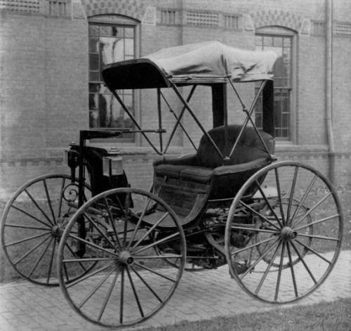
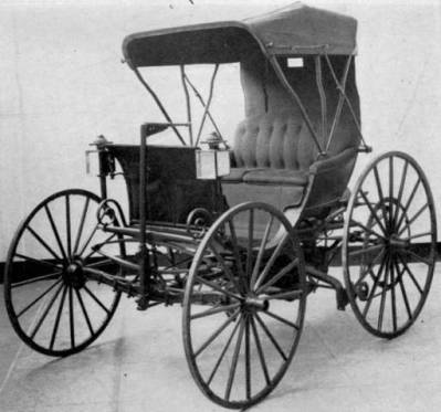
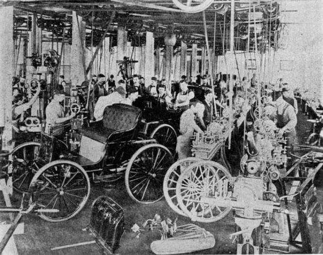
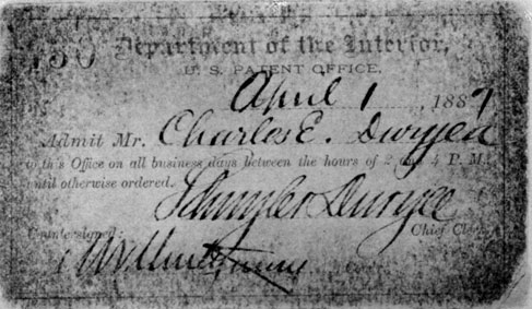
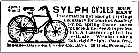
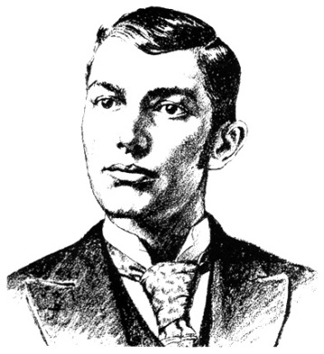
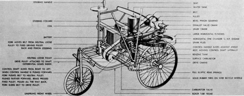
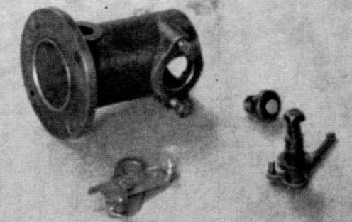
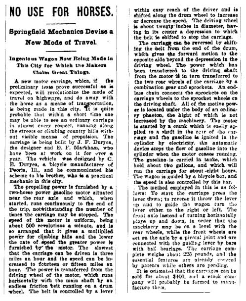
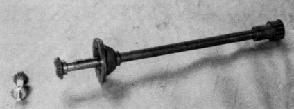
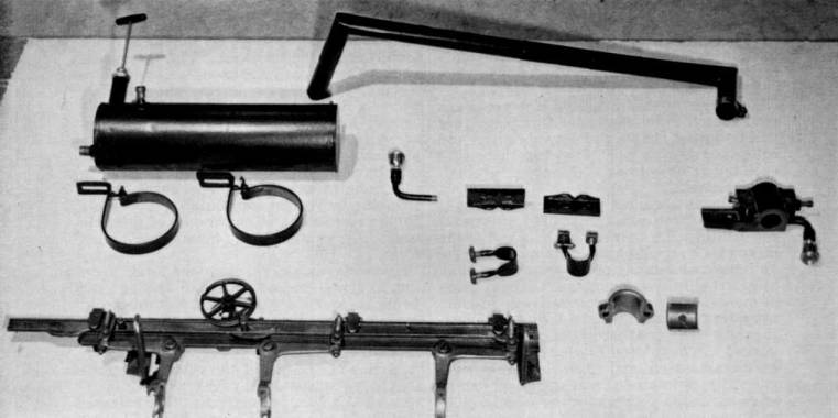


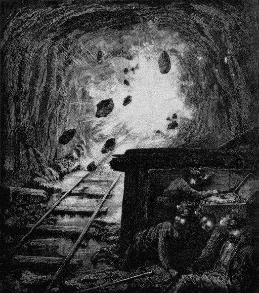
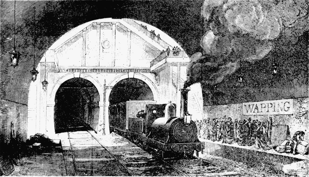
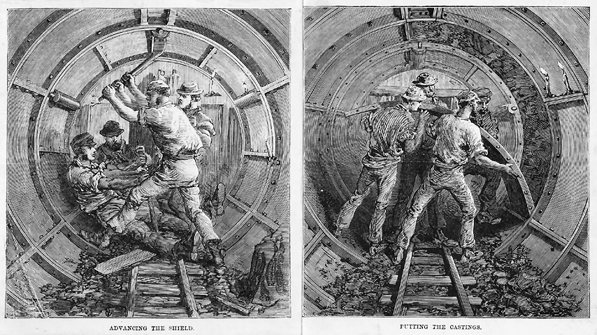
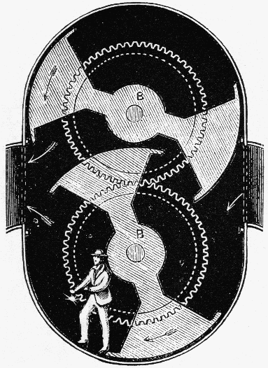
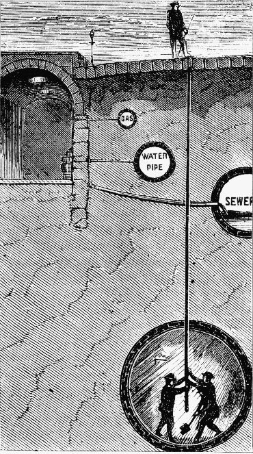


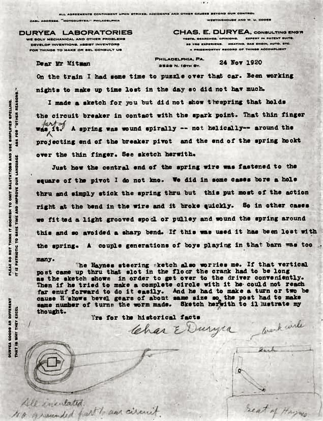
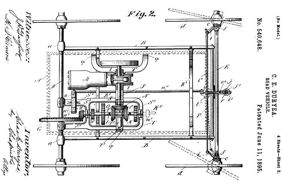
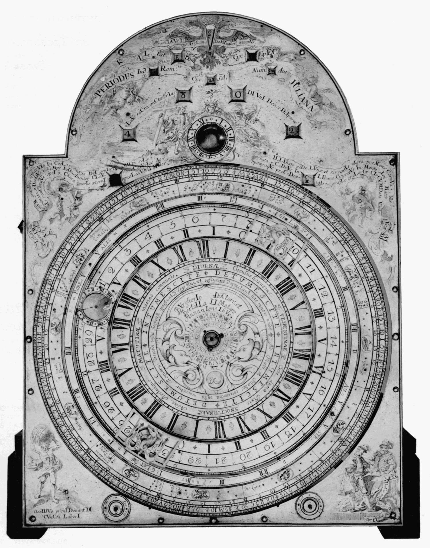
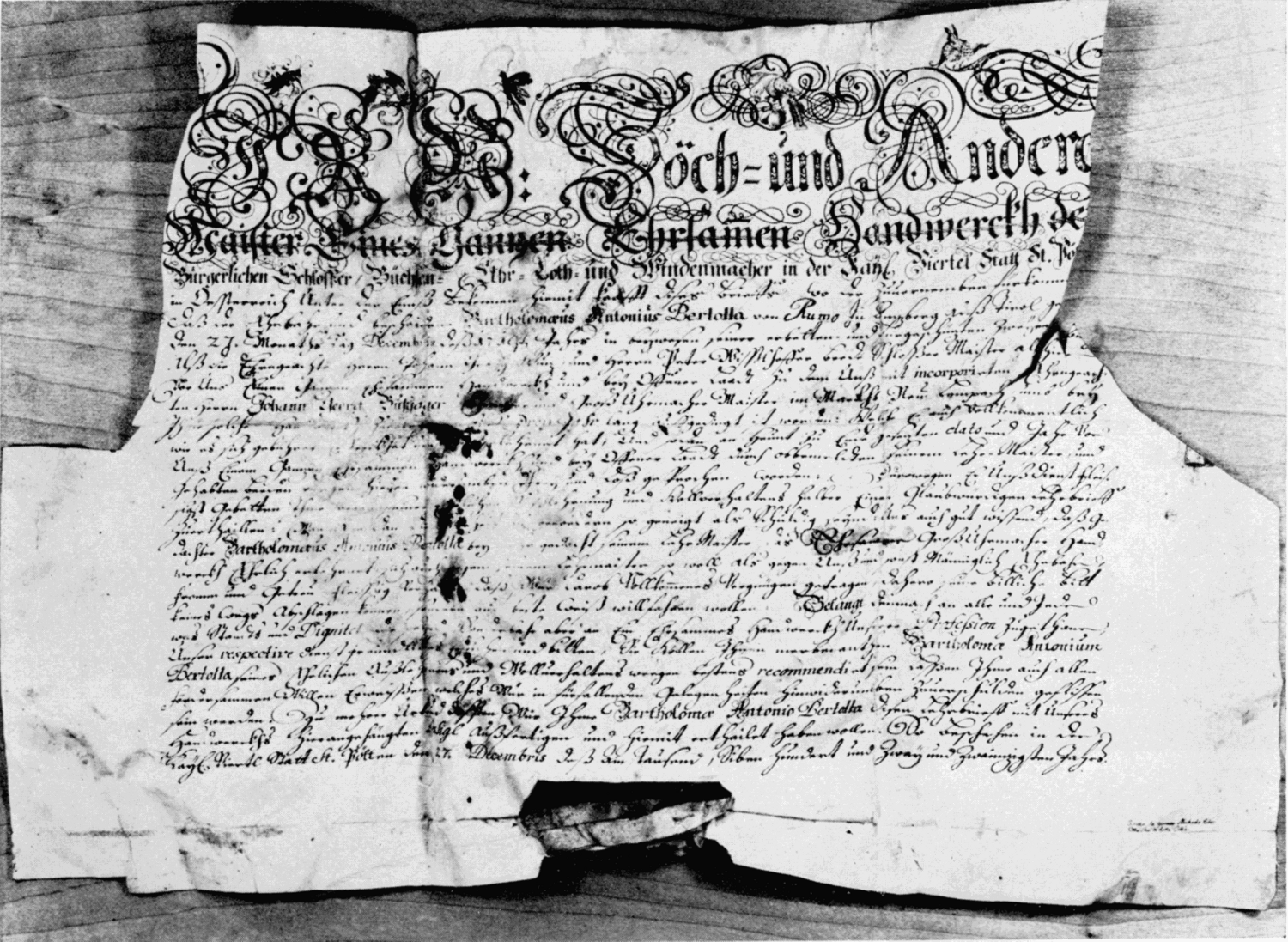
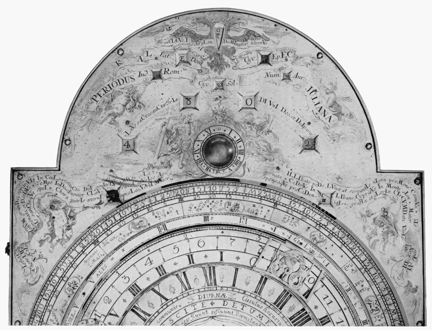
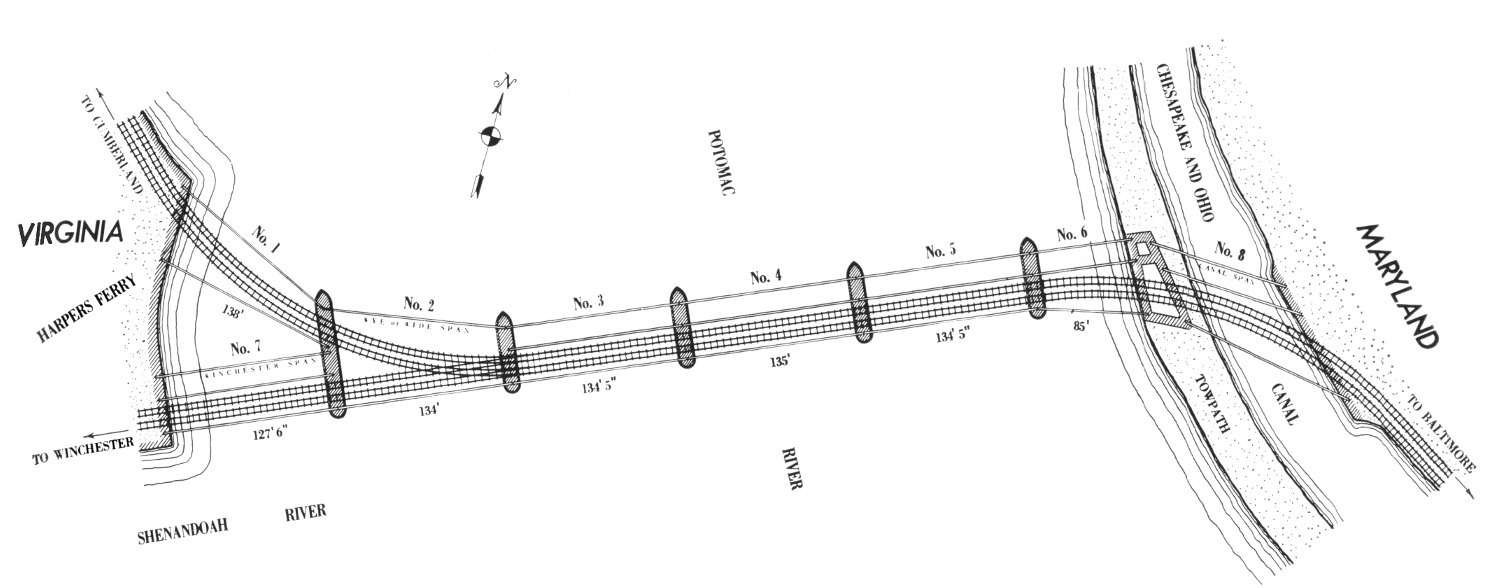
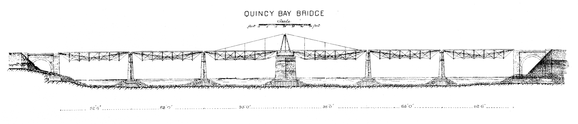
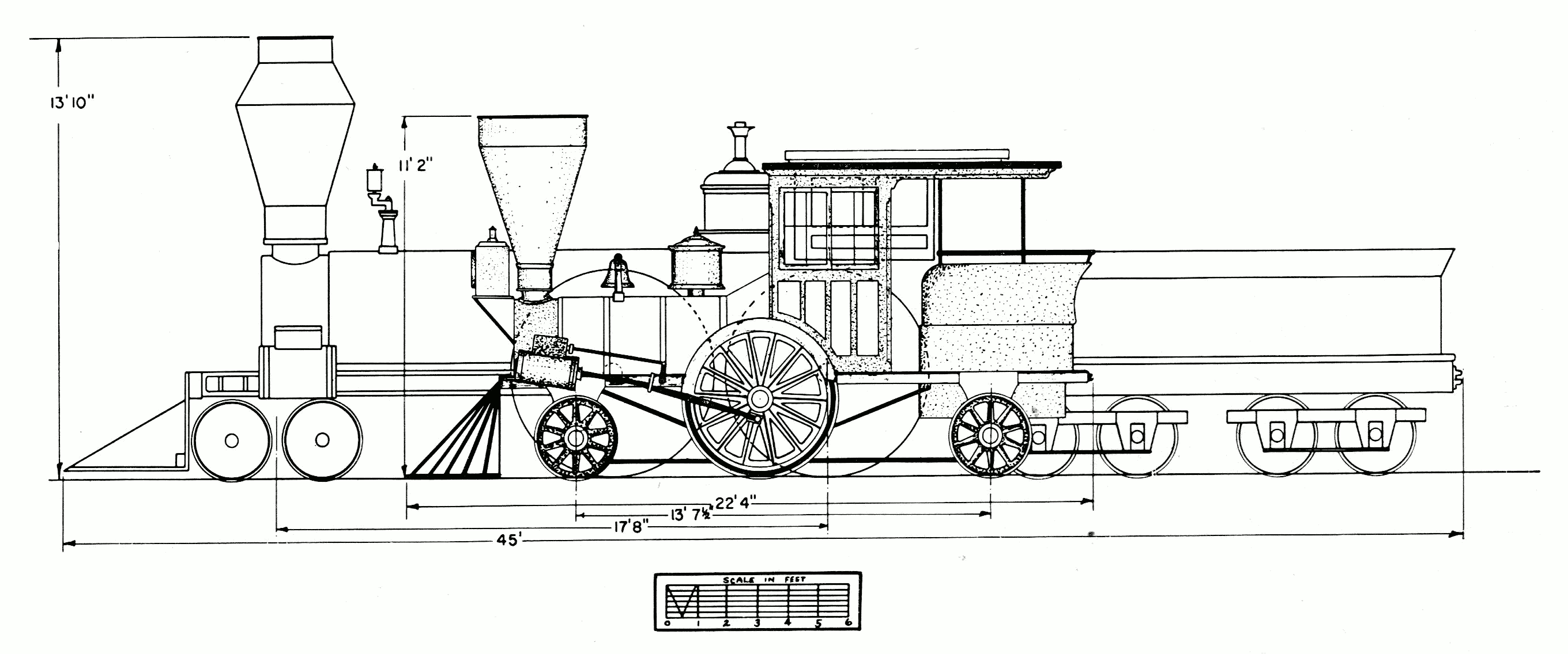
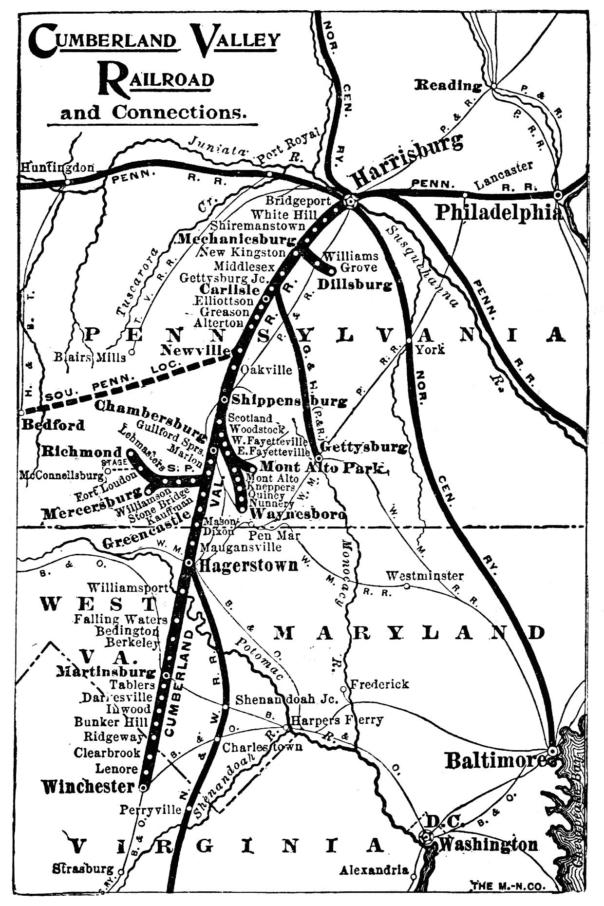
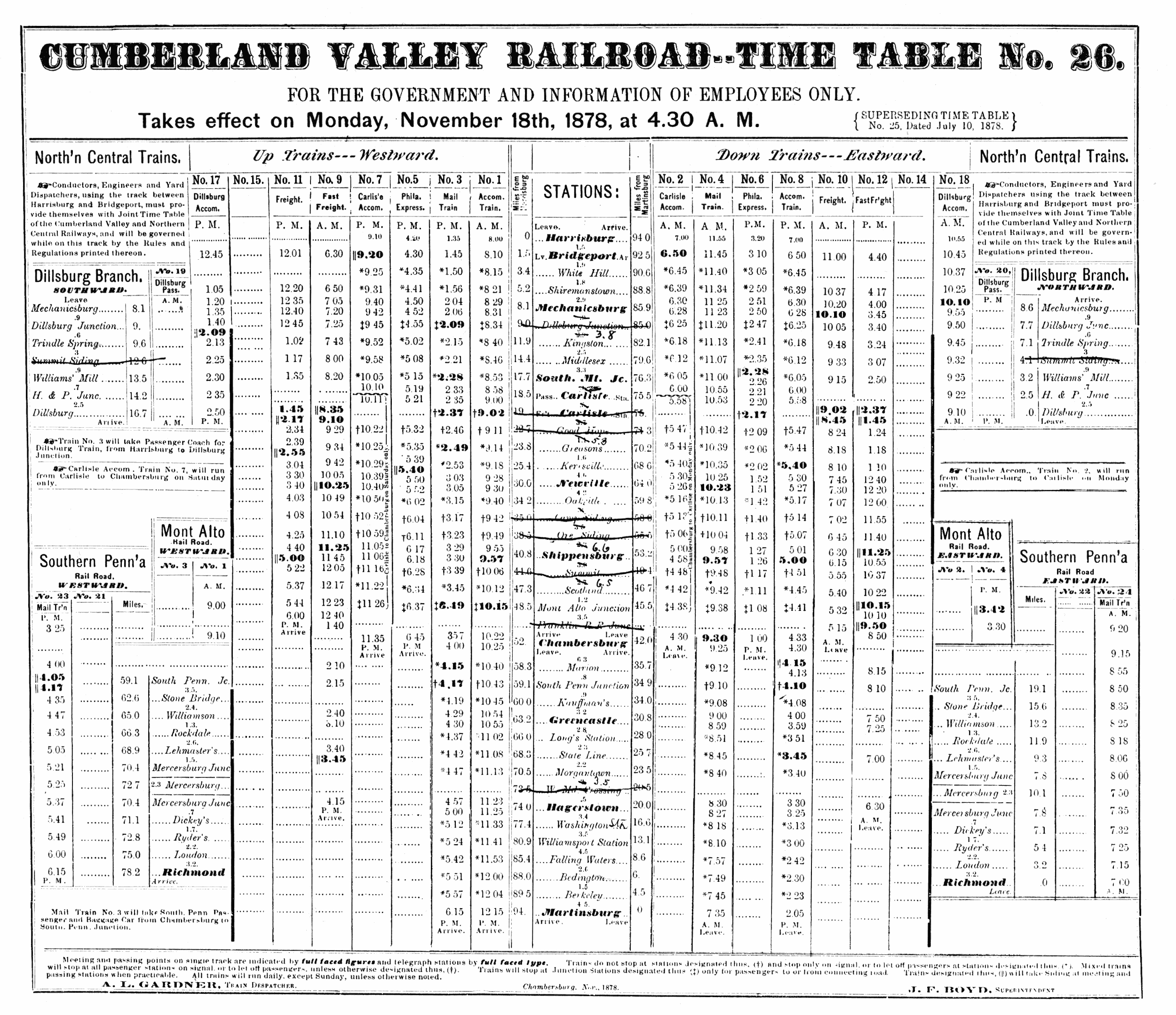
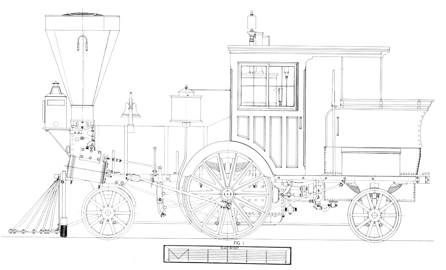
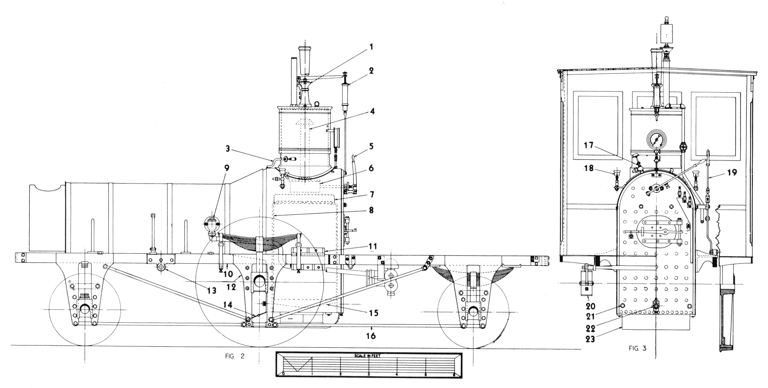
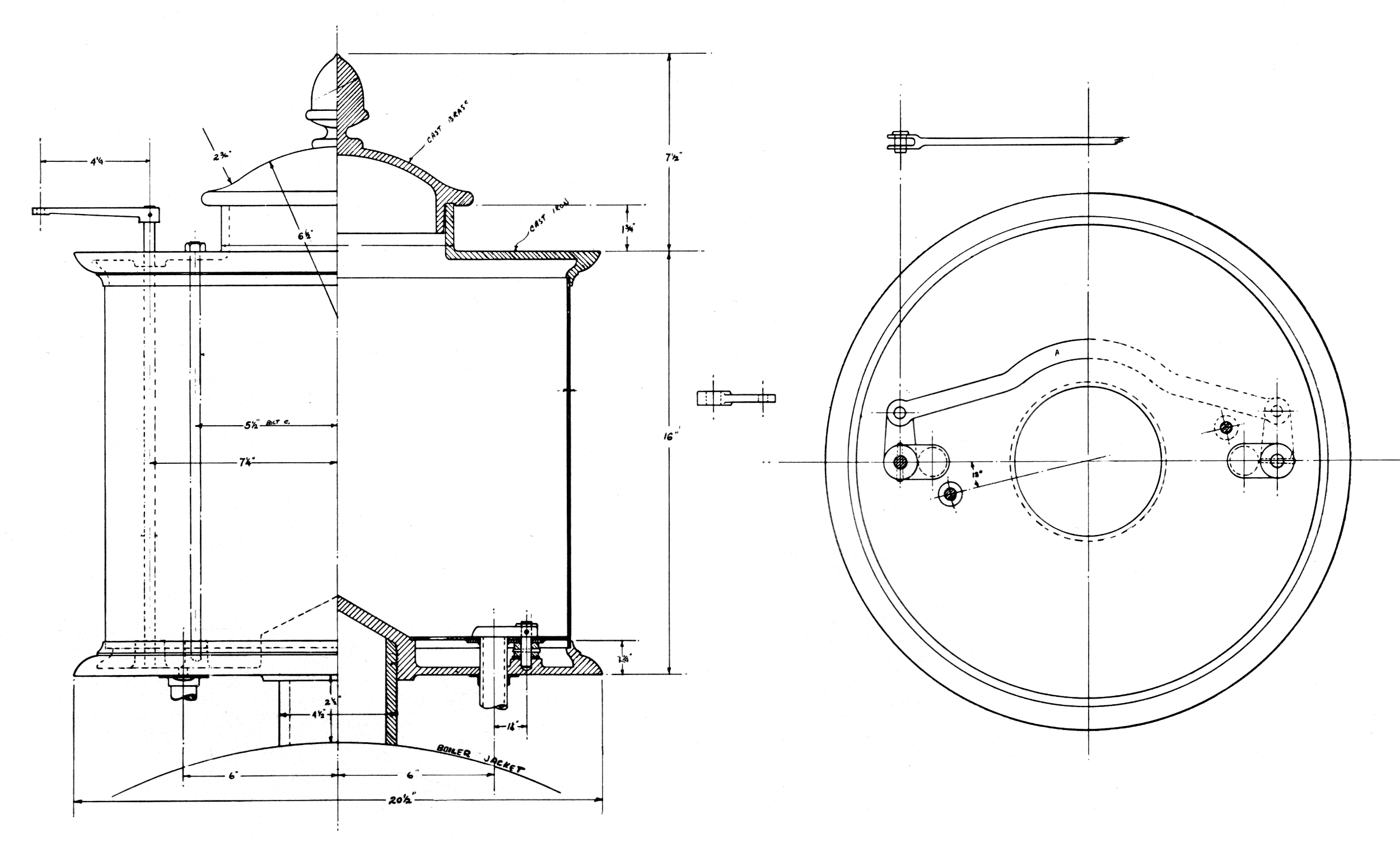